ESAB ESP-400C Plasma Power Source Handleiding
- Categorie
- Lassysteem
- Type
- Handleiding

F-15-758
Jun, 2005
Installatie, Uitvoering en Onderhoud voor de
ESP-400C
Plasma Krachtbron

De apparatuur beschreven in deze handleiding is
potentieel gevaarlijk. Wees voorzichtig bij de
installatie, uitvoering en het onderhoud van deze
apparatuur.
De koper is geheel verantwoordelijk voor de
veilige uitvoering en het gebruik van alle
aangeschafte producten inclusief conform de
OSHA en andere rijksregelgevingen. ESAB
Snijsystemen is niet verantwoordelijk voor
persoonlijk letsel of andere schade die
voortvloeit uit het gebruik van enige producten
die door ESAB gefabriceerd of verkocht zijn.
Zie de standaard verkoopvoorwaarden en
condities van ESAB voor een speciale
verklaring van de verantwoordelijkheden van
ESAB en de beperkingen en de
aansprakelijkheid.
De eerste prioriteit van ESAB Snijsystemen is
de totale tevredenheid van de klant. Wij zijn
voortdurend op zoek naar mogelijkheden om
onze producten, service en documentatie te
verbeteren. Het resultaat is dat wij indien
nodig verbeteringen en/of veranderingen in het
ontwerp doorvoeren. ESAB zal al het
mogelijke in werking stellen om ervoor te
zorgen dat onze documentatie bijgewerkt is.
We kunnen niet garanderen dat elk stukje
documentatie die door onze klanten worden
aangeleverd, op de laatste ontwerp
verbeteringen betrekking hebben. Daarom is
de informatie in dit document onderhevig aan
veranderingen zonder berichtgeving tevoren.
Dit is handleiding ESAB Onderdeelnummer F15758
Deze handleiding is voor het gemak en het gebruik
van de koper van de snijmachine. Het is geen
contract of een andere verplichting van het deel van
de ESAB snij systemen.
© ESAB Snijsystemen, 2000
Gedrukt in Amerika.

ESP-400C Plasma Krachtbron Inhoudsopgave
i
Pagina
Hoofdstuk 1 Veiligheid
1.1 Introductie 1
1.2 Opmerkingen m.b.t. veiligheid en symbolen 1
1.3 Algemene veiligheidsinformatie 2
1.4 Voorzorgsmaatregelen installatie 3
1.5 Basis elektriciteit 4
1.6 Uitvoering van een Plasma snijmachine 4-7
1.7 Voorzorgsmaatregelen service 8
1.8 Veiligheidsreferenties 9
Hoofdstuk 2 Beschrijving
2.1 Algemeen 1
2.2 Algemene specificaties 1
2.3 Afmetingen en gewicht 2
Hoofdstuk 3 Installatie
3,1 Algemeen 1
3.2 Uitpakken 1
3.3 Plaatsing 2
3.4 Invoer Stroomverbindingen 2-5
3.4.1 Eerste stroom 3
3.4.2 Invoer geleider 4
3.4.3 Invoer Verbindingsprocedure 4-5
3.5 Uitvoerverbindingen 5-6
3.5.1 Uitvoerkabels 5
3.5.2 Uitvoer verbindingsprocedure 5
3.6 Parallel installatie 6-7
3.7 Systeem Interconnectiviteit Blok diagram met Smart Flow II 8
3.8 Systeem Interconnectiviteit Blok diagram zonder Smart Flow II 9
Hoofdstuk 4 Werking
4,1 Introductie 1
4.2 Controle paneel 1-3
4.3 Volgorde van werking 4
4.4 Eerste boog instellingen 4-7
4.4.1 Inschakelen/uitschakelen van begin boog timer 6
4.4.2 Bijstellen begin boog timer 6
4.4.3 Eerste boog controles 7
4.4.4 Start stroom en oplopende timer 7
4.5 V-I Boog 8

ESP-400C Plasma Krachtbron Inhoudsopgave
ii
Hoofdstuk 5 Onderhoud
5,1 Algemeen 1
5.2 Reinigen 1
5.3 Smering ventilatie 2
Hoofdstuk 6 Oplossen problemen
6.1 General (Algemeen) 1
6.2 Fault Indicators (Fout indicatoren) 1-3
6.3 Fault Isolation (Diagnostics) (Fout Isolatie (diagnose)) 4-10
6.3.1 Fans (Ventilatoren) 4
6.3.2 Power not on or Low Voltage (Geen stroom of laag voltage) 4
6.3.3 Fault Light Illumination (Foutmelding verlichting) 5-8
6.3.4 Torch will not Fire (Brander wil niet branden) 9
6.3.5 Fuses 1 and 2 Blown (Zekeringen 1 en 2 zijn defect) 10
6.3.6 Intermittent, interrupted or Partial Operation (Onderbroken,
afgebroken of gedeeltelijke werking)
10-12
6.4 Testing and Replacing Components (Testen en vervangen van onderdelen) 13
6.4.1 Power Rectifiers (Stroom herstellers( 14
Negative Plate (Negatieve plaat) 14
Positive Plate (Positieve plaat) 15
Electrode Plate (Elektrode plaat) 15
6.4.2 Freewheeling Diodes and IGBTs (Vrijloop diodes en IGBT´s) 16-18
6.4.3 Power Shunt Installation (Installatie Stroom parallel schakeling) 18
6.4.4 Procedure for Verifying Calibration of Digital Meters (Procedure
voor nagaan smering van digitale meters)
19
6.5 ESP-400C Schematic Diagrams (ESP-400C Schema diagrammen) 20-27
6.6 Wiring Diagrams (Kabel diagrammen) 28-35
6.7 PC Controller Board (PCB1 - P/N 38032) Schematics (PC regeling
(PCB1-P/N 38032) schema´s)
36-40
6.8 PCB Digital Meter Board (PCB4 – P/N 38139) Schematics (PCB digitale
meter regeling (PCB4-P/N 381 39) schema´s)
41-43
6.9 IGBT Driver Board (PCB2,3 – P/N 38030) Schematics (IGBT Aandrijf
regeling (PCB2,3-P/N 38030) schema´s)
44-46

ESP-400C Plasma Krachtbron Inhoudsopgave
iii
Hoofdstuk 7 Vervangingsonderdelen
7,1 General (Algemeen) 1
7.2 Ordering (Bestellingen) 1
7.3 Outside View - Front and Back (Aanzicht buitenzijde – voorzijde en achterzijde) 2-3
7.4 Front View With PCBs Exposed (Aanzicht voorzijde met PCB´s blootgelegd) 4-5
7.5 Right Side View (Rechter zijaanzicht) 6-7
7.6 Left Side View (Linker zijaanzicht) 8-9
7.7 Top View (Boven aanzicht) 10-11
7.8 Back Inside View (Achter aanzicht binnenzijde) 12-13
7.9 Middle Cross Section (Midden tussengedeelte) 14-15
7.1.0 Front Cross Section – Behind Front Panel (Voor tussen gedeelte – achter
het voorste paneel)
16-17
Customer/Technical Information
Klanten/Technische informatie
Back Manual Cover
Achterzijde omslag
handleiding

ESP-400C Plasma Krachtbron Inhoudsopgave
iv
Deze pagina blijft blanco.

HOOFDSTUK 1 VEILIGHEID
ESP 400C Plasma Krachtbron - 1-1
1.1 Inleiding
Het metaalsnijproces met plasma-apparatuur verschaft
het bedrijfsleven een waardevol en veelzijdig
werkinstrument. ESAB snijmachines zijn zodanig
ontworpen dat zij zowel bedieningsveiligheid als
doelmatigheid bieden. Net als bij elk andere machinaal
werktuig is echter voor een optimaal nuttig gebruik
noodzakelijk, met gezond verstand aandacht te
besteden aan bedieningsmethoden,
voorzorgsmaatregelen en veilige gebruikspraktijken.
Ongeacht of iemand betrokken is bij bediening,
onderhoud of toezicht, het is van dwingend belang dat
wordt gehandeld in overeenstemming met de
vastgelegde voorzorgsmaatregelen en
veiligheidsvoorzieningen. Indien men zou verzuimen
bepaalde voorzorgen in acht te nemen, kan dat ernstig
letsel van personeel of schade aan de apparatuur tot
gevolg hebben. De hierna beschreven
voorzorgsmaatregelen zijn als algemene richtlijnen van
toepassing bij het werken met snijmachines.
Voorzorgen die meer specifiek op de basismachine en
accessoires zijn toegespitst vindt u in de
gebruiksaanwijzingen. Om uw blik op het gebied van
veiligheid bij het werken met snij- en lasapparatuur te
verruimen kunt u de uitgaven aanschaffen en lezen die
zijn opgesomd in de paragraaf Aanbevolen
literatuurverwijzingen.

HOOFDSTUK 1 VEILIGHEID
ESP 400C Plasma Krachtbron - 1-2
1.2 Veiligheidstermen en -tekens
In deze handleiding worden de hierna opgesomde
woorden en tekens gebruikt. Zij weerspiegelen
verschillende niveaus van betrokkenheid bij het aspect
veiligheid die bij bepaalde handelingen gewenst is.
!
ALARM- of ATTENTIEMELDING. Uw veiligheid is
in het geding of het risico van storing van de
apparatuur is aanwezig. Wordt gebruikt in
combinatie met andere tekens en geschreven
informatie.
GEVAAR
!
Wordt gebruikt om de aandacht te vestigen op
terstond bestaande gevaren die, als zij niet
worden vermeden, ernstig persoonlijk letsel of de
dood tot gevolg zullen hebben.
WAARSCHUWING
!
Wordt gebruikt om de aandacht te vestigen op
mogelijke gevaren die persoonlijk letsel of de
dood tot gevolg kunnen hebben.
VOORZICHTIG
!
Wordt gebruikt om de aandacht te vestigen op
risico’s die licht persoonlijk letsel of
beschadiging van apparatuur tot gevolg kunnen
hebben.
VOORZICHTIG
Wordt gebruikt om de aandacht te vestigen op
het risico van kleine beschadigingen van
apparatuur.
LET OP
Wordt gebruikt om de aandacht te vestigen op
belangrijke informatie over installatie, bediening
of onderhoud, die niet rechtstreeks verband
houdt met veiligheidsrisico’s.

HOOFDSTUK 1 VEILIGHEID
ESP 400C Plasma Krachtbron - 1-3
1.3 Algemene informatie over veiligheid
WAARSCHUWING
!
Machine start vaak automatisch.
Dit uitrustingsstuk beweegt in diverse richtingen en op
diverse snelheden.
· Door bewegende machines kan druk- of
pletschade ontstaan.
· Deze stroombron mag uitsluitend door daartoe
bevoegd personeel worden bediend en
onderhouden.
· Zorg dat personen, materialen en apparatuur
zonder functionele rol in het productieproces op
afstand blijven van de gehele systeemzone.
· Scherm het gehele werkgebied af zodat het
personen wordt belet, door het werkgebied te
lopen of in de werkingscyclus van de apparatuur te
staan.
· Plaats geschikte WAARSCHUWINGsmerktekens
bij elke toegang tot het werkgebied.
· Voer de uitschakelprocedure uit voordat
onderhoudswerk aan apparatuur wordt uitgevoerd.
WAARSCHUWING
!
Indien men bedieningsaanwijzingen niet
navolgt, kan dat tot de dood of tot ernstig
letsel leiden.
Lees deze bedieningshandleiding voordat u de
machine gebruikt en zorg dat u de inhoud volledig
begrepen hebt.
· Lees de gehele proceduregang door alvorens
het systeem te bedienen of systeemonderhoud
uit te voeren.
· Schenk in het bijzonder aandacht aan
risicowaarschuwingen die belangrijke informatie
bevatten over de veiligheid van personen en/of
risico’s van schade aan apparatuur.
· Alle veiligheidsvoorzorgen voor elektrische
apparatuur en procesbewerking moeten strikt in
acht worden genomen door allen die
verantwoordelijkheid voor en/of toegang tot het
systeem hebben.
· Lees alle veiligheidsdocumentatie die door uw
bedrijf ter beschikking wordt gesteld.

HOOFDSTUK 1 VEILIGHEID
ESP 400C Plasma Krachtbron - 1-4
WAARSCHUWING
!
Indien men aanwijzingen op veiligheids- en
waarschuwingsetiketten niet navolgt, kan
dat tot de dood of tot ernstig letsel leiden.
Lees alle veiligheids- en waarschuwingsetiketten op
de machine en zorg dat u de inhoud begrijpt.
Raadpleeg de bedieningshandleiding voor meer
informatie over veiligheid.
1.4 Voorzorgsmaatregelen voor installatie
WAARSCHUWING
!
Ondeugdelijk geïnstalleerde apparatuur kan
oorzaak zijn van letsel of overlijden.
Volg bij het installeren van de machine deze richtlijnen:
· Neem, voordat u gaat installeren, contact op met
uw ESAB vertegenwoordiger. Hij kan u advies
geven over bepaalde voorzorgsmaatregelen voor
het installeren van het leidingmateriaal, het tillen
van de machine, e.d., zodat optimale beveiliging
gewaarborgd is.
·
Experimenteer nooit met aanpassingen aan de
machine of toevoegingen aan de apparatuur
zonder dat u eerst een vertegenwoordiger van
ESAB hebt geraadpleegd.
· Neem de vereiste afstanden van de machine in
acht ter bevordering van een correcte bediening en
de veiligheid van medewerkers.
· Laat de installatie, het verhelpen van storingen en
het onderhoud van deze apparatuur altijd over aan
daartoe bevoegd personeel.
· Zorg dat er zich dicht bij de stroombron een wand-
hoofdschakelaar met de juiste aansluitmaten
bevindt.

HOOFDSTUK 1 VEILIGHEID
ESP 400C Plasma Krachtbron - 1-5
1.5 Elektrische aarding
Voor een goede en VEILIGE bediening van de machine
is elektrische aarding van dwingend belang.
Raadpleeg het hoofdstuk Installatie van deze
handleiding voor gedetailleerde aanwijzingen over het
aarden.
WAARSCHUWING
!
Gevaar van elektrische schok.
Ondeugdelijke aarding kan oorzaak zijn van ernstig
letsel of overlijden.
De machine moet goed geaard zijn voordat deze in
werking wordt gesteld.
1.6 De bediening van een plasma-
snijmachine
WAARSCHUWING
!
De gevaren van rondvliegend slijpsel
en luid geraas.
· Hete metaalspatten kunnen verbrandings- en
ander letsel aan de ogen veroorzaken. Draag altijd
een gelaatsscherm om uw ogen te beschermen
tegen verbrandingsletsel en wegspringend slijpsel
dat tijdens de werking van de machine kan worden
geproduceerd.
· Afbrokkelend slak kan heet zijn en ver
wegspringen. Ook omstanders moeten een
gelaatsscherm en veiligheidsbril dragen.
· Het geraas van de plasmaboog kan de
gehoorfunctie aantasten. Draag adequate
oorbeschermers wanneer u boven water snijdt.
WAARSCHUWING
!
Gevaar van verbrandingsletsel.
Heet metaal kan brandwonden veroorzaken.
· Raak metalen platen of stukken niet direct na het
snijden aan. Geef het werkstuk tijd om af te koelen
of koel het met water.
· Raak ook de plasmabrander niet direct na het
snijden aan. Geef de brander tijd om af te koelen.

HOOFDSTUK 1 VEILIGHEID
ESP 400C Plasma Krachtbron - 1-6
WAARSCHUWING
!
Gevaarlijke voltages. Een elektrische
schok kan dodelijk zijn.
Raak de plasmatoorts, de snijtafel of de
kabelverbindingen NIET aan tijdens het plasma-
snijproces.
Schakel de netvoeding naar de plasma-
stroomvoorziening altijd uit alvorens deze aan te raken
of onderhoud aan de plasmatoorts te verrichten.
Schakel de netvoeding naar de plasma-
stroomvoorziening altijd uit alvorens onderhoud aan
een systeemcomponent te verrichten.
Raak geen geactiveerde elektrische onderdelen
aan.
Laat alle panelen en afdekplaten op hun plaats
wanneer de machine op de netvoeding is aangesloten.
Draag beschermende handschoenen, schoenen
en kleding om uzelf te beschermen tegen
beschadiging door het werkstuk en door elektrische
aansluitingen.
Houd de handschoenen, schoenen, kleding, het
werkgebied en de instrumenten droog.
Vervang versleten of beschadigde kabels.
WAARSCHUWING
!
Gevaar van dampvorming.
Dampen en gassen die tijdens het plasma-snijproces
vrijkomen kunnen een gevaar vormen voor uw
gezondheid.
Adem deze dampen NIET in.
Bedien de plasmatoorts niet wanneer de
dampafzuiging niet correct werkt.
Maak, indien nodig, gebruik van aanvullende
ventilatie om de dampen te verwijderen.
Gebruik een goedgekeurd gasmasker indien de
ventilatie niet afdoende is.
Zorg voor positieve mechanische ventilatie bij het
snijden van gegalvaniseerd staal, roestvrij staal, koper,
zink, beryllium en cadmium. Adem deze dampen niet
in.
Gebruik de machine niet in de nabijheid van
ontvettende en vernevelende werkzaamheden. Hitte
of boogstralen kunnen een reactie aangaan met
gechloreerde koolwaterstofdampen tot fosgeen, een in
hoge mate toxisch gas, en andere irriterende gassen.

HOOFDSTUK 1 VEILIGHEID
ESP 400C Plasma Krachtbron - 1-7
WAARSCHUWING
!
Stralingsgevaar.
Boogstralen kunnen de ogen verwonden en
brandwonden aan de huid veroorzaken.
Draag de juiste oog- en lichaamsbescherming.
Draag een donkergekleurde veiligheidsbril of een
gelaatsscherm met zijschermen. Voor de aanbevolen
lenssterkten voor het plasmasnijden kunt u de
volgende tabel raadplegen:
Boogstroom Lenssterkte
Tot 100 A Sterkte 8
100-200 A Sterkte 10
200-400 A Sterkte 12
Meer dan 400 A Sterkte 14
Wanneer de lenzen van de veiligheidsbril of het
gelaatsscherm beschadigd zijn of gebroken, dient u
deze te vervangen.
Waarschuw anderen in uw directe omgeving niet
rechtstreeks in de boog te kijken, tenzij zij een goede
veiligheidsbril dragen.
Prepareer het snijgebied zodanig dat er zo weinig
mogelijk reflectie en transmissie van ultraviolet licht
plaatsvindt.
§ Gebruik speciale verf voor de wanden om de
UV-lichtstralen te absorberen.
§ Installeer beschuttende schermen of
gordijnen om de ultraviolette transmissie te
beperken.

HOOFDSTUK 1 VEILIGHEID
ESP 400C Plasma Krachtbron - 1-8
WAARSCHUWING
!
Gevaar van verbrandingsletsel.
Hitte, metaalspatten en vonken kunnen brand en
brandwonden veroorzaken.
Snij niet in de buurt van brandbaar materiaal.
Draag geen brandbare artikelen bij u (bijvoorbeeld
butaangasaansteker).
Een pilotboog kan brandwonden veroorzaken.
Houd het mondstuk van de toorts van uzelf en
anderen af gericht tijdens het activeren van het
plasmaprocédé.
Draag de juiste oog- en lichaamsbescherming.
Draag brandwerende handschoenen,
veiligheidsschoenen en een hoofddeksel.
Draag brandvertragende kleding die alle
blootgestelde delen bedekt.
Draag een broek zonder omslagen zodat er geen
vonken en slak in de vouw kunnen vallen.
Houd brandblusapparatuur binnen handbereik en
klaar voor gebruik.
WAARSCHUWING
!
Explosiegevaar.
Bepaalde gesmolten aluminium-lithium (Al-Li)
legeringen kunnen explosies veroorzaken wanneer het
plasmasnijden BOVEN water wordt uitgevoerd.
§ Deze legeringen mogen alleen droog worden
gesneden op een droge tafel.
§ Snij NIET droog boven water.
§ Neem contact op met uw
aluminiumleverancier voor extra
veiligheidsinformatie met betrekking
tot de risico’s die verbonden zijn aan
deze legeringen.
Snij niet in een atmosfeer die explosieve dampen
of explosief stuifsel bevat.
Draag geen brandbare artikelen bij u (bijvoorbeeld
butaangasaansteker).
Snij niet in containers die brandbaar materiaal
bevat hebben.

HOOFDSTUK 1 VEILIGHEID
ESP 400C Plasma Krachtbron - 1-9
1.7 Onderhoudsvoorzorgen
WAARSCHUWING
!
Gevaarlijke voltages. Een elektrische
schok kan dodelijk zijn.
Raak de plasmatoorts, de snijtafel of de
kabelverbindingen NIET aan tijdens het plasma-
snijproces.
Schakel de netvoeding naar de plasma-
stroomvoorziening altijd uit alvorens deze aan te raken
of onderhoud aan de plasmatoorts te verrichten.
Schakel de netvoeding naar de plasma-
stroomvoorziening altijd uit voordat u afdekplaten of
panelen verwijdert om onderhoud aan een
systeemcomponent te verrichten.
Raak geen geactiveerde elektrische onderdelen
aan.
Laat alle panelen en afdekplaten op hun plaats
wanneer de machine op de netvoeding is aangesloten.
Houd de handschoenen, schoenen, kleding, het
werkgebied en de instrumenten droog.
Controleer de stroom- en aardkabels op slijtage of
scheurtjes. Vervang versleten of beschadigde kabels.
In geval van beschadiging niet gebruiken.
Maak nooit een omloopaansluiting om een
veiligheidsverbinding.
Houd u aan de afsluitprocedures.
VOORZICHTIG
Maak een plan voor preventief onderhoud en houd u
daaraan. Men kan een samengesteld programma
vaststellen aan de hand van de aanbevolen schema’s.
Laat geen testapparatuur of handgereedschappen op
de machine liggen. Dit kan oorzaak zijn van ernstige
elektrische of mechanische schade aan de uitrusting of
de machine.

HOOFDSTUK 1 VEILIGHEID
ESP 400C Plasma Krachtbron - 1-10
VOORZICHTIG
!
Men dient de uiterste voorzichtigheid te betrachten bij
het nameten van het schakelcircuit met behulp van
een oscilloscoop of voltmeter. Geïntegreerde circuits
zijn gevoelig voor schade door een te hoog voltage.
Schakel het systeem uit alvorens de testsondes te
gebruiken, zodat kortsluiting van de onderdelen wordt
voorkomen.
Voordat de stroomvoorziening wordt ingeschakeld
moeten alle printplaten stevig in sockets zijn verankerd,
alle kabels correct zijn verbonden, alle kasten dicht en
afgesloten zijn en alle schutdelen en afdekplaten zijn
geplaatst.

HOOFDSTUK 1 VEILIGHEID
ESP 400C Plasma Krachtbron - 1-11
1.8 Verwijzingen m.b.t. veiligheid – Voorschriften, standaardnormen, richtlijnen
Het verdient aanbeveling de volgende erkende publicaties op het
gebied van veiligheid tijdens het lassen en snijden door te lezen. Deze
publicaties zijn tot stand gekomen ter persoonlijke bescherming tegen
letsel of ziekte en ter bescherming van producten tegen schade, die
kan voortvloeien uit onveilig handelen. Hoewel sommige van deze
publicaties niet specifiek met dit type industrieel snij-apparaat verband
houden, zijn de veiligheidsprincipes wel van toepassing.
1.8.1 USA
· “Precautions and Safe Practices in Welding and Cutting with
Oxygen-Fuel Gas Equipment,” Form 2035. ESAB Cutting
Systems.
· “Precautions and Safe Practices for Electric Welding and Cutting,”
Form 52-529. ESAB Cutting Systems.
· “Safety in Welding and Cutting” - ANSI Z 49.1, American Welding
Society, 2501 NW 7th Street, Miami, Florida, 33125.
· “Recommended Safe Practices for Shielded Gases for Welding and
Plasma Arc Cutting” - AWS C5.10-94, American Welding Society.
· “Recommended Practices for Plasma Arc Welding” - AWS C5.1,
American Welding Society.
· “Recommended Practices for Arc Cutting” - AWS C5.2, American
Welding Society.
· “Safe Practices” – AWS SP, American Welding Society.
· “Standard for Fire Protection in Use of Cutting and Welding
Procedures” – NFPA 51B, National Fire Protection Association, 60
Batterymarch Street, Boston, Massachusetts, 02110.
· “Standard for Installation and Operation of Oxygen - Fuel Gas
Systems for Welding and Cutting” - NFPA 51, National Fire
Protection Association.
· “Safety Precautions for Oxygen, Nitrogen, Argon, Helium, Carbon
Dioxide, Hydrogen, and Acetylene,” Form 3499. ESAB Cutting
Systems. Verkrijgbaar via uw ESAB-vertegenwoordiger of
plaatselijke leverancier.
· "Design and Installation of Oxygen Piping Systems," Form 5110.
ESAB Cutting Systems.
· “Precautions for Safe Handling of Compressed Gases in
Cylinders”, CGA Standard P-1, Compressed Gas Association.
Ook is lectuur over veilig werken bij het lassen en snijden met behulp
van gassen verkrijgbaar bij de Compressed Gas Association, Inc., 500
Fifth Ave., New York, NY 10036.

HOOFDSTUK 1 VEILIGHEID
ESP 400C Plasma Krachtbron - 1-12
International
Accident Prevention
VBG- Unfallverhütungsvorshriften
General Provisions
VBG 1
Allgemeine Unfallverhütungsvorshriften
Electrical Equipment and operating Equipment
VBG 4
Elektrische Anlagen
Welding, Cutting and related working methods
VBG 15
Schweißen un Schneiden un verwandte Verfahren
Shot Blasting Works
VBG 48
Strahlarbeiten
Gases
VBG 61
Gase
Oxygen
VBG 62
Sauerstoff
Operating liquid jet cutting machines
VBG 87
Arbeiten mit Flüssigkeitsstrahlem
Laser beams, accident prevention and Electro-
technology
VBG 93
Laserstrahlung, Unfallverhütungs-vorschriften für
Feinmechnik und Elektrotechnik
Noise
VBG 121
Lärm

HOOFDSTUK 1 VEILIGHEID
ESP 400C Plasma Krachtbron - 1-13
VDE Regulations
VDE - Vorschriften
Erection of power installations with normal voltages up to
1000 volts
VDE 0100
Bestimmungen für das Errichten von Stakstromanlagen
mit Nennspannungen bis 1000 Volt
Electrical equipment of industrial machines
VDE0113
Elektrishe Ausrüstung von Industriemaschinen
Radiation safety of laser products; users guide (DIN EN
60825)
VDE 0837
Strahlungssicherheit von Lasereinrichtungen und
Benutzungsrichtlinen (DIN EN 60825)
Specification for laser guards
VDE 0837-
50
Anforderung an Lasershcutzwänden
TRAC Technical Rules for Acetylene and Carbide Stores
TRAC- Techische Regein für Azetylenanlagen und Calciumcargidlager
Acetylene lines
TRAC-204
Azetylenleitungen
Acetylene cylinder battery systems
TRAC-206
Azetylenflaschenbatterieanlagen
Safety devices
TRAC-207
Sicherheitseinrichtungen
TRG Technical Rules for Pressure gases
TRG – Technische Regein für Druckgase
General regulations for pressure gases
TRG 100
Allgemeine Bestimmungen für Druckgase
Pressure gases
TRG 101
Druckgase
Technical gas mixtures
TRG 102
Technishe Gasgemische
Pressure gases; alterative use of compressed gas tanks
TRG 104
Druckgase, wahlweise Verwendung von
Druckgasbehältem

HOOFDSTUK 1 VEILIGHEID
ESP 400C Plasma Krachtbron - 1-14
TRGS – Technische Richtlinien für Gefahrstoffe
TRGS-102 Techn. Richtkonzentration (TRK) für gefährliche Stoffe
TRGS-402
Ermittlung u. Beurteilung der Konzentration gefährlicher
Stoffe in der Luft im Arbeitsbereich
TRGS-900 Grenzwerte in der Luft am Arbeitsplatz (Luftgrenzwerte)
TA TA-Luft un TA-Lärm (BLm SchV)
DIN Standards
DIN-Normen
DIN 2310
Part 1
Thermal cutting; terminology and nomenclature
Teil 1
Thermsiches Schneiden, Allgemeine Begriffe und
Bennungen
DIN 2310
Part 2
Thermal cutting; determination of quality of cut faces
Teil 2
Thermsiches Schneiden, Ermittein der Güte von
Schnittflächen
DIN 2310
Part 4
Thermal cutting; arc plasma cutting; process principles,
quality, dimensional tolerances
Teil 4
Thermsiches Schneiden, Plasmaschneiden,
Verfahrensgrundlagen, Güte, Maßtoleranzen
DIN 2310
Part 5
Thermal cutting; laser beam cutting of metallic materials;
process principles
Teil 5
Laserstrahlschneiden von metallischen Werkstoffen,
Verfahrensgrundlagen, Güte, Maßtoleranzen
DIN 2310
Part 6
Thermal cutting; Classification, processes
Teil 6 Einführung, Verfahren
DIN 4844
Part 1
Safety markings (DIN EN 7287)
Teil 1 Sicherheitskennzeichen (Siehe EN 7287)

HOOFDSTUK 1 VEILIGHEID
ESP 400C Plasma Krachtbron - 1-15
DIN EN ISO Harmonized Standards
DIN EN ISO-Harmonisierte Normen
Safety of machinery
DIN EN
292/1 and 2
Sicherheit von Maschinen, Geräten und Anlagen
Hoses for welding, cutting and allied processes
DIN EN 559
Schläuche für Schweißen, Schneiden und verwandte
Verfahren
Hose connections and hose couplings for equipment for
welding, cutting and allied processes
DIN EN 560
Schlauchanschlüsse und Schlauchverbindungen für
Geräte zum Schweißen, Schneiden und verwandte
Verfahren
Gas welding equipment hose couplings
DIN EN 561
Gasschweißgeräte, Kupplungen
Safety of machines, reduction of risks to health
DIN EN
626-1
Sichereit von Maschinen, Reduzierung des
Gesundheitsrisikos
Single spindle vertical milling machines
DIN EN
848-1
Fräsmaschine für einseitige Bearbeitung mit drehendem
Werkzeug
High pressure water jet machines
DIN EN
1829
Hochdruckwasserstrahlschneidmaschine
Thermal cutting, oxygen cutting, process principles,
dimensional tolerances
DIN EN
9013
Thermisches Schneiden, Autogenes Brennschneiden,
Verfahrensgrundlagen, Güte, Maßtoleranzen
Imperfections in oxy/fuel flame cuts, laser beam cuts and
plasma
DIN EN
12584
Unregeimäßigkeiten an Brennschnitten, Laserstrahl- und
Plasmaschnitten
Laser processing machines
DIN EN
12626
Laserbearbeitungsmaschinen
Acceptance testing for oxygen cutting machines
DIN EN
28206
Abnahmeprüfung für Brennschneidmaschinen
Laser Equipment
DIN EN
31252
Lasergeräte

HOOFDSTUK 1 VEILIGHEID
ESP 400C Plasma Krachtbron - 1-16
Laser and laser related equipment
DIN EN
31553
Laser und Laseranlagen
Electrical equipment of machines
DIN EN
60204-1
Elekrische Ausrüstung von Maschinen
Radiation safety of laser products
DIN EN
60825
Strahlensicherheit von Laseranlagen
Arrangement of protection devices
DIN EN 999
Anordnung von Schutzeinrichtungen
VDI Guidelines
Quality of cut faces on metallic workpieces; abrasive
water jet cutting and arc plasma cutting
VDI 2906
Schnittflächenqualität beim Schneiden von Werkstücken
aus Metall, Abrasiv- Wasserstrahischneiden und
Plasmastrahischneiden
Room air; Technical systems for welding workshops
VDI 2084
Raumluft techn. Anlagen für Schweißwerkstätten

HOOFDSTUK 2 Beschrjving
ESP 400C Plasma Krachtbron -
2-1
2.1 Introductie
De ESP krachtbron is ontworpen voor plasma
gemechaniseerde snijtoepassingen met hoge
snelheid. Deze kan worden gebruikt met andere
ESAB producten zoals de PT-15 en de PT-600
branders tezamen met de Smart Flow II, een
computer gestuurde gas regulatie en
schakelsysteem.
· 50 tot 400 ampères snij stroombereik.
· Gestuwde luchtkoeling
· Vaste staat DC kracht
· Invoer voltage bescherming
· Afstand gestuurde voorpaneel controle
· Hitte schakelaar bescherming voor de hoofd
transformator en de stroom semi-conductor
componenten
· Hijsogen aan de bovenzijde of basispunten voor
ophijsen middels vorkheftruck voor transport
· Tweede parallel stroombron capaciteiten voor
uitbreiding van de huidige uitvoerreeks.
2.2 Algemene specificaties
ESP-400C 400V,
50Hz
CE
ESP-400C 460V, 60Hz ESP-400C 575V, 60Hz
Onderdeel nummer
0558001730
0558001729
0558001731
Voltage
200 V dc
Stroombereik DC
50A tot 400A
Stroom
80 KW
UITVOER
(100 %
mechanisch
arbeidsver-
mogen)
Open Circuit
Voltage (OCV)
410 V dc
427 V dc 427 V dc
Voltage
(3-fase)
400 V
460 V 575 V
Stroom
(3-fase)
138 A RMS
120 A RMS 96 A RMS
Frequentie
50/60 HZ
60 Hz 60 Hz
KVA
95.6 KVA
95.6 KVA 95.6 KVA
Stroom
87 KW
87 KW 87 KW
INVOER
Stroom factor
91.0 %
Invoer
zekeringsoort
200A
150A 125A

HOOFDSTUK 2 Beschrjving
ESP 400C Plasma Krachtbron -
2-2
2.3 Afmetingen en gewicht
Gewicht = 2040 lbs.
(925.34 kg.)
37.25 inches
94.6 mm
45 inches
114.
3
mm
40.25 inches
102.2 mm

HOOFDSTUK 3 Installatie
ESP-400C Plasma Krachtbron -
3-1
600C
3,1 Algemeen
WAARSCHUWING
!
Als u nalaat de volgende instructies
op te volgen, kan dit leiden tot de
dood, verwondingen of kan de
apparatuur beschadigd worden
Volg deze instructies op om verwondingen
te voorkomen of dat de apparatuur
beschadigd wordt.
U moet zich houden aan de plaatselijke,
rijks- en landelijke codes voor elektriciteit
en veiligheid.
3.2 Uitpakken
VOORZICHTIG
Bij het gebruik van één hijsoog zal
het plaatmateriaal en de frame
beschadigen
Gebruik beide hijsogen voor transport met
de algemene methode.
De unit weegt meer dan 2000 lbs (900 kg)
Gebruik goedgekeurde banden of kabel die
in goede staat zijn.
· Na ontvangst dient u direct de apparatuur te
controleren op beschadigingen tijdens vervoer.
· Verwijder alle onderdelen uit de
scheepscontainer en contoleer of er onderdelen
in de container ontbreken.
· Controleer of de roosters vrij zijn van obstakels.

HOOFDSTUK 3 Installatie
ESP-400C Plasma Krachtbron -
3-2
3.3 Plaatsing
Opmerking: Gebruik beide hijsogen voor transport
met de algemene methode.
· Een minimum van 2 ft. (6 cm) ruimte moet vrij
zijn aan de voor en achterzijde van de gekoelde
luchtstroom.
· Er dient een plan opgesteld te worden dat de
bovenste panelen en de zijpanelen verwijderd
worden voor onderhoud, reinigen en inspectie.
· Plaats de ESP-400C relatief dicht bij een juist
geaarde elektrische stroomvoorziening.
· Zorg dat het gebied rond de krachtbron vrij is
voor gekoelde luchtstroom.
· De omgeving dient relatief vrij te zijn van stof,
rook en oververhitting. Deze factoren hebben
effect op de koeling efficiency.
VOORZICHTIG
Een ophoping van stof en vuil binnenin
de krachtbron kan een boogoverslag
veroorzaken.
De apparatuur kan beschadigd worden. Een
kortsluiting kan ontstaan als de stof de gelegenheid
krijgt om op te hopen binnen de krachtbron. Zie
hoofdstuk onderhoud.
3.4 Invoer Stroomverbindingen
WAARSCHUWING
!
Een elektrische schok kan tot de
dood leiden!!!
Zorg voor optimale bescherming tegen een
elektrische schok.
Voordat enige verbindingen gemaakt
worden binnenin de machine, schakel de
netspanningschakelaar uit om de stroom
uit te schakelen.
Krachtbron

HOOFDSTUK 3 Installatie
ESP-400C Plasma Krachtbron -
3-3
3.4.1 Eerste stroom
ESP-400C is een 3-fase unit. De invoerstroom
moet worden verkregen vanuit een leiding (muur)
afsluitschakelaar met zekeringen of circuit brekers
conform de plaatselijke of de regelgevingen van de
staat.
Aanbevolen invoer geleiders en grootte leiding
zekeringen:
Nominale belasting
Voltage Ampères
Invoer en
geaarde
geleiders*
CU/AWG
Vertraging
stijd
grootte
zekeringen
(ampères)
400
460
575
138
120
96
4/0
3/0
1/0
200
150
125
*Grootte conform de Landelijke elektriciteitscodes
voor
90 °C kopersoort geleiders @ 40 °C
omgevingstemperatuur Niet meer dan drie geleiders in
een leiding of kabel. De plaatselijke codes dienen te
worden gevolgd indien deze andere grootte aangeven
dan het hierboven vermelde.
(V boog) x (I boog) x
0.688
Invoerstroom
(V lijn)
LET OP
Een speciale krachtleiding kan nodig zijn.
De ESP-400 is uitgerust met een lijn voltage
compensatie maar om een verzwakte uitvoering te
voorkomen hetgeen te wijten is aan een
overbelast circuit, kan een speciale krachtleiding
nodig zijn.

HOOFDSTUK 3 Installatie
ESP-400C Plasma Krachtbron -
3-4
3.4.2 Invoer geleider
· Door de klant te leveren
· Kan bestaan uit of kopergeleiders met zware
rubberen omhulsel (drie stroom en een geaarde)
of een vaste of flexibele geleider.
· De maat overeenkomstig de tabel.
LET OP
Invoergeleiders moeten worden afgewerkt
met een ring eindaansluitpunten.
Invoer geleiders moeten worden afgewerkt met
een ring eindaansluitpunt maat ½" voordat deze
aangesloten wordt aan de ESP-400C.
3.4.3 Invoer Verbindingsprocedure
1. Verwijder het linker paneel van de ESP-400C.
2. Steek de kabels door de toegangsopening in
het achterpaneel.
3. Maak de kabels vast met een snoerontlasting of
een geleiderkoppeling (niet bijgeleverd) bij de
toegangsopening.
4. Verbind de geaarde leiding aan de schroefbout
op de basis van het chassis.
5. Verbind de stroomleiding eindaansluitpunt aan
de eerste eindaansluitpunten met de
bijgeleverde bouten, afsluitringen en moeren.
6. Verbind de invoer geleiders aan de leiding
(muur) afsluiting.
1
Stroom invoer kabel toegangsopening
(achterpaneel)
2
Chassis geaard
3
Eerste eindaansluitverbindingen
1
2
3

HOOFDSTUK 3 Installatie
ESP-400C Plasma Krachtbron -
3-5
WAARSCHUWING
!
Een elektrische schok kan tot de
dood leiden!!!
Ring eindaansluitpunten moeten ruimte
hebben tussen het zijpaneel en de hoofd
transformator. De ruimte moet voldoende zijn
om een mogelijke boogvorming te voorkomen.
Zorg ervoor dat de kabels niet in aanraking
komen met de draaiende koelventilator.
WAARSCHUWING
!
Onjuist aarden kan leiden tot de
dood of kan verwondingen
veroorzaken.
Het chassis moet worden aangesloten aan
een goedgekeurde elektrische aarde.
Zorg ervoor dat de geaarde leiding NIET
verbonden is met enige eerste
eindaansluitpunten.
3.5 Uitvoerverbindingen
WAARSCHUWING
!
Een elektrische schok kan tot de
dood leiden!!! Gevaarlijk voltage en
elektrische spanning!
Altijd als men werkt rond een plasma
krachtbron waarbij de afsluitplaten verwijderd
zijn.
· Sluit de krachtbron af via de
afsluitschakelaar van de leiding (muur).
· Laat een gekwalificeerd persoon de
uitvoer geleiders controleren (positieve en
negatieve) met een voltagemeter.
3.5.1 Uitvoer kabels (door de klant te leveren)
Kies uitvoerkabels voor plasma snijden (door de
klant te leveren) op de basis van een 4/0 AWG, 600
volt geïsoleerde koperen kabel voor elke 400
ampère of uitvoerstroom.
Opmerking: Gebruik geen 100 volt geïsoleerde
laskabel.

HOOFDSTUK 3 Installatie
ESP-400C Plasma Krachtbron -
3-6
3.5.2 Uitvoer verbindingsprocedure
1. Verwijder het toegangspaneel op de onderzijde
aan de voorkaant van de krachtbron.
2. Trek de uitvoerkabels door de openingen aan
de onderzijde van het voorste panel of aan de
onderzijde van de krachtbron direct achter het
voorste paneel.
3. Verbind de kabels voor de bestemde
eindaansluitpunten die bevestigd zijn binnenin
de krachtbron waarbij u gebruik maakt van de
UL vermelde drukkabel verbindingen.
4. Vervang het verwijderde paneel tijdens de
eerste stap.
3.6 Parallel installatie
Twee 400A krachtbronnen mogen met elkaar
worden verbonden om het uitvoer stroombereik uit
te breiden.
VOORZICHTIG
Parallel krachtbron start stroom
overschrijdt aanbevolen reeks als er
gesneden wordt beneden de 100A.
Gebruik alleen één krachtbron voor stroom
beneden de 100A.
Wij bevelen aan om de negatieve leiding af te
sluiten van de tweede stroombron als er
veranderingen worden aangebracht aan
stroom beneden de 100 ampère. Deze
leiding dient veilig te worden afgesloten om
bescherming te bieden tegen een elektrische
schok.
Toegangspan
el

HOOFDSTUK 3 Installatie
ESP-400C Plasma Krachtbron -
3-7
3 - 4/0 600V
negatieve
kabels naar
box
(hoge-
frequentie-
generator
Koppel de negatieve
aansluiting los van de
secundaire
voedingsbron en isoleer
om van twee
voedingsbronnen naar
één te converteren
3 - 4/0 600V
positieve
kabels
naar
werkstuk
Opmerking: Eerste krachtbron heeft een
elektrode (-) geleider overspringing. De tweede
krachtbron laat het werk (+) overspringen.
1. Verbind de negatieve (-) uitvoerkabels aan de
pijpbox (hoge frequentie generator).
2. Verbind de positieve (+) uitvoerkabels aan het
werkstuk.
3. Verbind de positieve (+) en de negatieve (-)
geleiders tussen de krachtbronnen.
4. Sluit de hulpboogkabel aan op de
hulpboogterminal in de primaire voedingsbron.
De hulpboogaansluiting in de secundaire
voedingsbron wordt niet gebruikt. Het
hulpboogcircuit wordt niet parallel uitgevoerd.
5. Stel de proefboog HIGH (HOOG)/LOW (LAAG)
op de tweede krachtbron in op `LOW (LAAG)`.
6. Stel de proefboog HIGH (HOOG)/LOW (LAAG)
schakelaar op de eerste krachtbron in op
`HIGH (HOOG)`.
GEVAAR
!
Een elektrische schok kan tot de
dood leiden!!!
Blootgelegde elektrische geleiders
kunnen gevaarlijk zijn!
Laat elektrische `hete` geleiders niet bloot
leggen. Sluit beide einden van de
geleiders veilig af.
Als er gebruik gemaakt wordt van een
krachtbron in een parallel configuratie,
moet de negatieve elektrode geleider
worden afgesloten van de tweede
krachtbron en van de pijpbox. Als dit
nagelaten wordt blijft de tweede
elektrische verbinding `heet`.
elektrode
(-)
werk
(+)
elektrode
(-)
werk
(+)
3 - 4/0 600V
naar box
3 - 4/0 600V
positieve kabels
naar
Primaire
voedingsbron
Bro
Secundaire
voedingsbron
4/0 600V
kabel
jumpers
tussen
units
1 - 14 AWG
600V-kabel naar
hulpboogaanslu
iting in box
(hoge-
frequentiegener
ator)
hulpboo
Bron
werkstuk
negatieve
kabels
Aansluitingen voor parallelle installatie van
2 voedingsbronnen
werk
(+)
werk
(+)
electrode
(-)
electrode
(-)
Secundaire
voedingsbron
Primaire
voedingsbron

HOOFDSTUK 3 Installatie
ESP-400C Plasma Krachtbron -
3-8
3.7 Systeem Verbinding Blok Diagram met Smart Flow II
4
00
C
N2
O2
Air
H-35
1
2
3
4
5
6
7
8
9
10
11
12
13
14
15
16
17
18

HOOFDSTUK 3 Installatie
ESP-400C Plasma Krachtbron -
3-9
Systeem Verbinding Blok Diagram met Smart Flow II
1
3 fase geaard (muur afsluiting)
2
Vooraanzicht
3
Achteraanzicht
4
Afstand naar CNC
5
CNC
6
CNC Invoer/Uitvoer naar Smart Flow II
7
Brander leiding (-)
8
Proefboog leiding
9
Werk leiding (+)
10
SmartFlow II
11
Snij waterpomp (benodigd voor de PT-15)
12
Koelwater naar brander
13
Koelwater vanaf brander
14
Controle voltage hoogte
15
Plasma Brander leidingbundel en brander
16
Geaarde grond
17
Aan/Uit Controle
18
WC-7C Water Koeling

HOOFDSTUK 3 Installatie
ESP-400C Plasma Krachtbron -
3-10
3.8 Systeem Verbinding Blok Diagram met handmatige stroomcontrole
1
2
3
4
5
6
7
8
9
10
11
12
13
14
15
16
17
18
19
20
21
22
23
24
25
26
27
28
29
30
31
32
33
34
35
36
37
38
39
40
41
42
43
44
46
47
5
45

HOOFDSTUK 3 Installatie
ESP-400C Plasma Krachtbron -
3-11
Systeem Verbinding Blok Diagram met handmatige stroom controle
1
Gas Regulatoren
25
Start Gas Solenoide
2
Zuurstof (snijgas)
26
Water Koeler (WC-7C)
3
Stikstof (Start Gas)
27
Muur afsluiting
4
Snij Waterpomp
28
Invoer stroom
5
Aan-uit
29
Plasma Krachtbron
6
Snijwater
30
Retournering koelmiddel
7
Stroom controle
31
Uitvoer koelmiddel
8
Proces Controle
32
Retour leiding [Werk (+)]
9
Tussen vergrendeling
33
Snij stroombereik [Electrode (-)]
10
Referentie stroombereik
34
Proefboog
11
E-Stop
35
Loodgietersbox
12
Snijmachine Controle
36
Tweede Gas Box
13
Hoogte referentie
37
Edelgas
14
Proces Aan/Uit
38
Lucht toevoer
15
Brander (PT-15 of PT-600)
39
Gas
16
Brander Hoogte Controle
40
Proefboog hoge frequentie
17
Werkstuk Voltage
41
Injectie Water
18
Voltage Feedback
42
Koelmiddel naar en stroombereik naar
brander
19
Snijgas
43
Koelmiddel vanaf brander
20
Start Gas
44
Werkstuk
21
Injectie Water
45
Geaarde grond
22
Tussen vergrendeling
Diagram verklaring
23
Hoge frequentie Aan/Uit
46
Electrische geleider
24
Snijgas Solenoide
47
Vloeistof en gasslangen

HOOFDSTUK 3 Installatie
ESP-400C Plasma Krachtbron -
3-12
Deze pagina is blanco.

HOOFDSTUK 4 Uitvoering
ESP 400C Plasma Krachtbron - 4-1
4.1 Introductie
De ESP-400 heeft geen ON (AAN)/OFF (UIT)
schakelaar. De Hoofdstoom wordt geregeld via de
leiding (muur) afsluit schakelaar.
WAARSCHUWING
!
Werk niet aan de ESP-400 als de
afdekplaten verwijderd zijn.
Hoge voltage onderdelen zijn blootgesteld
waardoor een verhoogd risico is voor een
gevaarlijke schok.
Interne onderdelen kunnen worden
beschadigd omdat de koelingventilatoren
minder efficiënt zullen functioneren.
4.2 Controle paneel
Main Power (Hoofdstroom)
De indicator licht op als de stroom op de
krachtbron is ingeschakeld.
Over Temp (Oververhitting)
Deze indicator licht op als de krachtbron oververhit
is geraakt.
Contactor On (Installatie aan)
Deze indicator licht op als de stroom naar de hoofd
installatie is ingeschakeld.

HOOFDSTUK 4 Uitvoering
ESP 400C Plasma Krachtbron - 4-2
Fault (foutmelding)
De indicator licht op als er ongebruikelijkheden
optreden in het snijproces of als de invoer lijn
voltage buiten de benodigde nominale waarde van
±10%.
Power Reset Fault (Krachtstroom foutmelding
opnieuw instellen)
De indicator licht op als er een serieuze foutmelding
is gesignaleerd. Invoer stroom moet worden
afgesloten voor tenminste 5 seconden en dan
opnieuw worden ingeschakeld.
Current Dial (Potentiometer) (Huidige draaiknop,
Potentiemeter)
ESP-400C draaiknop getoond. ESP-400 heeft een
reeks van 50 tot 600 A. Alleen te gebruiken in de
paneel mode.
Panel Remote Switch (Paneel Afstand
schakelaar)
Beheerst de locatie van de huidige controle.
· Positie plaats in het paneel voor de controle
waarbij gebruik gemaakt wordt van de huidige
potentiemeter.
· Zet deze in REMOTE (AFSTAND) positie voor
controle vanaf een extern signaal (CNC).
Remote Connection (Afstandsverbinding)
Amphenol 19 pen stekker voor verbinding met de
krachtbron naar de CNC.
Pilot Arc HIGH/LOW Switch (Proefboog
HOOG/LAAG schakelaar)
Gebruikt om de hoogte van de huidige proefboog te
selecteren. Als algemene regel, voor 100 ampère en
lager, wordt een LOW (LAGE) instelling gebruikt. Dit
is afhankelijk van het gas, materiaal en de brander
die gebruikt wordt. High (Hoge)/Low (LAGE)
instellingen staan gespecificeerd in de snijgegevens
die bijgevoegd zijn bij de brander handleiding.

HOOFDSTUK 4 Uitvoering
ESP 400C Plasma Krachtbron - 4-3
Meters
Toont de voltage en ampère tijdens het snijden. De
ampère meter kan worden geactiveerd als er niet
gesneden wordt om een overzicht te krijgen van
een inschatting van de snijstroom voordat het
snijden begint.
Actual/Preset Switch (Actuele/voor-
instellingen schakelaar)
De terugveer schakelaar komt niet terug in de
positie ACTUAL (huidige). Als deze naar beneden
wordt gedrukt, geeft de Ampère meter een
schatting van de huidige stroom. Hierdoor kan de
uitvoerder de snijstroom tevoren instellen dicht bij
de gewenste stroom die gebruikt wordt door de
huidige potentiemeter.
De uiteindelijke bijstellingen worden gemaakt nadat
de brander begonnen is met snijden om een meer
preciezere stroom te bereiken.
WAARSCHUWING
!
Gevaarlijk voltage en elektrische
spanning!
Een elektrische schok kan tot de
dood leiden!!!
Voordat u de machine in werking stelt, zorg
ervoor dat de installatie en de geaarde
procedures uitgevoerd zijn.
Stel de apparatuur niet in werking als de
afdekplaten verwijderd zijn.

HOOFDSTUK 4 Uitvoering
ESP 400C Plasma Krachtbron - 4-4
Begin
Cutting
ACTUAL AMPS
PRESET AMPS
HIGH
LOW
PILOT
ARC
PANEL
REMOTE
Apply Power
4.3 Volgorde van werking
1. Schakel de stroom in door het sluiten van de
leiding (muur) schakelaar. De ESP-400C heeft
geen ON (AAN)/OFF (UIT) schakelaar. Het
lichtje voor de hoofdstroom zal oplichten en een
foutmeldingslicht zal knipperen en hierna
uitgaan.
2. Selecteer de Panel/Remote (Paneel/Afstand)
instellingen.
3. Zet de pilot arc (proefboog) High/Low
(Hoog/Laag) schakelaar in. (zie de snijgegevens
in de brander handleiding).
4.
Als gebruik gemaakt wordt van de paneel
modus, kijk naar de preset amps
(voorinstellingen ampere) met de
ACTUAL/PRESET AMPS
(HUIDIGE/VOORINSTELLEN AMPERE)
schakelaar. Stel de stroom bij totdat de juiste
waarde bereikt is hetgeen getoond wordt op de
ampère meter.
5.
Begin met het uitvoeren van het plasma snijden.
Handmatige instellingen kunnen nodig zijn voor
andere opties hetgeen afhankelijk is van het
totale plasma pakket.
6.
Als gebruik gemaakt wordt van de paneel
modus, nadat het snijden begonnen is stel de
stroom bij tot de gewenste hoeveelheid bereikt
is.
7.
Controleer op foutmeldingen. Als een
foutmeldingslicht oplicht, verwijzen wij u naar
het hoofdstuk foutmeldingen.
Opmerking: Een foutmeldingslicht knippert als de
apparatuur voor het eerst aangezet wordt voor het
aangeven dat de DC BUS normaal van stroom
voorzien wordt.

HOOFDSTUK 4 Uitvoering
ESP 400C Plasma Krachtbron - 4-5
Cut Current
1
OUT
= 50 V
REF
1
OUT
= 50 V
REF
4.4 Eerste boog instellingen
De tijd die nodig is om de volledige stroom te
bereiken kan worden aangepast aan uw specifieke
systeem. Deze uitvoering gebruikt 50% van de
snijstroom om op te starten en dan langzamerhand
(minder dan één seconde) om de volledige stroom
te bereiken. De ESP-400C is vanaf de fabriek
uitgevoerd met deze eigenschap. De standaard
instellingen zijn:
Minimum Start Stroom 40A
Start Stroom 50% van de
snijstroom
Tijd om de volledige stroom
te bereiken
800 msec
Stilstand tijd 50 msec
Start Stroomgolf met boog
Eerste Timer UIT (OFF)
Ongeveer 2 msec
tijd tot volledige stroom
DC Uitvoer stroom
Tijd
Start Stroomgolf met boog
Eerste Timer AAN (ON)
Start Stroom
Stilstand
DC Uitvoer stroom
Tijd tot
volledig
e stroom
800
msec
Tijd
Deze timing functies kunnen worden uitgezet of
bijgesteld om te voldoen aan de individuele systeem
benodigdheden.

HOOFDSTUK 4 Uitvoering
ESP 400C Plasma Krachtbron - 4-6
12
ON
OFF
WAARSCHUWING
!
Een elektrische schok kan tot de
dood leiden!!!
Sluit de stroom uit via de leiding (muur)
voordat u enige afdekplaten verwijdert of
voordat u enige veranderingen aan de
krachtbron uitvoert.
4.4.1 Inschakelen/uitschakelen van begin boog timer
Fabriek standaardinstellingen getoond.
1. Verwijder het toegangspaneel op de bovenste
rechterhoek van het voorste paneel. Zorg
ervoor om dit paneel terug te plaatsen als er
wijzigingen zijn aangebracht.
2. Lokaliseer SW1 en PCB1 en druk beide
kantelschakelaars naar beneden om deze uit te
schakelen. Om deze weer in te schakelen,
schakel beide schakelaars naar boven. (Als een
schakelaar naar boven geschakeld is en de
andere naar beneden, is de eerste boogtijd
ingeschakeld).
SW1

HOOFDSTUK 4 Uitvoering
ESP 400C Plasma Krachtbron - 4-7
ON
OFF
12345678
SW2
4.4.2 Bijstellen begin boog timer
Minimum Start Stroom
Geregeld door het selecteren van de positie 5 via 8
van SW2. Als een schakelaar ingedrukt is, is de
waarde toegevoegd aan de fabrieksinstellingen die
een minimum waarde hebben van 25A.
Schakelaar #5 = 50A min. start stroom
Schakelaar #6 = 25A min. start stroom
Schakelaar #7 = 12A min. start stroom
Schakelaar #8 = 6A min. start stroom
Standaard instellingen is bij 7 en 8 ingeschakeld.
12A + 6A + 25A = 43A
Stilstand tijd
Geregeld door het selecteren van de positie 1 via 4
van SW2 op PCB1. Als een schakelaar ingedrukt
is, is de waarde toegevoegd aan de minimum
stilstandtijd van 10 msec.
Schakelaar #1 = 10 msec stilstandtijd.
Schakelaar #2 = 20 msec stilstandtijd.
Schakelaar #3 = 40 msec stilstandtijd.
Schakelaar #4 = 80 msec stilstandtijd.
De standaard instellingen is met schakelaar #3
ingeschakeld. 40 msec + 10 msec (minimum) = 50
msec
Factory default settings shown

HOOFDSTUK 4 Uitvoering
ESP 400C Plasma Krachtbron - 4-8
4.4.3 Eerste boog controles
4.4.4 Start stroom en oplopende timer
90%
80%
70%
60%
50%
40%
30%
20%
10%
0%
0 1 2 3 4 5 6 7 8 9 10 MAX
Start Current Pot Setting
Percentage (%) of Cutting Current
Starting Curent (%) and Pot Setting
Relationship
Start Stroom
Stel dit in met gebruik van de potentiemeter die
gelegen is boven en links midden van de PCB 1.
De standaard fabrieksinstelling is 7.
Oplopende timer
De drie positieschakelaar is gelegen naast de start
stroom potentiemeter. De tijd is vanaf de
startstroom (na einde stilstand) naar de volledige
stroom Standaard fabrieksinstellingen = 800 msec
Linker positie = 250 msec
Midden positie = 800 msec
Rechter positie = 1200 msec
SW2
SW1
Start Current Pot
UP-Slope Timer

HOOFDSTUK 4 Uitvoering
ESP 400C Plasma Krachtbron - 4-9
4.5 ESP-400C V-I Bogen
ESP-400C V-I CURVES
0
100
200
300
400
0 100 200 300 400 500
OUTPUT CURRENT (Amperes)
427V Open Circuit (460V & 575V Models)
410V Open Circuit (400V Model)
INTERNAL CURRENT LIMIT
MAX CURRENT RATING
V
REF
= 8.000
V
REF
= 6.000
V
REF
= 4.000
V
REF
= 2.000
V
REF
= 1.000
MIN CURREN
T
RA
T
ING
Output of Boost/Start Circuit
Max Output Voltage
@
Nominal Line
I
OUT
= (50) x (V
REF
)

HOOFDSTUK 4 Uitvoering
ESP 400C Plasma Krachtbron - 4-10
Deze pagina blijft blanco.

HOOFDSTUK 5 Onderhoud
ESP 400C Plasma Krachtbron -
5-1
5.1 Algemeen
WAARSCHUWING
!
Een elektrische schok kan tot de
dood leiden!!!
Sluit de stroom bij de leiding (muur) af
voordat u enig onderhoud gaat verrichten.
WAARSCHUWING
!
Gevaar voor de ogen als men
gebruik maakt van samengeperste
lucht voor reiniging.
· Draag goedgekeurde bescherming voor
de ogen met zijkanten als men
schoonmaak werkzaamheden aan de
krachtbron gaat uitvoeren.
· Gebruik alleen laag geperste lucht.
VOORZICHTIG
!
Onderhoud aan deze apparatuur
dient alleen te worden uitgevoerd
door opgeleid personeel.
5.2 Reinigen
Regelmatig gepland reinigen van de krachtbron is
nodig om ervoor te zorgen dat de uitvoering zonder
problemen verloopt. De regelmaat van reinigen is
afhankelijk van de omgeving en het gebruik.
1. Schakel de stroom uit middels de
muurschakelaar.
2. Verwijder de zijpanelen.
3. Gebruik lage geperste droge lucht om stof van
alle luchtdoorgangen en onderdelen te
verwijderen. Schenk speciale aandacht aan het
koelinglichaam aan de voorzijde van de unit.
Isolatie van stof verhoogt verspilling van de hitte.
Zorg dat u oogbescherming draagt.

HOOFDSTUK 5 Onderhoud
ESP 400C Plasma Krachtbron -
5-2
VOORZICHTIG
Luchtbeperkingen kan ervoor
zorgen dat de EPS-400C oververhit
raakt.
Thermische schakelaars kunnen worden
geactiveerd hetgeen een onderbreking van
de functie veroorzaakt.
Gebruik geen luchtfilters bij deze unit.
Zorg dat luchtdoorgangen vrij blijven van
stof en andere obstakels.
5.3 Smering
· Sommige units zijn uitgerust met olieslangen op
de ventilatoren. Deze ventilatoren dienen te
worden gesmeerd na 1 jaar uitvoering.
· Alle andere ESP-400C´s hebben ventilator
motoren die permanent gesmeerd worden en
hebben geen regelmatig onderhoud nodig.
WAARSCHUWING
!
Gevaar voor Elektrische Schok!
Zorg ervoor dat alle verwijderde
afdekplaten t.b.v. het schoonmaken
teruggeplaatst worden voordat u de
machine opnieuw inschakelt.

SECTION 6 Troubleshooting
ESP 400C Plasma Power Sources
6-1
WARNING
!
6.1 General
Electric Shock Can Kill!
Do not permit untrained persons to inspect
or repair this equipment.
Electrical work must be performed by an
experienced electrician.
CAUTION
!
Stop Work Immediately If Power
Source Does Not Work Properly.
Have only trained personnel investigate
the cause.
Use only recommended replacement parts.
6.2 Fault Indicators
Fault indicators are found on the front panel
Used with the LEDs on PCB1 (located behind
the cover with the ESP label) problems can be
diagnosed.
NOTE: Momentary lighting (flashing) is normal
and does not indicated a fault.
Fault Indicator used with:
LED 3
LED 4
LED 5
LED 7
LED 8
Power Reset Fault Indicator used with:
LED 6
LED 9
LED 10
LED 11
LED 12
LED 13
Front Panel Fault Indicators
PCB1 Located
behind this panel.

SECTION 6 Troubleshooting
ESP 400C and 600C Plasma Power Sources
6-2
Fault Indicator (Front Panel)
Illuminates when there are abnormalities in the
cutting process or when the input voltage falls
±10% outside the normal value. Momentary
illumination is normal. If continuously lit, check
LEDs 3, 4, 5, 7, and 8 on PCB1 for further
diagnosis.
LED 3 – (amber) Bus Ripple Fault -
Momentarily illuminates at the beginning of each
cut. Continuously lit during single-phasing or
imbalanced line-to-line voltages of the three phase
input line.(Excessive Ripple) Power Source is shut
down.
LED 4 – (amber) High Bus Fault – Illuminates
when input line voltage is too high for proper
operation (approx. 20% above nominal line voltage
rating). Power source is shut down.
LED 5 – (amber) Low Bus Fault – Illuminates
when input line voltage is approx. 20% below
nominal line voltage rating. PS is shut down.
LED 7 – (amber) Arc Voltage Saturation Fault
– Illuminates when the cutting arc voltage is too
high and cutting current drops below preset level.
LED will extinguish after voltage decreases and
current rises.
LED 8 – (amber) Arc Voltage Cutoff Fault –
Illuminates when arc voltage increases over the
preset value. PS is shut down.

SECTION 6 Troubleshooting
ESP 400C and 600C Plasma Power Sources
6-3
Power Reset Fault Indicator (on front panel)
Illuminates when a serious fault is detected. Input
power must be disconnected for a least 5 seconds
to clear this fault. Check PCB1 Red LEDs 6, 9, 10,
11, 12, and 13 if this fault is illuminated for further
diagnosis.
LED 6 – (red) Right Overcurrent Fault –
Illuminates when the current out of the right side
chopper is too high (300 amps). This current is
measured by the right-side hall sensor. The power
source is shut down.
LED 9 – (red) Left Overcurrent Fault –
Illuminates when the current from the left side
chopper is too high (300 amps). Measured by the
left hall sensor. Power source is shut down.
LED 10 _ (red) Left IGBT Unsaturated Fault –
Illuminates when left IGBT is not fully conducting.
PS (PS) is shut down.
LED 11 – (red) Right IGBT Unsaturated Fault –
Illuminates when right IGBT is not fully conducting.
Power Source (PS) is shut down.
LED 12 – (red) Left -(neg) 12V Bias Supply
Fault – Illuminates when negative 12 V bias supply
to the left side IGBT gate drive circuit (located on
PWM-drive board PCB2) is missing. PS is shut
down.
LED 13 – (red) Right –(neg) 12V Bias Supply
Fault - Illuminates when negative 12 V bias supply
to the right side IGBT gate drive circuit (located on
PWM-drive board PCB3) is missing. PS is shut
down.

SECTION 6 Troubleshooting
ESP 400C and 600C Plasma Power Sources
6-4
6.3 Fault Isolation
Many of the most common problems are listed by
symptom.
6.3.1 Fans not working
6.3.2 Power not on
6.3.3 Fault Light Illumination
6.3.4 Torch won’t fire
6.3.5 Fusses Blown F1 and F2
6.3.6 Intermittent, Interrupted or Partial Operation
6.3.1 Fans Not Working
Problem Possible Cause Action
All Three fans do not run
This is normal when not cutting.
Fans run only when “Contactor On”
signal is received.
None
One or two fans do not run.
Broken or disconnected wire in fan
motor circuit.
Faulty fan(s)
Repair wire.
Replace fans
6.3.2 Power Not On or LOW Voltage
Problem Possible Cause Action
Power source inoperable:
Main Power lamp is off.
Missing 3-phase input voltage
Missing 1 of 3-phase input voltage
Restore all 3 phases of input voltage
to within ±10% of nominal line.
Restore all 3 phases of input voltage
to within ±10% of nominal line.
Low Open Circuit Voltage
Fuse F3 blown
Pilot arc Contactor (K4) faulty
Faulty Control PCB1
Replace F3
Replace K4
Replace Control PCB1 (P/N 38032)

SECTION 6 Troubleshooting
ESP 400C and 600C Plasma Power Sources
6-5
6.3.3 Fault Light Illumination
Problem Possible Cause Action
Fault light illuminates at the end of
cut but goes off at the start of the
next.
Normal condition caused by
terminating the arc by running the
torch off the work or the arc being
attached to a part that falls away.
Reprogram cutting process to
ensure arc is terminated only by
removing the “Contactor On” signal.
LED 3 – (amber) Bus Ripple
Imbalance of 3-phase input power
Momentary loss of one phase of
input power
Faulty control PCB1
Maintain phase voltage imbalance of
less than 5%.
Restore and maintain input power
within ±10% nominal
Replace PCB1 P/N 38032
LED 4 – (amber) High Bus
One or more phases of input voltage
exceed nominal line voltage by more
than 20%.
Faulty control PCB1
One or more shorted diode rectifiers
(D25-D28) on the “Electrode Plate”
Restore and maintain line voltage
within ±10%
Replace PCB1 P/N 38032
Replace shorted diode rectifiers
LED 5 – (amber) Low Bus
One or more phases of input voltage
are lower than nominal by more than
15%.
Blown F1 and F2 fuses
Over temp Light comes on.
Imbalanced 3-phase input power
Momentary loss of one phase of
input power
Faulty Main Contactor (K1)
FAULTY Control PCB1
Restore and maintain with in ±10%
of nominal
See F1 and F2 in Blown Fuses
Section
See over temp in Fault Light Section
Maintain phase voltage imbalance of
less than 5%
Restore and maintain within ±10% of
nominal
Replace K1
Replace PCB1 P/N 30832

SECTION 6 Troubleshooting
ESP 400C and 600C Plasma Power Sources
6-6
Problem Possible Cause Action
LED 6 – (red) Right Over Current
Note:
If operation at 250A or less is
possible, then the LEFT side is
not working.
Output current of the right side
exceeds 200A because of operating
the power source over 400A.
Cutting at over 250A with a faulty
left side (left side output = 0)
Right current transducer connector
loose or unplugged. PCB loose.
Loose or unplugged connector at
right PWM/Drive Printed circuit
board.
P2 at left of PWM/Drive PCB loose or
unplugged.
Check voltage between P7-6 and
P7-7. A voltage in either polarity of
greater than 0.01 V indicates a faulty
right current transducer (TD2).
Faulty PCB1
Faulty right PWM/Drive PCB
Turn the output current down to
400A
See faulty left or right side
Secure connections
Secure connection
Secure connection
Replace right current transducer
(TD2)
Replace PCB1 P/N 30832
Replace right PWM/Drive PCB P/N
38030
LED 6 – (red) Left Over Current
Note:
If operation at 250A or less is
possible, then the Right side is
not working.
Output current of the left side
exceeds 250A because of operating
the power source over 400.
Cutting at over 250A with a faulty
right side (right side output = 0)
Left current transducer connector
loose or unplugged. PCB loose.
Loose or unplugged connector at left
PWM/Drive Printed circuit board.
P2 at right of PWM/Drive PCB loose
or unplugged.
Check voltage between P7-2 and
P7-3. A voltage in either polarity of
greater than 0.01 V indicates a faulty
left current transducer (TD1).
Faulty PCB1
Faulty left PWM/Drive PCB
Turn the output current down to
400A
See faulty right side
Secure connections
Secure connection
Secure connection
Replace left current transducer (TD1)
Replace PCB1 P/N 38032
Replace left PWM/Drive PCB P/N
38030

SECTION 6 Troubleshooting
ESP 400C and 600C Plasma Power Sources
6-7
Problem Possible Cause Action
Very high Output current
accompanied by either a left or
right over current (LED 6)
Shorted IGBT
Current pot set too high
Faulty left PWM/Drive PCB
High remote current signal
Faulty PCB1
Replace the pair of IGBTs containing
the shorted IGBT
Lower the current setting
Replace left PWM/Drive PCB
Decrease remote current signal
Replace PCB1 P/N 38032
LED 10 - (red) Left IGBT
Unsaturated
Black wire connecting IGBT (Q4)
collector to P3 of the left PWM/Drive
PCB (PCB2) is disconnected.
Shorted Freewheeling Diode(s)
Loose or unplugged P1 connector at
the left PWM/Drive PCB
Loose or unplugged P10 connector
at PCB1
Faulty PCB1
Faulty left PWM/Drive PCB
Secure connector
Replace freewheeling diode(s)
Secure P1
Secure P10
Replace PCB1 P/N 38032
Replace PCB2 P/N 38030
LED 11 - (red) Right IGBT
Unsaturated
Black wire connecting IGBT (Q4)
collector to P3 of the right
PWM/Drive PCB (PCB3) is
disconnected.
Shorted Freewheeling Diode(s)
Loose or unplugged P1 connector at
the left PWM/Drive PCB
Loose or unplugged P10 connector
at PCB1
Faulty PCB1
Faulty right PWM/Drive PCB
Secure connector
Replace freewheeling diode(s)
Secure P1
Secure P11
Replace PCB1 P/N 38032
Replace PCB3 P/N 38030

SECTION 6 Troubleshooting
ESP 400C and 600C Plasma Power Sources
6-8
Problem Possible Cause Action
LED 12 – (red) Left –12V
Missing
Loose or unplugged P1 connector at
the left PWM/Drive PCB
Loose or unplugged P10 connector
at PCB1
Faulty left PWM/Drive PCB
Secure P1 connector
Secure P10 connector
Replace left PWM/Drive PCB P/N
38030
LED 12 – (red) Right –12V
Missing
Loose or unplugged P1 connector at
the right PWM/Drive PCB
Loose or unplugged P11 connector
at PCB1
Faulty right PWM/Drive PCB
Secure P1 connector
Secure P11 connector
Replace right PWM/Drive PCB P/N
38030
Very high Output current
accompanied by either a left or
right over current (LED 6)
Shorted IGBT
Current pot set too high
Faulty left PWM/Drive PCB
High remote current signal
Faulty PCB1
Replace the pair of IGBTs containing
the shorted IGBT
Lower the current setting
Replace left PWM/Drive PCB
Decrease remote current signal
Replace PCB1 P/N 38032
Over Temp Lamp illuminates
One or more fans inoperable
Broken wire or unplugged connector
at thermal switch.
Obstruction to air flow closer than 2
feet to rear of power source.
Excessive dirt restricting cooling air
flow
Obstructed air intake
Repair or replace fan(s)
Repair broken wires and unplugged
connector
Allow 2 ft. minimum between the rear
of the power source and any object
that may restrict air flow.
Clean out excessive dirt, especially in
the extrusions for the IGBTs and
freewheeling diodes, the POS, NEG
and Electrode Plates, the main
transformer (T1) and the filter
inductors (L1 and L2).
Check and clear any obstructions
from the bottom, front, and top rear
of the Power Source.

SECTION 6 Troubleshooting
ESP 400C and 600C Plasma Power Sources
6-9
6.3.4 Torch Will Not Fire
Problem Possible Cause Action
Main Arc Transfers to the work
with a short “pop”, placing only a
small dimple in the work.
Panel/Remote switch in “Remote”
with no remote control of the
current
Remote current control present
but signal missing.
Current pot set too low.
Start current pot, located behind
the cover for the control PCB is
set too low.
Place Panel/Remote switch in
“Panel” position
Check for current reference signal
at TB1-4(+) and TB1-5(-). See
Signal vs. Output Current Curve
this section.
Increase current pot setting.
Increase the start current post
setting to “7”.
Arc does not start. There is no
arc at the torch. Open circuit
voltage is OK at 400 –460V
Open connection between the
power source positive output and
the work.
Fuse F6 in the Pilot arc circuit is
blown.
Fuse F7 in the pilot arc circuit is
blown.
Pilot arc High/Low switch is in the
”LOW” position when using
consumables for 100A or higher
(Refer to process data included in
torch manuals)
Pilot arc contactor (K4) faulty.
Faulty PCB1
Repair connection
Replace F6
Replace F7
Change Pilot arc to “High”
position. (Refer to process data
included in torch manuals)
Replace K4
Replace PCB1 P/N 38032

SECTION 6 Troubleshooting
ESP 400C and 600C Plasma Power Sources
6-10
6.3.5 Fuses F1 and F2 Blown
Problem Possible Cause Action
Fuses F1 and F2 blown. Process controller ignites pilot arc
too soon after providing the
“Contactor On” signal
Faulty negative (Electrode) output
cable shorting to earth ground.
Shorted freewheeling diode.
One or more shorted diode
rectifiers (D13-D18) on “POS
Plate”.
One or more shorted diode
rectifiers (D7-D12) on “NEG
Plate”.
Process controller must allow at
least 300MS to lapse between
the application of the “Contactor
On” signal and the ignition of the
pilot arc. Fix process controller
logic and replace diodes.
Repair cable
Replace shorted freewheeling
diode and F1-F2
Replace all diode rectifiers on the
“POS Plate”.
Replace all diode rectifiers on the
“NEG Plate”.
6.3.6 Intermittent, Interrupted or Partial Operation
Problem Possible Cause Action
Works OK at 250A or less- Over
current – Faulty Left Side
Loose or unplugged connector at
left PWM/Drive PCB (PCB2)
Faulty left PWM/Drive PCB
Check voltage between P5-1 and
P5-2 at the left PWM/Drive PCB
(PCB2). Should be 20V AC.
Between P5-1 and P5-3 should
be 40V AC. If not the control
transformer (T5) is faulty.
Secure connector
Replace right PWM/Drive PCB
P/N 38030
Replace control transformer T5

SECTION 6 Troubleshooting
ESP 400C and 600C Plasma Power Sources
6-11
Problem Possible Cause Action
Works OK at 250A or less- Over
current – Faulty Right Side
Loose or unplugged connector at
Right PWM/Drive PCB (PCB3)
Faulty Right PWM/Drive PCB
Check voltage between P5-1 and
P5-2 at the right PWM/Drive PCB
(PCB3). Should be 20V AC.
Between P5-1 and P5-3 should
be 40V AC. If not the control
transformer (T7) is faulty.
Secure connector
Replace right PWM/Drive PCB
P/N 38030
Replace control transformer T7
Power Supply turns off
prematurely in the middle of the
cut.
“Contactor On” signal is removed
from unit.
Momentary loss of primary input
power.
Faulty condition, indicated by
illumination of the fault lamp.
Faulty condition, indicated by the
illumination of the power reset
fault lamp.
Current setting too low.
Remote current signal removed
during cut.
Power source is OK. Trouble
shoot process controller.
Restore and maintain input
voltage within ±10% of nominal.
Remove control PCB (PCB1)
access panel to determine the
fault causing the shutdown.
Refer to fault light illumination
section.
Remove control PCB (PCB1)
access panel to determine the
fault causing the shutdown.
Refer to fault light illumination
section.
Increase current setting
Fix remote current signal

SECTION 6 Troubleshooting
ESP 400C and 600C Plasma Power Sources
6-12
Problem Possible Cause Action
Output current is unstable and
drifts above or below the setting.
Place the PANEL/REMOTE
switch in the “PANEL” position.
Adjust current control pot. If
current no longer drifts, the
remote current control signal is
faulty.
Select “PANEL” on the
PANEL/REMOTE switch and
adjust the current control pot.
The current still drifts, measure
the current reference signal at
TB1-4 (+) and TB1-5 (-). If the
signal drifts, the current control
pot is faulty. If the signal does
not drift, the Control PCB (PCB1)
is faulty.
Fix the remote current control
signal to operate the
PANEL/REMOTE switch in the
“PANEL” position.
Replace the current control pot.
Replace the control PCB (PCB1)
P/N 38032

SECTION 6 Troubleshooting
ESP 400C and 600C Plasma Power Sources
6-13
6.4 Testing and Replacing Components
NOTICE
• Replace a PC board only until a problem was
isolated to that board.
• Always disconnect power before removing or
installing a PC board.
• Do not grasp or pull on board components.
• Always place a removed board on a static free
surface.
• If a PC board is found to be a problem, check
with your ESAB distributor for a replacement.
Provide the distributor with the part number of
the board as well as the serial number of the
power source.
• Do not attempt to repair the board yourself.
Warranty will be voided if repaired by the
customer or an unauthorized repair shop.
Power Semiconductor Components
Three categories of power semiconductors include;
• Power Rectifiers
• Freewheeling Diodes
• IGBTs

SECTION 6 Troubleshooting
ESP 400C and 600C Plasma Power Sources
6-14
6.4.1 Power Rectifiers
Power Rectifiers – Procedure to access behind the
front panel
1. Remove top cover and side panels
2. Locate and disconnect plug in rear of ammeter
(white plug with one red and one black wire)
3. Remove pilot arc switch
4. Disconnect voltmeter
5. Disconnect orange and yellow wires from relay
K4.
6. Remove two bolts holding the left side of the
front panel to the base.
7. Remove three bolts holding across the center
base of the front panel. These are accessed
from underneath.
8. Remove one of the bolts holding the right side
of the front panel to the base. Loosen the
second bolt. Of these two bolts, remove the
bolt on the left and loosen the bolt on the right.
9. Swing the front panel out to gain access to
power rectifier components.
Troubleshooting Procedures –Negative Plate
1. Visually inspect fuses F8 and F9. Replace if
they show signs of being blown or melted.
Inspect diodes. If ruptured or burned, replace
all diodes on the NEG Plate. If diodes appear to
be OK, proceed to next step.
Power Rectifiers located
behind the front panel.
Location of fuses F8 and F9
Location of Neg. Plate

SECTION 6 Troubleshooting
ESP 400C and 600C Plasma Power Sources
6-15
1. Check ohms between NEG Plate and BR “A”
Bus. A reading of 2 ohms or less indicates one
or more shorted diodes. Replace all Diodes on
NEG Plate.
2. If fuses F8 and/or F9 were open in the first step,
make two more ohmmeter readings.
A. Measure resistance between the NEG Plate
and BR “B” bus.
B. Measure between NEG Plate and BR “C”
bus.
If resistance is 2 ohms or less in either case, replace
all the diodes on the NEG Plate.
Troubleshooting POS Plate
1. Check ohms between POS Plate and BR “A”
Bus. A reading of 2 ohms or less indicates one
or more shorted diodes. Replace all Diodes on
POS Plate.
2. If fuses F8 and/or F9 were open in the first step,
make two more ohmmeter readings.
A. Measure resistance between the POS Plate
and BR “B” bus.
B. Measure between POS Plate and BR “C” bus.
If resistance is 2 ohms or less in either case, replace
all the diodes on the POS Plate.
Troubleshooting Electrode Plate
D27,28
D25,26
1. Visually inspect for ruptured or burned diodes.
Replace only those damaged.
2. Check resistance between Electrode Plate and
the parallel pig tails (cathode leads) of D25 and
D26. If reading is 2 ohms or less, disconnect
leads from bus and check each diode. Replace
only shorted diodes.
Repeat procedure for D27 and D28. Replace only
shorted diodes.
“C” bus
“B” bus
“A” bus
NEG Plate
Electrode Plate
POS Plate
Diode Rectifier
Cathode
Leads
Bus
Location of Positive Plate
Fuses F8 and F9

SECTION 6 Troubleshooting
ESP 400C and 600C Plasma Power Sources
6-16
CAUTION
CAUTION
6.4.2 Troubleshooting Freewheeling Diode and IGBTs
Freewheeling Diodes and IGBTs
1. Remove top cover.
2. Remove “incoming” bus bars.
3. Remove PCB2 and PCB3 from IGBTs. (PC
boards are held in place by four screws each.)
After PCB2 and/or PCB3 have been
removed, protect against electrostatic
damage. The emitter and the gate of each
affected IGBT must be jumpered together
to prevent electrostatic damage.
Electrostatic Discharge Hazard
Electrostatic discharge may damage these
components.
• Damage is accumulative and may only
appear as shortened component life
and not as a catastrophic failure.
• Wear a protective ground strap when
handling to prevent damage to PCB
components.
• Always place a pc board in a static-free
bag when not installed.
Emitter
Gate

SECTION 6 Troubleshooting
ESP 400C and 600C Plasma Power Sources
6-17
32
1
3
1
2
2
1
3
Snubber Capacitor
(ex.C18)
Freewheeling Diode
(ex. D6)
Snubber Resistor
(ex. R9)
Red Wire
4. Remove bus bars between capacitor banks,
IGBTs and freewheeling diodes.
View of freewheeling diodes and capacitor banks
with bus bars removed. (PCB2 and PCB3 are
shown still in place)
CAUTION
Failure To Route Leads Properly Can Lead To
Failure Of Freewheeling Diodes.
Dressing Of Freewheeling Diode Snubber
Leads.
Red wire of snubber resistor must be routed under
capacitor self lead. Red wire terminal must have a
minimum 1/8" clearance from the bus bar on diode
terminal #2.
Note: Bus bar connecting terminal no. 3 is not
shown for terminal clarity.
The red snubber leads are numbered as viewed
from the rear of the power source:
D1 - Left D4 - Right
D2 - Right D5 - Left
D3 - Left D6 - Right
Cover snubber capacitor self leads with sleeving
P/N 95193486
PCB3
PCB2

SECTION 6 Troubleshooting
ESP 400C and 600C Plasma Power Sources
6-18
NOTICE
Some power sources may contain snubber
resistors and capacitors in a molded module similar
in size and mounting to the free wheeling diode
modules. These snubber modules utilize two
conductive straps. One strap attaches to the free
wheeling diode terminal #1 and the other to terminal
#3. Strap to #3 is sandwitched between the free
wheeling diode and the stamped copper bus. The
strap to #1 is mounted on top of the copper bus
under the mounting hardware and in direct contact
with the copper bus.
6.4.3 Power Shunt Installation
CAUTION
Instability Or Oscillation In Cutting Current
Can Be Caused By Improper Dressing Of
Shunt Pick-Up Leads.
Poor torch consumable life will be the
result.
There are two cables that attach to the shunt pick-
up points:
a two conductor cable drives the ammeter
a three conductor which provides the current
feedback signal to PCB1 (control PCB).
Dressing of the 2 conductor cable is not critical.
The following is the dressing procedure for the 3
conductor cable.
• The breakout point should be physically at the
middle of the shunt. The breakout point is the
place where the conductors exit from the outer
insulation jacket.
• The black and clear insulated wires must be
kept next to the shunt and under the cable ties.
• The wire terminals for the black and clear
insulated wires should be oriented in parallel
with bus bars as shown.
Terminals
parallel to
bus bars

SECTION 6 Troubleshooting
ESP 400C and 600C Plasma Power Sources
6-19
• It is important to have the barrels of the black
and clear insulated wires, from the three lead
cable, be pointing in opposite directions.
• The third wire attaches to the bus bar on the left
with the shunt mounting hardware. Orientation
of this wire is not critical.
6.4.4 Procedure For Verifying Calibration Of Digital Meters.
Voltmeter
1. Connect a digital meter known to be calibrated
to the positive and negative output bus bars.
2. Compare the power source voltmeter reading to
the calibrated meter reading. Readings should
match within ± 0.75%
Ammeter
1. External to the power source, connect a
precision shunt in series with the work lead(s).
The best shunt is one with a value of 100 µΩ
(50mV/500A or 100mV/1000A) and a calibrated
tolerance of ± 0.25%.
2. Use a calibrated 4 ½ digit meter to measure the
output of the shunt. The amperage indicated
with the external shunt and meter should match
power source ammeter to within ± 0.75%.
Two Leads
Three Leads
C
l
ea
r In
su
l
a
ti
o
n

SECTION 6 Troubleshooting
ESP 400C and 600C Plasma Power Sources
6-20
6.5 ESP-400C Schematic Diagrams - Drawing 1 - Part1
1a
2a
3a
4a
5a
6a
7a
8a
9a
BLK
BLK
GRY
GRY
LOC SYM Descrip LOC SYM Descrip LOC SYM Descrip
1 M1,2 Motor ,fan 1/3 hp 1 C14-16 Capacitor .033uf 630v 2 C24 Capacitor 5uf 600vdc
1 M3 Motor, fan 230v 50/60hz 1 D19,20,23 Module diode rectifier 630v 2 C13,15,17 Capacitor .033uf 630v
1 T1 Transformer main 1 R12,13 Resistor 8ohm 300w 2 K2 Contactor 3 pole 90A
1 T2 Transformer control 1 D2,4 Module diode Red 2 K4 Contactor 3 pole 40A
1 T5-8 Transformer 117/12/12/24ct 1 R5,7 Resistor 10ohm 50w 2 PL1 Lamp neon wht
1 K1A,B,C Contactor 3pole 90A 1 R53,54 Resistor 2ohm 25w 2 PL2 Lamp neon wht
1 PCB2 PC board circuit IGBT Driver 2 TD1,2 Transducer Current 2 PL3 Lamp indicator Amber
1 Q1-2 Module IGBT 600A 600V 2 PCB3 PC board IGBT driver 2 TS4,5,6 Switch thermal 176 deg.F
1 C19,20 Capacitor 27uf 1200vdc 2 Q3,4 Module IGBT 600A 600v 2 TS7 Switch thermal 194 deg.F
1 C23 Capacitor 5uf 800vdc 2 C21,22 Capacitor 27uf 1200vdc 2 TS1,2,3 Switch thermal 176 deg.F

SECTION 6 Troubleshooting
ESP 400C and 600C Plasma Power Sources
6-21
Schematic Diagram - Drawing 1 – Part2
1b
2b
3b
4b
5b
6b
7b
8b
9b
2 C18 Capacitor .033uf 630v 2 C41-43,44 Capacitor .01uf 125vdc 3 R44 Resistor 10k 8w
2 R4,6,8,9 Resistor 10ohm 50w 2 D29,30 Rectifier silicone reverse 85A 3 C30 Capacitor 60uf 370v
2 D1,3,5,6 Module diode dual 100A 600V 2 D31,32 Rectifier silicone forward 85A 3 C39,40 Capacitor .01uf 125vdc
2 D21,22,24 Module dual diode rectifier 630V 2 F3 Fuse slo-blo 15A 600v 3 D27,28 Diode rect reverse 800v 300A
2 R14,15 Resistor 8ohm 300w 2 F6 Fuse n-t delay 15A 3 D33,35 Rectifier silicone reverse 85A
2 L1,2 Inductor Assy 2 R23 Resistor 1 ohm 300w 3 D34 Rectifier silicone forward 85A
2 D25,26 Resistor 10ohm 300w 2 R24 Resistor 8 ohm 300w 3 R25,26 Resistor 10 ohm
2 C37,38 Capacitor .01uf 125vdc 2 FN1,FN2 Filter PC board 3 R39,40 Resistor 10k 8w
2 R30 Resistor 1k 100w 3 PCB4 PC board digital meter 3 R34,35,36 Resistor 220k 1w
2 R16,17 Resistor 8ohm 300w 3 SH1 Shunt 100mV 800A 3 R29 Resistor 1k 100w
2 S1 Switch toggle 3pst 2 pos 3 R31 Resistor 1k 100w 3 R21,22 Resistor 10ohm 300w
2 R41-43 Resistor 10k 8w 3 R18,19,20 Resistor 4 ohm 300w 3 R27 Resistor 10ohm 300w
2 C27,28,29 Capacitor 2900uf 450w 3 R38 Resistor 220k 1w

SECTION 6 Troubleshooting
ESP 400C and 600C Plasma Power Sources
6-22
Schematic Diagram - Drawing 2 – Part1
LOC SYM Descrip LOC SYM Descrip LOC SYM Descrip
C32,33 Capacitor 1900uf 450v 4 C25 Capacitor 10uf 370v 4 K6 Relay 3pdt
C34,35,36 Capacitor 10uf 370vac 4 R32 Resistor 220k 4 TD1 Transducer Current
R1,2,3 Resistor 1 ohm 300w 4 FN4 Filter RFI 4 TD2 Transducer Current
F1,2 Fuse 15A 4 R37 Resistor 10ohm 1w 4 R46-48 Resistor 133k 1/2w
TB4,5,6 Terminal Assy 4 C31 Capacitor 1uf 600v 4 R52 Resistor 4.7k ohms 2w 10%
4 K3,5-7 Relay 3pdt brkt mt 4 R51 Pot 10k 2w 4 PL4,5 Lamp LED red 12v

SECTION 6 Troubleshooting
ESP 400C and 600C Plasma Power Sources
6-23
Schematic Diagram - Drawing 2 – Part2
LOC SYM DESCRIPTION LOC SYM DESCRIPTION LOC SYM DESCRIPTION
4 T3,4 XMFR 117/12/12/24ct 5 C45,46 Capacitor .01uf 125vdc 5 S3 Switch toggle DPDT 3 pos
5 R50 Pot 15k 2w 5 R45 Resistor 10k 8w 5%
5 S2 Switch toggle DPDT 2 pos 5 FN3 Filter EMI

SECTION 6 Troubleshooting
ESP 400C and 600C Plasma Power Sources
6-24
Schematic Diagram - Drawing 3

SECTION 6 Troubleshooting
ESP 400C and 600C Plasma Power Sources
6-25
Schematic Diagram - Drawing 4

SECTION 6 Troubleshooting
ESP 400C and 600C Plasma Power Sources
6-26
Schematic Diagram - Drawing 5 – Part1

SECTION 6 Troubleshooting
ESP 400C and 600C Plasma Power Sources
6-27
Schematic Diagram - Drawing 5 – Part2

SECTION 6 Troubleshooting
ESP 400C and 600C Plasma Power Sources
6-28
6.6 Wiring Diagrams – 460V 60H
z
Drawing 1 – Part1 (P/N 35878)
YEL
ELECTRODE BUS BLK
BLU
WORK BUS BLU
TB10
FN1
FN2
GND4 GRN
K4-T1 YEL
GND4 GRN
3
3
Section A-A
TB1-10 BLK
TB1-12 BLK
PCB4 P1-1 GRN
PCB4 P1-2 GRN/YEL
PCB4 P1-3 GRN
H1
H2
T9
C47
D7,D8
BR"A" BUS
C50
D13
D14
C48 D9,D10
BR "B" BUS
C51
D15,
D16
C49
D11,
D12
C52
D17,
D18
BR "C" BUS
D27,
D28
C39
C40
TS3-1 WHT
TB9-21 BLK
D25,
D26
WHT
WHT
C38
C37
WHT
WHT
TS7
1
2
"B" COIL
"B" COIL
L1
"A" COIL
L2
"A" COIL
X1
X1
X1
X1
X3 YEL
X4 YEL
TB11-3 YEL
TB11-2 YEL
Section B-B
Ammeter
Voltmeter
K4-L1 BLK
R19-2 ORN
R17-1 YEL
D29/30 BUS WHT
S2-6 GRY
S2-3 RED
TB1-3 VIO
TB1-4 ORN
PCB1 P8-2 VIO
R50-2 RED
R50-3 GRY
TB1 6
GRY
PCB1 P8-1 GRY
TB1-5 BLU
POS PLATE RED
R24-2 BRN
FN4-3 BLK
TB1-10-A BLK
T2-X2
BLU
PCB1 P7-10 GRY
PCB1 P7-15 WHT
PCB1 P7-14 BRN
PCB1 P7-13 RED
PCB1 P7-12 VIO
PCB1 P7-11 BLK
TB1-12
WHT
TB1-11 WHT
TB1-9 RED
TB1-10-B BLK
TB1-18 BRN
TB9-24 YEL
TB9-24 YEL
PCB1 P9-11 VIO
PCB1 P9-5 GRY
TB9-21 BLK
FN1-1 BLK
PCB4 P3-1 BLK
FN1-3 GRN
FN2-3 GRN
FN2-2 BLU
PCB4 P1-4 BLU
J1
A TB1-1 BRN
B TB1-2 YEL
C TB1-4 ORN
D TB1-5 BLU
E TB1-9 RED
F TB1-7 BLK
G TB1-8 WHT
H GND 5 GRN
J TB1-13 GRY
K TB1-14 VIO
K3-4 RED
BR "A"
BUS
F5-1 BLU
R23-1 BRN
M3-2 RED
M2-2 RED
M1-2 RED
BR "B"
BUS
F5-2 BLU
F3-1 BRN
X2
X3
X4
X5
X6
X7
X8
X2
X3
X4
X5
X6
X7
X8
X2
X3
X4
X5
X6
X7
X8
BR "C"
BUS
M3-1 WHT
M2-1 WHT
M1-1 WHT
F4-1 BRN
D33 BUS GRY
2
1
2
1
2
1
TS4-1 WHT
H1
H2
H1
H2
H1
H2
TS7-2 WHT
K1C-T1.2.3 BLK
K1B-T1.2.3 BLK
K1A-T1.2.3 BLK
GND 1
L1
L2
GND 4
A
A
B
B
"A"
TS1
TS2
TS3
T1
"B"
"C"
WORK BUSELECTRODE BUS
R50
R51
PL1
PL2
PL3
PL4
PL5
3
2
1
1
2
3
S3
3
2
1
6
5
4
CB1
S1
5
3
1
6
4
2
4 5 6
1 2 3
S2
S4
1
2
3
PCB4
P2-1
P2-2
P2-3
P2-4
P2-5
P2-6
P2-7
P2-8
W
H
T
R
E
D
B
L
K
GR
N
B
R
N
B
L
U
OR
N
Y
E
L
PCB4 P1-11 VIO
PCB4 P1-12 GRY
A
B
C
D
E
F
G
H
J
K
L
M
N
P
R
S
T
U
V
1 7 8 2 1 7 8 2
1 T9-GRN
2 T9-GRN/YEL
3 T9-GRN
4 WORK BUS-BLU
5 TB1-15 RED
6 TB1-16 BLK
7 SH1 +
8 TB9-2 WHT
9 TB9-1 ORN
PCB4 P1-10 BLK
10 PCB4 P1-9 BLK
11 S4-1 VIO
12 S4-2 GRY
PCB4
P1
P3
1 ELECTRODE BUS-BLK
ESP-400C
Note: From ESP-400C/600C//460V
Drawing No. 35719, sheet 1 of 5
Rev E

SECTION 6 Troubleshooting
ESP 400C and 600C Plasma Power Sources
6-29
6.6 Wiring Diagrams – 460V 60H
z
Drawing 1 – Part2 (P/N 35878)
M1-3 GRN
M2-3 GRN
F2-1 ORN
K2-L3 RED
F1-1 VIO
ELECTRODE PLATE GRY
K4-T2 WHT
F7-1 BRN
C32 (-) BLU
T1-CX4 WHT
GND-2 GRN
T1-BX2 RED
K1B-L1 YEL
K1C-L1 BLK
WHT
FN4-4 WHT
GND 3 GRN
CB1-1 BLU
TB8-15 YEL
TB8-16 RED
F4-2 BLK
S1-3 ORN
T1-AX7 BRN
T2
H1
H2
H3
H4
H5
H6
X1
X2
X3
X4
K4-L3 RED
POS PLATE BLU
C27(-) WHT
S1-1 YEL
T1-BX2 RED
GND-2 GRN
T1-CX4 WHT
M2
1
2
3
R20
R23
1
1
1
1
2
2
2
2
ORN
1
2
2
1
2
2
1
1
R22
R19
R16
R17
R21
R18
TD1 (SPLICE) BLK
TD2 (SPLICE) BLK
F7-2 ORN
D35-C VIO
K2-L2 WHT
TB4 BLU
K2-L1 BLK
R3
R2
R1
M1
1
2
1
2
1
2
1
2
3
Note: From ESP-400C/600C//460V
Drawing No. 35719, sheet 1 of 5
Rev E

SECTION 6 Troubleshooting
ESP 400C and 600C Plasma Power Sources
6-30
6.6 Wiring Diagrams – 460V 60H
z
Drawing 2 – Part 1 (P/N 35878)
T1-BH2/CH1 BLK
C61
C62
C60
R57
R56
R55
F1-2 GRY
R1-1 BLU
K1A-L1 BLK
F2-2 GRN
K1A-L2 BLK
K1A-L3 BLK
K1C-L3 BLK
K1C-L2 BLK
K1C-L1 BLK
K1B-L3 BLK
K1B-L2 BLK
K1B-L1 BLK
TB4
TB5
TB6
VIEW L-L
400V 50HZ
UNITS ONLY
K1C-T3 RED
K1B-T3 WHT
K1A-T3 BLK
C26-1 ORN
R1-2 BLK
R2-2 WHT
R3-2 RED
C26-2 WHT
K2-T1 BLK
T1-AH1 BLK
T1-AH1 BLK
T1-AH1 BLK
K1B-A ORN
T1-AH2/BH1 BLK
T1-AH2/BH1 BLK
T1-AH2/BH1 BLK
K2-T2 WHT
T1-BH2/CH1 BLK
T1-BH2/CH1 BLK
K2-T3 RED
K1-B/C25-2 GRY
TB6 BLK
TB6 BLK
TB6 BLK
T2-H6 BLK
K1B-A/C25-1 ORN
K1A-B/K1C-B GRY
TB5 BLK
TB5 BLK
TB5 BLK
T2-H1 YEL
K1A-A/K1C-A ORN
K1B-B GRY
TB4 BLK
TB4 BLK
TB4 BLK
L1 L2 L3L1 L2 L3L1 L2 L3
T1 T2 T3T1 T2 T3T1 T2 T3
A K1A B
A K1B B
A K1C B
C2(+) BLU
C2(-) YEL
1
2
R10
R11
1
2
1 2
1 2
R53
R54
K7-4 BLK
"A"
"B"
"C"
X1
X1
X1
F8
F9
C23-2 VIO
C4(+) WHT
C24-1 VIO
C10(+) WHT
T1-CX4 WHT
T1-BX2 RED
M3
C
GC
G
R28-2 YEL
R25-2 GRY
T1-CX7 GRY
C34-2 BLK
R26-2 RED
C33(+) RED
S1-4 RED
ELECTRODE PLATE
POS PLATE
NEG PLATE
BLK
D33
D34
TB6 BRN
TB5 GRY
K3-7 ORN
K1C-A ORN
K7-7 GRY
K1C-B GRY
K2-A ORN
K4-B ORN
K7-9 ORN
TB1-11 WHT
K2-B WHT
F1
F2
R2-1 VIO
R3-1 ORN
C25
C26
R32 R33
1
2
1
2
K1A
K1B
K1C
K2
SEE VIEW K-K
TB4
TB5
TB6
SEE VIEW L-L
C8(+) BLU
C8(-) YEL
VIEW K-K

SECTION 6 Troubleshooting
ESP 400C and 600C Plasma Power Sources
6-31
6.6 Wiring Diagrams – 460V 60H
z
Drawing 2 – Part 2 (P/N 35878)
C2(+) BLU
C2(-) YEL
1
2
R10
R11
1
2
1 2
1 2
R53
R54
K7-4 BLK
"A"
"B"
"C"
X1
X1
X1
F8
F9
C23-2 VIO
C4(+) WHT
C24-1 VIO
C10(+) WHT
T1-CX4 WHT
T1-BX2 RED
M3
C
GC
G
C8(+) BLU
C8(-) YEL
PCB1 P7-9 BLU
NEG PLATE YEL
ELECTRODE PLATE GRY
PCB1 P5-9 BLK
PRA1
TB7
PRA1 YEL
C28(+) BLU
R20-2 BLU
F3-2 BLK
D31
D32
D29 D30
BLK
C41
C42
C43
C44
ORN
K4-T3 ORN
C27(-) WHT
S1-2 WHT
PRA1 GRY
C29(-) GRY
R21-2 GRY
TD2 (SPLICE) GRY
TD1 (SPLICE) GRY
ELECTRODE PLATE
POS
PLATE
NEGATIVE PLATE
F7-1 BRN
PCB1 P4-1 WHT
TB1-9 RED
K6-9 RED
PCB1 P6-1 ORN
K5-9 RED
R45
R52
2
1
34
5
6
7
9
10
11
12 13
8
TB7
VIEW G-G
SECTION D-D

SECTION 6 Troubleshooting
ESP 400C and 600C Plasma Power Sources
6-32
6.6 Wiring Diagrams – 460V 60H
z
Drawing 3 (P/N 35878)
R30-1 BLU
POS PLATE BLU
R16-1 WHT
D29/D30 BUS WHT
R31-2 GRY
ELECTRODE PLATE GRY
D31-A BLK
T1-BX7 BRN
D21-1 ORN
D22-1 ORN
D22-2 BRN
D21-2 BRN
TB11-8 RED
C29(-) GRY
R22-2 BLK
R14
R15
1
2
1
2
F3
F4
1
1
2
2
R16-2 (SPLICE) BLK
TD2
C29
C28
C27
C30
+
+
+
1
2
R38 R43
R42 R41
R44
GRY
R31
R30
1
1
2
2
F5
F6
F7
1
1
2
2
12
T3
T2
T1
L3
L2
L1
A
B
K4
BLK
C31 R37
R18-1 ORN
C29(+) VIO
T1-BX5 BLU
C29 (+) VIO
C28 (+) BLU
R31-1 VIO
F6-2 VIO
K4-T2 WHT
K4-T1 YEL
R19-1 BRN
TB7-5 BRN
R24-1 VIO
T1-AX5 BLU
TB10 YEL
C30-1 YEL
R18-2 WHT
C30-2 WHT
D32-A ORN
PCB1 P2-5 YEL
C26-1 ORN
S1-5 BLK
R23-2 RED
R29-1 RED
POS PLATE RED
R29-2 BLU
C36-2 BLU
R22-1 BLU
C36-1 ORN
C35-1 BRN
C34-1 YEL
C33(+) RED
ELECTRODE PLATE YEL
C33
C32
BLK
R39
R40
+
+
RED
1
1
1
1
1
2
2
2
2
2
R27
R26 R25 R29
R28
R27-1 ORN
C32(-) BLU
R26-1 BRN
R25-1 YEL
C32(-) BLU
D33 BUS GRY
POS PLATE RED
D35-C VIO
D34-A BLK
BLK
R34
R35
R36
1
1
2
1
2
2
C34
C35
C36
F6-1 VIO
S1-6 BRN
D19-2 BRN
D19-1 ORN
D20-1 ORN
D20-2 BRN
1
1
2
2
R12
R13
TD1
ELECTRODE PLATE (SPLICE) GRY
R17-2 (SPLICE) BLK
R21-1 VIO
R27-2 VIO
D35
T1-CX5 BRN
ELECTRODE PLATE (SPLICE) GRY
(-)
(+)
SH1
3
SH1(-)
(+)
PCB1 P1-1 CLR (TP)
TB1-15 RED(TP)
TB11-1 BLU
PCB1 P1-3 SHLD
PCB1 P1-2 BLK(TP)
TB1-16 BLK(TP)
TD1
1 2 3 4
P1
1 PCB1 P7-1 BLK
2 PCB1 P7-4 RED
3 PCB1 P7-2 GRN
4 PCB1 P7-3 WHT
P1
1 PCB1 P7-5 BLK
2 PCB1 P7-8 RED
3 PCB1 P7-6 GRN
4 PCB1 P7-7 WHT
1 2 3 4
TD2
P1
P1
R59
R63
R58
BLK
1
2
3
4
5
6
7
8
TB11
SHT BUS POS BLU
PCB1 P9-12 YEL
L2-X4 YEL
L2-X3 YEL
PCB1 P9-13 YEL
RIGHT COLLECTOR BUS RED
Note: Wires on shunt
(+) and (-) must be
dressed in location and
direction shown.
Note1:
Splice must pass through
transducers TD1 and TD2 in
direction shown.
H
J
H
J
VIEW E-E
Note: From ESP-400C/600C//460V
35719, sheet 3 of 5
Rev E
PCB4 P1-4 BLU

SECTION 6 Troubleshooting
ESP 400C and 600C Plasma Power Sources
6-33
6.6 Wiring Diagrams – 460V 60H
z
Drawing 4 (P/N 35878)
R12-1 BRN
R12-2 ORN
PCB2 P3 BLK
R10-1 YEL
R10-2 BLU
R53-2 WHT
R54-2 WHT
R11-1 BLU
R11-2 YEL
R54-1 VIO
R14-2 ORN
R14-1 BRN
X7
X6
X5
X4
X3
X2
X1
B
L
U
Y
E
L
G
R
N
G
R
Y
H1
H2
T6
PCB2 P6-3 RED
PCB2 P6-2 GRN/YEL
PCB2 P6-1 BRN
TB2-2 WHT
TB2-1 BLK
X7
X6
X5
X4
X3
X2
X1
B
L
U
Y
E
L
G
R
N
G
R
Y
H1
H2
T7
PCB3 P5-2 GRN/YEL
PCB3 P5-1 BRN
TB3-2 WHT
TB3-1 BLK
PCB3 P5-3 RED
C21
T7
D21
2
1
EC
Q3
P5
C7
C8
+
+
C1
C2
+
+
D19
C19
T6
E
C
Q1
P6
P3
P1
K2
PCB2
C23
1
2
D23
Q1-C BLK
P2
P5
TB2
T5
C20
D20
E
C
R13-1 BRN
R13-2 ORN
R52-1 VIO
C6 +
C5 +
C4 +
C3 +
C9
C10
C12
+
+
+
C11
+
PCB3 P3 BLK
R15-2 ORN
R15-1 BRN
D22
C22
T8
TB3
1
2
E
C
Q4
D24
C24
P3
P1
P2
Q4-C BLK
P6
2
1
TB2-1 BLK
TB9-20 BLK
TB2-2 WHT
TB9-15 WHT
T8-H1 BLK
T7-H1 BLK
T8-H2 BLK
T7-H2 WHT
TB3
1
2
T8
H1
H2
X1
X2
X3
X4
X5
X6
X7
TB3-1 BLK
TB3-2 BLK
PCB3 P6-1 BRN
PCB3 P6-2 GRN/YEL
PCB3 P6-3 RED
G
R
Y
G
R
N
Y
E
L
B
L
U
T5
H1
H2
X1
X2
X3
X4
X5
X6
X7
TB2-1 BLK
TB2-2 BLK
PCB2 P5-1 BRN
PCB2 P5-2 GRN/YEL
PCB2 P5-3 RED
G
R
Y
G
R
N
Y
E
L
TB2
T5-H1 BLK
T6-H1 BLK
T5-H2 BLK
T6-H2 WHT
TB3-1 BLK
TB3-2 WHT
1
2
1 PCB1 P10-1 BLK
2 PCB1 P10-2 WHT
3 PCB1 P10-3 GRN
4 PCB1 P10-4 RED
5 PCB1 P10-7 BLU
6 PCB1 P10-8 ORN
7 PCB1 P10-9 YEL
8 PCB1 P10-10 BRN
9 PCB1 P10-5 GRY
10 PCB1 P10-6 VIO
1 PCB2 P2-3 YEL
2 PCB3 P2-2 CLR(TP)
3 PCB2 P2-1 YEL
4 PCB3 P2-4 SHLD
5 PCB3 P2-3 BLK(TP)
6
1 T5-X1 BRN
2 T5-X4 GRN/YEL
3 T5-X7 RED
1 T6-X1 BRN
2 T6-X4 GRN/YEL
3 T6-X7 RED
PCB2
P1
P2
P5
P6
1 PCB1 P11-1 BLK
2 PCB1 P11-2 WHT
3 PCB1 P11-3 GRN
4 PCB1 P11-4 RED
5 PCB1 P11-7 BLU
6 PCB1 P11-8 ORN
7 PCB1 P11-9 YEL
8 PCB1 P11-10 BRN
9 PCB1 P11-5 GRY
10 PCB1 P11-6 VIO
1
2 PCB2 P2-2 CLR(TP)
3 PCB2 P2-5 BLK(TP)
4 PCB2 P2-4 SHLD(TP)
5
6
1 T7-X1 BRN
2 T7-X4 GRN/YEL
3 T7-X7 RED
1 T8-X1 BRN
2 T8-X4 GRN/YEL
3 T8-X7 RED
PCB3
P1
P2
P5
P6
VIEW F-F (WITH BUS BARS)
PCB3
Note: From ESP-400C/600C//460V
35719, sheet 4 of 5
Rev E
B
L
U

SECTION 6 Troubleshooting
ESP 400C and 600C Plasma Power Sources
6-34
6.6 Wiring Diagrams – 460V 60H
z
Drawing 5 – Part 1 (P/N 35878)
1 SH1(+) CLR(TP)
2 SH1(-) BLK(TP)
3 TB1-6 GRY
SH1-3 SHLD
1
2 TB8-4 ORN
3 TB8-3 BLK
4
5 K4-A YEL
6 TB9-14 WHT
PCB P3-3 WHT
7 FN3-4 ORN
8 FN3-3 GRY
1
2 K6-A BLU
3 PCB1 P2-6 WHT
PCB1 P6-2 WHT
1 TB7-7 WHT
2 TB1-6 GRY
3
4 TB8-5 VIO
5 TB8-6 YEL
1
2
3
4
5
6
7
8
9
10
11
12 TB11-2 YEL
13 TB11-4 YEL
14
GRY
GRY
GRY
GRY
VIO
VIO
VIO
VIO
VIO
PL4(+) GRY
PL5(+) VIO
1 TB9-1 RED
2 TB9-2 WHT
3 TB9-3 BRN
4 TB9-4 VIO
5 TB9-5 GRY
6 TB9-6 ORN
7 TB9-7 YEL
8 TB9-8 VIO
9 PRA1-BLK
10 T3-X1 BRN
11 TB9-24 YEL
T3-X4 GRN/YEL
12 T3-X7 RED
1 PCB2 P1-1 BLK
2 PCB2 P1-2 WHT
3 PCB2 P1-3 GRN
4 PCB2 P1-4 RED
5 PCB2 P1-9 GRY
6 PCB2 P1-10 VIO
7 PCB2 P1-5 BLU
8 PCB2 P1-6 ORN
9 PCB2 P1-7 YEL
10 PCB2 P1-8 BRN
11
12
1 TB7-9 ORN
2 PCB1 P3-3 WHT
3 TB9-11 GRY
4 TB9-10 BLU
5 TB9-9 BLK
6
1 S2-5 GRY
2 S2-2 VIO
3
4 T4-X1 BRN
5 T4-X4 GRN/YEL
6 T4-X7 RED
1 PCB3 P1-1 BLK
2 PCB3 P1-2 WHT
3 PCB3 P1-3 GRN
4 PCB3 P1-4 RED
5 PCB3 P1-9 GRY
6 PCB3 P1-10 VIO
7 PCB3 P1-5 BLU
8 PCB3 P1-6 ORN
9 PCB3 P1-7 YEL
10 PCB3 P1-8 BRN
11
12
1 TD1 P1-1 BLK
2 TD1 P1-3 GRN
3 TD1 P1-4 WHT
4 TD1 P1-2 RED
5 TD2 P1-1 BLK
6 TD2 P1-3 GRN
7 TD2 P1-4 WHT
8 TD2 P1-2 RED
9 PRA1- BLU
10 R51-1 GRY
11 R51-2 BLK
12 R51-3 VIO
13 S3-1 RED
14 S3-2 BRN
15 S3-3 WHT
TB9
PCB4 P1-9 ORN
PCB1 P5-1 RED
PCB4 P1-8 WHT
PCB1 P5-2 WHT
PCB1 P5-3 BRN
PCB1 P5-4 VIO
PCB1 P5-5 GRY
PCB1 P5-6 ORN
PCB1 P5-7 YEL
PCB1 P6-5 BLK
PCB1 P6-4 BLU
PCB1 P6-3 GRY
TB1-12 WHT
PCB1 P2-8 WHT
T3-H2 WHT
TB3-2 WHT
K3-B WHT
K7-B WHT
TB8-17 WHT
TB3-1 BLK
TB1-10 BLK
TS7-1 BLK
PL3-1 BLK
K3-6 BLK
K5-6 BLK
PCB1 P5-11 YEL
PL5(-) YEL
PL4(-) YEL
K6-B BLK
T3-H1 BLK
JUMPER
JUMPER
JUMPER
JUMPER
JUMPER
BLK
1
2
3
4
5
6
7
8
9
10
11
12
13
14
15
16
17
18
19
20
21
22
23
24
TB1-1 BRN
(LINE)
TB1-2 YEL
PCB1 P2-8 GRY
(LOAD)
PCB1 P2-7 ORN
FN3
1
2
3
4
PCB1 P5-10 BRN
PCB1 P5-11 GRN/YEL
PCB1 P5-12 RED
TB9-20 BLK
TB9-15 WHT
G
R
Y
G
R
N
Y
E
L
B
L
U
T3
X1
X2
X3
X4
X5
X6
X7
TB1-7 BLK
(LINE)
TB1-8 WHT
CB1-2 BLK
(LOAD)
T2-X1 WHT
TB1-11 WHT
FN4
1
2
3
4
TB1-12 BLK
TB1-10 BLK
PCB1 P8-6 RED
PCB1 P8-5 GRN/YEL
PCB1 P8-4 BRN
B
L
U
Y
E
L
G
R
N
G
R
Y
T4
H1
H2
X1
X2
X3
X4
X5
X6
X7
T4
GND5
P7
P6
P10 P11
P9
P8
P1
P2
P3
P4
P5
PCB1
T3
FN3
FN4
TB9
PL3-2 BRN
PCB4 P1-6 BLK
PCB4 P1-5 RED
J1-K VIO
J1-J GRY
PL1-2 WHT
PL2-2 WHT
WHT
PL1-1 BLK
CB1-2 BLK
PL2-1 RED
J1-E RED
J1-G WHT
J1-F BLK
TB8-7 BLK
S2-6 GRY
S2-4 BLU
J1-D BLU
J1-C ORN
S2-1 ORN
R50-1 VIO
J1-B YEL
J1-A BRN
TS6-2 BRN
K7-A BRN
SH1(-) BLK(TP)
SH1(+) RED(TP)
T9-H2 WHT
T4-H2 BLK
TB9-14 WHT
C26-2 WHT
FN4-4 WHT
T4-H1 BLK
TB9-20 BLK
T9-H1 BLK
TB7-8 RED
TB8-8 RED
FN4-2 WHT
FN4-1 BLK
PCB1 P1-3 GRY
PCB1 P4-2 GRY
TB8-12 BLU
TB8-11 ORN
PCB1 P5-8 VIO
FN3-2 YEL
FN3-1 BRN
C45
C46
J1-H GRN
GND 5
18
17
16
15
14
13
12
11
10
9
8
7
6
5
4
3
2
1
TB1
P1
P2
P3
P4
P5
P6
P7
P8
P9
P10
P11
PCB1
TB1
VIEW H-H
Note: From ESP-400C/600C//460V
35719, sheet 5 of 5
Rev E

SECTION 6 Troubleshooting
ESP 400C and 600C Plasma Power Sources
6-35
6.6 Wiring Diagrams – 460V 60H
z
Drawing 5 – Part 2 (P/N 35878)
TB1-18 BRN
TS6
1
2
C2
C3
C4
C5
C6
C7
C8
C9 C10
C11 C12
D1
D2
D3
D4 D5
D6
R
4
R
5
R
6
R
7
R
8
R
9
1
2
1
2
TS5-1 WHT
TS1-2 WHT
TS5
TS4
C13
C14
C15
C16
C17
C18
1
2
3
1
2
3
1
2
3
3
2
1
3
2
1
3
2
1
RED
RED
RED
RED
RED
RED
C1
C1
TS5-1 WHT
TS1-2 WHT
TS5-2 WHT
1 2 3
4 5 6
7 8 9
1 2 3
4 5 6
7 8 9
1 2 3
4 5 6
7 8 9
1 2 3
4 5 6
7 8 9
A B
A BA BA B
C54
C53
K3
K6
K6
K7
T1-AX1 BLK
C25-2 GRY
TB1-18 BRN
TB9-16 WHT
C26-1 ORN
K3-9 YEL
TB8-9 GRY
TB8-10 BRN
PCB1 P3-2 BLU
TB9-22 BLK
TB7-8 RED
TB8-18 VIO
TB8-1 BLU
TB8-2 WHT
TB7-8 RED
TB9-22 BLK
T1-AX2 RED
C25-1 ORN
TB8-19 BLU
TB9-16 WHT
K7-6 YEL
TB9-22 BLK
K3K5
K6
K7
TB8
K3-A BLU
K6-6 VIO
TB9-17 WHT
T2-X4 RED
T2-X3 YEL
TB1-5 BLU
TB1-4 ORN
K6-7 BRN
K6-1 GRY
TB1-9 RED
TB1-7 BLK
PCB1 P4-5 YEL
PCB1 P4-4 VIO
PCB1 P2-2 ORN
PCB1 P2-3 BLK
K5-B WHT
K5-A BLU
20
19
18
17
16
15
14
13
12
11
10
9
8
7
6
5
4
3
2
1
JUMPER
TB8
VIEW J-J
VIEW F-F
(WITHOUT BUS BARS)
Note: From ESP-400C/600C//460V
35719, sheet 5 of 5
Rev E

SECTION 6 Troubleshooting
ESP 400C and 600C Plasma Power Sources
6-36
6.7 Wiring Diagrams – 400V 50H
z
Drawing 1 – Part 1 (P/N 35879)
YEL
ELECTRODE BUS BLK
BLU
WORK BUS BLU
TB10
FN1
FN2
GND4 GRN
K4-T1 YEL
GND4 GRN
3
3
Section A-A
TB1-10 BLK
TB1-12 BLK
PCB4 P1-1 GRN
PCB4 P1-2 GRN/YEL
PCB4 P1-3 GRN
H1
H2
T9
C47
D7,D8
BR"A" BUS
C50
D13
D14
C48 D9,D10
BR "B" BUS
C51
D15,
D16
C49
D11,
D12
C52
D17,
D18
BR "C" BUS
D27,
D28
C39
C40
TS3-1 WHT
TB9-21 BLK
D25,
D26
WHT
WHT
C38
C37
WHT
WHT
TS7
1
2
"B" COIL
"B" COIL
L1
"A" COIL
L2
"A" COIL
X1
X1
X1
X1
X3 YEL
X4 YEL
TB11-3 YEL
TB11-2 YEL
Section B-B
Ammeter
Voltmeter
K4-L1 BLK
R19-2 ORN
R17-1 YEL
D29/30 BUS WHT
S2-6 GRY
S2-3 RED
TB1-3 VIO
TB1-4 ORN
PCB1 P8-2 VIO
R50-2 RED
R50-3 GRY
TB1 6
GRY
PCB1 P8-1 GRY
TB1-5 BLU
POS PLATE RED
R24-2 BRN
FN4-3 BLK
TB1-10-A BLK
T2-X2
BLU
PCB1 P7-10 GRY
PCB1 P7-15 WHT
PCB1 P7-14 BRN
PCB1 P7-13 RED
PCB1 P7-12 VIO
PCB1 P7-11 BLK
TB1-12
WHT
TB1-11 WHT
TB1-9 RED
TB1-10-B BLK
TB1-18 BRN
TB9-24 YEL
TB9-24 YEL
PCB1 P9-11 VIO
PCB1 P9-5 GRY
TB9-21 BLK
FN1-1 BLK
PCB4 P3-1 BLK
FN1-3 GRN
FN2-3 GRN
FN2-2 BLU
PCB4 P1-4 BLU
J1
A TB1-1 BRN
B TB1-2 YEL
C TB1-4 ORN
D TB1-5 BLU
E TB1-9 RED
F TB1-7 BLK
G TB1-8 WHT
H GND 5 GRN
J TB1-13 GRY
K TB1-14 VIO
K3-4 RED
BR "A"
BUS
F5-1 BLU
R23-1 BRN
M3-2 RED
M2-2 RED
M1-2 RED
BR "B"
BUS
F5-2 BLU
F3-1 BRN
X2
X3
X4
X5
X6
X7
X8
X2
X3
X4
X5
X6
X7
X8
X2
X3
X4
X5
X6
X7
X8
BR "C"
BUS
M3-1 WHT
M2-1 WHT
M1-1 WHT
F4-1 BRN
D33 BUS GRY
2
1
2
1
2
1
TS4-1 WHT
H1
H2
H1
H2
H1
H2
TS7-2 WHT
K1C-T1.2.3 BLK
K1B-T1.2.3 BLK
K1A-T1.2.3 BLK
GND 1
L1
L2
GND 4
A
A
B
B
"A"
TS1
TS2
TS3
T1
"B"
"C"
WORK BUSELECTRODE BUS
R50
R51
PL1
PL2
PL3
PL4
PL5
3
2
1
1
2
3
S3
3
2
1
6
5
4
CB1
S1
5
3
1
6
4
2
4 5 6
1 2 3
S2
S4
1
2
3
PCB4
P2-1
P2-2
P2-3
P2-4
P2-5
P2-6
P2-7
P2-8
W
H
T
R
E
D
B
L
K
GR
N
B
R
N
B
L
U
OR
N
Y
E
L
PCB4 P1-11 VIO
PCB4 P1-12 GRY
A
B
C
D
E
F
G
H
J
K
L
M
N
P
R
S
T
U
V
1 7 8 2 1 7 8 2
1 T9-GRN
2 T9-GRN/YEL
3 T9-GRN
4 WORK BUS-BLU
5 TB1-15 RED
6 TB1-16 BLK
7 SH1 +
8 TB9-2 WHT
9 TB9-1 ORN
PCB4 P1-10 BLK
10 PCB4 P1-9 BLK
11 S4-1 VIO
12 S4-2 GRY
PCB4
P1
P3
1 ELECTRODE BUS-BLK
ESP-400C
X9
X9
X9
Note: From ESP-400C/600C//400V
0558002859, sheet 1 of 5

SECTION 6 Troubleshooting
ESP 400C and 600C Plasma Power Sources
6-37
6.7 Wiring Diagrams – Drawing 1 – Part 1 400V 50H
z
(P/N 35879)
M1-3 GRN
M2-3 GRN
F2-1 ORN
K2-L3 RED
F1-1 VIO
ELECTRODE PLATE GRY
K4-T2 WHT
F7-1 BRN
C32 (-) BLU
T1-CX4 WHT
GND-2 GRN
T1-BX2 RED
K1B-L1 YEL
K1C-L1 BLK
WHT
FN4-4 WHT
GND 3 GRN
CB1-1 BLU
TB8-15 YEL
TB8-16 RED
F4-2 BLK
S1-3 ORN
T1-AX7 BRN
T2
H1
H2
H3
H4
H5
H6
X1
X2
X3
X4
K4-L3 RED
POS PLATE BLU
C27(-) WHT
S1-1 YEL
T1-BX2 RED
GND-2 GRN
T1-CX4 WHT
M2
1
2
3
R20
R23
1
1
1
1
2
2
2
2
ORN
1
2
2
1
2
2
1
1
R22
R19
R16
R17
R21
R18
TD1 (SPLICE) BLK
TD2 (SPLICE) BLK
F7-2 ORN
D35-C VIO
K2-L2 WHT
TB4 BLU
K2-L1 BLK
R3
R2
R1
M1
1
2
1
2
1
2
1
2
3
Note: From ESP-400C/600C//400V,50 Hz
Drawing No. 0558002859, sheet 1 of 5
OR

SECTION 6 Troubleshooting
ESP 400C and 600C Plasma Power Sources
6-38
6.7 Wiring Diagrams – Drawing 2 – Part 1 400V 50H
z
(P/N 35879)
T1-BH2/CH1 BLK
C61
C62
C60
R57
R56
R55
F1-2 GRY
R1-1 BLU
K1A-L1 BLK
F2-2 GRN
K1A-L2 BLK
K1A-L3 BLK
K1C-L3 BLK
K1C-L2 BLK
K1C-L1 BLK
K1B-L3 BLK
K1B-L2 BLK
K1B-L1 BLK
TB4 TB5
TB6
VIEW L-L
400V 50HZ
UNITS ONLY
K1C-T3 RED
K1B-T3 WHT
K1A-T3 BLK
C26-1 ORN
R1-2 BLK
R2-2 WHT
R3-2 RED
C26-2 WHT
K2-T1 BLK
T1-AH1 BLK
T1-AH1 BLK
T1-AH1 BLK
K1B-A ORN
T1-AH2/BH1 BLK
T1-AH2/BH1 BLK
T1-AH2/BH1 BLK
K2-T2 WHT
T1-BH2/CH1 BLK
T1-BH2/CH1 BLK
K2-T3 RED
K1-B/C25-2 GRY
TB6 BLK
TB6 BLK
TB6 BLK
T2-H6 BLK
K1B-A/C25-1 ORN
K1A-B/K1C-B GRY
TB5 BLK
TB5 BLK
TB5 BLK
T2-H1 YEL
K1A-A/K1C-A ORN
K1B-B GRY
TB4 BLK
TB4 BLK
TB4 BLK
L1 L2 L3L1 L2 L3L1 L2 L3
T1 T2 T3T1 T2 T3T1 T2 T3
A K1A B
A K1B B
A K1C B
R28-2 YEL
R25-2 GRY
T1-CX7 GRY
C34-2 BLK
R26-2 RED
C33(+) RED
S1-4 RED
ELECTRODE PLATE
POS PLATE
NEG PLATE
BLK
D33
D34
TB6 BRN
TB5 GRY
K3-7 ORN
K1C-A ORN
K7-7 GRY
K1C-B GRY
K2-A ORN
K4-B ORN
K7-9 ORN
TB1-11 WHT
K2-B WHT
F1
F2
R2-1 VIO
R3-1 ORN
C25
C26
R32 R33
1
2
1
2
K1A
K1B
K1C
K2
SEE VIEW K-K
TB4
TB5
TB6
SEE VIEW L-L
VIEW K-K
F
F
E
E
D
D
SECTION C-C
A K2 B
L1 L2 L3
T1 T2 T3
Note: From ESP-400C/600C//400V,50 Hz
Drawing No. 0558002859, sheet 2 of 5
OR

SECTION 6 Troubleshooting
ESP 400C and 600C Plasma Power Sources
6-39
6.7 Wiring Diagrams – Drawing 2 – Part 2 400V 50H
z
(P/N 35879)
C2(+) BLU
C2(-) YEL
1
2
R10
R11
1
2
1 2
1 2
R53
R54
K7-4 BLK
"A"
"B"
"C"
X1
X1
X1
F8
F9
C23-2 VIO
C4(+) WHT
C24-1 VIO
C10(+) WHT
T1-CX4 WHT
T1-BX2 RED
M3
C
GC
G
C8(+) BLU
C8(-) YEL
PCB1 P7-9 BLU
NEG PLATE YEL
ELECTRODE PLATE GRY
PCB1 P5-9 BLK
PRA1
TB7
PRA1 YEL
C28(+) BLU
R20-2 BLU
F3-2 BLK
D31
D32
D29
D30
BLK
C41
C42
C43
C44
ORN
K4-T3 ORN
C27(-) WHT
S1-2 WHT
PRA1 GRY
C29(-) GRY
R21-2 GRY
TD2 (SPLICE) GRY
TD1 (SPLICE) GRY
ELECTRODE PLATE
POS
PLATE
NEGATIVE PLATE
F7-1 BRN
PCB1 P4-1 WHT
TB1-9 RED
K6-9 RED
PCB1 P6-1 ORN
K5-9 RED
R45
R52
2
1
34
5
6
7
9
10
11
12 13
8
TB7
VIEW G-G
SECTION D-D
T2
Note: From ESP-400C/600C//400V,50 Hz
Drawing No. 0558002859, sheet 2 of 5
OR

SECTION 6 Troubleshooting
ESP 400C and 600C Plasma Power Sources
6-40
6.7 Wiring Diagrams – Drawing 3 400V 50H
z
(P/N 35879)
R30-1 BLU
POS PLATE BLU
D29/D30 BUS WHT
R31-2 GRY
ELECTRODE PLATE GRY
D31-A BLK
T1-BX7 BRN
D21-1 ORN
D22-1 ORN
D22-2 BRN
D21-2 BRN
TB11-8 RED
C29(-) GRY
R22-2 BLK
R14
R15
1
2
1
2
F3
F4
1
1
2
2
R16-2 (SPLICE) BLK
TD2
C29
C28
C27
C30
+
+
+
1
2
R38 R43
R42 R41
R44
GRY
R31
R30
1
1
2
2
F5
F6
F7
1
1
2
2
12
T3
T2
T1
L3
L2
L1
A
B
K4
BLK
C31 R37
R18-1 ORN
C29(+) VIO
T1-BX5 BLU
C29 (+) VIO
C28 (+) BLU
R31-1 VIO
F6-2 VIO
K4-T2 WHT
K4-T1 YEL
R19-1 BRN
TB7-5 BRN
R24-1 VIO
T1-AX5 BLU
TB10 YEL
C30-1 YEL
R18-2 WHT
C30-2 WHT
D32-A ORN
PCB1 P2-5 YEL
C26-1 ORN
S1-5 BLK
R23-2 RED
R29-1 RED
POS PLATE RED
R29-2 BLU
C36-2 BLU
R22-1 BLU
C36-1 ORN
C35-1 BRN
C34-1 YEL
C33(+) RED
ELECTRODE PLATE YEL
C33
C32
BLK
R39
R40
+
+
RED
1
1
1
1
1
2
2
2
2
2
R27
R26 R25 R29
R28
R27-1 ORN
C32(-) BLU
R26-1 BRN
R25-1 YEL
C32(-) BLU
D33 BUS GRY
POS PLATE RED
D35-C VIO
D34-A BLK
BLK
R34
R35
R36
1
1
2
1
2
2
C34
C35
C36
F6-1 VIO
S1-6 BRN
D19-2 BRN
D19-1 ORN
D20-1 ORN
D20-2 BRN
1
1
2
2
R12
R13
TD1
ELECTRODE PLATE (SPLICE) GRY
R17-2 (SPLICE) BLK
R21-1 VIO
R27-2 VIO
D35
T1-CX5 BRN
ELECTRODE PLATE (SPLICE) GRY
(-)
(+)
SH1
3
SH1
(-)
(+)
PCB1 P1-1 CLR (TP)
TB1-15 RED(TP)
TB11-1 BLU
PCB1 P1-3 SHLD
PCB1 P1-2 BLK(TP)
TB1-16 BLK(TP)
TD1
1 2 3 4
P1
1 PCB1 P7-1 BLK
2 PCB1 P7-4 RED
3 PCB1 P7-2 GRN
4 PCB1 P7-3 WHT
P1
1 PCB1 P7-5 BLK
2 PCB1 P7-8 RED
3 PCB1 P7-6 GRN
4 PCB1 P7-7 WHT
1 2 3 4
TD2
P1
P1
R59
R63
R58
BLK
1
2
3
4
5
6
7
8
TB11
SHT BUS POS BLU
PCB1 P9-12 YEL
L2-X4 YEL
L2-X3 YEL
PCB1 P9-13 YEL
RIGHT COLLECTOR BUS RED
Note: Wires on shunt
(+) and (-) must be
dressed in location and
direction shown.
Note1:
Splice must pass through
transducers TD1 and TD2 in
direction shown.
H
J
H
J
VIEW E-E
PCB4 P1-4 BLU
Note: From ESP-400C/600C//400V,50 Hz
Drawing No. 0558002859, sheet 3 of 5
OR
R16-1 WHT

SECTION 6 Troubleshooting
ESP 400C and 600C Plasma Power Sources
6-41
6.7 Wiring Diagrams – Drawing 4 400V 50H
z
(P/N 35879)
R12-1 BRN
R12-2 ORN
PCB2 P3 BLK
R10-1 YEL
R10-2 BLU
R53-2 WHT
R54-2 WHT
R11-1 BLU
R11-2 YEL
R54-1 VIO
R14-2 ORN
R14-1 BRN
X7
X6
X5
X4
X3
X2
X1
B
L
U
Y
E
L
G
R
N
G
R
Y
H1
H2
T6
PCB2 P6-3 RED
PCB2 P6-2 GRN/YEL
PCB2 P6-1 BRN
TB2-2 WHT
TB2-1 BLK
X7
X6
X5
X4
X3
X2
X1
B
L
U
Y
E
L
G
R
N
G
R
Y
H1
H2
T7
PCB3 P5-2 GRN/YEL
PCB3 P5-1 BRN
TB3-2 WHT
TB3-1 BLK
PCB3 P5-3 RED
C21
T7
D21
2
1
E
C
Q3
P5
C7
C8
+
+
C1
C2
+
+
D19
C19
T6
E
C
Q1
P6
P3
P1
K2
PCB2
C23
1
2
D23
Q1-C BLK
P2
P5
TB2
T5
C20
D20
E
C
R13-1 BRN
R13-2 ORN
R52-1 VIO
C6 +
C5 +
C4 +
C3 +
C9
C10
C12
+
+
+
C11
+
PCB3 P3 BLK
R15-2 ORN
R15-1 BRN
D22
C22
T8
TB3
1
2
E
CQ4
D24
C24
P3
P1
P2
Q4-C BLK
P6
2
1
TB2-1 BLK
TB9-20 BLK
TB2-2 WHT
TB9-15 WHT
T8-H1 BLK
T7-H1 BLK
T8-H2 BLK
T7-H2 WHT
TB3
1
2
T8
H1
H2
X1
X2
X3
X4
X5
X6
X7
TB3-1 BLK
TB3-2 BLK
PCB3 P6-1 BRN
PCB3 P6-2 GRN/YEL
PCB3 P6-3 RED
G
R
Y
G
R
N
Y
E
L
B
L
U
T5
H1
H2
X1
X2
X3
X4
X5
X6
X7
TB2-1 BLK
TB2-2 BLK
PCB2 P5-1 BRN
PCB2 P5-2 GRN/YEL
PCB2 P5-3 RED
G
R
Y
G
R
N
Y
E
L
TB2
T5-H1 BLK
T6-H1 BLK
T5-H2 BLK
T6-H2 WHT
TB3-1 BLK
TB3-2 WHT
1
2
1 PCB1 P10-1 BLK
2 PCB1 P10-2 WHT
3 PCB1 P10-3 GRN
4 PCB1 P10-4 RED
5 PCB1 P10-7 BLU
6 PCB1 P10-8 ORN
7 PCB1 P10-9 YEL
8 PCB1 P10-10 BRN
9 PCB1 P10-5 GRY
10 PCB1 P10-6 VIO
1 PCB2 P2-3 YEL
2 PCB3 P2-2 CLR(TP)
3 PCB2 P2-1 YEL
4 PCB3 P2-4 SHLD
5 PCB3 P2-3 BLK(TP)
6
1 T5-X1 BRN
2 T5-X4 GRN/YEL
3 T5-X7 RED
1 T6-X1 BRN
2 T6-X4 GRN/YEL
3 T6-X7 RED
PCB2
P1
P2
P5
P6
1 PCB1 P11-1 BLK
2 PCB1 P11-2 WHT
3 PCB1 P11-3 GRN
4 PCB1 P11-4 RED
5 PCB1 P11-7 BLU
6 PCB1 P11-8 ORN
7 PCB1 P11-9 YEL
8 PCB1 P11-10 BRN
9 PCB1 P11-5 GRY
10 PCB1 P11-6 VIO
1
2 PCB2 P2-2 CLR(TP)
3 PCB2 P2-5 BLK(TP)
4 PCB2 P2-4 SHLD(TP)
5
6
1 T7-X1 BRN
2 T7-X4 GRN/YEL
3 T7-X7 RED
1 T8-X1 BRN
2 T8-X4 GRN/YEL
3 T8-X7 RED
PCB3
P1
P2
P5
P6
VIEW F-F (WITH BUS BARS)
PCB3
B
L
U
Note: From ESP-400C/600C//400V,50 Hz
Drawing No. 0558002859, sheet 4 of 5
OR

SECTION 6 Troubleshooting
ESP 400C and 600C Plasma Power Sources
6-42
6.7 Wiring Diagrams – Drawing 5 – Part 1 400V 50H
z
(P/N 35879)
1 SH1(+) CLR(TP)
2 SH1(-) BLK(TP)
3 TB1-6 GRY
SH1-3 SHLD
1
2 TB8-4 ORN
3 TB8-3 BLK
4
5 K4-A YEL
6 TB9-14 WHT
PCB P3-3 WHT
7 FN3-4 ORN
8 FN3-3 GRY
1
2 K6-A BLU
3 PCB1 P2-6 WHT
PCB1 P6-2 WHT
1 TB7-7 WHT
2 TB1-6 GRY
3
4 TB8-5 VIO
5 TB8-6 YEL
1
2
3
4
5
6
7
8
9
10
11
12 TB11-2 YEL
13 TB11-4 YEL
14
GRY
GRY
GRY
GRY
VIO
VIO
VIO
VIO
VIO
PL4(+) GRY
PL5(+) VIO
1 TB9-1 RED
2 TB9-2 WHT
3 TB9-3 BRN
4 TB9-4 VIO
5 TB9-5 GRY
6 TB9-6 ORN
7 TB9-7 YEL
8 TB9-8 VIO
9 PRA1-BLK
10 T3-X1 BRN
11 TB9-24 YEL
T3-X4 GRN/YEL
12 T3-X7 RED
1 PCB2 P1-1 BLK
2 PCB2 P1-2 WHT
3 PCB2 P1-3 GRN
4 PCB2 P1-4 RED
5 PCB2 P1-9 GRY
6 PCB2 P1-10 VIO
7 PCB2 P1-5 BLU
8 PCB2 P1-6 ORN
9 PCB2 P1-7 YEL
10 PCB2 P1-8 BRN
11
12
1 TB7-9 ORN
2 PCB1 P3-3 WHT
3 TB9-11 GRY
4 TB9-10 BLU
5 TB9-9 BLK
6
1 S2-5 GRY
2 S2-2 VIO
3
4 T4-X1 BRN
5 T4-X4 GRN/YEL
6 T4-X7 RED
1 PCB3 P1-1 BLK
2 PCB3 P1-2 WHT
3 PCB3 P1-3 GRN
4 PCB3 P1-4 RED
5 PCB3 P1-9 GRY
6 PCB3 P1-10 VIO
7 PCB3 P1-5 BLU
8 PCB3 P1-6 ORN
9 PCB3 P1-7 YEL
10 PCB3 P1-8 BRN
11
12
1 TD1 P1-1 BLK
2 TD1 P1-3 GRN
3 TD1 P1-4 WHT
4 TD1 P1-2 RED
5 TD2 P1-1 BLK
6 TD2 P1-3 GRN
7 TD2 P1-4 WHT
8 TD2 P1-2 RED
9 PRA1- BLU
10 R51-1 GRY
11 R51-2 BLK
12 R51-3 VIO
13 S3-1 RED
14 S3-2 BRN
15 S3-3 WHT
TB9
PCB4 P1-9 ORN
PCB1 P5-1 RED
PCB4 P1-8 WHT
PCB1 P5-2 WHT
PCB1 P5-3 BRN
PCB1 P5-4 VIO
PCB1 P5-5 GRY
PCB1 P5-6 ORN
PCB1 P5-7 YEL
PCB1 P6-5 BLK
PCB1 P6-4 BLU
PCB1 P6-3 GRY
TB1-12 WHT
PCB1 P2-8 WHT
T3-H2 WHT
TB3-2 WHT
K3-B WHT
K7-B WHT
TB8-17 WHT
TB3-1 BLK
TB1-10 BLK
TS7-1 BLK
PL3-1 BLK
K3-6 BLK
K5-6 BLK
PCB1 P5-11 YEL
PL5(-) YEL
PL4(-) YEL
K6-B BLK
T3-H1 BLK
JUMPER
JUMPER
JUMPER
JUMPER
JUMPER
BLK
1
2
3
4
5
6
7
8
9
10
11
12
13
14
15
16
17
18
19
20
21
22
23
24
TB1-1 BRN
(LINE)
TB1-2 YEL
PCB1 P2-8 GRY
(LOAD)
PCB1 P2-7 ORN
FN3
1
2
3
4
PCB1 P5-10 BRN
PCB1 P5-11 GRN/YEL
PCB1 P5-12 RED
TB9-20 BLK
TB9-15 WHT
G
R
Y
G
R
N
Y
E
L
B
L
U
T3
X1
X2
X3
X4
X5
X6
X7
TB1-7 BLK
(LINE)
TB1-8 WHT
CB1-2 BLK
(LOAD)
T2-X1 WHT
TB1-11 WHT
FN4
1
2
3
4
TB1-12 BLK
TB1-10 BLK
PCB1 P8-6 RED
PCB1 P8-5 GRN/YEL
PCB1 P8-4 BRN
B
L
U
Y
E
L
G
R
N
G
R
Y
T4
H1
H2
X1
X2
X3
X4
X5
X6
X7
T4
GND5
P7
P6
P10 P11
P9
P8
P1
P2
P3
P4
P5
PCB1
T3
FN3
FN4
TB9
PL3-2 BRN
PCB4 P1-6 BLK
PCB4 P1-5 RED
J1-K VIO
J1-J GRY
PL1-2 WHT
PL2-2 WHT
WHT
PL1-1 BLK
CB1-2 BLK
PL2-1 RED
J1-E RED
J1-G WHT
J1-F BLK
TB8-7 BLK
S2-6 GRY
S2-4 BLU
J1-D BLU
J1-C ORN
S2-1 ORN
R50-1 VIO
J1-B YEL
J1-A BRN
TS6-2 BRN
K7-A BRN
SH1(-) BLK(TP)
SH1(+) RED(TP)
T9-H2 WHT
T4-H2 BLK
TB9-14 WHT
C26-2 WHT
FN4-4 WHT
T4-H1 BLK
TB9-20 BLK
T9-H1 BLK
TB7-8 RED
TB8-8 RED
FN4-2 WHT
FN4-1 BLK
PCB1 P1-3 GRY
PCB1 P4-2 GRY
TB8-12 BLU
TB8-11 ORN
PCB1 P5-8 VIO
FN3-2 YEL
FN3-1 BRN
C45
C46
J1-H GRN
GND 5
18
17
16
15
14
13
12
11
10
9
8
7
6
5
4
3
2
1
TB1
P1
P2
P3
P4
P5
P6
P7
P8
P9
P10
P11
PCB1
TB1
VIEW H-H
Note: From ESP-400C/600C//400V,50 Hz
Drawing No. 0558002859, sheet 5 of 5
OR

SECTION 6 Troubleshooting
ESP 400C and 600C Plasma Power Sources
6-43
6.7 Wiring Diagrams – Drawing 5 – Part 2 400V 50H
z
(P/N 35879)
TB1-18 BRN
TS6
1
2
C2
C3
C4
C5
C6
C7
C8
C9 C10
C11 C12
D1
D2
D3
D4 D5
D6
R
4
R
5
R
6
R
7
R
8
R
9
1
2
1
2
TS5-1 WHT
TS1-2 WHT
TS5
TS4
C13
C14
C15
C16
C17
C18
1
2
3
1
2
3
1
2
3
3
2
1
3
2
1
3
2
1
RED
RED
RED
RED
RED
RED
C1
C1
TS5-1 WHT
TS1-2 WHT
TS5-2 WHT
1 2 3
4 5 6
7 8 9
1 2 3
4 5 6
7 8 9
1 2 3
4 5 6
7 8 9
1 2 3
4 5 6
7 8 9
A B
A BA BA B
C54
C53
K3
K6
K6
K7
T1-AX1 BLK
C25-2 GRY
TB1-18 BRN
TB9-16 WHT
C26-1 ORN
K3-9 YEL
TB8-9 GRY
TB8-10 BRN
PCB1 P3-2 BLU
TB9-22 BLK
TB7-8 RED
TB8-18 VIO
TB8-1 BLU
TB8-2 WHT
TB7-8 RED
TB9-22 BLK
T1-AX2 RED
C25-1 ORN
TB8-19 BLU
TB9-16 WHT
K7-6 YEL
TB9-22 BLK
K3K5
K6
K7
TB8
K3-A BLU
K6-6 VIO
TB9-17 WHT
T2-X4 RED
T2-X3 YEL
TB1-5 BLU
TB1-4 ORN
K6-7 BRN
K6-1 GRY
TB1-9 RED
TB1-7 BLK
PCB1 P4-5 YEL
PCB1 P4-4 VIO
PCB1 P2-2 ORN
PCB1 P2-3 BLK
K5-B WHT
K5-A BLU
20
19
18
17
16
15
14
13
12
11
10
9
8
7
6
5
4
3
2
1
JUMPER
TB8
VIEW J-J
VIEW F-F
(WITHOUT BUS BARS)
Note: From ESP-400C/600C//400V,50 Hz
Drawing No. 0558002859, sheet 5 of 5
OR

SECTION 6 Troubleshooting
ESP 400C and 600C Plasma Power Sources
6-44
6.8 Wiring Diagrams – 575V 60H
z
Drawing 1 – Part 1 (P/N 35880)
YEL
ELECTRODE BUS BLK
BLU
WORK BUS BLU
TB10
FN1
FN2
GND4 GRN
K4-T1 YEL
GND4 GRN
3
3
Section A-A
TB1-10 BLK
TB1-12 BLK
PCB4 P1-1 GRN
PCB4 P1-2 GRN/YEL
PCB4 P1-3 GRN
H1
H2
T9
C47
D7,D8
BR"A" BUS
C50
D13
D14
C48 D9,D10
BR "B" BUS
C51
D15,
D16
C49
D11,
D12
C52
D17,
D18
BR "C" BUS
D27,
D28
C39
C40
TS3-1 WHT
TB9-21 BLK
D25,
D26
WHT
WHT
C38
C37
WHT
WHT
TS7
1
2
"B" COIL
"B" COIL
L1
"A" COIL
L2
"A" COIL
X1
X1
X1
X1
X3 YEL
X4 YEL
TB11-3 YEL
TB11-2 YEL
Section B-B
Ammeter
Voltmeter
K4-L1 BLK
R19-2 ORN
R17-1 YEL
D29/30 BUS WHT
S2-6 GRY
S2-3 RED
TB1-3 VIO
TB1-4 ORN
PCB1 P8-2 VIO
R50-2 RED
R50-3 GRY
TB1 6
GRY
PCB1 P8-1 GRY
TB1-5 BLU
POS PLATE RED
R24-2 BRN
FN4-3 BLK
TB1-10-A BLK
T2-X2
BLU
PCB1 P7-10 GRY
PCB1 P7-15 WHT
PCB1 P7-14 BRN
PCB1 P7-13 RED
PCB1 P7-12 VIO
PCB1 P7-11 BLK
TB1-12
WHT
TB1-11 WHT
TB1-9 RED
TB1-10-B BLK
TB1-18 BRN
TB9-24 YEL
TB9-24 YEL
PCB1 P9-11 VIO
PCB1 P9-5 GRY
TB9-21 BLK
FN1-1 BLK
PCB4 P3-1 BLK
FN1-3 GRN
FN2-3 GRN
FN2-2 BLU
PCB4 P1-4 BLU
J1
A TB1-1 BRN
B TB1-2 YEL
C TB1-4 ORN
D TB1-5 BLU
E TB1-9 RED
F TB1-7 BLK
G TB1-8 WHT
H GND 5 GRN
J TB1-13 GRY
K TB1-14 VIO
K3-4 RED
BR "A"
BUS
F5-1 BLU
R23-1 BRN
M3-2 RED
M2-2 RED
M1-2 RED
BR "B"
BUS
F5-2 BLU
F3-1 BRN
X2
X3
X4
X5
X6
X7
X8
X2
X3
X4
X5
X6
X7
X8
X2
X3
X4
X5
X6
X7
X8
BR "C"
BUS
M3-1 WHT
M2-1 WHT
M1-1 WHT
F4-1 BRN
D33 BUS GRY
2
1
2
1
2
1
TS4-1 WHT
H1
H2
H3
H4
TS7-2 WHT
K1C-T1.2.3 BLK
K1B-T1.2.3 BLK
K1A-T1.2.3 BLK
GND 1
L1
L2
GND 4
A
A
B
B
"A"
TS1
TS2
TS3
T1
"B"
"C"
WORK BUSELECTRODE BUS
R50
R51
PL1
PL2
PL3
PL4
PL5
3
2
1
1
2
3
S3
3
2
1
6
5
4
CB1
S1
5
3
1
6
4
2
4 5 6
1 2 3
S2
S4
1
2
3
PCB4
P2-1
P2-2
P2-3
P2-4
P2-5
P2-6
P2-7
P2-8
W
H
T
R
E
D
B
L
K
GR
N
B
RN
B
L
U
OR
N
Y
E
L
PCB4 P1-11 VIO
PCB4 P1-12 GRY
A
B
C
D
E
F
G
H
J
K
L
M
N
P
R
S
T
U
V
1 7 8 2 1 7 8 2
1 T9-GRN
2 T9-GRN/YEL
3 T9-GRN
4 SHUNT 1-3 -BLU
5 TB1-15 RED (600C Only)
6 TB1-16 BLK
7 TB1-15 (400C Only)
8 TB9-2 WHT
9 TB9-1 ORN
PCB4 P1-10 ORN
10 PCB4 P1-9 ORN
11 S4-1 VIO
12 S4-2 GRY
PCB4
P1
P3
1 ELECTRODE BUS-BLK
ESP-400C
X9
X9
X9
Note: From ESP-400C/600C//575V
Drawing No. 0558002852, sheet 1 of 5
OR
H1
H2
H3
H4
H1
H2
H3
H4

SECTION 6 Troubleshooting
ESP 400C and 600C Plasma Power Sources
6-45
6.8 Wiring Diagrams – 575V 60H
z
Drawing 1 – Part 2 (P/N 35880)
M1-3 GRN
M2-3 GRN
F2-1 ORN
K2-L3 RED
F1-1 VIO
ELECTRODE PLATE GRY
K4-T2 WHT
F7-1 BRN
C32 (-) BLU
T1-CX4 WHT
GND-2 GRN
T1-BX2 RED
K1B-L1 YEL
K1C-L1 BLK
WHT
FN4-4 WHT
GND 3 GRN
CB1-1 BLU
TB8-15 YEL
TB8-16 RED
F4-2 BLK
S1-3 ORN
T1-AX7 BRN
T2
H1
H2
H3
H4
H5
H6
H7
X1
X2
X3
X4
K4-L3 RED
POS PLATE BLU
C27(-) WHT
S1-1 YEL
T1-BX2 RED
GND-2 GRN
T1-CX4 WHT
M2
1
2
3
R20
R23
1
1
1
1
2
2
2
2
ORN
1
2
2
1
2
2
1
1
R22
R19
R16
R17
R21
R18
TD1 (SPLICE) BLK
TD2 (SPLICE) BLK
F7-2 ORN
D35-C VIO
K2-L2 WHT
TB4 BLU
K2-L1 BLK
R3
R2
R1
M1
1
2
1
2
1
2
1
2
3
Note: From ESP-400C/600C//575V
Drawing No. 0558002852, sheet 1 of 5
OR
GND 3

SECTION 6 Troubleshooting
ESP 400C and 600C Plasma Power Sources
6-46
6.8 Wiring Diagrams – 575V 60H
z
Drawing 2 – Part 1 (P/N 35880)
T1-BH2/CH1 BLK
C61
C62
C60
R57
R56
R55
F1-2 GRY
R1-1 BLU
K1A-L1 BLK
F2-2 GRN
K1A-L2 BLK
K1A-L3 BLK
K1C-L3 BLK
K1C-L2 BLK
K1C-L1 BLK
K1B-L3 BLK
K1B-L2 BLK
K1B-L1 BLK
TB4
TB5
TB6
VIEW L-L
400V 50HZ
UNITS ONLY
K1C-T3 RED
K1B-T3 WHT
K1A-T3 BLK
C26-1 ORN
R1-2 BLK
R2-2 WHT
R3-2 RED
C26-2 WHT
K2-T1 BLK
T1-AH1 BLK
T1-AH1 BLK
T1-AH1 BLK
K1B-A ORN
T1-AH2/BH1 BLK
T1-AH2/BH1 BLK
T1-AH2/BH1 BLK
K2-T2 WHT
T1-BH2/CH1 BLK
T1-BH2/CH1 BLK
K2-T3 RED
K1-B/C25-2 GRY
TB6 BLK
TB6 BLK
TB6 BLK
T2-H6 BLK
K1B-A/C25-1 ORN
K1A-B/K1C-B GRY
TB5 BLK
TB5 BLK
TB5 BLK
T2-H1 YEL
K1A-A/K1C-A ORN
K1B-B GRY
TB4 BLK
TB4 BLK
TB4 BLK
L1 L2 L3L1 L2 L3L1 L2 L3
T1 T2 T3T1 T2 T3T1 T2 T3
A K1A B
A K1B B
A K1C B
R28-2 YEL
R25-2 GRY
T1-CX7 GRY
C34-2 BLK
R26-2 RED
C33(+) RED
S1-4 RED
ELECTRODE PLATE
POS PLATE
NEG PLATE
BLK
D33
D34
TB6 BRN
TB5 GRY
K3-7 ORN
K1C-A ORN
K7-7 GRY
K1C-B GRY
K2-A ORN
K4-B ORN
K7-9 ORN
TB1-11 WHT
K2-B WHT
F1
F2
R2-1 VIO
R3-1 ORN
C25
C26
R32 R33
1
2
1
2
K1A
K1B
K1C
K2
SEE VIEW K-K
TB4
TB5
TB6
SEE VIEW L-L
VIEW K-K
F
F
E
E
D
D
SECTION C-C
A K2 B
L1 L2 L3
T1 T2 T3
Note: From ESP-400C/600C//575V
Drawing No. 0558002852, sheet 2 of 5
OR

SECTION 6 Troubleshooting
ESP 400C and 600C Plasma Power Sources
6-47
6.8 Wiring Diagrams – 575V 60H
z
Drawing 2 – Part 2 (P/N 35880)
C2(+) BLU
C2(-) YEL
1
2
R10
R11
1
2
1 2
1 2
R53
R54
K7-4 BLK
"A"
"B"
"C"
X1
X1
X1
F8
F9
C23-2 VIO
C4(+) WHT
C24-1 VIO
C10(+) WHT
T1-CX4 WHT
T1-BX2 RED
M3
C
GC
G
C8(+) BLU
C8(-) YEL
PCB1 P7-9 BLU
NEG PLATE YEL
ELECTRODE PLATE GRY
PCB1 P5-9 BLK
PRA1
TB7
PRA1 YEL
C28(+) BLU
R20-2 BLU
F3-2 BLK
D31
D32
D29
D30
BLK
C41
C42
C43
C44
ORN
K4-T3 ORN
C27(-) WHT
S1-2 WHT
PRA1 GRY
C29(-) GRY
R21-2 GRY
TD2 (SPLICE) GRY
TD1 (SPLICE) GRY
ELECTRODE PLATE
POS
PLATE
NEGATIVE PLATE
F7-1 BRN
PCB1 P4-1 WHT
TB1-9 RED
K6-9 RED
PCB1 P6-1 ORN
K5-9 RED
R45
R52
2
1
34
5
6
7
9
10
11
12 13
8
TB7
VIEW G-G
SECTION D-D
T2
Note: From ESP-400C/600C//575V
Drawing No. 0558002852, sheet 2 of 5
OR

SECTION 6 Troubleshooting
ESP 400C and 600C Plasma Power Sources
6-48
6.8 Wiring Diagrams – 575V 60H
z
Drawing 3 (P/N 35880)
R30-1 BLU
POS PLATE BLU
D29/D30 BUS WHT
R31-2 GRY
ELECTRODE PLATE GRY
D31-A BLK
T1-BX7 BRN
D21-1 ORN
D22-1 ORN
D22-2 BRN
D21-2 BRN
TB11-8 RED
C29(-) GRY
R22-2 BLK
R14
R15
1
2
1
2
F3
F4
1
1
2
2
R16-2 (SPLICE) BLK
TD2
C29
C28
C27
C30
+
+
+
1
2
R38 R43
R42 R41
R44
GRY
R31
R30
1
1
2
2
F5
F6
F7
1
1
2
2
12
T3
T2
T1
L3
L2
L1
A
B
K4
BLK
C31 R37
R18-1 ORN
C29(+) VIO
T1-BX5 BLU
C29 (+) VIO
C28 (+) BLU
R31-1 VIO
F6-2 VIO
K4-T2 WHT
K4-T1 YEL
R19-1 BRN
TB7-5 BRN
R24-1 VIO
T1-AX5 BLU
TB10 YEL
C30-1 YEL
R18-2 WHT
C30-2 WHT
D32-A ORN
PCB1 P2-5 YEL
C26-1 ORN
S1-5 BLK
R23-2 RED
R29-1 RED
POS PLATE RED
R29-2 BLU
C36-2 BLU
R22-1 BLU
C36-1 ORN
C35-1 BRN
C34-1 YEL
C33(+) RED
ELECTRODE PLATE YEL
C33
C32
BLK
R39
R40
+
+
RED
1
1
1
1
1
2
2
2
2
2
R27
R26 R25 R29
R28
R27-1 ORN
C32(-) BLU
R26-1 BRN
R25-1 YEL
C32(-) BLU
D33 BUS GRY
POS PLATE RED
D35-C VIO
D34-A BLK
BLK
R34
R35
R36
1
1
2
1
2
2
C34
C35
C36
F6-1 VIO
S1-6 BRN
D19-2 BRN
D19-1 ORN
D20-1 ORN
D20-2 BRN
1
1
2
2
R12
R13
TD1
ELECTRODE PLATE (SPLICE) GRY
R17-2 (SPLICE) BLK
R21-1 VIO
R27-2 VIO
D35
T1-CX5 BRN
ELECTRODE PLATE (SPLICE) GRY
(-)
(+)
SH1
3
SH1(-)
(+)
PCB1 P1-1 CLR (TP)
TB1-15 RED(TP)
TB11-1 BLU
PCB1 P1-3 SHLD
PCB1 P1-2 BLK(TP)
TB1-16 BLK(TP)
TD1
1 2 3 4
P1
1 PCB1 P7-1 BLK
2 PCB1 P7-4 RED
3 PCB1 P7-2 GRN
4 PCB1 P7-3 WHT
P1
1 PCB1 P7-5 BLK
2 PCB1 P7-8 RED
3 PCB1 P7-6 GRN
4 PCB1 P7-7 WHT
1 2 3 4
TD2
P1
P1
R59
R63
R58
BLK
1
2
3
4
5
6
7
8
TB11
SHT BUS POS BLU
PCB1 P9-12 YEL
L2-X4 YEL
L2-X3 YEL
PCB1 P9-13 YEL
RIGHT COLLECTOR BUS RED
Note: Wires on shunt
(+) and (-) must be
dressed in location and
direction shown.
Note1:
Splice must pass through
transducers TD1 and TD2 in
direction shown.
H
J
H
J
VIEW E-E
PCB4 P1-4 BLU
R16-1 WHT
Note: From ESP-400C/600C//575V
Drawing No. 0558002852, sheet 3 of 5
OR

SECTION 6 Troubleshooting
ESP 400C and 600C Plasma Power Sources
6-49
6.8 Wiring Diagrams – 575V 60H
z
Drawing 4 (P/N 35880)
R12-1 BRN
R12-2 ORN
PCB2 P3 BLK
R10-1 YEL
R10-2 BLU
R53-2 WHT
R54-2 WHT
R11-1 BLU
R11-2 YEL
R54-1 VIO
R14-2 ORN
R14-1 BRN
X7
X6
X5
X4
X3
X2
X1
B
L
U
Y
E
L
G
R
N
G
R
Y
H1
H2
T6
PCB2 P6-3 RED
PCB2 P6-2 GRN/YEL
PCB2 P6-1 BRN
TB2-2 WHT
TB2-1 BLK
X7
X6
X5
X4
X3
X2
X1
B
L
U
Y
E
L
G
R
N
G
R
Y
H1
H2
T7
PCB3 P5-2 GRN/YEL
PCB3 P5-1 BRN
TB3-2 WHT
TB3-1 BLK
PCB3 P5-3 RED
C21
T7
D21
2
1
E
C
Q3
P5
C7
C8
+
+
C1
C2
+
+
D19
C19
T6
E
C
Q1
P6
P3
P1
K2
PCB2
C23
1
2
D23
Q1-C BLK
P2
P5
TB2
T5
C20
D20
E
C
R13-1 BRN
R13-2 ORN
R52-1 VIO
C6 +
C5 +
C4 +
C3 +
C9
C10
C12
+
+
+
C11
+
PCB3 P3 BLK
R15-2 ORN
R15-1 BRN
D22
C22
T8
TB3
1
2
E
CQ4
D24
C24
P3
P1
P2
Q4-C BLK
P6
2
1
TB2-1 BLK
TB9-20 BLK
TB2-2 WHT
TB9-15 WHT
T8-H1 BLK
T7-H1 BLK
T8-H2 BLK
T7-H2 WHT
TB3
1
2
T8
H1
H2
X1
X2
X3
X4
X5
X6
X7
TB3-1 BLK
TB3-2 BLK
PCB3 P6-1 BRN
PCB3 P6-2 GRN/YEL
PCB3 P6-3 RED
G
R
Y
G
R
N
Y
E
L
B
L
U
T5
H1
H2
X1
X2
X3
X4
X5
X6
X7
TB2-1 BLK
TB2-2 BLK
PCB2 P5-1 BRN
PCB2 P5-2 GRN/YEL
PCB2 P5-3 RED
G
R
Y
G
R
N
Y
E
L
TB2
T5-H1 BLK
T6-H1 BLK
T5-H2 BLK
T6-H2 WHT
TB3-1 BLK
TB3-2 WHT
1
2
1 PCB1 P10-1 BLK
2 PCB1 P10-2 WHT
3 PCB1 P10-3 GRN
4 PCB1 P10-4 RED
5 PCB1 P10-7 BLU
6 PCB1 P10-8 ORN
7 PCB1 P10-9 YEL
8 PCB1 P10-10 BRN
9 PCB1 P10-5 GRY
10 PCB1 P10-6 VIO
1 PCB2 P2-3 YEL
2 PCB3 P2-2 CLR(TP)
3 PCB2 P2-1 YEL
4 PCB3 P2-4 SHLD
5 PCB3 P2-3 BLK(TP)
6
1 T5-X1 BRN
2 T5-X4 GRN/YEL
3 T5-X7 RED
1 T6-X1 BRN
2 T6-X4 GRN/YEL
3 T6-X7 RED
PCB2
P1
P2
P5
P6
1 PCB1 P11-1 BLK
2 PCB1 P11-2 WHT
3 PCB1 P11-3 GRN
4 PCB1 P11-4 RED
5 PCB1 P11-7 BLU
6 PCB1 P11-8 ORN
7 PCB1 P11-9 YEL
8 PCB1 P11-10 BRN
9 PCB1 P11-5 GRY
10 PCB1 P11-6 VIO
1
2 PCB2 P2-2 CLR(TP)
3 PCB2 P2-5 BLK(TP)
4 PCB2 P2-4 SHLD(TP)
5
6
1 T7-X1 BRN
2 T7-X4 GRN/YEL
3 T7-X7 RED
1 T8-X1 BRN
2 T8-X4 GRN/YEL
3 T8-X7 RED
PCB3
P1
P2
P5
P6
VIEW F-F (WITH BUS BARS)
PCB3
B
L
U
Note: From ESP-400C/600C//575V
Drawing No. 0558002852, sheet 4 of 5
OR

SECTION 6 Troubleshooting
ESP 400C and 600C Plasma Power Sources
6-50
6.8 Wiring Diagrams – 575V 60H
z
Drawing 5 – Part 1 (P/N 35880)
1 SH1(+) CLR(TP)
2 SH1(-) BLK(TP)
3 TB1-6 GRY
SH1-3 SHLD
1
2 TB8-4 ORN
3 TB8-3 BLK
4
5 K4-A YEL
6 TB9-14 WHT
PCB P3-3 WHT
7 FN3-4 ORN
8 FN3-3 GRY
1
2 K6-A BLU
3 PCB1 P2-6 WHT
PCB1 P6-2 WHT
1 TB7-7 WHT
2 TB1-6 GRY
3
4 TB8-5 VIO
5 TB8-6 YEL
1
2
3
4
5
6
7
8
9
10
11
12 TB11-2 YEL
13 TB11-4 YEL
14
GRY
GRY
GRY
GRY
VIO
VIO
VIO
VIO
VIO
PL4(+) GRY
PL5(+) VIO
1 TB9-1 RED
2 TB9-2 WHT
3 TB9-3 BRN
4 TB9-4 VIO
5 TB9-5 GRY
6 TB9-6 ORN
7 TB9-7 YEL
8 TB9-8 VIO
9 PRA1-BLK
10 T3-X1 BRN
11 TB9-24 YEL
T3-X4 GRN/YEL
12 T3-X7 RED
1 PCB2 P1-1 BLK
2 PCB2 P1-2 WHT
3 PCB2 P1-3 GRN
4 PCB2 P1-4 RED
5 PCB2 P1-9 GRY
6 PCB2 P1-10 VIO
7 PCB2 P1-5 BLU
8 PCB2 P1-6 ORN
9 PCB2 P1-7 YEL
10 PCB2 P1-8 BRN
11
12
1 TB7-9 ORN
2 PCB1 P3-3 WHT
3 TB9-11 GRY
4 TB9-10 BLU
5 TB9-9 BLK
6
1 S2-5 GRY
2 S2-2 VIO
3
4 T4-X1 BRN
5 T4-X4 GRN/YEL
6 T4-X7 RED
1 PCB3 P1-1 BLK
2 PCB3 P1-2 WHT
3 PCB3 P1-3 GRN
4 PCB3 P1-4 RED
5 PCB3 P1-9 GRY
6 PCB3 P1-10 VIO
7 PCB3 P1-5 BLU
8 PCB3 P1-6 ORN
9 PCB3 P1-7 YEL
10 PCB3 P1-8 BRN
11
12
1 TD1 P1-1 BLK
2 TD1 P1-3 GRN
3 TD1 P1-4 WHT
4 TD1 P1-2 RED
5 TD2 P1-1 BLK
6 TD2 P1-3 GRN
7 TD2 P1-4 WHT
8 TD2 P1-2 RED
9 PRA1- BLU
10 R51-1 GRY
11 R51-2 BLK
12 R51-3 VIO
13 S3-1 RED
14 S3-2 BRN
15 S3-3 WHT
TB9
PCB4 P1-9 ORN
PCB1 P5-1 RED
PCB4 P1-8 WHT
PCB1 P5-2 WHT
PCB1 P5-3 BRN
PCB1 P5-4 VIO
PCB1 P5-5 GRY
PCB1 P5-6 ORN
PCB1 P5-7 YEL
PCB1 P6-5 BLK
PCB1 P6-4 BLU
PCB1 P6-3 GRY
TB1-12 WHT
PCB1 P2-8 WHT
T3-H2 WHT
TB3-2 WHT
K3-B WHT
K7-B WHT
TB8-17 WHT
TB3-1 BLK
TB1-10 BLK
TS7-1 BLK
PL3-1 BLK
K3-6 BLK
K5-6 BLK
PCB1 P5-11 YEL
PL5(-) YEL
PL4(-) YEL
K6-B BLK
T3-H1 BLK
JUMPER
JUMPER
JUMPER
JUMPER
JUMPER
BLK
1
2
3
4
5
6
7
8
9
10
11
12
13
14
15
16
17
18
19
20
21
22
23
24
TB1-1 BRN
(LINE)
TB1-2 YEL
PCB1 P2-8 GRY
(LOAD)
PCB1 P2-7 ORN
FN3
1
2
3
4
PCB1 P5-10 BRN
PCB1 P5-11 GRN/YEL
PCB1 P5-12 RED
TB9-20 BLK
TB9-15 WHT
G
R
Y
G
R
N
Y
E
L
B
L
U
T3
X1
X2
X3
X4
X5
X6
X7
TB1-7 BLK
(LINE)
TB1-8 WHT
CB1-2 BLK
(LOAD)
T2-X1 WHT
TB1-11 WHT
FN4
1
2
3
4
TB1-12 BLK
TB1-10 BLK
PCB1 P8-6 RED
PCB1 P8-5 GRN/YEL
PCB1 P8-4 BRN
B
L
U
Y
E
L
G
R
N
G
R
Y
T4
H1
H2
X1
X2
X3
X4
X5
X6
X7
T4
GND5
P7
P6
P10 P11
P9
P8
P1
P2
P3
P4
P5
PCB1
T3
FN3
FN4
TB9
PL3-2 BRN
PCB4 P1-6 BLK
PCB4 P1-5 RED
J1-K VIO
J1-J GRY
PL1-2 WHT
PL2-2 WHT
WHT
PL1-1 BLK
CB1-2 BLK
PL2-1 RED
J1-E RED
J1-G WHT
J1-F BLK
TB8-7 BLK
S2-6 GRY
S2-4 BLU
J1-D BLU
J1-C ORN
S2-1 ORN
R50-1 VIO
J1-B YEL
J1-A BRN
TS6-2 BRN
K7-A BRN
SH1(-) BLK(TP)
SH1(+) RED(TP)
T9-H2 WHT
T4-H2 BLK
TB9-14 WHT
C26-2 WHT
FN4-4 WHT
T4-H1 BLK
TB9-20 BLK
T9-H1 BLK
TB7-8 RED
TB8-8 RED
FN4-2 WHT
FN4-1 BLK
PCB1 P1-3 GRY
PCB1 P4-2 GRY
TB8-12 BLU
TB8-11 ORN
PCB1 P5-8 VIO
FN3-2 YEL
FN3-1 BRN
C45
C46
J1-H GRN
GND 5
18
17
16
15
14
13
12
11
10
9
8
7
6
5
4
3
2
1
TB1
P1
P2
P3
P4
P5
P6
P7
P8
P9
P10
P11
PCB1
TB1
VIEW H-H
Note: From ESP-400C/600C//575V
Drawing No. 0558002852, sheet 5 of 5
OR

SECTION 6 Troubleshooting
ESP 400C and 600C Plasma Power Sources
6-51
6.8 Wiring Diagrams – Drawing 5 – Part 2 575V 50H
z
(P/N 35880)
TB1-18 BRN
TS6
1
2
C2
C3
C4
C5
C6
C7
C8
C9 C10
C11 C12
D1
D2
D3
D4 D5
D6
R4
R5
R6
R7
R8
R9
1
2
1
2
TS5-1 WHT
TS1-2 WHT
TS5
TS4
C13
C14
C15
C16
C17
C18
1
2
3
1
2
3
1
2
3
3
2
1
3
2
1
3
2
1
RED
RED
RED
RED
RED
RED
C1
C1
TS5-1 WHT
TS1-2 WHT
TS5-2 WHT
1 2 3
4 5 6
7 8 9
1 2 3
4 5 6
7 8 9
1 2 3
4 5 6
7 8 9
1 2 3
4 5 6
7 8 9
A B
A BA BA B
C54
C53
K3
K6
K6
K7
T1-AX1 BLK
C25-2 GRY
TB1-18 BRN
TB9-16 WHT
C26-1 ORN
K3-9 YEL
TB8-9 GRY
TB8-10 BRN
PCB1 P3-2 BLU
TB9-22 BLK
TB7-8 RED
TB8-18 VIO
TB8-1 BLU
TB8-2 WHT
TB7-8 RED
TB9-22 BLK
T1-AX2 RED
C25-1 ORN
TB8-19 BLU
TB9-16 WHT
K7-6 YEL
TB9-22 BLK
K3K5
K6
K7
TB8
K3-A BLU
K6-6 VIO
TB9-17 WHT
T2-X4 RED
T2-X3 YEL
TB1-5 BLU
TB1-4 ORN
K6-7 BRN
K6-1 GRY
TB1-9 RED
TB1-7 BLK
PCB1 P4-5 YEL
PCB1 P4-4 VIO
PCB1 P2-2 ORN
PCB1 P2-3 BLK
K5-B WHT
K5-A BLU
20
19
18
17
16
15
14
13
12
11
10
9
8
7
6
5
4
3
2
1
JUMPER
TB8
VIEW J-J
VIEW F-F
(WITHOUT BUS BARS)
Note: From ESP-400C/600C//575V
Drawing No. 0558002852, sheet 5 of 5
OR

SECTION 6 Troubleshooting
ESP 400C and 600C Plasma Power Sources
6-52
6.9 PC Controller Board (PCB1,P/N 38032, REV C) Schematics Drawing 1 Part 1

SECTION 6 Troubleshooting
ESP 400C and 600C Plasma Power Sources
6-53
6.9 PC Controller Board (PCB1-P/N 38032) Schematics - Drawing 1 Part 2

SECTION 6 Troubleshooting
ESP 400C and 600C Plasma Power Sources
6-54
6.9 PC Controller Board (PCB1-P/N 38032) Schematics - Drawing 2 Part 2
1
2
3
4
5

SECTION 6 Troubleshooting
ESP 400C and 600C Plasma Power Sources
6-55
6.9 PC Controller Board (PCB1-P/N 38032) Schematics - Drawing 2 Part 2
5
4
3
2
1

SECTION 6 Troubleshooting
ESP 400C and 600C Plasma Power Sources
6-56
6.9 PC Controller Board (PCB1-P/N 38032) Schematics - Drawing 3

SECTION 6 Troubleshooting
ESP 400C and 600C Plasma Power Sources
6-57
6.10 PCB Digital Meter Board (PCB4-P/N 38139) Drawing 1

SECTION 6 Troubleshooting
ESP 400C and 600C Plasma Power Sources
6-58
1
2
3
4
5
6
6.10 PCB Digital Meter Board (PCB4-P/N 38139) Drawing 2 Part
1

SECTION 6 Troubleshooting
ESP 400C and 600C Plasma Power Sources
6-59
1
2
3
4
5
6
6.10 PCB Digital Meter Board (PCB4-P/N 38139) Drawing 2 Part 2

SECTION 6 Troubleshooting
ESP 400C and 600C Plasma Power Sources
6-60
34001
3-12H
LOSS
IGBT SAT
-12V INDICATOR
SS CONTACTOR
.01
100K
P1-10
P1-09
P1-08
221
R84
LED3
R52
TP30
10K
221
R51
.01
TP28
TP29
C27
D13
IC08
P1-07
P1-06
P1-05
IC10
R49
Q7
R50
IC09
100K
1M
TP26
TP27
R86
-12H
C53
R85
100K
.01
C52
ANALOG
ISOLATOR
R47
Q6
TP25
1M
100K
R48
TP24
T
.01
1KV
R42
C54
#
R40
-15Z
P6-2
C31
1000
+
20V
SS CONTACTOR
20V
Z
COMPARATOR
+15Z
IC08
20K
R38
221
Z
R82
R83
Q3
.01
C21
ON
TP22
OFF
10K
P6-3
R59
2W
1.0
C32
.10
P6-1
1.0
2W
R60
H
1000
+
~
~
-
+
BR2
C28
.10
C33
TP31
4.7
C22
4.7
H
Q
D
R21
555
1
P1-02
P1-04
P1-03
P1-01
C06
.47
+15Z
C25
C24
R46
10
C26 .01
˜-0.5V
TP23
MAX
R43
10
1M
10K
R45
R44
9
15
2
.47
#
16
IC07
10
R35
10
8
7
#
.47
1
R39
R37
10
C19
.47
TP04
.01
˜+4.5VVMIN
5
2
C11
6
.0015C12
20K
#
R41
SET
8
11
IC03
4
VSS
7
SR
6
10
R19
CLOCK OSCILLATOR
IC02
20KHZ
TP03
3
7
48
3.32K
R20
10K
POT5
CW
CLK
13=OPEN
3
10
R
9
4013
12=OPEN
VDD
14
Q
1
C13
.47
R23
10
TP05
+15Z
C18
.0015
R36
680
1/2W
2N4401
D51
10K
R31
.47
C20
2
-
+
IC05
D10
TP16
D50
D11
TP13
6
499
R26
Q2
D12
Z
TP21
MAX ERROR
#
100K
R34
TP09
TP06
Z
CW
10K
#
POT4
+15Z
10K
TP20
R33
13
6
14
M57962L
IC06
8
C23
1
ZD7
5
4
TP32
IC10
R55
2.21K
2
D09
1
+15H
TP17
+15Z
TP12
C14
R22
IC04
2
2
1
+15Z
5
3
TP11
IC04
6
5
10
Z
7
.47
14
4
P2-1
P2-3
1K 10K
R87
TP19
1K
R24
+15Z
R29
P2-6P2-5
D08
TP18
8
IC04
9
10
C17
R32
221
560
PF
Z
10K
R25
1K
12
IC04
13
CW
POT1
+15Z
P2-4
P2-2
POT1˜3.32K
1
2
3
4
5
6
7
8
9
10
11
6.11 IGBT Driver Board (PCB2,3 – P/N 38030) Drawing 1 Part 1

SECTION 6 Troubleshooting
ESP 400C and 600C Plasma Power Sources
6-61
TP15
R05
IN
D15
IN
D19
10
#
ZD4
Q8
TP34
C30
1000
D17
7912
REG4
H
OUT
D18
LEAVE OFF BOARD#
LED5
+
R54
3.32K
-12H
10K
R58
IGBT 3
TP33
1000
C29
REG3
7815
D16
OUT
D14
3.32K
+
LED4
R53
R56
2
1
IC09
1K
E
E
#
2.2
1W
R07
#
2.2
1W
630V
.033
C51
R06
ZD6
ZD5
G
E
E
ZD3
R57
15K
+15H
R15
C03
IGBT 2
IGBT 1
2.2
1W
ZD2
Q4
#
R03
2.2
2.2
#
1W
1W
R04
D20
1W
Q5
G
P3-1
E
E
ZD1
TP01
2.2
R02
#
1
W
R01
˜+1.25V
.10
G
RAMP
˜-5.OV
v
t
POWER CONNECTIONS FOR IC1
R14
4
10
-15Z
IC01
7
-
+
34001
10
Z
.47
.47
C04
C05
C50
10K
R11
TP02
Z
R30
100 Q1
20K
POT6
10K
R10
+
3.3
10K
IC01
3
+
R81
10K
-
2
34001
6
22.1K
R16
SPAN
CW
POT2
10K
D07
R80
+15Z
POSITION
1.0
P5-3
P5-2
TP14
+15Z
20V
20V
~
~
.10
2W 1.0
C02
-
R09
2W
Z
BR1
+
.10
C01
P5-1
R08
LED2
-15Z
7
POWER CONNECTIONS FOR IC5
34001
+
IC05
-
10
-15Z
.47
.47
C15
4
R27
Z
7915
+15Z
D06
REG2
IN
TP10
C16
R28
10
OUT
3.32K
LED1
3.32K
+15Z
REG1
7815
D02
D05
1000
C08
+
1000
C07
+
TP08
IN
D03
C09
D01
+
D04
+
C10
3.3
R12
3.3
OUT
R13
TP07
Z
1
2
3
5
6
7
8
9
10
4
11
6.11 IGBT Driver Board (PCB2,3 – P/N 38030) Drawing 1 Part 2

SECTION 6 Troubleshooting
ESP 400C and 600C Plasma Power Sources
6-62
6.11 IGBT Driver Board (PCB2,3 – P/N 38030) Drawing 2

SECTION 7 Replacement Parts
ESP 400C Plasma Power Source -
7-1
7.1 General
Always provide the serial number of the unit on
which the parts will be used. The serial number is
stamped on the unit nameplate.
7.2 Ordering
To ensure proper operation, it is recommended
that only genuine ESAB parts and products be
used with this equipment. The use of non-ESAB
parts may void your warranty.
Replacement parts may be ordered from your
ESAB Distributor or from:
ESAB Welding and Cutting Products
ATTN: Customer Service Department
PO Box 100545 Ebenezer Road
Florence, SC USA 29501-0545
Phone (843) 664-4405
(800) ESAB-123 (372-3123)
ESAB Cutting Systems - Canada
6010 Tomken Road
Mississauga, Ontario, Canada L5T 1X9
Phone (905) 670-0220
Fax (905) 670-4879
ESAB Cutting Systems GmbH
Robert-Bosch-Strasse 20
Postfach 1128
D-61184 Karben 1
Germany
Phone 011 49 60 39 400
Fax 011 49 60 39 403 02
http://www.esab.de
Be sure to indicate any special shipping
instructions when ordering replacement parts.
Refer to the Communications Guide located on
the last page of this manual for a list of customer
service phone numbers.

SECTION 7 Replacement Parts
ESP 400C Plasma Power Source -
7-2
7.3 Outside View – Front And Back
1
2
3
4
5
6
7
8
9
11
10
12
13
14
15
16
17
18
19
20
22
21

SECTION 7 Replacement Parts
ESP 400C Plasma Power Source -
7-3
Item No Qty Part Number Description Circuit Symbol
1 1 35749 Base
2 1 35751 Panel Right Side
3 1 35753 Cover Top
4 2 951032 Lamp LED Red 12V PL4, PL5
5 1 2134926 Lamp Indicator Amber PL3
6 2 951526 Lamp Neon White PL1, PL2
7 1 950122 Circuit Breaker 10A CB1
8 1 950715 Potentiometer 15K 2W R50
9 1 2062170 Knob
10 1 634518 Switch Toggle DPDT 2 pos S2
11 1 672508 Switch 10GL 3pst 2 pos S1
12 1 951061 Meter LED 5VDC 200MN #dp-350 VM
13 1 951061 Meter LED 5VDC 200MN #dp-350 AM
14 1 1006733 Conn Box Recp 19P J1
15 1 35752 Panel Left Side
16 1 35722 Panel Front
17 1 954932 Label PC Box Cover –ESP-400C
18 1
32338GY,BK,D
G
Plate Cover ESP-400C
19 1
35822GY,BK,D
G
Access Door
20 5 993426 Grommet Rubber 1.5 ID
21 1 634516 Switch Toggle SPDT 2 pos 10A 250V Q/D S4
22 1
35750GY,BK,D
G
Rear Panel

SECTION 7 Replacement Parts
ESP 400C Plasma Power Source -
7-4
2
3
4
5
10
10
(T-4)
9
8
7
6
View with LED meter panel removed
P1
P2
1
7.4 Front View With PCBs Exposed
View with PCB Cover Removed

SECTION 7 Replacement Parts
ESP 400C Plasma Power Source -
7-5
Item No Qty Part Number Description Circuit Symbol
1 1 38139 PCB Meter Digital PCB4
2 1 2062018 Potentiometer 10 K 2W R51
3 1 951502 Knob
4 1 950458 Switch Toggle DPDT 3 pos S3
5 1 38032 PC Board Control PCB1
6 1 635568 Terminal Block 18 pos TB1
7 1 951275 Filter RFI FN4
8 1 995103 Terminal Strip 24 pos TB9
9 1 950116 Filter OMI FN3
10 1 35779 Kit Wire 600C Control 460/575V

SECTION 7 Replacement Parts
ESP 400C Plasma Power Source -
7-6
7.5 Right Side View
11
1
7
8
9
8
7
6
10
2
3
4
5
10
12

SECTION 7 Replacement Parts
ESP 400C Plasma Power Source -
7-7
Item No Qty Part Number Description Circuit Symbol
1 1 35717 Transformer Control T2
2 2 674969 PCB Filter FN1,2
3 4 950704 RECT SIL Reverse 85A D29,30,35
4 3 950703 RECT SIL Forward 85A D31,32,34
5 1 973168 Terminal Strip 13 pos TB7
6 7 17300008 Resistor 8 OHM 300W R12-17,24
7 6 17300001 Resistor 1 OHM 300W R1-3,21-23
8 3 17300004 Resistor 4 OHM 300W 18-20
9 1 35750 Panel Rear
10 1 35710 Inductor L2
11 1 0558002525 Potted Resistor Assembly PRA1
12 6 950631 PC Board Support

SECTION 7 Replacement Parts
ESP 400C Plasma Power Source -
7-8
7.6 Left Side View
1
3
4
5
6
5
8
7
9
10
11
x4

SECTION 7 Replacement Parts
ESP 400C Plasma Power Source -
7-9
Item No Qty Part Number Description Circuit Symbol
1 3 35895 Kit Wire 600C 400V
C60,61,62,
R55-57
3 4 951491 Contactor 3 pole 90A K2,K1a,1b,1c
4 2 2046333 Fuse Slo-Blo 15A 600V F1,2
5 2 672772 Capacitor 10 uf 370V C25,26,34-36
6 2 17280210 Resistor 1K ohms 100W R10,11,28-31
7 3 17280010 Resistor 10 ohms 100W R25,26,27
8 1 950703 RECT SIL Forward 85A D34
9 1 950704 RECT SIL Reverse 85A D33
10 35710 Inductor (REF) L1,2
11 1 952002 Core, Saturable Amorphos

SECTION 7 Replacement Parts
ESP 400C Plasma Power Source -
7-10
7.7 Top View

SECTION 7 Replacement Parts
ESP 400C Plasma Power Source -
7-11
Item No Qty Part Number Description Circuit Symbol
1 2 38030 PCB IGBT Driver PCB2,3
2 6 17750051 Resistor 10ohm 50W Noninductive R4-9
3 6 951828 Capacitor .033 µf 630V C13-18
4 15 951635 Capacitor 1900 µf 450V C1-12,29,32,33
5 3 951085 Switch Thermal 176 DEG F TS4-6
6 4 35779 Kit Wire ESP Control 460/575V
7 6 0558001020 Module Diode Dual 100A 600V D1-6
8 2 pr 951951 IGBT Matched Pair 600A 600V
9
10 4 950704 RECT SIL Reverse 85A
11 5 672772 Capacitor 10 µf 370V C25,26,34,35,36
12 5 17300008 Resistor 8 ohm 300W R12-15,24
13 2 0558002348 Transducer Current TD1,2
14 1 951223 Shunt 100mV 500A SH1
15 4 951998 Capacitor .27 µf 1200 VDC C19-22
16 4 951996 Module Dual Diode Rectifier 600V 30A D19,22
17 2 2046333 Fuse Slo-Blo 15A 600V F3,4
18
19 2 951802 Capacitor 2900 µf 450V C27,28
20 1 950255 Capacitor 60 µf 370V C30
21 2 2062357 Fuse Slo-Blo 30A 250V F5,7
22 1 951527 Fuse 15A F6
23 1 673458 Contactor 3 pole 40A K4
24 2 952103 Fuse holder 60A
25 4 951199 Core Saturable
26 6 952002 Core Saturable Amorphous
27 2 0558002435 Capacitor 3100 µf 450V C27,28

SECTION 7 Replacement Parts
ESP 400C Plasma Power Source -
7-12
7.8 Back Inside View
2
1
4
2
3

SECTION 7 Replacement Parts
ESP 400C Plasma Power Source -
7-13
Item No Qty Part Number Description Circuit Symbol
1 2 2062334 Motor Fan 1/3 hP M1,2
2 6 17300001 Resistor 1 ohm 300W R1-3,21-23
3 3 17300004 Resistor 4 ohm 300W R18-20

SECTION 7 Replacement Parts
ESP 400C Plasma Power Source -
7-14
7.9 Middle Cross Section
5
2
3
4
3
2
F8
F9
1

SECTION 7 Replacement Parts
ESP 400C Plasma Power Source -
7-15
Item No Qty Part Number Description Circuit Symbol
1 2 951997 Transducer Current (ref) TD1,2
2 2 17280210 Resistor 1K ohms 100W R10,11
3 2 23610413 Resistor 2 ohms 25W R53,54
4 1 951816 Fan 230 V 50/60 Hz M3
5 1 677298 Fuse Assembly F8,9

SECTION 7 Replacement Parts
ESP 400C Plasma Power Source -
7-16
7.10 Front Cross Section –Behind Front Panel
1
2
3
4
5
4
6
7
7

SECTION 7 Replacement Parts
ESP 400C Plasma Power Source -
7-17
Item No Qty Part Number Description Circuit Symbol
1 6 17280210 Resistor 1k ohms 100W R10,11,28-31
2 4 2080196 Relay 3 pos brkt MT K3,5,6,7
3 1 0558004783 Terminal Block 18 pos TB8
4 10 13730638 Diode Rectifier Reverse 800V 300A D7-12,25-28
5 6 13730639 Diode Rectifier Forward 800V 300A D13-18
6 1 950711 Switch Thermal 194 DegF TS7
7 2 35710 Inductor L1,2

SECTION 7 Replacement Parts
ESP 400C Plasma Power Source -
7-18
This page intentionally left blank.

REVISION HISTORY
Revision – Oct., 2004 – Added “1 - 14 AWG 600V lead to pilot arc connection in plumbing box (h.f.
generator)” note to top diagram on page 3-7. Changed note 4 to read - “Connect the pilot arc cable to
the pilot arc terminal in the primary power source. The pilot arc connection in the secondary power
source is not used. The pilot arc circuit is not run in parallel” on page 3-7. Modified bottom diagram
and changed note to read – “Disconnect negative connection from secondary power source and insu-
late to convert from two to one power source” on page 3-7.
Revision - June, 2005 - Section 6, Replaced 6.7 wiring diagram - drawing 1 - part 1 400v 50Hz to show
new white wire connection from H2 to H4 on page 6-37.
1.
2.

Customer // Technical Support
(843) 664-4405
(800) ESAB-123 (372-2123)
ESAB Welding and Cutting Products
PO BOX 100545 Ebenezer Road
Florence, SC 29501-0545
http://www.esab.com
ESAB Cutting Systems – Canada
6010 Tomken Road
Mississauga, Ontario Canada L5T 1X9
Phone: (905) 670-0220
Fax: (905) 670-4879
ESAB Cutting Systems GMBH
Robert-Bosch-Strasse 20
Postfach 1128
D-61184 Karben 1
Phone 011-49-6039-400
Fax 011-49-6039-403-02
http://www.esab.de
Printed in U.S.A
Documenttranscriptie
F-15-758 Jun, 2005 Installatie, Uitvoering en Onderhoud voor de ESP-400C Plasma Krachtbron De apparatuur beschreven in deze handleiding is potentieel gevaarlijk. Wees voorzichtig bij de installatie, uitvoering en het onderhoud van deze apparatuur. De koper is geheel verantwoordelijk voor de veilige uitvoering en het gebruik van alle aangeschafte producten inclusief conform de OSHA en andere rijksregelgevingen. ESAB Snijsystemen is niet verantwoordelijk voor persoonlijk letsel of andere schade die voortvloeit uit het gebruik van enige producten die door ESAB gefabriceerd of verkocht zijn. Zie de standaard verkoopvoorwaarden en condities van ESAB voor een speciale verklaring van de verantwoordelijkheden van ESAB en de beperkingen en de aansprakelijkheid. De eerste prioriteit van ESAB Snijsystemen is de totale tevredenheid van de klant. Wij zijn voortdurend op zoek naar mogelijkheden om onze producten, service en documentatie te verbeteren. Het resultaat is dat wij indien nodig verbeteringen en/of veranderingen in het ontwerp doorvoeren. ESAB zal al het mogelijke in werking stellen om ervoor te zorgen dat onze documentatie bijgewerkt is. We kunnen niet garanderen dat elk stukje documentatie die door onze klanten worden aangeleverd, op de laatste ontwerp verbeteringen betrekking hebben. Daarom is de informatie in dit document onderhevig aan veranderingen zonder berichtgeving tevoren. Dit is handleiding ESAB Onderdeelnummer F15758 Deze handleiding is voor het gemak en het gebruik van de koper van de snijmachine. Het is geen contract of een andere verplichting van het deel van de ESAB snij systemen. © ESAB Snijsystemen, 2000 Gedrukt in Amerika. ESP-400C Plasma Krachtbron Inhoudsopgave Pagina Hoofdstuk 1 Veiligheid 1.1 1.2 1.3 1.4 1.5 1.6 1.7 1.8 Introductie Opmerkingen m.b.t. veiligheid en symbolen Algemene veiligheidsinformatie Voorzorgsmaatregelen installatie Basis elektriciteit Uitvoering van een Plasma snijmachine Voorzorgsmaatregelen service Veiligheidsreferenties 1 1 2 3 4 4-7 8 9 Hoofdstuk 2 Beschrijving 2.1 Algemeen 2.2 Algemene specificaties 2.3 Afmetingen en gewicht 1 1 2 Hoofdstuk 3 Installatie 3,1 3.2 3.3 3.4 3.5 3.6 3.7 3.8 Algemeen Uitpakken Plaatsing Invoer Stroomverbindingen 3.4.1 Eerste stroom 3.4.2 Invoer geleider 3.4.3 Invoer Verbindingsprocedure Uitvoerverbindingen 3.5.1 Uitvoerkabels 3.5.2 Uitvoer verbindingsprocedure Parallel installatie Systeem Interconnectiviteit Blok diagram met Smart Flow II Systeem Interconnectiviteit Blok diagram zonder Smart Flow II 1 1 2 2-5 3 4 4-5 5-6 5 5 6-7 8 9 Hoofdstuk 4 Werking 4,1 4.2 4.3 4.4 Introductie Controle paneel Volgorde van werking Eerste boog instellingen 4.4.1 Inschakelen/uitschakelen van begin boog timer 4.4.2 Bijstellen begin boog timer 4.4.3 Eerste boog controles 4.4.4 Start stroom en oplopende timer 4.5 V-I Boog 1 1-3 4 4-7 6 6 7 7 8 i ESP-400C Plasma Krachtbron Inhoudsopgave Hoofdstuk 5 Onderhoud 5,1 Algemeen 1 5.2 Reinigen 1 5.3 Smering ventilatie 2 Hoofdstuk 6 Oplossen problemen 6.1 General (Algemeen) 1 6.2 Fault Indicators (Fout indicatoren) 1-3 6.3 Fault Isolation (Diagnostics) (Fout Isolatie (diagnose)) 4-10 6.3.1 Fans (Ventilatoren) 4 6.3.2 Power not on or Low Voltage (Geen stroom of laag voltage) 4 6.3.3 Fault Light Illumination (Foutmelding verlichting) 5-8 6.3.4 Torch will not Fire (Brander wil niet branden) 9 6.3.5 Fuses 1 and 2 Blown (Zekeringen 1 en 2 zijn defect) 10 6.3.6 Intermittent, interrupted or Partial Operation (Onderbroken, 10-12 afgebroken of gedeeltelijke werking) 6.4 Testing and Replacing Components (Testen en vervangen van onderdelen) 6.4.1 Power Rectifiers (Stroom herstellers( 13 14 Negative Plate (Negatieve plaat) 14 Positive Plate (Positieve plaat) 15 Electrode Plate (Elektrode plaat) 15 6.4.2 Freewheeling Diodes and IGBTs (Vrijloop diodes en IGBT´s) 16-18 6.4.3 Power Shunt Installation (Installatie Stroom parallel schakeling) 6.4.4 Procedure for Verifying Calibration of Digital Meters (Procedure 18 voor nagaan smering van digitale meters) 19 6.5 ESP-400C Schematic Diagrams (ESP-400C Schema diagrammen) 20-27 6.6 Wiring Diagrams (Kabel diagrammen) 6.7 PC Controller Board (PCB1 - P/N 38032) Schematics (PC regeling 28-35 (PCB1-P/N 38032) schema´s) 6.8 PCB Digital Meter Board (PCB4 – P/N 38139) Schematics (PCB digitale meter regeling (PCB4-P/N 381 39) schema´s) 6.9 IGBT Driver Board (PCB2,3 – P/N 38030) Schematics (IGBT Aandrijf regeling (PCB2,3-P/N 38030) schema´s) ii 36-40 41-43 44-46 ESP-400C Plasma Krachtbron Inhoudsopgave Hoofdstuk 7 Vervangingsonderdelen 7,1 General (Algemeen) 1 7.2 Ordering (Bestellingen) 1 7.3 Outside View - Front and Back (Aanzicht buitenzijde – voorzijde en achterzijde) 2-3 7.4 Front View With PCBs Exposed (Aanzicht voorzijde met PCB´s blootgelegd) 4-5 7.5 Right Side View (Rechter zijaanzicht) 6-7 7.6 Left Side View (Linker zijaanzicht) 8-9 7.7 Top View (Boven aanzicht) 7.8 Back Inside View (Achter aanzicht binnenzijde) 10-11 12-13 7.9 Middle Cross Section (Midden tussengedeelte) 14-15 7.1.0 Front Cross Section – Behind Front Panel (Voor tussen gedeelte – achter 16-17 het voorste paneel) Customer/Technical Information Klanten/Technische informatie Back Manual Cover Achterzijde omslag handleiding iii ESP-400C Plasma Krachtbron Deze pagina blijft blanco. iv Inhoudsopgave HOOFDSTUK 1 VEILIGHEID 1.1 Inleiding Het metaalsnijproces met plasma-apparatuur verschaft het bedrijfsleven een waardevol en veelzijdig werkinstrument. ESAB snijmachines zijn zodanig ontworpen dat zij zowel bedieningsveiligheid als doelmatigheid bieden. Net als bij elk andere machinaal werktuig is echter voor een optimaal nuttig gebruik noodzakelijk, met gezond verstand aandacht te besteden aan bedieningsmethoden, voorzorgsmaatregelen en veilige gebruikspraktijken. Ongeacht of iemand betrokken is bij bediening, onderhoud of toezicht, het is van dwingend belang dat wordt gehandeld in overeenstemming met de vastgelegde voorzorgsmaatregelen en veiligheidsvoorzieningen. Indien men zou verzuimen bepaalde voorzorgen in acht te nemen, kan dat ernstig letsel van personeel of schade aan de apparatuur tot gevolg hebben. De hierna beschreven voorzorgsmaatregelen zijn als algemene richtlijnen van toepassing bij het werken met snijmachines. Voorzorgen die meer specifiek op de basismachine en accessoires zijn toegespitst vindt u in de gebruiksaanwijzingen. Om uw blik op het gebied van veiligheid bij het werken met snij- en lasapparatuur te verruimen kunt u de uitgaven aanschaffen en lezen die zijn opgesomd in de paragraaf Aanbevolen literatuurverwijzingen. ESP 400C Plasma Krachtbron - 1-1 HOOFDSTUK 1 VEILIGHEID 1.2 Veiligheidstermen en -tekens ! ! ALARM- of ATTENTIEMELDING. Uw veiligheid is in het geding of het risico van storing van de apparatuur is aanwezig. Wordt gebruikt in combinatie met andere tekens en geschreven informatie. ! GEVAAR Wordt gebruikt om de aandacht te vestigen op terstond bestaande gevaren die, als zij niet worden vermeden, ernstig persoonlijk letsel of de dood tot gevolg zullen hebben. WAARSCHUWING ! VOORZICHTIG VOORZICHTIG LET OP 1-2 In deze handleiding worden de hierna opgesomde woorden en tekens gebruikt. Zij weerspiegelen verschillende niveaus van betrokkenheid bij het aspect veiligheid die bij bepaalde handelingen gewenst is. Wordt gebruikt om de aandacht te vestigen op mogelijke gevaren die persoonlijk letsel of de dood tot gevolg kunnen hebben. Wordt gebruikt om de aandacht te vestigen op risico’s die licht persoonlijk letsel of beschadiging van apparatuur tot gevolg kunnen hebben. Wordt gebruikt om de aandacht te vestigen op het risico van kleine beschadigingen van apparatuur. Wordt gebruikt om de aandacht te vestigen op belangrijke informatie over installatie, bediening of onderhoud, die niet rechtstreeks verband houdt met veiligheidsrisico’s. ESP 400C Plasma Krachtbron - HOOFDSTUK 1 VEILIGHEID 1.3 Algemene informatie over veiligheid ! ! Machine start vaak automatisch. WAARSCHUWING WAARSCHUWING Dit uitrustingsstuk beweegt in diverse richtingen en op diverse snelheden. · Door bewegende machines kan druk- of pletschade ontstaan. · Deze stroombron mag uitsluitend door daartoe bevoegd personeel worden bediend en onderhouden. · Zorg dat personen, materialen en apparatuur zonder functionele rol in het productieproces op afstand blijven van de gehele systeemzone. · Scherm het gehele werkgebied af zodat het personen wordt belet, door het werkgebied te lopen of in de werkingscyclus van de apparatuur te staan. · Plaats geschikte WAARSCHUWINGsmerktekens bij elke toegang tot het werkgebied. · Voer de uitschakelprocedure uit voordat onderhoudswerk aan apparatuur wordt uitgevoerd. Indien men bedieningsaanwijzingen niet navolgt, kan dat tot de dood of tot ernstig letsel leiden. Lees deze bedieningshandleiding voordat u de machine gebruikt en zorg dat u de inhoud volledig begrepen hebt. · Lees de gehele proceduregang door alvorens het systeem te bedienen of systeemonderhoud uit te voeren. · Schenk in het bijzonder aandacht aan risicowaarschuwingen die belangrijke informatie bevatten over de veiligheid van personen en/of risico’s van schade aan apparatuur. · Alle veiligheidsvoorzorgen voor elektrische apparatuur en procesbewerking moeten strikt in acht worden genomen door allen die verantwoordelijkheid voor en/of toegang tot het systeem hebben. · Lees alle veiligheidsdocumentatie die door uw bedrijf ter beschikking wordt gesteld. ESP 400C Plasma Krachtbron - 1-3 HOOFDSTUK 1 ! VEILIGHEID Indien men aanwijzingen op veiligheids- en waarschuwingsetiketten niet navolgt, kan dat tot de dood of tot ernstig letsel leiden. WAARSCHUWING Lees alle veiligheids- en waarschuwingsetiketten op de machine en zorg dat u de inhoud begrijpt. Raadpleeg de bedieningshandleiding voor meer informatie over veiligheid. 1.4 Voorzorgsmaatregelen voor installatie ! WAARSCHUWING Ondeugdelijk geïnstalleerde apparatuur kan oorzaak zijn van letsel of overlijden. Volg bij het installeren van de machine deze richtlijnen: 1-4 · Neem, voordat u gaat installeren, contact op met uw ESAB vertegenwoordiger. Hij kan u advies geven over bepaalde voorzorgsmaatregelen voor het installeren van het leidingmateriaal, het tillen van de machine, e.d., zodat optimale beveiliging gewaarborgd is. · Experimenteer nooit met aanpassingen aan de machine of toevoegingen aan de apparatuur zonder dat u eerst een vertegenwoordiger van ESAB hebt geraadpleegd. · Neem de vereiste afstanden van de machine in acht ter bevordering van een correcte bediening en de veiligheid van medewerkers. · Laat de installatie, het verhelpen van storingen en het onderhoud van deze apparatuur altijd over aan daartoe bevoegd personeel. · Zorg dat er zich dicht bij de stroombron een wandhoofdschakelaar met de juiste aansluitmaten bevindt. ESP 400C Plasma Krachtbron - HOOFDSTUK 1 VEILIGHEID 1.5 Elektrische aarding Voor een goede en VEILIGE bediening van de machine is elektrische aarding van dwingend belang. Raadpleeg het hoofdstuk Installatie van deze handleiding voor gedetailleerde aanwijzingen over het aarden. ! WAARSCHUWING Gevaar van elektrische schok. Ondeugdelijke aarding kan oorzaak zijn van ernstig letsel of overlijden. De machine moet goed geaard zijn voordat deze in werking wordt gesteld. 1.6 De bediening van een plasmasnijmachine ! ! WAARSCHUWING WAARSCHUWING De gevaren van rondvliegend slijpsel en luid geraas. · Hete metaalspatten kunnen verbrandings- en ander letsel aan de ogen veroorzaken. Draag altijd een gelaatsscherm om uw ogen te beschermen tegen verbrandingsletsel en wegspringend slijpsel dat tijdens de werking van de machine kan worden geproduceerd. · Afbrokkelend slak kan heet zijn en ver wegspringen. Ook omstanders moeten een gelaatsscherm en veiligheidsbril dragen. · Het geraas van de plasmaboog kan de gehoorfunctie aantasten. Draag adequate oorbeschermers wanneer u boven water snijdt. Gevaar van verbrandingsletsel. Heet metaal kan brandwonden veroorzaken. · Raak metalen platen of stukken niet direct na het snijden aan. Geef het werkstuk tijd om af te koelen of koel het met water. · Raak ook de plasmabrander niet direct na het snijden aan. Geef de brander tijd om af te koelen. ESP 400C Plasma Krachtbron - 1-5 HOOFDSTUK 1 ! VEILIGHEID WAARSCHUWING Gevaarlijke voltages. Een elektrische schok kan dodelijk zijn. Raak de plasmatoorts, de snijtafel of de kabelverbindingen NIET aan tijdens het plasmasnijproces. Schakel de netvoeding naar de plasmastroomvoorziening altijd uit alvorens deze aan te raken of onderhoud aan de plasmatoorts te verrichten. Schakel de netvoeding naar de plasmastroomvoorziening altijd uit alvorens onderhoud aan een systeemcomponent te verrichten. Raak geen geactiveerde elektrische onderdelen aan. Laat alle panelen en afdekplaten op hun plaats wanneer de machine op de netvoeding is aangesloten. Draag beschermende handschoenen, schoenen en kleding om uzelf te beschermen tegen beschadiging door het werkstuk en door elektrische aansluitingen. Houd de handschoenen, schoenen, kleding, het werkgebied en de instrumenten droog. Vervang versleten of beschadigde kabels. ! WAARSCHUWING Gevaar van dampvorming. Dampen en gassen die tijdens het plasma-snijproces vrijkomen kunnen een gevaar vormen voor uw gezondheid. Adem deze dampen NIET in. Bedien de plasmatoorts niet wanneer de dampafzuiging niet correct werkt. Maak, indien nodig, gebruik van aanvullende ventilatie om de dampen te verwijderen. Gebruik een goedgekeurd gasmasker indien de ventilatie niet afdoende is. Zorg voor positieve mechanische ventilatie bij het snijden van gegalvaniseerd staal, roestvrij staal, koper, zink, beryllium en cadmium. Adem deze dampen niet in. Gebruik de machine niet in de nabijheid van ontvettende en vernevelende werkzaamheden. Hitte of boogstralen kunnen een reactie aangaan met gechloreerde koolwaterstofdampen tot fosgeen, een in hoge mate toxisch gas, en andere irriterende gassen. 1-6 ESP 400C Plasma Krachtbron - HOOFDSTUK 1 ! VEILIGHEID WAARSCHUWING Stralingsgevaar. Boogstralen kunnen de ogen verwonden en brandwonden aan de huid veroorzaken. Draag de juiste oog- en lichaamsbescherming. Draag een donkergekleurde veiligheidsbril of een gelaatsscherm met zijschermen. Voor de aanbevolen lenssterkten voor het plasmasnijden kunt u de volgende tabel raadplegen: Boogstroom Lenssterkte Tot 100 A Sterkte 8 100-200 A Sterkte 10 200-400 A Sterkte 12 Meer dan 400 A Sterkte 14 Wanneer de lenzen van de veiligheidsbril of het gelaatsscherm beschadigd zijn of gebroken, dient u deze te vervangen. Waarschuw anderen in uw directe omgeving niet rechtstreeks in de boog te kijken, tenzij zij een goede veiligheidsbril dragen. Prepareer het snijgebied zodanig dat er zo weinig mogelijk reflectie en transmissie van ultraviolet licht plaatsvindt. § Gebruik speciale verf voor de wanden om de UV-lichtstralen te absorberen. § Installeer beschuttende schermen of gordijnen om de ultraviolette transmissie te beperken. ESP 400C Plasma Krachtbron - 1-7 HOOFDSTUK 1 ! VEILIGHEID WAARSCHUWING Gevaar van verbrandingsletsel. Hitte, metaalspatten en vonken kunnen brand en brandwonden veroorzaken. Snij niet in de buurt van brandbaar materiaal. Draag geen brandbare artikelen bij u (bijvoorbeeld butaangasaansteker). Een pilotboog kan brandwonden veroorzaken. Houd het mondstuk van de toorts van uzelf en anderen af gericht tijdens het activeren van het plasmaprocédé. Draag de juiste oog- en lichaamsbescherming. Draag brandwerende handschoenen, veiligheidsschoenen en een hoofddeksel. Draag brandvertragende kleding die alle blootgestelde delen bedekt. Draag een broek zonder omslagen zodat er geen vonken en slak in de vouw kunnen vallen. Houd brandblusapparatuur binnen handbereik en klaar voor gebruik. ! WAARSCHUWING Explosiegevaar. Bepaalde gesmolten aluminium-lithium (Al-Li) legeringen kunnen explosies veroorzaken wanneer het plasmasnijden BOVEN water wordt uitgevoerd. § § § Deze legeringen mogen alleen droog worden gesneden op een droge tafel. Snij NIET droog boven water. Neem contact op met uw aluminiumleverancier voor extra veiligheidsinformatie met betrekking tot de risico’s die verbonden zijn aan deze legeringen. Snij niet in een atmosfeer die explosieve dampen of explosief stuifsel bevat. Draag geen brandbare artikelen bij u (bijvoorbeeld butaangasaansteker). Snij niet in containers die brandbaar materiaal bevat hebben. 1-8 ESP 400C Plasma Krachtbron - HOOFDSTUK 1 VEILIGHEID 1.7 Onderhoudsvoorzorgen ! WAARSCHUWING Gevaarlijke voltages. Een elektrische schok kan dodelijk zijn. Raak de plasmatoorts, de snijtafel of de kabelverbindingen NIET aan tijdens het plasmasnijproces. Schakel de netvoeding naar de plasmastroomvoorziening altijd uit alvorens deze aan te raken of onderhoud aan de plasmatoorts te verrichten. Schakel de netvoeding naar de plasmastroomvoorziening altijd uit voordat u afdekplaten of panelen verwijdert om onderhoud aan een systeemcomponent te verrichten. Raak geen geactiveerde elektrische onderdelen aan. Laat alle panelen en afdekplaten op hun plaats wanneer de machine op de netvoeding is aangesloten. Houd de handschoenen, schoenen, kleding, het werkgebied en de instrumenten droog. Controleer de stroom- en aardkabels op slijtage of scheurtjes. Vervang versleten of beschadigde kabels. In geval van beschadiging niet gebruiken. Maak nooit een omloopaansluiting om een veiligheidsverbinding. Houd u aan de afsluitprocedures. VOORZICHTIG Maak een plan voor preventief onderhoud en houd u daaraan. Men kan een samengesteld programma vaststellen aan de hand van de aanbevolen schema’s. Laat geen testapparatuur of handgereedschappen op de machine liggen. Dit kan oorzaak zijn van ernstige elektrische of mechanische schade aan de uitrusting of de machine. ESP 400C Plasma Krachtbron - 1-9 HOOFDSTUK 1 ! VEILIGHEID VOORZICHTIG Men dient de uiterste voorzichtigheid te betrachten bij het nameten van het schakelcircuit met behulp van een oscilloscoop of voltmeter. Geïntegreerde circuits zijn gevoelig voor schade door een te hoog voltage. Schakel het systeem uit alvorens de testsondes te gebruiken, zodat kortsluiting van de onderdelen wordt voorkomen. Voordat de stroomvoorziening wordt ingeschakeld moeten alle printplaten stevig in sockets zijn verankerd, alle kabels correct zijn verbonden, alle kasten dicht en afgesloten zijn en alle schutdelen en afdekplaten zijn geplaatst. 1-10 ESP 400C Plasma Krachtbron - HOOFDSTUK 1 VEILIGHEID 1.8 Verwijzingen m.b.t. veiligheid – Voorschriften, standaardnormen, richtlijnen Het verdient aanbeveling de volgende erkende publicaties op het gebied van veiligheid tijdens het lassen en snijden door te lezen. Deze publicaties zijn tot stand gekomen ter persoonlijke bescherming tegen letsel of ziekte en ter bescherming van producten tegen schade, die kan voortvloeien uit onveilig handelen. Hoewel sommige van deze publicaties niet specifiek met dit type industrieel snij-apparaat verband houden, zijn de veiligheidsprincipes wel van toepassing. 1.8.1 USA · “Precautions and Safe Practices in Welding and Cutting with Oxygen-Fuel Gas Equipment,” Form 2035. ESAB Cutting Systems. · “Precautions and Safe Practices for Electric Welding and Cutting,” Form 52-529. ESAB Cutting Systems. · “Safety in Welding and Cutting” - ANSI Z 49.1, American Welding Society, 2501 NW 7th Street, Miami, Florida, 33125. · “Recommended Safe Practices for Shielded Gases for Welding and Plasma Arc Cutting” - AWS C5.10-94, American Welding Society. · “Recommended Practices for Plasma Arc Welding” - AWS C5.1, American Welding Society. · “Recommended Practices for Arc Cutting” - AWS C5.2, American Welding Society. · “Safe Practices” – AWS SP, American Welding Society. · “Standard for Fire Protection in Use of Cutting and Welding Procedures” – NFPA 51B, National Fire Protection Association, 60 Batterymarch Street, Boston, Massachusetts, 02110. · “Standard for Installation and Operation of Oxygen - Fuel Gas Systems for Welding and Cutting” - NFPA 51, National Fire Protection Association. · “Safety Precautions for Oxygen, Nitrogen, Argon, Helium, Carbon Dioxide, Hydrogen, and Acetylene,” Form 3499. ESAB Cutting Systems. Verkrijgbaar via uw ESAB-vertegenwoordiger of plaatselijke leverancier. · "Design and Installation of Oxygen Piping Systems," Form 5110. ESAB Cutting Systems. · “Precautions for Safe Handling of Compressed Gases in Cylinders”, CGA Standard P-1, Compressed Gas Association. Ook is lectuur over veilig werken bij het lassen en snijden met behulp van gassen verkrijgbaar bij de Compressed Gas Association, Inc., 500 Fifth Ave., New York, NY 10036. ESP 400C Plasma Krachtbron - 1-11 HOOFDSTUK 1 VEILIGHEID International Accident Prevention VBG- Unfallverhütungsvorshriften General Provisions VBG 1 Allgemeine Unfallverhütungsvorshriften Electrical Equipment and operating Equipment VBG 4 Elektrische Anlagen Welding, Cutting and related working methods VBG 15 Schweißen un Schneiden un verwandte Verfahren Shot Blasting Works VBG 48 Strahlarbeiten Gases VBG 61 Gase Oxygen VBG 62 Sauerstoff Operating liquid jet cutting machines VBG 87 Arbeiten mit Flüssigkeitsstrahlem Laser beams, accident prevention and Electrotechnology VBG 93 Laserstrahlung, Unfallverhütungs-vorschriften für Feinmechnik und Elektrotechnik Noise VBG 121 Lärm 1-12 ESP 400C Plasma Krachtbron - HOOFDSTUK 1 VEILIGHEID VDE Regulations VDE - Vorschriften VDE 0100 Erection of power installations with normal voltages up to 1000 volts Bestimmungen für das Errichten von Stakstromanlagen mit Nennspannungen bis 1000 Volt Electrical equipment of industrial machines VDE0113 Elektrishe Ausrüstung von Industriemaschinen VDE 0837 VDE 083750 Radiation safety of laser products; users guide (DIN EN 60825) Strahlungssicherheit von Lasereinrichtungen und Benutzungsrichtlinen (DIN EN 60825) Specification for laser guards Anforderung an Lasershcutzwänden TRAC Technical Rules for Acetylene and Carbide Stores TRAC- Techische Regein für Azetylenanlagen und Calciumcargidlager Acetylene lines TRAC-204 Azetylenleitungen Acetylene cylinder battery systems TRAC-206 Azetylenflaschenbatterieanlagen Safety devices TRAC-207 Sicherheitseinrichtungen TRG Technical Rules for Pressure gases TRG – Technische Regein für Druckgase General regulations for pressure gases TRG 100 Allgemeine Bestimmungen für Druckgase Pressure gases TRG 101 Druckgase Technical gas mixtures TRG 102 Technishe Gasgemische Pressure gases; alterative use of compressed gas tanks TRG 104 Druckgase, wahlweise Verwendung von Druckgasbehältem ESP 400C Plasma Krachtbron - 1-13 HOOFDSTUK 1 VEILIGHEID TRGS – Technische Richtlinien für Gefahrstoffe TRGS-102 Techn. Richtkonzentration (TRK) für gefährliche Stoffe TRGS-402 Ermittlung u. Beurteilung der Konzentration gefährlicher Stoffe in der Luft im Arbeitsbereich TRGS-900 Grenzwerte in der Luft am Arbeitsplatz (Luftgrenzwerte) TA TA-Luft un TA-Lärm (BLm SchV) DIN Standards DIN-Normen DIN 2310 Part 1 Teil 1 DIN 2310 Part 2 Teil 2 DIN 2310 Part 4 Teil 4 DIN 2310 Part 5 Teil 5 DIN 2310 Part 6 Teil 6 DIN 4844 Part 1 Teil 1 1-14 Thermal cutting; terminology and nomenclature Thermsiches Schneiden, Allgemeine Begriffe und Bennungen Thermal cutting; determination of quality of cut faces Thermsiches Schneiden, Ermittein der Güte von Schnittflächen Thermal cutting; arc plasma cutting; process principles, quality, dimensional tolerances Thermsiches Schneiden, Plasmaschneiden, Verfahrensgrundlagen, Güte, Maßtoleranzen Thermal cutting; laser beam cutting of metallic materials; process principles Laserstrahlschneiden von metallischen Werkstoffen, Verfahrensgrundlagen, Güte, Maßtoleranzen Thermal cutting; Classification, processes Einführung, Verfahren Safety markings (DIN EN 7287) Sicherheitskennzeichen (Siehe EN 7287) ESP 400C Plasma Krachtbron - HOOFDSTUK 1 VEILIGHEID DIN EN ISO Harmonized Standards DIN EN ISO-Harmonisierte Normen DIN EN 292/1 and 2 Safety of machinery Sicherheit von Maschinen, Geräten und Anlagen Hoses for welding, cutting and allied processes DIN EN 559 DIN EN 560 Schläuche für Schweißen, Schneiden und verwandte Verfahren Hose connections and hose couplings for equipment for welding, cutting and allied processes Schlauchanschlüsse und Schlauchverbindungen für Geräte zum Schweißen, Schneiden und verwandte Verfahren Gas welding equipment hose couplings DIN EN 561 Gasschweißgeräte, Kupplungen DIN EN 626-1 DIN EN 848-1 DIN EN 1829 DIN EN 9013 DIN EN 12584 DIN EN 12626 DIN EN 28206 DIN EN 31252 Safety of machines, reduction of risks to health Sichereit von Maschinen, Reduzierung des Gesundheitsrisikos Single spindle vertical milling machines Fräsmaschine für einseitige Bearbeitung mit drehendem Werkzeug High pressure water jet machines Hochdruckwasserstrahlschneidmaschine Thermal cutting, oxygen cutting, process principles, dimensional tolerances Thermisches Schneiden, Autogenes Brennschneiden, Verfahrensgrundlagen, Güte, Maßtoleranzen Imperfections in oxy/fuel flame cuts, laser beam cuts and plasma Unregeimäßigkeiten an Brennschnitten, Laserstrahl- und Plasmaschnitten Laser processing machines Laserbearbeitungsmaschinen Acceptance testing for oxygen cutting machines Abnahmeprüfung für Brennschneidmaschinen Laser Equipment Lasergeräte ESP 400C Plasma Krachtbron - 1-15 HOOFDSTUK 1 VEILIGHEID DIN EN 31553 Laser and laser related equipment Laser und Laseranlagen DIN EN 60204-1 Electrical equipment of machines DIN EN 60825 Radiation safety of laser products Elekrische Ausrüstung von Maschinen Strahlensicherheit von Laseranlagen Arrangement of protection devices DIN EN 999 Anordnung von Schutzeinrichtungen VDI Guidelines VDI 2906 Quality of cut faces on metallic workpieces; abrasive water jet cutting and arc plasma cutting Schnittflächenqualität beim Schneiden von Werkstücken aus Metall, Abrasiv- Wasserstrahischneiden und Plasmastrahischneiden Room air; Technical systems for welding workshops VDI 2084 Raumluft techn. Anlagen für Schweißwerkstätten 1-16 ESP 400C Plasma Krachtbron - HOOFDSTUK 2 Beschrjving 2.1 Introductie De ESP krachtbron is ontworpen voor plasma gemechaniseerde snijtoepassingen met hoge snelheid. Deze kan worden gebruikt met andere ESAB producten zoals de PT-15 en de PT-600 branders tezamen met de Smart Flow II, een computer gestuurde gas regulatie en schakelsysteem. · 50 tot 400 ampères snij stroombereik. · Gestuwde luchtkoeling · Vaste staat DC kracht · Invoer voltage bescherming · Afstand gestuurde voorpaneel controle · Hitte schakelaar bescherming voor de hoofd transformator en de stroom semi-conductor componenten · Hijsogen aan de bovenzijde of basispunten voor ophijsen middels vorkheftruck voor transport · Tweede parallel stroombron capaciteiten voor uitbreiding van de huidige uitvoerreeks. 2.2 Algemene specificaties ESP-400C 400V, 50Hz CE Onderdeel nummer 0558001730 INVOER 0558001729 0558001731 50A tot 400A Stroombereik DC 80 KW Stroom Open Circuit Voltage (OCV) Voltage (3-fase) Stroom (3-fase) ESP-400C 575V, 60Hz 200 V dc Voltage UITVOER (100 % mechanisch arbeidsvermogen) ESP-400C 460V, 60Hz 410 V dc 427 V dc 427 V dc 400 V 460 V 575 V 138 A RMS 120 A RMS 96 A RMS Frequentie 50/60 HZ 60 Hz 60 Hz KVA 95.6 KVA 95.6 KVA 95.6 KVA 87 KW 87 KW 87 KW Stroom 91.0 % Stroom factor Invoer zekeringsoort 200A 150A ESP 400C Plasma Krachtbron - 125A 2-1 HOOFDSTUK 2 2.3 Beschrjving Afmetingen en gewicht 45 inches 114.3 mm 37.25 inches 94.6 mm 40.25 inches 102.2 mm Gewicht = 2040 lbs. (925.34 kg.) 2-2 ESP 400C Plasma Krachtbron - HOOFDSTUK 3 Installatie 3,1 Algemeen ! WAARSCHUWING Als u nalaat de volgende instructies op te volgen, kan dit leiden tot de dood, verwondingen of kan de apparatuur beschadigd worden Volg deze instructies op om verwondingen te voorkomen of dat de apparatuur beschadigd wordt. U moet zich houden aan de plaatselijke, rijks- en landelijke codes voor elektriciteit en veiligheid. 3.2 Uitpakken VOORZICHTIG 6 0 0 C Bij het gebruik van één hijsoog zal het plaatmateriaal en de frame beschadigen Gebruik beide hijsogen voor transport met de algemene methode. De unit weegt meer dan 2000 lbs (900 kg) Gebruik goedgekeurde banden of kabel die in goede staat zijn. 3-1 · Na ontvangst dient u direct de apparatuur te controleren op beschadigingen tijdens vervoer. · Verwijder alle onderdelen uit de scheepscontainer en contoleer of er onderdelen in de container ontbreken. · Controleer of de roosters vrij zijn van obstakels. ESP-400C Plasma Krachtbron - HOOFDSTUK 3 Installatie 3.3 Plaatsing Opmerking: Gebruik beide hijsogen voor transport met de algemene methode. Krachtbron VOORZICHTIG · Een minimum van 2 ft. (6 cm) ruimte moet vrij zijn aan de voor en achterzijde van de gekoelde luchtstroom. · Er dient een plan opgesteld te worden dat de bovenste panelen en de zijpanelen verwijderd worden voor onderhoud, reinigen en inspectie. · Plaats de ESP-400C relatief dicht bij een juist geaarde elektrische stroomvoorziening. · Zorg dat het gebied rond de krachtbron vrij is voor gekoelde luchtstroom. · De omgeving dient relatief vrij te zijn van stof, rook en oververhitting. Deze factoren hebben effect op de koeling efficiency. Een ophoping van stof en vuil binnenin de krachtbron kan een boogoverslag veroorzaken. De apparatuur kan beschadigd worden. Een kortsluiting kan ontstaan als de stof de gelegenheid krijgt om op te hopen binnen de krachtbron. Zie hoofdstuk onderhoud. 3.4 Invoer Stroomverbindingen ! WAARSCHUWING Een elektrische schok kan tot de dood leiden!!! Zorg voor optimale bescherming tegen een elektrische schok. Voordat enige verbindingen gemaakt worden binnenin de machine, schakel de netspanningschakelaar uit om de stroom uit te schakelen. 3-2 ESP-400C Plasma Krachtbron - HOOFDSTUK 3 Installatie 3.4.1 Eerste stroom ESP-400C is een 3-fase unit. De invoerstroom moet worden verkregen vanuit een leiding (muur) afsluitschakelaar met zekeringen of circuit brekers conform de plaatselijke of de regelgevingen van de staat. Aanbevolen invoer geleiders en grootte leiding zekeringen: Nominale belasting Invoer en Vertraging geaarde stijd Voltage Ampères geleiders* grootte CU/AWG zekeringen (ampères) 400 138 4/0 200 460 120 3/0 150 575 96 1/0 125 *Grootte conform de Landelijke elektriciteitscodes voor 90 °C kopersoort geleiders @ 40 °C omgevingstemperatuur Niet meer dan drie geleiders in een leiding of kabel. De plaatselijke codes dienen te worden gevolgd indien deze andere grootte aangeven dan het hierboven vermelde. Invoerstroom LET OP 3-3 (V boog) x (I boog) x 0.688 (V lijn) Een speciale krachtleiding kan nodig zijn. De ESP-400 is uitgerust met een lijn voltage compensatie maar om een verzwakte uitvoering te voorkomen hetgeen te wijten is aan een overbelast circuit, kan een speciale krachtleiding nodig zijn. ESP-400C Plasma Krachtbron - HOOFDSTUK 3 Installatie 3.4.2 Invoer geleider · Door de klant te leveren · Kan bestaan uit of kopergeleiders met zware rubberen omhulsel (drie stroom en een geaarde) of een vaste of flexibele geleider. · De maat overeenkomstig de tabel. Invoergeleiders moeten worden afgewerkt met een ring eindaansluitpunten. LET OP Invoer geleiders moeten worden afgewerkt met een ring eindaansluitpunt maat ½" voordat deze aangesloten wordt aan de ESP-400C. 3.4.3 Invoer Verbindingsprocedure 1. Verwijder het linker paneel van de ESP-400C. 2. Steek de kabels door de toegangsopening in het achterpaneel. 3. Maak de kabels vast met een snoerontlasting of een geleiderkoppeling (niet bijgeleverd) bij de toegangsopening. 3 4. Verbind de geaarde leiding aan de schroefbout op de basis van het chassis. 5. Verbind de stroomleiding eindaansluitpunt aan de eerste eindaansluitpunten met de bijgeleverde bouten, afsluitringen en moeren. 2 6. Verbind de invoer geleiders aan de leiding (muur) afsluiting. 1 1 Stroom invoer kabel toegangsopening (achterpaneel) 2 Chassis geaard 3 Eerste eindaansluitverbindingen 3-4 ESP-400C Plasma Krachtbron - HOOFDSTUK 3 ! Installatie WAARSCHUWING Een elektrische schok kan tot de dood leiden!!! Ring eindaansluitpunten moeten ruimte hebben tussen het zijpaneel en de hoofd transformator. De ruimte moet voldoende zijn om een mogelijke boogvorming te voorkomen. Zorg ervoor dat de kabels niet in aanraking komen met de draaiende koelventilator. ! WAARSCHUWING Onjuist aarden kan leiden tot de dood of kan verwondingen veroorzaken. Het chassis moet worden aangesloten aan een goedgekeurde elektrische aarde. Zorg ervoor dat de geaarde leiding NIET verbonden is met enige eerste eindaansluitpunten. 3.5 Uitvoerverbindingen ! WAARSCHUWING Een elektrische schok kan tot de dood leiden!!! Gevaarlijk voltage en elektrische spanning! Altijd als men werkt rond een plasma krachtbron waarbij de afsluitplaten verwijderd zijn. · Sluit de krachtbron af via de afsluitschakelaar van de leiding (muur). · Laat een gekwalificeerd persoon de uitvoer geleiders controleren (positieve en negatieve) met een voltagemeter. 3.5.1 Uitvoer kabels (door de klant te leveren) Kies uitvoerkabels voor plasma snijden (door de klant te leveren) op de basis van een 4/0 AWG, 600 volt geïsoleerde koperen kabel voor elke 400 ampère of uitvoerstroom. Opmerking: Gebruik geen 100 volt geïsoleerde laskabel. 3-5 ESP-400C Plasma Krachtbron - HOOFDSTUK 3 Installatie 3.5.2 Uitvoer verbindingsprocedure Toegangspan el 1. Verwijder het toegangspaneel op de onderzijde aan de voorkaant van de krachtbron. 2. Trek de uitvoerkabels door de openingen aan de onderzijde van het voorste panel of aan de onderzijde van de krachtbron direct achter het voorste paneel. 3. Verbind de kabels voor de bestemde eindaansluitpunten die bevestigd zijn binnenin de krachtbron waarbij u gebruik maakt van de UL vermelde drukkabel verbindingen. 4. Vervang het verwijderde paneel tijdens de eerste stap. 3.6 Parallel installatie Twee 400A krachtbronnen mogen met elkaar worden verbonden om het uitvoer stroombereik uit te breiden. VOORZICHTIG Parallel krachtbron start stroom overschrijdt aanbevolen reeks als er gesneden wordt beneden de 100A. Gebruik alleen één krachtbron voor stroom beneden de 100A. Wij bevelen aan om de negatieve leiding af te sluiten van de tweede stroombron als er veranderingen worden aangebracht aan stroom beneden de 100 ampère. Deze leiding dient veilig te worden afgesloten om bescherming te bieden tegen een elektrische schok. 3-6 ESP-400C Plasma Krachtbron - HOOFDSTUK 3 Installatie Aansluitingen voor parallelle installatie van 2 voedingsbronnen Secundaire voedingsbron elektrode werk (+) (-) Bron Primaire voedingsbron werk (+) Bro hulpboo elektrode (-) Opmerking: Eerste krachtbron heeft een elektrode (-) geleider overspringing. De tweede krachtbron laat het werk (+) overspringen. 1. Verbind de negatieve (-) uitvoerkabels aan de pijpbox (hoge frequentie generator). 2. Verbind de positieve (+) uitvoerkabels aan het werkstuk. 3. Verbind de positieve (+) en de negatieve (-) geleiders tussen de krachtbronnen. 4. Sluit de hulpboogkabel aan op de 3 - 4/0 600V positieve kabels naar werkstuk 4/0 600V kabel jumpers tussen units 1 - 14 AWG 600V-kabel naar hulpboogaanslu iting in box (hogefrequentiegener ator) hulpboogterminal in de primaire voedingsbron. De hulpboogaansluiting in de secundaire voedingsbron wordt niet gebruikt. Het hulpboogcircuit wordt niet parallel uitgevoerd. 3 - 4/0 600V negatieve kabels naar box 5. Stel de proefboog HIGH (HOOG)/LOW (LAAG) op de tweede krachtbron in op `LOW (LAAG)`. 6. Stel de proefboog HIGH (HOOG)/LOW (LAAG) schakelaar op de eerste krachtbron in op `HIGH (HOOG)`. Een elektrische schok kan tot de dood leiden!!! ! GEVAAR Blootgelegde elektrische geleiders kunnen gevaarlijk zijn! Secundaire voedingsbron werk electrode (+) (-) Primaire voedingsbron werk electrode (+) (-) Laat elektrische `hete` geleiders niet bloot leggen. Sluit beide einden van de geleiders veilig af. Als er gebruik gemaakt wordt van een krachtbron in een parallel configuratie, moet de negatieve elektrode geleider worden afgesloten van de tweede krachtbron en van de pijpbox. Als dit nagelaten wordt blijft de tweede elektrische verbinding `heet`. 3 - 4/0 600V positieve kabels naar werkstuk 3-7 Koppel de negatieve aansluiting los van de secundaire voedingsbron en isoleer om van twee voedingsbronnen naar één te converteren 3 - 4/0 600V negatieve kabels naar box (hogefrequentiegenerator ESP-400C Plasma Krachtbron - HOOFDSTUK 3 Installatie 3.7 Systeem Verbinding Blok Diagram met Smart Flow II 1 5 3 2 4 400 C 6 7 N2 O2 Air H-35 8 17 9 18 10 11 12 13 14 15 16 3-8 ESP-400C Plasma Krachtbron - HOOFDSTUK 3 Installatie Systeem Verbinding Blok Diagram met Smart Flow II 3-9 1 3 fase geaard (muur afsluiting) 2 Vooraanzicht 3 Achteraanzicht 4 Afstand naar CNC 5 CNC 6 CNC Invoer/Uitvoer naar Smart Flow II 7 Brander leiding (-) 8 Proefboog leiding 9 Werk leiding (+) 10 SmartFlow II 11 Snij waterpomp (benodigd voor de PT-15) 12 Koelwater naar brander 13 Koelwater vanaf brander 14 Controle voltage hoogte 15 Plasma Brander leidingbundel en brander 16 Geaarde grond 17 Aan/Uit Controle 18 WC-7C Water Koeling ESP-400C Plasma Krachtbron - HOOFDSTUK 3 Installatie 3.8 Systeem Verbinding Blok Diagram met handmatige stroomcontrole 27 32 28 1 29 2 30 5 3 33 34 26 31 25 4 24 23 5 22 6 21 7 35 20 19 18 17 36 11 8 9 14 10 16 37 38 39 12 13 40 15 41 42 43 46 47 44 45 3-10 ESP-400C Plasma Krachtbron - HOOFDSTUK 3 Installatie Systeem Verbinding Blok Diagram met handmatige stroom controle 3-11 1 Gas Regulatoren 25 Start Gas Solenoide 2 Zuurstof (snijgas) 26 Water Koeler (WC-7C) 3 Stikstof (Start Gas) 27 Muur afsluiting 4 Snij Waterpomp 28 Invoer stroom 5 Aan-uit 29 Plasma Krachtbron 6 Snijwater 30 Retournering koelmiddel 7 Stroom controle 31 Uitvoer koelmiddel 8 Proces Controle 32 Retour leiding [Werk (+)] 9 Tussen vergrendeling 33 Snij stroombereik [Electrode (-)] 10 Referentie stroombereik 34 Proefboog 11 E-Stop 35 Loodgietersbox 12 Snijmachine Controle 36 Tweede Gas Box 13 Hoogte referentie 37 Edelgas 14 Proces Aan/Uit 38 Lucht toevoer 15 Brander (PT-15 of PT-600) 39 Gas 16 Brander Hoogte Controle 40 Proefboog hoge frequentie 17 Werkstuk Voltage 41 18 Voltage Feedback 42 19 Snijgas 43 Injectie Water Koelmiddel naar en stroombereik naar brander Koelmiddel vanaf brander 20 Start Gas 44 Werkstuk 21 Injectie Water 45 Geaarde grond 22 Tussen vergrendeling 23 Hoge frequentie Aan/Uit 46 Electrische geleider 24 Snijgas Solenoide 47 Vloeistof en gasslangen Diagram verklaring ESP-400C Plasma Krachtbron - HOOFDSTUK 3 Installatie Deze pagina is blanco. 3-12 ESP-400C Plasma Krachtbron - HOOFDSTUK 4 Uitvoering 4.1 Introductie De ESP-400 heeft geen ON (AAN)/OFF (UIT) schakelaar. De Hoofdstoom wordt geregeld via de leiding (muur) afsluit schakelaar. ! WAARSCHUWING Werk niet aan de ESP-400 als de afdekplaten verwijderd zijn. Hoge voltage onderdelen zijn blootgesteld waardoor een verhoogd risico is voor een gevaarlijke schok. Interne onderdelen kunnen worden beschadigd omdat de koelingventilatoren minder efficiënt zullen functioneren. 4.2 Controle paneel Main Power (Hoofdstroom) De indicator licht op als de stroom op de krachtbron is ingeschakeld. Over Temp (Oververhitting) Deze indicator licht op als de krachtbron oververhit is geraakt. Contactor On (Installatie aan) Deze indicator licht op als de stroom naar de hoofd installatie is ingeschakeld. ESP 400C Plasma Krachtbron - 4-1 HOOFDSTUK 4 Uitvoering Fault (foutmelding) De indicator licht op als er ongebruikelijkheden optreden in het snijproces of als de invoer lijn voltage buiten de benodigde nominale waarde van ±10%. Power Reset Fault (Krachtstroom foutmelding opnieuw instellen) De indicator licht op als er een serieuze foutmelding is gesignaleerd. Invoer stroom moet worden afgesloten voor tenminste 5 seconden en dan opnieuw worden ingeschakeld. Current Dial (Potentiometer) (Huidige draaiknop, Potentiemeter) ESP-400C draaiknop getoond. ESP-400 heeft een reeks van 50 tot 600 A. Alleen te gebruiken in de paneel mode. Panel Remote Switch (Paneel Afstand schakelaar) Beheerst de locatie van de huidige controle. · Positie plaats in het paneel voor de controle waarbij gebruik gemaakt wordt van de huidige potentiemeter. · Zet deze in REMOTE (AFSTAND) positie voor controle vanaf een extern signaal (CNC). Remote Connection (Afstandsverbinding) Amphenol 19 pen stekker voor verbinding met de krachtbron naar de CNC. Pilot Arc HIGH/LOW Switch (Proefboog HOOG/LAAG schakelaar) Gebruikt om de hoogte van de huidige proefboog te selecteren. Als algemene regel, voor 100 ampère en lager, wordt een LOW (LAGE) instelling gebruikt. Dit is afhankelijk van het gas, materiaal en de brander die gebruikt wordt. High (Hoge)/Low (LAGE) instellingen staan gespecificeerd in de snijgegevens die bijgevoegd zijn bij de brander handleiding. 4-2 ESP 400C Plasma Krachtbron - HOOFDSTUK 4 Uitvoering Meters Toont de voltage en ampère tijdens het snijden. De ampère meter kan worden geactiveerd als er niet gesneden wordt om een overzicht te krijgen van een inschatting van de snijstroom voordat het snijden begint. Actual/Preset Switch (Actuele/voorinstellingen schakelaar) De terugveer schakelaar komt niet terug in de positie ACTUAL (huidige). Als deze naar beneden wordt gedrukt, geeft de Ampère meter een schatting van de huidige stroom. Hierdoor kan de uitvoerder de snijstroom tevoren instellen dicht bij de gewenste stroom die gebruikt wordt door de huidige potentiemeter. De uiteindelijke bijstellingen worden gemaakt nadat de brander begonnen is met snijden om een meer preciezere stroom te bereiken. ! WAARSCHUWING Gevaarlijk voltage en elektrische spanning! Een elektrische schok kan tot de dood leiden!!! Voordat u de machine in werking stelt, zorg ervoor dat de installatie en de geaarde procedures uitgevoerd zijn. Stel de apparatuur niet in werking als de afdekplaten verwijderd zijn. ESP 400C Plasma Krachtbron - 4-3 HOOFDSTUK 4 Uitvoering 4.3 Volgorde van werking 1. Schakel de stroom in door het sluiten van de Apply Power leiding (muur) schakelaar. De ESP-400C heeft geen ON (AAN)/OFF (UIT) schakelaar. Het lichtje voor de hoofdstroom zal oplichten en een foutmeldingslicht zal knipperen en hierna uitgaan. 2. Selecteer de Panel/Remote (Paneel/Afstand) instellingen. PANEL 3. Zet de pilot arc (proefboog) High/Low (Hoog/Laag) schakelaar in. (zie de snijgegevens in de brander handleiding). REMOTE 4. Als gebruik gemaakt wordt van de paneel PILOT ARC HIGH LOW ACTUAL AMPS PRESET AMPS modus, kijk naar de preset amps (voorinstellingen ampere) met de ACTUAL/PRESET AMPS (HUIDIGE/VOORINSTELLEN AMPERE) schakelaar. Stel de stroom bij totdat de juiste waarde bereikt is hetgeen getoond wordt op de ampère meter. 5. Begin met het uitvoeren van het plasma snijden. Handmatige instellingen kunnen nodig zijn voor andere opties hetgeen afhankelijk is van het totale plasma pakket. 6. Als gebruik gemaakt wordt van de paneel Begin Cutting modus, nadat het snijden begonnen is stel de stroom bij tot de gewenste hoeveelheid bereikt is. 7. Controleer op foutmeldingen. Als een foutmeldingslicht oplicht, verwijzen wij u naar het hoofdstuk foutmeldingen. Opmerking: Een foutmeldingslicht knippert als de apparatuur voor het eerst aangezet wordt voor het aangeven dat de DC BUS normaal van stroom voorzien wordt. 4-4 ESP 400C Plasma Krachtbron - HOOFDSTUK 4 Uitvoering 4.4 Eerste boog instellingen De tijd die nodig is om de volledige stroom te bereiken kan worden aangepast aan uw specifieke systeem. Deze uitvoering gebruikt 50% van de snijstroom om op te starten en dan langzamerhand (minder dan één seconde) om de volledige stroom te bereiken. De ESP-400C is vanaf de fabriek uitgevoerd met deze eigenschap. De standaard instellingen zijn: Minimum Start Stroom 40A Start Stroom Tijd om de volledige stroom te bereiken Stilstand tijd Start Stroomgolf met boog Eerste Timer UIT (OFF) 50% van de snijstroom 800 msec 50 msec Deze timing functies kunnen worden uitgezet of bijgesteld om te voldoen aan de individuele systeem benodigdheden. DC Uitvoer stroom 1OUT = 50 VREF Ongeveer 2 msec tijd tot volledige stroom Tijd DC Uitvoer stroom Start Stroomgolf met boog Eerste Timer AAN (ON) Cut Current 1OUT = 50 VREF Start Stroom Stilstand Tijd tot volledig e stroom 800 msec Tijd ESP 400C Plasma Krachtbron - 4-5 HOOFDSTUK 4 ! Uitvoering WAARSCHUWING Een elektrische schok kan tot de dood leiden!!! Sluit de stroom uit via de leiding (muur) voordat u enige afdekplaten verwijdert of voordat u enige veranderingen aan de krachtbron uitvoert. 4.4.1 Inschakelen/uitschakelen van begin boog timer Fabriek standaardinstellingen getoond. 1 2 ON OFF SW1 4-6 1. Verwijder het toegangspaneel op de bovenste rechterhoek van het voorste paneel. Zorg ervoor om dit paneel terug te plaatsen als er wijzigingen zijn aangebracht. 2. Lokaliseer SW1 en PCB1 en druk beide kantelschakelaars naar beneden om deze uit te schakelen. Om deze weer in te schakelen, schakel beide schakelaars naar boven. (Als een schakelaar naar boven geschakeld is en de andere naar beneden, is de eerste boogtijd ingeschakeld). ESP 400C Plasma Krachtbron - HOOFDSTUK 4 Uitvoering 4.4.2 Bijstellen begin boog timer Minimum Start Stroom Geregeld door het selecteren van de positie 5 via 8 van SW2. Als een schakelaar ingedrukt is, is de waarde toegevoegd aan de fabrieksinstellingen die een minimum waarde hebben van 25A. Factory default settings shown 1 2 3 4 5 6 7 8 Schakelaar #5 = 50A min. start stroom Schakelaar #6 = 25A min. start stroom Schakelaar #7 = 12A min. start stroom Schakelaar #8 = 6A min. start stroom ON Standaard instellingen is bij 7 en 8 ingeschakeld. 12A + 6A + 25A = 43A OFF SW2 Stilstand tijd Geregeld door het selecteren van de positie 1 via 4 van SW2 op PCB1. Als een schakelaar ingedrukt is, is de waarde toegevoegd aan de minimum stilstandtijd van 10 msec. Schakelaar #1 = 10 msec stilstandtijd. Schakelaar #2 = 20 msec stilstandtijd. Schakelaar #3 = 40 msec stilstandtijd. Schakelaar #4 = 80 msec stilstandtijd. De standaard instellingen is met schakelaar #3 ingeschakeld. 40 msec + 10 msec (minimum) = 50 msec ESP 400C Plasma Krachtbron - 4-7 HOOFDSTUK 4 Uitvoering 4.4.3 Eerste boog controles Start Current Pot UP-Slope Timer SW1 SW2 4.4.4 Start stroom en oplopende timer Starting Curent (%) and Pot Setting Relationship 90% Start Stroom Stel dit in met gebruik van de potentiemeter die gelegen is boven en links midden van de PCB 1. De standaard fabrieksinstelling is 7. 80% Percentage (%) of Cutting Current 70% 60% 50% Oplopende timer De drie positieschakelaar is gelegen naast de start stroom potentiemeter. De tijd is vanaf de startstroom (na einde stilstand) naar de volledige stroom Standaard fabrieksinstellingen = 800 msec 40% 30% 20% 10% 0% 0 1 2 3 4 5 6 Start Current Pot Setting 4-8 7 8 9 10 MAX Linker positie = 250 msec Midden positie = 800 msec Rechter positie = 1200 msec ESP 400C Plasma Krachtbron - HOOFDSTUK 4 Uitvoering 4.5 ESP-400C V-I Bogen ESP-400C V-I CURVES 427V Open Circuit (460V & 575V Models) 410V Open Circuit (400V Model) 400 IOUT = (50) x (VREF) Output of Boost/Start Circuit MAX CURRENT RATING 100 VREF = 8.000 VREF = 6.000 VREF = 4.000 VREF = 2.000 VREF = 1.000 200 MIN CURRENT RATING 300 INTERNAL CURRENT LIMIT Max Output Voltage @ Nominal Line 0 0 100 200 300 OUTPUT CURRENT (Amperes) ESP 400C Plasma Krachtbron - 400 500 4-9 HOOFDSTUK 4 Uitvoering Deze pagina blijft blanco. 4-10 ESP 400C Plasma Krachtbron - HOOFDSTUK 5 Onderhoud 5.1 Algemeen ! WAARSCHUWING Een elektrische schok kan tot de dood leiden!!! Sluit de stroom bij de leiding (muur) af voordat u enig onderhoud gaat verrichten. ! WAARSCHUWING ! VOORZICHTIG Gevaar voor de ogen als men gebruik maakt van samengeperste lucht voor reiniging. · Draag goedgekeurde bescherming voor de ogen met zijkanten als men schoonmaak werkzaamheden aan de krachtbron gaat uitvoeren. · Gebruik alleen laag geperste lucht. Onderhoud aan deze apparatuur dient alleen te worden uitgevoerd door opgeleid personeel. 5.2 Reinigen Regelmatig gepland reinigen van de krachtbron is nodig om ervoor te zorgen dat de uitvoering zonder problemen verloopt. De regelmaat van reinigen is afhankelijk van de omgeving en het gebruik. 1. Schakel de stroom uit middels de muurschakelaar. 2. Verwijder de zijpanelen. 3. Gebruik lage geperste droge lucht om stof van alle luchtdoorgangen en onderdelen te verwijderen. Schenk speciale aandacht aan het koelinglichaam aan de voorzijde van de unit. Isolatie van stof verhoogt verspilling van de hitte. Zorg dat u oogbescherming draagt. ESP 400C Plasma Krachtbron - 5-1 HOOFDSTUK 5 Onderhoud VOORZICHTIG Luchtbeperkingen kan ervoor zorgen dat de EPS-400C oververhit raakt. Thermische schakelaars kunnen worden geactiveerd hetgeen een onderbreking van de functie veroorzaakt. Gebruik geen luchtfilters bij deze unit. Zorg dat luchtdoorgangen vrij blijven van stof en andere obstakels. 5.3 Smering ! WAARSCHUWING · Sommige units zijn uitgerust met olieslangen op de ventilatoren. Deze ventilatoren dienen te worden gesmeerd na 1 jaar uitvoering. · Alle andere ESP-400C´s hebben ventilator motoren die permanent gesmeerd worden en hebben geen regelmatig onderhoud nodig. Gevaar voor Elektrische Schok! Zorg ervoor dat alle verwijderde afdekplaten t.b.v. het schoonmaken teruggeplaatst worden voordat u de machine opnieuw inschakelt. 5-2 ESP 400C Plasma Krachtbron - SECTION 6 Troubleshooting 6.1 General ! WARNING Electric Shock Can Kill! Do not permit untrained persons to inspect or repair this equipment. Electrical work must be performed by an experienced electrician. ! CAUTION Stop Work Immediately If Power Source Does Not Work Properly. Have only trained personnel investigate the cause. Use only recommended replacement parts. 6.2 Fault Indicators Fault indicators are found on the front panel Used with the LEDs on PCB1 (located behind the cover with the ESP label) problems can be diagnosed. NOTE: Momentary lighting (flashing) is normal and does not indicated a fault. Fault Indicator used with: LED 3 LED 4 Front Panel Fault Indicators LED 5 PCB1 Located LED 7 behind this panel. LED 8 Power Reset Fault Indicator used with: LED 6 LED 9 LED 10 LED 11 LED 12 LED 13 ESP 400C Plasma Power Sources 6-1 SECTION 6 Troubleshooting Fault Indicator (Front Panel) Illuminates when there are abnormalities in the cutting process or when the input voltage falls ±10% outside the normal value. Momentary illumination is normal. If continuously lit, check LEDs 3, 4, 5, 7, and 8 on PCB1 for further diagnosis. LED 3 – (amber) Bus Ripple Fault Momentarily illuminates at the beginning of each cut. Continuously lit during single-phasing or imbalanced line-to-line voltages of the three phase input line.(Excessive Ripple) Power Source is shut down. LED 4 – (amber) High Bus Fault – Illuminates when input line voltage is too high for proper operation (approx. 20% above nominal line voltage rating). Power source is shut down. LED 5 – (amber) Low Bus Fault – Illuminates when input line voltage is approx. 20% below nominal line voltage rating. PS is shut down. LED 7 – (amber) Arc Voltage Saturation Fault – Illuminates when the cutting arc voltage is too high and cutting current drops below preset level. LED will extinguish after voltage decreases and current rises. LED 8 – (amber) Arc Voltage Cutoff Fault – Illuminates when arc voltage increases over the preset value. PS is shut down. 6-2 ESP 400C and 600C Plasma Power Sources SECTION 6 Troubleshooting Power Reset Fault Indicator (on front panel) Illuminates when a serious fault is detected. Input power must be disconnected for a least 5 seconds to clear this fault. Check PCB1 Red LEDs 6, 9, 10, 11, 12, and 13 if this fault is illuminated for further diagnosis. LED 6 – (red) Right Overcurrent Fault – Illuminates when the current out of the right side chopper is too high (300 amps). This current is measured by the right-side hall sensor. The power source is shut down. LED 9 – (red) Left Overcurrent Fault – Illuminates when the current from the left side chopper is too high (300 amps). Measured by the left hall sensor. Power source is shut down. LED 10 _ (red) Left IGBT Unsaturated Fault – Illuminates when left IGBT is not fully conducting. PS (PS) is shut down. LED 11 – (red) Right IGBT Unsaturated Fault – Illuminates when right IGBT is not fully conducting. Power Source (PS) is shut down. LED 12 – (red) Left -(neg) 12V Bias Supply Fault – Illuminates when negative 12 V bias supply to the left side IGBT gate drive circuit (located on PWM-drive board PCB2) is missing. PS is shut down. LED 13 – (red) Right –(neg) 12V Bias Supply Fault - Illuminates when negative 12 V bias supply to the right side IGBT gate drive circuit (located on PWM-drive board PCB3) is missing. PS is shut down. ESP 400C and 600C Plasma Power Sources 6-3 SECTION 6 Troubleshooting 6.3 Fault Isolation Many of the most common problems are listed by symptom. 6.3.1 Fans not working 6.3.2 Power not on 6.3.3 Fault Light Illumination 6.3.4 Torch won’t fire 6.3.5 Fusses Blown F1 and F2 6.3.6 Intermittent, Interrupted or Partial Operation 6.3.1 Fans Not Working Problem All Three fans do not run One or two fans do not run. Possible Cause This is normal when not cutting. Fans run only when “Contactor On” signal is received. Broken or disconnected wire in fan motor circuit. Faulty fan(s) Action None Repair wire. Replace fans 6.3.2 Power Not On or LOW Voltage Problem Power source inoperable: Main Power lamp is off. Low Open Circuit Voltage 6-4 Possible Cause Missing 3-phase input voltage Action Restore all 3 phases of input voltage to within ±10% of nominal line. Missing 1 of 3-phase input voltage Fuse F3 blown Restore all 3 phases of input voltage to within ±10% of nominal line. Replace F3 Pilot arc Contactor (K4) faulty Replace K4 Faulty Control PCB1 Replace Control PCB1 (P/N 38032) ESP 400C and 600C Plasma Power Sources SECTION 6 Troubleshooting 6.3.3 Fault Light Illumination Problem Fault light illuminates at the end of cut but goes off at the start of the next. LED 3 – (amber) Bus Ripple Possible Cause Normal condition caused by terminating the arc by running the torch off the work or the arc being attached to a part that falls away. Imbalance of 3-phase input power Momentary loss of one phase of input power Action Reprogram cutting process to ensure arc is terminated only by removing the “Contactor On” signal. Maintain phase voltage imbalance of less than 5%. Restore and maintain input power within ±10% nominal Faulty control PCB1 LED 4 – (amber) High Bus LED 5 – (amber) Low Bus One or more phases of input voltage exceed nominal line voltage by more than 20%. Replace PCB1 P/N 38032 Restore and maintain line voltage within ±10% Faulty control PCB1 Replace PCB1 P/N 38032 One or more shorted diode rectifiers (D25-D28) on the “Electrode Plate” One or more phases of input voltage are lower than nominal by more than 15%. Replace shorted diode rectifiers Blown F1 and F2 fuses See F1 and F2 in Blown Fuses Section Over temp Light comes on. See over temp in Fault Light Section Imbalanced 3-phase input power Maintain phase voltage imbalance of less than 5% Momentary loss of one phase of input power Restore and maintain within ±10% of nominal Faulty Main Contactor (K1) Replace K1 FAULTY Control PCB1 Replace PCB1 P/N 30832 Restore and maintain with in ±10% of nominal ESP 400C and 600C Plasma Power Sources 6-5 SECTION 6 Troubleshooting Problem LED 6 – (red) Right Over Current Note: If operation at 250A or less is possible, then the LEFT side is not working. LED 6 – (red) Left Over Current Note: If operation at 250A or less is possible, then the Right side is not working. 6-6 Possible Cause Output current of the right side exceeds 200A because of operating the power source over 400A. Action Turn the output current down to 400A Cutting at over 250A with a faulty left side (left side output = 0) See faulty left or right side Right current transducer connector loose or unplugged. PCB loose. Secure connections Loose or unplugged connector at right PWM/Drive Printed circuit board. Secure connection P2 at left of PWM/Drive PCB loose or unplugged. Secure connection Check voltage between P7-6 and P7-7. A voltage in either polarity of greater than 0.01 V indicates a faulty right current transducer (TD2). Replace right current transducer (TD2) Faulty PCB1 Replace PCB1 P/N 30832 Faulty right PWM/Drive PCB Replace right PWM/Drive PCB P/N 38030 Output current of the left side exceeds 250A because of operating the power source over 400. Turn the output current down to 400A Cutting at over 250A with a faulty right side (right side output = 0) See faulty right side Left current transducer connector loose or unplugged. PCB loose. Secure connections Loose or unplugged connector at left PWM/Drive Printed circuit board. Secure connection P2 at right of PWM/Drive PCB loose or unplugged. Secure connection Check voltage between P7-2 and P7-3. A voltage in either polarity of greater than 0.01 V indicates a faulty left current transducer (TD1). Replace left current transducer (TD1) Faulty PCB1 Replace PCB1 P/N 38032 Faulty left PWM/Drive PCB Replace left PWM/Drive PCB P/N 38030 ESP 400C and 600C Plasma Power Sources SECTION 6 Troubleshooting Problem Very high Output current accompanied by either a left or right over current (LED 6) LED 10 - (red) Left IGBT Unsaturated LED 11 - (red) Right IGBT Unsaturated Possible Cause Shorted IGBT Current pot set too high Action Replace the pair of IGBTs containing the shorted IGBT Lower the current setting Faulty left PWM/Drive PCB Replace left PWM/Drive PCB High remote current signal Decrease remote current signal Faulty PCB1 Black wire connecting IGBT (Q4) collector to P3 of the left PWM/Drive PCB (PCB2) is disconnected. Replace PCB1 P/N 38032 Secure connector Shorted Freewheeling Diode(s) Replace freewheeling diode(s) Loose or unplugged P1 connector at the left PWM/Drive PCB Secure P1 Loose or unplugged P10 connector at PCB1 Secure P10 Faulty PCB1 Replace PCB1 P/N 38032 Faulty left PWM/Drive PCB Replace PCB2 P/N 38030 Black wire connecting IGBT (Q4) collector to P3 of the right PWM/Drive PCB (PCB3) is disconnected. Secure connector Shorted Freewheeling Diode(s) Replace freewheeling diode(s) Loose or unplugged P1 connector at the left PWM/Drive PCB Secure P1 Loose or unplugged P10 connector at PCB1 Secure P11 Faulty PCB1 Replace PCB1 P/N 38032 Faulty right PWM/Drive PCB Replace PCB3 P/N 38030 ESP 400C and 600C Plasma Power Sources 6-7 SECTION 6 Troubleshooting Problem LED 12 – (red) Left –12V Missing LED 12 – (red) Right –12V Missing 6-8 Action Secure P1 connector Loose or unplugged P10 connector at PCB1 Secure P10 connector Faulty left PWM/Drive PCB Replace left PWM/Drive PCB P/N 38030 Secure P1 connector Loose or unplugged P1 connector at the right PWM/Drive PCB Very high Output current accompanied by either a left or right over current (LED 6) Over Temp Lamp illuminates Possible Cause Loose or unplugged P1 connector at the left PWM/Drive PCB Loose or unplugged P11 connector at PCB1 Secure P11 connector Faulty right PWM/Drive PCB Replace right PWM/Drive PCB P/N 38030 Replace the pair of IGBTs containing the shorted IGBT Shorted IGBT Current pot set too high Lower the current setting Faulty left PWM/Drive PCB Replace left PWM/Drive PCB High remote current signal Decrease remote current signal Faulty PCB1 One or more fans inoperable Replace PCB1 P/N 38032 Repair or replace fan(s) Broken wire or unplugged connector at thermal switch. Repair broken wires and unplugged connector Obstruction to air flow closer than 2 feet to rear of power source. Allow 2 ft. minimum between the rear of the power source and any object that may restrict air flow. Excessive dirt restricting cooling air flow Clean out excessive dirt, especially in the extrusions for the IGBTs and freewheeling diodes, the POS, NEG and Electrode Plates, the main transformer (T1) and the filter inductors (L1 and L2). Obstructed air intake Check and clear any obstructions from the bottom, front, and top rear of the Power Source. ESP 400C and 600C Plasma Power Sources SECTION 6 Troubleshooting 6.3.4 Torch Will Not Fire Problem Possible Cause Main Arc Transfers to the work with a short “pop”, placing only a small dimple in the work. Panel/Remote switch in “Remote” with no remote control of the current Place Panel/Remote switch in “Panel” position Remote current control present but signal missing. Check for current reference signal at TB1-4(+) and TB1-5(-). See Signal vs. Output Current Curve this section. Current pot set too low. Increase current pot setting. Start current pot, located behind the cover for the control PCB is set too low. Open connection between the power source positive output and the work. Increase the start current post setting to “7”. Fuse F6 in the Pilot arc circuit is blown. Replace F6 Fuse F7 in the pilot arc circuit is blown. Replace F7 Pilot arc High/Low switch is in the ”LOW” position when using consumables for 100A or higher (Refer to process data included in torch manuals) Change Pilot arc to “High” position. (Refer to process data included in torch manuals) Pilot arc contactor (K4) faulty. Replace K4 Faulty PCB1 Replace PCB1 P/N 38032 Arc does not start. There is no arc at the torch. Open circuit voltage is OK at 400 –460V Action Repair connection ESP 400C and 600C Plasma Power Sources 6-9 SECTION 6 Troubleshooting 6.3.5 Fuses F1 and F2 Blown Problem Possible Cause Fuses F1 and F2 blown. Action Process controller ignites pilot arc too soon after providing the “Contactor On” signal Process controller must allow at least 300MS to lapse between the application of the “Contactor On” signal and the ignition of the pilot arc. Fix process controller logic and replace diodes. Faulty negative (Electrode) output cable shorting to earth ground. Repair cable Shorted freewheeling diode. Replace shorted freewheeling diode and F1-F2 One or more shorted diode rectifiers (D13-D18) on “POS Plate”. Replace all diode rectifiers on the “POS Plate”. One or more shorted diode rectifiers (D7-D12) on “NEG Plate”. Replace all diode rectifiers on the “NEG Plate”. 6.3.6 Intermittent, Interrupted or Partial Operation Problem Possible Cause Works OK at 250A or less- Over current – Faulty Left Side 6-10 Action Loose or unplugged connector at left PWM/Drive PCB (PCB2) Secure connector Faulty left PWM/Drive PCB Replace right PWM/Drive PCB P/N 38030 Check voltage between P5-1 and P5-2 at the left PWM/Drive PCB (PCB2). Should be 20V AC. Between P5-1 and P5-3 should be 40V AC. If not the control transformer (T5) is faulty. Replace control transformer T5 ESP 400C and 600C Plasma Power Sources SECTION 6 Troubleshooting Problem Possible Cause Works OK at 250A or less- Over current – Faulty Right Side Power Supply turns off prematurely in the middle of the cut. Action Loose or unplugged connector at Right PWM/Drive PCB (PCB3) Secure connector Faulty Right PWM/Drive PCB Replace right PWM/Drive PCB P/N 38030 Check voltage between P5-1 and P5-2 at the right PWM/Drive PCB (PCB3). Should be 20V AC. Between P5-1 and P5-3 should be 40V AC. If not the control transformer (T7) is faulty. “Contactor On” signal is removed from unit. Replace control transformer T7 Momentary loss of primary input power. Restore and maintain input voltage within ±10% of nominal. Faulty condition, indicated by illumination of the fault lamp. Remove control PCB (PCB1) access panel to determine the fault causing the shutdown. Refer to fault light illumination section. Faulty condition, indicated by the illumination of the power reset fault lamp. Remove control PCB (PCB1) access panel to determine the fault causing the shutdown. Refer to fault light illumination section. Current setting too low. Increase current setting Remote current signal removed during cut. Fix remote current signal Power source is OK. Trouble shoot process controller. ESP 400C and 600C Plasma Power Sources 6-11 SECTION 6 Troubleshooting Problem Possible Cause Output current is unstable and drifts above or below the setting. 6-12 Action Place the PANEL/REMOTE switch in the “PANEL” position. Adjust current control pot. If current no longer drifts, the remote current control signal is faulty. Fix the remote current control signal to operate the PANEL/REMOTE switch in the “PANEL” position. Select “PANEL” on the PANEL/REMOTE switch and adjust the current control pot. The current still drifts, measure the current reference signal at TB1-4 (+) and TB1-5 (-). If the signal drifts, the current control pot is faulty. If the signal does not drift, the Control PCB (PCB1) is faulty. Replace the current control pot. Replace the control PCB (PCB1) P/N 38032 ESP 400C and 600C Plasma Power Sources SECTION 6 Troubleshooting 6.4 Testing and Replacing Components NOTICE • Replace a PC board only until a problem was isolated to that board. • Always disconnect power before removing or installing a PC board. • Do not grasp or pull on board components. • Always place a removed board on a static free surface. • If a PC board is found to be a problem, check with your ESAB distributor for a replacement. Provide the distributor with the part number of the board as well as the serial number of the power source. • Do not attempt to repair the board yourself. Warranty will be voided if repaired by the customer or an unauthorized repair shop. Power Semiconductor Components Three categories of power semiconductors include; • Power Rectifiers • Freewheeling Diodes • IGBTs ESP 400C and 600C Plasma Power Sources 6-13 SECTION 6 Troubleshooting 6.4.1 Power Rectifiers Power Rectifiers – Procedure to access behind the front panel 1. Remove top cover and side panels 2. Locate and disconnect plug in rear of ammeter (white plug with one red and one black wire) 3. Remove pilot arc switch 4. Disconnect voltmeter 5. Disconnect orange and yellow wires from relay K4. 6. Remove two bolts holding the left side of the front panel to the base. 7. Remove three bolts holding across the center base of the front panel. These are accessed from underneath. Power Rectifiers located behind the front panel. 8. Remove one of the bolts holding the right side of the front panel to the base. Loosen the second bolt. Of these two bolts, remove the bolt on the left and loosen the bolt on the right. 9. Swing the front panel out to gain access to power rectifier components. Troubleshooting Procedures –Negative Plate Location of Neg. Plate Location of fuses F8 and F9 6-14 1. Visually inspect fuses F8 and F9. Replace if they show signs of being blown or melted. Inspect diodes. If ruptured or burned, replace all diodes on the NEG Plate. If diodes appear to be OK, proceed to next step. ESP 400C and 600C Plasma Power Sources SECTION 6 Troubleshooting NEG Plate Diode Rectifier “C” bus “B” bus “A” bus 1. Check ohms between NEG Plate and BR “A” Bus. A reading of 2 ohms or less indicates one or more shorted diodes. Replace all Diodes on NEG Plate. 2. If fuses F8 and/or F9 were open in the first step, make two more ohmmeter readings. A. Measure resistance between the NEG Plate and BR “B” bus. POS Plate Electrode Plate B. Measure between NEG Plate and BR “C” bus. If resistance is 2 ohms or less in either case, replace all the diodes on the NEG Plate. Troubleshooting POS Plate Location of Positive Plate 1. Check ohms between POS Plate and BR “A” Bus. A reading of 2 ohms or less indicates one or more shorted diodes. Replace all Diodes on POS Plate. 2. If fuses F8 and/or F9 were open in the first step, make two more ohmmeter readings. A. Measure resistance between the POS Plate and BR “B” bus. Fuses F8 and F9 B. Measure between POS Plate and BR “C” bus. If resistance is 2 ohms or less in either case, replace all the diodes on the POS Plate. Troubleshooting Electrode Plate D27,28 D25,26 Bus Cathode Leads 1. Visually inspect for ruptured or burned diodes. Replace only those damaged. 2. Check resistance between Electrode Plate and the parallel pig tails (cathode leads) of D25 and D26. If reading is 2 ohms or less, disconnect leads from bus and check each diode. Replace only shorted diodes. Repeat procedure for D27 and D28. Replace only shorted diodes. ESP 400C and 600C Plasma Power Sources 6-15 SECTION 6 Troubleshooting 6.4.2 Troubleshooting Freewheeling Diode and IGBTs Freewheeling Diodes and IGBTs 1. Remove top cover. 2. Remove “incoming” bus bars. 3. Remove PCB2 and PCB3 from IGBTs. (PC boards are held in place by four screws each.) After PCB2 and/or PCB3 have been removed, protect against electrostatic damage. The emitter and the gate of each affected IGBT must be jumpered together to prevent electrostatic damage. CAUTION Emitter Gate CAUTION Electrostatic Discharge Hazard Electrostatic discharge may damage these components. 6-16 • Damage is accumulative and may only appear as shortened component life and not as a catastrophic failure. • Wear a protective ground strap when handling to prevent damage to PCB components. • Always place a pc board in a static-free bag when not installed. ESP 400C and 600C Plasma Power Sources SECTION 6 Troubleshooting 4. Remove bus bars between capacitor banks, IGBTs and freewheeling diodes. PCB3 PCB2 Failure To Route Leads Properly Can Lead To Failure Of Freewheeling Diodes. CAUTION 3 Snubber Resistor (ex. R9) 1 2 1 2 2 Dressing Of Freewheeling Diode Snubber Leads. 3 3 1 View of freewheeling diodes and capacitor banks with bus bars removed. (PCB2 and PCB3 are shown still in place) Snubber Capacitor (ex.C18) Freewheeling Diode (ex. D6) Red wire of snubber resistor must be routed under capacitor self lead. Red wire terminal must have a minimum 1/8" clearance from the bus bar on diode terminal #2. Note: Bus bar connecting terminal no. 3 is not shown for terminal clarity. Red Wire The red snubber leads are numbered as viewed from the rear of the power source: D1 - Left D2 - Right D3 - Left D4 - Right D5 - Left D6 - Right Cover snubber capacitor self leads with sleeving P/N 95193486 ESP 400C and 600C Plasma Power Sources 6-17 SECTION 6 Troubleshooting Some power sources may contain snubber resistors and capacitors in a molded module similar in size and mounting to the free wheeling diode modules. These snubber modules utilize two conductive straps. One strap attaches to the free wheeling diode terminal #1 and the other to terminal #3. Strap to #3 is sandwitched between the free wheeling diode and the stamped copper bus. The strap to #1 is mounted on top of the copper bus under the mounting hardware and in direct contact with the copper bus. NOTICE 6.4.3 Power Shunt Installation Instability Or Oscillation In Cutting Current Can Be Caused By Improper Dressing Of Shunt Pick-Up Leads. CAUTION Poor torch consumable life will be the result. There are two cables that attach to the shunt pickup points: a two conductor cable drives the ammeter a three conductor which provides the current feedback signal to PCB1 (control PCB). Dressing of the 2 conductor cable is not critical. The following is the dressing procedure for the 3 conductor cable. Terminals parallel to bus bars 6-18 • The breakout point should be physically at the middle of the shunt. The breakout point is the place where the conductors exit from the outer insulation jacket. • The black and clear insulated wires must be kept next to the shunt and under the cable ties. • The wire terminals for the black and clear insulated wires should be oriented in parallel with bus bars as shown. ESP 400C and 600C Plasma Power Sources SECTION 6 Troubleshooting Clear Insulation Three Leads • It is important to have the barrels of the black and clear insulated wires, from the three lead cable, be pointing in opposite directions. • The third wire attaches to the bus bar on the left with the shunt mounting hardware. Orientation of this wire is not critical. Two Leads 6.4.4 Procedure For Verifying Calibration Of Digital Meters. Voltmeter 1. Connect a digital meter known to be calibrated to the positive and negative output bus bars. 2. Compare the power source voltmeter reading to the calibrated meter reading. Readings should match within ± 0.75% Ammeter 1. External to the power source, connect a precision shunt in series with the work lead(s). The best shunt is one with a value of 100 µΩ (50mV/500A or 100mV/1000A) and a calibrated tolerance of ± 0.25%. 2. Use a calibrated 4 ½ digit meter to measure the output of the shunt. The amperage indicated with the external shunt and meter should match power source ammeter to within ± 0.75%. ESP 400C and 600C Plasma Power Sources 6-19 SECTION 6 Troubleshooting 6.5 ESP-400C Schematic Diagrams - Drawing 1 - Part1 2a 1a 4a 3a 5a 6a 7a 8a 9a GRY BLK GRY BLK LOC SYM Descrip LOC SYM Descrip LOC SYM Descrip 1 M1,2 Motor ,fan 1/3 hp 1 C14-16 Capacitor .033uf 630v 2 C24 Capacitor 5uf 600vdc 1 M3 Motor, fan 230v 50/60hz 1 D19,20,23 Module diode rectifier 630v 2 C13,15,17 Capacitor .033uf 630v 1 T1 Transformer main 1 R12,13 Resistor 8ohm 300w 2 K2 Contactor 3 pole 90A 1 T2 Transformer control 1 D2,4 Module diode Red 2 K4 Contactor 3 pole 40A 1 T5-8 Transformer 117/12/12/24ct 1 R5,7 Resistor 10ohm 50w 2 PL1 Lamp neon wht 1 K1A,B,C Contactor 3pole 90A 1 R53,54 Resistor 2ohm 25w 2 PL2 Lamp neon wht 1 PCB2 PC board circuit IGBT Driver 2 TD1,2 Transducer Current 2 PL3 Lamp indicator Amber 1 Q1-2 Module IGBT 600A 600V 2 PCB3 PC board IGBT driver 2 TS4,5,6 Switch thermal 176 deg.F 1 C19,20 Capacitor 27uf 1200vdc 2 Q3,4 Module IGBT 600A 600v 2 TS7 Switch thermal 194 deg.F 1 C23 Capacitor 5uf 800vdc 2 C21,22 Capacitor 27uf 1200vdc 2 TS1,2,3 Switch thermal 176 deg.F 6-20 ESP 400C and 600C Plasma Power Sources SECTION 6 Troubleshooting Schematic Diagram - Drawing 1 – Part2 1b 2b 3b 4b 5b 6b 7b 8b 9b 2 C18 Capacitor .033uf 630v 2 C41-43,44 Capacitor .01uf 125vdc 3 R44 2 R4,6,8,9 Resistor 10ohm 50w 2 D29,30 Rectifier silicone reverse 85A 3 C30 Resistor 10k 8w Capacitor 60uf 370v 2 D1,3,5,6 Module diode dual 100A 600V 2 D31,32 Rectifier silicone forward 85A 3 C39,40 Capacitor .01uf 125vdc 2 D21,22,24 Module dual diode rectifier 630V 2 F3 Fuse slo-blo 15A 600v 3 D27,28 Diode rect reverse 800v 300A 2 R14,15 Resistor 8ohm 300w 2 F6 Fuse n-t delay 15A 3 D33,35 Rectifier silicone reverse 85A Rectifier silicone forward 85A 2 L1,2 Inductor Assy 2 R23 Resistor 1 ohm 300w 3 D34 2 D25,26 Resistor 10ohm 300w 2 R24 Resistor 8 ohm 300w 3 R25,26 Resistor 10 ohm 2 C37,38 Capacitor .01uf 125vdc 2 FN1,FN2 Filter PC board 3 R39,40 Resistor 10k 8w 2 R30 Resistor 1k 100w 3 PCB4 PC board digital meter 3 R34,35,36 Resistor 220k 1w 2 R16,17 Resistor 8ohm 300w 3 SH1 Shunt 100mV 800A 3 R29 Resistor 1k 100w 2 S1 Switch toggle 3pst 2 pos 3 R31 Resistor 1k 100w 3 R21,22 Resistor 10ohm 300w 2 R41-43 Resistor 10k 8w 3 R18,19,20 Resistor 4 ohm 300w 3 R27 Resistor 10ohm 300w 2 C27,28,29 Capacitor 2900uf 450w 3 R38 Resistor 220k 1w ESP 400C and 600C Plasma Power Sources 6-21 SECTION 6 Troubleshooting Schematic Diagram - Drawing 2 – Part1 LOC 4 6-22 SYM Descrip LOC SYM Descrip LOC SYM C32,33 Capacitor 1900uf 450v 4 C25 Capacitor 10uf 370v 4 K6 Descrip Relay 3pdt C34,35,36 Capacitor 10uf 370vac 4 R32 Resistor 220k 4 TD1 Transducer Current Transducer Current R1,2,3 Resistor 1 ohm 300w 4 FN4 Filter RFI 4 TD2 F1,2 Fuse 15A 4 R37 Resistor 10ohm 1w 4 R46-48 Resistor 133k 1/2w TB4,5,6 Terminal Assy 4 C31 Capacitor 1uf 600v 4 R52 Resistor 4.7k ohms 2w 10% K3,5-7 Relay 3pdt brkt mt 4 R51 Pot 10k 2w 4 PL4,5 Lamp LED red 12v ESP 400C and 600C Plasma Power Sources SECTION 6 Troubleshooting Schematic Diagram - Drawing 2 – Part2 LOC SYM DESCRIPTION LOC SYM DESCRIPTION LOC SYM DESCRIPTION 4 T3,4 XMFR 117/12/12/24ct 5 C45,46 Capacitor .01uf 125vdc 5 S3 Switch toggle DPDT 3 pos 5 R50 Pot 15k 2w 5 R45 Resistor 10k 8w 5% 5 S2 Switch toggle DPDT 2 pos 5 FN3 Filter EMI ESP 400C and 600C Plasma Power Sources 6-23 SECTION 6 Troubleshooting Schematic Diagram - Drawing 3 6-24 ESP 400C and 600C Plasma Power Sources SECTION 6 Troubleshooting Schematic Diagram - Drawing 4 ESP 400C and 600C Plasma Power Sources 6-25 SECTION 6 Troubleshooting Schematic Diagram - Drawing 5 – Part1 6-26 ESP 400C and 600C Plasma Power Sources SECTION 6 Troubleshooting Schematic Diagram - Drawing 5 – Part2 ESP 400C and 600C Plasma Power Sources 6-27 SECTION 6 Troubleshooting 6.6 Wiring Diagrams – 460V 60Hz Drawing 1 – Part1 (P/N 35878) D7,D8 C47 C48 D9,D10 D11, D12 C49 ELECTRODE BUS BLK WORK BUS BLU BLU YEL BR "C" BUS BR"A" BUS D13 D14 BR "B" BUS D15, D16 C50 TB10 C37 FN1 FN2 3 WHT D17, D18 C51 C38 WHT C52 TB9-21 BLK TS3-1 WHT C39 D25, D26 1 D27, D28 C40 WHT WHT TS7 2 3 "B" COIL "B" COIL K4-T1 YEL GND4 GRN X1 GND4 GRN X1 Section A-A L2 "A" COIL L1 "A" COIL PCB4 P1-1 GRN X1 TB1-10 BLK TB1-12 BLK H1 X1 PCB4 P1-2 GRN/YEL T9 X3 YEL TB11-3 YEL H2 TB11-2 YEL PCB4 P1-3 GRN Ammeter 8 2 1 7 8 PCB4 P1-11 VIO 2 BRN BLU ORN YEL 7 WHT RED BLK GRN 1 X4 YEL Voltmeter Section B-B PCB4 P1-12 GRY B 2 3 PCB4 A R19-2 ORN R17-1 YEL D29/30 BUS WHT S2-6 GRY N U C D P E R V S F G T K J H S2 4 5 6 1 2 3 3 S2-3 RED R50 2 R50-2 RED 1 TB1-3 VIO PCB1 P8-2 VIO TB1-4 ORN TB1-12 WHT TB1-11 WHT FN4-3 BLK TB1-10-A BLK M R24-2 BRN L POS PLATE RED TB1-5 BLU PCB1 P8-1 GRY TB1 6 GRY R50-3 GRY B PL1 PL2 PL3 PL4 TB1-9 RED TB1-10-B BLK PCB1 P7-10 GRY R51 123 PCB1 P7-15 WHT S3 PCB1 P7-14 BRN 36 PCB1 P7-13 RED BR "A" BUS F5-1 BLU L1 FN2-2 BLU PCB4 P1-4 BLU PL5 PCB1 P9-11 VIO PCB1 P9-5 GRY TB9-21 BLK R23-1 BRN FN1-1 BLK PCB4 P3-1 BLK FN1-3 GRN FN2-3 GRN TS4-1 WHT X2 X3 X4 2 X5 TS1 1 X6 X7 X8 "A" H1 H2 F3-1 BRN X2 X3 X4 2 X5 TS2 X6 1 X7 X8 T1 "B" H1 H2 A K1C-T1.2.3 BLK GND 4 L2 PCB1 P7-12 VIO PCB1 P7-11 BLK BR "C" BUS M3-1 WHT M2-1 WHT M1-1 WHT F4-1 BRN D33 BUS GRY 25 X2 X3 X4 2 "C" X5 TS3 X6 1 X7 TS7-2 WHT X8 H1 H2 14 B PCB4 P1 P3 1 ELECTRODE BUS-BLK T9-GRN T9-GRN/YEL T9-GRN WORK BUS-BLU TB1-15 RED TB1-16 BLK SH1 + TB9-2 WHT TB9-1 ORN PCB4 P1-10 BLK ESP-400C 10 PCB4 P1-9 BLK 11 S4-1 VIO 12 S4-2 GRY 1 2 3 4 5 6 7 8 9 6-28 K1A-T1.2.3 BLK K1B-T1.2.3 BLK M3-2 RED M2-2 RED M1-2 RED BR "B" BUS A F5-2 BLU TB1-18 BRN TB9-24 YEL TB9-24 YEL CB1 T2-X2 BLU GND 1 K3-4 RED ELECTRODE BUS S1 5 6 3 4 1 2 K4-L1 BLK A B C D E F G H J K J1 TB1-1 BRN TB1-2 YEL TB1-4 ORN TB1-5 BLU TB1-9 RED TB1-7 BLK TB1-8 WHT GND 5 GRN TB1-13 GRY TB1-14 VIO WORK BUS P2-5 P2-6 P2-7 P2-8 P2-1 P2-2 P2-3 P2-4 S4 1 Note: From ESP-400C/600C//460V Drawing No. 35719, sheet 1 of 5 Rev E ESP 400C and 600C Plasma Power Sources SECTION 6 Troubleshooting 6.6 Wiring Diagrams – 460V 60Hz Drawing 1 – Part2 (P/N 35878) M1-3 GRN M2-3 GRN F2-1 ORN T1-CX4 WHT GND-2 GRN 1 3 1 R3 K2-L1 BLK 2 R1 M1 2 1 2 K2-L3 RED TB4 BLU T1-BX2 RED R2 1 2 K2-L2 WHT F1-1 VIO D35-C VIO ELECTRODE PLATE GRY 2 R21 1 2 R18 1 K4-T2 WHT F7-2 ORN F7-1 BRN TD2 (SPLICE) BLK C32 (-) BLU 1 1 R22 R19 T1-CX4 WHT GND-2 GRN TD1 (SPLICE) BLK 2 2 R16 R17 1 1 3 1 K1B-L1 YEL WHT K1C-L1 BLK H1 H2 H3 H4 H5 H6 X1 T2 X2 X3 X4 GND 3 GRN 2 F4-2 BLK CB1-1 BLU TB8-15 YEL M2 2 FN4-4 WHT 2 T1-BX2 RED S1-1 YEL ORN S1-3 ORN 1 R20 2 1 R23 2 TB8-16 RED C27(-) WHT POS PLATE BLU K4-L3 RED T1-AX7 BRN Note: From ESP-400C/600C//460V Drawing No. 35719, sheet 1 of 5 Rev E ESP 400C and 600C Plasma Power Sources 6-29 SECTION 6 Troubleshooting 6.6 Wiring Diagrams – 460V 60Hz Drawing 2 – Part 1 (P/N 35878) SEE VIEW K-K K1A K1C K1B K2-B WHT R33 C26 R32 TB1-11 WHT 1 1 2 K7-9 ORN K4-B ORN K2-A ORN C25 K1C-B GRY 2 K7-7 GRY R2-1 VIO K2 K1C-A ORN F1 K3-7 ORN R3-1 ORN NEG PLATE TB5 GRY F2 S1-4 RED TB6 BRN TB5 TB4 C33(+) RED R26-2 RED TB6 C34-2 BLK BLK D34 POS PLATE D33 T1-CX7 GRY R25-2 GRY ELECTRODE PLATE SEE VIEW L-L R28-2 YEL T2-H1 YEL TB5 BLK TB5 BLK K1A-A/K1C-A ORN TB5 BLK K1B-B GRY K1A-B/K1C-B GRY TB4 BLK K1B-A/C25-1 ORN TB4 BLK TB6 BLK TB4 BLK T2-H6 BLK TB6 BLK TB6 BLK L1 L2 L3 L1 K1B-A ORN A K1A L2 L3 A K1B B L1 B L2 A K1C L3 C23-2 VIO T1-AH1 BLK T1 T2 T3 T1 T2 T3 T1 T2 C T3 T1-AH1 BLK K2-T3 RED T1-AH1 BLK C10(+) WHT 1 R10 G R54 1 2 R53 1 2 C2(+) BLU C2(-) YEL K2-T2 WHT K2-T1 BLK C24-1 VIO C4(+) WHT K1-B/C25-2 GRY B 2 C8(+) BLU C8(-) YEL 1 R11 2 T1-BH2/CH1 BLK T1-AH2/BH1 BLK R3-2 RED T1-BH2/CH1 BLK T1-AH2/BH1 BLK T1-CX4 WHT T1-BX2 RED T1-BH2/CH1 BLK T1-AH2/BH1 BLK R2-2 WHT M3 R1-2 BLK VIEW K-K C26-2 WHT C26-1 ORN G K1A-T3 BLK K1B-T3 WHT K1B-L1 BLK K1C-T3 RED K1B-L2 BLK C K1B-L3 BLK K1C-L1 BLK K1A-L3 BLK K1C-L2 BLK K1A-L2 BLK "A" K1C-L3 BLK "C" "B" K1A-L1 BLK TB4 TB5 TB6 R1-1 BLU F2-2 GRN X1 K7-4 BLK C60 C61 C62 400V 50HZ UNITS ONLY R55 R57 R56 VIEW L-L 6-30 X1 X1 F8 F1-2 GRY ESP 400C and 600C Plasma Power Sources F9 SECTION 6 Troubleshooting 6.6 Wiring Diagrams – 460V 60Hz Drawing 2 – Part 2 (P/N 35878) C23-2 VIO C24-1 VIO C10(+) WHT C4(+) WHT C 1 R10 G R54 1 2 R53 1 2 C2(+) BLU C2(-) YEL C8(+) BLU C8(-) YEL 2 1 R11 2 T1-CX4 WHT T1-BX2 RED M3 G C "A" "C" "B" X1 X1 X1 F9 F8 K7-4 BLK K5-9 RED SECTION D-D 5 6 7 TB1-9 RED 4 8 9 10 11 12 13 K6-9 RED 3 2 F7-1 BRN 1 PCB1 P4-1 WHT TB7 PCB1 P6-1 ORN R45 VIEW G-G R52 TB7 PRA1 YEL NEGATIVE PLATE PCB1 P7-9 BLU NEG PLATE YEL PRA1 C28(+) BLU ELECTRODE PLATE GRY R20-2 BLU PCB1 P5-9 BLK F3-2 BLK K4-T3 ORN D31 D32 C43 C44 BLK POS PLATE ORN C41 C42 D29 D30 C27(-) WHT S1-2 WHT ELECTRODE PLATE PRA1 GRY C29(-) GRY R21-2 GRY TD2 (SPLICE) GRY TD1 (SPLICE) GRY ESP 400C and 600C Plasma Power Sources 6-31 SECTION 6 Troubleshooting 6.6 Wiring Diagrams – 460V 60Hz Drawing 3 (P/N 35878) TB11 SHT BUS POS BLU R63 R59 BLK 1 PCB1 P9-12 YEL L2-X4 YEL 2 3 L2-X3 YEL 4 PCB1 P9-13 YEL 5 6 Note: Wires on shunt (+) and (-) must be dressed in location and direction shown. PCB1 P1-1 CLR (TP) RIGHT COLLECTOR BUS RED PCB1 P1-3 SHLD 8 TB1-16 BLK(TP) R58 7 (-) (+) SH1 TD2 TD1 BLK RED GRN WHT P1 1 2 3 4 TB11-1 BLU Note1: Splice must pass through transducers TD1 and TD2 in direction shown. PCB1 P7-1 PCB1 P7-4 PCB1 P7-2 PCB1 P7-3 P1 1 2 3 4 TB1-15 RED(TP) 1 2 3 4 PCB4 P1-4 BLU P1 PCB1 P1-2 BLK(TP) P1 1 2 3 4 PCB1 P7-5 PCB1 P7-8 PCB1 P7-6 PCB1 P7-7 BLK RED GRN WHT R16-2 (SPLICE) BLK (-) SH1 (+) 3 R17-2 (SPLICE) BLK D20-2 BRN 1 R13 1 R12 TD1 TD2 2 1 R15 1 R14 2 D20-1 ORN D19-1 ORN ELECTRODE PLATE (SPLICE) GRY D19-2 BRN 2 2 D22-1 ORN D21-1 ORN ELECTRODE PLATE (SPLICE) GRY D22-2 BRN D21-2 BRN R22-2 BLK T1-CX5 BRN TB11-8 RED S1-6 BRN F6-1 VIO C29(-) GRY T1-BX7 BRN D31-A BLK 2 2 2 2 C32 1 2 F3 K4 L1 A R37 T3 T2 T1 F5 2 1 F6 2 1 F7 2 2 R31-2 GRY R16-1 WHT GRY 2 C29 C27 + R31 + R41 L2 1 R43 2 BLK C34 R40 R34 R25-1 YEL BLK B 2 C31 L3 D34-A BLK 1 2 D29/D30 BUS WHT D35 R21-1 VIO R27-2 VIO ELECTRODE PLATE GRY F4 1 C32(-) BLU D33 BUS GRY POS PLATE RED D35-C VIO + R30 R28 R39 1 C33 1 2 1 RED 1 1 C36 + R44 POS PLATE BLU R30-1 BLU J J K4-T1 YEL F6-2 VIO K4-T2 WHT R31-1 VIO C29 (+) VIO C28 (+) BLU R18-1 ORN H C29(+) VIO ELECTRODE PLATE YEL C33(+) RED C34-1 YEL C35-1 BRN C36-1 ORN 1 T1-BX5 BLU R27-1 ORN 1 C28 2 1 1 R29-1 RED POS PLATE RED R29-2 BLU C36-2 BLU R22-1 BLU R36 C32(-) BLU + 1 C30 R42 R29 R38 R25 T1-AX5 BLU R24-1 VIO TB7-5 BRN R19-1 BRN R26 C35 R23-2 RED S1-5 BLK C26-1 ORN PCB1 P2-5 YEL D32-A ORN C30-2 WHT R18-2 WHT C30-1 YEL TB10 YEL R27 BLK R35 2 R26-1 BRN H VIEW E-E Note: From ESP-400C/600C//460V 35719, sheet 3 of 5 Rev E 6-32 ESP 400C and 600C Plasma Power Sources SECTION 6 Troubleshooting 6.6 Wiring Diagrams – 460V 60Hz Drawing 4 (P/N 35878) PCB2 PCB3 P1 P2 1 2 3 4 5 6 1 PCB1 P10-1 BLK 2 PCB1 P10-2 WHT 3 PCB1 P10-3 GRN 4 PCB1 P10-4 RED 5 PCB1 P10-7 BLU 6 PCB1 P10-8 ORN 7 PCB1 P10-9 YEL 8 PCB1 P10-10 BRN 9 PCB1 P10-5 GRY 10 PCB1 P10-6 VIO PCB2 P2-3 PCB3 P2-2 PCB2 P2-1 PCB3 P2-4 PCB3 P2-3 YEL CLR(TP) YEL SHLD BLK(TP) P5 1 T5-X1 BRN 2 T5-X4 GRN/YEL 3 T5-X7 RED P1 P2 1 PCB1 P11-1 BLK 2 PCB1 P11-2 WHT 3 PCB1 P11-3 GRN 4 PCB1 P11-4 RED 5 PCB1 P11-7 BLU 6 PCB1 P11-8 ORN 7 PCB1 P11-9 YEL 8 PCB1 P11-10 BRN 9 PCB1 P11-5 GRY 10 PCB1 P11-6 VIO 1 2 PCB2 P2-2 CLR(TP) 3 PCB2 P2-5 BLK(TP) 4 PCB2 P2-4 SHLD(TP) 5 6 P5 1 T7-X1 BRN 2 T7-X4 GRN/YEL 3 T7-X7 RED P6 P6 1 T6-X1 BRN 2 T6-X4 GRN/YEL 3 T6-X7 RED 1 T8-X1 BRN 2 T8-X4 GRN/YEL 3 T8-X7 RED PCB2 P5-1 BRN G R Y X2X1 X3 T5 X4 L YE X5 X6 X7 U L B PCB2 P5-3 RED GR PCB2 P5-2 GRN/YEL N PCB3 P6-1 BRN TB2-2 BLK Y T5-H2 BLK H2 R T6-H1 BLK TB2-1 BLK G T5-H1 BLK H1 X2X1 X3 T8 X4 L YE X5 X6 X7 LU B PCB3 P6-3 RED GR PCB3 P6-2 GRN/YEL N TB3-1 BLK TB3 1 T8-H2 BLK TB3-2 WHT 2 TB3-2 BLK H2 T8-H1 BLK T7-H1 BLK TB2 1 TB3-1 BLK H1 2 T7-H2 WHT T6-H2 WHT T5 R15-2 ORN C11 C5 + R15-1 BRN + PCB3 P3 BLK C20 TB9-15 WHT TB3 C22 T8 D20 + 2 1 D22 Q4-C BLK P6 P5 E TB2-2 WHT C12 R52-1 VIO R13-1 BRN TB2 R13-2 ORN C6 + TB2-1 BLK TB9-20 BLK C Q4 C C10 C4 + P2 P3 E + 2 2 C9 C23 D24 D23 C3 + PCB2 P1 PCB3 C24 + P1 1 1 C2 + K2 P2 C8 + E P3 Q1-C BLK Q3 C C Q1 E P5 P6 C1 + C7 1 D19 2 D21 T6 T7 C19 TB2-1 BLK H1 R14-1 BRN R54-1 VIO R G Y PCB2 P6-1 BRN R14-2 ORN R11-2 YEL R11-1 BLU R54-2 WHT R10-2 BLU R53-2 WHT R10-1 YEL PCB2 P3 BLK H2 R12-2 ORN B X7 X6 L X5 YE PCB2 P6-2 GRN/YEL X4 T6 X3 GR N X2 X1 R12-1 BRN PCB2 P6-3 RED LU TB2-2 WHT C21 + TB3-2 WHT VIEW F-F (WITH BUS BARS) TB3-1 BLK PCB3 P5-3 RED LU B H2 H1 X7 X6 L X5 YE PCB3 P5-2 GRN/YEL X4 T7 X3 GR N X2 X1 R G Y PCB3 P5-1 BRN Note: From ESP-400C/600C//460V 35719, sheet 4 of 5 Rev E ESP 400C and 600C Plasma Power Sources 6-33 SECTION 6 Troubleshooting 6.6 Wiring Diagrams – 460V 60Hz Drawing 5 – Part 1 (P/N 35878) PCB1 P1 P6 1 SH1(+) CLR(TP) 2 SH1(-) BLK(TP) 3 TB1-6 GRY SH1-3 SHLD 1 2 3 4 5 6 P2 1 2 3 4 5 6 TB8-4 ORN TB8-3 BLK P3 TB1 TS6-2 BRN PL3-2 BRN P4 K7-A BRN 18 1 2 3 4 5 17 PCB4 P1-6 BLK SH1(-) BLK(TP) 16 PCB4 P1-5 RED J1-K VIO SH1(+) RED(TP) 15 T9-H2 WHT T4-H2 BLK TB9-14 WHT C26-2 WHT FN4-4 WHT T4-H1 BLK 13 PL1-2 WHT 12 PL2-2 WHT TB7-7 WHT TB1-6 GRY 1 2 3 4 5 6 WHT 11 PL1-1 BLK CB1-2 BLK TB9-20 BLK T9-H1 BLK TB7-8 RED 10 PL2-1 RED J1-E RED 9 J1-G WHT TB8-8 RED FN4-2 WHT 8 J1-F BLK FN4-1 BLK PCB1 P1-3 GRY PCB1 P4-2 GRY 7 TB8-7 BLK S2-6 GRY S2-4 BLU J1-D BLU J1-C ORN S2-1 ORN P5 1 TB9-1 RED 2 TB9-2 WHT 3 TB9-3 BRN 4 TB9-4 VIO 5 TB9-5 GRY 6 TB9-6 ORN 7 TB9-7 YEL 8 TB9-8 VIO 9 PRA1-BLK 10 T3-X1 BRN 11 TB9-24 YEL T3-X4 GRN/YEL 12 T3-X7 RED 6 C45 J1-H GRN TB8-12 BLU 5 GND 5 TB8-11 ORN 4 C46 P10 1 PCB3 P1-1 BLK 2 PCB3 P1-2 WHT 3 PCB3 P1-3 GRN 4 PCB3 P1-4 RED 5 PCB3 P1-9 GRY 6 PCB3 P1-10 VIO 7 PCB3 P1-5 BLU 8 PCB3 P1-6 ORN 9 PCB3 P1-7 YEL 10 PCB3 P1-8 BRN 11 12 S2-5 GRY S2-2 VIO T4-X1 BRN T4-X4 GRN/YEL T4-X7 RED P11 1 PCB2 P1-1 BLK 2 PCB2 P1-2 WHT 3 PCB2 P1-3 GRN 4 PCB2 P1-4 RED 5 PCB2 P1-9 GRY 6 PCB2 P1-10 VIO 7 PCB2 P1-5 BLU 8 PCB2 P1-6 ORN 9 PCB2 P1-7 YEL 10 PCB2 P1-8 BRN 11 12 PCB1 P5-8 VIO R50-1 VIO 3 J1-B YEL VIO VIO VIO VIO VIO PL5(+) VIO 12 TB11-2 YEL 13 TB11-4 YEL 14 P8 TB8-5 VIO TB8-6 YEL 14 J1-J GRY PL4(+) GRY 1 TD1 P1-1 BLK 2 TD1 P1-3 GRN 3 TD1 P1-4 WHT 4 TD1 P1-2 RED 5 TD2 P1-1 BLK 6 TD2 P1-3 GRN 7 TD2 P1-4 WHT 8 TD2 P1-2 RED 9 PRA1- BLU 10 R51-1 GRY 11 R51-2 BLK 12 R51-3 VIO 13 S3-1 RED 14 S3-2 BRN 15 S3-3 WHT 1 2 K6-A BLU 3 PCB1 P2-6 WHT PCB1 P6-2 WHT GRY GRY GRY GRY 6 7 8 9 10 11 P7 K4-A YEL TB9-14 WHT PCB P3-3 WHT 7 FN3-4 ORN 8 FN3-3 GRY P9 1 2 3 4 5 TB7-9 ORN PCB1 P3-3 WHT TB9-11 GRY TB9-10 BLU TB9-9 BLK FN3-2 YEL 2 J1-A BRN FN3-1 BRN 1 P7 H1 PCB1 P5-10 BRN T4 LU L YEPCB1 P8-5 GRN/YEL GR N T3 PCB1 TB1 P5 Y T4 TB1-10 BLK X6 X5 X4 X3 X2 X1 R X7 H2 G B TB1-12 BLK P6 P8 PCB1 P8-6 RED P9 P10 P11 P1 G GND5 P2 P3 GR PCB1 P5-11 GRN/YEL N X2 X3 X4 L X5 X6 YE P4 RY PCB1 P8-4 BRN PCB1 P5-12 RED FN4 B LU X1 TB9-20 BLK T3 TB9-15 WHT X7 FN3 TB9 VIEW H-H JUMPER K6-B BLK JUMPER T3-H1 BLK JUMPER JUMPER JUMPER K5-6 BLK PCB1 P5-11 YEL PL4(-) YEL PL5(-) YEL TB1-7 BLK BLK PCB1 P2-8 GRY 3 1 FN3 (LINE) TB1-2 YEL (LOAD) PCB1 P2-7 ORN 4 2 24 23 TS7-1 BLK PL3-1 BLK K3-6 BLK 22 21 TB3-1 BLK TB1-10 BLK 20 19 18 17 TB3-2 WHT K3-B WHT K7-B WHT TB8-17 WHT 16 15 TB1-12 WHT PCB1 P2-8 WHT T3-H2 WHT 14 13 PCB1 P6-3 GRY 12 11 10 PCB1 P6-5 BLK 9 PCB1 P6-4 BLU PCB1 P5-7 YEL 8 7 PCB1 P5-6 ORN 6 PCB1 P5-4 VIO PCB1 P5-5 GRY 5 4 PCB1 P5-2 WHT PCB4 P1-8 WHT PCB4 P1-9 ORN PCB1 P5-3 BRN 3 2 1 TB9 PCB1 P5-1 RED TB1-1 BRN (LINE) TB1-8 WHT 3 1 FN4 2 4 CB1-2 BLK (LOAD) T2-X1 WHT TB1-11 WHT Note: From ESP-400C/600C//460V 35719, sheet 5 of 5 Rev E 6-34 ESP 400C and 600C Plasma Power Sources SECTION 6 Troubleshooting 6.6 Wiring Diagrams – 460V 60Hz Drawing 5 – Part 2 (P/N 35878) 2 3 1 2 3 1 2 3 1 2 3 4 5 6 4 5 6 4 5 6 4 5 6 7 8 9 7 8 9 7 8 9 7 8 K7-6 YEL C53 TB9-22 BLK B TB9-16 WHT C25-1 ORN TB8-19 BLU T1-AX2 RED TB7-8 RED TB9-22 BLK TB8-1 BLU 9 A B TB8-2 WHT TB8-18 VIO C54 A TB7-8 RED B TB9-22 BLK TB8-10 BRN PCB1 P3-2 BLU C26-1 ORN K3-9 YEL A TB8-9 GRY TB1-18 BRN B TB9-16 WHT C25-2 GRY A T1-AX1 BLK K3 K6 K6 K7 1 TB8 TB8 20 K3-A BLU K7 K6 K5 K3 19 K6-6 VIO JUMPER 18 TB9-17 WHT 17 T2-X4 RED 16 T2-X3 YEL 15 14 13 TB1-5 BLU 12 TB1-4 ORN 11 K6-7 BRN 10 K6-1 GRY 9 TB1-9 RED 8 TB1-7 BLK 7 PCB1 P4-5 YEL 6 PCB1 P4-4 VIO 5 PCB1 P2-2 ORN VIEW J-J 4 PCB1 P2-3 BLK 3 K5-B WHT 2 K5-A BLU 1 TS5-2 WHT VIEW F-F (WITHOUT BUS BARS) TB1-18 BRN 2 TS6 1 C2 C1 D1 RED D2 1 3 RED D4 1 RED D5 1 3 C6 C5 D6 RED 3 C18 2 R9 C17 2 R8 C16 2 R7 R6 2 C15 2 R5 2 C14 1 2 C13 TS5 R4 TS5-1 WHT RED D3 RED C4 C1 C3 TS1-2 WHT 3 1 C7 3 3 1 C9 C8 C10 1 C11 C12 TS4 1 2 TS5-1 WHT TS1-2 WHT Note: From ESP-400C/600C//460V 35719, sheet 5 of 5 Rev E ESP 400C and 600C Plasma Power Sources 6-35 SECTION 6 Troubleshooting 6.7 Wiring Diagrams – 400V 50Hz Drawing 1 – Part 1 (P/N 35879) D7,D8 C47 C48 D9,D10 D11, D12 C49 ELECTRODE BUS BLK WORK BUS BLU BLU YEL BR "C" BUS BR"A" BUS D13 D14 BR "B" BUS D15, D16 C50 TB10 C51 C37 FN1 FN2 3 WHT C38 WHT D17, D18 C52 TB9-21 BLK TS3-1 WHT C39 D25, D26 1 D27, D28 C40 WHT WHT TS7 2 3 "B" COIL "B" COIL K4-T1 YEL GND4 GRN X1 GND4 GRN X1 Section A-A L2 "A" COIL L1 "A" COIL PCB4 P1-1 GRN X1 TB1-10 BLK TB1-12 BLK H1 X1 PCB4 P1-2 GRN/YEL T9 X3 YEL TB11-3 YEL H2 TB11-2 YEL PCB4 P1-3 GRN Ammeter 8 Voltmeter 2 1 7 8 PCB4 P1-11 VIO 2 BRN BLU ORN YEL 7 WHT RED BLK GRN 1 X4 YEL Section B-B PCB4 P1-12 GRY B 2 3 PCB4 A R19-2 ORN R17-1 YEL D29/30 BUS WHT S2-6 GRY N K J H S2 4 5 6 1 2 3 3 S2-3 RED R50 2 R50-2 RED 1 TB1-3 VIO PCB1 P8-2 VIO TB1-4 ORN PL1 PL2 PL3 PL4 TB1-9 RED TB1-10-B BLK PCB1 P7-10 GRY R51 123 PCB1 P7-15 WHT S3 PCB1 P7-14 BRN 36 PCB1 P7-13 RED BR "A" BUS F5-1 BLU L1 FN2-2 BLU PCB4 P1-4 BLU R23-1 BRN PL5 PCB1 P9-11 VIO PCB1 P9-5 GRY TB9-21 BLK FN1-1 BLK PCB4 P3-1 BLK FN1-3 GRN FN2-3 GRN TS4-1 WHT X2 X3 X4 2 X5 TS1 1 "A" X6 X7 X8 X9 H1 H2 F3-1 BRN X2 X3 X4 2 X5 TS2 X6 1 X7 X8 X9 T1 H1 H2 "B" A K1C-T1.2.3 BLK GND 4 L2 PCB1 P7-12 VIO PCB1 P7-11 BLK BR "C" BUS M3-1 WHT M2-1 WHT M1-1 WHT F4-1 BRN D33 BUS GRY 25 X2 X3 X4 2 "C" X5 TS3 X6 1 X7 TS7-2 WHT X8 H1 H2 X9 14 B PCB4 P1 P3 1 ELECTRODE BUS-BLK T9-GRN T9-GRN/YEL T9-GRN WORK BUS-BLU TB1-15 RED TB1-16 BLK SH1 + TB9-2 WHT TB9-1 ORN PCB4 P1-10 BLK ESP-400C 10 PCB4 P1-9 BLK 11 S4-1 VIO 12 S4-2 GRY 1 2 3 4 5 6 7 8 9 6-36 K1A-T1.2.3 BLK K1B-T1.2.3 BLK M3-2 RED M2-2 RED M1-2 RED A F5-2 BLU TB1-18 BRN TB9-24 YEL TB9-24 YEL CB1 T2-X2 BLU K3-4 RED BR "B" BUS TB1-12 WHT TB1-11 WHT FN4-3 BLK TB1-10-A BLK M R24-2 BRN L POS PLATE RED TB1-5 BLU PCB1 P8-1 GRY TB1 6 GRY R50-3 GRY C D P E R V S F U G T B GND 1 J1 TB1-1 BRN TB1-2 YEL TB1-4 ORN TB1-5 BLU TB1-9 RED TB1-7 BLK TB1-8 WHT GND 5 GRN TB1-13 GRY TB1-14 VIO ELECTRODE BUS S1 5 6 3 4 1 2 K4-L1 BLK A B C D E F G H J K WORK BUS 1 P2-5 P2-6 P2-7 P2-8 P2-1 P2-2 P2-3 P2-4 S4 Note: From ESP-400C/600C//400V 0558002859, sheet 1 of 5 ESP 400C and 600C Plasma Power Sources SECTION 6 Troubleshooting 6.7 Wiring Diagrams – Drawing 1 – Part 1 400V 50Hz (P/N 35879) M1-3 GRN M2-3 GRN F2-1 ORN T1-CX4 WHT GND-2 GRN 1 3 1 R3 K2-L1 BLK 2 R1 M1 2 1 2 K2-L3 RED TB4 BLU T1-BX2 RED R2 1 2 K2-L2 WHT F1-1 VIO D35-C VIO ELECTRODE PLATE GRY 2 R21 1 2 R18 1 K4-T2 WHT F7-2 ORN F7-1 BRN TD2 (SPLICE) BLK C32 (-) BLU 1 1 R22 R19 T1-CX4 WHT GND-2 GRN TD1 (SPLICE) BLK 2 2 R16 R17 1 1 3 1 FN4-4 WHT K1B-L1 YEL WHT K1C-L1 BLK H1 H2 H3 H4 H5 H6 X1 T2 X2 X3 X4 GND 3 GRN 2 F4-2 BLK CB1-1 BLU TB8-15 YEL M2 2 2 T1-BX2 RED S1-1 YEL ORN S1-3 ORN 1 R20 2 1 R23 2 TB8-16 RED C27(-) WHT POS PLATE BLU T1-AX7 BRN K4-L3 RED Note: From ESP-400C/600C//400V,50 Hz Drawing No. 0558002859, sheet 1 of 5 OR ESP 400C and 600C Plasma Power Sources 6-37 SECTION 6 Troubleshooting 6.7 Wiring Diagrams – Drawing 2 – Part 1 400V 50Hz (P/N 35879) SEE VIEW K-K F F E E D K1A K1C K1B K2-B WHT R33 1 R32 TB1-11 WHT C26 1 2 K7-9 ORN K4-B ORN K2-A ORN C25 2 K1C-B GRY K7-7 GRY R2-1 VIO K2 K1C-A ORN F1 K3-7 ORN R3-1 ORN NEG PLATE TB5 GRY F2 S1-4 RED TB6 BRN TB4 TB5 C33(+) RED R26-2 RED TB6 C34-2 BLK BLK D34 POS PLATE D33 T1-CX7 GRY SECTION C-C R25-2 GRY ELECTRODE PLATE SEE VIEW L-L D R28-2 YEL T2-H1 YEL TB5 BLK TB5 BLK K1A-A/K1C-A ORN K1B-L1 BLK TB5 BLK K1B-B GRY K1B-L2 BLK K1A-B/K1C-B GRY TB4 BLK K1B-A/C25-1 ORN TB4 BLK TB6 BLK TB4 BLK K1B-L3 BLK K1C-L1 BLK K1A-L3 BLK K1C-L2 BLK T2-H6 BLK K1A-L2 BLK K1C-L3 BLK TB6 BLK TB6 BLK K1A-L1 BLK TB4 L1 L2 L3 K1B-A ORN A K1A B L1 L2 L3 A K1B L1 B L2 A K1C TB5 TB6 R1-1 BLU L3 K1-B/C25-2 GRY B F2-2 GRN F1-2 GRY T1-AH1 BLK T1 T2 T3 T1 T2 T3 T1 T2 T3 T1-AH1 BLK K2-T3 RED T1-AH1 BLK K2-T2 WHT K2-T1 BLK T1-BH2/CH1 BLK C60 C61 C62 T1-AH2/BH1 BLK R3-2 RED T1-AH2/BH1 BLK T1-AH2/BH1 BLK R2-2 WHT R1-2 BLK C26-1 ORN K1A-T3 BLK L1 L2 T1 T2 R55 B VIEW K-K T3 K1B-T3 WHT K1C-T3 RED 6-38 R57 R56 VIEW L-L L3 C26-2 WHT A K2 400V 50HZ UNITS ONLY T1-BH2/CH1 BLK T1-BH2/CH1 BLK Note: From ESP-400C/600C//400V,50 Hz Drawing No. 0558002859, sheet 2 of 5 OR ESP 400C and 600C Plasma Power Sources SECTION 6 Troubleshooting 6.7 Wiring Diagrams – Drawing 2 – Part 2 400V 50Hz (P/N 35879) C23-2 VIO C24-1 VIO C10(+) WHT C4(+) WHT C 1 2 R10 G R54 1 2 R53 1 2 C2(+) BLU C2(-) YEL C8(+) BLU C8(-) YEL 1 R11 2 T1-CX4 WHT T1-BX2 RED M3 G C T2 "A" "C" "B" X1 X1 X1 F9 F8 K7-4 BLK K5-9 RED SECTION D-D R45 VIEW G-G 5 6 7 8 9 10 11 12 13 PCB1 P6-1 ORN 3 4 TB1-9 RED 2 K6-9 RED 1 F7-1 BRN TB7 PCB1 P4-1 WHT R52 TB7 PRA1 YEL NEGATIVE PLATE PCB1 P7-9 BLU NEG PLATE YEL PRA1 C28(+) BLU ELECTRODE PLATE GRY R20-2 BLU PCB1 P5-9 BLK F3-2 BLK K4-T3 ORN D31 D32 C43 C44 BLK POS PLATE ORN C41 C42 D29 D30 C27(-) WHT S1-2 WHT ELECTRODE PLATE PRA1 GRY C29(-) GRY R21-2 GRY Note: From ESP-400C/600C//400V,50 Hz Drawing No. 0558002859, sheet 2 of 5 OR TD2 (SPLICE) GRY TD1 (SPLICE) GRY ESP 400C and 600C Plasma Power Sources 6-39 SECTION 6 Troubleshooting 6.7 Wiring Diagrams – Drawing 3 400V 50Hz (P/N 35879) TB11 SHT BUS POS BLU R63 R59 BLK 1 PCB1 P9-12 YEL L2-X4 YEL 2 3 L2-X3 YEL 4 PCB1 P9-13 YEL 5 6 Note: Wires on shunt (+) and (-) must be dressed in location and direction shown. PCB1 P1-1 CLR (TP) RIGHT COLLECTOR BUS RED PCB1 P1-3 SHLD 8 TB1-16 BLK(TP) R58 7 (+) SH1 (-) TD2 TD1 P1 1 2 3 4 TB11-1 BLU BLK RED GRN WHT TB1-15 RED(TP) Note1: Splice must pass through transducers TD1 and TD2 in direction shown. PCB1 P7-1 PCB1 P7-4 PCB1 P7-2 PCB1 P7-3 PCB4 P1-4 BLU P1 1 2 3 4 PCB1 P1-2 BLK(TP) P1 1 2 3 4 P1 1 2 3 4 PCB1 P7-5 PCB1 P7-8 PCB1 P7-6 PCB1 P7-7 BLK RED GRN WHT R16-2 (SPLICE) BLK (-) SH1 (+) 3 R17-2 (SPLICE) BLK D20-2 BRN 1 R13 1 R12 TD1 TD2 2 1 R15 1 R14 2 D20-1 ORN D19-1 ORN ELECTRODE PLATE (SPLICE) GRY D19-2 BRN 2 2 D22-1 ORN D21-1 ORN ELECTRODE PLATE (SPLICE) GRY D22-2 BRN D21-2 BRN R22-2 BLK T1-CX5 BRN TB11-8 RED S1-6 BRN F6-1 VIO C29(-) GRY T1-BX7 BRN D31-A BLK C32 2 2 1 F7 2 C29 R29 R28 1 1 1 RED 1 1 R39 1 C30 C28 2 1 + R44 POS PLATE BLU R30-1 BLU J J C36 + R30 VIEW E-E K4-T1 YEL F6-2 VIO K4-T2 WHT R31-1 VIO C28 (+) BLU C29 (+) VIO R18-1 ORN H C29(+) VIO ELECTRODE PLATE YEL C33(+) RED C34-1 YEL C35-1 BRN C36-1 ORN 1 T1-BX5 BLU R29-1 RED POS PLATE RED R29-2 BLU C36-2 BLU R22-1 BLU R36 2 + C27 + 1 R41 F5 F6 T1-AX5 BLU R24-1 VIO TB7-5 BRN R19-1 BRN R25 C33 6-40 T1 1 1 R31 R23-2 RED S1-5 BLK C26-1 ORN PCB1 P2-5 YEL D32-A ORN C30-2 WHT R18-2 WHT C30-1 YEL TB10 YEL R26 BLK R35 R27 C35 1 R27-1 ORN A T2 + 2 R26-1 BRN L1 T3 R31-2 GRY D29/D30 BUS WHT R16-1 WHT GRY 2 2 R42 2 2 2 K4 2 F3 R43 2 1 L2 1 2 R38 2 BLK R34 C34 R40 BLK R25-1 YEL C32(-) BLU B 2 R37 L3 D34-A BLK C31 D35 R21-1 VIO R27-2 VIO ELECTRODE PLATE GRY F4 1 C32(-) BLU D33 BUS GRY POS PLATE RED D35-C VIO H Note: From ESP-400C/600C//400V,50 Hz Drawing No. 0558002859, sheet 3 of 5 OR ESP 400C and 600C Plasma Power Sources SECTION 6 Troubleshooting 6.7 Wiring Diagrams – Drawing 4 400V 50Hz (P/N 35879) PCB2 PCB3 P1 P2 1 2 3 4 5 6 1 PCB1 P10-1 BLK 2 PCB1 P10-2 WHT 3 PCB1 P10-3 GRN 4 PCB1 P10-4 RED 5 PCB1 P10-7 BLU 6 PCB1 P10-8 ORN 7 PCB1 P10-9 YEL 8 PCB1 P10-10 BRN 9 PCB1 P10-5 GRY 10 PCB1 P10-6 VIO PCB2 P2-3 PCB3 P2-2 PCB2 P2-1 PCB3 P2-4 PCB3 P2-3 YEL CLR(TP) YEL SHLD BLK(TP) P5 1 T5-X1 BRN 2 T5-X4 GRN/YEL 3 T5-X7 RED P1 P2 1 PCB1 P11-1 BLK 2 PCB1 P11-2 WHT 3 PCB1 P11-3 GRN 4 PCB1 P11-4 RED 5 PCB1 P11-7 BLU 6 PCB1 P11-8 ORN 7 PCB1 P11-9 YEL 8 PCB1 P11-10 BRN 9 PCB1 P11-5 GRY 10 PCB1 P11-6 VIO 1 2 PCB2 P2-2 CLR(TP) 3 PCB2 P2-5 BLK(TP) 4 PCB2 P2-4 SHLD(TP) 5 6 P5 1 T7-X1 BRN 2 T7-X4 GRN/YEL 3 T7-X7 RED P6 P6 1 T6-X1 BRN 2 T6-X4 GRN/YEL 3 T6-X7 RED 1 T8-X1 BRN 2 T8-X4 GRN/YEL 3 T8-X7 RED PCB2 P5-1 BRN RY G X2X1 X3 T5 X4 L X5 YE X6 X7 LU B PCB2 P5-3 RED GR PCB2 P5-2 GRN/YEL N PCB3 P6-1 BRN TB2-2 BLK Y T5-H2 BLK H2 R T6-H1 BLK TB2-1 BLK G T5-H1 BLK H1 X2X1 X3 T8 X4 L X5 E Y X6 X7 U L B PCB3 P6-3 RED GR PCB3 P6-2 GRN/YEL N TB3-1 BLK TB3 1 T8-H2 BLK TB3-2 WHT 2 TB3-2 BLK H2 T8-H1 BLK T7-H1 BLK TB2 1 TB3-1 BLK H1 2 T7-H2 WHT T6-H2 WHT R15-2 ORN C11 C5 + T5 R15-1 BRN + PCB3 P3 BLK C20 TB9-15 WHT TB3 C22 T8 D20 + 2 1 D22 Q4-C BLK P6 P5 E TB2-2 WHT C12 R52-1 VIO R13-1 BRN TB2 R13-2 ORN C6 + TB2-1 BLK TB9-20 BLK C P2 E Q4 C C10 C4 + P3 + 2 2 C9 C23 D24 D23 C3 + PCB2 P1 PCB3 C24 + P1 1 1 C2 + K2 C8 P2 + E P3 Q1-C BLK Q3 C C Q1 E P5 P6 C1 + C7 1 D19 2 D21 T6 T7 C19 TB2-1 BLK H1 R14-1 BRN R54-1 VIO R14-2 ORN R11-2 YEL R11-1 BLU R54-2 WHT R10-2 BLU R53-2 WHT R10-1 YEL R12-2 ORN H2 PCB2 P3 BLK B X7 X6 L X5 YE PCB2 P6-2 GRN/YEL X4 T6 X3 GR N X2 X1 R12-1 BRN PCB2 P6-3 RED LU TB2-2 WHT C21 + PCB3 P5-3 RED LU B G RY PCB2 P6-1 BRN VIEW F-F (WITH BUS BARS) TB3-2 WHT TB3-1 BLK H2 H1 X7 X6 L X5 YE PCB3 P5-2 GRN/YEL X4 T7 X3 GR N X2 X1 G R Y PCB3 P5-1 BRN Note: From ESP-400C/600C//400V,50 Hz Drawing No. 0558002859, sheet 4 of 5 OR ESP 400C and 600C Plasma Power Sources 6-41 SECTION 6 Troubleshooting 6.7 Wiring Diagrams – Drawing 5 – Part 1 400V 50Hz (P/N 35879) PCB1 P1 P6 1 SH1(+) CLR(TP) 2 SH1(-) BLK(TP) 3 TB1-6 GRY SH1-3 SHLD 1 2 3 4 5 6 P2 1 2 3 4 5 6 TB8-4 ORN TB8-3 BLK P3 TB1 PL3-2 BRN TS6-2 BRN K7-A BRN 18 P4 1 2 3 4 5 17 PCB4 P1-6 BLK SH1(-) BLK(TP) 16 PCB4 P1-5 RED J1-K VIO SH1(+) RED(TP) 15 1 2 3 4 5 6 12 WHT 11 PL1-1 BLK CB1-2 BLK TB9-20 BLK T9-H1 BLK TB7-8 RED 10 PL2-1 RED J1-E RED 9 J1-G WHT TB8-8 RED FN4-2 WHT 8 J1-F BLK FN4-1 BLK PCB1 P1-3 GRY PCB1 P4-2 GRY 7 TB8-7 BLK S2-6 GRY S2-4 BLU J1-D BLU J1-C ORN S2-1 ORN 1 TB9-1 RED 2 TB9-2 WHT 3 TB9-3 BRN 4 TB9-4 VIO 5 TB9-5 GRY 6 TB9-6 ORN 7 TB9-7 YEL 8 TB9-8 VIO 9 PRA1-BLK 10 T3-X1 BRN 11 TB9-24 YEL T3-X4 GRN/YEL 12 T3-X7 RED 6 C45 J1-H GRN TB8-12 BLU 5 GND 5 TB8-11 ORN 4 C46 P10 1 PCB3 P1-1 BLK 2 PCB3 P1-2 WHT 3 PCB3 P1-3 GRN 4 PCB3 P1-4 RED 5 PCB3 P1-9 GRY 6 PCB3 P1-10 VIO 7 PCB3 P1-5 BLU 8 PCB3 P1-6 ORN 9 PCB3 P1-7 YEL 10 PCB3 P1-8 BRN 11 12 S2-5 GRY S2-2 VIO T4-X1 BRN T4-X4 GRN/YEL T4-X7 RED P11 1 PCB2 P1-1 BLK 2 PCB2 P1-2 WHT 3 PCB2 P1-3 GRN 4 PCB2 P1-4 RED 5 PCB2 P1-9 GRY 6 PCB2 P1-10 VIO 7 PCB2 P1-5 BLU 8 PCB2 P1-6 ORN 9 PCB2 P1-7 YEL 10 PCB2 P1-8 BRN 11 12 PCB1 P5-8 VIO R50-1 VIO 3 J1-B YEL VIO VIO VIO VIO VIO PL5(+) VIO 12 TB11-2 YEL 13 TB11-4 YEL 14 P8 TB8-5 VIO TB8-6 YEL P5 T9-H2 WHT T4-H2 BLK TB9-14 WHT C26-2 WHT FN4-4 WHT T4-H1 BLK 13 PL1-2 WHT PL2-2 WHT TB7-7 WHT TB1-6 GRY 14 J1-J GRY PL4(+) GRY 1 TD1 P1-1 BLK 2 TD1 P1-3 GRN 3 TD1 P1-4 WHT 4 TD1 P1-2 RED 5 TD2 P1-1 BLK 6 TD2 P1-3 GRN 7 TD2 P1-4 WHT 8 TD2 P1-2 RED 9 PRA1- BLU 10 R51-1 GRY 11 R51-2 BLK 12 R51-3 VIO 13 S3-1 RED 14 S3-2 BRN 15 S3-3 WHT 1 2 K6-A BLU 3 PCB1 P2-6 WHT PCB1 P6-2 WHT GRY GRY GRY GRY 6 7 8 9 10 11 P7 K4-A YEL TB9-14 WHT PCB P3-3 WHT 7 FN3-4 ORN 8 FN3-3 GRY P9 1 2 3 4 5 TB7-9 ORN PCB1 P3-3 WHT TB9-11 GRY TB9-10 BLU TB9-9 BLK FN3-2 YEL 2 FN3-1 BRN J1-A BRN 1 P7 H1 PCB1 P5-10 BRN T4 LU L YEPCB1 P8-5 GRN/YEL GR N T3 PCB1 TB1 P5 Y T4 TB1-10 BLK X6 X5 X4 X3 X2 X1 R X7 H2 G B TB1-12 BLK P6 P8 PCB1 P8-6 RED P9 X2 X3 GR PCB1 P5-11 GRN/YEL N P10 P11 P1 G GND5 P2 P3 YE P4 L RY PCB1 P8-4 BRN PCB1 P5-12 RED FN4 X1 X5 X6 B LU TB9-20 BLK T3 X4 TB9-15 WHT X7 FN3 TB9 VIEW H-H JUMPER K6-B BLK JUMPER T3-H1 BLK JUMPER JUMPER JUMPER PL4(-) YEL PL5(-) YEL TB1-7 BLK BLK PCB1 P2-8 GRY 3 1 FN3 (LINE) TB1-2 YEL (LOAD) PCB1 P2-7 ORN 4 2 24 K5-6 BLK PCB1 P5-11 YEL 23 TS7-1 BLK PL3-1 BLK K3-6 BLK 22 21 TB3-1 BLK TB1-10 BLK 20 19 18 17 TB3-2 WHT K3-B WHT K7-B WHT TB8-17 WHT 16 15 TB1-12 WHT PCB1 P2-8 WHT T3-H2 WHT 14 13 PCB1 P6-3 GRY 12 11 10 PCB1 P6-5 BLK 9 8 PCB1 P6-4 BLU PCB1 P5-7 YEL 7 PCB1 P5-6 ORN 6 5 PCB1 P5-5 GRY PCB1 P5-3 BRN PCB1 P5-2 WHT PCB4 P1-8 WHT PCB4 P1-9 ORN PCB1 P5-4 VIO 4 3 2 1 TB9 PCB1 P5-1 RED TB1-1 BRN (LINE) TB1-8 WHT 3 1 FN4 2 4 CB1-2 BLK (LOAD) T2-X1 WHT TB1-11 WHT Note: From ESP-400C/600C//400V,50 Hz Drawing No. 0558002859, sheet 5 of 5 OR 6-42 ESP 400C and 600C Plasma Power Sources SECTION 6 Troubleshooting 6.7 Wiring Diagrams – Drawing 5 – Part 2 400V 50Hz (P/N 35879) 2 3 1 2 3 1 2 3 1 2 4 5 6 4 5 6 4 5 6 4 5 9 7 9 7 9 7 3 6 8 9 K7-6 YEL C53 TB9-22 BLK C25-1 ORN TB8-19 BLU T1-AX2 RED TB7-8 RED TB9-22 BLK B TB9-16 WHT A B TB8-1 BLU TB8-18 VIO C54 8 A TB7-8 RED TB8-10 BRN PCB1 P3-2 BLU K3-9 YEL B TB8-2 WHT 8 A TB8-9 GRY TB9-16 WHT C25-2 GRY TB1-18 BRN B TB9-22 BLK 8 A C26-1 ORN 7 T1-AX1 BLK K3 K6 K6 K7 1 TB8 TB8 20 K3-A BLU K7 K5 K6 K3 19 K6-6 VIO JUMPER 18 TB9-17 WHT 17 T2-X4 RED 16 T2-X3 YEL 15 14 13 TB1-5 BLU 12 TB1-4 ORN 11 K6-7 BRN 10 K6-1 GRY 9 TB1-9 RED 8 TB1-7 BLK PCB1 P4-5 YEL 5 PCB1 P2-2 ORN VIEW J-J 7 6 PCB1 P4-4 VIO 4 PCB1 P2-3 BLK 3 K5-B WHT 2 K5-A BLU 1 TS5-2 WHT VIEW F-F (WITHOUT BUS BARS) TB1-18 BRN 2 TS6 1 C2 C1 D1 RED D2 1 3 RED D4 1 RED D5 1 3 C6 C5 D6 RED 3 C18 2 R9 2 R8 C17 R7 2 C16 C15 2 R6 C14 2 R5 2 R4 TS5 1 2 C13 TS5-1 WHT RED D3 RED C4 C1 C3 TS1-2 WHT 3 1 C7 3 3 1 C9 C8 C10 1 C11 C12 TS4 1 2 TS5-1 WHT TS1-2 WHT Note: From ESP-400C/600C//400V,50 Hz Drawing No. 0558002859, sheet 5 of 5 OR ESP 400C and 600C Plasma Power Sources 6-43 SECTION 6 Troubleshooting 6.8 Wiring Diagrams – 575V 60Hz Drawing 1 – Part 1 (P/N 35880) D7,D8 C47 C48 D9,D10 D11, D12 C49 ELECTRODE BUS BLK WORK BUS BLU BLU YEL BR "C" BUS BR"A" BUS D13 D14 BR "B" BUS D15, D16 C50 TB10 C51 C37 FN1 FN2 3 WHT C38 WHT D17, D18 C52 TB9-21 BLK TS3-1 WHT C39 D25, D26 1 D27, D28 C40 WHT WHT TS7 2 3 "B" COIL "B" COIL K4-T1 YEL GND4 GRN X1 GND4 GRN X1 Section A-A TB1-10 BLK TB1-12 BLK L2 "A" COIL L1 "A" COIL PCB4 P1-1 GRN X1 H1 X1 PCB4 P1-2 GRN/YEL T9 X3 YEL TB11-3 YEL H2 TB11-2 YEL PCB4 P1-3 GRN Ammeter 8 Voltmeter 2 1 7 8 PCB4 P1-11 VIO 2 BRN BLU ORN YEL 7 WHT RED BLK GRN 1 X4 YEL Section B-B PCB4 P1-12 GRY B 2 3 PCB4 A R19-2 ORN R17-1 YEL D29/30 BUS WHT S2-6 GRY N K J H S2 4 5 6 1 2 3 3 S2-3 RED R50 2 R50-2 RED 1 TB1-3 VIO PCB1 P8-2 VIO TB1-4 ORN TB1-12 WHT TB1-11 WHT FN4-3 BLK TB1-10-A BLK M R24-2 BRN L POS PLATE RED TB1-5 BLU PCB1 P8-1 GRY TB1 6 GRY R50-3 GRY C D P E R V S F U G T B T2-X2 BLU PL2 PL3 R51 123 PCB1 P7-15 WHT S3 PCB1 P7-14 BRN 36 PCB1 P7-13 RED BR "A" BUS F5-1 BLU R23-1 BRN L1 FN2-2 BLU PCB4 P1-4 BLU PL4 PL5 PCB1 P9-11 VIO PCB1 P9-5 GRY TB9-21 BLK FN1-1 BLK PCB4 P3-1 BLK FN1-3 GRN FN2-3 GRN TS4-1 WHT X2 X3 X4 2 X5 TS1 1 "A" X6 X7 X8 F3-1 BRN X9 H1 H3 H4 X2 X3 X4 2 X5 TS2 X6 1 X7 X8 X9 T1 H1 H2 "B" H3 H4 A K1C-T1.2.3 BLK GND 4 L2 PCB1 P7-12 VIO PCB1 P7-11 BLK BR "C" BUS M3-1 WHT M2-1 WHT M1-1 WHT F4-1 BRN D33 BUS GRY 25 X2 X3 X4 2 "C" X5 TS3 X6 1 X7 TS7-2 WHT X8 H1 H2 H3 H4 X9 14 B PCB4 P1 P3 1 ELECTRODE BUS-BLK T9-GRN T9-GRN/YEL T9-GRN SHUNT 1-3 -BLU TB1-15 RED (600C Only) TB1-16 BLK TB1-15 (400C Only) TB9-2 WHT TB9-1 ORN PCB4 P1-10 ORN ESP-400C 10 PCB4 P1-9 ORN 11 S4-1 VIO 12 S4-2 GRY 1 2 3 4 5 6 7 8 9 6-44 K1A-T1.2.3 BLK H2 K1B-T1.2.3 BLK M3-2 RED M2-2 RED M1-2 RED A BR "B" BUS TB1-18 BRN TB9-24 YEL TB9-24 YEL TB1-9 RED TB1-10-B BLK PCB1 P7-10 GRY K3-4 RED F5-2 BLU CB1 PL1 GND 1 J1 TB1-1 BRN TB1-2 YEL TB1-4 ORN TB1-5 BLU TB1-9 RED TB1-7 BLK TB1-8 WHT GND 5 GRN TB1-13 GRY TB1-14 VIO ELECTRODE BUS S1 5 6 3 4 1 2 K4-L1 BLK A B C D E F G H J K WORK BUS 1 P2-5 P2-6 P2-7 P2-8 P2-1 P2-2 P2-3 P2-4 S4 Note: From ESP-400C/600C//575V Drawing No. 0558002852, sheet 1 of 5 OR ESP 400C and 600C Plasma Power Sources SECTION 6 Troubleshooting 6.8 Wiring Diagrams – 575V 60Hz Drawing 1 – Part 2 (P/N 35880) M1-3 GRN M2-3 GRN F2-1 ORN K2-L1 BLK T1-CX4 WHT GND-2 GRN 1 3 1 R3 2 R1 M1 2 1 2 K2-L3 RED TB4 BLU T1-BX2 RED R2 1 2 K2-L2 WHT F1-1 VIO D35-C VIO ELECTRODE PLATE GRY 2 R21 1 2 R18 1 K4-T2 WHT F7-2 ORN F7-1 BRN TD2 (SPLICE) BLK C32 (-) BLU 1 1 R22 R19 TD1 (SPLICE) BLK T1-CX4 WHT GND-2 GRN 2 2 R16 R17 1 1 3 1 FN4-4 WHT K1B-L1 YEL WHT K1C-L1 BLK H1 H2 H3 H4 H5 H6 H7 X1 T2 X2 X3 X4 GND 3 GRN M2 2 2 2 T1-BX2 RED F4-2 BLK CB1-1 BLU S1-1 YEL ORN TB8-15 YEL S1-3 ORN 1 R20 2 1 R23 2 TB8-16 RED C27(-) WHT POS PLATE BLU K4-L3 RED T1-AX7 BRN GND 3 Note: From ESP-400C/600C//575V Drawing No. 0558002852, sheet 1 of 5 OR ESP 400C and 600C Plasma Power Sources 6-45 SECTION 6 Troubleshooting 6.8 Wiring Diagrams – 575V 60Hz Drawing 2 – Part 1 (P/N 35880) SEE VIEW K-K F F E E D K1A K1C K1B K2-B WHT R33 C26 R32 TB1-11 WHT 1 1 2 K7-9 ORN K4-B ORN K2-A ORN C25 2 K1C-B GRY K7-7 GRY R2-1 VIO K2 K1C-A ORN F1 K3-7 ORN R3-1 ORN NEG PLATE TB5 GRY F2 S1-4 RED TB6 BRN TB4 TB5 C33(+) RED R26-2 RED TB6 C34-2 BLK BLK D34 POS PLATE D33 T1-CX7 GRY SECTION C-C R25-2 GRY ELECTRODE PLATE SEE VIEW L-L D R28-2 YEL T2-H1 YEL TB5 BLK TB5 BLK K1A-A/K1C-A ORN K1B-L1 BLK TB5 BLK K1B-B GRY K1B-L2 BLK K1A-B/K1C-B GRY TB4 BLK K1B-A/C25-1 ORN TB4 BLK TB6 BLK TB4 BLK K1B-L3 BLK K1C-L1 BLK K1A-L3 BLK K1C-L2 BLK T2-H6 BLK K1A-L2 BLK K1C-L3 BLK TB6 BLK TB6 BLK K1A-L1 BLK TB4 L1 L2 L3 K1B-A ORN A K1A B L1 L2 L3 A K1B L1 B L2 A K1C TB5 TB6 R1-1 BLU L3 K1-B/C25-2 GRY B F2-2 GRN F1-2 GRY T1-AH1 BLK T1 T2 T3 T1 T2 T3 T1 T2 T3 T1-AH1 BLK K2-T3 RED T1-AH1 BLK K2-T2 WHT K2-T1 BLK C60 T1-BH2/CH1 BLK C61 C62 T1-AH2/BH1 BLK R3-2 RED T1-AH2/BH1 BLK T1-AH2/BH1 BLK R2-2 WHT R1-2 BLK C26-1 ORN K1A-T3 BLK K1B-T3 WHT K1C-T3 RED 6-46 L1 L2 T1 T2 R55 B T3 R57 R56 VIEW L-L L3 C26-2 WHT A K2 400V 50HZ UNITS ONLY T1-BH2/CH1 BLK T1-BH2/CH1 BLK VIEW K-K Note: From ESP-400C/600C//575V Drawing No. 0558002852, sheet 2 of 5 OR ESP 400C and 600C Plasma Power Sources SECTION 6 Troubleshooting 6.8 Wiring Diagrams – 575V 60Hz Drawing 2 – Part 2 (P/N 35880) C23-2 VIO C24-1 VIO C10(+) WHT C4(+) WHT C 1 2 R10 G R54 1 2 R53 1 2 C2(+) BLU C2(-) YEL C8(+) BLU C8(-) YEL 1 R11 2 T1-CX4 WHT T1-BX2 RED M3 G C T2 "A" "C" "B" X1 X1 X1 F9 F8 K7-4 BLK K5-9 RED SECTION D-D 4 5 6 7 TB1-9 RED 3 8 9 10 11 12 13 K6-9 RED 2 F7-1 BRN 1 PCB1 P4-1 WHT TB7 PCB1 P6-1 ORN R45 VIEW G-G R52 TB7 PRA1 YEL NEGATIVE PLATE PCB1 P7-9 BLU NEG PLATE YEL PRA1 C28(+) BLU ELECTRODE PLATE GRY R20-2 BLU PCB1 P5-9 BLK F3-2 BLK K4-T3 ORN D31 D32 C43 C44 BLK POS PLATE ORN C41 C42 D29 D30 C27(-) WHT S1-2 WHT ELECTRODE PLATE PRA1 GRY C29(-) GRY R21-2 GRY TD2 (SPLICE) GRY TD1 (SPLICE) GRY Note: From ESP-400C/600C//575V Drawing No. 0558002852, sheet 2 of 5 OR ESP 400C and 600C Plasma Power Sources 6-47 SECTION 6 Troubleshooting 6.8 Wiring Diagrams – 575V 60Hz Drawing 3 (P/N 35880) TB11 SHT BUS POS BLU R63 R59 BLK 1 PCB1 P9-12 YEL L2-X4 YEL 2 3 L2-X3 YEL 4 PCB1 P9-13 YEL 5 6 Note: Wires on shunt (+) and (-) must be dressed in location and direction shown. PCB1 P1-1 CLR (TP) RIGHT COLLECTOR BUS RED PCB1 P1-3 SHLD 8 TB1-16 BLK(TP) R58 7 (-) (+) SH1 TD2 TD1 BLK RED GRN WHT TB1-15 RED(TP) Note1: Splice must pass through transducers TD1 and TD2 in direction shown. PCB1 P7-1 PCB1 P7-4 PCB1 P7-2 PCB1 P7-3 P1 1 2 3 4 P1 1 2 3 4 TB11-1 BLU 1 2 3 4 PCB4 P1-4 BLU P1 PCB1 P1-2 BLK(TP) P1 1 2 3 4 PCB1 P7-5 PCB1 P7-8 PCB1 P7-6 PCB1 P7-7 BLK RED GRN WHT R16-2 (SPLICE) BLK (-) SH1 (+) 3 R17-2 (SPLICE) BLK D20-2 BRN 1 R13 1 R12 TD1 TD2 2 1 R15 1 R14 2 D20-1 ORN D19-1 ORN ELECTRODE PLATE (SPLICE) GRY D19-2 BRN 2 2 D22-1 ORN D21-1 ORN ELECTRODE PLATE (SPLICE) GRY D22-2 BRN D21-2 BRN R22-2 BLK T1-CX5 BRN TB11-8 RED S1-6 BRN F6-1 VIO C29(-) GRY T1-BX7 BRN D31-A BLK 2 2 2 2 C32 1 K4 L1 A T3 T2 T1 1 F5 2 1 F6 2 1 F7 2 2 2 F3 C29 C27 + R31 + R31-2 GRY D29/D30 BUS WHT R16-1 WHT GRY 2 R41 L2 1 2 R43 2 BLK C34 R40 R34 R25-1 YEL BLK B 2 R37 L3 D34-A BLK C31 D35 R21-1 VIO R27-2 VIO ELECTRODE PLATE GRY F4 1 C32(-) BLU D33 BUS GRY POS PLATE RED D35-C VIO + R30 R28 R39 1 C33 1 2 1 RED 1 1 VIEW E-E K4-T1 YEL F6-2 VIO K4-T2 WHT R31-1 VIO C29 (+) VIO C28 (+) BLU R18-1 ORN H C29(+) VIO ELECTRODE PLATE YEL C33(+) RED C34-1 YEL C35-1 BRN C36-1 ORN 1 6-48 POS PLATE BLU J J C36 + R44 R30-1 BLU T1-BX5 BLU R27-1 ORN 1 C28 2 1 1 R29-1 RED POS PLATE RED R29-2 BLU C36-2 BLU R22-1 BLU R36 C32(-) BLU + 1 C30 R42 R29 R38 R25 T1-AX5 BLU R24-1 VIO TB7-5 BRN R19-1 BRN R26 C35 R23-2 RED S1-5 BLK C26-1 ORN PCB1 P2-5 YEL D32-A ORN C30-2 WHT R18-2 WHT C30-1 YEL TB10 YEL R27 BLK R35 2 R26-1 BRN H Note: From ESP-400C/600C//575V Drawing No. 0558002852, sheet 3 of 5 OR ESP 400C and 600C Plasma Power Sources SECTION 6 Troubleshooting 6.8 Wiring Diagrams – 575V 60Hz Drawing 4 (P/N 35880) PCB2 PCB3 P1 P2 1 2 3 4 5 6 1 PCB1 P10-1 BLK 2 PCB1 P10-2 WHT 3 PCB1 P10-3 GRN 4 PCB1 P10-4 RED 5 PCB1 P10-7 BLU 6 PCB1 P10-8 ORN 7 PCB1 P10-9 YEL 8 PCB1 P10-10 BRN 9 PCB1 P10-5 GRY 10 PCB1 P10-6 VIO PCB2 P2-3 PCB3 P2-2 PCB2 P2-1 PCB3 P2-4 PCB3 P2-3 YEL CLR(TP) YEL SHLD BLK(TP) P5 1 T5-X1 BRN 2 T5-X4 GRN/YEL 3 T5-X7 RED P1 P2 1 PCB1 P11-1 BLK 2 PCB1 P11-2 WHT 3 PCB1 P11-3 GRN 4 PCB1 P11-4 RED 5 PCB1 P11-7 BLU 6 PCB1 P11-8 ORN 7 PCB1 P11-9 YEL 8 PCB1 P11-10 BRN 9 PCB1 P11-5 GRY 10 PCB1 P11-6 VIO 1 2 PCB2 P2-2 CLR(TP) 3 PCB2 P2-5 BLK(TP) 4 PCB2 P2-4 SHLD(TP) 5 6 P5 1 T7-X1 BRN 2 T7-X4 GRN/YEL 3 T7-X7 RED P6 P6 1 T6-X1 BRN 2 T6-X4 GRN/YEL 3 T6-X7 RED 1 T8-X1 BRN 2 T8-X4 GRN/YEL 3 T8-X7 RED PCB2 P5-1 BRN RY G X2X1 X3 T5 X4 L X5 YE X6 X7 U L B PCB2 P5-3 RED GR PCB2 P5-2 GRN/YEL N T5-H2 BLK H2 PCB3 P6-1 BRN Y R T6-H1 BLK TB2-1 BLK G T5-H1 BLK H1 TB2-2 BLK X2X1 X3 T8 X4 L YE X5 X6 X7 LU B PCB3 P6-3 RED GR PCB3 P6-2 GRN/YEL N TB3-1 BLK TB3 1 T8-H2 BLK TB3-2 WHT 2 TB3-2 BLK H2 T8-H1 BLK T7-H1 BLK TB2 1 TB3-1 BLK H1 2 T7-H2 WHT T6-H2 WHT R15-2 ORN R15-1 BRN C11 C5 + T5 PCB3 P3 BLK C20 TB9-15 WHT TB3 C22 T8 D20 + 2 1 D22 Q4-C BLK P6 P5 E TB2-2 WHT C12 + R52-1 VIO R13-1 BRN TB2 R13-2 ORN C6 + TB2-1 BLK TB9-20 BLK C E Q4 C C10 C4 + P3 + P2 2 2 C9 C23 D24 D23 C3 + PCB2 P1 PCB3 C24 + P1 1 1 C2 + K2 C8 P2 + E P3 Q1-C BLK Q3 C C Q1 E P5 P6 C1 + C7 1 D19 2 D21 T6 T7 C19 TB2-1 BLK H1 R14-1 BRN R54-1 VIO R14-2 ORN R11-2 YEL R11-1 BLU R54-2 WHT R10-2 BLU R53-2 WHT R10-1 YEL R12-2 ORN H2 PCB2 P3 BLK B X7 X6 L X5 YE PCB2 P6-2 GRN/YEL X4 T6 X3 GR N X2 X1 R12-1 BRN PCB2 P6-3 RED LU TB2-2 WHT C21 + PCB3 P5-3 RED LU B G RY PCB2 P6-1 BRN TB3-2 WHT VIEW F-F (WITH BUS BARS) TB3-1 BLK H2 H1 X7 X6 L X5 YE PCB3 P5-2 GRN/YEL X4 T7 X3 GR N X2 X1 G R Y PCB3 P5-1 BRN Note: From ESP-400C/600C//575V Drawing No. 0558002852, sheet 4 of 5 OR ESP 400C and 600C Plasma Power Sources 6-49 SECTION 6 Troubleshooting 6.8 Wiring Diagrams – 575V 60Hz Drawing 5 – Part 1 (P/N 35880) PCB1 P1 P6 1 SH1(+) CLR(TP) 2 SH1(-) BLK(TP) 3 TB1-6 GRY SH1-3 SHLD 1 2 3 4 5 6 P2 1 2 3 4 5 6 TB8-4 ORN TB8-3 BLK P3 TB1 PL3-2 BRN TS6-2 BRN K7-A BRN 18 P4 1 2 3 4 5 17 PCB4 P1-6 BLK SH1(-) BLK(TP) 16 PCB4 P1-5 RED J1-K VIO SH1(+) RED(TP) 15 1 2 3 4 5 6 12 WHT 11 PL1-1 BLK CB1-2 BLK TB9-20 BLK T9-H1 BLK TB7-8 RED 10 PL2-1 RED J1-E RED 9 J1-G WHT TB8-8 RED FN4-2 WHT 8 J1-F BLK FN4-1 BLK PCB1 P1-3 GRY PCB1 P4-2 GRY 7 TB8-7 BLK S2-6 GRY S2-4 BLU J1-D BLU J1-C ORN S2-1 ORN 1 TB9-1 RED 2 TB9-2 WHT 3 TB9-3 BRN 4 TB9-4 VIO 5 TB9-5 GRY 6 TB9-6 ORN 7 TB9-7 YEL 8 TB9-8 VIO 9 PRA1-BLK 10 T3-X1 BRN 11 TB9-24 YEL T3-X4 GRN/YEL 12 T3-X7 RED 6 C45 J1-H GRN TB8-12 BLU 5 GND 5 TB8-11 ORN 4 C46 P10 1 PCB3 P1-1 BLK 2 PCB3 P1-2 WHT 3 PCB3 P1-3 GRN 4 PCB3 P1-4 RED 5 PCB3 P1-9 GRY 6 PCB3 P1-10 VIO 7 PCB3 P1-5 BLU 8 PCB3 P1-6 ORN 9 PCB3 P1-7 YEL 10 PCB3 P1-8 BRN 11 12 S2-5 GRY S2-2 VIO T4-X1 BRN T4-X4 GRN/YEL T4-X7 RED P11 1 PCB2 P1-1 BLK 2 PCB2 P1-2 WHT 3 PCB2 P1-3 GRN 4 PCB2 P1-4 RED 5 PCB2 P1-9 GRY 6 PCB2 P1-10 VIO 7 PCB2 P1-5 BLU 8 PCB2 P1-6 ORN 9 PCB2 P1-7 YEL 10 PCB2 P1-8 BRN 11 12 PCB1 P5-8 VIO R50-1 VIO 3 J1-B YEL VIO VIO VIO VIO VIO PL5(+) VIO 12 TB11-2 YEL 13 TB11-4 YEL 14 P8 TB8-5 VIO TB8-6 YEL P5 T9-H2 WHT T4-H2 BLK TB9-14 WHT C26-2 WHT FN4-4 WHT T4-H1 BLK 13 PL1-2 WHT PL2-2 WHT TB7-7 WHT TB1-6 GRY 14 J1-J GRY PL4(+) GRY 1 TD1 P1-1 BLK 2 TD1 P1-3 GRN 3 TD1 P1-4 WHT 4 TD1 P1-2 RED 5 TD2 P1-1 BLK 6 TD2 P1-3 GRN 7 TD2 P1-4 WHT 8 TD2 P1-2 RED 9 PRA1- BLU 10 R51-1 GRY 11 R51-2 BLK 12 R51-3 VIO 13 S3-1 RED 14 S3-2 BRN 15 S3-3 WHT 1 2 K6-A BLU 3 PCB1 P2-6 WHT PCB1 P6-2 WHT GRY GRY GRY GRY 6 7 8 9 10 11 P7 K4-A YEL TB9-14 WHT PCB P3-3 WHT 7 FN3-4 ORN 8 FN3-3 GRY P9 1 2 3 4 5 TB7-9 ORN PCB1 P3-3 WHT TB9-11 GRY TB9-10 BLU TB9-9 BLK FN3-2 YEL 2 J1-A BRN FN3-1 BRN 1 P7 H1 PCB1 P5-10 BRN T4 LU L YEPCB1 P8-5 GRN/YEL GR N T3 PCB1 TB1 P5 Y T4 TB1-10 BLK X6 X5 X4 X3 X2 X1 R X7 H2 G B TB1-12 BLK P6 P8 PCB1 P8-6 RED P9 X2 X3 GR PCB1 P5-11 GRN/YEL N P10 P11 P1 G GND5 P2 P3 YE P4 L RY PCB1 P8-4 BRN PCB1 P5-12 RED FN4 X1 X5 X6 B LU TB9-20 BLK T3 X4 TB9-15 WHT X7 FN3 TB9 VIEW H-H JUMPER K6-B BLK JUMPER T3-H1 BLK JUMPER JUMPER JUMPER PL4(-) YEL PL5(-) YEL TB1-7 BLK BLK PCB1 P2-8 GRY 3 1 FN3 (LINE) TB1-2 YEL (LOAD) PCB1 P2-7 ORN 4 2 24 K5-6 BLK PCB1 P5-11 YEL 23 TS7-1 BLK PL3-1 BLK K3-6 BLK 22 21 TB3-1 BLK TB1-10 BLK 20 19 18 17 TB3-2 WHT K3-B WHT K7-B WHT TB8-17 WHT 16 15 TB1-12 WHT PCB1 P2-8 WHT T3-H2 WHT 14 13 PCB1 P6-3 GRY 12 11 10 PCB1 P6-5 BLK 9 8 PCB1 P6-4 BLU PCB1 P5-7 YEL 7 PCB1 P5-6 ORN 6 5 PCB1 P5-5 GRY PCB1 P5-3 BRN PCB1 P5-2 WHT PCB4 P1-8 WHT PCB4 P1-9 ORN PCB1 P5-4 VIO 4 3 2 1 TB9 PCB1 P5-1 RED TB1-1 BRN (LINE) TB1-8 WHT 3 1 FN4 2 4 CB1-2 BLK (LOAD) T2-X1 WHT TB1-11 WHT Note: From ESP-400C/600C//575V Drawing No. 0558002852, sheet 5 of 5 OR 6-50 ESP 400C and 600C Plasma Power Sources SECTION 6 Troubleshooting 6.8 Wiring Diagrams – Drawing 5 – Part 2 575V 50Hz (P/N 35880) 2 3 1 2 3 1 2 3 1 2 4 5 6 4 5 6 4 5 6 4 5 7 8 9 7 8 9 7 8 9 7 6 8 9 K7-6 YEL C53 TB9-22 BLK B TB9-16 WHT C25-1 ORN TB8-19 BLU T1-AX2 RED TB9-22 BLK TB7-8 RED B TB8-1 BLU TB7-8 RED C54 3 A TB8-2 WHT A TB8-18 VIO B TB9-22 BLK TB8-10 BRN PCB1 P3-2 BLU TB8-9 GRY K3-9 YEL A C26-1 ORN TB1-18 BRN C25-2 GRY B TB9-16 WHT A T1-AX1 BLK K3 K6 K6 K7 1 TB8 TB8 20 K3-A BLU K7 K5 K6 K3 19 K6-6 VIO JUMPER 18 TB9-17 WHT 17 T2-X4 RED 16 T2-X3 YEL 15 14 13 TB1-5 BLU 12 TB1-4 ORN 11 K6-7 BRN 10 K6-1 GRY TB1-9 RED PCB1 P4-5 YEL 7 6 PCB1 P4-4 VIO 5 PCB1 P2-2 ORN VIEW J-J 9 8 TB1-7 BLK 4 PCB1 P2-3 BLK 3 K5-B WHT 2 K5-A BLU 1 TS5-2 WHT VIEW F-F (WITHOUT BUS BARS) TB1-18 BRN 2 TS6 1 C2 C1 D1 RED D2 1 3 RED D4 1 RED D5 1 3 C6 C5 D6 RED 3 C18 2 R9 2 R8 C17 R7 2 C16 C15 2 R6 2 C14 2 R5 1 2 R4 TS5 C13 TS5-1 WHT RED D3 RED C4 C1 C3 TS1-2 WHT 3 1 C7 3 3 1 C9 C8 C10 1 C11 C12 TS4 1 2 TS5-1 WHT TS1-2 WHT Note: From ESP-400C/600C//575V Drawing No. 0558002852, sheet 5 of 5 OR ESP 400C and 600C Plasma Power Sources 6-51 SECTION 6 Troubleshooting 6.9 PC Controller Board (PCB1,P/N 38032, REV C) Schematics 6-52 ESP 400C and 600C Plasma Power Sources Drawing 1 Part 1 SECTION 6 Troubleshooting 6.9 PC Controller Board (PCB1-P/N 38032) Schematics - Drawing 1 Part 2 ESP 400C and 600C Plasma Power Sources 6-53 SECTION 6 Troubleshooting 6.9 PC Controller Board (PCB1-P/N 38032) Schematics - Drawing 2 Part 2 1 2 3 4 5 6-54 ESP 400C and 600C Plasma Power Sources SECTION 6 Troubleshooting 6.9 PC Controller Board (PCB1-P/N 38032) Schematics - Drawing 2 Part 2 1 2 3 4 5 ESP 400C and 600C Plasma Power Sources 6-55 SECTION 6 Troubleshooting 6.9 PC Controller Board (PCB1-P/N 38032) Schematics - Drawing 3 6-56 ESP 400C and 600C Plasma Power Sources SECTION 6 Troubleshooting 6.10 PCB Digital Meter Board (PCB4-P/N 38139) ESP 400C and 600C Plasma Power Sources Drawing 1 6-57 SECTION 6 Troubleshooting 6.10 PCB Digital Meter Board (PCB4-P/N 38139) 1 Drawing 2 Part 1 2 3 4 5 6 6-58 ESP 400C and 600C Plasma Power Sources SECTION 6 Troubleshooting 6.10 PCB Digital Meter Board (PCB4-P/N 38139) Drawing 2 Part 2 1 2 3 4 5 6 ESP 400C and 600C Plasma Power Sources 6-59 SECTION 6 Troubleshooting 6.11 IGBT Driver Board (PCB2,3 – P/N 38030) 7 TP03 R21 20K 6 TP04 2 5 C11 C12.0015 .01 1 C06 .47 V P1-02 P1-03 P1-04 P1-05 P1-06 IC03 TP09 +15Z TP19 8 R87 R41 # TP18 IC04 10 9 10K C18 .0015 3 10K MAX ERROR CW # # R34 POT4 10K 100K TP29 P1-09 R52 10K D13 C27 .01 R51 +15H IC10 R55 2.21K 8 -12H -12V INDICATOR C53 R86 .01 100K P6-3 P6-2 R84 221 4 2 1 4 M57962L IC06 5 5 TP32 6 1 6 ZD7 C23 -12H 4.7 7 C22 4.7 8 H TP31 R60 1.0 2W 20V TP28 TP17 2 20V P1-08 1 IC04 13 R33 TP27 R49 1M R50 100K IC09 R25 1K 12 D09 +15Z MAX˜-0.5V Z R39 R43 14 10 D50 D51 # R37 TP16 R44 10 TP23 1M C19 D12 C25.47 R45 1 TP21 .47 10K 9 D11 15 7 C26 .01 D10 R36 IC07 C20 TP13 680 8 16 1/2W 13 2 10 R31 2 Q2 C24 .47 R26 R35 .47 R46 2N4401 10K IC05 6 499 10 # 10 + 3 34001 R40 ANALOG R82 -15Z R83 10K ISOLATOR TP24 221 TP22 R42 COMPARATOR # OFF C54 T Z Q3 ON R38 .01 TP25 +15Z 1KV 20K R47 C21 .01 1M R48 IC08 100K Q6 IC10 IGBT SAT C52 R85 Z SS CONTACTOR .01 100K LOSS P6-1 Q7 D08 R32 C17 221 560 PF TP20 +15Z MIN ˜+4.5V P1-07 6-60 P2-3 CW POT1 10K Z TP26 P1-10 Z R59 1.0 C32 2W .10 C33 .10 H 9 BR2 + 3 IC02 555 P2-1 1 +15Z 14 TP11 VDD Q 5 3 CLK D R22 1 4013 9 IC04 3 12=OPEN Q 2 1K 10R 13=OPEN 2 11 SETVSS R S TP06 8 7 4 6 R20 3.32K 8 C14 .47 Z +15Z R24 1K ~ 4 C13 .47 TP12 ~ POT5 10K CW POT1˜3.32K P2-4 P2-2 P2-5 P2-6 - R23 10 R19 10 P1-01 +15Z R29 10 TP05 5 14 4 IC04 6 7 +15Z CLOCK OSCILLATOR 20KHZ Drawing 1 Part 1 + C28 1000 10 + C31 1000 LED3 11 IC08 SS CONTACTOR TP30 221 ESP 400C and 600C Plasma Power Sources SECTION 6 Troubleshooting 6.11 IGBT Driver Board (PCB2,3 – P/N 38030) Drawing 1 Part 2 +15Z 2- 100 Q1 RAMP 2 v ˜+1.25V 3 t 7 34001 + 4 IC01 R14 10 ˜-5.OV R01 2.2 1W # R02 2.2 1W IGBT 1 G C07 + 1000 + C08 1000 Q5 C04 .47 R05 10 1W E E Q4 6 D20 7 8 ZD4 # ZD3 C51 .033 630V +15Z TP10 R28 10 7 34001 + 4 IC05 R27 10 - C16 .47 C15 .47 Z -15Z P3-1 # R04 2.2 1W # R03 2.2 1W # R12 D04 C10 + 3.32K Z 3.3 LED2 7915 OUT REG2 -15Z D06 Z ZD1 5 D05 IN C05 .47 -15Z POWER CONNECTIONS FOR IC1 ZD2 +15Z REG1 OUT 7815 R13 D02 D01 C09 + 3.32K TP08 LED1 3.3 IN BR1 R09 2W 1.0 .10 C02 P5-2 P5-3 R15 10 TP01 4 Z +15Z R81 10K C03 .10 D03 ~ TP14 6 IC01 3 + 34001 R30 1 20V 10K CW TP07 C01 .10 + POT2SPAN R16 22.1K TP02 Z 20V D07 R08 2W 1.0 - TP15 P5-1 ~ POSITION R80 R11 20K 10K R10 POT6 10K 10K + C50 3.3 POWER CONNECTIONS FOR IC5 IGBT 2 G E R06 2.2 1W # R07 2.2 1W E IGBT 3 G ZD6 ZD5 E E D14 TP33 9 IN REG3 7815 D15 OUT D16 +15H R53 R57 R56 3.32K IC09 15K 1K C29 + LED4 1000 2 1 10 D19 11 IN H 7912 REG4 D17 D18 R54 C30 + 3.32K LED5 1000 Q8 R58 10K OUT -12H TP34 # LEAVE OFF BOARD ESP 400C and 600C Plasma Power Sources 6-61 SECTION 6 Troubleshooting 6.11 IGBT Driver Board (PCB2,3 – P/N 38030) 6-62 ESP 400C and 600C Plasma Power Sources Drawing 2 SECTION 7 Replacement Parts 7.1 General Always provide the serial number of the unit on which the parts will be used. The serial number is stamped on the unit nameplate. 7.2 Ordering To ensure proper operation, it is recommended that only genuine ESAB parts and products be used with this equipment. The use of non-ESAB parts may void your warranty. Replacement parts may be ordered from your ESAB Distributor or from: ESAB Welding and Cutting Products ATTN: Customer Service Department PO Box 100545 Ebenezer Road Florence, SC USA 29501-0545 Phone (843) 664-4405 (800) ESAB-123 (372-3123) ESAB Cutting Systems - Canada 6010 Tomken Road Mississauga, Ontario, Canada L5T 1X9 Phone (905) 670-0220 Fax (905) 670-4879 ESAB Cutting Systems GmbH Robert-Bosch-Strasse 20 Postfach 1128 D-61184 Karben 1 Germany Phone 011 49 60 39 400 Fax 011 49 60 39 403 02 http://www.esab.de Be sure to indicate any special shipping instructions when ordering replacement parts. Refer to the Communications Guide located on the last page of this manual for a list of customer service phone numbers. ESP 400C Plasma Power Source - 7-1 SECTION 7 Replacement Parts 7.3 Outside View – Front And Back 22 11 12 10 9 8 7 6 5 4 17 3 18 13 21 2 14 15 1 16 19 7-2 20 ESP 400C Plasma Power Source - SECTION 7 Replacement Parts Item No Qty Part Number Description 1 1 35749 Base 2 1 35751 Panel Right Side 3 1 35753 Cover Top 4 2 951032 Lamp LED Red 12V PL4, PL5 5 1 2134926 Lamp Indicator Amber PL3 6 2 951526 Lamp Neon White PL1, PL2 7 1 950122 Circuit Breaker 10A CB1 8 1 950715 Potentiometer 15K 2W R50 9 1 2062170 Knob 10 1 634518 Switch Toggle DPDT 2 pos S2 11 1 672508 Switch 10GL 3pst 2 pos S1 12 1 951061 Meter LED 5VDC 200MN #dp-350 VM 13 1 951061 Meter LED 5VDC 200MN #dp-350 AM 14 1 1006733 Conn Box Recp 19P J1 15 1 35752 Panel Left Side 16 1 35722 Panel Front 17 1 Label PC Box Cover –ESP-400C 18 1 19 1 20 5 954932 32338GY,BK,D G 35822GY,BK,D G 993426 21 1 22 1 634516 35750GY,BK,D G Circuit Symbol Plate Cover ESP-400C Access Door Grommet Rubber 1.5 ID Switch Toggle SPDT 2 pos 10A 250V Q/D S4 Rear Panel ESP 400C Plasma Power Source - 7-3 SECTION 7 Replacement Parts 7.4 Front View With PCBs Exposed P2 P1 1 View with LED meter panel removed 5 10 6 3 4 7 View with PCB Cover Removed 7-4 10 (T-4) 2 ESP 400C Plasma Power Source - 8 9 SECTION 7 Replacement Parts Item No Qty Part Number Description Circuit Symbol 1 1 38139 PCB Meter Digital PCB4 2 1 2062018 Potentiometer 10 K 2W R51 3 1 951502 Knob 4 1 950458 Switch Toggle DPDT 3 pos S3 5 1 38032 PC Board Control PCB1 6 1 635568 Terminal Block 18 pos TB1 7 1 951275 Filter RFI FN4 8 1 995103 Terminal Strip 24 pos TB9 9 1 950116 Filter OMI FN3 10 1 35779 Kit Wire 600C Control 460/575V ESP 400C Plasma Power Source - 7-5 SECTION 7 Replacement Parts 7.5 Right Side View 5 4 6 10 7 3 8 9 8 7 2 12 10 11 1 7-6 ESP 400C Plasma Power Source - SECTION 7 Replacement Parts Item No Qty Part Number Description Circuit Symbol 1 1 35717 Transformer Control T2 2 2 674969 PCB Filter FN1,2 3 4 950704 RECT SIL Reverse 85A D29,30,35 4 3 950703 RECT SIL Forward 85A D31,32,34 5 1 973168 Terminal Strip 13 pos TB7 6 7 17300008 Resistor 8 OHM 300W R12-17,24 7 6 17300001 Resistor 1 OHM 300W R1-3,21-23 8 3 17300004 Resistor 4 OHM 300W 18-20 9 1 35750 Panel Rear 10 1 35710 Inductor L2 11 1 0558002525 Potted Resistor Assembly PRA1 12 6 950631 PC Board Support ESP 400C Plasma Power Source - 7-7 SECTION 7 Replacement Parts 7.6 Left Side View 8 4 3 x4 1 5 5 7 9 10 11 7-8 6 ESP 400C Plasma Power Source - SECTION 7 Replacement Parts Item No Qty Part Number Description 1 3 35895 Kit Wire 600C 400V 3 4 951491 Contactor 3 pole 90A Circuit Symbol C60,61,62, R55-57 K2,K1a,1b,1c 4 2 2046333 Fuse Slo-Blo 15A 600V F1,2 5 2 672772 Capacitor 10 uf 370V C25,26,34-36 6 2 17280210 Resistor 1K ohms 100W R10,11,28-31 7 3 17280010 Resistor 10 ohms 100W R25,26,27 8 1 950703 RECT SIL Forward 85A D34 9 1 950704 RECT SIL Reverse 85A D33 35710 Inductor (REF) L1,2 952002 Core, Saturable Amorphos 10 11 1 ESP 400C Plasma Power Source - 7-9 SECTION 7 Replacement Parts 7.7 Top View 7-10 ESP 400C Plasma Power Source - SECTION 7 Replacement Parts Item No Qty Part Number Description Circuit Symbol 1 2 38030 PCB IGBT Driver PCB2,3 2 6 17750051 Resistor 10ohm 50W Noninductive R4-9 3 6 951828 Capacitor .033 µf 630V C13-18 4 15 951635 Capacitor 1900 µf 450V C1-12,29,32,33 5 3 951085 Switch Thermal 176 DEG F TS4-6 6 4 35779 Kit Wire ESP Control 460/575V 7 6 0558001020 Module Diode Dual 100A 600V 8 2 pr 951951 IGBT Matched Pair 600A 600V 10 4 950704 RECT SIL Reverse 85A 11 5 672772 Capacitor 10 µf 370V C25,26,34,35,36 12 5 17300008 Resistor 8 ohm 300W R12-15,24 13 2 0558002348 Transducer Current TD1,2 14 1 951223 Shunt 100mV 500A SH1 15 4 951998 Capacitor .27 µf 1200 VDC C19-22 16 4 951996 Module Dual Diode Rectifier 600V 30A D19,22 17 2 2046333 Fuse Slo-Blo 15A 600V F3,4 19 2 951802 Capacitor 2900 µf 450V C27,28 20 1 950255 Capacitor 60 µf 370V C30 21 2 2062357 Fuse Slo-Blo 30A 250V F5,7 22 1 951527 Fuse 15A F6 23 1 673458 Contactor 3 pole 40A K4 24 2 952103 Fuse holder 60A 25 4 951199 Core Saturable 26 6 952002 Core Saturable Amorphous 27 2 0558002435 Capacitor 3100 µf 450V D1-6 9 18 ESP 400C Plasma Power Source - C27,28 7-11 SECTION 7 Replacement Parts 7.8 Back Inside View 4 2 2 1 7-12 ESP 400C Plasma Power Source - 3 SECTION 7 Replacement Parts Item No Qty Part Number Description Circuit Symbol 1 2 2062334 Motor Fan 1/3 hP M1,2 2 6 17300001 Resistor 1 ohm 300W R1-3,21-23 3 3 17300004 Resistor 4 ohm 300W R18-20 ESP 400C Plasma Power Source - 7-13 SECTION 7 Replacement Parts 7.9 Middle Cross Section 2 3 4 3 1 F9 F8 5 7-14 ESP 400C Plasma Power Source - 2 SECTION 7 Replacement Parts Item No Qty Part Number Description Circuit Symbol 1 2 951997 Transducer Current (ref) TD1,2 2 2 17280210 Resistor 1K ohms 100W R10,11 3 2 23610413 Resistor 2 ohms 25W R53,54 4 1 951816 Fan 230 V 50/60 Hz M3 5 1 677298 Fuse Assembly F8,9 ESP 400C Plasma Power Source - 7-15 SECTION 7 Replacement Parts 7.10 Front Cross Section –Behind Front Panel 2 1 3 4 4 5 6 7 7-16 7 ESP 400C Plasma Power Source - SECTION 7 Replacement Parts Item No Qty Part Number Description Circuit Symbol 1 6 17280210 Resistor 1k ohms 100W R10,11,28-31 2 4 2080196 Relay 3 pos brkt MT K3,5,6,7 3 1 0558004783 Terminal Block 18 pos 4 10 13730638 Diode Rectifier Reverse 800V 300A D7-12,25-28 5 6 13730639 Diode Rectifier Forward 800V 300A D13-18 6 1 950711 Switch Thermal 194 DegF TS7 7 2 35710 Inductor L1,2 ESP 400C Plasma Power Source - TB8 7-17 SECTION 7 Replacement Parts This page intentionally left blank. 7-18 ESP 400C Plasma Power Source - REVISION HISTORY 1. Revision – Oct., 2004 – Added “1 - 14 AWG 600V lead to pilot arc connection in plumbing box (h.f. generator)” note to top diagram on page 3-7. Changed note 4 to read - “Connect the pilot arc cable to the pilot arc terminal in the primary power source. The pilot arc connection in the secondary power source is not used. The pilot arc circuit is not run in parallel” on page 3-7. Modified bottom diagram and changed note to read – “Disconnect negative connection from secondary power source and insulate to convert from two to one power source” on page 3-7. 2. Revision - June, 2005 - Section 6, Replaced 6.7 wiring diagram - drawing 1 - part 1 400v 50Hz to show new white wire connection from H2 to H4 on page 6-37. Customer // Technical Support (843) 664-4405 (800) ESAB-123 (372-2123) ESAB Welding and Cutting Products PO BOX 100545 Ebenezer Road Florence, SC 29501-0545 http://www.esab.com ESAB Cutting Systems – Canada 6010 Tomken Road Mississauga, Ontario Canada L5T 1X9 Phone: (905) 670-0220 Fax: (905) 670-4879 ESAB Cutting Systems GMBH Robert-Bosch-Strasse 20 Postfach 1128 D-61184 Karben 1 Phone 011-49-6039-400 Fax 011-49-6039-403-02 http://www.esab.de Printed in U.S.A-
 1
1
-
 2
2
-
 3
3
-
 4
4
-
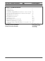 5
5
-
 6
6
-
 7
7
-
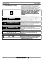 8
8
-
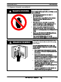 9
9
-
 10
10
-
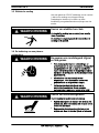 11
11
-
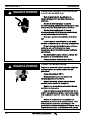 12
12
-
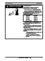 13
13
-
 14
14
-
 15
15
-
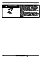 16
16
-
 17
17
-
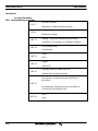 18
18
-
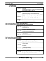 19
19
-
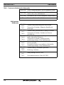 20
20
-
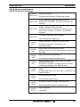 21
21
-
 22
22
-
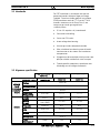 23
23
-
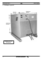 24
24
-
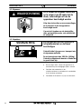 25
25
-
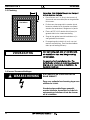 26
26
-
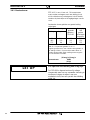 27
27
-
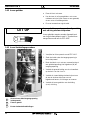 28
28
-
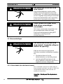 29
29
-
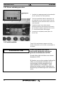 30
30
-
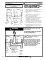 31
31
-
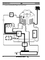 32
32
-
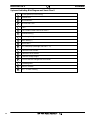 33
33
-
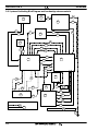 34
34
-
 35
35
-
 36
36
-
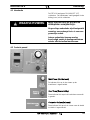 37
37
-
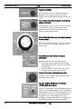 38
38
-
 39
39
-
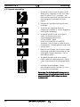 40
40
-
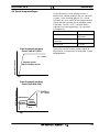 41
41
-
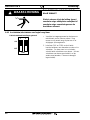 42
42
-
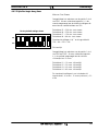 43
43
-
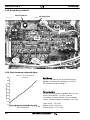 44
44
-
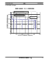 45
45
-
 46
46
-
 47
47
-
 48
48
-
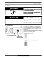 49
49
-
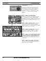 50
50
-
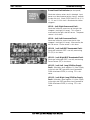 51
51
-
 52
52
-
 53
53
-
 54
54
-
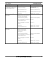 55
55
-
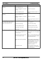 56
56
-
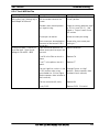 57
57
-
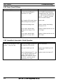 58
58
-
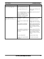 59
59
-
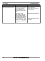 60
60
-
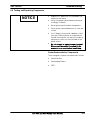 61
61
-
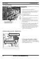 62
62
-
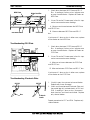 63
63
-
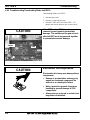 64
64
-
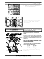 65
65
-
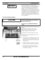 66
66
-
 67
67
-
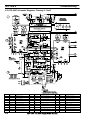 68
68
-
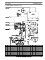 69
69
-
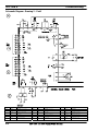 70
70
-
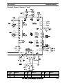 71
71
-
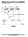 72
72
-
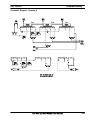 73
73
-
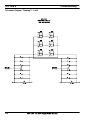 74
74
-
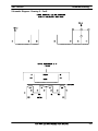 75
75
-
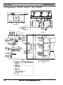 76
76
-
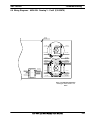 77
77
-
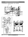 78
78
-
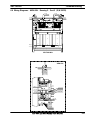 79
79
-
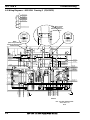 80
80
-
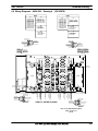 81
81
-
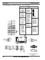 82
82
-
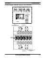 83
83
-
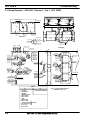 84
84
-
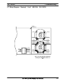 85
85
-
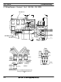 86
86
-
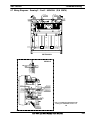 87
87
-
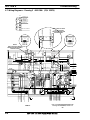 88
88
-
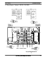 89
89
-
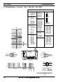 90
90
-
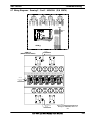 91
91
-
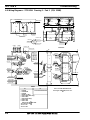 92
92
-
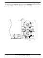 93
93
-
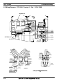 94
94
-
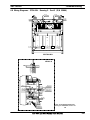 95
95
-
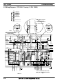 96
96
-
 97
97
-
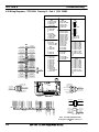 98
98
-
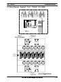 99
99
-
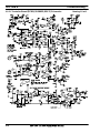 100
100
-
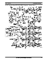 101
101
-
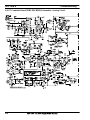 102
102
-
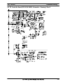 103
103
-
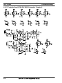 104
104
-
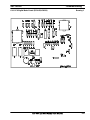 105
105
-
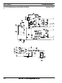 106
106
-
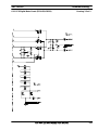 107
107
-
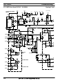 108
108
-
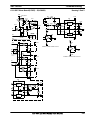 109
109
-
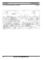 110
110
-
 111
111
-
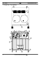 112
112
-
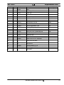 113
113
-
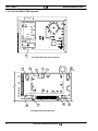 114
114
-
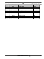 115
115
-
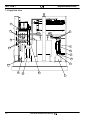 116
116
-
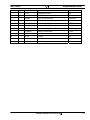 117
117
-
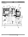 118
118
-
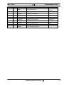 119
119
-
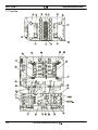 120
120
-
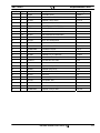 121
121
-
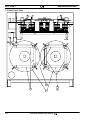 122
122
-
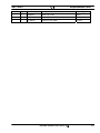 123
123
-
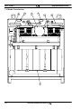 124
124
-
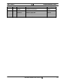 125
125
-
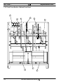 126
126
-
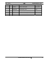 127
127
-
 128
128
-
 129
129
-
 130
130


ESAB ESP-400C Plasma Power Source Handleiding
- Categorie
- Lassysteem
- Type
- Handleiding
Gerelateerde papieren
-
ESAB PT-600 Mechanized Plasma Cutting Torch Handleiding
-
-
-
-
ESAB EPP-450 Plasma Power Source Handleiding
-
ESAB EPP-400 Plasma Power Source Handleiding
-
ESAB Precision Plasmarc System with Electronic Flow Control Installatie gids
-
-
-
Andere documenten
-
Paso C34-TB de handleiding
-
Tunturi FitRun 90i PRO Treadmill Manual Concise
-
Exodraft ESP-10 de handleiding
-
CAME RBE-RE Installatie gids
-
-
Conrad Components 16-Channel Running Light Controller Module Handleiding
-
-
-
spex Power Recline Installatie gids