ESAB EPP-400 Plasma Power Source Handleiding
- Type
- Handleiding

EPP- 400
Plasmavoedingsbron
Instructiehandleiding (NL)
0558006923 08/2010

Dit apparaat werkt conform de beschrijving in deze handleiding en de bijbehorende labels en/of bladen wan-
neer het wordt geïnstalleerd, bediend, onderhouden en gerepareerd volgens de bijgeleverde instructies. Dit ap-
paraat moet periodiek worden gecontroleerd. Een slecht werkend of verkeerd onderhouden apparaat mag niet
worden gebruikt. Gebroken, ontbrekende, versleten, vervormde of besmette onderdelen moeten onmiddellijk
worden vervangen. Als een dergelijke reparatie of vervanging nodig is, raadt de fabrikant u aan om telefonisch
of schriftelijk een serviceaanvraag in te dienen bij de erkende distributeur, of bij wie u het apparaat hebt aan-
geschaft.
Dit apparaat en de bijbehorende onderdelen mogen niet zonder voorafgaande schriftelijke toestemming van
de fabrikant worden gewijzigd. De gebruiker van dit apparaat is zelf verantwoordelijk voor defecten die ont-
staan vanwege onjuist gebruik, verkeerd onderhoud, schade, verkeerde reparatie of wijzigingen door iemand
anders dan de fabrikant of een servicefaciliteit die door de fabrikant is aangewezen.
ZORG DAT U DEZE INFORMATIE DOORGEEFT AAN DE BEDIENER
VAN DIT APPARAAT.
BIJ UW LEVERANCIER KUNT U EXTRA EXEMPLAREN KRIJGEN.
Deze instructies zijn voor ervaren bedieners. Als u niet bekend bent met de principes van
de bediening en veilige werking van booglassen en -snijden, raden wij u dringend aan om
ons boekje “Precautions and Safe Practices for Arc Welding, Cutting, and Gouging,” for-
mulier 52-529 door te lezen. Laat ongetraind personeel dit apparaat NIET installeren, be-
dienen of onderhouden. Probeer dit apparaat NIET te installeren of te bedienen voordat
u deze instructies volledig hebt gelezen en begrepen. Als u deze instructies niet helemaal
begrijpt, neemt u contact op met de leverancier voor meer informatie. Lees de veiligheids-
voorschriften voordat u dit apparaat installeert of bedient.
LET OP
VERANTWOORDELIJKHEID VAN DE GEBRUIKER
LEES EN BEGRIJP DE INSTRUCTIEHANDELING VOORDAT U HET APPARAAT BEDIENT.
BESCHERM UZELF EN ANDEREN!

TABLE OF CONTENTS
Hoofdstuk / Titel Pagina
1.0 Voorzorgsmaatregelen . . . . . . . . . . . . . . . . . . . . . . . . . . . . . . . . . . . . . . . . . . . . . . . . . . . . . . . . . . . . . . . . . . . . . . . . . . . . . . . .5
2.0 Beschrijving. . . . . . . . . . . . . . . . . . . . . . . . . . . . . . . . . . . . . . . . . . . . . . . . . . . . . . . . . . . . . . . . . . . . . . . . . . . . . . . . . . . . . . . . . . .7
2.1 Inleiding. . . . . . . . . . . . . . . . . . . . . . . . . . . . . . . . . . . . . . . . . . . . . . . . . . . . . . . . . . . . . . . . . . . . . . . . . . . . . . . . . . . . . . . . . .7
2.2 Algemene specicaties . . . . . . . . . . . . . . . . . . . . . . . . . . . . . . . . . . . . . . . . . . . . . . . . . . . . . . . . . . . . . . . . . . . . . . . . . . . .7
2.3 Afmetingen en gewicht. . . . . . . . . . . . . . . . . . . . . . . . . . . . . . . . . . . . . . . . . . . . . . . . . . . . . . . . . . . . . . . . . . . . . . . . . . .8
3.0 Installatie . . . . . . . . . . . . . . . . . . . . . . . . . . . . . . . . . . . . . . . . . . . . . . . . . . . . . . . . . . . . . . . . . . . . . . . . . . . . . . . . . . . . . . . . . . . . .9
3.1 Algemeen . . . . . . . . . . . . . . . . . . . . . . . . . . . . . . . . . . . . . . . . . . . . . . . . . . . . . . . . . . . . . . . . . . . . . . . . . . . . . . . . . . . . . . . .9
3.2 Uitpakken . . . . . . . . . . . . . . . . . . . . . . . . . . . . . . . . . . . . . . . . . . . . . . . . . . . . . . . . . . . . . . . . . . . . . . . . . . . . . . . . . . . . . . . .9
3.3 Plaatsen. . . . . . . . . . . . . . . . . . . . . . . . . . . . . . . . . . . . . . . . . . . . . . . . . . . . . . . . . . . . . . . . . . . . . . . . . . . . . . . . . . . . . . . . . .9
3.4 Aansluiting van ingangsvoeding . . . . . . . . . . . . . . . . . . . . . . . . . . . . . . . . . . . . . . . . . . . . . . . . . . . . . . . . . . . . . . . . .10
3.5 Uitgangsaansluiting . . . . . . . . . . . . . . . . . . . . . . . . . . . . . . . . . . . . . . . . . . . . . . . . . . . . . . . . . . . . . . . . . . . . . . . . . . . . .12
3.6 Parallelle installatie . . . . . . . . . . . . . . . . . . . . . . . . . . . . . . . . . . . . . . . . . . . . . . . . . . . . . . . . . . . . . . . . . . . . . . . . . . . . . .13
3.7 Interfacekabels . . . . . . . . . . . . . . . . . . . . . . . . . . . . . . . . . . . . . . . . . . . . . . . . . . . . . . . . . . . . . . . . . . . . . . . . . . . . . . . . . .16
4.0 Bediening . . . . . . . . . . . . . . . . . . . . . . . . . . . . . . . . . . . . . . . . . . . . . . . . . . . . . . . . . . . . . . . . . . . . . . . . . . . . . . . . . . . . . . . . . . .19
4.1 Beschrijving van blokdiagramcircuit . . . . . . . . . . . . . . . . . . . . . . . . . . . . . . . . . . . . . . . . . . . . . . . . . . . . . . . . . . . . . .19
4.2 Bedieningspaneel . . . . . . . . . . . . . . . . . . . . . . . . . . . . . . . . . . . . . . . . . . . . . . . . . . . . . . . . . . . . . . . . . . . . . . . . . . . . . . 22
4.3 Volgorde van bediening . . . . . . . . . . . . . . . . . . . . . . . . . . . . . . . . . . . . . . . . . . . . . . . . . . . . . . . . . . . . . . . . . . . . . . . . 26
4.4 Instellingen voor het starten van de boog . . . . . . . . . . . . . . . . . . . . . . . . . . . . . . . . . . . . . . . . . . . . . . . . . . . . . . . .27
4.5 EPP-400 V-I-curven . . . . . . . . . . . . . . . . . . . . . . . . . . . . . . . . . . . . . . . . . . . . . . . . . . . . . . . . . . . . . . . . . . . . . . . . . . . . . 30
5.0 Onderhoud . . . . . . . . . . . . . . . . . . . . . . . . . . . . . . . . . . . . . . . . . . . . . . . . . . . . . . . . . . . . . . . . . . . . . . . . . . . . . . . . . . . . . . . . . .33
5.1 Algemeen . . . . . . . . . . . . . . . . . . . . . . . . . . . . . . . . . . . . . . . . . . . . . . . . . . . . . . . . . . . . . . . . . . . . . . . . . . . . . . . . . . . . . . .33
5.2 Reinigen . . . . . . . . . . . . . . . . . . . . . . . . . . . . . . . . . . . . . . . . . . . . . . . . . . . . . . . . . . . . . . . . . . . . . . . . . . . . . . . . . . . . . . . .33
5.3 Smeren . . . . . . . . . . . . . . . . . . . . . . . . . . . . . . . . . . . . . . . . . . . . . . . . . . . . . . . . . . . . . . . . . . . . . . . . . . . . . . . . . . . . . . . . 34
6.0 Problemen oplossen . . . . . . . . . . . . . . . . . . . . . . . . . . . . . . . . . . . . . . . . . . . . . . . . . . . . . . . . . . . . . . . . . . . . . . . . . . . . . . . . .35
6.1 Algemeen . . . . . . . . . . . . . . . . . . . . . . . . . . . . . . . . . . . . . . . . . . . . . . . . . . . . . . . . . . . . . . . . . . . . . . . . . . . . . . . . . . . . . . .35
6.2 Foutindicatielampjes . . . . . . . . . . . . . . . . . . . . . . . . . . . . . . . . . . . . . . . . . . . . . . . . . . . . . . . . . . . . . . . . . . . . . . . . . . . .35
6.3 Fout isoleren . . . . . . . . . . . . . . . . . . . . . . . . . . . . . . . . . . . . . . . . . . . . . . . . . . . . . . . . . . . . . . . . . . . . . . . . . . . . . . . . . . . 38
6.4 Onderdelen testen en vervangen . . . . . . . . . . . . . . . . . . . . . . . . . . . . . . . . . . . . . . . . . . . . . . . . . . . . . . . . . . . . . . . 46
6.5 Stuurstroomkringinterface met connectors J1 en J6. . . . . . . . . . . . . . . . . . . . . . . . . . . . . . . . . . . . . . . . . . . . . . .52
6.6 Externe hoofdcontactsluiter (K3) en halfgeleiderafsluitercircuits . . . . . . . . . . . . . . . . . . . . . . . . . . . . . . . . . . 54
6.7 Activeringscircuit hoofdafsluiter (K1A, K1B en K1C) . . . . . . . . . . . . . . . . . . . . . . . . . . . . . . . . . . . . . . . . . . . . . . . .55
6.8 Boogstroomdetectorcircuits . . . . . . . . . . . . . . . . . . . . . . . . . . . . . . . . . . . . . . . . . . . . . . . . . . . . . . . . . . . . . . . . . . . . 56
6.9 Stroomregelpotentiometer en externe Vref . . . . . . . . . . . . . . . . . . . . . . . . . . . . . . . . . . . . . . . . . . . . . . . . . . . . . . 57
6.10 Hulpboog HI / LO en snij-/markeercircuits . . . . . . . . . . . . . . . . . . . . . . . . . . . . . . . . . . . . . . . . . . . . . . . . . . . . . . . 58
7.0 Vervangingsonderdelen. . . . . . . . . . . . . . . . . . . . . . . . . . . . . . . . . . . . . . . . . . . . . . . . . . . . . . . . . . . . . . . . . . . . . . . . . . . . . .59
7.1 Algemeen . . . . . . . . . . . . . . . . . . . . . . . . . . . . . . . . . . . . . . . . . . . . . . . . . . . . . . . . . . . . . . . . . . . . . . . . . . . . . . . . . . . . . . .59
7.2 Bestellen . . . . . . . . . . . . . . . . . . . . . . . . . . . . . . . . . . . . . . . . . . . . . . . . . . . . . . . . . . . . . . . . . . . . . . . . . . . . . . . . . . . . . . . .59

4

5
HOOFDSTUK 1 VEILIGHEIDSVOORSCHRIFTEN
1.0 Veiligheidsvoorschriften
Gebruikers van ESAB-las- en plasmasnijapparaten moeten er zelf voor zorgen dat iedereen die met of in de buurt
van het apparaat werkt zich aan de betreende veiligheidsvoorschriften houdt. De veiligheidsvoorschriften
moeten aan de eisen voor dit type las- of plasmasnijapparaat voldoen. Houd u aan de volgende aanbevelingen
en aan de standaardreguleringen die voor de werkplek gelden.
Het werk moet worden uitgevoerd door getraind personeel dat goed bekend is met de bediening van las- of
plasmijsnijapparaten. Onjuiste bediening van de apparatuur kan leiden tot gevaarlijke situaties, die kunnen
leiden tot persoonlijk letsel en schade aan het apparaat.
1. Iedereen die las- of plasmasnijapparaten gebruikt, moet bekend zijn met:
- de bediening
- de plaats van noodstop
- de werking
- de relevante veiligheidsvoorschriften
- lassen en/of plasmasnijden
2. Degene die het apparaat bedient, moet ervoor zorgen dat:
- er zich geen ongeautoriseerd personeel in het werkgebied van het apparaat bevindt wanneer dit wordt
opgestart
- niemand onbeschermd is wanneer de boog wordt gestart
3. Het werkgebied moet:
- geschikt zijn voor het doel
- vrij zijn van tocht
4. Artikelen voor uw persoonlijke veiligheid:
- Draag altijd de aanbevolen artikelen voor persoonlijke veiligheid, zoals een veiligheidsbril,
vlambestendige kleding en veiligheidshandschoenen.
- Draag geen loszittende artikelen, zoals dassen, armbanden, ringen, enz. Deze kunnen verstrikt raken en
brandwonden veroorzaken.
5. Algemene voorzorgsmaatregelen:
- Zorg dat de retourkabel veilig is aangesloten.
- Werkzaamheden met apparatuur van een hoog voltage mogen alleen door een gekwaliceerde
elektricien worden uitgevoerd.
- De juiste brandblusapparatuur moet duidelijk zijn aangegeven en binnen handbereik staan.
- Tijdens de bediening van het apparaat mag geen smering en onderhoud worden uitgevoerd.
De IP-code geeft de behuizingsklasse aan, bijv. de bestendigheid tegen doordringing van vaste voorwerpen
of water. Het is bestendig tegen vingeraanrakingen, doordringing van vaste voorwerpen die groter zijn dan
12 mm en opspattend water tot 60 graden vanaf een verticaal oppervlak. Apparatuur met de markering IP23S
mag buiten worden opgeslagen, maar is niet bedoeld voor gebruik buitenshuis bij neerslag tenzij de appara-
tuur is afgeschermd.
Behuizingsklasse
15°
Maximale
toegestane
schuine stand
Wanneer de apparatuur op een schuin op-
pervlak met een helling van meer dan 15°
wordt geplaatst, kan deze omkiepen. Dit
kan persoonlijk letsel en/of ernstige schade
aan de apparatuur tot gevolg hebben.
WAARSCHUWING

6
HOOFDSTUK 1 VEILIGHEIDSVOORSCHRIFTEN
LASSEN EN PLASMASNIJDEN KUNEN PERSOONLIJK LETSEL EN LETSEL BIJ
ANDEREN VEROORZAKEN. NEEM VOORZORGSMAATREGELEN WANNEER
U LAST OF SNIJDT. VRAAG UW WERKGEVER WELKE MAATREGELEN U
MOET TREFFEN, OP BASIS VAN DE RISICOGEGEVENS VAN DE FABRIKANT.
ELEKTRISCHE SCHOK - kan dodelijk zijn.
- Installeer en aard de las- of plasmasnijunit volgens de geldende normen.
- Raak geen elektrische onderdelen of elektrodes die onder stroom staan met de blote huid, natte hand
schoenen of natte kleding aan.
- Isoleer uzelf van de aarde en het werkstuk.
- Zorg voor een goede werkhouding.
ROOK EN GAS - kunnen gevaarlijk voor de gezondheid zijn.
- Houd uw hoofd uit de rook.
- Gebruik ventilatie of boogextractie, of beide, om rook en gassen uit de ademzone en de algemene ruimte
te verwijderen.
BOOGSTRALEN - kunnen letsel aan ogen en huid veroorzaken.
- Bescherm uw lichaam en uw ogen. Gebruik het juiste las/plasmasnijscherm en lterlens, en draag bescher
- mende kleding.
- Bescherm omstanders met geschikte schermen of gordijnen.
BRANDGEVAAR
- Vonken (spatten) kunnen brand veroorzaken. Zorg daarom dat er geen ontvlambare materialen in de
buurt staan.
LAWAAI - te veel lawaai kan het gehoor beschadigen.
- Bescherm uw oren. Gebruik oorbeschermers of een andere gehoorbescherming.
- Wijs omstanders op het risico.
DEFECTEN - bel voor assistentie van een expert als het apparaat defect is.
LEES EN BEGRIJP DE INSTRUCTIEHANDELING VOORDAT U HET APPARAAT BEDIENT.
BESCHERM UZELF EN ANDEREN!
WAARSCHUWING
Dit product is uitsluitend bedoeld voor plasmasnijden. Elk
ander gebruik kan persoonlijk letsel en/of schade aan de
apparatuur tot gevolg hebben.
WAARSCHUWING
Ter voorkoming van persoonlijk letsel en/of schade
aan de apparatuur, zijn hier de wijze waarop getild
moet worden en de bevestigingspunten afgebeeld.
WAARSCHUWING

7
HOOFDSTUK 2 BESCHRIJVING
2.1 Inleiding
De EPP-voedingsbron wordt gebruikt voor markeren en snel gemechaniseerd plasmasnijden. U kunt de voed-
ingsbron gebruiken met andere ESAB-producten, zoals de PT-15-, Pt-19XLS-, PT-600- en PT-36-toortsen met de
Smart Flow II, een gecomputeriseerd gasregel- en schakelsysteem.
• 12 tot 400 ampère voor markeren
• Snijstroomvermogen 50 tot 400 ampère
• Gekoeld met geforceerde lucht
• Halfgeleidergelijkstroom
• Bescherming van ingangsvoltage
• Lokale bediening of bediening op extern voorpaneel
• Thermale schakelbeveiliging voor hoofdtransformator en halfgeleidercomponenten van voeding
• Optilringen bovenaan of vorkliftruimte onderaan voor transport
• Parallelle extra voedingsbronmogelijkheden voor uitbreiding van uitgangsstroombereik
EPP-400 400 V,
50 / 60 Hz CE
EPP-400 460 V,
60 Hz
EPP-400 575 V,
60 Hz
Onderdeelnummer 0558006470 0558006471 0558006472
Uitgang
(100 % duty cycle)
Voltage 200 VDC
Stroombereik DC
(markeren)
12A tot 400A
Stroombereik DC (snijden) 50A tot 400A
Vermogen 120 KW
* Open circuitvoltage (OCV) 423 VDC 427 VDC 427 VDC
Ingang
Voltage (3-fase) 400 V 460 V 575 V
Stroom (3-fase) 138A RMS 120A RMS 96A RMS
Frequentie 50/60 HZ 60 Hz 60 Hz
KVA 95,6 KVA 95,6 KVA 95,6 KVA
Vermogen 87 KW 87 KW 87 KW
Vermogensfactor 91,0 % 91,0% 91,0%
Ingangszekering 200 A 150 A 125 A
2.2 Algemene specicaties
* Open circuitvoltage wordt verlaagd tot 360 V in de markeermodus voor 460 V en 575 V, 60 Hz-modellen en
tot 310 V voor 400 V, 50 Hz-model.

8
HOOFDSTUK 2 BESCHRIJVING
2.3 Afmetingen en gewicht
114,3 cm
94,6 cm
102,2 cm
Gewicht = 825 kg

9
HOOFDSTUK 3 INSTALLATIE
3.1 Algemeen
INDIEN U ZICH NIET AAN DE INSTRUCTIES HOUD, KAN DIT DOOD,
LETSEL OF SCHADE AAN EIGENDOMMEN TOT GEVOLG HEBBEN.
VOLG DEZE INSTRUCTIES OM LETSEL OF SCHADE TE VOORKOMEN.
U MOET ZICH AAN ALLE LOKALE EN NATIONALE ELEKTRICITEITS EN
VEILIGHEIDSVOORSCHRIFTEN HOUDEN.
WAARSCHUWING
3.2 Uitpakken
Als u één tiloog gebruikt, worden de metalen platen en het frame
beschadigd. Gebruik beide tilogen wanneer u de bovengrondse me-
thode gebruikt.
• Controleer bij ontvangst of er geen schade is.
• Verwijder alle onderdelen uit de verzenddos en controleer de losse onderdelen in de doos.
• Controleer of de luchtopeningen niet zijn verstopt.
3.3 Plaatsen
Opmerking:
Gebruik beide tilogen wanneer u het apparaat bovengronds verplaatst.
• Er moet minimaal 1 meter ruimte aan de voor- en achterkant zijn zodat de koellucht kan stromen.
• Zorg dat het bovenpaneel en de zijpanelen voor onderhoud, reiniging en inspectie kunnen worden
verwijderd.
• Plaats de EPP-400 relatief dicht bij een elektrische voedingsvoorziening met goede zekeringen.
• Houd de ruimte onder de voedingsbron schoon in verband met de luchtkoeling.
• De omgeving moet relatief vrij van stof, rook en overmatige hitte zijn. Deze factoren beïnvloeden de
doelmatigheid van de koeling.
Geleidend stof en vuil in de voedingsbron kan een ashover van de
boog veroorzaken.
Hierdoor kan schade aan het apparaat optreden. Er kan kortsluit-
ing ontstaan als vuil zich aan de binnenkant van de voedingsbron
ophoopt. Zie het hoofdstuk Onderhoud.
CAUTIONLET OP
LET OP

10
HOOFDSTUK 3 INSTALLATIE
3.4 Aansluiting van de ingangsvoeding
EEN ELEKTRISCHE SCHOK KAN DODELIJK ZIJN!
ZORG VOOR MAXIMALE BESCHERMING TEGEN EEN ELEKTRISCHE
SCHOK. VOORDAT U BINNEN IN HET APPARAAT VERBINDINGEN
MAAKT, ZET U DE STROOM UIT MET DE HOOFDSCHAKELAAR.
WAARSCHUWING
3.4.1 Hoofdvoeding
De EPP-400 is een 3-faseneenheid. De ingangsvoeding moet afkomstig zijn van een wandcontactdoos die ze-
keringen of circuitonderbrekingen bevat conform de geldende wetging.
U het mogelijk een speciaal voedingscircuit nodig.
De EPP-400 is voorzien van een voltagecompensatie maar om slech-
te prestaties vanwege een overladen circuit te voorkomen, hebt u
mogelijk een elektriciteitslijn nodig.
KENNISGEVING
Ingangsstroom=
(V boog) x (I boog) x 0,688
(V lijn)
Aanbevolen ingangsconnector en zekeringsterkte:
** Formaat volgens National Electrical Code voor een kopergeleider van 90° C bij een omgeving van 40° C. Niet meer
dan drie geleiders in kanaal of kabel. De lokale voorschriften moeten worden gevolgd als er andere formaten dan de
bovenstaande zijn gespeciceerd.
Als u de ingansstroom voor een variëteit aan uitgangscondities wilt schatten, gebruikt u de onderstaande formule.
Ingang bij nominale
belasting Ingang en aar-
degeleider* CU/
mm2 (AWG)
Tijdver-
traging
zekering-
grootte
(ampère)
Volt Ampère
400 138 95 (4/0) 200
460 120 95 (3/0) 150
575 96 50 (1/0) 125
Nominale belasting is uitgang van 400 A bij 200 V

11
• Door klant geleverd
• Kan bestaan uit zware met rubber afgedekte kopergeleiders (drie voeding en één aarde) of door een
solide of exibele buis worden geleid.
• Formaat volgens tabel.
3.4.2 Ingangsgeleiders
Ingangsgeleiders moeten worden afgesloten met ringtongen.
Ingangsgeleiders moeten worden afgesloten met ringtongen van
12,7 mm voordat ze worden aangesloten op de EPP-400.
KENNISGEVING
1. Verwijder het linkerzijpaneel van de EPP-400.
2. Voer de kabels door de toegangsopening in het achterpa-
neel.
3. Maak de kabels vast met een trekontlasting of kabelbuiskop-
peling (niet bijgeleverd) in de toegangsopening.
4. Sluit de aardekabel aan op de tapbout van de chassibasis.
5. Sluit de ringtongen van de voedingskabel aan op de primaire
terminals met de bijgeleverde bouten, sluitringen en moe-
ren.
6. Sluit de ingangsgeleiders aan op de wandcontactdoos.
3.4.3 Procedure voor aansluiting van ingang
1
3
2
1 = Primaire terminals
2 = Chassisaarde
3 = Toegangsopening voedingsingangskabel (achterpaneel)
HOOFDSTUK 3 INSTALLATIE

12
EEN ELEKTRISCHE SCHOK KAN DODELIJK ZIJN!
TUSSEN ZIJPANEEL EN HOOFDTRANSFORMATOR MOET ER VOL
DOENDE RUIMTE VOOR DE RINGTONGEN ZIJN. DE RUIMTE MOET
VOLDOENDE ZIJN OM BOOGVORMING TE VOORKOMEN. CONTRO
LEER OF DE KABELS DE WERKING VAN DE KOELVENTILATOR NIET
VERSTOREN.
VERKEERDE AARDING KAN DOOD OF LETSEL TOT GEVOLG HEBBEN.
HET CHASSIS MOET OP EEN GOEDGEKEURDE ELEKTRISCHE AARDE
ZIJN AANGESLOTEN. CONTROLEER OF DE AARDEKABEL NIET IS AAN
GESLOTEN OP EEN PRIMAIRE TERMINAL.
EEN ELEKTRISCHE SCHOK KAN DODELIJK ZIJN! GEVAARLIJK VOLTA
GE EN STROOM!
WANNEER U WERKT BIJ EEN PLASMAVOEDINGSBRON MET DE DEK
SELS VERWIJDERD:
• HAALT U DE STEKKER VAN DE VOEDINGSBRON UIT HET STOPCON-
TACT.
• LAAT U EEN GEKWALIFICEERD PERSOON DE UITGANGSSTROOM-
RAILS (POSITIEF EN NEGATIEF) CONTROLEREN MET EEN VOLTME-
TER.
3.5 Uitgangsaansluitingen
WAARSCHUWING
WAARSCHUWING
WAARSCHUWING
3.5.1 Uitgangskabels (door klant geleverd)
Kies uitgangskabels voor plasmasnijden (door de klant geelverd) op basis van een 4/0 AWG, 600 volt geïsoleerde
koperkabel voor elke 400 ampère uitgangsstroom.
Opmerking:
Gebruik geen geïsoleerde laskabel van 100 volt.
HOOFDSTUK 3 INSTALLATIE

13
HOOFDSTUK 3 INSTALLATIE
3.5.2 Procedure voor aansluiting van uitgang
Toegangspaneel
1. Verwijder het toegangspaneel aan de onderzijde (voor) van de voedingsbron.
2. Voer de uitgangskabels door de openingen aan de onderkant van het voorpaneel of aan de onderkant van de voedings-
bron rechtsteeks achter het voorpaneel.
3. Sluit kabels aan op de aangewezen terminals gemonteerd binnen in de voedingsbron met UL-vermelde drukkabelcon-
nectors.
4. Plaats het paneel dat u bij de eerste stap hebt verwijderd.
U kunt twee EPP-400-voedingsbronnen parallel aansluiten om het uitgangstroombereik uit te breiden.
3.6 Parallelle installatie
LET OP
De minimum uitgangsstroom van de parallelle voedingsbron over-
schrijdt de aanbevolen aantallen wanneer u bij minder dan 100 A
snijdt.
Gebruik slechts één voedingsbron wanneer u bij minder dan 100 A
snijdt. Wij raden u aan de negatieve kabel los te koppelen van de ex-
tra voedingsbron wanneer u overgaat op stroom onder 100 A. Deze
kabel moet veilig worden afgesloten om een elektrische schok te
voorkomen.

14
HOOFDSTUK 3 INSTALLATIE
Opmerking:
De primaire voedingsbron heeft een jumper voor de elektrodegeleider (-). De extra voedingsbron heeft
een jumper op het werkstuk (+).
1. Sluit de negatieve (-) uitgangskabels aan op de hulpboogstartbox (hogefrequentiegenerator).
2. Sluit de positieve (+) uitgangskabels aan op het werkstuk.
3. Sluit de positieve (+) en negatieve (-) geleiders tussen de voedingsbronnen aan.
4. Sluit de hulpboogkabel aan op de hulpboogterminal in de primaire voedingsbron. De hulpboogaansluiting in de extra
voedingsbron wordt niet gebruikt. Het hulpboogcircuit wordt niet parallel uitgevoerd.
5. Stel de HIGH/LOW-schakelaar van de hulpboog op de extra voedginsbron in op “LOW”.
6. Stel de HIGH/LOW-schakelaar van de hulpboog op de primaire voedingsbron in op “HIGH”.
7. Als een extern 0,00 tot +10,00 VDC-stroomreferentiesignaal wordt gebruikt om de uitgangsstroom in te stellen, voert
u hetzelfde signaal in beide voedingsbronnen in. Sluit J1-G (positief 0,00 tot 10,00 VDC) van beide voedingsbronnen
samen aan en sluit J1-P (negatief) van beide voedingsbronnen samen aan. Wanneer beide voedingsbronnen werken,
kan de uitgangsstroom worden voorspeld met deze formule: [uitgangsstroom (amp)] = [referentievoltage] x [100]
Aansluitingen voor parallelle installatie van twee EPP-400-voedingsbronnen met beide voedingsbronnen
ingeschakeld.
3.6.1 Verbindingen voor twee parallelle EPP-400
Extra voedings-
bron
Primary Power
Source
werk
(+)
elektrode
(-)
hulpboog
2 - 4/0 600 V
positieve kabels
naar werkstuk
1 - 14 AWG 600 V-
kabel naar hulp-
boogaansluiting in
boogstartbox (hoge-
frequentiegenerator)
2 - 4/0 600 V
negatieve kabels
in boogstartbox
(hogefrequen-
tiegenerator)
EPP-400 EPP-400
werk
(+)
elektrode
(-)

15
HOOFDSTUK 3 INSTALLATIE
EEN ELEKTRISCHE SCHOK KAN DODELIJK ZIJN!
BLOOTLIGGENDE ELEKTRISCHE GELEIDERS KUNNEN LEVENS
GEVAARLIJK ZIJN!
LAAT ELEKTRISCHE “HOT”GELEIDERS NIET BLOOTLIGGEN. WANNEER
U DE EXTRA VOEDINGSBRON LOSKOPPELT VAN DE PRIMAIRE, CON
TROLEERT U OF DE JUISTE KABELS ZIJN LOSGEKOPPELD. ISOLEER DE
LOSGEKOPPELDE UITEINDEN.
WANNEER U SLECHTS ÉÉN VOEDINGSBRON IN EEN PARALLELLE OP
STELLING GEBRUIKT, MOET DE NEGATIEVE ELEKTRODEGELEIDER
LOSGEKOPPELD ZIJN VAN DE SECUNDAIRE VOEDINGSBRON EN DE
PLUMBING BOX. ALS U DIT NALAAT, BLIJFT DE EXTRA ELEKTRISCH
“HEET”.
WAARSCHUWING
GEBRUIK DE EPP400 NIET WANNEER DE DEKSELS ZIJN VERWIJ
DERD.
COMPONENTEN MET EEN HOOG VOLTAGE ZIJN DAN BLOOT
GESTELD, WAARDOOR HET RISICO OP EEN SCHOK TOENEEMT.
INTERNE COMPONENTEN KUNNEN BESCHADIGD RAKEN OMDAT
DE KOELVENTILATORS HUN DOELMATIGHEID VERLIEZEN.
WAARSCHUWING
De EPP-400 heeft geen AAN/UIT-schakelaar. De hoofdvoeding wordt ingeschakeld door de stekker in het stopcontact te
steken.
Aansluitingen voor parallelle installatie van twee EPP-400-voedingsbronnen met slechts één voedingsbron
ingeschakeld.
Extra voedings-
bron
Primaire voedings-
bron
werk
werk
elektrode
elektrode
2 - 4/0 600 V
positieve kabels
naar werkstuk
2 - 4/0 600 V
negatieve kabels
in boogstartbox
(hogefrequen-
tiegenerator)
Koppel de negatieve
aansluiting los van de
extra voedingsbron
en isoleer om van
twee voedingsbron-
nen naar één te con-
verteren
EPP-400 EPP-400

16
HOOFDSTUK 3 INSTALLATIE
3.7 Interfacekabels
CNC-interface (24-pins)
3.6.2 Markeren met twee parallelle EPP-400
Waterkoelerinterface (8-pins)
U kunt twee parallel aangesloten EPP-400 gebruiken voor markeren tot 24 A en snijden van 100 A tot 800 A. U maakt twee
eenvoudige wijzigingen in de extra voedingsbron om te kunnen markeren tot 12 A. De wijzigingen zijn alleen nodig als u
tot 12 A moet markeren.
VELDWIJZIGINGEN OM TOT 12 A TE KUNNEN MARKEREN:
1. WIJZIGINGEN IN DE PRIMAIRE VOEDINGSBRON: geen
2. WIJZIGINGEN IN DE EXTRA VOEDINGSBRON:
A. Haal de WHT-kabel van de spoel van K12
B. Verwijder de ORN-jumper van TB7-11 en sluit beide uiteinden van de jumper aan op TB7-12.
TWEE PARALLELLE EPP-400 GEBRUIKEN:
1. Suut de signalen van Contactor On/O, Cut/Mark,en Pilot Arc Hi/Lo naar de primaire en extra voeding voor zowel sni-
jden als markeren. Tijdens het markeren worden beide voedingsbronnen gestart, maar het markeersignaal schakelt
de uitgang van de extra voeding uit als deze is gewijzigd voor markeren tot 12 A. Als de extra voedingsbron niet is
gewijzigd, levert deze dezelfde uitgangsstroom als de primaire voedingsbron.
2. Voer hetzelfde V
ref
-signaal in de primaire en extra bron voor zowel snijden als markeren. Voor installaties met een
gewijzigde extra voedingsbron is de overdrachtsfunctie voor uitgangsstroom die van de primaire voedingsbron: I
OUT
= 50 x V
REF
. Voor het snijden is het de som van de primaire en extra voedingsbronnen: I
OUT
= 100 x V
REF
. Voor installat-
ies met een ongewijzigde extra voedingsbron is de overdrachtsfunctie voor uitgangsstroom voor zowel snijden als
markeren I
OUT
= 100 x V
REF
.

17
HOOFDSTUK 3 INSTALLATIE
3.7.1 CNC-interfackabels met bijbehorende voedingsbronconnector en
onafgesloten CNC-interface
3.7.2 CNC-interfacekabels met bijbehorende voedingsbronconnectors aan beide uiteinden
GRN/YEL
RED #4
GRN/YEL
RED #4

18
HOOFDSTUK 3 INSTALLATIE
3.7.3 Waterkoelerinterfacekabels met bijbehorende voedingsbronconnectors aan
beide uiteinden

19
HOOFDSTUK 4 BEDIENING
4.1 Beschrijving van blokdiagramcircuit
Left PWM / Gate Drive Board
Galvanic
Isolator
PWM
Gate
Drive
Galvanic
Isolator
PWM
Gate
Drive
(Master)
(Slave)
Right PWM / Gate Drive Board
2
H
Sync Signal
For Alternate
Switching
3 Phase
Input
T1 Main
Transformer
-300V-375V
DC Bus
Bus Rectiers
300U120’s
Cap.
Bank
Control Circuit
Feedback For Fast Inner Servos
Error Ampliers
Galvanic
Isolator
0.0 - 10.0V DC Vref
Iout = (Vref) x (50)
CNC Common
(Floating)
S
T
“T” Common Connected to Earth Grounded Work Through the “+” Output
Feedback for Constant
Current Servo
Twisted Pair
Left
IGBT Modules
See Note
Right
IGBT Modules
T
Left Hall
Sensor
Right Hall
Sensor
L1
Blocking Diodes
Blocking Diodes
L2
Free Wheeling
Diodes - See Note
T
T1
T1
Contact on Pilot
Arc Contactor
425V Peak
250V Peak
Boost Starting
Circuit
Biased Snubber
R (boost)
R (snub)
Pilot Arc
Circuit
Precision
Shunt
ELECTRODE
NOZZLE
WORK
BLOKDIAGRAM
VAN EPP-400
See
Note
See Note
Note
Both the IGBT’s and Free Wheeling Diodes are
contained in the same module.

20
P. K. Higgins: Current_Ripple_ESP-600C; RMS CURRENT RIPPLE Chart 17
EPP-600 10/20KHz Output RMS Ripple Current Versus Output Voltage
0.0
1.0
2.0
3.0
4.0
5.0
6.0
7.0
8.0
9.0
0 50 100 150 200 250 300 350
Output Voltage (Volts)
RMS Ripple Current (Amperes)
Choppers Synchronized and Switchng in Unison (10KHz Ripple)
Choppers Synchronized and Switching Alternately (20KHz Ripple)
HOOFDSTUK 4 BEDIENING
4.1 Beschrijving van blokdiagramcircuit (vervolg)
Het voedingscircuit dat in de EPP-400 is gebruikt, wordt ook een terugslagomzetter of een stroomonderbreker genoemd.
Elektronische hogesnelheidsswitches schakelen duizende keren per seconden in en uit, en voorzien de uitgang van voe-
ding. Een ltercircuit, dat hoofdzakelijk uit een inductor (soms ook een smoorspoel genoemd) bestaat, converteert de
pulsen in een relatief constante gelijkstroomuitgang (DC of Direct Current).
Hoewel de lterinductor de meeste uctueringen verwijdert uit de ‘onderbroken’ uitgang van de elektronische switches,
blijven er kleine uctueringen in de uitgang aanwezig. Deze worden rimpelspanning genoemd. De EPP-400 gebruikt een
gepatenteerd voedingscircuit waarin de uitgang van beide stroomonderbrekers is gecombineerd en waarbij elk ongeveer
de helft van de totale uitgang verzorgt op een manier waarop rimpelspanning wordt gereduceerd. De stroomonderbre-
kers zijn gesynchroniseerd: wanneer de rimpelspanning van de eerste stroomonderbreker de uitgang verhoogt, verlaagt
de tweede stroomonderbreker de uitgang. Dit heeft tot resultaat dat de rimpelspanning van de ene stroomonderbreker de
rimpelspanning van de andere deels ongedaan maakt. Het resultaat is een ultralage rimpelspanning met een zeer soepele
en gelijkmatige uitgang. Een lage rimpelspanning is wenselijk omdat de levensduur van de toorts daarmee toeneemt.
In de onderstaande graek ziet u het eect van de gepatenteerde rimpelspanningverlaging van ESAB met twee stroom-
onderbrekers die gesynchroniseerd zijn en alternerend schakelen. In vergelijking met twee stroomonderbrekers die tege-
lijkertijd schakeeln, wordt bij alternerend schakelen de rimpelspanning met factor 4 tot 10 verlaagd.
EPP-400 10/20 KHz Uitgang RMS rimpelspanningsstroom versus uitgangsvoltage
RMS rimpelspanningsstroom (ampère)
Uitgangsvoltage (volt)
Stroomonderbrekers gesynchroniseerd en gelijktijdig geschakeld (rimpelspanning 10 KHz)
Stroomonderbrekers gesynchroniseerd en
afwisselend schakelend (rimpelspanning 20 KHz)

21
Het regelcircuit bevat regulerende servo’s voor beide stroomonderbrekers. Het circuit bevat tevens een derde servo dat het
totale uitgangsspanningsignaal controleert dat terugkomt van de precisieshunt. Dit derde servo regelt de twee stroomon-
derbrekerservo’s om een nauwkeurig geregelde uitgangsstroom te behouden die door het Vref-signaal wordt beheerst.
Het Vref-circuit is galvanisch geïsoleerd van de rest van de voedingsbron. De isolatie voorkomt problemen die vanwege
‘aarde’lussen kunnen optreden.
Elke stroomonderbreker, de linker Master en de rechter Slave, bevatten hun eigen PWM / Gate Drive PC-borden, die recht-
streeks op de IGBT’s zijn gemonteerd. Dit circuit verzorgt de aan/uit PWM-signalen (pulsbreedtemodulatie) om de IGBT’s
aan te sturen. De linker (Master) PWM verzorgt naast een gesynchroniseerd kloksignaal naar zijn eigen Gate Drive-circuit
ook een signaal naar het rechter (Slave) Gate Drive-circuit. Via dit signaal schakelen de IGBT’s alternerend van de twee
kanten om de uitgangsrimpelspanning te reduceren..
De EPP-400 bevat een Boost Supply die ongeveer 425 V DC voor het starten van de boog verzorgt. Nadat de snijboog tot
stand is gekomen, wordt de Boost Supply uitgeschakeld met een contact op de hulpboogcontactor (K4).
Een solenoïde verlaagt de voltageovergangen die optreden tijdens de beëindiging van de snijboog. Tevens worden de
overgangsvoltages van een parallele voedingsbron verlaagt om schade aan de voedingsbron te voorkomen.
Het hulpboogcircuit bestaat uit de onderdelen die nodig zijn om een hulpboog tot stand te brengen. Dit circuit wordt
uitgeschakeld wanneer de snijboog tot stand is gebracht.
* Het busvoltage voor het model 400 V, 50 Hz bedraagt ongeveer 320 VDC.
HOOFDSTUK 4 BEDIENING
Het EPP-400-blokdiagram (na paragraaf 6.4.4) toont de belangrijkste functionele onderdelen van de voedingsbron. T1, de
hoofdtransformator, verzorgt naast de isolatie van de primaire voedingskabel ook het juiste voltage voor de *375 VDC-bus.
De buscorrectors converteren de driefasenuitgang van T1 naar het *375 V-busvoltage. Een condensatorbank verzogt de l-
tering en de energieopslag die de voeding verzorgt naar de elektronische hogesnelheidswitches. Deze switches zijn IGBT’s
(Insulated Gate Bipolar Transistors). De *375 V-bus verzorgt de voeding voor zowel de linkerstroomonderbreker (Master)
en de rechterstroomonderbreker (Slave).
Elke stroomonderbreker bevat IGBT’s, vrijloopdiodes, een Hall-sensor, een lterinductor en blokkerende diodes. De IGBT’s
zijn de electronische switches die, in de EPP-400, 10.000 keer per seconde worden in- en uitgeschakeld. Ze leverende
voedingspulsen die door de inductor worden gelterd. De vrijloopdiodes verzorgen het pad voor de stroom wanneer de
IGBT’s uit zijn. De Hall-sensor is een stroomtransductor die de uitgangsstroom controleert en het feedbacksignaal voor het
regelcircuit verzorgt.
De blokkerende diodes hebben twee functies. Ten eerste voorkomen ze dat de 425 VDC van het booststartcircuit terug
wordt gevoerd naar de IGBT’s en de *375 V-bus. Ten tweede verzorgen ze de isolatie tussen de twee stroomonderbrekers.
Hierdoor is een onafhankelijke werking van de ene stroomonderbreker mogelijk zonder dat de andere functioneert.
4.1 Beschrijving van het blokdiagramcircuit (vervolg)

22
HOOFDSTUK 4 BEDIENING
4.2 Bedieningspaneel
A - Hoofdvoeding
Indicatielampje brandt wanneer ingangsstroom op de voedingsbron wordt toegepast.
B - Contactschakelaar aan
Indicatielampje brandt wanneer de hoofdschakelaar van stroom is voorzien.
C - Overtemperatuur
Indicatilampje brandt wanneer de voedingsbron oververhit is.
D - Fout
Indicatilampje brandt wanneer er onregelmatigheden tijdens het snijproces zijn of wanneer het ingangskabelvoltage
buiten de vereiste nominale waarde met ±10% valt.
E - Fout bij reset van voeding
Indicatielampje brandt wanneer een ernstige fout is gecontstateert. De ingangsvoeding moet ten minste 5 seconden
worden uitgeschakeld en daarna weer worden ingeschakeld.
F - Stroomknop (potentiometer)
EPP-400-knop weergegeven. EPP-400 heeft een bereik van 12 tot 400 A. Wordt alleen in de paneelmodus gebruikt.
C
B
D
E
K
J
I
H
F
G
A
L

23
HOOFDSTUK 4 BEDIENING
G - Externe paneelschakelaar
Regelt de locatie van de huidige regeling
Zet in de stand PANEL voor regeling met de stroompotentiometer.
• Zet in de stand REMOTE voor regeling met eeen extern signaal (CNC).
C
B
D
E
K
J
I
H
F
G
A
H en L - Externe aansluiting
H - 24-pins plug voor aansluiting van de voedingsbron op CNC (afstandsbediening)
L - 8 pins plug voor aansluiting van de voedingsbron op de water koeler
I - Schakelaar HIGH / LOW voor hulpboog
Wordt gebruikt om de gewenste hoeveelheid hulpboogstroom te selecteren. Als vuistregel moet de instelling LOW voor
100 ampère en lager worden gebruikt. Dit kan variëren naar gelang het gebruikte gas, materiaal en toorts. De instellingen
voor High/Low worden bij de snijgegevens in de toortshandleiding vermeld. Wanneer de EPP-400 is ingesteld op de modus
Markeren, moet deze schakelaar in de stand Low staan.
4.2 Bedieningspaneel (vervolg)
L

24
HOOFDSTUK 4 BEDIENING
J - Meters
Geeft tijdens het snijden het voltage en het ampèrage weer. De ammeter kan geactiveerd worden wanneer u niet snijdt om
een schatting te krijgen van de snijstroom voordat u met snijden begint.
K - Schakelaar Actual/Preset
De springveerschakelaar ACTUAL AMPS / PRESET AMPS, S42, staat standaard in de stand ACTUAL (UP). In de stand ACTUAL
geeft de OUTPUT AMMETER de uitgangssnijspanning weer.
In de stand PRESET (DOWN) geeft de OUTPUT AMMETER een schatting weer van de uitgangssnijspanning door het 0,00
– 10,00 VDC snijstroomreferentiesignaal (Vref) te controleren. Het referentiesignaal is afkomstig van de CURRENT POTEN-
TIOMETER met de schakelaar PANEL/REMOTE in de stand PANEL (UP) en van een extern referentiesignaal (J1-J / J1-L(+)) met
de schakelaar PANEL/REMOTE in de stand REMOTE (DOWN). De waarde die op de OUTPUT AMMETER wordt weergegeven,
is de waarde van Vref (volt) vermenigvuldigd met 50. Een referentiesignaal van 5,00 V resulteert in een presetaezing van
250 A op de meter.
De schakelaar kan op elk moment van de stand ACTUAL en PRESET en omgekeerd worden gezet zonder dat dit invloed op
het snijproces heeft.
GEVAARLIJKE VOLTAGES EN STROOM!
EEN ELEKTRISCHE SCHOK KAN DODELIJK ZIJN!
ZORG VOOR BEDIENING DAT U DE INSTALLATIE EN AARDINGSPRO
CEDURES HEBT GEVOLGD. GEBRUIK DIT APPARAAT NIET ALS DE
DEKSELS ZIJN VERWIJDERD.
WAARSCHUWING
4.2 Bedieningspaneel (vervolg)

25
HOOFDSTUK 4 BEDIENING
4.2.1 Bedieningsmodi: de modi snijden en markeren
1. De EPP-400 werkt in de modus Snijden via één continu aanpasbaar uitgangsstroombereik van 50 A tot 400 A met de
stroompotentiometer op het voorpaneel of een extern stroomreferentiesignaal dat in de connector J1 wordt gevo-
erd.
Wanneer een extern signaal wordt gebruikt, komt 50 A overeen met een stroomreferentiesignaal van 1,00 VDC, en
400 A een signaal van 8,00 VDC. Voor signalen groter dan 8,00 V beperkt de voedingsbron intern de uitgangsstroom
tot een typische waarde van 420 A.
Standaard wordt door de EPP-400 de modus Snijden voor de bewerking gebruikt, tenzij het opdrachtsignaal voor de
modus Markeren wordt gegeven.
2. De voedingsbron is geplaatst in de modus Markeren met een extern geïsoleerd relais of schakelaarcontact dat J1-R
(115 VAC) verbindt met J1-M. Zie het schematische diagram aan de binnenkant van de achteromslag. De contactsluit-
ing moet worden gemaakt voordat (50 ms of langer) de opdracht Start of Contactor On wordt gegeven.
In de modus Markeren wordt de uitgangsstroom geregeld via één continu aanpasbaar bereik van 12 A tot 400 A met
de stroompotentiometer op het voorpaneel of een extern stroomreferentiesignaal dat in de connector J1 wordt ge-
voerd.
Wanneer een extern signaal wordt gebruikt, komt 12 A overeen met een stroomreferentiesignaal van 0,24 VDC, en
komt 400 A overeen met een signaal van 8,00 VDC. Voor signalen groter dan 8,00 V, beperkt de voedingsbron intern
de uitgangsstroom tot een typische waarde van 420 A.
In de modus markeren wordt de Boost Supply, die gebruikt wordt om de boog in de modus Snijden te starten, gede-
activeerd. Het resulterende opencircuitvoltage is ongeveer 360 V bij nominale ingangskabelvoltage. Bovendien sluit
K12 de connecterende R60 tot R67 in het uitgangscircuit. Deze weerstanden helpen de uitgang voor de lage markeer-
stroom te stabiliseren. De voedingsbron is in staat om de volledige 400 A 100% werkuitgang in de modus Markeren
te leveren.
De uitgang van 12 ampère wordt geleverd door de weerstanden R60 – R67. De minimum startstroom (SW2) is in de
fabriek ingesteld op 3 ampère. De standaardinstellingen van schakelaar twee (SW2) op de printplaat van de bestur-
ings-pc achter het toegangsdeksel op de bovenkant van het voorpaneel zijn stand 5, 6, 7 en 8 uit (omlaag).
* Ongeveer 310 V voor het 400 V-model.

26
HOOFDSTUK 4 BEDIENING
1. Schakel de voeding in door de schakelaar van het stopcontact in de schakelen. (De
EPP-400 heeft geen aan-/uitschakelaar.) Het hoofdvoedingslampje gaat branden
en het foutlmapje knippert en dooft vervolgens.
2. Selecteer de instelling Panel / Remote.
3. Stel de hulpboogschakelaar High / Low in. (Raadpleeg de snijgegevens in de
toortshandleiding.)
4. Als u de paneelmodus gebruikt, bekijkt u het vooraf ingestelde ampèrage met de
schakelaar ACTUAL / PRESET AMPS. Wijzig de stroom totdat ongeveerde gewenste
waarde op de ammeter wordt weergegeven.
5. Begin de plasmasnijbewerking. U moet mogelijk andere opties handmatig instel-
len, afhankelijke van het totale plasmapakket.
6. Als u de paneelmodus gebruikt nadat u bent begonnen met snijden, regelt u de
de gewenste hoeveelheid stroom.
7. Controleer de foutlampjes. Als een foutlampje brandt, raadpleegt u het hoofdstuk
over probleemoplossing.
Opmerking:
Het foutlampje knippert wanneer de schakelaar voor het eerst wordt
omgedraaid en betekent dat de DC-bus op normale wijze wordt gevoed.
4.3 Bedieningsvolgorde
SECTION 4 Operation
ESP 400C Plasma Power Source
ESP 400C Plasma Power SourceESP 400C Plasma Power Source
ESP 400C Plasma Power Source
4-4
Begin
Cutting
ACTUAL AMPS
PRESET AMPS
HIGH
LOW
PILOT
ARC
PANEL
REMOTE
Apply Power
4.3 Sequence of Operation
1. Apply power by closing the line (wall) switch.
(The ESP-400C does not have an on/off
switch). The main power light will illuminate
and the fault light will flash and then go out.
2. Select the Panel/Remote setting.
3. Set pilot arc High/Low switch. (Refer to cutting
data in the torch manual.)
4. If using panel mode, view preset amps with the
ACTUAL/PRESET AMPS switch. Adjust current
until the approximate desired value is shown on
the ammeter.
5. Begin plasma cutting operation. This may
include manually setting up other options,
depending on the total plasma package.
6. If using panel mode, after cutting has begun,
adjust current to desired amount.
7. Check for fault light. If a fault light illuminates,
refer to troubleshooting section.
Note: The fault light flashes when the contactor is
Note: The fault light flashes when the contactor isNote: The fault light flashes when the contactor is
Note: The fault light flashes when the contactor is
first turned on signifying the DC Bus powered up
first turned on signifying the DC Bus powered upfirst turned on signifying the DC Bus powered up
first turned on signifying the DC Bus powered up
normally.
normally.normally.
normally.
4.4 Arc Initiation Settings
The time to achieve full current can be adjusted to
suit your particular system. This feature uses 50%
of the cutting current to start, dwell and then
gradually (less than a second) achieve full current.
The ESP-400C is factory shipped with this feature
enabled. The default settings are:
Minimum Start Current 40A
Start Current 50% of cut current
Timing to achieve full current 800 msec
Dwell Time 50 msec

27
HOOFDSTUK 4 BEDIENING
4.4 Instellingen voor het starten van de boog
De tijd om de volledige stroom te bereiken, kan voor een softstart worden gewijzigd. Met deze functie wordt een verlaagde
stroom gebruikt om te starten en neemt de stroom geleidelijk aan toe tot de volledige stroom. De softstart op de EPP-400
is reeds op de fabriek ingesteld. De standaardinstellingen zijn:
U kunt deze timingfuncties uitschakelen of aanpassen aan individuele systeemvereisten.
Start stroomgolfvorm met softstart uitgeschakeld
Snijstroom
1
OUT
= 50 V
REF
Ongeveer 2 msec tijd tot volledige
stroom
DC-uitgangstroom
Tijd
Start stroomgolfvorm met softstart ingeschakeld
Snijstroom1
OUT
= 50 V
REF
Startstroom
Time to full current
800 msec
Rust-
tijd
DC-uitgangstroom
Tijd
EEN ELEKTRISCHE SCHOK KAN DODELIJK ZIJN!
ZET DE SCHAKELAAR VAN HET STOPCONTACT UIT VOORDAT U
DEKSELS VERWIJDERT OF WIJZIGINGEN IN DE VOEDINGSBRON
AANBRENGT.
WAARSCHUWING
Minimum startstroom . . . . . . . . . . . . . . 3 A
Startstroom . . . . . . . . . . . . . . . . . . . . . . . . 50% van snijstroom
Tijd om volledige stroom te bereiken 800 msec
Stilstandtijd . . . . . . . . . . . . . . . . . . . . . . . . 50 msec

28
4.4.1 Timer voor ontsteking van de boog in- en uitschakelen
HOOFDSTUK 4 BEDIENING
1. Verwijder het toegangspaneel in de rechterbovenhoek van het voorpaneel. Zorg dat u dit paneel weer terugzet nadat
u wijzigingen hebt aangebracht.
2. Lokaliseer SW1 en PCB1, en druk beide tuimelschakelaars terug om uit te schakelen. Druk beide tuimelschakelaars om-
hoog om in te schakelen. (Als de ene schakelaar omhoog en de andere schakelaar omlaag staat, wordt de boogstarttijd
als ingeschakeld beschouwd.)
4.4.2 Timer voor ontsteking van de boog instellen
Geregeld door keus van stand 1 tot en met 4 van SW2 op PCB1. Wanneer een schakelaar wordt ingeschakeld, wordt de
waarde ervan toegevoegd aan de minimale rusttijd van 10 msec.
Schakelaar nr. 1 = 10 msec rusttijd
Schakelaar nr. 2 = 20 msec rusttijd
Schakelaar nr. 3 = 40 msec rusttijd
Schakelaar nr. 4 = 80 msec rusttijd
De standaardinstelling is met nr 3 aan. 40 msec + 10 msec (minimum) = 50 msec
4.4.3 De minimum startstroom instellen
De minimum startstroom wordt geregeld door keus van stand 5 tot en met 8 van SW 2.
Wanneer een schakelaar wordt ingeschakeld, wordt de waarde ervan toegevoegd aan de minimum fabriekswaarde van
3A.
Schakelaar nr. 5 = 25 A min. startstroom
Schakelaar nr. 6 = 12 A min. startstroom
Schakelaar nr. 7 = 6 A min. startstroom
Schakelaar nr. 8 = 3 A min. startstroom
De standaardinstelling is met 5, 6, 7 en 8 uit (omlaag ) 0 A + 0 A + 0 A + 3 A = 3 A
Standaardinstellingen van fabriek weergegeven
Standaardinstelling van fabriek weergegeven
1 2 3 4 5 6 7 8
SW2
SW1
aan
uit
1 2 3 4 5 6 7 8
SW2
aan
uit
38
4.4.1 Enable/Disable Arc Initiation Conditions
SECTION 4 OPERATION
1. Remove access panel on the upper-right corner of the front panel. Be sure to replace this panel after adjustments have
been made.
2. Locate SW1 and PCB1 and push both rocker switches down to disable. To enable push both switches up. (If one switch
is up and the other is down, arc initiation time is considered on.)
4.4.2 Adjusting Arc Initiation Dwell Timer
Dwell Time is controlled by selections of positions 1 through 4 of SW2 on PCB1. When a switch is pushed on, its value is
added to the minimum dwell time of 10 msec.
Switch #1 = 10 msec dwell time
Switch #2 = 20 msec dwell time
Switch #3 = 40 msec dwell time
Switch #4 = 80 msec dwell time
The default setting is with switch #3 on. 40 msec + 10 msec (minimum) = 50 msec
4.4.3 Adjusting the Minimum Start Current
Minimum Start Current is controlled by selection of positions 5 through 8 of SW2. When a switch is pushed on, its value is
added to the factory set minimum value of 3A.
Switch #5 = 25A min. start current
Switch #6 = 12A min. start current
Switch #7 = 6A min. start current
Switch #8 = 3A min. start current
Default setting is with 5, 6, 7 and 8 off (down) 0A + 0A + 0A + 3A = 3A
Factory default settings shown
Factory default setting shown.
1 2 3 4 5 6 7 8
SW2
SW1
on
off
1 2 3 4 5 6 7 8
SW2
on
off
SW2
1 2 3 4 5 6 7 8

29
HOOFDSTUK 4 BEDIENING
4.4.4 Boogstartinstellingen
38
Stroomtoenemingstimer
Startstroompotentiometer
4.4.5 Startstroom en stroomtoenemingstimer
Startstroom
Instellen met de potentiometer boven en aan de linkerkant van
het midden van PCB1. De standaardinstelling van de fabriek van
7 leidt tot een startstroom die 50% is van de snijstroom.
Stroomtoenemingstimer
Schakelaar met drie standen, naast de startstroompotentiome-
ter. Tijd is van startstroom (na einde stilstandtijd) tot volledige
stroom. Fabrieksstandaard = 800 msec.
Linkerstand = 250 msec
Middenstand = 800 msec
Rechterstand = 1200 msec
90%
80%
70%
60%
50%
40%
30%
20%
10%
0%
0 1 2 3 4 5 6 7
8 9 10
Percentage (%) van snijstroom
Potentiometerinstelling startstroom
Verhouding tussen startstroom (%) en potentiometer-
instelling
MAX
SW1
SW2

30
PKH: VI_Curves_370V_Bus.xls; EPP-400 (460&575V) VI Curves
EPP-400 V-I CURVES FOR 460V & 575V INPUTS
0
100
200
300
400
0 100 200 300 400 500
OUTPUT CURRENT (Amperes)
OUTPUT VOLTAGE (Volts)
427V Open Circuit (460V & 575V Inputs)
INTERNAL CURRENT LIMIT
VREF = 8.000
VREF = 6.000
VREF = 4.000
VREF = 2.000
VREF = 1.000
MIN CUT CURRENT RATING
Output of Boost/Start Circuit
Max Output Voltage
@ Nominal Line
I
OUT
= (50) x (V
REF
)
MIN MARK CURRENT RATING
VREF = 0.240
DATA PLATE
MAX RATING
HOOFDSTUK 4 BEDIENING
4.5.1 EPP-400 V-I-curven voor 460 V en 575 V, 60Hz ingang
Output Voltage (Volts)
Output Current (Amperes)
427V Open Circuit (460V & 575V Inputs)
Output of Boost / Start Circuit
I
OUT
= (50) x ( V
REF
)
Max. Output Voltage
@Nominal Line
Internal Current Limit
V
REF
= 8.000V
V
REF
= 6.000V
Min. Cutting Current
V
REF
= 0.240V Min. Marking Current
V
REF
= 2.000V
V
REF
= 4.000V
V
REF
= 1.000V
DATA PLATE
MAX RATING

31
PKH: VI_Curves_370V_Bus.xls; EPP-400 (400V) VI Curves
EPP-400 V-I CURVES FOR 400V INPUT
0
100
200
300
400
0 100 200 300 400 500
OUTPUT CURRENT (Amperes)
OUTPUT VOLTAGE (Volts)
423V Open Circuit (400V Input)
INTERNAL CURRENT LIMIT
VREF = 8.000
VREF = 6.000
VREF = 4.000
VREF = 2.000
VREF = 1.000
MIN CUT CURRENT RATING
Output of Boost/Start Circuit
Max Output Voltage
@ Nominal Line
I
OUT
= (50) x (V
REF
)
MIN MARK CURRENT RATING
VREF = 0.240
DATA PLATE
MAX RATING
HOOFDSTUK 4 BEDIENING
4.5.2 EPP-400 V-I-curven
Output Voltage (Volts)
Output Current (Amperes)
423V Open Circuit (400V Inputs)
Output of Boost / Start Circuit
I
OUT
= (50) x ( V
REF
)
Max. Output Voltage
@Nominal Line
Internal Current Limit
V
REF
= 8.000V
V
REF
= 6.000V
Min. Cutting Current
V
REF
= 0.240V Min. Marking Current
V
REF
= 2.000V
V
REF
= 4.000V
V
REF
= 1.000V
DATA PLATE
MAX RATING

32
HOOFDSTUK 4 BEDIENING

33
SECTION 5 MAINTENANCE
5.1 General
ELECTRIC SHOCK CAN KILL!
SHUT OFF POWER AT THE LINE WALL DISCONNECT BEFORE AT
TEMPTING ANY MAINTENANCE.
WARNING
WARNING
EYE HAZARD WHEN USING COMPRESSED AIR TO CLEAN.
• Wear approved eye protection with side shields when cleaning the
power source.
• Use only low pressure air.
CAUTION
Maintenance On This Equipment Should Only Be Performed By
Trained Personnel.
5.2 Cleaning
Regularly scheduled cleaning of the power source is required to help keep the unit running trouble free. The frequency of
cleaning depends on environment and use.
1. Turn power o at wall disconnect.
2. Remove side panels.
3. Use low pressure compressed dry air, remove dust from all air passages and components. Pay particular attention to
heat sinks in the front of the unit. Dust insulates, reducing heat dissipation. Be sure to wear eye protection.

34
SECTION 5 MAINTENANCE
Air restrictions may cause EPP-400 to over heat.
Thermal Switches may be activated causing interruption of func-
tion.
Do not use air lters on this unit.
Keep air passages clear of dust and other obstructions.
WARNING
CAUTION
5.3 Lubrication
• Some units are equipped with oil tubes on the fans. These fans should be oiled after 1 year of ser-
vice.
• All other EPP-400s have fan motors that are permanently lubricated and require no regular mainte-
nance.
ELECTRIC SHOCK HAZARD!
BE SURE TO REPLACE ANY COVERS REMOVED DURING CLEANING
BEFORE TURNING POWER BACK ON.

35
SECTION 6 TROUBLESHOOTING
6.1 General
ELECTRIC SHOCK CAN KILL!
DO NOT PERMIT UNTRAINED PERSONS TO INSPECT OR REPAIR THIS
EQUIPMENT. ELECTRICAL WORK MUST BE PERFORMED BY AN EXPE
RIENCED ELECTRICIAN.
WARNING
Stop work immediately if power source does not work properly.
Have only trained personnel investigate the cause.
Use only recommended replacement parts.
CAUTION
6.2 Fault Indicators
Fault indicators are found on the front panel Used with
the LEDs on PCB1 (located behind the cover with the
EPP label) problems can be diagnosed.
NOTE:
It is normal for momentary light-
ing (ashing) of the fault indicator
and LED 3 when a “contactor on”
signal is applied at the beginning
of each cut start.
Fault Indicator used with:
LED 3 - Bus Ripple
LED 4 - High Bus
LED 5 - Low Bus
LED 7 - Arc Voltage Saturation
LED 8 - Arc Voltage Cuto
Power Reset Fault Indicator used with:
LED 6 - Right Overcurrent
LED 9 - Left Overcurrent
LED 10 - Left IGBT Unsaturated
LED 11 - Right IGBT Unsaturated
LED 12 - Left -12V Bias Supply
LED 13 - Right -12V Bias Supply
PCB1 Located behind
this panel.
Front Panel Fault
Indicators

36
SECTION 6 TROUBLESHOOTING
Fault Indicator (Front Panel)
Illuminates when there are abnormalities in the cutting process or when the input
voltage falls ±10% outside the normal value. Momentary illumination is normal. If
continuously lit, check LEDs 3, 4, 5, 7, and 8 on PCB1 for further diagnosis.
38
38
LED 3 – (amber) Bus Ripple Fault - Momentarily illuminates at the beginning
of each cut. Continuously lit during single-phasing or imbalanced line-to-line
voltages of the three phase input line (Excessive Ripple). Power Source is shut
down.
LED 4 – (amber) High Bus Fault – Illuminates when input line voltage is too high
for proper operation (approximately 20% above nominal line voltage rating).
Power source is shut down.
LED 5 – (amber) Low Bus Fault – Illuminates when input line
voltage is approximately 20% below nominal line voltage
rating. Power Source is shut down.
LED 7 – (amber) Arc Voltage Saturation Fault – Illuminates
when the cutting arc voltage is too high and cutting current
drops below preset level. LED will extinguish after voltage
decreases and current rises.
LED 8 – (amber) Arc Voltage Cuto Fault – Illuminates when arc
voltage increases over the preset value. PS is shut down.

37
SECTION 6 TROUBLESHOOTING
Power Reset Fault Indicator (on front panel)
Illuminates when a serious fault is detected. Input power must be disconnected for a
least 5 seconds to clear this fault. Check PCB1 Red LEDs 6, 9, 10, 11, 12, and 13 if this
fault is illuminated for further diagnosis.
LED 6 – (red) Right Overcurrent Fault – Illuminates when the current out of the right
side chopper is too high (300 amps). This current is measured by the right-side hall
sensor. The power source is shut down.
38
LED 9 – (red) Left Overcurrent Fault – Illuminates when the current from the left side
chopper is too high (300 amps). Measured by the left hall sensor. Power source is
shut down.
LED 10 _ (red) Left IGBT Unsaturated Fault – Illuminates when left IGBT is not fully
conducting. PS (PS) is shut down.
LED 11 – (red) Right IGBT Unsaturated Fault – Illuminates
when right IGBT is not fully conducting. Power Source (PS)
is shut down.
LED 12 – (red) Left -(neg) 12V Bias Supply Fault – Illuminates
when negative 12 V bias supply to the left side IGBT gate
drive circuit (located on PWM-drive board PCB2) is missing.
PS is shut down.
LED 13 – (red) Right –(neg) 12V Bias Supply Fault - Illuminates when negative 12 V bias
supply to the right side IGBT gate drive circuit (located on PWM drive board PCB3) is
missing. PS is shut down.

38
SECTION 6 TROUBLESHOOTING
6.3 Fault Isolation
Many of the most common problems are listed by symptom.
6.3.1 Fans not working
6.3.2 Power not on
6.3.3 Fault Light Illumination
6.3.4 Torch won’t re
6.3.5 Fusses Blown F1 and F2
6.3.6 Intermittent, Interrupted or Partial Operation
6.3.1 Fans Not Working
Problem Possible Cause Action
All 4 fans do not run
This is normal when not cutting.
Fans run only when “Contactor On”
signal is received.
None
1, 2 or 3 fans do not run.
Broken or disconnected wire in fan
motor circuit.
Repair wire.
Faulty fan(s) Replace fans
6.3.2 Power Not On or LOW Voltage
Problem Possible Cause Action
Power source inoperable:
Main power lamp is o.
Missing 3-phase input voltage
Restore all 3 phases of input voltage to within
±10% of nominal line.
Missing 1 of 3-phase input voltage
Restore all 3 phases of input voltage to within
±10% of nominal line.
Low open circuit voltage
Fuse F3 blown Replace F3
Pilot arc Contactor (K4) faulty Replace K4
Faulty Control PCB1 Replace Control PCB1 (P/N
0558038287
)

39
Problem Possible Cause Action
Fault light illuminates at the end of
cut but goes o at the start of the
next.
Normal condition caused when ter-
minating the arc by running the torch
o the work or the arc being attached
to a part that falls away.
Reprogram cutting process to
ensure arc is terminated only by
removing the “Contactor On” signal.
LED 3 – (amber) Bus Ripple
Imbalance of 3-phase input power
Maintain phase voltage imbalance
of less than 5%.
Momentary loss of one phase of
input power
Restore and maintain input power
within ±10% nominal
Faulty control PCB1 Replace PCB1 P/N
0558038287
LED 4 – (amber) High Bus
One or more phases of input voltage
exceed nominal line voltage by more
than 15%.
Restore and maintain line voltage
within ±10%
Faulty control PCB1 Replace PCB1 P/N
0558038287
One or more shorted diode rectiers
(D25-D28) on the “Electrode Plate”
Replace shorted diode rectiers
LED 5 – (amber) Low Bus
One or more phases of input volt-
age are lower than nominal by more
than 15%.
Restore and maintain within
±10% of nominal
Blown F1 and F2 fuses
See F1 and F2 in Blown
Fuses Section
Over temp Light comes on. See over temp in Fault Light Section
Imbalanced 3-phase input
power
Maintain phase voltage imbalance
of less than 5%
Momentary loss of one phase of
input power
Restore and maintain within
±10% of nominal
Faulty Main Contactor (K1) Replace K1
FAULTY Control PCB1 Replace PCB1 P/N
0558038287
SECTION 6 TROUBLESHOOTING
6.3.3 Fault Light Illumination

40
SECTION 6 TROUBLESHOOTING
Problem Possible Cause Action
LED 6 – (red) Right Over Cur-
rent
Note:
If operation at 275A or less is
possible, then the LEFT side is
not working.
Cutting at over 275A with a faulty left side
(left side output = 0)
See faulty left or right side
Right current transducer connector loose
or unplugged. PCB loose.
Secure connections
Loose or unplugged connector at right
PWM/Drive Printed circuit board.
Secure connection
P2 at left of PWM / Drive PCB loose or un-
plugged.
Secure connection
Check voltage between P7-6 and P7-7. A
voltage in either polarity of greater than
0.01 V indicates a faulty right current trans-
ducer (TD2).
Replace right current transducer
(TD2)
Faulty PCB1 Replace PCB1 P/N
0558038287
Faulty right PWM / Drive PCB
Replace right PWM / Drive PCB P/N
0558038308
LED 9 – (red) Left Over Current
Note:
If operation at 275A or less is
possible, then the Right side is
not working.
Cutting at over 275A with a faulty right side
(right side output = 0)
See faulty right side
Left current transducer connector loose or
unplugged. PCB loose.
Secure connections
Loose or unplugged connector at left PWM
/ Drive Printed circuit board.
Secure connection
P2 at right of PWM / Drive PCB loose or
unplugged.
Secure connection
Check voltage between P7-2 and P7-3. A
voltage in either polarity of greater than
0.01 V indicates a faulty left current trans-
ducer (TD1).
Replace left current transducer (TD1)
Faulty PCB1 Replace PCB1 P/N
0558038287
Faulty left PWM / Drive PCB
Replace left PWM / Drive PCB P/N
0558038308
NEVER attempt to power-up or operate the power source with any
Gate / Emitter IGBT Plug disconnected from it’s PWM / Gate Drive
Board. Attempting to operate the power source with any open (un-
plugged) IGBT Gate / Emitter Connector may damage the IGBT and
the plasma cutting torch.
CAUTION

41
SECTION 6 TROUBLESHOOTING
Problem Possible Cause Action
Very high Output current ac-
companied by either a left or
right over current (LED 6)
Shorted IGBT Replace the IGBTs
Current pot set too high Lower the current setting
Faulty left PWM / Drive PCB Replace left PWM / Drive PCB
High remote current signal Decrease remote current signal
Faulty PCB1 Replace PCB1 P/N 0558038287
LED 10 - (red) Left IGBT Un-
saturated
Black wire connecting IGBT (Q2) collector to P3 of the
left PWM / Drive PCB (PCB2) is disconnected.
Secure connector
Shorted Freewheeling Diode(s) Replace freewheeling diode(s)
Loose or unplugged P1 connector at the left PWM /
Drive PCB
Secure P1
Loose or unplugged P10 connector at PCB1 Secure P10
Faulty PCB1 Replace PCB1 P/N 0558038287
Faulty left PWM / Drive PCB Replace PCB2 P/N 0558038308
LED 11 - (red) Right IGBT
Unsaturated
Black wire connecting IGBT (Q5) collector to P3 of the
right PWM / Drive PCB (PCB3) is disconnected.
Secure connector
Shorted Freewheeling Diode(s) Replace freewheeling diode(s)
Loose or unplugged P1 connector at the left PWM /
Drive PCB
Secure P1
Loose or unplugged P10 connector at PCB1 Secure P11
Faulty PCB1 Replace PCB1 P/N 0558038287
Faulty right PWM / Drive PCB Replace PCB3 P/N 0558038308

42
SECTION 6 TROUBLESHOOTING
Problem Possible Cause Action
LED 12 – (red) Left –12V Missing
Loose or unplugged P1 connector at
the left PWM / Drive PCB
Secure P1 connector
Loose or unplugged P10 connector
at PCB1
Secure P10 connector
Faulty left PWM / Drive PCB
Replace left PWM / Drive PCB P/N
0558038308
LED 12 – (red) Right –12V Missing
Loose or unplugged P1 connector at
the right PWM / Drive PCB
Secure P1 connector
Loose or unplugged P11 connector
at PCB1
Secure P11 connector
Faulty right PWM / Drive PCB
Replace right PWM / Drive PCB P/N
0558038308
Very high Output current accompa-
nied by either a left or right over cur-
rent (LED 9 or LED 6 respectively)
Shorted IGBT Replace the IGBTs
Current pot set too high Lower the current setting
Faulty left PWM / Drive PCB
Replace left PWM / Drive PCB P/N
0558038308
High remote current signal Decrease remote current signal
Faulty PCB1 Replace PCB1 P/N 0558038287
Over Temp Lamp illuminates
One or more fans inoperable Repair or replace fan(s)
Broken wire or unplugged connector
at thermal switch.
Repair broken wires and unplugged con-
nector
Obstruction to air ow closer than 3 feet
(1 m) to rear of power source.
Allow 3 ft. (1 m) minimum between the rear
of the power source and any object that may
restrict air ow.
Excessive dirt restricting cooling air
ow
Clean out excessive dirt, especially in the
extrusions for the IGBTs and freewheeling
diodes, the POS, NEG and Electrode Plates,
the main transformer (T1) and the lter
inductors (L1 and L2).
Obstructed air intake
Check and clear any obstructions from the
bottom, front, and top rear of the Power
Source.

43
SECTION 6 TROUBLESHOOTING
6.3.4 Torch Will Not Fire
Problem Possible Cause Action
Main Arc Transfers to the work with a
short “pop”, placing only a small dimple
in the work.
Remote control removes the start
signal when the main arc transfers to
the work.
Panel/Remote switch in “Remote” with
no remote control of the current
Place Panel/Remote switch in “Panel”
position
Remote current control present but
signal missing.
Check for current reference signal at TB1-
4(+) and TB1-5(-). See Signal vs. Output
Current Curve this section.
Current pot set too low. Increase current pot setting.
Start current pot, located behind the
cover for the control PCB is set too
low.
Increase the start current post setting
to “7”.
Arc does not start. There is no arc at the
torch. Open circuit voltage is OK.
Open connection between the power
source positive output and the work.
Repair connection
Fuse F6 in the Pilot arc circuit is blown. Replace F6
Fuse F7 in the pilot arc circuit is blown. Replace F7
Pilot arc High/Low switch is in the ”LOW”
position when using consumables for
100A or higher (Refer to process data
included in torch manuals)
Change Pilot arc to “High” position.
(Refer to process data included in torch
manuals)
Pilot arc contactor (K4) faulty. Replace K4
Faulty PCB1
Replace PCB1 P/N
0558038287

44
Problem Possible Cause Action
Fuses F1 and F2 blown.
Process controller ignites pilot arc too
soon after providing the “Contactor
On” signal
Process controller must allow at least
300MS to lapse between the applica-
tion of the “Contactor On” signal and
the ignition of the pilot arc. Fix process
controller logic and replace diodes.
Faulty negative (Electrode) output cable
shorting to earth ground.
Repair cable
Shorted freewheeling diode.
Replace shorted freewheeling diode
and F1-F2
One or more shorted diode rectiers
(D13-D18) on “POS Plate”.
Replace all diode rectiers on the “POS
Plate”.
One or more shorted diode rectiers
(D7-D12) on “NEG Plate”.
Replace all diode rectiers on the “NEG
Plate”.
SECTION 6 TROUBLESHOOTING
6.3.5 Fuses F1 and F2 Blown
Problem Possible Cause Action
Works OK at 275A or less - Over
current right side when cutting
over 275A. LED 6 on control board
illuminated.
Loose or unplugged connector at left PWM /
Drive PCB (PCB2)
Secure connector
Faulty left PWM / Drive PCB
Replace right PWM / Drive PCB P/N
0558038308
Check voltage between P5-1 and P5-2 at the
left PWM / Drive PCB (PCB2). Should be 20V
AC. Between P5-1 and P5-3 should be 40V AC.
If not the control transformer (T5) is faulty.
Replace control transformer T5
6.3.6 Intermittent, Interrupted or Partial Operation
NEVER attempt to power-up or operate the power source with any
Gate / Emitter IGBT Plug disconnected from it’s PWM / Gate Drive
Board. Attempting to operate the power source with any open (un-
plugged) IGBT Gate / Emitter Connector may damage the IGBT and
the plasma cutting torch.
CAUTION
Works OK at 275A or less - Over
current left side when cutting
over 275A. LED 9 on control board
illuminated.
Loose or unplugged connector at Right PWM
/ Drive PCB (PCB3)
Secure connector
Faulty Right PWM / Drive PCB
Replace right PWM / Drive PCB P/N
0558038308
Check voltage between P5-1 and P5-2 at the
right PWM / Drive PCB (PCB3). Should be 20V
AC. Between P5-1 and P5-3 should be 40V AC.
If not the control transformer (T7) is faulty.
Replace control transformer T7

45
SECTION 6 TROUBLESHOOTING
Problem Possible Cause Action
Power Supply turns o prema-
turely in the middle of the cut.
“Contactor On” signal is removed from unit.
Power source is OK. Trouble shoot pro-
cess controller.
Momentary loss of primary input power.
Restore and maintain input voltage
within ±10% of nominal.
Faulty condition, indicated by illumination
of the fault lamp.
Remove control PCB (PCB1) access panel
to determine the fault causing the shut-
down. Refer to fault light illumination
section.
Faulty condition, indicated by the illumination
of the power reset fault lamp.
Remove control PCB (PCB1) access panel
to determine the fault causing the shut-
down. Refer to fault light illumination
section.
Current setting too low. Increase current setting
Remote current signal removed during cut. Fix remote current signal
Problem Possible Cause Action
Output current is unstable and
drifts above or below the set-
ting.
Place the PANEL / REMOTE switch in the “PANEL”
position. Adjust current control pot. If current
no longer drifts, the remote current control
signal is faulty.
Fix the remote current control signal to
operate the PANEL / REMOTE switch in
the “PANEL” position.
Select “PANEL” on the PANEL / REMOTE switch
and adjust the current control pot. The cur-
rent still drifts, measure the current reference
signal at TB1-4 (+) and TB1-5 (-). If the signal
drifts, the current control pot is faulty. If the
signal does not drift, the Control PCB (PCB1)
is faulty.
Replace the current control pot.
Replace the control PCB (PCB1) P/N
0558038287

46
SECTION 6 TROUBLESHOOTING
6.4 Testing and Replacing Components
• Replace a PC board only when a problem is isolated to that board.
• Always disconnect power before removing or installing a PC board.
• Do not grasp or pull on board components.
• Always place a removed board on a static free surface.
• If a PC board is found to be a problem, check with your ESAB distribu-
tor for a replacement. Provide the distributor with the part number of
the board as well as the serial number of the power source.
• Do not attempt to repair the board yourself. Warranty will be voided if
repaired by the customer or an unauthorized repair shop.
NOTICE
Power Semiconductor Components
Categories of power semiconductors include;
• Power Rectiers
• Modules containing the free wheeling diodes and IGBTs

47
SECTION 6 TROUBLESHOOTING
6.4.1 Power Rectiers
Power Rectiers – Procedure to access behind the front panel
1. Remove top cover and side panels
2. Locate and disconnect plug in rear of ammeter (at-
tached tone red and one black wire)
3. Remove pilot arc switch
4. Disconnect voltmeter
5. Disconnect orange and yellow wires from relay K4.
6. Remove two bolts holding the left side of the front
panel to the base.
7. Remove three bolts holding across the center base
of the front panel. These are accessed from under-
neath.
8. Remove one of the bolts holding the right side of the
front panel to the base. Loosen the second bolt. Of
these two bolts, remove the bolt on the left and loosen
the bold on the right.
9. Swing the front panel out to gain access to power
rectier components.
Power Rectiers located behind the
front panel.
Troubleshooting Procedures –Negative Plate
1. Visually inspect fuses F8 and F9. Replace if they show signs
of being blown or melted. Inspect diodes. If ruptured
or burned, replace all diodes on the NEG Plate. If diodes
appear to be OK, proceed to next step.
Location of Neg. Plate
Location of fuses F8 and F9

48
SECTION 6 TROUBLESHOOTING
1. Check ohms between NEG Plate and BR “A” Bus. A reading
of 2 ohms or less indicates one or more shorted diodes.
Replace all Diodes on NEG Plate.
2. If fuses F8 and/or F9 were open in the rst step, make two
more ohmmeter readings.
A. Measure resistance between the NEG Plate and
BR “B” bus.
B. Measure between NEG Plate and BR “C” bus.
If resistance is 2 ohms or less in either case, replace all the
diodes on the NEG Plate.
POS PlateElectrode Plate
Diode RectierNEG Plate
Location of Pos. Plate
Location of fuses F8 and F9
Troubleshooting POS Plate
1. Check ohms between POS Plate and BR “A” Bus. A reading
of 2 ohms or less indicates one or more shorted diodes.
Replace all Diodes on POS Plate.
2. If fuses F8 and/or F9 were open in the rst step, make two
more ohmmeter readings.
A. Measure resistance between the POS Plate and BR
“B” bus.
B. Measure between POS Plate and BR “C” bus.
If resistance is 2 ohms or less in either case, replace all the
diodes on the POS Plate.
D27,28
D25,26
Cathode
Leads
Bus
1. Visually inspect for ruptured or burned diodes. Replace
only those damaged.
2. Check resistance between Electrode Plate and the parallel
pig tails (cathode leads) of D25 and D26. If reading is 2
ohms or less, disconnect leads from bus and check each
diode. Replace only shorted diodes.
Repeat procedure for D27 and D28. Replace only shorted
diodes.

49
SECTION 6 TROUBLESHOOTING
6.4.2 IGBT / Freewheeling Diode (FWD) Replacement
The emitter and the gate of each aected IGBT must be jum-
pered together to prevent electrostatic damage. Each power
source is supplied with six jumper plugs that mate to the IGBT
Gate / Emitter Plug.
CAUTION
Electrostatic Discharge Hazard
Electrostatic discharge may damage these components.
• Damage is accumulative and may only appear as shortened compo-
nent life and not as a catastrophic failure.
• Wear a protective ground strap when handling to prevent damage
to PCB components.
• Always place a pc board in a static-free bag when not installed.
CAUTION
The module gate plugs must be plugged into the PWM/Gate
Drive PC Board whenever the power source is in operation.
Failure to plug them in will result in damage to the module and
possible damage to the torch.
CAUTION
REMOVAL:
A. Insure that input power is removed by two actions such as a disconnect switch and removal of fuses. Tag and lock any
disconnect switch to prevent accidental activation.
B. Remove the top panel to gain access to the modules located in the top rear of the power source.
C. Clean the compartment containing the modules with dry, oil-free compressed air.
D. Unplug the gate drive leads connecting the IGBT Gates to the PWM/Gate Drive PC Board. In order to prevent damage
to the IGBT, install jumper plugs into the IGBT Gate Drive Connector. See Caution below. Jumper plugs are supplied
with each power source.
E. Remove the copper buss plates and bars connected to the IGBT’s. Save the M6 hardware connecting the bus structure
to the module terminals. You may need to re-use the hardware. Longer hardware can damage the module by contact-
ing the circuitry directly below the terminals.
F. Remove the M6 hardware mounting the modules to the heat sink. Save the hardware because you may need to re-use
it. Hardware too short can strip the threads in the Aluminum heat sink. Hardware too long can hit the bottom of the
holes causing the modules to have insucient thermal contact to the heat sink. Hardware too long or too short can
cause module damage due to over heating.

50
three leads
SECTION 6 TROUBLESHOOTING
REPLACEMENT:
A. Thoroughly clean any thermal compound from the heat sink and the modules. Any foreign material trapped between
the module and heat sink, other than an appropriate thermal interface, can cause module damage due to over heat-
ing.
B. Inspect the thermal (interface) pad, P/N 951833, for damage. A crease or deformity can prevent the module from seat-
ing properly, impeding the heat transfer from the module to the heat sink. The result can be module damage due to
over heating.
If a thermal pad is not available, a heat sink compound such as Dow Corning® 340 Heat Sink Compound may be used. It’s
a good idea to mount all paralleled modules located on the same heat sink using the same thermal interface. Dierent
interfaces can cause the modules to operate at dierent temperatures resulting in un-equal current sharing. The imbal-
ance can shorten module life.
C. Place a thermal pad, and an IGBT module on the heat sink. Carefully align the holes in the thermal pad with the heat-
sink and module holes. If heat sink compound is used in place of a thermal pad, apply a thin coat of even thickness to
the metal bottom of the module. A thickness of 0.002” – 0.003” (0.050mm – 0.075mm) is optimum. Too much com-
pound impedes heat transfer from the module to the heat sink resulting in short module life due to over heating.
D. Insert the four M6 mounting bolts, but do not tighten. Leave them loose a few turns. Be certain that the threads from
the mounting bolts do not bend the edges of the thermal pad clearance holes. A bent thermal pad can prevent the
module from seating properly, impeding the heat transfer from the module to the heat sink. The result can be module
damage due to over heating.
E. Partially tighten the four mounting bolts a little more than nger tight in the order: A-B-C-D. See gure below.
F. Fully tighten, in the same order above, to a torque of 35 – 44 in-lbs (4.0 – 5.0 N-M). See gure below.
G. Install the bus plates and bus bars. Be careful that the sheets of insulation separating the bus plates are still in their
original positions. It’s a good idea to tighten the mounting hardware only after getting it all started. Torque the M6
module terminal hardware to 35 – 44 in-lbs (4.0 – 5.0 N-M).
H. Remove the jumper plugs from the module gate lead plugs, and plug into the appropriate plugs from the PWM/Gate
Drive PC Board. See Caution below.
I. Replace the top panel.
The module gate plugs must be plugged into the PWM/Gate
Drive PC Board whenever the power source is in operation.
Failure to plug them in will result in damage to the module and
possible damage to the torch.
CAUTION
Four-Point Mounting Type
Partial tightening - A
➜B➜C➜D
Fully tightening - A
➜B➜C➜D
A
D
C
B
1
2
3
6 (RED)
7 (WHT)
Key Plug
Position 1 (RED)
1 - IBGT Collector, Free Wheeling
Diode (FWD) Anode
2 - IGBT Emitter
3 - FWD Cathode
6 - IGBT Gate
7 - IGBT Emitter

51
6.4.3 Power Shunt Installation
Instability or oscillation in cutting current can be caused by im-
proper dressing of shunt pick-up leads.
Poor torch consumable life will be the result.
CAUTION
Terminals parallel
to bus bars
There are two cables that attach to the shunt pick-up points:
a two conductor cable drives the ammeter
a three conductor which provides the current feedback signal to PCB1 (control PCB).
Dressing of the 2 conductor cable is not critical.
The following is the dressing procedure for the 3 conductor cable.
• The breakout point should be physically at the middle of the shunt. The breakout point is the place
where the conductors exit from the outer insulation jacket.
• The black and clear insulated wires must be kept next to the shunt and under the cable ties.
• The wire terminals for the black and clear insulated wires should be oriented in parallel with bus bars
as shown.
SECTION 6 TROUBLESHOOTING
clear insulation
two leads
three leads
• It is important to have the barrels of the black
and clear insulated wires, from the three lead
cable, be pointing in opposite directions.
• The third wire attaches to the bus bar on the left
with the shunt mounting hardware. Orientation
of this wire is not critical.

52
SECTION 6 TROUBLESHOOTING
6.5 Control Circuit Interface Using J1 and J6 Connectors
Interface to the EPP-400 control circuitry is made with connectors J1 and J6 on the front panel. J1 has 24 conductors, and
J6 has 8.
J1-P and J1-G provide access to the galvanically isolated transistor output signal indicating an “Arc On” condition. See
Subsection 6.8, Arc Current Detector Circuits. J1-L and J1-J are the inputs for the remote Voltage Reference Signal that
commands the EPP-400 output current Subsection 6.9, Current Control Pot & Remote Vref. J1-R and J1-Z supply 115V AC
for remote controls. See Subsection 6.6, Auxiliary Main Contactor (K3) & Solid State Contactor Circuits and Subsection 6.10,
Pilot Arc Hi/lo & Cut/mark Circuits.
J1-E and J1-F are the input connections for the Emergency Stop function. For Emergency Stop to operate, the Jumper
between TB8-18 and TB8-19 must be removed.
J1-S is the input to K8 that parallels S1 switch contact. When 115V AC from J1-R is fed into J1-S, K8 activates placing the Pilot
Arc in High.
J6 Cut / Mark selection: The power source defaults to Cutting mode when there is no signal fed into J1-C. When 115V AC
from J1-R is fed into J1-C, K11 is activated placing the EPP-400 in the Marking mode. For more details concerning the opera-
tion of K11 and the Cut / Mark modes, refer to Subsection 6.10, Pilot Arc HI / LO & Cut / Mark Circuits.
J6 connects to the water cooler. J6-A and J6-B are 115VAC hot and neutral respectively. This 115VAC activates the contactor
for the pump. J6-C and J6-D connect to the ow switch. The ow switch is closed when coolant is owing. J6-E and J6-H
connect to the coolant level switch. The switch is closed when the coolant reservoir contains sucient coolant and it is
open when the reservoir is low.
6.4.4 Procedure For Verifying Calibration Of Digital Meters.
Voltmeter
1. Connect a digital meter known to be calibrated to the positive and negative output bus bars.
2. Compare the power source voltmeter reading to the calibrated meter reading. Readings should match within
±0.75%.
Ammeter
1. External to the power source, connect a precision shunt in series with the work lead(s). The best shunt is one with a
value of 100 micro-ohms (50mV / 500A or 100mV / 1000A) and a calibrated tolerance of 0.25%.
2. Use a calibrated 4 ½ digit meter to measure the output of the shunt. The amperage indicated with the external shunt
and meter should match power source ammeter to within 0.75%.

53
SECTION 6 TROUBLESHOOTING

54
SECTION 6 TROUBLESHOOTING
K3, activated by supplying a Contactor Signal, initiates and controls the operation of K2 (Starting Contactor) and K4 (Pilot
Arc Contactor). K3 is called the Auxiliary Main Contactor because it must be activated before the Main Contactor (K1)
power-up sequence can occur. The Contactor Signal is supplied through a remote contact connecting 115VAC from J1-R to
J1-M. If K6-2 is closed (no fault) and the Emergency Stop loop is closed, K3 will activate. The closing of K3-3 activates K2,
the Starting Contactor, and K4, the Pilot Arc Contactor, provided the power source is not over heated. See Subsection 6.7,
Main Contactor (K1A, K1B and K1C) Activation Circuit for more information on the operation of K2. K4 is turned o when
the Current Detector senses arc current and opens the contact connecting P2-5 to P2-6 on the Control PC Board.
In addition to operating K3, the Contactor Signal also activates the Solid State Contactor. The Solid State Contactor is a
logic and interlock circuit permitting the IGBT’s to conduct whenever the remote Contactor Signal is present. The 115V AC
Contactor Signal is fed to TB1-9, TB7-8, and resistors R45 and R45A. These resistors reduce the 115V to approximately 16V
AC fed into the Control PC Board at P6-1 and P6-2. The Control PC Board sends a signal to both the Left and Right PWM /
Gate Drive PC Boards mounted directly on the IGBT’s. Illumination of LED3 on both of the PWM / Gate Drive PC Boards is
indication that the Solid State Contactor is functioning.
6.6 Auxiliary Main Contactor (K3) and Solid State Contactor Circuits
J1-R
J1-Z
J1-D
J1-F
J1-E
J1-M

55
SECTION 6 TROUBLESHOOTING
6.7 Main Contactor (K1A, K1B and K1C) Activation Circuit
A power-up sequence takes place before the Main Contactor (K1) activates. K1 is actually three separate contactors – one
for each primary input phase. Thus, K1A, K1B, and K1C switch phases A, B, and C respectively to the Main Transformer, T1.
The power-up sequence begins with a remote Contactor Signal activating K3. Refer to the description entitled, “Auxiliary
Main Contactor (K3) & Solid State Contactor Circuits” for more information. K3 activates K2 closing the three contacts of
K2. K2 bypasses K1 contacts providing primary input power to the Main Transformer, T1. This current is limited by three
one Ohm resistors, R1, R2, and R3. The resistors eliminate the high surge currents typical of the turn-on inrush transients
associated with large transformers. The high current surge of charging the Bus Capacitor Bank is also eliminated by initially
powering the Main Transformer through K2 and the resistors.
The discharged Bus Capacitor Bank initially prevents the output of the Main transformer from reaching its normal value.
As the Bus Capacitor Bank charges, the Main Transformer output voltage rises and becomes high enough for K1A, K1B, and
K1C to close. Once the K1’s are closed, the contacts of the Starting Contactor, K2, are bypassed, and full primary line power
is supplied to the Main Transformer.
Because the starting sequence takes time, it is important at least 300 mS lapse between applying the Contactor Signal and
applying load to the power source. Applying load too soon will prevent K1 from closing, and fuses F1 and F2 will open.

56
SECTION 6 TROUBLESHOOTING
6.8 Arc Current Detector Circuits
There are three Arc Current Detector circuits in the EPP-400. One is used internally to control the Pilot Arc Contactor, K4.
The other two are available for remote use.
A galvanically isolated transistor Current Detector Output is accessible at J1-G (-) and J1-P (+). J1 is the 24 conductor con-
nector on the EPP-400 front panel. The transistor is best suited for switching small relays or low current logic signals like
those utilized by PLC’s (Programmable Logic Controllers). The transistor can withstand a maximum peak voltage of 150V.
It can switch a maximum of 50 mA. The transistor turns on whenever the arc current through the Work Lead exceeds 5A.
Pilot arcs not establishing main arcs will not turn on the transistor.
A second current detector output is available at TB8-3 and TB8-4. This output is supplied by an isolated relay contact rated
for 150V, 3 Amperes. This contact is closed when the primary input power to the EPP-400 is o. It opens whenever primary
power is supplied to the power source, and it closes when main arc current is established. Like the transistor output, the
relay contact closes whenever the arc current through the Work Lead exceeds 3A. Pilot arcs not establishing main arcs will
not close the contact.
J6-D J6-E J1-G J1-P

57
SECTION 6 TROUBLESHOOTING
6.9 Current Control Pot and Remote Vref
A Reference Voltage, Vref, is used to command the output current of the EPP-400. Vref is a DC voltage that can come from
either the Current Control Potentiometer on the front panel or from a remote source. In the “Panel” position, S2, the Panel
/ Remote switch selects the Current Control Potentiometer. In the “Remote” position, the Panel/Remote switch selects the
Vref fed into J1-L (+) and J1-J (-). The EPP-400 Output Current, I (out), will follow Vref with the following relationship:
I(out) = (50) x (Vref)
The Control PC Board contains two inputs for Vref: High Speed; and Normal. When the negative of the Vref signal is fed
into the High Speed input (P8-3), the EPP-400 will respond to a change in Vref within 10 mS. When the negative of the
Vref signal is fed into the Low Speed input (P8-1), the EPP-400 will respond to a change in Vref within 50 mS. The slower
response of the “Normal” input helps lter electrical noise sometimes encountered in industrial environments.
EPP-400:
(50)

58
SECTION 6 TROUBLESHOOTING
6.10 Pilot Arc HI / LO and Cut / Mark Circuits
A remote contact connecting 115V AC from J1-F to J1-L places the Pilot Arc in High by operating K8. Note, that for this func-
tion to operate, the Pilot Arc Hi/Lo switch on the front panel must be in the “LO” position.
The EPP-400 is placed in the Marking mode when a remote contact connecting 115V AC from J1-R to J1-C operates K11. In
the Marking mode, a normally closed contact on K11 opens turning o K10. When K10 turns o, the Boost supply is discon-
nected lowering the normal Cutting Mode 425V DC Open Circuit Voltage to 360V* DC for Marking. A normally open con-
tact on K11 activates K12. K12 connects the I (min) resistors necessary for stabilizing the low currents required for marking.
In the Cutting mode, the minimum stable output current is 50A, and in the marking mode, it’s 12A.
* 310V for 400V, 50/60Hz model
J1-Z
J1-S J1-C
J1-D
J1-R
J6-A
J6-B

59
SECTION 7 REPLACEMENT PARTS
7.1 General
Always provide the serial number of the unit on which the parts will be used. The serial number is stamped on
the unit serial number plate.
To ensure proper operation, it is recommended that only genuine ESAB parts and products be used with this
equipment. The use of non-ESAB parts may void your warranty.
Replacement parts may be ordered from your ESAB Distributor.
Be sure to indicate any special shipping instructions when ordering replacement parts.
Refer to the Communications Guide located on the back page of this manual for a list of customer service phone
numbers.
7.2 Ordering
Bill of material items that have blank part numbers are provided for customer information only.
Hardware items should be available through local sources.
Note
7.0 Replacement Parts
NOTE:
Schematics on 279.4mm x 431.8mm
(11” x 17”) paper are included
inside the back cover of this manual.

60
SECTION 7 REPLACEMENT PARTS

61
SECTION 7 REPLACEMENT PARTS

62
SECTION 7 REPLACEMENT PARTS

63
SECTION 7 REPLACEMENT PARTS

64
SECTION 7 REPLACEMENT PARTS

65
SECTION 7 REPLACEMENT PARTS
EPP-400
Only - 2
Places
EPP-400
Only - 2
Places

66
SECTION 7 REPLACEMENT PARTS

67
SECTION 7 REPLACEMENT PARTS
49

68
SECTION 7 REPLACEMENT PARTS

69
SECTION 7 REPLACEMENT PARTS

70
SECTION 7 REPLACEMENT PARTS

71
SECTION 7 REPLACEMENT PARTS
35751Y
35752Y
0558006169

72
SECTION 7 REPLACEMENT PARTS
17280215
R10-11 RESISTOR 1.5K OHMS 100W
R28-31
951198 L3 FERRITE CORE

73
SECTION 7 REPLACEMENT PARTS

74
SECTION 7 REPLACEMENT PARTS

75
SECTION 7 REPLACEMENT PARTS

76
SECTION 7 REPLACEMENT PARTS
0558954035

77
SECTION 7 REPLACEMENT PARTS
4600610
3.62 W

NOTES

REVISION HISTORY
1. Original release - 11 / 2006.
2. Revision 08/2010 - Updated with new DOC form.

Europe
AUSTRIA
ESAB Ges.m.b.H
Vienna-Liesing
Tel: +43 1 888 25 11
Fax: +43 1 888 25 11 85
BELGIUM
S.A. ESAB N.V.
Brussels
Tel: +32 2 745 11 00
Fax: +32 2 745 11 28
THE CZECH REPUBLIC
ESAB VAMBERK s.r.o.
Prague
Tel: +420 2 819 40 885
Fax: +420 2 819 40 120
DENMARK
Aktieselskabet ESAB
Copenhagen-Valby
Tel: +45 36 30 01 11
Fax: +45 36 30 40 03
FINLAND
ESAB Oy
Helsinki
Tel: +358 9 547 761
Fax: +358 9 547 77 71
FRANCE
ESAB France S.A.
Cergy Pontoise
Tel: +33 1 30 75 55 00
Fax: +33 1 30 75 55 24
GERMANY
ESAB GmbH
Solingen
Tel: +49 212 298 0
Fax: +49 212 298 218
GREAT BRITAIN
ESAB Group (UK) Ltd
Waltham Cross
Tel: +44 1992 76 85 15
Fax: +44 1992 71 58 03
ESAB Automation Ltd
Andover
Tel: +44 1264 33 22 33
Fax: +44 1264 33 20 74
HUNGARY
ESAB Kft
Budapest
Tel: +36 1 20 44 182
Fax: +36 1 20 44 186
ITALY
ESAB Saldatura S.p.A.
Mesero (Mi)
Tel: +39 02 97 96 81
Fax: +39 02 97 28 91 81
THE NETHERLANDS
ESAB Nederland B.V.
Utrecht
Tel: +31 30 2485 377
Fax: +31 30 2485 260
NORWAY
AS ESAB
Larvik
Tel: +47 33 12 10 00
Fax: +47 33 11 52 03
POLAND
ESAB Sp.zo.o.
Katowice
Tel: +48 32 351 11 00
Fax: +48 32 351 11 20
PORTUGAL
ESAB Lda
Lisbon
Tel: +351 8 310 960
Fax: +351 1 859 1277
SLOVAKIA
ESAB SIovakia s.r.o.
Bratislava
Tel: +421 7 44 88 24 26
Fax: +421 7 44 88 87 41
SPAIN
ESAB Ibérica S.A.
Alcalá de Henares (MADRID)
Tel: +34 91 878 3600
Fax: +34 91 802 3461
SWEDEN
ESAB Sverige AB
Gothenburg
Tel: +46 31 50 95 00
Fax: +46 31 50 92 22
ESAB International AB
Gothenburg
Tel: +46 31 50 90 00
Fax: +46 31 50 93 60
SWITZERLAND
ESAB AG
Dietikon
Tel: +41 1 741 25 25
Fax: +41 1 740 30 55
North and South America
ARGENTINA
CONARCO
Buenos Aires
Tel: +54 11 4 753 4039
Fax: +54 11 4 753 6313
BRAZIL
ESAB S.A.
Contagem-MG
Tel: +55 31 2191 4333
Fax: +55 31 2191 4440
CANADA
ESAB Group Canada Inc.
Missisauga, Ontario
Tel: +1 905 670 02 20
Fax: +1 905 670 48 79
MEXICO
ESAB Mexico S.A.
Monterrey
Tel: +52 8 350 5959
Fax: +52 8 350 7554
USA
ESAB Welding and
Cutting Products
Florence, SC
Tel: +1 843 669 44 11
Fax: +1 843 664 57 48
Asia/Pacic
CHINA
Shanghai ESAB A/P
Shanghai
Tel: +86 21 5308 9922
Fax: +86 21 6566 6622
INDIA
ESAB India Ltd
Calcutta
Tel: +91 33 478 45 17
Fax: +91 33 468 18 80
INDONESIA
P.T. ESABindo Pratama
Jakarta
Tel: +62 21 460 0188
Fax: +62 21 461 2929
JAPAN
ESAB Japan
Tokyo
Tel: +81 3 5296 7371
Fax: +81 3 5296 8080
MALAYSIA
ESAB (Malaysia) Snd Bhd
Shah Alam Selangor
Tel: +60 3 5511 3615
Fax: +60 3 5512 3552
SINGAPORE
ESAB Asia/Pacic Pte Ltd
Singapore
Tel: +65 6861 43 22
Fax: +65 6861 31 95
SOUTH KOREA
ESAB SeAH Corporation
Kyungnam
Tel: +82 55 269 8170
Fax: +82 55 289 8864
UNITED ARAB EMIRATES
ESAB Middle East FZE
Dubai
Tel: +971 4 887 21 11
Fax: +971 4 887 22 63
Representative Oces
BULGARIA
ESAB Representative Oce
Soa
Tel/Fax: +359 2 974 42 88
EGYPT
ESAB Egypt
Dokki-Cairo
Tel: +20 2 390 96 69
Fax:+20 2 393 32 13
ROMANIA
ESAB Representative Oce
Bucharest
Tel/Fax: +40 1 322 36 74
RUSSIA-CIS
ESAB Representative Oce
Moscow
Tel: +7 095 937 98 20
Fax: +7 095 937 95 80
ESAB Representative Oce
St Petersburg
Tel: +7 812 325 43 62
Fax: +7 812 325 66 85
Distributors
For addresses and phone num-
bers to our distributors in other
countries, please visit our home
page
www.esab.co m
ESAB AB
SE-695 81 LAXÅ
SWEDEN
Phone: +46 584 81 000
www.esab.co m
ESAB subsidiaries and representative oces
-
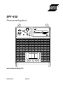 1
1
-
 2
2
-
 3
3
-
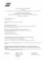 4
4
-
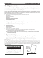 5
5
-
 6
6
-
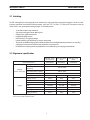 7
7
-
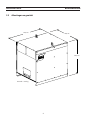 8
8
-
 9
9
-
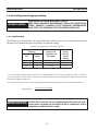 10
10
-
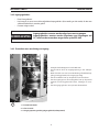 11
11
-
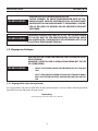 12
12
-
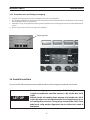 13
13
-
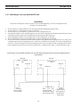 14
14
-
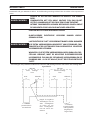 15
15
-
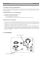 16
16
-
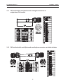 17
17
-
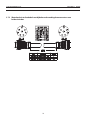 18
18
-
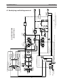 19
19
-
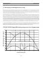 20
20
-
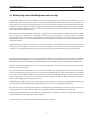 21
21
-
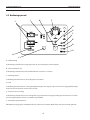 22
22
-
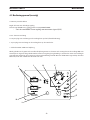 23
23
-
 24
24
-
 25
25
-
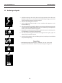 26
26
-
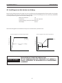 27
27
-
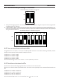 28
28
-
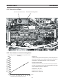 29
29
-
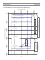 30
30
-
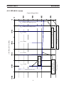 31
31
-
 32
32
-
 33
33
-
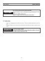 34
34
-
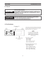 35
35
-
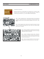 36
36
-
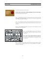 37
37
-
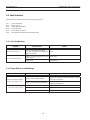 38
38
-
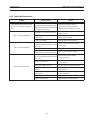 39
39
-
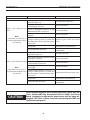 40
40
-
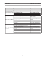 41
41
-
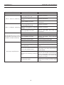 42
42
-
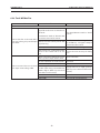 43
43
-
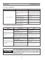 44
44
-
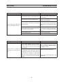 45
45
-
 46
46
-
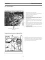 47
47
-
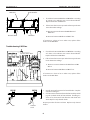 48
48
-
 49
49
-
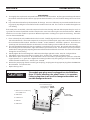 50
50
-
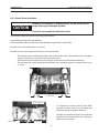 51
51
-
 52
52
-
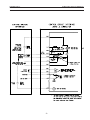 53
53
-
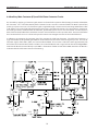 54
54
-
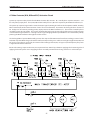 55
55
-
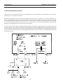 56
56
-
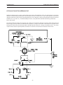 57
57
-
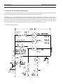 58
58
-
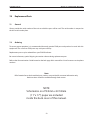 59
59
-
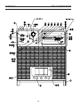 60
60
-
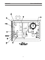 61
61
-
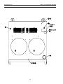 62
62
-
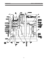 63
63
-
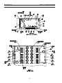 64
64
-
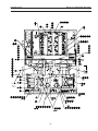 65
65
-
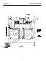 66
66
-
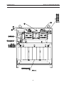 67
67
-
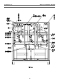 68
68
-
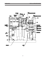 69
69
-
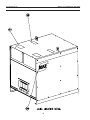 70
70
-
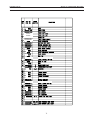 71
71
-
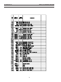 72
72
-
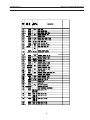 73
73
-
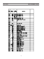 74
74
-
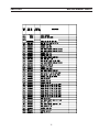 75
75
-
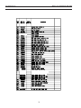 76
76
-
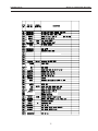 77
77
-
 78
78
-
 79
79
-
 80
80


ESAB EPP-400 Plasma Power Source Handleiding
- Type
- Handleiding
in andere talen
Gerelateerde papieren
-
ESAB EPP-400 Plasma Power Source Handleiding
-
ESAB EPP-600 Plasma Power Source Handleiding
-
-
-
ESAB EPP-450 Plasma Power Source Handleiding
-
ESAB EPP-450 Handleiding
-
ESAB EPP-601 Handleiding
-
ESAB EPP-201 Plasma Power Source Handleiding
-
-