TESTBOY TV 470 Operating Instructions Manual
- Categorie
- Accessoires voor het maken van koffie
- Type
- Operating Instructions Manual


Inhaltsverzeichnis
Testboy® TV 470 3
DEUTSCH
Inhaltsverzeichnis
Inhaltsverzeichnis 3
Sicherheitsmaßnahmen 5
Beschreibung 8
Bedienelemente auf der Front 8
Anzeige 10
Inbetriebnahme 11
Einstellen der Prüfnorm 12
Einstellungen im Punkt "Menü" 13
Anschließen und Verwenden des Barcode-Scanners 15
Starten einer Messung 15
Schutzleiterwiderstandsmessung (R-PE) 16
Isolationswiderstandsmessung (R-ISO) 18
Ableitstrommessung (I-ABL) 21
Ersatzableitstrommessung (I-EA) 22
Gleichspannungsmessung bis 200 V DC / Wechselspannungs-
messung bis 200 V AC 23
Leistungsmessung PWR 24
Laststrommessung I-L 25
Informationen zur DIN VDE 0701-0702:2008-06 26
Schutzleiter-Widerstand 26
Isolationswiderstand 27
Ersatzableitstrom 28
Berührungsstrom 29

Inhaltsverzeichnis
4 Testboy® TV 470
Informationen zur DIN EN 62353 (VDE 0751-1:2008-8) 30
Schutzleiterwiderstand 30
Isolationswiderstand 31
Ersatz-Geräteableitstrom 32
Ersatz-Patientenableitstrom 33
Geräte-Ableitstrom 34
Patientenableitstrom 34
Patientenableitstrom Netzspannung am Anwendungsteil 35
Anhang 36
Grenzwerte der DIN VDE 0701-0702:2008-06 36
DIN EN 62353 (VDE 0751-1:2008-8) 37
Technische Daten 40

Sicherheitsmaßnahmen
Testboy® TV 470 5
DEUTSCH
Sicherheitsmaßnahmen
WARNUNG
Das TV 470 hat das Werk in sicherheitstechnisch einwandfrei-
em Zustand verlassen. Um diesen Zustand zu erhalten, muss
der Anwender die Sicherheitshinweise in dieser Anleitung be-
achten.
WARNUNG
Die Bedienungsanleitung enthält Informationen und Hinweise,
die zu einer sicheren Bedienung und Nutzung des Gerätes
notwendig sind. Vor der Verwendung des Gerätes ist die Be-
dienungsanleitung aufmerksam zu lesen und in allen Punkten
zu befolgen. Wird die Anleitung nicht beachtet oder sollten Sie
es versäumen, die Warnungen und Hinweise zu beachten,
können ernste oder lebensgefährliche Verletzungen bzw. Be-
schädigungen des Gerätes eintreten.
Das Gerät darf nur unter den Bedingungen und für die Zwecke
eingesetzt werden, für die es konstruiert wurde. Hierzu sind
besonders die Sicherheitshinweise, die technischen Daten mit
den Umgebungsbedingungen und die Verwendung in trockener
Umgebung zu beachten.

Sicherheitsmaßnahmen
6 Testboy® TV 470
Einleitung
Das TV 470 ist ein Tester nach DIN VDE 0701-0702 sowie DIN EN 62353
(VDE 0751-1). Das Messgerät wurde nach den neuesten Sicherheitsvor-
schriften gebaut und gewährleistet ein sicheres und zuverlässiges Arbeiten.
Reinigung
Sollte das Gerät durch den täglichen Gebrauch schmutzig geworden sein,
kann das Gerät mit einem feuchten Tuch gereinigt werden. Niemals scharfe
Reiniger oder Lösungsmittel zur Reinigung verwenden.
5 Jahre Garantie
Testboy-Geräte unterliegen einer strengen Qualitätskontrolle. Sollten wäh-
rend der täglichen Praxis dennoch Fehler in der Funktion auftreten, gewäh-
ren wir eine Garantie von 5 Jahren (nur gültig mit Rechnung). Das Gerät be-
nötigt bei einem Betrieb gemäß der Bedienungsanleitung keine besondere
Wartung. Fabrikations- oder Materialfehler werden von uns kostenlos besei-
tigt sofern das Gerät ohne Fremdeinwirkung und ungeöffnet an uns zurück-
gesandt wird. Beschädigungen durch Sturz oder falsche Handhabung sind
vom Garantieanspruch ausgeschlossen.
Bitte wenden Sie sich an:
Testboy GmbH Tel: 0049 (0)4441 / 89112-10
Elektrotechnische Spezialfabrik Fax: 0049 (0)4441 / 84536
Beim Alten Flugplatz 3
D-49377 Vechta www.testboy.de
Germany [email protected]
Diese Bedienungsanleitung wurde mit großer Sorgfalt erstellt. Für die Rich-
tigkeit und Vollständigkeit der Daten, Abbildungen und Zeichnungen wird
keine Gewähr übernommen. Änderungen vorbehalten.

Sicherheitsmaßnahmen
Testboy® TV 470 7
DEUTSCH
Qualitätszertifikat
Alle innerhalb der Testboy GmbH durchgeführten, qualitätsrelevanten Tätig-
keiten und Prozesse werden permanent durch ein Qualitätsmanagementsys-
tem überwacht. Die Testboy GmbH bestätigt weiterhin, dass die während
der Kalibrierung verwendeten Prüfeinrichtungen und Instrumente einer per-
manenten Prüfmittelüberwachung unterliegen.
Konformitätserklärung
Das Produkt erfüllt die Richtlinie 93/68/EEC, 2004/108/EC und 2006/95/EC.
Nicht im Hausmüll entsorgen!
Dieses Produkt stimmt mit den Kennzeichnungsanforderungen
der WEEE-Richtlinie (2002/96/EC) überein. Das angebrachte
Etikett weist darauf hin, dass dieses elektrische/elektronische
Produkt nicht im Hausmüll entsorgt werden darf. Produktkatego-
rie: In Bezug auf die Gerätetypen in Anhang I der WEEE-
Richtlinie ist dieses Produkt als Kategorie 9 "Überwachungs-
und Kontrollinstrument" klassifiziert.
Zur Rückgabe von unerwünschten Produkten die auf dem Pro-
dukt angegebene Website des Herstellers oder die zuständig
Verkaufsstelle bzw. den zuständigen Fachhändler konsultieren.
Lieferumfang
| VDE-Tester TV 470
| Barcode-Scanner
| Bedienungsanleitung
| CD mit Software, Treibern und Bedienungsanleitung
| USB-Kabel
| Netzkabel
| Messleitungen mit Krokoklemmen
| Transporttasche


Beschreibung
Testboy® TV 470 9
DEUTSCH
Anschlussbuchsen
GND Massekabel
R Widerstandsmessung
V+ Spannungsmessung
PELV Schutzkleinspannungsmessung
I Strommessung
Bedientasten
Die Funktion der Tasten variiert je nach Menüposition.
In der unteren Zeile des Displays wird die aktuelle Funktion der darunterlie-
genden Taste angezeigt.
LED Anzeigen
LED 1 Grün OK / Wert innerhalb der Richtlinie
LED 2 Gelb Überlauf (größeren Messbereich wählen)
LED 3 Rot Wert außerhalb der Richtlinie
LED 4 Rot Achtung! Spannung an der Anschlussbuchse V+
LED 1 und LED 3 Wert kann noch OK sein, bitte die Norm beachten.
Die Bewertung der Messdaten durch die LED1 und LED3 entspre-
chen nur den Grenzwerten von "normalen" Schutzklasse I Geräten.
Die Bewertung ist nur als Hilfsmittel gedacht. Die jeweils gültigen
Grenzwerte entnehmen Sie bitte dem Anhang dieser Anleitung bzw.
der jeweils gültigen Norm.

Beschreibung
10 Testboy® TV 470
Anzeige
Die Anzeige des TV 470 ist in drei Bereiche eingeteilt. Im oberen Bereich
werden Informationen zu den Einstellungen bzw. zur aktuellen Messung an-
gezeigt. In der Mitte wird der Messwert angezeigt und in der unteren Zeile
die derzeitige Funktion der darunterliegenden Taste.
A
B
C
A Anzeigebereich der Messwerte
B Geräteeinstellungen bzw. Informationen zur Messung
C Derzeitige Funktion der darunterliegenden Taste

Inbetriebnahme
Testboy® TV 470 11
DEUTSCH
Inbetriebnahme
Der TV 470 schaltet sich automatisch ein, wenn der Netzstecker in die
Steckdose gesteckt wird.
Soll der Tester ausgeschaltet werden, müssen Sie den Netzstecker aus der
Steckdose ziehen.
Beim Einschalten läuft automatisch ein Selbsttest. Wird dieser ohne Fehler
durchgeführt, erscheint der Startbildschirm im Display.
Startbildschirm des TV 470

Inbetriebnahme
12 Testboy® TV 470
Einstellen der Prüfnorm
Um Änderungen an der Einstellung der Prüfnorm vorzunehmen, drücken Sie
bitte im Hauptmenü die Taste "NORM".
Die Anzeige wechselt nun je nach Voreinstellung von z.B. VDE701/702 zu
EN 62353 (VDE0751-1).
Bei Auswahl der Prüfnorm EN 62353 (VDE0751-1) (Medizinische elektrische
Geräte) erscheint ein weiteres Menü mit folgenden Einstellmöglichkeiten:
Auswahlmenü EN 62353 (VDE751-1)
Schutzklasse
Hier kann Schutzklasse I oder II eingestellt werden.
Messungsart
Hier wird eingestellt, ob Ableitströme per "Direktmessung" oder per "Ersatz-
messung" gemessen werden.
Anwendungstyp
Hier wird der benötigte Anwendungsteil B, BF oder CF eingestellt.

Inbetriebnahme
Testboy® TV 470 13
DEUTSCH
Einstellungen im Punkt "Menü"
Weitere Einstellungen und Funktionen stehen Ihnen unter dem Punkt "Me-
nü" zur Verfügung. Drücken Sie die Taste unter dem Punkt "Menü". Im Dis-
play erscheint nun folgende Anzeige.
Auto-Messung
Unter dem Punkt "Auto-Messung" kann eingestellt werden, ob der Prüfablauf
automatisch erfolgen soll oder ob eine einzelne Messung durchgeführt wer-
den soll.
Die Datenspeicherung erfolgt nur im automatischen Modus.
Datensätze
Durch Auswahl von "Datensätze" können Sie durch vorhandene Datensätze
blättern und sich gespeicherte Messwerte noch einmal anschauen.

Inbetriebnahme
14 Testboy® TV 470
Alle Löschen
Dieser Menüpunkt löscht den gesamten Messwertspeicher des Gerätes.
Durch Ausführen dieser Funktion werden alle Datensätze auf dem
Gerät unwiderruflich gelöscht!
Firmware neu
Sollte es in Zukunft Änderungen im Bereich der Norm oder Weiterentwick-
lungen der Gerätesoftware geben, wird dieser Menü-Punkt für ein Firmware-
update benötigt.
Informationen und Updates werden über unsere Internetseite
www.testboy.de bereitgestellt.
Sichtprüfung
Bei aktivierter Sichtprüfungsfunktion erfolgt vor der Geräteprüfung eine Ab-
frage, die mit einem Tastendruck bestätigt werden muss. Bei Auswahl von
"Nein" wird der Prüfvorgang abgebrochen.
Kompensation der Messleitungen (LtgKompensat)
Mit dieser Funktion ist es möglich die verwendeten Messleitungen zu kom-
pensieren. So wird verhindert, dass der Widerstand der Messleitungen das
Messergebnis beeinträchtigt.
Um den Abgleich durchzuführen, schließen Sie eine Messleitung an die
Buchse R an und messen zum Schutzleiterkontakt der Prüflingssteckdose.
Drücken Sie nun die Taste "Speichern", um den Wert im Gerät zu hinterle-
gen.
Bei Wechsel der Messleitungen sollte die Messleitungskompensation erneut
durchgeführt werden.

Inbetriebnahme
Testboy® TV 470 15
DEUTSCH
Anschließen und Verwenden des Barcode-Scanners
Schließen Sie den Barcode-Scanner an der Rückseite des TV 470 an. Der
Scanner signalisiert die Funktionsbereitschaft durch ein akustisches Signal.
Um einen Barcode zu erfassen, richten Sie den Scanner auf den Barcode
und drücken Sie die Scannertaste. Das erfolgreiche Einlesen der Codes wird
durch einen Signalton quittiert.
Durch die Verwendung von Barcodes lassen sich Wiederholungsprüfungen
vereinfachen.
Im "Auto"-Modus wird durch das Einlesen eines Barcodes die Messung ge-
startet. Alle Messwerte werden zusammen mit dem Barcode gespeichert.
Bei der Auswertung werden Messwerte sowie der Barcode in der Datenbank
auf dem PC hinterlegt.
Im Falle einer Wiederholungsprüfung werden die Ergebnisse automatisch
dem Prüfling zusortiert. Aus diesem Grunde ist darauf zu achten, dass jeder
Barcode nur einmal vergeben wird.
Starten einer Messung
Um einen Messvorgang zu starten, drücken Sie die Taste mit der Funktion
"Mess" oder lesen Sie im "Auto"-Modus einen Barcode ein. Im "Auto"-Modus
startet das Gerät nun mit der ersten Messung.
Im manuellen Messmodus erscheint die Auswahl der Messmöglichkeiten.
Die Abfolge der "Auto"-Messung erfolgt in der durch die Norm vorgegebenen
Reihenfolge. Diese ist abhängig von der Schutzklasseneinstellung am Gerät.
Schutzklasse I:
Schutzleiterwiderstand – Isolationswiderstand – Ableitstrom – Ersatzableit-
strom
Schutzklasse II:
Isolationswiderstand – Ableitstrom – Ersatzableitstrom
Schutzklasse III:
Isolationswiderstand

Inbetriebnahme
16 Testboy® TV 470
Bei Geräten der Schutzklasse I und II kann der Messvorgang nach
der Ableitstrommessung durch Drücken der Taste "End" beendet
werden.
Befindet sich der Messwert außerhalb der Messbereichsgrenzen des
TV 470, so wird dieser Überlauf durch eine "1" im Display angezeigt.
Zur Bewertung der Messdaten können die LED1 und LED3 zu Hilfe genom-
men werden. Die voreingestellten Grenzwerte entsprechen denen von "nor-
malen" Geräten der Schutzklasse I.
Die Bewertung ist nur als Hilfsmittel gedacht. Die jeweils gültigen Grenzwer-
te entnehmen Sie bitte der jeweils gültigen Norm im Original.
WARNUNG
Bei Messungen, bei denen Hochspannung an der Messbuchse
"V+" anliegt (Isolationswiderstand), wird dieses durch Aufleuch-
ten der roten LED 4 signalisiert, um den Bediener auf die mög-
liche Gefahr bei Berührung der Messleitungen hinzuweisen!
Schutzleiterwiderstandsmessung (R-PE)
Schließen Sie den Prüfling, wie im Bild1 gezeigt, an die Prüfsteckdose an
und eine Messleitung an die Buchse "R". Um die Prüfung durchzuführen,
tasten Sie alle Schutzleiterverbundenen Metallteile ab.
Sie können die Prüfung auch nur mit Hilfe der Messleitungen durchführen
(Bild 2). Dazu schließen Sie je eine Messleitung an der Buchse "R" und
"GND" an.
Gemessen wird der Widerstand des Schutzleiters vom Netzstecker zu
schutzleiterverbundenen Metallteilen des Prüflings.
Bei Prüfung mit Hilfe der Messleitungen wird der Widerstand zwischen den
beiden Messleitungen ermittelt.


Inbetriebnahme
18 Testboy® TV 470
Isolationswiderstandsmessung (R-ISO)
Bild 3
Schließen Sie den Prüfling, wie im Bild 3 gezeigt, an die Prüflingssteckdose
an.
Der Prüfling muss eingeschaltet sein, damit er richtig überprüft werden kann.
Bei der Messung müssen alle Schalter, Regler usw. geschlossen sein, um
die Isolierung aller aktiven Teile vollständig zu erfassen.
WARNUNG
Bei Verwendung der Messleitungen liegt eine Leerlaufspan-
nung von bis zu 650 V an den Messleitungen an, dies wird
auch durch Aufleuchten der roten LED 4 angezeigt.
Es stehen verschiedene Messmöglichkeiten zur Verfügung:
| Messung über die Prüfsteckdose (nur Geräte der Schutzklasse I) (Bild 3)
| Messung über die Messleitungen (Bild 4)
| Messung über die Prüfsteckdose und die Messleitungen (Bild 5 und 6)

Inbetriebnahme
Testboy® TV 470 19
DEUTSCH
Bei Geräten der Schutzklasse I wird zwischen allen aktiven Teilen (Phase
und Neutralleiter) und dem Schutzleiter gemessen sowie allen berührbaren,
leitfähigen Teilen, die nicht mit dem Schutzleiter verbunden sind.
Bei Geräten der Schutzklasse II wird zwischen allen aktiven Teilen (Phase
und Neutralleiter) sowie allen berührbaren, leitfähigen Teilen gemessen.
Bild 4


Inbetriebnahme
Testboy® TV 470 21
DEUTSCH
Ableitstrommessung (I-ABL)
Bild 7
Schließen Sie den Prüfling an die Prüfsteckdose an. Der Prüfling muss ein-
geschaltet sein, damit er richtig überprüft werden kann.
Mit der Messleitung in der Buchse I müssen nun folgende Teile überprüft
werden:
| Schutzklasse I-Geräte: Alle nicht geerdeten Teile, die berührbar und
leitfähig sind.
| Schutzklasse II-Geräte: Alle berührbaren, leitfähigen Teile.
WARNUNG
Führen Sie diese Messung niemals durch, bevor nicht die
Schutzleiterwiderstands- und Isolationswiderstandsmessung
erfolgreich durchgeführt worden sind!
Der Prüfling wird während der Messung mit Netzspannung ver-
sorgt und ist in Betrieb. Seien Sie deshalb vorsichtig mit Gerä-
ten die Wärme abgeben oder bewegliche Teile besitzen!

Inbetriebnahme
22 Testboy® TV 470
Ersatzableitstrommessung (I-EA)
Bild 8
Der Prüfling wird an die Prüfsteckdose angeschlossen und muss eingeschal-
tet sein.
Es wird eine Schutzkleinspannung zwischen dem Schutzleiter und den akti-
ven Leitern (Phase und Neutralleiter) der Prüfsteckdose gelegt.
Die Messleitung wird nur in folgenden Fällen benötigt:
| Bei Schutzklasse I-Geräten: Zur Überprüfung von berührbaren, leitfähi-
gen Teilen die nicht mit dem Schutzleiter verbunden sind.
| Bei Schutzklasse II-Geräten: Zur Überprüfung von allen berührbaren,
leitfähigen Teilen.

Inbetriebnahme
Testboy® TV 470 23
DEUTSCH
Gleichspannungsmessung bis 200 V DC / Wechselspannungs-
messung bis 200 V AC
(Nur im manuellen Modus, keine Speicherung)
Bild 9
Schließen Sie die Messleitungen an GND und PELV, wie im Bild gezeigt, an.
Wechseln Sie im Menü "Auto-Messung" auf "Nein", um den manuellen
Messmodus zu aktivieren. Danach betätigen Sie im Hauptmenü die Taste
"Mess" und wählen die gewünschte Messung (Gleichspannung bzw. Wech-
selspannung) aus. Bestätigen Sie die Auswahl mit der Taste "Wählen". Der
gemessene Wert wird nun angezeigt. Überschreitet der Messwert 25 V, wird
dieses durch Aufleuchten der LED 3 (rot) angezeigt (Überschreitung der Ge-
rätekleinspannung).

Inbetriebnahme
24 Testboy® TV 470
WARNUNG
Dieses Gerät eignet sich nicht dazu, Netzspannungen zu prü-
fen oder zu messen.
Es ist nur für Messungen von Gleich- und Wechselspannungen
bis max. 200 V ausgelegt.
Leistungsmessung PWR
(Nur im manuellen Modus, keine Speicherung)
Stecken Sie den Prüfling in die Prüfsteckdose. Wählen Sie im manuellen
Modus den Punkt "Leistungsmessung" aus und bestätigen Sie die Auswahl
mit der Taste "Wählen". Der Prüfling wird mit Netzspannung versorgt und ist
in Betrieb. Im Display wird die Höhe der Leistungsaufnahme angezeigt.
Es stehen zwei Messbereiche, 1 kW und 4 kW, zur Verfügung.
WARNUNG
Führen Sie diese Messung niemals durch, bevor nicht die
Schutzleiterwiderstands- und Isolationswiderstandsmessung
erfolgreich durchgeführt worden sind!
Der Prüfling wird während der Messung mit Netzspannung ver-
sorgt, seien Sie deshalb vorsichtig mit Geräten die Wärme ab-
geben oder bewegliche Teile besitzen!

Inbetriebnahme
Testboy® TV 470 25
DEUTSCH
Laststrommessung I-L
(Nur im manuellen Modus, keine Speicherung)
Stecken Sie den Prüfling in die Prüfsteckdose. Wählen Sie die Laststrom-
messung (I-L) aus und bestätigen Sie die Auswahl mit der Taste "Wählen".
Der Prüfling wird mit Netzspannung versorgt und im Display wird die Last-
stromaufnahme angezeigt.
WARNUNG
Führen Sie diese Messung niemals durch, bevor nicht die
Schutzleiterwiderstands- und Isolationswiderstandsmessung
erfolgreich durchgeführt worden sind!
Der Prüfling wird während der Messung mit Netzspannung ver-
sorgt, seien Sie deshalb vorsichtig mit Geräten die Wärme ab-
geben oder bewegliche Teile besitzen!

Informationen zur DIN VDE 0701-0702:2008-06
26 Testboy® TV 470
Informationen zur DIN VDE 0701-0702:2008-06
(Prüfung nach Instandsetzung bzw. Änderung elektrischer Geräte, VDE
0701)
(Wiederholungsprüfung elektrischer Geräte, VDE 0702)
Maßgebend für die Durchführung von Prüfungen sowie die Bestim-
mung von Grenzwerten ist die jeweils gültige Norm im Original!
Nachstehend aufgeführte Prüfungen ...
| Schutzleiter-Widerstand (bei Geräten mit Schutzleiter)
| Isolationswiderstand (wenn technisch möglich)
| Ersatzableitstrom (wenn Isolationswiderstand bestanden wurde)
| Berührstrom an berührbaren, leitfähigen Teilen, die nicht mit dem
Schutzleiter verbunden sind
Schutzleiter-Widerstand
Die Durchgängigkeit bzw. der Widerstand und der Schutzleiter sind zu mes-
sen.
Messspannung 4 ... 24 V,
Messstrom >200 mA
Grenzwerte
< 0,3 Ω bis 5m Leitungslänge + 0,1 Ω je weitere 7,5 m Leitungslänge – max.
1 Ω
Wichtige Hinweise
| Während der Messung die Anschlussleitungen bewegen.
| Messleitungswiderstand geht in Messung ein, Messleitungen gut leitend
anschließen.

Informationen zur DIN VDE 0701-0702:2008-06
Testboy® TV 470 27
DEUTSCH
Isolationswiderstand
Der Isolationswiderstand ist zu messen bei:
Schutzklasse 1 zwischen L+N gegen PE
Schutzklasse 2 zwischen L+N gegen berührbare, leitfähige Teile des Ge-
rätes
Schutzklasse 3 zwischen dem Spannungsanschluss und berührbaren, leit-
fähigen Teilen des Gerätes
Um sicherzustellen, dass alle durch Netzspannung beanspruchten
Isolierungen bei dieser Messung erfasst werden, ist darauf zu ach-
ten, dass Schalter, Temperaturregler usw. geschlossen sind.
Messspannung 500 VDC.
Grenzwerte
Schutzklasse DIN VDE 0701 DIN VDE 0702
SK 1 > 0,3 MΩ Geräte mit Heizelementen
> 1 MΩ Geräte ohne Heizelemente
> 2 MΩ Berührbare leitfähige Teile ohne SL-Anschluss
SK2 > 2 MΩ
SK3 > 250 kΩ
Wichtige Hinweise
| Auch bei bestandener ISO-Prüfung ist zusätzlich der Ersatzableitstrom
zu messen.
| Berührbare, leitfähige Teile, die nicht mit dem Schutzleiter verbunden
sind, mit Messleitung abtasten.
| Fehlerhafte ISO-Messungen täuschen gute Messwerte vor.
| Wenn bei der ISO-Messung nicht alle sicherheitsrelevanten Teile erreicht
werden, muss anstelle von ISO/EA eine Schutzleiter- oder Berührungs-
strommessung mit der direkten Methode oder indirekt als I erfolgen; bei
der direkten Methode muss der Prüfling isoliert aufgestellt werden.
| Prüflinge SK2 ohne berührbare, leitfähige Teile können nur einer Sicht-
prüfung unterzogen werden.

Informationen zur DIN VDE 0701-0702:2008-06
28 Testboy® TV 470
Ersatzableitstrom
Auch bei gutem Isolationswiderstand ist die Messung des Ersatzableitstro-
mes Pflicht.
Grenzwerte
Schutzklasse DIN VDE 0701 DIN VDE 0702
SK 1 < 3,5 mA oder 1 mA/kW
SK2 oder berührbare-leitfähige Teile ohne SL < 0,5 mA
Wichtige Hinweise
| Isolationsmessung ist nur gültig, wenn alle Stromkreise im Gerät einge-
schaltet sind.
| Bei Messung des Schutzleiter- oder Berührungsstromes muss der Prüf-
ling isoliert aufgestellt und von allen sonstigen Anschlüssen abgetrennt
sein, das ist bei Differenzstrommessung nicht erforderlich. In beiden Fäl-
len ist eine Messung während des Standardbetriebes erforderlich.
| Bei Schutzleiter-, Differenz- oder Berührungsstrom Netzstecker "wenn
möglich" umpolen.
| Unterscheiden Sie zwischen Ersatzableitstrom, Berührungsstrom,
Schutzleiter- oder Differenzstrom.
| Wird Berührungsstrom gemessen, weil Unterbrechung nicht möglich ist,
muss später die Isolationsmessung nachgeholt werden.
| Abweichende Grenzwerte in DIN VDE0701Teil 1... 240 beachten!
| Halbierung des Messwertes bei allpolig abschaltbarer symmetrischer ka-
pazitiver Beschaltung.
| Für mehrphasige Geräte ist die Messung des Ersatzableitstromes nicht
geeignet.
| Geräte mit höheren Ableitströmen müssen gekennzeichnet sein.

Informationen zur DIN VDE 0701-0702:2008-06
Testboy® TV 470 29
DEUTSCH
Berührungsstrom
Bei Geräten der Schutzklasse II mit berührbaren, leitfähigen Teilen, bei de-
nen Bedenken gegen eine Messung des Isolationswiderstandes bestehen
oder eine Unterbrechung des Betriebes nicht möglich ist, darf diese Mes-
sung durchgeführt werden. Dieses gilt auch für Messungen an berührbaren,
leitfähigen Teilen bei Geräten der Schutzklasse I, die nicht mit dem Schutz-
leiter verbunden sind.
Grenzwert
DIN VDE 0701-0702:2008-6
< 0,5 mA
Schutzkleinspannung
Werte über den folgenden Angaben werden unter normalen Bedingungen
als gefährlich aktiv angesehen.
Grenzwert
EN 61010-1:2011-07
33 V AC / 70V DC

Informationen zur DIN EN 62353 (VDE 0751-1:2008-8)
30 Testboy® TV 470
Informationen zur DIN EN 62353 (VDE 0751-1:2008-8)
(Wiederholungsprüfung und Prüfung nach Instandsetzung von medizini-
schen elektrischen Geräten)
Maßgebend für die Durchführung von Prüfungen sowie die Bestim-
mung von Grenzwerten ist die jeweils gültige Norm im Original!
Die Prüfungen sind in der angegebenen Reihenfolge durchzuführen:
| Sichtprüfung
| Schutzleiterwiderstand
| Isolationswiderstand (wenn von Hersteller gefordert)
| Ableitstrom
| Funktionstest und Dokumentation
Schutzleiterwiderstand
Die Durchgängigkeit bzw. der Widerstand und der Schutzleiter sind zu mes-
sen.
Messspannung 4...24 V,
Messstrom >200 mA
Grenzwerte
< 0,3 Ω inklusive Netzleitung
Bei abnehmbaren Leitungen ggf. 0,2 oder 0,1 Ω
Wichtige Hinweise
| Anschlussleitungen während der Messung bewegen
| Messleitungswiderstand geht in Messung ein, Messleitung gut leitend
anschließen.

Informationen zur DIN EN 62353 (VDE 0751-1:2008-8)
Testboy® TV 470 31
DEUTSCH
Isolationswiderstand
Der Isolationswiderstand ist zu messen, wenn vom Hersteller gefordert, bei:
Schutzklasse 1 zwischen L+N gegen PE
Schutzklasse 2 zwischen L+N gegen berührbare, leitfähige Tei-
le des Gerätes
Anwendungsteil Typ CF zwischen Anwendungsteil und L+N+SL
Um sicherzustellen, dass alle durch Netzspannung beanspruchten
Isolierungen bei dieser Messung erfasst werden, ist darauf zu ach-
ten, dass Schalter, Temperaturregler usw. geschlossen sind.
Messspannung 500 VDC.
Grenzwerte
Schutzklasse DIN EN 62353 (VDE 0751-1)
SK 1 > 2 MΩ
SK2 > 7 MΩ
Anwendungsteil Typ CF > 70MΩ
Wichtige Hinweise
| Bei Schutzklasse 2-Prüflingen berührbare, leitfähige Teile mit Messlei-
tung abtasten.

Informationen zur DIN EN 62353 (VDE 0751-1:2008-8)
32 Testboy® TV 470
Ersatz-Geräteableitstrom
Zulässige Werte von langzeitig fließenden Er-
satz-Geräteableitströmen Werte in mA
Anwendungsteil B BF CF
Im Schutzleiter oder mit dem Schutzleiter verbun-
denen Teilen
1,0 1,0 1,0
Geräte mit mineralischer Isolierung und Geräte
nach Anmerkung 1
5,0 5,0 5,0
Geräte nach Anmerkung 2 10,0 10,0 10,0
Fahrbare Röntgengeräte mit zusätzlichem Schutz-
leiter
5,0 5,0 5,0
Fahrbare Röntgengeräte ohne zusätzlichem
Schutzleiter
2,0 2,0 2,0
Nicht mit dem Schutzleiter verbundene, berührba-
re Teile
0,2 0,2 0,2
Anmerkung 1: Geräte/Systeme, die nicht mit dem Schutzleiter verbundenen
berührbaren Teilen ausgestattet sind und die mit den Anforderungen für den
Gehäuseableitstrom und, falls zutreffend, für den Patientenstrom überein-
stimmen. Beispiel:
| EDV-Geräte mit abgeschirmtem Netzteil.
Anmerkung 2: Geräte, die für festen Anschluss bestimmt sind und einen
Schutzleiter haben, der so angeschlossen ist, dass er nur nach Anwendung
eines Werkzeuges bewegt werden kann. Beispiele:
| die Hauptteile einer Röntgeneinrichtung, wie der Röntgenstrahlenerzeu-
ger, der Untersuchungs- oder Behandlungstisch.
| Geräte mit mineralisolierten Heizelementen.
| Geräte, die wegen Einhaltung von Funkschutzbestimmungen einen hö-
heren Erdableitstrom als die bei "Erdableitstrom allgemein" zulässigen
Werte aufweisen.

Informationen zur DIN EN 62353 (VDE 0751-1:2008-8)
Testboy® TV 470 33
DEUTSCH
Ersatz-Patientenableitstrom
Zulässige Werte von langzeitig fließenden Er-
satz-Patientenableitströmen Werte in mA
Anwendungsteil B BF CF
Ersatz-Patientenableitstrom – 5,0 0,05
Anmerkung 3: Fahrbare Röntgengeräte mit mineralischer Isolierung.
Wichtige Hinweise
| Ersatz-Geräteableitstrom- oder Isolationsmessung ist nur gültig, wenn al-
le Stromkreise im Gerät eingeschaltet sind.
| Typ des Anwendungsteils bestimmt den Grenzwert.
Wenn bei der Ersatz-Geräteableitstrommessung nicht alle sicherheitsrele-
vanten Teile erreicht werden, muss stattdessen eine Ableitstrommessung
mit der direkten Methode oder indirekt als I erfolgen; bei der direkten Me-
thode muss der Prüfling isoliert aufgestellt werden.

Informationen zur DIN EN 62353 (VDE 0751-1:2008-8)
34 Testboy® TV 470
Geräte-Ableitstrom
Bei Geräten, bei denen nicht sichergestellt werden kann, dass alle durch
Netzspannung beanspruchten Teile mit der Messung des Ersatz-Geräteab-
leitstromes erfasst werden oder die Messung des Ersatz-Geräteableitstro-
mes aus anderen Gründen nicht durchgeführt werden kann, darf die Mes-
sung des Geräte-Ableitstromes direkt oder als Differenzstrom durchgeführt
werden.
Zulässige Werte von langzeitig fließenden Ge-
räteableitströmen Werte in mA
Anwendungsteil B BF CF
Geräteableitstrom Allgemein 0,5 0,5 0,5
Geräteableitstrom für Geräte nach Anmerkung 1
und 3
2,5 2,5 2,5
Geräteableitstrom für Geräte nach Anmerkung 2 5,0 5,0 5,0
Geräteableitstrom für Geräte der Schutzklasse 2
und nicht mit dem Schutzleiter verbundene leitfä-
hige Teile von Geräten der Schutzklasse 1
0,1 0,1 0,1
Patientenableitstrom
Zulässige Werte von langzeitig fließenden Er-
satzableitströmen Werte in mA
Anwendungsteil B BF CF
Gleichstrom 0,01 – – Patientenableitstrom
Wechselstrom 0,10 – –


Anhang
36 Testboy® TV 470
Anhang
Grenzwerte der DIN VDE 0701-0702:2008-06
Schutzleiterwiderstand <0,3 Ω bis 5 m, über 5 m 0,1 Ω je weitere
7,5 m Leitung
>0,3 MΩ Geräte mit Heizelementen
>1 MΩ Geräte ohne Heizelemente
Isolationswiderstand SK1
>2 MΩ Berührbare, leitfähige Teile ohne
SL-Anschluss
Isolationswiderstand SK2 >2,0 MΩ
Isolationswiderstand SK3 >0,25 MΩ
Ersatzableitstrom SK2
SK2
<3,5 mA
0,25 mA
Bei Geräten mit 2poliger Ab-
schaltung und Symmetri-
scher kapazitiver Schaltung
darf der Messwert beim Er-
satzableitstrom halbiert wer-
den.
Schutzleiter- / Differenzstrom <3,5 mA >3,5 kW 1 mA/kW
Berührungsstrom <0,5 mA

Anhang
Testboy® TV 470 37
DEUTSCH
DIN EN 62353 (VDE 0751-1:2008-8)
| Zulässige Ableitstromwerte
| Zulässige Werte von langzeitig fließenden Ersatz-, Geräte- und Patien-
tenableitströmen
Anwendungsteil Typ B Typ BF Typ CF
Geräteableitstrom allgemein 0,5 mA 0,5 mA 0,5 mA
Geräteableitstrom für Geräte nach den
Anmerkungen 1 und 3
2,5 mA 2,5 mA 2,5 mA
Geräteableitstrom für Geräte nach An-
merkung 2
5,0 mA 5,0 mA 5,0 mA
Geräteableitstrom für Geräte der
Schutzklasse 2 und nicht mit dem
Schutzleiter verbundene leitfähige be-
rührbare Teile von Geräten der Schutz-
klasse 1
0,1 mA 0,1 mA 0,1 mA
Ersatzgeräteableitstrom für Geräte der
Schutzklasse 2 und nicht mit dem
Schutzleiter verbundene leitfähige be-
rührbare Teile von Geräten der Schutz-
klasse 1
| im Schutzleiter oder mit
dem Schutzleiter verbun-
dene Teile
| Geräte mit mineralischer
Isolierung und Geräte
nach Anmerkung 1
| nach Anmerkung 2
0,2 mA
1,0 mA
5,0 mA
10,0 mA
0,2 mA
1,0 mA
5,0 mA
10,0 mA
0,2 mA
1,0 mA
5,0 mA
10,0 mA
Fahrbare Röntgengeräte mit zusätzli-
chem Schutzleiter
5,0 mA 5,0 mA 5,0 mA
Fahrbare Röntgengeräte ohne zusätzli-
chem Schutzleiter
2,0 mA 2,0 mA 2,0 mA

Anhang
38 Testboy® TV 470
Anwendungsteil Typ B Typ BF Typ CF
Patientenableitstrom
Gleichstrom
Wechselstrom
0,01 mA
0,1 mA
0,01 mA
0,1 mA
0,01 mA
0,1 mA
Ersatzableitstrom
Netzspannung am Anwendungsteil
- 5,0 mA 5,0 mA
Ersatzpatientenableitstrom - 5,0 mA 5,0 mA
Maßgebend für die Durchführung von Prüfungen sowie die Bestim-
mung von Grenzwerten ist die jeweils gültige Norm im Original!
Anmerkungen:
Anmerkung 1:Geräte/Systeme, die nicht mit Schutzleiterverbundenen be-
rührbaren Teilen ausgestattet sind und die mit den Anforderungen für den
Gehäuseableitstrom und falls zutreffend, für den Patientenableitstrom über-
einstimmen.
Beispiel: EDV-Geräte mit abgeschirmtem Netzteil.
Anmerkung 2:Geräte, die für festen Anschluss bestimmt sind und einen
Schutzleiter haben, der so angeschlossen ist, dass er nur mittels Werkzeug
gelöst werden kann, und so befestigt oder mechanisch an einem bestimm-
ten Platz gesichert ist, dass er nur nach Anwendung eines Werkzeuges be-
wegt werden kann.
Beispiele für solche Geräte sind:
Die Hauptteile einer Röntgeneinrichtung, wie der Röntgenstrahlenerzeuger,
der Untersuchungs- oder Behandlungstisch; Geräte mit mineralisolierten
Heizelementen; Geräte, die wegen Einhaltung von Funkschutzbestimmun-
gen einen höheren Erdableitstrom als die bei "Erdableitstrom allgemein" zu-
lässigen Werte aufweisen.
Anmerkung 3:Fahrbare Röntgengeräte und fahrbare Geräte mit minerali-
scher Isolierung.

Anhang
Testboy® TV 470 39
DEUTSCH
Bitte beachten Sie!
Alle technischen Angaben und Grenzwerte in dieser Anleitung ent-
sprechen dem Stand der Drucklegung und wurden nach bestem
Wissen ermittelt. Für fehlerhafte Angaben, Irrtümer und Druckfehler
wird keine juristische Verantwortung oder Haftung übernommen.
Maßgebend für die Durchführung von Prüfungen sowie die Bestim-
mung von Grenzwerten ist die jeweils gültige Norm im Original!

Technische Daten
40 Testboy® TV 470
Technische Daten
Anzeige Dot Matrix LC-Display 128x64 Pixel
Stromversorgung 230 V AC ±10%, 50 Hz ±2%
Eingangsstrom max. 16 A
Betriebstemperatur 0 - +40 °C
Schutzart IP40
Überspannungsschutz CAT II 600V
Schnittstelle USB
RS232 für Barcodescanner
Datenspeicher bis zu 500 Prüflinge
Schutzleiterwiderstand 0,1 bis 20 ; ±5%
Isolationswiderstand 0,15 – 200 M; ±5%
Berührungsstrom 0,1 – 20 mA; ±5%
Ersatzableitstrom 0,1 – 20 mA ; ±5%
Laststrom 0,0 – 16 A; ±5%
Leistung 0 – 3700 VA; ±5%
PELV-Test ab 25 Veff

Table of contents
Testboy® TV 470 41
ENGLISH
Table of contents
Table of contents 41
Safety precautions 43
Description 46
Front side controls 46
Display 48
Preparing for first-time use 49
Setting up the test standard 50
Settings in "Menu" option 51
Connecting and using the bar code scanner. 53
To start a measurement 53
PE conductor resistance measurement (R-PE) 54
Insulation resistance measurement (R-ISO) 56
Leakage current measurement (I-ABL) 59
Equivalent leakage current measurement (I-EA) 60
DC voltage measurement up to 200V DC / AC current measurement
up to 200 V AC 61
Power measurement PWR 62
Load current measurement I-L 63
Information to DIN VDE 0701-0702:2008-06 64
PE conductor-resistance 64
Insulation resistance 65
Equivalent leakage current 66
Contact current 67

Table of contents
42 Testboy® TV 470
Information about DIN EN 62353 (VDE 0751-1:2008-8) 68
PE conductor resistance 68
Insulation resistance 69
Equivalent device leakage current 70
Equivalent patient leakage current 71
Device leakage current 72
Patient leakage current 72
Patient leakage current at the mains voltage application part 73
Appendix 74
Limit according to DIN VDE 0701-0702:2008-06 74
DIN EN 62353 (VDE 0751-1:2008-8) 75
Technical data 78

Safety precautions
Testboy® TV 470 43
ENGLISH
Safety precautions
WARNING
The TV 470 left the factory in proper and safe working order. In
order to maintain this condition, the user must observe the
safety notes contained in this manual.
WARNING
This operation manual contains information and notes required
to operate and use this instrument safely. Before using this in-
strument, you must read this operation manual with due care
and attention and adhere to all aspects. Failure to observe the
instructions, warnings and notes could lead to serious or life-
threatening injury or to damage of the device.
The instrument must only be used under the conditions and for
the purposes for which it was designed and built. Thus, it is im-
perative to observe the notes on safety, the technical data in
conjunction with the ambient conditions and use the instrument
in dry conditions.

Safety precautions
44 Testboy® TV 470
Introduction
TheTV 470 is a Tester according to DIN VDE 0701-0702 as well as DIN EN
62353 (VDE 0751-1). This measuring instrument has been manufactured to
the latest safety specifications, and guarantees safe and reliable use.
Cleaning
Use a damp cloth and mild household cleaning agent to clean the instrument
should it become soiled through daily use. Never use aggressive cleaning
agents or solvents to clean the instrument.
5 year warranty
Testboy instruments are subject to strict quality control standards. The in-
strument is covered by a warranty for a period of five years against malfunc-
tions during the course of your daily work (valid only with invoice). The in-
strument does not require special maintenance when used as specified in
this operation manual. We will rectify production or material defects free of
charge upon return if these have not been caused by misuse or abuse and if
the instrument has not been opened. Damage resulting from a fall or im-
proper handling is excluded from the warranty.
Please contact:
Testboy GmbH Tel: 0049 (0)4441 / 89112-10
Elektrotechnische Spezialfabrik Fax: 0049 (0)4441 / 84536
Beim Alten Flugplatz 3
D-49377 Vechta www.testboy.de
Germany [email protected]
These operating instructions were created with the utmost care and atten-
tion. However, we offer no guarantee that the data, graphics and drawings
are correct or complete. This document is subject to alteration without notice.

Safety precautions
Testboy® TV 470 45
ENGLISH
Certificate of quality
All aspects of the activities carried out by Testboy GmbH relating to quality
during the manufacturing process are monitored permanently within the
framework of a Quality Management System. Furthermore, Testboy GmbH
confirms that the testing equipment and instruments used during the calibra-
tion process are subject to a permanent inspection process.
Declaration of Conformity
This product fulfils the directives 93/68/EEC, 2004/108/EC and 2006/95/EC.
Do not dispose of in household waste!
This product is labelled according to the requirements of the
WEEE-Directive (2002/96/EC). The attached label indicates that
this electrical / electronic product should not be disposed of in
the household waste. Product category: This product is classi-
fied as a category-9 device (a "monitoring and control instru-
ments") according to the device type in appendix I of the WEEE
directive.
Consult a specialist dealer or responsible sales office if you want
to return unwanted products. Refer to the manufacturer's web
site specified on the product.
Included in delivery
| VDE-Tester TV470
| Bar code scanner
| Operating Instructions
| CD with software, drivers and operating instructions
| USB cable
| Power cord
| Test leads with alligator clips
| Transport bag


Description
Testboy® TV 470 47
ENGLISH
Connection socket
GND Ground cable
R Resistance measurement
V+ Voltage measurement
PELV Protection low voltage measurement
I current measurement
Buttons
The operation of the button varies according to the menu position.
The current function of the underlying key is shown on the bottom line of the
display.
LED Indicators
LED 1 Green OK / Value within the directive
LED 2 Yellow Overrun (choose a larger range)
LED 3 Red Value outside of the directive
LED 4 Red Warning! Voltage on the connection socket V+
LED 1 and LED 3 Value can be OK but beware of the specifications.
The evaluation of the measurement data through LED1 and LED3
correspond only to the limits of the "normal" protection class-I de-
vices. The assessment is only considered to be as an aid. Refer to
the appendix of this manual or the relevant standard for the appli-
cable limits.

Description
48 Testboy® TV 470
Display
The TV 470 display is divided into three areas. In the upper part, information
concerning the current settings or measurements is shown. The measure-
ment value is shown in the middle and in the lower line the function of the
underlying key.
A
B
C
A Display area of the measured values
B Device settings or information concerning current measurement
C Current function of the underlying key

Preparing for first-time use
Testboy® TV 470 49
ENGLISH
Preparing for first-time use
The TV 470 switches on automatically when the mains plug is connected in-
to the socket outlet.
If the Tester is turned off the mains plug should be removed from the socket
outlet.
An automatic self-test is started when switched on. A start screen appears in
the display if completed successfully.
The TV 470 start screen

Preparing for first-time use
50 Testboy® TV 470
Setting up the test standard
In order to make changes to the test standard settings, press the "NORM"
key in the main menu.
The display changes according to the pre-sets. Refer to VDE701/702 to EN
62353 (VDE0751-1).
By choosing standard EN 62353 (VDE0751-1) (Medical electrical equip-
ment) an additional menu with the following setting options is displayed:
Selection menu EN 62353 (VDE751-1)
Protection class
Protection class-I or II can be set.
Type of measurement
Selection of how leakage currents are measured, either by "direct measure-
ment" or by "equivalent measurement".
Application type
Here the necessary application type B, BF or CF can be set.

Preparing for first-time use
Testboy® TV 470 51
ENGLISH
Settings in "Menu" option
Additional settings and functions are available under the "Menu" option.
Press the key under the "Menu" option. The following appears in the display.
Auto measurement
Under the "Auto-measurement" option, either the test procedure should oc-
cur automatically or the measurement should occur individually.
The data storage only occurs in automatic mode.
Records
By selecting "records", you can browse through existing records and view
previously stored readings.

Preparing for first-time use
52 Testboy® TV 470
Delete all
This menu item deletes the complete measurement memory of the device.
By performing this function, all records on the device will be irrevo-
cable deleted!
New firmware
This menu item is needed for future firmware updates, if there are changes
in the standards or device software enhancements.
Information and updates are made available on our internet site
www.testboy.de.
Visual inspection
When the visual inspection function is activated, a query is made that has to
be confirmed with a key press before the device test is carried out. The test
is terminated if "No" is selected.
Test lead compensation (LtgKompensat)
This function allows the test leads to be compensated for. This prevents the
resistance of the test leads influencing the measurement results.
In order to carry out the compensation, connect one test lead to the socket R
and measure to the grounded contact of the DUT (device under test) socket.
Press the "Save" key to store the value in the device.
When the test leads are changed, the test lead compensation should be re-
peated.

Preparing for first-time use
Testboy® TV 470 53
ENGLISH
Connecting and using the bar code scanner.
Connect the bar code scanner to the rear of the TV 470. An acoustic signal
indicates that the scanner is ready.
In order to read a bar code, aim the scanner at the bar code and press the
scan key. An acoustic signal indicates that the code has been read success-
fully.
Repeat tests are simplified when bar codes are used.
In "Auto" mode, reading a bar code will automatically start a measurement.
All measurement values will be saved along with the bar code. With the
analysis, all measurements as well as the bar code will be saved in the da-
tabase.
With a repeat test, all results are automatically sorted to the DUT. For this
reason, ensure that each bar code is assigned only once.
To start a measurement
In order to start a measurement, press the key with the function "Measure"
or read a bar code in the "Auto" mode. In "Auto" mode, the device starts with
the first measurement.
In manual mode, the measurement choices are displayed.
The "Auto" measurement sequence follows the order given by the directive.
This is dependent on the protection class setting on the device.
Protection class-I:
PE conductor resistance – insulation resistance – leakage current – equiva-
lent leakage current
Protection class-II:
Insulation resistance – leakage current – equivalent leakage current
Protection class-III:
Insulation resistance
When testing devices of protection class-I and II, the measurement
can be stopped after the leakage current measurement by pressing

Preparing for first-time use
54 Testboy® TV 470
"End".
If the measured value is outside the range of the TV 470, the number "1" will
be displayed on the screen.
To evaluate the measurement result LED1 and LED2 can be used to help.
The pre-set limits correspond to the "normal" protection class-I devices.
The assessment is only considered to be as an aid. For the applicable limits
refer to the relevant standard.
WARNING
Measurements carried out on high voltages and connected to
the "V+" socket (insulation resistance) will be indicated by the
illumination of the red LED 4, to indicate danger to the user in
the event of contact to the test leads!
PE conductor resistance measurement (R-PE)
Connect the DUT to the test socket according to Illustration1. Connect one
test lead to the socket "R". To carry out the test, touch all the associated pro-
tective metal parts.
The test can only be carried out with the use of the test leads (Illustration 2).
Connect a test lead to each of the sockets "R" and "GND".
The resistance of the PE conductor from the mains power plug to the metal
parts of the DUT that are touching the PE.
The resistance between the two test leads is determined using these two
leads.


Preparing for first-time use
56 Testboy® TV 470
Insulation resistance measurement (R-ISO)
Illustration 3
Connect the DUT to the DUT socket as shown in Illustration 3.
The DUT has to be switched on in order to be tested correctly.
With this measurement, make sure that all switches, regulators etc. are acti-
vated in order to test completely the insulation on all active parts.
WARNING
If a no-load voltage of up to 650 V is applied to the test leads
this will also be indicated by the illumination of the red LED 4.
Several measurement options are available:
| Measurement using the test sockets (only for protection class-I devices)
(Illustration 3)
| Measurement using the test leads (Illustration 4)
| Measurement using the test sockets and the test leads (Illustrations 5
and 6)

Preparing for first-time use
Testboy® TV 470 57
ENGLISH
With devices in protection class I, measurements will be made between all
active parts (phase and neutral) and the PE conductor as well as all exposed
conductive surfaces that are not connected to the PE conductor.
With devices in protection class II, measurements will be made between all
active parts (phase and neutral) as well as all exposed conductive compo-
nents.
Illustration 4


Preparing for first-time use
Testboy® TV 470 59
ENGLISH
Leakage current measurement (I-ABL)
Illustration 7
Connect the DUT to the test socket. The DUT has to be switched on in order
to be tested correctly.
With the test lead connected to socket I the following should now be tested:
| Protection class-I device: All non-earthed components, that are ex-
posed and conductive.
| Protection class-II device: All exposed conductive parts.
WARNING
Never carry out these measurements until the PE conductor
resistance and the insulation resistance measurements have
been successfully carried out!
The DUT should be connected to the mains voltage and in op-
eration during testing. Therefore, be careful with devices that
emit heat or contain moving parts!

Preparing for first-time use
60 Testboy® TV 470
Equivalent leakage current measurement (I-EA)
Illustration 8
The DUT is connected to the test socket and has to be switched on.
A low protection voltage is put between the PE conductor and the active
lines (phase and neutral) of the test sockets.
The test leads are only needed in the following cases:
| With protection class-I devices: To test exposed conductive compo-
nents that are not connected to the PE conductor.
| With protection class-II devices: To test all exposed conductive com-
ponents.

Preparing for first-time use
Testboy® TV 470 61
ENGLISH
DC voltage measurement up to 200V DC / AC current measure-
ment up to 200 V AC
(Only in manual mode, no storage)
Illustration 9
Connect the test leads to GND and PELV as shown in the Illustration. To ac-
tivate the manual mode, change "Auto-measurement" to "No" in the menu.
Then press "Measure" in the main menu and choose the desired measure-
ment (DC or AC). Confirm by pressing the "Select" key. The measured value
is displayed. If the measured value exceeds 25 V, LED3 illuminates (red)
(exceeding the device low voltage range).

Preparing for first-time use
62 Testboy® TV 470
WARNING
This device is not suitable for testing or measuring mains volt-
ages.
It is only designed for measuring DC or AC voltages up to a
maximum of 200 V.
Power measurement PWR
(Only in manual mode, no storage)
Connect the DUT to the test socket. In the manual mode, choose the power
measurement option and confirm your selection by pressing "Select". The
DUT should be connected to the mains voltage and in operation during test-
ing. The display will show the level of the power consumption.
Two measurement ranges are available 1 kW and 4 kW.
WARNING
Never carry out these measurements until the PE conductor
resistance and the insulation resistance measurements have
been successfully carried out!
The DUT is connected to the mains voltage during measure-
ments. Therefore, be careful with devices that emit heat or
have moving parts!

Preparing for first-time use
Testboy® TV 470 63
ENGLISH
Load current measurement I-L
(Only in manual mode, no storage)
Connect the DUT to the test socket. In the manual mode, choose the load
current measurement (I-L) option and confirm your selection by pressing
"Select". The DUT is supplied with mains voltage during measurement and
the display shows the load current.
WARNING
Never carry out these measurements until the PE conductor
resistance and the insulation resistance measurements have
been successfully carried out!
The DUT is connected to the mains voltage during measure-
ments. Therefore, be careful with devices that emit heat or
have moving parts!

Information to DIN VDE 0701-0702:2008-06
64 Testboy® TV 470
Information to DIN VDE 0701-0702:2008-06
(Inspection according to repair or modification of electrical equipment, VDE
0701)
(Recurrent test of electrical equipment, VDE 0702)
The relevant original valid directive is decisive for the implementa-
tion of tests or determining limit values!
The following listed tests –
| PE conductor resistance (for equipment with PE conductor)
| Insulation resistance (if technically possible)
| Leakage current compensation (if insulation resistance test is passed)
| To test exposed conductive components that are not connected to the
PE conductor
PE conductor-resistance
The resistance and integrity of the PE conductor should be measured.
Measurement voltage 4 – 24 V,
Measurement current >200 mA
Limits
< 0.3 Ω to 5m cable length + 0.1 Ω for each additional 7.5 m of cable length
– max. 1 Ω
Important notes
| Move the connection cables during measurement.
| As the test leads resistance is part of the measurement, the test leads
should have a good electrical connection.

Information to DIN VDE 0701-0702:2008-06
Testboy® TV 470 65
ENGLISH
Insulation resistance
The insulation resistance should be measured as follows:
Protection class 1 between L+N against PE
Protection class 2 between L+N and against exposed conductive com-
ponents of the device
Protection class 3 between the voltage connection and exposed con-
ductive components of the device.
In order to ensure that all insulation exposed to the mains is checked
with this measurement, make sure that all switches, temperature
regulator etc. are activated. The measurement voltage is 500 VDC.
Limits
Protection class DIN VDE 0701 DIN VDE 0702
class-I > 0.3 MΩ Devices with heating elements
> 1 MΩ Devices without heating elements
> 2 MΩ Exposed conductive components without
PE connection
class-II > 2 MΩ
PC III > 250 kΩ
Important notes
| The equivalent leakage current test should be done even when the ISO
test is successful.
| Exposed conductive components that are connected to the PE conductor
should be tested with the test leads.
| Good measurement values can be shown as erroneous ISO measure-
ments.
| If all safety relevant parts are not reach when doing ISO measurements,
a PE conductor current measurement or a touch current measurement
should be made instead of the ISO/EV test. Either the direct method or
the indirect method I can be used. With the indirect method, the DUT
has to be in an isolated position.

Information to DIN VDE 0701-0702:2008-06
66 Testboy® TV 470
| Only a visual inspection can be done with class-II DUTs that have no ex-
posed conductive components.
Equivalent leakage current
It is mandatory to carry out the equivalent leakage current test even with
good insulation resistance.
Limits
Protection class DIN VDE 0701 DIN VDE 0702
class-I < 3.5 mA or 1 mA/kW
class-II or with exposed conductive component without PE
< 0.5 mA
Important notes
| The insulation test is only valid when all circuits in the device are acti-
vated.
| When measuring the PE conductor or contact current, the DUT should
be set in an isolated position and be separated from all other connec-
tions. This is not necessary with differential current measurements. A
measurement is necessary during standard usage in both cases.
| Reverse the mains power plug (if possible) when the PE conductor cur-
rent, differential current or contact current is measured.
| Distinguish between equivalent leakage, contact, PE conductor or differ-
ential current.
| If touch current is measured because a break is not possible, the insula-
tion measurement should be done later.
| Note the different limit values in DIN VDE0701 Part 1 - 240!
| With an all-pole disconnecting capacitive circuitry switch, halve the
measured value.
| Measuring the equivalent leakage current is not suitable for multi-phase
devices.
| Devices with high leakage current should be marked as such.

Information to DIN VDE 0701-0702:2008-06
Testboy® TV 470 67
ENGLISH
Contact current
A measurement is allowed for devices with protection class-II that have ex-
posed conductive components when there are concerns with a measure-
ment of the insulation resistance or when an interruption in usage is not pos-
sible. This also applies for measurements of protection class-I devices that
have exposed conductive components and do not have a connection to the
PE conductor.
Limit
DIN VDE 0701-0702:2008-6
< 0.5 mA
Low protection voltage
Values above the following specifications should be viewed as actively dan-
gerous under normal circumstances.
Limit
EN 61010-1:2011-07
33 V AC / 70V DC

Information about DIN EN 62353 (VDE 0751-1:2008-8)
68 Testboy® TV 470
Information about DIN EN 62353 (VDE 0751-1:2008-8)
(Retest and inspection after overhauling of medical electrical devices)
The relevant original valid directive is decisive for the implementa-
tion of tests or determining limit values!
The tests should be carried out in the order specified:
| Visual inspection
| PE conductor resistance
| Insulation resistance (when required by the manufacturer)
| Leakage current
| Functional test and documentation
PE conductor resistance
The resistance and integrity of the PE conductor should be measured.
Measurement voltage 4 – 24 V,
Measurement current > 200 mA
Limits
< 0.3 Ω inclusive of the mains lead
With removable leads where applicable 0.2 or 0.1 Ω
Important notes
| Move the connection cables during measurements
| As the test lead resistance is part of the measurement, the test lead
should have a good electrical connection.

Information about DIN EN 62353 (VDE 0751-1:2008-8)
Testboy® TV 470 69
ENGLISH
Insulation resistance
When require by the manufacturer, the insulation resistance should be
measured:
Protection class 1 between L+N against PE
Protection class 2 between L+N and against exposed conductive
components of the device
Application type CF between application part and L+N+ PE
In order to ensure that all insulation exposed to the mains is
checked with this measurement, make sure that all switches, tem-
perature regulator etc. are activated.
The measurement voltage is 500 VDC.
Limits
Protection class DIN EN 62353 (VDE 0751-1)
class-I > 2 MΩ
class-II > 7 MΩ
Application part Type CF > 70MΩ
Important notes
| With protection class-II DUTs, exposed conductive components should
be tested with the test leads.

Information about DIN EN 62353 (VDE 0751-1:2008-8)
70 Testboy® TV 470
Equivalent device leakage current
Allowable values from long-term flow equiva-
lent device leakage current Value in mA
Application part B BF CF
In the PE conductor, or in parts connected to the
PE conductor
1.0 1.0 1.0
Devices with mineral insulation and devices ac-
cording to note 1
5.0 5.0 5.0
Devices according to note 2 10.0 10.0 10.0
Mobile X-ray machines with additional PE conduc-
tor
5.0 5.0 5.0
Mobile X-ray machines without additional PE con-
ductor
2.0 2.0 2.0
Not connected to the PE conductor exposed com-
ponents
0.2 0.2 0.2
Note 1: Devices and systems that meet the requirements for the casing
leakage current and if applicable for the patient power, but are not equipped
with PE conductor or parts connected to the PE conductor. Example:
| Data processing equipment with shielded power supply unit.
Note 2: Devices that have a permanent connection with a PE conductor, and
are connected in such a way, that it can only be moved by using some tool.
Examples:
| The main part of an X-ray apparatus like the X-ray generator, the exami-
nation table or the treatment table.
| Devices with mineral insulated heating elements.
| Devices that have a higher earth leakage current than is normally al-
lowed, due to having to conform to the radio emission regulations.

Information about DIN EN 62353 (VDE 0751-1:2008-8)
Testboy® TV 470 71
ENGLISH
Equivalent patient leakage current
Allowable values from long-term flow equiva-
lent patient leakage current Value in mA
Application part B BF CF
Equivalent patient leakage current. – 5.0 0.05
Note 3: Mobile X-ray machines with mineral insulation.
Important notes
| Equivalent device leakage current insulation test is only valid when all
circuits in the device are activated.
| The application part type determines the limit value.
If all safety-relevant parts are not reached with the equivalent device leakage
current, then a leakage current measurement should be made instead. Use
either the direct method or the indirect method. With the indirect method,
the DUT has to be in an isolated position.

Information about DIN EN 62353 (VDE 0751-1:2008-8)
72 Testboy® TV 470
Device leakage current
With devices where you cannot determine if all mains affected components
are tested with the replacement device leakage current measurement or the
replacement device leakage current measurement for another reason can
not be carried out, then the device leakage current or the differential current
measurement can be measured.
Allowable values from long-term flow device
leakage current Value in mA
Application part B BF CF
Device leakage current generally 0.5 0.5 0.5
Leakage current for devices according to notes 1
and 3
2.5 2.5 2.5
Leakage current for devices according to note 2 5.0 5.0 5.0
Device leakage current for protection class-II de-
vices and protection class-I devices, which are not
connected to the PE conductor conductive com-
ponents.
0.1 0.1 0.1
Patient leakage current
Allowable values from long-term flow equiva-
lent leakage current Value in mA
Application part B BF CF
Direct current 0.01 – – Patient leakage current
Alternating current 0.10 – –

Information about DIN EN 62353 (VDE 0751-1:2008-8)
Testboy® TV 470 73
ENGLISH
Patient leakage current at the mains voltage application part
Allowable values from long-term flow equiva-
lent leakage current Value in mA
Application part B BF CF
Patient leakage current Mains voltage on the
application.
– 5.0 0.05

Appendix
74 Testboy® TV 470
Appendix
Limit according to DIN VDE 0701-0702:2008-06
PE conductor resistance <0.3 Ω to 5 m, above 5 m 0.1 Ω for
each additional 7.5 m cable
>0.3 MΩ Devices with heater elements
>1 MΩ Devices without heater elements
Insulation resistance PC I
>2 MΩ touchable conductive parts with-
out PE conductor connections
Insulation resistance class-II >2.0 MΩ
Insulation resistance PC III >0.25 MΩ
Equivalent leakage
current
PC II
PC II
<3.5 mA
0.25 mA
The equivalent leakage
current can be halved
with devices that have a
2-pole switch and sym-
metrical capacitive
switching.
PE conductor current /
Differential current
<3.5 mA >3.5 kW 1 mA/kW
Contact current <0.5 mA

Appendix
Testboy® TV 470 75
ENGLISH
DIN EN 62353 (VDE 0751-1:2008-8)
| Allowable leakage current values
| Allowable values for long-term substitute-, device-, and patient leakage
current.
Application part Type B Type
BF Type
CF
Device leakage current generally 0.5 mA 0.5 mA 0.5 mA
Device leakage current for devices ac-
cording to notes 1 and 3
2.5 mA 2.5 mA 2.5 mA
Leakage current for devices according
to note 2
5.0 mA 5.0 mA 5.0 mA
Device leakage current for protection
class-II devices as well as exposed
conductive components from class-I
devices which are not connected to the
PE conductor.
0.1 mA 0.1 mA 0.1 mA
Equivalent device leakage current for
protection class-II devices as well as
exposed conductive components from
class-I devices which are not con-
nected to the PE conductor.
| In the PE conductor or
parts connected to the
PE conductor
| Devices with mineral in-
sulation and devices ac-
cording to note 1
| According to note 2
0.2 mA
1.0 mA
5.0 mA
10.0 mA
0.2 mA
1.0 mA
5.0 mA
10.0 mA
0.2 mA
1.0 mA
5.0 mA
10.0 mA
Mobile X-ray machines with additional
PE conductor
5.0 mA 5.0 mA 5.0 mA
Mobile X-ray machines without addi-
tional PE conductor
2.0 mA 2.0 mA 2.0 mA

Appendix
76 Testboy® TV 470
Application part Type B Type
BF Type
CF
Patient leakage current
DC
AC
0.01 mA
,
0.1 mA
0.01 mA
,
0.1 mA
0.01 mA
,
0.1 mA
Substitute leakage voltage
Mains voltage on the application part
- 5.0 mA 5.0 mA
Equivalent patient leakage current - 5.0 mA 5.0 mA
The relevant original valid directive is decisive for the implementa-
tion of tests or determining limit values!
Remarks:
Note 1: Devices and systems that meet the requirements for the casing
leakage current and if applicable for the patient power, but are not equipped
with PE conductor or parts connected to the PE conductor.
Example: Data processing equipment with shielded power supply unit.
Note 2: Devices that have a permanent connection with a PE conductor and
are connected in such a way that they can only be disconnected by using
some tool, and fixed at a certain place or mechanically secured in such a
way that they can only be moved by using some tool.
Examples of such equipment:
The main part of an X-ray apparatus like the X-ray generator, the examina-
tion table or the treatment table, device with mineral insulated heating ele-
ments; devices that have a higher earth leakage current than is normally al-
lowed due to having to conform to the radio emission regulations.
Note 3: Mobile X-ray machines and mobile devices with mineral insulation.

Appendix
Testboy® TV 470 77
ENGLISH
Please note!
All technical information and limit values contained in this manual
comply at the time of printing and were determined to the best of
our knowledge. No legal responsibility or liability will be taken for
any incorrect information, errors or printing mistakes.
The relevant original valid directive is decisive for the implementa-
tion of tests or determining limit values!

Technical data
78 Testboy® TV 470
Technical data
Display Dot Matrix LC-Display 128x64 Pixel
Power supply 230 V AC ±10%, 50 Hz ±2%
Input current Max. 16 A
Operating temperature 0 - +40 °C
Protection class IP 40
Surge protection CAT II 600V
Interface USB
RS232 for bar code scanner
Data storage Up to 500 DUTs
PE conductor resistance 0.1 up to 20 ; ±5%
Insulation resistance 0.15 – 200 M; ±5%
Contact current 0.1 – 20 mA; ±5%
Equivalent leakage cur-
rent
0.1 – 20 mA ; ±5%
Load current 0.0 – 16 A; ±5%
Power output 0 – 3700 VA; ±5%
PELV-Test From 25 Veff

Inhoudsopgave
Testboy® TV 470 79
NEDERLANDS
Inhoudsopgave
Inhoudsopgave Fehler! Textmarke nicht definiert.
Voorzorgsmaatregelen Fehler! Textmarke nicht definiert.
Beschrijving Fehler! Textmarke nicht definiert.
Bedieningselementen op het front Fehler! Textmarke nicht definiert.
Aflezing Fehler! Textmarke nicht definiert.
Ingebruikneming Fehler! Textmarke nicht definiert.
Instellen van de testnorm Fehler! Textmarke nicht definiert.
Instellingen in het item ‘Menu’ Fehler! Textmarke nicht definiert.
Aansluiten en gebruiken van de barcodescannerFehler! Textmarke nicht definiert.
Starten van een meting Fehler! Textmarke nicht definiert.
Aardgeleiderweerstandsmeting (R-PE) Fehler! Textmarke nicht definiert.
Meting van de isolatieweerstand (R-ISO) Fehler! Textmarke nicht definiert.
Lekstroommeting (I-ABL) Fehler! Textmarke nicht definiert.
Vervangende lekstroommeting (I-EA) Fehler! Textmarke nicht definiert.
Gelijkspanningsmeting tot 200 V DC/wisselspanningsmeting tot
200 V AC Fehler! Textmarke nicht definiert.
Capaciteitsmeting PWR Fehler! Textmarke nicht definiert.
Laststroommeting I-L Fehler! Textmarke nicht definiert.
Informatie over DIN VDE 0701-0702:2008-06Fehler! Textmarke nicht d
e
Aardgeleiderweerstand Fehler! Textmarke nicht definiert.
Isolatieweerstand Fehler! Textmarke nicht definiert.
Vervangende lekstroom Fehler! Textmarke nicht definiert.
Aanraakstroom Fehler! Textmarke nicht definiert.

Inhoudsopgave
80 Testboy® TV 470
Informatie over DIN EN 62353 (VDE 0751-1:2008-8)Fehler! Textmarke
Aardgeleiderweerstand Fehler! Textmarke nicht definiert.
Isolatieweerstand Fehler! Textmarke nicht definiert.
Vervangende apparaatlekstroom Fehler! Textmarke nicht definiert.
Vervangende patiëntlekstroom Fehler! Textmarke nicht definiert.
Apparaatlekstroom Fehler! Textmarke nicht definiert.
Patiëntlekstroom Fehler! Textmarke nicht definiert.
Patiëntlekstroom Netspanning op het toepassingsdeelFehler! Textmarke nicht de
f
Bijlage Fehler! Textmarke nicht definiert.
Grenswaarden DIN VDE 0701-0702:2008-06Fehler! Textmarke nicht definiert.
DIN EN 62353 (VDE 0751-1:2008-8) Fehler! Textmarke nicht definiert.
Technische gegevens Fehler! Textmarke nicht definiert.

Voorzorgsmaatregelen
Testboy® TV 470 81
NEDERLANDS
Voorzorgsmaatregelen
WAARSCHUWING
De TV 470 heeft de fabriek in veiligheidstechnisch
onberispelijke staat verlaten. Om deze staat te behouden moet
de gebruiker de veiligheidsinstructies in deze
gebruiksaanwijzing opvolgen.
WAARSCHUWING
De gebruiksaanwijzing bevat informatie en aanwijzingen die
voor een veilige bediening en veilig gebruik van het apparaat
noodzakelijk zijn. Voorafgaand aan het gebruik van het
apparaat moet de gebruiksaanwijzing aandachtig worden
gelezen en op alle punten worden opgevolgd. Als de
gebruiksaanwijzing niet wordt opgevolgd of als u het nalaat, de
waarschuwingen en aanwijzingen op te volgen, kan ernstig of
levensgevaarlijk letsel of kunnen beschadigingen van het
apparaat ontstaan.
Het apparaat mag alleen onder de condities en voor de
doeleinden worden gebruikt waarvoor het geconstrueerd is.
Hiervoor moeten in het bijzonder de veiligheidsaanwijzingen,
de technische gegevens met de omgevingsomstandigheden en
het gebruik in droge omgevingen worden aangehouden.

Voorzorgsmaatregelen
82 Testboy® TV 470
Inleiding
De TV 470 is een tester volgens DIN VDE 0701-0702 evenals DIN EN
62353 (VDE 0751-1). Het meetapparaat is volgens de nieuwste
veiligheidsvoorschriften gebouwd en waarborgt veilig en betrouwbaar
werken.
Reiniging
Als het apparaat door dagelijks gebruik vuil geworden is, kan het met een
vochtige doek worden gereinigd. Nooit scherpe reinigingsmiddelen of
oplosmiddelen voor reiniging gebruiken.
5 jaar garantie
Testboy-apparaten worden onderworpen aan een strenge kwaliteitscontrole.
Als in het dagelijks gebruik desondanks fouten in de werking optreden,
bieden wij 5 jaar garantie (alleen geldig met rekening). Het apparaat vereist
gedurende het gebruik volgens de gebruiksaanwijzing geen bijzonder
onderhoud. Fabricage- of materiaalfouten worden door ons kosteloos
hersteld voor zover het apparaat zonder sporen van uitwendige inwerking en
ongeopend naar ons wordt teruggezonden. Beschadigingen door vallen of
verkeerde behandeling vallen niet onder de garantie.
Neem contact op met:
Testboy GmbH Tel.: 0049 (0)4441/89112-10
Elektrotechnische Spezialfabrik Fax: 0049 (0)4441/84536
Beim Alten Flugplatz 3
49377 Vechta (D) www.testboy.de
Duitsland info@testboy.de
Deze gebruiksaanwijzing is met de grootste zorgvuldigheid samengesteld.
Voor de juistheid en volledigheid van de gegevens, afbeeldingen en
tekeningen wordt geen aansprakelijkheid aanvaard. Wijzigingen
voorbehouden.

Voorzorgsmaatregelen
Testboy® TV 470 83
NEDERLANDS
Kwaliteitscertificaat
Alle binnen de firma Testboy GmbH uitgevoerde werkzaamheden en
processen die relevant zijn voor de kwaliteit worden continu door een
kwaliteitsmanagementsysteem bewaakt. De firma Testboy GmbH bevestigt
daarnaast dat de gedurende de kalibratie gebruikte test-inrichtingen en
instrumenten onderworpen zijn aan een voortdurende test.
Verklaring van overeenstemming
Het product voldoet aan de richtlijnen 93/68/EEC, 2004/108/EC en
2006/95/EC.
Niet via het huisvuil afvoeren!
Dit product voldoet aan de markeringseisen van de AEEA-
richtlijn (2002/96/EC). Het aangebrachte etiket wijst erop dat dit
elektrische/elektronische product niet in het huisvuil mag
terechtkomen. Productcategorie: Uitgaande van de
apparaattypen in bijlage I van de AEEA-richtlijn is dit product als
categorie 9 ‘Bewakings- en test-instrument’ geclassificeerd.
Voor teruggave van ongewenste producten moet de op het
product vermelde website van de fabrikant of het bevoegde
verkooppunt c.q. de bevoegde dealer worden geraadpleegd.
Inhoud van de verpakking
| VDE-tester TV 470
| Barcodescanner
| Gebruiksaanwijzing
| Cd met software, stuurprogramma's en gebruiksaanwijzing
| USB-kabel
| Netsnoer
| Meetsnoeren met krokodilklemmen
| Draagtas


Beschrijving
Testboy® TV 470 85
NEDERLANDS
Connectoren
GND Massakabel
R Weerstandsmeting
V+ Spanningsmeting
PELV Veiligheidslaagspanningsmeting
I Stroommeting
Bedieningsknoppen
De functie van de knoppen varieert afhankelijk van de menupositie.
Op de onderste regel van het display wordt de huidige functie van de
eronder gelegen knop weergegeven.
Led-displays
Led 1 Groen OK/Waarde binnen de richtlijn
Led 2 Geel Overloop (groter meetbereik selecteren)
Led 3 Rood Waarde buiten de richtlijn
Led 4 Rood Pas op! Spanning op de connector V+
Led 1 en led 3 Waarde kan nog OK zijn, raadpleeg de norm.
De beoordeling van de meetgegevens door led 1 en led 3 komt
slechts overeen met de grenswaarden van ‘normale’
Veiligheidsklasse I-apparaten. De beoordeling is slechts als
hulpmiddel bedoeld. De geldende grenswaarden vindt u in de
bijlage van deze gebruiksaanwijzing c.q. in de geldende norm.

Beschrijving
86 Testboy® TV 470
Aflezing
De aflezing van de TV 470 is in drie zones ingedeeld. In het bovenste deel
wordt informatie over de instellingen of over de huidige meting
weergegeven. In het midden wordt de meetwaarde weergegeven en op de
onderste regel de momentele functie van de eronder gelegen knop.
A
B
C
A Weergavegebied voor de meetwaarden
B Apparaatinstellingen c.q. informatie over de meting
C Momentele functie van de eronder gelegen knop

Ingebruikneming
Testboy® TV 470 87
NEDERLANDS
Ingebruikneming
De TV 470 schakelt automatisch in als de netstekker in het stopcontact
wordt gestoken.
Als de tester moet worden uitgeschakeld, moet u de stekker uit het
stopcontact trekken.
Bij inschakeling wordt automatisch een zelftest uitgevoerd. Als hij zonder
fouten wordt uitgevoerd, verschijnt het startmenu op het display.
Startmenu van de TV 470

Ingebruikneming
88 Testboy® TV 470
Instellen van de testnorm
Om wijzigingen aan de instelling van de testnorm uit te voeren drukt u in het
hoofdmenu op de knop ‘NORM’.
De aflezing wisselt nu afhankelijk van de voorinstelling van bijv. VDE
701/702 naar EN 62353 (VDE 0751-1).
Bij selectie van de testnorm EN 62353 (VDE 0751-1) (Medische elektrische
toestellen) verschijnt een ander menu met de volgende instelmogelijkheden:
Selectiemenu EN 62353 (VDE 751-1)
Veiligheidsklasse
Hier kan Veiligheidsklasse I of II worden ingesteld.
Metingtype
Hier wordt ingesteld of lekstromen door middel van ‘Directe meting’ of door
middel van ‘Vervangende meting’ worden gemeten.
Toepassingstype
Hier wordt het benodigde toepassingsdeel B, BF of CF ingesteld.

Ingebruikneming
Testboy® TV 470 89
NEDERLANDS
Instellingen in het item ‘Menu’
Overige instellingen en functies staan in het item ‘Menu’ ter beschikking.
Druk op de knop onder het item ‘Menu’. Op het display verschijnt nu de
volgende weergave.
‘Auto’-meting
Onder het item ‘Auto’-meting kan worden ingesteld of de testprocedure
automatisch moet worden uitgevoerd of dat een aparte meting moet worden
uitgevoerd.
De gegevensopslag vindt alleen plaats in de automatische modus.
Gegevensrecords
Door selectie van ‘Gegevensrecords’ kunt u door voorhanden
gegevensrecords bladeren en eerder opgeslagen meetwaarden nogmaals
bekijken.

Ingebruikneming
90 Testboy® TV 470
Alles wissen
Dit menu-item wist het complete meetwaardegeheugen van het apparaat.
Door uitvoering van deze functie worden alle gegevensrecords op
het apparaat onherroepelijk gewist!
Firmware nieuw
Als in de toekomst wijzigingen in de norm of verdere ontwikkelingen van de
embedded software ontstaan, is dit menu-item voor een firmware-update
vereist.
Gegevens en updates worden via onze website www.testboy.de ter
beschikking gesteld.
Visuele controle
Als de visuele controlefunctie geactiveerd is, verschijnt vóór de
apparaatcontrole een vraag die met een druk op de knop moet worden
bevestigd. Bij selectie van ‘Nee’ wordt het controleproces afgebroken.
Compensatie van de meetsnoeren (LdgCompens)
Met deze functie kunnen de gebruikte meetsnoeren worden
gecompenseerd. Zo wordt voorkomen dat de weerstand van de
meetsnoeren het meetresultaat beïnvloedt.
Om de kalibratie uit te voeren sluit u een meetsnoer op de connector R aan
en meet u ten opzichte van het aardgeleidercontact van de testcontactdoos.
Druk nu op de knop ‘Opslaan’ om de waarde in het apparaat op te slaan.
Bij een wissel van de meetsnoeren moet de meetsnoercompensatie
opnieuw worden uitgevoerd.

Ingebruikneming
Testboy® TV 470 91
NEDERLANDS
Aansluiten en gebruiken van de barcodescanner
Verbind de barcodescanner aan de achterzijde van de TV 470 aan. De
scanner signaleert de gereedheid door middel van een akoestisch signaal.
Om een barcode te scannen richt u de scanner op de barcode en drukt u op
de scannerknop. Het succesvol inlezen van de barcodes wordt door middel
van een geluidssignaal bevestigd.
Door gebruik van barcodes kunnen periodieke tests worden vereenvoudigd.
In de ‘Auto’-modus wordt door het inlezen van een barcode de meting
gestart. Alle meetwaarden worden samen met de barcode opgeslagen. Bij
de evaluatie worden meetwaarden evenals de barcode in de database op de
pc opgeslagen.
In geval van een periodieke test worden de resultaten automatisch aan het
testobject toegewezen. Om deze reden moet erop worden gelet dat elke
barcode slechts eenmaal wordt toegewezen.
Starten van een meting
Om een meetproces te starten drukt u op de knop met de functie ‘Meet’ of
leest u in de ‘Auto’-modus een barcode in. In de ‘Auto’-modus start het
apparaat nu met de eerste meting.
In de handmatige meetmodus verschijnt de selectie van de
meetmogelijkheden.
De uitvoering van de ‘Auto’-meting wordt bepaald in de door de norm
voorgeschreven volgorde. Deze is afhankelijk van de veiligheidsklasse-
instelling op het apparaat.
Veiligheidsklasse I:
Aardgeleiderweerstand – Isolatieweerstand – Lekstroom – Vervangende
lekstroom
Veiligheidsklasse II:
Isolatieweerstand – Lekstroom – Vervangende lekstroom
Veiligheidsklasse III:
Isolatieweerstand

Ingebruikneming
92 Testboy® TV 470
Bij apparaten uit veiligheidsklasse I en II kan de meting na de
lekstroommeting door drukken op de knop ‘End’ worden beëindigd.
Als de meetwaarde buiten de meetbereikgrenzen van de TV 470 ligt, wordt
deze overloop door een ‘1’ weergegeven op het display.
Voor de evaluatie van de meetgegevens kunnen led 1 en led 3 worden
gebruikt. De vastgelegde grenswaarden komen overeen met die van
‘normale’ Veiligheidsklasse 1-apparaten.
De beoordeling is slechts als hulpmiddel bedoeld. De geldende
grenswaarden vindt u in de geldende norm in de oorspronkelijke versie.
WAARSCHUWING
Bij metingen waarbij hoogspanning op de meetconnector ‘V+’
staat (isolatieweerstand), wordt dit door oplichten van de rode
led 4 gesignaleerd om de gebruiker op het mogelijke gevaar bij
aanraking van de meetsnoeren te wijzen!
Aardgeleiderweerstandsmeting (R-PE)
Sluit het testobject, zoals in afbeelding 1 weergegeven, op de
testcontactdoos aan en een meetsnoer op de connector ‘R’. Om de test uit
te voeren tast u alle met de aardgeleider verbonden metalen delen af.
U kunt de test ook alleen met behulp van de meetsnoeren uitvoeren (afb. 2).
Hiervoor sluit u meetsnoeren op de connectoren ‘R’ en ‘GND’ aan.
Gemeten wordt de weerstand van de aardleiding van de netstekker ten
opzichte van de met de aardgeleider verbonden metalen delen van het
testobject.
Bij een test met behulp van de meetsnoeren wordt de weerstand tussen de
beide meetsnoeren bepaald.


Ingebruikneming
94 Testboy® TV 470
Meting van de isolatieweerstand (R-ISO)
Afb. 3
Sluit het testobject, zoals in afbeelding 3 weergegeven, op de
testcontactdoos aan.
Het testobject moet ingeschakeld zijn om ervoor te zorgen dat het op de
juiste manier kan worden getest.
Bij de meting moeten alle schakelaars, regelaars enz. gesloten zijn om de
isolatie van alle actieve delen volledig te registreren.
WAARSCHUWING
Bij gebruik van de meetsnoeren staat een nullastspanning van
maximaal 650 V op de meetsnoeren; dit wordt ook door
oplichten van de rode led 4 weergegeven.
Er staan verschillende meetmogelijkheden ter beschikking:
| Meting via de testcontactdoos (alleen Veiligheidsklasse I-apparaten)
(afb. 3)
| Meting via de meetsnoeren (afb. 4)
| Meting via de testcontactdoos en van de meetsnoeren (afb. 5 en 6)

Ingebruikneming
Testboy® TV 470 95
NEDERLANDS
Bij apparaten uit Veiligheidsklasse I wordt tussen alle actieve delen (fase
en neutrale geleider) en de aardgeleider gemeten evenals alle aan te raken,
geleidende delen die niet met de aardgeleider verbonden zijn.
Bij apparaten uit Veiligheidsklasse II wordt tussen alle actieve delen (fase
en neutrale geleider) evenals alle aan te raken, geleidende delen gemeten.
Afb. 4


Ingebruikneming
Testboy® TV 470 97
NEDERLANDS
Lekstroommeting (I-ABL)
Afb. 7
Sluit het testobject op de testcontactdoos aan. Het testobject moet
ingeschakeld zijn om ervoor te zorgen dat het op de juiste manier kan
worden getest.
Met het meetsnoer in de connector I moeten nu de volgende delen worden
getest:
| Veiligheidsklasse I-apparaten: Alle niet-geaarde delen die aan te raken
en geleidend zijn.
| Veiligheidsklasse II-apparaten: Alle aan te raken, geleidende delen.
WAARSCHUWING
Voer deze meting nooit uit zonder dat vooraf de
aardgeleiderweerstands- en isolatieweerstandsmeting met
succes uitgevoerd zijn!
Het testobject wordt gedurende de meting met netspanning
gevoed en is in werking. Wees daarom voorzichtig met
apparaten die warmte afgeven of bewegende delen hebben!

Ingebruikneming
98 Testboy® TV 470
Vervangende lekstroommeting (I-EA)
Afb. 8
Het testobject wordt op de testcontactdoos aangesloten en moet
ingeschakeld zijn.
Er wordt een veiligheidslaagspanning tussen de aardgeleider en de actieve
geleiders (fase en neutrale geleider) van de testcontactdoos gezet.
Het meetsnoer wordt alleen in de volgende gevallen gebruikt:
| Bij Veiligheidsklasse I-apparaten: Voor het testen van aan te raken,
geleidende delen die niet met de aardgeleider verbonden zijn.
| Bij Veiligheidsklasse II-apparaten: Voor het testen van alle aan te
raken, geleidende delen.

Ingebruikneming
Testboy® TV 470 99
NEDERLANDS
Gelijkspanningsmeting tot 200 V DC/wisselspanningsmeting tot
200 V AC
(Alleen in handmatige modus, geen opslag)
Afb. 9
Sluit de meetsnoeren op GND en PELV, zoals in afbeelding weergegeven,
aan. Navigeer in het menu ‘Auto-meting’ naar ‘Nee’ om de handmatige
meetmodus te activeren. Vervolgens drukt u in het hoofdmenu op de knop
‘Meet’ en u selecteert de gewenste meting (gelijkspanning of
wisselspanning). Bevestig uw keuze met de knop ‘Selecteren’. De gemeten
waarde wordt nu weergegeven. Als de meetwaarde groter is dan 25 V, wordt
dit door oplichten van de led 3 (rood) weergegeven (overschrijding van de
apparaatlaagspanning).

Ingebruikneming
100 Testboy® TV 470
WAARSCHUWING
Dit apparaat is niet geschikt om netspanningen te testen of te
meten.
Het is alleen voor metingen van gelijk- en wisselspanningen tot
max. 200 V gedimensioneerd.
Capaciteitsmeting PWR
(Alleen in handmatige modus, geen opslag)
Steek de stekker van het testobject in de testcontactdoos. Selecteer in
handmatige modus het item ‘Capaciteitsmeting’ en bevestig de selectie met
de knop ‘Selecteren’. Het testobject wordt met netspanning gevoed en is in
werking. Op het display wordt de omvang van het opgenomen vermogen
weergegeven.
Er staan twee meetbereiken, 1 kW en 4 kW, ter beschikking.
WAARSCHUWING
Voer deze meting nooit uit zonder dat vooraf de
aardgeleiderweerstands- en isolatieweerstandsmeting met
succes uitgevoerd zijn!
Het testobject wordt gedurende de meting met netspanning
gevoed, wees daarom voorzichtig met apparaten die warmte
afgeven of bewegende delen hebben!

Ingebruikneming
Testboy® TV 470 101
NEDERLANDS
Laststroommeting I-L
(Alleen in handmatige modus, geen opslag)
Steek de stekker van het testobject in de testcontactdoos. Selecteer de
laststroommeting (I-L) en bevestig de selectie met de knop ‘Selecteren’. Het
testobject wordt met netspanning gevoed en op het display wordt de
laststroomopname weergegeven.
WAARSCHUWING
Voer deze meting nooit uit zonder dat vooraf de
aardgeleiderweerstands- en isolatieweerstandsmeting met
succes uitgevoerd zijn!
Het testobject wordt gedurende de meting met netspanning
gevoed, wees daarom voorzichtig met apparaten die warmte
afgeven of bewegende delen hebben!

Informatie over DIN VDE 0701-0702:2008-06
102 Testboy® TV 470
Informatie over DIN VDE 0701-0702:2008-06
(Test na reparatie of wijziging van elektrische apparaten, VDE 0701)
(Periodieke test van elektrische apparaten, VDE 0702)
Doorslaggevend voor de uitvoering van tests evenals de bepaling
van grenswaarden is de geldende norm in de oorspronkelijke
versie!
Hieronder genoemde tests ...
| Aardgeleiderweerstand (bij apparaten met aardgeleider)
| Isolatieweerstand (indien technisch mogelijk)
| Vervangende lekstroom (indien isolatieweerstandsmeting geslaagd is)
| Aanraakstroom op aan te raken, geleidende delen die niet met de
aardgeleider verbonden zijn
Aardgeleiderweerstand
De doorgang c.q. weerstand en de aardgeleider moeten worden gemeten.
Meetspanning 4 ... 24 V,
Meetstroom >200 mA
Grenswaarden
< 0,3 Ω tot 5 m leidinglengte + 0,1 Ω elke volgende 7,5 m leidinglengte –
max. 1 Ω
Belangrijke informatie
| Gedurende de meting de aansluitleidingen bewegen.
| Meetsnoerweerstand wordt in de meting verdisconteerd, meetsnoeren
goed geleidend aansluiten.

Informatie over DIN VDE 0701-0702:2008-06
Testboy® TV 470 103
NEDERLANDS
Isolatieweerstand
De isolatieweerstand moet worden gemeten bij:
Veiligheidsklasse 1 tussen L+N ten opzichte van PE
Veiligheidsklasse 2 tussen L+N ten opzichte van aan te raken,
geleidende delen van het apparaat
Veiligheidsklasse 3 tussen de spanningsaansluiting en aan te raken,
geleidende delen van het apparaat
Om te waarborgen dat alle door netspanning belaste isolaties bij
deze meting worden geregistreerd, moet ervoor worden gezorgd
dat schakelaars, temperatuurregelaars enz. gesloten zijn.
Meetspanning 500 V DC.
Grenswaarden
Veiligheidsklasse DIN VDE 0701 DIN VDE 0702
SK1 > 0,3 MΩ Apparaten met verwarmingselementen
> 1 MΩ Apparaten zonder verwarmingselementen
> 2 MΩ Aan te raken geleidende delen zonder
aardgeleideraansluiting
SK2 > 2 MΩ
SK3 > 250 kΩ
Belangrijke informatie
| Ook bij een geslaagde ISO-test moet bovendien de vervangende
lekstroom worden gemeten.
| Aan te raken, geleidende delen die niet met de aardgeleider verbonden
zijn, met meetsnoer aftasten.
| Slechte ISO-metingen suggereren goede meetwaarden.
| Als bij de ISO-meting niet alle veiligheidsrelevante delen worden bereikt,
moet in plaats van ISO/EA een aardgeleider- of aanraakstroommeting
met de directe methode of indirect als I plaatsvinden; bij de directe
methode moet het testobject geïsoleerd worden geplaatst.
| Testobjecten SK2 zonder aan te raken, geleidende delen kunnen alleen
aan een visuele controle worden onderworpen.

Informatie over DIN VDE 0701-0702:2008-06
104 Testboy® TV 470
Vervangende lekstroom
Ook bij goede isolatieweerstand is de meting van de vervangende lekstroom
verplicht.
Grenswaarden
Veiligheidsklasse DIN VDE 0701 DIN VDE 0702
SK1 < 3,5 mA of 1 mA/kW
SK2 of aan te raken, geleidende delen zonder
aardgeleider < 0,5 mA
Belangrijke informatie
| Isolatiemeting is alleen geldig als alle stroomcircuits in het apparaat
ingeschakeld zijn.
| Bij meting van de aardgeleider- of aanraakstroom moet het testobject
geïsoleerd opgesteld en van alle andere aansluitingen gescheiden zijn.
Dit is bij verschilstroommeting niet noodzakelijk. In beide gevallen is een
meting gedurende standaardgebruik noodzakelijk.
| Bij aardgeleider-, verschil- of aanraakstroom netstekker ‘indien mogelijk’
omgedraaid insteken.
| Maak onderscheid tussen vervangende lekstroom, aanraakstroom,
aardgeleider- of verschilstroom.
| Als aanraakstroom wordt gemeten, omdat onderbreking niet mogelijk is,
moet later de isolatiemeting worden ingehaald.
| Op afwijkende grenswaarden in DIN VDE 0701 Deel 1... 240 letten!
| Halvering van de meetwaarde bij op alle polen uitschakelbare
symmetrische capacitieve schakeling.
| Voor meerfaseapparaten is de meting van de vervangende lekstroom
niet geschikt.
| Apparaten met hogere lekstromen moeten gemarkeerd zijn.

Informatie over DIN VDE 0701-0702:2008-06
Testboy® TV 470 105
NEDERLANDS
Aanraakstroom
Bij apparaten uit Veiligheidsklasse II met aan te raken, geleidende delen,
waarbij bezwaren tegen een meting van de isolatieweerstand bestaan of een
onderbreking van de werking niet mogelijk is, mag deze meting worden
uitgevoerd. Dit geldt ook voor metingen aan aan te raken, geleidende delen
bij apparaten uit Veiligheidsklasse I, die niet met de aardgeleider verbonden
zijn.
Grenswaarde
DIN VDE 0701-0702:2008-6
< 0,5 mA
Veiligheidslaagspanning
Waarden boven de volgende vermeldingen worden onder normale
omstandigheden als ‘gevaarlijk actief’ beschouwd.
Grenswaarde
EN 61010-1:2011-07
33 V AC/70 V DC

Informatie over DIN EN 62353 (VDE 0751-1:2008-8)
106 Testboy® TV 470
Informatie over DIN EN 62353 (VDE 0751-1:2008-8)
(Periodieke test en test na reparatie van medische elektrische apparaten)
Doorslaggevend voor de uitvoering van tests evenals de bepaling
van grenswaarden is de geldende norm in de oorspronkelijke
versie!
De tests moeten in de opgegeven volgorde worden uitgevoerd:
| Visuele controle
| Aardgeleiderweerstand
| Isolatieweerstand (indien door fabrikant geëist)
| Lekstroom
| Functietest en documentatie
Aardgeleiderweerstand
De doorgang c.q. weerstand en de aardgeleider moeten worden gemeten.
Meetspanning 4...24 V,
Meetstroom >200 mA
Grenswaarden
< 0,3 Ω inclusief netsnoer
Bij afneembare leidingen indien nodig 0,2 of 0,1 Ω
Belangrijke informatie
| Gedurende de meting de aansluitleidingen bewegen
| Meetsnoerweerstand wordt in de meting verdisconteerd, meetsnoer goed
geleidend aansluiten.

Informatie over DIN EN 62353 (VDE 0751-1:2008-8)
Testboy® TV 470 107
NEDERLANDS
Isolatieweerstand
De isolatieweerstand moet worden gemeten, indien door fabrikant geëist, bij:
Veiligheidsklasse 1 tussen L+N ten opzichte van PE
Veiligheidsklasse 2 tussen L+N ten opzichte van aan te raken,
geleidende delen van het apparaat
Toepassingsdeel type CF tussen toepassingsdeel en L+N+aardgeleider
Om te waarborgen dat alle door netspanning belaste isolaties bij
deze meting worden geregistreerd, moet ervoor worden gezorgd
dat schakelaars, temperatuurregelaars enz. gesloten zijn.
Meetspanning 500 V DC.
Grenswaarden
Veiligheidsklasse DIN EN 62353 (VDE 0751-1)
SK1 > 2 MΩ
SK2 > 7 MΩ
Toepassingsdeel type CF > 70 MΩ
Belangrijke informatie
| Bij Veiligheidsklasse 2-testobjecten aan te raken, geleidende delen met
meetsnoer aftasten.

Informatie over DIN EN 62353 (VDE 0751-1:2008-8)
108 Testboy® TV 470
Vervangende apparaatlekstroom
Toelaatbare waarden voor langdurig vloeiende
vervangende apparaatlekstromen Waarden in mA
Toepassingsdeel B BF CF
In de aardgeleider of met de aardgeleider
verbonden delen
1,0 1,0 1,0
Apparaten met minerale isolatie en apparaten
volgens opmerking 1
5,0 5,0 5,0
Apparaten volgens opmerking 2 10,0 10,0 10,0
Mobiele röntgenapparaten met aanvullende
aardgeleider
5,0 5,0 5,0
Mobiele röntgenapparaten zonder aanvullende
aardgeleider
2,0 2,0 2,0
Niet met de aardgeleider verbonden, aan te raken
delen
0,2 0,2 0,2
Opmerking 1: Apparaten/systemen die niet met de aardgeleider verbonden
aan te raken delen hebben en die met de eisen voor de behuizinglekstroom
en, indien van toepassing, voor de patiëntlekstroom overeenkomen.
Voorbeeld:
| IT-apparaten met afgeschermde netvoeding.
Opmerking 2: Apparaten die voor vaste aansluiting bestemd zijn en een
aardgeleider hebben die zodanig aangesloten is dat hij alleen na gebruik
van gereedschap kan worden bewogen. Voorbeelden:
| De voornaamste onderdelen van een röntgeninrichting, zoals de
röntgenstraalbron, de onderzoeks- of behandelingstafel.
| Apparaten met in mineraal materiaal geïsoleerde
verwarmingselementen.
| Apparaten de wegens de naleving van ontstoringsbepalingen een hogere
aardlekstroom dan de bij ‘Aardlekstroom algemeen’ toelaatbare waarden
hebben.

Informatie over DIN EN 62353 (VDE 0751-1:2008-8)
Testboy® TV 470 109
NEDERLANDS
Vervangende patiëntlekstroom
Toelaatbare waarden voor langdurig vloeiende
vervangende patiëntlekstromen Waarden in mA
Toepassingsdeel B BF CF
Vervangende patiëntlekstroom – 5,0 0,05
Opmerking 3: Mobiele röntgenapparaten met minerale isolatie.
Belangrijke informatie
| Vervangende apparaatlekstroom- of isolatiemeting is alleen geldig als
alle stroomcircuits in het apparaat ingeschakeld zijn.
| Het type toepassingsdeel bepaalt de grenswaarde.
Als bij de vervangende apparaatlekstroommeting niet alle
veiligheidsrelevante delen worden bereikt, moet in plaats daarvan een
lekstroommeting met de directe methode of indirect als I plaatsvinden; bij
de directe methode moet het testobject geïsoleerd worden geplaatst.

Informatie over DIN EN 62353 (VDE 0751-1:2008-8)
110 Testboy® TV 470
Apparaatlekstroom
Bij apparaten waarbij niet kan worden gewaarborgd dat alle door
netspanning belaste delen met vervangende apparaatlekstroommeting
worden geregistreerd of de meting van de vervangende
apparaatlekstroommeting om andere redenen niet kan worden uitgevoerd,
mag de meting van de apparaatlekstroom direct of als verschilstroom
worden uitgevoerd.
Toelaatbare waarden voor langdurig vloeiende
vervangende apparaatlekstromen Waarden in mA
Toepassingsdeel B BF CF
Apparaatlekstroom Algemeen 0,5 0,5 0,5
Apparaatlekstroom voor apparaten volgens
opmerking 1 en 3
2,5 2,5 2,5
Apparaatlekstroom voor apparaten volgens
opmerking 2
5,0 5,0 5,0
Apparaatlekstroom voor apparaten uit
Veiligheidsklasse 2 en niet met de aardgeleider
verbonden, geleidende delen van apparaten uit
Veiligheidsklasse 1
0,1 0,1 0,1
Patiëntlekstroom
Toelaatbare waarden voor langdurig vloeiende
vervangende lekstromen Waarden in mA
Toepassingsdeel B BF CF
Gelijkstroom 0,01 – – Patiëntlekstroom
Wisselstroom 0,10 – –

Informatie over DIN EN 62353 (VDE 0751-1:2008-8)
Testboy® TV 470 111
NEDERLANDS
Patiëntlekstroom Netspanning op het toepassingsdeel
Toelaatbare waarden voor langdurig vloeiende
vervangende lekstromen Waarden in mA
Toepassingsdeel B BF CF
Patiëntlekstroom Netspanning op het
toepassingsdeel
– 5,0 0,05

Bijlage
112 Testboy® TV 470
Bijlage
Grenswaarden DIN VDE 0701-0702:2008-06
Aardgeleiderweerstand <0,3 Ω tot 5 m, boven 5 m 0,1 Ω per
volgende 7,5 m leiding
>0,3 MΩ apparaten met
verwarmingselementen
>1 MΩ apparaten zonder
verwarmingselementen
Isolatieweerstand SK1
>2 MΩ aan te raken, geleidende delen
zonder aardgeleideraansluiting
Isolatieweerstand SK2 >2,0 MΩ
Isolatieweerstand SK3 >0,25 MΩ
Vervangende
lekstroom
SK2
SK2
<3,5 mA
0,25 mA
Bij apparaten met 2-polige
uitschakeling en
symmetrische capacitieve
schakeling mag de
meetwaarde bij de
vervangende lekstroom
worden gehalveerd.
Aardgeleider-/verschilstroom <3,5 mA >3,5 kW 1 mA/kW
Aanraakstroom <0,5 mA

Bijlage
Testboy® TV 470 113
NEDERLANDS
DIN EN 62353 (VDE 0751-1:2008-8)
| Toelaatbare lekstroomwaarden
| Toelaatbare waarden voor langdurig vloeiende vervangende, apparaten-
en patiëntlekstromen
Toepassingsdeel Type B Type
BF Type
CF
Apparaatlekstroom algemeen 0,5 mA 0,5 mA 0,5 mA
Apparaatlekstroom voor apparaten
volgens de opmerkingen 1 en 3
2,5 mA 2,5 mA 2,5 mA
Apparaatlekstroom voor apparaten
volgens opmerking 2
5,0 mA 5,0 mA 5,0 mA
Apparaatlekstroom voor apparaten uit
Veiligheidsklasse 2 en niet met de
aardgeleider verbonden, geleidende
aan te raken delen van apparaten uit
Veiligheidsklasse 1
0,1 mA 0,1 mA 0,1 mA
Vervangende apparaatlekstroom voor
apparaten uit Veiligheidsklasse 2 en
niet met de aardgeleider verbonden,
geleidende aan te raken delen van
apparaten uit Veiligheidsklasse 1
| in de aardgeleider of met
de aardgeleider
verbonden delen
| Apparaten met minerale
isolatie en apparaten
volgens opmerking 1
| volgens opmerking 2
0,2 mA
1,0 mA
5,0 mA
10,0 mA
0,2 mA
1,0 mA
5,0 mA
10,0 mA
0,2 mA
1,0 mA
5,0 mA
10,0 mA
Mobiele röntgenapparaten met
aanvullende aardgeleider
5,0 mA 5,0 mA 5,0 mA
Mobiele röntgenapparaten zonder
aanvullende aardgeleider
2,0 mA 2,0 mA 2,0 mA

Bijlage
114 Testboy® TV 470
Toepassingsdeel Type B Type
BF Type
CF
Patiëntlekstroom
Gelijkstroom
Wisselstroom
0,01 mA
0,1 mA
0,01 mA
0,1 mA
0,01 mA
0,1 mA
Vervangende lekstroom
Netspanning op het toepassingsdeel
- 5,0 mA 5,0 mA
Vervangende patiëntlekstroom - 5,0 mA 5,0 mA
Doorslaggevend voor de uitvoering van tests evenals de bepaling
van grenswaarden is de geldende norm in de oorspronkelijke
versie!
Opmerkingen:
Opmerking 1: Apparaten/systemen die niet met de aardgeleider verbonden
aan te raken delen hebben en die met de eisen voor de behuizinglekstroom
en, indien van toepassing, voor de patiëntlekstroom overeenkomen.
Voorbeeld: IT-apparaten met afgeschermde netvoeding.
Opmerking 2:Apparaten die voor vaste aansluiting bestemd zijn en een
aardgeleider hebben die zodanig aangesloten is dat hij alleen met behulp
van gereedschap kan worden losgedraaid, en zodanig bevestigd of
mechanisch op een bepaalde plaats geborgd is dat hij alleen na gebruik van
gereedschap kan worden bewogen.
Voorbeelden van dergelijke apparaten zijn:
De voornaamste onderdelen van een röntgeninrichting, zoals de
röntgenstraalbron, de onderzoeks- of behandelingstafel; apparaten met in
mineraal materiaal geïsoleerde verwarmingselementen; apparaten die
wegens de naleving van ontstoringsbepalingen een hogere aardlekstroom
dan de bij ‘Aardlekstroom algemeen’ toelaatbare waarden hebben.
Opmerking 3: Mobiele röntgenapparaten en mobiele apparaten met
minerale Isolatie.

Bijlage
Testboy® TV 470 115
NEDERLANDS
Let op!
Alle technische gegevens en grenswaarden in deze
gebruiksaanwijzing zijn ten tijde van druk up to date zijn naar eer en
geweten bepaald. Voor foutieve gegevens, vergissingen en
drukfouten wordt geen juridische verantwoordelijkheid of
aansprakelijkheid aanvaard.
Doorslaggevend voor de uitvoering van tests evenals de bepaling
van grenswaarden is de geldende norm in de oorspronkelijke
versie!

Technische gegevens
116 Testboy® TV 470
Technische gegevens
Aflezing Dotmatrix lcd-display 128x64 pixels
Voeding 230 V AC ±10 %, 50 Hz ±2 %
Ingangsstroom max. 16 A
Gebruikstemperatuur 0 – +40 °C
Beschermingsgraad IP 40
Overspanningsbeveiliging CAT II 600 V
Interface USB
RS-232 voor barcodescanner
Gegevensgeheugen tot 500 testobjecten
Aardgeleiderweerstand 0,1 tot 20 ; ±5 %
Isolatieweerstand 0,15 – 200 M; ±5 %
Aanraakstroom 0,1 – 20 mA; ±5 %
Vervangende lekstroom 0,1 – 20 mA; ±5 %
Laststroom 0,0 – 16 A; ±5 %
Vermogen 0 – 3700 VA; ±5 %
PELV-test vanaf 25 Veff.

Índice
Testboy® TV 470 117
PORTUGUÊS
Índice
Índice 117
Precauções de segurança 119
Descrição 122
Controlos do painel dianteiro 122
Ecrã 124
Preparação para a primeira utilização 125
Configuração do padrão de teste 126
Configurações na opção "Menu" 127
Ligação e utilização do leitor de código de barras. 129
Iniciar uma medição 129
Medição da resistência do condutor PE (R-PE) 130
Medição da resistência do isolamento (R-ISO) 132
Medição da corrente de fuga (I-ABL) 135
Medição da corrente de fuga equivalente (I-EA) 136
Medição da tensão CC até 200V CC / medição da corrente CA
até 200 V CA 137
Medição do desempenho PWR 138
Medição da corrente de carga-L 139
Informação sobre DIN VDE 0701-0702:2008-06 140
Resistência do condutor PE 140
Resistência do isolamento 141
Corrente de fuga equivalente 142
Corrente de contacto 143

Índice
118 Testboy® TV 470
Informação sobre DIN EN 62353 (VDE 0751-1:2008-8) 144
Resistência do condutor PE 144
Resistência do isolamento 145
Dispositivo de corrente de fuga equivalente 146
Corrente de fuga do paciente - equivalente 147
Dispositivos – corrente de fuga 148
Corrente de fuga do paciente 148
Tensão de rede da corrente de fuga do paciente no componente
de aplicação 149
Apêndice 150
Limite de acordo com DIN VDE 0701-0702:2008-06 150
DIN EN 62353 (VDE 0751-1:2008-8) 151
Dados técnicos 154

Precauções de segurança
Testboy® TV 470 119
PORTUGUÊS
Precauções de segurança
AVISO
O TV 470 saiu da fábrica em condições para funcionar com
segurança. A fim de manter esta condição, o utilizador deve
respeitar as notas de segurança contidas neste manual.
AVISO
Este manual contém informação e notas necessárias ao bom
funcionamento e utilização deste aparelho com segurança.
Antes de usar este instrumento, deve ler este manual de
funcionamento com a devida atenção e cuidado e segui-lo em
todos os aspetos. A não observância das instruções, avisos
e notas pode causar ferimentos sérios ou lesão fatal ou ainda
danificar o aparelho.
O instrumento só deve ser usado dentro das condições e dos
fins para que foi concebido e construído. Assim, é imperativa
a observância dos avisos de segurança, dos dados técnicos
em conjunção com as condições ambientais e ainda a
utilização do instrumento em ambiente seco.

Precauções de segurança
120 Testboy® TV 470
Introdução
O TV 470 é um instrumento de teste que está em conformidade com
as diretrizes DIN VDE 0701-0702 e DIN EN 62353 (VDE 0751-1).
Este instrumento de medição foi fabricado de acordo com as últimas
especificações de segurança e garante uma utilização segura e de
confiança.
Limpeza
Use um pano humedecido num produto de limpeza doméstico suave para
limpar o instrumento, no caso de ele se sujar com o uso diário. Nunca use
produtos de limpeza agressivos ou solventes para limpar o instrumento.
5 anos de garantia
Os instrumentos Testboy estão sujeitos a rigorosos padrões de controlo de
qualidade. O instrumento está coberto por garantia durante um período de
cinco anos contra avarias durante o curso do seu trabalho diário (válido
apenas com fatura). O instrumento não requer uma manutenção especial
quando utilizado de acordo com as especificações deste manual de
instruções. Retificaremos gratuitamente qualquer defeito material ou de
fabrico se estes não tiverem sido causados por má utilização do aparelho
ou se este não tiver sido aberto. Os danos causados por quedas ou
manuseamento inadequado estão excluídos da garantia.
Por favor contacte:
Testboy GmbH Tel: 0049 (0)4441 / 89112-10
Elektrotechnische Spezialfabrik Fax: 0049 (0)4441 / 84536
Beim Alten Flugplatz 3
D-49377 Vechta www.testboy.de
Germany [email protected]
Estas instruções de funcionamento foram concebidas com o maior cuidado
e atenção. Contudo, não garantimos que os dados, gráficos e desenhos
estejam corretos ou completos. Este documento está sujeito a alterações
sem aviso prévio.

Precauções de segurança
Testboy® TV 470 121
PORTUGUÊS
Certificado de qualidade
Todos os aspetos das atividades realizadas pela Testboy GmbH que dizem
respeito à qualidade do processo de fabrico são monitorizados
permanentemente dentro dos padrões de um Serviço de Gestão de
Qualidade. Além disso, a Testboy GmbH confirma que o equipamento de
teste e os instrumentos usados durante o processo de calibração estão
sujeitos a um processo de inspeção permanente.
Declaração de conformidade
Este produto cumpre com as diretivas 93/68/CEE, 2004/108/CE e
2006/95/CE.
Não descarte este instrumento no lixo doméstico!
Este produto está classificado de acordo com as exigências da
Diretiva REEE (2002/96/CE). A classificação anexada indica
que este produto elétrico / eletrónico não deve ser descartado
juntamente com o lixo doméstico.
Categoria do produto: Este produto está classificado no
apêndice I da diretiva REEE, como aparelho de categoria 9
("instrumento de controlo e monitori-zação") de acordo com o
tipo de aparelho. Consulte um revendedor especializado ou um
representante de vendas responsável se desejar devolver
produtos indesejados. Consulte a página da internet do
fabricante, especificada no produto.
Incluído na entrega
| Instrumento de teste VDE- TV 470
| Leitor de código de barras
| Instruções de funcionamento
| CD com programa, drivers e instruções de funcionamento
| Cabo USB
| Cabo de alimentação
| Cabos de teste com pinças de crocodilo
| Saco de transporte


Descrição
Testboy® TV 470 123
PORTUGUÊS
Tomada de ligação
GND Cabo de terra
R Medição da resistência
V+ Medição da tensão
PELV Medição de proteção de baixa tensão
I Medição da corrente
Botões
A função do botão varia com a posição do menu.
A função atual da tecla subjacente é apresentada na linha de fundo do ecrã.
Indicadores LED
LED 1 Verde OK / Valor dentro da diretiva
LED 2 Amarelo Ultrapassado (escolha um intervalo maior)
LED 3 Vermelho Valor fora da diretiva
LED 4 Vermelho Aviso! Tensão na tomada de ligação V+
LED 1 e LED 3 O valor pode ser o correto mas tenha em conta as
especificações.
A avaliação dos dados de medição através do LED1 e LED3
corresponde apenas aos limites dos aparelhos de proteção
"normal" de classe I. A avaliação é apenas considerada como uma
ajuda. Consulte o apêndice deste manual ou a norma relevante
para os limites aplicáveis.

Descrição
124 Testboy® TV 470
Ecrã
O ecrã do TV 470 está dividido em três áreas. Na parte superior surge a
informação relativa às configurações ou medições atuais. O valor da
medição é apresentado a meio e na linha inferior surge a função da tecla
subjacente.
A
B
C
D Área do ecrã dos valores medidos
B Configurações do aparelho ou informação relativa à medição atual
C Função atual da tecla subjacente

Preparação para a primeira utilização
Testboy® TV 470 125
PORTUGUÊS
Preparação para a primeira utilização
O TV 470 liga-se automaticamente quando a ficha de corrente é ligada à
tomada de saída.
Se desligar o instrumento de teste, deve remover a ficha de corrente da
tomada de saída.
Um autoteste automático inicia-se quando ligado e surge um ecrã inicial se
tiver sido concluído com êxito.
O ecrã inicial do TV 470

Preparação para a primeira utilização
126 Testboy® TV 470
Configuração do padrão de teste
Pressione a tecla "NORM" do menu principal, a fim de fazer alterações nas
configurações do padrão de teste.
O ecrã muda de acordo com as predefinições. Consulte o VDE701/702 para
EN 62353 (VDE0751-1).
Ao escolher o padrão EN 62353 (VDE0751-1) (Equipamento médico
elétrico), é apresentado um menu adicional com as seguintes opções de
configuração:
Menu de seleção EN 62353 (VDE751-1)
Classe de proteção
Pode-se configurar uma proteção de classe I ou II.
Tipo de medição
Pode-se selecionar o modo de medição das correntes de fuga: ou por
"medição direta" ou por "medição equivalente".
Tipo de aplicação
Aqui pode-se configurar o tipo de aplicação necessária: tipo B, BF ou CF.

Preparação para a primeira utilização
Testboy® TV 470 127
PORTUGUÊS
Configurações na opção "Menu"
As configurações e funções adicionais estão disponíveis na opção "Menu".
Ao pressionar a tecla na opção "Menu", aparece o seguinte no ecrã:
Medição automática
Na opção medição automática, ou o procedimento de teste ocorre
automaticamente, ou a medição se realiza individualmente.
O armazenamento de dados só se realiza no modo automático.
Registos
Ao selecionar registos (records), pode navegar através de registos já
existentes e visualizar leituras previamente armazenadas.

Preparação para a primeira utilização
128 Testboy® TV 470
Apagar tudo (Delete all)
Este item do menu apaga toda a memória de medições do aparelho.
Ao executar esta função, todos os registos do aparelho serão
irrevogavelmente apagados!
Novo firmware
Este item do menu é necessário para futuras atualizações de firmware, no
caso de haver alterações nas normas ou melhoramentos no software do
aparelho.
Informação e atualizações estão disponíveis no nosso sitio na
internet www.testboy.de.
Inspeção visual
Quando a função de inspeção visual está ativada, é colocada uma questão
que tem de ser confirmada com o premir de uma tecla antes do teste do
aparelho ser executado. O teste termina se selecionar "Não" (No).
Compensação do cabo de teste (LtgKompensat)
Esta função permite que os cabos de teste sejam compensados. Isto evita
que a resistência dos cabos de teste influencie os resultados da medição.
A fim de proceder à compensação, ligue um cabo de teste à tomada R e
meça o contacto ligado à terra da tomada do aparelho a testar (DUT).
Pressione a tecla "Gravar" (Save) para armazenar o valor no aparelho.
Quando os cabos de teste forem mudados, deve-se repetir a compensação
dos cabos de teste.

Preparação para a primeira utilização
Testboy® TV 470 129
PORTUGUÊS
Ligação e utilização do leitor de código de barras.
Conexão do leitor de código de barras (scanner) à parte de trás do TV 470.
Um sinal acústico indica que o leitor está pronto.
Para ler um código de barras, aponte o leitor ao código de barras e
pressione a tecla de digitalização. Um sinal acústico indica que o código foi
lido com êxito. A repetição de testes fica simplificada quando se usa códigos
de barras.
No modo automático "Auto", a leitura de um código de barras despoleta
imediatamente uma medição. Todos os valores das medições serão
gravados juntamente com o código de barras. Com a análise, todos os
resultados assim como o código de barras serão gravados na base de
dados.
Com um teste de repetição, todos os resultados são automaticamente
separados para a tomada do aparelho a testar (DUT). Por esta razão,
certifique-se de que cada código de barras só é atribuído uma vez.
Iniciar uma medição
A fim de iniciar uma medição, pressione a tecla da função "Medição"
(Measure) ou leia um código de barras no modo "Auto". No modo "Auto" o
aparelho inicia a primeira medição. Os diferentes tipos de medições a
escolher são apresentadas no modo manual. A sequência de medição
automática segue a ordem dada pela diretiva. Isto depende da classe de
proteção configurada no aparelho.
Proteção de classe-I:
Resistência do condutor PE – resistência do isolamento – corrente de fuga –
corrente de fuga equivalente
Proteção de classe-II:
Resistência do isolamento – corrente de fuga – corrente de fuga equivalente
Proteção de classe-III:
Resistência do isolamento

Preparação para a primeira utilização
130 Testboy® TV 470
Quando se testam dispositivos de proteção da classe I ou II, a
medição pode ser interrompida após a medição da corrente de
fuga, pressionando "End" (fim).
Se o valor da medição estiver fora do alcance do TV 470, o número "1"
surgirá no ecrã.
Para ajudar na avaliação do resultado da medição, pode-se usar LED1 e
LED2. Os limites pré-estabelecidos correspondem a dispositivos de classe I
com proteção "normal".
A avaliação é apenas considerada como ajuda. Para os limites aplicáveis,
consulte a norma aplicável.
AVISO
As medições realizadas com altas tensões e ligadas à tomada
"V+"( resistência do isolamento) serão sinalizadas pela
iluminação do LED4 vermelho, que indica perigo para o
utilizador, na eventualidade de contacto com os cabos de
teste!
Medição da resistência do condutor PE (R-PE)
Ligue o aparelho a testar à tomada de teste, de acordo com a Figura 1.
Ligue um cabo de teste à tomada "R". Toque em todas as peças metálicas
de proteção associadas, para realizar o teste.
O teste só pode ser realizado com os cabos de teste (Figura 2). Ligue um
cabo de teste a cada uma das tomadas "R" e "GND".
Ligue a resistência do condutor PE da ficha de alimentação de rede às
peças metálicas do aparelho a testar e que estão em contacto com o PE.
A resistência entre ambos os cabos de teste é determinada usando estes
dois cabos.


Preparação para a primeira utilização
132 Testboy® TV 470
Medição da resistência do isolamento (R-ISO)
Figura 3
Ligue o aparelho a testar à tomada do aparelho a testar, conforme ilustrado
na figura 3.
O aparelho a testar tem de estar ligado, a fim de poder ser testado
corretamente.
Com esta medição, certifique-se de que todos os interrutores, reguladores,
etc., estão ativados, para que se possa testar completamente o isolamento
de todas as peças ativas.
AVISO
Se uma tensão de circuito aberto de até 650 V for aplicada aos
cabos de teste, esta ocorrência também será indicada pela
iluminação do LED 4 vermelho.
Estão disponíveis várias opções de medição:
| Medição usando as tomadas de teste (só para dispositivos de proteção
de classe I) (Figura 3)
| Medição usando os cabos de teste (Figura 4)
| Medição usando as tomadas de teste e os cabos de teste (Figuras 5 e 6)

Preparação para a primeira utilização
Testboy® TV 470 133
PORTUGUÊS
Nos dispositivos de proteção de classe I, as medições serão feitas entre
todas as linhas ativas (fase e neutro) e o condutor PE, assim como todas as
superfícies condutoras expostas, que não estejam ligadas ao condutor PE.
Nos dispositivos de proteção de classe II, as medições serão feitas entre
todas as linhas ativas (fase e neutro), assim como todos os componentes
condutores expostos.
Figura 4


Preparação para a primeira utilização
Testboy® TV 470 135
PORTUGUÊS
Medição da corrente de fuga (I-ABL)
Figura 7
Ligue o aparelho a testar à tomada de teste. O aparelho tem de estar ligado,
a fim de ser testado corretamente.
Com o cabo de teste ligado à tomada I, pode-se testar os seguintes
dispositivos:
| Dispositivos de proteção de classe-I: Todos os componentes que não
estejam ligados à terra e que estão expostos e são condutores.
| Dispositivos de proteção de classe-II: Todas as peças condutoras
expostas.
AVISO
Nunca realize estas medições até as medições da resistência
do condutor PE e da resistência do iso-lamento terem sido
realizadas com êxito!
Durante o teste, o aparelho a testar deve estar liga-do à fonte
de alimentação e em funcionamento. Por isso, tenha cuidado
com dispositivos que emitem calor ou que contêm peças
móveis!

Preparação para a primeira utilização
136 Testboy® TV 470
Medição da corrente de fuga equivalente (I-EA)
Figura 8
O aparelho a testar deve estar ligado à tomada de teste e a funcionar.
Uma tensão de baixa proteção é aplicada entre o condutor PE e as linhas
ativas (fase e neutro) das tomadas de teste.
Os cabos de teste são necessários apenas nos seguintes casos:
| Em dispositivos de proteção de classe-I: Para testar os componentes
condutores expostos que não estão ligados ao condutor PE.
| Em dispositivos de proteção de classe-II: Para testar todos os
componentes condutores expostos.

Preparação para a primeira utilização
Testboy® TV 470 137
PORTUGUÊS
Medição da tensão CC até 200V CC / medição da corrente CA até
200 V CA
(Só em modo manual, sem armazenamento)
Figura 9
Ligue os cabos de teste a GND e PELV, conforme ilustrado na figura. Para
ativar o modo manual mude de "Medição automática" (Auto-measurement)
para "Não" (No) no menu. Em seguida, pressione "Medição" (Measure) no
menu principal e escolha a medição desejada (CC ou CA). Confirme
pressionando a tecla "Select". O valor da medição é apresentado. Se o valor
da medição exceder os 25 V, o LED3 (vermelho) irá acender, indicando que
foi excedido o intervalo de baixa tensão do aparelho).
AVISO
Este aparelho não é adequado para testar ou medir tensões de
rede.
Apenas foi concebido para medir tensões CC ou CA até um
máximo de 200 V.

Preparação para a primeira utilização
138 Testboy® TV 470
Medição do desempenho PWR
(Só em modo manual, sem armazenamento)
Ligue o aparelho a testar à tomada de teste. No modo manual, escolha a
opção de medição do desempenho e confirme a sua seleção premindo
"Select". Durante o teste, o aparelho a testar deve estar ligado à tensão de
rede e a funcionar. O ecrã mostrará o nível do consumo de energia.
Estão dois âmbitos de medição disponíveis : 1 kW e 4 kW.
AVISO
Nunca realize estas medições até as medições da resistência
do condutor PE e da resistência do iso-lamento terem sido
realizadas com êxito!
Durante o teste, o aparelho a testar está ligado à fonte de
alimentação. Por isso, tenha cuidado com dispositivos que
emitem calor ou que contêm peças móveis!

Preparação para a primeira utilização
Testboy® TV 470 139
PORTUGUÊS
Medição da corrente de carga-L
(Apenas no modo manual, sem armazenamento)
Ligue o aparelho a testar à tomada de teste. No modo manual, escolha a
opção de medição da corrente de carga (I-L) e confirme a sua seleção
pressionando "Select". Uma vez que, durante a medição, o aparelho a testar
é abastecido de corrente, o ecrã mostra a corrente de carga.
AVISO
Nunca realize estas medições até as medições da resistência
do condutor PE e da resistência do iso-lamento terem sido
realizadas com êxito!
Durante o teste, o aparelho a testar está ligado à fonte de
alimentação. Por isso, tenha cuidado com dispositivos que
emitem calor ou que contêm peças móveis!

Informação sobre DIN VDE 0701-0702:2008-06
140 Testboy® TV 470
Informação sobre DIN VDE 0701-0702:2008-06
(Inspeção de acordo com a reparação ou modificação de equipamento
elétrico, VDE 0701)
(Teste recorrente de equipamento elétrico, VDE 0702)
A diretiva válida e relevante no original é decisiva para a
implementação de testes assim como para a determinação
de valores limite!
São os seguintes os testes –
| Resistência do condutor PE (para equipamento com condutor PE)
| Resistência do isolamento (se tecnicamente possível)
| Compensação da corrente de fuga (se passar o teste de resistência do
isolamento)
| Para testar os componentes condutores expostos que não estão ligados
ao condutor PE.
Resistência do condutor PE
A resistência e integridade do condutor PE deve ser medida.
Tensão de medição 4 – 24 V,
Corrente de medição >200 mA
Limites
< 0.3 Ω para 5m de comprimento de cabo + 0.1 Ω por cada 7.5 m adicionais
de comprimento de cabo – max. 1 Ω
Notas importantes
| Mude os cabos de ligação durante as medições.
| Os cabos de teste devem ter uma boa ligação elétrica, uma vez que a
resistência dos cabos de teste faz parte da medição.

Informação sobre DIN VDE 0701-0702:2008-06
Testboy® TV 470 141
PORTUGUÊS
Resistência do isolamento
A resistência do isolamento deve ser medida do seguinte modo:
Proteção de classe 1 entre L+N contra PE
Proteção de classe 2 entre L+N e contra os componentes condutores
expostos do dispositivo
Proteção de classe 3 entre a ligação de tensão e os componentes
condutores expostos do dispositivo
A fim de assegurar que todo o isolamento exposto à corrente é
verificado com esta medição, certifique-se de que todos os
interrutores, regulador de temperatura, etc., estão ativos. A tensão
de medição é de 500 VCC.
Limites
Classe de proteção DIN VDE 0701 DIN VDE 0702
classe-I > 0.3 MΩ Dispositivos com elementos de
aquecimento
> 1 MΩ Dispositivos sem elementos de
aquecimento
> 2 MΩ Componentes condutores expostos
sem ligação PE
classe-II > 2 MΩ
PC III > 250 kΩ
Notas importantes
| O teste de corrente de fuga equivalente deve ser realizado ainda que o
teste de isolamento tenha tido êxito.
| Os componentes condutores expostos que estão ligados ao condutor
PE, devem ser testados com os cabos de teste.
| Valores de medição corretos podem ser apresentados como medições
de isolamento erradas.
| Se não forem alcançados todos os componentes de segurança
relevantes durante as medições do isolamento, deve-se proceder à
medição da corrente do condutor PE ou à medição da corrente de
contacto, em vez de se fazer um teste de isolamento. Pode-se usar o

Informação sobre DIN VDE 0701-0702:2008-06
142 Testboy® TV 470
método I direto ou indireto. Com o método indireto, o aparelho a testar
tem de estar numa posição isolada.
| Com aparelhos a testar de classe II, que não têm componentes
condutores expostos, só se pode realizar uma inspeção visual.
Corrente de fuga equivalente
É obrigatório realizar um teste de corrente de fuga equivalente ainda que
haja uma boa resistência de isolamento.
Limites
Classe de proteção DIN VDE 0701 DIN VDE 0702
classe-I < 3.5 mA ou 1 mA/kW
classe-II Ou com componente condutor exposto sem PE
< 0.5 mA
Notas importantes
| O teste de isolamento só é válido quando todos os circuitos do aparelho
estão ativos.
| O aparelho a testar deve ser colocado numa posição isolada e separado
de todas as outras ligações, quando se procede à medição do condutor
PE ou da corrente de contato. Isto não é necessário com medições de
corrente diferencial. Em ambos os casos, é necessária uma medição
durante o funcionamento padrão.
| Inverta o cabo de alimentação de rede (se possível) quando a corrente
condutora PE, a corrente diferencial ou a corrente de contacto estiver a
ser medida.
| Distinga entre corrente de fuga equivalente, corrente de contacto,
condutor PE ou corrente diferencial.
| Se a corrente de contacto estiver a ser medida porque não é possível
fazer uma pausa, a medição do isolamento deve ser feita mais tarde.
| Tenha em consideração os diferentes valores limite da DIN VDE0701
Parte 1 - 240!
| Reduza para metade o valor medido, com um interrutor de circuito
capacitivo desconector de todos os polos.

Informação sobre DIN VDE 0701-0702:2008-06
Testboy® TV 470 143
PORTUGUÊS
| A medição da corrente de fuga equivalente não é adequada para
dispositivos mutifásicos.
| Os dispositivos com uma corrente de fuga elevada devem ser
assinalados como tal.
Corrente de contacto
É permitida uma medição para dispositivos com proteção de classe II, que
possuem componentes condutores expostos, sempre que haja preocupação
com uma medição da resistência do isolamento ou quando não é possível
interromper a sua utilização.
Isto também se aplica a medições de dispositivos de proteção de classe I
que possuem componentes condutores expostos e que não têm uma
ligação a um condutor PE.
Limite
DIN VDE 0701-0702:2008-6
< 0.5 mA
Tensão de baixa proteção
Os valores acima das especificações seguintes devem ser considerados
como ativamente perigosos em circunstâncias normais.
Limite
EN 61010-1:2011-07
33 V AC / 70V DC

Informação sobre DIN EN 62353 (VDE 0751-1:2008-8)
144 Testboy® TV 470
Informação sobre DIN EN 62353 (VDE 0751-1:2008-8)
(Novo teste e inspeção após revisão de dispositivos médicos elétricos)
A diretiva válida e relevante no original é decisiva para a
implementação de testes assim como para a determinação de
valores limite!
Os testes devem ser realizados pela seguinte ordem:
| Inspeção visual
| Resistência do condutor PE
| Resistência do isolamento (quando exigida pelo fabricante)
| Corrente de fuga
| Teste ao funcionamento e documentação
Resistência do condutor PE
Deve-se medir a resistência e integridade do condutor PE.
Tensão de medição 4 – 24 V,
Corrente de medição > 200 mA
Limites
< 0.3 Ω inclusive do cabo de corrente
Com cabos amovíveis no caso de 0.2 ou 0.1 Ω
Notas importantes
| Mude os cabos de ligação durante as medições.
| Uma vez que a resistência do cabo de teste faz parte da medição, o
cabo de teste deve ter uma boa ligação elétrica.

Informação sobre DIN EN 62353 (VDE 0751-1:2008-8)
Testboy® TV 470 145
PORTUGUÊS
Resistência do isolamento
A resistência do isolamento deve ser medida quando requerida pelo
fabricante:
Proteção de classe 1 entre L+N contra PE
Proteção de classe 2 entre L+N e contra os componentes condutores
expostos do aparelho
Aplicação tipo CF entre o componente de aplicação e L+N+ PE
A fim de se certificar que todo o isolamento exposto à corrente é
verificado com esta medição, verifique que todos os interrutores,
regulador de temperatura, etc., estão ativados. A tensão de
medição é 500 VCC.
Limites
Classe de proteção DIN EN 62353 (VDE 0751-1)
classe-I > 2 MΩ
classe-II > 7 MΩ
Componente de aplicação
Tipo CF > 70MΩ
Notas importantes
| Nos aparelhos a testar com proteção de classe II, os componentes
condutores expostos devem ser testados com os cabos de teste.

Informação sobre DIN EN 62353 (VDE 0751-1:2008-8)
146 Testboy® TV 470
Dispositivo de corrente de fuga equivalente
Valores permitidos do dispositivo de corrente
de fuga equivalente, de fluxo de longo-prazo Valor em mA
Componente de aplicação B BF CF
No condutor PE ou em componentes ligados ao
condutor PE
1.0 1.0 1.0
Dispositivos com isolamento mineral e
dispositivos em conformidade com a nota 1
5.0 5.0 5.0
Dispositivos em conformidade com a nota 2 10.0 10.0 10.0
Máquinas de raio X móveis com um condutor PE
adicional
5.0 5.0 5.0
Máquinas de raio X móveis sem um condutor PE
adicional
2.0 2.0 2.0
Componentes expostos não ligados ao condutor
PE
0.2 0.2 0.2
Nota 1: Dispositivos e sistemas que estão em conformidade com as
exigências relativas à corrente de fuga de revestimento e, se aplicável, à
corrente de fuga do paciente, mas que não estão equipadas com o condutor
PE ou com componentes ligados ao condutor PE. Por exemplo:
| Equipamento de processamento de dados com uma unidade de fonte de
alimentação protegida.
Nota 2: Dispositivos que têm uma ligação permanente com um condutor PE
e que estão ligados de tal forma, que só podem ser removidos com recurso
a ferramentas. Exemplos:
| A parte principal de um aparelho de raios-X, como um gerador de raios-
X, a mesa de exames ou a mesa de tratamentos.
| Dispositivos com elementos de aquecimento com isolamento mineral.
| Dispositivos que possuem uma corrente de fuga à terra mais elevada do
que o normalmente permitido, devido a terem de estar em conformidade
com as normas de emissão de radiações.

Informação sobre DIN EN 62353 (VDE 0751-1:2008-8)
Testboy® TV 470 147
PORTUGUÊS
Corrente de fuga do paciente - equivalente
Valores permitidos de corrente de fuga do
paciente – equivalente, de dispositivos de
fluxo de longo prazo
Valor em mA
Componente de aplicação B BF CF
Corrente de fuga do paciente - equivalente – 5.0 0.05
Nota 3: Máquinas móveis de raios-X com isolamento mineral.
Notas importantes
| O teste do isolamento ou do dispositivo da corrente de fuga equivalente
só é válido quando todos os circuitos do dispositivo estão ativados.
| O tipo do componente de aplicação determina o valor limite.
B=Corpo BF=Flutuação corporal CF=Flutuação cardíaca
Se com o dispositivo de corrente de fuga equivalente não se conseguir
alcançar todos os componentes relevantes para a segurança, deve-se então
realizar uma medição da corrente de fuga.
Use o métodoI direto ou indireto. No caso do método indireto, o aparelho a
testar tem de estar numa posição isolada.

Informação sobre DIN EN 62353 (VDE 0751-1:2008-8)
148 Testboy® TV 470
Dispositivos – corrente de fuga
Em dispositivos onde não se pode determinar se todos os componentes
afetados pela corrente são testados pela medição da corrente de fuga dos
dispositivos de substituição ou se, por outra razão, não se pode realizar
uma medição da corrente de fuga do dispositivo de substituição, então
pode-se efetuar a medição da corrente de fuga do dispositivo ou da corrente
diferencial.
Valores permitidos da corrente de fuga de
dispositivos de fluxo de longo-prazo Valor em mA
Componente de aplicação B BF CF
Corrente de fuga dos dispositivos - geral 0.5 0.5 0.5
Corrente de fuga para dispositivos de acordo com
as notas 1 e 3
2.5 2.5 2.5
Corrente de fuga para dispositivos de acordo com
a nota 2
5.0 5.0 5.0
Corrente de fuga para dispositivos de classe de
proteção II, e para os dispositivos de classe de
proteção I que não estejam ligados aos
componentes condutores do condutor PE.
0.1 0.1 0.1
Corrente de fuga do paciente
Valores permitidos da corrente de fuga
equivalente, de fluxo de longo-prazo Valor em mA
Componente de aplicação B BF CF
Corrente contínua 0.01 – –
Corrente de fuga do
paciente Corrente alternada 0.10 – –

Informação sobre DIN EN 62353 (VDE 0751-1:2008-8)
Testboy® TV 470 149
PORTUGUÊS
Tensão de rede da corrente de fuga do paciente no componente
de aplicação
Valores permitidos da corrente de fuga
equivalente, de fluxo de longo-prazo Valor em mA
Componente de aplicação B BF CF
Corrente de fuga do
paciente
Tensão de rede na
aplicação
– 5.0 0.05

Apêndice
150 Testboy® TV 470
Apêndice
Limite de acordo com DIN VDE 0701-0702:2008-06
Resistência do condutor
PE
<0.3 Ω para 5 m, acima de 5 m 0.1 Ω por
cada 7.5 m de cabo adicional
>0.3 MΩ Dispositivos com elementos de
aquecimento
>1 MΩ Dispositivos sem elementos de
aquecimento
Resistência
do isolamento
PC I
>2 MΩ componentes condutores palpáveis
sem ligações ao condutor PE
Resistência
do isolamento
classe-II >2.0 MΩ
Resistência
do isolamento
PC III >0.25MΩ
Corrente de
fuga
equivalente
PC II
PC II
<3.5 mA
0.25 mA
A corrente de fuga equivalente
pode ser reduzida para metade
através de dispositivos que
possuam um comutador de dois
polos e uma ligação capacitiva
simétrica.
Corrente do condutor PE /
Corrente diferencial
<3.5 mA >3.5 kW 1 mA/kW
Corrente de contacto <0.5 mA

Apêndice
Testboy® TV 470 151
PORTUGUÊS
DIN EN 62353 (VDE 0751-1:2008-8)
| Valores permitidos de corrente de fuga.
| Valores permitidos para a corrente de fuga do paciente de dispositivos e
corrente de fuga equivalente de longo prazo.
Componentes de aplicação Tipo B Tipo BF Tipo CF
Corrente de fuga de dispositivos - geral 0.5 mA 0.5 mA 0.5 mA
Corrente de fuga de dispositivos para
dispositivos de acordo com as notas 1 e 3
2.5 mA 2.5 mA 2.5 mA
Corrente de fuga para dispositivos de
acordo com a nota 2
5.0 mA 5.0 mA 5.0 mA
Corrente de fuga de dispositivos para
dispositivos com classe de proteção II,
bem como componentes condutores
expostos de dispositivos de classe I, que
não estejam ligados ao condutor PE.
0.1 mA 0.1 mA 0.1 mA
Corrente de fuga equivalente para
dispositivos de proteção de classe II, bem
como componentes condutores expostos
de dispositivos de classe I, que não
estejam ligados ao condutor PE.
| No condutor PE ou componentes
ligados ao condutor PE
| Dispositivos com isolamento
mineral e dispositivos de acordo
com a nota 1
| De acordo com a nota 2
0.2 mA
1.0 mA
5.0 mA
10.0 mA
0.2 mA
1.0 mA
5.0 mA
10.0 mA
0.2 mA
1.0 mA
5.0 mA
10.0 mA
Máquinas de raios-X móveis com um
condutor PE adicional
5.0 mA 5.0 mA 5.0 mA
Máquinas de raios-X móveis sem um
condutor PE adicional
2.0 mA 2.0 mA 2.0 mA
Corrente de fuga do paciente
CC
CA
0.01 mA,
0.1 mA
0.01 mA,
0.1 mA
0.01 mA,
0.1 mA

Apêndice
152 Testboy® TV 470
Componentes de aplicação Tipo B Tipo BF Tipo CF
Tensão de fuga de substituição
Tensão da rede no componente de
aplicação
- 5.0 mA 5.0 mA
Corrente de fuga do paciente
equivalente
- 5.0 mA 5.0 mA
A diretiva válida e relevante no original é decisiva para a
implementação de testes assim como para a determinação
de valores limite!
Notas:
Nota 1: Dispositivos e sistemas que estão em conformidade com as
exigências relativas à corrente de fuga de revestimento e, se aplicável, à
corrente de fuga do paciente, mas que não estão equipadas com o condutor
PE ou com componentes ligados ao condutor PE. Por exemplo:
Equipamento de processamento de dados com uma unidade de fonte de
alimentação protegida.
Nota 2: Dispositivos que têm uma ligação permanente com um condutor PE
e que estão ligados de tal forma, que só podem ser removidos com recurso
a ferramentas. Exemplos:
A parte principal de um aparelho de raios-X, como um gerador de raios-X, a
mesa de exames ou a mesa de tratamentos.
Dispositivos com elementos de aquecimento com isolamento mineral.
Dispositivos que possuem uma corrente de fuga à terra mais elevada do
que o normalmente permitido, devido a terem de estar em conformidade
com as normas de emissão de radiações.
Nota 3: Máquinas móveis de raios-X com isolamento mineral.

Apêndice
Testboy® TV 470 153
PORTUGUÊS
Por favor note!
Toda a informação técnica e valores limite contidos neste manual
correspondem à data de impressão e foram transmitidos com base
no nosso melhor conhecimento. Não se assume qualquer tipo de
responsabilidade legal por qualquer informação incorreta, erros ou
falhas de impressão.
A diretiva válida e relevante no original é decisiva para a
implementação de testes assim como para a determinação de
valores limite!

Dados técnicos
154 Testboy® TV 470
Dados técnicos
Ecrã Ecrã de matriz LC de 128x64 Pixéis
Fonte de alimentação 230 V AC ±10%, 50 Hz ±2%
Corrente de entrada Max. 16 A
Temperatura de
funcionamento
0 - +40 °C
Classe de proteção IP 40
Proteção contra picos de
tensão
CAT II 600V
Interface USB
RS232 para leitor de código de barras
Armazenamento de
dados
Até 500 DUTs
Resistência do condutor
PE
0.1 até 20 ; ±5%
Resistência do
isolamento
0.15 – 200 M; ±5%
Corrente de contacto 0.1 – 20 mA; ±5%
Corrente de fuga
equivalente
0.1 – 20 mA ; ±5%
Corrente de carga 0.0 – 16 A; ±5%
Potência de saída 0 – 3700 VA; ±5%
Teste PELV A partir de 25 Vrms


Testboy GmbH Tel: 0049 (0)4441 / 89112-10
Elektrotechnische Spezialfabrik Fax: 0049 (0)4441 / 84536
Beim Alten Flugplatz 3
D-49377 Vechta www.testboy.de
Germany [email protected]
-
 1
1
-
 2
2
-
 3
3
-
 4
4
-
 5
5
-
 6
6
-
 7
7
-
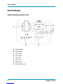 8
8
-
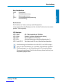 9
9
-
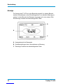 10
10
-
 11
11
-
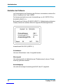 12
12
-
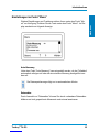 13
13
-
 14
14
-
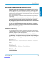 15
15
-
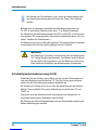 16
16
-
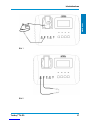 17
17
-
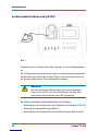 18
18
-
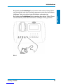 19
19
-
 20
20
-
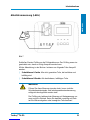 21
21
-
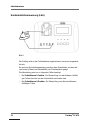 22
22
-
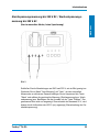 23
23
-
 24
24
-
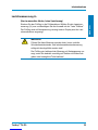 25
25
-
 26
26
-
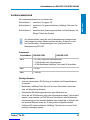 27
27
-
 28
28
-
 29
29
-
 30
30
-
 31
31
-
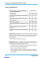 32
32
-
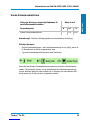 33
33
-
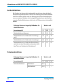 34
34
-
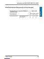 35
35
-
 36
36
-
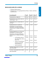 37
37
-
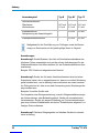 38
38
-
 39
39
-
 40
40
-
 41
41
-
 42
42
-
 43
43
-
 44
44
-
 45
45
-
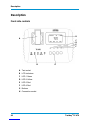 46
46
-
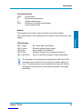 47
47
-
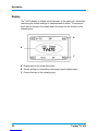 48
48
-
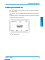 49
49
-
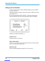 50
50
-
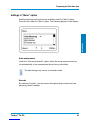 51
51
-
 52
52
-
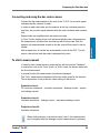 53
53
-
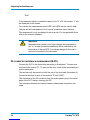 54
54
-
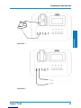 55
55
-
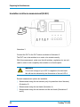 56
56
-
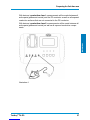 57
57
-
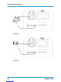 58
58
-
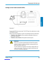 59
59
-
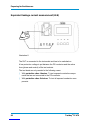 60
60
-
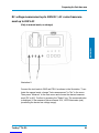 61
61
-
 62
62
-
 63
63
-
 64
64
-
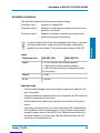 65
65
-
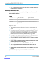 66
66
-
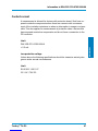 67
67
-
 68
68
-
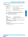 69
69
-
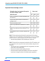 70
70
-
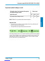 71
71
-
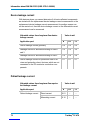 72
72
-
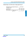 73
73
-
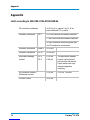 74
74
-
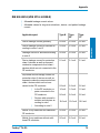 75
75
-
 76
76
-
 77
77
-
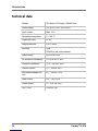 78
78
-
 79
79
-
 80
80
-
 81
81
-
 82
82
-
 83
83
-
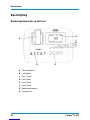 84
84
-
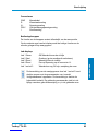 85
85
-
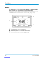 86
86
-
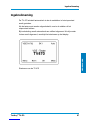 87
87
-
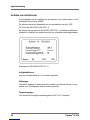 88
88
-
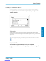 89
89
-
 90
90
-
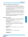 91
91
-
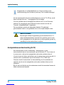 92
92
-
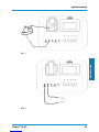 93
93
-
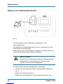 94
94
-
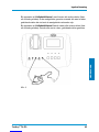 95
95
-
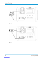 96
96
-
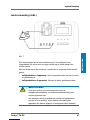 97
97
-
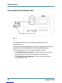 98
98
-
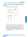 99
99
-
 100
100
-
 101
101
-
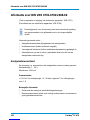 102
102
-
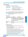 103
103
-
 104
104
-
 105
105
-
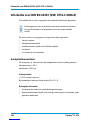 106
106
-
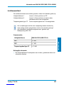 107
107
-
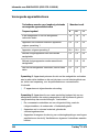 108
108
-
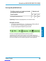 109
109
-
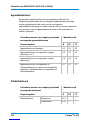 110
110
-
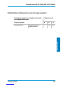 111
111
-
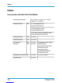 112
112
-
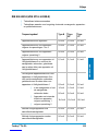 113
113
-
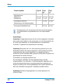 114
114
-
 115
115
-
 116
116
-
 117
117
-
 118
118
-
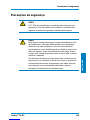 119
119
-
 120
120
-
 121
121
-
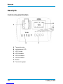 122
122
-
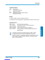 123
123
-
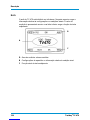 124
124
-
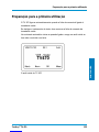 125
125
-
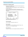 126
126
-
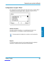 127
127
-
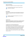 128
128
-
 129
129
-
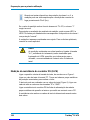 130
130
-
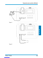 131
131
-
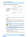 132
132
-
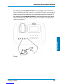 133
133
-
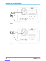 134
134
-
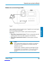 135
135
-
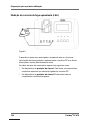 136
136
-
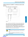 137
137
-
 138
138
-
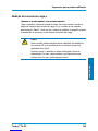 139
139
-
 140
140
-
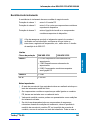 141
141
-
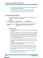 142
142
-
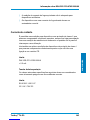 143
143
-
 144
144
-
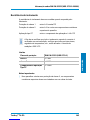 145
145
-
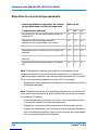 146
146
-
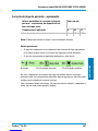 147
147
-
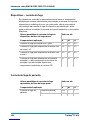 148
148
-
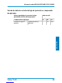 149
149
-
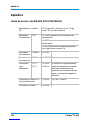 150
150
-
 151
151
-
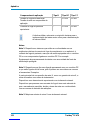 152
152
-
 153
153
-
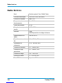 154
154
-
 155
155
-
 156
156
-
 157
157
-
 158
158
-
 159
159
-
 160
160


TESTBOY TV 470 Operating Instructions Manual
- Categorie
- Accessoires voor het maken van koffie
- Type
- Operating Instructions Manual
in andere talen
- English: TESTBOY TV 470
- Deutsch: TESTBOY TV 470
- português: TESTBOY TV 470
Gerelateerde papieren
Andere documenten
-
Benning 044141 Handleiding
-
POWERFIX KH 3322 de handleiding
-
Benning ST 710 de handleiding
-
Burmeier Westfalia Handleiding
-
Laserliner MultiMeter de handleiding
-
STIEBEL ELTRON DHB-E SLi Electronic Control Instantaneous Water Heater Handleiding
-
-
VOLTCRAFT ET-200 Operating Instructions Manual
-
-