STIEBEL ELTRON ETW 420 Plus Operation and Installation
- Type
- Operation and Installation

BEDIENUNG UND INSTALLATION
OPERATION AND INSTALLATION
UTILISATION ET INSTALLATION
GEBRUIK EN INSTALLATIE
OBSLUHA A INSTALACE
OBSŁUGA I INSTALACJA
Wärmespeicher | Storage heater | Radiateur à accumulation | Warmteaccumulator |
Akumulační kamna | Piece akumulacyjne
» ETS 200 Plus
» ETS 300 Plus
» ETS 400 Plus
» ETS 500 Plus
» ETS 600 Plus
» ETS 700 Plus

2 | ETS 200-700 Plus www.stiebel-eltron.com
INHALT
BESONDERE HINWEISE
BEDIENUNG
1. Allgemeine Hinweise ����������������������������������������3
1.1 Sicherheitshinweise ��������������������������������������������� 3
1.2 Andere Markierungen in dieser Dokumentation ���������� 4
1.3 Hinweise am Gerät ���������������������������������������������� 4
1.4 Maßeinheiten ����������������������������������������������������� 4
2. Sicherheit �����������������������������������������������������4
2.1 Bestimmungsgemäße Verwendung ������������������������� 4
2.2 Allgemeine Sicherheitshinweise ������������������������������ 4
2.3 Prüfzeichen ������������������������������������������������������� 5
3. Gerätebeschreibung �����������������������������������������5
4. Bedienung ����������������������������������������������������5
4.1 Bedieneinheit ����������������������������������������������������� 5
4.2 Wärmespeicherung ��������������������������������������������� 6
4.3 Wärmeabgabe ��������������������������������������������������� 7
5. Einstellungen �������������������������������������������������7
5.1 Standardanzeige ������������������������������������������������� 7
5.2 Basismenü �������������������������������������������������������� 7
5.3 Konfigurationsmenü �������������������������������������������� 7
6. Einstellungen bei vorhandenem wandmontierten
Raumtemperaturregler �������������������������������������� 9
6.1 Standardanzeige ������������������������������������������������� 9
6.2 Basismenü �������������������������������������������������������� 9
6.3 Konfigurationsmenü ������������������������������������������� 10
7. Reinigung, Pflege und Wartung �������������������������� 10
7.1 Reinigung des Flusensiebes ���������������������������������� 10
8. Problembehebung ����������������������������������������� 11
INSTALLATION
9. Sicherheit ��������������������������������������������������� 11
9.1 Allgemeine Sicherheitshinweise ����������������������������� 11
9.2 Vorschriften, Normen und Bestimmungen ���������������� 11
10. Gerätebeschreibung ��������������������������������������� 12
10.1 Wirkungsweise �������������������������������������������������� 12
10.2 Lieferumfang ����������������������������������������������������12
10.3 Zubehör �����������������������������������������������������������12
11. Vorbereitungen ��������������������������������������������� 12
11.1 Montageort ������������������������������������������������������12
11.2 Mindestabstände ����������������������������������������������� 13
12. Montage ����������������������������������������������������� 13
12.1 Gerät öffnen ����������������������������������������������������� 13
12.2 Aufladeregelung einstellen ����������������������������������� 14
12.3 Netzanschluss / Anschlussleitungen ������������������������ 14
12.4 Elektrischer Anschluss ����������������������������������������� 14
12.5 Montagevarianten ����������������������������������������������15
12.6 Speichersteine einsetzen �������������������������������������� 15
12.7 Säubern des Gerätes ������������������������������������������� 16
12.8 Gerät schließen ������������������������������������������������� 16
13. Einstellungen ����������������������������������������������� 17
13.1 Konfigurationsmenü ������������������������������������������� 17
14. Inbetriebnahme �������������������������������������������� 19
14.1 Kontrolle vor der Inbetriebnahme ��������������������������� 19
14.2 Erstinbetriebnahme �������������������������������������������� 19
15. Umbau des Gerätes ���������������������������������������� 19
16. Übergabe ���������������������������������������������������� 19
17. Störungsbehebung ����������������������������������������� 20
17.1 Störungstabelle �������������������������������������������������20
17.2 Symbole des Typenschildes ����������������������������������� 21
18. Wartung und Reinigung ����������������������������������� 21
19. Technische Daten ������������������������������������������� 22
19.1 Maße und Anschlüsse ����������������������������������������� 22
19.2 Elektroschaltplan �����������������������������������������������23
19.3 Anschlussleistung reduzieren �������������������������������� 24
19.4 Leistungsanpassung (Nennaufladedauer) �����������������24
19.5 Anschlussleistung reduzieren unter Beibehaltung
Nennaufladedauer 8Stunden �������������������������������� 24
19.6 Angaben zum Energieverbrauch ���������������������������� 25
19.7 Datentabelle ����������������������������������������������������� 25
KUNDENDIENST UND GARANTIE
UMWELT UND RECYCLING

DEUTSCH
www.stiebel-eltron.com ETS 200-700 Plus | 3
BESONDERE HINWEISE | BEDIENUNG
Allgemeine Hinweise
BESONDERE HINWEISE
- Bewahren Sie diese Bedienungs- und Instal-
lationsanleitung sorgfältig auf, damit sie bei
Bedarf zur Verfügung steht.
- Halten Sie Kinder unter 3Jahren von dem
Gerät fern, wenn keine ständige Beaufsichti-
gung gewährleistet ist.
- Das Gerät kann von 3- bis 7-jährigen Kin-
dern ein- und ausgeschaltet werden, wenn
sie beaufsichtigt werden oder bezüglich des
sicheren Gebrauchs des Gerätes unterwiesen
wurden und die daraus resultierenden Gefah-
ren verstanden haben. Voraussetzung hierfür
ist, dass das Gerät wie beschrieben montiert
wurde. 3- bis 7-jährige Kinder dürfen das
Gerät nicht regulieren.
- Das Gerät kann von Kindern ab 8Jahren sowie
von Personen mit verringerten physischen,
sensorischen oder mentalen Fähigkeiten oder
Mangel an Erfahrung und Wissen benutzt
werden, wenn sie beaufsichtigt werden oder
bezüglich des sicheren Gebrauchs des Gerätes
unterwiesen wurden und die daraus resultie-
renden Gefahren verstanden haben.
- Kinder dürfen nicht mit dem Gerät spielen.
Reinigung und Benutzer-Wartung dürfen
nicht von Kindern ohne Beaufsichtigung
durchgeführt werden.
- Teile des Gerätes können sehr heiß werden
und Verbrennungen verursachen. Wenn Kin-
der und schutzbedürftige Personen anwesend
sind, ist besondere Vorsicht geboten.
- Bei der ersten Aufladung kann eine Geruchs-
bildung auftreten. Sorgen Sie für eine ausrei-
chende Belüftung des Raumes.
- Halten Sie die Mindestabstände zu angren-
zenden Objektflächen oder sonstigen brenn-
baren Materialien ein (siehe Kapitel „Installa-
tion/ Mindestabstände“).
- Um eine Überhitzung des Gerätes zu vermei-
den, decken Sie das Gerät nicht ab.
- Legen Sie keine Gegenstände auf das Gerät
oder in dessen unmittelbare Nähe. Lehnen Sie
keine Gegenstände an das Gerät.
- Bringen Sie das Gerät nicht unmittelbar unter
einer Wandsteckdose an.
- Beachten Sie die Werte der Nennaufladung im
Kapitel „Technische Daten/ Datentabelle“.
- Bringen Sie das Gerät so an, dass die Schalt-
und Reglereinrichtungen nicht von einer in
der Badewanne oder unter der Dusche be-
findlichen Person berührt werden können.
- Der Anschluss an das Stromnetz ist nur als
fester Anschluss erlaubt. Das Gerät muss
über eine Trennstrecke von mindestens 3mm
allpolig vom Netzanschluss getrennt werden
können.
- Befestigen Sie das Gerät wie in Kapitel „In-
stallation/ Montage“ beschrieben.
BEDIENUNG
1. Allgemeine Hinweise
Die Kapitel „Besondere Hinweise“ und „Bedienung“ richten sich
an den Gerätebenutzer und den Fachhandwerker.
Das Kapitel „Installation“ richtet sich an den Fachhandwerker.
Hinweis
Lesen Sie diese Anleitung vor dem Gebrauch sorgfältig
durch und bewahren Sie sie auf.
Geben Sie die Anleitung ggf. an einen nachfolgenden
Benutzer weiter.
1.1 Sicherheitshinweise
1.1.1 Aufbau von Sicherheitshinweisen
SIGNALWORT Art der Gefahr
Hier stehen mögliche Folgen bei Nichtbeachtung des Si-
cherheitshinweises.
Hier stehen Maßnahmen zur Abwehr der Gefahr.

BEDIENUNG
Sicherheit
4 | ETS 200-700 Plus www.stiebel-eltron.com
1.1.2 Symbole, Art der Gefahr
Symbol Art der Gefahr
Verletzung
Stromschlag
Verbrennung
(Verbrennung, Verbrühung)
1.1.3 Signalworte
SIGNALWORT Bedeutung
GEFAHR Hinweise, deren Nichtbeachtung schwere Verletzungen
oder Tod zur Folge haben.
WARNUNG Hinweise, deren Nichtbeachtung schwere Verletzungen
oder Tod zur Folge haben kann.
VORSICHT Hinweise, deren Nichtbeachtung zu mittelschweren oder
leichten Verletzungen führen kann.
1.2 Andere Markierungen in dieser Dokumentation
Hinweis
Allgemeine Hinweise werden mit dem nebenstehenden
Symbol gekennzeichnet.
Lesen Sie die Hinweistexte sorgfältig durch.
Symbol Bedeutung
Sachschaden
(Geräte-, Folge-, Umweltschaden)
Geräteentsorgung
Dieses Symbol zeigt Ihnen, dass Sie etwas tun müssen.
Die erforderlichen Handlungen werden Schritt für Schritt
beschrieben.
1.3 Hinweise am Gerät
Symbol Bedeutung
Gerät nicht abdecken
1.4 Maßeinheiten
Hinweis
Wenn nicht anders angegeben, sind alle Maße in Milli-
meter.
2. Sicherheit
2.1 Bestimmungsgemäße Verwendung
Das Gerät dient zur Erwärmung von Wohnräumen.
Das Gerät ist für den Einsatz im häuslichen Umfeld vorgesehen.
Es kann von nicht eingewiesenen Personen sicher bedient wer-
den. In nicht häuslicher Umgebung, z.B. im Kleingewerbe, kann
das Gerät ebenfalls verwendet werden, sofern die Benutzung in
gleicher Weise erfolgt.
Eine andere oder darüber hinausgehende Benutzung gilt als nicht
bestimmungsgemäß. Zum bestimmungsgemäßen Gebrauch ge-
hört auch das Beachten dieser Anleitung sowie der Anleitungen
für eingesetztes Zubehör.
2.2 Allgemeine Sicherheitshinweise
Beachten Sie die nachfolgenden Sicherheitshinweise und Vor-
schriften.
- Die Elektroinstallation und die Installation des Gerätes dür-
fen nur von einem Fachhandwerker oder von unseren Kun-
dendienst-Technikern entsprechend dieser Anleitung durch-
geführt werden.
- Der Fachhandwerker ist bei der Installation und der Erstinbe-
triebnahme verantwortlich für die Einhaltung der geltenden
Vorschriften.
- Betreiben Sie das Gerät nur komplett installiert und mit allen
Sicherheitseinrichtungen.
WARNUNG Verletzung
- Halten Sie Kinder unter 3Jahren von dem Gerät
fern, wenn keine ständige Beaufsichtigung gewähr-
leistet ist.
- Das Gerät kann von 3- bis 7-jährigen Kindern ein-
und ausgeschaltet werden, wenn sie beaufsichtigt
werden oder bezüglich des sicheren Gebrauchs
des Gerätes unterwiesen wurden und die daraus
resultierenden Gefahren verstanden haben. Voraus-
setzung hierfür ist, dass das Gerät wie beschrieben
montiert wurde. 3- bis 7-jährige Kinder dürfen das
Gerät nicht regulieren.
- Das Gerät kann von Kindern ab 8Jahren sowie von
Personen mit verringerten physischen, sensorischen
oder mentalen Fähigkeiten oder Mangel an Erfah-
rung und Wissen benutzt werden, wenn sie beauf-
sichtigt werden oder bezüglich des sicheren Ge-
brauchs des Gerätes unterwiesen wurden und die
daraus resultierenden Gefahren verstanden haben.
- Kinder dürfen nicht mit dem Gerät spielen. Reini-
gung und Benutzer-Wartung dürfen nicht von Kin-
dern ohne Beaufsichtigung durchgeführt werden.

BEDIENUNG
Gerätebeschreibung
DEUTSCH
www.stiebel-eltron.com ETS 200-700 Plus | 5
WARNUNG Verbrennung
Betreiben Sie das Gerät nicht ...
- wenn die Mindestabstände zu angrenzenden Ob-
jektflächen oder sonstigen brennbaren Materialien
unterschritten werden.
- in Räumen, die durch Chemikalien, Staub, Gase oder
Dämpfe feuer- oder explosionsgefährdet sind. Lüf-
ten Sie den Raum vor der Aufladung ausreichend.
- in unmittelbarer Nähe von Rohrleitungen oder Be-
hältnissen, die brennbare oder explosionsgefährde-
te Stoffe führen oder enthalten.
- wenn im Aufstellraum Arbeiten wie Verlegen,
Schleifen, Versiegeln, durchgeführt werden.
- wenn ein Gerätebauteil beschädigt ist oder eine
Fehlfunktion vorliegt.
WARNUNG Verbrennung
- Legen Sie keine brennbaren, entzündbaren oder
wärmedämmenden Gegenstände oder Stoffe auf
das Gerät oder in dessen unmittelbare Nähe. Leh-
nen Sie keine Gegenstände an das Gerät. Dadurch
kann Stauwärme entstehen, die zu einer überhöh-
ten Temperatur der Gehäuseoberfläche und der
Gegenstände führt.
- Achten Sie darauf, dass Lufteintritt und -austritt
nicht blockiert werden.
- Stecken Sie keine Gegenstände zwischen Gerät und
Wand.
VORSICHT Verbrennung
Die Gehäuseoberflächen des Gerätes und die austreten-
de Luft können bei Betrieb sehr heiß (über 80°C) wer-
den und Verbrennungen verursachen. Wenn Kinder und
schutzbedürftige Personen anwesend sind, ist besonde-
re Vorsicht geboten.
WARNUNG Überhitzung
Um eine Überhitzung des Gerätes zu vermeiden, decken
Sie das Gerät nicht ab.
2.3 Prüfzeichen
Siehe Typenschild am Gerät. Das Typenschild befindet sich auf der
linken Seitenwand des Gerätes.
3. Gerätebeschreibung
Mit diesem Gerät wird elektrisch erzeugte Wärme gespeichert. Die
elektrische Wärme wird während der Freigabezeiten von preis-
günstigem Niedertarifstrom erzeugt.
Die Freigabezeiten hängen vom jeweiligen Elektrizitäts-Versor-
gungs-Unternehmen (EVU) ab. Die freigegebenen Zeiten liegen
überwiegend in den Nachtstunden.
Die gespeicherte Wärme wird entsprechend der gewünschten
Raumtemperatur als Warmluft über ein Gebläse sowie zu einem
geringen Anteil auch über die Geräteoberfläche in den Raum ab-
gegeben.
4. Bedienung
D0000074968
1
1 Bedieneinheit
4.1 Bedieneinheit
Die Bedienung erfolgt über die Bedieneinheit, die sich rechts oben
in der Gerätefront befindet.
Made in Germany
D0000074970
2
1
1 Anzeige
2 Bedienfeld
4.1.1 Bedienfeld
Taste Benennung Beschreibung
Taste „Lüfter“
Gebläsefreigabe ein- und ausschalten
Taste „OK“
Auswahl;
Einstellungen bestätigen
Taste „Menü“
Menü aufrufen und verlassen
Taste „+“
Menüpunkte aufrufen;
Einstellungen ändern
Taste „–“ Menüpunkte aufrufen;
Einstellungen ändern

BEDIENUNG
Bedienung
6 | ETS 200-700 Plus www.stiebel-eltron.com
4.1.2 Anzeige
Wenn 20Sekunden lang keine Bedieneraktion erfolgt, schaltet sich
die Hintergrundbeleuchtung aus. Durch Drücken einer beliebigen
Taste schalten Sie die Hintergrundbeleuchtung wieder ein.
Symbole
Hinweis
Wenn die Wärmeabgabe (Entladung) über einen wand-
montierten Raumtemperaturregler geregelt wird, wer-
den nicht alle Symbole angezeigt.
Symbol Beschreibung
Uhrzeitanzeige:
Anzeige der aktuellen Uhrzeit oder eines programmierten Start-
zeitpunktes
Timer-Betrieb:
Das Gerät heizt entsprechend dem aktivierten Zeitprogramm.
Komfortbetrieb:
Das Gerät hält die eingestellte Komforttemperatur.
Standardwert: 21,0°C. Nutzen Sie diese Einstellung für komforta-
ble Raumtemperaturen bei Anwesenheit.
Absenkbetrieb:
Das Gerät hält die eingestellte Absenktemperatur.
Standardwert: 18,0°C. Nutzen Sie diese Einstellung z.B. nachts
oder bei Abwesenheit für einige Stunden.
Adaptiver Start:
Im Timer-Betrieb werden die Schaltzeiten des Heizgerätes so
angepasst, dass die jeweils eingestellte Raum-Soll-Temperatur
bereits zum programmierten Startzeitpunkt erreicht wird.
Voraussetzung: Die Funktion „Adaptiver Start“ ist eingeschaltet
(siehe Kapitel „Einstellungen/ Basismenü“).
Fenster-offen-Erkennung:
Um einen unnötigen Energieverbrauch während des Lüftens zu
vermeiden, senkt das Gerät bei geöffnetem Fenster automatisch
für eine Stunde die eingestellte Raum-Soll-Temperatur auf 7,0°C
ab. Das Symbol „Fenster-offen-Erkennung“ blinkt. Sie können die
Fenster-offen-Erkennung nach dem Lüften mit der Taste „+“ oder
„OK“ manuell beenden. Das Gerät heizt wieder auf die eingestell-
te Raum-Soll-Temperatur.
Voraussetzung: Die Fenster-offen-Erkennung ist eingeschaltet
(siehe Kapitel „Einstellungen/ Basismenü“).
Bediensperre:
Zum Sperren oder Entsperren des Bedienfeldes halten Sie die
Tasten „+“ und „–“ gleichzeitig 5Sekunden lang gedrückt.
Zusatzheizung (Zubehör) freigegeben:
Wenn die Speicherwärmemenge zum Beheizen eines Raumes
nicht mehr ausreicht, heizt die Zusatzheizung ergänzend.
Anzeige Raumtemperatur
Gebläsefreigabe aktiv:
Wenn die Raumtemperatur unter die eingestellte Raum-Soll-Tem-
peratur sinkt, schaltet das Gebläse ein und gibt erwärmte Luft an
den Raum ab, bis die eingestellte Temperatur erreicht ist.
Parameter editierbar:
Der angezeigte Parameter kann mit den Tasten „+“ und „–“ ver-
ändert werden.
Wochentage:
1=Montag, 2=Dienstag … 7=Sonntag
4.2 Wärmespeicherung
Über die Aufladeregelung wird der Grad der Wärmespeicherung
(Aufladung) bestimmt.
Welche Einstellungen Sie an der Aufladeregelung vornehmen
müssen, ist davon abhängig, ob Sie ein Gerät mit oder ohne zen-
trale witterungsgeführte Aufladesteuerung einsetzen.
Die witterungsgeführte Aufladesteuerung befindet sich im Schalt-
schrank.
4.2.1 Geräte mit witterungsgeführter Aufladesteuerung
Rufen Sie mit der Taste „Menü“ das Basismenü auf und drü-
cken Sie die Taste „OK“.
Sobald das Symbol „Parameter editierbar“ erscheint, stellen
Sie mit den Tasten „+“ und „–“ den Ladegradabschwächer
auf 100% ein.
Hinweis
Wenn die Wärmeabgabe (Entladung) über einen wand-
montierten Raumtemperaturregler geregelt wird, stellen
Sie in der Standardanzeige den Ladegradabschwächer
mit den Tasten „+“ und „–“ ein.
Die witterungsgeführte Aufladesteuerung sorgt für die richtige
Aufladung.
Hinweis
Beachten Sie hierzu die Anleitung der Aufladesteuerung
oder des Gruppensteuergerätes.
Zur unterschiedlichen Regelung einzelner Geräte können Sie über
den Ladegradabschwächer zusätzlich eine manuelle Anpassung
der Auflademenge vornehmen.
Wenn Sie den Ladegradabschwächer auf 0 % einstellen, erfolgt
keine Aufladung.
4.2.2 Geräte ohne witterungsgeführte Aufladesteuerung
Die Auflademenge wird über den Ladegradabschwächer einge-
stellt.
Rufen Sie mit der Taste „Menü“ das Basismenü auf und drü-
cken Sie die Taste „OK“.
Sobald das Symbol „Parameter editierbar“ erscheint, stellen
Sie mit den Tasten „+“ und „–“ den Ladegradabschwächer
ein.
Hinweis
Wenn die Wärmeabgabe (Entladung) über einen wand-
montierten Raumtemperaturregler geregelt wird, stellen
Sie in der Standardanzeige den Ladegradabschwächer
mit den Tasten „+“ und „–“ ein.

BEDIENUNG
Einstellungen
DEUTSCH
www.stiebel-eltron.com ETS 200-700 Plus | 7
Dabei gelten folgende Richtwerte:
Wert Auflademenge
0 % keine Aufladung (im Sommer)
30 % ca. 1/3 der Vollaufladung für Übergangszeiten wie Frühling oder
Herbst
70 % ca. 2/3 der Vollaufladung für milde Wintertage
100 % Vollaufladung für kalte Wintertage
Nach kurzer Eingewöhnung werden Sie über die nötige Erfahrung
verfügen, um die jeweils richtige Einstellung zu finden.
4.3 Wärmeabgabe
Die Wärmeabgabe (Entladung) wird über den im Gerät inte-
grierten Raumtemperaturregler oder einen wandmontierten
2-Punkt-Raumtemperaturregler (siehe Kapitel „Zubehör“) gere-
gelt.
Der Raumtemperaturregler regelt automatisch die Wärmeabgabe
über das Gebläse, sodass die eingestellte Raum-Soll-Temperatur
gehalten wird. Damit das Gebläse laufen kann, muss die Geblä-
sefreigabe eingeschaltet sein.
Hinweis
Bei mehrtägiger Abwesenheit in der Heizperiode ist es
sinnvoll eine reduzierte Raumtemperatur von z.B. 10°C
einzustellen. Durch diese Einstellung vermeiden Sie, dass
der Raum zu stark auskühlt (Frostschutz).
4.3.1 Gebläsefreigabe ein- und ausschalten
Um die Gebläsefreigabe ein- und auszuschalten, drücken Sie
die Taste „Lüfter“. Bei eingeschalteter Gebläsefreigabe wird
in der Anzeige das „Lüftersymbol“ angezeigt.
5. Einstellungen
5.1 Standardanzeige
D0000074972
Die Standardanzeige wird dauerhaft angezeigt. Wenn Sie sich in-
nerhalb des Menüs befinden und länger als 20Sekunden keine
Bedieneraktion ausführen, wechselt das Gerät automatisch zur
Standardanzeige.
In der Standardanzeige sehen Sie die aktuelle Raum-Soll-Tempe-
ratur sowie das Symbol „Parameter editierbar“. Über die Tasten
„+“ und „–“ können Sie die Raum-Soll-Temperatur verändern.
Wenn die eingestellte Raum-Soll-Temperatur einem der einge-
stellten Werte für Komfort- oder Absenktemperatur entspricht,
erscheint in der Menüleiste das Symbol der entsprechenden Be-
triebsart (Komfortbetrieb, Absenkbetrieb).
Die Raum-Soll-Temperatur kann auch im Timer-Betrieb manuell
geändert werden. Die geänderte Raum-Soll-Temperatur bleibt bis
zum nächsten programmierten Schaltzeitpunkt erhalten.
5.2 Basismenü
Um in das Basismenü zu gelangen, drücken Sie kurz die Taste
„Menü“. Sie können nun folgende Menüpunkte aufrufen:
Anzeige Beschreibung
Ladegradabschwächer einstellen
Für die Tage, an denen ein geringerer Wärmebedarf besteht,
können Sie eine manuelle Anpassung der Auflademenge in
10% Schritten vornehmen.
Wochentag und Uhrzeit einstellen
Komforttemperatur einstellen
Die Komforttemperatur muss mindestens 0,5°C höher einge-
stellt sein als die Absenktemperatur.
Absenktemperatur einstellen
Funktion „Fenster-offen-Erkennung“ ein- und ausschalten
Zeitprogramm (Pro1, Pro2, Pro3) auswählen oder deaktivie-
ren (off)
Funktion „Adaptiver Start“ ein- und ausschalten
Zusatzheizung (Zubehör) ein- und ausschalten
Wenn Sie die Einstellung eines Menüpunktes ändern möchten,
rufen Sie den entsprechenden Menüpunkt mit den Tasten „+“ und
„–“ auf. Drücken Sie die Taste „OK“.
Sobald das Symbol „Parameter editierbar“ erscheint, können Sie
mit den Tasten „+“ und „–“ die Einstellung des Menüpunktes än-
dern. Um die Einstellungen zu speichern, drücken Sie die Taste
„OK“.
Um das Basismenü zu verlassen, drücken Sie die Taste „Menü“.
Die Standardanzeige erscheint.
5.3 Konfigurationsmenü
Anzeige Beschreibung
I1-I2 Ist-Werte
Pro1-Pro3 Zeitprogramme
P1-P5 Parameter
CodE Fachhandwerker-Zugang
Im Konfigurationsmenü können Sie Ist-Werte aufrufen, die Zeit-
programme für den Timer-Betrieb programmieren und Parameter
einstellen.

BEDIENUNG
Einstellungen
8 | ETS 200-700 Plus www.stiebel-eltron.com
Um in das Konfigurationsmenü zu gelangen, halten Sie die Taste
„Menü“ gedrückt. Nach ca.3Sekunden wird der Ist-WertI1 an-
gezeigt.
Mit den Tasten „+“ und „–“ können Sie zwischen den einzelnen
Ist-Werten, Zeitprogrammen und Parametern wechseln.
Um das Konfigurationsmenü zu verlassen, drücken Sie die Taste
„Menü“. Die Standardanzeige erscheint.
5.3.1 Ist-Werte
Sie können folgende Ist-Werte aufrufen:
Anzeige Beschreibung Einheit
I1 Ist-Wert Raumtemperatur [°C] | [°F]
I2
Relative Heizdauer
(Über den Parameter P5 können Sie den Zähler
zurücksetzen.)
[h]
Hinweis
Der Zähler für die relative Heizdauer(I2) zählt die Zeit
der Aufladung in vollen Betriebsstunden. Wenn das Gerät
eine volle Stunde, auch abschnittsweise, aufgeladen
wurde, wird der Zähler erhöht.
5.3.2 Zeitprogramme
Für die Verwendung des Gerätes im Timer-Betrieb stehen Ihnen
drei Zeitprogramme zur Verfügung. Die Zeitprogramme Pro1 und
Pro2 sind werkseitig vorkonfiguriert. Das Zeitprogramm Pro3 kön-
nen Sie nach Ihren individuellen Bedürfnissen einstellen.
Anzeige Beschreibung
Pro1 Zeitprogramm „täglich“
- Wiederholung: Montag bis Sonntag
Pro2 Zeitprogramm „werktags“
- Wiederholung: Montag bis Freitag
Pro3 Zeitprogramm „benutzerdefiniert“
- bis zu 14Komfortphasen frei konfigurierbar
Hinweis
Wenn Sie den Timer-Betrieb nutzen möchten, müssen Sie
im Basismenü das gewünschte Zeitprogramm auswählen
(siehe Kapitel „Einstellungen/ Basismenü“).
Hinweis
Beachten Sie beim Einstellen der Zeitprogramme, dass
Wochentag und Uhrzeit korrekt eingestellt sind.
Hinweis
Für alle Zeitprogramme (Pro1, Pro2, Pro3) gilt:
Wenn der Endzeitpunkt nach 23:59 Uhr liegt, wird der
Endzeitpunkt automatisch auf den nächsten Wochentag
gelegt. Die Komfortphase wird über Mitternacht gehalten
und endet am folgenden Wochentag zum eingestellten
Endzeitpunkt.
Zeitprogramme Pro1 und Pro2
Mit den ZeitprogrammenPro1 und Pro2 können Sie den Start- und
Endzeitpunkt des Komfortbetriebs festlegen. In dieser Zeitspanne
heizt das Gerät auf die eingestellte Komforttemperatur. Außerhalb
dieser festgelegten Zeitspanne arbeitet das Gerät im Absenkbe-
trieb. Daraus ergeben sich eine Komfort- und eine Absenkphase,
die sich täglich(Pro1) bzw. an jedem Werktag(Pro2) wiederholen.
Werkseitig sind diese Phasen wie folgt konfiguriert:
- 08:00Uhr - 22:00Uhr: Komfortbetrieb
- 22:00Uhr - 08:00Uhr: Absenkbetrieb
Hinweis
Bei aktiviertem ZeitprogrammPro2 arbeitet das Gerät am
Wochenende ausschließlich im Absenkbetrieb.
Um die ZeitprogrammePro1 und Pro2 Ihren Bedürfnissen entspre-
chend anzupassen, gehen Sie folgendermaßen vor:
Rufen Sie im Konfigurationsmenü mit den Tasten „+“ und „–“
das gewünschte Zeitprogramm auf.
Drücken Sie die Taste „OK“.
Der Startzeitpunkt für den Komfortbetrieb wird angezeigt.
Stellen Sie den gewünschten Startzeitpunkt mit den Tasten
„+“ und „–“ ein.
Drücken Sie die Taste „OK“.
Der Endzeitpunkt für den Komfortbetrieb wird angezeigt.
Stellen Sie den gewünschten Endzeitpunkt mit den Tasten „+“
und „–“ ein.
Drücken Sie zum Speichern die Taste „OK“.
Zeitprogramm Pro3
Mit dem ZeitprogrammPro3 können Sie bis zu 14 separate Kom-
fortphasen festlegen, die sich wöchentlich wiederholen.
Um im ZeitprogrammPro3 eine Komfortphase zu konfigurieren,
gehen Sie folgendermaßen vor:
Rufen Sie im Konfigurationsmenü mit den Tasten „+“ und „–“
das ZeitprogrammPro3 auf.
Drücken Sie die Taste „OK“.
Die Anzeige zeigt „3---“.
Drücken Sie die Taste „OK“.
Ein Wochentag bzw. eine Gruppe von Wochentagen wird
angezeigt.
Stellen Sie den gewünschten Wochentag bzw. die gewünsch-
te Gruppe von Wochentagen mit den Tasten „+“ und „–“ ein.
Drücken Sie die Taste „OK“.
Der Startzeitpunkt für den Komfortbetrieb wird angezeigt.
Stellen Sie den gewünschten Startzeitpunkt mit den Tasten
„+“ und „–“ ein.
Drücken Sie die Taste „OK“.
Der Endzeitpunkt für den Komfortbetrieb wird angezeigt.
Stellen Sie den gewünschten Endzeitpunkt mit den Tasten „+“
und „–“ ein.
Drücken Sie die Taste „OK“.
Die Komfortphase „3-01“ ist konfiguriert.

BEDIENUNG
Einstellungen bei vorhandenem wandmontierten Raumtemperaturregler
DEUTSCH
www.stiebel-eltron.com ETS 200-700 Plus | 9
Um eine weitere Komfortphase zu konfigurieren, wählen Sie
im ZeitprogrammPro3 mit den Tasten „+“ und „–“ die Anzei-
ge „3---“. Gehen Sie wie beschrieben vor.
Hinweis
Um die eingestellten Komfortphasen zurückzusetzen,
aktivieren Sie den ParameterP4.
Beachten Sie, dass durch Aktivieren des Parame-
tersP4 alle Zeitprogramme (Pro1, Pro2, Pro3) in den
Auslieferungszustand zurückgesetzt werden.
5.3.3 Parameter
Sie können folgende Parameter aufrufen:
Anzeige Beschreibung Optionen
P1 Offset Raumtemperatur ±3°C | ±5°F
P2 Uhrzeitformat 12h | 24h
P3 Einheit Temperaturanzeige °C | °F
P4 Zeitprogramme (Timer-Betrieb) zurücksetzen. on | off
P5 Relative Heizdauer zurücksetzen on | off
Wenn Sie den Wert eines Parameters ändern möchten, rufen Sie
den entsprechenden Parameter mit den Tasten „+“ und „–“ auf.
Drücken Sie die Taste „OK“.
Sobald das Symbol „Parameter editierbar“ erscheint, können Sie
mit den Tasten „+“ und „–“ den Wert des Parameters ändern. Um
den eingestellten Wert zu speichern, drücken Sie die Taste „OK“.
P1: Offset Raumtemperatur
Eine ungleichmäßige Temperaturverteilung im Raum kann zu
einer Differenz zwischen der angezeigten Ist-TemperaturI1 und
der von Ihnen gemessenen Raumtemperatur führen. Um die
Differenz auszugleichen, können Sie über den ParameterP1 ein
Raumtemperatur-Offset von ±3°C einstellen.
Beispiel: Das Gerät zeigt I1=21,0°C. Die von Ihnen gemessene
Raumtemperatur beträgt 20,0°C. Es besteht eine Differenz von
1,0°C.
Um die Differenz auszugleichen, stellen Sie einen Offset von
P1=-1,0 ein.
P2: Uhrzeitformat
Über den ParameterP2 können Sie festlegen, ob die Uhrzeit im
12-Stunden- oder im 24-Stunden-Format angezeigt wird.
P3: Einheit Temperaturanzeige
Über den ParameterP3 können Sie festlegen, ob die Raumtempe-
ratur in Grad Celsius [°C] oder in Grad Fahrenheit [°F] angezeigt
wird.
P4: Zeitprogramme zurücksetzen
Durch Aktivieren des ParametersP4 setzen Sie alle Zeitprogramme
in den Auslieferungszustand zurück.
P5: Relative Heizdauer zurücksetzen
Durch Aktivieren des ParametersP5 setzen Sie den Zähler für die
relative Heizdauer (I2) zurück.
5.3.4 Fachhandwerker-Zugang
Anzeige Beschreibung
CodE Fachhandwerker-Zugang
Hinweis
Einige Menüpunkte sind durch einen Code geschützt und
können nur durch einen Fachhandwerker eingesehen und
eingestellt werden.
6. Einstellungen bei
vorhandenem wandmontierten
Raumtemperaturregler
Hinweis
Wenn Sie die Wärmeabgabe (Entladung) über einen
wandmontierten Raumtemperaturregler regeln, stehen
Ihnen am Gerät nur sehr eingeschränkte Einstellmöglich-
keiten zur Verfügung.
6.1 Standardanzeige
D0000074973
Die Standardanzeige wird dauerhaft angezeigt. Wenn Sie sich in-
nerhalb des Menüs befinden und länger als 20Sekunden keine
Bedieneraktion ausführen, wechselt das Gerät automatisch zur
Standardanzeige.
In der Standardanzeige sehen Sie die aktuelle Einstellung des
Ladegradabschwächers sowie das Symbol „Parameter editierbar“.
Über die Tasten „+“ und „–“ können Sie für die Tage, an denen ein
geringerer Wärmebedarf besteht eine manuelle Anpassung der
Auflademenge in 10% Schritten vornehmen.
6.2 Basismenü
Hinweis
Sie können das Basismenü nur aufrufen, wenn Ihr Gerät
mit einer Zusatzheizung (Zubehör) ausgestattet ist.
Um in das Basismenü zu gelangen, drücken Sie kurz die Taste
„Menü“.
Anzeige Beschreibung
Zusatzheizung (Zubehör) ein- und ausschalten
Auch bei einem wandmontierten Raumtemperaturregler mit
Zusatzheizungsschalter muss die Zusatzheizung im Basisme-
nü eingeschaltet sein.
Wenn Sie die Einstellung des Menüpunktes ändern möchten, drü-
cken Sie die Taste „OK“.

BEDIENUNG
10 | ETS 200-700 Plus www.stiebel-eltron.com
Sobald das Symbol „Parameter editierbar“ erscheint, können Sie
mit den Tasten „+“ und „–“ die Einstellung des Menüpunktes än-
dern. Um die Einstellung zu speichern, drücken Sie die Taste „OK“.
Um das Basismenü zu verlassen, drücken Sie die Taste „Menü“.
Die Standardanzeige erscheint.
6.3 Konfigurationsmenü
Anzeige Beschreibung
I2 Ist-Wert
P5 Parameter
CodE Fachhandwerker-Zugang
Um in das Konfigurationsmenü zu gelangen, halten Sie die Taste
„Menü“ gedrückt. Nach ca.3Sekunden wird der Ist-WertI2 an-
gezeigt.
Mit den Tasten „+“ und „–“ können Sie zwischen dem Ist-Wert und
dem Parameter wechseln.
Um das Konfigurationsmenü zu verlassen, drücken Sie die Taste
„Menü“. Die Standardanzeige erscheint.
6.3.1 Ist-Wert
Anzeige Beschreibung Einheit
I2
Relative Heizdauer
(Über den Parameter P5 können Sie den Zähler
zurücksetzen.)
[h]
Hinweis
Der Zähler für die relative Heizdauer(I2) zählt die Zeit
der Aufladung in vollen Betriebsstunden. Wenn das Gerät
eine volle Stunde, auch abschnittsweise, aufgeladen
wurde, wird der Zähler erhöht.
6.3.2 Parameter
Anzeige Beschreibung Optionen
P5
Relative Heizdauer zurücksetzen
Durch Aktivieren des Parameters setzen Sie den
Zähler für die relative Heizdauer (I2) zurück.
on | off
Wenn Sie die Einstellung des Parameters ändern möchten, drü-
cken Sie die Taste „OK“.
Sobald das Symbol „Parameter editierbar“ erscheint, können Sie
mit den Tasten „+“ und „–“ die Einstellung des Parameters ändern.
Um die Einstellung zu speichern, drücken Sie die Taste „OK“.
6.3.3 Fachhandwerker-Zugang
Anzeige Beschreibung
CodE Fachhandwerker-Zugang
Hinweis
Einige Menüpunkte sind durch einen Code geschützt und
können nur durch einen Fachhandwerker eingesehen und
eingestellt werden.
7. Reinigung, Pflege und Wartung
Sachschaden
- Sprühen Sie kein Reinigungsspray in die Luftschlitze.
- Achten Sie darauf, dass keine Feuchtigkeit in das
Gerät eindringt.
- Wenn am Gerätegehäuse leichte bräunliche Verfärbungen
auftreten, reiben Sie sie mit einem feuchten Tuch ab.
- Reinigen Sie das Gerät im abgekühlten Zustand mit ge-
bräuchlichen Pflegemitteln. Vermeiden Sie scheuernde und
ätzende Pflegemittel.
7.1 Reinigung des Flusensiebes
Hinweis
Reinigen Sie das hinter dem Lufteintritt sitzende Flusen-
sieb regelmäßig. Damit gewährleisten Sie eine störungs-
freie Entladung des Gerätes. Schalten Sie bei zugesetztem
Flusensieb die Lüfter ab.
D0000074981
Reinigen Sie das hinter dem Lufteintritt sitzende Flusensieb
mit einem Staubsauger.

DEUTSCH
www.stiebel-eltron.com ETS 200-700 Plus | 11
BEDIENUNG | INSTALLATION
Problembehebung
8. Problembehebung
Problem Ursache Behebung
Das Gerät wird nicht
warm.
Es wurde keine oder eine
zu geringe Aufladung
eingestellt.
Stellen Sie eine höhere
Aufladung ein.
Temperatur am Gerät ist
zu niedrig eingestellt.
Prüfen Sie die einge-
stellte Raumtemperatur.
Regeln Sie ggf. nach.
Die Gebläsefreigabe ist
ausgeschaltet.
Schalten Sie die Gebläse-
freigabe ein.
Fehlende Spannungsver-
sorgung.
Prüfen Sie die Sicherung
und den FI-Schalter in
der Hausinstallation.
Der Raum wird nicht aus-
reichend warm, obwohl
das Gerät heiß wird.
Überhitzung. Der Si-
cherheitstemperatur-
begrenzer begrenzt die
Heizleistung.
Beseitigen Sie die Ursa-
che (Schmutz oder Hin-
dernisse am Luftein- oder
Luftaustritt). Beachten
Sie die Mindestabstände!
Der Wärmebedarf des
Raumes ist höher als die
Leistung des Gerätes.
Beseitigen Sie Wärme-
verluste (Schließen Sie
Fenster und Türen. Ver-
meiden Sie Dauerlüften.)
Das Gerät hat auch bei
milder Witterung eine zu
hohe Wärmeabgabe.
Die Einstellung an Auf-
ladesteuerung und/oder
Aufladeregler ist falsch.
Passen Sie die Einstellun-
gen an.
Der Raum wird zu warm.
Temperatur am Gerät ist
zu hoch eingestellt.
Prüfen Sie die einge-
stellte Raumtemperatur.
Regeln Sie ggf. nach.
Das Gerät entlädt nicht. Das Flusensieb ist ver-
stopft.
Siehe Kapitel „Reinigung,
Pflege und Wartung“.
Die Fenster-offen-Erken-
nung reagiert nicht.
Das Gerät erkennt keinen
deutlichen Temperatur-
abfall durch Lüften. (Die
Fenster-offen-Erkennung
setzt eine zuvor stabile
Raumtemperatur voraus.)
Warten Sie nach Ein-
stellungen am Gerät
eine Weile, bis sich die
Raumtemperatur voll-
ständig stabilisiert hat.
Vermeiden Sie Hindernis-
se für den Luftaustausch
zwischen Gerät und
Raumluft.
Sperren Sie das Gebläse
für die Dauer des Lüftens.
Die Fenster-offen-Erken-
nung ist nicht aktiviert.
Schalten Sie im Basisme-
nü die Fenster-offen-Er-
kennung ein.
Die Funktion „Adaptiver
Start“ arbeitet nicht wie
gewünscht.
Die Funktion wirkt sich
nur im Timer-Betrieb
aus.
Nutzen Sie den
Timer-Betrieb für opti-
mierten Heizkomfort.
Die Raumtemperatur
schwankt stark bzw. der
Lernvorgang des Gerätes
ist nicht abgeschlossen.
Warten Sie einige Tage,
bis sich das Verhalten
stabilisiert hat.
Die Funktion „Adaptiver
Start“ ist nicht aktiviert.
Schalten Sie im Basisme-
nü die Funktion „Adapti-
ver Start“ ein.
Die Anzeige zeigt „E1“,
„E2“ oder „E3“.
Ein interner Fehler wurde
erkannt.
Informieren Sie den
Fachhandwerker.
Hinweis
Änderungen oder Behebungen an der Aufladesteuerung
machen sich erst nach erneuter Aufladung bemerkbar.
Wenn Sie die Ursache nicht beheben können, rufen Sie den Fach-
handwerker. Zur besseren und schnelleren Hilfe teilen Sie ihm die
Nummer vom Typenschild mit (000000-0000-000000).
INSTALLATION
9. Sicherheit
Die Installation, Inbetriebnahme sowie Wartung und Reparatur
des Gerätes darf nur von einem Fachhandwerker durchgeführt
werden.
9.1 Allgemeine Sicherheitshinweise
Wir gewährleisten eine einwandfreie Funktion und Betriebssicher-
heit nur, wenn das für das Gerät bestimmte Original-Zubehör und
die originalen Ersatzteile verwendet werden.
9.2 Vorschriften, Normen und Bestimmungen
WARNUNG Stromschlag
Führen Sie alle elektrischen Anschluss- und Installati-
onsarbeiten nach Vorschrift aus.
WARNUNG Stromschlag
Der Anschluss an das Stromnetz ist nur als fester An-
schluss möglich.
Das Gerät muss über eine Trennstrecke von mindestens
3mm allpolig vom Netzanschluss getrennt werden kön-
nen.
Sachschaden
Beachten Sie das Typenschild. Die angegebene Spannung
muss mit der Netzspannung übereinstimmen.
Legen Sie die Betriebsmittel auf die Nennaufnahme der
Geräte aus.
Sachschaden
Befestigen Sie das Gerät so an Wand oder Boden, dass
die Standsicherheit gewährleistet ist.
Sachschaden
- Montieren Sie das Gerät nicht unmittelbar unter
einer Wandsteckdose.
- Achten Sie darauf, dass das Anschlusskabel keine
Geräteteile berührt.
Sachschaden
Beachten Sie alle nationalen und regionalen Vorschriften
und Bestimmungen.

INSTALLATION
Gerätebeschreibung
12 | ETS 200-700 Plus www.stiebel-eltron.com
10. Gerätebeschreibung
26�07�27�0022
10
9
8
7
6
5
1
2
4
3
1 Abdeckblech
2 Heizkörper
3 Raumtemperaturfühler
4 Gebläse (M1)
5 Schutz-Temperaturregler (N5)
6 Lufteintritt
7 Luftaustritt
8 Dämmung
9 Speichersteine
10 Vorderwand und innere Vorderwand
10.1 Wirkungsweise
Die Speichersteine werden über die zwischen den Speicherstein-
reihen liegenden Heizkörper erwärmt. Mit dem Aufladeregler
wird die Aufladung eingestellt. Beginn und Dauer der Auflade-
zeit werden vom zuständigen Energieversorgungsunternehmen
(EVU) bestimmt.
Zwei eingebaute Schutz-Temperaturregler sowie ein Sicherheits-
temperaturbegrenzer verhindern eine Überhitzung des Gerätes.
Während die Schutz-Temperaturregler sich selbsttätig wieder
einschalten, muss der Sicherheitstemperaturbegrenzer nach Be-
hebung der Fehlerursache durch Eindrücken des mittig am Be-
grenzer sitzenden Knopfes wieder eingeschaltet werden.
Die gespeicherte Wärme wird mit Hilfe eines Gebläses, teilwei-
se auch über die Geräteoberfläche, abgegeben. Dazu wird die
Raumluft vom Gebläse durch die Lufteintrittsöffnung angesaugt
und durch die Luftkanäle der Speichersteine geblasen, wobei sie
sich erwärmt.
Vor Austritt über das Luftaustrittsgitter wird die so erzeugte heiße
Luft über zwei Mischluftklappen mit kälterer Raumluft gemischt,
damit die austretende Luft die zulässige Höchsttemperatur nicht
überschreitet. Die Stellung der Mischluftklappe, und somit das
Mischungsverhältnis der Luft, wird über einen Bimetallregler
geregelt.
10.2 Lieferumfang
Mit dem Gerät werden geliefert:
- Speichersteine
10.3 Zubehör
- 2-Punkt-Raumtemperaturregler (Entladeregelung)
- Zusatzheizung
- Bausatz DC Control Input (DC-Steuersignal)
11. Vorbereitungen
Sachschaden
Es ist sicherzustellen, dass zwischen allen Anschlüssen
der Netzspannungsseite L, L1 und den verschiedenen
Steuersignalen SL, A1, A2, LF, SH, LE und LH ein Potenti-
alunterschied von max. 230V eingehalten wird.
Hinweis
An den Klemmen L und N der Klemmleiste X2 muss Dau-
erspannung anliegen.
Hinweis
Beim Anschluss des Gerätes an eine automatische Aufla-
desteuerung (z.B. EAC4) muss die Aufladesteuerung für
elektronische Aufladeregler ohne Spannungskorrektur
eingestellt werden.
11.1 Montageort
WARNUNG Verbrennung
- Stellen Sie sicher, dass die Befestigungswand bis
mindestens 85°C und der Fußboden bis mindestens
80°C temperaturbeständig ist.
- Halten Sie die Mindestabstände zu angrenzenden
Objektflächen ein.
Hinweis
Wenn das Gerät in Räumen aufgestellt wird, in denen
Abgas-, Öl- oder Benzingeruch auftritt oder in denen mit
Lösungsmitteln und Chemikalien gearbeitet wird, können
durch den Gerätebetrieb lang anhaltende Geruchsbeläs-
tigungen oder Verunreinigungen am Gerät entstehen.
Sachschaden
Das Gerät muss wandbündig aufgestellt werden.
Die Stellfläche des Gerätes muss eben und ausreichend tragfähig
sein. Angaben zum Gewicht des Gerätes finden Sie im Kapitel
„Technische Daten/ Datentabelle“.
Wenden Sie sich im Zweifelsfall an einen
Bausachverständigen.
Die Geräte können auf jeden herkömmlichen Fußboden gestellt
werden, jedoch können im Kufenbereich bei PVC-, Parkett- und
lang- bzw. hochflorigen Teppichböden unter Druck und Wärme-
einwirkung Veränderungen auftreten. In diesen Fällen müssen
wärmebeständige Unterlegplatten verwendet werden (bauseits
zu beschaffen).

INSTALLATION
Montage
DEUTSCH
www.stiebel-eltron.com ETS 200-700 Plus | 13
Die Standsicherheit des Gerätes muss durch eine Wand- oder
Bodenbefestigung gesichert werden (siehe Kapitel „Montage/
Montagevarianten“).
11.2 Mindestabstände
≥100
≥500
≥100
≥100
D0000074984
Stellen Sie sicher, dass die Warmluft ungehindert aus dem
Gerät austreten kann.
12. Montage
12.1 Gerät öffnen
D0000074986
1
1 Luftaustrittsgitter
Lösen Sie die beiden Viertel-Drehverschlüsse des Luftaus-
trittsgitters und nehmen Sie es ab.
D0000075740
Lösen Sie die Schrauben der Vorderwand.
Ziehen Sie die Vorderwand nach vorn und heben Sie sie ab.
D0000075741
Lösen Sie die Schrauben der inneren Vorderwand an der un-
teren Abkantung.
Ziehen Sie die innere Vorderwand nach vorn und heben Sie
sie ab.

INSTALLATION
Montage
14 | ETS 200-700 Plus www.stiebel-eltron.com
D0000075742
1
1 Rechte Seitenwand (mit gelöster Verschraubung)
Lösen Sie die 3 Schrauben vorn und hinten an der rechten
Seitenwand.
Ziehen Sie die Seitenwand etwas nach vorn und kippen Sie
sie oben zur Seite.
Heben Sie die Seitenwand leicht an und nehmen Sie sie ab.
12.2 Aufladeregelung einstellen
Hinweis
Berücksichtigen Sie die folgenden Angaben. Nach der
Montage können diese Einstellungen je nach Montageort
und -variante unter Umständen nur bedingt vorgenom-
men werden.
12.2.1 Anschlussleistung reduzieren
WARNUNG Stromschlag
Ein 1-phasiger Anschluss darf nach den Technischen
Anschlussbedingungen (TAB) der EVU’s nur bis 2kW
(ETS200Plus) erfolgen.
Der Anschluss des Gerätes ist werkseitig auf die maximale Leis-
tung (100%) verdrahtet.
Durch Umlegen bzw. Entfernen von Brücken an den Anschluss-
klemmen können Sie die Anschlussleistung um 3Leistungsstufen
reduzieren (siehe Kapitel „Technische Daten/ Anschlussleistung
reduzieren“).
Die Dimensionierung der Leitungsquerschnitte und die Absiche-
rung muss entsprechend der maximal möglichen Leistung des
Gerätes erfolgen.
Hinweis
Beachten Sie die Vorschriften des zuständigen Energie-
versorgungsunternehmens (EVU).
Eine nachträgliche Erhöhung der Anschlussleistung muss
in Deutschland vom zuständigen EVU erneut genehmigt
werden. Wird die nachträgliche Leistungserhöhung dem
EVU nicht gemeldet, führt dies zu einem Vertragsbruch
des Stromlieferungsvertrages.
12.2.2 Leistungsanpassung entsprechend einer erhöhten
Nennaufladedauer
Durch Umlegen bzw. Entfernen von Brücken an den Anschluss-
klemmen kann die Anschlussleistung an die vom EVU vorgegebene
Nennaufladedauer angepasst werden. Werkseitig ist der Wärme-
speicher auf eine Nennaufladedauer von 8Stunden ausgelegt.
Beachten Sie dazu die Angaben in Kapitel „Technische
Daten/ Leistungsanpassung“.
12.2.3 Anschluss an DC-Steuersignal
Wenn in der Anlage eine Aufladesteuerung mit DC-Steuersignal
(Gleichspannung 0,91V - 1,43V) installiert ist, benötigen Sie den
Bausatz DC Control Input (Zubehör). Das DC-Steuersignal muss an
die Klemmen A1/Z1 „DC+ (Pluspol)“ und A2/Z2 „DC- (Minuspol)“
auf der Klemmleiste X3 angeschlossen werden. Beachten Sie die
Polarität.
12.3 Netzanschluss / Anschlussleitungen
D0000075749
WARNUNG Stromschlag
Schalten Sie vor Arbeiten am Gerät die Anschluss-
leitungen im Schaltkasten spannungsfrei.
Führen Sie die Netzanschlussleitungen sowie Anschlusslei-
tungen für Auf- und Entladeregler durch die Öffnungen in
der Geräterückwand in das Gerät ein und schließen Sie diese
an (siehe Kapitel „Technische Daten/ Elektroschaltplan“).
Setzen Sie die Anschlussleitungen ca. 260mm ab und kür-
zen Sie diese nach Bedarf. Die Leitungen dürfen nicht an die
Luftschlitze der Seitenwand anliegen.
12.4 Elektrischer Anschluss
12.4.1 Allgemeines
WARNUNG Stromschlag
Beim Anschluss des Gerätes an eine automatische Auf-
ladesteuerung kann auch bei herausgenommenen Si-
cherungen an den Klemmen A1/Z1 und A2/Z2 Spannung
auftreten!
Der elektrische Anschluss der Heizkörper erfolgt mit 3/N/PE~400V.
Für das Gerät ETS200Plus ist auch ein Anschluss mit 1/N/PE~230V
möglich.

INSTALLATION
Montage
DEUTSCH
www.stiebel-eltron.com ETS 200-700 Plus | 15
Der Anschluss mit NYM ist möglich. Die Anzahl der Zuleitungen
und Leitungsadern sowie die Leitungsquerschnitte sind abhängig
vom Anschlusswert des Gerätes und der Art des Netzanschlusses
wie auch von besonderen EVU-Vorschriften.
Beachten Sie den Elektroschaltplan und die Leistungsstufen (siehe
Kapitel „Technische Daten“).
12.4.2 Anschluss des Gerätes
WARNUNG Stromschlag
Achten Sie unbedingt auf den einwandfreien Anschluss
des Schutzleiters.
WARNUNG Stromschlag
Anschlussleitungen dürfen nicht beschädigt, abgezogen
oder aus dem Gerät herausgezogen werden.
Verlegen Sie die Anschlussleitungen entsprechend.
Hinweis
An den Klemmen L und N der Klemmleiste X2 muss Dau-
erspannung anliegen.
Zugentlasten Sie die elektrischen Anschlussleitungen und
schließen Sie diese gemäß dem Schaltplan im Gerät (auf der
Innenseite der rechten Seitenwand) oder gemäß dem Elek-
troschaltplan in Kapitel „Technische Daten“ an.
Wenn das im Schaltraum sitzende Winkelblech zur Aufnahme der
Netzanschlussklemmen durch einen zu geringen Seitenabstand
schlecht zugänglich ist, können Sie es nach dem Lösen der Befes-
tigungsschraube nach vorn schwenken.
12.4.3 Ansteuerung ohne Heizungsschütz
Soll kein Heizungsschütz installiert werden (teilweise EVU-Forde-
rung), kann die Funktion der Wärmespeicher-Elektronik genutzt
werden.
Schließen Sie dazu entweder die EVU-Signale LF und N oder
die Signale SH und N der jeweiligen Aufladesteuerung direkt
an die Klemmen LF/SH und N des Wärmespeichers an.
Stellen Sie im Konfigurationsmenü den ParameterP15 auf 1
(siehe Kapitel „Installation/ Einstellungen).
Die Heizkörper im Gerät werden erst eingeschaltet, wenn die
LF-Freigabe vom EVU erfolgt ist und der elektronische Auflade-
regler die Aufladung freigibt.
12.4.4 Geräte-Typenschild
Hinweis
Dokumentieren Sie die Anschlussleistung und die Nenn-
aufladedauer.
Kennzeichnen Sie dazu die entsprechenden Kästchen auf
dem Typenschild.
12.5 Montagevarianten
12.5.1 Wandbefestigung
(bei einer ausreichend tragfähigen Wand)
Für die Wandbefestigung ist in der Geräterückwand im Bereich
des Schaltraumes ein Loch vorgesehen.
Schrauben Sie das Gerät mit einer geeigneten Schraube an
die Wand, um es gegen ein Umkippen zu sichern.
12.5.2 Bodenbefestigung
Alternativ können Sie das Gerät durch vier Löcher (Ø9mm) in den
Gerätefüßen mit dem Fußboden verschrauben.
Bauen Sie das Luftaustrittsgitter, die Vorderwand und die
Luftführungsbaugruppe aus (siehe Kapitel „Montage/ Gerät
öffnen und Säubern des Gerätes“).
Schrauben Sie das Gerät mit geeigneten Schrauben am Fuß-
boden fest.
12.6 Speichersteine einsetzen
WARNUNG Verbrennung
Gebrochene Wärmedämmungen können zu einer Über-
hitzung des Gehäuses führen.
Prüfen Sie die Wärmedämmung im Gerät auf
Transportschäden.
Wechseln Sie defekte Wärmedämmteile aus.
Das Gerät muss völlig frei von Fremdkörpern wie Verpackungs-
resten sein.
Entfernen Sie das Abdeckblech und die Pappeinlagen aus
dem Innenraum des Gerätes.
Die Speichersteine werden separat verpackt geliefert. Speicher-
steine mit leichten Transportschäden können verwendet werden.
Die Funktion des Gerätes wird dadurch nicht beeinträchtigt.
D0000075746
1
2
1 Heizkörper
2 Speicherstein
Heben Sie zum Einsetzen der Speichersteine die Heizkörper
etwas an.
Achten Sie beim Anheben der Heizkörper darauf, dass die
Durchgangslöcher in der seitlichen Wärmedämmung nicht
durch die Heizkörper aufgeweitet werden.
Legen Sie den ersten Speicherstein mit der Heizkörpermulde
nach oben in einigem Abstand zur rechten Wärmedämmung
ein.

INSTALLATION
Montage
16 | ETS 200-700 Plus www.stiebel-eltron.com
D0000075747
Schieben Sie den Speicherstein an die rechte sowie hin-
tere Wärmedämmung heran. Die Langlöcher bilden die
Heizkanäle.
Legen Sie die weiteren Speichersteine in der dargestellten
Reihenfolge ein.
D0000075748
Schieben Sie das aus dem Innenraum entnommene Abdeck-
blech über die oberen Speichersteine.
12.7 Säubern des Gerätes
Säubern Sie das Gerät nach Aufstellung und Einsetzen der
Speichersteine. Gehen Sie dazu wie folgt vor:
D0000075803
Bauen Sie die Luftführungsbaugruppe aus.
D0000075804
1
1 Schutz-Temperaturregler (N5)
Heben Sie das Gebläse an und nehmen Sie es heraus. Lösen
Sie dazu die vorne an den Haltewinkeln sitzenden Schrauben.
Achten Sie auf die Kabelverlegung.
Bei einigen Geräten müssen Sie dazu den Schutz-Temperaturreg-
ler (N5) inklusive Halteblech abschrauben.
Sachschaden
Achten Sie beim Ablegen der ausgebauten Teile darauf,
dass die Litzen nicht beschädigt werden.
Säubern Sie das Bodenblech und das Gebläse. Achten Sie
darauf, die Lamellen nicht zu beschädigen.
Bauen Sie danach das Gebläse, evtl. den Schutz-Temperatur-
regler sowie die Luftführungsbaugruppe wieder ein.
Achten Sie auf die richtige Kabelverlegung.
12.8 Gerät schließen
D0000075744
Setzen Sie die innere Vorderwand wieder ein.

INSTALLATION
Einstellungen
DEUTSCH
www.stiebel-eltron.com ETS 200-700 Plus | 17
D0000075745
Setzen Sie die rechte Seitenwand unten ein und kippen Sie
sie oben an das Gerät.
Hängen Sie die Seitenwand oben am Deckel ein und drücken
Sie sie nach hinten.
Achten Sie darauf, dass die Seitenwand auf dem Halteblech
der Bedieneinheit aufliegt.
Schrauben Sie die Seitenwand mit den 3 Schrauben inkl.
Zahnscheiben fest.
D0000075743
Entfernen Sie vor Montage der Vorderwand die Schutzfolie
von der Bedieneinheit.
Setzen Sie die Vorderwand wieder ein.
Schrauben Sie die Vorderwand mit den Schrauben inkl.
Zahnscheiben fest.
D0000074986
Ziehen Sie das Luftaustrittsgitter über die beiden Vier-
tel-Drehverschlüsse an.
13. Einstellungen
13.1 Konfigurationsmenü
Um in das Konfigurationsmenü zu gelangen, halten Sie die Taste
„Menü“ gedrückt. Nach ca.3Sekunden wird der Ist-WertI1 an-
gezeigt.
Anzeige Beschreibung
I1-I2 Ist-Werte
Pro1-Pro3 Zeitprogramme
P1-P5 Parameter
CodE Fachhandwerker-Zugang
Nach Eingabe eines vierstelligen Zifferncodes werden zusätzliche
Ist-Werte und Parameter freigeschaltet, die dem Fachhandwerker
vorbehalten sind.
Zugriffs-
level
Beschreibung
A0 Ist-Werte und Parameter, die für den Gerätebenutzer freigegeben
sind und daher ohne Code erreichbar sind.
A1 Ist-Werte und Parameter für den Fachhandwerker.
13.1.1 Code eingeben
Der werkseitig einprogrammierte Code ist 1 0 0 0.
Rufen Sie mit der Taste „+“ oder „–“ den Menüpunkt „CodE“
auf.
Im Wechsel mit dem Menüpunkt wird der ZugriffslevelA0
angezeigt.
Drücken Sie die Taste „OK“.
Die Code-Eingabe wird angezeigt. Die erste Ziffer blinkt.
Geben Sie mit der Taste „+“ oder „–“ den Code 1 0 0 0 ein.
Drücken Sie nach jeder eingegebenen Ziffer die Taste „OK“.
Nach korrekter Code-Eingabe werden die Ist-Werte und Parameter
sichtbar, die zuvor gesperrt waren.
13.1.2 Ist-Werte
Anzeige Beschreibung Zugriffs-
level
Einheit
I1 Ist-Wert Raumtemperatur A0 [°C] | [°F]
I2
Relative Heizdauer
(Über den Parameter P5 können Sie
den Zähler zurücksetzen.)
A0
[h]
I3 Soll-Ladegrad nächste Aufladung A1 [%]
I4 Ist-Ladegrad A1 [%]

INSTALLATION
Einstellungen
18 | ETS 200-700 Plus www.stiebel-eltron.com
13.1.3 Parameter
Anzeige Beschreibung Zugriffs-
level
Optionen
P1 Offset Raumtemperatur A0 ±3°C| ±5°F
P2 Uhrzeitformat A0 12h | 24h
P3 Einheit Temperaturanzeige A0 °C | °F
P4 Zeitprogramme zurücksetzen A0 on | off
P5 Relative Heizdauer zurücksetzen A0 on | off
P6 SL-Steuersignal A1 0 | 1
P7 Art der Lüftersteuerung A1 0 | 1
P8 Abschalttemperatur absenken A1
100%| 90%|
80%| 70%
P12 Zusatzheizung A1 0 | 1
P14 Quelle Soll-Ladegrad A1 1 | 2 | 3
P15 Quelle Niedertarif-Freigabe A1 0 | 1
P17 ED-System A1 30 - 80%
P18 Störverhalten A1 0 | 1
Wenn Sie den Wert eines Parameters ändern möchten, rufen Sie
den entsprechenden Parameter mit der Taste „+“ auf. Drücken
Sie die Taste „OK“.
Sobald das Symbol „Parameter editierbar“ erscheint, können Sie
mit den Tasten „+“ und „–“ den Wert des Parameters ändern. Um
den eingestellten Wert zu speichern, drücken Sie die Taste „OK“.
Wenn Sie die Taste „Menü“ drücken oder länger als 10Minuten
keine Bedieneraktion ausführen, wechselt das Gerät automatisch
zur Standardanzeige. Die Parametersperre ist wieder aktiviert.
P6: SL-Steuersignal
Optionen Beschreibung
0
SL-Eingang deaktiviert (Werkseinstellung):
Die Lüftersteuerung erfolgt über den im Gerät integrierten
Raumtemperaturregler.
1
SL-Eingang aktiviert:
Die Lüftersteuerung erfolgt über einen wandmontierten
2-Punkt-Raumtemperaturregler.
P7: Art der Lüftersteuerung
Optionen Beschreibung
0
2-Punkt-Regler:
Das Gebläse wird von dem im Gerät integrierten Raumtempera-
turregler je nach Wärmebedarf ein- und ausgeschaltet.
1
Proportional-Regler (Werkseinstellung):
Die Drehzahl der Gebläsemotoren wird von dem im Gerät inte-
grierten Raumtemperaturregler stufenlos dem Wärmebedarf
angepasst.
P8: Abschalttemperatur reduzieren
Über den ParameterP8 können in Verbindung mit der veränder-
baren Anschlussleistung vier unterschiedliche Aufladestufen für
den elektronischen Aufladeregler gewählt werden (100%, 90%,
80% oder 70%). Die werkseitige Einstellung ist 100% (keine
Reduzierung).
Wird eine andere Einstellung gewählt, ergibt sich ein reduzierter
Ladegrad (Abschalttemperatur des elektronischen Aufladereglers
wird abgesenkt). Siehe Kapitel „Technische Daten/ Anschlussleis-
tung reduzieren unter Beibehaltung Nennaufladedauer 8Stun-
den“.
P12: Zusatzheizung (Zubehör)
Optionen Beschreibung
0 Wenn im Gerät keine Zusatzheizung installiert ist (Werkseinstel-
lung).
1 Die im Gerät installierte Zusatzheizung wird aktiviert.
P14: Quelle Soll-Ladegrad
Optionen Beschreibung
1 Bei Geräten ohne witterungsgeführte Aufladesteuerung. Die Auf-
lademenge wird über den Ladegradabschwächer geregelt.
2 Die Aufladesteuerleitung ist an ein AC-Steuersignal angeschlos-
sen (Werkseinstellung).
3 Die Aufladesteuerleitung ist an ein DC-Steuersignal angeschlos-
sen.
P15: Quelle Niedertarif-Freigabe
Optionen Beschreibung
0
Permanente Freigabe (Werkseinstellung):
Die Heizkörper im Gerät werden eingeschaltet, wenn das Hei-
zungsschütz und der elektronische Aufladeregler die Aufladung
freigeben.
1
Hardwaresignal LF:
Die Heizkörper im Gerät werden erst eingeschaltet, wenn die
LF-Freigabe vom EVU erfolgt ist und der elektronische Auflade-
regler die Aufladung freigibt.
P17: ED-System
Die Aufladesteuerleitung muss an ein AC-Steuersignal (Wechsel-
spannungssignal an den Klemmen A1 und A2) angeschlossen sein.
Der elektronische Aufladeregler des Gerätes kann an Auflade-
steuerungen der ED-Systeme 80%, 72%, 68%, 40% und 37%
betrieben werden. Die werkseitige Einstellung ist für 80% ED-Sys-
teme vorgesehen.
Wenn das Gerät an anderen ED-Systemen betrieben wird, so muss
dieser Parameter auf den entsprechenden Prozentwert eingestellt
werden.
P18: Störverhalten
Optionen Beschreibung
0
Der Aufladeregler im Gerät ist auf „negatives Störverhalten“
(keine Aufladung des Wärmespeichers bei defekter Aufladesteu-
erung) eingestellt. Diese Einstellung kann nur bei Betrieb an di-
gitalen Aufladesteuerungen erfolgen. Bei AC-Aufladesteuerungen
ist zusätzlich ein 80% ED-Signal erforderlich.
1
Der Aufladeregler im Gerät ist auf „positives Störverhalten“ ein-
gestellt (Werkseinstellung). Das bedeutet, bei defekter Auflade-
steuerung (z.B. Ausfall des Steuersignals) erhält das Gerät eine
Vollaufladung.

INSTALLATION
Inbetriebnahme
DEUTSCH
www.stiebel-eltron.com ETS 200-700 Plus | 19
14. Inbetriebnahme
14.1 Kontrolle vor der Inbetriebnahme
Sie können vor der Inbetriebnahme eine Funktionsprüfung durch-
führen. Rufen Sie dazu den Inbetriebnahmemodus im Konfigura-
tionsmenü auf.
Um in das Konfigurationsmenü zu gelangen, halten Sie die
Taste „Menü“ ca.3Sekunden gedrückt.
Zuerst müssen Sie den Zugriffslevel A1 freischalten, der dem Fach-
handwerker vorbehalten ist.
Rufen Sie mit der Taste „+“ oder „–“ den Menüpunkt „CodE“
auf.
Drücken Sie die Taste „OK“.
Die Code-Eingabe wird angezeigt. Die erste Ziffer blinkt.
Geben Sie mit der Taste „+“ oder „–“ den Code 1 0 0 0 ein.
Drücken Sie nach jeder eingegebenen Ziffer die Taste „OK“.
Nach korrekter Code-Eingabe rufen Sie mit der Taste „+“ den
Ist-WertI4 auf.
Um in den Inbetriebnahmemodus zu gelangen, halten Sie die
Tasten „Menü“ und „+“ gleichzeitig ca.3Sekunden gedrückt.
Im Inbetriebnahmemodus erfolgt eine Erstaufladung. Die Aufla-
demenge entspricht der Einstellung am Ladegradabschwächer.
In der Anzeige wird der Fortschritt der Aufladung in Prozent an-
gezeigt.
Hinweis
- Wenn der Ladegradabschwächer auf 0% eingestellt
ist, erfolgt keine Aufladung.
- Nach Erreichen der Auflademenge verlässt das Gerät
den Inbetriebnahmemodus automatisch.
Prüfen Sie die Funktion des Gebläses durch Einschalten der
Gebläsefreigabe mit der Taste „Lüfter“.
Hinweis
Das Gebläse läuft nur bei Aufladung.
Um den Inbetriebnahmemodus zu verlassen, halten Sie die
Tasten „Menü“ und „–“ gleichzeitig ca.3Sekunden gedrückt.
14.2 Erstinbetriebnahme
Sie können das Gerät nach erfolgter Montage direkt in Betrieb
nehmen.
Stellen Sie die Aufladung über den Ladegradabschwächer
oder die Aufladesteuerung ein.
14.2.1 Aufladung
Bei der Erstaufladung kann eine Geruchsbildung auftreten.
Sorgen Sie für eine ausreichende Belüftung des Raumes.
Durch eine gekippte Fensterstellung erreichen Sie z.B. einen
1,5-fachen Luftwechsel.
Wenn Sie das Gerät im Schlafzimmer aufstellen, sollte die Erst-
aufladung nicht während des Schlafens erfolgen.
15. Umbau des Gerätes
Für Umbau-, Anbau- und Einbauarbeiten ist die dem jeweiligen
Bausatz beiliegende Anleitung maßgebend.
16. Übergabe
Erklären Sie dem Benutzer die Funktionen des Gerätes. Machen
Sie ihn besonders auf die Sicherheitshinweise aufmerksam. Über-
reichen Sie dem Benutzer diese Bedienungs- und Installations-
anleitung.

INSTALLATION
Störungsbehebung
20 | ETS 200-700 Plus www.stiebel-eltron.com
17. Störungsbehebung
17.1 Störungstabelle
Störung Ursache Behebung
Das Gerät wird nicht warm.
Die Ansteuerung des Heizkörperschütz ist nicht in
Ordnung.
Prüfen Sie die Ansteuerung des Heizkörperschützes.
Fehlende Spannungsversorgung im Wärmespeicher. Prüfen Sie die Sicherung in der Hauptverteilung.
Fehlende Spannungsversorgung am Aufladeregler. Prüfen Sie die Spannungsversorgung. Siehe Kapitel „Elektri-
scher Anschluss“ und/oder „Technische Daten“.
Der Sicherheitstemperaturbegrenzer (F1) hat ausge-
löst.
Schalten Sie den Temperaturbegrenzer wieder frei (siehe Ka-
pitel „Sicherheitstemperaturbegrenzer freischalten“).
Die Aufladesteuerung ist falsch eingestellt. Prüfen Sie die Einstellungen der Aufladesteuerung.
Der Aufladeregler arbeitet fehlerhaft.
Prüfen Sie die Einstellungen der Parameter P14, P15, P17
und P18 im Konfigurationsmenü (siehe Kapitel „Installation/
Einstellungen).
Das Gerät hat bei milden Außentemperatu-
ren eine zu hohe Aufladung (bei Verwen-
dung einer Aufladesteuerung).
Die Übermittlung des Steuersignals ist unterbrochen.
Prüfen Sie, ob das Steuersignal der Aufladesteuerung im Wär-
mespeicher ansteht.
Die Heizkurve ist falsch eingestellt. Prüfen Sie die Einstellungen an der Aufladesteuerung
Der Außentemperaturfühler ist defekt. Messen Sie den Außentemperaturfühler durch und ersetzen
Sie ihn gegebenenfalls.
Der Aufladeregler sendet ein falsches Steuersignal.
Prüfen Sie die Einstellungen der Parameter P17 und P18 im
Konfigurationsmenü (siehe Kapitel „Installation/Einstellun-
gen).
Das Gerät hat bei milden Außentemperatu-
ren eine zu hohe Aufladung (bei manueller
Einstellung der Aufladung).
Einstellungen des Ladegradabschwächers am Wär-
mespeicher.
Kontrollieren Sie die Einstellung des Ladegradabschwächers.
Das Gerät entlädt nicht.
Die Lüfter drehen sich nicht.
Prüfen Sie ...
... die Einstellungen des Parameters P6 im Konfigurationsme-
nü (siehe Kapitel „Installation/Einstellungen).
... ob die Gebläsefreigabe eingeschaltet ist.
... ob die Lüfterspannung im Wärmespeicher anliegt.
Das Flusensieb im Lufteintritt ist verstopft.
Reinigen Sie das Flusensieb. Siehe Kapitel „Reinigung, Pflege
und Wartung“.
Prüfen sie, ob eine Behinderung der Luftzufuhr vorliegt, z.B.
durch hochflorige Teppiche.
Prüfen Sie ob der Schutz-Temperaturregler (N5) im Luftaus-
tritt angesprochen hat.
Die Anzeige zeigt den Fehlercode „E1“. Der Raumtemperaturfühler ist defekt. Messen Sie den Raumtemperaturfühler durch und ersetzen
Sie ihn gegebenenfalls.
Die Anzeige zeigt den Fehlercode „E2“. Der Kerntemperaturfühler ist defekt. Messen Sie den Kerntemperaturfühler durch und ersetzen Sie
ihn gegebenenfalls.
Die Anzeige zeigt den Fehlercode „E3“. Das DC-Steuersignal ist verpolt angeschlossen. Prüfen Sie den Anschluss des DC-Steuersignals.
17.1.1 Sicherheitstemperaturbegrenzer (F1) freischalten
D0000075751
1
1 Rückstellknopf Sicherheitstemperaturbegrenzer
Der Sicherheitstemperaturbegrenzer kann nach Behebung der
Fehlerursache durch Eindrücken des Rückstellknopfes wieder
freigeschaltet werden.

INSTALLATION
Wartung und Reinigung
DEUTSCH
www.stiebel-eltron.com ETS 200-700 Plus | 21
17.2 Symbole des Typenschildes
Nr.: 236429 - 9270 - 000057
Typ: ETS 700 Plus 373 kg
5,25
h 8 9 10
5,83 6,426,42 7,00
3/N/PE ~ 400V 50 Hz
1,5 kW
29 W
1/N/PE ~ 230V 50 Hz
kW
STIEBEL ELTRON GmbH & Co. KG
Dr.-Stiebel-Straße 33, 37603 Holzminden, Germany
*236429-9270-000057*
324663-40162
Made in Germany
D0000075045
Muster
Symbole des Typenschildes (Beispiel ETS700 Plus)
Gesamtgewicht
Aufladung
Entladung
Zusatzheizung
Lüfter
18. Wartung und Reinigung
Der Gebläsekanal hinter dem Luftaustrittsgitter muss alle zwei
Jahre überprüft werden. Hier kann es zu leichten Schmutzabla-
gerungen kommen.
Hinweis
Wir empfehlen bei den regelmäßigen Wartungen auch
die Kontroll- und Regelvorrichtungen prüfen zu lassen.
Lassen Sie die Sicherheits-, Kontroll- und Regelvor-
richtungen sowie das gesamte Auf- und Entlade-
steuersystem spätestens 10Jahre nach der Erstinbe-
triebnahme durch einen Fachhandwerker prüfen.

INSTALLATION
Technische Daten
22 | ETS 200-700 Plus www.stiebel-eltron.com
19. Technische Daten
19.1 Maße und Anschlüsse
275
30
a4495
130
80
95
a20
650
63
194
236
b02
b03
60
464
i32
D0000074967
ETS 200 Plus ETS 300 Plus ETS 400 Plus ETS 500 Plus ETS 600 Plus ETS 700 Plus
a20 Gerät Breite mm 605 780 955 1130 1305 1480
a44 Gerät Abstand Stellfüße mm 415 590 765 940 1115 1290
b02 Durchführung elektr.
Leitungen I
b03 Durchführung elektr.
Leitungen II
i32 Fixierung

INSTALLATION
Technische Daten
DEUTSCH
www.stiebel-eltron.com ETS 200-700 Plus | 23
19.2 Elektroschaltplan
Sachschaden
Es ist sicherzustellen, dass zwischen allen Anschlüssen der Netzspannungsseite L, L1 und den verschiedenen Steuersignalen
SL, A1, A2, LF, SH, LE und LH ein Potentialunterschied von max. 230V eingehalten wird.
1/N/PE ~ 230V
M2
M3
M1
N5
A1
X 9
N
L
LE
SL
X 11
A1
A2
LF/SH
X 12
A3
L3 L2
L1
K3
K1
R1
R3
R2
K2
ws
br
vi
E 5
E 3
E 1
E 2
E 6
E 4
F1
L3 L2
L1
X 9X 9
X 13
X 15
X 18
X 17
X10.3 X10.2 X10.1
N 4
N 6
L N
LE
A1
Z1
SL
N NL L
LF
SH
A2
Z2
X2
B2
B1
L2L3
L1
23
X1
1
A2
4
X3
3
A1
Z1
A2
Z2
-
+
N2
N3
E8
X4
*1
LH N
X25
3/N/PE ~ 400V
D0000075345
Zusatzheizung
Ansteuerung
extern (LH)
DC
Aufladesteuerung
Kleinspannungs-
system
AC
Aufladesteuerung
230V System
Lüfter
Ansteuerung
extern (LE)
Speicherteil
A1 Elektronischer Auf-/Entladeregler
A2 Bedienfeldelektronik
B1 Kernfühler - Aufladung
B2 Raumtemperaturfühler - Entladung
F1 Sicherheitstemperaturbegrenzer
E1 - E6 Heizkörper
M1 - M3 Gebläse Wärmespeicher
N4 Temperaturbegrenzer - Aufladung
N5 Schutz-Temperaturregler
N6 Temperaturbegrenzer - Ladegrad
nur für 6 - 7 kW
X25 Verbindungsleitung intern A1 - A2
X1 Netzanschlussklemme
X2 Anschlussklemme
Zubehör
(Gehört nicht zum Lieferumfang. Kreuzen Sie das jeweilig einge-
baute Zubehör in den quadratischen Kästchen an.)
DC-Anschluss
X3 Anschlussklemme (0,91 - 1,43 V)
Zusatzheizung (Ansteuerung intern)
*1 / Litze LH - L
Zusatzheizung (Ansteuerung extern)
A3 Relais-Baugruppe Zusatzheizung
E8 Zusatzheizkörper
N2 Temperaturregler - Zusatzheizung
N3 Temperaturregler - Zusatzheizung
X4 Anschlussklemme

INSTALLATION
Technische Daten
24 | ETS 200-700 Plus www.stiebel-eltron.com
19.3 Anschlussleistung reduzieren
Anschlussvarianten (8h-Heizkörper)
1 2 3 4 5
100 % 91,6 % 83,3 % 75 % 100 %
Typen
ETS 200 Plus kW 2,00 1,83 1,67 1,50 2,00
ETS 300 Plus kW 3,00 2,75 2,50 2,25 -
ETS 400 Plus kW 4,00 3,66 3,33 3,00 -
ETS 500 Plus kW 5,00 4,58 4,16 3,75 -
ETS 600 Plus kW 6,00 5,50 5,00 4,50 -
ETS 700 Plus kW 7,00 6,42 5,83 5,25 -
L3 L2 L1 3 2 1 X1
L3 L2 L1 N
3/N/PE ~ 400 V
100 % PN
L3 L2 L1 3 2 1 X1
L3 L2 L1 N
3/N/PE ~ 400 V
L3 L2 L1 3 2 1 X1
L3 L2 L1 N
3/N/PE ~ 400 V
91,6 % PN
83,3 % PN
L3 L2 L1 3 2 1 X1
L3 L2 L1
3/PE ~ 400 V
L3 L2 L1 3 2 1 X1
L1 N
1/N/PE ~ 230 V
75 % PN
100 % PN ≤ 2kW
1
2
3
4
5
D0000075046
*
* Serienverdrahtung
19.4 Leistungsanpassung (Nennaufladedauer)
Heizkörperausführung (8h-Heizkörper)
Nennaufladedauer 8h 9h 10h
Anschlussvarianten
1 2 3
Typen
ETS 200 Plus kW 2,00 1,83 1,67
ETS 300 Plus kW 3,00 2,75 2,50
ETS 400 Plus kW 4,00 3,66 3,33
ETS 500 Plus kW 5,00 4,58 4,16
ETS 600 Plus kW 6,00 5,50 5,00
ETS 700 Plus kW 7,00 6,42 5,83
1
2
3
L3 L2 L1 3 2 1 X1
L3 L2 L1 N
3/N/PE ~ 400 V
10 h
L3 L2 L1 3 2 1 X1
L3 L2 L1 N
3/N/PE ~ 400 V
8 h
L3 L2 L1 3 2 1 X1
L3 L2 L1 N
3/N/PE ~ 400 V
9 h
D0000075047
*
* Serienverdrahtung
19.5 Anschlussleistung reduzieren unter
Beibehaltung Nennaufladedauer 8Stunden
Anschlussleistungen (8h-Heizkörper)
Anschlussvarianten
1 2 3 4
Anschlussleistungen 100 % 91,6 % 83,3 % 75 %
Über ParameterP8 wählbare Aufla-
destufen
100 % 90 % 80 % 70 %
L3 L2 L1 3 2 1 X1
L3 L2 L1 N
3/N/PE ~ 400 V
100 % PN
L3 L2 L1 3 2 1 X1
L3 L2 L1 N
3/N/PE ~ 400 V
L3 L2 L1 3 2 1 X1
L3 L2 L1 N
3/N/PE ~ 400 V
91,6 % PN
83,3 % PN
L3 L2 L1 3 2 1 X1
L3 L2 L1
3/PE ~ 400 V
75 % PN
1
2
3
4
D0000075333
*
* Serienverdrahtung

INSTALLATION
Technische Daten
DEUTSCH
www.stiebel-eltron.com ETS 200-700 Plus | 25
19.6 Angaben zum Energieverbrauch
Die Produktdaten entsprechen den EU-Verordnungen zur Richtlinie für umweltgerechte Gestaltung energieverbrauchsrelevanter Pro-
dukte (ErP).
ETS 200
Plus
ETS 300
Plus
ETS 400
Plus
ETS 500
Plus
ETS 600
Plus
ETS 700
Plus
236424 236425 236426 236427 236428 236429
Hersteller STIEBEL
ELTRON
STIEBEL
ELTRON
STIEBEL
ELTRON
STIEBEL
ELTRON
STIEBEL
ELTRON
STIEBEL
ELTRON
Wärmeleistung
Nennwärmeleistung P
nom
kW 1,0 1,5 2,0 2,5 3,0 3,5
Mindestwärmeleistung (Richtwert) P
min
kW 0,0 0,0 0,0 0,0 0,0 0,0
Maximale kontinuierliche Wärmeleistung P
max,c
kW 1,3 2,3 3,0 3,5 4,3 4,9
Hilfsstromverbrauch
Bei Nennwärmeleistung el
max
kW 0,000 0,000 0,000 0,000 0,000 0,000
Bei Mindestwärmeleistung el
min
kW 0,000 0,000 0,000 0,000 0,000 0,000
Im Bereitschaftszustand el
SB
kW 0,000 0,000 0,000 0,000 0,000 0,000
Art der Regelung der Wärmezufuhr
Manuelle Regelung der Wärmezufuhr mit integriertem Thermostat - - - - - -
Manuelle Regelung der Wärmezufuhr mit Rückmeldung der Raum- und/oder
Außentemperatur
- - - - - -
Elektronische Regelung der Wärmezufuhr mit Rückmeldung der Raum- und/oder
Außentemperatur
x x x x x x
Wärmeabgabe mit Gebläseunterstützung x x x x x x
Art der Wärmeleistung/Raumtemperaturkontrolle
Einstufige Wärmeleistung, keine Raumtemperaturkontrolle - - - - - -
Zwei oder mehr manuell einstellbare Stufen, keine Raumtemperaturkontrolle - - - - - -
Raumtemperaturkontrolle mit mechanischem Thermostat - - - - - -
Mit elektronischer Raumtemperaturkontrolle - - - - - -
Elektronische Raumtemperaturkontrolle und Tageszeitregelung - - - - - -
Elektronische Raumtemperaturkontrolle und Wochentagsregelung x x x x x x
Sonstige Regelungsoptionen
Raumtemperaturkontrolle mit Präsenzerkennung - - - - - -
Raumtemperaturkontrolle mit Erkennung offener Fenster x x x x x x
Mit Fernbedienungsoption - - - - - -
Mit adaptiver Regelung des Heizbeginns x x x x x x
Mit Betriebszeitbegrenzung - - - - - -
Mit Schwarzkugelsensor - - - - - -
19.7 Datentabelle
ETS 200 Plus ETS 300 Plus ETS 400 Plus ETS 500 Plus ETS 600 Plus ETS 700 Plus
236424 236425 236426 236427 236428 236429
Elektrische Daten
Anschlussleistung W 2000 3000 4000 5000 6000 7000
Nennspannung V ~400 ~400 ~400 ~400 ~400 ~400
Phasen 3/N/PE 3/N/PE 3/N/PE 3/N/PE 3/N/PE 3/N/PE
Frequenz Hz 50/- 50/- 50/- 50/- 50/- 50/-
Nennaufladung kWh 16 24 32 40 48 56
Elektrische Zusatzheizung kW 0,35 0,5 0,8 1,0 1,2 1,5
Dimensionen
Höhe mm 650 650 650 650 650 650
Breite mm 605 780 955 1130 1305 1480
Tiefe mm 245 245 245 245 245 245
Gewichte
Gewicht kg 32 40 48 56 64 72
Gewicht (mit Steinen) kg 118 169 220 271 322 373
Ausführungen
Farbe alpineweiß alpineweiß alpineweiß alpineweiß alpineweiß alpineweiß
Werte
Ladegradreduzierung 4-stufig 100/90/80/70 100/90/80/70 100/90/80/70 100/90/80/70 100/90/80/70 100/90/80/70
Wärmerückhaltevermögen % 48 53 55 56 58 59
Betriebsgeräusch dB(A) 30 32 33 34 34 34
Kaufmännische Attribute
Anzahl Steinpakete 6 9 12 15 18 21

26 | ETS 200-700 Plus www.stiebel-eltron.com
KUNDENDIENST UND GARANTIE
Erreichbarkeit
Sollte einmal eine Störung an einem unserer Produkte auftre-
ten, stehen wir Ihnen natürlich mit Rat und Tat zur Seite.
Rufen Sie uns an:
05531 702-111
oder schreiben Sie uns:
Stiebel Eltron GmbH & Co. KG
- Kundendienst -
Fürstenberger Straße 77, 37603 Holzminden
E-Mail: kundendienst@stiebel-eltron.de
Fax: 05531 702-95890
Weitere Anschriften sind auf der letzten Seite aufgeführt.
Unseren Kundendienst erreichen Sie telefonisch rund um die
Uhr, auch an Samstagen und Sonntagen sowie an Feiertagen.
Kundendiensteinsätze erfolgen während unserer Geschäftszei-
ten (von 7.15 bis 18.00 Uhr, freitags bis 17.00 Uhr). Als Sonder-
service bieten wir Kundendiensteinsätze bis 21.30 Uhr. Für die-
sen Sonderservice sowie Kundendiensteinsätze an Wochenen-
den und Feiertagen werden höhere Preise berechnet.
Garantiebedingungen
Diese Garantiebedingungen regeln zusätzliche Garantieleistun-
gen von uns gegenüber dem Endkunden. Sie treten neben die
gesetzlichen Gewährleistungsansprüche des Kunden. Die ge-
setzlichen Gewährleistungsansprüche gegenüber den sonsti-
gen Vertragspartnern sind nicht berührt.
Diese Garantiebedingungen gelten nur für solche Geräte, die
vom Endkunden in der Bundesrepublik Deutschland als Neuge-
räte erworben werden. Ein Garantievertrag kommt nicht zu-
stande, soweit der Endkunde ein gebrauchtes Gerät oder ein
neues Gerät seinerseits von einem anderen Endkunden erwirbt.
Inhalt und Umfang der Garantie
Die Garantieleistung wird erbracht, wenn an unseren Geräten
ein Herstellungs- und/oder Materialfehler innerhalb der Garan-
tiedauer auftritt. Die Garantie umfasst jedoch keine Leistungen
für solche Geräte, an denen Fehler, Schäden oder Mängel auf-
grund von Verkalkung, chemischer oder elektrochemischer
Einwirkung, fehlerhafter Aufstellung bzw. Installation sowie
unsachgemäßer Einregulierung, Bedienung oder unsachgemä-
ßer Inanspruchnahme bzw. Verwendung auftreten. Ebenso
ausgeschlossen sind Leistungen aufgrund mangelhafter oder
unterlassener Wartung, Witterungseinflüssen oder sonstigen
Naturerscheinungen.
Die Garantie erlischt, wenn am Gerät Reparaturen, Eingriffe oder
Abänderungen durch nicht von uns autorisierte Personen vor-
genommen wurden.
Die Garantieleistung umfasst die sorgfältige Prüfung des Gerä-
tes, wobei zunächst ermittelt wird, ob ein Garantieanspruch
besteht. Im Garantiefall entscheiden allein wir, auf welche Art
der Fehler behoben wird. Es steht uns frei, eine Reparatur des
Gerätes ausführen zu lassen oder selbst auszuführen. Etwaige
ausgewechselte Teile werden unser Eigentum.
Für die Dauer und Reichweite der Garantie übernehmen wir
sämtliche Material- und Montagekosten.
Soweit der Kunde wegen des Garantiefalles aufgrund gesetzli-
cher Gewährleistungsansprüche gegen andere Vertragspartner
Leistungen erhalten hat, entfällt eine Leistungspflicht von uns.
Soweit eine Garantieleistung erbracht wird, übernehmen wir
keine Haftung für die Beschädigung eines Gerätes durch Dieb-
stahl, Feuer, Aufruhr oder ähnliche Ursachen.
Über die vorstehend zugesagten Garantieleistungen hinausge-
hend kann der Endkunde nach dieser Garantie keine Ansprüche
wegen mittelbarer Schäden oder Folgeschäden, die durch das
Gerät verursacht werden, insbesondere auf Ersatz außerhalb des
Gerätes entstandener Schäden, geltend machen. Gesetzliche
Ansprüche des Kunden uns gegenüber oder gegenüber Dritten
bleiben unberührt.
Garantiedauer
Für im privaten Haushalt eingesetzte Geräte beträgt die Garan-
tiedauer 24 Monate; im Übrigen (zum Beispiel bei einem Einsatz
der Geräte in Gewerbe-, Handwerks- oder Industriebetrieben)
beträgt die Garantiedauer 12 Monate.
Die Garantiedauer beginnt für jedes Gerät mit der Übergabe des
Gerätes an den Kunden, der das Gerät zum ersten Mal einsetzt.
Garantieleistungen führen nicht zu einer Verlängerung der
Garantiedauer. Durch die erbrachte Garantieleistung wird keine
neue Garantiedauer in Gang gesetzt. Dies gilt für alle erbrachten
Garantieleistungen, insbesondere für etwaig eingebaute Ersatz-
teile oder für die Ersatzlieferung eines neuen Gerätes.
Inanspruchnahme der Garantie
Garantieansprüche sind vor Ablauf der Garantiedauer, innerhalb
von zwei Wochen, nachdem der Mangel erkannt wurde, bei uns
anzumelden. Dabei müssen Angaben zum Fehler, zum Gerät
und zum Zeitpunkt der Feststellung gemacht werden. Als Ga-
rantienachweis ist die Rechnung oder ein sonstiger datierter
Kaufnachweis beizufügen. Fehlen die vorgenannten Angaben
oder Unterlagen, besteht kein Garantieanspruch.
Garantie für in Deutschland erworbene, jedoch außer-
halb Deutschlands eingesetzte Geräte
Wir sind nicht verpflichtet, Garantieleistungen außerhalb der
Bundesrepublik Deutschland zu erbringen. Bei Störungen eines
im Ausland eingesetzten Gerätes ist dieses gegebenenfalls auf
Gefahr und Kosten des Kunden an den Kundendienst in
Deutschland zu senden. Die Rücksendung erfolgt ebenfalls auf
Gefahr und Kosten des Kunden. Etwaige gesetzliche Ansprüche
des Kunden uns gegenüber oder gegenüber Dritten bleiben
auch in diesem Fall unberührt.
Außerhalb Deutschlands erworbene Geräte
Für außerhalb Deutschlands erworbene Geräte gilt diese Garan-
tie nicht. Es gelten die jeweiligen gesetzlichen Vorschriften und
gegebenenfalls die Lieferbedingungen der Ländergesellschaft
bzw. des Importeurs.
KUNDENDIENST UND GARANTIE

DEUTSCH
www.stiebel-eltron.com ETS 200-700 Plus | 27
UMWELT UND RECYCLING
Entsorgung von Transport- und
Verkaufsverpackungsmaterial
Damit Ihr Gerät unbeschädigt bei Ihnen ankommt, haben wir
es sorgfältig verpackt. Bitte helfen Sie, die Umwelt zu schützen,
und entsorgen Sie das Verpackungsmaterial des Gerätes sach-
gerecht. Wir beteiligen uns gemeinsam mit dem Großhandel
und dem Fachhandwerk/ Fachhandel in Deutschland an einem
wirksamen Rücknahme- und Entsorgungskonzept für die um-
weltschonende Aufarbeitung der Verpackungen.
Überlassen Sie die Transportverpackung dem Fachhandwerker
beziehungsweise dem Fachhandel.
Entsorgen Sie Verkaufsverpackungen über eines der Dualen
Systeme in Deutschland.
Entsorgung von Altgeräten in Deutschland
Geräteentsorgung
Die mit diesem Symbol gekennzeichneten Geräte dür-
fen nicht mit dem Hausmüll entsorgt werden.
Als Hersteller sorgen wir im Rahmen der Produktverantwor-
tung für eine umweltgerechte Behandlung und Verwertung
der Altgeräte. Weitere Informationen zur Sammlung und Ent-
sorgung erhalten Sie über Ihre Kommune oder Ihren Fach-
handwerker/ Fachhändler.
Bereits bei der Entwicklung neuer Geräte achten wir auf eine
hohe Recyclingfähigkeit der Materialien.
Über das Rücknahmesystem werden hohe Recyclingquoten
der Materialien erreicht, um Deponien und die Umwelt zu ent-
lasten. Damit leisten wir gemeinsam einen wichtigen Beitrag
zum Umweltschutz.
Entsorgung außerhalb Deutschlands
Entsorgen Sie dieses Gerät fach- und sachgerecht nach den
örtlich geltenden Vorschriften und Gesetzen.
UMWELT UND RECYCLING

28 | ETS 200-700 Plus www.stiebel-eltron.com
CONTENTS
SPECIAL INFORMATION
OPERATION
1. General information ��������������������������������������� 29
1.1 Safety instructions ����������������������������������������������29
1.2 Other symbols in this documentation ����������������������30
1.3 Information on the appliance �������������������������������� 30
1.4 Units of measurement �����������������������������������������30
2. Safety �������������������������������������������������������� 30
2.1 Intended use �����������������������������������������������������30
2.2 General safety instructions ����������������������������������� 30
2.3 Test symbols ����������������������������������������������������� 31
3. Appliance description ������������������������������������� 31
4. Operation ��������������������������������������������������� 31
4.1 Programming unit ���������������������������������������������� 31
4.2 Heat storage ����������������������������������������������������� 32
4.3 Heat transfer ���������������������������������������������������� 32
5. Settings ����������������������������������������������������� 33
5.1 Standard display ������������������������������������������������ 33
5.2 Standard menu �������������������������������������������������� 33
5.3 Configuration menu �������������������������������������������� 33
6. Settings when a wall mounted room temperature
controller is present ��������������������������������������� 35
6.1 Standard display ������������������������������������������������ 35
6.2 Standard menu �������������������������������������������������� 35
6.3 Configuration menu �������������������������������������������� 35
7. Cleaning, care and maintenance ������������������������� 36
7.1 Cleaning the fluff filter ����������������������������������������� 36
8. Troubleshooting �������������������������������������������� 36
INSTALLATION
9. Safety �������������������������������������������������������� 37
9.1 General safety instructions �����������������������������������37
9.2 Instructions, standards and regulations ������������������� 37
10. Appliance description ������������������������������������� 37
10.1 Function ���������������������������������������������������������� 37
10.2 Standard delivery �����������������������������������������������38
10.3 Accessories �������������������������������������������������������38
11. Preparation ������������������������������������������������� 38
11.1 Installation location ��������������������������������������������38
11.2 Minimum clearances ������������������������������������������� 38
12. Installation �������������������������������������������������� 38
12.1 Opening the appliance �����������������������������������������38
12.2 Adjusting the charge controller ������������������������������ 39
12.3 Power supply/ connecting cables ���������������������������40
12.4 Electrical connection �������������������������������������������40
12.5 Installation versions ��������������������������������������������40
12.6 Inserting storage blocks ���������������������������������������40
12.7 Cleaning the appliance ���������������������������������������� 41
12.8 Closing the appliance ������������������������������������������42
13. Settings ����������������������������������������������������� 42
13.1 Configuration menu �������������������������������������������� 42
14. Commissioning ��������������������������������������������� 44
14.1 Checks before commissioning��������������������������������44
14.2 Initial start-up ��������������������������������������������������� 44
15. Modifying the appliance ����������������������������������� 44
16. Handover ���������������������������������������������������� 44
17. Troubleshooting �������������������������������������������� 45
17.1 Fault table �������������������������������������������������������� 45
17.2 Symbols on the type plate ������������������������������������46
18. Maintenance and cleaning �������������������������������� 46
19. Specification ������������������������������������������������ 47
19.1 Dimensions and connections ��������������������������������� 47
19.2 Wiring diagram �������������������������������������������������48
19.3 Reducing the connected load �������������������������������� 49
19.4 Output matching (nominal charge duration) �������������� 49
19.5 Reducing connected load while maintaining nominal
charge duration of 8hours ����������������������������������� 49
19.6 Energy consumption data ������������������������������������� 50
19.7 Data table �������������������������������������������������������� 50
GUARANTEE
ENVIRONMENT AND RECYCLING

ENGLISH
www.stiebel-eltron.com ETS 200-700 Plus | 29
SPECIAL INFORMATION | OPERATION
General information
SPECIAL INFORMATION
- Keep these operating and installation instruc-
tions safe so that you can refer to them when
necessary.
- Keep children under the age of3 away from
the appliance if constant supervision cannot
be guaranteed.
- Children from the age of 3 to 7 may switch
the appliance on and off, provided they are
supervised or have been instructed in the safe
operation of the appliance and understand
any risks that may result. This is subject to the
appliance having been installed as described.
Children from the age of 3 to 7 must not regu-
late the appliance.
- The appliance may be used by children aged8
and older and persons with reduced physical,
sensory or mental capabilities or a lack of ex-
perience and know-how, provided that they
are supervised or they have been instructed
on how to use the appliance safely and have
understood the potential risks.
- Children must never play with the appliance.
Children must never clean the appliance or
perform user maintenance unless they are
supervised.
- Parts of the appliance can get very hot and
may cause burns. Particular caution is ad-
vised when children or vulnerable persons are
present.
- Odours may build up during initial charg-
ing. Make sure that the room is adequately
ventilated.
- Observe the minimum clearances to adjacent
surfaces or other combustible materials (see
chapter "Installation/ Minimum clearances").
- To prevent the appliance from overheating,
never cover it with anything.
- Never place anything on the appliance or very
close to it. Do not lean any objects against the
appliance.
- Never install the appliance directly below a
wall socket.
- Observe the nominal charging values in chap-
ter "Specification/ Data table".
- Install the appliance in such a way that the
control equipment cannot be touched by a
person in the bath or shower.
- The connection to the power supply must
be in the form of a permanent connection.
Ensure the appliance can be separated from
the power supply by an isolator that discon-
nects all poles with at least 3mm contact
separation.
- Secure the appliance as described in chapter
"Installation/ Installation".
OPERATION
1. General information
The chapters "Special information" and "Operation" are intended
for both users and qualified contractors.
The chapter "Installation" is intended for qualified contractors.
Note
Read these instructions carefully before using the appli-
ance and retain them for future reference.
Pass on the instructions to a new user if required.
1.1 Safety instructions
1.1.1 Structure of safety instructions
KEYWORD Type of risk
Here, possible consequences are listed that may result
from failure to observe the safety instructions.
Steps to prevent the risk are listed.

OPERATION
Safety
30 | ETS 200-700 Plus www.stiebel-eltron.com
1.1.2 Symbols, type of risk
Symbol Type of risk
Injury
Electrocution
Burns
(burns, scalding)
1.1.3 Keywords
KEYWORD Meaning
DANGER Failure to observe this information will result in serious
injury or death.
WARNING Failure to observe this information may result in serious
injury or death.
CAUTION Failure to observe this information may result in non-seri-
ous or minor injury.
1.2 Other symbols in this documentation
Note
General information is identified by the adjacent symbol.
Read these texts carefully.
Symbol Meaning
Material losses
(appliance damage, consequential losses and environmen-
tal pollution)
Appliance disposal
This symbol indicates that you have to do something. The ac-
tion you need to take is described step by step.
1.3 Information on the appliance
Symbol Meaning
Never cover the appliance
1.4 Units of measurement
Note
All measurements are given in mm unless stated oth-
erwise.
2. Safety
2.1 Intended use
This appliance is designed to heat living areas.
The appliance is intended for domestic use. It can be used safely
by untrained persons. The appliance can also be used in a non-do-
mestic environment, e.g. in a small business, as long as it is used
in the same way.
Any other use beyond that described shall be deemed inappro-
priate. Observation of these instructions and of the instructions
for any accessories used is also part of the correct use of this
appliance.
2.2 General safety instructions
Observe the following safety instructions and regulations.
- The electrical installation and installation of the appliance
must only be carried out by a qualified contractor or by
our customer service engineers, in accordance with these
instructions.
- The qualified contractor is responsible for adherence
to all applicable regulations during installation and
commissioning.
- The appliance should only be operated once it is fully in-
stalled and all safety equipment has been fitted.
WARNING Injury
- Keep children under the age of3 away from the
appliance if constant supervision cannot be guar-
anteed.
- Children from the age of 3 to 7 may switch the ap-
pliance on and off, provided they are supervised
or have been instructed in the safe operation of
the appliance and understand any risks that may
result. This is subject to the appliance having been
installed as described. Children from the age of 3 to
7 must not regulate the appliance.
- The appliance may be used by children aged8 and
older and persons with reduced physical, sensory
or mental capabilities or a lack of experience and
know-how, provided that they are supervised or
they have been instructed on how to use the appli-
ance safely and have understood the potential risks.
- Children must never play with the appliance. Chil-
dren must never clean the appliance or perform
user maintenance unless they are supervised.

OPERATION
Appliance description
ENGLISH
www.stiebel-eltron.com ETS 200-700 Plus | 31
WARNING Burns
Never operate this appliance...
- if the distance from adjacent objects or other flam-
mable materials would be less than the minimum
permissible distance.
- in rooms where it is at risk of fire or explosion as a
result of chemicals, dust, gases or vapours. Venti-
late the room sufficiently before heating.
- in the direct proximity of pipes or receptacles that
carry or contain flammable or explosive materials.
- if work such as laying tiles, sanding or sealing is
being carried out in the installation room.
- if an appliance component is damaged or there is a
fault.
WARNING Burns
- Never place any flammable, combustible or insulat-
ing objects or materials on the appliance or in direct
proximity to it. Do not lean any objects against the
appliance. This can cause a build-up of heat, lead-
ing to an excessive temperature in the surface of
the casing and in such objects.
- Ensure that the air intake and discharge are never
blocked.
- Never place any objects between the appliance and
the wall.
CAUTION Burns
The surfaces of the appliance casing and the expelled
air can become very hot during operation (above 80°C)
and can cause burns. Particular caution is advised when
children or vulnerable persons are present.
WARNING Overheating
To prevent the appliance from overheating, never cover
it with anything.
2.3 Test symbols
See type plate on the appliance. The type plate is located on the
left side panel of the appliance.
3. Appliance description
This appliance is designed to store electrically generated heat. The
electrical heat is generated when the power supply utility enables
the supply of cheaper off-peak power.
The times when this supply is enabled depend on the relevant
power supply utility. The times when it is enabled are predomi-
nantly at night.
Subject to the required room temperature, the stored heat is
transferred to the room as hot air via a fan, and partially via the
appliance surface.
4. Operation
D0000074968
1
1 Programming unit
4.1 Programming unit
The appliance is operated using the programming unit which is
located at the top right of the appliance front.
Made in Germany
D0000074970
2
1
1 Display
2 User interface
4.1.1 User interface
Button Designation Description
"Fan" button
Switching fan enabling on and off
"OK" button
Selection;
Confirm settings
"Menu" button
Call up and exit menu
"+" button
Call up menu items;
Change settings
"–" button Call up menu items;
Change settings

OPERATION
Operation
32 | ETS 200-700 Plus www.stiebel-eltron.com
4.1.2 Display
If no user action occurs for 20seconds, the backlighting switches
off. Press any button to switch the background lighting on again.
Symbols
Note
If heat transfer (discharge) is controlled via a wall mount-
ed room temperature controller, not all symbols will be
displayed.
Symbol Description
Time display:
Indication of the current time or a programmed start time
Timer mode:
The appliance heats in accordance with the enabled time pro-
gram.
Comfort mode:
The appliance maintains the set comfort temperature.
Standard setting: 21.0°C. Use this setting for comfortable room
temperatures when someone is present.
Setback mode:
The appliance maintains the selected setback temperature.
Standard setting: 18.0°C. Use this setting e.g. at night or when
absent for several hours.
Adaptive start:
In timer mode, the heating appliance switching times are adjust-
ed to ensure that, at the programmed start time, the respective
set room temperature is already reached.
Conditions: The "Adaptive start" function is enabled (see chapter
"Settings/ Standard menu").
Window open detection:
To avoid unnecessary energy consumption while ventilating the
room, the appliance automatically reduces the set room temper-
ature to 7.0°C for one hour if a window is open. The "Window
open detection" symbol flashes. After ventilation, window open
detection can be terminated manually by pressing "+" or "OK". The
appliance then heats to the set room temperature again.
Conditions: Window open detection is enabled (see chapter "Set-
tings/ Standard menu").
Operating lock:
To lock or unlock the user interface, press and hold "+" and "–"
simultaneously for 5seconds.
Enable the booster heater (accessory):
If storage heating is insufficient to heat a room, the booster heat-
er will provide additional heat.
Room temperature display
Fan enabled:
If the room temperature falls below the set room temperature, the
fan switches on and delivers heated air to the room until the set
temperature has been reached.
Editable parameter:
The parameter shown can be changed using "+" and "–".
Days of the week:
1=Monday, 2=Tuesday … 7=Sunday
4.2 Heat storage
The degree of heat storage (charge) is set via the charge controller.
The settings you have to make via the charge controller depend
on whether you use an appliance with or without a central weath-
er-compensated charge control system.
The weather-compensated charge control system is located in
the control panel.
4.2.1 Appliances with a weather-compensated charge control
system
Call up the standard menu with the "Menu" button and then
press "OK".
Once the "Editable parameter" symbol appears, set the
charge level reducer to 100% with the "+" and "–" buttons.
Note
If heat transfer (discharge) is controlled by a wall mount-
ed room temperature controller, adjust the charge level
reducer on the standard display with the "+" and "–" but-
tons.
The weather-compensated charge control system ensures the
correct charge level.
Note
Observe the instructions of the charge control system or
group control unit.
For separate control of individual appliances, you can also manu-
ally adjust the charge volume via the charge level reducer.
If you set the charge level reducer to 0%, no charging takes place.
4.2.2 Appliances without a weather-compensated charge
control system
The charge volume is set by means of the charge level reducer.
Call up the standard menu with the "Menu" button and then
press "OK".
Once the "Editable parameter" symbol appears, adjust the
charge level reducer with the "+" and "–" buttons.
Note
If heat transfer (discharge) is controlled by a wall mount-
ed room temperature controller, adjust the charge level
reducer on the standard display with the "+" and "–" but-
tons.
In this respect, the following standard values apply:
Value Charge volume
0 % No charge (in summer)
30 % Approx. 1/3 of full charge during shoulder seasons (spring or
autumn)
70 % Approx. 2/3 of full charge on mild winter days
100 % Full charge on cold winter days
Once you have familiarised yourself with the appliance, you will
be able to find the correct setting as appropriate.
4.3 Heat transfer
Heat transfer (discharge) is controlled either by the room tem-
perature controller built into the appliance or by a wall mounted
2-point room temperature controller (see chapter "Accessories").
The room temperature controller automatically regulates heat
transfer via the fan so that the set room temperature is maintained.
Fan enabling must be switched on for the fan to run.

OPERATION
Settings
ENGLISH
www.stiebel-eltron.com ETS 200-700 Plus | 33
Note
If you are away for several days during the heating sea-
son, it makes sense to set a reduced room temperature,
e.g. 10°C. This setting prevents the room temperature
from falling too low (frost protection).
4.3.1 Switching fan enabling on and off
To switch fan enabling on or off, press the "Fan" button. If
fan enabling is switched on, the fan symbol appears on the
display.
5. Settings
5.1 Standard display
D0000074972
The standard display is continuously displayed. If no user action
is performed for longer than 20seconds while in the menu, the
device automatically switches to the standard display.
The default display shows the current set room temperature as
well as the "Editable parameter" symbol. You can use "+" and "–"
to change the set room temperature.
If the set room temperature corresponds to one of the values
set for the comfort or setback temperature, the symbol for the
corresponding operating mode (comfort mode, setback mode)
appears in the menu bar.
The set room temperature can also be changed manually when
in timer mode. The changed set room temperature is maintained
until the next programmed switching point is reached.
5.2 Standard menu
To access the standard menu, briefly press "Menu". You can now
call up the following menu items:
Display Description
Adjust the charge level reducer
For days when the heat demand is lower, you can adjust the
charge volume manually in 10% increments.
Select day of the week and time
Select comfort temperature
The comfort temperature must be set at least 0.5°C higher
than the setback temperature.
Select setback temperature
Display Description
Switch "Window open detection" function on and off
Select time program (Pro1, Pro2, Pro3) or deactivate (off)
Switch "Adaptive start" function on and off
Switch booster heater (accessory) on or off
To change the setting of a menu item, call the relevant menu item
up using "+" and "–". Press "OK".
As soon as the "Editable parameter" symbol appears, you can
change the setting of the menu item with "+" and "–". Press "OK"
to save the setting.
To exit the standard menu, press "Menu". The standard display
appears.
5.3 Configuration menu
Display Description
I1-I2 Actual values
Pro1-Pro3 Time programs
P1-P5 Parameters
CodE Contractor access
In the configuration menu, you can call up actual values, program
time programs for timer mode and set parameters.
To access the configuration menu, press and hold "Menu". After
approx.3seconds, actual valueI1 is displayed.
Use "+" and "–" to switch between the individual actual values,
time programs and parameters.
To exit the configuration menu, press "Menu". The standard dis-
play appears.
5.3.1 Actual values
The following actual values can be called up:
Display Description Unit
I1 Actual room temperature [°C] | [°F]
I2 Relative heating time
(The counter can be reset via parameter P5.)
[h]
Note
The counter for relative heating time(I2) counts the
charge time in complete hours run. The counter increas-
es when the appliance has been charged for a full hour,
even if this is split between shorter periods.

OPERATION
Settings
34 | ETS 200-700 Plus www.stiebel-eltron.com
5.3.2 Time programs
There are three time programs available when using the appliance
in timer mode. Time programs Pro1 and Pro2 are pre-configured
at the factory. Time program Pro3 can be set according to your
individual requirements.
Display Description
Pro1 Time program "Daily"
- Repeated: Monday to Sunday
Pro2 Time program "Weekdays"
- Repeated: Monday to Friday
Pro3 Time program "User defined"
- up to 14comfort phases, freely configurable
Note
To use timer mode, select the required time program
in the standard menu (see chapter "Settings/ Standard
menu").
Note
Ensure the day of the week and the time are set correctly
when setting the time programs.
Note
The following applies to all time programs (Pro1, Pro2,
Pro3):
If the end time is later than 23:59h, the end time will
automatically be moved to the next day of the week. The
comfort phase is maintained past midnight and will end
on the next day at the set end time.
Time programs Pro1 and Pro2
You can specify the comfort mode start and end times with time
programsPro1 and Pro2. During this time period, the appliance
heats to the set comfort temperature. Outside this specified time
period, the appliance operates in setback mode. This results
in a comfort phase and a setback phase, which are repeated
daily(Pro1) or on every working day (Pro2).
Theses phases are factory-set as follows:
- 08:00h - 22:00h: Comfort mode
- 22:00h - 08:00h: Setback mode
Note
When time programPro2 is enabled, the appliance oper-
ates at weekends exclusively in setback mode.
To adapt time programsPro1 and Pro2 according to your needs,
proceed as follows:
In the configuration menu, use "+" and "–" to call up the re-
quired time program.
Press "OK".
The start time for comfort mode is displayed.
Use "+" and "–" to set the required start time.
Press "OK".
The end time for comfort mode is displayed.
Use "+" and "–" to set the required end time.
Press "OK" to save.
Time program Pro3
You can use time programPro3 to specify up to 14 separate com-
fort phases which are repeated weekly.
To configure a comfort phase in time programPro3, proceed as
follows:
In the configuration menu, use "+" and "–" to call up time
programPro3.
Press "OK".
The display shows "3---".
Press "OK".
A day of the week or a group of days is displayed.
Use "+" and "–" to select the required day or group of days.
Press "OK".
The start time for comfort mode is displayed.
Use "+" and "–" to set the required start time.
Press "OK".
The end time for comfort mode is displayed.
Use "+" and "–" to set the required end time.
Press "OK".
Comfort phase "3-01" has been configured.
To configure a further comfort phase, use "+" and "–" in time
programPro3 to select display"3---". Proceed as describe
above.
Note
To reset the selected comfort phases, activate parame-
terP4.
Please note that activating parameterP4 resets all
time programs (Pro1, Pro2, Pro3) to the factory set-
ting.
5.3.3 Parameters
You can call up the following parameters:
Display Description Options
P1 Room temperature offset ±3°C | ±5°F
P2 Time format 12h | 24h
P3 Temperature display units °C | °F
P4 Reset time programs (timer mode). on | off
P5 Reset relative heating time on | off
To change the value of a parameter, use "+" and "–" to call up the
relevant parameter. Press "OK".
As soon as the "Editable parameter" symbol appears, you can
change the parameter value with "+" and "–". Press "OK" to save
the selected value.
P1: Room temperature offset
Uneven temperature distribution in the room can result in a dif-
ference between displayed actual temperatureI1 and the room
temperature you measure. To compensate for this difference, a
room temperature offset of ±3°C can be set via parameterP1.
Example: The appliance indicates I1=21.0°C. You have measured
a room temperature of 20.0°C. There is a difference of 1.0°C.
To compensate for the difference, select an offset of P1=-1.0.

OPERATION
Settings when a wall mounted room temperature controller is present
ENGLISH
www.stiebel-eltron.com ETS 200-700 Plus | 35
P2: Time format
ParameterP2 allows you to specify whether the time is displayed
in the 12hour or 24hour format.
P3: Temperature display units
ParameterP3 is used to specify whether the room temperature is
displayed in degrees Centigrade [°C] or Fahrenheit [°F].
P4: Reset time programs
Activating parameterP4 resets all time programs to the factory
setting.
P5: Reset relative heating time
Activating parameterP5 resets the counter for relative heating
time (I2).
5.3.4 Contractor access
Display Description
CodE Contractor access
Note
Some menu items are protected by a code and can only
be accessed and adjusted by a qualified contractor.
6. Settings when a wall mounted
room temperature controller is
present
Note
If heat transfer (discharge) is controlled via a wall mount-
ed room temperature controller, only a very limited num-
ber of adjustment options are available to you on the
appliance.
6.1 Standard display
D0000074973
The standard display is continuously displayed. If no user action
is performed for longer than 20seconds while in the menu, the
device automatically switches to the standard display.
The standard display shows the current setting of the charge level
reducer as well as the "Editable parameter" symbol. For days
when the heat demand is lower, you can adjust the charge volume
manually in 10% increments using the "+" and "–" buttons.
6.2 Standard menu
Note
You can call up the standard menu only if your appliance
is fitted with a booster heater (accessory).
To access the standard menu, briefly press "Menu".
Display Description
Switch booster heater (accessory) on or off
Even if the wall mounted room temperature controller has a
booster heater switch, the booster heater must be switched
on in the standard menu.
If you wish to change the setting of the menu item, press the "OK"
button.
As soon as the "Editable parameter" symbol appears, you can
change the setting of the menu item with "+" and "–". Press "OK"
to save the setting.
To exit the standard menu, press "Menu". The standard display
appears.
6.3 Configuration menu
Display Description
I2 Actual value
P5 Parameters
CodE Contractor access
To access the configuration menu, press and hold "Menu". After
approx.3seconds, actual valueI2 is displayed.
Use "+" and "–" to switch between the individual actual value and
the parameter.
To exit the configuration menu, press "Menu". The standard dis-
play appears.
6.3.1 Actual value
Display Description Unit
I2 Relative heating time
(The counter can be reset via parameter P5.)
[h]
Note
The counter for relative heating time(I2) counts the
charge time in complete hours run. The counter increas-
es when the appliance has been charged for a full hour,
even if this is split between shorter periods.
6.3.2 Parameters
Display Description Options
P5
Reset relative heating time
Activating the parameter resets the counter for the
relative heating time (I2).
on | off
If you wish to change the setting of the parameter, press the "OK"
button.
As soon as the "Editable parameter" symbol appears, you can
adjust the setting of the parameter with the "+" and "–" buttons.
Press "OK" to save the setting.

OPERATION
Cleaning, care and maintenance
36 | ETS 200-700 Plus www.stiebel-eltron.com
6.3.3 Contractor access
Display Description
CodE Contractor access
Note
Some menu items are protected by a code and can only
be accessed and adjusted by a qualified contractor.
7. Cleaning, care and maintenance
Material losses
- Never spray cleaning spray into the air slot.
- Ensure that no moisture can enter the appliance.
- If a pale brownish discolouration appears on the appliance
casing, wipe it off with a damp cloth.
- Clean the appliance when cold with ordinary cleaning prod-
ucts. Avoid abrasive or corrosive cleaning products.
7.1 Cleaning the fluff filter
Note
Clean the fluff filter behind the air intake regularly. This
will ensure trouble-free discharging of the appliance. If
a fluff filter is added, switch OFF the fan.
D0000074981
Clean the fluff filter behind the air intake with a vacuum
cleaner.
8. Troubleshooting
Problem Cause Remedy
The appliance does not
heat up.
The charge was not set or
was set too low.
Set a higher charge level.
Temperature set too low
on the appliance.
Check the selected room
temperature. Adjust if
necessary.
Fan enabling is turned
off.
Switch fan enabling on.
No power supply.
Check the fuse/MCB and
the RCD in the domestic
distribution board.
Room does not get warm
enough although the ap-
pliance is hot.
Overheating. High limit
safety cut-out limits
heating output.
Eliminate the cause (dirt
or obstructions at the
air intake or discharge).
Observe minimum clear-
ances.
Heat demand of the room
is higher than the appli-
ance output.
Remedy heat losses
(Close windows and
doors. Avoid constant
venting.)
The heat transfer of the
appliance is too high
even in mild weather.
The setting at the charge
control system and/or
charge controller is in-
correct.
Adjust the settings.
The room gets too hot.
Appliance temperature is
set too high.
Check the selected room
temperature. Adjust if
necessary.
Appliance does not dis-
charge.
The fluff filter is clogged. See chapter "Cleaning,
care and maintenance".
Window open detection
does not respond.
Appliance does not detect
a pronounced tempera-
ture drop when venting.
(Window open detection
requires a previously sta-
ble room temperature.)
Wait a while after making
settings on the appliance,
until the room tempera-
ture has fully stabilised.
Avoid obstructions to air
changes between appli-
ance and indoor air.
Stop the fan for the venti-
lation period.
Window open detection
is not enabled.
Switch on window open
detection in the standard
menu.
"Adaptive start" function
does not work as re-
quired.
This function is only ef-
fective in timer mode.
Use the timer mode for
optimised heating con-
venience.
Severely fluctuating room
temperature or the appli-
ance learning procedure
has not been completed.
Wait a few days for the
behaviour to stabilise.
"Adaptive start" function
is not enabled.
Switch on the "Adaptive
start" function in the
standard menu.
The display shows "E1",
"E2" or "E3".
Internal fault detected. Notify the qualified con-
tractor.
Note
Changes or removal of faults at the charge control system
only become apparent after renewed charging.
If you cannot remedy the fault, contact your qualified contractor.
To facilitate and speed up your request, provide the number from
the type plate (000000-0000-000000).

INSTALLATION
Safety
ENGLISH
www.stiebel-eltron.com ETS 200-700 Plus | 37
INSTALLATION
9. Safety
Only a qualified contractor should carry out installation, commis-
sioning, maintenance and repair of the appliance.
9.1 General safety instructions
We guarantee trouble-free function and operational reliability only
if original accessories and spare parts intended for the appliance
are used.
9.2 Instructions, standards and regulations
WARNING Electrocution
Carry out all electrical connection and installation work
in accordance with relevant regulations.
WARNING Electrocution
The connection to the power supply must be in the form
of a permanent connection.
Ensure the appliance can be separated from the power
supply by an isolator that disconnects all poles with at
least 3mm contact separation.
Material losses
Observe the type plate. The specified voltage must match
the mains voltage.
Design all materials in accordance with the rated con-
sumption of the appliances.
Material losses
Secure the appliance to the wall or floor in such a way
as to ensure stability.
Material losses
- Never install the appliance directly below a wall
socket.
- Ensure that the power cable is not in contact with
any appliance components.
Material losses
Observe all applicable national and regional regulations
and instructions.
10. Appliance description
26�07�27�0022
10
9
8
7
6
5
1
2
4
3
1 Cover panel
2 Heating element
3 Room temperature sensor
4 Fan (M1)
5 Protective temperature controller (N5)
6 Air intake
7 Air discharge
8 Insulation
9 Storage blocks
10 Front panel and inner front panel
10.1 Function
The storage blocks are heated via the heating elements between
the rows of storage blocks. The charge can be adjusted with the
charge controller. The start and duration of the charge time are
set by the local power supply utility (PSU).
Two integral protective temperature controllers and a high limit
safety cut-out prevent the appliance overheating. The protective
temperature controllers switch back on automatically but the high
limit safety cut-out must be switched back on by pressing the
button in its centre after the cause of the fault has been rectified.
The stored heat is transferred via a fan, and partially also via
the appliance surface. For this, indoor air is drawn in by the fan
through the air intake and released through the air ducts in the
storage blocks, which heat it.
Before the hot air produced in this way is released via the air dis-
charge grille, it is mixed with cooler indoor air via two mixing air
dampers, so the expelled air does not exceed the highest permis-
sible temperature. The position of the mixing air damper, and thus
the mixing ratio of the air, is regulated via a bi-metal controller.

INSTALLATION
Preparation
38 | ETS 200-700 Plus www.stiebel-eltron.com
10.2 Standard delivery
The following are delivered with the appliance:
- Storage blocks
10.3 Accessories
- 2-point room temperature controller (discharge controller)
- Booster heater
- DC Control Input assembly (DC control signal)
11. Preparation
Material losses
Ensure that the differential in potential between con-
nections L, L1 on the mains power side and the various
control signals SL, A1, A2, LF, SH, LE and LH does not
exceed 230V.
Note
There must be continuous voltage at terminals L and N
on terminal strip X2.
Note
If the appliance is connected to an automatic charge con-
trol system (e.g.EAC4), the charge control system for
electronic charge controllers must be set without voltage
correction.
11.1 Installation location
WARNING Burns
- Ensure that the mounting wall is resistant to tem-
peratures up to at least 85°C and the floor is resist-
ant to temperatures up to at least 80°C.
- Maintain the minimum clearances to adjacent ob-
jects.
Note
If the appliance is installed in rooms where flue gas, oil
or petrol vapours occur or where work involves solvents
and chemicals, the operation of the appliance can result
in long lasting odours or contamination of the appliance.
Material losses
The appliance must be installed flush against the wall.
The surface on which the appliance is installed must be level and
offer sufficient load bearing capacity. For details regarding the
appliance weight, see chapter "Specification/ Data table".
If in doubt, consult a qualified structural engineer.
The appliances may be installed on any conventional floor, al-
though PVC, parquet and long- or deep-pile carpets may be af-
fected by pressure and heat. In such cases, heat-resistant support
plates must be used (to be provided on site).
The stability of the appliance must be ensured by fixing it to the
wall or floor (see chapter "Installation/ Installation versions").
11.2 Minimum clearances
≥100
≥500
≥100
≥100
D0000074984
Ensure that the hot air can escape from the appliance with-
out obstruction.
12. Installation
12.1 Opening the appliance
D0000074986
1
1 Air discharge grille
Undo the two quarter-turn locks on the air discharge grille
and remove it.
D0000075740

INSTALLATION
Installation
ENGLISH
www.stiebel-eltron.com ETS 200-700 Plus | 39
Undo the screws in the front panel.
Pull the front panel forwards and lift it upwards to remove it.
D0000075741
Undo the screws on the inner front panel at the bottom edge.
Pull the inner front panel forwards and lift it upwards to re-
move it.
D0000075742
1
1 R.h. side panel (with loosened screws)
Undo the 3screws at the front and back of the right side
panel.
Pull the side panel forwards slightly and tilt it to the side at
the top.
Lift the side panel slightly and remove it.
12.2 Adjusting the charge controller
Note
Observe the following information. After installation,
these settings can be made, in some cases to a limited
extent, subject to the installation location and version.
12.2.1 Reducing the connected load
WARNING Electrocution
According to the technical connection conditions of
power supply utilities, a single phase connection may
only be made up to 2kW (ETS200Plus).
The appliance connection is fully wired at the factory to the max-
imum output (100%).
You can reduce the connected load by 3output stages by moving
or removing jumpers at the terminals (see chapter "Specification/
Reducing the connected load").
Size the cross-sections and fuse according to the maximum pos-
sible output of the appliance.
Note
Observe the requirements of the local power supply util-
ity.
Any subsequent increase in connected load must be ap-
proved by the relevant power supply utility [Germany]. If
such a subsequent increase in load is not notified to the
power supply utility, this would represent a breach of the
power supply contract.
12.2.2 Output matching according to an increased nominal
charge duration
If jumpers at the terminals are moved or removed, the connected
load can be matched to the nominal charge duration specified by
the power supply utility. The storage heater is sized at the factory
to a nominal charge duration of 8hours.
Observe the details specified in chapter "Specification/ Out-
put matching".
12.2.3 Connection to DC control signal
If a charge control system with a DC control signal (DC voltage
0.91V - 1.43V) is installed on the system, you will need the DC
Control Input assembly (accessory). The DC control signal must be
connected to terminals A1/Z1 "DC+ (positive)" and A2/Z2 "DC–
(negative)" on terminal strip X3. Observe the polarity.

INSTALLATION
Installation
40 | ETS 200-700 Plus www.stiebel-eltron.com
12.3 Power supply/ connecting cables
D0000075749
WARNING Electrocution
Before any work on the appliance, isolate the con-
necting cables in the control panel.
Route the power cables and connecting cables for the charge
and discharge controllers into the appliance through the
apertures in the back panel and connect them (see chapter
"Specification/ Wiring diagram").
Remove approx. 260mm of insulation from the connecting
cables and trim as required. The cables must not be placed
next to the air slot in the side panel.
12.4 Electrical connection
12.4.1 General information
WARNING Electrocution
If the appliance is connected to an automatic charge con-
trol system, there may be voltage at terminals A1/Z1 and
A2/Z2 even if the fuses have been removed.
Power to the heating elements is connected with 3/N/PE~400V.
For the ETS 200 Plus appliance, a connection with 1/N/PE~230V
is also possible.
The connection is possible with NYM. The number of power cables,
conductors and cross-sections depends on the connected load of
the appliance and the type of power connection, as well as on
special regulations from the power supply utility.
Observe the wiring diagram and output stages (see chapter "Spec-
ification").
12.4.2 Connecting the appliance
WARNING Electrocution
Ensure the earth conductor is properly connected.
WARNING Electrocution
Connection cables must not be damaged, removed or
pulled out of the appliance.
Route the connecting cables accordingly.
Note
There must be continuous voltage at terminals L and N
on terminal strip X2.
Apply strain relief to the power cables and connect them
according to the wiring diagram inside the appliance (on the
inside of the r.h. side panel), or according to the wiring dia-
gram in chapter "Specification".
If the angled panel located in the wiring chamber interior for
mounting the mains terminals is not easily accessible because
the side clearance is inadequate, you can pivot it forwards after
undoing the retaining screw.
12.4.3 Control without heating contactor
If a heating contactor is not installed (may be required by the
power supply utility), the function in the storage heater's PCB
can be used.
For this, connect either the LF and N power-OFF signals or
the SH and N signals of the relevant charge control system
directly to the LF/SH and N terminals of the storage heater.
In the configuration menu, set parameterP15 to 1 (see chap-
ter "Installation/ Settings").
The heating elements in the appliance are not switched on until
the LF from the power supply utility has been enabled and the
electronic charge controller has enabled charging.
12.4.4 Appliance type plate
Note
Document the connected load and the nominal charge
duration.
Mark the relevant boxes on the type plate.
12.5 Installation versions
12.5.1 Wall mounting
(where the wall has adequate load bearing capacity)
For wall mounting, there is a hole in the appliance back panel
near the wiring chamber.
Secure the appliance with a suitable screw to the wall to pre-
vent it from tipping over.
12.5.2 Floor mounting
Alternatively, you can secure the appliance to the floor through
four holes (Ø9mm) in the feet.
Remove the air discharge grille, the front panel and the air
routing assembly (see chapter “Installation/ Opening and
cleaning the appliance”).
Secure the appliance to the floor with suitable screws.
12.6 Inserting storage blocks
WARNING Burns
Broken insulation can lead to the casing overheating.
Check the thermal insulation in the appliance for transport
damage.
Replace faulty thermal insulation.
The appliance must be completely free of foreign bodies such as
parts of the packaging.

INSTALLATION
Installation
ENGLISH
www.stiebel-eltron.com ETS 200-700 Plus | 41
Remove the cover panel and cardboard inserts from the inte-
rior of the appliance.
The storage blocks are delivered in separate packaging. Storage
blocks with slight transport damage can be used. This does not
impair the function of the appliance.
D0000075746
1
2
1 Heating element
2 Storage block
To insert the storage blocks, raise the heating elements
slightly.
When raising the heating elements, ensure the through
holes in the side insulation are not widened by the heating
elements.
Insert the first storage block, with the heating element cavity
pointing upwards, with some clearance to the r.h. thermal
insulation.
D0000075747
Push the storage block up against the r.h. and back thermal
insulation. The long holes form the heating ducts.
Insert the other storage blocks in the order shown.
D0000075748
Push the cover panel taken from the interior of the appliance
over the upper storage blocks.
12.7 Cleaning the appliance
Clean the appliance after installation and inserting the stor-
age blocks. For this, proceed as follows:
D0000075803
Remove the air routing assembly.
D0000075804
1
1 Protective temperature controller (N5)
Lift the fan out. To do this, loosen the screws located at the
front on the retaining brackets.
Observe the cable routing.
With some appliances, the protective temperature controller (N5)
incl. retaining bracket must be unscrewed.
Material losses
When depositing the components you have removed,
ensure that the wires are not damaged.
Clean the floor plate and fan. Make sure not to damage the
fins.
Then refit the fan, and if necessary the protective tempera-
ture controller and air routing assembly.
Observe the correct cable routing.

INSTALLATION
Settings
42 | ETS 200-700 Plus www.stiebel-eltron.com
12.8 Closing the appliance
D0000075744
Insert the inner front panel again.
D0000075745
Insert the right side panel at the bottom and pivot the top
towards the appliance.
Hook the top of the side panel into the cover and push it
backwards.
Make sure that the side panel rests on the mounting plate of
the programming unit.
Secure the side panel using the 3screws with serrated
washers.
D0000075743
Before installing the front panel, remove the protective film
from the programming unit.
Insert the front panel again.
Secure the front panel using the screws with serrated
washers.
D0000074986
Tighten the air discharge grille with the two quarter-turn
locks.
13. Settings
13.1 Configuration menu
To access the configuration menu, press and hold "Menu". After
approx.3seconds, actual valueI1 is displayed.
Display Description
I1-I2 Actual values
Pro1-Pro3 Time programs
P1-P5 Parameters
CodE Contractor access
Once you have entered a four-digit code, additional actual values
and parameters reserved for qualified contractors are enabled.
Access
level
Description
A0 Actual values and parameters that are enabled for the appliance
user and can therefore be accessed without a code.
A1 Actual values and parameters for the qualified contractor.

INSTALLATION
Settings
ENGLISH
www.stiebel-eltron.com ETS 200-700 Plus | 43
13.1.1 Enter code
The factory-set code is 1 0 0 0.
Use "+" or "–" to call up the "CodE" menu item.
Access levelA0 is displayed, alternating with the menu item.
Press "OK".
The code entry field is displayed. The first digit flashes.
Use "+" or "–" to enter the code 1 0 0 0. After entering each
digit, press "OK".
Once the code has been entered correctly, the actual values and
parameters that were previously inaccessible become visible.
13.1.2 Actual values
Display Description Access
level
Unit
I1 Actual room temperature A0 [°C] | [°F]
I2
Relative heating time
(The counter can be reset via param-
eter P5.)
A0
[h]
I3 Set charging level for next charge A1 [%]
I4 Actual charging level A1 [%]
13.1.3 Parameters
Display Description Access
level
Options
P1 Room temperature offset A0 ±3°C | ±5°F
P2 Time format A0 12h | 24h
P3 Temperature display units A0 °C | °F
P4 Reset time programs A0 on | off
P5 Reset relative heating time A0 on | off
P6 SL control signal A1 0 | 1
P7 Type of fan control A1 0 | 1
P8 Reduce switch-off temperature A1
100%| 90%|
80%| 70%
P12 Booster heater A1 0 | 1
P14 Source of set charging level A1 1 | 2 | 3
P15 Source of low tariff enabling A1 0 | 1
P17 Duty cycle A1 30 - 80%
P18 Fault characteristics A1 0 | 1
To change the value of a parameter, use the "+" button to call up
the relevant parameter. Press "OK".
As soon as the "Editable parameter" symbol appears, you can
change the parameter value with "+" and "–". Press "OK" to save
the selected value.
If you press the "Menu" button or if no user action is performed
within 10minutes, the appliance automatically switches to the
standard display. Parameter blocking is reactivated.
P6: SL control signal
Options Description
0
SL input deactivated (factory setting):
The fan is controlled via the room temperature controller built
into the appliance.
1
SL input activated:
The fan is controlled via a wall mounted 2-point room tempera-
ture controller.
P7: Type of fan control
Options Description
0
2-point controller:
The fan is switched on and off by the room temperature controller
built into the appliance, according to heat demand.
1
Proportional controller (factory setting):
The speed of the fan motors is adjusted to the heat demand by the
room temperature controller built into the appliance.
P8: Reducing the switch-off temperature
Using parameterP8, four different charging levels for the electron-
ic charge controller (100%, 90%, 80% or 70%) can be selected,
in conjunction with the adjustable connected load. The factory
setting is 100% (no reduction).
If a different setting is selected, a reduced charge level results
(reduced switch-off temperature of the electronic charge control-
ler). See chapter "Specification/ Reducing connected load while
maintaining nominal charge duration of 8hours".
P12: Booster heater (accessory)
Options Description
0 If no booster heater is installed in the appliance (factory setting).
1 The booster heater installed in the appliance is activated.
P14: Source of set charging level
Options Description
1
For appliances without a weather-compensated charge control
system. The charge volume is controlled via the charge level re-
ducer.
2 The charge control cable is connected to an AC control signal
(factory setting).
3 The charge control cable is connected to a DC control signal.
P15: Source of low tariff enabling
Options Description
0
Permanently enabled (factory setting):
The heating elements in the appliance are switched on when the
heating contactor and the electronic charge controller enable
charging.
1
LF hardware signal:
The heating elements in the appliance are not switched on until
the LF from the power supply utility has been enabled and the
electronic charge controller has enabled charging.
P17: Duty cycle
The charge control cable must be connected to an AC control signal
(alternating voltage signal at terminals A1 and A2).
The electronic charge controller in the appliance can be operated
by charge control systems with duty cycles of 80%, 72%, 68%,
40% and 37%. The factory setting is designed for duty cycles
of 80%.
If the appliance is operated with other duty cycles, this parameter
must be adjusted to the appropriate percentage.

INSTALLATION
Commissioning
44 | ETS 200-700 Plus www.stiebel-eltron.com
P18: Fault characteristics
Options Description
0
The charge controller on the appliance is set to "negative fault
characteristics" (storage heater not charged if charge control
system is faulty). This setting will work only when operated by a
digital charge control system. With AC charge control systems, an
80% duty cycle signal is additionally required.
1
The charge controller in the appliance is set to "positive fault
characteristics" (factory setting). This means if the charge control
system is faulty (e.g. control signal failure), the appliance receives
a full charge.
14. Commissioning
14.1 Checks before commissioning
You can carry out a function check before commissioning. To do
so, call up commissioning mode in the configuration menu.
To access the configuration menu, press and hold the "Menu"
button for about 3seconds.
You must first enable access level A1, which is reserved for qual-
ified contractors.
Use "+" or "–" to call up the "CodE" menu item.
Press "OK".
The code entry field is displayed. The first digit flashes.
Use "+" or "–" to enter the code 1 0 0 0. After entering each
digit, press "OK".
After entering the correct code, call up the actual valueI4
with the "+" button.
To access commissioning mode, press and hold the "Menu"
and "+" buttons simultaneously for about 3seconds.
An initial charge takes place in commissioning mode. The charge
volume is determined by the setting on the charge level reducer.
The display shows charging progress as a percentage.
Note
- If the charge level reducer is set to 0%, no charging
takes place.
- Once the charge volume has been reached, the ap-
pliance quits commissioning mode automatically.
Test the fan function by switching on fan enabling, using the
"Fan" button.
Note
The fan runs only while charging is taking place.
To quit commissioning mode, press and hold the "Menu" and
"–" buttons simultaneously for about 3seconds.
14.2 Initial start-up
You can start the appliance directly, once installation has been
completed.
Set the charge via the charge level reducer or the charge
control system.
14.2.1 Charging
During initial charging, a smell may develop.
Make sure that the room is adequately ventilated. Partial-
ly opening windows, for example, results in a 1.5-fold air
change.
If you install the appliance in the bedroom, initial charging should
not take place while anyone is sleeping there.
15. Modifying the appliance
For modifications, attachments and installations, the instructions
provided with the relevant kit are valid.
16. Handover
Explain the functions of the appliance to the user. Draw special
attention to the safety instructions. Hand over these operating and
installation instructions to the user.

INSTALLATION
Troubleshooting
ENGLISH
www.stiebel-eltron.com ETS 200-700 Plus | 45
17. Troubleshooting
17.1 Fault table
Fault Cause Remedy
The appliance does not heat up.
Heating element contactor control is faulty. Check the heating element contactor control.
No power supply to the storage heater. Check the fuse/MCB in the main distribution box.
No power supply at the charge controller. Check the power supply. See chapters "Electrical connection"
and/or "Specification".
The high limit safety cut-out (F1) has responded. Reset the high limit safety cut-out (see chapter "Resetting the
high limit safety cut-out").
The charge control system is incorrectly adjusted. Check the charge control system settings.
The charge controller is not working properly. Check the settings of parameters P14, P15, P17 and P18 in the
configuration menu (see chapter "Installation/ Settings").
When the outside temperature is mild, the
appliance charge is too high (when using a
charge control system).
The transmission of the control signal is interrupted.
Check whether the control signal from the charge control sys-
tem in the storage heater is present.
The heating curve is incorrectly adjusted. Check the charge control system settings
The outside temperature sensor is faulty. Test the outside temperature sensor and replace it if required.
The charge controller is transmitting an incorrect
control signal.
Check the settings of parameters P17 and P18 in the configu-
ration menu (see chapter "Installation/ Settings").
When the outside temperature is mild, the
appliance charge is too high (when adjusting
the charge manually).
Settings for the charge level reducer in the storage
heater.
Check the charge level reducer settings.
Appliance does not discharge.
The fans are not turning.
Check:
... the settings of parameter P6 in the configuration menu (see
chapter "Installation/ Settings").
... that fan enable is switched on.
... that fan voltage is present in the storage heater.
The fluff filter in the air intake is clogged.
Clean the fluff filter. See chapter "Cleaning, care and mainte-
nance".
Check whether the air supply is obstructed, e.g. due to thick
carpets.
Check whether the protective temperature controller (N5) in
the air discharge has responded.
The display shows fault code "E1". The room temperature sensor is faulty. Test the room temperature sensor and replace it if necessary.
The display shows fault code "E2". The core temperature sensor is faulty. Test the core temperature sensor and replace it if necessary.
The display shows fault code "E3". The DC control signal is corrected to the wrong poles. Check the DC control signal connection.
17.1.1 Resetting the high limit safety cut-out (F1)
D0000075751
1
1 Reset button, high limit safety cut-out
Once the cause of the fault has been rectified, the high limit safety
cut-out can be reset by pressing the reset button.

INSTALLATION
Maintenance and cleaning
46 | ETS 200-700 Plus www.stiebel-eltron.com
17.2 Symbols on the type plate
Nr.: 236429 - 9270 - 000057
Typ: ETS 700 Plus 373 kg
5,25
h 8 9 10
5,83 6,426,42 7,00
3/N/PE ~ 400V 50 Hz
1,5 kW
29 W
1/N/PE ~ 230V 50 Hz
kW
STIEBEL ELTRON GmbH & Co. KG
Dr.-Stiebel-Straße 33, 37603 Holzminden, Germany
*236429-9270-000057*
324663-40162
Made in Germany
D0000075045
Sample
Symbols on the type plate (example ETS700 Plus)
Total weight
Charging
Discharge
Booster heater
Fan
18. Maintenance and cleaning
The fan duct behind the air discharge grille must be checked every
two years. Small dirt deposits can build up here.
Note
We recommend having the control components checked
as part of regular maintenance.
Have a qualified contractor check the safety and
control components as well as the entire charging
and discharging system, no more than 10years after
commissioning.

INSTALLATION
ENGLISH
www.stiebel-eltron.com ETS 200-700 Plus | 47
19. Specification
19.1 Dimensions and connections
275
30
a4495
130
80
95
a20
650
63
194
236
b02
b03
60
464
i32
D0000074967
ETS 200 Plus ETS 300 Plus ETS 400 Plus ETS 500 Plus ETS 600 Plus ETS 700 Plus
a20 Appliance Width mm 605 780 955 1130 1305 1480
a44 Appliance Clearance adjustable
feet
mm 415 590 765 940 1115 1290
b02 Entry electrical cables I
b03 Entry electrical cables II
i32 Fixing

INSTALLATION
48 | ETS 200-700 Plus www.stiebel-eltron.com
19.2 Wiring diagram
Material losses
Ensure that the differential in potential between connections L, L1 on the mains power side and the various control signals SL,
A1, A2, LF, SH, LE and LH does not exceed 230V.
1/N/PE ~ 230V
M2
M3
M1
N5
A1
X 9
N
L
LE
SL
X 11
A1
A2
LF/SH
X 12
A3
L3 L2
L1
K3
K1
R1
R3
R2
K2
ws
br
vi
E 5
E 3
E 1
E 2
E 6
E 4
F1
L3 L2
L1
X 9X 9
X 13
X 15
X 18
X 17
X10.3 X10.2 X10.1
N 4
N 6
L N
LE
A1
Z1
SL
N NL L
LF
SH
A2
Z2
X2
B2
B1
L2L3
L1
23
X1
1
A2
4
X3
3
A1
Z1
A2
Z2
-
+
N2
N3
E8
X4
*1
LH N
X25
3/N/PE ~ 400V
D0000075345
Booster heater
Control
external (LH)
DC
Charge control system
LV system
AC
Charge control system
230V system
Fan
Control
external (LE)
Storage component
A1 Electronic charge/discharge controller
A2 User interface PCB
B1 Core sensor – charge
B2 Room temperature sensor – discharge
F1 High limit safety cut-out
E1 - E6 Heating element
M1 - M3 Storage heater fan
N4 Temperature limiter – charge
N5 Protective temperature controller
N6 Temperature limiter – charging level
only for 6 - 7kW
X25 Internal connecting lead A1 - A2
X1 Mains terminal
X2 Terminal
Accessories
(Not part of the standard delivery. Tick the boxes to show the
accessories installed.)
DC connection
X3 Terminal (0.91 - 1.43V)
Booster heater (internally controlled)
*1 / wire LH - L
Booster heater (externally controlled)
A3 Booster heater assembly relay
E8 Booster heater element
N2 Temperature controller - booster heater
N3 Temperature controller - booster heater
X4 Terminal

INSTALLATION
ENGLISH
www.stiebel-eltron.com ETS 200-700 Plus | 49
19.3 Reducing the connected load
Connection versions (8 h heating element)
1 2 3 4 5
100 % 91.6% 83.3% 75 % 100 %
Types
ETS 200 Plus kW 2.00 1.83 1.67 1.50 2.00
ETS 300 Plus kW 3.00 2.75 2.50 2.25 -
ETS 400 Plus kW 4.00 3.66 3.33 3.00 -
ETS 500 Plus kW 5.00 4.58 4.16 3.75 -
ETS 600 Plus kW 6.00 5.50 5.00 4.50 -
ETS 700 Plus kW 7.00 6.42 5.83 5.25 -
L3 L2 L1 3 2 1 X1
L3 L2 L1 N
3/N/PE ~ 400 V
100 % PN
L3 L2 L1 3 2 1 X1
L3 L2 L1 N
3/N/PE ~ 400 V
L3 L2 L1 3 2 1 X1
L3 L2 L1 N
3/N/PE ~ 400 V
91,6 % PN
83,3 % PN
L3 L2 L1 3 2 1 X1
L3 L2 L1
3/PE ~ 400 V
L3 L2 L1 3 2 1 X1
L1 N
1/N/PE ~ 230 V
75 % PN
100 % PN ≤ 2kW
1
2
3
4
5
D0000075046
*
* Wired in series
19.4 Output matching (nominal charge duration)
Heating element version (8 h heating element)
Nominal charge duration 8 h 9 h 10 h
Connection versions
1 2 3
Types
ETS 200 Plus kW 2.00 1.83 1.67
ETS 300 Plus kW 3.00 2.75 2.50
ETS 400 Plus kW 4.00 3.66 3.33
ETS 500 Plus kW 5.00 4.58 4.16
ETS 600 Plus kW 6.00 5.50 5.00
ETS 700 Plus kW 7.00 6.42 5.83
1
2
3
L3 L2 L1 3 2 1 X1
L3 L2 L1 N
3/N/PE ~ 400 V
10 h
L3 L2 L1 3 2 1 X1
L3 L2 L1 N
3/N/PE ~ 400 V
8 h
L3 L2 L1 3 2 1 X1
L3 L2 L1 N
3/N/PE ~ 400 V
9 h
D0000075047
*
* Wired in series
19.5 Reducing connected load while maintaining
nominal charge duration of 8hours
Connection versions
1 2 3 4
Connected loads 100 % 91.6% 83.3% 75 %
Charge levels selectable with parameterP8 100 % 90 % 80 % 70 %
L3 L2 L1 3 2 1 X1
L3 L2 L1 N
3/N/PE ~ 400 V
100 % PN
L3 L2 L1 3 2 1 X1
L3 L2 L1 N
3/N/PE ~ 400 V
L3 L2 L1 3 2 1 X1
L3 L2 L1 N
3/N/PE ~ 400 V
91,6 % PN
83,3 % PN
L3 L2 L1 3 2 1 X1
L3 L2 L1
3/PE ~ 400 V
75 % PN
1
2
3
4
D0000075333
*
* Wired in series

INSTALLATION
50 | ETS 200-700 Plus www.stiebel-eltron.com
19.6 Energy consumption data
The product data complies with EU regulations relating to the directive on the ecodesign of energy related products (ErP).
ETS 200
Plus
ETS 300
Plus
ETS 400
Plus
ETS 500
Plus
ETS 600
Plus
ETS 700
Plus
236424 236425 236426 236427 236428 236429
Manufacturer STIEBEL
ELTRON
STIEBEL
ELTRON
STIEBEL
ELTRON
STIEBEL
ELTRON
STIEBEL
ELTRON
STIEBEL
ELTRON
Heating output
Rated heating output P
nom
kW 1.0 1.5 2.0 2.5 3.0 3.5
Minimum heating output (standard value) P
min
kW 0.0 0.0 0.0 0.0 0.0 0.0
Maximum continuous heating output P
max,c
kW 1.3 2.3 3.0 3.5 4.3 4.9
Auxiliary power consumption
At rated heating output el
max
kW 0.000 0.000 0.000 0.000 0.000 0.000
At minimum heating output el
min
kW 0.000 0.000 0.000 0.000 0.000 0.000
In standby el
SB
kW 0.000 0.000 0.000 0.000 0.000 0.000
Type of control of heat supply
Manual control of heat supply with integral thermostat - - - - - -
Manual control of heat supply with feedback on room and/or outside temperature - - - - - -
Electronic control of heat supply with feedback on room and/or outside temperature x x x x x x
Fan-assisted heat transfer x x x x x x
Type of heating output/room temperature control
Single stage heating output, no room temperature control - - - - - -
Two or more manually selectable stages, no room temperature control - - - - - -
Room temperature control with mechanical thermostat - - - - - -
With electronic room temperature control - - - - - -
Electronic room temperature control and time of day control - - - - - -
Electronic room temperature control and day of week control x x x x x x
Other control options
Room temperature control with motion detection - - - - - -
Room temperature control with window open detection x x x x x x
With remote control option - - - - - -
With adaptive control of heating start x x x x x x
With operating time limitation - - - - - -
With black bulb sensor - - - - - -
19.7 Data table
ETS 200 Plus ETS 300 Plus ETS 400 Plus ETS 500 Plus ETS 600 Plus ETS 700 Plus
236424 236425 236426 236427 236428 236429
Electrical data
Connected load W 2000 3000 4000 5000 6000 7000
Rated voltage V ~400 ~400 ~400 ~400 ~400 ~400
Phases 3/N/PE 3/N/PE 3/N/PE 3/N/PE 3/N/PE 3/N/PE
Frequency Hz 50/- 50/- 50/- 50/- 50/- 50/-
Rated heat-up kWh 16 24 32 40 48 56
Electric booster heater kW 0.35 0.5 0.8 1.0 1.2 1.5
Dimensions
Height mm 650 650 650 650 650 650
Width mm 605 780 955 1130 1305 1480
Depth mm 245 245 245 245 245 245
Weights
Weight kg 32 40 48 56 64 72
Weight (incl. blocks) kg 118 169 220 271 322 373
Versions
Colour Alpine white Alpine white Alpine white Alpine white Alpine white Alpine white
Values
4-stage charge level reduction 100/90/80/70 100/90/80/70 100/90/80/70 100/90/80/70 100/90/80/70 100/90/80/70
Heat retention capability % 48 53 55 56 58 59
Operating noise dB(A) 30 32 33 34 34 34
Commercial attributes
Number of stone packs 6 9 12 15 18 21

ENGLISH
www.stiebel-eltron.com ETS 200-700 Plus | 51
GUARANTEE | ENVIRONMENT AND RECYCLING
Guarantee
The guarantee conditions of our German companies do not
apply to appliances acquired outside of Germany. In countries
where our subsidiaries sell our products a guarantee can only
be issued by those subsidiaries. Such guarantee is only grant-
ed if the subsidiary has issued its own terms of guarantee. No
other guarantee will be granted.
We shall not provide any guarantee for appliances acquired in
countries where we have no subsidiary to sell our products.
This will not aect warranties issued by any importers.
Environment and recycling
We would ask you to help protect the environment. After use,
dispose of the various materials in accordance with national
regulations.
GUARANTEE
ENVIRONMENT AND RECYCLING

52 | ETS 200-700 Plus www.stiebel-eltron.com
TABLE DES MATIÈRES
REMARQUES PARTICULIÈRES
UTILISATION
1. Remarques générales ������������������������������������� 53
1.1 Consignes de sécurité ������������������������������������������ 53
1.2 Autres repérages utilisés dans cette documentation ����54
1.3 Remarques apposées sur l’appareil ������������������������54
1.4 Unités de mesure ����������������������������������������������� 54
2. Sécurité ����������������������������������������������������� 54
2.1 Utilisation conforme ������������������������������������������� 54
2.2 Consignes de sécurité générales ����������������������������54
2.3 Label de conformité �������������������������������������������� 55
3. Description de l’appareil ���������������������������������� 55
4. Utilisation ��������������������������������������������������� 55
4.1 Unité de commande �������������������������������������������� 55
4.2 Accumulation de chaleur ��������������������������������������56
4.3 Restitution de la chaleur �������������������������������������57
5. Configuration ����������������������������������������������� 57
5.1 Affichage par défaut �������������������������������������������57
5.2 Menu principal �������������������������������������������������� 57
5.3 Menu de paramétrage ����������������������������������������� 58
6. Réglages avec un régulateur de température
ambiante existant monté au mur������������������������� 59
6.1 Affichage par défaut ������������������������������������������� 59
6.2 Menu principal �������������������������������������������������� 59
6.3 Menu de paramétrage ����������������������������������������� 60
7. Nettoyage, entretien et maintenance �������������������� 60
7.1 Nettoyage du filtre à peluches ������������������������������� 60
8. Aide au dépannage ���������������������������������������� 61
INSTALLATION
9. Sécurité ����������������������������������������������������� 61
9.1 Consignes de sécurité générales ���������������������������� 61
9.2 Prescriptions, normes et réglementations����������������� 61
10. Description de l’appareil ���������������������������������� 62
10.1 Mode opératoire ������������������������������������������������ 62
10.2 Fournitures������������������������������������������������������� 62
10.3 Accessoires ������������������������������������������������������� 62
11. Travaux préparatoires ������������������������������������� 62
11.1 Lieu d’installation ����������������������������������������������� 62
11.2 Distances minimales ������������������������������������������� 63
12. Montage ����������������������������������������������������� 63
12.1 Ouvrir l’appareil ������������������������������������������������� 63
12.2 Réglage de la régulation �������������������������������������� 64
12.3 Alimentation secteur / Câbles de raccordement ���������64
12.4 Raccordement électrique �������������������������������������64
12.5 Variantes de pose ����������������������������������������������� 65
12.6 Mise en place des briques réfractaires ��������������������� 65
12.7 Nettoyage de l’appareil ���������������������������������������� 66
12.8 Fermeture de l’appareil ��������������������������������������� 66
13. Configuration ����������������������������������������������� 67
13.1 Menu de paramétrage ����������������������������������������� 67
14. Mise en service ��������������������������������������������� 69
14.1 Contrôles avant la mise en service �������������������������� 69
14.2 Première mise en service ������������������������������������� 69
15. Transformation de l’appareil ����������������������������� 69
16. Remise de l’appareil à l’utilisateur ����������������������� 69
17. Aide au dépannage ���������������������������������������� 70
17.1 Tableau des pannes �������������������������������������������� 70
17.2 Symboles de la plaque signalétique ������������������������ 71
18. Entretien et maintenance���������������������������������� 71
19. Données techniques ��������������������������������������� 72
19.1 Cotes et raccordements ���������������������������������������� 72
19.2 Schéma électrique ����������������������������������������������73
19.3 Réduction de la puissance d’alimentation ����������������� 74
19.4 Adaptation de la puissance (durée de charge
nominale) �������������������������������������������������������� 74
19.5 Réduire la puissance de raccordement en maintenant
une durée de charge nominale de 8heures �������������� 74
19.6 Indications relatives à la consommation énergétique ��� 75
19.7 Tableau des données ������������������������������������������� 76
GARANTIE
PROTECTION DE L’ENVIRONNEMENT ET RECYCLAGE

FRANÇAIS
www.stiebel-eltron.com ETS 200-700 Plus | 53
REMARQUES PARTICULIÈRES | UTILISATION
Remarques générales
REMARQUES
PARTICULIÈRES
- Conservez précieusement ces instructions
d’utilisation et d’installation pour les avoir à
disposition en cas de besoin.
- Veuillez tenir les enfants de moins de 3ans
éloignés de l’appareil s’ils ne sont pas sous
constante surveillance.
- L’appareil peut être allumé et éteint par des
enfants âgés de 3 à 7 ans lorsqu’ils sont ac-
compagnés ou qu’ils ont appris à l’utiliser en
toute sécurité et s’ils ont compris les dangers
encourus. La condition préalable est que l’ap-
pareil ait été monté comme décrit. Les enfants
de 3 à 7 ans ne doivent pas régler l’appareil.
- L’appareil peut être utilisé par des enfants de
8ans et plus ainsi que par des personnes aux
facultés physiques, sensorielles ou mentales
réduites, ou par des personnes sans expé-
rience, lorsqu’ils sont accompagnés ou qu’ils
ont appris à l’utiliser en toute sécurité et s’ils
ont compris les dangers encourus.
- Ne laissez pas les enfants jouer avec l’appa-
reil. Ni le nettoyage ni la maintenance rele-
vant de l’utilisateur ne doivent être effectués
par des enfants sans surveillance.
- Certaines parties de l’appareil peuvent être
très chaudes et causer des brûlures. La pré-
sence d’enfants ou de personnes vulnérables
requiert une attention particulière.
- Des odeurs peuvent se dégager lors de la pre-
mière charge. Veillez à aérer suffisamment la
pièce.
- Respectez les distances minimales par rap-
port aux objets voisins ou autres matériaux
inflammables (voir le chapitre «Installation /
Distances minimales»).
- Afin d’éviter la surchauffe de l’appareil, veuil-
lez ne pas le couvrir.
- Ne placez aucun objet sur l’appareil ou à
proximité immédiate. N’appuyez aucun objet
contre l’appareil.
- N’installez pas l’appareil directement sous
une prise électrique murale.
- Tenez compte des valeurs de charge nominale
figurant au chapitre «Données techniques/
Tableau des données».
- Placez l’appareil de sorte que les dispositifs
de commutation et de régulation ne puissent
pas être accessibles depuis une baignoire ou
une douche.
- Le raccordement au secteur n’est autorisé
qu’en installation fixe. L’appareil doit pouvoir
être mis hors tension par un dispositif de cou-
pure omnipolaire ayant une ouverture mini-
male des contacts de 3mm.
- Fixez l’appareil comme indiqué dans le cha-
pitre «Installation/ Montage».
UTILISATION
1. Remarques générales
Les chapitres «Remarquesparticulières» et «Utilisation»
s’adressent aux utilisateurs de l’appareil et aux installateurs.
Le chapitre «Installation» s’adresse aux installateurs.
Remarque
Lisez attentivement cette notice avant utilisation et
conservez-la soigneusement.
Remettez cette notice à tout nouvel utilisateur le cas
échéant.
1.1 Consignes de sécurité
1.1.1 Structure des consignes de sécurité
MENTION D’AVERTISSEMENT Nature du danger
Sont indiqués ici les risques éventuellement encourus en
cas de non-respect de la consigne de sécurité.
Indique les mesures permettant de prévenir le dan-
ger.

UTILISATION
Sécurité
54 | ETS 200-700 Plus www.stiebel-eltron.com
1.1.2 Symboles, nature du danger
Symbole Nature du danger
Blessure
Électrocution
Brûlure
(brûlure, ébouillantement)
1.1.3 Mentions d’avertissement
MENTION
D’AVERTISSE-
MENT
Signification
DANGER Caractérise des remarques dont le non-respect entraîne de
graves lésions, voire la mort.
AVERTISSEMENT Caractérise des remarques dont le non-respect peut entraî-
ner de graves lésions, voire la mort.
ATTENTION Caractérise des remarques dont le non-respect peut entraî-
ner des lésions légères ou moyennement graves.
1.2 Autres repérages utilisés dans cette
documentation
Remarque
Le symbole ci-contre caractérise des remarques géné-
rales.
Lisez attentivement les remarques.
Symbole Signification
Dommages matériels
(dommages subis par l’appareil, dommages indirects et
pollution de l’environnement)
Recyclage de l’appareil
Ce symbole signale une action à entreprendre. Les actions
nécessaires sont décrites étape par étape.
1.3 Remarques apposées sur l’appareil
Symbole Signification
Ne pas couvrir l’appareil
1.4 Unités de mesure
Remarque
Sauf indication contraire, toutes les cotes sont indiquées
en millimètres.
2. Sécurité
2.1 Utilisation conforme
Cet appareil est conçu pour le chauffage de pièces d’habitation.
L’appareil est prévu pour une utilisation domestique. Il peut être
utilisé sans risque par des personnes qui ne disposent pas de
connaissances techniques particulières. L’appareil peut également
être utilisé dans un environnement non domestique, par exemple
dans de petites entreprises, à condition que son utilisation soit
de même nature.
Tout autre emploi est considéré comme non conforme. Une uti-
lisation conforme de l’appareil implique également le respect de
cette notice et de celles des accessoires utilisés.
2.2 Consignes de sécurité générales
Respectez les consignes de sécurité et les instructions énoncées
ci-après.
- L’installation électrique et l’installation de l’appareil ne
doivent être effectuées que par un installateur ou un tech-
nicien de notre service après-vente conformément à ces
instructions.
- L’installateur est responsable du respect des prescriptions
applicables lors de l’installation et de la première mise en
service.
- N’utilisez cet appareil que s’il est installé dans son intégralité
et doté de tous les dispositifs de sécurité.
AVERTISSEMENT Blessure
- Veuillez tenir les enfants de moins de 3ans éloignés
de l’appareil s’ils ne sont pas sous constante sur-
veillance.
- L’appareil peut être allumé et éteint par des enfants
âgés de 3 à 7 ans lorsqu’ils sont accompagnés ou
qu’ils ont appris à l’utiliser en toute sécurité et s’ils
ont compris les dangers encourus. La condition pré-
alable est que l’appareil ait été monté comme dé-
crit. Les enfants de 3 à 7 ans ne doivent pas régler
l’appareil.
- L’appareil peut être utilisé par des enfants de 8ans
et plus ainsi que par des personnes aux facultés
physiques, sensorielles ou mentales réduites, ou
par des personnes sans expérience, lorsqu’ils sont
accompagnés ou qu’ils ont appris à l’utiliser en
toute sécurité et s’ils ont compris les dangers en-
courus.
- Ne laissez pas les enfants jouer avec l’appareil. Ni
le nettoyage ni la maintenance relevant de l’utilisa-
teur ne doivent être effectués par des enfants sans
surveillance.

UTILISATION
Description de l’appareil
FRANÇAIS
www.stiebel-eltron.com ETS 200-700 Plus | 55
AVERTISSEMENT Brûlure
N’utilisez pas l’appareil:
- si les distances minimales aux surfaces d’objets
voisins ou autres objets inflammables ne sont pas
suffisantes;
- dans les locaux où existe un risque d’incendie ou
d’explosion en raison de la présence de produits
chimiques, poussières, gaz ou vapeurs. Avant le re-
chargement, aérez suffisamment le local;
- à proximité immédiate de conduites ou récipients
susceptibles de contenir ou de transporter des ma-
tériaux inflammables ou explosibles;
- si des travaux de pose, de ponçage, de vitrification
sont exécutés dans le local où l’appareil est instal-
lé;
- si un composant de l’appareil est endommagé ou si
un dysfonctionnement survient.
AVERTISSEMENT Brûlure
- Ne placez pas d’objets ou de substances combus-
tibles ou inflammables ni thermo-isolants sur l’ap-
pareil ou dans sa proximité immédiate. N’appuyez
aucun objet contre l’appareil. De la chaleur risque
de s’accumuler et de porter la surface de l’habillage
et les objets à une température excessive.
- Veillez à ne jamais bloquer les ouvertures d’arrivée
et de sortie d’air.
- N’intercalez pas d’objet entre l’appareil et le mur.
ATTENTION Brûlure
La surface des habillages de l’appareil et l’air rejeté
peuvent être très chauds lorsque l’appareil est en ser-
vice (plus de 80°C) et causer des brûlures. La présence
d’enfants ou de personnes vulnérables requiert une at-
tention particulière.
AVERTISSEMENT Surchauffe
Afin d’éviter la surchauffe de l’appareil, veuillez ne pas
le couvrir.
2.3 Label de conformité
Voir la plaque signalétique sur l’appareil. La plaque signalétique
se trouve sur la paroi latérale gauche de l’appareil.
3. Description de l’appareil
Cet appareil accumule de la chaleur produite électriquement. La
chaleur électrique est produite à un tarif préférentiel pendant les
heures creuses.
Les heures creuses sont définies par le distributeur d’électricité.
Elles se situent généralement la nuit.
En fonction de la température ambiante souhaitée, la chaleur ac-
cumulée est restituée dans le local sous forme d’air chaud par
une soufflante et, dans une moindre mesure, par le biais de la
surface de l’appareil.
4. Utilisation
D0000074968
1
1 Unité de commande
4.1 Unité de commande
La commande s’effectue à l’aide de l’unité de commande qui est
logée dans la façade en haut à droite.
Made in Germany
D0000074970
2
1
1 Affichage
2 Module de commande
4.1.1 Module de commande
Touche Dénomination Description
Touche «Ventila-
teur»
Mise en marche et arrêt de la soufflante
Touche «OK»
Sélection;
Confirmation des réglages
Touche «Menu»
Appeler et quitter les menus
Touche «+»
Accès aux rubriques des menus;
Modification des réglages
Touche «–» Accès aux rubriques des menus;
Modification des réglages

UTILISATION
Utilisation
56 | ETS 200-700 Plus www.stiebel-eltron.com
4.1.2 Affichage
En l’absence d’action de l’utilisateur pendant 20 secondes, le ré-
tro-éclairage s’éteint. Appuyez sur une touche quelconque pour
réactiver le rétro-éclairage.
Symboles
Remarque
Tous les symboles ne sont pas affichés lorsque la restitu-
tion de chaleur (décharge) est régulée par un régulateur
de température ambiante monté au mur.
Symbole Description
Horloge:
Affichage de l’heure actuelle ou d’une heure de démarrage pro-
grammée
Mode programmateur:
L’appareil chauffe en fonction du programme de temporisation
en cours.
Mode confort:
L’appareil régule à la température de confort préréglée.
Par défaut: 21°C. Conserver ce réglage pour une température
ambiante de confort quand la pièce est occupée.
Mode réduit:
L’appareil régule à la température réduite préréglée.
Par défaut: 18°C. Utilisez ce réglage la nuit ou lorsque les occu-
pants s’absentent plusieurs heures.
Démarrage adapté:
En mode programmateur, l’heure de démarrage du convecteur
est adaptée en fonction de la durée nécessaire pour atteindre la
température ambiante de consigne à l’heure programmée.
Condition requise: la fonction «Démarrage adapté» est activée
(voir chapitre «Réglages/ Menu principal»).
Détection de fenêtre ouverte:
Pour éviter de consommer de l’énergie inutilement lors de l’aé-
ration des pièces, l’appareil baisse automatiquement la consigne
de température ambiante pendant une heure à 7,0°C lorsqu’une
fenêtre est ouverte. L’icône «Détection de fenêtre ouverte» cli-
gnote. Vous pouvez quitter manuellement le mode de détection
de fenêtre ouverte après l’aération en appuyant sur l’une des
touches «+» ou «OK». L’appareil chauffe de nouveau le local
jusqu’à atteindre la température ambiante de consigne préréglée.
Condition requise: La détection de fenêtre ouverte est activée
(voir chapitre «Réglages/ Menu principal»).
Verrouillage des commandes:
Pour verrouiller ou déverrouiller l’unité de commande, maintenez
les touches «+» et «–» enfoncées pendant 5secondes.
Autorisation du chauffage d’appoint (en accessoire):
Lorsque la quantité de chaleur de l’accumulateur ne suffit plus
au chauffage d’une pièce, le chauffage d’appoint chauffe en com-
plément.
Affichage de la température ambiante
Autorisation de la soufflante active:
Lorsque la température ambiante baisse en dessous de la
consigne définie pour la température ambiante, la soufflante se
met en marche et insuffle de l’air chauffé dans la pièce jusqu’à ce
que la température réglée soit atteinte.
Paramètre modifiable:
Le paramètre affiché peut être modifié à l’aide des touches «+»
ou «–».
Jours de la semaine:
1=lundi, 2=mardi… 7=dimanche
4.2 Accumulation de chaleur
Le degré de chaleur accumulée (charge) est défini par la régulation
de charge.
Les réglages auxquels vous devez procéder au niveau du régula-
teur de charge dépendent de la présence ou non d’une commande
centralisée de la charge en fonction des conditions climatiques.
Cette centrale de commande de charge se trouve dans l’armoire
électrique.
4.2.1 Appareils avec commande de charge en fonction des
conditions climatiques
Ouvrez le menu de base avec la touche «Menu» et appuyez
sur la touche «OK».
Dès que le symbole «Paramètre modifiable» apparaît,
réglez le dispositif d’abaissement du degré de charge sur
100% à l’aide des touches «+» et «–».
Remarque
Réglez le dispositif d’abaissement du degré de charge à
l’aide des touches «+» et «–» dans l’affichage standard
lorsque la restitution de chaleur (décharge) est régulée
par un régulateur de température ambiante monté au
mur.
La commande de charge pilotée en fonction des conditions clima-
tiques assure une accumulation idéale.
Remarque
Tenez compte de la notice de la commande de charge ou
de l’unité de commande groupée à ce sujet.
Outre les différentes régulations des divers appareils, vous avez la
possibilité de procéder à un ajustement manuel de l’accumulation
via le dispositif d’abaissement du degré de charge.
Il n’y aura pas de charge si vous réglez le dispositif d’abaissement
du degré de charge sur 0%.
4.2.2 Appareils sans commande de charge pilotée en fonction
des conditions climatiques
La quantité d’accumulation est réglée par le dispositif d’abaisse-
ment du degré de charge.
Ouvrez le menu de base avec la touche «Menu» et appuyez
sur la touche «OK».
Dès que le symbole «Paramètre modifiable» apparaît, ré-
glez le dispositif d’abaissement du degré de charge à l’aide
des touches «+» et «–».
Remarque
Réglez le dispositif d’abaissement du degré de charge à
l’aide des touches «+» et «–» dans l’affichage standard
lorsque la restitution de chaleur (décharge) est régulée
par un régulateur de température ambiante monté au
mur.

UTILISATION
FRANÇAIS
www.stiebel-eltron.com ETS 200-700 Plus | 57
Les valeurs indicatives suivantes s’appliquent:
Valeur Quantité d’accumulation
0 % Pas de charge (en été)
30 % 1/3 env. de la charge complète pour l’entre-saison (printemps,
automne)
70 % 2/3 env. de la charge complète pour les journées douces en hiver
100 % Charge complète pour les journées d’hiver froides
Après une courte période de familiarisation, vous aurez acquis
l’expérience nécessaire pour effectuer le réglage correct.
4.3 Restitution de la chaleur
La restitution de chaleur (décharge) est régulée par un régulateur
de température ambiante intégré à l’appareil ou par un régulateur
de température ambiante 2 points monté au mur (voir le chapitre
«Accessoires»).
Le régulateur de température ambiante régule automatiquement
la restitution de la chaleur par la soufflante de manière à ce que
la consigne de température ambiante reste constante. L’autori-
sation de la soufflante doit être activée pour que la soufflante
puisse fonctionner.
Remarque
Pendant une absence de plusieurs jours durant la période
de chauffage, il est judicieux de régler une température
ambiante réduite (10°C par ex.). Ce réglage évite un re-
froidissement excessif du local (protection hors gel).
4.3.1 Mise en marche et arrêt de la soufflante
Appuyez sur la touche «Ventilateur» pour activer ou désac-
tiver l’autorisation de la soufflante. Lorsque l’autorisation de
la soufflante est activée, le symbole du ventilateur apparaît à
l’affichage.
5. Configuration
5.1 Affichage par défaut
D0000074972
L’écran par défaut reste affiché en permanence. Si vous vous
trouvez dans le menu et n’effectuez aucune commande pendant
20secondes, l’appareil repasse automatiquement à l’affichage
par défaut.
Celui-ci affiche la température ambiante de consigne actuelle ainsi
que l’icône «Paramètre modifiable». Vous pouvez modifier cette
température de consigne à l’aide des touches «+» et «–».
Lorsque la température ambiante de consigne correspond à la
valeur préréglée pour la température de confort ou réduite, l’icône
correspondant au mode de fonctionnement s’affiche dans la barre
de menu (confort ou réduit).
La température ambiante de consigne peut également être mo-
difiée en mode programmateur. La température ambiante de
consigne est maintenue jusqu’à la fin de la plage horaire pro-
grammée.
5.2 Menu principal
Pour accéder au menu principal, appuyez brièvement sur la touche
«Menu». Vous pouvez alors accéder aux rubriques suivantes:
Affichage Description
Réglage du dispositif d’abaissement du degré de charge
Une adaptation manuelle de la quantité d’accumulation par
pas de 10% est possible pour les jours où les besoins en
chaleur sont faibles.
Réglage du jour de la semaine et de l’heure
Réglage de la température de confort
La température de confort doit être supérieure d’au moins
0,5°C à la température réduite.
Réglage de la température réduite
Activation/désactivation de la fonction «Détection de fenêtre
ouverte»
Sélection ou désactivation (off) du programme de temporisa-
tion (Pro1, Pro2, Pro3)
Activation/ désactivation de la fonction «Démarrage adap-
té»
Mise en marche ou arrêt du chauffage d’appoint (accessoire)
Si vous souhaitez modifier les valeurs d’une rubrique de menu,
appelez celle-ci à l’aide des touches «+» et «–». Appuyez sur
la touche «OK».
La modification par les touches «+» et «–» est possible si l’icône
«Paramètre modifiable» est affichée. Appuyez sur la touche
«OK» pour enregistrer le réglage.
Pour quitter le menu principal, appuyez sur la touche «Menu».
L’affichage standard apparaît.

UTILISATION
58 | ETS 200-700 Plus www.stiebel-eltron.com
5.3 Menu de paramétrage
Affi-
chage
Description
I1-I2 Valeurs réelles
Pro1-Pro3 Programmes de temporisation
P1-P5 Paramètres
CodE Accès installateur
Dans le menu de paramétrage, vous pouvez accéder aux valeurs
réelles, configurer les programmations et définir les paramètres.
Pour accéder au menu de paramétrage, maintenez la touche
«Menu» appuyée. La valeur réelleI1 s’affiche au bout de 3se-
condes env.
Vous pouvez naviguer entre les différentes valeurs réelles et entre
les différents programmes et paramètres à l’aide des touches
«+» et «–».
Pour quitter le menu de paramétrage, appuyez sur la touche
«Menu». L’affichage standard apparaît.
5.3.1 Valeurs réelles
Vous pouvez accéder aux valeurs réelles suivantes:
Affi-
chage
Description Unité
I1 Valeur réelle de la température ambiante [°C] | [°F]
I2
Temps de chauffe relatif
(le paramètre P5 permet de réinitialiser ce comp-
teur)
[h]
Remarque
Le compteur du temps de chauffe relatif(l2) additionne le
temps de charge en heures complètes de fonctionnement.
Le compteur incrémente d’une unité lorsque l’appareil a
chargé pendant une heure complète (même si c’était en
plusieurs fois).
5.3.2 Programmes de temporisation
Vous disposez de 3 programmes pour le fonctionnement en mode
programmateur. Les programmes Pro1 et Pro2 sont préconfigu-
rés en usine. Vous pouvez définir le programme Pro3 selon vos
besoins personnels.
Affi-
chage
Description
Pro1 Programme «tous les jours»
- répétition: du lundi au dimanche
Pro2 Programme «jours ouvrables»
- répétition: du lundi au vendredi
Pro3 Programme «personnalisé»
- jusqu’à 14 phases de confort en configuration libre
Remarque
Si vous désirez utiliser le programmateur, vous devez
choisir le programme qui vous convient dans le menu
principal (voir chapitre «Réglages/ Menu principal»).
Remarque
Lors de la programmation, assurez-vous que l’heure et
le jour de la semaine actuels sont corrects.
Remarque
La remarque suivante est valable pour chacun des pro-
grammes (Pro1, Pro2, Pro3):
si la plage programmée se termine après 23 h 59, la fin
sera automatiquement reportée au jour suivant. La plage
de confort sera maintenue après minuit et se terminera
le lendemain à l’heure programmée.
Programmes Pro1 et Pro2
Les programmes Pro1 et Pro2 permettent de définir les horaires
de début et de fin du mode confort. Durant cette période, l’ap-
pareil chauffe à la température de confort préréglée. En dehors
de cette plage, il fonctionne en mode réduit. Vous pouvez ainsi
programmer une phase confort et une phase de fonctionnement
à température réduite pour tous les jours de la semaine (Pro1) ou
tous les jours ouvrables (Pro2).
La configuration usine est la suivante:
- de 08h00 à 22h00: mode confort
- de 22h00 à 08h00: mode réduit
Remarque
Si le programme Pro2 est activé, l’appareil fonctionne
exclusivement en mode réduit pendant le week-end.
Procédez comme suit pour adapter les programmesPro1 et Pro2
à vos besoins:
Dans le menu de paramétrage, appelez le programme sou-
haité à l’aide des touches «+» et «–».
Appuyez sur la touche «OK».
L’heure de début du mode confort s’affiche.
Programmez l’heure de début souhaitée à l’aide des touches
«+» et «–».
Appuyez sur la touche «OK».
L’heure de fin du mode confort s’affiche.
Programmez l’heure de fin souhaitée à l’aide des touches
«+» et «–».
Appuyez sur la touche «OK» pour enregistrer.
Programme Pro3
Avec le programme Pro3, vous pouvez définir jusqu’à 14 plages
horaires de mode confort séparées, celles-ci se répétant à l’iden-
tique d’une semaine sur l’autre.
Procédez comme suit pour paramétrer une plage de confort dans
le programme Pro3:
Dans le menu de paramétrage, appelez le programme Pro3 à
l’aide des touches «+» et «–».
Appuyez sur la touche «OK».
L’écran affiche «3---».
Appuyez sur la touche «OK».
L’écran affiche un jour / un groupe de jours de la semaine.
Définissez le jour / le groupe de jours de la semaine souhaité
à l’aide des touches «+» et «–».
Appuyez sur la touche «OK».
L’heure de début du mode confort s’affiche.
Programmez l’heure de début souhaitée à l’aide des touches
«+» et «–».

UTILISATION
Réglages avec un régulateur de température ambiante existant monté au mur
FRANÇAIS
www.stiebel-eltron.com ETS 200-700 Plus | 59
Appuyez sur la touche «OK».
L’heure de fin du mode confort s’affiche.
Programmez l’heure de fin souhaitée à l’aide des touches
«+» et «–».
Appuyez sur la touche «OK».
La plage de confort «3-01» est paramétrée.
Pour paramétrer une plage de confort supplémentaire, choi-
sissez l’affichage «3---» à l’aide des touches «+» et «–».
Procédez ensuite comme décrit plus haut.
Remarque
Activez le paramètreP4 pour réinitialiser les phases
confort programmées.
À noter que tous les programmes de temporisation
(Pro1, Pro2, Pro3) sont réinitialisés à leur configura-
tion d’origine par l’activation du paramètreP4.
5.3.3 Paramètres
Vous pouvez accéder aux paramètres suivants:
Affi-
chage
Description Options
P1 Décalage température ambiante ±3°C | ±5°F
P2 Format de l’heure 12h | 24h
P3 Unité de température °C | °F
P4 Réinitialiser les programmes (mode programma-
tion).
on | off
P5 Réinitialisation du temps de chauffe relatif on | off
Si vous souhaitez modifier la valeur d’un paramètre, appelez ce-
lui-ci à l’aide des touches «+» et «–». Appuyez sur la touche
«OK».
Dès que l’icône «Paramètre modifiable» s’affiche, vous pouvez
modifier la valeur à l’aide des touches «+» et «–». Appuyez sur
la touche «OK» pour enregistrer la valeur paramétrée.
P1: Décalage température ambiante
Une répartition irrégulière de la température dans le local peut
être à l’origine d’un écart entre la température réellel1 et celle
que vous mesurez. Pour compenser cet écart, le paramètre P1
vous permet de définir un décalage par rapport à la température
ambiante de ±3°C.
Exemple: L’appareil affiche I1=21,0°C. Vous avez mesuré une
température de 20,0°C. L’écart constaté est de 1,0°C.
Pour compenser cet écart, vous devez définir un décalage de
P1=-1,0.
P2: Format de l’heure
Le paramètreP2 vous permet de définir le format horaire sur 12
ou 24 heures.
P3: Unité de température
Avec le paramètre P3, il est possible de définir l’unité d’affichage
de la température ambiante: degrés Celsius [°C] ou degrés
Fahrenheit [°F].
P4: Réinitialisation des programmes de temporisation
En activant le paramètreP4, vous réinitialisez tous les programmes
à leur configuration d’origine.
P5: Réinitialisation du temps de chauffe relatif
En activant le paramètreP5, vous réinitialisez le compteur du
temps de chauffe relatif (l2).
5.3.4 Accès installateur
Affi-
chage
Description
CodE Accès installateur
Remarque
Certaines options du menu sont protégées par un code
et ne peuvent être consultées et réglées que par un ins-
tallateur.
6. Réglages avec un régulateur de
température ambiante existant
monté au mur
Remarque
Si vous réglez la restitution de chaleur (décharge) par un
régulateur de température ambiante monté au mur, vous
ne disposez que de possibilités de réglage très restreintes
sur l’appareil.
6.1 Affichage par défaut
D0000074973
L’écran par défaut reste affiché en permanence. Si vous vous
trouvez dans le menu et n’effectuez aucune commande pendant
20secondes, l’appareil repasse automatiquement à l’affichage
par défaut.
L’affichage standard indique le réglage actuel du dispositif d’abais-
sement du degré de charge ainsi que l’icône «Paramètre modi-
fiable». Une adaptation manuelle de la quantité d’accumulation
par pas de 10% est possible à l’aide des touches «+» et «–»
pour les jours aux faibles besoins de chaleur.
6.2 Menu principal
Remarque
Vous ne pouvez ouvrir le menu de base que si votre ap-
pareil est équipé d’un chauffage d’appoint (accessoire).

UTILISATION
Nettoyage, entretien et maintenance
60 | ETS 200-700 Plus www.stiebel-eltron.com
Pour accéder au menu principal, appuyez brièvement sur la touche
«Menu».
Affichage Description
Mise en marche ou arrêt du chauffage d’appoint (accessoire)
Même en présence d’un régulateur de température ambiante
monté au mur équipé d’un interrupteur du chauffage d’ap-
point, le chauffage d’appoint doit être activé dans le menu
de base.
Appuyez sur la touche «OK» si vous souhaitez modifier les valeurs
d’une rubrique de menu.
La modification par les touches «+» et «–» est possible si l’icône
«Paramètre modifiable» est affichée. Appuyez sur la touche
«OK» pour enregistrer le réglage.
Pour quitter le menu principal, appuyez sur la touche «Menu».
L’affichage standard apparaît.
6.3 Menu de paramétrage
Affi-
chage
Description
I2 Valeur réelle
P5 Paramètres
CodE Accès installateur
Pour accéder au menu de paramétrage, maintenez la touche
«Menu» appuyée. La valeur réelleI2 s’affiche au bout de 3se-
condes env.
Vous pouvez naviguer entre la valeur réelle et le paramètre à l’aide
des touches «+» et «–».
Pour quitter le menu de paramétrage, appuyez sur la touche
«Menu». L’affichage standard apparaît.
6.3.1 Valeur réelle
Affi-
chage
Description Unité
I2
Temps de chauffe relatif
(le paramètre P5 permet de réinitialiser ce comp-
teur)
[h]
Remarque
Le compteur du temps de chauffe relatif(l2) additionne le
temps de charge en heures complètes de fonctionnement.
Le compteur incrémente d’une unité lorsque l’appareil a
chargé pendant une heure complète (même si c’était en
plusieurs fois).
6.3.2 Paramètres
Affi-
chage
Description Options
P5
Réinitialisation du temps de chauffe relatif
En activant le paramètreP5, vous réinitialisez le
compteur du temps de chauffe relatif (l2).
on | off
Appuyez sur la touche «OK» si vous souhaitez modifier les valeurs
du paramètre.
La modification du paramètre par les touches «+» et «–» est
possible dès que l’icône «Paramètre modifiable» est affichée.
Appuyez sur la touche «OK» pour enregistrer le réglage.
6.3.3 Accès installateur
Affi-
chage
Description
CodE Accès installateur
Remarque
Certaines options du menu sont protégées par un code
et ne peuvent être consultées et réglées que par un ins-
tallateur.
7. Nettoyage, entretien et
maintenance
Dommages matériels
- Ne vaporisez pas de nettoyant en spray dans la fente
de passage d’air.
- Évitez toute pénétration d’humidité dans l’appareil.
- Si une légère coloration brune apparaît sur l’enveloppe de
l’appareil, éliminez-la en frottant avec un chiffon humide.
- Nettoyez l’appareil avec des produits d’entretien usuels
lorsqu’il a refroidi. Évitez les produits d’entretien abrasifs et
corrosifs.
7.1 Nettoyage du filtre à peluches
Remarque
Nettoyez régulièrement le filtre à peluches situé derrière
l’arrivée d’air. Vous garantissez ainsi une décharge de
l’appareil sans défauts. Arrêtez le ventilateur si le filtre
à peluches est très encrassé.
D0000074981
Nettoyez le filtre à peluches situé derrière l’arrivée d’air avec
un aspirateur.

FRANÇAIS
www.stiebel-eltron.com ETS 200-700 Plus | 61
UTILISATION | INSTALLATION
Aide au dépannage
8. Aide au dépannage
Problème Cause Remède
L’appareil ne chauffe pas.
La charge n’a pas été
définie ou bien elle est
réglée trop bas.
Réglez sur une charge
plus élevée.
La température réglée
sur l’appareil est trop
basse.
Contrôlez le réglage de
température ambiante.
Adaptez le réglage si né-
cessaire.
L’autorisation de la souf-
flante est désactivée.
Activez l’autorisation de
la soufflante.
Pas d’alimentation élec-
trique.
Vérifiez le fusible du
circuit et le disjoncteur
différentiel du tableau
électrique de la maison.
Le local n’est pas suffi-
samment chauffé bien
que l’appareil soit chaud.
Surchauffe. Le limiteur
de sécurité limite la puis-
sance de chauffe.
Éliminez la cause
(encrassement ou obs-
tacles à l’entrée ou à la
sortie d’air). Respectez
les distances minimales!
La puissance de l’appa-
reil ne permet pas de
couvrir les besoins de
chaleur du local.
Éliminez les déperditions
calorifiques (fermez les
fenêtres et les portes.
Évitez d’aérer en perma-
nence.)
Malgré un temps doux,
l’appareil fournit une
forte chaleur.
Mauvais réglage de la
commande de charge
et /ou du régulateur de
charge.
Ajustez les réglages.
Le local est trop chaud.
La température réglée
sur l’appareil est trop
élevée.
Contrôlez le réglage de
température ambiante.
Adaptez le réglage si né-
cessaire.
L’appareil ne restitue pas
la chaleur.
Le filtre à peluches est
obstrué.
Voir le chapitre «Net-
toyage, entretien et
maintenance».
La détection de fenêtre
ouverte ne réagit pas.
L’appareil ne détecte pas
une chute de tempéra-
ture importante due à
l’aération. (La détection
de fenêtre ouverte pré-
suppose une température
ambiante stable.)
Après réglage de l’appa-
reil, attendez que la tem-
pérature ambiante se soit
entièrement stabilisée.
Évitez la présence
d’obstacles entravant la
circulation d’air entre
l’appareil et le local.
Verrouillez la soufflante
pour la durée de la ven-
tilation.
La détection de fenêtre
ouverte n’est pas activée.
Activez la détection de
fenêtre ouverte dans le
menu principal.
La fonction «Démarrage
adapté» ne fonctionne
pas comme prévu.
Cette fonction n’a d’effet
qu’en mode program-
mateur.
Utilisez le mode pro-
grammateur pour obtenir
un confort optimal.
La température ambiante
fluctue fortement/ la
procédure d’apprentis-
sage n’est pas achevée.
Attendez quelques jours
que le système se soit
stabilisé.
La fonction «Démar-
rage adapté» n’est pas
activée.
Activez la fonction «Dé-
marrage adapté» dans le
menu principal.
L’écran affiche «E1»,
«E2» ou «E3».
Une erreur interne a été
détectée.
Veuillez en informer
votre installateur.
Remarque
Les modifications et les actions correctives sur la com-
mande de charge ne seront perceptibles qu’après un
nouveau cycle de charge.
Appelez votre installateur si vous ne réussissez pas à résoudre
le problème. Pour obtenir une aide efficace et rapide, communi-
quez-lui le numéro indiqué sur la plaque signalétique (000000-
0000-000000).
INSTALLATION
9. Sécurité
L’installation, la mise en service, la maintenance et les répara-
tions de cet appareil doivent exclusivement être confiées à un
installateur.
9.1 Consignes de sécurité générales
Nous ne garantissons le bon fonctionnement et la sécurité de
fonctionnement de l’appareil que si les accessoires et pièces de
rechange utilisés sont d’origine.
9.2 Prescriptions, normes et réglementations
AVERTISSEMENT Électrocution
Exécutez tous les travaux de raccordement et d’installa-
tion électriques conformément aux prescriptions.
AVERTISSEMENT Électrocution
Le raccordement au secteur doit être réalisé exclusive-
ment sous la forme d’un raccordement fixe.
L’appareil doit pouvoir être mis hors tension par un
dispositif de coupure omnipolaire ayant une ouverture
minimale des contacts de 3mm.
Dommages matériels
Tenez compte des indications de la plaque signalétique.
La tension indiquée doit correspondre à la tension du
secteur.
Dimensionnez tous les équipements en fonction de la
puissance absorbée nominale des appareils.
Dommages matériels
Fixez l’appareil au mur ou au sol de manière à assurer
sa stabilité statique.
Dommages matériels
- N’installez pas l’appareil directement sous une prise
électrique murale.
- Veillez à ce que le câble d’alimentation ne soit en
contact avec aucune pièce de l’appareil.
Dommages matériels
Respectez toutes les prescriptions et réglementations
nationales et locales en vigueur.

INSTALLATION
Description de l’appareil
62 | ETS 200-700 Plus www.stiebel-eltron.com
10. Description de l’appareil
26�07�27�0022
10
9
8
7
6
5
1
2
4
3
1 Tôle de recouvrement
2 Corps de chauffe
3 Sonde d’ambiance
4 Turbine (M1)
5 Thermostat de protection (N5)
6 Aspiration d’air
7 Sortie d’air
8 Isolation
9 Briques réfractaires
10 Paroi avant et paroi avant interne
10.1 Mode opératoire
Les rangées de briques réfractaires sont chauffées par des ré-
sistances intercalées. Le régulateur de charge définit la charge.
Le début et la fin de charge sont déterminés par la société distri-
butrice d’électricité.
Deux thermostats de protection intégrés et un limiteur de sécurité
thermostatique préviennent toute surchauffe de l’appareil. Alors
que les thermostats de protection se réactivent automatiquement,
le limiteur de sécurité doit être réarmé en appuyant sur le bouton
se trouvant en son milieu après avoir éliminé la cause du défaut.
La chaleur accumulée est également partiellement restituée
au-dessus de l’appareil à l’aide d’une turbine. Pour cela, l’air
ambiant est aspiré par l’orifice d’arrivée d’air par la soufflante
et pulsé au travers des conduits d’air des briques réfractaires où
il se réchauffe.
Avant de sortir par la grille de sortie d’air, cet air brûlant est
mélangé avec de l’air ambiant plus froid en passant par deux cla-
pets mélangeurs, de manière à ce que la température maximale
admissible de sortie ne soit pas dépassée. La position du clapet
mélangeur et par conséquent la proportion air chaud / air froid,
est régulée par un thermostat bimétallique.
10.2 Fournitures
Sont fournis avec l’appareil:
- Briques réfractaires
10.3 Accessoires
- Thermostat d’ambiance 2 points (régulation de décharge)
- Chauffage d’appoint
- Kit de montage DC Control Input (commande de charge à
signal pilote CC)
11. Travaux préparatoires
Dommages matériels
Il faut s’assurer qu’une différence de potentiel de 230V
max. soit maintenue entre toutes les connexions côté ten-
sion de réseau L, L1 et les différents signaux pilotes SL,
A1, A2, LF, SH, LE et LH.
Remarque
Une tension permanente doit être appliquée sur les
bornes L et N de la barrette à bornes X2.
Remarque
Si l’appareil est raccordé à une commande de charge au-
tomatique (EAC4 p. ex.), cette commande de charge doit
être réglée pour un régulateur électronique de charge
sans correction de tension.
11.1 Lieu d’installation
AVERTISSEMENT Brûlure
- Assurez-vous que le mur où est fixé l’appareil ré-
siste à une température de 85°C et le sol à 80°C.
- Respectez les distances minimales d’espacement
avec les objets avoisinants.
Remarque
Si l’appareil est placé dans des locaux où des odeurs de
gaz d’échappement, de mazout ou d’essence sont déga-
gées où dans lesquels des solvants et produits chimiques
sont manipulés, le fonctionnement de l’appareil peut en-
traîner des mauvaises odeurs ou des souillures tenaces
sur l’appareil.
Dommages matériels
L’appareil doit être installé à fleur du mur.
La surface où est posé l’appareil doit être plane et suffisamment
porteuse. Référez-vous au chapitre «Données techniques / Ta-
bleau des données» pour obtenir des informations sur le poids
de l’appareil.
En cas de doute, adressez-vous à un expert en construction.

INSTALLATION
Montage
FRANÇAIS
www.stiebel-eltron.com ETS 200-700 Plus | 63
Les appareils peuvent être posés sur tout type de sol. Toutefois,
des altérations peuvent apparaître sous l’effet de la pression ou
de la chaleur au niveau des pieds sur des sols en PVC, parquet
et moquettes à fibres longues ou courtes. Il faut utiliser dans de
tels cas des plaques de support résistantes à la chaleur (à fournir
par le client).
La stabilité de l’appareil doit être assurée par la fixation au sol ou
au mur (voir le chapitre «Montage / Variantes de pose»).
11.2 Distances minimales
≥100
≥500
≥100
≥100
D0000074984
Assurez-vous que l’air chaud peut sortir librement de
l’appareil.
12. Montage
12.1 Ouvrir l’appareil
D0000074986
1
1 Grille de refoulement d’air
Desserrez les deux fermetures 1/4 de tour de la grille de sor-
tie d’air avant de la retirer.
D0000075740
Desserrez les vis de la paroi avant.
Tirez la paroi avant vers l’avant et soulevez-la.
D0000075741
Dévissez les vis situées à la partie inférieure de la paroi avant
intérieure.
Tirez la paroi avant interne vers l’avant et soulevez-la.

INSTALLATION
Montage
64 | ETS 200-700 Plus www.stiebel-eltron.com
D0000075742
1
1 Paroi latérale droite (dévissée)
Desserrez les 3 vis devant et derrière sur la paroi latérale
droite.
Tirez un peu la paroi latérale vers l’avant et basculez-la en
haut sur le côté.
Soulevez légèrement la paroi latérale pour la dégager.
12.2 Réglage de la régulation
Remarque
Veuillez tenir compte des indications suivantes. Une fois
l’appareil en place, ce réglage ne pourra être effectué
que sous certaines conditions en fonction du lieu d’im-
plantation et de la variante d’appareil.
12.2.1 Réduction de la puissance d’alimentation
AVERTISSEMENT Électrocution
Selon les conditions techniques de raccordement du
fournisseur d’énergie, un appareil ne peut être raccordé
en monophasé que si sa puissance est inférieure à 2kW
(ETS200Plus), sinon il faut adapter la section du câble
d’alimentation
En configuration usine, le raccordement de l’appareil est réalisé
pour la puissance maximale (100%).
En déplaçant ou en éliminant certains cavaliers de pontage aux
bornes de raccordement, vous pouvez réduire la puissance d’ali-
mentation selon trois niveaux du degré de charge (voir chapitre
«Données techniques / Réduction de la puissance d’alimentation»).
La section des conducteurs et les dispositifs de protection doivent
correspondre à la puissance maximale admissible.
Remarque
Respectez les prescriptions de la société distributrice
d’électricité.
En Allemagne, le rehaussement ultérieur de la puissance
de raccordement doit faire l’objet de l’approbation préa-
lable de la SDE compétente. La non-signalisation du re-
haussement de la puissance à la SDE entraîne la rupture
du contrat de fourniture d’électricité.
12.2.2 Ajustement de la puissance correspondant à une durée
de charge nominale plus longue
La puissance d’alimentation peut être adaptée à la durée de charge
nominale imposée par le fournisseur d’énergie en déplaçant ou
en enlevant des cavaliers sur le bornier de raccordement. Dans
sa configuration d’usine, le radiateur à accumulation est réglé sur
une durée de change nominale de 8 heures.
Respectez les indications du chapitre «Données techniques /
Adaptation de la puissance».
12.2.3 Raccordement à un signal pilote CC
Si l’installation est équipée d’une commande de charge à signal
pilote CC (courant continu de 0,91V - 1,43V), le kit de montage DC
Control Input (accessoire) est nécessaire. Le signal pilote CC doit
être raccordé aux bornes A1/Z1 «DC+ (pôle positif)» et A2/Z2
«DC- (pôle négatif)» sur la barrette à bornes X3. Tenez compte
de la polarité.
12.3 Alimentation secteur / Câbles de raccordement
D0000075749
AVERTISSEMENT Électrocution
Mettez les raccordements hors tension au coffret
électrique avant d’entreprendre les travaux sur
l’appareil!
Introduisez le câble d’alimentation secteur et du régulateur
de charge et de décharge dans les ouvertures de la paroi
arrière de l’appareil et effectuez le branchement (voir «Don-
nées techniques / Schéma électrique»).
Prévoyez 260mm de câble env. et raccourcissez-le au besoin.
Les câbles ne doivent pas toucher les fentes d’aération de la
paroi latérale.
12.4 Raccordement électrique
12.4.1 Généralités
AVERTISSEMENT Électrocution
Lors du raccordement de l’appareil à un dispositif auto-
matique de commande de charge, les bornes A1/Z1 et
A2/Z2 peuvent être sous tension alors que les protections
ont été enlevées!
Raccordement électrique des résistances: 3/N/PE ~ 400 V. L’ap-
pareil ETS200Plus peut éventuellement être branché en 1/N/PE
~ 230 V, sinon il faut adapter la section du câble d’alimentation

INSTALLATION
Montage
FRANÇAIS
www.stiebel-eltron.com ETS 200-700 Plus | 65
Un raccordement NYM est possible. Le nombre de câbles rac-
cordés, le nombre de conducteurs et leur section dépendent des
caractéristiques électriques de l’appareil, du type de branchement
au secteur et des prescriptions du fournisseur d’énergie.
Tenez compte du schéma électrique et des niveaux de puissance
(voir le chapitre «Données techniques»).
12.4.2 Raccordement de l’appareil
AVERTISSEMENT Électrocution
Il est impératif d’apporter le plus grand soin au bran-
chement de la prise de terre.
AVERTISSEMENT Électrocution
Les câbles de raccordement ne doivent pas être endom-
magés, retirés ou débranchés de l’appareil.
Posez les câbles de raccordement en fonction.
Remarque
Une tension permanente doit être appliquée sur les
bornes L et N de la barrette à bornes X2.
Installez un dispositif anti-traction sur les câbles électriques
et branchez-les selon le schéma de raccordement se trouvant
à l’intérieur de l’appareil (paroi latérale droite) ou le schéma
électrique au chapitre «Données techniques».
S’il s’avère difficile d’accéder au bornier de raccordement se trou-
vant à l’intérieur du boîtier de raccordement par manque de place
sur le côté, vous pouvez le basculer vers l’avant après avoir enlevé
la vis de fixation.
12.4.3 Commande sans contacteur de chauffage
Si aucun contacteur de chauffage ne doit être installé (suivant pré-
conisation du fournisseur d’énergie), la fonction de l’électronique
du radiateur à accumulation peut en faire office.
Dans ce cas, ce sont soit les fils pilotes LF et N du fournisseur
d’énergie, soit les fils pilote SH et N de la commande de
charge correspondante que vous devez raccorder directe-
ment aux bornes LF/SH et N du radiateur à accumulation.
Réglez le paramètreP15 sur 1 dans le menu de paramétrage
(voir le chapitre «Installation / Réglages»).
Les corps de chauffe ne seront alimentés que lorsque l’autorisation
LF aura été donnée par le fournisseur d’électricité et que le ré-
gulateur de charge électronique aura autorisé le commencement
de la charge.
12.4.4 Plaque signalétique de l’appareil
Remarque
Vous devez consigner la puissance raccordée et la durée
de charge nominale.
Cochez pour cela les cases correspondantes de la plaque
signalétique.
12.5 Variantes de pose
12.5.1 Fixation murale
(sur un mur suffisamment porteur)
Un trou est prévu dans la paroi arrière de l’appareil au niveau du
boîtier de raccordement.
Fixez l’appareil à la cloison avec une vis appropriée de sorte
à éviter qu’il ne bascule.
12.5.2 Fixation au sol
Vous pouvez aussi visser l’appareil au sol par les quatre trous
(Ø9mm) pratiqués dans les pieds de l’appareil.
Déposez la grille de sortie d’air, la paroi avant et le module
de conduit d’air (voir le chapitre «Montage/Ouverture de
l’appareil» et «Nettoyage de l’appareil»).
Fixez solidement l’appareil au sol avec des vis appropriées.
12.6 Mise en place des briques réfractaires
AVERTISSEMENT Brûlure
Une isolation thermique en mauvais état peut être à l’ori-
gine d’une surchauffe des parois de l’appareil.
Vérifiez que l’isolant thermique de l’appareil n’a pas été en-
dommagé lors du transport.
Remplacez tout élément d’isolation thermique qui présente
un défaut.
L’appareil doit être entièrement dégagé de tout élément étranger
tel que des résidus d’emballage.
Enlevez la tôle de recouvrement et le carton de calage se
trouvant à l’intérieur de l’appareil.
Les briques réfractaires sont livrées sous un conditionnement sé-
paré. Elles peuvent être utilisées même si elles ont été légèrement
abîmées pendant le transport. Cela n’a aucune influence sur le
fonctionnement de l’appareil.
D0000075746
1
2
1 Corps de chauffe
2 Brique réfractaire
Soulevez légèrement les corps de chauffe pour introduire les
briques.
Faites bien attention de ne pas agrandir les trous de passage
des résistances dans l’isolation thermique latérale quand
vous soulevez les corps de chauffe.
Placez la première brique avec le creux vers le haut sans tou-
cher l’isolation thermique à droite.

INSTALLATION
Montage
66 | ETS 200-700 Plus www.stiebel-eltron.com
D0000075747
Poussez la brique contre les éléments isolants de droite et de
l’arrière. Les évidements forment les conduits d’air chaud.
Posez les briques suivantes selon l’ordre indiqué sur
l’illustration.
D0000075748
Glissez la tôle de recouvrement que vous aviez précédem-
ment sortie de l’intérieur de l’appareil en la faisant passer
au-dessus du rang de briques supérieur.
12.7 Nettoyage de l’appareil
Nettoyez l’appareil après l’avoir posé et après avoir installé
les briques. Procédez comme suit:
D0000075803
Déposez le kit de conduit d’air.
D0000075804
1
1 Thermostat de protection (N5)
Soulevez la soufflante et extrayez-la de l’appareil après avoir
enlevé les vis situées à l’avant de l’équerre de fixation.
Notez l’implantation du câblage.
Sur certains appareils, il faut préalablement dévisser le thermostat
de protection (N5) avec sa tôle de fixation.
Dommages matériels
Prenez garde de ne pas détériorer les fils lors de la dé-
pose des éléments.
Nettoyez la tôle de fond et la soufflante. Faites bien attention
de ne pas endommager les lamelles.
Reposez ensuite la soufflante, éventuellement le thermostat
de protection et le kit de conduit d’air.
Apportez un soin particulier à l’implantation du câblage.
12.8 Fermeture de l’appareil
D0000075744
Reposez la paroi avant intérieure.

INSTALLATION
FRANÇAIS
www.stiebel-eltron.com ETS 200-700 Plus | 67
D0000075745
Insérez la paroi latérale droite en bas et basculez le haut de
la paroi sur l’appareil.
Suspendez la paroi latérale en haut au couvercle et ap-
puyez-la vers l’arrière.
Veillez à ce que la paroi latérale repose sur la tôle de fixation
de l’unité de commande.
Vissez à fond la paroi latérale à l’aide des 3 vis et rondelles
crantées.
D0000075743
Retirez le film de protection de l’unité de commande avant la
monter la paroi avant.
Reposez la paroi avant.
Vissez à fond la paroi avant à l’aide des vis et rondelles
crantées.
D0000074986
Fixez la grille de sortie d’air en vissant les deux fermetures
1/4 de tour.
13. Configuration
13.1 Menu de paramétrage
Pour accéder au menu de paramétrage, maintenez la touche
«Menu» appuyée. La valeur réelleI1 s’affiche au bout de 3se-
condes env.
Affi-
chage
Description
I1-I2 Valeurs réelles
Pro1-Pro3 Programmes de temporisation
P1-P5 Paramètres
CodE Accès installateur
Après la saisie d’un code à quatre chiffres, l’accès à des valeurs
réelles et des paramètres supplémentaires réservés à l’installateur
est autorisé.
Niveau
d’accès
Description
A0 Valeurs réelles et paramètres autorisés pour l’utilisateur de l’ap-
pareil, accessibles par conséquent sans code.
A1 Valeurs réelles et paramètres autorisés pour l’installateur.
13.1.1 Saisir le code
Le code paramétré en usine est 1 0 0 0.
Ouvrez la rubrique «CodE» du menu à l’aide de la touche
«+» ou «–».
Le niveau d’accèsA0 s’affiche en alternance avec cette
rubrique.
Appuyez sur la touche «OK».
La saisie du code s’affiche. Le premier chiffre clignote.
Saisissez le code 1 0 0 0 à l’aide de la touche «+» ou «–».
Appuyez sur la touche «OK» après chaque chiffre saisi.
Si la saisie du code est correcte, des valeurs effectives et para-
mètres supplémentaires, qui étaient verrouillés auparavant, sont
alors visibles.
13.1.2 Valeurs réelles
Affi-
chage
Description Niveau
d’accès
Unité
I1 Valeur réelle de la température am-
biante
A0 [°C] | [°F]
I2
Temps de chauffe relatif
(le paramètre P5 permet de réinitiali-
ser ce compteur)
A0
[h]
I3 Degré de charge de consigne de la
prochaine charge
A1 [%]
I4 Degré de charge réel A1 [%]

INSTALLATION
68 | ETS 200-700 Plus www.stiebel-eltron.com
13.1.3 Paramètres
Affi-
chage
Description Niveau
d’accès
Options
P1 Décalage température ambiante A0 ±3°C | ±5°F
P2 Format de l’heure A0 12h | 24h
P3 Unité de température A0 °C | °F
P4 Réinitialisation des programmes de
temporisation
A0 on | off
P5 Réinitialisation du temps de chauffe
relatif
A0 on | off
P6 Signal pilote SL A1 0 | 1
P7 Type de commande de ventilateur A1 0 | 1
P8 Abaisser la température de coupure A1
100%| 90%|
80%| 70%
P12 Chauffage d’appoint A1 0 | 1
P14 Source Degré de charge de consigne A1 1 | 2 | 3
P15 Source Dérogation tarifaire heures
creuses
A1 0 | 1
P17 Système ED A1 30 - 80%
P18 Réaction aux défauts A1 0 | 1
Si vous souhaitez modifier la valeur d’un paramètre, appelez ce-
lui-ci à l’aide de la touche «+». Appuyez sur la touche «OK».
Dès que l’icône «Paramètre modifiable» s’affiche, vous pouvez
modifier la valeur à l’aide des touches «+» et «–». Appuyez sur
la touche «OK» pour enregistrer la valeur paramétrée.
Si vous appuyez sur la touche «Menu» ou n’effectuez aucune
commande pendant 10minutes, l’appareil repasse automati-
quement à l’affichage par défaut. Le blocage des paramètres est
réactivé.
P6: Signal pilote SL
Options Description
0
Entrée SL désactivé (réglage d’usine):
La commande du ventilateur est réalisée par le régulateur de
température ambiante intégré dans l’appareil.
1
Entrée SL activée:
La commande du ventilateur est réalisée par le régulateur de
température ambiante 2 points monté au mur.
P7: Type de commande de ventilateur
Options Description
0
Régulateur 2 points:
La soufflante est mise en marche ou arrêtée par le régulateur de
température ambiante intégré dans l’appareil selon les besoins
de chaleur.
1
Régulateur proportionnel (réglage d’usine):
La vitesse de rotation des moteurs de la soufflante est adaptée en
continu aux besoins de chaleur par le régulateur de température
ambiante intégré dans l’appareil.
P8: Réduire la température de coupure
En association avec la puissance de raccordement variable, le
paramètreP8 permet de sélectionner quatre degrés de charge
différents pour le régulateur électronique de charge (100%, 90%,
80% ou 70%). Le réglage d’usine est 100% (pas de réduction).
Si un autre réglage est choisi, cela entraîne une réduction du
degré de charge (la température de coupure du régulateur de
charge électronique est plus basse). Voir le chapitre «Données
techniques / Réduction de la puissance d’alimentation en main-
tenant une durée de charge nominale de 8heures».
P12: chauffage d’appoint (en accessoire)
Options Description
0 Si aucun chauffage d’appoint n’est installé dans l’appareil (ré-
glage d’usine).
1 Activation du chauffage d’appoint installé dans l’appareil.
P14: Source Degré de charge de consigne
Options Description
1
Pour les appareils sans commande de charge pilotée en fonction
des conditions climatiques. La quantité d’accumulation est régu-
lée par le dispositif d’abaissement du degré de charge.
2 Le câble pilote de charge est raccordé au signal pilote CA (réglage
d’usine).
3 Le câble pilote de charge est raccordé au signal pilote CC.
P15: Source Dérogation tarifaire heures creuses
Options Description
0
Autorisation permanente (réglage d’usine):
Les corps de chauffe dans l’appareil sont mis en marche lorsque
le contacteur de chauffage et le régulateur de charge électronique
autorisent la charge.
1
Signal matériel LF:
Les corps de chauffe ne seront alimentés que lorsque l’autorisa-
tion LF aura été donnée par le fournisseur d’électricité et que le
régulateur de charge électronique aura autorisé le commence-
ment de la charge.
P17: Système ED
Le câble pilote doit être raccordé à un signal pilote CA (signal de
tension alternative aux bornes A1 et A2).
Le régulateur de charge électronique de l’appareil peut fonction-
ner à 80%, 72%, 68%, 40% et 37% avec des commandes de
charge des systèmes ED. Le réglage d’usine est prévu pour des
systèmes ED à 80%.
Lorsque l’appareil est utilisé avec d’autres systèmes ED, ce para-
mètre doit être réglé sur la valeur en pourcentage correcte.
P18: Réaction aux défauts
Options Description
0
Le régulateur de charge dans l’appareil est réglé sur «Réponse
négative aux défauts» (pas de charge du radiateur à accumula-
tion en cas de commande de charge défaillante). Ce réglage n’est
réalisable qu’en cas de fonctionnement avec des commandes de
charge numériques. Dans le cas de commande de charge CA, un
signal ED à 80% est en plus nécessaire.
1
Le régulateur de charge dans l’appareil est réglé sur «Réponse
positive aux défauts» (réglage d’usine). Cela signifie qu’en cas de
défaut de la commande de charge (par exemple lors d’une panne
du signal pilote), l’appareil reçoit en charge complète.

INSTALLATION
Mise en service
FRANÇAIS
www.stiebel-eltron.com ETS 200-700 Plus | 69
14. Mise en service
14.1 Contrôles avant la mise en service
Vous pouvez effectuer un test de fonctionnement avant la mise
en service. Appelez le mode de mise en service dans le menu de
paramétrage.
Pour accéder au menu de paramétrage, maintenez la touche
«Menu» appuyée pendant 3 secondes.
Autorisez tout d’abord le niveau d’accès A1 réservé à l’installateur.
Ouvrez la rubrique «CodE» du menu à l’aide de la touche
«+» ou «–».
Appuyez sur la touche «OK».
La saisie du code s’affiche. Le premier chiffre clignote.
Saisissez le code 1 0 0 0 à l’aide de la touche «+» ou «–».
Appuyez sur la touche «OK» après chaque chiffre saisi.
Après avoir saisi le code correct, appelez la valeur réelleI4 à
l’aide de la touche «+».
Pour accéder au menu de mise en service, maintenez les
touches «Menu» et «+» appuyées pendant 3 secondes
environ.
Une première charge a lieu en mode de mise en service. La quan-
tité d’accumulation correspond au réglage sur le dispositif d’abais-
sement du degré de charge. La progression de la charge apparaît
en pourcentage dans l’affichage.
Remarque
- Il n’y a pas de charge si le dispositif d’abaissement
du degré de charge est réglé sur 0%.
- Une fois la quantité d’accumulation atteinte, l’ap-
pareil quitte automatiquement le mode de mise en
service.
Vérifiez le fonctionnement de la soufflante en activant l’auto-
risation de la soufflante avec la touche «Ventilateur».
Remarque
La soufflante ne fonctionne qu’en charge.
Pour quitter le menu de mise en service, maintenez les
touches «Menu» et «-» appuyées pendant 3 secondes
environ.
14.2 Première mise en service
Cet appareil peut être directement mis en service, une fois le
montage terminé.
Réglez la charge avec le dispositif d’abaissement du degré de
charge ou par la commande de charge.
14.2.1 Réalisation d’une charge
Une odeur peut se dégager lors de la première charge.
Veillez à aérer suffisamment la pièce. Si une fenêtre est en-
trouverte, vous pouvez atteindre p. ex. un taux de renouvel-
lement d’air de 1,5 fois.
Si l’appareil se trouve dans une chambre à coucher, la première
charge ne doit pas avoir lieu alors que des personnes y dorment.
15. Transformation de l’appareil
Pour les travaux de transformation, d’ajout d’équipement et d’en-
castrement, c’est la notice du kit de montage correspondant qui
doit être respectée.
16. Remise de l’appareil à l’utilisateur
Expliquez les différentes fonctions de l’appareil à l’utilisateur. At-
tirez particulièrement son attention sur les consignes de sécurité.
Remettez ces notices d’utilisation et d’installation à l’utilisateur.

INSTALLATION
Aide au dépannage
70 | ETS 200-700 Plus www.stiebel-eltron.com
17. Aide au dépannage
17.1 Tableau des pannes
Défaut Cause Remède
L’appareil ne chauffe pas.
Le pilotage par le contacteur du corps de chauffe ne
fonctionne pas correctement.
Contrôlez la commande du contacteur du corps de chauffe.
Pas d’alimentation électrique du radiateur à accu-
mulation.
Contrôlez le fusible dans l’armoire électrique principale.
Pas d’alimentation électrique du régulateur de
charge.
Contrôlez l’alimentation électrique. Voir chapitres «Raccorde-
ment électrique» et / ou «Données techniques».
Le limiteur de sécurité (F1) s’est déclenché. Réarmez le limiteur de température (voir chapitre «Réarme-
ment du limiteur de sécurité»).
La commande de charge est mal réglée. Vérifiez les réglages de la commande de charge.
Le régulateur de charge fonctionne incorrectement.
Contrôlez les réglages des paramètres P14, P15, P17 et P18
dans le menu de paramétrage (voir le chapitre «Installation /
Réglages»).
L’appareil charge trop alors que la tempéra-
ture extérieure est douce (si utilisation d’une
commande de charge).
La transmission du signal pilote est interrompue.
Vérifiez que le signal pilote de charge est appliqué au radia-
teur à accumulation.
La courbe de chauffe est mal réglée. Vérifiez les réglages de la commande de charge
La sonde de température extérieure est défectueuse. Testez la sonde de température extérieure et remplacez-la si
besoin est.
Le régulateur de charge émet un signal pilote erroné.
Contrôlez les réglages des paramètres P17 et P18 dans le
menu de paramétrage (voir le chapitre «Installation / Ré-
glages»).
L’appareil charge trop alors que la tempé-
rature extérieure est douce (avec réglage
manuel de charge).
Réglages du dispositif d’abaissement du degré de
charge sur le radiateur à accumulation.
Vérifiez le réglage du dispositif d’abaissement du degré de
charge.
L’appareil ne restitue pas la chaleur.
Les ventilateurs ne fonctionnent pas.
Vérifiez:
... les réglages du paramètre P6 dans le menu de paramétrage
(voir le chapitre «Installation / Réglages»);
... que l’autorisation de la soufflante est activée;
... que la tension du ventilateur est appliquée au radiateur à
accumulation.
Le filtre à peluches de l’arrivée d’air est obstrué.
Nettoyez le filtre à peluches. Voir le chapitre «Nettoyage, en-
tretien et maintenance».
Vérifiez si l’arrivée d’air n’est pas entravée, p. ex. par la pré-
sence de tapis à poils hauts.
Vérifiez que le thermostat de protection de la sortie d’air (N5)
ne s’est pas déclenché.
L’écran affiche le code d’erreur «E1». La sonde d’ambiance est défectueuse. Testez la sonde d’ambiance et remplacez-la si besoin est.
L’écran affiche le code d’erreur «E2». La sonde de température au cœur est défectueuse. Testez la sonde de température au cœur de l’appareil et rem-
placez-la si besoin est.
L’écran affiche le code d’erreur «E3». Les pôles du pilote CC sont inversés. Vérifiez le branchement du pilote CC.
17.1.1 Activer le limiteur de sécurité (F1)
D0000075751
1
1 Bouton de réarmement du limiteur de sécurité
Le limiteur de sécurité peut être réactivé après élimination du
défaut en appuyant le bouton de réarmement.

INSTALLATION
Entretien et maintenance
FRANÇAIS
www.stiebel-eltron.com ETS 200-700 Plus | 71
17.2 Symboles de la plaque signalétique
Nr.: 236429 - 9270 - 000057
Typ: ETS 700 Plus 373 kg
5,25
h 8 9 10
5,83 6,426,42 7,00
3/N/PE ~ 400V 50 Hz
1,5 kW
29 W
1/N/PE ~ 230V 50 Hz
kW
STIEBEL ELTRON GmbH & Co. KG
Dr.-Stiebel-Straße 33, 37603 Holzminden, Germany
*236429-9270-000057*
324663-40162
Made in Germany
D0000075045
Modèle
Symboles de la plaque signalétique (exemple ETS700 Plus)
Poids total
Réalisation d’une charge
Décharge (restitution)
Chauffage d’appoint
Ventilateur
18. Entretien et maintenance
Le conduit de soufflante situé derrière la grille de sortie d’air
doit être vérifié tous les deux ans. Il peut être sujet à de légers
encrassements.
Remarque
Nous recommandons de faire vérifier les dispositifs de
contrôle et de régulation lors des visites de maintenance
régulières.
Faites appel à un professionnel au plus tard 10 ans
après la première mise en service pour qu’il vérifie
les dispositifs de sécurité, de contrôle et de régula-
tion, ainsi que l’ensemble du système de commande
de charge et décharge.

INSTALLATION
Données techniques
72 | ETS 200-700 Plus www.stiebel-eltron.com
19. Données techniques
19.1 Cotes et raccordements
275
30
a4495
130
80
95
a20
650
63
194
236
b02
b03
60
464
i32
D0000074967
ETS 200 Plus ETS 300 Plus ETS 400 Plus ETS 500 Plus ETS 600 Plus ETS 700 Plus
a20 Appareil Largeur mm 605 780 955 1130 1305 1480
a44 Appareil Distance entre pieds mm 415 590 765 940 1115 1290
b02 Passage des câbles
électriques I
b03 Passage des câbles
électriques II
i32 Fixation

INSTALLATION
Données techniques
FRANÇAIS
www.stiebel-eltron.com ETS 200-700 Plus | 73
19.2 Schéma électrique
Dommages matériels
Il faut s’assurer qu’une différence de potentiel de 230V max. soit maintenue entre toutes les connexions côté tension de réseau
L, L1 et les différents signaux pilotes SL, A1, A2, LF, SH, LE et LH.
1/N/PE ~ 230V
M2
M3
M1
N5
A1
X 9
N
L
LE
SL
X 11
A1
A2
LF/SH
X 12
A3
L3 L2
L1
K3
K1
R1
R3
R2
K2
ws
br
vi
E 5
E 3
E 1
E 2
E 6
E 4
F1
L3 L2
L1
X 9X 9
X 13
X 15
X 18
X 17
X10.3 X10.2 X10.1
N 4
N 6
L N
LE
A1
Z1
SL
N NL L
LF
SH
A2
Z2
X2
B2
B1
L2L3
L1
23
X1
1
A2
4
X3
3
A1
Z1
A2
Z2
-
+
N2
N3
E8
X4
*1
LH N
X25
3/N/PE ~ 400V
D0000075345
Chauffage d’appoint
Commande
externe (LH)
CC
Commande de charge
Système à très basse
tension de sécurité
AC
Commande de charge
Système 230V
Ventilateur
Commande
externe (LE)
Partie accumulateur
A1 Régulateur électronique de charge et de décharge
A2 Système électronique de l’interface utilisateur
B1 Sonde centrale – charge
B2 Sonde d’ambiance - décharge
F1 Limiteur de température de sécurité
E1 - E6 Corps de chauffe
M1 - M3 Soufflante du radiateur à accumulation
N4 Limiteur de température - charge
N5 Thermostat de protection
N6 Limiteur de température - degré de charge
uniquement pour 6 - 7kW
X25 Câblage interne A1 - A2
X1 Bornier de raccordement au secteur
X2 Bornier de raccordement
Accessoires
(non compris à la livraison. Cochez la case correspondant à l’ac-
cessoire intégré à l’appareil.)
Raccordement CC
X3 Borne de raccordement CC (0,91 - 1,43 V)
Chauffage d’appoint (commande interne)
*1 / fil conducteur LH - L
Chauffage d’appoint (commande externe)
A3 Relais de résistance d’appoint du module
E8 Résistances d’appoint
N2 Thermostat - chauffage d’appoint
N3 Thermostat - chauffage d’appoint
X4 Bornier de raccordement

INSTALLATION
Données techniques
74 | ETS 200-700 Plus www.stiebel-eltron.com
19.3 Réduction de la puissance d’alimentation
Variantes de raccordement (résistances 8h)
1 2 3 4 5
100 % 91,6% 83,3% 75 % 100 %
Types
ETS 200 Plus kW 2,00 1,83 1,67 1,50 2,00
ETS 300 Plus kW 3,00 2,75 2,50 2,25 -
ETS 400 Plus kW 4,00 3,66 3,33 3,00 -
ETS 500 Plus kW 5,00 4,58 4,16 3,75 -
ETS 600 Plus kW 6,00 5,50 5,00 4,50 -
ETS 700 Plus kW 7,00 6,42 5,83 5,25 -
L3 L2 L1 3 2 1 X1
L3 L2 L1 N
3/N/PE ~ 400 V
100 % PN
L3 L2 L1 3 2 1 X1
L3 L2 L1 N
3/N/PE ~ 400 V
L3 L2 L1 3 2 1 X1
L3 L2 L1 N
3/N/PE ~ 400 V
91,6 % PN
83,3 % PN
L3 L2 L1 3 2 1 X1
L3 L2 L1
3/PE ~ 400 V
L3 L2 L1 3 2 1 X1
L1 N
1/N/PE ~ 230 V
75 % PN
100 % PN ≤ 2kW
1
2
3
4
5
D0000075046
*
* Câblage de série
19.4 Adaptation de la puissance (durée de charge
nominale)
Type de résistances (résistance 8h)
Durée de charge nominale 8h 9h 10h
Variantes de raccordement
1 2 3
Types
ETS 200 Plus kW 2,00 1,83 1,67
ETS 300 Plus kW 3,00 2,75 2,50
ETS 400 Plus kW 4,00 3,66 3,33
ETS 500 Plus kW 5,00 4,58 4,16
ETS 600 Plus kW 6,00 5,50 5,00
ETS 700 Plus kW 7,00 6,42 5,83
1
2
3
L3 L2 L1 3 2 1 X1
L3 L2 L1 N
3/N/PE ~ 400 V
10 h
L3 L2 L1 3 2 1 X1
L3 L2 L1 N
3/N/PE ~ 400 V
8 h
L3 L2 L1 3 2 1 X1
L3 L2 L1 N
3/N/PE ~ 400 V
9 h
D0000075047
*
* Câblage de série
19.5 Réduire la puissance de raccordement en
maintenant une durée de charge nominale de
8heures
Puissances de raccordement (résistances 8h)
Variantes de raccordement
1 2 3 4
Puissances de raccordement 100 % 91,6% 83,3% 75 %
Degrés de charge à sélectionner via le
paramètreP8
100 % 90 % 80 % 70 %
L3 L2 L1 3 2 1 X1
L3 L2 L1 N
3/N/PE ~ 400 V
100 % PN
L3 L2 L1 3 2 1 X1
L3 L2 L1 N
3/N/PE ~ 400 V
L3 L2 L1 3 2 1 X1
L3 L2 L1 N
3/N/PE ~ 400 V
91,6 % PN
83,3 % PN
L3 L2 L1 3 2 1 X1
L3 L2 L1
3/PE ~ 400 V
75 % PN
1
2
3
4
D0000075333
*
* Câblage de série

INSTALLATION
Données techniques
FRANÇAIS
www.stiebel-eltron.com ETS 200-700 Plus | 75
19.6 Indications relatives à la consommation énergétique
Les caractéristiques du produit sont conformes aux prescriptions de la directive UE sur l’écoconception applicable aux produits liés à
l’énergie (ErP).
ETS 200
Plus
ETS 300
Plus
ETS 400
Plus
ETS 500
Plus
ETS 600
Plus
ETS 700
Plus
236424 236425 236426 236427 236428 236429
Fabricant STIEBEL
ELTRON
STIEBEL
ELTRON
STIEBEL
ELTRON
STIEBEL
ELTRON
STIEBEL
ELTRON
STIEBEL
ELTRON
Puissance calorifique
Puissance calorifique nominale P
nom
kW 1,0 1,5 2,0 2,5 3,0 3,5
Puissance calorifique minimale (indicative) P
min
kW 0,0 0,0 0,0 0,0 0,0 0,0
Puissance calorifique maximale en continu P
max,c
kW 1,3 2,3 3,0 3,5 4,3 4,9
Consommation courant auxiliaire
En puissance calorifique nominale el
max
kW 0,000 0,000 0,000 0,000 0,000 0,000
En puissance calorifique minimale el
min
kW 0,000 0,000 0,000 0,000 0,000 0,000
En veille el
SB
kW 0,000 0,000 0,000 0,000 0,000 0,000
Type de régulation de l’apport thermique
Régulation manuelle de l’apport thermique avec thermostat intégré - - - - - -
Régulation manuelle de l’apport thermique avec retour d’information de la température
ambiante et/ou extérieure
- - - - - -
Régulation électronique de l’apport thermique avec retour d’information de la tempéra-
ture ambiante et/ou extérieure
x x x x x x
Restitution de chaleur à l’aide de ventilo-convecteurs x x x x x x
Type de puissance calorifique/ contrôle de la température ambiante
Puissance calorifique mono allure, pas de contrôle de la température ambiante - - - - - -
Une ou deux allures de chauffe réglables manuellement, pas de contrôle de la tempéra-
ture ambiante
- - - - - -
Contrôle de la température ambiante par thermostat mécanique - - - - - -
Avec contrôle de la température ambiante électronique - - - - - -
Contrôle de la température ambiante électronique et régulation en fonction de l’heure - - - - - -
Contrôle de la température ambiante électronique et régulation en fonction du jour de la
semaine
x x x x x x
Autres options de régulation
Contrôle de la température ambiante avec détection de présence - - - - - -
Contrôle de la température ambiante avec détection de fenêtre ouverte x x x x x x
Avec option de commande à distance - - - - - -
Avec démarrage adapté du chauffage x x x x x x
Avec limitation du temps de fonctionnement - - - - - -
Avec sonde de température sphérique à boule noire - - - - - -

INSTALLATION
Données techniques
76 | ETS 200-700 Plus www.stiebel-eltron.com
Garantie
Les conditions de garantie de nos sociétés allemandes ne
s’appliquent pas aux appareils achetés hors d’Allemagne. Au
contraire, c’est la liale chargée de la distribution de nos pro-
duits dans le pays qui est seule habilitée à accorder une garan-
tie. Une telle garantie ne pourra cependant être accordée que
si la liale a publié ses propres conditions de garantie. Il ne sera
accordé aucune garantie par ailleurs.
Nous n’accordons aucune garantie pour les appareils achetés
dans des pays où aucune liale de notre société ne distribue
nos produits. D’éventuelles garanties accordées par l’importa-
teur restent inchangées.
Environnement et recyclage
Merci de contribuer à la préservation de notre environnement.
Après usage, procédez à l’élimination des matériaux conformé-
ment à la réglementation nationale.
GARANTIE
PROTECTION DE L’ENVIRONNEMENT ET RECYCLAGE
19.7 Tableau des données
ETS 200 Plus ETS 300 Plus ETS 400 Plus ETS 500 Plus ETS 600 Plus ETS 700 Plus
236424 236425 236426 236427 236428 236429
Données électriques
Puissance raccordée W 2000 3000 4000 5000 6000 7000
Tension nominale V ~400 ~400 ~400 ~400 ~400 ~400
Phases 3/N/PE 3/N/PE 3/N/PE 3/N/PE 3/N/PE 3/N/PE
Fréquence Hz 50/- 50/- 50/- 50/- 50/- 50/-
Charge nominale kWh 16 24 32 40 48 56
Chauffage électrique d’appoint kW 0,35 0,5 0,8 1,0 1,2 1,5
Dimensions
Hauteur mm 650 650 650 650 650 650
Largeur mm 605 780 955 1130 1305 1480
Profondeur mm 245 245 245 245 245 245
Poids
Poids kg 32 40 48 56 64 72
Poids (briques comprises) kg 118 169 220 271 322 373
Versions
Couleur blanc alpin blanc alpin blanc alpin blanc alpin blanc alpin blanc alpin
Valeurs
Réduction du degré de charge, 4 niveaux 100/90/80/70 100/90/80/70 100/90/80/70 100/90/80/70 100/90/80/70 100/90/80/70
Capacité calorifique % 48 53 55 56 58 59
Bruits de fonctionnement dB(A) 30 32 33 34 34 34
Références commerciales
Nombre de paquets de briques 6 9 12 15 18 21

NEDERLANDS
www.stiebel-eltron.com ETS 200-700 Plus | 77
INHOUD
BIJZONDERE INFO
BEDIENING
1. Algemene aanwijzingen ����������������������������������� 78
1.1 Veiligheidsaanwijzingen �������������������������������������� 78
1.2 Andere aandachtspunten in deze documentatie ���������79
1.3 Info op het toestel ���������������������������������������������� 79
1.4 Meeteenheden �������������������������������������������������� 79
2. Veiligheid ��������������������������������������������������� 79
2.1 Reglementair gebruik ������������������������������������������ 79
2.2 Algemene veiligheidsaanwijzingen �������������������������79
2.3 Keurmerk ��������������������������������������������������������� 80
3. Toestelbeschrijving ���������������������������������������� 80
4. Bediening ��������������������������������������������������� 80
4.1 Bedieningseenheid ��������������������������������������������� 80
4.2 Warmteopslag ��������������������������������������������������� 81
4.3 Warmteafgifte �������������������������������������������������� 82
5. Instellingen ������������������������������������������������� 82
5.1 Standaardweergave �������������������������������������������� 82
5.2 Basismenu �������������������������������������������������������82
5.3 Configuratiemenu ����������������������������������������������82
6. Instellingen bij een aanwezige, aan de wand
gemonteerde kamerthermostaat ������������������������� 84
6.1 Standaardweergave �������������������������������������������� 84
6.2 Basismenu �������������������������������������������������������84
6.3 Configuratiemenu ����������������������������������������������85
7. Reiniging, verzorging en onderhoud ��������������������� 85
7.1 De pluizenzeef reinigen ���������������������������������������85
8. Problemen verhelpen �������������������������������������� 86
INSTALLATIE
9. Veiligheid ��������������������������������������������������� 86
9.1 Algemene veiligheidsaanwijzingen �������������������������86
9.2 Voorschriften, normen en bepalingen���������������������� 86
10. Toestelbeschrijving ���������������������������������������� 87
10.1 Werkwijze �������������������������������������������������������� 87
10.2 Inhoud van het pakket ����������������������������������������� 87
10.3 Toebehoren ������������������������������������������������������87
11. Voorbereidingen ������������������������������������������� 87
11.1 Montageplaats �������������������������������������������������� 87
11.2 Minimumafstanden ��������������������������������������������88
12. Montage ����������������������������������������������������� 88
12.1 Toestel openen �������������������������������������������������� 88
12.2 Oplaadregeling instellen ��������������������������������������89
12.3 Netaansluiting/aansluitkabels �������������������������������89
12.4 Elektrische aansluiting ����������������������������������������89
12.5 Montagevarianten ����������������������������������������������90
12.6 Accumulatorstenen plaatsen ���������������������������������90
12.7 Het toestel reinigen �������������������������������������������� 91
12.8 Het toestel sluiten ���������������������������������������������� 91
13. Instellingen ������������������������������������������������� 92
13.1 Configuratiemenu ����������������������������������������������92
14. Ingebruikname ��������������������������������������������� 94
14.1 Controle voor de opstart ��������������������������������������94
14.2 Eerste ingebruikname �����������������������������������������94
15. Het toestel ombouwen ������������������������������������ 94
16. Overdracht �������������������������������������������������� 94
17. Storingen verhelpen ��������������������������������������� 95
17.1 Storingstabel ���������������������������������������������������� 95
17.2 Symbolen op het typeplaatje ��������������������������������� 96
18. Onderhoud en reiniging ����������������������������������� 96
19. Technische gegevens��������������������������������������� 97
19.1 Afmetingen en aansluitingen��������������������������������� 97
19.2 Schakelschema �������������������������������������������������� 98
19.3 Aansluitvermogen reduceren �������������������������������� 99
19.4 Vermogensaanpassing (nominale oplaadduur) ���������� 99
19.5 Aansluitvermogen verlagen met inachtneming van de
nominale oplaadduur van 8uur ����������������������������� 99
19.6 Gegevens over het energieverbruik ����������������������� 100
19.7 Gegevenstabel ������������������������������������������������� 100
GARANTIE
MILIEU EN RECYCLING

78 | ETS 200-700 Plus www.stiebel-eltron.com
- Bewaar deze bedienings- en installatiehand-
leiding zorgvuldig, zodat deze beschikbaar is,
indien nodig.
- Houd kinderen jonger dan 3 jaar uit de buurt
van het toestel, wanneer er niet voortdurend
toezicht is.
- Het toestel kan door kinderen van 3 tot 7 jaar
worden in- en uitgeschakeld, wanneer er
toezicht op hen gehouden wordt, of wanneer
ze met betrekking tot het veilige gebruik van
het toestel geïnstrueerd zijn en de gevaren
die daaruit ontstaan, begrepen hebben. Voor-
waarde hiervoor is dat het toestel gemonteerd
is, zoals beschreven. Kinderen van 3 tot 7 jaar
mogen het toestel niet regelen.
- Het toestel kan door kinderen vanaf 8jaar,
alsmede door personen met fysieke, zintuig-
lijke of geestelijke beperkingen of met een ge-
brek aan ervaring en kennis gebruikt worden,
wanneer er toezicht op hen gehouden wordt,
of wanneer ze met betrekking tot het veilige
gebruik van het toestel getraind zijn en de ge-
varen die daaruit ontstaan, begrepen hebben.
- Kinderen mogen niet met het toestel spelen.
Kinderen mogen zonder toezicht het toestel
niet reinigen noch gebruikersonderhoudsta-
ken uitvoeren.
- Delen van het toestel kunnen zeer heet wor-
den en verbrandingen veroorzaken. Wanneer
er kinderen en hulpbehoevenden aanwezig
zijn, is extra voorzichtigheid geboden.
- Bij de eerste ingebruikname is het mogelijk
dat er iets gaat ruiken. Zorg voor voldoende
ventilatie van de ruimte.
- Houd de minimale afstanden tot aangren-
zende objecten of overige brandbare ma-
terialen aan (zie hoofdstuk "Installatie/
minimumafstanden").
- Dek het toestel niet af om oververhitting van
het toestel te vermijden.
- Leg geen voorwerpen op het toestel of in de
onmiddellijke omgeving van het toestel. Plaats
geen voorwerpen tegen het toestel.
- Plaats het toestel niet direct onder een
stopcontact.
- Houd rekening met de waarden van de no-
minale oplading in het hoofdstuk "Technische
gegevens/gegevenstabel".
- Plaats het toestel zo dat de schakel- en re-
gelvoorzieningen niet kunnen worden aange-
raakt door een persoon die in bad zit of onder
de douche staat.
- Aansluiting op het stroomnet is alleen als
vaste aansluiting toegestaan. Het toestel moet
op alle polen met een afstand van minstens
3mm van de aansluiting van het net kunnen
worden losgekoppeld.
- Monteer het toestel zoals beschreven in het
hoofdstuk "Installatie/montage".
BEDIENING
1. Algemene aanwijzingen
De hoofdstukken "Bijzondere info" en "Bediening" zijn bedoeld
voor de gebruiker van het toestel en de installateur.
Het hoofdstuk "Installatie" is bedoeld voor de installateur.
Info
Lees deze handleiding voor gebruik zorgvuldig door en
bewaar deze.
Overhandig de handleiding zo nodig aan een volgende
gebruiker.
1.1 Veiligheidsaanwijzingen
1.1.1 Opbouw veiligheidsinstructies
TREFWOORD Soort gevaar
Hier worden de mogelijke gevolgen vermeld, wanneer
de veiligheidsinstructies genegeerd worden.
Hier staan maatregelen om gevaren te voorkomen.

BEDIENING
Veiligheid
NEDERLANDS
www.stiebel-eltron.com ETS 200-700 Plus | 79
1.1.2 Symbolen, soort gevaar
Symbool Soort gevaar
Letsel
Elektrische schok
Verbranding
(verbranding, verschroeiing)
1.1.3 Trefwoorden
TREFWOORD Betekenis
GEVAAR Aanwijzingen die leiden tot zwaar letsel of overlijden, wan-
neer deze niet in acht genomen worden.
WAARSCHUWING Aanwijzingen die kunnen leiden tot zwaar letsel of overlij-
den, wanneer deze niet in acht genomen worden.
VOORZICHTIG Aanwijzingen die kunnen leiden tot middelmatig zwaar of
licht letsel, wanneer deze niet in acht genomen worden.
1.2 Andere aandachtspunten in deze documentatie
Info
Algemene aanwijzingen worden aangeduid met het hier-
naast afgebeelde symbool.
Lees de aanwijzingen grondig door.
Symbool Betekenis
Materiële schade
(toestel-, gevolg-, milieuschade)
Het toestel afdanken
Dit symbool geeft aan dat u iets doen moet. De vereiste han-
delingen worden stap voor stap beschreven.
1.3 Info op het toestel
Symbool Betekenis
Toestel niet afdekken
1.4 Meeteenheden
Info
Tenzij anders vermeld, worden alle afmetingen in milli-
meter aangegeven.
2. Veiligheid
2.1 Reglementair gebruik
Het toestel is bestemd voor het verwarmen van woonruimten.
Het toestel is bestemd voor gebruik in een huishoudelijke omge-
ving. Het kan op een veilige manier bediend worden door onge-
schoolde personen. Het toestel kan ook buiten het huishouden
gebruikt worden, bijv. in een klein bedrijf, voor zover het op de-
zelfde wijze gebruikt wordt.
Elk ander gebruik dat verder gaat dan wat hier wordt omschreven,
geldt als niet-reglementair. Onder reglementair gebruik valt ook
het in acht nemen van deze handleiding evenals de handleidingen
voor het gebruikte toebehoren.
2.2 Algemene veiligheidsaanwijzingen
Neem de hierna vermelde veiligheidsaanwijzingen en voorschrif-
ten in acht.
- De elektrische installatie en de installatie van het toestel
mogen alleen uitgevoerd worden door een installateur of
door technici van onze klantenservice overeenkomstig deze
handleiding.
- De installateur is tijdens de installatie en de eerste inge-
bruikname verantwoordelijk voor het naleven van de gelden-
de voorschriften.
- Gebruik het toestel enkel als het volledig geïnstalleerd is en
als alle veiligheidsvoorzieningen aangebracht zijn.
WAARSCHUWING letsel
- Houd kinderen jonger dan 3 jaar uit de buurt van
het toestel, wanneer er niet voortdurend toezicht is.
- Het toestel kan door kinderen van 3 tot 7 jaar wor-
den in- en uitgeschakeld, wanneer er toezicht op
hen gehouden wordt, of wanneer ze met betrekking
tot het veilige gebruik van het toestel geïnstrueerd
zijn en de gevaren die daaruit ontstaan, begrepen
hebben. Voorwaarde hiervoor is dat het toestel ge-
monteerd is, zoals beschreven. Kinderen van 3 tot 7
jaar mogen het toestel niet regelen.
- Het toestel kan door kinderen vanaf 8jaar, alsmede
door personen met fysieke, zintuiglijke of geeste-
lijke beperkingen of met een gebrek aan ervaring
en kennis gebruikt worden, wanneer er toezicht op
hen gehouden wordt, of wanneer ze met betrekking
tot het veilige gebruik van het toestel getraind zijn
en de gevaren die daaruit ontstaan, begrepen heb-
ben.
- Kinderen mogen niet met het toestel spelen. Kinde-
ren mogen zonder toezicht het toestel niet reinigen
noch gebruikersonderhoudstaken uitvoeren.

BEDIENING
80 | ETS 200-700 Plus www.stiebel-eltron.com
WAARSCHUWING verbranding
Gebruik het toestel niet ...
- wanneer de afstand tot naastliggende voorwerpen
of overige brandbare materialen kleiner is dan de
minimaal voorgeschreven afstand.
- in ruimtes waar door chemicaliën, stof, gassen of
dampen gevaar voor brand of explosies bestaat.
Ventileer de ruimte voldoende voordat het toestel
wordt opgeladen.
- in de onmiddellijke omgeving van leidingen of con-
tainers met brandbare of explosieve stoffen.
- wanneer in de opstelruimte werkzaamheden uitge-
voerd worden, zoals leggen, slijpen, verzegelen.
- wanneer er een toestelmodule beschadigd is of het
toestel een storing heeft.
WAARSCHUWING verbranding
- Leg geen brandbare, ontvlambare of warmte-isole-
rende voorwerpen of stoffen op het toestel of in de
onmiddellijke omgeving van het toestel. Plaats geen
voorwerpen tegen het toestel. Daardoor kan warm-
teophoping ontstaan, wat leidt tot een verhoogde
temperatuur van het oppervlak van de behuizing en
de voorwerpen.
- Let erop dat luchttoevoer en -afvoer niet geblok-
keerd worden.
- Steek geen voorwerpen tussen het toestel en de
wand.
VOORZICHTIG verbranding
De oppervlakken van de behuizing van het toestel en de
uitstromende lucht kunnen bij werkingzeer warm (meer
dan 80°C) worden en verbrandingen veroorzaken. Wan-
neer er kinderen en hulpbehoevenden aanwezig zijn, is
extra voorzichtigheid geboden.
WAARSCHUWING oververhitting
Dek het toestel niet af om oververhitting van het toestel
te vermijden.
2.3 Keurmerk
Zie het typeplaatje op het toestel. Het typeplaatje zit aan de lin-
kerzijwand van het toestel.
3. Toestelbeschrijving
Met dit toestel wordt elektrisch gewonnen warmte opgeslagen.
Het elektrisch genereren van warmte gebeurt tijdens de uren dat
het voordelige nachtstroomtarief van toepassing is.
Wanneer het nachtstroomtarief van toepassing is, is afhankelijk
van de energieleverancier. Over het algemeen geldt het nachttarief
tijdens de nachtelijke uren.
De opgeslagen warmte wordt afhankelijk van de gewenste ka-
mertemperatuur in de vorm van hete lucht met behulp van een
ventilator, maar voor een klein deel ook via de oppervlakken van
het toestel aan de kamer afgegeven.
4. Bediening
D0000074968
1
1 Bedieningseenheid
4.1 Bedieningseenheid
De bediening gebeurt door middel van de bedieningseenheid, die
zich rechtsboven in de voorzijde van het toestel bevindt.
Made in Germany
D0000074970
2
1
1 Display
2 Bedieningspaneel
4.1.1 Bedieningspaneel
Toets Naam Beschrijving
Toets "Ventilator"
Activering van de ventilator in- en uitscha-
kelen
Toets "OK"
Selectie;
instellingen bevestigen
Toets "Menu"
Menu oproepen en sluiten
Toets "+"
Menuopties oproepen;
instellingen wijzigen
Toets "–" Menuopties oproepen;
instellingen wijzigen

BEDIENING
Bediening
NEDERLANDS
www.stiebel-eltron.com ETS 200-700 Plus | 81
4.1.2 Display
Wanneer gedurende 20seconden geen bediening wordt uitge-
voerd, schakelt de achtergrondverlichting uit. Door op een wille-
keurige toets te drukken, wordt de achtergrondverlichting weer
ingeschakeld.
Symbolen
Info
Wanneer de warmteafgifte (ontlading) via een aan de
wand gemonteerde thermostaat geregeld wordt, worden
niet alle symbolen weergegeven.
Symbool Beschrijving
Tijdsaanduiding:
Weergave van de actuele tijd of van een geprogrammeerd start-
tijdstip
Timerwerking:
Het toestel warmt op overeenkomstig het geactiveerde tijdpro-
gramma.
Comfortwerking:
Het toestel houdt de ingestelde comforttemperatuur aan.
Standaardwaarde: 21,0°C. Gebruik deze instelling voor comforta-
bele kamertemperaturen als u aanwezig bent.
Verlaagde werking:
Het toestel houdt de ingestelde verlaagde temperatuur aan.
Standaardwaarde: 18,0°C. Gebruik deze instelling bijv. 'snachts
of wanneer u gedurende enkele uren afwezig bent.
Adaptieve start:
In timerwerking worden de schakeltijden van het verwarmings-
toestel dusdanig aangepast dat de ingestelde kamertemperatuur
reeds op het geprogrammeerde starttijdstip wordt bereikt.
Voorwaarde: de functie "Adaptieve start" is ingeschakeld (zie
hoofdstuk "Instellingen/basismenu").
Venster-open-herkenning:
Om nodeloos energieverbruik tijdens het ventileren te vermijden,
verlaagt het toestel bij een geopend venster automatisch gedu-
rende één uur de ingestelde kamertemperatuur naar 7,0°C. Het
symbool "Venster-open-herkenning" knippert. U kunt de ven-
ster-open-herkenning na het ventileren handmatig beëindigen
met de toets "+" of "OK". Het toestel warmt weer op naar de inge-
stelde kamertemperatuur.
Voorwaarde: De venster-open-herkenning is ingeschakeld (zie
hoofdstuk "Instellingen/basismenu").
Bedieningsblokkering:
Om het bedieningspaneel te vergrendelen of te ontgrendelen,
houdt u de toetsen "+" en "–" gedurende 5seconden tegelijk in-
gedrukt.
Bijkomende verwarming (toebehoren) vrijgegeven:
Wanneer de opgeslagen hoeveelheid warmte voor het verwarmen
van een ruimte niet meer voldoende is, verwarmt de bijkomende
verwarming aanvullend.
Weergave kamertemperatuur
Vrijgave ventilator actief:
Wanneer de kamertemperatuur daalt tot onder de ingestelde
kamertemperatuur, schakelt de ventilator in en geeft verwarmde
lucht aan de ruimte af totdat de ingestelde temperatuur bereikt is.
Parameter bewerkbaar:
De weergegeven parameter kan worden gewijzigd met de toetsen
"+" en "–".
Dagen van de week:
1=maandag, 2=dinsdag … 7=zondag
4.2 Warmteopslag
Met de oplaadregeling wordt de mate van warmteopslag (opla-
ding) bepaald.
Welke instellingen u op de oplaadregeling dient uit te voeren, is
afhankelijk van het feit of u een toestel met of zonder centrale,
weersafhankelijke oplaadsturing gebruikt.
De weersafhankelijke oplaadsturing bevindt zich in de schakelkast.
4.2.1 Toestellen met weersafhankelijke oplaadsturing
Roep met de toets "Menu" het basismenu op en druk op de
toets "OK".
Zodra het symbool "Parameter bewerkbaar" verschijnt, stelt
u met de toetsen "+" en "–" de afzwakking van de oplaad-
graad in op 100%.
Info
Wanneer de warmteafgifte (ontlading) via een aan de
wand gemonteerde kamerthermostaat wordt geregeld,
stelt u de standaardweergave van de afzwakking van de
oplaadgraad met de toetsen "+" en "–" in.
De weersafhankelijke oplaadsturing zorgt voor de juiste oplading.
Info
Raadpleeg daarvoor de handleiding van de oplaadsturing
of het groepsregeltoestel.
Om individuele toestellen verschillend te regelen, kunt u via de
afzwakking van de oplaadgraad ook een manuele aanpassing van
het oplaadvolume uitvoeren.
Wanneer u de afzwakking van de oplaadgraad op 0% instelt,
wordt er niet opgeladen.
4.2.2 Toestellen zonder weersafhankelijke oplaadsturing
De oplaadhoeveelheid wordt via de afzwakking van de oplaad-
graad ingesteld.
Roep met de toets "Menu" het basismenu op en druk op de
toets "OK".
Zodra het symbool "Parameter bewerkbaar" verschijnt, stelt
u met de toetsen "+" en "–" de afzwakking van de oplaad-
graad in.
Info
Wanneer de warmteafgifte (ontlading) via een aan de
wand gemonteerde kamerthermostaat wordt geregeld,
stelt u de standaardweergave van de afzwakking van de
oplaadgraad met de toetsen "+" en "–" in.
Daarbij gelden de volgende richtwaarden:
Waarde Oplaadhoeveelheid
0 % Geen oplading (in de zomer)
30 % Ca. 1/3 van de volledige oplading voor overgangsseizoenen zoals
lente of herfst
70 % Ca. 2/3 van de volledige oplading voor milde winterdagen
100 % Volledige oplading voor koude winterdagen
Na een korte periode van gewenning beschikt u over voldoende
ervaring om telkens de juiste instelling te kiezen.

BEDIENING
Instellingen
82 | ETS 200-700 Plus www.stiebel-eltron.com
4.3 Warmteafgifte
De warmteafgifte (ontlading) wordt via de in het toestel geïn-
tegreerde kamerthermostaat of een aan de wand gemonteerde
2-punts kamerthermostaat (zie hoofdstuk "Toebehoren") geregeld.
De kamerthermostaat regelt automatisch de warmteafgifte via de
ventilator, zodat de ingestelde kamertemperatuur aangehouden
wordt. De vrijgave van de ventilator moet ingeschakeld zijn, zodat
de ventilator kan werken.
Info
Bij een afwezigheid van meerdere dagen tijdens de
verwarmingsperiode is het nuttig om een verlaagde ka-
mertemperatuur van bijv. 10°C in te stellen. Met deze
instelling voorkomt u dat de ruimte te sterk afkoelt (vorst-
bescherming).
4.3.1 Activering van de ventilator in- en uitschakelen
Druk op de toets "Ventilator" om de vrijgave van de ventilator
in en uit te schakelen. Bij ingeschakelde vrijgave van de ven-
tilator wordt het "Ventilatorsymbool" weergegeven.
5. Instellingen
5.1 Standaardweergave
D0000074972
De standaardweergave wordt continu weergegeven. Wanneer
u zich in het menu bevindt en u langer dan 20seconden geen
bediening uitvoert, gaat het toestel automatisch naar de stan-
daardweergave.
In de standaardweergave ziet u de actueel ingestelde kamertem-
peratuur en het symbool "Parameter bewerkbaar". Met de toetsen
"+" en "–" kunt u de ingestelde kamertemperatuur wijzigen.
Wanneer de ingestelde kamertemperatuur overeenkomt met een
van de ingestelde waarden voor comfort- of verlaagde tempera-
tuur, verschijnt in de menubalk het symbool van de overeenkom-
stige werkingswijze (comfortwerking, verlaagde werking).
De ingestelde kamertemperatuur kan ook in timerwerking hand-
matig worden gewijzigd. De gewijzigde kamertemperatuur blijft
behouden tot aan het volgende geprogrammeerde schakeltijdstip.
5.2 Basismenu
Om naar het basismenu te gaan, drukt u kort op de toets "Menu".
U kunt nu de volgende menuopties oproepen:
Display Beschrijving
Afzwakking van de oplaadgraad instellen
Voor de dagen waarop een geringere behoefte aan warmte
bestaat, kunt u de oplaadhoeveelheid in stappen van 10%
handmatig aanpassen.
Display Beschrijving
Dag van de week en tijd instellen
Comforttemperatuur instellen
De comforttemperatuur moet minstens 0,5°C hoger ingesteld
zijn dan de verlaagde temperatuur.
Verlaagde temperatuur instellen
Functie "Venster-open-herkenning" in- en uitschakelen
Tijdprogramma (Pro1, Pro2, Pro3) selecteren of deactiveren
(off)
Functie "Adaptieve start" in- en uitschakelen
Bijverwarming (toebehoren) in- en uitschakelen
Wanneer u de instelling van een menuoptie wijzigen wilt, roept
u de gewenste menuoptie op met de toetsen "+" en "–". Druk op
de toets "OK".
Zodra het symbool "Parameter bewerkbaar" verschijnt, kunt u met
de toetsen "+" en "–" de instelling van de menuoptie wijzigen. Om
de instellingen op te slaan, drukt u op de toets "OK".
Om het basismenu te verlaten, drukt u op de toets "Menu". De
standaardweergave verschijnt.
5.3 Configuratiemenu
Display Beschrijving
I1-I2 Actuele waarden
Pro1-Pro3 Tijdprogramma's
P1-P5 Parameters
Code Toegang voor installateur
In het configuratiemenu kunt u actuele waarden oproepen, de
klokprogramma's voor timerwerking programmeren en parame-
ters instellen.
Om naar het configuratiemenu te gaan, houdt u de toets "Menu"
ingedrukt. Na ca.3seconden wordt de actuele waardeI1 weer-
gegeven.
Met de toetsen "+" en "–" kunt u schakelen tussen de verschillende
actuele waarden, tijdprogramma's en parameters.
Om het configuratiemenu te verlaten, drukt u op de toets "Menu".
De standaardweergave verschijnt.

BEDIENING
Instellingen
NEDERLANDS
www.stiebel-eltron.com ETS 200-700 Plus | 83
5.3.1 Actuele waarden
U kunt de volgende actuele waarden oproepen:
Display Beschrijving Eenheid
I1 Actuele waarde kamertemperatuur [°C] | [°F]
I2 Relatieve verwarmingsduur
(Met parameter P5 kunt u de teller resetten.)
[h]
Info
De teller voor de relatieve verwarmingsduur(I2) telt de
tijd van de oplading in volle bedrijfsuren. Wanneer het
toestel een volledig uur, ook gedeeltelijk, opgeladen
werd, wordt de teller verhoogd.
5.3.2 Tijdprogramma's
Om het toestel in timerwerking te gebruiken, beschikt u over drie
tijdprogramma's. De tijdprogramma's Pro1 en Pro2 zijn in de fa-
briek voorgeconfigureerd. U kunt het tijdprogramma Pro3 instellen
volgens uw individuele wensen.
Display Beschrijving
Pro1 Tijdprogramma "Dagelijks"
- herhaling: maandag tot zondag
Pro2 Tijdprogramma "Werkdag"
- herhaling: maandag tot vrijdag
Pro3 Tijdprogramma "Door gebruiker gedefinieerd"
- tot 14comfortfasen vrij configureerbaar
Info
Wanneer u de timerwerking wilt gebruiken, dient u in
het basismenu het gewenste tijdprogramma te selecteren
(zie hoofdstuk "Instellingen/basismenu").
Info
Let er bij het instellen van de tijdprogramma's op dat de
dag van de week en de tijd correct ingesteld zijn.
Info
Voor alle tijdprogramma's (Pro1, Pro2, Pro3) geldt:
Wanneer het eindtijdstip na 23:59 uur ligt, wordt het
eindtijdstip automatisch op de volgende dag van de week
geplaatst. De comfortfase wordt over middernacht aan-
gehouden en eindigt de volgende dag van de week op
het ingestelde eindtijdstip.
Tijdprogramma's Pro1 en Pro2
Met de tijdprogramma'sPro1 en Pro2 kunt u het start- en eindtijd-
stip van de comfortwerking bepalen. Gedurende die tijd verwarmt
het toestel naar de ingestelde comforttemperatuur. Buiten deze
gedefinieerde tijd werkt het toestel in verlaagde werking. Daaruit
resulteert een comfort- en een nachtfase, die dagelijks(Pro1) of
elke werkdag(Pro2) worden herhaald.
In de fabriek zijn deze fasen als volgt geconfigureerd:
- 08:00uur - 22:00uur: Comfortwerking
- 22:00uur - 8:00uur: Verlaagde werking
Info
Bij geactiveerd tijdprogrammaPro2 werkt het toestel
tijdens het weekend uitsluitend in verlaagde werking.
Om de tijdprogramma'sPro1 en Pro2 aan te passen aan uw be-
hoeften, gaat u als volgt te werk:
Roep in het configuratiemenu het gewenste tijdprogramma
op met de toetsen "+" en "–".
Druk op de toets "OK".
Het starttijdstip voor comfortwerking wordt weergegeven.
Stel het gewenste starttijdstip in met de toetsen "+" en "–".
Druk op de toets "OK".
Het eindtijdstip voor comfortwerking wordt weergegeven.
Stel het gewenste eindtijdstip in met de toetsen "+" en "–".
Druk op de toets "OK" om op te slaan.
Tijdprogramma Pro3
Met tijdprogrammaPro3 kunt u tot 14 afzonderlijke comfortfasen
definiëren, die wekelijks worden herhaald.
Om in tijdprogrammaPro3 een comfortfase te configureren, gaat
u als volgt te werk:
Roep in het configuratiemenu tijdprogrammaPro3 op met de
toetsen "+" en "–".
Druk op de toets "OK".
Het display toont "3---".
Druk op de toets "OK".
Een dag van de week of een groep weekdagen wordt
weergegeven.
Stel de gewenste dag van de week of de gewenste groep
weekdagen in met de toetsen "+" en "–".
Druk op de toets "OK".
Het starttijdstip voor comfortwerking wordt weergegeven.
Stel het gewenste starttijdstip in met de toetsen "+" en "–".
Druk op de toets "OK".
Het eindtijdstip voor comfortwerking wordt weergegeven.
Stel het gewenste eindtijdstip in met de toetsen "+" en "–".
Druk op de toets "OK".
De comfortfase "3-01" is geconfigureerd.
Om een andere comfortfase te configureren, selecteert u in
tijdprogrammaPro3 de weergave "3---" met de toetsen "+"
en "–". Ga te werk zoals beschreven.
Info
Om de ingestelde comfortfasen te resetten, activeert u
parameterP4.
Merk op dat door parameterP4 te activeren, alle
tijdprogramma's (Pro1, Pro2, Pro3) weer in de leve-
ringstoestand worden gezet.

BEDIENING
84 | ETS 200-700 Plus www.stiebel-eltron.com
5.3.3 Parameters
U kunt de volgende parameters oproepen:
Display Beschrijving Opties
P1 Offset kamertemperatuur ±3°C | ±5°F
P2 Tijdnotatie 12h | 24h
P3 Eenheid temperatuurweergave °C | °F
P4 Tijdprogramma's (timerwerking) resetten. on | off
P5 Relatieve verwarmingsduur resetten on | off
Wanneer u de waarde van een parameter wilt wijzigen, roept u
de overeenkomstige parameter op met de toetsen "+" en "–". Druk
op de toets "OK".
Zodra het symbool "Parameter bewerkbaar" verschijnt, kunt u de
waarde van de parameter wijzigen met de toetsen "+" en "–". Druk
op de toets "OK" om de ingestelde waarde op te slaan.
P1: Offset kamertemperatuur
Een ongelijkmatige temperatuurverdeling in de ruimte kan tot een
verschil leiden tussen de weergegeven actuele temperatuurI1 en
de door u gemeten kamertemperatuur. Om dit verschil te com-
penseren, kunt u met parameterP1 een kamertemperatuur-offset
van ±3°C instellen.
Voorbeeld: Het toestel geeft I1=21,0°C aan. De door u gemeten
kamertemperatuur bedraagt 20,0°C. Er is een verschil van 1,0°C.
Om het verschil te compenseren, stelt u een offset van
P1=-1,0 in.
P2: Tijdnotatie
Met parameterP2 kunt u definiëren of de tijd wordt weergegeven
in 12-uurs- of 24-uurs notatie.
P3: Eenheid temperatuurweergave
Met parameterP3 kunt u bepalen of de kamertemperatuur wordt
weergegeven in graden Celsius [°C] of in graden Fahrenheit [°F].
P4: Tijdprogramma's resetten
Door parameterP4 te activeren, zet u alle tijdprogramma's weer
in de leveringstoestand.
P5: Relatieve verwarmingsduur resetten
Door parameterP5 te activeren, zet u de teller voor de relatieve
verwarmingsduur (I2) terug.
5.3.4 Toegang voor installateur
Display Beschrijving
Code Toegang voor installateur
Info
Een aantal menuopties is beschermd met een code; ze
kunnen alleen door een installateur bekeken en ingesteld
worden.
6. Instellingen bij een aanwezige,
aan de wand gemonteerde
kamerthermostaat
Info
Wanneer u de warmteafgifte (ontlading) via een aan de
wand gemonteerde kamerthermostaat regelt, zijn er op
het toestel slechts zeer beperkte instelmogelijkheden
beschikbaar.
6.1 Standaardweergave
D0000074973
De standaardweergave wordt continu weergegeven. Wanneer
u zich in het menu bevindt en u langer dan 20seconden geen
bediening uitvoert, gaat het toestel automatisch naar de stan-
daardweergave.
In de standaardweergave ziet u de actuele instelling van de af-
zwakking van de oplaadgraad alsmede het symbool "Parameter
bewerkbaar". Met de toetsen "+" en "–" kunt u voor de dagen
waarop een geringere behoefte aan warmte bestaat, de oplaad-
hoeveelheid in stappen van 10% handmatig aanpassen.
6.2 Basismenu
Info
U kunt het basismenu alleen oproepen, wanneer uw toe-
stel uitgerust is met een bijverwarming (toebehoren).
Om naar het basismenu te gaan, drukt u kort op de toets "Menu".
Display Beschrijving
Bijverwarming (toebehoren) in- en uitschakelen
Ook bij een aan de wand gemonteerde kamerthermostaat
met bijverwarmingsschakelaar moet de bijverwarming in het
basismenu ingeschakeld zijn.
Wanneer u de instelling van de menuoptie wilt wijzigen, druk dan
op de toets "OK".
Zodra het symbool "Parameter bewerkbaar" verschijnt, kunt u met
de toetsen "+" en "–" de instelling van de menuoptie wijzigen. Om
de instelling op te slaan, drukt u op de toets "OK".
Om het basismenu te verlaten, drukt u op de toets "Menu". De
standaardweergave verschijnt.

BEDIENING
Reiniging, verzorging en onderhoud
NEDERLANDS
www.stiebel-eltron.com ETS 200-700 Plus | 85
6.3 Configuratiemenu
Display Beschrijving
I2 Actuele waarde
P5 Parameters
Code Toegang voor installateur
Om naar het configuratiemenu te gaan, houdt u de toets "Menu"
ingedrukt. Na ca.3seconden wordt de actuele waardeI2 weer-
gegeven.
Met de toetsen "+" en "–" kunt u schakelen tussen de actuele
waarde en de parameter.
Om het configuratiemenu te verlaten, drukt u op de toets "Menu".
De standaardweergave verschijnt.
6.3.1 Actuele waarde
Display Beschrijving Eenheid
I2 Relatieve verwarmingsduur
(Met parameter P5 kunt u de teller resetten.)
[h]
Info
De teller voor de relatieve verwarmingsduur(I2) telt de
tijd van de oplading in volle bedrijfsuren. Wanneer het
toestel een volledig uur, ook gedeeltelijk, opgeladen
werd, wordt de teller verhoogd.
6.3.2 Parameters
Display Beschrijving Opties
P5
Relatieve verwarmingsduur resetten
Door de parameter te activeren, reset u de teller
voor de relatieve verwarmingsduur (I2).
on | off
Wanneer u de instelling van de parameter wilt wijzigen, druk dan
op de toets "OK".
Zodra het symbool "Parameter bewerkbaar" verschijnt, kunt u met
de toetsen "+" en "–" de instelling van de parameter wijzigen. Om
de instelling op te slaan, drukt u op de toets "OK".
6.3.3 Toegang voor installateur
Display Beschrijving
Code Toegang voor installateur
Info
Een aantal menuopties is beschermd met een code; ze
kunnen alleen door een installateur bekeken en ingesteld
worden.
7. Reiniging, verzorging en onderhoud
Materiële schade
- Spuit geen reinigingsspray in de luchtspleten.
- Let erop dat er geen vocht binnendringt in het toe-
stel.
- Als er een lichte, bruinachtige verkleuring optreedt op de be-
huizing van het toestel, veegt u deze met een vochtige doek
af.
- Reinig het toestel in afgekoelde toestand met gebruikelij-
ke onderhoudsmiddelen. Vermijd schurende en bijtende
onderhoudsmiddelen.
7.1 De pluizenzeef reinigen
Info
Maak de pluizenzeef achter de luchttoevoer regelmatig
schoon. Dat waarborgt een storingvrije ontlading van het
toestel. Schakel bij een verstopte pluizenzeef de ventila-
toren uit.
D0000074981
Maak de pluizenzeef achter de luchttoevoer schoon met een
stofzuiger.

86 | ETS 200-700 Plus www.stiebel-eltron.com
BEDIENING | INSTALLATIE
Problemen verhelpen
8. Problemen verhelpen
Probleem Oorzaak Oplossing
Het toestel wordt niet
warm.
Het is niet of te laag inge-
steld op opladen.
Stel een hogere opla-
ding in.
De temperatuur is te laag
ingesteld op het toestel.
Controleer de ingestelde
kamertemperatuur. Regel
eventueel bij.
De ventilatorvrijgave is
uitgeschakeld.
Schakel de ventilatorvrij-
gave in.
Probleem met de voe-
ding.
Controleer de zekering en
de aardlekschakelaar in
uw huisinstallatie.
De ruimte wordt niet
warm genoeg hoewel het
toestel warm wordt.
Oververhitting. De
veiligheidstemperatuur-
begrenzer begrenst het
verwarmingsvermogen.
Verhelp de oorzaak (vuil
of hindernissen bij de
luchtaanvoer of lucht-
afvoer). Let op de mini-
mumafstanden!
De warmtebehoefte van
de ruimte is groter dan
het vermogen van het
toestel.
Verhelp de warmtever-
liezen (sluit vensters en
deuren. Vermijd continue
ventilatie.)
Het toestel geeft ook bij
mild weer te veel warm-
te af.
De oplaadsturing en/of
de oplaadregelaar is ver-
keerd ingesteld.
Pas de instellingen aan.
De ruimte wordt te warm.
De temperatuur is te
hoog ingesteld op het
toestel.
Controleer de ingestelde
kamertemperatuur. Regel
eventueel bij.
Het toestel wordt niet
ontladen.
De pluizenzeef is ver-
stopt.
Zie het hoofdstuk "Rei-
niging, verzorging en
onderhoud".
De venster-open-herken-
ning reageert niet.
Het toestel herkent geen
duidelijke temperatuur-
daling door ventileren.
(De venster-open-her-
kenning gaat uit van een
stabiele kamertempe-
ratuur.)
Wacht na instellingen op
het toestel een tijdje tot
de kamertemperatuur
zich volledig gestabili-
seerd heeft.
Vermijd hindernissen
voor de luchtuitwisseling
tussen het toestel en de
kamerlucht.
Blokkeer de ventilator
tijdens het ventileren.
De venster-open-herken-
ning is niet geactiveerd.
Schakel de ven-
ster-open-herkenning in
het basismenu in.
De functie "Adaptieve
start" werkt niet zoals
gewenst.
De functie werkt alleen in
timerwerking.
Gebruik de timerwerking
voor een geoptimaliseerd
verwarmingscomfort.
De kamertemperatuur
schommelt sterk of het
leerproces van het toestel
is niet afgesloten.
Wacht enkele dagen tot
het gedrag zich gestabili-
seerd heeft.
De functie "Adaptieve
start" is niet geactiveerd.
Schakel de functie "Adap-
tieve start" in het basis-
menu in.
Het display toont "E1",
"E2" of "E3".
Er werd een interne fout
vastgesteld.
Informeer de installateur.
Info
Het effect van gewijzigde instellingen en opgeloste sto-
ringen op de oplaadsturing treedt pas in werking als het
toestel weer wordt opgeladen.
Waarschuw de installateur, wanneer u de oorzaak niet zelf kunt
verhelpen. Hij kan u sneller en beter helpen als u hem het nummer
op het typeplaatje doorgeeft (000000-0000-000000).
INSTALLATIE
9. Veiligheid
Installatie, ingebruikname, onderhoud en reparatie van het toestel
mogen alleen door een gekwalificeerde installateur uitgevoerd
worden.
9.1 Algemene veiligheidsaanwijzingen
Wij waarborgen de goede werking en de bedrijfszekerheid uit-
sluitend bij gebruik van originele onderdelen en vervangingson-
derdelen voor het toestel.
9.2 Voorschriften, normen en bepalingen
WAARSCHUWING elektrische schok
Voer alle werkzaamheden voor elektriciteitsaansluitin-
gen en montage uit conform de voorschriften.
WAARSCHUWING elektrische schok
Aansluiting op het elektriciteitsnet is alleen als vaste
aansluiting mogelijk.
Het toestel moet op alle polen met een afstand van min-
stens 3mm van de aansluiting van het net kunnen wor-
den losgekoppeld.
Materiële schade
Houd rekening met de specificaties op het typeplaatje.
De aangegeven spanning moet overeenkomen met de
netspanning.
Dimensioneer alle componenten voor het nominale ver-
bruik van het toestel.
Materiële schade
Zet het toestel zo vast aan de wand of op de vloer dat de
stabiliteit is gewaarborgd.
Materiële schade
- Installeer het toestel niet direct onder een stopcon-
tact.
- Let erop dat de aansluitkabel niet in contact komt
met de onderdelen van het toestel.
Materiële schade
Neem alle nationale en regionale voorschriften en be-
palingen in acht.

INSTALLATIE
NEDERLANDS
www.stiebel-eltron.com ETS 200-700 Plus | 87
10. Toestelbeschrijving
26�07�27�0022
10
9
8
7
6
5
1
2
4
3
1 Afdekplaat
2 Verwarmingselement
3 Kamertemperatuursensor
4 Ventilator (M1)
5 Veiligheidsthermostaat (N5)
6 Luchttoevoer
7 Luchtafvoer
8 Isolatie
9 Accumulatorstenen
10 Voorwand en inwendige voorwand
10.1 Werkwijze
De accumulatorstenen worden met behulp van de tussen de rijen
accumulatorstenen liggende verwarmingselementen verhit. Met
de oplaadregelaar wordt het opladen ingesteld. Begin en duur
van de oplaadtijd worden door de desbetreffende energiemaat-
schappij bepaald.
Twee ingebouwde veiligheidsthermostaten en een veiligheidstem-
peratuurbegrenzer beschermen het toestel tegen oververhitting.
De veiligheidsthermostaten hebben een automatische resetfunc-
tie, maar de veiligheidstemperatuurbegrenzer moet na het verhel-
pen van een storing door middel van het indrukken van de midden
op de begrenzer aangebrachte knop worden gereset.
De opgeslagen warmte wordt met behulp van een ventilator en
gedeeltelijk via het oppervlak van het toestel afgegeven. Daartoe
wordt de lucht uit de ruimte waarin het toestel zich bevindt, met
behulp van de ventilator door het luchttoevoerrooster aangezo-
gen en door de luchtkanalen van de accumulatorstenen geblazen,
waarbij deze wordt verhit.
Voordat de op die manier verwarmde lucht weer door het lucht-
afvoerrooster uitstroomt, wordt deze via twee luchtmengkleppen
met koudere lucht uit de ruimte vermengd, zodat de uitstromen-
de lucht de maximaal toelaatbare temperatuur niet overschrijdt.
De stand van de luchtmengklep en dus de mengverhouding van
warme en koude lucht, wordt gestuurd met een bimetaalregelaar.
10.2 Inhoud van het pakket
Bij het toestel wordt het volgende geleverd:
- Accumulatorstenen
10.3 Toebehoren
- 2-punt-kamerthermostaat (ontlaadregeling)
- Bijverwarming
- Module DC Control Input (DC-stuursignaal)
11. Voorbereidingen
Materiële schade
Zorg ervoor dat tussen alle aansluitingen van de netspan-
ningszijde L, L1 en de verschillende stuursignalen SL, A1,
A2, LF, SH, LE en LH een potentiaalverschil van max. 230V
aangehouden wordt.
Info
Klemmen L en N van klemmenstrip X2 moeten continu
onder spanning staan.
Info
Bij het aansluiten van het toestel op een automatische
oplaadsturing (bijv. EAC4) moet de oplaadsturing voor
elektronische oplaadregelaars zonder spanningscorrectie
ingesteld worden.
11.1 Montageplaats
WAARSCHUWING verbranding
- Verifieer of de bevestigingswand temperatuurbe-
stendig is tot 85°C en de vloer tot minstens 80°C.
- Houd de minimale afstanden tot naastliggende op-
pervlakken aan.
Info
Wanneer het toestel in ruimten opgesteld wordt waar uit-
laatgassen, olie- of benzinedampen voorkomen, of waar
met oplosmiddelen en chemicaliën wordt gewerkt, kan
bij gebruik de geur lang in het toestel blijven hangen en
eventueel verontreiniging van het toestel veroorzaken.
Materiële schade
Het toestel moet aansluitend op de wand geplaatst wor-
den.
Het montagevlak voor het toestel moet effen zijn en voldoende
draagvermogen hebben. Meer gegevens over het gewicht van het
toestel vindt u in het hoofdstuk "Technische gegevens/gegeven-
stabel".
Neem bij twijfel contact op met een bouwexpert.
De toestellen kunnen op iedere gangbare vloer geplaatst worden,
maar in de steunzone kunnen bij PVC-, parket- en lang- of hoogpo-
lige tapijtvloeren onder druk en warmte-inwerking veranderingen
optreden. In deze gevallen moeten warmtebestendige onderleg-
platen gebruikt worden (ter plaatse aan te schaffen).

INSTALLATIE
Montage
88 | ETS 200-700 Plus www.stiebel-eltron.com
De stabiliteit van het toestel moet verzekerd worden door be-
vestiging op de wand of op de vloer (zie hoofdstuk "Montage/
montagevarianten").
11.2 Minimumafstanden
≥100
≥500
≥100
≥100
D0000074984
Controleer of de warme lucht ongehinderd uit het toestel kan
stromen.
12. Montage
12.1 Toestel openen
D0000074986
1
1 Luchtafvoerrooster
Draai de beide kwart-draaisluitingen van het luchtafvoer-
rooster los en verwijder het rooster.
D0000075740
Maak de schroeven aan de voorwand los.
Trek de voorwand naar voren en til deze van het toestel.
D0000075741
Draai de schroeven van de inwendige voorwand aan de on-
derste schuine kant los.
Trek de binnenste voorwand naar voren en til deze van het
toestel.

INSTALLATIE
Montage
NEDERLANDS
www.stiebel-eltron.com ETS 200-700 Plus | 89
D0000075742
1
1 Rechterzijwand (met losgemaakte schroefkoppeling)
Maak de 3 schroeven voor en achter aan de rechterzijwand
los.
Trek de zijwand iets naar voren en kantel deze omhoog naar
de zijkant.
Til de zijwand iets op en verwijder deze.
12.2 Oplaadregeling instellen
Info
Houd rekening met het volgende. Na montage kunt u
deze instellingen afhankelijk van de montageplaats en
de montagevariant in bepaalde gevallen slechts beperkt
uitvoeren.
12.2.1 Aansluitvermogen reduceren
WAARSCHUWING elektrische schok
Een 1-fase aansluiting mag conform de technische voor-
schriften van energiebedrijven (TAB) uitsluitend tot 2 kW
(ETS200Plus) uitgevoerd worden.
De aansluitcapaciteit van het toestel is in de fabriek bedraad voor
het maximaal vermogen (100%).
Door het omzetten of verwijderen van bruggen op de aansluit-
klemmen kunt u het aansluitvermogen met 3vermogenstrappen
reduceren (zie hoofdstuk "Technische gegevens/aansluitvermogen
reduceren").
De dimensionering van de kabeldiameter en de beveiliging moe-
ten zo uitgevoerd worden dat ze geschikt zijn voor het maximaal
mogelijke vermogen van het toestel.
Info
Neem de voorschriften van het plaatselijke energiebedrijf
in acht.
Voor verhoging van het aansluitvermogen achteraf is in
Duitsland toestemming vereist van het plaatselijke ener-
giebedrijf. Als verhoging van het aansluitvermogen ach-
teraf niet wordt gemeld bij het plaatselijke energiebedrijf,
leidt dat tot een contractbreuk van de overeenkomst voor
levering van energie.
12.2.2 Vermogensaanpassing overeenkomstig een verhoogde
nominale oplaadduur
Door het omzetten resp. verwijderen van bruggen op de aansl-
uitklemmen kan het aansluitvermogen aangepast worden aan de
door de energiebedrijven vastgestelde nominale oplaadduur. In
de fabriek is de warmteaccumulator gedimensioneerd voor een
nominale oplaadduur van 8uur.
Houd rekening met de gegevens in het hoofdstuk "Technische
gegevens/vermogensaanpassing".
12.2.3 Aansluiting op DC-stuursignaal
Wanneer in de installatie een oplaadsturing met DC-stuursignaal
(gelijkspanning 0,91V - 1,43V) geïnstalleerd is, heeft u de module
DC Control Input (toebehoren) nodig. Het DC-stuursignaal moet
aan klemmen A1/Z1 "DC+ (pluspool)" en A2/Z2 "DC- (minpool)"
op de klemmenstrip X3 aangesloten worden. Let op de polariteit.
12.3 Netaansluiting/aansluitkabels
D0000075749
WAARSCHUWING elektrische schok
Voordat er werkzaamheden aan het toestel uitge-
voerd worden, dient u de aansluitkabels in de scha-
kelkast spanningsvrij te schakelen.
Leid de kabels voor netvoeding en de kabels voor oplaad- en
ontlaadregelaar door de openingen in de achterwand van het
toestel naar binnen en sluit deze aan (zie hoofdstuk "Techni-
sche gegevens/schakelschema").
Zet de aansluitkabels ca. 260mm af en kort deze naar be-
hoefte in. De kabels mogen niet tegen de luchtspleten in de
zijwand komen.
12.4 Elektrische aansluiting
12.4.1 Algemeen
WAARSCHUWING elektrische schok
Bij aansluiting van het toestel op een automatische op-
laadsturing kan er, ook als de zekeringen zijn verwijderd,
spanning optreden op de klemmen A1/Z1 en A2/Z2!
De elektrische aansluiting van de verwarmingselementen ge-
schiedt met 3/N/PE~400V. Voor het toestel ETS200Plus is ook
aansluiting met 1/N/PE~230V mogelijk.

INSTALLATIE
Montage
90 | ETS 200-700 Plus www.stiebel-eltron.com
Aansluiting met NYM is mogelijk. Het aantal voedingskabels en
kabeladers, alsmede de kabeldiameters zijn afhankelijk van de
aansluitwaarde van het toestel en de soort netaansluiting, evenals
bijzondere voorschriften van de energiebedrijven.
Houd rekening met het schakelschema en de vermogenstrappen
(zie hoofdstuk "Technische gegevens").
12.4.2 Het toestel aansluiten
WAARSCHUWING elektrische schok
Het is absoluut noodzakelijk om te zorgen voor een on-
berispelijke aansluiting van de aardleiding.
WAARSCHUWING elektrische schok
Aansluitkabels mogen niet beschadigd raken, eraf ge-
trokken of uit het toestel getrokken worden.
Plaats de aansluitkabels dienovereenkomstig.
Info
Klemmen L en N van klemmenstrip X2 moeten continu
onder spanning staan.
Zorg voor trekontlasting van de aansluitkabels en sluit die
overeenkomstig het schakelschema in het toestel (op de bin-
nenzijde van de rechterzijwand) of conform het schakelsche-
ma in het hoofdstuk "Technische gegevens" aan.
Wanneer de hoekplaat die in de schakelruimte is gemonteerd voor
de bevestiging van de netaansluitklemmen, moeilijk bereikbaar is
omdat de afstand tot de zijkant te beperkt is, kunt u die plaat naar
voren zwenken nadat u de bevestigingsschroef hebt losgedraaid.
12.4.3 Aansturing zonder verwarmingsbeveiliging
Als er geen verwarmingsbeveiliging gemonteerd moet worden
(soms door het energiebedrijf vereist), kan de functie van de elek-
tronica van de warmteaccumulator gebruikt worden.
Daarvoor sluit u ofwel de signalen van het elektriciteitsbe-
drijf LF en N ofwel de signalen SH en N van de betreffende
oplaadsturing rechtstreeks aan op de klemmen LF/SH en N
van de warmteaccumulator.
Stel in het configuratiemenu parameterP15 in op 1 (zie
hoofdstuk "Installatie/instellingen").
De verwarmingselementen in het toestel worden pas ingescha-
keld, wanneer het energiebedrijf LF heeft vrijgegeven en de elek-
tronische oplaadregelaar het opladen vrijgeeft.
12.4.4 Typeplaatje toestel
Info
Documenteer het aansluitvermogen en de nominale op-
laadduur.
Markeer daarvoor de betreffende vakjes op het typeplaatje.
12.5 Montagevarianten
12.5.1 Wandbevestiging
(bij een wand met voldoende draagvermogen)
Voor montage aan de wand is in de achterwand van het toestel
ter hoogte van de schakelruimte een gat aangebracht.
Schroef het toestel met een geschikte schroef op de wand
zodat het niet kan kantelen.
12.5.2 Vloerbevestiging
Optioneel kunt u het toestel door vier gaten (Ø9mm) in de toe-
stelvoeten aan de vloer vastschroeven.
Demonteer het luchtafvoerrooster, de voorwand en de lucht-
geleidingsmodule (zie hoofdstuk “Montage/toestel openen en
het toestel reinigen”).
Schroef het toestel met geschikte schroeven vast aan de
vloer.
12.6 Accumulatorstenen plaatsen
WAARSCHUWING verbranding
Beschadigd isolatiemateriaal kan leiden tot oververhit-
ting van de behuizing.
Controleer de warmte-isolatie in het toestel op
transportschade.
Vervang beschadigde delen van het isolatiemateriaal.
In het toestel mogen zich geen vreemd voorwerpen meer bevin-
den, zoals resten van verpakkingsmateriaal.
Verwijder de afdekplaat en het karton uit het inwendige van
het toestel.
De accumulatorstenen worden afzonderlijk verpakt geleverd. U
kunt accumulatorstenen met lichte transportschade gebruiken.
De werking van het toestel wordt daardoor niet nadelig beïnvloed.
D0000075746
1
2
1 Verwarmingselement
2 Accumulatorsteen
Til het verwarmingselement iets op om de accumulatorste-
nen te kunnen plaatsen.
Let er bij het optillen van het verwarmingselement op dat
de doorvoeropeningen in het isolatiemateriaal in de zijwand
niet door het verwarmingselement worden opgerekt.
Leg de eerste accumulatorsteen, met de uitholling voor het
verwarmingselement omhoog op enige afstand van het isola-
tiemateriaal aan de rechterzijde.

INSTALLATIE
Montage
NEDERLANDS
www.stiebel-eltron.com ETS 200-700 Plus | 91
D0000075747
Schuif de accumulatorsteen tegen het isolatiemateriaal
rechts en achteraan. De slobgaten vormen de luchtkanalen.
Plaats de andere accumulatorstenen in de aangegeven
volgorde.
D0000075748
Schuif de afdekplaat die u uit de binnenruimte had verwij-
derd, op de bovenste accumulatorstenen.
12.7 Het toestel reinigen
Maak het toestel schoon nadat u het hebt gemonteerd en de
accumulatorstenen hebt geplaatst. Ga daarvoor als volgt te
werk:
D0000075803
Demonteer de luchtleidingskit.
D0000075804
1
1 Veiligheidsthermostaat (N5)
Hef de ventilator op en verwijder deze. Draai daarvoor de
schroeven aan de voorzijde van de bevestigingsbeugels los.
Let op de plaatsing van de kabels.
Bij sommige toestellen zult u daartoe eerst de veiligheidsthermo-
staat (N5) met de montageplaat af moeten schroeven.
Materiële schade
Let er bij het terzijde leggen van gedemonteerde onder-
delen op dat de kabelstrengen niet beschadigd raken.
Maak de bodemplaat en de ventilator schoon. Pas op dat u
de lamellen niet beschadigt.
Monteer vervolgens opnieuw de ventilator, eventueel de vei-
ligheidsthermostaat en de luchtgeleidingsmodule.
Let op de juiste plaatsing van de kabels.
12.8 Het toestel sluiten
D0000075744
Plaats de binnenste voorwand terug.

INSTALLATIE
Instellingen
92 | ETS 200-700 Plus www.stiebel-eltron.com
D0000075745
Plaats de rechterzijwand aan de onderkant erin en kantel
deze boven tegen het toestel aan.
Haak de zijwand boven in het deksel en druk deze naar achter.
Let erop dat de zijwand tegen de houdplaat van de bedie-
ningseenheid ligt.
Schroef de zijwand met de 3 schroeven incl. tandringen vast.
D0000075743
Verwijder vóór montage van de voorwand de beschermfolie
van de bedieningseenheid.
Plaats de voorwand weer terug.
Schroef de voorwand met de schroeven incl. tandringen vast.
D0000074986
Zet het luchtafvoerrooster met de beide kwart-draaivergren-
delingen vast.
13. Instellingen
13.1 Configuratiemenu
Om naar het configuratiemenu te gaan, houdt u de toets "Menu"
ingedrukt. Na ca.3seconden wordt de actuele waardeI1 weer-
gegeven.
Display Beschrijving
I1-I2 Actuele waarden
Pro1-Pro3 Tijdprogramma's
P1-P5 Parameters
Code Toegang voor installateur
Na de invoer van een cijfercode met vier posities worden aanvul-
lende actuele waarden en parameters vrijgeschakeld die voorbe-
houden zijn aan de installateur.
Toegang-
sniveau
Beschrijving
A0 Actuele waarden en parameters die voor de gebruiker van het
toestel vrijgegeven zijn en daarom zonder code toegankelijk zijn.
A1 Actuele waarden en parameters voor de installateur.
13.1.1 Code invoeren
De code die in de fabriek geprogrammeerd is, is 1 0 0 0.
Roep met de toets "+" of "–" de menuoptie "CodE" op.
Afwisselend met de menuoptie wordt toegangsniveauA0
weergegeven.
Druk op de toets "OK".
De code-invoer wordt weergegeven. Het eerste cijfer
knippert.
Voer met de toets "+" of "–" code 1 0 0 0 in. Druk na elk inge-
voerd cijfer op de toets "OK".
Nadat de code correct is ingevoerd, worden de actuele waarden
en parameters zichtbaar die eerder waren geblokkeerd.
13.1.2 Actuele waarden
Display Beschrijving Toegang-
sniveau
Eenheid
I1 Actuele waarde kamertemperatuur A0 [°C] | [°F]
I2
Relatieve verwarmingsduur
(Met parameter P5 kunt u de teller
resetten.)
A0
[h]
I3 Gewenste oplaadgraad volgende op-
lading
A1 [%]
I4 Actuele oplaadgraad A1 [%]

INSTALLATIE
Instellingen
NEDERLANDS
www.stiebel-eltron.com ETS 200-700 Plus | 93
13.1.3 Parameters
Display Beschrijving Toegang-
sniveau
Opties
P1 Offset kamertemperatuur A0 ±3°C | ±5°F
P2 Tijdnotatie A0 12h | 24h
P3 Eenheid temperatuurweergave A0 °C | °F
P4 Tijdprogramma's resetten A0 on | off
P5 Relatieve verwarmingsduur resetten A0 on | off
P6 SL-stuursignaal A1 0 | 1
P7 Type ventilatorbesturing A1 0 | 1
P8 Uitschakeltemperatuur verlagen A1
100%| 90%|
80%| 70%
P12 Bijverwarming A1 0 | 1
P14 Bron gewenste oplaadgraad A1 1 | 2 | 3
P15 Bron vrijgave laag tarief A1 0 | 1
P17 ED-systeem A1 30 - 80%
P18 Storingsgedrag A1 0 | 1
Wanneer u de waarde van een parameter wijzigen wilt, roept u
de overeenkomstige parameter op met de toets "+". Druk op de
toets "OK".
Zodra het symbool "Parameter bewerkbaar" verschijnt, kunt u de
waarde van de parameter wijzigen met de toetsen "+" en "–". Druk
op de toets "OK" om de ingestelde waarde op te slaan.
Wanneer u op toets "Menu" drukt of langer dan 10minuten geen
bediening uitvoert, gaat het toestel automatisch naar de stan-
daardweergave. De parameterblokkering is weer geactiveerd.
P6: SL-stuursignaal
Opties Beschrijving
0
SL-ingang gedeactiveerd (fabrieksinstelling):
de besturing van de ventilator gebeurt via de in het toestel geïn-
tegreerde kamerthermostaat.
1
SL-ingang geactiveerd:
de besturing van de ventilator gebeurt via een aan de wand ge-
monteerde 2-punts kamerthermostaat.
P7: Type ventilatorbesturing
Opties Beschrijving
0
2-punts thermostaat:
de ventilator wordt door de in het toestel geïntegreerde kamer-
thermostaat afhankelijk van de warmtebehoefte in- en uitgescha-
keld.
1
Proportionele regelaar (fabrieksinstelling):
het toerental van de ventilatormotoren wordt door de in het toe-
stel geïntegreerde kamerthermostaat traploos aangepast aan de
warmtebehoefte.
P8: Uitschakeltemperatuur verlagen
Via parameterP8 kunnen in combinatie met het aanpasbare aan-
sluitvermogen vier verschillende oplaadtrappen voor de elektroni-
sche oplaadregelaar gekozen worden (100%, 90%, 80% of 70%).
De instelling af fabriek is 100% (geen verlaging).
Als er een andere instelling gekozen wordt, ontstaat een geredu-
ceerde oplaadgraad (de uitschakeltemperatuur van de elektroni-
sche oplaadregelaar wordt verlaagd). Zie hoofdstuk "Technische
gegevens/aansluitvermogen verlagen met inachtneming van de
nominale oplaadduur van 8uur".
P12: bijverwarming (toebehoren)
Opties Beschrijving
0 Wanneer in het toestel geen bijverwarming geïnstalleerd is (fa-
brieksinstelling).
1 De in het toestel geïnstalleerde bijverwarming wordt geactiveerd.
P14: Bron gewenste oplaadgraad
Opties Beschrijving
1
Bij toestellen zonder weersafhankelijke oplaadsturing. De op-
laadhoeveelheid wordt via de afzwakking van de oplaadgraad
ingesteld.
2 De oplaadstuurkabel is aangesloten op een AC-stuursignaal (fa-
brieksinstelling).
3 De oplaadstuurkabel is aangesloten op een DC-stuursignaal.
P15: Bron vrijgave laag tarief
Opties Beschrijving
0
Permanente vrijgave (fabrieksinstelling):
de verwarmingselementen in het toestel worden ingeschakeld,
wanneer de verwarmingsbeveiliging en de elektronische op-
laadregelaar de oplading vrijgeven.
1
Hardwaresignaal LF:
De verwarmingselementen in het toestel worden pas ingescha-
keld, wanneer het energiebedrijf LF heeft vrijgegeven en de elek-
tronische oplaadregelaar het opladen vrijgeeft.
P17: ED-systeem
de oplaadstuurkabel moet op een AC-stuursignaal (wisselspan-
ningssignaal aan klemmen A1 en A2) aangesloten zijn.
De elektronische oplaadregelaar van het toestel kan op oplaad-
sturingen van de ED-systemen 80%, 72%, 68%, 40% en 37%
gebruikt worden. De instelling af fabriek is voor 80% ED-systemen
voorzien.
Wanneer het toestel op andere ED-systemen gebruikt wordt, dan
moet deze parameter op het betreffende percentage ingesteld
worden.
P18: Storingsgedrag
Opties Beschrijving
0
De oplaadregelaar in het toestel is ingesteld op "negatief sto-
ringsgedrag" (geen oplading van de warmteaccumulator bij een
defecte oplaadsturing). Deze instelling kan alleen bij bedrijf aan
digitale oplaadsturingen gebruikt worden. Bij AC-oplaadsturingen
is bovendien een 80% ED-signaal vereist.
1
De oplaadregelaar in het toestel is ingesteld op "positief storings-
gedrag" (fabrieksinstelling). Als de oplaadsturing dus defect is
(bijv. wegvallen van het stuursignaal), wordt het toestel volledig
opgeladen.

INSTALLATIE
Ingebruikname
94 | ETS 200-700 Plus www.stiebel-eltron.com
14. Ingebruikname
14.1 Controle voor de opstart
U kunt voor de ingebruikname een werkingstest uitvoeren. Roep
daarvoor de ingebruiknamemodus in het configuratiemenu op.
Om naar het configuratiemenu te gaan, houdt u de toets
"Menu" ca. 3seconden ingedrukt.
Eerst moet u toegangsniveau A1 vrijschakelen, dat voorbehouden
is aan de installateur.
Roep met de toets "+" of "–" de menuoptie "CodE" op.
Druk op de toets "OK".
De code-invoer wordt weergegeven. Het eerste cijfer
knippert.
Voer met de toets "+" of "–" code 1 0 0 0 in. Druk na elk inge-
voerd cijfer op de toets "OK".
Roep met de toets "+" de actuele waardeI4 op nadat u de
correcte code ingevoerd hebt.
Om naar de ingebruiknamemodus te gaan, houdt u de toet-
sen "Menu" en "+" tegelijkertijd ca. 3seconden ingedrukt.
Een eerste oplading vindt plaats in de ingebruiknamemodus. De
oplaadhoeveelheid komt overeen met de instelling op de afzwak-
king van de oplaadgraad. Op het display wordt de voortgang van
de oplading in procent weergegeven.
Info
- Wanneer de afzwakking van de oplaadgraad op 0%
ingesteld is, wordt er niet opgeladen.
- Na het bereiken van de oplaadhoeveelheid verlaat
het toestel de ingebruiknamemodus automatisch.
Controleer de werking van de ventilator door de ventilator-
vrijgave in te schakelen met de toets "Ventilator".
Info
De ventilator draait alleen bij oplading.
Om de ingebruiknamemodus te verlaten, houdt u de toetsen
"Menu" en "–" tegelijkertijd ca. 3seconden ingedrukt.
14.2 Eerste ingebruikname
U kunt het toestel direct in gebruik nemen nadat de montage
uitgevoerd werd.
Stel de oplading in via de afzwakking van de oplaadgraad of
de oplaadsturing.
14.2.1 Opladen
Bij de eerste oplading is het mogelijk dat er iets gaat ruiken.
Zorg voor voldoende ventilatie van de ruimte. Door een ven-
ster te kantelen kunt u bijvoorbeeld een 1,5-voudige lucht-
verversing realiseren.
Wanneer u het toestel in de slaapkamer opstelt, is het niet toege-
staan tijdens het slapen voor het eerst op te laden.
15. Het toestel ombouwen
Bij ombouw, aanbouw of inbouw dient u de handleiding in acht
te nemen die bij de bouwset werd geleverd.
16. Overdracht
Leg aan de gebruiker uit hoe het toestel werkt. Schenk daarbij
vooral aandacht aan de veiligheidsaanwijzingen. Geef deze be-
dienings- en installatiehandleiding aan de gebruiker.

INSTALLATIE
Storingen verhelpen
NEDERLANDS
www.stiebel-eltron.com ETS 200-700 Plus | 95
17. Storingen verhelpen
17.1 Storingstabel
Storing Oorzaak Oplossing
Het toestel wordt niet warm.
De aansturing van de beveiliging van het verwar-
mingselement is niet in orde.
Controleer de aansturing van de beveiliging van het verwar-
mingselement.
Geen netspanning in de warmteaccumulator. Controleer de zekering in hoofdverdeling.
Geen netspanning op de oplaadregelaar. Controleer de stroomvoorziening. Zie hoofdstuk "Elektrische
aansluiting" en/of "Technische gegevens".
De veiligheidstemperatuurbegrenzer (F1) is geacti-
veerd.
Schakel de temperatuurbegrenzer opnieuw vrij (zie hoofdstuk
"Veiligheidstemperatuurbegrenzer vrijschakelen").
De oplaadsturing is verkeerd ingesteld. Controleer de instellingen van de oplaadsturing.
De oplaadregelaar werkt niet goed.
Controleer de instellingen van parameters P14, P15, P17 en
P18 in het configuratiemenu (zie hoofdstuk "Installatie/instel-
lingen").
Het toestel wordt bij milde buitentempera-
turen te veel opgeladen (terwijl een oplaad-
sturing wordt gebruikt).
De overdracht van het stuursignaal is onderbroken.
Controleer of het stuursignaal van de oplaadsturing in de
warmteaccumulator beschikbaar is.
De stooklijn is verkeerd ingesteld. Controleer de instellingen van de oplaadsturing
De buitentemperatuursensor is defect. Meet de buitentemperatuursensor door en vervang deze
eventueel.
De oplaadregelaar verstuurt een verkeerd stuursig-
naal.
Controleer de instellingen van parameters P17 en P18 in het
configuratiemenu (zie hoofdstuk "Installatie/instellingen").
Het toestel wordt bij milde buitentemperatu-
ren te veel opgeladen (wanneer het opladen
handmatig is ingesteld).
Instellingen van de afzwakking van de oplaadgraad
op de warmteaccumulator.
Controleer de instelling van de afzwakking van de oplaad-
graad.
Het toestel wordt niet ontladen.
De ventilatoren draaien niet.
Controleer ...
... de instellingen van parameter P6 in het configuratiemenu
(zie hoofdstuk "Installatie/instellingen").
... of de ventilatorvrijgave is ingeschakeld.
... of de ventilatorspanning in de warmteaccumulator aanwe-
zig is.
De pluizenzeef in de luchttoevoer is verstopt.
Reinig de pluizenzeef. Zie het hoofdstuk "Reiniging, verzor-
ging en onderhoud".
Controleer of de luchttoevoer gehinderd wordt, bijvoorbeeld
door een hoogpolig tapijt.
Controleer of de veiligheidsthermostaat (N5) in de luchtafvoer
is geactiveerd.
Op het display verschijnt de foutcode "E1". De kamertemperatuursensor is defect. Meet de kamertemperatuursensor door en vervang deze
eventueel.
Op het display verschijnt de foutcode "E2". De kerntemperatuursensor is defect. Meet de kerntemperatuursensor door en vervang deze even-
tueel.
Op het display verschijnt de foutcode "E3". De polen van het DC-stuursignaal zijn verwisseld. Controleer de aansluiting van het DC-stuursignaal.
17.1.1 Veiligheidstemperatuurbegrenzer (F1) vrijschakelen
D0000075751
1
1 Resetknop veiligheidstemperatuurbegrenzer
De veiligheidstemperatuurbegrenzer kan na het verhelpen van de
oorzaak van de storing door het indrukken van de resetknop weer
vrijgeschakeld worden.

INSTALLATIE
Onderhoud en reiniging
96 | ETS 200-700 Plus www.stiebel-eltron.com
17.2 Symbolen op het typeplaatje
Nr.: 236429 - 9270 - 000057
Typ: ETS 700 Plus 373 kg
5,25
h 8 9 10
5,83 6,426,42 7,00
3/N/PE ~ 400V 50 Hz
1,5 kW
29 W
1/N/PE ~ 230V 50 Hz
kW
STIEBEL ELTRON GmbH & Co. KG
Dr.-Stiebel-Straße 33, 37603 Holzminden, Germany
*236429-9270-000057*
324663-40162
Made in Germany
D0000075045
Model
Symbolen op het typeplaatje (voorbeeld ETS700 Plus)
Totaalgewicht
Opladen
Ontlading
Bijverwarming
Ventilator
18. Onderhoud en reiniging
Het ventilatorkanaal achter het luchtafvoerrooster moet om de
twee jaar worden gecontroleerd. In het kanaal zet zich gemak-
kelijk vuil af.
Info
Het is aan te bevelen tijdens regelmatige onderhouds-
beurten ook de controle- en regelinrichtingen te laten
controleren.
Laat de veiligheids-, controle- en regelinrichtingen,
alsmede het volledige op- en ontlaadstuursysteem
uiterlijk 10jaar na de eerste ingebruikname contro-
leren door een installateur.

INSTALLATIE
Technische gegevens
NEDERLANDS
www.stiebel-eltron.com ETS 200-700 Plus | 97
19. Technische gegevens
19.1 Afmetingen en aansluitingen
275
30
a4495
130
80
95
a20
650
63
194
236
b02
b03
60
464
i32
D0000074967
ETS 200 Plus ETS 300 Plus ETS 400 Plus ETS 500 Plus ETS 600 Plus ETS 700 Plus
a20 Toestel Breedte mm 605 780 955 1130 1305 1480
a44 Toestel Afstand stelvoeten mm 415 590 765 940 1115 1290
b02 Doorvoer elektr. kabels I
b03 Doorvoer elektr. kabels II
i32 Bevestiging

INSTALLATIE
Technische gegevens
98 | ETS 200-700 Plus www.stiebel-eltron.com
19.2 Schakelschema
Materiële schade
Zorg ervoor dat tussen alle aansluitingen van de netspanningszijde L, L1 en de verschillende stuursignalen SL, A1, A2, LF, SH,
LE en LH een potentiaalverschil van max. 230V aangehouden wordt.
1/N/PE ~ 230V
M2
M3
M1
N5
A1
X 9
N
L
LE
SL
X 11
A1
A2
LF/SH
X 12
A3
L3 L2
L1
K3
K1
R1
R3
R2
K2
ws
br
vi
E 5
E 3
E 1
E 2
E 6
E 4
F1
L3 L2
L1
X 9X 9
X 13
X 15
X 18
X 17
X10.3 X10.2 X10.1
N 4
N 6
L N
LE
A1
Z1
SL
N NL L
LF
SH
A2
Z2
X2
B2
B1
L2L3
L1
23
X1
1
A2
4
X3
3
A1
Z1
A2
Z2
-
+
N2
N3
E8
X4
*1
LH N
X25
3/N/PE ~ 400V
D0000075345
Bijverwarming
Aansturing
extern (LH)
DC
Oplaadsturing
Zwakstroom-
systeem
AC
Oplaadsturing
230V-systeem
Ventilator
Aansturing
extern (LE)
Accumulatorgedeelte
A1 Elektronische op-/ontlaadregelaar
A2 Elektronica bedieningspaneel
B1 Kernsensor - oplading
B2 Kamertemperatuursensor - ontlading
F1 Veiligheidstemperatuurbegrenzer
E1 - E6 Verwarmingselement
M1 - M3 Ventilator warmteaccumulator
N4 Temperatuurbegrenzer oplading
N5 Bescherm-temperatuurregelaar
N6 Temperatuurbegrenzer - oplaadgraad
alleen voor 6 - 7 kW
X25 Verbindingskabel intern A1 - A2
X1 Netaansluitklem
X2 Aansluitklem
Toebehoren
(Maakt geen deel uit van de leveringsomvang. Kruis telkens in de
vakjes het betreffende ingebouwd toebehoren aan.)
DC-aansluiting
X3 Aansluitklem (0,91 - 1,43 V)
Bijverwarming (aansturing intern)
*1/draad LH - L
Bijverwarming (aansturing extern)
A3 Relaismodule bijverwarming
E8 Bijkomend verwarmingselement
N2 Temperatuurregelaar - bijverwarming
N3 Temperatuurregelaar - bijverwarming
X4 Aansluitklem

INSTALLATIE
Technische gegevens
NEDERLANDS
www.stiebel-eltron.com ETS 200-700 Plus | 99
19.3 Aansluitvermogen reduceren
Aansluitvarianten (8 uur-verwarmingselement)
1 2 3 4 5
100 % 91,6 % 83,3% 75 % 100 %
Typen
ETS 200 Plus kW 2,00 1,83 1,67 1,50 2,00
ETS 300 Plus kW 3,00 2,75 2,50 2,25 -
ETS 400 Plus kW 4,00 3,66 3,33 3,00 -
ETS 500 Plus kW 5,00 4,58 4,16 3,75 -
ETS 600 Plus kW 6,00 5,50 5,00 4,50 -
ETS 700 Plus kW 7,00 6,42 5,83 5,25 -
L3 L2 L1 3 2 1 X1
L3 L2 L1 N
3/N/PE ~ 400 V
100 % PN
L3 L2 L1 3 2 1 X1
L3 L2 L1 N
3/N/PE ~ 400 V
L3 L2 L1 3 2 1 X1
L3 L2 L1 N
3/N/PE ~ 400 V
91,6 % PN
83,3 % PN
L3 L2 L1 3 2 1 X1
L3 L2 L1
3/PE ~ 400 V
L3 L2 L1 3 2 1 X1
L1 N
1/N/PE ~ 230 V
75 % PN
100 % PN ≤ 2kW
1
2
3
4
5
D0000075046
*
* Seriebedrading
19.4 Vermogensaanpassing (nominale oplaadduur)
Uitvoering verwarmingselement (8 uur-verwarmingselement)
Nominale oplaadduur 8 uur 9 uur 10 uur
Aansluitvarianten
1 2 3
Typen
ETS 200 Plus kW 2,00 1,83 1,67
ETS 300 Plus kW 3,00 2,75 2,50
ETS 400 Plus kW 4,00 3,66 3,33
ETS 500 Plus kW 5,00 4,58 4,16
ETS 600 Plus kW 6,00 5,50 5,00
ETS 700 Plus kW 7,00 6,42 5,83
1
2
3
L3 L2 L1 3 2 1 X1
L3 L2 L1 N
3/N/PE ~ 400 V
10 h
L3 L2 L1 3 2 1 X1
L3 L2 L1 N
3/N/PE ~ 400 V
8 h
L3 L2 L1 3 2 1 X1
L3 L2 L1 N
3/N/PE ~ 400 V
9 h
D0000075047
*
* Seriebedrading
19.5 Aansluitvermogen verlagen met inachtneming
van de nominale oplaadduur van 8uur
Aansluitvermogens (8 uur-verwarmingselement)
Aansluitvarianten
1 2 3 4
Aansluitvermogens 100 % 91,6 % 83,3% 75 %
Via parameterP8 selecteerbare oplaad-
trappen
100 % 90 % 80 % 70 %
L3 L2 L1 3 2 1 X1
L3 L2 L1 N
3/N/PE ~ 400 V
100 % PN
L3 L2 L1 3 2 1 X1
L3 L2 L1 N
3/N/PE ~ 400 V
L3 L2 L1 3 2 1 X1
L3 L2 L1 N
3/N/PE ~ 400 V
91,6 % PN
83,3 % PN
L3 L2 L1 3 2 1 X1
L3 L2 L1
3/PE ~ 400 V
75 % PN
1
2
3
4
D0000075333
*
* Seriebedrading

INSTALLATIE
Technische gegevens
100 | ETS 200-700 Plus www.stiebel-eltron.com
19.6 Gegevens over het energieverbruik
De productgegevens voldoen aan de EU-verordeningen betreffende de richtlijn voor milieuvriendelijke vormgeving van energiegere-
lateerde producten (ErP).
ETS 200
Plus
ETS 300
Plus
ETS 400
Plus
ETS 500
Plus
ETS 600
Plus
ETS 700
Plus
236424 236425 236426 236427 236428 236429
Fabrikant STIEBEL
ELTRON
STIEBEL
ELTRON
STIEBEL
ELTRON
STIEBEL
ELTRON
STIEBEL
ELTRON
STIEBEL
ELTRON
Warmtevermogen
Nominaal warmtevermogen P
nom
kW 1,0 1,5 2,0 2,5 3,0 3,5
Minimaal warmtevermogen (richtwaarde) P
min
kW 0,0 0,0 0,0 0,0 0,0 0,0
Maximaal continu warmtevermogen P
max,c
kW 1,3 2,3 3,0 3,5 4,3 4,9
Hulpstroomverbruik
Bij nominaal warmtevermogen el
max
kW 0,000 0,000 0,000 0,000 0,000 0,000
Bij minimaal warmtevermogen el
min
kW 0,000 0,000 0,000 0,000 0,000 0,000
In stand-bystand el
SB
kW 0,000 0,000 0,000 0,000 0,000 0,000
Soort regeling van de warmtetoevoer
Handmatige regeling van de warmtetoevoer met geïntegreerde thermostaat - - - - - -
Handmatige regeling van de warmtetoevoer met retourmelding van de kamer-
en/of buitentemperatuur
- - - - - -
Elektronische regeling van de warmtetoevoer met retourmelding van de kamer-
en/of buitentemperatuur
x x x x x x
Warmteafgifte met ventilatorondersteuning x x x x x x
Soort warmtevermogen/kamertemperatuurcontrole
Eentraps-warmtevermogen, geen kamertemperatuurcontrole - - - - - -
Twee of meer handmatig instelbare trappen, geen kamertemperatuurcontrole - - - - - -
Kamertemperatuurcontrole met mechanische thermostaat - - - - - -
Met elektronische kamertemperatuurcontrole - - - - - -
Elektronische kamertemperatuurcontrole en dagtijdregeling - - - - - -
Elektronische kamertemperatuurcontrole en weekdagregeling x x x x x x
Andere regelopties
Kamertemperatuurcontrole met aanwezigheidsherkenning - - - - - -
Kamertemperatuurcontrole met herkenning van open vensters x x x x x x
Met afstandsbedieningsoptie - - - - - -
Met adaptieve regeling van het verwarmingsbegin x x x x x x
Met werkingstijdbegrenzing - - - - - -
Met zwarte-kogelsensor - - - - - -
19.7 Gegevenstabel
ETS 200 Plus ETS 300 Plus ETS 400 Plus ETS 500 Plus ETS 600 Plus ETS 700 Plus
236424 236425 236426 236427 236428 236429
Elektrische gegevens
Aansluitvermogen W 2000 3000 4000 5000 6000 7000
Nominale spanning V ~400 ~400 ~400 ~400 ~400 ~400
Fasen 3/N/PE 3/N/PE 3/N/PE 3/N/PE 3/N/PE 3/N/PE
Frequentie Hz 50/- 50/- 50/- 50/- 50/- 50/-
Nominale oplading kWh 16 24 32 40 48 56
Elektrische bijverwarming kW 0,35 0,5 0,8 1,0 1,2 1,5
Afmetingen
Hoogte mm 650 650 650 650 650 650
Breedte mm 605 780 955 1130 1305 1480
Diepte mm 245 245 245 245 245 245
Gewichten
Gewicht Kg 32 40 48 56 64 72
Gewicht (met stenen) Kg 118 169 220 271 322 373
Uitvoeringen
Kleur alpinewit alpinewit alpinewit alpinewit alpinewit alpinewit
Waarden
Ladingsgraadreductie, 4-traps 100/90/80/70 100/90/80/70 100/90/80/70 100/90/80/70 100/90/80/70 100/90/80/70
Warmtebehoudend vermogen % 48 53 55 56 58 59
Werkingsgeluid dB(A) 30 32 33 34 34 34
Commerciële attributen
Aantal steenpakketten 6 9 12 15 18 21

NEDERLANDS
www.stiebel-eltron.com ETS 200-700 Plus | 101
GARANTIE | MILIEU EN RECYCLING
Garantie
Voor toestellen die buiten Duitsland zijn gekocht, gelden de
garantievoorwaarden van onze Duitse ondernemingen niet.
Bovendien kan in landen waar één van onze dochtermaat-
schappijen verantwoordelijk is voor de verkoop van onze
producten, alleen garantie worden verleend door deze doch-
termaatschappij. Een dergelijk garantie wordt alleen verstrekt,
wanneer de dochtermaatschappij eigen garantievoorwaarden
heeft gepubliceerd. In andere situaties wordt er geen garantie
verleend.
Voor toestellen die in landen worden gekocht waar wij geen
dochtermaatschappijen hebben die onze producten verkopen,
verlenen wij geen garantie. Een eventueel door de importeur
verzekerde garantie blijft onverminderd van kracht.
Milieu en recycling
Wij verzoeken u ons te helpen ons milieu te beschermen. Doe
de materialen na het gebruik weg overeenkomstig de natio-
nale voorschriften.
GARANTIE
MILIEU EN RECYCLING

102 | ETS 200-700 Plus www.stiebel-eltron.com
OBSAH
ZVLÁŠTNÍ POKYNY
OBSLUHA
1. Obecné pokyny �������������������������������������������� 103
1.1 Bezpečnostní pokyny �����������������������������������������103
1.2 Jiné symboly použité vtéto dokumentaci ���������������� 104
1.3 Upozornění na přístroji �������������������������������������� 104
1.4 Měrné jednotky ����������������������������������������������� 104
2. Zabezpečení ����������������������������������������������� 104
2.1 Správné používání �������������������������������������������� 104
2.2 Všeobecné bezpečnostní pokyny �������������������������� 104
2.3 Kontrolní symbol �����������������������������������������������105
3. Popis přístroje ��������������������������������������������� 105
4. Obsluha����������������������������������������������������� 105
4.1 Ovládací jednotka ����������������������������������������������105
4.2 Ukládání tepla ��������������������������������������������������106
4.3 Uvolňování tepla ����������������������������������������������106
5. Nastavení �������������������������������������������������� 107
5.1 Standardní zobrazení �����������������������������������������107
5.2 Základní nabídka ����������������������������������������������107
5.3 Konfigurační nabídka �����������������������������������������107
6. Nastavení při stávajícím prostorovém termostatu
montovaném na stěnu ������������������������������������ 109
6.1 Standardní zobrazení �����������������������������������������109
6.2 Základní nabídka ����������������������������������������������109
6.3 Konfigurační nabídka �����������������������������������������109
7. Čištění, péče a údržba ������������������������������������ 110
7.1 Čištění sítka proti prachu ������������������������������������110
8. Odstranění problémů ������������������������������������� 110
INSTALACE
9. Zabezpečení ����������������������������������������������� 111
9.1 Všeobecné bezpečnostní pokyny ���������������������������111
9.2 Předpisy, normy a ustanovení ������������������������������111
10. Popis přístroje ��������������������������������������������� 111
10.1 Princip činnosti �������������������������������������������������111
10.2 Rozsah dodávky ������������������������������������������������112
10.3 Příslušenství ����������������������������������������������������112
11. Příprava ���������������������������������������������������� 112
11.1 Místo montáže ��������������������������������������������������112
11.2 Minimální vzdálenosti ����������������������������������������112
12. Montហ����������������������������������������������������� 112
12.1 Otevření přístroje ����������������������������������������������112
12.2 Nastavte regulaci nabíjení �����������������������������������113
12.3 Síťová přípojka / přívodní vedení ���������������������������113
12.4 Připojení elektrického napětí �������������������������������114
12.5 Možnosti montáže ���������������������������������������������114
12.6 Vložení akumulační vyzdívky ��������������������������������114
12.7 Předání přístroje �����������������������������������������������115
12.8 Uzavření přístroje����������������������������������������������115
13. Nastavení �������������������������������������������������� 116
13.1 Konfigurační nabídka �����������������������������������������116
14. Uvedení do provozu ��������������������������������������� 118
14.1 Kontrola před uvedením do provozu ����������������������118
14.2 První uvedení do provozu ������������������������������������118
15. Přestavba přístroje ��������������������������������������� 118
16. Předání přístroje ������������������������������������������ 118
17. Odstraňování poruch ������������������������������������� 119
17.1 Tabulka poruch �������������������������������������������������119
17.2 Symboly na typovém štítku ��������������������������������� 120
18. Čištění a údržba ������������������������������������������� 120
19. Technické údaje ������������������������������������������� 121
19.1 Rozměry a přípojky��������������������������������������������121
19.2 Schéma elektrického zapojení ������������������������������122
19.3 Snížení příkonu ����������������������������������������������� 123
19.4 Úprava výkonu (jmenovitá doba nabíjení) �������������� 123
19.5 Snížení příkonu při zachování jmenovité doby
nabíjení 8 hodin ����������������������������������������������� 123
19.6 Údaje ke spotřebě energie �����������������������������������124
19.7 Tabulka údajů ��������������������������������������������������124
ZÁRUKA
ŽIVOTNÍ PROSTŘEDÍ A RECYKLACE

ČESKY
www.stiebel-eltron.com ETS 200-700 Plus | 103
Všeobecné pokyny
ZVLÁŠTNÍ POKYNY
- Tento návod k obsluze a instalaci pečli-
vě uschovejte, aby byl v případě potřeby k
dispozici.
- Děti do3let udržujte vdostatečné vzdálenosti
odpřístroje, pokud není zajištěn stálý dohled.
- Děti vevěku 3až 7let smějí přístroj zapínat a
vypínat, jsou-li pod dohledem nebo byly po-
učeny obezpečném použití přístroje a pocho-
pily zněho vyplývající rizika. Předpokladem
ktomu je, aby montáž přístroje byla provede-
na podle popisu. Děti ve věku 3–7 let nesmějí
přístroj nastavovat.
- Přístroj smí používat děti od 8let a osoby se
sníženými fyzickými, senzorickými nebo men-
tálními schopnostmi nebo snedostatkem zku-
šeností a znalostí pouze pod dozorem nebo
po poučení obezpečném používání přístroje,
a poté, co porozuměly nebezpečí, které zjeho
používání plyne.
- Nenechávejte děti, aby si spřístrojem hrály.
Čištění a uživatelskou údržbu nesmějí prová-
dět děti bez dozoru.
- Části přístroje mohou být velmi horké a způ-
sobit popáleniny. Jsou -li přítomny děti a
osoby vyžadující ochranu, je nutná zvláštní
opatrnost.
- Při prvním nabíjení se může tvořit zápach.
Zajistěte dostatečné větrání prostoru.
- Dodržujte minimální vzdálenosti od při-
lehlých předmětů nebo jiných hořlavých
materiálů (viz kapitola „Instalace/Minimální
vzdálenosti“).
- Aby se zabránilo přehřátí přístroje, nezakrý-
vejte jej.
- Nepokládejte na přístroj ani v jeho bezpro-
střední blízkosti žádné předměty. O přístroj
neopírejte žádné předměty.
- Neinstalujte přístroj přímo pod zásuvku.
- Dodržujte hodnoty jmenovitého dohřívání v
kapitole „Technické údaje/Tabulka údajů“.
- Instalujte přístroj tak, aby se osoba ve sprše
nebo ve vaně nemohla dostat do kontaktu se
spínači a regulátory.
- Přípojka k elektrické síti smí být provedena
pouze jako pevná přípojka. Přístroj musí být
možné odpojit odsíťové přípojky navšech pó-
lech navzdálenost nejméně 3mm.
- Upevněte přístroj způsobem popsaným vka-
pitole „Instalace/ Montáž“.
OBSLUHA
1. Obecné pokyny
Kapitoly „Zvláštní pokyny“ a „Obsluha“ jsou určeny uživatelům
přístroje a instalačním technikům.
Kapitola „Instalace“ je určena instalačním technikům.
Upozornění
Dříve, než zahájíte provoz, si pozorně přečtěte tento
návod a pečlivě jej uschovejte.
Případně předejte návod dalšímu uživateli.
1.1 Bezpečnostní pokyny
1.1.1 Struktura bezpečnostních pokynů
UVOZUJÍCÍ SLOVO - Druh nebezpečí
Zde jsou uvedeny možné následky nedodržení bezpeč-
nostních pokynů.
Zde jsou uvedena opatření kodvrácení nebezpečí.
1.1.2 Symboly, druh nebezpečí
Symbol
Úraz
Úraz elektrickým proudem
Popálení
(popálení, opaření)

OBSLUHA
104 | ETS 200-700 Plus www.stiebel-eltron.com
1.1.3 Uvozující slova
UVOZUJÍCÍ
SLOVO
Význam
NEBEZPEČÍ Pokyny, jejichž nedodržení má za následek vážné nebo
smrtelné úrazy.
VÝSTRAHA Pokyny, jejichž nedodržení může mít za následek vážné
nebo smrtelné úrazy.
POZOR Pokyny, jejichž nedodržení může mít za následek středně
vážné nebo lehké úrazy.
1.2 Jiné symboly použité vtéto dokumentaci
Upozornění
Obecné pokyny jsou označeny symbolem zobrazeným
vedle.
Texty upozornění čtěte pečlivě.
Symbol Význam
Věcné škody
(poškození přístroje, následné škody, poškození životního
prostředí)
Likvidace přístroje
Tento symbol vás vyzývá kurčitému jednání. Potřebné úkony
jsou popsány po jednotlivých krocích.
1.3 Upozornění na přístroji
Symbol Význam
Nezakrývejte přístroj
1.4 Měrné jednotky
Upozornění
Pokud není uvedeno jinak, jsou všechny rozměry uvedeny
vmilimetrech.
2. Zabezpečení
2.1 Správné používání
Přístroj je určen k vytápění obytných místností.
Přístroj je určen kpoužití vdomácnostech. Mohou jej tedy bezpeč-
ně obsluhovat neškolené osoby. Lze jej používat i mimo domác-
nosti, např. v drobném průmyslu, pokud je provozován stejným
způsobem jako v domácnostech.
Jiné použití nebo použití nad rámec daného rozsahu je považová-
no za použití vrozporu surčením. Kpoužití vsouladu surčením
patří také dodržování tohoto návodu a návodů kpoužívanému
příslušenství.
2.2 Všeobecné bezpečnostní pokyny
Dodržujte následující bezpečnostní pokyny a předpisy.
- Elektrickou instalaci a instalaci přístroje smí provést pouze
autorizovaný servis nebo naši technici zákaznického servisu v
souladu s tímto návodem.
- Instalační firma nese při instalaci a při prvním uvedení do
provozu odpovědnost za dodržení platných předpisů.
- Používejte přístroj pouze v plně instalovaném stavu a se
všemi bezpečnostními zařízeními.
VÝSTRAHA úraz
- Děti do3let udržujte vdostatečné vzdálenosti
odpřístroje, pokud není zajištěn stálý dohled.
- Děti vevěku 3až 7let smějí přístroj zapínat a vypí-
nat, jsou-li pod dohledem nebo byly poučeny obez-
pečném použití přístroje a pochopily zněho vyplý-
vající rizika. Předpokladem ktomu je, aby montáž
přístroje byla provedena podle popisu. Děti ve věku
3–7 let nesmějí přístroj nastavovat.
- Přístroj smí používat děti od 8let a osoby se sní-
ženými fyzickými, senzorickými nebo mentálními
schopnostmi nebo snedostatkem zkušeností a
znalostí pouze pod dozorem nebo po poučení obez-
pečném používání přístroje, a poté, co porozuměly
nebezpečí, které zjeho používání plyne.
- Nenechávejte děti, aby si spřístrojem hrály. Čištění
a uživatelskou údržbu nesmějí provádět děti bez
dozoru.
VÝSTRAHA popálení
Nepoužívejte přístroj...
- pokud nejsou dosaženy minimální vzdálenosti od
ploch přilehlých předmětů nebo jiných hořlavých
materiálů.
- Nebezpečí požáru nebo exploze v místnostech s
chemikáliemi, prachem, plyny nebo výpary. Před
zahájením provozu prostor dostatečně odvětrejte.
- v bezprostřední blízkosti potrubí nebo nádob, které
obsahují nebo rozvádějí hořlavé nebo výbušné
látky.
- pokud se v místě instalace provádějí práce, jako na-
příklad pokládka, broušení, nátěry.
- pokud je některá část přístroje poškozena nebo
pokud je přístroj vadný.
VÝSTRAHA popálení
- Na přístroj ani do jehobezprostřední blízkosti ne-
pokládejte žádné hořlavé, vznětlivé nebo tepelně
izolační materiály nebo předměty. O přístroj neopí-
rejte žádné předměty. To může způsobit akumulaci
tepla, vedoucí k nadměrné teplotě povrchu tělesa
přístroje a předmětů.
- Dbejte na to, aby nebyl blokován vstup a výstup
vzduchu.
- Mezi přístroj a stěnu nezasouvejte žádné předměty.

OBSLUHA
ČESKY
www.stiebel-eltron.com ETS 200-700 Plus | 105
POZOR, nebezpečí popálení
Povrchy tělesa přístroje a unikající vzduch mohou být
během provozu velmi horké (nad 80 °C) a způsobit popá-
leniny. Jsou -li přítomny děti a osoby vyžadující ochranu,
je nutná zvláštní opatrnost.
VÝSTRAHA – přehřátí
Aby se zabránilo přehřátí přístroje, nezakrývejte jej.
2.3 Kontrolní symbol
Viz typový štítek na přístroji. Typový štítek je umístěn na levé
postranní stěně přístroje.
3. Popis přístroje
Tento přístroj zajišťuje ukládání elektricky vyrobeného tepla. Teplo
je vyráběno z elektrické energie během doby s nízkým tarifem.
Doba s nízkým tarifem se liší podle jednotlivých výrobců elektrické
energie. Doba s nízkým tarifem připadá převážně na noční hodiny.
Uložené teplo se uvolňuje do prostoru podle požadované prosto-
rové teploty jako teplý vzduch pomocí ventilátoru a z malé části
přes povrch přístroje.
4. Obsluha
D0000074968
1
1 Ovládací jednotka
4.1 Ovládací jednotka
Ovládání probíhá pomocí ovládací jednotky, která se nachází na-
hoře vpravo na čelní straně přístroje.
Made in Germany
D0000074970
2
1
1 Ukazatel
2 Ovládací panel
4.1.1 Ovládací panel
Název Popis
Tlačítko „Venti-
látor“
Zapnutí a vypnutí spuštění ventilátoru
Tlačítko „OK“
Výběr;
Potvrzení nastavení
tlačítko „Nabídka“
Vyvolání a opuštění nabídky
Tlačítko „+“
Vyvolání položek nabídky;
Změna nastavení
Tlačítko „-“ Vyvolání položek nabídky;
Změna nastavení
4.1.2 Ukazatel
Pokud v průběhu 20 sekund neproběhne žádná akce obsluhy, pod-
svícení displeje se vypne. Stisknutím libovolného tlačítka podsví-
cení displeje opět zapnete.
Symboly
Upozornění
Pokud je odběr tepla (vybíjení) řízen prostorovým ter-
mostatem namontovaným na stěně, nebudou zobrazeny
všechny symboly.

OBSLUHA
Obsluha
106 | ETS 200-700 Plus www.stiebel-eltron.com
Symbol Popis
Zobrazení času:
Zobrazení aktuálního času nebo naprogramovaného času zahájení
Provoz časovače:
Přístroj topí podle aktivovaného časového programu.
Komfortní režim:
Přístroj udržuje nastavenou komfortní teplotu.
Standardní hodnota: 21,0°C. Toto nastavení použijte pro komfort-
ní teploty místnosti v přítomnosti osob.
Útlumový režim:
Přístroj udržuje nastavenou útlumovou teplotu.
Standardní hodnota: 18,0°C. Toto nastavení použijte např. v noci
nebo v nepřítomnosti po dobu několika hodin.
Adaptivní start:
V provozu časovače jsou spínací časy topného zařízení přizpů-
sobeny tak, aby nastavená požadovaná teplota místnosti byla již
dosažena k naprogramovanému času zahájení.
Předpoklad: Funkce „Adaptivní start“ je zapnutá (viz kapitola
„Nastavení/ Základní nabídka“).
Zjištění otevřeného okna:
Aby se zamezilo zbytečné spotřebě energie při větrání, přístroj
automaticky sníží při otevřeném okně nastavenou požadovanou
teplotu v místnosti na 7,0 °C na dobu jedné hodiny. Bliká symbol
„Zjištění otevřeného okna“. Detekci otevřeného okna lze ručně
ukončit po větrání stisknutím tlačítka „+“ nebo „OK“. Přístroj se
znovu zahřeje místnost na nastavenou požadovanou teplotu.
Předpoklad: Zjištění otevřeného okna je zapnuté (viz kapitola
„Nastavení/ Základní nabídka“).
Zámek ovládání:
Chcete-li ovládací panel zamknout nebo odemknout, stiskněte
současně tlačítka „+“ a „–“ na 5 sekund.
Spuštění přídavného topení (příslušenství):
Pokud akumulované množství tepla k vytápění místnosti již není
dostatečné, topí dodatečně přídavné topení.
Zobrazení teploty místnosti
Aktivní spuštění ventilátoru:
Když teplota místnosti klesne pod nastavenou požadovanou tep-
lotu v místnosti, zapne se ventilátor a uvolní ohřátý vzduch do
místnosti, dokud se nedosáhne nastavené teploty.
Parametry lze editovat:
Zobrazený parametr lze změnit pomocí tlačítek „+“ a „–“.
Dny v týdnu:
1=Pondělí, 2=Úterý … 7=Neděle
4.2 Ukládání tepla
Regulací nabíjení se určuje stupeň ukládání tepla (nabíjení).
Nastavení, které musíte na regulaci ohřevu provést, závisí na tom,
zda přístroj používáte s centrální regulací nabíjení podle počasí
nebo bez ní.
Řídicí systém nabíjení podle počasí se nachází v rozvaděči.
4.2.1 Přístroje s řídicím systémem nabíjení podle počasí
Tlačítkem „Nabídka“ vyvolejte základní nabídku a stiskněte
tlačítko „OK“.
Jakmile se zobrazí symbol „Parametr lze editovat“, nastavte
pomocí tlačítek „+“ a „–“ zeslabovač stupně nabití na 100 %.
Upozornění
Pokud je odběr tepla (vybíjení) řízen prostorovým ter-
mostatem namontovaným na stěně, nastavte na stan-
dardním displeji zeslabovač stupně nabití pomocí tlačítek
„+“ a „–“.
Řídicí systém nabíjení podle počasí zajišťuje správné nabití.
Upozornění
Dbejte přitom návodu k řídicímu systému nabíjení nebo
skupinové řídící jednotce.
Chcete-li použít odlišnou regulaci jednotlivých přístrojů, může-
te omezovačem stupně nabití provést dodatečnou ruční úpravu
množství nabití.
Pokud nastavíte omezovač stupně nabití na 0 %, nebude se na-
bíjet.
4.2.2 Přístroje bez řídicího systému nabíjení podle počasí
Množství nabíjení se nastavuje pomocí omezovače stupně nabití.
Tlačítkem „Nabídka“ vyvolejte základní nabídku a stiskněte
tlačítko „OK“.
Jakmile se zobrazí symbol „Parametr lze editovat“, nastavte
pomocí tlačítek „+“ a „–“ omezovač stupně nabití.
Upozornění
Pokud je odběr tepla (vybíjení) řízen prostorovým ter-
mostatem namontovaným na stěně, nastavte na stan-
dardním displeji zeslabovač stupně nabití pomocí tlačítek
„+“ a „–“.
Přitom platí následující orientační hodnoty:
Hodnota
0 % bez nabití (v létě)
30 % cca 1/3 plného nabití pro přechodná období, jako je jaro nebo
podzim
70 % cca 2/3 plného nabití pro mírné zimní dny
100 % Plné nabití pro chladné zimní dny
Po nezbytné krátké zkušenosti poznáte, jak najít vždy to správné
nastavení.
4.3 Uvolňování tepla
Uvolnění tepla (vybíjení) je řízeno pomocí prostorového termosta-
tu integrovaného v přístroji nebo 2bodového prostorového ter-
mostatu namontovaného na stěně (viz kapitola „Příslušenství“).
Prostorový termostat řídí uvolňování tepla automaticky pomocí
ventilátoru tak, aby se udržovala nastavená požadovaná teplota v
místnosti. Aby ventilátor mohl běžet, musí být zapnuto spuštění
ventilátoru.
Upozornění
Po dobu několika dnů nepřítomnosti v topné sezoně je
vhodné nastavit redukovanou teplotu místnosti např.
10°C. Tímto nastavením se vyhnete silnému prochladnutí
prostoru (ochrana před mrazem).
4.3.1 Zapnutí a vypnutí spuštění ventilátoru
K zapnutí a vypnutí spuštění ventilátoru stiskněte tlačítko
„Ventilátor“. Při zapnutém spuštění ventilátoru se na displeji
zobrazí „Symbol ventilátoru“.

OBSLUHA
ČESKY
www.stiebel-eltron.com ETS 200-700 Plus | 107
5. Nastavení
5.1 Standardní zobrazení
D0000074972
Standardní zobrazení je ukázáno trvale. Pokud se nacházíte v na-
bídce a neprovedete po dobu delší než 20 sekund žádnou akci
obsluhy, přístroj se automaticky přepne na standardní zobrazení.
Ve standardním zobrazení vidíte aktuální požadovanou teplotu
místnosti a symbol „Parametry lze editovat“. Pomocí tlačítek „+“
a „–“ lze požadovanou teplotu místnosti změnit.
Pokud požadovaná teplota místnosti odpovídá jedné z nastavených
hodnot pro komfortní nebo útlumovou teplotu, v liště nabídky se
zobrazí symbol příslušného provozního režimu (komfortní režim,
útlumový režim).
Požadovanou teplotu místnosti je také možné změnit ručně v pro-
vozu časovače. Změněná požadovaná teplota místnosti zůstane
zachována až do příštího naprogramovaného okamžiku sepnutí.
5.2 Základní nabídka
Abyste se dostali do základní nabídky, musíte krátce stisknout
tlačítko „Nabídka“. Nyní máte přístup k následujícím položkám
nabídky:
Ukazatel Popis
Nastavení omezovače stupně nabití
Pro dny, kdy je spotřeba tepla nižší, můžete provést ruční
úpravu množství nabití v krocích po 10 %.
Nastavení dne v týdnu a času
Nastavení komfortní teploty
Komfortní teplota musí být nastavena o nejméně 0,5°C vyšší
než útlumová teplota.
Nastavení útlumové teploty
Zapnutí a vypnutí funkce „Zjištění otevřeného okna“
Výběr nebo deaktivace (off) časového programu (Pro1, Pro2,
Pro3)
Zapnutí a vypnutí funkce „Adaptivní start“
Ukazatel Popis
Zapnutí a vypnutí přídavného topení (příslušenství)
Chcete-li změnit nastavení položky nabídky, vyvolejte příslušnou
položku nabídky tlačítka „+“ a „–“. Stiskněte tlačítko „OK“.
Jakmile se zobrazí symbol „Parametry lze editovat“, můžete nasta-
vení položky nabídky změnit pomocí tlačítek „+“ a „–“. K uložení
nastavení stiskněte tlačítko „OK“.
K opuštění základní nabídky stiskněte tlačítko „Nabídka“. Zobrazí
se standardní zobrazení.
5.3 Konfigurační nabídka
Ukazatel Popis
I1-I2 Skutečné hodnoty
Pro1-Pro3 Časové programy
P1-P5 Parametry
CodE Přístup pro autorizovaný servis
V konfigurační nabídce můžete vyvolat skutečné hodnoty, na-
programovat časové programy pro provoz časovače a nastavit
parametry.
Chcete-li vstoupit do konfigurační nabídky, podržte stisknuté tla-
čítko „Nabídka“. Po cca3 sekundách se zobrazí skutečná hodnota
I1.
Tlačítky „+“ a „–“ lze přepínat mezi jednotlivými skutečnými hod-
notami, časovými programy a parametry.
K opuštění konfigurační nabídky stiskněte tlačítko „Nabídka“. Zob-
razí se standardní zobrazení.
5.3.1 Skutečné hodnoty
Můžete vyvolat následující skutečné hodnoty:
Ukazatel Popis Jednotka
I1 Skutečná hodnota teploty místnosti [°C] | [°F]
I2 Relativní doba ohřevu
(Počitadlo lze resetovat pomocí parametru P5.)
[h]
Upozornění
Počitadlo relativní doby ohřevu (I2) počítá dobu nabíjení
v celých provozních hodinách. Pokud byl přístroj nabíjen
celou hodinu, dokonce i v intervalech, počítadlo se zvýší.
5.3.2 Časové programy
K dispozici jsou tři časové programy pro používání přístroje v pro-
vozu časovače. Časové programy Pro1 a Pro2 jsou přednastaveny
sériově. Časový program Pro3 lze nastavit podle vašich individu-
álních požadavků.
Ukazatel Popis
Pro1 Časový program „denně“
– opakování: Pondělí až neděle
Pro2 Časový program „v pracovních dnech“
– opakování: Pondělí až pátek
Pro3 Časový program „uživatelsky definovaný“
– až 14 volně konfigurovatelných komfortních fází

OBSLUHA
108 | ETS 200-700 Plus www.stiebel-eltron.com
Upozornění
Chcete-li použít provoz časovače, musíte v základní na-
bídce vybrat požadovaný časový program (viz kapitola
„Nastavení / Základní nabídka“).
Upozornění
Při nastavování časových programů zkontrolujte, zda je
správně nastaven den v týdnu a čas.
Upozornění
Pro všechny časové programy (Pro1, Pro2, Pro3) platí:
Pokud je čas ukončení po 23:59 hod., automaticky se na-
staví na další den v týdnu. Komfortní fáze je udržována
přes půlnoc a končí následující den v týdnu k nastave-
nému času ukončení.
Časové programy Pro1 a Pro2
Pomocí časových programů Pro1 a Pro2 lze nastavit čas zahájení
a ukončení komfortního režimu. Během tohoto období přístroj
topí na nastavenou komfortní teplotu. Mimo tuto pevně stano-
venou dobu pracuje přístroj v útlumovém režimu. Výsledkem je
fáze komfortu a poklesu, které se opakují denně (Pro1) nebo každý
pracovní den (Pro2).
Od výrobce jsou tyto fáze konfigurovány takto:
- 08:00– 22:00hod.: Komfortní režim
- 22:00– 8:00hod.: Režim spouštění
Upozornění
Když je aktivován časový program Pro2, přístroj pracuje
o víkendu výhradně v útlumovém režimu.
Chcete-li upravit časové programy Pro1 a Pro2 podle svých potřeb,
postupujte následovně:
Stisknutím tlačítek „+“ a –“ vyvolejte v konfigurační nabídce
požadovaný časový program.
Stiskněte tlačítko „OK“.
Zobrazí se čas zahájení komfortního režimu.
Nastavte požadovaný čas zahájení pomocí tlačítek „+“ a „–“.
Stiskněte tlačítko „OK“.
Zobrazí se čas ukončení komfortního režimu.
Nastavte požadovaný čas ukončení pomocí tlačítek „+“ a „–“.
K uložení stiskněte tlačítko „OK“.
Časový program Pro3
Pomocí časového programu Pro3 můžete definovat až 14 samo-
statných komfortních fází, které se opakují jednou týdně.
Chcete-li nakonfigurovat komfortní fázi v časovém programu Pro3,
postupujte následovně:
Stisknutím tlačítek „+“ a –“ vyvolejte v konfigurační nabídce
časový program Pro3.
Stiskněte tlačítko „OK“.
Displej zobrazuje „3---“.
Stiskněte tlačítko „OK“.
Zobrazí se den v týdnu nebo skupina dnů v týdnu.
Nastavte požadovaný den v týdnu nebo požadovanou skupinu
dnů v týdnu pomocí tlačítek „+“ a „–“.
Stiskněte tlačítko „OK“.
Zobrazí se čas zahájení komfortního režimu.
Nastavte požadovaný čas zahájení pomocí tlačítek „+“ a „–“.
Stiskněte tlačítko „OK“.
Zobrazí se čas ukončení komfortního režimu.
Nastavte požadovaný čas ukončení pomocí tlačítek „+“ a „–“.
Stiskněte tlačítko „OK“.
Komfortní fáze „3-01“ je nakonfigurována.
Chcete-li konfigurovat další komfortní fázi, zvolte v časovém
programu Pro3 pomocí tlačítek „+“ a „–“ zobrazení „3---“.
Postupujte podle popisu výše.
Upozornění
K vynulování nastavených komfortních fází aktivujte pa-
rametr P4.
Dbejte na to, že aktivací parametru P4 se resetují
všechny časové programy (Pro1, Pro2, Pro3) do stavu
při dodání.
5.3.3 Parametry
Můžete vyvolat následující parametry:
Ukazatel Popis
P1 Ofset teploty místnosti ±3°C | ±5°F
P2 Časový formát 12 h | 24 h
P3 Jednotka ukazatele teploty °C | °F
P4 Reset časových programů (provoz časovače). on | off
P5 Reset relativní doby ohřevu on | off
Chcete-li změnit hodnotu parametru, vyvolejte příslušný parametr
tlačítky „+“ a „–“. Stiskněte tlačítko „OK“.
Jakmile se zobrazí symbol „Parametry lze editovat“, můžete hod-
notu parametru změnit pomocí tlačítek „+“ a „–“. K uložení na-
stavené hodnoty stiskněte tlačítko „OK“.
P1: Ofset teploty místnosti
Nerovnoměrné rozložení teploty v místnosti může vést k rozdílu
mezi zobrazenou skutečnou teplotou I1 a vámi naměřenou tep-
lotou místnosti. Chcete-li rozdíl vyrovnat, můžete nastavit ofset
teploty místnosti ± 3°C pomocí parametru P1.
Příklad: Přístroj zobrazuje I1 = 21,0°C. Vámi naměřená teplota
místnosti je 20,0°C. Rozdíl je 1,0°C.
Chcete-li rozdíl vyrovnat, nastavte ofset P1 = -1,0.
P2: Časový formát
Pomocí parametru P2 lze určit, zda se čas zobrazí ve 12hodinovém
nebo 24hodinovém formátu.
P3: Jednotka ukazatele teploty
Pomocí parametru P3 lze určit, zda se teplota místnosti zobrazí ve
stupních Celsia [°C] nebo stupních Fahrenheita [°F].
P4: Reset časových programů
Aktivací parametru P4 resetujete všechny časové programy na
stav při dodání.

OBSLUHA
ČESKY
www.stiebel-eltron.com ETS 200-700 Plus | 109
P5: Reset relativní doby ohřevu
Aktivováním parametru P5 resetujete počítadlo relativní doby
ohřevu (I2).
5.3.4 Přístup pro autorizovaný servis
Ukazatel Popis
CodE Přístup pro autorizovaný servis
Upozornění
Některé položky menu jsou chráněné kódem a může je
číst a nastavovat jen autorizovaný servisní personál.
6. Nastavení při stávajícím
prostorovém termostatu
montovaném na stěnu
Upozornění
Pokud je odběr tepla (vybíjení) řízen prostorovým ter-
mostatem namontovaným na stěně, máte v přístroji k
dispozici jen velmi omezené možnosti nastavení.
6.1 Standardní zobrazení
D0000074973
Standardní zobrazení je ukázáno trvale. Pokud se nacházíte v na-
bídce a neprovedete po dobu delší než 20 sekund žádnou akci
obsluhy, přístroj se automaticky přepne na standardní zobrazení.
Ve standardním zobrazení vidíte aktuální nastavení omezovače
stupně nabití a symbol „Parametry lze editovat“. Pomocí tlačítek
„+“ a „–“ lze pro dny, kdy je spotřeba tepla nižší, provést ruční
úpravu množství nabití v krocích po 10 %.
6.2 Základní nabídka
Upozornění
Základní nabídku je možné vyvolat pouze v případě, že
je přístroj vybaven přídavným topením (příslušenství).
Abyste se dostali do základní nabídky, musíte krátce stisknout
tlačítko „Nabídka“.
Ukazatel Popis
Zapnutí a vypnutí přídavného topení (příslušenství)
Dokonce i s prostorovým termostatem montovaným na stěnu
a se spínačem přídavného topení je nutné v základní nabídce
zapnout přídavné topení.
Chcete-li změnit nastavení bodu nabídky, stiskněte tlačítko „OK“.
Jakmile se zobrazí symbol „Parametry lze editovat“, můžete nasta-
vení položky nabídky změnit pomocí tlačítek „+“ a „–“. K uložení
nastavení stiskněte tlačítko „OK“.
K opuštění základní nabídky stiskněte tlačítko „Nabídka“. Zobrazí
se standardní zobrazení.
6.3 Konfigurační nabídka
Ukazatel Popis
I2 Skutečná hodnota
P5 Parametry
CodE Přístup pro autorizovaný servis
Chcete-li vstoupit do konfigurační nabídky, podržte stisknuté tla-
čítko „Nabídka“. Po cca3 sekundách se zobrazí skutečná hodnota
I2.
Pomocí tlačítek „+“ a „–“ lze přepínat mezi skutečnou hodnotou
a parametrem.
K opuštění konfigurační nabídky stiskněte tlačítko „Nabídka“. Zob-
razí se standardní zobrazení.
6.3.1 Skutečná hodnota
Ukazatel Popis Jednotka
I2 Relativní doba ohřevu
(Počitadlo lze resetovat pomocí parametru P5.)
[h]
Upozornění
Počitadlo relativní doby ohřevu (I2) počítá dobu nabíjení
v celých provozních hodinách. Pokud byl přístroj nabíjen
celou hodinu, dokonce i v intervalech, počítadlo se zvýší.
6.3.2 Parametry
Ukazatel Popis
P5
Reset relativní doby ohřevu
Aktivováním parametru resetujete počítadlo rela-
tivní doby ohřevu (I2).
on | off
Pokud chcete změnit nastavení parametru, stiskněte tlačítko „OK“.
Jakmile se zobrazí symbol „Parametry lze editovat“, můžete na-
stavení parametru změnit pomocí tlačítek „+“ a „–“. K uložení
nastavení stiskněte tlačítko „OK“.
6.3.3 Přístup pro autorizovaný servis
Ukazatel Popis
CodE Přístup pro autorizovaný servis
Upozornění
Některé položky menu jsou chráněné kódem a může je
číst a nastavovat jen autorizovaný servisní personál.

OBSLUHA
110 | ETS 200-700 Plus www.stiebel-eltron.com
7. Čištění, péče a údržba
Věcné škody
- Nestříkejte do větracích otvorů čisticí spreje.
- Pamatujte, že do přístroje nesmí vniknout žádná
vlhkost.
- Pokud se na přístroji objeví mírně zahnědlé zbarvení, setřete
je vlhkou utěrkou.
- Přístroj čistěte v ochlazeném stavu běžnými čisticími pro-
středky. Nepoužívejte čisticí písky a leptavé prostředky.
7.1 Čištění sítka proti prachu
Upozornění
Pravidelně čistěte vláknové sítko usazené pod vstupem
vzduchu. Tím zajistíte bezvadné vybíjení přístroje. V pří-
padě zaneseného sítka vypněte ventilátor.
D0000074981
Vláknové sítko usazené pod vstupem vzduchu čistěte
vysavačem.
8. Odstranění problémů
Problém
Přístroj se neohřívá.
Nabití nebylo nastaveno
nebo bylo nastaveno pří-
liš nízké nabití.
Nastavte vyšší nabíjení.
Je nastavena příliš nízká
teplota na přístroji.
Zkontrolujte nastavenou
teplotu místnosti. Případ-
ně dolaďte.
Spuštění ventilátoru je
vypnuté.
Zapněte spuštění venti-
látoru.
Chybí napájení.
Zkontrolujte pojistky a
ochranný spínač domovní
instalace.
Místnost není dostatečně
teplá, přestože přístroj
je horký.
Přehřátí. Bezpečnostní
omezovač teploty omezu-
je topný výkon.
Odstraňte příčinu (ne-
čistoty nebo překážky
na vstupu nebo výstupu
vzduchu). Dodržte mini-
mální vzdálenosti!
Potřeba tepla v místnosti
je vyšší než výkon pří-
stroje.
Omezte tepelné ztráty
(zavřete okna a dveře.
Zabraňte trvalému vě-
trání.)
Přístroj vyrábí i při mír-
ných klimatických pod-
mínkách velké množství
tepla.
Nastavení na řídicím
systému nabíjení a/nebo
regulaci nabíjení není
správné.
Upravte nastavení.
Místnost je příliš teplá.
Je nastavena příliš vysoká
teplota na přístroji.
Zkontrolujte nastavenou
teplotu místnosti. Případ-
ně dolaďte.
Přístroj se nevybíjí. Sítko je ucpané. Viz kapitola „Čištění,
péče a údržba“.
Zjištění otevřeného okna
nereaguje.
Přístroj nezjistí žádný
významný pokles tep-
loty v důsledku větrání.
(Zjištění otevřeného okna
vyžaduje dříve stabilní
teplotu místnosti.)
Po nastavení na přístroji
vyčkejte, dokud se teplo-
ta místnosti zcela nesta-
bilizuje.
Vyhněte se překážkám
pro výměnu vzduchu
mezi přístrojem a vzdu-
chem v místnosti.
Uzamkněte ventilátor na
dobu větrání.
Zjištění otevřeného okna
není aktivováno.
V základní nabídce za-
pněte zjištění otevřeného
okna.
Funkce „Adaptivní start“
nefunguje podle potřeby.
Funkce má vliv pouze na
provoz časovače.
Provoz časovače použijte
pro optimální komfort
topení.
Teplota místnosti se silně
mění nebo proces učení
přístroje není dokončen.
Počkejte několik dní, než
se chování stabilizuje.
Funkce „Adaptivní start“
není aktivována.
Zapněte v základní na-
bídce funkci „Adaptivní
start“.
Zobrazení ukazuje „E1“,
„E2“ nebo „E3“.
Byla zjištěna vnitřní
chyba.
Informujte autorizovaný
servis.
Upozornění
Změny nebo nápravy řídicího systému nabíjení se projeví
teprve po opětovném nabití.
Pokud nedokážete příčinu odstranit, kontaktujte specializovaného
odborníka. Kzískání lepší a rychlejší pomoci sdělte číslo ztypo-
vého štítku (000000-0000-000000).

INSTALACE
ČESKY
www.stiebel-eltron.com ETS 200-700 Plus | 111
INSTALACE
9. Zabezpečení
Instalaci, uvedení do provozu, údržbu a opravy přístroje smí pro-
vádět pouze odborník.
9.1 Všeobecné bezpečnostní pokyny
Řádnou funkci a spolehlivý provoz lze zaručit pouze vpřípadě
použití původního příslušenství a originálních náhradních dílů
určených pro tento přístroj.
9.2 Předpisy, normy a ustanovení
VÝSTRAHA elektrický proud
Veškerá elektrická zapojení a instalace provádějte podle
předpisů.
VÝSTRAHA elektrický proud
Přípojka k elektrické síti smí být provedena pouze jako
pevná přípojka.
Přístroj musí být možné odpojit od síťové přípojky
navšech pólech navzdálenost nejméně 3mm.
Věcné škody
Dodržujte údaje uvedené na typovém štítku. Uvedené
napětí se musí shodovat se síťovým napětím.
Provozní prostředky přizpůsobte jmenovitému příkonu
přístrojů.
Věcné škody
Upevněte přístroj na stěnu nebo podlahu tak, aby byla
zaručena jeho stabilita.
Věcné škody
- Neinstalujte přístroj přímo pod zásuvku.
- Pamatujte, že se přívodní kabel nesmí dotýkat žád-
ných částí přístroje.
Věcné škody
Dodržujte všechny národní a místní předpisy a ustano-
vení.
10. Popis přístroje
26�07�27�0022
10
9
8
7
6
5
1
2
4
3
1 Krycí plech
2 Topná tělesa
3 Snímač teploty v místnosti
4 Ventilátor (M1)
5 Ochranný regulátor teploty (N5)
6 Vstup vzduchu
7 Výstup vzduchu
8 Izolace
9 Akumulační cihly
10 Přední stěna a vnitřní přední stěna
10.1 Princip činnosti
Akumulační vyzdívka se nahřívá prostřednictvím topných těles
uložených mezi řadami cihel vyzdívky. Regulátorem nabíjení se
nastavuje nabíjení. Začátek a trvání doby nabíjení určuje příslušné
elektrorozvodné závody.
Přehřátí přístroje brání dva vestavěné ochranné regulátory teplo-
ty a bezpečnostní omezovač teploty. Zatímco ochranný regulátor
teploty se sám opět zapne, bezpečnostní omezovač teploty se musí
po odstranění příčiny závady znovu zapnout stisknutím knoflíku
umístěného uprostřed omezovače.
Uložené teplo se uvolňuje pomocí ventilátoru, částečně i přes po-
vrch přístroje. Přitom ventilátor nasává vzduch z místnosti přes
otvor vstupního vzduchu a fouká jej přes vzduchové kanály aku-
mulační vyzdívky, kde se ohřívá.
Před výstupem přes mřížku pro výstup vzduchu se takto vyro-
bený horký vzduch smíchá pomocí dvou směšovacích klapek s
chladnějším venkovním vzduchem, aby vystupující vzduch nepře-
kročil maximální přípustnou teplotu. Poloha směšovací klapky a
tím směšovací poměr vzduchu se reguluje pomocí bimetalického
regulátoru.

INSTALACE
112 | ETS 200-700 Plus www.stiebel-eltron.com
10.2 Rozsah dodávky
Spolu spřístrojem je dodáváno:
- Akumulační cihly
10.3 Příslušenství
- 2bodový prostorový termostat (regulace vybíjení)
- Přídavné topení
- Konstrukční sada DC Control Input (řídicí signál DC)
11. Příprava
Věcné škody
Je nutno zajistit, aby byl zachován rozdíl potenciálů max.
230 V mezi všemi přípojkami na straně síťového napětí L,
L1 a různými řídicími signály SL, A1, A2, LF, SH, LE a LH.
Upozornění
Na svorkách L a N svorkovnice X2 musí být přítomno tr-
valé napětí.
Upozornění
Je-li přístroj připojen k automatickému řídicímu systému
dobíjení (např.EAC 4), musí být nastaveno řízení nabíjení
pro elektronický regulátor nabíjení bez korekce napětí.
11.1 Místo montáže
VÝSTRAHA popálení
- Zajistěte, aby stěna, na kterou se přístroj instaluje,
odolávala teplotám alespoň 85°C a podlaha alespoň
80°C.
- Dodržujte minimální vzdálenosti odsousedních po-
vrchů.
Upozornění
Pokud se přístroj instaluje vmístnostech, ve kterých hrozí
výskyt spalin,oleje nebo výparů nebo ve kterých probíha-
jí práce srozpouštědly a chemikáliemi, může následkem
provozu vzniknout na přístroji dlouhodobé načichnutí
nebo znečištění.
Věcné škody
Přístroj musí být instalován rovnoběžně se stěnou.
Instalační plocha přístroje musí být rovná a musí mít dostatečnou
nosnost. Informace ohmotnosti přístroje získáte vkapitole „Tech-
nické údaje / Tabulka údajů“.
Vpřípadě pochybností kontaktujte znalce voboru
stavebnictví.
Přístroje mohou být umístěny na libovolnou běžnou podlahu, ale
v oblasti nohou přístrojů se pod tlakem a vlivem tepla mohou vy-
skytnout změny na podlaze z PVC, parketách a koberci s dlouhým
nebo vysokým vlasem. V těchto případech musí být používány
tepelně odolné podložky (které musí poskytnout zákazník).
Stabilita přístroje musí být zajištěna upevněním ke stěně nebo
podlaze (viz kapitola „Montáž/Možnosti montáže“).
11.2 Minimální vzdálenosti
≥100
≥500
≥100
≥100
D0000074984
Zajistěte, aby mohl z přístroje volně unikat horký vzduch.
12. Montáž
12.1 Otevření přístroje
D0000074986
1
1 Mřížka na výstupu vzduchu
Povolte oba čtvrteční otočné uzávěry mřížky na výstupu
vzduchu a vyjměte je.
D0000075740

INSTALACE
ČESKY
www.stiebel-eltron.com ETS 200-700 Plus | 113
Povolte šrouby přední stěny.
Přední stěnu potáhněte dopředu a vyzdvihněte ji směrem
vzhůru.
D0000075741
Uvolněte šrouby vnitřní přední stěny na spodní hraně.
Vnitřní přední stěnu potáhněte dopředu a vyzdvihněte ji smě-
rem vzhůru.
D0000075742
1
1 Pravá postranní stěna (s uvolněným šroubením)
Uvolněte 3 šrouby vpředu a vzadu na pravé postranní stěně.
Postranní stěnu lehce přitáhněte směrem dopředu a sklopte
ji nahoru na stranu.
Lehce nadzvedněte postranní stěnu a sejměte ji.
12.2 Nastavte regulaci nabíjení
Upozornění
Zohledněte následující údaje. Po montáži lze někdy tato
nastavení provést v závislosti na místě a způsobu montáže
pouze podmíněně.
12.2.1 Snížení příkonu
VÝSTRAHA elektrický proud
Jednofázové připojení se smí provádět v souladu s tech-
nickými připojovacími podmínkami elektrorozvodných
závodů pouze do 2 kW (ETS 200 Plus).
Zapojení přístroje je ze závodu nastaveno na maximální výkon
(100%).
Přemostěním, resp. odstraněním přemostění na připojovacích
svorkách můžete příkon snížit o 3 výkonové stupně (viz kapitola
„Technické údaje / Snížení příkonu“).
Dimenzování průřezů vodičů a zajištění je třeba provést v souladu
s maximálním možným výkonem přístroje.
Upozornění
Dodržujte předpisy příslušných elektrorozvodných závo-
dů.
Dodatečné zvýšení příkonu musí v Německu znovu schvá-
lit příslušný elektrorozvodný závod. Vpřípadě nenahlá-
šení dodatečného zvýšení výkonu elektrorozvodnému
závodu dojde kporušení smlouvy sdodavatelem elek-
trické energie.
12.2.2 Úprava výkonu v souladu se zvýšenou jmenovitou
dobou nabíjení
Přeložením resp. odstraněním přemostění na připojovacích svor-
kách lze příkon upravit na jmenovitou dobu nabíjení určenou
elektrorozvodnými závody. Sériově jsou akumulační kamna di-
menzována na jmenovitou dobu nabíjení v délce 8 hodin.
Dbejte minimálních odstupů (viz kapitola „Technické údaje/
Minimální odstupy“).
12.2.3 Přípojka k řídícímu signálu DC
Je-li v zařízení instalován řídicí systém nabíjení (stejnosměrné
napětí 0,91V – 1,43V), potřebujete konstrukční sadu DC Control
Input (příslušenství). Řídicí signál DC musí být připojen na svorky
A1/Z1 „DC + (kladný pól)“ a A2/Z2 „DC – (záporný pól)“ na svor-
kovnici X3. Dbejte na polaritu.
12.3 Síťová přípojka / přívodní vedení
D0000075749
VÝSTRAHA elektrický proud
Před zahájením práce na přístroji odpojte přívodní
vedení v rozvaděči od napětí.

INSTALACE
114 | ETS 200-700 Plus www.stiebel-eltron.com
Protáhněte síťová přívodní vedení a přívodní vedení regu-
látoru nabíjení a vybíjení otvory v zadní stěně přístroje a
zapojte (viz kapitola „Technické údaje / Schéma elektrického
zapojení“).
Položte přívodní vedení v délce cca 260mm a podle potřeby
zkraťte. Kabely nesmí přiléhat k větracím otvorům v postran-
ní stěně.
12.4 Připojení elektrického napětí
12.4.1 Obecné informace
VÝSTRAHA elektrický proud
Je-li přístroj připojen k automatickému řídicímu systému
nabíjení, může být na svorkách A1/Z1 a A2/Z2 napětí i
tehdy, jsou-li vyjmuté pojistky.
Elektrické připojení topných těles probíhá za těchto podmínek:
3/N/PE~400V. U přístrojů ETS200 Plus je možné i připojení 1/N/
PE~230V.
Připojení pomocí NYM je možné. Počet přívodních vedení a žil
kabelu, jakož i průřezy vodiče závisí na připojovací hodnotě pří-
stroje a typu síťové přípojky a dále na zvláštních předpisech elek-
trorozvodny.
Dodržujte schéma elektrického zapojení a výkonové stupně (viz
kapitola „Technické údaje“).
12.4.2 Připojení přístroje
VÝSTRAHA elektrický proud
Dbejte bezpodmínečně na bezvadné připojení ochran-
ného vodiče.
VÝSTRAHA elektrický proud
Přívodní vedení nesmí být poškozená, vyjmutá nebo vy-
tažená z přístroje.
Položte přívodní vedení odpovídajícím způsobem.
Upozornění
Na svorkách L a N svorkovnice X2 musí být přítomno tr-
valé napětí.
Elektrická přívodní vedení zajistěte proti vytržení a připojte je
podle schématu zapojení v přístroji (na vnitřní straně pravé
postranní stěny) nebo podle schématu elektrického zapojení
v kapitole „Technické údaje“.
Pokud je plechový úhelník usazený v prostoru rozvaděče obtíž-
ně dostupný pro umístění svorek síťového zapojení kvůli malé
vzdálenosti mezi stěnami, můžete ho po uvolnění upevňovacího
šroubu vychýlit vpřed.
12.4.3 Řízení bez stykače k topení
Pokud se nemá instalovat stykač topení (částečně požadavek
elektrorozvodného závodu), může být použita funkce elektroniky
akumulačních kamen.
K tomu připojte buď signály elektrorozvodného závodu LF a
N nebo signály SH a N příslušného řízení nabíjení přímo na
svorkách LF/SH a N akumulačních kamen.
V konfigurační nabídce nastavte parametr P15 na 1 (viz kapi-
tola „Instalace/Nastavení“).
Topná tělesa v přístroji se zapnou teprve tehdy, dojde-li ze strany
elektrorozvodných závodů k uvolnění tarifu pro nabíjení a nabíjení
povolí elektronický regulátor nabíjení.
12.4.4 Typový štítek přístroje
Upozornění
Poznamenejte si příkon a jmenovitou dobu nabíjení.
Vyznačte proto na typovém štítku příslušná políčka.
12.5 Možnosti montáže
12.5.1 Montáž na stěnu
(u dostatečně nosné stěny)
Pro upevnění na stěnu se v zadní stěně přístroje v prostoru roz-
vaděče nachází otvor.
Přišroubujte přístroj vhodným šroubem ke stěně, aby nedo-
šlo k jeho překlopení.
12.5.2 Upevnění k podlaze
Případně můžete přístroj sešroubovat pomocí čtyř otvorů (Ø9 mm)
v patkách přístroje s podlahou.
Demontujte mřížku výstupu vzduchu, přední stěnu a kon-
strukční skupinu rozvodu vzduchu (viz kapitoly „Montáž/Ote-
vření přístroje a Čištění přístroje“).
Přišroubujte přístroj pomocí vhodných šroubů k podlaze.
12.6 Vložení akumulační vyzdívky
VÝSTRAHA popálení
Poškozená tepelná izolace může způsobit přehřátí pláště.
Zkontrolujte tepelnou izolaci v přístroji, zda nebyla při pře-
pravě poškozena.
Vyměňte vadné části tepelné izolace.
Přístroj musí být zcela očištěn od cizích těles a zbytků obalu.
Odstraňte krycí plech a vloženou lepenku z vnitřního prostoru
přístroje.
Cihly akumulační vyzdívky se dodávají ve zvláštním obalu. Aku-
mulační cihly s lehkým poškozením způsobeným přepravou lze
použít. Funkce přístroje tím není omezena.
D0000075746
1
2
1 Topná tělesa
2 Akumulační cihla
Při instalaci akumulačních cihel topná tělesa mírně zvedněte.

INSTALACE
ČESKY
www.stiebel-eltron.com ETS 200-700 Plus | 115
Dbejte při zvedání topných těles na to, aby průchozí otvory v
postranní tepelné izolaci nebyly topným tělesem rozšířeny.
Vložte první akumulační cihlu při dodržení určitého rozestu-
pu k pravé tepelné izolaci, a sice štěrbinou topného tělesa
nahoru.
D0000075747
Přisuňte akumulační cihlu k pravé a současně zadní tepelné
izolaci. Podélné otvory tvoří topné kanály.
Další akumulační cihly vložte v předepsaném pořadí.
D0000075748
Krycí plech sejmutý z vnitřního prostoru posuňte nad horní
akumulační cihly.
12.7 Předání přístroje
Po instalaci a vsazení akumulační vyzdívky přístroj vyčistěte.
Postupujte takto:
D0000075803
Vyjměte konstrukční skupinu rozvodu vzduchu.
D0000075804
1
1 Ochranný regulátor teploty (N5)
Zvedněte ventilátor a vyjměte ho. K tomu musíte uvolnit
šrouby usazené vpředu na přidržovacím úhelníku.
Pamatujte na uložení kabelů.
U některých přístrojů je k tomu třeba vyšroubovat ochranný re-
gulátor teploty (N5) včetně úchytného plechu.
Věcné škody
Při ukládání demontovaných částí dbejte na to, aby se
nepoškodily vodiče.
Vyčistěte spodní plech a ventilátor. Dávejte pozor, abyste ne-
poškodili lamely.
V případě potřeby znovu namontujte ventilátor, ochranný re-
gulátor teploty a konstrukční skupinu rozvodu vzduchu.
Pamatujte na správné uložení kabelů.
12.8 Uzavření přístroje
D0000075744
Nasaďte zpět vnitřní přední stěnu.

INSTALACE
116 | ETS 200-700 Plus www.stiebel-eltron.com
D0000075745
Nasaďte pravou dolní postranní stěnu a vyklopte ji nahoru na
přístroj.
Zavěste horní postranní stěnu na víko a zatlačte ji dozadu.
Ujistěte se, že postranní stěna spočívá na úchytném plechu
ovládací jednotky.
Postranní stěnu přišroubujte 3 šrouby včetně ozubených
kotoučů.
D0000075743
Před montáží přední stěny sundejte ochrannou fólii zovláda-
cí jednotky.
Nasaďte zpět přední stěnu.
Přední stěnu přišroubujte šrouby včetně ozubených kotoučů.
D0000074986
Nasaďte mřížku výstupu vzduchu přes oba čtvrteční otočné
uzávěry.
13. Nastavení
13.1 Konfigurační nabídka
Chcete-li vstoupit do konfigurační nabídky, podržte stisknuté tla-
čítko „Nabídka“. Po cca3 sekundách se zobrazí skutečná hodnota
I1.
Ukazatel Popis
I1-I2 Skutečné hodnoty
Pro1-Pro3 Časové programy
P1-P5 Parametry
CodE Přístup pro autorizovaný servis
Po zadání čtyřmístného číselného kódu se aktivují další skuteč-
né hodnoty a parametry, které jsou vyhrazeny pro autorizovaný
servis.
Popis
A0 Skutečné hodnoty a parametry, které jsou odblokovány pro uživa-
tele přístroje, a proto jsou dostupné bez kódu.
A1 Skutečné hodnoty a parametry pro autorizovaný servis.
13.1.1 Zadejte kód
Kód naprogramovaný zezávodu je 1 0 0 0.
Pomocí tlačítek „+“ nebo „–“ vyvolejte bod nabídky „CodE“.
Střídavě s bodem nabídky se zobrazí úroveň přístupu A0.
Stiskněte tlačítko „OK“.
Zobrazí se zadání kódu. První číslice bliká.
Pomocí tlačítek „+“ nebo „–“ zadejte kód 1 0 0 0. Po zadání
každé číslice stiskněte tlačítko „OK“.
Po správném zadání kódu jsou vidět skutečné hodnoty a parame-
try, které byly dříve zablokované.
13.1.2 Skutečné hodnoty
Ukazatel Popis
Jednotka
I1 Skutečná hodnota teploty místnosti A0 [°C] | [°F]
I2
Relativní doba ohřevu
(Počitadlo lze resetovat pomocí para-
metru P5.)
A0
[h]
I3 Požadovaný stupeň nabití dalšího
nabíjení
A1 [%]
I4 Skutečný stupeň nabití A1 [%]

INSTALACE
ČESKY
www.stiebel-eltron.com ETS 200-700 Plus | 117
13.1.3 Parametry
Ukazatel Popis
P1 Ofset teploty místnosti A0 ±3°C | ±5°F
P2 Časový formát A0 12 h | 24 h
P3 Jednotka ukazatele teploty A0 °C | °F
P4 Reset časových programů A0 on | off
P5 Reset relativní doby ohřevu A0 on | off
P6 Řídicí signál SL A1 0 | 1
P7 Typ řízení ventilátoru A1 0 | 1
P8 Snížení vypínací teploty A1
100%| 90%|
80%| 70%
P12 Přídavné topení A1 0 | 1
P14 Zdroj požadovaného stupně nabití A1 1 | 2 | 3
P15 Zdroj aktivace nízkého tarifu A1 0 | 1
P17 Systém ED A1 30–80%
P18 Postup při poruchách A1 0 | 1
Chcete-li změnit hodnotu parametru, vyvolejte příslušný parametr
tlačítkem „+“. Stiskněte tlačítko „OK“.
Jakmile se zobrazí symbol „Parametry lze editovat“, můžete hod-
notu parametru změnit pomocí tlačítek „+“ a „–“. K uložení na-
stavené hodnoty stiskněte tlačítko „OK“.
Pokud stisknete tlačítko „Nabídka“ nebo neprovedete po dobu
delší než 10 sekund žádnou akci obsluhy, přístroj se automaticky
přepne na standardní zobrazení. Blokování parametrů se znovu
aktivuje.
P6: Řídicí signál SL
Popis
0
Vstup SL deaktivován (tovární nastavení):
Řízení ventilátoru se provádí pomocí prostorového termostatu
integrovaného v přístroji.
1
Vstup SL aktivován:
Řízení ventilátoru se provádí pomocí 2bodového prostorového
termostatu montovaného na stěnu.
P7: Typ řízení ventilátoru
Popis
0
2bodový regulátor:
Ventilátor se zapíná a vypíná podle spotřeby tepla prostorovým
termostatem integrovaným v přístroji.
1
Proporcionální regulátor (nastavení z výroby):
Otáčky motorů ventilátorů se plynule přizpůsobí spotřebě tepla
prostorového termostatu integrovaného v přístroji.
P8: Snížení vypínací teploty
Přes parametr P8 lze ve spojení s měnitelným příkonem vybí-
rat čtyři různé stupně nabití pro elektronický regulátor nabíjení
(100%, 90 %, 80 % nebo 70 %). Nastavení z výroby je 100 %
(žádné snížení).
Je-li vybráno jiné nastavení, sníží se stupeň nabití (sníží se vy-
pínací teplota elektronického regulátoru nabíjení). Viz kapitola
„Technické údaje / Snížení příkonu při zachování jmenovité doby
nabíjení 8 hodin“.
P12: Přídavné topení (příslušenství)
Popis
0 Není-li v přístroji instalováno žádné přídavné topení (tovární
nastavení).
1 Přídavné topení instalované v přístroji se aktivuje.
P14: Zdroj požadovaného stupně nabití
Popis
1
U přístrojů bez řídicího systému nabíjení regulovaného podle
počasí. Množství nabíjení se reguluje pomocí omezovače stupně
nabití.
2 Vedení řídicího systému nabíjení je připojeno k řídicímu signálu
AC (tovární nastavení).
3 Vedení řídicího systému nabíjení je připojeno k řídicímu signálu
DC.
P15: Zdroj aktivace nízkého tarifu
Popis
0
Trvalé spuštění (tovární nastavení):
Topná tělesa v přístroji se zapnou po uvolnění nabíjení stykačem
topení a elektronickým regulátorem nabíjení.
1
Hardwarový signál LF:
Topná tělesa v přístroji se zapnou teprve tehdy, dojde-li ze strany
elektrorozvodných závodů k uvolnění tarifu pro nabíjení a nabíje-
ní povolí elektronický regulátor nabíjení.
P17: Systém ED
Vedení řídicího systému nabíjení musí být připojeno k řídicímu
signálu AC (signál střídavého napětí na svorkách A1 a A2).
Elektronický regulátor nabíjení přístroje lze provozovat na řídicích
systémech nabíjení systémů ED 80 %, 72 %, 68 %, 40 % a 37 %.
Nastavení z výroby je určeno pro 80% systémy ED.
Pokud je přístroj provozován na jiných systémech ED, musí být
tento parametr nastaven na odpovídající procentuální hodnotu.
P18: Postup při poruchách
Popis
0
Regulátor nabíjení v přístroji je nastaven na „negativní chování
při poruchách“ (bez nabíjení akumulačních kamen při vadném
řídicím systému nabíjení). Toto nastavení lze provést pouze při
provozu s digitálními řídicími systémy nabíjení. U řídicích systé-
mů nabíjení AC je navíc zapotřebí také 80% signál ED.
1
Regulátor nabíjení v přístroji je nastaven na „pozitivní chování při
poruchách“ (tovární nastavení). To znamená, že má-li řídicí sys-
tém nabíjení závadu (například výpadek řídicího signálu), bude
přístroj plně nabit.

INSTALACE
118 | ETS 200-700 Plus www.stiebel-eltron.com
14. Uvedení do provozu
14.1 Kontrola před uvedením do provozu
Před uvedením do provozu můžete provést zkoušku funkce. Vy-
volejte k tomu režim uvedení do provozu v konfigurační nabídce.
Chcete-li vstoupit do konfigurační nabídky, podržte stisknuté
tlačítko „Nabídka“ cca 3 sekundy.
Nejprve musíte uvolnit úroveň přístupu A1, která je vyhrazena
autorizovanému servisu.
Pomocí tlačítek „+“ nebo „–“ vyvolejte bod nabídky „CodE“.
Stiskněte tlačítko „OK“.
Zobrazí se zadání kódu. První číslice bliká.
Pomocí tlačítek „+“ nebo „–“ zadejte kód 1 0 0 0. Po zadání
každé číslice stiskněte tlačítko „OK“.
Po zadání správného kódu vyvolejte tlačítkem „+“ skutečnou
hodnotu I4.
Chcete-li vstoupit do režimu uvedení do provozu, podržte
stisknutá současně tlačítka „Nabídka“ a „+“ cca 3 sekundy.
V režimu uvedení do provozu se provede první nabíjení. Množství
nabití odpovídá nastavení na omezovači stupně nabití. Na displeji
se zobrazí průběh nabíjení v procentech.
Upozornění
- Pokud je omezovač stupně nabití nastaven na 0 %,
nedojde k žádnému nabíjení.
- Po dosažení množství nabití opustí přístroj automa-
ticky režim uvedení do provozu.
Zkontrolujte funkci ventilátoru zapnutím spuštění ventilátoru
pomocí tlačítka „Ventilátor“.
Upozornění
Ventilátor běží pouze při nabíjení.
Chcete-li opustit režim uvedení do provozu, podržte stisknutá
současně tlačítka „Nabídka“ a „–“ cca 3 sekundy.
14.2 První uvedení do provozu
Přístroj můžete uvést do provozu ihned po úspěšné montáži.
Nabíjení nastavte pomocí omezovače stupně nabití nebo řídi-
cího systému nabíjení.
14.2.1 Nabíjení
Při prvním nabíjení může vznikat zápach.
Zajistěte dostatečné větrání prostoru. Vyklopením okna do
větrací polohy např. dosáhnete 1,5násobku výměny vzduchu.
Pokud přístroj instalujete v ložnici, nemělo by probíhat první na-
bíjení během spánku.
15. Přestavba přístroje
Pro přestavbu, nástavbu a vestavbu je rozhodující vždy návod při-
ložený k příslušné konstrukční sadě.
16. Předání přístroje
Vysvětlete uživateli funkce přístroje. Upozorněte jej především
na bezpečnostní pokyny. Předejte uživateli tento návod kobsluze
a instalaci.

INSTALACE
ČESKY
www.stiebel-eltron.com ETS 200-700 Plus | 119
17. Odstraňování poruch
17.1 Tabulka poruch
Závada
Přístroj se neohřívá.
Řízení stykače topného tělesa není v pořádku. Zkontrolujte řízení stykače topného tělesa.
Chybějící napájení akumulačních kamen. Zkontrolujte pojistky vnitřní instalace.
Chybějící napájení v regulátoru nabíjení. Zkontrolujte napájení. Viz kapitola „Elektrické připojení“ a/
nebo „Technické údaje“.
Bezpečnostní omezovač teploty (F1) se spustil. Uvolněte opět omezovač teploty (viz kapitola „Uvolnění bez-
pečnostního omezovače teploty“).
Řídicí systém dobíjení je špatně nastaven. Zkontrolujte nastavení řídicího systému nabíjení.
Regulátor nabíjení nepracuje bezchybně. Zkontrolujte nastavení parametrů P14, P15, P17 a P18 v konfi-
gurační nabídce (viz kapitola „Instalace/Nastavení“).
Přístroj se při mírných venkovních teplotách
příliš nabíjí (za použití řízení nabíjení).
Je přerušen přenos řídícího signálu. Zkontrolujte, zda akumulační kamna přijímají řídicí signál
řídicího systému nabíjení.
Topná křivka je špatně nastavena. Zkontrolujte nastavení řízení nabíjení
Vadné čidlo venkovní teploty. Přeměřte čidlo venkovní teploty a případně ho vyměňte.
Regulátor nabíjení vysílá špatný řídící signál. Zkontrolujte nastavení parametrů P17 a P18 v konfigurační
nabídce (viz kapitola „Instalace/Nastavení“).
Přístroj se při mírných venkovních teplotách
příliš nabíjí (při ručním nastavení nabíjení).
Nastavení omezovače stupně nabití na akumulačních
kamnech.
Zkontrolujte nastavení omezovače stupně nabití.
Přístroj se nevybíjí.
Ventilátory se netočí.
Zkontrolujte...
... nastavení parametru P6 v konfigurační nabídce (viz kapitola
„Instalace/Nastavení“).
... zda je zapnuto spuštění ventilátoru.
... zda je napětí ventilátoru v akumulačních kamnech.
Vláknové sítko ve vstupu vzduchu je ucpané.
Vyčistěte sítko. Viz kapitola „Čištění, péče a údržba“.
Zkontrolujte, zda něco nebrání přívodu vzduchu, např. u ko-
berců s vysokým vlasem.
Zkontrolujte, zda se nespustil ochranný regulátor teploty (N5)
na výstupu vzduchu.
Zobrazení ukazuje kód chyby „E1“. Snímač teploty v místnosti je vadný. Přeměřte snímač teploty v místnosti a případně ho vyměňte.
Zobrazení ukazuje kód chyby „E2“. Snímač teploty jádra je vadný. Přeměřte snímač teploty jádra a případně ho vyměňte.
Zobrazení ukazuje kód chyby „E3“. Řídicí signál DC je připojen s přepólováním. Zkontrolujte připojení řídicího signálu DC.
17.1.1 Uvolnění bezpečnostního omezovače teploty (F1)
D0000075751
1
1 Tlačítko Reset bezpečnostního omezovače teploty
Po odstranění příčiny chyby lze bezpečnostní omezovač teploty
opět uvolnit stisknutím tlačítka Reset.

INSTALACE
120 | ETS 200-700 Plus www.stiebel-eltron.com
17.2 Symboly na typovém štítku
Nr.: 236429 - 9270 - 000057
Typ: ETS 700 Plus 373 kg
5,25
h 8 9 10
5,83 6,426,42 7,00
3/N/PE ~ 400V 50 Hz
1,5 kW
29 W
1/N/PE ~ 230V 50 Hz
kW
STIEBEL ELTRON GmbH & Co. KG
Dr.-Stiebel-Straße 33, 37603 Holzminden, Germany
*236429-9270-000057*
324663-40162
Made in Germany
D0000075045
Šablona
Symboly typového štítku (příklad ETS 700 Plus)
Celková hmotnost
Nabíjení
Vybíjení
Přídavné topení
Ventilátor
18. Čištění a údržba
Kanál ventilátoru za mřížkou výstupu vzduchu se musí každé dva
roky kontrolovat. Zde může docházet k usazování mírných nečistot.
Upozornění
Při pravidelné údržbě doporučujeme nechat otestovat
také kontrolní a regulační zařízení.
Bezpečnostní, kontrolní a regulační zařízení a celý
řídicí systém nabíjení a vybíjení nechejte otestovat
autorizovaným servisem nejpozději 10 let po prvním
uvedení do provozu.

INSTALACE
ČESKY
www.stiebel-eltron.com ETS 200-700 Plus | 121
19. Technické údaje
19.1 Rozměry a přípojky
275
30
a4495
130
80
95
a20
650
63
194
236
b02
b03
60
464
i32
D0000074967
ETS 200 Plus ETS 300 Plus ETS 400 Plus ETS 500 Plus ETS 600 Plus ETS 700 Plus
a20 Přístroj Šířka mm 605 780 955 1130 1305 1480
a44 Přístroj Vzdálenost stavěcích
noh
mm 415 590 765 940 1115 1290
b02 Průchodka el. rozvoduI
b03 Průchodka el. vodičůII
i32 Fixace

INSTALACE
122 | ETS 200-700 Plus www.stiebel-eltron.com
19.2 Schéma elektrického zapojení
Věcné škody
Je nutno zajistit, aby byl zachován rozdíl potenciálů max. 230 V mezi všemi přípojkami na straně síťového napětí L, L1 a různými
řídicími signály SL, A1, A2, LF, SH, LE a LH.
1/N/PE ~ 230V
M2
M3
M1
N5
A1
X 9
N
L
LE
SL
X 11
A1
A2
LF/SH
X 12
A3
L3 L2
L1
K3
K1
R1
R3
R2
K2
ws
br
vi
E 5
E 3
E 1
E 2
E 6
E 4
F1
L3 L2
L1
X 9X 9
X 13
X 15
X 18
X 17
X10.3 X10.2 X10.1
N 4
N 6
L N
LE
A1
Z1
SL
N NL L
LF
SH
A2
Z2
X2
B2
B1
L2L3
L1
23
X1
1
A2
4
X3
3
A1
Z1
A2
Z2
-
+
N2
N3
E8
X4
*1
LH N
X25
3/N/PE ~ 400V
D0000075345
Přídavné topení
externí
ovládání (LH)
DC
Řízení nabíjení
systém nízkého
napětí
AC
Řízení nabíjení
systém 230V
Ventilátor
externí
ovládání (LE)
Část zásobníku
A1 Elektronický regulátor nabíjení/vybíjení
A2 Elektronika ovládacího pultu
B1 Čidlo ve vyzdívce – nabíjení
B2 Snímač teploty místnosti - vybíjení
F1 Bezpečnostní omezovač teploty
E1–E6 Topná tělesa
M1–M3 Ventilátor akumulačních kamen
N4 Omezovač teploty – nabíjení
N5 Ochranný regulátor teploty
N6 Omezovač teploty – stupeň nabití
pouze pro 6–7 kW
X25 Spojovací vedení vnitřní A1–A2
X1 Síťová připojovací svorka
X2 Připojovací svorka
Příslušenství
(Není součástí dodávky. Zakřížkujte příslušné instalované příslu-
šenství v políčkách.)
Připojení stejnosměrného proudu
X3 Připojovací svorka DC (0,91–1,43V)
Přídavné topení (interní ovládání)
*1 / žíla LH - L
Přídavné topení (externí ovládání)
A3 Konstrukční skupina relé přídavného topení
E8 Přídavné topné těleso
N2 Regulátor teploty přídavného topení
N3 Regulátor teploty přídavného topení
X4 Připojovací svorka

INSTALACE
ČESKY
www.stiebel-eltron.com ETS 200-700 Plus | 123
19.3 Snížení příkonu
1 2 3 4 5
100 % 91,6 % 83,3% 75 % 100 %
Typy
ETS 200 Plus kW 2,00 1,83 1,67 1,50 2,00
ETS 300 Plus kW 3,00 2,75 2,50 2,25 -
ETS 400 Plus kW 4,00 3,66 3,33 3,00 -
ETS 500 Plus kW 5,00 4,58 4,16 3,75 -
ETS 600 Plus kW 6,00 5,50 5,00 4,50 -
ETS 700 Plus kW 7,00 6,42 5,83 5,25 -
L3 L2 L1 3 2 1 X1
L3 L2 L1 N
3/N/PE ~ 400 V
100 % PN
L3 L2 L1 3 2 1 X1
L3 L2 L1 N
3/N/PE ~ 400 V
L3 L2 L1 3 2 1 X1
L3 L2 L1 N
3/N/PE ~ 400 V
91,6 % PN
83,3 % PN
L3 L2 L1 3 2 1 X1
L3 L2 L1
3/PE ~ 400 V
L3 L2 L1 3 2 1 X1
L1 N
1/N/PE ~ 230 V
75 % PN
100 % PN ≤ 2kW
1
2
3
4
5
D0000075046
*
* Sériové zapojení
19.4 Úprava výkonu (jmenovitá doba nabíjení)
Jmenovitá doba nabíjení 8h 9h 10h
Možnosti připojení
1 2 3
Typy
ETS 200 Plus kW 2,00 1,83 1,67
ETS 300 Plus kW 3,00 2,75 2,50
ETS 400 Plus kW 4,00 3,66 3,33
ETS 500 Plus kW 5,00 4,58 4,16
ETS 600 Plus kW 6,00 5,50 5,00
ETS 700 Plus kW 7,00 6,42 5,83
1
2
3
L3 L2 L1 3 2 1 X1
L3 L2 L1 N
3/N/PE ~ 400 V
10 h
L3 L2 L1 3 2 1 X1
L3 L2 L1 N
3/N/PE ~ 400 V
8 h
L3 L2 L1 3 2 1 X1
L3 L2 L1 N
3/N/PE ~ 400 V
9 h
D0000075047
*
* Sériové zapojení
19.5 Snížení příkonu při zachování jmenovité doby
nabíjení 8 hodin
Možnosti připojení
1 2 3 4
Připojovací kabely 100 % 91,6 % 83,3% 75 %
Stupně nabití volitelné pomocí para-
metru P8
100 % 90 % 80 % 70 %
L3 L2 L1 3 2 1 X1
L3 L2 L1 N
3/N/PE ~ 400 V
100 % PN
L3 L2 L1 3 2 1 X1
L3 L2 L1 N
3/N/PE ~ 400 V
L3 L2 L1 3 2 1 X1
L3 L2 L1 N
3/N/PE ~ 400 V
91,6 % PN
83,3 % PN
L3 L2 L1 3 2 1 X1
L3 L2 L1
3/PE ~ 400 V
75 % PN
1
2
3
4
D0000075333
*
* Sériové zapojení

INSTALACE
124 | ETS 200-700 Plus www.stiebel-eltron.com
19.6 Údaje ke spotřebě energie
Údaje o výrobku odpovídají nařízením EU ke směrnici o ekodesignu výrobků v souvislosti se spotřebou energie (ErP).
ETS 200
Plus
ETS 300
Plus
ETS 400
Plus
ETS 500
Plus
ETS 600
Plus
ETS 700
Plus
236424 236425 236426 236427 236428 236429
Výrobce STIEBEL
ELTRON
STIEBEL
ELTRON
STIEBEL
ELTRON
STIEBEL
ELTRON
STIEBEL
ELTRON
STIEBEL
ELTRON
Tepelný výkon
Jmenovitý tepelný výkon P
nom
kW 1,0 1,5 2,0 2,5 3,0 3,5
Minimální tepelný výkon (směrná hodnota) P
min
kW 0,0 0,0 0,0 0,0 0,0 0,0
Maximální trvalý tepelný výkon P
max,c
kW 1,3 2,3 3,0 3,5 4,3 4,9
Spotřeba pomocného proudu
Při jmenovitém tepelném výkonu el
max
kW 0,000 0,000 0,000 0,000 0,000 0,000
Při minimálním tepelném výkonu el
min
kW 0,000 0,000 0,000 0,000 0,000 0,000
V pohotovostním stavu el
SB
kW 0,000 0,000 0,000 0,000 0,000 0,000
Typ regulace přívodu tepla
Ruční regulace přívodu tepla s integrovaným termostatem - - - - - -
Ruční regulace přívodu tepla se zpětnou vazbou o teplotě místnosti a/nebo venkovní
teplotě
- - - - - -
Elektronická regulace přívodu tepla se zpětnou vazbou o teplotě místnosti a/nebo
venkovní teplotě
x x x x x x
Uvolňování tepla s podporou ventilátoru x x x x x x
Druh tepelného výkonu/kontroly teploty místnosti
Jednostupňový tepelný výkon, žádná kontrola teploty místnosti - - - - - -
Dva nebo více ručně nastavitelných stupňů, bez kontroly teploty místnosti - - - - - -
Kontrola teploty místnosti s mechanickým termostatem - - - - - -
S elektronickou kontrolou teploty místnosti - - - - - -
Elektronická kontrola teploty místnosti a regulace denní doby - - - - - -
Elektronická kontrola teploty místnosti a regulace podle dnů v týdnu x x x x x x
Jiné možnosti regulace
Kontrola teploty místnosti se zjištěním přítomnosti - - - - - -
Kontrola teploty místnosti se zjištěním otevřeného okna x x x x x x
S možností dálkového ovládání - - - - - -
S adaptivní regulací zahájení topení x x x x x x
S omezením doby provozu - - - - - -
Se snímačem s černou kuličkou - - - - - -
19.7 Tabulka údajů
ETS 200 Plus ETS 300 Plus ETS 400 Plus ETS 500 Plus ETS 600 Plus ETS 700 Plus
236424 236425 236426 236427 236428 236429
Elektrotechnické údaje
Připojovací výkon W 2000 3000 4000 5000 6000 7000
Jmenovité napětí V ~400 ~400 ~400 ~400 ~400 ~400
Fáze 3/N/PE 3/N/PE 3/N/PE 3/N/PE 3/N/PE 3/N/PE
Frekvence Hz 50/- 50/- 50/- 50/- 50/- 50/-
Jmenovité dohřívání kWh 16 24 32 40 48 56
Elektrické přídavné topení kW 0,35 0,5 0,8 1,0 1,2 1,5
Rozměry
Výška mm 650 650 650 650 650 650
Šířka mm 605 780 955 1130 1305 1480
Hloubka mm 245 245 245 245 245 245
Hmotnosti
Hmotnost kg 32 40 48 56 64 72
Hmotnost (s kameny) kg 118 169 220 271 322 373
Provedení
Barva Alpská bílá Alpská bílá Alpská bílá Alpská bílá Alpská bílá Alpská bílá
Hodnoty
4stupňová redukce stupně naplnění 100/90/80/70 100/90/80/70 100/90/80/70 100/90/80/70 100/90/80/70 100/90/80/70
Schopnost akumulace tepla % 48 53 55 56 58 59
Provozní hluk dB(A) 30 32 33 34 34 34
Obchodní atributy
Počet sad cihel 6 9 12 15 18 21

ČESKY
www.stiebel-eltron.com ETS 200-700 Plus | 125
ZÁRUKA | ŽIVOTNÍ PROSTŘEDÍ A RECYKLACE
Záruka
Pro přístroje nabyté mimo území Německa neplatí záruční
podmínky poskytované našimi rmami vNěmecku. Vzemích,
ve kterých některá znašich dceřiných společností distribuuje
naše výrobky, poskytuje záruku jenom tato dceřiná společnost.
Takovou záruku lze poskytnout pouze tehdy, pokud dceřiná
společnost vydala vlastní záruční podmínky. Jinak nelze záruku
poskytnout.
Na přístroje zakoupené vzemích, ve kterých nejsou naše vý-
robky distribuovány žádnou zdceřiných společností, nepo-
skytujeme žádnou záruku. Případné záruky závazně přislíbené
dovozcem zůstávají proto nedotčené.
Životní prostředí a recyklace
Pomozte nám chránit naše životní prostředí. Materiály po pou-
žití zlikvidujte v souladu s platnými národními předpisy.
ZÁRUKA

126 | ETS 200-700 Plus www.stiebel-eltron.com
WSKAZÓWKI SPECJALNE
OBSŁUGA
1. Wskazówki ogólne ���������������������������������������� 127
1.1 Wskazówki dotyczące bezpieczeństwa ��������������������128
1.2 Inne oznaczenia stosowane wniniejszej dokumentacji 128
1.3 Wskazówki na urządzeniu �����������������������������������128
1.4 Jednostki miar ��������������������������������������������������128
2. Bezpieczeństwo �������������������������������������������128
2.1 Użytkowanie zgodne z przeznaczeniem �������������������128
2.2 Ogólne wskazówki dotyczące bezpieczeństwa ����������128
2.3 Znak kontroli �������������������������������������������������� 129
3. Opis urządzenia ������������������������������������������� 129
4. Obsługa����������������������������������������������������� 129
4.1 Panel obsługowy ���������������������������������������������� 129
4.2 Magazynowanie energii cieplnej �������������������������� 130
4.3 Oddawanie ciepła ���������������������������������������������131
5. Nastawy ���������������������������������������������������� 131
5.1 Wskazanie standardowe �������������������������������������131
5.2 Menu podstawowe ��������������������������������������������131
5.3 Menu konfiguracyjne �����������������������������������������131
6. Nastawy wprzypadku regulatora temperatury
pomieszczenia zamontowanego na ścianie ������������ 133
6.1 Wskazanie standardowe �������������������������������������133
6.2 Menu podstawowe ��������������������������������������������133
6.3 Menu konfiguracyjne ���������������������������������������� 134
7. Czyszczenie i konserwacja �������������������������������134
7.1 Czyszczenie sitka ���������������������������������������������� 134
8. Usuwanie problemów ������������������������������������ 135
INSTALACJA
9. Bezpieczeństwo ������������������������������������������� 135
9.1 Ogólne wskazówki dotyczące bezpieczeństwa ����������135
9.2 Przepisy, normy i wymogi �����������������������������������135
10. Opis urządzenia ������������������������������������������� 136
10.1 Zasada działania ���������������������������������������������� 136
10.2 Zakres dostawy ����������������������������������������������� 136
10.3 Osprzęt ���������������������������������������������������������� 136
11. Przygotowanie �������������������������������������������� 136
11.1 Miejsce montażu ���������������������������������������������� 136
11.2 Minimalne odległości �����������������������������������������137
12. Montaż ����������������������������������������������������� 137
12.1 Otwieranie urządzenia����������������������������������������137
12.2 Ustawianie regulacji ładowania ��������������������������� 138
12.3 Przyłącze sieciowe / przewody przyłączeniowe �������� 138
12.4 Podłączenie elektryczne ������������������������������������� 138
12.5 Sposoby montażu ����������������������������������������������139
12.6 Układanie wkładów akumulujących ciepło ���������������139
12.7 Czyszczenie urządzenia �������������������������������������� 140
12.8 Zamknięcie urządzenia �������������������������������������� 140
13. Nastawy ���������������������������������������������������� 141
13.1 Menu konfiguracyjne �����������������������������������������141
14. Uruchomienie ���������������������������������������������� 143
14.1 Kontrola przed uruchomieniem �����������������������������143
14.2 Pierwsze uruchomienie ��������������������������������������143
15. Modyfikacja urządzenia ���������������������������������� 143
16. Przekazanie ������������������������������������������������ 143
17. Usuwanie usterek ����������������������������������������� 144
17.1 Tabela usterek ������������������������������������������������� 144
17.2 Symbole na tabliczce znamionowej ������������������������ 145
18. Konserwacja iczyszczenie ������������������������������� 145
19. Dane techniczne ������������������������������������������� 146
19.1 Wymiary i przyłącza ������������������������������������������146
19.2 Schemat połączeń elektrycznych ���������������������������147
19.3 Ograniczenie mocy przyłączeniowej ���������������������� 148
19.4 Dopasowanie mocy (znamionowy czas ładowania) ��� 148
19.5 Ograniczenie mocy przyłączeniowej przy zachowaniu
znamionowego czasu ładowania 8godzin �������������� 148
19.6 Dane dotyczące zużycia energii �����������������������������149
19.7 Tabela danych ������������������������������������������������� 150
GWARANCJA
OCHRONA ŚRODOWISKA NATURALNEGO IRECYCLING

POLSKI
www.stiebel-eltron.com ETS 200-700 Plus | 127
Wskazówki ogólne
WSKAZÓWKI
SPECJALNE
- Niniejszą instrukcję obsługi iinstalacji należy
starannie przechowywać, tak aby wrazie po-
trzeby mieć do niej dostęp.
- Nie zezwalać dzieciom poniżej 3.roku życia
na zbliżanie się do urządzenia, jeśli nie jest
możliwy stały nadzór.
- Urządzenie może być włączane iwyłączane
przez dzieci wwieku od 3do 7 lat, jeśli od-
bywa się to pod nadzorem, lub dzieci zostały
poinstruowane o zasadach bezpiecznego ko-
rzystania zurządzenia izrozumiały zagrożenia
wynikające zjego użytkowania. Warunkiem
jest zamontowanie urządzenia zgodnie zopi-
sem. Dzieci wwieku od 3 do 7 lat nie mogą
regulować urządzenia.
- Dzieci w wieku powyżej 8 lat, osoby o obni-
żonej sprawności ruchowej, sensorycznej lub
umysłowej, lub też osoby bez doświadczenia i
odpowiedniej wiedzy mogą obsługiwać urzą-
dzenie pod nadzorem lub samodzielnie o ile
zostały poinstruowane o zasadach bezpiecz-
nego użytkowania urządzenia i rozumieją
ewentualne zagrożenia.
- Urządzenie nie może być używane przez dzie-
ci do zabawy. Czyszczenia oraz konserwacji ze
strony użytkownika nie wolno powierzać dzie-
ciom bez nadzoru.
- Elementy urządzenia mogą się mocno nagrze-
wać ipowodować poparzenia. Wobecności
dzieci lub osób wymagających opieki należy
zachować szczególną ostrożność.
- Podczas pierwszego ładowania może wydzie-
lać się zapach. Zadbaj o właściwą wentylację
pomieszczenia.
- Zachować minimalne odleglości od po-
wierzchni sąsiadujących obiektów lub innych
palnych materiałów (patrz rozdział „Instala-
cja/ Minimalne odstępy”).
- Nie zakrywać urządzenia, aby nie doprowa-
dzić do jego przegrzania.
- Nie odkładać żadnych przedmiotów na urzą-
dzeniu ani wjego bezpośredniej bliskości. Nie
opierać żadnych przedmiotów ourządzenie.
- Nie montować urządzenia bezpośrednio pod
ściennym gniazdkiem elektrycznym.
- Zwrócić uwagę na wartości ładowania zna-
mionowego wrozdziale „Dane techniczne/
Tabela danych”.
- Urządzenie zamontować wtaki sposób, aby
elementy przełączające i regulacyjne nie były
dostępne dla osób przebywających w wannie
lub w kabinie prysznicowej.
- Podłączenie do sieci elektrycznej dopuszczal-
ne jest wyłącznie wformie przyłącza stałego.
Urządzenie musi mieć możliwość odłączania
od sieci elektrycznej za pomocą wielobiegu-
nowego wyłącznika z rozwarciem styków wy-
noszącym min. 3mm.
- Zamocować urządzenie wsposób opisany
wrozdziale „Instalacja/ Montaż”.
1. Wskazówki ogólne
Rozdziały „Wskazówki specjalne” i „Obsługa” są przeznaczone
dla użytkowników urządzenia i wyspecjalizowanych instalatorów.
Rozdział „Instalacja” przeznaczony jest dla wyspecjalizowanego
instalatora.
Wskazówka
Przed przystąpieniem do użytkowania należy dokładnie
zapoznać się zniniejszą instrukcją i zachować ją do póź-
niejszego wykorzystania.
W przypadku przekazania produktu innemu użytkowni-
kowi należy załączyć niniejszą instrukcję.

128 | ETS 200-700 Plus www.stiebel-eltron.com
1.1 Wskazówki dotyczące bezpieczeństwa
1.1.1 Struktura wskazówek dotyczących bezpieczeństwa
HASŁO OSTRZEGAWCZE – rodzaj zagrożenia
W tym miejscu określone są potencjalne skutki nieprze-
strzegania wskazówki dotyczącej bezpieczeństwa.
W tym miejscu są określone środki zapobiegające
zagrożeniu.
1.1.2 Symbole irodzaje zagrożenia
Symbol
Obrażenia ciała
Porażenie prądem elektrycznym
Poparzenie
(Poparzenie)
1.1.3 Hasła ostrzegawcze
-
GAWCZE
Znaczenie
ZAGROŻENIE Wskazówki, których nieprzestrzeganie prowadzi do cięż-
kich obrażeń ciała lub śmierci.
OSTRZEŻENIE Wskazówki, których nieprzestrzeganie może prowadzić do
ciężkich obrażeń ciała lub śmierci.
OSTROŻNIE Wskazówki, których nieprzestrzeganie może prowadzić do
średnich lub lekkich obrażeń ciała.
1.2 Inne oznaczenia stosowane wniniejszej
dokumentacji
Wskazówka
Wskazówki ogólne są oznaczone symbolem umieszczo-
nym obok.
Należy dokładnie zapoznać się ztreścią wskazówek.
Symbol Znaczenie
Szkody materialne
(uszkodzenia urządzenia, szkody wtórne, szkody dla środo-
wiska naturalnego)
Utylizacja urządzenia
Ten symbol informuje o konieczności wykonania jakiejś czyn-
ności. Wymagane czynności opisane są krok po kroku.
1.3 Wskazówki na urządzeniu
Symbol Znaczenie
Nie zakrywać urządzenia
1.4 Jednostki miar
Wskazówka
Jeśli nie określono innych jednostek, wszystkie wymiary
podane są w milimetrach.
2. Bezpieczeństwo
2.1 Użytkowanie zgodne z przeznaczeniem
Urządzenie służy do ogrzewania pomieszczeń mieszkalnych.
Urządzenie przeznaczone jest do użytku w budownictwie miesz-
kaniowym. Może być bezpiecznie użytkowane przez nieprzeszko-
lone osoby. Urządzenie może być użytkowane również poza bu-
downictwem mieszkaniowym, np. w budynkach gospodarczych i
przemysłowych, pod warunkiem użytkowania zgodnego z prze-
znaczeniem.
Inne lub wykraczające poza obowiązujące ustalenia użytkowanie
traktowane jest jako niezgodne z przeznaczeniem. Do użytkowania
zgodnego z przeznaczeniem należy również przestrzeganie niniej-
szej instrukcji obsługi oraz instrukcji obsługi użytego osprzętu.
2.2 Ogólne wskazówki dotyczące bezpieczeństwa
Przestrzegać poniższych wskazówek dotyczących bezpieczeństwa
iprzepisów.
- Instalację elektryczną imontaż urządzenia mogą wykonywać
wyłącznie wyspecjalizowani instalatorzy lub technicy nasze-
go serwisu na podstawie niniejszej instrukcji.
- Podczas instalacji i pierwszego uruchomienia wyspecjalizo-
wany instalator odpowiedzialny jest za przestrzeganie obo-
wiązujących przepisów.
- Urządzenie należy użytkować wyłącznie w stanie całkowicie
zmontowanym i z wszystkimi elementami zabezpieczającymi.
OSTRZEŻENIE - obrażenia ciała
- Nie zezwalać dzieciom poniżej 3.roku życia na zbli-
żanie się do urządzenia, jeśli nie jest możliwy stały
nadzór.
- Urządzenie może być włączane iwyłączane przez
dzieci wwieku od 3do 7 lat, jeśli odbywa się to pod
nadzorem, lub dzieci zostały poinstruowane o zasa-
dach bezpiecznego korzystania zurządzenia izro-
zumiały zagrożenia wynikające zjego użytkowania.
Warunkiem jest zamontowanie urządzenia zgodnie
zopisem. Dzieci wwieku od 3 do 7 lat nie mogą re-
gulować urządzenia.
- Dzieci w wieku powyżej 8 lat, osoby o obniżonej
sprawności ruchowej, sensorycznej lub umysłowej,
lub też osoby bez doświadczenia i odpowiedniej
wiedzy mogą obsługiwać urządzenie pod nadzorem
lub samodzielnie o ile zostały poinstruowane o
zasadach bezpiecznego użytkowania urządzenia i
rozumieją ewentualne zagrożenia.
- Urządzenie nie może być używane przez dzieci do
zabawy. Czyszczenia oraz konserwacji ze strony
użytkownika nie wolno powierzać dzieciom bez
nadzoru.

POLSKI
www.stiebel-eltron.com ETS 200-700 Plus | 129
OSTRZEŻENIE - poparzenie
Nie korzystać z urządzenia ...
- jeśli nie są zapewnione minimalne odległości od
powierzchni sąsiednich obiektów lub innych mate-
riałów palnych.
- wpomieszczeniach, wktórych zachodzi ryzyko po-
żaru lubwybuchu wskutek obecności chemikaliów,
pyłów, gazów lub oparów. Przed użyciem urządze-
nia należy odpowiednio przewietrzyć pomieszcze-
nie.
- Nie montować w bezpośredniej bliskości rur lub
pojemników, przewodzących lub zawierających ma-
teriały łatwopalne albo wybuchowe.
- jeśli w miejscu ustawienia urządzenia układane są
podłogi oraz odbywa się szlifowanie, lakierowanie.
- jeśli uszkodzony jest jakiś element urządzenia lub
stwierdzono nieprawidłowość wjego działaniu.
OSTRZEŻENIE - poparzenie
- Nie odkładać palnych, łatwopalnych lub termoizola-
cyjnych przedmiotów ani materiałów na urządzeniu
lub wjego bezpośredniej bliskości. Nie opierać
żadnych przedmiotów ourządzenie. Wskutek tego
może dochodzić do akumulowania się ciepła, które
powoduje nadmierny wzrost temperatury po-
wierzchni obudowy iprzedmiotów.
- Zwracać uwagę, aby wlot iwylot powietrza nie był
zablokowany.
- Nie umieszczać żadnych przedmiotów między urzą-
dzeniem aścianą.
OSTROŻNIE poparzenie
Powierzchnie obudowy urządzenia iwypływające po-
wietrze mogą rozgrzewać się podczas pracy do wysokich
temperatur (powyżej 80°C) ispowodować poparzenia.
Wobecności dzieci lub osób wymagających opieki należy
zachować szczególną ostrożność.
OSTROŻNIE – przegrzanie
Nie zakrywać urządzenia, aby nie doprowadzić do jego
przegrzania.
2.3 Znak kontroli
Patrz tabliczka znamionowa na urządzeniu. Tabliczka znamionowa
znajduje się na lewej ścianie bocznej urządzenia.
3. Opis urządzenia
Urządzenie służy do magazynowania wytworzonej elektrycznie
energii cieplnej. Energia cieplna jest wytwarzana w czasie obo-
wiązywania korzystnej cenowo niskiej taryfy.
Czas obowiązywania niskiej taryfy określa odpowiedni zakład
energetyczny. Z reguły niska taryfa obowiązuje w godzinach
nocnych.
Nagromadzone ciepło jest oddawane do otoczenia odpowiednio
do nastawy temperatury w formie ciepłego powietrza tłoczonego
poprzez dmuchawę oraz w niewielkiej części także poprzez po-
wierzchnię urządzenia.
4. Obsługa
D0000074968
1
1 Panel obsługowy
4.1 Panel obsługowy
Do obsługi służy panel obsługowy znajdujący się z przodu urzą-
dzenia, w jego prawym górnym rogu.
Made in Germany
D0000074970
2
1
1 Wyświetlacz
2 Panel obsługowy
4.1.1 Panel obsługowy
Przycisk Nazwa Opis
Przycisk „ Dmu-
chawa”
Włączanie iwyłączanie aktywacji dmuchawy
Przycisk „OK”
Wybór;
zatwierdzanie nastaw
Przycisk „Menu”
Wyświetlanie iwychodzenie zmenu
Przycisk „+”
Wybór punktów menu;
zmiana nastaw
Przycisk „-” Wybór punktów menu;
zmiana nastaw

130 | ETS 200-700 Plus www.stiebel-eltron.com
4.1.2 Wyświetlacz
Jeśli przez 20 sekundnie nastąpi żadna reakcja ze strony użytkow-
nika, podświetlenie wyświetlacza wyłączy się. Naciśnięcie dowol-
nego przycisku spowoduje ponowne włączenie podświetlenia tła.
Symbole
Wskazówka
Jeśli oddawanie ciepła (rozładowanie) regulowane jest
przez regulator temperatury pomieszczenia zamontowa-
ny na ścianie, nie wszystkie symbole będą wyświetlane.
Symbol Opis
Wskazanie godziny:
Wskazanie aktualnej godziny lub zaprogramowanej godziny roz-
poczęcia
Tryb programatora czasowego:
Urządzenie grzeje zgodnie zwłączonym programem czasowym.
Tryb komfortowy:
Urządzenie utrzymuje nastawioną temperaturę komfortową.
Wartość standardowa: 21,0°C. Ta nastawa służy do utrzymywania
komfortowej temperatury pomieszczenia podczas obecności osób.
Tryb obniżony:
Urządzenie utrzymuje nastawioną temperaturę obniżoną.
Wartość standardowa: 18,0°C. Ztej nastawy należy korzystać np.
nocą lub podczas nieobecności osób przez kilka godzin.
Start adaptacyjny:
Wtrybie programatora czasowego czasy przełączania urządzenia
grzewczego są dopasowywane wtaki sposób, że nastawiona
temperatura zadana pomieszczenia jest osiągana już ozaprogra-
mowanej godzinie rozpoczęcia.
Warunek: włączona jest funkcja „Start adaptacyjny” (patrz roz-
dział „Nastawy/ Menu podstawowe”).
Wykrywanie otwartego okna
Aby uniknąć niepotrzebnego zużycia energii podczas wietrzenia,
przy otwartym oknie urządzenie automatycznie obniża nastawio-
ną temperaturę zadaną pomieszczenia na jedną godzinę do 7,0°C.
Symbol „Wykrywanie otwartego okna” miga. Wykrywanie otwar-
tego okna po wietrzeniu można ręcznie zakończyć przyciskiem „+”
lub „OK”. Urządzenie znów grzeje do nastawionej temperatury
zadanej pomieszczenia.
Warunek: włączone jest wykrywanie otwartego okna (patrz roz-
dział „Nastawy/ Menu podstawowe”).
Blokada obsługi:
Wcelu zablokowania lub odblokowania panelu obsługowego
przytrzymać równocześnie przycisk „+” i„–” przez 5sekund.
Aktywowanie ogrzewania dodatkowego (osprzęt):
Jeśli ilość ciepła wpiecu nie wystarcza już do ogrzania pomiesz-
czenia, dodatkowo pracuje ogrzewanie dodatkowe.
Wskazanie temperatury pomieszczenia
Uruchomieniedmuchawy aktywne:
Jeśli temperatura pomieszczenia spadnie poniżej nastawionej
temperatury zadanej, dmuchawa włączy się iciepłe powietrze
będzie oddawane do pomieszczenia, aż do osiągnięcia tempera-
tury nastawionej.
Parametr edytowalny:
Wyświetlony parametr można zmieniać przyciskiem „+” i„–”.
Dni tygodnia:
1=poniedziałek, 2=wtorek … 7=niedziela
4.2 Magazynowanie energii cieplnej
Pokrętło regulacji ładowania umożliwia nastawienie stopnia aku-
mulacji ciepła (ładowania urządzenia).
Wybór właściwego nastawienia zależy od tego, czy stosowane
urządzenie posiada centralny sterownik ładowania załeżny od
warunków atmosferycznych.
Sterownik ładowania zależny od warunków atmosferycznych znaj-
duje się w szafie sterowniczej.
4.2.1 Piece akumulacyjne ze sterownikiem ładowania
zależnym od warunków atmosferycznych
Za pomocą przycisku „Menu” wyświetlić menu podstawowe
inacisnąć przycisk „OK”.
Gdy wyświetlony zostanie symbol „Parametr edytowalny”,
przyciskiem „+” i „–” nastawić stopień ładowania na 100%.
Wskazówka
Jeśli oddawanie ciepła (rozładowanie) regulowane jest za
pomocą regulatora temperatury pomieszczenia zamon-
towanego na ścianie, we wskazaniu głównym nastawić
stopień ładowania przyciskiem „+” i „–”.
Sterownik ładowania zależny od warunków atmosferycznych ste-
ruje właściwym ładowaniem pieca akumulacyjnego.
Wskazówka
Należy przy tym przestrzegać instrukcji obsługi sterow-
nika ładowania lub sterownika grupowego.
Za pomocą osłabiacza stopnia ładowania można ponadto nastawić
ręcznie inny stopień ładowania dla poszczególnych urządzeń.
Jeśli stopień ładowania zostanie nastawiony na 0%, ładowanie
nie będzie przeprowadzane.
4.2.2 Piece akumulacyjne bez sterownika ładowania
zależnego od warunków atmosferycznych
Stopień ładowania nastawia się za pomocą funkcji stopnia łado-
wania.
Za pomocą przycisku „Menu” wyświetlić menu podstawowe
inacisnąć przycisk „OK”.
Gdy wyświetlony zostanie symbol „Parametr edytowalny”,
przyciskiem „+” i „–” nastawić stopień ładowania.
Wskazówka
Jeśli oddawanie ciepła (rozładowanie) regulowane jest za
pomocą regulatora temperatury pomieszczenia zamon-
towanego na ścianie, we wskazaniu głównym nastawić
stopień ładowania przyciskiem „+” i „–”.
Obowiązują tutaj następujące wartości orientacyjne:
0 % bez ładowania (latem)
30 % ok. 1/3 pełnego ładowania wokresach przejściowych, takich jak
wiosna lub jesień
70 % ok. 2/3 pełnego ładowania wdni łagodnej zimy
100 % pełne ładowanie wzimne dni zimowe

Nastawy
POLSKI
www.stiebel-eltron.com ETS 200-700 Plus | 131
Po krótkim okresie przystosowawczym i zdobyciu odpowiedniego
doświadczenia znalezienie odpowiedniego nastawienia urządze-
nia nie sprawia już trudności.
4.3 Oddawanie ciepła
Oddawanie ciepła (rozładowanie) jest regulowane przez regu-
lator temperatury pomieszczenia wbudowany wurządzenie lub
2-punktowy regulator temperatury pomieszczenia zamontowany
na ścianie (patrz rozdział „Osprzęt”).
Regulator temperatury pomieszczenia reguluje automatycznie
proces oddawania ciepła poprzez dmuchawę, aby wpomieszcze-
niu utrzymać nastawioną temperaturę zadaną pomieszczenia. Aby
dmuchawa mogła pracować, włączone musi być uruchomienie
dmuchawy.
Wskazówka
W przypadku kilkudniowej nieobecności w sezonie
grzewczym sensowne jest nastawienie obniżonej tempe-
ratury pomieszczenia, np. 10°C. Pozwoli to na uniknięcie
zbyt silnego wychłodzenia pomieszczenia (ochrona przed
zamarzaniem).
4.3.1 Włączanie iwyłączanie aktywacji dmuchawy
Aby włączyć iwyłączyć uruchomienie dmuchawy, nacisnąć
przycisk „Dmuchawa”. Przy włączonym uruchomieniu dmu-
chawy we wskazaniu pokazywany jest „symbol dmuchawy”.
5. Nastawy
5.1 Wskazanie standardowe
D0000074972
Wskazanie standardowe jest wyświetlane na stałe. Jeśli wyświe-
tlone jest menu iprzez 20sekund nie zostanie wykonana żadna
czynność obsługowa, urządzenie automatycznie przejdzie do
wskazania standardowego.
We wskazaniu standardowym wyświetlana jest aktualna tempe-
ratura zadana pomieszczenia oraz symbol „Parametr edytowal-
ny”. Przyciskiem „+” i„–” można zmienić temperaturę zadaną
pomieszczenia.
Jeśli nastawiona temperatura zadana pomieszczenia odpowiada
jednej znastawionych wartości temperatury komfortowej lub ob-
niżenia, na pasku menu wyświetlany jest symbol odpowiedniego
trybu pracy (temperatura komfortowa, tryb obniżony).
Temperaturę zadaną pomieszczenia można zmieniać również ręcz-
nie, wtrybie programatora czasowego. Zmieniona temperatura
zadana pomieszczenia pozostanie zachowana do następnego za-
programowanego czasu przełączenia.
5.2 Menu podstawowe
Aby przejść do menu podstawowego, nacisnąć krótko przycisk
„Menu”. Teraz można wyświetlić następujące punkty menu:
Opis
Nastawianie stopnia ładowania. Dla dni, w które jest mniej-
sze zapotrzebowanie ciepła, można ręcznie dostosować sto-
pień ładowania w krokach co 10%.
Nastawianie dnia tygodnia i godziny
Nastawianie temperatury komfortowej
Nastawiona temperatura komfortowa musi być przynajmniej
o0,5°C wyższa od temperatury obniżonej.
Nastawianie temperatury obniżonej
Włączanie iwyłączanie funkcji „Wykrywanie otwartego okna”
Wybór programu czasowego (Pro1, Pro2, Pro3) lub jego wy-
łączenie (off)
Włączanie iwyłączanie funkcji „Start adaptacyjny”
Włączanie iwyłączanie ogrzewania dodatkowego (wyposaże-
nie dodatkowe)
Aby zmienić nastawę punktu menu, wyświetlić odpowiedni punkt
menu przyciskiem „+” i„–”. Nacisnąć przycisk „OK”.
Gdy wyświetlony zostanie symbol „Parametr edytowalny”, przyci-
skiem „+” i„–” można zmienić nastawę punktu menu. Aby zapisać
nastawy, nacisnąć przycisk „OK”.
Aby wyjść zmenu podstawowego, nacisnąć przycisk „Menu”. Wy-
świetlone zostanie wskazanie standardowe.
5.3 Menu konfiguracyjne
-
tlacz
Opis
I1-I2 Wartości rzeczywiste
Pro1-Pro3 Programy czasowe
P1-P5 Parametry
CodE Dostęp dla wyspecjalizowanego instalatora
Wmenu konfiguracyjnym można wyświetlać wartości rzeczywiste,
programować programy czasowe dla trybu programatora czaso-
wego inastawiać parametry.

Nastawy
132 | ETS 200-700 Plus www.stiebel-eltron.com
Aby przejść do menu konfiguracyjnego, przytrzymać przycisk
„Menu”. Po ok.3sekundach wyświetlana jest wartość rzeczy-
wistaI1.
Przyciskiem „+” i„–” można przechodzić między poszczególnymi
wartościami rzeczywistymi, programami czasowymi iparame-
trami.
Aby wyjść zmenu konfiguracyjnego, nacisnąć przycisk „Menu”.
Wyświetlone zostanie wskazanie standardowe.
5.3.1 Wartości rzeczywiste
Można wyświetlić następujące wartości rzeczywiste:
-
tlacz
Opis Jednostka
I1 Rzeczywista temperatura pomieszczenia [°C] | [°F]
I2
Względny czas grzania
(Za pomocą parametru P5 można wyzerować
licznik.)
[h]
Wskazówka
Licznik względnego czasu grzania(I2) zlicza czas ładowa-
nia wpełnych godzinach. Jeśli urządzenie było ładowa-
ne przez pełną godzinę, również wsposób przerywany,
zwiększana jest wartość licznika.
5.3.2 Programy czasowe
Wcelu korzystania zurządzenia wtrybie programatora czaso-
wego dostępne są trzy programy czasowe. Programy czasowe
Pro1 iPro2 są fabrycznie skonfigurowane. Program czasowy Pro3
można nastawić zgodnie zindywidualnymi potrzebami.
-
tlacz
Opis
Pro1 Program czasowy „codziennie”
- powtarzanie: od poniedziałku do niedzieli
Pro2 Program czasowy „dni robocze”
- powtarzanie: od poniedziałku do piątku
Pro3 Program czasowy „zdefiniowany przez użytkownika”
- do 14faz komfortowych zmożliwością dowolnej konfiguracji
Wskazówka
Chcąc korzystać z trybu programatora czasowego,
wmenu podstawowym należy wybrać żądany program
czasowy (patrz rozdział „ Nastawy/ Menu podstawowe”).
Wskazówka
Przy nastawianiu programów czasowych należy zwrócić
uwagę, aby dzień tygodnia igodzina były prawidłowo
nastawione.
Wskazówka
Zasada obowiązująca dla wszystkich programów czaso-
wych (Pro1, Pro2, Pro3):
Jeśli godzina zakończenia przekracza godzinę 23:59, go-
dzina zakończenia zostanie automatycznie przesunięta na
następny dzień tygodnia. Faza komfortowa jest utrzymy-
wana przez północ ikończy się następnego dnia onasta-
wionej godzinie zakończenia.
Program czasowy Pro1 iPro2
Program czasowyPro1 iPro2 pozwala na określenie godziny roz-
poczęcia izakończenia trybu komfortowego. Wtym przedziale
czasu urządzenie grzeje do nastawionej temperatury komfortowej.
Poza tym okresem czasu urządzenie pracuje wtrybie obniżonym.
Ztakiego układu wynika faza komfortowa iobniżona, która po-
wtarza się codziennie(Pro1) bądź każdego dnia roboczego(Pro2).
Te fazy skonfigurowane są fabrycznie wnastępujący sposób:
- godz. 08:00– godz. 22:00: Tryb komfortowy
- godz. 22:00– godz. 08:00: Tryb obniżony
Wskazówka
Przy aktywowanym programie czasowymPro2 urządze-
nie pracuje wweekend wyłącznie wtrybie obniżonym.
Aby dopasować programy czasowePro1 iPro2 do własnych po-
trzeb, należy postępować następująco:
Wmenu konfiguracyjnym wybrać przyciskiem „+” i„–” żąda-
ny program czasowy.
Nacisnąć przycisk „OK”.
Wyświetlona zostanie godzina rozpoczęcia trybu
komfortowego.
Nastawić żądaną godzinę rozpoczęcia przyciskiem „+” i„–”.
Nacisnąć przycisk „OK”.
Wyświetlona zostanie godzina zakończenia trybu
komfortowego.
Nastawić żądaną godzinę zakończenia przyciskiem „+” i„–”.
Wcelu zatwierdzenia nacisnąć przycisk „OK”.
Program czasowy Pro3
Zpomocą programu czasowegoPro3 można określić do 14 od-
dzielnych faz komfortowych, które powtarzają się co tydzień.
Aby skonfigurować fazę komfortową wprogramie czasowymPro3,
postępować następująco:
Wmenu konfiguracyjnym wybrać przyciskiem „+” i„–” żąda-
ny program czasowy Pro3.
Nacisnąć przycisk „OK”.
Na ekranie widoczne jest wskazanie „3---”.
Nacisnąć przycisk „OK”.
Wyświetlony zostanie dzień tygodnia bądź grupa dni
tygodnia.
Nastawić przyciskiem „+” i„–” żądany dzień tygodnia bądź
żądaną grupę dni tygodnia.
Nacisnąć przycisk „OK”.
Wyświetlona zostanie godzina rozpoczęcia trybu
komfortowego.
Nastawić żądaną godzinę rozpoczęcia przyciskiem „+” i„–”.
Nacisnąć przycisk „OK”.
Wyświetlona zostanie godzina zakończenia trybu
komfortowego.
Nastawić żądaną godzinę zakończenia przyciskiem „+” i„–”.
Nacisnąć przycisk „OK”.
Faza komfortowa „3-01” jest skonfigurowana.
Aby skonfigurować kolejną fazę komfortową, wybrać wpro-
gramie czasowymPro3 wskazanie „3---” przyciskiem „+”
i„–”. Postępować zgodnie zopisem.

POLSKI
www.stiebel-eltron.com ETS 200-700 Plus | 133
Wskazówka
Zaprogramowane fazy komfortowe można zresetować,
uaktywniając parametrP4.
Uaktywnienie parametru P4 skutkuje przywróce-
niem nastawy fabrycznej wszystkich programów
czasowych (Pro1, Pro2, Pro3).
5.3.3 Parametry
Można wyświetlić następujące parametry:
-
tlacz
Opis Opcje
P1 Margines temperatury pomieszczenia ±3°C | ±5°F
P2 Format godziny 12h | 24h
P3 Jednostka wskazania temperatury °C|°F
P4 Reset programów czasowych (tryb programatora
czasowego)
on | off
P5 Reset względnego czasu grzania on | off
Aby zmienić wartość parametru, wybrać odpowiedni parametr
przyciskiem „+” i„–”. Nacisnąć przycisk „OK”.
Gdy wyświetlony zostanie symbol „Parametr edytowalny”, przy-
ciskiem „+” i„–” można zmienić wartość parametru. Aby zapisać
nastawioną wartość, nacisnąć przycisk „OK”.
P1: Margines temperatury pomieszczenia
Nierównomierny rozkład temperatury wpomieszczeniu może
prowadzić do różnicy między wyświetlaną temperaturą rzeczy-
wistąI1, atemperaturą pomieszczenia zmierzoną przez użytkow-
nika. Aby wyrównać tę różnicę, za pomocą parametruP1 można
nastawić tolerancję temperatury pomieszczenia równy ±3°C.
Przykład: Urządzenie wskazuje I1=21,0°C. Temperatura zmierzo-
na przez użytkownika wynosi 20,0°C. Występuje różnica 1,0°C.
Aby wyrównać różnicę, należy nastawić tolerancję P1=-1,0.
P2: Format godziny
ParametrP2 pozwala określić, czy godzina wyświetlana będzie
wformacie 12-godzinnym, czy też 24-godzinnym.
P3: Jednostka wskazania temperatury
Za pomocą parametruP3 można określić, czy temperatura bę-
dzie wyświetlana wstopniach Celsjusza [°C], czy też wstopniach
Fahrenheita [°F].
P4: Reset programów czasowych
Aktywacja parametruP4 powoduje przywrócenie nastaw fabrycz-
nych wszystkich programów czasowych.
P5: Reset względnego czasu grzania
Poprzez aktywację parametruP5 resetuje się licznik względnego
czasu grzania (I2).
5.3.4 Dostęp dla wyspecjalizowanego instalatora
-
tlacz
Opis
CodE Dostęp dla wyspecjalizowanego instalatora
Wskazówka
Niektóre punkty menu zabezpieczone są kodem itylko
wyspecjalizowany instalator może przeglądać je inasta-
wiać.
6. Nastawy wprzypadku regulatora
temperatury pomieszczenia
zamontowanego na ścianie
Wskazówka
Jeśli oddawanie ciepła (rozładowanie) jest regulowane
przez regulator temperatury pomieszczenia zamontowa-
ny na ścianie, wurządzeniu dostępne są tylko bardzo
ograniczone możliwości nastaw.
6.1 Wskazanie standardowe
D0000074973
Wskazanie standardowe jest wyświetlane na stałe. Jeśli wyświe-
tlone jest menu iprzez 20sekund nie zostanie wykonana żadna
czynność obsługowa, urządzenie automatycznie przejdzie do
wskazania standardowego.
We wskazaniu standardowym wyświetlana jest aktualna nasta-
wa stopnia ładowania oraz symbol „Parametr edytowalny”. Za
pomocą przycisku „+” i„–” można ręcznie dostosować stopień
ładowania wkrokach co 10% dla dni, wktórych występuje mniej-
sze zapotrzebowanie ciepła.
6.2 Menu podstawowe
Wskazówka
Menu podstawowe można wyświetlić tylko wtedy, gdy
urządzenie jest wyposażone wogrzewanie dodatkowe
(osprzęt).
Aby przejść do menu podstawowego, nacisnąć krótko przycisk
„Menu”.
Opis
Włączanie iwyłączanie ogrzewania dodatkowego ( osprzęt)
Również wprzypadku regulatora temperatury pomieszczenia
zamontowanego na ścianie zprzełącznikiem ogrzewania
dodatkowego ogrzewanie dodatkowe musi być włączone
wmenu podstawowym.
Chcąc zmienić nastawę punktu menu, nacisnąć przycisk „OK”.
Gdy wyświetlony zostanie symbol „Parametr edytowalny”, przy-
ciskiem „+” i„–” można zmienić nastawę punktu menu. Aby za-
twierdzić nastawę, nacisnąć przycisk „OK”.
Aby wyjść zmenu podstawowego, nacisnąć przycisk „Menu”. Wy-
świetlone zostanie wskazanie standardowe.

Czyszczenie i konserwacja
134 | ETS 200-700 Plus www.stiebel-eltron.com
6.3 Menu konfiguracyjne
-
tlacz
Opis
I2 Wartość rzeczywista
P5 Parametry
CodE Dostęp dla wyspecjalizowanego instalatora
Aby przejść do menu konfiguracyjnego, przytrzymać przycisk
„Menu”. Po ok.3sekundach wyświetlana jest wartość rzeczy-
wistaI2.
Przyciskiem „+” i„–” można przechodzić między wartością rze-
czywistą aparametrem.
Aby wyjść zmenu konfiguracyjnego, nacisnąć przycisk „Menu”.
Wyświetlone zostanie wskazanie standardowe.
6.3.1 Wartość rzeczywista
-
tlacz
Opis Jednostka
I2
Względny czas grzania
(Za pomocą parametru P5 można wyzerować
licznik.)
[h]
Wskazówka
Licznik względnego czasu grzania(I2) zlicza czas ładowa-
nia wpełnych godzinach. Jeśli urządzenie było ładowa-
ne przez pełną godzinę, również wsposób przerywany,
zwiększana jest wartość licznika.
6.3.2 Parametry
-
tlacz
Opis Opcje
P5
Resetowanie względnego czasu grzania
Poprzez aktywację parametru resetuje się licznik
względnego czasu grzania (I2).
on | off
Chcąc zmienić nastawę parametru, nacisnąć przycisk „OK”.
Gdy wyświetlony zostanie symbol „Parametr edytowalny”, przyci-
skiem „+” i„–” można zmienić nastawę parametru. Aby zatwier-
dzić nastawę, nacisnąć przycisk „OK”.
6.3.3 Dostęp dla wyspecjalizowanego instalatora
-
tlacz
Opis
CodE Dostęp dla wyspecjalizowanego instalatora
Wskazówka
Niektóre punkty menu zabezpieczone są kodem itylko
wyspecjalizowany instalator może przeglądać je inasta-
wiać.
7. Czyszczenie i konserwacja
Szkody materialne
- Do otworu wentylacyjnego nie pryskać środków
czyszczących waerozolu.
- Uważać, aby do urządzenia nie przedostała się wil-
goć.
- Jeżeli na obudowie urządzenia wystąpią nieznaczne brązo-
wawe przebarwienia, należy je zetrzeć wilgotną ściereczką.
- Urządzenie należy czyścić, gdy jest schłodzone, przy użyciu
standardowych środków czyszczących. Unikać żrących środ-
ków czyszczących o właściwościach szorujących.
7.1 Czyszczenie sitka
Wskazówka
Wregularnych odstępach należy czyścić sitko zamonto-
wane za wlotem powietrza. Zapewni to płynne odda-
wanie ciepła przez urządzenie. Gdy sitko jest zapchane,
dmuchawy należy wyłączyć. Nleży wyłączyć dmuchawy.
D0000074981
Sitko zamontowane za wlotem powietrza czyścić
odkurzaczem.

POLSKI
www.stiebel-eltron.com ETS 200-700 Plus | 135
INSTALACJA
Usuwanie problemów
8. Usuwanie problemów
Problem Przyczyna Usuwanie
Urządzenie nie rozgrze-
wa się.
Nie nastawiono poziomu
ładowania lub wybrano za
niski poziom ładowania.
Nastawić wyższy stopień
ładowania.
Wurządzeniu nastawiona
jest za niska tempera-
tura.
Sprawdzić nastawioną
temperaturę pomiesz-
czenia. Wrazie potrzeby
wyregulować.
Uruchomienie dmuchawy
jest wyłączone.
Włączyć uruchomienie
dmuchawy.
Brak zasilania energią
elektryczną.
Sprawdź bezpiecznik i
wyłącznik różnicowo-
-prądowy w instalacji
domowej.
Pomieszczenie nie jest
dostatecznie ogrzewane,
mimo że urządzenie na-
grzewa się.
Przegrzanie. Ogranicznik
temperatury bezpie-
czeństwa ogranicza moc
grzewczą.
Usunąć przyczynę (brud
lub przeszkody we wlocie
lub wylocie powietrza).
Zwrócić uwagę na mini-
malne odległości!
Zapotrzebowanie po-
mieszczenia na ciepło
przekracza moc urzą-
dzenia.
Zlikwidować straty ciepła
(Zamknąć okna idrzwi.
Unikać ciągłego wietrze-
nia.)
Urządzenie oddaje zbyt
dużo energii cieplnej
również podczas niezbyt
chłodnych dni.
Niewłaściwe nastawienie
sterownika ładowania
lub/i niewłaściwy regula-
tor ładowania.
Zmodyfikuj nastawy.
Wpomieszczeniu jest za
ciepło.
Wurządzeniu nastawiona
jest za wysoka tempe-
ratura.
Sprawdzić nastawioną
temperaturę pomiesz-
czenia. Wrazie potrzeby
wyregulować.
Urządzenie nie oddaje
ciepła.
Sitko jest zapchane. Patrz rozdział „Czyszcze-
nie i konserwacja”.
Funkcja wykrywania
otwartego okna nie re-
aguje.
Urządzenie nie wykry-
wa znacznego spadku
temperatury wskutek
wietrzenia. (Funkcja
wykrywania otwartego
okna zakłada wcześniej-
szą stabilną temperaturę
pomieszczenia.)
Po wprowadzeniu nastaw
wurządzeniu odczekać
przez chwilę, aż tempe-
ratura pomieszczenia
całkowicie się ustabi-
lizuje.
Unikać przeszkód wwy-
mianie powietrza między
urządzeniem apowie-
trzem wpomieszczeniu.
Zablokować dmuchawę
na czas wietrzenia.
Wykrywanie otwartego
okna nie jest uaktyw-
nione.
Włączyć wmenu podsta-
wowym funkcję wykry-
wania otwartego okna.
Funkcja „Start adapta-
cyjny” nie działa zgodnie
zoczekiwaniami.
Funkcja jest skuteczna
tylko wtrybie programa-
tora czasowego.
Korzystać ztrybu pro-
gramatora czasowego,
aby uzyskać optymalny
komfort grzewczy.
Temperatura pomiesz-
czenia znacznie się waha
bądź proces programo-
wania urządzenia nie jest
zakończony.
Odczekać kilka dni, aż re-
akcja ustabilizuje się.
Funkcja „Start adaptacyj-
ny” nie jest uaktywniona.
Włączyć wmenu podsta-
wowym funkcję „Start
adaptacyjny”.
Na ekranie widoczne jest
wskazanie „E1”, „E2” lub
„E3”.
Wykryto błąd wewnętrz-
ny.
Powiadomić wyspecjali-
zowanego instalatora.
Wskazówka
Efekty zmiany nastaw lub usunięć w sterowniku łado-
wania są widoczne dopiero przy kolejnym procesie ła-
dowania.
Jeśli nie można usunąć przyczyny usterki, należy wezwać wyspe-
cjalizowanego instalatora. Wcelu usprawnienia iprzyspieszenia
pomocy należy podać numer urządzenia ztabliczki znamionowej
(000000-0000-000000).
INSTALACJA
9. Bezpieczeństwo
Instalacja, uruchomienie, jak również konserwacja inaprawa
urządzenia mogą być wykonane wyłącznie przez wyspecjalizo-
wanego instalatora.
9.1 Ogólne wskazówki dotyczące bezpieczeństwa
Producent zapewnia prawidłowe działanie i bezpieczeństwo eks-
ploatacji tylko w przypadku stosowania oryginalnego osprzętu,
przeznaczonego do tego urządzenia, oraz oryginalnych części
zamiennych.
9.2 Przepisy, normy i wymogi
OSTRZEŻENIE - porażenie prądem elektrycznym
Wszystkie elektryczne prace przyłączeniowe i instalacyj-
ne należy wykonywać zgodnie z przepisami.
OSTRZEŻENIE - porażenie prądem elektrycznym
Podłączenie do sieci elektrycznej dopuszczalne jest wy-
łącznie wformie przyłącza stałego.
Urządzenie musi mieć możliwość odłączania od sieci
elektrycznej za pomocą wielobiegunowego wyłącznika
z rozwarciem styków wynoszącym min. 3mm.
Szkody materialne
Zwrócić uwagę na treść tabliczki znamionowej. Podane
napięcie musi być zgodne znapięciem sieciowym.
Wyposażenie należy dostosować do poboru znamiono-
wego urządzenia.
Szkody materialne
Urządzenie należy przymocować stabilnie na ścianie lub
podłodze.
Szkody materialne
- Nie montować urządzenia bezpośrednio pod gniazd-
kiem elektrycznym.
- Zwrócić uwagę na to, aby przewód przyłączeniowy
nie stykał się z żadnymi elementami urządzenia.
Szkody materialne
Należy przestrzegać krajowych i lokalnych przepisów
oraz wymogów.

INSTALACJA
136 | ETS 200-700 Plus www.stiebel-eltron.com
10. Opis urządzenia
26�07�27�0022
10
9
8
7
6
5
1
2
4
3
1 Osłona blaszana
2 Grzałka
3 Czujnik temperatury pomieszczenia
4 Dmuchawa (M1)
5 Regulator temperatury (N5)
6 Wlot powietrza
7 Wylot powietrza
8 Izolacja
9 Wkłady akumulujące ciepło
10 Ściana przednia iwewnętrzna ściana przednia
10.1 Zasada działania
Wkłady akumulujące ciepło są ogrzewane za pomocą umieszczo-
nych pomiędzy nimi grzałek. Proces ładowania można regulować
pokrętłem regulacji. Godzinę rozpoczęcia oraz czas trwania łado-
wania określa właściwy zakład energetyczny.
Dwa wbudowane ochronne regulatory temperatury iogranicz-
nik temperatury bezpieczeństwa zabezpieczają urządzenie przed
przegrzaniem. Po usunięciu usterki ochronne regulatory tempe-
ratury włączają się samoczynnie, natomiast ogranicznik tempera-
tury bezpieczeństwa należy włączyć ręcznie, naciskając przycisk
umieszczony pośrodku ogranicznika.
Nagromadzona energia cieplna jest oddawana do pomieszcze-
nia za pomocą dmuchawy, a częściowo także przez powierzchnię
urządzenia. W tym celu dmuchawa zasysa powietrze przez otwór
wlotu powietrza, przetłacza je przez kanały powietrzne wkładów
akumulujących ciepło, podgrzewając je przy tym.
Przed wylotem na zewnątrz przez kratkę wylotową podgrzane
powietrze jest mieszane przy użyciu dwóch klap powietrza z
chłodniejszym powietrzem z pomieszczenia, aby temperatura wy-
pływającego powietrza nie przekroczyła maksymalnej wartości.
Nastawianiem klapy powietrza, a tym samym proporcją mieszania
powietrza steruje regulator bimetaliczny.
10.2 Zakres dostawy
Z urządzeniem dostarczane są:
- Wkłady akumulujące ciepło
10.3 Osprzęt
- 2-punktowy regulator temperatury pokojowej (regulator
rozładowania)
- Ogrzewanie dodatkowe
- Zestaw montażowy DC Control Input (sygnał sterujący DC)
11. Przygotowanie
Szkody materialne
Należy upewnić się, że między wszystkimi przyłączami
strony napięcia sieciowego L, L1 iposzczególnymi sygna-
łami sterującymi SL, A1, A2, LF, SH, LE iLH zachowana jest
różnica potencjałów wynosząca maks. 230V.
Wskazówka
Do zacisków L iN listwy zaciskowej X2 doprowadzone
musi być napięcie ciągłe.
Wskazówka
Wprzypadku podłączania pieca akumulacyjnego do au-
tomatycznego sterownika ładowania (np. EAC4) sterow-
nik ładowania do elektronicznych regulatorów ładowania
musi być nastawiony bez korekty napięcia.
11.1 Miejsce montażu
OSTRZEŻENIE - poparzenie
- Ściana, przy której urządzenie ma być zamontowa-
ne, musi posiadać odporność termiczną wynoszącą
min. 85°C, a posadzka 80°C.
- Zachować minimalne odległości od sąsiednich po-
wierzchni obiektów.
Wskazówka
Jeśli piec akumulacyjny zostanie ustawiony w pomiesz-
czeniach, w których występują spaliny, opary oleju lub
benzyny itd. lub w których podczas prac wykorzystywane
są rozpuszczalniki i środki chemiczne, wskutek eksplo-
atacji urządzenia przez dłuższy czas może utrzymywać
się nieprzyjemny zapach, jak również może dojść do za-
nieczyszczenia urządzenia.
Szkody materialne
Piec akumulacyjny musi być ustawiony wjednej płasz-
czyźnie ze ścianą.
Powierzchnia ustawienia pieca musi być równa i dostatecznie
nośna. Informacje na temat masy urządzenia podane są w roz-
dziale „Dane techniczne/ Tabela danych”.
W razie wątpliwości skontaktować się z rzeczoznawcą
budowlanym.

INSTALACJA
POLSKI
www.stiebel-eltron.com ETS 200-700 Plus | 137
Urządzenia mogą zostać ustawione na każdej standardowej
podłodze, jednak wokolicy płóz na podłogach zPCW, parkiecie
iwykładzinach dywanowych zdługim bądź wysokim włosem pod
wpływem nacisku iciepła mogą pojawiać się zmiany. Wtakich
przypadkach należy zastosować podkłady zpłyt odpornych na
ciepło (do nabycia we własnym zakresie).
Aby zapewnić stabilność urządzania, należy je przymocować do
ściany lub posadzki (patrz rozdział „Montaż/ Sposoby montażu”).
11.2 Minimalne odległości
≥100
≥500
≥100
≥100
D0000074984
Należy zapewnić płynną wymianę energii cieplnej między
urządzeniem a otoczeniem.
12. Montaż
12.1 Otwieranie urządzenia
D0000074986
1
1 Kratka wylotu powietrza
Poluzować oba zamknięcia obrotowe 1/4 kratki wylotu po-
wietrza izdjąć kratkę.
D0000075740
Odkręcić śruby ściany przedniej.
Pociągnąć ścianę przednią do przodu izdjąć ją.
D0000075741
Odkręć wkręty mocujące wewnętrzną przednią ściankę znaj-
dujące się w dolnym zagięciu.
Pociągnąć wewnętrzną ścianę przednią do przodu izdjąć ją.

INSTALACJA
138 | ETS 200-700 Plus www.stiebel-eltron.com
D0000075742
1
1 Prawa boczna ścianka (po odkręceniu wkrętów)
Poluzować 3śruby zprzodu iztyłu przy prawej ścianie
bocznej.
Pociągnąć ścianę boczną nieco do przodu iprzechylić ją
ugóry na bok.
Unieść lekko ścianę boczną izdjąć ją.
12.2 Ustawianie regulacji ładowania
Wskazówka
Należy przestrzegać poniższych wskazówek. W zależności
od miejsca i sposobu montażu wykonanie ustawień po
montażu może się okazać utrudnione.
12.2.1 Ograniczenie mocy przyłączeniowej
OSTRZEŻENIE - porażenie prądem elektrycznym
Zgodnie z technicznymi warunkami podłączenia zakładu
energetycznego podłączenie jednofazowe jest dozwolo-
ne tylko przy mocy do 2 kW (ETS200Plus).
Fabrycznie przyłącze urządzenia jest okablowane na podłączenie
mocy maksymalnej (100%).
Poprzez zmianę położenia lub usunięcie mostków na zaciskach
przyłączeniowych moc przyłączeniową można zmniejszyć o trzy
stopnie mocy (patrz rozdział „Dane techniczne/ Ograniczenie
mocy przyłączeniowej”).
Przy doborze średnicy przewodów i zabezpieczeń należy uwzględ-
nić maksymalną moc urządzenia.
Wskazówka
Przestrzegać przepisów właściwego zakładu energetycz-
nego.
Na zwiększenie mocy przyłączeniowej w późniejszym ter-
minie wNiemczech ponownej zgody musi udzielić wła-
ściwy zakład energetyczny. Jeśli późniejsze zwiększenie
mocy przyłączeniowej nie zostanie zgłoszone w zakładzie
energetycznym, skutkiem będzie zerwanie umowy na do-
stawy energii elektrycznej.
12.2.2 Dopasowanie mocy przy wydłużonym znamionowym
czasie ładowania
Poprzez przełożenie lub usunięcie mostków z zacisków przyłącze-
niowych można dopasować moc przyłączeniową do określonego
przez zakład energetyczny znamionowego czasu ładowania. Fa-
brycznie piec akumulacyjny jest nastawiony na znamionowy czas
ładowania równy 8 godzinom.
Należy przy tym przestrzegać wskazówek zawartych w roz-
dziale „Dane techniczne - Dopasowanie mocy”.
12.2.3 Podłączenie do stałonapięciowego sygnału sterującego
Jeśli winstalacji zamontowany jest sterownik ładowania zsygna-
łem sterującym (napięcie stałe 0,91V – 1,43V), niezbędny jest
zestaw montażowy DC Control Input ( osprzęt). Sygnał sterujący
DC musi zostać doprowadzony do zacisków A1/Z1 „DC+ (biegun
dodatni)” iA2/Z2 „DC- (biegun ujemny)” na listwie zaciskowej
X3. Zwrócić uwagę na biegunowość.
12.3 Przyłącze sieciowe / przewody przyłączeniowe
D0000075749
OSTRZEŻENIE - porażenie prądem elektrycznym
Przed wykonywaniem jakichkolwiek czynności w
urządzeniu należy odłączyć od napięcia przewody
przyłączeniowe w skrzynce rozdzielczej.
Przeprowadzić sieciowe ipozostałe przewody przyłączenio-
we regulatora ładowania irozładowania przez otwory znaj-
dujące się w ścianie tylnej urządzenia, po czym podłączyć je
(patrz rozdział „Dane techniczne/ Schemat połączeń”).
Zastosować przewody przyłączeniowe o długości ok. 260
mm, a w razie potrzeby je odpowiednio skróć. Przewody
nie mogą przylegać do otworów wentylacyjnych w ściance
bocznej.
12.4 Podłączenie elektryczne
12.4.1 Informacje ogólne
OSTRZEŻENIE - porażenie prądem elektrycznym
W przypadku podłączenia pieca akumulacyjnego do au-
tomatycznego sterownika ładowania na zaciskach „A1/
Z1” i „A2/Z2” może występować napięcie, także przy
wyjętych bezpiecznikach.
Grzałki należy podłączyć do sieci elektrycznej o napięciu 3/N/
PE~400V. Piec ETS200Plus można również podłączyć do sieci o
napięciu 1/N/PE~230V.

INSTALACJA
POLSKI
www.stiebel-eltron.com ETS 200-700 Plus | 139
Można również wykonać przyłącze przewodem NYM. Ilość prze-
wodów zasilających i żył oraz ich przekroje zależą od mocy przy-
łączowej urządzenia, rodzaju przyłącza i stosownych przepisów
zakładu energetycznego.
Zwrócić uwagę na schemat połączeń elektrycznych istopnie mocy
(patrz rozdział „Dane techniczne”).
12.4.2 Podłączenie urządzenia
OSTRZEŻENIE - porażenie prądem elektrycznym
Należy zapewnić właściwe przyłączenie przewodu
ochronnego.
OSTRZEŻENIE - porażenie prądem elektrycznym
Przewody przyłączeniowe nie mogą zostać uszkodzone,
odłączone lub wyjęte zurządzenia.
Przewody przyłączeniowe należy odpowiednio uło-
żyć.
Wskazówka
Do zacisków L iN listwy zaciskowej X2 doprowadzone
musi być napięcie ciągłe.
Zastosować zabezpieczenie przed wyrwaniem przewodów
przyłączeniowych i podłączyć je do urządzenia zgodnie ze
schematem połączeń elektrycznych (znajdującym się po
wewnętrznej stronie prawej ściany bocznej) lub ze schema-
tem połączeń elektrycznych zawartym w rozdziale „Dane
techniczne”.
W przypadku niewystarczającego dostępu do kątownika blasza-
nego służącego jako wspornik sieciowych zacisków przyłączenio-
wych wskutek zbyt małego odstępu bocznego można go przechylić
do przodu po uprzednim odkręceniu śruby mocującej.
12.4.3 Praca bez stycznika ogrzewania
Jeśli nie jest planowany montaż stycznika ogrzewania (wymagany
przez niektóre zakłady energetyczne), można wykorzystać funkcję
elektroniki pieca akumulacyjnego.
Wtym celu sygnały zakładu energetycznego LF iN lub
sygnały SH iN danego urządzenia sterowniczego ładowa-
nia podłączyć bezpośrednio do zacisków LF/SH iN pieca
akumulacyjnego.
Wmenu konfiguracyjnym nastawić parametrP15 na 1 (patrz
rozdział „Instalacja/ Nastawy”).
Załączenie grzałek w ogrzewaczu akumulacyjnym następuje po
załączeniu mocy przez zakład energetyczny lub po sygnale roz-
poczęcia nagrzewania z elektronicznego regulatora ładowania.
12.4.4 Tabliczka znamionowa urządzenia
Wskazówka
Udokumentować moc przyłączeniową iznamionowy czas
ładowania.
W tym celu zaznacz odpowiednie pola na tabliczce
znamionowej.
12.5 Sposoby montażu
12.5.1 Zamocowanie na ścianie
(przy dostatecznie nośnej ścianie)
Umocowanie pieca przy ścianie umożliwia otwór znajdujący się w
tylnej ściance urządzenia w pobliżu szafki sterowniczej.
Przykręć urządzenie do ściany przy użyciu odpowiedniego
wkrętu, aby je zabezpieczyć przed przewróceniem.
12.5.2 Zamocowanie na posadzce
Alternatywnie urządzenie można przykręcić do posadzki przez
cztery otwory (Ø9mm) wstopkach urządzenia.
Wymontować kratkę wylotu powietrza, ścianę przednią ize-
spół prowadzący powietrze (patrz rozdział „Montaż/ Otwie-
ranie urządzenia iczyszczenie urządzenia”).
Odpowiednimi wkrętami przymocować urządzenie do
posadzki.
12.6 Układanie wkładów akumulujących ciepło
OSTRZEŻENIE - poparzenie
Uszkodzona warstwa izolacji cieplnej może być przyczy-
ną nadmiernego nagrzewania się obudowy urządzenia.
Sprawdzić izolację cieplną pod kątem występowania uszko-
dzeń transportowych.
Uszkodzone elementy izolacji cieplnej wymienić na nowe.
W urządzeniu nie mogą znajdować się żadne ciała obce, jak np.
fragmenty materiałów opakowaniowych.
Zdjąć osłonę blaszaną, po czym z wnętrza urządzenia wyjąć
tekturowe wkładki.
Wkłady akumulujące ciepło są dostarczane w osobnym opakowa-
niu. Wkłady akumulujące ciepło, które wykazują niewielkie uszko-
dzenia transportowe, mogą być używane. Nie ma to negatywnego
wpływu na pracę urządzenia.
D0000075746
1
2
1 Grzałka
2 Wkład akumulujący ciepło
Aby włożyć wkłady akumulujące ciepło, podnieś nieznacznie
grzałkę.
Przy podnoszeniu grzałek uważać, aby nie powiększyły
one otworów przepustowych w bocznej warstwie izolacji
cieplnej.

INSTALACJA
140 | ETS 200-700 Plus www.stiebel-eltron.com
Włożyć do urządzenia pierwszy wkład akumulujący ciepło
z wgłębieniem na grzałkę skierowanym do góry, pamięta-
jąc, by zachować pewien odstęp od prawej warstwy izolacji
cieplnej.
D0000075747
Dosunąć kamień do prawej, tylnej warstwy izolacji cieplnej.
Wzdłużne otwory stanowią kanały grzewcze.
Włożyć następne wkłady akumulujące ciepło w kolejności
przedstawionej na ilustracji.
D0000075748
Wyjętą uprzednio z urządzenia osłonę blaszaną założyć na
górną warstwę wkładów akumulujących ciepło.
12.7 Czyszczenie urządzenia
Po ustawieniu urządzenia i włożeniu do niego wkładów aku-
mulujących ciepło wyczyścić urządzenie W tym celu wykonać
następujące czynności:
D0000075803
Zdemontować zespół prowadzenia powietrza.
D0000075804
1
1 Regulator temperatury (N5)
Podnieś dmuchawę i wyjąć ją z urządzenia. W tym celu
odkręcić wkręty umieszczone z przodu kątowników
wspornikowych.
Uważać przy tym na przewody.
Wtym celu wniektórych urządzeniach należy odkręcić ochronny
regulator temperatury (N5) iwspornik blaszany.
Szkody materialne
Przy odkładaniu wymontowanych części na bok należy
uważać, aby nie uszkodzić przewodów plecionych.
Wyczyścić blaszane dno i dmuchawę. Uważać, aby nie uszko-
dzić lameli .
Następnie zpowrotem zamontować dmuchawę, ew. ochron-
ny regulator temperatury oraz zespól prowadzący powietrze.
Uważać, aby prawidłowo ułożyć przewody.
12.8 Zamknięcie urządzenia
D0000075744
Założyć z powrotem wewnętrzną ściankę przednią.

INSTALACJA
Nastawy
POLSKI
www.stiebel-eltron.com ETS 200-700 Plus | 141
D0000075745
Założyć prawą ścianę boczną na dole iprzechylić ją ugóry
do urządzenia.
Zaczepić ścianę boczną ugóry na pokrywie inacisnąć ją do
tyłu.
Zwrócić uwagę, aby ściana boczna przylegała do blachy mo-
cującej panelu obsługowego.
Przykręcić ścianę boczną 3śrubami zpodkładkami zębatymi.
D0000075743
Przed zamontowaniem ściany przedniej usunąć folię ochron-
ną zpanelu obsługowego.
Założyć z powrotem ściankę przednią.
Przykręcić ścianę przednią śrubami ztarczami zębatymi.
D0000074986
Przykręcić kratkę wylotu powietrza obydwoma zamknięciami
obrotowymi 1/4.
13. Nastawy
13.1 Menu konfiguracyjne
Aby przejść do menu konfiguracyjnego, przytrzymać przycisk
„Menu”. Po ok.3sekundach wyświetlana jest wartość rzeczy-
wistaI1.
-
tlacz
Opis
I1-I2 Wartości rzeczywiste
Pro1-Pro3 Programy czasowe
P1-P5 Parametry
CodE Dostęp dla wyspecjalizowanego instalatora
Po wprowadzeniu czterocyfrowego kodu odblokowane zostaną
dodatkowe wartości rzeczywiste iparametry, które zarezerwo-
wane są dla wyspecjalizowanego instalatora.
Poziom
Opis
A0 Wartości rzeczywiste iparametry, które są odblokowane dla użyt-
kownika urządzenia, dostępne są bez kodu.
A1 Wartości rzeczywiste iparametry dla instalatora.
13.1.1 Podaj kod
Fabrycznie zaprogramowanym kodem jest 1 0 0 0.
Za pomocą przycisku „+” lub„–” wyświetlić punkt menu
„CodE”.
Na przemian zpunktem menu wyświetlany jest poziom
dostępuA0.
Nacisnąć przycisk „OK”.
Wyświetlane jest pole wprowadzania kodu. Miga pierwsza
cyfra.
Przyciskiem „+” lub„–” wprowadzić kod 1 0 0 0. Po każdej
wprowadzonej cyfrze nacisnąć przycisk „OK”.
Po wprowadzeniu prawidłowego kodu widoczne będą wartości
rzeczywiste iparametry, które wcześniej były zablokowane.
13.1.2 Wartości rzeczywiste
-
tlacz
Opis Poziom
Jednostka
I1 Rzeczywista temperatura pomiesz-
czenia
A0 [°C] | [°F]
I2
Względny czas grzania
(Za pomocą parametru P5 można wy-
zerować licznik.)
A0
[h]
I3 Zadany stopień następnego ładowania A1 [%]
I4 Rzeczywisty stopień ładowania A1 [%]

INSTALACJA
Nastawy
142 | ETS 200-700 Plus www.stiebel-eltron.com
13.1.3 Parametry
-
tlacz
Opis Poziom
Opcje
P1 Margines temperatury pomieszczenia A0 ±3°C | ±5°F
P2 Format godziny A0 12h | 24h
P3 Jednostka wskazania temperatury A0 °C|°F
P4 Reset programów czasowych A0 on | off
P5 Reset względnego czasu grzania A0 on | off
P6 Sygnał sterujący SL A1 0 | 1
P7 Rodzaj sterowania wentylatora A1 0 | 1
P8 Obniżanie temperatury wyłączania A1
100%| 90%|
80%| 70%
P12 Ogrzewanie dodatkowe A1 0 | 1
P14 Źródło zadanego stopnia ładowania A1 1 | 2 | 3
P15 Źródło aktywowania niskiej taryfy A1 0 | 1
P17 System ED A1 30 - 80%
P18 Reakcja na usterkę A1 0 | 1
Aby zmienić wartość parametru, wybrać odpowiedni parametr
przyciskiem „+”. Nacisnąć przycisk „OK”.
Gdy wyświetlony zostanie symbol „Parametr edytowalny”, przy-
ciskiem „+” i„–” można zmienić wartość parametru. Aby zapisać
nastawioną wartość, nacisnąć przycisk „OK”.
Jeśli naciśnięty zostanie przycisk „Menu” lub przez 10sekund
nie zostanie wykonana żadna czynność obsługowa, urządzenie
automatycznie przejdzie do wskazania standardowego. Blokada
parametrów jest znów aktywna.
P6: Sygnał sterujący SL
Opcje Opis
0
Wejście SL wylączone ( nastawa fabryczna):
Sterowanie wentylatorem odbywa się za pośrednictwem regula-
tora temperatury pomieszczenia wbudowanego wurządzenie.
1
Wejście SL aktywne:
Sterowanie dmuchawą odbywa się za pośrednictwem 2-punkto-
wego regulatora temperatury pomieszczenia zamontowanego na
ścianie.
P7: Rodzaj sterowania wentylatora
Opcje Opis
0
Regulator 2-punktowy:
Dmuchawa jest włączana iwyłączana przez regulator tempera-
tury pomieszczenia wbudowany wurządzenie wzależności od
zapotrzebowania ciepła.
1
Regulator proporcjonalny ( nastawa fabryczna):
Prędkość obrotowa silników dmuchawy jest płynnie dostosowy-
wana przez regulator temperatury pomieszczenia wbudowany
wurządzenie.
P8: Redukcja temperatury wyłączania
Za pomocą parametruP8 wpołączeniu zmocą przyłączeniową,
którą można zmienić, istnieje możliwość wybrania czterech róż-
nych stopni ładowania dla elektronicznego regulatora ładowania
(100%, 90%, 80% lub 70%). Nastawą fabryczną jest 100% (bez
redukcji).
Jeśli wybrana zostanie inna nastawa, efektem będzie zredukowa-
ny stopień ładowania (temperatura wyłączania elektronicznego
regulatora ładowania zostanie obniżona). Patrz rozdział „Dane
techniczne/ Ograniczenie mocy przyłączeniowej przy zachowaniu
znamionowego czasu ładowania 8godzin”.
P12: Ogrzewanie dodatkowe ( osprzęt):
Opcje Opis
0 Jeśli wurządzeniu nie jest zainstalowane ogrzewanie dodatkowe (
nastawa fabryczna).
1 Ogrzewanie dodatkowe zainstalowane wurządzeniu zostanie
aktywowane.
P14: Źródło zadanego stopnia ładowania
Opcje Opis
1
Wurządzeniach bez sterownika ładowania zależnego od warun-
ków atmosferycznych. Stopień ładowania reguluje się za pomocą
osłabiacza stopnia ładowania.
2 Przewód sterujący ładowania jest podłączony do sygnału sterują-
cego AC ( nastawa fabryczna).
3 Przewód sterujący ładowania jest podłączony do sygnału steru-
jącego DC.
P15: Źródło aktywowania niskiej taryfy
Opcje Opis
0
Aktywacja na stałe ( nastawa fabryczna):
Grzałki wurządzeniu są włączane, gdy stycznik ogrzewania
ielektroniczny regulator ładowania aktywują ładowanie.
1
Sygnał sprzętowy LF:
Załączenie grzałek w ogrzewaczu akumulacyjnym następuje po
załączeniu mocy przez zakład energetyczny lub po sygnale rozpo-
częcia nagrzewania z elektronicznego regulatora ładowania.
P17: System ED
Przewód sterujący ładowania musi być podłączony do sygnału ste-
rującego AC (sygnał napięcia przemiennego na zaciskach A1 iA2).
Elektroniczny regulator ładowania urządzenia może być użytko-
wany przy sterownikach ładowania systemów ED 80%, 72%, 68%,
40% i37%. Nastawa fabryczna jest przewidziana dla systemów
ED 80%.
Jeśli urządzenie będzie eksploatowane przy innych systemach ED,
ten parametr musi zostać nastawiony na odpowiednią wartość
procentową.
P18: Reakcja na usterkę
Opcje Opis
0
Regulator ładowania wurządzeniu jest nastawiony na „nega-
tywną reakcję na usterkę” (bez ładowania pieca akumulacyjnego
wprzypadku awarii sterownika ładowania). Tej nastawy można
dokonać jedynie wprzypadku eksploatacji przy cyfrowych ste-
rownikach ładowania. Wprzypadku sterowników ładowania AC
dodatkowo wymagany jest sygnał ED 80%.
1
Regulator ładowania wurządzeniu jest nastawiony na „pozy-
tywną reakcję na usterkę” ( nastawa fabryczna). Oznacza to, że w
przypadku usterki sterownika ładowania (np. w przypadku braku
sygnału sterującego) urządzenie zostanie naładowane do pełna.

INSTALACJA
Uruchomienie
POLSKI
www.stiebel-eltron.com ETS 200-700 Plus | 143
14. Uruchomienie
14.1 Kontrola przed uruchomieniem
Przed uruchomieniem można przeprowadzić kontrolę funkcji.
Wtym celu wyświetlić tryb uruchamiania wmenu konfiguracyj-
nym.
Aby przejść do menu konfiguracyjnego, przytrzymać przycisk
„Menu” przez ok. 3sekundy.
Najpierw należy odblokować poziom dostępu A1, który jest zare-
zerwowany dla wyspecjalizowanego instalatora.
Za pomocą przycisku „+” lub„–” wyświetlić punkt menu
„CodE”.
Nacisnąć przycisk „OK”.
Wyświetlane jest pole wprowadzania kodu. Miga pierwsza
cyfra.
Przyciskiem „+” lub„–” wprowadzić kod 1 0 0 0. Po każdej
wprowadzonej cyfrze nacisnąć przycisk „OK”.
Po wprowadzeniu prawidłowego kodu za pomocą przycisku
„+” wyświetlić wartość rzeczywistąI4.
Aby przejść do trybu uruchamiania, przytrzymać równocze-
śnie przycisk „Menu” i„+” przez ok. 3sekundy.
Wtrybie uruchamiania odbywa się pierwsze ładowanie. Stopień
ładowania odpowiada jego nastawie. Na ekranie wyświetlany jest
postęp ładowania wprocentach.
Wskazówka
- Jeśli stopień ładowania jest nastawiony na 0%, ła-
dowanie nie będzie przeprowadzane.
- Po osiągnięciu stopnia ładowania urządzenie auto-
matycznie wychodzi ztrybu uruchamiania.
Sprawdzić funkcję dmuchawy poprzez włączenie uruchomie-
nia dmuchawy przyciskiem „Wentylator”.
Wskazówka
Dmuchawa pracuje tylko podczas ładowania.
Aby wyjść ztrybu uruchamiania, przytrzymać równocześnie
przycisk „Menu” i„–” przez ok. 3sekundy.
14.2 Pierwsze uruchomienie
Urządzenie można uruchomić bezpośrednio po zakończeniu mon-
tażu.
Nastawić ładowanie za pośrednictwem stopnia ładowania
lub sterownika ładowania.
14.2.1 Ładowanie
Podczas pierwszego ładowania mogą pojawić się pewne zapachy.
Zadbaj o właściwą wentylację pomieszczenia. Otworzenie
okna w położeniu uchylonym zapewni 1,5-krotną wymianę
powietrza.
Przy ustawieniu urządzenia w sypialni nie należy wykonywać
pierwszego ładowania podczas snu.
15. Modyfikacja urządzenia
Przy modyfikacjach i montażu podzespołów należy przestrzegać
informacji podanych w stosownej instrukcji obsługi.
16. Przekazanie
Objaśnić użytkownikowi sposób działania urządzenia. Zwrócić
jego uwagę szczególnie na wskazówki dotyczące bezpieczeństwa.
Przekazać niniejszą instrukcję obsługi i instalacji użytkownikowi
urządzenia.

INSTALACJA
Usuwanie usterek
144 | ETS 200-700 Plus www.stiebel-eltron.com
17. Usuwanie usterek
17.1 Tabela usterek
Usterka Przyczyna Usuwanie
Urządzenie nie rozgrzewa się.
Stycznik grzałki nie załącza się prawidłowo. Sprawdź wysterowanie stycznika grzałki.
Brak zasilania ogrzewacza akumulacyjnego. Sprawdź bezpiecznik wskrzynce rozdzielczej.
Brak zasilania regulatora ładowania. Sprawdź zasilanie. Patrz rozdział „Podłączenie elektryczne”
lub/i „Dane techniczne”.
Zadziałał ogranicznik temperatury bezpieczeństwa
(F1).
Włączyć zpowrotem ogranicznik temperatury (patrz rozdział
„Włączanie ogranicznika temperatury bezpieczeństwa”).
Sterownik ładowania nie jest właściwie nastawiony. Sprawdzić nastawę sterownika ładowania.
Regulator ładowania nie działa prawidłowo. Sprawdzić nastawy parametrów P14, P15, P17 iP18 wmenu
konfiguracyjnym (patrz rozdział „Instalacja/ Nastawy).
Urządzenie ładuje się zbyt mocno przy
umiarkowanej temperaturze zewnętrznej
(przy stosowaniu sterownika ładowania).
Przerwany przepływ sygnału sterującego.
Sprawdzić, czy do pieca akumulacyjnego doprowadzony jest
sygnał sterujący sterownika ładowania.
Niewłaściwa nastawa krzywej grzewczej. Sprawdzić nastawy w sterowniku ładowania.
Czujnik temperatury zewnętrznej jest uszkodzony. Sprawdzić czujnik temperatury zewnętrznej i w razie potrzeby
wymienić na nowy.
Regulator ładowania podaje niewłaściwy sygnał
sterujący.
Sprawdzić nastawy parametrów P17 iP18 wmenu konfigura-
cyjnym (patrz rozdział „Instalacja/ Nastawy).
Urządzenie ładuje się zbyt mocno przy
umiarkowanej temperaturze zewnętrznej
(przy ręcznej regulacji ładowania).
Nastawy stopnia ładowania przy piecu akumulacyj-
nym.
Skontrolować nastawę stopnia ładowania.
Urządzenie nie oddaje ciepła.
Dmuchawy nie obracają się.
Skontrolować ...
... nastawy parametru P6 wmenu konfiguracyjnym (patrz roz-
dział „Instalacja/ Nastawy).
... czy włączone jest uruchomienie dmuchawy.
... czy do pieca akumulacyjnego doprowadzone jest napięcie
dmuchawy.
Sitko we wlocie powietrza jest zapchane.
Wyczyścić sitko. Patrz rozdział „Czyszczenie i konserwacja”.
Sprawdzić, czy przepływ powietrza nie jest blokowany przez
np. dywan.
Sprawdzić, czy załączył się regulator temperatury (N5) na
wylocie powietrza.
Na wskazaniu pojawił się kod błędu „E1”. Czujnik temperatury pomieszczenia jest uszkodzony. Sprawdzić czujnik temperatury pomieszczenia i w razie po-
trzeby wymienić na nowy.
Na wskazaniu pojawił się kod błędu „E2”. Czujnik temperatury rdzenia jest uszkodzony. Sprawdzić czujnik temperatury rdzeniowej i w razie potrzeby
wymienić na nowy.
Na wskazaniu pojawił się kod błędu „E3”. Sygnał sterujący DC jest podłączony z niewłaściwą
polaryzacją.
Sprawdzić przyłącze sygnału sterującego DC.
17.1.1 Włączanie ogranicznika temperatury bezpieczeństwa (F1)
D0000075751
1
1 Przycisk resetowania w ograniczniku temperatury
bezpieczeństwa
Ogranicznik temperatury bezpieczeństwa można zpowrotem
włączyć poprzez wciśnięcie przycisku resetowania, po usunięciu
przyczyny błędu.

INSTALACJA
POLSKI
www.stiebel-eltron.com ETS 200-700 Plus | 145
17.2 Symbole na tabliczce znamionowej
Nr.: 236429 - 9270 - 000057
Typ: ETS 700 Plus 373 kg
5,25
h 8 9 10
5,83 6,426,42 7,00
3/N/PE ~ 400V 50 Hz
1,5 kW
29 W
1/N/PE ~ 230V 50 Hz
kW
STIEBEL ELTRON GmbH & Co. KG
Dr.-Stiebel-Straße 33, 37603 Holzminden, Germany
*236429-9270-000057*
324663-40162
Made in Germany
D0000075045
Wzór
Symbole na tabliczce znamionowej (przykład: ETS700 Plus)
Waga łączna
Ładowanie
Rozładowanie
Ogrzewanie dodatkowe
Dmuchawa
18. Konserwacja iczyszczenie
Kanał nadmuchowy znajdujący się za kratką wylotu powietrza
należy sprawdzać co dwa lata. Mogą się w nim gromadzić zanie-
czyszczenia.
Wskazówka
Podczas regularnych konserwacji zalecamy również zle-
canie kontroli przyrządów kontrolnych iregulacyjnych.
Zlecić wyspecjalizowanemu instalatorowi kontrolę
zabezpieczeń, przyrządów kontrolnych iregulacyj-
nych oraz cały układ ładowania irozładowywania
najpóźniej po upływie 10lat od pierwszego urucho-
mienia.

INSTALACJA
Dane techniczne
146 | ETS 200-700 Plus www.stiebel-eltron.com
19. Dane techniczne
19.1 Wymiary i przyłącza
275
30
a4495
130
80
95
a20
650
63
194
236
b02
b03
60
464
i32
D0000074967
ETS 200 Plus ETS 300 Plus ETS 400 Plus ETS 500 Plus ETS 600 Plus ETS 700 Plus
a20 Urządzenie Szerokość mm 605 780 955 1130 1305 1480
a44 Urządzenie Rozstaw nóżek regu-
lowanych
mm 415 590 765 940 1115 1290
b02 Przepust na przewody
elektr.I
b03 Przepust na przewody
elektr.II
i32 Zamocowanie

INSTALACJA
Dane techniczne
POLSKI
www.stiebel-eltron.com ETS 200-700 Plus | 147
19.2 Schemat połączeń elektrycznych
Szkody materialne
Należy upewnić się, że między wszystkimi przyłączami strony napięcia sieciowego L, L1 iposzczególnymi sygnałami sterującymi
SL, A1, A2, LF, SH, LE iLH zachowana jest różnica potencjałów wynosząca maks. 230V.
1/N/PE ~ 230V
M2
M3
M1
N5
A1
X 9
N
L
LE
SL
X 11
A1
A2
LF/SH
X 12
A3
L3 L2
L1
K3
K1
R1
R3
R2
K2
ws
br
vi
E 5
E 3
E 1
E 2
E 6
E 4
F1
L3 L2
L1
X 9X 9
X 13
X 15
X 18
X 17
X10.3 X10.2 X10.1
N 4
N 6
L N
LE
A1
Z1
SL
N NL L
LF
SH
A2
Z2
X2
B2
B1
L2L3
L1
23
X1
1
A2
4
X3
3
A1
Z1
A2
Z2
-
+
N2
N3
E8
X4
*1
LH N
X25
3/N/PE ~ 400V
D0000075345
Ogrzewanie dodatkowe
Wysterowanie zewn. (LH)
DC
Sterownik ładowania
Układ niskonapięciowy
AC
Sterownik ładowania
Układ 230V
Dmuchawa
Wysterowanie
zewn. (LE)
Część akumulacyjna
A1 Elektroniczny regulator ładowania/rozładowania
A2 Elektroniczny moduł obsługowy
B1 Czujnik rdzeniowy – ładowanie
B2 Czujnik temperatury pomieszczenia – rozładowywanie
F1 Ogranicznik temperatury bezpieczeństwa
E1 – E6 Grzałka
M1 – M3 Dmuchawa pieca akumulacyjnego
N4 Ogranicznik temperatury – ładowanie
N5 Ochronny regulator temperatury
N6 Ogranicznik temperatury – stopień ładowania
tylko dla 6 – 7 kW
X25 Przewód łączący wewn. A1 – A2
X1 Zacisk sieciowy
X2 Zacisk przyłączeniowy
Osprzęt
(Nie jest zawarty w zakresie dostawy. Zakreślić zamontowany
osprzęt, zaznaczając odpowiednie pola krzyżykiem.)
Przyłącze DC
X3 Zacisk przyłączeniowy (0,91 – 1,43 V)
Ogrzewanie dodatkowe (wysterowanie wewn.)
*1 / skrętka LH - L
Ogrzewanie dodatkowe (wysterowanie zewn.)
A3 Podzespół zprzekaźnikiem ogrzewania dodatkowego
E8 Grzałka dodatkowa
N2 Regulator temperatury ogrzewania dodatkowego
N3 Regulator temperatury ogrzewania dodatkowego
X4 Zacisk przyłączeniowy

INSTALACJA
Dane techniczne
148 | ETS 200-700 Plus www.stiebel-eltron.com
19.3 Ograniczenie mocy przyłączeniowej
1 2 3 4 5
100 % 91,6 % 83,3% 75 % 100 %
Typ
ETS 200 Plus kW 2,00 1,83 1,67 1,50 2,00
ETS 300 Plus kW 3,00 2,75 2,50 2,25 -
ETS 400 Plus kW 4,00 3,66 3,33 3,00 -
ETS 500 Plus kW 5,00 4,58 4,16 3,75 -
ETS 600 Plus kW 6,00 5,50 5,00 4,50 -
ETS 700 Plus kW 7,00 6,42 5,83 5,25 -
L3 L2 L1 3 2 1 X1
L3 L2 L1 N
3/N/PE ~ 400 V
100 % PN
L3 L2 L1 3 2 1 X1
L3 L2 L1 N
3/N/PE ~ 400 V
L3 L2 L1 3 2 1 X1
L3 L2 L1 N
3/N/PE ~ 400 V
91,6 % PN
83,3 % PN
L3 L2 L1 3 2 1 X1
L3 L2 L1
3/PE ~ 400 V
L3 L2 L1 3 2 1 X1
L1 N
1/N/PE ~ 230 V
75 % PN
100 % PN ≤ 2kW
1
2
3
4
5
D0000075046
*
* okablowanie seryjne
19.4 Dopasowanie mocy (znamionowy czas
ładowania)
Znamionowy czas ładowania 8 godz. 9 godz. 10 godz.
Wariant podłączenia
1 2 3
Typ
ETS 200 Plus kW 2,00 1,83 1,67
ETS 300 Plus kW 3,00 2,75 2,50
ETS 400 Plus kW 4,00 3,66 3,33
ETS 500 Plus kW 5,00 4,58 4,16
ETS 600 Plus kW 6,00 5,50 5,00
ETS 700 Plus kW 7,00 6,42 5,83
1
2
3
L3 L2 L1 3 2 1 X1
L3 L2 L1 N
3/N/PE ~ 400 V
10 h
L3 L2 L1 3 2 1 X1
L3 L2 L1 N
3/N/PE ~ 400 V
8 h
L3 L2 L1 3 2 1 X1
L3 L2 L1 N
3/N/PE ~ 400 V
9 h
D0000075047
*
* okablowanie seryjne
19.5 Ograniczenie mocy przyłączeniowej przy
zachowaniu znamionowego czasu ładowania
8godzin
Wariant podłączenia
1 2 3 4
Moc przyłączeniowa 100 % 91,6 % 83,3% 75 %
Stopnie ładowania do wyboru przez
parametrP8
100 % 90 % 80 % 70 %
L3 L2 L1 3 2 1 X1
L3 L2 L1 N
3/N/PE ~ 400 V
100 % PN
L3 L2 L1 3 2 1 X1
L3 L2 L1 N
3/N/PE ~ 400 V
L3 L2 L1 3 2 1 X1
L3 L2 L1 N
3/N/PE ~ 400 V
91,6 % PN
83,3 % PN
L3 L2 L1 3 2 1 X1
L3 L2 L1
3/PE ~ 400 V
75 % PN
1
2
3
4
D0000075333
*
* okablowanie seryjne

INSTALACJA
Dane techniczne
POLSKI
www.stiebel-eltron.com ETS 200-700 Plus | 149
19.6 Dane dotyczące zużycia energii
Dane produktu odpowiadają rozporządzeniom UE dotyczącym dyrektywy do ekologicznego kształtowania produktów istotnych dla
zużycia energii.
ETS 200
Plus
ETS 300
Plus
ETS 400
Plus
ETS 500
Plus
ETS 600
Plus
ETS 700
Plus
236424 236425 236426 236427 236428 236429
Producent STIEBEL
ELTRON
STIEBEL
ELTRON
STIEBEL
ELTRON
STIEBEL
ELTRON
STIEBEL
ELTRON
STIEBEL
ELTRON
Moc grzewcza
Znamionowa moc grzewcza P
nom
kW 1,0 1,5 2,0 2,5 3,0 3,5
Minimalna moc grzewcza (wartość orientacyjna) P
min
kW 0,0 0,0 0,0 0,0 0,0 0,0
Maksymalna ciągła moc grzewcza P
max,c
kW 1,3 2,3 3,0 3,5 4,3 4,9
Zużycie prądu pomocniczego
Przy znamionowej mocy grzewczej el
max
kW 0,000 0,000 0,000 0,000 0,000 0,000
Przy minimalnej mocy grzewczej el
min
kW 0,000 0,000 0,000 0,000 0,000 0,000
Wstanie gotowości el
SB
kW 0,000 0,000 0,000 0,000 0,000 0,000
Sposób regulacji doprowadzania ciepła
Regulacja ręczna doprowadzania ciepła zwbudowanym termostatem - - - - - -
Regulacja ręczna doprowadzania ciepła w połączeniu z informacją zwrotną odnośnie
temperatury pomieszczenia i/lub temperatury zewnętrznej
- - - - - -
Regulacja elektroniczna doprowadzania ciepła w połączeniu z informacją zwrotną
odnośnie temperatury pomieszczenia i/lub temperatury zewnętrznej
x x x x x x
odpływ ciepła ze wsparciem dmuchawy x x x x x x
Rodzaj mocy grzewczej/kontrola temperatury pomieszczenia
Jednostopniowa moc grzewcza, bez kontroli temperatury pomieszczenia - - - - - -
Dwa lub więcej ręcznie nastawianych stopni, bez kontroli temperatury pomieszczenia - - - - - -
Kontrola temperatury pomieszczenia za pomocą termostatu mechanicznego - - - - - -
Zelektroniczną kontrolą temperatury pomieszczenia - - - - - -
Elektroniczna kontrola temperatury pomieszczenia iregulacja wg pory dnia - - - - - -
Elektroniczna kontrola temperatury pomieszczenia iregulacja wg dnia tygodnia x x x x x x
Pozostałe opcje regulacji
Kontrola temperatury pomieszczenia zwykrywaniem obecności - - - - - -
Kontrola temperatury pomieszczenia zwykrywaniem otwartego okna x x x x x x
Zopcjami zdalnego sterowania - - - - - -
Zregulacją adaptacyjną początku grzania x x x x x x
Zograniczeniem czasu pracy - - - - - -
Zczujnikiem - - - - - -

INSTALACJA
Dane techniczne
150 | ETS 200-700 Plus www.stiebel-eltron.com
19.7 Tabela danych
ETS 200 Plus ETS 300 Plus ETS 400 Plus ETS 500 Plus ETS 600 Plus ETS 700 Plus
236424 236425 236426 236427 236428 236429
Dane elektryczne
Moc przyłączeniowa W 2000 3000 4000 5000 6000 7000
Napięcie znamionowe V ~400 ~400 ~400 ~400 ~400 ~400
Fazy 3/N/PE 3/N/PE 3/N/PE 3/N/PE 3/N/PE 3/N/PE
Częstotliwość Hz 50/- 50/- 50/- 50/- 50/- 50/-
Ładowanie znamionowe kWh 16 24 32 40 48 56
Elektryczne ogrzewanie dodatkowe kW 0,35 0,5 0,8 1,0 1,2 1,5
Wymiary
Wysokość mm 650 650 650 650 650 650
Szerokość mm 605 780 955 1130 1305 1480
Głębokość mm 245 245 245 245 245 245
Masy
Masa kg 32 40 48 56 64 72
Masa (z wkładami akumulującymi ciepło) kg 118 169 220 271 322 373
Wykonania
Kolor Biały alpejski Biały alpejski Biały alpejski Biały alpejski Biały alpejski Biały alpejski
Parametry
Redukcja ładowania 4-stopniowa 100 / 90 / 80 / 70 100 / 90 / 80 / 70 100 / 90 / 80 / 70 100 / 90 / 80 / 70 100 / 90 / 80 / 70 100 / 90 / 80 / 70
Zdolność gromadzenia ciepła % 48 53 55 56 58 59
Poziom hałasu dB(A) 30 32 33 34 34 34
Kwestie handlowe
Ilość pakietów wkładów akumulujących
ciepło
6 9 12 15 18 21

POLSKI
www.stiebel-eltron.com ETS 200-700 Plus | 151
GWARANCJA | OCHRONA ŚRODOWISKA NATURALNEGO IRECYCLING
Gwarancja
Urządzeń zakupionych poza granicami Niemiec nie obejmu-
ją warunki gwarancji naszych niemieckich spółek. Ponadto w
krajach, w których jedna z naszych spółek córek jest dystrybu-
torem naszych produktów, gwarancji może udzielić wyłącznie
ta spółka. Taka gwarancja obowiązuje tylko wówczas, gdy spół-
ka-córka sformułowała własne warunki gwarancji. W innych
przypadkach gwarancja nie jest udzielana.
Nie udzielamy gwarancji na urządzenia zakupione w krajach, w
których żadna z naszych spółek córek nie jest dystrybutorem
naszych produktów. Ewentualne gwarancje udzielone przez
importera zachowują ważność.
Ochrona środowiska irecycling
Pomóż chronić środowisko naturalne. Materiały po wykorzy-
staniu należy utylizować zgodnie zkrajowymi przepisami.
GWARANCJA

Deutschland
STIEBEL ELTRON GmbH & Co. KG
Dr.-Stiebel-Straße 33 | 37603 Holzminden
Tel. 05531 702-0 | Fax 05531 702-480
www.stiebel-eltron.de
Verkauf Tel. 05531 702-110 | Fax 05531 702-95108 | [email protected]
Kundendienst Tel. 05531 702-111 | Fax 05531 702-95890 | [email protected]
Ersatzteilverkauf Tel. 05531 702-120 | Fax 05531 702-95335 | [email protected]
Irrtum und technische Änderungen vorbehalten! | Subject to errors and technical changes! | Sous réserve
d‘erreurs et de modifications techniques! | Onder voorbehoud van ver
g
issin
g
en en technische wi
j
zi
g
in
g
en! |
Salvo error o modificación técnica! | Excepto erro ou alteração técnica | Zastrzeżone zmian
y
techniczne i
ewentualne błędy | Omyly a technické změny jsou vyhrazeny! | A muszaki változtatások és tévedések
j
o
g
át
fenntartjuk! |
Отсутствие ошибок не гарантируется. Возможны технические изменения.
| Ch
y
b
y
a
technické zmeny sú vyhradené! Stand 9147
Australia
STIEBEL ELTRON Australia Pty. Ltd.
6 Prohasky Street | Port Melbourne VIC 3207
Tel. 03 9645-1833 | Fax 03 9645-4366
www.stiebel.com.au
Austria
STIEBEL ELTRON Ges.m.b.H.
Gewerbegebiet Neubau-Nord
Margaritenstraße 4 A | 4063 Hörsching
Tel. 07221 74600-0 | Fax 07221 74600-42
www.stiebel-eltron.at
Belgium
STIEBEL ELTRON bvba/sprl
't Hofveld 6 - D1 | 1702 Groot-Bijgaarden
Tel. 02 42322-22 | Fax 02 42322-12
www.stiebel-eltron.be
China
STIEBEL ELTRON (Guangzhou) Electric
Appliance Co., Ltd.
Rm 102, F1, Yingbin-Yihao Mansion, No. 1
Yingbin Road
Panyu District | 511431 Guangzhou
Tel. 020 39162209 | Fax 020 39162203
info@stiebeleltron.cn
www.stiebeleltron.cn
Czech Republic
STIEBEL ELTRON spol. s r.o.
K Hájům 946 | 155 00 Praha 5 - Stodůlky
Tel. 251116-111 | Fax 235512-122
www.stiebel-eltron.cz
Finland
STIEBEL ELTRON OY
Kapinakuja 1 | 04600 Mäntsälä
Tel. 020 720-9988
www.stiebel-eltron.fi
France
STIEBEL ELTRON SAS
7-9, rue des Selliers
B.P 85107 | 57073 Metz-Cédex 3
Tel. 0387 7438-88 | Fax 0387 7468-26
www.stiebel-eltron.fr
Hungary
STIEBEL ELTRON Kft.
Gyár u. 2 | 2040 Budaörs
Tel. 01 250-6055 | Fax 01 368-8097
www.stiebel-eltron.hu
Japan
NIHON STIEBEL Co. Ltd.
Kowa Kawasaki Nishiguchi Building 8F
66-2 Horikawa-Cho
Saiwai-Ku | 212-0013 Kawasaki
Tel. 044 540-3200 | Fax 044 540-3210
www.nihonstiebel.co.jp
Netherlands
STIEBEL ELTRON Nederland B.V.
Daviottenweg 36 | 5222 BH 's-Hertogenbosch
Tel. 073 623-0000 | Fax 073 623-1141
www.stiebel-eltron.nl
Poland
STIEBEL ELTRON Polska Sp. z O.O.
ul. Działkowa 2 | 02-234 Warszawa
Tel. 022 60920-30 | Fax 022 60920-29
www.stiebel-eltron.pl
Russia
STIEBEL ELTRON LLC RUSSIA
Urzhumskaya street 4,
building 2 | 129343 Moscow
Tel. 0495 7753889 | Fax 0495 7753887
www.stiebel-eltron.ru
Slovakia
TATRAMAT - ohrievače vody s.r.o.
Hlavná 1 | 058 01 Poprad
Tel. 052 7127-125 | Fax 052 7127-148
www.stiebel-eltron.sk
Switzerland
STIEBEL ELTRON AG
Industrie West
Gass 8 | 5242 Lupfig
Tel. 056 4640-500 | Fax 056 4640-501
www.stiebel-eltron.ch
Thailand
STIEBEL ELTRON Asia Ltd.
469 Moo 2 Tambol Klong-Jik
Amphur Bangpa-In | 13160 Ayutthaya
Tel. 035 220088 | Fax 035 221188
info@stiebeleltronasia.com
www.stiebeleltronasia.com
United Kingdom and Ireland
STIEBEL ELTRON UK Ltd.
Unit 12 Stadium Court
Stadium Road | CH62 3RP Bromborough
Tel. 0151 346-2300 | Fax 0151 334-2913
www.stiebel-eltron.co.uk
United States of America
STIEBEL ELTRON, Inc.
17 West Street | 01088 West Hatfield MA
Tel. 0413 247-3380 | Fax 0413 247-3369
www.stiebel-eltron-usa.com
A 324656-40471-9331
4<AMHCMO=cegfgf>
-
 1
1
-
 2
2
-
 3
3
-
 4
4
-
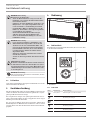 5
5
-
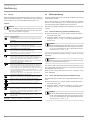 6
6
-
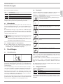 7
7
-
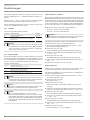 8
8
-
 9
9
-
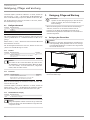 10
10
-
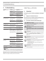 11
11
-
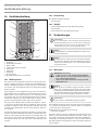 12
12
-
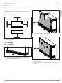 13
13
-
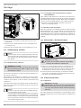 14
14
-
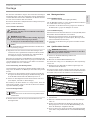 15
15
-
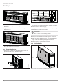 16
16
-
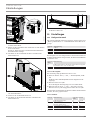 17
17
-
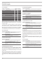 18
18
-
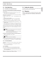 19
19
-
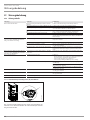 20
20
-
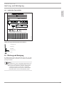 21
21
-
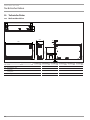 22
22
-
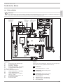 23
23
-
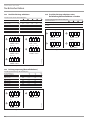 24
24
-
 25
25
-
 26
26
-
 27
27
-
 28
28
-
 29
29
-
 30
30
-
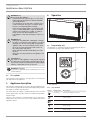 31
31
-
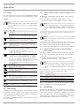 32
32
-
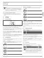 33
33
-
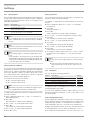 34
34
-
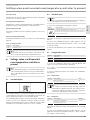 35
35
-
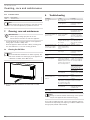 36
36
-
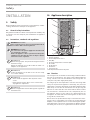 37
37
-
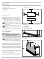 38
38
-
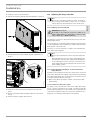 39
39
-
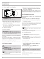 40
40
-
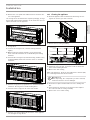 41
41
-
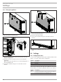 42
42
-
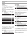 43
43
-
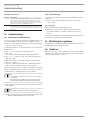 44
44
-
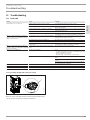 45
45
-
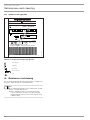 46
46
-
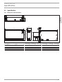 47
47
-
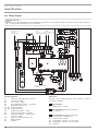 48
48
-
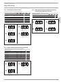 49
49
-
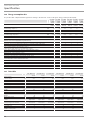 50
50
-
 51
51
-
 52
52
-
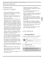 53
53
-
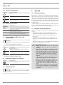 54
54
-
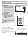 55
55
-
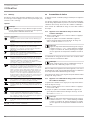 56
56
-
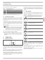 57
57
-
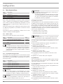 58
58
-
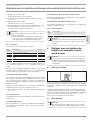 59
59
-
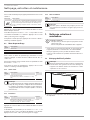 60
60
-
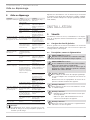 61
61
-
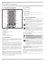 62
62
-
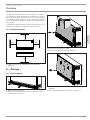 63
63
-
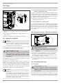 64
64
-
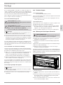 65
65
-
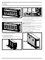 66
66
-
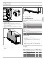 67
67
-
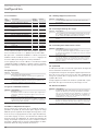 68
68
-
 69
69
-
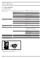 70
70
-
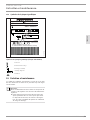 71
71
-
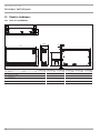 72
72
-
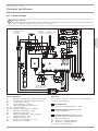 73
73
-
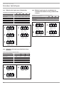 74
74
-
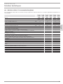 75
75
-
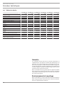 76
76
-
 77
77
-
 78
78
-
 79
79
-
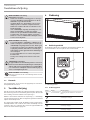 80
80
-
 81
81
-
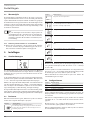 82
82
-
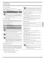 83
83
-
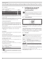 84
84
-
 85
85
-
 86
86
-
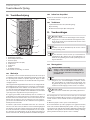 87
87
-
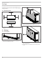 88
88
-
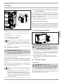 89
89
-
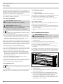 90
90
-
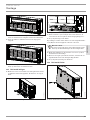 91
91
-
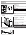 92
92
-
 93
93
-
 94
94
-
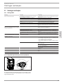 95
95
-
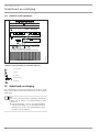 96
96
-
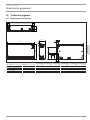 97
97
-
 98
98
-
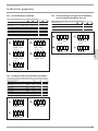 99
99
-
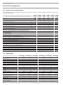 100
100
-
 101
101
-
 102
102
-
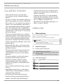 103
103
-
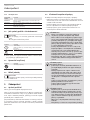 104
104
-
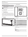 105
105
-
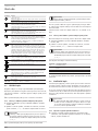 106
106
-
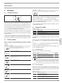 107
107
-
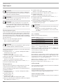 108
108
-
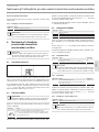 109
109
-
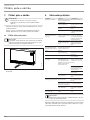 110
110
-
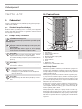 111
111
-
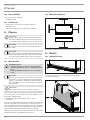 112
112
-
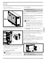 113
113
-
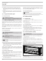 114
114
-
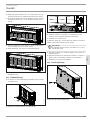 115
115
-
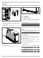 116
116
-
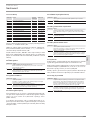 117
117
-
 118
118
-
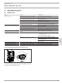 119
119
-
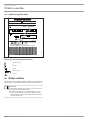 120
120
-
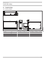 121
121
-
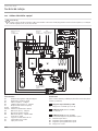 122
122
-
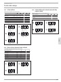 123
123
-
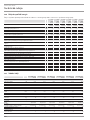 124
124
-
 125
125
-
 126
126
-
 127
127
-
 128
128
-
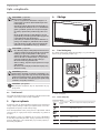 129
129
-
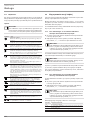 130
130
-
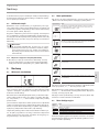 131
131
-
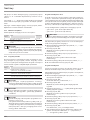 132
132
-
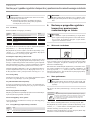 133
133
-
 134
134
-
 135
135
-
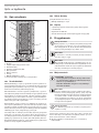 136
136
-
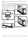 137
137
-
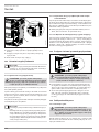 138
138
-
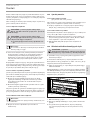 139
139
-
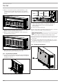 140
140
-
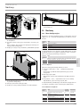 141
141
-
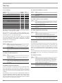 142
142
-
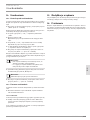 143
143
-
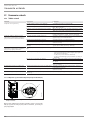 144
144
-
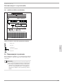 145
145
-
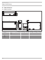 146
146
-
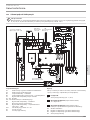 147
147
-
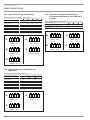 148
148
-
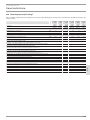 149
149
-
 150
150
-
 151
151
-
 152
152


STIEBEL ELTRON ETW 420 Plus Operation and Installation
- Type
- Operation and Installation
in andere talen
- français: STIEBEL ELTRON ETW 420 Plus
- Deutsch: STIEBEL ELTRON ETW 420 Plus
- polski: STIEBEL ELTRON ETW 420 Plus
Gerelateerde papieren
-
STIEBEL ELTRON 200268 Operation and Installation
-
-
-
STIEBEL ELTRON CON 5 Premium Operation Instruction
-
-
-
-
-
-
STIEBEL ELTRON RHW Series Operation and Installation
Andere documenten
-
BLACK DECKER BXCSH1200E Convector Handleiding
-
Dimplex VF70 de handleiding
-
AEG WSP3510N Handleiding
-
-
RADSON 51004 Handleiding
-
AEG 102 D de handleiding
-
AEG WSP 3010 Handleiding
-
Vaillant GEOTHERM PLUS de handleiding
-
Bauknecht VN524E de handleiding
-