Atlantic edition 2014 PECS 1998-2016 Installation and User Manual
- Type
- Installation and User Manual

Échangeur optimisé
Préparateur Eau Chaude Sanitaire
Optimised exchanger
Domestic hot water preparer
Geoptimaliseerde warmtewisselaar
Sanitaire warmwater-bereider
FR
EN
NL


FR
Échangeur Optimisé - Préparateur Eau Chaude Sanitaire
FR
1
AVERTISSEMENTS
Cet appareil n’est pas prévu pour être utilisé par des personnes (y compris les enfants)
dont les capacités physiques, sensorielles ou mentales sont réduites, ou des personnes
dénuées d’expérience ou de connaissance, sauf si elles ont pu bénéficier, par l’intermé-
diaire d’une personne responsable de leur sécurité, d’une surveillance ou d’instructions
préalables concernant l’utilisation de l’appareil.
Il convient de surveiller les enfants pour s’assurer qu’ils ne jouent pas avec l’appareil.
Cet appareil peut être utilisé par des enfants âgés d’au moins 8 ans et par des personnes
ayant des capacités physiques, sensorielles ou mentales réduites ou dénuées d’expérience
ou de connaissance, s’ils (si elles) sont correctement surveillé(e)s ou si des instructions
relatives à l’utilisation de l’appareil en toute sécurité leur ont été données et si les risques
encourus ont été appréhendés. Les enfants ne doivent pas jouer avec l’appareil.
Le nettoyage et l’entretien par l’usager ne doivent pas être effectués par des enfants
sans surveillance.
INSTALLATION
ATTENTION : Produit lourd à manipuler avec précaution :
1/ Installer l’appareil dans un local à l’abri du gel. La destruction de l’appareil par surpres-
sion due au blocage de l’organe de sécurité est hors garantie.
2/ S’assurer que la cloison est capable de supporter le poids de l’appareil rempli d’eau.
3/ Si l’appareil doit être installé dans un local ou un emplacement dont la température
ambiante est en permanence à plus de 35°C, prévoir une aération de ce local.
4/ Placer l’appareil dans un lieu accessible.
5/ Se reporter aux figures d’installation (§4)
Fixation d’un chauffe-eau vertical mural : Pour permettre l’échange éventuel de l’élément
chauffant, laisser au-dessous des extrémités des tubes du chauffe-eau un espace libre
de 300 mm jusqu’à 100L et 480 mm pour les capacités supérieures.
RACCORDEMENT HYDRAULIQUE
Installer obligatoirement à l’abri du gel un organe de sécurité (ou tout autre dispositif
limiteur de pression), neuf, de dimensions 3/4’’ ou 1’’ (pour DS VS 200 et DS VS 300)
et de pression 7 bar – 0,7 MPa sur l’entrée du chauffe-eau, qui respectera les normes
locales en vigueur.
Le dispositif de vidange du limiteur de pression doit être mis en fonctionnement réguliè-
rement afin de retirer les dépôts de tartre et de vérifier qu’il ne soit pas bloqué.
Un réducteur de pression (non fourni) est nécessaire lorsque la pression d’alimentation est
supérieure à 5 bar (0,5 MPa) qui sera placé sur l’alimentation principale.
Raccorder l’organe de sécurité à un tuyau de vidange, maintenu à l’air libre, dans un
environnement hors gel, en pente continue vers le bas pour l’évacuation de l’eau
de dilatation de la chauffe ou l’eau en cas de vidange du chauffe-eau.
La pression de service du circuit de l’échangeur thermique ne devra pas dépasser 3 bar -
0,3 MPa, sa température ne devra pas être supérieure à 100°C.
Vidange : Couper l’alimentation électrique et l’eau froide, ouvrir les robinets d’eau chaude
puis manœuvrer la soupape de vidange de l’organe de sécurité.

FR
Échangeur Optimisé - Préparateur Eau Chaude Sanitaire
2
RACCORDEMENT ÉLECTRIQUE
Avant tout démontage du capot, s’assurer que l’alimentation est coupée pour éviter tout
risque de blessure ou d’électrocution.
L’installation électrique doit comporter en amont de l’appareil un dispositif de coupure
omnipolaire (disjoncteur, fusible) conformément aux règles d’installation locales
en vigueur (disjoncteur différentiel 30mA).
Si le câble est endommagé, il doit être remplacé par un câble ou un ensemble spécial
disponible auprès du fabricant ou du SAV.

FR
3
Échangeur optimisé
Préparateur Eau Chaude Sanitaire
Sommaire
1. Principe général de fonctionnement ......................................... 5
2. Descriptif de l’appareil ............................................................... 5
3 Caractéristiques dimensionnelles et performances ................ 6
4. Installation de l’appareil ............................................................ 8
4.1 Positionnement ..................................................................................................8
4.2 Raccordement hydraulique .............................................................................. 8
4.2.1 Généralités .............................................................................................................................8
4.2.2 Protection des circuits hydrauliques .....................................................................................8
Circuit primaire .......................................................................................................................8
Circuit secondaire ..................................................................................................................10
Circuit recyclage ....................................................................................................................10
4.3 Raccordement électrique - Kits en options ...................................................11
4.4 Raccordement de la protection cathodique .................................................14
5. Mise en service ......................................................................... 14
6. Entretien ................................................................................... 15
7 Certicat et conditions de garantie ........................................ 16
7.1 Conditions de garantie ....................................................................................16
7.2 Recommandations ..........................................................................................17

FR
Échangeur Optimisé - Préparateur Eau Chaude Sanitaire
4
Vous venez d’acquérir un Préparateur Eau Chaude Sanitaire (PECS) ATLANTIC.
Avant propos
Afin de vous « garantir une parfaite installation » dans les règles de l’art, et d’optimiser ainsi les performances
de votre appareil, nous vous invitons à lire attentivement les instructions portées sur cette notice que vous devez
conserver au même titre que le bon de garantie.
IMPORTANT
Un câble d’alimentation 3 conducteurs solidaire de l’appareil alimentant votre système de protection
anti-corrosion (A.C.I.) est prêt à être raccordé à un bornier de dérivation, avec une alimentation permanente
24h/24.
Tout oubli de ce raccordement électrique à une alimentation permanente (230V), entraîne la perte
de la garantie constructeur.

FR
Échangeur Optimisé - Préparateur Eau Chaude Sanitaire
FR
5
GAMME DS VM (75L à 200L) - GAMME DS VS (150L à 300L)
1. Principe général de fonctionnement
1.1 En hiver (chaudière en marche)
Votre chaudière fonctionne et assure la chauffe de l’eau sanitaire par la circulation d’un fluide chaud
à l’intérieur d’un échangeur (serpentin à spires elliptiques pour modèles DS VS ; E)
1.2 En été ou en ½ saison (chaudière à l’arrêt)
pour fonctionnement avec un kit électrique (non fourni d’origine)
Votre chaudière est à l’arrêt. La chauffe est assurée par la mise sous tension de la résistance électrique.
Le thermostat interrompt l’alimentation électrique lorsque la température de l’eau atteint 65°C.
2. Descriptif de l’appareil
Schéma général de principe
Rep. Rep. Rep. Rep.
A Entrée échangeur Ø F1’’ D Sortie eau chaude G Revêtement intérieur émail J Anode en titane
B Sortie échangeur Ø F1’’ E
Echangeur interne (spires
elliptiques pour modèles
DS VS)
H
Appoint électrique
(selon modèle)
K
Isolation par mousse
de polyuréthane
C Entrée eau froide F Jaquette extérieure peinte I Capot de protection
B
E
E
K
K
F F
G G
J
J
CD I
I
H
H
A
Vertical mural (DS VM) Vertical sur socle (DS VS)
D
B
A
C

FR
Échangeur Optimisé - Préparateur Eau Chaude Sanitaire
6
3. Caractéristiques dimensionnelles et performances
Ballons échangeurs muraux (DS VM) et sur socle (DS VS)
Réf.
Capacité
(L)
Dimensions
Poids
à vide
Ø A B C D E F G
DS VM 75 75 505 320 - 387 - 175 528 735 34
DS VM 100 100 505 498 - 394 - 175 528 890 37
DS VM 150* 150 505 798 - 449 - 175 528 1 210 50
DS VM 200* 200 505 798 - 449 - 175 528 1 540 60
DS VS 150 150 565 1 010 420 465 385 650 320 - 54
DS VS 200** 200 565 1 270 533 555 500 650 460 - 70
DS VS 300** 300 565 1 770 1 006 600 515 650 510 - 82
Raccordements hydrauliques : Circuit primaire Ø1’’F, Circuit secondaire Ø 3/4’’ M et 1’’ M en 200/300 DS VS
* existe en mixte stéatite A.C.I. P = 2 400 W / ** existe en mixte blindé A.C.I. P = 3 300 W
Pour DS VM sur trépied, prévoir 444 mm entre le sol et la base de la côte C.
A
G
C
CF
B A
D
E
F
250 mm
230 mm
Ø
Ø E
104 mm
104 mm
Vue de dessous
Vertical mural (DS VM)
Vertical sur socle (DS VS)

FR
Échangeur Optimisé - Préparateur Eau Chaude Sanitaire
FR
7
Caractéristiques techniques
Réf.
Capacité
(L)
Pression
primaire
max. (bar)
Puissance
échangeur
kW*
Débit
horaire
Litres**
Débit
en 10 min.
Temps de préchauffage
min. (delta T)
Consommation d’entretien
kWh/24h***
Ballons échangeurs (DS VM) muraux
DS VM 75 75 10 19,3 476 121 22 9 1,2
DS VM 100 100 10 19,3 476 162 30 13 1,3
DS VM 150 150 10 25,6 631 242 35 15 1,5
DS VM 200 200 10 25,6 631 272 46 24 1,8
Ballons échangeurs (DS VS) sur socle
DS VS 150 150 10 30 740 244 29 12 1,6
DS VS 200 200 10 43,2 1064 326 28 12 2
DS VS 300 300 10 49 1230 489 38 15 2,7
* Puissance nominale donnée en kW pour un débit primaire de 2m
3
/h à 90°C et un secondaire à 45°C (delta T = 35°C).
** Débit maxi de la première heure en tenant compte d’un stockage à 60°C dans le réservoir.
*** Consommation d’entretien en kWh par 24 heures pour un stockage à 65°C et une ambiance de 20°C.
Caractéristiques techniques observées conformes à la norme : EN 60335
Nota: Ces valeurs peuvent varier en fonction de la saison et des températures de l’eau froide et de celle du local
de chaufferie et ceci sans recyclage.

FR
Échangeur Optimisé - Préparateur Eau Chaude Sanitaire
8
4. Installation de l’appareil
4.1 Positionnement
Les préparateurs d’eau chaude sanitaire peuvent être installés au mur (VM) ou posés au sol (VS).
Les versions verticales murales (VM) sont équipées d’étriers qui permettent leur fixation directe sur 4 boulons
à sceller au mur.
En position verticale (VM), si la cloison ne peut supporter le poids de l’appareil plein d’eau, poser celui-ci
sur un trépied (fourniture en option) et le fixer à la paroi à l’aide de l’étrier supérieur.
Laisser un espace libre de 400 mm en dessous du capot de protection (voir schéma p. 9) pour permettre l’accès
aux équipements pour l’entretien ou pour procéder à un éventuel démontage.
Une évacuation raccordée à l’égoût est nécessaire en sortie de groupe de sécurité.
4.2 Raccordements hydrauliques
4.2.1 Généralités
Toutes les canalisations neuves devront être obligatoirement nettoyées avant leur raccordement à l’appareil
afin de ne pas gêner la libre circulation du fluide dans le réservoir.
Pour le circuit secondaire (entrée eau froide / sortie eau chaude), chaque tubulure est en acier avec
l’extrémité filetée au pas du gaz Ø 20/27 (3/4’’) pour tous les DS VM et DS VS 150L et Ø 26/34 (1’’) pour
les DS VS 200/300L. Pour le circuit primaire (circuit chauffage), chaque tubulure est taraudée au pas
du gaz 1’’.
Dans le cas d’utilisation de tuyaux en matériau de synthèse (PER par exemple), la pose d’un régulateur
thermostatique en sortie de chauffe-eau est impérative. Il sera réglé en fonction des performances
du matériau utilisé.
IMPORTANT :
La pression du réseau d’eau froide est généralement inférieure à 5 bar (0,5 MPa). Si ce n’est pas le cas, placer
un réducteur de pression sur l’alimentation principale, après le compteur général.
Prendre toutes les précautions utiles pour mettre l’appareil ainsi que les équipements (vase d’expansion,
canalisations, groupe de sécurité) à l’abri du gel.
Ne pas interposer d’organe de fermeture sur la canalisation reliant le vase d’expansion à l’échangeur interne
(échangeur à spires elliptiques pour modèles DS VS) (RISQUE DE DÉTERIORATION DU CIRCUIT EN CAS
DE FERMETURE INVOLONTAIRE).
4.2.2 Protection des circuits hydrauliques
•Pourlecircuitprimaire(circuitchauffage)
L’appareil sera protégé contre les excès de pression dus à la dilatation de l’eau lors de la chauffe :
- par un vase d’expansion du type ouvert (à la pression atmosphérique)
- ou par un vase d’expansion du type fermé
- la pression de service du circuit ne devra pas dépasser 3 bar (0,3 MPa), sa température ne devra pas
être supérieure à 100°C.
Principe de fonctionnement avec pompe de charge
- Prévoir une pompe (kit aquastat en option). L’aquastat inverseur étant monté de série et sa sonde
est positionnée dans le même doigt de gant que celui du bulbe du thermostat tripolaire électrique
commandant la résistance électrique.
- Procéder au raccordement électrique entre l’aquastat et la commande de la pompe de charge.
- La consigne de l’aquastat est sur la position 65°C (réglage d’usine), et celle du thermostat tripolaire
électrique commandant la résistance électrique sur la position maxi soit 65°C.

FR
Échangeur Optimisé - Préparateur Eau Chaude Sanitaire
FR
9
Rep. Rep. Rep.
1 Chaudière 5 Purgeur automatique C Arrivée eau froide sanitaire
2 Réducteur de pression 6 Clapet anti-retour D Sortie eau chaude sanitaitre
3 Pompe chauffage 7 Pompe de charge E Retour circuit chauffage
4
Liaison électrique aquastat inverseur
/ pompe circuit sanitaire et/ou circuit
chauffage
8
Raccordement
par exible
F Départ circuit chauffage
9
Aquastat inverseur cde pompe
de charge (7) et pompe chauffage
D
400 mm mini
C
E
1
2
F
5
6
8
9
7
3
4
Vertical mural (DS VM)

FR
Échangeur Optimisé - Préparateur Eau Chaude Sanitaire
10
•Pourlecircuitsecondaire(circuiteauchaudesanitaire)
L’appareil sera protégé contre les excès de pression dus au réseau :
- Installer obligatoirement un organe de sécurité neuf sur l’entrée du chauffe-eau, qui respectera
les normes en vigueur (en Europe EN 1487), de pression 7 bar (0,7 MPa) et de dimension ¾’’
(1’’ pour DS VS 200L et 300L). Le groupe de sécurité doit être protégé du gel.
- La nature des tuyauteries peut être rigide (généralement en cuivre) ou souple. L’acier noir est
interdit (voir DTU 60.1)
- Dans le cas d’un raccordement en cuivre, la liaison eau chaude devra impérativement être réalisée
à l’aide d’un manchon en fonte, acier ou raccord isolant, afin d’éviter tout risque de corrosion
des tubulures par effet galvanique. De ce fait, les raccords en laiton sont interdits (NFC 15-100).
- Raccorder l’organe de sécurité à un tuyau de vidange, maintenu à l’air libre, dans un environnement
hors gel, en pente continue vers le bas pour l’évacuation de l’eau de dilatation de la chauffe
ou l’eau en cas de vidange du chauffe-eau. Les canalisations utilisées doivent supporter 100°C et
10 bar (1 MPa).
Circuit de recyclage éventuel
- Si l’emplacement de l’appareil se trouve éloigné du dernier point de puisage, il est possible de créer
une boucle de distribution (voir schéma ci-dessous). La circulation sera assurée à l’aide d’une pompe
(E.C.S.).
- Si la tuyauterie passe à l’extérieur, prévoir une isolation des canalisations.
- Pour le raccordement, veuillez respecter impérativement les mêmes préconisations que celles
du circuit secondaire (tubes, raccords).
C
4
Vertical mural (DS VM)
D
D
A
A
B
B
1
3
2
2
Rep.
1 Groupe de sécurité EN 1487
2 Vanne d’arrêt
3 Siphon d’évacuation
4 Réducteur de pression éventuel
A, B, C et D : p. 5
C
Vertical sur socle (DS VS)
4
1
3
Le recyclage permet de disposer d’eau chaude
rapidement, dans le cas de point(s) de puisage(s)
éloigné(s), ceci peut générer une baisse de la
température de stockage.
En été, nécessité d’une alimentation électrique
permanente (kit électrique en option).
Rep.
5 Vannes d’isolement
6 Pompe E.C.S.
7 Clapet anti-retour
A, B, C et D : p. 5
C
D
A
B
5
6
7

FR
Échangeur Optimisé - Préparateur Eau Chaude Sanitaire
FR
11
4.3 Raccordement électrique - Kits en option
4.3.1 Généralités
Nos appareils sont conformes aux normes en vigueur et disposent par conséquent de toutes les conditions
de sécurité. Le raccordement électrique devra être conforme aux normes d’installation NF C 15-100.
Les kits électriques (en option) comprennent :
En VM 150L et 200L les kits se composent de :
- une résistance électrique stéatite tous courants pré-câblée en triphasé 400V (3 phases + terre) ; elle peut
être raccordée en monophasé (phase / neutre + terre). Respecter le schéma de raccordement joint
à l’appareil.
- Un thermostat tripolaire (régulation et sécurité) relié électriquement à la résistance en raccordement
triphasé d’origine.
En VM 75L et 100L : pas de kit électrique
En VS 150L, 200L et 300L : pas de kit électrique
IMPORTANT
L’installation comprendra : un disjoncteur omnipolaire avec ouverture des contacts d’au moins 3 mm, une liaison
en câbles rigides 3 x 2,5 mm² (phase, neutre, terre) en mode monophasé ou 4 x 2,5 mm² (trois phases + terre).
Le conducteur de terre sera repéré vert/jaune. Pour la sécurité, son raccordement est obligatoire sur la borne
de terre.
W
Pour une installation en monophasé, le neutre est déjà existant (se reporter à la notice jointe dans le kit aquastat).
Pour l’installation et le raccordement électrique des kits, se reporter aux notices jointes dans chaque
emballage (kit électrique, kit pompe).
Raccordement électrique du kit de pompe (option) à l’aquastat inverseur (série) en PECS
CÂBLAGE EN PECS DS VM (75L et 100L - Non kitable)
L
N
E
D
A B
C
Rep.
A Alimentation A.C.I. 24h/24
B Commande de pompe
C Alimentation 230V pompe
D Carte A.C.I.
E Pompe
D
E
CBA

FR
Échangeur Optimisé - Préparateur Eau Chaude Sanitaire
12
CÂBLAGE EN PECS DS VM (150L et 200L - Kitable)
CÂBLAGE EN PECS MIXTE DS VM 150L et 200L - Stéatite A.C.I. (P = 2 400 W)
L
N
E
D
A B
C
A B
C
D
F
L
N
E
F
Rep.
A Alimentation A.C.I. 24h/24
B Commande de pompe
C Alimentation 230V pompe
D Carte A.C.I.
E Pompe
Rep.
A Alimentation A.C.I. 24h/24
B
Câble d’alimentation élément chauffant
230V mono
C Interrupteur été/hiver
D Carte A.C.I.
E Pompe
F Élément chauffant
G Thermostat
A
C
B
G
E
D
F
E
D
CBA

FR
Échangeur Optimisé - Préparateur Eau Chaude Sanitaire
FR
13
CÂBLAGE EN PECS DS VS
CÂBLAGE EN PECS MIXTE DS VS 200L et 300L blindé A.C.I. (P = 3 300 W),
avec commande de pompe par sonde extérieure de chaudière
L
S
C
A
LN
LN
B
C
D
E
L
C
S
L
S
C
A B
C
D
F
E
G
H
LN
Rep.
A Alimentation A.C.I. 24h/24
B
Câble d’alimentation pompe
230V mono
C Pompe chauffage
D Pompe E.C.S.
E Carte A.C.I.
Rep.
A Alimentation A.C.I. 24h/24
B
Câble d’alimentation pompe
230V mono
C
Câble d’alimentation élément chauf-
fant 230V mono
D
Interrupteur
été/hiver
E Carte A.C.I.
F Pompe E.C.S.
G Élément chauffant
H Thermostat
A
E
B
C
D
A B
C
E
F
GD
H

FR
Échangeur Optimisé - Préparateur Eau Chaude Sanitaire
14
4.4 Raccordement de la protection cathodique
Aucune intervention supplémentaire n’est à prévoir (les connexions sont déjà réalisées).
Un câble d’alimentation 3 conducteurs solidaire de l’appareil est prêt à être raccordé à un bornier
de dérivation, avec une alimentation permanente 24h/24h.
IMPORTANT
Tout oubli de raccordement électrique ou liaison à une alimentation non-permanente entraîne la perte
de la garantie constructeur.
Après la mise sous tension de l’appareil, vérifier le bon clignotement de la led verte de l’A.C.I.
SÉCURITÉ
Vérifier que l’appareil est rempli en eau avant sa mise sous tension.
5. Mise en service
5.1 Première mise en service
IMPORTANT
Avant tout remplissage des circuits, s’assurer que l’appareil n’est pas sous tension.
5.1.1 Remplir impérativement le circuit secondaire
- Ouvrir un robinet situé sur la canalisation de l’eau chaude
- Ouvrir un robinet d’eau froide situé sur le groupe de sécurité (s’assurer au préalable que la vidange
de l’appareil n’est pas en position ouverte)
- Lorsque l’eau s’écoule au robinet d’eau chaude, votre réservoir est plein d’eau. Laisser quelques
minutes le robinet ouvert afin de procéder au rinçage du ballon.
- Fermer le robinet d’eau chaude.
- Vérifier l’étanchéité des raccords, ainsi que celle de la bride dotée d’écrous, resserrer si nécessaire.
- Pour un appareil doté d’une résistance électrique, une mise en chauffe de 30 mn est conseillée,
elle permet de vérifier le bon fonctionnement du groupe de sécurité
(*)
, ainsi que l’étanchéité
de l’ensemble de votre installation.
(*)
En chauffe, un goutte à goutte au groupe de sécurité est normal après 15 à 30 minutes de fonctionnement.
5.1.2 Remplir le circuit primaire (circuit chauffage)
- Ouvrir le robinet d’eau de ville, dévisser le purgeur d’air afin d’évacuer l’air introduit par l’opération
de remplissage.
- Pour une installation équipée d’une pompe de charge, la mettre en marche quelques instants
afin d’accélérer l’opération de dégazage.
- Vérifier que le circuit est plein d’eau, soit par le contrôle du niveau de l’eau contenue dans le vase
ouvert, soit en ouvrant le purgeur situé au point haut de l’installation.
IMPORTANT
Après remplissage des circuits, mettre sous tension les équipements électriques et vérifier impérativement
le bon fonctionnement de l’A.C.I. (clignotement de la led verte après quelques minutes).
5.2 Votre appareil est en ordre de marche
5.2.1 Fonctionnement en hiver
- Sans kit électrique : l’eau sanitaire est chauffée par le circuit primaire (échange thermique)
- Avec l’aquastat : l’aquastat inverseur pilote la mise en marche de la pompe de charge et autorise
la circulation du fluide primaire ; il peut être raccordé à la pompe du circuit de chauffage.
- 15 à 30 minutes plus tard, l’eau doit s’écouler en goutte à goutte par l’orifice du groupe de sécurité.
Ce phénomène est tout à fait normal ; il s’agit de la dilatation de l’eau due à la chauffe (2 à 3%
de la capacité du réservoir).

FR
Échangeur Optimisé - Préparateur Eau Chaude Sanitaire
FR
15
5.2.2 Fonctionnement en été et en ½ saison
- Si vous possédez un kit électrique, la chaudière étant coupée, l’eau chaude sanitaire sera produite
par la résistance électrique.
- Couper l’alimentation électrique reliant le thermostat de commande pompe.
- Basculer l’interrupteur du tableau électrique alimentant le thermostat connecté à la résistance
électrique.
- Appuyer sur l’interrupteur « été-hiver » situé sur la capot électrique du préparateur.
- 15 à 30 minutes plus tard, l’eau doit s’écouler en goutte à goutte par l’orifice du groupe de sécurité.
Ce phénomène est tout à fait normal ; il s’agit de la dilatation de l’eau due à la chauffe (2 à 3 %
de la capacité du réservoir).
- Si vous ne possédez pas un kit électrique, l’eau chaude sanitaire sera produite par le circuit primaire
(échange thermique) idem hiver.
6. Entretien
Pour l’utilisateur : manœuvrer le groupe de sécurité une ou deux fois par mois. Faites vérifier l’état
des connections électriques pour un resserrage éventuellement.
Si les performances de l’appareil venaient à diminuer, il se peut que votre échangeur soit entartré, dans ce cas
faites appel à votre installateur qui se chargera de cette opération de nettoyage.
Pour une installation dotée d’une pompe de charge ; avant le redémarrage, suite à un arrêt prolongé,
faites tourner le rotor en respectant les consignes de la notice du fabricant.
CONSEILS À L’USAGER :
Pour une eau présentant des teneurs en TH>20°f, il est recommandé de traiter celle-ci. Dans le cas d’un adoucisseur,
la dureté de l’eau doit rester supérieure à 15°f.
Pour le basculement hiver/été, bien respecter les indications décrites en amont c’est-à-dire en interrompant
la circulation du fluide primaire par la fermeture de la vanne située sur le circuit.
Le fonctionnement en hiver impose la coupure de l’alimentation électrique de la résistance (si vous possédez un kit).
Dans le cas d’une absence prolongée et notamment en hiver, vidanger votre appareil en suivant cette procédure :
- couper l’alimentation électrique de la résistance
- fermer l’arrivée d’eau froide du groupe de sécurité
- ouvrir un robinet d’eau chaude
- ouvrir le robinet de vidange du groupe de sécurité et laisser l’appareil se vider
En cas d’anomalie, absence d’eau chaude, dégagement de vapeur au soutirage, couper l’alimentation électrique
(en été) et prévenir votre installateur.
La réglementation en vigueur en France impose de na pas dépasser la valeur de 60°C au point de puisage.
Si ce n’est pas le cas, prévoir un moyen de réglage (mélangeur, mitigeur…).
Ne jetez pas votre appareil avec les ordures ménagères, mais déposez-le à un endroit assigné à cet effet
(point de collecte) où il pourra être recyclé.

FR
Échangeur Optimisé - Préparateur Eau Chaude Sanitaire
16
7. Certificat et conditions de garantie
7.1 Conditions de garantie
Le préparateur d’eau chaude sanitaire doit être installé par un professionnel qualifié conformément
aux règles de l’art, aux normes en vigueur et aux prescriptions de nos notices techniques.
Il sera utilisé et entretenu normalement par un spécialiste.
Dans ces conditions, notre garantie s’exerce par échange ou fourniture gratuite à notre Distributeur
ou Installateur des pièces reconnues défectueuses par nos services ou le cas échéant de l’appareil
à l’exclusion des frais de main-d’œuvre, des frais de transport ainsi que toute indemnité et prolongation
de garantie.
Nota : Les frais ou dégâts dus à une installation défectueuse (gel, groupe de sécurité non raccordé
à l’évacuation des eaux usées, absence de raccord diélectrique, par exemple) ou à des difficultés d’accès,
ne peuvent en aucun cas être imputés au fabricant.
La garantie prend effet à compter de la date de pose, facture d’installation faisant foi ; en l’absence
de justificatif, la date de prise en compte sera celle de fabrication indiquée sur la plaque signalétique
du chauffe-eau majorée de six mois.
Les dispositions des présentes conditions de garantie ne sont pas exclusives du bénéfice au profit de l’acheteur,
de la garantie légale pour défauts et vices cachés qui s’appliquent en tout état de cause dans les conditions
des articles 1641 et suivants du Code Civil.
Ces appareils sont conformes aux directives 2004/108/CEE concernant la compatibilité électro-magnétique
et 2006/95/CEE concernant la basse tension.
La cuve et le fourreau du PECS sont garantis 5 ans.
L’appareil électrique et les équipements amovibles sont garantis 2 ans.
Type de l’appareil : ........................................................................................................
N° de série : ........................................................................................................
Puissance : ........................................................................................................
Capacité : ........................................................................................................
Date d’achat : ........................................................................................................
Usager (nom/adresse) : ........................................................................................................
.........................................................................................................
.........................................................................................................
CACHET DE L’INSTALLATEUR :

FR
Échangeur Optimisé - Préparateur Eau Chaude Sanitaire
FR
17
Sont exclues de ces garanties les défaillances dues à :
Une installation non conforme à la réglementation, aux normes et aux règles de l’art (voir notice) –
Notamment :
- Absence ou montage incorrect d’un groupe de sécurité neuf et conforme à la norme NF D 36-401,
modification du réglage du groupe de sécurité après violation du plombage.
- Corrosion anormale due à un raccordement hydraulique incorrect (contact fer-cuivre)
- Raccordement électrique défectueux : non conforme à la norme d’installation NF C 15-100, mise
à la terre incorrecte, section de câble insuffisante, non-respect des schémas de raccordements
prescrits, etc.
- Mise sous tension de l’appareil sans remplissage préalable (chauffe à sec)
- Mise en service non conforme à la présente notice
- Non raccordement électrique de l’anode à courant imposé
Des conditions d’environnement anormales :
- Positionnement dans un endroit soumis au gel ou aux intempéries et ambiances humides.
- Alimentation avec une eau présentant des critères d’agressivité particulièrement anormaux
(DTU Plomberie 60-1 additif 4).
- Alimentation électrique présentant des surtensions importantes.
Un entretien défectueux :
- Entartrage anormal des éléments chauffants et des organes de sécurité
- Non entretien du groupe de sécurité se traduisant pas des surpressions (voir notice du fabricant).
- Carrosserie soumise à des agressions extérieures.
- Modification des équipements d’origine, sans avis du constructeur ou emploi de pièces détachées
non référencées par celui-ci.
7.2 Recommandations
Pour les régions où l’eau est très calcaire, l’utilisation d’un adoucisseur n’entraîne pas de dérogation
à notre garantie sous réserve que l’adoucisseur soit réglé conformément aux règles de l’art, vérifié
et entretenu régulièrement (la dureté de l’eau doit rester supérieure à 15°f)
Les normes ou habitudes d’installation nationales ne peuvent en aucun cas prévaloir sur les règles
élémentaires de sécurité repérées IMPORTANT dans cette notice.
Gestion des Garanties France :
SATC - BP65 - 85002 La-Roche-sur-Yon
Téléphone : 02 51 44 34 26 - 02 51 44 34 67 - 02 51 44 34 68 - Fax : 02 51 37 38 27
www.atlantic.tm.fr
INTERNATIONAL : Consulter votre installateur
ATLANTIC Belgium :
Avenue Château Jaco 1 - 1410 WATERLOO - Belgique
Tél. : 0080038713858 (Belgïe)


EN
Optimised heat exchanger – Domestic hot water preparer
EN
19
WARNINGS
This appliance is not designed for use by people (including children) of reduced physical,
sensory or metal capacity, or those inexperienced or ignorant unless they have received
prior instruction or supervision from someone responsible for their safety, about the use
of the appliance.
Children must be supervised to ensure they do not play with the appliance. This appliance
may be used by children of 8 years or over, and by people with of reduced physical,
sensory or metal capacity, or those inexperienced or ignorant if they are properly
supervised or if they have been given instructions about the safe use of the appliance,
and made aware of the associated risks. Children must not play with the appliance.
Children must not clean or maintain the appliance without supervision.
INSTALLATION
WARNING: Product heavy, handle with care.
1/ Install the appliance in a frost-free room. The warranty does not cover destruction
of the appliance through excess pressure caused by a blockage in the safety valve.
2/ Ensure that the wall on which it is mounted can support the weight of the appliance
filled with water.
3/ If the appliance has to be installed in a room or location with an ambient temperature
always above 35°C, this room must be ventilated.
4/ Place the appliance in an accessible place.
5/ Refer to the installation diagrams (§4)
Fixing an upright, wall-mounted water heater: A free space of 300mm must be left below
the ends of the water heater’s tubes for a capacity up to 100L, and 480mm for larger capa-
city heaters, so that the heating element can be replaced if necessary.
WATER CONNECTION
A safety valve (or other pressure-relief component) must be installed at the intake to the
water heater, in a frost-free environment, with dimensions of 3/4’’ or 1’’ (for DS VS 200
and DS VS 300), and with pressure of 7 bars - 0.7 MPa, compliant with local regulations in
force.
The pressure limiter’s relief device must be operated regularly to remove any scale depo-
sits and check it is not blocked. A pressure reducer (not supplied) is needed when pressure
is more than 5 bar (0.5 MPa) and it will be placed on the main supply. Connect the safety
unit to a drain pipe kept in the open air, in a frost-free environment, with a permanent
downward gradient, to remove any expansion water from the heating process, or drai-
nage water from the water-heater. The operating pressure of the heat exchanger circuit
must not exceed 3 bar - 0.3 Mpa, and its temperature must not be higher than 100°C.
Drainage: Cut the power and cold water supplies, open the hot water valves then operate
the safety unit’s drain valve.

EN
Optimised heat exchanger – Domestic hot water preparer
20
ELECTRICAL CONNECTION
Before removing the cover, always make sure that the power is turned off, to prevent any
risk of injury or electric shock.
There must be an omni-polar power cut-off (circuit-breaker or fuse) fitted upstream of
the electrical installation, compliant with local rules in force (30mA differential circuit-
breaker).
If the power cable is damaged, it must be replaced by a cable or special assembly obtained
from the manufacturer or after-sales service.

EN
21
Optimised exchanger
Domestic hot water preparer
Contents
1. General operating principle ..................................................... 23
2. Description of the apparatus ................................................... 23
3 Dimensional and performances features ................................ 24
4. Installing the appliance ............................................................ 26
4.1 Position .............................................................................................................26
4.2 Hydraulic connection ......................................................................................26
4.2.1 General points .....................................................................................................................26
4.2.2 Protection of circuits ...........................................................................................................26
Primary circuit .......................................................................................................................26
Secondary circuit ...................................................................................................................28
Recycling circuit .....................................................................................................................28
4.3 Electrical connection - Kits optional ..............................................................29
4.4 Connection of cathode protection ................................................................32
5. Start-up ..................................................................................... 32
6. Maintenance ............................................................................ 33
7 Warranty certicate and conditions ....................................... 34
7.1 Warranty conditions ........................................................................................34
7.2 Recommendations ..........................................................................................35

EN
Optimised heat exchanger – Domestic hot water preparer
22
You have just purchased an ATLANTIC Domestic hot water heater system.
Foreword
Please read the instructions contained in this manual carefully, and keep it along with the warranty certificate, to
ensure that your «installation is guaranteed successful», and the performance of your appliance is optimised.
IMPORTANT
A 3-wire power cable attached to the appliance to supply the A.C.I. system is ready to be connected
to a terminal, and kept always powered up.
If the power (230V) is turned off at any time the manufacturer’s warranty is no longer valid.

EN
Optimised heat exchanger – Domestic hot water preparer
EN
23
DS VM RANGE (75L to 200L) - DS VS RANGE (150L to 300L)
1. General operating principle
1.1 In winter (boiler operating)
Your boiler is operating, to heat the domestic hot water by circulating a hot liquid inside a heat exchanger
(elliptical spiral coil for DS VS models; E)
1.2 In summer or in mid-season (boiler shutdown)
for operation with an electrical kit (not supplied at the outset)
Your boiler is shut down. The electrical resistance is powered up to provide heating. The thermostat cuts
the power when the water temperature reaches 65°C.
2. Description of the apparatus
General circuit diagram
Rep. Rep. Rep. Rep.
A Exchanger input dia. F1’’ D Hot water outlet G Internal enamel coating J Titanium anode
B Exchanger output dia. F1’’ E
Internal heat exchanger
(elliptical spiral coil for DS
VS models)
H
Electrical connection
(depending on model)
K
Polyurethane foam
insulation
C Cold water intake F Painted outer jacket I Protective cover
B
E
E
K
K
F F
G G
J
J
CD I
I
H
H
A
Vertical wall-mounted (DS VM) Vertical on stand (DS VS)
D
B
A
C

EN
Optimised heat exchanger – Domestic hot water preparer
24
3. Dimensional and performances features
Heat exchanger cylinders, wall-mounted (DS VM) & on stand (DS VS)
Ref.
Capacity
(L)
Dimensions
Empty
weight
Ø A B C D E F G
DS VM 75 75 505 320 - 387 - 175 528 735 34
DS VM 100 100 505 498 - 394 - 175 528 890 37
DS VM 150* 150 505 798 - 449 - 175 528 1 210 50
DS VM 200* 200 505 798 - 449 - 175 528 1 540 60
DS VS 150 150 565 1 010 420 465 385 650 320 - 54
DS VS 200** 200 565 1 270 533 555 500 650 460 - 70
DS VS 300** 300 565 1 770 1 006 600 515 650 510 - 82
Hydraulic connections: Primary circuit dia. 1’’F, Secondary circuit dia. 3/4’’ M and 1’’ M in 200/300 DS VS
* available in mixed steatite A.C.I. P = 2400 W / ** available in mixed screened A.C.I. P = 3300 W
For DS VM on tripod, allow 444 mm between ground and base dimension C.
A
G
C
CF
B A
D
E
F
250 mm
230 mm
Ø
Ø E
104 mm
104 mm
Bottom view
Vertical wall-mounted (DS VM)
Vertical on stand (DS VS)

EN
Optimised heat exchanger – Domestic hot water preparer
EN
25
Technical characteristics
Ref.
Capacity
(L)
Max.
primary
pressure
(bar)
Heat
exchanger
power
(kW)*
Hourly
ow rate
(liters)**
Flow rate
in 10 min.
Min pre-heat time
(delta T)
Operating consumption
(kWh/24hr) ***
Wall-mounted heat exchanger cylinders (DS VM)
DS VM 75 75 10 19,3 476 121 22 9 1,2
DS VM 100 100 10 19,3 476 162 30 13 1,3
DS VM 150 150 10 25,6 631 242 35 15 1,5
DS VM 200 200 10 25,6 631 272 46 24 1,8
Heat exchanger cylinders (DS VS) on stand
DS VS 150 150 10 30 740 244 29 12 1,6
DS VS 200 200 10 43,2 1064 326 28 12 2
DS VS 300 300 10 49 1230 489 38 15 2,7
* Rated power in kW for primary flow rate of 2m3/h at 90°C and secondary flow at 45°C (delta T = 35°C).
** Max flow rate for first hour, allowing for storage in tank at 60°C.
*** Operating consumption in kWh per 24 hours for storage at 65°C and ambient temperature of 20°C.
Technical properties observed in accordance with standard: EN 60335
Note : These values may vary according to season and cold water temperature, and that of the heating room,
without recycling.

EN
Optimised heat exchanger – Domestic hot water preparer
26
4. Installing the appliance
4.1 Position
The domestic hot water heaters may be wall-mounted (VM) or placed on the floor (VS).
Vertical, wall-mounted type (VM) are fitted with brackets so they can be attached straight onto 4 bolts
to be fastened to the wall.
In the vertical position (VM), if the wall behind cannot carry the weight of the appliance full of water, place it
onto a tripod (supplied as an option), and fix it to the wall using the upper bracket.
Leave a free space of 400mm below the protection cover (see diagram p. 27), to give access to the equipment
for maintenance, or for removal if necessary.
A discharge point connected to the drain is needed at the safety unit outlet.
4.2 Hydraulic connections
4.2.1 General points
All new ducts have to be cleaned before connecting them to the appliance, so that the fluid can circulate
unhindered in the tank.
For the secondary circuit (cold water inlet / hot water outlet), each pipe is made of steel with gas threaded
end Ø 20/27 (3/4’’) for all DS VM and DS VS 150L and Ø 26/34 (1’’) for DS VS 200/300L. For the primary
circuit (heating circuit) each tube is gas threaded 1’’.
In the case of synthetic pipes use (PEX for example), the installation of a thermostatic regulator
at the heater output is imperative. It will be set according to material used performances.
IMPORTANT :
The cold water system pressure is normally less than 5 bar (0.5 MPa). If this is not so, place a pressure reducer
onto the main supply, after the meter.
Take all necessary precautions to protect the appliance and the equipment (expansion tank, ducts, safety unit)
from frost.
Do not place the closure device onto the duct that connects the expansion tank to the internal exchanger
(elliptical spiral coil for DS VS models) (RISK OF DAMAGING THE CIRCUIT IF INADVERTENTLY CLOSED).
4.2.2 Protection of hydraulic circuits
•Forprimarycircuit(heatingcircuit)
The appliance will be protected from excess pressure caused by water expanding when heated:
- with an open expansion tank (at atmospheric pressure)
- or by a closed expansion tank
- the operating pressure of the circuit must not exceed 3 bar (0.3 Mpa), and its temperature must not
be higher than 100°C.
Operating principle with charge pump
- Fit a pump (aquastat kit optional). The inverter aquastat is fitted in series, and its probe placed
in the same holder as that of the three-pole electric thermostat controlling the electrical resistance.
- Connect the aquastat and control of the charge pump to the power.
- The aquastat is set to 65°C (factory setting), and the three-pole thermostat controlling the electrical
resistance is at its maximum setting of 65°C.

EN
Optimised heat exchanger – Domestic hot water preparer
EN
27
Rep. Rep. Rep.
1 Boiler 5 Automatic bleed valve C Domestic cold water intake
2 Pressure reducer 6 Non-return valve D Domestic hot water outlet
3 Heating pump 7 Charge pump E Heating circuit return
4
Inverter aquastat / hot water circuit
and/or heating circuit pump
electrical connection
8 Flexible hose connection F Heating circuit outlet
9
Inverter aquastat charge pump (7)
and heating pump control
D
400 mm mini
C
E
1
2
F
5
6
8
9
7
3
4
Vertical wall-mounted (DS VM)

EN
Optimised heat exchanger – Domestic hot water preparer
28
•Forthesecondarycircuit(domestichotwatercircuit)
The appliance will be protected from any excess pressure caused by the network:
- A new safety device has to be installed at the water-heater intake, which will comply with current
regulations (EN 1487 in Europe), at a pressure of 7 bar (0.7 MPa) and dimension of 3/4’’ (1’’ for
DS VS 200L and 300L). The safety unit must be protected from frost.
- The pipes may be either rigid (normally in copper) or flexible. Black steel must not be used
(see DTU 60.1)
- For a copper connection, the hot water link must be a cast iron, steel or insulating sleeve,
to prevent any risk of galvanic corrosion on the pipes. Hence, brass connectors are forbidden
(NFC 15-100).
- Connect the safety unit to a drain pipe kept in the open air, in a frost-free environment,
with a permanent downward gradient, to remove any expansion water from the heating process,
or drainage water from the water-heater. The pipes used must tolerate 100°C and 10 bar (1 MPa).
Recycling circuit if any
- If the appliance is placed at a distance from the drainage point, a distribution circuit may be
installed (see diagram below). A pump will be used for circulation (DHW).
- If the piping goes outside, insulate the conduits.
- It is essential that the same recommendations are met for the connection as those of the secondary
circuit (pipes, connectors).
C
4
Vertical wall-mounted (DS VM)
D
D
A
A
B
B
1
3
2
2
Rep.
1 Safety unit EN 1487
2 Stop valve
3 Siphon
4 Pressure reducer if any
A, B, C and D : page 23
C
Vertical on stand (DS VS)
4
1
3
Recycling allows the hot water to be discharged
quickly, if the drainage point(s) is/are located
at a distance, which could cause the storage
temperature to drop.
In summer, there must be a permanent power
supply (electrical kit optional).
Rep.
5 Isolating valves
6 DHW pump
7 Non-return valve
A, B, C and D : p. 23
C
D
A
B
5
6
7

EN
Optimised heat exchanger – Domestic hot water preparer
EN
29
4.3 Electrical connection - Kits optional
4.3.1 General points
Our appliances comply with current regulations and thus with all the necessary safety conditions.
The electrical connection must comply with installation regulations NF C 15-100.
Electrical kits (optional) include:
In VM 150L and 200L kits comply with:
- an all-currents, pre-wired steatite electrical resistance , 400 V (three-phase + earth); it may be connected
in single-phase (phase/neutral + earth). Comply with the connection diagram included with
the appliance.
- A three-pole thermostat (control and safety) with electrical connection to the resistance with
the original three-phase connection.
In VM 75L and 100L: no electrical kit
In VS 150L, 200L and 300L: no electrical kit
IMPORTANT
The installation shall include: an omnipolar circuit-breaker, opening contacts at least 3 mm, a rigid cable link
3 x 2.5 mm
2
(phase, neutral, earth) in single-phase or 4 x 2.5 mm
2
(three phase + earth). The earth wire will be
green/yellow. It has to be connected to the earth terminal, to comply with safety requirements
.
W
For single-phase installation, neutral is already provided (see the manual included in the aquastat kit).
When installing the kits and connecting them up to the power supply, see the manuals in each package
(electrical kit, pump kit).
Electrical connection of the pump (optional) to the inverter aquastat (series) in DHW system
CABLING FOR DHW system DS VM (75L and 100L - Non-kitable)
L
N
E
D
A B
C
Rep.
A A.C.I. power supply
B Pump control
C 230V pump power supply
D A.C.I. card
E Pump
D
E
CBA

EN
Optimised heat exchanger – Domestic hot water preparer
30
CABLING FOR DHW system DS VM (150L and 200L - Kitable)
CABLING FOR DHW system mixed DS VM 150L and 200L - Steatite, A.C.I. (P = 2,400 W)
L
N
E
D
A B
C
A B
C
D
F
L
N
E
F
Rep.
A A.C.I. 24 hr power supply
B Pump control
C 230V pump power supply
D A.C.I. card
E Pump
Rep.
A A.C.I. 24 hr power supply
B Heating element power cable, 230V/monophase
C Summer/winter switch
D A.C.I. card
E Pump
F Heating element
G Thermostat
A
C
B
G
E
D
F
E
D
CBA

EN
Optimised heat exchanger – Domestic hot water preparer
EN
31
CABLING FOR DHW SYSTEM DS VS
CABLING FOR DHW system mixed DS VS 200L and 300L,
screened, A.C.I. (P = 3,300 W), with pump control by external boiler probe
L
S
C
A
LN
LN
B
C
D
E
L
C
S
L
S
C
A B
C
D
F
E
G
H
LN
Rep.
A A.C.I. 24 hr power supply
B Pump power cable 230V/monophase
C Heating pump
D DHW pump
E A.C.I. card
Rep.
A A.C.I. 24 hr power supply
B Pump power cable, 230V/monophase
C
Heating element power cable, 230V/
monophase
D Summer/winter switch
E A.C.I. card
F DHW Pump
G Heating element
H Thermostat
A
E
B
C
D
A B
C
E
F
GD
H

EN
Optimised heat exchanger – Domestic hot water preparer
32
4.4 Connection of cathode protection
No further work is needed (connections are already made).
A 3-wire power cable, attached to the appliance is ready for connection to a terminal, with a continuous,
24 hr a day power supply.
IMPORTANT
If the power is turned off at any time or the device connected to a non-permanent supply, the
manufacturer’s warranty is no longer valid.
After the device is powered up, check that the green LED on the A.C.I. is flashing.
SECURITY
Check the appliance is filled with water before it is powered up.
5. Start-up
5.1 First start-up
IMPORTANT
Before circuits are filled, check the appliance is not powered up.
5.1.1 The secondary circuit has to be filled
- Open a tap on the hot water pipe.
- Open a cold water tap on the safety unit (first check that the appliance drain is not left open).
- When the water flows from the hot water tap, your tank is full of water Leave the tap open
for a few minutes in order to rinse out the cylinder.
- Close the hot water valve.
- Check the connections are water-tight, and tighten the nuts on the flange again if necessary.
- A 30-minute heating cycle is recommended for an appliance with an electrical resistance, to check
that the safety unit
(*)
is operating correctly, and that your installation is properly watertight.
(*)
When heating, a drip from the safety unit is normal after 15 to 30 minutes operation.
5.1.2 Fill the primary circuit (connected to the boiler)
- Open the mains water valve, unscrew the air-bleed to discharge the air that entered during
the filling operation.
- For an installation with a gas purge.
- Check the circuit is filled with water, by checking the water level.
IMPORTANT
After filling up the circuit, switch on the electrical equipment, and check the operation of the A.C.I.
(green LED flashing after a few minutes).
5.2 Your appliance is ready to go
5.2.1 Operation in winter
- Without electrical kit: the hot water is heated by the primary circuit (heat exchange)
- With the aquastat: the inverter aquastat starts up the charge pump and allows the primary fluid
to circulate; it may be connected to the heating circuit pump.
- 15 to 30 minutes later, water should drop from the safety unit opening. This is quite normal;
it is caused by water expanding as it heats (2 to 3% of tank capacity).

EN
Optimised heat exchanger – Domestic hot water preparer
EN
33
5.2.2 Operating in summer and mid-season
- If you have an electrical kit, when the boiler is turned off, domestic hot water is produced
by the electrical resistance.
- Cut the power connection to the pump control thermostat.
- Toggle the switch on the electrical control panel feeding the thermostat on the electrical resistance.
- Press the «summer-winter» switch on the cover of the electrical water system.
- 15 to 30 minutes later, water should drop from the safety unit opening. This is quite normal;
it is caused by water expanding as it heats (2 to 3 % of tank capacity).
- If you do not have an electrical kit, domestic hot water will be produced by the primary circuit
(heat exchange), as in winter.
6. Maintenance
For user: operate the safety unit once or twice a month. Check the state of the electrical connections and tighten
them if necessary.
If the appliance’s performance is reduced, your exchanger may be scaled up, so you have to call your installer
who will be able to clean it.
For an installation with a charge pump, after an extended shutdown turn the rotor before restarting, as
indicated in the manufacturer’s manual instructions.
ADVICE TO USER:
Water should be treated if it has TH>20°f content. If a water softener is used, the hardness of the water must be higher
than 15°f
.
When switching from winter/summer and back, comply with the above requirements, cutting off the primary
fluid by closing the valve on the circuit.
Operation in winter needs the power to the resistance to be cut (if you have a kit).
If you are away for a long time, especially in winter, drain your apparatus, following this procedure:
- cut the power supply to the resistance
- close the safety unit cold water intake valve
- open a hot water valve
- open the safety unit drain tap and allow the appliance to empty
If there is a problem, lack of hot water or release of fumes from the bleedoff, cut the power supply (in summer)
and notify your installer.
Regulations in force in France mean that the temperature must not exceed 60°C at the drainage point.
If this is not so, there must be a way of adjusting it (mixer, mixer tap, etc.).
Do not throw your appliance away with household waste but put it in a collection point designated
for the purpose (collection point), where it can be recycled.

EN
Optimised heat exchanger – Domestic hot water preparer
34
7. Warranty conditions and certificate
7.1 Warranty conditions
The domestic water heater must be installed by a person qualified to professional standards, in accordance
with standards in force and the conditions of our technical manuals.
It will be used in the normal way, and maintained by a specialist.
Under these conditions, our warranty is implemented by exchange or free return to our distributor
or installer of parts we acknowledge as faulty, or of the whole appliance if necessary, excluding labour costs,
transport charges and any compensation for warranty extension.
Note: Costs or damages caused by a faulty installation (freezing, safety unit not connected to waste water
discharge, no dielectric fitting, for instance) or problems with access cannot in any case be blamed
on the manufacturer.
The warranty runs from the date of installation, according to the invoice; if there is no documentary
evidence, the date used will be that of manufacture shown on the water-heater information plate, plus
six months.
The provisions of this warranty do not exclude the purchaser’s enjoyment of the legal warranty against defects
and hidden faults, which apply in all cases under the terms of articles 1641 ff of the Civil Code
.
These appliances comply with directives 2004/108/CEE on electromagnetic compatibility and 2006/95/CEE
on low voltage.
The tank and domestic hot water heater are guaranteed for 5 years.
The electrical appliance and removable equipment are guaranteed for 2 years.
Type of appliance : ........................................................................................................
Serial no. : ........................................................................................................
Power : ........................................................................................................
Capacity : ........................................................................................................
Date of purchase : ........................................................................................................
User (name/address) : ........................................................................................................
.........................................................................................................
.........................................................................................................
INSTALLER’s STAMP:

EN
Optimised heat exchanger – Domestic hot water preparer
EN
35
The following faults are not covered by this warranty:
Installation does not comply with regulations, standards and professional rules, (see manual) -
In particular:
- Missing or incorrectly fitted new safety unit, compliant with NF D 36-401, modification to safety unit
settings after seal broken.
- Abnormal corrosion caused by an incorrect water connection (iron-copper connection)
- Faulty electrical connection: non-compliant installation standard NF C 15-100, incorrect earthing,
inadequate cable gauge, failure to comply with specified circuit connection diagrams, etc.
- Powering up the appliance without first filling it (dry heating)
- Start-up not compliant with this manual
- Current anode required not connected
Abnormal environmental conditions:
- Placed in a position exposed to frost or bad weather and damp environment.
- Water supply with especially abnormal aggressivity levels (DTU Plumbing 60-1, annex 4).
- Electrical power with significant voltage spikes.
Faulty maintenance:
- Abnormal scaling of heating elements and safety units
- No maintenance of safety unit, leading to overpressure (see manufacturer’s manual)
- Bodywork exposed to external attack
- Modification of original equipment, without notifying constructor, or use of spare parts not listed
by constructor
7.2 Recommendations
Where the water is very chalky, using a softener does not invalidate our warranty, as long as the softener
is adjusted in accordance with professional standards, checked and maintained regularly (water hardness
must still be over 15°f)
National standards or practices may never take precedence over basic safety rules marked IMPORTANT
in this manual.
Management of Warranties, France:
SATC - BP65 - F-85002 La-Roche-sur-Yon
Telephone : 0033 2 51 44 34 26 - 0033 2 51 44 34 67 - 0033 2 51 44 34 68 - Fax : 0033 2 51 37 38 27
www.atlantic.tm.fr
INTERNATIONAL: Contact your installer
ATLANTIC Belgium :
Avenue Château Jaco 1 - 1410 WATERLOO - Belgium
Telephone : 0080038713858 (Belgium)


NL
Geoptimaliseerde warmtewisselaar - Sanitaire warmwater-bereider
NL
37
WAARSCHUWINGEN
Dit apparaat is niet bedoeld te worden gebruikt door personen (waaronder kinderen)
met verminderde fysieke, sensorische of mentale vaardigheden, of personen zonder
ervaring of kennis, behalve wanneer zij, met tussenkomst van een persoon die verantwoor-
delijk is voor hun veiligheid, onder begeleiding staan of voorafgaande instructies krijgen
betreffende het gebruik van dit apparaat.
Aangeraden wordt om kinderen in het oog te houden om ervoor te zorgen dat ze niet
met het apparaat gaan spelen.
Dit apparaat kan worden gebruikt door kinderen van ten minste 8 jaar en door personen
met een verminderde fysieke, sensorische of mentale vaardigheden of zonder ervaring
of kennis, wanneer zij goed worden begeleid of als zij instructies over het veilige gebruik
van het apparaat hebben gekregen en wanneer de mogelijke risico’s begrepen zijn.
Kinderen mogen niet met het apparaat spelen.
Het reinigen en onderhouden door de gebruiker mogen niet worden uitgevoerd door
kinderen zonder begeleiding.
INSTALLATIE
LET OP: zwaar product - met voorzichtigheid hanteren
1. Installeer het apparaat in een vorstvrije ruimte. Het defect raken van het apparaat door
overdruk als gevolg van een blokkade van de veiligheidsinrichting valt buiten de garantie.
2. Controleer of de wand het gewicht van het apparaat gevuld met water kan dragen.
3. Wanneer het apparaat moet worden geïnstalleerd in een ruimte of omgeving met een
omgevingstemperatuur die permanent boven de 35 °C ligt, dient er een verluchting van
de ruimte te worden voorzien.
4. Plaats het apparaat in een toegankelijke plek.
5. Raadpleeg de afbeeldingen van de installatie (§4)
Bevestigen van een verticaal warmwaterapparaat aan de muur: voor een eventuele
vervanging van het verwarmingselement, dient u onder de buisuiteinden van het
apparaat een ruimte vrij te laten van 300 mm tot 100 l en van 480 mm voor grotere
capaciteiten.
HYDRAULISCHE AANSLUITING
Het is verplicht om een nieuwe veiligheidsinrichting (of elk ander drukbeperkend
apparaat) in een vorstvrije ruimte te installeren met een afmeting van 3/4’’ of 1’’ (voor
DS VS 200 en DS VS 300) en een druk van 7 bar - 0,7 MPa bij de ingang van het
warmwaterapparaat en die overeenkomt met de lokaal geldende normen.
De afvoerinrichting van de drukregelaar dient regelmatig gebruikt te worden, teneinde
de kalkafzetting te verwijderen en te controleren op blokkades.
Een drukregelaar (niet bijgeleverd) is vereist als de drukaanvoer hoger is dan 5 bar
(0,5 MPa) en deze moet op de hoofdaanvoer worden geplaatst.
Koppel de veiligheidsinrichting aan een afvoerleiding, in de open lucht, in een vorstvrije
omgeving, in een constante hoek omlaag zodat het dilatatiewater bij het verwarmen
of het water bij het legen van het warmwaterapparaat verwijderd kan worden.
De gebruiksdruk van het circuit van de thermische warmtewisselaar mag niet hoger
komen dan 3 bar - 0,3 MPa en de temperatuur mag niet hoger zijn dan 100 ºC.
Legen: schakel de stroom uit en sluit de aanvoer van koud water, open de warmwater-
kranen en open de afvoerklep van de veiligheidsinrichting.

NL
Geoptimaliseerde warmtewisselaar - Sanitaire warmwater-bereider
38
ELEKTRISCHE AANSLUITING
Controleer, voordat de kap wordt verwijderd, of de netvoeding is uitgeschakeld om elk
risico van letsel of elektrocutie te voorkomen.
Bij de elektrische installatie moet voor het apparaat een omnipolaire stroomonderbreker
geplaatst worden (uitschakelinrichting, zekeringen), overeenkomstig de lokaal geldende
installatieregels (differentieelschakelaar 30 mA).
Wanneer de kabel beschadigd is, dient deze te worden vervangen door een kabel of een
inrichting verkrijgbaar bij de fabrikant of de DNV.

NL
39
Geoptimaliseerde warmtewisselaar
Sanitaire warmwater-bereider
Inhoudsopgave
1. Algemeen beginsel van de werking ........................................ 41
2. Beschrijving van het apparaat ................................................. 41
3 Afmetingen en prestaties......................................................... 42
4. Installatie van het apparaat ..................................................... 44
4.1 Plaatsing ...........................................................................................................44
4.2 Hydraulische aansluiting ...............................................................................44
4.2.1 Algemeenheden ..................................................................................................................44
4.2.2 Bescherming van hydraulische circuits ...............................................................................44
Primair circuit ........................................................................................................................44
Secundair circuit ....................................................................................................................46
Terugwinningscircuit .............................................................................................................46
4.3 Elektrische aansluitingen - sets optioneel verkrijgbaar ..............................47
4.4 Aansluiting van de kathodische bescherming .............................................50
5. Ingebruikstelling ...................................................................... 50
6. Onderhoud ............................................................................... 51
7 Certicaat en garantievoorwaarden ...................................... 52
7.1 Garantievoorwaarden......................................................................................52
7.2 Aanbevelingen ................................................................................................ 53

NL
Geoptimaliseerde warmtewisselaar - Sanitaire warmwater-bereider
40
U hebt een sanitaire warmwater-bereider van ATLANTIC aangeschaft.
VOORWOORD
Voordat wij u een «perfecte installatie garanderen» volgens de regels van de kunst en daarmee de prestaties
van uw apparaat verbeteren, vragen wij u om de instructies in deze gebruiksaanwijzing zorgvuldig te lezen en deze
samen met de garantiebon te bewaren.
BELANGRIJK
Een voedingskabel met 3 draden van het apparaat en die uw anti-corrosiebeveiligingssysteem van stroom
voorziet, is klaar om te worden aangesloten op een aansluitklem met een constante voeding, 24u/24.
Het niet uitvoeren van deze elektrische aansluiting op een constante voeding (230 V) doet de garantie
van de fabrikant teniet.

NL
Geoptimaliseerde warmtewisselaar - Sanitaire warmwater-bereider
NL
41
REEKS DS VM (75L tot 200L) - REEKS DS VS (150L tot 300L)
1. Algemeen beginsel van gebruik
1.1 In de winter (ketel in gebruik)
Uw ketel is in gebruik en zorgt voor de opwarming van het sanitaire water door de circulatie van een
warme vloeistof in de warmtewisselaar (elliptische spiraal spoel voor DS VS modellen; E)
1.2 In de zomer of tijdens het tussenseizoen (ketel niet in gebruik)
voor een werking met een elektrische set (niet bijgeleverd)
Uw ketel is niet in gebruik. De opwarming gebeurt door de elektrische weerstand onder spanning te zetten.
De thermostaat onderbreekt de elektrische voeding wanneer de watertemperatuur 65 ºC bereikt.
2. Beschrijving van het apparaat
generaal schakeldiagram
Uitleg Uitleg Uitleg Uitleg
A
Ingang warmtewisselaar
Diam F1’’
D
Uitgang warm water
G
Emaille binnenbekleding
J
Titaan anode
B
Uitgang warmtewisselaar
Diam F1’’
E
Inwendige warmtewisselaar
(elliptische spiraal spoel voor
DS VS modellen)
H
Elektrische reserveverwarming
(volgens model)
K
Isolatie door polyurethaan
schuim
C
Ingang koud water
F
Geschilderde de buitenmantel
I
Beschermingskap
B
E
E
K
K
F F
G G
J
J
CD I
I
H
H
A
Verticaal aan de muur (DS VM) Verticaal op voetstuk (DS VS)
D
B
A
C

NL
Geoptimaliseerde warmtewisselaar - Sanitaire warmwater-bereider
42
3. Afmetingen en prestaties
Ballon warmtewisselaar aan de muur (DS VM) & op een voetstuk (DS VS)
Ref.
Capaciteit
(L)
afmetingen
Leeg
gewicht
Ø A B C D E F G
DS VM 75 75 505 320 - 387 - 175 528 735 34
DS VM 100 100 505 498 - 394 - 175 528 890 37
DS VM 150* 150 505 798 - 449 - 175 528 1 210 50
DS VM 200* 200 505 798 - 449 - 175 528 1 540 60
DS VS 150 150 565 1 010 420 465 385 650 320 - 54
DS VS 200** 200 565 1 270 533 555 500 650 460 - 70
DS VS 300** 300 565 1 770 1 006 600 515 650 510 - 82
Hydraulische aansluitingen: primair circuit Diam 1’’ F, secundair circuit Diam. 3/4’’ M en 1’’ M bij 200/300 DS VS
* bestaat in gemengd steatiet A.C.I. P = 2400 W / ** bestaat in geblindeerde gemengde A.C.I. P = 3300 W
Voor DS VM op voetstuk, voorzie 444 mm tussen de bodem en de basis aan kant C.
A
G
C
CF
B A
D
E
F
250 mm
230 mm
Ø
Ø E
104 mm
104 mm
Onderaanzicht
Verticaal aan muur (DS VM)
Verticaal op voetstuk (DS VS)

NL
Geoptimaliseerde warmtewisselaar - Sanitaire warmwater-bereider
NL
43
Technische eigenschappen
Ref.
Capaciteit
(L)
Max.
primaire
druk
(bar)
Vermogen
warmtewis-
selaar
(kW)*
Uurdebiet
(liters)**
Debiet in
10 min.
Min. temp. bij voorve-
rwarming (delta T)
Verbruik bij onderhoud
(kWh/24u) ***
Ballon warmtewisselaar (DS VM) aan de muur
DS VM 75 75 10 19,3 476 121 22 9 1,2
DS VM 100 100 10 19,3 476 162 30 13 1,3
DS VM 150 150 10 25,6 631 242 35 15 1,5
DS VM 200 200 10 25,6 631 272 46 24 1,8
Ballon warmtewisselaar (DS VS) op een voetstuk
DS VS 150 150 10 30 740 244 29 12 1,6
DS VS 200 200 10 43,2 1064 326 28 12 2
DS VS 300 300 10 49 1230 489 38 15 2,7
* Nominaal vermogen in kW voor een primair debiet van 2 m3/u bij 90 ºC en een secundair debiet bij 45 ºC (delta T = 35 ºC).
** Max. debiet in het eerste uur, rekening houdend met een voorraad op 60 ºC in het reservoir.
*** Verbruik bij onderhoud in kWh per 24 uur voor een voorraad op 65 ºC en een omgevingstemp. van 20 ºC.
Waargenomen technische eigenschappen overeenkomstig de norm EN 60335
NB: deze waarden kunnen verschillen aan de hand van het seizoen en de koudwatertemperatuur en van de ruimte
van het ketelhuis en dit zonder recyclage.

NL
Geoptimaliseerde warmtewisselaar - Sanitaire warmwater-bereider
44
4. Installatie van het apparaat
4.1 Plaatsing
TDe sanitaire warmwater-bereiders kunnen tegen de muur worden bevestigd (VM) of op de grond worden
geplaatst (VS).
De verticale muurversies (VM) zijn voorzien van beugels waarmee ze direct kunnen worden bevestigd op
4 bouten die in de muur worden gedraaid.
In een verticale positie (VM), wanneer de wand het gewicht van het apparaat gevuld met water niet
kan dragen, dient u deze op een voetstuk (optioneel bijgeleverd) te plaatsen en te fixeren aan de wand
met behulp van de bovenste beugel.
Zorg voor een vrije ruimte van 400 mm onder de beschermingskap (zie schema p. 45) voor toegang tot het
apparaat voor onderhoud of om een eventuele demontage uit te voeren.
Een afvoer aangesloten op het riool is noodzakelijk bij de uitgang van de beveiligingsgroep.
4.2 Hydraulische aansluitingen
4.2.1 Algemeenheden
Alle nieuwe leidingen moeten verplicht gereinigd worden voordat ze worden aangesloten op het apparaat,
zodat ze de vrije circulatie van vloeistof in het reservoir niet hinderen.
Voor het secundaire circuit (koudwaterinlaat / warmwateruitlaat), wordt elke buis gemaakt van staal met
gas draadeind Ø 20/27 (3/4’’) voor alle DS VM en DS VS 150L, en Ø 26/34 (1’’) voor de DS VS 200/300L.
Voor het primaire circuit (verwarmingscircuit) elke buis is gas schroefdraad 1’’.
Bij gebruik van synthetische leidingen (PEX bijvoorbeeld), de installatie van een thermostatische regelaar
op verwarmingsuitgang is noodzakelijk. Het zal worden ingesteld op de prestaties van het gebruikte
materiaal.
BELANGRIJK:
De druk van het koudwaternetwerk is meestal lager dan 5 bar (0,5 MPa). Als dit niet het geval is, plaatst
u een drukregelaar op de hoofdvoeding na de algemene meter.
Neem alle voorzorgsmaatregelen om ervoor te zorgen dat het apparaat en de materialen (expansievat,
leidingen, veiligheidsgroep) vorstvrij zijn.
Plaats het sluitingsorgaan niet op de leidingen die verbonden zijn met het expansievat en de bereider
met inwendige warmtewisselaar (elliptische spiraal spoel voor DS VS modellen) (RISICO VAN VERSLECHTERING
VAN HET CIRCUIT BIJ EEN ONVRIJWILLIGE SLUITING).
4.2.2 Bescherming van de hydraulische circuits
•Voorhetprimairecircuit(verwarmingscircuit)
Het apparaat zal worden beschermd tegen overdruk als gevolg van het uitzetten van het water
tijdens de opwarming:
- door een expansievat van het type open (bij luchtdruk)
- of door een expansievat van het type gesloten
- de gebruiksdruk van het circuit mag niet hoger zijn dan 3 bar (0,3 MPa) en de temperatuur mag
niet hoger komen dan 100 ºC.
Werking met aanvoerpomp
- Voorzie een pomp (aquastat-set is optioneel). Het seriegeschakelde aquastat omkeermechanisme
en diens sonde is in dezelfde vinger geplaatst als die van de elektrische, tripolaire thermostaat-
voeler die de elektrische weerstand regelt.
- Ga verder met de elektrische aansluiting tussen de aquastat en de bediening van de aanvoerpomp.
- De waarde van de aquastat staat op 65 ºC (fabrieksinstelling) en die van de elektrische tripolaire
thermostaat die de elektrische weerstand regelt, staat op de max. positie van 65 ºC.

NL
Geoptimaliseerde warmtewisselaar - Sanitaire warmwater-bereider
NL
45
Uitleg Uitleg Uitleg
1 Ketel 5 Automatische ontluchter C Ingang koud water
2 Drukregelaar 6 Terugslagklep D Uitgang warm water
3 Verwarmingspomp 7 Aanvoerpomp E Retour verwarmingscircuit
4
Elektrische verbinding aquastat
omkeermechanisme / pomp
van sanitair circuit en/of
verwarmingscircuit
8 Verbinding met exibele leiding F Vertrek verwarmingscircuit
9
Aquastat omkeermechanisme -
aanvoerpomp (7) en verwarmings-
pomp
D
400 mm mini
C
E
1
2
F
5
6
8
9
7
3
4
Verticaal aan muur (DS VM)

NL
Geoptimaliseerde warmtewisselaar - Sanitaire warmwater-bereider
46
•Voorsecundaircircuit(sanitairwarmwatercircuit)
Het apparaat zal worden beschermd tegen overdruk afkomstig van het netwerk:
- Installeer verplicht een nieuwe veiligheidsinrichting op de ingang van het warmwaterapparaat
die voldoet aan de geldende normen (in Europa is dat EN 1487) met een druk van 7 bar (0,7 MPa)
en een afmeting van 3/4’’ (1’’ voor DS VS 200L en 300L). De veiligheidsgroep moet worden
beschermd tegen vorst.
- De leidingen kunnen stijf (meestal van koper) of flexibel zijn. Smidsstaal is verboden (zie DTU
60.1).
- Bij een koperen leidingwerk, moet de warmwaterverbinding worden uitgevoerd met een ijzeren,
gietijzeren mof of een isoalnt-verbinding om te voorkomen dat er elektrolytische corrosie ontstaat
in de leidingen. Daarom zijn messing verbindingen verboden (NFC 15-100).
- Verbind de veiligheidsinrichting aan een afvoerleiding, in de open lucht, in een vorstvrije
omgeving, in een constante hoek omlaag zodat het dilatatiewater bij het verwarmen of het water
bij het legen van het warmwaterapparaat verwijderd kan worden. De gebruikte leidingen dienen
100 ºC en 10 bar (1 MPa) te kunnen verdragen.
Eventueel terugwinningscircuit
- Wanneer het apparaat ver uit de buurt is geplaatst van het laatste tappunt, is het mogelijk
om een distributielus te creëren (zie onderstaand schema). De circulatie wordt gegarandeerd
met behulp van een pomp (sanitair warmwater -S.W.W.).
- Wanneer het leidingwerk via buiten wordt geleid dienen de leidingen te worden geïsoleerd.
- Neem voor het leidingwerk dezelfde voorzorgsmaatregelen als die gelden bij het secundaire
circuit (leidingen, verbindingen).
C
4
Verticaal aan muur (DS VM)
D
D
A
A
B
B
1
3
2
2
Uitleg
1 Veiligheidsgroep EN 1487
2 Afsluitklep
3 Afvoersifon
4 Eventuele drukregelaar
A, B, C en D : p 41
C
Verticaal op voetstuk (DS VS)
4
1
3
De recyclage staat toe om het warme water snel
af te voeren en bij afgelegen tappunten, kan
dit een daling van de voorraadtemperatuur
veroorzaken.
In de zomer is een permanente elektrische
voeding vereist (elektrische set optioneel
verkrijgbaar).
Uitleg
5 Isolatieklep
6 S.W.W.-pomp
7 Terugslagklep
A, B, C en D : p. 41
C
D
A
B
5
6
7

NL
Geoptimaliseerde warmtewisselaar - Sanitaire warmwater-bereider
NL
47
4.3 Elektrische aansluitingen - sets optioneel verkrijgbaar
4.3.1 Algemeenheden
Onze apparaten komen overeen met de geldende normen en beschikken daarmee over alle veiligheids-
condities. De elektrische aansluiting moet overeenkomstig zijn met de installatienormen NF C 15-100.
De elektrische sets (optioneel) bestaan uit:
Bij VM 150L en 200L bestaan de sets uit:
- een elektrische weerstand van steatiet voor alle stroom, driefasig voorbekabelt 400 V (3 fasen + aarde);
deze kan monofasisch worden aangesloten (fase / neutraal + aarde). Volg het aansluitschema dat bij
het apparaat is geleverd.
- een tripolaire thermostaat (bediening en beveiliging) dat elektrisch is verbonden aan de weerstand
met een driefase verbinding van het origineel.
Bij VM 75L en 100L: geen elektrische set
Bij VS 150L, 200L en 300L: geen elektrische set
BELANGRIJK
De installatie bestaat uit: een omnipolaire stroomonderbreker met contactopeningen van ten minste 3 mm,
een verbinding met stijve kabels 3 x 2,5 mm
2
(fase, neutraal, aarde) in monofasemodus of 4 x 2,5 mm
2
(drie fasen
+ aarde). De aardgeleider is geel/groen. Voor de veiligheid moet deze aangesloten zijn op de aardklem
.
W
Voor de monofasemodus installatie, de neutrale wordt reeds bestaande (raadpleeg de gebruiksaanwijzing van
de aquastat-set).
Voor de installatie en de elektrische aansluiting van de sets dient u de gebruiksaanwijzing in elke
verpakking (elektrische set, pompset) te raadplegen.
Elektrische aansluiting van de pompset (optioneel) op het aquastat omkeermechanisme (serie) bij de SWWB
BEKABELING VAN SWWB DS VM (75 l en 100 l - niet te gebruiken met sets)
L
N
E
D
A B
C
Uitleg
A A.C.I.-voeding 24u/24
B Pompbediening
C Voeding 230 V pomp
D A.C.I.-kaart
E Pomp
D
E
CBA

NL
Geoptimaliseerde warmtewisselaar - Sanitaire warmwater-bereider
48
BEKABELING VAN SWWB DS VM (150L EN 200L - TE GEBRUIKEN MET SETS)
BEKABELING VAN GEMENGDE SWWB DS VM 150L EN 200L- STEATIET A.C.I. (P = 2400 W)
L
N
E
D
A B
C
A B
C
D
F
L
N
E
F
Uitleg
A A.C.I.-voeding 24u/24
B Pompbediening
C Voeding 230 V pomp
D A.C.I.-kaart
E Pomp
Uitleg
A A.C.I.-voeding 24u/24
B Stroomkabel van verwarmingselement 230 V mono
C Onderbreker zomer/winter
D A.C.I.-kaart
E Pomp
F Verwarmingselement
G Thermostaat
A
C
B
G
E
D
F
E
D
CBA

NL
Geoptimaliseerde warmtewisselaar - Sanitaire warmwater-bereider
NL
49
BEKABELING VAN SWWB DS VS
BEKABELING VAN GEMENGDE SWWB DS VS 200L en 300L,
afgeschermde, A.C.I. (P = 3300 W), met pomp controle door externe ketelvoeler
L
S
C
A
LN
LN
B
C
D
E
L
C
S
L
S
C
A B
C
D
F
E
G
H
LN
Uitleg
A A.C.I.-voeding 24u/24
B Pomp stroomkabel 230V/mono
C Verwarmingspomp
D SWWB Pomp
E A.C.I.-kaart
Uitleg
A A.C.I.-voeding 24u/24
B Pomp stroomkabel 230V/mono
C
Stroomkabel van verwarmingselement
230 V mono
D Onderbreker zomer/winter
E A.C.I.-kaart
F SWWB Pomp
G Verwarmingselement
H Thermostaat
A
E
B
C
D
A B
C
E
F
GD
H

NL
Geoptimaliseerde warmtewisselaar - Sanitaire warmwater-bereider
50
4.4 Aansluiting van de kathodische bescherming
Er is geen enkele aanvullende interventie voorzien (de verbindingen zijn al gemaakt).
Een integrale stroomkabel met 3 draden van het apparaat is klaar om te worden aangesloten op een
aansluitklem met een constante 24u/24 netvoeding.
BELANGRIJK
De fabrieksgarantie vervalt wanneer een elektrische aansluiting of verbinding met een niet-constante
netvoeding wordt vergeten.
Controleer na inschakeling van het apparaat of de groene stroom-LED knippert.
VEILIGHEID
Controleer of het apparaat is gevuld met water voordat het wordt ingeschakeld.
5. Ingebruikstelling
5.1 Eerste gebruik
BELANGRIJK
Controleer, voordat de circuits worden gevuld, of het apparaat is uitgeschakeld.
5.1.1 Verplicht het secundaire circuit vullen
- Open een kraan van de koudwaterleiding.
- Open een koudwaterkraan in de veiligheidsgroep (controleer vooraf of de afvoer van het apparaat
niet open staat).
- Wanneer het water uit de warmwaterkraan stroomt, is uw reservoir gevuld met water. Laat
de kraan enkele minuten open staan voordat u begint met het spoelen van de ballon.
- Sluit de warmwaterkraan.
- Controleer de dichtheid van de verbindingen, en die van de flens met schroeven; zo nodig
vastdraaien.
- Bij een apparaat met een elektrische weerstand, wordt aanbevolen om 30 min. voor te verwarmen.
Nu kunt u de goede werking van de veiligheidsgroep controleren
(*)
, evenals de dichtheid van
uw gehele installatie.
(*)
Bij het verwarmen is het normaal dat de veiligheidsgroep druppelt na 15 tot 30 minuten ingeschakeld te zijn.
5.1.2 Vullen van het primaire circuit (circuit aangesloten op de ketel)
- Open de kraan van het leidingwater, schroef de ontluchter los zodat de lucht kan ontsnappen
die tijdens het vullen in het circuit is gekomen.
- Voor een installatie voorzien van een ontluchting.
- Controleer of het circuit gevuld is met water door het waterniveau na te gaan.
BELANGRIJK
Na het vullen van de circuits dient u alle elektrische elementen in te schakelen en de goede werking van
de voeding te controleren (na enkele minuten knippert de groene LED).
5.2 Uw apparaat is klaar voor gebruik
5.2.1 Werking in de winter
- Zonder elektrische set: het sanitaire water wordt verwarmd door het primaire circuit (thermische
uitwisseling)
- Met aquastat: het aquastat omkeermechanisme regelt de werking van de aanvoerpomp
en de circulatie van de primaire vloeistof; deze kan worden aangesloten op de pomp van
het verwarmingscircuit.
- 15 tot 30 minuten later moet het water druppelsgewijs uit de opening van de veiligheidsgroep
komen. Dit fenomeen is normaal; het betreft de uitzetting van het water door het opwarmen
(2 tot 3% van de reservoircapaciteit).

NL
Geoptimaliseerde warmtewisselaar - Sanitaire warmwater-bereider
NL
51
5.2.2 Werking in de zomer en tijdens het tussenseizoen
- Indien u beschikt over een elektrische set: bij een uitgeschakelde ketel, zal het warme water voor
sanitair gebruik worden opgewekt met de elektrische weerstand.
- Schakel de netvoeding tussen de thermostaat en de bediening van de pomp uit.
- Schakel de onderbreker op het schakelbord aan en uit dat stroom voorziet naar de thermostaat
die is verbonden met de elektrische weerstand.
- Druk op de «zomer/winter»-schakelaar op de elektrische kap van de bereider.
- 15 tot 30 min. later moet het water druppelsgewijs uit de opening van de veiligheidsgroep komen.
Dit fenomeen is normaal; het betreft de uitzetting van het water door het opwarmen (2 tot 3%
van de reservoircapaciteit).
- Indien u niet beschikt over een elektrische set, zal het warme water voor sanitair gebruik worden
opgewekt door het primaire circuit (thermische uitwisseling), idem voor de winter.
6. Onderhoud
Voor de gebruiker: beweeg de veiligheidsgroep een of twee keer per maand. Controleer de staat van
de elektrische aansluitingen en draai deze zo nodig vast.
Indien de prestatie van het apparaat afneemt, kan het zijn dat er kalk in de warmtewisselaar aanwezig is.
Doe in dit geval beroep op uw installateur die deze reinigingsprocedure uit zal voeren.
Voor een installatie met een aanvoerpomp: voordat het apparaat opnieuw wordt ingeschakeld na een lange
periode van stilstand, dient u de rotor te draaien en de voorzorgsmaatregelen van uw fabrikant in acht
te nemen.
AANBEVELINGEN AAN DE GEBRUIKER:
Wij raden aan om water met een TH>20ºf te behandelen. Bij een ontharder moet de hardheid van het water hoger
blijven dan 15ºf
.
Bij de omschakeling winter/zomer dient u de beschreven indicaties in acht te nemen; d.w.z. dat de primaire
vloeistofcirculatie moet worden onderbroken door de klep op het circuit te sluiten.
De werking in de winter houdt de uitschakeling in van de netvoeding van de weerstand (indien u over een set beschikt).
Als u met name in de winter lange tijd weg bent, dient u uw apparaat te legen door de volgende procedure te volgen:
- schakel de netvoeding van de weerstand uit
- sluit de ingang van het koude water af van de veiligheidsgroep
- open een warmwaterkraan
- open de aftapkraan van de veiligheidsgroep en laat het water uit het apparaat stromen
Bij een afwijking, het niet aanwezig zijn van warm water, ontsnappen van stoom uit de aftapafsluiter,
de netvoeding uitschakelen (in de zomer) en contact opnemen met uw installateur.
De geldende regelgeving in Frankrijk vereist dat de temperatuurwaarde van 60 ºC bij het aftappunt niet wordt
overschreden.
Gooi uw apparaat niet bij het huishoudelijk afval weg, maar breng het naar een inzamelpunt
waar het kan worden gerecycleerd.

NL
Geoptimaliseerde warmtewisselaar - Sanitaire warmwater-bereider
52
7. Certificaat en garantievoorwaarden
7.1 Garantievoorwaarden
De sanitaire warmwater-bereider moet worden geïnstalleerd door een gekwalificeerd professional
overeenkomstig de regels van de kunst, de geldende normen en de voorschriften van onze technische
gegevens.
Het apparaat zal normaal worden gebruikt en worden onderhouden door een specialist.
Onder deze omstandigheden kan onze garantie worden verkregen door een uitwisseling of gratis levering
aan onze leverancier of installateur van de onderdelen die door onze dienstverlening als defect zijn erkend,
of waar nodig van het apparaat, exclusief arbeidskosten, transportkosten, en elke vergoeding
en verlenging van de garantie.
NB.: de kosten of schade door een defecte installatie (bijv. vorst, veiligheidsgroep niet aangesloten
op de afvoer van het afvalwater, afwezigheid van diëlektrische aansluiting) of door toegangsproblemen,
kunnen in geen geval worden verhaald op de fabrikant.
De garantie gaat van kracht vanaf de datum van plaatsing, waarbij de installatiefactuur het bewijs is;
bij afwezigheid van bewijs, zal de geldende datum de datum van fabricage zijn die staat aangegeven
op het typeplaatje van het warmwaterapparaat aangevuld met zes maanden.
De bepalingen van deze garantievoorwaarden zijn niet exclusief in het voordeel van de koper, en de wettelijke
garantie voor verborgen defecten en gebreken die de oorzaak blijken te zijn, staan in de bepalingen van artikels
1641 en navolgende van het Burgerlijk Wetboek
.
Deze apparaten zijn overeenkomstig de normen 2004/108/EEG betreffende de elektromagnetische
compatibiliteit en 2006/95/EEG betreffende laagspanning.
Het vat en de huls van de SWWB hebben een garantie van 5 jaar.
Het elektrische apparaat en de verwijderbare materialen hebben een garantie van 2 jaar.
Apparaattype : ........................................................................................................
Serienr. : ........................................................................................................
Vermogen : ........................................................................................................
Capaciteit : ........................................................................................................
Aankoopdatum : ........................................................................................................
Gebruiker (naam/adres) : ........................................................................................................
.........................................................................................................
.........................................................................................................
Stempel van de installateur:

NL
Geoptimaliseerde warmtewisselaar - Sanitaire warmwater-bereider
NL
53
Uitgezonderd van deze garanties zijn het in gebreke blijven als gevolg van:
Een installatie die niet overeenkomt met de regelgeving, normen of regels van de kunst (zie
gebruiksaanwijzing) - Met name:
- Afwezigheid of onjuiste montage van een nieuwe veiligheidsgroep en overeenkomstig de norm
NF D 36-401, aanpassing van de besturing van de veiligheidsgroep na het kapot maken van
de verzegeling.
- Afwijkende corrosie als gevolg van een onjuiste hydraulische aansluiting (contact tussen ijzer
en koper)
- Defecte elektrische aansluiting: niet overeenkomstig de installatienorm NF C 15-100, onjuiste
aarding, onvoldoende bekabeling, niet volgen van voorgeschreven aansluitschema’s, enz.
- Inschakeling van het apparaat zonder dat deze vooraf is gevuld (droog verwarmen)
- Inschakeling niet overeenkomstig met de huidige gebruiksaanwijzing
- Geen elektrische aansluiting van de anode met de juiste netvoeding
Afwijkende omgevingsomstandigheden:
- Plaatsing in een ruimte die niet vorstvrij is of waar regen toegang tot heeft of die heel vochtig is.
- Aanvoer van water met criteria van agressiviteit die zeer afwijkend zijn (DTU loodgieterij 60-1
bijlage 4).
- Netvoeding met aanzienlijke overspanning.
Ontoereikend onderhoud:
- Abnormale kalkaanslag op de verwarmingselementen en de veiligheidsinrichting
- Niet uitvoeren van onderhoud aan de veiligheidsgroep uit zich in overspanning (zie gebruik-
saanwijzing van de fabrikant)
- Carrosserie is onderhevig aan externe agressies
- Aanpassing van het oorspronkelijke materiaal zonder toestemming van de fabrikant of gebruik
van losse onderdelen die niet door de fabrikant worden aanbevolen
7.2 Aanbevelingen
Voor gebieden met zeer kalkrijk water vormt het gebruik van een ontkalker geen derogatie van
de garantie onder voorbehoud dat de ontkalker is ingesteld volgens de regels van de kunst,
en regelmatig wordt nagekeken en onderhouden. (de hardheid van het water moet hoger dan 15ºf
blijven)
De normen of gewoonten van de nationale installatie mogen in geen geval prioriteit krijgen
op de elementaire beginselen van de veiligheid die worden aangegeven met BELANGRIJK in deze
gebruiksaanwijzing.
Beheer van de garantie in Frankrijk:
SATC - BP65 - F-85002 La-Roche-sur-Yon
Telefoon : 0033 2 51 44 34 26 - 0033 2 51 44 34 67 - 0033 2 51 44 34 68 - Fax : 0033 2 51 37 38 27
www.atlantic.tm.fr
INTERNATIONAAL: raadpleeg uw installateur
ATLANTIC Belgium :
Avenue Château Jaco 1 - 1410 WATERLOO - België
Telefoon : 0080038713858 (België)

112.30.506 L - 193 OC 57 - 08-2013 - Imp. Signatures Graphiques F-68360 Soultz
Documenttranscriptie
FR EN NL échangeur optimisé Préparateur Eau Chaude Sanitaire Optimised exchanger Domestic hot water preparer Geoptimaliseerde warmtewisselaar Sanitaire warmwater-bereider FR échangeur Optimisé - Préparateur Eau Chaude Sanitaire FR AVERTISSEMENTS Cet appareil n’est pas prévu pour être utilisé par des personnes (y compris les enfants) dont les capacités physiques, sensorielles ou mentales sont réduites, ou des personnes dénuées d’expérience ou de connaissance, sauf si elles ont pu bénéficier, par l’intermédiaire d’une personne responsable de leur sécurité, d’une surveillance ou d’instructions préalables concernant l’utilisation de l’appareil. Il convient de surveiller les enfants pour s’assurer qu’ils ne jouent pas avec l’appareil. Cet appareil peut être utilisé par des enfants âgés d’au moins 8 ans et par des personnes ayant des capacités physiques, sensorielles ou mentales réduites ou dénuées d’expérience ou de connaissance, s’ils (si elles) sont correctement surveillé(e)s ou si des instructions relatives à l’utilisation de l’appareil en toute sécurité leur ont été données et si les risques encourus ont été appréhendés. Les enfants ne doivent pas jouer avec l’appareil. Le nettoyage et l’entretien par l’usager ne doivent pas être effectués par des enfants sans surveillance. INSTALLATION ATTENTION : Produit lourd à manipuler avec précaution : 1/ Installer l’appareil dans un local à l’abri du gel. La destruction de l’appareil par surpression due au blocage de l’organe de sécurité est hors garantie. 2/ S’assurer que la cloison est capable de supporter le poids de l’appareil rempli d’eau. 3/ Si l’appareil doit être installé dans un local ou un emplacement dont la température ambiante est en permanence à plus de 35°C, prévoir une aération de ce local. 4/ Placer l’appareil dans un lieu accessible. 5/ Se reporter aux figures d’installation (§4) Fixation d’un chauffe-eau vertical mural : Pour permettre l’échange éventuel de l’élément chauffant, laisser au-dessous des extrémités des tubes du chauffe-eau un espace libre de 300 mm jusqu’à 100L et 480 mm pour les capacités supérieures. RACCORDEMENT HYDRAULIQUE Installer obligatoirement à l’abri du gel un organe de sécurité (ou tout autre dispositif limiteur de pression), neuf, de dimensions 3/4’’ ou 1’’ (pour DS VS 200 et DS VS 300) et de pression 7 bar – 0,7 MPa sur l’entrée du chauffe-eau, qui respectera les normes locales en vigueur. Le dispositif de vidange du limiteur de pression doit être mis en fonctionnement régulièrement afin de retirer les dépôts de tartre et de vérifier qu’il ne soit pas bloqué. Un réducteur de pression (non fourni) est nécessaire lorsque la pression d’alimentation est supérieure à 5 bar (0,5 MPa) qui sera placé sur l’alimentation principale. Raccorder l’organe de sécurité à un tuyau de vidange, maintenu à l’air libre, dans un environnement hors gel, en pente continue vers le bas pour l’évacuation de l’eau de dilatation de la chauffe ou l’eau en cas de vidange du chauffe-eau. La pression de service du circuit de l’échangeur thermique ne devra pas dépasser 3 bar 0,3 MPa, sa température ne devra pas être supérieure à 100°C. Vidange : Couper l’alimentation électrique et l’eau froide, ouvrir les robinets d’eau chaude puis manœuvrer la soupape de vidange de l’organe de sécurité. 1 FR échangeur Optimisé - Préparateur Eau Chaude Sanitaire RACCORDEMENT éLECTRIQUE Avant tout démontage du capot, s’assurer que l’alimentation est coupée pour éviter tout risque de blessure ou d’électrocution. L’installation électrique doit comporter en amont de l’appareil un dispositif de coupure omnipolaire (disjoncteur, fusible) conformément aux règles d’installation locales en vigueur (disjoncteur différentiel 30mA). Si le câble est endommagé, il doit être remplacé par un câble ou un ensemble spécial disponible auprès du fabricant ou du SAV. 2 échangeur optimisé FR Préparateur Eau Chaude Sanitaire Sommaire 1. Principe général de fonctionnement.......................................... 5 2. Descriptif de l’appareil................................................................ 5 3 Caractéristiques dimensionnelles et performances ................. 6 4. Installation de l’appareil............................................................. 8 4.1 Positionnement...................................................................................................8 4.2 Raccordement hydraulique ...............................................................................8 4.2.1 Généralités..............................................................................................................................8 4.2.2 Protection des circuits hydrauliques......................................................................................8 Circuit primaire ........................................................................................................................8 Circuit secondaire...................................................................................................................10 Circuit recyclage.....................................................................................................................10 4.3 Raccordement électrique - Kits en options....................................................11 4.4 Raccordement de la protection cathodique ..................................................14 5. Mise en service .......................................................................... 14 6. Entretien .................................................................................... 15 7 Certificat et conditions de garantie ......................................... 16 7.1 Conditions de garantie.....................................................................................16 7.2 Recommandations ...........................................................................................17 3 FR échangeur Optimisé - Préparateur Eau Chaude Sanitaire Vous venez d’acquérir un Préparateur Eau Chaude Sanitaire (PECS) ATLANTIC. Avant propos Afin de vous « garantir une parfaite installation » dans les règles de l’art, et d’optimiser ainsi les performances de votre appareil, nous vous invitons à lire attentivement les instructions portées sur cette notice que vous devez conserver au même titre que le bon de garantie. IMPORTANT Un câble d’alimentation 3 conducteurs solidaire de l’appareil alimentant votre système de protection anti-corrosion (A.C.I.) est prêt à être raccordé à un bornier de dérivation, avec une alimentation permanente 24h/24. Tout oubli de ce raccordement électrique à une alimentation permanente (230V), entraîne la perte de la garantie constructeur. 4 FR échangeur Optimisé - Préparateur Eau Chaude Sanitaire GAMME DS VM (75L à 200L) - GAMME DS VS (150L à 300L) FR 1. Principe général de fonctionnement 1.1 En hiver (chaudière en marche) Votre chaudière fonctionne et assure la chauffe de l’eau sanitaire par la circulation d’un fluide chaud à l’intérieur d’un échangeur (serpentin à spires elliptiques pour modèles DS VS ; E) 1.2 En été ou en ½ saison (chaudière à l’arrêt) pour fonctionnement avec un kit électrique (non fourni d’origine) Votre chaudière est à l’arrêt. La chauffe est assurée par la mise sous tension de la résistance électrique. Le thermostat interrompt l’alimentation électrique lorsque la température de l’eau atteint 65°C. 2. Descriptif de l’appareil Schéma général de principe Vertical mural (DS VM) Vertical sur socle (DS VS) F F G G D K A K B J B J A E C H I D I E C H Rep. Rep. Rep. Rep. A Entrée échangeur Ø F1’’ D Sortie eau chaude G Revêtement intérieur émail J Anode en titane B Sortie échangeur Ø F1’’ E Echangeur interne (spires elliptiques pour modèles DS VS) H Appoint électrique (selon modèle) K Isolation par mousse de polyuréthane C Entrée eau froide F Jaquette extérieure peinte I Capot de protection 5 FR échangeur Optimisé - Préparateur Eau Chaude Sanitaire 3. Caractéristiques dimensionnelles et performances Ballons échangeurs muraux (DS VM) et sur socle (DS VS) Capacité (L) Réf. Dimensions Ø A B C D E F G Poids à vide DS VM 75 75 505 320 - 387 - 175 528 735 34 DS VM 100 100 505 498 - 394 - 175 528 890 37 DS VM 150* 150 505 798 - 449 - 175 528 1 210 50 DS VM 200* 200 505 798 - 449 - 175 528 1 540 60 DS VS 150 150 565 1 010 420 465 385 650 320 - 54 DS VS 200** 200 565 1 270 533 555 500 650 460 - 70 DS VS 300** 300 565 1 770 1 006 600 515 650 510 - 82 Raccordements hydrauliques : Circuit primaire Ø1’’F, Circuit secondaire Ø 3/4’’ M et 1’’ M en 200/300 DS VS * existe en mixte stéatite A.C.I. P = 2 400 W / ** existe en mixte blindé A.C.I. P = 3 300 W Pour DS VM sur trépied, prévoir 444 mm entre le sol et la base de la côte C. Vertical mural (DS VM) Ø A G 104 mm F E Vue de dessous 250 mm C 230 mm Vertical sur socle (DS VS) Ø A 104 mm B D 6 F C E FR échangeur Optimisé - Préparateur Eau Chaude Sanitaire Caractéristiques techniques Capacité (L) Pression primaire max. (bar) Puissance échangeur kW* Débit horaire Litres** Débit en 10 min. Temps de préchauffage min. (delta T) Consommation d’entretien kWh/24h*** FR Réf. Ballons échangeurs (DS VM) muraux DS VM 75 75 10 19,3 476 121 22 9 1,2 DS VM 100 100 10 19,3 476 162 30 13 1,3 DS VM 150 150 10 25,6 631 242 35 15 1,5 DS VM 200 200 10 25,6 631 272 46 24 1,8 Ballons échangeurs (DS VS) sur socle DS VS 150 150 10 30 740 244 29 12 1,6 DS VS 200 200 10 43,2 1064 326 28 12 2 DS VS 300 300 10 49 1230 489 38 15 2,7 * ** *** Puissance nominale donnée en kW pour un débit primaire de 2m3/h à 90°C et un secondaire à 45°C (delta T = 35°C). Débit maxi de la première heure en tenant compte d’un stockage à 60°C dans le réservoir. Consommation d’entretien en kWh par 24 heures pour un stockage à 65°C et une ambiance de 20°C. Caractéristiques techniques observées conformes à la norme : EN 60335 Nota : Ces valeurs peuvent varier en fonction de la saison et des températures de l’eau froide et de celle du local de chaufferie et ceci sans recyclage. 7 FR échangeur Optimisé - Préparateur Eau Chaude Sanitaire 4. Installation de l’appareil 4.1 Positionnement Les préparateurs d’eau chaude sanitaire peuvent être installés au mur (VM) ou posés au sol (VS). Les versions verticales murales (VM) sont équipées d’étriers qui permettent leur fixation directe sur 4 boulons à sceller au mur. En position verticale (VM), si la cloison ne peut supporter le poids de l’appareil plein d’eau, poser celui-ci sur un trépied (fourniture en option) et le fixer à la paroi à l’aide de l’étrier supérieur. Laisser un espace libre de 400 mm en dessous du capot de protection (voir schéma p. 9) pour permettre l’accès aux équipements pour l’entretien ou pour procéder à un éventuel démontage. Une évacuation raccordée à l’égoût est nécessaire en sortie de groupe de sécurité. 4.2 Raccordements hydrauliques 4.2.1 Généralités Toutes les canalisations neuves devront être obligatoirement nettoyées avant leur raccordement à l’appareil afin de ne pas gêner la libre circulation du fluide dans le réservoir. Pour le circuit secondaire (entrée eau froide / sortie eau chaude), chaque tubulure est en acier avec l’extrémité filetée au pas du gaz Ø 20/27 (3/4’’) pour tous les DS VM et DS VS 150L et Ø 26/34 (1’’) pour les DS VS 200/300L. Pour le circuit primaire (circuit chauffage), chaque tubulure est taraudée au pas du gaz 1’’. Dans le cas d’utilisation de tuyaux en matériau de synthèse (PER par exemple), la pose d’un régulateur thermostatique en sortie de chauffe-eau est impérative. Il sera réglé en fonction des performances du matériau utilisé. IMPORTANT : La pression du réseau d’eau froide est généralement inférieure à 5 bar (0,5 MPa). Si ce n’est pas le cas, placer un réducteur de pression sur l’alimentation principale, après le compteur général. Prendre toutes les précautions utiles pour mettre l’appareil ainsi que les équipements (vase d’expansion, canalisations, groupe de sécurité) à l’abri du gel. Ne pas interposer d’organe de fermeture sur la canalisation reliant le vase d’expansion à l’échangeur interne (échangeur à spires elliptiques pour modèles DS VS) (RISQUE DE DéTERIORATION DU CIRCUIT EN CAS DE FERMETURE INVOLONTAIRE). 4.2.2 Protection des circuits hydrauliques • Pour le circuit primaire (circuit chauffage) L’appareil sera protégé contre les excès de pression dus à la dilatation de l’eau lors de la chauffe : - par un vase d’expansion du type ouvert (à la pression atmosphérique) - ou par un vase d’expansion du type fermé - la pression de service du circuit ne devra pas dépasser 3 bar (0,3 MPa), sa température ne devra pas être supérieure à 100°C. Principe de fonctionnement avec pompe de charge - Prévoir une pompe (kit aquastat en option). L’aquastat inverseur étant monté de série et sa sonde est positionnée dans le même doigt de gant que celui du bulbe du thermostat tripolaire électrique commandant la résistance électrique. - Procéder au raccordement électrique entre l’aquastat et la commande de la pompe de charge. - La consigne de l’aquastat est sur la position 65°C (réglage d’usine), et celle du thermostat tripolaire électrique commandant la résistance électrique sur la position maxi soit 65°C. 8 FR échangeur Optimisé - Préparateur Eau Chaude Sanitaire F FR Vertical mural (DS VM) 3 5 6 7 4 8 9 400 mm mini D 1 2 C E Rep. Rep. Rep. 1 Chaudière 5 Purgeur automatique C 2 Réducteur de pression 6 Clapet anti-retour D Arrivée eau froide sanitaire Sortie eau chaude sanitaitre 3 Pompe chauffage 7 Pompe de charge E Retour circuit chauffage 4 Liaison électrique aquastat inverseur / pompe circuit sanitaire et/ou circuit chauffage 8 Raccordement par flexible F Départ circuit chauffage 9 Aquastat inverseur cde pompe de charge (7) et pompe chauffage 9 FR échangeur Optimisé - Préparateur Eau Chaude Sanitaire • Pour le circuit secondaire (circuit eau chaude sanitaire) L’appareil sera protégé contre les excès de pression dus au réseau : - Installer obligatoirement un organe de sécurité neuf sur l’entrée du chauffe-eau, qui respectera les normes en vigueur (en Europe EN 1487), de pression 7 bar (0,7 MPa) et de dimension ¾’’ (1’’ pour DS VS 200L et 300L). Le groupe de sécurité doit être protégé du gel. - La nature des tuyauteries peut être rigide (généralement en cuivre) ou souple. L’acier noir est interdit (voir DTU 60.1) - Dans le cas d’un raccordement en cuivre, la liaison eau chaude devra impérativement être réalisée à l’aide d’un manchon en fonte, acier ou raccord isolant, afin d’éviter tout risque de corrosion des tubulures par effet galvanique. De ce fait, les raccords en laiton sont interdits (NFC 15-100). - Raccorder l’organe de sécurité à un tuyau de vidange, maintenu à l’air libre, dans un environnement hors gel, en pente continue vers le bas pour l’évacuation de l’eau de dilatation de la chauffe ou l’eau en cas de vidange du chauffe-eau. Les canalisations utilisées doivent supporter 100°C et 10 bar (1 MPa). Vertical mural (DS VM) Vertical sur socle (DS VS) Rep. D A 1 Groupe de sécurité EN 1487 2 Vanne d’arrêt 3 Siphon d’évacuation 4 Réducteur de pression éventuel A, B, C et D : p. 5 B B A 2 D C 1 3 2 1 4 3 C 4 Circuit de recyclage éventuel - Si l’emplacement de l’appareil se trouve éloigné du dernier point de puisage, il est possible de créer une boucle de distribution (voir schéma ci-dessous). La circulation sera assurée à l’aide d’une pompe (E.C.S.). - Si la tuyauterie passe à l’extérieur, prévoir une isolation des canalisations. - Pour le raccordement, veuillez respecter impérativement les mêmes préconisations que celles du circuit secondaire (tubes, raccords). Le recyclage permet de disposer d’eau chaude rapidement, dans le cas de point(s) de puisage(s) éloigné(s), ceci peut générer une baisse de la température de stockage. En été, nécessité d’une alimentation électrique permanente (kit électrique en option). Rep. 5 Vannes d’isolement 6 Pompe E.C.S. 7 Clapet anti-retour A, B, C et D : p. 5 6 D B A 5 7 C 10 FR échangeur Optimisé - Préparateur Eau Chaude Sanitaire 4.3.1 Généralités Nos appareils sont conformes aux normes en vigueur et disposent par conséquent de toutes les conditions de sécurité. Le raccordement électrique devra être conforme aux normes d’installation NF C 15-100. Les kits électriques (en option) comprennent : FR 4.3 Raccordement électrique - Kits en option En VM 150L et 200L les kits se composent de : - une résistance électrique stéatite tous courants pré-câblée en triphasé 400V (3 phases + terre) ; elle peut être raccordée en monophasé (phase / neutre + terre). Respecter le schéma de raccordement joint à l’appareil. - Un thermostat tripolaire (régulation et sécurité) relié électriquement à la résistance en raccordement triphasé d’origine. En VM 75L et 100L : pas de kit électrique En VS 150L, 200L et 300L : pas de kit électrique IMPORTANT L’installation comprendra : un disjoncteur omnipolaire avec ouverture des contacts d’au moins 3 mm, une liaison en câbles rigides 3 x 2,5 mm² (phase, neutre, terre) en mode monophasé ou 4 x 2,5 mm² (trois phases + terre). Le conducteur de terre sera repéré vert/jaune. Pour la sécurité, son raccordement est obligatoire sur la borne de terre. W Pour une installation en monophasé, le neutre est déjà existant (se reporter à la notice jointe dans le kit aquastat). Pour l’installation et le raccordement électrique des kits, se reporter aux notices jointes dans chaque emballage (kit électrique, kit pompe). Raccordement électrique du kit de pompe (option) à l’aquastat inverseur (série) en PECS Câblage en PECS DS VM (75L et 100L - Non kitable) Rep. A Alimentation A.C.I. 24h/24 B Commande de pompe C Alimentation 230V pompe D Carte A.C.I. E Pompe A A L B C N D D E 11 FR échangeur Optimisé - Préparateur Eau Chaude Sanitaire Câblage en PECS DS VM (150L et 200L - Kitable) Rep. A Alimentation A.C.I. 24h/24 B Commande de pompe C Alimentation 230V pompe D Carte A.C.I. E Pompe A A L B C C N D E Câblage en PECS MIXTE DS VM 150L et 200L - Stéatite A.C.I. (P = 2 400 W) Rep. A Alimentation A.C.I. 24h/24 B Câble d’alimentation élément chauffant 230V mono C Interrupteur été/hiver D Carte A.C.I. E Pompe F élément chauffant G Thermostat F C A A B B D D F G L N E E 12 FR échangeur Optimisé - Préparateur Eau Chaude Sanitaire Câblage en PECS DS VS Rep. Alimentation A.C.I. 24h/24 B Câble d’alimentation pompe 230V mono C Pompe chauffage D Pompe E.C.S. E Carte A.C.I. D D L L S N C C C L EE FR A N B B A A CÂBLAGE EN PECS MIXTE DS VS 200L et 300L blindé A.C.I. (P = 3 300 W), avec commande de pompe par sonde extérieure de chaudière Rep. A Alimentation A.C.I. 24h/24 B Câble d’alimentation pompe 230V mono C Câble d’alimentation élément chauffant 230V mono D Interrupteur été/hiver E Carte A.C.I. F Pompe E.C.S. G élément chauffant H Thermostat D D G G FF L N L C S SC L H H EE A A B B C C 13 FR échangeur Optimisé - Préparateur Eau Chaude Sanitaire 4.4 Raccordement de la protection cathodique Aucune intervention supplémentaire n’est à prévoir (les connexions sont déjà réalisées). Un câble d’alimentation 3 conducteurs solidaire de l’appareil est prêt à être raccordé à un bornier de dérivation, avec une alimentation permanente 24h/24h. IMPORTANT Tout oubli de raccordement électrique ou liaison à une alimentation non-permanente entraîne la perte de la garantie constructeur. Après la mise sous tension de l’appareil, vérifier le bon clignotement de la led verte de l’A.C.I. SéCURITé Vérifier que l’appareil est rempli en eau avant sa mise sous tension. 5. Mise en service 5.1 Première mise en service IMPORTANT Avant tout remplissage des circuits, s’assurer que l’appareil n’est pas sous tension. 5.1.1 Remplir impérativement le circuit secondaire - Ouvrir un robinet situé sur la canalisation de l’eau chaude - Ouvrir un robinet d’eau froide situé sur le groupe de sécurité (s’assurer au préalable que la vidange de l’appareil n’est pas en position ouverte) - Lorsque l’eau s’écoule au robinet d’eau chaude, votre réservoir est plein d’eau. Laisser quelques minutes le robinet ouvert afin de procéder au rinçage du ballon. - Fermer le robinet d’eau chaude. - Vérifier l’étanchéité des raccords, ainsi que celle de la bride dotée d’écrous, resserrer si nécessaire. - Pour un appareil doté d’une résistance électrique, une mise en chauffe de 30 mn est conseillée, elle permet de vérifier le bon fonctionnement du groupe de sécurité(*), ainsi que l’étanchéité de l’ensemble de votre installation. (*) En chauffe, un goutte à goutte au groupe de sécurité est normal après 15 à 30 minutes de fonctionnement. 5.1.2 Remplir le circuit primaire (circuit chauffage) - Ouvrir le robinet d’eau de ville, dévisser le purgeur d’air afin d’évacuer l’air introduit par l’opération de remplissage. - Pour une installation équipée d’une pompe de charge, la mettre en marche quelques instants afin d’accélérer l’opération de dégazage. - Vérifier que le circuit est plein d’eau, soit par le contrôle du niveau de l’eau contenue dans le vase ouvert, soit en ouvrant le purgeur situé au point haut de l’installation. IMPORTANT Après remplissage des circuits, mettre sous tension les équipements électriques et vérifier impérativement le bon fonctionnement de l’A.C.I. (clignotement de la led verte après quelques minutes). 5.2 Votre appareil est en ordre de marche 5.2.1 Fonctionnement en hiver - Sans kit électrique : l’eau sanitaire est chauffée par le circuit primaire (échange thermique) - Avec l’aquastat : l’aquastat inverseur pilote la mise en marche de la pompe de charge et autorise la circulation du fluide primaire ; il peut être raccordé à la pompe du circuit de chauffage. - 15 à 30 minutes plus tard, l’eau doit s’écouler en goutte à goutte par l’orifice du groupe de sécurité. Ce phénomène est tout à fait normal ; il s’agit de la dilatation de l’eau due à la chauffe (2 à 3% de la capacité du réservoir). 14 échangeur Optimisé - Préparateur Eau Chaude Sanitaire 5.2.2 Fonctionnement en été et en ½ saison - Si vous possédez un kit électrique, la chaudière étant coupée, l’eau chaude sanitaire sera produite par la résistance électrique. - Couper l’alimentation électrique reliant le thermostat de commande pompe. - Basculer l’interrupteur du tableau électrique alimentant le thermostat connecté à la résistance électrique. - Appuyer sur l’interrupteur « été-hiver » situé sur la capot électrique du préparateur. - 15 à 30 minutes plus tard, l’eau doit s’écouler en goutte à goutte par l’orifice du groupe de sécurité. Ce phénomène est tout à fait normal ; il s’agit de la dilatation de l’eau due à la chauffe (2 à 3 % de la capacité du réservoir). - Si vous ne possédez pas un kit électrique, l’eau chaude sanitaire sera produite par le circuit primaire (échange thermique) idem hiver. FR FR 6. Entretien Pour l’utilisateur : manœuvrer le groupe de sécurité une ou deux fois par mois. Faites vérifier l’état des connections électriques pour un resserrage éventuellement. Si les performances de l’appareil venaient à diminuer, il se peut que votre échangeur soit entartré, dans ce cas faites appel à votre installateur qui se chargera de cette opération de nettoyage. Pour une installation dotée d’une pompe de charge ; avant le redémarrage, suite à un arrêt prolongé, faites tourner le rotor en respectant les consignes de la notice du fabricant. CONSEILS à L’USAGER : Pour une eau présentant des teneurs en TH>20°f, il est recommandé de traiter celle-ci. Dans le cas d’un adoucisseur, la dureté de l’eau doit rester supérieure à 15°f. Pour le basculement hiver/été, bien respecter les indications décrites en amont c’est-à-dire en interrompant la circulation du fluide primaire par la fermeture de la vanne située sur le circuit. Le fonctionnement en hiver impose la coupure de l’alimentation électrique de la résistance (si vous possédez un kit). Dans le cas d’une absence prolongée et notamment en hiver, vidanger votre appareil en suivant cette procédure : couper l’alimentation électrique de la résistance fermer l’arrivée d’eau froide du groupe de sécurité ouvrir un robinet d’eau chaude ouvrir le robinet de vidange du groupe de sécurité et laisser l’appareil se vider En cas d’anomalie, absence d’eau chaude, dégagement de vapeur au soutirage, couper l’alimentation électrique (en été) et prévenir votre installateur. La réglementation en vigueur en France impose de na pas dépasser la valeur de 60°C au point de puisage. Si ce n’est pas le cas, prévoir un moyen de réglage (mélangeur, mitigeur…). Ne jetez pas votre appareil avec les ordures ménagères, mais déposez-le à un endroit assigné à cet effet (point de collecte) où il pourra être recyclé. 15 FR échangeur Optimisé - Préparateur Eau Chaude Sanitaire 7. Certificat et conditions de garantie 7.1 Conditions de garantie Le préparateur d’eau chaude sanitaire doit être installé par un professionnel qualifié conformément aux règles de l’art, aux normes en vigueur et aux prescriptions de nos notices techniques. Il sera utilisé et entretenu normalement par un spécialiste. Dans ces conditions, notre garantie s’exerce par échange ou fourniture gratuite à notre Distributeur ou Installateur des pièces reconnues défectueuses par nos services ou le cas échéant de l’appareil à l’exclusion des frais de main-d’œuvre, des frais de transport ainsi que toute indemnité et prolongation de garantie. Nota : Les frais ou dégâts dus à une installation défectueuse (gel, groupe de sécurité non raccordé à l’évacuation des eaux usées, absence de raccord diélectrique, par exemple) ou à des difficultés d’accès, ne peuvent en aucun cas être imputés au fabricant. La garantie prend effet à compter de la date de pose, facture d’installation faisant foi ; en l’absence de justificatif, la date de prise en compte sera celle de fabrication indiquée sur la plaque signalétique du chauffe-eau majorée de six mois. Les dispositions des présentes conditions de garantie ne sont pas exclusives du bénéfice au profit de l’acheteur, de la garantie légale pour défauts et vices cachés qui s’appliquent en tout état de cause dans les conditions des articles 1641 et suivants du Code Civil. Ces appareils sont conformes aux directives 2004/108/CEE concernant la compatibilité électro-magnétique et 2006/95/CEE concernant la basse tension. La cuve et le fourreau du PECS sont garantis 5 ans. L’appareil électrique et les équipements amovibles sont garantis 2 ans. Type de l’appareil :......................................................................................................... N° de série :......................................................................................................... Puissance :......................................................................................................... Capacité :......................................................................................................... Date d’achat :......................................................................................................... Usager (nom/adresse) :......................................................................................................... .......................................................................................................... .......................................................................................................... 16 CACHET DE L’INSTALLATEUR : échangeur Optimisé - Préparateur Eau Chaude Sanitaire Sont exclues de ces garanties les défaillances dues à : Une installation non conforme à la réglementation, aux normes et aux règles de l’art (voir notice) – Notamment : - Absence ou montage incorrect d’un groupe de sécurité neuf et conforme à la norme NF D 36-401, modification du réglage du groupe de sécurité après violation du plombage. - Corrosion anormale due à un raccordement hydraulique incorrect (contact fer-cuivre) - Raccordement électrique défectueux : non conforme à la norme d’installation NF C 15-100, mise à la terre incorrecte, section de câble insuffisante, non-respect des schémas de raccordements prescrits, etc. - Mise sous tension de l’appareil sans remplissage préalable (chauffe à sec) - Mise en service non conforme à la présente notice - Non raccordement électrique de l’anode à courant imposé FR FR Des conditions d’environnement anormales : - Positionnement dans un endroit soumis au gel ou aux intempéries et ambiances humides. - Alimentation avec une eau présentant des critères d’agressivité particulièrement anormaux (DTU Plomberie 60-1 additif 4). - Alimentation électrique présentant des surtensions importantes. Un entretien défectueux : - Entartrage anormal des éléments chauffants et des organes de sécurité - Non entretien du groupe de sécurité se traduisant pas des surpressions (voir notice du fabricant). - Carrosserie soumise à des agressions extérieures. - Modification des équipements d’origine, sans avis du constructeur ou emploi de pièces détachées non référencées par celui-ci. 7.2 Recommandations Pour les régions où l’eau est très calcaire, l’utilisation d’un adoucisseur n’entraîne pas de dérogation à notre garantie sous réserve que l’adoucisseur soit réglé conformément aux règles de l’art, vérifié et entretenu régulièrement (la dureté de l’eau doit rester supérieure à 15°f) Les normes ou habitudes d’installation nationales ne peuvent en aucun cas prévaloir sur les règles élémentaires de sécurité repérées IMPORTANT dans cette notice. Gestion des Garanties France : SATC - BP65 - 85002 La-Roche-sur-Yon Téléphone : 02 51 44 34 26 - 02 51 44 34 67 - 02 51 44 34 68 - Fax : 02 51 37 38 27 www.atlantic.tm.fr INTERNATIONAL : Consulter votre installateur ATLANTIC Belgium : Avenue Château Jaco 1 - 1410 WATERLOO - Belgique Tél. : 0080038713858 (Belgïe) 17 Optimised heat exchanger – Domestic hot water preparer WARNINGS This appliance is not designed for use by people (including children) of reduced physical, sensory or metal capacity, or those inexperienced or ignorant unless they have received prior instruction or supervision from someone responsible for their safety, about the use of the appliance. Children must be supervised to ensure they do not play with the appliance. This appliance may be used by children of 8 years or over, and by people with of reduced physical, sensory or metal capacity, or those inexperienced or ignorant if they are properly supervised or if they have been given instructions about the safe use of the appliance, and made aware of the associated risks. Children must not play with the appliance. Children must not clean or maintain the appliance without supervision. EN EN INSTALLATION WARNING: Product heavy, handle with care. 1/ Install the appliance in a frost-free room. The warranty does not cover destruction of the appliance through excess pressure caused by a blockage in the safety valve. 2/ Ensure that the wall on which it is mounted can support the weight of the appliance filled with water. 3/ If the appliance has to be installed in a room or location with an ambient temperature always above 35°C, this room must be ventilated. 4/ Place the appliance in an accessible place. 5/ Refer to the installation diagrams (§4) Fixing an upright, wall-mounted water heater: A free space of 300mm must be left below the ends of the water heater’s tubes for a capacity up to 100L, and 480mm for larger capacity heaters, so that the heating element can be replaced if necessary. WATER CONNECTION A safety valve (or other pressure-relief component) must be installed at the intake to the water heater, in a frost-free environment, with dimensions of 3/4’’ or 1’’ (for DS VS 200 and DS VS 300), and with pressure of 7 bars - 0.7 MPa, compliant with local regulations in force. The pressure limiter’s relief device must be operated regularly to remove any scale deposits and check it is not blocked. A pressure reducer (not supplied) is needed when pressure is more than 5 bar (0.5 MPa) and it will be placed on the main supply. Connect the safety unit to a drain pipe kept in the open air, in a frost-free environment, with a permanent downward gradient, to remove any expansion water from the heating process, or drainage water from the water-heater. The operating pressure of the heat exchanger circuit must not exceed 3 bar - 0.3 Mpa, and its temperature must not be higher than 100°C. Drainage: Cut the power and cold water supplies, open the hot water valves then operate the safety unit’s drain valve. 19 EN Optimised heat exchanger – Domestic hot water preparer ELECTRICAL CONNECTION Before removing the cover, always make sure that the power is turned off, to prevent any risk of injury or electric shock. There must be an omni-polar power cut-off (circuit-breaker or fuse) fitted upstream of the electrical installation, compliant with local rules in force (30mA differential circuitbreaker). If the power cable is damaged, it must be replaced by a cable or special assembly obtained from the manufacturer or after-sales service. 20 Optimised exchanger Domestic hot water preparer EN Contents 1. General operating principle...................................................... 23 2. Description of the apparatus.................................................... 23 3 Dimensional and performances features................................. 24 4. Installing the appliance............................................................. 26 4.1 Position..............................................................................................................26 4.2 Hydraulic connection .......................................................................................26 4.2.1 General points......................................................................................................................26 4.2.2 Protection of circuits............................................................................................................26 Primary circuit ........................................................................................................................26 Secondary circuit....................................................................................................................28 Recycling circuit......................................................................................................................28 4.3 Electrical connection - Kits optional...............................................................29 4.4 Connection of cathode protection .................................................................32 5. Start-up ...................................................................................... 32 6. Maintenance ............................................................................. 33 7 Warranty certificate and conditions ........................................ 34 7.1 Warranty conditions.........................................................................................34 7.2 Recommendations ...........................................................................................35 21 EN Optimised heat exchanger – Domestic hot water preparer You have just purchased an ATLANTIC Domestic hot water heater system. Foreword Please read the instructions contained in this manual carefully, and keep it along with the warranty certificate, to ensure that your «installation is guaranteed successful», and the performance of your appliance is optimised. IMPORTANT A 3-wire power cable attached to the appliance to supply the A.C.I. system is ready to be connected to a terminal, and kept always powered up. If the power (230V) is turned off at any time the manufacturer’s warranty is no longer valid. 22 EN Optimised heat exchanger – Domestic hot water preparer DS VM RANGE (75L to 200L) - DS VS RANGE (150L to 300L) 1. General operating principle 1.1 In winter (boiler operating) Your boiler is operating, to heat the domestic hot water by circulating a hot liquid inside a heat exchanger (elliptical spiral coil for DS VS models; E) 1.2 In summer or in mid-season (boiler shutdown) for operation with an electrical kit (not supplied at the outset) Your boiler is shut down. The electrical resistance is powered up to provide heating. The thermostat cuts the power when the water temperature reaches 65°C. EN 2. Description of the apparatus General circuit diagram Vertical wall-mounted (DS VM) Vertical on stand (DS VS) F F G G D K A K B J B J A E C H I D I E C H Rep. Rep. Rep. Rep. A Exchanger input dia. F1’’ D Hot water outlet G Internal enamel coating J Titanium anode B Exchanger output dia. F1’’ E Internal heat exchanger (elliptical spiral coil for DS VS models) H Electrical connection (depending on model) K Polyurethane foam insulation C Cold water intake F Painted outer jacket I Protective cover 23 EN Optimised heat exchanger – Domestic hot water preparer 3. Dimensional and performances features Heat exchanger cylinders, wall-mounted (DS VM) & on stand (DS VS) Capacity (L) Ref. Dimensions Ø A B C D E F G DS VM 75 75 505 320 - 387 - 175 528 735 34 DS VM 100 100 505 498 - 394 - 175 528 890 37 DS VM 150* 150 505 798 - 449 - 175 528 1 210 50 DS VM 200* 200 505 798 - 449 - 175 528 1 540 60 DS VS 150 150 565 1 010 420 465 385 650 320 - 54 DS VS 200** 200 565 1 270 533 555 500 650 460 - 70 DS VS 300** 300 565 1 770 1 006 600 515 650 510 - 82 Hydraulic connections: Primary circuit dia. 1’’F, Secondary circuit dia. 3/4’’ M and 1’’ M in 200/300 DS VS * available in mixed steatite A.C.I. P = 2400 W / ** available in mixed screened A.C.I. P = 3300 W For DS VM on tripod, allow 444 mm between ground and base dimension C. Vertical wall-mounted (DS VM) Ø A G 104 mm F E Bottom view 250 mm C 230 mm Vertical on stand (DS VS) Ø A 104 mm B D 24 Empty weight F C E EN Optimised heat exchanger – Domestic hot water preparer Technical characteristics Capacity (L) Max. primary pressure (bar) Heat exchanger power (kW)* DS VM 75 75 10 19,3 476 121 22 9 1,2 DS VM 100 100 10 19,3 476 162 30 13 1,3 DS VM 150 150 10 25,6 631 242 35 15 1,5 DS VM 200 200 10 25,6 631 272 46 24 1,8 DS VS 150 150 10 30 740 244 29 12 1,6 DS VS 200 200 10 43,2 1064 326 28 12 2 DS VS 300 300 10 49 1230 489 38 15 2,7 Ref. Hourly flow rate (liters)** Flow rate in 10 min. Min pre-heat time (delta T) Operating consumption (kWh/24hr) *** EN Wall-mounted heat exchanger cylinders (DS VM) Heat exchanger cylinders (DS VS) on stand * ** *** Rated power in kW for primary flow rate of 2m3/h at 90°C and secondary flow at 45°C (delta T = 35°C). Max flow rate for first hour, allowing for storage in tank at 60°C. Operating consumption in kWh per 24 hours for storage at 65°C and ambient temperature of 20°C. Technical properties observed in accordance with standard: EN 60335 Note : These values may vary according to season and cold water temperature, and that of the heating room, without recycling. 25 EN Optimised heat exchanger – Domestic hot water preparer 4. Installing the appliance 4.1 Position The domestic hot water heaters may be wall-mounted (VM) or placed on the floor (VS). Vertical, wall-mounted type (VM) are fitted with brackets so they can be attached straight onto 4 bolts to be fastened to the wall. In the vertical position (VM), if the wall behind cannot carry the weight of the appliance full of water, place it onto a tripod (supplied as an option), and fix it to the wall using the upper bracket. Leave a free space of 400mm below the protection cover (see diagram p. 27), to give access to the equipment for maintenance, or for removal if necessary. A discharge point connected to the drain is needed at the safety unit outlet. 4.2 Hydraulic connections 4.2.1 General points All new ducts have to be cleaned before connecting them to the appliance, so that the fluid can circulate unhindered in the tank. For the secondary circuit (cold water inlet / hot water outlet), each pipe is made of steel with gas threaded end Ø 20/27 (3/4’’) for all DS VM and DS VS 150L and Ø 26/34 (1’’) for DS VS 200/300L. For the primary circuit (heating circuit) each tube is gas threaded 1’’. In the case of synthetic pipes use (PEX for example), the installation of a thermostatic regulator at the heater output is imperative. It will be set according to material used performances. IMPORTANT : The cold water system pressure is normally less than 5 bar (0.5 MPa). If this is not so, place a pressure reducer onto the main supply, after the meter. Take all necessary precautions to protect the appliance and the equipment (expansion tank, ducts, safety unit) from frost. Do not place the closure device onto the duct that connects the expansion tank to the internal exchanger (elliptical spiral coil for DS VS models) (RISK OF DAMAGING THE CIRCUIT IF INADVERTENTLY CLOSED). 4.2.2 Protection of hydraulic circuits • For primary circuit (heating circuit) The appliance will be protected from excess pressure caused by water expanding when heated: - with an open expansion tank (at atmospheric pressure) - or by a closed expansion tank - the operating pressure of the circuit must not exceed 3 bar (0.3 Mpa), and its temperature must not be higher than 100°C. Operating principle with charge pump - Fit a pump (aquastat kit optional). The inverter aquastat is fitted in series, and its probe placed in the same holder as that of the three-pole electric thermostat controlling the electrical resistance. - Connect the aquastat and control of the charge pump to the power. - The aquastat is set to 65°C (factory setting), and the three-pole thermostat controlling the electrical resistance is at its maximum setting of 65°C. 26 EN Optimised heat exchanger – Domestic hot water preparer F Vertical wall-mounted (DS VM) 5 6 EN 3 7 4 8 9 400 mm mini D 1 2 C E Rep. Rep. Rep. 1 Boiler 5 Automatic bleed valve C 2 Pressure reducer 6 Non-return valve D Domestic cold water intake Domestic hot water outlet 3 Heating pump 7 Charge pump E Heating circuit return 4 Inverter aquastat / hot water circuit and/or heating circuit pump electrical connection 8 Flexible hose connection F Heating circuit outlet 9 Inverter aquastat charge pump (7) and heating pump control 27 EN Optimised heat exchanger – Domestic hot water preparer • For the secondary circuit (domestic hot water circuit) The appliance will be protected from any excess pressure caused by the network: - A new safety device has to be installed at the water-heater intake, which will comply with current regulations (EN 1487 in Europe), at a pressure of 7 bar (0.7 MPa) and dimension of 3/4’’ (1’’ for DS VS 200L and 300L). The safety unit must be protected from frost. - The pipes may be either rigid (normally in copper) or flexible. Black steel must not be used (see DTU 60.1) - For a copper connection, the hot water link must be a cast iron, steel or insulating sleeve, to prevent any risk of galvanic corrosion on the pipes. Hence, brass connectors are forbidden (NFC 15-100). - Connect the safety unit to a drain pipe kept in the open air, in a frost-free environment, with a permanent downward gradient, to remove any expansion water from the heating process, or drainage water from the water-heater. The pipes used must tolerate 100°C and 10 bar (1 MPa). Vertical wall-mounted (DS VM) Vertical on stand (DS VS) Rep. D A 1 Safety unit EN 1487 2 Stop valve 3 Siphon 4 Pressure reducer if any A, B, C and D : page 23 B B A 2 D C 1 3 2 1 4 3 C 4 Recycling circuit if any - If the appliance is placed at a distance from the drainage point, a distribution circuit may be installed (see diagram below). A pump will be used for circulation (DHW). - If the piping goes outside, insulate the conduits. - It is essential that the same recommendations are met for the connection as those of the secondary circuit (pipes, connectors). Recycling allows the hot water to be discharged quickly, if the drainage point(s) is/are located at a distance, which could cause the storage temperature to drop. In summer, there must be a permanent power supply (electrical kit optional). Rep. 5 Isolating valves 6 DHW pump 7 Non-return valve A, B, C and D : p. 23 6 D B A 5 7 C 28 EN Optimised heat exchanger – Domestic hot water preparer 4.3.1 General points Our appliances comply with current regulations and thus with all the necessary safety conditions. The electrical connection must comply with installation regulations NF C 15-100. Electrical kits (optional) include: In VM 150L and 200L kits comply with: - an all-currents, pre-wired steatite electrical resistance , 400 V (three-phase + earth); it may be connected in single-phase (phase/neutral + earth). Comply with the connection diagram included with the appliance. - A three-pole thermostat (control and safety) with electrical connection to the resistance with the original three-phase connection. EN 4.3 Electrical connection - Kits optional In VM 75L and 100L: no electrical kit In VS 150L, 200L and 300L: no electrical kit IMPORTANT The installation shall include: an omnipolar circuit-breaker, opening contacts at least 3 mm, a rigid cable link 3 x 2.5 mm2 (phase, neutral, earth) in single-phase or 4 x 2.5 mm2 (three phase + earth). The earth wire will be green/yellow. It has to be connected to the earth terminal, to comply with safety requirements. W For single-phase installation, neutral is already provided (see the manual included in the aquastat kit). When installing the kits and connecting them up to the power supply, see the manuals in each package (electrical kit, pump kit). Electrical connection of the pump (optional) to the inverter aquastat (series) in DHW system CABLING FOR DHW system DS VM (75L and 100L - Non-kitable) Rep. A A.C.I. power supply B Pump control C 230V pump power supply D A.C.I. card E Pump A A L B C N D D E 29 EN Optimised heat exchanger – Domestic hot water preparer CABLING FOR DHW system DS VM (150L and 200L - Kitable) Rep. A A.C.I. 24 hr power supply B Pump control C 230V pump power supply D A.C.I. card E Pump A A L B C C N D E CABLING FOR DHW system mixed DS VM 150L and 200L - Steatite, A.C.I. (P = 2,400 W) Rep. A A.C.I. 24 hr power supply B Heating element power cable, 230V/monophase C Summer/winter switch D A.C.I. card E Pump F Heating element G Thermostat F C A A B B D D F G L N E E 30 EN Optimised heat exchanger – Domestic hot water preparer CABLING FOR DHW system DS VS Rep. A.C.I. 24 hr power supply B Pump power cable 230V/monophase C Heating pump D DHW pump E A.C.I. card D D L L S C C C L EE N N EN A B B A A CABLING FOR DHW system mixed DS VS 200L and 300L, screened, A.C.I. (P = 3,300 W), with pump control by external boiler probe Rep. A A.C.I. 24 hr power supply B Pump power cable, 230V/monophase C Heating element power cable, 230V/ monophase D Summer/winter switch E A.C.I. card F DHW Pump G Heating element H Thermostat D D G G FF L N L C S SC L H H EE A A B B C C 31 EN Optimised heat exchanger – Domestic hot water preparer 4.4 Connection of cathode protection No further work is needed (connections are already made). A 3-wire power cable, attached to the appliance is ready for connection to a terminal, with a continuous, 24 hr a day power supply. IMPORTANT If the power is turned off at any time or the device connected to a non-permanent supply, the manufacturer’s warranty is no longer valid. After the device is powered up, check that the green LED on the A.C.I. is flashing. SECURITY Check the appliance is filled with water before it is powered up. 5. Start-up 5.1 First start-up IMPORTANT Before circuits are filled, check the appliance is not powered up. 5.1.1 The secondary circuit has to be filled - Open a tap on the hot water pipe. - Open a cold water tap on the safety unit (first check that the appliance drain is not left open). - When the water flows from the hot water tap, your tank is full of water Leave the tap open for a few minutes in order to rinse out the cylinder. - Close the hot water valve. - Check the connections are water-tight, and tighten the nuts on the flange again if necessary. - A 30-minute heating cycle is recommended for an appliance with an electrical resistance, to check that the safety unit(*) is operating correctly, and that your installation is properly watertight. (*) When heating, a drip from the safety unit is normal after 15 to 30 minutes operation. 5.1.2 Fill the primary circuit (connected to the boiler) - Open the mains water valve, unscrew the air-bleed to discharge the air that entered during the filling operation. - For an installation with a gas purge. - Check the circuit is filled with water, by checking the water level. IMPORTANT After filling up the circuit, switch on the electrical equipment, and check the operation of the A.C.I. (green LED flashing after a few minutes). 5.2 Your appliance is ready to go 5.2.1 Operation in winter - Without electrical kit: the hot water is heated by the primary circuit (heat exchange) - With the aquastat: the inverter aquastat starts up the charge pump and allows the primary fluid to circulate; it may be connected to the heating circuit pump. - 15 to 30 minutes later, water should drop from the safety unit opening. This is quite normal; it is caused by water expanding as it heats (2 to 3% of tank capacity). 32 EN Optimised heat exchanger – Domestic hot water preparer EN 5.2.2 Operating in summer and mid-season - If you have an electrical kit, when the boiler is turned off, domestic hot water is produced by the electrical resistance. - Cut the power connection to the pump control thermostat. - Toggle the switch on the electrical control panel feeding the thermostat on the electrical resistance. - Press the «summer-winter» switch on the cover of the electrical water system. - 15 to 30 minutes later, water should drop from the safety unit opening. This is quite normal; it is caused by water expanding as it heats (2 to 3 % of tank capacity). - If you do not have an electrical kit, domestic hot water will be produced by the primary circuit (heat exchange), as in winter. 6. Maintenance For user: operate the safety unit once or twice a month. Check the state of the electrical connections and tighten them if necessary. If the appliance’s performance is reduced, your exchanger may be scaled up, so you have to call your installer who will be able to clean it. For an installation with a charge pump, after an extended shutdown turn the rotor before restarting, as indicated in the manufacturer’s manual instructions. ADVICE TO USER: Water should be treated if it has TH>20°f content. If a water softener is used, the hardness of the water must be higher than 15°f. When switching from winter/summer and back, comply with the above requirements, cutting off the primary fluid by closing the valve on the circuit. Operation in winter needs the power to the resistance to be cut (if you have a kit). If you are away for a long time, especially in winter, drain your apparatus, following this procedure: cut the power supply to the resistance close the safety unit cold water intake valve open a hot water valve open the safety unit drain tap and allow the appliance to empty If there is a problem, lack of hot water or release of fumes from the bleedoff, cut the power supply (in summer) and notify your installer. Regulations in force in France mean that the temperature must not exceed 60°C at the drainage point. If this is not so, there must be a way of adjusting it (mixer, mixer tap, etc.). Do not throw your appliance away with household waste but put it in a collection point designated for the purpose (collection point), where it can be recycled. 33 EN Optimised heat exchanger – Domestic hot water preparer 7. Warranty conditions and certificate 7.1 Warranty conditions The domestic water heater must be installed by a person qualified to professional standards, in accordance with standards in force and the conditions of our technical manuals. It will be used in the normal way, and maintained by a specialist. Under these conditions, our warranty is implemented by exchange or free return to our distributor or installer of parts we acknowledge as faulty, or of the whole appliance if necessary, excluding labour costs, transport charges and any compensation for warranty extension. Note: Costs or damages caused by a faulty installation (freezing, safety unit not connected to waste water discharge, no dielectric fitting, for instance) or problems with access cannot in any case be blamed on the manufacturer. The warranty runs from the date of installation, according to the invoice; if there is no documentary evidence, the date used will be that of manufacture shown on the water-heater information plate, plus six months. The provisions of this warranty do not exclude the purchaser’s enjoyment of the legal warranty against defects and hidden faults, which apply in all cases under the terms of articles 1641 ff of the Civil Code. These appliances comply with directives 2004/108/CEE on electromagnetic compatibility and 2006/95/CEE on low voltage. The tank and domestic hot water heater are guaranteed for 5 years. The electrical appliance and removable equipment are guaranteed for 2 years. Type of appliance :......................................................................................................... Serial no. :......................................................................................................... Power :......................................................................................................... Capacity :......................................................................................................... Date of purchase :......................................................................................................... User (name/address) :......................................................................................................... .......................................................................................................... .......................................................................................................... 34 INSTALLER’s STAMP: Optimised heat exchanger – Domestic hot water preparer The following faults are not covered by this warranty: Installation does not comply with regulations, standards and professional rules, (see manual) In particular: - Missing or incorrectly fitted new safety unit, compliant with NF D 36-401, modification to safety unit settings after seal broken. - Abnormal corrosion caused by an incorrect water connection (iron-copper connection) - Faulty electrical connection: non-compliant installation standard NF C 15-100, incorrect earthing, inadequate cable gauge, failure to comply with specified circuit connection diagrams, etc. - Powering up the appliance without first filling it (dry heating) - Start-up not compliant with this manual - Current anode required not connected EN EN Abnormal environmental conditions: - Placed in a position exposed to frost or bad weather and damp environment. - Water supply with especially abnormal aggressivity levels (DTU Plumbing 60-1, annex 4). - Electrical power with significant voltage spikes. Faulty maintenance: - Abnormal scaling of heating elements and safety units - No maintenance of safety unit, leading to overpressure (see manufacturer’s manual) - Bodywork exposed to external attack - Modification of original equipment, without notifying constructor, or use of spare parts not listed by constructor 7.2 Recommendations Where the water is very chalky, using a softener does not invalidate our warranty, as long as the softener is adjusted in accordance with professional standards, checked and maintained regularly (water hardness must still be over 15°f) National standards or practices may never take precedence over basic safety rules marked IMPORTANT in this manual. Management of Warranties, France: SATC - BP65 - F-85002 La-Roche-sur-Yon Telephone : 0033 2 51 44 34 26 - 0033 2 51 44 34 67 - 0033 2 51 44 34 68 - Fax : 0033 2 51 37 38 27 www.atlantic.tm.fr INTERNATIONAL: Contact your installer ATLANTIC Belgium : Avenue Château Jaco 1 - 1410 WATERLOO - Belgium Telephone : 0080038713858 (Belgium) 35 Geoptimaliseerde warmtewisselaar - Sanitaire warmwater-bereider WAARSCHUWINGEN Dit apparaat is niet bedoeld te worden gebruikt door personen (waaronder kinderen) met verminderde fysieke, sensorische of mentale vaardigheden, of personen zonder ervaring of kennis, behalve wanneer zij, met tussenkomst van een persoon die verantwoordelijk is voor hun veiligheid, onder begeleiding staan of voorafgaande instructies krijgen betreffende het gebruik van dit apparaat. Aangeraden wordt om kinderen in het oog te houden om ervoor te zorgen dat ze niet met het apparaat gaan spelen. Dit apparaat kan worden gebruikt door kinderen van ten minste 8 jaar en door personen met een verminderde fysieke, sensorische of mentale vaardigheden of zonder ervaring of kennis, wanneer zij goed worden begeleid of als zij instructies over het veilige gebruik van het apparaat hebben gekregen en wanneer de mogelijke risico’s begrepen zijn. Kinderen mogen niet met het apparaat spelen. Het reinigen en onderhouden door de gebruiker mogen niet worden uitgevoerd door kinderen zonder begeleiding. NL NL INSTALLATIE LET OP: zwaar product - met voorzichtigheid hanteren 1. Installeer het apparaat in een vorstvrije ruimte. Het defect raken van het apparaat door overdruk als gevolg van een blokkade van de veiligheidsinrichting valt buiten de garantie. 2. Controleer of de wand het gewicht van het apparaat gevuld met water kan dragen. 3. Wanneer het apparaat moet worden geïnstalleerd in een ruimte of omgeving met een omgevingstemperatuur die permanent boven de 35 °C ligt, dient er een verluchting van de ruimte te worden voorzien. 4. Plaats het apparaat in een toegankelijke plek. 5. Raadpleeg de afbeeldingen van de installatie (§4) Bevestigen van een verticaal warmwaterapparaat aan de muur: voor een eventuele vervanging van het verwarmingselement, dient u onder de buisuiteinden van het apparaat een ruimte vrij te laten van 300 mm tot 100 l en van 480 mm voor grotere capaciteiten. HYDRAULISCHE AANSLUITING Het is verplicht om een nieuwe veiligheidsinrichting (of elk ander drukbeperkend apparaat) in een vorstvrije ruimte te installeren met een afmeting van 3/4’’ of 1’’ (voor DS VS 200 en DS VS 300) en een druk van 7 bar - 0,7 MPa bij de ingang van het warmwaterapparaat en die overeenkomt met de lokaal geldende normen. De afvoerinrichting van de drukregelaar dient regelmatig gebruikt te worden, teneinde de kalkafzetting te verwijderen en te controleren op blokkades. Een drukregelaar (niet bijgeleverd) is vereist als de drukaanvoer hoger is dan 5 bar (0,5 MPa) en deze moet op de hoofdaanvoer worden geplaatst. Koppel de veiligheidsinrichting aan een afvoerleiding, in de open lucht, in een vorstvrije omgeving, in een constante hoek omlaag zodat het dilatatiewater bij het verwarmen of het water bij het legen van het warmwaterapparaat verwijderd kan worden. De gebruiksdruk van het circuit van de thermische warmtewisselaar mag niet hoger komen dan 3 bar - 0,3 MPa en de temperatuur mag niet hoger zijn dan 100 ºC. Legen: schakel de stroom uit en sluit de aanvoer van koud water, open de warmwaterkranen en open de afvoerklep van de veiligheidsinrichting. 37 NL Geoptimaliseerde warmtewisselaar - Sanitaire warmwater-bereider ELEKTRISCHE AANSLUITING Controleer, voordat de kap wordt verwijderd, of de netvoeding is uitgeschakeld om elk risico van letsel of elektrocutie te voorkomen. Bij de elektrische installatie moet voor het apparaat een omnipolaire stroomonderbreker geplaatst worden (uitschakelinrichting, zekeringen), overeenkomstig de lokaal geldende installatieregels (differentieelschakelaar 30 mA). Wanneer de kabel beschadigd is, dient deze te worden vervangen door een kabel of een inrichting verkrijgbaar bij de fabrikant of de DNV. 38 Geoptimaliseerde warmtewisselaar Sanitaire warmwater-bereider Inhoudsopgave 1. Algemeen beginsel van de werking......................................... 41 2. Beschrijving van het apparaat.................................................. 41 4. Installatie van het apparaat...................................................... 44 NL 3 Afmetingen en prestaties......................................................... 42 4.1 Plaatsing............................................................................................................44 4.2 Hydraulische aansluiting ................................................................................44 4.2.1 Algemeenheden...................................................................................................................44 4.2.2 Bescherming van hydraulische circuits................................................................................44 Primair circuit .........................................................................................................................44 Secundair circuit.....................................................................................................................46 Terugwinningscircuit..............................................................................................................46 4.3 Elektrische aansluitingen - sets optioneel verkrijgbaar...............................47 4.4 Aansluiting van de kathodische bescherming ..............................................50 5. Ingebruikstelling ....................................................................... 50 6. Onderhoud ................................................................................ 51 7 Certificaat en garantievoorwaarden ....................................... 52 7.1 Garantievoorwaarden......................................................................................52 7.2 Aanbevelingen .................................................................................................53 39 NL Geoptimaliseerde warmtewisselaar - Sanitaire warmwater-bereider U hebt een sanitaire warmwater-bereider van ATLANTIC aangeschaft. VOORWOORD Voordat wij u een «perfecte installatie garanderen» volgens de regels van de kunst en daarmee de prestaties van uw apparaat verbeteren, vragen wij u om de instructies in deze gebruiksaanwijzing zorgvuldig te lezen en deze samen met de garantiebon te bewaren. BELANGRIJK Een voedingskabel met 3 draden van het apparaat en die uw anti-corrosiebeveiligingssysteem van stroom voorziet, is klaar om te worden aangesloten op een aansluitklem met een constante voeding, 24u/24. Het niet uitvoeren van deze elektrische aansluiting op een constante voeding (230 V) doet de garantie van de fabrikant teniet. 40 NL Geoptimaliseerde warmtewisselaar - Sanitaire warmwater-bereider REEKS DS VM (75L tot 200L) - REEKS DS VS (150L tot 300L) 1. Algemeen beginsel van gebruik 1.1 In de winter (ketel in gebruik) Uw ketel is in gebruik en zorgt voor de opwarming van het sanitaire water door de circulatie van een warme vloeistof in de warmtewisselaar (elliptische spiraal spoel voor DS VS modellen; E) 1.2 In de zomer of tijdens het tussenseizoen (ketel niet in gebruik) voor een werking met een elektrische set (niet bijgeleverd) Uw ketel is niet in gebruik. De opwarming gebeurt door de elektrische weerstand onder spanning te zetten. De thermostaat onderbreekt de elektrische voeding wanneer de watertemperatuur 65 ºC bereikt. NL 2. Beschrijving van het apparaat generaal schakeldiagram Verticaal aan de muur (DS VM) Verticaal op voetstuk (DS VS) F F G G D K A K B J B J A E C H I D I E C H Uitleg Uitleg Uitleg Uitleg A Ingang warmtewisselaar Diam F1’’ D Uitgang warm water G Emaille binnenbekleding J Titaan anode B Uitgang warmtewisselaar Diam F1’’ E Inwendige warmtewisselaar (elliptische spiraal spoel voor DS VS modellen) H Elektrische reserveverwarming (volgens model) K Isolatie door polyurethaan schuim C Ingang koud water F Geschilderde de buitenmantel I Beschermingskap 41 NL Geoptimaliseerde warmtewisselaar - Sanitaire warmwater-bereider 3. Afmetingen en prestaties Ballon warmtewisselaar aan de muur (DS VM) & op een voetstuk (DS VS) Capaciteit (L) Ref. afmetingen Ø A B C D E F G Leeg gewicht DS VM 75 75 505 320 - 387 - 175 528 735 34 DS VM 100 100 505 498 - 394 - 175 528 890 37 DS VM 150* 150 505 798 - 449 - 175 528 1 210 50 DS VM 200* 200 505 798 - 449 - 175 528 1 540 60 DS VS 150 150 565 1 010 420 465 385 650 320 - 54 DS VS 200** 200 565 1 270 533 555 500 650 460 - 70 DS VS 300** 300 565 1 770 1 006 600 515 650 510 - 82 Hydraulische aansluitingen: primair circuit Diam 1’’ F, secundair circuit Diam. 3/4’’ M en 1’’ M bij 200/300 DS VS * bestaat in gemengd steatiet A.C.I. P = 2400 W / ** bestaat in geblindeerde gemengde A.C.I. P = 3300 W Voor DS VM op voetstuk, voorzie 444 mm tussen de bodem en de basis aan kant C. Verticaal aan muur (DS VM) Ø A G 104 mm F E Onderaanzicht 250 mm C 230 mm Verticaal op voetstuk (DS VS) Ø A 104 mm B D 42 F C E NL Geoptimaliseerde warmtewisselaar - Sanitaire warmwater-bereider Technische eigenschappen Capaciteit (L) Max. primaire druk (bar) Vermogen warmtewisselaar (kW)* DS VM 75 75 10 19,3 476 121 22 9 1,2 DS VM 100 100 10 19,3 476 162 30 13 1,3 DS VM 150 150 10 25,6 631 242 35 15 1,5 DS VM 200 200 10 25,6 631 272 46 24 1,8 DS VS 150 150 10 30 740 244 29 12 1,6 DS VS 200 200 10 43,2 1064 326 28 12 2 DS VS 300 300 10 49 1230 489 38 15 2,7 Ref. Uurdebiet (liters)** Debiet in 10 min. Min. temp. bij voorverwarming (delta T) Verbruik bij onderhoud (kWh/24u) *** Ballon warmtewisselaar (DS VM) aan de muur * ** *** NL Ballon warmtewisselaar (DS VS) op een voetstuk Nominaal vermogen in kW voor een primair debiet van 2 m3/u bij 90 ºC en een secundair debiet bij 45 ºC (delta T = 35 ºC). Max. debiet in het eerste uur, rekening houdend met een voorraad op 60 ºC in het reservoir. Verbruik bij onderhoud in kWh per 24 uur voor een voorraad op 65 ºC en een omgevingstemp. van 20 ºC. Waargenomen technische eigenschappen overeenkomstig de norm EN 60335 NB : deze waarden kunnen verschillen aan de hand van het seizoen en de koudwatertemperatuur en van de ruimte van het ketelhuis en dit zonder recyclage. 43 NL Geoptimaliseerde warmtewisselaar - Sanitaire warmwater-bereider 4. Installatie van het apparaat 4.1 Plaatsing TDe sanitaire warmwater-bereiders kunnen tegen de muur worden bevestigd (VM) of op de grond worden geplaatst (VS). De verticale muurversies (VM) zijn voorzien van beugels waarmee ze direct kunnen worden bevestigd op 4 bouten die in de muur worden gedraaid. In een verticale positie (VM), wanneer de wand het gewicht van het apparaat gevuld met water niet kan dragen, dient u deze op een voetstuk (optioneel bijgeleverd) te plaatsen en te fixeren aan de wand met behulp van de bovenste beugel. Zorg voor een vrije ruimte van 400 mm onder de beschermingskap (zie schema p. 45) voor toegang tot het apparaat voor onderhoud of om een eventuele demontage uit te voeren. Een afvoer aangesloten op het riool is noodzakelijk bij de uitgang van de beveiligingsgroep. 4.2 Hydraulische aansluitingen 4.2.1 Algemeenheden Alle nieuwe leidingen moeten verplicht gereinigd worden voordat ze worden aangesloten op het apparaat, zodat ze de vrije circulatie van vloeistof in het reservoir niet hinderen. Voor het secundaire circuit (koudwaterinlaat / warmwateruitlaat), wordt elke buis gemaakt van staal met gas draadeind Ø 20/27 (3/4’’) voor alle DS VM en DS VS 150L, en Ø 26/34 (1’’) voor de DS VS 200/300L. Voor het primaire circuit (verwarmingscircuit) elke buis is gas schroefdraad 1’’. Bij gebruik van synthetische leidingen (PEX bijvoorbeeld), de installatie van een thermostatische regelaar op verwarmingsuitgang is noodzakelijk. Het zal worden ingesteld op de prestaties van het gebruikte materiaal. BELANGRIJK: De druk van het koudwaternetwerk is meestal lager dan 5 bar (0,5 MPa). Als dit niet het geval is, plaatst u een drukregelaar op de hoofdvoeding na de algemene meter. Neem alle voorzorgsmaatregelen om ervoor te zorgen dat het apparaat en de materialen (expansievat, leidingen, veiligheidsgroep) vorstvrij zijn. Plaats het sluitingsorgaan niet op de leidingen die verbonden zijn met het expansievat en de bereider met inwendige warmtewisselaar (elliptische spiraal spoel voor DS VS modellen) (RISICO VAN VERSLECHTERING VAN HET CIRCUIT BIJ EEN ONVRIJWILLIGE SLUITING). 4.2.2 Bescherming van de hydraulische circuits • Voor het primaire circuit (verwarmingscircuit) Het apparaat zal worden beschermd tegen overdruk als gevolg van het uitzetten van het water tijdens de opwarming: - door een expansievat van het type open (bij luchtdruk) - of door een expansievat van het type gesloten - de gebruiksdruk van het circuit mag niet hoger zijn dan 3 bar (0,3 MPa) en de temperatuur mag niet hoger komen dan 100 ºC. Werking met aanvoerpomp - Voorzie een pomp (aquastat-set is optioneel). Het seriegeschakelde aquastat omkeermechanisme en diens sonde is in dezelfde vinger geplaatst als die van de elektrische, tripolaire thermostaat voeler die de elektrische weerstand regelt. - Ga verder met de elektrische aansluiting tussen de aquastat en de bediening van de aanvoerpomp. - De waarde van de aquastat staat op 65 ºC (fabrieksinstelling) en die van de elektrische tripolaire thermostaat die de elektrische weerstand regelt, staat op de max. positie van 65 ºC. 44 NL Geoptimaliseerde warmtewisselaar - Sanitaire warmwater-bereider F Verticaal aan muur (DS VM) 3 5 6 7 NL 4 8 9 400 mm mini D 1 2 C E Uitleg Uitleg Uitleg 1 Ketel 5 Automatische ontluchter C 2 Drukregelaar 6 Terugslagklep D Ingang koud water Uitgang warm water 3 Verwarmingspomp 7 Aanvoerpomp E Retour verwarmingscircuit 4 Elektrische verbinding aquastat omkeermechanisme / pomp van sanitair circuit en/of verwarmingscircuit 8 Verbinding met flexibele leiding F Vertrek verwarmingscircuit 9 Aquastat omkeermechanisme aanvoerpomp (7) en verwarmingspomp 45 NL Geoptimaliseerde warmtewisselaar - Sanitaire warmwater-bereider • Voor secundair circuit (sanitair warmwatercircuit) Het apparaat zal worden beschermd tegen overdruk afkomstig van het netwerk: - Installeer verplicht een nieuwe veiligheidsinrichting op de ingang van het warmwaterapparaat die voldoet aan de geldende normen (in Europa is dat EN 1487) met een druk van 7 bar (0,7 MPa) en een afmeting van 3/4’’ (1’’ voor DS VS 200L en 300L). De veiligheidsgroep moet worden beschermd tegen vorst. - De leidingen kunnen stijf (meestal van koper) of flexibel zijn. Smidsstaal is verboden (zie DTU 60.1). - Bij een koperen leidingwerk, moet de warmwaterverbinding worden uitgevoerd met een ijzeren, gietijzeren mof of een isoalnt-verbinding om te voorkomen dat er elektrolytische corrosie ontstaat in de leidingen. Daarom zijn messing verbindingen verboden (NFC 15-100). - Verbind de veiligheidsinrichting aan een afvoerleiding, in de open lucht, in een vorstvrije omgeving, in een constante hoek omlaag zodat het dilatatiewater bij het verwarmen of het water bij het legen van het warmwaterapparaat verwijderd kan worden. De gebruikte leidingen dienen 100 ºC en 10 bar (1 MPa) te kunnen verdragen. Verticaal aan muur (DS VM) Verticaal op voetstuk (DS VS) Uitleg D A 1 Veiligheidsgroep EN 1487 2 Afsluitklep 3 Afvoersifon 4 Eventuele drukregelaar A, B, C en D : p 41 B B A 2 D C 1 3 2 1 4 3 C 4 Eventueel terugwinningscircuit - Wanneer het apparaat ver uit de buurt is geplaatst van het laatste tappunt, is het mogelijk om een distributielus te creëren (zie onderstaand schema). De circulatie wordt gegarandeerd met behulp van een pomp (sanitair warmwater -S.W.W.). - Wanneer het leidingwerk via buiten wordt geleid dienen de leidingen te worden geïsoleerd. - Neem voor het leidingwerk dezelfde voorzorgsmaatregelen als die gelden bij het secundaire circuit (leidingen, verbindingen). De recyclage staat toe om het warme water snel af te voeren en bij afgelegen tappunten, kan dit een daling van de voorraadtemperatuur veroorzaken. In de zomer is een permanente elektrische voeding vereist (elektrische set optioneel verkrijgbaar). Uitleg 5 Isolatieklep 6 S.W.W.-pomp 7 Terugslagklep A, B, C en D : p. 41 6 D B A 5 7 C 46 NL Geoptimaliseerde warmtewisselaar - Sanitaire warmwater-bereider 4.3 Elektrische aansluitingen - sets optioneel verkrijgbaar 4.3.1 Algemeenheden Onze apparaten komen overeen met de geldende normen en beschikken daarmee over alle veiligheidscondities. De elektrische aansluiting moet overeenkomstig zijn met de installatienormen NF C 15-100. De elektrische sets (optioneel) bestaan uit: Bij VM 150L en 200L bestaan de sets uit: - een elektrische weerstand van steatiet voor alle stroom, driefasig voorbekabelt 400 V (3 fasen + aarde); deze kan monofasisch worden aangesloten (fase / neutraal + aarde). Volg het aansluitschema dat bij het apparaat is geleverd. - een tripolaire thermostaat (bediening en beveiliging) dat elektrisch is verbonden aan de weerstand met een driefase verbinding van het origineel. NL Bij VM 75L en 100L: geen elektrische set Bij VS 150L, 200L en 300L: geen elektrische set BELANGRIJK De installatie bestaat uit: een omnipolaire stroomonderbreker met contactopeningen van ten minste 3 mm, een verbinding met stijve kabels 3 x 2,5 mm2 (fase, neutraal, aarde) in monofasemodus of 4 x 2,5 mm2 (drie fasen + aarde). De aardgeleider is geel/groen. Voor de veiligheid moet deze aangesloten zijn op de aardklem. W Voor de monofasemodus installatie, de neutrale wordt reeds bestaande (raadpleeg de gebruiksaanwijzing van de aquastat-set). Voor de installatie en de elektrische aansluiting van de sets dient u de gebruiksaanwijzing in elke verpakking (elektrische set, pompset) te raadplegen. Elektrische aansluiting van de pompset (optioneel) op het aquastat omkeermechanisme (serie) bij de SWWB BEKABELING VAN SWWB DS VM (75 l en 100 l - niet te gebruiken met sets) Uitleg A A.C.I.-voeding 24u/24 B Pompbediening C Voeding 230 V pomp D A.C.I.-kaart E Pomp A A L B C N D D E 47 NL Geoptimaliseerde warmtewisselaar - Sanitaire warmwater-bereider BEKABELING VAN SWWB DS VM (150L en 200L - te gebruiken met sets) Uitleg A A.C.I.-voeding 24u/24 B Pompbediening C Voeding 230 V pomp D A.C.I.-kaart E Pomp A A L B C C N D E BEKABELING VAN GEMENGDE SWWB DS VM 150L en 200L- Steatiet A.C.I. (P = 2400 W) Uitleg A A.C.I.-voeding 24u/24 B Stroomkabel van verwarmingselement 230 V mono C Onderbreker zomer/winter D A.C.I.-kaart E Pomp F Verwarmingselement G Thermostaat F C A A B B D D F G L N E E 48 NL Geoptimaliseerde warmtewisselaar - Sanitaire warmwater-bereider BEKABELING VAN SWWB DS VS Uitleg A A.C.I.-voeding 24u/24 B Pomp stroomkabel 230V/mono C Verwarmingspomp D SWWB Pomp E A.C.I.-kaart D D L L S N C C C N NL L EE B B A A BEKABELING VAN GEMENGDE SWWB DS VS 200L en 300L, afgeschermde, A.C.I. (P = 3300 W), met pomp controle door externe ketelvoeler Uitleg A A.C.I.-voeding 24u/24 B Pomp stroomkabel 230V/mono C Stroomkabel van verwarmingselement 230 V mono D Onderbreker zomer/winter E A.C.I.-kaart F SWWB Pomp G Verwarmingselement H Thermostaat D D G G FF L N L C S SC L H H EE A A B B C C 49 NL Geoptimaliseerde warmtewisselaar - Sanitaire warmwater-bereider 4.4 Aansluiting van de kathodische bescherming Er is geen enkele aanvullende interventie voorzien (de verbindingen zijn al gemaakt). Een integrale stroomkabel met 3 draden van het apparaat is klaar om te worden aangesloten op een aansluitklem met een constante 24u/24 netvoeding. BELANGRIJK De fabrieksgarantie vervalt wanneer een elektrische aansluiting of verbinding met een niet-constante netvoeding wordt vergeten. Controleer na inschakeling van het apparaat of de groene stroom-LED knippert. VEILIGHEID Controleer of het apparaat is gevuld met water voordat het wordt ingeschakeld. 5. Ingebruikstelling 5.1 Eerste gebruik BELANGRIJK Controleer, voordat de circuits worden gevuld, of het apparaat is uitgeschakeld. 5.1.1 Verplicht het secundaire circuit vullen - Open een kraan van de koudwaterleiding. - Open een koudwaterkraan in de veiligheidsgroep (controleer vooraf of de afvoer van het apparaat niet open staat). - Wanneer het water uit de warmwaterkraan stroomt, is uw reservoir gevuld met water. Laat de kraan enkele minuten open staan voordat u begint met het spoelen van de ballon. - Sluit de warmwaterkraan. - Controleer de dichtheid van de verbindingen, en die van de flens met schroeven; zo nodig vastdraaien. - Bij een apparaat met een elektrische weerstand, wordt aanbevolen om 30 min. voor te verwarmen. Nu kunt u de goede werking van de veiligheidsgroep controleren(*), evenals de dichtheid van uw gehele installatie. (*) Bij het verwarmen is het normaal dat de veiligheidsgroep druppelt na 15 tot 30 minuten ingeschakeld te zijn. 5.1.2 Vullen van het primaire circuit (circuit aangesloten op de ketel) - Open de kraan van het leidingwater, schroef de ontluchter los zodat de lucht kan ontsnappen die tijdens het vullen in het circuit is gekomen. - Voor een installatie voorzien van een ontluchting. - Controleer of het circuit gevuld is met water door het waterniveau na te gaan. BELANGRIJK Na het vullen van de circuits dient u alle elektrische elementen in te schakelen en de goede werking van de voeding te controleren (na enkele minuten knippert de groene LED). 5.2 Uw apparaat is klaar voor gebruik 5.2.1 Werking in de winter - Zonder elektrische set: het sanitaire water wordt verwarmd door het primaire circuit (thermische uitwisseling) - Met aquastat: het aquastat omkeermechanisme regelt de werking van de aanvoerpomp en de circulatie van de primaire vloeistof; deze kan worden aangesloten op de pomp van het verwarmingscircuit. - 15 tot 30 minuten later moet het water druppelsgewijs uit de opening van de veiligheidsgroep komen. Dit fenomeen is normaal; het betreft de uitzetting van het water door het opwarmen (2 tot 3% van de reservoircapaciteit). 50 NL Geoptimaliseerde warmtewisselaar - Sanitaire warmwater-bereider 5.2.2 Werking in de zomer en tijdens het tussenseizoen - Indien u beschikt over een elektrische set: bij een uitgeschakelde ketel, zal het warme water voor sanitair gebruik worden opgewekt met de elektrische weerstand. - Schakel de netvoeding tussen de thermostaat en de bediening van de pomp uit. - Schakel de onderbreker op het schakelbord aan en uit dat stroom voorziet naar de thermostaat die is verbonden met de elektrische weerstand. - Druk op de «zomer/winter»-schakelaar op de elektrische kap van de bereider. - 15 tot 30 min. later moet het water druppelsgewijs uit de opening van de veiligheidsgroep komen. Dit fenomeen is normaal; het betreft de uitzetting van het water door het opwarmen (2 tot 3% van de reservoircapaciteit). - Indien u niet beschikt over een elektrische set, zal het warme water voor sanitair gebruik worden opgewekt door het primaire circuit (thermische uitwisseling), idem voor de winter. Voor de gebruiker: beweeg de veiligheidsgroep een of twee keer per maand. Controleer de staat van de elektrische aansluitingen en draai deze zo nodig vast. NL 6. Onderhoud Indien de prestatie van het apparaat afneemt, kan het zijn dat er kalk in de warmtewisselaar aanwezig is. Doe in dit geval beroep op uw installateur die deze reinigingsprocedure uit zal voeren. Voor een installatie met een aanvoerpomp: voordat het apparaat opnieuw wordt ingeschakeld na een lange periode van stilstand, dient u de rotor te draaien en de voorzorgsmaatregelen van uw fabrikant in acht te nemen. AANBEVELINGEN AAN DE GEBRUIKER: Wij raden aan om water met een TH>20ºf te behandelen. Bij een ontharder moet de hardheid van het water hoger blijven dan 15ºf. Bij de omschakeling winter/zomer dient u de beschreven indicaties in acht te nemen; d.w.z. dat de primaire vloeistofcirculatie moet worden onderbroken door de klep op het circuit te sluiten. De werking in de winter houdt de uitschakeling in van de netvoeding van de weerstand (indien u over een set beschikt). Als u met name in de winter lange tijd weg bent, dient u uw apparaat te legen door de volgende procedure te volgen: schakel de netvoeding van de weerstand uit sluit de ingang van het koude water af van de veiligheidsgroep open een warmwaterkraan open de aftapkraan van de veiligheidsgroep en laat het water uit het apparaat stromen Bij een afwijking, het niet aanwezig zijn van warm water, ontsnappen van stoom uit de aftapafsluiter, de netvoeding uitschakelen (in de zomer) en contact opnemen met uw installateur. De geldende regelgeving in Frankrijk vereist dat de temperatuurwaarde van 60 ºC bij het aftappunt niet wordt overschreden. Gooi uw apparaat niet bij het huishoudelijk afval weg, maar breng het naar een inzamelpunt waar het kan worden gerecycleerd. 51 NL Geoptimaliseerde warmtewisselaar - Sanitaire warmwater-bereider 7. Certificaat en garantievoorwaarden 7.1 Garantievoorwaarden De sanitaire warmwater-bereider moet worden geïnstalleerd door een gekwalificeerd professional overeenkomstig de regels van de kunst, de geldende normen en de voorschriften van onze technische gegevens. Het apparaat zal normaal worden gebruikt en worden onderhouden door een specialist. Onder deze omstandigheden kan onze garantie worden verkregen door een uitwisseling of gratis levering aan onze leverancier of installateur van de onderdelen die door onze dienstverlening als defect zijn erkend, of waar nodig van het apparaat, exclusief arbeidskosten, transportkosten, en elke vergoeding en verlenging van de garantie. NB.: de kosten of schade door een defecte installatie (bijv. vorst, veiligheidsgroep niet aangesloten op de afvoer van het afvalwater, afwezigheid van diëlektrische aansluiting) of door toegangsproblemen, kunnen in geen geval worden verhaald op de fabrikant. De garantie gaat van kracht vanaf de datum van plaatsing, waarbij de installatiefactuur het bewijs is; bij afwezigheid van bewijs, zal de geldende datum de datum van fabricage zijn die staat aangegeven op het typeplaatje van het warmwaterapparaat aangevuld met zes maanden. De bepalingen van deze garantievoorwaarden zijn niet exclusief in het voordeel van de koper, en de wettelijke garantie voor verborgen defecten en gebreken die de oorzaak blijken te zijn, staan in de bepalingen van artikels 1641 en navolgende van het Burgerlijk Wetboek. Deze apparaten zijn overeenkomstig de normen 2004/108/EEG betreffende de elektromagnetische compatibiliteit en 2006/95/EEG betreffende laagspanning. Het vat en de huls van de SWWB hebben een garantie van 5 jaar. Het elektrische apparaat en de verwijderbare materialen hebben een garantie van 2 jaar. Apparaattype :......................................................................................................... Serienr. :......................................................................................................... Vermogen :......................................................................................................... Capaciteit :......................................................................................................... Aankoopdatum :......................................................................................................... :......................................................................................................... .......................................................................................................... .......................................................................................................... 52 Gebruiker (naam/adres) Stempel van de installateur: NL Geoptimaliseerde warmtewisselaar - Sanitaire warmwater-bereider Uitgezonderd van deze garanties zijn het in gebreke blijven als gevolg van: Afwijkende omgevingsomstandigheden: - Plaatsing in een ruimte die niet vorstvrij is of waar regen toegang tot heeft of die heel vochtig is. - Aanvoer van water met criteria van agressiviteit die zeer afwijkend zijn (DTU loodgieterij 60-1 bijlage 4). - Netvoeding met aanzienlijke overspanning. NL Een installatie die niet overeenkomt met de regelgeving, normen of regels van de kunst (zie gebruiksaanwijzing) - Met name: - Afwezigheid of onjuiste montage van een nieuwe veiligheidsgroep en overeenkomstig de norm NF D 36-401, aanpassing van de besturing van de veiligheidsgroep na het kapot maken van de verzegeling. - Afwijkende corrosie als gevolg van een onjuiste hydraulische aansluiting (contact tussen ijzer en koper) - Defecte elektrische aansluiting: niet overeenkomstig de installatienorm NF C 15-100, onjuiste aarding, onvoldoende bekabeling, niet volgen van voorgeschreven aansluitschema’s, enz. - Inschakeling van het apparaat zonder dat deze vooraf is gevuld (droog verwarmen) - Inschakeling niet overeenkomstig met de huidige gebruiksaanwijzing - Geen elektrische aansluiting van de anode met de juiste netvoeding Ontoereikend onderhoud: - Abnormale kalkaanslag op de verwarmingselementen en de veiligheidsinrichting - Niet uitvoeren van onderhoud aan de veiligheidsgroep uit zich in overspanning (zie gebruik saanwijzing van de fabrikant) - Carrosserie is onderhevig aan externe agressies - Aanpassing van het oorspronkelijke materiaal zonder toestemming van de fabrikant of gebruik van losse onderdelen die niet door de fabrikant worden aanbevolen 7.2 Aanbevelingen Voor gebieden met zeer kalkrijk water vormt het gebruik van een ontkalker geen derogatie van de garantie onder voorbehoud dat de ontkalker is ingesteld volgens de regels van de kunst, en regelmatig wordt nagekeken en onderhouden. (de hardheid van het water moet hoger dan 15ºf blijven) De normen of gewoonten van de nationale installatie mogen in geen geval prioriteit krijgen op de elementaire beginselen van de veiligheid die worden aangegeven met BELANGRIJK in deze gebruiksaanwijzing. Beheer van de garantie in Frankrijk: SATC - BP65 - F-85002 La-Roche-sur-Yon Telefoon : 0033 2 51 44 34 26 - 0033 2 51 44 34 67 - 0033 2 51 44 34 68 - Fax : 0033 2 51 37 38 27 www.atlantic.tm.fr INTERNATIONAAL: raadpleeg uw installateur ATLANTIC Belgium : Avenue Château Jaco 1 - 1410 WATERLOO - België Telefoon : 0080038713858 (België) 53 112.30.506 L - 193 OC 57 - 08-2013 - Imp. Signatures Graphiques F-68360 Soultz-
 1
1
-
 2
2
-
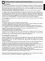 3
3
-
 4
4
-
 5
5
-
 6
6
-
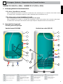 7
7
-
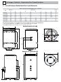 8
8
-
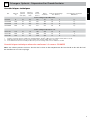 9
9
-
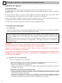 10
10
-
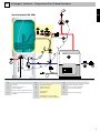 11
11
-
 12
12
-
 13
13
-
 14
14
-
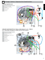 15
15
-
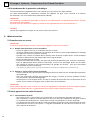 16
16
-
 17
17
-
 18
18
-
 19
19
-
 20
20
-
 21
21
-
 22
22
-
 23
23
-
 24
24
-
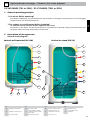 25
25
-
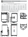 26
26
-
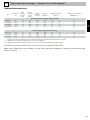 27
27
-
 28
28
-
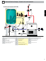 29
29
-
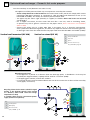 30
30
-
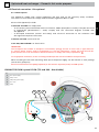 31
31
-
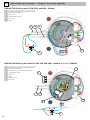 32
32
-
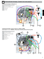 33
33
-
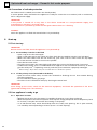 34
34
-
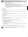 35
35
-
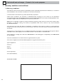 36
36
-
 37
37
-
 38
38
-
 39
39
-
 40
40
-
 41
41
-
 42
42
-
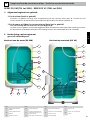 43
43
-
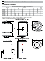 44
44
-
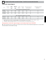 45
45
-
 46
46
-
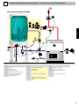 47
47
-
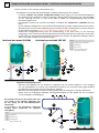 48
48
-
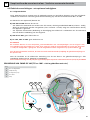 49
49
-
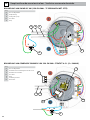 50
50
-
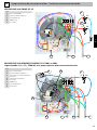 51
51
-
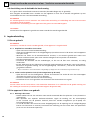 52
52
-
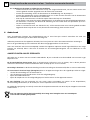 53
53
-
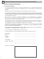 54
54
-
 55
55
-
 56
56


Atlantic edition 2014 PECS 1998-2016 Installation and User Manual
- Type
- Installation and User Manual
in andere talen
- English: Atlantic edition 2014 PECS 1998-2016
- français: Atlantic edition 2014 PECS 1998-2016
Gerelateerde artikelen
-
Atlantic ODEO 2020 Installation and User Manual
-
-
-
-
-
-
-
-
Andere documenten
-
PACIFIC CHAUFFE EAU DRAKKAR de handleiding
-
Tecumseh RKA5513CXC Drawing Data
-
THERMOR CHAUFFE EAU PETITES CAPACITES de handleiding
-
DeDietrich Installation and user’s instruction manual CEB / CES de handleiding
-
 De Dietrich Installation and user’s instruction manual CEB / CES Handleiding
-
RADSON HYBV Installatie gids
-
Casselin CDEC68 Handleiding
-
AEG GYB08016XA de handleiding
-
Wolf CSW-120 Assembly Instructions
