THERMOR CHAUFFE EAU PETITES CAPACITES de handleiding
- Type
- de handleiding

3
CARACTÉRISTIQUES TECHNIQUES / TECHNICAL CHARACTERISTICS / TECHNISCHE KENMERKEN
CAPACI++TÉ PUISSANCE (W) ALIMENTATION CONSOMMATION D’ENTRETIEN(1) DIMENSIONS (MM) POIDS NU
CAPACI+TY POWER (W) POWER SUPPLY CONSUMPTION FOR STEADY TEMP(1) DIMENSIONS (MM) WEIGHT EMPTY
INHOUD VERMOGEN (W) VOEDING VERBRUIK HANDHAVING TEMPERATUUR(1) AFMETINGEN (MM) NAAKT GEWICHT
(L) A.C.I.+ Blindée A.C.I.+ Blindée A* B C D E F (EN KG)
A.C.I.+ Shielded A.C.I.+ Shielded ACI+ Blindée ACI+ Blindée
(IN KG)
(l) A.C.I.+
Geblindeerde weerstand
A.C.I.+
Geblindeerde weerstand (KG)
50L 1200/1800
(2)
1200 MO MO 0,82 0,82 576 - - 35 368 156 - 22
75L 1200/2400
(2)
1200 MO MO 1,02 1,02 742 - - 35 570 120 - 27
100L 1200/2400
(2)
1200 MO MO 1,25 1,25 908 - - 35 748 113 - 32
150L 1800/3000
(2)
1600/1650 MO
(3)
MO/TC 1,59 1,75 1241 - 798 35 1048 146 - 41
200L 2400/3000
(2)
2200 MO
(3)
MO/TC 1,84 2,04 1568 - 798 35 1048 473 - 51
Verticaux muraux A.C.I.+ et blindés / A.C.I.+ and immersion element Vertical wall mounted units / Verticale muurboi-
lers A.C.I.+ en Geblindeerde weerstanden
* Hauteur sur trépied, ajouter 492 mm. (2) Puissance à l’export
* Height on tripod, add 492 mm. (2) Power for export
* Hoogte op driepoot, 492 mm. (2) Vermogen
150 1800 2200 MO
(3)
MO 1,59 1,69 1005 575 567 161 31 10 2 40
200 2400 2200 MO
(3)
MO 1,81 2,08 1260 575 567 161 31 10 2 51
250 3000 3300 MO
(3)
MO/TC 2,07 2,48 1499 575 567 161 31 10 2 57
300 3000 3300 MO
(3)
MO/TC 2,5 2,77 1761 575 567 161 31 10 2 67
500 - 5000 - TC - 4,00 Cf schéma 147
Stables A.C.I.+ et Blindés / Floor-standing units / Boilers op pootjes A.C.I.+ en Geblindeerde weerstanden
Alimentation MO : 230 V monophasé
• Alimentation TC - Tous courants, livré triphasé 400 V commutable en monophasé 230 V
(1) KWh/24h à 65°C - (1) KWh/24h at 65°C - (1) kWh/24 h bij 65 °C
Voeding MO = 230 V eenfasig
• Voeding TC = alle stroomtypes, bij de levering driefasig 400 V, overschakelbaar op eenfasig 230 V
MO power supply : 230 V single phased
• TC power supply - all types of power supplies, delivered 400 V three phase switchable to 230 V single phase
ø1”
ø1”
500L
31
678
26
25
a=45
60
ø3/4”
F
70°
74
347
ø3/4”
A
B
D
175
505
513 200L ACI+
529
230
C
E
440
315
ø3/4”
ø B
A
D
C
E
250
270*
150 à 300L
(3) Possible avec kit triphasé 400V / Possible with 400 V three-phase kit / Mogelijk een 400V driefasig onbouwkit P. 15

4
CAPACITÉ PUISSANCE (W) ALIMENTATION CONSOMMATION D’ENTRETIEN(1) DIMENSIONS (MM) POIDS NU
CAPACITY POWER (W) POWER SUPPLY CONSUMPTION FOR STEADY TEMP(1) DIMENSIONS (MM) WEIGHT EMPTY
INHOUD VERMOGEN (W) VOEDING VERBRUIK HANDHAVING TEMPERATUUR(1) AFMETINGEN (MM) NAAKT GEWICHT
(L) A.C.I.+ Blindée A.C.I.+ Blindée A B** C D E (EN KG)
A.C.I.+ Shielded A.C.I.+ Shielded ACI+ Blindée
(IN KG)
A.C.I.+
Geblindeerde weerstand
A.C.I.+
Geblindeerde weerstand (KG)
75 - 1600 - MO - 1,09 - - 580 600 - 28
100 1800 1600 MO
(3)
MO 1,28 1,24 860 600 580 600 - 32
150 1800 2200 MO
(3)
MO 1,60 1,59 1182 800 580 600 - 41
200 2100 2200 MO
(3)
MO 2,06 1,96 1509 1050 580 600 - 50
Horizontaux A.C.I.+ / A.C.I.+ Horizontal units / Horizontale boilers A.C.I.+
** Distance entre les deux étriers de fixation. Nota : voir page 9 pour fixation au sol.
** Distance between two attachment stirrups. Note : see page 9 for attachment to floor
** Afstand tussen beide bevestigingshaken. Noot: zie p. 9 wat betreft de bevestiging op de vloer.
10L sous/und/ond 2000 MO 0,63 456 255 218 262 64 7
10L sur/abov./bov. 1600 MO 0,48 456 255 289 262 64 7
15L sur/abov./bov. 2000 MO 0,53 496 287 327 294 70 9
15L sous/und/ond 2000 MO 0,66 399 338 164 345 81 9
15L sur/abov./bov. 1600 MO 0,58 399 338 236 345 81 9
30L sur/abov./bov. 2000 MO 0,76 623 338 463 345 81 12,5
50L sur/abov./bov. 2000 MO 1,13 918 338 750 345 81 17,2
Petites Capacités (sur ou sous évier) / Small tanks (above or under sink) / Kleine inhoud (boven of onder gootsteen)
100 A 200 L
75 L
90
46
691
195
Fixation Mur
Wall mounting
Wandbevestiging
Fixation Plafond
Ceiling mounting
Bevestiging aan plafond
sur évier
above sink
boven gootsteen
sous évier
under sink
onder gootsteen
CARACTÉRISTIQUES TECHNIQUES / TECHNICAL CHARACTERISTICS / TECHNISCHE KENMERKEN
Alimentation MO : 230 V monophasé / • Alimentation TC - Tous courants, livré triphasé 400 V commutable en monophasé 230 v / (1) KWh/24h à 65°C
MO power supply : 230 V single phased • TC power supply : all types of power supplies, delivered 400 V three phase switchable to 230 V single phase /
(1)
KWh/24h at 65°C
Voeding MO = 230 V eenfasig / Voeding TC = alle stroomtypes, bij de levering driefasig 400 V, overschakelbaar op eenfasig 230 V /
(1)
kWh/24 h bij 65 °C
E
D
C
184
100
A
ØB
G1/2“
E
D
C
100
A
ØB
G1/2“
(3) Possible avec kit triphasé 400V / Possible with 400 V three-phase kit / Mogelijk een 400V driefasig onbouwkit P. 15

5
CAPACI+TÉ PUISSANCE ECHANGEUR PUISSANCE ELECTRIQUE CONSOMMATION D’ENTRETIEN** DIMENSIONS POIDS NU
(L) KW(1) W(2)(3) MM KG
CAPACI+TY EXCHANGER POWER POWER SUPPLY CONSUMPTION FOR STEADY TEMP DIMENSIONS WEIGHT EMPTY
INHOUD Vermogen warmtewisselaar VERMOGEN VERBRUIK HANDHAVING TEMPERATUUR AFMETINGEN NAAKT GEWICHT
ø A* B C D E F
75 19,3 - 1,43 505 728 320 386 490 529 - 36
100 19,3 - 1,54 505 861 498 393 497 529 - 41
150 25,6 2 400 1,76 505 1194 798 437 541 529 - 55
200 25,6 2 400 1,98 505 1521 798 437 541 529 - 63
Préparateur eau chaude sanitaire et mixte mural / Wall mounted indirect storage water heaters /
Combi boilers en Ketels met warmtewisselaars - Spiraalweerstand (wandbevostiging)
* Hauteur sur trépied, ajouter 492 mm - (1) Primaire : température 90° C, débit 2 m
3
/h - Secondaire : température 10-45° C
(2) Equipant les chaufffe-eau mixtes - (3) Kit électrique en option
* Height on tripot, add 492 mm - (1) Primary : temperature 90° C, flew2m
3
/h - Secondary temperature 10-45° C -
(2) Used on indirect storage with element - (3) Electrical kit optional
* Hoogte op driepoot, 492 mm toevoegen. - (1) Primair circuit: temperatuur 90 °C, debiet 2 m
3
/h. -
(2) Combi toestellen: geblindeerde weerstand. - (3) Option
150 30 2 400 1,76 577 1015 420 455 356 645 304 62
200 43,2 3 300 2,20 577 1270 533 543 465 645 446 73
300 49 3 300 2,97 577 1787 1006 587 489 645 490 94
Préparateur eau chaude sanitaire stable / Floor standing indirect storage water heaters /
Op pootjes ketels met warmtewisselaars spiraalweerstand
CARACTÉRISTIQUES TECHNIQUES / TECHNICAL CHARACTERISTICS / TECHNISCHE KENMERKEN
** KWh/24h à 65°C
V** kWh/24 h bij 65 °C
** KWh/24h at 65°C
eau chaude
Ø S
H
A
F
eau
froide
ØS
ØP
ØP

6
MISE EN PLACE / INSTALLATION / INSTALLATIE
• Installer l’appareil dans un local à l’abri du gel.
• Pour les appareils muraux (verticaux et horizontaux), s’assurer que la cloison est capable de supporter le
poids de l’appareil rempli d’eau.
• Si l’appareil doit être installé dans un local humide ou un emplacement dont la température ambiante est
en permanence à plus de 35°C, prévoir une aération de ce local.
• Installation dans la salle de bains : 4 volumes sont définis pour implanter des appareils suivant leurs carac-
téristiques. Nos chauffe-eau électriques peuvent être installés dans tous les volumes (hors vol. 0 = bai-
gnoire) ci-dessous référencés, selon leur classe suivant les consignes d’installation de la norme NF C15-
100, tableau 701-4 et règle 701-5. (FIG. 1)
FIXATION D’UN APPAREIL VERTICAL MURAL
Chauffe-eau* et ballon à échangeur
• Laisser au dessous des extrémités des tubes de l’appareil un espace libre au moins égal 300 mm (jusqu’à
100L) / 480 mm (150 et 200L).
• Fixer l’appareil au mur par 4 boulons Ø 10 mm préalablement scellés (2 boulons seulement pour les
modèles 50, 75 et 100L).
• Les appareils peuvent être montés sur trépied (en option). Il est cependant obligatoire de fixer au mur
l’étrier supérieur de l’appareil pour éviter tout basculement.
• Il est possible de remplacer d’anciens appareils verticaux muraux sans refaire le perçage grâce à un systè-
me de pattes de transfert (disponible en option).
POSE D’UN CHAUFFE-EAU STABLE
• L’appareil doit être installé en position strictement verticale avec accessibilité à l’équipement électrique et
au groupe de sécurité.
CHAUFFE-EAU HORIZONTAL cf. Figure 2
DIFFÉRENTES POSSIBILITÉS D’INSTALLATION
ATTENTION : une fois le chauffe-eau mis en place, les têtes de raccordement hydraulique doivent impérati-
vement se trouver en position strictement verticale en dessous de l’appareil.
PETITES CAPACITÉS
Fixation murale : fixer l’étrier sur le mur à l’aide de goujons M8, préalablement scellés et d'écrous M8.
Attention : on ne peut pas mettre un chauffe-eau sur évier en lieu et place d’un chauffe-eau sous-évier
et inversement. (FIG. 3)
• Install the unit in a room protected from frost.
• For wall mounted units (vertical and horizontal), make sure that the wall is strong enough to support the
weight of the unit full of water.
• If the water heater is to be installed in a damp room or in a location in which the ambient temperature is
continuously above 35°C, then ventilate this room.
• Installation in the bathroom: four volumes are defined in which units may be installed, depending on their
characteristics. Our electric water heaters may be installed in all volumes (apart from volume 0 = bath) shown
below, in accordance with their class and with the installation instructions in NF standard C15-100, table 701-
4 and rule 701-5.
MOUNTING OF A WALL MOUNTED VERTICAL MODEL
Water heater* and exchanger tank
• Leave a free space of at least 300 mm (for 100 L models) or 480 mm (for 150 and 200 L models) below the
ends of the water heater tubes.
• Fix the unit to the wall using four Ø 10 mm bolts already anchored into the wall (only 2 bolts for 50, 75 and
100 L models).
• Units may be mounted on a tripod (optional). However, the upper stirrup of the unit must be attached
to the wall to prevent the unit from tipping.
• Old wall mounted units can be replaced without drilling new holes by using a load transfer system (available
as option).
INSTALLATION A FLOOR-STANDING WATER HEATER
• The unit must be installed in the strictly vertical position, and the electrical equipment for the safety device must
be accessible.
HORIZONTAL WATER HEARTER figure 2
SMALL TANKS
Wall attachment: fix the stirrups to the wall using M8 studs anchored to the wall and M8 nuts. Warning: an
under sink model cannot be replaced by an above sink model and vice versa. (FIG. 3)
(*hors petites capacités) / (*except for small tanks) / (*behalve kleine modellen)

7
MISE EN PLACE / INSTALLATION / INSTALLATIE
(FIG. 1)
(FIG. 2)
(FIG. 3)
• Installeer het toestel in een vorstvrije ruimte.
• Controleer voor de bevestiging van (verticale en horizontale) wandmodellen of de muur sterk genoeg is om het gewicht van het
met water gevulde toestel te dragen.
• Wordt het toestel opgesteld in een vochtige ruimte of in een ruimte waar de omgevingstemperatuur constant meer dan 35 °C
bedraagt, dan is een ventilatiesysteem noodzakelijk.
• Installatie in een badkamer: voor de opstelling van een toestel dient met 4 volumes rekening te worden gehouden, afhankelijk van
de kenmerken van het toestel. Onze elektrische boilers mogen in alle onderstaande volumes worden opgesteld (behalve in volu-
me 0 = het bad), afhankelijk van hun categorie en volgens de installatierichtlijnen van de norm NF C15-100, tabel 701-4 en regel
701-5.
BEVESTIGING VAN EEN VERTICAAL WANDMODEL
Boiler* en Ketel met warmtewisselaar
• Laat onder de uiteinden van de buizen van het toestel een ruimte van ten minste 300 mm (100 l) of 480 mm (150 -200 l) vrij.
• Bevestig het toestel aan de wand met behulp van 4 vooraf in de muur gemetste bouten Ø 10 mm (2 bouten volstaan voor de model-
len van 50, 75 en 100 l).
• De toestellen kunnen op een (afzonderlijk te verkrijgen) driepoot worden opgesteld. Het is verplicht ze in dat geval aan de muur
te bevestigen met behulp van de bovenste bevestigingshaak om omkantelen te vermijden.
• Het is mogelijk een oud verticaal wandmodel te vervangen zonder nieuwe gaten te moeten boren dankzij de (afzonderlijk te ver-
krijgen) verloophaken.
INSTALLTIE VAN EEN BOILER OP POOTJES
• Stel het toestel perfect verticaal op en zorg ervoor dat de elektrische onderdelen van het veiligheidselement vrij toegankelijk blijven.
HORIZONTALE BOILIER figuur 2
KLEINE MODELLEN
Wandbevestiging: Zet de bevestigingshaak aan de wand vast met behulp van vooraf in de muur gemetste M8 pennen en M8 moeren.
Let op! Een boiler voor boven de gootsteen mag in geen geval onder de gootsteen geïnstalleerd worden of omgekeerd. (FIG.3)
(*hors petites capacités) / (*except for small tanks) / (*behalve kleine modellen)
450
450 450

8
RACCORDEMENT HYDRAULIQUE / WATER CONNECTIONS / AANSLUITING WATERLEIDINGEN
Avant de procéd
er au raccordement hydraulique, il est
absolument indispensable de bien nettoyer les tuyaute-
ries d’alimentation afin de ne pas risquer d’introduire
dans la cuve du chauffe-eau des particules métalliques
ou autres.
ATTENTION : Ne pas raccorder directement aux cana-
lisations en cuivre les tubes eau chaude (repère rouge)
et eau froide (repère bleu) du chauffe-eau; pour éviter
les couples galvaniques fer/cuivre. Il est obligatoire
d’équiper le tube eau chaude d’un raccord diélectrique
(généralement fourni avec l’appareil hors petites capa-
cités) et le tube eau froide d’un groupe de sécurité.
En cas de corrosion des filetages des tubes non
équipés de ces protections, notre garantie ne pour-
rait être appliquée.
Quel que soit le type d’installation, elle doit comporter
un robinet d’arrêt sur l’alimentation d’eau froide, en
amont du groupe de sécurité.
Un chauffe-eau à accumulation peut être utilisé de
deux façons :
1 - sous pr
ession quand il doit desservir plusieurs postes
d’eau. L’installation doit comporter un réducteur de
pression si la pression d’alimentation est supérieure à 5
bar. Le réducteur de pression doit être monté au
départ de la distribution générale. Une pression de 3
à 4 bar est recommandée. L’installation doit être effec-
tuée avec un groupe de sécurité taré à 7 bar (non four-
ni ), neuf, de dimensions appropriées à la capaci+té
(petites capacités : 1/2”, 50 à 300l : 3/4”, 500 l : 1”),
et portant la marque NF (norme NFD 36-401).
Son installation doit être faite rigoureusement selon les
schémas ci-après (p.10). Il est obligatoire de placer le
groupe de sécurité directement sur l’entrée d’eau
froide (NFC 15-100 ch 559-3).
Before making the water connections, it is essential to
ensure that the supply pipes are thoroughly clean, to
avoid any risk of metallic or other particles entering the
water heater tank.
WARNING : do not connect water heater hot water
pipes (red mark) and cold water pipes (blue mark)
directly to copper pipes, to prevent iron-copper galva-
nic couples. The hot water pipe must be fitted with a
dielectric connector (supplied with the equipment
except for small tanks) and the cold water pipe with a
safety valve.
Our guarantee will be invalid if there is any corro-
sion on the threads of pipes not fitted with these
protectives devices.
Regardless of the installation type, it must include a
stop tap on the cold water supply, before the safety
valve.
A storage water heater may be used in two different
ways :
1 - pr
essurized when it supplies several taps. The ins-
tallation must include a pressure reducer if the supply
pressure exceeds 5 bar. The pressure reducer must
be installed at the outlet of the general distribu-
tion. A pressure of 3 to 4 bar is recommended. The
installation must be done using a new safety valve set
to 7 bar not supplied, with dimensions appropriate to
the tank (1/2" for small tanks, 3/4" for 50 to 300 L
models, and 1" for 500 l models), and bearing the NF
mark (standard NF D 36-401).
It must be installed strictly respecting the following
diagrams (p. 10). It is recommended that the safe-
ty valve should be placed directly on the cold water
inlet (NFC 15-100 ch 559-3).
Alvorens het toestel op de waterleidingen aan te slui-
ten, is het absoluut noodzakelijk de toevoerbuizen
schoon te maken om te vermijden dat metalen of
andere deeltjes in de tank van de boiler terecht komen.
LET OP ! Sluit de warmwaterbuizen (rood kenteken)
en de koudwaterbuizen (blauw kenteken) van de boi-
ler in geen geval rechtstreeks op koperen buizen aan
om te vermijden dat een galvanisch koppel
(ijzer/koper) ontstaat. Het is verplicht de warmwater-
buis van een diëlektrische koppeling te voorzien (bij
het toestel geleverd, behalve bij de kleine modellen)
en de koudwaterbuis van een veiligheidselement.
Krijgen de schroefdraden van buizen die niet met
dergelijke beveiligingen zijn uitgerust, te lijden
onder corrosie, dan geldt onze garantie niet.
Het is bij alle soorten installaties verplicht op de koud-
watertoevoer, vóór het veiligheidselement, een afsluit-
kraan te voorzien.
Een boiler kan op twee manier worden gebruikt :
1 - onder dr
uk, wanneer hij water moet produceren
dat op verschillende plaatsen kan worden afgetapt. De
installatie moet voorzien zijn van een reduceerventiel
indien de druk meer dan 5 bar bedraagt. Het redu-
ceerventiel moet gemonteerd worden aan het
begin van de algemene waterdistributie. Wij raden
een druk van 3 tot 4 bar aan. De installatie moet voor-
zien zijn van een op 7 bar getarreerd (niet bijgeleverd)
veiligheidselement dat het merkteken NF (norm NFD
36-401) draagt en waarvan de afmetingen aan de
inhoud zijn aangepast (kleine inhoud : 1/2", 50 tot
300 l: 3/4", 500 l: 1").
Bij de installatie dienen de schema's op p. 10 nauw-
keurig in acht te worden genomen. Het is verplicht
het veiligheidselement rechtstreeks op de koudwa-
tertoevoer te plaatsen (NFC 15-100 ch 559-3).

9
RACCORDEMENT HYDRAULIQUE / WATER CONNECTIONS / AANSLUITING WATERLEIDINGEN
- En outre, il ne faut absolument pas qu’en cas de sur-
pression, l’écoulement en résultant puisse être freiné.
Ceci implique que le tube de vidange ait une pente
continue et suffisante, et un diamètre adapté au débit.
2 - en écoulement libr
e, pour alimenter un seul point
d’eau : Ce type d’installation est spécialement adapté
aux chauffe-eau de la gamme des petites capacités de
10, 15, 30 et 50 L, sur-évier et sous-évier suivant les
modèles, lorsqu’ils ne peuvent être installés sous pres-
sion. L’installation doit être réalisée avec un robinet
mélangeur spécifique. Dans ce cas, il n’y a pas lieu
d’utiliser un groupe de sécurité.
Attention, il est normal que cela goutte par la
robinetterie, lors des périodes de chauffe. Ne pas
obstruer l’écoulement.
- Furthermore, if there is an overpressure, the resulting
flow must never be hindered. This means that the
drain pipe should have a continuous and sufficient
slope, and its diameter should be appropriate for the
flow.
During heating periods, the water contained in the
tank expands and some will escape as a slow stream by
draining (about 3% of the capaci+ty for each heating
cycle). This is nothing to worry about, this phenome-
non is absolutely normal.
It is recommended that a retention tank should be pla-
ced under the water heater with drainage if the tank is
installed on an upper floor.
2 - in fr
ee flow, when only a single water tap is to be
supplied. This type of installation is specifically adap-
ted to point-of-use water heaters (i.e. capacities of 10,
15, 30 and 50 L) that cannot be installed as unvented
systems (i.e. pressurised). The installation must be
made with a special mixing tap. In this case there is
no need for a safety valve.
- Bovendien mag het wegvloeiend water bij overdruk
in geen geval worden afgeremd. Dat betekent dat de
aftapbuis constant en op toereikende wijze moet afhel-
len en dat de diameter geschikt moet zijn voor het
debiet.
Tijdens het opwarmen zet het water in de tank uit en
een deel van dat water ontsnapt druppelsgewijze via
de afvoergoot (ongeveer 3 % van de inhoud per ver-
warmingscyclus). U hoeft zich daar geen zorgen over
te maken: dit is een heel normaal verschijnsel.
Wordt het toestel in de hoogte geïnstalleerd, dan is het
raadzaam een vergaarbak met een afvoergoot onder
de boiler te monteren.
2 - met een spontane waterafvoer
, voor één enkele
waterkraan. Dit soort installatie is speciaal aangepast
voor de kleine inhoud boilers van 10, 15, 30 en 50
liters, boven en onder de gootsteen volgens de model-
len, toen ze kunnen niet onder druk geplaatst worden.
In dit geval is de installatie van een specifieke meng-
kraan noodzakelijk; een veiligheidselement is echter
overbodig.

10
RACCORDEMENT HYDRAULIQUE / WATER CONNECTIONS / AANSLUITING WATERLEIDINGEN
A
B
C
D
2
3
4
5
6
1
7
ECOULEMENT LIBRE (*)
FREE FLOW (*)
S
PONTANE AFVOER (*)
6
7
1
2
5
SOUS PRESSION (*)
MAINS PRESSURE (*)
O
NDER DRUK (*)
4
3
7
1
5
VERTICAUX MURAUX
VERTICAL WALL MOUNTED
VERTICALE WANDMODELLEN
3
4
6
2
Arrivée eau froide / Cold water inlet / Koudwatertoevoer
Robinet d’arrêt / Stop tap/ Afsluitkraan
Réducteur de pression éventuel / Pressure reducer if necessary / Eventueel reduceerventiel
Groupe de sécurité / Safety valve / Veiligheidselement
Entonnoir / Funnel / Trechter
Départ eau chaude / Hot water outlet / Warmwaterafvoer
Manchon diélectrique obligatoire / Compulsory dielectric connection / Verplichte diëlektrische mof
1
2
3
4
5
6
7
* Ces schémas montrent l’installation des appa-
reils sous évier.
Pour les modèles sur-évier, les raccordements
sont sous l’appareil comme dans le cas des
appareils muraux.
** Les appareils équipés d’un échangeur ser-
pentin doivent être installés en position verti-
cale, avec une pompe de charge (cf fig. 1)
* These diagrams show the installation of
under sink models.
Connections for above sink models are
under the water heater as in the case of wall
mounted equipment.
** Vertical wall mounted and horizontal water
heaters may also be mounted in series using
the same principale.
* Deze schema's illustreren de installatie van
toestellen onder de gootsteen.
De installatie van toestellen voor boven de
gootsteen is dezelfde als bij wandmodellen.
** De verticale en horizontale wandmodellen
kunnen ook volgens hetzelfde principe in
serie gemonteerd worden.
Arrivée d’eau froide
Cold water inlet/ Koudwatertoevoer
Départ eau chaude sanitaire
Domestic hot water outlet / Afvoer warm water voor sanitair
Retour chauffage
Heating return / Retour verwarming
Départ chauffage
Heating outlet / Afvoer verwarming
Purgeur automatique / Automatic purge /
Automatische aftapkraan
Clapet anti-retour / Non-return valve /
Terugslagklep
Pompe de charge / Pressurizing pump / Circulatiepomp
Raccordement par flexible / Flexible connection / Aansluiting
Aquastat commande pompe de charge (option) / Pumpthermostat (optional) /
Thermostaat pomp (option)
(FIG. 1)**
1
Kit Pompe de charge / Kit pomp / Kit pump
- Electrical connection
Thermostat / pump
- Elektrische armsluiting
Thermostat / pomp
Thermostat / pump
C
D
Liaison électrique
aquastat/pompe
1
2
5
3
4
B
A
400 mm
mini

11
RACCORDEMENT HYDRAULIQUE / WATER CONNECTIONS /AANSLUITING WATERLEIDINGEN
INFORMATIONS COMPLEMENTAIRES
POUR LES P.E.C.S.
(FIG. 1)
Ces appareils possèdent :
- Un circuit primaire qui doit être fermé par raccordement à une sour-
ce de chaleur, telle que chaudière de chauffage central. La pression de
service de ce circuit ne devra pas excéder 3 bar et sa température
100°C (entrée et sortie de ce circuit repérées en blanc sur l’extrémité
ou sur le côté - Ø 1” femelle).
- Un circuit secondaire pour l’eau chaude sanitaire (entrée de l’eau froi-
de repérée en bleu et sortie de l’eau chaude repérée en rouge).
Le raccordement à l’installation de chauffage central s’effectue au
moyen de tubes d’un diamètre intérieur minimum de 20 mm. Utiliser
de préférence des tubes en aci+er pour éviter tout risque de corrosion
et en intercalant une vanne de sectionnement. L’appareil est pourvu
d’un doigt de gant pour placer la sonde régulant le circuit primaire (en
option).
Dans le cas où des vannes de sectionnement sont intercalées, il est
impératif de laisser ces vannes ouvertes afin d’éviter les surpressions à
l’intérieur du serpentin.
1
re
mise en service
Remplir impérativement le circuit primaire en premier (circuit connec-
té à la chaudière)
• ouvrir le robinet d’eau de ville, dévisser le purgeur d’air afin d’évacuer
l’air introduit par l’opération de remplissage
• mettre la pompe de charge en marche quelques instants afin d’accé-
lérer l’opération de dégazage.
ATTENTION MODELES A.C.I.
(uniquement pour les préparateurs d’eau chaude sanitaire)
les appareils à échangeur serpentin sont protégés contre la corrosion
par un système électronique (système A.C.I.) qui doit être alimenté
sous 230 V 24 h/24 pendant les périodes d’utilisation. En cas d’absen-
ce prolongée, il est possible de couper l’alimentation.
Le branchement du système A.C.I. s’effectue par la connexion du câble
de raccordement fourni et précablé sur l’appareil. Utiliser une alimen-
tation indépendante qui est continuellement sous tension. La garantie
dépend du bon raccordement du système. Un petit voyant lumineux
clignotant vous indique que le système est sous tension.
ADDITIONAL INFORMATION FOR INDIRECT
STORAGE WATER HEATERS
(FIG. 1)
These water heaters have:
- A primary circuit that must be closed by connection to a heat source,
such as a central heating boiler. The working pressure in this circuit
must not exceed 6 bar and its temperature must not exceed 100°C
(inlet and outlet for this circuit marked in white on the end or on the
side - Æ 1" female fitting).
- A secondary circuit for domestic hot water (cold water inlet marked in
blue and hot water outlet marked in red).
The first step is to supply the primary circuit, and then the secondary
circuit, with water.
The connection to the central heating installation is made using pipes
with a minimum inside diameter of 20 mm. Use steel tubes in prefe-
rence to prevent any risk of corrosion, and include an isolating valve.
The unit is provided with a well in which the probe regulating the pri-
mary circuit can be placed (optional).
If isolating valves are inserted, it is essential that these valves should be
left open to avoid overpressures inside the coil.
1st star
t up:
The primary circuit must be filled first (circuit connected to the boiler)
• Open the town water tap, unscrew the air purge to allow air that
entered during the filling operation to escape.
• Start up the pressurizing pump for a few minutes in order to accele-
rate the degassing operation.
WARNING A.C.I. MODELS
(Indirect storage water heaters solely)
Water heaters with concentric coil heat exchangers are protected
against corrosion by an electronic system (A.C.I. system) that must be
powered at 230 V for 24 hours per day during usage periods. The
power supply can be switched off if the premises are vacant for a long
period.
The A.C.I. system is plugged in using the connecting cable supplied
and pre-wired onto the water heater. Use an independent power sup-
ply that is never switched off. The guarantee will be null and void if the
system is not properly connected. A small flashing light indicator
informs you that the system is switched on.
BIJKOMSTIGE INFORMATIE M.B.T. DE
COMBI BOILERS
(FIG. 1)
Deze toestellen zijn voorzien van:
- Een primair circuit dat gesloten moet zijn door aansluiting op een warm-
tebron, bij voorbeeld op de verwarmingsketel van de centrale verwarming.
De bedrijfsdruk van dit circuit mag niet meer bedragen dan 6 bar en de
temperatuur 100 °C (in- en uitgang van dit circuit zijn in het wit aangeduid
op het uiteinde of aan de zijkant - Ø 1" wartelring).
- Een secundair circuit voor het warm water voor het sanitair (koudwater-
toevoer aangeduid in het blauw en warmwaterafvoer in het rood).
Eerst moet het primair circuit van water voorzien worden en daarna het
secundair circuit. De aansluiting op de centrale verwarmingsinstallatie
gebeurt met behulp van buizen met een binnendiameter van ten minste
20 mm. Gebruik bij voorkeur stalen buizen om corrosieverschijnselen te
vermijden en monteer tussenin een afsluitschuif.
Het toestel is voorzien van een taster om de sonde die het primair circuit
regelt, te plaatsen (en option).
Eventueel tussengeschakelde afsluitschuiven moeten open blijven om
overdruk in de spiraal te vermijden.
1ste indienstneming:
Vul in ieder geval eerst het primair circuit (het circuit dat op de verwar-
mingsketel is aangesloten).
• Draai de hoofdwaterkraan open en draai de ontluchtingskraan los om de
tijdens het vullen binnengestroomde lucht te verwijderen.
• Schakel de circulatiepomp enkele ogenblikken in om het ontluchten te
versnellen.
LET OP A.C.I .
(M.B.T. de combi boilers tijdens)
De toestellen met een spiraalwisselaar zijn voorzien van een elektronisch cor-
rosie werend veiligheidssysteem (het A.C.I. syteem); dit systeem moet tijdens
het gebruik 24 uur per dag op een 230 V net aangesloten blijven. Bent u vrij
lang afwezig, dan kan de stroom onderbroken worden.
Het A.C.I. systeem wordt aangesloten d.m.v. het bijgeleverde en voorbe-
kabelde snoer. Gebruik een afzonderlijke voeding die constant onder span-
ning staat. De garantie is slechts geldig indien het systeem behoorlijk is aan-
gesloten. Een knipperend controlelampje wijst erop dat het systeem onder
spanning staat.

12
Le chauffe-eau ne peut être branché et fonctionner que sur un réseau à
courant alternatif.
ATTENTION : LE RACCORDEMENT DE L’ALIMENTATION S’EFFECTUE
SUR LE BORNIER POUR LES MODÈLES AVEC BORNIER, SUR L’ENTRÉE
DU THERMOSTAT POUR LES MODÈLES SANS BORNIER ET EN
AUCUN CAS SUR LA RESISTANCE OU À LA SORTIE DU THERMO-
STAT. AUCUNE INTERVENTION SUPPLEMENTAIRE N’EST A PREVOIR
EXCEPTÉS LES CHANGEMENTS DE COUPLAGE SI NECESSAIRE. POUR
LES CHAUFFE-EAU A.C.I.+, LE CIRCUIT A.C.I.+ EST PRÉCABLÉ EN
USINE.
• Si le chauffe-eau est un modèle «Tous Courants», veiller à ce que le
câblage électrique de l’appareil soit adapté à la tension
d’alimentation du réseau.
• Le chauffe-eau doit être relié à une canalisation fixe ou une gaine anne-
lée normalisée jusqu’au logement calibré du capot par un câble rigide
(section des conducteurs : minimum 2,5 mm2 et 4 mm2 sur le 500L).
• La mise à la terre est obligatoire. Une borne spéciale portant le repère
est prévue à cet effet.
• L’installation doit comporter en amont du chauffe-eau un dispositif de
coupure omnipolaire avec une distance d’ouverture des contacts d’au
moins 3 mm.
Dans le but d’optimiser la consommation d’énergie, le thermostat a été
réglé pour que la température de l’eau dans le chauffe-eau soit limitée à
65° C (± 5°C) ; la résistance à la corrosion et à l’entartrage s’en trouve
améliorée.
Le thermostat ne doit sous aucun pretexte subir d’éventuels réglages ou
réparations en dehors de nos usines à l’exception du réglage normal par
rotation de l’index (qui ne peut être effectué que par l’installateur après
mise hors tension de l’appareil). Le non respect de cette clause suppri-
me le bénéfice de la garantie.
PETITES CAP
ACITÉS : Le thermostat est réglé en usine à 65°C (± 5°C). Il
vous est possible de modifier ce réglage par la molette du thermostat.
Diminuer la température de réglage contribue à diminuer les dépôts de
calcaire. Le témoin de fonctionnement reste allumé uniquement pendant
la phase de chauffe.
COUPE-CIRCUIT THERMIQUE :
Tous nos chauffe-eau sont équipés d’un coupe-circuit de sécurité qui
déclenche l’arrêt du chauffe-eau si la température atteint accidentelle-
ment une valeur exagérée. En cas de déclenchement de la sécurité, COU-
PER LE COURANT AVANT TOUTE OPÉRATION, vérifier l’installation avant
de procéder à son réarmement. Rétablir le courant. En cas de déclenche-
ment répétitif, faire remplacer le thermostat par une personne habilitée.
BRANCHEMENT ÉLECTRIQUE*/ ELECTRICAL CONNECTIONS*/ELEKTRISCHE AANSLUITINGEN *
(CONFORME NFC 15-100)
The water heater can only be connected to and operate on an AC
network.
WARNING: THE POWER SUPPLY IS CONNECTED TO THE TERMI-
NAL BLOCK FOR MODELS WITH A TERMINAL BLOCK, TO THE
THERMOSTAT INPUT FOR MODELS WITHOUT A TERMINAL
BLOCK, AND NEVER TO THE ELEMENT OR THE THERMO-
STAT OUTPUT. NO ADDITIONAL WORK IS REQUIRED, EXCEPT
FOR COUPLING CHANGES IF NECESSARY. THE A.C.I.+ CIRCUIT
ON A.C.I.+ MODELS IS PREWIRED IN THE FACTORY.
• If the water heater is an "All Currents" model, check that its electric
wiring is correctly adjusted for the network power supply voltage.
• The water heater must be connected to a fixed pipe through a
rigid cable (minimum conductor cross-section = 2.5 mm≈ or 4
mm2 for the 500 l tank).
• Earthing is compulsory. A special terminal marked is pro-
vided for this purpose.
• The installation must include an all-pole circuit breaking device
before the water heater, with a contact opening distance of at
least 3 mm.
The thermostat was set so that the water temperature in the water
heater is limited to 65°C (± 5 °C) in order to optimize energy
consumption; this improves resistance to corrosion and to scaling.
The thermostat must not be modified or repaired in any way out-
side our factories for any reason whatsoever, except for normal
adjustment by rotating the index (which should only be done by
the installer after switching the equipment off). Failure to respect
this clause will invalidate the guarantee.
SMALL
TANKS : The thermostat is set to 65°C (±5°C) in the fac-
tory. You can modify this setting using the knurled knob on the
thermostat. Reducing the temperature will help to reduce deposi-
ted scale. The operating light remains on only during the heating
phase.
TEMPERATURE CIRCUIT BREAKER :
All our water heaters are equipped with a safety temperature cir-
cuit breaker that switches the water heater off if the temperature
accidentally reaches an excessively high value. If the safety device
trips, SWITCH OFF THE POWER BEFORE DOING ANYTHING, and
then check the installation before resetting it. Switch the power
on again. Have the thermostat replaced by a professional if it trips
repeatedly.
NEVER SHORT CIRCUIT THE SAFETY DEVICE.
De boiler mag uitsluitend worden aangesloten op wisselstroom.
LET OP ! BIJ DE MODELLEN MET EEN AANSLUITKLEMMENBLOK MOET
HET SNOER OP HET AANSLUITKLEMMENBLOK WORDEN AANGESLO-
TEN, BIJ MODELLEN ZONDER AANSLUITKLEMMENBLOK OP DE
INGANG VAN DE THERMOSTAAT. IN GEEN GEVAL OP DE WEERSTAND
OF OP DE UITGANG VAN DE THERMOSTAAT. VERDER BLIJFT DE ELEK-
TRISCHE INSTALLATIE ONGEWIJZIGD, BEHALVE INDIEN DE KOPPELING
VERANDERD DIENT TE WORDEN. BIJ A.C.I.+ BOILERS IS HET A.C.I.+ CIR-
CUIT IN DE FABRIEK VOORBEKABELD.
• Is de boiler een TC-model (alle stroomtypes), controleer of de elek-
trische draden aan de netspanning zijn aangepast
• De boiler moet op een vaste leiding zijn aangesloten d.m.v. een
onbuigzame kabel (doorsnede van de geleiders: minimum 2,5 mm≈ en
4 mm≈ bij het model 500 l).
• De aarding van het toestel is verplicht. Daarvoor is een specifieke aans-
luitklem voorzien .
• De installatie moet stroomopwaarts van de boiler voorzien zijn van een
schakelaar voor alle polen met contactopeningen van ten minste 3 mm.
Om het energieverbruik te optimaliseren werd de thermostaat zo afges-
teld dat de temperatuur van het water in de boiler beperkt blijft tot
65 °C (± 5 °C); zo blijft de weerstand beter bestand tegen corrosie en kal-
kaanslag.
De thermostaat mag in geen geval worden bijgesteld of hersteld buiten
onze fabrieken; alleen de normale afstelling door de installateur is toe-
gestaan, d.w.z. dat alleen hij de wijzer na uitschakeling van het toestel
mag verdraaien. Door niet-naleving van deze clausule vervalt de
garantie.
Verwarmingsketels met een kleine capaci+teit: de thermostaat is in fabriek
afgesteld op 65°C (±5°C). U kunt deze afstelling wijzigen met behulp van
het kartelwieltje op de thermostaat. Een lager afgestelde temperatuur leidt
tot minder kalkaanslag. Het werkingscontrolelampje brandt uitshuitend
tijdens het verwarmen.
THERMISCHE BEVEILIGING:
Al onze boilers zijn voorzien van een beveiliging die de boiler uitschakelt
zodra per ongeluk een overdreven temperatuur wordt bereikt. Treedt het
veiligheidssysteem in werking, ONDERBREEK IN DE EERSTE PLAATS DE
STROOM; de installatie mag pas na een grondige controle opnieuw
gereset worden. Schakel het toestel opnieuw in. Doet het probleem zich
opnieuw voor, raadpleeg een bekwaam technicus om de thermostaat te
laten vervangen.
HET VEILIGHEIDSSYSTEEM MAG IN GEEN GEVAL KORTGESLOTEN WORDEN

13
BRANCHEMENT ÉLECTRIQUE*/ ELECTRICAL CONNECTIONS
(CONFORME NFC 15-100)
EN AUCUN CAS ON NE DOIT COURT-CIRCUITER LA SÉCURITÉ
ACI+ : en cas de déclenchement en sécurité, remplacer le bloc thermo-
stat eléctronique.
PETITES CAP
ACITÉS : Pour réarmer la sécurité, il est nécessaire de retirer le
capot, ensuite, appuyer sur le bouton safety du thermostat. Après avoir
réenclenché la sécurité, remettre le capot et rétablir le courant. En cas de
déclenchement répété, demander l’intervention d’une personne habilitée.
* NOTA : ne concerne pas les ballons à échangeur. Il est cependant obligatoire
de raccorder ce type d’appareils à la terre.
* NOTE: Not applicable to tanks with heater exchanger. However, this type of heater must be earthed.
* NOOT: dit geldt niet voor de ketels met warmtewisselaars. Het is echter verplicht deze toestellen
te aarden.
ACI+ : If the security system set off, change the electronique ther-
mostat.
SMALL TANKS: The safety device is reset by moving the cover,
and then pressing on the safety button of the thermostat. After
resetting the safety device, put the cover back on and switch the
power on again. Have the thermostat replaced by a professional
if it trips repeatedly.
ACI +: Als het veiligheidssysteem in werking treedt, het electronische
thermostaatblok vervangen.
KLEINE MODELLEN:
Om het veiligheidssysteem te resetten is het nood-
zakelijk de kap die toegang geven tot het veiligheidssysteem, te verwij-
deren om vervolgens de safety knop van de thermostaat in te drukken.
Na het veiligheidssysteem opnieuw te hebben ingeschakeld, de kap
opnieuw aanbrengen en het toestel inschakelen. Treedt het veiligheid-
ssysteem opnieuw in werking, raadpleeg een bekwaam technicus.

Verticaux muraux mono
Single phase wall mounted vertical models
Verticale muurboilers eenf.
Horizontaux
Horizontal models
Horizontale modellen
Horizontaux
Stables floor-standing
Op pootjes
OBLIGATION :
Pour bénéficier de la garantie,
il est obligatoire de brancher
le système A.C.I.+
OBLIGATION :
You must plug in the A.C.I.+
system otherwise the
guarantee will not be valid.
VERPLICHT :
Om van de garantie gebruik te
kunnen maken dient u verplicht
het A.C.I.+ systeem aan te sluiten.
14
BRANCHEMENT ÉLECTRIQUE A.C.I.+ / A.C.I.+ ELECTRICAL CONNECTION / ELEKTRISCHE AANSLUITINGEN A.C.I.+
■ MODELES A.C.I.+
A.C.I.+ MODELS
A.C.I.+ MODELLEN
ALIMENTATION
POWER SUPPLY /VOEDING
MONO 230 V
230 V SINGLE PHASE
EENFASING 230 V.
A B
C D
C D
+
+
+
PROCEDURE DE RACCORDEMENT
• Ce chauffe-eau est pré-câblé en 230 V~ mono-
phasé. Pour du 400 V~ triphasé vous devez rem-
placer la platine monophasée d’origine par un
kit triphasé 400V~. La procédure d’installation
de ce kit est détaillée dans la notice joint au kit.
• Raccorder les extrémités du câble sur le ther-
mostat, aux bornes à vis prévues à cet effet (le
démontage du thermostat n’est pas nécessaire).
• Raccorder le fil de terre vert/jaune sur la borne
repère , sur la porte du chauffe-eau.
Voir photos p.15
CONNECTION PROCEDURE
• The original connection for this water heater is
configured for 230 V~ single phase. For a 400 V~
three-phase connection you need to replace the
original single phase plate by a 400 V~three-phase
kit. Refer to the manual enclosed with the kit for
instructionss for installation.
• Connect the ends of the thermostat cables to
the screw terminals provided for this purpose
(there is no need to disassemble the thermostat).
• Connect the yellow/green earthing wire to the
terminal marked with the earthing symbol on the
door of the water heater. See pictures p.15
CONNECTION PROCEDURE
• De oorspronkelijke aansluiting voor deze boiler
is geschikt voor 230 V~ éénfasig. Voor een 400
V~ driefasige aansluiting dient u de oorspronkelij-
ke éénfaseplaat vervangen door een 400 V~ drie-
fasige ombouwkit. Zie handleiding ombouwkit
voor installatie.
• Sluit de uiteinden van de kabel aan op de ther-
mostaat, op de twee hiervoor bestemde schroefk-
lemmen (het is niet nodig the thermostaat te
demonteren).
• Sluit de groen/gele aardleiding aan op de plaats
met het aardesymbool op de deur van de boiler.
p. 15
Règlage de la température
de l’eau /
Water temperature setting /
Instelling watertemperatuur

15
BRANCHEMENT ÉLECTRIQUE A.C.I.+ / A.C.I.+ ELECTRICAL CONNECTION / ELEKTRISCHE AANSLUITINGEN A.C.I.+
AB
C
D
Borne de terre / Earthing terminal / Aardingsklem
Filerie de l’ACI / ICA wiring / Bedrading ACI
Voyant ACI / ICA pilot light / ACI signaalampje
Bornier d’alimentation (non polarisé) /
Supply terminal (not polarized) /
Stroomvoedingsklem (niet gepolariseerd)
Filerie élément chauffant / Heating element wiring
Bedrading verwarmingselement
Règlage de la température de l’eau / Water
temperature setting / Instelling watertemperatuur
Element chauffant / Heating element /
Verwarmingselement
Connecteur filerie élément chauffant /
Heating element wiring connector /
Aansluitklem bedrading verwarmingselement
Sonde température / Heat sensor /
Temperatuursensor
Borne de terre / Earthing terminal / Aardingsklem
Element chauffant / Heating element /
Verwarmingselement
Sonde température / Heat sensor /
Temperatuursensor
Bornier d’alimentation (non polarisé) /
Supply terminal (not polarized) /
Stroomvoedingsklem (niet gepolariseerd)
Filerie élément chauffant / Heating element wiring
Bedrading verwarmingselement
Connecteur filerie élément chauffant /
Heating element wiring connector /
Aansluitklem bedrading verwarmingselement
Filerie de l’ACI / ICA wiring / Bedrading ACI
Voyant de chauffe ACI / ACI pilot light heating /
ACI signaalampje
Règlage de la température de l’eau / Water
temperature setting / Instelling watertemperatuur
EFFECTUER LE RACCORDEMENT DE L’ALIMENTATION SUR LE BORNIER UNIQUEMENT /
CONNECT THE POWER SUPPLY ONLY VIA THE TERMINAL / DE STROOM ENKEL OP DE KLEMMENSTROOL ANSLUITEN

16
BRANCHEMENT ÉLECTRIQUE MIXTES ET PREPARATEURS EAU CHAUDE SANITAIRE
ALIMENTATION
POWER SUPPLY / VOEDING
MONO / SINGLE PHASE/ EENF.
Préparateur eau chaude sanitaire vertical mural
Indirect storage wall mounted
Ketels met warmtewisselaars wandmodel
Préparateur eau chaude sanitaire stable
Indirect storage floor standing
Op pootjes ketels met warmtewisselaars
J1
K1
1- Ph : Phase alimentation
2- S : Pompe «Circuit sanitaire»
3- Ch : Pompe «Circuit Chauffage
J1
K1
* Und Ketels met warmtewisselaars
OBLIGATION : Pour bénéficier de la garantie, il est obligatoire de brancher
le système A.C.I.
OBLIGA
TION : You must plug in the A.C.I. system otherwise the guarantee
will not be valid.
VERPLICHT :
Om van de garantie gebruik te kunnen maken dient u
verplicht het A.C.I. systeem aan te sluiten.
(75-200 L)
(150-300 L)
(Uniquement sur 150-200L)
Commande de pompe
Commande
de pompe
Alimentation 230V pompe
Alimentation
230V pompe
Câble non fourni
N
N
N
L
N
L
N
L
N
CABLE
ALIMENTATION
ACI+
A ALIMENTER
24H/24
CABLE
ALIMENTATION
ACI A ALIMENTER
24H/24
L
Câble non fourni
Câble non fourni
Câble non fourni
POMPE
CHAUFFAGE
Heating pump
Verwarming pomp
POMPE
CHAUFFAGE
Heating pump
Verwarming
pomp
POMPE ECS
DHW pump
Pomp
warmtewisselaar
POMPE ECS
DHW pump
Pomp
warmtewisselaar
Pas de triphasé / No Three phase / Niet drief.
Schémas non contractuels / Diagrams not contractually binding / Niet contractuele schema’s
A.C.I.

17
INDIRECT STORAGE WATER HEATERS* / ELECTRISCHE AANSLUITIGEN ACI COMBISPIRAAL*
Schémas non contractuels / Diagrams not contractually binding / Niet contractuele schema’s
N1
L1
1- Ph : Phase alimentation
2- S : Pompe «Circuit sanitaire»
3- Ch : Pompe «Circuit Chauffage
OBLIGATION : Pour bénéficier de la garantie, il est obligatoire de brancher
le système A.C.I.
OBLIGA
TION : You must plug in the A.C.I. system otherwise the guarantee
will not be valid.
VERPLICHT :
Om van de garantie gebruik te kunnen maken dient u
verplicht het A.C.I. systeem aan te sluiten.
Alimentation 230V stéatite
Câble non fourni
NL
Commande de pompe
Cable non fourni
POMPE ECS
DHW pump
Pomp
warmtewisselaar
POMPE ECS
DHW pump
Pomp
warmtewisselaar
CABLE ALIMENTATION
ACI A ALIMENTER
24H/24
INTERRUPTEUR
ETE / HIVER
Alimentation 230V pompe
Cable non fourni
ALIMENTATION
POWER SUPPLY / VOEDING
MONO / SINGLE PHASE/ EENF.
Chauffe-eau mixtes ACI vertical mural
Indirect storage with element wall mounted
Combispiraal ACI wandmodel
Préparateur eau chaude sanitaire vertical mural magnésium
Indirect storage wall mounted magnesium
Ketels met warmtewisselaars wandmodel
L1
N1
* Und Ketels met warmtewisselaars
(75-200 L)
Pas de triphasé / No Three phase / Niet drief.
Alimentation 230V pompe
Câble non fourni
Câble non fourni
POMPE
CHAUFFAGE
Heating pump
Verwarming pomp

18
Verticaux muraux 50-200L mono
50-200L vertical wall mounted models single phase
Verticale muurboilers 50-200 l eenf.
Horizontaux 75, 100, 150, 200L mono
75-200L horizontal models single phase / Horizontale modellen 75-200 l
Stables 150, 200, 250 et 300L
150 - 300L floor-standing single phase / Op pootjes 150 - 300 l
Verticaux muraux 150 et 200L tous courants
150 and 200L vertical wall mounted all powers
Verticale muurboilers 150 en 200 l alle stroomtypes
Stables 200, 250 et 300L
200, 250 and 300L floor-standing / Op pootjes 200, 250 en 300 l
Stable 500L / 500L floor-standing / Op pootjes 500 l
BRANCHEMENT ÉLECTRIQUE BLINDÉ / IMMERSION ELEMENT ELECTRICAL CONNECTION
A
A
A1
B1
C2
C1
D2
D1
B2
230 V
A1
* Passage de tri en mono : raccordement des fils noirs à modifier comme indiqué sur le schéma.
* Change from 3-phase to single phase : connection of black wires to be modified as shown on the drawing.
* Overschakeling van drief. naar eenf.: wijzig de aansluiting van de zwarte draden volgens het schema.
*
*
*
Schémas non contractuels
Diagrams not contractually binding
Niet contractuele schema’s
■ MODELES BLINDÉS
SHIELDED MODELS
GEBLINDEERE MODELLEN
ALIMENTATION
POWER SUPPLY / VOEDING
MONO TRIPHASE
SINGLE PHASE/ EENF. THREE PHASE/DRIEF.
230 V
400 V
B2
230 V
B1
*
Eau chaude
Hot water
Warm water
Eau froide
Cold water / Koud water
Eau chaude
Hot water
Warm water
Eau froide
Cold water
Koud water

230 V
230 V
Schémas non contractuels
Diagrams not contractually binding
Niet contractuele schema’s
ELEKTRISCHE AANSLUITINGEN GEBLINDEERDE MODELLEN
C1
C2
A1
A2
A3
B1
B2
B3
P
1
P
2
P
3
D1
D2
400 V
400 V
19

20
BRANCHEMENT ÉLECTRIQUE PETITES CAPACITÉS / ELECTRICAL CONNECTION FOR SMALL TANKS / ELEKTRISCHE AANSLUITINGEN KLEINE MODELLEN
MISE EN SERVICE / START UP / INDIENSTSTELLING
ATTENTION : NE JAMAIS METTRE SOUS TENSION LE
CHAUFFE-EAU SANS EAU.
Avant de mettre le chauffe-eau sous tension, le remplir com-
plètement d’eau en ayant auparavant ouvert les robinets
d’eau chaude ; ne refermer les robinets que lorsque l’écou-
lement s’effectue régulièrement et sans bruit de tuyauterie
(purge complète de l’air et nettoyage des tuyauteries).
Lorsque le remplissage est terminé, mettre le contacteur
électrique en marche forcée et attendre environ 30 minutes
(pression de l’installation atteignant 7 bar).
Vérifier, pour les chauffe-eau équipés de l’A.C.I.+, que le
voyant A.C.I. vert fonctionne au plus tard 15 minutes après
la mise sous tension, cela garantit le bon fonctionnement de
WARNING : NEVER SWITCH THE WATER HEATER ON
WITH NO WATER.
Before switching the water heater on, open hot water
taps and fill it completely with water; do not close the
valves until flow takes place uniformly and there are no
more pipe noises (all air purged and pipes cleaned).
When filling is finished, put the electrical contactor into
forced operation and wait for about 30 minutes (installa-
tion pressure reaches 7 bar)
For water heaters equipped with A.C.I.+, check that the
green A.C.I.+ light it works not more than 15 minutes
after switching the power on, to ensure that the corro-
sion protection is working properly.
LET OP ! ZET EEN LEGE BOILER NOOIT ONDER
SPANNING !
Zet de boiler pas onder spanning nadat hij volledig met
water gevuld is: laat hem vollopen door eerst de warm-
waterkranen te openen en opnieuw dicht te draaien
zodra het water er regelmatig en geluidloos uit stroomt
(d.w.z. na het volledig ontluchten en reinigen van de lei-
dingen).
Wanneer de boiler gevuld is, zet de schakelaar handma-
tig op AAN en wacht een 30-tal minuten (de druk in de
boiler bereikt dan 7 bar).
Bij een A.C.I.+ boiler, controleer of het groene A.C.I.+
controlelampje ten laatste een kwartier na het onder
spanning zetten begint in werking zijn: dit wijst erop dat

MISE EN SERVICE / START UP /INDIENSTSTELLING
la protection contre la corrosion.
Le voyant A.C.I. doit fonctionner 24 heures / 24 , quel que
soit le système d’alimentation choisi pour l’installation (tarif
jour/nuit). Vert = ACI / Orange = ACI+ CHAUFFE
Avant de raccorder définitivement l’appareil, vérifier qu’il
est plein d’eau. Si ce n’est pas le cas, l’alimentation élec-
trique du chauffe-eau ne peut pas s’effectuer (Anti-chauffe
à sec).
Pendant les périodes de chauffe, l’eau contenue dans la
cuve se dilate et une partie de cette eau s’échappe sous
forme de filet par la vidange (environ 3% de la capaci+té
par cycle de chauffe). Il n’y a pas lieu de s'inquiéter, ce phé-
nomène est absolument normal.
Dans le cas d’une installation en étage, il est conseillé de
mettre un bac de rétention sous le chauffe-eau avec éva-
cuation.
Pour une eau présentant des teneurs en TH 20°f, il est
recommandé de traiter celle-ci. Dans le cas d’un adoucis-
seur, la dureté de l’eau doit rester supérieure à 12°f.
▲ Vérifier que :
- Le robinet de vidange du groupe de sécurité fonctionne
bien, le basculer de la position vidange à la position arrêt et
reciproquement afin d’éliminer tous les déchets éventuels.
- Le joint de bride est bien étanche, resserrer raisonnable-
ment si nécessaire. (Serrer les écrous en vis à vis; muraux
maxi 0,8kg.m, stables et horizontaux 0,6kg.m et petites
capacités 0,8kg.m).
- Le chauffe-eau fonctionne bien après la première mise en
température. Le thermostat doit couper après le temps de
chauffe de l'appareil.
Pendant la chauffe et suivant la qualité de l’eau, les chauf-
fe-eau blindés peuvent émettre un bruit de bouillonne-
ment; ce bruit est normal et ne traduit aucun défaut de
l’appareil.
The A.C.I. light must flash 24 hours per day, regardless of
the type of power supply chosen for the installation
(day / night rates). Green = ACI / Orange = ACI+ HEATING
Before making the final connection for the heaters,
make surethat it is full of water. If not, it is impossible to
supply electrical power to the water heater (Dry heating
protection).
The water in the tank expands during heating periods,
and some of this water escapes through the drain in the
form of a stream (about 3 % of the tank volume per
heating cycle). Do not worry about this phenomenon
which is absolutely normal.
It is recommended that you put a retention tank with a
drain under the water heater for installations on upper
floors.
It is recommended that water with a TH content of 20°f
should be treated. If you use a softener, the water hard-
ness should remain above 12°f.
▲ Check that:
- The safety valve drain tap is working properly, move it
from the drain position to the stop position and vice
versa to eliminate any waste.
- The flange seal is watertight, tighten if necessary but
not excessively (tighten the nuts one by one; wall
mounted models to 0.8 kg m, self-standing and hori-
zontal models to 0.6 kg m and small tanks 0,8kg m).
- The water heater is working properly the first time you
warm it up. The thermostat should switch itself off after
the water heater has warmed up.
You may hear a boiling noise from immersion element
water heaters while they are heating, depending on the
water quality, this noise is quite normal and is not a sign
of anything wrong with the heater.
de beveiliging tegen corrosie behoorlijk werkt.
Het A.C.I. controlelampje moet 24 uur per dag in wer-
king zijn, ook wanneer uw installatie op nachtstroom
werkt.
Tijdens het verwarmen zet het zich in de tank
bevindende water uit en een deel van dit water zal
in een straaltje via de afblaaskraan ontsnappen
(ongeveer 3 % van de capaciteit per verwarming-
scyclus). Er is geen reden voor paniek, dit is een
heel normaal verschijnsel.
in het geval van een trapsgewijs gemonteerde ins-
tallatie is het aan te raden onder de boiler een ver-
zameltank met afvoer te plaasten.
Bereikt het water een TH gehalte van 20 °f, dan is het
raadzaam het water te behandelen. Bij het gebruik van
een waterverzachter moet dit gehalte ten minste 12 °f
blijven bedragen.
▲ Controleer:
- Of de aftapkraan van het veiligheidselement behoorlijk
werkt; draai deze kraan van de stand voor het aftappen
op UIT en omgekeerd om eventueel vuil te verwijderen.
- Of de afdichting waterdicht is; indien nodig, redelijker-
wijs opspannen. (de moeren vastdraaien totdat ze tege-
nover elkaar komen te zitten; muurboiler maximum 0,8
kg.m; modellen op pootjes en horizontale modellen 0,6
kg.m en kleine modellen 1 kg.m).
- Of de boiler na de eerste verwarmingscyclus behoorlijk
werkt. De thermostaat moet deze cyclus na de verwar-
mingstijd stopzetten.
Tijdens het verwarmen en afhankelijk van de hoeveelheid
water kan het gebeuren dat de geblindeerde boilers een
borrelend geluid laten horen; dat is normaal en wijst
geenszins op een defect.
21

22
ENTRETIEN / MAINTENANCE / ONDERHOUD
IMPORTANT : PERIODIQUEMENT (AU MOINS UNE
FOIS PAR MOIS), IL EST NECESSAIRE DE METTRE PEN-
DANT QUELQUES SECONDES LE GROUPE DE SECURI-
TE EN POSITION DE VIDANGE. CETTE MANŒUVRE
PERMET D’EVACUER D’EVENTUELS DEPOTS POUVANT
A LA LONGUE OBSTRUER LA SOUPAPE DU GROUPE DE
SECURITE. LE NON RESPECT DE CETTE REGLE D’EN-
TRETIEN PEUT ENTRAINER UNE DETERIORATION DE LA
CUVE DU CHAUFFE-EAU ( NON COUVERTE PAR LA
GARANTIE).
• Vidange : opération indispensable si l’appareil doit
rester sans fonctionner dans un local soumis au gel.
1 - Couper le courant
2 - Fermer l’arrivée d’eau froide
3 - Vidanger grâce à la manette du groupe de sécurité
en ayant ouvert un robinet d’eau chaude
4 - Protéger le groupe de sécurité contre le gel
5 - Pour remettre le chauffe-eau en service, voir
rubrique «Mise en Service».
NOTA : vidange en cas de gel sur les appareils à échan-
geur.
Circuit primaire :
1 - Déconnecter les arrières du serpentin
2 - Par l’intermédiaire d’un tube préalablement glissé
dans l’échangeur, siphonner l’eau
• Appeler votre installateur si le groupe de sécurité a
gelé.
• Détartrage : à faire effectuer tous les deux ans dans
les régions d’eaux entartrante ; s’adresser à
une per-
sonne habilitée
; ne pas gratter les parois de l’appareil.
Remarque :
Si les performances de votre appareil venaient à dimi-
nuer, il se peut que votre échangeur soit entartré, dans
ce cas, faites appel à votre installateur qui se chargera
de cette opération de nettoyage.
• Chauffe-eau électrique A.C.I.+ : après coupure de
l’alimentation électrique, le voyant vert A.C.I. continue
de fonctionner (batterie); aucun risque de choc élec-
trique n’est à craindre.
IMPORTANT: PUT THE SAFETY VALVE INTO THE DRAIN
POSITION FOR A FEW SECONDS PERIODICALLY (AT LEAST
ONCE A MONTH). THIS OPERATION WILL ELIMINATE
ANY DEPOSIT THAT MIGHT OTHERWISE OBSTRUCT THE
SAFETY VALVE. FAILURE TO RESPECT THIS MAINTENANCE
RULE COULD CAUSE DAMAGE TO THE WATER HEATER
TANK (NOT COVERED BY THE GUARANTEE).
• Drain: essential operation if the equipment is to remain
out of service in a room subject to frost.
1 - Switch off the power supply.
2 - Close the cold water supply.
3 - Drain, opening a hot water tap and then using the safe-
ty valve handle.
4 - Protect the safety valve from frost.
5 - To switch your water heater on again, see "Start up"
section.
NOTE : Drain water heaters with heat exchanger if
frost occurs. Primary circuit :
1 - Disconnect coil intets
2 - Slide a tube into the water exchanger, and siphon
off the water through the tube.
•
Call your installer if the safety valve has frozen.
• Descaling: must be done every two years in regions with
hard water; call a professional; do not scrape the inside of
the heater.
Note :
If the performances of your water heater drop, it is possible
that scale has built up inside your heat exchanger ; in this
case call your installer who will clean it.
• A.C.I.+ electric water heater: the green A.C.I.+ indicator
it works (battery) after the electricity power supply is swit-
ched off; there is no risk of an electric shock.
Check regularly that the green light it works.
If the A.C.I. light does it works, CALL YOUR
INSTALLER. The electronic circuit is equipped
with a recyclable battery that is not to be dis-
posed of.
• Verification of the magnesium anode (for
immersion element water heaters) :
BELANGRIJK: HET IS NOODZAKELIJK HET VEILIGHEIDSE-
LEMENT REGELMATIG (D.W.Z. TEN MINSTE EEN KEER
PER MAAND) EEN PAAR SECONDEN OP DE STAND
VOOR HET AFTAPPEN TE ZETTEN. OP DIE MANIER
WORDT HET EVENTUEEL AANWEZIGE VUIL DAT DE KLEP
OP DEN DUUR KAN VERSTOPPEN, AFGEVOERD. DOOR
NIET-NALEVING VAN DEZE REGEL KAN DE TANK VAN DE
BOILER BESCHADIGD RAKEN (IN DAT GEVAL GELDT DE
GARANTIE NIET).
• Het aftappen: een boiler die niet gebruikt wordt en die
aan vorst is blootgesteld moet worden afgetapt.
1 - Onderbreek de stroom.
2 - Draai de koudwatertoevoer dicht.
3 - Laat de tank leeglopen met behulp van de hendel van
het veiligheidselement en door een warmwaterkraan
open te draaien.
4 - Bescherm het veiligheidselement tegen vorst.
5 - Om de boiler opnieuw in dienst te stellen, raadpleeg
de rubriek "Indienststelling".
NOOT : Het aftappen van toesstellen met een warm-
tewisselaar bij vorst. Primair circuit :
1 - Ontkoppel de toevoer van de spiraal.
2 - Hevel het water over met behulp van een vooraf in
de warmtewisselaar gestoken slang.
•
Raadpleeg uw installateur indien het veiligheidselement
bevriest.
• Ontkalking: laat de boiler in streken met kalkhoudend
water om de twee jaar door een bekwaam technicus ont-
kalken; schraap de binnenwand van het toestel niet
schoon.
Opmerking :
Werkt uw toestel minder goed, dan kan dat te wijten zijn
aan kalkaanslag op de warmtewisselaar ; raadpleeg in dat
geval uw installateur om de warmtewisselaar te laten rei-
nigen.
• Elektrische boiler A.C.I.+: na het onderbreken van de
stroom blijft het groene A.C.I. controlelampje
in werking
zijn
(batterij); het risico op een elektrische schok is onbes-
taand.

ENTRETIEN / MAINTENANCE / ONDERHOUD
Vérifier régulièrement que le témoin vert fonctionne.
Si le voyant A.C.I. ne fonctionne plus,
PREVENIR VOTRE INSTALLATEUR. Le circuit
électronique déposé contient un accumula-
teur recyclable qui ne doit pas être jeté.
• Vérification de l’anode magnésium
(concerne les chauffe-eau blindés) : à faire effectuer
tous les 2 ans; s’adresser à une personne habilitée.
• Les pièces pouvant être remplacées sont :
- Le thermostat,
- L’anode de magnésium (pour les chauffe-eau élec-
triques à résistance blindée),
- La résistance avec éventuellement le corps de chauf-
fe (pour les chauffe-eau ACI+),
- Le joint
- Le circuit A.C.I.+
- Le capot
- La sécurité thermique et le cordon d’alimentation des
petites capacités
- le voyant lumineux des petites capacités.
Le remplacement du corps de chauffe ou l'ouverture
du chauffe-eau implique le remplacement du joint.
Pour les chauffe-eau équipés d’une résistance blindée,
le remplacement de la résistance implique la vidange
du chauffe-eau et le remplacement du joint.
Toute opération de remplacement doit être effectuée
par
une personne habilitée avec des pièces d’origine
constructeur.
• S’il est constaté un dégagement continu de vapeur
ou d’eau bouillante par la vidange ou lors de l’ouver-
ture d’un robinet de puisage par ce dernier, couper
l’alimentation électrique du chauffe-eau (pour les
appareils à échangeur, couper également l'alimenta-
tion du circuit primaire)...
et PRÉVENIR VOTRE INSTALLATEUR.
FIN DE VIE
- Avant démontage de l’appareil, mettre celui-ci hors
tension et procéder à sa vidange.
- La combustion de certains composants peut dégager
des gaz toxiques, ne pas incinérer l’appareil.
necessary every two years; call a professional.
• The following parts may be replaced:
- The thermostat
- The magnesium anode (for electric water heaters with
immersion elements)
- The resistance, possibly with the heating cover (for ACI+
water heaters).
- The gasket
- The A.C.I.+ circuit
- The access cover
- The temperature safety device and the power supply
cable for small tanks
- The light indicator for small tanks
The gasket must be replaced whenever the heating cover
is replaced or the water heater is opened. The water hea-
ter must be drained and the seal must be replaced when
replaci+ng the element in water heaters equipped with a
immersion element.
All replacement operations must be done by a professional
using the manufacturer's original parts.
• If a continuous release of steam or boiling water is obser-
ved through the drain, or if a drain valve is opened by
steam or boiling water, switch off the water heater electri-
city power supply (also cut off the primary circuit supply
for heaters with exchanger)…
and CALL YOUR INSTALLER.
APPLIANCE TAKING-OFF
- Before taking-off of an appliance, proceed to the electric
disconection and drain the tanks of his water content.
- Do not put in the fire an appliance or his components. A
dangerous product should be released by the incineration.
Controleer regelmatig of het groene controlelampje in wer-
king zijn.
In werking zijn
het A.C.I.+ controlelampje niet,
RAADPLEEG UW INSTALLATEUR.
Het gedeponnerd electronisch circuit bevat
een accu die hergebruikt kan worden.
- Controle van de magnesium-anode (bij
geblindeerde toestellen): raadpleeg hiervoor om de 2 jaar
een bekwaam technicus.
- De volgende onderdelen kunnen vervangen worden:
- De thermostaat,
- De magnesium-anode (bij elektrische boilers met een
geblindeerde weerstand),
- De weerstand, eventueel samen met het verwarmingsli-
chaam (bij boilers met een ACI+),
- De pakking,
- Het A.C.I.+ circuit,
- De kap,
- De thermische beveiliging en het snoer van kleine
modellen,
- Het controlelampje van kleine modellen.
Wordt het verwarmingslichaam vervangen of de boiler
geopend, dan moet de pakking systematisch worden ver-
vangen. Om de weerstand van boilers met een geblin-
deerde weerstand te vervangen is het noodzakelijk de
boiler af te tappen.
Alleen een bekwaam technicus mag defecte onderdelen
vervangen door originele onderdelen van de construc-
teur.
• Ontsnapt er voortdurend damp of kokend water uit de
aftapgoot of bij het openen van een warmwaterkraan,
onderbreek de stroomtoevoer van de boiler (bij toestellen
met een warmtewisselaar, eveneens de toevoer van het
primair circuit)...
en RAADPLEEG UW INSTALLATEUR.
LEVENSEINDE
- Het apparaat ledigen en de strom uitschakelen alvorens
het te demonteren.
- De verbranding van bepaalde componenten kan giftige
gassen vrij maken, het apparaat dus niet verbranden.
23

24
1) - The water heater must be installed by a qualified pro-
fessional according to standard practice, the standards in
force and the instructions in our technical manuals.
It shall be used normally and maintained regularly by a
specialist.
Under these conditions, our guarantee consists of a
replacement or a free supply to our Distributor or
Installer of parts recognized by us as being defective, or
if applicable the entire water heater, excluding labor
costs, transport costs and compensation and extension
of the guarantee. "It comes into force on the installation
date as identified by the installation invoice; if there is no
backup document, the date considered will be the
manufacturing date as shown on the water heater name
plate plus six months".
The guarantee of the replacement part or water heater
(under guarantee) terminates on the same date as the
guarantee for the replaced part or water heater.
GUARANTEE
- A.C.I.+ water heater :
Tank and enamelled heating cover : 5 years
Electrical equipment and removable equipment : 2 years
- Indirect storage water heater A.C.I. :
Tank and enamelled heating cover : 5 years
Electrical equipment and removable equipment : 2 years
- Immersion element water heater :
Tank : 5 years
Electrical equipment and removable equipment : 2 years
- Small tanks :
Tank : 1 year
Electrical equipment and removable equipment : 1 year
NOTE : The manufacturer shall in no case be responsible
for the costs or damage caused by defective installation
(for example frost, safety valve not connected to the
waste water drain, lack of retention tank) or difficult
access.
1) - De boiler dient door een bekwaam technicus
geïnstalleerd te worden volgens de regels der kunst,
de geldende normen en de voorschriften in de tech-
nische handleidingen.
Het toestel dient normaal te worden gebruikt en regel-
matig door een technicus te worden onderhouden.
In die omstandigheden worden de defecte onderde-
len, die als dusdanig door onze diensten erkend wor-
den, of eventueel het hele toestel, in het kader van de
garantie vervangen of gratis aan de verkoper of de ins-
tallateur geleverd, met uitzondering van de werkuren,
de transportkosten, eventuele schadevergoedingen en
verlenging van de garantie.
"De garantie gaat in vanaf de datum van de installatie;
de factuur m.b.t. tot de installatie geldt als bewijsstuk.
Kan er geen bewijsstuk worden voorgelegd, dan wordt
de begindatum berekend op basis van de fabricageda-
tum die op het plaatje met de technische kenmerken
op de boiler staat, waaraan zes maanden worden toe-
gevoegd."
De einddatum van de garantie van de nieuwe onder-
delen of van de nieuwe boiler is dezelfde als van de
vervangen onderdelen of van de vervangen boiler.
GARANTIE
- A.C.I.+ Boilers :
Tank en het verwarmingslichaam : 5 jaar
Elecktrische apparatuur en verwijderbare uitrustingen : 2 jaar
- ACI ketels met warmtewisselaars :
Tank en het verwarmingslichaam : 5 jaar
Elecktrische apparatuur en verwijderbare uitrustingen : 2 jaar
- Geblindeerde boilers :
Tank : 5 jaar
Elecktrische apparatuur en verwijderbare uitrustingen : 2 jaar
- Kleine Modellen :
Tank : 3 jaar
Elecktrische apparatuur en verwijderbare uitrustingen : 1 jaar
CONDITIONS DE GARANTIE / GUARANTEE CONDITIONS / GARANTIEVOORWAARDEN
1) - Le chauffe-eau doit être installé par une personne
habilitée conformément aux règles de l’art, aux
normes en vigueur et aux prescriptions de nos notices
techniques.
Il sera utilisé normalement et régulièrement entretenu
par un spécialiste.
Dans ces conditions, notre garantie s’exerce par
échange ou fourniture gratuite à notre Distributeur ou
Installateur des pièces reconnues défectueuses par nos
services, ou le cas échéant de l’appareil, à l’exclusion
des frais de main d’œuvre, des frais de transport ainsi
que de toute indemnité et prolongation de garantie.
«La garantie prend effet à compter de la date de pose,
facture d’installation faisant foi ; en l’absence de justi-
ficatif, la date de prise en compte sera celle de fabrica-
tion indiquée sur la plaque signalétique du chauffe-eau
majorée de six mois.»
La garantie de la pièce ou du chauffe-eau de rempla-
cement (sous garantie) cesse en même temps que
celle de la pièce ou du chauffe-eau remplacé.
GARANTIE
- Chauffe eau ACI+ :
Cuve et corps de chauffe émaillés : 5 ans
Eléments électriques et pièces amovibles : 2 ans
- Ballons serpentin ACI
Cuve et corps de chauffe émaillés : 5 ans
Eléments électriques et pièces amovibles : 2 ans
- Chauffe eau blindés :
Cuve : 5 ans
Eléments électriques et pièces amovibles : 2 ans
- Petites capacités :
Cuve : 3 ans
Eléments électriques et pièces amovibles : 1 an
NOTA : Les frais ou dégâts dûs à une installation défec-
tueuse (gel, groupe de sécurité non raccordé à l’éva-
cuation des eaux usées, absence de bac de retention,
par exemple) ou à des difficultés d’accès ne peuvent
en aucun cas être imputés au fabricant.

CONDITIONS DE GARANTIE / GUARANTEE CONDITIONS / GARANTIEVOORWAARDEN
2) - Limites de garantie.
Sont exclues de ces garanties les défaillances dues à :
Des conditions d’environnement anormales:
-Positionnement dans un endroit soumis au gel ou aux
intempéries, locaux surchauffés ou mal ventilés.
-Alimentation avec une eau présentant des critères
d’agressivités particulièrement anormaux (DTU -
Plomberie 60-1 additif 4).
-Alimentation électrique présentant des surtensions
importantes.
L’application de la garantie est, en outre, subordonnée
à la pression de l’eau d’alimentation qui ne doit pas
être supérieure à 5 bar à l’entrée de l’appareil.
Une installation non conforme à la réglementation, aux
normes et aux règles de l’art - Notamment :
-Absence ou montage incorrect d’un groupe de sécuri-
té neuf et conforme à la norme NF D 36-401, modifi-
cation du réglage du groupe de sécurité.
-Corrosion anormale dûe à un raccordement hydrau-
lique incorrect ou à une absence de manchons diélec-
triques (contact direct fer cuivre).
-Raccordement électrique défectueux : non conforme à
la norme d’installation NFC 15-100, mise à la terre
incorrecte, section de câble insuffisante, non respect
des schémas de raccordement prescrits, non raccor-
dement du système A.C.I.+, etc...
-Mise sous tension de l’appareil sans remplissage préa-
lable (chauffe à sec).
- Position de l’appareil non conforme aux consignes de
la notice.
Un entretien défectueux:
-Entartrage anormal des éléments chauffants et des
organes de sécurité.
-Non entretien ou dysfonctionnement du groupe de
sécurité se traduisant par des surpressions (voir notice).
- Corrosion de cuve avec dissolution complète de l’ano-
de de magnésium ou non fonctionnement de l’A.C.I.+
-Carrosserie soumise à des agressions extérieures.
-Modification des équipements d’origine, sans avis du
constructeur ou emploi de pièces détachées non réfé-
2) - Guarantee limits.
These guarantees exclude failures due to:
Abnormal environment conditions:
- Placement in a location subject to frost or bad weather.
Very warm or badly ventilated rooms.
- Supply using water with abnormal aggressive criteria
(DTU - Plumbing 60-1 addendum 4).
- Electricity power supply with severe overvoltages.
Furthermore, the guarantee will be null and void if the
water supply pressure at the water heater inlet exceeds
5 bar.
An installation not in conformity with the regulations,
standards and standard practice, and particularly:
- Omission or incorrect installation of a new safety valve
according to standard NF D 36-401, modification of the
setting of the safety valve
- Abnormal corrosion due to an incorrect water connec-
tion or if the dielectric connections are not fitted (direct
contact between iron and copper).
- Defective electrical connection (not conform with ins-
tallation standard NF C15-100, incorrect earthing, cable
with inadequate cross-section, failure to respect specified
connection diagrams,. A.C.I.+ system not connected
etc.
- Equipment switched on without prior filling (dry hea-
ting).
- Equipment position not in conformity with the instruc-
tions in the manual
- Improper maintenance:
- Abnormal scaling of heating elements and safety
devices.
- Lack of maintenance or malfunction of the safety valve
resulting in overpressures (see instructions).
- Tank corrosion with the magnesium anode being com-
pletely corroded, or the A.C.I.+ not working.
- Signs of external aggression on the casing,
- Modification of the original equipment without the
manufacturer's permission or the use of spare parts not
referenced by the manufacturer.
NOOT : De fabrikant kan in geen geval aansprakelijk
worden gesteld voor de kosten of de schade die aan
een gebrekkige installatie (vorst, veiligheidselement
niet aangesloten op de riolering, afwezigheid van een
vergaarbak, enz...) of aan een slechte toegang te wij-
ten zijn.
2) - Beperkingen van de garantie
Worden niet door deze garantie gedekt, alle gebreken
die te wijten zijn aan:
Een abnormale context:
- Installatie op een plaats die aan vorst of slechte weer-
somstandigheden is blootgesteld, in een oververhit of
slecht geventileerd lokaal.
- Gebruik van water met abnormaal corrosieve eigen-
schappen (DTU - Loodgieterij 60-1 bijvoegsel 4).
- Aansluiting op een elektriciteitsnet met belangrijke
overspanningen.
De toepassing van de garantie is bovendien onder-
worpen aan de druk van het leidingwater die aan de
ingang van het toestel niet meer dan 5 bar mag
bedragen.
Een installatie die niet aan de geldende reglementen
en normen of aan de regels der kunst voldoen, o.a.:
- Bij afwezigheid of onjuiste montage van een nieuw
veiligheidselement, en volgens de norm NF D 36-401,
bij wijziging van de afstelling van het veiligheidsele-
ment.
- Bij abnormale corrosie n.a.v. een onjuiste koppeling
van de waterleidingen of de afwezigheid van diëlek-
trische moffen (rechtstreeks contact tussen ijzer en
koper).
- Bij een gebrekkige elektrische aansluiting: niet nale-
ving van de installatienormen NFC 15-100, onjuiste
aarding, gebruik van kabels met een te kleine doors-
nede, het niet naleven van de voorgeschreven scha-
kelschema's, het niet aansluiten van het A.C.I.+
systeem, enz...
- Wanneer toestel wordt ingeschakeld terwijl de tank
leeg is.
25

26
CONDITIONS DE GARANTIE / GUARANTEE CONDITIONS / GARANTIEVOORWAARDEN
rencées par celui-ci.
3) - Recommandations
Pour les régions où l’eau est très calcaire, l’utilisation
d’un adoucisseur n'entraîne pas de dérogation à notre
garantie sous réserve que l’adoucisseur soit réglé
conformément aux règles de l’art, vérifié et entretenu
régulièrement.
4) - Les dispositions des présentes conditions de garan-
tie ne sont pas exclusives du bénéfice au profit de
l’acheteur, de la garantie légale pour défauts et vices
cachés qui s’appliquent en tout état de cause dans les
conditions des articles 1641 et suivants du Code Civil.
3) - Recommendations
In regions with very hard water, the use of a softener
does not affect our guarantee provided that the softener
is adjusted according to standard practice, and is chec-
ked and maintained regularly.
4) - The provisions of these guarantee conditions are not
exclusive to the personal benefit of the purchaser, and
do not affect the legal guarantee for hidden defects and
vices that is applicable in all cases under the conditions
described in articles 1641 and subsequent articles in Civil
Code.
- Wanneer het toestel niet volgens de richtlijnen in
deze handleiding wordt opgesteld.
Een gebrekkig onderhoud:
- Abnormale kalkaanslag op de verwarmings- en veili-
gheidselementen.
- Een niet onderhouden of defect veiligheidselement
waardoor overdruk ontstaat (zie handleiding).
- Corrosie in de tank en volledig opgeloste magne-
sium-anode of defect A.C.I.+
- Blootstelling van de buitenbekleding aan corrosieve
factoren.
- Wijziging van de oorspronkelijke uitrustingen zonder
instemming van de constructeur of gebruik van niet
door de constructeur erkende reserveonderdelen.
3) - Aanbevelingen
In streken met bijzonder hard water, doet het gebruik
van een waterverzachter niets af aan onze garantie, op
voorwaarde dat de verzachter wordt afgesteld volgens
de regels der kunst en regelmatig gecontroleerd en
onderhouden wordt.
4) - De bepalingen uit deze garantievoorwaarden
doen niets af aan de wettelijke waarborg tegen ver-
borgen gebreken ten gunste van de koper; deze waar-
borg blijft in ieder geval van toepassing volgens de
voorwaarden van artikelen 1641 e.v. van het Burgerlijk
Wetboek.
Documenttranscriptie
CARACTÉRISTIQUES TECHNIQUES / TECHNICAL CHARACTERISTICS / TECHNISCHE KENMERKEN Verticaux muraux A.C.I.+ et blindés / A.C.I.+ and immersion element Vertical wall mounted units / Verticale muurboilers A.C.I.+ en Geblindeerde weerstanden CAPACI++TÉ CAPACI+TY INHOUD (L) (l) 50L 75L 100L 150L 200L PUISSANCE (W) POWER (W) VERMOGEN (W) A.C.I.+ Blindée A.C.I.+ Shielded ALIMENTATION POWER SUPPLY VOEDING A.C.I.+ Blindée A.C.I.+ Shielded CONSOMMATION D’ENTRETIEN(1) CONSUMPTION FOR STEADY TEMP(1) VERBRUIK HANDHAVING TEMPERATUUR(1) A.C.I.+ Geblindeerde weerstand A.C.I.+ Geblindeerde weerstand 1200/1800(2) 1200 MO MO 1200/2400(2) 1200 MO MO 1200/2400(2) 1200 MO MO 1800/3000(2) 1600/1650 MO(3) MO/TC 2400/3000(2) 2200 MO(3) MO/TC ACI+ 0,82 1,02 1,25 1,59 1,84 A* Blindée 0,82 1,02 1,25 1,75 2,04 DIMENSIONS (MM) DIMENSIONS (MM) AFMETINGEN (MM) C D B E POIDS NU WEIGHT EMPTY NAAKT GEWICHT F (EN KG) 576 742 908 1241 1568 - 798 798 35 35 35 35 35 368 570 748 1048 1048 - 22 27 32 41 51 175 529 230 B A D 505 513 440 (IN KG) ACI+ Blindée (KG) 156 120 113 146 473 E 200L ACI+ C ø3/4” * Hauteur sur trépied, ajouter 492 mm. (2) Puissance à l’export * Height on tripod, add 492 mm. (2) Power for export * Hoogte op driepoot, 492 mm. (2) Vermogen ø3/4” ø1” D 26 Stables A.C.I.+ et Blindés / Floor-standing units / Boilers op pootjes A.C.I.+ en Geblindeerde weerstanden 1,59 1,81 2,07 2,5 - 1,69 2,08 2,48 2,77 4,00 1005 1260 1499 1761 575 575 575 575 567 567 567 567 161 161 161 161 Cf schéma 31 31 31 31 10 10 10 10 2 2 2 2 40 51 57 67 147 øB (1) KWh/24h à 65°C - (1) KWh/24h at 65°C - (1) kWh/24 h bij 65 °C 347 25 500L 150 à 300L Alimentation MO : 230 V monophasé • Alimentation TC - Tous courants, livré triphasé 400 V commutable en monophasé 230 V 31 74 F MO power supply : 230 V single phased • TC power supply - all types of power supplies, delivered 400 V three phase switchable to 230 V single phase Voeding MO = 230 V eenfasig • Voeding TC = alle stroomtypes, bij de levering driefasig 400 V, overschakelbaar op eenfasig 230 V (3) Possible avec kit triphasé 400V / Possible with 400 V three-phase kit / Mogelijk een 400V driefasig onbouwkit 678 315 MO MO MO/TC MO/TC TC A MO (3) MO (3) MO (3) MO (3) - 270* 2200 2200 3300 3300 5000 60 ø 3 /4 ” 1800 2400 3000 3000 - C 250 E 150 200 250 300 500 70° ø1” a=45 P. 15 3 CARACTÉRISTIQUES TECHNIQUES / TECHNICAL CHARACTERISTICS / TECHNISCHE KENMERKEN Horizontaux A.C.I.+ / A.C.I.+ Horizontal units / Horizontale boilers A.C.I.+ CAPACITÉ CAPACITY INHOUD (L) 75 100 150 200 PUISSANCE (W) ALIMENTATION CONSOMMATION D’ENTRETIEN(1) POWER (W) POWER SUPPLY CONSUMPTION FOR STEADY TEMP(1) VERMOGEN (W) VOEDING VERBRUIK HANDHAVING TEMPERATUUR(1) A.C.I.+ Blindée A.C.I.+ Blindée A.C.I.+ Shielded A.C.I.+ Shielded ACI+ Blindée A.C.I.+ Geblindeerde weerstand A.C.I.+ Geblindeerde weerstand 1800 1800 2100 1600 1600 2200 2200 MO (3) MO (3) MO (3) MO MO MO MO 1,28 1,60 2,06 1,09 1,24 1,59 1,96 A 860 1182 1509 B** 600 800 1050 DIMENSIONS (MM) DIMENSIONS (MM) AFMETINGEN (MM) C D 580 580 580 580 (KG) 600 600 600 600 E POIDS NU WEIGHT EMPTY NAAKT GEWICHT (EN KG) - 28 32 41 50 100 A 200 L (IN KG) Fixation Mur Wall mounting Wandbevestiging 90 75 L ** Distance entre les deux étriers de fixation. Nota : voir page 9 pour fixation au sol. ** Distance between two attachment stirrups. Note : see page 9 for attachment to floor ** Afstand tussen beide bevestigingshaken. Noot: zie p. 9 wat betreft de bevestiging op de vloer. 46 195 691 Fixation Plafond Ceiling mounting Bevestiging aan plafond Petites Capacités (sur ou sous évier) / Small tanks (above or under sink) / Kleine inhoud (boven of onder gootsteen) 10L sous/und/ond 10L sur/abov./bov. 15L sur/abov./bov. 15L sous/und/ond 15L sur/abov./bov. 30L sur/abov./bov. 50L sur/abov./bov. 2000 1600 2000 2000 1600 2000 2000 MO MO MO MO MO MO MO 0,63 0,48 0,53 0,66 0,58 0,76 1,13 456 456 496 399 399 623 918 255 255 287 338 338 338 338 218 289 327 164 236 463 750 262 262 294 345 345 345 345 64 64 70 81 81 81 81 7 7 9 9 9 12,5 17,2 sur évier above sink boven gootsteen A E 4 E C 184 D P. 15 C 100 G1/2“ Alimentation MO : 230 V monophasé / • Alimentation TC - Tous courants, livré triphasé 400 V commutable en monophasé 230 v / (1) KWh/24h à 65°C MO power supply : 230 V single phased • TC power supply : all types of power supplies, delivered 400 V three phase switchable to 230 V single phase / (1) KWh/24h at 65°C Voeding MO = 230 V eenfasig / Voeding TC = alle stroomtypes, bij de levering driefasig 400 V, overschakelbaar op eenfasig 230 V / (1) kWh/24 h bij 65 °C (3) Possible avec kit triphasé 400V / Possible with 400 V three-phase kit / Mogelijk een 400V driefasig onbouwkit ØB D ØB A G1/2“ sous évier under sink onder gootsteen 100 CARACTÉRISTIQUES TECHNIQUES / TECHNICAL CHARACTERISTICS / TECHNISCHE KENMERKEN Préparateur eau chaude sanitaire et mixte mural / Wall mounted indirect storage water heaters / Combi boilers en Ketels met warmtewisselaars - Spiraalweerstand (wandbevostiging) CAPACI+TÉ PUISSANCE ECHANGEUR (L) KW(1) PUISSANCE ELECTRIQUE CONSOMMATION D’ENTRETIEN** W(2)(3) CAPACI+TY INHOUD EXCHANGER POWER Vermogen warmtewisselaar POWER SUPPLY VERMOGEN CONSUMPTION FOR STEADY TEMP VERBRUIK HANDHAVING TEMPERATUUR 75 100 150 200 19,3 19,3 25,6 25,6 2 400 2 400 1,43 1,54 1,76 1,98 DIMENSIONS ø A* 505 728 505 861 505 1194 505 1521 POIDS NU MM KG DIMENSIONS AFMETINGEN WEIGHT EMPTY NAAKT GEWICHT B 320 498 798 798 C 386 393 437 437 D 490 497 541 541 E 529 529 529 529 F - 36 41 55 63 455 543 587 356 465 489 645 645 645 304 446 490 62 73 94 * Hauteur sur trépied, ajouter 492 mm - (1) Primaire : température 90° C, débit 2 m3/h - Secondaire : température 10-45° C (2) Equipant les chaufffe-eau mixtes - (3) Kit électrique en option * Height on tripot, add 492 mm - (1) Primary : temperature 90° C, flew2m3/h - Secondary temperature 10-45° C (2) Used on indirect storage with element - (3) Electrical kit optional * Hoogte op driepoot, 492 mm toevoegen. - (1) Primair circuit: temperatuur 90 °C, debiet 2 m3/h. (2) Combi toestellen: geblindeerde weerstand. - (3) Option Préparateur eau chaude sanitaire stable / Floor standing indirect storage water heaters / Op pootjes ketels met warmtewisselaars spiraalweerstand 150 200 300 30 43,2 49 ** KWh/24h à 65°C ** KWh/24h at 65°C V** kWh/24 h bij 65 °C 2 400 3 300 3 300 1,76 2,20 2,97 577 1015 420 577 1270 533 577 1787 1006 eau chaude ØS F H ØP ØP eau froide ØS A 5 MISE EN PLACE / INSTALLATION / INSTALLATIE • Installer l’appareil dans un local à l’abri du gel. • Pour les appareils muraux (verticaux et horizontaux), s’assurer que la cloison est capable de supporter le poids de l’appareil rempli d’eau. • Si l’appareil doit être installé dans un local humide ou un emplacement dont la température ambiante est en permanence à plus de 35°C, prévoir une aération de ce local. • Installation dans la salle de bains : 4 volumes sont définis pour implanter des appareils suivant leurs caractéristiques. Nos chauffe-eau électriques peuvent être installés dans tous les volumes (hors vol. 0 = baignoire) ci-dessous référencés, selon leur classe suivant les consignes d’installation de la norme NF C15100, tableau 701-4 et règle 701-5. (FIG. 1) FIXATION D’UN APPAREIL VERTICAL MURAL Chauffe-eau* et ballon à échangeur • Laisser au dessous des extrémités des tubes de l’appareil un espace libre au moins égal 300 mm (jusqu’à 100L) / 480 mm (150 et 200L). • Fixer l’appareil au mur par 4 boulons Ø 10 mm préalablement scellés (2 boulons seulement pour les modèles 50, 75 et 100L). • Les appareils peuvent être montés sur trépied (en option). Il est cependant obligatoire de fixer au mur l’étrier supérieur de l’appareil pour éviter tout basculement. • Il est possible de remplacer d’anciens appareils verticaux muraux sans refaire le perçage grâce à un système de pattes de transfert (disponible en option). POSE D’UN CHAUFFE-EAU STABLE • L’appareil doit être installé en position strictement verticale avec accessibilité à l’équipement électrique et au groupe de sécurité. CHAUFFE-EAU HORIZONTAL cf. Figure 2 DIFFÉRENTES POSSIBILITÉS D’INSTALLATION ATTENTION : une fois le chauffe-eau mis en place, les têtes de raccordement hydraulique doivent impérativement se trouver en position strictement verticale en dessous de l’appareil. PETITES CAPACITÉS Fixation murale : fixer l’étrier sur le mur à l’aide de goujons M8, préalablement scellés et d'écrous M8. Attention : on ne peut pas mettre un chauffe-eau sur évier en lieu et place d’un chauffe-eau sous-évier et inversement. (FIG. 3) 6 (*hors petites capacités) / (*except for small tanks) / (*behalve kleine modellen) • Install the unit in a room protected from frost. • For wall mounted units (vertical and horizontal), make sure that the wall is strong enough to support the weight of the unit full of water. • If the water heater is to be installed in a damp room or in a location in which the ambient temperature is continuously above 35°C, then ventilate this room. • Installation in the bathroom: four volumes are defined in which units may be installed, depending on their characteristics. Our electric water heaters may be installed in all volumes (apart from volume 0 = bath) shown below, in accordance with their class and with the installation instructions in NF standard C15-100, table 7014 and rule 701-5. MOUNTING OF A WALL MOUNTED VERTICAL MODEL Water heater* and exchanger tank • Leave a free space of at least 300 mm (for 100 L models) or 480 mm (for 150 and 200 L models) below the ends of the water heater tubes. • Fix the unit to the wall using four Ø 10 mm bolts already anchored into the wall (only 2 bolts for 50, 75 and 100 L models). • Units may be mounted on a tripod (optional). However, the upper stirrup of the unit must be attached to the wall to prevent the unit from tipping. • Old wall mounted units can be replaced without drilling new holes by using a load transfer system (available as option). INSTALLATION A FLOOR-STANDING WATER HEATER • The unit must be installed in the strictly vertical position, and the electrical equipment for the safety device must be accessible. HORIZONTAL WATER HEARTER figure 2 SMALL TANKS Wall attachment: fix the stirrups to the wall using M8 studs anchored to the wall and M8 nuts. Warning: an under sink model cannot be replaced by an above sink model and vice versa. (FIG. 3) MISE EN PLACE / INSTALLATION / INSTALLATIE • Installeer het toestel in een vorstvrije ruimte. • Controleer voor de bevestiging van (verticale en horizontale) wandmodellen of de muur sterk genoeg is om het gewicht van het met water gevulde toestel te dragen. • Wordt het toestel opgesteld in een vochtige ruimte of in een ruimte waar de omgevingstemperatuur constant meer dan 35 °C bedraagt, dan is een ventilatiesysteem noodzakelijk. • Installatie in een badkamer: voor de opstelling van een toestel dient met 4 volumes rekening te worden gehouden, afhankelijk van de kenmerken van het toestel. Onze elektrische boilers mogen in alle onderstaande volumes worden opgesteld (behalve in volume 0 = het bad), afhankelijk van hun categorie en volgens de installatierichtlijnen van de norm NF C15-100, tabel 701-4 en regel 701-5. BEVESTIGING VAN EEN VERTICAAL WANDMODEL Boiler* en Ketel met warmtewisselaar • Laat onder de uiteinden van de buizen van het toestel een ruimte van ten minste 300 mm (100 l) of 480 mm (150 -200 l) vrij. • Bevestig het toestel aan de wand met behulp van 4 vooraf in de muur gemetste bouten Ø 10 mm (2 bouten volstaan voor de modellen van 50, 75 en 100 l). • De toestellen kunnen op een (afzonderlijk te verkrijgen) driepoot worden opgesteld. Het is verplicht ze in dat geval aan de muur te bevestigen met behulp van de bovenste bevestigingshaak om omkantelen te vermijden. • Het is mogelijk een oud verticaal wandmodel te vervangen zonder nieuwe gaten te moeten boren dankzij de (afzonderlijk te verkrijgen) verloophaken. INSTALLTIE VAN EEN BOILER OP POOTJES • Stel het toestel perfect verticaal op en zorg ervoor dat de elektrische onderdelen van het veiligheidselement vrij toegankelijk blijven. HORIZONTALE BOILIER figuur 2 KLEINE MODELLEN Wandbevestiging: Zet de bevestigingshaak aan de wand vast met behulp van vooraf in de muur gemetste M8 pennen en M8 moeren. Let op! Een boiler voor boven de gootsteen mag in geen geval onder de gootsteen geïnstalleerd worden of omgekeerd. (FIG.3) (FIG. 1) (FIG. 2) 450 450 450 (FIG. 3) (*hors petites capacités) / (*except for small tanks) / (*behalve kleine modellen) 7 RACCORDEMENT HYDRAULIQUE / WATER CONNECTIONS / AANSLUITING WATERLEIDINGEN Avant de procéder au raccordement hydraulique, il est absolument indispensable de bien nettoyer les tuyauteries d’alimentation afin de ne pas risquer d’introduire dans la cuve du chauffe-eau des particules métalliques ou autres. ATTENTION : Ne pas raccorder directement aux canalisations en cuivre les tubes eau chaude (repère rouge) et eau froide (repère bleu) du chauffe-eau; pour éviter les couples galvaniques fer/cuivre. Il est obligatoire d’équiper le tube eau chaude d’un raccord diélectrique (généralement fourni avec l’appareil hors petites capacités) et le tube eau froide d’un groupe de sécurité. En cas de corrosion des filetages des tubes non équipés de ces protections, notre garantie ne pourrait être appliquée. Quel que soit le type d’installation, elle doit comporter un robinet d’arrêt sur l’alimentation d’eau froide, en amont du groupe de sécurité. Un chauffe-eau à accumulation peut être utilisé de deux façons : 1 - sous pression quand il doit desservir plusieurs postes d’eau. L’installation doit comporter un réducteur de pression si la pression d’alimentation est supérieure à 5 bar. Le réducteur de pression doit être monté au départ de la distribution générale. Une pression de 3 à 4 bar est recommandée. L’installation doit être effectuée avec un groupe de sécurité taré à 7 bar (non fourni ), neuf, de dimensions appropriées à la capaci+té (petites capacités : 1/2”, 50 à 300l : 3/4”, 500 l : 1”), et portant la marque NF (norme NFD 36-401). Son installation doit être faite rigoureusement selon les schémas ci-après (p.10). Il est obligatoire de placer le groupe de sécurité directement sur l’entrée d’eau froide (NFC 15-100 ch 559-3). 8 Before making the water connections, it is essential to ensure that the supply pipes are thoroughly clean, to avoid any risk of metallic or other particles entering the water heater tank. Alvorens het toestel op de waterleidingen aan te sluiten, is het absoluut noodzakelijk de toevoerbuizen schoon te maken om te vermijden dat metalen of andere deeltjes in de tank van de boiler terecht komen. WARNING : do not connect water heater hot water pipes (red mark) and cold water pipes (blue mark) directly to copper pipes, to prevent iron-copper galvanic couples. The hot water pipe must be fitted with a dielectric connector (supplied with the equipment except for small tanks) and the cold water pipe with a safety valve. LET OP ! Sluit de warmwaterbuizen (rood kenteken) en de koudwaterbuizen (blauw kenteken) van de boiler in geen geval rechtstreeks op koperen buizen aan om te vermijden dat een galvanisch koppel (ijzer/koper) ontstaat. Het is verplicht de warmwaterbuis van een diëlektrische koppeling te voorzien (bij het toestel geleverd, behalve bij de kleine modellen) en de koudwaterbuis van een veiligheidselement. Our guarantee will be invalid if there is any corrosion on the threads of pipes not fitted with these protectives devices. Regardless of the installation type, it must include a stop tap on the cold water supply, before the safety valve. A storage water heater may be used in two different ways : 1 - pressurized when it supplies several taps. The installation must include a pressure reducer if the supply pressure exceeds 5 bar. The pressure reducer must be installed at the outlet of the general distribution. A pressure of 3 to 4 bar is recommended. The installation must be done using a new safety valve set to 7 bar not supplied, with dimensions appropriate to the tank (1/2" for small tanks, 3/4" for 50 to 300 L models, and 1" for 500 l models), and bearing the NF mark (standard NF D 36-401). It must be installed strictly respecting the following diagrams (p. 10). It is recommended that the safety valve should be placed directly on the cold water inlet (NFC 15-100 ch 559-3). Krijgen de schroefdraden van buizen die niet met dergelijke beveiligingen zijn uitgerust, te lijden onder corrosie, dan geldt onze garantie niet. Het is bij alle soorten installaties verplicht op de koudwatertoevoer, vóór het veiligheidselement, een afsluitkraan te voorzien. Een boiler kan op twee manier worden gebruikt : 1 - onder druk, wanneer hij water moet produceren dat op verschillende plaatsen kan worden afgetapt. De installatie moet voorzien zijn van een reduceerventiel indien de druk meer dan 5 bar bedraagt. Het reduceerventiel moet gemonteerd worden aan het begin van de algemene waterdistributie. Wij raden een druk van 3 tot 4 bar aan. De installatie moet voorzien zijn van een op 7 bar getarreerd (niet bijgeleverd) veiligheidselement dat het merkteken NF (norm NFD 36-401) draagt en waarvan de afmetingen aan de inhoud zijn aangepast (kleine inhoud : 1/2", 50 tot 300 l: 3/4", 500 l: 1"). Bij de installatie dienen de schema's op p. 10 nauwkeurig in acht te worden genomen. Het is verplicht het veiligheidselement rechtstreeks op de koudwatertoevoer te plaatsen (NFC 15-100 ch 559-3). RACCORDEMENT HYDRAULIQUE / WATER CONNECTIONS / AANSLUITING WATERLEIDINGEN - En outre, il ne faut absolument pas qu’en cas de surpression, l’écoulement en résultant puisse être freiné. Ceci implique que le tube de vidange ait une pente continue et suffisante, et un diamètre adapté au débit. 2 - en écoulement libre, pour alimenter un seul point d’eau : Ce type d’installation est spécialement adapté aux chauffe-eau de la gamme des petites capacités de 10, 15, 30 et 50 L, sur-évier et sous-évier suivant les modèles, lorsqu’ils ne peuvent être installés sous pression. L’installation doit être réalisée avec un robinet mélangeur spécifique. Dans ce cas, il n’y a pas lieu d’utiliser un groupe de sécurité. Attention, il est normal que cela goutte par la robinetterie, lors des périodes de chauffe. Ne pas obstruer l’écoulement. - Furthermore, if there is an overpressure, the resulting flow must never be hindered. This means that the drain pipe should have a continuous and sufficient slope, and its diameter should be appropriate for the flow. - Bovendien mag het wegvloeiend water bij overdruk in geen geval worden afgeremd. Dat betekent dat de aftapbuis constant en op toereikende wijze moet afhellen en dat de diameter geschikt moet zijn voor het debiet. During heating periods, the water contained in the tank expands and some will escape as a slow stream by draining (about 3% of the capaci+ty for each heating cycle). This is nothing to worry about, this phenomenon is absolutely normal. Tijdens het opwarmen zet het water in de tank uit en een deel van dat water ontsnapt druppelsgewijze via de afvoergoot (ongeveer 3 % van de inhoud per verwarmingscyclus). U hoeft zich daar geen zorgen over te maken: dit is een heel normaal verschijnsel. It is recommended that a retention tank should be placed under the water heater with drainage if the tank is installed on an upper floor. Wordt het toestel in de hoogte geïnstalleerd, dan is het raadzaam een vergaarbak met een afvoergoot onder de boiler te monteren. 2 - in free flow, when only a single water tap is to be supplied. This type of installation is specifically adapted to point-of-use water heaters (i.e. capacities of 10, 15, 30 and 50 L) that cannot be installed as unvented systems (i.e. pressurised). The installation must be made with a special mixing tap. In this case there is no need for a safety valve. 2 - met een spontane waterafvoer, voor één enkele waterkraan. Dit soort installatie is speciaal aangepast voor de kleine inhoud boilers van 10, 15, 30 en 50 liters, boven en onder de gootsteen volgens de modellen, toen ze kunnen niet onder druk geplaatst worden. In dit geval is de installatie van een specifieke mengkraan noodzakelijk; een veiligheidselement is echter overbodig. 9 RACCORDEMENT HYDRAULIQUE / WATER CONNECTIONS / AANSLUITING WATERLEIDINGEN ECOULEMENT LIBRE (*) FREE FLOW (*) SPONTANE AFVOER (*) SOUS PRESSION (*) MAINS PRESSURE (*) ONDER DRUK (*) D VERTICAUX MURAUX VERTICAL WALL MOUNTED VERTICALE WANDMODELLEN 1 3 - Electrical connection Thermostat / pump - Elektrische armsluiting Thermostat / pomp Thermostat / pump Liaison électrique aquastat/pompe 2 6 7 4 6 1 7 1 4 2 3 6 7 5 B 2 A 400 mm mini C 4 3 5 Kit Pompe de charge / Kit pomp / Kit pump 1 A 1 Arrivée eau froide / Cold water inlet / Koudwatertoevoer 2 Robinet d’arrêt / Stop tap/ Afsluitkraan B 3 Réducteur de pression éventuel / Pressure reducer if necessary / Eventueel reduceerventiel C 4 Groupe de sécurité / Safety valve / Veiligheidselement D 5 Entonnoir / Funnel / Trechter 6 Départ eau chaude / Hot water outlet / Warmwaterafvoer 10 5 7 Manchon diélectrique obligatoire / Compulsory dielectric connection / Verplichte diëlektrische mof 1 * Ces schémas montrent l’installation des appa- * These diagrams show the installation of reils sous évier. under sink models. Pour les modèles sur-évier, les raccordements Connections for above sink models are sont sous l’appareil comme dans le cas des under the water heater as in the case of wall appareils muraux. mounted equipment. ** Les appareils équipés d’un échangeur ser- ** Vertical wall mounted and horizontal water pentin doivent être installés en position vertiheaters may also be mounted in series using cale, avec une pompe de charge (cf fig. 1) the same principale. 3 * Deze schema's illustreren de installatie van toestellen onder de gootsteen. De installatie van toestellen voor boven de gootsteen is dezelfde als bij wandmodellen. ** De verticale en horizontale wandmodellen kunnen ook volgens hetzelfde principe in serie gemonteerd worden. 2 4 5 (FIG. 1)** Arrivée d’eau froide Cold water inlet/ Koudwatertoevoer Départ eau chaude sanitaire Domestic hot water outlet / Afvoer warm water voor sanitair Retour chauffage Heating return / Retour verwarming Départ chauffage Heating outlet / Afvoer verwarming Purgeur automatique / Automatic purge / Automatische aftapkraan Clapet anti-retour / Non-return valve / Terugslagklep Pompe de charge / Pressurizing pump / Circulatiepomp Raccordement par flexible / Flexible connection / Aansluiting Aquastat commande pompe de charge (option) / Pumpthermostat (optional) / Thermostaat pomp (option) RACCORDEMENT HYDRAULIQUE / WATER CONNECTIONS /AANSLUITING WATERLEIDINGEN INFORMATIONS COMPLEMENTAIRES POUR LES P.E.C.S. (FIG. 1) Ces appareils possèdent : - Un circuit primaire qui doit être fermé par raccordement à une source de chaleur, telle que chaudière de chauffage central. La pression de service de ce circuit ne devra pas excéder 3 bar et sa température 100°C (entrée et sortie de ce circuit repérées en blanc sur l’extrémité ou sur le côté - Ø 1” femelle). - Un circuit secondaire pour l’eau chaude sanitaire (entrée de l’eau froide repérée en bleu et sortie de l’eau chaude repérée en rouge). Le raccordement à l’installation de chauffage central s’effectue au moyen de tubes d’un diamètre intérieur minimum de 20 mm. Utiliser de préférence des tubes en aci+er pour éviter tout risque de corrosion et en intercalant une vanne de sectionnement. L’appareil est pourvu d’un doigt de gant pour placer la sonde régulant le circuit primaire (en option). Dans le cas où des vannes de sectionnement sont intercalées, il est impératif de laisser ces vannes ouvertes afin d’éviter les surpressions à l’intérieur du serpentin. 1re mise en service Remplir impérativement le circuit primaire en premier (circuit connecté à la chaudière) • ouvrir le robinet d’eau de ville, dévisser le purgeur d’air afin d’évacuer l’air introduit par l’opération de remplissage • mettre la pompe de charge en marche quelques instants afin d’accélérer l’opération de dégazage. ATTENTION MODELES A.C.I. (uniquement pour les préparateurs d’eau chaude sanitaire) les appareils à échangeur serpentin sont protégés contre la corrosion par un système électronique (système A.C.I.) qui doit être alimenté sous 230 V 24 h/24 pendant les périodes d’utilisation. En cas d’absence prolongée, il est possible de couper l’alimentation. Le branchement du système A.C.I. s’effectue par la connexion du câble de raccordement fourni et précablé sur l’appareil. Utiliser une alimentation indépendante qui est continuellement sous tension. La garantie dépend du bon raccordement du système. Un petit voyant lumineux clignotant vous indique que le système est sous tension. ADDITIONAL INFORMATION FOR INDIRECT STORAGE WATER HEATERS (FIG. 1) BIJKOMSTIGE INFORMATIE M.B.T. DE COMBI BOILERS (FIG. 1) These water heaters have: - A primary circuit that must be closed by connection to a heat source, such as a central heating boiler. The working pressure in this circuit must not exceed 6 bar and its temperature must not exceed 100°C (inlet and outlet for this circuit marked in white on the end or on the side - Æ 1" female fitting). - A secondary circuit for domestic hot water (cold water inlet marked in blue and hot water outlet marked in red). The first step is to supply the primary circuit, and then the secondary circuit, with water. The connection to the central heating installation is made using pipes with a minimum inside diameter of 20 mm. Use steel tubes in preference to prevent any risk of corrosion, and include an isolating valve. The unit is provided with a well in which the probe regulating the primary circuit can be placed (optional). If isolating valves are inserted, it is essential that these valves should be left open to avoid overpressures inside the coil. 1st start up: The primary circuit must be filled first (circuit connected to the boiler) • Open the town water tap, unscrew the air purge to allow air that entered during the filling operation to escape. • Start up the pressurizing pump for a few minutes in order to accelerate the degassing operation. WARNING A.C.I. MODELS (Indirect storage water heaters solely) Water heaters with concentric coil heat exchangers are protected against corrosion by an electronic system (A.C.I. system) that must be powered at 230 V for 24 hours per day during usage periods. The power supply can be switched off if the premises are vacant for a long period. The A.C.I. system is plugged in using the connecting cable supplied and pre-wired onto the water heater. Use an independent power supply that is never switched off. The guarantee will be null and void if the system is not properly connected. A small flashing light indicator informs you that the system is switched on. Deze toestellen zijn voorzien van: - Een primair circuit dat gesloten moet zijn door aansluiting op een warmtebron, bij voorbeeld op de verwarmingsketel van de centrale verwarming. De bedrijfsdruk van dit circuit mag niet meer bedragen dan 6 bar en de temperatuur 100 °C (in- en uitgang van dit circuit zijn in het wit aangeduid op het uiteinde of aan de zijkant - Ø 1" wartelring). - Een secundair circuit voor het warm water voor het sanitair (koudwatertoevoer aangeduid in het blauw en warmwaterafvoer in het rood). Eerst moet het primair circuit van water voorzien worden en daarna het secundair circuit. De aansluiting op de centrale verwarmingsinstallatie gebeurt met behulp van buizen met een binnendiameter van ten minste 20 mm. Gebruik bij voorkeur stalen buizen om corrosieverschijnselen te vermijden en monteer tussenin een afsluitschuif. Het toestel is voorzien van een taster om de sonde die het primair circuit regelt, te plaatsen (en option). Eventueel tussengeschakelde afsluitschuiven moeten open blijven om overdruk in de spiraal te vermijden. 1ste indienstneming: Vul in ieder geval eerst het primair circuit (het circuit dat op de verwarmingsketel is aangesloten). • Draai de hoofdwaterkraan open en draai de ontluchtingskraan los om de tijdens het vullen binnengestroomde lucht te verwijderen. • Schakel de circulatiepomp enkele ogenblikken in om het ontluchten te versnellen. LET OP A.C.I . (M.B.T. de combi boilers tijdens) De toestellen met een spiraalwisselaar zijn voorzien van een elektronisch corrosie werend veiligheidssysteem (het A.C.I. syteem); dit systeem moet tijdens het gebruik 24 uur per dag op een 230 V net aangesloten blijven. Bent u vrij lang afwezig, dan kan de stroom onderbroken worden. Het A.C.I. systeem wordt aangesloten d.m.v. het bijgeleverde en voorbekabelde snoer. Gebruik een afzonderlijke voeding die constant onder spanning staat. De garantie is slechts geldig indien het systeem behoorlijk is aangesloten. Een knipperend controlelampje wijst erop dat het systeem onder spanning staat. 11 BRANCHEMENT ÉLECTRIQUE*/ ELECTRICAL CONNECTIONS*/ELEKTRISCHE AANSLUITINGEN * (CONFORME NFC 15-100) Le chauffe-eau ne peut être branché et fonctionner que sur un réseau à courant alternatif. ATTENTION : LE RACCORDEMENT DE L’ALIMENTATION S’EFFECTUE SUR LE BORNIER POUR LES MODÈLES AVEC BORNIER, SUR L’ENTRÉE DU THERMOSTAT POUR LES MODÈLES SANS BORNIER ET EN AUCUN CAS SUR LA RESISTANCE OU À LA SORTIE DU THERMOSTAT. AUCUNE INTERVENTION SUPPLEMENTAIRE N’EST A PREVOIR EXCEPTÉS LES CHANGEMENTS DE COUPLAGE SI NECESSAIRE. POUR LES CHAUFFE-EAU A.C.I.+, LE CIRCUIT A.C.I.+ EST PRÉCABLÉ EN USINE. • Si le chauffe-eau est un modèle «Tous Courants», veiller à ce que le câblage électrique de l’appareil soit adapté à la tension d’alimentation du réseau. • Le chauffe-eau doit être relié à une canalisation fixe ou une gaine annelée normalisée jusqu’au logement calibré du capot par un câble rigide (section des conducteurs : minimum 2,5 mm2 et 4 mm2 sur le 500L). • La mise à la terre est obligatoire. Une borne spéciale portant le repère est prévue à cet effet. • L’installation doit comporter en amont du chauffe-eau un dispositif de coupure omnipolaire avec une distance d’ouverture des contacts d’au moins 3 mm. Dans le but d’optimiser la consommation d’énergie, le thermostat a été réglé pour que la température de l’eau dans le chauffe-eau soit limitée à 65° C (± 5°C) ; la résistance à la corrosion et à l’entartrage s’en trouve améliorée. Le thermostat ne doit sous aucun pretexte subir d’éventuels réglages ou réparations en dehors de nos usines à l’exception du réglage normal par rotation de l’index (qui ne peut être effectué que par l’installateur après mise hors tension de l’appareil). Le non respect de cette clause supprime le bénéfice de la garantie. PETITES CAPACITÉS : Le thermostat est réglé en usine à 65°C (± 5°C). Il vous est possible de modifier ce réglage par la molette du thermostat. Diminuer la température de réglage contribue à diminuer les dépôts de calcaire. Le témoin de fonctionnement reste allumé uniquement pendant la phase de chauffe. COUPE-CIRCUIT THERMIQUE : Tous nos chauffe-eau sont équipés d’un coupe-circuit de sécurité qui déclenche l’arrêt du chauffe-eau si la température atteint accidentellement une valeur exagérée. En cas de déclenchement de la sécurité, COUPER LE COURANT AVANT TOUTE OPÉRATION, vérifier l’installation avant de procéder à son réarmement. Rétablir le courant. En cas de déclenchement répétitif, faire remplacer le thermostat par une personne habilitée. 12 The water heater can only be connected to and operate on an AC network. WARNING: THE POWER SUPPLY IS CONNECTED TO THE TERMINAL BLOCK FOR MODELS WITH A TERMINAL BLOCK, TO THE THERMOSTAT INPUT FOR MODELS WITHOUT A TERMINAL BLOCK, AND NEVER TO THE ELEMENT OR THE THERMOSTAT OUTPUT. NO ADDITIONAL WORK IS REQUIRED, EXCEPT FOR COUPLING CHANGES IF NECESSARY. THE A.C.I.+ CIRCUIT ON A.C.I.+ MODELS IS PREWIRED IN THE FACTORY. • If the water heater is an "All Currents" model, check that its electric wiring is correctly adjusted for the network power supply voltage. • The water heater must be connected to a fixed pipe through a rigid cable (minimum conductor cross-section = 2.5 mm≈ or 4 mm2 for the 500 l tank). • Earthing is compulsory. A special terminal marked is provided for this purpose. • The installation must include an all-pole circuit breaking device before the water heater, with a contact opening distance of at least 3 mm. The thermostat was set so that the water temperature in the water heater is limited to 65°C (± 5 °C) in order to optimize energy consumption; this improves resistance to corrosion and to scaling. The thermostat must not be modified or repaired in any way outside our factories for any reason whatsoever, except for normal adjustment by rotating the index (which should only be done by the installer after switching the equipment off). Failure to respect this clause will invalidate the guarantee. SMALL TANKS : The thermostat is set to 65°C (±5°C) in the factory. You can modify this setting using the knurled knob on the thermostat. Reducing the temperature will help to reduce deposited scale. The operating light remains on only during the heating phase. TEMPERATURE CIRCUIT BREAKER : All our water heaters are equipped with a safety temperature circuit breaker that switches the water heater off if the temperature accidentally reaches an excessively high value. If the safety device trips, SWITCH OFF THE POWER BEFORE DOING ANYTHING, and then check the installation before resetting it. Switch the power on again. Have the thermostat replaced by a professional if it trips repeatedly. NEVER SHORT CIRCUIT THE SAFETY DEVICE. De boiler mag uitsluitend worden aangesloten op wisselstroom. LET OP ! BIJ DE MODELLEN MET EEN AANSLUITKLEMMENBLOK MOET HET SNOER OP HET AANSLUITKLEMMENBLOK WORDEN AANGESLOTEN, BIJ MODELLEN ZONDER AANSLUITKLEMMENBLOK OP DE INGANG VAN DE THERMOSTAAT. IN GEEN GEVAL OP DE WEERSTAND OF OP DE UITGANG VAN DE THERMOSTAAT. VERDER BLIJFT DE ELEKTRISCHE INSTALLATIE ONGEWIJZIGD, BEHALVE INDIEN DE KOPPELING VERANDERD DIENT TE WORDEN. BIJ A.C.I.+ BOILERS IS HET A.C.I.+ CIRCUIT IN DE FABRIEK VOORBEKABELD. • Is de boiler een TC-model (alle stroomtypes), controleer of de elektrische draden aan de netspanning zijn aangepast • De boiler moet op een vaste leiding zijn aangesloten d.m.v. een onbuigzame kabel (doorsnede van de geleiders: minimum 2,5 mm≈ en 4 mm≈ bij het model 500 l). • De aarding van het toestel is verplicht. Daarvoor is een specifieke aansluitklem voorzien . • De installatie moet stroomopwaarts van de boiler voorzien zijn van een schakelaar voor alle polen met contactopeningen van ten minste 3 mm. Om het energieverbruik te optimaliseren werd de thermostaat zo afgesteld dat de temperatuur van het water in de boiler beperkt blijft tot 65 °C (± 5 °C); zo blijft de weerstand beter bestand tegen corrosie en kalkaanslag. De thermostaat mag in geen geval worden bijgesteld of hersteld buiten onze fabrieken; alleen de normale afstelling door de installateur is toegestaan, d.w.z. dat alleen hij de wijzer na uitschakeling van het toestel mag verdraaien. Door niet-naleving van deze clausule vervalt de garantie. Verwarmingsketels met een kleine capaci+teit: de thermostaat is in fabriek afgesteld op 65°C (±5°C). U kunt deze afstelling wijzigen met behulp van het kartelwieltje op de thermostaat. Een lager afgestelde temperatuur leidt tot minder kalkaanslag. Het werkingscontrolelampje brandt uitshuitend tijdens het verwarmen. THERMISCHE BEVEILIGING: Al onze boilers zijn voorzien van een beveiliging die de boiler uitschakelt zodra per ongeluk een overdreven temperatuur wordt bereikt. Treedt het veiligheidssysteem in werking, ONDERBREEK IN DE EERSTE PLAATS DE STROOM; de installatie mag pas na een grondige controle opnieuw gereset worden. Schakel het toestel opnieuw in. Doet het probleem zich opnieuw voor, raadpleeg een bekwaam technicus om de thermostaat te laten vervangen. HET VEILIGHEIDSSYSTEEM MAG IN GEEN GEVAL KORTGESLOTEN WORDEN BRANCHEMENT ÉLECTRIQUE*/ ELECTRICAL CONNECTIONS (CONFORME NFC 15-100) EN AUCUN CAS ON NE DOIT COURT-CIRCUITER LA SÉCURITÉ ACI+ : en cas de déclenchement en sécurité, remplacer le bloc thermostat eléctronique. PETITES CAPACITÉS : Pour réarmer la sécurité, il est nécessaire de retirer le capot, ensuite, appuyer sur le bouton safety du thermostat. Après avoir réenclenché la sécurité, remettre le capot et rétablir le courant. En cas de déclenchement répété, demander l’intervention d’une personne habilitée. ACI+ : If the security system set off, change the electronique thermostat. SMALL TANKS: The safety device is reset by moving the cover, and then pressing on the safety button of the thermostat. After resetting the safety device, put the cover back on and switch the power on again. Have the thermostat replaced by a professional if it trips repeatedly. ACI +: Als het veiligheidssysteem in werking treedt, het electronische thermostaatblok vervangen. KLEINE MODELLEN: Om het veiligheidssysteem te resetten is het noodzakelijk de kap die toegang geven tot het veiligheidssysteem, te verwijderen om vervolgens de safety knop van de thermostaat in te drukken. Na het veiligheidssysteem opnieuw te hebben ingeschakeld, de kap opnieuw aanbrengen en het toestel inschakelen. Treedt het veiligheidssysteem opnieuw in werking, raadpleeg een bekwaam technicus. * NOTA : ne concerne pas les ballons à échangeur. Il est cependant obligatoire de raccorder ce type d’appareils à la terre. * NOTE: Not applicable to tanks with heater exchanger. However, this type of heater must be earthed. * NOOT: dit geldt niet voor de ketels met warmtewisselaars. Het is echter verplicht deze toestellen te aarden. 13 BRANCHEMENT ÉLECTRIQUE A.C.I.+ / A.C.I.+ ELECTRICAL CONNECTION / ELEKTRISCHE AANSLUITINGEN A.C.I.+ ■ MODELES A.C.I.+ A.C.I.+ MODELS A.C.I.+ MODELLEN 14 ALIMENTATION POWER SUPPLY /VOEDING MONO 230 V 230 V SINGLE PHASE EENFASING 230 V. Verticaux muraux mono Single phase wall mounted vertical models Verticale muurboilers eenf. A + B Horizontaux Horizontal models Horizontale modellen C + D Horizontaux Stables floor-standing Op pootjes C + Règlage de la température de l’eau / Water temperature setting / Instelling watertemperatuur D OBLIGATION : Pour bénéficier de la garantie, il est obligatoire de brancher le système A.C.I.+ OBLIGATION : You must plug in the A.C.I.+ system otherwise the guarantee will not be valid. VERPLICHT : Om van de garantie gebruik te kunnen maken dient u verplicht het A.C.I.+ systeem aan te sluiten. PROCEDURE DE RACCORDEMENT CONNECTION PROCEDURE CONNECTION PROCEDURE • Ce chauffe-eau est pré-câblé en 230 V~ monophasé. Pour du 400 V~ triphasé vous devez remplacer la platine monophasée d’origine par un kit triphasé 400V~. La procédure d’installation de ce kit est détaillée dans la notice joint au kit. • Raccorder les extrémités du câble sur le thermostat, aux bornes à vis prévues à cet effet (le démontage du thermostat n’est pas nécessaire). • Raccorder le fil de terre vert/jaune sur la borne repère , sur la porte du chauffe-eau. Voir photos p.15 • The original connection for this water heater is configured for 230 V~ single phase. For a 400 V~ three-phase connection you need to replace the original single phase plate by a 400 V~three-phase kit. Refer to the manual enclosed with the kit for instructionss for installation. • Connect the ends of the thermostat cables to the screw terminals provided for this purpose (there is no need to disassemble the thermostat). • Connect the yellow/green earthing wire to the terminal marked with the earthing symbol on the door of the water heater. See pictures p.15 • De oorspronkelijke aansluiting voor deze boiler is geschikt voor 230 V~ éénfasig. Voor een 400 V~ driefasige aansluiting dient u de oorspronkelijke éénfaseplaat vervangen door een 400 V~ driefasige ombouwkit. Zie handleiding ombouwkit voor installatie. • Sluit de uiteinden van de kabel aan op de thermostaat, op de twee hiervoor bestemde schroefklemmen (het is niet nodig the thermostaat te demonteren). • Sluit de groen/gele aardleiding aan op de plaats met het aardesymbool op de deur van de boiler. p. 15 BRANCHEMENT ÉLECTRIQUE A.C.I.+ / A.C.I.+ ELECTRICAL CONNECTION / ELEKTRISCHE AANSLUITINGEN A.C.I.+ A Borne de terre / Earthing terminal / Aardingsklem Filerie de l’ACI / ICA wiring / Bedrading ACI B Voyant ACI / ICA pilot light / ACI signaalampje Bornier d’alimentation (non polarisé) / Supply terminal (not polarized) / Stroomvoedingsklem (niet gepolariseerd) Filerie élément chauffant / Heating element wiring Bedrading verwarmingselement Règlage de la température de l’eau / Water temperature setting / Instelling watertemperatuur Element chauffant / Heating element / Verwarmingselement Connecteur filerie élément chauffant / Heating element wiring connector / Aansluitklem bedrading verwarmingselement Sonde température / Heat sensor / Temperatuursensor EFFECTUER LE RACCORDEMENT DE L’ALIMENTATION SUR LE BORNIER UNIQUEMENT / CONNECT THE POWER SUPPLY ONLY VIA THE TERMINAL / DE STROOM ENKEL OP DE KLEMMENSTROOL ANSLUITEN C Borne de terre / Earthing terminal / Aardingsklem Element chauffant / Heating element / Verwarmingselement D Sonde température / Heat sensor / Temperatuursensor Bornier d’alimentation (non polarisé) / Supply terminal (not polarized) / Stroomvoedingsklem (niet gepolariseerd) Filerie élément chauffant / Heating element wiring Bedrading verwarmingselement Connecteur filerie élément chauffant / Heating element wiring connector / Aansluitklem bedrading verwarmingselement Filerie de l’ACI / ICA wiring / Bedrading ACI Voyant de chauffe ACI / ACI pilot light heating / ACI signaalampje Règlage de la température de l’eau / Water temperature setting / Instelling watertemperatuur 15 Pas de triphasé / No Three phase / Niet drief. (Uniquement sur 150-200L) J1 K1 A.C.I. Câble non fourni Commande de pompe CABLE ALIMENTATION ACI+ A ALIMENTER 24H/24 N L POMPE ECS DHW pump Pomp warmtewisselaar Commande de pompe Câble non fourni Alimentation 230V pompe Câble non fourni CABLE ALIMENTATION ACI A ALIMENTER 24H/24 N L L Alimentation 230V pompe N POMPE ECS DHW pump Pomp warmtewisselaar N L N N POMPE CHAUFFAGE Heating pump Verwarming pomp Câble non fourni POMPE CHAUFFAGE Heating pump Verwarming pomp Schémas non contractuels / Diagrams not contractually binding / Niet contractuele schema’s * Und Ketels met warmtewisselaars K1 (150-300 L) Préparateur eau chaude sanitaire stable Indirect storage floor standing Op pootjes ketels met warmtewisselaars J1 Préparateur eau chaude sanitaire vertical mural Indirect storage wall mounted (75-200 L) Ketels met warmtewisselaars wandmodel 16 MONO / SINGLE PHASE/ EENF. ALIMENTATION POWER SUPPLY / VOEDING BRANCHEMENT ÉLECTRIQUE MIXTES ET PREPARATEURS EAU CHAUDE SANITAIRE OBLIGATION : Pour bénéficier de la garantie, il est obligatoire de brancher le système A.C.I. 1- Ph : Phase alimentation 2- S : Pompe «Circuit sanitaire» 3- Ch : Pompe «Circuit Chauffage OBLIGATION : You must plug in the A.C.I. system otherwise the guarantee will not be valid. VERPLICHT : Om van de garantie gebruik te kunnen maken dient u verplicht het A.C.I. systeem aan te sluiten. Pas de triphasé / No Three phase / Niet drief. L1 INTERRUPTEUR ETE / HIVER N1 CABLE ALIMENTATION ACI A ALIMENTER 24H/24 Cable non fourni Commande de pompe Alimentation 230V pompe Câble non fourni Alimentation 230V stéatite Câble non fourni Cable non fourni Câble non fourni Alimentation 230V pompe N L POMPE ECS DHW pump Pomp warmtewisselaar POMPE ECS DHW pump Pomp warmtewisselaar POMPE CHAUFFAGE Heating pump Verwarming pomp Schémas non contractuels / Diagrams not contractually binding / Niet contractuele schema’s * Und Ketels met warmtewisselaars N1 Préparateur eau chaude sanitaire vertical mural magnésium Indirect storage wall mounted magnesium Ketels met warmtewisselaars wandmodel L1 Chauffe-eau mixtes ACI vertical mural Indirect storage with element wall mounted (75-200 L) Combispiraal ACI wandmodel MONO / SINGLE PHASE/ EENF. ALIMENTATION POWER SUPPLY / VOEDING INDIRECT STORAGE WATER HEATERS* / ELECTRISCHE AANSLUITIGEN ACI COMBISPIRAAL* OBLIGATION : Pour bénéficier de la garantie, il est obligatoire de brancher le système A.C.I. 1- Ph : Phase alimentation 2- S : Pompe «Circuit sanitaire» 3- Ch : Pompe «Circuit Chauffage OBLIGATION : You must plug in the A.C.I. system otherwise the guarantee will not be valid. VERPLICHT : Om van de garantie gebruik te kunnen maken dient u verplicht het A.C.I. systeem aan te sluiten. 17 BRANCHEMENT ÉLECTRIQUE BLINDÉ / IMMERSION ELEMENT ELECTRICAL CONNECTION ■ MODELES BLINDÉS ALIMENTATION POWER SUPPLY / VOEDING SHIELDED MODELS GEBLINDEERE MODELLEN MONO SINGLE PHASE/ EENF. Verticaux muraux 50-200L mono 50-200L vertical wall mounted models single phase Verticale muurboilers 50-200 l eenf. A 230 V TRIPHASE THREE PHASE/DRIEF. A Horizontaux 75, 100, 150, 200L mono 75-200L horizontal models single phase / Horizontale modellen 75-200 l Stables 150, 200, 250 et 300L 150 - 300L floor-standing single phase / Op pootjes 150 - 300 l A1 Verticaux muraux 150 et 200L tous courants 150 and 200L vertical wall mounted all powers Verticale muurboilers 150 en 200 l alle stroomtypes B1 Stables 200, 250 et 300L 200, 250 and 300L floor-standing / Op pootjes 200, 250 en 300 l C1 Stable 500L / 500L floor-standing / Op pootjes 500 l * B2 * D1 * C2 D2 B2 A1 230 V B1 230 V * 400 V Eau chaude Hot water Warm water Eau chaude Hot water Warm water Eau froide Cold water Koud water Eau froide Cold water / Koud water 18 * Passage de tri en mono : raccordement des fils noirs à modifier comme indiqué sur le schéma. * Change from 3-phase to single phase : connection of black wires to be modified as shown on the drawing. * Overschakeling van drief. naar eenf.: wijzig de aansluiting van de zwarte draden volgens het schema. Schémas non contractuels Diagrams not contractually binding Niet contractuele schema’s ELEKTRISCHE AANSLUITINGEN GEBLINDEERDE MODELLEN C1 D1 230 V 230 V C2 D2 400 V 400 V A1 B1 A2 B2 A3 B3 P1 P2 P3 Schémas non contractuels Diagrams not contractually binding Niet contractuele schema’s 19 BRANCHEMENT ÉLECTRIQUE PETITES CAPACITÉS / ELECTRICAL CONNECTION FOR SMALL TANKS / ELEKTRISCHE AANSLUITINGEN KLEINE MODELLEN MISE EN SERVICE / START UP / INDIENSTSTELLING ATTENTION : NE JAMAIS METTRE SOUS TENSION LE CHAUFFE-EAU SANS EAU. WARNING : NEVER SWITCH THE WATER HEATER ON WITH NO WATER. LET OP ! ZET EEN LEGE BOILER NOOIT ONDER SPANNING ! Avant de mettre le chauffe-eau sous tension, le remplir complètement d’eau en ayant auparavant ouvert les robinets d’eau chaude ; ne refermer les robinets que lorsque l’écoulement s’effectue régulièrement et sans bruit de tuyauterie (purge complète de l’air et nettoyage des tuyauteries). Before switching the water heater on, open hot water taps and fill it completely with water; do not close the valves until flow takes place uniformly and there are no more pipe noises (all air purged and pipes cleaned). Zet de boiler pas onder spanning nadat hij volledig met water gevuld is: laat hem vollopen door eerst de warmwaterkranen te openen en opnieuw dicht te draaien zodra het water er regelmatig en geluidloos uit stroomt (d.w.z. na het volledig ontluchten en reinigen van de leidingen). Lorsque le remplissage est terminé, mettre le contacteur électrique en marche forcée et attendre environ 30 minutes (pression de l’installation atteignant 7 bar). Vérifier, pour les chauffe-eau équipés de l’A.C.I.+, que le voyant A.C.I. vert fonctionne au plus tard 15 minutes après la mise sous tension, cela garantit le bon fonctionnement de 20 When filling is finished, put the electrical contactor into forced operation and wait for about 30 minutes (installation pressure reaches 7 bar) For water heaters equipped with A.C.I.+, check that the green A.C.I.+ light it works not more than 15 minutes after switching the power on, to ensure that the corrosion protection is working properly. Wanneer de boiler gevuld is, zet de schakelaar handmatig op AAN en wacht een 30-tal minuten (de druk in de boiler bereikt dan 7 bar). Bij een A.C.I.+ boiler, controleer of het groene A.C.I.+ controlelampje ten laatste een kwartier na het onder spanning zetten begint in werking zijn: dit wijst erop dat MISE EN SERVICE / START UP /INDIENSTSTELLING la protection contre la corrosion. Le voyant A.C.I. doit fonctionner 24 heures / 24 , quel que soit le système d’alimentation choisi pour l’installation (tarif jour/nuit). Vert = ACI / Orange = ACI+ CHAUFFE Avant de raccorder définitivement l’appareil, vérifier qu’il est plein d’eau. Si ce n’est pas le cas, l’alimentation électrique du chauffe-eau ne peut pas s’effectuer (Anti-chauffe à sec). Pendant les périodes de chauffe, l’eau contenue dans la cuve se dilate et une partie de cette eau s’échappe sous forme de filet par la vidange (environ 3% de la capaci+té par cycle de chauffe). Il n’y a pas lieu de s'inquiéter, ce phénomène est absolument normal. Dans le cas d’une installation en étage, il est conseillé de mettre un bac de rétention sous le chauffe-eau avec évacuation. Pour une eau présentant des teneurs en TH 20°f, il est recommandé de traiter celle-ci. Dans le cas d’un adoucisseur, la dureté de l’eau doit rester supérieure à 12°f. ▲ Vérifier que : - Le robinet de vidange du groupe de sécurité fonctionne bien, le basculer de la position vidange à la position arrêt et reciproquement afin d’éliminer tous les déchets éventuels. - Le joint de bride est bien étanche, resserrer raisonnablement si nécessaire. (Serrer les écrous en vis à vis; muraux maxi 0,8kg.m, stables et horizontaux 0,6kg.m et petites capacités 0,8kg.m). - Le chauffe-eau fonctionne bien après la première mise en température. Le thermostat doit couper après le temps de chauffe de l'appareil. Pendant la chauffe et suivant la qualité de l’eau, les chauffe-eau blindés peuvent émettre un bruit de bouillonnement; ce bruit est normal et ne traduit aucun défaut de l’appareil. The A.C.I. light must flash 24 hours per day, regardless of the type of power supply chosen for the installation (day / night rates). Green = ACI / Orange = ACI+ HEATING Before making the final connection for the heaters, make surethat it is full of water. If not, it is impossible to supply electrical power to the water heater (Dry heating protection). The water in the tank expands during heating periods, and some of this water escapes through the drain in the form of a stream (about 3 % of the tank volume per heating cycle). Do not worry about this phenomenon which is absolutely normal. It is recommended that you put a retention tank with a drain under the water heater for installations on upper floors. It is recommended that water with a TH content of 20°f should be treated. If you use a softener, the water hardness should remain above 12°f. ▲ Check that: - The safety valve drain tap is working properly, move it from the drain position to the stop position and vice versa to eliminate any waste. de beveiliging tegen corrosie behoorlijk werkt. Het A.C.I. controlelampje moet 24 uur per dag in werking zijn, ook wanneer uw installatie op nachtstroom werkt. Tijdens het verwarmen zet het zich in de tank bevindende water uit en een deel van dit water zal in een straaltje via de afblaaskraan ontsnappen (ongeveer 3 % van de capaciteit per verwarmingscyclus). Er is geen reden voor paniek, dit is een heel normaal verschijnsel. in het geval van een trapsgewijs gemonteerde installatie is het aan te raden onder de boiler een verzameltank met afvoer te plaasten. Bereikt het water een TH gehalte van 20 °f, dan is het raadzaam het water te behandelen. Bij het gebruik van een waterverzachter moet dit gehalte ten minste 12 °f blijven bedragen. ▲ Controleer: - Of de aftapkraan van het veiligheidselement behoorlijk werkt; draai deze kraan van de stand voor het aftappen op UIT en omgekeerd om eventueel vuil te verwijderen. - The flange seal is watertight, tighten if necessary but not excessively (tighten the nuts one by one; wall mounted models to 0.8 kg m, self-standing and horizontal models to 0.6 kg m and small tanks 0,8kg m). - Of de afdichting waterdicht is; indien nodig, redelijkerwijs opspannen. (de moeren vastdraaien totdat ze tegenover elkaar komen te zitten; muurboiler maximum 0,8 kg.m; modellen op pootjes en horizontale modellen 0,6 kg.m en kleine modellen 1 kg.m). - The water heater is working properly the first time you warm it up. The thermostat should switch itself off after the water heater has warmed up. - Of de boiler na de eerste verwarmingscyclus behoorlijk werkt. De thermostaat moet deze cyclus na de verwarmingstijd stopzetten. You may hear a boiling noise from immersion element water heaters while they are heating, depending on the water quality, this noise is quite normal and is not a sign of anything wrong with the heater. Tijdens het verwarmen en afhankelijk van de hoeveelheid water kan het gebeuren dat de geblindeerde boilers een borrelend geluid laten horen; dat is normaal en wijst geenszins op een defect. 21 ENTRETIEN / MAINTENANCE / ONDERHOUD IMPORTANT : PERIODIQUEMENT (AU MOINS UNE FOIS PAR MOIS), IL EST NECESSAIRE DE METTRE PENDANT QUELQUES SECONDES LE GROUPE DE SECURITE EN POSITION DE VIDANGE. CETTE MANŒUVRE PERMET D’EVACUER D’EVENTUELS DEPOTS POUVANT A LA LONGUE OBSTRUER LA SOUPAPE DU GROUPE DE SECURITE. LE NON RESPECT DE CETTE REGLE D’ENTRETIEN PEUT ENTRAINER UNE DETERIORATION DE LA CUVE DU CHAUFFE-EAU ( NON COUVERTE PAR LA GARANTIE). • Vidange : opération indispensable si l’appareil doit rester sans fonctionner dans un local soumis au gel. 1 - Couper le courant 2 - Fermer l’arrivée d’eau froide 3 - Vidanger grâce à la manette du groupe de sécurité en ayant ouvert un robinet d’eau chaude 4 - Protéger le groupe de sécurité contre le gel 5 - Pour remettre le chauffe-eau en service, voir rubrique «Mise en Service». NOTA : vidange en cas de gel sur les appareils à échangeur. Circuit primaire : 1 - Déconnecter les arrières du serpentin 2 - Par l’intermédiaire d’un tube préalablement glissé dans l’échangeur, siphonner l’eau • Appeler votre installateur si le groupe de sécurité a gelé. • Détartrage : à faire effectuer tous les deux ans dans les régions d’eaux entartrante ; s’adresser à une personne habilitée ; ne pas gratter les parois de l’appareil. Remarque : Si les performances de votre appareil venaient à diminuer, il se peut que votre échangeur soit entartré, dans ce cas, faites appel à votre installateur qui se chargera de cette opération de nettoyage. • Chauffe-eau électrique A.C.I.+ : après coupure de l’alimentation électrique, le voyant vert A.C.I. continue de fonctionner (batterie); aucun risque de choc électrique n’est à craindre. 22 IMPORTANT: PUT THE SAFETY VALVE INTO THE DRAIN POSITION FOR A FEW SECONDS PERIODICALLY (AT LEAST ONCE A MONTH). THIS OPERATION WILL ELIMINATE ANY DEPOSIT THAT MIGHT OTHERWISE OBSTRUCT THE SAFETY VALVE. FAILURE TO RESPECT THIS MAINTENANCE RULE COULD CAUSE DAMAGE TO THE WATER HEATER TANK (NOT COVERED BY THE GUARANTEE). • Drain: essential operation if the equipment is to remain out of service in a room subject to frost. 1 - Switch off the power supply. 2 - Close the cold water supply. 3 - Drain, opening a hot water tap and then using the safety valve handle. 4 - Protect the safety valve from frost. 5 - To switch your water heater on again, see "Start up" section. NOTE : Drain water heaters with heat exchanger if frost occurs. Primary circuit : 1 - Disconnect coil intets 2 - Slide a tube into the water exchanger, and siphon off the water through the tube. • Call your installer if the safety valve has frozen. • Descaling: must be done every two years in regions with hard water; call a professional; do not scrape the inside of the heater. Note : If the performances of your water heater drop, it is possible that scale has built up inside your heat exchanger ; in this case call your installer who will clean it. • A.C.I.+ electric water heater: the green A.C.I.+ indicator it works (battery) after the electricity power supply is switched off; there is no risk of an electric shock. Check regularly that the green light it works. If the A.C.I. light does it works, CALL YOUR INSTALLER. The electronic circuit is equipped with a recyclable battery that is not to be disposed of. • Verification of the magnesium anode (for immersion element water heaters) : BELANGRIJK: HET IS NOODZAKELIJK HET VEILIGHEIDSELEMENT REGELMATIG (D.W.Z. TEN MINSTE EEN KEER PER MAAND) EEN PAAR SECONDEN OP DE STAND VOOR HET AFTAPPEN TE ZETTEN. OP DIE MANIER WORDT HET EVENTUEEL AANWEZIGE VUIL DAT DE KLEP OP DEN DUUR KAN VERSTOPPEN, AFGEVOERD. DOOR NIET-NALEVING VAN DEZE REGEL KAN DE TANK VAN DE BOILER BESCHADIGD RAKEN (IN DAT GEVAL GELDT DE GARANTIE NIET). • Het aftappen: een boiler die niet gebruikt wordt en die aan vorst is blootgesteld moet worden afgetapt. 1 - Onderbreek de stroom. 2 - Draai de koudwatertoevoer dicht. 3 - Laat de tank leeglopen met behulp van de hendel van het veiligheidselement en door een warmwaterkraan open te draaien. 4 - Bescherm het veiligheidselement tegen vorst. 5 - Om de boiler opnieuw in dienst te stellen, raadpleeg de rubriek "Indienststelling". NOOT : Het aftappen van toesstellen met een warmtewisselaar bij vorst. Primair circuit : 1 - Ontkoppel de toevoer van de spiraal. 2 - Hevel het water over met behulp van een vooraf in de warmtewisselaar gestoken slang. • Raadpleeg uw installateur indien het veiligheidselement bevriest. • Ontkalking: laat de boiler in streken met kalkhoudend water om de twee jaar door een bekwaam technicus ontkalken; schraap de binnenwand van het toestel niet schoon. Opmerking : Werkt uw toestel minder goed, dan kan dat te wijten zijn aan kalkaanslag op de warmtewisselaar ; raadpleeg in dat geval uw installateur om de warmtewisselaar te laten reinigen. • Elektrische boiler A.C.I.+: na het onderbreken van de stroom blijft het groene A.C.I. controlelampje in werking zijn (batterij); het risico op een elektrische schok is onbestaand. ENTRETIEN / MAINTENANCE / ONDERHOUD Vérifier régulièrement que le témoin vert fonctionne. Si le voyant A.C.I. ne fonctionne plus, PREVENIR VOTRE INSTALLATEUR. Le circuit électronique déposé contient un accumulateur recyclable qui ne doit pas être jeté. • Vérification de l’anode magnésium (concerne les chauffe-eau blindés) : à faire effectuer tous les 2 ans; s’adresser à une personne habilitée. • Les pièces pouvant être remplacées sont : - Le thermostat, - L’anode de magnésium (pour les chauffe-eau électriques à résistance blindée), - La résistance avec éventuellement le corps de chauffe (pour les chauffe-eau ACI+), - Le joint - Le circuit A.C.I.+ - Le capot - La sécurité thermique et le cordon d’alimentation des petites capacités - le voyant lumineux des petites capacités. Le remplacement du corps de chauffe ou l'ouverture du chauffe-eau implique le remplacement du joint. Pour les chauffe-eau équipés d’une résistance blindée, le remplacement de la résistance implique la vidange du chauffe-eau et le remplacement du joint. Toute opération de remplacement doit être effectuée par une personne habilitée avec des pièces d’origine constructeur. • S’il est constaté un dégagement continu de vapeur ou d’eau bouillante par la vidange ou lors de l’ouverture d’un robinet de puisage par ce dernier, couper l’alimentation électrique du chauffe-eau (pour les appareils à échangeur, couper également l'alimentation du circuit primaire)... et PRÉVENIR VOTRE INSTALLATEUR. FIN DE VIE - Avant démontage de l’appareil, mettre celui-ci hors tension et procéder à sa vidange. - La combustion de certains composants peut dégager des gaz toxiques, ne pas incinérer l’appareil. necessary every two years; call a professional. • The following parts may be replaced: - The thermostat - The magnesium anode (for electric water heaters with immersion elements) - The resistance, possibly with the heating cover (for ACI+ water heaters). - The gasket - The A.C.I.+ circuit - The access cover - The temperature safety device and the power supply cable for small tanks - The light indicator for small tanks The gasket must be replaced whenever the heating cover is replaced or the water heater is opened. The water heater must be drained and the seal must be replaced when replaci+ng the element in water heaters equipped with a immersion element. All replacement operations must be done by a professional using the manufacturer's original parts. • If a continuous release of steam or boiling water is observed through the drain, or if a drain valve is opened by steam or boiling water, switch off the water heater electricity power supply (also cut off the primary circuit supply for heaters with exchanger)… and CALL YOUR INSTALLER. APPLIANCE TAKING-OFF - Before taking-off of an appliance, proceed to the electric disconection and drain the tanks of his water content. - Do not put in the fire an appliance or his components. A dangerous product should be released by the incineration. Controleer regelmatig of het groene controlelampje in werking zijn. In werking zijn het A.C.I.+ controlelampje niet, RAADPLEEG UW INSTALLATEUR. Het gedeponnerd electronisch circuit bevat een accu die hergebruikt kan worden. - Controle van de magnesium-anode (bij geblindeerde toestellen): raadpleeg hiervoor om de 2 jaar een bekwaam technicus. - De volgende onderdelen kunnen vervangen worden: - De thermostaat, - De magnesium-anode (bij elektrische boilers met een geblindeerde weerstand), - De weerstand, eventueel samen met het verwarmingslichaam (bij boilers met een ACI+), - De pakking, - Het A.C.I.+ circuit, - De kap, - De thermische beveiliging en het snoer van kleine modellen, - Het controlelampje van kleine modellen. Wordt het verwarmingslichaam vervangen of de boiler geopend, dan moet de pakking systematisch worden vervangen. Om de weerstand van boilers met een geblindeerde weerstand te vervangen is het noodzakelijk de boiler af te tappen. Alleen een bekwaam technicus mag defecte onderdelen vervangen door originele onderdelen van de constructeur. • Ontsnapt er voortdurend damp of kokend water uit de aftapgoot of bij het openen van een warmwaterkraan, onderbreek de stroomtoevoer van de boiler (bij toestellen met een warmtewisselaar, eveneens de toevoer van het primair circuit)... en RAADPLEEG UW INSTALLATEUR. LEVENSEINDE - Het apparaat ledigen en de strom uitschakelen alvorens het te demonteren. - De verbranding van bepaalde componenten kan giftige gassen vrij maken, het apparaat dus niet verbranden. 23 CONDITIONS DE GARANTIE / GUARANTEE CONDITIONS / GARANTIEVOORWAARDEN 1) - Le chauffe-eau doit être installé par une personne habilitée conformément aux règles de l’art, aux normes en vigueur et aux prescriptions de nos notices techniques. Il sera utilisé normalement et régulièrement entretenu par un spécialiste. Dans ces conditions, notre garantie s’exerce par échange ou fourniture gratuite à notre Distributeur ou Installateur des pièces reconnues défectueuses par nos services, ou le cas échéant de l’appareil, à l’exclusion des frais de main d’œuvre, des frais de transport ainsi que de toute indemnité et prolongation de garantie. «La garantie prend effet à compter de la date de pose, facture d’installation faisant foi ; en l’absence de justificatif, la date de prise en compte sera celle de fabrication indiquée sur la plaque signalétique du chauffe-eau majorée de six mois.» La garantie de la pièce ou du chauffe-eau de remplacement (sous garantie) cesse en même temps que celle de la pièce ou du chauffe-eau remplacé. GARANTIE - Chauffe eau ACI+ : Cuve et corps de chauffe émaillés : 5 ans Eléments électriques et pièces amovibles : 2 ans - Ballons serpentin ACI Cuve et corps de chauffe émaillés : 5 ans Eléments électriques et pièces amovibles : 2 ans - Chauffe eau blindés : Cuve : 5 ans Eléments électriques et pièces amovibles : 2 ans - Petites capacités : Cuve : 3 ans Eléments électriques et pièces amovibles : 1 an NOTA : Les frais ou dégâts dûs à une installation défectueuse (gel, groupe de sécurité non raccordé à l’évacuation des eaux usées, absence de bac de retention, par exemple) ou à des difficultés d’accès ne peuvent en aucun cas être imputés au fabricant. 24 1) - The water heater must be installed by a qualified professional according to standard practice, the standards in force and the instructions in our technical manuals. It shall be used normally and maintained regularly by a specialist. Under these conditions, our guarantee consists of a replacement or a free supply to our Distributor or Installer of parts recognized by us as being defective, or if applicable the entire water heater, excluding labor costs, transport costs and compensation and extension of the guarantee. "It comes into force on the installation date as identified by the installation invoice; if there is no backup document, the date considered will be the manufacturing date as shown on the water heater name plate plus six months". The guarantee of the replacement part or water heater (under guarantee) terminates on the same date as the guarantee for the replaced part or water heater. GUARANTEE - A.C.I.+ water heater : Tank and enamelled heating cover : 5 years Electrical equipment and removable equipment : 2 years - Indirect storage water heater A.C.I. : Tank and enamelled heating cover : 5 years Electrical equipment and removable equipment : 2 years - Immersion element water heater : Tank : 5 years Electrical equipment and removable equipment : 2 years - Small tanks : Tank : 1 year Electrical equipment and removable equipment : 1 year NOTE : The manufacturer shall in no case be responsible for the costs or damage caused by defective installation (for example frost, safety valve not connected to the waste water drain, lack of retention tank) or difficult access. 1) - De boiler dient door een bekwaam technicus geïnstalleerd te worden volgens de regels der kunst, de geldende normen en de voorschriften in de technische handleidingen. Het toestel dient normaal te worden gebruikt en regelmatig door een technicus te worden onderhouden. In die omstandigheden worden de defecte onderdelen, die als dusdanig door onze diensten erkend worden, of eventueel het hele toestel, in het kader van de garantie vervangen of gratis aan de verkoper of de installateur geleverd, met uitzondering van de werkuren, de transportkosten, eventuele schadevergoedingen en verlenging van de garantie. "De garantie gaat in vanaf de datum van de installatie; de factuur m.b.t. tot de installatie geldt als bewijsstuk. Kan er geen bewijsstuk worden voorgelegd, dan wordt de begindatum berekend op basis van de fabricagedatum die op het plaatje met de technische kenmerken op de boiler staat, waaraan zes maanden worden toegevoegd." De einddatum van de garantie van de nieuwe onderdelen of van de nieuwe boiler is dezelfde als van de vervangen onderdelen of van de vervangen boiler. GARANTIE - A.C.I.+ Boilers : Tank en het verwarmingslichaam : 5 jaar Elecktrische apparatuur en verwijderbare uitrustingen : 2 jaar - ACI ketels met warmtewisselaars : Tank en het verwarmingslichaam : 5 jaar Elecktrische apparatuur en verwijderbare uitrustingen : 2 jaar - Geblindeerde boilers : Tank : 5 jaar Elecktrische apparatuur en verwijderbare uitrustingen : 2 jaar - Kleine Modellen : Tank : 3 jaar Elecktrische apparatuur en verwijderbare uitrustingen : 1 jaar CONDITIONS DE GARANTIE / GUARANTEE CONDITIONS / GARANTIEVOORWAARDEN 2) - Limites de garantie. Sont exclues de ces garanties les défaillances dues à : Des conditions d’environnement anormales: -Positionnement dans un endroit soumis au gel ou aux intempéries, locaux surchauffés ou mal ventilés. -Alimentation avec une eau présentant des critères d’agressivités particulièrement anormaux (DTU Plomberie 60-1 additif 4). -Alimentation électrique présentant des surtensions importantes. L’application de la garantie est, en outre, subordonnée à la pression de l’eau d’alimentation qui ne doit pas être supérieure à 5 bar à l’entrée de l’appareil. Une installation non conforme à la réglementation, aux normes et aux règles de l’art - Notamment : -Absence ou montage incorrect d’un groupe de sécurité neuf et conforme à la norme NF D 36-401, modification du réglage du groupe de sécurité. -Corrosion anormale dûe à un raccordement hydraulique incorrect ou à une absence de manchons diélectriques (contact direct fer cuivre). -Raccordement électrique défectueux : non conforme à la norme d’installation NFC 15-100, mise à la terre incorrecte, section de câble insuffisante, non respect des schémas de raccordement prescrits, non raccordement du système A.C.I.+, etc... -Mise sous tension de l’appareil sans remplissage préalable (chauffe à sec). - Position de l’appareil non conforme aux consignes de la notice. Un entretien défectueux: -Entartrage anormal des éléments chauffants et des organes de sécurité. -Non entretien ou dysfonctionnement du groupe de sécurité se traduisant par des surpressions (voir notice). - Corrosion de cuve avec dissolution complète de l’anode de magnésium ou non fonctionnement de l’A.C.I.+ -Carrosserie soumise à des agressions extérieures. -Modification des équipements d’origine, sans avis du constructeur ou emploi de pièces détachées non réfé- 2) - Guarantee limits. These guarantees exclude failures due to: Abnormal environment conditions: - Placement in a location subject to frost or bad weather. Very warm or badly ventilated rooms. - Supply using water with abnormal aggressive criteria (DTU - Plumbing 60-1 addendum 4). - Electricity power supply with severe overvoltages. Furthermore, the guarantee will be null and void if the water supply pressure at the water heater inlet exceeds 5 bar. An installation not in conformity with the regulations, standards and standard practice, and particularly: - Omission or incorrect installation of a new safety valve according to standard NF D 36-401, modification of the setting of the safety valve - Abnormal corrosion due to an incorrect water connection or if the dielectric connections are not fitted (direct contact between iron and copper). - Defective electrical connection (not conform with installation standard NF C15-100, incorrect earthing, cable with inadequate cross-section, failure to respect specified connection diagrams,. A.C.I.+ system not connected etc. - Equipment switched on without prior filling (dry heating). - Equipment position not in conformity with the instructions in the manual - Improper maintenance: - Abnormal scaling of heating elements and safety devices. - Lack of maintenance or malfunction of the safety valve resulting in overpressures (see instructions). - Tank corrosion with the magnesium anode being completely corroded, or the A.C.I.+ not working. - Signs of external aggression on the casing, - Modification of the original equipment without the manufacturer's permission or the use of spare parts not referenced by the manufacturer. NOOT : De fabrikant kan in geen geval aansprakelijk worden gesteld voor de kosten of de schade die aan een gebrekkige installatie (vorst, veiligheidselement niet aangesloten op de riolering, afwezigheid van een vergaarbak, enz...) of aan een slechte toegang te wijten zijn. 2) - Beperkingen van de garantie Worden niet door deze garantie gedekt, alle gebreken die te wijten zijn aan: Een abnormale context: - Installatie op een plaats die aan vorst of slechte weersomstandigheden is blootgesteld, in een oververhit of slecht geventileerd lokaal. - Gebruik van water met abnormaal corrosieve eigenschappen (DTU - Loodgieterij 60-1 bijvoegsel 4). - Aansluiting op een elektriciteitsnet met belangrijke overspanningen. De toepassing van de garantie is bovendien onderworpen aan de druk van het leidingwater die aan de ingang van het toestel niet meer dan 5 bar mag bedragen. Een installatie die niet aan de geldende reglementen en normen of aan de regels der kunst voldoen, o.a.: - Bij afwezigheid of onjuiste montage van een nieuw veiligheidselement, en volgens de norm NF D 36-401, bij wijziging van de afstelling van het veiligheidselement. - Bij abnormale corrosie n.a.v. een onjuiste koppeling van de waterleidingen of de afwezigheid van diëlektrische moffen (rechtstreeks contact tussen ijzer en koper). - Bij een gebrekkige elektrische aansluiting: niet naleving van de installatienormen NFC 15-100, onjuiste aarding, gebruik van kabels met een te kleine doorsnede, het niet naleven van de voorgeschreven schakelschema's, het niet aansluiten van het A.C.I.+ systeem, enz... - Wanneer toestel wordt ingeschakeld terwijl de tank leeg is. 25 CONDITIONS DE GARANTIE / GUARANTEE CONDITIONS / GARANTIEVOORWAARDEN rencées par celui-ci. 3) - Recommandations Pour les régions où l’eau est très calcaire, l’utilisation d’un adoucisseur n'entraîne pas de dérogation à notre garantie sous réserve que l’adoucisseur soit réglé conformément aux règles de l’art, vérifié et entretenu régulièrement. 4) - Les dispositions des présentes conditions de garantie ne sont pas exclusives du bénéfice au profit de l’acheteur, de la garantie légale pour défauts et vices cachés qui s’appliquent en tout état de cause dans les conditions des articles 1641 et suivants du Code Civil. 3) - Recommendations In regions with very hard water, the use of a softener does not affect our guarantee provided that the softener is adjusted according to standard practice, and is checked and maintained regularly. 4) - The provisions of these guarantee conditions are not exclusive to the personal benefit of the purchaser, and do not affect the legal guarantee for hidden defects and vices that is applicable in all cases under the conditions described in articles 1641 and subsequent articles in Civil Code. - Wanneer het toestel niet volgens de richtlijnen in deze handleiding wordt opgesteld. Een gebrekkig onderhoud: - Abnormale kalkaanslag op de verwarmings- en veiligheidselementen. - Een niet onderhouden of defect veiligheidselement waardoor overdruk ontstaat (zie handleiding). - Corrosie in de tank en volledig opgeloste magnesium-anode of defect A.C.I.+ - Blootstelling van de buitenbekleding aan corrosieve factoren. - Wijziging van de oorspronkelijke uitrustingen zonder instemming van de constructeur of gebruik van niet door de constructeur erkende reserveonderdelen. 3) - Aanbevelingen In streken met bijzonder hard water, doet het gebruik van een waterverzachter niets af aan onze garantie, op voorwaarde dat de verzachter wordt afgesteld volgens de regels der kunst en regelmatig gecontroleerd en onderhouden wordt. 4) - De bepalingen uit deze garantievoorwaarden doen niets af aan de wettelijke waarborg tegen verborgen gebreken ten gunste van de koper; deze waarborg blijft in ieder geval van toepassing volgens de voorwaarden van artikelen 1641 e.v. van het Burgerlijk Wetboek. 26-
 1
1
-
 2
2
-
 3
3
-
 4
4
-
 5
5
-
 6
6
-
 7
7
-
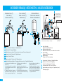 8
8
-
 9
9
-
 10
10
-
 11
11
-
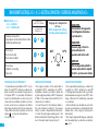 12
12
-
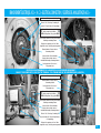 13
13
-
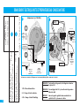 14
14
-
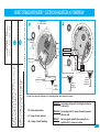 15
15
-
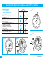 16
16
-
 17
17
-
 18
18
-
 19
19
-
 20
20
-
 21
21
-
 22
22
-
 23
23
-
 24
24


THERMOR CHAUFFE EAU PETITES CAPACITES de handleiding
- Type
- de handleiding
in andere talen
Andere documenten
-
DeDietrich Installation and user’s instruction manual CEB / CES de handleiding
-
 De Dietrich Installation and user’s instruction manual CEB / CES Handleiding
-
Atlantic DIAPASON V2 - bloc hydraulique- depuis N°0946 à N°1210 de handleiding
-
-
-
Eldom Invest Household Electric Water Heaters Handleiding
-
Tecumseh RKA5513CXC Drawing Data
-
-
AEG GYB00816ST Handleiding
-
