
Combinatietank
Combination tank
HYBV
Installatiehandleiding
Installation manual

beschrijving
description
Bedankt voor het vertrouwen dat u in ons stelt met
de aankoop van dit product. ij nodigen u uit deze
handleiding aandachtig te lezen. Ze bevat de technische
eigenschappen en alle nuttige informatie voor een correcte
werking.
De technische gegevens in deze publicatie kunnen om
technische of commerciële redenen op elk moment
worden gewijzigd zonder voorafgaande kennisgeving.
Wij kunnen dus niet aansprakelijk worden gesteld voor
eventuele fouten of onnauwkeurigheden in deze publicatie.
Opgelet!
Bewaar de handleiding op een droge plaats om aantasting
te vermijden zodat u ze later nog kunt raadplegen.
Thank you for the trust you have shown by purchasing this
product. Please read this manual carefully: this contains the
specifications and all the information useful for the correct
functioning.
The information contained in this publication may be
subject to changes at any time and without any notice
whatsoever for technical and/or commercial reasons as
they arise.
Warning!
Keep this manual in a dry place avoiding in this way to
damage the information in order to consult it later.
|
2
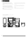
beschrijving HYBV / description HYBV
C
D
E
F
G
H
I
J
K
M
N
O
R
S
T
U
V
Z
A
B
W
Z
R
W

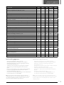
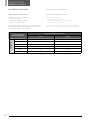
technische gegevens
technical specifications
model / modell ref. 1000 u.m. HYBV300 HYBV500
nuttig volume (opslag sanitair/systeemwater)
total capacity (sanitary water/heating water storage)
ℓ
350
(270/80)
524
(450/74)
ø zonder isolatie / without insulation
A
mm 550 650
ø met isolatie / with insulation
B
mm 690 790
hoogte / height
C
mm 1925 2040
aanvoer sanitair warm water / outlet hot sanitary water
D
1” mm 1755 1850
aanvoer bovenste warmtewisselaar / inlet upper heat exchanger
E
1” mm 1675 1765
hercirculatie / recirculation
F
1” mm 1280 1320
retour bovenste warmtewisselaar / outlet upper heat exchanger
G
1” mm 1125 1070
aanvoer onderste warmtewisselaar / inlet lower heat exchanger
H
1” mm 945 895
retour onderste warmtewisselaar / outlet lower heat exchanger
I
1” mm 755 645
aanvoer sanitair koud water / inlet sanitary cold water
J
1” mm 675 565
aansluiting voor ontluchting / connection for air vent
K
1/2” mm 505 375
aanvoer warmtepomp / flow heat pump
M
1” mm 340 235
retour warmtepomp / return heat pump
N
1” mm 160 135
retour installatie / system return
O
1” mm 160 135
thermometer aansluiting / thermometer - probe
P
1/2” mm 250 235
aanvoer installatie / system flow
Q
1” mm 340 235
elektrische weerstand / electrical resistance
R
1”1/2 mm 250 135
thermometer aansluiting/ thermometer - probe
S
1/2” mm 810 690
flens / flange
T
DN 180 mm 1035 995
thermometer aansluiting / thermometer - probe
U
1/2” mm 1420 1415
thermometer aansluiting / thermometer - probe
V
1/2” mm 1755 1850
aanvoer sanitair warm water / outlet hot sanitary water
W
1”1/4 mm boven / up boven / up
anode / anodo
Z
1”1/4 mm boven / up boven / up
warmteoverdrachtsopp. bovenste vaste warmtewisselaar
upper fixed heat exchanger surface
m
2
2,8 4,4
inhoud bovenste vaste warmtewisselaar / upper fixed heat exchanger content
ℓ
17 26,6
warmteoverdrachtsoppervlak onderste vaste warmtewisselaar
lower heat exchanger surface
m
2
0,9 1,5
inhoud onderste vaste warmtewisselaar / lower heat exchanger content
ℓ
5,3 9,4
leeggewicht / empty weight kg 150 200
3
|
technische gegevens
- Maximale bedrijfsdruk: 10 bar sanitair,
6 bar spiraalelement, 6 bar opslag systeemwater
- Maximumtemperatuur van het opgeslagen water bij
voortdurende werking: 95 °C
- Testdruk: 15 bar sanitair; 9 bar opslag systeemwater
- Anorganisch geëmailleerd (glazuur) voor sanitaire
tank
- Intern niet behandeld voor de opslag van systeemwater
- Isolatie in hard polyurethaanschuim, dikte 70 mm
- SKY isolatiebekleding in grijs pvc.
-
Conform art. 4 lid 3, Richtlijn Drukapparatuur 2014/68/EU
- Conform DIN 4753.3 en UNI 10025
NB: In het sanitaire circuit moeten naast de tank een
veiligheidsklep met een maximale kalibratie van 6 bar en
een expansievat dat geschikt is voor het volume van de
sanitaire installatie worden geïnstalleerd.
technical specifications
- Maximum operating pressure: 10 bar sanitary,
6 bar heat exchanger, 6 bar water storage technique.
- Maximum continuous operating temperature
accumulation: 95 °C.
- Testing pressure: 15 bar., 9 bar water storage technique.
- Inorganic enamelling (vitrification).
- Inside untreated for water storage technique
- Insulation: in rigid expanded polyurethane thickness
70 mm.
- Insulation coating SKY Grey PVC.
- In compliance with directive 2014/68/EU, art. 4.3.
- In compliance with DIN 4753.3 and UNI 10025.
Note: in the sanitary circuit near of the boiler must be
installed a safety valve with calibration maximum = 6 bar
and the expansion vessel adapted to the volume of the
sanitary system.

warmtewisselaars
heat exchangers
|
4
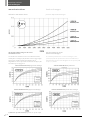
de warmte-uitwisseling van de vaste
warmtewisselaars
Het thermische rendement van een warmtewisselaar,
namelijk het vermogen (W) dat deze aan het opgeslagen
water geeft, wordt bepaald door middel van de
diagrammen van het specifieke rendement KS (W/°C) die
hieronder zijn weergegeven:
the heat exchange of the
fixed heat exchangers
The thermal performance of a heat exchanger, ie, the
power (W) that this provides the water accumulation, is
determined by means of the diagrams of the specific yield
KS (W / ° C) below:
Q = Debiet KS = Specifiek rendement/ Q = Flow - KS = Specific output
warmtewisselaars heat exchangers
bovenste warmtewisselaar/ upper heat exchanger onderste warmtewisselaar / lower heat
exchanger
bovenste warmtewisselaar/ upper heat exchanger onderste warmtewisselaar / lower heat exchanger
drukverlies warmtewisselaars pressure drop heat exchangers
BOVENSTE/UPPER
BOVENSTE/UPPER
ONDERSTE/LOWER
ONDERSTE/LOWER

led
apparaat
equipment
elektrode
electrode
installatie-instructies
installation instruction
5
|
de volgende instructies zijn bepalend voor de
geldigheid van de garantie.
1. De installatie moet:
- Worden uitgevoerd door een gekwalificeerd installateur.
- Waar nodig een drukverminderingsklep voorzien voor het
binnenkomende water.
- Een geijkte veiligheidsklep voorzien naargelang de
vermelding op het etiket met technische gegevens op de
tank.
- Een expansievat (zie tabel voor de berekening van de
afmetingen van het expansievat) dat overeenstemt
met de afmetingen van de tank (het is aanbevolen de
berekening over te laten aan een verwarmingstechnicus).
2. Controleer vóór de inbedrijfstelling of de schroeven van de
flens goed zijn aangedraaid.
3. De temperatuur van de inhoud van de tank moet altijd
lager zijn dan 95 °C.
4. Om de 12 maanden moet de binnenkant worden
gereinigd.
5. Om corrosie te vermijden moet een elektronische anode
worden geïnstalleerd die tot de uitrusting van de tank
behoort.
6. Contact tussen metalen kan, zoals geweten, corrosie
veroorzaken. Het is dan ook aanbevolen een diëlektrische
koppeling aan te brengen tussen de koppelingen in de
tank en de overeenstemmende leidingen.
7. Het geleidingsvermogen van het water mag niet lager zijn
dan 150 μS/cm of hoger dan 1000 μS/cm.
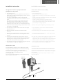
elektronische anode
De tanks HYBV zijn uitgerust met 1 elektronische anode.
De koppeling voor de elektronische anode bevindt zich op
het bovenste gedeelte van de tank (Koppeling Z).
De anode heeft een koppeling van 1/2”M: u hebt een
verkleinstuk nodig van 1”1/4M naar 1/2”F
(niet meegeleverd).
Zie de meegeleverde handleiding voor de inbedrijfstelling
van de elektronische anode
what follows determines the validity
of the warranty
1. The installation must:
- Be performed by a qualified installer.
- Include, where necessary, a pressure reducer for the inlet
water.
- Include a relief valve calibrated as shown on the technical
data label affixed to the boiler.
- Include an expansion tank (see expansion tank
sizing table ) commensurate with the sizes of the boiler
(it is recommended to arrange for the calculations to be
performed by a heating engineer).
2. Before start-up check tightening of the flange screws.
3. The temperature of the contents of the boiler must
always be below 95°C.
4. Internal cleaning must be performed every 12 months.
5. To prevent corrosion the electronic anode supplied with
the boiler must be installed.
6. As is known, contact between different metals can cause
corrosion. In this sense, it is advisable to insert an
appropriate dielectric coupling between the attachments
located inside the boiler and the corresponding pipes.
7. The electrical conductivity of the water must not be less
than 150 μS/cm or greater than 1000 μS/cm.
electronic anode
The boilers HYBV are delivered with nr. 1 electronic anode.
The connection for the electronic anode is located on the
top of the boiler (Attachment Z). The anode has an 1/2”M
attachment: a reduction from 1”1/4M . to 1/2”F is required
(not supplied).
For the initial operation of the anode electronic see the
manual supplied.
installatie-instructies installation instruction
draagsteun
bracket support

installatie-instructies
installation instructions
dimensionering expansievat
Waarden in liter met betrekking tot:
- voordruk = 2,0 bar
- druk veiligheidsklep = 6,0 bar
- expansie van 10 tot 90 °C.
Bij installaties met recirculatielussen voor sanitair water
moet ook rekening worden gehouden met het volume
water dat aanwezig is in de leidingen.
dimensioning expansion vessel
Values in litres relating to:
- pre-load pressure of 2.0 bar
- relief valve calibration pressure of 6.0 bar
- expansion from 10 to 90°C.
In systems with domestic water recirculation rings, the
volume of the water in the pipes should also be considered.
|
6
volume expansievat (l)
expansion tank volume (i)
capaciteit tank / cylinder capacity / storage
300 liter 500 liter
opslagtemperatuur
storage temperature
40 °C
3,8 6,6
50 °C
6,0 10,3
60 °C
8,6 14,7
70 °C
11,5 19,7
80 °C
14,7 25,2
90 °C
18,2 31,3
installatie-instructies installation instructions

voorbeeld
example
7
|
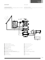
aansluitingsvoorbeeld
Installatieschema met vloerverwarming, productie van SWW en
integratie met zonnepanelen
connection example
Plant layout with runderfloor heating, domestic hot water and
integration with solar panels
voorbeeld example
SWW
1 circulatiepomp Mirai-smi
2 circulatiepomp thermische installatie
3 circulatiepomp thermische zonnepanelen
4 warmtepomp Mirai-smi
5 driewegs-omschakelklep
6 terugslagklep
7 buffertank systeemwater
8 opslagtank sanitair warm water
9 warmtewisselaar voor sww van de warmtepomp
warmtewisselaar voor sww van de thermische zonnepanelen
ventiloconvector
vloerverwarming
thermisch zonnepaneel
1 circulation pump mirai-smi
2 circulation pump heating system
3 circulation pump solar heat
4 heat pump mirai-smi
5 three-way valve
6 check valve
7 inertial storage technical water
8 domestic hot water
9 heat exchanger for dhw from heat pump
heat exchanger for dhw by solar thermal
fan
underfloor heating
panel solar thermal

|
8
Draag zorg voor het milieu!
Voor een correcte afvalverwijdering moeten de verschillende materialen volgens de toepasselijke regelgeving worden gescheiden.
Auteursrechten Emmeti powered by RADSON
Alle rechten voorbehouden. Niets in deze publicatie mag worden gereproduceerd of verdeeld zonder de schriftelijke toestemming van Emmeti powered by RADSON.
De gegevens in deze publicatie zijn, omwille van technische en/of commerciële redenen, onderhevig aan wijziging zonder voorafgaande kennisgeving.
Emmeti Spa is niet verantwoordelijk voor eventuele vergissingen of onjuistheden in deze publicatie.
Vogelsancklaan 250 - B-3520 Zonhoven
T. +32 (0)11 81 31 41 - F. +32 (0)11 81 73 78 - [email protected] - www.radson.com
powered by
04/2019
-
 1
1
-
 2
2
-
 3
3
-
 4
4
-
 5
5
-
 6
6
-
 7
7
-
 8
8


in andere talen
- English: RADSON HYBV Installation guide
Gerelateerde artikelen
Andere documenten
-
CTC Union EcoWater 302 Installatie gids
-
ACV Glass HP 300 (C) Handleiding
-
Atlantic edition 2014 PECS 1998-2016 Installation and User Manual
-
THERMOR CHAUFFE EAU PETITES CAPACITES de handleiding
-
-
-
-
STIEBEL ELTRON HSBC 200 Operation Instruction
-