
ANLEITUNG FÜR EINBAU, BEDIENUNG UND WARTUNG
KESSEL Rückstaupumpanlage
Pumpx F Comfort
Stand 2017/04 Sach-Nr. 010-843
Installation Inbetriebnahme Einweisung
der Anlage wurde durchgeführt von Ihrem Fachbetrieb:
Name/Unterschrift Datum Ort
Für fäkalienhaltiges und
fäkalienfreies Abwasser
Rückstauverschluss und
Entwässerungspumpe
Einfacher Einbau in durchgehende
Rohrleitungen
Steckerfertiges Schaltgerät mit
Display und Selbstdiagnosesystem
(SDS) mit integrierter
Batteriepufferung
Motorische Verriegelung der
Rückstauklappe
Integrierte Ablauffunktion zur
Oberflächenentwässerung
Produktvorteile
Stempel Fachbetrieb
Technische Änderungen vorbehalten
D Seite 1
GB Page 23
F Page 45
I Pagina 67
NL Pagina 89
PL Strona 111
85101 Lenting
Z-53.2-388
Pumpx F Comfort
Unterurinstallation
Pumpx F Comfort
Überurinstallation
mit Sicherheit
geprüfte Qualität
Bauart
geprüft
und überwacht
Bauart
geprüft
und überwacht
L
GA
Landesgewerbeamt Bayern
mit Sicherheit
geprüfte Qualität
Bauart
geprüft
und überwacht
Bauart
geprüft
und überwacht
L
GA
Landesgewerbeamt Bayern

2 / 132
2017/04
010-843
1 Einleitung 3
1.1 Produktbeschreibung, allgemein.......................................................................................................3
1.2 Allgemeine Hinweise zu dieser Betriebs- und Wartungsanleitung ....................................................4
1.3 Funktionsprinzip ................................................................................................................................4
1.3.1 Funktionsprinzip Pumpx F Comfort Unterurinstallation .................................................................4
1.3.2 Funktionsprinzip Pumpx F Comfort Überurinstallation ..................................................................5
1.4 Typenschild .......................................................................................................................................5
1.5 Lieferumfang .....................................................................................................................................6
1.5.1 Variante Pumpx F Comfort Unterurinstallation ..............................................................................6
1.5.2 Variante Pumpx F Comfort Überurinstallation ...............................................................................6
2 Sicherheit 7
2.1 Bestimmungsgemäße Verwendung ..................................................................................................7
2.2 Personalauswahl und -qualikation ..................................................................................................7
2.3 Organisatorische Sicherheits-Maßnahmen.......................................................................................7
2.4 Gefahren, die vom Produkt ausgehen ..............................................................................................7
2.4.1 Gefahr durch besondere Örtlichkeit / Umgebungsbedingungen .......................................................7
2.4.2 Gefahr durch elektrischen Schlag bei abgeschraubtem Stecker ......................................................7
2.4.3 Gefahr durch gesundheitsgefährdende Atmosphäre ........................................................................7
2.4.4 Gefahr für die Gesundheit.................................................................................................................8
2.4.5 Gefahr durch Lärm ............................................................................................................................8
2.4.6 Gefahr durch Hitze ............................................................................................................................8
2.4.7 Gefahr durch unerwartetes Anlaufen einer Pumpe ...........................................................................8
3 Montage 9
3.1 Allgemeines zur Montage .................................................................................................................9
3.2 Einbauvorschlag „Schwarze Wanne“ ................................................................................................9
3.3 Einbauvorschlag „Weiße Wanne“ .....................................................................................................10
3.4 Vorbereitungen zum Einbau..............................................................................................................10
3.5 Grundkörper montieren .....................................................................................................................11
3.6 Grundkörper waagerecht ausrichten.................................................................................................12
3.7 Einbau in die Bodenplatte (schwarze Wanne) ..................................................................................12
3.8 Einbau in die Bodenplatte (weiße Wanne) ........................................................................................13
3.9 Entlüftungsleitung anschließen (Option) ...........................................................................................13
3.10 Kabelleerrohr montieren ...................................................................................................................14
3.11 Aufsatzstück montieren.....................................................................................................................14
3.12 Zulaufdeckel montieren.....................................................................................................................15
4 Wartung 16
4.1 Allgemeine Hinweise für die Wartung ...............................................................................................16
4.2 Wartungsintervalle ............................................................................................................................16
5 Technische Daten 20
5.1 Pumpen.............................................................................................................................................20
5.2 Schaltgerät Pumpx F Comfort ........................................................................................................20
5.3 Förderstrom ......................................................................................................................................20
6 DOP/Leistungserklärung 21

Einleitung
3 / 1322017/04
010-843
1 Einleitung
Sehr geehrte Kundin
sehr geehrter Kunde,
wir freuen uns, dass Sie sich für den Erwerb eines unserer Produkte entschieden haben. Sicher wird dieses Ihre
Anforderungen in vollem Umfang erfüllen. Wir wünschen ihnen einen reibungslosen und erfolgreichen Einbau.
Im Bemühen unseren Qualitätsstandard auf höchstmöglichem Niveau zu halten, sind wir natürlich auch auf Ihre
Mithilfe angewiesen. Bitte teilen Sie uns Möglichkeiten zur Verbesserung unserer Produkte mit.
Haben Sie Fragen? Wir freuen uns auf Ihre Kontaktaufnahme.
1.1 Produktbeschreibung, allgemein
Die KESSEL Rückstaupumpanlage Pumpx F Comfort (im folgenden Rückstaupumpanlage benannt) ist für das
Abpumpen von fäkalienfreiem und fäkalienhaltigem Abwasser vorgesehen. In den Abwasserbehälter sind die
Baugruppen für die Pumpen, den optischen Sensor, die motorisch angetriebene Rückstauklappe eingebaut.
Die Pendelklappe dient als handbetätigter Notverschluss. Sie kann ebenfalls mit einem Motor versehen werden.
Dieser wird kann dann von einem eigenen Schaltgerät angetrieben, welches sich mit dem Schaltgerät der
Rückstaupumpanlage im Dialog bendet.
Im Normalbetrieb läuft das Abwasser rückstaufrei durch die Rückstaupumpanlage hindurch in den
Abwasserkanal.
Staut sich das Abwasser aus dem Kanalsystem bis in die Rückstaupumpanlage zurück, wird das durch eine
optische Sonde erkannt. Die motorisch angetriebene Rückstauklappe wird geschlossen. Das gebäudeseitige
Abwasser sammelt sich dann im Behälter des Pumpx F.
Die Schaltsignale der Sensoren für den Pegelstand im Abwasserbehälter werden im Schaltgerät elektronisch
verarbeitet. Als Niveaugeber wird eine optische Sonde verwendet. Ist das entsprechende Niveau erreicht, wird
die Entsorgung mittels Pumpe, gegen den anstehenden Rückstau, aktiviert. Abgepumpt wird über den Behälter
des Pumpx F Comfort.
Bei Netzausfall kann über einen Zeitraum von ca. 2 Stunden mittels Batteriebetrieb die Funktionssicherheit der
motorbetriebenen Rückstauklappe sichergestellt werden. Nach Ablauf dieser Zeit wird die Rückstauklappe zum
Schutz des Gebäudes geschlossen.

4 / 132
Einleitung
2017/04
010-843
1.2 Allgemeine Hinweise zu dieser Betriebs- und Wartungsanleitung
Diese Betriebs- und Wartungsanleitung ist nur in Verbindung der Betriebs- und Montageanleitung des Pumpx F
Comfort Schaltgeräts (Sach-Nr. 016-004) vollständig.
Verwendete Symbole und Legenden
<1> Hinweis im Text auf eine Legendennummer in einer Abbildung
[2] Bezug auf eine Abbildung
• Arbeitsschritt
3. Arbeitsschritt in nummerierter Reihenfolge
– Aufzählung
Kursiv Kursive Schriftdarstellung: Bezug zu einem Abschnitt / Punkt im Steuerungs-Menü
VORSICHT: Warnt vor einer Gefährdung von Personen und Material. Eine Missachtung
der mit diesem Symbol gekennzeichneten Hinweise kann schwere Verletzungen und
Materialschäden zur Folge haben.
Hinweis: Technische Hinweise, die besonders beachtet werden müssen.
1.3 Funktionsprinzip
1.3.1 Funktionsprinzip Pumpx F Comfort Unterurinstallation
66 Rückstauebene
66
Abb. [1]
1.3.2 Funktionsprinzip Pumpx F Comfort Überurinstallation
66 Rückstauebene
1.4 Typenschild
Informationen auf dem Typenschild
1 Bezeichnung der Anlage
2 Materialnummer
3 Anschlussspannung und Anschlussfrequenz
4 Hydraulische Daten
5 Allgemeine Daten
6 Seriennummer
7 Fertigungsdatum
8 Revisionsstand
9 Normenbezeichung
10 Auftragsnummer
66
Abb. [2]
RevStd.: X.X
TT.MM.JJ
JJ
S3 xx% ED IP xx (3mWS /48h)
xxxxx
Pumpfix F Comfort
XY
U = xxxV xxHz I = x,xA P1 = x,xkW
Ser.Nr. xxxxxxx
Q = xxm³/h H = xxm
www.kessel.com
Auftr.Nr.: xxxxxxx
DIN-EN 12050-1
2
1
2
3
9
8
6
4
5
10
7
Abb. [3]

Einleitung
5 / 1322017/04
010-843
1.3.2 Funktionsprinzip Pumpx F Comfort Überurinstallation
66 Rückstauebene
1.4 Typenschild
Informationen auf dem Typenschild
1 Bezeichnung der Anlage
2 Materialnummer
3 Anschlussspannung und Anschlussfrequenz
4 Hydraulische Daten
5 Allgemeine Daten
6 Seriennummer
7 Fertigungsdatum
8 Revisionsstand
9 Normenbezeichung
10 Auftragsnummer
66
Abb. [2]
RevStd.: X.X
TT.MM.JJ
JJ
S3 xx% ED IP xx (3mWS /48h)
xxxxx
Pumpfix F Comfort
XY
U = xxxV xxHz I = x,xA P1 = x,xkW
Ser.Nr. xxxxxxx
Q = xxm³/h H = xxm
www.kessel.com
Auftr.Nr.: xxxxxxx
DIN-EN 12050-1
2
1
2
3
9
8
6
4
5
10
7
Abb. [3]

6 / 132
Einleitung
2017/04
010-843
1.5 Lieferumfang
Anlage bzw. alle Lieferkomponenten auf evtl. Mängel überprüfen
1.5.1 Variante Pumpx F Comfort Unterurinstallation
1
Grundkörper
3
Aufsatzstück, mit Zulaufdeckel
5
Verlängerungsstück (optional, max. 2 Stück)
20
Pumpeneinheit
26
Motorische Klappeneinheit
37
Dichtung
41
Kabeldurchführung
56
Zulauf-Seite
57
Ablauf-Seite
1.5.2 Variante Pumpx F Comfort Überurinstallation
1 Grundkörper
20 Pumpeneinheit
26 Motorische Klappeneinheit
56 Zulauf-Seite
57 Ablauf-Seite
1
20
26
37
5
37
3
41
56
57
Abb. [4]
56
57
1
20
26
Abb. [5]

Sicherheit
7 / 1322017/04
010-843
1.5 Lieferumfang
Anlage bzw. alle Lieferkomponenten auf evtl. Mängel überprüfen
1.5.1 Variante Pumpx F Comfort Unterurinstallation
1
Grundkörper
3
Aufsatzstück, mit Zulaufdeckel
5
Verlängerungsstück (optional, max. 2 Stück)
20
Pumpeneinheit
26
Motorische Klappeneinheit
37
Dichtung
41
Kabeldurchführung
56
Zulauf-Seite
57
Ablauf-Seite
1.5.2 Variante Pumpx F Comfort Überurinstallation
1 Grundkörper
20 Pumpeneinheit
26 Motorische Klappeneinheit
56 Zulauf-Seite
57 Ablauf-Seite
1
20
26
37
5
37
3
41
56
57
Abb. [4]
56
57
1
20
26
Abb. [5]
2 Sicherheit
2.1 Bestimmungsgemäße Verwendung
Die Rückstaupumpanlage dient als Entwässerungsanlange für fäkalienhaltiges und –freies, häusliches und
gewerbliches Abwasser.
2.2 Personalauswahl und -qualikation
Personen, die die Rückstaupumpanlage montieren, müssen
– mindestens 18 Jahre alt sein.
– für die jeweiligen Tätigkeiten ausreichend geschult und qualiziert sein.
– die einschlägigen technischen Regeln und Sicherheitsvorschriften kennen und befolgen.
Qualiziertes Personal sind Personen, die durch ihre Ausbildung und Erfahrung sowie ihrer Kenntnisse
einschlägiger Bestimmungen, gültiger Normen und Unfallverhütungsvorschriften die jeweils erforderlichen
Tätigkeiten ausführen und dabei mögliche Gefahren erkennen und vermeiden können.
Arbeiten an elektrischen Bauteilen dürfen nur von dafür ausgebildetem Fachpersonal und unter Einhaltung aller
geltenden Regelungen der Unfallverhütungsvorschriften (UVVen) vorgenommen werden.
2.3 Organisatorische Sicherheits-Maßnahmen
Die Betriebs- und Wartungsanleitung ist stets verfügbar zu halten.
2.4 Gefahren, die vom Produkt ausgehen
2.4.1 Gefahr durch besondere Örtlichkeit / Umgebungsbedingungen
Gefahr durch giftige und gesundheitsgefährdende Dämpfe, Gase und Stoffe (z. B. Bakterien, Viren). Bendet
sich die Rückstaupumpanlage in einem Schacht, sind darin notwendige Arbeiten ausschließlich durch
Fachpersonal (Siehe 2.2) durchzuführen.
2.4.2 Gefahr durch elektrischen Schlag bei abgeschraubtem Stecker
Am Schaltgerät besteht die Gefahr eines elektrischen Stromschlags, wenn der Stecker für die
Stromversorgung der Pumpen demontiert ist. Die Überwurfmutter des elektrischen Steckers muss so fest
montiert sein, dass sie werkzeugfrei (z.B. durch Kinder) nicht gelöst werden kann.
2.4.3 Gefahr durch gesundheitsgefährdende Atmosphäre
Bei Arbeiten besteht die Gefahr, dass die Atmosphäre gesundheitsgefährdend ist. Auf ausreichende Belüftung
achten und ggf. Sicherheitseinrichtungen wie z.B. Multigaswarngerät verwenden.

8 / 132
Sicherheit
2017/04
010-843
2.4.4 Gefahr für die Gesundheit
Die Rückstaupumpanlage fördert fäkalienhaltiges Abwasser, welches gesundheitsgefährdende Stoffe enthalten
kann. Es ist sicherzustellen, dass kein direkter Kontakt zwischen dem Abwasser oder davon verschmutzten
Anlagenteilen mit Augen, Mund oder Haut stattndet. Bei einem direkten Kontakt die betroffene Körperstelle
sofort gründlich reinigen und ggf. desinzieren. Persönliche Schutzausrüstung tragen.
2.4.5 Gefahr durch Lärm
Der Betrieb der Rückstaupumpanlage kann einen einen Geräuschpegel verursachen. Tragen Sie bei Bedarf
entsprechende Schutzausrüstung und sorgen sie für schalldämmende Maßnahmen.
2.4.6 Gefahr durch Hitze
Gefahr von Verbrennungen beim Berühren heißer Oberächen. Abwasserpumpen können bei längeren
Laufzeiten eine hohe Betriebstemperatur an der Gehäuseoberäche entwickeln. Schutzausrüstung
(Handschuhe) tragen oder Pumpen entsprechend abkühlen lassen.
2.4.7 Gefahr durch unerwartetes Anlaufen einer Pumpe
Ist die Rückstaupumpanlage nicht vom Netz getrennt, kann die Pumpe unvermittelt anlaufen. Pumpen
ausschließlich durch Fachpersonal und bei freigeschalter sowie gegen unbeabsichtigtes Wiedereinschalten
abgesicherter Ablage ausbauen.

Montage
9 / 1322017/04
010-843
3 Montage
Gefahr durch giftige und gesundheitsgefährdende Dämpfe, Gase und Stoffe (z. B. Bakterien, Viren). Alle an
der Rückstaupumpanlage notwendige Arbeiten ausschließlich durch Fachpersonal (Siehe 2.2) durchführen.
3.1 Allgemeines zur Montage
Die Rückstaupumpanlage wird entsprechend den auf einer Baustelle üblichen Bauabschnitten zu
unterschiedlichen Zeitpunkten montiert und in Betrieb genommen.
3.2 Einbauvorschlag „Schwarze Wanne“
1 Pumpx F
2 Dichtungsset Art.-Nr. 83 023 mit Gegenansch und Dichtungsbahn
3 Rohrdurchführungsdichtung
a Fliesen f Abdichtung
b Estrich g Schaltgerät
c Dämmung h Druckleitung
d Betonboden
e Schutzbeton BWS* Bemessungswasserstand
g
a
b
c
d
h
3
2
1
BWS*
e
f
Abb. [6]

10 / 132
Montage
2017/04
010-843
3.3 Einbauvorschlag „Weiße Wanne“
1 Pumpx F
2 Verlängerungsstück mit mittigem Flansch für den Einbau in WU-Beton, Art.-Nr. 83075
a Fliesen e Schaltgerät
b Estrich f Druckleitung
c Dämmung
d Betonboden BWS* Bemessungswasserstand
3.4 Vorbereitungen zum Einbau
Für einen reibungslosen Einbau und Betrieb folgendes beachten:
- Ausreichend Abstand zur Wand bzw. Objekten für Wartungsarbeiten einhalten.
- Beruhigungsstrecke vor und nach der Pumpx F Comfort (min. 1 m) einhalten.
- Kabelleerrohr (DN70) von der Pumpx F Comfort zum Montageort des Schaltgeräts verlegen.
Richtungsänderungen nur mit 45°-Bögen vornehmen.
Bei der Auswahl des Montageorts die Position für das Schaltgerät berücksichtigen:
Die Kabellänge der Elektrokomponenten beträgt 5 Meter Verlängerungssets sind optional erhältlich. Damit die
Pumpe bei Wartungsarbeiten vollständig aus dem Grundkörper herausgehoben werden kann, muss sich eine
ausreichende Kabellänge des Pumpen- Anschluss-Kabels im Grundkörper benden.
Das Kabelleerrohr dient zur Entlüftung des Raumes oberhalb der Pumpe. Es darf deshalb nicht luftdicht
verschlossen werden.
Für das Schaltgerät wird auch eine Steckdose (Schuko, 230 VA) benötigt.
- Soll anstelle des Entlüftungsventils eine Entlüftungsleitung montiert werden, muss diese bis zum Grundkörper
verlegt werden.
a
b
c
d
f
e
BWS*
1
2
Abb. [7]
3.5 Grundkörper montieren
- Die beiden Stutzen Zulauf <56> und Ablaufseite <57>
mit dem Grundkörper <1> verbinden, die Schnellverschlüsse
<64> am Grundkörper ermöglichen eine rasche Montage.
- Den Pumpx F Comfort mit dem Rohrleitungssystem verbinden,
Einbau in freiliegende Abwasserleitung Einbau in die Bodenplatte
Unbedingt auf die Fließrichtung achten (siehe Pfeil <77> Abb. [10] bzw. [11])
56
64
64
57
1
Abb. [8]
64
Abb. [9]
77
Abb. [10]
77
Abb. [11]

Montage
11 / 1322017/04
010-843
3.5 Grundkörper montieren
- Die beiden Stutzen Zulauf <56> und Ablaufseite <57>
mit dem Grundkörper <1> verbinden, die Schnellverschlüsse
<64> am Grundkörper ermöglichen eine rasche Montage.
- Den Pumpx F Comfort mit dem Rohrleitungssystem verbinden,
Einbau in freiliegende Abwasserleitung Einbau in die Bodenplatte
Unbedingt auf die Fließrichtung achten (siehe Pfeil <77> Abb. [10] bzw. [11])
56
64
64
57
1
Abb. [8]
64
Abb. [9]
77
Abb. [10]
77
Abb. [11]

12 / 132
Montage
2017/04
010-843
3.6 Grundkörper waagerecht ausrichten
3.7 Einbau in die Bodenplatte (schwarze Wanne)
Bauseitige Dichtungsbahn <68> zwischen Pressdichtungsansch
<13> und Gegenansch <47> einklemmen und mit den
Schrauben <48> verschrauben.
Notiz: Ist keine bauseitige Dichtungsbahn vorhanden, ist das
Kessel Dichtungsset 83023 inkl. elastomerer Sperrbahn zu benutzen.
Abb. [12]
48
47
68
13
Abb. [13]

Montage
13 / 1322017/04
010-843
3.6 Grundkörper waagerecht ausrichten
3.7 Einbau in die Bodenplatte (schwarze Wanne)
Bauseitige Dichtungsbahn <68> zwischen Pressdichtungsansch
<13> und Gegenansch <47> einklemmen und mit den
Schrauben <48> verschrauben.
Notiz: Ist keine bauseitige Dichtungsbahn vorhanden, ist das
Kessel Dichtungsset 83023 inkl. elastomerer Sperrbahn zu benutzen.
Abb. [12]
48
47
68
13
Abb. [13]
3.8 Einbau in die Bodenplatte (weiße Wanne)
Dichtung <37> in Bodenteil <1> einlegen und auf Sitz der
Dichtung achten. Anschließend Oberseite der Dichtung fetten.
Verlängerungsstück mittiger Flansch <33> einschieben
und in Position bringen.
3.9 Entlüftungsleitung anschließen (Option)
Die Entlüftungsleitung muss so verlegt werden, dass sie
weder den Zugang zu Wartungszwecken noch die anderen
Leitungsverbindungen (Druckleitung / Kabel- Leerrohr) behindert.
- Entlüftungsventil <11> aus der Pumpeneinheit
<20> herausschrauben.
- Am Anschluss <12> des Entlüftungsventils die Entlüftungsleitung
befestigen und durch den Grundkörper oberhalb der Dichtebene
hindurchführen.
37
33
1
Abb. [14]
11
20
12
Abb. [15]

14 / 132
Montage
2017/04
010-843
3.10 Kabelleerrohr montieren
- Das Kabelleerrohr (DN70) bis zur Kabeldurchführung <41>
(DN50) an den Grundkörper heranführen und montieren.
Für Richtungsänderungen max. 45° Bögen verwenden.
Kabelleerrohr vorsehen für spätere Nachrüstung. Sollte das
Kabelleerrohr im Aufsatzstück installiert werden, muss dieses
mit der KESSEL Sägeglocke Art.-Nr. 50101 oder einer
handelsüblichen Sägeglocke Ø 60 mm und der
Rohrdurchführungsdichtung Art.-Nr. 850114 ausgeführt werden.
3.11 Aufsatzstück montieren
Je nach Einbautiefe ist das Aufsatzstück (Einstecktiefe des
Aufsatzstückes <3>) ggf. abzulängen bzw. mit Aussparungen
<67> für die Leitungsverbindungen, die seitlich in den Grundkörper
<1> hineingeführt werden, zu versehen.
Das Aufsatzstück <3> darf mit maximal 2 Verlängerungsstücken
verlängert werden, damit zu Wartungszwecken noch bis zum
Grundkörper hinunter gegriffen werden kann.
- Dichtung <37> fettfrei in die Nut am Grundkörper <1> einsetzen.
- Dichtlippen der Dichtung <37> einfetten.
- Aufsatzstück <3> in den Grundkörper hineinschieben und ausrichten.
DN50
DN70
41
Abb. [16]
3
67
37
1
Fett
Abb. [17]

Montage
15 / 1322017/04
010-843
3.10 Kabelleerrohr montieren
- Das Kabelleerrohr (DN70) bis zur Kabeldurchführung <41>
(DN50) an den Grundkörper heranführen und montieren.
Für Richtungsänderungen max. 45° Bögen verwenden.
Kabelleerrohr vorsehen für spätere Nachrüstung. Sollte das
Kabelleerrohr im Aufsatzstück installiert werden, muss dieses
mit der KESSEL Sägeglocke Art.-Nr. 50101 oder einer
handelsüblichen Sägeglocke Ø 60 mm und der
Rohrdurchführungsdichtung Art.-Nr. 850114 ausgeführt werden.
3.11 Aufsatzstück montieren
Je nach Einbautiefe ist das Aufsatzstück (Einstecktiefe des
Aufsatzstückes <3>) ggf. abzulängen bzw. mit Aussparungen
<67> für die Leitungsverbindungen, die seitlich in den Grundkörper
<1> hineingeführt werden, zu versehen.
Das Aufsatzstück <3> darf mit maximal 2 Verlängerungsstücken
verlängert werden, damit zu Wartungszwecken noch bis zum
Grundkörper hinunter gegriffen werden kann.
- Dichtung <37> fettfrei in die Nut am Grundkörper <1> einsetzen.
- Dichtlippen der Dichtung <37> einfetten.
- Aufsatzstück <3> in den Grundkörper hineinschieben und ausrichten.
DN50
DN70
41
Abb. [16]
3
67
37
1
Fett
Abb. [17]
3.12 Zulaufdeckel montieren
Die Montage erfolgt zum Schutz vor Verunreinigungen
durch z.B. Baumaterial.
Dabei:
- Dichtungsbereich sauber halten
- Dichtung außen einfetten
• Zulaufdeckel <51> in das Aufsatzstück <3> einsetzen.
• Beide Deckelverschlüsse <78> schließen.
3
51
78
Abb. [18]

16 / 132
Wartung
2017/04
010-843
4 Wartung
Vor einem Öffnen von Gehäuseabdeckungen, Steckern und Kabeln (auch an den potentialfreien Kontakten)
sind diese spannungsfrei zu machen. Arbeiten an elektrischen Bauteilen dürfen nur von Fachpersonal
(Siehe 2.2) durchgeführt werden.
4.1 Allgemeine Hinweise für die Wartung
Bei Wartungsarbeiten darf weder auf elektrische Komponenten, Leitungsverbindungen oder Kabel
gestiegen werden.
Gefahr durch giftige und gesundheitsgefährdende Dämpfe, Gase und Stoffe (z. B. Bakterien, Viren). Bendet
sich die Rückstaupumpanlage in einem Schacht, sind darin notwendige Arbeiten ausschließlich durch
Fachpersonal (Siehe 2.2) durchzuführen.
Gefahr des Ertrinkens im Anlagenschacht. Ein Anlagenschacht kann z.B. bei Überschwemmungen innerhalb
kurzer Zeit voll Wasser laufen. Besteht das Risiko von eindringendem Wassers, darf der Schacht so lange nicht
betreten werden, bis ein gefahrloser Aufenthalt darin möglich ist.
Nach jeder Wartungsarbeit an der Rückstaupumpanlage Funktionsprüfung durchführen.
4.2 Wartungsintervalle
Wartung von Rückstaupumpanlagen
Die Rückstaupumpanlage muss regelmäßig durch einen Fachkundigen gewartet werden. Die Zeitabstände
dürfen nicht größer sein als ½ jährlich.
Für jede Wartung ist ein Wartungsprotokoll mit Angabe aller durchgeführten Arbeiten und wesentlichen Daten zu
erstellen.
Soweit Mängel festgestellt werden, die nicht behoben werden können, sind diese dem Anlagenbetreiber von dem
die Wartung durchführenden Fachkundigen sofort schriftlich gegen Quittung zu melden.
Warnhinweis
Gerät darf nicht mit mineralischen oder teilweise mineralischen Schmierstoffen (z. B. WD-40) in Berührung
kommen. Mineraliche Schmierstoffe können die Funktionsfähigkeit und Dichtheit beeinträchtigen.
Ausschließlich vollsynthetische Schmierstoffe verwenden!

Wartung
17 / 1322017/04
010-843
Inspektion-/Wartung Pumpx F
Bitte beachten Sie die Sicherheitshinweise und Unfallverhütungsvorschriften
Wartungsleistungen nach EN 12056-4 u. DIN 1986 Teil 3
Objektbezeichnung
Objekt
Strasse
PLZ, Ort
Kontakt
Typ
Schaltgerät
ja ❏ nein ❏
Pumpentyp
1 ❏ 2 ❏
Zusatzinfos DN: da: Förderhöhe: m
Fehlermeldung vorhanden
ja ❏ nein ❏
LNr. Prüfung Erledigungsvermerk
ja nein
1 Schaltgerät auf mögliche Fehlermeldungen prüfen
2 Manueller Funktionstest am Schaltgerät, Klappe zu fahren (über Klappe Test Handsymbol)
Für Zulauf sorgen (klares Wasser) ➞ abwarten ob Pumpe pumpt
LNr. Prüfung Erledigungsvermerk
ja nein
1 Dokumentation
1.1 Einbau-, Bedienungs- und Wartungsanleitung vor Ort vorhanden
1.2 Schaltplan zu Schaltgerät bzw. Steueranlage vorhanden
2 Einbausituation
2.1 freie Zugänglichkeit zur Gesamtanlage gewährleistet (Schacht, Sammelbehälter, Schaltgerät)
2.2 Anbaukomponenten, wie z.B. Rohrleitungen traglastsicher und schallgedämt gehaltert
3 Pumpen / Armaturen / Rohrleitung / Zubehör
3.4 BE- und Entlüftungsleitung stetig steigend über Dach ins Freie verlegt (bei fäkalienhaltigem Abwasser)
3.5 Kabelleerrohr vorhanden; Abdichtung für Kabeleinführung im Schacht
4 Steuerung
4.1 Netzstecker vorhanden und frei zugänglich / bedienbar
4.2 Vorsicherung im Schaltschrank zugänglich; gekennzeichnet; Typ / Wert
4.3 Elektrische Leiterverbindungen korrekt ausgeführt (Wackelkontakt?)
5 Funktionsprüfung
5.1 Störmeldung optisch und akustisch korrekt; Quittierung Hupe (akustisches Signal)
5.2 Störmeldung potentialfrei korrekt; Anzeige an z.B. Gebäudeleittechnik (GLT); Quittierung / Reset
Störmeldung
5.3 Sofern Akku / Batterie für netzunabhängigen Betrieb – Störmeldung korrekt
5.4 LED-Anzeigen Schaltgerät korrekt

18 / 132
Wartung
2017/04
010-843
LNr. Prüfung Erledigungsvermerk
ja nein
5.5 Tastenfunktion in Ordnung
7 Messwerte
ACHTUNG: Bei allen Wartungsarbeiten, Anlage vom Netz trennen! Sicherheitshinweise
beachten!
7.1 Nennstromangabe gemäß Typenschild auf Pumpe
8 Gesamtzustand der Anlage
8.1 Anlage geprüft und betriebsbereit
9 Wartung
9.1 Wartungs- und Servicearbeiten ohne Einschränkungen möglich
9.2 Sicherungspersonal gemäß Unfallverhütungsvorschrift erforderlich (Schachteinstieg, Gaswarngerät)
Funktionstest
LNr. Prüfung Erledigungsvermerk
ja nein
1 Anlage mit Wasser spülen
2 Funktion gegeben, Funktionsstart durchführen
3 Anlage vertiefter Einbau
Ist mit geschlossender Abdeckplatte ohne Zulaufanschluss und ohne Multistop
4 Deckeldemontage, Einschiebeteil mit Klappe entnehmen
- Deckel Notverschluss auf Stellung ZU
- Schwenkanschluss des Motors nach hinten kippen
- Deckel mit Pumpenverbindung kann abgehoben werden
- Verriegelungshebel der Deckel öffnen, Deckel abnehmen
- Einschiebeteil mit Klappe herausziehen und Teile reinigen, Dichtungen Deckel und
Einschiebteil überprüfen
- Führungsteile Einschiebeteil und Deckel mit Armaturenfett einstreichen
- Teile wieder in Grundkörper einsetzen
5 Druckleitungsklappe
- Druckleitungsklappe in Pumpenverbindung reinigen, prüfen ggf. tauschen
- Aufnahme Einhandschnellverschluss mit Klappe, verschraubt mit drei Torxschrauben
(TX 25) abschrauben
- Druckleitungsklappe überprüfen, reinigen ggf. austauschen
6 Pumpen
- Pumpe(n) entnehmen
- Ansaugkorb/Spiralgehäuse abschrauben
- Entlüftungsbohrung reinigen
- Schneidmesser auf Verschleiß überprüfen und ggf. austauschen
- Flügelrad abziehen und reinigen
- Teile wieder einbauen
- Pumpe(n) wieder einsetzen und xieren
7 Funktionsprüfung
- Pumpensonde in Wasser eintauchen (optische und akustische Warneinrichtung spricht an)
- Pumpe läuft an
- Sonde aus dem Wasser nehmen --> Pumpe schaltet ab
Achtung: Sondenreihenfolge einhalten!

Wartung
19 / 1322017/04
010-843
LNr. Prüfung Erledigungsvermerk
ja nein
8 Batterieprüfung
- 2 Stück 9V Batterien (Duracell)
- Achtung: Gesamtkapazität darf nicht < 13,5 V sein
9 Logbuch mit Auslesetool auslesen
10 Werte eintragen
Schaltspiele Klappe (maximal 5000)
Schaltspiele Pumpe (maximal 100000)
Anzahl Rückstauereignisse
Der Hersteller bzw. dessen beauftragter Vertreter (z.B. Werkskundendienst) bestätigt durch seine Unterschrift die oben
gemachten Angaben von Seite 1und 2 dieses Protokolls.
Verwendete Hilfsmittel: ❑ Dreibein
❑ Gasmessgerät
Ergebnisbericht ___________________________________________________________________________
___________________________________________________________________________
___________________________________________________________________________
verwendete Erstazteile ___________________________________________________________________________
___________________________________________________________________________
___________________________________________________________________________
Verbleib der ausgetauschten Ersatzteile: ❑ beim Auftraggeber ❑ beim Leistungserbringer
Anlage betriebsbereit an Kunden übergeben:
.......................................................................... ..............................................................................................
Werkskundendienst/Fachmann Stempel Ort, Datum
..................................................................... .............................................................................................
Unterschrtift KESSEL AG/Werkskundendienst Name in Druckbuchstaben/Unterschrift Auftraggeber

20 / 132
Technische Daten
2017/04
010-843
5 Technische Daten
5.1 Pumpen
Pumpe SPZ 1000
Gewicht [kg]* 10,5
Leistung P1 [kW] 1,2
Leistung P2 [kW] 0,7
Drehzahl [U/min] 2800
Betriebsspannung [V] 50 Hz 230
Nennstrom [A] 5,2
Förderleistung max. [m³/h] 12
Förderhöhe max. [m] 10
Förderguttemperatur max. [°C] 35
Schutzart IP68 (bei max. 3 mWS und max. 48 h)
Schutzklasse I
Motorschutz integriert
Steckertyp Phoenix-Stecker
Anschlusskabel** 5 m, 3x1 mm²
Erforderliche Absicherung Siehe Anleitung Schaltgerät
Betriebsart S3 - 50%
5.2 Schaltgerät Pumpx F Comfort
Betriebsspannung VAC / 50Hz 230
Leistung standby, W 2,5
Leistung, W 1200
Potentialfreier Kontakt (Option), Umschaltkontakt V DC / A 42 / 0,5
Einsatztemperatur, °C 0° bis + 50°
Schutzart IP 54
Schutzart (Gesamtanlage ohne Schaltgerät) IP 68 (bei max. 3 mWS und ma 48 h)
Schutzklasse I
5.3 Förderstrom
Werte für SPZ 1000 mit Schneidrad
1,0
0,3
9,5
2,0
0,6
8,9
3,0
0,8
8,3
4,0
1,1
7,6
5,0
1,4
6,9
6,0
1,7
6,1
7,0
1,9
5,2
Max. Förderm Q (m
3
/h)
Max. Förderm Q (l/sec.)
Förderhöhe H (mWS)
8,0
2,2
4,2
9,0
2,5
3,2
10,0
2,8
2,1
10,9
3,0
1,0
1
2
3
4
5
6
7
8
9
2
46
8
10
Q
[
m
3
/h
]
H
[
m
]
Abb. [19]

DOP/Leistungserklärung
21 / 1322017/04
010-843
6 DOP/Leistungserklärung
2
(
€
4
8
9
a
a
22
:
a
10
10
10
1'i
31
32

22 / 132
DOP/Leistungserklärung
2017/04
010-843

INSTRUCTIONS FOR INSTALLATION, OPERATION AND
MAINTENANCE
KESSEL Backwater Pumping Station
Pumpx F Comfort
Status 2017/04 Part no. 010-843
Installation Commissioning Instructional brieng
for the system was carried out by your specialist company:
Name/Signature Date City
For wastewater with and without
sewage
Backwater valve and draining pump
Simple installation in through
pipes
Plug & play control unit with display
and self-diagnosis system (SDS)
with integrated battery back-up
Motor-driven locking of the
backwater flap
Integrated drain function
for surface water drainage
Product advantages
Stamp of specialist company
Subject to technical modications
85101 Lenting
Z-53.2-388
Pumpx F Comfort
Underground installation
Pumpx F Comfort
Installation above
ground
mit Sicherheit
geprüfte Qualität
Bauart
geprüft
und überwacht
Bauart
geprüft
und überwacht
L
GA
Landesgewerbeamt Bayern
mit Sicherheit
geprüfte Qualität
Bauart
geprüft
und überwacht
Bauart
geprüft
und überwacht
L
GA
Landesgewerbeamt Bayern

24 / 132 2017/04
010-843
1 Introduction 25
1.1 Product description, general .............................................................................................................25
1.2 General instructions on using these operating and maintenance instructions ..................................26
1.3 How it works ......................................................................................................................................26
1.3.1 How the Pumpx F Comfort for underground installation works .......................................................26
1.3.2 How the Pumpx F Comfort for installation above ground works .....................................................27
1.4 Type plate .........................................................................................................................................27
1.5 Scope of delivery ..............................................................................................................................28
1.5.1 Variant Pumpx F Comfort for underground installation ...................................................................28
1.5.2 Variant Pumpx F Comfort for installation above ground ..................................................................28
2 Safety 29
2.1 Correct use .......................................................................................................................................29
2.2 Staff selection and qualication ........................................................................................................29
2.3 Organisational safety measures .......................................................................................................29
2.4 Risks caused by the product .............................................................................................................29
2.4.1 Risk caused by special location / ambient conditions .......................................................................29
2.4.2 Risk of electric shock when plug has been screwed off ....................................................................29
2.4.3 Risk caused by hazardous atmosphere ............................................................................................29
2.4.4 Health risks .......................................................................................................................................30
2.4.5 Risk caused by noise ........................................................................................................................30
2.4.6 Risk caused by heat..........................................................................................................................30
2.4.7 Risk caused by unexpected pump start-up .......................................................................................30
3 Installation 31
3.1 General points related to installation.................................................................................................31
3.2 Installation suggestion “black tub”.....................................................................................................31
3.3 Installation suggestion “white tub”.....................................................................................................32
3.4 Preparing for installation ...................................................................................................................32
3.5 Installing the drain body ....................................................................................................................33
3.6 Aligning the drain body horizontally ..................................................................................................34
3.7 Installation in the concrete slab (black tub) .......................................................................................34
3.8 Installation in the concrete slab (white tub) .......................................................................................35
3.9 Connecting the venting pipe (optional) .............................................................................................35
3.10 Installing the cable conduit................................................................................................................36
3.11 Installing the upper section ...............................................................................................................36
3.12 Installing the inow cover ..................................................................................................................37
4 Maintenance 38
4.1 General maintenance information .....................................................................................................38
4.2 Maintenance intervals .......................................................................................................................38
5 Technical data 42
5.1 Pumps ...............................................................................................................................................42
5.2 Control unit Pumpx F Comfort ........................................................................................................42
5.3 Pumping ow ....................................................................................................................................42
6 Declaration of performance 43

Introduction
25 / 1322017/04
010-843
1 Introduction
Dear customer,
customer,
We are pleased that you have decided to buy one of our products. This will certainly completely match your
requirements. We wish you smooth and successful installation.
In trying to keep our quality standard as high as possible, we rely on your help of course. Please let us know of
any possible improvements we could make to our product.
Have you got any questions? We look forward to you getting in touch.
1.1 Product description, general
The KESSEL Pumpx F Comfort backwater valve with integrated pump (referred to as the backwater pumping
station from here onwards) has been designed for pumping off wastewater with and without sewage. The
assemblies for the pumps, the optical sensor and motor-driven backwater ap are installed in the wastewater
tank.
The hinged ap serves as a manually operated emergency closure. It can also be equipped with a motor. This is
then driven by a separate control unit which communicates with the control unit of the backwater pumping station.
In normal operation, the wastewater passes through the backwater pumping station to the sewage channel
without any backwater occurrence.
If the wastewater from the sewage system swells back as far as the backwater pumping station, this will be
detected by an optical probe. The motor-driven backwater ap is closed. The wastewater from the building is then
collected in the tank of the Pumpx F.
The sensor switching signals for the level in the wastewater tank are processed electronically in the control unit.
An optical probe is used as a level sensor. Once the corresponding level has been reached, disposal is activated
by the pump against the backwater. The wastewater is pumped off via the tank of the Pumpx F Comfort.
In the event of power outage, the functional safety of the motor-driven backwater ap can be guaranteed for
about 2 hours during which it is battery-operated. After this period, the backwater ap is closed to protect the
building.

Introduction
26 / 132 2017/04
010-843
1.3.2 How the Pumpx F Comfort for installation above ground works
66 Backwater level
1.4 Type plate
Information on the typeplate
1 Name of the system
2 Material number
3 Connection voltage and connection frequency
4 Hydraulic data
5 General data
6 Serial number
7 Date of manufacture
8 Revision index
9 Name of standard
10 Order number
66
Fig. [2]
RevStd.: X.X
TT.MM.JJ
JJ
S3 xx% ED IP xx (3mWS /48h)
xxxxx
Pumpfix F Comfort
XY
U = xxxV xxHz I = x,xA P1 = x,xkW
Ser.Nr. xxxxxxx
Q = xxm³/h H = xxm
www.kessel.com
Auftr.Nr.: xxxxxxx
DIN-EN 12050-1
2
1
2
3
9
8
6
4
5
10
7
Fig. [3]
1.2 General instructions on using these operating and maintenance instructions
These operating and maintenance instructions are only complete in combination with the operating and
maintenance instructions of the Pumpx F Comfort control unit (part no. 016-004).
Symbols and legends used
<1> Reference in the text to a legend number in an illustration
[2] Reference to an illustration
• Working step
3. Working step in numbered sequence
– List
Italics Italic case design: Reference to a section / item in the control menu
CAUTION: Warns of a risk to persons and material. Ignoring the instructions marked with this
symbol can lead to serious injuries and material damage.
Note: Technical notes which must be given particular attention.
1.3 How it works
1.3.1 How the Pumpx F Comfort for underground installation works
66 Backwater level
66
Fig. [1]

Introduction
27 / 1322017/04
010-843
1.3.2 How the Pumpx F Comfort for installation above ground works
66 Backwater level
1.4 Type plate
Information on the typeplate
1 Name of the system
2 Material number
3 Connection voltage and connection frequency
4 Hydraulic data
5 General data
6 Serial number
7 Date of manufacture
8 Revision index
9 Name of standard
10 Order number
66
Fig. [2]
RevStd.: X.X
TT.MM.JJ
JJ
S3 xx% ED IP xx (3mWS /48h)
xxxxx
Pumpfix F Comfort
XY
U = xxxV xxHz I = x,xA P1 = x,xkW
Ser.Nr. xxxxxxx
Q = xxm³/h H = xxm
www.kessel.com
Auftr.Nr.: xxxxxxx
DIN-EN 12050-1
2
1
2
3
9
8
6
4
5
10
7
Fig. [3]

Introduction
28 / 132 2017/04
010-843
1.5 Scope of delivery
Check the system and all components supplied for any faults
1.5.1 Variant Pumpx F Comfort for underground installation
1
Drain body
3
Upper section, with inow cover
5
Extension section (optional, max. 2 units)
20
Pump unit
26
Motor-driven ap unit
37
Sealing gasket
41
Cable duct
56
Inow side
57
Outlet side
1.5.2 Variant Pumpx F Comfort for installation above ground
1 Drain body
20 Pump unit
26 Motor-driven ap unit
56 Inow side
57 Outlet side
1
20
26
37
5
37
3
41
56
57
Fig. [4]
56
57
1
20
26
Fig. [5]

Safety
29 / 1322017/04
010-843
2 Safety
2.1 Correct use
The backwater pumping station serves as a draining system for wastewater with and without sewage, domestic
and industrial wastewater.
2.2 Staff selection and qualication
Persons who install the backwater pumping station must
– be at least 18 years old.
– have been sufciently trained and be sufciently qualied for the respective tasks.
– be familiar with and follow the respective technical rules and safety regulations.
Qualied staff are members of staff who, on the basis of their training and experience as well as their knowledge
of the relevant instructions, valid standards and accident prevention regulations, can carry out the required tasks
and both recognise and avoid any possible hazards.
Work on electrical components may only be carried out by specially trained specialist staff and under adherence
to all the valid accident prevention regulations (UVV).
2.3 Organisational safety measures
The operating and maintenance instructions must always be kept available.
2.4 Risks caused by the product
2.4.1 Risk caused by special location / ambient conditions
Risk caused by toxic and hazardous vapours, gases and substances (e. g. bacteria, viruses). If the backwater
pumping station is located in an inspection chamber, any necessary work must always be done by specialist
staff (see 2.2).
2.4.2 Risk of electric shock when plug has been screwed off
There is a risk of electric shock at the control unit if the plug for power supply to the pumps has been
dismantled. The union nut on the electric plug must be tted so tightly that it cannot be loosened without a tool
(e.g. by children).
2.4.3 Risk caused by hazardous atmosphere
There is a risk of a hazardous atmosphere occurring during work. Make sure the system is well aerated and
use safety equipment such as e.g. a multi-gas warning device if appropriate.
1.5 Scope of delivery
Check the system and all components supplied for any faults
1.5.1 Variant Pumpx F Comfort for underground installation
1
Drain body
3
Upper section, with inow cover
5
Extension section (optional, max. 2 units)
20
Pump unit
26
Motor-driven ap unit
37
Sealing gasket
41
Cable duct
56
Inow side
57
Outlet side
1.5.2 Variant Pumpx F Comfort for installation above ground
1 Drain body
20 Pump unit
26 Motor-driven ap unit
56 Inow side
57 Outlet side
1
20
26
37
5
37
3
41
56
57
Fig. [4]
56
57
1
20
26
Fig. [5]

Safety
30 / 132 2017/04
010-843
2.4.4 Health risks
The backwater pumping station pumps wastewater with sewage which can contain hazardous substances.
Make sure eyes, mouth or skin do not come into direct contact with the wastewater or parts of the system
soiled by it. In the case of direct contact, the part of the body affected must be washed thoroughly immediately
and disinfected if necessary. Wear personal protective equipment.
2.4.5 Risk caused by noise
Operation of the backwater pumping station can cause a high noise level. Wear appropriate protective
equipment if necessary and take sound-insulating measures.
2.4.6 Risk caused by heat
Risk of burning by touching hot surfaces. When in operation for longer periods, wastewater pumps can develop
a high operating temperature on the housing surface. Wear protective equipment (gloves) or allow the pumps
to cool down accordingly.
2.4.7 Risk caused by unexpected pump start-up
The pump can start up at any time if the backwater pumping station is not disconnected from the power supply.
Always have specialist staff remove the pumps and only after the system has been cleared and secured
against being switched on again unintentionally.

Installation
31 / 1322017/04
010-843
3 Installation
Risk caused by toxic and hazardous vapours, gases and substances (e. g. bacteria, viruses). Always have any
necessary work on the backwater pumping station done by specialist staff (see 2.2).
3.1 General points related to installation
The backwater pumping station is installed and put into operation at different times according to the usual
construction phases on a building site.
3.2 Installation suggestion “black tub”
1 Pumpx F
2 Sealing gasket set art. # 83 023 with counterange and sealing sheet
3 Pipe duct sealing gasket
a Tiles f Seal
b Screed g Control unit
c Insulation h Pressure pipe
d Concrete oor
e Protective concrete BWS* Design ood
g
a
b
c
d
h
3
2
1
BWS*
e
f
Fig. [6]

Installation
32 / 132 2017/04
010-843
3.5 Installing the drain body
- Connect the two muffs on the inow <56> and outow side <57>
to the drain body <1>, the quick-release closures
<64> on the drain body make fast installation possible.
- Connect the Pumpx F Comfort to the pipe system
Installation in an exposed drainage pipe Installation in the concrete slab
Always pay attention to the direction of ow (see arrow <77> Fig. [10] or [11])
64
Fig. [8]
56
64
64
57
1
Fig. [9]
77
Fig. [10]
77
Fig. [11]
3.3 Installation suggestion “white tub”
1 Pumpx F
2 Extension section with central ange for installation in impermeable concrete, art. # 83075
a Tiles e Control unit
b Screed f Pressure pipe
c Insulation
d Concrete oor BWS* Design ood
3.4 Preparing for installation
For smooth installation and operation, please heed the following:
- Make sure there is a sufcient gap to the wall or objects for maintenance work to be carried out.
- Maintain a stilling section before and after the Pumpx F Comfort (min. 1 m).
- Route a cable conduit (DN70) from the Pumpx F Comfort to where the control unit is installed. Changes of
direction must be made using 45° bends only.
When selecting the installation location, take the position for the control unit into consideration:
The electric components have cable lengths of 5 metres, extension sets are available as optional extras. For
the pump to be lifted out of the drain body completely for maintenance work, there must be a sufcient length of
pump connection cable within the drain body.
The cable conduit serves to vent the space above the pump. For this reason, it must not be sealed airtight.
A socket (safety socket, 230 VA) is also required for the control unit.
- If a vent pipe is installed instead of the venting valve, it must be routed to the drain body.
a
b
c
d
f
e
BWS*
1
2
Fig. [7]

Installation
33 / 1322017/04
010-843
3.5 Installing the drain body
- Connect the two muffs on the inow <56> and outow side <57>
to the drain body <1>, the quick-release closures
<64> on the drain body make fast installation possible.
- Connect the Pumpx F Comfort to the pipe system
Installation in an exposed drainage pipe Installation in the concrete slab
Always pay attention to the direction of ow (see arrow <77> Fig. [10] or [11])
64
Fig. [8]
56
64
64
57
1
Fig. [9]
77
Fig. [10]
77
Fig. [11]

Installation
34 / 132 2017/04
010-843
3.6 Aligning the drain body horizontally
3.7 Installation in the concrete slab (black tub)
Clamp the on-site sealing sheet <68> between the pressure sealing ange
<13> and the counterange <47> and screw together using the
screws <48>.
Note: If there is no on-site sealing sheet available, the
Kessel sealing gasket set 83023 incl. elastomer
waterproong sheet must be used.
Fig. [12]
48
47
68
13
Fig. [13]

Installation
35 / 1322017/04
010-843
3.8 Installation in the concrete slab (white tub)
Insert the sealing gasket <37> in the base <1> and make sure the
sealing gasket is in place correctly. Then grease the upper side of the
sealing gasket. Push the extension section central ange <33> in
and move it into position.
3.9 Connecting the venting pipe (optional)
The venting pipe must be routed in such a way that it
does not hinder access for maintenance purposes nor the other
pipe connections (pressure pipe / cable conduit pipe).
- Screw the venting valve <11> out of the pump unit
<20>.
- Fix the vent pipe to the connection <12> on the venting valve
and route it through the drain body above the sealing
level.
37
33
1
Fig. [14]
11
20
12
Fig. [15]
3.6 Aligning the drain body horizontally
3.7 Installation in the concrete slab (black tub)
Clamp the on-site sealing sheet <68> between the pressure sealing ange
<13> and the counterange <47> and screw together using the
screws <48>.
Note: If there is no on-site sealing sheet available, the
Kessel sealing gasket set 83023 incl. elastomer
waterproong sheet must be used.
Fig. [12]
48
47
68
13
Fig. [13]

Installation
36 / 132 2017/04
010-843
3.10 Installing the cable conduit
- Bring the cable conduit (DN70) up to the cable duct <41>
(DN50) on the drain body and t it.
For changes of direction use max. 45° bends.
Provide a cable tube for later retrotting. If this cable tube has to
be installed in the upper section, drill a hole with the KESSEL
hole saw (article number 50101) or a standard Ø 60 mm hole saw
and put in the pipe sealing gasket (article number 850114).
3.11 Installing the upper section
Depending on installation depth, the upper section (insertion depth of the
upper section <3>) must be cut to length or given recesses
<67> for the pipe connections which are routed into the drain body
<1> at the side.
The upper section <3> may only be extended using a maximum
of 2 extension sections,so that technicians can still reach down to
the drain body for maintenance purposes.
- Insert the sealing gasket <37> grease-free into the groove on the
drain body <1>.
- Grease the sealing lips of the sealing gasket <37>.
- Push the upper section <3> into the drain body and align it.
DN50
DN70
41
Fig. [16]
3
67
37
1
Fett
Fig. [17]

Installation
37 / 1322017/04
010-843
3.12 Installing the inow cover
This is tted to protect the drain from soiling
through e.g. construction material.
For this:
- Keep the sealing area clean
- Grease the outside of the sealing gasket
• Insert the inow cover <51> into the upper section <3>.
• Close both cover closures <78>.
3
51
78
Fig. [18]
3.10 Installing the cable conduit
- Bring the cable conduit (DN70) up to the cable duct <41>
(DN50) on the drain body and t it.
For changes of direction use max. 45° bends.
Provide a cable tube for later retrotting. If this cable tube has to
be installed in the upper section, drill a hole with the KESSEL
hole saw (article number 50101) or a standard Ø 60 mm hole saw
and put in the pipe sealing gasket (article number 850114).
3.11 Installing the upper section
Depending on installation depth, the upper section (insertion depth of the
upper section <3>) must be cut to length or given recesses
<67> for the pipe connections which are routed into the drain body
<1> at the side.
The upper section <3> may only be extended using a maximum
of 2 extension sections,so that technicians can still reach down to
the drain body for maintenance purposes.
- Insert the sealing gasket <37> grease-free into the groove on the
drain body <1>.
- Grease the sealing lips of the sealing gasket <37>.
- Push the upper section <3> into the drain body and align it.
DN50
DN70
41
Fig. [16]
3
67
37
1
Fett
Fig. [17]

Maintenance
38 / 132 2017/04
010-843
4 Maintenance
Before housing covers, plugs and cables (including those on potential-free contacts) are opened they must be
switched voltage-free. Work on electrical components may only be carried out by specialist staff (see 2.2).
4.1 General maintenance information
No climbing on electrical components, pipe connections or cables during maintenance work.
Risk caused by toxic and hazardous vapours, gases and substances (e. g. bacteria, viruses). If the backwater
pumping station is located in an inspection chamber, any necessary work must always be done by specialist
staff (see 2.2).
Risk of drowning in the system chamber. In the event of a ood, a system chamber can ll with water within a
very short time. If there is a risk of water entering, the inspection chamber must not be entered until there is no
danger involved.
After all maintenance work, carry out a function test on the backwater pumping station.
4.2 Maintenance intervals
Maintenance of backwater pumping stations
The backwater pumping station must be maintained regularly by a technical specialist. The intervals must not
exceed 6 months.
A maintenance protocol with details of all the work carried out and the main data must be prepared for all
maintenance work.
In as far as faults are found which cannot be eliminated, the system operator must be notied immediately in
writing by the maintenance expert, and must conrm receipt of this notication.
Device may not come into contact with mineral or partially mineral lubricants (such as WD-40). Mineral lubricants
can compromise the functionality of the product. Use fully synthetic lubricants only!

Maintenance
39 / 1322017/04
010-843
Inspection/Maintenance Pumpx F
Please note the safety instructions and accident prevention regulations
Maintenance work according to EN 12056-4 and DIN 1986 Part 3
Name of the building
Building
Street
Postcode, city
Contact
Type
Control unit
yes ❏ no ❏
Pump type
1 ❏ 2 ❏
Additional information DN: da: Pumping height: m
Fault message available
yes ❏ no ❏
No. Test Done record
yes no
1 Check control unit for possible fault messages
2 Manual function test on the control unit, close ap (using ap test hand symbol)
Make sure of inow (clear water) ➞ wait to see if the pump starts working
No. Test Done record
yes no
1 Documentation
1.1 Installation, operating and maintenance instructions available on site
1.2 Circuit diagram for control unit or control system available
2 Installation situation
2.1 Free access to the whole system guaranteed (inspection chamber, collecting tank, control unit)
2.2 Attached components such as e.g. pipes secured safely to cope with the load, and sound-proofed
3 Pumps / ttings / pipe / accessories
3.4 Aeration and vent pipe routed on a continual gradient via the roof to the outside (for wastewater with
sewage)
3.5 Cable conduit available; seal for cable gland in the inspection chamber
4 Control
4.1 Mains plug available and freely accessible / operable
4.2 Pre-fuse in the control cabinet accessible; marked; type / value
4.3 Electric conductor connections done properly (loose contact?)
5 Functional test
5.1 Fault message optically and acoustically correct; acknowledgement horn (acoustic signal)
5.2 Fault message potential-free correct; display to e.g. building management system (GLT);
acknowledgement / reset fault message
5.3 In as far as rechargeable battery / battery available for operation without mains voltage – fault message
correct
5.4 LED displays for control unit correct

Maintenance
40 / 132 2017/04
010-843
No. Test Done record
yes no
5.5 Key function OK
7 Measured values
CAUTION: Disconnect the unit from the mains during all servicing work! Heed safety
instructions!
7.1 Nominal current data in accordance with the type plate on the pump
8 Overall condition of the system
8.1 System tested and ready for operation
9 Maintenance
9.1 Maintenance and service work possible without limitations
9.2 Safety staff required in accordance with accident prevention regulations (inspection chamber entrance,
gas warning device)
Functional test
No. Test Done record
yes no
1 Rinse the system with water
2 Function given, carry out function start
3 Innitely with deeper installation
Is with closed cover plate without inow connection and without Multistop
4 Cover removal, remove insert ap housing with ap
- Cover emergency closure to position CLOSED
- Tilt the motor swivel connection backwards
- Cover with pump connection can be lifted
- Open the locking lever of the cover, remove cover
- Pull the insert ap housing out with the ap and clean the parts, check sealing gaskets for cover and
insert ap housing
- Grease the guide parts for the insert ap housing and cover using ttings grease
- Insert the parts back into the drain body
5 Pressure pipe ap
- Clean the pressure pipe ap in the pump connection, test it and replace if necessary
- Unscrew seat for one-handed quick-action closure with ap, screwed with three Torx screws
(TX 25)
- Check the pressure pipe ap, clean and replace if necessary
6 Pumps
- Remove pump(s)
- Unscrew the intake cage/spiral housing
- Clean the ventilation bore
- Check the cutting blade for wear and replace if necessary
- Take the impeller off and clean it
- Install the parts again
- Insert the pump(s) again and x in place
7 Functional test
- Submerse the pump probe in water (optical and acoustic warning equipment responds)
- Pump starts running
- Take the probe out of the water -> the pump switches off
Caution: Keep to the probe sequence!

Maintenance
41 / 1322017/04
010-843
No. Test Done record
yes no
8 Battery check
- 2 x 9V batteries (Duracell)
- Caution: Overall capacity must not be < 13.5 V
9 Readout the log book using the readout tool
10 Enter values
Switching cycles ap (maximum 5,000)
Switching cycles pump (maximum 100,000)
Number of backwater events
The manufacturer or his representative (e.g. Factory Customer Service) conrms the above data from page 1 and 2 of this
protocol by means of their signature.
Resources used: ❑ Tripod
❑ Gas monitor
Result report ___________________________________________________________________________
___________________________________________________________________________
___________________________________________________________________________
Spare parts used ___________________________________________________________________________
___________________________________________________________________________
___________________________________________________________________________
Whereabouts of the spare parts replaced: ❑ at the client‘s ❑ at the service customer‘s
System ready for operation and handed over to the customer:
.......................................................................... ..............................................................................................
Factory Customer Service/Technical Expert Stamp Town, date
..................................................................... .............................................................................................
Signature KESSEL AG/Factory Customer Service Name printed in capital letters/Signature of client

Technical data
42 / 132 2017/04
010-843
5 Technical data
5.1 Pumps
Pump SPZ 1000
Weight [kg]* 10.5
Capacity P1 [kW] 1.2
Capacity P2 [kW] 0.7
Speed [rpm] 2800
Operating voltage [V] 50 Hz 230
Nominal current [A] 5.2
Max. pumping capacity [m³/h] 12
Max. pumping height [m] 10
Max. temperature of material to be
conveyed [°C]
35
Protective rating IP68 (with max. 3 mWS and max. 48
h)
Protective class I
Motor protection integrated
Plug type Phoenix plug
Connection cable** 5 m, 3x1 mm²
Required fuse protection See control unit instructions
Mode of operation S3 - 50%
5.2 Control unit Pumpx F Comfort
Operating voltage VAC / 50Hz 230
Standby capacity, W 2.5
Capacity, W 1200
Potential-free contact (option), switchover contact V DC / A 42 / 0.5
Working temperature, °C 0° to + 50°
Protective rating IP 54
Protective rating (complete system without control unit) IP 68 (with max. 3 mWS and max. 48 h)
Protective class I
5.3 Pumping ow
Werte für SPZ 1000 mit Schneidrad
1,0
0,3
9,5
2,0
0,6
8,9
3,0
0,8
8,3
4,0
1,1
7,6
5,0
1,4
6,9
6,0
1,7
6,1
7,0
1,9
5,2
Max. Förderm Q (m
3
/h)
Max. Förderm Q (l/sec.)
Förderhöhe H (mWS)
8,0
2,2
4,2
9,0
2,5
3,2
10,0
2,8
2,1
10,9
3,0
1,0
1
2
3
4
5
6
7
8
9
2
46
8
10
Q
[
m
3
/h
]
H
[
m
]
Fig. [19]

Declaration of performance
43 / 1322017/04
010-843
6 Declaration of performance
2
(
€
4
8
9
a
a
22
:
a
10
10
10
1'i
31
32

Declaration of performance
44 / 132 2017/04
010-843

INSTRUCTIONS DE MONTAGE, D’UTILISATION ET DE
MAINTENANCE
Clapet anti-retour avec pompe KESSEL
Pumpx F Comfort
Version 2017/04 Réf. n° 010-843
Installation Mise en service Initiation
effectuée par votre revendeur spécialisé :
Nom / Signature Date Lieu
Pour eaux grises et eaux-vannes
Clapet anti-retour et pompe
d‘épuisement
Montage facile dans des
canalisations sans joints
Gestionnaire « prêt à brancher »
avec écran et système
d‘autodiagnostic (SDS) avec piles
de sauvegarde intégrées
Verrouillage motorisé du clapet
anti-retour
Fonction siphon intégrée
d‘écoulement des eaux de surface
Avantages du produit
Cachet du revendeur spécialisé
Sous réserve de modications techniques
85101 Lenting
Z-53.2-388
Pumpx F Comfort
Installation à enterrer
Pumpx F Comfort
Installation hors sol
mit Sicherheit
geprüfte Qualität
Bauart
geprüft
und überwacht
Bauart
geprüft
und überwacht
L
GA
Landesgewerbeamt Bayern
mit Sicherheit
geprüfte Qualität
Bauart
geprüft
und überwacht
Bauart
geprüft
und überwacht
L
GA
Landesgewerbeamt Bayern

46 / 132 2017/04
010-843
1 Introduction .......................................................................................................................................47
1.1 Description générale du produit ........................................................................................................47
1.2 Informations d‘ordre général concernant ces instructions d‘utilisation et de maintenance ...............48
1.3 Principe de fonctionnement ..............................................................................................................48
1.3.1 Principe de fonctionnement du Pumpx F Comfort à enterrer ..........................................................48
1.3.2 Principe de fonctionnement du Pumpx F Comfort à installer hors sol ............................................49
1.4 Plaque signalétique...........................................................................................................................49
1.5 Fournitures ........................................................................................................................................50
1.5.1 Variante du Pumpx F Comfort à enterrer ........................................................................................50
1.5.2 Variante du Pumpx F Comfort à installer hors sol ...........................................................................50
2 Sécurité 51
2.1 Utilisation conforme à l‘usage prévu .................................................................................................51
2.2 Sélection et qualication du personnel .............................................................................................51
2.3 Consignes de sécurité organisationnelles ........................................................................................51
2.4 Risques liés au produit......................................................................................................................51
2.4.1 Risque lié à des lieux particuliers / aux conditions ambiantes ..........................................................51
2.4.2 Risque lié au coup électrique en cas de che dévissée ...................................................................51
2.4.3 Risque lié à une atmosphère nuisible à la santé ..............................................................................51
2.4.4 Risque pour la santé .........................................................................................................................52
2.4.5 Nuisances sonores ...........................................................................................................................52
2.4.6 Risque lié à la chaleur.......................................................................................................................52
2.4.7 Risque lié au démarrage imprévu d‘une pompe ...............................................................................52
3 Montage 53
3.1 Conseils de montage d‘ordre général ...............................................................................................53
3.2 Suggestion de montage « cuve noire » ............................................................................................53
3.3 Suggestion de montage « cuve blanche » ........................................................................................54
3.4 Préparatifs de montage.....................................................................................................................54
3.5 Montage du corps de base ...............................................................................................................55
3.6 Positionnement horizontal du corps de base ....................................................................................56
3.7 Pose dans la dalle de fondation (cuve noire) ....................................................................................56
3.8 Pose dans la dalle de fondation (cuve blanche) ...............................................................................57
3.9 Raccordement de la conduite de purge d‘air (en option) ..................................................................57
3.10 Montage du conduit de câbles ..........................................................................................................58
3.11 Montage de la rehausse ...................................................................................................................58
3.12 Montage du couvercle d‘entrée.........................................................................................................59
4 Maintenance 60
4.1 Conseils de maintenance d‘ordre général ........................................................................................60
4.2 Intervalles de maintenance ...............................................................................................................60
5 Caractéristiques techniques 64
5.1 Pompes .............................................................................................................................................64
5.2 Gestionnaire Pumpx F Comfort ......................................................................................................64
5.3 Débit de refoulement.........................................................................................................................64
6 Déclaration de performance 65

Introduction
47 / 1322017/04
010-843
1 Introduction
Chère cliente,
Cher client,
Nous vous félicitons de votre achat d‘un produit KESSEL. Ce produit sera certainement en mesure de répondre à
toutes vos attentes. Nous vous souhaitons une mise en place sans faille et réussie.
Nous tentons de maintenir un niveau de qualité aussi élevé que possible de nos produits et avons évidemment
besoin de votre collaboration. Nous vous serions reconnaissants de nous communiquer toutes les possibilités de
perfectionner nos produits.
Avez-vous des questions ? Nous nous réjouissons de votre prise de contact.
1.1 Description générale du produit
Le clapet anti-retour avec pompe Pumpx F Comfort (ci-après nommé le clapet anti-retour avec pompe) est
destiné au refoulement des eaux grises et eaux-vannes. Les composants des pompes, le détecteur optique et le
clapet anti-retour à commande motorisée sont intégrés au bac collecteur des eaux usées.
La vanne à clapet oscillant sert de verrouillage d‘urgence à actionnement manuel. Elle peut être équipée d‘un
moteur en option. Ce moteur est commandé par un propre gestionnaire en interaction avec le gestionnaire du
clapet anti-retour avec pompe.
En fonctionnement normal, les eaux usées sont évacuées sans reux via le clapet anti-retour avec pompe dans
la canalisation des eaux d‘égout.
Le reux des eaux usées du système de canalisation jusque dans le clapet anti-retour avec pompe est détecté
via une sonde optique. Le poste ferme le clapet anti-retour à commande motorisée. Dans un tel cas, les eaux
usées côté bâtiment sont accumulées dans le bac collecteur du Pumpx F.
Le gestionnaire procède au traitement électronique des signaux de commutation des détecteurs du niveau dans
le bac collecteur des eaux usées. Une sonde optique sert de capteur de niveau. Le refoulement contre le reux
existant via la pompe est activé dès l‘atteinte du niveau s‘y rapportant. Le refoulement s‘effectue via la cuve du
Pumpx F Comfort.
En cas de panne de secteur, la sécurité de fonctionnement du clapet anti-retour à commande motorisée est
assurée pendant env. 2 heures en mode batterie. Le clapet anti-retour se ferme après l‘expiration de ce délai
pour protéger le bâtiment.

Introduction
48 / 132 2017/04
010-843
1.3.2 Principe de fonctionnement du Pumpx F Comfort à installer hors sol
66 Niveau des plus hautes eaux
1.4 Plaque signalétique
Information sur laplaque signalétique
1 Désignation du poste
2 Numéro du matériau
3 Tension et fréquence d‘alimentation
4 Données hydrauliques
5 Données d‘ordre général
6 Numéro de série
7 Date de fabrication
8 Version de mise à jour
9 Désignation normative
10 Numéro de commande
66
Ill. [2]
RevStd.: X.X
TT.MM.JJ
JJ
S3 xx% ED IP xx (3mWS /48h)
xxxxx
Pumpfix F Comfort
XY
U = xxxV xxHz I = x,xA P1 = x,xkW
Ser.Nr. xxxxxxx
Q = xxm³/h H = xxm
www.kessel.com
Auftr.Nr.: xxxxxxx
DIN-EN 12050-1
2
1
2
3
9
8
6
4
5
10
7
Ill. [3]
1.2 Informations d‘ordre général concernant ces instructions d‘utilisation et de maintenance
Ces instructions d‘utilisation et de maintenance ne sont complètes qu‘en combinaison avec les instructions
d‘utilisation et de montage du gestionnaire Pumpx F Comfort (Réf. n° 016-004).
Pictogrammes et légendes utilisés
<1> Information dans le texte attirant l‘attention sur un numéro de légende dans une gure
[2] Renvoi à une gure
• Étape opératoire
3. Étape opératoire par ordre d‘apparition numéroté
– Énumération
Italique Caractères en italique : renvoi à une section / un point dans le menu de commande
ATTENTION: avertit d‘un danger corporel et matériel. Une inobservation des informations
caractérisées par ce pictogramme risque de provoquer des blessures et des dégâts matériels
graves.
Observation: informations techniques à observer en particulier.
1.3 Principe de fonctionnement
1.3.1 Principe de fonctionnement du Pumpx F Comfort à enterrer
66 Niveau des plus hautes eaux
66
Ill. [1]

Introduction
49 / 1322017/04
010-843
1.3.2 Principe de fonctionnement du Pumpx F Comfort à installer hors sol
66 Niveau des plus hautes eaux
1.4 Plaque signalétique
Information sur laplaque signalétique
1 Désignation du poste
2 Numéro du matériau
3 Tension et fréquence d‘alimentation
4 Données hydrauliques
5 Données d‘ordre général
6 Numéro de série
7 Date de fabrication
8 Version de mise à jour
9 Désignation normative
10 Numéro de commande
66
Ill. [2]
RevStd.: X.X
TT.MM.JJ
JJ
S3 xx% ED IP xx (3mWS /48h)
xxxxx
Pumpfix F Comfort
XY
U = xxxV xxHz I = x,xA P1 = x,xkW
Ser.Nr. xxxxxxx
Q = xxm³/h H = xxm
www.kessel.com
Auftr.Nr.: xxxxxxx
DIN-EN 12050-1
2
1
2
3
9
8
6
4
5
10
7
Ill. [3]

Introduction
50 / 132 2017/04
010-843
1.5 Fournitures
Contrôler le poste et/ou tous les composants livrés quant à la présence éventuelle de défauts.
1.5.1 Variante du Pumpx F Comfort à enterrer
1
Corps de base
3
Rehausse, avec couvercle d‘entrée
5
Pièce de rallonge (en option, au plus 2 pièces)
20
Unité de la pompe
26
Unité motorisée du battant
37
Joint d‘étanchéité
41
Passe-câble
56
Côté entrée
57
Côté sortie
1.5.2 Variante du Pumpx F Comfort à installer hors sol
1 Corps de base
20 Unité de la pompe
26 Unité motorisée du battant
56 Côté entrée
57 Côté sortie
1
20
26
37
5
37
3
41
56
57
Ill. [4]
56
57
1
20
26
Ill. [5]

Sécurité
51 / 1322017/04
010-843
2 Sécurité
2.1 Utilisation conforme à l‘usage prévu
Le clapet anti-retour avec pompe sert de système d‘assainissement des eaux-vannes, eaux grises et eaux
domestiques et industrielles.
2.2 Sélection et qualication du personnel
Les personnes affectées au montage du clapet anti-retour avec pompe doivent
– être âgées d‘au moins 18 ans.
– disposer d‘une qualication sufsante et appropriée aux activités à mettre en pratique.
– connaître et être capables de donner suite aux règles techniques et consignes de sécurité respectives.
Les personnes qualiées sont des personnes capables d‘effectuer les activités nécessaires et d‘identier
d‘éventuels dangers en raison de leur formation, expérience et familiarisation, ainsi qu’en raison de leurs
connaissances des normes, dispositions et prescriptions de prévention des accidents respectives en vigueur.
Les travaux sur des éléments électriques demeurent réservés au domaine de compétence de personnes dûment
formées et doivent se faire dans le respect de toutes les réglementations des prescriptions de prévention des
accidents en vigueur.
2.3 Consignes de sécurité organisationnelles
Les instructions d‘utilisation et de maintenance doivent être disponibles en permanence.
2.4 Risques liés au produit
2.4.1 Risque lié à des lieux particuliers / aux conditions ambiantes
Risque lié aux vapeurs, gaz et substances toxiques ou nuisible à la santé (p. ex. les bactéries, virus). Les
travaux à effectuer sur un clapet anti-retour avec pompe logé dans un regard demeurent réservés au domaine
de compétence exclusif de personnes qualiées (voir 2.2).
2.4.2 Risque lié au coup électrique en cas de che dévissée
Attention au risque d‘un coup électrique touchant le gestionnaire, si la che d‘alimentation en courant des
pompes a été démontée. Serrer l‘écrou-raccord de la che d‘alimentation électrique de sorte qu‘il ne soit pas
desserrable sans outils (p. ex. par des enfants).
2.4.3 Risque lié à une atmosphère nuisible à la santé
L‘atmosphère peut nuire à la santé lors de travaux à effectuer dans le regard. Veiller toujours à une ventilation
sufsante et utiliser des équipements et dispositifs de sécurité tels qu‘un appareil multigaz.
1.5 Fournitures
Contrôler le poste et/ou tous les composants livrés quant à la présence éventuelle de défauts.
1.5.1 Variante du Pumpx F Comfort à enterrer
1
Corps de base
3
Rehausse, avec couvercle d‘entrée
5
Pièce de rallonge (en option, au plus 2 pièces)
20
Unité de la pompe
26
Unité motorisée du battant
37
Joint d‘étanchéité
41
Passe-câble
56
Côté entrée
57
Côté sortie
1.5.2 Variante du Pumpx F Comfort à installer hors sol
1 Corps de base
20 Unité de la pompe
26 Unité motorisée du battant
56 Côté entrée
57 Côté sortie
1
20
26
37
5
37
3
41
56
57
Ill. [4]
56
57
1
20
26
Ill. [5]

Sécurité
52 / 132 2017/04
010-843
2.4.4 Risque pour la santé
Le clapet anti-retour avec pompe refoule des eaux-vannes susceptibles de contenir des substances nuisibles à
la santé. Veiller à exclure tout risque d‘un contact direct entre les eaux usées ou les éléments souillés du poste
avec les yeux, la bouche ou la peau. En cas de contact direct, nettoyez minutieusement et désinfectez la zone
du corps touchée au besoin. Porter un équipement de protection personnelle.
2.4.5 Nuisances sonores
Le clapet anti-retour avec pompe risque de causer un niveau sonore élevé en fonctionnement. Portez un
équipement de protection adéquat au besoin et prévoyez une insonorisation appropriée.
2.4.6 Risque lié à la chaleur
Risque de brûlures au contact des surfaces chaudes Les pompes d‘assainissement développent une
température élevée à la surface du carter après un fonctionnement de longue durée. Porter un équipement de
protection (des gants) ou patienter jusqu‘au refroidissement des pompes.
2.4.7 Risque lié au démarrage imprévu d‘une pompe
Chaque pompe peut démarrer subitement si le clapet anti-retour avec pompe n‘est pas séparé du réseau. Le
démontage des pompes doit exclusivement se faire par des personnes qualiées en veillant à ce que le poste
soit déconnecté et bloqué contre une remise en marche par inadvertance.

Montage
53 / 1322017/04
010-843
3 Montage
Risque lié aux vapeurs, gaz et substances toxiques ou nuisible à la santé (p. ex. les bactéries, virus). Tous
les travaux à effectuer sur un clapet anti-retour avec pompe demeurent réservés au domaine de compétence
exclusif de personnes qualiées (voir 2.2).
3.1 Conseils de montage d‘ordre général
La pose, le montage et la mise en service du clapet anti-retour avec pompe sont effectués le moment donné
suivant les tranches de travaux à effectuer habituellement sur le chantier.
3.2 Suggestion de montage « cuve noire »
1 Pumpx F
2 Jeu de joints d’étanchéité Réf. n° 83 023 avec contre-bride et bande d‘étanchéité
3 Passage de tuyau à joint d‘étanchéité
a Carrelage f Étanchéité
b Chape g Gestionnaire
c Isolation h Conduite de refoulement
d Dalle de béton
e Sous-sol BWS* Niveau d‘eau de référence
g
a
b
c
d
h
3
2
1
BWS*
e
f
Ill. [6]

Montage
54 / 132 2017/04
010-843
3.5 Montage du corps de base
- Relier les deux manchons côté entrée <56> et côté sortie <57>
avec le corps de base <1>, les fermetures rapides
<64> du corps de base permettent un montage rapide.
- Relier le Pumpx F Comfort avec le système de conduites,
Pose dans une canalisation d‘eau usée hors sol Pose dans la dalle de fondation
Respecter impérativement le sens du ux (voir la èche <77> Fig. [10] ou [11])
64
Ill. [8]
56
64
64
57
1
Ill. [9]
77
Ill. [10]
77
Ill. [11]
3.3 Suggestion de montage « cuve blanche »
1 Pumpx F
2 Kit de rallonge avec bride médiane de pose dans du béton étanche, Réf. n° 83075
a Carrelage e Gestionnaire
b Chape f Conduite de refoulement
c Isolation
d Dalle de béton BWS* Niveau d‘eau de référence
3.4 Préparatifs de montage
Observer les instructions suivantes pour un montage et une utilisation sans problèmes :
- prévoir sufsamment d‘espace par rapport au mur ou aux autres ouvrages pour les interventions de
maintenance.
- prévoir une section d‘apaisement en amont et en aval du Pumpx F Comfort (au moins 1 m).
- poser le conduit de câbles (DN de 70) du Pumpx F Comfort jusqu‘à l‘emplacement de montage du
gestionnaire. Se servir de coudes d‘au plus 45° pour les changements de direction.
Tenir également compte de la position du gestionnaire en choisissant l‘emplacement de montage :
La longueur des câbles des composants électroniques est de 5 mètres, des kits de rallonge sont disponibles en
option. Prévoir une longueur sufsante des câbles de raccordement de la pompe dans le corps de base an qu‘il
soit possible d‘extraire la pompe complètement du corps de base lors des interventions de maintenance.
Le conduit de câbles sert à la ventilation de l‘espace au-dessus de la pompe. Sa fermeture n‘est donc pas
hermétique à l‘air.
Le gestionnaire nécessite aussi une prise de courant (che à contact de protection, 230 VA).
- S‘il est prévu de monter une conduite de purge d‘air à la place de la vanne de purge d‘air, il est impératif de
poser la conduite jusqu‘au corps de base.
a
b
c
d
f
e
BWS*
1
2
Ill. [7]

Montage
55 / 1322017/04
010-843
3.5 Montage du corps de base
- Relier les deux manchons côté entrée <56> et côté sortie <57>
avec le corps de base <1>, les fermetures rapides
<64> du corps de base permettent un montage rapide.
- Relier le Pumpx F Comfort avec le système de conduites,
Pose dans une canalisation d‘eau usée hors sol Pose dans la dalle de fondation
Respecter impérativement le sens du ux (voir la èche <77> Fig. [10] ou [11])
64
Ill. [8]
56
64
64
57
1
Ill. [9]
77
Ill. [10]
77
Ill. [11]

Montage
56 / 132 2017/04
010-843
3.6 Positionnement horizontal du corps de base
3.7 Pose dans la dalle de fondation (cuve noire)
Serrer la bande d‘étanchéité à prévoir sur site <68> entre la bride
de compression <13> et la contre-bride <47> et relier par des
vis <48>.
Note : à défaut d‘une bande d‘étanchéité existante sur site, utiliser le
jeu de joints d’étanchéité Kessel 83023, y compris la membrane
d‘étanchéité en élastomère.
Ill. [12]
48
47
68
13
Ill. [13]

Montage
57 / 1322017/04
010-843
3.8 Pose dans la dalle de fondation (cuve blanche)
Poser le joint d‘étanchéité <37> dans le segment inférieur <1> et veiller
au logement correct du joint d‘étanchéité. Graisser ensuite la face
supérieure du joint d‘étanchéité.
Glisser la pièce de rallonge dans la bride médiane <33>
et l‘amener à la position voulue.
3.9 Raccordement de la conduite de purge d‘air (en option)
Poser la conduite de purge d‘air en veillant à ce qu‘elle ne gêne
ni l‘accès pour les interventions de maintenance ni les autres
raccords de tuyauterie (conduite de refoulement / conduit pour câbles).
- Dévisser la vanne de purge <11> de l‘unité de la pompe
<20>.
- Fixer la conduite de purge d‘air au raccord <12> de la vanne de
purge et la faire passer à travers le corps de base au-dessus du
plan d‘étanchéité
.
37
33
1
Ill. [14]
11
20
12
Ill. [15]
3.6 Positionnement horizontal du corps de base
3.7 Pose dans la dalle de fondation (cuve noire)
Serrer la bande d‘étanchéité à prévoir sur site <68> entre la bride
de compression <13> et la contre-bride <47> et relier par des
vis <48>.
Note : à défaut d‘une bande d‘étanchéité existante sur site, utiliser le
jeu de joints d’étanchéité Kessel 83023, y compris la membrane
d‘étanchéité en élastomère.
Ill. [12]
48
47
68
13
Ill. [13]

Montage
58 / 132 2017/04
010-843
3.10 Montage du conduit de câbles
- Avancer le conduit de câbles (DN de 70) jusqu‘au passe-câble <41>
(DN de 50) du corps de base et le monter.
Se servir de coudes d‘au plus 45° pour les changements de direction.
Prendre en compte le conduit de câble pour l’équipement futur.
Si le conduit de câble doit être installé dans la rehausse celui-ci
doit être percé avec la scie à cloche KESSEL REF 50501 ou une
scie à cloche standard Ø 60 mm et le joint passe câble
REF 850114.
3.11 Montage de la rehausse
Il convient, suivant la profondeur d‘installation, de rallonger la rehausse
(profondeur d‘insertion de la rehausse <3>) ou de pratiquer des évidements
<67> pour les raccords de tuyauterie à introduire latéralement dans le
corps de base <1>.
Utiliser au plus 2 pièces pour rallonger la rehausse <3>
an qu‘il soit encore possible d‘atteindre le fond du
corps de base au cours des interventions de maintenance.
- Engager le joint d‘étanchéité <37> sans graisse dans la gorge du
corps de base <1>.
- Graisser les bagues à lèvre du joint d‘étanchéité <37>.
- Glisser la rehausse <3> dans le corps de base et l‘aligner.
DN50
DN70
41
Ill. [16]
3
67
37
1
Fett
Ill. [17]

Montage
59 / 1322017/04
010-843
3.12 Montage du couvercle d‘entrée
Le montage s‘effectue pour protéger le poste contre
les saletés, p. ex. dues aux matériaux de construction.
Veiller simultanément :
- à la propreté de la zone d‘étanchéité
- au graissage extérieur du joint d‘étanchéité
• Engager le couvercle d‘entrée <51> dans la rehausse <3>.
• Fermer les deux fermetures du couvercle <78>.
3
51
78
Ill. [18]
3.10 Montage du conduit de câbles
- Avancer le conduit de câbles (DN de 70) jusqu‘au passe-câble <41>
(DN de 50) du corps de base et le monter.
Se servir de coudes d‘au plus 45° pour les changements de direction.
Prendre en compte le conduit de câble pour l’équipement futur.
Si le conduit de câble doit être installé dans la rehausse celui-ci
doit être percé avec la scie à cloche KESSEL REF 50501 ou une
scie à cloche standard Ø 60 mm et le joint passe câble
REF 850114.
3.11 Montage de la rehausse
Il convient, suivant la profondeur d‘installation, de rallonger la rehausse
(profondeur d‘insertion de la rehausse <3>) ou de pratiquer des évidements
<67> pour les raccords de tuyauterie à introduire latéralement dans le
corps de base <1>.
Utiliser au plus 2 pièces pour rallonger la rehausse <3>
an qu‘il soit encore possible d‘atteindre le fond du
corps de base au cours des interventions de maintenance.
- Engager le joint d‘étanchéité <37> sans graisse dans la gorge du
corps de base <1>.
- Graisser les bagues à lèvre du joint d‘étanchéité <37>.
- Glisser la rehausse <3> dans le corps de base et l‘aligner.
DN50
DN70
41
Ill. [16]
3
67
37
1
Fett
Ill. [17]

Maintenance
60 / 132 2017/04
010-843
4 Maintenance
Débrancher impérativement les ches d‘alimentation et câbles (y compris au niveau des contacts libres) avant
d‘ouvrir les recouvrements ou caches des carters ou boîtiers. Les travaux sur les composants électriques
demeurent réservés au domaine de compétence d‘électriciens qualiés (voir 2.2).
4.1 Conseils de maintenance d‘ordre général
Il est interdit de monter sur les composants électriques, les raccords de tuyauterie ou les câbles lors
d‘interventions de maintenance.
Risque lié aux vapeurs, gaz et substances toxiques ou nuisible à la santé (p. ex. les bactéries, virus). Les
travaux à effectuer sur un clapet anti-retour avec pompe logé dans un regard demeurent réservés au domaine
de compétence exclusif de personnes qualiées (voir 2.2).
Risque de se noyer dans le regard. Le regard du poste peut être rempli d‘eau en très peu de temps, p. ex. lors
d‘une inondation. Il est impératif, tant que le risque d‘une inltration ou d‘un écoulement d‘eau dans le regard
existe, de patienter jusqu‘à ce qu‘un séjour sans risque dans le regard soit possible.
Soumettre le clapet anti-retour avec pompe à un contrôle fonctionnel après chaque intervention de
maintenance.
4.2 Intervalles de maintenance
Maintenance des clapets anti-retour avec pompe
La maintenance du clapet anti-retour avec pompe est imposée périodiquement par un spécialiste qualié. Les
intervalles ne doivent pas dépasser six mois.
Chaque intervention doit faire l‘objet d‘un rapport de maintenance indiquant tous les travaux effectués et les
principales données.
Dans l‘hypothèse de la constatation de défauts impossibles à éliminer, le spécialiste chargé de la maintenance
devra signaler les défauts à l‘exploitant du poste dans l‘immédiat par écrit moyennant conrmation.
Le produit ne doit pas venir en contact avec des lubriant minéraux ou partiellement minéraux (ex : WD 40).
Cela pourrait compromettre la fonctionnalité et l’étanchéité. Utiliser uniquement des lubriants synthétique !

Maintenance
61 / 1322017/04
010-843
Inspection / maintenance Pumpx F
Veuillez observer les consignes de sécurité et directives de prévention des accidents
Prestations de maintenance suivant EN 12056-4 et DIN 1986, partie 3
Désignation de l‘ouvrage
Ouvrage
Rue
Code postal, ville
Contact
Modèle
Gestionnaire
Oui ❏ Non ❏
Type de pompe
1 ❏ 2 ❏
Infos supplémentaires DN : da : Hauteur de refoulement : m
Message d‘erreur actif ?
Oui ❏ Non ❏
N°
d‘ordre
Contrôle Avis d‘exécution
oui non
1 Contrôle des messages d‘erreur éventuellement afchés par le gestionnaire
2 Mise en pratique d‘un test fonctionnel manuel du gestionnaire, fermer le battant (via le pictogramme de
la main du test du battant)
Ouvrir l‘entrée (eau claire) ➞ patienter jusqu‘à ce que la pompe refoule
N°
d‘ordre
Contrôle Avis d‘exécution
oui non
1 Documentation
1.1 Disponibilité des instructions de montage, d‘utilisation et de maintenance sur site
1.2 Disponibilité du schéma des connexions du gestionnaire et/ou de la commande sur site
2 Situation de montage
2.1 Possibilité garantie d‘accéder librement au système dans l‘ensemble (regard, bac collecteur / cuve,
gestionnaire)
2.2 Respect de la sécurité de charge et de l‘isolation des composants rapportés, tels p. ex. les
canalisations
3 Pompes / robinetteries / canalisations / accessoires
3.4 Pose de la conduite de ventilation et de purge d‘air en pente ascendante jusqu‘au-dessus du toit à l‘air
libre (si eaux-vannes)
3.5 Disponibilité du conduit de câbles ; étanchéité de l‘engagement du câble dans le regard
4 Commande
4.1 Disponibilité et accessibilité de la che de secteur / utilisation sans obstacles
4.2 Accessibilité du fusible de puissance dans le boîtier de commande ; marquage ; type / valeur
4.3 Exécution correcte des raccords des câbles électriques (mauvais contact ?)
5 Contrôle fonctionnel
5.1 Alarme optique et acoustique correcte ; acquittement via le signal acoustique (klaxon)
5.2 Alarme de contact sans potentiel correcte ; afchage p. ex. via la technique d‘automatique industrielle
du bâtiment ; acquittement / remise à zéro de l‘alarme
5.3 Alarme correcte si fonctionnement autonome par accu / batterie
5.4 Afchage correct des diodes du gestionnaire

Maintenance
62 / 132 2017/04
010-843
N°
ad‘ordre
Contrôle Avis d‘exécution
oui non
5.5 Fonction correcte des touches
7 Valeurs mesurées
ATTENTION : Couper impérativement le courant du poste avant toute intervention de
maintenance ! Respecter les consignes de sécurité !
7.1 Indication correcte du courant nominal sur la plaque signalétique de la pompe
8 État général du poste
8.1 Poste contrôlé et opérationnel
9 Maintenance
9.1 Possibilité de mise en œuvre des travaux de maintenance et de SAV sans restrictions
9.2 Personnel technique requis capable de respecter les directives de prévention des accidents (accès au
regard, détecteur de gaz)
Test fonctionnel
N°
d‘ordre
Contrôle Avis d‘exécution
oui non
1 Rinçage du poste à l‘eau
2 Application et démarrage de la fonction
3 Installation encastrée du poste
avec une plaque de protection fermée sans raccord d‘entrée et sans dispositif anti-odeurs et remontées
4 Montage du couvercle, dégagement de la pièce engagée avec le battant
- couvercle du verrouillage d‘urgence en position FERMÉE
- basculer le raccord pivotant du moteur en arrière
- possibilité de soulever le couvercle avec la pompe
- ouvrir le levier de verrouillage du couvercle, ouvrir le couvercle
- extraire la pièce engagée avec le battant et nettoyer les pièces, contrôler les joints d‘étanchéité du
couvercle et la pièce engagée
- badigeonner les pièces de guidage de la pièce engagée et du couvercle de graisse pour robinetteries
- replacer les pièces dans le corps de base
5 Battant de la conduite de refoulement
- nettoyer le battant de la conduite de refoulement dans le raccord de pompe, contrôler et remplacer si
nécessaire
- dévisser le support de la fermeture rapide à une main à battant vissé avec trois vis Torx
(TX 25)
- contrôler le battant de la conduite de refoulement, nettoyer et remplacer si nécessaire
6 Pompes
- extraire la/les pompe(s)
- dévisser la cage d‘aspiration / la volute de pompe
- nettoyer l‘orice d‘échappement
- contrôler l‘usure du couteau et remplacer si nécessaire
- retirer la roue à ailes et nettoyer
- remonter les pièces
- remettre la/les pompe(s) en placer et xer
7 Contrôle fonctionnel
- plonger la sonde de la pompe dans l‘eau (ceci devrait déclencher l‘alarme optique et acoustique)
- la pompe démarre
- retirer la sonde de l‘eau et la pompe devrait se débrancher
Attention : respecter l‘ordre des sondes !

Maintenance
63 / 1322017/04
010-843
N°
d‘ordre
Contrôle Avis d‘exécution
oui non
8 Contrôle de la batterie
- 2 batteries de 9 volts (Duracell)
- Attention : la capacité totale ne doit pas être < à 13,5 volts
9 Exporter le journal de bord via l‘outil d‘exportation
10 Noter les valeurs
Cycles de commutation du battant (5 000 cycles maximum)
Cycles de commutation de la pompe (100 000 cycles maximum)
Nombre d‘événements de reux
Le fabricant ou son délégué (p. ex. le service clientèle du fabricant) conrme par sa signature les indications ci-dessus
gurant aux pages 1 et 2 de ce compte-rendu.
Moyens auxiliaires utilisés : ❑ Trépied
❑ Détecteur de gaz
Rapport sur les résultats ___________________________________________________________________________
___________________________________________________________________________
___________________________________________________________________________
pièces de rechange utilisées ___________________________________________________________________________
___________________________________________________________________________
___________________________________________________________________________
Où les pièces de rechange échangées sont-elles restées : ❑ chez le donneur d‘ordre ❑ chez le fournisseur de la
prestation
Poste en ordre de marche remis au client :
.......................................................................... ..............................................................................................
Service clientèle du fabricant / Cachet du spécialiste Date, lieu
..................................................................... .............................................................................................
Signature de KESSEL AG / service clientèle du fabricant Nom en caractères d‘imprimerie / Signature du client

Caractéristiques techniques
64 / 132 2017/04
010-843
5 Caractéristiques techniques
5.1 Pompes
Pompe SPZ 1000
Poids [kg]* 10,5
Puissance P1 [kW] 1,2
Puissance P2 [kW] 0,7
Régime [tr/min] 2800
Tension de service [V] 50 Hz 230
Courant nominal [A] 5,2
Capacité de refoulement
maximum [m³/h]
12
Hauteur de relevage maximum
[m]
10
Température du uide refoulé
maximum [°C]
35
Type de protection IP68 (si 3 m/colonne d‘eau maximum
et 48 h maximum)
Catégorie de protection I
Protection du moteur intégrée
Type de che Fiche Phoenix
Câble de raccordement** 5 m, 3x1 mm²
Fusible requis Voir les instructions du gestionnaire
Mode de service S3 - 50 %
5.2 Gestionnaire Pumpx F Comfort
Tension de service volts C.A. / 50 Hz 230
Puissance en veille, W 2,5
Puissance, W 1200
Contact libre (en option), contact de commutation volts C.C. / A 42 / 0,5
Plage de température, °C 0° à + 50°
Type de protection IP 54
Type de protection (système dans l‘ensemble sans
gestionnaire)
IP 68 (si 3 m/colonne d‘eau et 48 h maximum)
Catégorie de protection I
5.3 Débit de refoulement
Werte für SPZ 1000 mit Schneidrad
1,0
0,3
9,5
2,0
0,6
8,9
3,0
0,8
8,3
4,0
1,1
7,6
5,0
1,4
6,9
6,0
1,7
6,1
7,0
1,9
5,2
Max. Förderm Q (m
3
/h)
Max. Förderm Q (l/sec.)
Förderhöhe H (mWS)
8,0
2,2
4,2
9,0
2,5
3,2
10,0
2,8
2,1
10,9
3,0
1,0
1
2
3
4
5
6
7
8
9
2
46
8
10
Q
[
m
3
/h
]
H
[
m
]
Ill. [19]

Déclaration de performance
65 / 1322017/04
010-843
6 Déclaration de performance
2
(
€
4
8
9
a
a
22
:
a
10
10
10
1'i
31
32

Déclaration de performance
66 / 132 2017/04
010-843

ISTRUZIONI PER L’INSTALLAZIONE, L’USO E
LA MANUTENZIONE
Valvola di non ritorno con sistema di pompaggio
KESSEL Pumpx F Comfort
Edizione 2017/04 Codice articolo 010-843
Installazione Messa in funzione Istruzioni
dell’impianto sono state fornite dal vostro rivenditore
specializzato:
Nome / Firma Data Luogo
Per acque nere e acque grigie
Chiusura per il non ritorno e pompa
di drenaggio
Semplice installazione nelle
tubazioni
continue
Quadro elettrico pronto per la
connessione con display e sistema
di auto-diagnostica (SDS) con
bufferizzazione batteria integrata
Chiusura motorizzata della
clapet antiriflusso
Funzione di scarico integrata per il
drenaggio superficiale
Vantaggi del prodotto
Timbro del rivenditore specializzato
Modiche tecniche riservate
85101 Lenting
Z-53.2-388
Pumpx F Comfort
Installazione sotto la
pavimentazione
Pumpx F Comfort
Installazione sopra la
pavimentazione
mit Sicherheit
geprüfte Qualität
Bauart
geprüft
und überwacht
Bauart
geprüft
und überwacht
L
GA
Landesgewerbeamt Bayern
mit Sicherheit
geprüfte Qualität
Bauart
geprüft
und überwacht
Bauart
geprüft
und überwacht
L
GA
Landesgewerbeamt Bayern

68 / 132 2017/04
010-843
1 Introduzione 69
1.1 Descrizione del prodotto, in generale ...............................................................................................69
1.2 Indicazioni generali sulle presenti istruzioni per l’uso e la manutenzione .........................................70
1.3 Principio di funzionamento ................................................................................................................70
1.3.1 Principio di funzionamento di Pumpx F Comfort per l‘installazione sotto la pavimentazione..........70
1.3.2 Principio di funzionamento di Pumpx F Comfort per l‘installazione sopra la pavimentazione ........71
1.4 Targhetta ...........................................................................................................................................71
1.5 Fornitura ............................................................................................................................................72
1.5.1 Variante Pumpx F Comfort per l‘installazione sotto la pavimentazione ..........................................72
1.5.2 Variante Pumpx F Comfort per l‘installazione sopra la pavimentazione .........................................72
2 Sicurezza 73
2.1 Uso conforme alla destinazione ........................................................................................................73
2.2 Scelta e qualica del personale ........................................................................................................73
2.3 Misure di sicurezza organizzative .....................................................................................................73
2.4 Pericoli derivanti dal prodotto............................................................................................................73
2.4.1 Pericoli causati da particolari condizioni locali / ambientali...............................................................73
2.4.2 Pericolo di scossa elettrica in presenza di un connettore svitato......................................................73
2.4.3 Percoli causati dalle atmosfere nocive..............................................................................................73
2.4.4 Pericoli per la salute..........................................................................................................................74
2.4.5 Pericoli causati dal rumore................................................................................................................74
2.4.6 Pericoli causati dal calore .................................................................................................................74
2.4.7 Pericoli causati dall‘avvio inatteso di una pompa..............................................................................74
3 Montaggio 75
3.1 Informazioni generali sul montaggio .................................................................................................75
3.2 Suggerimento di installazione „vasca nera“ ......................................................................................75
3.3 Suggerimento di installazione „vasca bianca“...................................................................................76
3.4 Preparazioni per l‘installazione .........................................................................................................76
3.5 Montaggio del corpo base.................................................................................................................77
3.6 Allineamento orizzontale del corpo base ..........................................................................................78
3.7 Installazione nel pavimento (vasca nera)..........................................................................................78
3.8 Installazione nel pavimento (vasca bianca) ......................................................................................79
3.9 Collegamento del condotto di sato (opzione) ..................................................................................79
3.10 Montaggio del tubo vuoto per cavi ....................................................................................................80
3.11 Montaggio del rialzo ..........................................................................................................................80
3.12 Montaggio del coperchio d‘entrata ....................................................................................................81
4 Manutenzione 82
4.1 Avvertenze generali per la manutenzione .........................................................................................82
4.2 Intervalli di manutenzione .................................................................................................................82
5 Dati tecnici 86
5.1 Pompe ...............................................................................................................................................86
5.2 Quadro elettrico Pumpx F Comfort ................................................................................................86
5.3 Portata ..............................................................................................................................................86
6 DoP / Dichiarazione di prestazione 87

Introduzione
69 / 1322017/04
010-843
1 Introduzione
Gentile
cliente,
siamo lieti che abbia optato per l‘acquisto di uno dei nostri prodotti. Siamo sicuri che soddisferà in pieno le sue
esigenze. Le auguriamo un‘installazione impeccabile e vincente.
Nello sforzo di mantenere i nostri standard di qualità al massimo livello possibile, siamo ovviamente pronti a
fornirle il nostro aiuto. Le preghiamo di comunicarci le possibilità di miglioramento dei nostri prodotti.
Ha delle domande? Saremo felici di ricevere le sue richieste.
1.1 Descrizione del prodotto, in generale
La valvola di non ritorno con sistema di pompaggio Pumpx F Comfort KESSEL (denominata di seguito valvola
di non ritorno con sistema di pompaggio) è pensata per il pompaggio di svuotamento delle acque di scarico nere
e grigie. Nel contenitore delle acque di scarico sono installati i gruppi costruttivi per le pompe, il sensore ottico, la
clapet antiriusso azionata a motore.
La valvola oscillante funge da chiusura d‘emergenza azionata manualmente, che può essere a sua volta dotata
di un motore. Questo verrà quindi azionato da un quadro elettrico proprio, dialogante con il quadro elettrico della
valvola di non ritorno con sistema di pompaggio.
Nel funzionamento normale in assenza di ristagno le acque di scarico uiscono nel rispettivo canale attraverso la
valvola di non ritorno con sistema di pompaggio.
L‘eventuale riusso delle acque di scarico dal sistema di canali nella valvola di non ritorno con sistema di
pompaggio verrà identicato da una sonda ottica. La clapet antiriusso azionata a motore verrà chiusa. Le acque
di scarico dal lato dell‘edicio si accumuleranno quindi nel contenitore di Pumpx F.
I segnali di commutazione dei sensori per il livello dell‘acqua nel contenitore delle acque di scarico vengono
elaborati elettronicamente nel quadro elettrico. Quale sensore di livello viene impiegata una sonda ottica. Al
raggiungimento del livello corrispondente viene attivato lo smaltimento per mezzo della pompa, contro il ristagno
esistente. Il pompaggio avviene attraverso il contenitore di Pumpx F Comfort.
In caso di guasto alla rete elettrica in un arco di tempo di circa 2 ore la sicurezza di funzionamento della clapet
antiriusso azionata a motore è garantita grazie al funzionamento a batteria. Al trascorrere di questo periodo di
tempo la clapet antiriusso viene chiusa per la protezione dell‘edicio.

Introduzione
70 / 132 2017/04
010-843
1.3.2 Principio di funzionamento di Pumpx F Comfort per l‘installazione sopra la pavimentazione
66 Piano di riusso
1.4 Targhetta
Informazioni sullatarghetta
1 Denominazione dell‘impianto
2 Codice del materiale
3 Tensione di collegamento e frequenza di
collegamento
4 Dati idraulici
5 Dati generali
6 Numero di serie
7 Data di produzione
8 Stato di revisione
9 Denominazione della norma
10 Numero d‘ordine
66
Ill. [2]
RevStd.: X.X
TT.MM.JJ
JJ
S3 xx% ED IP xx (3mWS /48h)
xxxxx
Pumpfix F Comfort
XY
U = xxxV xxHz I = x,xA P1 = x,xkW
Ser.Nr. xxxxxxx
Q = xxm³/h H = xxm
www.kessel.com
Auftr.Nr.: xxxxxxx
DIN-EN 12050-1
2
1
2
3
9
8
6
4
5
10
7
Ill. [3]
1.2 Indicazioni generali sulle presenti istruzioni per l’uso e la manutenzione
Le presenti istruzioni per l‘uso e la manutenzione sono complete solo unitamente alle istruzioni per l‘uso e il
montaggio del quadro elettrico Pumpx F Comfort (codice articolo 016-004).
Simboli utilizzati e legenda
<1> Riferimento nel testo a un numero di legenda in un‘immagine
[2] Riferimento a una gura
• Passo di lavoro
3. Passo di lavoro in una sequenza numerata
– Numerazione
Corsivo Scritta in corsivo: riferimento a una sezione / un punto nel menù di comando
PRUDENZA: avverte circa un pericolo per le persone e il materiale. La mancata osservanza
delle indicazioni contrassegnate con questo simbolo può causare lesioni gravi e danni
materiali.
Avvertenza: avvertenza tecnica che richiede particolare attenzione.
1.3 Principio di funzionamento
1.3.1 Principio di funzionamento di Pumpx F Comfort per l‘installazione sotto la pavimentazione
66 Piano di riusso
66
Ill. [1]

Introduzione
71 / 1322017/04
010-843
1.3.2 Principio di funzionamento di Pumpx F Comfort per l‘installazione sopra la pavimentazione
66 Piano di riusso
1.4 Targhetta
Informazioni sullatarghetta
1 Denominazione dell‘impianto
2 Codice del materiale
3 Tensione di collegamento e frequenza di
collegamento
4 Dati idraulici
5 Dati generali
6 Numero di serie
7 Data di produzione
8 Stato di revisione
9 Denominazione della norma
10 Numero d‘ordine
66
Ill. [2]
RevStd.: X.X
TT.MM.JJ
JJ
S3 xx% ED IP xx (3mWS /48h)
xxxxx
Pumpfix F Comfort
XY
U = xxxV xxHz I = x,xA P1 = x,xkW
Ser.Nr. xxxxxxx
Q = xxm³/h H = xxm
www.kessel.com
Auftr.Nr.: xxxxxxx
DIN-EN 12050-1
2
1
2
3
9
8
6
4
5
10
7
Ill. [3]

Introduzione
72 / 132 2017/04
010-843
1.5 Fornitura
Controllare l‘impianto ovvero tutti i componenti forniti alla ricerca di eventuali difetti.
1.5.1 Variante Pumpx F Comfort per l‘installazione sotto la pavimentazione
1
Corpo base
3
Rialzo con coperchio d‘entrata
5
Pezzo di prolunga (opzionale, max 2 pezzi)
20
Unità della pompa
26
Unità della cerniera motorizzata
37
Guarnizione
41
Passante per i cavi
56
Lato d‘entrata
57
Lato di scarico
1.5.2 Variante Pumpx F Comfort per l‘installazione sopra la pavimentazione
1 Corpo base
20 Unità della pompa
26 Unità della cerniera motorizzata
56 Lato d‘entrata
57 Lato di scarico
1
20
26
37
5
37
3
41
56
57
Ill. [4]
56
57
1
20
26
Ill. [5]

Sicurezza
73 / 1322017/04
010-843
2 Sicurezza
2.1 Uso conforme alla destinazione
La valvola di non ritorno con sistema di pompaggio funge da impianto di drenaggio per le acque di scarico
domestiche e commerciali nere e grigie.
2.2 Scelta e qualica del personale
Le persone che montano la valvola di non ritorno con sistema di pompaggio devono
– Avere almeno 18 anni di età.
– Essere sufcientemente formate e qualicate per la mansione in oggetto.
– Conoscere e rispettare le regole tecniche e le norme di sicurezza pertinenti.
Il personale qualicato è rappresentato da persone che – alla luce della loro formazione ed esperienza e della
loro conoscenza delle regole pertinenti, delle norme vigenti e delle norme antinfortunistiche – sono in grado di
svolgere le mansioni in questione e di identicare ed eliminare i possibili rischi a esse connessi.
I lavori ai componenti elettrici possono essere eseguiti solo da personale specializzato e appositamente formato
e nel rispetto di tutte le regole vigenti delle norme antinfortunistiche.
2.3 Misure di sicurezza organizzative
Le istruzioni per l‘uso e la manutenzione devono sempre essere disponibili.
2.4 Pericoli derivanti dal prodotto
2.4.1 Pericoli causati da particolari condizioni locali / ambientali
Pericolo a causa di vapori, gas o sostanze velenose o nocive (ad esempio batteri o virus). Qualora la valvola
di non ritorno con sistema di pompaggio si trovi in un pozzetto, i lavori necessari all‘interno di quest‘ultimo
dovranno essere eseguiti esclusivamente da personale specializzato (vedere 2.2).
2.4.2 Pericolo di scossa elettrica in presenza di un connettore svitato
Sul quadro elettrico sussiste il pericolo di una scossa elettrica qualora il connettore per l‘alimentazione di
corrente delle pompe sia stato smontato. Il dado per raccordo del connettore elettrico deve essere montato in
modo talmente saldo da non poter essere allentato senza utensili (ad esempio a opera dei bambini).
2.4.3 Percoli causati dalle atmosfere nocive
In caso di lavori sussiste il pericolo che l‘atmosfera sia nociva. Garantire una ventilazione sufciente e
impiegare eventualmente dei dispositivi di sicurezza, come ad esempio un rilevatore di gas universale.
1.5 Fornitura
Controllare l‘impianto ovvero tutti i componenti forniti alla ricerca di eventuali difetti.
1.5.1 Variante Pumpx F Comfort per l‘installazione sotto la pavimentazione
1
Corpo base
3
Rialzo con coperchio d‘entrata
5
Pezzo di prolunga (opzionale, max 2 pezzi)
20
Unità della pompa
26
Unità della cerniera motorizzata
37
Guarnizione
41
Passante per i cavi
56
Lato d‘entrata
57
Lato di scarico
1.5.2 Variante Pumpx F Comfort per l‘installazione sopra la pavimentazione
1 Corpo base
20 Unità della pompa
26 Unità della cerniera motorizzata
56 Lato d‘entrata
57 Lato di scarico
1
20
26
37
5
37
3
41
56
57
Ill. [4]
56
57
1
20
26
Ill. [5]

Sicurezza
74 / 132 2017/04
010-843
2.4.4 Pericoli per la salute
La valvola di non ritorno con sistema di pompaggio trasporta acque di scarico contenenti sostanze fecali che
possono contenere sostanze nocive per la salute. È necessario accertarsi che non avvenga alcun contatto
tra le acque di scarico o le parti dell‘impianto da esse toccate e gli occhi, la bocca o la pelle. In caso di
contatto diretto, lavare immediatamente con cura la parte del corpo interessata ed eventualmente disinfettare.
Indossare i Dispositivi di Protezione Individuale.
2.4.5 Pericoli causati dal rumore
Il funzionamento della valvola di non ritorno con sistema di pompaggio può produrre un livello di rumore
elevato. In caso di necessità, indossare i dispositivi di protezione appropriati e mettere in pratica delle misure di
protezione contro il rumore.
2.4.6 Pericoli causati dal calore
Pericolo di ustioni in caso di contatto con le superci calde. Le pompe delle acque di scarico possono
sviluppare una temperatura di funzionamento elevata sulla supercie dell‘alloggiamento in caso di tempi di
funzionamento prolungati. Indossare dei dispositivi di protezione (guanti) o lasciare raffreddare adeguatamente
le pompe.
2.4.7 Pericoli causati dall‘avvio inatteso di una pompa
Qualora la valvola di non ritorno con sistema di pompaggio non sia separata dalla rete elettrica, la pompa può
avviarsi senza preavviso. Smontare le pompe esclusivamente tramite l‘intervento di personale specializzato e
con l‘impianto scollegato dalla rete e assicurato contro la riaccensione accidentale.

Montaggio
75 / 1322017/04
010-843
3 Montaggio
Pericolo a causa di vapori, gas o sostanze velenose o nocive (ad esempio batteri o virus). Fare eseguire tutti i
lavori necessari alla valvola di non ritorno con sistema di pompaggio a personale specializzato (vedere 2.2).
3.1 Informazioni generali sul montaggio
La valvola di non ritorno con sistema di pompaggio viene montata e messa in funzione in diversi momenti in base
alle comuni fasi di costruzione di un cantiere.
3.2 Suggerimento di installazione „vasca nera“
1 Pumpx F
2 Set di guarnizioni, cod.art. 83 023, con contro-angia e materiale impermeabilizzante
3 Guarnizione per il passante tubi
a Piastrelle f Tenuta
b Massetto g Quadro elettrico
c Isolamento h Condotto di mandata
d Pavimento in calcestruzzo
e Calcestruzzo protettivo BWS* Livello acqua di riferimento
g
a
b
c
d
h
3
2
1
BWS*
e
f
Ill. [6]

Montaggio
76 / 132 2017/04
010-843
3.5 Montaggio del corpo base
- Collegare i due bocchettoni di entrata <56> e del lato di scarico <57>
con il corpo base <1>, le chiusure rapide
<64> sul corpo base permettono un montaggio rapido.
- Collegare Pumpx F Comfort con il sistema di tubazioni,
Installazione nel condotto delle acque di scarico non interrato Installazione nel
pavimento
Tenere assolutamente conto della direzione di usso (vedere la freccia <77>. gura [10] ovvero [11])
64
Ill. [8]
56
64
64
57
1
Ill. [9]
77
Ill. [10]
77
Ill. [11]
3.3 Suggerimento di installazione „vasca bianca“
1 Pumpx F
2 Pezzo di prolunga con angia centrale per l‘installazione nel calcestruzzo impermeabile, cod.art.
83075
a Piastrelle e Quadro elettrico
b Massetto f Condotto di mandata
c Isolamento
d Pavimento in calcestruzzo BWS* Livello acqua di riferimento
3.4 Preparazioni per l‘installazione
Per un‘installazione e un funzionamento impeccabili, tenere conto di quanto segue:
- Mantenere una distanza sufciente dalla parete ovvero dagli oggetti per i lavori di manutenzione.
- Rispettare il tratto di calma a monte e a valle di Pumpx F Comfort (minimo 1 m).
- Posare il tubo vuoto per cavi (DN70) da Pumpx F Comfort al luogo di montaggio del quadro elettrico. Eseguire
i cambi di direzione solo con curve di 45°.
Nella scelta del luogo di montaggio tenere conto della posizione per il quadro elettrico:
La lunghezza dei cavi dei componenti elettrici è pari a 5 metri; sono disponibili in via opzionale dei set di
prolunga. Afnché la pompa possa essere estratta completamente dal corpo base in occasione dei lavori di
manutenzione, nel corpo base deve trovarsi una lunghezza di cavo di collegamento della pompa sufciente.
Il tubo vuoto per cavi è destinato alla sato del vano sopra la pompa. Pertanto non deve essere chiuso
ermeticamente.
Per il quadro elettrico è necessaria una presa (Schuko, 230 VA).
- Se, in luogo della valvola di sato, deve essere montato un condotto di sato, questo deve essere posato no al
corpo base.
a
b
c
d
f
e
BWS*
1
2
Ill. [7]

Montaggio
77 / 1322017/04
010-843
3.5 Montaggio del corpo base
- Collegare i due bocchettoni di entrata <56> e del lato di scarico <57>
con il corpo base <1>, le chiusure rapide
<64> sul corpo base permettono un montaggio rapido.
- Collegare Pumpx F Comfort con il sistema di tubazioni,
Installazione nel condotto delle acque di scarico non interrato Installazione nel
pavimento
Tenere assolutamente conto della direzione di usso (vedere la freccia <77>. gura [10] ovvero [11])
64
Ill. [8]
56
64
64
57
1
Ill. [9]
77
Ill. [10]
77
Ill. [11]

Montaggio
78 / 132 2017/04
010-843
3.6 Allineamento orizzontale del corpo base
3.7 Installazione nel pavimento (vasca nera)
Incastrare il materiale impermeabilizzante del cliente <68> tra
angia a guarnizione a pressione <13> e contro-angia <47> e
avvitare con le viti <48>.
Nota: se non è disponibile alcun materiale impermeabilizzante del cliente
deve essere usato il set di guarnizioni Kessel 83023 comprensivo di
guaina impermeabilizzante in elastomero.
Ill. [12]
48
47
68
13
Ill. [13]

Montaggio
79 / 1322017/04
010-843
3.8 Installazione nel pavimento (vasca bianca)
Posare la guarnizione <37> nella base <1> e prestare attenzione
alla sede della guarnizione. Ingrassare quindi la parte superiore della
guarnizione.
Innestare il pezzo di prolunga nella angia centrale <33>
e portare in posizione.
3.9 Collegamento del condotto di sato (opzione)
Il condotto di sato deve essere posato in modo che non ostacoli
né l‘accesso a scopo di manutenzione né gli altri
collegamenti dei condotti (condotto di mandata / tubo vuoto per cavi).
- Svitare la valvola di sato <11> dall‘unità della
pompa <20>.
- Fissare il condotto di sato sul collegamento <12> della valvola di sato
e far passare attraverso il corpo base al di sopra del livello
di tenuta.
37
33
1
Ill. [14]
11
20
12
Ill. [15]
3.6 Allineamento orizzontale del corpo base
3.7 Installazione nel pavimento (vasca nera)
Incastrare il materiale impermeabilizzante del cliente <68> tra
angia a guarnizione a pressione <13> e contro-angia <47> e
avvitare con le viti <48>.
Nota: se non è disponibile alcun materiale impermeabilizzante del cliente
deve essere usato il set di guarnizioni Kessel 83023 comprensivo di
guaina impermeabilizzante in elastomero.
Ill. [12]
48
47
68
13
Ill. [13]

Montaggio
80 / 132 2017/04
010-843
3.10 Montaggio del tubo vuoto per cavi
- Condurre il tubo vuoto per cavi (DN70) no al passante
per i cavi <41> (DN50) sul corpo base e montarlo.
Per i cambi di direzione impiegare delle curve di 45° al massimo.
Predisposizione per l’installazione del tubo in PVC rigido passa
cavi per una futura trasformazione. Se il tubo in PVC rigido
passa cavi dovesse essere installato nella prolunga, il foro deve
essere eseguito con la Sega a tazza della Kessel articolo n. 50101
e usata la guarnizione passa tubo articolo n. 850114.
3.11 Montaggio del rialzo
A seconda della profondità di posa, il rialzo (profondità di innesto del
rialzo <3>) deve essere eventualmente accorciato ovvero provvisto di
incavi <67> per i collegamenti delle linee inseriti nel corpo base
<1> lateralmente.
Il rialzo <3> è allungabile al massimo con 2 pezzi di prolunga,
afnché, a scopo di manutenzione, sia ancora
possibile raggiungere il corpo base sottostante.
- Inserire la guarnizione <37> senza grasso nella scanalatura sul corpo
base <1>.
- Ingrassare i labbri di tenuta della guarnizione <37>.
- Inserire il rialzo <3> nel corpo base e allineare.
DN50
DN70
41
Ill. [16]
3
67
37
1
Fett
Ill. [17]

Montaggio
81 / 1322017/04
010-843
3.12 Montaggio del coperchio d‘entrata
Il montaggio avviene per la protezione dalle impurità,
causate ad esempio dal materiale edile.
Al riguardo:
- Tenere pulita l‘area della guarnizione
- Ingrassare esternamente la guarnizione
• Collocare il coperchio d‘entrata <51> nel rialzo <3>.
• Chiudere entrambe le chiusure del coperchio <78>.
3
51
78
Ill. [18]
3.10 Montaggio del tubo vuoto per cavi
- Condurre il tubo vuoto per cavi (DN70) no al passante
per i cavi <41> (DN50) sul corpo base e montarlo.
Per i cambi di direzione impiegare delle curve di 45° al massimo.
Predisposizione per l’installazione del tubo in PVC rigido passa
cavi per una futura trasformazione. Se il tubo in PVC rigido
passa cavi dovesse essere installato nella prolunga, il foro deve
essere eseguito con la Sega a tazza della Kessel articolo n. 50101
e usata la guarnizione passa tubo articolo n. 850114.
3.11 Montaggio del rialzo
A seconda della profondità di posa, il rialzo (profondità di innesto del
rialzo <3>) deve essere eventualmente accorciato ovvero provvisto di
incavi <67> per i collegamenti delle linee inseriti nel corpo base
<1> lateralmente.
Il rialzo <3> è allungabile al massimo con 2 pezzi di prolunga,
afnché, a scopo di manutenzione, sia ancora
possibile raggiungere il corpo base sottostante.
- Inserire la guarnizione <37> senza grasso nella scanalatura sul corpo
base <1>.
- Ingrassare i labbri di tenuta della guarnizione <37>.
- Inserire il rialzo <3> nel corpo base e allineare.
DN50
DN70
41
Ill. [16]
3
67
37
1
Fett
Ill. [17]

Manutenzione
82 / 132 2017/04
010-843
4 Manutenzione
Prima dell‘apertura delle coperture dell‘alloggiamento, dei connettori e dei cavi (anche sui contatti a potenziale
zero), questi devono essere privati della tensione. I lavori agli elementi elettrici devono essere eseguiti solo da
personale specializzato (vedere 2.2).
4.1 Avvertenze generali per la manutenzione
Durante i lavori di manutenzione non è ammesso salire né sui componenti elettrici, né sui collegamenti
delle linee, né sui cavi.
Pericolo a causa di vapori, gas o sostanze velenose o nocive (ad esempio batteri o virus). Qualora la valvola
di non ritorno con sistema di pompaggio si trovi in un pozzetto, i lavori necessari all‘interno di quest‘ultimo
dovranno essere eseguiti esclusivamente da personale specializzato (vedere 2.2).
Pericolo di annegamento nel pozzetto dell‘impianto. Un pozzetto dell‘impianto può riempirsi rapidamente
d‘acqua in breve tempo, ad esempio in caso di inondazioni. In presenza di rischi di penetrazione dell‘acqua non
sarà possibile accedere al pozzetto no a che non sarà garantita un permanenza priva di rischi al suo interno.
Eseguire una verica del funzionamento dopo ogni lavoro di manutenzione alla valvola di non ritorno con
sistema di pompaggio.
4.2 Intervalli di manutenzione
Manutenzione delle valvole di non ritorno con sistema di pompaggio
La valvola di non ritorno con sistema di pompaggio deve essere sottoposta a manutenzione regolarmente a cura
di uno specialista. Gli intervalli temporali non devono essere superiori a ½ anno.
Per ogni manutenzione deve essere stilato un protocollo di manutenzione con l‘indicazione di tutti i lavori eseguiti
e i dati importanti.
Qualora vengano rilevate delle lacune che non possono essere rimosse, queste dovranno essere segnalate
immediatamente all‘esercente dell‘impianto da parte dello specialista incaricato della manutenzione in forma
scritta e confermate con una ricevuta.
Nota per manutenzione:
Il dispositivo non deve essere in contatto con lubricanti minerale o parzialmente minerali (ad esempio,
WD-40). Lubricanti minerali possono compromettere il funzionamento e la tenuta. Utilizzare solo lubricanti
completamente sintetici!

Manutenzione
83 / 1322017/04
010-843
Ispezione / Manutenzione di Pumpx F
Prestare attenzione alle avvertenze di sicurezza e alle norme antinfortunistiche
Prestazioni di manutenzione a norma EN 12056-4 e DIN 1986, parte 3
Denominazione immobile
Immobile
Via
CAP, luogo
Contatti
Tipo
Quadro elettrico
sì ❏ no ❏
Tipo di pompa
1 ❏ 2 ❏
Informazioni aggiuntive DN: DA: Prevalenza: m
Messaggio di errore
disponibile
sì ❏ no ❏
N°
Verica Nota d‘esecuzione
sì no
1 Vericare la presenza di possibili messaggi di errore sul quadro elettrico
2 Test di funzionamento manuale sul quadro elettrico di spostamento della cerniera (tramite il simbolo
manuale di test della cerniera)
Garantire l‘entrata (di acqua pulita) ➞ Attendere e vericare che la pompa pompi
N°
Verica Nota d‘esecuzione
sì no
1 Documentazione
1.1 Istruzioni di installazione, uso e manutenzione disponibili in loco
1.2 Schema elettrico del quadro elettrico ovvero dell‘impianto di comando disponibile
2 Situazione di installazione
2.1 Accessibilità libera all‘intero impianto garantita (pozzetto, serbatoio di raccolta, quadro elettrico)
2.2 Componenti aggiuntivi, come ad esempio le tubazioni, ssati a prova di capacità di carico e
insonorizzati
3 Pompe / Valvole / Tubazioni / Accessori
3.4 Condotto di ventilazione e sato posato con una pendenza crescente all‘aperto al di sopra del tetto (in
presenza di acque di scarico contenenti sostanze fecali).
3.5 Tubo vuoto per cavi disponibile; tenuta per il punto di inserzione dei cavi nel pozzetto
4 Comando
4.1 Spina di rete elettrica disponibile e accessibile / controllabile liberamente
4.2 Prefusibile accessibile nel quadro ad armadio; contrassegnato; tipo / valore
4.3 Collegamenti dei conduttori elettrici eseguiti correttamente (contatto allentato?)
5 Verica del funzionamento
5.1 Messaggio di disturbo ottico e acustico corretto; conferma del segnalatore acustico (segnale acustico)
5.2 Messaggio di disturbo a potenziale zero corretto; visualizzazione, ad esempio, alla tecnica di gestione e
controllo degli spazi abitativi (GLT); conferma / reset del messaggio di disturbo
5.3 In presenza di accumulatore / batteria per il funzionamento indipendente dalla rete elettrica –
messaggio di disturbo corretto
5.4 Visualizzazioni LED del quadro elettrico corrette

Manutenzione
84 / 132 2017/04
010-843
N° Verica Nota d‘esecuzione
sì no
5.5 Funzionamento dei tasti regolare
7 Valori misurati
ATTENZIONE: Durante tutti i lavori di manutenzione staccare l’impianto dalla rete! Rispettare le
avvertenze di sicurezza!
7.1 Indicazione della corrente nominale ai sensi della targhetta sulla pompa
8 Condizioni generali dell‘impianto
8.1 Impianto controllato e pronto per il funzionamento
9 Manutenzione
9.1 Lavori di manutenzione e servizio possibili senza limitazioni
9.2 Personale di messa in sicurezza necessario in base alle norme antinfortunistiche (discesa nel pozzetto,
segnalatore di gas)
Test di funzionamento
N° Verica Nota d‘esecuzione
sì no
1 Spurgare l‘impianto con acqua
2 Funzionamento assicurato, eseguire l‘avvio di funzionamento
3 Impianto per installazione più profonda
È con piastra di copertura chiusa e senza collegamento d‘entrata e senza Multistop
4 Smontaggio del coperchio, rimuovere il pezzo ad innesto con cerniera
- Coperchio della chiusura di emergenza in posizione CHIUSA
- Ribaltare indietro l‘attacco orientabile del motore
- Il coperchio con collegamento della pompa può essere tolto
- Aprire la leva di bloccaggio del coperchio, rimuovere il coperchio
- Estrarre il pezzo ad innesto con la cerniera e pulire i pezzi, controllare la guarnizione del coperchio e
del pezzo ad innesto
- Spalmare i pezzi di guida del pezzo ad innesto e del coperchio con grasso per valvole
- Reinserire i pezzi nel corpo base
5 Cerniera del condotto di mandata
- Lavare, controllare ed eventualmente sostituire la cerniera del condotto di mandata nel collegamento
della pompa
- Svitare l‘alloggiamento della chiusura rapida mono - manuale con cerniera, avvitato con tre viti Torx
(TX 25)
- Controllare, lavare ed eventualmente sostituire la cerniera del condotto di mandata
6 Pompe
- Rimuovere la/e pompa/e
- Svitare il cestello di aspirazione / corpo della spirale
- Lavare il foro di sato
- Controllare l‘usura della lama ed eventualmente sostituire
- Estrarre e lavare la ruota a pale
- Rimontare i pezzi
- Reinserire e ssare la/e pompa/e
7 Verica del funzionamento
- Immergere la sonda della pompa in acqua (il dispositivo di avvertimento ottico e acustico si attiva)
- La pompa si avvia
- Estrarre la sonda dall‘acqua --> la pompa si spegne
Attenzione: Rispettare la sequenza delle sonde!

Manutenzione
85 / 1322017/04
010-843
N° Verica Nota d‘esecuzione
sì no
8 Controllo della batteria
- 2 batterie da 9 V (Duracell)
- Attenzione: la capacità totale non deve essere < 13,5 V
9 Leggere il diario d‘esercizio con lo strumento di lettura
10 Immettere i valori
Cicli di commutazione della cerniera (massimo 5000)
Cicli di commutazione della pompa (massimo 100000)
Numero di eventi di ristagno
Il produttore ovvero il suo rappresentante incaricato (ad esempio il centro di assistenza dell‘azienda) conferma con la propria
rma le indicazioni effettuate sopra alla pagina 1 e 2 del presente protocollo.
Strumenti impiegati: ❑ Treppiede
❑ Misuratore di gas
Relazione sui risultati ___________________________________________________________________________
___________________________________________________________________________
___________________________________________________________________________
Ricambi impiegati ___________________________________________________________________________
___________________________________________________________________________
___________________________________________________________________________
Destinazione dei ricambi sostituiti: ❑ presso il committente ❑ presso l‘erogatore della prestazione
Impianto consegnato al cliente in condizione di prontezza per il funzionamento:
.......................................................................... ..............................................................................................
Timbro del centro di assistenza dell‘azienda / dello specialista Luogo, data
..................................................................... .............................................................................................
Firma KESSEL AG / centro di assistenza dell‘azienda Nome in stampatello / Firma del committente

Dati tecnici
86 / 132 2017/04
010-843
5 Dati tecnici
5.1 Pompe
Pompa SPZ 1000
Peso [kg]* 10,5
Potenza P1 [kW] 1,2
Potenza P2 [kW] 0,7
Numero di giri [giri/minuto] 2800
Tensione di funzionamento [V] 50
Hz
230
Corrente nominale [A] 5,2
Portata max [m³/h] 12
Prevalenza max [m] 10
Temperatura materiale trasportato
max [°C]
35
Tipo di protezione IP68 (max 3 mH2O e max 48 h)
Classe di protezione I
Salvamotore integrato
Tipo di connettore Connettore Phoenix
Cavo di collegamento** 5 m, 3x1 mm²
Protezione necessaria Vedere le istruzioni del quadro elettrico
Tipo di funzionamento S3 – 50%
5.2 Quadro elettrico Pumpx F Comfort
Tensione di funzionamento V AC / 50 Hz 230
Potenza stand-by, W 2,5
Potenza, W 1200
Contatto a potenziale zero (opzionale), contatto di
commutazione V DC / A
42 / 0,5
Temperatura d‘impiego, °C da 0° a +50°
Tipo di protezione IP54
Tipo di protezione (impianto completo senza quadro elettrico) IP 68 (max 3 mH2O e max 48 h)
Classe di protezione I
5.3 Portata
Werte für SPZ 1000 mit Schneidrad
1,0
0,3
9,5
2,0
0,6
8,9
3,0
0,8
8,3
4,0
1,1
7,6
5,0
1,4
6,9
6,0
1,7
6,1
7,0
1,9
5,2
Max. Förderm Q (m
3
/h)
Max. Förderm Q (l/sec.)
Förderhöhe H (mWS)
8,0
2,2
4,2
9,0
2,5
3,2
10,0
2,8
2,1
10,9
3,0
1,0
1
2
3
4
5
6
7
8
9
2
46
8
10
Q
[
m
3
/h
]
H
[
m
]
Ill. [19]

DoP / Dichiarazione di prestazione
87 / 1322017/04
010-843
6 DoP / Dichiarazione di prestazione
2
(
€
4
8
9
a
a
22
:
a
10
10
10
1'i
31
32

DoP / Dichiarazione di prestazione
88 / 132 2017/04
010-843

GEBRUIKSAANWIJZING VOOR INBOUW, BEDIENING EN
ONDERHOUD
KESSEL terugstuwpompinstallatie
Pumpx F Comfort
Stand 2017/04 Zaaknr. 010-843
Installatie Inbedrijfstelling Instructie
van de installatie werd uitgevoerd door uw gespecialiseerd
bedrijf:
Naam /handtekening Datum Plaats
Voor fecaliënhoudend en fecaliënvrij
afvalwater
Terugstroomafsluiter en
afwateringspomp
Eenvoudige inbouw in doorlopende
buisleidingen
Plug & play besturingskast met
zelfdiagnosesysteem (SDS) met
geïntegreerde accubuffering
Motorische vergrendeling van de
keerklep
Geïntegreerde afvoerfunctie voor
afwatering van oppervlakken
Productvoordelen
Stempel gespecialiseerd bedrijf
Technische wijzigingen voorbehouden
85101 Lenting
Z-53.2-388
Pumpx F Comfort
Vloerinbouw
Pumpx F Comfort
Inbouw boven de
vloer
mit Sicherheit
geprüfte Qualität
Bauart
geprüft
und überwacht
Bauart
geprüft
und überwacht
L
GA
Landesgewerbeamt Bayern
mit Sicherheit
geprüfte Qualität
Bauart
geprüft
und überwacht
Bauart
geprüft
und überwacht
L
GA
Landesgewerbeamt Bayern

90 / 132 2017/04
010-843
1 Introductie 91
1.1 Productomschrijving, algemeen ........................................................................................................91
1.2 Algemene instructies bij deze gebruiks- en onderhoudshandleiding ................................................92
1.3 Functieprincipe..................................................................................................................................92
1.3.1 Functieprincipe Pumpx F Comfort vloerinbouw ..............................................................................92
1.3.2 Functieprincipe Pumpx F Comfort inbouw boven de vloer..............................................................93
1.4 Typeplaatje........................................................................................................................................93
1.5 Leveringsprogramma ........................................................................................................................94
1.5.1 Variant Pumpx F Comfort vloerinbouw ............................................................................................94
1.5.2 Variant Pumpx F Comfort inbouw boven de vloer ...........................................................................94
2 Veiligheid 95
2.1 Voorgeschreven gebruik ...................................................................................................................95
2.2 Personeelskeuze en -kwalicatie ......................................................................................................95
2.3 Organisatorische veiligheidsmaatregelen .........................................................................................95
2.4 Gevaren die uitgaan van het product ................................................................................................95
2.4.1 Gevaar door speciale plaats / omgevingsfactoren ............................................................................95
2.4.2 Gevaar door stroomstoot bij afgeschroefde stekker .........................................................................95
2.4.3 Gevaar door voor de gezondheid gevaarlijke atmosfeer ..................................................................95
2.4.4 Gevaar voor de gezondheid..............................................................................................................96
2.4.5 Gevaar door lawaai ...........................................................................................................................96
2.4.6 Gevaar door hitte ..............................................................................................................................96
2.4.7 Gevaar door onverwacht opstarten van een pomp ...........................................................................96
3 Montage 97
3.1 Algemene zaken m.b.t. de montage .................................................................................................97
3.2 Inbouwvoorstel „Zwarte opvangbak“ .................................................................................................97
3.3 Inbouwvoorstel „Witte opvangbak“....................................................................................................98
3.4 Voorbereidingen voor de inbouw ......................................................................................................98
3.5 Basiselement monteren ....................................................................................................................99
3.6 Basiselement horizontaal uitlijnen.....................................................................................................100
3.7 Inbouw in de vloerplaat (zwarte opvangbak) ....................................................................................100
3.8 Inbouw in de vloerplaat (witte opvangbak)........................................................................................101
3.9 Ontluchtingsleiding aansluiten (optie) ...............................................................................................101
3.10 Lege kabelbuis monteren..................................................................................................................102
3.11 Opzetstuk monteren..........................................................................................................................102
3.12 Toevoerdeksel monteren...................................................................................................................103
4 Onderhoud 104
4.1 Algemene instructies voor het onderhoud ........................................................................................104
4.2 Onderhoudsinterval...........................................................................................................................104
5 Technische gegevens 108
5.1 Pompen.............................................................................................................................................108
5.2 Besturingskast Pumpx F Comfort ..................................................................................................108
5.3 Transportstroom ................................................................................................................................108
6 DOP/vermogensverklaring 109

Introductie
91 / 1322017/04
010-843
1 Introductie
Geachte klant
Geachte klant,
Wij zijn blij dat u gekozen hebt voor één van onze producten. Dit zal zeker in volle omvang voldoen aan uw eisen.
Wij wensen u een vlotte en succesvolle inbouw toe.
Wij zijn natuurlijk ook aangewezen op uw medewerking om te streven onze kwaliteitsnorm op een zo hoog
mogelijk niveau te houden. Deel ons a.u.b. mogelijkheden ter verbetering van onze producten mee.
Hebt u vragen? Wij zien ernaar uit dat u contact opneemt.
1.1 Productomschrijving, algemeen
De KESSEL terugstuwpompinstallatie Pumpx F Comfort (hieronder terugstuwpompinstallatie genoemd) is
beoogd voor het wegpompen van fecaliënvrij en fecaliënhoudend afvalwater. In de afvalwatertank zijn de
modules voor de pompen, de optische sensor, de door een motor aangedreven terugstuwklep gemonteerd.
De pendelklep dient als met de hand bediende noodafsluiter. Hij kan eveneens worden voorzien van een motor.
Deze wordt dan door een eigen schakelapparaat aangedreven, dat in dialoog staat met het schakelapparaat van
de terugstuwpompinstallatie.
Tijdens normaal bedrijf loopt het afvalwater zonder opstuwing door de terugstuwpompinstallatie het
afvalwaterriool in.
Als het afvalwater uit het rioolsysteem wordt opgestuwd tot in de terugstuwpompinstallatie, wordt het herkend
door een optische sonde. De door een motor aangedreven terugstuwklep wordt gesloten. Het afvalwater in het
gebouw wordt dan verzameld in de tank van de Pumpx F.
De schakelsignalen van de sensors voor de niveaustand in de afvalwatertank worden in het schakelapparaat
elektronisch verwerkt. Als niveausensor wordt een optische sonde gebruikt. Als het desbetreffende niveau
bereikt is, wordt de leging, tegen de aanwezige opstuwing in, geactiveerd door middel van een pomp. Er wordt
weggepompt via de tank van de Pumpx F Comfort.
Als de stroom uitvalt, kan gedurende een periode van ca. 2 uur door gebruik van een batterij de functieveiligheid
van de door een motor aangedreven terugstuwklep worden gewaarborgd. Na aoop van deze tijd wordt de
terugstuwklep gesloten ter bescherming van het gebouw.

Introductie
92 / 132 2017/04
010-843
1.3.2 Functieprincipe Pumpx F Comfort inbouw boven de vloer
66 Terugstroomniveau
1.4 Typeplaatje
Informatie op het type-plaatje
1 Aanduiding van de installatie
2 Materiaalnummer
3 Aansluitspanning en aansluitfrequentie
4 Hydraulische gegevens
5 Algemene gegevens
6 Serienummer
7 Datum van fabricage
8 Revisiestand
9 Normaanduiding
10 Ordernummer
66
Fig. [2]
RevStd.: X.X
TT.MM.JJ
JJ
S3 xx% ED IP xx (3mWS /48h)
xxxxx
Pumpfix F Comfort
XY
U = xxxV xxHz I = x,xA P1 = x,xkW
Ser.Nr. xxxxxxx
Q = xxm³/h H = xxm
www.kessel.com
Auftr.Nr.: xxxxxxx
DIN-EN 12050-1
2
1
2
3
9
8
6
4
5
10
7
Fig. [3]
1.2 Algemene instructies bij deze gebruiks- en onderhoudshandleiding
Deze gebruiks- en onderhoudshandleiding is uitsluitend in combinatie met de gebruiks- en montagehandleiding
van de Pumpx F Comfort besturingskast (zaaknr. 016-004) compleet.
Gebruikte symbolen en legenda
<1> Verwijzing in de tekst naar een legendanummer op een afbeelding
[2] Referentie naar een afbeelding
• Functie
3. Werkstap in genummerde volgorde
– Opsomming
Cursief Cursieve letterweergave: Referentie naar een paragraaf / punt in het besturingsmenu
LET OP: Waarschuwt tegen gevaar voor personen en materiaal. Het niet-opvolgen van de
met dit symbool aangeduide instructies kan ernstig letsel en materiaalschade tot gevolg
hebben.
Aanwijzing: Technische instructies die met name in acht moeten worden genomen.
1.3 Functieprincipe
1.3.1 Functieprincipe Pumpx F Comfort vloerinbouw
66 Terugstroomniveau
66
Fig. [1]

Introductie
93 / 1322017/04
010-843
1.3.2 Functieprincipe Pumpx F Comfort inbouw boven de vloer
66 Terugstroomniveau
1.4 Typeplaatje
Informatie op het type-plaatje
1 Aanduiding van de installatie
2 Materiaalnummer
3 Aansluitspanning en aansluitfrequentie
4 Hydraulische gegevens
5 Algemene gegevens
6 Serienummer
7 Datum van fabricage
8 Revisiestand
9 Normaanduiding
10 Ordernummer
66
Fig. [2]
RevStd.: X.X
TT.MM.JJ
JJ
S3 xx% ED IP xx (3mWS /48h)
xxxxx
Pumpfix F Comfort
XY
U = xxxV xxHz I = x,xA P1 = x,xkW
Ser.Nr. xxxxxxx
Q = xxm³/h H = xxm
www.kessel.com
Auftr.Nr.: xxxxxxx
DIN-EN 12050-1
2
1
2
3
9
8
6
4
5
10
7
Fig. [3]

Introductie
94 / 132 2017/04
010-843
1.5 Leveringsprogramma
Installatie c.q. alle leveringscomponenten op evtl. manco‘s controleren
1.5.1 Variant Pumpx F Comfort vloerinbouw
1
Basiselement
3
Opzetstuk, met toevoerdeksel
5
Verlengstuk (optioneel, max. 2 stuks)
20
Pompeenheid
26
Motorische klepeenheid
37
Afsluitrubber
41
Kabeldoorvoer
56
Toevoerzijde
57
Afvoerzijde
1.5.2 Variant Pumpx F Comfort inbouw boven de vloer
1 Basislichaam
20 Pompeenheid
26 Motorische klepeenheid
56 Toevoerzijde
57 Afvoerzijde
1
20
26
37
5
37
3
41
56
57
Fig. [4]
56
57
1
20
26
Fig. [5]

Veiligheid
95 / 1322017/04
010-843
2 Veiligheid
2.1 Voorgeschreven gebruik
De terugstuwpompinstallatie dient als afwateringsinstallatie voor fecaliënhoudend en fecaliënvrij, huishoudelijk en
bedrijfsmatig afvalwater.
2.2 Personeelskeuze en -kwalicatie
Personen die de terugstuwpompinstallatie monteren, moeten
– minstens 18 jaar oud zijn.
– voldoende geschoold en gekwaliceerd zijn voor de betreffende activiteiten.
– de desbetreffende technische regels en veiligheidsvoorschriften kennen en opvolgen.
Gekwaliceerd personeel bestaat uit personen die door hun opleiding en ervaring en hun kennis van
desbetreffende bepalingen, geldige normen en ongevalpreventievoorschriften de telkens vereiste activiteiten
uitvoeren en daarbij mogelijke gevaren kunnen herkennen en voorkomen.
Werkzaamheden aan elektrische componenten mogen uitsluitend door daarvoor opgeleid geschoold personeel
en met inachtneming van alle geldende regelingen van de ongevalpreventievoorschriften (OPV-en) worden
verricht.
2.3 Organisatorische veiligheidsmaatregelen
De gebruiks- en onderhoudshandleiding moet altijd beschikbaar worden gehouden.
2.4 Gevaren die uitgaan van het product
2.4.1 Gevaar door speciale plaats / omgevingsfactoren
Gevaar door giftige en voor de gezondheid gevaarlijke dampen, gassen en stoffen (bv. bacteriën, virussen).
Als de terugstuwpompinstallatie zich in een schacht bevindt, moeten vereiste werkzaamheden daarin
uitsluitend door geschoold personeel (zie 2.2) worden uitgevoerd.
2.4.2 Gevaar door stroomstoot bij afgeschroefde stekker
Bij de besturingskast bestaat het gevaar van een elektrische stroomstoot, als de stekker voor de
stroomvoorziening van de pompen gedemonteerd is. De dopmoer van de elektrische stekker moet zo vast
gemonteerd zijn dat hij niet zonder gereedschap (bv. door kinderen) kan worden losgedraaid.
1.5 Leveringsprogramma
Installatie c.q. alle leveringscomponenten op evtl. manco‘s controleren
1.5.1 Variant Pumpx F Comfort vloerinbouw
1
Basiselement
3
Opzetstuk, met toevoerdeksel
5
Verlengstuk (optioneel, max. 2 stuks)
20
Pompeenheid
26
Motorische klepeenheid
37
Afsluitrubber
41
Kabeldoorvoer
56
Toevoerzijde
57
Afvoerzijde
1.5.2 Variant Pumpx F Comfort inbouw boven de vloer
1 Basislichaam
20 Pompeenheid
26 Motorische klepeenheid
56 Toevoerzijde
57 Afvoerzijde
1
20
26
37
5
37
3
41
56
57
Fig. [4]
56
57
1
20
26
Fig. [5]

Veiligheid
96 / 132 2017/04
010-843
2.4.3 Gevaar door voor de gezondheid gevaarlijke atmosfeer
Bij werkzaamheden bestaat het gevaar dat de atmosfeer gevaarlijk is voor de gezondheid.
Op voldoende ventilatie letten en evtl. veiligheidsvoorzieningen zoals bv. gebruik maken van
multigas-waarschuwingsapparaat.
2.4.4 Gevaar voor de gezondheid
De terugstuwpompinstallatie transporteert fecaliënhoudend afvalwater, dat voor de gezondheid gevaarlijke
stoffen kan bevatten. Er moet worden gewaarborgd dat er geen direct contact tussen het afvalwater of
daardoor vervuilde installatieonderdelen en de ogen, mond of huid optreedt. Bij direct contact het betrokken
lichaamspunt onmiddellijk grondig reinigen en zo nodig desinfecteren. Persoonlijke veiligheidsvoorziening
dragen.
2.4.5 Gevaar door lawaai
Het gebruik van de terugstuwpompinstallatie kan een geluidsniveau veroorzaken. Draag indien nodig passende
veiligheidsvoorzieningen en zorg voor geluiddempende maatregelen.
2.4.6 Gevaar door hitte
Gevaar voor verbranding bij het aanraken van hete oppervlakken. Afvalwaterpompen kunnen bij vrij lange
looptijden een hoge temperatuur aan het oppervlak van de behuizing ontwikkelen. Draag beschermende
uitrusting (handschoenen) of laat de pompen navenant afkoelen.
2.4.7 Gevaar door onverwacht opstarten van een pomp
Als de terugstuwpompinstallatie niet losgekoppeld is van het net, kan de pomp plotseling opstarten. Pompen
uitsluitend door geschoold personeel demonteren en wanneer de installatie vrijgeschakeld en tegen onbedoeld
herstarten beveiligd is.

Montage
97 / 1322017/04
010-843
3 Montage
Gevaar door giftige en voor de gezondheid gevaarlijke dampen, gassen en stoffen (bv. bacteriën, virussen).
Alle aan de terugstuwpompinstallatie vereiste werkzaamheden uitsluitend door geschoold personeel (zie 2.2)
laten uitvoeren.
3.1 Algemene zaken m.b.t. de montage
De terugstuwpompinstallatie wordt conform de op een bouwplaats gebruikelijke bouwfasen op verschillende
tijdstippen gemonteerd en in bedrijf genomen.
3.2 Inbouwvoorstel „Zwarte opvangbak“
1 Pumpx F
2 Afsluitrubberset art.nr. 83 023 met contraens en afdichtingsbaan
3 Doorvoerrubber
a Tegels f Afdichting
b Afwerkvloer g Besturingskast
c Isolatie h Persleiding
d Betonvloer
e Beschermingsbeton BWS* Dimensioneringswaterpeil
g
a
b
c
d
h
3
2
1
BWS*
e
f
Fig. [6]

Montage
98 / 132 2017/04
010-843
3.5 Basiselement monteren
- De twee moffen toevoer <56> en afvoerkant <57>
met het basiselement <1> verbinden, de snelvergrendelingen
<64> bij het basiselement maken een snelle montage mogelijk.
- De Pumpx F Comfort met het buisleidingssysteem verbinden,
inbouw in vrijliggende afvalwaterleiding Inbouw in de vloerplaat
Absoluut op de stromingsrichting letten (zie pijl <77> afb. [10] c.q. [11])
64
Fig. [8]
56
64
64
57
1
Fig. [9]
77
Fig. [10]
77
Fig. [11]
3.3 Inbouwvoorstel „Witte opvangbak“
1 Pumpx F
2 Verlengset met centrale ens voor inbouw in waterdicht beton, art.nr. 83075
a Tegels e Besturingskast
b Afwerkvloer f Persleiding
c Isolatie
d Betonvloer BWS* Dimensioneringswaterpeil
3.4 Voorbereidingen voor de inbouw
Neem voor een soepele inbouw en gebruik het volgende in acht:
- Voldoende afstand tot de wand of objecten voor onderhoudswerkzaamheden aanhouden.
- Bezinktraject vóór en achter de Pumpx F Comfort (min. 1 m) aanhouden.
- Lege kabelbuis (DN70) van de Pumpx F Comfort naar de montageplaats van de besturingskast leggen.
Richtingveranderingen uitsluitend met een bocht van 45° uitvoeren.
Bij het kiezen van de montageplaats rekening houden met de positie van de besturingskast:
De kabellengte van de elektrische componenten bedraagt 5 meter; verlengsets zijn optioneel verkrijgbaar. Om
de pomp bij onderhoudswerkzaamheden volledig uit het basiselement te kunnen tillen moet zich voldoende
kabellengte van de aansluitkabel van de pomp in het basiselement bevinden.
De lege kabelbuis dient om de ruimte boven de pomp te ontluchten. Zij mag daarom niet luchtdicht worden
afgesloten.
Voor de besturingskast is ook een stopcontact (geaard, 230 VA) nodig.
- Als in plaats van de ontluchtingsklep een ontluchtingsleiding moet worden gemonteerd, moet deze tot aan het
basiselement worden gelegd.
a
b
c
d
f
e
BWS*
1
2
Fig. [7]

Montage
99 / 1322017/04
010-843
3.5 Basiselement monteren
- De twee moffen toevoer <56> en afvoerkant <57>
met het basiselement <1> verbinden, de snelvergrendelingen
<64> bij het basiselement maken een snelle montage mogelijk.
- De Pumpx F Comfort met het buisleidingssysteem verbinden,
inbouw in vrijliggende afvalwaterleiding Inbouw in de vloerplaat
Absoluut op de stromingsrichting letten (zie pijl <77> afb. [10] c.q. [11])
64
Fig. [8]
56
64
64
57
1
Fig. [9]
77
Fig. [10]
77
Fig. [11]

Montage
100 / 132 2017/04
010-843
3.6 Basiselement horizontaal uitlijnen
3.7 Inbouw in de vloerplaat (zwarte opvangbak)
Op locatie aanwezige afdichtingsbaan <68> tussen persafdichtingsens
<13> en contraens <47> klemmen en met de
schroeven <48> vastdraaien.
Notitie: Als er geen afdichtingsbaan op locatie aanwezig is, moet de
Kessel afsluitrubberset 83023 incl. elastomeer afsluitbaan worden gebruikt.
Fig. [12]
48
47
68
13
Fig. [13]

Montage
101 / 1322017/04
010-843
3.8 Inbouw in de vloerplaat (witte opvangbak)
Afsluitrubber <37> in bodemgedeelte <1> leggen en op zitten van het
afsluitrubber letten. Vervolgens bovenkant van het afsluitrubber invetten.
Verlengstuk van centrale ens <33> inschuiven
en in positie brengen.
3.9 Ontluchtingsleiding aansluiten (optie)
De ontluchtingsleiding moet zodanig worden gelegd dat zij
noch de toegang voor onderhoudsdoeleinden noch de andere
leidingverbindingen (persleiding / lege kabelbuis) hindert.
- Ontluchtingsklep <11> uit de pompeenheid
<20> schroeven.
- Aan de aansluiting <12> van de ontluchtingsklep de ontluchtingsleiding
bevestigen en door het basiselement boven het afdichtniveau
voeren.
37
33
1
Fig. [14]
11
20
12
Fig. [15]
3.6 Basiselement horizontaal uitlijnen
3.7 Inbouw in de vloerplaat (zwarte opvangbak)
Op locatie aanwezige afdichtingsbaan <68> tussen persafdichtingsens
<13> en contraens <47> klemmen en met de
schroeven <48> vastdraaien.
Notitie: Als er geen afdichtingsbaan op locatie aanwezig is, moet de
Kessel afsluitrubberset 83023 incl. elastomeer afsluitbaan worden gebruikt.
Fig. [12]
48
47
68
13
Fig. [13]

Montage
102 / 132 2017/04
010-843
3.10 Lege kabelbuis monteren
- De lege kabelbuis (DN70) tot de kabeldoorvoer <41>
(DN50) naar het basiselement toebrengen en monteren.
Voor richtingveranderingen max. 45°-bocht gebruiken.
Mantelbuis voorzien i.v.m. ombouw in later stadium. Indien
deze in het opzetstuk wordt geplaatst, deze aanbrengen middels
KESSEL gatenzaag (art.nr. 50101) of een in de handel gebruikelijk
gatenzaag Ø 60 mm en de doorvoerdichting DN 50 (art.nr. 850114).
3.11 Opzetstuk monteren
Afhankelijk van de inbouwdiepte moet het opzetstuk (insteekdiepte van het
opzetstuk <3>) evtl. worden afgekort c.q. van uitsparingen
<67> voor de leidingverbindingen, die aan de zijkant in het basiselement
<1> worden ingebracht, worden voorzien.
Het opzetstuk <3> mag met maximaal 2 verlengstukken
worden verlengd, opdat voor onderhoudsdoeleinden nog tot en met het
basiselement kan worden gegrepen.
- Afsluitrubber <37> vetvrij in de groef bij het basiselement <1> plaatsen.
- Afdichtingslippen van het afsluitrubber <37> invetten.
- Opzetstuk <3> in het basiselement schuiven en uitlijnen.
DN50
DN70
41
Fig. [16]
3
67
37
1
Fett
Fig. [17]

Montage
103 / 1322017/04
010-843
3.12 Toevoerdeksel monteren
Ter bescherming tegen verontreinigingen gebeurt de montage
door bv. bouwmateriaal.
Hierbij:
- afdichtingszone schoonhouden
- afsluitrubber buiten invetten
• Toevoerdeksel <51> in het opzetstuk <3> zetten.
• Beide dekselsluitingen <78> sluiten.
3
51
78
Fig. [18]
3.10 Lege kabelbuis monteren
- De lege kabelbuis (DN70) tot de kabeldoorvoer <41>
(DN50) naar het basiselement toebrengen en monteren.
Voor richtingveranderingen max. 45°-bocht gebruiken.
Mantelbuis voorzien i.v.m. ombouw in later stadium. Indien
deze in het opzetstuk wordt geplaatst, deze aanbrengen middels
KESSEL gatenzaag (art.nr. 50101) of een in de handel gebruikelijk
gatenzaag Ø 60 mm en de doorvoerdichting DN 50 (art.nr. 850114).
3.11 Opzetstuk monteren
Afhankelijk van de inbouwdiepte moet het opzetstuk (insteekdiepte van het
opzetstuk <3>) evtl. worden afgekort c.q. van uitsparingen
<67> voor de leidingverbindingen, die aan de zijkant in het basiselement
<1> worden ingebracht, worden voorzien.
Het opzetstuk <3> mag met maximaal 2 verlengstukken
worden verlengd, opdat voor onderhoudsdoeleinden nog tot en met het
basiselement kan worden gegrepen.
- Afsluitrubber <37> vetvrij in de groef bij het basiselement <1> plaatsen.
- Afdichtingslippen van het afsluitrubber <37> invetten.
- Opzetstuk <3> in het basiselement schuiven en uitlijnen.
DN50
DN70
41
Fig. [16]
3
67
37
1
Fett
Fig. [17]

Onderhoud
104 / 132 2017/04
010-843
4 Onderhoud
Voordat afdekkingen van behuizingen, stekkers en kabels worden geopend (ook bij de potentiaalvrije
contacten), moeten deze vrij van spanning worden gemaakt. Werkzaamheden aan elektrische componenten
mogen uitsluitend door geschoold personeel (zie 2.2) worden uitgevoerd.
4.1 Algemene instructies voor het onderhoud
Bij onderhoudswerkzaamheden mag noch op elektrische componenten, noch op kabelverbindingen of
kabels worden geklommen.
Gevaar door giftige en voor de gezondheid gevaarlijke dampen, gassen en stoffen (bv. bacteriën, virussen).
Als de terugstuwpompinstallatie zich in een schacht bevindt, moeten vereiste werkzaamheden daarin
uitsluitend door geschoold personeel (zie 2.2) worden uitgevoerd.
Gevaar voor verdrinking in de schacht van de installatie. Een installatieschacht kan bv. bij overstromingen
binnen korte tijd vol water lopen. Als het risico bestaat dat water binnendringt, mag de schacht niet worden
binnengegaan voordat men er zonder gevaar kan verblijven.
Na iedere onderhoudswerkzaamheid aan de terugstuwpompinstallatie functiecontrole uitvoeren.
4.2 Onderhoudsinterval
Onderhoud van terugstuwpompinstallatie
De terugstuwpompinstallatie moet regelmatig worden onderhouden door een deskundige persoon. De
tijdsafstanden mogen niet groter zijn dan ½ jaar.
Er dient voor ieder onderhoud een onderhoudsprotocol te worden opgesteld met opgave van alle uitgevoerde
werkzaamheden en wezenlijke gegevens.
Voor zover defecten worden vastgesteld die niet verholpen kunnen worden, moeten deze onmiddellijk door de
deskundige die het onderhoud verricht, schriftelijk met bevestiging aan de exploitant van de installatie worden
gemeld.
Onderhoudsinstructie:
Product mag niet met minerale of gedeeltelijk minerale smeermiddelen (z. B. WD-40) in aanraking komen.
Minerale smeerstoffen kunnen de functie en dichtheid aantasten. Uitsluitend volsynthetische smeemiddelen
toepas

Onderhoud
105 / 1322017/04
010-843
Inspectie-/onderhoud Pumpx F
Neem a.u.b. de veiligheidsinstructies en ongevalpreventievoorschriften in acht
Onderhoudsprestaties conform EN 12056-4 en DIN 1986 deel 3
Objectbenaming
Object
Straat
Postcode/plaats
Contact
Type
Besturingskast
ja ❏ nee ❏
Type pomp
1 ❏ 2 ❏
Extra informatie DN: da: Opvoerhoogte: m
Storingsmelding aanwezig
ja ❏ nee ❏
L-nr. Controle Uitvoeringsnotitie
ja nee
1 Besturingskast controleren op mogelijke storingsmeldingen
2 Handmatige functietest bij de besturingskast, klep dichtzetten (via klep test handsymbool)
Voor toevoer zorgen (helder water) ➞ afwachten of pomp pompt
L-nr. Controle Uitvoeringsnotitie
ja nee
1 Documentatie
1.1 Inbouw-, bedienings- en onderhoudshandleiding op locatie aanwezig
1.2 Schakelschema bij besturingskast c.q. besturingsinstallatie aanwezig
2 Inbouwsituatie
2.1 Vrije toegankelijkheid tot de gehele installatie gewaarborgd (schacht, verzameltank, besturingskast)
2.2 Montagecomponenten, zoals bv. buisleidingen bestand tegen eindbelasting en met geluidsisolatie
geborgd
3 Pompen / armaturen / buisleiding / toebehoren
3.4 Be- en ontluchtingsleiding constant oplopend boven het dak naar de openlucht gelegd (bij
fecaliënhoudend afvalwater)
3.5 Lege kabelbuis aanwezig; afdichting voor invoer van kabel in de schacht
4 Besturing
4.1 Netstekker aanwezig en vrij toegankelijk / bedienbaar
4.2 Voorzekering in de kast t.b.v. Besturingskast toegankelijk; aangeduid; type / waarde
4.3 Elektrische kabelverbindingen correct uitgevoerd (loszittend contact?)
5 Functiecontrole
5.1 Storingsmelding optisch en akoestisch correct; bevestiging claxon (akoestisch signaal)
5.2 Storingsmelding potentiaalvrij correct; display op bv. geleidingstechniek in gebouwen (GLT); bevestiging
/ reset storingsmelding
5.3 Voor zover accu / batterij voor van net onafhankelijk gebruik – storingsmelding correct
5.4 LED-displays besturingskast correct

Onderhoud
106 / 132 2017/04
010-843
L-nr. Controle Uitvoeringsnotitie
ja nee
5.5 Toetsfunctie in orde
7 meetwaarden
ATTENTIE: Bij alle onderhoudswerkzaamheden de installatie loskoppelen van het net!
Veiligheidsinstructies in acht nemen!
7.1 Opgave nominale stroom conform typeplaatje op pomp
8 Algehele toestand van de installatie
8.1 Installatie gecontroleerd en bedrijfsklaar
9 Onderhoud
9.1 Onderhouds- en servicewerkzaamheden zonder beperkingen mogelijk
9.2 Beveiligingspersoneel conform ongevalpreventievoorschrift nodig (binnengaan van schacht,
gaswaarschuwingsapparaat)
Functietest
L-nr. Controle Uitvoeringsnotitie
ja nee
1 Installatie met water spoelen
2 Functie aanwezig, functiestart uitvoeren
3 Installatie verdiepte inbouw
Is met gesloten afdekplaat zonder toevoeraansluiting en zonder multistop
4 Dekseldemontage, inschuifdeel met klep wegnemen
- Deksel noodvergrendeling naar stand DICHT
- Draaiaansluiting van de motor naar achteren kantelen
- Deksel met pompverbinding kan worden weggetild
- Vergrendelingshendels van de deksels openen, deksels wegnemen
- Inschuifdeel met klep uittrekken en onderdelen reinigen, afsluitrubbers deksels en
inschuifdeel controleren
- Geleidingsonderdelen inschuifdeel en deksel met armaturenvet insmeren
- Onderdelen weer in basiselement plaatsen
5 Persleidingklep
- Persleidingklep in pompverbinding reinigen, controleren evtl. vervangen
- Opneming eenhandige snelsluiting met klep, vastgeschroefd met drie torx-schroeven
(TX 25) afschroeven
- Persleidingklep controleren, reinigen evtl. vervangen
6 Pompen
- Pomp(en) wegnemen
- Aanzuigkorf/spiraalbehuizing afschroeven
- Ontluchtingsboring reinigen
- Snijmes op slijtage controleren en evtl. vervangen
- Vleugelrad eraf trekken en reinigen
- Onderdelen weer monteren
- Pomp(en) weer installeren en vastzetten
7 Functiecontrole
- Pompsonde in water dompelen (optische en akoestische waarschuwingsvoorziening reageert)
- Pomp start op
- Sonde uit het water nemen --> Pomp schakelt uit
Attentie: Speciale volgorde aanhouden!

Onderhoud
107 / 1322017/04
010-843
L-nr. Controle Uitvoeringsnotitie
ja nee
8 Batterijcontrole
- 2 stuks 9 V batterijen (Duracell)
- Attentie: Totale capaciteit mag niet < 13,5 V zijn
9 Logboek met uitlees-tool uitlezen
10 Waarden invoeren
Schakelcycli klep (maximaal 5000)
Schakelcycli pomp (maximaal 100000)
Aantal opstuwingsvoorvallen
De fabrikant c.q. diens ermee belaste vertegenwoordiger (bv. fabrieksklantenservice) bevestigt door zijn handtekening de
boven vermelde gegevens van pagina 1 en 2 van dit protocol.
Gebruikte hulpmiddelen: ❑ Driepoot
❑ Gasmeetapparaat
Resultaatrapport___________________________________________________________________________
___________________________________________________________________________
___________________________________________________________________________
Gebruikte onderdelen ___________________________________________________________________________
___________________________________________________________________________
___________________________________________________________________________
Verblijfplaats van de vervangen onderdelen: ❑ bij de opdrachtgever ❑ bij de leverancier van de
prestatie
Installatie bedrijfsklaar overgedragen aan klant:
.......................................................................... ..............................................................................................
Fabrieksklantenservice/vakman stempel Plaats, datum
..................................................................... .............................................................................................
Handtekening KESSEL AG/fabrieksklantenservice Naam in drukletters/handtekening opdrachtgever

Technische gegevens
108 / 132 2017/04
010-843
5 Technische gegevens
5.1 Pompen
Pomp SPZ 1000
Gewicht [kg]* 10,5
Vermogen P1 [kW] 1,2
Vermogen P2 [kW] 0,7
Toerental [t/min] 2800
Bedrijfsspanning [V] 50 Hz 230
Nominale stroom [A] 5,2
Afvoercapaciteit max. [m³/h] 12
Opvoerhoogte max. [m] 10
Temperatuur transportmateriaal
max. [°C]
35
Beschermingsklasse IP68 (bij max. 3 mWS en max. 48 h)
Beveiligingsklasse I
Motorveiligheid geïntegreerd
Stekkertype Phoenix-stekker
Netsnoer** 5 m, 3x1 mm²
Vereiste zekering Zie handleiding schakelapparaat
Modus S3 - 50 %
5.2 Besturingskast Pumpx F Comfort
Bedrijfsspanning VAC / 50Hz 230
Vermogen stand-by, W 2,5
Vermogen, W 1200
Potentiaalvrij contact (optie), omschakelcontact V DC / A 42 / 0,5
Gebruikstemperatuur, °C 0° tot + 50°
Beschermingsklasse IP 54
Beschermingsklasse (totale installatie zonder besturingskast) IP 68 (bij max. 3 mWS en ma 48 h)
Beveiligingsklasse I
5.3 Transportstroom
Werte für SPZ 1000 mit Schneidrad
1,0
0,3
9,5
2,0
0,6
8,9
3,0
0,8
8,3
4,0
1,1
7,6
5,0
1,4
6,9
6,0
1,7
6,1
7,0
1,9
5,2
Max. Förderm Q (m
3
/h)
Max. Förderm Q (l/sec.)
Förderhöhe H (mWS)
8,0
2,2
4,2
9,0
2,5
3,2
10,0
2,8
2,1
10,9
3,0
1,0
1
2
3
4
5
6
7
8
9
2
46
8
10
Q
[
m
3
/h
]
H
[
m
]
Fig. [19]

DOP/vermogensverklaring
109 / 1322017/04
010-843
6 DOP/vermogensverklaring
2
(
€
4
8
9
a
a
22
:
a
10
10
10
1'i
31
32

DOP/vermogensverklaring
110 / 132 2017/04
010-843

INSTRUKCJA ZABUDOWY, OBSŁUGI I KONSERWACJI
Zawór zwrotny z pompą KESSEL
Pumpx F Comfort
Stan 2017/04 Nr 010-843
Instalację Uruchomienie Instruktaż
przeprowadził zakład specjalistyczny:
Nazwisko/podpis Data Miejscowość
Do ścieków zawierających fekalia i
bez fekaliów
Zawór zwrotny z pompą
odwadniającą
Łatwa zabudowa w
ciągłym rurociągu
Urządzenie sterownicze gotowe
do podłączenia z wyświetlaczem i
systemem samodiagnozy (SDS) ze
zintegrowanym podtrzymywaniem
bateryjnym
Napędzana silnikiem blokada
klapy zwrotnej
Zintegrowana funkcja wpustu
do odwadniania powierzchni
Zalety produktu
Pieczęć rmy specjalistycznej
Zmiany techniczne zastrzeżone
85101 Lenting
Z-53.2-388
Pumpx F Comfort
Do zabudowy w płycie
podłogowej
Pumpx F Comfort
Do zabudowy na
swobodnym przewodzie
kanalizacyjnym
mit Sicherheit
geprüfte Qualität
Bauart
geprüft
und überwacht
Bauart
geprüft
und überwacht
L
GA
Landesgewerbeamt Bayern
mit Sicherheit
geprüfte Qualität
Bauart
geprüft
und überwacht
Bauart
geprüft
und überwacht
L
GA
Landesgewerbeamt Bayern

112 / 132 2017/04
010-843
1 Wstęp 113
1.1 Ogólny opis produktu ........................................................................................................................113
1.2 Ogólne informacje dotyczącej tej instrukcji obsługi i konserwacji .....................................................114
1.3 Zasada działania ...............................................................................................................................114
1.3.1 Zasada działania urządzenia Pumpx F Comfort do zabudowy w płycie podłogowej ......................114
1.3.2 Zasada działania urządzenia Pumpx F Comfort do zabudowy na swobodnym przewodzie
kanalizacyjnym ..................................................................................................................................115
1.4 Tabliczka znamionowa ......................................................................................................................115
1.5 Zakres dostawy .................................................................................................................................116
1.5.1 Wariant Pumpx F Comfort do zabudowy w płycie podłogowej .......................................................116
1.5.2 Wariant Pumpx F Comfort do zabudowy na swobodnym przewodzie kanalizacyjnym ...................116
2 Bezpieczeństwo 117
2.1 Zastosowanie zgodnie z przeznaczeniem ........................................................................................117
2.2 Wybór i kwalikacje personelu ..........................................................................................................117
2.3 Organizacyjne środki bezpieczeństwa ..............................................................................................117
2.4 Zagrożenia ze strony produktu .........................................................................................................117
2.4.1 Zagrożenie związane z miejscem lokalizacji / warunkami otoczenia ................................................117
2.4.2 Zagrożenie związane z możliwością porażenia prądem elektrycznym przy odkręconej wtyczce.....117
2.4.3 Zagrożenie związane z atmosferą szkodliwą dla zdrowia ................................................................117
2.4.4 Zagrożenie dla zdrowia .....................................................................................................................118
2.4.5 Zagrożenie związane z hałasem.......................................................................................................118
2.4.6 Zagrożenie związane z wysoką temperaturą ....................................................................................118
2.4.7 Zagrożenie wskutek nieoczekiwanego rozruchu pompy...................................................................118
3 Montaż 119
3.1 Ogólne informacje dotyczące montażu .............................................................................................119
3.2 Propozycja zabudowy „czarna wanna“ .............................................................................................119
3.3 Propozycja zabudowy „biała wanna“ ................................................................................................120
3.4 Przygotowania do zabudowy ............................................................................................................120
3.5 Montaż korpusu ................................................................................................................................121
3.6 Ustawienie korpusu poziomo ............................................................................................................122
3.7 Zabudowa w płycie podłogowej (czarna wanna) ..............................................................................122
3.8 Zabudowa w płycie podłogowej (biała wanna)..................................................................................123
3.9 Podłączenie przewodu odpowietrzającego (opcja) ...........................................................................123
3.10 Montaż rury ochronnej na kable........................................................................................................124
3.11 Montaż nasady..................................................................................................................................124
3.12 Montaż pokrywy dopływowej ............................................................................................................125
4 Konserwacja 126
4.1 Ogólne informacje dotyczące konserwacji ........................................................................................126
4.2 Częstotliwość konserwacji ................................................................................................................126
5 Dane techniczne 130
5.1 Pompy ...............................................................................................................................................130
5.2 Urządzenie sterujące Pumpx F Comfort ........................................................................................130
5.3 Wydajność pompy .............................................................................................................................130
6 DOP / Deklaracja właściwości użytkowych 131

Wstęp
113 / 1322017/04
010-843
1 Wstęp
Szanowna Klientko,
szanowny Kliencie!
Dziękujemy za zakup produktu naszej rmy. Mamy nadzieję, że spełni on Państwa wszystkie oczekiwania.
Życzymy udanego montażu urządzenia!
W staraniach o utrzymanie naszych standardów jakościowych na możliwie najwyższym poziomie jesteśmy
zależni od Państwa pomocy. Prosimy o zgłaszanie ewentualnych uwag odnośnie możliwości poprawy naszych
produktów
Pytania? Chętnie udzielimy Państwu odpowiedzi.
1.1 Ogólny opis produktu
Zawór zwrotny z pompą Pumpx F Comfort rmy KESSEL (w dalszej części zwany zaworem zwrotnym z pompą)
jest przeznaczony do wypompowywania ścieków zawierających fekalia i bez fekaliów. W zbiorniku ściekowym
znajdują się podzespoły pomp, czujnika optycznego oraz napędzanej silnikiem klapy zwrotnej.
Klapa wahadłowa służy jako uruchamiane ręcznie zamknięcie remontowe. Może ona być również wyposażona w
silnik. Jest on wówczas sterowany własnym urządzeniem sterującym, które znajduje się w dialogu z urządzeniem
sterującym zaworu zwrotnego z pompą.
W normalnym trybie ścieki przepływają bez spiętrzania się przez zawór zwrotny z pompą do kanału ściekowego.
Jeżeli ścieki spiętrzają się cofając się z kanału aż do zaworu zwrotnego z pompą, ten fakt zostaje rozpoznany
przez sondę optyczną. Napędzana silnikiem klapa zwrotna zostaje zamknięta. Ścieki odpływające z budynku
zbierają się wówczas w zbiorniku urządzenia Pumpx F.
Sygnały przełączające czujników poziomu ścieków w zbiorniku ściekowym są przetwarzane elektronicznie w
urządzeniu sterującym. Jako czujnik poziomu używany jest czujnik ciśnienia. Gdy osiągnięty zostanie odpowiedni
poziom, aktywowane jest odpompowywanie ścieków w kierunku spiętrzenia. Odpompowywanie odbywa się
poprzez zbiornik urządzenia Pumpx F Comfort.
W przypadku przerwy w zasilaniu przez okres ok. 2 godzin pewność działania napędzanej silnikiem klapy
zwrotnej gwarantuje tryb bateryjny. Po upływie tego czasu klapa zwrotna zostaje zamknięta w celu ochrony
budynku.

Wstęp
114 / 132 2017/04
010-843
1.3.2 Zasada działania urządzenia Pumpx F Comfort do zabudowy na swobodnym przewodzie kanalizacyjnym
66 Poziom spiętrzenia
1.4 Tabliczka znamionowa
Informacje na tabliczceznamionowej
1 Nazwa urządzenia
2 Numer materiału
3 Napięcie przyłączeniowe i częstotliwość
przyłączeniowa
4 Dane hydrauliczne
5 Dane ogólne
6 Numer seryjny
7 Data produkcji
8 Stan rewizji
9 Nazwa normy
10 Numer zlecenia
66
Rys. [2]
RevStd.: X.X
TT.MM.JJ
JJ
S3 xx% ED IP xx (3mWS /48h)
xxxxx
Pumpfix F Comfort
XY
U = xxxV xxHz I = x,xA P1 = x,xkW
Ser.Nr. xxxxxxx
Q = xxm³/h H = xxm
www.kessel.com
Auftr.Nr.: xxxxxxx
DIN-EN 12050-1
2
1
2
3
9
8
6
4
5
10
7
Rys. [3]
1.2 Ogólne informacje dotyczącej tej instrukcji obsługi i konserwacji
Niniejsza instrukcja eksploatacji i konserwacji jest kompletna tylko w połączeniu z instrukcją eksploatacji i
montażu urządzenia sterującego Pumpx F Comfort (nr 016-004).
Stosowane symbole i legendy
<1> Wskazówka w treści odnosząca się do numeru legendy na rysunku
[2] Odniesienie do rysunku
• Krok roboczy
3. Krok roboczy w ponumerowanej kolejności
– Wyliczenie
Kursywa Tekst pisany kursywą: Odniesienie do fragmentu / punktu w menu sterowania
OSTROŻNIE: Ostrzeżenie przed zagrożeniem dla osób lub rzeczy. Nieprzestrzeganie
wskazówek opatrzonych powyższym symbolem może doprowadzić do poważnych obrażeń
ciała lub szkód materialnych.
Wskazówka: Wskazówki techniczne, które należy szczególnie przestrzegać.
1.3 Zasada działania
1.3.1 Zasada działania urządzenia Pumpx F Comfort do zabudowy w płycie podłogowej
66 Poziom spiętrzenia
66
Rys. [1]

Wstęp
115 / 1322017/04
010-843
1.3.2 Zasada działania urządzenia Pumpx F Comfort do zabudowy na swobodnym przewodzie kanalizacyjnym
66 Poziom spiętrzenia
1.4 Tabliczka znamionowa
Informacje na tabliczceznamionowej
1 Nazwa urządzenia
2 Numer materiału
3 Napięcie przyłączeniowe i częstotliwość
przyłączeniowa
4 Dane hydrauliczne
5 Dane ogólne
6 Numer seryjny
7 Data produkcji
8 Stan rewizji
9 Nazwa normy
10 Numer zlecenia
66
Rys. [2]
RevStd.: X.X
TT.MM.JJ
JJ
S3 xx% ED IP xx (3mWS /48h)
xxxxx
Pumpfix F Comfort
XY
U = xxxV xxHz I = x,xA P1 = x,xkW
Ser.Nr. xxxxxxx
Q = xxm³/h H = xxm
www.kessel.com
Auftr.Nr.: xxxxxxx
DIN-EN 12050-1
2
1
2
3
9
8
6
4
5
10
7
Rys. [3]

Wstęp
116 / 132 2017/04
010-843
1.5 Zakres dostawy
Sprawdzić urządzenie wzgl. wszystkie elementy dostawy pod kątem ewentualnych wad
1.5.1 Wariant Pumpx F Comfort do zabudowy w płycie podłogowej
1
Korpus
3
Nasada, z pokrywą wlotową
5
Element przedłużający (opcjonalny, maks. 2 sztuki)
20
Zespół pompy
26
Zespół klapy silnikowej
37
Uszczelka
41
Przepust kablowy
56
Strona dopływu
57
Strona odpływu
1.5.2 Wariant Pumpx F Comfort do zabudowy na swobodnym przewodzie kanalizacyjnym
1 Korpus
20 Zespół pompy
26 Zespół klapy silnikowej
56 Strona dopływu
57 Strona odpływu
1
20
26
37
5
37
3
41
56
57
Rys. [4]
56
57
1
20
26
Rys. [5]

Bezpieczeństwo
117 / 1322017/04
010-843
2 Bezpieczeństwo
2.1 Zastosowanie zgodnie z przeznaczeniem
Zawór zwrotny z pompą służy jako instalacja kanalizacyjna do ścieków zawierających fekalia i bez fekaliów z
gospodarstw domowych i zakładów przemysłowych.
2.2 Wybór i kwalikacje personelu
Osoby dokonujące montażu zaworu zwrotnego z pompą muszą:
– mieć ukończone przynajmniej 18 lat,
– być odpowiednio przeszkolone i wykwalikowane do wykonywania danych czynności,
– znać i przestrzegać odnośnych zasad technicznych oraz przepisów bezpieczeństwa.
Wykwalikowany personel to osoby, które dzięki swojemu wykształceniu i doświadczeniu, jak również znajomości
odnośnych regulacji, obowiązujących norm oraz przepisów bhp, mogą wykonywać konieczne czynności oraz
rozpoznawać i zapobiegać potencjalnym zagrożeniom.
Prace przy urządzeniach elektrycznych powinny być wykonywane przez odpowiednio przeszkolony personel
specjalistyczny oraz pod warunkiem przestrzegania wszystkich obowiązujących przepisów bezpieczeństwa
pracy.
2.3 Organizacyjne środki bezpieczeństwa
Instrukcję eksploatacji i konserwacji należy przechowywać zawsze w pobliżu.
2.4 Zagrożenia ze strony produktu
2.4.1 Zagrożenie związane z miejscem lokalizacji / warunkami otoczenia
Niebezpieczeństwo wskutek trujących i szkodliwych oparów, gazów i pyłów (np. bakterie, wirusy). Jeżeli zawór
zwrotny z pompą znajduje się w studzience, konieczne do wykonania w niej prace może wykonywać wyłącznie
personel specjalistyczny (patrz 2.2).
2.4.2 Zagrożenie związane z możliwością porażenia prądem elektrycznym przy odkręconej wtyczce
Na urządzeniu sterującym istnieje ryzyko porażenia prądem elektrycznym, jeżeli zdemontowana jest wtyczka
elektryczna pomp. Nakrętka kołpakowa wtyczki elektrycznej musi być tak mocno zamontowana, aby nie
mogła zostać odkręcona bez użycia narzędzia (np. przez dzieci).
2.4.3 Zagrożenie związane z atmosferą szkodliwą dla zdrowia
Podczas prac w studzience istnieje ryzyko wystąpienia w systemie studzienek atmosfery szkodliwej dla
zdrowia. Zadbać o wystarczającą wentylację i ew. urządzenia zabezpieczające, np. wykrywacz gazu.
1.5 Zakres dostawy
Sprawdzić urządzenie wzgl. wszystkie elementy dostawy pod kątem ewentualnych wad
1.5.1 Wariant Pumpx F Comfort do zabudowy w płycie podłogowej
1
Korpus
3
Nasada, z pokrywą wlotową
5
Element przedłużający (opcjonalny, maks. 2 sztuki)
20
Zespół pompy
26
Zespół klapy silnikowej
37
Uszczelka
41
Przepust kablowy
56
Strona dopływu
57
Strona odpływu
1.5.2 Wariant Pumpx F Comfort do zabudowy na swobodnym przewodzie kanalizacyjnym
1 Korpus
20 Zespół pompy
26 Zespół klapy silnikowej
56 Strona dopływu
57 Strona odpływu
1
20
26
37
5
37
3
41
56
57
Rys. [4]
56
57
1
20
26
Rys. [5]

Bezpieczeństwo
118 / 132 2017/04
010-843
2.4.4 Zagrożenie dla zdrowia
Zawór zwrotny z pompą tłoczy ścieki zawierające fekalia, które mogą zawierać substancje szkodliwe dla
zdrowia. Należy upewnić się, że niemożliwy jest bezpośredni kontakt ścieków lub zabrudzonych nimi
elementami urządzenia z oczami, ustami lub skórą. Jeżeli dojdzie do bezpośredniego kontaktu ze ściekami lub
zabrudzoną powierzchnią, należy natychmiast oczyścić i ewentualnie zdezynfekować zabrudzoną część ciała.
Nosić środki ochrony osobistej.
2.4.5 Zagrożenie związane z hałasem
Praca zaworu zwrotnego z pompą może powodować wysoki poziom hałasu. W razie konieczności należy nosić
odpowiednie wyposażenie ochronne oraz przedsięwziąć kroki w celu wykonania izolacji dźwiękochłonnej.
2.4.6 Zagrożenie związane z wysoką temperaturą
Niebezpieczeństwo poparzenia podczas dotknięcia gorących powierzchni. Obudowa pomp ściekowych
podczas dłuższej pracy nagrzewa się do wysokiej temperatury. Nosić wyposażenie ochronne (rękawice) lub
odczekać do ochłodzenia się pomp.
2.4.7 Zagrożenie wskutek nieoczekiwanego rozruchu pompy
Jeżeli zawór zwrotny z pompą nie jest odłączony od sieci, pompa może w każdej chwili włączyć się.
Demontażu pomp może dokonywać wyłącznie personel specjalistyczny przy odłączonej od sieci i
zabezpieczonej przed przypadkowym włączeniem instalacji.

Montaż
119 / 1322017/04
010-843
3 Montaż
Niebezpieczeństwo wskutek trujących i szkodliwych oparów, gazów i pyłów (np. bakterie, wirusy). Wszelkie
prace zaworze zwrotnym z pompą może wykonywać wyłącznie personel specjalistyczny (patrz 2.2).
3.1 Ogólne informacje dotyczące montażu
Zawór zwrotny z pompą montowany i uruchamiany jest na odpowiednich odcinkach budowy w różnym czasie.
3.2 Propozycja zabudowy „czarna wanna“
1 Pumpx F
2 Zestaw uszczelek nr art. 83 023 z przeciwkołnierzem i taśmą uszczelniającą
3 Uszczelka przepustu rurowego
a Płytki f Uszczelnienie
b Jastrych g Urządzenie sterujące
c Izolacja h Przewód tłoczny
d Beton
e Beton ochronny BWS* Zwierciadło wody
g
a
b
c
d
h
3
2
1
BWS*
e
f
Rys. [6]

Montaż
120 / 132 2017/04
010-843
3.5 Montaż korpusu
- Połączyć obydwa króćce od strony dopływu <56> i od strony odpływu <57>
z korpusem <1>, szybkozłączki
<64> na korpusie umożliwiają sprawny montaż.
- Połączyć urządzenie Pumpx F Comfort z systemem rurociągu.
Zabudowa na swobodnym przewodzie kanalizacyjnym Zabudowa w płycie podłogowej
Koniecznie zwrócić uwagę na kierunek przepływu (patrz strzałka <77> rys. [10] lub [11])
64
Rys. [8]
56
64
64
57
1
Rys. [9]
77
Rys. [10]
77
Rys. [11]
3.3 Propozycja zabudowy „biała wanna“
1 Pumpx F
2 elementy przedłużające ze środkowym kołnierzem do zabudowy w betonie wodoszczelnym, nr art.
83075
a Płytki e Urządzenie sterujące
b Jastrych f Przewód tłoczny
c Izolacja
d Beton BWS* Zwierciadło wody
3.4 Przygotowania do zabudowy
Aby zagwarantować niezakłóconą zabudowę i eksploatację urządzenia należy pamiętać, aby:
- Zachować wystarczający odstęp od ściany lub obiektów, aby umożliwić konserwację.
- Zachować odcinek stabilizacji przed i za urządzeniem Pumpx F Comfort (min. 1 m).
- Poprowadzić rurę ochronną na kable (DN70) od urządzenia Pumpx F Comfort do miejsca montażu urządzenia
sterującego. Zmiany kierunku wykonywać tylko przy użyciu łuków 45°.
Przy wyborze miejsca montażowego dla urządzenia sterującego należy uwzględnić co następuje:
Długość kabli komponentów elektrycznych wynosi 5 metrów, istnieje możliwość nabycia opcjonalnych zestawów
przedłużających. Aby pompa mogła na czas prac konserwacyjnych zostać całkowicie wyjęta z korpusu, w
korpusie musi znajdować się kabel instalacyjny pompy o wystarczającej długości.
Rura ochronna na kable służy do odpowietrzania pomieszczenia nad pompą. Z tego względu nie wolno jej
szczelnie zamykać.
Dla urządzenia sterującego wymagane jest gniazdko (ze stykiem ochronnym, 230 VA).
- Jeżeli w miejscu zaworu odpowietrzającego ma być zamontowany przewód odpowietrzający, należy go
poprowadzić aż do korpusu.
a
b
c
d
f
e
BWS*
1
2
Rys. [7]

Montaż
121 / 1322017/04
010-843
3.5 Montaż korpusu
- Połączyć obydwa króćce od strony dopływu <56> i od strony odpływu <57>
z korpusem <1>, szybkozłączki
<64> na korpusie umożliwiają sprawny montaż.
- Połączyć urządzenie Pumpx F Comfort z systemem rurociągu.
Zabudowa na swobodnym przewodzie kanalizacyjnym Zabudowa w płycie podłogowej
Koniecznie zwrócić uwagę na kierunek przepływu (patrz strzałka <77> rys. [10] lub [11])
64
Rys. [8]
56
64
64
57
1
Rys. [9]
77
Rys. [10]
77
Rys. [11]

Montaż
122 / 132 2017/04
010-843
3.6 Ustawienie korpusu poziomo
3.7 Zabudowa w płycie podłogowej (czarna wanna)
Włożyć taśmę uszczelniającą klienta <68> między dociskowym
kołnierzem uszczelniającym <13> i przeciwkołnierzem <47>, zacisnąć i
przykręcić śrubami <48>.
Uwaga: Jeżeli klient nie posiada taśmy uszczelniającej, można
użyć zestawu uszczelniającego rmy Kessel nr art. 83023 zawierającego
elastomerową taśmę uszczelniającą.
Rys. [12]
48
47
68
13
Rys. [13]

Montaż
123 / 1322017/04
010-843
3.8 Zabudowa w płycie podłogowej (biała wanna)
Włożyć uszczelkę <37> do części podłogowej <1>,
zwracając uwagę na osadzenie uszczelki. Następnie nasmarować
górną część uszczelki. Wsunąć element przedłużający środkowy
kołnierz <33> i ustawić w pozycji.
3.9 Podłączenie przewodu odpowietrzającego (opcja)
Przewód odpowietrzający należy poprowadzić w taki sposób, aby nie
utrudniał on dostępu w celu przeprowadzenia konserwacji ani nie
zawadzał połączeniom innych przewodów (przewód tłoczny, rura
ochronna na kable).
- Wykręcić zawór odpowietrzający <11> z zespołu pompy
<20>.
- W przyłączu <12> zaworu odpowietrzającego zamontować przewód
odpowietrzający i poprowadzić przez korpus powyżej poziomu
uszczelnienia
.
37
33
1
Rys. [14]
11
20
12
Rys. [15]
3.6 Ustawienie korpusu poziomo
3.7 Zabudowa w płycie podłogowej (czarna wanna)
Włożyć taśmę uszczelniającą klienta <68> między dociskowym
kołnierzem uszczelniającym <13> i przeciwkołnierzem <47>, zacisnąć i
przykręcić śrubami <48>.
Uwaga: Jeżeli klient nie posiada taśmy uszczelniającej, można
użyć zestawu uszczelniającego rmy Kessel nr art. 83023 zawierającego
elastomerową taśmę uszczelniającą.
Rys. [12]
48
47
68
13
Rys. [13]

Montaż
124 / 132 2017/04
010-843
3.10 Montaż rury ochronnej na kable
- Poprowadzić rurę ochronną na kable (DN70) do przepustu
kablowego <41> (DN50) na korpusie i zamontować.
Zmiany kierunku wykonać za pomocą łuków maks. 45°.
W przypadku późniejszego doposażenia należy przewidzieć
rurę osłonową na kabel. Jeżeli kanał kablowy być zainstalowany
w nasadzie, należy zastosować otwornicę KESSEL nr art. 50101
lub dostępną w handlu otwornicę Ø 60 mm oraz uszczelkę do
przejścia rurowego KESSEL nr art. 850114.
3.11 Montaż nasady
Zależnie od głębokości zabudowy należy nasadę (głębokość włożenia
nasady <3>) w razie potrzeby skrócić lub opatrzyć
otworami <67> na przewody wprowadzane z boku do korpusu <1>.
Nasadę <3> można przedłużyć przy użyciu maks. 2 elementów
przedłużających, aby podczas przeprowadzania konserwacji można
było sięgnąć aż do korpusu.
- Włożyć uszczelkę <37> do rowka w korpusie <1> nie smarując jej.
- Nasmarować wargi uszczelki <37>.
- Wsunąć nasadę <3> do korpusu i ustawić.
DN50
DN70
41
Rys. [16]
3
67
37
1
Fett
Rys. [17]

Montaż
125 / 1322017/04
010-843
3.12 Montaż pokrywy dopływowej
Montaż wykonywany jest w celu ochrony przed zabrudzeniami
np. materiałem budowlanym.
Należy przy tym;
- Zachować czystość obszaru uszczelnienia.
- Nasmarować uszczelkę z zewnątrz.
• Włożyć pokrywę dopływową <51> do nasady k <3>.
• Zamknąć obydwa zamknięcia pokrywy <78>.
3
51
78
Rys. [18]
3.10 Montaż rury ochronnej na kable
- Poprowadzić rurę ochronną na kable (DN70) do przepustu
kablowego <41> (DN50) na korpusie i zamontować.
Zmiany kierunku wykonać za pomocą łuków maks. 45°.
W przypadku późniejszego doposażenia należy przewidzieć
rurę osłonową na kabel. Jeżeli kanał kablowy być zainstalowany
w nasadzie, należy zastosować otwornicę KESSEL nr art. 50101
lub dostępną w handlu otwornicę Ø 60 mm oraz uszczelkę do
przejścia rurowego KESSEL nr art. 850114.
3.11 Montaż nasady
Zależnie od głębokości zabudowy należy nasadę (głębokość włożenia
nasady <3>) w razie potrzeby skrócić lub opatrzyć
otworami <67> na przewody wprowadzane z boku do korpusu <1>.
Nasadę <3> można przedłużyć przy użyciu maks. 2 elementów
przedłużających, aby podczas przeprowadzania konserwacji można
było sięgnąć aż do korpusu.
- Włożyć uszczelkę <37> do rowka w korpusie <1> nie smarując jej.
- Nasmarować wargi uszczelki <37>.
- Wsunąć nasadę <3> do korpusu i ustawić.
DN50
DN70
41
Rys. [16]
3
67
37
1
Fett
Rys. [17]

Konserwacja
126 / 132 2017/04
010-843
4 Konserwacja
Przed otwarciem pokryw, wtyczek i kabli (również na stykach bezpotencjałowych) należy odłączyć zasilanie.
Prace wykonywane przy podzespołach elektrycznych może wykonywać tylko personel specjalistyczny (patrz
2.2).
4.1 Ogólne informacje dotyczące konserwacji
Podczas prac konserwacyjnych nie wolno wspinać się na komponenty elektryczne, połączenia
przewodów lub kable.
Niebezpieczeństwo wskutek trujących i szkodliwych oparów, gazów i pyłów (np. bakterie, wirusy). Jeżeli zawór
zwrotny z pompą znajduje się w studzience, konieczne do wykonania w niej prace może wykonywać wyłącznie
personel specjalistyczny (patrz 2.2).
Niebezpieczeństwo utonięcia w studzience. Studzienka może np. podczas powodzi w krótkim czasie napełnić
się wodą. Jeżeli istnieje ryzyko zalania studzienki, nie wolno do niej wchodzić aż do chwili, gdy przebywanie w
niej będzie znów bezpieczne.
Po każdej pracy konserwacyjnej przy zaworze zwrotny z pompą należy dokonać sprawdzenia działania.
4.2 Częstotliwość konserwacji
Konserwacja zaworów zwrotnych z pompą
Zawór zwrotny z pompą musi być regularnie konserwowany przez specjalistę. Odstępy czasowe pomiędzy
przeglądami nie mogą być dłuższe niż:
- ½ roku w przypadku urządzeń przeznaczonych do użytku przemysłowego
- 1 rok w przypadku urządzeń przeznaczonych do użytku prywatnego
Podczas każdej konserwacji należy sporządzić protokół konserwacji z wyszczególnieniem wszystkich
przeprowadzonych prac oraz ważnych danych.
W przypadku stwierdzenia usterek, których nie da się naprawić, wykwalikowany pracownik serwisu
przeprowadzający przegląd powinien niezwłocznie poinformować użytkownika urządzenia w formie pisemnej (za
pokwitowaniem) o zaistniałej sytuacji.
Uwaga do konserwacji:
Urządzenie nie może mieć kontaktu ze smarami mineralnymi lub częściowo mineralnymi (np. WD-40). Smary
mineralne mogą pogorszyć funkcjonowanie i szczelność produktu. Używać tylko w pełni syntetycznych środków
smarujących!

Konserwacja
127 / 1322017/04
010-843
Inspekcja/konserwacja urządzenia Pumpx F
Przestrzegać wskazówek bezpieczeństwa i przepisów bezpieczeństwa pracy
Konserwacja wg EN 12056-4 i DIN 1986 część 3
Nazwa obiektu
Obiekt
Ulica
Kod pocztowy, miejscowość
Kontakt
Typ
Urządzenie sterujące
tak ❏ nie ❏
Typ pompy
1 ❏ 2 ❏
Informacje dodatkowe DN: da: Wysokość tłoczenia: m
Komunikat o błędzie obecny
tak ❏ nie ❏
Bież.
nr
Kontrola Wykonana
tak nie
1 Sprawdzić urządzenie sterujące pod kątem możliwych komunikatów o błędach.
2 Wykonać ręczny test działania na urządzeniu sterującym, zamknąć klapę (poprzez symbol ręczny testu
klapy).
Zadbać o dopływ (czystej wody). ➞ Zaczekać, aż pompa będzie pompować.
Bież.
nr
Kontrola Wykonana
tak nie
1 Dokumentacja
1.1 Instrukcja zabudowy, obsługi i konserwacji dostępna na miejscu
1.2 Schemat połączeń urządzenia sterującego lub instalacji sterującej obecny
2 Sytuacja zabudowy
2.1 Zagwarantowany wolny dostęp do całej instalacji (studzienka, zbiornik zasobnikowy, urządzenie
sterujące)
2.2 Komponenty dobudowywane np. rury mają odpowiednie obciążenie graniczne i są izolowane
akustycznie
3 Pompy / armatury / rury / wyposażenie
3.4 Przewód napowietrzający i odpowietrzający jest ułożony zawsze ukośnie do góry poprzez dach na
zewnątrz (w przypadku ścieków zawierających fekalia)
3.5 Rura ochronna na kable obecna; uszczelnienie wpustu kablowego w studzience
4 Sterowanie
4.1 Wtyki sieciowe obecne i wolno dostępne / możliwe do obsługi
4.2 Zabezpieczenie wstępne w szae sterowniczej dostępne, oznakowane, typ/wartość
4.3 Połączenia elektryczne przewodów prawidłowo wykonane (styk chwiejny?)
5 Kontrola działania
5.1 Komunikat o zakłóceniu prawidłowy pod względem optycznym i akustycznym; klakson podczas
kasowania (sygnał dźwiękowy)
5.2 Komunikat o zakłóceniu bezpotencjałowy; wskazanie np. na systemie zarządzania budynkiem;
kasowanie/reset komunikatu o błędzie

Konserwacja
128 / 132 2017/04
010-843
Bież.
nr
Kontrola Wykonana
tak nie
5.3 Jeżeli obecna jest bateria/akumulator do eksploatacji niezależnie od sieci - komunikat o błędzie
prawidłowy
5.4 Wskaźniki LED na urządzeniu sterującym prawidłowe
5.5 Funkcje przycisków poprawne
7 Wartości zmierzone
UWAGA: Podczas wszystkich prac konserwacyjnych należy instalację odłączyć od sieci!
Przestrzegać wskazówek bezpieczeństwa!
7.1 Wartość prądu znamionowego zgodnie z tabliczką znamionową na pompie
8 Ogólny stan instalacji
8.1 Instalacja sprawdzona i gotowa do pracy
9 Konserwacja
9.1 Prace konserwacyjne i serwisowe możliwe bez ograniczeń
9.2 Wymagany personel bezpieczeństwa zgodnie z przepisami bezpieczeństwa pracy (wejście do
studzienki, wykrywacz gazu)
Test działania
Bież.
nr
Kontrola Wykonana
tak nie
1 Wypłukać instalację wodą.
2 Obecna funkcja, dokonać uruchomienia funkcji.
3 Instalacja z głębszą zabudową
z zamkniętą płytą nakrywającą oraz bez przyłącza dopływu i syfonu Multistop
4 Zdemontować pokrywę, wyjąć element wsuwany z klapą.
- Ustawić pokrywę do zamknięcia remontowego w pozycji zamkniętej.
- Przechylić do tyłu przyłącze odchylane na silniku.
- Pokrywa z połączeniem pompy może zostać uniesiona.
- Otworzyć dźwignię blokującą pokrywy, zdjąć pokrywę.
- Wysunąć element wsuwany z klapą i wyczyścić części, sprawdzić uszczelki
pokrywy i elementu wsuwanego.
- Posmarować części prowadzące elementu wsuwanego i pokrywy smarem do armatur.
- Włożyć części z powrotem do korpusu.
5 Klapa przewodu tłocznego
- Wyczyścić klapę przewodu tłocznego w połączeniu pompy, sprawdzić i w razie potrzeby wymienić.
- Odkręcić mocowanie zamknięcia jednoręcznego z klapą przykręcone trzema śrubami Torx
(TX 25).
- Sprawdzić klapę przewodu tłocznego, wyczyścić i w razie potrzeby wymienić.
6 Pompy
- Wyjąć pompę(y).
- Odkręcić kosz ssący/osłonę spiralną.
- Wyczyścić otwór odpowietrzający.
- Sprawdzić stopień zużycia noży, ew. wymienić.
- Zdjąć wirnik i wyczyścić.
- Ponownie zabudować części.
- Włożyć z powrotem pompę(y) i przymocować.

Konserwacja
129 / 1322017/04
010-843
Bież.
nr
Kontrola Wykonana
tak nie
7 Kontrola działania
- Zanurzyć sondę pompy w wodzie (aktywowane jest optyczne i akustyczne urządzenie ostrzegawcze).
- Następuje rozruch pompy.
- Wyjąć sondę z wody --> Pompa wyłącza się.
Uwaga: Przestrzegać kolejności sond!
8 Kontrola baterii
- 2 sztuki 9 V (Duracell)
- Uwaga: Łączna pojemność nie może być < 13,5 V
9 Dziennik urządzenia z narzędziem do odczytu
10 Wartości do wprowadzenia
Cykle łączeniowe klapy (maks. 5000)
Cykle łączeniowe pompy (maks. 100000)
Liczba spiętrzeń
Producent lub posiadający pełnomocnictwo przedstawiciel (np. zakład serwisowy) potwierdzają swoim podpisem wyżej
podane dane na stronie 1 i 2 w tym protokole.
Użyte pomoce: ❑ Trójnóg
❑ Gazomierz
Raport wyników __________________________________________________________________________
___________________________________________________________________________
___________________________________________________________________________
Użyte części zamienne
___________________________________________________________________________
___________________________________________________________________________
Wymienione części zamienne pozostają u: ❑ Zleceniodawca ❑ Usługodawca
Urządzenie przekazane klientowi w stanie gotowym do użytku:
.......................................................................... ..............................................................................................
Pieczątka zakład serwisowy / specjalista Miejscowość/data
..................................................................... .............................................................................................
Podpis KESSEL AG / zakład serwisowy Imię i nazwisko drukowanymi literami / podpis zleceniodawcy

Dane techniczne
130 / 132 2017/04
010-843
5 Dane techniczne
5.1 Pompy
Pompa SPZ 1000
Ciężar [kg]* 10,5
Moc P1 [kW] 1,2
Moc P2 [kW] 0,7
Prędkość obrotowa [obr./min] 2800
Napięcie robocze VAC / 50 Hz 230
Prąd znamionowy [A] 5,2
Wydajność pompy maks. [m³/h] 12
Wysokość tłoczenia maks. [m] 10
Temperatura tłoczonej cieczy
maks. [°C]
35
Stopień ochrony IP68 (przy maks. 3 mWS i maks. 48 h)
Klasa ochrony I
Ochrona silnika zintegrowana
Rodzaj wtyczki Wtyczka Phoenix
Kabel instalacyjny** 5 m, 3x1 mm²
Wymagane zabezpieczenie Patrz instrukcja urządzenia
sterującego
Rodzaj trybu S3 - 50%
5.2 Urządzenie sterujące Pumpx F Comfort
Napięcie robocze VAC / 50 Hz 230
Moc w stanie stan gotowości, W 2,5
Moc, W 1200
Zestyk bezpotencjałowy (opcja), styk przełączny V DC / A 42 / 0,5
Temperatura użytkowania 0° do + 50°
Stopień ochrony IP 54
Stopień ochrony (cała instalacja bez urządzenia sterującego) IP 68 (dla maks. 3 mWS i maks. 48 h)
Klasa ochrony I
5.3 Wydajność pompy
Werte für SPZ 1000 mit Schneidrad
1,0
0,3
9,5
2,0
0,6
8,9
3,0
0,8
8,3
4,0
1,1
7,6
5,0
1,4
6,9
6,0
1,7
6,1
7,0
1,9
5,2
Max. Förderm Q (m
3
/h)
Max. Förderm Q (l/sec.)
Förderhöhe H (mWS)
8,0
2,2
4,2
9,0
2,5
3,2
10,0
2,8
2,1
10,9
3,0
1,0
1
2
3
4
5
6
7
8
9
2
46
8
10
Q
[
m
3
/h
]
H
[
m
]
Rys. [19]

DOP / Deklaracja właściwości użytkowych
131 / 1322017/04
010-843
6 DOP / Deklaracja właściwości użytkowych
2
(
€
4
8
9
a
a
22
:
a
10
10
10
1'i
31
32

DOP / Deklaracja właściwości użytkowych
132 / 132 2017/04
010-843
-
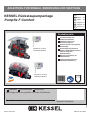 1
1
-
 2
2
-
 3
3
-
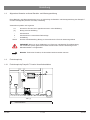 4
4
-
 5
5
-
 6
6
-
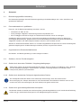 7
7
-
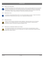 8
8
-
 9
9
-
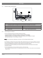 10
10
-
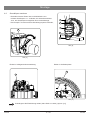 11
11
-
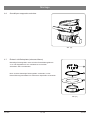 12
12
-
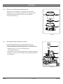 13
13
-
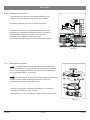 14
14
-
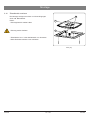 15
15
-
 16
16
-
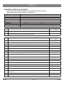 17
17
-
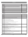 18
18
-
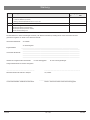 19
19
-
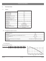 20
20
-
 21
21
-
 22
22
-
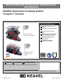 23
23
-
 24
24
-
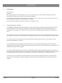 25
25
-
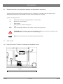 26
26
-
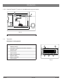 27
27
-
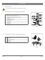 28
28
-
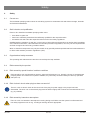 29
29
-
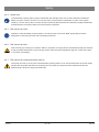 30
30
-
 31
31
-
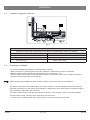 32
32
-
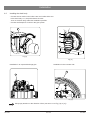 33
33
-
 34
34
-
 35
35
-
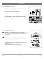 36
36
-
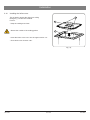 37
37
-
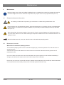 38
38
-
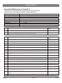 39
39
-
 40
40
-
 41
41
-
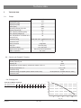 42
42
-
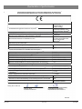 43
43
-
 44
44
-
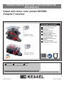 45
45
-
 46
46
-
 47
47
-
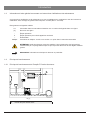 48
48
-
 49
49
-
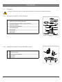 50
50
-
 51
51
-
 52
52
-
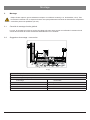 53
53
-
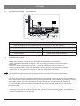 54
54
-
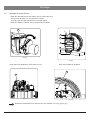 55
55
-
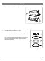 56
56
-
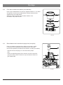 57
57
-
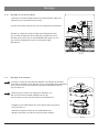 58
58
-
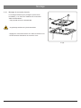 59
59
-
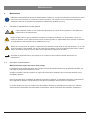 60
60
-
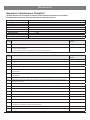 61
61
-
 62
62
-
 63
63
-
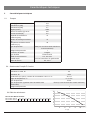 64
64
-
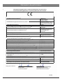 65
65
-
 66
66
-
 67
67
-
 68
68
-
 69
69
-
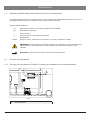 70
70
-
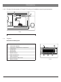 71
71
-
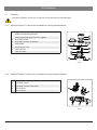 72
72
-
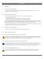 73
73
-
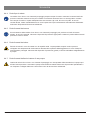 74
74
-
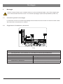 75
75
-
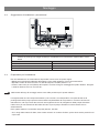 76
76
-
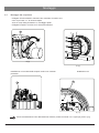 77
77
-
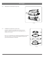 78
78
-
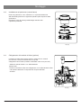 79
79
-
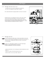 80
80
-
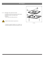 81
81
-
 82
82
-
 83
83
-
 84
84
-
 85
85
-
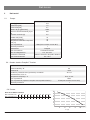 86
86
-
 87
87
-
 88
88
-
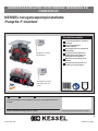 89
89
-
 90
90
-
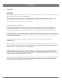 91
91
-
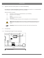 92
92
-
 93
93
-
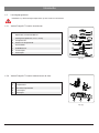 94
94
-
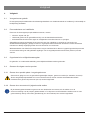 95
95
-
 96
96
-
 97
97
-
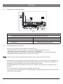 98
98
-
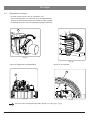 99
99
-
 100
100
-
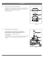 101
101
-
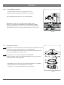 102
102
-
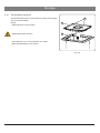 103
103
-
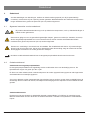 104
104
-
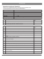 105
105
-
 106
106
-
 107
107
-
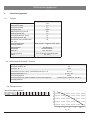 108
108
-
 109
109
-
 110
110
-
 111
111
-
 112
112
-
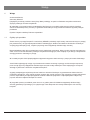 113
113
-
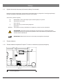 114
114
-
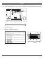 115
115
-
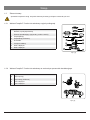 116
116
-
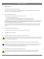 117
117
-
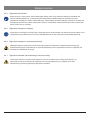 118
118
-
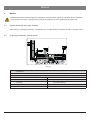 119
119
-
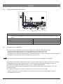 120
120
-
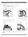 121
121
-
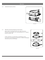 122
122
-
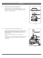 123
123
-
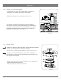 124
124
-
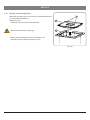 125
125
-
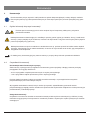 126
126
-
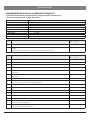 127
127
-
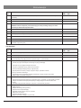 128
128
-
 129
129
-
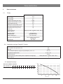 130
130
-
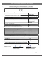 131
131
-
 132
132


Kessel Pumpfix F Comfort Handleiding
- Type
- Handleiding
- Deze handleiding is ook geschikt voor
in andere talen
Gerelateerde artikelen
-
 Kessel 010-701 Technikschacht-LW1000 Installation and Operating Instructions
-
 Kessel 016-328 SG Ecolift L 230 V Installation and Operating Instructions
-
 Kessel 328-198 PS Aquapump Medium LW600 Installation and Operating Instructions
-
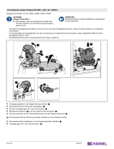 Kessel 016-333 Beiblatt Umrüstsatz für zweite Pumpe Installation and Operating Instructions
-
 Kessel SG 400 V Mono Original Operation Manual
-
 Kessel 016-307 Minilift S Überflur Installation and Operating Instructions
-
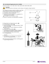 Kessel 016-335 Beiblatt Umrustset Pegelsonde - Ecolift L Installation and Operating Instructions


Andere documenten
-
Pentair 625-3 Handleiding
-
Pentair U5 K Handleiding
-
-
Hornbach Drain box DN 50 Luxembourg Handleiding
-
DAB FEKABOX 110 Series Instruction For Installation And Maintenance
-
 BADU JET Smart Final assembly kit 400 V Handleiding
-
Artweger TWINLINE 2 Tub Assembly Instructions
-
-
Homa TP 28 Original Instruction Manual
-
