Kessel 010-701 Technikschacht-LW1000 Installation and Operating Instructions
- Type
- Installation and Operating Instructions

Technikschacht
LW1000
Einbau- und Betriebsanleitung
DE Technikschacht LW 1000 / Einbau- und Betriebsanleitung.............................2
EN Engineering chamber LW 1000 / Installation and operating instructions...... 18
FR Module rehausse LW 1000 / Instructions de pose et d’utilisation.................34
IT Pozzetto tecnico LW 1000 / Istruzioni per l’installazione e l’uso...................50
NL Techniekschacht LW 1000 / Inbouw- en bedieningshandleiding.................. 67
PL Studzienka techniczna LW 1000 / Instrukcja zabudowy i obsługi.................83
2022/07 010-701_03

DE
Liebe Kundin, lieber Kunde,
als Premiumhersteller von innovativen Produkten für die Entwässerungstechnik bietet KESSEL ganzheitliche Systemlösun-
gen und kundenorientierten Service. Dabei stellen wir höchste Qualitätsstandards und setzen konsequent auf Nachhaltig-
keit - nicht nur bei der Herstellung unserer Produkte, sondern auch im Hinblick auf deren langfristigen Betrieb setzen wir uns
dafür ein, dass Sie und Ihr Eigentum dauerhaft geschützt sind.
Ihre KESSEL AG
Bahnhofstraße 31
85101 Lenting, Deutschland
Bei technischen Fragestellungen helfen Ihnen gerne unsere qualifizierten Servicepartner vor Ort weiter.
Ihren Ansprechpartner finden Sie unter:
www.kessel.de/kundendienst
Bei Bedarf unterstützt unser Werkskundendienst mit Dienstleistungen wie Inbetriebnahme, Wartung oder
Generalinspektion in der gesamten DACH-Region, andere Länder auf Anfrage.
Informationen zur Abwicklung und Bestellung finden Sie unter:
www.kessel.de/service/dienstleistungen
Inhalt
1 Hinweise zu dieser Anleitung................................................................................................................................... 3
2 Sicherheit.................................................................................................................................................................. 4
2.1 Allgemeine Sicherheitshinweise............................................................................................................................... 4
2.2 Personal - Qualifikation............................................................................................................................................ 4
2.3 Bestimmungsgemäße Verwendung......................................................................................................................... 5
2.4 Produktbeschreibung................................................................................................................................................ 5
2.5 Funktionsprinzip........................................................................................................................................................ 8
3 Technische Daten..................................................................................................................................................... 9
4 Montage.................................................................................................................................................................... 10
4.1 Geeigneten Aufstellort wählen................................................................................................................................. 10
4.2 Bodenteil setzen....................................................................................................................................................... 10
4.3 Rohrleitungen anschließen....................................................................................................................................... 11
4.4 Schachtsystem montieren........................................................................................................................................ 13
4.5 Elektrische Leitungen verlegen................................................................................................................................ 15
4.6 Entlüftungsleitung anschließen................................................................................................................................. 16
4.7 Baugrube verfüllen................................................................................................................................................... 16
2 / 100 Technikschacht LW 1000 / Einbau- und Betriebsanleitung 010-701

1 Hinweise zu dieser Anleitung
Folgende Darstellungskonventionen erleichtern die Orientierung:
Darstellung Erläuterung
[1] siehe Abbildung 1
(5) Positionsnummer 5 von nebenstehender Abbildung
... Handlungsschritt in Abbildung
Prüfen, ob Handbetrieb aktiviert wurde. Handlungsvoraussetzung
OK betätigen. Handlungsschritt
Anlage ist betriebsbereit. Handlungsergebnis
siehe "Sicherheit", Seite 4 Querverweis auf Kapitel 2
Fettdruck besonders wichtige oder sicherheitsrelevante Information
Kursivschreibung Variante oder Zusatzinformation (z. B. gilt nur für ATEX-Variante)
Technische Hinweise, die besonders beachtet werden müssen.
Folgende Symbole werden verwendet:
Zeichen Bedeutung
Gerät freischalten!
Gebrauchsanweisung beachten
CE-Kennzeichnung
Warnung Elektrizität
WARNUNG
Warnt vor einer Gefährdung von Personen. Eine Missachtung
dieses Hinweises kann schwerste Verletzungen oder Tod zur Folge haben.
VORSICHT
Warnt vor einer Gefährdung von Personen und Material. Eine Missachtung
dieses Hinweises kann schwere Verletzungen und Materialschäden zur Folge haben.
DE
010-701_03 Einbau- und Betriebsanleitung 3 / 100

DE
2 Sicherheit
2.1 Allgemeine Sicherheitshinweise
VORSICHT
Quetschgefahr. Anlage und Anlagenkomponenten sind schwer und teilweise unhandlich.
Beim Heben und Transport angemessenes Hebewerkzeug verwenden. Die Anlage darf nur bei ordnungsgemäß
gesicherter Befestigung auf Paletten bewegt werden. Es muss ein Gabelstapler als Transportmittel eingesetzt
werden.
Ein Heben mittels Kran darf nur an Anlagen erfolgen, die mit einer Transport-Öse (optionale Sonderanfertigung)
ausgestattet sind.
Transportmittel und persönliche Schutzausrüstung verwenden.
ACHTUNG
Gesundheitsgefährdende Atmosphäre!
Bei Arbeiten in der Schachtanlage besteht die Gefahr, dass die Atmosphäre im Schachtsystem gesundheitsgefähr-
dend ist.
Auf ausreichende Belüftung achten.
Ggf. Sicherheitseinrichtungen, wie z.B. Multigaswarngerät, verwenden.
ACHTUNG
Kontaminierte Oberfläche!
Anlage und Umgebung können durch Keime verunreinigt sein.
Keine Nahrungsmittel im selben Raum lagern oder konsumieren.
Berühren der Oberfläche vermeiden, sichtbaren Schmutz entfernen.
Nach Abschluss der Arbeiten, Hände waschen.
VORSICHT
Statik für Verkehrssicherheit beachten. Schachtverbau für Lastklasse D erfordert eine Lastverteilplatte aus armier-
tem Beton (Ausnahme: bei Standardstraßenaufbau nicht erforderlich).
Erforderliche Lastklasse und Statik gemäß Umgebung/Nutzungsbedingungen ermitteln.
Entsprechenden Bewehrungsplan bei KESSEL-Hotline anfordern.
2.2 Personal - Qualifikation
Für den Betrieb der Anlage gelten die jeweils gültige Betriebssicherheitsverordnung und die Gefahrstoffverordnung oder
nationale Entsprechungen.
Der Betreiber der Anlage ist dazu verpflichtet:
eine Gefährdungsbeurteilung zu erstellen,
entsprechende Gefährdungszonen zu ermitteln und auszuweisen,
Sicherheitsunterweisungen durchzuführen,
gegen die Benutzung durch Unbefugte zu sichern.
Person 1) freigegebene Tätigkeiten an KESSEL-Anlagen
Betreiber Sichtprüfung, Inspektion
Sachkundiger (kennt, ver-
steht Betriebsanweisung)
Entleerung, Reinigung
(innen), Funktionskontrolle
Fachkundiger (Fachhandwerker, nach Ein-
bauanweisung und Ausführungsnormen)
Einbau, Tausch, War-
tung von Komponen-
ten, Inbetriebnahme
1) Bedienung und Montage darf nur durch Personen erfolgen, die das 18. Lebensjahr vollendet haben.
4 / 100 Einbau- und Betriebsanleitung 010-701_03

2.3 Bestimmungsgemäße Verwendung
Die Schachtanlage ist ausschließlich dafür vorgesehen, als Rückstauschacht oder als Aufnahme verschiedener KESSEL
Pump- und Hebeanlagen eingesetzt zu werden. Die Voraussetzungen der Baugrube und das anschließende Verfüllen müs-
sen den Angaben im Kapitel 4.1 entsprechen (siehe "Geeigneten Aufstellort wählen", Seite 10).
Ein Einsatz der Schachtanlage in explosionsgefährdeter Umgebung ist unzulässig.
Nachträgliche Erweiterungen von KESSEL-Schachtanlagen müssen durch den KESSEL-Werkskundendienst abgewickelt
werden.
Alle nicht durch eine ausdrückliche und schriftliche Erlaubnis des Herstellers erfolgten Um- oder Anbauten, Verwendungen
von nicht originalen Ersatzteilen und Reparaturen durch nicht durch den Hersteller autorisierten Betriebe oder Personen füh-
ren zum Verlust der Gewährleistung.
Die Standfestigkeit des Produktes ist ausschließlich für das Eigengewicht, den Transport und für den beschriebenen Ver-
bau gemäß bestimmungsgemäßer Verwendung (z. B. Belastungsklasse, Straßenaufbau, Bewehrungsplan, bauliche Ver-
wendung gemäß Zulassung) gewährleistet.
Zusatzlasten aus Einzel- oder Streifenfundamenten oder anderen Fremdeinwirkungen müssen vermieden werden. Sind
diese zu erwarten, sind ggf. Sondermaßnahmen zu ergreifen.
2.4 Produktbeschreibung
Das Schachtsystem ist modular aufgebaut und für die Aufnahme verschiedener Pump- und Hebeanlagen geeignet.
Jeder Distanzring (bei Zwischenstück und Konus) ist mit mindestens einer Steighilfe ausgerüstet. Die Distanzringe werden
werkzeugfrei aufeinandergefügt.
Die Aufsatzstücke sind stufenlos höhenverstellbar und können mit verschiedenen Abdeckplatten ausgestattet werden.
Anforderungen an die Wasserundurchlässigkeit können durch den Einbau einer Dichtbahn erfüllt werden.
DE
010-701_03 Einbau- und Betriebsanleitung 5 / 100

DE
Aufbau
16
15
14
12
13
12
19
18
17
15
15
12
20
21
7
8
9
10
11
1
2
3
4 4
5
6
Nicht in Abbildung
Steigkasten (Art.-Nr. 860109)
Einstieghilfe Aufsatzstück (Art.-Nr. 860159)
Pos. Bezeichnung Art.-Nr.
1 Aufsatzstück mit Abdeckplatte
LW 800, Klasse K3
8740181
2
Aufsatzstücke LW 800 mit Abdeckplatte
- Klasse A/L15
- Klasse K3, befliesbar
8740177
8740175
3 Schachtmodul LW 1000 Erdreich Zugang LW 800, versch. Einbautiefen, Klasse B/
D
8740179
8740180
4 Aufsatzstück mit Abdeckplatte
LW 800, Klasse K3, mit WU-Flansch
8740176
5 Dichtung für Schachtmodul LW 1000 680375
6 WU-Verlängerungsstück für Schachtmodul (LW 800) 680378
1) Stufenlos höhenverstellbar
2) Luftdichte Verpackung erst unmittelbar vor der Montage entfernen!
3) End-Höhenmaß nach Verbau
6 / 100 Einbau- und Betriebsanleitung 010-701_03

Pos. Bezeichnung Art.-Nr.
7 Abdeckplatte Klasse B, Grauguss / Abdeckplatte Klasse D, Grauguss, ver-
schraubt
860118 / 860136
8 Aufsatzstück 1) d: 600 mm 860153
9 Klemmring für Aufsatzstücke d: 600 mm 680276
10 Dichtung für Schachtmodul 680374
11 Schachtkonus
LW 600 Zugang Schachtmodul
680431
12 Dichtung für Zwischenstück 2) 680125
13 Zwischenstück 250 mm, für Schachtmodul LW 1000 680370
14 Zwischenstück 500 mm, für Schachtmodul LW 1000 680371
15 Verbindungsbolzen-Set, 10 Stück 680373
16 Bodenteil (Technikmodul), Ausführung je nach Verwendungszweck. Kann aus mehreren Bauteilen bestehen. Die
Verbindungselemente und Dichtungen sind identisch aufgebaut.
17 Schachtkonus
LW 800 Zugang Schachtmodul
680430
18 Dichtung für Schachtmodul LW 1000 680375
19 Klemmring für Aufsatzstücke d: 800 mm 680568
20 Dichtung für Rohrdurchführung, DN 70 850116
21 Dichtung für Rohrdurchführung, DN 100 850117
1) Stufenlos höhenverstellbar
2) Luftdichte Verpackung erst unmittelbar vor der Montage entfernen!
3) End-Höhenmaß nach Verbau
DE
010-701_03 Einbau- und Betriebsanleitung 7 / 100

DE
2.5 Funktionsprinzip
Ecolift XL
(Druckleitung über die Rückstauebene
hinaus verlegt)
Pumpstation Aquapump XL (für fäkalienhaltiges Abwasser, trockene Aufstellung)
(Druckleitung über die Rückstauebene
hinaus verlegt)
Pumpstation Aquapump XL (für fäkalienfreies Abwasser, 400 V, nasse Aufstellung)
(Druckleitung über die Rückstauebene
hinaus verlegt)
8 / 100 Einbau- und Betriebsanleitung 010-701_03

3 Technische Daten
Allgemeine Angaben
Maximale Einbautiefe 5 m
Minimaler Schachtauf-
bau (ohne Technikmodul
(Bodenteil))
siehe nebenstehende Zeich-
nung
Höhe der Zwischenstücke
(hoch/niedrig)
50/25 cm
Grundwasserbeständigkeit
ab Unterkante Bodenteil
3 m
Abmessungen siehe "Aufbau", Seite 6
Abstand der Steighilfen 25 cm
Tragfähigkeit der Steighilfen entspricht EN 13598-2
Material
Kunststoff PE (Schacht und Konus),
PP (Aufsatzstück) und PPO/
PA (Steighilfen)
Dichtungen Elastomer 55 Shore A
SBR 50+/- IRHD
380 - 629 mm
LW 600
1200 mm
LW 800
668 - 917 mm
1200 mm
DE
010-701_03 Einbau- und Betriebsanleitung 9 / 100

DE
4 Montage
4.1 Geeigneten Aufstellort wählen
Zusammenstellung der Schachtelemente (siehe "Aufbau", Seite 6).
Die Beschaffenheit des Untergrunds (Auflage Bodenteil (Technikmodul)) und das seitliche Füllmaterial müssen wie folgt aus-
geprägt sein:
Sauberkeitsschicht:
Ebene ca. 30 cm hohe und verdichtete Schicht Bruchschotter.
Sofern gewünscht, Fixierung des Bodenteils mit Magerbeton.
Seitliches Füllmaterial: Ringförmig umlaufend ca. 50 cm, Bruchschotter (0-16mm), alle 30 cm verdichtet 1.
Sicherstellen, dass bei einem Einbau des Schachtes im Gebäudeinneren die statischen Anforderungen eingehalten wer-
den (siehe "Einflussbereich von Fundament und Bodenplatte berücksichtigen", Seite 17).
Kontrolle Schachttiefe:
Sicherstellen, dass die Schachtelemente in montiertem Zustand der Tiefe der Baugrube entsprechen.
Soll ein WU-Verlängerungsstück (6) (siehe "Aufbau", Seite 6) eingebracht werden, sicherstellen, dass sich dieser in der
vorgesehenen Höhe befindet.
Die Aufsatzstücke können um 25 cm stufenlos höhenverstellbar im WU-Verlängerungsstück positioniert werden.
Sind bauseitige Druckleitungen erforderlich, sind diese nach PN 6,3 auszulegen.
Wird die Druckleitung über die Rückstauebene hinaus verlegt (siehe "Pumpstation Aquapump XL (für fäkalienhaltiges
Abwasser, trockene Aufstellung)", Seite 8 und siehe "Ecolift XL", Seite 8), sicherstellen, dass diese frostsicher betrieben
werden kann.
Schachtelemente und Dichtungen frei von Verschmutzungen halten.
Die Verbindungen zwischen den Schachtelementen 1 sind als Einwegbefestigungen konzipiert. Ist eine solche Befesti-
gung hergestellt, kann sie nicht mehr gelöst werden. Aufsatzstücke können jederzeit demontiert werden.
Montage der Schachtelemente erfolgt von unten nach oben.
Die Schachtanlage ist für einen Wasserdruck von maximal 0,3 bar ausgelegt.
4.2 Bodenteil setzen
Baugrube ausheben.
Auf Baugruben-Böschungswinkel achten.
Bodenteil waagerecht in der Baugrube ausrichten.
Geringe Abweichungen machen sich bei tiefen Schächten bis nach oben deutlich bemerkbar.
Das Bodenteil muss vollflächigen Kontakt zum Untergrund haben.
Das Bodenteil seitlich mit Magerbeton fixieren ( siehe "Baugrube verfüllen", Seite 16).
Bei Krantransport beachten
Immer 4 Lasthaken verwenden.
Maximale Tragkraft von 4 Lasthaken: 200 kg.
Schäkel mit einem Bolzendurchmesser von 16 mm ver-
wenden.
Die Krankette bzw. der Schlupf zum einzelnen Lastpunkt
muss eine Länge von mindestens 1 m haben (A).
Last nicht länger als eine Stunde am Kran hängen las-
sen.
1Verbindungsbolzen zwischen Bodenteil, Zwischenstück(en) und Konus sowie die Steighilfen
10 / 100 Einbau- und Betriebsanleitung 010-701_03

4.3 Rohrleitungen anschließen
Bei Verwendung als Rückstauschacht, weiter mit Kapitel 4.4.
Ecolift XL
(A) Verlegung der Druckleitung über
die Rückstauebene hinaus
Zulauf (1) anschließen.
Auslauf (2) anschließen.
Druckleitung anschließen.
Abb. 1: Ecolift XL
Verlegung der Druckleitung direkt in die Kanalleitung
Kanalleitung L1 [cm] L2 [cm]
DN100 20 35
DN125 21,5 33,5
DN150 24 28,5
DN200 32,5 22,5
DE
010-701_03 Einbau- und Betriebsanleitung 11 / 100

DE
Pumpstation Aquapump XL - Trockene Aufstellung
Zulauf (1) anschließen.
Druckleitung (2) anschließen.
Pumpstation Aquapump XL (für fäkalienfreies Abwasser, 400 V, nasse Aufstellung)
Zulauf (1) anschließen.
Druckleitung (2) anschließen.
Pumpstation Aquapump XL (für fäkalienfreies oder fäkalienhaltiges Abwasser, 400 V, nasse Aufstellung)
Zulauf (1) anschließen.
Druckleitung (2) anschließen.
12 / 100 Einbau- und Betriebsanleitung 010-701_03

4.4 Schachtsystem montieren
Luftdichte Verpackung der Dichtung erst unmittelbar vor
der Montage entfernen!
Dichtung (1) fettfrei auf die Aufnahmenut des Bodenteils
(bzw. Zwischenstücks) auflegen.
Mit einem Gummihammer die Dichtung an vier gleichmä-
ßig verteilten Punkten (A), (B), (C) und (D) in die Aufnah-
menut hineinklopfen.
Dichtung vollständig in die Aufnahmenut hineinklopfen.
Sicherstellen, dass die Dichtung dabei weder gestaucht
noch in die Länge gezogen wird.
Mit dem optionalen Kabelbefestigungsset (Art.-Nr. 28076)
können diverse Kabel sauber im Schacht verlegt werden.
Oberseite der Dichtung (2) leicht einfetten.
Zwischenstück oder Konus aufsetzen.
Dabei sicherstellen, dass dieses/dieser nach der Kodie-
rung ausgerichtet ist.
Kodierung:
Die Aussparung (1) des oberen Elementes muss auf den
Dorn (3) des unteren Elements aufgesetzt werden.
Sicherstellen, dass sich die Steighilfen übereinander
befinden.
(1) Dichtungssystem A
(2) Dichtungssystem N
DE
010-701_03 Einbau- und Betriebsanleitung 13 / 100

DE
Verbindungsbolzen montieren
Beide Verbindungsflächen mit einer Zange zusammen-
drücken.
Verbindungsbolzen (1) hineinklopfen und Zange wieder
abnehmen.
Dichtung für das nächste Schachtelement einsetzen, wie
zuvor beschrieben, usw.
Aufsatz- und Zwischenstücke montieren
WU-Verlängerungsstück einsetzen (Option)
WU-Verlängerungsstück (3) einsetzen.
Dichtung (2) in WU-Verlängerungsstück (3) einsetzen.
Aufsatzstück einsetzen
(A) Einstieg 800 mm
(B) Einstieg 600 mm
Gefettete Dichtung (1) in Konus montieren.
Aufsatzstück (2) einsetzen.
Ggf. Aufsatzstück kürzen, wie nachstehend beschrieben.
14 / 100 Einbau- und Betriebsanleitung 010-701_03

Aufsatzstück kürzen (optional)
Rundherum so anzeichnen, dass das Aufsatzstück (1)
mindestens 8 cm in das WU-Verlängerungsstück (2) hin-
einragt.
Mit Stichsäge (15°) ablängen.
Kanten entgraten.
15°
≥ 80
1
2
Aufsatzstück ausrichten
KESSEL-Aufsatzstücke sind grundsätzlich neigbar. Das
lichte Weite 600 Aufsatzstück (A) kann um 5° und das lichte
Weite 800 Aufsatzstück (B) kann um 3° geneigt werden, um
es den örtlichen Gegebenheiten anzupassen.
4.5 Elektrische Leitungen verlegen
Kabelbefestigungen (1) (Option) an den Anbohrpunkten
(2) befestigen.
Mit den mitgelieferten Befestigungsschrauben befestigen.
Sicherstellen, dass die Befestigungsschrauben nicht län-
ger als 16 mm sind.
Die Schachtwand könnte undicht werden.
Eine Kabeldurchführung kann mit entsprechender Sägeglo-
cke vorgenommen werden.
Höhe Zwischenstück [cm] Maximaler Durchmesser
250 DN100
500 DN150
Konus DN200
Dichtung für Rohr-
durchführung
Art.-Nr.
DN50 (Ø 50) 850114
DN70 (Ø 75) 850116
DN100 (Ø 110) 850117
DN125 (Ø 125) 850118
DN150 (Ø 160) 850119
DE
010-701_03 Einbau- und Betriebsanleitung 15 / 100

DE
4.6 Entlüftungsleitung anschließen
Bei der Verlegung der Entlüftungsleitung darauf achten, dass für spätere Montage und Wartungsarbeiten bestmögliche
Bewegungsfreiheit verbleibt.
Alle Anlagenkomponenten (Pumpen, Rückstauklappen und Rohrleitungen) müssen gut zugänglich bleiben.
Entlüftungsleitung oberhalb der Rückstauebene unter Verwendung einer Dichtung für Rohrdurchführung hinausführen.
Montage im Konus (A)
Zur Durchführung Anbohrfläche (1) verwenden.
Montage im Zwischenstück (B)
Durchführung an einem geeigneten Anbohrpunkt (2) her-
stellen.
4.7 Baugrube verfüllen
VORSICHT
Statik für Verkehrssicherheit beachten. Schachtverbau für Lastklasse D erfordert eine Lastverteilplatte aus armier-
tem Beton (Ausnahme: bei Standardstraßenaufbau nicht erforderlich).
Erforderliche Lastklasse und Statik gemäß Umgebung/Nutzungsbedingungen ermitteln.
Entsprechenden Bewehrungsplan bei KESSEL-Hotline anfordern.
Grube mit Bruchschotter (0-16 mm Durchmesser), mind. 50 cm umlaufend auffüllen, dabei alle 30 cm das Füllmaterial
fachgerecht auf 97% Dpr verdichten (z. B. Rüttelplatte).
Zur sauberen Fixierung Bodenteil ggf. mit Magerbeton umfüllen (siehe Magerbetonkeil (1)).
Der erforderliche Baugruben-Böschungswinkel β ist umlaufend einzuhalten.
Die Zuordnung von innerem Reibungswinkel φ des Verfüllmaterials und zulässigem Baugruben-Böschungswinkel β hat
nach EN 4124 zu erfolgen.
16 / 100 Einbau- und Betriebsanleitung 010-701_03

Einflussbereich von Fundament und Bodenplatte berücksichtigen
Wenn der Schacht so positioniert werden soll, dass er sich
später innerhalb oder in der Nähe eines Gebäudes befindet,
müssen folgende zusätzliche Voraussetzungen berücksich-
tigt werden.
Benachbarte Fundamente
Der Schacht darf nicht im Einflussbereich von benachbarten
Fundamenten sein, d. h.
Mindestabstand a = Abstand zwischen Unterkante Schacht
und Unterkante Fundament:
a = ΔH x 1,73
Außerdem darf die Bodenplatte im Bereich des Schach-
tes nicht zum flächigen Lastabtrag aus dem Gebäude
herangezogen werden.
Berührende Bodenplatte
Unter der Bodenplatte ist im Schachtbereich eine ca. 5 cm
dicke Styroporschicht mit einem Überstand von etwa 20 cm
vorzusehen, damit mögliche Setzungen der Bodenplatte
nicht zu großen Vertikallasten im Schacht führen.
Der Schacht könnte sonst ggf. wie ein Pfahl wirken.
Der Schachtaufbau ist so auszuführen, dass sich die Styro-
porplatte auf Höhe des höhenverstellbaren Aufsatzstückes
befindet.
(1) 5 cm Styroporschicht
Falls der Konus im Übergangsbereich der Bodenplatte liegt,
muss eine Trennung mittels Bewegungsfuge t = 5 cm erfol-
gen und eine Styroporschicht über dem Schachtbereich, wie
oben beschrieben, platziert werden.
(1) 5 cm Styroporschicht
(2) Bodenplatte
DE
010-701_03 Einbau- und Betriebsanleitung 17 / 100

EN
Dear Customer,
As a premium manufacturer of innovative products for draining technology, KESSEL offers integrated system solutions and
customer-oriented service. In doing so, we set the highest quality standards and focus firmly on sustainability - not only with
the manufacturing of our products, but also with regard to their long-term operation and we strive to ensure that you and your
property are protected over the long term.
Your KESSEL AG
Bahnhofstraße 31
85101 Lenting, Germany
Our local, qualified service partners would be happy to help you with any technical questions.
You can find your contact partner at:
www.kessel.de/kundendienst
If necessary, our Factory Customer Service provides support with services such as commissioning, main-
tenance or general inspection throughout the DACH region, other countries on request.
For information about handling and ordering, see:
www.kessel.de/service/dienstleistungen
Contents
1 Notes on this manual............................................................................................................................................... 19
2 Safety........................................................................................................................................................................ 20
2.1 General safety notes................................................................................................................................................ 20
2.2 Personnel - qualification........................................................................................................................................... 20
2.3 Intended use............................................................................................................................................................. 21
2.4 Product description................................................................................................................................................... 21
2.5 How it works............................................................................................................................................................. 24
3 Technical data.......................................................................................................................................................... 25
4 Installation................................................................................................................................................................. 26
4.1 Choose suitable installation location........................................................................................................................ 26
4.2 Setting the base section.......................................................................................................................................... 26
4.3 Connecting the pipes............................................................................................................................................... 27
4.4 Assembling and installing the chamber system...................................................................................................... 29
4.5 Routing electric cables............................................................................................................................................. 31
4.6 Connecting the ventilation pipe................................................................................................................................ 31
4.7 Backfill the excavation pit........................................................................................................................................ 32
4.7.1 Taking the influence of foundation and floor slab into account............................................................................... 32
18 / 100 Engineering chamber LW 1000 /
Installation and operating instructions
010-701

1 Notes on this manual
The following conventions make it easier to navigate the manual:
Symbol Explanation
[1] See Figure 1
(5) Position number 5 from the adjacent figure
... Action step in figure
Check whether manual operation has been
activated. Prerequisite for action
Press OK. Action step
System is ready for operation. Result of action
see "Safety", page 20 Cross-reference to Chapter 2
Bold type Particularly important or safety-relevant information
Italics Variants or additional information (e.g. applicable only for ATEX variants)
Technical information or instructions which must be paid particular attention.
The following symbols are used:
Icon Meaning
Isolate device!
Observe the instructions for use
CE marking
Warning, electricity
WARNING
Warns of a hazard for persons. Disregarding
this warning can lead to very serious injuries or death.
CAUTION
Warns of a hazard for persons and material. Disregarding
this warning can lead to serious injuries and material damage.
EN
010-701 Engineering chamber LW 1000 /
Installation and operating instructions
19 / 100

EN
2 Safety
2.1 General safety notes
CAUTION
Risk of crushing. The system and system components are heavy and in some cases unwieldy.
Use suitable lifting gear when lifting or transporting. The system shall be moved only when properly secured on
pallets. A forklift truck must be used for transport.
Craning is only permitted in the case of systems equipped with a transport eye (optional special design).
Use transport equipment and personal protective equipment.
NOTICE
Hazardous atmosphere!
There is a risk of a hazardous atmosphere occurring in the chamber system during work.
Make sure the system is well aerated.
Use safety equipment such as e.g. a multi-gas warning device if necessary.
NOTICE
Contaminated surface!
The system and surroundings can be contaminated by germs.
Do not store or consume any food in the same room.
Avoid touching the surface, remove visible dirt.
After work is complete, wash your hands.
CAUTION
Note the structural calculations for traffic safety. Chamber installation for load class D makes a load distribution plate
made of reinforced concrete necessary (exception: not necessary for standard road construction).
Determine the required load class and structural calculations in accordance with the environment / use condi-
tions.
Request an appropriate reinforcement drawing from the KESSEL hotline.
2.2 Personnel - qualification
The relevant operational safety regulations and the hazardous substances ordinance or national equivalents apply for the
operation of the system.
The operator of the system must:
prepare a risk assessment
identify and demarcate corresponding hazard zones
carry out safety training
secure the system against unauthorised use.
Person 1) Approved activities on KESSEL systems
Operating company Visual inspection, inspection
Competent expert / inspector (familiar
with, understands operating instructions)
Emptying, cleaning
(inside), functional check
Competent skilled person (specialist
craftsman, in accordance with installa-
tion instructions and execution standards)
Installation, replacement,
maintenance of compo-
nents, commissioning
1) Operation and assembly work may only be carried out by persons who are 18 years of age.
20 / 100 Engineering chamber LW 1000 /
Installation and operating instructions
010-701

2.3 Intended use
The chamber system has been designed exclusively to serve as a backwater chamber or for housing various KESSEL
pumping and lifting stations. The excavation pit prerequisites and subsequence backfilling work must comply with the specifi-
cations set out in chapter 4.1 (see "Choose suitable installation location", page 26).
The chamber system must not be used in a potentially explosive environment.
Later extensions to the KESSEL chamber systems must be carried out by KESSEL Factory Customer Services.
All conversions or attachments that are carried out without the express and written permission of the manufacturer, the use
of non-genuine spare parts and repairs carried out by companies or persons not approved by the manufacturer will lead to a
loss of warranty.
The stability of the product is only guaranteed for its own weight, transport and the installation described in accordance
with intended use (e.g. load class, road construction, reinforcement drawing, structural use in accordance with approval).
Additional loads from single or strip footings or other external impacts must be avoided. Special measures may have to be
taken if these are to be expected.
2.4 Product description
The chamber system has a modular design and is suitable for housing various pumping and lifting stations.
Each spacer ring (with intermediate section and taper) is fitted with at least one access step. The spacer rings are fitted
together without tools.
The upper sections are continuously height-adjustable and can be fitted with different cover plates.
Waterproof requirements can be fulfilled by installing a sealing sheet.
EN
010-701 Engineering chamber LW 1000 /
Installation and operating instructions
21 / 100

EN
Design
16
15
14
12
13
12
19
18
17
15
15
12
20
21
7
8
9
10
11
1
2
3
4 4
5
6
Not in figure
Embedded step (art. no. 860109)
Upper section access steps (art. no. 860159)
Item Designation Art. no.
1 Upper section with cover plate
LW 800, Class K3
8740181
2
Upper sections CO 800 with cover plate
- Class A/L15
- Class K3, tileable
8740177
8740175
3 Chamber module CO 1000 underground access CO 800, different installation
depths, Class B/D
8740179
8740180
4 Upper section with cover plate
LW 800, Class K3, with waterproof flange
8740176
5 Seal for chamber module LW 1000 680375
6 Waterproof extension section for chamber module (CO800) 680378
7 Cover plate Class B, grey iron / cover plate Class D, grey iron, screwed 860118 / 860136
1) Continuously height-adjustable
2) Do not remove the airtight packaging until directly before assembly and installation!
3) Final overall height after installation
22 / 100 Engineering chamber LW 1000 /
Installation and operating instructions
010-701

Item Designation Art. no.
8 Upper section 1) d: 600 mm 860153
9 Clamping ring for upper sections d: 600 mm 680276
10 Seal for chamber module 680374
11 Chamber taper
LW 600 access chamber module
680431
12 Seal for intermediate section 2) 680125
13 Intermediate section 250 mm, for chamber module LW 1000 680370
14 Intermediate section 500 mm, for chamber module LW 1000 680371
15 Connecting bolt set, 10 pcs. 680373
16 Base section (technical module), version depending on application purpose. Can comprise several components.
The connection elements and seals are designed identical.
17 Chamber taper
LW 800 access chamber module
680430
18 Seal for chamber module LW 1000 680375
19 Clamping ring for upper sections d: 800 mm 680568
20 Seal for pipe penetration, DN 70 850116
21 Seal for pipe penetration, DN 100 850117
1) Continuously height-adjustable
2) Do not remove the airtight packaging until directly before assembly and installation!
3) Final overall height after installation
EN
010-701 Engineering chamber LW 1000 /
Installation and operating instructions
23 / 100

EN
2.5 How it works
Ecolift XL
(pressure pipe routed above the backwa-
ter level)
Aquapump XL pumping station (for faecal wastewater, dry installation)
(pressure pipe routed above the backwa-
ter level)
Aquapump XL pumping station (for non-faecal wastewater, 400 V, wet installation)
(pressure pipe routed above the backwa-
ter level)
24 / 100 Engineering chamber LW 1000 /
Installation and operating instructions
010-701

3 Technical data
General information
Maximum installation depth 5 m
Minimum chamber structure
(without technical module
(base section))
see adjacent drawing
Height of the intermediate
section (high/low)
50/25 cm
Groundwater resistant from
lower edge of base section
3 m
Dimensions see "Design", page 22
Spacing of the access steps 25 cm
Load-bearing capacity of the
access steps
complies with EN 13598-2
Material
polymer PE (chamber and taper), PP
(upper section) and PPO/PA
(access steps)
Seals Elastomer 55 Shore A
SBR 50+/- IRHD
380 - 629 mm
LW 600
1200 mm
LW 800
668 - 917 mm
1200 mm
EN
010-701 Engineering chamber LW 1000 /
Installation and operating instructions
25 / 100

EN
4 Installation
4.1 Choose suitable installation location
Composition of the chamber elements (see "Design", page 22).
The substrate (support for base section (technical module)) and filling material at the side of the chamber must have the fol-
lowing properties:
Blinding layer:
Layer of compacted crushed stone approx. 30 cm in height.
If required, fixing of the base section using lean concrete.
Filling material at the side: ring-shaped, all the way round approx. 50 cm, crushed stone (0-16mm), compacted every
30 cm 1.
When the chamber is installed inside a building, care must be taken that the structural requirements are fulfilled (see
"Taking the influence of foundation and floor slab into account", page 32).
Check chamber depth:
Make sure that the assembled chamber elements correspond to the depth of the excavation pit.
If a waterproof extension section (6) (see "Design", page 22) is to be used, make sure this is positioned at the prescribed
height.
The upper sections can be positioned in the waterproof extension section continuously height-adjustable by 25 cm.
If pressure pipes are required on site, they must be designed in accordance with PN 6.3.
If the pressure pipe is routed above the backwater level (see "Aquapump XL pumping station (for faecal wastewater, dry
installation)", page 24 and see "Ecolift XL", page 24), make sure that this can be operated frost-free.
Keep chamber elements and seals free of soiling.
The connections between the chamber elements 1 have been designed as single-use fasteners. Once such connections
have been made, they can no longer be loosened. Upper sections can be dismantled at any time.
The chamber elements must be assembled from the bottom up.
The chamber system has been designed for a maximum of 0.3 bar water pressure.
4.2 Setting the base section
Dig out the excavations.
Pay attention to the slope angle of the excavations.
Align the base section horizontally in the excavations.
Slight deviations are noticed significantly right to the top of deep chambers.
The base section must be in contact with the subsoil across the whole of its surface.
Use lean concrete to fix the base section in place at the side ( see "Backfill the excavation pit", page 32).
Information for crane transport
Always use 4 load hooks.
Maximum load-bearing capacity of 4 load hooks: 200 kg.
Use a shackle with a 16 mm bolt diameter.
The crane chain or slip neck to the individual load point
must be at least 1 m long (A).
Do not leave loads suspended from the crane for longer
than one hour.
1connection bolts between base section, intermediate section(s) and taper as well as the access steps
26 / 100 Engineering chamber LW 1000 /
Installation and operating instructions
010-701

4.3 Connecting the pipes
For use as a backwater chamber, continue at chapter 4.4.
Ecolift XL
(A) Routing the pressure pipe above
the backwater level
Connect the inlet (1).
Connect the outlet (2).
Connect the pressure pipe.
Fig. 1: Ecolift XL
Routing of the pressure pipe directly into the sewer pipe
Sewer pipe L1 [cm] L2 [cm]
DN100 20 35
DN125 21.5 33.5
DN150 24 28.5
DN200 32.5 22.5
EN
010-701 Engineering chamber LW 1000 /
Installation and operating instructions
27 / 100

EN
Aquapump XL pumping station - dry installation
Connect the inlet (1).
Connect the pressure pipe (2).
Aquapump XL pumping station (for non-faecal wastewater, 400 V, wet installation)
Connect the inlet (1).
Connect the pressure pipe (2).
Aquapump XL pumping station (for non-faecal or faecal wastewater, 400 V, wet installation)
Connect the inlet (1).
Connect the pressure pipe (2).
28 / 100 Engineering chamber LW 1000 /
Installation and operating instructions
010-701

4.4 Assembling and installing the chamber system
Do not remove the seal from the airtight packaging until
directly before assembly and installation!
Place the seal (1) grease-free onto the seat groove of the
base section (or intermediate section).
Use a rubber hammer to knock the seal into the seat
groove at four equi-distant points (A), (B), (C), (D) around
the edge.
Knock the seal completely into the seat groove.
Make sure that the seal is neither bulged nor stretched.
Various cables can be laid cleanly in the chamber using
the optional cable fastener set (art. no. 28076).
Lightly grease the top of the seal (2).
Set an intermediate section or taper in place.
Make sure that this is aligned in accordance with the cod-
ing.
Coding:
The cut-out (1) in the upper element must be set onto the
pin (3) of the lower element.
Make sure that the access steps are aligned above one
another.
(1) Seal system A
(2) Seal system N
EN
010-701 Engineering chamber LW 1000 /
Installation and operating instructions
29 / 100

EN
Installing the connection bolts
Use pliers to press both connecting surfaces together.
Knock the connecting bolt (1) in place and release the pli-
ers again.
Insert the seal for the next chamber element as described
above etc.
Install the upper and intermediate sections.
Inserting a waterproof extension section (optional)
Insert waterproof extension section (3).
Insert the seal (2) in the waterproof extension section (3).
Fit the upper section
(A) Entry 800 m
(B) Entry 600 m
Fit greased seal (1) into the taper.
Insert the upper section (2).
If necessary, shorten the upper section as described
below.
30 / 100 Engineering chamber LW 1000 /
Installation and operating instructions
010-701

Shortening the upper section (optional)
Mark the upper section (1) all the way round in such
a way that it projects at least 8 cm into the waterproof
extension section (2).
Use a jigsaw (15°) to cut to the required length.
Deburr the edges.
15°
≥ 80
1
2
Align the upper section
KESSEL upper sections are tiltable The upper section (A)
with clear opening 600 can be tilted by 5° and the upper
section (B) with clear opening 800 can be tilted by 3° to
adapt it to the circumstances on site.
4.5 Routing electric cables
Fix cable fasteners (1) (optional) to the scoring points (2).
Use the fixing screws to fix these in place.
Make sure that the fixing screws are not longer than
16 mm.
The chamber wall could leak.
An appropriate hole saw can be used for a cable passage.
Height of interme-
diate section [cm]
Maximum diameter
250 DN100
500 DN150
Taper DN200
Seal for pipe penetration Art. no.
DN50 (Ø 50) 850114
DN70 (Ø 75) 850116
DN100 (Ø 110) 850117
DN125 (Ø 125) 850118
DN150 (Ø 160) 850119
4.6 Connecting the ventilation pipe
When routing the ventilation pipe, make sure you leave sufficient room for later fitting and maintenance work.
All the system components (pumps, backwater flaps and pipework) must remain easily accessible.
EN
010-701 Engineering chamber LW 1000 /
Installation and operating instructions
31 / 100

EN
Route the ventilation pipe above the backwater level using a seal for pipe penetration.
Installation in the taper (A)
Use scoring surface (1) for passage.
Installation in the intermediate section (B)
Choose a suitable scoring point (2) for passage.
4.7 Backfill the excavation pit
CAUTION
Note the structural calculations for traffic safety. Chamber installation for load class D makes a load distribution plate
made of reinforced concrete necessary (exception: not necessary for standard road construction).
Determine the required load class and structural calculations in accordance with the environment / use condi-
tions.
Request an appropriate reinforcement drawing from the KESSEL hotline.
Fill the excavations with crushed stone (0-16 mm diameter), at least 50 cm all around; place in layers of maximum 30 cm
and compact each layer of fill material properly to 97% Dpr (e.g. using vibrating plate).
To fix the base section in place correctly, surround with lean concrete (see lean concrete wedge (1)).
The required excavation pit slope angle β must be observed all the way round.
The assignment of internal frictional angle φ of the fill material, and permissible excavation pit slope angle β must be car-
ried out in accordance with EN 4124.
4.7.1 Taking the influence of foundation and floor slab into account
If the chamber is to be positioned in such a way that it is
inside or near a building later, the following additional pre-
requisites must be taken into account.
32 / 100 Engineering chamber LW 1000 /
Installation and operating instructions
010-701

Adjacent foundations
The chamber must not be installed in a spot where it could
influence adjacent foundations, i.e.
minimum distance a = distance between the bottom edge of
the chamber and bottom edge of the foundation:
a = ΔH x 1.73
In addition, the floor slab near the chamber must not be
used for calculating the traffic load for the building.
Touching floor slab
Under the floor slab, a layer of polystyrene approx. 5 cm
thick with an excess depth of around 20 cm must be
included in order to prevent any settling of the concrete slab
leading to large vertical loads in the chamber.
Otherwise the chamber could have the effect of a stake.
The chamber structure must be designed in such a way that
the polystyrene layer is on level with the height-adjustable
upper section.
(1) 5 cm polystyrene layer
If the taper is in the transition area of the floor slab, sepa-
ration must be by means of a moving joint t = 5 cm and the
polystyrene layer must be fitted above the chamber area , as
described above.
(1) 5 cm polystyrene layer
(2) Floor slab
EN
010-701 Engineering chamber LW 1000 /
Installation and operating instructions
33 / 100

FR
Chère cliente, cher client,
En qualité de producteur de pointe de produits novateurs dans le domaine de la technique d’assainissement, KESSEL pro-
pose des réponses systématiques globales et un service orienté aux besoins de la clientèle. Nous misons simultanément
sur les normes de qualité les plus élevées et une durabilité conséquente – non seulement lors de la fabrication de nos pro-
duits, mais également pour leur utilisation à long terme afin que vous, et vos biens, soient protégés durablement.
Votre KESSEL AG
Bahnhofstrasse 31
85101 Lenting, Allemagne
Nos partenaires qualifiés du service après-vente se feront un plaisir de répondre à vos questions tech-
niques sur site.
Vous trouverez votre correspondant sur :
www.kessel.de/kundendienst
Si nécessaire, notre propre SAV vous prête son assistance en matière de mise en service, de mainte-
nance ou d’inspection générale en Allemagne, en Autriche et en Suisse, comme dans d’autres pays sur
demande.
Toutes les informations de traitement et de commande sont à votre disposition sur :
www.kessel.de/service/dienstleistungen
Sommaire
1 Informations spécifiques aux présentes instructions............................................................................................... 35
2 Sécurité..................................................................................................................................................................... 36
2.1 Consignes de sécurité générales............................................................................................................................ 36
2.2 Personnel – qualification.......................................................................................................................................... 36
2.3 Utilisation conforme à l'usage prévu........................................................................................................................ 37
2.4 Description du produit.............................................................................................................................................. 37
2.5 Principe de fonctionnement...................................................................................................................................... 40
3 Caractéristiques techniques..................................................................................................................................... 41
4 Montage.................................................................................................................................................................... 42
4.1 Choisir un emplacement de montage approprié..................................................................................................... 42
4.2 Pose du segment inférieur....................................................................................................................................... 42
4.3 Raccordement de la canalisation............................................................................................................................. 43
4.4 Montage du système de regard............................................................................................................................... 45
4.5 Pose des câbles électriques.................................................................................................................................... 47
4.6 Raccordement de la conduite d’aération et de ventilation...................................................................................... 48
4.7 Remplir l’excavation................................................................................................................................................. 48
4.7.1 Tenir compte de l’influence de la semelle et de la dalle de fondation..................................................................... 49
34 / 100 Module rehausse LW 1000 / Instructions de pose et d’utilisation 010-701

1 Informations spécifiques aux présentes instructions
Les conventions de représentation suivantes facilitent l’orientation :
Représentation Explication
[1] voir figure 1
(5) Numéro de repère 5 de la figure ci-contre
... Action de la figure
Vérifier si le mode manuel a été activé. Condition de réalisation de l’action
Valider <OK>. Action
Le système est prêt au service. Résultat de l'action
cf. "Sécurité", page 36 Renvoi au chapitre 2
Caractères gras particulièrement important ou information importante pour la sécurité
Caractères italiques Variante ou informations complémentaires (par
exemple, uniquement valable pour la variante ATEX)
informations techniques à observer en particulier.
Les instructions emploient les pictogrammes suivants :
Pictogramme / label Signification
Activer l’appareil !
Observer le mode d'emploi
Label de conformité CE
Mise en garde contre l’électricité
MISE EN GARDE
Avertit d'un danger corporel. Le non-respect
de cette mise en garde peut provoquer des blessures graves, voire mortelles.
ATTENTION
Avertit d'un danger corporel et matériel. Le non-respect
de cette mise en garde peut provoquer des blessures graves et des dommages matériels.
FR
010-701 Module rehausse LW 1000 / Instructions de pose et d’utilisation 35 / 100

FR
2 Sécurité
2.1 Consignes de sécurité générales
ATTENTION
Risque d'écrasement. Le poste ainsi que ses composants sont lourds et en partie peu maniables.
Utiliser un dispositif de levage approprié pour le levage et le transport. Le poste ne doit être déplacé que s'il est
fixé de manière appropriée et sécurisée sur des palettes. Il convient d’utiliser un chariot-élévateur comme moyen
de transport.
Les postes ne peuvent être soulevés à l'aide d'une grue que s’ils disposent d’un anneau de transport (fabrication
spéciale optionnelle).
Utiliser un moyen de transport et un équipement de protection individuelle.
AVIS
Atmosphère dangereuse pour la santé !
L'atmosphère dans le système de regard peut nuire à la santé lors de travaux à effectuer dans le système de
regard.
Veiller toujours à une ventilation suffisante.
Utiliser si besoin des équipements de sécurité comme par ex. un détecteur multigaz.
AVIS
Surface contaminée !
Le système et l’environnement peuvent être souillés par des germes.
Ne jamais ranger ou consommer des denrées alimentaires dans la même pièce.
Éviter tout contact avec la surface, éliminer les saletés apparentes.
Se laver les mains après l’achèvement des travaux.
ATTENTION
Observer la statique de conformité à la sécurité routière. La pose d'un regard pour la classe de charge D nécessite
une plaque de répartition de la charge en béton armé (exception : pas nécessaire pour les corps de chaussée stan-
dard).
Déterminer la classe de charge requise et la statique suivant la situation environnementale et les conditions d'uti-
lisation.
Demander le plan d'armature correspondant auprès de la ligne d'assistance de KESSEL.
2.2 Personnel – qualification
L’utilisation du système est soumise au règlement de sécurité du travail et aux dispositions relatives aux produits dangereux
s'y rapportant en vigueur ou aux dispositions des ouvrages équivalents sur le plan national.
L’exploitant du système est tenu :
d’établir une évaluation des risques,
de déterminer les zones à risques s’y rapportant et d'attirer l’attention sur ces zones,
de veiller à la mise en pratique de formations se rapportant aux consignes de sécurité,
de le protéger contre l’utilisation par des personnes non autorisées.
Personne 1) Activités autorisées sur les systèmes KESSEL
Exploitant Contrôle visuel, inspection
Technicien spécialisé (connaît et com-
prend les instructions d’utilisation)
Vidange, nettoyage (inté-
rieur), contrôle fonctionnel
Spécialiste (ouvrier spécia-
lisé, suivant les instructions de
pose et les normes d’exécution)
Pose, remplacement,
maintenance des compo-
sants, mise en service
1) L'utilisation et le montage sont réservés au domaine de compétence de personnes âgées de 18 ans révolus.
36 / 100 Module rehausse LW 1000 / Instructions de pose et d’utilisation 010-701

2.3 Utilisation conforme à l'usage prévu
Le regard est exclusivement destiné à une utilisation en tant que regard avec clapet antiretour ou de puits de logement pour
différents postes de relevage KESSEL. L'excavation et son remblayage consécutif doivent se faire dans le respect des indi-
cations du chapitre 4.1 (cf. "Choisir un emplacement de montage approprié", page 42).
L'utilisation du regard dans des zones à risque d'explosion est interdite.
Les extensions ultérieures des systèmes de regard Kessel relèvent du domaine de compétence du service clientèle du
fabricant.
Les transformations ou éléments rapportés sans l’accord explicite et écrit du fabricant, les utilisations de pièces de rechange
non d’origine et les réparations effectuées par des établissements ou personnes non autorisés par le fabricant ont pour effet
d'exclure tout recours à la garantie du fabricant.
La stabilité du produit est exclusivement garantie pour son propre poids, le transport et la pose décrite et spécifique à une
utilisation conforme à l'usage prévu (par ex. la classe de charge, le type de chaussée, le plan d'armature, l'installation
structurelle conformément à l’autorisation).
Éviter les charges supplémentaires dues aux fondations individuelles ou aux semelles filantes, ou à d'autres influences
extérieures. Il convient de prendre des mesures spéciales si de telles charges sont attendues.
2.4 Description du produit
Le système de regard est doté d'une structure modulaire et approprié à recevoir différents postes de relevage.
Chaque bague d'écartement (de la rallonge de rehausse et du cône) est équipée d'au moins une barre d'accès. Les bagues
d'écartement sont superposées sans outil.
Les rehausses sont réglables en hauteur de manière continue et peuvent être pourvues de différents couvercles de protec-
tion.
L'intégration d'une bande d'étanchéité permet d'imperméabiliser le système.
FR
010-701 Module rehausse LW 1000 / Instructions de pose et d’utilisation 37 / 100

FR
Structure
16
15
14
12
13
12
19
18
17
15
15
12
20
21
7
8
9
10
11
1
2
3
4 4
5
6
Non illustré
Caisson d’accès (réf. 860109)
Rehausse de l’auxiliaire d’accès (réf. 860159)
Pos. Description Réf.
1 Rehausse avec couvercle de protection
LW 800, classe K3
8740181
2
Rehausses LW 800 avec couvercle de protection
- classe A/L15
- classe K3, carrelable
8740177
8740175
3 Module rehausse LW 1000 à enterrer, accès LW 800, différentes profondeurs de
pose, classe B/D
8740179
8740180
4 Rehausse avec couvercle de protection
LW 800, classe K3, avec bride étanche à l’eau
8740176
5 Joint pour module rehausse LW 1000 680375
6 Rallonge de rehausse étanche à l’eau pour module rehausse (LW 800) 680378
1) Progressivement réglable en hauteur
2) Ne retirer le conditionnement hermétique que juste avant le montage !
3) Hauteur finale après la pose
38 / 100 Module rehausse LW 1000 / Instructions de pose et d’utilisation 010-701

Pos. Description Réf.
7 Couvercle de protection classe B, fonte grise / couvercle de protection classe D,
fonte grise, vissé
860118 / 860136
8 Rehausse* 1) d : 600 mm 860153
9 Anneau serrant pour rehausses d : 600 mm 680276
10 Joint pour module rehausse 680374
11 Cône
LW 600 accès module rehausse
680431
12 Joint pour la rallonge de rehausse 2) 680125
13 Rallonge de rehausse 250 mm, pour module rehausse LW 1000 680370
14 Rallonge de rehausse 500 mm, pour module rehausse LW 1000 680371
15 Jeu de boulons, 10 pièces 680373
16 Segment inférieur (module pompe), variante suivant l'utilisation envisagée. Peut être composé de plusieurs com-
posants. La structure des éléments de jonction et des joints est identique.
17 Cône
LW 800 accès module rehausse
680430
18 Joint pour module rehausse LW 1000 680375
19 Anneau serrant pour rehausses d : 800 mm 680568
20 Joint d'étanchéité pour passage de tuyau, DN 70 850116
21 Joint d'étanchéité pour passage de tuyau, DN 100 850117
1) Progressivement réglable en hauteur
2) Ne retirer le conditionnement hermétique que juste avant le montage !
3) Hauteur finale après la pose
FR
010-701 Module rehausse LW 1000 / Instructions de pose et d’utilisation 39 / 100

FR
2.5 Principe de fonctionnement
Ecolift XL
(conduite de refoulement posée au-des-
sus du niveau des plus hautes eaux)
Station de relevage Aquapump XL (pour les eaux vannes, pose sèche)
(conduite de refoulement posée au-des-
sus du niveau des plus hautes eaux)
Station de relevage Aquapump XL (pour les eaux grises, 400 V, pose immergée)
(conduite de refoulement posée au-des-
sus du niveau des plus hautes eaux)
40 / 100 Module rehausse LW 1000 / Instructions de pose et d’utilisation 010-701

3 Caractéristiques techniques
Indications générales
Profondeur de pose maxi-
male
5 m
Structure minimale du
regard (sans le module
pompe (segment inférieur))
voir dessin ci-contre
Hauteur des rallonges de
rehausse (haute/basse)
50/25 cm
Étanchéité aux eaux souter-
raines à partir du bord infé-
rieur du segment inférieur
3 m
Dimensions cf. "Structure", page 38
Montage des barres d'accès 25 cm
Capacité portante des
barres d'accès
correspond à la norme EN
13598-2
Matériau
Composite PE (regard et cône), PP
(rehausse) et PPO/PA
(barres d'accès)
Joints Élastomère 55 Shore A
SBR 50+/- IRHD
380 - 629 mm
LW 600
1200 mm
LW 800
668 - 917 mm
1200 mm
FR
010-701 Module rehausse LW 1000 / Instructions de pose et d’utilisation 41 / 100

FR
4 Montage
4.1 Choisir un emplacement de montage approprié
Assemblage des éléments du regard (cf. "Structure", page 38).
La nature du sol (support du segment inférieur (module pompe)) et les matériaux pour le remblayage latéral de l'excavation
doivent répondre aux conditions suivantes :
Couche de mise à niveau :
Couche de graviers concassés compactés d’env. 30 cm de haut.
Si souhaité, fixation du segment inférieur avec du béton maigre.
Matériau de remblayage latéral : env. 50 cm autour du regard, graviers concassés (0-16mm), compactés tous les 30 cm 1.
Si la pose du regard doit se faire à l'intérieur du bâtiment, s'assurer que les exigences de stabilité statique sont respec-
tées (cf. "Tenir compte de l’influence de la semelle et de la dalle de fondation.", page 49).
Contrôle de la profondeur du regard :
S'assurer que les éléments du regard en l'état monté correspondent à la profondeur de l'excavation.
S’assurer, en cas de pose d'une rallonge de rehausse étanche à l’eau (6) (cf. "Structure", page 38), que cette dernière se
trouve à la hauteur prévue.
Les rehausses peuvent être positionnées dans la rallonge de rehausse étanche à l’eau avec un réglage progressif de la
hauteur de 25 cm.
Les conduites de refoulement éventuellement montées côté bâtiment doivent être dimensionnées pour résister à une
pression nominale (PN) de 6,3.
S'assurer, en cas de pose de la conduite de refoulement au-dessus du niveau des plus hautes eaux, (cf. "Station de rele-
vage Aquapump XL (pour les eaux vannes, pose sèche)", page 40 et cf. "Ecolift XL", page 40),qu’il est possible de l’ex-
ploiter hors-gel.
Veiller à ce que les éléments du regard et les joints soient exempts de saletés.
Les jonctions entre les éléments du regard 1 sont des fixations de conception irréversible. Il est impossible de desserrer
une telle fixation dès qu'elle a été établie. Le démontage des rehausses est possible à tout moment.
Le montage des éléments du regard se fait de bas en haut.
Le système de regard est conçu pour une pression d'eau de 0,3 bar maximum.
4.2 Pose du segment inférieur
Creuser l’excavation.
Tenir compte de l'angle d'inclinaison de l’excavation.
Disposer le segment inférieur à l'horizontale dans l'excavation.
Même de faibles écarts risquent de provoquer de fortes divergences jusqu'au niveau supérieur des regards profonds.
Le segment inférieur doit être complètement en contact avec le support.
Fixer le segment inférieur sur les côtés avec du béton maigre ( cf. "Remplir l’excavation", page 48).
À savoir en cas de transport par grue
Utiliser toujours 4 crochets de levage.
Capacité portante maximale des 4 crochets de levage :
200 kg.
Utiliser une manille avec un diamètre d'axes de 16 mm.
La longueur de chaîne de la grue ou bien le glissement
vers les points d'application isolés de la charge doit au
moins correspondre à 1 m (A).
Ne pas suspendre la charge à la grue pendant plus d'une
heure.
1boulons entre le segment inférieur, la(les) rallonge(s) de rehausse et le cône ainsi que les barres d'accès
42 / 100 Module rehausse LW 1000 / Instructions de pose et d’utilisation 010-701

4.3 Raccordement de la canalisation
En cas d'utilisation d'un regard avec clapet antiretour, poursuivre avec le chapitre 4.4.
Ecolift XL
(A) Pose de la conduite de refoule-
ment au-dessus du niveau des
plus hautes eaux
Raccorder l’arrivée (1).
Raccorder la sortie (2).
Raccorder la conduite de refoulement.
Fig. 1: Ecolift XL
Pose directe de la conduite de refoulement dans la canalisation
Canalisation L1 [cm] L2 [cm]
DN100 20 35
DN125 21,5 33,5
DN150 24 28,5
DN200 32,5 22,5
FR
010-701 Module rehausse LW 1000 / Instructions de pose et d’utilisation 43 / 100

FR
Station de relevage Aquapump XL - Pose sèche
Raccorder l’arrivée (1).
Raccorder la conduite de refoulement
(2).
Station de relevage Aquapump XL (pour les eaux grises, 400 V, pose immergée)
Raccorder l’arrivée (1).
Raccorder la conduite de refoulement
(2).
Station de relevage Aquapump XL (pour les eaux grises ou les eaux vannes, 400 V, pose immergée)
Raccorder l’arrivée (1).
Raccorder la conduite de refoulement
(2).
44 / 100 Module rehausse LW 1000 / Instructions de pose et d’utilisation 010-701

4.4 Montage du système de regard
Ne retirer le conditionnement hermétique du joint que
juste avant le montage !
Poser le joint (1) sans le graisser sur la rainure de récep-
tion du segment inférieur (ou de la rallonge de rehausse).
Utiliser un maillet en caoutchouc pour fixer le joint dans la
rainure de réception en frappant sur quatre points répartis
uniformément (A), (B), (C) et (D).
Battre le joint complètement dans la rainure de réception.
Veiller cependant à ne pas comprimer ou étirer le joint en
longueur pendant cette opération.
Le kit de fixation de câbles optionnel (réf. 28076) permet
une pose soignée de différents câbles dans le regard.
Graisser légèrement la face supérieure du joint (2).
Poser la rallonge de rehausse ou le cône.
S'assurer d'avoir placé les pièces suivant le codage cor-
rect.
Codage :
L'évidement (1) de l'élément supérieur doit être placé sur
le goujon (3) de l'élément inférieur.
S'assurer que les barres d'accès sont superposées.
(1) Système d'étanchéité A
(2) Système d'étanchéité N
FR
010-701 Module rehausse LW 1000 / Instructions de pose et d’utilisation 45 / 100

FR
Montage des boulons
Comprimer les deux surfaces à assembler avec une
pince.
Enfoncer le boulon (1) dans le trou et retirer la pince.
Poser le joint pour l’élément suivant comme décrit au
préalable, etc.
Monter les rehausses et les rallonges de rehausse
Insertion de la rallonge de rehausse étanche à l’eau (option)
Insérer la rallonge de rehausse étanche à l’eau (3).
Insérer le joint (2) dans la rallonge de rehausse étanche à
l’eau (3).
Insertion de la rehausse
(A) Entrée 800 mm
(B) Entrée 600 mm
Monter le joint graissé (1) dans le cône.
Insérer la rehausse (2).
Raccourcir si besoin la rehausse comme décrit ci-après.
46 / 100 Module rehausse LW 1000 / Instructions de pose et d’utilisation 010-701

Raccourcir la rehausse (optionnel)
Marquer le pourtour suivant le dessin de sorte que la
rehausse (1) s'insère d'au moins 8 cm dans la rallonge
de rehausse étanche à l’eau (2).
La raccourcir avec une scie sauteuse (15°).
Ébavurer les bords.
15°
≥ 80
1
2
Aligner la rehausse
Les rehausses KESSEL sont toujours inclinables. La
rehausse de largeur intérieure 600 (A) peut être inclinée de
5° et la rehausse de largeur intérieure 800 (B) de 3° afin de
s'adapter aux conditions locales.
4.5 Pose des câbles électriques
Fixer les fixations de câbles (1) (en option) sur les points
de perçage (2).
Fixer en se servant des vis de fixation fournies.
Veiller à ce que les vis de fixation ne dépassent pas une
longueur de 16 mm,
elles pourraient sinon percer la paroi du regard.
Se servir d'une scie cloche d'une taille appropriée pour per-
cer une ouverture destinée au passe-câble.
Hauteur de la rallonge
de rehausse [cm]
Diamètre maximal
250 DN100
500 DN150
Cône DN200
Joint d'étanchéité
pour passage de tuyau
Réf.
DN50 (Ø 50) 850114
DN70 (Ø 75) 850116
DN100 (Ø 110) 850117
DN125 (Ø 125) 850118
DN150 (Ø 160) 850119
FR
010-701 Module rehausse LW 1000 / Instructions de pose et d’utilisation 47 / 100

FR
4.6 Raccordement de la conduite d’aération et de ventilation
Veiller, lors de la pose de la conduite d’aération et de ventilation, à prévoir suffisamment d'espace afin de garantir une
mobilité optimale lors de futurs travaux de montage et interventions de maintenance
Tous les composants du système (pompes, clapet anti-retour et conduites) doivent demeurer bien accessibles après la
pose.
Diriger la conduite d'aération et de ventilation au-dessus du niveau des plus hautes eaux vers l'extérieur en utilisant un
joint d'étanchéité pour passage de tuyau.
Montage dans le cône (A)
Utiliser la surface de perçage (1) pour la traversée.
Montage dans la rallonge de rehausse (B)
Réaliser la traversée sur un point de perçage (2) appro-
prié.
4.7 Remplir l’excavation
ATTENTION
Observer la statique de conformité à la sécurité routière. La pose d'un regard pour la classe de charge D nécessite
une plaque de répartition de la charge en béton armé (exception : pas nécessaire pour les corps de chaussée stan-
dard).
Déterminer la classe de charge requise et la statique suivant la situation environnementale et les conditions d'uti-
lisation.
Demander le plan d'armature correspondant auprès de la ligne d'assistance de KESSEL.
Remblayer l’excavation avec de la pierre concassée (diamètre 0-16 mm), sur au moins 50 cm autour de la cuve en
veillant à compacter les matériaux de remblayage à 97 % Dpr tous les 30 cm(avec par ex. une plaque vibrante).
Envelopper le segment inférieur de béton maigre pour assurer sa fixation (voir cale de béton maigre (1)).
L’angle d'inclinaison de l’excavation β doit être observé sur tout le pourtour.
L'affectation entre le coefficient de friction intérieur φ du matériau de remblayage et l'angle d'inclinaison de l'excavation
admissible β doit être effectuée conformément à la norme EN 4124.
48 / 100 Module rehausse LW 1000 / Instructions de pose et d’utilisation 010-701

4.7.1 Tenir compte de l’influence de la semelle et de la dalle de fondation.
Si le regard doit être positionné de façon à se trouver ulté-
rieurement à l’intérieur ou à proximité d'un bâtiment, il est
nécessaire de prendre en compte les conditions supplémen-
taires suivantes :
Semelles avoisinantes
Le regard ne doit pas être soumis à l'influence de semelles
avoisinantes, c.-à-d.
qu’il faut respecter un écart minimum a = écart entre le bord
inférieur du regard et le bord inférieur de la semelle :
a = ΔH x 1,73
La dalle de fondation dans la zone du regard ne doit par
ailleurs pas servir à la dérivation en nappe des charges
du bâtiment.
Dalle de fondation en contact
Prévoir une couche de polystyrène expansé d'env. 5 cm
d'épaisseur avec une saillie d'environ 20 cm sous la dalle de
fondation dans la zone du regard, afin que les éventuels tas-
sements de la dalle de fondation ne risquent pas d'exercer
de fortes charges verticales sur le regard.
Le regard pourrait éventuellement agir comme un poteau au
cas contraire.
Monter le regard de sorte que la plaque en polystyrène se
trouve à la hauteur de la rehausse réglable en hauteur.
(1) Couche de polystyrène d'une épaisseur d'env. 5 cm
Si le cône est situé dans la zone de transition de la dalle de
fondation, il est indispensable de prévoir une séparation via
un joint de dilatation d'une profondeur de 5 cm et la disposi-
tion d'une couche de polystyrène expansé au-dessus de la
zone du regard comme décrit ci-dessus.
(1) Couche de polystyrène d'une épaisseur d'env. 5 cm
(2) Dalle de fondation
FR
010-701 Module rehausse LW 1000 / Instructions de pose et d’utilisation 49 / 100

IT
Cara cliente, caro cliente,
in qualità di produttore premium di prodotti innovativi per la tecnica di drenaggio, KESSEL offre soluzioni di sistema integrate
e un servizio orientato al cliente. Puntiamo sui massimi standard qualitativi e ci impegniamo coerentemente per la sosteni-
bilità – non ci impegniamo solo nella produzione dei nostri prodotti, ma anche rispetto al funzionamento a lungo termine, in
modo che la vostra proprietà sia protetta nel tempo.
KESSEL AG
Bahnhofstraße 31
85101 Lenting, Germania
In caso di domande di carattere tecnico, i nostri partner di servizio qualificati sul posto saranno felici di
aiutarvi.
Potete trovare i vostri referenti alla pagina:
www.kessel.de/kundendienst
In caso di necessità, il nostro centro di assistenza dell’azienda vi supporta con servizi come la messa in
funzione, la manutenzione o l’ispezione generale in tutta la regione DACH e in altri Paesi a richiesta.
Per le informazioni sullo svolgimento e sull’ordine consultate la pagina
www.kessel.de/service/dienstleistungen
Indice
1 Indicazioni sulle presenti istruzioni.......................................................................................................................... 51
2 Sicurezza.................................................................................................................................................................. 52
2.1 Avvertenze di sicurezza generali............................................................................................................................. 52
2.2 Personale – Qualifica............................................................................................................................................... 52
2.3 Uso conforme alla destinazione............................................................................................................................... 53
2.4 Descrizione del prodotto.......................................................................................................................................... 53
2.5 Principio di funzionamento....................................................................................................................................... 56
3 Dati tecnici................................................................................................................................................................ 57
4 Montaggio................................................................................................................................................................. 58
4.1 Scelta di un luogo di montaggio adatto................................................................................................................... 58
4.2 Posa della base....................................................................................................................................................... 58
4.3 Collegamento delle tubazioni................................................................................................................................... 59
4.4 Montaggio del sistema di pozzetto.......................................................................................................................... 61
4.5 Posa delle linee elettriche........................................................................................................................................ 64
4.6 Collegamento del condotto di aerazione e sfiato.................................................................................................... 64
4.7 Riempimento dello scavo......................................................................................................................................... 65
4.7.1 Considerazione dell’area di influenza della fondazione e della lastra di cemento.................................................. 65
50 / 100 Pozzetto tecnico LW 1000 / Istruzioni per l’installazione e l’uso 010-701

1 Indicazioni sulle presenti istruzioni
Le seguenti convenzioni illustrative semplificano l’orientamento:
Simbolo Spiegazione
[1] vedere figura 1
(5) Posizione numero 5 della figura accanto
... Passaggio procedurale nella figura
Controllare se il funzionamento manuale è
stato attivato. Presupposti per l’azione
Premere OK. Passaggio procedurale
L’impianto è pronto per funzionare. Risultato dell’azione
vd. "Sicurezza", pagina 52 Rimando al capitolo 2
Grassetto Informazioni particolarmente importanti o rilevanti per la sicurezza
Corsivo Variante o informazione supplementare (ad esem-
pio in caso di validità per la sola variante ATEX)
Avvertenza tecnica che richiede particolare attenzione.
Sono impiegati i simboli seguenti:
Simbolo Significato
Mettere fuori tensione l’apparecchio!
Prestare attenzione all’istruzione per l’uso
Marchio CE
Attenzione, elettricità
ATTENZIONE
Avverte circa un pericolo per le persone. La mancata osservanza
di questa avvertenza può causare lesioni gravissime o provocare la morte.
PRUDENZA
Avverte circa un pericolo per le persone e il materiale. La mancata osservanza
di questa avvertenza può causare lesioni gravi o provocare danni materiali.
IT
010-701 Pozzetto tecnico LW 1000 / Istruzioni per l’installazione e l’uso 51 / 100

IT
2 Sicurezza
2.1 Avvertenze di sicurezza generali
ATTENZIONE
Pericolo di schiacciamento. L’impianto e i relativi componenti sono pesanti e in parte non maneggevoli.
Utilizzare dei dispositivi di sollevamento adatti per il sollevamento e il trasporto. L’impianto può essere movimen-
tato solo in presenza di un fissaggio sicuro e regolare su dei pallet. Quale mezzo di trasporto deve essere usato
un carrello.
Il sollevamento per mezzo di una gru è ammesso solo per gli impianti dotati di occhielli di trasporto (dotazione
speciale opzionale).
Utilizzare il mezzo di trasporto e i dispositivi di protezione individuale.
AVVISO
Atmosfera nociva!
In caso di lavori nell’impianto di pozzetto sussiste il pericolo che l’atmosfera all’interno del sistema di pozzetto sia
nociva.
Garantire una ventilazione sufficiente e impiegare eventualmente
dei dispositivi di sicurezza, come ad esempio un rilevatore di gas universale.
AVVISO
Superficie contaminata!
L’impianto e l’ambiente circostante possono essere contaminati dai batteri.
Non conservare o consumare alimenti nello stesso locale.
Evitare di toccare la superficie, rimuovere la sporcizia evidente.
Dopo la fine dei lavori, lavarsi le mani.
ATTENZIONE
Tenere in considerazione la statica per la sicurezza della circolazione. L’installazione di un pozzetto per la classe di
carico D richiede una piastra di distribuzione del carico in calcestruzzo armato (non necessaria per la costruzione
stradale standard).
Determinare la classe di carico e la statica necessarie sulla base dell’ambiente circostante e delle condizioni
d’uso.
Richiedere il rispettivo piano di armatura al centralino KESSEL.
2.2 Personale – Qualifica
Per il funzionamento dell’impianto valgono l’ordinanza sulla sicurezza operativa e l’ordinanza sulle sostanze pericolose
rispettivamente valide o le norme nazionali equivalenti.
L’esercente dell’impianto ha inoltre l’obbligo di:
effettuare una valutazione dei rischi,
determinare e segnalare delle zone di rischio adeguate,
effettuare la formazione per la sicurezza,
impedire l’uso da parte di persone non autorizzate.
Persona 1) Mansioni ammesse sugli impianti KESSEL
Esercente Controllo visivo, ispezione
Esperto (conosce e com-
prende le istruzioni per l’uso)
Svuotamento, puli-
zia (all’interno), con-
trollo di funzionamento
Tecnico specializzato (artigiano specializ-
zato nel rispetto delle istruzioni di instal-
lazione e delle norme di esecuzione)
Installazione, sostituzione,
manutenzione dei compo-
nenti, messa in funzione
1) Comando e montaggio possono essere affidati solo a persone che hanno compiuto il 18° anno di età.
52 / 100 Pozzetto tecnico LW 1000 / Istruzioni per l’installazione e l’uso 010-701

2.3 Uso conforme alla destinazione
L’impianto di pozzetto è destinato esclusivamente all’impiego quale pozzetto di ispezione per valvola antiriflusso o quale
alloggiamento per diversi impianti di sollevamento e stazioni di pompaggio KESSEL. I requisiti relativi allo scavo e al
riempimento conclusivo devono rispettare le indicazioni del capitolo 4.1 (vd. "Scelta di un luogo di montaggio adatto",
pagina 58).
Un impiego dell’impianto di pozzetto negli ambienti a rischio di esplosione non è ammesso.
Gli ampliamenti successivi degli impianti di pozzetto KESSEL devono essere eseguiti a cura del centro di assistenza
dell’azienda KESSEL.
In assenza di un permesso espresso in forma scritta da parte del produttore, le modifiche e le aggiunte, gli impieghi di
ricambi non originali e le riparazioni da parte di aziende o personale non autorizzato dal produttore causano la perdita delle
prestazioni di garanzia.
La stabilità del prodotto è garantita esclusivamente per il peso proprio, per il trasporto e per la costruzione descritta nel
rispetto dell’uso conforme alla destinazione (ad esempio in fatto di classe di carico, costruzione stradale, piano di arma-
tura, uso edile ai sensi dell’omologazione).
Si devono evitare i carichi aggiuntivi da fondazioni singole o continue o altri fattori esterni. Se questi sono previsti, occorre
prevedere degli accorgimenti speciali.
2.4 Descrizione del prodotto
Il sistema di pozzetto è montato in modo modulare ed è adatto ad accogliere diversi impianti di sollevamento e stazioni di
pompaggio.
Ogni anello distanziatore (in presenza di prolunga e cono) è dotato di almeno un gradino di salita. Gli anelli distanziatori ven-
gono uniti gli uni agli altri senza bisogno di utensili.
I rialzi sono regolabili in altezza senza soluzione di continuità e possono essere dotati di diverse piastre di copertura.
I requisiti in merito all’impermeabilità possono essere soddisfatti tramite l’installazione di una guaina impermeabilizzante.
IT
010-701 Pozzetto tecnico LW 1000 / Istruzioni per l’installazione e l’uso 53 / 100

IT
Struttura
16
15
14
12
13
12
19
18
17
15
15
12
20
21
7
8
9
10
11
1
2
3
4 4
5
6
Non nella figura
Gradino incassato (codice articolo 860109)
Maniglia di sicurezza per la salita per il rialzo (codice articolo 860159)
N. Denominazione Codice articolo
1 Rialzo con piastra di copertura
LW 800, classe K3
8740181
2
Rialzi LW 800 con piastra di copertura
- Classe di carico A/L15
- Classe di carico K3, piastrellabile
8740177
8740175
3 Modulo del pozzetto LW 1000, installazione interrata, accesso LW 800, diverse
profondità di installazione, classe di carico B/D
8740179
8740180
4 Rialzo con piastra di copertura
LW 800, classe K3, con flangia impermeabile
8740176
5 Guarnizione per il modulo del pozzetto LW 1000 680375
6 Prolunga impermeabile per il modulo del pozzetto (LW 800) 680378
1) Regolabile in altezza senza soluzione di continuità
2) Rimuovere la confezione ermetica solo immediatamente prima del montaggio!
3) Altezza finale dopo il montaggio
54 / 100 Pozzetto tecnico LW 1000 / Istruzioni per l’installazione e l’uso 010-701

N. Denominazione Codice articolo
7 Piastra di copertura classe B, ghisa grigia / Piastra di copertura classe D, ghisa
grigia, avvitata
860118 / 860136
8 Rialzo 1) d: 600 mm 860153
9 Anello di fissaggio per rialzi d: 600 mm 680276
10 Guarnizione per il modulo del pozzetto 680374
11 Cono del pozzetto
Modulo del pozzetto accesso LW 600
680431
12 Guarnizione per prolunga 2) 680125
13 Prolunga 250 mm, per il modulo del pozzetto LW 1000 680370
14 Prolunga 500 mm, per il modulo del pozzetto LW 1000 680371
15 Set di perni di collegamento, 10 pezzi 680373
16 Base (modulo tecnico), variante a seconda della finalità d’impiego. Può essere composta da diversi componenti.
Gli elementi di collegamento e le guarnizioni sono montati in modo identico.
17 Cono del pozzetto
Modulo del pozzetto accesso LW 800
680430
18 Guarnizione per il modulo del pozzetto LW 1000 680375
19 Anello di fissaggio per rialzi d: 800 mm 680568
20 Guarnizione per condotto vuoto, DN 70 850116
21 Guarnizione per condotto vuoto, DN 100 850117
1) Regolabile in altezza senza soluzione di continuità
2) Rimuovere la confezione ermetica solo immediatamente prima del montaggio!
3) Altezza finale dopo il montaggio
IT
010-701 Pozzetto tecnico LW 1000 / Istruzioni per l’installazione e l’uso 55 / 100

IT
2.5 Principio di funzionamento
Ecolift XL
(Condotto di mandata posato al di sopra
del livello di riflusso)
Stazione di pompaggio Aquapump XL (per le acque di scarico contenenti sostanze fecali, installazione a secco)
(Condotto di mandata posato al di sopra
del livello di riflusso)
Stazione di pompaggio Aquapump XL (per le acque di scarico non contenenti sostanze fecali, 400 V, installazione a
umido)
(Tubo di mandata posato al di sopra del
livello di riflusso)
56 / 100 Pozzetto tecnico LW 1000 / Istruzioni per l’installazione e l’uso 010-701

3 Dati tecnici
Dati generali
Profondità di posa massima 5 m
Struttura minima del poz-
zetto (senza modulo tecnico
(base))
vedere il disegno accanto
Altezza delle prolunghe
(alta/bassa)
50/25 cm
Resistenza all’acqua frea-
tica dal bordo inferiore della
base
3 m
Misure vd. "Struttura", pagina 54
Distanza dei gradini di salita 25 cm
Portata dei gradini di salita a norma EN 13598-2
Materiale
Materiale plastico PE (pozzetto e cono), PP
(rialzo) e PPO/PA (gradini di
salita)
Guarnizioni Elastomero 55 Shore A
SBR 50+/- IRHD
380 - 629 mm
LW 600
1200 mm
LW 800
668 - 917 mm
1200 mm
IT
010-701 Pozzetto tecnico LW 1000 / Istruzioni per l’installazione e l’uso 57 / 100

IT
4 Montaggio
4.1 Scelta di un luogo di montaggio adatto
Composizione degli elementi del pozzetto (vd. "Struttura", pagina 54).
Le caratteristiche del sottofondo (appoggio della base (modulo tecnico)) e del materiale di riempimento laterale devono
essere le seguenti:
Strato di protezione:
Strato piano di pietrisco frantumato compattato alto circa 30 cm.
Fissaggio della base con calcestruzzo magro, se desiderato.
Materiale di riempimento laterale: disposto ad anello attorno al perimetro per circa 50 cm, pietrisco frantumato (0-16 mm),
compattato ogni 30 cm 1.
In caso di installazione del pozzetto all’interno dell’edificio, accertare che vengano rispettati i requisiti statici (vd. "Conside-
razione dell’area di influenza della fondazione e della lastra di cemento", pagina 65).
Controllare la profondità del pozzetto:
Accertare che gli elementi del pozzetto in condizioni montate corrispondano alla profondità dello scavo.
Se viene installata una prolunga impermeabile (6) (vd. "Struttura", pagina 54), accertare che questa si trovi all’altezza pre-
vista.
I rialzi possono essere posizionati nella prolunga impermeabile e sono regolabili in altezza di 25 cm senza soluzione di
continuità.
Qualora siano necessari dei condotti di mandata locali, questi dovranno essere dimensionati a norma PN 6,3.
Se il condotto di mandata è posato al di sopra del livello di riflusso (vd. "Stazione di pompaggio Aquapump XL (per le
acque di scarico contenenti sostanze fecali, installazione a secco)", pagina 56 e vd. "Ecolift XL", pagina 56), accertare
che questo possa essere utilizzato senza rischi di congelamento.
Mantenere liberi dalla sporcizia gli elementi del pozzetto e le guarnizioni.
I collegamenti tra gli elementi del pozzetto 1 sono concepititi quali fissaggi monouso. Una volta realizzati, tali fissaggi non
potranno più essere allentati. I rialzi possono essere smontati in qualsiasi momento.
Il montaggio degli elementi del pozzetto avviene dal basso verso l’alto.
L’impianto di pozzetto è dimensionato per una pressione idrica massima di 0,3 bar.
4.2 Posa della base
Effettuare lo scavo.
Prestare attenzione all’angolo di scarpata dello scavo.
Allineare orizzontalmente la base nello scavo.
Degli scostamenti minimi hanno ripercussioni molto marcate nella parte alta dei moduli del pozzetto più profondi.
La base deve essere a contatto con il sottofondo su tutta la superficie.
Fissare la base lateralmente con del calcestruzzo magro (vd. "Riempimento dello scavo", pagina 65).
Punti da seguire in caso di trasporto con gru
Impiegare sempre 4 ganci di carico.
Portata massima di 4 ganci di carico: 200 kg.
Impiegare dei grilli con un diametro dei perni di 16 mm.
La catena della gru ovvero lo scorrimento verso il singolo
punto di carico deve avere una lunghezza minima di 1 m
(A).
Non lasciare il carico appeso alla gru per oltre un’ora.
1perni di collegamento tra base, prolunga (o prolunghe) e cono, oltre ai gradini di salita
58 / 100 Pozzetto tecnico LW 1000 / Istruzioni per l’installazione e l’uso 010-701

4.3 Collegamento delle tubazioni
Passare al capitolo 4.4 in caso di impiego quale pozzetto di ispezione per valvola antiriflusso.
Ecolift XL
(A) Posa del condotto di mandata al
di sopra del livello di riflusso
Collegare l’entrata (1).
Collegare l’uscita (2).
Collegare il condotto di mandata.
Fig. 1: Ecolift XL
Posa del condotto di mandata direttamente nel condotto della canalizzazione
Condotto della
canalizzazione
L1 [cm] L2 [cm]
DN100 20 35
DN125 21,5 33,5
DN150 24 28,5
DN200 32,5 22,5
IT
010-701 Pozzetto tecnico LW 1000 / Istruzioni per l’installazione e l’uso 59 / 100

IT
Stazione di pompaggio Aquapump XL – installazione a secco
Collegare l’entrata (1).
Collegare il condotto di mandata (2).
Stazione di pompaggio Aquapump XL (per le acque di scarico non contenenti sostanze fecali, 400 V, installazione a
umido)
Collegare l’entrata (1).
Collegare il condotto di mandata (2).
60 / 100 Pozzetto tecnico LW 1000 / Istruzioni per l’installazione e l’uso 010-701

Stazione di pompaggio Aquapump XL (per le acque di scarico contenenti sostanze fecali o non contenenti sostanze
fecali, 400 V, installazione a umido)
Collegare l’entrata (1).
Collegare il condotto di mandata (2).
4.4 Montaggio del sistema di pozzetto
Rimuovere la confezione ermetica della guarnizione solo
immediatamente prima del montaggio!
Collocare la guarnizione (1) priva di grasso sulla scanala-
tura di alloggiamento della base (ovvero della prolunga).
Spingere la guarnizione nella scanalatura di alloggia-
mento martellandola con un martello di gomma su quattro
punti distribuiti omogeneamente (A), (B), (C) e (D).
Martellare la guarnizione completamente all’interno della
scanalatura di alloggiamento.
Accertare che la guarnizione non venga compressa o
tesa in lunghezza.
Con il kit opzionale per il fissaggio dei cavi (codice arti-
colo 28076) è possibile posare diversi cavi nel modulo del
pozzetto in modo ordinato.
IT
010-701 Pozzetto tecnico LW 1000 / Istruzioni per l’installazione e l’uso 61 / 100

IT
Ingrassare la parte superiore della guarnizione (2).
Collocare la prolunga o il cono.
Nel farlo, accertare che il rispettivo orientamento rispetti
la codifica.
Codifica:
L’incavo (1) dell’elemento superiore deve essere collo-
cato sulla spina (3) dell’elemento inferiore.
Accertare che i gradini di salita si trovino sovrapposti.
(1) Sistema di tenuta A
(2) Sistema di tenuta N
Montaggio del perno di collegamento
Fare combaciare con una pinza entrambe le superfici di
collegamento.
Conficcare il perno di collegamento (1) e rimuovere la
pinza.
Applicare la guarnizione per l’elemento del pozzetto suc-
cessivo come descritto sopra, ecc.
62 / 100 Pozzetto tecnico LW 1000 / Istruzioni per l’installazione e l’uso 010-701

Montaggio del rialzo e del pezzo intermedio
Applicazione della prolunga impermeabile (opzionale)
Applicare la prolunga impermeabile (3).
Inserire la guarnizione (2) nella prolunga impermeabile
(3).
Applicazione del rialzo
(A) Accesso 800 mm
(B) Accesso 600 mm
Montare la guarnizione ingrassata (1) nel cono.
Applicare il rialzo (2).
Eventualmente accorciare il rialzo come descritto di
seguito.
Accorciamento del rialzo (opzionale)
Tracciare una riga attorno all’intera circonferenza, in
modo che il rialzo (1) sporga di almeno di 8 cm nella pro-
lunga impermeabile (2).
Accorciare con un gattuccio (15).
Sbavare i bordi.
15°
≥ 80
1
2
IT
010-701 Pozzetto tecnico LW 1000 / Istruzioni per l’installazione e l’uso 63 / 100

IT
Orientare il rialzo
I rialzi KESSEL sono fondamentalmente inclinabili. Il rialzo
con diametro interno 600 (A) può essere inclinato di 5°, il
rialzo con diametro interno 800 (B) può essere inclinato di 3°
per essere adattato alle condizioni presenti localmente.
4.5 Posa delle linee elettriche
Fissare i fissaggi per cavi (1) (opzionali) sui punti perfora-
bili (2).
Fissare con le viti di fissaggio in dotazione.
Accertare che le viti di fissaggio non siano più lunghe di
16 mm.
Le pareti del pozzetto potrebbero diventare permeabili.
Un passante per i cavi può essere realizzato con una sega a
tazza adeguata.
Altezza della
prolunga [cm]
Diametro massimo
250 DN100
500 DN150
Cono DN200
Guarnizione per
condotto vuoto
Codice articolo
DN50 (Ø 50) 850114
DN70 (Ø 75) 850116
DN100 (Ø 110) 850117
DN125 (Ø 125) 850118
DN150 (Ø 160) 850119
4.6 Collegamento del condotto di aerazione e sfiato
Nella posa del condotto di aerazione e sfiato, accertare di mantenere la massima libertà di movimento possibile per i
futuri lavori di montaggio e manutenzione.
Tutti i componenti dell’impianto (pompe, clapet antiriflusso e tubazioni) devono continuare a essere accessibili agevol-
mente.
Portare il condotto di aerazione e sfiato al di sopra del livello di riflusso utilizzando una guarnizione per condotto vuoto.
64 / 100 Pozzetto tecnico LW 1000 / Istruzioni per l’installazione e l’uso 010-701

Montaggio nel cono (A)
Per l’attraversamento utilizzare la superficie perforabile
(1).
Montaggio nella prolunga (B)
Realizzare l’attraversamento in un punto perforabile (2)
adeguato.
4.7 Riempimento dello scavo
ATTENZIONE
Tenere in considerazione la statica per la sicurezza della circolazione. L’installazione di un pozzetto per la classe di
carico D richiede una piastra di distribuzione del carico in calcestruzzo armato (non necessaria per la costruzione
stradale standard).
Determinare la classe di carico e la statica necessarie sulla base dell’ambiente circostante e delle condizioni
d’uso.
Richiedere il rispettivo piano di armatura al centralino KESSEL.
Riempire lo scavo perimetralmente per almeno 50 cm con del pietrisco frantumato (diametro di 0-16 mm), compattando il
materiale di riempimento a regola d’arte ogni 30 cm con gc 97% (ad esempio con una piastra vibrante).
Per fissare correttamente la base, versarvi eventualmente intorno del calcestruzzo magro (vedere il cuneo in calcestruzzo
magro (1)).
L’angolo di inclinazione dello scavo β necessario deve essere rispettato su tutto il perimetro.
L’assegnazione dell’angolo d’attrito interno φ del materiale di riempimento e dell’angolo di inclinazione dello scavo β
ammesso deve avvenire a norma EN 4124.
4.7.1 Considerazione dell’area di influenza della fondazione e della lastra di cemento
Se il pozzetto deve essere posizionato in modo tale da tro-
varsi successivamente all’interno o nelle vicinanze di un edi-
ficio, sarà necessario tenere in considerazione i seguenti
requisiti supplementari.
IT
010-701 Pozzetto tecnico LW 1000 / Istruzioni per l’installazione e l’uso 65 / 100

IT
Fondazioni adiacenti
Il pozzetto non deve trovarsi nell’area di influenza delle fon-
dazioni adiacenti, vale a dire:
Distanza minima = distanza tra il bordo inferiore del pozzetto
e il bordo inferiore della fondazione:
a = ΔH x 1,73
Inoltre, la lastra di cemento nell’area del pozzetto non
può essere impiegata per il trasferimento del carico pla-
nare dall’edificio.
Lastra di cemento a contatto
Al di sotto della lastra di cemento, nell’area del pozzetto,
deve essere previsto uno strato di polistirolo espanso
spesso 5 cm con un sopralzo di circa 20 cm, in modo che i
possibili assestamenti della lastra di cemento non causino
dei carichi verticali eccessivi nel pozzetto.
In caso contrario, il pozzetto potrebbe agire come un pic-
chetto.
La struttura del pozzetto deve essere realizzata in modo che
il pannello di polistirolo espanso si trovi all’altezza del rialzo
regolabile in altezza.
(1) Strato di polistirolo espanso di 5 cm
Qualora il cono venga a trovarsi nella zona di transizione
del pavimento, dovrà essere realizzata una separazione per
mezzo di un giunto di deformazione con profondità di 5 cm
e dovrà essere posato uno strato di polistirolo espanso al di
sopra dell’area del pozzetto come descritto sopra.
(1) Strato di polistirolo espanso di 5 cm
(2) Lastra di cemento
66 / 100 Pozzetto tecnico LW 1000 / Istruzioni per l’installazione e l’uso 010-701

Beste klant,
Als premium fabrikant van innovatieve producten voor de afwateringstechniek biedt KESSEL totale systeemoplossingen en
klantgerichte service. Wij stellen hierbij maximale kwaliteitsnormen en zetten consequent in op duurzaamheid, niet alleen bij
de productie van onze producten, maar ook met het oog op hun langdurige gebruik zetten wij ons in voor een permanente
bescherming van u en uw eigendom.
KESSEL AG
Bahnhofstraße 31
D-85101 Lenting, Duitsland
Bij technische vragen helpen onze gekwalificeerde servicepartners u met alle plezier op locatie verder.
U vindt uw contactpersoon op:
www.kessel-nederland.nl/servicepartners www.kessel-belgie.be/servicepartners
Indien nodig ondersteunen onze servicepartners met diensten zoals inbedrijfstelling, onderhoud of alge-
mene inspectie in de gehele DACH-regio, andere landen op aanvraag.
Informatie over afwikkeling en bestelling vindt u op:
www.kessel.de/service/dienstleistungen
Inhoud
1 Informatie over deze handleiding............................................................................................................................. 68
2 Veiligheid.................................................................................................................................................................. 69
2.1 Algemene veiligheidsinstructies............................................................................................................................... 69
2.2 Personeel/kwalificatie............................................................................................................................................... 69
2.3 Gebruik volgens de voorschriften............................................................................................................................ 70
2.4 Productomschrijving.................................................................................................................................................. 70
2.5 Werkingsprincipe...................................................................................................................................................... 73
3 Technische gegevens............................................................................................................................................... 74
4 Monteren................................................................................................................................................................... 75
4.1 Een geschikte bedrijfslocatie kiezen........................................................................................................................ 75
4.2 Bodemdeel plaatsen................................................................................................................................................. 75
4.3 Buisleidingen aansluiten........................................................................................................................................... 76
4.4 Schachtsysteem monteren....................................................................................................................................... 78
4.5 Elektrische kabels leggen........................................................................................................................................ 80
4.6 Be - en ontluchtingsleiding aansluiten..................................................................................................................... 81
4.7 Bouwput opvullen..................................................................................................................................................... 81
4.7.1 Rekening houden met de invloed die funderingen en de betonplaat op elkaar hebben......................................... 82
NL
010 – 701 Techniekschacht LW 1000 / Inbouw- en bedieningshandleiding 67 / 100

NL
1 Informatie over deze handleiding
De volgende weergaveconventies maken de oriëntatie eenvoudiger:
Afbeelding Uitleg
[1] zie afbeelding 1
[5] Positienummer 5 van nevenstaande afbeelding
…Handeling op de afbeelding
Controleren of de handmatige bediening is
ingeschakeld. Voorwaarde voor de handeling
Op OK drukken. Werkstap
De installatie is bedrijfsklaar. Resultaat van de handeling
zie "Veiligheid", pagina 69 Kruisverwijzing naar hoofdstuk 2
Vetgedrukt Bijzonder belangrijke of voor de veiligheid relevante informatie
Cursief schrift Variant of extra informatie (geldt bijv. alleen voor ATEX-variant)
Technische instructies die in acht moeten worden genomen.
De volgende symbolen worden gebruikt:
Teken Betekenis
Apparaat vrijschakelen!
Gebruiksaanwijzing in acht nemen
CE-markering
Waarschuwing elektriciteit
WAARSCHUWING
Waarschuwt tegen gevaar voor personen. Het niet opvolgen
deze instructie kan zeer ernstig letsel of de dood tot gevolg hebben.
LET OP
Waarschuwt tegen gevaar voor personen en materiaal. Het niet opvolgen
deze instructie kan zeer ernstig letsel of materiële schade tot gevolg hebben.
68 / 100 Techniekschacht LW 1000 / Inbouw- en bedieningshandleiding 010 – 701

2 Veiligheid
2.1 Algemene veiligheidsinstructies
VOORZICHTIG
Beknellingsgevaar. De installatie en haar onderdelen zijn zwaar en deels onhandzaam.
Bij het tillen en transport passende werktuigen gebruiken. De installatie mag alleen op pallets worden verplaatst
als zij volgens voorschrift op de pallets is bevestigd. Als transportmiddel moet een vorkheftruck worden gebruikt.
Installaties mogen alleen met een hijskraan worden getild als de installatie met hijsogen (optionele bevestiging) is
uitgerust.
Gebruik transportmiddelen en persoonlijke beschermingsmiddelen.
LET OP
Ongezonde atmosfeer!
Bij werkzaamheden in de schacht bestaat het gevaar dat de atmosfeer in het schachtsysteem gevaarlijk is voor de
gezondheid.
Voor voldoende ventilatie zorgen.
Eventueel veiligheidsapparatuur zoals een multigasdetector gebruiken.
LET OP
Verontreinigd oppervlak!
Installatie en omgeving kunnen door kiemen zijn verontreinigd.
Geen voedingsmiddelen in dezelfde ruimte bewaren of consumeren.
Aanraken van de oppervlaken voorkomen, zichtbare verontreinigingen verwijderen.
Nadat de werkzaamheden zijn afgesloten de handen wassen.
VOORZICHTIG
Statische belasting i.v.m. de verkeersveiligheid in acht nemen. Schachtinbouw voor belastingsklasse D vereist een
lastverdeelplaat van gewapend beton (uitgezonderd bij een standaardopbouw van de weg).
De vereiste belastingsklasse en statica conform de omgevings-/gebruiksomstandigheden bepalen.
Passend wapeningsplan bij de KESSEL-hotline aanvragen.
2.2 Personeel/kwalificatie
Voor het gebruik van de installatie gelden de telkens geldige verordening inzake bedrijfsveiligheid en gevaarlijke stoffen of
nationale verordeningen.
De exploitant van de installatie is verplicht tot:
het maken van een risicobeoordeling,
het vaststellen en aantonen van gevarenzones,
het uitvoeren van veiligheidsinstructies,
het beveiligen tegen gebruik door onbevoegden.
Persoon 1) Vrijgegeven werkzaamheden bij KESSEL-installaties
Exploitant Visuele controle, inspectie
Deskundige (kent en
begrijpt gebruiksaanwijzing)
Lediging, reiniging
(binnenkant), contro-
leren van de werking
Vakkundige (vakman, volgens inbouw-
handleiding en uitvoeringsnormen)
Inbouw, vervanging,
onderhoud van compo-
nenten, inbedrijfstelling
1) Bediening en montage mogen alleen door personen van 18 jaar of ouder worden uitgevoerd.
NL
010 – 701 Techniekschacht LW 1000 / Inbouw- en bedieningshandleiding 69 / 100

NL
2.3 Gebruik volgens de voorschriften
De schachtinstallatie is uitsluitend bedoeld om als terugstuwschacht of als behuizing van verschillende pomp- en opvoerin-
stallaties van KESSEL te worden gebruikt. De bouwput en het latere opvullen daarvan moeten voldoen aan de voorwaarden
die worden vermeld in paragraaf 4.1 (zie "Een geschikte bedrijfslocatie kiezen", pagina 75).
De schachtinstallatie mag niet in een omgeving met explosiegevaar worden gebruikt.
Latere uitbreidingen van KESSEL-schachtinstallaties moeten door de KESSEL-klantenservice worden afgewikkeld.
Iedere niet door een uitdrukkelijke en schriftelijke toestemming van de fabrikant verrichte om- of aanbouw, gebruik van niet-
originele onderdelen en reparaties door niet door de fabrikant geautoriseerde bedrijven of personen leiden tot het verlies van
de fabrieksgarantie.
De stabiliteit van het product is uitsluitend gegarandeerd voor het eigen gewicht, het transport en de beschreven installa-
tie (bijv. de belastingsklasse, opbouw van de weg, wapeningsplan, structurele toepassing volgens de voorschriften).
Aanvullende belastingen van afzonderlijke of strookfundamenten of andere externe invloeden moeten worden vermeden.
Als deze kunnen worden verwacht, moeten eventueel speciale maatregelen worden getroffen.
2.4 Productomschrijving
Het schachtsysteem is modulair opgebouwd en is geschikt voor het plaatsen van verschillende pomp- en opvoerinstallaties.
Iedere afstandsring (bij verlengstuk en conus) is voorzien van minimaal één klimhulp. De afstandsringen worden zonder
gereedschap op elkaar geplaatst.
De opzetstukken zijn traploos in hoogte verstelbaar en kunnen van verschillende afdekplaten worden voorzien.
Door het monteren van een afdichtbaan kan worden voldaan aan de eisen voor de waterdichtheid.
70 / 100 Techniekschacht LW 1000 / Inbouw- en bedieningshandleiding 010 – 701

Opbouw
16
15
14
12
13
12
19
18
17
15
15
12
20
21
7
8
9
10
11
1
2
3
4 4
5
6
Niet afgebeeld
Klimhulp voor opzetstuk (art.nr. 860109)
Inklimhulp opzetstuk (art.nr. 860159)
Pos. Benaming Art.nr.
1 Opzetstuk met afdekplaat
LW 800, belastingsklasse K3
8740181
2
Opzetstukken LW 800 met afdekplaat
- klasse A/L15
- klasse K3, betegelbaar
8740177
8740175
3 Schachtmodule LW 1000 aardinbouw toegang LW 800, div. inbouwdiepten, klasse
B/D
8740179
8740180
4 Opzetstuk met afdekplaat
LW 800, belastingsklasse K3, met waterdichte flens
8740176
5 Afdichting voor schachtmodule LW 1000 680375
6 Waterdicht verlengstuk voor schachtmodule (LW 800) 680378
1) Traploos in hoogte verstelbaar
2) Luchtdichte verpakking pas vlak voor de montage verwijderen!
3) Uiteindelijke hoogte na installatie
NL
010 – 701 Techniekschacht LW 1000 / Inbouw- en bedieningshandleiding 71 / 100

NL
Pos. Benaming Art.nr.
7 Afdekplaat voor belastingsklasse B, gietijzer / afdekplaat voor belastingsklasse D,
gietijzer, geschroefd
860118 / 860136
8 Opzetstuk, 1) d: 600 mm 860153
9 Klemring voor opzetstuk, d: 600 mm 680276
10 Afdichting voor schachtmodule 680374
11 Schachtconus
LW 600, toegang schachtmodule
680431
12 Afdichting voor verlengstuk 2) 680125
13 Verlengstuk 250 mm voor schachtmodule LW 1000 680370
14 Verlengstuk 500 mm voor schachtmodule LW 1000 680371
15 Verbindingsboutenset, 10 stuks 680373
16 Bodemdeel (techniekmodule), uitvoering afhankelijk van gebruiksdoel. Kan uit verschillende componenten
bestaan. De verbindingselementen en afdichtingen zijn identiek afgebouwd.
17 Schachtconus
LW 800, toegang schachtmodule
680430
18 Afdichting voor schachtmodule LW 1000 680375
19 Klemring voor opzetstuk, d: 800 mm 680568
20 Afdichting, DN 70 850116
21 Afdichting, DN 100 850117
1) Traploos in hoogte verstelbaar
2) Luchtdichte verpakking pas vlak voor de montage verwijderen!
3) Uiteindelijke hoogte na installatie
72 / 100 Techniekschacht LW 1000 / Inbouw- en bedieningshandleiding 010 – 701

2.5 Werkingsprincipe
Ecolift XL
(Persleiding tot boven het terugstuwni-
veau aangelegd)
Pompstation Aquapump XL (voor fecaliënhoudend afvalwater, droge opstelling)
(Persleiding tot boven het terugstuwni-
veau aangelegd)
Pompstation Aquapump XL (voor afvalwater zonder fecaliën, 400 V, natte opstelling)
(Persleiding tot boven het terugstuwni-
veau aangelegd)
NL
010 – 701 Techniekschacht LW 1000 / Inbouw- en bedieningshandleiding 73 / 100

NL
3 Technische gegevens
Algemene informatie
Maximale inbouwdiepte 5 m
Minimale schachtopbouw
(zonder techniekmodule
(bodemdeel))
zie de tekening hiernaast
Hoogte van de verlengstuk-
ken (hoog/laag)
50 / 25 cm
Grondwaterdichtheid vanaf
bodem
3 m
Afmetingen zie "Opbouw", pagina 71
Afstand van de klimhulpen 25 cm
Draagvermogen van de
klimhulpen
conform EN 13598-2
Materiaal
Kunststof PE (schacht en conus), PP
(opzetstuk) en PPO/ PA
(klimhulpen)
Afdichtingen Elastomeer 55 Shore A
SBR 50+/- IRHD
380 - 629 mm
LW 600
1200 mm
LW 800
668 - 917 mm
1200 mm
74 / 100 Techniekschacht LW 1000 / Inbouw- en bedieningshandleiding 010 – 701

4 Monteren
4.1 Een geschikte bedrijfslocatie kiezen
Samenstelling van de schachtelementen (zie "Opbouw", pagina 71).
De staat van de ondergrond (steun van het bodemdeel (techniekmodule)) en het vulmateriaal rond de schacht moeten als
volgt zijn:
Schone ondergrond:
Laag van ca. 30 cm hoog en een verdichte laag steenslag.
Indien gewenst het bodemdeel met stampbeton fixeren.
Vulmateriaal rond de schacht: ca. 50 cm, steenslag (0-16 mm), elke 30 cm verdicht 1.
Zorgen dat bij het inbouwen van de schachtmodule binnen een gebouw wordt voldaan aan de statische eisen (zie "Reke-
ning houden met de invloed die funderingen en de betonplaat op elkaar hebben", pagina 82).
De schachtdiepte controleren:
Zorgen dat de schachtelementen in gemonteerde staat overeenkomen met de diepte van de bouwput.
Als een waterdicht verlengstuk (6) (zie "Opbouw", pagina 71) wordt geplaatst, moet worden gezorgd dat het zich op de
voorziene hoogte bevindt.
De opzetstukken kunnen 25 cm traploos in hoogte worden versteld en in het waterdichte verlengstuk worden geplaatst.
Als op locatie persleidingen nodig zijn, moeten deze volgens PN 6,3 worden ontworpen.
Als de persleiding tot boven het terugstuwniveau wordt aangelegd (zie "Pompstation Aquapump XL (voor fecaliënhou-
dend afvalwater, droge opstelling)", pagina 73 en zie "Ecolift XL", pagina 73), moet worden gezorgd dat zij vorstvrij kan
worden gebruikt.
Schachtelementen en afdichtingen vrij van vervuilingen houden.
De verbindingen tussen de schachtelementen 1 zijn ontworpen als permanente bevestigingen. Als een dergelijke bevesti-
ging is aangebracht, kan zij niet meer worden losgedraaid. Opzetstukken kunnen altijd worden gedemonteerd.
De schachtelementen worden van onder naar boven gemonteerd.
De schachtinstallatie is ontworpen voor een waterdruk van maximaal 0,3 bar.
4.2 Bodemdeel plaatsen
Bouwput uitgraven.
Rekening houden met de hellingshoek van de bouwput.
Bodemdeel horizontaal in de bouwput uitlijnen.
Bij diepe schachten zijn kleine afwijkingen tot bovenaan merkbaar.
Het bodemdeel moet over het volledige vlak contact maken met de ondergrond.
Het bodemdeel aan de zijkant met stampbeton fixeren (zie "Bouwput opvullen", pagina 81).
Instructies voor kraantransport
Altijd vier lasthaken gebruiken.
Maximaal draagvermogen van vier lasthaken: 200 kg.
Kettingsluitingen met een boutdiameter van 16 mm
gebruiken.
De lengte van de kraanketting resp. glijding naar een
belastingspunt moet minimaal 1 m zijn (A).
Last niet langer dan een uur aan de kraan laten hangen.
1verbindingsbouten tussen het bodemdeel, verlengstuk(ken), conus en de klimhulpen
NL
010 – 701 Techniekschacht LW 1000 / Inbouw- en bedieningshandleiding 75 / 100

NL
4.3 Buisleidingen aansluiten
Bij gebruik als terugstuwschacht verdergaan naar paragraaf 4.4.
Ecolift XL
(A) Aanleg van de persleiding tot
boven het terugstuwniveau
Toevoer (1) aansluiten.
Uitloop (2) aansluiten.
Persleiding aansluiten.
Afb. 1: Ecolift XL
Aanleg van de persleiding direct naar de rioolleiding
Rioolleiding L1 [cm] L2 [cm]
DN100 20 35
DN125 21,5 33,5
DN150 24 28,5
DN200 32,5 22,5
76 / 100 Techniekschacht LW 1000 / Inbouw- en bedieningshandleiding 010 – 701

Pompstation Aquapump XL - droge opstelling
Toevoer (1) aansluiten.
Persleiding (2) aansluiten.
Pompstation Aquapump XL (voor afvalwater zonder fecaliën, 400 V, natte opstelling)
Toevoer (1) aansluiten.
Persleiding (2) aansluiten.
Pompstation Aquapump XL (voor afvalwater zonder fecaliën of fecaliënhoudend afvalwater, 400 V, natte opstelling)
Toevoer (1) aansluiten.
Persleiding (2) aansluiten.
NL
010 – 701 Techniekschacht LW 1000 / Inbouw- en bedieningshandleiding 77 / 100

NL
4.4 Schachtsysteem monteren
Luchtdichte verpakking van de afdichting pas vlak voor
de montage verwijderen!
Afdichting (1) zonder invetten op de sponning van het
bodemdeel (resp. verlengstuk) leggen.
Met een rubberhamer de afdichting op vier gelijkmatig
verdeelde punten (A), (B), (C) en (D) in de sponning klop-
pen.
De afdichting volledig in de sponning kloppen.
Zorgen dat de afdichting hierbij noch gestuikt noch in de
lengte wordt uitgetrokken.
Met de optionele kabelbevestigingsset (art.nr. 28076)
kunnen verschillende kabels netjes in de schacht worden
gelegd.
Bovenkant van de afdichting (2) licht invetten.
Verlengstuk of conus plaatsen.
Zorgen dat dit onderdeel ook volgens de codering is uit-
gelijnd.
Codering:
De uitsparing (1) van het bovenste element moet op de
doorn (3) van het onderste element worden geplaatst.
Zorgen dat de klimhulpen zich boven elkaar bevinden.
(1) Afdichtingssysteem A
(2) Afdichtingssysteem N
78 / 100 Techniekschacht LW 1000 / Inbouw- en bedieningshandleiding 010 – 701

Verbindingsbouten monteren
Beide verbindingsvlakken met een tang op elkaar druk-
ken.
Verbindingsbouten (1) vastkloppen en de tang weer weg-
nemen.
Afdichting voor het volgende schachtelement zoals eer-
der beschreven plaatsen, etc.
Opzet- en tussenstukken monteren
Waterdicht verlengstuk plaatsen (optioneel)
Waterdicht verlengstuk (3) plaatsen.
Afdichting (2) in waterdicht verlengstuk (3) plaatsen.
Opzetstuk plaatsen
(A) Toegang 800 mm
(B) Toegang 600 mm
Ingevette afdichting (1) in de conus monteren.
Opzetstuk (2) plaatsen.
Eventueel opzetstuk inkorten, zoals hieronder beschre-
ven.
NL
010 – 701 Techniekschacht LW 1000 / Inbouw- en bedieningshandleiding 79 / 100

NL
Opzetstuk inkorten (optioneel)
Rondom zo aftekenen dat het opzetstuk (1) minstens
8 cm in het waterdichte verlengstuk (2) steekt.
Kort het met een decoupeerzaag (15°) in.
Ontbraam de randen.
15°
≥ 80
1
2
Opzetstuk uitlijnen
KESSEL-opzetstukken kunnen in principe schuin worden
gezet. Het binnenwerkse breedte 600 opzetstuk (A) kan 5°
en het binnenwerkse breedte 800 opzetstuk (B) kan 3° wor-
den schuin gezet, om het aan de plaatselijke omstandighe-
den aan te passen.
4.5 Elektrische kabels leggen
Kabelbuisklemmen (1) (optie) aan de boorpunten (2)
bevestigen.
Met de meegeleverde bevestigingsschroeven bevestigen.
Zorgen dat de bevestigingsschroeven niet langer zijn dan
16 mm.
De schachtwand zou lek kunnen raken.
Een kabeldoorvoer kan met een passende gatenzaag wor-
den gemaakt.
Hoogte verlengstuk (cm) Maximale diameter
250 DN100
500 DN150
Conus DN200
Afdichting Art.nr.
DN50 (Ø 50) 850114
DN70 (Ø 75) 850116
DN100 (Ø 110) 850117
DN125 (Ø 125) 850118
DN150 (Ø 160) 850119
80 / 100 Techniekschacht LW 1000 / Inbouw- en bedieningshandleiding 010 – 701

4.6 Be - en ontluchtingsleiding aansluiten
Bij het aanleggen van de be- en ontluchtingsleiding zorgen dat er voor latere montage en onderhoudswerkzaamheden
maximale bewegingsvrijheid overblijft.
Alle installatieonderdelen (pompen, terugstuwkleppen en buisleidingen) moeten goed toegankelijk blijven.
Be- en ontluchtingsleiding tot boven het terugstuwniveau voeren en hierbij een afdichting gebruiken.
Montage in de conus (A)
Voor de doorvoer het boorvlak (1) gebruiken.
Montage in het verlengstuk (B)
Doorvoer op een geschikt boorpunt (2) maken.
4.7 Bouwput opvullen
VOORZICHTIG
Statische belasting i.v.m. de verkeersveiligheid in acht nemen. Schachtinbouw voor belastingsklasse D vereist een
lastverdeelplaat van gewapend beton (uitgezonderd bij een standaardopbouw van de weg).
De vereiste belastingsklasse en statica conform de omgevings-/gebruiksomstandigheden bepalen.
Passend wapeningsplan bij de KESSEL-hotline aanvragen.
Bouwput vullen met steenslag (0 – 16 mm doorsnede), minstens 50 cm rondom opvullen, hierbij om de 30 cm het vulma-
teriaal vakkundig verdichten tot 97% Dpr (bijvoorbeeld met een trilplaat).
Voor een goede fixatie van het bodemdeel eventueel stampbeton aanbrengen (zie stampbetonspie (1)).
De vereiste hellingshoek β van de bouwput moet rondom worden aangehouden.
De inwendige wrijvingshoek φ van het vulmateriaal en de toelaatbare hellingshoek β van de bouwput moeten volgens
EN 4124 worden bepaald.
NL
010 – 701 Techniekschacht LW 1000 / Inbouw- en bedieningshandleiding 81 / 100

NL
4.7.1 Rekening houden met de invloed die funderingen en de betonplaat op elkaar hebben
Als de schachtmodule zo wordt gepositioneerd dat hij zich
later binnen of in de buurt van een gebouw bevindt, moet
met de volgende voorwaarden rekening worden gehouden.
Aangrenzende funderingen
De schachtmodule mag geen invloed ondervinden van aan-
grenzende funderingen, dat betekent:
Minimale afstand a = de afstand tussen de onderkant van de
schachtmodule en de onderkant van de fundering:
a = ΔH x 1,73
Bovendien mag de vloerplaat in de schacht niet worden
gebruikt om lasten vlak uit het gebouw af te voeren.
Contact makende vloerplaat
Onder de vloerplaat moet in de schachtruimte een EPS-laag
van 5 cm met een overstek van ongeveer 20 cm worden
voorzien, zodat mogelijke zetting van de vloerplaat niet tot
grote verticale belastingen in de schachtmodule kan leiden.
De schacht zou anders eventueel als een paal kunnen wer-
ken.
De schachtopbouw moet zo worden uitgevoerd, dat de EPS-
plaat zich op de hoogte van het in hoogte verstelbare opzet-
stuk bevindt.
(1) EPS-laag van 5 cm
Als de conus in het overgangsgedeelte van de vloerplaat
ligt, moet door middel van een dilatatievoeg t = 5 cm een
afscheiding tot stand worden gebracht en moet boven de
schacht een EPS-laag worden aangebracht zoals boven
omschreven staat.
(1) EPS-laag van 5 cm
(2) Vloerplaat
82 / 100 Techniekschacht LW 1000 / Inbouw- en bedieningshandleiding 010 – 701

Szanowna Klientko, Szanowny Kliencie,
jako producent najwyższej klasy innowacyjnych produktów z zakresu techniki odwadniania firma KESSEL oferuje komplek-
sowe rozwiązania systemowe i serwis odpowiadający potrzebom klientów. Stawiamy sobie najwyższe standardy jakościowe
i konsekwentnie stawiamy na trwałość – nie tylko podczas produkcji naszych urządzeń, lecz również w zakresie ich długo-
trwałego użytkowania dbamy o to, by stale gwarantowane było bezpieczeństwo użytkownika i jego mienia.
KESSEL Sp. z o.o.
Innowacyjna 2
55-040 Biskupice Podgórne, Polska
W razie pytań natury technicznej proszę zwrócić się do naszych fachowych partnerów serwisowych w
Państwa okolicy.
Osobę kontaktową znajdą Państwo tutaj:
http://www.kessel.pl/kontakt0/biuro/doradztwo-techniczne.html
W razie potrzeby nasz autoryzowany serwis oferuje Państwu usługi w zakresie uruchomienia, konserwa-
cji i przeglądu generalnego na całym terenie Niemiec, Austrii i Szwajcarii, w innych krajach na żądanie.
Informacje na temat realizacji i zamówienia patrz tutaj:
http://www.kessel.pl/kontakt0/biuro-serwis.html
Spis treści
1 Wskazówki dotyczące niniejszej instrukcji............................................................................................................... 84
2 Bezpieczeństwo........................................................................................................................................................ 85
2.1 Ogólne zasady bezpieczeństwa............................................................................................................................... 85
2.2 Kwalifikacje personelu.............................................................................................................................................. 85
2.3 Zastosowanie zgodnie z przeznaczeniem............................................................................................................... 86
2.4 Opis wyrobu.............................................................................................................................................................. 86
2.5 Zasada działania...................................................................................................................................................... 89
3 Dane techniczne....................................................................................................................................................... 90
4 Montaż...................................................................................................................................................................... 91
4.1 Wybór odpowiedniego miejsca ustawienia.............................................................................................................. 91
4.2 Włożenie części dennej............................................................................................................................................ 91
4.3 Podłączenie przewodów rurowych........................................................................................................................... 92
4.4 Montaż systemu studzienki...................................................................................................................................... 94
4.5 Poprowadzenie przewodów elektrycznych.............................................................................................................. 97
4.6 Podłączenie przewodu wentylacyjnego................................................................................................................... 97
4.7 Zasypanie wykopu.................................................................................................................................................... 98
4.7.1 Uwzględnienie obszaru wpływu fundamentu i płyty podłogowej............................................................................. 98
PL
010-701 Studzienka techniczna LW 1000 / Instrukcja zabudowy i obsługi 83 / 100

PL
1 Wskazówki dotyczące niniejszej instrukcji
Poniższe formy oznaczeń ułatwiają orientację:
Oznaczenie Objaśnienie
[1] Patrz rysunek 1
(5) Numer pozycji 5 na rysunku obok
... Krok postępowania na rysunku
Sprawdzić, czy aktywo-
wana została obsługa ręczna. Warunek postępowania
Nacisnąć przycisk OK. Krok postępowania
Urządzenie jest gotowe do pracy. Wynik postępowania
patrz "Bezpieczeństwo", strona 85 Odniesienie do rozdz. 2
Czcionka pogrubiona Informacja szczególnie ważna lub istotna dla bezpieczeństwa
Kursywa Wariant lub informacja dodatkowa (np. obowiązuje tylko dla wariantu ATEX)
Wskazówki techniczne, których należy szczególnie przestrzegać
Używane są następujące symbole:
Symbol Znaczenie
Odłączyć urządzenie od prądu!
Przestrzegać instrukcji obsługi
Znak CE
Ostrzeżenie przed prądem elektrycznym
OSTRZEŻENIE
Ostrzeżenie przed zagrożeniem dla osób. Nieprzestrzeganie
tej wskazówki może prowadzić do najcięższych obrażeń ciała lub śmierci.
OSTROŻNIE
Ostrzeżenie przed zagrożeniem dla osób lub rzeczy. Nieprzestrzeganie
tej wskazówki może prowadzić do ciężkich obrażeń ciała lub szkód materialnych.
84 / 100 Studzienka techniczna LW 1000 / Instrukcja zabudowy i obsługi 010-701

2 Bezpieczeństwo
2.1 Ogólne zasady bezpieczeństwa
OSTRZEŻENIE
Niebezpieczeństwo zmiażdżenia. Urządzenie i komponenty urządzenia są ciężkie i częściowo nieporęczne.
Do podnoszenia i transportu należy używać odpowiedniego podnośnika. Urządzenie wolno przemieszczać na
paletach tylko pod warunkiem, że jest ono na nich odpowiednio zabezpieczone. Jako środka transportu należy
użyć wózka widłowego.
Dźwigiem wolno unosić tylko urządzenia wyposażone w uchwyt transportowy (opcjonalny, wykonywany na
zamówienie).
Używać środków transportowych i wyposażenia ochrony indywidualnej.
UWAGA
Atmosfera szkodliwa dla zdrowia!
Podczas prac w studzience istnieje ryzyko, że atmosfera w systemie studzienki będzie szkodliwa dla zdrowia.
Zwrócić uwagę na wystarczającą wentylację.
Ewentualnie użyć urządzeń bezpieczeństwa, np. miernika wielogazowego.
UWAGA
Skażona powierzchnia!
Urządzenie i otoczenie mogą być skażone drobnoustrojami.
Nie przechowywać i nie spożywać żywności w tym samym pomieszczeniu.
Unikać dotykania powierzchni, usunąć widoczny brud.
Po zakończeniu prac należy umyć ręce.
OSTRZEŻENIE
Przestrzegać statyki budowlanej dla bezpieczeństwa ruchu drogowego. Zabudowa w studzience dla klasy obciąże-
nia D wymaga użycia płyty odciążającej z betonu zbrojonego (wyjątek: standardowa nawierzchnia drogi).
Wymaganą klasę obciążenia i statykę należy wyznaczyć stosownie do otoczenia i warunków użytkowania.
Plan zbrojenia można nabyć dzwoniąc do lokalnego oddziału firmy KESSEL.
2.2 Kwalifikacje personelu
Podczas eksploatacji urządzenia obowiązują odpowiednie rozporządzenie w sprawie bezpieczeństwa pracy (niem. Betriebs-
sicherheitsverordnung) i rozporządzenie o materiałach niebezpiecznych (niem. Gefahrstoffverordnung) lub ich krajowe odpo-
wiedniki.
Użytkownik urządzenia jest zobowiązany do:
sporządzenia oceny zagrożenia,
wyznaczenia i oznakowania odpowiednich stref zagrożenia,
przeprowadzenia instruktaży postępowania w razie niebezpieczeństwa,
zabezpieczenia przed użyciem przez osoby nieupoważnione.
Osoba 1) Dozwolone czynności przy urządzeniach KESSEL
Użytkownik Oględziny, przegląd
Osoba o odpowiednich kwalifikacjach
(zna i rozumie instrukcję obsługi)
Opróżnienie, czyszczenie
(wnętrza), kontrola działania
Fachowiec (rzemieślnik, zgodnie z instruk-
cją montażu i normami wykonania)
Instalacja, wymiana,
konserwacja kompo-
nentów, uruchomienie
1) Obsługi i montażu mogą dokonywać wyłącznie osoby, które ukończyły 18 rok życia.
PL
010-701 Studzienka techniczna LW 1000 / Instrukcja zabudowy i obsługi 85 / 100

PL
2.3 Zastosowanie zgodnie z przeznaczeniem
Studzienka jest przeznaczona wyłącznie do użycia jako studzienka przeciwzalewowa lub do umieszczenia w niej przepom-
powni KESSEL. Wykop i wypełnienie należy wykonać zgodnie z danymi w rozdziale 4.1 (patrz "Wybór odpowiedniego miej-
sca ustawienia", strona 91).
Użycie studzienki w otoczeniu zagrożonym wybuchem jest niedozwolone.
Późniejsze rozszerzenia studzienek KESSEL musi wykonać autoryzowany serwis KESSEL.
Wszelkie przebudowy lub dobudowy wykonane bez wyraźnego i pisemnego zezwolenia producenta, użycie nieoryginalnych
części zamiennych oraz naprawy wykonane przez zakłady lub osoby nieautoryzowane przez producenta prowadzą do utraty
gwarancji.
Stabilność produktu jest gwarantowana wyłącznie dla ciężaru własnego, transportu i opisanej zabudowy zgodnie z uży-
ciem we właściwy sposób (np. klasa obciążenia, budowa drogi, plan zbrojenia, wykorzystanie w celach budowlanych
zgodnie z zezwoleniem).
Należy unikać dodatkowych obciążeń stopami fundamentowymi, ławami fundamentowymi lub innymi czynnikami
zewnętrznymi. Jeżeli są one przewidywane, w razie potrzeby należy zastosować środki specjalne.
2.4 Opis wyrobu
System studzienki ma modułową budowę i nadaje się do umieszczenia w nim różnych przepompowni.
Każdy pierścień dystansowy (przy przedłużce i stożku) jest wyposażony w przynajmniej jeden stopień złazowy. Pierścienie
dystansowe montowane są bez użycia narzędzi.
Nasady mają bezstopniowo regulowaną wysokość i można je wyposażyć w różne pokrywy.
Wymagania względem szczelności można spełnić przez użycie taśmy uszczelniającej.
86 / 100 Studzienka techniczna LW 1000 / Instrukcja zabudowy i obsługi 010-701

Budowa
16
15
14
12
13
12
19
18
17
15
15
12
20
21
7
8
9
10
11
1
2
3
4 4
5
6
Nieprzedstawione na rysunku
Stopień-skrzynka (nr art. 860109)
Stopnie złazowe do nasady (nr art. 860159)
Poz. Nazwa Nr art.
1 Nasada z pokrywą
LW 800, klasa obciążenia K3
8740181
2
Nasady LW 800 z pokrywą
- klasa A/L15
- klasa K3, do wklejenia płytek
8740177
8740175
3 Moduł studzienki LW 1000, do zabudowy w ziemi LW 800, różne głębokości zabu-
dowy, klasa B/D
8740179
8740180
4 Nasada z pokrywą
LW 800, klasa obciążenia K3, z kołnierzem wodoszczelnym
8740176
5 Uszczelka do modułu studzienki LW 1000 680375
6 Przedłużka wodoszczelna do modułu studzienki (LW 800) 680378
1) Bezstopniowa regulacja wysokości
2) Szczelne opakowanie należy zdjąć bezpośrednio przed montażem!
3) Ostateczny wymiar wysokości po zabudowaniu
PL
010-701 Studzienka techniczna LW 1000 / Instrukcja zabudowy i obsługi 87 / 100

PL
Poz. Nazwa Nr art.
7 Pokrywa, klasa obciążenia B, żeliwo szare / pokrywa, klasa obciążenia D, żeliwo
szare, przykręcana
860118 / 860136
8 Nasada 1) d: 600 mm 860153
9 Pierścień zaciskowy do nasad d: 600 mm 680276
10 Uszczelka do modułu studzienki 680374
11 Stożek studzienki
LW 600 dostęp do modułu studzienki
680431
12 Uszczelka do przedłużki 2) 680125
13 Przedłużka 250 mm, do modułu studzienki LW 1000 680370
14 Przedłużka 500 mm, do modułu studzienki LW 1000 680371
15 Zestaw trzpieni łączących, 10 sztuk 680373
16 Część denna (moduł techniczny), wariant zależnie od zastosowania. Może składać się z kilku części. Elementy
łączące i uszczelki są identycznie zbudowane.
17 Stożek studzienki
LW 800 dostęp do modułu studzienki
680430
18 Uszczelka do modułu studzienki LW 1000 680375
19 Pierścień zaciskowy do nasad d: 800 mm 680568
20 Uszczelka do przeprowadzenia przewodu rurowego, DN 70 850116
21 Uszczelka do przeprowadzenia przewodu rurowego, DN 100 850117
1) Bezstopniowa regulacja wysokości
2) Szczelne opakowanie należy zdjąć bezpośrednio przed montażem!
3) Ostateczny wymiar wysokości po zabudowaniu
88 / 100 Studzienka techniczna LW 1000 / Instrukcja zabudowy i obsługi 010-701

2.5 Zasada działania
Ecolift XL
(Przewód tłoczny poprowadzony powyżej
poziomu zalewania)
Przepompownia zewnętrzna Aquapump XL (do ścieków zawierających fekalia, ustawienie suche)
(Przewód tłoczny poprowadzony powyżej
poziomu zalewania)
Przepompownia zewnętrzna Aquapump XL (do ścieków bez fekaliów, 400 V, ustawienie mokre)
(Przewód tłoczny poprowadzony powyżej
poziomu zalewania)
PL
010-701 Studzienka techniczna LW 1000 / Instrukcja zabudowy i obsługi 89 / 100

PL
3 Dane techniczne
Ogólne dane
Maksymalna głębokość
zabudowy
5 m
Minimalna nadbudowa stu-
dzienki (bez modułu tech-
nicznego (część denna))
patrz rysunek obok
Wysokość przedłużek
(wysoka/niska)
50/25 cm
Odporność na wodę grun-
tową od dolnej krawędzi
części dennej
3 m
Wymiary patrz "Budowa", strona 87
Odstęp między stopniami
złazowymi
25 cm
Nośność stopni złazowych zgodna z normą PN-EN
13598-2
Materiał
tworzywo sztuczne PE (studzienka i stożek), PP
(nasada) i PPO/PA (stopnie
złazowe)
Uszczelki elastomer 55, twardość w
skali Shore’a A
SBR 50+/- IRHD
380 - 629 mm
LW 600
1200 mm
LW 800
668 - 917 mm
1200 mm
90 / 100 Studzienka techniczna LW 1000 / Instrukcja zabudowy i obsługi 010-701

4 Montaż
4.1 Wybór odpowiedniego miejsca ustawienia
Zestawienie elementów studzienki (patrz "Budowa", strona 87).
Podłoże (miejsce ustawienia części dennej (moduł techniczny)) i wypełnienie po bokach muszą mieść następujące cechy:
Warstwa wyrównawcza:
równa i zagęszczona warstwa tłucznia o grubości ok. 30 cm.
Jeśli jest to pożądane, część denną można unieruchomić betonem chudym.
Wypełnienie po bokach: okrężnie dookoła warstwa tłucznia (0-16 mm) o szerokości 50 cm, zagęszczana co 30 cm 1.
Zapewnić, aby podczas zabudowy studzienki wewnątrz budynku zachowane były wymagania statyczne (patrz "Uwzględ-
nienie obszaru wpływu fundamentu i płyty podłogowej", strona 98).
Kontrola głębokości studzienki:
elementy studzienki muszą w zamontowanym stanie pasować do głębokości wykopu.
W przypadku użycia wodoszczelnej przedłużki (6) (patrz "Budowa", strona 87) należy zapewnić, aby znajdowała się ona
na przewidzianej wysokości.
Wysokość nasady można o 25 cm bezstopniowo przestawić w wodoszczelnej przedłużce.
Jeśli miejsce instalacji wymaga użycia przewodów tłocznych, muszą one być przystosowane do ciśnienia nominalnego
PN 6,3.
Jeśli przewód tłoczny ma być poprowadzony powyżej poziomu zalewania (patrz "Przepompownia zewnętrzna Aquapump
XL (do ścieków zawierających fekalia, ustawienie suche)", strona 89 i patrz "Ecolift XL", strona 89), musi on być zabez-
pieczony przed mrozem.
Dbać o czystość elementów studzienki i uszczelek.
Połączenia między elementami studzienki 1 są zaprojektowane jako jednorazowe zamocowanie. Po wykonaniu takiego
zamocowania nie można go ponownie poluzować. Nasady można w każdym momencie zdemontować.
Montaż elementów studzienki następuje od dołu do góry.
Studzienka została zaprojektowana dla ciśnienia wody maks. 0,3 bara.
4.2 Włożenie części dennej
Wykonać wykop.
Zwrócić uwagę na kąt nachylenia stoku naturalnego.
Ustawić część denną poziomo w wykopie.
W przypadku głębokich studzienek nawet niewielkie odchylenia są wyraźnie widoczne u góry.
Część denna musi mieć całą powierzchnią kontakt z miejscem ustawienia.
Ustalić część denną po bokach betonem chudym (patrz "Zasypanie wykopu", strona 98).
Podczas transportu dźwigiem:
Używać zawsze 4 haków do zawieszenia ciężaru.
Maksymalna nośność 4 haków: 200 kg.
Użyć ogniwa zamykającego z trzpieniem o średnicy
16 mm.
Łańcuch dźwigowy lub zawiesie dźwigowe w pojedyn-
czym punkcie przyłożenia obciążenia musi mieć długość
min. 1 m (A).
Ciężar nie powinien być zawieszony na dźwigu przez dłu-
żej niż 1 godzinę.
1trzpienie łączące między częścią denną, przedłużką(-ami) i stożkiem oraz stopniami złazowymi
PL
010-701 Studzienka techniczna LW 1000 / Instrukcja zabudowy i obsługi 91 / 100

PL
4.3 Podłączenie przewodów rurowych
Jeśli studzienka ma być używana jako studzienka przeciwzalewowa, należy przejść do rozdziału 4.4.
Ecolift XL
(A) Poprowadzenie przewodu tłocz-
nego powyżej poziomu zalewania
Podłączyć dopływ (1).
Podłączyć odpływ (2).
Podłączyć przewód tłoczny.
Rys. 1: Ecolift XL
Poprowadzenie przewodu tłocznego bezpośrednio do rury kanalizacyjnej
Rura kanaliza-
cyjna
L1 [cm] L2 [cm]
DN100 20 35
DN125 21,5 33,5
DN150 24 28,5
DN200 32,5 22,5
92 / 100 Studzienka techniczna LW 1000 / Instrukcja zabudowy i obsługi 010-701

Przepompownia zewnętrzna Aquapump XL – ustawienie suche
Podłączyć dopływ (1).
Podłączyć przewód tłoczny (2).
Przepompownia zewnętrzna Aquapump XL (do ścieków bez fekaliów, 400 V, ustawienie mokre)
Podłączyć dopływ (1).
Podłączyć przewód tłoczny (2).
PL
010-701 Studzienka techniczna LW 1000 / Instrukcja zabudowy i obsługi 93 / 100

PL
Przepompownia zewnętrzna Aquapump XL (do ścieków bez fekaliów lub ścieków zawierających fekalia, 400 V, usta-
wienie mokre)
Podłączyć dopływ (1).
Podłączyć przewód tłoczny (2).
4.4 Montaż systemu studzienki
Szczelne opakowanie uszczelki należy zdjąć bezpośred-
nio przed montażem!
Umieścić pozbawioną smaru uszczelkę (1) w rowku mon-
tażowym części dennej (lub przedłużki).
Gumowym młotkiem wbić uszczelkę w czterech równo-
miernie rozłożonych punktach (A), (B), (C) i (D) w rowek
montażowy.
Wbić uszczelkę całkowicie w rowek montażowy.
Upewnić się, że uszczelka nie jest ani ściśnięta, ani roz-
ciągnięta.
Przy pomocy opcjonalnego zestawu mocującego do kabli
(nr art. 28076) w studzience można starannie ułożyć
różne kable.
94 / 100 Studzienka techniczna LW 1000 / Instrukcja zabudowy i obsługi 010-701

Lekko nasmarować górną część uszczelki (2).
Nałożyć przedłużkę lub stożek.
Zwrócić uwagę na to, aby były one ustawione zgodnie z
kodowaniem.
Kodowanie:
wgłębienie (1) górnego elementu musi być osadzone na
trzpieniu (3) dolnego elementu.
Stopnie złazowe muszą znajdować się jeden nad drugim.
(1) System uszczelek A
(2) System uszczelek N
Montaż trzpienia łączącego
Ścisnąć obie powierzchnie łączące obcęgami.
Wbić trzpień łączący (1) młotkiem i odłożyć obcęgi.
Włożyć uszczelkę w następny element studzienki w spo-
sób opisany powyżej itd.
PL
010-701 Studzienka techniczna LW 1000 / Instrukcja zabudowy i obsługi 95 / 100

PL
Montaż nasady i elementów pośrednich
Włożenie wodoszczelnej przedłużki (opcja)
Włożyć wodoszczelną przedłużkę (3).
Włożyć w wodoszczelną przedłużkę (3) uszczelkę (2).
Włożenie nasady
(A) Właz 800 mm
(B) Właz 600 mm
Zamontować w stożku nasmarowaną uszczelkę (1).
Włożyć nasadę (2).
W razie potrzeby skrócić nasadę w sposób opisany poni-
żej.
Skrócenie nasady (opcjonalnie)
Zaznaczyć miejsce dookoła, tak aby nasada (1) sięgała
min. 8 cm do wnętrza wodoszczelnej przedłużki (2).
Skrócić przy pomocy otwornicy (pod kątem 15°).
Usunąć zadziory na krawędziach.
15°
≥ 80
1
2
96 / 100 Studzienka techniczna LW 1000 / Instrukcja zabudowy i obsługi 010-701

Ustawienie nasady
Nasady KESSEL można z reguły nachylić. Nasadę do sze-
rokości w świetle 600 (A) można nachylić o 5°, a nasadę
do szerokości w świetle 800 (B) o 3°, aby je dopasować do
panujących lokalnych warunków.
4.5 Poprowadzenie przewodów elektrycznych
Przymocować zamocowania kabli (1) (opcjonalne) w
nawierconych punktach (2).
Przymocować przy pomocy dostarczonych śrub mocują-
cych.
Śruby mocujące nie mogą być dłuższe niż 16 mm.
Inaczej ścianka studzienki mogłaby się stać nieszczelna.
Przepust kablowy można wykonać przy pomocy odpowied-
niej otwornicy.
Wysokość przedłużki [cm] Maksymalna średnica
250 DN100
500 DN150
Stożek DN200
Uszczelka do prze-
prowadzenia prze-
wodu rurowego
Nr art.
DN50 (Ø 50) 850114
DN70 (Ø 75) 850116
DN100 (Ø 110) 850117
DN125 (Ø 125) 850118
DN150 (Ø 160) 850119
4.6 Podłączenie przewodu wentylacyjnego
Podczas układania przewodu wentylacyjnego należy zwrócić uwagę na to, aby pozostawić jak najwięcej miejsca na póź-
niejszy montaż i konserwację.
Wszystkie komponenty urządzenia (pompy, klapy zwrotne i rury) muszą pozostać dobrze dostępne.
Poprowadzić przewód wentylacyjny powyżej poziomu zalewania i użyć uszczelki do przeprowadzenia przewodu ruro-
wego.
PL
010-701 Studzienka techniczna LW 1000 / Instrukcja zabudowy i obsługi 97 / 100

PL
Montaż w stożku (A)
Użyć do wykonania przepustu nawierconej powierzchni
(1).
Montaż w przedłużce (B)
Wykonać przepust w odpowiednim nawierconym punkcie
(2).
4.7 Zasypanie wykopu
OSTRZEŻENIE
Przestrzegać statyki budowlanej dla bezpieczeństwa ruchu drogowego. Zabudowa w studzience dla klasy obciąże-
nia D wymaga użycia płyty odciążającej z betonu zbrojonego (wyjątek: standardowa nawierzchnia drogi).
Wymaganą klasę obciążenia i statykę należy wyznaczyć stosownie do otoczenia i warunków użytkowania.
Plan zbrojenia można nabyć dzwoniąc do lokalnego oddziału firmy KESSEL.
Wypełnić wykop dookoła warstwą tłucznia (średnica 0-16 mm) o szerokości min. 50 cm, fachowo zagęszczając materiał
wypełniający co 30 cm do wartości 97% Dpr (np. za pomocą płyty wibracyjnej).
Aby czysto ustalić część denną, wypełnić ją dookoła betonem chudym (patrz klin z betonu chudego (1)).
Zachować dookoła kąt nachylenia stoku naturalnego β.
Przyporządkowanie wewnętrznego kąta tarcia φ materiału wypełniającego i dopuszczalnego kąta nachylenia stoku natu-
ralnego β określa norma PN-EN 4124.
4.7.1 Uwzględnienie obszaru wpływu fundamentu i płyty podłogowej
Jeśli studzienka ma być ustawiona tak, aby później znajdo-
wała się wewnątrz lub w pobliżu budynku, spełnione muszą
zostać dodatkowe warunki.
98 / 100 Studzienka techniczna LW 1000 / Instrukcja zabudowy i obsługi 010-701

Sąsiadujące fundamenty
Studzienka nie może znajdować się w obszarze wpływu
sąsiadujących fundamentów, tzn.
minimalna odległość a = odległość dolnej krawędzi stu-
dzienki od dolnej krawędzi fundamentu:
a = ΔH x 1,73
Poza tym płyty podłogowej w obszarze studzienki nie
wolno używać do przenoszenia obciążeń pochodzących
od budynku.
Dotykająca płyta podłogowa
Pod płytą podłogową należy w obszarze studzienki ułożyć
warstwę ze styropianu o grubości ok. 5 cm z nadmiarem ok.
20 cm, aby ewentualne osiadanie płyty podłogowej nie pro-
wadziło do zbyt dużych pionowych obciążeń w studzience.
Studzienka mogłaby w innym przypadku zachowywać się
jak pal.
Nadbudowę studzienki należy wykonać w taki sposób, aby
płyta styropianowa znajdowała się na wysokości nasady o
regulowanej wysokości.
(1) Warstwa styropianu 5 cm
Jeśli stożek znajduje się w obszarze przejściowym płyty
podłogowej, należy go oddzielić przez wykonanie szcze-
liny dylatacyjnej t = 5 cm, a nad obszarem studzienki ułożyć
warstwę ze styropianu w sposób opisany powyżej.
(1) Warstwa styropianu 5 cm
(2) Płyta podłogowa
PL
010-701 Studzienka techniczna LW 1000 / Instrukcja zabudowy i obsługi 99 / 100

-
 1
1
-
 2
2
-
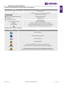 3
3
-
 4
4
-
 5
5
-
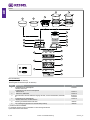 6
6
-
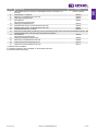 7
7
-
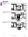 8
8
-
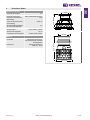 9
9
-
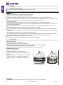 10
10
-
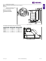 11
11
-
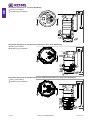 12
12
-
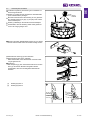 13
13
-
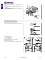 14
14
-
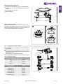 15
15
-
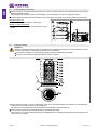 16
16
-
 17
17
-
 18
18
-
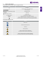 19
19
-
 20
20
-
 21
21
-
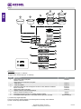 22
22
-
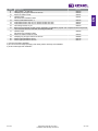 23
23
-
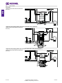 24
24
-
 25
25
-
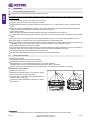 26
26
-
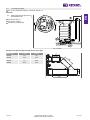 27
27
-
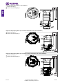 28
28
-
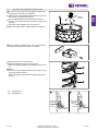 29
29
-
 30
30
-
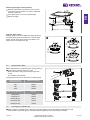 31
31
-
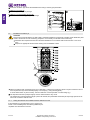 32
32
-
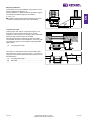 33
33
-
 34
34
-
 35
35
-
 36
36
-
 37
37
-
 38
38
-
 39
39
-
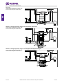 40
40
-
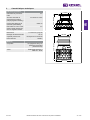 41
41
-
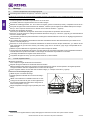 42
42
-
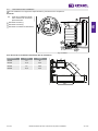 43
43
-
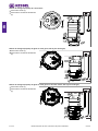 44
44
-
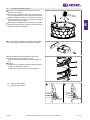 45
45
-
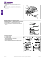 46
46
-
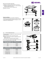 47
47
-
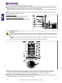 48
48
-
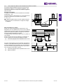 49
49
-
 50
50
-
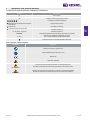 51
51
-
 52
52
-
 53
53
-
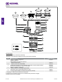 54
54
-
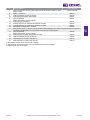 55
55
-
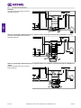 56
56
-
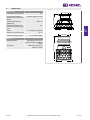 57
57
-
 58
58
-
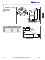 59
59
-
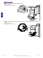 60
60
-
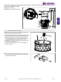 61
61
-
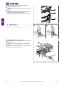 62
62
-
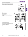 63
63
-
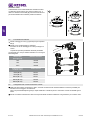 64
64
-
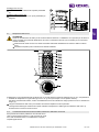 65
65
-
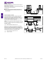 66
66
-
 67
67
-
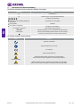 68
68
-
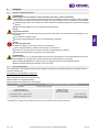 69
69
-
 70
70
-
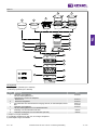 71
71
-
 72
72
-
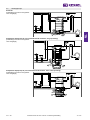 73
73
-
 74
74
-
 75
75
-
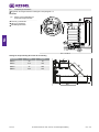 76
76
-
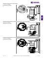 77
77
-
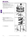 78
78
-
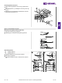 79
79
-
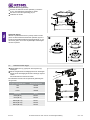 80
80
-
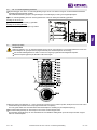 81
81
-
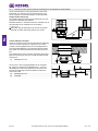 82
82
-
 83
83
-
 84
84
-
 85
85
-
 86
86
-
 87
87
-
 88
88
-
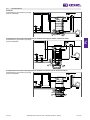 89
89
-
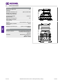 90
90
-
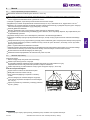 91
91
-
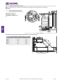 92
92
-
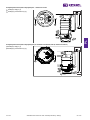 93
93
-
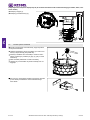 94
94
-
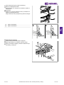 95
95
-
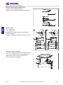 96
96
-
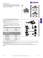 97
97
-
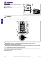 98
98
-
 99
99
-
 100
100


Kessel 010-701 Technikschacht-LW1000 Installation and Operating Instructions
- Type
- Installation and Operating Instructions
in andere talen
- italiano: Kessel 010-701 Technikschacht-LW1000
- français: Kessel 010-701 Technikschacht-LW1000
- Deutsch: Kessel 010-701 Technikschacht-LW1000
- polski: Kessel 010-701 Technikschacht-LW1000
Gerelateerde artikelen
-
 Kessel SPZ 1000 Handleiding
-
 Kessel 328-198 PS Aquapump Medium LW600 Installation and Operating Instructions
-
 Kessel 016-307 Minilift S Überflur Installation and Operating Instructions
-
 Kessel SG 400 V Mono Original Operation Manual
-
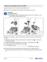 Kessel 016-337 Beiblatt Optischer Alarmgeber Installation and Operating Instructions


Andere documenten
-
ESS EDM1NAT800-50 Installatie gids
-
Dovre 300CB/B de handleiding
-
GYS GYSPOT COMBI ARCPULL de handleiding
-
Pentair JUNG PUMPEN BAUFIX 100 Handleiding
-
Metabo HWW 4000/20 S Handleiding
-
Princess Starck 3-in-1 Curling Iron Set Handleiding
-
-
Victaulic RG3400 Roll Grooving Tool Operating And Maintenance Manual