Kessel 328-198 PS Aquapump Medium LW600 Installation and Operating Instructions
- Type
- Installation and Operating Instructions

Aquapump Medium
LW 600
Einbau- und Betriebsanleitung
DE Einbau- und Betriebsanleitung....................................................................... 2
EN Installation and operating instructions.......................................................... 15
FR Instructions de pose et d’utilisation.............................................................. 29
IT Istruzioni per l’installazione e l’uso...............................................................42
NL Inbouw- en bedieningshandleiding............................................................... 56
PL Instrukcja zabudowy i obsługi.......................................................................69
2023/06 328-198_04

DE
Inhalt
1 Hinweise zu dieser Anleitung................................................................................................................................... 4
2 Sicherheit.................................................................................................................................................................. 5
3 Technische Daten..................................................................................................................................................... 9
4 Montage.................................................................................................................................................................... 11
5 Inbetriebnahme......................................................................................................................................................... 13
6 Wartung.................................................................................................................................................................... 14
7 Konformitäts- und Leistungserklärung..................................................................................................................... 83
2 / 88 Einbau- und Betriebsanleitung 328-198_03

Liebe Kundin, lieber Kunde,
als Premiumhersteller von innovativen Produkten für die Entwässerungstechnik bietet KESSEL ganzheitliche Systemlösun-
gen und kundenorientierten Service. Dabei stellen wir höchste Qualitätsstandards und setzen konsequent auf Nachhaltig-
keit - nicht nur bei der Herstellung unserer Produkte, sondern auch im Hinblick auf deren langfristigen Betrieb setzen wir uns
dafür ein, dass Sie und Ihr Eigentum dauerhaft geschützt sind.
Ihre KESSEL AG
Bahnhofstraße 31
85101 Lenting, Deutschland
Bei technischen Fragestellungen helfen Ihnen gerne unsere qualifizierten Servicepartner vor Ort weiter.
Ihren Ansprechpartner finden Sie unter:
www.kessel.de/kundendienst
Bei Bedarf unterstützt unser Werkskundendienst mit Dienstleistungen wie Inbetriebnahme, Wartung oder
Generalinspektion in der gesamten DACH-Region, andere Länder auf Anfrage.
Informationen zur Abwicklung und Bestellung finden Sie unter:
www.kessel.de/service/dienstleistungen
DE
328-198_03 Einbau- und Betriebsanleitung 3 / 88

DE
1 Hinweise zu dieser Anleitung
Folgende Darstellungskonventionen erleichtern die Orientierung:
Darstellung Erläuterung
(5) Positionsnummer 5 von nebenstehender Abbildung
... Handlungsschritt in Abbildung
Prüfen, ob Handsteuerung aktiviert wurde. Handlungsvoraussetzung
OK betätigen. Handlungsschritt
Anlage ist betriebsbereit. Handlungsergebnis
siehe "Sicherheit", Seite 5 Querverweis auf Kapitel 2
|Wartungsintervall definieren| Bildschirmtext
Fettdruck besonders wichtige oder sicherheitsrelevante Information
Kursivschreibung Variante oder Zusatzinformation (z. B. gilt nur für ATEX-Variante)
Technische Hinweise, die besonders beachtet werden müssen.
4 / 88 Einbau- und Betriebsanleitung 328-198_04

2 Sicherheit
Folgende Symbole werden verwendet:
Zeichen Bedeutung
Gerät freischalten!
Gebrauchsanweisung beachten
CE-Kennzeichnung
Warnung Elektrizität
WEEE-Symbol, Produkt unterliegt RoHS-Richtlinie
WARNUNG
Warnt vor einer Gefährdung von Personen. Eine Missachtung
dieses Hinweises kann schwerste
Verletzungen oder Tod zur Folge haben.
VORSICHT
Warnt vor einer Gefährdung von Personen und Material. Eine Missachtung
dieses Hinweises kann schwere
Verletzungen und Materialschäden zur Folge haben.
Produkt erfüllt die Anforderungen für explosionsgefährdete Atmosphäre (ATEX)
Warnung vor explosionsfähiger Atmosphäre
2.1 Allgemeine Sicherheitshinweise
Bei Installation, Betrieb, Wartung oder Reparatur der Anlage sind die Unfallverhütungsvorschriften, die in Frage kommenden
Normen und Richtlinien, sowie die Vorschriften der örtlichen Energie- und Versorgungsunternehmen zu beachten.
ACHTUNG
Anlage freischalten!
Sicherstellen, dass die elektrischen Komponenten während der Arbeiten von der Spannungsversorgung getrennt
sind.
WARNUNG
Spannungsführende Teile!
Bei Tätigkeiten an elektrischen Leitungen und Anschlüssen Folgendes beachten:
Für alle elektrischen Arbeiten an der Anlage gelten die nationalen Sicherheitsvorschriften.
Die Anlage muss über eine Fehlerstrom-Schutzeinrichtung (RCD) mit einem Bemessungsfehlerstrom von nicht
mehr als 30 mA versorgt werden.
Die Schwimmerschalter stehen unter Spannung und dürfen nicht geöffnet werden.
Sicherstellen, dass sich die Elektrokabel sowie alle anderen elektrischen Anlagenteile in einem einwandfreien Zustand befin-
den. Bei Beschädigung darf die Anlage auf keinen Fall in Betrieb genommen werden, bzw. ist umgehend abzustellen.
WARNUNG
Gefahr durch Überspannung!
Anlage nur in Gebäuden betreiben, in denen ein Überspannungsableiter (z. B. Überspannungsschutzeinrichtung
Typ 2 nach VDE) installiert ist. Störspannung kann elektrische Komponenten stark beschädigen und zu einem
Ausfall der Anlage führen.
VORSICHT
Heiße Oberflächen!
Pumpen können während des Betriebes eine hohe Temperatur entwickeln.
Schutzhandschuhe tragen, oder Pumpe abkühlen lassen.
WARNUNG
Transportrisiko/Eigengewicht der Anlage!
Gewicht der Anlage/Anlagenbestandteile prüfen (siehe "Technische Daten", Seite 9).
Auf richtiges Heben und Arbeitsergonomie achten.
DE
328-198_04 Einbau- und Betriebsanleitung 5 / 88

DE
Vorgeschriebene persönliche Schutzausrüstung!
Bei Einbau, Wartung und Entsorgung an der Anlage stets Schutzausrüstung verwenden.
Schutzkleidung
Schutzhandschuhe
Sicherheitsschuhe
Gesichtsschutz
VORSICHT
Pumpen können unerwartet anlaufen.
Vor Wartung oder Reparatur die Anlage ausschalten oder von der Stromversorgung trennen.
Die Pumpe darf niemals trocken oder im Schlürfbetrieb laufen, Freistromrad und Pumpengehäuse müssen
immer bis zur Mindesteintauchtiefe überflutet sein.
Die Pumpe darf nicht benutzt werden, wenn sich Personen im Wasser aufhalten oder die Druckleitung nicht
angeschlossen ist.
Die Pumpe baut einen Förderdruck/Überdruck auf.
Betriebs- und Wartungsanleitungen müssen am Produkt verfügbar gehalten werden.
2.2 Personal - Qualifikation
Für den Betrieb der Anlage gelten die jeweils gültige Betriebssicherheitsverordnung und die Gefahrstoffverordnung oder
nationale Entsprechungen.
Der Betreiber der Anlage ist dazu verpflichtet:
eine Gefährdungsbeurteilung zu erstellen,
entsprechende Gefährdungszonen zu ermitteln und auszuweisen,
Sicherheitsunterweisungen durchzuführen,
gegen die Benutzung durch Unbefugte zu sichern.
Person 1) freigegebene Tätigkeiten an KESSEL-Anlagen
Betreiber Sichtprüfung,
Batterietausch
Sachkundiger (kennt, ver-
steht Betriebsanweisung)
Entleerung, Reinigung
(innen), Funktionskon-
trolle, Konfiguration
des Schaltgerätes
Fachkundiger (Fachhandwer-
ker, nach Einbauanweisung
und Ausführungsnormen)
Einbau, Tausch, War-
tung von Komponen-
ten, Inbetriebnahme
Elektrofachkraft VDE 0105
(nach Vorschriften für elektr.
Sicherheit, oder nach natio-
nalen Entsprechungen)
Arbeiten an elektri-
scher Installation
1) Bedienung und Montage dürfen nur durch Personen erfolgen, die das 18. Lebensjahr vollendet haben.
2.3 Bestimmungsgemäße Verwendung
Die Anlage ist als Mono-Anlage mit einer Pumpe für den Einsatz bei Einfamilienhäusern und als Duo-Anlage für den Einsatz
bei Mehrfamilienhäusern, gewerblichen Objekten und Einrichtungen der Öffentlichen Hand einzusetzen.
Als Fördermedium sind ausschließlich häusliche Abwässer möglich. Wird die Anlage für fäkalienhaltiges Abwasser einge-
setzt, muss auch die entsprechende Pumpenvariante (hier STZ 1000 - Schwarzwasser-Tauchpumpe mit Zerhacker) mon-
tiert werden.
Besondere Bedingungen für den sicheren Betrieb
Außerhalb von explosionsgefährdeten Bereichen aufstellen
Frostfreie Tiefe - Einbau des Produktes so ausführen, dass wasserführende Bestandteile in frostfreier Tiefe (regional defi-
niert) liegen
Belastungsklasse für Verkehrssicherheit beachten
Regionale Einleitbestimmungen der Kommune beachten, oftmals sind u. a. maximale Abwassertemperaturen vorgeschrie-
ben (z. B. 35°C).
Alle nicht durch eine ausdrückliche und schriftliche Erlaubnis des Herstellers erfolgten Um- oder Anbauten, Verwendungen
von nicht originalen Ersatzteilen und Reparaturen durch nicht durch den Hersteller autorisierten Betriebe oder Personen füh-
ren zum Verlust der Gewährleistung.
6 / 88 Einbau- und Betriebsanleitung 328-198_04

2.4 Produktbeschreibung
Die Anlage ist zum Einbau ins Erdreich, im mitgelieferten Schacht mit der lichten Weite 600 mm, außerhalb von Gebäu-
den vorgesehen. Die Grundwasserbeständigkeit ist bis max. 2,5 m gegeben. Die Anlage kann mit einer oder zwei Pumpen
(Mono/Duo) ausgestattet werden. Der Aufbau der beiden Pumpen und deren Verrohrung ist symmetrisch.
Folgende Merkmale sind als Varianten verfügbar:
Schwimmerschalter oder pneumatische Niveauerfassung, entsprechend mit/ohne Schaltgerät
Pumpe(n) für fäkalienfreies Abwasser GTF 600 oder GTF 1200
Pumpe(n) für fäkalienhaltiges Abwasser STZ 1000 (keine ATEX-Eignung)
Einbautiefen T1, T2, T3
(1) Eine bzw. zwei Pumpen
(2) Schachtsystem LW 600
(3) Zulauf (DN 100 bei Pumpentyp KTP 500/ DN 150
bei GTF 1200)
(4) Anschluss Entlüftungsleitung (DN 100)
(5) Abdeckplatte
(6) Teleskopisches Aufsatzstück
(7) Anschluss Kabelleerrohr (DN 100)
(8) Rückflussverhinderer
(9) Anschlussstutzen für Druckleitung (DN 32) PVC
(10) Niveauerfassung (in Abbildung: Tauchglocke)
DE
328-198_04 Einbau- und Betriebsanleitung 7 / 88

DE
Einbautiefe T
482 / 894 / 1394
700 / 1200 / 1700
400
Ø806
965
DN 32
OD 40
T1
112,5
T2
T3
524,5
1024,5
T1
T2
T3
800-1250
395
100
482
1300-1750
395
370
894
1800-2250
395
Ø806
Ø986
370
1394
370
Ø806
Ø986
Ø806
Ø986
100
100
8 / 88 Einbau- und Betriebsanleitung 328-198_04

3 Technische Daten
Angabe / Pumpenart GTF 600 GTF 1200 STZ 1000
Gewicht 7 kg 10 kg 10 kg
Leistung P1 / P2 500 W / 320 W 1400 W /840 W 1200 W / 690 W
Drehzahl 2800 min-1 2650 min-1 2800 min-1
Betriebsspannung 230 V; 50 Hz 230 V; 50 Hz 230 V; 50 Hz
Nennstrom 2,2 A 6,2 A 5,2 A
Förderleistung max. 8,5 m3/h 15.5 m3/h 11,5 m3/h
Förderhöhe max. 8 m 9 m 10 m
Max. Temperatur
Fördermedium 40°C 40°C 40°C
Schutzart IP68 (36h 3m WS) IP68 (36h 3m WS) IP68 (36h 3m WS)
Schutzklasse I I I
Motorschutz integriert integriert integriert
Anschlusstyp Schuko/Schaltgerät Schuko/Schaltgerät Schuko/Schaltgerät
empfohlene Sicherung C16 A
einpolig
C16 A
einpolig
C16 A
einpolig
S1 S1* S3 - 50 %
Betriebsart * Pumpe GTF 1200 mit direktem Schwimmer S3 – 50%
Rohranschlüsse
GTF 600 GTF 1200 /
STZ 1000
Zulauf DN 100 DN 150
Anschluss
Druckleitung DN 32 (OD 40) DN 32 (OD 40)
Kabelleerrohr DN 100 DN 100
Entlüftung DN 100 DN 100
Nutzvolumina
Mono-Anlage
mit Schwim-
merschalter
GTF 600 GTF 1200/
STZ 1000
Nutzvolumen [l]
T1/T2/T3 25 30
Einschaltniveau
[mm] 130 170
Ausschaltniveau
[mm] 80 80
GTF 600 GTF 1200/
STZ 1000
Mono/Duo-
Anlage
mit SDS-
Schaltgerät Mono Duo Mono Duo
Nutzvolumen [l]
T1/T2/T3 40 40 40 40
Einschaltniveau
[mm] 185 185/200 185 185/200
Alarmniveau
[mm] 225 225 225 225
Ausschaltniveau
[mm] 145 145/160 145 145/160
DE
328-198_04 Einbau- und Betriebsanleitung 9 / 88

DE
3.1 Maße und Gewichte
GTF 600 Pumpe mit Schwim-
merschalter Pumpe für Schaltgerät 2 Pumpen für Schaltgerät
Einbautiefe
T in mm
Art. Nr.
Klasse A/B, D
Gewicht (kg*)
A/B, D
Art. Nr.
Klasse A/B, D
Gewicht (kg*)
A/B, D
Art. Nr.
Klasse A/B, D
Gewicht (kg*)
A/B, D
T1 800 - 1250 825 810 B, D 123, 148 825 811 B, D 126, 151 824 811 B, D 130, 155
T2 1300 - 1750 825 820 B, D 129, 155 825 821 B, D 131, 156 824 821 B, D 133, 158
T3 1800 - 2250 825 830 B, D 136, 161 825 831 B, D 138, 163 824 831 B, D 141, 166
GTF 1200 Pumpe mit Schwim-
merschalter Pumpe für Schaltgerät 2 Pumpen für Schaltgerät
Einbautiefe
T in mm
Art. Nr.
Klasse A/B, D
Gewicht (kg*)
A/B, D
Art. Nr.
Klasse A/B, D
Gewicht (kg*)
A/B, D
Art. Nr.
Klasse A/B, D
Gewicht (kg*)
A/B, D
T1 800 - 1250 827 810 B, D 127, 152 827 811 B, D 130, 155 826 811 B, D 130, 155
T2 1300 - 1750 827 820 B, D 142. 159 827 821 B, D 130, 155 826 821 B, D 139, 160
T3 1800 - 2250 827 830 B, D 140, 165 827 831 B, D 142, 167 826 831 B, D 142, 167
STZ 1000 Pumpe mit Schwim-
merschalter Pumpe für Schaltgerät 2 Pumpen für Schaltgerät
Einbautiefe
T in mm
Art. Nr.
Klasse A/B, D
Gewicht (kg*)
A/B, D
Art. Nr.
Klasse A/B, D
Gewicht (kg*)
A/B, D
Art. Nr.
Klasse A/B, D
Gewicht (kg*)
A/B, D
T1 800 - 1250 827 710 B, D 127, 152 827 711 B, D 130, 155 826 711 B, D 130, 155
T2 1300 - 1750 827 720 B, D 142. 159 827 721 B, D 130, 155 826 721 B, D 139, 160
T3 1800 - 2250 827 730 B, D 140, 165 827 731 B, D 142, 167 826 731 B, D 142, 167
* Gewicht ohne Schaltgerät
10 / 88 Einbau- und Betriebsanleitung 328-198_04

4 Montage
4.1 Bodenaushub
VORSICHT
Statik für Verkehrssicherheit beachten.
Schachtverbau für Lastklasse D kann eine Last-
verteilplatte, Beton: 0,18m x 2,3m x 2,3m (Stärke x
Höhe x Breite) erforderlich machen.
Erforderliche Lastklasse und Statik gemäß
Umgebung/Nutzungsbedingungen ermitteln.
Standardstraßenaufbau gemäß Richtlinien für
Anlage von Straßen einhalten.
Eignung von Produkt(-variante) für Umgebungsbedingun-
gen (siehe "Bestimmungsgemäße Verwendung", Seite 6)
und Einbautiefe (siehe "Produktbeschreibung", Seite 7)
sicherstellen.
Böschungswinkel β nach DIN 4124 festlegen.
Baugrube ausheben, am Fuß mind. 50 cm umlaufend.
Untergrund (Sauberkeitsschicht von 30 cm) verdichten
und plan nivellieren.
Abb. 1: Bodenaushub
4.2 Schachteinbau
Schacht einsetzen und waagrecht ausrichten.
Bei Bedarf Schacht mit Magerbeton vertikal fixieren.
Bei Grundwasser den Schacht mit Beton gegen Auftrieb sichern.
Verbleibenden Zwischenraum (siehe "Abb. 1: Bodenaushub", Seite 11) abschnittsweise mit 0/16 Füllmaterial verfüllen.
Nach 30 cm jeweils auf Dpr = 97% verdichten, bis Höhe Bodenkante oder Standard-Straßenaufbau.
4.3 Rohranschluss
Zulaufleitung anschließen (Gefälle beachten, ggf. Doppelmuffe verwenden).
Kabelleerrohr einführen.
Entlüftungsleitung einführen (Leitung über Dach führen).
4.4 Teleskopisches Aufsatzstück montieren
Teleskopisches Aufsatzstück probeweise aufsetzen.
Aufsatzstück entsprechend Bodenniveau anpassen (bei
Aufliegen auf Kabelleerrohr entsprechend kürzen, z. B.
mit Stichsäge).
Abdeckplatte mit passender Lastklasse aufsetzen.
Kunststoff-Abdeckplatten fixieren, um Kinder-/Verkehrssi-
cherheit zu gewährleisten.
DE
328-198_04 Einbau- und Betriebsanleitung 11 / 88

DE
4.5 Pumpe und Steigleitung anschließen
Dichtung auf Druckanschluss aufschieben.
Steigleitung am Druckanschluss der Pumpe montie-
ren.
Pumpe inkl. Steigleitung am Haltegriff in den Schacht hin-
einlassen.
Einhandverschluss schließen.
Ggf. Höhe der Steigleitung anpassen:
Schlauchschelle lockern.
Rückflussverhinderer (horizontale Leitung) waagrecht
ausrichten. (Fehlerhafter Verbau beeinträchtigt die Leis-
tung des Rückflussverhinderers und führt zu erhöhtem
Verschleiß).
Schlauchschelle festziehen.
Netzanschlussleitung der Pumpe durch Kabelleerrohr zie-
hen.
4.6 Niveauerfassung montieren
Anlagen, deren Niveauerfassung mit Schwimmerschal-
ter ausgeführt ist, verfügen nicht über Schaltgeräte und
Alarmsonde. In diesem Fall entsprechende Handlungs-
schritte ignorieren.
Alarmsonde an folgende Position montieren:
T1 - Schutzrohr an waagrechte Halterung anklipsen.
T2/T3 - Schutzrohr an Steigleitung anklipsen.
Alarmsonde in Schutzrohr einschrauben, Leitung durch
Kabelleerrohr führen.
Niveauerfassung montieren:
Anbindungslängen der Tauchglocke beachten.
Druckschlauch stetig steigend verlegen, um die Ansamm-
lung von Kondenswasser zu vermeiden.
Leitung(en) für Niveauerfassung durch Kabelleerohr zie-
hen.
Kabelleerrohr luft- und wasserdicht abdichten.
4.7 Schaltgerät
Wenn vorhanden, Schaltgerät gemäß entsprechender Anleitung anbringen und anschließen.
Montage der Anlage ist abgeschlossen.
12 / 88 Einbau- und Betriebsanleitung 328-198_04

5 Inbetriebnahme
Für die Inbetriebnahme ist die EN 12056-4 zu beachten.
5.1 Prüfung der Anlage
Bei Schwarzwasserbetrieb darf die Pumpe nur so eingesetzt werden, dass kein Lufteintritt ins Pumpengehäuse möglich
ist. Der Lauf der Pumpen ohne Wasser führt zu erhöhtem Verschleiß und möglicher Funkenbildung.
Vor Inbetriebnahme sind folgende Punkte zu prüfen:
Korrekter Einbau der Pumpe
Fixierung aller entnehmbaren Bauteile
Dichtheit der Anlage
Netzspannung (max. Abweichung ± 10 %)
Dichte des Fördermediums ϱ = 1,1 kg/l (bei höheren Werten ist Rückfrage im Werk erforderlich)
Korrekter Sitz der Elemente zur Niveauerfassung
5.2 Inbetriebnahme der Anlage (Mono mit Schwimmerschalter)
Durch Herstellen des Netzanschlusses wird die Anlage in Betriebsbereitschaft versetzt.
Anlage ist betriebsbereit.
DE
328-198_04 Einbau- und Betriebsanleitung 13 / 88

DE
6 Wartung
Bei der Wartung ist die EN 12056-4 zu beachten.
6.1 Funktionsprüfung - Reinigung
Pumpe und Steigleitung warten
ACHTUNG
Anlage freischalten!
Sicherstellen, dass die elektrischen Komponen-
ten während der Arbeiten von der Spannungs-
versorgung getrennt sind.
Einhandverschluss öffnen.
Steigleitung komplett mit Pumpe am Haltegriff herauszie-
hen.
Pumpenteile auf Verformung und Ablagerungen prüfen,
ggf. KESSEL-Service kontaktieren.
Leichtgängigkeit der beweglichen Teile sicherstellen.
Alarmsonde herausziehen. Schutzrohr abklipsen, ggf.
beides in Wasserbad reinigen.
Tauchglocke herausziehen und mit Wasser reinigen.
Sichtprüfung der Armaturenkomponenten durchführen.
Rückflussverhinderer warten
Einhandverschluss des Rückflussverhinderers öffnen.
Gewindeanschluss mit Rückflussverhinderer wegzie-
hen.
VORSICHT
Angestautes Abwasser läuft aus!
Gewindeanschluss mit Rückflussverhinderer in Wasser-
bad reinigen.
Beweglichkeit der Rückschlagklappe sicherstellen.
Schachtsystem auf starke Verunreinigungen prüfen, falls
erforderlich reinigen. Spitze Geräte sind nicht geeignet.
Elektrische Komponenten überprüfen
Anschlussleitungen auf mechanische Schäden prüfen.
Isolationsmessung der Pumpe durchführen.
14 / 88 Einbau- und Betriebsanleitung 328-198_04

Contents
1 Notes on this manual............................................................................................................................................... 17
2 Safety........................................................................................................................................................................ 18
3 Technical data.......................................................................................................................................................... 22
4 Installation................................................................................................................................................................. 24
5 Commissioning......................................................................................................................................................... 27
6 Maintenance............................................................................................................................................................. 28
EN
328-198_03 Installation and operating instructions 15 / 88

EN
Dear Customer,
As a premium manufacturer of innovative products for draining technology, KESSEL offers integrated system solutions and
customer-oriented service. In doing so, we set the highest quality standards and focus firmly on sustainability - not only with
the manufacturing of our products, but also with regard to their long-term operation and we strive to ensure that you and your
property are protected over the long term.
Your KESSEL AG
Bahnhofstraße 31
85101 Lenting, Germany
Our local, qualified service partners would be happy to help you with any technical questions.
You can find your contact partner at:
www.kessel.de/kundendienst
If necessary, our Factory Customer Service provides support with services such as commissioning, main-
tenance or general inspection throughout the DACH region, other countries on request.
For information about handling and ordering, see:
www.kessel.de/service/dienstleistungen
16 / 88 Installation and operating instructions 328-198_03

1 Notes on this manual
The following conventions make it easier to navigate the manual:
Symbol Explanation
(5) Position number 5 from the adjacent figure
... Action step in figure
Check whether manual control has been
activated. Prerequisite for action
Press OK. Action step
System is ready for operation. Result of action
see "Safety", page 18 Cross-reference to Chapter 2
|Define maintenance interval| Screen text
Bold type Particularly important or safety-related information
Italics Variants or additional information (e.g. applicable only for ATEX variants)
Technical information or instructions which must be paid particular attention.
EN
328-198_03 Installation and operating instructions 17 / 88

EN
2 Safety
The following symbols are used:
Icon Meaning
Isolate device!
Observe the instructions for use
CE marking
Warning, electricity
WEEE icon, product is subject to the RoHS Directive
WARNING
Warns of a hazard for persons. Disregarding
this warning can lead to very serious
injuries or death.
CAUTION
Warns of a hazard for persons and material. Disregarding
this warning can lead to serious
injuries and material damage.
The product fulfils the requirements for potentially explosive atmospheres (ATEX)
Warning of potentially explosive atmospheres
2.1 General safety notes
The accident prevention regulations, the applicable standards and directives as well as the regulations from the local energy
and supply companies must be observed during the installation, operation, maintenance and repair of the system.
NOTICE
Disconnect system from energy sources!
Ensure that the electrical components are disconnected from the electrical power supply during the work.
WARNING
Live parts!
Heed the following points when working on electrical cables and connections:
The national safety regulations apply for all electrical work on the system.
The system must be supplied through a residual current protection device (RCD) with residual current of not
more than 30 mA.
The float switch unit are live and must not be opened.
Make sure that the electric cables as well as all other electrical installation components are in a faultless condition. In case of
damage, the system may on no account be put into operation or must be stopped immediately.
WARNING
Danger due to overvoltage!
Operate the system only in buildings in which an overvoltage protection system (e.g. surge arrestor, type 2 per
VDE regulations) is installed. Interference voltage can seriously damage electrical components and lead to sys-
tem failure.
CAUTION
Hot surfaces!
Pumps can become very hot during operation.
Wear protective gloves or allow the pump to cool.
WARNING
Transport risk / system's own weight!
Check the weight of the system / system components (see "Technical data", page 22).
Pay attention to correct lifting and ergonomic factors.
18 / 88 Installation and operating instructions 328-198_03

Prescribed personal protective equipment!
Always use personal protective equipment during installation, maintenance and disposal work on the system.
Protective clothing
Protective gloves
Safety footwear
Face protection
CAUTION
Pumps can start up unexpectedly.
Before undertaking maintenance or repair work on the system, switch it off or disconnect it from the power supply.
The pump must never run dry or in slurping operation; the multi-vane impeller and pump housing must always be
flooded up to at least the minimum immersion depth.
The pump must never be used when there are people in the water or the pressure pipe is not connected.
The pump builds up a pumping pressure/excess pressure.
Operating and maintenance instructions must be kept available at the product.
2.2 Personnel - qualification
The relevant operational safety regulations and the hazardous substances ordinance or national equivalents apply for the
operation of the system.
The operator of the system must:
prepare a risk assessment
identify and demarcate corresponding hazard zones
carry out safety training
secure the system against unauthorised use.
Person 1) Approved activities on KESSEL systems
Operating company Visual check, inspec-
tion, change of battery
Technical expert, (familiar with,
understands operating instructions)
Emptying, cleaning
(inside), functional
check, configuration
of the control unit
Technical specialist, (technical
worker, per installation instruc-
tions and execution standards)
Installation, replace-
ment, maintenance
of components,
commissioning
Electrical specialist VDE 0105
(per regulations for electrical
safety, or per national equivalents)
Work on electri-
cal installation
1) Operation and assembly work may only be carried out by persons who are 18 years of age.
2.3 Intended use
The system is to be used as a Mono system with one pump in single-family homes and as a Duo system in multi-family
homes, industrial buildings and public facilities.
Domestic wastewater is the only pumping medium possible. If the system is used for faecal wastewater, the corresponding
pump variant (here STZ 1000) must also be installed.
Special conditions for safe operation
Set up outside of potentially explosive areas
Frost-free depth - Install the product so that water-bearing components are at a frost-free depth (defined regionally)
Heed the load class for traffic safety
Observe regional and local municipal regulations - maximum wastewater temperatures (e.g. 35°C) are often stipulated,
amongst other things.
All conversions or attachments that are carried out without the express and written permission of the manufacturer, the use
of non-genuine spare parts and repairs carried out by companies or persons not approved by the manufacturer will lead to a
loss of warranty.
EN
328-198_03 Installation and operating instructions 19 / 88

EN
2.4 Product description
The system is intended for underground installation, in the chamber provided with a clear width of 600 mm, outside build-
ings. Groundwater resistance exists up to max. 2.5 m. The system can be equipped with one or two pumps (Mono/Duo). The
layout of the two pumps and their piping is symmetrical.
The following characteristics are available as variants:
Float switch or pneumatic level measurement accordingly with/without control unit
Pump(s) for wastewater without sewage GTF 600 or GTF 1200
Pump(s) for wastewater containing sewage STZ 1000 (not suitable for ATEX)
Installation depths D1, D2, D3
(1) One or two pumps
(2) Chamber system LW 600
(3) Inlet (DN 100 for pump type KTP 500/DN 150 for
GTF 1200)
(4) Connection of ventilation pipe (DN 100)
(5) Cover plate
(6) Vertically adjustable upper section
(7) Connection for cable duct (DN 100)
(8) Backflow preventer
(9) Connection socket for pressure pipe (DN 32) PVC
(10) Level measurement (in figure: submersible pressure
switch)
20 / 88 Installation and operating instructions 328-198_03

Einbautiefe T
482 / 894 / 1394
700 / 1200 / 1700
400
Ø806
965
DN 32
OD 40
T1
112,5
T2
T3
524,5
1024,5
T1
T2
T3
800-1250
395
100
482
1300-1750
395
370
894
1800-2250
395
Ø806
Ø986
370
1394
370
Ø806
Ø986
Ø806
Ø986
100
100
EN
328-198_03 Installation and operating instructions 21 / 88

EN
3 Technical data
Information / pump type GTF 600 GTF 1200 STZ 1000
Weight 7 kg 10 kg 10 kg
Power P1 / P2 500 W / 320 W 1400 W /840 W 1200 W / 690 W
Speed 2800 rpm 2650 rpm 2800 rpm
Operating voltage 230 V; 50 Hz 230 V; 50 Hz 230 V; 50 Hz
Rated current 2.2 A 6.2 A 5.2 A
Max. pumping capacity 8.5 m3/h 15.5 m3/h 11.5 m3/h
Max. pumping height 8 m 9 m 10 m
Max. temperature
Pumped medium 40°C 40°C 40°C
Protection rating IP68 (36h 3m WC) IP68 (36h 3m WC) IP68 (36h 3m WC)
Protection class I I I
Motor protection integrated integrated integrated
Connection type Earthed coupling/control unit Earthed coupling/control unit Earthed coupling/control unit
recommended fuse C16 A
one-pole
C16 A
one-pole
C16 A
one-pole
S1 S1* S3 - 50 %
Operating mode * Pump GTF 1200 with direct float S3 – 50%
Pipe connections
GTF 600 GTF 1200 /
STZ 1000
Inlet [DN] 100 150
Pressure pipe
connection [DN]
32 32
Cable duct [DN] 100 100
Ventilation [DN] 100 100
Pumping volumes
Mono system
with float switch GTF 600 GTF 1200/
STZ 1000
Pumping volume [l]
D1/D2/D3
25 30
Switch-on level [mm] 130 170
Switch-off level [mm] 80 80
GTF 600 GTF 1200/
STZ 1000
Mono/Duo
system with
SDS con-
trol unit Mono Duo Mono Duo
Pumping
volume [l]
D1/D2/D3
40 40 40 40
Switch-on
level [mm]
185 185/200 185 185/200
Alarm
level [mm]
225 225 225 225
Switch-off
level [mm]
145 145/160 145 145/160
22 / 88 Installation and operating instructions 328-198_03

3.1 Dimensions and weights
GTF 600 Pump with float switch Pump for control unit 2 pumps for control unit
Installation depth
D in mm
Art. no.
Class A/B, D
Weight (kg*)
A/B, D
Art. no.
Class A/B, D
Weight (kg*)
A/B, D
Art. no.
Class A/B, D
Weight (kg*)
A/B, D
D1 800 - 1250 825 810 B, D 123, 148 825 811 B, D 126, 151 824 811 B, D 130, 155
D2 1300 - 1750 825 820 B, D 129, 155 825 821 B, D 131, 156 824 821 B, D 133, 158
D3 1800 - 2250 825 830 B, D 136, 161 825 831 B, D 138, 163 824 831 B, D 141, 166
GTF 1200 Pump with float switch Pump for control unit 2 pumps for control unit
Installation depth
D in mm
Art. no.
Class A/B, D
Weight (kg*)
A/B, D
Art. no.
Class A/B, D
Weight (kg*)
A/B, D
Art. no.
Class A/B, D
Weight (kg*)
A/B, D
D1 800 - 1250 827 810 B, D 127, 152 827 811 B, D 130, 155 826 811 B, D 130, 155
D2 1300 - 1750 827 820 B, D 142. 159 827 821 B, D 130, 155 826 821 B, D 139, 160
D3 1800 - 2250 827 830 B, D 140, 165 827 831 B, D 142, 167 826 831 B, D 142, 167
STZ 1000 Pump with float switch Pump for control unit 2 pumps for control unit
Installation depth
D in mm
Art. no.
Class A/B, D
Weight (kg*)
A/B, D
Art. no.
Class A/B, D
Weight (kg*)
A/B, D
Art. no.
Class A/B, D
Weight (kg*)
A/B, D
D1 800 - 1250 827 710 B, D 127, 152 827 711 B, D 130, 155 826 711 B, D 130, 155
D2 1300 - 1750 827 720 B, D 142. 159 827 721 B, D 130, 155 826 721 B, D 139, 160
D3 1800 - 2250 827 730 B, D 140, 165 827 731 B, D 142, 167 826 731 B, D 142, 167
* Weight without control unit
EN
328-198_03 Installation and operating instructions 23 / 88

EN
4 Installation
4.1 Soil excavation
CAUTION
Note the structural calculations for traffic safety.
Chamber installation for load class D may require
a load distribution plate made of concrete: 0.18m x
2.3m x 2.3m (thickness x height x width).
Determine the required load class and structural
calculations in accordance with the environment /
use conditions.
Comply with the standard road construction /
cross section build-up in accordance with the
local road construction regulations (in Germany
the RASt guidelines (“Richtlinien für Anlage von
Straßen”), in the UK the Highway Design Man-
ual, etc.).
Ensure suitability of product (variant) for environmental
conditions (see "Intended use", page 19) and installation
depth (see "Product description", page 20).
Define slope angle β to DIN 4124
Excavate pit. ensure a working space of at least 50 cm all
around the base.
Compact the surface (30 cm blinding layer) and level it
off.
Fig. 1: Soil excavation
4.2 Chamber installation
Insert the chamber and align it horizontally.
If necessary, fix the chamber in place vertically using lean concrete.
When installed in groundwater, secure the chamber against buoyancy.
Backfill the remaining space (see "Fig. 1: Soil excavation", page 24) in sections using 0/16 fill material. After every 30 cm
compact to DPr = 97%, up to the height of the ground edge or standard road structure.
4.3 Pipe connection
Connect inlet pipe (note gradient, use socket if necessary)
Insert cable duct.
Insert ventilation pipe (route pipe to above the roof).
24 / 88 Installation and operating instructions 328-198_03

4.4 Fit on the vertically adjustable upper section
Fit vertically adjustable upper section provisionally.
Adjust the upper section according to the ground level (if
it rests on the cable duct, shorten accordingly, e.g.with jig
saw).
Position the cover plate with suitable load class.
Fix polymer cover plates to ensure child/third party safety.
4.5 Connect pump and riser pipe
Push the seal onto the pressure pipe connection.
Fit the riser pipe onto the pressure pipe connection of the
pump.
Lower the pump incl. riser pipe into the chamber using
the handle.
Close the one-handed closure.
If necessary, adjust the height of the riser pipe:
Loosen the hose clamp.
Align the backflow preventer (horizontal pipe) vertically.
(Faulty installation impairs the performance of the back-
flow preventer and leads to increased wear.)
Tighten hose clamp.
Pull the mains connection cable of the pump through the
cable duct.
EN
328-198_03 Installation and operating instructions 25 / 88

EN
4.6 Installing the level measurement
Systems that have float switches for level measurement
do not have control units and an alarm probe. In this
case, ignore the associated steps.
Install the alarm probe in the following position:
Clip the D1 protective tube onto the horizontal bracket.
Clip the D2/D3 protective tube onto the riser pipe.
Screw the alarm probe into the protective tube, route the
cable through the cable duct.
Install the level measurement:
Note the connection lengths of the submersible pressure
switch.
Lay the pressure hose with a constant upward gradient in
order to avoid the accumulation of condensation.
Pull the cable(s) for level detection through the cable
duct.
Seal the cable duct airtight and watertight.
4.7 Control unit
If there is a control unit, attach and connect it according to the relevant instructions.
Installation of the system is completed.
26 / 88 Installation and operating instructions 328-198_03

5 Commissioning
Observe EN 12056-4 for the commissioning.
5.1 Checking the system
During black water operation, the pump may only be used in such a way that no air can get into the pump housing. Run-
ning the pump without water leads to increased wear and possible sparking.
Check the following points before commissioning:
Correct installation of the pump
Fixing of all removable components
Leak-tightness of the system
Mains voltage (max. deviation ± 10 %)
Density of the pumped medium ϱ = 1.1 kg/L (the manufacturer must be consulted in the case of higher values)
Correct fit of the elements for level detection
5.2 Commissioning the system (Mono with float switch)
The system is made ready for operation by connection to the mains power supply.
System is ready for operation.
EN
328-198_03 Installation and operating instructions 27 / 88

EN
6 Maintenance
Observe EN 12056-4 for maintenance.
6.1 Functional test - cleaning
Carry out maintenance on pump and riser pipe
NOTICE
Disconnect system from energy sources!
Ensure that the electrical components are dis-
connected from the electrical power supply dur-
ing the work.
Open the one-handed closure.
Pull out the riser pipe complete with pump using the han-
dle.
Check the pump parts for deformation and deposits, con-
tact KESSEL service department if necessary.
Ensure the moving parts can move easily.
Pull out the alarm probe. Unclip the protective tube,
clean both in a water bath if necessary.
Pull out the submersible pressure switch out and clean
with water.
Carry out a visual check of the fitting components.
Carry out maintenance on the backflow preventer
Open the one-handed closure of the backflow preven-
ter.
Pull away threaded connection with backflow preven-
ter.
CAUTION
Accumulated wastewater flows out!
Clean the threaded connection with backflow preventer in
a water bath.
Make sure that the non-return flap can move freely.
Check the chamber system for heavy soiling, clean if nec-
essary. Sharp devices are not suitable.
Check the electric components
Check the connection pipes for mechanical damage.
Carry out isolation measurement of the pump.
28 / 88 Installation and operating instructions 328-198_03

Sommaire
1 Informations spécifiques aux présentes instructions............................................................................................... 31
2 Sécurité..................................................................................................................................................................... 32
3 Caractéristiques techniques..................................................................................................................................... 36
4 Montage.................................................................................................................................................................... 38
5 Mise en service........................................................................................................................................................ 40
6 Maintenance............................................................................................................................................................. 41
FR
328-198_03 Instructions de pose et d’utilisation 29 / 88

FR
Chère cliente, cher client,
En qualité de producteur de pointe de produits novateurs dans le domaine de la technique d’assainissement, KESSEL pro-
pose des réponses systématiques globales et un service orienté aux besoins de la clientèle. Nous misons simultanément
sur les normes de qualité les plus élevées et une durabilité conséquente – non seulement lors de la fabrication de nos pro-
duits, mais également pour leur utilisation à long terme afin que vous, et vos biens, soient protégés durablement.
Votre KESSEL AG
Bahnhofstrasse 31
85101 Lenting, Allemagne
Nos partenaires qualifiés du service après-vente se feront un plaisir de répondre à vos questions tech-
niques sur site.
Vous trouverez votre correspondant sur :
www.kessel.de/kundendienst
Si nécessaire, notre propre SAV vous prête son assistance en matière de mise en service, de mainte-
nance ou d’inspection générale en Allemagne, en Autriche et en Suisse, comme dans d’autres pays sur
demande.
Toutes les informations de traitement et de commande sont à votre disposition sur :
www.kessel.de/service/dienstleistungen
30 / 88 Instructions de pose et d’utilisation 328-198_03

1 Informations spécifiques aux présentes instructions
Les conventions de représentation suivantes facilitent l’orientation :
Représentation Explication
(5) Numéro de repère 5 de la figure ci-contre
... Action de la figure
Vérifier si la commande manuelle a été acti-
vée. Condition de réalisation de l’action
Valider <OK>. Action
Le système est prêt au service. Résultat de l'action
cf. "Sécurité", page 32 Renvoi au chapitre 2
|Définir l’inter-
valle de maintenance| Texte affiché à l’écran
Caractères gras particulièrement important ou information importante pour la sécurité
Caractères italiques Variante ou informations complémentaires (par
exemple, uniquement valable pour la variante ATEX)
informations techniques à observer en particulier.
FR
328-198_03 Instructions de pose et d’utilisation 31 / 88

FR
2 Sécurité
Les instructions emploient les pictogrammes suivants :
Pictogramme / label Signification
Activer l’appareil !
Observer le mode d'emploi
Label de conformité CE
Mise en garde contre l’électricité
Pictogramme DEEE, produit soumis à la directive RoHS
MISE EN GARDE
Avertit d'un danger corporel. Le non-respect
de cette mise en garde peut provoquer
des blessures graves, voire mortelles.
ATTENTION
Avertit d'un danger corporel et matériel. Le non-respect
de cette mise en garde peut provoquer
des blessures graves et des dommages matériels.
Le produit remplit les exigences relatives aux atmosphères à risque d’explosion (ATEX)
Avertissement : atmosphère explosive
2.1 Consignes de sécurité générales
L'installation, l'utilisation, la maintenance ou la réparation du poste pose toujours pour condition de respecter les directives
de prévention des accidents, ainsi que les normes, directives et prescriptions des entreprises d'approvisionnement en éner-
gie sur le plan local s’y rapportant.
AVIS
Activer le système !
S'assurer que l'alimentation électrique est coupée pendant les travaux.
AVERTISSEMENT
Pièces sous tension !
Respecter les instructions suivantes lors de travaux sur des câbles et raccordements électriques :
Les directives nationales relatives à la sécurité s’appliquent à tous les travaux électriques effectués sur le poste.
Le système doit être alimenté par un dispositif différentiel à courant résiduel (RCD) avec courant assigné de
défaut d'une sensibilité au plus égale à 30 mA.
Les interrupteurs à flotteur sont des dispositifs sous tension qu'il est strictement interdit d'ouvrir.
Vérifier toujours l'état impeccable des câbles électriques, de même que celui de tous les composants électriques du poste.
Il est strictement interdit de mettre le système en service s'il présente des dégradations et imposé de le mettre hors service
dans l'immédiat.
AVERTISSEMENT
Risque de surtension !
N’utiliser le système que dans des bâtiments dotés d'un limiteur de surtension (par exemple, dispositif de pro-
tection contre les surtensions de type 2 selon VDE). Une tension perturbatrice peut gravement endommager les
composants électriques et entraîner une panne du système.
ATTENTION
Surfaces chaudes !
Les pompes peuvent atteindre des températures élevées en cours de fonctionnement.
Porter des gants de protection ou laisser refroidir la pompe.
32 / 88 Instructions de pose et d’utilisation 328-198_03

AVERTISSEMENT
Risque lié au transport / attention au poids propre du système !
Contrôler le poids du système / des composants du système (cf. "Caractéristiques techniques", page 36).
Veiller à un levage dans le respect d’une ergonomie correcte.
Équipement de protection personnel prescrit!
Le port d’un équipement de protection est toujours imposé lors de la pose, de la maintenance et de l’évacuation du
poste.
Vêtements de protection
Gants de protection
Chaussures de sécurité
Dispositif de protection du visage
ATTENTION
Les pompes peuvent démarrer de manière inopinée.
Avant toute opération de maintenance ou de réparation, arrêter le poste ou le couper de l'alimentation électrique.
La pompe ne doit jamais fonctionner à sec ou au ralenti, la roue vortex et le carter de la pompe doivent toujours
être noyés jusqu'à la profondeur d'immersion minimale.
Il est interdit d'utiliser la pompe quand il y a des personnes dans l'eau ou si la conduite de refoulement n’est pas
raccordée.
La pompe génère une pression de refoulement / une surpression.
Les instructions d’utilisation et de maintenance doivent être tenues à disposition avec le produit.
2.2 Personnel – qualification
L’utilisation du poste est soumise au règlement de sécurité du travail et aux dispositions relatives aux produits dangereux s'y
rapportant en vigueur ou aux dispositions des ouvrages équivalents sur le plan national.
L’exploitant du poste est tenu :
d’établir une évaluation des risques,
de déterminer les zones à risques s’y rapportant et d'attirer l’attention sur ces zones,
de veiller à la mise en pratique de formations se rapportant aux consignes de sécurité,
d’empêcher toute personne non autorisée de l’utiliser.
Personne 1) Activités autorisées sur les postes KESSEL
Exploitant Contrôle visuel,
remplacement
de la batterie
Technicien spécialisé
(connaît et comprend les
instructions d’utilisation)
Vidage, nettoyage
(intérieur), contrôle
fonctionnel, configura-
tion du gestionnaire
Spécialiste (ouvrier spécia-
lisé, suivant les instructions de
pose et les normes d’exécution)
Pose, remplace-
ment, maintenance
des composants,
mise en service
Électricien VDE 0105 (selon les
prescriptions de sécurité électrique
ou les dispositions nationales)
Travaux sur l’ins-
tallation électrique
1) L'utilisation et le montage sont réservés au domaine de compétence de personnes âgées de 18 ans révolus.
2.3 Utilisation conforme à l'usage prévu
Le poste doit être utilisé en tant que poste Mono avec une pompe pour une utilisation dans des maisons individuelles et
en tant que poste Duo pour une utilisation dans des logements collectifs, des bâtiments commerciaux et des organismes
publics.
Les eaux usées ménagères sont les seuls liquides qu’il peut transporter. Si le poste est utilisé pour des eaux usées conte-
nant des matières fécales, il convient de monter la variante de pompe correspondante (ici STZ 1000).
FR
328-198_03 Instructions de pose et d’utilisation 33 / 88

FR
Conditions spécifiques à un service fiable
Pose en dehors des zones à risque d’explosion
Profondeur hors gel - Installer le produit de façon à ce que les composants conducteurs d’eau se trouvent à une profon-
deur hors gel (définie au niveau régional)
Observer la classe de charge pour la sécurité routière
Respecter les dispositions régionales édictées par la commune. Entre autres, celles-ci prescrivent souvent des températures
maximales pour les eaux usées (par exemple, 35 °C).
Les transformations ou éléments rapportés sans l’accord explicite et écrit du fabricant, l’utilisation de pièces de rechange
non d’origine et les réparations effectuées par des établissements ou personnes non autorisés par le fabricant ont pour effet
d'exclure tout recours à la garantie du fabricant.
2.4 Description du produit
Le poste est prévu pour une pose enterrée, dans le module rehausse fourni d'une largeur intérieure de 600 mm, à l’extérieur
des bâtiments. L'étanchéité aux eaux souterraines est assurée jusqu’à 2,5 m max. Le poste peut être équipé d'une ou de
deux pompes (Mono/Duo). La structure des deux pompes et leur tubulure sont symétriques.
Les caractéristiques suivantes sont disponibles en tant que variante :
Interrupteur à flotteur ou détection par capteur de pression, avec/sans gestionnaire
Pompe(s) pour eaux grises GTF 600 ou GTF 1200
Pompe(s) pour eaux vannes STZ 1000 (pas d'aptitude ATEX)
Profondeurs de pose T1, T2, T3
(1) Une ou deux pompes
(2) Système de regard LW 600
(3) Arrivée (DN 100 pour type de pompe KTP 500/ DN
150 pour GTF 1200)
(4) Raccord de la conduite d'aération et de ventilation
(DN 100)
(5) Couvercle de protection
(6) Rehausse télescopique
(7) Raccord du fourreau pour câbles (DN 100)
(8) Dispositif anti-retour
(9) Raccord pour conduite de refoulement (DN 32) PVC
(10) Détection du niveau (sur la figure : cloche)
34 / 88 Instructions de pose et d’utilisation 328-198_03

Einbautiefe T
482 / 894 / 1394
700 / 1200 / 1700
400
Ø806
965
DN 32
OD 40
T1
112,5
T2
T3
524,5
1024,5
T1
T2
T3
800-1250
395
100
482
1300-1750
395
370
894
1800-2250
395
Ø806
Ø986
370
1394
370
Ø806
Ø986
Ø806
Ø986
100
100
FR
328-198_03 Instructions de pose et d’utilisation 35 / 88

FR
3 Caractéristiques techniques
Indication / type de pompe GTF 600 GTF 1200 STZ 1000
Poids 7 kg 10 kg 10 kg
Puissance P1 / P2 500 W / 320 W 1400 W /840 W 1200 W / 690 W
Régime 2800 min-1 2650 min-1 2800 min-1
Tension de service 230 volts ; 50 Hz 230 volts ; 50 Hz 230 volts ; 50 Hz
Courant nominal 2,2 A 6,2 A 5,2 A
Capacité de refoulement
max. 8,5 m3/h 15.5 m3/h 11,5 m3/h
Hauteur de relevage max. 8 m 9 m 10 m
Température max.
fluide refoulé 40 °C 40 °C 40 °C
Indice de protection IP68 (36h 3m colonne d’eau) IP68 (36h 3m colonne d’eau) IP68 (36h 3m colonne d’eau)
Classe de protection I I I
Protection du moteur intégrée intégrée intégrée
Type de raccord Fiche d’alimenta-
tion / gestionnaire
Fiche d’alimenta-
tion / gestionnaire
Fiche d’alimenta-
tion / gestionnaire
Fusible recommandé C16 A
unipolaire
C16 A
unipolaire
C16 A
unipolaire
S1 S1* S3 - 50 %
Mode de fonctionnement * Pompe GTF 1200 avec flotteur S3 – 50%
Raccords de tuyaux
GTF 600 GTF 1200 /
STZ 1000
Arrivée DN 100 DN 150
Raccord de la
conduite de
refoulement
DN 32 (OD 40) DN 32 (OD 40)
Fourreau
pour câbles DN 100 DN 100
Ventilation DN 100 DN 100
Volume utile
Poste Mono avec
interrupteur à flotteur GTF 600 GTF 1200/
STZ 1000
Volume utile [l]
T1/T2/T3 25 30
Niveau d'activation [mm] 130 170
Niveau de désactivation
[mm] 80 80
36 / 88 Instructions de pose et d’utilisation 328-198_03

GTF 600 GTF 1200/
STZ 1000
Poste Mono/
Duo avec ges-
tionnaire SDS Mono Duo Mono Duo
Volume utile [l]
T1/T2/T3
40 40 40 40
Niveau d'acti-
vation [mm]
185 185/200 185 185/200
Niveau
d’alarme [mm]
225 225 225 225
Niveau de
désactivation
[mm]
145 145/160 145 145/160
3.1 Dimensions et poids
GTF 600 Pompe avec inter-
rupteur à flotteur Pompe pour gestionnaire 2 pompes pour gestionnaire
Profondeur de
pose
T en mm
Réf.
Classe A/B, D
Poids (kg*)
A/B, D
Réf.
Classe A/B, D
Poids (kg*)
A/B, D
Réf.
Classe A/B, D
Poids (kg*)
A/B, D
T1 800 - 1250 825 810 B, D 123, 148 825 811 B, D 126, 151 824 811 B, D 130, 155
T2 1300 - 1750 825 820 B, D 129, 155 825 821 B, D 131, 156 824 821 B, D 133, 158
T3 1800 - 2250 825 830 B, D 136, 161 825 831 B, D 138, 163 824 831 B, D 141, 166
Titre
GTF 1200 Pompe avec inter-
rupteur à flotteur Pompe pour gestionnaire 2 pompes pour gestionnaire
Profondeur de
pose
T en mm
Réf.
Classe A/B, D
Poids (kg*)
A/B, D
Réf.
Classe A/B, D
Poids (kg*)
A/B, D
Réf.
Classe A/B, D
Poids (kg*)
A/B, D
T1 800 - 1250 827 810 B, D 127, 152 827 811 B, D 130, 155 826 811 B, D 130, 155
T2 1300 - 1750 827 820 B, D 142. 159 827 821 B, D 130, 155 826 821 B, D 139, 160
T3 1800 - 2250 827 830 B, D 140, 165 827 831 B, D 142, 167 826 831 B, D 142, 167
Titre
STZ 1000 Pompe avec inter-
rupteur à flotteur Pompe pour gestionnaire 2 pompes pour gestionnaire
Profondeur de
pose
T en mm
Réf.
Classe A/B, D
Poids (kg*)
A/B, D
Réf.
Classe A/B, D
Poids (kg*)
A/B, D
Réf.
Classe A/B, D
Poids (kg*)
A/B, D
T1 800 - 1250 827 710 B, D 127, 152 827 711 B, D 130, 155 826 711 B, D 130, 155
T2 1300 - 1750 827 720 B, D 142. 159 827 721 B, D 130, 155 826 721 B, D 139, 160
T3 1800 - 2250 827 730 B, D 140, 165 827 731 B, D 142, 167 826 731 B, D 142, 167
Titre
* Poids sans gestionnaire
FR
328-198_03 Instructions de pose et d’utilisation 37 / 88

FR
4 Montage
4.1 Excavation du sol
ATTENTION
Observer la statique de conformité à la sécurité
routière.
La pose du regard pour une classe de charge D
peut imposer la mise en place d’une plaque de
répartition de la charge, béton : 0,18 m x 2,3 m x
2,3 m (épaisseur x hauteur x largeur).
Déterminer la classe de charge requise et la sta-
tique suivant la situation environnementale et les
conditions d'utilisation.
Respecter le corps de chaussée standard sui-
vant les directives de construction routière.
S’assurer de l’adéquation du produit (de la variante) avec
les conditions environnantes (cf. "Utilisation conforme
à l'usage prévu", page 33) et la profondeur de pose (cf.
"Description du produit", page 34).
Définir l’angle du talus β selon DIN 4124.
Réaliser l’excavation sur au moins 50 cm autour du pied.
Compacter le sol (couche de mise à niveau de 30 cm) et
égaliser jusqu’à ce qu’il soit plan.
Fig. 1: Excavation du sol
4.2 Montage du module rehausse
Mettre le module rehausse en place et l’installer horizontalement.
Si nécessaire, fixer le module rehausse à la verticale via l’ajout de béton maigre.
En cas de pose dans la nappe phréatique, sécuriser le module rehausse contre les poussées avec du béton.
Remblayer l'espace intermédiaire résiduel, (cf. "Fig. 1: Excavation du sol", page 38) segment par segment, de matériau
de charge d'une grosseur de 0/16. Après chaque remblayage de 30 cm, compacter à Dpr = 97 % jusqu’au bord supérieur
ou la hauteur du corps de chaussée standard.
4.3 Raccord de tuyaux
Raccorder la conduite d'arrivée (observer la pente, utiliser si besoin un manchon).
Introduire le fourreau pour câbles.
Introduire la conduite d'aération et de ventilation (diriger la conduite au-dessus du toit).
4.4 Montage de la rehausse télescopique
Mettre la rehausse télescopique provisoirement en place.
Adapter la rehausse au niveau du sol (si elle repose sur
le fourreau pour câbles, la raccourcir en conséquence en
utilisant par ex. une scie sauteuse).
Mettre en place un couvercle de protection avec une
classe de charge adaptée.
Fixer les couvercles de protection en composite afin de
garantir la sécurité des enfants/du trafic.
38 / 88 Instructions de pose et d’utilisation 328-198_03

4.5 Raccordement de la pompe et de la conduite ascendante
Insérer le joint sur le refoulement.
Monter la conduite ascendante sur le refoulement de la
pompe.
Descendre la pompe avec la conduite ascendante dans
le module rehausse à l’aide de la poignée.
Fermer l’ouverture à une main.
Adapter si besoin la hauteur de la conduite ascendante :
Desserrer le collier de serrage.
Orienter le dispositif anti-retour (conduite horizontale)
à l’horizontale. (Tout montage incorrect impacte la per-
formance du dispositif anti-retour et entraîne une usure
accrue).
Serrer le collier de serrage.
Faire passer le câble d'alimentation de la pompe à tra-
vers le fourreau pour câbles.
4.6 Montage de la détection du niveau
Les postes dotés d’un interrupteur à flotteur pour la
détection du niveau n'ont pas de gestionnaire ni de sonde
d'alarme. Dans un tel cas, ignorer les étapes correspon-
dantes.
Monter la sonde d'alarme à la position suivante :
T1 - Clipser le tube de protection sur le support horizon-
tal.
T2/T3 - Clipser le tube de protection sur la conduite
ascendante.
Visser la sonde d'alarme dans le tube de protection, faire
passer le câble à travers le fourreau pour câbles.
Monter la détection du niveau :
Observer les longueurs de raccordement de la cloche.
Veiller à la pose ascendante en continu du tuyau de
refoulement afin d'éviter toute accumulation d’eau de
condensation.
Faire passer le(s) câble(s) de la détection du niveau à
travers le fourreau pour câbles.
Veiller à l’étanchéité à l’air et à l’eau du fourreau pour
câbles.
4.7 Gestionnaire
Si présent, poser et raccorder le gestionnaire conformément aux instructions s'y rapportant.
Le montage du poste est terminé.
FR
328-198_03 Instructions de pose et d’utilisation 39 / 88

FR
5 Mise en service
La norme EN 12056-4 doit être respectée lors de la mise en service.
5.1 Contrôle du poste
Veillez à exclure toute entrée d'air dans le carter de la pompe en exploitation avec des eaux vannes. Le fonctionnement
des pompes sans eau entraîne une usure accrue et une éventuelle formation d'étincelles.
Vérifiez les points suivants avant la mise en service :
Montage correct de la pompe
Fixation de tous les éléments démontables
Étanchéité du poste
Tension secteur (écart max. de ± 10 %)
Masse volumique du fluide refoulé ϱ = 1,1 kg/l (demander conseil à l’usine dans l'hypothèse de valeurs plus élevées)
Montage correct des éléments de détection du niveau
5.2 Mise en service du système (Mono avec interrupteur à flotteur)
Le système est prêt au service dès son raccordement au secteur.
Le système est prêt au service.
40 / 88 Instructions de pose et d’utilisation 328-198_03

6 Maintenance
La norme EN 12056-4 doit être respectée lors de la maintenance.
6.1 Contrôle fonctionnel - Nettoyage
Procéder à la maintenance de la pompe et de la conduite ascendante
AVIS
Activer le système !
S'assurer que l'alimentation électrique est cou-
pée pendant les travaux.
Ouvrir l’ouverture à une main.
Extraire entièrement la conduite ascendante avec la
pompe au niveau de la poignée.
Vérifier si les pièces de la pompe présentent des défor-
mations et des dépôts. Au besoin, contacter le service
KESSEL.
S’assurer que les pièces mobiles se déplacent sans
entrave.
Extraire la sonde d'alarme. Déclipser le tube de pro-
tection, si nécessaire nettoyer les deux pièces à l’eau.
Extraire la cloche et la nettoyer à l’eau.
Procéder à un contrôle visuel des composants de la
canalisation de refoulement.
Procéder à la maintenance du dispositif anti-retour
Ouvrir l’ouverture à une main du dispositif anti-retour.
Retirer le raccord fileté avec le dispositif anti-retour.
ATTENTION
Les eaux usées accumulées s’échappent !
Nettoyer le raccord fileté avec le dispositif anti-retour à
l’eau.
S'assurer de la mobilité du clapet anti-retour.
S’assurer que le système de regard est exempt de salis-
sures importantes, le nettoyer si besoin. Les dispositifs
pointus ne conviennent pas.
Vérifier les composants électriques
Contrôler l'absence de détériorations mécaniques des conduites et câbles.
Procéder à une mesure de l’isolation de la pompe.
FR
328-198_03 Instructions de pose et d’utilisation 41 / 88

IT
Indice
1 Indicazioni sulle presenti istruzioni.......................................................................................................................... 44
2 Sicurezza.................................................................................................................................................................. 45
3 Dati tecnici................................................................................................................................................................ 49
4 Montaggio................................................................................................................................................................. 51
5 Messa in funzione.................................................................................................................................................... 54
6 Manutenzione........................................................................................................................................................... 55
42 / 88 Istruzioni per l’installazione e l’uso 328-198_03

Cara cliente, caro cliente,
in qualità di produttore premium di prodotti innovativi per la tecnica di drenaggio, KESSEL offre soluzioni di sistema integrate
e un servizio orientato al cliente. Puntiamo sui massimi standard qualitativi e ci impegniamo coerentemente per la sosteni-
bilità – non ci impegniamo solo nella produzione dei nostri prodotti, ma anche rispetto al funzionamento a lungo termine, in
modo che la vostra proprietà sia protetta nel tempo.
KESSEL AG
Bahnhofstraße 31
85101 Lenting, Germania
In caso di domande di carattere tecnico, i nostri partner di servizio qualificati sul posto saranno felici di
aiutarvi.
Potete trovare i vostri referenti alla pagina:
www.kessel.de/kundendienst
In caso di necessità, il nostro centro di assistenza dell’azienda vi supporta con servizi come la messa in
funzione, la manutenzione o l’ispezione generale in tutta la regione DACH e in altri Paesi a richiesta.
Per le informazioni sullo svolgimento e sull’ordine consultate la pagina
www.kessel.de/service/dienstleistungen
IT
328-198_03 Istruzioni per l’installazione e l’uso 43 / 88

IT
1 Indicazioni sulle presenti istruzioni
Le seguenti convenzioni illustrative semplificano l’orientamento:
Simbolo Spiegazione
(5) Posizione numero 5 della figura accanto
... Passaggio procedurale nella figura
Controllare se il comando manuale è stato
attivato. Presupposti per l’azione
Premere OK. Passaggio procedurale
L’impianto è pronto per funzionare. Risultato dell’azione
vd. "Sicurezza", pagina 45 Rimando al capitolo 2
|Definizione dell’inter-
vallo di manutenzione| Testo sullo schermo
Grassetto Informazioni particolarmente importanti o rilevanti per la sicurezza
Corsivo Variante o informazione supplementare (ad esem-
pio in caso di validità per la sola variante ATEX)
Avvertenza tecnica che richiede particolare attenzione.
44 / 88 Istruzioni per l’installazione e l’uso 328-198_03

2 Sicurezza
Sono impiegati i simboli seguenti:
Simbolo Significato
Mettere fuori tensione l’apparecchio!
Prestare attenzione all’istruzione per l’uso
Marchio CE
Attenzione, elettricità
Simbolo WEEE, prodotto soggetto alla direttiva RoHS
ATTENZIONE
Avverte circa un pericolo per le persone. La mancata osservanza
di questa avvertenza può causare
lesioni gravissime o provocare la morte.
PRUDENZA
Avverte circa un pericolo per le persone e il materiale. La mancata osservanza
di questa avvertenza può causare
lesioni gravi o provocare danni materiali.
Il prodotto soddisfa i requisiti per le atmosfere potenzialmente esplosive (ATEX)
Attenzione: atmosfere esplosive
2.1 Avvertenze di sicurezza generali
Durante l’installazione, il funzionamento, la manutenzione o la riparazione dell’impianto devono essere rispettate le norme
antinfortunistiche, le norme e le direttive pertinenti e le prescrizioni delle aziende di energia e fornitura locali.
AVVISO
Mettere fuori tensione l’impianto!
Accertare che i componenti elettrici siano separati dall’alimentazione di tensione durante i lavori.
AVVERTENZA
Parti conducenti tensione!
Per i lavori alle linee elettriche e ai collegamenti elettrici, tenere in considerazione quanto segue.
Per tutti i lavori elettrici sull’impianto trovano applicazione le norme di sicurezza nazionali.
L’impianto deve essere alimentato tramite un interruttore differenziale (RCD) con una corrente di guasto nomi-
nale non superiore a 30 mA.
L’interruttore a galleggiante si trovano sotto tensione e non devono essere aperti.
Accertare che i cavi elettrici e tutte le altre parti elettriche dell’impianto siano in perfetto stato. In caso di danni, l’impianto non
può assolutamente essere messo in funzione e deve essere immediatamente spento.
AVVERTENZA
Pericolo a causa della sovratensione!
Mettere in funzione l’impianto solo in edifici in cui è installato uno scaricatore di sovratensione (ad esempio un
dispositivo di protezione contro le sovratensioni di tipo 2 a norma VDE). La tensione di disturbo può danneggiare
fortemente i componenti elettrici e causare il guasto dell’impianto.
ATTENZIONE
Superfici incandescenti!
Durante il funzionamento, le pompe possono sviluppare delle temperature elevate.
Indossare i guanti protettivi o lasciare raffreddare la pompa.
AVVERTENZA
Rischio di trasporto/peso proprio dell’impianto!
Controllare il peso dell’impianto/dei componenti dell’impianto (vd. "Dati tecnici", pagina 49).
Prestare attenzione al sollevamento corretto e all’ergonomia.
IT
328-198_03 Istruzioni per l’installazione e l’uso 45 / 88

IT
Dispositivi di protezione individuale prescritti!
In occasione dell’installazione, della manutenzione e dello smaltimento dell’impianto, impiegare sempre i disposi-
tivi di protezione.
Indumenti protettivi
Guanti protettivi
Calzature antinfortunistiche
Protezione per il viso
ATTENZIONE
Le pompe possono avviarsi inaspettatamente.
Prima della manutenzione o della riparazione, spegnere l’impianto o scollegarlo dall’alimentazione di corrente.
La pompa non deve mai funzionare a vuoto o in funzionamento in risucchio, la girante libera e l’alloggiamento
della pompa devono essere sempre sommersi fino alla profondità di immersione minima.
Non usare la pompa se ci sono persone in acqua o se il tubo di mandata non è collegato.
La pompa genera una pressione di alimentazione/sovrapressione.
Le istruzioni per l’uso e la manutenzione devono essere disponibili presso il prodotto.
2.2 Personale – Qualifica
Per il funzionamento dell’impianto valgono l’ordinanza sulla sicurezza operativa e l’ordinanza sulle sostanze pericolose
rispettivamente valide o le norme nazionali equivalenti.
L’esercente dell’impianto ha inoltre l’obbligo di:
effettuare una valutazione dei rischi,
determinare e segnalare delle zone di rischio adeguate,
effettuare la formazione per la sicurezza,
impedire l’uso da parte di persone non autorizzate.
Persona 1) Mansioni ammesse sugli impianti KESSEL
Esercente Controllo visivo, sosti-
tuzione della batteria
Esperto (conosce e com-
prende le istruzioni per l’uso)
Svuotamento, puli-
zia (interna), con-
trollo di funziona-
mento, configura-
zione della centralina
Tecnico specializzato (arti-
giano specializzato nel rispetto
delle istruzioni di installazione
e delle norme di esecuzione)
Installazione, sosti-
tuzione, manuten-
zione dei componenti,
messa in funzione
Elettricista specializzato VDE
0105 (nel rispetto delle norme
per la sicurezza elettrica o delle
norme nazionali equivalenti)
Lavori all’instal-
lazione elettrica
1) Comando e montaggio possono essere affidati solo a persone che hanno compiuto il 18° anno di età.
2.3 Uso conforme alla destinazione
L’impianto deve essere impiegato quale impianto Mono con una pompa per l’impiego nelle case unifamiliari e quale impianto
Duo per l’impiego nelle case plurifamiliari, negli edifici commerciali e nelle strutture pubbliche.
Il fluido trasportato può essere rappresentato esclusivamente dalle acque di scarico domestiche. Se l’impianto dovesse
essere impiegato per le acque di scarico contenenti sostanze fecali, dovrà essere montata una variante di pompa adeguata
(in questo caso STZ 1000).
Condizioni speciali per un uso sicuro
Montare al di fuori delle atmosfere potenzialmente esplosive
Profondità protetta dal gelo – eseguire l’installazione del prodotto in modo tale che le parti conducenti acqua si trovino alla
profondità antigelo (definita regionalmente)
Tenere in considerazione la classe di carico per la sicurezza della circolazione
Tenere in considerazione le disposizioni di immissione comunali, spesso sono ad esempio previste delle temperature mas-
sime delle acque di scarico (ad esempio 35 °C).
46 / 88 Istruzioni per l’installazione e l’uso 328-198_03

In assenza di un permesso espresso e in forma scritta da parte del produttore, le modifiche e le aggiunte, gli impieghi di
ricambi non originali e le riparazioni da parte di aziende o personale non autorizzato dal produttore causano la perdita delle
prestazioni di garanzia.
2.4 Descrizione del prodotto
L’impianto è destinato all’installazione interrata, nel modulo del pozzetto in dotazione con diametro di luce di 600 mm, all'e-
sterno degli edifici. La resistenza all’acqua freatica è garantita fino a 2,5 m al massimo. L’impianto può essere dotato di una
o due pompe (Mono/Duo). Le strutture delle due pompe e le rispettive tubazioni sono simmetriche.
Le seguenti caratteristiche sono disponibili quale variante:
Interruttore a galleggiante o rilevamento pneumatico del livello, rispettivamente con/senza centralina
Pompa/e per le acque di scarico non contenenti sostanze fecali GTF 600 o GTF 1200
Pompa/e per le acque di scarico contenenti sostanze fecali STZ 1000 (priva di adeguatezza ATEX)
Profondità di installazione P1, P2, P3
(1) Una o due pompe
(2) Sistema di pozzetto LW 600
(3) Entrata (DN 100 con le pompe del tipo KTP 500 /
DN 150 con le pompe del tipo GTF 1200)
(4) Collegamento per condotto di aerazione e sfiato (DN
100)
(5) Piastra di copertura
(6) Rialzo telescopico
(7) Collegamento per tubo per cavi (DN 100)
(8) Blocco antiriflusso
(9) Anschlussstutzen für Druckleitung (DN 32) PVC
(10) Rilevamento del livello (nella figura: campana ad
immersione)
IT
328-198_03 Istruzioni per l’installazione e l’uso 47 / 88

IT
Einbautiefe T
482 / 894 / 1394
700 / 1200 / 1700
400
Ø806
965
DN 32
OD 40
T1
112,5
T2
T3
524,5
1024,5
T1
T2
T3
800-1250
395
100
482
1300-1750
395
370
894
1800-2250
395
Ø806
Ø986
370
1394
370
Ø806
Ø986
Ø806
Ø986
100
100
48 / 88 Istruzioni per l’installazione e l’uso 328-198_03

3 Dati tecnici
Indicazione / tipo di pompa GTF 600 GTF 1200 STZ 1000
Peso 7 kg 10 kg 10 kg
Potenza P1 / P2 500 W / 320 W 1400 W / 840 W 1200 W / 690 W
Numero di giri 2.800 min-1 2.650 min-1 2.800 min-1
Tensione di funzionamento 230 V; 50 Hz 230 V; 50 Hz 230 V; 50 Hz
Corrente nominale 2,2 A 6,2 A 5,2 A
Portata max. 8,5 m3/h 15,5 m3/h 11,5 m3/h
Altezza di pompaggio mas-
sima 8 m 9 m 10 m
Temperatura max.
Fluido trasportato 40 °C 40 °C 40 °C
Tipo di protezione IP68 (36 h 3 mH2O) IP68 (36 h 3 mH2O) IP68 (36 h 3 mH2O)
Classe di protezione I I I
Salvamotore integrato integrato integrato
Tipo di collegamento Presa tipo Schuko/centralina Presa tipo Schuko/centralina Presa tipo Schuko/centralina
Fusibile consigliato C16 A
unipolare
C16 A
unipolare
C16 A
unipolare
S1 S1* S3 - 50%
Tipo di funzionamento * Pompa GTF 1200 con galleggiante diretto S3 - 50%
Collegamenti dei tubi
GTF 600 GTF 1200 /
STZ 1000
Entrata DN 100 DN 150
Collegamento
al tubo di
mandata
DN 32 (OD 40) DN 32 (OD 40)
Tubo per cavi DN 100 DN 100
Sfiato DN 100 DN 100
Volumi di pompaggio
Impianto
Mono con
interruttore a
galleggiante
GTF 600 GTF 1200/
STZ 1000
Volume di
pompaggio [l]
P1/P2/P3
25 30
Livello di
accensione
[mm]
130 170
Livello di spe-
gnimento
[mm]
80 80
IT
328-198_03 Istruzioni per l’installazione e l’uso 49 / 88

IT
GTF 600 GTF 1200/
STZ 1000
Impianto
Mono/Duo
con centra-
lina SDS Mono Duo Mono Duo
Volume di
pompaggio [l]
T1/T2/T3
40 40 40 40
Livello di
accensione
[mm]
185 185/200 185 185/200
Livello d’al-
larme [mm] 225 225 225 225
Livello di spe-
gnimento [mm] 145 145/160 145 145/160
3.1 Misure e pesi
GTF 600 Pompa con interrut-
tore a galleggiante Pompa per centralina 2 pompe per centralina
Profondità di
installazione
P in mm
Codice articolo
Classe di
carico A/B, D
Peso (kg*)
A/B, D
Codice articolo
Classe di
carico A/B, D
Peso (kg*)
A/B, D
Codice articolo
Classe di
carico A/B, D
Peso (kg*)
A/B, D
P1 800 - 1250 825 810 B, D 123, 148 825 811 B, D 126, 151 824 811 B, D 130, 155
P2 1300 - 1750 825 820 B, D 129, 155 825 821 B, D 131, 156 824 821 B, D 133, 158
P3 1800 - 2250 825 830 B, D 136, 161 825 831 B, D 138, 163 824 831 B, D 141, 166
Titolo
GTF 1200 Pompa con interrut-
tore a galleggiante Pompa per centralina 2 pompe per centralina
Profondità di
installazione
P in mm
Codice articolo
Classe di
carico A/B, D
Peso (kg*)
A/B, D
Codice articolo
Classe di
carico A/B, D
Peso (kg*)
A/B, D
Codice articolo
Classe di
carico A/B, D
Peso (kg*)
A/B, D
P1 800 - 1250 827 810 B, D 127, 152 827 811 B, D 130, 155 826 811 B, D 130, 155
P2 1300 - 1750 827 820 B, D 142. 159 827 821 B, D 130, 155 826 821 B, D 139, 160
P3 1800 - 2250 827 830 B, D 140, 165 827 831 B, D 142, 167 826 831 B, D 142, 167
Titolo
STZ 1000 Pompa con interrut-
tore a galleggiante Pompa per centralina 2 pompe per centralina
Profondità di
installazione
P in mm
Codice articolo
Classe di
carico A/B, D
Peso (kg*)
A/B, D
Codice articolo
Classe di
carico A/B, D
Peso (kg*)
A/B, D
Codice articolo
Classe di
carico A/B, D
Peso (kg*)
A/B, D
P1 800 - 1250 827 710 B, D 127, 152 827 711 B, D 130, 155 826 711 B, D 130, 155
P2 1300 - 1750 827 720 B, D 142. 159 827 721 B, D 130, 155 826 721 B, D 139, 160
P3 1800 - 2250 827 730 B, D 140, 165 827 731 B, D 142, 167 826 731 B, D 142, 167
Titolo
* Peso senza centralina
50 / 88 Istruzioni per l’installazione e l’uso 328-198_03

4 Montaggio
4.1 Scavo nel terreno
ATTENZIONE
Tenere in considerazione la statica per la sicu-
rezza della circolazione.
L’installazione di un pozzetto per la classe di carico
D può rendere necessaria una piastra di distribu-
zione del carico di calcestruzzo: 0,18 m x 2,3 m x
2,3 m (spessore x altezza x larghezza).
Determinare la classe di carico e la statica
necessarie sulla base dell’ambiente circostante e
delle condizioni d’uso.
Rispettare la costruzione stradale standard nel
rispetto delle direttive per la realizzazione delle
strade.
Accertare l’adeguatezza del prodotto (o della sua
variante) alle condizioni ambientali (vd. "Uso conforme
alla destinazione", pagina 46) e alla profondità di installa-
zione (vd. "Descrizione del prodotto", pagina 47).
Determinare l’angolo di inclinazione β a norma DIN 4124.
Praticare lo scavo con almeno 50 cm di spazio libero su
tutto il perimetro alla base.
Compattare il sottofondo (strato di protezione di 30 cm) e
livellare in piano.
Fig. 1: Scavo nel terreno
4.2 Installazione del pozzetto
Posare il modulo del pozzetto e allinearlo in orizzontale.
Se necessario, fissare verticalmente il modulo del pozzetto con calcestruzzo magro.
In presenza di acqua freatica, assicurare il modulo del pozzetto contro il galleggiamento con calcestruzzo.
Riempire lo spazio vuoto rimasto (vd. "fig. 1: Scavo nel terreno", pagina 51) a strati con materiale di riempimento 0/16.
Compattare ogni 30 cm con gc = 97%, fino a raggiungere l’altezza del bordo superiore della costruzione stradale stan-
dard.
4.3 Collegamento dei tubi
Collegare il condotto di alimentazione (tenere conto della pendenza, eventualmente usare un manicotto doppio).
Inserire il tubo per cavi.
Inserire il condotto di aerazione e sfiato (portare il condotto sopra il tetto).
IT
328-198_03 Istruzioni per l’installazione e l’uso 51 / 88

IT
4.4 Montaggio del rialzo telescopico
Applicare il rialzo telescopico per tentativi.
Adeguare il rialzo in base al livello del terreno (in caso di
appoggio sul tubo per cavi, tagliare adeguatamente, ad
esempio con un gattuccio).
Applicare una piastra di copertura con una classe di
carico adeguata.
Fissare le piastre di copertura di materiale plastico per
garantire la sicurezza dei bambini/della circolazione.
4.5 Collegamento della pompa e della colonna montante
Inserire la guarnizione sull’uscita in pressione.
Montare la colonna montante sull’uscita in pressione
della pompa.
Lasciare entrare la pompa comprensiva della colonna
montante nel modulo del pozzetto tenendola dalla mani-
glia.
Chiudere la chiusura a sgancio rapido.
Eventualmente adeguare l’altezza della colonna montante:
Allentare la fascetta per tubo.
Allineare orizzontalmente il blocco antiriflusso (condotto
orizzontale). (Il montaggio errato influenza la potenza del
blocco antiriflusso e causa una maggiore usura).
Serrare la fascetta per tubo.
Far passare il cavo di alimentazione della pompa attra-
verso il tubo per cavi.
52 / 88 Istruzioni per l’installazione e l’uso 328-198_03

4.6 Montaggio del rilevamento del livello
Gli impianti il cui rilevamento del livello avviene tramite
l’interruttore a galleggiante non dispongono di centraline
e sonda di allarme. In questo caso, ignorare le relative
istruzioni.
Montare la sonda di allarme nella posizione seguente:
P1 – fissare il tubo di protezione al supporto orizzontale.
P2/P3 – fissare il tubo di protezione alla colonna mon-
tante.
Avvitare la sonda di allarme nel tubo di protezione, far
passare il cavo attraverso il tubo per cavi.
Montaggio del rilevamento del livello:
tenere presenti le lunghezze di collegamento della campana
ad immersione.
Posare il tubo di mandata sempre con una pendenza cre-
scente per evitare l’accumulo di condensa.
Far passare il cavo/i cavi per il rilevamento del livello
attraverso il tubo per cavi.
Sigillare il tubo per cavi a prova di aria e acqua.
4.7 Centralina
Se presente, montare e collegare la centralina nel rispetto delle relative istruzioni.
Il montaggio dell’impianto è concluso.
IT
328-198_03 Istruzioni per l’installazione e l’uso 53 / 88

IT
5 Messa in funzione
Per la messa in funzione deve essere rispettata la norma EN 12056-4.
5.1 Controllo dell’impianto
In caso di funzionamento con le acque nere, la pompa può essere impiegata solo in modo che nel corpo della pompa non
sia possibile alcuna infiltrazione d’aria. La marcia della pompa senza acqua produce un’usura elevata e potrebbe pro-
durre scintille.
Prima della messa in funzione devono essere verificati i seguenti punti:
Installazione corretta della pompa
Fissaggio di tutti gli elementi rimovibili
Tenuta resistente dell’impianto
Tensione di rete (massimo scostamento: ±10%)
Densità del fluido trasportato ϱ = 1,1 kg/l (con valori superiori è necessario contattare la fabbrica)
Sede corretta degli elementi per il rilevamento del livello
5.2 Messa in funzione dell’impianto (Mono con interruttore a galleggiante)
Con la realizzazione dei collegamenti di rete, l’impianto viene portato in condizione di prontezza per il funzionamento.
L’impianto è pronto per funzionare.
54 / 88 Istruzioni per l’installazione e l’uso 328-198_03

6 Manutenzione
Per la manutenzione è necessario osservare la norma EN 12056-4.
6.1 Controllo del funzionamento – pulizia
Manutenzione della pompa e della colonna montante
AVVISO
Mettere fuori tensione l’impianto!
Accertare che i componenti elettrici siano sepa-
rati dall’alimentazione di tensione durante i
lavori.
Aprire la chiusura a sgancio rapido
Estrarre completamente la colonna montante con la
pompa dalla maniglia.
Controllare la presenza di deformazioni e depositi sulle
parti della pompa, eventualmente contattare il servizio
KESSEL.
Accertare la mobilità della parti mobili.
Estrarre la sonda di allarme. Staccare il tubo di prote-
zione, eventualmente lavare in un bagno d’acqua.
Estrarre la campana ad immersione e lavarla con
acqua.
Eseguire un controllo visivo dei componenti delle valvole.
Manutenzione del blocco antiriflusso
Aprire la chiusura a sgancio rapido del blocco antiri-
flusso.
Togliere l’attacco filettato con il blocco antiriflusso.
ATTENZIONE
Fuoriuscita delle acque di scarico accumulatesi!
Lavare l’attacco filettato con il blocco antiriflusso in un
bagno d’acqua.
Assicurare la mobilità della clapet di non ritorno.
Controllo del sistema di pozzetto rispetto alla sporcizia
intensa e, se necessario, pulizia. Gli oggetti appuntiti non
sono adatti.
Controllo dei componenti elettrici
Controllo dei condotti di collegamento per identificare eventuali danni meccanici.
Eseguire una misurazione dell’isolamento della pompa.
IT
328-198_03 Istruzioni per l’installazione e l’uso 55 / 88

NL
Inhoud
1 Informatie over deze handleiding............................................................................................................................. 58
2 Veiligheid.................................................................................................................................................................. 59
3 Technische gegevens............................................................................................................................................... 63
4 Monteren................................................................................................................................................................... 65
5 Inbedrijfstelling.......................................................................................................................................................... 67
6 Onderhoud................................................................................................................................................................ 68
56 / 88 Inbouw- en bedieningshandleiding 328-198_03

Beste klant,
Als premium fabrikant van innovatieve producten voor de afwateringstechniek biedt KESSEL totale systeemoplossingen en
klantgerichte service. Wij stellen hierbij maximale kwaliteitsnormen en zetten consequent in op duurzaamheid, niet alleen bij
de productie van onze producten, maar ook met het oog op hun langdurige gebruik zetten wij ons in voor een permanente
bescherming van u en uw eigendom.
KESSEL AG
Bahnhofstraße 31
D-85101 Lenting, Duitsland
Bij technische vragen helpen onze gekwalificeerde servicepartners u met alle plezier op locatie verder.
U vindt uw contactpersoon op:
www.kessel-nederland.nl/servicepartners www.kessel-belgie.be/servicepartners
Indien nodig ondersteunen onze servicepartners met diensten zoals inbedrijfstelling, onderhoud of alge-
mene inspectie in de gehele DACH-regio, andere landen op aanvraag.
Informatie over afwikkeling en bestelling vindt u op:
www.kessel.de/service/dienstleistungen
NL
328-198_03 Inbouw- en bedieningshandleiding 57 / 88

NL
1 Informatie over deze handleiding
De volgende weergaveconventies maken de oriëntatie eenvoudiger:
Afbeelding Uitleg
[5] Positienummer 5 van nevenstaande afbeelding
…Handeling op de afbeelding
Controleren of de handbesturing is inge-
schakeld. Voorwaarde voor de handeling
Op OK drukken. Werkstap
De installatie is bedrijfsklaar. Resultaat van de handeling
zie "Veiligheid", pagina 59 Kruisverwijzing naar hoofdstuk 2
|Onderhoudsinterval definiëren| Beeldschermtekst
Vetgedrukt Bijzonder belangrijke of voor de veiligheid relevante informatie
Cursief schrift Variant of extra informatie (geldt bijv. alleen voor ATEX-variant)
Technische instructies die in acht moeten worden genomen.
58 / 88 Inbouw- en bedieningshandleiding 328-198_03

2 Veiligheid
De volgende symbolen worden gebruikt:
Teken Betekenis
Schakel het apparaat vrij!
Neem de gebruiksaanwijzing in acht
CE-markering
Waarschuwing elektriciteit
AEEA-symbool, product is onderhevig aan de RoHS-richtlijn
WAARSCHUWING
Waarschuwt tegen gevaar voor personen. Het niet opvolgen
van deze aanwijzing kan ernstig
letsel of de dood tot gevolg hebben.
LET OP
Waarschuwt tegen gevaar voor personen en materiaal. Het niet opvolgen
van deze aanwijzing kan ernstig
letsel of materiële schade tot gevolg hebben.
Het product voldoet aan de eisen voor explosiegevaarlijke atmosferen (ATEX)
Waarschuwing voor explosiegevaarlijke atmosferen
2.1 Algemene veiligheidsinstructies
Bij de installatie, het gebruik, het onderhoud of de reparatie van de installatie moeten de ongevalpreventievoorschriften, de
relevante normen en richtlijnen en de voorschriften van de plaatselijke nutsbedrijven in acht worden genomen.
LET OP
Installatie vrijschakelen!
Waarborgen dat de elektrische componenten tijdens de werkzaamheden losgekoppeld zijn van de voe-
dingsspanning.
WAARSCHUWING
Spanningvoerende onderdelen!
Bij werkzaamheden aan de elektrische bekabeling en aansluitingen het onderstaande in acht nemen:
Voor alle elektrische werkzaamheden gelden de nationale veiligheidsvoorschriften.
De installatie moet via een lekstroomvoorziening (RCD) met een nominale lekstroom van niet meer dan 30 mA
worden gevoed.
De vlotterschakelaar staan onder spanning en mogen niet worden geopend.
De elektriciteitskabels en alle andere elektrische installatieonderdelen moeten in perfecte staat verkeren. Bij beschadigingen
mag de installatie in geen geval in bedrijf worden genomen, of moet zij direct worden uitgezet.
WAARSCHUWING
Gevaar door overspanning!
Installaties mogen alleen worden gebruikt in gebouwen die beschikken over een overspanningsafleider (bijv. een
overspanningsafleider type 2 volgens de VDE). Ruisspanning kan de elektrische onderdelen ernstig beschadigen
en ervoor zorgen dat de installatie uitvalt.
VOORZICHTIG
Hete oppervlakten!
De pompen kunnen tijdens het bedrijf een hoge temperatuur ontwikkelen.
Beschermende handschoenen dragen of de pompen laten afkoelen.
WAARSCHUWING
Transportrisico/eigengewicht van de installatie!
Gewicht van de installatie/installatieonderdelen controleren (zie "Technische gegevens", pagina 63).
Let op het correct tillen en de ergonomie.
NL
328-198_03 Inbouw- en bedieningshandleiding 59 / 88

NL
Voorgeschreven persoonlijke beschermingsmiddelen!
Bij de inbouw, het onderhoud en lediging van de installatie altijd beschermingsmiddelen gebruiken.
beschermende kleding
Veiligheidshandschoenen
Veiligheidsschoenen
Gezichtsbescherming
VOORZICHTIG
Pompen kunnen onverwachts starten.
Voordat u onderhoud pleegt of reparaties uitvoert, moet u de installatie uitschakelen of de stroomvoorziening onder-
breken.
De pomp mag nooit drooglopen of gaan slurpen: de open waaier en de pompbehuizing moeten altijd tot de mini-
male dompeldiepte onder water staan.
De pomp mag niet worden gebruikt als er mensen in het water zijn of als de persleiding niet is aangesloten.
De pomp bouwt persdruk/overdruk op.
Gebruiks- en onderhoudshandleidingen moeten bij product beschikbaar gehouden worden.
2.2 Personeel/kwalificatie
Voor het gebruik van de installatie gelden de telkens geldige verordening inzake bedrijfsveiligheid en gevaarlijke stoffen of
nationale verordeningen.
De exploitant van de installatie is verplicht tot:
het maken van een risicobeoordeling,
het vaststellen en aantonen van gevarenzones,
het uitvoeren van veiligheidsinstructies,
het beveiligen tegen gebruik door onbevoegden.
Persoon 1) Vrijgegeven werkzaamheden bij KESSEL-installaties
Exploitant Visuele controle,
batterij vervangen
Deskundige (kent en
begrijpt gebruiksaanwijzing)
Leging, reiniging
(inwendig), functie-
controle, configuratie
van de besturingskast
Vakkundige (vakman, vol-
gens inbouwhandleiding
en uitvoeringsnormen)
Inbouw, vervanging,
onderhoud van compo-
nenten, inbedrijfstelling
Elektricien VDE 0105 (volgens
voorschriften voor elektr. vei-
ligheid of nationaal equivalent)
Werkzaamhe-
den aan de elek-
trische installatie
1) Bediening en montage mogen alleen door personen van 18 jaar of ouder worden uitgevoerd.
2.3 Beoogd gebruik
De installatie kan als mono-installatie met één pomp worden gebruikt voor eengezinswoningen en als duo-installatie worden
gebruikt voor meergezinswoningen, commerciële en overheidsgebouwen.
De pomp is alleen geschikt voor huishoudelijk afvalwater. Als de installatie voor fecaliënhoudend afvalwater moet worden
gebruikt, moet ook de bijbehorende pompvariant (in dit geval de STZ 1000) worden gemonteerd.
Speciale voorwaarden voor veilig gebruik
Buiten explosiegevaarlijke omgevingen plaatsen
Vorstvrije diepte: het product moet zo worden geïnstalleerd, dat de watervoerende onderdelen op vorstvrije diepte (lokaal
bepaald) liggen
Vanwege de verkeersveiligheid moet rekening met de belastingsklasse worden gehouden
Lokale wetgeving moet in acht worden genomen. Vaak schrijven deze regels onder andere een maximale temperatuur voor
afvalwater voor (bijv. 35 °C).
Iedere niet door een uitdrukkelijke en schriftelijke toestemming van de fabrikant verrichte om- of aanbouw, gebruik van niet-
originele onderdelen en reparaties door niet door de fabrikant geautoriseerde bedrijven of personen leiden tot het verlies van
de fabrieksgarantie.
60 / 88 Inbouw- en bedieningshandleiding 328-198_03

2.4 Productomschrijving
De installatie is bedoeld voor aardinbouw, in de meegeleverde schacht met een binnendiameter van 600 mm buiten gebou-
wen. De schacht is tot max. 2,5 m grondwaterbestendig. De installatie kan met één of twee pompen (mono of duo) worden
uitgerust. De opbouw van de beide pompen en bijbehorend leidingwerk is symmetrisch.
De volgende kenmerken zijn als varianten beschikbaar:
Vlotterschakelaar of pneumatische niveauregistratie, desbetreffend met of zonder besturingskast.
Pomp(en) voor fecaliënvrij afvalwater GTF 600 of GTF 1200
Pomp(en) voor fecaliënhoudend afvalwater STZ 1000 (niet geschikt voor ATEX)
Inbouwdiepten T1, T2, T3
(1) Een of twee pompen
(2) Schachtsysteem LW 600
(3) Toevoer (DN 100 voor pomptype KTP 500 of DN
150 voor pomptype GTF 1200)
(4) Aansluiting ontluchtingsleiding (DN 100)
(5) Afdekplaat
(6) In hoogte verstelbaar opzetstuk
(7) Aansluiting mantelbuis (DN 100)
(8) Terugslagklep
(9) Anschlussstutzen für Druckleitung (DN 32) PVC
(10) Niveauregistratie (afgebeeld: dompelklok)
NL
328-198_03 Inbouw- en bedieningshandleiding 61 / 88

NL
Einbautiefe T
482 / 894 / 1394
700 / 1200 / 1700
400
Ø806
965
DN 32
OD 40
T1
112,5
T2
T3
524,5
1024,5
T1
T2
T3
800-1250
395
100
482
1300-1750
395
370
894
1800-2250
395
Ø806
Ø986
370
1394
370
Ø806
Ø986
Ø806
Ø986
100
100
62 / 88 Inbouw- en bedieningshandleiding 328-198_03

3 Technische gegevens
Informatie / soort pomp GTF 600 GTF 1200 STZ 1000
Gewicht 7 kg 10 kg 10 kg
Vermogen P1 / P2 500 W / 320 W 1400 W / 840 W 1200 W / 690 W
Toerental 2800 omw/min 2650 omw/min 2800 omw/min
Bedrijfsspanning 230 V; 50 Hz 230 V; 50 Hz 230 V; 50 Hz
Nominale stroom 2,2 A 6,2 A 5,2 A
Afvoercapaciteit max. 8,5 m3/h 15.5 m3/h 11,5 m3/h
Opvoerhoogte max. 8 m 9 m 10 m
Max. temperatuur
verpompte vloeistof 40 °C 40 °C 40 °C
Beschermingsklasse IP68 (36 u 3 m waterdicht) IP68 (36 u 3 m waterdicht) IP68 (36 u 3 m waterdicht)
Beschermingsklasse I I I
Motorbeveiliging Geïntegreerd Geïntegreerd Geïntegreerd
Aansluittype Geaard/besturingskast Geaard/besturingskast Geaard/besturingskast
Aanbevolen zekering C16 A
eenpolig
C16 A
eenpolig
C16 A
eenpolig
S1 S1* S3 - 50%
Modus * GTF 1200 S3-50% pomp met vlotter
Leidingen aansluiten
GTF 600 GTF 1200 /
STZ 1000
Toevoer DN 100 DN 150
Aansluiting
persleiding DN 32 (OD 40) DN 32 (OD 40)
Mantelbuis DN 100 DN 100
Be- en ont-
luchting DN 100 DN 100
Nettovolumes
Mono-
installatie
met vlotter-
schakelaar
GTF 600 GTF 1200 /
STZ 1000
Netto-inhoud [l]
T1/T2/T3 25 30
Inschakelni-
veau [mm] 130 170
Uitschakelni-
veau [mm] 80 80
NL
328-198_03 Inbouw- en bedieningshandleiding 63 / 88

NL
GTF 600 GTF 1200 /
STZ 1000
Mono-/duo-
installatie met
ZDS-bestu-
ringskast Mono Duo Mono Duo
Netto-inhoud [l]
T1/T2/T3 40 40 40 40
Inschakelni-
veau [mm] 185 185/200 185 185/200
Alarmniveau
[mm] 225 225 225 225
Uitschakelni-
veau [mm] 145 145/160 145 145/160
3.1 Maten en gewichten
GTF 600 Pomp met vlotterschakelaar Pomp voor besturingskast Twee pompen voor
besturingskast
Inbouwdiepte
T in mm
Art.nr.
Klasse A/B, D
Gewicht (kg*)
A/B, D
Art.nr.
Klasse A/B, D
Gewicht (kg*)
A/B, D
Art.nr.
Klasse A/B, D
Gewicht (kg*)
A/B, D
T1 800 – 1250 825 810 B, D 123, 148 825 811 B, D 126, 151 824 811 B, D 130, 155
T2 1300 – 1750 825 820 B, D 129, 155 825 821 B, D 131, 156 824 821 B, D 133, 158
T3 1800 – 2250 825 830 B, D 136, 161 825 831 B, D 138, 163 824 831 B, D 141, 166
Titel
GTF 1200 Pomp met vlotterschakelaar Pomp voor besturingskast Twee pompen voor
besturingskast
Inbouwdiepte
T in mm
Art.nr.
Klasse A/B, D
Gewicht (kg*)
A/B, D
Art.nr.
Klasse A/B, D
Gewicht (kg*)
A/B, D
Art.nr.
Klasse A/B, D
Gewicht (kg*)
A/B, D
T1 800 – 1250 827 810 B, D 127, 152 827 811 B, D 130, 155 826 811 B, D 130, 155
T2 1300 – 1750 827 820 B, D 142. 159 827 821 B, D 130, 155 826 821 B, D 139, 160
T3 1800 – 2250 827 830 B, D 140, 165 827 831 B, D 142, 167 826 831 B, D 142, 167
Titel
STZ 1000 Pomp met vlotterschakelaar Pomp voor besturingskast Twee pompen voor
besturingskast
Inbouwdiepte
T in mm
Art.nr.
Klasse A/B, D
Gewicht (kg*)
A/B, D
Art.nr.
Klasse A/B, D
Gewicht (kg*)
A/B, D
Art.nr.
Klasse A/B, D
Gewicht (kg*)
A/B, D
T1 800 – 1250 827 710 B, D 127, 152 827 711 B, D 130, 155 826 711 B, D 130, 155
T2 1300 – 1750 827 720 B, D 142. 159 827 721 B, D 130, 155 826 721 B, D 139, 160
T3 1800 – 2250 827 730 B, D 140, 165 827 731 B, D 142, 167 826 731 B, D 142, 167
Titel
* Gewicht zonder besturingskast
64 / 88 Inbouw- en bedieningshandleiding 328-198_03

4 Monteren
4.1 Grond afgraven
VOORZICHTIG
Houd vanwege de verkeersveiligheid rekening
met de statische belasting.
Bij het dichten van schachten voor belastingsklasse
D kan een betonnen lastverdeelplaat van 0,18 m x
2,3 m x 2,3 m (dikte x hoogte x breedte) noodzake-
lijk zijn.
Bepaal de vereiste belastingsklasse en stati-
sche berekening aan de hand van de omge-
vings-/gebruiksomstandigheden.
Houd de standaardwegopbouw conform de richt-
lijn voor de aanleg van straten aan.
Controleer de geschiktheid van de product(variant) voor
de omgevingsomstandigheden (zie "Beoogd gebruik",
pagina 60) en inbouwdiepte (zie "Productomschrijving",
pagina 61).
Bepaal de hellingshoek β volgens DIN 4124.
Graaf de bouwput uit en houd rondom de basis minstens
50 cm vrij.
Stamp de ondergrond (schone ondergrond van 30 cm)
aan en egaliseer de grond vlak.
Afb. 1: Grond afgraven
4.2 De schacht monteren
Plaats de schacht en lijn hem waterpas uit.
Zet hem zo nodig met stampbeton vast.
Zorg er bij grondwater met beton voor dat de schacht niet kan gaan drijven.
Vul de resterende tussenruimte (zie "Afb. 1: Grond afgraven", pagina 65) in delen met 0/16 vulmateriaal. Stamp het vul-
materiaal elke 30 cm tot een Dpr van 97% aan, tot de hoogte van de bodemkant of de standaard wegconstructie.
4.3 Leidingen aansluiten
Sluit de toevoerleiding aan (let op het verval en gebruik zo nodig een mof).
Plaats de mantelbuis.
Plaats de ontluchtingsleiding (leiding naar het dak leiden).
4.4 Monteer het in hoogte verstelbare opzetstuk
Plaats het in hoogte verstelbare opzetstuk om het te tes-
ten.
Pas het opzetstuk aan het grondniveau aan (voldoende
inkorten als het op de mantelbuis ligt, bijv. met een
decoupeerzaag).
Plaats een afdekplaat met een geschikte belastings-
klasse.
Bevestig kunststofafdekplaten om de kinder-/verkeersvei-
ligheid te garanderen.
NL
328-198_03 Inbouw- en bedieningshandleiding 65 / 88

NL
4.5 De pomp en stijgbuis aansluiten
Schuif de afdichting op de perskoppeling.
Monteer de stijgbuis op de perskoppeling van de
pomp.
Til de pomp inclusief stijgbuis aan het handvat in de
schacht.
Sluit de eenhandssluiting.
Pas eventueel de hoogte van de stijgbuis aan:
Maak de slangklem los.
Richt de terugslagklep (horizontale leiding) horizontaal
uit. (Een verkeerde montage beïnvloedt de prestaties van
de terugslagklep en leidt tot extra slijtage.)
Maak de slangklem weer vast.
Trek de netaansluitkabel van de pomp door de mantel-
buis.
4.6 De niveaudetectie monteren
Installaties met niveaudetectie door een vlotterschakelaar
beschikken niet over besturingskasten en alarmsonden.
In dit geval kunt u de bijbehorende handelingen negeren.
Monteer de alarmsonde op de volgende plek:
T1: klik de beschermingsbuis aan de horizontale houder
vast.
T2/T3: klik de beschermingsbuis aan de stijgbuis vast.
Schroef de alarmsonde in de beschermingsbuis vast en
voer de leiding door de mantelbuis.
De niveaudetectie monteren:
Let op de bevestigingsslangen van de dompelklok.
Leg de luchtslang altijd oplopend aan, zodat er zich geen
condens ophoopt.
Trek de leiding(en) voor de niveaudetectie door de man-
telbuis.
Dicht de mantelbuis lucht- en waterdicht af.
4.7 Besturingskast
Als er een besturingskast wordt geplaatst, volgt u de handleiding van de besturingskast voor het monteren en aansluiten.
De montage van de installatie is nu voltooid.
66 / 88 Inbouw- en bedieningshandleiding 328-198_03

5 Inbedrijfstelling
Voor de inbedrijfstelling moet DIN 12056-4, in acht genomen worden.
5.1 De installatie controleren
Bij gebruik met zwartwater mag de pomp alleen zo worden ingezet, dat er geen lucht in de pompbehuizing kan komen.
Als de pomp zonder water loopt, veroorzaakt dat extra slijtage en mogelijk vonken.
Vóór de inbedrijfstelling moeten de volgende punten worden gecontroleerd.
Correcte inbouw van de pomp
Vastzitten van alle wegneembare componenten
Dichtheid van de installatie
Netspanning (maximale afwijking ± 10%)
Dichtheid van de verpompte vloeistof ϱ = 1,1 kg/l (bij hogere waarden moet met de fabriek worden overlegd).
Correcte positie van elementen t.b.v. niveauregistratie
5.2 Inbedrijfstelling van de installatie (mono met vlotterschakelaar)
De installatie wordt bedrijfsklaar gemaakt door haar op het stroomnet aan te sluiten.
Daarna is de installatie bedrijfsklaar.
NL
328-198_03 Inbouw- en bedieningshandleiding 67 / 88

NL
6 Onderhoud
Voor de inbedrijfstelling moet EN 12056-4 in acht genomen worden.
6.1 Functiecontrole: reiniging
De pomp en stijgbuis onderhouden
LET OP
Installatie vrijschakelen!
Waarborgen dat de elektrische componenten tij-
dens de werkzaamheden losgekoppeld zijn van
de voedingsspanning.
Open de eenhandssluiting.
Trek de stijgleiding samen met de pomp aan het handvat
uit de schacht.
Controleer de onderdelen van de pomp op vervormin-
gen en sediment en neem eventueel contact op met de
KESSEL-klantenservice.
Controleer of de beweegbare delen makkelijk bewegen.
Verwijder de alarmsonde. Klik de beschermingsbuis
los en maak ze zo nodig allebei in water schoon.
Verwijder de dompelklok en maak hem met water
schoon.
Controleer de onderdelen van de armaturen visueel.
De terugslagklep onderhouden
Open de eenhandssluiting van de terugslagklep.
Verwijder de schroefdraadaansluiting met de terugslag-
klep.
VOORZICHTIG
De waterkolom loopt terug!
Maak de schroefdraadaansluiting met terugslagklep in
water schoon.
Controleer of de terugslagklep goed beweegt.
Controleer het schachtsysteem op sterke verontreini-
gingen, en maak het zo nodig schoon. Puntige gereed-
schappen zijn hier niet voor geschikt.
De elektrische onderdelen controleren
Controleer aansluitleidingen op mechanische schade.
Meet de isolatie van de pomp door.
68 / 88 Inbouw- en bedieningshandleiding 328-198_03

Spis treści
1 Wskazówki dotyczące niniejszej instrukcji............................................................................................................... 71
2 Bezpieczeństwo........................................................................................................................................................ 72
3 Dane techniczne....................................................................................................................................................... 76
4 Montaż...................................................................................................................................................................... 78
5 Uruchomienie............................................................................................................................................................ 81
6 Konserwacja............................................................................................................................................................. 82
PL
328-198_03 Instrukcja zabudowy i obsługi 69 / 88

PL
Szanowna Klientko, Szanowny Kliencie,
jako producent najwyższej klasy innowacyjnych produktów z zakresu techniki odwadniania firma KESSEL oferuje komplek-
sowe rozwiązania systemowe i serwis odpowiadający potrzebom klientów. Stawiamy sobie najwyższe standardy jakościowe
i konsekwentnie stawiamy na trwałość – nie tylko podczas produkcji naszych urządzeń, lecz również w zakresie ich długo-
trwałego użytkowania dbamy o to, by stale gwarantowane było bezpieczeństwo użytkownika i jego mienia.
KESSEL Sp. z o.o.
Innowacyjna 2
55-040 Biskupice Podgórne, Polska
W razie pytań natury technicznej proszę zwrócić się do naszych fachowych partnerów serwisowych w
Państwa okolicy.
Osobę kontaktową znajdą Państwo tutaj:
http://www.kessel.pl/kontakt0/biuro/doradztwo-techniczne.html
W razie potrzeby nasz autoryzowany serwis oferuje Państwu usługi w zakresie uruchomienia, konserwa-
cji i przeglądu generalnego na całym terenie Niemiec, Austrii i Szwajcarii, w innych krajach na żądanie.
Informacje na temat realizacji i zamówienia patrz tutaj:
http://www.kessel.pl/kontakt0/biuro-serwis.html
70 / 88 Instrukcja zabudowy i obsługi 328-198_03

1 Wskazówki dotyczące niniejszej instrukcji
Poniższe formy oznaczeń ułatwiają orientację:
Oznaczenie Objaśnienie
(5) Numer pozycji 5 na rysunku obok
... Krok postępowania na rysunku
Sprawdzić, czy aktywowane zostało stero-
wanie ręczne. Warunek postępowania
Nacisnąć przycisk OK. Krok postępowania
Urządzenie jest gotowe do pracy. Wynik postępowania
patrz "Bezpieczeństwo", strona 72 Odniesienie do rozdz. 2
|Zdefiniuj często-
tliwość konserwacji| Tekst na ekranie
Czcionka pogrubiona Informacja szczególnie ważna lub istotna dla bezpieczeństwa
Kursywa Wariant lub informacja dodatkowa (np. obowiązuje tylko dla wariantu ATEX)
Wskazówki techniczne, których należy szczególnie przestrzegać.
PL
328-198_03 Instrukcja zabudowy i obsługi 71 / 88

PL
2 Bezpieczeństwo
Używane są następujące symbole:
Symbol Znaczenie
Odłączyć urządzenie od prądu!
Przestrzegać instrukcji obsługi
Znak CE
Ostrzeżenie przed prądem elektrycznym
Symbol WEEE, produkt podlega dyrektywie RoHS
OSTRZEŻENIE
Ostrzeżenie przed zagrożeniem dla osób. Nieprzestrzeganie
tej wskazówki może prowadzić do najcięższych
obrażeń ciała lub śmierci.
OSTROŻNIE
Ostrzeżenie przed zagrożeniem dla osób lub rzeczy. Nieprzestrzeganie
tej wskazówki może prowadzić do ciężkich
obrażeń ciała lub szkód materialnych.
Produkt spełnia wymagania dotyczące urządzeń
pracujących w atmosferze wybuchowej (ATEX)
Ostrzeżenie przed atmosferą wybuchową
2.1 Ogólne zasady bezpieczeństwa
Podczas instalacji, obsługi, konserwacji lub naprawy urządzenia należy przestrzegać przepisów dotyczących zapobiega-
nia wypadkom, odpowiednich norm i dyrektyw oraz przepisów miejscowych przedsiębiorstw energetycznych i dostawców
mediów.
UWAGA
Odłączyć urządzenie od zasilania!
Upewnić się, że komponenty elektryczne są na czas prac odłączone od zasilania napięciem.
OSTRZEŻENIE
Elementy będące pod napięciem!
Podczas prac przy przewodach i przyłączach elektrycznych należy przestrzegać, co następuje:
Podczas wszystkich prac elektrycznych przy urządzeniu zastosowanie mają krajowe przepisy bezpieczeństwa.
Urządzenie musi posiadać wyłącznik różnicowoprądowy (RCD) o prądzie zadziałania nie większym niż 30 mA.
Przełącznik pływakowy znajdują się pod napięciem i nie wolno ich otwierać.
Zapewnić, aby kable elektryczne oraz wszystkie inne elektryczne elementy urządzenia znajdowały się w nienagannym sta-
nie. W przypadku uszkodzenia nie wolno w żadnym wypadku włączać urządzenia, a jeśli urządzenie pracuje, należy je
natychmiast wyłączyć.
OSTRZEŻENIE
Niebezpieczeństwo wskutek przepięcia!
Urządzenie należy stosować wyłącznie w budynkach, w których zainstalowany jest ochronnik przepięciowy (np.
urządzenie przeciwprzepięciowe typu 2 zgodnie z VDE). Napięcie zakłócające może spowodować znaczne
uszkodzenie komponentów elektrycznych i prowadzić do awarii urządzenia.
OSTRZEŻENIE
Gorące powierzchnie!
Pompy mogą podczas pracy nagrzać się do wysokiej temperatury.
Nosić rękawice ochronne lub zaczekać do ochłodzenia pomp.
OSTRZEŻENIE
Ryzyko transportowe / ciężar własny urządzenia!
Sprawdzić wagę urządzenia / jego komponentów (patrz "Dane techniczne", strona 76).
Zwrócić uwagą na prawidłowy sposób podnoszenia i ergonomię pracy.
72 / 88 Instrukcja zabudowy i obsługi 328-198_03

Przepisowe wyposażenie ochrony indywidualnej!
Podczas instalacji, konserwacji i usuwania zawartości urządzenia należy zawsze stosować sprzęt ochronny.
odzież ochronną
Rękawice ochronne
Obuwie ochronne
Ochrona twarzy
OSTRZEŻENIE
Pompy mogą uruchomić się w nieoczekiwanym momencie.
Przed konserwacją lub naprawą wyłączyć urządzenie lub zasilanie w energię elektryczną.
Pompa nie może nigdy pracować na sucho lub w trybie podsysającym, wirnik Vortex z wolnym przelotem i obu-
dowa pompy muszą być zawsze zalane do minimalnej głębokości zanurzenia.
Nie wolno używać pompy, gdy w wodzie przebywają osoby lub jeżeli przewód tłoczny jest nie podłączony.
Pompa wytwarza nadciśnienie potrzebne do tłoczenia czynnika.
Instrukcje obsługi i konserwacji muszą się znajdować w pobliżu produktu i być dostępne.
2.2 Kwalifikacje personelu
Podczas eksploatacji urządzenia obowiązują odpowiednie rozporządzenie w sprawie bezpieczeństwa pracy (niem. Betriebs-
sicherheitsverordnung) i rozporządzenie o materiałach niebezpiecznych (niem. Gefahrstoffverordnung) lub ich krajowe odpo-
wiedniki.
Użytkownik urządzenia jest zobowiązany do:
sporządzenia oceny zagrożenia,
wyznaczenia i oznakowania odpowiednich stref zagrożenia,
przeprowadzenia instruktaży postępowania w razie niebezpieczeństwa,
zabezpieczenia przed użyciem przez osoby nieupoważnione.
Osoba 1) Dozwolone czynności przy urządzeniach KESSEL
Użytkownik Oględziny,
wymiana baterii
Osoba o odpowiednich
kwalifikacjach (zna i rozu-
mie instrukcję obsługi)
Opróżnianie, czysz-
czenie (wewnątrz),
kontrola działania,
konfiguracja urzą-
dzenia sterującego
Fachowiec (rzemieślnik,
zgodnie z instrukcją mon-
tażu i normami wykonania)
Instalacja, wymiana,
konserwacja kompo-
nentów, uruchomienie
Wykwalifikowany elektryk wg
VDE 0105 (zgodnie z przepi-
sami bezpieczeństwa elektrycz-
nego lub zgodnie z ich odpo-
wiednikami w danym kraju)
Prace przy insta-
lacji elektrycznej
1) Obsługi i montażu mogą dokonywać wyłącznie osoby, które ukończyły 18. rok życia.
2.3 Zastosowanie zgodnie z przeznaczeniem
Urządzenie typu Mono z jedną pompą jest przeznaczone do użytku w domach jednorodzinnych, a w wersji Duo do użytku w
domach wielorodzinnych, obiektach przemysłowych i instytucjach publicznych.
Urządzenie jest przeznaczone wyłącznie do pompowania ścieków domowych. Jeżeli urządzenie stosowane jest do tłoczenia
ścieków zawierających fekalia, należy zamontować odpowiedni wariant pompy (tutaj STZ 1000).
Szczególne wymagania zapewniające bezpieczną pracę
Ustawić poza obszarem zagrożonym wybuchem
Głębokość nieprzemarzająca – dokonać zabudowy produktu w taki sposób, aby części prowadzące wodę leżały na głę-
bokości nieprzemarzającej (zdefiniowanej regionalnie)
Przestrzegać klasy obciążenia dla bezpieczeństwa drogowego
Należy przestrzegać lokalnych przepisów wydanych przez odbiorców ścieków, np. maksymalna wartość temperatury ście-
ków (35°C), itp.
PL
328-198_03 Instrukcja zabudowy i obsługi 73 / 88

PL
Wszelkie przebudowy lub dobudowy wykonane bez wyraźnego i pisemnego zezwolenia producenta, użycie nieoryginalnych
części zamiennych oraz naprawy wykonane przez zakłady lub osoby nieautoryzowane przez producenta prowadzą do utraty
gwarancji.
2.4 Opis wyrobu
Urządzenie jest przeznaczone do zabudowy w ziemi, w dostarczonej studzience o średnicy w świetle 600 mm, poza budyn-
kami. Odporność na wodę gruntową gwarantowana jest do głębokości maks. 2,5 m. Urządzenie można wyposażyć w jedną
lub dwie pompy (Mono/Duo). Konstrukcja obydwu pomp i ich orurowanie są symetryczne.
Następujące cechy są dostępne jako warianty:
przełącznik pływakowy lub pneumatyczne rozpoznawanie poziomu odpowiednio z urządzeniem sterującym lub bez
pompa/pompy do ścieków bez fekaliów GTF 600 lub GTF 1200
pompa/pompy do ścieków zawierających fekalia STZ 1000 (bez certyfikatu ATEX)
głębokości zabudowy T1, T2, T3
(1) Jedna lub dwie pompy
(2) System studzienki LW 600
(3) Dopływ (DN 100 w przypadku pompy typu KTP 500 /
DN 150 w przypadku GTF 1200)
(4) Przyłącze przewodu wentylacyjnego (DN 100)
(5) Pokrywa
(6) Nasada teleskopowa
(7) Przyłącze rury osłonowej na przewody elektryczne
(DN 100)
(8) Zawór zwrotny
(9) Anschlussstutzen für Druckleitung (DN 32) PVC
(10) Urządzenie do rozpoznawania poziomu (na rysunku:
dzwon zanurzeniowy)
74 / 88 Instrukcja zabudowy i obsługi 328-198_03

Einbautiefe T
482 / 894 / 1394
700 / 1200 / 1700
400
Ø806
965
DN 32
OD 40
T1
112,5
T2
T3
524,5
1024,5
T1
T2
T3
800-1250
395
100
482
1300-1750
395
370
894
1800-2250
395
Ø806
Ø986
370
1394
370
Ø806
Ø986
Ø806
Ø986
100
100
PL
328-198_03 Instrukcja zabudowy i obsługi 75 / 88

PL
3 Dane techniczne
Dane / typ pompy GTF 600 GTF 1200 STZ 1000
Ciężar 7 kg 10 kg 10 kg
Pobór mocy P1 / P2 500 W / 320 W 1400 W / 840 W 1200 W / 690 W
Liczba obrotów 2800 min-1 2650 min-1 2800 min-1
Napięcie robocze 230 V; 50 Hz 230 V; 50 Hz 230 V; 50 Hz
Prąd znamionowy 2,2 A 6,2 A 5,2 A
Maks. wydajność tłoczenia 8,5 m3/h 15,5 m3/h 11,5 m3/h
Maks. wysokość podnosze-
nia 8 m 9 m 10 m
Maks. temperatura
tłoczonego czynnika 40°C 40°C 40°C
Stopień ochrony IP68 (36h 3m WS) IP68 (36h 3m WS) IP68 (36h 3m WS)
Klasa ochrony I I I
Ochrona silnika zintegrowana zintegrowana zintegrowana
Typ przyłącza Wtyczka ze stykiem ochron-
nym / urządzenie sterujące
Wtyczka ze stykiem ochron-
nym / urządzenie sterujące
Wtyczka ze stykiem ochron-
nym / urządzenie sterujące
Zalecany bezpiecznik C16 A
jednobiegunowy
C16 A
jednobiegunowy
C16 A
jednobiegunowy
S1 S1* S3 - 50%
Tryb roboczy * Pompa GTF1200 z przełącznikiem pływakowym bezpośrednim S3 – 50%
Przyłącza rur
GTF 600 GTF 1200/
STZ 1000
Dopływ DN 100 DN 150
Przyłącze
przewodu
tłocznego
DN 32 (OD40) DN 32 (OD 40)
Rura osło-
nowa na
przewody
elektryczne
DN 100 DN 100
Przewód
wentylacyjny DN 100 DN 100
Pojemności użytkowe
Urządzenie
typu Mono
z przełącz-
nikiem pły-
wakowym
GTF 600 GTF 1200/
STZ 1000
Pojemność
użytkowa [l]
T1/T2/T3
25 30
Poziom włą-
czenia [mm] 130 170
Poziom wyłą-
czenia [mm] 80 80
76 / 88 Instrukcja zabudowy i obsługi 328-198_03

GTF 600 GTF 1200/
STZ 1000
Urządzenie
typu Mono/
Duo z urzą-
dzeniem ste-
rującym SDS Mono Duo Mono Duo
Pojemność
użytkowa [l]
T1/T2/T3
40 40 40 40
Poziom włą-
czenia [mm] 185 185/200 185 185/200
Poziom alarmu
[mm] 225 225 225 225
Poziom wyłą-
czenia [mm] 145 145/160 145 145/160
3.1 Masa i ciężary
GTF 600 Pompa z przełączni-
kiem pływakowym
Pompa do urzą-
dzenia sterującego
Dwie pompy do urzą-
dzenia sterującego
Głębokość zabu-
dowy
T w mm
Nr art.
Klasa A/B, D
Ciężar (kg*)
A/B, D
Nr art.
Klasa A/B, D
Ciężar (kg*)
A/B, D
Nr art.
Klasa A/B, D
Ciężar (kg*)
A/B, D
T1 800 - 1250 825 810 B, D 123, 148 825 811 B, D 126, 151 824 811 B, D 130, 155
T2 1300 - 1750 825 820 B, D 129, 155 825 821 B, D 131, 156 824 821 B, D 133, 158
T3 1800 - 2250 825 830 B, D 136, 161 825 831 B, D 138, 163 824 831 B, D 141, 166
GTF 1200 Pompa z przełączni-
kiem pływakowym
Pompa do urzą-
dzenia sterującego
Dwie pompy do urzą-
dzenia sterującego
Głębokość zabu-
dowy
T w mm
Nr art.
Klasa A/B, D
Ciężar (kg*)
A/B, D
Nr art.
Klasa A/B, D
Ciężar (kg*)
A/B, D
Nr art.
Klasa A/B, D
Ciężar (kg*)
A/B, D
T1 800 - 1250 827 810 B, D 127, 152 827 811 B, D 130, 155 826 811 B, D 130, 155
T2 1300 - 1750 827 820 B, D 142 159 827 821 B, D 130, 155 826 821 B, D 139, 160
T3 1800 - 2250 827 830 B, D 140, 165 827 831 B, D 142, 167 826 831 B, D 142, 167
STZ 1000 Pompa z przełączni-
kiem pływakowym
Pompa do urzą-
dzenia sterującego
Dwie pompy do urzą-
dzenia sterującego
Głębokość zabu-
dowy
T w mm
Nr art.
Klasa A/B, D
Ciężar (kg*)
A/B, D
Nr art.
Klasa A/B, D
Ciężar (kg*)
A/B, D
Nr art.
Klasa A/B, D
Ciężar (kg*)
A/B, D
T1 800 - 1250 827 710 B, D 127, 152 827 711 B, D 130, 155 826 711 B, D 130, 155
T2 1300 - 1750 827 720 B, D 142 159 827 721 B, D 130, 155 826 721 B, D 139, 160
T3 1800 - 2250 827 730 B, D 140, 165 827 731 B, D 142, 167 826 731 B, D 142, 167
* ciężar bez urządzenia sterującego
PL
328-198_03 Instrukcja zabudowy i obsługi 77 / 88

PL
4 Montaż
4.1 Wykonanie wykopu
OSTRZEŻENIE
Przestrzegać statyki budowlanej dla bezpieczeń-
stwa ruchu drogowego.
Zabudowa w studzience dla klasy obciążenia D
może wymagać użycia betonowej płyty odciążają-
cej o wymiarach: 0,18 m x 2,3 m x 2,3 m (grubość x
wysokość x szerokość).
Wymaganą klasę obciążenia i statykę należy
wyznaczyć stosownie do otoczenia i warunków
użytkowania.
Przestrzegać struktury dróg standardowych
zgodnie z wytycznymi projektowania dróg.
Upewnić się, że produkt (wariant produktu) nadaje się do
danych warunków otoczenia (patrz "Zastosowanie zgod-
nie z przeznaczeniem", strona 73) i głębokości zabudowy
(patrz "Opis wyrobu", strona 74).
Określić kąt nachylenia stoku naturalnego β wg DIN
4124.
Wykopać dół, zapewniając u stóp co najmniej 50 cm ota-
czającego gruntu.
Zagęścić podłoże (warstwa wyrównawcza 30 cm) i
wyrównać.
Rys. 1: Wykonanie wykopu
4.2 Zabudowa studzienki
Włożyć studzienkę i ustawić poziomo.
W razie potrzeby ustalić studzienkę pionowo betonem chudym.
W przypadku zabudowy w wodzie gruntowej zabezpieczyć studzienkę przed działaniem siły wyporu.
Wypełnić wolną przestrzeń (patrz "rys. 1: Wykonanie wykopu", strona 78) stopniowo materiałem wypełnieniowym 0/16.
Zagęszczać poszczególne warstwy o grubości 30 cm do wartości Dpr = 97%, do krawędzi gruntu lub do standardowej
nawierzchni drogi.
4.3 Przyłącze rurowe
Podłączyć przewód dopływowy (przestrzegać spadku, ewentualnie użyć kielicha).
Włożyć rurę osłonową na przewody elektryczne.
Włożyć przewód wentylacyjny (poprowadzić przewód powyżej poziomu dachu).
78 / 88 Instrukcja zabudowy i obsługi 328-198_03

4.4 Montaż nasady teleskopowej
Nałożyć na próbę nasadę teleskopową.
Dopasować nasadę odpowiednio do poziomu gruntu
(nałożyć na rurę osłonową na przewody elektryczne i
odpowiednio skrócić, np. przy pomocy wyrzynarki).
Nałożyć pokrywę o odpowiedniej klasie obciążenia.
Pokrywy z tworzywa sztucznego zaryglować, aby zapew-
nić bezpieczeństwo dla dzieci oraz bezpieczeństwo dro-
gowe.
4.5 Podłączenie pompy i pionu instalacyjnego
Nasunąć na króciec tłoczny uszczelkę.
Zamontować na króćcu tłocznym pompy pion instala-
cyjny.
Spuścić pompę z pionem instalacyjnym do wnętrza stu-
dzienki trzymając za uchwyt.
Zamknąć jednoręczne zamknięcie.
W razie potrzeby dopasować wysokość pionu instalacyj-
nego:
Poluzować obejmę do węża.
Ustawić poziomo zawór zwrotny (poziomy przewód).
(Nieprawidłowa zabudowa wpływa negatywnie na wydaj-
ność zaworu zwrotnego i prowadzi do zwiększonego
zużycia).
Dociągnąć obejmę do węża.
Poprowadzić przewód sieciowy pompy w rurze osłonowej
na przewody elektryczne.
PL
328-198_03 Instrukcja zabudowy i obsługi 79 / 88

PL
4.6 Montaż urządzenia do rozpoznawania poziomu
Urządzenia wyposażone w przełącznik pływakowy do
rozpoznawania poziomu nie posiadają urządzeń steru-
jących ani sondy alarmowej. W takim przypadku należy
zignorować odpowiednie kroki postępowania.
Zamontować sondę alarmową w następującej pozycji:
T1 – przymocować rurę ochronną do poziomego
uchwytu.
T2/T3 – przymocować rurę ochronną do pionu instalacyj-
nego.
Wkręcić sondę alarmową do rury ochronnej, poprowadzić
przewód w rurze osłonowej na przewody elektryczne.
Montaż urządzenia do rozpoznawania poziomu:
Przestrzegać długości do przyłączenia dzwonu zanurzenio-
wego.
Ułożyć wąż ciśnieniowy w sposób stale wzrastający, aby
uniknąć gromadzenia się skroplin.
Poprowadzić przewód/przewody urządzenia do pomiaru
poziomu w rurze osłonowej na przewody elektryczne.
Uszczelnić rurę osłonową na przewody elektryczne her-
metycznie i wodoszczelnie.
4.7 Urządzenie sterujące
Jeżeli obecne jest urządzenie sterujące, należy je przymocować i podłączyć zgodnie z odpowiednią instrukcją.
Montaż urządzenia jest zakończony.
80 / 88 Instrukcja zabudowy i obsługi 328-198_03

5 Uruchomienie
Przy uruchamianiu przestrzegać normy PN-EN 12056-4.
5.1 Kontrola urządzenia
Jeżeli urządzenie używane jest do pompowania ścieków zawierających fekalia, pompy wolno używać tylko w sposób
uniemożliwiający przedostanie się powietrza do wnętrza obudowy pompy. Bieg pomp bez wody prowadzi do zwiększo-
nego zużycia i możliwego powstawania iskier.
Przed uruchomieniem należy sprawdzić następujące punkty:
prawidłową zabudowę pompy
ustalenie wszystkich wyjmowanych komponentów
szczelność urządzenia
napięcie sieciowe (maksymalne odchylenie ± 10%)
maksymalna gęstość tłoczonego czynnika wynosi ϱ = 1,1 kg/l (w przypadku wyższych wartości konieczny jest kontakt z
zakładem)
prawidłowe osadzenie elementów do pomiaru poziomu
5.2 Uruchomienie urządzenia (Mono z czujnikiem pływakowym)
Po podłączeniu urządzenia do sieci urządzenie jest gotowe do pracy.
Urządzenie jest gotowe do pracy.
PL
328-198_03 Instrukcja zabudowy i obsługi 81 / 88

PL
6 Konserwacja
Podczas konserwacji przestrzegać normy PN-EN 12056-4.
6.1 Kontrola działania, czyszczenie
Konserwacja pompy i pionu instalacyjnego
UWAGA
Odłączyć urządzenie od zasilania!
Upewnić się, że komponenty elektryczne są na
czas prac odłączone od zasilania napięciem.
Otworzyć jednoręczne zamknięcie.
Wyciągnąć pion instalacyjny razem z pompą trzymając za
uchwyt.
Sprawdzić, czy części pompy nie są zdeformowane lub
pokryte osadem, w razie potrzeby skontaktować się z
serwisem firmy KESSEL.
Zapewnić lekkobieżność ruchomych części.
Wyjąć sondę alarmową. Odłączyć rurę ochronną i
ewentualnie wyczyścić obydwie części w kąpieli wodnej.
Wyjąć dzwon zanurzeniowy i wyczyścić wodą.
Przeprowadzić oględziny elementów armatury.
Konserwacja zaworu zwrotnego
Otworzyć jednoręczne zamknięcie zaworu zwrotnego.
Odsunąć przyłącze gwintowane z zaworem zwrotnym.
OSTRZEŻENIE
Nagromadzone ścieki wyciekną!
Wyczyścić przyłącze gwintowane z zaworem zwrotnym w
kąpieli wodnej.
Zapewnić ruchliwość klapy zwrotnej.
Sprawdzić system studzienki pod kątem dużych zanie-
czyszczeń, w razie potrzeby wyczyścić. Ostre urządzenia
nie nadają się do tego.
Kontrola komponentów elektrycznych
Sprawdzić przewody przyłączeniowe pod kątem uszkodzeń mechanicznych.
Wykonać pomiar rezystancji izolacji pompy.
82 / 88 Instrukcja zabudowy i obsługi 328-198_03

7 Konformitäts- und Leistungserklärung
DE
328-198_04 Einbau- und Betriebsanleitung 83 / 88

DE
84 / 88 Einbau- und Betriebsanleitung 328-198_04

DE
328-198_04 Einbau- und Betriebsanleitung 85 / 88

DE
86 / 88 Einbau- und Betriebsanleitung 328-198_04

328-198_04 87 / 88

-
 1
1
-
 2
2
-
 3
3
-
 4
4
-
 5
5
-
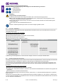 6
6
-
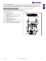 7
7
-
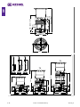 8
8
-
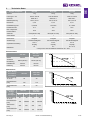 9
9
-
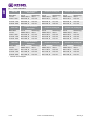 10
10
-
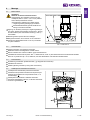 11
11
-
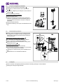 12
12
-
 13
13
-
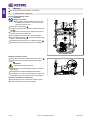 14
14
-
 15
15
-
 16
16
-
 17
17
-
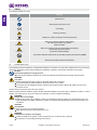 18
18
-
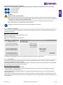 19
19
-
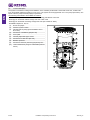 20
20
-
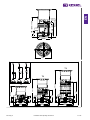 21
21
-
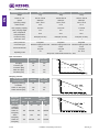 22
22
-
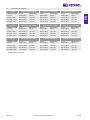 23
23
-
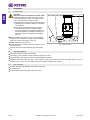 24
24
-
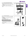 25
25
-
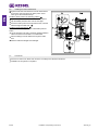 26
26
-
 27
27
-
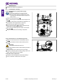 28
28
-
 29
29
-
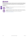 30
30
-
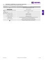 31
31
-
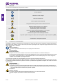 32
32
-
 33
33
-
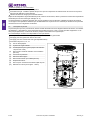 34
34
-
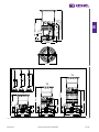 35
35
-
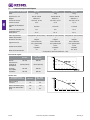 36
36
-
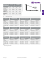 37
37
-
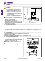 38
38
-
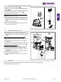 39
39
-
 40
40
-
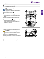 41
41
-
 42
42
-
 43
43
-
 44
44
-
 45
45
-
 46
46
-
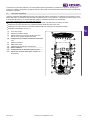 47
47
-
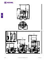 48
48
-
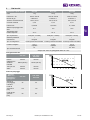 49
49
-
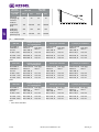 50
50
-
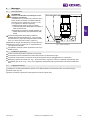 51
51
-
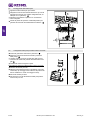 52
52
-
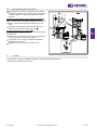 53
53
-
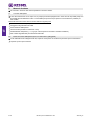 54
54
-
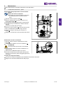 55
55
-
 56
56
-
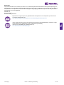 57
57
-
 58
58
-
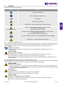 59
59
-
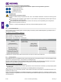 60
60
-
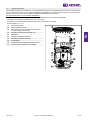 61
61
-
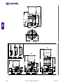 62
62
-
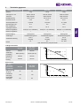 63
63
-
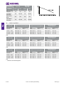 64
64
-
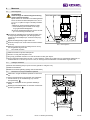 65
65
-
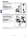 66
66
-
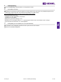 67
67
-
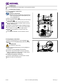 68
68
-
 69
69
-
 70
70
-
 71
71
-
 72
72
-
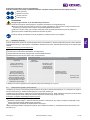 73
73
-
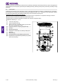 74
74
-
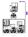 75
75
-
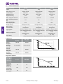 76
76
-
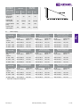 77
77
-
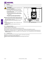 78
78
-
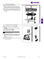 79
79
-
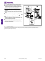 80
80
-
 81
81
-
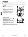 82
82
-
 83
83
-
 84
84
-
 85
85
-
 86
86
-
 87
87
-
 88
88


Kessel 328-198 PS Aquapump Medium LW600 Installation and Operating Instructions
- Type
- Installation and Operating Instructions
in andere talen
- italiano: Kessel 328-198 PS Aquapump Medium LW600
- français: Kessel 328-198 PS Aquapump Medium LW600
- Deutsch: Kessel 328-198 PS Aquapump Medium LW600
- polski: Kessel 328-198 PS Aquapump Medium LW600
Gerelateerde artikelen
-
 Kessel SG 400 V Mono Original Operation Manual
-
 Kessel 016-307 Minilift S Überflur Installation and Operating Instructions
-
 Kessel 016-328 SG Ecolift L 230 V Installation and Operating Instructions
-
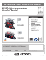 Kessel SPZ 1000 Handleiding
-
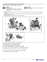 Kessel 016-333 Beiblatt Umrüstsatz für zweite Pumpe Installation and Operating Instructions
-
 Kessel 010-701 Technikschacht-LW1000 Installation and Operating Instructions


Andere documenten
-
Pentair 625-3 Handleiding
-
Wilo TWI 5 Handleiding
-
-
Pentair U5 K Handleiding
-
Wilo TWI 5-SE Gebruikershandleiding
-
 BADU JET Smart Final assembly kit 400 V Handleiding
-
Homa TP 28 Original Instruction Manual
-
-
SFA SANIFOS 500 Series Installation Instructions Manual
-
Grundfos LCD 108 Installation And Operating Instructions Manual
