Kessel 016-307 Minilift S Überflur Installation and Operating Instructions
- Type
- Installation and Operating Instructions

Minilift S
Einbau- und Betriebsanleitung
DE ........................................................................................................................ 2
EN ...................................................................................................................... 20
FR ...................................................................................................................... 38
IT ...................................................................................................................... 56
NL ...................................................................................................................... 74
PL ...................................................................................................................... 92
2023/06 016-307

DE
Liebe Kundin, lieber Kunde,
als Premiumhersteller von innovativen Produkten für die Entwässerungstechnik bietet KESSEL ganzheitliche Systemlösun-
gen und kundenorientierten Service. Dabei stellen wir höchste Qualitätsstandards und setzen konsequent auf Nachhaltig-
keit - nicht nur bei der Herstellung unserer Produkte, sondern auch im Hinblick auf deren langfristigen Betrieb setzen wir uns
dafür ein, dass Sie und Ihr Eigentum dauerhaft geschützt sind.
Ihre KESSEL AG
Bahnhofstraße 31
85101 Lenting, Deutschland
Bei technischen Fragestellungen helfen Ihnen gerne unsere qualifizierten Servicepartner vor Ort weiter.
Ihren Ansprechpartner finden Sie unter:
www.kessel.de/kundendienst
Bei Bedarf unterstützt unser Werkskundendienst mit Dienstleistungen wie Inbetriebnahme, Wartung oder
Generalinspektion in der gesamten DACH-Region, andere Länder auf Anfrage.
Informationen zur Abwicklung und Bestellung finden Sie unter:
www.kessel.de/service/dienstleistungen
Inhalt
1 Hinweise zu dieser Anleitung................................................................................................................................... 3
2 Sicherheit.................................................................................................................................................................. 4
3 Technische Daten..................................................................................................................................................... 7
4 Montage.................................................................................................................................................................... 9
5 Inbetriebnahme......................................................................................................................................................... 15
6 Wartung.................................................................................................................................................................... 16
7 Konformitäts- und Leistungserklärung..................................................................................................................... 110
2 / 116 016-307

1 Hinweise zu dieser Anleitung
Bei diesem Dokument handelt es sich um die Originalbetriebsanleitung. Die Sprache der Originalbetriebsanleitung ist
Deutsch. Alle weiteren Sprachen dieser Anleitung sind eine Übersetzung der Originalbetriebsanleitung.
Folgende Darstellungskonventionen erleichtern die Orientierung:
Darstellung Erläuterung
[1] siehe Abbildung 1
(5) Positionsnummer 5 von nebenstehender Abbildung
... Handlungsschritt in Abbildung
Prüfen, ob Handbetrieb aktiviert wurde. Handlungsvoraussetzung
OK betätigen. Handlungsschritt
Anlage ist betriebsbereit. Handlungsergebnis
siehe "Sicherheit" Querverweis auf Kapitel 2
Fettdruck besonders wichtige oder sicherheitsrelevante Information
Kursivschreibung Variante oder Zusatzinformation (z. B. gilt nur für ATEX-Variante)
Technische Hinweise, die besonders beachtet werden müssen.
Folgende Symbole werden verwendet:
Zeichen Bedeutung
Gerät freischalten!
Gebrauchsanweisung beachten
CE-Kennzeichnung
Warnung Elektrizität
WARNUNG
Warnt vor einer Gefährdung von Personen. Eine Missachtung
dieses Hinweises kann schwerste Verletzungen oder Tod zur Folge haben.
VORSICHT
Warnt vor einer Gefährdung von Personen und Material. Eine Missachtung
dieses Hinweises kann schwere Verletzungen und Materialschäden zur Folge haben.
DE
016-307 3 / 116

DE
2 Sicherheit
2.1 Allgemeine Sicherheitshinweise
ACHTUNG
Anlage freischalten!
Sicherstellen, dass die elektrischen Komponenten während der Arbeiten von der Spannungsversorgung getrennt
sind.
WARNUNG
Spannungsführende Teile
Bei Tätigkeiten an elektrischen Leitungen und Anschlüssen Folgendes beachten.
Für alle Anschlüsse und Installations-Arbeiten an der Anlage gelten nationale Vorschriften zur elektrischen
Sicherheit.
Die Anlage muss über eine Fehlerstrom-Schutzeinrichtung (RCD) mit einem Bemessungsfehlerstrom von nicht
mehr als 30mA versorgt werden.
2.2 Personal - Qualifikation
Um die dauerhafte Sicherheit der Anlage zu gewährleisten, dürfen ausschließlich folgende Tätigkeiten entsprechend der
Qualifikation der ausführenden Person durchgeführt werden.
Person freigegebene Tätigkeiten an KESSEL-Anlagen
Betreiber Sichtprü-
fung, Stecker
einstecken
Sachkundige Person, (kennt,
versteht Betriebsanweisung)
Entleerung, Reinigung
(innen), Funktionskontrolle
Fachkundige Person, (nach Einbau-
anweisung und Ausführungsnormen)
Einbau, Tausch, Wartung von
Komponenten, Inbetriebnahme
Elektrofachkraft (nach nationalen Vor-
schriften für elektrische Sicherheit)
Elektrische Installation
2.3 Bestimmungsgemäße Verwendung
Die Anlage darf nur zum Abpumpen von haushaltsüblichen, fäkalienfreiem Abwasser, nicht jedoch von brennbaren bzw.
explosiven Flüssigkeiten oder Lösungsmitteln verwendet werden. Der Einsatz hinter Waschbecken, Duschen, Waschma-
schinen und nahe den Anschlüssen von Rückspülventilen ist problemlos möglich.
Die Anlagenvariante Resistant ist überdies geeignet für eine Kombination aus Abwässern und salzhaltigen Medien sowie für
Kondensat aus Brennwertgeräten.
Die Anlage ist zur Entsorgung von Schmutzwasser unterhalb der Rückstauebene geeignet. Ein Einsatz der Anlage in
explosionsgefährdeter Atmosphäre (ATEX) ist nicht zulässig.
4 / 116 016-307

2.4 Produktbeschreibung
Die Anlage besteht aus dem Pumpenbehälter mit beidseitig
anschließbarem Druckanschluss mit Rückflussverhinderer
und mehreren optionalen Zuläufen.
Eine zusätzliche Alarmsonde (optische Niveauerfassung)
kann optional nachgerüstet werden, um die Anlage mit opti-
schen und akustischen Warnsignalen bei starker Niveau-
überschreitung auszustatten (Art.-Nr. 20223).
Pos. Nr. Komponente
(1) Zuläufe (hier mit Blindstopfen)
(2) Deckelverriegelung
(3) Kabelkanal
(4) Kabeldurchführung
(5) Vertikaler Zulauf
(6) Entlüftung mit Aktivkohlefilter
(7) Druckstutzen mit Rückflussverhinderer
(8) Druckabgang
(9) Vertikaler Schwimmerschalter
(10) Auftriebssicherung/Behälterbefestigung
(11) Pumpe
1
2
11
3
4 5 6
7
8
9
10
2.5 Funktionsschema
10 cm
15 cm
2
4
3
5
1
(1) Minilift S Überflur (4) Scheitelhöhe der Rückstauschleife wegen Saughebereffekt
(2) Öffentlicher Kanalschacht (5) Aufweitung der Rückstauschleife nach dem Scheitelpunkt
(3) Anstauhöhe über Entspannungsspunkt
DE
016-307 5 / 116

DE
100 mm
Bei Anschluss der Dusche bitte beachten:
Minimale Einschalthöhe der Pumpe (Variante KTP 300 & GTF 500) = 85 mm.
Beim Einbau ist das Gefälle vom Ablauf der Dusche zu berücksichtigen.
6 / 116 016-307

3 Technische Daten
Pumpentyp KTP 300 GTF 500 GTF 1000
Gewicht (Anlage) 9,5 kg 11 kg 15 kg
Aufnahmeleistung P1 0,34 kW 0,6 kW 1,27 kW
Nennleistung P2 0,21 kW 0,36 kW 0,73 kW
Drehzahl 2800 min-1
Betriebsspannung 230 V (50 Hz)
Nennstrom 1,6 A 2,7 A 5,6 A
Förderhöhe max. 6m max. 8m max. 10m
Förderleistung 8 m3/h 10 m3/h 14,5 m3/h
Kugeldurchgang 10 mm
Förderguttemperatur (dauerhaft) max. 40° C
Heißwasserbeständigkeit kurzzeitig (2 min) 80° C
Schutzart (Pumpe) IP 68 (3m)
Schutzklasse I
Motorschutz Thermoschalter
Anschlusstyp Schuko
Betriebsart S1 S1 S3 (50%)
Erforderliche Absicherung C16 A
RCD 30 mA
Zulauf DN 40/50
Druckabgang DN 32 (DA 40) / 1 ½“
Laufrad Typ Freistromrad
Länge Netzanschlussleitung Pumpe 5 m
Typ Anschlussleitung Pumpe H07RN-F 3G 1,0 mm2
Temperaturüberwachung integriert
Pumpentyp KTP 300 GTF 500 GTF 1000
Nutzvolumen min. 5 l
Nutzvolumen max. 12 l 7 l
Behältervolumen max. 30 l
Einschalthöhe
Schwimmerposition UNTEN 85 mm
Schwimmerposition OBEN 170 mm 150 mm
Ausschalthöhe
Schwimmerposition UNTEN 35 mm
Schwimmerposition OBEN 40 mm 80 mm
DE
016-307 7 / 116

DE
DN 32
OD 40
424
339
296
228
78
218
52
193
8 / 116 016-307

4 Montage
Schalldämmfüße montieren
4 Schalldämmfüße unten am Behälter montieren bzw.
einkleben.
Auf Schallentkopplung zum Mauerwerk achten.
4.1 Zuläufe montieren
Übersicht möglicher Zuläufe
DN 50
DN 40
DN 50
DN 50
DN 50
Senkrechten Zulauf anschließen
Blinddeckel herausziehen.
Dichtung einfetten.
Zulaufrohr (DN 40) einschieben.
DE
016-307 9 / 116

DE
Waagrechte Zuläufe montieren
1
2
3
DN 50
DN 40
681111
DN 50
28093
Ggf. Blinddeckel herausziehen.
Dichtung einlegen und einfetten.
Falls erforderlich, Rückflussverhinderer (DN50) ins Zulaufrohr einsetzen (Zubehör Art.-Nr. 28093)
Zulaufrohr (DN50 oder mit Übergangsadapter DN40) einsetzen, auf Einstecktiefe achten.
Falls Zulaufrohr nicht verwendet wird, mit Blinddeckel verschließen
10 / 116 016-307

4.2 Druckanschluss montieren
Druckleitung auf gewünschter Seite (rechts oder links) an
Anlage heranführen.
Dichtung plan auf Druckstutzen aufschieben, dabei Nut
und Aussparung aufeinander ausrichten.
Druckstutzen in Öffnung einführen und mit Kontermutter
und Dichtung fixieren, Anzugsdrehmoment 10 Nm.
1
3
2
Nicht benötige Öffnung mit Blindstopfen verschließen.
1
2
3
Druckleitung anschließen, dabei nebenstehend abgebil-
dete Anschlussmöglichkeiten beachten.
Bei den Varianten B und C muss das Übergangsstück
aufgeschraubt werden.
DE
016-307 11 / 116

DE
4.3 Pumpe montieren
Pumpe in Behälter einsetzen.
Pumpe an Druckstutzen heranschieben.
Schnellverschluss verriegeln.
1
2
4.4 Schwimmerposition prüfen (nur bei Varianten mit vertikalem Schwimmer)
Bitte korrekte Schwimmerposition prüfen:
Schwimmer ist in zwei Positionen verwendbar, OBEN
und UNTEN (Position OBEN Werkseinstellung).
Entsprechend der Positionierung des Schwimmers Dreh-
regler auf entsprechende Stellung einstellen.
Mit oberer Position kann das maximale Volumen des
Behälters genutzt werden.
Einschalthöhe = 170 mm
Position UNTEN zur Verwendung bei Anschluss einer
Dusche. Einschalthöhe = 85 mm
Schwimmerposition ändern
Schwimmer leicht nach vorne ankippen und bei der Füh-
rung jeweils in Pos. A (oben) oder Pos. B (unten) wieder
einklicken.
Bitte beachten Sie, über die obere Drehscheibe die Nach-
laufzeit entsprechend der Schwimmerposition anzupassen.
12
3
A
B
A
B
A
B
12 / 116 016-307

4.5 Netzleitung herausführen
Pumpenkabel aus Anlage herausführen und in Kabel-
durchführung einklemmen.
Pumpenkabel in Kabelkanal einsetzen.
Netzstecker anschließen.
4.6 Deckel montieren
Deckeldichtung einfetten, hierfür beiliegendes Schmierfett
verwenden.
Deckel aufsetzen.
Dazu Rastnasen am Deckel hinten in die Behälternut ein-
führen und den Deckel umlaufen mit leichtem Druck auf
Anschlag eindrücken.
Verriegelung (beidseitig) arretieren.
2
2
1
DE
016-307 13 / 116

DE
4.7 Behälter befestigen
Für die beiliegende Befestigung sind zwei 6 mm Bohrun-
gen zu setzen. Dann kann der Behälter mit den beiliegen-
den Dübeln und Schrauben am Boden befestigt werden.
Winkel einklipsen
Behälter mit Schraube und Dübel am Boden befestigen
Ø 6 mm
2x
4.8 Anschluss einer optionalen Warnsonde (Art.-Nr. 20223)
Zur Inbetriebnahme des Warngerätes bitte beiliegende Bedienungsanleitung 016-051 zum Anschluss der optischen Sonde
im Behälter beachten, siehe Grafik.
1
234
14 / 116 016-307

5 Inbetriebnahme
5.1 Funktion- und Dichtheit prüfen
Sicherstellen, dass Anlage stromlos ist und Deckel pass-
genau auf dem Behälter sitzt.
Klarwasser bis zum Deckel auffüllen.
Prüfen, ob Anschlüsse dicht sind.
Stecker einstecken.
Wasser wird selbsttätig abgepumpt.
DE
016-307 15 / 116

DE
6 Wartung
6.1 Wartung vorbereiten
ACHTUNG
Anlage freischalten!
Sicherstellen, dass die elektrischen Geräte wäh-
rend der Arbeiten von der Spannungsversorgung
getrennt sind.
Sicherstellen, dass kein Abwasser an der Anlage anfällt.
Verriegelung (beidseitig) zur Seite schieben.
Deckel abnehmen.
1
1
2
Pumpe demontieren
Schnellverschluss öffnen.
Pumpe entnehmen.
Schwimmerschalter reinigen (ggf. Auftriebskörper und
Gehäuse von Schmutz befreien)
Dazu ggf. Auftriebskörper vom Schwimmerkörper abzie-
hen.
16 / 116 016-307

Rückflussverhinderer demontieren
In Druckleitung aufgestautes Wasser auslaufen lassen.
Drehverschluss öffnen.
Klappenhalter und Rückflussverhinderer abziehen.
Kleinteile reinigen und auf Beschädigungen prüfen.
Behälter reinigen
Behälter innen reinigen.
Feststoffe und Ablagerungen entfernen.
Falls vorhanden, Rückflussverhinderer im Zulaufrohr rei-
nigen.
Falls vorhanden, optische Sonde (Zubehör) reinigen.
DE
016-307 17 / 116

DE
6.2 Pumpenwartung
6.2.1 Pumpen instandsetzen
ACHTUNG
Anlage freischalten!
Sicherstellen, dass die elektrischen Geräte während der Arbeiten von der Spannungsversorgung getrennt sind.
Um die Pumpe vor Ablagerungen und blockierenden Gegenständen zu schützen, ist die Pumpe in regelmäßigen Abständen
zu reinigen, bzw. von Ablagerungen zu befreien.
Bewegliche Komponenten demontieren
Ansaugkorb demontieren.
Spiralgehäuse demontieren.
Reinigung durchführen
Achsaufnahme des Freistromrades und Antriebswelle (Raum hinter Freistromrad) von allen umwickelten Gegenständen
und Verschmutzungen befreien. Freistromrad auf Verformungen und Leichtläufigkeit überprüfen.
Freigelegtes Freistromrad z.B. im Wasserbad reinigen.
Entlüftungsöffnung A freimachen, ggf. Abdeckung beiseite schieben.
Komponenten prüfen und zusammenbauen
Freigängigkeit des horizontalen Schwimmerschalters (nur KTP 1000) sicherstellen.
Demontierte Komponenten auf Verschleiß prüfen, ggf. austauschen.
Komponenten in umgekehrter Reihenfolge wieder zusammenbauen.
Funktionsprüfung durchführen.
1
2
2
1
1
2
KTP 300
GTF 500
KTP 1000
A
A
A
18 / 116 016-307

6.3 Entlüftungseinheit überprüfen
Abdeckung wegnehmen.
Ggf. Aktivkohlefilter wechseln, Art.-Nr. 28061 (1x pro Jahr
oder bei Geruchsbelästigung).
Falls Kugel verschmutzt, Niederhalter abschrauben,
Kleinteile herausnehmen und alles reinigen.
6.4 Hilfe bei Störungen
Fehler Ursache Abhilfemaßnahmen
Pumpe läuft nicht Keine Netzspannung vorhanden Netzspannung prüfen
Pumpe läuft nicht Hausstrom-Sicherung hat ausgelöst Sicherung überprüfen
Pumpe läuft nicht Anschlussleitung beschädigt Reparatur nur durch Elektrofachkräfte
Pumpe läuft nicht Schwimmerschalter vertikal falsch einge-
stellt
Position und Einstellung überprüfen
Pumpe läuft nicht Schwimmerschalter defekt Kundendienst kontaktieren
Pumpe läuft nicht Überhitzung Tauchpumpe schaltet sich nach Temperatu-
rückgang selbstständig wieder ein
Freistromrad blockiert Verunreinigungen, Feststoffe haben sich
zwischen Freistromrad und Spiralgehäuse
festgesetzt
Pumpe reinigen (siehe Pumpenwartung)
verminderte Förderleistung Ansaugkorb verstopft Pumpe reinigen (siehe Pumpenwartung)
verminderte Förderleistung Verschleiß des Spiralgehäuses Spiralgehäuse auswechseln
verminderte Förderleistung Verschleiß des Freistromrades Freistromrad auswechseln
verminderte Förderleistung Entlüftungsöffnung verstopft Entlüftungsöffnung reinigen
verminderte Förderleistung Entlüftungsblende fehlt oder falsch montiert Kundendienst kontaktieren
DE
016-307 19 / 116

EN
Dear Customer,
As a premium manufacturer of innovative products for draining technology, KESSEL offers integrated system solutions and
customer-oriented service. In doing so, we set the highest quality standards and focus firmly on sustainability - not only with
the manufacturing of our products, but also with regard to their long-term operation and we strive to ensure that you and your
property are protected over the long term.
Your KESSEL AG
Bahnhofstraße 31
85101 Lenting, Germany
Our local, qualified service partners would be happy to help you with any technical questions.
You can find your contact partner at:
www.kessel.de/kundendienst
If necessary, our Factory Customer Service provides support with services such as commissioning, main-
tenance or general inspection throughout the DACH region, other countries on request.
For information about handling and ordering, see:
www.kessel.de/service/dienstleistungen
Contents
1 Notes on this manual............................................................................................................................................... 21
2 Safety........................................................................................................................................................................ 22
3 Technical data.......................................................................................................................................................... 25
4 Installation................................................................................................................................................................. 27
5 Commissioning......................................................................................................................................................... 33
6 Maintenance............................................................................................................................................................. 34
20 / 116 016-307

1 Notes on this manual
This document is a translation of the original operating instructions. The original operating instructions are written in German.
All other language versions of these instructions are a translation of the original operating instructions.
The following conventions make it easier to navigate the manual:
Symbol Explanation
[1] See Figure 1
(5) Position number 5 from the adjacent figure
... Action step in figure
Check whether manual operation has been
activated. Prerequisite for action
Press OK. Action step
System is ready for operation. Result of action
see "Safety" Cross-reference to Chapter 2
Bold type Particularly important or safety-relevant information
Italics Variants or additional information (e.g. applicable only for ATEX variants)
Technical information or instructions which must be paid particular attention.
The following symbols are used:
Icon Meaning
Isolate device!
Observe the instructions for use
CE marking
Warning, electricity
WARNING
Warns of a hazard for persons. Disregarding
this warning can lead to very serious injuries or death.
CAUTION
Warns of a hazard for persons and material. Disregarding
this warning can lead to serious injuries and material damage.
EN
016-307 21 / 116

EN
2 Safety
2.1 General safety notes
NOTICE
Disconnect system from energy sources!
Ensure that the electrical components are disconnected from the electrical power supply during the work.
WARNING
Live parts
Heed the following points when working on electrical cables and connections.
The national regulations concerning electrical safety apply to all connections and installation work.
The system must be supplied through a residual current protection device (RCD) with residual current of not
more than 30mA.
2.2 Personnel - qualification
In order to guarantee the long-term safety of the system, only the following activities may be performed, in accordance with
the qualification of the person carrying out the activity.
Person Approved activities on KESSEL systems
Operating company Visual inspec-
tion, insert plug
Technical expert, (familiar with,
understands operating instructions)
Emptying, cleaning
(inside), functional check
Technical specialist, (technical worker,
in accordance with installation instruc-
tions and execution standards)
Installation, replacement, mainte-
nance of components, commissioning
Qualified electrician (accord-
ing to the national regula-
tions for electrical safety)
Electrical installation
2.3 Intended use
The system may only be used for pumping away domestic non-faecal wastewater; however, it must not be used for flamma-
ble, explosive liquids or solvents. It can be easily installed behind washbasins, showers, washing machines or near the con-
nections of backwash valves.
The 'Resistant' system variant is additionally suitable for a combination of wastewater and salt-laden media as well as for
condensate from condensing boiler systems.
The system is suitable for the disposal of grey water below the backwater level. Use of the system in a potentially explo-
sive environment (ATEX) is not permitted.
22 / 116 016-307

2.4 Product description
The system consists of a pump tank with pressure pipe con-
nection (both sides) with backflow preventer with several
optional inlets.
An additional alarm probe (optical level measurement) can
be retrofitted as an option in order to equip the system with
visual and acoustic warning signals in the event of the high
level being exceeded (art. no. 20223).
Item No. Component
(1) Inlets (here with blind plugs)
(2) Cover lock
(3) Cable duct
(4) Cable gland
(5) Vertical inlet
(6) Venting with activated carbon filter
(7) Outlets with backflow preventer
(8) Pressure pipe connection
(9) Vertical float switch
(10) Anti-buoyancy protection/tank fixing
(11) Pump
1
2
11
3
4 5 6
7
8
9
10
2.5 Functional diagram
10 cm
15 cm
2
4
3
5
1
(1) Minilift S above ground (4) Soffit level of the backwater loop due to siphon effect
(2) Public sewer chamber (5) Widening of the backwater loop downstream of the soffit level
(3) Accumulation height above relief point
EN
016-307 23 / 116

EN
100 mm
Please note when connecting the shower:
Minimum switch-on level of the pump (KTP 300 & GTF 500 versions) = 85 mm.
When installing, allow for the gradient from the shower drain.
24 / 116 016-307

3 Technical data
Pump type KTP 300 GTF 500 GTF 1000
Weight (system) 9.5 kg 11 kg 15 kg
Input power P1 0.34 kW 0.6 kW 1.27 kW
Nominal power P2 0.21 kW 0.36 kW 0.73 kW
Speed 2800 min-1
Operating voltage 230 V (50 Hz)
Rated current 1.6 A 2.7 A 5.6 A
Pumping height max. 6m max. 8m max. 10m
Pumping capacity 8 m3/h 10 m3/h 14.5 m3/h
Completely free passage 10 mm
Max. temperature (permanent) of conveyed
material 40 °C
Hot water resistance, short-term (2 min) 80 °C
Protection rating (pump) IP 68 (3m)
Protection class I
Motor protection Thermal cut-out
Connection type Schuko earthed safety plug
Operating mode S1 S1 S3 (50%)
Required fusing C16 A
RCD 30 mA
Inlet DN 40/50
Pressure pipe connection DN 32 (DA 40) / 1 ½“
Impeller type Multi-vane vortex impeller
Length of mains cable for pump 5 m
Type of pump connection cable H07RN-F 3G 1.0 mm2
Temperature monitoring integrated
Pump type KTP 300 GTF 500 GTF 1000
Pumping volume min. 5 l
Pumping volume max. 12 l 7 l
Tank volume max. 30 l
Switch-on level
Floater position BOTTOM 85 mm
Floater position TOP 170 mm 150 mm
Switch-off level
Floater position BOTTOM 35 mm
Floater position TOP 40 mm 80 mm
EN
016-307 25 / 116

EN
DN 32
OD 40
424
339
296
228
78
218
52
193
26 / 116 016-307

4 Installation
Fitting the sound insulating feet
Fit or glue in the 4 sound insulating feet on the bottom of
the tank.
Pay attention to decoupling noise from the masonry.
4.1 Installing the inlets
Overview of possible inlets
DN 50
DN 40
DN 50
DN 50
DN 50
Connect the vertical inlet
Pull out the blind plug.
Grease the seal.
Push in the inlet pipe (DN 40).
EN
016-307 27 / 116

EN
Install the horizontal inlets
1
2
3
DN 50
DN 40
681111
DN 50
28093
Pull out the blind plugs if necessary.
Insert the seal and grease.
If necessary, insert the backflow preventer (DN50) into the inlet pipe (accessories art. no. 28093)
Insert the inlet pipe (DN50 or DN40 with adapter), check insertion depth is sufficient.
Close off unused inlet pipe with blind plug
28 / 116 016-307

4.2 Installing the pressure pipe connection
Lay the pressure pipe up to the required side (left or right)
of the system
Push the seal flat onto the outlet, at the same time align-
ing the groove and recess with each other.
Insert the outlet into the opening and fix with lock nut and
seal, tightening torque 10 Nm.
1
3
2
Close off unused opening with blind plug.
1
2
3
Connect the pressure pipe, note the connection options
shown on the right.
The adapter must be screwed on for versions B and C.
EN
016-307 29 / 116

EN
4.3 Installing the pump
Insert the pump in the tank.
Push the pump up to the outlet.
Lock the quick-release closure.
1
2
4.4 Check floater position (only versions with vertical floater)
Please check for correct floater position:
The floater can be used in two position, TOP and BOT-
TOM (TOP position is the factory setting).
Set the rotary controller to the relevant position according
to the positioning of the floater.
With the top position the maximum volume of the tank
can be used.
Switch-on level = 170 mm
The BOTTOM position is for use when connecting a
shower. Switch-on level = 85 mm
Changing the floater position
Tilt the floater forward slightly and click back into the
guide in Pos. A (top) or Pos. B (bottom).
Please be sure to use the top rotary disc to adjust the post
run time according to the floater position.
12
3
A
B
A
B
A
B
30 / 116 016-307

4.5 Feeding out the mains cable
Feed the pump cable out of the system and clamp it in
the cable gland.
Insert the pump cable in the cable duct.
Connect the mains plug.
4.6 Fitting the cover
Grease the cover seal; use the enclosed grease.
Put on the cover.
To do so, insert the catches on the rear of the cover into
the tank groove and press the cover in all the way round
with light pressure.
Lock the locking device (on both sides).
2
2
1
EN
016-307 31 / 116

EN
4.7 Fixing the tank
Two 6 mm holes must be made for the enclosed fixing.
The tank can then be fixed on the floor using the enclosed
plugs and screws.
Clip in the bracket.
Fixing the tank on the floor with screw and plug
Ø 6 mm
2x
4.8 Connection of an optional alarm probe (art. no. 20223)
To start up the alarm device, please follow the enclosed operating instructions 016-051 for the connection of the optical
probe in the tank, see diagram.
1
234
32 / 116 016-307

5 Commissioning
5.1 Test the function and leaktightness
Make sure that the system is disconnected from the
power supply and the cover fits properly on the tank.
Top up clean water up to the cover.
Test whether the connections are leaktight.
Plug in the plug.
The water is pumped away automatically.
EN
016-307 33 / 116

EN
6 Maintenance
6.1 Prepare maintenance
NOTICE
Disconnect system from energy sources!
Ensure that the electrical equipment is discon-
nected from the power supply during the work.
Ensure that there is no wastewater in the system.
Push the lock to the side (on both sides).
Remove the cover.
1
1
2
Remove the pump
Open the quick-release closure.
Remove the pump.
Clean the float switch (remove dirt from the floater and
housing if necessary)
To do so, pull the floater off the float body if necessary.
34 / 116 016-307

Dismantle the backflow preventer
Allow any water that has accumulated in the pressure
pipe to run out.
Open the rotating fastener.
Pull off the flap holder and backflow preventer.
Clean the small parts and check for damage.
Clean the tank
Clean the inside of the tank.
Remove solids and deposits.
If present, clean the backflow preventer in the inlet pipe.
If present, clean the optical probe (accessories).
EN
016-307 35 / 116

EN
6.2 Pump maintenance
6.2.1 Repair the pumps
NOTICE
Disconnect system from energy sources!
Ensure that the electrical equipment is disconnected from the power supply during the work.
To protect the pump from deposits and blocking objects, it must be cleaned or freed from deposits at regular intervals.
Dismantle the movable components
Remove the intake cage.
Remove the spiral housing.
Carry out cleaning
Remove all dirt and items wound around the axle retainer of the multi-vane vortex impeller and drive shaft (space behind
the impeller). Check the multi-vane vortex impeller for deformation and ease of movement.
Clean exposed multi-vane vortex impeller, e.g. in a water bath.
Clear vent opening A, push the cover to the side if necessary.
Check and assemble the components
Make sure that the horizontal float switch can move freely (KTP 1000 only).
Check the dismantled components for wear, replace if necessary.
Assemble the components again in reverse order.
Perform a functional test.
1
2
2
1
1
2
KTP 300
GTF 500
KTP 1000
A
A
A
36 / 116 016-307

6.3 Check the ventilation unit
Remove the cover.
Replace the activated carbon filter, art. no. 28061, if nec-
essary (1x per year or in case of odour nuisance).
If the ball is dirty, unscrew the hold-down, remove the
small parts and clean everything.
6.4 Troubleshooting
Error Cause Remedial measures
Pump is not running No mains voltage available Check the mains voltage
Pump is not running Mains power fuse has tripped Check the fuse
Pump is not running Connection cable is damaged Repair by electrically skilled personnel only
Pump is not running Float switch set wrong vertically Check position and setting
Pump is not running Float switch is defective Contact customer service
Pump is not running Overheating Submersible pump switches back on again
automatically after the temperature has
dropped
Multi-vane impeller is blocked Dirt, solids have become lodged between
the multi-vane impeller and the spiral hous-
ing.
Clean the pump (see pump maintenance )
Reduced pumping capacity Intake cage blocked Clean the pump (see pump maintenance )
Reduced pumping capacity Spiral housing is worn Replace spiral housing
Reduced pumping capacity Multi-vane impeller is worn Replace multi-vane impeller
Reduced pumping capacity Vent is blocked Clean the vent
Reduced pumping capacity Vent cover is missing or incorrectly fitted Contact customer service
EN
016-307 37 / 116

FR
Chère cliente, cher client,
En qualité de producteur de pointe de produits novateurs dans le domaine de la technique d’assainissement, KESSEL pro-
pose des réponses systématiques globales et un service orienté aux besoins de la clientèle. Nous misons simultanément
sur les normes de qualité les plus élevées et une durabilité conséquente – non seulement lors de la fabrication de nos pro-
duits, mais également pour leur utilisation à long terme afin que vous, et vos biens, soient protégés durablement.
Votre KESSEL AG
Bahnhofstrasse 31
85101 Lenting, Allemagne
Nos partenaires qualifiés du service après-vente se feront un plaisir de répondre à vos questions tech-
niques sur site.
Vous trouverez votre correspondant sur :
www.kessel.de/kundendienst
Si nécessaire, notre propre SAV vous prête son assistance en matière de mise en service, de mainte-
nance ou d’inspection générale en Allemagne, en Autriche et en Suisse, comme dans d’autres pays sur
demande.
Toutes les informations de traitement et de commande sont à votre disposition sur :
www.kessel.de/service/dienstleistungen
Sommaire
1 Informations spécifiques aux présentes instructions............................................................................................... 39
2 Sécurité..................................................................................................................................................................... 40
3 Caractéristiques techniques..................................................................................................................................... 43
4 Montage.................................................................................................................................................................... 45
5 Mise en service........................................................................................................................................................ 51
6 Maintenance............................................................................................................................................................. 52
38 / 116 016-307

1 Informations spécifiques aux présentes instructions
Ce document est la traduction de l'original du mode d’emploi. L’original a été rédigé en allemand. Toutes les autres versions
linguistiques de ce mode d’emploi sont des traductions de l’original.
Les conventions de représentation suivantes facilitent l’orientation :
Représentation Explication
[1] voir figure 1
(5) Numéro de repère 5 de la figure ci-contre
... Action de la figure
Vérifier si le mode manuel a été activé. Condition de réalisation de l’action
Valider <OK>. Action
Le système est prêt au service. Résultat de l'action
cf. "Sécurité" Renvoi au chapitre 2
Caractères gras particulièrement important ou information importante pour la sécurité
Caractères italiques Variante ou informations complémentaires (par
exemple, uniquement valable pour la variante ATEX)
informations techniques à observer en particulier.
Les instructions emploient les pictogrammes suivants :
Pictogramme / label Signification
Activer l’appareil !
Observer le mode d'emploi
Label de conformité CE
Mise en garde contre l’électricité
MISE EN GARDE
Avertit d'un danger corporel. Le non-respect
de cette mise en garde peut provoquer des blessures graves, voire mortelles.
ATTENTION
Avertit d'un danger corporel et matériel. Le non-respect
de cette mise en garde peut provoquer des blessures graves et des dommages matériels.
FR
016-307 39 / 116

FR
2 Sécurité
2.1 Consignes de sécurité générales
AVIS
Activer le système !
S'assurer que l'alimentation électrique est coupée pendant les travaux.
AVERTISSEMENT
Pièces sous tension
Respecter les instructions suivantes lors de travaux sur des câbles et raccordements électriques.
Les directives nationales de sécurité électrique s’appliquent à tous les raccordements et travaux d’installation sur
le système.
Le système doit être alimenté par un dispositif différentiel à courant résiduel (RCD) avec courant assigné de
défaut d'une sensibilité au plus égale à 30 mA.
2.2 Personnel - qualification
Afin de garantir la sécurité durable du système, seules les personnes mentionnées ci-après et disposant de la qualification
requise sont autorisées à travailler sur le système.
Personne Activités autorisées sur les postes KESSEL
Exploitant Contrôle
visuel, bran-
cher la fiche
Personne qualifiée (connaît et com-
prend les instructions d’utilisation)
Vidange, nettoyage (inté-
rieur) contrôle fonctionnel
Technicien qualifié (confor-
mément aux instructions de
pose et normes d’exécution)
Pose, remplacement, maintenance
des composants, mise en service
Électricien (selon les prescriptions
nationales de sécurité électrique)
Installation électrique
2.3 Utilisation conforme à l'usage prévu
Le système est uniquement destiné au pompage des eaux usées ménagères sans matières fécales et ne doit pas servir
pour le relevage de liquides inflammables et/ou explosifs ou de solvants. Il est possible de l'utiliser sans problème derrière
des éviers, des douches, des machines à laver et à proximité des raccordements des vannes de rétrolavage.
La variante Resistant du système convient par ailleurs aux combinaisons d’eaux usées et de fluides contenant du sel, ainsi
qu’au condensat issu des appareils à condensation.
Le système est approprié à l’évacuation des eaux usées sous le niveau des plus hautes eaux. L'utilisation du système
dans des zones à risque d'explosion (ATEX) est interdite.
40 / 116 016-307

2.4 Description du produit
Le poste est composé d'une cuve de pompe avec un refou-
lement raccordable des deux côtés et un dispositif anti-
retour ainsi que plusieurs arrivées optionnelles.
Le rééquipement avec une sonde d’alarme supplémentaire
(détection optique du niveau) est possible en option afin
d’équiper le poste de signaux d’alarme optiques et acous-
tiques en cas de dépassement important du niveau (Réf.
20223).
N° pos. Composants
(1) Arrivées (ici avec des bouchons)
(2) Verrouillage du couvercle
(3) Fourreau pour câbles
(4) Passage de câble
(5) Arrivée verticale
(6) Purge avec filtre à charbon actif
(7) Tubulure de refoulement avec dispositif anti-
retour
(8) Refoulement
(9) Interrupteur à flotteur vertical
(10) Protection contre les poussées verticales/fixa-
tion de la cuve
(11) Pompe
1
2
11
3
4 5 6
7
8
9
10
2.5 Schéma de fonctionnement
10 cm
15 cm
2
4
3
5
1
(1) Minilift S à installer hors sol (4) Point le plus haut de la boucle antiretour en raison de l’effet
de siphon
(2) Regard de canalisation public (5) Élargissement de la boucle antiretour après le point le plus
haut
(3) Hauteur de retenue au-dessus du point de détente
FR
016-307 41 / 116

FR
100 mm
Veuillez observer l’élément suivant lors du raccordement de la douche :
Hauteur minimale d’enclenchement de la pompe (variante KTP 300 & GTF 500) = 85 mm.
Il convient de prendre en compte la pente de l’écoulement de la douche lors du montage.
42 / 116 016-307

3 Caractéristiques techniques
Type de pompe KTP 300 GTF 500 GTF 1000
Poids net (poste) 9,5 kg 11 kg 15 kg
Puissance absorbée P1 0,34 kW 0,6 kW 1,27 kW
Puissance nominale P2 0,21 kW 0,36 kW 0,73 kW
Régime 2 800 tr/min
Tension de service 230 volts (50 Hz)
Courant nominal 1,6 A 2,7 A 5,6 A
Hauteur de refoulement max. 6 m max. 8 m max. 10 m
Puissance de refoulement 8 m3/h 10 m3/h 14,5 m3/h
Passage libre 10 mm
Température maximale du fluide refoulé
(refoulement ininterrompu) 40° C
Résistance à l’eau chaude sur une courte
durée (2 min) 80° C
Catégorie de protection (pompe) IP 68 (3 m)
Classe de protection I
Protection du moteur Interrupteur thermique
Type de raccord Fiche d’alimentation
Mode de fonctionnement S1 S1 S3 (50 %)
Protection par fusible nécessaire C16 A
RCD 30 mA
Arrivée DN 40/50
Refoulement DN 32 (DA 40) / 1 ½“
Type de roue Roue vortex
Longueur du câble d'alimentation de la
pompe 5 m
Type de câble d'alimentation de la pompe H07RN-F 3G, 1,0 mm²
Surveillance de la température intégrée
Type de pompe KTP 300 GTF 500 GTF 1000
Volume utile min. 5 l
Volume utile maxi 12 l 7 l
Volume utile maxi 30 l
Hauteur d'activation
Position de l’interrupteur à flotteur EN BAS 85 mm
Position de l’interrupteur à flotteur EN HAUT 170 mm 150 mm
Hauteur déconnecter
Position de l’interrupteur à flotteur EN BAS 35 mm
Position de l’interrupteur à flotteur EN HAUT 40 mm 80 mm
FR
016-307 43 / 116

FR
DN 32
OD 40
424
339
296
228
78
218
52
193
44 / 116 016-307

4 Montage
Montage des pieds à isolation phonique
Monter ou coller les 4 pieds à isolation phonique sous la
cuve.
Veillez à l’isolation phonique avec l’ouvrage.
4.1 Montage des arrivées
Aperçu des arrivées possibles
DN 50
DN 40
DN 50
DN 50
DN 50
Raccordement de l’arrivée verticale
Retirer le bouchon.
Graisser le joint.
Insérer le tuyau d'arrivée (DN 40).
FR
016-307 45 / 116

FR
Montage des arrivées horizontales
1
2
3
DN 50
DN 40
681111
DN 50
28093
Retirer si besoin le bouchon.
Insérer le joint et le graisser.
Si besoin, insérer le dispositif anti-retour (DN50) dans le tuyau d'arrivée (accessoire, Réf. 28093)
Insérer le tuyau d'arrivée (DN50 ou DN40 avec adaptateur), veiller à la profondeur d’insertion.
Si le tuyau d'arrivée n’est pas utilisé, obturer le trou à l’aide d'un bouchon.
46 / 116 016-307

4.2 Montage du refoulement
Amener la conduite de refoulement à l’emplacement sou-
haité (droite ou gauche) sur le poste.
Insérer le joint à plat sur la tubulure de refoulement,
veillez à bien aligner la rainure et l’évidement.
Introduire la tubulure de refoulement dans l’ouverture et
la fixer avec le contre-écrou et le joint, couple de
serrage 10 Nm.
1
3
2
Fermer l’ouverture non utilisée à l’aide d'un bouchon.
1
2
3
Raccorder la conduite de refoulement. Observer à cet
effet les possibilités de raccordement illustrées ci-contre.
Sur les variantes B et C, l'adaptateur doit être vissé.
FR
016-307 47 / 116

FR
4.3 Montage de la pompe
Insérer la pompe dans la cuve.
Approcher la pompe de la tubulure de refoulement.
Verrouiller la fermeture rapide.
1
2
4.4 Contrôle de la position de l’interrupteur à flotteur (uniquement sur les variantes avec interrupteur à flotteur vertical)
Vérifier si l'interrupteur à flotteur est correctement posi-
tionné :
L'interrupteur à flotteur peut être utilisé sur deux posi-
tions, EN HAUT et EN BAS (réglage d'usine : EN HAUT).
Régler le bouton rotatif sur la position correspondante en
fonction de la position de l’interrupteur à flotteur.
La position supérieure permet d'utiliser le volume maxi-
mal de la cuve.
Hauteur d’enclenchement = 170 mm
Position BASSE utilisée lors du raccordement d'une
douche. Hauteur d’enclenchement = 85 mm
Modifier la position de l’interrupteur à flotteur
Incliner l'interrupteur à flotteur légèrement vers l’avant et
l’encliqueter de nouveau au niveau du guidage en pos. A
(en haut) ou en pos. B (en bas).
Veillez à adapter le temps d'inertie en fonction de la position
du flotteur via le bouton rotatif supérieur.
12
3
A
B
A
B
A
B
48 / 116 016-307

4.5 Raccordement du câble d'alimentation
Faire sortir du poste le câble de la pompe et le coincer
dans le passage de câble.
Insérer le câble de la pompe dans le fourreau pour
câbles.
Raccorder la fiche secteur.
4.6 Montage du couvercle
Graisser le joint du couvercle. Utiliser à cet effet la
graisse fournie.
Poser le couvercle.
Pour cela, insérer les ergots d'arrêt du couvercle à l'ar-
rière dans les rainures de la cuve et enfoncer le cou-
vercle en exerçant une légère pression jusqu'à la butée.
Bloquer le verrouillage (des deux côtés).
2
2
1
FR
016-307 49 / 116

FR
4.7 Fixation de la cuve
Il convient de percer deux trous de 6 mm pour la fixation
fournie. Il est possible ensuite de fixer la cuve au sol à l’aide
des chevilles et vis fournies.
Clipser l’équerre
Fixer la cuve au sol avec la vis et la cheville.
Ø 6 mm
2x
4.8 Raccordement de la sonde d'alarme optionnelle (Réf. 20223)
Pour la mise en service du dispositif d'avertissement, veuillez-vous référer au manuel d’utilisation 016-051 pour le raccorde-
ment de la sonde optique dans la cuve, voir graphique.
1
234
50 / 116 016-307

5 Mise en service
5.1 Contrôle du fonctionnement et de l’étanchéité
S'assurer que le poste est hors tension et que le cou-
vercle est parfaitement positionné sur la cuve.
Remplir d’eau claire jusqu’au couvercle.
Vérifier si les raccords sont bien étanches.
Brancher la fiche.
L’eau est pompée automatiquement.
FR
016-307 51 / 116

FR
6 Maintenance
6.1 Préparation de la maintenance
AVIS
Activer le système !
S'assurer que les appareils électriques sont cou-
pés de l'alimentation en tension pendant les tra-
vaux.
S’assurer qu’il n'y ait pas de production d’eaux usées
dans le poste.
Pousser le verrouillage (des deux côtés) sur le côté.
Retirer le couvercle.
1
1
2
Démontage de la pompe
Ouvrir la fermeture rapide.
Retirer la pompe.
Nettoyer l’interrupteur à flotteur (enlever si besoin la
saleté au niveau du flotteur et du boîtier)
Pour ce faire, retirer si besoin le flotteur de l’interrupteur à
flotteur.
52 / 116 016-307

Démonter le dispositif anti-retour
Laisser s'écouler les eaux usées accumulées dans la
conduite de refoulement.
Ouvrir la fermeture rotative.
Retirer le support du clapet et le dispositif anti-retour.
Nettoyer les petites pièces et vérifier l’absence de dété-
riorations.
Nettoyage de la cuve
Nettoyer l’intérieur de la cuve.
Retirer les particules solides et les dépôts.
Si présent, nettoyer le dispositif anti-retour dans le tuyau
d'arrivée.
Si présente, nettoyer la sonde optique (accessoire).
FR
016-307 53 / 116

FR
6.2 Maintenance de la pompe
6.2.1 Remettre les pompes en état
AVIS
Activer le système !
S'assurer que les appareils électriques sont coupés de l'alimentation en tension pendant les travaux.
Il convient de nettoyer la pompe et d’éliminer les éventuels dépôts à intervalles réguliers afin de protéger la pompe contre
les dépôts et particules susceptibles de la bloquer.
Démontage des composants mobiles
Démonter la grille d'aspiration.
Démonter la volute de pompe.
Mise en œuvre du nettoyage
Nettoyer le logement d'axe de la roue vortex et l'arbre d’entraînement (espace derrière la roue vortex) afin de retirer tous
les objets ayant pu s’enrouler autour ainsi que toutes les salissures. Vérifier l’absence de déformations et la souplesse de
fonctionnement de la roue vortex.
Nettoyer la roue vortex démontée dans un bain d’eau par ex.
Désobstruer l’ouverture de purge A, pousser éventuellement le couvercle de recouvrement sur le côté.
Vérifier et remonter les composants
Vérifier la souplesse de fonctionnement de l'interrupteur à flotteur horizontal (KTP 1000 uniquement).
Vérifier le degré d’usure des composants démontés, les remplacer si nécessaire.
Remonter les composants dans le sens inverse du démontage.
Procéder à un contrôle fonctionnel.
1
2
2
1
1
2
KTP 300
GTF 500
KTP 1000
A
A
A
54 / 116 016-307

6.3 Vérification de l’unité d’aération et de ventilation
Retirer le couvercle de recouvrement.
Si nécessaire, remplacer le filtre à charbon actif, Réf.
28061 (1 x par an ou en cas de nuisances olfactives).
Si la bille est sale, dévisser le dispositif de retenue, retirer
les petites pièces et nettoyer le tout.
6.4 Aide en cas de panne
Défaut Cause Remèdes
La pompe ne fonctionne pas La tension de réseau fait défaut Vérifier la tension de réseau
La pompe ne fonctionne pas Déclenchement du fusible principal Vérifier le fusible
La pompe ne fonctionne pas Câble d'alimentation défectueux Réparation par un électricien qualifié uni-
quement
La pompe ne fonctionne pas Interrupteur à flotteur vertical mal réglé Vérifier la position et le réglage
La pompe ne fonctionne pas Interrupteur à flotteur défectueux Informer le service après-vente si néces-
saire
La pompe ne fonctionne pas Surchauffe La pompe submersible se remet automa-
tiquement en marche après la chute de la
température
Roue vortex bloquée Dépôts d’impuretés ou de matières solides
entre la roue vortex et la volute de pompe
Nettoyer la pompe (voir maintenance de la
pompe)
Capacité de refoulement
réduite
Grille d'aspiration bouchée Nettoyer la pompe (voir maintenance de la
pompe)
Capacité de refoulement
réduite
Usure de la volute de pompe Remplacer la volute de pompe
Capacité de refoulement
réduite
Usure de la roue vortex Remplacer la roue vortex
Capacité de refoulement
réduite
Ouverture de ventilation bouchée Nettoyer l'ouverture de ventilation
Capacité de refoulement
réduite
Cache du système de ventilation manquant
ou monté de manière incorrecte
Informer le service après-vente si néces-
saire
FR
016-307 55 / 116

IT
Cara cliente, caro cliente,
in qualità di produttore premium di prodotti innovativi per la tecnica di drenaggio, KESSEL offre soluzioni di sistema integrate
e un servizio orientato al cliente. Puntiamo sui massimi standard qualitativi e ci impegniamo coerentemente per la sosteni-
bilità – non ci impegniamo solo nella produzione dei nostri prodotti, ma anche rispetto al funzionamento a lungo termine, in
modo che la vostra proprietà sia protetta nel tempo.
KESSEL AG
Bahnhofstraße 31
85101 Lenting, Germania
In caso di domande di carattere tecnico, i nostri partner di servizio qualificati sul posto saranno felici di
aiutarvi.
Potete trovare i vostri referenti alla pagina:
www.kessel.de/kundendienst
In caso di necessità, il nostro centro di assistenza dell’azienda vi supporta con servizi come la messa in
funzione, la manutenzione o l’ispezione generale in tutta la regione DACH e in altri Paesi a richiesta.
Per le informazioni sullo svolgimento e sull’ordine consultate la pagina
www.kessel.de/service/dienstleistungen
Indice
1 Indicazioni sulle presenti istruzioni.......................................................................................................................... 57
2 Sicurezza.................................................................................................................................................................. 58
3 Dati tecnici................................................................................................................................................................ 61
4 Montaggio................................................................................................................................................................. 63
5 Messa in funzione.................................................................................................................................................... 69
6 Manutenzione........................................................................................................................................................... 70
56 / 116 016-307

1 Indicazioni sulle presenti istruzioni
Il presente documento costituisce le istruzioni per l’uso originali. La lingua delle istruzioni per l’uso originali è il tedesco. Tutte
le versioni in altre lingue di queste istruzioni costituiscono delle traduzioni.
Le seguenti convenzioni illustrative semplificano l’orientamento:
Simbolo Spiegazione
[1] vedere figura 1
(5) Posizione numero 5 della figura accanto
... Passaggio procedurale nella figura
Controllare se il funzionamento manuale è stato
attivato. Presupposti per l’azione
Premere OK. Passaggio procedurale
L’impianto è pronto per funzionare. Risultato dell’azione
vd. "Sicurezza" Rimando al capitolo 2
Grassetto Informazioni particolarmente importanti o rilevanti per la sicurezza
Corsivo Variante o informazione supplementare (ad esempio in caso di validità per la sola variante ATEX)
Avvertenza tecnica che richiede particolare attenzione.
Sono impiegati i simboli seguenti:
Simbolo Significato
Mettere fuori tensione l’apparecchio!
Prestare attenzione all’istruzione per l’uso
Marchio CE
Attenzione, elettricità
ATTENZIONE
Avverte circa un pericolo per le persone. La mancata osservanza
di questa avvertenza può causare lesioni gravissime o provocare la morte.
PRUDENZA
Avverte circa un pericolo per le persone e il materiale. La mancata osservanza
di questa avvertenza può causare lesioni gravi o provocare danni materiali.
IT
016-307 57 / 116

IT
2 Sicurezza
2.1 Avvertenze di sicurezza generali
AVVISO
Mettere fuori tensione l’impianto!
Accertare che i componenti elettrici siano separati dall’alimentazione di tensione durante i lavori.
AVVERTENZA
Parti conducenti tensione
Per i lavori alle linee elettriche e ai collegamenti elettrici, tenere in considerazione quanto segue.
Per tutti i lavori di collegamento e installazione sull’impianto trovano applicazione le norme nazionali sulla sicu-
rezza elettrica.
L’impianto deve essere alimentato tramite un interruttore differenziale con una corrente di guasto nominale non
superiore a 30 mA.
2.2 Personale – Qualifica
Per garantire una sicurezza duratura dell’impianto, possono essere svolte esclusivamente le mansioni seguenti nel rispetto
della qualifica della persona esecutrice.
Persona Mansioni ammesse sugli impianti KESSEL
Esercente Controllo visivo,
innestare il
connettore
Persona esperta (conosce e com-
prende le istruzioni per l’uso)
Svuotamento, pulizia (all’inter-
no), controllo di funzionamento
Persona specializzata (nel rispetto
delle istruzioni di installazione
e delle norme di esecuzione)
Installazione, sostituzione, manuten-
zione dei componenti, messa in funzione
Elettricista specializzato (nel rispetto delle
norme nazionali per la sicurezza elettrica)
Installazione elettrica
2.3 Uso conforme alla destinazione
L’impianto può essere utilizzato solo per il pompaggio di svuotamento delle comuni acque di scarico domestiche senza
sostanze fecali, ma non per i liquidi esplosivi o i solventi. L'impiego a valle di lavabi, docce, lavatrici e nelle vicinanze dei col-
legamenti con le valvole selettrici è possibile senza problemi.
La variante di impianto Resistant è inoltre adatta a una combinazione di acque di scarico e fluidi salini e alla condensa dei
dispositivi a condensazione.
L’impianto è adatto allo smaltimento dell’acqua sporca al di sotto del livello di riflusso. Un impiego dell’impianto nelle
atmosfere potenzialmente esplosive (ATEX) non è ammesso.
58 / 116 016-307

2.4 Descrizione del prodotto
L’impianto è composto da un serbatoio della pompa con
uscita in pressione collegabile su entrambi i lati con blocco
antiriflusso e diverse entrate opzionali.
Una sonda di allarme supplementare (rilevamento del livello
ottico) può essere montata in via opzionale per equipaggiare
l’impianto con dei segnali di avvertimento ottici e acustici in
caso di forte superamento del livello (codice articolo 20223).
N° pos. Componente
(1) Entrate (qui con tappo cieco)
(2) Bloccaggio del coperchio
(3) Canale per cavi
(4) Passante per i cavi
(5) Entrata verticale
(6) Sfiato con filtro a carbone attivo
(7) Bocchettone di mandata con blocco antiri-
flusso
(8) Uscita in pressione
(9) Interruttore a galleggiante verticale
(10) Protezione anti-galleggiamento/fissaggio del
serbatoio
(11) Pompa
1
2
11
3
4 5 6
7
8
9
10
2.5 Schema di funzionamento
10 cm
15 cm
2
4
3
5
1
(1) Minilift S sopra la pavimentazione (4) Vertice del circuito antiriflusso alla luce dell’effetto sifone
(2) Tombino pubblico (5) Allargamento del circuito antiriflusso dopo il punto di vertice
(3) Altezza di accumulo sopra al punto di scarico
IT
016-307 59 / 116

IT
100 mm
Nel collegamento della doccia prestare attenzione al punto seguente:
Altezza di accensione minima della pompa (versione KTP 300 & GTF 500) = 85 mm.
Durante l’installazione è necessario tenere conto della pendenza dello scarico della doccia.
60 / 116 016-307

3 Dati tecnici
Tipo di pompa KTP 300 GTF 500 GTF 1000
Peso (impianto) 9,5 kg 11 kg 15 kg
Potenza assorbita P1 0,34 kW 0,6 kW 1,27 kW
Potenza nominale P2 0,21 kW 0,36 kW 0,73 kW
Numero di giri 2800 min-1
Tensione di funzionamento 230 V (50 Hz)
Corrente nominale 1,6 A 2,7 A 5,6 A
Prevalenza max. 6 m max. 8 m max. 10 m
Portata 8 m3/h 10 m3/h 14,5 m3/h
Passaggio 10 mm
Temperatura materiale (permanente) max. 40 °C
Resistenza all’acqua bollente per breve
tempo (2 minuti) 80 °C
Tipo di protezione (pompa) IP 68 (3 m)
Classe di protezione I
Salvamotore Interruttore termico
Tipo di collegamento Presa tipo Schuko
Tipo di funzionamento S1 S1 S3 (50%)
Protezione necessaria C16 A
RCD 30 mA
Entrata DN 40/50
Uscita in pressione DN 32 (DA 40) / 1 ½“
Tipo di girante Girante libera
Lunghezza cavo di alimentazione della
pompa 5 m
Tipo di cavo di collegamento della pompa H07RN-F 3G 1,0 mm2
Monitoraggio della temperatura integrato
Tipo di pompa KTP 300 GTF 500 GTF 1000
Volume di pompaggio min. 5 l
Volume di pompaggio max. 12 l 7 l
Volume del serbatoio max. 30 l
Altezza di accensione
Posizione dell’interruttore a galleggiante
SOTTO
85 mm
Posizione dell’interruttore a galleggiante
SOPRA
170 mm 150 mm
Altezza di spegnimento
Posizione dell’interruttore a galleggiante
SOTTO
35 mm
Posizione dell’interruttore a galleggiante
SOPRA
40 mm 80 mm
IT
016-307 61 / 116

IT
DN 32
OD 40
424
339
296
228
78
218
52
193
62 / 116 016-307

4 Montaggio
Montaggio dei piedini insonorizzanti
Montare o incollare i 4 piedini insonorizzanti sotto al ser-
batoio.
Prestare attenzione al disaccoppiamento acustico rispetto
alla muratura.
4.1 Montaggio delle entrate
Panoramica delle possibili entrate
DN 50
DN 40
DN 50
DN 50
DN 50
Collegamento dell’entrata verticale
Sfilare il tappo cieco.
Ingrassare la guarnizione per condotto del tubo.
Inserire il tubo di entrata (DN 40).
IT
016-307 63 / 116

IT
Montaggio delle entrate orizzontali
1
2
3
DN 50
DN 40
681111
DN 50
28093
Sfilare l’eventuale tappo cieco.
Ingrassare e posizionare la guarnizione per condotto del tubo
Se necessario, inserire il blocco antiriflusso (DN50) nel tubo di entrata (accessorio, codice articolo 28093)
Inserire il tubo di entrata (DN50 o con adattatore di passaggio DN40), prestare attenzione alla profondità di inseri-
mento.
Se il tubo di entrata non viene usato, chiuderlo con il tappo cieco
64 / 116 016-307

4.2 Montaggio dell’uscita in pressione
Portare il tubo di mandata sul lato desiderato (destro o
sinistro) dell’impianto.
Spingere la guarnizione per condotto del tubo in modo
piano sul bocchettone di mandata, allineando reciproca-
mente la scanalatura e l’apertura.
Inserire il bocchettone di mandata nell’apertura e fis-
sarlo con il controdado e la guarnizione per condotto del
tubo, momento di serraggio di 10 Nm.
1
3
2
Chiudere l’apertura non utilizzata con il tappo cieco.
1
2
3
Collegare il tubo di mandata, tenendo conto delle possibi-
lità di collegamento illustrate accanto.
Nelle versioni B e C il pozzetto di transazione deve
essere avvitato.
IT
016-307 65 / 116

IT
4.3 Montaggio della pompa
Inserire la pompa nel serbatoio.
Spingere la pompa sul bocchettone di mandata.
Bloccare la chiusura rapida.
1
2
4.4 Controllo della posizione dell’interruttore a galleggiante (solo per le versioni con interruttore a galleggiante verticale)
Controllare la posizione corretta dell’interruttore a galleg-
giante:
L’interruttore a galleggiante è utilizzabile in due posizioni,
SOPRA e SOTTO (la posizione SOPRA rappresenta l’im-
postazione di fabbrica).
Impostare il regolatore girevole nella posizione appro-
priata in base al posizionamento dell’interruttore a galleg-
giante.
Con la posizione superiore è possibile sfruttare il volume
massimo del serbatoio.
Altezza di accensione = 170 mm
La posizione SOTTO deve essere utilizzata in caso di
collegamento di una doccia. Altezza di accensione = 85
mm
Modifica della posizione dell’interruttore a galleggiante
Inclinare leggermente in avanti l’interruttore a galleg-
giante e agganciarlo nuovamente sulla guida in posizione
A (sopra) o B (sotto).
Ricordare di adeguare la durata di funzionamento dopo lo
spegnimento in base alla posizione dell’interruttore a galleg-
giante tramite la manopola in alto.
12
3
A
B
A
B
A
B
66 / 116 016-307

4.5 Posa del cavo di rete elettrica
Portare il cavo della pompa fuori dall’impianto e fissarlo
nel passante per i cavi.
Infilare il cavo della pompa nel canale per cavi.
Collegare la spina di rete elettrica.
4.6 Montaggio del coperchio
Ingrassare la guarnizione del coperchio utilizzando un
grasso lubrificante a scelta.
Posizionare il coperchio.
A tal fine, inserire i fermi sul retro del coperchio nella sca-
nalatura del contenitore e premere il coperchio fino in
fondo con una leggera pressione.
Bloccare le chiusure (su entrambi i lati).
2
2
1
IT
016-307 67 / 116

IT
4.7 Fissaggio del serbatoio
Per il fissaggio è necessario praticare due fori da 6 mm. Il
serbatoio potrà quindi essere fissato al pavimento con i tas-
selli e le viti in dotazione.
Fissare il raccordo angolare
Fissare il serbatoio al pavimento con viti e tasselli
Ø 6 mm
2x
4.8 Collegamento di una sonda di avvertimento opzionale (codice articolo 20223)
Per la messa in funzione del dispositivo di preavviso, seguire le istruzioni per l’uso 016-051 fornite per il collegamento della
sonda ottica nel serbatoio, vedere il disegno.
1
234
68 / 116 016-307

5 Messa in funzione
5.1 Controllo della funzionalità e della tenuta resistente
Accertare che l’impianto sia privo di corrente e che il
coperchio sia appoggiato precisamente sul serbatoio.
Riempire di acqua pulita fino al coperchio.
Controllare che i collegamenti siano a tenuta stagna.
Innestare il connettore.
L’acqua verrà pompata via automaticamente.
IT
016-307 69 / 116

IT
6 Manutenzione
6.1 Preparazione della manutenzione
AVVISO
Mettere fuori tensione l’impianto!
Accertare che gli apparecchi elettrici siano sepa-
rati dall’alimentazione di tensione durante i
lavori.
Accertare che nell’impianto non affluiscano acque di sca-
rico.
Spostare sul lato il bloccaggio (su entrambi i lati).
Rimuovere il coperchio.
1
1
2
Smontaggio della pompa
Aprire la chiusura rapida.
Togliere la pompa.
Lavare l’interruttore a galleggiante (eventualmente pulire
il corpo portante e l’alloggiamento)
Per farlo, staccare il corpo portante dal corpo dell’interrut-
tore a galleggiante.
70 / 116 016-307

Smontaggio del blocco antiriflusso
Lasciare defluire l’acqua accumulata nel tubo di mandata.
Aprire la chiusura girevole.
Togliere il supporto del clapet e il blocco antiriflusso.
Pulire la minuteria e controllare la presenza di danni.
Lavaggio del serbatoio
Lavare il serbatoio all’interno.
Eliminare corpi solidi e incrostazioni.
Se presente, lavare il blocco antiriflusso nel tubo di
entrata.
Se presente, lavare la sonda ottica (accessorio).
IT
016-307 71 / 116

IT
6.2 Manutenzione della pompa
6.2.1 Manutenzione delle pompe
AVVISO
Mettere fuori tensione l’impianto!
Accertare che gli apparecchi elettrici siano separati dall’alimentazione di tensione durante i lavori.
Per proteggere la pompa dalle incrostazioni e dagli oggetti bloccanti, è necessario che la pompa sia pulita e/o liberata dalle
incrostazioni a intervalli regolari.
Smontare i componenti mobili
Smontare il filtro di aspirazione.
Smontare il corpo a spirale.
Effettuare la pulizia
Pulire l’alloggiamento dell’asse della girante libera e l’albero di azionamento (spazio dietro alla girante libera) da tutti gli
oggetti attorcigliati e dalla sporcizia. Verificare la presenza di deformazioni e la libertà di movimento della girante libera.
Lavare la girante libera smontata in un bagno d’acqua.
Liberare l’apertura di sfiato A, eventualmente spostare lateralmente la copertura.
Controllare e assemblare le parti della pompa
Garantire la mobilità dell’interruttore a galleggiante orizzontale (solo KTP 1000).
Controllare l’usura dei componenti smontati, eventualmente sostituirli.
Rimontare i componenti in ordine inverso.
Eseguire il controllo funzionale.
1
2
2
1
1
2
KTP 300
GTF 500
KTP 1000
A
A
A
72 / 116 016-307

6.3 Controllo dell’unità aerazione e sfiato
Togliere la copertura.
Sostituire eventualmente il filtro carbone attivo, codice
articolo 28061 (1 volta all’anno o in presenza di cattivi
odori).
Se la sfera è sporca, svitare il pressore, sfilare la minute-
ria e lavare tutto.
6.4 Aiuto in caso di disturbi
Errore Causa Misure correttive
La pompa non funziona Nessuna tensione di rete elettrica presente Controllare la tensione di rete elettrica
La pompa non funziona Il fusibile per corrente domestica è scattato Controllo del fusibile
La pompa non funziona Cavo di collegamento danneggiato Riparazione solo a cura di un elettricista
specializzato
La pompa non funziona Interruttore a galleggiante impostato erro-
neamente verticalmente
Controllare la posizione e la regolazione
La pompa non funziona Interruttore a galleggiante guasto Contattare il servizio clienti
La pompa non funziona Surriscaldamento La pompa ad immersione si riaccenderà
automaticamente dopo l’abbassamento
della temperatura
Girante libera bloccata Impurità e sostanze solide si sono inca-
strate tra la girante libera e il corpo a spirale
Lavare la pompa (vedere Manutenzione
della pompa)
Portata ridotta Filtro di aspirazione intasato Lavare la pompa (vedere Manutenzione
della pompa)
Portata ridotta Usura del corpo a spirale Sostituire il corpo a spirale
Portata ridotta Usura della girante libera Sostituire la girante libera
Portata ridotta Apertura di aerazione e sfiato intasata Lavare l’apertura di aerazione e sfiato
Portata ridotta Schermo di sfiato mancante o montato in
modo errato
Contattare il servizio clienti
IT
016-307 73 / 116

NL
Beste klant,
Als premium fabrikant van innovatieve producten voor de afwateringstechniek biedt KESSEL totale systeemoplossingen en
klantgerichte service. Wij stellen hierbij maximale kwaliteitsnormen en zetten consequent in op duurzaamheid, niet alleen bij
de productie van onze producten, maar ook met het oog op hun langdurige gebruik zetten wij ons in voor een permanente
bescherming van u en uw eigendom.
KESSEL AG
Bahnhofstraße 31
D-85101 Lenting, Duitsland
Bij technische vragen helpen onze gekwalificeerde servicepartners u met alle plezier op locatie verder.
U vindt uw contactpersoon op:
www.kessel-nederland.nl/servicepartners www.kessel-belgie.be/servicepartners
Indien nodig ondersteunen onze servicepartners met diensten zoals inbedrijfstelling, onderhoud of alge-
mene inspectie in de gehele DACH-regio, andere landen op aanvraag.
Informatie over afwikkeling en bestelling vindt u op:
www.kessel.de/service/dienstleistungen
Inhoud
1 Informatie over deze handleiding............................................................................................................................. 75
2 Veiligheid.................................................................................................................................................................. 76
3 Technische gegevens............................................................................................................................................... 79
4 Monteren................................................................................................................................................................... 81
5 Inbedrijfstelling.......................................................................................................................................................... 87
6 Onderhoud................................................................................................................................................................ 88
74 / 116 016-307

1 Informatie over deze handleiding
Dit document bevat de originele bedieningshandleiding. De handleiding is in het Duits geschreven. Alle teksten in andere
talen in deze handleiding zijn vertalingen van de oorspronkelijke Duitse tekst.
De volgende weergaveconventies maken de oriëntatie eenvoudiger:
Afbeelding Uitleg
[1] zie afbeelding 1
[5] Positienummer 5 van nevenstaande afbeelding
…Handeling op de afbeelding
Controleren of de handmatige bediening is
ingeschakeld. Voorwaarde voor de handeling
Op OK drukken. Werkstap
De installatie is bedrijfsklaar. Resultaat van de handeling
zie "Veiligheid" Kruisverwijzing naar hoofdstuk 2
Vetgedrukt Bijzonder belangrijke of voor de veiligheid relevante informatie
Cursief schrift Variant of extra informatie (geldt bijv. alleen voor ATEX-variant)
Technische instructies die in acht moeten worden genomen.
De volgende symbolen worden gebruikt:
Teken Betekenis
Apparaat vrijschakelen!
Gebruiksaanwijzing in acht nemen
CE-markering
Waarschuwing elektriciteit
WAARSCHUWING
Waarschuwt tegen gevaar voor personen. Het niet opvolgen
deze instructie kan zeer ernstig letsel of de dood tot gevolg hebben.
LET OP
Waarschuwt tegen gevaar voor personen en materiaal. Het niet opvolgen
deze instructie kan zeer ernstig letsel of materiële schade tot gevolg hebben.
NL
016-307 75 / 116

NL
2 Veiligheid
2.1 Algemene veiligheidsinstructies
LET OP
Installatie vrijschakelen!
Waarborgen dat de elektrische componenten tijdens de werkzaamheden losgekoppeld zijn van de voe-
dingsspanning.
WAARSCHUWING
Spanningvoerende delen
Bij werkzaamheden aan de elektrische bekabeling en aansluitingen het onderstaande in acht nemen.
Voor alle aansluitingen en installatiewerkzaamheden aan de installatie gelden nationale voorschriften voor elek-
trische veiligheid.
De installatie moet via een lekstroomvoorziening (RCD) met een nominale lekstroom van niet meer dan 30 mA
worden gevoed.
2.2 Personeel/kwalificatie
Om de langdurige betrouwbaarheid van de installatie te garanderen, mogen alleen de volgende werkzaamheden worden uit-
gevoerd door personen met de genoemde kwalificaties.
Persoon Vrijgegeven werkzaamheden bij KESSEL-installaties
Exploitant Visuele con-
trole, stek-
ker insteken
Deskundige (kent en
begrijpt gebruiksaanwijzing)
Lediging, reiniging
(binnenkant), contro-
leren van de werking
Vakkundige persoon (volgens inbouw-
handleiding en uitvoeringsnormen)
Inbouw, vervanging, onderhoud
van onderdelen, inbedrijfstelling
Elektricien (volgens nationale voor-
schriften voor elektrische veiligheid)
Elektrische installatie
2.3 Beoogd gebruik
De installatie mag alleen worden gebruikt voor het wegpompen van huishoudelijk, fecaliënvrij afvalwater, dus niet voor
brandbare of explosieve vloeistoffen of oplosmiddelen. Ze kan probleemloos achter wastafels, douches, wasmachines en in
de buurt van aansluitingen voor terugspoelventielen worden ingezet.
De installatievariant Resistant is bovendien geschikt voor een combinatie van afvalwater en zoute media en voor conden-
saat van verwarmingsketels.
De installatie is geschikt voor opvoeren van vuilwater beneden terugstuwniveau. Het is niet toegestaan de installatie in
een omgeving met explosiegevaar (ATEX) te gebruiken.
76 / 116 016-307

2.4 Productomschrijving
De installatie bestaat uit het pompreservoir met een aan
beide kanten aansluitbare perskoppeling met terugslagklep
en meerdere optionele toevoeren.
Om de installatie uit te rusten met optische en akoestische
waarschuwingssignalen voor grote niveau-overschrijdingen,
kan een extra alarmsonde (optische niveaudetectie) worden
gemonteerd (art.nr. 20223).
Nr. Onderdeel
(1) Toevoer (hier met blindstop)
(2) Dekselvergrendeling
(3) Kabelgoot
(4) Kabeldoorvoer
(5) Verticale toevoer
(6) Ontluchting met actiefkoolfilter
(7) Persaansluiting met terugslagklep
(8) Perskoppeling
(9) Verticale vlotterschakelaar
(10) Opdrijfbeveiliging/reservoirbevestiging
(11) Pomp
1
2
11
3
4 5 6
7
8
9
10
2.5 Functieschema
10 cm
15 cm
2
4
3
5
1
(1) Minilift S bovenvloers (4) Hoogste punt van de terugstuwlus vanwege het heveleffect
(2) Put van het openbare riool (5) Uitbreiding van de terugstuwlus na het hoogste punt
(3) Opstuwhoogte boven het ontspanningsniveau
NL
016-307 77 / 116

NL
100 mm
Houd bij het aansluiten van een douche rekening met:
De minimale inschakelhoogte van de pomp (varianten KTP 300 & GTF 500) = 85 mm.
Het verval van de afvoer van de douche.
78 / 116 016-307

3 Technische gegevens
Pomptype KTP 300 GTF 500 GTF 1000
Gewicht (installatie) 9,5 kg 11 kg 15 kg
Opnamevermogen P1 0,34 kW 0,6 kW 1,27 kW
Nominaal vermogen P2 0,21 kW 0,36 kW 0,73 kW
Toerental 2800 min-1
Bedrijfsspanning 230 V (50 Hz)
Nominale stroom 1,6 A 2,7 A 5,6 A
Opvoerhoogte max. 6 m max. 8 m max. 10m
Pompvermogen 8 m3/h 10 m3/h 14,5 m3/h
Kogeldoorgang 10 mm
Max. watertemperatuur (permanent) 40 °C
Korte tijd (2 min) bestand tegen heet water 80 °C
Beschermklasse (pomp) IP 68 (3 m)
Beschermingsklasse I
Motorbeveiliging Thermische schakelaar
Soort aansluiting Geaard
Modus S1 S1 S3 (50%)
Vereiste zekering C16 A
RCD 30 mA
Toevoer DN 40/50
Perskoppeling DN 32 (DA 40) / 1 ½“
Type schoepenwiel Open waaier
Lengte van pompkabel 5 m
Type aansluitleiding pomp H07RN-F 3G 1,0 mm²
Temperatuurbewaking Geïntegreerd
Pomptype KTP 300 GTF 500 GTF 1000
Pompvolumne min. 5 l
Pompvolumne max. 12 l 7 l
Reservoirvolume max. 30 l
Inschakelhoogte
Positie van de vlotterschakelaar ONDER 85 mm
Positie van de vlotterschakelaar BOVEN 170 mm 150 mm
Uitschakelhoogte
Positie van de vlotterschakelaar ONDER 35 mm
Positie van de vlotterschakelaar BOVEN 40 mm 80 mm
NL
016-307 79 / 116

NL
DN 32
OD 40
424
339
296
228
78
218
52
193
80 / 116 016-307

4 Monteren
Geluiddempende voeten monteren
Monteer of lijm de vier geluiddempende voeten onderop
het reservoir.
Zorg dat het reservoir akoestisch van de muur is ontkop-
peld.
4.1 Toevoeren monteren
Overzicht van de mogelijke toevoeren
DN 50
DN 40
DN 50
DN 50
DN 50
De verticale toevoer aansluiten
Verwijder de blindstop.
Vet de afdichting in.
Steek de toevoerbuis (DN 40) in het gat.
NL
016-307 81 / 116

NL
De horizontale toevoeren aansluiten
1
2
3
DN 50
DN 40
681111
DN 50
28093
Verwijder eventueel de blindstop.
Plaats de afdichting en vet haar in.
Plaats zo nodig een terugslagklep (DN 50) in de toevoerbuis (toebehoor art.nr. 28093).
Plaats de toevoerbuis (DN 50 of DN 40 met adapter); let daarbij op de insteekdiepte.
Sluit de toevoer af met een blindstop als de toevoerbuis niet wordt gebruikt.
82 / 116 016-307

4.2 De perskoppeling monteren
Leid de persleiding naar de gewenste kant (links of
rechts) van de installatie.
Schuif de afdichting vlak op de persaansluiting en zorg
daarbij dat de groef en uitsparing met elkaar zijn uitge-
lijnd.
Plaats de persaansluiting in de opening en bevestig hem
met de contramoer en afdichting, gebruik een aan-
draaimoment van 10 Nm.
1
3
2
Sluit niet-benodigde openingen met een blindstop af.
1
2
3
Sluit de persleiding aan en let daarbij op de hiernaast
afgebeelde aansluitmogelijkheden.
Bij de varianten A en B moet het overgangsstuk worden
gebruikt.
NL
016-307 83 / 116

NL
4.3 De pomp monteren
Plaats de pomp in het reservoir.
Schuif de pomp tegen de persaansluiting aan.
Zet de snelsluiting vast.
1
2
4.4 De positie van de vlotterschakelaar controleren (alleen bij varianten met een verticale vlotter)
Controleer of de positie van de vlotterschakelaar klopt:
De vlotterschakelaar kan in twee posities worden
gebruikt, BOVEN en ONDER (BOVEN is de standaardin-
stelling).
De draaiknop van de vlotterschakelaar moet afhankelijk
van de positie worden ingesteld.
Met de bovenste positie kan het maximale volume van
het reservoir worden gebruikt.
Inschakelhoogte = 170 mm
De onderste positie is bedoeld voor gebruik met een dou-
che. Inschakelhoogte = 85 mm
De positie van de vlotterschakelaar aanpassen
Kantel de vlotterschakelaar licht naar voren en klik hem
in het gat van positie A (boven) of positie B (onder) weer
vast.
Vergeet niet om de nalooptijd met de draaiknop bovenop de
vlotterschakelaar aan de positie van de vlotterschakelaar
aan te passen.
12
3
A
B
A
B
A
B
84 / 116 016-307

4.5 De stroomkabel naar buiten voeren
Voer de pompkabel uit de installatie en klem hem vast in
de kabeldoorvoer.
Leg de pompkabel in de kabelgoot.
Steek de stekker in een contactdoos.
4.6 Het deksel monteren
Vet de dekselafdichting in; gebruik hiervoor het meegele-
verde smeervet.
Plaats het deksel.
Steek daartoe de vergrendelingen aan de achterkant van
het deksel in de gleuf van de container en druk het deksel
met lichte druk helemaal in.
Zet de vergrendelingen aan beide kanten vast.
2
2
1
NL
016-307 85 / 116

NL
4.7 Het reservoir bevestigen
Voor de meegeleverde bevestiging moet u twee gaten
van 6 mm boren. Vervolgens kan het reservoir met de mee-
geleverde pluggen en schroeven aan de grond worden
bevestigd.
Klik de hoekjes vast
Bevestig het reservoir met schroeven en pluggen aan de
vloer
Ø 6 mm
2x
4.8 Een optionele waarschuwingssonde aansluiten (art.nr. 20223)
Raadpleeg voor de inbedrijfstelling van de alarmkast de meegeleverde bedieningshandleiding 016-051 voor het aansluiten
van de optische sonde in het reservoir (zie de afbeelding).
1
234
86 / 116 016-307

5 Inbedrijfstelling
5.1 De werking en dichtheid controleren
Zorg dat de installatie stroomloos is en het deksel perfect
op het reservoir zit.
Vul het reservoir tot aan het deksel met schoon water.
Controleer of de aansluitingen dicht zijn.
Steek de stekker in een contactdoos.
Het water wordt automatisch weggepompt.
NL
016-307 87 / 116

NL
6 Onderhoud
6.1 Onderhoud voorbereiden
LET OP
Installatie vrijschakelen!
Zorgen dat de elektrische onderdelen tijdens de
werkzaamheden van de voedingsspanning zijn
losgekoppeld.
Voorkom dat er nieuw afvalwater de installatie inloopt.
Schuif de vergrendeling aan beide kanten los.
Verwijder het deksel.
1
1
2
De pomp demonteren
Open de snelsluiting.
Verwijder de pomp.
Maak de vlotterschakelaar schoon (en verwijder eventu-
eel vuil van het drijflichaam en behuizing).
Hiervoor moet u misschien het drijflichaam van de vlotter
af trekken.
88 / 116 016-307

De terugslagklep demonteren
Laat het water uit de persleiding lopen.
Open de draaisluiting.
Verwijder de kleppenhouder en de terugslagklep.
Maak kleine onderdelen schoon en controleer ze op
schade.
Het reservoir reinigen
Maak het reservoir van binnen schoon.
Verwijder vaste stoffen en afzettingen.
Maak de terugslagklep in de toevoerleiding (mits aanwe-
zig) schoon.
Maak de optische sonde (toebehoor, mits aanwezig)
schoon.
NL
016-307 89 / 116

NL
6.2 Pomponderhoud
6.2.1 De pomp repareren
LET OP
Installatie vrijschakelen!
Zorgen dat de elektrische onderdelen tijdens de werkzaamheden van de voedingsspanning zijn losgekoppeld.
Om de pomp tegen afzettingen en blokkerende voorwerpen te beschermen, moet hij regelmatig worden gereinigd, waarbij
afzettingen moeten worden verwijderd.
Bewegende onderdelen demonteren
Demonteer de aanzuigkorf.
Demonteer de spiraalbehuizing.
Reiniging uitvoeren
Verwijder alle voorwerpen en vervuilingen uit de asruimte van de open waaier en de aandrijfas (de ruimte achter de open
waaier). Controleer de open waaier op vervormingen en of hij makkelijk draait.
Maak de vrijgemaakte open waaier in een waterbad schoon.
Maak ontluchtingsopening A vrij, schuif eventueel de afdekking opzij.
Onderdelen controleren en in elkaar zetten
Zorg dat de horizontale vlotterschakelaar (alleen KTP 1000) vrij kan bewegen.
Controleer de gedemonteerde onderdelen op slijtage en vervang ze eventueel.
Monteer de onderdelen weer in omgekeerde volgorde.
Voer een functiecontrole uit.
1
2
2
1
1
2
KTP 300
GTF 500
KTP 1000
A
A
A
90 / 116 016-307

6.3 De ontluchtingseenheid controleren
Verwijder de afdekking.
Verwissel eventueel het actiefkoolfilter (art.nr. 28061)
(een keer per jaar of bij stankoverlast).
Als de kogel vuil is, schroeft u de bevestiging los, haalt u
de kleine onderdelen eruit en maakt u alles schoon.
6.4 Hulp bij storingen
Storing Oorzaak Herstelmaatregelen
De pomp draait niet Geen netspanning aanwezig Netspanning controleren
De pomp draait niet De zekering in de meterkast is geactiveerd Controleer de zekering
De pomp draait niet Voedingskabel beschadigd Laat hem alleen door elektricien repareren
De pomp draait niet De verticale vlotterschakelaar is verkeerd
ingesteld
Controleer de positie en instelling
De pomp draait niet Vlotterschakelaar defect Contact met de klantenservice opnemen
De pomp draait niet Oververhitting Dompelpomp wordt na temperatuurdaling
automatisch ingeschakeld.
Open waaier geblokkeerd Er zijn verontreinigingen, vaste stoffen tus-
sen de open waaier en spiraalbehuizing
gaan vastzitten.
Pomp reinigen (zie Pomponderhoud)
Verminderde opvoercapaciteit Aanzuigkorf verstopt Pomp reinigen (zie Pomponderhoud)
Verminderde opvoercapaciteit Slijtage aan spiraalbehuizing De spiraalbehuizing vervangen
Verminderde opvoercapaciteit Slijtage aan open waaier De open waaier vervangen
Verminderde opvoercapaciteit De ontluchtingsopening is verstopt De ontluchtingsopening schoonmaken
Verminderde afvoercapaciteit De ontluchtingsklep ontbreekt of is verkeerd
gemonteerd.
Neem contact met de klantenservice op
NL
016-307 91 / 116

PL
Szanowna Klientko, Szanowny Kliencie,
jako producent najwyższej klasy innowacyjnych produktów z zakresu techniki odwadniania firma KESSEL oferuje komplek-
sowe rozwiązania systemowe i serwis odpowiadający potrzebom klientów. Stawiamy sobie najwyższe standardy jakościowe
i konsekwentnie stawiamy na trwałość – nie tylko podczas produkcji naszych urządzeń, lecz również w zakresie ich długo-
trwałego użytkowania dbamy o to, by stale gwarantowane było bezpieczeństwo użytkownika i jego mienia.
KESSEL Sp. z o.o.
Innowacyjna 2
55-040 Biskupice Podgórne, Polska
W razie pytań natury technicznej proszę zwrócić się do naszych fachowych partnerów serwisowych w
Państwa okolicy.
Osobę kontaktową znajdą Państwo tutaj:
http://www.kessel.pl/kontakt0/biuro/doradztwo-techniczne.html
W razie potrzeby nasz autoryzowany serwis oferuje Państwu usługi w zakresie uruchomienia, konserwa-
cji i przeglądu generalnego na całym terenie Niemiec, Austrii i Szwajcarii, w innych krajach na żądanie.
Informacje na temat realizacji i zamówienia patrz tutaj:
http://www.kessel.pl/kontakt0/biuro-serwis.html
Spis treści
1 Wskazówki dotyczące niniejszej instrukcji............................................................................................................... 93
2 Bezpieczeństwo........................................................................................................................................................ 94
3 Dane techniczne....................................................................................................................................................... 97
4 Montaż...................................................................................................................................................................... 99
5 Uruchomienie............................................................................................................................................................ 105
6 Konserwacja............................................................................................................................................................. 106
92 / 116 016-307

1 Wskazówki dotyczące niniejszej instrukcji
Niniejszy dokument jest oryginalną instrukcją obsługi. Oryginalna instrukcja obsługi jest napisana w języku niemieckim.
Wszystkie inne wersje językowe tej instrukcji są tłumaczeniem oryginalnej instrukcji obsługi.
Poniższe formy oznaczeń ułatwiają orientację:
Oznaczenie Objaśnienie
[1] Patrz rysunek 1
(5) Numer pozycji 5 na rysunku obok
... Krok postępowania na rysunku
Sprawdzić, czy aktywo-
wana została obsługa ręczna. Warunek postępowania
Nacisnąć przycisk OK. Krok postępowania
Urządzenie jest gotowe do pracy. Wynik postępowania
patrz "Bezpieczeństwo" Odniesienie do rozdz. 2
Czcionka pogrubiona Informacja szczególnie ważna lub istotna dla bezpieczeństwa
Kursywa Wariant lub informacja dodatkowa (np. obowiązuje tylko dla wariantu ATEX)
Wskazówki techniczne, których należy szczególnie przestrzegać
Używane są następujące symbole:
Symbol Znaczenie
Odłączyć urządzenie od prądu!
Przestrzegać instrukcji obsługi
Znak CE
Ostrzeżenie przed prądem elektrycznym
OSTRZEŻENIE
Ostrzeżenie przed zagrożeniem dla osób. Nieprzestrzeganie
tej wskazówki może prowadzić do najcięższych obrażeń ciała lub śmierci.
OSTROŻNIE
Ostrzeżenie przed zagrożeniem dla osób lub rzeczy. Nieprzestrzeganie
tej wskazówki może prowadzić do ciężkich obrażeń ciała lub szkód materialnych.
PL
016-307 93 / 116

PL
2 Bezpieczeństwo
2.1 Ogólne zasady bezpieczeństwa
UWAGA
Odłączyć urządzenie od zasilania!
Upewnić się, że komponenty elektryczne są na czas prac odłączone od zasilania napięciem.
OSTRZEŻENIE
Elementy będące pod napięciem
Podczas prac przy przewodach i przyłączach elektrycznych należy przestrzegać następujących wskazówek.
Do wszystkich prac związanych z podłączaniem i instalacją na urządzeniu mają zastosowanie przepisy krajowe
dot. bezpieczeństwa elektrycznego.
Urządzenie musi posiadać wyłącznik różnicowoprądowy (RCD) o prądzie zadziałania nie większym niż 30 mA.
2.2 Kwalifikacje personelu
Aby zapewnić stałe bezpieczeństwo urządzenia, wykonywać można wyłącznie następujące czynności zgodnie z kwalifika-
cjami posiadanymi przez osobę je wykonującą.
Osoba Dozwolone czynności przy urządzeniach KESSEL
Użytkownik Kontrola wzro-
kowa, podłą-
czenie wtyczki
Osoba o odpowiednich kwalifikacjach,
(zna i rozumie instrukcję obsługi)
Opróżnienie, czysz-
czenie (wnętrza),
kontrola działania
Fachowiec, (zgodnie z instrukcją
montażu i normami wykonania)
Instalacja, wymiana, konserwa-
cja komponentów, uruchomienie
Specjalista elektryk, (zgodnie z kra-
jowymi przepisami dotyczącymi
bezpieczeństwa elektrycznego)
Instalacja elektryczna
2.3 Zastosowanie zgodnie z przeznaczeniem
Urządzenie jest przeznaczone wyłącznie do odprowadzania ścieków z gospodarstw domowych, które nie zawierają fekaliów;
nie mogą to być jednak ciecze palne lub wybuchowe ani rozpuszczalniki. Użycie za umywalkami, prysznicami, pralkami oraz
w pobliżu przyłączy zaworów płukania wstecznego nie stanowi żadnego problemu.
Wariant urządzenia Resistant jest ponadto odporny na ścieki zawierające sole oraz kondensaty z urządzeń grzewczych.
Urządzenie nadaje się do odprowadzania ścieków poniżej poziomu zalewania. Używanie urządzenia w atmosferze zagro-
żonej wybuchem (ATEX) jest niedozwolone.
94 / 116 016-307

2.4 Opis produktu
Urządzenie składa się ze zbiornika z pompą, ma możliwość
podłączenia króćca przewodu tłocznego z zaworem zwrot-
nym do jednego z dwóch boków oraz posiada kilka dodatko-
wych dopływów.
Urządzenie można opcjonalnie doposażyć w dodatkową
sondę alarmową (optyczny pomiar poziomu), która umożliwi
generowanie optycznych i akustycznych sygnałów ostrze-
gawczych podczas znacznego przekroczenia poziomu ście-
ków (nr art. 20223).
Nr poz. Komponent
(1) Dopływy (tu z zaślepkami)
(2) Blokada pokrywy
(3) Kanał kablowy
(4) Przepust kablowy
(5) Dopływ pionowy
(6) Odpowietrznik z filtrem z węglem aktywnym
(7) Króciec tłoczny z zaworem zwrotnym
(8) Wylot tłoczny
(9) Pionowy przełącznik pływakowy
(10) Zabezpieczenie przed wyporem/zamocowanie
pojemnika
(11) Pompa
1
2
11
3
4 5 6
7
8
9
10
2.5 Schemat działania
10 cm
15 cm
2
4
3
5
1
(1) Minilift S do montażu na podłodze (4) Wysokość wierzchołka pętli przeciwzalewowej uwzględniająca
efekt ssania lewara hydraulicznego
(2) Publiczna studzienka włazowa (5) Rozszerzenie pętli przeciwzalewowej za punktem wierzchołka
(3) Wysokość piętrzenia nad punktem spokojnym
PL
016-307 95 / 116

PL
100 mm
Podczas podłączania prysznica należy uwzględnić następujące kwestie:
Minimalna wysokość włączenia pompy (wariant KTP 300 & GTF 500) = 85 mm.
Podczas montażu należy uwzględnić nachylenie od odpływu prysznicowego.
96 / 116 016-307

3 Dane techniczne
Typ pompy KTP 300 GTF 500 GTF 1000
Ciężar (urządzenie) 9,5 kg 11 kg 15 kg
Pobór mocy P1 0,34 kW 0,6 kW 1,27 kW
Moc znamionowa P2 0,21 kW 0,36 kW 0,73 kW
Prędkość obrotowa 2800 min-1
Napięcie robocze 230 V (50 Hz)
Prąd znamionowy 1,6 A 2,7 A 5,6 A
Wysokość podnoszenia maks. 6 m maks. 8m maks. 10m
Wydajność tłoczenia 8 m3/h 10 m3/h 14,5 m3/h
Wolny przelot 10 mm
Maks. temperatura tłoczonego medium
(przy pracy stałej) 40°C
Krótkotrwała odporność na gorącą wodę
(2 min) 80°C
Stopień ochrony (pompy) IP 68 (3 m)
Klasa ochrony I
Ochrona silnika Przełącznik termiczny
Typ przyłącza z zestykiem ochronnym
Tryb roboczy S1 S1 S3 (50%)
Wymagany bezpiecznik C16 A
RCD 30 mA
Dopływ DN 40/50
Wylot tłoczny DN 32 (DA 40) / 1 ½“
Typ wirnika Wirnik z wolnym przelotem
Długość przewodu sieciowego pompy 5 m
Rodzaj przewodu przyłączeniowego pompy H07RN-F 3G 1,0 mm2
Nadzór temperatury zintegrowana
Typ pompy KTP 300 GTF 500 GTF 1000
Pojemność użytkowa min. 5 l
Pojemność użytkowa maks. 12 l 7 l
Pojemność zbiornika maks. 30 l
Wysokość załączenia
Pozycji pływaka DÓŁ 85 mm
Pozycji pływaka GÓRA 170 mm 150 mm
Wysokość wyłączenia
Pozycji pływaka DÓŁ 35 mm
Pozycji pływaka GÓRA 40 mm 80 mm
PL
016-307 97 / 116

PL
DN 32
OD 40
424
339
296
228
78
218
52
193
98 / 116 016-307

4 Montaż
Montaż nóżek antywibracyjnych
4 Zamontować lub przykleić nóżki antywibracyjne do dna
zbiornika.
Zapewnić izolację akustyczną od ściany.
4.1 Montaż dopływów
Przegląd możliwych dopływów
DN 50
DN 40
DN 50
DN 50
DN 50
Podłączenie dopływu pionowego
Wyjąć zaślepkę.
Nasmarować uszczelkę.
Wsunąć rurę dopływową (DN 40).
PL
016-307 99 / 116

PL
Montaż dopływów poziomych
1
2
3
DN 50
DN 40
681111
DN 50
28093
W razie potrzeby wyjąć zaślepkę.
Włożyć uszczelkę i nasmarować.
W razie potrzeby włożyć zawór zwrotny (DN50) do rury dopływowej (akcesoria nr art. 28093).
Włożyć rurę dopływową (DN50 lub z adapterem przejściowym DN40), zwrócić uwagę na głębokość włożenia.
Jeśli rura dopływowa nie będzie używana, zamknąć ją zaślepką.
100 / 116 016-307

4.2 Montaż krócca tłocznego
Podłączyć przewód tłoczny po wybranej stronie (prawej
lub lewej) urządzenia.
Nasunąć uszczelkę płasko na króciec tłoczny, wyrównu-
jąc rowek i wgłębienie.
Wprowadzić króciec tłoczny do otworu i zamocować go
za pomocą nakrętki zabezpieczającej i uszczelki,
moment dokręcający 10 Nm.
1
3
2
Zamknąć zaślepką nieużywany otwór.
1
2
3
Podłączyć przewód tłoczny. Zwrócić uwagę na opcje pod-
łączeń pokazane na rysunkach obok.
W wariantach B i C należy nakręcić przejściówkę.
PL
016-307 101 / 116

PL
4.3 Montaż pompy
Włożyć pompę do zbiornika.
Przysunąć pompę do króćca tłocznego.
Zamknąć szybkozłącze.
1
2
4.4 Sprawdzenie pozycji pływaka (tylko w wariantach z pływakiem pionowym)
Proszę sprawdzić prawidłowe położenie pływaka:
Pływaka można używać w dwóch położeniach: GÓRA i
DÓŁ (ustawienie fabryczne to GÓRA).
Ustawić obrotowy przełącznik w odpowiedniej pozycji,
zależnie od położenia pływaka.
W pozycji górnej można wykorzystać maksymalną obję-
tość zbiornika.
Wysokość załączenia = 170 mm
Pozycja DÓŁ stosowana jest przy podłączeniu prysznica.
Wysokość załączenia = 85 mm
Zmiana pozycji pływaka
Przechylić pływak lekko do przodu i zatrzasnąć go z
powrotem w pozycji A (góra) lub B (dół) w prowadnicy.
Należy pamiętać o dopasowaniu za pomocą górnego prze-
łącznika obrotowego czasu wybiegu pompy, odpowiednio do
pozycji pływaka.
12
3
A
B
A
B
A
B
102 / 116 016-307

4.5 Wyprowadzenie kabla sieciowego
Wyprowadzić kabel pompy z urządzenia i zacisnąć go w
przepuście kablowym.
Włożyć kabel pompy do kanału kablowego.
Podłączyć wtyczkę sieciową.
4.6 Montaż pokrywy
Nasmarować uszczelkę pokrywy, używając dostarczo-
nego smaru.
Nałożyć pokrywę.
W tym celu należy włożyć zaczepy z tyłu pokrywy w
rowek pojemnika i lekko docisnąć pokrywę do końca.
Zablokować zamek (po obu stronach).
2
2
1
PL
016-307 103 / 116

PL
4.7 Mocowanie zbiornika
Wywiercić w podłodze dwa otwory 6 mm pod załączone
mocowanie. Następnie przymocować zbiornik do podłogi za
pomocą załączonych kołków i wkrętów.
Zatrzasnąć kątownik
Przymocować zbiornik do podłogi za pomocą wkrętów i
kołków.
Ø 6 mm
2x
4.8 Podłączenie opcjonalnego urządzenia ostrzegawczego z sondą optyczną (art. nr 20223)
Przy uruchomianiu urządzenia ostrzegawczego należy przestrzegać załączonej instrukcji obsługi 016-051, dotyczącej podłą-
czania sondy optycznej w zbiorniku, patrz rysunek.
1
234
104 / 116 016-307

5 Uruchomienie
5.1 Kontrola działania i szczelności
Upewnić się, że urządzenie jest odłączone od prądu i że
pokrywa dobrze przylega do zbiornika.
Napełnić czystą wodą aż po pokrywę.
Sprawdzić, czy połączenia są szczelne.
Włożyć wtyczkę.
Woda zostanie wypompowana automatycznie.
PL
016-307 105 / 116

PL
6 Konserwacja
6.1 Przygotowanie do konserwacji
UWAGA
Odłączyć urządzenie od zasilania!
Zapewnić, aby urządzenia elektryczne były na
czas prac odłączone od zasilania napięciem.
Upewnić się, że w urządzeniu nie ma żadnych ścieków.
Przesunąć zamek (po obu stronach) na bok.
Zdjąć pokrywę.
1
1
2
Demontaż pompy
Otworzyć szybkozłączkę.
Wyjąć pompę.
Oczyścić przełącznik pływakowy (w razie potrzeby oczy-
ścić mechanizm wypornościowy pływaka i obudowę).
W razie potrzeby zdjąć mechanizm wypornościowy pły-
waka z korpusu przełącznika pływakowego.
106 / 116 016-307

Demontaż zaworu zwrotnego
Spuścić wodę stojącą w przewodzie tłocznym.
Otworzyć zamknięcie obrotowe.
Zdjąć uchwyt klapy i zawór zwrotny.
Wyczyścić drobne części i sprawdzić, czy nie są uszko-
dzone.
Czyszczenie zbiornika
Wyczyścić wnętrze zbiornika.
Usunąć ciała stałe i osady.
Wyczyścić zawór zwrotny w rurze dopływowej, jeśli jest
zamontowany.
Wyczyścić sondę optyczną (akcesoria), jeśli jest zamon-
towana.
PL
016-307 107 / 116

PL
6.2 Konserwacja pompy
6.2.1 Naprawa pompy
UWAGA
Odłączyć urządzenie od zasilania!
Zapewnić, aby urządzenia elektryczne były na czas prac odłączone od zasilania napięciem.
Aby chronić pompę przed osadami i blokującymi ją przedmiotami, należy systematycznie czyścić pompę oraz usuwać gro-
madzące się osady.
Demontaż ruchomych komponentów
Zdemontować kosz ssawny.
Zdemontować korpus spiralny.
Czyszczenie
Z mocowania osi wirnika z wolnym przelotem i wału napędowego (przestrzeń za wirnikiem z wolnym przelotem) usunąć
wszystkie nawinięte przedmioty i zanieczyszczenia. Sprawdzić wirnik Vortex z wolnym przelotem pod kątem odkształceń
i swobody ruchu.
Wyczyścić odsłonięty wirnik z wolnym przelotem, np. w kąpieli wodnej.
Udrożnić otwór odpowietrzający A, w razie potrzeby odsunąć pokrywę.
Sprawdzenie i zmontowanie komponentów
Zapewnić swobodę ruchu poziomego wyłącznika pływakowego (tylko KTP 1000).
Sprawdzić zdemontowane komponenty pod kątem zużycia, ewentualnie wymienić.
Ponownie zmontować komponenty w odwrotnej kolejności.
Sprawdzić działanie.
1
2
2
1
1
2
KTP 300
GTF 500
KTP 1000
A
A
A
108 / 116 016-307

6.3 Kontrola zespołu odpowietrzającego
Zdjąć pokrywę.
W razie potrzeby wymienić filtr z węglem aktywnym, nr
art. 28061 (1x w roku lub gdy pojawi się nieprzyjemny
zapach).
Jeśli kula jest zabrudzona, odkręcić docisk, wyjąć drobne
części i wyczyścić wszystko.
6.4 Pomoc w razie usterek
Błąd Przyczyna Rozwiązanie
Pompa nie uruchamia się Brak napięcia sieciowego Sprawdzić napięcie sieciowe
Pompa nie uruchamia się Zadziałał bezpiecznik prądowy instalacji
domowej
Sprawdzić bezpiecznik
Pompa nie uruchamia się Uszkodzony przewód przyłączeniowy Naprawa tylko przez wykwalifikowanych
elektryków
Pompa nie uruchamia się Nieprawidłowo ustawiony w pionie przełącz-
nik pływakowy
Sprawdzić pozycję i ustawienie
Pompa nie uruchamia się Uszkodzony przełącznik pływakowy Skontaktować się z serwisem klienta
Pompa nie uruchamia się Przegrzanie Pompa zanurzeniowa włącza się samo-
czynnie po spadku temperatury
Zablokowany wirnik Vortex z
wolnym przelotem
Zanieczyszczenia, ciała stałe zakleszczyły
się między wirnikiem Vortex z wolnym prze-
lotem a korpusem spiralnym
Wyczyścić pompę (patrz Konserwacja
pompy)
Zmniejszona wydajność tło-
czenia
Zatkany kosz ssawny Wyczyścić pompę (patrz Konserwacja
pompy)
Zmniejszona wydajność tło-
czenia
Zużyty korpus spiralny Wymienić korpus spiralny
Zmniejszona wydajność tło-
czenia
Zużyty wirnik Vortex z wolnym przelotem Wymienić wirnik Vortex z wolnym przelotem
Zmniejszona wydajność tło-
czenia
Zatkany otwór odpowietrzający Wyczyść otwór odpowietrzający
Zmniejszona wydajność tło-
czenia
Brak lub nieprawidłowy montaż kryzy odpo-
wietrzającej
Skontaktować się z serwisem klienta
PL
016-307 109 / 116

DE
7 Konformitäts- und Leistungserklärung
110 / 116 016-307

DE
016-307 111 / 116

DE
EU
Konformitätserklärun
g /
EU
Declaration
of Conformity
Dokumentennummer
/ number of
document
Do-Nr. 009
-230
-C-01
Hersteller / manufacturer
KESSEL AG
,
Bahnhofstraße 31
, D-85101 Lenting
Produ
k
tbezeichnung / product name
KESSEL
Minilift S
(fäkalienfreies Abwasser
, Freiaufstellung) /
KESSEL
Minilift S
(faecalfree water
, free standing)
K
ennzeichen zur Identifikation /
Identification cod
e
gemäß Kennzeichnung
according to the relevant marking
Berücksich
tig
te
Richt
linie/n
/
directive/s
considered:
2006/42/EG
Maschinenrichtlinie
/ (MRL)
Directive
on m
achinery
2014/30/EU
Elektromagneti
sche Verträglichkeit /
(EMV)
Directive on electromagnetic compatibility
(EMC)
2014/35/EU
Niederspannu
ngsrichtlinie /
Low voltage
directive (LVD)
2011/65/EU
Richtlinie zur Besch
ränkung der Verwendung bestimmter
gefährlicher Stoffe in E
lektro-
und Elektro
nikgeräten /
Directive on the restriction of the use of certain hazardous
substances in electrical and electronic equipm
ent (RoHS)
Zugrunde gelegte No
rmen / Relevant standards:
EN IEC 61000
-
6
-2: 2019
Elektromagnetische Verträglichkeit
(EMV) - Teil 6-2:
Störfestigkeit für Industriebereiche
/ Electromagnetic
compatibility
(EMC)
- Part 6-2: Generic standards
- Immunity
standard f
or industrial environments
EN 61000
-
6
-
3:
20
22
Elektromagnetische Verträglichkeit (EMV)
- Teil 6-3: Störaus-
sendung für Wohnb
ereich, Geschäfts
- und Gewerbebereiche
sowie Kleinbetriebe
/ Electromagnetic compatibility (EMC)
-
Part 6-
3: Emission st
andard for
residential, commercial and
light-industrial env
ironments
EN 60204
-
1:
2019
Sicherheit von Maschinen
- Elektrische Ausrüstun
g von
Maschinen
- Teil 1: Allgemeine Anforderungen
/ Safety of
machinery
– Electrical equipment of machines
– part 1 –
General requi
rements
EN 63000:
2019
2019 Technische Dokumen
tation zur Beurteilung von Elektro
-
und Elektronikgeräten hinsichtlich
der Beschränkung
gefährlicher Stoffe
/ Technical documentation for the
assessment of electrical and electronic products with r
espect
to the restriction of hazardous substances
Wir als
Hersteller der Maschine erklären in allei
niger Verantwortung die Übereinstimmung der nachfolgend bezeichneten Mas
chine
mit de
n unten a
ngeführten Harmonisierungsvorschriften der E
U. Die aufgeführten
einschlägigen harmonisierten Normen der EU
und ggf. weiter
er Spezifikationen wurden für die Konform
ität zugrunde gelegt. Im Falle von Änderungen an den Produkten, die
nich
t durch die
KESSEL AG
freigegeben wurden, verliert diese Konformi
tätserklärung ihre Gültigkeit.
/
As manufacturer of the machine we declare und
er the sole responsibility that the machi
ne specified in the following is in
conformity
with the relevant Communi
ty harmonisa
tion legislation as listed below. The listed relevant harmonised standar
ds and other related
specifications are used to declare the
conformity. If any modifications which h
ave not been approved by KESSEL AG a
re made to
the products, this Declar
ation of Conformity i
s no longer valid.
Lenting,
2023-
02
-
27
___________________________
____________________________
E
. Thiemt
i.V. R. Priller
Vorstand Technik / Managing Board
Dokumentenverantwortlicher / Responsible for Doc.
112 / 116 016-307

LE
–
Leistungserklärung /
DoP
Declaration of
Perfo
rmance
Gemäß
/ according
EU Nr. 305/2011
Do
-
Nr. 009
-230-01
1.
Eindeutiger Kenncode des Produkttyps:
Name of the construction product
KESSEL
Minilift S (fäkalienfreies Abwasser
, Freiaufstellung
) /
KESSEL
Minilift S (faecalfree water
, free standing
)
2.
Kennzeichen zur Identif
ikation /
Identification code
gemäß Kennzeichnung
according to the relevant marking
3.
Vorgesehener Verwendungszweck /
Intended
use
Fördern
von Abwasser in Schwerkraftentwässe
rungsanlagen
/
Lifting of
wastewater for use in drainage systems
4.
Name und Anschrift des Her
stellers / Name
and address of the manufacturer
KESSEL AG
Bahnhofstraße 31, D
-85101 Lenting, Germany
5.
Nam
e und Ansch
rift des Bevollmächtigten
/
Nam
e and
adress of
authorized
representative
Nicht anwendbar /
Not applicable
6.
System zur Bewertung der Leistung
sfähig-
keit / National system used for assessment
System
3
Typprüfung der Produkte durch eine anerkannte
Prüfstelle
/
System 3 Typ
testing by a certified test in
stitute
7.
Notifizierte Prüfstelle / Notified Body
0197 /
TÜV Rheinland
8.
Erklärte Leistung /
D
eclared performance:
Wesentliche Merkmale /
Essential characteristics
Anforderung /
Requir
ement
:
Leistung /
Performance
:
Spezifikation/
specification:
Wasser
dichtheit / water tightness
Abschnitt / chapter 4.4
Bestanden / Passed
EN 12050-2:
2001-01
Geruchsdic
htheit / odour tightness
Abschnitt / chapter 5.2
Bestanden / Passed
Hebewirkung / Lifting effectiveness
Abschni
tt / chapter 5
Bestanden / Passed
mec
hanische Widerstandskraft /
Mechanical resistance
Abschnitt Chapter 4.
4,
5.2, 5.3 and
6
Bestanden / P
assed
Geräuschpegel / Noise level
Anhang / annex A.
2
70 dB
Haltbarkeit / Durability
Abschnitt /
Chapter 4.4,
5.2, 5.3 and
6
Bestanden / Passed
Die
Leistung der Produkte gemäß Nummer
1
und 2
entspr
icht der Leistung nach Nummer 8
. Verantwortlich für die E
rstellung
d
ieser Leistungserklärung
ist al
lein der Hersteller gemäß Nummer 4.
/ The performance of the product
identified in points 1
and 2 is in con
f
ormity with the
declared performance in point 8
.
This declaration of performance is issued under the sole
responsibil
ity of the manufacturer i
dentified in point 4.
Unterzeichnet für den
Hersteller und im Namen des H
erstellers von: / Signed for and on beh
alf of the manufacturer by:
Lenting,
2023
-02
-
27
___________________________
____________________________
E. Thiemt
i.V. R. Priller
Vorstand Technik / Managing Board
Dokumentenverantwortlicher / Responsible for
Doc.
DE
016-307 113 / 116

114 / 116 016-307

016-307 115 / 116

-
 1
1
-
 2
2
-
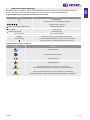 3
3
-
 4
4
-
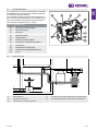 5
5
-
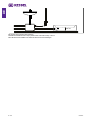 6
6
-
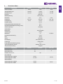 7
7
-
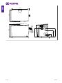 8
8
-
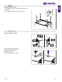 9
9
-
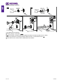 10
10
-
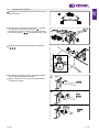 11
11
-
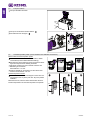 12
12
-
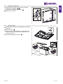 13
13
-
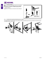 14
14
-
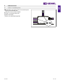 15
15
-
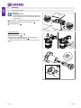 16
16
-
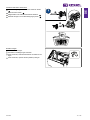 17
17
-
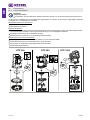 18
18
-
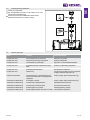 19
19
-
 20
20
-
 21
21
-
 22
22
-
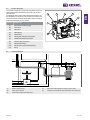 23
23
-
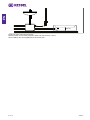 24
24
-
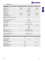 25
25
-
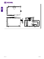 26
26
-
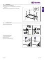 27
27
-
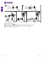 28
28
-
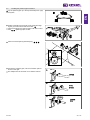 29
29
-
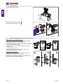 30
30
-
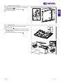 31
31
-
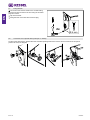 32
32
-
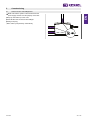 33
33
-
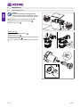 34
34
-
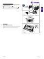 35
35
-
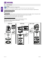 36
36
-
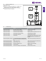 37
37
-
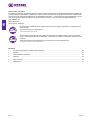 38
38
-
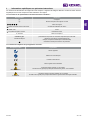 39
39
-
 40
40
-
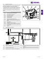 41
41
-
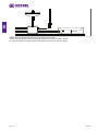 42
42
-
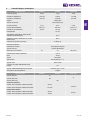 43
43
-
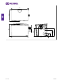 44
44
-
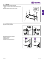 45
45
-
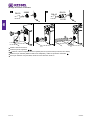 46
46
-
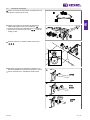 47
47
-
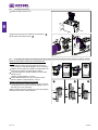 48
48
-
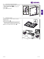 49
49
-
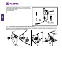 50
50
-
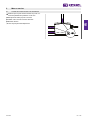 51
51
-
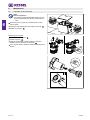 52
52
-
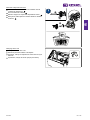 53
53
-
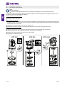 54
54
-
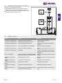 55
55
-
 56
56
-
 57
57
-
 58
58
-
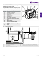 59
59
-
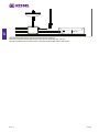 60
60
-
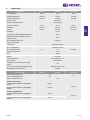 61
61
-
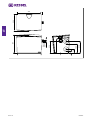 62
62
-
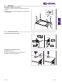 63
63
-
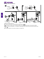 64
64
-
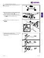 65
65
-
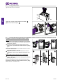 66
66
-
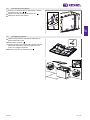 67
67
-
 68
68
-
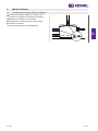 69
69
-
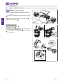 70
70
-
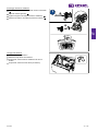 71
71
-
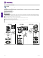 72
72
-
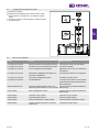 73
73
-
 74
74
-
 75
75
-
 76
76
-
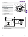 77
77
-
 78
78
-
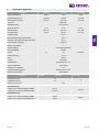 79
79
-
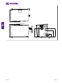 80
80
-
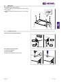 81
81
-
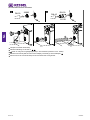 82
82
-
 83
83
-
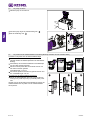 84
84
-
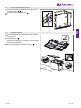 85
85
-
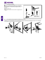 86
86
-
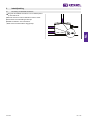 87
87
-
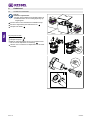 88
88
-
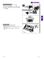 89
89
-
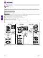 90
90
-
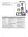 91
91
-
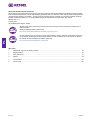 92
92
-
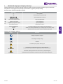 93
93
-
 94
94
-
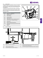 95
95
-
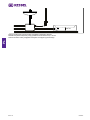 96
96
-
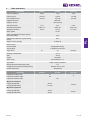 97
97
-
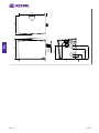 98
98
-
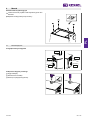 99
99
-
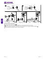 100
100
-
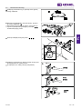 101
101
-
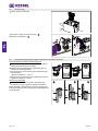 102
102
-
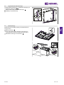 103
103
-
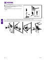 104
104
-
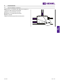 105
105
-
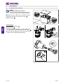 106
106
-
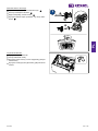 107
107
-
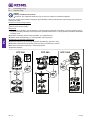 108
108
-
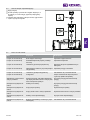 109
109
-
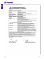 110
110
-
 111
111
-
 112
112
-
 113
113
-
 114
114
-
 115
115
-
 116
116


Kessel 016-307 Minilift S Überflur Installation and Operating Instructions
- Type
- Installation and Operating Instructions
in andere talen
- italiano: Kessel 016-307 Minilift S Überflur
- Deutsch: Kessel 016-307 Minilift S Überflur
- polski: Kessel 016-307 Minilift S Überflur
Gerelateerde artikelen
-
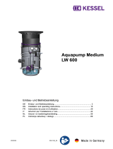 Kessel 328-198 PS Aquapump Medium LW600 Installation and Operating Instructions
-
 Kessel SG 400 V Mono Original Operation Manual
-
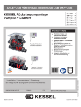 Kessel SPZ 1000 Handleiding
-
 Kessel 016-328 SG Ecolift L 230 V Installation and Operating Instructions
-
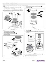 Kessel 016-334 Beiblatt Aktivkohlefilter DN 70 Installation and Operating Instructions
-
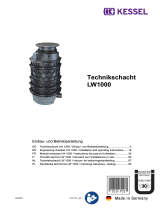 Kessel 010-701 Technikschacht-LW1000 Installation and Operating Instructions
-
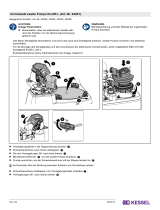 Kessel 016-333 Beiblatt Umrüstsatz für zweite Pumpe Installation and Operating Instructions


Andere documenten
-
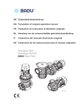 Speck pumpen Block Multi S 125/250 Handleiding
-
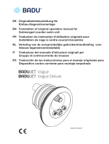 BADU JET Vogue Deluxe Final assembly kit 230 V Handleiding
-
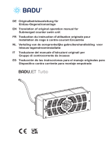 BADU JET Turbo Pro assembly kit design 2 Handleiding
-
Perel Tools Perel 3795-B Handleiding
-
Perel Perel GWP3 Handleiding
-
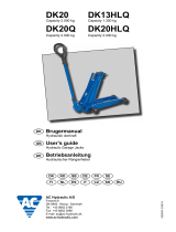 AC Hydraulic DK20 Handleiding
-
SFA SANIFOS 500 Series Installation Instructions Manual
-
Pentair JUNG PUMPEN BAUFIX 100 Handleiding
-
Bosch Aquatak Clic 135 de handleiding
-
Homa TP 28 Original Instruction Manual


