
nVent.com/RAYCHEM | 1
Connection and Splice Kit for Polymer Insulated (PI) Series
Heating Cable
Anschluss- und Verbindungsgarnitur für Polymerisolierte
Heizleitungen (PI)
Kit de connexion et de jonction pour cable série a isolation
polymère (PI)
Aansluitset en verbindingsmof voor kunststof seriële
verwarmingskabel (PI)
CS-150-UNI-PI (CW-C/S-150)

2 | nVent.com/RAYCHEM
NVENT RAYCHEM CS-150-UNI-PI
(CW-C/S-150)
CS-150-UNI-PI:
PTB 09 ATEX 1067 U
II 2 G Ex eb IIC Gb
II 2 D Ex tb IIIC Db IP66
IECEx PTB 09.0042U
Ex eb IIC Gb
Ex tb IIIC Db IP66
XPF, XPI & XPl-S
System Approval:
PTB 08 ATEX 1102X
II 2 G Ex eb 60079-30-1 IIC T2 ... T6 Gb
II 2 D Ex tb 60079-30-1 IIIC T260 ... T90°C Db
IECEx PTB 08.0051X
Ex eb 60079-30-1 IIC T2 ... T6 Gb
Ex tb 60079-30-1 IIIC T260 ... T90°C Db
XPF, XPI & XPl-S
Bulk:
Baseefa15ATEX0158U
II 2 G Ex 60079-30-1 IIC Gb
II 2 D Ex 60079-30-1 IIIC Db
IECEx BAS 15.0105U
Ex 60079-30-1 IIC Gb
Ex 60079-30-1 IIIC Db
TC RU C-BE.ИМ43.В.01854
Ex e II Gb U
Ex tb IIIC Db U
Ta –55°C…+180°C
ООО “ТехИмпорт”
Special conditions for safe use:
1 The components of the connection system, nVent
RAYCHEM type CS-150-UNI-PI (CW-C/S-150), are
used for installation with single core plastic-insulated
heating conductors.
2 Only heating conductors should be used that are
provided with a separate EC type examination
certificate ("ATEX generation"). The installation
instructions and technical data provided have to be
considered.
3 The manufacturer shall prove that suitable measures
have to be taken to safeguard safe and permanent
clamping of heating conductors of a small cross
section.
4 The temperature class of each heat-tracing system
shall be established separately.
5 The specific heating rate of the heating system shall
be established with due regard to the voltage and
spec. conductor resistance variations. Due regard
shall also be given to the permissible current ratings.
6 The connecting cable(s) shall be selected with due
regard, above all, to the max. current rating, the
permissible diameter of the rubber gaskets and the
temperature conditions.
7 The required rubber gaskets shall be selected on
the basis of the specifications in these installation
instructions.
8 The cables connected to the kit shall be secured on
both sides of the kit to permanently provide pull out
protection.
Rated insulation voltage
(between L and PE, and L and N)
Variants S and C: 750 V
Variant L: 420 V
Max allowed current: (continuous)
Variant S: 32 A
Variant C with 1 x 2.5 mm
2
cold lead 25 A
Variant C with 1 x 4 mm
2
cold lead 32 A
Variant L with 3 x 2.5 mm
2
cold lead 25 A
Maximum operating temperature:
180°C power on
200°C power off
(Variant L is dependant on the type of cold lead used:
e.g. 200°C for Silicon cold lead, unless the 3 core cold
lead is installed away from the surface to be heated,
such that the limiting temperature of the cold lead is not
exceeded)
Ambient Temperature:
–50°C to +40°C (–58°F to +104°F)
Storage and transportation
Store and transport product in a clean, dry place
Store and transport at temperatures between –55°C
and +40°C
Protect product from moisture, direct sunlight and
mechanical damage
ATTENTION: to avoid danger of electrical shock or
fire, the product must be installed in accordance with
these instructions.
Ingress of moisture has to be avoided before and
duringinstallation.
RCD’s are required for all heating circuits. Read
instructions completely before starting installation.
Thisproduct does not require maintenance. Damaged
units shall be replaced. Do not use other parts or
ducttape.
Avoid eye contact with lubricant.
Respect the safety data sheet.
ENGLISH


4 | nVent.com/RAYCHEM
DEUTSCH
CS-150-UNI-PI:
PTB 09 ATEX 1067 U
II 2 G Ex eb IIC Gb
II 2 D Ex tb IIIC Db IP66
IECEx PTB 09.0042U
Ex eb IIC Gb
Ex tb IIIC Db IP66
XPF, XPI & XPl-S
System
Zulassung:
PTB 08 ATEX 1102X
II 2 G Ex eb 60079-30-1 IIC T2 ... T6 Gb
II 2 D Ex tb 60079-30-1 IIIC T260 ... T90°C Db
IECEx PTB 08.0051X
Ex eb 60079-30-1 IIC T2 ... T6 Gb
Ex tb 60079-30-1 IIIC T260 ... T90°C Db
XPF, XPI & XPl-S
Meterware:
Baseefa15ATEX0158U
II 2 G Ex 60079-30-1 IIC Gb
II 2 D Ex 60079-30-1 IIIC Db
IECEx BAS 15.0105U
Ex 60079-30-1 IIC Gb
Ex 60079-30-1 IIIC Db
TC RU C-BE.ИМ43.В.01854
Ex e II Gb U
Ex tb IIIC Db U
Ta –55°C…+180°C
ООО “ТехИмпорт”
Besondere Bedingungen für den sicheren Einsatz:
1 Die Komponenten des Anschluß- und
Verbindungssystems Typ nVent RAYCHEM
CS-150-UNI-PI (CW-C/S-150) dienen zur Errichtung
von Begleitheizsystemen mit einadrigen
kunststoffisolierten Heizleitungen.
2 Zum Einsatz kommen nur Heizleitungen mit separater
EG-Baumusterprüfbescheinigung („ATEX-Generation").
Die betreffenden Errichtungshinweise sowie
technischen Daten sind zu beachten.
3 Der Hersteller hat den Nachweis zu führen, dass durch
geeignete Maßnahmen die sichere und dauerhafte
Klemmung der Heizleiter mit geringem Querschnitt
gewährleistet wird.
4 Die Temperaturklasse des jeweiligen
Begleitheizsystems ist separat festzulegen.
5 Die spezielle Heizleistung der Heizsysteme ist jeweils
unter Berücksichtigung der Toleranzen von Spannung
und spez. Leiterwiderstand zu ermitteln. Die max.
zulässigen Bemessungsströme sind zu beachten.
6 Bei der Auswahl der Anschlussleitungen sind
u.a. der max. Bemessungsstrom, der zulässige
Durchmesserbereich (Dichtungsgummi!) und die
Temperaturverhältnisse zu beachten.
7 Die Dichtungsgummis sind gemäß den Vorgaben in
dieser Montageanleitung auszuwählen.
8 Die an den Bausatz angeschlossenen Kabel müssen
auf beiden Seiten des Bausatzes befestigt werden, um
einen dauerhaften Auszugsschutz zu gewährleisten.
Bemessungsisolationsspannung
(zwischen L und PE bzw. N)
Variant S und C: 750 V
Variant L: 420 V
Max. zulässiger Strom (dauernd)
Variant S: 32 A
Variant C mit 1 x 2,5 mm
2
Kaltende: 25 A
Variant C mit 1 x 4 mm
2
Kaltende: 32 A
Variant L mit 3 x 2,5 mm
2
Kaltende: 25 A
Maximale zulässige Ein satztemperatur:
180°C eingeschaltet
200°C ausgeschaltet
(Bei Einsatzvariante L abhängig vom Typ der Zuleitung,
z.B. 200°C für Silikonleitung, es sei denn, die 3-Ader-
Anschlußleitung wird in entsprechendem Abstand
von dem zu beheizenden Gegenstand verlegt, so daß
eine Überschreitung der Grenztemperatur der Leitung
verhindert wird)
Umgebungstemperatur:
–50°C bis +40°C (–58°F bis +104°F)
Lagerung und Transport
Lagern und transportieren Sie das Produkt an/in einem
sauberen und trockenen Ort
Lagern und transportieren bei Temperaturen zwischen
–55°C and +40°C
Schützen Sie das Produkt vor Feuchtigkeit, direkter
Sonneneinstrahlung und mechanischer Beschädigung
ACHTUNG: Zur Vermeidung von elektrischem Schlag
und Bränden muß dieses Produkt vorschriftsmäßig
montiert werden. Das Eindringen von Feuchtigkeit muß
vor und während der Montage vermieden werden.
Alle Heizkreise müssen über FI-Schutzschalter
abgesichert werden. Lesen Sie die Montage anleitung
sorgfältig und vollständig, bevor Sie mit der Montage
beginnen. Benutzen Sie keine fremden Teile und kein
Isolierband.
Wartung: Nicht erforderlich. Beschädigte Teile müssen
ausgetauscht werden. Vermeiden Sie Augenkontakt mit
dem Schmiermittel.
Beachten Sie das Sicherheitsdatenblatt.

nVent.com/RAYCHEM | 5
FRANÇAIS
CS-150-UNI-PI:
PTB 09 ATEX 1067 U
II 2 G Ex eb IIC Gb
II 2 D Ex tb IIIC Db IP66
IECEx PTB 09.0042U
Ex eb IIC Gb
Ex tb IIIC Db IP66
XPF, XPI & XPl-S
Agrément
Système:
PTB 08 ATEX 1102X
II 2 G Ex eb 60079-30-1 IIC T2 ... T6 Gb
II 2 D Ex tb 60079-30-1 IIIC T260 ... T90°C Db
IECEx PTB 08.0051X
Ex eb 60079-30-1 IIC T2 ... T6 Gb
Ex tb 60079-30-1 IIIC T260 ... T90°C Db
XPF, XPI & XPl-S
Câble en vrac:
Baseefa15ATEX0158U
II 2 G Ex 60079-30-1 IIC Gb
II 2 D Ex 60079-30-1 IIIC Db
IECEx BAS 15.0105U
Ex 60079-30-1 IIC Gb
Ex 60079-30-1 IIIC Db
TC RU C-BE.ИМ43.В.01854
Ex e II Gb U
Ex tb IIIC Db U
Ta –55°C…+180°C
ООО “ТехИмпорт”
Conditions spéciales pour une utilisation sûre :
1 Les composants du système de connexion, type
nVent RAYCHEM CS-150-UNI-PI (CW-C/S-150), sont
utilisés pour l'installation de câbles chauffants séries
à isolation polymère.
2 Seuls des câbles chauffants approuvés avec un
certificat CE de type ("Génération ATEX") seront
utilisés. Les instructions d'installation et les données
techniques devront être considérées et appliquées.
3 Le fabricant devra prouver que des mesures
adéquates seront mises en œuvre de façon à ce que
les conducteurs chauffants de petites tailles soient
connectés et maintenus fixés de manière sûre et
permanente.
4 La classe de température de chaque câble chauffant
doit être déterminée séparément.
5 La charge spécifique du système chauffant doit être
déterminée et vérifiée en fonction des variations de
résistance et de tension. De manière identique, les
calibres des courants autorisés devront être vérifiés.
6 Les câbles chauffants connectés devront être
déterminés en fonction des courants maximum
autorisés, des diamètres possibles et autorisés au
niveau des joints et des conditions de température.
7 Les joints d'étanchéité devront être sélectionnés sur la
base des spécifications données dans les conditions
d'installation.
8 Les câbles raccordés au kit doivent être fixés des
deux côtés du kit pour assurer une protection
permanente contre l’arrachement.
Tension d’isolement :
(entre L et PE, ou L et N)
Variante S et C : 750 V
Variante L : 420 V
Courant maximum admis : (en continu)
Variante S : 32 A
Variante C avec sortie froide 1 x 2.5 mm
2
: 25 A
Variante C avec sortie froide 1 x 4 mm
2
: 32 A
Variante C avec câble sortie froide 3 x 2.5 mm
2
: 25 A
Températures maximales d’utilisation :
180°C sous tension
200°C hors tension
(Les données pour la variante L dépendent du type de
sortie froide utilisée : ex : 200°C pour une sortie froide
silicone, à moins que les trois câbles ne soient installés
à distance de la surface à chauffer, de telle façon que
le température limite de la sortie froide ne soit pas
dépassée).
Température ambiante :
–50°C à +40°C (–58°F à +104°F)
Stockage et transport
Entreposer et transporter le produit dans un endroit
propre et sec
Stockage et transport à des températures comprises
entre –55°C et +40°C
Protegez le produit de l’ humidité, de la lumiere directe du
soleil et des dommages mécaniques
ATTENTION: de façon à éviter tout danger électrique
par contact ou feu, les produits doivent être installés
en conformité avec ces instructions. La pénétration
d’humidité doit être évitée avant et pendant l’installation.
Les protections différentielles sont requises pour tous
les circuits.
Lire entièrement ces instructions avant le début de tous
travaux. Ce produit ne requiert pas de maintenance.
Lespièces endommagées doivent être remplacées.
Nepas utiliser d’autres pièces ou des adhésifs PVC.
Eviter tout contact du composé silicone avec les yeux.
Respecter les informations de la fiche de sécurité.

6 | nVent.com/RAYCHEM
NEDERLANDS
CS-150-UNI-PI:
PTB 09 ATEX 1067 U
II 2 G Ex eb IIC Gb
II 2 D Ex tb IIIC Db IP66
IECEx PTB 09.0042U
Ex eb IIC Gb
Ex tb IIIC Db IP66
XPF, XPI & XPl-S
Systeem goed-
keuring:
PTB 08 ATEX 1102X
II 2 G Ex eb 60079-30-1 IIC T2 ... T6 Gb
II 2 D Ex tb 60079-30-1 IIIC T260 ... T90°C Db
IECEx PTB 08.0051X
Ex eb 60079-30-1 IIC T2 ... T6 Gb
Ex tb 60079-30-1 IIIC T260 ... T90°C Db
XPF, XPI & XPl-S
Bulk kabel:
Baseefa15ATEX0158U
II 2 G Ex 60079-30-1 IIC Gb
II 2 D Ex 60079-30-1 IIIC Db
IECEx BAS 15.0105U
Ex 60079-30-1 IIC Gb
Ex 60079-30-1 IIIC Db
TC RU C-BE.ИМ43.В.01854
Ex e II Gb U
Ex tb IIIC Db U
Ta –55°C…+180°C
ООО “ТехИмпорт”
Speciale voorwaarden voor veilig gebruik:
1 De componenten van het aansluitsysteem, nVent
RAYCHEM CS-150-UNI-PI (CW-C/S-150), worden
gebruikt voor de installatie met enkeladerige kunststof
geïsoleerde verwarmingskabels.
2 Alleen verwarmingskabels voorzien van een apart CE
testcertificaat ("ATEX generation") mogen gebruikt
worden. De installatie instructies en technische
informatie die wordt verstrekt dient in acht te worden
genomen.
3 De fabrikant verbindt zich ertoe om duidelijke instructies
te voorzien met betrekking tot het veilig aansluiten
van hoogohmige verwarmingskabels en zodoende een
permanente verbinding te garanderen.
4 De temperatuursklasse van ieder verwarmingssysteem
dient apart te worden bepaald.
5 Het specifieke vermogen van het verwarmingssysteem
dient te worden bepaald aan de hand van de spanning
en de geleider weerstand variaties. Tevens dient de
max. toegelaten stroom in ogenschouw te worden
genomen.
6 De selectie van de aansluitkabel wordt bepaald door
de maximale stroom, de toelaatbare kabeldiameter
(rubberafdichting)en de temperatuurscondities.
7 De vereiste rubber afdichtingen dienen te worden
gekozen overeenkomstig de specificaties in de
installatie instructies.
8 De kabels die met de kit zijn verbonden, moeten
aan beide zijden van de kit worden bevestigd als
permanente bescherming tegen het uittrekken.
Toelaatbare spanning
(tussen L en PE en tussen L en N)
Variant S en C: 750 V
Variant L: 420 V
Max. toelaatbare stroom: (continu)
Variant S: 32 A
Variant C met 1 x 2.5 mm
2
koudeinde: 25 A
Variant C met 1 x 4 mm
2
koudeinde: 32 A
Variant L met 3 x 2.5 mm
2
koudeinde: 25A
Maximum temperatuur bereik:
180°C onder spanning
200°C spanningsloos
(Bij variant L is het temperatuur bereik afhankelijk van
het toegepaste koudeinde: bijv. 200°C voor een silicone
kabel tenzij kabel zelf niet wordt blootgesteld aan het te
verwarmen oppervlak zodat de limiet temperatuur van de
kabel niet wordt overschreden.)
Omgevingstemperatuur:
–50°C tot 40°C
Bewaring en transport
Bewaar en transporteer het produkt in een propere,
droge plaats
Bewaar en transporteer bij temperaturen tussen –55°C
en +40°C
Bescherm het produkt tegen vocht, direkt zonlicht en
mechanische schade
LET OP: Ter voorkoming van elektrische schokken
of brand moet het product altijd volgens de installatie
instructies worden gemonteerd. Binnendringen van vocht
voor of tijdens de montage dient te worden voorkomen.
Aardlekschakelaars zijn verplicht voor alle
verwarmingscircuits.
Lees de instructies aandachtig door, alvorens de
werkzaamheden te beginnen.
Dit onderdeel heeft geen onderhoud nodig. Beschadigde
exemplaren dienen te worden vervangen. Gebruik geen
andere onderdelen of tapes. Vermijd contact met silicone
en de ogen. Neem de aanwijzigen van Safety Data Sheet
in aanmerking.

nVent.com/RAYCHEM | 7
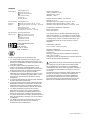
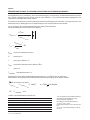
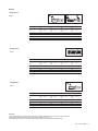
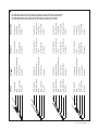
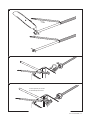
Configuration L
Configuration S
1 x 2,5 mm
2
I max = 25A
1 x 4 mm
2
I max = 32A
I max = 32A
T < 150°C I max = 25 A
T < 180°C I max = 20 A
The CS-150-UNI-PI can be used in different configurations
Für den CS-150-UNI-PI gibt es drei Einsatz-Varianten
Le CS-150-UNI-PI peut être utilisé sous différentes configurations
De CS-150-UNI-PI kan in verschillende configuraties worden toegepast.

8 | nVent.com/RAYCHEM
ENGLISH
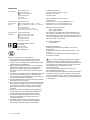
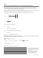
A. Cold lead selection:
Use the CS-150-UNI-PI either with:
Power cable, 3 x 2.5 mm2 (e.g. C-150-PC) or temperature
resistant single core- or cold lead cable 1 x 2.5 mm
2
or 1 x 4 mm
2
(e.g. XPI-7, XPI-S-7 or XPI-4.4)
Note: It is possible to use armored power cable with 3 cores.
Earthing of the armouring to be done at the power supply end
(e.g. at the junction box.)
The performance and dimensions of the power cable, taking
into account the manufacturer's specification, must be selected
in accordance with the thermal, electrical and mechanical
requirements of the application.
DEUTSCH
A. Anschlußleitung
Verwendung des CS-150-UNI-PI mit:
Temperaturbeständiger Anschlussleitung 3 x 2,5 mm
2
(z.B.
C-150-PC) oder Einader-Kaltleitung 1 x 2,5 mm
2
oder 1 x 4 mm
2
(z.B. XPI-7, XPI-S-7 oder XPI-4.4).
Bemerkung: Auch armierte dreiadrige Kabel können ver wen-
det werden, soweit PE als Ader mitgeführt wird. Die Schirmung
sollte an der Ein spei sungs sei te, z.B. am Anschlußkasten auf ge-
legt werden. Qualität und Lei ter quer schnitt der An schluß lei tung
sind - unter Beachtung der ein schlä gi gen Bestimmungen sowie
der Her stell er an ga ben - entsprechend den thermischen,
elek tri schen und me cha ni schen Anforderungen im E
insatzbereich aus zuwäh len.
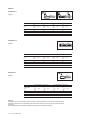
3 x 2.5 mm
2
min Ø = 7.8 mm
max Ø = 12.5 mm
min Ø = 3.2 mm
max Ø = 6.4 mm
1 x 2.5 mm
2
1 x 4 mm
2
Configuration L Configuration C
FRANÇAIS
A. Sélection de la sortie froide :
Utiliser le CS-150-UNI-PI soit avec :
Câble de puissance, 3x 2.5 mm
2
(ex : C-150-PC) ou un câble de
sortie froide unifilaire 1 x 2.5 mm
2
ou 1 x 4 mm
2
(ex : XPI-7, XPI-S-7 ou XPI-4.4)
Note: Il est possible d’utiliser des câbles de puissance armés
avec 3 conducteurs.
La mise à la terre de l’armure doit être réalisée du côté de
l’alimentation (ex : boite de jonction.) Les dimensions et les
caractéristiques du câble de puissance, prenant en compte
les spécifications du fabricant, doivent être sélectionnés
en conformité avec les requis mécaniques, électriques et
thermiques de l’application
NEDERLANDS
A. Selectie van koud einde:
Gebruik de CS-150-UNI-PI met de volgende kabels:
Voedingskabel, 3x2.5mm
2
(bijv C-150-PC) of
temperatuursbestendige enkel aderige kabel 1x2.5 mm
2
of
1x4mm
2
(bijv XPI-7, XPI-S-7 of XPI-4.4)
Opmerking: Het is mogelijk drie aderige bewapende kabel
te gebruiken. Aarding van de bewapening vindt dan plaats
aan de voedingszijde (bv voedingsdoos). De kwalificaties en
afmetingen van de voedingskabel moeten worden bepaald
aan de hand van de thermische, elektrische en mechanische
eigenschappen van de toepassing, controleer kabel specificaties
van de leverancier.

nVent.com/RAYCHEM | 9
VERIFICATION OF THE MAXIMUM PERMITTED POWER OUTPUT AND CURRENT
The heat-tracing system has to be built in such a way that under consideration of voltage and resistance tolerances
the max currents, given in table 1, and the max specific power outputs, given in tables 2, 3, and 4 (depending on variant
inuse) are NOT exceeded.
The specific power output of a single conductor polymer insulated heating cable has to be calculated considering of
the maximum voltage and minimum resistance for a given circuit length, using the formulas shown below.
To design such a heating system, nVent offers state of the art software (Trace Calc Pro) and detailed design guides.
Please contact nVent for more information.
p
spec
max
=
U
2
max
W
r
spec
min
(hot)
l
2
m
I
max
=
p
spec
max
l
[A]
U
max
p
spec
Specific power in W/m
U Voltage in V
l Length of heating cable in m
r
spec
Specific resistance of heating cable in Ω/m
I Current in A
T
conducteur
Conductor temperature in °C
Remark: For heating cables with conductors with a temperature dependent resistance (e.g. copper or copper alloy
conductors), the specific resistance will be calculated for the relevant use temperature, using the α-factor.
Temperature dependent resistance conductors:
r
spec
min
hot
= r
spec
min
cold
(1 + α∆T) α = 0,004
1
pour cuivre
K
∆T = T
conductor
–20°C
Table 1 Maximum current for each variant
ENGLISH
* for temperature related
reduction factors, see relevant
manufacturersdata.
Recommendation for selection of cold
lead:
1 x 2.5 mm
2
and 1x 4 mm
2
withstand
temp. up to 260°C (e.g. PTFE)
3 x 2.5 mm
2
withstand temp.
(e.g.Silicon up to 200°C)
Maximum current
Configuration cold lead Max. temperature of use I max*
C (power connection) 1 x 2,5 mm
2
180°C 25 A
C (power connection) 1 x 4 mm
2
180°C 32 A
L (loop) 3 x 2,5 mm
2
150°C 25 A
L (loop) 3 x 2,5 mm
2
180°C 20 A
S (splice) non applicable 180°C 32 A

10 | nVent.com/RAYCHEM
ÜBERPRÜFUNG DER MAX. ZULÄSSIGEN HEIZLEISTUNG UND STROMBELASTBARKEIT
Die Begleitheizung ist so auszuführen, dass unter Berücksichtigung von Spannungs- und Widerstandstoleranzen weder
die in Tabelle 1 angegebenen max. Ströme, noch die in den Tabellen 2, 3, 4 (je nach Einsatzvariante) angegebenen max.
spezifischen Leistungen überschritten werden.
Die spezifische Heizleistung einer PI-Heizleitung wird unter Berücksichtigung der Toleranzen von Spannung (max.) und
Widerstand (min) in Abhängigkeit von der Heizkreislänge mit der nachfolgenden Formel ermittelt.
Für die Auslegung des gesamten Begleitheizsystems stellt nVent ausführliche
Plannungsanleitungen sowie Software zur Verfügung.
p
spez
max
=
U
2
max
W
r
spez
min
(warm)
l
2
m
I
max
=
p
spez
max
l
[A]
U
max
p
spez
spezifische Heizleistung in W/m
U Spannung in V
l Länge des PI Kabels in m
r
spez
spezifischer Widerstand des PI Kabels in Ω/m
I Strom in A
T
Heizleiter
Heizleitertemperatur in °C
Anmerkung: Für die PI Kabel mit Widerstandsmaterial Kupfer (r < 100 Ω/km) wird der spezifische
Widerstand für die entsprechende Einsatztemperatur unter Berücksichtigung des α–Wertes ermittelt:
Nur für Heizleiter aus Kupfer:
r
spez
min
warm
= r
spez
min
kalt
(1 + α∆T) α = 0,004
1
für Kupfer
K
∆T = T
Heizleiter
– 20°C
Tabelle 1 (Strombelastbarheit nach Variant)
DEUTSCH
* Für temperaturbezogene Reduktionsfaktoren
der zulässigen Strombelastung sind die
Herstellerangabenmaßgeblich.
Empfehlung zur Auswahl der Kaltleitung:
1 x 2,5 mm
2
und 1 x 4 mm
2
temperaturbeständig bis 260°C z.B. PTFE oder
PFA
3 x 2,5 mm
2
temperaturbeständig, z.B. Silicon
bis 200°C.
Max.strom
Konfiguration Kaltleiter Max. Einsatztemperatur I max*
C (Anschluss) 1 x 2,5 mm
2
180°C 25 A
C (Anschluss) 1 x 4 mm
2
180°C 32 A
L (Schleife) 3 x 2,5 mm
2
150°C 25 A
L (Schleife) 3 x 2,5 mm
2
180°C 20 A
S (Verbindung) nicht zutreffend 180°C 32 A

nVent.com/RAYCHEM | 11
VÉRIFICATION DE LA PUISSANCE MAXIMALE ET DU COURANT MAXIMAL AUTORISÉ.
Le système de traçage doit être conçu de façon à ce que sous les tolérances de la tension et de la résistance, les
courants maximum donnés dans le tableau 1 et les puissances spécifiques maximum donnés dans les tableaux
2, 3 et4 (en fonction de la variante utilisée) ne soient PAS dépassés.
La puissance spécifique d’un câble chauffant unifilaire à isolation polymère doit être calculée en considérant la tension
maximale et la résistance minimale pour un circuit donné, en utilisant les formules ci-dessous.
Pour effectuer cette détermination, nVent propose des guides de calcul détaillés et un logiciel de calcul.
p
spec
max
=
U
2
max
W
r
spec
min
(hot)
l
2
m
I
max
=
p
spec
max
l
[A]
U
max
p
spec
Puissance spécifique en W/m
U Tension en V
l longueur du câble chauffant en m
r
spec
Résistance spécifique du câble chauffant en Ω/m
I Courant en A
T
conducteur
Température du conducteur en °C
Remarque : Pour les câbles chauffants avec des conducteurs cuivre (r < 100 Ω/km), la résistance spécifique sera calculée
pour la température d’utilisation en utilisant le α facteur suivant
Pour conducteurs cuivre seuls :
r
spec
min
hot
= r
spec
min
cold
(1 + α∆T) α = 0,004
1
pour cuivre
K
∆T = T
conducteur
–20°C
Tableau 1 Courant maximal pour chaque variante
FRANÇAIS
* Pour les facteurs de dégrèvement avec la
température, voir les données Constructeur
Recommandation pour la sélection des
sorties froides :
1 x 2.5 mm
2
et 1x 4 mm
2
température
d’exposition jusqu’à +260°C (ex:PTFE)
3 x 2.5 mm
2
température d’exposition
(ex. Silicone jusqu’à 200°C)
Courant maximal
Configuration Sortie froide Temp. Maxi de service I max*
C (connexion puissance) 1 x 2,5 mm
2
180°C 25 A
C (connexion puissance) 1 x 4 mm
2
180°C 32 A
L (boucle) 3 x 2,5 mm
2
150°C 25 A
L (boucle) 3 x 2,5 mm
2
180°C 20 A
S (jonction) non applicable 180°C 32 A

12 | nVent.com/RAYCHEM
CONTROLE VAN HET MAXIMALE VERMOGEN EN STROOM
Het elektrische verwarmingskabel systeem moet zodanig worden gebouwd dat met in ogenschouw van de spanning
en weerstandsvariaties zoals opgegeven in tabel 1 en de specifieke vermogens zoals opgegeven in tabel 2, 3 en 4
(afhankelijk van de toegepaste configuratie) NIET worden overschreden.
Het specifieke vermogen van een enkel aderige kunststof geïsoleerde verwarmingskabel moet worden berekend,
rekening houdend met de maximale spanning en minimale weerstand, volgens onderstaande formules.
Voor ontwerp heeft nVent gedetailleerde onderwerp gidsen en software ter beschikking.
p
spec
max
=
U
2
max
W
r
spec
min
(hot)
l
2
m
I
max
=
p
spec
max
l
[A]
U
max
p
spec
Specifiek vermogen in W/m
U Spanning in V
l Lengte van de verwarmingskabel in m
r
spec
Specifieke weerstand van de verwarmingskabel in Ω/m
I Stroom in A
T
geleider
Geleidertemperatuur in °C
Opmerking: Voor verwarmingskabels met koperen geleiders (r < 100 _/m) zal de specifieke weerstand van de relevante
gebruikstemperatuur moeten worden berekend, gebruik makend van de α-coëfficiënt.
Alleen voor koperen geleiders:
r
spec
min
hot
= r
spec
min
cold
(1 + α∆T) α = 0,004
1
voor koper
K
∆T = T
geleider
–20°C
Tabel 1 Maximum stroom voor iedere configuratie
NEDERLANDS
* voor temperatuur gerelateerde reductie
factors, zie leveranciers data.
Advies voor de selectie van koud einde
1 x 2.5 mm
2
en 1x4 mm
2
temperatuursbereik tot 260°C (bijv PTFE)
3 x 2.5 mm
2
temperatuursbereik tot
200°C (bijv silicone 200°C)
Maximum stroom
Gebruikte configuratie Koudeinde Max toelaatbare temperatuur I max*
C (aansluitset) 1 x 2,5 mm
2
180°C 25 A
C (aansluitset) 1 x 4 mm
2
180°C 32 A
L (lus) 3 x 2,5 mm
2
150°C 25 A
L (lus) 3 x 2,5 mm
2
180°C 20 A
S (mof) niet toepasbaar 180°C 32 A

nVent.com/RAYCHEM | 13
ENGLISH
Attention:
These values apply to polymer insulated (PI) series heating cables from nVent. For the use of this product in
combination with heating cables from other manufacturers contact nVent.
The temperature class of the complete heat-tracing installation must be defined independently.
Configuration C
Table 2
r < 80 Ohm/km (a > 0.0007 1/K) r ≥ 80 Ohm/km (a ≤ 0.0007 1/K)
T Pipe/Tank
(°C)
T3
p
spec (W/m)
max
T2
p
spec (W/m)
max
T3
p
spec (W/m)
max
T2
p
spec (W/m)
max
80 24 24 30 30
120 24 24 25 30
150 15 23 17 30
180 not allowed 15 not allowed 20
Configuration S
Table 3
r < 80 Ohm/km (a > 0.0007 1/K) r ≥ 80 Ohm/km (a ≤ 0.0007 1/K)
T Pipe/Tank
(°C)
T3
p
spec (W/m)
max
T2
p
spec (W/m)
max
T3
p
spec (W/m)
max
T2
p
spec (W/m)
max
80 22 22 30 30
120 22 22 25 30
150 13 22 17 30
180 not allowed 12 not allowed 20
Configuration L
Table 4
r < 80 Ohm/km (a > 0.0007 1/K) r ≥ 80 Ohm/km (a ≤ 0.0007 1/K)
T Pipe/Tank
(°C)
T3
p
spec (W/m)
max
T2
p
spec (W/m)
max
T3
p
spec (W/m)
max
T2
p
spec (W/m)
max
80 24 24 30 30
120 24 24 25 30
150 15 23 17 25
180 not allowed 15 not allowed 15

14 | nVent.com/RAYCHEM
DEUTSCH
Achtung:
Diese Werte sind nur anwendbar für polymerisolierte serielle Heizkabel (PI) von nVent. Bei Verwendung des
Produktes in Kombination mit Heizkabeln anderer Hersteller wenden Sie sich bitte an Ihre zuständige nVent-
Vertretung.
Die Temperaturklasse des gesamten Begleitheizungssystems ist separat festzulegen.
Konfiguration C
Tabelle 2
r < 80 Ohm/km (a > 0.0007 1/K) r ≥ 80 Ohm/km (a ≤ 0.0007 1/K)
T Rohr/Tank
(°C)
T3
p
spez (W/m)
max
T2
p
spez (W/m)
max
T3
p
spez (W/m)
max
T2
p
spez (W/m)
max
80 24 24 30 30
120 24 24 25 30
150 15 23 17 30
180 nicht zulässig 15 nicht zulässig 20
Konfiguration S
Tabelle 3
r < 80 Ohm/km (a > 0.0007 1/K) r ≥ 80 Ohm/km (a ≤ 0.0007 1/K)
T Rohr/Tank
(°C)
T3
p
spez (W/m)
max
T2
p
spez (W/m)
max
T3
p
spez (W/m)
max
T2
p
spez (W/m)
max
80 22 22 30 30
120 22 22 25 30
150 13 22 17 30
180 nicht zulässig 12 nicht zulässig 20
Konfiguration L
Tabelle 4
r < 80 Ohm/km (a > 0.0007 1/K) r ≥ 80 Ohm/km (a ≤ 0.0007 1/K)
T Rohr/Tank
(°C)
T3
p
spez (W/m)
max
T2
p
spez (W/m)
max
T3
p
spez (W/m)
max
T2
p
spez (W/m)
max
80 24 24 30 30
120 24 24 25 30
150 15 23 17 25
180 nicht zulässig 15 nicht zulässig 15

nVent.com/RAYCHEM | 15
FRANÇAIS
Attention :
Ces valeurs s’appliquent pour les câbles chauffants à isolation polymère (PI) de nVent. Dans le cas d’utilisation
avec des câbles chauffants d’autres fabricants contacter nVent.
La classe de température de chaque système de traçage doit être défini séparément.
Configuration C
Tableau 2
r < 80 Ohm/km (a > 0.0007 1/K) r ≥ 80 Ohm/km (a ≤ 0.0007 1/K)
T tuyau/bac
(°C)
T3
p
spec (W/m)
max
T2
p
spec (W/m)
max
T3
p
spec (W/m)
max
T2
p
spec (W/m)
max
80 24 24 30 30
120 24 24 25 30
150 15 23 17 30
180 Non autorisé 15 Non autorisé 20
Configuration S
Tableau 3
r < 80 Ohm/km (a > 0.0007 1/K) r ≥ 80 Ohm/km (a ≤ 0.0007 1/K)
T tuyau/bac
(°C)
T3
p
spec (W/m)
max
T2
p
spec (W/m)
max
T3
p
spec (W/m)
max
T2
p
spec (W/m)
max
80 22 22 30 30
120 22 22 25 30
150 13 22 17 30
180 Non autorisé 12 Non autorisé 20
Configuration L
Tableau 4
r < 80 Ohm/km (a > 0.0007 1/K) r ≥ 80 Ohm/km (a ≤ 0.0007 1/K)
T tuyau/bac
(°C)
T3
p
spec (W/m)
max
T2
p
spec (W/m)
max
T3
p
spec (W/m)
max
T2
p
spec (W/m)
max
80 24 24 30 30
120 24 24 25 30
150 15 23 17 25
180 Non autorisé 15 Non autorisé 15

16 | nVent.com/RAYCHEM
NEDERLANDS
Let op:
Deze waarden zijn van toepassing op kunststof geïsoleerde seriële verwarmingskabels van nVent. Voor gebruik van
dit product met kabels van andere leveranciers contacteer nVent.
De temperatuursklasse van het totale verwarmingssysteem moet apart worden gedefinieerd.
Configuratie C
Tabel 2
r < 80 Ohm/km (a > 0.0007 1/K) r ≥ 80 Ohm/km (a ≤ 0.0007 1/K)
T Buis/Tank
(°C)
T3
p
spec (W/m)
max
T2
p
spec (W/m)
max
T3
p
spec (W/m)
max
T2
p
spec (W/m)
max
80 24 24 30 30
120 24 24 25 30
150 15 23 17 30
180 niet toegestaan 15 niet toegestaan 20
Configuratie S
Tabel 3
r < 80 Ohm/km (a > 0.0007 1/K) r ≥ 80 Ohm/km (a ≤ 0.0007 1/K)
T Buis/Tank
(°C)
T3
p
spec (W/m)
max
T2
p
spec (W/m)
max
T3
p
spec (W/m)
max
T2
p
spec (W/m)
max
80 22 22 30 30
120 22 22 25 30
150 13 22 17 30
180 niet toegestaan 12 niet toegestaan 20
Configuratie L
Tabel 4
r < 80 Ohm/km (a > 0.0007 1/K) r ≥ 80 Ohm/km (a ≤ 0.0007 1/K)
T Buis/Tank
(°C)
T3
p
spec (W/m)
max
T2
p
spec (W/m)
max
T3
p
spec (W/m)
max
T2
p
spec (W/m)
max
80 24 24 30 30
120 24 24 25 30
150 15 23 17 25
180 niet toegestaan 15 niet toegestaan 15

nVent.com/RAYCHEM | 17
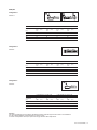
Configuration C
ENGLISH
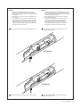
1. Data given by manufacturer of cold lead concerning the
minimum and maximum temperatures of use, including
reduction factors (if given) must be considered during design
and installation.
2. When selecting cross section, maximum voltage drop has to
beconsidered.
3. It is possible that the maximum usage temperature of the
CS-150-UNI-PI will be reduced due to the maximum allowed
usage temperature of the cold lead, unless the cold lead is
installed in sufficient distance away from the surface to be
heated, so that this maximum allowed usage temperature of
thecold lead will not be exceeded.
DEUTSCH
1. Angaben des Herstellers der An schluß lei tung zur minimalen
und maximalen Montage- bzw. Betriebstemperatur inklusive
eventueller Reduktionsfaktoren müssen bei der Planung und
bei der Montage beachtet werden.
2. Bei der Auswahl des Querschnitts ist der max. zulässige
Spannungsfall zu beachten.
3. Die max. Einsatztemperatur von CS-150-UNI-PI kann sich
durch die max. zulässige Dauergebrauchstemperatur
der Zuleitung reduzieren, es sei denn die Zuleitung
wird so verlegt (inausreichendem Abstand von der zu
beheizenden Oberfläche), dass diese max. zulässige
Dauergebrauchstemperatur nicht überschritten wird.
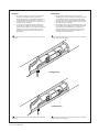
Configuration L
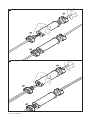
The connected cables must be secured on both sides of the kit.
The connected cables must be secured on both sides of the kit.
Die angeschlossenen Kabel müssen auf beiden Seiten des
Bausatzes befestigt werden.
Die angeschlossenen Kabel müssen auf beiden Seiten des
Bausatzes befestigt werden.

18 | nVent.com/RAYCHEM
Configuration C
NEDERLANDS
1. De specificaties van de fabrikant van koud einde met
betrekking tot minimum en maximum temperaturen inclusief
correctie factoren (indien van toepassing) moeten worden
overwogen bij het ontwerp en de installatie werkzaamheden.
2. Bij het selecteren van de kabeldoorsnede moet de maximale
spanningsval worden overwogen
3. Het is mogelijk dat de maximale gebruikstemperatuur van de
CS-150-UNI-PI wordt verlaagd door de maximaal toelaatbare
temperatuur van het koudeinde tenzij het koudeinde op
voldoende afstand van het te verwarmen oppervlak wordt
bevestigd en de maximale gebruikstemperatuur van het
koudeinde niet wordt overschreden.
Configuration L
FRANÇAIS
1. Les données constructeur concernant les températures
minimales et maximales d’utilisation, incluant les
facteurs de dégrèvement (si applicable) doivent prises en
considération durant la détermination et l’installation
2. Lors de la sélection de la sortie froide, la chute de tension
maximale doit être considérée.
3. Il se peut que la température maximale d’utilisation du
CS-150-UNI-PI soit réduite par celle de la sortie froide,
àmoins que cette dernière ne soit installée à une distance
suffisante de la surface à chauffer de façon à ce que
la température maximale de cette sortie froide ne soit
pasdépassée.
Les câbles raccordés au kit doivent être fixés des deux côtés
du kit.
Les câbles raccordés au kit doivent être fixés des deux côtés
du kit.
De kabels die met de kit zijn verbonden, moeten aan beide zijden
van de kit worden bevestigd.
De kabels die met de kit zijn verbonden, moeten aan beide zijden
van de kit worden bevestigd.


nVent.com/RAYCHEM | 21
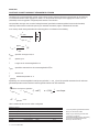
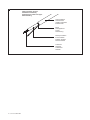
Heizleiter
Schutzgeflecht (metallisch)
Innere Isolation
Schutzmantel
Innere Isolation
Heizleiter
Glasfaser-Geflecht
Schutzmantel
Schutzgeflecht (metallisch)
Innere Isolation
Glasfaser-Geflecht
Glasfaser-Geflecht
Schutzmantel
Schutzgeflecht (metallisch)
Innere Isolation
Schutzgeflecht (metallisch)
Schutzmantel
Polymerfolie
Heizleiter
Heizleiter
DEUTSCH
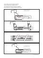
Conductor
Braid
Primary Insulation
Outer Insulation
Primary Insulation
Conductor
Glass fibre braiding
Outer Insulation
Braid
Primary Insulation
Braid
Outer Insulation
Polymeric Foil
Primary Insulation
Glass fibre braiding
Conductor
Glass fibre braiding
Outer Insulation
Braid
Conductor
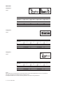
ENGLISH
CS-150-UNI-PI can be used in conjunction with various cable type constructions.
CS-150-UNI-PI kann für verschiedene Kabelkonstruktionen verwendet werden.
CS-150-UNI-PI peut être utilisé avec différentes constructions de câble.
CS-150-UNI-PI kan worden gebruikt op verschillende kabel constructies.
Conducteur
Tresse
Isolation primaire
Isolation extérieure
Isolation primaire
Conducteur
Tresse en fibre de verre
Isolation extérieure
Tresse
Isolation primaire
Tresse
Isolation extérieure
Ruban polymère
Isolation primaire
Tresse en fibre de verre
Conducteur
Tresse en fibre de verre
Isolation extérieure
Tresse
Conducteur
FRANÇAIS
Geleider
Afscherming
Primaire isolatie
Buitenmantel
Primaire isolatie
Geleider
Glasvezel scherm
Buitenmantel
Afscherming
Primaire isolatie
Afscherming
Buitenmantel
Kunststof folie
Primaire isolatie
Glasvezel scherm
Geleider
Glasvezel scherm
Buitenmantel
Afscherming
Geleider
NEDERLANDS
4

22 | nVent.com/RAYCHEM
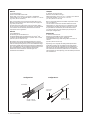
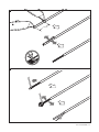
Cable preparation all types
Vorbereitete Heizleitung
Préparation des câbles tous types
Kabel afwerking
Conductor
Heizleiter
Conducteur
Geleider
Braid
Schutzgeflecht
Tresse
Afscherming
Outer Insulation
Schutzmantel
Isolation extérieure
Buitenmantel
Primary Insulation
Innere Isolation
Isolation primaire
Primaire isolatie
5


28 | nVent.com/RAYCHEM
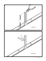
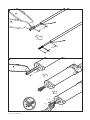
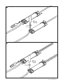
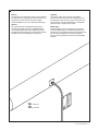
The connected cables must be secured on both
sides of the kit.
Die angeschlossenen Kabel müssen auf beiden
Seiten des Bausatzes befestigt werden.
Les câbles raccordés au kit doivent être fixés
des deux côtés du kit.
De kabels die met de kit zijn verbonden, moeten
aan beide zijden van de kit worden bevestigd.
Ø 5-13 mm IEK-20-PI
Ø 8-17 mm IEK-25-04
3 x 2.5 mm
2
1 x 2.5 mm
2
1 x 4 mm
2
13
14
15

nVent.com/RAYCHEM | 29
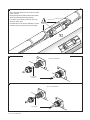
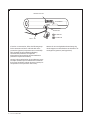
ENGLISH
The type plate for the heating system (not included in
this kit) has to be completed at commissioning and
attached to the cold lead at the power supply.
Actual installation has to be compared with design.
DEUTSCH
Das Typenschild für die Begleitheizung (nicht in
der Garnitur enthalten) ist bei der Inbetriebnahme
zu vervollständigen und an der Kaltleitung auf der
Einspeisungsseite anzubringen, dabei ist die aktuelle
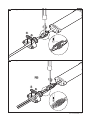
Installation mit der Auslegung zu vergleichen.
: PI-LABEL-EX
: PI-LABEL-NH
FRANÇAIS
L’étiquette de type pour le système chauffant
(non inclus dans ce kit) doit être complétée lors de
la vérification avant mise en service et attachée à la
sortie froide du côté de l’alimentation. L’installation
réelle doit être comparée avec l’étude.
NEDERLANDS
Identificatielabel voor het verwarmingscircuit (niet
in deze kit bijgesloten) moet worden ingevuld bij in
gebruikname en worden bevestigd aan het koudeinde
van de verwarmingskabel. De actuele installatie
dient te worden geverifieerd met het oorspronkelijke
ontwerp.
16

30 | nVent.com/RAYCHEM
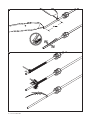
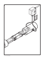
17
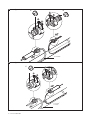
If used as a connection kit, follow the following steps
for the termination of the PI cold lead cable in the
junction box (optional, components are not included).
Falls die Muffe für eine Kaltleiter-Verbindung
verwendet wird, finden Sie im Folgenden
Informationen zum Anschluss im Klemmenkasten
(Zubehör ist separat zu bestellen).
Lorsque le kit est utilisé en kit de raccordement, suivre
les étapes suivantes pour la réalisation de l’extrémité
de la sortie froide dans la boite de jonction (option, les
composants ne sont pas inclus dans ce kit).
Wanneer de set wordt gebruikt als aansluiting volg
dan de stappen voor het afwerken van de kabel in de
voedingsdoos (optioneel, niet bijgesloten).
IEK-20-PI
C20-PI-..-KIT
CS-150-UNI-PI
LAB-SPLICE-CS-150
: PI-LABEL-EX
: PI-LABEL-NH

nVent.com/RAYCHEM | 31
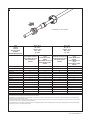
18
C20-PI-PA-KIT or C20-PI-M0-KIT
Cold
lead ref
Leitertyp
Réf. sortie froide
draadref.
Холодный ввод кабеля
Up to –40°C
Bis –40 °C
Jusqu’à –40 °C
Min. –40°C
до –40°C
Up to –55C
Bis –55 °C
Jusqu’à –55 °C
Min. –55°C
до –55C
C20-PI-PA-KIT with insert
C20-PI-PA-KIT mit Einsatz
C20-PI-PA-KIT avec insert
C20-PI-PA-KIT met
reductie
C20-PI-PA-KIT without
insert
C20-PI-PA-KIT ohne
Einsatz
C20-PI-PA-KIT sans insert
C20-PI-PA-KIT zonder
reductie
C20-PI-M0-KIT with insert
C20-PI-M0-KIT mit Einsatz
C20-PI-M0-KIT avec insert
C20-PI-M0-KIT met
reductie
C2O-PI-M0-KIT without
insert
C2O-PI-M0-KIT ohne
Einsatz
C2O-PI-M0-KIT sans
insert
C2O-PI-M0-KIT zonder
reductie
XPI-F-7 √ X √ X
XPI-F-4.4 √ X √ X
XPI-F-2.9 √ X √ X
XPI-F-1.8 X √ X √
XPI-7 √ X √ X
XPI-4.4 √ X √ X
XPI-2.9 √ X √ X
XPI-1.8 X √ √ X
XPI-1.1 X √ X √
XPI-0.8 X √ X √
XPI-S-7 √ X √ X
XPI-S-4.4 √ X √ X
XPI-S-2.9 √ X √ X
XPI-S-1.8 X √ √ X
XPIS-1.8 X √ X √
XPI-S-0.8 X √ X √
* The C20-PI-M0-KIT should be used with junction boxes with an earth plate or separately grounded with a lug.
(A grounding lug is not included in the kit and should be purchased separately)
* C20-PI-M0-KIT muss mit Anschlusskästen mit Erdungsplatte verwendet oder mit einem eigenen Erdungsanschluss versehen werden. (Der Erdungsanschluss ist in der Garnitur nicht
inbegriffen und muss separat erworben werden.)
* Le kit C20-PI-M0-KIT s’utilise avec des boîtes de raccordement équipées d’une plaque de mise à la terre ou est raccordé à la terre séparément au moyen d’une cosse. (Le kit ne contient
pas de cosse de mise à la terre ; elle doit être achetée séparément.)
* De C20-PI-M0-KIT moet in combinatie met aansluitdozen met een aardingsklem gebruikt worden of afzonderlijk geaard worden met een verbindingslip. (Een aardingsverbindingslip is
niet inbegrepen in de set en moet apart gekocht worden)


North America
Tel +1.800.545.6258
Fax +1.800.527.5703
België/Belgique
Tel +32 16 21 35 02
Fax +32 16 21 36 04
Bulgaria
Tel +359 5686 6886
Fax +359 5686 6886
Česká Republica
Tel +420 606 069 618
Danmark
Tel +45 70 11 04 00
Deutschland
Tel 0800 1818205
Fax 0800 1818204
España
Tel +34 911 59 30 60
Fax +34 900 98 32 64
France
Tel 0800 906045
Fax 0800 906003
Hrvatska
Tel +385 1 605 01 88
Fax +385 1 605 01 88
Italia
Tel +39 02 577 61 51
Fax +39 02 577 61 55 28
Lietuva/Latvija/Eesti
Tel +370 5 2136633
Fax +370 5 2330084
Magyarország
Tel. +36 1 253 7617
Fax +36 1 253 7618
Nederland
Tel 0800 0224978
Fax 0800 0224993
Norge
Tel +47 66 81 79 90
Österreich
Tel. 0800 29 74 10
Fax 0800 29 74 09
Polska
Tel +48 22 331 29 50
Fax +48 22 331 29 51
Republic of Kazakhstan
Tel. +7 7122 32 09 68
Fax +7 7122 32 55 54
Россия
Тел +7 495 926 18 85
Факс +7 495 926 18 86
Serbia and Montenegro
Tel +381 230 401 770
Fax +381 230 401 770
Schweiz/Suisse
Tel. +41 (41) 766 30 80
Fax +41 (41) 766 30 81
Suomi
Puh 0800 11 67 99
Sverige
Tel +46 31 335 58 00
Türkiye
Tel +90 560 977 6467
Fax +32 16 21 36 04
United Kingdom
Tel 0800 969 013
Fax 0800 968 624
©2021 nVent. All nVent marks and logos are owned or licensed by nVent Services GmbH or its affiliates. All other trademarks are the property of their respective owners.
nVent reserves the right to change specifications without notice.
RAYCHEM-IM-INSTALL064-CS150UNIPI-ML-2102 PCN 1244-000067
nVent.com/RAYCHEM
-
 1
1
-
 2
2
-
 3
3
-
 4
4
-
 5
5
-
 6
6
-
 7
7
-
 8
8
-
 9
9
-
 10
10
-
 11
11
-
 12
12
-
 13
13
-
 14
14
-
 15
15
-
 16
16
-
 17
17
-
 18
18
-
 19
19
-
 20
20
-
 21
21
-
 22
22
-
 23
23
-
 24
24
-
 25
25
-
 26
26
-
 27
27
-
 28
28
-
 29
29
-
 30
30
-
 31
31
-
 32
32
-
 33
33
-
 34
34
-
 35
35
-
 36
36


in andere talen
Gerelateerde papieren
-
Raychem et kit de réparation T2Green, T2Blue, T2Blue-Mat, T2Black et QuickNet Installatie gids
-
-
-
-
 nvent Raychem QuickNet Handleiding
-
-
-
-
-

Andere documenten
-
 nVent RAYCHEM S-20 Splice Kit Handleiding
-
WEG Electric motors for explosive atmospheres Handleiding
-
-
Asco Series 298 398 885 Signalling Box de handleiding
-
Dimplex HMR de handleiding
-
STIEBEL ELTRON FTT 160-1120 C Operation Instruction
-
Pentair Raychem T-100 Handleiding
