
GEBRUIKERSHANDLEIDING / USERS MANUAL / BETRIEBSANLEITUNG
MODE D’EMPLOI / MANUAL DE UTILIZACION / INSTRUZIONI PER L’USO
MAGIC
12/12-20, 12/24-10
24/12-20, 24/24-20
DC-DC converter / DC-DC converter / DC-DC Wandler /
convertisseur CC-CC / convertidor CC-CC / convertitore CC-CC
MASTERVOLT
Snijdersbergweg 93,
1105 AN Amsterdam
The Netherlands
Tel.: +31-20-342 21 00
Fax: +31-20-697 10 06 10000002796/03
www.mastervolt.com Copyright © 2018 Mastervolt

ENGLISH
Product description
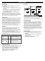
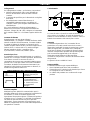
The DC-DC converter MAGIC converts a DC-voltage into
another stabilized DC-voltage with a full galvanic isolation
between the input and output.
Applications
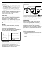
It offers you the following applications (see drawings
“INSTALLATION”):
MAGIC 24/12-20A (part no. 81300100)
• Drawing 1A, 1B: a stabilized 13.6V DC power supply
/ single stage float charger (e.g. to supply 12V
equipment from a 24V system), or
• Drawing 2A, 2B: a three-stage battery charger to
charge a 12V battery from a 24V system fully
automatically, or
• Drawing 3A, 3B: a 24/36 converter without galvanic
isolation, where the input is connected in series with
output.
• Drawing 4: a dimmer for 12V lights
MAGIC 24/24-20A (part no. 81300200)
• Drawing 1A, 1B: a 27.2VDC stabilized DC power
supply / single stage float charger (e.g. for a galvanic
isolation of the vehicle’s electrical system)
• Drawing 2A, 2B: a three-stage battery charger to
charge a 24V battery from a 24V system fully
automatically, or
• Drawing 3A, 3B: a 24/48V converter without galvanic
isolation, where the input is connected in series with
output.
• Drawing 4: a dimmer for 24V lights
MAGIC 12/12-20A (part no. 81300400)
• Drawing 1A, 1B: a 13.6VDC stabilized DC power
supply / single stage float charger (e.g. for a galvanic
isolation of the vehicle’s electrical system)
• Drawing 2A, 2B: a three-stage battery charger to
charge a 12V battery from a 12V system fully
automatically or
• Drawing 4: a dimmer for 12V lights.
MAGIC 12/24-10A (part no. 81300300)
• Drawing 1A, 1B: a 27.2V stabilized DC power supply
/ single stage float charger (e.g. for a galvanic
isolation of the 24V system), or
• Drawing 2A, 2B: a three-stage battery charger to
charge a 24V battery from a 12V system fully
automatically, or
• Drawing 3A, 3B: a 12/36V converter without galvanic
isolation, where the input is connected in series with
output.
Safety regulations and measures
1. Install the converter according to the stated
instructions.
2. Never use the converter at a location where there is
danger of gas or dust explosions.
3. Connections and safety features must be executed
according to the locally applicable regulations.
4. The converter may only be taken into operation while
the cover is closed as lethal voltages may exist.
The converter is provided with a non-replaceable input
fuse. If the plus and minus connections on the battery are
exchanged, the converter will become irreparable.
Do not use fuses larger than those indicated in the
specifications.
Installation
• Be sure that the output of the supplying source is
switched off during installation. Also be sure that no
consumers are connected to the batteries during
installation, to prevent hazardous situations.
• Check that the battery voltage is the same as the
converter’s input voltage (e.g. 24V battery for a 24V
input voltage). Also check that the output voltage
satisfies loading requirements
• Due to possible moisture accumulation and optimal
heat discharge, the converter must be installed in a
well-ventilated room protected against rain, vapour,
moisture and dust. We advise to mount the unit in a
vertical position with the connecting cables downward.
• Integrate a fuse in the positive wiring and place it
nearby the battery. See specifications for the
recommended fuse.
• Do not install the DC-DC converter straight above the
batteries because of possible corrosive sulphur
fumes.
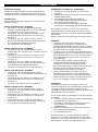
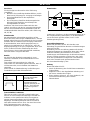
Settings
There is no need to change the settings if the converter is
used as a stabilized DC power supply. Inside the
converter four DIP switches can be found to adjust the
converter according to your personal preferences. (see
table “DIP SWITCH SETTINGS”).
To adjust the DIP switches, proceed as follows:
1. Be sure the converter is disconnected from any
power source;
2. Remove the back cover of the converter by loosen
the four screws (see drawing “DIMENSIONS”);
3. Use a small flat-blade screw driver to change the
DIP-settings;
4. Remount the back cover again.
When more converters are paralleled to increase the total
output current, DIP-switches 1, 2 and 4 must be set to
the “OFF”-position and DIP-switch 3 depended to the
preferred output voltage.

ENGLISH
Connections
For correct connection - see drawings “INSTALLATION”.
• Use reliable cord end terminals to fix the wires to the
DC-input and –output.
• See specifications for the recommended wire size.
• To minimize any EMC-interference we advise to
connect the negative pole of the supplying battery to
the ground.
Connect a momentary switch between the “switch”-
connection and the DC-output ground if you want to use
the remote switch function and/or the light dimmer
function (see drawing 1B, 2B, 3B).
Alarm contact
The alarm contact, right side connection on the back
(see drawings “DIMENSIONS”), is connected to the
contact. The contact is activated and connected to the
output ground in a normal situation, and will be
deactivated if the input voltage is too low (default 10.0V
or 20.0V), if the input voltage is too high (default 16.0V
or 32.0V), in case of overload or short-circuit. The
contact is also deactivated when the MAGIC is switched
off.
Operation
The converter operates automatically. Under normal
circumstances, there is no need for operation. Despite
its low no-load consumption, the converter should be
disconnected from the supplying battery when it is not in
use to protect the battery from discharging.
Refer to table “SWITCH OPERATION” for explanation of
the remote switch function / dimmer operation.
SWITCH OPERATION
Short
Converter switches off.
Press again to switch
on.
Long
After 1 sec. the output
voltage slowly
decreases to 4V or 8V.
Press again to increase
the voltage
Extended functions
Via the “QRS232 communication port” various settings
can be adjusted in terms of software to your specific
demands (control software and interface not included).
Check the Internet site www.mastervolt.com for
applications. Please mind that this plug is not intended
for connecting any remote panels or a battery
temperature sensor.
Battery charger
Three-stage charge curve: Stage A: BULK, for quick
charging from 0 to 80%, Stage B: ABSORPTION, the
battery is charged from 80 to 100%. Stage C: FLOAT,
battery is maintained in fully charged state.
Guarantee terms
Mastervolt guarantees that this converter was built
according to the legally applicable standards and
stipulations. During production and before delivery all
converters were exhaustively tested and controlled. If
you fail to act in accordance with the regulations,
instructions and stipulations in this user’s manual,
damage can occur and/or the converter will not fulfil the
specifications. This may mean that the guarantee will
become null and void.
The guarantee period is 2 years.
Liability
Mastervolt cannot be held liable for:
• Consequential damage resulting from the use of the
converter.
• Possible errors in the included manual and the
consequences of these.
• Use that is inconsistent with the purpose of the
product

NEDERLANDS
Productbeschrijving
De DC-DC converter MAGIC vormt een gelijkspanning
om naar een andere, geregelde gelijkspanning met een
volledige galvanische scheiding tussen de in- en uitgang.
Toepassingen
De converter kan worden toegepast als (zie tekeningen
“INSTALLATION”):
MAGIC 24/12-20A (art. nr. 81300100)
• Tekening 1A, 1B: een gestabiliseerde 13.6VDC
voeding / enkeltraps lader (bijv. voor het voeden van
12V apparatuur uit een 24V boordnet), of
• Tekening 2A, 2B: een drietraps acculader voor het
automatisch laden van een 12V accu uit een 24V
boordnet, of
• Tekening 3A, 3B: een 24/36V converter zonder
galvanische scheiding, waarbij de ingangsspanning
in serie staat met de uitgangsspanning.
• een dimmer voor 12V verlichting.
MAGIC 24/24-20A (art. nr. 81300200)
• Tekening 1A, 1B: een gestabiliseerde 27.2VDC
voeding (bijv. voor een galvanische scheiding van het
boordnet), of
• Tekening 2A, 2B: een drietraps acculader voor het
automatisch laden van een 14V accu uit een 24V
boordnet, of
• Tekening 3A, 3B: een 24/48V converter zonder
galvanische scheiding, waarbij de ingangsspanning
in serie staat met de uitgangsspanning, of
• Tekening 4: een dimmer voor of 24V verlichting.
MAGIC 12/12-20A (art. nr. 81300400)
• Tekening 1A, 1B: een gestabiliseerde 13.6VDC
voeding (bijv. voor een galvanische scheiding van het
boordnet), of
• Tekening 2A, 2B: een drietraps acculader voor het
automatisch laden van een 12V accu uit een 12V
boordnet, of
• Tekening 4: een dimmer voor 12V verlichting.
MAGIC 12/24-10A (art. nr. 81300300)
• Tekening 1A, 1B: een gestabiliseerde 27.2VDC
voeding (bijv. voor het voeden van 24V apparatuur
uit een 12V accu), of
• Tekening 2A, 2B: een drietraps acculader voor het
automatisch laden van een 24V accu uit een 12V
boordnet, of
• Tekening 3A, 3B: een 12/36V converter zonder
galvanische scheiding, waarbij de ingangsspanning
in serie staat met de uitgangsspanning.
Veiligheidsvoorschriften en –maatregelen.
1. Installeer de converter volgens de aangegeven
instructies.
2. Gebruik de converter nooit op een locatie met gas of
stofontploffingsgevaar.
3. Aansluitingen en beveiligingen moeten in
overeenstemming met de plaatselijk geldende
voorschriften worden uitgevoerd.
4. In de converter komen hoge spanningen voor.
Gebruik de converter alleen met gesloten behuizing.
De converter is voorzien van een niet-vervangbare
ingangszekering. Bij verwisseling van de plus- en min
aansluitingen op de accu zal de converter onherstelbaar
defect raken.
Gebruik geen zwaardere zekeringen dan gespecificeerd.
Installatie
• Overtuig u zelf ervan dat de uitgang van de
voedingsbron spanningsloos is gedurende de
installatiewerkzaamheden. Zorg er tevens voor dat er
geen gebruikers zijn aangesloten op de accugroepen
ter voorkoming van onveilige situaties
• Controleer of de accuspanning overeenkomt met de
ingangsspanning van de converter (bijv. een 24V accu
bij een ingangsspanning van 24V). Controleer tevens
of de uitgangsspanning geschikt is voor de aan te
sluiten belasting
• In verband met mogelijke condensvorming en
optimale warmteafvoer, dient u de converter te
installeren in een goed geventileerde ruimte,
beschermd tegen regen, condens, vocht en stof. Wij
adviseren om de converter verticaal, met de
aansluitkabels naar beneden te monteren.
• Neem in de plusleiding een zekering op in de
bedrading en plaats deze zo dicht mogelijk bij de
accu. Zie specificaties voor aanbevolen zekeringen.
• Monteer de DC-DC converter nooit direct boven een
accu i.v.m. mogelijke corrosieve accudampen.
Instellingen
U hoeft de instellingen niet te wijzigen indien u de
converter gebruikt als een gestabiliseerde voeding. In de
converter bevinden zich vier DIP-switches om de
converter naar uw persoonlijke voorkeur in te stellen. (zie
tabel “DIP SWITCH SETTINGS”).
Ga als volgt te werk om instellingen van de DIP switches
te wijzigen:
1. Overtuig uzelf ervan dat de converter op geen enkele
spanningsbron is aangesloten.
2. Verwijder de achterzijde van de behuizing door de
vier schroeven los te draaien (zie tekening
“DIMENSIONS”).
3. Wijzig de instellingen van de DIP-switch met een
kleine platte schroevendraaier.
4. Sluit de behuizing weer.
Wanneer meerdere converters parallel geschakeld
worden voor een grotere uitgangsstroom, dient u DIP-
switches 1,2 en 4 in te stellen op “OFF” en DIP-switch 3
afhankelijk van de gewenste uitgangsspanning.

NEDERLANDS
Aansluitingen
Zie tekeningen “INSTALLATION” voor de juiste wijze
van aansluiten.
• Gebruik deugdelijke adereindhulsen om de
bedrading op de in- en uitgang van de converter aan
te sluiten.
• Zie Specificaties voor aanbevolen draaddiameters.
• Ter vermindering van EMC- interferentie adviseren
wij de negatieve pool van de voedingsaccu te
verbinden met de massa.
U kunt een momentschakelaar tussen de “SWITCH”-
aansluiting en de DC-uitgangsmassa monteren indien u
gebruik wilt maken van de afstandsbedieningschakelaar
of de dimmer functie (zie tekening 1B, 2B, 3B).
Alarm contact
Het alarm contact, rechter aansluiting aan de achterzijde
(zie tekening “DIMENSIONS”), is verbonden met het
contact. Onder normale omstandigheden is het contact
geactiveerd en doorverbonden met de uitgangsmassa.
Het contact wordt geopend indien er een fout optreedt:
de ingangsspanning is te laag (standaard 10.0 of 20.0V),
de ingangsspanning is te hoog (standaard 16.0 of
32.0V), en bij overbelasting of kortsluiting. Het contact is
ook geopend indien de MAGIC uitgeschakeld is.
Bediening
De converter werkt automatisch. Bediening is onder
normale omstandigheden dan ook niet nodig.
Ondanks het lage nullastverbruik dient u de converter
van de accu los te koppelen indien u deze niet gebruikt.
Dit is ter voorkoming van ontlading van de accu.
Zie tabel “SCHAKELAAR BEDIENING” voor een uitleg
van de bediening van de afstandsbedieningschakelaar
of de dimmer functie.
SCHAKELAAR BEDIENING
Kort
1X drukken: converter
schakelt uit. Nogmaals
drukken: converter schakelt
aan.
Lang
Na 1 sec. drukken:
uitgangsspanning vermindert
langzaam tot 4V of 8V.
Nogmaals drukken om de
spanning weer te verhogen.
Uitgebreide functies
Via de “QRS232 communication port” kunnen
softwarematig de diverse instellingen aangepast worden
aan uw specifieke wensen (besturingssoftware en
interface optioneel leverbaar). Zie de internetsite
www.mastervolt.com voor toepassingen. NB: het
aansluiten van een accutemperatuur sensor of
bedieningspanelen is niet mogelijk.
Acculader
Drie-Traps laadkurve: Fase A is Bulk (snelladen). Fase
B is Absorption, waarin de accu van 80 tot 100%
geladen wordt. Fase C is de onderhoudingsfase (Float).
Garantiebepalingen
Mastervolt garandeert dat de converter is gebouwd
volgens de wettelijk van toepassing zijnde normen en
bepalingen. Gedurende de productie en voor aflevering
zijn alle converters uitvoerig getest en gecontroleerd.
Wanneer niet volgens de in deze handleiding gegeven
voorschriften, aanwijzingen en bepalingen wordt
gehandeld, kunnen beschadigingen ontstaan en/of het
apparaat zal niet aan de specificaties voldoen. Een en
ander kan inhouden dat de garantie komt te vervallen.
De garantietermijn is 2 jaar
Aansprakelijkheid
Mastervolt kan niet aansprakelijk worden gesteld voor:
• Gevolgschade ontstaan door het gebruik van de
converter.
• Eventuele fouten in bijbehorende handleiding en de
gevolgen daarvan.
• Ander gebruik geldend als niet conform de
bestemming van het product.

DEUTSCH
Produktbeschreibung
Der DC-DC Wandler MAGIC wandelt eine
Gleichstromspannung in eine andere stabilisierte
Gleichstromspannung um, mit vollständiger galvanischer
Trennung zwischen Eingang und Ausgang.
Anwendungsbereiche
Er kann für folgende Anwendungsbereiche eingesetzt
werden (siehe Zeichnungen „INSTALLATION“):
MAGIC 24/12-20A (Art. Nr. 81300100)
• Zeichnung 1A, 1B: eine stabilisierte 13.6VDC
Stromversorgung / ein einstufiger Erhaltungslader
(z.B. zur Versorgung von 12V Ausrüstung von einem
24V System), oder
• Zeichnung 2A, 2B: ein 3-Stufen-Batterieladegerät
zum vollautomatischen Laden einer 12V Batterie von
einem 24V System, oder
• Zeichnung 3A, 3B: einen 24/36V Wandler ohne
galvanische Trennung, bei dem der Eingang mit dem
Ausgang in Reihe geschaltet ist.
• Zeichnung 4: einen Dimmer für 12V Lampen
MAGIC 24/24-20A (Art. Nr. 81300200)
• Zeichnung 1A, 1B: eine stabilisierte 27.2VDC
Gleichstromversorgung / ein einstufiger
Erhaltungslader (z.B. zur galvanischen Trennung des
elektrischen Systems eines Fahrzeugs)
• Zeichnung 2A, 2B: ein 3-Stufen-Batterieladegerät
zum vollautomatischen Laden einer 24V Batterie von
einem 24V System,
• Zeichnung 3A, 3B: einen 24/48V Wandler ohne
galvanische Trennung, bei dem der Eingang mit dem
Ausgang in Reihe geschaltet ist,
• Zeichnung 4: einen Dimmer für 24V Lampen
MAGIC 12/12-20A (Art. Nr. 81300400)
• Zeichnung 1A, 1B: eine stabilisierte 13.6VDC
Gleichstromversorgung / ein einstufiger
Erhaltungslader (z.B. zur galvanischen Trennung des
elektrischen Systems eines Fahrzeugs),
• Zeichnung 2A, 2B: ein 3-Stufen-Batterieladegerät
zum vollautomatischen Laden einer 12V Batterie von
einem 12V System,
• Zeichnung 4: einen Dimmer für 12V Lampen
MAGIC 12/24-10A (Art. Nr. 81300300)
• Zeichnung 1A, 1B: eine stabilisierte 27.2V
Gleichstromversorgung / ein einstufiger
Erhaltungslader (z.B. zur galvanischen Trennung des
24V Systems), oder
• Zeichnung 2A, 2B: ein 3-Stufen-Batterieladegerät
zum vollautomatischen Laden einer 24V Batterie von
einem 12V System,
• Zeichnung 3A, 3B: einen 12/36V Wandler ohne
galvanische Trennung, bei dem der Eingang mit dem
Ausgang in Reihe geschaltet ist.
Sicherheitsvorschriften und -maßnahmen
1. Installieren Sie den Stromrichter gemäß den
genannten Anweisungen.
2. Benutzen Sie den Gleichrichter nie in einer
Umgebung, in der die Gefahr einer Gas- oder
Staubexplosion besteht.
3. Anschlüsse und Sicherheitsvorkehrungen müssen
den lokalen Vorschriften entsprechend ausgeführt
werden.
4. Der Gleichrichter darf nur mit geschlossenem
Gehäuse in Betrieb genommen werden, da
lebensgefährdende Spannungen anliegen können.
Der Wandler ist mit einer nicht austauschbaren
Eingangssicherung ausgestattet. Wenn die Plus- und
Minus-Anschlüsse der Batterie umgewechselt werden,
kann der Wandler nicht mehr repariert werden.
Verwenden Sie keine größeren Sicherungen als die in
den Spezifikationen angegebenen.
Installation
• Stellen Sie sicher, dass der Ausgang der
Versorgungsquelle während der Installation
ausgeschaltet ist. Es ist ebenfalls wichtig, dass
während der Installation keine Verbraucher an den
Batteriesätzen angeschlossen sind, um gefährliche
Situationen zu vermeiden.
• Stellen Sie vor dem Anschließen sicher, dass die
Spannung der Batterie der Sicherungsspannung des
Gleichrichters entspricht (z. B. eine 24 V Batterie für
eine 24 V Sicherungsspannung). Prüfen Sie
ebenfalls, dass die Ausgangsspannung den
Ladeanforderungen gerecht wird.
• Im Hinblick auf eine eventuelle Ansammlung von
Feuchtigkeit und eine optimale Wärmeableitung
sollten Sie den Gleichrichter in einem gut belüfteten
Raum installieren, geschützt gegen Regen,
Kondenswasser, Feuchtigkeit und Staub. Wir
empfehlen, den Gleichrichter vertikal, mit den
Anschlusskabeln nach unten, zu montieren.
• Schließen Sie eine Sicherung in der Nähe der
Batterie an das Pluskabel an. Siehe Spezifikationen
für die empfohlene Sicherung.
• Montieren Sie den DC-DC Wandler niemals direkt
oberhalb der Batterien, wegen möglicher korrosiver
Batteriedämpfe.
Einstellungen
Es ist nicht erforderlich, die Einstellungen zu verändern,
wenn der Wandler als stabilisierte
Gleichstromversorgung eingesetzt wird. An der
Innenseite des Gleichrichters befinden sich vier DIP-
Schalter, mit denen Sie den Gleichrichter nach Ihren
spezifischen Wünschen einstellen können. (siehe Tabelle
“DIP switch settings”). Um die DIP-Schalter einzustellen,
gehen Sie wie folgt vor.
1. Stellen Sie sicher, dass der Gleichrichter von
jeglicher Stromquelle abgetrennt ist;
2. Schrauben Sie die vier Schrauben an der Rückseite
des Gehäuses auf und entfernen Sie die Rückseite
(siehe Abbildung „Dimensions“);
3. Verwenden Sie einen kleinen flachten
Schraubendreher zur Einstellung der DIP-Schalter;
4. Schließen Sie das Gehäuse wieder.
Wenn mehrere Wandler parallel geschaltet werden, um
den Gesamt-Ausgangsstrom zu erhöhen, müssen die
DIP-Schalter 1, 2 und 4 in die Position „AUS“ gestellt
werden und DIP-Schalter 3 entsprechend der
gewünschten Ausgangsspannung.

DEUTSCH
Anschluss
Für die richtige Anschlussweise siehe Zeichnung
„Installation“.
• Benützen Sie zuverlässige Kabelendhülsen, um die
Kabel am DC-Eingang and –Ausgang zu befestigen.
• Siehe Spezifikationen für die empfohlene
Kabelgröße.
• Zur Verringerung sämtlicher elektromagnetischer
Störungen wird empfohlen, den Minuspol der
Versorgerbatterie zu erden.
Installieren Sie einen Druckschalter zwischen den
“switch”- Anschluss und den DC-ausgang Massepunkt,
falls Sie die Fernbedienungsschalterfunktion oder die
Lichtdimmerfunktion benutzen wollen (seihe Zeichnung
1B, 2B, 3B).
Alarmkontakt
Der Alarmkontakt, rechtsseitiger Anschluss auf der
Rückseite (siehe Zeichnungen “DIMENSIONS”), wird am
Kontakt angeschlossen. Der Kontakt ist in einer normalen
Situation aktiv und mit Masse des Ausgangs verbunden.
Er wird deaktiviert, wenn die Eingangsspannung zu
niedrig ist (Vorgabewert 10,0V oder 20,0V), wenn die
Eingangsspannung zu hoch ist (Vorgabewert 16,0V oder
32,0V) sowie im Fall einer Überlastung oder eines
Kurzschlusses. Der Kontakt wird ebenfalls deaktiviert,
wenn der MAGIC ausgeschaltet wird.
Betrieb
Der Gleichrichter funktioniert automatisch. Unter
normalen Umständen ist eine Inbetriebnahme nicht
erforderlich.
Trotz seines Null-Last-Verbrauchs, sollte der
Gleichrichter von der Batterie getrennt werden, wenn er
nicht benutzt wird, um ein Entladen der Batterie zu
vermeiden
Siehe Tabelle “Schalterbedienung” zur Erklärung der
Fernbedienungsschalter-/Dimmerfunktion.
SCHALTERBEDIENUNG
Kurz
Der Gleichrichter schaltet
aus. Zum Anschalten
erneut drücken.
Lang
Nach 1 Sek. wird die
Ausgangsspannung
langsam reduziert bis 4V
oder 8V. Zur Erhöhung
der Spannung erneut
drücken
Fortschrittliche Funktionen
Über den Anschluss „QRS232 communication port“
können die verschiedenen Einstellungen mit Hilfe der
Software an Ihre spezifischen Wünsche angepasst
werden (Steuerungssoftware und Schnittstelle nicht
beigefügt). Anwendungsbeispiele stehen im Internet
unter www.mastervolt.com. Anm.: Der Anschluss eines
Akku-Temperatursensors oder eines
Fernbedienungspanels ist nicht möglich.
Batterielader
Ladekurve in 3 Stufen: A ist die Hauptladung (Bulk), B ist
die Ausgleichsladung (Absorption), in der die Batterien
von 80 auf 100% geladen werden, und C ist die
Erhaltungsladung (Float).
Garantiebestimmungen
Mastervolt garantiert, der DC-DC Wandler unter
Einhaltung der gesetzlichen Normen und Bestimmungen
gebaut ist. Bei der
Herstellung und vor der Lieferung werden alle Geräte
weitgehend getestet und kontrolliert. Wenn die in dieser
Gebrauchsanleitung beschriebenen Vorschriften,
Anweisungen und Bestimmungen nicht beachtet werden,
können Schäden entstehen und/oder kann das Gerät
nicht den Spezifikationen entsprechen. Das bedeutet,
dass keine Garantie mehr geleistet werden kann.
Die Garantiezeit beträgt 2 Jahre
Haftung
Mastervolt haftet nicht für:
• Durch die Benutzung des Gleichrichters entstandene
Folgeschäden.
• Mögliche Fehler in der mitgelieferten Anleitung und
die daraus entstehenden Folgen.
• Einen anderen Gebrauch, d.h. einen Gebrauch, der
nicht mit der Bestimmung des Produkts
übereinstimmt.

FRANÇAIS
Description de l’appareil
Le convertisseur MAGIC CC-CC convertit une tension
CC en une tension CC stable avec isolation galvanique
totale entre l’entrée et la sortie.
Applications
Le convertisseur est utilisé dans les applications
suivantes (se référer aux schémas “INSTALLATION”) :
MAGIC 24/12-20A (Réf. 81300100)
• Schéma 1A, 1B: alimentation 13.6V CC stable /
chargeur une étape (pour alimenter des appareils
12V à partir d’un système 24V, par exemple), ou
• Schéma 2A, 2B: chargeur de batteries à 3 étapes
permettant de charger entièrement automatiquement
une batterie 12V à partir d’un système 24V, ou
• Schéma 3A, 3B: convertisseur 24/36V sans isolation
galvanique, où l’entrée est raccordée en série avec la
sortie.
• Schéma 4: variateur pour lumières 12V.
MAGIC 24/24-20A (Réf. 81300200)
• Schéma 1A, 1B: alimentation 27.2V CC stable /
chargeur une étape (pour l’isolation galvanique du
système électrique d’un véhicule, par exemple),
• Schéma 2A, 2B: chargeur de batteries à 3 étapes
permettant de charger entièrement automatiquement
une batterie 24V à partir d’un système 24V, ou
• convertisseur 24/48V sans isolation galvanique, où
l’entrée est raccordée en série avec la sortie.
• Schéma 4: variateur pour lumières 24V.
MAGIC 12/12-20A (Réf. 81300400)
• Schéma 1A, 1B: alimentation 13.6V CC stable /
chargeur une étape (pour l’isolation galvanique du
système électrique d’un véhicule, par exemple),
• Schéma 2A, 2B: chargeur de batteries à 3 étapes
permettant de charger entièrement automatiquement
une batterie 12V à partir d’un système 12V, ou
• Schéma 4: variateur pour lumières 12V.
MAGIC 12/24-10A (Réf. 81300300)
• Schéma 1A, 1B: alimentation 27.2V CC stable /
chargeur une étape (pour l’isolation galvanique du
système 24V, par exemple), ou
• Schéma 2A, 2B: chargeur de batteries à 3 étapes
permettant de charger entièrement automatiquement
une batterie 24V à partir d’un système 12V, ou
• Schéma 3A, 3B: convertisseur 12/36V sans isolation
galvanique, où l’entrée est raccordée en série avec la
sortie.
Consignes et mesures de sécurité
1. Installer le convertisseur selon les instructions.
2. Ne jamais utiliser le convertisseur à un endroit où
existe des risques d’explosion de gaz ou de
poussière.
3. Les connexions et sécurisations doivent être
effectuées conformément à la réglementation locale
en vigueur.
4. Le convertisseur ne doit être mis en route que
lorsque le boîtier est fermé, en cas de haute tension.
Le convertisseur est fourni avec un fusible d’entrée qui
ne peut être remplacé. Si les connexions plus et moins
de la batterie sont inversées, le convertisseur sera
irréparable.
Ne pas utiliser de fusibles plus gros que ceux indiqués
dans les caractéristiques techniques.
Installation
• S’assurer que la sortie de la source d’alimentation est
arrêtée pendant l’installation. Vérifier également
qu’aucun appareil n’est connecté aux batteries
pendant l’installation, afin d’éviter toute situation
dangereuse.
• Vérifier que la tension batterie est la même que la
tension d’entrée du convertisseur (par exemple
batterie 24V pour une tension d’entrée 24V). Vérifier
également que la tension de sortie satisfait aux
exigences de charge.
• En raison d’un risque d’humidité et en vue d’obtenir
une évacuation optimale de la chaleur, le
convertisseur doit être installé dans un local bien
aéré, protégé de la pluie, la vapeur, l’humidité et la
poussière. Nous conseillons d’installer l’appareil
verticalement, en plaçant les câbles de connexion
vers le bas.
• Insérer un fusible dans le câblage positif et le placer à
proximité de la batterie. Se référer aux
caractéristiques techniques pour le fusible
recommandé.
• Ne jamais installer le convertisseur au-dessus des
batteries en raison de possibles dégagements
corrosifs de soufre.
Ajustements
Si le convertisseur est utilisé en tant qu’alimentation CC
stable, il n’est pas nécessaire de modifier les réglages. A
l’intérieur du convertisseur se trouvent quatre cavaliers
servant à ajuster le convertisseur selon les préférences
de l’utilisateur (voir tableau « DIP switch settings »).
Pour ajuster les cavaliers, procéder comme ci-dessous:
1. S’assurer que le convertisseur n’est connecté à
aucune source d’alimentation ;
2. Dévisser les quatre vis afin de retirer la face arrière
du convertisseur (voir schéma « dimensions ») ;
3. Utiliser un petit tournevis plat pour ajuster les
cavaliers ;
4. Refermer le boîtier.
Lorsque plusieurs convertisseurs sont mis en parallèle
pour augmenter la charge totale de sortie, les cavaliers 1,
2 et 4 doivent être positionnés sur “OFF”, et le cavalier 3
doit être positionné en fonction de la tension de sortie
souhaitée.

FRANÇAIS
Connexions
Pour une connexion correcte, se référer aux schémas
« INSTALLATION ».
• Utiliser des cosses fiables pour connecter les câbles
d’entrée et sortie CC.
• Se référer aux caractéristiques techniques pour la
taille recommandée du câble électrique.
• Afin de minimiser les interférences EMC, nous
conseillons de connecter le pôle négatif de la batterie
d’alimentation à la masse.
Connecter un interrupteur entre la connexion « switch »
et la masse sortie CC si vous souhaitez utiliser la fonction
télécommande et/ou la fonction variateur de lumière (voir
le dessin 1B, 2B, 3B).
Contact alarme
Le contact alarme, connexion côté droit à l’arrière (se
référer aux schémas “DIMENSIONS”), est connecté au
contact. Dans des conditions normales d’utilisation, le
contact est activé et connecté à la masse ; il sera
désactivé si la tension d’entrée est trop basse (10,0V ou
20,0V par défaut), si la tension d’entrée est trop élevée
(16,0V ou 32,0V par défaut), et en cas de surcharge ou
de court-circuit. Le contact sera également désactivé
lorsque le MAGIC est arrêté.
Fonctionnement
Le convertisseur fonctionne automatiquement. Dans des
circonstances normales, pas besoin de le démarrer.
Malgré sa faible consommation à vide, le convertisseur
doit toujours être déconnecté de la batterie d’alimentation
lorsqu’il n’est pas utilisé, afin d’éviter que la batterie ne se
décharge.
Se référer au tableau « Fonctionnement d’interrupteur »
pour obtenir les explications sur les fonctions
télécommande et variateur de lumière.
Fonctionnement d’interrupteur
Court
convertisseur s’arrête.
Appuyer de nouveau
pour le remettre en
route.
Long
après 1 seconde, la
tension de sortie
diminue
progressivement jusqu’à
4V ou 8V. Appuyer de
nouveau pour
augmenter la tension.
Fonctions étendues
Le connecteur QRS232 permet d’effectuer différents
réglages par un logiciel selon les besoins spécifiques de
l’utilisateur (logiciel de contrôle et interface ne sont pas
compris). Vérifier les applications sur le site internet
www.mastervolt.com. Noter que cette prise n’est pas
prévue pour connecter un panneau de télécommande ou
une sonde de température.
Chargeur de batterie
Courbe de charge à 3 étapes. Etape A : Bulk, la batterie
est chargée rapidement, jusqu’à 80% environ. Etape B :
Absorption, la batterie est chargée de 80-100%. Etape C
: Float, la charge de la batterie est maintenue à 100%
Conditions de garantie
Mastervolt certifie que les convertisseurs sont fabriqués
conformément aux normes et dispositions légales en
vigueur. Tous les convertisseurs sont minutieusement
testés et contrôlés pendant leur production et avant leur
livraison. L’utilisation non conforme aux consignes,
instructions et dispositions fournies dans ce manuel
d’utilisation peut entraîner des dommages et/ou l’appareil
ne répondra pas aux spécifications. Ceci peut donner lieu
à l’annulation de la garantie.
La période de garantie est de deux ans.
Responsabilité
Mastervolt décline toute responsabilité dans les cas
suivants :
• Dommage indirect survenu suite à l’utilisation du
convertisseur.
• Eventuelles erreurs dans le manuel et leurs
conséquences.
• Utilisation considérée comme non conforme.

CASTELLANO
Descripción del producto
El convertidor CC-CC MAGIC convierte el voltaje CC en
otro voltaje CC estabilizado con un aislamiento galvánico
completo entre la entrada y la salida.
Aplicaciones
Le ofrece las siguientes aplicaciones (véase ilustraciones
“INSTALLATION”):
MAGIC 24/12-20A (Nº artículo 81300100)
• ilustración 1A, 1B: un cargador monofásico /
alimentación eléctrica de CC estabilizada de 13.6V
(p. ej. para alimentar un equipo de 12V de un
sistema de 24V), o
• ilustración 2A, 2B: un cargador de baterías trifásico
para cargar de forma completamente automática una
batería de 12V de un sistema de 24V, o
• ilustración 3A, 3B: un convertidor de 24/36V sin
aislamiento galvánico, en el cual la entrada se
conecta en serie a la salida.
• ilustración 4: un atenuador para luces de 12V.
MAGIC 24/24-20A (Nº artículo 81300200)
• ilustración 1A, 1B: un cargador monofásico /
alimentación eléctrica de CC estabilizada de
27.2VCC (p. ej. para un aislamiento galvánico del
sistema eléctrico del vehículo)
• ilustración 2A, 2B: un cargador de baterías trifásico
para cargar de forma completamente automática una
batería de 24V de un sistema de 24V, o
• ilustración 3A, 3B: un convertidor de 24/48V sin
aislamiento galvánico, en el cual la entrada se
conecta en serie a la salida.
• ilustración 4: un atenuador para luces de 24V
MAGIC 12/12-20A (Nº artículo 81300400)
• ilustración 1A, 1B: un cargador monofásico /
alimentación eléctrica de CC estabilizada de
13.6VCC (p. ej. para un aislamiento galvánico del
sistema eléctrico del vehículo)
• ilustración 2A, 2B: un cargador de baterías trifásico
para cargar de forma completamente automática una
batería de 12V de un sistema de 12V, o
• ilustración 4: un atenuador para luces de 12V.
MAGIC 12/24-10A (Nº artículo 81300300)
• ilustración 1A, 1B: un cargador monofásico /
alimentación eléctrica de CC estabilizada de 27.2V
(p. ej. para el aislamiento galvánico del sistema de
24V), o
• ilustración 2A, 2B: un cargador de baterías trifásico
para cargar de forma completamente automática una
batería de 24V de un sistema de 12V, o
• ilustración 3A, 3B: un convertidor de 12/36V sin
aislamiento galvánico, en el cual la entrada se
conecta en serie a la salida.
Prescripciones y medidas de seguridad
1. Instale el convertidor según las instrucciones
indicadas.
2. Nunca use el convertidor en sitios donde exista
peligro de explosiones de gas o polvo.
3. Las conexiones y medidas de seguridad siempre se
deben llevar a cabo de acuerdo con las normativas
vigentes en el país.
4. Debido a la posible existencia de voltajes letales, sólo
puede aceptarse el funcionamiento del convertidor
con la cubierta cerrada.
Integre un fusible en el cableado positivo y colóquelo
cerca de la batería. Consulte las especificaciones para
saber cuál es el fusible recomendado.
Instalación
• Para prevenir situaciones de peligro, asegúrese que
la salida de la fuente de alimentación esté
desconectada y de que ningún consumo permanezca
conectado a las baterías, durante la instalación.
• Antes de conectar, compruebe que el voltaje de la
batería es el mismo que el del voltaje de entrada del
transformador (p.ej. una batería de 24V para un
voltaje de entrada de 24V). Compruebe también que
el voltaje de salida satisface los requisitos de la carga.
• Para evitar una posible acumulación de humedad y
permitir una óptima disipación de calor, se debe
instalar el cargador de baterías en un espacio bien
ventilado, protegidos contra la lluvia, la condensación,
la humedad y el polvo. Aconsejamos montar las
unidades con los cables de conexión hacia abajo.
• Integre un fusible en el cableado positivo y colóquelo
cerca de la batería. Consulte las especificaciones
para saber cuál es el fusible recomendado.
• El convertidor no debe instalarse por encima de las
baterías debido a la posible presencia de humos
sulfurosos corrosivos.
Ajustes
No es necesario cambiar los ajustes si el convertidor se
utiliza como una alimentación eléctrica de CC
estabilizada.En el interior del convertidor pueden
encontrarse cuatro conmutadores DIP para ajustar el
convertidor según sus preferencias personales (véase la
tabla “dip switch settings”).
Para ajustar los conmutadores DIP, proceda del modo
siguiente:
1. Asegúrese de que el convertidor está desconectado
de toda fuente de alimentación eléctrica;
2. Quite el panel posterior del convertidor aflojando los
cuatro tornillos (véase el plano “dimensions”);
3. Use un pequeño destornillador de hoja plana para
cambiar los ajustes DIP;
4. Vuelva a montar el panel posterior.
Cuando varios convertidores se colocan en paralelo para
aumentar la corriente de salida total, los conmutadores
DIP 1, 2 y 4 se deben ajustar a la posición “OFF”,
mientras que el conmutador DIP 3 depende del voltaje
de salida preferido.

CASTELLANO
Conexión
Para una conexión correcta - véase figura “connections”.
• Para fijar los hilos a la entrada y salida de CC use un
cable con terminales de conexión fiable.
• Consulte las especificaciones para saber cuál es el
tamaño de cable recomendado.
• Para reducir al mínimo toda interferencia EMC le
aconsejamos la conexión a tierra del polo negativo
de la batería de alimentación.
Si desea usar la función de conmutador a distancia y/o
la función de regulación de la intensidad de la luz,
conecte un interruptor instantáneo entre la conexión del
“salida” y la puesta a tierra común (vea el dibujo 1B, 2B,
3B)
Contacto de alarma
El contacto de alarma, la conexión en la parte derecha
posterior (véase ilustraciones “DIMENSIONS”), está
conectado al contacto. El contacto se activa en una
situación normal (la conexión del “salida” de CC) y se
desactivará si el voltaje de entrada es demasiado bajo
(valor por defecto 10.0V ó 20.0V), demasiado elevado
(valor por defecto 16.0V ó 32.0V), en caso de
sobrecarga o cortocircuito. El contacto también se
desactiva cuando MAGIC se desconecta.
Instrucciones de uso
El convertidor funciona automáticamente. En
circunstancias normales no hay necesidad de hacerlo
funcionar. A pesar de su bajo consumo cuando no
carga, el transformador debe estar desconectado de la
batería cuando no está en uso, para evitar una descarga
de la batería.
Consulte la tabla “funcionamiento del interruptor” para la
explicación de la función del conmutador a distancia /
regulador de la intensidad de luz.
FUNCIONAMIENTO DEL INTERRUPTOR
Breve
El convertidor se
desconecta. Vuelva a
pulsar para
conectarlo.
Prolongado
Al cabo de 1 segundo
el voltaje de salida
disminuye lentamente
hasta
4 V o 8V.
Vuelva a
pulsar para aumentar
el voltaje.
Funciones ampliadas
Mediante la clavija “QRS232 communication port” se
pueden modificar los diversos ajustes a través de
programas de software, para adaptar el cargador a sus
necesidades específicas. (software de control e
interface son disponibles bajo pedido). Visite la página
de Internet www.mastervolt.com para más información.
Tenga en cuenta que esta clavija no se debe utilizar
para conectar un sensor de temperatura o un panel de
control remoto.
Cargador de batería
Curva de carga de tres etapas. Fase A: BULK, para
carga rápida del 0 al 80%, Fase B: ABSORPCIÓN, la
batería se carga del 80 al 100%. Fase C: FLOTACIÓN,
la batería se mantiene en estado de carga total.
Garantía
Mastervolt garantiza que los convertidores están
fabricados conforme a las normas y especificaciones
legales aplicables. Durante la fabricación y antes de su
entrega, todos los convertidores han sido sometidos a
diversos controles y pruebas. Si al utilizar el convertidor
no se respetan las prescripciones, indicaciones y
disposiciones recogidas en este manual de
instrucciones, pueden producirse daños en el mismo y /
o el aparato no cumplirá las especificaciones indicadas.
Tanto lo uno como lo otro pueden implicar la anulación
de la garantía.
La garantía tiene un periodo de validez de 2 años.
Responsabilidad
En ningún caso Mastervolt asumirá responsabilidad
alguna derivada de:
• Los daños provocados por el uso del convertidor.
• Eventuales errores en el manual de instrucciones
correspondiente y sus posibles consecuencias.
• Cualquier uso del producto distinto de aquellos para
los que está destinado.

ITALIANO
Descrizione del prodotto
Il convertitore DC-DC MAGIC consente di convertire un
voltaggio a corrente contnua (DC) in un altro voltaggio
DC stabilizzato, con pieno isolamento galvanico tra
l’ingresso e l’uscita.
Applicazioni
Esso offre le seguenti applicazioni (vedere i disegni
“INSTALLAZIONE”):
MAGIC 24/12-20A (Numero di pezzo: 81300100)
• installazione 1A, 1B: un alimentatore stabilizzato da
13.6VDC / caricatore mobile monostadio (ad
esempio per l’alimentazione di dispositivi a 12V a
partire da un sistema a 24V), oppure
• installazione 2A, 2B: un caricabatterie a tre stadi per
caricare batterie da 12V a partire da un sistema a
24V in modo completamente automatico, oppure
• installazione 3A, 3B: un trasformatore 24/36V senza
isolazione galvanica, nel quale l’ingresso è collegato
in serie all’uscita.
• installazione 4: un oscuratore graduale per luci da
12V
MAGIC 24/24-20A (Numero di pezzo: 81300200)
• installazione 1A, 1B: un alimentatore stabilizzato da
27.2VDC / caricatore mobile monostadio (ad
esempio per isolare galvanicamente il sistema
elettrico del veicolo)
• installazione 2A, 2B: un caricabatterie a tre stadi per
caricare batterie da 24V a partire da un sistema a
24V in modo completamente automatico, oppure
• installazione 3A, 3B: un trasformatore 24/48V senza
isolazione galvanica, nel quale l’ingresso è collegato
in serie all’uscita
• installazione 4: un oscuratore graduale per luci da
24V
MAGIC 12/12-20A (Numero di pezzo: 81300400)
• installazione 1A, 1B: un alimentatore stabilizzato da
13.6VDC / caricatore mobile monostadio (ad
esempio per isolare galvanicamente il sistema
elettrico del veicolo)
• installazione 2A, 2B: un caricabatterie a tre stadi per
caricare batterie da 12V a partire da un sistema a
12V in modo completamente automatico, oppure
• installazione 4: un oscuratore graduale per luci da
12V
MAGIC 12/24-10A (Numero di pezzo: 81300300)
• installazione 1A, 1B: un alimentatore stabilizzato da
27.2VDC / caricatore mobile monostadio (ad
esempio per isolare galvanicamente il sistema
elettrico da 24V)
• installazione 2A, 2B: un caricabatterie a tre stadi per
caricare batterie da 24V a partire da un sistema a
12V in modo completamente automatico, oppure
• installazione 3A, 3B: un trasformatore 12/36V senza
isolazione galvanica, nel quale l’ingresso è collegato
in serie all’uscita.
Prescrizioni e misure di sicurezza
1. Effettuare la messa in opera in osservanza alle
istruzioni fornite.
2. Non utilizzare mai il convertitore in presenza di gas o
in aree a rischio di esplosione causata da polvere.
3. Gli allacciamenti ed i dispositivi di protezione devono
essere realizzati in conformità alle norme localmente
vigenti.
4. Poiché sussistono voltaggi letali, il convertitore può
essere posto in funzionamento solo con il coperchio
chiuso.
Il convertitore è dotato di un fusibile di ingresso non
sostituibile. Se si scambiano i collegamenti positivo e
negativo della batteria, non sarà possibile riparare il
trasformatore. Non usare fusibili più grandi di quelli
indicati nelle specifiche.
Installazione
• Verificare che durante l’installazione, l’uscita della
fonte di energia sia spenta. Inoltre verificare che gli
utilizzatori collegati alla batteria siano spenti, per
prevenire pericoli.
• Prima del collegamento, controllate che la tensione
della batteria coincida con la tensione di ingresso del
convertitore (ad esempio, una batteria da 24V per una
tensione di ingresso di 24V). Verificate anche che la
tensione di uscita sia conforme ai requisiti di carico.
• Per evitare il rischio di accumulo di condensa e
assicurare una dispersione ottimale del calore, il
convertitore MAC 24/12-20A deve poter operare in
un'area ben ventilata, protetti dalla pioggia, vapori,
salmastro e polvere. Consigliamo di montare le unità
in verticale, con i cavi di collegamento rivolti verso il
basso.
• Integrare un fusibile nel cablaggio positivo e collocarlo
vicino alla batteria. Per il fusibile consigliato, vedere le
specifiche.
• Non installare il convertitore sopra le batterie a causa
di possibili vapori solforosi corrosivi.
Impostazioni
Se il convertitore viene utilizzato come alimentatore
stabilizzato a corrente continua, non è necessario
modificare le impostazioni. All'interno del convertitore si
trovano quattro interruttori DIP che servono a regolare il
convertitore secondo le preferenze personali (vedere la
tabella “DIP switch settings”).
Per regolare gli interruttori DIP procedere come segue:
1. Assicurarsi di aver scollegato il convertitore da
qualsiasi fonte di alimentazione;
2. Togliere il rivestimento posteriore del convertitore
allentando le quattro viti (vedi grafico “dimensions”);
3. Usare un cacciavite piccolo a lama piatta per
cambiare le impostazioni DIP;
4. Ricollocare il rivestimento posteriore.
Quando si collegano in parallelo diversi trasformatori al
fine di aumentare la corrente totale in uscita, è
necessario spostare in posizione “OFF” gli interruttori DIP
1, 2 e 4, mentre l’interruttore DIP 3 dipende dal voltaggio
di uscita preferito.

ITALIANO
Collegamenti
Per collegamento corretto - vedi schema “connections”.
• Utilizzare dei terminali di fine cavo affidabili per
fissare i fili all'entrata e all'uscita della corrente
continua.
• Consultare le specifiche per le dimensioni consigliate
delle linee.
• Per minimizzare eventuali interferenze di
compatibilità elettromagnetica consigliamo di
collegare a terra il polo negativo della batteria di
alimentazione.
Se si vuole utilizzare la funzione di interruttore a
distanza e/o la funzione di regolazione dell'intensità
luminosa, (disegni 1B, 2B e 3B), collegare un interruttore
tra il contatto "SWITCH" e il contatto negativo dell'uscita
DC.
Contatto di allarme
Posteriormente, sul lato destro (disegni
"DIMENSIONS"), è collegato il contatto di allarme. Nelle
normali condizioni di funzionamento, il contatto è attivo.
Il contatto di allarme si disattiva nei seguenti casi (il
contatto negativo dell'uscita DC); tensione troppo bassa
(minore di 10 V o minore doi 20 V), tensione troppo
elevata (maggiore di 16 V o maggiore di 32
V),sovraccarico, cortocircuito, MAGIC spento.
Istruzioni per l'uso
Il convertitore funziona automaticamente. In condizioni
normali non c'è bisogno di azioni specifiche. Nonostante
il suo basso consumo in assenza di carico, il
convertitore deve essere staccato dalla batteria stessa
quando non è usato per evitare di scaricare la batteria.
Consultare la tabella “funzionamento interruttore” per
spiegazioni sulla funzione di interruttore a distanza / la
funzione di regolazione della luce.
FUNZIONAMENTO DELL'INTERRUTTORE
Breve
il convertitore si spegne.
Premere di nuovo per
accendere.
Lungo
dopo 1 sec. Il voltaggio
in uscita diminuisce
lentamente fino a 4V o
8V. Premere di nuovo
per aumentare il
voltaggio.
Funzioni ampliate
Mediante la presa “QRS232 communication port” è
possibile effettuare le diverse regolazioni avvalendosi di
un software, in modo da rendere l'apparecchio
rispondente alle proprie esigenze. (Software di gestione
e interfaccia non a corredo). Si consiglia di consultare il
sito internet www.mastervolt.com per le possibili
applicazioni. Tenere presente che questa presa non è
adatta al collegamento di una sonda della temperatura o
uno panello di controllo.
Caricabatterie
La curva di carico a 3 stadi. Lo stadio A: Bulk è per la
carica veloce da 0 all’80%; lo stadio B Absorption, la
batteria è caricata dall’80% al 100%; Stadio C: Float, la
batteria è mantenuta nello stato di piena carica.
Garanzia
La Mastervolt garantisce che i convertitori di sua
produzione sono stati costruiti secondo le norme e
disposizioni applicabili. Durante la produzione e prima
della consegna, tutti i convertitori sono sottoposti a
severi test e collaudi. Il non attenersi alle prescrizioni,
istruzioni e disposizioni riportate nella presente guida
può causare danneggiamenti e/o la mancata
rispondenza degli apparecchi alle specifiche,
circostanze che possono causare il decadere del diritto
alla garanzia.
La garanzia ha una validità di 2 anni.
Responsabilità
La Mastervolt declina ogni responsabilità per:
• Danni indiretti legati all’uso del convertitore.
• Eventuali errori o omissioni nelle istruzioni per l'uso e
le conseguenze che ne derivano.
• Un utilizzo del prodotto non conforme allo scopo
previsto

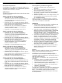
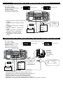
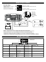
INSTALLATION 1A: STABILIZED VOLTAGE SUPPLY
INSTALLATION 1B: STABILIZED VOLTAGE SUPPLY WITH REMOTE SWITCH
U-out = 13.6V
- Stabilized DC-power supply / single stage
charger
- Gestabiliseerde DC-voeding / eentraps
lader
- Stabilisierte DC-Speisung / einstufiges
Ladegerät
- Alimentation stable CC / chargeur une
étape
- Cargador monofásico / alimentación
eléctrica de de CC estabilizada
- Alimentatore a corrente continua
stabilizzata da / caricatore a fase
singola
DIP switch setting:
DIP switch instelling:
Einstellung des DIP-Schalters:
Réglage cavalier:
Ajuste del conmutador DIP:
Impostazioni interruttore DIP:
1 2 3 4
ON
OFF
U-out = 27.2V
1 2 3 4
ON
OFF
+ –
12V/24V
Load
Belasting
Last
Charge
Carico
Carga
U-out=
0V / 13.6V or
0V / 27.2V
+ –
12V/24V
U-out=
0V / 13.6V or
0V / 27.2V
DIP switch setting:
DIP switch instelling:
Einstellung des DIP-Schalters:
Réglage cavalier:
Ajuste del conmutador DIP:
Impostazioni interruttore DIP:
- Stabilized DC power supply with remote switch function
- Gestabiliseerde DC-voeding met afstandsbedieningschakelaar
- Stabilisierte DC-Speisung mit Fernbedienungsschalter
- Alimentation stable CC avec fonction télécommande
- Alimentación de CC con función de conmutador a distancia.
- Alimentatore a corrente continua stabilizzata da con funzione di interruttore a distanza
ON
OFF
1 2 3 4
Remote switch function ON
U-out = 13.6V
ON
OFF
1 2 3 4
U-out = 27.2V
ON
OFF
Load
Belasting
Last
Charge
Carga
Carico
Rear side
Achterzijde
Rückseite
Face arrière
Parte posterior
Indietro

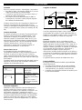
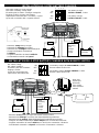
INSTALLATION 2A: 3-STEP BATTERY CHARGER
INSTALLATION 2B: 3-STEP BATTERY CHARGER WITH REMOTE SWITCH
- Automatic 3-step battery charger
- Automatische drietraps acculader
- Automatisches 3-stufiges Batterieladegerät
- Chargeur de batterie automatique
à 3 étapes
- Cargador automático de batería trifásico
- Caricabatterie automatico a 3 passi
+ –
12V/24V
+ –
12V/24V
Load
Belasting
Last
Charge
Carico
Carga
ON
OFF
24V battery charger,
3-STEP CHARGE, I= 80%
+ –
12V/24V
DIP switch setting:
DIP switch instelling:
Einstellung des DIP-Schalters:
Réglage cavalier:
Ajuste del conmutador DIP:
Impostazioni interruttore DIP:
- Automatic 3-step battery charger with remote switch function
- Automatische drietraps acculader met afstandsbedieningschakelaar
- Automatisches 3-stufiges Batterieladegerät mit Fernbedienungsschalter
- Chargeur de batterie automatique à trois étapes avec fonction télécommande
- Cargador automático de batería trifásico con función de conmutador a distancia
- Caricabatterie automatico a 3 passi con funzione di interruttore a distanza
ON
OFF
1 2 3 4
+ –
12V/24V
Load
Belasting
Last
Charge
Carico
Carga
12V battery charger, 3-STEP CHARGE, I= 80%
Remote switch function ON
ON
OFF
ON
OFF
24V battery charger, 3-STEP CHARGE, I= 80%
Remote switch function ON
Rear side
Achterzijde
Rückseite
Face arrière
Parte posterior
Indietro
DIP switch setting: 3 stage charger.
DIP switch instelling: 3-traps lader.
Einstellung DIP-Schalter: 3-Stufiges Ladegerät.
Réglage cavalier: chargeur trois étapes.
Impostazioni interruttore DIP: caricatore a 3 passi.
Ajuste del conmutador DIP: cargador trifásico.
12V battery charger,
3-STEP CHARGE, I= 80%
1 2 3 4
ON
OFF

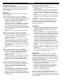
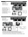
INSTALLATION 3A: 12/36, 24/36 OR 24/48 CONVERTER
INSTALLATION 3B: 12/36, 24/36 OR 24/48 CONVERTER WITH REMOTE SWITCH
+ –
U-battery
U-out=
0V/ Ubat+13.6V
or
0V/ Ubat+27.2V
DIP switch setting:
DIP switch instelling:
Einstellung des DIP-Schalters:
Réglage cavalier:
Impostazioni interruttore DIP:
Ajuste del conmutador DIP:
- A 12/36, 24/36 or 24/48V converter without galvanic insulation with remote switch function
- Een 12/36, 24/36 of 24/48V converter zonder galvanische scheiding met afstandsbedieningschakelaar
- Ein 12/36, 24/36 oder 24/48V Wandler ohne galvanische Trennung mit Fernschaltfunktion.
- Convertisseur 12/36, 24/36 ou 24/48V sans isolation galvanique avec fonction télécommande.
- Un convertidor de 12/36, 24/36 o 24/48V sin aislamiento galvánico y con función de conmutador a distancia
- Un trasformatore 12/36, 24/36 o 24/48V senza isolamento galvanico con funzione di interruttore a distanza
ON
OFF
Load
Belasting
Last
Charge
Carico
Carga
Model
MAGIC 12/24-10
MAGIC 24/12-20
MAGIC 24/24-20
U-battery
12V
24V
24V
U-out
U-battery + 27.2V
U-battery + 13.6V
U-battery + 27.2V
I-out
10A
20A
20A
ON
OFF
Rear side
Achterzijde
Rückseite
Face arrière
Parte posterior
Indietro
- A 12/36, 24/36 or 24/48V converter
without galvanic isolation.
- Een 12/36, 24/36 of 24/48V converter
zonder galvanische scheiding.
- Ein 12/36, 24/36 oder 24/48V Wandler
ohne galvanische Trennung
- Convertisseur 12/36, 24/36 ou 24/48V
sans isolation galvanique.
- Un convertidor de 12/36, 24/36 o 24/48V
sin aislamiento galvánico
- Un trasformatore 12/36, 24/36 o 24/48V
senza isolamento galvanico.
DIP switch setting:
DIP switch instelling:
Einstellung des DIP-Schalters:
Réglage cavalier:
Ajuste del conmutador DIP:
Impostazioni interruttore DIP:
+ –
U-battery
U-out=
0V / Ubatt+13.6V
or
0V / Ubatt+27.2V
Load
Belasting
Last
Charge
Carico
Carga
Model
MAGIC 12/24-10
MAGIC 24/12-20
MAGIC 24/24-20
U-battery
12V
24V
24V
U-out
U-battery + 27.2V
U-battery + 13.6V
U-battery + 27.2V
I-out
10A
20A
20A
ON
OFF

INSTALLATION 4: DIMMER
DIP SWITCH SETTINGS
# 1 Activate → ON 2 Activate → ON
3 12V→ OFF
24V→ ON
4 Activate → ON
Function
Dimmer function
3-step charge mode
Output voltage
13.6V / 27.2V
Remote switch
Functie
Dimmer functie
3-traps laadfunctie
Uitgangsspanning
13.6V / 27.2V
Afstandsbedieningschakelaar
Funktion
Lichtdimmer
3-stufiger
Batterielader
Ausgangsspannung
13.6V / 27.2V
Fernbedienungsschalter
Fonctionnement
Fonction variateur
Mode de charge à
trois étapes
Tension de sortie
13.6V / 27.2V
Interrupteur télécommande
Función
Función de
atenuación de luz
Modo de carga
trifásico
Voltaje de salida
13.6V / 27.2V
Conmutador a distancia
Funzione
Funzione di
regolazione
Modalità di carica a
3 passi
Voltaggio in uscita
13.6V / 27.2V
Interruttore a distanza
ON
OFF
Default: OFF
+ –
12V/24V
U-out = 4.0…13.0V
Dimmer and remote switch function ON
U-out = 8.0…26.0V
Dimmer and remote switch function ON
U-out=
4.0…13.0V /
8.0…26.0V
1 2 3 4
Dimmer configuration for 12 or 24V halogen lights with remote switch function
Dimmer schakeling voor 12 of 24V halogeen verlichting met afstandsbedieningschakelaar
Dimmerschaltung für 12 oder 24V Halogenbeleuchtung mit Fernbedienungsschalter
Configuration variateur pour lumières halogènes 12 ou 24V avec fonction télécommande
Configuración de atenuador para luces halógenas de 12 o 24 V con función de conmutador a distancia
Configurazione di regolazione per lampade alogene da 12 o 24V con funzione di interruttore a distanza
DIP switch setting:
DIP switch instelling:
Einstellung des DIP-Schalters:
Réglage cavalier:
Ajuste del conmutador DIP:
Impostazioni interruttore DIP:
ON
OFF
ON
OFF
Rear side
Achterzijde
Rückseite
Face arrière
Parte posterior
Indietro

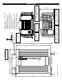
DIMENSIONS
• Remove the back cover to change the DIP-
settings (see text)
•
Verwijder de achterzijde om de DIP
schakelaars in te stellen (zie tekst)
•
Rückseite entfernen, um die DIP
-Schalter-
Einstellungen zu ändern (siehe Text)
•
Retirer la face arriè
re pour régler les
cavaliers (voir texte)
•
Quite el panel posterior para cambiar los
ajustes DIP (véase el texto)
•
Per cambiare le impostazioni DIP togliere il
rivestimento posteriore (vedere testo)
QRS232 communication port
(For extended functions)
OUTPUT / UITGANG / SORTIE
AUSGANG / SALIDA / USCITA
INPUT / INGANG / ENTRÉE
EINGANG / ENTRADA / ENTRATA
154 [6.1]
91 [3.6]
31,5
215
Detail A : Mounting
holes
8
[0.3]
5
[0.2]
6
[0.25]
203 [8.0]
227 [8.9]
DIP switches
81 [3.2]
Remote Switch
Alarm contact
Dimensions in mm [inch]
5
[0.2]
6
[0.25]

SPECIFICATIONS MAGIC
Model MAGIC 24/12-20A MAGIC 24/24-20A MAGIC 12/12-20A MAGIC 12/24-10A
Part no. 81300100 81300200 81300400 81300300
Nominal input voltage 24V 24V 12V 12V
Input range, full output specifications 19-32V DC 19-32V DC 11-16V DC 11-16V DC
Input range, three step charger mode 24-32V DC 24-32V DC 12-16V DC 12-16V DC
Input range, no defects 0-35V DC 0-35V DC 0-17.5V DC 0-17.5V DC
Low voltage set point to trigger alarm * 20.0V DC 20.0V DC 10.0V DC 10.0V DC
Delay lower input set point * 30 sec. 30 sec. 30 sec. 30 sec.
Recommended fuse input 15A-T 30A-T 30A-T 30A-T
Wire size < 3m 4mm²/AWG11 6mm²/AWG9 6mm²/AWG9 6mm²/AWG9
Wire size > 3m 6mm²/AWG9 10mm²/AWG7 10mm²/AWG7 10mm²/AWG7
Output
Voltage adjustable * 10-15V DC 20-28.5V DC 10-15V DC 20-28.5V DC
Nominal voltage stabilized voltage * 13.6V DC 27.2V DC 13.6V DC 27.2V DC
Output voltage 3 step charger
Absorption / Float
14.25 / 13.25V DC
28.5 / 26.5V DC
14.25 / 13.25V DC
28.5 / 26.5V DC
Output voltage dimmer 4.0-13.0V DC 8.0-26.0V DC 4.0-13.0V DC 8.0-26.0V DC
Stabilized 2% at extremes of temperature, load and input
Ripple Max 1% peak peak
Maximum power 300W @ U
out
=12.0V 580W @ U
out
=24.0V 300W @ U
out
=12.0V 300W @ U
out
=24.0V
Rated power 300W @ U
out
=12.0V 580W @ U
out
=24.0V 300W @ U
out
=12.0V 300W @ U
out
=24.0V
Current max. (derating >40°C, 5%/°C) 20A 20A 20A 10A
Maximum 3 step charge current (bulk) 16A 16A 16A 8A
Wire size < 2m 6mm²/AWG9 6mm²/AWG9 6mm²/AWG9 4mm²/AWG11
General
Ambient operating temperature Guaranteed operation: 0°C to 60°C (derating above +40°C, 5% per °C); in practice: -20°C to 60°C/
guaranteed operation: 32 °F to 140 °F (derating above 104 °F, 3% per °F), in practice -4°F to 140 °F
Storage temperature -25°C to 85°C/ -13 °F to 185 °F
Operating humidity 95% max., non-condensing
Galvanic isolation Yes
Current limited Yes, I-max
Three stage battery charge option Yes (DIP switch setting).
Efficiency 90% (at nominal input voltage, full load) typical; 92% peak
No load consumption Typical <115mA
Protections
Over current Limited by current sensing circuit
Over heat Limited power by temperature sense circuit
Options
3 Step battery Charger Yes, all models, by means of DIP switch settings
Dimmer function Yes, by external momentary switch via fast-on connection. To be activated by DIP-switch setting
Alarm contact Yes (fast-on connector)
Communication Quasi RS232, modular RJ12 connection, to alter set points and to change characteristics. Optional:
MasterBus serial interface (art. no. 77030450) to control & configure from MasterBus network.
Parallel connectability In mode Stabilized Voltage, up to 6 devices in parallel
Mechanical
Connections input/output Screw terminals, maximum wire size 16mm² / AWG 5
Dimensions (HxWxD) 227 x 154 x 81 mm [8.9 x 6.1 x 3.2 inch]
Mounting holes Diameter 5mm
Weight 1.8 kg / 3.9 lbs
Cabinet Anodized aluminium, strapton ABS blend, blue RAL 5021
Directives and standards: - EMC directive 2004/108/EC
- Transient voltage protection: meets ISO 7637-2
- Electrostatic voltage protection: meets ISO10605, 14892, 8kV contact, 15kV discharge
- RoHS directive 2011/65/EC
Setpoints software Default setting
Low input voltage switch off level 10.0V / 20.0V; three step charger mode:12.0VDC / 24.0VDC.
Low input voltage switch off delay 30 seconds
Low input voltage switch on level 11.0V / 22.0V; three step charger mode: 13.0VDC / 26.0VDC.
High input voltage switch off level 16.0V / 32.0V
High input voltage switch on level 15.0V / 30.0V
Output voltage 13.6V / 27.2V
* Adjustable by means of MasterAdjust software, see www. mastervolt.com

EC DECLARATION OF CONFORMITY
We,
Manufacturer: Mastervolt
Address: Snijdersbergweg 93
1105 AN Amsterdam
The Netherlands
Declare under our sole responsibility that:
Product:
81300100
MAGIC 24/12
81300200
MAGIC 24/24
81300400
MAGIC 12/12
81300300
MAGIC 12/24
Is in conformity with the following provisions of the EC:
2004/108/EC EMC directive.
The following harmonized standards have been applied:
• EN 61000-6-1:2007: Immunity for residential, commercial and light-industrial
environments
• EN 61000-6-3: 2007: Emission standard for residential, commercial and light-
industrial environments
2011/65/EC RoHS directive
Amsterdam,
8 January 2012
Marc Persoon
Product Manager Power Conversion products
MASTERVOLT
Snijdersbergweg 93, 1105 AN Amsterdam, The Netherlands
Tel : + 31-20-3422100 Fax : + 31-20-6971006
Email : info@mastervolt.com
-
 1
1
-
 2
2
-
 3
3
-
 4
4
-
 5
5
-
 6
6
-
 7
7
-
 8
8
-
 9
9
-
 10
10
-
 11
11
-
 12
12
-
 13
13
-
 14
14
-
 15
15
-
 16
16
-
 17
17
-
 18
18
-
 19
19
-
 20
20


Mastervolt Magic 12/12-20 Handleiding
- Type
- Handleiding
- Deze handleiding is ook geschikt voor
in andere talen
Gerelateerde artikelen
-
Mastervolt Mac 24/12-20 Handleiding
-
-
-
-
-
-
-
-
-
Andere documenten
-
Victron energy Orion-Tr Smart DC-DC Charger Isolated de handleiding
-
-
-
Victron energy Orion-Tr DC-DC converters isolated de handleiding
-
-
-
Brigade bbs-TI(6235) Handleiding
-
Sterling Power Galvanic Isolator / Zinc Saver Handleiding
-
Samlexpower IDC-360B-12 de handleiding
-
VOLTCRAFT SMP-90 USB Handleiding