
ZG5
AUTOMAZIONE PER CHIUSURA INDUSTRIALE
MANUALE D’INSTALLAZIONE
SCHEDA COMANDO PLUS PER BARRIERE A 230V
AF
ZG 5

Tutti i dati e le informazioni quì contenute sono da ritenersi suscettibili di modifica in qualsiasi momento e a nostro giudizio
2
ITALIANO
4.1 Scheda di comando
1 Legenda simboli
Questo simbolo segnala parti da leggere con attenzione.
Questo simbolo segnala parti riguardanti alla sicurezza.
Questo simbolo segnala le note da comunicare all’utente.
Progettata e costruita interamente dalla CAME Cancelli Automatici S.p.A. Garantita 24 mesi salvo manomissioni.
La scheda comando va alimentata a (230V a.c.) sui morsetti L e N con frequenza 50÷60 Hz ed è protetta in ingresso con fusibile
da 5A.
I dispositivi di comandi sono a bassa tensione (24V), protetti con fusibile da 2A.
Fusibile centralina 630mA. Fusibile elettroblocco 1,6A.
La potenza complessiva degli accessori a 24V, non deve superare i 40W.
La scheda gestisce un tempo lavoro di 20 secondi, a protezione nel caso in cui non intervenga il gruppo fi necorsa.
Possibilità di inserire la scheda RSE per abilitare la funzione bussola o abbinato tramite dip (1 ON = Bussola, 2 ON = Abbinato).
Le fotocellule possono essere collegate e predisposte per:
- Riapertura in fase di chiusura, le fotocellule rilevando un ostacolo durante la fase di chiusura dell’asta, provocano l’inversione
di marcia fi no alla completa apertura;
- Stop totale: arresto dell’asta con conseguente esclusione dell'eventuale ciclo di chiusura automatica; per riprendere il movimento
bisogna agire sulla pulsantiera o sul trasmettitore radio.
La scheda, inoltre, integra e gestisce autonomamente una funzione di sicurezza sensibile agli ostacoli (Encoder) che:
in apertura: l’asta inverte il senso di marcia fi no alla completa chiusura;
in chiusura: l’asta inverte il senso di marcia fi no alla completa apertura;
Attenzione! dopo tre inversioni consecutive, l’asta resta alzata escludendo la chiusura automatica: per chiudere, usare il
trasmettitore o il pulsante di chiusura.
Altre funzioni selezionabili:
- Chiusura automatica. Il temporizzatore di chiusura automatica si autoalimenta a fi necorsa in apertura. Il tempo prefi ssato re-
golabile, é comunque subordinato dall'intervento di eventuali accessori di sicurezza e si esclude dopo un intervento di «stop»
totale o in mancanza di energia elettrica;
- Chiusura immediata: l’asta si abbassa automaticamente dopo che il veicolo ha oltrepassato il raggio d’azione dei dispositivi di
sicurezza;
- Rilevazione d'ostacolo: tale funzione annulla ogni comando nel caso di ostacolo rilevato dalle fotocellule (collegate in qualsiasi
funzione di sicurezza);
- Funzionamento ad «azione mantenuta»: funzionamento della barriera mantenendo premuto il pulsante (esclude il funzionamento
del trasmettitore radio);
- Prelampeggio in apertura e chiusura; dopo un comando di apertura o di chiusura, il lampeggiatore collegato su 10-E, lampeg-
gia per 5 secondi prima di iniziare la manovra;
- Tipo di comando: apre-chiude o solo apertura.
4 Descrizione
“ISTRUZIONI IMPORTANTI DI SICUREZZA PER L’INSTALLAZIONE”
“ATTENZIONE: L’INSTALLAZIONE NON CORRETTA PUÓ CAUSARE GRAVI DANNI, SEGUIRE TUTTE LE ISTRUZIONI DI INSTALLAZIONE”
“IL PRESENTE MANUALE É DESTINATO SOLAMENTE A INSTALLATORI PROFESSIONALI O A PERSONA COMPETENTE”
2.1 Destinazione d’uso
Per il prodotto in oggetto sono state considerate le seguenti normative di riferimento: EN 12978, UNI EN 954-1, CEI EN 60335-1,
UNI EN 12453.
2 Destinazione e limiti d’impiego
Scheda elettronica di comando è stata progettata per un uso specifico nelle barriere automatiche della serie GARD 4 e GARD 8
con motoriduttori a 230 Volt; inserita nel contenitore dotato di trasformatore con grado di protezione IP54, alimentata a 230V
con frequenza 50÷60 Hz..
Ogni uso, diverso da quanto sopra descritto ed installazioni in modalità diverse da quanto esposto nel seguente ma-
nuale tecnico, sono da considerarsi vietate.
3 Riferimenti normativi
2.2 Limiti d’impiego
Rispettare diametri dei cavi come espresso nella tabella a cap. 5.3.
vedi dichiarazione di confomità

3
Tutti i dati e le informazioni quì contenute sono da ritenersi suscettibili di modifica in qualsiasi momento e a nostro giudizio
ITALIANO
Tensione di alimentazione: 230V / 50÷60 Hz.
Potenza massima ammessa: 400W
Assorbimento a riposo: 25W
Potenza massima accessori 24V : 20W
Potenza massima accessori 230V :200W
Classe d’isolamento:
Materiale contenitore: ABS
#
#
4.2 Informazioni tecniche
4.3 Componenti principali
1 - Fusibile di linea 5A
2 - Fusibile centralina 630 mA
3 - Fusibile accessori 2A
4 - Fusibile elettroblocco 1,6 A
5 - Morsettiera collegamento alimentazione
6 - Morsettiera collegamento trasformatore
7 - Morsettiera collegamento Elettroblocco
8 - Morsettiera di collegamento gruppo fi necorsa
9 - Morsettiera collegamento barriera abbinate.
10- Morsettiera collegamento Encoder
Regolazioni: tempo di chiusura automatica.
Accessori opzionali:
- cupola lampeggiante, segnala l’asta in movimento;
- cordone luminoso che segnala l’asta chiusa o in movimento, si spegne solo se l’asta è a fi necorsa apre.
- lampada spia asta aperta, segnala la posizione di apertura dell’asta, si spegne a fi ne tempo lavoro di chiusura.
ATTENZIONE: prima di intervenire all’interno dell’apparecchiatura, togliere la tensione di linea.
11- Morsettiere di collegamento
12- Innesto scheda radiofrequenza (vedi tabella pag. 9)
13- Innesto scheda seriale RSE (opzionale per collegamento
barriere in abbinato e/o bussola)
14- Trimmer TCA: regolazione tempo di chiusura automatica
15- Dip-switch "selezione funzioni"
16- Pulsanti memorizzazione codici radio
17- LED di segnalazione codice radio / chiusura automatica
18- Contatore manovre
19- Morsettiera collegamento motore
5
67
&#
&!&
/.
%" %" 63 #4 ,4 ,4 ).4%2",/##/
.,
'.$
"! $
% 6"
% % 43 0 # #
$IS
16 8315 18
91
6
13
12
11
10
Nero
Marrone
Marrone
Nero
Blu
Rosso
Arancio
Bianco
Nero
Rosso
17
14
2
6
Bianco
Rosso
5
7
19
Blu
Viola
Arancio
4
Grigio

Tutti i dati e le informazioni quì contenute sono da ritenersi suscettibili di modifica in qualsiasi momento e a nostro giudizio
4
ITALIANO
Prima di procedere all’installazione è necessario:
- Prevedere adeguato dispositivo di disconnesione onnipolare, con distanza maggiore di 3 mm tra i contatti, a sezionamento
dell’alimentazione;
- Connessioni interne all’involucro eseguite per la continutà del circuito di protezione sono ammesse, purchè provviste
d'isolamento supplementare rispetto ad altre parti conduttrici interne;
- Assicurarsi che la tensione di linea sia scollegata.
Assicurarsi di avere tutti gli strumenti ed il materiale necessario, per effettuare l’installazione nella massima sicurezza, se-
condo le normative vigenti. Ecco alcuni esempi.
Collegamenti Tipologia Cavo Lunghezza
Cavo 1<10 m Lunghezza
Cavo 10<20 m Lunghezza
Cavo 20<30 m
Linea alimentazione 230V
FROR CEI 20-22
CEI EN 50267-2-1
3G 1,5mm² 3G 2,5mm² 3G 4mm²
Motore 230V 3G 1mm² 3G 1,5mm² 3G 2,5mm²
Lampade di ciclo / cortesia 230V 3G 0,5mm² 3G 1mm² 3G 1,5mm²
Alimentazione accessori 24V 2 x 0,5mm² 2 x 0,5mm² 2 x 1mm²
Lampade spia 24V 2 x 0,5mm² 2 x 0,5mm² 2 x 1mm²
Uscita 24V “in movimento” 2 x 0,5mm² 2 x 0,5mm² 2 x 1mm²
Contatti di sicurezza 2 x 0,5mm² 2 x 0,5mm² 2 x 0,5mm²
Pulsanti di comando N.O./N.C. 2 x 0,5mm² 2 x 0,5mm² 2 x 0,5mm²
Finecorsa 3 x 0,5mm² 3 x 1mm² 3 x 1,5mm²
Comando 2° motore abbinato 1 x 0,5mm² 1 x 0,5mm² 1 x 1mm²
Collegamento antenna RG58 max. 10m
N.B. La valutazione della sezione dei cavi con lunghezza diversa dai dati in tabella, deve essere considerata sulla base degli
effettivi assorbimenti dei dispositivi collegati, secondo le prescrizioni indicate dalla normativa CEI EN 60204-1.
Per i collegamenti che prevedano più carichi sulla stessa linea (sequenziali), il dimensionamento a tabella deve essere riconsi-
derato sulla base degli assorbimenti e distanze effettivi.
5.3 Tipologia cavi e spessori minimi
5.2 Atrezzi e materiali
5 Installazione
5.1 Verifiche preliminari

5
Tutti i dati e le informazioni quì contenute sono da ritenersi suscettibili di modifica in qualsiasi momento e a nostro giudizio
ITALIANO
U
VW
FC
FAF
ON
2
1345678910
EB EB VS CT L2T L1T INTERBLOCCO
NL
GND
BA D
E+ VB 24 12 0
10 11 E6 E7 TS 1233P 457C1 C5
5.4 Installazione della scheda elettrica
1) Svitare le quattro viti di fi ssaggio
(o tre nel caso della G4041)
del coperchio del contenitore
posizionato sulla parte superiore
dell’automazione.
2) Inserire la scheda nel contenitore e fissarla con le
viti in dotazione.
G4041
G4041I
Bianco
3) Collegare le morsettiere
del trasformatore alloggiato
nel contenitore alla scheda di
comando.
Rosso
Arancio
Bianco
Finecorsa
di chiusura
Finecorsa
di apertura
Condensatore
M
Rosso Nero Marrone
Marrone
Nero
Blu
G2081
G2081I
Arancio
Grigio
Blu
Viola
:,

Tutti i dati e le informazioni quì contenute sono da ritenersi suscettibili di modifica in qualsiasi momento e a nostro giudizio
6
ITALIANO
(Condensatore)
5.5 Collegamenti elettrici
10
E7
L
N
+10
-11
1
2
2
3
U
W
V
2
C1
10
5
F
FA
2
C5
F
FC
2
7
Alimentazione 230V (a.c.)
Motore 230V(a.c.)
Cupola lampeggiante 24V (A.C.) max.8W, segnalazione intermittente in movimento
Alimentazione accessori 24V (A.C.) max. 30W
Pulsante stop (N.C.)
Pulsante di apertura (N.O.)
Pulsante per comando
Contatto (N.C.) di «riapertura durante la chiusura»
Lampada spia (24V-3W max.) “barriera aperta
Contatto (N.O.) di «chiusura immediata»
Collegamento fi necorsa apre
Collegamento fi necorsa chiude
SE NON USATO
SE NON USATO
% % 43 0 # #
U
VW
FC FA F
EB
EB
N
LVSCTL2T
L1T
M
10
E6 Cordone luminoso 24V (A.C.) max. 24W, segnalazione intermittente dell’asta chiusa
e in movimento, si spegne solo se l’asta è a fi ne corsa apre
2
3P Pulsante di apertura (N.O.) per funzione abbinato e/o bussola
2
4Pulsante di chiusura (N.O.)
Collegamento antenna
/
.
DIP/.
/
.
DIP/.

7
Tutti i dati e le informazioni quì contenute sono da ritenersi suscettibili di modifica in qualsiasi momento e a nostro giudizio
ITALIANO
% % 43 0
&53)"),%M!
48
48
48 #
.#
$)2
Consente alla centralina di verifi care l’effi cenza dei dispositivi di
sicurezza (fotocellule) dopo ogni comando di apertura o di chiusura.
Un eventuale anomalia delle fotocellule viene identifi cata con un
lampeggio del led sul quadro comando, di conseguenza annulla
qualsiasi comando dal trasmettitore radio o dal pulsante.
Collegamento elettrico per il funzionamento del test di sicurezza:
I trasmettitori e i ricevitori delle fotocellule
devono essere
collegati come da disegno
, selezionare il dip 8 in ON per attivare il
funzionamento del test.
IMPORTANTE:
quando si esegue la funzione test di sicurezza, i contatti N.C. se non
utilizzati, escluderli su relativi DIP (vedi selezione funzioni pag.8)
5.6 Test funzionalità fotocellule
EB
EB
5.7 Collegamento motoriduttore-finecorsa
Gruppo motoriduttore-fi necorsa già collegati per
installazione a sinistra vista interna.
FA FC
NC
NC
COM
FUW
M
V
FA FC
NC
NC
COM
FUW
M
V
Per eventuale installazione a destra:
- invertire FA-FC dei fi necorsa sulla morsettiera;
- invertire le fasi U-V del motore sulla morsettiera.
Uscita di alimentazione per
elettroblocco (si attiva con
il comando di apertura)
6
6
- VB1 (spostato) alimentazione
elettroblocco a 12V
- VB2 (preimpostato) alimentazione
elettroblocco a 24V
5.8 Limitatore di coppia motore
Per variare la coppia motrice, spostare il faston indicato (con il fi lo di
colore nero) su una delle 4 posizioni: 1 min ÷ 4 max.

Tutti i dati e le informazioni quì contenute sono da ritenersi suscettibili di modifica in qualsiasi momento e a nostro giudizio
8
ITALIANO
G2081
G2081I G4041
G4041I
/.
/.
ON
OFF
Trimmer A.C.T. = Tempo chiusura automatica:
da 1" a 120"
/.
5.10 Regolazioni
5.9 Selezioni funzioni 1 ON Funzione chiusura automatica attivata; (1 OFF-disattivata);
2 ON Funzione "apre" con trasmettitore radio (scheda AF inserita) attivato;
2 OFF Funzione "apre-chiude-inversione" con pulsante (2-7) e trasmettitore radio
(scheda AF inserita) attivato;
3 ON Funzione ad "azione mantenuta" (esclude la funzione del trasmettitore radio)
attivato; (3 OFF disattivato);
4 ON Prelampeggio in apertura e in chiusura attivato, con dispositivo collegato sui
morsetti 10- E7 (4 OFF disattivato);
5 ON Rilevazione ostacolo. A motore fermo (barriera chiusa, aperta o dopo un
comando di stop totale), impedisce qualsiasi movimento se i dispositivi di
sicurezza (es. fotocellule) rilevano un ostacolo;
6 OFF Funzione di stop totale (collegare pulsante su 1-2) attivato;(se non utilizzato
posizionare il dip in ON);
7 OFF Funzione di riapertura in fase di chiusura (collegare i dispositivi di sicurezza sui
morsetti 2-C1) attivata; (se non utilizzato posizionare il dip in ON);
8 ON Funzione del test di sicurezza per la verifi ca dell’effi cienza delle fotocellule (pag.
7) attivato; (8 OFF disattivata).
9 OFF Encoder attivato per la rilevazione degli ostacoli (9 ON disattivato);
10 Non utilizzato
5.12 Contatore manovre
/.
Conteggio del numero di manovre
visualizzato tramite n°8 led, per
azzerare il conteggio, posizionare
il dip n°1 in OFF (se selezionato in
ON) e il dip n°3 in ON, premere il
pulsante CH1 ed attendere che tutti i
led si spengano. Dopo l’azzeramento,
riposizionare il dip n°1 in ON (se
selezionato) e il dip n°3 in OFF.
Led n°1 = 5000 manovre
Led n°2 = 10000 manovre
Led n°3 = 25000 manovre
Led n°4 = 50000 manovre
Led n°5 = 100000 manovre
Led n°6 = 250000 manovre
Led n°7 = 500000 manovre
Led n°8 = 1000000 manovre
!#4
5.11 Gestione spunto manovra
/.
Per la gestione dello spunto manovra, posizionare
il dip n°1 e n°3 in ON, tutti gli 8 led del contatore
manovre saranno accesi (memorizzazione default
per barriere G2081 e G2081I), per selezionare la
gestione dello spunto per barriere G4041 e G4041I,
posizionare i dip 1 e 3 in ON e premere il pulsante
CH1, i primi 4 led saranno accesi. Riposizionare
il dip n°3 in OFF e il dip n°1 può essere lasciato
posizionato in ON, se si desideri la funzione di
chiusura automatica.

9
Tutti i dati e le informazioni quì contenute sono da ritenersi suscettibili di modifica in qualsiasi momento e a nostro giudizio
ITALIANO
/.
Prima dell’installazione, è necessario leggere attentamente le tre procedure che seguono:
- preparazione della scheda radio (parag. 6.1);
- procedura di codifica del radiocomando (parag. 6.2);
- memorizzazione del codice sulla scheda di comando (parag. 6.3).
2) La schedina AF deve essere inserita OBBLIGATO-
RIAMENTE in assenza di tensione, perché la scheda
madre la riconosce solo quando viene alimentata
1) Per trasmettitori con frequenza 433.92 AM (serie
TOP e serie TAM) bisogna, sulla relativa scheda AF43S,
posizionare il jumper come illustrato.
Frequenza/MHz Scheda Trasmettitore
FM 26.995 AF130 TFM
FM 30.900 AF150 TFM
AM 26.995 AF26 TOP
AM 30.900 AF30 TOP
AM 433.92 AF43S / AF43SM TAM / TOP
AM 433.92 AF43SR ATOMO
AM 40.685 AF40 TOUCH
6.1 Preparazione della scheda radio (AF)
6 Procedura di installazione per il comando a distanza
Procedura comune di codifica T262M - T264M - T2622M - T302M - T304M - T3022M
1 segnare un codice (anche per archivio)
2 inserire jumper codifica J
3 memorizzarlo
4 disinserire jumper J
SERIE TOP QUARZATI
6.2 Procedura di codifica del trasmetittore
TOP TAM
/.
/&&
0
0
premere in sequenza P1 o P2 per registrare il codi-
ce; al decimo impulso un doppio suono confermerà
l’avvenuta registrazione
Scheda radio (AF)
Scheda base

Tutti i dati e le informazioni quì contenute sono da ritenersi suscettibili di modifica in qualsiasi momento e a nostro giudizio
10
ITALIANO
0 0
La prima codifi ca deve essere effettuata mantenendo i jumper posizionati per
i canali 1 e 2 come da fi g. A; per eventuali e successive impostazioni su canali
diversi vedi fi g. B
TOP
T262M - T302M
FIG.A FIG.B
0 0
0 0
T264M - T304M
0 0
0 0
/.
/&&
0
0
T2622M - T3022M
P1 = CH1
P2 = CH2
P3 = CH3
P4 = CH4
P1 = CH1
P2 = CH2
P1 = CH1 - P2 = CH3 P1 = CH3 - P2 = CH2
P1 = CH1 - P2 = CH4 P1 = CH3 - P2 = CH4
1° Codice
P1 = CH1
P2 = CH2
2° Codice
P3 = CH1
P4 = CH2

11
Tutti i dati e le informazioni quì contenute sono da ritenersi suscettibili di modifica in qualsiasi momento e a nostro giudizio
ITALIANO
SERIE TOP
0 0
/. /. /. /.
/. /. /. /.
TOP
T432M - T312M
Impostare il codice sul dip-switch C e il canale su D (P1 = CH1 e P2 = CH2, impostazione di default)
D
C
P1
P2
CH1 CH2 CH3 CH4
CH1 CH2 CH3 CH4
TOP
T434M - T314M
0 0
0 0
C
Impostare solo il codice
P1 = CH1
P2 = CH2
P3 = CH3
P4 = CH4
TOP
T432S - T432SA - T434MA - T432NA - T434NA
Vedi foglio istruzioni inserito
nella confezione
TAM
T432 - T434 - T438 - TAM432SA
Vedi foglio istru-
zioni inserito nella
confezione
TFM
T132 - T134 - T138
T152 - T154 - T158
Vedi foglio istruzioni inserito nella
confezione
CAME
AT01 - AT02 - AT04
vedi foglio istruzioni inserito nella confezione
della scheda AF43SR
SERIE ATOMO
CAME
TCH 4024 - TCH 4048
Vedi foglio istruzioni inserito nella confezione
SERIE TOUCH

Tutti i dati e le informazioni quì contenute sono da ritenersi suscettibili di modifica in qualsiasi momento e a nostro giudizio
12
ITALIANO
#
#
6.3 Memorizzazione del codice sulla scheda comando
1) Tenere premuto il tasto "CH1" sulla sche da base,
il led di se gna la zio ne lam peg gia (led intermittente).
2) Premere un tasto del tra smet ti to re per in viare il codice, il led
rimarrà acceso a se gna la re l'av ve nu ta memorizzazione.
Eseguire la stessa procedura con il tasto “CH2” associandolo con
un altro tasto del trasmettitore.
LED intermittente
LED acceso
Scheda radio
2) Inserire lo sportello d’ispezione e chiuderlo.
1) Dopo aver eseguito le
operazioni di regolazioni e settaggi
dalla scheda di comando, inserire
il coperchio del contenitore e
chiuderlo con le viti.
6.4 Montaggio coperchio
3) Inserire la cupola di protezione sulla
parte superiore dell’automazione (per
il GARD4 fi ssarlo di lato con le due viti
UNI6954 Ø3,9x13 in dotazione.
1
2
ZL38
2
1
3
G2081
G2081I G4041
G4041I
CH1 = Canale per comandi diretti ad una funzione della centralina
del motoriduttore (comando “solo apre” o “apre-chiude”, a seconda
della selezione effetuata sul dip-switch 2).
CH2 = Canale per comandi diretti ad un dispositivo accessorio (comando radio con collegamento barriere abbinate o a
bussola).
N.B.: se in seguito si vuol cambiare codice, basta ri pe te re la se quen za descritta.
CH1
CH2

13
Tutti i dati e le informazioni quì contenute sono da ritenersi suscettibili di modifica in qualsiasi momento e a nostro giudizio
ITALIANO
CAME CANCELLI AUTOMATICI S.p.A. implementa all’interno dei propri stabilimenti un Sistema di Gestione Ambientale
certifi cato in conformità alla norma UNI EN ISO 14001 a garanzia del rispetto e della tutela dell’ambiente.
Vi chiediamo di continuare l’opera di tutela dell’ambiente, che CAME considera uno dei cardini di sviluppo delle proprie strategie
operative e di mercato, semplicemente osservando brevi indicazioni in materia di smaltimento:
SMALTIMENTO DELL’IMBALLO - I componenti dell’imballo (cartone, plastiche etc.) sono tutti prodotti assimilabili ai rifi uti solidi
urbani e possono essere smaltiti senza alcuna diffi coltà, semplicemente operando la raccolta differenziata ai fi ni del riciclaggio.
Prima di procedere è sempre opportuno verifi care le normative specifi che vigenti nel luogo d’installazione.
NON DISPERDERE NELL’AMBIENTE!
SMALTIMENTO DEL PRODOTTO - I nostri prodotti sono costituiti da varie tipologie di materiali. La maggior parte di essi
(alluminio, plastica, ferro, cavi elettrici) sono assimilabili ai rifi uti solidi e urbani e possono essere riciclati attraverso la raccolta
e lo smaltimento differenziato nei centri autorizzati. Altri componenti (schede elettriche, batterie dei radiocomandi etc.) possono
invece contenere sostanze inquinanti. Vanno quindi rimossi e affi dati a ditte abilitate al recupero e smaltimento degli stessi.
Prima di procedere è sempre opportuno verifi care le normative specifi che vigenti nel luogo di smaltimento.
NON DISPERDERE NELL’AMBIENTE!
7 Demolizione e smaltimento
8 Dichiarazione
DICHIARAZIONE DEL FABBRICANTE
Ai sensi dell’Allegato II A della Direttiva 2006/95/CE
I Rappresentanti della
CAME Cancelli Automatici S.p.A.
via Martiri della Libertà, 15
31030Dosson di Casier - Treviso - ITALYtel
(+39) 0422 4940 - fax (+39) 0422 4941
internet: www.came.it - e-mail: info@came.it
Dichiarano sotto la propria responsabilità che i/il prodotto/i denominato/i ...
… sono conformi alle seguenti Direttive Comunitarie:
2006/95/CE - Direttiva Bassa Tensione
2014/30/UE - Direttiva Compatigilità Elettromagnetica
Inoltre, dichiara che il/i prodotto/i, oggetto della presente dichiarazione, sono costruiti nel rispetto
delle seguenti principali norme armonizzate:
EN 60335-1 / EN 60335-2-103 / EN 13241-1 / EN 61000-6-2 / EN 61000-6-3
Codice di riferimento per richiedere una copia conforme all’originale: DDC L IT Z002
Amministratore Delegato
Sig. Gianni Michielan
ZG5

Cod. 319T47 ver. 1.3 06/06 © CAME CANCELLI AUTOMATICI
CAME CANCELLI AUTOMATICI S.p.A.
VIA MARTIRI DELLA LIBERTÀ 15
31030 DOSSON DI CASIER - TV - ITALY
www.came.it
Per assistenza e informazioni tecniche
.5-%2/6%2$%

ZG5
INSTALLATION MANUAL
AF
ZG 5
COMMAND BOARD PLUS FOR BARRIERS
WITH 230V MOTOR

2
All the data and information contained herein is considered subject to change at any time and at our discretion
ENGLISH
4.1 Command board
1 Legend
This symbol indicates sections to be read with particular care.
This symbol indicates sections concernig safety
This symbol indicates notes to communicate to users.
Fully designed and built by CAME CANCELLI AUTOMATICI S.p.A. Guaranteed for 24 months unless tampered with.
The command board is powered at 230V A.C. on the L-N terminals with 50÷60 Hz frequency and is protected in input with 5A
fuse.
A 2A fuse protects the low voltage (24V) command devices.
630mA control unit fuse. 1.6A electrical locking fuse.
The overall rated power of the 24V accessories must not exceed 40 W.
The board manages an operating time of 20 seconds, which protects in the case that the end stop unit does not intervene.
Possibility of inserting the RSE board to enable the compass function or paired with dip (1 ON = compass, 2 ON = paired).
The photoelectric cells may be connected and pre-set for:
- Re-opening during closing phases: if the photocells identify an obstacle while the gate is closing, they will reverse the direc-
tion of movement until the gate is completely open;
- Total stop: stops the bar with consequent exclusion of the automatic closing cycle; pushbuttons or transmitters must be used
to resume movement.
The board also integrates and independently manages a safety function which is sensitive to the obstacles (encoder) that:
during opening: the bar inverts its direction until it is completely close,
during closure: the bar inverts its direction until it is completely open.
Caution! after three consecutive direction reversals, the bar will remain up and automatic closure will be discontinued. To
close the gate, use the radio remote control or the push-button.
Other selectable functions:
- Automatic closure. The automatic closure timer self-powers at the end stop in opening. The set time can be adjusted and is
also subject to modifi cations due to the intervention of additional safety features. This does not happen following a complete
“stop” command or if there be a power cut;
- Immediate closure: The bar lowers automatically after the vehicle has exceeded the range of action of the safety devices;
- Obstacle detection: this function voids every command if an obstacle is detected by the photoelectric cells (connected to any
safety function);
- Maintained action operations: barrier operation while keeping the pushbutton pressed (it excludes the radio transmitter ope-
ration);
- Pre-fl ashing during opening and closing: after an opening or closing command, the fl ashing lamp connected to 10-E, fl ashes
for 5 seconds before the manoeuvre begins;
- Type of command: open-close or opening only
Settings: automatic closure time adjustment.
4 Description
“IMPORTANT SAFETY INSTRUCTIONS FOR INSTALLATION”
“CAUTION: IMPROPER INSTALLATION MAY CAUSE SERIOUS DAMAGE, FOLLOW ALL INSTALLATION INSTRUCTIONS CAREFULLY”
“THIS MANUAL IS ONLY FOR PROFESSIONAL INSTALLERS OR QUALIFIED PERSONS”
2.1 Destination
The following standard were complied with for this product: EN 12978, UNI EN 954-1, CEI EN 60335-1, UNI EN 12453.
2 Destination and limits of use
The electronic command board was designed for specific use in automatic GARD 4 and GARD 8 series barriers with 230V
gear motors; inserted into the container fitted with a transformer with IP54 protection level, 230V power supply with 50÷60
Hz frequency.
Uses other than the ones described above and installations using methods other than those shown in this technical
manual are considered prohibited.
3 Standard followed
2.2 Limits of use
Comply with the cable cross-sections recommended in the table under chapter 5.3.
see declaration of compliance

3
All the data and information contained herein is considered subject to change at any time and at our discretion
ENGLISH
Power supply: 230V / 50÷60 Hz.
Maximum power allowed: 400W
Absorption at rest: 25W
Maximum power for 24V accessories: 20W
Maximum power for 230V accessories: 200W
Insulation type:
Material case: ABS
#
#
4.2 Technical information
4.3 Main components
1 - 5 A mains fuse
2 - 630 mA fuse control assembly
3 - 2 A accessories fuse
4 - 1.6 A electric lock fuse
5 - Supply-connecting terminal board
6 - Transformer-connecting terminal board
7 - Electric lock-connecting terminal board
8 - End-stop assembly-connecting terminal board
9 - Combined barriers connecting terminal board
10 - Encoder-connecting terminal board
Optional accessories:
- fl ashing dome signals the bar in motion;
- lighted cord signals the bar closed or in motion; it turns off only if the bar is at an end stop and opens.
- bar open light marks the position of opening of the bar; it turns off after the closing operation.
Caution: Switch off the mains prior to any inspection or maintenance work on the equipment.
11 - Connecting terminal boards
12 - radiofrequency board coupling (see table page 9)
13 - RSE serial board coupling (optional for connection of
combined and/or interlock barriers)
14 - ACT Trimmer: automatic closure time adjustment
15 - “function selection” dipswitch
16 - Code saving buttons
17 - radio code / automatic closing fl ashing LED indicator
18 - manoeuvre counter
19 - Motor terminal board
5
67
&#
&!&
/.
%" %" 63 #4 ,4 ,4 ).4%2",/##/
.,
'.$
"! $
% 6"
% % 43 0 # #
$IS
16 8315 18
91
6
13
12
11
10
Black
Brown
Brown
Black
Blue
Red
Orange
White
Black
Red
17
14
2
6
White
Red
5
7
19
Blue
Violet
Orange
4
Grey

4
All the data and information contained herein is considered subject to change at any time and at our discretion
ENGLISH
Before proceeding with the installation, it is necessary to:
- provide for suitable omnipolar disconnection device with more than 3 mm between contacts to section power supply;
- connections inside the case made for protection circuit continuity are allowed as long as they include additional insulation
with respect to other internal drive parts;
- make sure the mains voltage is disconnected.
5.3 Cable list and minimun thickness
Make sure all tools and materials necessary are within reach to install the edge in maximum safety, according to regulations in
force. The following figure illustrates the minimum equipment for the installer.
5.2 Tools and materials
Connections Type of cable Length of
cable 1<10 m Length of
cable 10<20 m Length of
cable 20<30 m
230V 2F power supply line
FROR CEI 20-22
CEI EN 50267-2-1
3G 1,5mm² 3G 2,5mm² 3G 4mm²
230V motor 3G 1mm² 3G 1,5mm² 3G 2,5mm²
230V courtesy / cycle light 3G 0,5mm² 3G 1mm² 3G 1,5mm²
24V power supply accessory 2 x 0,5mm² 2 x 0,5mm² 2 x 1mm²
24V pilot light 2 x 0,5mm² 2 x 0,5mm² 2 x 1mm²
24V “in motion” output 2 x 0,5mm² 2 x 0,5mm² 2 x 1mm²
Safety contacts 2 x 0,5mm² 2 x 0,5mm² 2 x 0,5mm²
N.O./N.C. control button 2 x 0,5mm² 2 x 0,5mm² 2 x 0,5mm²
End stop 3 x 0,5mm² 3 x 1mm² 3 x 1,5mm²
Command 2nd combined motor 1 x 0,5mm² 1 x 0,5mm² 1 x 1mm²
Antenna connection RG58 max. 10 m
N.B.: An evaluation of the size of the cables with lengths other than the data in the table must be made based on the effective
absorption of the connected devices, according to the instructions indicated by the CEI EN 60204-1 standards.
For connections that require several loads on the same line (sequential), the size given on the table must be re-evaluated based
on actual absorption and distances.
5 Installation
5.1 Preliminary checks

5
All the data and information contained herein is considered subject to change at any time and at our discretion
ENGLISH
U
VW
FC
FAF
ON
2
1345678910
EB EB VS CT L2T L1T INTERBLOCCO
NL
GND
BA D
E+ VB 24 12 0
10 11 E6 E7 TS 1233P 457C1 C5
G4041
G4041I
White
Red
Orange
White
Condenser
M
Red Black Brown
Brown
Black
Blue
G2081
G2081I
Orange
Grey
Blue
Violet
5.4 Installing the electrical card
1) Unscrew the four
mounting screws (or three
in the case of the G4041) of
the cover of the container
located on the upper part of
the automation.
2) Insert the card into the container and fasten
it with the screws supplied.
3) Connect the terminal
boards of the transformer
housed in the container to the
command board.
Opening limit
switch
Closure limit
switch
:,

6
All the data and information contained herein is considered subject to change at any time and at our discretion
ENGLISH
(Condenser)
5.5 Electrical connections
10
E7
L
N
+10
-11
1
2
2
3
U
W
V
2
C1
10
5
F
FA
2
C5
F
FC
2
7
230V (a.c.) power supply
230V(a.c.) motor
Flashing dome 24V (A.C.) max.8W, signals the bar in motion
24V (A.C.) max. 30W supply accessories
Stop pushbutton (N.C.)
Open pushbutton (N.O.)
Command pushbutton (see dip-switch 2 in function selections)
Contact (N.C.) of «reopening during closing»
Pilot light indicating “barrier open” (24V-3W max.)
Contact (N.O.) of «immediate closing»
Open end stop connection (N.C.)
Close end stop connection (N.C.)
IF NOT USED
IF NOT USED
% % 43 0 # #
U
VW
FC FA F
EB
EB
N
LVSCTL2T
L1T
M
10
E6 Cord signals 24V (A.C.) max. 24W, signals the bar closed or in motion, it turns off
only if the bar is in open end stop mode
2
3P Opening pushbutton (N.O.) for combined and/or bush function
2
4Closing pushbutton (N.O.)
Antenna connection
/
.
DIP/.
/
.
DIP/.

7
All the data and information contained herein is considered subject to change at any time and at our discretion
ENGLISH
% % 43 0
&53)"),%M!
48
48
48 #
.#
$)2
Allows the control assembly to check the effi ciency of the safety de-
vices (photoelectric cells) after each opening or closing command.
A possible photoelectric cell malfunction is identifi ed with via LED
indicator fl ashing on the control panel, consequently cancelling any
remote control or pushbutton commands.
Electrical connection for safety test activation:
- photoelectric cell transmitters and receivers must be connected in
the following way (see scheme)
- turn dip-switch 8 to ON to carry out the test.
IMPORTANT:
when carrying out the safety test function, contacts N.C. if not used,
on the relative dip switches (see functions selection p. 8)
5.6 Photoelectric cells performance test
EB
EB
5.7 Gearmotor end-stop connection
Gearmotor end-stop assembly already connected for
installation on the left-hand side seen from inside.
FA FC
NC
NC
COM
FUW
M
V
FA FC
NC
NC
COM
FUW
M
V
For right-hand installation:
- reverse FA-FC of the end stops on the terminal board;
- reverse the U-V phases of the motor on the terminal board.
Output supplied for
electric lock (comes
on with the opening
command)
6
6
- VB1 (shifted) supplied for
electric lock a 12V
- VB2 (preset) supplied for electric
lock a 24V
5.8 Motor torque limiter
To alter the torque, move the fast-on (marked with black string) to one
of the 4 remaining positions: 1 min ÷ 4 max.

8
All the data and information contained herein is considered subject to change at any time and at our discretion
ENGLISH
G2081
G2081I G4041
G4041I
/.
/.
ON
OFF
A.C.T Trimmer = min. automatic closing
time 1 sec, max. 120 sec.
5.10 Adjustments
5.9 Function selections 1 ON Automatic closing function activated; (1 OFF-deactivated);
2 ON “Open” function with activated remote control (HF board inserted);
2 OFF “Open-close-reverse” function with pushbutton (2-7) and activated remote con-
trol (HF board inserted) ;
3 ON “Maintained Action” function (remote control function disabled) activated; (3 OFF
deactivated);
4 ON Activated pre-fl ashing during opening and closing,, with device connected on ter-
minals 10- E7 (4 OFF deactivated);
5 ON Obstacle detection. With the motor off (bar closed, open or after a total-stop com-
mand), movement is blocked if safety devices (e.g. photoelectric cells) detect an
obstacle;
6 OFF Total stop function activated, connect pushbutton to 1-2 (if not set the dipswitch
to ON);
7 OFF Reopening function during closure activated, connect the safety devices to termi-
nals 2-C1 (if not used set the dipswitch to ON);
8 ON Safety test function to check photoelectric cell effi ciency (page.7) activated; (8
OFF deactivated).
9 OFF Encoder activated for obstacle detection (9 ON deactivated);
10 Not used
5.12 Operation counter
/.
Counts the number of operations
displayed with the 8 LED to zero
out the count, position the dip 1 to
OFF (if selected to ON) and the dip
3 to ON, press the CH1 and wait
for all the LED to turn off. After
zeroing out, return the dip 1 to ON
(if selected) and dip 3 to OFF.
Led n°1 = 5000 manoeuvres
Led n°2 = 10000 manoeuvres
Led n°3 = 25000 manoeuvres
Led n°4 = 50000 manoeuvres
Led n°5 = 100000 manoeuvres
Led n°6 = 250000 manoeuvres
Led n°7 = 500000 manoeuvres
Led n°8 = 1000000 manoeuvres
!#4
5.11 Management of the manoeuvre pick-up function
/.
To manage the manoeuvre pick-up function,
position the dip 1 and dip 3 to ON; all 8 LED of the
manoeuvre counter will be on (default memorization
for G2081 and G2081I); to select management of
manoeuvre pick-up function for G4041 e G4041I
barriers, position the dip 1 and 3 to ON and
press the CH1 button. The fi rst 4 LEDs will be on.
Reposition the dip 3 to OFF and dip 1 can be left on
the ON position, if automatic closure is desired.
/.

9
All the data and information contained herein is considered subject to change at any time and at our discretion
ENGLISH
/.
2) The AF board should AL WAYS be in sert ed
when the pow er is off.
1) On AM transmitters operating at 433.92 MHz (TOP
and TAM series), position the jumper connection on
circuit card AF43S as shown on the sheet.
Frequency/MHz Radiofrequency board Transmitter
FM 26.995 AF130 TFM
FM 30.900 AF150 TFM
AM 26.995 AF26 TOP
AM 30.900 AF30 TOP
AM 433.92 AF43S / AF43SM TAM / TOP
AM 433.92 AF43SR ATOMO
AM 40.685 AF40 TOUCH
Standard encoding procedure T262M - T264M - T2622M - T302M - T304M - T3022M
1 assign a code (also on file)
2 connect encoding jumper J
3 register code
4 disinserire jumper J
TOP TAM
/.
/&&
0
0
Press P1 or P2 in sequence in order to register the
code; at the tenth pulse, a double beep will confi rm
that registration has occurred
“AF” board
Mother board
TOP QUARZATI SERIES
Read the three steps below before beginning installation procedures:
- prepare the radio board (paragraph 6.1);
- procedure for codifying the transmitter (paragraph 6.2);
- memorizing the code on the command board (paragraph 6.3).
6.1 Prepare the radio board (AF)
6 Installation procedure of the transmitter for remote control
6.2 Procedure for codifying the transmitter

10
All the data and information contained herein is considered subject to change at any time and at our discretion
ENGLISH
0 0
The fi rst encoding operation must be carried out whilst keeping the jumpers po-
sitioned for channels 1 and 2 as per fi g. A; see fi g. B for any subsequent settings
on different channels.
TOP
T262M - T302M
FIG.A FIG.B
0 0
0 0
T264M - T304M
0 0
0 0
/.
/&&
0
0
T2622M - T3022M
P1 = CH1
P2 = CH2
P3 = CH3
P4 = CH4
P1 = CH1
P2 = CH2
P1 = CH1 - P2 = CH3 P1 = CH3 - P2 = CH2
P1 = CH1 - P2 = CH4 P1 = CH3 - P2 = CH4
1° Code
P1 = CH1
P2 = CH2
2° Code
P3 = CH1
P4 = CH2

11
All the data and information contained herein is considered subject to change at any time and at our discretion
ENGLISH
0 0
/. /. /. /.
/. /. /. /.
TOP
T432M - T312M
set the code to dip-switch C and channel to D (P1=CH1 and P2=CH2, default setting)
D
C
P1
P2
CH1 CH2 CH3 CH4
CH1 CH2 CH3 CH4
TOP
T434M - T314M
0 0
0 0
C
set code only
P1 = CH1
P2 = CH2
P3 = CH3
P4 = CH4
TOP
T432S - T432SA - T434MA - T432NA - T434NA
see instructions on pack
TAM
T432 - T434 - T438 - TAM432SA
see instruction
sheet inside the
pack
TFM
T132 - T134 - T138
T152 - T154 - T158
see instruction sheet inside the
pack
CAME
AT01 - AT02 - AT04
see instruction sheet inside the pack of
AF43SR circuit card
CAME
TCH 4024 - TCH 4048
see instructions on pack
TOUCH SERIES
TOP SERIES
ATOMO SERIES

12
All the data and information contained herein is considered subject to change at any time and at our discretion
ENGLISH
#
#
2) Press a transmitter key to send the code; the LED will remain
lighted to signal memorization.
Follow the same procedure with the “CH2” key, again using another
transmitter key.
Flashing LED
Lit LED
Radiofrequency
board
1
2
ZL38
2
1
3
G2081
G2081I G4041
G4041I
CH1 = Channel for direct commands with a gearmotor control
assembly function of “open only” or “open-close-reverse”, depend-
ing on the selection carried out on dip-switches 2).
CH2 = Channel for direct commands with an accessory device (radio control with combined barrier connection or with bush).
N.B.: if desired, simply repeat the sequence described to change the code.
CH1
CH2
6.3 Memorizing the code on the command board
1) Keep the "CH1" key pressed on the base card, the
signal LED will fl ash.
2) Insert the inspection door and close it.
1) After making the adjustments
and settings from the command
board, insert the lid of the
container and close it with the
screws.
6.4 Mounting the lid
3) Insert the protection dome on the upper
part of the automation (for the GARD4
fasten it on the side with two UNI6954
Ø3.9x13 screws supplied.

13
All the data and information contained herein is considered subject to change at any time and at our discretion
ENGLISH
In its premises, CAME CANCELLI AUTOMATICI S.p.A. implements an Environmental Management System certifi ed in
compliance with the UNI EN ISO 14001 standard to ensure environmental protection.
Please continue our efforts to protect the environment—which CAME considers one of the cardinal elements in the development
of its operational and market strategies—simply by observing brief recommendations as regards disposal:
DISPOSAL OF PACKAGING – The packaging components (cardboard, plastic, etc.) are all classifi able as solid urban waste
products and may be disposed of easily, keeping in mind recycling possibilities.
Prior to disposal, it is always advisable to check specifi c regulations in force in the place of installation.
PLEASE DISPOSE OF PROPERLY!
PRODUCT DISPOSAL – Our products are made up of various types of materials. Most of them (aluminium, plastics, iron,
electrical wires, etc.) may be disposed of in normal garbage collection bins and can be recycled by disposing of in specifi c re-
cyclable material collection bins and disposal in authorized centres. Other components (electrical boards, remote control batteries,
etc.), however, may contain polluting substances. They should therefore be removed and given to qualifi ed service companies for
proper disposal.
Prior to disposal, it is always advisable to check specifi c regulations in force in the place of disposal.
PLEASE DISPOSE OF PROPERLY!
7 Demolition and disposal
8 Manufacturer’s warranty
Also, they furthermore represent and warrant that the product/s that are the subject of the present
Declaration are manufactured in the respect of the following main harmonized provisions:
Reference code to request a true copy of the original: DDC L EN Z002
MANUFACTURER’S DECLARATION
As per Enclosure II A of Directive 2006/95/CE
The representatives of
CAME Cancelli Automatici S.p.A.
via Martiri della Libertà, 15
31030 Dosson di Casier - Treviso - ITALY
tel (+39) 0422 4940 - fax (+39) 0422 4941
internet: www.came.it - e-mail: [email protected]t
Hereby declare, under their own respons ibility, that the product/s called ...
… complies with the provisions of the following Directives
2006/95/CE - Direttiva Bassa Tensione
2014/30/UE - Direttiva Compatigilità Elettromagnetica
EN 60335-1 / EN 60335-2-103 / EN 13241-1 / EN 61000-6-2 / EN 61000-6-3
Managing Director
Mr. Gianni Michielan
ZG5

Cod. 319T47 ver. 1.3 06/06 © CAME CANCELLI AUTOMATICI
CAME UNITED KINGDOM LTD
UNIT 3, ORCHARD BUSINESS PARK TOWN
STREET, SANDIACRE
NOTTINGHAM - NG10 5BP - U.K.
Tel 0044 115 9210430
Fax 0044 115 9210431

ZG5
AUTOMAZIONE PER CHIUSURA INDUSTRIALE
MANUEL D’INSTALLATION
AF
ZG 5
CARTE DE COMMANDE PLUS
POUR BARRIÈRES EN 230V

2
Ces données et ces informations peuvent être modifiées à tout moment et sans préavis
FRANÇAIS
4.1 Carte de commande
1 Légende des symboles
Ce symbole signale les parties à lire attentivement.
Ce symbole signale les parties concernant la sécurité.
Ce symbole signale les indications à communiquer à l’utilisateur.
Conçue et fabriquée entièrement par CAME Cancelli Automatici S.p.A. Garantie 24 mois sauf en cas d’altérations.
La carte de commande doit être alimentée en (230V c.a.) sur les bornes L et N avec une fréquence de 50÷60 Hz. Elle est protégée
à l’entrée par des fusible de 5A.
Les dispositifs de commande sont en basse tension (24V) et sont protégés par un fusible de 2A.
Fusible centrale 630mA. Fusible électrobloc 1,6A.
La puissance totale des accessoires en 24V ne doit pas être supérieure à 40W.
La carte gère un temps de fonctionnement de 20 secondes, ce qui représente une protection au cas où le groupe de fi n de course
n’intervienne pas.
Possibilité d’insérer la carte RSE pour activer la fonction passage simple ou passage double à l’aide du commutateur (1 ON =
Simple, 2 ON = Double).
Les photocellules peuvent être branchées et prévues pour:
- Réouverture durant la phase de fermeture, si elles détectent un obstacle durant la phase de fermeture de la lisse, les photo-
cellules provoquent l’inversion de marche jusqu’à l’ouverture complète;
- Arrêt total: arrêt de la lisse avec par conséquent exclusion du cycle éventuel de fermeture automatique; pour reprendre le
mouvement, agir sur le boîtier de commande ou sur l’émetteur.
La carte gère par ailleurs de façon autonome une fonction de sécurité sensible aux obstacles (encodeur):
en ouverture: la lisse inverse le sens de marche jusqu’à fermeture complète;
en fermeture: la lisse inverse le sens de marche jusqu’à l’ouverture complète.
Attention ! après trois inversions consécutives, la liste reste levée en excluant la fermeture automatique : pour la fermer,
utiliser la radiocommande ou le bouton de sécurité.
Autres fonctions pouvant être sélectionnées:
- Fermeture automatique. Le temporisateur de fermeture automatique s’alimente de lui-même à la fi n de la course en ouverture.
Le temps préétabli réglable est néanmoins lié à l’intervention d’accessoires de sécurité éventuels et s’exclut après une interven-
tion d’ « arrêt » total ou en cas de coupure de courant ;
- Fermeture immédiate: la lisse s’abaisse automatiquement lorsque le véhicule se trouve au-delà du rayon d’action des dispo-
sitifs de sécurité;
- Détection d’obstacle: cette fonction annule toute commande en cas d’obstacle détecté par les photocellules (reliées à n’im-
porte quelle fonction de sécurité) ;
- Fonctionnement avec « action qui reste maintenue » : fonctionnement de la barrière en continuant à appuyer sur le bouton (ce
qui exclut le fonctionnement de l’émetteur radio) ;
4 Description
2.1 Usage prévu
Les normes de référence suivantes ont été considérées pour l’appareil en objet: EN 12978, UNI EN 954-1, CEI EN 60335-1,
UNI EN 12453.
2 Usage prévu et limites d’emploi
Cette carte électronique de commande a été spécialement conçue pour être utilisée sur les barrières automatiques de la série
GARD 4 et GARD 8, avec des motoréducteurs en 230 Volt ; placée dans un boîtier muni d’un transformateur avec degré de
protection IP54, elle est alimentée en 230V avec une fréquence de 50÷60 Hz.
Tout usage autre que celui indiqué et le montage qui ne respecte pas les indications reportées dans cette notice tech-
nique sont interdits.
3 Normes de référence
2.2 Limites d’emploi
Respecter les diamètres des câbles comme indiqué dans le tableau au chap. 5.3
“CONSIGNES DE SÉCUITÉ IMPORTANTES POUR LE MONTAGE”
“ATTENTION: UN MAUVAIS MONTAGE PEUT PROVOQUER DE GRAVES DOMMAGES, SUIVRE TOUTES LES INSTRUCTIONS DE MONTAGE”
“LA PRÉSENTE NOTICE N’EST DESTINÉE QU’AUX INSTALLATEURS PROFESSIONNELS OU AU PERSONNEL COMPÉTENT”
voir declaration de conformite

3
Ces données et ces informations peuvent être modifiées à tout moment et sans préavis
FRANÇAIS
Tension d’alimentation: 230V / 50÷60 Hz.
Puissance maximale admise: 400W
Absorption au repos: 25W
Puissance maximale accessoires en 24V: 20W
Puissance maximale accessoires en 230V: 200W
Classe d’isolation:
Matériau boîtier: ABS
#
#
4.2 Informations techniques
4.3 Main components
1 - Fusible de ligne 5A
2 - Fusible centrale 630 mA
3 - Fusible accessoires 2A
4 - Fusible bloc électrique 1,6 A
5 - Bornier de branchement alimentation
6 - Bornier de branchement transformateur
7 - Bornier de branchement bloc électrique
8 - Bornier de branchement groupe fi n corse
9 - Bornier de branchement barrière accouplée
10 - Bornier de branchement encodeur
- Pré-clignotement en ouverture et en fermeture ; après une commande d’ouverture ou de fermeture, le clignotant branché sur
10-E clignote pendant 5 secondes avant de commencer la manœuvre;
- Type de commande: ouverture-fermeture ou uniquement ouverture.
Réglages: temps de fermeture automatique.
Accessoires en option:
- clignotant avec coupole qui signale que la lisse est en mouvement ;
- cordon lumineux qui signale que la lisse est fermée ou en mouvement, il ne s’éteint que si la lisse est en fi n de course d’ouverture.
- voyant lisse ouverte qui signale la position d’ouverture de la lisse. Il s’éteint à la fi n du temps de fermeture.
ATTENTION: avant d’intervenir à l’intérieur de l’appareil, couper le courant.
11 - Borniers de branchement
12 - Raccord carte de fréquence radio (voir tableau page 9)
13 - Raccord carte séquentielle RSE (en option pour le branchement
accouplé des barrières et/ou douille)
14 - Compensateur TCA : réglage du temps de fermeture automatique
15 - Microinterrupteur «sélection des fonctions»
16 - Boutons de mémorisation des codes
17 - DIODE de signalisation du code radio/ fermeture automatique
18 - Compteur manœuvres
19 - Bornier de branchement moteur
5
67
&#
&!&
/.
%" %" 63 #4 ,4 ,4 ).4%2",/##/
.,
'.$
"! $
% 6"
% % 43 0 # #
$IS
16 8315 18
91
6
13
12
11
10
Noir
Marron
Marron
Noir
Bleus
Rouge
Orange
Blanc
Noir
Rouge
17
14
2
6
Blanc
Rouge
5
7
19
Bleus
Violets
Orange
4
Gris

4
Ces données et ces informations peuvent être modifiées à tout moment et sans préavis
FRANÇAIS
Avant de procéder à l’installation, il est nécessaire de:
- prévoir un disjoncteur omnipolaire approprié, avec une distance supérieure à 3 mm entre les contacts, pour couper le courant;
- les branchements à l’intérieur du boîtier pour la continuité du circuit de protection sont admis à condition que les fi ls aient
une isolation supplémentaire par rapport aux autres parties conductrices internes;
- s’assurer qu’il n’y a pas de courant.
5.3 Types de câbles et épaisseurs minimales
S’assurer d’avoir les outils et le matériel nécessaire à installer l’automatisme en toute sécurité, conformément aux normes en
vigueur. Voici quelques exemples.
5.2 Outils et matériel
Branchements Type de câble Longueur
Câble 1<10 m Longueur
Câble 10<20 m Longueur
Câble 20<30 m
Ligne d’alimentation 230V
FROR CEI 20-22
CEI EN 50267-2-1
3G 1,5mm² 3G 2,5mm² 3G 4mm²
Moteur 230V 3G 1mm² 3G 1,5mm² 3G 2,5mm²
Lampe de cycle/ courtoisie 230V 3G 0,5mm² 3G 1mm² 3G 1,5mm²
Alimentation accessoires 24V 2 x 0,5mm² 2 x 0,5mm² 2 x 1mm²
Voyants 24V 2 x 0,5mm² 2 x 0,5mm² 2 x 1mm²
Sortie 24V “en mouvement” 2 x 0,5mm² 2 x 0,5mm² 2 x 1mm²
Contacts de sécurité 2 x 0,5mm² 2 x 0,5mm² 2 x 0,5mm²
Boutons de commande N.O./N.F. 2 x 0,5mm² 2 x 0,5mm² 2 x 0,5mm²
Fin de course 3 x 0,5mm² 3 x 1mm² 3 x 1,5mm²
Commande 2e moteur accouplé 1 x 0,5mm² 1 x 0,5mm² 1 x 1mm²
Branchement antenne RG58 max. 10 m
N.B. La section des câbles ayant une longueur autre que celle indiquée sur le tableau doit être évaluée en se basant sur l’absorption
effective des dispositifs branchés, conformément aux indications des normes CEI EN 60204-1.
Pour les branchements qui prévoient plusieurs charges sur la même ligne (séquentiels), il faut revoir les dimensions indiquées
sur le tableau en se basant sur les absorptions et les distances effectives.
5 Installation
5.1 Contrôles préliminaires

5
Ces données et ces informations peuvent être modifiées à tout moment et sans préavis
FRANÇAIS
U
VW
FC
FAF
ON
2
1345678910
EB EB VS CT L2T L1T INTERBLOCCO
NL
GND
BA D
E+ VB 24 12 0
10 11 E6 E7 TS 1233P 457C1 C5
G4041
G4041I
Blanc
Rouge
Orange
Blanc
Condensateur
M
RougeNoir Marron
Marron
Noir
Blues
G2081
G2081I
Orange
Gris
Bleus
Violets
5.4 Montage de la carte électrique
1) Dévisser les quatre
vis (ou trois s’il s’agit de
la G4041) qui fi xent le
couvercle du boîtier situé
sur la partie supérieure de
l’automatisme.
2) Placer la carte dans le boîtier et la fi xer avec
les vis fournies de série.
3) Brancher les borniers du
transformateur qui se trouve
dans le boîtier à la carte de
commande.
Fin de course
de ouverture
Fin de course
de fermeture
:,

6
Ces données et ces informations peuvent être modifiées à tout moment et sans préavis
FRANÇAIS
(Condensateur)
5.5 Branchements électriques
10
E7
L
N
+10
-11
1
2
2
3
U
W
V
2
C1
10
5
F
FA
2
C5
F
FC
2
7
Alimentation 230V (a.c.)
Moteur 230V(a.c.)
Clignotant coupole 24V (A.C.) max.8W, signale que la lisse est en mouvement
Alimentation accessoires 24V (A.C.) max. 30W
Bouton d’arrêt (N.F.)
Bouton ouvre (N.O.)
Bouton pour la commande
Contact (N.F.) de «réouverture durant la fermeture»
Voyant “barrière ouverte (24V-3W max.)
Contact (N.O.) de «fermeture immédiate»
Branchement fi n de course ouvre (N.F.)
Branchement fi n de course ferme (N.F.)
S’IL N’EST PAS
UTILISÉ
S’IL N’EST PAS
UTILISÉ
% % 43 0 # #
U
VW
FC FA F
EB
EB
N
LVSCTL2T
L1T
M
10
E6 Cordon lumineux 24V (A.C.) max. 24W, signale que la lisse est fermée ou en mouve-
ment, il ne s’éteint que si la lisse est en fi n de course d’ouverture.
2
3P Bouton pour l’ouverture (N.O.) pour la fonction accouplé et/ou douille
2
4Bouton de fermeture (N.O.)
Branchement antenne
/
.
DIP/.
/
.
DIP/.

7
Ces données et ces informations peuvent être modifiées à tout moment et sans préavis
FRANÇAIS
% % 43 0
&53)"),%M!
48 48
48 #
.#
$)2
Il permet à la centrale de vérifi er l’effi cacité des dispositifs de sécurité
(photocellules) après chaque commande d’ouverture ou de fermeture.
Toute anomalie éventuelle des photocellules est indiquée par une diode
qui clignote sur le tableau de commande, ce qui annule par conséquent
les commandes à partir de la transmetteur radio ou du bouton.
Branchement électrique pour le fonctionnement du test de sécurité:
- Les émetteurs et les récepteurs des photocellules doivent être bran-
chés de la façon suivante (voir dessin)
- mettre le microinterrupteur 8 sur ON pour activer le fonctionnement
du test.
IMPORTANT :
au moment d’exécuter la fonction test de sécurité, les contacts N.C.
s’ils ne sont pas utilisés, sur les microinterrupteurs correspondants
(voir sélection des fonctions page 8)
5.6 Test de fonctionnement des photocellules
EB
EB
5.7 Branchement motoréducteur-fin de course
Groupe motoréducteur-fi n de course déjà branchés
pour le montage à gauche vue interne.
FA FC
NC
NC
COM
FUW
M
V
FA FC
NC
NC
COM
FUW
M
V
Procéder comme suit pour un montage à droite éventuel:
- inverser FA-FC des fi ns de course sur le bornier;
- inverser les phases U-V du moteur sur le bornier.
Sortie alimentée par
le bloc électrique
(elle s’active avec la
commande d’ouverture)
6
6
- VB1 (déplacé) pour alimentée
bloc électrique à 12V
- VB2 (pré-saisi) pour alimentée
bloc électrique à 24V
5.8 Limiteur de couple du moteur
Pour varier le couple du moteur, déplacer la cosse indiquée (avec le fi l
de couleur noire) sur une des 4 positions : 1 min ÷ 4 max.

8
Ces données et ces informations peuvent être modifiées à tout moment et sans préavis
FRANÇAIS
G2081
G2081I G4041
G4041I
/.
/.
ON
OFF
A.C.T Trimmer = temps de fermeture automa-
tique min. 1 sec, max. 120 sec.
5.10 Reglages
5.9 Sélection des fonctions 1 ON Fonction fermeture automatique activée ; (1 OFF-désactivé);
2 ON Fonction “ouvre” avec la transmetteur radio (carte AF branchée) activée;
2 OFF Fonction «ouvre-ferme-inversion» avec le bouton (2-7) et la transmetteur radio
(carte AF branchée) activée;
3 ON Fonction dont «l’action reste maintenue» (ce qui exclut la fonction de la radio-
commande) activée (3 OFF désactivé);
4 ON Pré-clignotement en ouverture et en fermeture activé, avec dispositif relié aux
bornes 10- E7 (4 OFF désactivé);
5 ON Détection des obstacles. Quand le moteur est arrêté (barrière fermée, ouverte ou
après une commande d’arrêt total), cette fonction empêche tout mouvement si
les dispositifs de sécurité (ex. photocellules) détectent un obstacle;
6 OFF Fonction d’arrêt total (brancher le bouton sur 1-2) activée ; (si elle n’est pas utili-
sée, mettre le microinterrupteur sur ON);
7 OFF Fonction de réouverture durant la phase de fermeture (brancher les dispositifs de
sécurité aux bornes 2-C1) activée; (si elle n’est pas utilisée, mettre le microinter-
rupteur sur ON)
8 ON Fonction du test de sécurité pour contrôler l’effi cacité des photocellules (page.7)
activée; (8OFF désactivée)
9 OFF Encodeur activé pour la détection des obstacles (9 ON désactivé);
10 Pas utilisé
5.12 Compteur des manœuvres
/.
Comptage du nombre de manœuvres
indiqué à l’aide de 8 diodes. Pour remettre
le compteur à zéro, mettre le commutateur
n° 1 sur OFF (s’il est sur ON) et le
commutateur n° 3 sur ON, appuyer sur
le bouton CH1 et attendre que toutes les
diodes s’éteignent. Lorsque le compteur
est à zéro, remettre le commutateur
n° 1 sur ON (s’il est sélectionné) et le
commutateur n° 3 sur OFF.
Led n°1 = 5000 manœuvres
Led n°2 = 10000 manœuvres
Led n°3 = 25000 manœuvres
Led n°4 = 50000 manœuvres
Led n°5 = 100000 manœuvres
Led n°6 = 250000 manœuvres
Led n°7 = 500000 manœuvres
Led n°8 = 1000000 manœuvres
!#4
5.11 Gestion amorce de la manœuvre
/.
Pour gérer l’amorce de la manœuvre, mettre les
commutateurs n° 1 et 3 sur ON, les 8 diodes du
compteur des manœuvres s’allument (mémorisation
par défaut pour les barrières G2081 et G2081I).
Pour sélectionner la gestion de l’amorce pour
les barrières G4041 et G4041I, mettre les
commutateurs 1 et 3 sur ON et appuyer sur le
bouton CH1, les 4 premières diodes s’allument.
Remettre le commutateur n° 3 sur OFF, tandis que le
commutateur n° 1 peut rester sur ON si l’on désire
la fonction de fermeture automatique.
/.

9
Ces données et ces informations peuvent être modifiées à tout moment et sans préavis
FRANÇAIS
/.
Procedure commune de codification T262M - T264M - T2622M - T302M - T304M - T3022M
1
taper un code (également pour les archives
)
2 placer un cavalier de codifi cation J
3 mémoriser le code
4 enlever le cavalier J
TOP TAM
/.
/&&
0
0
Carte “AF”
Carte de base
SÉRIE TOP QUARZATI
2) La carte AF doit OBLIGATOIREMENT être
branchée en l’absence de tension car la carte mère ne
la reconnaît que quand elle est alimentée.
1) Pour les émetteurs de fréquence 433.92 AM (série
TOP et série TAM) il faut positionner le pontet sur la
carte AF43S correspondante de la façon indiquée.
Frequence/MHz Carte radiofréquence Emetteur
FM 26.995 AF130 TFM
FM 30.900 AF150 TFM
AM 26.995 AF26 TOP
AM 30.900 AF30 TOP
AM 433.92 AF43S / AF43SM TAM / TOP
AM 433.92 AF43SR ATOMO
AM 40.685 AF40 TOUCH
Avant de monter les cartes, lire attentivement les trois procédures qui suivent:
- préparation de la carte radio (par. 6.1);
- procédure de codage de l’émetteur (par. 6.2);
- mémorisation du code sur la carte de commande (par. 6.3).
6.1 Préparation de la carte radio (AF)
6 Procédure d’installation pour la commande à distance
6.2 Procédure de codage de lémetteur
Appuyer l’un après l’autre sur P1 ou P2 pour enregistrer le
code; un double signal acoustique à la dixième impulsion
confi rme que le code a été enregistré

10
Ces données et ces informations peuvent être modifiées à tout moment et sans préavis
FRANÇAIS
0 0
TOP
T262M - T302M
FIG.A FIG.B
0 0
0 0
T264M - T304M
0 0
0 0
/.
/&&
0
0
T2622M - T3022M
P1 = CH1
P2 = CH2
P3 = CH3
P4 = CH4
P1 = CH1
P2 = CH2
P1 = CH1 - P2 = CH3 P1 = CH3 - P2 = CH2
P1 = CH1 - P2 = CH4 P1 = CH3 - P2 = CH4
1° Code
P1 = CH1
P2 = CH2
2° Code
P3 = CH1
P4 = CH2
La première codifi cation doit être effectuée en maintenant les cavaliers en position
pour les canaux 1 et 2, comme d’après la fi g. A; pour des saisies successives
éventuelles sur des canaux différents, voir fi g. B

11
Ces données et ces informations peuvent être modifiées à tout moment et sans préavis
FRANÇAIS
0 0
/. /. /. /.
/. /. /. /.
TOP
T432M - T312M
D
C
P1
P2
CH1 CH2 CH3 CH4
CH1 CH2 CH3 CH4
TOP
T434M - T314M
0 0
0 0
C
TOP
T432S - T432SA - T434MA - T432NA - T434NA
TAM
T432 - T434 - T438 - TAM432SA TFM
T132 - T134 - T138
T152 - T154 - T158
CAME
AT01 - AT02 - AT04
CAME
TCH 4024 - TCH 4048
saisir le code sur le commutateur dip C et le canal sur D (P1=CH1 et P2=CH2, saisie de défaut)
ne saisir que le code
P1 = CH1
P2 = CH2
P3 = CH3
P4 = CH4
voir instructions sur
l’emballage
voir la notice
d’instructions qui
se trouve dans
l’emballage
voir la notice d’instructions qui
se trouve dans l’emballage
voir les instructions qui se trouve dans l’em-
ballage de la carte AF43SR
voir instructions sur l’emballage
SÉRIE TOP
SÉRIE ATOMO
SÉRIE TOUCH

12
Ces données et ces informations peuvent être modifiées à tout moment et sans préavis
FRANÇAIS
#
#
2) Appuyer sur une touche de l’émetteur pour envoyer le code, la
diode reste alors allumée pour signaler que la mémorisation a été
effectuée.
Procéder de la même façon avec la touche «CH2» en l’associant à
une autre touche de l’émetteur.
LED clignotant
LED allumé
Carte
radiofréquence
1
2
ZL38
2
1
3
G2081
G2081I G4041
G4041I
CH1 = Canal pour les commandes directes à une fonction de la
centrale du motoréducteur (commande «uniquement ouvre» ou
«ouvre-ferme-inversion», selon la sélection faite sur les microinterrup-
teurs 2).
CH2 = Canal pour les commandes directes à un dispositif accessoire (commande radio avec branchement des barrières accou-
plée ou avec douille).
Il suffi t de répéter la séquence décrite plus haut pour changer de code par la suite.
CH1
CH2
6.3 Mémorisation du code sur la carte de commande
1) Appuyer sur la touche “CH1” de la carte de base
sans la relâcher, la diode de signalisation clignote.
2) Placer la porte d’inspection et la fermer.
1) Après avoir effectué les
opérations de réglage de la carte
de commande, monter le couvercle
du boîtier et le fi xer avec les vis.
6.4 Montage du couvercle
3) Mettre la calotte de protection sur la partie
supérieure de l’automatisme (pour le modèle
GARD4, la fi xer sur le côté avec les deux vis
UNI6954 Ø 3,9x13 fournies de série).

13
Ces données et ces informations peuvent être modifiées à tout moment et sans préavis
FRANÇAIS
CAME CANCELLI AUTOMATICI S.p.A. dispose d’un Système de Gestion de l’environnement, certifi é conforme à la norme
UNI EN ISO 14001, au sein de son établissement pour garantir le respect et la sauvegarde de l’environnement.
L’utilisateur est prié de continuer cet effort de sauvegarde de l’environnement, que CAME considère comme un des facteurs de
développement de ses stratégies de fabrication et commerciales, en suivant ces brèves indications concernant le recyclage :
ÉLIMINATION DE L’EMBALLAGE – Les éléments de l’emballage (carton, plastique, etc.) sont tous des produits assimilables
aux déchets solides urbains. Ils peuvent donc être éliminés sans aucun problème, tout simplement en les triant pour pouvoir les
recycler.
Avant de procéder, s’informer sur la réglementation en vigueur en la matière dans le pays où le dispositif est monté.
NE PAS JETER N’IMPORTE OÙ !
ÉLIMINATION DU DISPOSITIF – Nos produits sont constitués de différents types de matériaux. La plupart d’entre eux (alu-
minium, plastique, fer et câbles électriques) sont assimilables aux déchets solides urbains. Ils peuvent donc être recyclés en
les triant et en les portant dans un des centres de ramassage spécialisés. Les autres composants (cartes électriques, piles des
radiocommandes, etc.) peuvent au contraire contenir des substances polluantes. Il faut donc les confi er aux sociétés chargées
de les traiter.
Avant de procéder, s’informer sur la réglementation en vigueur en la matière dans le pays où le dispositif est monté.
NE PAS JETER N’IMPORTE OÙ !
7 Démolition et élimination
8 Déclaration
Aux termes de l’Annexe II A de la Directive 2006/95/CE
Les Représentants de la
déclarent sous leur propre responsabilité que le/les produit/s appelé/s ...
Ils déclarent également que le/s produit/s, objet de la présente déclaration, sont fabriqués
conformément aux principales normes harmonisées suivantes:
Administrateur Délégué
Monsieur Gianni Michielan
Code de référence pour demander une copie conforme à l’original : DDC L FR Z002
DECLARATION DU FABRICANT
CAME Cancelli Automatici S.p.A.
via Martiri della Libertà, 15
31030 Dosson di Casier - Treviso - ITALY
tel (+39) 0422 4940 - fax (+39) 0422 4941
internet: www.came.it - e-mail: info@came.it
EN 60335-1 / EN 60335-2-103 / EN 13241-1 / EN 61000-6-2 / EN 61000-6-3
… sont conformes aux Directives communautaires suivantes :
2006/95/CE - Directive Basse Tension
2014/30/UE - Directive Compatibilité Electromagnétique
ZG5

Cod. 319T47 ver. 1.3 06/06 © CAME CANCELLI AUTOMATICI
CAME FRANCE S.A.
7 RUE DES HARAS
92737 NANTERRE CEDEX
PARIS - FRANCE
Tel 0032 68 333014
Fax 0032 68 338019

ZG5
AUTOMAZIONE PER CHIUSURA INDUSTRIALE
INSTALLATIONSALEITUNG
AF
ZG 5
STEUERKARTE PLUS FÜR SCHRANKEN 230V

2
Alle hier enthaltenen Daten und Informationen können nach unserem Ermessen zu jedem Zeitpunkt abgeändert werden
DEUTSCH
4.1 Steuerkarte
1 Zeichenerklärung
Dieses Zeichen steht vor den Teilen des Handbuchs, die aufmerksam zu lesen sind.
Dieses Zeichen steht vor den Teilen des Handbuchs, welche die Sicherheit betreffen.
Dieses Zeichen steht vor den Anmerkungen für den Benutzer.
Insgesamt von CAME Cancelli Automatici S.p.A. entwickelt und hergestellt. Garantie 24 Monate, vorbehaltlich Verletzungen.
Die Steuerkarte wird an den Klemmen L und N bei (230V W.S.) mit Frequenz 50÷60 Hz gespeist und am Eingang durch Siche-
rung von 5A geschützt.
Die Niederspannungssteuervorrichtungen (24V) sind durch Sicherungen von 2A geschützt.
Steuereinheitssicherung 630mA, Sicherung der Elektrosperre 1.6A.
Die Gesamtleistung der Zubehörteile 24V darf nicht 40W überschreiten.
Die Karte verwaltet eine Arbeitszeit von 20 Sekunden und ist, falls die Endschaltergruppe nicht eingreifen sollte, geschützt.
Um mit dem Dip (1 EIN = Schleusenfunktion, 2 EIN = gekoppelt) die Funktion „Schleuse“ oder „gekoppelt“ zu aktivieren, besteht
die Möglichkeit, die RSE-Karte einzufügen.
Die Photozellen können für folgende Leistungen angeschlossen und vorgesehen werden:
- Neuöffnung während der Schließung; sollten die Photozellen während der Schließung des Schlagbaums ein Hindernis erfas-
sen, erfolgt bis zur vollständigen neuen Öffnung eine Umsteuerung;
- Vollständiger Stopp: Anhalten des Schlagbaums mit sich ergebendem Ausschluss des eventuellen automatischen Schließzyklus;
zwecks Wiederaufnahme der Bewegung auf die Druckknopftafel oder auf den Funksender einwirken.
Die Karte ergänzt und überwacht selbständig außerdem eine auf Hindernisse (Encoder) reagierende Sicherheitsfunktion, welche
folgendes bewirkt:
beim Öffnen: wird die Laufrichtung vom Schlagbaum umgekehrt, bis das Schlagbaum vollständig Schließen ist.
beim Schließen: wird die Laufrichtung vom Schlagbaum umgekehrt, bis das Schlagbaum vollständig geöffnet ist.
Achtung! Nach drei aufeinanderfolgenden Umsteuerungen, bleibt der Schlagbaum angehoben, und die automatische
Schließung bleibt ausgeschlossen: zum Schließen die Funksteuerung oder die entsprechende Drucktaste benutzen.
Weitere wählbare Funktionen:
- Automatische Schließung. Der Zeitgeber für die automatische Schließung speist sich am Ende des Öffnungslaufs selbst. Die
regulierbare vorbestimmte Zeit, ist in jedem Fall dem Eingriff eventueller Sicherheitsvorrichtungen untergeordnet und wird
nach einem “Gesamtstopp“ oder bei Stromunterbrechung ausgeschlossen;
- Sofortige Schließung: der Schlagbaum senkt sich, nachdem das Fahrzeug den Aktionskreis der Sicherheitsvorrichtungen
überfahren hat, automatisch;
- Hinderniserfassung: diese Funktion annulliert nach Erfassung eines Hindernisses durch die Photozellen, jede Steuerung (in
jeder Sicherheitsfunktion angeschlossen);
- Betrieb bei «andauernder Betätigung»: Betrieb der Schranke durch andauernde Betätigung der Drucktaste (schließt den
Funksender aus);
- Vorheriges Blinken während der Öffnung und Schließung; nach einer Öffnungs- oder Schließsteuerung, blinkt vor Beginn des
Vorgangs die an 10-E angeschlossene Blinkleuchte für 5 Sekunden;
2.1 Gebrauchszweck
2 Gebrauchszweck und Einsatzbeschränkungen
Die elektronische Steuerkarte wurde spezifisch für die Automatikschranken der Serie GARD 4 und GARD 8 mit Getriebemo-
toren 230 Volt entwickelt; sie ist in dem mit einem Transformator ausgestatteten Gehäuse der Schutzklasse IP54 angebracht
und wird bei 230V, Frequenz 50÷60 Hz gespeist.
Jede Anwendung, die von der oben beschriebenen abweicht, und alle Installationen, die nicht nach den im vorliegen-
den Handbuch enthaltenen Anweisungen vorgenommen werden, sind unzulässig.
Die in der Tabelle in Kap. 5.3 angeführten Kabeldurchmesser beachten.
“WICHTIGE SICHERHEITSHINWEISE FÜR DIE INSTALLATION ”
“ACHTUNG: EINE NICHT KORREKTE INSTALLATION KANN SCHWERE SCHÄDEN VERURSACHEN – DAHER MÜSSEN ABSOLUT ALLE INSTAL-
LATIONSANWEISUNGEN BEFOLGT WERDEN”
“DAS VORLIEGENDE HANDBUCH IST AUSSCHLIESSLICH FÜR FACHINSTALLATEURE ODER ANDERE SACHKUNDIGE PERSONEN BESTIMMT”
2.2 Einsatzbeschränkungen
Für das besagte Produkt wurden die nachstehenden Bezugsnormen berücksichtigt: EN 12978, UNI EN 954-1, CEI EN 60335-1,
UNI EN 12453.
3 Bezugsnormen
4 Beschreibung
siehe Konformitatserklarung

3
Alle hier enthaltenen Daten und Informationen können nach unserem Ermessen zu jedem Zeitpunkt abgeändert werden
DEUTSCH
Speisespannung: 230V / 50÷60 Hz.
Zulässige Höchstleistung: 400 W
Leistungsaufnahme im Ruhezustand: 25W
Höchstleistung Zubehörteile 24V : 20 W
Höchstleistung Zubehörteile 230V :200 W
Isolierklasse:
Material Gehäuse: ABS
#
#
1 - Leitungssicherung 5A
2 - Steuergehäusesicherung 630mA
3 - Zubehörteilesicherung 2A
4 - Elektrosperrensicherung 1.6A
5 - Anschlussklemmenbrett Speisung
6 - Anschlussklemmenbrett Transformator
7 - Anschlussklemmenbrett Elektrosperre
8 - Anschlussklemmenbrett feine Gruppe korsisch
9 - Anschlussklemmenbrett gekoppelte Schranke
10 - Anschlussklemmenbrett Encoder
- Steuerart: öffnen-schließen oder nur Öffnen .
Einstellungen: automatische Schließzeit.
Serienmäßige Zubehörteile:
- Blinkkuppel zeigt an, dass sich der Schlagbaum bewegt;
- Leuchtschnur, zeigt an, dass der Schlagbaum geschlossen ist oder sich bewegt; sie schaltet sich nur aus, wenn der Schlagbaum
den Öffnungsendschalter erreicht hat.
Optionale Zubehörteile:
- Kontrollleuchte “Schlagbaum offen”, zeigt die Öffnungsstellung des Schlagbaums an und schaltet sich nach erfolgter Schließung aus.
ACHTUNG: vor einem Eingriff im Inneren des Geräts, die Leitungsspannung unterbrechen.
11 - Anschlussklemmenbretter
12 - Steckverbindung für Radifrequenzkarte (Tabelle Seite 9)
13 - Steckverbindung serielle Karte RSE (optional für den
Anschluss von gekoppelten Schranken u/o kompass)
14 - Trimmer TCA: Einstellung automatische Schließzeit
15 - Dip-Switch „Funktionswahl”
16 - Drucktasten für Codeeinspeicherung
17 - Anzeige-LED Funkcode/automatische Schließung
18 - Betätigungszähl
19 - Anschlussklemmenbrett Motor
5
67
&#
&!&
/.
%" %" 63 #4 ,4 ,4 ).4%2",/##/
.,
'.$
"! $
% 6"
% % 43 0 # #
$IS
16 8315 18
91
6
13
12
11
10
Schwarz
Braun
Braun
Schwarz
Blau
Rot
Dunkelorange
Weiß
Schwarz
Rot
17
14
2
6
Weiß
Rot
5
7
19
Blau
Violett
Dunkelorange
4
Grau
4.2 Technische Daten
4.3 Hauptkomponenten

4
Alle hier enthaltenen Daten und Informationen können nach unserem Ermessen zu jedem Zeitpunkt abgeändert werden
DEUTSCH
Vor der Installation sind folgende Kontrollen vorzunehmen:
- Einen geeigneten allpoligen Trennschalter mit einem Höchstabstand zwischen den Kontakten von mehr als 3 mm zur Unter-
brechung der Stromversorgung vorsehen.
- Anschlüsse im Inneren des Gehäuses, welche zur Kontinuität des Schutzkreises ausgeführt wurden, sind zulässig, wenn
dieselben gegenüber anderen internen Leitern eine zusätzliche Isolierung haben.
- Sich vergewissern, dass die Leitungsspannung unterbrochen ist.
5 Installation
5.1 Vorherige Überprüfungen
Sich davon überzeugen, dass alle Werkzeuge und das notwendige Material zur Durchführung der Installation nach den gel-
tenden Sicherheitsvorschriften vorhanden ist. In der nachstehenden Abbildung ist die Mindestausrüstung für den Installateur
dargestellt.
5.2 Arbeitsgeräte und Material
Anschlüsse Kabeltyp Kabellänge
1<10 m Kabellänge
10<20 m Kabellänge
20<30 m
Speiseleitung 230V
FROR CEI 20-22
CEI EN 50267-2-1
3G 1,5mm² 3G 2,5mm² 3G 4mm²
Motor 230V 3G 1mm² 3G 1,5mm² 3G 2,5mm²
Zyklus-/Höfl ichkeit Lampen 230V 3G 0,5mm² 3G 1mm² 3G 1,5mm²
Speisung Zubehör 24V 2 x 0,5mm² 2 x 0,5mm² 2 x 1mm²
Kontrollleuchten 24V 2 x 0,5mm² 2 x 0,5mm² 2 x 1mm²
Ausgang 24V “in Bewegung” 2 x 0,5mm² 2 x 0,5mm² 2 x 1mm²
Sicherheitskontakte 2 x 0,5mm² 2 x 0,5mm² 2 x 0,5mm²
Steuerdrucktasten N.O./N.C. 2 x 0,5mm² 2 x 0,5mm² 2 x 0,5mm²
Endschalter 3 x 0,5mm² 3 x 1mm² 3 x 1,5mm²
Steuerung gekoppelter 2° Motor 1 x 0,5mm² 1 x 0,5mm² 1 x 1mm²
Anschluss Antenne RG58 max. 10 m
N.B. Die Querschnittbewertung der Kabel mit einer anderen Länge als die in der Tabelle angeführten, muss laut den Angaben
der Rechtsvorschrift CEI EN 60204-1 auf der Grundlage der effektiven Leistungsaufnahme der angeschlossenen Vorrichtungen
erfolgen.
Für Anschlüsse, welche mehrere Belastungen auf der gleichen Leitung (sequentielle) vorsehen, muss die Bemessung laut Tabelle
auf der Grundlage der Leistungsaufnahmen und effektiven Entfernungen nochmals überdacht werden.
5.3 Kabelmindeststärken und Typen

5
Alle hier enthaltenen Daten und Informationen können nach unserem Ermessen zu jedem Zeitpunkt abgeändert werden
DEUTSCH
U
VW
FC
FAF
ON
2
1345678910
EB EB VS CT L2T L1T INTERBLOCCO
NL
GND
BA D
E+ VB 24 12 0
10 11 E6 E7 TS 1233P 457C1 C5
G4041
G4041I
Weiß
Rot
Dunkelorange
Weiß
Schließ-
endschalter
Öffnungs-
endschalter
Kondensator
M
Rot Schwarz Braun
Braun
Schwarz
Blau
G2081
G2081I
Dunkel-
orange
Grau
Blau
Violett
5.4 Installation der steuerkarte
1) Die vier
Befestigungsschrauben
(bei der G4041 drei) des
oben am Automatiksystem
angebrachten
Gehäusedeckels lösen.
2) Die Karte in das Gehäuse einfügen und mit
den mitgelieferten Schrauben befestigen.
3) Die Klemmenbretter des
im Gehäuse angebrachten
Transformators an die
Steuerkarte anschließen.
:,

6
Alle hier enthaltenen Daten und Informationen können nach unserem Ermessen zu jedem Zeitpunkt abgeändert werden
DEUTSCH
(Kondensator)
5.5 Elekrische anschlässe
10
E7
L
N
+10
-11
1
2
2
3
U
W
V
2
C1
10
5
F
FA
2
C5
F
FC
2
7
Speisung 230V (W.S.)
Einphasen 230V (W.S.)
Blinkkuppel 24V (A.C.) max.8W, dass sich der Schlagbaum bewegt
Speisung der Zubehörteile 24V (W.S.) max. 30W
Stoppaste (N.C.)
Öffnungstaste (N.O.)
Steuertaste (siehe Dip 2 Funktionswahl)
Kontakt (N.C.) für erneute Öffnung während der Schließung
Kontrolllampe “ Schranke offen” (24V-3W max.)
Kontakt (N.O.) “Sofortige Schließung”
Anschluss Öffnungsendschalter (N.C.)
Anschluss Schließendschalter (N.C.)
WENN NICHT
BENUTZT
WENN NICHT
BENUTZT
% % 43 0 # #
U
VW
FC FA F
EB
EB
N
LVSCTL2T
L1T
M
10
E6 Leuchtschnur 24V (A.C.) max. 24W, dass der Schlagbaum geschlossen ist oder sich bewegt;
sie schaltet sich nur aus, wenn der Schlagbaum den Öffnungsendschalter erreicht hat.
2
3P Öffnungstaste (N.O.) für gekoppelte Funktion u/o Kompass
2
4Schließtaste (N.O.)
Antennenanschluss
/
.
DIP/.
/
.
DIP/.

7
Alle hier enthaltenen Daten und Informationen können nach unserem Ermessen zu jedem Zeitpunkt abgeändert werden
DEUTSCH
% % 43 0
&53)"),%M!
48
48
48 #
.#
$)2
Ermöglicht dem Steuergehäuse, die Effi zienz der Sicherheitsvorrich-
tungen (Photozellen) nach jeder Öffnungs- oder Schließungssteue-
rung zu überprüfen. Eine eventuelle Störung der Photozellen wird
durch ein Blinken des Leds auf der Schalttafel angezeigt und annul-
liert daher jegliche Aktion der Funksteuerung oder der Drucktaste.
Elektroanschluss für die Durchführung des Sicherheitstests:
I Sender und Empfänger der Photozellen müssen wie folgt ange-
schlossen werden (Zeichnen sehen);
- Zur Aktivierung des Tests den Dip 8 auf ON wählen.
WICHTIG:
Bei Durchführung der Funktion „Sicherheitstest“ muss
überprüft werden, dass zwischen den Kontakten N.C. KEINE
ÜBERBRÜCKUNGEN sind; Auf den entsprechenden DIPs (siehe
Funktionswahl Seite 8)
5.6 Photozellenfunktionstest
EB
EB
5.7 Anschluss Getriebemotor -endschalter
Getriebemotor-Endschaltergruppe bereits für die Installation
auf der linken Innenseite angeschlossen.
FA FC
NC
NC
COM
FUW
M
V
FA FC
NC
NC
COM
FUW
M
V
Für die eventuelle rechtsseitige Installation:
- FA-FC der Endschalter auf dem Klemmenbrett umkehren;
- die Motorphasen U-V auf dem Klemmenbrett umkehren
Für Elektrosperre
gespeister Ausgang
(wird durch die
Öffnungssteuerung
aktiviert)
6
6
- VB1 (verstellt) für Ernährung
Elektrosperre zu 12V
- VB2 (voreingestellt) für Ernährung
Elektrosperre zu 24V
5.8 Motorendrehmomentbegrenzung
Zur Änderung des Drehmoments, den gekennzeichneten Faston (mit
dem schwarzen Draht) auf eine der 4 Stellungen: 1 Min ÷ 4 max.

8
Alle hier enthaltenen Daten und Informationen können nach unserem Ermessen zu jedem Zeitpunkt abgeändert werden
DEUTSCH
G2081
G2081I G4041
G4041I
/.
/.
ON
OFF
Trimmer T.C.A. = Automatikschließzeit
min. 1”, max. 120”
5.10 Einstellungen
5.9 Function selections 1 ON Funktion Automatikschließung aktiviert; (1 OFF deaktiviert;
2 ON Funktion “öffnet” mit Funksteuerung (Karte AF ON) aktiviert;
2 OFF Funktion “öffnen -schließen-Umsteuerung” mit Drucktaste (2-7) und Funksteue-
rung (Karte AF ON) aktiviert;
3 ON Funktion “andauernde Betätigung” (schließt Funksteuerung aus) aktiviert;
4 ON Vorheriges Blinken bei Öffnung und Schließung aktiviert, mit angeschlossener
Vorrichtung an den Klemmen 10-E7 (4 OFF deaktiviert);
5 ON Erfassung eines Hindernisses Bei ausgeschaltetem Motor (Schranke geschlos-
sen, offen oder nach einem Gesamtstopp) wird jegliche Bewegung verhindert,
wenn die Sicherheitsvorrichtungen (z.B. Photozellen) ein Hindernis erfassen;
6OFF Funktion “Gesamtstopp” (Drucktaste an 1-2 anschließen) aktiviert; bei Nichtbe-
nutzung den Dip auf ON stellen);
7OFF Funktion erneute Öffnung während des Schließens; Sicherheitsvorrichtungen an den
Klemmen 2-C5 anschließen aktiviert; bei Nichtbenutzung den Dip auf ON stellen);
8 ON Funktion “Sicherheitstest” zur Überprüfung der Photozelleneffi zienz (Seite 7) ak-
tiviert; (8 OFF deaktiviert);
(falls nicht benutzt, den Dip auf ON wählen);
9 OFF Encoder zur Erfassung eines Hindernisses aktiviert (9 ON deaktiviert);
10 Nicht benutzt
5.12 Schrankenbetätigungszähler
/.
Die Anzahl der Betätigungen wird
durch N° 8 LEDs angezeigt; zur
Nullstellung des Zählers Dip N° 1
auf AUS (wenn auf EIN) und Dip
N° 3 auf EIN stellen, die Taste CH1
drücken und abwarten, dass sich
alle LEDs ausschalten. Nach der
Nullstellung, Dip N° 1 erneut auf
EIN (falls gewählt) und Dip N° 3
auf AUS stellen.
Led n°1 = 5000 Betätigungen
Led n°2 = 10000 Betätigungen
Led n°3 = 25000 Betätigungen
Led n°4 = 50000 Betätigungen
Led n°5 = 100000 Betätigungen
Led n°6 = 250000 Betätigungen
Led n°7 = 500000 Betätigungen
Led n°8 = 1000000 Betätigungen
!#4
5.11 Überwachung des Getriebemotoranlaufs
/.
Zur Überwachung des Getriebemotoranlaufs
Dip N° 1 und N° 3 auf ON stellen; alle 8 LEDs
sind eingeschaltet (Defaultspeicherung für
Schranken G2081 und G2081I); zwecks Wahl der
obengenannten Funktion für Schranken G4041
und G40411, Dip 1 und 3 auf ON stellen und die
Taste CH1 drücken; es sind die ersten 4 LEDs
eingeschaltet. Dip N° 3 erneut auf AUS stellen,
während bei Wahl der automatischen Schließung,
Dip N° 1 auf EIN gestellt bleiben kann.
!#4
/.

9
Alle hier enthaltenen Daten und Informationen können nach unserem Ermessen zu jedem Zeitpunkt abgeändert werden
DEUTSCH
/.
TOP TAM
/.
/&&
0
0
Karte “AF”
Basiskarte
2) Vor Einschieben der Karte die Stromzufuhr UNBED-
INGT abschalten, da die Erkennung durch die Hauptkarte nur
über eine Neueinschaltung (nur durch Versorgung) erfolgt.
1) Bei Sendern mit einer Frequenz von 433.92 AM (Reihe
TOP und Reihe TAM) ist der auf der entsprechenden
Platine AF43S befi ndliche Jumper der Abbildung entspre-
chend zu positionieren.
Anleitungen zur codierung T262M - T264M - T2622M - T302M - T304M - T3022M
1 Ordnen Sie einen Code zu (auch für das Archiv).
2
Schalten Sie den Codierungs-Jumper J ein.
3 Speichern Sie den Code.
4 Schalten Sie den Jumper J wieder aus.
Drücken Sie nacheinander P1 oder P2, um den Code
zu speichern. Nach dem zehnten Impuls signalisiert
ein doppelter Piepton, daß der Code gespeichert
worden ist.
Frequenz/MHz Funkfrequenz-Platine Funksender
FM 26.995 AF130 TFM
FM 30.900 AF150 TFM
AM 26.995 AF26 TOP
AM 30.900 AF30 TOP
AM 433.92 AF43S / AF43SM TAM / TOP
AM 433.92 AF43SR ATOMO
AM 40.685 AF40 TOUCH
REIHE TOP QUARZATI
Vor der Installation sollte man aufmerksam die folgenden Anweisungen lesen:
- Vorbereitung der Funkkarte (Abschn. 6.1);
- Codierung des Senders (Abschn. 6.2);
- Einspeichern des Codes auf der Steuerkarte (Abschn. 6.3).
6.1 Vorbereitung der Funkkarte (AF)
6 Installationsverfahren für die fernsteuerung
6.2 Codierung des Senders

10
Alle hier enthaltenen Daten und Informationen können nach unserem Ermessen zu jedem Zeitpunkt abgeändert werden
DEUTSCH
0 0
TOP
T262M - T302M
ABB.A ABB.B
0 0
0 0
T264M - T304M
0 0
0 0
/.
/&&
0
0
T2622M - T3022M
P1 = CH1
P2 = CH2
P3 = CH3
P4 = CH4
P1 = CH1
P2 = CH2
P1 = CH1 - P2 = CH3 P1 = CH3 - P2 = CH2
P1 = CH1 - P2 = CH4 P1 = CH3 - P2 = CH4
1° Kode
P1 = CH1
P2 = CH2
2° Kode
P3 = CH1
P4 = CH2
Für die erste Codierung muß der Jumper auf den Kanälen 1 und 2 positioniert
bleiben (siehe Abb. A). Für eventuelle weitere oder spätere Einstellungen auf
anderen Kanälen halten Sie sich bitte an Abb. B.

11
Alle hier enthaltenen Daten und Informationen können nach unserem Ermessen zu jedem Zeitpunkt abgeändert werden
DEUTSCH
0 0
/. /. /. /.
/. /. /. /.
TOP
T432M - T312M
D
C
P1
P2
CH1 CH2 CH3 CH4
CH1 CH2 CH3 CH4
TOP
T434M - T314M
0 0
0 0
C
TOP
T432S - T432SA - T434MA - T432NA - T434NA
TAM
T432 - T434 - T438 - TAM432SA TFM
T132 - T134 - T138
T152 - T154 - T158
CAME
AT01 - AT02 - AT04
CAME
TCH 4024 - TCH 4048
REIHE TOP
Stellen Sie den Code auf den Dip-Switch C und den Kanal auf D (P1=CH1 und P2=CH2;
Grundeinstellung).
Stellen Sie nur den Code ein
P1 = CH1
P2 = CH2
P3 = CH3
P4 = CH4
Siehe Anleitungen auf der
Packung
Siehe Anleitungen,
die der Packung
beiliegen Siehe Anleitungen, die der
Packung beiliegen
Siehe Anleitungen, die der Packung beiliegen
der Platine AF43SR
REIHE ATOMO
Siehe Anleitungen auf der Packung
REIHE TOUCH

12
Alle hier enthaltenen Daten und Informationen können nach unserem Ermessen zu jedem Zeitpunkt abgeändert werden
DEUTSCH
#
#
2) Zur Codeübersendung eine Taste des Senders drücken, das LED
bleibt eingeschaltet und zeigt die erfolgte Speicherung an.
Den gleichen Vorgang mit der Taste “CH2” wiederholen und diesel-
be dabei einer anderei Taste des Senders zuordnen.
LED Aufblinkende
LED Kontrolleuchte
Funkfrequenz-
Platine
1
2
ZL38
2
1
3
G2081
G2081I G4041
G4041I
CH1 = Kanal für Einfunktions-Direktsteuerungen des Getrie-
bemotor-Steuergehäuses (Steuerung “nur öffnen” oder “öffnen-
schließen-Umsteuerung”, je nach der auf den Dip-Switch 2 vorgenom-
menen Wahl ).
CH2 = Kanal für Direktsteuerungen an eine Nebenvorrichtung (Funksteuerung mit Anschluss “gekoppelte Schranken oder mit
Kompass”).
Wenn danach der Code gewechselt werden soll, braucht nur die beschriebene Sequenz wiederholt werden.
CH1
CH2
6.3 Einspeichern des Codes auf der Steuerkarte
1) Auf der Grundkarte die Taste “CH1” gedrückt
halten; das Anzeige-LED blinkt,
2) Die Inspektionsklappe anbringen und
schließen.
1) Nach dem Einstellen und Setzen
von der Steuerkarte aus, den
Gehäusedeckel anbringen und mit
den Schrauben erneut befestigen.
6.4 Montage des Deckels
3) Die Schutzkuppel oben am
Automatiksystem anbringen (bei GARD4
mit den beiden Schrauben UNI6954
Ø3,9x13 seitlich befestigen).

13
Alle hier enthaltenen Daten und Informationen können nach unserem Ermessen zu jedem Zeitpunkt abgeändert werden
DEUTSCH
CAME CANCELLI AUTOMATICI S.p.A. hat in ihren Werken zur Garantie des Umweltschutzes ein in Übereinstimmung
mit der Vorschrift UNI EN ISO 14001 bescheinigtes Umweltmanagementsystem implementiert.
Wir bitten Sie, das Werk für den Umweltschutz, das CAME als einen der wesentlichen Punkte für die Entwicklung seiner Be-
triebs- und Marktstrategien betrachtet, und zwar durch einfache Beachtung der Entsorgungsanweisungen:
ENTSORGUNG DER VERPACKUNG - Die Verpackungen (Schachteln, Kunststoff usw.) sind alle als fester Stadtmüll klas-
sifizierbar und können durch die differenzierte Sammlung zum Zweck der Wiederverwertbarkeit ohne Schwierigkeiten entsorgt
werden.
Vor der Entsorgung sollten immer die am Installationsort geltenden Vorschriften überprüft werden.
NICHT IN DER UMWELT ZERSTREUEN !
ENTSORGUNG DES PRODUKTS - Unsere Produkte bestehen aus verschiedenen Materialien. Die meisten von ihnen (Alumi-
nium, Kunststoff, Eisen, elektrische Kabel) können zusammen mit dem festen Stadtmüll entsorgt und in den mit der differenzierten
Sammlung und Entsorgung beauftragten Zentren wiederverwertet werden. Weitere Komponenten (elektrische Karten, Batterien
der Funksteuerungen usw.) können dagegen verunreinigende Stoffe enthalten, Sie sind daher auszusortieren und den mit der
Rückgewinnung und Entsorgung derselben befähigten Firmen zu übergeben.
Vor der Entsorgung, sollten immer die am Entsorgungsort geltenden spezifi schen Vorschriften überprüft werden.
NICHT IN DER UMWELT ZERSTREUEN !
7 Abriss und Entsorgung
8 Konformitätserklärung des Herstellers
Der Geschäftsführer
Herr Gianni Michielan
gemäß Anlage II A der Richtlinien 2006/95/CE
Die Vertreter der
erklären unter ihrer eigenen Verantwortung, daß das/die genannte/n Produkt/e
Es wird ferner erklärt, daß das/die Produkt/e, Gegenstand der vorliegenden Erklärung, unter
Beachtung der folgenden angepaßten Hauptvorschriften hergestellt wurden:
Code zur Anforderung einer dem Original entsprechenden Kopie: DDC L DE Z002
…mit den den nachstehenden EG-Richtlinien:
2006/95/CE -
EG-Richtlinie über Niedrigspannung
2014/30/UE -
EG-Richtlinie über elektromagnetische Kompatibilität
EN 60335-1 / EN 60335-2-103 / EN 13241-1 / EN 61000-6-2 / EN 61000-6-3
ERKLÄRUNG DES HERSTELLERS
CAME Cancelli Automatici S.p.A.
via Martiri della Libertà, 15
31030 Dosson di Casier - Treviso - ITALY
tel (+39) 0422 4940 - fax (+39) 0422 4941
internet: www.came.it - e-mail: info@came.it
ZG5

Cod. 319T47 ver. 1.3 06/06 © CAME CANCELLI AUTOMATICI
CAME GmbH
KORNWESTHEIMER STR. 37
70825 KORNTAL - MÜNCHINGEN
BEI STUTTGART - DEUTSCHLAND
Tel 0049 71 5037830
Fax 0049 71 50378383
CAME GmbH
AKAZIENSTR. 9
16356 SEEFELD BEI BERLIN
DEUTSCHLAND
Tel 0049 33 3988390
Fax 0049 33 3988550831

ZG5
AUTOMAZIONE PER CHIUSURA INDUSTRIALE
MANUAL DE INSTALACIÓN
AF
ZG 5
TARJETA DE MANDO PLUS
PARA BARRERAS DE 230V

2
Todos los datos y las informaciones contenidas aquí deben considerarse susceptibles de modificación en cualquier momento y según nuestro juicio
ESPAÑOL
4.1 Tarjeta de mando
Diseñada y fabricada completamente por CAME Cancelli Automatici S.p.A.. Garantizada por 24 meses, salvo modifi caciones.
La tarjeta de mando se alimenta (con 230V c.a.) en los bornes L y N, con frecuencia 50÷60 Hz, y está protegida en la entrada
con fusible de 5A.
Los dispositivos de mando son de baja tensión (24V), protegidos con fusible de 2A.
Fusible de la central 630mA. Fusible del bloqueo eléctrico 1,6A.
La potencia total de los accesorios de 24V no debe superar 40W.
La tarjeta gestiona un tiempo de funcionamiento de 20 segundos que es una protección en el caso de que no se accione el
grupo fi n de carrera.
Posibilidad de insertar la tarjeta RSE para activar la función interbloqueada o combinada mediante dip (1 ON = Interbloqueada,
2 ON = Combinada).
Las fotocélulas pueden estar conectadas y preparadas para:
- Reapertura durante el cierre, las fotocélulas detectan un obstáculo durante el cierre del mástil y provocan la inversión de
marcha hasta la apertura completa;
- Parada total: parada del mástil excluyendo el ciclo de cierre automático; para reanudar el movimiento, utilice la botonera o el
transmisor.
La tarjeta también integra y controla automáticamente una función de seguridad sensible a los obstáculos (Encoder) que:
durante la apertura: el mástil invierte la dirección de marcha hasta el cierre completa;
durante el cierre: el mástil invierte la dirección de marcha hasta la apertura completa.
¡Atención! después de tres inversiones consecutivas el mástil queda levantado, excluyendo el cierre automático: para
cerrar, use el radiomando o el botón de cierre.
Otras funciones seleccionables:
- Cierre automático: el temporizador de cierre automático se alimenta automáticamente en el fi n de carrera de apertura. El
tiempo predeterminado regulable depende del accionamiento de los accesorios de seguridad y se desactiva después de un
accionamiento de «parada» total o ante el fallo de la alimentación eléctrica;
- Cierre inmediato: el mástil se baja automáticamente después de que el vehículo supera el radio de acción de los dispositivos
de seguridad;
- Detección de obstáculo: dicha función anula cualquier mando en el caso de que las fotocélulas detecten un obstáculo (co-
nectadas a cualquier función de seguridad);
- Funcionamiento de «accionamiento continuo»: funcionamiento de la barrera manteniendo pulsado el botón (excluye el fun-
cionamiento del transmisor);
La tarjeta electrónica de mando ha sido diseñada para un uso específico en las barreras automáticas de la serie GARD 4 y
GARD 8 con motorreductores de 230V; la tarjeta se coloca en la caja dotada de transformador con grado de protección IP54,
alimentada con 230V, con frecuencia 50÷60 Hz.
Queda prohibido cualquier uso diferente de cuanto antedicho y cualquier instalación diferente a la indicada en este
manual técnico.
Respete los diámetros de los cables, tal como indicado en la tabla del cap. 5.3
1 Leyenda de los símbolos
“INSTRUCCIONES IMPORTANTES DE SEGURIDAD PARA LA INSTALACIÓN”
“ATENCIÓN: LA INSTALACIÓN INCORRECTA PUEDE PROVOCAR GRAVES DAÑOS, SIGA LAS INSTRUCCIONES DE INSTALACIÓN”
“ESTE MANUAL ESTÁ DESTINADO ÚNICAMENTE A INSTALADORES PROFESIONALES O A LAS PERSONAS COMPETENTES”
Este símbolo indica las partes que deben leerse detenidamente.
Este símbolo indica las partes que se refieren a la seguridad.
Este símbolo indica las informaciones destinadas al usuario final.
2 Uso previsto y límites de utilización
2.1 Uso previsto
2.2 Límites de utilización
Para el producto en cuestión se han tomado como referencia las siguientes normativas: EN 12978, UNI EN 954-1, CEI EN 60335-1,
UNI EN 12453.
3 Normativas de referencia
4 Descrizione
vease declaracion de conformidad

3
Todos los datos y las informaciones contenidas aquí deben considerarse susceptibles de modificación en cualquier momento y según nuestro juicio
ESPAÑOL
#
#
1 - Fusible de línea 5A
2 - Fusible central 630 mA
3 - Fusible accesorios 2A
4 - Fusible electrobloqueo 1,6 A
5 - Regleta de conexión alimentación
6 - Regleta de conexión transformador
7 - Regleta de conexión Electrobloqueo
8 - Regleta de conexión grupo fi na carrera
9 - Regleta de conexión barreras combinadas
10 - Regleta de conexión Encoder
- Predestello durante la apertura y el cierre: después de un mando de apertura o de cierre, la luz intermitente conectada a 10-E
destella durante 5 segundos antes de comenzar la maniobra;
- Tipo de mando: abrir-cerrar o sólo apertura.
Regulaciones: tiempo de cierre automático.
Accesorios conectados en serie:
- cúpula intermitente, señala que el mástil se está moviendo;
- cordón luminoso que señala que el mástil está cerrado o moviéndose, se apaga sólo si el mástil está en el fi n de carrera de apertura.
Accesorios opcionales:
- Indicador luminoso mástil abierto, señala la posición de apertura del mástil, se apaga al fi nal del tiempo de funcionamiento de cierre
Atención: antes de trabajar en el interior del equipo, corte la tensión de línea.
11 - Regletas de conexión
12 - Conector tarjeta radiofrecuencia (véase la tabla p. 9)
13 - Conector tarjeta serial RSE (opcional para la conexión de
barreras combinadas o/y interbloqueadas)
14 - Trimmer TCA: regulación del tiempo de cierre automático
15 - Dip-switch “selección funciones”
16 - Botones memorización códigos
17 - LED de señalización código radio / cierre automático
18 - Contador de maniobras
19 - Regleta de conexión motor
5
67
&#
&!&
/.
%" %" 63 #4 ,4 ,4 ).4%2",/##/
.,
'.$
"! $
% 6"
% % 43 0 # #
$IS
16 8315 18
91
6
13
12
11
10
Negro
Marrón
Marrón
Negro
Azul
Rojo
Anaranjado
Blanco
Negro
Rojo
17
14
2
6
Blanco
Rojo
5
7
19
Azul
Morado
Anaranjado
4
Gris
4.3 Componentes principales
Tensión de alimentación: 230V / 50÷60 Hz.
Potencia máxima admitida: 400 W
Absorción en reposo: 25W
Potencia máxima accesorios 24V: 20 W
Potencia máxima accesorios 230V: 200 W
Clase de aislamiento:
Material caja: ABS
4.2 Informaciones técnicas

4
Todos los datos y las informaciones contenidas aquí deben considerarse susceptibles de modificación en cualquier momento y según nuestro juicio
ESPAÑOL
Antes de proceder con la instalación es necesario:
- instalar un dispositivo de desconexión omnipolar adecuado con una distancia mayor que 3 mm entre los contactos, para
cortar la alimentación.
- admiten conexiones en el interior de la cubierta para la continuidad del circuito de protección, siempre y cuando estén dota-
das de aislamiento adicional respecto de las demás piezas conductoras internas.
- controle que la tensión de línea esté desconectada.
5 Instalación
5.1 Controles préliminares
Tenga a disposición todas las herramientas y el material necesario para efectuar la instalación de manera segura, respetando
las normativas vigentes. A continuación, en la figura se indican las herramientas mínimas para el instalador.
5.2 Herramientas y materiales
Conexiones Tipo Cable Longitud
Cable 1<10 m Longitud
Cable 10<20 m Longitud
Cable 20<30 m
Línea alimentación 230V
FROR CEI 20-22
CEI EN 50267-2-1
3G 1,5mm² 3G 2,5mm² 3G 4mm²
Motor 230V 3 x 1mm² 3 x 1,5mm² 3 x 2,5mm²
Lámparas de ciclo / cortesía 230V 3G 0,5mm² 3G 1mm² 3G 1,5mm²
Alimentación accesorios 24V 2 x 0,5mm² 2 x 0,5mm² 2 x 1mm²
Lámparas indicador luminoso 24V 2 x 0,5mm² 2 x 0,5mm² 2 x 1mm²
Salida 24V “en movimiento” 2 x 0,5mm² 2 x 0,5mm² 2 x 1mm²
Contactos de seguridad 2 x 0,5mm² 2 x 0,5mm² 2 x 0,5mm²
Botones de mando (N.A./N.C.) 2 x 0,5mm² 2 x 0,5mm² 2 x 0,5mm²
Fin de carrera 3 x 0,5mm² 3 x 1mm² 3 x 1,5mm²
Mando 2° motor acoplado 1 x 0,5mm² 1 x 0,5mm² 1 x 1mm²
Conexión para antena RG58 max. 10 m
N.B. La evaluación de la sección de los cables con una longitud distinta de los datos indicados en la tabla, debe considerarse en
función de las absorciones efectivas de los dispositivos conectados, según las prescripciones indicadas por la normativa CEI EN
60204-1.
Para las conexiones que prevean varias cargas en la misma línea (secuenciales), el dimensionamiento en la tabla debe reconsi-
derarse en función de las absorciones y distancias efectivas.
5.3 Tipo de cables y espesores mínimis

5
Todos los datos y las informaciones contenidas aquí deben considerarse susceptibles de modificación en cualquier momento y según nuestro juicio
ESPAÑOL
U
VW
FC
FAF
ON
2
1345678910
EB EB VS CT L2T L1T INTERBLOCCO
NL
GND
BA D
E+ VB 24 12 0
10 11 E6 E7 TS 1233P 457C1 C5
G4041
G4041I
Blanco
Rojo
Anaranjado
Blanco
Fin de carrera
cierra
Fin de carrera
abrir
Condensador
M
Rojo Negro Marrón
Marrón
Negro
Azul
G2081
G2081I
Anaranjado
Gris
Azul
Morado
5.4 Instalación de la tarjeta eléctrica
1) Desenrosque los cuatro
tornillos de fi jación (o tres
en el caso de la G4041) de
la tapa de la caja situada
en la parte superior de la
automatización.
2) Introduzca la tarjeta en la caja y fíjela con
los tornillos suministrados.
3) Conecte las regletas de
conexión del transformador,
alojado en la caja, a la tarjeta
de mando.
:,

6
Todos los datos y las informaciones contenidas aquí deben considerarse susceptibles de modificación en cualquier momento y según nuestro juicio
ESPAÑOL
(Condensador)
5.5 Conexiones eléctricas
10
E7
L
N
+10
-11
1
2
2
3
U
W
V
2
C1
10
5
F
FA
2
C5
F
FC
2
7
Alimentación 230V (C.A.)
Motor 230V (C.A.)
Cúpula intermitente 24V (A.C.) max.8W, señala que el mástil se está moviendo
Alimentación accesorios 24V (C.A.) máx. 30W
Botón parada (N.C.)
Botón abrir (N.A.)
Botón para mando (véase dip-switch 2 selecciones funciónes)
Contacto (N.C.) de “reapertura durante el cierre”
Indicador luminoso “barrera abierta” (24V-3W máx.)
Contacto (N.A.) de “cierre immediato”
Conexión fi n de carrera abrir (N.C.)
Conexión fi n de carrera cerrar (N.C.)
SI NO USADO
% % 43 0 # #
U
VW
FC FA F
EB
EB
N
LVSCTL2T
L1T
M
10
E6 Cordón luminoso 24V (A.C.) max. 24W, señala que el mástil está cerrado o movién-
dose, se apaga sólo si el mástil está en el fin de carrera de apertura
2
3P Botón para la apertura (N.A.) para función combinada o interbloqueada
2
4Botón de cierre (N.A.)
Conexión antena
/
.
DIP/.
/
.
DIP/.
SI NO USADO

7
Todos los datos y las informaciones contenidas aquí deben considerarse susceptibles de modificación en cualquier momento y según nuestro juicio
ESPAÑOL
% % 43 0
&53)"),%M!
48 48
48 #
.#
$)2
Permite a la central controlar el funcionamiento de los dispositivos de
seguridad (fotocélulas) después de cada mando de apertura o cierre.
Un desperfecto en las fotocélulas es identifi cado por un parpadeo
del led en el cuadro de mando; por consiguiente, se anula cualquier
mando desde el transmisor radio o desde el botón.
Conexión eléctrica para el funcionamiento del test de seguridad:
- los transmisores y receptores de las fotocélulas deben estar conec-
tados de la siguiente manera (véase dibujo);
- seleccione el dip 8 en ON para activar el funcionamiento del test.
IMPORTANTE:
cuando se ejecuta la función test de seguridad, los contactos N.C. si
no se los utiliza, en los DIPs respectivos (véase selección funciones
pág.8)
5.6 Test del funcionamiento de las fotocélulas
EB
EB
5.7 Conexión motorreductor-fin de carrera
Grupo motorreductor-fi n de carrera conectados para la instalación
a izquierda vista interior.
FA FC
NC
NC
COM
FUW
M
V
FA FC
NC
NC
COM
FUW
M
V
Para la instalación a derecha:
- invierta FA-FC de los fi nes de carrera en la regleta de conexión;
- invierta las fases U-V del motor en la regleta de conexión.
Salida alimentada para
Electrobloqueo (se
activa con el mando de
apertura)
6
6
- VB1 (desplazado) por alimen
taciónElectrobloqueo a 12V
- VB2 (predeterminado) por
alimentación Electrobloqueo a 24V
5.8 Limitador de par del motor
Para modifi car el par del motor desplace la conexión rápida indicada
(con el hilo negro) hacia una de las 4 posiciones: 1 mín. ÷ 4 máx.

8
Todos los datos y las informaciones contenidas aquí deben considerarse susceptibles de modificación en cualquier momento y según nuestro juicio
ESPAÑOL
G2081
G2081I G4041
G4041I
/.
/.
ON
OFF
Trimmer T.C.A. = Tiempo cierre automático
mín. 1”, máx. 120”
5.10 Regulaciones
5.9 Selecciones funciones
1 ON Función cierre automático activa; (1 OFF-desactivada);
2 ON
Función “abrir”con transmisor radio
(tarjeta AF conectada) activa;
2 OFF Función “abrir-cerrar-inversión” con botón (2-7) y radiomando (tarjeta AF conec-
tada) activa;
3 ON Función de “accionamiento continuo” (desactiva la función del transmisor radio)
activa; (3 OFF desactivada)
4 ON Destello previo durante la apertura y cierre activo, con dispositivo conectado a los
bornes 10- E7 (4 OFF desactivado);
5 ON Detección de obstáculos. Con el motor detenido (barrera cerrada, abierta o des-
pués de un mando de parada total), impide cualquier movimiento si los dispositi-
vos de seguridad (por. ej. fotocélulas) detectan un obstáculo;
6 OFF Función de parada total (conecte el botón en 1-2) activa; (si no se utiliza, coloque
el dip en ON);
7 OFF Función de reapertura durante el cierre (conecte los dispositivos de seguridad a
los bornes 2-C1) activa; (si no se utiliza, coloque el dip en ON);
8 ON Función del test de seguridad para el control del funcionamiento de las fotocélu-
las (pág. 6) activa; (8 OFF desactivada).
9 OFF Codifi cador activo para la detección de obstáculos (9 ON desactivado);
10 No utilizado
5.12 Contador de maniobras
/.
Cuenta del número de maniobras
visualizada mediante 8 leds; para
poner a cero la cuenta, coloque el dip
n°1 en OFF (si está seleccionado en
ON) y el dip n°3 en ON, pulse el botón
CH1 y espere a que todos los leds se
apaguen. Después de la puesta a cero,
coloque nuevamente el dip n°1 en ON
(si está seleccionado) y el dip n°3 en
OFF.
Led n°1 = 5000 maniobras
Led n°2 = 10000 maniobras
Led n°3 = 25000 maniobras
Led n°4 = 50000 maniobras
Led n°5 = 100000 maniobras
Led n°6 = 250000 maniobras
Led n°7 = 500000 maniobras
Led n°8 = 1000000 maniobras
!#4
5.11 Gestión del punto de arranque maniobra
/.
Para la gestión del punto de arranque de la
maniobra, coloque el dip n°1 y n°3 en ON, los 8
leds del contador de maniobras se encenderán
(memorización por defecto para las barreras
G2081 y G2081I); para seleccionar la gestión del
punto de arranque para barreras G4041 y G4041I,
coloque los dips 1 y 3 en ON y pulse el botón CH1,
los primeros 4 leds se encenderán. Si se desea la
función de cierre automático, coloque el dip n°3 en
OFF y el dip n°1 puede dejarse colocado en ON.
/.

9
Todos los datos y las informaciones contenidas aquí deben considerarse susceptibles de modificación en cualquier momento y según nuestro juicio
ESPAÑOL
/.
Frecuencia/MHz Tarjeta radiofrecuencia Transmisor
FM 26.995 AF130 TFM
FM 30.900 AF150 TFM
AM 26.995 AF26 TOP
AM 30.900 AF30 TOP
AM 433.92 AF43S / AF43SM TAM / TOP
AM 433.92 AF43SR ATOMO
AM 40.685 AF40 TOUCH
TOP TAM
/.
/&&
0
0
Tarjeta “AF”
Tarjeta base
2) La tarjeta AF se debe montar OBLIGATORIAMENTE
en caso de falta de corriente.
1) Para transmisores con frecuencia 433.92 MHz (serie
TOP y serie TAM) es necesario, en la tarjeta corespondi-
ente AF43S, colocar el jumper como se indica.
Procedimiento común de codificación T262M - T264M - T2622M - T302M - T304M - T3022M
1
marcar un código (también para el archivo)
2 conectar un jumper codifi cación J
3 registrar el código
4 desconectar jumper J
Oprimir repetidamente P1 ó P2 para registrar el
código; con el décimo impulso un doble sonido
señalará que el registro se ha efectuado.
SERIE TOP QUARZATI
Antes de la instalación es necesario leer detenidamente los siguiente tres procedimientos:
- preparación de la tarjeta radio (párrafo 6.1);
- procedimiento de codificación del transmisor (párrafo 6.2);
- memorización del código en la tarjeta de mando (párrafo 6.3).
6.1 Preparación de la tarjeta radio (AF)
6 Procedimiento de instalación para el mando a distancia
6.2 Procedimiento de codificación del transmisor

10
Todos los datos y las informaciones contenidas aquí deben considerarse susceptibles de modificación en cualquier momento y según nuestro juicio
ESPAÑOL
0 0
TOP
T262M - T302M
FIG.A FIG.B
0 0
0 0
T264M - T304M
0 0
0 0
/.
/&&
0
0
T2622M - T3022M
P1 = CH1
P2 = CH2
P3 = CH3
P4 = CH4
P1 = CH1
P2 = CH2
P1 = CH1 - P2 = CH3 P1 = CH3 - P2 = CH2
P1 = CH1 - P2 = CH4 P1 = CH3 - P2 = CH4
1° Código
P1 = CH1
P2 = CH2
2° Código
P3 = CH1
P4 = CH2
La primera codifi cación tiene que efectuarse manteniendo los jumper conectados
para los canales 1 y 2 como se ilustra en la fi g. A; para planteamientos posterio-
res en canales distintos ver la fi g. B

11
Todos los datos y las informaciones contenidas aquí deben considerarse susceptibles de modificación en cualquier momento y según nuestro juicio
ESPAÑOL
0 0
/. /. /. /.
/. /. /. /.
TOP
T432M - T312M
D
C
P1
P2
CH1 CH2 CH3 CH4
CH1 CH2 CH3 CH4
TOP
T434M - T314M
0 0
0 0
C
TOP
T432S - T432SA - T434MA - T432NA - T434NA
TAM
T432 - T434 - T438 - TAM432SA TFM
T132 - T134 - T138
T152 - T154 - T158
CAME
AT01 - AT02 - AT04
CAME
TCH 4024 - TCH 4048
SERIE TOP
plantear el código en el dip-switch C y el canal en D (P1=CH1 y P2=CH2, planteamiento
por defecto)
plantear sólo el código
P1 = CH1
P2 = CH2
P3 = CH3
P4 = CH4
ver instrucciones en el
embalaje
ver hoja de in-
strucciones adjun-
ta en el embalaje ver hoja de instrucciones
adjunta en el embalaje
ver hoja de instrucciones adjunta en el emba-
laje de la tarjeta AF43SR
SERIE ATOMO
ver instrucciones en el embalaje
SERIE TOUCH

12
Todos los datos y las informaciones contenidas aquí deben considerarse susceptibles de modificación en cualquier momento y según nuestro juicio
ESPAÑOL
#
#
2) Pulse un botón del transmisor para enviar el código, el led que-
dará encendido señalando que la memorización se ha ejecutado.
Realice el mismo procedimiento con el botón “CH2” asociándolo a
otro botón del transmisor
LED intermittente
LED encendido
Tarjeta
radiofrecuencia
1
2
ZL38
2
1
3
G2081
G2081I G4041
G4041I
CH1 = Canal para mandos dirigidos a una función de la central
del motorreductor (mando “sólo abrir” o “abrir-cerrar-inversión”,
según la selección efectuada en los dip-switches 2).
CH2 = Canal para mandos dirigidos a un dispositivo opcional (mando radio con conexión barreras combinadas o
interbloqueadas).
Si en un futuro se deseara cambiar el código, es sufi ciente repetir la secuencia antedicha.
CH1
CH2
6.3 Memorización del código en la tarjeta de mando
1) Mantenga pulsado el botón “CH1” en la tarjeta base,
el led de señalización parpadea,
2) Introduzca la tapa de inspección y ciérrela.
1) Después de haber efectuado
las operaciones de regulación y
de ajuste de la tarjeta de mando,
coloque la tapa de la caja y ciérrela
con los tornillos.
6.4 Montaje de la tapa
3) Introduzca la cúpula de protección en
la parte superior de la automatización
(para el GARD4 fíjela a los costados
con los dos tornillos UNI6954 Ø3,9x13
suministrados).

13
Todos los datos y las informaciones contenidas aquí deben considerarse susceptibles de modificación en cualquier momento y según nuestro juicio
ESPAÑOL
CAME CANCELLI AUTOMATICI S.p.A. implementa en el interior de sus establecimientos un Sistema de Gestión Ambiental
certifi cado, de conformidad con la norma UNI EN ISO 14001, para garantizar el respeto y la protección del medio ambiente.
Le pedimos continuar con la obra de protección del medio ambiente, que CAME considera uno de los puntos de desarrollo de sus
estrategias operativas y de mercado, simplemente observando breves indicaciones en materia de eliminación:
ELIMINACIÓN DEL EMBALAJE - Todos los componentes del embalaje (cartón, plástico, etc.) son productos asimilables con
los residuos sólidos urbanos y pueden eliminarse sin ninguna difi cultad, simplemente ejecutando la recogida selectiva para el reci-
claje.
Antes de proceder, es oportuno consultar las normativas específi cas vigentes en el lugar de instalación.
¡NO ABANDONAR EN EL MEDIO AMBIENTE!
ELIMINACIÓN DEL PRODUCTO - Nuestros productos están hechos con materiales de diferentes tipos. La mayoría de éstos
(aluminio, plástico, hierro, cables eléctricos) son asimilables con los residuos sólidos urbanos y pueden reciclarse mediante la
recogida y la eliminación selectiva en los centros autorizados. Otros componentes (tarjetas eléctricas, baterías de los radioman-
dos, etc.) pueden contener substancias contaminantes. Por consiguiente, deben entregarse a las empresas autorizadas para su
recuperación y eliminación.
Antes de proceder, es oportuno consultar las normativas específi cas vigentes en el lugar de eliminación.
¡NO ABANDONAR EN EL MEDIO AMBIENTE!
7 Desguace y eliminación
8 Declaración
DECLARACION DEL FABRICANTE
De conformidad con el Anexo II A de la Directiva 2006/95/CE
Los Representantes de la compañía
CAME Cancelli Automatici S.p.A.
via Martiri della Libertà, 15
31030 Dosson di Casier - Treviso - ITALY
tel (+39) 0422 4940 - fax (+39) 0422 4941
internet: www.came.it - e-mail: [email protected]t
Declaran bajo su responsabilidad que el/los producto/s denominado/s ...
Los productos objeto de esta declaración están fabricados respetando las siguientes normas
armonizadas:
Código de referencia para solicitar una copia de conformidad con la copia original: DDC L ES Z002
… cumplen con las siguientes Directivas
Comunitarias:
2006/95/CE - Direttiva Bassa Tensione
2014/30/UE - Direttiva Compatigilità Elettromagnetica
EN 60335-1 / EN 60335-2-103 / EN 13241-1 / EN 61000-6-2 / EN 61000-6-3
Administrador Delegado
Sr. Gianni Michielan
ZG5

Cod. 319T47 ver. 1.3 06/06 © CAME CANCELLI AUTOMATICI
CAME AUTOMATISMOS S.A.
C/JUAN DE MARIANA, 17
28045 MADRID
ESPAÑA
Tel 0034 91 52 85 009
Fax 0034 91 46 85 442
CAME AUTOMATISMOS CATALUNYA S.A.
POL. IND. MOLì DELS FRARES - CARRER A, 23
08620 SANT VICENÇ DELS HORTS
BARCELONA - ESPAÑA
Tel 0034 93 65 67 694
Fax 0034 93 67 24 505

ZG5
AUTOMAZIONE PER CHIUSURA INDUSTRIALE
HANDLEIDING VOOR INSTALLATIE
AF
ZG 5
STUURKAART PLUS VOOR
SLAGBOMEN OP 230V

2
Alle gegevens en informatie die hier vermeld worden kunnen op elk ogenblik, volgens ons eigen oordeel, gewijzigd worden.
NEDERLAND
4.1 Stuurkaart
Volledig ontworpen en gebouwd volgens CAME Cancelli Automatici S.p.A. Garantie 24 maanden tenzij niet geautoriseerde
handelingen werden uitgevoerd.
De stuurkaart moet gevoed worden (230V a.c.) op de L en N klemmen met frequentie 50÷60 Hz en is aan de ingang beveiligd
door zekering van 5A.
De stuurinrichtingen worden op laagspanning (24V) gevoed en zijn beveiligd door een zekering van 2A.
Zekering van centrale 630mA. Zekering van elektroblokkering 1,6A.
Het totale vermogen van de accessoires op 24V mag niet hoger zijn dan 40W.
De kaart bestuurt een werktijd van 20 seconden en heeft een beveiliging indien de eindschakelaareenheid niet tussenkomt.
De RSE kaart kan ingeschakeld worden voor de activering van de functie koker of gekoppeld via dip switch (1 ON = koker, 2 ON
= gekoppeld).
De fotocellen kunnen aangesloten en uitgerust zijn voor:
- Heropening tijdens sluiting, de fotocellen detecteren een hindernis tijdens de sluiting van de slagboom en zorgen voor een
ommekeer tot de volledige opening;
- Totale stop: stoppen van de slagboom met uitsluiting van mogelijke automatische sluitcyclus; om de beweging te hervatten
moet u het bedieningspaneel of de zender terug gebruiken.
De kaart integreert en beheert bovendien op een autonome wijze een veiligheidsfunctie (Encoder) die hindernissen detecteert en
die voor het volgende zorgt:
tijdens de opening: de slagboom gaat weer dicht;
tijdens de sluiting: de slagboom gaat weer open.
Opgelet! Na drie opeenvolgende ommekeren zal de slagboom omhoog blijven staan en de automatische sluitfunctie uit-
sluiten: om de slagboom terug te sluiten moet de radiozender of de knop voor sluiting gebruikt worden.
Andere instelbare functies:
- Automatische sluiting. De timer voor automatische sluiting zal zichzelf voeden op het einde van het openingstraject. De waar-
de van de vooraf bepaalde en instelbare tijdsduur is hoe dan ook ondergeschikt aan de mogelijke tussenkomst van veiligheid-
saccessoires en wordt uitgesloten na de interventie van een totale «stop» of bij het ontbreken van elektrische energie;
- Onmiddellijke sluiting: de slagboom zal automatisch naar beneden gaan nadat het voertuig de werkstraal van de veiligheid-
sinrichtingen heeft overschrijden;
- Detectie hindernis: deze functie annuleert elk commando indien er een hindernis door de fotocellen wordt gedetecteerd (aan-
gesloten op alle veiligheidsfuncties);
- Werking met «ingedrukte knop»: werking van de slagboom door blijvende indrukking van de knop (sluit de werking met de
radiozender uit);
- Vooraf knipperen tijdens opening en sluiting; na een commando voor opening of sluiting zal het knipperlicht aangesloten op
10-E gedurende 5 seconden knipperen, alvorens het manoeuvre uit te voeren;
De elektronische stuurkaart werd ontworpen voor specifiek gebruik bij automatische slagbomen uit de serie GARD 4 en GARD
8 met motorreducers op 230 Volt; wordt in het bakje geplaatst met transformator met beschermklasse IP54, gevoed op 230V
met frequentie 50÷60 Hz.
Alle gebruikswijzen verschillend van de hoger op beschreven wijzen en installatiewijzen die afwijken van die vermeld
in de volgende technische handleiding zijn verboden.
Respecteer de diameters van de kabels zoals uitgedrukt in de tabel in hfst. 5.3
“BELANGRIJKE VEILIGHEIDSINSTRUCTIES VOOR DE INSTALLATIE”
“OPGELET: EEN VERKEERDE INSTALLATIE KAN ERNSTIGE SCHADE VEROORZAKEN. VOLG ALLE INSTRUCTIES OP VOOR DE INSTALLATIE”
“DEZE HANDLEIDING IS ENKEL BESTEMD VOOR PROFESSIONELE INSTALLATEURS OF GELIJKWAARDIG COMPETENT PERSONEEL”
1 Legende van de symbolen
Dit symbool duidt delen aan die zeer aandachtig gelezen moeten worden.
Dit symbool duidt delen aan die de veiligheid betreffen.
Dit symbool duidt opmerkingen aan die aan de gebruiker moeten medegedeeld worden.
2 Gebruikslimieten en -doeleinden
2.1 Gebruiksbestemming
2.2 Gebruikslimieten
4 Beschrijving
Dit product valt onder de volgende referentienormen: EN 12978, UNI EN 954-1, CEI EN 60335-1, UNI EN 12453.
3 Referentienormen
zie de Verklaring van overeenstemming

3
Alle gegevens en informatie die hier vermeld worden kunnen op elk ogenblik, volgens ons eigen oordeel, gewijzigd worden.
NEDERLAND
#
#
4.3 Belangrijkste componenten
1- Zekering lijn 5A
2- Zekering schakelkast 630 mA
3- Zekering accessoires 2A
4- Zekering elektrische blokkering 1,6 A
5- Klemmenbord aansluiting voeding
6- Klemmenbord aansluiting transformator
7- Klemmenbord aansluiting elektrische blokkering
8- Klemmenbord aansluiting Eindschakelaar
9- Klemmenbord aansluiting gekoppelde slagbomen
10- Klemmenbord aansluiting Encoder
- Bedieningstype: openen-sluiten of enkel openen.
Instellingen: tijdsduur voor automatische sluiting.
Standaard aangesloten accessoires:
- koepelvormig knipperlicht, signaleert dat de slagboom beweegt;
- lichtgevende buis die signaleert dat de slagboom gesloten is of in beweging is, dooft enkel uit indien de slagboom zich op
het einde van het traject in de openstaande stand bevindt.
Optionele accessoires:
- het controlelampje “slagboom open” signaleert de openingsstand van de slagboom en dooft uit op het einde van de werktijd
voor sluiting.
OPGELET: alvorens werkzaamheden uit te voeren binnenin het apparaat moet de stroomtoevoer worden onderbroken.
11- Klemmenborden voor aansluiting
12- Aansluiting radiofrequentiekaart (zie tabel p. 9)
13- Aansluiting seriële kaart RSE (optioneel voor aansluiting
gekoppelde en/of koker slagbomen)
14- Trimmer TAS: afstelling tijd automatische sluiting
15- Dip-switch “selectie functies”
16- Knoppen opslaan codes
17- LED voor signalering radiocodes / automatische sluiting
18- Maneouvreteller
19- Klemmenbord aansluiting Motor
5
67
&#
&!&
/.
%" %" 63 #4 ,4 ,4 ).4%2",/##/
.,
'.$
"! $
% 6"
% % 43 0 # #
$IS
16 8315 18
91
6
13
12
11
10
Zwart
Bruin
Bruin
Zwart
Blauw
Rood
Oranje
Wit
Zwart
Rood
17
14
2
6
Wit
Rood
5
7
19
Blauw
Paars
Oranje
4
Grijs
Voedingsspanning: 230V / 50÷60 Hz.
Max. toegelaten vermogen: 400 W
Stroomopname in rust: 25W
Max. vermogen accessoires op 24V : 20 W
Max. vermogen accessoires op 230V :200 W
Isoleringsklasse:
Materiaal kast: ABS
4.2 Technische informatie

4
Alle gegevens en informatie die hier vermeld worden kunnen op elk ogenblik, volgens ons eigen oordeel, gewijzigd worden.
NEDERLAND
Aansluitingen Type Kabel Lengte Kabel
1<10 m Lengte Kabel
10<20 m Lengte Kabel
20<30 m
Voedingslijn 230V
FROR CEI 20-22
CEI EN 50267-2-1
3G 1,5mm² 3G 2,5mm² 3G 4mm²
Motor 230V 3G 1mm² 3G 1,5mm² 3G 2,5mm²
Cycluslampje / Hulplampje 230V 3G 0,5mm² 3G 1mm² 3G 1,5mm²
Voeding accessoires 24V 2 x 0,5mm² 2 x 0,5mm² 2 x 1mm²
Controlelampje 24V 2 x 0,5mm² 2 x 0,5mm² 2 x 1mm²
Uitgang 24V “in beweging” 2 x 0,5mm² 2 x 0,5mm² 2 x 1mm²
Veiligheidscontacten 2 x 0,5mm² 2 x 0,5mm² 2 x 0,5mm²
Bedieningstoetsen N.O./N.C. 2 x 0,5mm² 2 x 0,5mm² 2 x 0,5mm²
Eindschakelaar 3 x 0,5mm² 3 x 1mm² 3 x 1,5mm²
Bediening 2° gekoppelde motor 1 x 0,5mm² 1 x 0,5mm² 1 x 1mm²
Aansluiting antenne RG58 max. 10 m
N.B. Indien kabelsecties in acht genomen worden met een lengte verschillend van die vermeld in de tabel, moet dit gebaseerd zijn op
de effectieve stroomopname van de aangesloten inrichtingen, volgens de voorschriften vermeld door de CEI EN 60204-1 norm.
Voor aansluitingen met meerdere belastingen op dezelfde lijn (sequentie), moeten de afmetingen uit te tabel herbeschouwd worden
op basis van de stroomopnamen en effectieve afstanden.
Handelingen uit te voeren vóór de installatie:
- voorzie in een geschikte veelpolige stroomonderbreker, met een afstand van minstens 3 mm tussen de contacten, voor de
loskoppeling van de stroomvoorziening;
- aansluitingen binnenin de koker nodig voor de continuïteit van het beveiligingscircuit zijn toegelaten indien die voorzien
werden van een bijkomende isolering ten opzichte van andere interne geleidende delen;
- controleer dat de stroomtoevoer losgekoppeld is.
Ga na of u beschikt over alle nodige instrumenten en materiaal voor een veilige installatie, in overeenstemming met de geldende
normen. De figuur toont de minimum uitrusting van de plaatser.
5.2 Uitrustingen en materialen
5 5 Installatie
5.1 Voorafgaande controles
5.3 Types van kabels en minimumdikten

5
Alle gegevens en informatie die hier vermeld worden kunnen op elk ogenblik, volgens ons eigen oordeel, gewijzigd worden.
NEDERLAND
U
VW
FC
FAF
ON
2
1345678910
EB EB VS CT L2T L1T INTERBLOCCO
NL
GND
BA D
E+ VB 24 12 0
10 11 E6 E7 TS 1233P 457C1 C5
G4041
G4041I
Wit
Rood
Oranje
Wit
Condensor
M
RoodZwart Bruin
Bruin
Zwart
Blauw
G2081
G2081I
Oranje
Grijs
Blauw
Paars
5.4 Installatie van de elektrische kaart
1) Draai de vier
bevestigingsschroeven
(of drie voor de G4041)
van het deksel van de bak
gelegen op het bovenstel
deel van de automatisatie.
2) Plaats de kaart in de bak en bevestig hem
met de bijgeleverde schroeven.
3) Sluit de klemmenborden van
de transformator gelegen in de
bak van de stuurkaart aan.
Eindschakelaar
voor opening
Eindschakelaar
voor sluiting
:,

6
Alle gegevens en informatie die hier vermeld worden kunnen op elk ogenblik, volgens ons eigen oordeel, gewijzigd worden.
NEDERLAND
Condensor
5.5 Elektrische aansluitingen
10
E7
L
N
+10
-11
1
2
2
3
U
W
V
2
C1
10
5
F
FA
2
C5
F
FC
2
7
Voeding 230V (W.S.)
Motor 230V(W.S.)
Koepelvormig knipperlicht 24V (A.C.) max.8W, signaleert dat de slagboom beweegt
Voeding toebehoren 24V (W.S.) max. 30W
Stopknop (N.C.)
Knop openen (N.O.)
Commandoknop (zie dip-switch 2 selectie functies)
Contact (N.C.) voor «heropening tijdens sluiting»
Waarschuwingslampje “slagboom open” (24V-3W max.)
Contact (N.O.) voor «onmiddellijke sluiting»
Aansluiting eindschakelaar open (N.C.)
Aansluiting eindschakelaar dicht (N.C.)
INDIEN NIET
GEBRUIKT
% % 43 0 # #
U
VW
FC FA F
EB
EB
N
LVSCTL2T
L1T
M
10
E6
lichtgevende buis 24V (A.C.) max. 24W, signaleert dat de slagboom gesloten is of in
beweging is, dooft enkel uit indien de slagboom zich op het einde van het traject in de
openstaande stand bevindt.
2
3P Knop voor opening (N.O.) voor functie gekoppeld en/of koker
2
4Knop voor sluiting (N.O.)
Antenne-aansluiting
/
.
DIP/.
/
.
DIP/.
INDIEN NIET
GEBRUIKT

7
Alle gegevens en informatie die hier vermeld worden kunnen op elk ogenblik, volgens ons eigen oordeel, gewijzigd worden.
NEDERLAND
% % 43 0
&53)"),%M!
48 48
48 #
.#
$)2
Zorg ervoor dat de schakelkast de effi ciëntie van de veiligheidsinrich-
tingen kan controleren (fotocellen) na ieder bevel tot opening of slui-
ting. Een eventuele afwijking van de fotocellen wordt aangegeven met
het knipperen van de led op het commandopaneel met als gevolg dat
ieder commando van de afstandsbediening of de knop geannuleerd
wordt.
Elektrische aansluiting voor het functioneren van de veiligheidstest:
- De transmitters en de ontvangers van de fotocellen moeten op de
volgende manier aangesloten zijn (zie tekening)
- Selecteer de dip switch 8 op ON om de werking van de test aan te
schakelen.
BELANGRIJK:
CONTROLEER wanneer men de functie veiligheidstest uitvoert dat er
geen bruggen zijn tussen de contacten N.C. op de overeenkomstige
DIP switches (zie selectie functies pag.8)
5.6 Test werking fotocellen
EB
EB
5.7 Aansluiting motorreductor-eindschakelaar
De eenheid motorreductor-eindschakelaar is reeds aangesloten
voor de installatie op de linkerkant, van binnen gezien.
FA FC
NC
NC
COM
FUW
M
V
FA FC
NC
NC
COM
FUW
M
V
Voor eventuele installatie op de rechterkant:
- Draai de FA-FC van de eindschakelaar om op het klemmenbord;
- Draai de U-V fasen van de motor om op het klemmenbord.
Uitgang met voeding
voor elektrische
blokkering (activeert
met het commando voor
opening)
6
6
- VB1 (verplaatst) met voeding
voor elektrische blokkering 12V
- VB2 (van te voren ingesteld) met
voeding voor elektrische blokkering 24V
5.8 Koppelbegrenzer van de motor
Om het motorkoppel te wijzigen moet u de aangeduide faston (met de
zwarte draad) verplaatsen op één van de 4 standen: van 1 min tot 4 max.

8
Alle gegevens en informatie die hier vermeld worden kunnen op elk ogenblik, volgens ons eigen oordeel, gewijzigd worden.
NEDERLAND
G2081
G2081I G4041
G4041I
/.
/.
ON
OFF
A.C.T Trimmer = Instelling tijd voor automa-
tische sluiting min 1 sec, max. 120 sec.
5.10 Afstellingen
5.9 Selectie functies
1 ON Functie automatische sluiting geactiveerd; (1 OFF - uitgeschakeld;
2 ON Functie “open” met afstandsbediening (kaart AF geplaatst) geactiveerd;
2 OFF Functie “open - sluiten - ommekeer” met knop (2-7) en afstandsbediening (kaart
AF geplaatst) geactiveerd;
3 ON Functie op “actie onderhoud” (sluit de functie van de afstandsbediening uit) geac-
tiveerd; (3 OFF uitgeschakeld);
4 ON Functie voorafgaand knipperen bij opening en sluiting geactiveerd, met inrichting
aangesloten op de klemmen 10- E7 (4 OFF uitgeschakeld);
5 ON Detectie van obstakel. Met de motor in stilstand (slagbomen gesloten, open of na
een algeheel stop commando), verhindert dit alle bewegingen als de veiligheids-
inrichtingen (vb. fotocellen) een obstakel detecteren;
6 OFF Functie totale stop (knop aansluiten op 1-2) geactiveerd;(indien deze niet gebruikt
wordt, zet de dip switch op ON);
7 OFF Functie voor heropening in sluitingsfase (de veiligheidsinrichtingen aansluiten op de
klemmen 2-C1) geactiveerd; (indien deze niet gebruikt wordt, zet de dip switch op ON);
8 ON Veiligheidstest voor controle effi ciëntie van fotocellen (pag. 7) geactiveerd; (8 OFF
uitgeschakeld).
9 OFF Encoder geactiveerd voor detectie bij obstakels. (9 ON uitgeschakeld);
10 Niet gebruikt
5.12 Koppelbegrenzer van de motor
/.
Telling van het aantal manoeuvres
weergegeven door led 8, zet voor
nulinstelling van de teller de dip
switch 1 op OFF (indien die op ON
staat) en dip switch 3 op ON, druk de
knop CH1 in en wacht totdat alle leds
uitdoven. Plaats na de nulinstelling
dip switch 1 terug op ON (indien die
op OFF staat) en dip switch 3 op OFF.
Led n°1 = 5000 manoeuvres
Led n°2 = 10000 manoeuvres
Led n°3 = 25000 manoeuvres
Led n°4 = 50000 manoeuvres
Led n°5 = 100000 manoeuvres
Led n°6 = 250000 manoeuvres
Led n°7 = 500000 manoeuvres
Led n°8 = 1000000 manoeuvres
!#4
5.11 Startsignaalbeheer van het manoeuvre
/.
Voor het beheer van het startsignaal van het
manoeuvre moet u dip switch 1 en 3 op ON
plaatsen, alle 8 leds van de manoeuvreteller
zullen branden (default instelling voor slagbomen
G2081 en G2081I). Voor de selectie van het
startsignaalbeheer voor de slagbomen G4041 en
G4041I moet u de dip switch 1 en 3 op ON plaatsen
en de knop CH1 indrukken; de eerste 4 leds zullen
branden. Plaats dip switch 3 terug op OFF en dip
switch 1 kan nu op ON gelaten worden indien de
functie automatische sluiting gewenst is.
/.

9
Alle gegevens en informatie die hier vermeld worden kunnen op elk ogenblik, volgens ons eigen oordeel, gewijzigd worden.
NEDERLAND
/.
Frequentie/MHz Frequentieprint Zender
FM 26.995 AF130 TFM
FM 30.900 AF150 TFM
AM 26.995 AF26 TOP
AM 30.900 AF30 TOP
AM 433.92 AF43S / AF43SM TAM / TOP
AM 433.92 AF43SR ATOMO
AM 40.685 AF40 TOUCH
TOP TAM
/.
/&&
0
0
Kaart “AF”
Basiskaart
2) Bij het plaatsen van de frequentieprint moet de
voeding VERPLICHT worden afgesloten. Bij het terug
aansluiten van de voeding wordt de print herkend.
1) Voor zenders met frequentie 433.92 MHz (serie
TOP en serie TAM) moet men op de bijbehorende kaart
AF43S de jumper positioneren zoals afgebeeld op de
fi guur.
Algemene werkwijze voor codering T262M - T264M - T2622M - T302M - T304M - T3022M
1 Kies een code (ook voor uw archieven)
2 Verplaats de jumper J
3 Sla de code op
4 Plaats jumper J terug in de originele positie
Druk afwisselend op de toetsen P1 en P2 om de code
in te geven. Na de tiende toets, hoort u een dubbele
biep als teken dat de memorisatie geslaagd is.
SERIE TOP QUARZATI
Alvorens de installatie uit te voeren moeten de drie volgende procedures aandachtig doorgelezen worden:
- voorbereiding van de radiokaart (parag. 6.1);
- coderingsprocedure van de zender (parag. 6.2);
- opslag van de code op de stuurkaart (parag. 6.3).
6.1 Voorbereiding van de radiokaart (AF)
6 Installatieprocedure voor de besturing van op afstand
6.2 Coderingsprocedure van de zender

10
Alle gegevens en informatie die hier vermeld worden kunnen op elk ogenblik, volgens ons eigen oordeel, gewijzigd worden.
NEDERLAND
0 0
TOP
T262M - T302M
FIG.A FIG.B
0 0
0 0
T264M - T304M
0 0
0 0
/.
/&&
0
0
T2622M - T3022M
P1 = CH1
P2 = CH2
P3 = CH3
P4 = CH4
P1 = CH1
P2 = CH2
P1 = CH1 - P2 = CH3 P1 = CH3 - P2 = CH2
P1 = CH1 - P2 = CH4 P1 = CH3 - P2 = CH4
1° Code
P1 = CH1
P2 = CH2
2° Code
P3 = CH1
P4 = CH2
De eerste programmering moet gebeuren met de jumpers op de positie voor
kanalen 1 en 2, zie fi g. A. Voor verdere programmatie van andere kanalen, zie fi g. B.

11
Alle gegevens en informatie die hier vermeld worden kunnen op elk ogenblik, volgens ons eigen oordeel, gewijzigd worden.
NEDERLAND
0 0
/. /. /. /.
/. /. /. /.
TOP
T432M - T312M
D
C
P1
P2
CH1 CH2 CH3 CH4
CH1 CH2 CH3 CH4
TOP
T434M - T314M
0 0
0 0
C
TOP
T432S - T432SA - T434MA - T432NA - T434NA
TAM
T432 - T434 - T438 - TAM432SA TFM
T132 - T134 - T138
T152 - T154 - T158
CAME
AT01 - AT02 - AT04
CAME
TCH 4024 - TCH 4048
SERIE TOUCH
SERIE ATOMO
Stel de code in via de dipswitches C en het gewenste kanaal via dipswitches D (P1=CH1 en
P2=CH2, originele instelling)
Stel enkel de code in
P1 = CH1
P2 = CH2
P3 = CH3
P4 = CH4
Zie instructies op de verpakking
Zie instructies op de
verpakking Zie instructies op de verpakking
Zie de instructies op de verpakking van de
frequentieprint AF43SR
Zie instructies op de verpakking

12
Alle gegevens en informatie die hier vermeld worden kunnen op elk ogenblik, volgens ons eigen oordeel, gewijzigd worden.
NEDERLAND
#
#
2) Druk op een knop van de zender om de code te verzenden. De led
blijft nu branden wat signaleert dat deze werd opgeslagen.
Voer dezelfde procedure uit met de knop “CH2” en associeer deze
met een andere knop van de transmittor
LED knippert
LED brandt
Frequentieprint
1
2
ZL38
2
1
3
G2081
G2081I G4041
G4041I
CH1 = Kanaal voor commando’s nodig voor een functie van de
schakelkast van de motorreductor (commando “alleen open” of
open - sluiten - ommekeer”, afhankelijk van de selectie die gedaan is op
de dipswitch 2).
CH2 = Kanaal voor commando’s nodig voor een accessoire-inrichting (afstandsbediening met aansluiting slagboom met
“gekoppeld” of “koker” systeem).
Als men vervolgens de code wil veranderen hoeft alleen de beschreven volgorde herhaald te worden.
CH1
CH2
6.3 Opslag van de code op de stuurkaart
1) Houd de toets “CH1” op de kaart van de basis
ingedrukt en de led voor signalering zal knipperen.
2) Plaats het inspectieluikje en sluit het.
1) Nadat de afstellingen en
instellingen van de stuurkaart
werden uitgevoerd moet u het
deksel op de bak plaatsen en dit
sluiten met de schroeven.
6.4 Montage van deksel
3) Plaats de koepelvormige afscherming
op het bovenste deel van de automatisatie
(voor de GARD4 moet deze aan de zijkant
met de twee bijgeleverde schroeven UNI6954
Ø3,9x13 bevestigd worden).

13
Alle gegevens en informatie die hier vermeld worden kunnen op elk ogenblik, volgens ons eigen oordeel, gewijzigd worden.
NEDERLAND
CAME CANCELLI AUTOMATICI S.p.A. past binnen haar eigen bedrijf een gecertifi ceerd Milieubeheerprocedure toe volgens
de norm UNI EN ISO 14001, om het mileu ten volle te respecteren.
Wij verzoeken u ook mee te werken aan het milieubehoud, wat CAME als één van de ontwikkelingsgrondslagen beschouwt van
haar eigen werkings- en marktstrategieën. Hiervoor moet u gewoonweg enkele korte aanwijzingen volgen omtrent het afval:
WEGGOOIEN VAN DE VERPAKKING: De onderdelen van de verpakking (karton, plastic, enz.) zijn allen vaste stadse afvalpro-
ducten en kunnen dus probleemloos worden weggegooid in overeenstemming met de afvalscheidingsmethode, om vervolgens
gerecycleerd te worden.
Best kunnen eerst de specifi eke normen die gelden in het land van installatie worden doorgelezen.
ET IN HET MILIEU ACHTERLATEN!
WEGGOOIEN VAN HET PRODUCT – Onze producten bestaan uit verschillende soorten materialen. De meeste onder hen
(aluminium, plastic, ijzer, elektrische kabels) vallen onder de groep van vaste stadse afvalproducten en kunnen dus probleemloos
voor recyclage gescheiden en weggegooid worden in de geautoriseerde recyclageparken. Andere onderdelen (elektrische kaarten,
batterijen van de afstandsbediening, enz.) kunnen echter vervuilende stoffen bevatten. Deze moeten verwijderd en overhandigd
worden aan bedrijven gespecialiseerd in de ophaal en verwerking ervan.
Best kunnen eerst de specifi eke normen die gelden in het land van installatie worden doorgelezen.
NIET IN HET MILIEU ACHTERLATEN!
7 Sloop en afval
8 Conformiteitsverklaring
Afgevaardigd Beheerder
De heer Gianni Michielan
volgens bijlage II A van de Richtlijnen 2006/95/CE
De vertegenwoordigers van
verklaren onder eigen verantwoordelijkheid dat het product / de producten met naam...
Verklaren bovendien dat het product / de producten waarop deze verklaring van toepassing is gebouwd
werden volgens de volgende belangrijkste geharmoniseerde normen:
Referentiecode voor het aanvragen van een conforme kopie van het origineel: DDC L NL Z002
… conform zijn aan de volgende Communautaire Richtlijnen:
2006/95/CE - Laagspanningsrichtlijn
2014/30/UE - Richtlijn Elektromagnetische Compatibiliteit
EN 60335-1 / EN 60335-2-103 / EN 13241-1 / EN 61000-6-2 / EN 61000-6-3
VERKLARING VAN DE FABRIKANT
CAME Cancelli Automatici S.p.A.
via Martiri della Libertà, 15
31030 Dosson di Casier - Treviso - ITALY
tel (+39) 0422 4940 - fax (+39) 0422 4941
internet: www.came.it - e-mail: info@came.it
ZG5

Cod. 319T47 ver. 1.3 06/06 © CAME CANCELLI AUTOMATICI
CAME BELGIUM
ZONING OUEST, 7
7860 LESSINES
BELGIQUE
Tel 0032 68 333014
Fax 0032 68 338019
-
 1
1
-
 2
2
-
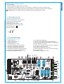 3
3
-
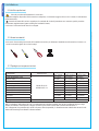 4
4
-
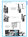 5
5
-
 6
6
-
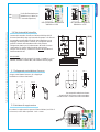 7
7
-
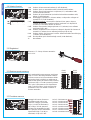 8
8
-
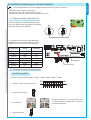 9
9
-
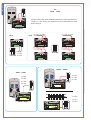 10
10
-
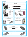 11
11
-
 12
12
-
 13
13
-
 14
14
-
 15
15
-
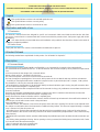 16
16
-
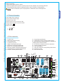 17
17
-
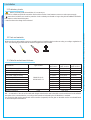 18
18
-
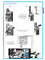 19
19
-
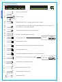 20
20
-
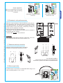 21
21
-
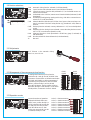 22
22
-
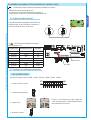 23
23
-
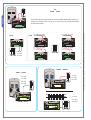 24
24
-
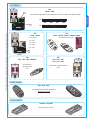 25
25
-
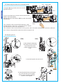 26
26
-
 27
27
-
 28
28
-
 29
29
-
 30
30
-
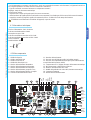 31
31
-
 32
32
-
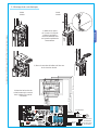 33
33
-
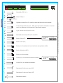 34
34
-
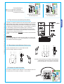 35
35
-
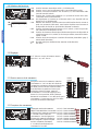 36
36
-
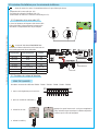 37
37
-
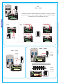 38
38
-
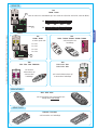 39
39
-
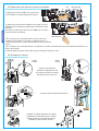 40
40
-
 41
41
-
 42
42
-
 43
43
-
 44
44
-
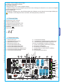 45
45
-
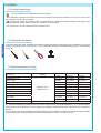 46
46
-
 47
47
-
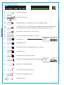 48
48
-
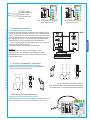 49
49
-
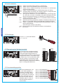 50
50
-
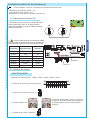 51
51
-
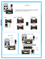 52
52
-
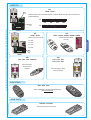 53
53
-
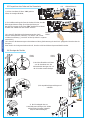 54
54
-
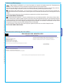 55
55
-
 56
56
-
 57
57
-
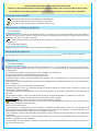 58
58
-
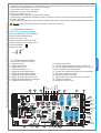 59
59
-
 60
60
-
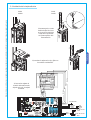 61
61
-
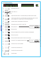 62
62
-
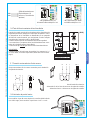 63
63
-
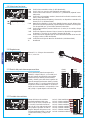 64
64
-
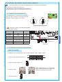 65
65
-
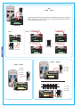 66
66
-
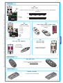 67
67
-
 68
68
-
 69
69
-
 70
70
-
 71
71
-
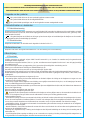 72
72
-
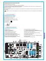 73
73
-
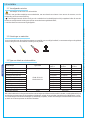 74
74
-
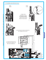 75
75
-
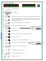 76
76
-
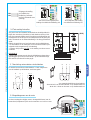 77
77
-
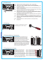 78
78
-
 79
79
-
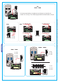 80
80
-
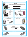 81
81
-
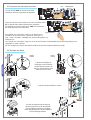 82
82
-
 83
83
-
 84
84


in andere talen
- English: CAME 2199ZG5 Installation guide
- italiano: CAME 2199ZG5 Guida d'installazione
- français: CAME 2199ZG5 Guide d'installation
- Deutsch: CAME 2199ZG5 Installationsanleitung
Gerelateerde papieren
-
CAME 2199ZG6 Installatie gids
-
-
-
-
-
-
CAME Z24-Z230 Spare Parts Manual
-
-
-