
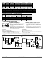
Handleiding ejector SCP / SMP
Operating Instructions for Ejectors SCP / SMP
30.30.01.00248-NL Status 03.2022 / Index 02 Pagina / Page 1/17
J. Schmalz GmbH
Johannes-Schmalz-Str. 1
D - 72293 Glatten
Tel +49 +7443 / 2403 - 0
Fax +49 +7443 / 2403 - 259
http://www.schmalz.de
e-mail: schmalz@schmalz.de
Tevens geldende documenten
Handleiding VS-V-PM 30.30.01.00047
Handleiding VS-V-A-EM 30.30.01.00036
Handleiding VS-V / VS-P / VS-P1 30.30.01.00033
Handleiding VS-Series 30.30.01.00031
Handleiding VS-D-Series 30.30.01.00011
Onderhoudsinstructie SCP / SMP 30.30.01.00076
Handleiding VSi V D M8-4 30.30.01.00956
Handleiding VSi V D M8-4 30.30.01.00997
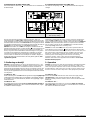
1. Technische specificaties
Werkingsprincipe: Vacuümopwekking door middel van gestuurde
perslucht met venturiwerking.
Toepassing: Het toestel is bestemd voor vacuümopwekking, d.w.z. voor
het evacueren van bijv. vacuümgrijpers met als doel het vasthouden van
lasten of het evacueren van andere elementen. Het apparaat mag worden
toegepast om lucht en andere neutrale gassen conform EN 983 te
evacueren.
Het toestel mag niet worden gebruikt voor het transport (pompen) van
vloeistoffen of granulaat.
Medium: gefilterde (SCP 10/15: max. 20 µm, SCP 20-30 en
SMP 15-30: max. 40 µm) oliehoudende of olievrije perslucht of neutrale
gassen conform EN 983.
Aanbevolen olie: olie klasse H, (HM 32/HG 32) - ISO 3498
Viscositeitsklasse: VG 32 - ISO 3448 , bijv. HYSPIN SP 32, MAGNAGLIDE
D 32 (Castrol)
Maximale bedrijfsdruk: 4 ... 6 bar
(optimale bedrijfsdruk bij ejectoringang: 5 ... 6 bar )
Montagepositie
Willekeurig. Onder bepaalde omstandigheden (stof; olie of andere
vloeistoffen aan de aanzuigkant) is het eventueel aan te raden de ejector
met het filter verticaal naar beneden te installeren.
Voedingsspanning
(Laagspanning PELV)
Elektromagnetische kleppen: +24 V DC -5 % / +10 %
Vacuümschakelaars: +10,8 ... 30 V DC
Toegestaan temperatuurbereik
Omgevingstemperatuur: 0 °C ... +45 °C
Te evacueren medium: 0 °C ... +60 °C
1. Technical Data
Principle of operation: vacuum generation by means of controlled
compressed air (Venturi principle).
Application: the unit is intended for vacuum generation, i.e. for evacuation
of suction pads in order to secure loads, or for evacuation of other
containers. It may be used for removal of air or other neutral gases in
accordance with EN 983.
The unit is not intended for the transport (pumping) of liquids or granulates.
Medium: filtered (SCP 10/15: max. 20 µm, SCP 20-30 and
SMP 15-30: max. 40 µm), oily or oil-free compressed air or neutral gases
in accordance with EN 983.
Recommended oil: oil of class H, (HM 32/HG 32) - ISO 3498
Viscosity class: VG 32 - ISO 3448, such as HYSPIN SP 32, MAGNAGLIDE
D 32 (Castrol)
Permissible operating pressure: 4.....6 bar
(optimum pressure at ejector inlet: 5 ... 6 bar )
Installation orientation
Any. Under certain conditions (dust; oil or similar liquids on the inlet side) it
may be advisable to install with the filter pointing vertically downwards.
Supply voltage
(Protected extra-low voltage PELV)
Solenoid valves: +24 V DC -5% / +10%
Vacuum switches: +10.8 ... 30 V DC
Permissible temperature range
Ambient temperature: 0°C ... +45°C
Medium to be evacuated: 0°C ... +60°C
Toegepaste materialen Materials
Lichaam
Aluminiumlegering geëloxeerd
Body
Aluminium alloy, anodised
Filterkast
PC
Filter casing
PC
Filterinzetstuk
Poroplast (poreus PE); grootte van de
poriën 50 µm
Filter insert
Poroplast (porous PE); pore size 50 µm
Geluiddemper
Poroplast (poreus PE)
Silencer
Poroplast (porous PE)
Deksel geluiddemper
POM
Silencer cover
POM
Bouten
Staal, met zwarte chromaatlag/verzinkt
Screws
Steel, black-chromated / galvanized
Interne onderdelen
Messing; POM; roestvast staal; luminium
Internal parts
Brass; POM; stainless steel; aluminium
Pakkingen
NBR
Gaskets
NBR
Smering
Siliconenvrij
Lubrication
Silicone-free
Elektromagnetische kleppen
Toestel
Spanning /
tolerantie
Vermogen
Inschakel-
duur
Schakelduur
aan/uit
Handbediening
Overspannings-
beveiliging
Statusindicatie
Beschermings-
graad
SCP 10-15
24 V DC -5/+10%
1,3 W
100 %
8 ms / 10 ms
Drukknop
Zenerdiode (in klep)
LED - rood
IP 40 (met
stekker)
SMP / SCP 20-30
24 V DC -5/+10%
2,5 W
100 %
10 ms / 12 ms
Drukknop
Varistor (in stekker)
LED - rood
IP 65 (met
stekker)
Solenoid Valves
Unit
Voltage / Tolerance
Power
Duty cycle
Switching time on/off
Manual actuation
Protective circuit
Status indicator
Enclosure type
SCP 10-15
24 V DC -5/+10%
1.3 W
100 %
8 ms / 10 ms
Push button
Z diode (in valve)
LED – red
IP 40 (with plug)
SMP / SCP 20-30
24 V DC -5/+10%
2.5 W
100 %
10 ms / 12 ms
Push button
Varistor (in plug)
LED - red
IP 65 (with plug)

Handleiding ejector SCP / SMP
Operating Instructions for Ejectors SCP / SMP
30.30.01.00248-NL Status 03.2022 / Index 02 Pagina / Page 2/17
J. Schmalz GmbH
Johannes-Schmalz-Str. 1
D - 72293 Glatten
Tel +49 +7443 / 2403 - 0
Fax +49 +7443 / 2403 - 259
http://www.schmalz.de
e-mail: schmalz@schmalz.de
Type-aanduidingen Type Designations
SCP
Schmalz Compact Pump
SCP
Schmalz Compact Pump
SMP
Schmalz Mega Pump
SMP
Schmalz Mega Pump
10 ... 30
Sproeierdiameter = 1,0 .... 3,0 mm
10 ... 30
Nozzle diameter = 1.0 ... 3.0 mm
NO / NC
Rustpositie zuigklep (elektromagnetische klep),
NO = normaal geopend, NC = normaal gesloten
NO / NC
Idle position of suction valve (solenoid valve),
NO = normally open, NC = normally closed
FS
Zonder elektromagnetische kleppen, geschikt voor
externe besturing
FS
without solenoid valves, suitable for external control
AS
Met afblaasklep en terugslagklep
AS
with blow-off valve and non-return valve
V ...
Met vacuümschakelaar
V ...
with vacuum switch
R ...
Met interne regeling (automatische luchtbesparing)
R ...
with internal regulation (automatic air-saving)

30.30.01.00248-NL Status 03.2022 / Index 02 Pagina / Page 3/17
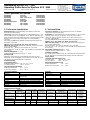
Ejector SCP 10 - 15
(ook geregelde versie ...RD/RE / also regulated version ...RD/RE)
Ejectors SMP 15 - 30 and SCP 20 – 30
(ook geregelde versie ...RD/RE / also regulated version ...RD/RE)
Ejectors SCP 10 – 15 ...FS
(met externe besturing / with external control)
Ejectors SMP 15 - 30 ... / SCP 20 – 30
(met externe besturing / with external control)
Ejectors SCP 10 – 15 ...FS-RP (met externe besturing,
pneumatisch geregeld / with external control, pneumatically
regulated)
Ejectors SMP 15 - 30 ... / SCP 20 – 30 ... FS-RP (met externe besturing,
pneumatisch geregeld / with external control, pneumatically regulated)
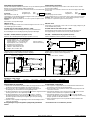
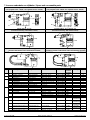
1 Montagegaten voor de ejector
SCP 10-15: diameter 4,5 mm
SMP / SCP 20-30: diameter 5,5 mm
2 Vacuümaansluiting
SCP 10-15: schroefdraad G1/8"
SMP / SCP 20-30: schroefdraad G3/8"
3 Persluchtaansluiting
SCP 10-15: schroefdraad G1/8"
SMP / SCP 20-30: schroefdraad G1/4"
4 Filterkast
5 Filterelement
6 Geluiddemper
7 Vacuümschakelaar
8 Elektrische aansluiting voor vacuümschakelaar (behalve ... VPM)
Voor alle toestellen: M8 x 1
9 Elektrische aansluiting voor stuurklep „zuigen”
SCP 10-15: geometrisch verbonden; niet gestandaardiseerd
SMP / SCP 20-30: connector volgens DIN 43650, vorm C
10 Handmatige hulpbediening (drukknop) voor stuurklep „zuigen”
11 Elektrische aansluiting voor stuurklep „afblazen”
12 Handmatige hulpbediening (drukknop) voor stuurklep „afblazen”
13 Instelschroef afblaasimpuls (alleen bij SMP...)
14 Stuurluchtaansluiting „zuigen” schroefdraad M5
15 Stuurluchtaansluiting „afblazen” schroefdraad M5
16 Persluchttoevoer voor pneumatische vacuümschakelaar
(alleen bij versie ... FS-RP)
17 Stuurleiding „zuigen” (alleen bij versie ... FS-RP)
1 Mounting holes for ejector
SCP 10-15: Diameter 4.5 mm
SMP / SCP 20-30: Diameter 5.5 mm
2 Vacuum connector
SCP 10-15: Thread G1/8"
SMP / SCP 20-30: Thread G3/8"
3 Compressed-air connector
SCP 10-15: Thread G1/8"
SMP / SCP 20-30: Thread G1/4"
4 Filter housing
5 Filter element
6 Silencer
7 Vacuum switch
8 Electrical connector for vacuum switch (except ... VPM)
On all versions: M8 x 1
9 Electrical connector for pilot valve “Suction”
SCP 10-15: positive locking, not standardised
SMP / SCP 20-30: connector to DIN 43650, shape C
10 Auxiliary manual actuation (push button) for pilot valve “Suction”
11 Electrical connector for pilot valve “Blow off”
12 Auxiliary manual actuation (push button) for pilot valve “Blow off”
13 Throttle screw for blow-off pulse (SMP... only)
14 Control air connection “Suction” Thread M5
15 Control air connection “Blow off” Thread M5
16 Compressed air for pneumatic vacuum switch
(only on version ... FS-RP)
17 Control line “Suction” (only on version ... FS-RP)

30.30.01.00248-NL Status 03.2022 / Index 02 Pagina / Page 4/17
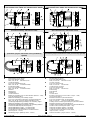
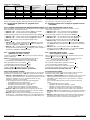
1.1 Ejector SMP
Zuigvermogen / Suction capacity
Vacuüm / Vacuum
Luftverbruik / Air consumption
Seite / Page 1/1 03.2000
Fax +49 +7443 / 2403 - 259
e-mail: schmalz@schmalz.de
Zuigvermogen (l/min)
Bedrijfsdruk (bar)
Seite / Page 1/1 03.2000
Fax +49 +7443 / 2403 - 259
e-mail: schmalz@schmalz.de
Vacuüm (mbar)
Bedrijfsdruk (bar)
Seite / Page 1/1 03.2000
Fax +49 +7443 / 2403 - 259
e-mail: schmalz@schmalz.de
Bedrijfsdruk (bar)
Luchtverbruik (l/min)
Zuigen
Afblazen
Technische specificaties / Technical Data
Type /
Type
Sproeier- /
Nozzle
Max. vacuüm
Max. vacuum
Max. zuigvermogen
Max. suction capacity
Bedrijfsdruk
Operating pressure
Totaal gewicht /
Total weight
SMP 15
1,5 mm
85 %
65 l/min
5 ... 6 bar
0,465 kg
SMP 20
2 mm
85 %
116 l/min
5 ... 6 bar
0,465 kg
SMP 25
2,5 mm
85 %
161 l/min
5 ... 6 bar
0,485 kg
SMP 30
3 mm
85 %
200 l/min
5 ... 6 bar
0,485 kg
Zuigvermogen bij verschillende maten van evacuatie in l/min / Suction capacity at various degrees of evacuation in l/min
Type
-50
-100
-200
-300
-400
-500
-600
-700
-800
SMP 15
62
58
50
41
32
21
16
9
4
SMP 20
108
101
90
78
63
48
36
18
5
SMP 25
149
136
123
107
86
66
49
25
7
SMP 30
184
168
153
132
107
82
61
31
9
Luchtverbruik en geluidsdrukniveau / Air consumption and noise level
Luchtverbruik in Nl/min bij 5 bar voedingsdruk /
Air consumption in Nl/min at a supply pressure of 5 bar
Geluidsdrukniveau bij zuigen /
Noise level during suction
Type
Zuigen /
Evacuating
Afblazen min. /
Blowing off, min.
Afblazen max. /
Blowing off, max.
Zonder last /
Without load
Met last /
With load attached
SMP 15
117
170
250
74
74
SMP 20
190
170
250
78
76
SMP 25
310
170
250
82
72
SMP 30
420
170
250
82
82
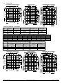
1.2 Ejector SCP
Zuigvermogen / Vacuum Flow
Vacuüm / Vacuum
Luftverbruik / Air consumption
Seite / Page 1/1 03.2000
Fax +49 +7443 / 2403 - 259
e-mail: schmalz@schmalz.de
Zuigvermogen (l/min)
Bedrijfsdruk (bar)
Seite / Page 1/1 03.2000
Fax +49 +7443 / 2403 - 259
e-mail: schmalz@schmalz.de
Vacuüm (mbar)
Bedrijfsdruk (bar)
Seite / Page 1/1 03.2000
Fax +49 +7443 / 2403 - 259
e-mail: schmalz@schmalz.de
Zuigen
Afblazen
Bedrijfsdruk (bar)
Luchtverbruik (l/min)

30.30.01.00248-NL Status 03.2022 / Index 02 Pagina / Page 5/17
Technische specificaties / Technical Data
Type
Sproeier- /
Nozzle
Max. vacuüm
Max. vacuum
Max. zuigvermogen
Max. Suction capacity
Bedrijfsdruk
Operating pressure
Totaal gewicht /
Total weight
SCP 10
1 mm
85 %
37 l/min
5 ... 6 bar
0,275 kg
SCP 15
1,5 mm
85 %
65 l/min
5 ... 6 bar
0,275 kg
SCP 20
2 mm
85 %
116 l/min
5 ... 6 bar
0,465 kg
SCP 25
2,5 mm
85 %
161 l/min
5 ... 6 bar
0,485 kg
SCP 30
3 mm
85 %
200 l/min
5 ... 6 bar
0,485 kg
Zuigvermogen bij verschillende maten van evacuatie in l/min / Suction capacity at various degrees of evacuation in l/min
Type
-50
-100
-200
-300
-400
-500
-600
-700
-800
SCP 10
35,4
33,2
28,8
24
19,4
16
11,2
6
1,4
SCP 15
62
58
50
41
32
21
16
9
4
SCP 20
108
101
90
78
63
48
36
18
5
SCP 25
149
136
123
107
86
66
49
25
7
SCP 30
184
168
153
132
107
82
61
31
9
Luchtverbruik en geluidsdrukniveau / Air consumption and noise level
Luchtverbruik in Nl/min bij 5 bar voedingsdruk /
Air consumption in Nl/min at a supply pressure of 5 bar
Geluidsdrukniveau bij zuigen /
Noise level during suction
Type
Zuigen /
Evacuating
Afblazen min. /
Blowing off, min.
Afblazen max. /
Blowing off, max.
Zonder last /
Without load
Met last /
With load attached
SCP 10
53
200
68
66
SCP 15
117
200
68
68
SCP 20
190
200
78
76
SCP 25
310
200
82
72
SCP 30
420
200
82
82
2. Inbedrijfstelling / Commissioning
Voorwaarden: Lees de gebruiks- en
veiligheidsinstructies zorgvuldig door
Gebruik correct behandelde perslucht (zie Technische
specificaties) (de kwaliteit van de perslucht is van
doorslaggevend belang voor een optimale levensduur
van het toestel)
Als er oliehoudende perslucht wordt toegepast, dient
dit altijd toegepast te worden, aangezien de olie de
oorspronkelijke smering uit het toestel verwijderd heeft.
Geen olievrije perslucht gebruiken!
Prerequisites: read the user and safety instructions
carefully
Use correctly processed compressed air (see the
Technical Data) (the quality of the compressed air is of
decisive importance for achieving an optimum operating
lifetime).
If oily compressed air is used, it must always be used,
since the oil removes the initial lubrication from the unit.
Do not change to oil-free compressed air later!
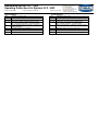
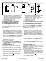
2.1 Montage
Ruimte voor montage/demontage
Houd de ruimtes uit de tekeningen voor montage/demontage aan, om
vervangen van het filter te vereenvoudigen
de elektrische aansluitkabels zonder knikken te kunnen leggen
de pneumatische leidingen/slangen te kunnen leggen zonder deze plat
te drukken
2.1 Installation
Space for installation and removal
Please note the installation / removal spaces shown in the drawings, since
these
simplify changing of the filter,
permit laying the electrical cables without kinks,
permit laying of the pneumatic hoses without pinching them.
SCP 10 ... 15
SMP / SCP 20 ... 30

30.30.01.00248-NL Status 03.2022 / Index 02 Pagina / Page 6/17
2.2 Elektrische aansluitingen
Sluit de desbetreffende stekkers en/of kabels aan op de elektromagnetische
kleppen en de vacuümschakelaar (indien gemonteerd).
Voor de juiste stekkers en/of kabels voor ieder toestel, zie de onderstaande
toebehorentabel (punt 5).
2.2 Electrical Connections
Connect the related plugs and/or cables to the solenoid valves and the
vacuum switch (if fitted).
See the table of accessories in Section 5 for the correct plug and/or cable
for each unit:
SCP 10/15
Klik de stekkers vast in de
aansluitingen van de elektromagnetische kleppen. Druk op de vastzetklem
om de stekkers weer los te koppelen.
Attentie! Let er bij het aansluiten van +24 V DC op, dat u de polen correct
aansluit!
Het toestel is niet ompoolbeveiligd!
SCP 10/15
Snap the plugs into the sockets
on the solenoid valves. To remove them, press down on the locking levers.
Caution!: when connecting +24 V DC, ensure that the polarity is correct,
since there is no protection against reverse polarity!
SMP/SCP 20-30
Stekkers voor kleppen worden met schroef bevestigd. U kunt +24 V DC op
een willekeurige pool aansluiten.
SMP/SCP 20-30
Valve plugs are secured with screws. The +24 V DC supply voltage may be
connected with either polarity.
SCP/SMP met vacuümschakelaar (behalve ... VPM)
Steek de stekkers in de aansluitingen en borg ze met wartelmoeren.
De aansluitingen voor de voedingsspanning zijn ompoolbeveiligd.
SCP/SMP with vacuum switch (except ... VPM)
Snap the plugs into the sockets and secure them with the union nut.
The supply voltage connections have reverse-polarity protection.
SCP/SMP ... RE/RD (elektrisch geregelde versie)
Kabel van de aansluitingsverdeler (let op de posities (a) (b) (c))
SCP/SMP ... RE/RD (electrically regulated versions)
Cable to distributor (note the positions of cables (a) (b) (c))
WH: Analoge uitgang (+1 ... +5 V) alleen bij RE
Digitale uitgang 2 (+24 V) alleen bij RD *
Analog output (+1 ... +5 V) for RE only
Digital output 2 (+24 V) for RD only *
BN: Positieve pool / Positive pole
GY: Negatieve pool / Negative pole
YE: Afblazen / AAN / Blow-off / ON
GN: Zuigen / UIT / Suction / OFF
Attentie: Geen spanning aan de aansluiting (WH) koppelen! Caution: do not connect any voltage to (WH)!
* Digitale uitgang 2 onafhankelijk van interne regeling * Digital output 2 independent of internal control loop
(Digitale uitgang 1 wordt gebruikt voor interne regeling) (Digital output 1 is used for internal adjustment)
Aderkleuren / Cable colours
BN = bruin
GY = grijs
YE = geel
GN = groen
WH = wit
RD = rood
BK = zwart
BN = brown
GY = grey
YE = yellow
GN = green
WH = white
RD= red
BK = black
2.3 Pneumatische aansluiting
Sluit het toestel uitsluitend aan door middel van slangen of buizen die de
aanbevolen binnendiameter hebben (zie onderstaande tabel).
Zorg ervoor dat er geen vuildeeltjes of vreemde voorwerpen in de
aansluitingen van het toestel en in de slangleidingen zitten.
Als de binnendiameter aan de persluchtzijde 3 te klein is, krijgt het toestel
te weinig perslucht voor een optimale prestatie.
Als de binnendiameter aan de vacuümzijde 2 te klein is, wordt de
stromingweerstand langs de binnenkant van de leiding te hoog; dit
heeft een negatieve invloed op het zuigvermogen en op de aanzuig-
en afblaastijden.
Gebruik zo kort mogelijke slangleidingen: hoe korter de leidingen, des te
sneller de reactietijden.
De slangleidingen mogen niet geknikt of platgedrukt geïnstalleerd
worden.
2.3 Pneumatic Connections
Use only hoses or pipes with the recommended internal diameter for
the unit being connected (see the table below).
Ensure that there are no particles of dirt or other foreign objects in the
connectors and hoses.
If the internal diameter on the compressed-air side 3 is too small, the
unit will receive insufficient air for optimum operation.
If the internal diameter on the vacuum side 2 is too small, the flow
resistance will be too high, reducing the suction capacity and increasing
the pick-up times and the blow-off times.
Hoses should be kept as short as possible in order to minimise the
reaction times.
Ensure that hoses are not kinked or pinched.
SMP / SCP 20-30 ... RE/RD
SCP 10-15 ... RE/RD
Positieve pool (RD)
Negatieve pool (BK)
Positive Pol (RD)
Negative Pol (BK)
Interne regeling /
Internal control loop

30.30.01.00248-NL Status 03.2022 / Index 02 Pagina / Page 7/17
Aanbevolen slangdiameters Recommended hose diameters
Toestel
Persluchtzijde
binnen- /
Vacuümzijde
binnen- /
Externe besturing
stuurluchtzijdig
binnen-
Unit
Internal on
pressure side
Internal on
vacuum side
External control
control air side
internal -
SCP 10...
2 mm
4 mm
2 mm
SCP 10...
2 mm
4 mm
2 mm
SCP 15...
4 mm
6 mm
2 mm
SCP 15...
4 mm
6 mm
2 mm
SMP 15...
4 mm
6 mm
2 mm
SMP 15...
4 mm
6 mm
2 mm
SMP 20/SCP 20...
6 mm
9 mm
2 mm
SMP 20/SCP 20...
6 mm
9 mm
2 mm
SMP 25/SCP 25...
9 mm
9 mm
2 mm
SMP 25/SCP 25...
9 mm
9 mm
2 mm
SMP 30/SCP 30...
9 mm
12 mm
2 mm
SMP 30/SCP 30...
9 mm
12 mm
2 mm
De aanbevolen binnendiameters gelden voor een max. lengte van 2 m.
Gebruik voor langere slangen de binnendiameter die een maat groter is.
2.4 Functiecontrole (geldt niet voor geregelde versie
...RE/RD/RP)
2.4.1 Toestellen met geïntegreerde elektromagnetische kleppen
Nadat alle elektrische en pneumatische verbindingen tot stand zijn gebracht,
dient u het toestel van perslucht te voorzien.
SMP/SCP... NO...: Toestel wordt in toestand „zuigen” geschakeld.
SMP/SCP... NC...: Toestel blijft in toestand „niet zuigen”.
Sluit de voedingsspanning aan op de elektromagnetische klep „zuigen” 9.
SMP/SCP... NO...: Toestel wordt in toestand „niet zuigen” geschakeld.
SMP/SCP... NC...: Toestel wordt in toestand „zuigen” geschakeld.
Sluit de voedingsspanning aan op de elektromagnetische klep
„afblazen” 11.
SMP/SCP... NO...: Toestel wordt in toestand „afblazen” geschakeld.
(Laat de voedingsspanning aangesloten op 9, anders overlappen de
toestanden „zuigen” en „afblazen” elkaar.)
SMP/SCP... NC...: Toestel wordt in toestand „afblazen” geschakeld.
(Schakel de elektromagnetische klep 9 spanningsvrij, anders overlappen
de toestanden „zuigen” en „afblazen” elkaar.)
These diameters are for a maximum hose length of 2 m.
For longer hoses, select the next larger diameter.
2.4 Operational Check (does not apply to regulated versions
... RE/RD/RP)
2.4.1 Units with integrated solenoid valves
After making all electrical and pneumatic connections, connect
compressed air to the unit.
SMP/SCP... NO...: unit is switched to the state “Suction”.
SMP/SCP... NC...: unit remains in the state “No suction”.
Connect the supply voltage to the solenoid valve “Suction” 9.
SMP/SCP... NO...: The unit switches to the state “No suction”.
SMP/SCP... NC...: The unit switches to the state “Suction”.
Connect the supply voltage to the solenoid valve “Blow off” 11.
SMP/SCP... NO...: The unit switches to the state “Blow off”.
(Leave the supply voltage connected to 9, since the states “Suction”
and “Blow off” will be superimposed on each other and neither will be
fully active.)
SMP/SCP... NC...: The unit switches to the state “Blow off”.
(Switch the solenoid valve 9 in idle status, since the states “Suction”
and “Blow off” will be superimposed on each other)
2.4.2 Toestellen met externe besturing
(geldt niet voor versie ... FS RP)
Voorzie de aansluitingen 3, 14 en 15 van perslucht (via reeds aanwezige
externe stuurkleppen).
Attentie: De druk dient voor alle aansluitingen even hoog te zijn
(zie pneumatische schema’s in hoofdstuk 8 en 9).
Toestel wordt in de rusttoestand „niet zuigen” geschakeld.
Zet de persluchtttoevoer naar aansluiting 14 stop.
Toestel wordt in toestand „zuigen” geschakeld.
Zet de persluchtttoevoer naar aansluiting 15 stop.
Voorzie aansluiting 14 tegelijkertijd weer van perslucht.
Toestel wordt in toestand „afblazen” geschakeld.
2.4.2 Units with external control
(does not apply to versions ... FS RP)
Apply compressed air to the unit (via locally provided control valves) to
connector 3 and to connectors 14 and 15.
Caution: the same pressure must be applied to all three connectors
(see pneumatic diagrams in Sections 8 and 9).
The unit is now in the state “No suction”.
Disconnect the compressed air supply from connector 14.
The unit switches to the state “Suction”.
Disconnect the compressed air supply from connector 15
and connect the compressed air supply to connector 14 again.
The unit switches to the state “Blow off”.
2.5 Vacuümschakelaar instellen
Sluit de voedingsspanning aan op de vacuümschakelaar (op de versie met
pneumatische vacuümschakelaar .. VPM dient u perslucht aan te sluiten).
SMP/SCP... VM/VE/VEH/VPM: Stel het schakelpunt af op de gewenste
waarde door aan de stelschroef (7.1) te draaien (wij adviseren u om deze
instelling te controleren d.m.v. een vacuümmanometer, bijv. type:
VAM 63/1 U, bestelnr.: 10.07.02.00004)
Als het schakelpunt bereikt is, wordt dit als volgt aangegeven:
- ... VE/VEH/RE/RD: LED (7.2) gaat branden
- ... VM/VD-NO (maakcontact): LED (7.2) gaat branden
- ... VM/VD-NC (breekcontact): LED (7.2) gaat uit
- ... VPM-NO: perslucht aan uitgang (7.6) wordt stopgezet
- ... VPM-NC: perslucht aan uitgang (7.6) wordt geactiveerd
SMP/SCP... VEH: Stel de hysterese af op de gewenste waarde door
aan de stelschroef (7.3) te draaien (wij adviseren u om deze instelling
te controleren d.m.v. een vacuümmanometer).
SMP/SCP... VD: Programmeer het schakelpunt en de hysterese naar
uw wensen d.m.v. het folietoetsenbord (7.1/7.3); de geprogrammeerde
en de gemeten waarden worden weergegeven op het LED-display (7.4).
2.5 Adjust Vacuum Switch
Connect the supply voltage to the vacuum switch (on the version with
pneumatic vacuum switch ..VPM, connect compressed air).
SMP/SCP... VM/VE/VEH/VPM: Turn the adjusting screw (7.1) to set the
switching point to the desired value (we recommend checking the
setting with a vacuum gauge such as Type VAM 63/1 U, Order No.:
10.07.02.00004).
The fact that the switching point has been reached is indicated as
follows:
- ... VE/VEH/RE/RD: the LED (7.2) lights
- ... VM/VD-NO (normally open): the LED (7.2) lights
- ... VM/VD-NC (normally closed): the LED (7.2) is extinguished
- ... VPM-NO: the compressed air at the output (7.6) is switched off
- ... VPM-NC: the compressed air at the output (7.6) is switched on
SMP/SCP... VEH: Turn the adjusting screw (7.3) to set the hysteresis to
the desired value (we recommend checking the setting with a vacuum
gauge).
SMP/SCP... VD: Programme the switching point and the hysteresis as
desired with the membrane keypad (7.1/7.3). The programmed and
measured (actual) values are shown on the LED display (7.4)

30.30.01.00248-NL Status 03.2022 / Index 02 Pagina / Page 8/17
Vacuümschakelaar (7) voor ejector SMP / SCP Vacuum switch (7) for ejector SMP / SCP ...
... VM
... VE
... VEH / RE
... VD / RD
... VPM
Type vacuümschakelaar
VS-V-A-EM-M8
VS-V-A-PNP-S
VS-V-PNP
VS-V-D-PNP
VS-V-PM
7.1 Potentiometer voor afstelling van het schakelpunt of folietoetsenbord
voor programmering van het schakelpunt (bij versie ... VD/RD)
7.2 LED voor indicatie van de schakeltoestand
7.3 Potentiometer voor afstelling van de hysterese of folietoetsenbord
voor programmering van de hysterese (bij versie ... VD/RD)
7.4 LED-display (bij versie ... VD/RD)
7.5 Pneumatische ingang (bij versie ... VPM)
7.6 Pneumatische uitgang (bij versie ... VPM)
De aparte bedieningsvoorschriften van de desbetreffende
vacuümschakelaar dienen tevens opgevolgd te worden.
2.6 Toestellen met interne regeling (automatische
luchtbesparing) (serie ... RE/RD/RP)
2.6.1 Elektrische regeling (... RE/RD)
Sluit de voedingsspanning (permanent) aan op de aansluitingen BN(+)
en GY(-). Plaats het toestel met een aangesloten vacuümgrijper op een
werkstuk met een zo dicht mogelijk oppervlak of op een ander geschikt
glad en dicht oppervlak.
7.1 Potentiometer switching point adjustment or membrane keypad for
programming the switching point (on versions ...VD/RD )
7.2 LED for switching status indication
7.3 Potentiometer for hysteresis adjustment or membrane keypad for
programming the hysteresis (on versions ... VD/RD)
7.4 LED display (on versions ... VD/RD)
7.5 Pneumatic input (on version ... VPM)
7.6 Pneumatic output (on version ... VPM)
See also the separate Operating Instructions for the vacuum switch
being used.
2.6 Units with internal regulation (automatic air-saving)
(Serie ... RE/RD/RP)
2.6.1 Electrical regulation... RE/RD)
Connect the supply voltage (permanently) to the terminals BN(+) and
GY(-). Connect a suction pad to the unit and place the pad on the
workpiece to be picked up (which should be as air-tight as possible) or on
some other suitably flat and air-tight surface.
SMP/SCP...NO ...: Het toestel wordt door de interne regeling in de
toestand „niet zuigen” geschakeld. De geïntegreerde terugslagklep
houdt deze toestand in stand, afhankelijk van de poreusheid van de
slangen en het werkstuk, totdat het vacuümniveau lager is dan het van
tevoren ingestelde regelbereik (hysterese van de vacüumschakelaar),
waarna de functie „zuigen” weer geactiveerd wordt totdat het
vacuümniveau het ingestelde schakelpunt bereikt en de functie „zuigen”
onderbroken wordt.
SMP/SCP... NC ...: De functie „zuigen” wordt geactiveerd, vervolgens
wordt het toestel door de interne regeling in de toestand „niet zuigen”
geschakeld. Daarna wordt het proces voortgezet, zoals hierboven
beschreven is.
SMP/SCP...NO ...: the internal control loop sets the unit to the state
“No suction”. The built-in non-return valve maintains this state,
depending on the porosity of the hoses and workpiece, until the vacuum
drops below the preset lower limit (hysteresis of the vacuum switch),
when the function “Suction” is again activated until the vacuum
reaches the upper limit value, when it is again switched off.
SMP/SCP...NC ...: “Suction” is activated and the internal control
loop then switches to the state “No suction”. Further operations are
then as described above.
Sluit +24 V DC aan op de aansluiting GN.
De functie „zuigen” wordt onderbroken, onafhankelijk van de
schakeltoestand van de interne regeling.
Sluit +24 V DC aan op de aansluiting YE.
De functie „afblazen” wordt geactiveerd en tegelijkertijd wordt de
functie „zuigen” onderbroken, onafhankelijk van de schakeltoestand
van de interne regeling. De aansluiting GN hoeft in dit geval niet
aangekoppeld te worden!
Connect +24 VDC to the terminal GN.
The function "Suction" is deactivated, regardless of the switching
status of the internal control loop.
Connect +24 VDC to the terminal YE.
The function “Blow off” is activated and the function “Suction” is
deactivated simultaneously, regardless of the switching status of the
internal control loop. Terminal GN does not need to be connected in
this case!
2.6.2 Pneumatische regeling (... RP)
Voorzie aansluiting 3 en (via de reeds aanwezige externe stuurklep
„afblazen”) aansluiting 15 van perslucht.
Attentie: De druk dient voor beide aansluitingen even hoog te zijn (zie
pneumatisch schema in hoofdstuk 8 en 9). Plaats het toestel met een
aangesloten vacuümgrijper op een werkstuk met een zo dicht mogelijk
oppervlak of op een ander geschikt glad en dicht oppervlak.
Het toestel wordt door de interne regeling in de toestand „niet zuigen”
geschakeld. De geïntegreerde terugslagklep houdt deze toestand in
stand, afhankelijk van de poreusheid van de slangen en het werkstuk,
totdat het vacuümniveau lager is dan het van tevoren ingestelde
regelbereik (hysterese van de vacüumschakelaar), waarna de functie
„zuigen” weer geactiveerd wordt totdat het vacuümniveau het ingestelde
schakelpunt bereikt en de functie „zuigen” onderbroken wordt.
Zet de persluchttoevoer naar aansluiting 15 stop via de reeds aanwezige
externe stuurklep „afblazen”.
De functie „afblazen” wordt geactiveerd.
2.6.2 Pneumatic Regulation ( ... RP)
Connect compressed air directly to connector 3 and via a locally provided
control valve to connector 15.
Caution: the same pressure must be connected to both connectors (see
pneumatic diagram in Sections 8 and 9).
Connect a suction pad to the unit and place the pad on the workpiece to be
picked up (which should be as air-tight as possible) or on some other
suitably flat and air-tight surface.
the internal control loop sets the unit to the state “No suction”. The
built-in non-return valve maintains this state, depending on the porosity
of the hoses and workpiece, until the vacuum drops below the preset
lower limit (hysteresis of the vacuum switch), when the function
“Suction” is again activated until the vacuum reaches the upper limit
value, when it is again switched off.
Disconnect the compressed air supply from 15 with the locally provided
control valve.
The “Blow off” function is activated.

30.30.01.00248-NL Status 03.2022 / Index 02 Pagina / Page 9/17
2.7 Afblaasimpuls instellen (alleen SMP)
Het toestel heeft een stelschroef 13 voor het instellen van de intensiteit van
de afblaasimpuls.
2.7 Adjusting the Blow-Off Pulse (SMP only)
This unit has an adjusting screw 13 for adjustment of the blow-off pulse
strength.
MIN
MAX (basisinstelling) /
MAX (factory setting)
Door de stelschroef 90° (instelling is traploos) te draaien, kunt u de
intensiteit wijzigen van Min. in Max. (fabrieksinstelling); zodoende kan het
reeds opgewekte vacuüm sneller of langzamer gereduceerd worden. Deze
toestellen hebben bovendien een extra functie die het mogelijk maakt dat
het volledige persluchtvolume in het zuigkanaal geperst wordt; dit heeft een
positief effect op de afblaastijd, vooral bij lange zuigleidingen.
Attentie! De toestellen uit de SMP-serie mogen in de afblaasmodus niet
gebruikt worden met gesloten vacuümaansluiting 2 en met slangen die een
kleinere binnendiameter dan voorgeschreven hebben (vacuümzijde, zie
boven), aangezien dit tot ontoelaatbare drukverhoudingen in het systeem
zou leiden en beschadiging of vernietiging van onderdelen zou kunnen
veroorzaken. Bovendien mogen deze toestellen niet gebruikt worden
voor het vullen van drukvaten of het aandrijven van cilinders, kleppen of
andere elementen die met druk werken; dit soort gebruik geldt als „niet-
reglementair gebruik”.
Turning the screw through 90° (it has no stops) varies the strength of the
pulse from Min. to Max. (factory setting), and the previously generated
vacuum is reduced more slowly or quickly. These units have an additional
function which permits the entire volume of compressed air to be blown
into the suction channel; this has a positive effect on the blow-off time,
particularly if long suction hoses are being used.
Caution! The units of the SMP Series may not be operated in blow-off
mode with the vacuum connector 2 closed and with hoses with less than
the recommended internal diameter (see above) on the vacuum side, since
this would result in unpermissible pressure conditions and could cause
damage to, or destruction of, internal components. Furthermore, these
units may not be used for filling pressure reservoirs or for driving
pneumatic cylinders, valves or other pressure-operated functional
elements. Their use for such purposes would constitute “use for other
than the intended purpose”.
3. Bediening en bedrijf
Attentie! In de transportzone van de last, die vastgezogen is d.m.v. van
het vacüum dat door het toestel is opgewekt, mogen zich geen personen
onder deze last bevinden. Als de stroomtoevoer uitvalt, voorkomt een
geïntegreerde terugslagklep dat het vacuüm te snel wegvalt en dat de last
daardoor plotseling losgelaten wordt. Door lekkage in de slangen of door
ruwe of poreuze oppervlakten kan het vacüum bij stroomuitval desondanks
snel wegvallen.
3. Operation
Caution!: no persons may enter the area below the suspended load which
is held by the vacuum. In the case of failure of electricity, a built-in non-
return valve prevents rapid loss of the vacuum and sudden release of the
load. Nevertheless, leaks in the hoses or rough or porous surfaces on the
load can cause the vacuum to drop more or less quickly if the power fails.
3.1 SMP/SCP... NO ...
Houd er rekening mee dat beide elektromagnetische kleppen tegelijkertijd
voedingsspanning moeten krijgen om het toestel in de toestand „afblazen”
te schakelen, om te voorkomen dat het „afblazen” door gelijktijdig „zuigen”
wordt belemmerd.
3.1 SMP/SCP... NO ...
Please note that both solenoid valves must receive the supply voltage
simultaneously in order to switch the unit to the “Blow off” state.
Otherwise, blowing off will less efficient, as the suction function will hinder
blowing off.
3.2 SMP/SCP... NC ...
De voedingsspanning moet altijd op de ene elektromagnetische klep óf
op de andere aangesloten zijn, om te voorkomen dat de functies „zuigen”
en „afblazen” elkaar overlappen.
3.2 SMP/SCP... NC ...
The supply voltage must always be connected to either one solenoid
valve or the other at any time in order to avoid simultaneous activation of
the “Suction” and “Blow off” functions.

30.30.01.00248-NL Status 03.2022 / Index 02 Pagina / Page 10/17
3.3 SMP/SCP... met interne regeling (versies ... RE/RD/RP)
De schakelfrequentie en daardoor het luchtbesparingseffect zijn afhankelijk
van de oppervlakte en de luchtdichtheid van het vast te zuigen werkstuk of
het te evacueren volume. Zeer poreuze oppervlakten kunnen tot een relatief
hoge schakelfrequentie leiden, waardoor er slechts weinig lucht bespaard
wordt en het toestel sneller zal slijten.
De vacuümschakelaar, en dus ook het interne regelbereik, wordt in de
fabriek ingesteld. De volgende waarden zijn ingesteld:
3.3 SMP/SCP... with internal regulation (Versions ... RE/RD/RP)
The switching frequency, and thus the air-saving effect, depends on the
surface of the load and is air-tightness or on the volume to be evacuated.
Very porous workpieces can result in relatively high switching frequencies;
these save little air but cause increased wear on the unit.
The vacuum switch, and thus the regulation range, is set in the factory to
the following values:
Versie ... RD
Versie ... RE
Uitgang 1
Schakelfunctie
NO
Schakelpunt S
750 mbar
Modus
Hysterese
Hysterese H
150 mbar
Schakelpunt H
750 mbar
Hysterese h
150 mbar
Versie ... RP
Uitgang 2
Schakelfunctie
NO
Schakelpunt S
750 mbar
Modus
Hysterese
Hysterese H
50 .. 100
Schakelpunt H
550 mbar
mbar
Hysterese h
10 mbar
Als het regelbereik wordt gewijzigd, dient u er rekening mee te houden
dat u de hysterese niet te klein instelt, aangezien de schakelfrequentie
hierdoor te hoog wordt. Stel de hysterese ook niet te groot in, aangezien dit
de veiligheid kan belemmeren, bijv. als het onderste inschakelpunt van de
regeling lager ligt dan het minimale vacuümniveau waarop het systeem
berekend is.
If these settings are changed, care must be taken that the hysteresis is not
made too small, since this can cause increased switching frequencies, or
too large, since this can reduce the safety function if, for example, the
lower limit of the range lies below the minimum vacuum level required on
which the system design is based.
3.3.1 SMP/SCP... RD
Het toestel produceert een aanvullend digitaal signaal voor toepassing in
een externe besturing (bijv. PLC); dit signaal kan gebruikt worden om de
interne regelkring te controleren. Het signaal kan onafhankelijk van de
interne regelkring geprogrammeerd worden.
Als de fabrieksinstelling gewijzigd wordt, moet het aanvullende signaal dat
voor de controle gebruikt wordt altijd iets lager dan het onderste
inschakelpunt van de interne regelkring liggen (schakelpunt „H” min
hysterese „h”).
3.3.2 SMP/SCP... RE
Het toestel produceert een aanvullend analoog signaal in het bereik
+1......+5 V, dat niet onafhankelijk van de interne regelkring kan worden
ingesteld. De hoogte van de afgegeven spanning is proportioneel aan de
druk van het ingestelde interne regelbereik. Houd er rekening mee dat het
signaal alleen wordt afgegeven tijdens de luchtbesparingspauzes.
3.3.3 SMP/SCP... RP
Het toestel produceert geen aanvullend signaal.
3.3.1 SMP/SCP... RD
These units deliver an additional digital signal for use in an external
controller (such as a PLC). This can be used for monitoring the internal
control loop. The signal can be programmed independently of the internal
control loop.
If the default setting is changed, it should be noted that this signal, if used
for monitoring, should be generated just below the point at which the internal
control loop switches on the vacuum generator (switching point “H” – the
hysteresis “h”).
3.3.2 SMP/SCP... RE
These units deliver an additional analogue signal in the range +1...+5 V
which is not independent of the internal control loop. The output voltage is
proportional by pressure to the internal control loop setting. Note that this
signal is output only when the vacuum generator is switched off.
3.3.3 SMP/SCP... RP
This unit does not deliver an additional signal.
4. Onderhoud
4.1 Algemene informatie
Reinig de buitenkant van het toestel indien nodig met een zachte doek en
zeepsop (max. 60 °C). Let erop dat de geluiddemper niet met zeepsop
doordrenkt wordt!
4.2 Filter
Controleer regelmatig hoe vuil de geïntegreerde vacuümfilter is. Als het filter
te vuil is, wordt de capaciteit minder (langere aanzuigtijden, lager vacuüm).
Als het filter te vuil is, dient het gereinigd of vervangen te worden. Verwijder
daarvoor de bevestigingsschroeven van de filterkast 4 en haal het filter-
inzetstuk 5 eruit. Droog stof kunt u van binnen naar buiten met perslucht
wegblazen; als het stof vochtig of vettig is, adviseren wij u om het filter-
inzetstuk te vervangen.
4. Maintenance
4.1 Introduction
Clean the outside of the unit as necessary with a soft cloth and soap
solution (max. 60 °C). Take care that the silencer does not become
saturated with soap solution!
4.2 Filter
Check the contamination level of the vacuum filter at regular intervals.
Excessive dirt in the filter reduces the performance (longer suction times,
lower vacuum). The filter should be cleaned or replaced when it is dirty. To
do this, remove the securing screws from the filter housing 4 and take out
the filter insert 5. Dry dust can be blown out with compressed air from the
inside outwards. If the dirt is damp or oily, we recommend replacing the
filter insert.
De filterkast zelf mag alleen met zeepsop (max. 60 °C) gereinigd worden.
De pakking van de filterkast kan met zeepsop of wasbenzine gereinigd
worden.
Attentie: Als u de filterkast monteert na afloop van het reinigen:
Vergeet niet om de pakking aan te brengen!
Breng alle schroeven aan en draai ze gelijkmatig vast!
Aandraaimoment van de bevestigingsschroeven van de filterkast: 0,8 Nm.
De filterkast mag niet in contact komen met cyaanacrylaatlijm.
The filter housing may be cleaned only with soap solution
(max. 60 °C). The shaped gasket in the filter housing may be cleaned with
soap solution or benzene.
Caution: when mounting the filter housing after cleaning:
remember to fit the gasket!
insert all screws and tighten them equally!
Tightening torque for the securing screws of the filter housing: 0.8 Nm
Do not allow the filter housing to come into contact with cyanoacrylate
adhesives.
4.3 Geluiddemper
Met verloop van tijd kan de geluiddemper 6 door stof, olie enz. vuil worden;
hierdoor wordt het zuigvermogen lager. In dat geval dient de geluiddemper
vervangen te worden. Reiniging is niet aan te raden als gevolg van de
capillaire werking van het poreuze materiaal.
4.3 Silencer
The silencer 6 can become filled with dust, oil, etc. in the course of time.
This will cause the suction capacity to be reduced. When this occurs, the
silencer should be replaced, since the capillary effect of the porous
material used in it makes cleaning difficult or even impossible.
Version ... RD
Version ... RE
Output 1
Switch function
NO
Switching point S
750 mbar
Mode
Hysteresis
Hysteresis H
150 mbar
Switching point H
750 mbar
Hysteresis h
150 mbar
Version ... RP
Output 2
Switch function
NO
Switching point S
750 mbar
Mode
Hysteresis
Hysteresis H
50 .. 100
Switching point H
550 mbar
mbar
Hysterese h
10 mbar

30.30.01.00248-NL Status 03.2022 / Index 02 Pagina / Page 11/17
5. Toebehoren
5. Accessories
Stekkers voor elektromagnetische kleppen Plugs for solenoid valves
Type stekker
Voor SCP 10 / 15
Plug type
for SCP 10 / 15
Stekker met 3 m kabel
21.04.06.00086
Plug with 3 m cable
21.04.06.00086
Type stekker voor
SMP / SCP 20...30
Plug type for
SMP / SCP 20...30
Stekker met overspanningsbeveiliging en 5 m
kabel
21.04.06.00084
Plug with protective circuit and 5 m cable
21.04.06.00084
Stekker met overspanningsbeveiliging zonder
kabel
21.04.06.00085
Plug with protective circuit, without cable
21.04.06.00085
Stekkers voor vacuümschakelaars Plugs for vacuum switches
Type stekker
Artikelnr.
Plug type
Article No.
Stekker, recht, met 5 m kabel
10.06.02.00031
Plug, straight, with 5 m cable
10.06.02.00031
Stekker, 90°, met 5 m kabel
10.06.02.00032
Plug; 90° with 5 m cable
10.06.02.00032
Stoffilters
Als er in een zeer stoffige omgeving wordt gewerkt of bij fijn stof <50 µm
dient er aan de inlaatkant een stoffilter geïnstalleerd te worden.
Dust filters
In very dusty operating conditions, or in the case of fine dust <50 µm,
a separate dust filter must be fitted on the inlet side.
Type filter
Artikelnr.
Geschikt voor ejector
Filter type
Article No.
Suitable for ejector
F 1/4
10.07.01.00003
SMP / SCP 10-15 ...
F 1/4
10.07.01.00003
SMP / SCP 10-15 ...
F3/8
10.07.01.00004
SMP / SCP 20 ...
F3/8
10.07.01.00004
SMP / SCP 20 ...
STF 3/4
10.07.01.00007
SMP / SCP 25-30 ...
STF 3/4
10.07.01.00007
SMP / SCP 25-30 ...
6. Opsporen van storingen
Storing
Mogelijke oorzaak
Verhelpen
Vacuümniveau
wordt niet bereikt of
Filter is vuil
Filter reinigen of
vervangen
Vacuüm wordt
te langzaam
opgebouwd
Geluiddemper is vuil
Geluiddemper vervangen
Lekkage in slangleiding
Slangkoppelingen
controleren
Lekkage aan
vacuümzuiger
Vacuümzuigers
controleren
Bedrijfsdruk te laag
Bedrijfsdruk verhogen
(zie karakteristieke
krommen)
Binnen- van de
slangleidingen te klein
Zie aanbevelingen voor
slang-
Last kan niet
vastgehouden
worden
Vacuümniveau te laag
Bij luchtbesparings-
schakeling regelbereik
verhogen
Vacuümgrijper te klein
Grotere vacuümgrijper
toepassen
Interne regelkring
schakelt ejector niet
uit
Schakelpunt is hoger
dan max. mogelijk
vacuüm
Schakelpunt verlagen
Interne regelkring
schakelt ejector niet
in
Hysterese groter dan
schakelpunt
Hysterese reduceren of
schakelpunt verhogen
Regeling werkt niet
Kabels aan elektro-
magnetische klep
verwisseld
Kabels correct aansluiten
(zie punt 2.2)
6. Fault-Finding
Symptom
Possible cause
Remedy
Vacuum to low or
Filter dirty
Clean or replace filter
vacuum generation
Silencer dirty
Replace silencer
takes too long
Leaks in hoses
Check hose connectors
Leaks on suction pad
Check suction pads
Operating pressure too
low
Increase the pressure
(see technical data)
Internal diameter of
hoses too small
See recommended hose
diameters
Load cannot be held
Vacuum too low
If air-saving is used,
increase the hysteresis
Suction pad too small
Use a larger suction pad
Internal control loop
does not switch
vacuum generator off
Switching point higher
than the maximum
possible vacuum
Reduce the upper limit
value
Internal control loop
does not switch
vacuum generator on
Hysteresis greater than
switching point
Reduce the hysteresis or
increase the switching
point
Regulation does not
work
Cables connected to
wrong solenoid valves
Connect cables to
correct valves
(see Chapter 2.2)

30.30.01.00248-NL Status 03.2022 / Index 02 Pagina / Page 12/17
7. Reserve-onderdelen en slijtdelen / Spare and consumable parts
Ejector SCP 10 - 15
(ook geregelde versie ...RD/RE / also regulated version ...RD/RE)
Ejectors SMP 15 - 30 en SCP 20 – 30
(ook geregelde versie ...RD/RE / also regulated version ...RD/RE)
Ejector SCP 10 – 15 ...FS
(met externe besturing / with external control)
Ejectors SMP 15 - 30 ... / SCP 20 – 30
(met externe besturing / with external control)
Ejector SCP 10 – 15 ...FS-RP (met externe besturing, pneumatisch
geregeld / with external control, pneumatical regulated)
Ejectors SMP 15 - 30 ... / SCP 20 – 30 ... FS-RP (met externe besturing,
pneumatisch geregeld / with external control, pneumatically regulated)
Pos.
Stuks
Benaming
Designation
Toestel / Unit
Artikelnr.
Aandraai
moment
opvolgen
Geldig
Legende
4
1
Filterkast compleet
Filter housing cpl.
SCP 10-15
10.02.02.00809
0,8 Nm
VB
1
Filterkast compleet
Filter housing cpl.
SMP / SCP 20-30...
10.02.02.00808
0,8 Nm
VB
5
1
Filterelement
Filter element
SCP 10-15
10.02.02.00655
V
1
Filterelement
Filter element
SMP / SCP 20-30
10.02.02.00654
V
6
1
Geluiddemper
Silencer
SCP 10-15
10.02.02.00653
V
1
Geluiddemper
Silencer
SMP 15-20 / SCP 20...
10.02.02.00651
V
1
Geluiddemper
Silencer
SMP 25-30 / SCP 25-30...
10.02.02.00652
V
1
Geluiddemper geperforeerd
Silencer with slit
SMP 25-30 / SCP 25-30...
10.02.02.01318
V
1
Geluiddemper geperforeerd
Silencer with slit
SCP 10-15
10.02.02.01497
V
1
Geluiddemper geperforeerd
Silencer with slit
SMP 15-20 / SCP 20
10.02.02.01533
V
7
1
VS-V-A-EM-M8-compleet
VS-V-A-EM-M8-kpl
SMP/SCP...VM
10.06.02.00095
1 Nm
E
1
VS-V-A-PNP-S-M8-compleet
VS-V-A-PNP-S-M8-kpl
SMP/SCP...VE
10.06.02.00096
1,4 Nm
E
1
VS-V-PNP
VS-V-PNP
SMP/SCP...VEH/RE
10.06.02.00027
0,8 Nm
E
1
VS-V-D-PNP
VS-V-D-PNP
SMP/SCP...VD/RD
10.06.02.00049
1 Nm
E
1
VS-V-PM-NC
VS-V-PM-NC
SMP/SCP...FS
10.06.02.00118
1 Nm
E
SMP/SCP...FS RP-NO
10.06.02.00118
1 Nm
E
1
VS-V-PM-NO
VS-V-PM-NO
SMP/SCP...FS
10.06.02.00117
1 Nm
E
9
1
Elektromagnetische klep (1)*
Solenoid valve (1)*
SCP 10-15 NO...
10.05.01.00103
0,2 Nm
Een groene
handbediening
E
1
Elektromagnetische klep (1)*
Solenoid valve (1)*
SCP 10-15 NO...
10.05.01.00195
0,2 Nm
Een gele
handbediening
E
1
Elektromagnetische klep (1)*
Solenoid valve (1)*
SCP 10-15 NC...
10.05.01.00104
0,2 Nm
Een groene
handbediening
E
1
Elektromagnetische klep (1)*
Solenoid valve (1)*
SCP 10-15 NC...
10.05.01.00196
0,2 Nm
Een witte
handbediening
E
1
Elektromagnetische klep (1)*
Solenoid valve (1)*
SMP/SCP 20-30 NO...
10.05.01.00107
0,8 Nm
E
1
Elektromagnetische klep (1)*
Solenoid valve (1)*
SMP/SCP 20-30 NC...
10.05.01.00106
0,8 Nm
E

30.30.01.00248-NL Status 03.2022 / Index 02 Pagina / Page 13/17
Pos.
Stuks
Benaming
Designation
Toestel / Unit
Artikelnr.
Aandraai
moment
opvolgen
Geldig
Legende
11
1
Elektromagnetische klep (2)*
Solenoid valve (2)*
SCP 10-15 NO/NC...
10.05.01.00104
0,2 Nm
Een groene
handbediening
E
1
Elektromagnetische klep (2)*
Solenoid valve (2)*
SCP 10-15 NO/NC...
10.05.01.00196
0,2 Nm
Een witte
handbediening
E
1
Elektromagnetische klep (2)*
Solenoid valve (2)*
SMP/SCP 20-30 NO/NC...
10.05.01.00106
0,8 Nm
E
14
1
Controle klep
Check valve
SCP 10-15
10.02.02.01665
E
1
Controle klep
Check valve
SCP 20-30 / SMP 15-
30…FS
10.02.02.01295
E
*Functie van de klep / Functions of the valve: (1) Functie „zuigen” / Function “Suction“ (2) Functie „afblazen” / Function “Blow-Off”
E= reserve-onderdeel, V= slijtdeel, VB= module met slijtdelen, bevat slijtdelen
Tevens geldende documenten
Handleiding VSi V D M8-4 30.30.01.00956
Handleiding VSi V D M8-4 30.30.01.00997

30.30.01.00248-NL Status 03.2022 / Index 02 Pagina / Page 14/17
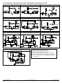
8. Pneumatische schakelschema’s SCP / Pneumatic Circuit Diagrams SCP
SCP... NO AS ...
SCP... NC AS ...
SCP... NO ASV ...
SCP... NC ASV ...
SCP... NO AS RE/RD
SCP... NC AS RE/RD
SCP... FS met NO-aansturing door klant /
SCP... FS with customer-provided NO control
SCP... FS met NC-aansturing door klant, variant 1 /
SCP... FS with customer-provided NC control, version 1
SCP... FS met NC-aansturing door klant, variant 2 /
SCP... FS with customer-provided NC control, version 2
SCP... RP (pneumatisch geregeld) /
SCP... RP (pneumatically regulated)
Externe stuurklep „zuigen” (door klant) /
external control valve (provided by customer)
Externe stuurklep „afblazen” (door klant) /
external control valve “Blow off” (provided by customer)
Externe stuurklep (door klant), basisinstelling geventileerd /
external control valve “Blow off” (provided by customer), idle
position vented

30.30.01.00248-NL Status 03.2022 / Index 02 Pagina / Page 15/17
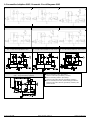
9. Pneumatikschaltpläne SMP / Pneumatic Circuit Diagrams SMP
SMP ... NO AS ...
SMP ... NC AS ...
SMP ... NO ASV ...
SMP ... NC ASV ...
SMP ... NO AS RE/RD
SMP ... NC AS RE/RD
SMP ... NO ... FS met NO-aansturing door klant / SMP ...
NO ... FS with customer-provided NO control
SMP ... FS met NC-aansturing door klant, variant 1 /
SMP ... FS with customer-provided NC control, version 1
SMP ... FS, met NC-aansturing door klant, variant 2 /
SMP ... FS, with customer-provided NC control, version 2
SMP ... RP (pneumatisch geregeld) /
SMP ... RP (pneumatically regulated)
Externe stuurklep „zuigen” (door klant) /
external control valve (provided by customer)
Externe stuurklep „afblazen” (door klant) /
external control valve “Blow off” (provided by customer)
Externe stuurklep (door klant), basisinstelling geventileerd /
external control valve “Blow off” (provided by customer), idle
position vented

30.30.01.00248-NL Status 03.2022 / Index 02 Pagina / Page 16/17
10. Gebruikers- en veiligheidsvoorschriften
Niet-toegestaan bedrijf met andere middelen kan leiden tot storingen,
beschadigingen en mogelijk dodelijk letsel.
Montage / demontage
Montage en demontage mogen alleen verricht worden als het toestel
van het stroomnet gescheiden is en niet onder druk staat!
Onderdelen mogen alleen door betrouwbaar vakpersoneel gemonteerd
worden, dat o.a. opgeleid is omtrent en op de hoogte is van:
de actueelste geldende veiligheidsregels en vereisten omtrent de
toepassing van de onderdelen en de bijbehorende besturingen in
toestellen, machines en installaties (voor elektromagnetische kleppen,
drukschakelaars, elektronische besturingen etc.)
en de vereiste elektrische aansturing, bijv. redundanties en eventuele
meldingen (voor elektromagnetische kleppen, drukschakelaars,
elektronische besturingen etc.)
en correcte omgang met onderdelen en producten voor de
bijbehorende bedoelde toepassing
en de juiste toepassing van bedrijfsmiddelen in installaties
en de desbetreffende, actueelste geldende EG-richtlijnen, wetten,
regelingen en normen
en de actuele technische stand van zaken.
Foutief gebruik van de onderdelen, o.a. met andere dan de toegestane
bedrijfsmiddelen, aangegeven spanning en milieuvoorschriften, kan leiden
tot storingen, beschadigingen en letsel.
Deze opsomming is bedoeld als hulpmiddel en maakt geen aanspraak
volledig te zijn. De voorschriften dienen indien nodig door de exploitant/
operator aangevuld te worden.
Veiligheidsinstruties
Voor veilige installatie en storingsvrij bedrijf dienen bovendien o.a. de
volgende handelwijzen opgevolgd te worden:
Haal de onderdelen voorzichtig uit de verpakkingen.
Ga voorzichtig met de onderdelen om ter voorkoming van
beschadigingen.
Bij installatie en onderhoud: Schakel de spanningstoevoer naar
het onderdeel en het toestel uit en zorg ervoor dat de spanning
niet onbedoeld ingeschakeld kan worden.
Gebruik het apparaat uitsluitend met voedingsadapters met
laagspanning (PELV) en goed gescheiden van de
bedrijfsspanning, conform EN 60204.
Er mogen geen wijzigingen aan de onderdelen verricht worden.
Zorg ervoor dat het toestel en de omgeving schoon gehouden worden.
Op de onderdelen staan aansluitingssymbolen en -gegevens, die
opgevolgd dienen te worden.
Gebruik alleen de daarvoor bestemde aansluitingen.
Gebruik uitsluitend slangen/buizen die voor het bedrijfsmiddel geschikt
zijn en sluit deze correct aan (losschietende slangen of elektrische
leidingen kunnen levensgevaarlijk zijn!)
Alle stroom- en spanningsleidingen dienen voldoende geïsoleerd te
zijn, de juiste diameter te hebben en correct geïnstalleerd te worden.
Pneumatische en elektrische leidingen dienen permanent aan het
onderdeel vastgekoppeld te blijven en geborgd te worden.
De elektrische aansluitingen en geïnstalleerde onderdelen moeten
voldoende tegen aanraking beschermd worden.
Gebruik uitsluitend de reeds aanwezige bevestigingsgaten en
meegeleverde bevestigingsmiddelen.
Alle actuele en geldende richtlijnen, wetten, regelingen en normen die
betrekking hebben op de bedoelde toepassing van het toestel en de
actuele technische stand van zaken dienen aangehouden te worden.
Indien nodig moet de exploitant/gebruiker er door middel van extra
maatregelen voor zorgen dat de desbetreffende richtlijnen, wetten,
regelingen en normen en de actuele technische stand van zaken
aangehouden worden.
Als de bovenstaande voorschriften niet opgevolgd worden, kan dat leiden tot
storingen, beschadigingen en mogelijk dodelijk letsel.
Als er onderdelen buiten bedrijf worden gesteld, dienen deze op een
milieuvriendelijke manier afgevoerd te worden!
Opmerking over elektromagnetische compatibiliteit
Iedere elektromagneet, elektromagnetische klep en relais heeft een spoel
die voor inductiviteit zorgt. Als de stroom door deze inductiviteit wordt
uitgeschakeld, genereert het aflopende magnetische veld altijd een
overspanningsimpuls, die in de omgeving elektromagnetische storing kan
veroorzaken. Deze storende impulsen kunnen door de exploitant onderdrukt
worden door de installatie van daartoe bestemde componenten. Hiervoor
kunnen zenerdioden en varistors toegepast worden.
10. Safety instructions for operation and
maintenance
Operation with other than the specified media can result in incorrect
function, damage to the components and (possibly fatal) injuries to
persons.
Assembly and disassembly
This may be done only with the electrical and compressed-air
supplies switched off !
The components may be installed only by reliable and trained persons who
have been instructed in and are familiar with:
the current safety regulations and the requirements for the use of the
components and their controllers in devices, machines and plants
(applies to solenoid valves, pressure switches, electronic controllers,
etc.);
the necessary electrical controls such as redundancy and, if
applicable, feedback signals (applies to solenoid valves, pressure
switches, electronic controllers, etc.);
the correct handling of components and products for the intended
purpose;
the correct use of the components with the operating medium being
used;
the current editions of the applicable EU guidelines, laws and
standards;
and the state of the art.
Incorrect use of the components, such as their with other than the
specified operating media, specified voltages and permissible ambient
conditions, can result in incorrect function, damage to equipment and
injuries to persons.
This information is intended as an aid and is not necessarily complete. If
necessary, it must be supplemented by the company operating the
equipment.
Safety notes
For safe installation and trouble-free operation, the following instructions
must be observed and complied with:
Remove the components carefully from their packing materials.
Handle the components carefully to avoid damaging them.
For installation and maintenance, switch off the electrical and
compressed-air supplies to the component or equipment and
ensure that they cannot be switched on inadvertently.
The unit may only be run via power supply units with protected
extra-low voltage and safe electrical cut-off of the operating
voltage, in accordance with EN60204.
The components may not be modified in any manner.
Keep the components and the work are clean.
The connections are clearly marked on the components and must be
connected accordingly.
Only the connection facilities provided may be used.
Only fittings and pipes/hoses suitable for the operating medium being
used may be used for installation and must be connected correctly
(hoses or power cables which are not securely connected are a
major cause of accidents, which may even result in fatal injuries
to persons in the vicinity!).
Electric cables must be suitably insulated and have a cross-section
suitable for the current they are to carry. They must be installed
securely and correctly.
Pneumatic pipes/hoses and electric cables must be permanently
connected to the component and secured to prevent them from
becoming loose.
All electrical terminals and components must be suitably covered to
prevent accidental contact.
Only the mounting holes and brackets provided may be used for
mounting the components.
All applicable regulations, guidelines, laws and standards must be
observed at all times. All work must comply with the state of the art.
If necessary, the company operating the equipment must implement
additional measures to ensure compliance with the applicable
regulations, guidelines, laws and standards.
Non-compliance with the above can result in incorrect function, damage to
equipment and (possible fatal) injuries to persons.
Any components removed from the equipment must be disposed of in
accordance with the local environmental regulations.
Note on electromagnetic compatibility (EMC)
Every electromagnet, solenoid valve and relay contains a coil, which acts
as an electrical inductance. When the current through such an inductance
is switched off, the decaying magnetic field generates an overvoltage pulse
which can cause electromagnetic disturbances in the vicinity. Such pulses
can be suppressed only locally by the connection of suitable damping
components, such as Zener diodes or varistor.

30.30.01.00248-NL Status 03.2022 / Index 02 Pagina / Page 17/17
-
 1
1
-
 2
2
-
 3
3
-
 4
4
-
 5
5
-
 6
6
-
 7
7
-
 8
8
-
 9
9
-
 10
10
-
 11
11
-
 12
12
-
 13
13
-
 14
14
-
 15
15
-
 16
16
-
 17
17


in andere talen
Gerelateerde papieren
-
Schmalz SCPSb 15 S02 NO Handleiding
-
Schmalz SCPS 2-07 G02 NO M12-5 PNP Handleiding
-
Schmalz SCPSi 2-07 G02 NO M12-5 Handleiding
-
Schmalz FMP-SW140 1036 3R54 SPB2-40P G60 Handleiding
-
-
-
Schmalz VE-EVE-8-FUV-1/4-PVS-1 Handleiding
-
Schmalz STF 100 P 12.0 SSB Handleiding
-
-
Andere documenten
-
Kärcher SCP 12000 IP LEVEL SENSOR Handleiding
-
Cooler Master Silent Pro Hybrid 1300W Handleiding
-
Sencor SCP 3201GY Handleiding
-
Sencor SCP 4202GY Handleiding
-
Sencor SCP 5303GY Handleiding
-
Huawei 10000mAh Super Charge Black(AP09S) Handleiding
-
Cooler Master Silent Pro M 700W Handleiding
-
Sharkoon Rebel P30 Gold de handleiding