
Innovative Vacuum for Automation /
Innovatieve vacuüm-automatisering
Operating Instructions FMP/
Bedieningsinstructies FMP
NL/DE
Area vacuum gripping system FMP
Vlakke-grijpersysteem FMP
FMP-SVK/SW
FMP-SVK/SW SPB2
Picture includes special
equipment/
Afbeelding incl.
speciale uitvoering

Operating Instructions FMP-SVK / FMP-SW
Bedieningsinstructies
30.30.01.00413 Status 22.01.2014 / Index 2
J. Schmalz GmbH
Aacher Straße 29
D - 72293 Glatten
Tel +49 (0) 7443 / 2403 - 0
Fax +49 (0) 7443 / 2403 - 259
www.schmalz.com
schmalz@schmalz.de
2
Contents / Inhaltsverzeichnis
1. Safety Notes / Veiligheids- en gevareninstructies ........................................................................................ 3
1.1 Symbols used / Gebruikte symbolen .................................................................................................................. 3
1.2 General safety instructions / Algemene veiligheidsinstructies ............................................................................ 3
1.3 Intended use / Reglementair gebruik .................................................................................................................. 5
1.4 Specific hazards / Bijzondere gevaren................................................................................................................ 5
1.5 Instructions for users of the gripper FMP / Instructie voor de operator van de FMP-vacuümgrijper ................... 6
2. Installation and Connections / Installeren en aansluitingen ........................................................................ 6
2.1 Attaching to the handling system / Bevestiging aan het handlingsysteem .......................................................... 6
2.2 Vacuum connection and gauge / Vacuümaansluiting en manometer ................................................................. 6
2.3 Connecting the compressed air blow-off pulse / Aansluiting perslucht afblaasimpuls ........................................ 8
2.4 Connecting the compressed air separation / Aansluiting perslucht afscheiding ................................................. 9
3. Description of Functions / Beschrijving van de werking ........................................................................... 10
3.1 Description of functions – components / Beschrijving van de werking – componenten .................................... 10
3.2 Description of functions: valve technology SVK / Beschrijving van de werking ventieltechniek SVK ............... 14
4. Mounting Individual Components / Montage van de afzonderlijke componenten .................................. 15
4.1 Mounting the sealing plate / Montage afdichtingsplaat ..................................................................................... 15
4.2 Mounting the suction pad connection strip / Montage aansluitprofiel voor vacuümgrijpers............................... 15
4.3 Mounting the valve films (SW and SVK film) / Montage klepfolie (SW en SVK –folie) ...................................... 16
5. Maintenance / Onderhoud ............................................................................................................................. 17
5.1 Maintenance schedule / Onderhoudsschema ................................................................................................... 18
6. Troubleshooting / Opsporen van storingen ................................................................................................ 20
7. Technical Data / Technische gegevens ........................................................................................................ 22
7.1 Dimensions of the FMP with the sealing plate / Afmetingen bij FMP met afdichtingsplaat .............................. 22
7.2 Dimensions of the FMP with suction pad SPB2/Afmetingen bij FMP met vacuümgrijper SPB2 ....................... 23
8. Accessories, Options / Accessoires, opties ................................................................................................ 24
8.1 Robot flange attachment kit / Montageset robotflens ........................................................................................ 24
8.2 Suspension attachment kit / Montageset ophanging ........................................................................................ 25
8.3 Attachment kit for solenoid valve for blow-off / Montageset elektromagnetisch ventiel Afblazen ...................... 26
8.4 Suction pad strip kit for screw-in suction pads 1/8" male thread / Montageset aansluitprofiel
vacuümgrijpers voor schroefzuigers 1/8" buitendraad ...................................................................................... 26
8.5 Cover strip for T-slot on side / Afdekprofiel voor zijdelingse T-sleuf ................................................................. 27
9. Spare and Wearing Parts / Reserveonderdelen en slijtdelen .................................................................... 28
10. Special model with the separation function V / Speciale uitvoering afscheidingsfunctie V ................. 31
10.1 Operation and pressure setting / Bediening en drukinstelling ........................................................................... 31
10.2 Accessories, options / Accessoires, opties ....................................................................................................... 32
10.3 Spare Parts and wearing parts / Reserveonderdelen en slijtdelen ................................................................... 32
10.4 Pneumatic diagram and time diagram / Pneumatisch schema en tijddiagram .................................................. 33
Appendix / Bijlage
EC-declaration of manufacture / EG-verklaring van de fabrikant

Operating Instructions FMP-SVK / FMP-SW
Bedieningsinstructies
30.30.01.00413 Status 22.01.2014 / Index 2
J. Schmalz GmbH
Aacher Straße 29
D - 72293 Glatten
Tel +49 (0) 7443 / 2403 - 0
Fax +49 (0) 7443 / 2403 - 259
www.schmalz.com
schmalz@schmalz.de
3
1. Safety Notes / Veiligheids- en gevareninstructies
1.1 Symbols used / Gebruikte symbolen
This symbol indicates important information
and instructions.
Caution
This symbol indicates a potentially dangerous
situation.
If it is not avoided, slight or minor injuries may
result.
Danger
This symbol indicates an immediate
hazard.
If it is not avoided, severe or fatal injuries
may result.
Dit symbool duidt op belangrijke informatie
en aanwijzingen.
Voorzichtig!
Dit symbool duidt op een eventueel
gevaarlijke situatie.
Indien u deze situatie niet voorkomt, dan
kan dit licht letsel tot gevolg hebben.
Gevaar!
Dit symbool duidt op een direct dreigend
gevaar.
Indien u deze situatie niet voorkomt,
dan kan dit zwaar letsel en de dood tot
gevolg hebben.
1.2 General safety instructions / Algemene veiligheidsinstructies
These operating instructions contain important
information on the area gripper FMP. Please read the
operating instructions thoroughly and keep them for later
reference.
Never look into any open or closed vacuum
vents (e.g. vacuum connections or suction
pads).
Severe injuries could occur as a result.
Eyes can be sucked in.
Deze bedieningsinstructies bevatten belangrijke infor-
matie over hoe met de vlakke-grijpermodules om te
gaan. Lees de bedieningsinstructies zorgvuldig door en
bewaar deze als naslagwerk voor op een later tijdstip.
Nooit in zuigende of niet-zuigende
vacuümopeningen (bijv. vacuümaans-
luitingen of zuignappen) kijken.
Zwaar letsel kan het gevolg zijn. Ogen
kunnen worden aangezogen.

Operating Instructions FMP-SVK / FMP-SW
Bedieningsinstructies
30.30.01.00413 Status 22.01.2014 / Index 2
J. Schmalz GmbH
Aacher Straße 29
D - 72293 Glatten
Tel +49 (0) 7443 / 2403 - 0
Fax +49 (0) 7443 / 2403 - 259
www.schmalz.com
schmalz@schmalz.de
4
Other general safety instructions:
For safe installation and trouble-free operation, the following
instructions must be observed and complied with:
Carefully remove the components from the packaging.
Protect the components from damage of any kind
During installation and maintenance, make sure that
the component and the device are disconnected,
depressurized and cannot be switched on again without
authorization.
Making changes to the components is not permitted.
Keep location of use and surroundings clean
Observe the connection symbols and descriptions on the
components
Use only the designated connections.
Pneumatic and electrical line connections must be
permanently connected and secured to the component.
The gripper is used in combination with an automated
handling system (portal / robot). For this reason, you
must also follow the safety guidelines for the relevant
system.
Do not operate outside of the specified capacity. Doing
so may cause it to malfunction or be destroyed.
Failure to observe the above instructions can lead to
malfunctions, damage, injury or death.
When the device is decommissioned, the components are to
be disposed of in an environmentally safe manner.
Overige algemene veiligheidsinstructies:
Voor een veilige installatie en storingsvrije werking dienen
bovendien o.a. de volgende handelwijzen te worden
opgevolgd:
Haal de onderdelen voorzichtig uit de verpakkingen.
Ga voorzichtig met de onderdelen om ter voorkoming van
beschadigingen.
Bij installatie en onderhoud: Onderdeel, toestel
spannings- en drukvrij schakelen en tegen onbevoegd
opnieuw inschakelen beveiligen.
Er mogen geen wijzigingen aan de onderdelen worden
uitgevoerd.
Zorg ervoor dat het toestel en de omgeving schoon
worden gehouden.
Neem de desbetreffende aansluitsymbolen en –
omschrijvingen, welke zich op de onderdelen bevinden,
in acht.
Gebruik alleen de daarvoor bestemde aansluitingen.
Pneumatische en elektrische verbindingen dienen
permanent met het onderdeel te zijn verbonden en
geborgd.
De vacuümgrijper wordt in combinatie met een geauto-
matiseerd handlingsysteem (portaal / robot) toegepast.
Om die reden gelden bovendien de veiligheids-
voorschriften van het desbetreffende systeem.
Gebruik buiten de aangegeven prestatiegrens is niet
toegestaan. Dit kan een verkeerde werking benevens
vernieling tot gevolg hebben.
Indien de bovenstaande voorschriften niet worden
opgevolgd, dan kan dat leiden tot storingen, materiële
schade en mogelijk dodelijk letsel.
Indien er onderdelen buiten werking worden gesteld, dan
dienen deze op een milieuvriendelijke manier te worden
afgevoerd!

Operating Instructions FMP-SVK / FMP-SW
Bedieningsinstructies
30.30.01.00413 Status 22.01.2014 / Index 2
J. Schmalz GmbH
Aacher Straße 29
D - 72293 Glatten
Tel +49 (0) 7443 / 2403 - 0
Fax +49 (0) 7443 / 2403 - 259
www.schmalz.com
schmalz@schmalz.de
5
1.3 Intended use / Reglementair gebruik
The gripper FMP is used for gripping and transporting
workpieces made of materials that all suction. Neutral gases
in accordance with EN 983 are approved as evacuation
media. Neutral gases include air, nitrogen and inert gases.
The gripper is designed for automatic operation and not for
manual handling. Operations using the device must take
place in a secure area where no people are allowed to enter.
The gripper FMP is mounted on the customer-provided load
suspension device using the T-slots designated for this
purpose. The customer also provides a control device.
No people or animals may be transported with the load or
the gripper FMP.
For safety reasons, the gripper FMP must not be
modified or changed without approval.
The operating, maintenance and servicing conditions
specified in these operating instructions must be
observed.
The maximum permissible load may not be exceeded.
De FMP-vacuümgrijper dient voor het grijpen en transpor-
teren van werkstukken bestaande uit materialen, welke
geschikt zijn om onder vacuüm te worden aangezogen. Als
te evacueren media zijn neutrale gassen overeenkomstig
EN 983 toegestaan. Neutrale gassen zijn bijv. lucht, stikstof
en edelgassen. De vacuümgrijper is uitsluitend voor de
toepassing in de automatische modus geconcipieerd en niet
voor de handmatige handling. Met het toestel mag alleen in
de beveiligde zone (verboden toegang voor personen)
worden gewerkt.
De FMP-vacuümgrijper wordt aan de lokale lastopname via
en met behulp van de daarvoor bestemde T-groeven
gemonteerd. De besturing wordt via een door de klant/
contractor ter beschikking gesteld toestel uitgevoerd.
Het is verboden om personen en dieren met de last of de
FMP-vacuümgrijper te transporteren!
Het is om veiligheidsredenen verboden om de FMP-
vacuümgrijper eigenmachtig om te bouwen of aan te
passen!
De in deze bedieningsinstructies voorgeschreven
bedrijfs-, onderhouds- en servicevoorwaarden moeten
worden opgevolgd.
De toegestane hijscapaciteit mag niet worden overschreden.
1.4 Specific hazards / Bijzondere gevaren
Because the load is held to the gripper FMP by a vacuum,
it is dropped as soon as the vacuum stops. This can be
caused by a sudden power failure.
Never look into any open or closed vacuum openings (e.g.
vacuum connections, suction openings or suction pads).
Severe injuries could occur as a result. Eyes can be sucked in.
Never look into a stream of compressed air or exhaust air.
A vacuum can cause closed containers to implode
No person may sit or stand under the load in
the area in which the load is to be transported
by the gripper system. If the vacuum
generation stops or decreases, the load is
released. For more information, see “Safety Notes and
Warnings”.
Omdat de last door onderdruk aan de FMP-vacuümgrijper
wordt vastgehouden, valt de last zodra de onderdruk
wegvalt. Dit gebeurt als bijv. de elektriciteit plotseling uitvalt.
Nooit in zuigende of niet-zuigende vacuümopeningen (bijv.
vacuümaansluitingen, aanzuigopeningen, vacuümgrijpers)
kijken.
Zwaar letsel kan het gevolg zijn. Ogen kunnen worden
aangezogen.
Nooit in perslucht- of afvoerluchtstromingen kijken.
Door vacuüm kunnen gesloten vaten imploderen.
In de transportzone van de last, welke met
het grijpsysteem wordt verplaatst, mogen
zich geen personen onder deze last
bevinden. Bij het uitvallen / wegvallen van de
vacuümopwekking wordt de last losgelaten. Overige
informatie onder „Veiligheids- en gevareninstructies”.

Operating Instructions FMP-SVK / FMP-SW
Bedieningsinstructies
30.30.01.00413 Status 22.01.2014 / Index 2
J. Schmalz GmbH
Aacher Straße 29
D - 72293 Glatten
Tel +49 (0) 7443 / 2403 - 0
Fax +49 (0) 7443 / 2403 - 259
www.schmalz.com
schmalz@schmalz.de
6
1.5 Instructions for users of the gripper FMP / Instructie voor de operator van de
FMP-vacuümgrijper
You must have been trained before starting operations with
the gripper FMP. You must have read and understood the
operating instructions, in particular the “Safety” section.
Ensure that only authorized personnel use the device. You
are responsible for third parties in the working area of the
device.
Local safety regulations apply. In Germany, this includes, but
is not limited to, UVV 18.4/VBG 9a “Load-bearing devices...”.
The other safety instructions in this manual do not replace
these guidelines, but should be seen as a supplement to
them.
Als operator dient u geïnstrueerd te zijn voordat de
FMP-vacuümgrijper in bedrijf wordt gesteld. U dient de
bedieningsinstructies, en in het bijzonder het hoofdstuk
„Veiligheid”, te hebben gelezen en begrepen.
Zorg ervoor dat uitsluitend daartoe bevoegde personen met
het toestel werken. Binnen het werkbereik van het toestel
bent u voor derden verantwoordelijk.
De plaatselijke veiligheidsvoorschriften zijn van toepassing,
in Duitsland o.a. de voorschriften voor ongevallenpreventie
18.4/VBG 9a „Lastopname-inrichtingen ...”.
Overige veiligheidsinstructies in deze bedieningsinstructies
heffen deze voorschriften niet op, maar dienen als aanvulling
te worden opgevat.
2. Installation and Connections / Installeren en aansluitingen
2.1 Attaching to the handling system / Bevestiging aan het handlingsysteem
The gripper system is attached using sliding blocks. Special
sliding block strips (1) are integrated into the main body to
hold the sliding blocks. The system can be adapted directly
using the sliding block strip, a robot flange or a spring-
mounted suspension eye. Suitable attachment kits are listed
in the Accessories section. (See Detail A) (Fig. 2.3-1)
Het grijpsysteem wordt met behulp van hamerkopbouten
bevestigd. In het lichaam zijn speciale hamerkopbout-
profielen (1) voor het opnemen van de hamerkopbouten
geïntegreerd. Het adapteren kan direct via het hamer-
kopboutprofiel, een robotflens of een afgeveerde ophanging
worden uitgevoerd. Desbetreffende montagesets zijn in het
hoofdstuk Accessoires vermeld. (zie detail A) (afb. 2.3-1)
2.2 Vacuum connection and gauge / Vacuümaansluiting en manometer
The vacuum supply from the vacuum generator installed by
the customer is applied through a vacuum hose.
The hose is connected using the hose connector (2) (for the
hose diameter, see the Dimensions section). The gauge (4)
may only be connected on the side where there are no
markings in the sliding block strip. (See Detail A) (Fig. 2.3-1)
De aanvoer van het vacuüm vanuit de door de klant/contrac-
tor verzorgde vacuümgenerator verloopt via een vacuüms-
lang.
Deze slang wordt op het slang-aansluitstuk (2) aangesloten
(slangdiameter, zie hoofdstuk Afmetingen). De manometer
(4) mag uitsluitend aan de zijde worden gemonteerd, alwaar
zich geen markeringen in het hamerkopboutprofiel bevinden.
(zie detail A) (afb. 2.3-1)
2.2.1 Pneumatic circuit FMP for external vacuum generation – SW version / Pneumatische schakeling FMP voor
externe vacuümopwekking – SW-versie
The solenoid valve (8) can be positioned in front of the
vacuum distributor (9). The area gripper and hose
connectors (2) are still the standard versions. (Fig. 2.2-1)
Het elektromagnetisch ventiel (8) kan zich voor de vacuüm-
verdeler (9) bevinden. De vlakke-grijpermodule en het slang-
aansluitstuk (2) blijven standaard. (afb. 2.2-1)
2.2.2 Pneumatic circuit FMP for external vacuum generation – SVK version / Pneumatische schakeling FMP voor
externe vacuümopwekking – SVK-versie
The solenoid valve (8) is screwed directly onto the area
gripper. The area gripper is equipped with a threaded
connector (11) and a second standard connector (2).
(Fig. 2.2-2)
Het elektromagnetisch ventiel (8) wordt direct op de vlakke-
grijpermodule geschroefd. De vlakke-grijpermodule is uitge-
voerd met een schroef-aansluitstuk (11) en een tweede
standaard-aansluitstuk (2). (afb. 2.2-2)

Operating Instructions FMP-SVK / FMP-SW
Bedieningsinstructies
30.30.01.00413 Status 22.01.2014 / Index 2
J. Schmalz GmbH
Aacher Straße 29
D - 72293 Glatten
Tel +49 (0) 7443 / 2403 - 0
Fax +49 (0) 7443 / 2403 - 259
www.schmalz.com
schmalz@schmalz.de
7
Pneumatic circuit in SW* version (parallel circuit)
Pneumatische schakeling SW*-versie (parallelschakeling)
Fig./Afb. 2.2-1
Pneumatic circuit in SVK** version (series circuit)
Pneumatische schakeling SVK**-versie (serieschakeling)
Fig./Afb. 2.2-2
* SW stands for flow resistance technology
* SW staat voor stromingsweerstandtechniek
** SVK stands for flow valve technology
** SVK staat voor stroomregelventieltechniek
Image shows the blower with ventilation (to prevent over-
heating the blower) from the additional solenoid valve (10)
Afbeelding toont ventilator met luchttoevoer, ter bescherming
tegen oververhitting van de ventilator, d.m.v. extra EMV (10)
Legend / Legenda:
Vacuum generator (blower, pump) / Vacuümgenerator (ventilator, pomp)
Compressed air source / Persluchtbron
Vacuum filter / Vacuümfilter
Solenoid valve / Magneetventiel
Vacuum distributor / Vacuümverdeler
Area Vacuum Gripping System FMP / Vlakke-grijpersysteem FMP
Standard hose
connector (2)
Standaard
slang-
aansluitstuk (2)
Standard area gripper
Standaard vlakke-
grijpermodule
EMV (8)
Additional solenoid valve (10)
Extra EMV (10)
EMV (8)
Vacuum valve directly
screwed onto threaded
connector (11)
EMV (8) Vacuümventiel
direct op schroef-
aansluitstuk (11)
geschroefd /
Vacuum distributor (9)
Vacuümverdeler (9)
Standard hose
connector (2)
Standaard
slang-
aansluitstuk (2)
Special threaded
connector (11)
Speciaal schroef-
aansluitstuk (11)
Afsluitdeksel
Special area gripper with two connectors
Speciale vlakke-grijpermodule voorzien
van twee aansluitstukken

Operating Instructions FMP-SVK / FMP-SW
Bedieningsinstructies
30.30.01.00413 Status 22.01.2014 / Index 2
J. Schmalz GmbH
Aacher Straße 29
D - 72293 Glatten
Tel +49 (0) 7443 / 2403 - 0
Fax +49 (0) 7443 / 2403 - 259
www.schmalz.com
schmalz@schmalz.de
8
2.3 Connecting the compressed air blow-off pulse / Aansluiting perslucht afblaasimpuls
The connection for the blow-off pulse is located on the end
cover. When the product is delivered, the end cover is closed
with a plug (3). (Fig. 2.3-1)
The hose for the blow-off pulse (3) must be connected on the
“middle” 1/8" female tapped holes (3).
De aansluiting voor de afblaasimpuls bevindt zich in het
einddeksel. Deze is bij levering door middel van een
blindplug (3) afgesloten. (afb. 2.3-1)
De slangaansluiting voor de afblaasimpuls (3) dient op het
„middelste” 1/8"-bin.dr. tapgat (3) te worden uitgevoerd.
With optional parts for blowing off (3), separation (5) and
connecting vacuum switches (7) (See Accessories) / Met als
optie te verkrijgen onderdelen voor afblazen (3), afscheiding
(5) en aansluiting vacuümschakelaar (7) (zie accessoires)
Standard / Standaard
Fig./Afb. 2.3-2
Fig./Afb. 2.3-1
To quickly deposit picked up workpieces and to make quick
cycle times possible, the control valve set “Blow off on/off”
should be used. This includes all required components such
as the solenoid valve, cables, mounting elements and hoses
(see Accessories).
If the blow-off pulse is not used, the connection in the end
cover must be sealed with the included plug.
Before initiating the blow-off pulse, ensure that the
gripper (with attached workpiece) is not pressed against
a solid surface. The workpiece must be able to freely
detach from the gripper.
The dynamic pressure in the gripper must not be more
than 0.2 bar during blow-off.
Voor het snel neerzetten van de aangezogen werkstukken
en voor het realiseren van snelle cyclustijden dient stuur-
ventiel-set Afblazen In/Uit te worden toegepast. De set
bestaat uit alle noodzakelijke componenten zoals een
elektromagnetisch ventiel, kabel, bevestigingselementen
en slangen (zie accessoires).
Indien de afblaasimpuls niet wordt gebruikt, dan dient de
aansluiting in het einddeksel met de meegeleverde blindplug
te worden afgesloten!
Let erop dat bij het in werking stellen van de afblaas-
impuls de grijper met werkstuk niet op een vaste
ondergrond is gedrukt. Het moet namelijk mogelijk zijn
dat het werkstuk de grijper „vrij kan loslaten”.
De stuwdruk in de vacuümgrijper mag bij het afblazen
max. 0,2 bar bedragen.
1
3
2
6
5
4
3
5
7

Operating Instructions FMP-SVK / FMP-SW
Bedieningsinstructies
30.30.01.00413 Status 22.01.2014 / Index 2
J. Schmalz GmbH
Aacher Straße 29
D - 72293 Glatten
Tel +49 (0) 7443 / 2403 - 0
Fax +49 (0) 7443 / 2403 - 259
www.schmalz.com
schmalz@schmalz.de
9
Electrical connection
Operation of the optional control valves with 24 V DC.
For connection of any optional vacuum switches, see further
below. Operate only with power supply units with protected
extra-low voltage (PELV) in accordance with EN 60204.
Elektrische aansluiting
Werking van de als optie verkrijgbare stuurventielen met
24 V DC.
Aansluiting evt. als optie verkrijgbare vacuümschakelaar:
zie verder onderstaand. Toepassing en werking uitsluitend
via voedingsadapters voorzien van een veilige, zeer lage
spanning (PELV) overeenkomstig EN 60204.
Pneumatic circuit diagram with one and multiple grippers /
Pneumatisch schakelschema bij één en meerdere vacuümgrijpers:
View of the SW version (parallel circuit) / Afbeelding bij SW-versie (parallelschakeling)
2.4 Connecting the compressed air separation / Aansluiting perslucht afscheiding
The connection for the separation pulse is located on the end
cover. When the product is delivered, the end cover is closed
with a plug (5). The compressed air (5) for separation should
only be connected on the side with the markings (6, see
Detail A) of the sliding block strip. The markings are on either
end of the section. (Fig. 2.3-2)
De aansluiting voor de afblaasimpuls bevindt zich in het
einddeksel. Deze is bij levering door middel van een blind-
plug (5) afgesloten. De persluchtaansluiting (5) voor de
afscheiding dient alleen aan de zijde te worden aangesloten,
waarop zich de markeringen (6, zie detail A) van het hamer-
kopboutprofiel bevinden. De markeringen zijn steeds op de
einden van het profiel aangebracht. (afb. 2.3-2)
The separation pulse is needed when two or more air-
permeable sheets are picked up during suction. The briefly
applied compressed air pulse separates the second sheet
from the first.
De afscheidingsimpuls is benodigd, indien twee of meerdere
poreuze platen bij het aanzuigen samen worden opgehesen.
De kort in werking gestelde persluchtimpuls scheidt de
tweede plaat van de eerste.
The valve screw setting can vary according to the properties
of the workpieces.
Deze instelling met de drukregelaar kan al naargelang de
samenstelling van de werkstukken variëren.
Additional details on the separation function can be found in
section 10.
Overige details met betrekking tot de afscheidingsfunctie zijn
in hoofdstuk 10 beschreven.
Solenoid valve for suction
Elektromagnetisch ventiel
voor aanzuigen
Solenoid valve for
blow-off pulse
Elektromagnetisch ventiel
voor afblaasimpuls
Filter
Air pressure in the
gripper interior max
0.2 bar
Luchtdruk in de
vacuümgrijper max.
0,2 bar
Area gripper FMP-SVK
Vlakke-grijpermodule FMP-SVK
Connect on cover Item 3
(Fig.2.3-1 / 2.3-2)
Aansluiten op deksel
pos. 3 (afb. 2.3-1 / 2.3-2)

Operating Instructions FMP-SVK / FMP-SW
Bedieningsinstructies
30.30.01.00413 Status 22.01.2014 / Index 2
J. Schmalz GmbH
Aacher Straße 29
D - 72293 Glatten
Tel +49 (0) 7443 / 2403 - 0
Fax +49 (0) 7443 / 2403 - 259
www.schmalz.com
schmalz@schmalz.de
10
3. Description of Functions / Beschrijving van de werking
3.1 Description of functions – components / Beschrijving van de werking –
componenten
Version Overview / Variantenoverzicht
FMP with sealing plate / FMP met afdichtingsplaat:
Valve
Technology /
Ventieltechniek
Length of the
gripper [mm] /
Lengte van de
grijper [mm]
Number of suction
rows / Aantal
aanzuigrijen
Hole spacing
[mm] /
Gatenpatroon
[mm]
SW
442 … 1432
3R = 3 suction rows /
3R = 3 aanzuigrijen
18
SVK
5R = 5 suction rows
(special) / 5R =
5 aanzuigrijen
(speciaal)
18
FMP with suction pads / FMP met vacuümgrijpers:
Valve
Technology /
Ventieltechniek
Length of the
gripper [mm] /
Lengte van de
grijper [mm]
Number of suction
rows / Aantal
aanzuigrijen
Hole spacing
[mm] /
Gatenpatroon
[mm]
Suction pad types
and number of folds /
Types vacuümgrijper
en aantal vouwen
Suction pad diameter [mm]
and connection type /
Vacuümgrijper-diameter
[mm] en aansluitvorm
SW
442 ... 1432
3R = 3 suction rows /
3R = 3 aanzuigrijen
54
SPB2 = type, SPB2
with 2.5 folds /
SPB2 = type SPB2
met 2,5 vouwen
40 P = 40 mm diameter with
push-in head / 40 P = 40 mm
diameter met insteekkop
(Push In)
SVK
5R = 5 suction rows /
5R = 5 aanzuigrijen
36
SPB2 = type, SPB2
with 2.5 folds /
SPB2 = type SPB2
met 2,5 vouwen
20 P = 20mm diameter with
push-in head / 20 P = 20 mm
diameter met insteekkop
(Push In)

Operating Instructions FMP-SVK / FMP-SW
Bedieningsinstructies
30.30.01.00413 Status 22.01.2014 / Index 2
J. Schmalz GmbH
Aacher Straße 29
D - 72293 Glatten
Tel +49 (0) 7443 / 2403 - 0
Fax +49 (0) 7443 / 2403 - 259
www.schmalz.com
schmalz@schmalz.de
11
Fig./Afb. 3.1-1 Fig./Afb. 3.1-2
FMP with sealing plate FMP with suction pads
FMP met afdichtingsplaat FMP met vacuümgrijpers
Item /
Pos.
Designation
Omschrijving
1
Main body
Lichaam
2
Sliding block strip
Hamerkopboutprofiel
3
Suction connection
Vacuümaansluiting
4
End cover
Einddeksel
5
Vacuum gauge
Vacuümmanometer
6
Insert element (for optimizing the flow)
Inschuifelement (t.b.v. optimaliseren stroming)
7
Valve film
Klepfolie
8
Sealing plate (with integrated filter screen mat as an option)
Afdichtingsplaat (als optie met geïntegreerde filterzeefmat)
9
Suction pad connection strip
Aansluitprofiel vacuümgrijpers
10
Suction pad (plug-in suction pad)
Vacuümgrijper (steekzuiger)
1
2
3
4
4
5
6
7
8
1
2
3
4
3
4
5
6
7
9
10
4

Operating Instructions FMP-SVK / FMP-SW
Bedieningsinstructies
30.30.01.00413 Status 22.01.2014 / Index 2
J. Schmalz GmbH
Aacher Straße 29
D - 72293 Glatten
Tel +49 (0) 7443 / 2403 - 0
Fax +49 (0) 7443 / 2403 - 259
www.schmalz.com
schmalz@schmalz.de
12
Top part:
1 Main body
The main body consists of a length-adjustable extrusion-
molded aluminum section with an integrated compressed air
duct for the separation function (see Special Equipment:
Separation Function)
Standard lengths 442 / 640 / 838 / 1234 / 1432 mm
Bovenste deel:
1 Lichaam
Het lichaam bestaat uit een qua lengte variabel geëxtrudeerd
aluminium profiel, met een geïntegreerd persluchtkanaal
voor de afscheidingsfunctie (zie speciale uitvoering:
afscheidingsfunctie).
Standaard lengtes 442 / 640 / 838 / 1234 / 1432 mm
2 Sliding block strips
The block strips are used for flexible mechanical attachment
of the gripper using the sliding blocks.
Suitable attachment kits are listed in the Accessories section.
The block strips on the side offer the option of connecting
sensors and additional components.
2 Hamerkopboutprofielen
De hamerkopboutprofielen dienen voor de flexibele
mechanische montage van de vacuümgrijpers met behulp
van hamerkopbouten.
Desbetreffende montagesets zijn in het hoofdstuk
Accessoires vermeld. De zijdelings aangebrachte profielen
bieden de mogelijkheid voor het monteren van een sensor
en extra componenten.
3 Suction connection
The vacuum generator is connected using the suction
connection. See also the Dimensions section. The suction
connection used depends on the length of the gripper.
3 Vacuümaansluiting
De vacuümgenerator wordt op de vacuümaansluiting
aangesloten. Zie tevens het hoofdstuk Afmetingen. De
gebruikte vacuümaansluiting is afhankelijk van de lengte
van de vacuümgrijper.
4 End cover
The end cover has 1/8" female threaded connections. These
allow a vacuum gauge or a vacuum switch to be connected
and a compressed air pulse to be supplied for blow-off and
separation.
(The compressed air supply for separation may only be
attached on the side with the marking holes)
4 Einddeksel
Het einddeksel beschikt over aansluitingen met 1/8"
binnendraad. Deze maken de aansluiting van een vacuüm-
manometer of vacuümschakelaar en de toevoer van een
persluchtimpuls voor afblazen en afscheiding mogelijk.
(De persluchttoevoer voor de afscheiding dient alleen op de
zijde van de markeringspunten te worden aangebracht)
6 Insert element
The insert element was developed to optimize the flow and
may not be removed, particularly when using the SVK valve
technology.
6 Inschuifelement
Het inschuifelement werd t.b.v. het optimaliseren van de
stroming ontwikkeld en mag bij de SVK-ventieltechniek in het
bijzonder niet worden verwijderd.
Lower part:
7 Valve film
The valve film is available as an SW film or an SVK film,
each of which is available in suction row types 3R and 5R.
This film allows the gripper to be quickly converted from the
SW technology to the SVK technology.
The area grippers work with SW and SVK valve technology.
The SVK valve technology is used for applications with very
fast cycle times (e.g. benchmark for depositing of workpieces
with active blow-off pulse: approx. 0.3 sec.) The suction
properties are also optimized for rough and textured
surfaces.
(see Fig. 10.4-2 for the optimal working cycle)
Onderste deel:
7 Klepfolie
De klepfolie is qua vormgeving als SW-folie en SVK-folie
beschikbaar, in de beide aanzuigrijvarianten 3R en 5R.
Met deze folie kan de grijper zeer snel van de SW-techniek
naar de SVK-techniek worden omgebouwd.
De vlakke-grijpersystemen werken met SW- resp.
SVK-ventieltechniek.
De ventieltechniek SVK wordt bij toepassingen met zeer
snelle cyclustijden gebruikt (bijv. richtwaarde voor het
neerzetten van de werkstukken met actieve afblaasimpuls:
ca. 0,3 sec.). Bovendien is het aanzuiggedrag voor ruwe en
gestructureerde oppervlakken geoptimaliseerd.
(Optimale arbeidscyclus zie afb. 10.4-2)

Operating Instructions FMP-SVK / FMP-SW
Bedieningsinstructies
30.30.01.00413 Status 22.01.2014 / Index 2
J. Schmalz GmbH
Aacher Straße 29
D - 72293 Glatten
Tel +49 (0) 7443 / 2403 - 0
Fax +49 (0) 7443 / 2403 - 259
www.schmalz.com
schmalz@schmalz.de
13
8 Sealing plate
The sealing plate is made of technical foam. The grid is
available in 3R LL-20x7 (workpieces that are 25 mm or
wider) and 5R LL-12x5 (workpieces that are 20 mm or
wider). The sealing plate has asymmetric holes and is
designed for fast replacement. For details, see the Assembly
section.
An optional sealing plate with a self-cleaning filter screen
mat is also available. This prevents contamination and
extends the maintenance intervals.
Note on foam properties:
The technical properties and look of foams are subject to
variances due to production. The user is responsible for
testing whether a foam is suitable for a specific application.
We would be happy to assist you in placing your first order
by performing grip tests at our premises if you provide us
with your original workpieces.
As the foam height is also subject to tolerances, it is
recommended that you adjust the height setting of the
gripper every time that the foam is replaced (40% foam
compression before the workpiece is picked up is optimal).
This ensures that the gripper functions optimally and that
the service life of the foam is not reduced.
This flexing work makes the foam more air-permeable.
When a high number of working cycles is reached, it may
be necessary to replace the foam, even if there is no visible
indication of wear.
The foam may not be cleaned with a compressed-air gun.
This would make the foam air-permeable in the places
where compressed air was applied.
8 Afdichtingsplaat
De afdichtingsplaat is samengesteld uit een technisch
schuim. Het raster is beschikbaar in 3R LL-20x7 (vanaf
werkstukbreedte 25mm) en 5R LL-12x5 (vanaf werkstuk-
breedte 20mm). De afdichtingsplaat is asymmetrisch van
gaten voorzien en geconstrueerd voor een snelle uitwisse-
ling. Voor meer informatie zie hoofdstuk Montage.
Als optie is een afdichtingsplaat te verkrijgen voorzien van
een zelfreinigende filterzeefmat. Het binnendringen van vuil
wordt daardoor voorkomen en de onderhoudsintervallen
worden verlengd.
Opmerking over de eigenschappen van schuimen:
Schuimen kunnen variëren voor wat betreft hun technische
eigenschappen en optische indruk. Het is de verantwoor-
delijkheid van de exploitant de geschiktheid van een schuim
voor een specifieke toepassing te testen. Wij ondersteunen
u graag bij de eerste bestelling door bij ons grijptests uit te
voeren met uw originele monsters.
Omdat ook de schuimhoogte aan toleranties onderhevig is,
bevelen wij aan bij elke schuimvervanging de hoogte-
instelling van de grijper opnieuw af te stellen (optimaal 40%
schuimcompressie bij het aanzuigen van op te heffen
werkstukken), voor een optimale functie en
schuimlevensduur.
Door de gewenste vervorming (zgn. walken) wordt het
schuim op den duur meer luchtdoorlatend. Bij het bereiken
van een groot aantal arbeidscycli, kan een schuimver-
vanging nodig zijn zonder dat dit optisch waarneembaar is.
Het schuim mag niet met een persluchtpistool worden
gereinigd. Daardoor zal het schuim op die plaatsen
luchtdoorlatend worden.
FMP with suction pads:
9 & 10 Suction pad connection strip with plug-in suction
pads
The primary use of the FMP with suction pads is lifting parts
that are not intrinsically stable
The suction pad connection strips are available with plug-in
suction pads with and without filter plates. The strips are
screwed onto the main body intended especially for this
purpose.
The suction pads are available in diameters of 20 and
40 mm with 2.5 folds. An optional integrated filter plate is
also available. Every suction pad can be changed separately
without tools.
Suction pad strips with 1/8" female thread
Optional suction pads with 1/8" connection nipples can also
be used for special applications. Corresponding suction pad
strips with 1/8" female threads are offered for this purpose.
(See accessories in section 8.4).
FMP met vacuümgrijpers:
9 & 10 Aansluitprofiel vacuümgrijpers voorzien van
steekzuigers
De hoofdtoepassing van de FMP met vacuümgrijpers is bij
het aanzuigen van niet-eigenstabiele onderdelen.
Het aansluitprofiel voor vacuümgrijpers is verkrijgbaar met
steekzuigers zonder en met geïntegreerde filterplaat. De
profielen worden op het speciaal daarvoor bedoelde lichaam
geschroefd.
De vacuümgrijpers worden in de diameters 20mm en 40mm
met 2,5 vouwen aangeboden, als optie met geïntegreerde
filterplaat. Iedere vacuümgrijper kan zonder gereedschap
separaat worden uitgewisseld.
Profielen voor vacuümgrijpers met 1/8" binnendraad
Voor bijzondere toepassingen kunnen tevens als optie
vacuümgrijpers voorzien van 1/8"-aansluitnippels worden
gebruikt. Hiervoor worden de desbetreffende profielen voor
vacuümgrijpers voorzien van 1/8" binnendraad aangeboden.
(zie ook Accessoires onder hoofdstuk 8.4)

Operating Instructions FMP-SVK / FMP-SW
Bedieningsinstructies
30.30.01.00413 Status 22.01.2014 / Index 2
J. Schmalz GmbH
Aacher Straße 29
D - 72293 Glatten
Tel +49 (0) 7443 / 2403 - 0
Fax +49 (0) 7443 / 2403 - 259
www.schmalz.com
schmalz@schmalz.de
14
3.2 Description of functions: valve technology SVK /
Beschrijving van de werking ventieltechniek SVK
Step / Stap
Designation
Omschrijving
1
Switch off the vacuum generation or separate
the gripper from the vacuum generator using
the vacuum valve*
Vacuümopwekking uitschakelen resp.
vacuümgrijper door middel van het
vacuümventiel scheiden*
2
Place the gripper on the workpiece – the
sealing plate should be 40% compressed
Vacuümgrijper op werkstuk plaatsen –
afdichtingsplaat dient min. 40 % te worden
samengedrukt
3
Switch on vacuum generation
Vacuümopwekking inschakelen
4
Lift the workpiece using the vacuum
Werkstuk met behulp van vacuüm opheffen
*Grippers with valve technology SW can be placed on the
workpiece when vacuum generation is switched on.
* Bij de ventieltechniek SW kan met ingeschakelde
vacuümopwekking op het werkstuk worden neergezet.
Note
The valve technology SVK functions optimally when the
gripper is used horizontally. For swiveling operations or
movements at an incline, the sealing properties for
workpieces with rough/textured surfaces is somewhat
limited.
Aanwijzing
De optimale functionaliteit is bij de ventieltechniek SVK ter
beschikking, indien de vacuümgrijper horizontaal wordt
gebruikt. Indien schuin gesteld of tijdens zwenken is de mate
van afdichting op ruwe / gestructureerde werkstukopper-
vlakken enigszins beperkt.
Maximum permitted swivel angle relative to the horizontal
for SVK: 60°
Maximum permitted acceleration in a vertical direction for
SVK: 5 m/s²
Pick up of additional workpieces after gripper picked up
initial workpieces is not possible!
Maximaal toegestane zwenkhoek ten opzichte van
horizontaal bij SVK: 60°
Maximaal toegestane versnelling in verticale richting bei
SVK: 5m/s²
Nazuigen of later opnemen van meerdere producten niet
mogelijk!

Operating Instructions FMP-SVK / FMP-SW
Bedieningsinstructies
30.30.01.00413 Status 22.01.2014 / Index 2
J. Schmalz GmbH
Aacher Straße 29
D - 72293 Glatten
Tel +49 (0) 7443 / 2403 - 0
Fax +49 (0) 7443 / 2403 - 259
www.schmalz.com
schmalz@schmalz.de
15
4. Mounting Individual Components / Montage van de afzonderlijke
componenten
4.1 Mounting the sealing plate / Montage afdichtingsplaat
Replacing old sealing plates
Remove the sealing plate
Remove any adhesive residues or dirt
SW holes in the valve film may not be plugged.
(Visual inspection against a light source)
Verwijderen oude afdichtingsplaat
Afdichtingsplaat lostrekken
Eventuele plak- en vuilresten verwijderen
SW-stansgaten in de klepfolie mogen niet verstopt raken!
(visuele controle door tegen het licht te houden)
Mounting new sealing plates
The sealing plate is asymmetrical. Observe the
alignment.
Remove protective paper
Press the sealing plate firmly onto the entire surface
without any folds.
Use a surface pressure of approx. 20 N/cm²
Openings in the sealing plate and holes in the main body
must be lined up.
Note: The surface must be free of: Dust, oil, oxides and
adhesive residues
Processing temperature: A range of +10°C to +40°C is
recommended for the object and ambient temperature.
Note: After you have glued on the foam, it should not be
used for at least one hour so that the adhesive has time to
set completely.
Montage van de nieuwe afdichtingsplaat
De afdichtingsplaat is asymmetrisch! Let erop
dat deze correct wordt aangebracht!
Dekvel verwijderen
Afdichtingsplaat stevig, over het gehele oppervlak en
zonder vouwen vastdrukken.
Drukkracht ca. 20 N/cm²
De openingen in de afdichtingsplaat en de boorgaten in
het lichaam moeten met elkaar in één lijn liggen!
Aanwijzing: Het oppervlak moet vrij zijn van: stof, olie,
oxidatie en lijmresten
Verwerkingstemperatuur: zowel voor het object als voor
de omgeving adviseren wij een verwerkingstemperatuur
van +10 °C tot +40 °C.
Aanwijzing: Na het opplakken van het schuim dient dit ten
minste gedurende 1 uur niet te worden gebruikt opdat de lijm
volledig kan uitharden.
4.2 Mounting the suction pad connection strip / Montage aansluitprofiel voor
vacuümgrijpers
If you need to change the valve film on area grippers with
suction pad connection strips (Fig. 4.3-2), you must unscrew
all the suction pad connection strips. The suction pad
connection strips are designed to have whole strips of four
suction pads with a suction pad diameter of 40 mm and six
suction pads with a suction pad diameter of 20 mm mounted
first.
Indien de klepfolie bij vlakke-grijpermodules voorzien van
aansluitprofielen voor vacuümgrijpers (afb. 4.3-2) dient te
worden vervangen, dan dienen alle aansluitprofielen voor
vacuümgrijpers te worden losgeschroefd. De montage van
de aansluitprofielen voor vacuümgrijpers is zodanig
opgebouwd, dat aan het begin te allen tijde complete
profielen met vier vacuümgrijpers bij een diameter van
40 mm en zes vacuümgrijpers bij een diameter van 20 mm
worden toegepast.
Then shorter strips can be mounted at the end of the area
gripper.
Op het einde van de vlakke-grijpermodule kunnen ook
kortere aansluitprofielen gemonteerd zijn.
When removing the suction pad connection strips, please
mark the places where shorter strips were installed. These
markings will ensure that the suction pad connection strips
are screwed back on in the correct order. The torque is
3 Nm.
Bij de demontage van de aansluitprofielen voor vacuüm-
grijpers markeert u a.u.b. deze plaatsen waarop kortere
profielen werden gemonteerd. Deze markering waarborgt
dan weer de juiste volgorde zodra de aansluitprofielen voor
vacuümgrijpers weer worden vastgeschroefd. Het
aandraaimoment bedraagt 3 Nm.
Gefahr
Gefahr
Gefahr
Gefahr

Operating Instructions FMP-SVK / FMP-SW
Bedieningsinstructies
30.30.01.00413 Status 22.01.2014 / Index 2
J. Schmalz GmbH
Aacher Straße 29
D - 72293 Glatten
Tel +49 (0) 7443 / 2403 - 0
Fax +49 (0) 7443 / 2403 - 259
www.schmalz.com
schmalz@schmalz.de
16
4.3 Mounting the valve films (SW and SVK film) / Montage klepfolie (SW en SVK –folie)
The same sealing plate grid can be used to glue either the
valve film SW or the valve film SVK to the main body. When
switching from valve type SW to valve type SVK, you must
first insert the ball valves specified by the manufacturer into
the opening in the main body. Small recesses in the cover
make it easy to pull off the valve film. (Fig. 4.3-1)
Before applying the valve film, ensure that the
surface of the main body is free of residues and
grease. The same valve film should not be
reattached more than 4-6 times for maintenance purposes
(e.g. cleaning the valve face. Please note that after you
remove the valve film above head height, the valve bodies
will fall out. For this reason, the gripper must be
disassembled and rotated 180° before the film is removed.
The adhesive side of the valve film must be protected from
dust after removal.
Naar keuze kan zowel de klepfolie SW alsook de klepfolie
SVK bij hetzelfde afdichtingsplaatraster op het lichaam
worden geplakt. Bij het uitwisselen van de klepsoort SW voor
de klepsoort SVK dienen vooraf de door de fabrikant voor-
geschreven kogelkleppen in de opening van het lichaam
worden geplaatst. Teneinde de klepfolie eenvoudig los te
kunnen trekken zijn op het deksel kleine gefreesde sleufjes
aangebracht. (afb. 4.3-1)
Vóór het aanbrengen dan de klepfolie dient erop
te worden gelet dat het hechtoppervlak van het
lichaam vrij is van achtergebleven resten en
vetvrij is. Ten behoeve van onderhoudsdoeleinden (bijv.
reinigen van de klepzetels) dient dezelfde klepfolie niet meer
dan 4-6 maal weer opnieuw te worden opgeplakt. Let erop
dat na het lostrekken van de klepfolie de kleponderdelen
eruit vallen indien het lichaam op de kop wordt gehouden.
Om deze reden dient de vacuümgrijper vóór het lostrekken
van de folie te worden gedemonteerd en 180° gedraaid te
worden geplaatst. De hechtzijde van de klepfolie dient na het
lostrekken tegen stof te worden beschermd.
Fig./Afb. 4.3-1
Fig./Afb. 4.3-2
Item /
Pos.
Designation
Omschrijving
1
Main body
Lichaam
2
Valve film (SW or SVK design)
Klepfolie (SW of SVK-uitvoering)
3
Suction element (sealing plate or suction pad
connection strip)
Aanzuigelement (afdichtingsplaat of aansluitprofiel voor
vacuümgrijpers)
4
Screws M4 for suction pad plug in Terminal (3Nm)
Boutjes M4 voor aansluitprofiel voor vacuümgrijpers
(3 Nm)
1
2
3
1
2
3
4
Gefahr
Gefahr
Gefahr
Gefahr

Operating Instructions FMP-SVK / FMP-SW
Bedieningsinstructies
30.30.01.00413 Status 22.01.2014 / Index 2
J. Schmalz GmbH
Aacher Straße 29
D - 72293 Glatten
Tel +49 (0) 7443 / 2403 - 0
Fax +49 (0) 7443 / 2403 - 259
www.schmalz.com
schmalz@schmalz.de
17
5. Maintenance / Onderhoud
Remove any dirt on the exterior with a soft cloth and soap
suds (max. 60°C).
Operation of the area gripper can draw in dust from the
environment. The necessary maintenance intervals can be
increased considerably by taking the following measures.
Reinig de buitenkant van het toestel met een zachte doek en
zeepsop (max. 60 °C).
Door de werking van de vlakke-grijpermodule kan stof uit de
omgeving worden ingezogen. De noodzakelijke
onderhoudsintervallen kunnen door de hieronder vermelde
eenvoudige maatregelen aanzienlijk worden verlengd.
Optimized control
Only turn on the suction when workpieces are being lifted.
Otherwise, additional dust from the environment is drawn in,
which shortens the necessary maintenance intervals.
Geoptimaliseerde besturing
Het aanzuigen alleen dan inschakelen, indien werkstukken
worden geheven. Anders wordt tevens stof uit de omgeving
mede ingezogen, hetgeen de noodzakelijke
onderhoudsintervallen verkort.
Use of sealing plates with integrated filter fleece
A filter fleece prevents dust from being drawn into the
area gripper. Because the filter fleece makes the flexing
movements along with the sealing plate in each working
cycle, the filter fleece is self-cleaning.
Gebruikmaking van afdichtingsplaten voorzien van
geïntegreerd filtervlies
Dankzij een filtervlies wordt voorkomen dat stof in de vlakke-
grijpermodule wordt ingezogen. Doordat het filtervlies de
zgn. walk-beweging van de afdichtingsplaat bij iedere
arbeidscycles volgt, ontstaat een zelfreinigend effect van het
filtervlies.
Use of suction pads with integrated filter plate
A filter plate prevents dust from being drawn into the area
gripper. We recommend that you regularly clean the filter
plate with compressed air.
Gebruikmaking van vacuümgrijpers voorzien van
geïntegreerde filterplaat
Dankzij een filterplaat wordt voorkomen dat stof in de vlakke-
grijpermodule wordt ingezogen. Wij adviseren de filterplaat
regelmatig met perslucht te reinigen.
Generally, no other maintenance work is necessary. Heavy
contamination can cause malfunctions. We recommend
overhaul by J. Schmalz GmbH in this case.
The replaceable sealing plates are described in the Spare
Parts and Wearing Parts section.
If the sealing plate is damaged mechanically, it can be
repaired up to a certain point using standard vulcanizing
adhesive (e.g. adhesive for repairing the inner tubes of
bicycles)
Verdere onderhoudswerkzaamheden zijn normaliter niet
noodzakelijk. Sterke vervuiling kan tot storingen in de
werking leiden. Wij adviseren in dat geval de componenten
door J. Schmalz GmbH te laten reviseren.
Afdichtingsplaten ter vervanging zijn in het hoofdstuk
Reserveonderdelen en slijtdelen beschreven.
Bij een mechanische beschadiging van de afdichtingsplaat
kan deze, tot zekere hoogte, met een gangbare
vulcaniserende lijm weer worden gerepareerd (bijv. lijm om
fietsbinnenbanden te plakken)

Operating Instructions FMP-SVK / FMP-SW
Bedieningsinstructies
30.30.01.00413 Status 22.01.2014 / Index 2
J. Schmalz GmbH
Aacher Straße 29
D - 72293 Glatten
Tel +49 (0) 7443 / 2403 - 0
Fax +49 (0) 7443 / 2403 - 259
www.schmalz.com
schmalz@schmalz.de
18
5.1 Maintenance schedule / Onderhoudsschema
Interval
Daily
Weekly
Monthly
Every six
months
Annual
check
Check all load-bearing parts (e.g. suspension) for deformation, wear or
other damage
X
X
Check the sealing plates or suction pads for wear, cracks and leaks;
replace if necessary
X
X
Check whether the optional filter fleece is dirty
X
X
Check whether the optional suction pad filter plate is dirty
X
X
General condition of the device
X
Leak test
When the vacuum generation is running and the smooth, non-
permeable surface of a workpiece (e.g. a metal plate) is fully picked up,
the system vacuum at the vacuum gauge (Fig. 3.1-1 / Point 5) must
indicate a vacuum that is no more than 10% lower than the maximum
possible vacuum of the vacuum generator used. Example: Vacuum
generator reaches max. -0.5 bar. A vacuum between -0.45 and -0.5 bar
must be shown on the gauge
X
X
Vacuum test
When the vacuum generation is running and no workpiece is picked up,
the system vacuum at the vacuum gauge must indicate a vacuum
between -0.2 and -0.5 bar. For the area gripper FMP with SVK valve
technology, between -0.35 and -0.5 bar
X
X
Visual inspection of the check valves and flow resistors to see whether
they are contaminated
X
X
Has the dust filter been cleaned?
X
X
Are the vacuum hoses in good condition (not brittle, not kinked, no worn
sections and no leaks)?
X
X
Is the type plate still on the device?
X
Is the operating manual still available and are workers familiar with it?
X
Clean the sealing plate with a soft brush and a vacuum cleaner, and
remove wood chips, dust, etc. Do not blow off with compressed air.
The force of the stream of compressed air would destroy the structure
of the foam
X
Check and adjust connections, screws, etc.
X
Check hose lines and connections for leakage
X
Note: Suspension, vakuum generators, vacuum hoses and dust filters are not part of the FMP device.

Operating Instructions FMP-SVK / FMP-SW
Bedieningsinstructies
30.30.01.00413 Status 22.01.2014 / Index 2
J. Schmalz GmbH
Aacher Straße 29
D - 72293 Glatten
Tel +49 (0) 7443 / 2403 - 0
Fax +49 (0) 7443 / 2403 - 259
www.schmalz.com
schmalz@schmalz.de
19
Interval
dagelijks
wekelijks
maan-
delijks
halfjaar-
lijks
jaarlijkse
controle
Controle van de dragende delen (bijv. ophanging) op vervorming,
slijtage en andere beschadigingen.
X
X
Afdichtplaten of vacuümgrijpers controleren, geen slijtage, scheuren,
lekken, indien nodig vervangen
X
X
Controle of het als optie aangebrachte filtervlies is vervuild
X
X
Controle of de als optie aangebrachte filterplaat van de vacuümgrijper is
vervuild
X
X
Algemene toestand van het toestel
X
Lektest
Bij een werkende vacuümopwekking en met een over het gehele
oppervlak aangezogen glad en voor lucht ondoorlaatbaar werkstuk (bijv.
een metalen plaat) dient het systeemvacuüm op de vacuümmanometer
(afb.3.1-1 / pos. 5) een onderdruk aan te geven, welke de maximaal te
bereiken onderdruk van de gebruikte vacuümgenerator met maximaal
10% onderschrijdt. Voorbeeld: Vacuümgenerator bereikt maximaal
-0,5 bar. Op de manometer dient een onderdruk tussen -0,45 en
-0,5 bar te worden aangegeven.
X
X
Vacuümtest
Bij een werkende vacuümopwekking en zonder aangezogen werkstuk
dient het systeemvacuüm op de vacuümmanometer een onderdruk
tussen -0,2 en -0,5 bar aan te geven. Bij FMP-vlakke-grijpermodules
met SVK-ventieltechniek tussen 0,35 – 0,5 bar
X
X
Visuele controle van de stroomregelkleppen en stromingsweerstanden
op vervuiling
X
X
Is het stoffilter gereinigd?
X
X
Zijn de vacuümslangen in orde (niet broos, niet geknikt, geen
schuurplekken en dus lekdicht)?
X
X
Is het typeplaatje nog op het toestel aanwezig?
X
Zijn de bedieningsinstructies nog aanwezig en zijn deze bekend bij de
werknemers?
X
Afdichtingsplaat met een zachte borstel en een stofzuiger reinigen en
bijv. houtspaanders en stofophopingen verwijderen. Niet met perslucht
afblazen. De harde persluchtstroom vernielt de structuur van het schuim
X
Verbindingen en schroeven etc. controleren en ev. vastdraaien
X
Slangen en aansluitingen op lekkage controleren
X
Aanwijzing: ophanging, vacuümopwekking, vacuümslangen, stoffilters zijn geen bestanddeel van het toestel FMP.

Operating Instructions FMP-SVK / FMP-SW
Bedieningsinstructies
30.30.01.00413 Status 22.01.2014 / Index 2
J. Schmalz GmbH
Aacher Straße 29
D - 72293 Glatten
Tel +49 (0) 7443 / 2403 - 0
Fax +49 (0) 7443 / 2403 - 259
www.schmalz.com
schmalz@schmalz.de
20
6. Troubleshooting / Opsporen van storingen
Fault
Possible Cause
Solution
Storing
Mogelijke oorzaak
Verhelpen
Vacuum
level is not
reached or
vacuum is
created too
slowly
Leakage in hose line
Check hose
connections
Vacuümnive
au wordt niet
bereikt of
vacuüm
wordt te
langzaam
opgebouwd
Lekkage in slang
Slangkoppelingen
controleren
Leakage or wear on
the sealing plate or
suction pads
Check the sealing plate
or suction pads and
replace if necessary
Lekkage of slijtage van
de afdichtingsplaat of
vacuümgrijpers
Afdichtingsplaat of
vacuümgrijpers
controleren en eventueel
vervangen
Payload
cannot be
held
Vacuum level too low
See above for possible
causes
Last kan niet
worden vast-
gehouden
Vacuümniveau te laag
Mogelijke oorzaken zie
bovenstaand
Suction force not
suitable for load
Connect an additional
FMP module
Zuigkracht ongeschikt
voor de te heffen last
Extra FMP-module
aansluiten
Check valves and
flow resistors
contaminated
Remove the valve film
and clean the gripper;
replace the valve film if
necessary. Use sealing
plate with integrated
filter screen
Stroomregelkleppen en
stromingsweerstanden
vervuild
Klepfolie verwijderen en
vacuümgrijper reinigen,
eventueel klepfolie
vervangen.
Afdichtingsplaat met
geïntegreerde filterzeef
gebruiken
The area gripper is
not pressed firmly
enough onto the
workpieces to be
lifted
Press it on more firmly
(sealing plate should
be compressed min.
40%)
De vlakke-
grijpermodule drukt te
zwak op de te heffen
werkstukken
Steviger aandrukken
(afdichtingsplaat dient
min. 40 % te worden
gecomprimeerd, dit geldt
voor de vacuümgrijpers in
het bijzonder)
Too short retention
time for the area
gripper when picking
up the workpiece
Extend the retention
time
Te korte verblijftijd van
de vlakke-grijper-
module op het te heffen
werkstuk bij het
aanzuigen
Verblijftijd verlengen
Too fast or jerky lifting
of workpieces
Optimize the motion.
Avoid acceleration
peaks (especially when
lifting the workpieces)
Te snel of schoksgewijs
opheffen van de
werkstukken
Beweging optimaliseren.
Versnellingspieken (bij
het opheffen van de
werkstukken in het
bijzonder) voorkomen
The workpieces to be
lifted are not suitable
for a area gripper
with sealing plate
(e.g. thin boxes,
goods wrapped with
thin film, etc.)
Use a different gripper
system, e.g. vacuum
spiders type SSP or
area grippers with
suction pads type
FMP-SPB2.
De te heffen
werkstukken zijn niet
geschikt voor vlakke-
grijpermodules met
afdichtingsplaat (bijv.
dunne dozen, met folie
omwikkelde waren...)
Ander grijpsysteem
toepassen.
Bijv. vacuüm-
grijperspinnen type SSP
of vlakke-grijpermodules
met vacuümgrijpers van
het type FMP-SPB2.
Sealing plate
wears out
very quickly
It is placed on the
workpiece at an angle
or with friction
Place it vertically on the
workpiece to be lifted
Afdichtingspl
aat slijt zeer
snel
Er wordt scheef/
slepend op het te
heffen werkstuk
neergezet
Loodrecht op het te
heffen werkstuk
neerzetten

Operating Instructions FMP-SVK / FMP-SW
Bedieningsinstructies
30.30.01.00413 Status 22.01.2014 / Index 2
J. Schmalz GmbH
Aacher Straße 29
D - 72293 Glatten
Tel +49 (0) 7443 / 2403 - 0
Fax +49 (0) 7443 / 2403 - 259
www.schmalz.com
schmalz@schmalz.de
21
We recommend always performing tests with original
sample workpieces. We are happy to help you with
testing.
Wij adviseren te allen tijde testen met originele
werkstukken (monsters) uit te voeren! Wij ondersteunen u
graag bij het uitvoeren van testen!

Operating Instructions FMP-SVK / FMP-SW
Bedieningsinstructies
30.30.01.00413 Status 22.01.2014 / Index 2
J. Schmalz GmbH
Aacher Straße 29
D - 72293 Glatten
Tel +49 (0) 7443 / 2403 - 0
Fax +49 (0) 7443 / 2403 - 259
www.schmalz.com
schmalz@schmalz.de
22
7. Technical Data / Technische gegevens
7.1 Dimensions of the FMP with the sealing plate /
Afmetingen bij FMP met afdichtingsplaat
Type / Type
Dimensions / Afmetingen [mm]
Weight /
Gewicht
B
B3
ØD
H
H1
H2*
H3
H4
H5
L
L2
L3
Y1
[kg]
FMP-SVK 442 3R18
130
21.6
32
70
111
20
7.7
5.5
41
442
404
90
90
2.5
FMP-SVK 640 3R18
130
21.6
32
70
111
20
7.7
5.5
41
640
602
90
90
3.3
FMP-SVK 838 3R18
130
21.6
60
70
116
20
7.7
5.5
46
838
800
90
90
4.1
FMP-SVK 1234 3R18
130
21.6
60
70
116
20
7.7
5.5
46
1234
1196
90
90
5.5
FMP-SVK 1432 3R18
130
21.6
60
70
116
20
7.7
5.5
46
1432
1394
90
90
6.1
FMP-SW 442 3R18
130
21.6
32
70
111
20
7.7
5.5
41
442
404
90
90
2.4
FMP-SW 640 3R18
130
21.6
32
70
111
20
7.7
5.5
41
640
602
90
90
3.2
FMP-SW 838 3R18
130
21.6
60
70
116
20
7.7
5.5
46
838
800
90
90
4.0
FMP-SW 1234 3R18
130
21.6
60
70
116
20
7.7
5.5
46
1234
1196
90
90
5.4
FMP-SW 1432 3R18
130
21.6
60
70
116
20
7.7
5.5
46
1432
1394
90
90
6.0
* Other foam heights and foam types upon request /
* andere schuimdiktes en schuimsoorten op aanvraag
Note:
Customer-specific gripper sizes are available on request
For connector size for vacuum hose, see “ØD”
Opmerking:
Klantspecifieke vacuümgrijpergroottes op aanvraag
Aansluitdiameters voor vacuümslang zie „ØD”

Operating Instructions FMP-SVK / FMP-SW
Bedieningsinstructies
30.30.01.00413 Status 22.01.2014 / Index 2
J. Schmalz GmbH
Aacher Straße 29
D - 72293 Glatten
Tel +49 (0) 7443 / 2403 - 0
Fax +49 (0) 7443 / 2403 - 259
www.schmalz.com
schmalz@schmalz.de
23
7.2 Dimensions of the FMP with suction pad SPB2/Afmetingen bij FMP met
vacuümgrijper SPB2
Type / Type
Dimensions / Afmetingen [mm]
Weight /
Gewicht
B
B3
ØD
H
H1
H2*
H3
H4
H5
L
L2
L3
Y1
N**
[kg]
FMP-SVK 442 3R54 SPB2-40
130
21,6
32
105
146
55
7,7
5,5
41
442
404
90
90
23
3,0
FMP-SVK 640 3R54 SPB2-40
130
21,6
32
105
146
55
7,7
5,5
41
640
602
90
90
33
4,1
FMP-SVK 838 3R54 SPB2-40
130
21,6
60
105
151
55
7,7
5,5
46
838
800
90
90
44
5,1
FMP-SVK 1234 3R54 SPB2-40
130
21,6
60
105
151
55
7,7
5,5
46
1234
1196
90
90
66
7,1
FMP-SVK 1432 3R54 SPB2-40
130
21,6
60
105
151
55
7,7
5,5
46
1432
1394
90
90
77
8,0
FMP-SVK 442 5R36 SPB2-20
130
21,6
32
83
124
33
7,7
5,5
41
442
404
90
90
55
3,3
FMP-SVK 640 5R36 SPB2-20
130
21,6
32
83
124
33
7,7
5,5
41
640
602
90
90
82
4,4
FMP-SVK 838 5R36 SPB2-20
130
21,6
60
83
129
33
7,7
5,5
46
838
800
90
90
110
5,4
FMP-SVK 1234 5R36 SPB2-20
130
21,6
60
83
129
33
7,7
5,5
46
1234
1196
90
90
165
7,4
FMP-SVK 1432 5R36 SPB2-20
130
21,6
60
83
129
33
7,7
5,5
46
1432
1394
90
90
193
8,3
FMP-SW 442 3R54 SPB2-40
130
21,6
32
105
146
55
7,7
5,5
41
442
404
90
90
23
2,9
FMP-SW 640 3R54 SPB2-40
130
21,6
32
105
146
55
7,7
5,5
41
640
602
90
90
33
4,0
FMP-SW 838 3R54 SPB2-40
130
21,6
60
105
151
55
7,7
5,5
46
838
800
90
90
44
5,0
FMP-SW 1234 3R54 SPB2-40
130
21,6
60
105
151
55
7,7
5,5
46
1234
1196
90
90
66
7,0
FMP-SW 1432 3R54 SPB2-40
130
21,6
60
105
151
55
7,7
5,5
46
1432
1394
90
90
77
7,9
FMP-SW 442 5R36 SPB2-20
130
21,6
32
83
124
33
7,7
5,5
41
442
404
90
90
55
3,2
FMP-SW 640 5R36 SPB2-20
130
21,6
32
83
124
33
7,7
5,5
41
640
602
90
90
82
4,3
FMP-SW 838 5R36 SPB2-20
130
21,6
60
83
129
33
7,7
5,5
46
838
800
90
90
110
5,3
FMP-SW 1234 5R36 SPB2-20
130
21,6
60
83
129
33
7,7
5,5
46
1234
1196
90
90
165
7,3
FMP-SW 1432 5R36 SPB2-20
130
21,6
60
83
129
33
7,7
5,5
46
1432
1394
90
90
193
8,2
* Other suction pad types (construction, material) available upon request. Permissible dimensional tolerances for elastomer parts according
to DIN ISO 3302-1 M3 /
* andere types vacuümgrijpers (constructie, materiaal) op aanvraag. Toegestane maattoleranties voor elastomeeronderdelen conform
DIN ISO 3302-1 M3
** Number of suction pads / Aantal vacuümgrijpers
Note:
Customer-specific gripper sizes are available on request
For connector size for vacuum hose, see “ØD”
Opmerking:
Klantspecifieke vacuümgrijpergroottes op aanvraag
Aansluitdiameters voor vacuümslang zie „ØD”

Operating Instructions FMP-SVK / FMP-SW
Bedieningsinstructies
30.30.01.00413 Status 22.01.2014 / Index 2
J. Schmalz GmbH
Aacher Straße 29
D - 72293 Glatten
Tel +49 (0) 7443 / 2403 - 0
Fax +49 (0) 7443 / 2403 - 259
www.schmalz.com
schmalz@schmalz.de
24
8. Accessories, Options / Accessoires, opties
Type
Type
Part no. /
Art.nr.
Vacuum switch VS-V-D-PNP end cover
(Fig. 2.3-2 / Item 7)
incl. connection accessories for connecting to the end cover
Vacuümschakelaar VS-V-D-PNP einddeksel
(afb. 2.3-2 / pos. 7)
incl. toebehoren voor aansluiting in einddeksel
10.06.02.00343
Vacuum switch VS-V-D-PNP flange plate
(Fig. 8.3 / Item 3)
incl. cables, hose, mounting bracket for mounting on the flange plate
or silencer housing
Vacuümschakelaar VS-V-D-PNP voor flensplaat
(afb. 8.3 / pos. 3)
incl. kabel, slang, hoekprofiel voor montage op flensplaat of
geluidsisolerende behuizing
10.01.38.01122
Attachment kit 4x sliding blocks M8
incl. screws, washers
Montageset 4x hamerkopbout M8
incl. schroeven, sluitringen
10.01.21.00243
Robot flange attachment kit (8.1)
incl. sliding blocks, screws
Montageset robotflens (8.1)
incl. hamerkopbouten, schroeven
10.01.21.00244
Spring-mounted suspension eye attachment kit (8.2)
incl. flange plate, spring plunger, sliding blocks, screws
Montageset afgeveerde ophanging (8.2)
incl. flensplaat, veerstoter, hamerkopbouten, schroeven
10.01.21.02407
Attachment kit for solenoid valve for switching blow-off
on and off (8.3)
incl. hose, cables, flange plate, sliding blocks, screws
Montageset elektromagnetisch ventiel Afblazen
In/Uit (8.3)
incl. slang, kabel, flensplaat, hamerkopbouten, schroeven
10.01.21.02405
Suction pad connection strip kit for screw-in suction
pads, 1/8" male thread (8.4)
Montageset aansluitprofiel vacuümgrijpers voor
schroefzuigers 1/8" buitendraad (8.4)
See figure in 8.4
for part number /
Artikelnummer zie
afb. onder 8.4
Cover strip for the T-slot on the side (8.5)
L = 1450 mm
Afdekprofiel voor zijdelingse T-sleuf (8.5)
L=1450mm
26.07.03.00002
8.1 Robot flange attachment kit / Montageset robotflens
Item /
Pos.
Designation
Omschrijving
1
Robot flange (for other dimensions, see below)
Robotflens (overige afmetingen zie onderstaand)
2
8x mounting holes for TK 85 mm
8x montagegat voor TK 85 mm
3
4x mounting holes for FMP module
4x montagegat FMP-module

Operating Instructions FMP-SVK / FMP-SW
Bedieningsinstructies
30.30.01.00413 Status 22.01.2014 / Index 2
J. Schmalz GmbH
Aacher Straße 29
D - 72293 Glatten
Tel +49 (0) 7443 / 2403 - 0
Fax +49 (0) 7443 / 2403 - 259
www.schmalz.com
schmalz@schmalz.de
25
8.2 Suspension attachment kit / Montageset ophanging
Item /
Pos.
Designation
Omschrijving
1
Flange plate (for other dimensions, see below)
Flensplaat (overige afmetingen zie onderstaand)
2
4x mounting holes for FMP module
4x montagegat FMP-module
3
Spring plunger FSTF...VG with 1/2" threaded
connection
Veerstoter FSTF...VG met aansluiting G1/2"
The FMP module can be spring-mounted on the handling
system using the integrated spring plunger.
For applications in which the gripper is positioned at
large angles, we recommend using the spring plunger FST-
FLEX. (see separate product information)
Met behulp van de geïntegreerde veerstoter kan de FMP-
module aan het handlingsysteem worden bevestigd.
Bij toepassingen met een zeer schuine stand van de
vacuümgrijper adviseren wij de veerstoter van het type
FST-FLEX. (zie separate productinformatie)
Dimensions of flange plate Item 1 / Afmetingen flensplaat pos. 1
Item /
Pos.
Designation
Omschrijving
1
Flange plate
Flensplaat
2
6x mounting holes for TK 52 mm
6x montagegat voor TK 52 mm
3
8x mounting holes for TK 85 mm
8x montagegat voor TK 85 mm
4
4x mounting holes for FMP module
4x montagegat FMP-module
5
Threaded 1/2" mounting hole for spring plunger FSTF
Montagegat G1/2" voor veerstoter FSTF
All attachment kits have the same flange plate. This ensures
a uniform interface with the same pattern of holes.
Alle montagesets beschikken over dezelfde flensplaat.
Hierdoor is een scheidslijn volgens één bepaald gaten-
patroon tot stand gebracht.

Operating Instructions FMP-SVK / FMP-SW
Bedieningsinstructies
30.30.01.00413 Status 22.01.2014 / Index 2
J. Schmalz GmbH
Aacher Straße 29
D - 72293 Glatten
Tel +49 (0) 7443 / 2403 - 0
Fax +49 (0) 7443 / 2403 - 259
www.schmalz.com
schmalz@schmalz.de
26
8.3 Attachment kit for solenoid valve for blow-off / Montageset elektromagnetisch
ventiel Afblazen
Item /
Pos.
Designation
Omschrijving
1
Flange plate (for other dimensions, see above)
Flensplaat (overige afmetingen zie bovenstaand)
2
Solenoid valve for blow-off, NC 24 V DC (Compressed
air connection 8/6)
Elektromagnetisch ventiel Afblazen NC 24V DC
(persluchtaansluiting 8/6)
(3)
Vacuum switch VS-V-D-PNP flange plate (optional)
Vacuümschakelaar VS-V-D-PNP flensplaat (als optie)
4
4x mounting holes for FMP module
4x montagegat FMP-module
The flange plate is screwed directly onto the FMP module.
The blow-off command can be activated using the solenoid
valve. An optional vacuum switch (Item 3) for recording the
system vacuum on the FMP module is available.
De flensplaat wordt direct op de FMP-module geschroefd.
Met behulp van het elektromagnetisch ventiel kan de
opdracht Afblazen actief worden aangestuurd. Als optie is er
een vacuümschakelaar (pos. 3) voor het registreren van het
systeemvacuüm op de FMP-module ter beschikking.
8.4 Suction pad strip kit for screw-in suction pads 1/8" male thread / Montageset
aansluitprofiel vacuümgrijpers voor schroefzuigers 1/8" buitendraad
Suction pad plug in Terminal
Aansluitprofiel vacuümgrijpers
Number of suction pads /
Aantal vacuümgrijpers
Suction pad plug in Terminal incl.
Suction pad type SPB1-40-ED-1/8-AG /
Aansluitprofiel vacuümgrijpers incl.
vacuümgrijpertype SPB1-40-ED-1/8-
buitendraad
Suction pad plug in Terminal incl.
Suction pad type FSG 20 SI-1/8-AG /
Aansluitprofiel vacuümgrijpers incl.
vacuümgrijpertype FSG 20 SI-1/8-
buitendraad
Without filter /
Zonder filterzeef
With filter /
Met filterzeef
Without filter /
Zonder filterzeef
With filter / Met
filterzeef
6 suction pads / 6-vacuümgrijpers
-
-
10.01.38.01043
10.01.38.01044
5 suction pads / 5-vacuümgrijpers
-
-
10.01.38.01045
10.01.38.01046
4 suction pads / 4-vacuümgrijpers
10.01.38.01011
10.01.38.01012
10.01.38.01047
10.01.38.01048
3 suction pads / 3-vacuümgrijpers
10.01.38.01013
10.01.38.01014
10.01.38.01049
10.01.38.01050
2 suction pads / 2-vacuümgrijpers
10.01.38.01015
10.01.38.01016
-
-
A Retrofitting of gripper with sealing plate to suction pad plug in terminals is possible only on request.
Het op een later tijdstip ombouwen van vacuümgrijpers met afdichtingsplaat naar aansluitprofielen voor vacuümgrijpers is alleen
op aanvraag mogelijk.

Operating Instructions FMP-SVK / FMP-SW
Bedieningsinstructies
30.30.01.00413 Status 22.01.2014 / Index 2
J. Schmalz GmbH
Aacher Straße 29
D - 72293 Glatten
Tel +49 (0) 7443 / 2403 - 0
Fax +49 (0) 7443 / 2403 - 259
www.schmalz.com
schmalz@schmalz.de
27
8.5 Cover strip for T-slot on side / Afdekprofiel voor zijdelingse T-sleuf
Item /
Pos.
Designation
Omschrijving
1
Cover strip
Afdekprofiel
1

Operating Instructions FMP-SVK / FMP-SW
Bedieningsinstructies
30.30.01.00413 Status 22.01.2014 / Index 2
J. Schmalz GmbH
Aacher Straße 29
D - 72293 Glatten
Tel +49 (0) 7443 / 2403 - 0
Fax +49 (0) 7443 / 2403 - 259
www.schmalz.com
schmalz@schmalz.de
28
9. Spare and Wearing Parts / Reserveonderdelen en slijtdelen
We guarantee this device pursuant to our General Terms
and Conditions of Sale and Delivery.
The same applies to spare parts, provided that these are
original parts supplied by us. We are not liable for any
damage resulting from the use of non-original spare parts or
accessories. Wearing parts are not covered by the warranty.
Op dit hijssysteem verlenen wij garantie conform onze
algemene verkoop- en leveringsvoorwaarden.
Dat geldt tevens voor reserveonderdelen, voor zover deze
origineel en door ons geleverd zijn. Voor schade die ontstaat
door het gebruik van niet-originele reserveonderdelen of niet-
originele accessoires zijn wij niet aansprakelijk. De garantie
geldt niet voor aan slijtage onderhevige onderdelen.
When ordering, always provide the part number of the
entire gripper system as a reference.
Bij de bestelling dient te allen tijde het artikelnummer
van het complete grijpsysteem als referentie te worden
opgegeven!
Type
Type
Part no./
Art.nr.
Legend /
Legenda
Sliding block 20x20 M8 female thread
Hamerkopbout 20x20 M8
binnendraad
25.09.06.00012
S / E
Vacuum gauge (manometer)
Vacuümmanometer
10.07.02.00046
S / E
Overview of available Sealing change plates / Variantenoverzicht afdichtingsplaten ter vervanging
Abbreviated designation / Korte
omschrijving
Sealing plate
length [mm] /
Lengte afdich-
tingsplaat [mm]
Sealing plate width
[mm] / Breedte
afdichtingsplaat
[mm]
Hole spacing [mm] /
Gatenpatroon [mm]
Number of
suction rows /
Aantal
aanzuigrijen
DI-PL
442 ... 1432
128
18
3R = 3 suction
rows / 3R =
3 aanzuigrijen
18
5R = 5 suction
rows (special) /
5R = 5R =
5 aanzuigrijen
(speciaal)

Operating Instructions FMP-SVK / FMP-SW
Bedieningsinstructies
30.30.01.00413 Status 22.01.2014 / Index 2
J. Schmalz GmbH
Aacher Straße 29
D - 72293 Glatten
Tel +49 (0) 7443 / 2403 - 0
Fax +49 (0) 7443 / 2403 - 259
www.schmalz.com
schmalz@schmalz.de
29
Sealing change plates / Afdichtingsplaten ter vervanging
Type / Type
Without filter / Zonder filterzeef
With filter / Met filterzeef
Legend /
Legenda
DI-PL 442x128 3R18
10.01.38.00113
10.01.38.00192
W / V
DI-PL 640x128 3R18
10.01.38.00405
10.01.38.00408
W / V
DI-PL 838x128 3R18
10.01.38.00140
10.01.38.00409
W / V
DI-PL 1234x128 3R18
10.01.38.00193
10.01.38.00196
W / V
DI-PL 1432x128 3R18
10.01.38.00406
10.01.38.00410
W / V
DI-PL 442x128 5R18 (special / speciaal)
10.01.38.00864
10.01.38.00622
W / V
DI-PL 640x128 5R18 (special / speciaal)
10.01.38.00865
10.01.38.00627
W / V
DI-PL 838x128 5R18 (special / speciaal)
10.01.38.00866
10.01.38.00628
W / V
DI-PL 1234x128 5R18 (special / speciaal)
10.01.38.00867
10.01.38.00629
W / V
DI-PL 1432x128 5R18 (special / speciaal)
10.01.38.00868
10.01.38.00630
W / V
A Retrofitting of gripper with suction pad plugs with Sealing plates is possible
Het op een later tijdstip ombouwen van vacuümgrijpers met aanzuigprofielen met afdichtingsplaten is mogelijk
Notes for replacing sealing plates:
When replacing the sealing plate, make sure you do
not remove the valve film. To avoid this, always start to
remove the sealing plate using its outermost corner
A special foam for vacuum applications is used for the
sealing plates. We also offer oil-resistant and tempe-
rature-resistant foams (temperature > 60°C) for special
applications.
Note the installation instructions on the replaceable
sealing plate.
Aanwijzing voor het vervangen van afdichtingsplaten:
Bij het vervangen van een afdichtingsplaat dient erop
te worden gelet dat de klepfolie niet mede wordt losge-
trokken. Om die reden te allen tijde aan de uiterste hoek
met het lostrekken van de afdichtingsplaat beginnen.
Voor de afdichtingsplaten wordt een speciaal schuim
voor vacuümtoepassingen gebruikt. Voor speciale
toepassingen bieden wij tevens olie- en temperatuur-
bestendige schuimen (temperatuur > 60 °C) aan.
Montage-instructies op de afdichtingsplaat ter
vervanging in acht nemen!
Overview of replacement suction pad models / Variantenoverzicht reserve-vacuümgrijpers
Abbreviated designation / Korte
omschrijving
Suction pad type and number of folds
/Type vacuümgrijper en aantal vouwen
Suction pad diameter [mm] and
connection type / Vacuümgrijper-
diameter [mm] en aansluitvorm
SPB2…..P
SPB2 = Type, SPB with 2.5 folds /
SPB2 = type SPB met 2,5 vouwen
40P = 40 mm diameter with push-in head /
40P = 40mm diameter met insteekkop
(Push In)
20P = 20 mm diameter with push-in head /
20P = 20mm diameter met insteekkop
(Push In)

Operating Instructions FMP-SVK / FMP-SW
Bedieningsinstructies
30.30.01.00413 Status 22.01.2014 / Index 2
J. Schmalz GmbH
Aacher Straße 29
D - 72293 Glatten
Tel +49 (0) 7443 / 2403 - 0
Fax +49 (0) 7443 / 2403 - 259
www.schmalz.com
schmalz@schmalz.de
30
Replacement suction pads without and with filter screens / Reserve-vacuümgrijper zonder en met filterring
Typ / Type
Without filter / Zonder
filterzeef
With filter / Met filterzeef
Legend /
Legenda
SPB2-40 P (plug-in suction pad)
SPB2-40 P (steekzuiger)
10.01.06.03126
10.01.38.00452
W / V
SPB2-20 P (plug-in suction pad)
SPB2-20 P (steekzuiger)
10.01.06.03125
10.01.38.00465
W / V
S= Spare part, W= Wearing part, WA= Wearing part
assembly, contains wearing parts
E = reserveonderdeel (Ersatzteil), V = aan slijtage
onderhevig onderdeel (Verschleißteil), VB = component met
aan slijtage onderhevige onderdelen
(Verschleißteilbaugruppe), bevat aan slijtage onderhevige
onderdelen
Maskingfilm (spare part / Maskerfolie (reserveonderdeel)
Gripper length /
442
640
838
1234
1432
Lengte van de vacuümgrijper
Grid / Raster
MASK-FOL 3R18
SVK
10.01.38.00307
10.01.38.00317
10.01.38.00318
10.01.38.00319
10.01.38.00320
SW
10.01.38.00502
10.01.38.00503
10.01.38.00504
10.01.38.00505
10.01.38.00506
MASK-FOL 5R18
(special / speciaal)
SVK
10.01.38.00520
10.01.38.00521
10.01.38.00522
10.01.38.00523
10.01.38.00524
SW
10.01.38.00637
10.01.38.00638
10.01.38.00639
10.01.38.00640
10.01.38.00641
MASK-FOL 3R54
SVK
10.01.38.00496
10.01.38.00497
10.01.38.00498
10.01.38.00499
10.01.38.00500
SW
10.01.38.00518
10.01.38.00539
10.01.38.00540
10.01.38.00541
10.01.38.00542
MASK-FOL 5R36
SVK
10.01.38.00525
10.01.38.00526
10.01.38.00527
10.01.38.00528
10.01.38.00529
SW
10.01.38.00530
10.01.38.00531
10.01.38.00532
10.01.38.00533
10.01.38.00534

Operating Instructions FMP-SVK / FMP-SW
Bedieningsinstructies
30.30.01.00413 Status 22.01.2014 / Index 2
J. Schmalz GmbH
Aacher Straße 29
D - 72293 Glatten
Tel +49 (0) 7443 / 2403 - 0
Fax +49 (0) 7443 / 2403 - 259
www.schmalz.com
schmalz@schmalz.de
31
10. Special model with the separation function V /
Speciale uitvoering afscheidingsfunctie V
This section provides supplementary information on the
special model of the FMP with the separation function.
In deze paragraaf is als aanvulling de speciale uitvoering van
de FMP met afscheidingsfunctie beschreven
10.1 Operation and pressure setting / Bediening en drukinstelling
The special separation model offers the option of pushing
away the 2nd layer of highly permeable materials even
before lifting them. It is started up as follows:
De speciale uitvoering „afscheiding” biedt de mogelijkheid, bij
sterk luchtdoorlatende materialen, de 2e laag reeds vóór het
opheffen van de last af te stoten. Zij wordt als volgt in bedrijf
gesteld:
Start of Operations
1. Tighten valve screw 1 using a flathead screwdriver
(clockwise direction)
2. Apply the compressed air using connection 2
(8/6 hose)
3. Slowly loosen valve screw 1 until you have
achieved the necessary separation effect
This setting cannot be made at the factory because it must
be adapted to the individual materials being lifted.
Inbedrijfstelling
1. Met behulp van een steekschroevendraaier de
regelschroef 1 dichtdraaien (rechtsom)
2. Via aansluiting 2 (8/6-slang) perslucht activeren
3. Regelschroef 1 langzaam openen totdat het
gewenste afstooteffect (scheiden/loslaten) is bereikt
Deze instelling kan niet in de fabriek worden uitgevoerd, zij
dient individueel op de te heffen materialen te worden
afgestemd resp. ingesteld!
1
2

Operating Instructions FMP-SVK / FMP-SW
Bedieningsinstructies
30.30.01.00413 Status 22.01.2014 / Index 2
J. Schmalz GmbH
Aacher Straße 29
D - 72293 Glatten
Tel +49 (0) 7443 / 2403 - 0
Fax +49 (0) 7443 / 2403 - 259
www.schmalz.com
schmalz@schmalz.de
32
Compressed air connection
The compressed air is controlled using connection 2.
The compressed air is switched using a 3/2-way valve.
This valve is not included in the delivered equipment for
the gripper. For suitable accessories, see below.
Description of functions: separation
Place the gripper on the workpiece (sheet),
compressing the sealing plate at least 40%. Switch on the
suction pulse and allow an evacuation time of approx. 0.5
to 1.0 sec. Now lift the workpiece a few millimeters before
starting the separation pulse. Continue lifting during the
separation period. Installing the valve allows the separation
pulse to be switched off just after the 2nd layer is separated.
The separation pulse can only run for a very brief period;
otherwise there is a risk of destroying the sealing plate.
A brief pulse is sufficient to separate the lower from the
upper layer.
Note:
Two valve screws are used for some grippers.
The separation function is only available with SVK.
Persluchtaansluiting
De persluchtaansluiting wordt via aansluiting 2 uitgevoerd.
De perslucht wordt daarbij via een 3/2-wegventiel
geschakeld. Dit ventiel is niet bij de levering van de
vacuümgrijper inbegrepen. Geschikte accessoires zie
onderstaand.
Beschrijving van de werking „afscheiding”
Vacuümgrijper op het werkstuk (plaat) neerzetten
onder een drukuitoefening van de afdichtingsplaat van min.
40 %. Inschakelen van de aanzuigimpuls en na een
aanzuigtijd van ca. 0,5 tot 1,0 sec. nu een paar millimeter
opheffen en pas dan de afscheidingsimpuls starten. Tijdens
de afscheidingstijd verder opheffen. Door de inbouw van het
ventiel kan de afscheidingsimpuls kort na het afstoten van de
2e laag weer worden uitgeschakeld. De afscheidingsimpuls
mag slechts zeer kort worden uitgevoerd, omdat anders het
gevaar bestaat dat de afdichtingsplaat op deze plaats wordt
vernield. De korte impuls is voldoende om de onderste laag
van de bovenste te laten lossen.
Aanwijzing:
Bij sommige vacuümgrijpers worden 2 regelschroeven
toegepast.
Afscheidingsfunctie is alleen bij SVK verkrijgbaar.
For other functions of the FMP, see the previous standard
version.
Overige functies van de FMP zie de in het voorgaande
beschreven standaarduitvoering.
10.2 Accessories, options / Accessoires, opties
Designation
Omschrijving
Part no. / Art.nr.
Solenoid-valve 3/2 NC
incl. Connecting cable, connector for hose 8/6
Elektromagnetisch ventiel 3/2 NC
incl. aansluitkabel, slangkoppelingen voor slang 8/6
10.01.11.00805
Connecting cable for solenoid-valve
PUR, 2.5 m, with LED
Aansluitkabel voor elektromagnetisch ventiel
PUR, 2.5 m, met LED-indicatie
10.05.06.00053
Compressed air hose
1 m, PU, 8/6
Persluchtslang
1 m, PU; 8/6
10.07.09.00003
Coverstrip (see image in 8.5; Item 1)
1.45 m
Afdekprofiel (zie afbeelding onder 8.5; pos 1)
1.45 m
26.07.03.00002
10.3 Spare Parts and wearing parts / Reserveonderdelen en slijtdelen
Sealing change plate / Afdichtingsplaat ter vervanging
Designation / Omschrijving
Part no./
Art.nr.
Legend / Legenda
DI-PL 838x128 3R18
10.01.38.00140
W / O
DI-PL 1234x128 3R18
10.01.38.00193
W / O
S= Spare part, W= Wearing part, WA= Wearing part
assembly, contains wearing parts
R = reserveonderdeel, S = aan slijtage onderhevig
onderdeel, CS = component met aan slijtage onderhevige
onderdelen, bevat aan slijtage onderhevige onderdelen
For more spare and wearing parts, see the standard version
FMP-SVK.
Overige reserveonderdelen en slijtdelen zie standaard-
uitvoering FMP-SVK.

Operating Instructions FMP-SVK / FMP-SW
Bedieningsinstructies
30.30.01.00413 Status 22.01.2014 / Index 2
J. Schmalz GmbH
Aacher Straße 29
D - 72293 Glatten
Tel +49 (0) 7443 / 2403 - 0
Fax +49 (0) 7443 / 2403 - 259
www.schmalz.com
schmalz@schmalz.de
33
10.4 Pneumatic diagram and time diagram / Pneumatisch schema en tijddiagram
Fig./Afb. 10.4-1
FMP-SW with optional separation function, includes throttle. Optional three/two-way valve /
FMP-SW met afscheidingsfunctie als optie, bevat drukregelaar. 3/2-wegventiel als optie
Fig./Afb. 10.4-2
Note:
For some versions, the solenoid valve no. 3 (blow-off
function) is not used.
Aanwijzing:
Bij sommige uitvoeringen wordt het elektromagnetisch
ventiel nr. 3 (afblaasfunctie) niet gebruikt.
We reserve the right to make technical changes. No
responsibility is taken for printing or other types of errors.
Technische wijzigingen, drukfouten en vergissingen
voorbehouden!
Optimal flow pressure
5.5-6.5 bar /
Stromingsdruk
optimaal 5.5-6.5 bar
Option separation /
Optie afscheiding
Throttle on end plate /
Drukregelaar op einddeksel
Vacuum generator separate
(the example shows a pneumatic
vacuum generator /
Vacuümgenerator separaat
(tot voorbeeld als pneumatische
vacuümgenerator afgebeeld)
Area gripper FMP
Vlakke-grijpermodule FMP
Shown flow resistor (SW) / Afgebeeld
stromingsweerstand (SW)
Option blow-off /
Optie Afblazen


FMP-SVK / FMP-SW
Bedieningsinstructies
30.30.01.00413 Status 22.01.2014 / Index 2 Bijlage / Appendix
J. Schmalz GmbH
Aacher Straße 29
D - 72293 Glatten
Tel +49 (0) 7443 / 2403 - 0
Fax +49 (0) 7443 / 2403 - 259
www.schmalz.com
schmalz@schmalz.de
35
Schmalz worldwide – local competence with own
subsidiaries
Schmalz wereldwijd – Competentie ter plaatse met eigen
filialen
Canada
Tel. +1 905 569 9520
Fax +1 905 569 8256
schmalz@schmalz.ca
China
Tel. +86 21 5109 9933
Fax +86 21 5039 8882
schmalz@schmalz.net.cn
Finland
Tel. +358 9 85746 92
Fax +358 9 85746 94
schmalz@schmalz.fi
France
Tel. +33 (0) 1 6473 1730
Fax +33 (0) 1 6006 6371
schmalz@schmalz.fr
India
Tel. +91 (0) 20 4072 5500
Fax +91 (0) 20 4072 5588
schmalz@schmalz.co.in
Italy
Tel. +39 0321 621510
Fax +39 0321 621714
schmalz@schmalz.it
Japan
Tel. +81 45 308 9940
Fax +81 45 308 9941
schmalz@schmalz.co.jp
Netherlands
Tel. +31 (0)74 255 5757
Fax +31 (0)74 255 5758
schmalz@schmalz.nl
Poland
Tel. +48 (0)22 46 04970
Fax +48 (0)22 87 40062
schmalz@schmalz.pl
Russia
Tel. +7 495 9671248
Fax +7 495 9671249
schmalz@schmalz.ru
Spain
Tel. +34 94 4805585
Fax +34 94 4807264
schmalz@schmalz.es
South Korea
Tel. +82 31 8162403
Fax +82 31 8162404
schmalz@schmalz.co.kr
Switzerland
Tel. +41 44 88875 25
Fax +41 44 88875 29
schmalz@schmalz.ch
Turkey
Tel. +90 216 3400121
Fax +90 216 3400124
schmalz@schmalz.com.tr
USA
Tel. +1 919 7130880
Fax +1 919 7130883
schmalz@schmalz.us
J. Schmalz GmbH
Aacher Strasse 29
D-72293 Glatten
Tel. +49 (0)7443 2403 0
Fax +49 (0)7443 2403 259
www.schmalz.com
-
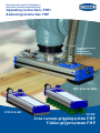 1
1
-
 2
2
-
 3
3
-
 4
4
-
 5
5
-
 6
6
-
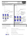 7
7
-
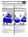 8
8
-
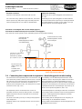 9
9
-
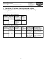 10
10
-
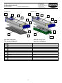 11
11
-
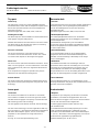 12
12
-
 13
13
-
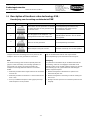 14
14
-
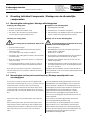 15
15
-
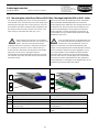 16
16
-
 17
17
-
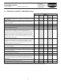 18
18
-
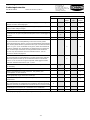 19
19
-
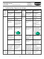 20
20
-
 21
21
-
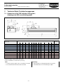 22
22
-
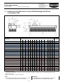 23
23
-
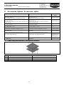 24
24
-
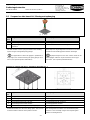 25
25
-
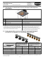 26
26
-
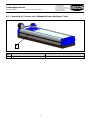 27
27
-
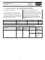 28
28
-
 29
29
-
 30
30
-
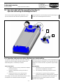 31
31
-
 32
32
-
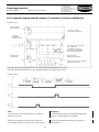 33
33
-
 34
34
-
 35
35


Schmalz FMP-SW140 1036 3R54 SPB2-40P G60 Handleiding
- Type
- Handleiding
- Deze handleiding is ook geschikt voor
in andere talen
Gerelateerde artikelen
-
Schmalz VS P10 SA M8-4 Handleiding
-
-
Schmalz SMP 15 NO AS Handleiding
-
Schmalz SCPS 2-07 G02 NO M12-5 PNP Handleiding
-
-
-
Schmalz SENDER-902-E-SBM/L/V-EL/IND Handleiding
-
-
Schmalz STF 100 P 12.0 SSB Handleiding
-