
Documentazione
Tecnica
T21
rev. 0.4
09/2003
©
CAME
CANCELLI
AUTOMATICI
119RT21
SERIE R |
R SERIES
|
SÉRIE R |
BAUREIHE R
|
SERIE R /
SERIE R
DF
CANCELLI AUTOMATICI
PROFILO DI SICUREZZA IN GOMMA A CONTATTO MECCANICO
MECHANICAL-CONTACT, RUBBER SAFETY SECTION
PROFIL DE SÉCURITÉ EN CAOUTCHOUC À CONTACT MÉCANIQUE
GUMMI-SICHERHEITSPROFIL MIT MECHANISCHEM KONTAKT
PERFIL DE SEGURIDAD DE GOMA POR CONTACTO MECÁNICO
VEILIGHEIDSPROFIEL IN RUBBER VOOR MECHANISCH CONTACT
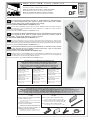
I La costa permette il rilevamento dell'ostacolo immediatamente, è multidirezionale e
sensibile in tutta la lunghezza del profilo, grazie al sistema a leva snodata e alla completa
assenza di parti rigide, inoltre rispetta le vigenti norme di legge.
Sistema brevettato CAME CANCELLI AUTOMATICI S.p.a.
GB The rib allows immediate obstacle detection and is multidirectional and sensitive along the
full section length, due to the articulated-lever system and absence of rigid parts. It also meets the
current rules and standards.
System patented by CAME CANCELLI AUTOMATICI S.p.A.
F Le bord permet de détecter immédiatement l’obstacle. Il est multidirectionnel et sensible
sur toute la longueur du profil grâce au système à levier articulé et à l’absence totale de
parties rigides. Il respecte par ailleurs les normes en vigueur.
Système breveté CAME CANCELLI AUTOMATICI S.p.a.
D Der Steg ermöglicht eine sofortige Feststellung des Hindernisses, dank seines
Gelenkhebelsystems und ohne irgendwelche steife Teile, kann er in mehrere Richtungen ausgerichtet
werden und ist über die gesamte Profillänge empfindlich. Gemäß den geltenden Gesetzesvorschriften.
Patentiertes System CAME CANCELLI AUTOMATICI S.p.a.
E La goma permite detectar el obstáculo inmediatamente, es multidireccional y sensible
a todo lo largo del perfil, gracias al sistema de palanca articulada y a que no posee piezas
rígidas, también respeta las normas vigentes.
Sistema patentado por CAME CANCELLI AUTOMATICI S.p.a.
NL De ribbe zorgt voor de onmiddellijke detectie van hindernissen, is multidirectioneel en gevoelig
over de volledige lengte van het profiel dankzij een geleed hefboomsysteem en de afwezigheid van
rigide delen. Voldoet ook aan de wettelijk geldende normen.
Gepatenteerd systeem van CAME CANCELLI AUTOMATICI S.p.a.
001 TMF 001 CMP
001 DF15 001 DF17 001 DF20
Profilo in gomma a contatto
meccanico L=1,7m
Mechanical-contact rubber
section L=1,7m
Profil en caoutchouc à contact
mécanique L=1,7m
Gummiprofil mit mechanischem
Kontakt L=1,7m
Perfil de goma por contacto
mecánico L=1,7m
Rubber profiel voor mechanisch
contact L=1,7m
Profilo in gomma a contatto
meccanico L=2,0m
Mechanical-contact rubber
section L=2,0m
Profil en caoutchouc à contact
mécanique L=2,0m
Gummiprofil mit mechanischem
Kontakt L=2,0m
Perfil de goma por contacto
mecánico L=2,0m
Rubber profiel voor mechanisch
contact L=2,0m
Gomma sensibile e profilo in alluminio per TMF
Sensitive rubber and aluminium section for TMF.
Caoutchouc sensible et profil en aluminium pour TMF
Empfindliches Gummi und Aluminiumprofil für TMF
Goma sensible y perfil de aluminio para TMF
Gevoelig rubber en profiel in aluminium voor TMF
Confezione di tappi e meccanismi per profili CMP, di
sicurezza a contatto meccanico.
Pack of lids and mechanisms for mechanical-contact
safety sections CMP.
Lot de bouchons et de mécanismes pour profils CMP,
de sécurité à contact mécanique.
Konfektion Deckel und Mechanismen für
Sicherheitsprofile CMP, mit mechanischem Kontakt.
Paquetes de tapas y mecanismos para perfiles de
seguridad por contacto mecánico CMP.
Verpakking met doppen en mechanismen voor
veiligheidsprofielen CMP voor mechanisch contact.
4 m
Profilo in gomma a contatto
meccanico L=1,5m
Mechanical-contact rubber
section L=1,5m
Profil en caoutchouc à contact
mécanique L=1,5m
Gummiprofil mit mechanischem
Kontakt L=1,5m
Perfil de goma por contacto
mecánico L=1,5m
Rubber profiel voor mechanisch
contact L=1,5m
ARTICOLI PER COSTE PREMONTATE A LUNGHEZZA FISSA
ITEMS FOR FIXED-LENGTH, PRE-ASSEMBLED RIBS
ARTICLES POUR BORDS SENSIBLES PRÉ-MONTÉS À LONGUEUR FIXE
ARTIKEL FÜR AUF FESTSTEHENDE LÄNGE VORMONTIERTE STEGE
ÁRTICULOS PARA GOMAS SENSIBLES PREMONTADAS DE LONGITUD FIJA
ARTIKELS VOOR REEDS GEASSEMBLEERDE RIBBEN MET VASTE LENGTE
ARTICOLI PER COSTE DA ASSEMBLARE A LUNGHEZZA VARIABILE fino a 4 metri (vedi fasi da 1 a 7)
ITEMS FOR RIBS TO ASSEMBLE AT VARIABLE LENGTHS up to 4 meters (see phases from 1 to 7)
ARTICLES POUR BORDS SENSIBLES À ASSEMBLER À LONGUEUR VARIABLE jusqu’à 4 mètres (voir phases de 1 à 7)
ARTIKEL FÜR AUF VERSCHIEDENE LÄNGEN ZU MONTIERENDE STEGE bis zu 4 Meter (siehe Phasen von 1 bis 7)
ÁRTICULOS PARA GOMAS SENSIBLES A ENSAMBLAR DE LONGITUD VARIABLE hasta 4 metros (véanse pasos de 1 a 7)
ARTIKELS VOOR TE ASSEMBLEREN RIBBEN MET VARIEERBARE LENGTE tot 4 meter (zie fasen 1 tot 7)

Documentazione
Tecnica
T31
rev. 0.1
07/2003
©
CAME
CANCELLI
AUTOMATICI
119RT31
SERIE DF |
DF SERIES |
SÉRIE DF |
BAUREIHE DF |
SERIE DF /
SERIE DF
CANCELLI AUTOMATICI
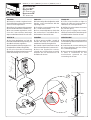
REGOLAZIONE DF
DF ADJUSTMENT
RÉGLAGE DF
DF-EINSTELLUNG
REGULACIÓN DF
DF INSTELLING
20 mm
ITALIANO
1) Fissare la costola e regolare la ten-
sione della fune sul meccanismo attra-
verso la vite di regolazione.
2) Verificare il corretto posizionamento
del microinterruttore del contatto N.C..
3) Per una corretta regolazione, verifi-
care che il meccanismo intervenga
dopo una deformazione di circa 20 mm.
ENGLISH
1) Fix the safety rib and adjust the cable
tension, on the mechanism with the
adjusting screw.
2) Check the correct positioning of the
N.C. contact microswitch.
3) For a correct adjustment, check that
the mechanism is activaded after a
deformation of around 20 mm.
FRANÇAIS
1) Fixer le bord mobile et régler la
tension du câble sur le mécanisme à
l’aide de la vis correspondante.
2) Vérifier si le microcontact du contact
N.F. est bien placé.
3) Pour que le réglage soit correct,
vérifier si le mécanisme intervient aprés
une déformation d’environ 20 mm.
DEUTSCH
1) Den Steg befestigen und mit der
Einstellschraube die Seilspannung auf
dem Mechanismus regulieren.
2) Die korrekte Positionierung des N.C.-
Kontaktmikroschalters überprüfen.
3) Für eine korrekte Einstellung
überprüfen, daß der Mechanismus nach
einer Verformung von ca. 20 mm.
ESPAÑOL
1) Fije la goma sensible y regule la
tensión del cable en el mecanismo
mediante el tornillo de regulación.
2) Controle el posicionamiento correcto
del microinterruptor del contacto N.C..
3) Para una regulación correcta,
controle que el mecanismo se active
después de una deformación de
alrededor de 20 mm.
NEDERLANDS
1) Bevestig de ribbe en stel de spanning
van de kabel op het mechanisme in via
de stelschroef.
2) Controleer de correcte werking van
de microschakelaar van het contact
N.C. (normaal gesloten).
3) Om na te gaan of de instelling correct
is moet u controleren of het
mechanisme optreedt na een
vervorming van 20 mm.
1
2
3

Tutti i dati sono stati controllati con la
massima cura. Non ci assumiamo co-
munque alcuna responsabilità per
eventuali errori od omissioni.
All data checked with the maximum care.
However, no liability is accepted for any error
or omission.
Toutes les données ont été contrôlées
très soigneusement. Nous n’assumons
de toute façon aucune responsabilité pour
les erreurs ou omissions éventuelles.
Die Daten wurden mit höchster Sorgfalt
geprüft. Für eventuelle Fehler oder
Auslassungen übernehmen wir keine
Haftung.
CANCELLI AUTOMATICI
CAME LOMBARDIA S.R.L.______COLOGNO M. (MI)
(+39) 02 26708293 (+39) 02 25490288
CAME SUD S.R.L. ___________________NAPOLI
(+39) 081 7524455 (+39) 081 7529109
CAME (AMERICA) L.L.C.____________MIAMI ( FL)
(+1) 305 593 8798 (+1) 305 593 9823
CAME AUTOMATISMOS S.A__________MADRID
(+34) 091 5285009 (+34) 091 4685442
CAME BELGIUM__________________LESSINES
(+32) 068 333014 (+32) 068 338019
CAME FRANCE S.A.____NANTERRE CEDEX (PARIS)
(+33) 01 46130505 (+33) 01 46130500
CAME GMBH__KORNTAL MÜNCHINGEN BEI ( STUTTGART)
(+49) 07150 37830 (+49) 07510 378383
CAME GMBH______________SEEFELD BEI (BERLIN)
(+49) 03 33988390 (+49) 03 339885508
CAME PL SP.ZO.O_________________WARSZAWA
(+48) 022 8365076 (+48) 022 8369920
CAME UNITED KINGDOM LTD______NOTTINGHAM
(+44) 0115 9210430 (+44) 0115 9210431
CAME CANCELLI AUTOMATICI S.P.A.
DOSSON DI CASIER (TREVISO)
(+39) 0422 4940 (+39) 0422 4941
SISTEMA QUALITÀ
CERTIFICATO
ASSISTENZA TECNICA
NUMERO VERDE
800 295830
W
EB
www.came.it
E-
MAIL
Todos los datos se han controlado con
la máxima atención. No obstante no nos
responsabilizamos de los posibles
errores u omisiones.
ITALIANO
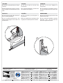
4) Fissare la vite per bloccare il mec-
canismo.
5) Nelle installazioni verticali, posizio-
nare il gruppo microinterruttore verso
l’alto.
ENGLISH
4) Fix the screw to secure the
mechanism.
5) In vertical installations, position the
microswitch unit upward.
FRANÇAIS
4) Fixer la vis pour bloquer le
mécanisme.
5) S’il s’agit d’une installation vertica-
le, placer le groupe microcontact vers
le haut.
DEUTSCH
4) Zur Blockierung des Mechanismus
die Schraube befestigen.
5) Bei Vertikalinstallationen, die
Mikroschaltergruppe nach oben hin
positionieren.
ESPAÑOL
4) Fije el tornillo para bloquear el
mecanismo.
5) En las instalaciones verticales, sitúe
el grupo microinterruptor hacia arriba.
NEDERLANDS
4) Draai de blokkeringsschroef van het
mechanisme vast.
5) Voor verticale installaties moet de
eenheid met microschakelaar
bovenaan geplaatst worden.
4
5

2
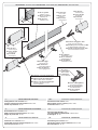
Tappo di testa
Head stopper
Bouchon de tête
Kopfdeckel
Tapa terminal
Kopstopper
Profilo alluminio
Aluminium section
Profil en aluminium
Aluminiumprofil
Perfil de aluminio
Aluminium profiel
Profilo di gomma
Rubber section
Profil en caoutchouc
Gummiprofil
Perfil de goma
Rubber profiel
Fune di acciaio
Steel cable
Câble en acier
Stahlseil
Cable de acero
Stalen kabel
Tappo di testa
Head stopper
Bouchon de tête
Kopfdeckel
Tapa terminal
Kopstopper
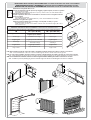
DESCRIZIONE
/ DESCRIPTION
/ DESCRIPTION
/ BESCHREIBUNG
/ DESCRIPCIÓN
/ BESCHRIJVING
- I - CARATTERISTICHE TECNICHE
Collegamento con contatto: N.C.;
Portata contatto microinterruttore: 3A a 24V;
Grado di protezione: IP 54.
- GB - TECHNICAL CHARACTERISTICS
Connection with contact: N.C.;
Microswitch contact capacity: 3A to 24V;
Protection level: IP 54
- F - CARACTERISTIQUES TÉCHNIQUES
Branchement avec contact: N.C.;
Débit contact microinterrupteur: 3A à 24V;
Degré de protection: IP 54.
- D - TECHNISCHE EIGENSCHAFTEN
Anschluß mit Kontakt : N.C.;
Leistung Mikroschalterkontakt : 3A bei 24V;
Schutzgrad : IP 54.
- E- CARACTERISTÍCAS TÉCNICAS
Conexión con contacto: N.C.;
Capacidad contacto microinterruptor: 3A a 24V;
Clase de protección: IP 54.
- NL- TÉCHNISCHE KENMERKEN
Aansluiting met contact: N.C.;
Vermogen contact microschakelaar: 3A tot 24V;
Beschermklasse: IP 54.
Staffa di fissaggio
Fixing bracket.
Bride de fixation
Befestigungsbügel
Estribo de fijación
Bevestigingsstaaf
Meccanismo di aggancio fune
Cable hitch mechanism
Mécanisme pour accrocher le câble
Seilkupplungsmechanismus
Mecanismo de enganche del cable
Kabelvasthaakmechanisme
Morsetto di collegamento
Connecting terminal
Borne de branchement
Anschlußklemme
Borne de conexión
Aansluitklem
Microinterruttore
Microswitch
microinterrupteur
Mikroschalter
microinterruptor
microschakelaar
Meccanismo porta microinterruttore
Microswitch door mechanism
Mécanisme porte microinterrupteur
Mikroschalter-Türmechanismus
Mecanismo soporte microinterruptor
Steunmechanisme voor de
microschakelaar
40
25
86
17,5
101
190
46

3
C
A
M
E
L N
MONTAGGIO DEGLI ARTICOLI DA ASSEMBLARE /
PUTTING TOGETHER THE ITEMS TO ASSEMBLE
MONTAGE DES ARTICLES À ASSEMBLER /
MONTAGE DER ZUSAMMENZUBAUENDEN ARTIKEL
MONTAJE DE LOS ARTÍCULOS A ENSAMBLAR /
MONTAGE VAN DE TE ASSEMBLEREN ARTIKELS
L P
L N
L N
L N
L N
L
UNGHEZZE
DI
TAGLIO
PER
ARTICOLI
DA
ASSEMBLARE
/
C
UT
LENGTHS
FOR
ITEMS
TO
ASSEMBLE
L
ONGUEUR
DE
COUPE
POUR
LES
ARTICLES
À
ASSEMBLER
/
SCHNITTLÄNGEN
FÜRZU
MONTIERENDE
ARTIKEL
L
ONGITUDES
DE
CORTE
PARA
ARTÍCULOS
A
ENSAMBLAR
/
AF
TE
SNIJDEN
LENGTEN
VOOR
TE
ASSEMBLEREN
ARTIKELS
L G
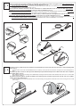
N.B. nelle installazioni verticali, ridurre di 30 mm la lunghezza nominale rilevata, per evitare il contatto con il terreno.
N.B. in vertical installations, reduce the current nominal length by 30 mm to avoid contact with the ground.
N.B. s’il s’agit d’une installation verticale, réduire la longueur nominale relevée de 30 mm pour éviter le contact avec le terrain.
N.B. um die Berührung mit dem Boden zu vermeiden, bei den vertikalen Installationen die erfaßte Nennlänge um 30 mm verkürzen.
N.B. en las instalaciones verticales, reduzca 30 mm la longitud nominal medida, para evitar el contacto con el suelo.
N.B. verminder bij verticale plaatsing de gemeten nominale lengte met 30 mm om aanraking met het terrein te vermijden.
FASE
PHASE
PHASE
PHASE
1
ETAPA
FASE
30mm
NL )mm04-NL(=PL )mm582-NL(=GL
elanimonazzehgnul
oinimullaoliforpazzehgnul
aniaugazzehgnul
htgnelhtaehs
htgnelnoitcesmuinimula
htgnelhtaehs
eniagrueugnol
muinimulaneliforprueugnol eniagrueugnol
egnälnellüH
egnälliforpmuinimulA egnälnellüH
aniavdutignol oinimulalifrepdutignol
aniavdutignol
.edehcsetgnel
.leiforpmuinimulaetgnel
.edehcsetgnel
L
O
C
K
U
N
L
O
C
K
C
A
M
E
C
A
M
E
L N
Determinare la lunghezza della costa.
In base alla lughezza nominale (zona da proteggere), tagliare il profilo, la fune e la gomma.
Determine the rib length.
Depending on the nominal length (zone to protect), cut the section, the cable and the rubber.
Calculer la longueur du bord.
Couper le profilé, le câble et le bord sensible en caoutchouc selon la longueur nominale
(zone à protéger).
Die Steglänge bestimmen.
Nach der Nennlänge (zu schützende Zone ), Profil, Seil und Gummi zuschneiden.
Determine la longitud de la goma.
Según la longitud nominal (zona a proteger), corte el perfil, el cable y la goma
Bepaal de lengte van de ribbe.
Snijd het profiel, de kabel en het rubber in functie van de nominale lengte (dit is de te
beschermen zone).

4
4 m
Forare con punta da ø 3 il profilo in alluminio da entrambi i lati e infilare il meccanismo di aggancio fune (nella parte inferiore se
la costa è posizionata verticalmente), e avvitare le due viti UNI 6955 ø 3,9 x 13.
Drill the aluminium section with a 3 dia. bit from both sides and insert the cable-hitch mechanism (in the lower part if the rib is vertical),
and tighten the two screws UNI 6955 dia. 3.9 x 13.
Percer le profil en aluminium des deux côtés avec une mèche ø 3, enfiler le mécanisme pour accrocher le câble (dans la partie
inférieure si le bord est placé verticalement) et visser les deux vis UNI 6955 ø 3,9 x 13.
Das Aluminiumprofil von beiden Seiten mit einer Spitze ø 3 durchlochen und den Seilkupplungsmechanismus einführen (bei vertikaler
Positionierung des Stegs im unteren Teil); die beiden Schrauben UNI 6955 ø 3,9 x 13 befestigen.
Taladre con broca de ø 3 el perfil de aluminio en ambos lados y monte el mecanismo de enganche del cable (en la parte
inferior, si la goma está situada en posición vertical), y enrosque los dos tornillos UNI 6955 ø 3,9 x 13.
Boor aan beide kanten een gat in het aluminiumprofiel met een boorpunt met ø 3 en plaats hier het kabelvasthaakmechanisme in (in
het onderste deel indien de ribbe verticaal geplaatst is) en draai de twee schroeven UNI 6955 ø 3,9 x 13 vast;
Inserire il profilo in gomma nel profilo in alluminio fino alla battuta e poi far passare la fune di acciaio nel foro superiore della guaina
(fase. 3 fig.1);
Insert the rubber section into the aluminium bracket to its end-stop. Then, pass the steel cable into the upper hole of the sheath (phase.3,
fig.1);
Introduire le profil en caoutchouc dans la profil en aluminium jusqu’à la butée et faire passer le câble en acier dans le trou supérieur
de la gaine (phase. 3 fig. 1);
Das Gummiprofil bis zum Anschlag in den Aluminiumprofil einfügen und anschließend das Stahlseil durch das obere Loch der Hülle
führen (phase. 3 Abb.1);
Introduzca el perfil de goma en el perfil de aluminio hasta que haga tope y después haga pasar el cable de acero por el agujero
superior de la vaina (etapa.3 fig.1);
Plaats het rubber profiel in de aluminiumprofiel tot aan de aanslag en breng dan de stalen kabel door het bovenste gat in de schede
(fase.3 fig.1);
150
150
150
150
7,57,5
40
18
2
1
2
1
FASE
PHASE
PHASE
PHASE
2
ETAPA
FASE
FASE
PHASE
PHASE
PHASE
3
ETAPA
FASE
Fig. A
Add. A

5
2
1
3
4
FASE
PHASE
PHASE
PHASE
4
ETAPA
FASE
FASE
PHASE
PHASE
PHASE
5
ETAPA
FASE
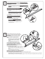
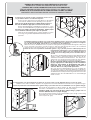
Infilare il meccanismo porta microinterruttore (nella parte superiore se la
costa è posizionata verticalmente). Una volta inserito, sbloccare la leva con
una leggera pressione verso il basso (fase.4 fig.4) e avvitare le due viti UNI
6955 ø 2,9 x 13;
Insert the microswitch-holder mechanism (if the rib is vertical, insert into the
upper part). Once inserted, release the lever with light downward pressure
(phase.4, fig.4) and tighten the two screws UNI 6955 dia.
2.9 x 13;
Enfiler le mécanisme porte microinterrupteur (dans la
partie supérieure si le bord est placé verticalement).
Débloquer ensuite le levier en appuyant légèrement
vers le bas (phase. 4 fig. 4) et visser les deux vis UNI
6955 ø 2,9 x 13;
Den Mikroschalter-Türmechanismus einfügen (bei
vertikaler Anbringung des Steges im oberen Teil ).
Nach seiner Anbringung, den Hebel durch einen
leichten Druck nach unten lösen (phase. 4 Abb.4)
und die beiden Schrauben UNI 6955 ø 2,9 x 13
befestigen;
Monte el mecanismo de soporte del microinterruptor
(en la parte superior si la goma está situada en
posición vertical). Una vez montado, desbloquee la
palanca presionando ligeramente hacia abajo (etapa.4
fig.4)y enrosque los dos tornillos UNI 6955 ø 2,9 x 13;
Plaats het steunmechanisme voor de
microschakelaar (in het bovenste deel indien de
ribbe verticaal geplaatst is).Nadat deze geplaatst
werd moet de hendel gedeblokkeerd worden door
deze lichtjes naar onder toe te drukken (fase.4 fig.4)
en moeten beide schroeven UNI 6955 ø 2,9 x 13
vastgedraaid worden;
1
2
3
Infilare la fune di acciaio nel foro del grano
(fase.5 fig.1), inserire il tutto nella leva (fase.5
fig.2),mettere in tensione la fune e avvitare
(fase.5 fig.3).
Una volta regolata la tensione della fune,
tagliare la parte in eccedenza (fase.5
fig.4).
Feed the steel cable through the dowel
hole (phase 5, fig. 1), insert everything
in the lever (phase 5, fig.2), put the
cable under tension and screw (phase
5, fig.3).
After adjusting the cable tension, cut
off the excess length (phase.5, fig.4).
Enfiler le câble en acier dans le trou de la
vis sans tête (phase 5 figure 1), introduire
le tout dans le levier (phase 5 fig.2), tendre le
câble et visser (phase 5 fig.3).
Couper la partie en trop du câble après en avoir
réglé la tension (phase. 5 fig. 4).
Das Stahlseil in das Stiftloch einführen (Phase 5 –
Abb. 1) und alles in den Hebel einfügen (Phase 5 Abb.
2),das Seil spannen und anschrauben (Phase 5 –
Abb. 3).
Nach Einstellung der Seilspannung, das überstehende
Stück abschneiden (Phase.5 Abb.4).
Introduzca el cable de acero en el agujero del pasador
(etapa 5 fig.1), introduzca todo en la palanca (etapa 5
fig.2), tense el cable y enrosque (etapa 5 fig.3).
Una vez regulada la tensión del cable, corte la parte sobrante (etapa.5 fig.4).
Voeg de stalen kabel in het gat van de stift (fase 5 fig. 1), plaats het geheel in de hendel (fase 5 fig.2), zet de kabel
onder spanning en schroef vast (fase 5 fig. 3).
Nadat de spanning van de kabel werd ingesteld mag de overschot van de kabel eraf geknipt worden (fase.5 fig.4).

6
1
2
1
2
4
5
3
3
FASE
PHASE
PHASE
PHASE
6
ETAPA
FASE
FASE
PHASE
PHASE
PHASE
7
ETAPA
FASE
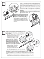
Regolare la tensione della fune sul meccanismo attraverso la vite di
regolazione (fase.6 fig.1) e verificare il corretto azionamento del
microinterruttore del contatto N.C. con un tester. Fissare il grano (vite senza
testa) per bloccare il meccanismo (fase.6 fig.3).
Adjust the cable tension on the mechanism with the adjusting screw (phase 6 fig.1)
and use a tester to check that the N.C. contact microswitch switches correctly.
Tighten the grub screw (screw without head) to secure the mechanism (phase 6
fig.3).
Régler la tension du câble sur le mécanisme à l’aide de la vis de réglage
(phase 6 fig. 1) et vérifier si le microinterrupteur du contact N.F. s’actionne
correctement avec un testeur. Fixer la vis sans tête pour bloquer le mécanisme
(phase 6 fig. 3).
Mit Hilfe der Einstellschraube die Seilspannung auf dem Mechanismus (Phase 6
Abb. 1) regulieren, und mit einem Tester den korrekten N.C. Kontakt -
Mikroschalterantrieb überprüfen. Zur
Blockierung des Mechanismus den Stift
(Schraube ohne Kopf) befestigen. (Phase 6 Abb. 3).
Regule la tensión del cable en el mecanismo a través
del tornillo de regulación (etapa 6 fig.1) y controle el
accionamiento correcto del microinterruptor del
contacto N.C. con un tester. Apriete el tornillo sin
cabeza para bloquear el mecanismo (etapa 6 fig.3).
Stel de spanning van de kabel in op het mechanisme
met behulp van de stelschroef (fase 6 fig.1) en controleer
de werking van de microschakelaar van het contact
N.C. (normaal gesloten) met een tester. Plaats de stift
(wormschroef) zodat het mechanisme geblokkeerd wordt
(fase 6 fig.3).
Solo su istallazioni verticali forare con punta Ø 4 le apposite tracce situate
sul tappo da posizionare nella parte inferiore (fase.7 fig. 1) della costa,
per evitare che si formi condensa all'inerno. Inserire il tappo e fissarlo
con n°3 viti UNI 6954 Ø 3,9 x 13 e relative rondelle (fase.7 fig.3-4-5)
(vedi pag. 4 fig. A).
On vertical installations only, use a 4-Diam. bit to drill the
appropriate traces on the top that must be
positioned in the lower part (phase 7 fig. 1) of
the rib; this avoids condensation from building
up inside. Insert the top and secure it with
3 UNI 6954 screws DIA 3.9 x 13 and
related washers (phase 7 fig.3-4-5) (see
page 4, fig. A).
Uniquement pour les installations
verticales: percer le bouchon à placer dans
la partie inférieure (phase 7 fig. 1) du bord
sensible aux endroits indiqués avec une mèche
Ø 4, pour éviter qu’il se forme de la condensation
à l’intérieur. Mettre le bouchon et le fixer avec 3 vis
UNI 6954 Ø 3,9 x 13 et les rondelles correspondantes
(phase 7 fig. 3-4-5) (voir à la page 4 fig. A).
Zwecks Vermeidung von innerer
Kondenswasserbildung , ausschließlich
bei vertikalen Installationen mit einer
Spitze Ø 4 den im unteren Teil des Steges
anzubringenden Verschluß an den eigens
dafür vorgesehenen Stellen durchbohren (Phase 7 Abb. 1). Den
Verschluß einführen und mit 3 Schrauben UNI 6954 Ø 3,9 x 13 und
den entsprechenden Unterlegscheiben (Phase 7 Abb. 3-4-5) (siehe
Seite 4 Abb. A) befestigen.
Sólo en las instalaciones verticales, taladre con una broca de Ø 4 en las
marcas situadas en el tapón a colocar en la parte inferior (etapa 7 fig. 1) de la
goma, para que no se forme condensación en su interior. Coloque el tapón y fíjelo
con 3 tornillos UNI 6954 Ø 3,9 x 13 y sus arandelas correspondientes (etapa 7 fig.3-4-5) (véase pág. 4
fig. A).
Enkel in geval van verticale plaatsing moet een gat geboord worden met een boorpunt met Ø 4 ter hoogte
van de merktekens op de dop die onderaan op de ribbe geplaatst moet worden (fase 7 fig. 1), om te
vermijden dat er binnenin condens gevormd wordt. Plaats de dop en bevestig hem met de 3 schroeven
UNI 6954 Ø 3,9 x 13 en bijbehorende ringetjes (fase 7 fig.3-4-5) (zie pag. 4 fig. A).

7
1
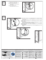
Posizionare le tre staffe di fissaggio equidistanti, forare e fissare
con gli elementi adatti a seconda della superfice.
Position the three fixing brackets at equal distances, drill and then
secure with the suitable elements depending on the superfive.
Placer les trois brides de fixation à la même distance, percer et
fixer avec les éléments appropriés en fonction de la surface.
Die drei Befestigungsbügel abstandsgleich positionieren, lochen
und mit den für die Oberfläche geeigneten Elementen befestigen.
Coloque los tres estribos de fijación equidistantes, taladre y fíjelos
con los elementos adecuados para el tipo de superficie.
Plaats de drie bevestigingsbeugels op gelijke afstand, boor gaten
en bevestig met geschikte hulpmiddelen afhankelijk van het
oppervlak.
1
2
ESEMPIO DI POSA DELLA COSTA VERTICALE SU PILASTRO
EXAMPLE OF LAYING THE VERTICAL RIB ON THE PILLAR
EXEMPLE DE POSE DU BORD VERTICAL SUR LE PILIERBEISPIEL
FÜR DIE ANBRINGUNG DES VERTIKALEN STEGES AUF EINEM PFEILER
EJEMPLO DE COLOCACIÓN DE LA GOMA VERTICAL EN UNA COLUMNA
VOORBEELD VAN PLAATSING VAN DE VERTICALE RIBBE OP EEN ZUIL
FASE
PHASE
PHASE
PHASE
8
ETAPA
FASE
2
Forare il profilo con una punta da Ø 2,5 (fase 10 fig.1) e fissarlo con viti UNI 6954 Ø 3,9 x 13 (fase 10 fig.2).
Drill the section with a 2.5 Diam. bit (phase 10, fig.1) and secure it with UNI 6954 screws DIA 3.9 x 13 (phase 10, fig.2).
Percer le profilé avec une mèche de Ø 2,5 (phase 10 fig. 1) et le fixer avec les vis UNI 6954 Ø 3,9 x 13 (phase 10 fig.2).
Das Profil mit einer Spitze von Ø 2,5 (Phase 10 Abb.1) durchlochen und mit
Schrauben UNI 6954 Ø 3,9 x 13 (Phase 10 Abb.2) befestigen.
Taladre el perfil con una punta de Ø 2,5 (etapa 10 fig.1) y fíjelo con los
tornillos UNI 6954 Ø 3,9 x 13 (etapa 10 fig.2).
Boor een gat in het profiel met een boorpunt met Ø 2,5 (fase 10 fig.1) en bevestig
met behulp van schroeven UNI 6954 Ø
3,9 x 13 (fase 10 fig.2).
FASE
PHASE
PHASE
PHASE
10
ETAPA
FASE
1
O 2,5
30 mm
Prevedere foratura passaggio cavo sul profilo in alluminio (fase 9, fig.1) e far scorrere il cavo (2x1)
per i collegamenti elettrici. Per facilitare lo scorrimento del cavo attraverso il profilo, è consigliato
l'uso di una sonda. Negli articoli: DF 15 / 17 / 20 il foro è già predisposto.
Make a hole in the aluminium section to pass the cable (phase 9, fig.1) and slide through the cable (2x1)
for the electrical connections. To make it easier to slide the cable through the section, we recommend
using a probe. In the articles: DF 15 / 17 / 20 the hole is already made.
Percer un trou sur le profilé en aluminium (phase 9, fig. 1) et faire passer le câble (2x1) pour les
branchements électriques. Il est conseillé d’utiliser une
sonde pour que le câble passe plus facilement dans le
profilé. Le trou est déjà prévu pour les modèles: DF 15 /
17 / 20.
Ein Loch für den Kabeldurchgang auf dem Aluminiumprofil
(Phase 9, Abb. 1) anbringen und das Kabel (2x1) für die
elektrischen Anschlüsse hindurchziehen. Für diesen Vor-
gang sollte eine Sonde benutzt werden. Bei den Artikeln:
DF 15 / 17 / 20 wurde das Loch bereits vorgesehen.
Perfore el perfil de aluminio para pasar el cable (etapa 9,
fig.1) y haga pasar el cable (2x1) para las conexiones
eléctricas. Para facilitar el deslizamiento del cable a
través del perfil, se aconseja utilizar una sonda Los
artículos: DF 15 / 17 / 20 ya están perforados.
Boor een gat in het aluminiumprofiel voor de doorgang van
de draad (fase 9, fig.1) en breng de draad (2x1) er doorheen
voor de verwezenlijking van de elektrische aansluitingen. Om
de draad beter door het profiel te brengen kan best een sonde
gebruikt worden. Voor de artikels DF 15 / 17 / 20 werd dit gat
reeds voorzien
FASE
PHASE
PHASE
PHASE
9
ETAPA
FASE

Tutti i dati sono stati controllati con la massima cura.
Non ci assumiamo comunque alcuna responsabilità
per eventuali errori od omissioni.
All data checked with the maximum care. However, no
liability is accepted for any error or omission.
Toutes les données ont été contrôlées très
soigneusement. Nous n’assumons de toute façon
aucune responsabilité pour les erreurs ou omissions
éventuelles.
Die Daten wurden mit höchster Sorgfalt geprüft. Für
eventuelle Fehler oder Auslassungen übernehmen wir
keine Haftung.
Todos los datos se han controlado con la máxima
atención. No obstante no nos responsabilizamos de
los posibles errores u omisiones.
CANCELLI AUTOMATICI
CAME LOMBARDIA S.R.L.______COLOGNO M. (MI)
(+39) 02 26708293 (+39) 02 25490288
CAME SUD S.R.L. ___________________NAPOLI
(+39) 081 7524455 (+39) 081 7529109
CAME (AMERICA) L.L.C.____________MIAMI ( FL)
(+1) 305 5938798 (+1) 305 5939823
CAME AUTOMATISMOS S.A__________MADRID
(+34) 091 5285009 (+34) 091 4685442
CAME BELGIUM__________________LESSINES
(+32) 068 333014 (+32) 068 338019
CAME FRANCE S.A.____NANTERRE CEDEX (PARIS)
(+33) 01 46130505 (+33) 01 46130500
CAME GMBH________KORNTAL BEI (STUTTGART)
(+49) 07 15037830 (+49) 07 150378383
CAME GMBH____________SEEFELD BEI (BERLIN)
(+49) 03 33988390 (+49) 03 339885508
CAME PL SP.ZO.O______________WARSZAWA
(+48) 022 8365076 (+48) 022 8369920
CAME UNITED KINGDOM LTD___NOTTINGHAM
(+44) 0115 9210430 (+44) 0115 9210431
CAME CANCELLI AUTOMATICI S.P.A.
DOSSON DI CASIER (TREVISO)
(+39) 0422 4940 (+39) 0422 4941
SISTEMA QUALITÀ
CERTIFICATO
ASSISTENZA TECNICA
NUMERO VERDE
800 295830
W
EB
www.came.it
E-MAIL
De gegevens in deze handleiding werden nauwkeurig
gecontroleerd. Wij wijzen iedere verantwoordelijkheid
af in geval van drukfouten of vergissingen.
Collegare il cavo al morsetto
Connect the cable to the clamp
Brancher le câble à la borne
Das Kabel an die Klemme
anschließen
Conecte el cable al borne
Sluit de kabel aan op de klem.
FASE
PHASE
PHASE
PHASE
11
ETAPA
FASE
Infilare il tappo e fissarlo con n°3 viti UNI 6954 Ø 3,9 x 13 e relative rondelle.
Insert the stopper and secure it with 3 UNI 6954-type screws DIA 3.9 x 13 and
related washers.
Enfiler le bouchon et le fixer avec 3 vis UNI 6954 Ø 3,9 x 13 et les rondelles
correspondantes.
Den Deckel anbringen und mit n°3 Schrauben UNI 6954 Ø 3,9 x 13 und den
entsprechenden Unterlegscheiben befestigen.
Encaje la tapa y fíjela con 3 tornillos UNI 6954 Ø 3,9 x 13 y las arandelas
correspondientes.
Plaats de dop en bevestig hem met 3 schroeven UNI 6954 Ø 3,9 x 13 en
ringetjes.
FASE
PHASE
PHASE
PHASE
12
ETAPA
FASE
Documenttranscriptie
SERIE R | R SERIES | SÉRIE R | BAUREIHE R | SERIE R / SERIE R Documentazione Tecnica T21 PROFILO DI SICUREZZA IN GOMMA A CONTATTO MECCANICO MECHANICAL-CONTACT, RUBBER SAFETY SECTION rev. 0.4 09/2003 PROFIL DE SÉCURITÉ EN CAOUTCHOUC À CONTACT MÉCANIQUE GUMMI-SICHERHEITSPROFIL MIT MECHANISCHEM KONTAKT PERFIL DE SEGURIDAD DE GOMA POR CONTACTO MECÁNICO VEILIGHEIDSPROFIEL IN RUBBER VOOR MECHANISCH CONTACT CANCELLI AUTOMATICI DF © CAME CANCELLI AUTOMATICI 119RT21 I La costa permette il rilevamento dell'ostacolo immediatamente, è multidirezionale e sensibile in tutta la lunghezza del profilo, grazie al sistema a leva snodata e alla completa assenza di parti rigide, inoltre rispetta le vigenti norme di legge. Sistema brevettato CAME CANCELLI AUTOMATICI S.p.a. GB The rib allows immediate obstacle detection and is multidirectional and sensitive along the full section length, due to the articulated-lever system and absence of rigid parts. It also meets the current rules and standards. System patented by CAME CANCELLI AUTOMATICI S.p.A. F Le bord permet de détecter immédiatement l’obstacle. Il est multidirectionnel et sensible sur toute la longueur du profil grâce au système à levier articulé et à l’absence totale de parties rigides. Il respecte par ailleurs les normes en vigueur. Système breveté CAME CANCELLI AUTOMATICI S.p.a. D Der Steg er möglicht eine sofor tige Feststellung des Hindernisses, dank seines Gelenkhebelsystems und ohne irgendwelche steife Teile, kann er in mehrere Richtungen ausgerichtet werden und ist über die gesamte Profillänge empfindlich. Gemäß den geltenden Gesetzesvorschriften. Patentiertes System CAME CANCELLI AUTOMATICI S.p.a. E La goma permite detectar el obstáculo inmediatamente, es multidireccional y sensible a todo lo largo del perfil, gracias al sistema de palanca articulada y a que no posee piezas rígidas, también respeta las normas vigentes. Sistema patentado por CAME CANCELLI AUTOMATICI S.p.a. NL De ribbe zorgt voor de onmiddellijke detectie van hindernissen, is multidirectioneel en gevoelig over de volledige lengte van het profiel dankzij een geleed hefboomsysteem en de afwezigheid van rigide delen. Voldoet ook aan de wettelijk geldende normen. Gepatenteerd systeem van CAME CANCELLI AUTOMATICI S.p.a. ARTICOLI PER COSTE PREMONTATE A LUNGHEZZA FISSA ITEMS FOR FIXED-LENGTH, PRE-ASSEMBLED RIBS ARTICLES POUR BORDS SENSIBLES PRÉ-MONTÉS À LONGUEUR FIXE ARTIKEL FÜR AUF FESTSTEHENDE LÄNGE VORMONTIERTE STEGE ÁRTICULOS PARA GOMAS SENSIBLES PREMONTADAS DE LONGITUD FIJA ARTIKELS VOOR REEDS GEASSEMBLEERDE RIBBEN MET VASTE LENGTE 001 DF15 001 DF17 001 DF20 Profilo in gomma a contatto meccanico L=1,5m Profilo in gomma a contatto meccanico L=1,7m Profilo in gomma a contatto meccanico L=2,0m Mechanical-contact rubber section L=1,5m Mechanical-contact rubber section L=1,7m Mechanical-contact rubber section L=2,0m Profil en caoutchouc à contact mécanique L=1,5m Profil en caoutchouc à contact mécanique L=1,7m Gummiprofil mit mechanischem Kontakt L=1,7m Gummiprofil mit mechanischem Kontakt L=1,5m Perfil de goma por contacto mecánico L=1,5m Gummiprofil mit mechanischem Kontakt L=2,0m Perfil de goma por contacto mecánico L=2,0m Perfil de goma por contacto mecánico L=1,7m Rubber profiel voor mechanisch contact L=1,5m Profil en caoutchouc à contact mécanique L=2,0m Rubber profiel voor mechanisch contact L=1,7m Rubber profiel voor mechanisch contact L=2,0m ARTICOLI PER COSTE DA ASSEMBLARE A LUNGHEZZA VARIABILE fino a 4 metri (vedi fasi da 1 a 7) ITEMS FOR RIBS TO ASSEMBLE AT VARIABLE LENGTHS up to 4 meters (see phases from 1 to 7) ARTICLES POUR BORDS SENSIBLES À ASSEMBLER À LONGUEUR VARIABLE jusqu’à 4 mètres (voir phases de 1 à 7) ARTIKEL FÜR AUF VERSCHIEDENE LÄNGEN ZU MONTIERENDE STEGE bis zu 4 Meter (siehe Phasen von 1 bis 7) ÁRTICULOS PARA GOMAS SENSIBLES A ENSAMBLAR DE LONGITUD VARIABLE hasta 4 metros (véanse pasos de 1 a 7) ARTIKELS VOOR TE ASSEMBLEREN RIBBEN MET VARIEERBARE LENGTE tot 4 meter (zie fasen 1 tot 7) 001 TMF Confezione di tappi e meccanismi per profili CMP, di sicurezza a contatto meccanico. Pack of lids and mechanisms for mechanical-contact safety sections CMP. Lot de bouchons et de mécanismes pour profils CMP, de sécurité à contact mécanique. Konfektion Deckel und Mechanismen für Sicherheitsprofile CMP, mit mechanischem Kontakt. 001 CMP Gomma sensibile e profilo in alluminio per TMF Sensitive rubber and aluminium section for TMF. Caoutchouc sensible et profil en aluminium pour TMF Empfindliches Gummi und Aluminiumprofil für TMF Goma sensible y perfil de aluminio para TMF Gevoelig rubber en profiel in aluminium voor TMF Paquetes de tapas y mecanismos para perfiles de seguridad por contacto mecánico CMP. Verpakking met doppen en mechanismen voor veiligheidsprofielen CMP voor mechanisch contact. 4m SERIE DF CANCELLI AUTOMATICI | DF SERIES | SÉRIE DF | BAUREIHE DF | SERIE DF / SERIE DF Documentazione Tecnica T31 REGOLAZIONE DF DF ADJUSTMENT RÉGLAGE DF DF-EINSTELLUNG REGULACIÓN DF DF INSTELLING rev. 0.1 07/2003 © CAME CANCELLI AUTOMATICI 119RT31 ITALIANO ENGLISH FRANÇAIS 1) Fissare la costola e regolare la tensione della fune sul meccanismo attraverso la vite di regolazione. 1) Fix the safety rib and adjust the cable tension, on the mechanism with the adjusting screw. 1) Fixer le bord mobile et régler la tension du câble sur le mécanisme à l’aide de la vis correspondante. 2) Verificare il corretto posizionamento del microinterruttore del contatto N.C.. 2) Check the correct positioning of the N.C. contact microswitch. 2) Vérifier si le microcontact du contact N.F. est bien placé. 3) Per una corretta regolazione, verificare che il meccanismo intervenga dopo una deformazione di circa 20 mm. 3) For a correct adjustment, check that the mechanism is activaded after a deformation of around 20 mm. 3) Pour que le réglage soit correct, vérifier si le mécanisme intervient aprés une déformation d’environ 20 mm. DEUTSCH ESPAÑOL NEDERLANDS 1) Den Steg befestigen und mit der Einstellschraube die Seilspannung auf dem Mechanismus regulieren. 1) Fije la goma sensible y regule la tensión del cable en el mecanismo mediante el tornillo de regulación. 1) Bevestig de ribbe en stel de spanning van de kabel op het mechanisme in via de stelschroef. 2) Die korrekte Positionierung des N.C.Kontaktmikroschalters überprüfen. 2) Controle el posicionamiento correcto del microinterruptor del contacto N.C.. 3) Für eine korrekte Einstellung überprüfen, daß der Mechanismus nach einer Verformung von ca. 20 mm. 3) Para una regulación correcta, controle que el mecanismo se active después de una deformación de alrededor de 20 mm. 2) Controleer de correcte werking van de microschakelaar van het contact N.C. (normaal gesloten). 3) Om na te gaan of de instelling correct is moet u controleren of het mechanisme optreedt na een vervorming van 20 mm. 1 3 2 20 mm ITALIANO ENGLISH FRANÇAIS 4) Fissare la vite per bloccare il meccanismo. 4) Fix the screw to secure the mechanism. 4) Fixer la vis pour bloquer le mécanisme. 5) Nelle installazioni verticali, posizionare il gruppo microinterruttore verso l’alto. 5) In vertical installations, position the microswitch unit upward. 5) S’il s’agit d’une installation verticale, placer le groupe microcontact vers le haut. DEUTSCH ESPAÑOL NEDERLANDS 4) Zur Blockierung des Mechanismus die Schraube befestigen. 4) Fije el tornillo para bloquear el mecanismo. 4) Draai de blokkeringsschroef van het mechanisme vast. 5) Bei Ver tikalinstallationen, die Mikroschaltergruppe nach oben hin positionieren. 5) En las instalaciones verticales, sitúe el grupo microinterruptor hacia arriba. 5) Voor verticale installaties moet de eenheid met microschakelaar bovenaan geplaatst worden. 4 5 Tutti i dati sono stati controllati con la massima cura. Non ci assumiamo comunque alcuna responsabilità per eventuali errori od omissioni. All data checked with the maximum care. However, no liability is accepted for any error or omission. ASSISTENZA TECNICA N UMERO VERDE 800 295830 CANCELLI AUTOMATICI SISTEMA QUALITÀ CERTIFICATO WEB www.came.it E-MAIL [email protected] CAME CANCELLI AUTOMATICI S.P.A. DOSSON DI CASIER (TREVISO) (+39) 0422 4940 (+39) 0422 4941 Toutes les données ont été contrôlées très soigneusement. Nous n’assumons de toute façon aucune responsabilité pour les erreurs ou omissions éventuelles. Die Daten wurden mit höchster Sorgfalt geprüft. Für eventuelle Fehler oder Auslassungen übernehmen wir keine Haftung. CAME LOMBARDIA S.R.L.______COLOGNO M. (MI) (+39) 02 26708293 (+39) 02 25490288 CAME SUD S.R.L. ___________________NAPOLI (+39) 081 7524455 (+39) 081 7529109 CAME (AMERICA) L.L.C.____________MIAMI (FL) (+1) 305 593 8798 (+1) 305 593 9823 CAME AUTOMATISMOS S.A__________MADRID (+34) 091 5285009 (+34) 091 4685442 CAME BELGIUM__________________LESSINES (+32) 068 333014 (+32) 068 338019 Todos los datos se han controlado con la máxima atención. No obstante no nos responsabilizamos de los posibles errores u omisiones. CAME FRANCE S.A.____NANTERRE CEDEX (PARIS) (+33) 01 46130505 (+33) 01 46130500 CAME GMBH__KORNTAL MÜNCHINGEN BEI (STUTTGART) (+49) 07150 37830 (+49) 07510 378383 CAME GMBH______________SEEFELD BEI (BERLIN) (+49) 03 33988390 (+49) 03 339885508 CAME PL SP.ZO.O_________________WARSZAWA (+48) 022 8365076 (+48) 022 8369920 CAME UNITED KINGDOM LTD______NOTTINGHAM (+44) 0115 9210430 (+44) 0115 9210431 DESCRIZIONE / DESCRIPTION / DESCRIPTION / BESCHREIBUNG / DESCRIPCIÓN / BESCHRIJVING 40 ,5 Tappo di testa Head stopper Bouchon de tête Kopfdeckel Tapa terminal Kopstopper Fune di acciaio Steel cable Câble en acier Stahlseil Cable de acero Stalen kabel 101 25 86 17 Profilo di gomma Rubber section Profil en caoutchouc Gummiprofil Perfil de goma Rubber profiel 0 19 Meccanismo di aggancio fune Cable hitch mechanism Mécanisme pour accrocher le câble Seilkupplungsmechanismus Mecanismo de enganche del cable Kabelvasthaakmechanisme 46 Tappo di testa Head stopper Bouchon de tête Kopfdeckel Tapa terminal Kopstopper Staffa di fissaggio Fixing bracket. Bride de fixation Befestigungsbügel Estribo de fijación Bevestigingsstaaf Meccanismo porta microinterruttore Microswitch door mechanism Mécanisme porte microinterrupteur Mikroschalter-Türmechanismus Mecanismo soporte microinterruptor Steunmechanisme voor de microschakelaar -I- CARATTERISTICHE TECNICHE Collegamento con contatto: N.C.; Portata contatto microinterruttore: 3A a 24V; Grado di protezione: IP 54. -F- CARACTERISTIQUES TÉCHNIQUES Branchement avec contact: N.C.; Débit contact microinterrupteur: 3A à 24V; Degré de protection: IP 54. - E- CARACTERISTÍCAS TÉCNICAS Conexión con contacto: N.C.; Capacidad contacto microinterruptor: 3A a 24V; Clase de protección: IP 54. 2 - GB - Profilo alluminio Aluminium section Profil en aluminium Aluminiumprofil Perfil de aluminio Aluminium profiel Microinterruttore Microswitch microinterrupteur Mikroschalter microinterruptor microschakelaar Morsetto di collegamento Connecting terminal Borne de branchement Anschlußklemme Borne de conexión Aansluitklem TECHNICAL CHARACTERISTICS Connection with contact: N.C.; Microswitch contact capacity: 3A to 24V; Protection level: IP 54 -D- TECHNISCHE EIGENSCHAFTEN Anschluß mit Kontakt : N.C.; Leistung Mikroschalterkontakt : 3A bei 24V; Schutzgrad : IP 54. - NL- TÉCHNISCHE KENMERKEN Aansluiting met contact: N.C.; Vermogen contact microschakelaar: 3A tot 24V; Beschermklasse: IP 54. MONTAGGIO DEGLI ARTICOLI DA ASSEMBLARE / PUTTING TOGETHER THE ITEMS TO ASSEMBLE MONTAGE DES ARTICLES À ASSEMBLER / MONTAGE DER ZUSAMMENZUBAUENDEN ARTIKEL MONTAJE DE LOS ARTÍCULOS A ENSAMBLAR / MONTAGE VAN DE TE ASSEMBLEREN ARTIKELS FASE PHASE PHASE PHASE ETAPA FASE Determinare la lunghezza della costa. In base alla lughezza nominale (zona da proteggere), tagliare il profilo, la fune e la gomma. Determine the rib length. Depending on the nominal length (zone to protect), cut the section, the cable and the rubber. Calculer la longueur du bord. Couper le profilé, le câble et le bord sensible en caoutchouc selon la longueur nominale (zone à protéger). Die Steglänge bestimmen. Nach der Nennlänge (zu schützende Zone ), Profil, Seil und Gummi zuschneiden. Determine la longitud de la goma. Según la longitud nominal (zona a proteger), corte el perfil, el cable y la goma Bepaal de lengte van de ribbe. Snijd het profiel, de kabel en het rubber in functie van de nominale lengte (dit is de te beschermen zone). 1 L P LUNGHEZZE DI TAGLIO PER ARTICOLI DA ASSEMBLARE / CUT LENGTHS FOR ITEMS TO ASSEMBLE LONGUEUR DE COUPE POUR LES ARTICLES À ASSEMBLER / SCHNITTLÄNGEN FÜRZU MONTIERENDE ARTIKEL LONGITUDES DE CORTE PARA ARTÍCULOS A ENSAMBLAR / AF TE SNIJDEN LENGTEN VOOR TE ASSEMBLEREN ARTIKELS LN LP = (LN - 40 mm) lunghezza nominale lunghezza profilo alluminio sheath length aluminium section length longueur gaine longueur profil en aluminium Hüllenlänge LG = (LN - 285 mm) lunghezza guaina sheath length longueur gaine Aluminiumprofillänge Hüllenlänge L longitud vaina longitud perfil aluminio longitud vaina lengte schede. lengte aluminium profiel. lengte schede. G N.B. nelle installazioni verticali, ridurre di 30 mm la lunghezza nominale rilevata, per evitare il contatto con il terreno. N.B. in vertical installations, reduce the current nominal length by 30 mm to avoid contact with the ground. N.B. s’il s’agit d’une installation verticale, réduire la longueur nominale relevée de 30 mm pour éviter le contact avec le terrain. N.B. um die Berührung mit dem Boden zu vermeiden, bei den vertikalen Installationen die erfaßte Nennlänge um 30 mm verkürzen. N.B. en las instalaciones verticales, reduzca 30 mm la longitud nominal medida, para evitar el contacto con el suelo. N.B. verminder bij verticale plaatsing de gemeten nominale lengte met 30 mm om aanraking met het terrein te vermijden. CAM L N E L N 30mm LN K UNLOC LOCK CAME CAME L N LN L N 3 FASE PHASE PHASE PHASE ETAPA FASE 2 Forare con punta da ø 3 il profilo in alluminio da entrambi i lati e infilare il meccanismo di aggancio fune (nella parte inferiore se la costa è posizionata verticalmente), e avvitare le due viti UNI 6955 ø 3,9 x 13. Drill the aluminium section with a 3 dia. bit from both sides and insert the cable-hitch mechanism (in the lower part if the rib is vertical), and tighten the two screws UNI 6955 dia. 3.9 x 13. Percer le profil en aluminium des deux côtés avec une mèche ø 3, enfiler le mécanisme pour accrocher le câble (dans la partie inférieure si le bord est placé verticalement) et visser les deux vis UNI 6955 ø 3,9 x 13. Das Aluminiumprofil von beiden Seiten mit einer Spitze ø 3 durchlochen und den Seilkupplungsmechanismus einführen (bei vertikaler Positionierung des Stegs im unteren Teil); die beiden Schrauben UNI 6955 ø 3,9 x 13 befestigen. Taladre con broca de ø 3 el perfil de aluminio en ambos lados y monte el mecanismo de enganche del cable (en la parte inferior, si la goma está situada en posición vertical), y enrosque los dos tornillos UNI 6955 ø 3,9 x 13. Boor aan beide kanten een gat in het aluminiumprofiel met een boorpunt met ø 3 en plaats hier het kabelvasthaakmechanisme in (in het onderste deel indien de ribbe verticaal geplaatst is) en draai de twee schroeven UNI 6955 ø 3,9 x 13 vast; Fig. A Add. A 18 4m 7,5 7,5 2 40 15 0 0 15 1 15 0 2 0 15 FASE PHASE PHASE PHASE ETAPA FASE 3 Inserire il profilo in gomma nel profilo in alluminio fino alla battuta e poi far passare la fune di acciaio nel foro superiore della guaina (fase. 3 fig.1); Insert the rubber section into the aluminium bracket to its end-stop. Then, pass the steel cable into the upper hole of the sheath (phase.3, fig.1); Introduire le profil en caoutchouc dans la profil en aluminium jusqu’à la butée et faire passer le câble en acier dans le trou supérieur de la gaine (phase. 3 fig. 1); Das Gummiprofil bis zum Anschlag in den Aluminiumprofil einfügen und anschließend das Stahlseil durch das obere Loch der Hülle führen (phase. 3 Abb.1); Introduzca el perfil de goma en el perfil de aluminio hasta que haga tope y después haga pasar el cable de acero por el agujero superior de la vaina (etapa.3 fig.1); Plaats het rubber profiel in de aluminiumprofiel tot aan de aanslag en breng dan de stalen kabel door het bovenste gat in de schede (fase.3 fig.1); 1 4 FASE PHASE PHASE PHASE ETAPA FASE 4 Infilare il meccanismo porta microinterruttore (nella parte superiore se la costa è posizionata verticalmente). Una volta inserito, sbloccare la leva con una leggera pressione verso il basso (fase.4 fig.4) e avvitare le due viti UNI 6955 ø 2,9 x 13; Insert the microswitch-holder mechanism (if the rib is vertical, insert into the upper part). Once inserted, release the lever with light downward pressure (phase.4, fig.4) and tighten the two screws UNI 6955 dia. 2.9 x 13; Enfiler le mécanisme porte microinterrupteur (dans la partie supérieure si le bord est placé verticalement). Débloquer ensuite le levier en appuyant légèrement vers le bas (phase. 4 fig. 4) et visser les deux vis UNI 6955 ø 2,9 x 13; Den Mikroschalter-Türmechanismus einfügen (bei vertikaler Anbringung des Steges im oberen Teil ). Nach seiner Anbringung, den Hebel durch einen leichten Druck nach unten lösen (phase. 4 Abb.4) und die beiden Schrauben UNI 6955 ø 2,9 x 13 befestigen; Monte el mecanismo de soporte del microinterruptor (en la parte superior si la goma está situada en posición vertical). Una vez montado, desbloquee la palanca presionando ligeramente hacia abajo (etapa.4 fig.4)y enrosque los dos tornillos UNI 6955 ø 2,9 x 13; Plaats het steunmechanisme voor de microschakelaar (in het bovenste deel indien de ribbe verticaal geplaatst is).Nadat deze geplaatst werd moet de hendel gedeblokkeerd worden door deze lichtjes naar onder toe te drukken (fase.4 fig.4) en moeten beide schroeven UNI 6955 ø 2,9 x 13 vastgedraaid worden; 4 2 3 1 1 FASE PHASE PHASE PHASE ETAPA FASE 5 Infilare la fune di acciaio nel foro del grano (fase.5 fig.1), inserire il tutto nella leva (fase.5 fig.2),mettere in tensione la fune e avvitare (fase.5 fig.3). Una volta regolata la tensione della fune, tagliare la parte in eccedenza (fase.5 fig.4). Feed the steel cable through the dowel hole (phase 5, fig. 1), insert everything in the lever (phase 5, fig.2), put the cable under tension and screw (phase 5, fig.3). After adjusting the cable tension, cut off the excess length (phase.5, fig.4). Enfiler le câble en acier dans le trou de la vis sans tête (phase 5 figure 1), introduire le tout dans le levier (phase 5 fig.2), tendre le câble et visser (phase 5 fig.3). Couper la partie en trop du câble après en avoir réglé la tension (phase. 5 fig. 4). Das Stahlseil in das Stiftloch einführen (Phase 5 – Abb. 1) und alles in den Hebel einfügen (Phase 5 Abb. 2),das Seil spannen und anschrauben (Phase 5 – Abb. 3). Nach Einstellung der Seilspannung, das überstehende Stück abschneiden (Phase.5 Abb.4). Introduzca el cable de acero en el agujero del pasador (etapa 5 fig.1), introduzca todo en la palanca (etapa 5 fig.2), tense el cable y enrosque (etapa 5 fig.3). Una vez regulada la tensión del cable, corte la parte sobrante (etapa.5 fig.4). Voeg de stalen kabel in het gat van de stift (fase 5 fig. 1), plaats het geheel in de hendel (fase 5 fig.2), zet de kabel onder spanning en schroef vast (fase 5 fig. 3). Nadat de spanning van de kabel werd ingesteld mag de overschot van de kabel eraf geknipt worden (fase.5 fig.4). 2 3 5 FASE PHASE PHASE PHASE ETAPA FASE 6 2 1 FASE PHASE PHASE PHASE ETAPA FASE 6 7 Regolare la tensione della fune sul meccanismo attraverso la vite di regolazione (fase.6 fig.1) e verificare il corretto azionamento del microinterruttore del contatto N.C. con un tester. Fissare il grano (vite senza testa) per bloccare il meccanismo (fase.6 fig.3). Adjust the cable tension on the mechanism with the adjusting screw (phase 6 fig.1) and use a tester to check that the N.C. contact microswitch switches correctly. Tighten the grub screw (screw without head) to secure the mechanism (phase 6 fig.3). Régler la tension du câble sur le mécanisme à l’aide de la vis de réglage (phase 6 fig. 1) et vérifier si le microinterrupteur du contact N.F. s’actionne correctement avec un testeur. Fixer la vis sans tête pour bloquer le mécanisme (phase 6 fig. 3). Mit Hilfe der Einstellschraube die Seilspannung auf dem Mechanismus (Phase 6 Abb. 1) regulieren, und mit einem Tester den korrekten N.C. Kontakt Mikroschalterantrieb überprüfen. Zur Blockierung des Mechanismus den Stift (Schraube ohne Kopf) befestigen. (Phase 6 Abb. 3). Regule la tensión del cable en el mecanismo a través del tornillo de regulación (etapa 6 fig.1) y controle el accionamiento correcto del microinterruptor del contacto N.C. con un tester. Apriete el tornillo sin cabeza para bloquear el mecanismo (etapa 6 fig.3). Stel de spanning van de kabel in op het mechanisme met behulp van de stelschroef (fase 6 fig.1) en controleer de werking van de microschakelaar van het contact N.C. (normaal gesloten) met een tester. Plaats de stift (wormschroef) zodat het mechanisme geblokkeerd wordt (fase 6 fig.3). 3 Solo su istallazioni verticali forare con punta Ø 4 le apposite tracce situate sul tappo da posizionare nella parte inferiore (fase.7 fig. 1) della costa, per evitare che si formi condensa all'inerno. Inserire il tappo e fissarlo 1 con n°3 viti UNI 6954 Ø 3,9 x 13 e relative rondelle (fase.7 fig.3-4-5) (vedi pag. 4 fig. A). On vertical installations only, use a 4-Diam. bit to drill the appropriate traces on the top that must be positioned in the lower part (phase 7 fig. 1) of the rib; this avoids condensation from building up inside. Insert the top and secure it with 3 UNI 6954 screws DIA 3.9 x 13 and related washers (phase 7 fig.3-4-5) (see 2 page 4, fig. A). Uniquement pour les installations verticales: percer le bouchon à placer dans 3 la partie inférieure (phase 7 fig. 1) du bord sensible aux endroits indiqués avec une mèche Ø 4, pour éviter qu’il se forme de la condensation à l’intérieur. Mettre le bouchon et le fixer avec 3 vis UNI 6954 Ø 3,9 x 13 et les rondelles correspondantes (phase 7 fig. 3-4-5) (voir à la page 4 fig. A). Zwecks Vermeidung von innerer Kondenswasserbildung , ausschließlich bei vertikalen Installationen mit einer Spitze Ø 4 den im unteren Teil des Steges anzubringenden Verschluß an den eigens dafür vorgesehenen Stellen durchbohren (Phase 7 Abb. 1). Den Verschluß einführen und mit 3 Schrauben UNI 6954 Ø 3,9 x 13 und 4 den entsprechenden Unterlegscheiben (Phase 7 Abb. 3-4-5) (siehe Seite 4 Abb. A) befestigen. Sólo en las instalaciones verticales, taladre con una broca de Ø 4 en las marcas situadas en el tapón a colocar en la parte inferior (etapa 7 fig. 1) de la goma, para que no se forme condensación en su interior. Coloque el tapón y fíjelo con 3 tornillos UNI 6954 Ø 3,9 x 13 y sus arandelas correspondientes (etapa 7 fig.3-4-5) (véase pág. 4 fig. A). Enkel in geval van verticale plaatsing moet een gat geboord worden met een boorpunt met Ø 4 ter hoogte van de merktekens op de dop die onderaan op de ribbe geplaatst moet worden (fase 7 fig. 1), om te vermijden dat er binnenin condens gevormd wordt. Plaats de dop en bevestig hem met de 3 schroeven UNI 6954 Ø 3,9 x 13 en bijbehorende ringetjes (fase 7 fig.3-4-5) (zie pag. 4 fig. A). 5 ESEMPIO DI POSA DELLA COSTA VERTICALE SU PILASTRO EXAMPLE OF LAYING THE VERTICAL RIB ON THE PILLAR EXEMPLE DE POSE DU BORD VERTICAL SUR LE PILIERBEISPIEL FÜR DIE ANBRINGUNG DES VERTIKALEN STEGES AUF EINEM PFEILER EJEMPLO DE COLOCACIÓN DE LA GOMA VERTICAL EN UNA COLUMNA VOORBEELD VAN PLAATSING VAN DE VERTICALE RIBBE OP EEN ZUIL FASE PHASE PHASE PHASE ETAPA FASE 8 FASE PHASE PHASE PHASE ETAPA FASE 9 FASE PHASE PHASE PHASE ETAPA FASE 10 Posizionare le tre staffe di fissaggio equidistanti, forare e fissare con gli elementi adatti a seconda della superfice. Position the three fixing brackets at equal distances, drill and then secure with the suitable elements depending on the superfive. Placer les trois brides de fixation à la même distance, percer et fixer avec les éléments appropriés en fonction de la surface. Die drei Befestigungsbügel abstandsgleich positionieren, lochen und mit den für die Oberfläche geeigneten Elementen befestigen. Coloque los tres estribos de fijación equidistantes, taladre y fíjelos con los elementos adecuados para el tipo de superficie. Plaats de drie bevestigingsbeugels op gelijke afstand, boor gaten en bevestig met geschikte hulpmiddelen afhankelijk van het oppervlak. 2 1 Prevedere foratura passaggio cavo sul profilo in alluminio (fase 9, fig.1) e far scorrere il cavo (2x1) per i collegamenti elettrici. Per facilitare lo scorrimento del cavo attraverso il profilo, è consigliato l'uso di una sonda. Negli articoli: DF 15 / 17 / 20 il foro è già predisposto. Make a hole in the aluminium section to pass the cable (phase 9, fig.1) and slide through the cable (2x1) for the electrical connections. To make it easier to slide the cable through the section, we recommend using a probe. In the articles: DF 15 / 17 / 20 the hole is already made. Percer un trou sur le profilé en aluminium (phase 9, fig. 1) et faire passer le câble (2x1) pour les branchements électriques. Il est conseillé d’utiliser une sonde pour que le câble passe plus facilement dans le profilé. Le trou est déjà prévu pour les modèles: DF 15 / 17 / 20. Ein Loch für den Kabeldurchgang auf dem Aluminiumprofil (Phase 9, Abb. 1) anbringen und das Kabel (2x1) für die elektrischen Anschlüsse hindurchziehen. Für diesen Vorgang sollte eine Sonde benutzt werden. Bei den Artikeln: DF 15 / 17 / 20 wurde das Loch bereits vorgesehen. Perfore el perfil de aluminio para pasar el cable (etapa 9, 1 fig.1) y haga pasar el cable (2x1) para las conexiones eléctricas. Para facilitar el deslizamiento del cable a través del perfil, se aconseja utilizar una sonda Los artículos: DF 15 / 17 / 20 ya están perforados. Boor een gat in het aluminiumprofiel voor de doorgang van de draad (fase 9, fig.1) en breng de draad (2x1) er doorheen voor de verwezenlijking van de elektrische aansluitingen. Om de draad beter door het profiel te brengen kan best een sonde gebruikt worden. Voor de artikels DF 15 / 17 / 20 werd dit gat reeds voorzien Forare il profilo con una punta da Ø 2,5 (fase 10 fig.1) e fissarlo con viti UNI 6954 Ø 3,9 x 13 (fase 10 fig.2). Drill the section with a 2.5 Diam. bit (phase 10, fig.1) and secure it with UNI 6954 screws DIA 3.9 x 13 (phase 10, fig.2). Percer le profilé avec une mèche de Ø 2,5 (phase 10 fig. 1) et le fixer avec les vis UNI 6954 Ø 3,9 x 13 (phase 10 fig.2). Das Profil mit einer Spitze von Ø 2,5 (Phase 10 Abb.1) durchlochen und mit Schrauben UNI 6954 Ø 3,9 x 13 (Phase 10 Abb.2) befestigen. Taladre el perfil con una punta de Ø 2,5 (etapa 10 fig.1) y fíjelo con los 1 tornillos UNI 6954 Ø 3,9 x 13 (etapa 10 fig.2). Boor een gat in het profiel met een boorpunt met Ø 2,5 (fase 10 fig.1) en bevestig met behulp van schroeven UNI 6954 Ø 3,9 x 13 (fase 10 fig.2). O 2 2 ,5 30 mm 7 FASE PHASE PHASE PHASE ETAPA FASE 11 FASE PHASE PHASE PHASE ETAPA FASE 12 Collegare il cavo al morsetto Connect the cable to the clamp Brancher le câble à la borne Das Kabel an die Klemme anschließen Conecte el cable al borne Sluit de kabel aan op de klem. Infilare il tappo e fissarlo con n°3 viti UNI 6954 Ø 3,9 x 13 e relative rondelle. Insert the stopper and secure it with 3 UNI 6954-type screws DIA 3.9 x 13 and related washers. Enfiler le bouchon et le fixer avec 3 vis UNI 6954 Ø 3,9 x 13 et les rondelles correspondantes. Den Deckel anbringen und mit n°3 Schrauben UNI 6954 Ø 3,9 x 13 und den entsprechenden Unterlegscheiben befestigen. Encaje la tapa y fíjela con 3 tornillos UNI 6954 Ø 3,9 x 13 y las arandelas correspondientes. Plaats de dop en bevestig hem met 3 schroeven UNI 6954 Ø 3,9 x 13 en ringetjes. Tutti i dati sono stati controllati con la massima cura. All data checked with the maximum care. However, no Toutes les données ont été contrôlées très Die Daten wurden mit höchster Sorgfalt geprüft. Für Todos los datos se han controlado con la máxima De gegevens in deze handleiding werden nauwkeurig Non ci assumiamo comunque alcuna responsabilità liability is accepted for any error or omission. soigneusement. Nous n’assumons de toute façon eventuelle Fehler oder Auslassungen übernehmen wir atención. No obstante no nos responsabilizamos de gecontroleerd. Wij wijzen iedere verantwoordelijkheid per eventuali errori od omissioni. aucune responsabilité pour les erreurs ou omissions keine Haftung. los posibles errores u omisiones. af in geval van drukfouten of vergissingen. éventuelles. ASSISTENZA T ECNICA NUMERO VERDE 800 295830 CANCELLI AUTOMATICI SISTEMA QUALITÀ CERTIFICATO WEB www.came.it E-MAIL [email protected] CAME CANCELLI AUTOMATICI S.P.A. DOSSON DI CASIER (TREVISO) (+39) 0422 4940 (+39) 0422 4941 CAME LOMBARDIA S.R.L.______COLOGNO M. (MI) (+39) 02 26708293 (+39) 02 25490288 CAME SUD S.R.L. ___________________NAPOLI (+39) 081 7524455 (+39) 081 7529109 CAME (AMERICA) L.L.C.____________MIAMI (FL) (+1) 305 5938798 (+1) 305 5939823 CAME AUTOMATISMOS S.A__________MADRID (+34) 091 5285009 (+34) 091 4685442 CAME BELGIUM__________________LESSINES (+32) 068 333014 (+32) 068 338019 CAME FRANCE S.A.____NANTERRE CEDEX (PARIS) (+33) 01 46130505 (+33) 01 46130500 CAME GMBH________KORNTAL BEI (STUTTGART) (+49) 07 15037830 (+49) 07 150378383 CAME GMBH____________SEEFELD BEI (BERLIN) (+49) 03 33988390 (+49) 03 339885508 CAME PL SP.ZO.O______________WARSZAWA (+48) 022 8365076 (+48) 022 8369920 CAME UNITED KINGDOM LTD___NOTTINGHAM (+44) 0115 9210430 (+44) 0115 9210431-
 1
1
-
 2
2
-
 3
3
-
 4
4
-
 5
5
-
 6
6
-
 7
7
-
 8
8
-
 9
9
-
 10
10


in andere talen
- English: CAME DF15 User manual
- italiano: CAME DF15 Manuale utente
- français: CAME DF15 Manuel utilisateur