Hach ORBISPHERE 3650 Atex Basic User Manual
- Type
- Basic User Manual

DOC024.98.93004
ORBISPHERE Model
3650 ATEX
12/2019, Edition 5
Basic User Manual
Allgemeines Benutzerhandbuch
Manuale di base per l'utente
Manuel d'utilisation de base
Manual básico do utilizador
Basisgebruikershandleiding
Начальное руководство пользователя

Table of Contents
English..............................................................................................................................3
Deutsch.......................................................................................................................... 23
Italiano............................................................................................................................ 45
Français......................................................................................................................... 67
Português...................................................................................................................... 89
Nederlands................................................................................................................. 111
Русский........................................................................................................................133
2

Table of Contents
1 Table of contents on page 3
2 Specifications on page 3
3 Expanded manual version on page 4
4 General information on page 4
5 Installation on page 7
6 User interface on page 12
7 Options setup on page 17
8 Calibration on page 19
9 Maintenance on page 21
10 Troubleshooting on page 21
Section 1 Table of contents
Specifications on page 3 Options setup on page 17
General information on page 4 Calibration on page 19
Installation on page 7 Maintenance on page 21
User interface on page 12 Troubleshooting on page 21
Section 2 Specifications
Specifications are subject to change without notice.
2.1 3650EX Instrument
Specification Details
Power supply Model 32960 non-rechargeable lithium battery
Power autonomy 60 hours continuous use
Signal drift < 0.5% of reading between service
Serial output (RS232) Baud rate: 9600; Stop Bits: 1; Start Bits: 0; Parity: None;
Temperature compensation range -5 to 60°C
Instrument operating limits 0 to 45°C
Dimensions (H x W x D) 150 mm x 115 mm x 220 mm
Weight 2.4 kg
Enclosure protection IP 65/NEMA 4
EMC standards EN 61326
EXPROOF standards EN 60079-0; EN 60079-11
LCIE 03 ATEX 6003 X
II 1 G, EX ia IIC T4 Ga
ISO certification ISO9001/EN29001
2.2 29122 Interface box
Specification Details
Power supply
120 VAC 50/60 Hz (Model 29122.A)
230 VAC 50/60 Hz (Model 29122.B)
Power consumption
11 VA (Model 29122.A)
7 VA (Model 29122.B)
English 3

Specification Details
Fuse
Max current 250 mA (Model 29122.A)
Max current 100 mA (Model 29122.B)
Instrument operating limits 0 to 45°C
Dimensions (H x W x D) 70 mm x 140 mm x 190 mm
Weight 0.65 kg
Enclosure protection IP 20
Enclosure materials ABS FR (V0)
EMC Directive EN 61326-1
LVD Directive EN 61010-1
2.3 Analyzer gas and display options
Instrument model Gas measured Display units Maximum display resolution
3650EX/111 Oxygen ppm/ppb (liquid) 1 ppb
3650EX/112 Oxygen %/ppm (gaseous) 1 ppm
3650EX/113 Oxygen
ppm (liquid) 0.001 ppm
% (gaseous) 0.001%
3650EX/114 Oxygen kPa/Pa (gaseous) 1 Pa
3650EX/115 Oxygen bar/mbar (gaseous) 1 mbar
3650EX/211 Hydrogen ppm/ppb (liquid) 0.01 ppb
3650EX/212 Hydrogen %/ppm (gaseous) 0.01 ppm
Section 3 Expanded manual version
For additional information, refer to the expanded version of this manual, which is available on the
manufacturer's website.
Section 4 General information
In no event will the manufacturer be liable for direct, indirect, special, incidental or consequential
damages resulting from any defect or omission in this manual. The manufacturer reserves the right to
make changes in this manual and the products it describes at any time, without notice or obligation.
Revised editions are found on the manufacturer’s website.
4.1 Safety information
N O T I C E
The manufacturer is not responsible for any damages due to misapplication or misuse of this product including,
without limitation, direct, incidental and consequential damages, and disclaims such damages to the full extent
permitted under applicable law. The user is solely responsible to identify critical application risks and install
appropriate mechanisms to protect processes during a possible equipment malfunction.
Please read this entire manual before unpacking, setting up or operating this equipment. Pay
attention to all danger and caution statements. Failure to do so could result in serious injury to the
operator or damage to the equipment.
Make sure that the protection provided by this equipment is not impaired. Do not use or install this
equipment in any manner other than that specified in this manual.
4
English

4.2 Use of hazard information
D A N G E R
Indicates a potentially or imminently hazardous situation which, if not avoided, will result in death or serious injury.
W A R N I N G
Indicates a potentially or imminently hazardous situation which, if not avoided, could result in death or serious
injury.
C A U T I O N
Indicates a potentially hazardous situation that may result in minor or moderate injury.
N O T I C E
Indicates a situation which, if not avoided, may cause damage to the instrument. Information that requires special
emphasis.
4.3 Interface box (model 29122)
W A R N I N G
Explosion hazard. Only use the Interface Box 29122 in the safe area and never in the explosive area.
W A R N I N G
The interface box should only be connected to an earthed power supply socket.
W A R N I N G
In accordance with safety standards, it must be possible to disconnect the external power supply of the interface
box in its immediate vicinity.
W A R N I N G
Any maintenance of the interface box should be performed exclusively by personnel specialized and authorized to
work on electrical equipment, in accordance with relevant local regulations.
W A R N I N G
Disconnect the interface box from the power supply before carrying out any maintenance (including changing
fuses).
W A R N I N G
Electrical danger and fire hazard. Only use the supplied power cable. Only qualified experts may perform the
tasks detailed in the installation section of this manual, while adhering to all locally valid safety regulations.
W A R N I N G
Removable power cables must not be replaced with inadequately dimensioned power cables.
4.4 Precautionary labels
Read all labels and tags attached to the instrument. Personal injury or damage to the instrument
could occur if not observed. A symbol on the instrument is referenced in the manual with a
precautionary statement.
This is the safety alert symbol. Obey all safety messages that follow this symbol to avoid potential
injury. If on the instrument, refer to the instruction manual for operation or safety information.
This symbol indicates that a risk of electrical shock and/or electrocution exists.
English 5

This symbol indicates the presence of devices sensitive to Electro-static Discharge (ESD) and
indicates that care must be taken to prevent damage with the equipment.
This symbol, when noted on a product, indicates the instrument is connected to alternate current.
Electrical equipment marked with this symbol may not be disposed of in European domestic or
public disposal systems. Return old or end-of-life equipment to the manufacturer for disposal at no
charge to the user.
Products marked with this symbol indicates that the product contains toxic or hazardous substances
or elements. The number inside the symbol indicates the environmental protection use period in
years.
Products marked with this symbol indicates that the product must only be used in the safe area and
never in the explosive area.
4.5 Intrinsically safe conformity
Orbisphere series 3650Ex analyzers for gas measurement have been certified as Intrinsically Safe
by:
• LCIE (Laboratoire Central des Industries Electriques), 33 av. Division Leclerc, Fontenay aux
Roses 92260, France.
Note: LCIE is a notified body number 0081 in accordance with the European ATEX Directive.
LCIE certifies that the electrical apparatus has been found to comply with the essential Health and
Safety Requirements: EN 60079-0, EN 60079-11.
These instruments are certified II 1G EX ia IIC T4 Ga under EU type Examination Certificate
number LCIE 03 ATEX 6003 X
Table 1 ATEX Certification
Category Explanation
II 1 G
ATEX marking: Surface apparatus with permanent explosive gas presence.
Ex Explosion-proof apparatus built to the universal standards below:
ia Type of protection: The highest category, based on a safety factor of 1.5 on two faults. No
combination of two faults in the 3650Ex can produce a spark, or heating, causing ignition of an
explosive atmosphere.
IIC Gas group: Corresponds to the most flammable gases, including hydrogen.
T4 Temperature category: Maximum surface temperature of 135º C.
Ga Equipment protection level.
4.5.1 Specific conditions of use
Use only non-rechargeable cell of type LS 26500 SAFT. Cell replacement is allowed in explosive
area.
The use of the external power supply input is not allowed in hazardous area. External link shall be
equipped with protection for voltage limitation when used in the non- hazardous area.
6
English

The equipment enclosure contains more than 15% aluminum. It must be mounted in such a manner
as to eliminate any risk of sparks caused by friction or impact.
The user shall implement any the necessary actions to avoid any electrostatic discharges hazards on
accessible metallic and non-metallic parts of the enclosure.
4.5.2 Send the Orbisphere 3650EX for repair
Important information
There are special regulations for the transport of the Orbisphere 3650EX portable oxygen instrument.
The instrument contains a special lithium battery, which based on current transport regulations by
ADR, IMDG or IATA
1
is classified as a dangerous good for all types of transport and is subject to
special dangerous goods regulations.
To send the instrument for repair or maintenance, make sure to remove the lithium battery from
the device. Do not send the battery. To remove the battery, refer to Batteries on page 10.
Remove the battery to prevent dangerous goods violations within the transport chain.
Section 5 Installation
W A R N I N G
Electrical danger and fire hazard. Only use the supplied power cable. Only qualified experts may perform the
tasks detailed in the installation section of this manual, while adhering to all locally valid safety regulations.
W A R N I N G
This instrument is powered by a special non-rechargeable Exproof lithium battery (model 32960).
W A R N I N G
The battery may be installed or changed in the hazardous area.
W A R N I N G
Do not short circuit the battery.
W A R N I N G
The instrument can be connected to a PC via the Interface Box (model 29122) only in a safe area.
1
ADR is the European Agreement concerning the International Carriage of Dangerous Goods by
Road. IMDG is the International Maritime Dangerous Goods Code. IATA is the International Air
Transport Association.
English 7

Figure 1 3650Ex Portable analyzer
1 Flow chamber 3 RS232 port 5 Barometric pressure sensor
relief valve
2 EC sensor 4 Battery cap
The series 3650Ex Intrinsically Safe Portable Analyzer is a self-contained instrument configured to
make oxygen or hydrogen gas concentration measurements with Electrochemical (EC) Sensors in a
hazardous area, in either liquid or gaseous samples.
The instrument is a portable unit and should be located convenient to the sample being analyzed.
5.1 Sensor installation
The electrochemical (EC) sensor connects to the instrument base through a 10-pin LEMO connector.
A locking nut holds the sensor in place. Generally, the sensor is shipped already installed in the
instrument. If this is not the case, for full installation instructions, please refer to the Sensor Manual
provided with your instrument.
Connection Sensor Signal LEMO-10 Pin
Guard ring electrode Pin 1
Not used Pin 2
Temperature measurement Pin 3
Counter electrode Pin 4
Not used Pin 5
Temperature measurement Pin 6
Not used Pin 7
Not used Pin 8
Working electrode Pin 9
Not used Pin 10
8 English

5.2 Flow chamber installation
Figure 2 3650Ex (rear view) with 32007E flow chamber
1 Inlet 5 Battery cap 9 Retractable carrying handle
2 Barometric pressure sensor
relief valve switch
6 Outlet 10 Sensor collar
3 Sensor 7 Guide pins 11 Sensor locking nut
4 RS-232 socket and cap 8 Reducing ring
The model 32007E flow chamber draws the liquid or gaseous sample past the EC sensor. It attaches
to the sensor with a threaded collar and is then sealed to the sensor with two O-rings.
The flow chamber centrally located inlet and eccentrically located outlet use either ¼-inch or 6-mm
diameter transparent plastic tubing. Connect by compression fittings to the sample source and to the
drain, respectively.
You may also have received a model 32051 sample tube adapter to attach the flow chamber inlet
tubing to the sampling point.
5.3 Sample tube adapter (optional)
A model 32051A sample tube adapter can be attached to the flow chamber's inlet tubing. This
adapter, in turn, attaches to 6 mm or ¼ inch stainless steel or flexible tubing using rubber gasket
model 32813 (or, for 8 mm tubing, rubber gasket model 32814).
The tightening ring provides a compression fitting to the sample tube.
Figure 3 Sample tube adapter
1 Inlet tubing 3 Check valve 5 Tightening ring
2 Cover 4 Rubber gasket (2 included)
English 9

5.4 WinLog97 PC program installation
Install the WinLog97 program onto the PC by inserting the accompanying CD into your PC and
running the SetUp program. Simply follow the on-screen instructions. When finished, a new Windows
Program Group labeled Orbisphere is created containing the software and help files.
5.5 Connections
5.5.1 Batteries
The instrument is designed to work on battery power.
W A R N I N G
Only the model 32960 non-rechargeable Exproof lithium battery can be used with this instrument.
Install the Exproof lithium battery by first unscrewing the instrument's battery cap located on the right
side of the instrument (see Figure 1 on page 21) with a coin or flat screwdriver. Then insert the
battery pack lengthwise, positive end first, and replace the cap.
The power autonomy of the instrument is about 60 hours with a new battery. If battery power should
drop, a LO BAT warning appears in the instrument LCD's top-left corner.
5.5.2 3650Ex Instrument - PC connection
W A R N I N G
Explosion hazard. Only use the Interface Box 29122 in the safe area and never in the explosive area.
The interface box operates from 115 VAC or 230 VAC power. Make sure that the power is correct
before connecting to a power supply. A green power LED is illuminated when the box is plugged into
the power source.
Figure 4 Instrument to PC connection
1 Model 3650EX instrument 3 Model 29122 interface box 5 Model 32538 cable
2 RS-232 LEMO-6 4 Model 32511 cable
The model 29122 interface box must be used to connect the 3650EX instrument to a personal
computer (PC) as illustrated in Figure 4. This unit converts TTL digital signals from the instrument to
RS-232 compatible signals.
W A R N I N G
This connection should be made exclusively within the safe area.
Two cables are supplied with the model 29122 interface box:
10
English

• A model 32511 cable for connection between the 3650EX instrument LEMO-6 connector and the
interface box.
• A model 32538 cable for connection between the interface box and the PC.
The connections should be made as indicated in Figure 4.
Note: When the Interface Box is connected to the 3650Ex instrument, this also acts as a power supply to the
instrument and disconnects the internal battery power source.
Connection Pseudo RS232 Signal LEMO-6 Pin
Transmitted data (TTL-TXD) Pin 1
Received data (TTL-RXD) Pin 2
Not used Pin 3
Not used Pin 4
External voltage input (used with the model 29122 interface only in safe area) Pin 5
Ground Pin 6
Interface box to instrument 9-Pin female connector Interface box to PC 9-Pin male connector
Pin 2 TTL Transmitted data (TXD) RS-232 Transmitted data (TXD)
Pin 3 TTL Received data (RXD) RS-232 Received data (RXD)
Pin 5 Power supply (V+) Ground
Pin 9 Ground Not used
Other pins not used
Note: If you use an adapter for the connection to the PC, make sure it is designed for this purpose and, thus, has
all nine pins accessible. Some 25-to-9 pin adapters are supplied for specific use, such as a mouse, and these may
have only certain pins available.
5.6 Installation checklist
5.6.1 Instrument clock setting
If you use the instrument to store measurements for downloading to a PC, you should verify the date
and time settings of the instrument's internal clock, as described in Clock settings on page 22.
5.6.2 Electrochemical sensor
Before making any measurements, for GA2800 ATEX sensors perform the preparation procedure in
the GA2x00 Sensor Manual. For other ATEX sensors perform the sensor service procedure as
described in the EC Sensor Manual.
5.6.3 Flow chamber
The model 32007E flow chamber's inlet and outlet should be free of any obstructions. It is mounted
by means of the sensor's collar, as shown in Figure 2 on page 9. A guide pin on the flow chamber
surface prevents twisting during operation.
When switching from liquid to gaseous samples, ensure that the sensor membrane is dry. Ensure
that the gas from the exit tube of the flow chamber (in gaseous mode) is released at atmospheric
pressure and that it is constant.
English
11

5.7 Storage when not used
At the end of the workday clean the outside of the instrument and interface box (if used) with a damp
cloth. Run clean water through the flow chamber to prevent passageways from clogging. You may
wish to repeat sensor preconditioning (see Preconditioning sensors on page 13) prior to the next
use.
If you do not expect not to use your sensor for more than a few months, you should clean the sensor
as instructed in the Sensor Manual and then store it dry, without electrolyte, and with the calibration
cap in place for protection.
Section 6 User interface
6.1 Keypad and function keys
The front panel of the instrument has a three-digit liquid crystal display (LCD). The LCD includes a
right-side marker to distinguish between gas concentration and temperature display. This marker
also indicates the measurement display units (ppm, ppb, %, etc.) depending on the instrument
model. To the LCD's right is a label showing the measurement units configured at the factory for your
application.
In addition to the controls indicated on the front panel, there is also a pressure relief valve switch on
top of the instrument to enable atmospheric pressure equilibrium for sensor calibration, or for
measurements in gaseous samples in % units. The panel keyboard has the following push-button
controls:
Power switch. This turns instrument power on or off. The instrument starts in measurement mode
Places the instrument in measurement mode
Calibrates the analyzer against a reference sample. This button can be locked out from the
WinLog97 PC program
Stores a measurement value into memory
Backlights the LCD for approximately three minutes
Toggles between gas concentration and temperature measurement displays in measurement
mode, increases or decreases the storage number during storage or memory view, or sets a
calibration value during calibration
To start the analyzer, press the keyboard POWER switch (located bottom left of the keyboard). When
you turn power on, the instrument displays its model number briefly, and then starts in measurement
mode. You can access other instrument functions by pushing one of these keys while turning power
on:
12
English

Sensor calibration - see Sensor calibration on page 20
Start automatic data acquisition - see Automatic data acquisition on page 14
Start memory storage view - see Viewing stored measurements on page 14
Display program identification information
6.2 Taking measurements
Once the system is calibrated, you should be able to begin taking measurements. Connect the top-
mounted inlet to accept your sample, typically this is accomplished by connection to a sampling
valve. The sample flow can be regulated by adjusting the knurled stainless steel knob on top of the
flow chamber.
Minimum flow rates, measurement limits and response times for the various available membranes
are given in the accompanying Sensor Manual.
To switch between gas measurement and temperature measurement, press the Up/Down Arrow
buttons.
To backlight the LCD for approximately three minutes, press the Backlight button.
Note: For measurements of gaseous samples in % units, you must open the barometric pressure sensor relief
valve switch on the top of the instrument from time to time, to allow the pressure inside the instrument to equilibrate
to the barometric pressure.
6.3 Preconditioning sensors
You can expect a more rapid and accurate first result if you precondition the sensor before you take
readings. You may want to precondition prior to each series of measurements, depending on
frequency of use.
To precondition, connect the flow chamber to a convenient sampling source at or below expected O
2
levels. If measurements take place in carbonated samples, precondition with carbonated water.
Open the sampling valve on the flow chamber, just enough for a trickle. Then, switch on the
instrument and watch the LCD. You will see the values drop.
If you are measuring in the 0.1 ppm range, then only a short time is required for the display to fall to
this level, whereas ppb level measurements may require the sensor to remain exposed to the sample
for half an hour or more. You will establish your own requirement with experience.
Once the LCD displays the expected level of O
2
, close off the sample. The sensor is now
preconditioned and ready to use.
6.4 Storing measurements in the instrument
The instrument will store up to 500 gas measurement values, labeled by numbers 0 through 499,
along with the current date and time of each measurement. You have the choice of acquiring this
information manually or automatically, as described below.
Before storing measurements, you should verify the date and time settings of the instrument's
internal clock, as described in Clock settings on page 22.
English
13

6.4.1 Automatic data acquisition
Note: When the instrument is used to automatically store measurement data, all buttons except the POWER key
are disabled. If enough time elapses to store all 500 values, the instrument will return to normal measurement mode
and the buttons re-enabled.
Before starting automatic measurement storage, first select the sampling rate desired using the
Sampling Rate menu of the WinLog97 program (see Automatic data acquisition - setting sampling
intervals on page 18).
1. Switch the instrument OFF (by pressing the POWER key).
2. Then hold down the STO button while switching the instrument back ON. The LCD displays the
message Sto for about one second.
3. Normal gas concentration measurements are displayed for about two minutes.
4. After two minutes the instrument displays the sample number (starting at 000), then the gas
concentration measurement value followed by [- - -] to indicate the measurement is being stored.
5. This storage sequence repeats automatically, at the rate specified by the WinLog97 program
Sampling Rate menu. Values are stored sequentially in sample numbers 000 through 499.
Note: If you have not cleared previously stored values, the storage sequence automatically overwrites the older
values, as they are stored.
6. To end automatic storage, switch the instrument OFF (by pressing the POWER key) while it is in
normal measurement mode and not while it is in the process of automatically storing data.
7. Switching ON again without holding down the STO button returns the instrument to measurement
mode.
Note: If you accidentally interrupt the automatic data storage by switching off the instrument while it is in the
process of storing a value, and you then attempt to download the stored values by the WinLog97 program, you
will get a Windows Checksum Error message, and you will not be able to view the measurement data. If this
happens, then go back to the instrument and manually log one more value (as described in Manual data
acquisition on page 14). You can then download your original set of values to your PC.
6.4.2 Manual data acquisition
Note: You cannot store measurement data manually if the instrument has already been set up to store the data
automatically.
1. For the first measurement you wish to store, press the STO button once to display a sample
number. The default sample number is 000 (for first time access), or the last used memory
position where data was stored, incremented by a value of 1.
2. You can increase or decrease this number by pressing the Up/Down Arrow buttons within three
seconds.
3. Should you decide at this point, not to store this particular measurement, just wait five seconds
and the display returns to measurement mode. You may also exit this routine by pressing the
MEAS button.
4. Press STO a second time, within five seconds of the first. The instrument then displays a brief
clearing [- - -] message, followed by the gas concentration measurement value for about three
seconds
5. The [- - -] message is displayed as this measurement value is stored
6. Repeat the above steps to store additional measurements.
If you stored the first value as sample 001, the instrument automatically increases the next
storage location, and labels it sample 002. You can increase or decrease this number by pressing
the Up/Down Arrow buttons. If you label a sample number the same as a previously stored
measurement value, the new measurement value overwrites the previously stored value.
6.4.3 Viewing stored measurements
1. Switch the instrument OFF (by pressing the POWER key).
2. Hold down the Up Arrow button while switching the instrument back ON. The LCD displays a
sample location number.
14
English

3. Scroll through the numbered sample locations of all the stored values using the Up Arrow and
Down Arrow buttons.
4. To view the actual gas concentration measurement value at a particular sample number, press
the STO button. The LCD now displays the stored value for that sample number.
5. Press STO a second time to return to the next numbered location display, to continue scrolling or
view another stored value.
6. To return to the measurement mode, switch the instrument OFF and then back ON again without
holding down any additional buttons.
6.5 Storing and accessing measurements from the PC
If you have made measurements and stored them in the instrument, you should be ready to bring
them into the WinLog97 program for viewing, copying, saving and printing. See also Options setup
on page 17 for additional information on the WinLog97 program.
6.5.1 Downloading stored values
To download the stored results from the instrument to the PC, choose the DownLoad data command
from the Logger menu.
The DownLoad window presents a display of the stored measurements from the instrument. The
window displays five columns of data:
• Sample (sequence number of the sample)
• Gas (concentration of the measured gas)
• Date (date of the measurement)
• Time (time of the measurement)
• Sample Description
The descriptions can be modified for your applications using the procedures described below.
6.5.2 Altering the sampling point descriptions
For help in identifying the locations of various sampling points that are stored by the instrument, you
may choose the Sampling Point Description command from the Logger menu to bring up the
dialog box.
The measurement values to be placed in positions 0 through 499 (identified as Text 0, Text 1... etc.)
can be described however you wish. Double-click on a particular position (or click Modify), then type
a description in the box. Choose OK when finished entering a description.
When you Close this box, your modifications will be saved, and will appear in the Sample
Description column for the next downloaded list. These descriptions can be modified again later as
your requirements change.
6.5.3 Copying values
To copy the results to the Windows Clipboard, so that the data can be pasted into a spreadsheet,
word processor or other Windows program that accepts tabular text information, choose the
Clipboard command from the Export menu.
6.5.4 Saving values
To save this list of measurements as a text (.txt) file, capable of being recalled by the
WinLog97 program or imported as a file into other Windows programs, choose the Save As
command from the File menu. A dialog box appears, with a space to fill in with an eight-letter name.
(The program automatically attaches a .txt suffix to these files.) If you have saved previous files, a
grayed-out list of these names appears as well. Typical to Windows programs, Directories and
Drives boxes can be used to locate other places to save. You may also type the drive and directory
yourself when saving the file.
6.5.5 Printing values
To place this list of measurements into a tabular format and send it to the Windows printer, choose
the Print command from the File menu. The program asks you to enter Title and Author
information. Note that the Date is fixed by your operating system. The resulting printed list will
include this information on each page.
English
15

6.5.6 Clearing stored values
To clear all the values stored in the instrument via the WinLog97 program, choose the Clear Data
command from the Logger menu. Since this action will clear the storage memory of the instrument, a
warning appears first. Choose OK to bring up the next dialog box to confirm the clear action. Choose
Clear to start the memory clear operation. A message, Reset should be completed appears in this
box when the task is finished.
Note: You can accomplish the same thing passively, by simply allowing the analyzer to overwrite a set of stored
values with new ones.
6.6 Monitoring measurements in real-time
You may wish to analyze a particular sampling point via the WinLog97 program's Monitoring menu.
To use this Monitoring chart, the instrument must be connected to your PC. Choose Monitoring from
the WinLog97 menu to bring up a chart display.
The Monitoring chart shows the gas concentration (in blue), temperature (in red), and pressure (in
green) as the sample is being measured by the instrument. The chart is updated directly from
instrument measurements, at a rate determined by the time scale set in the TIMEBASE box at the
lower right corner of the chart.
Click the TIMEBASE up/down pointers to change the time scale of the divisions of the chart. Each
division mark along the baseline (1, 2, ...10) can be made to represent from 30 seconds to 2½ hours,
providing from 5 minutes to 25 hours of continuously displayed samples. The chart updating rate is
determined by the time scale selected.
Timebase Updating rate* Maximum samples
(10 divisions)
30 Seconds/Division 5 Seconds/Sample 60
1 Minute/Division 5 Seconds/Sample 120
10 Minutes/Division 5 Seconds/Sample 1,200
30 Minutes/Division 9 Seconds/Sample 2,000
1 Hour/Division 18 Seconds/Sample 2,000
2.5 Hours/Division 45 Seconds/Sample 2,000
*This chart's updating rate is independent from the acquisition rate (see Automatic data acquisition - setting
sampling intervals on page 18).
Click on the Continuous box, in the lower right corner, to enable or disable continuous charting.
When this box is checked, the chart scrolls continuously after reaching the 10 division, and the oldest
samples are lost off the left of the chart. When Continuous is not checked, the chart stops displaying
new results after reaching the 10 division, and all subsequent measurements are lost.
Click the up/down pointers for each measurement variable (GAS, TEMPERATURE and
PRESSURE) at the right of the chart to change the scaling of that value on the chart. The display of
each measurement variable may be turned on or off by choosing the appropriate On or Off switch at
the right of the chart.
If your measurements do not chart properly, try using a higher or lower value scale or time base than
the one displayed. Adjust these scale factors before starting the monitoring operation. A running
display of latest sample Gas, Temperature and Pressure is also shown in the bottom-right corner of
the chart.
Use the buttons at the bottom of the chart to control real-time monitoring. Choose Go to clear the
chart and start real-time monitoring display, Stop to stop real-time monitoring and Copy to copy the
data from the chart as text information to the Windows Clipboard. This information can be pasted
from the clipboard into any Windows application, such as a spreadsheet or word processor. Finally,
choose Close to close the Monitoring window.
16
English

Section 7 Options setup
The WinLog97 program is an integral part of the analyzer. Running under Microsoft Windows
®
, it
permits you to list and analyze up to 500 stored measurement values. The program also includes a
special monitoring feature, which lets your computer act as a chart recorder, and enables a hardware
test to ensure that the system is in good working order.
7.1 Main menu basics
When you start the program, it displays the
Main Menu, which automatically maximizes
on opening and appears as follows:
• File serves typical Windows file management needs.
• The Logger menu lets you download measurement values from the instrument, make
modifications to the sample list that can be used to identify sampling point locations, or clear the
instrument's stored values.
• Export places your information into the Windows Clipboard, so that it can be pasted directly into
other Windows programs. This is especially useful when working with spreadsheet programs, but
the information can be pasted into word processing programs as well.
• The Monitoring menu creates a running chart of real-time measurements (see Monitoring
measurements in real-time on page 16). These can also be saved to the Windows Clipboard.
• The Configuration menu lets you see how your system has been configured for your application.
You may change the PC's COM port, the sensor membrane, automatic data acquisition rate, or the
sensor calibration mode. You may also lock out the instrument's CAL button, or for calibration
using a span gas, you may enter the span gas percentage.
• The Troubleshooting menu includes a series of tests, permits the setting of the clock, and
enables a barometric pressure calibration routine.
• The Help menu gives access to the Help file and allows the identification of the
WinLog97 program.
7.2 Instrument - PC connection
For the hardware connection of the instrument to a PC, see 3650Ex Instrument - PC connection
on page 10. The Configuration, Serial port menu lets you choose one of four serial communication
ports.
Usually, COM1 is used to connect to a mouse, so try COM2 first. You may find that a separate SetUp
program supplied with your PC is necessary to activate this port. Click on OK to activate the selected
port. If the port you have selected here is adequate, the WinLog97 program will return to the main
menu. Otherwise, you will see an RS232 ERRORS message advising you to select another port.
7.3 Reviewing instrument configuration
To review if the analyzer is set up as expected, choose the Configuration, Configuration view
command.
You may change a number of these settings using the WinLog97 program. The modifiable settings,
and information relating to these settings are listed in the next section, Configuring the instrument.
However, should you see any unexpected items listed on your screen which you are unable to
correct, please contact your Hach Lange representative.
7.4 Configuring the instrument
The analyzer can be readily configured for your application using the following commands in the
Configuration menu. The instrument must be connected to your PC in order to change its
configuration.
English
17

7.4.1 Automatic data acquisition - setting sampling intervals
The instrument can perform as a standalone data acquisition device, automatically recording gas
measurements with the date and time, and storing up to 500 of these values. Choosing the
WinLog97 program's Configuration, Sampling Rate menu lets you select time intervals (acquisition
rate) for this storage capability.
Use the slide bar to view and select a sampling rate, from 15 seconds to 1 hour. The selected rate is
shown in the Acquisition rate window. Click OK to save this rate. Once your choice is made, the
instrument can be used independently of the WinLog97 program for data acquisition, as described in
Automatic data acquisition on page 14.
Note: The Acquisition rate set via this menu is independent from the monitoring chart updating rate described in
Monitoring measurements in real-time on page 16. The sampling rate menu applies only to automatic data
acquisition, while the chart updating rate is used only for displaying real-time results via the monitoring chart.
7.4.2 Membrane selection
You may find it necessary to use a different type of membrane for different applications. Naturally,
with any membrane change, you will need to re-calibrate (see Sensor calibration on page 20). You
should also consider the changes in required flow rates and response times, which are specified in
the accompanying Sensor Manual.
To re-configure the analyzer, choose Configuration, Membrane to bring up the box which reveals
the membrane models available. Choose OK when the desired membrane is selected.
7.4.3 Selecting type of calibration
7.4.3.1 Select from the PC
You can use the Configuration, Calibration mode command to select how the sensor is to be
calibrated.
Note: Only the calibration modes applicable to your sensor can be selected. Others will be grayed out.
Choose In Air to allow calibration of the sensor in air. Choose In Line to calibrate the sensor directly
in the sampling line, in a sample of known gas content. In instrument models that measure gaseous
samples, you may select In a Span Gas to calibrate. Choose OK when the desired mode is selected.
7.4.3.2 Select from the instrument
1. Switch the instrument power OFF
2. Switch the instrument on by holding down the CAL button and then pressing the POWER button
while still pressing the CAL button
3. The instrument display will show either SPA for span gas calibration, LI for in line calibration, or
Air for in air calibration
4. Use the Up/Down Arrow buttons to change the mode to your choice
5. Press the STO button to set the selected mode. The instrument displays Sto for a few seconds,
then returns to measurement mode
7.4.4 Locking out the instrument's CAL button
You can use the Configuration, Calibration Key Status menu to prevent an accidental sensor re-
calibration from the instrument keyboard.
Choose Disabled to lock out the keyboard CAL button. To unlock this capability, choose Enabled.
Choose OK when the desired mode is selected.
7.4.5 Sensor calibration range checking
When calibration is performed for In Air and In a Span Gas calibration modes, the sensor
measurement current is compared to an ideal current for the selected membrane to determine
whether or not to complete the calibration. You can use the Configuration, Calibration Range
Checking menu to enable or disable sensor calibration range checking in the instrument.
Choose Disabled to calibrate without checking the value of the measurement current, within a range
of 0% to 999% of the ideal current.
18
English

When set to Enabled, at calibration the measurement current should be between 25% and 175% of
the ideal current; if the value is outside of these limits, the calibration fails and Err is displayed on the
instrument LCD. Choose OK when the desired mode is selected.
Note: It is recommended to leave range checking enabled. In special measurement situations it may be necessary
to disable range checking. However, contact a Hach Lange representative for further details before disabling this
feature.
7.4.6 Entering a span gas value
When calibrating the sensor in a span gas, use the Configuration, Span Gas menu to enter the
concentration of the gas to be measured in the span gas. Enter the percentage of measurement gas
in the span gas (e.g. 10.00%), then choose OK.
7.4.7 Dual use (model 3650/113 only)
7.4.7.1 Change from the PC
Use the Configuration, Dual Use menu to change the measurement phase (either dissolved or
gaseous) for the model 3650/113 dual-use analyzer. Choose ppm (dissolved) to set the instrument
for dissolved measurement in liquids, or % (gaseous) to set the instrument to gas phase
measurement.
7.4.7.2 Change from the instrument
1. Switch the instrument power OFF
2. Switch the instrument on by holding down the Down Arrow button and then pressing the
POWER button while still pressing the Down Arrow button
3. The instrument will first display USE followed by either dIS for dissolved phase measurement in
liquids or gAS for gaseous phase measurement
4. Use the Up/Down Arrow buttons to change the mode to your choice
5. Press the STO button to set the selected mode. The instrument displays Sto for a few seconds,
then returns to measurement mode
Section 8 Calibration
8.1 Pressure calibration
Since the instrument is sealed against moisture, you must open the barometric pressure sensor relief
valve switch on top of the instrument to permit the instrument to achieve atmospheric pressure
equilibrium, and take an accurate barometric pressure reading. This must be done with every
calibration. To open the relief valve, depress and hold down for five seconds, then release.
If you have access to an accurate barometer, you may wish to calibrate the instrument's internal
barometric pressure sensor. This is done using the PC WinLog97 program. Choose
Troubleshooting, Pressure Calibration and an informational message will appear to warn you that
the instrument’s current pressure calibration will be lost.
Choose OK to continue. The calibration procedure then displays a Pressure Calibration dialog box.
The Measured Pressure value shows the current instrument pressure reading.
Enter the current atmospheric pressure, in mbars, in the Calibration Pressure entry box. Choose
Calibrate to direct the instrument to read and display the Measured Pressure using this calibration
value. Choose Quit when you are satisfied with the pressure calibration to return to normal
operation.
8.2 Calibration range checking
When calibrating the sensor in air or in a span gas, as detailed in Sensor calibration on page 20,
the new calibration current should be between 25% to 175% of the ideal current (which is stored in
the instrument's non-volatile memory for each membrane). If not, the instrument displays Err on its
LCD and the system will not calibrate. When the system will not calibrate, it is likely that a sensor
service will be required.
English
19

Note: This calibration range checking can be enabled or disabled using the WinLog97 program (see Sensor
calibration range checking on page 18). It is recommended to leave this checking feature enabled. In special
measurement situations it may be necessary to disable range checking. This will allow calibration between 0% to
999% of the ideal current. Contact a Hach Lange representative before disabling this range checking feature.
8.3 Sensor calibration
When delivered, the sensor is pre-calibrated. However, it should be re-calibrated on site, when being
used for the first time, and always after a membrane change. If you have just replaced the
membrane, allow at least half an hour for the membrane to settle before attempting to calibrate.
If you want to verify the accuracy of the calibration, place the analyzer back in measurement mode
and compare your displayed gas concentration against the value in the appropriate tables found in
the accompanying Calibration Tables booklet.
Your calibration is stored internally and is valid for the life of the sensor's membrane, thus it is not
necessary to repeat the calibration procedure until after the next membrane change.
The sensor can be calibrated either by using a span gas, directly in line in a liquid sample, or in air.
The mode of calibration may be selected using the WinLog97 program or directly from the instrument
(see Selecting type of calibration on page 18 for more details).
8.3.1 Calibration in span gas
The span gas calibration procedure may be used if you have a supply of gas with a known
concentration of O
2
(in % units). To perform this type of calibration, the instrument must be set for
calibration In a Span Gas. The WinLog97 program also must be used in this procedure.
Switch on the instrument, if necessary, and wait a minute or so for the displayed measurement to
settle. Then expose the sensor to a span gas sample with a known oxygen concentration. Enter the
percentage of oxygen in the span gas using the WinLog97 program (see Entering a span gas value
on page 19).
1. Press the CAL button. Remember, this button may have been locked out to prevent an accidental
reset (see Locking out the instrument's CAL button on page 18 for details).
2. A brief clearing [- - -] message appears.
3. Press CAL again within a 3 second period.
4. The percentage of the measured current to the ideal one is displayed.
5. When the reading is stable, press CAL again.
If the new calibration current is within 25% to 175% of the ideal current, the instrument displays
CAL and returns to the measurement mode. Calibration is now complete, the sensor is
calibrated, and you can proceed with your measurements. If the new calibration current is not
within this range, the instrument displays Err and returns to measurement mode. The system will
not calibrate, and it is likely that a sensor service will be required.
8.3.2 Calibration in line
The in line calibration procedure can be used to calibrate the sensor directly in line, against a liquid
sample with a known dissolved oxygen concentration. To perform this type of calibration, the
instrument must be set for calibration In line. Switch on the instrument, if necessary, and wait a
minute or so for the displayed measurement to settle. Expose the sensor to a liquid sample with a
known gas concentration.
1. Press the CAL button. Remember, this button may have been locked out to prevent an accidental
reset (see Locking out the instrument's CAL button on page 18 for details).
2. A brief clearing [- - -] message appears.
3. Press CAL again within a 3 second period.
4. A measurement will flash on the LCD, showing the oxygen concentration of the calibration
sample.
5. Assuming you know the gas content to be a certain value, you can adjust the displayed value with
the Up/Down Arrow keys.
20
English

6. When the reading is adjusted to the known concentration, press CAL again.
7. The instrument displays CAL and returns to the measurement mode.
8.3.3 Calibration in air (oxygen sensors only)
The oxygen sensor can be accurately calibrated in air. To perform this type of calibration, the
instrument must be set for calibration In air.
In order to calibrate the sensor in air, you will need to extract it from its mounting or flow chamber,
and wipe dry the sensor protection grille (if applicable).
Calibration is best achieved using the storage cap that protected the sensor during shipment. Put
several drops of tap water in the cap, shake out the excess, and then attach it to the sensor by
means of its collar. It is best to leave the cap slightly loose, to avoid compressing the air inside. The
cap and sensor should be about the same temperature.
Switch on the instrument, if necessary, and wait a minute or so for the displayed measurement to
settle.
1. Press the CAL button. Remember, this button may have been locked out to prevent an accidental
reset (see Locking out the instrument's CAL button on page 18 for details).
2. A brief clearing [- - -] message appears.
3. Press CAL again within a 3 second period.
4. The percentage of the measured current to the ideal one is displayed.
5. When the reading is stable, press CAL again.
If the new calibration current is within 25% to 175% of the ideal current, the instrument displays
CAL and returns to the measurement mode. Calibration is now complete, the sensor is
calibrated, and you can proceed with your measurements. If the new calibration current is not
within this range, the instrument displays Err and returns to measurement mode. The system will
not calibrate, and it is likely that a sensor service will be required.
Section 9 Maintenance
9.1 Instrument
If there are problems with the instrument, please contact your local Hach Lange service
representative.
9.2 Sensor
For information on sensor maintenance and servicing, please refer to the accompanying Sensor
Manual.
Section 10 Troubleshooting
If your analyzer is behaving strangely (failing to calibrate, giving inappropriate measurement values,
etc.) and you have attempted to rectify the problem by servicing the sensor, but to no avail, you may
wish to use the Troubleshooting menu of the PC WinLog97 program to make sure that the
instrument is configured correctly for your application, and is in good working order.
The instrument must be connected to your PC and placed in measurement mode to perform these
tests.
10.1 Serial test
Normally, the analyzer will inform you of a disconnected RS-232 (serial) link when appropriate.
However, you can confirm a good connection using the Troubleshooting, Serial Link Test by
echoing a test message via the instrument.
Enter text characters in the Text to be sent box, then click Send. If the serial link is operating
correctly, the exact same text will be displayed back from the instrument in the Echo box. Choose
Cancel to exit from this test box.
English
21

10.2 Keyboard test
The Troubleshooting, Keyboard Test will reveal whether all the analyzer buttons are functioning
correctly.
Press any one of the instrument's buttons (except the ON/OFF button) for a full second or more. The
appropriate square on-screen should darken. Choose Cancel to exit from this test box.
10.3 Display test
Choosing Troubleshooting, Display Test lets you perform a one-way communication between
computer and instrument.
Type a number in the Number box (you may also select one of three units positions for the LCD's
rightmost indicator bar as well). Then choose Send. The number and indicator bar placement should
appear on your instrument LCD.
10.4 Clock settings
Choose the Clock settings command to set the date and time in the instrument.
The first screen displays the current date and time as set in the instrument. If this is correct, choose
Ok, else if either date or time must be changed, choose Modify to bring up the next screen. Enter
the current date and time and choose Ok to store the entry into the instrument. All measurements will
be noted with the appropriate date and time when they are downloaded to the WinLog97 program.
10.5 Analog voltages view
The Troubleshooting, Analog Voltage View gives a real-time look at voltages used by the system
to transmit information about sensor current, temperature and pressure. This is useful when trying to
identify an instrument problem with a Hach Lange service representative either on-site or over the
phone.
When performing this test, if the system is over-range, you may receive a message that states, for
example, The current input is saturated. Similar messages will also appear, to warn when
temperature and pressure limits are exceeded.
The voltage limits for normal operation are:
• Current channel: -1.5 V to +1.5 V
• Temperature channel: +10 mV to +4 V
• Pressure channel: -100 mV to +100 mV
The Range window on the right side of the Current channel voltage indicates one of the four
instrument ranges: 0 (less sensitive) to 3 (most sensitive).
10.6 Measurements view
The Troubleshooting, Measurements View confirms, on your PC monitor, what your instrument
should be displaying on the LCD for gas concentration and sample temperature. Choose Cancel to
exit from this display.
22
English

Inhaltsverzeichnis
1 Inhaltsverzeichnis auf Seite 23
2 Spezifikationen auf Seite 23
3 Erweiterte Version des Handbuchs auf Seite 24
4 Allgemeine Informationen auf Seite 24
5 Installation auf Seite 27
6 Benutzeroberfläche auf Seite 32
7 Einrichtung der Optionen auf Seite 38
8 Kalibrierung auf Seite 40
9 Wartung auf Seite 43
10 Fehlerbehebung auf Seite 43
Kapitel 1 Inhaltsverzeichnis
Spezifikationen auf Seite 23 Einrichtung der Optionen auf Seite 38
Allgemeine Informationen auf Seite 24 Kalibrierung auf Seite 40
Installation auf Seite 27 Wartung auf Seite 43
Benutzeroberfläche auf Seite 32 Fehlerbehebung auf Seite 43
Kapitel 2 Spezifikationen
Die Spezifikationen können ohne Vorankündigung Änderungen unterliegen.
2.1 Instrument 3650Ex
Spezifikation Details
Stromversorgung Nicht nachladbare Lithiumbatterie Modell 32960
Batterieautonomie 60 Stunden Dauerbetrieb
Signalabweichung < 0,5% der Anzeigeskala zwischen Wartungen
Serieller Ausgang (RS232) Baudrate: 9600; Stopbits: 1; Startbits: 0; Parität: Keine;
Temperaturkompensationsbereich
-5 bis 60℃
Betriebsgrenzwerte des Instruments
0 bis 45℃
Abmessungen (HxBxT) 150 mm x 115 mm x 220 mm
Gewicht 2,4 kg
Schutzart IP 65/NEMA 4
Europäische Standards EN 61326
EXPROOF-Anforderungen EN 60079-0; EN 60079-11
LCIE 03 ATEX 6003 X
II 1 G, EX ia IIC T4 Ga
ISO-Zertifizierung ISO9001/EN29001
2.2 29122 Schnittstellenbox
Spezifikation Details
Stromversorgung
120Vac 50/60Hz (Modell 29122.A)
230Vac 50/60Hz (Modell 29122.B)
Stromverbrauch
11VA (Modell 29122.A)
7VA (Modell 29122.B)
Deutsch 23

Spezifikation Details
Sicherung
Max Strom 250mA (Modell 29122.A)
Max Strom 100mA (Modell 29122.B)
Betriebsgrenzwerte des Instruments
0 bis 45℃
Abmessungen (HxBxT) 70 mm x 140 mm x 190 mm
Gewicht 0.65 kg
Schutzart IP20
Gehäusematerial ABS FR (V0)
EMV-Richtlinie EN 61326-1
Niederspannungsrichtlinie EN61010-1
2.3 Gas- und Display-Optionen des Analysators
Modell des Geräts Gemessenes Gas Anzeigeeinheiten Max. Auflösung der Anzeige
3650Ex/111 Sauerstoff ppm/ppb (Flüssigkeit) 1 ppb
3650Ex/112 Sauerstoff %/ppm (gasförmig) 1 ppm
3650Ex/113 Sauerstoff
ppm (Flüssigkeit) 0,001 ppm
% (gasförmig) 0,001 %
3650Ex/114 Sauerstoff kPa/Pa (gasförmig) 1 Pa
3650Ex/115 Sauerstoff bar/mbar (gasförmig) 1 mbar
3650Ex/211 Wasserstoff ppm/ppb (Flüssigkeit) 0,01 ppb
3650Ex/212 Wasserstoff %/ppm (gasförmig) 0,01 ppm
Kapitel 3 Erweiterte Version des Handbuchs
Zusätzliche Informationen finden Sie in der ausführlichen Version dieser Bedienungsanleitung auf
der Website des Herstellers.
Kapitel 4 Allgemeine Informationen
Der Hersteller ist nicht verantwortlich für direkte, indirekte, versehentliche oder Folgeschäden, die
aus Fehlern oder Unterlassungen in diesem Handbuch entstanden. Der Hersteller behält sich
jederzeit und ohne vorherige Ankündigung oder Verpflichtung das Recht auf Verbesserungen an
diesem Handbuch und den hierin beschriebenen Produkten vor. Überarbeitete Ausgaben der
Bedienungsanleitung sind auf der Hersteller-Webseite erhältlich.
4.1 Sicherheitshinweise
H I N W E I S
Der Hersteller ist nicht für Schäden verantwortlich, die durch Fehlanwendung oder Missbrauch dieses Produkts
entstehen, einschließlich, aber ohne Beschränkung auf direkte, zufällige oder Folgeschäden, und lehnt jegliche
Haftung im gesetzlich zulässigen Umfang ab. Der Benutzer ist selbst dafür verantwortlich, schwerwiegende
Anwendungsrisiken zu erkennen und erforderliche Maßnahmen durchzuführen, um die Prozesse im Fall von
möglichen Gerätefehlern zu schützen.
Bitte lesen Sie dieses Handbuch komplett durch, bevor Sie dieses Gerät auspacken, aufstellen oder
bedienen. Beachten Sie alle Gefahren- und Warnhinweise. Nichtbeachtung kann zu schweren
Verletzungen des Bedieners oder Schäden am Gerät führen.
24
Deutsch

Stellen Sie sicher, dass die durch dieses Messgerät bereitgestellte Sicherheit nicht beeinträchtigt
wird. Verwenden bzw. installieren Sie das Messsystem nur wie in diesem Handbuch beschrieben.
4.2 Bedeutung von Gefahrenhinweisen
G E F A H R
Kennzeichnet eine mögliche oder drohende Gefahrensituation, die, wenn sie nicht vermieden wird, zum Tod oder
zu schweren Verletzungen führt.
W A R N U N G
Kennzeichnet eine mögliche oder drohende Gefahrensituation, die, wenn sie nicht vermieden wird, zum Tod oder
zu schweren Verletzungen führen kann.
V O R S I C H T
Kennzeichnet eine mögliche Gefahrensituation, die zu leichteren Verletzungen führen kann.
H I N W E I S
Kennzeichnet eine Situation, die, wenn sie nicht vermieden wird, das Gerät beschädigen kann. Informationen, die
besonders beachtet werden müssen.
4.3 Schnittstellenbox (Modell 29122)
W A R N U N G
Explosionsgefahr. Die Schnittstellenbox 29122 nur im sicheren Bereich und niemals in dem
explosionsgefährdeten Bereich verwenden.
W A R N U N G
Die Schnittstellenbox darf nur an eine vorschriftsmäßig geerdete Steckdose angeschlossen werden.
W A R N U N G
Gemäß den Sicherheitsstandards muss es möglich sein, die Stromversorgung der Schnittstellenbox in deren
unmittelbarer Nähe zu unterbrechen.
W A R N U N G
Die Wartung der Schnittstellenbox darf ausschließlich von Fachpersonal vorgenommen werden, das gemäß den
diesbezüglichen lokalen Bestimmungen zum Arbeiten an elektrischen Installationen befugt ist.
W A R N U N G
Vor allen Wartungsarbeiten (einschließlich dem Austausch von Sicherungen) die Schnittstellenbox von der
Stromversorgung trennen
W A R N U N G
Elektrogefahren und Brandgefahr Verwenden Sie nur das beiliegende Netzteil. Die in dem Abschnitt "Installation"
aufgeführten Arbeitsschritte müssen von einem qualifizierten Techniker und unter Berücksichtigung aller örtlich
geltenden Sicherheitsvorschriften durchgeführt werden.
W A R N U N G
Abnehmbare Netzteile dürfen nicht durch falsch dimensionierte Netzteile ersetzt werden.
Deutsch 25

4.4 Warnaufkleber
Lesen Sie alle am Gerät angebrachten Aufkleber und Hinweise. Nichtbeachtung kann Verletzungen
oder Beschädigungen des Geräts zur Folge haben. Im Handbuch wird in Form von Warnhinweisen
auf die am Gerät angebrachten Symbole verwiesen.
Dies ist das Sicherheits-Warnsymbol. Befolgen Sie alle Sicherheitshinweise im Zusammenhang mit
diesem Symbol, um Verletzungen zu vermeiden. Wenn es am Gerät angebracht ist, beachten Sie
die Betriebs- oder Sicherheitsinformationen im Handbuch.
Dieses Symbol weist auf die Gefahr eines elektrischen Schlages hin, der tödlich sein kann.
Dieses Symbol zeigt das Vorhandensein von Geräten an, die empfindlich auf elektrostatische
Entladung reagieren. Es müssen Vorsichtsmaßnahmen getroffen werden, um die Geräte nicht zu
beschädigen.
Dieses Symbol weist darauf hin, dass das Instrument an Wechselstrom angeschlossen werden
muss.
Elektrogeräte, die mit diesem Symbol gekennzeichnet sind, dürfen nicht im normalen öffentlichen
Abfallsystem entsorgt werden. Senden Sie Altgeräte an den Hersteller zurück. Dieser entsorgt die
Geräte ohne Kosten für den Benutzer.
Produkte, die mit diesem Symbol gekennzeichnet sind, enthalten toxische oder gefährliche
Substanzen oder Elemente. Die Ziffer in diesem Symbol gibt den Umweltschutzzeitraum in Jahren
an.
Produkte, die so gekennzeichnet sind, dürfen nur in sicheren Arbeitsumgebungen und vor allem nie
in explosiongefährdeten Bereichen verwendet werden.
4.5 Intrinsische Sicherheit
Die Orbisphere-Analysatoren der Serie 3650Ex für die Gasmessung wurden als intrinsisch sicher
zertifiziert von:
• LCIE (Laboratoire Central des Industries Electriques), 33 av. Division Leclerc, Fontenay aux
Roses 92260, France.
Hinweis: LCIE ist eine benannte Stelle Nummer 0081 gemäß der europäischen ATEX-Richtlinie.
LCIE zertifiziert, dass das Elektrogerät die wesentlichen Gesundheits- und Sicherheitsanforderungen
(EN 60079-0, EN 60079-11) erfüllt.
Diese Instrumente sind II 1G EX ia IIC T4 Ga unter EU-Typprüfungszertifikat Nummer LCIE
03 ATEX 6003 X zertifiziert.
Tabelle 1 ATEX-Zertifizierung
Kategorie Erklärung
II 1 G
ATEX-Kennzeichnung: Oberflächengerät mit permanentem Vorhandensein von explosivem Gas.
Ex Explosionssichere Gerät gemäß folgender europäischer Standards:
ia Schutztyp: Die höchste Kategorie, die auf einem Sicherheitsfaktor von 1,5 bei zwei Fehlern basiert.
Keine Kombination von zwei Fehlern beim 3650Ex kann zu Funken oder Erwärmung führen, die eine
Entzündung einer explosiven Atmosphäre bewirken.
26 Deutsch

Tabelle 1 ATEX-Zertifizierung (fortgesetzt)
Kategorie Erklärung
IIC Gasgruppe: entspricht den entzündlichsten Gasen, einschließlich Wasserstoff.
T4 Temperaturkategorie: max. Oberflächentemperatur von 135º C.
Ga Schutzart des Geräts.
4.5.1 Besondere Gebrauchsbedingungen
Verwenden Sie nur nicht-aufladbare Zellen des Typs LS 26500 SAFT. Der Austausch der Zelle ist in
einem explosionsgefährdeten Bereich erlaubt.
Die Verwendung der externen Stromversorgung ist im Gefahrenbereich nicht erlaubt. Externe
Verbindungen müssen mit einem Schutz für eine Spannungsbegrenzung versehen werden, wenn sie
außerhalb des Gefahrenbereichs verwendet werden.
Das Gerätegehäuse enthält mehr als 15 % Aluminium. Es muss so montiert werden, dass durch
Reibung oder einen Aufprall unter keinen Umständen Funken entstehen.
Der Benutzer muss alle notwendigen Vorkehrungen treffen, um jede Gefährdung durch
elektrostatische Entladung auf metallische oder nicht metallische Teile des Gehäuses zu vermeiden.
4.5.2 Senden des 3650EX Orbisphere zur Reparatur
Wichtige Informationen
Es gibt besondere Vorschriften für den Transport des tragbaren Sauerstoffgeräts 3650EX
Orbisphere. Das Gerät enthält einen speziellen Lithiumakku, der entsprechend den
Transportvorschriften von ADR, IMDG oder IATA
1
für alle Transportarten als Gefahrengut klassifiziert
ist und den besonderen Vorschriften für Gefahrengut unterliegt.
Wenn Sie das Gerät zur Reparatur oder Wartung versenden, stellen Sie sicher, dass Sie vorher
den Lithiumakku aus dem Gerät entfernen. Versenden Sie nicht den Akku. Eine Anleitungen zum
Entfernen des Akkus finden Sie unter Batteries auf Seite 30.
Entfernen Sie den Akku, um Verstöße gegen Gefahrengutvorschriften in der Transportkette zu
vermeiden.
Kapitel 5 Installation
W A R N U N G
Elektrogefahren und Brandgefahr Verwenden Sie nur das beiliegende Netzteil. Die in dem Abschnitt "Installation"
aufgeführten Arbeitsschritte müssen von einem qualifizierten Techniker und unter Berücksichtigung aller örtlich
geltenden Sicherheitsvorschriften durchgeführt werden.
W A R N U N G
Dieses Instrument wird von einer speziellen nicht aufladbaren explosionssicheren Lithiumbatterie
(Modell 32960) gespeist.
W A R N U N G
Die Batterie kann in dem Gefahrenbereich eingesetzt oder ausgewechselt werden
W A R N U N G
Schließen Sie die Batterie nicht kurz.
1
ADR ist das Europäische Übereinkommen über die internationale Beförderung gefährlicher
Güter auf der Straße. IMDG ist die Gefahrengutkennzeichnung für gefährliche Güter im
Seeschiffsverkehr. IATA ist die Internationale Luftverkehrs-Vereinigung.
Deutsch 27

W A R N U N G
Das Instrument kann nur im sicheren Bereich über die Schnittstellenbox (Modell 29122) an einen PC
angeschlossen werden.
Abbildung 1 3650Ex tragbarer Analysator
1 Flusskammer 3 RS232-Anschluss 5 Entlastungsventil
Luftdrucksensor
2 EC-Sensor 4 Batteriekappe
Der intrinsisch sichere tragbare Analysator der Serie 3650Ex ist ein für die Messung der
Konzentration von Sauerstoff- oder Wasserstoffgas konfiguriertes Instrument mit elektrochemischen
(EC) Sensoren in Gefahrenbereichen, entweder in flüssigen oder in gasförmigen Proben.
Das Instrument ist ein tragbares Gerät und muss in geeigneter Weise in die zu analysierende Probe
eingesetzt werden.
5.1 Sensorinstallation
Der elektrochemische (EC) Sensor wird über die LEMO-Steckverbindung mit 10 Kontaktstiften an die
Basis des Instruments angeschlossen. Eine Sperrmutter hält den Sensor. Normalerweise wird der
Sensor bereits am Instrument montiert geliefert. Bitte nehmen Sie anderenfalls für die vollständige
Installation auf das Sensorhandbuch Bezug, das zusammen mit dem Instrument geliefert wird.
28
Deutsch

Belegung Sensorsignal LEMO-10 Kontaktstifte
Schutzringelektrode Kontaktstift 1
Nicht verwendet Kontaktstift 2
Temperaturmessung Kontaktstift 3
Zählwerkelektrode Kontaktstift 4
Nicht verwendet Kontaktstift 5
Temperaturmessung Kontaktstift 6
Nicht verwendet Kontaktstift 7
Nicht verwendet Kontaktstift 8
Arbeitselektrode Kontaktstift 9
Nicht verwendet Kontaktstift 10
5.2 Installation der Flusskammer
Abbildung 2 3650Ex (Rückansicht) mit Flusskammer 32007E
1 Einlass 5 Batteriekappe 9 Abnehmbarer Tragegriff
2 Ventilschalter barometrischer
Sensor
6 Auslass 10 Sensorkragen
3 Sensor 7 Führungsstifte 11 Sensorsperrmutter
4 RS-232 Sockel und Kappe 8 Reduzierring
Die Flusskammer Modell 32007E zieht die flüssige oder gasförmige Probe durch den EC-Sensor. Sie
wird mit einem Gewindekragen am Sensor angebracht und dann mit zwei O-Ringen mit dem Sensor
versiegelt.
Der zentrale Einlass und der exzentrische Auslass der Flusskammer verwenden transparente
Kunststoffleitungen mit einem Durchmesser von ¼" oder 6 mm. Schließen Sie sie mit den
Druckanschlüssen jeweils an den Probeneinlass und den Problenauslass an.
Falls bestellt, erhalten Sie außerdem einen Probenleitungsadapter Modell 32051 für den Anschluss
der Einlassleitung der Flusskammersample an den Probenentnahmepunkt.
Deutsch
29

5.3 Probenleitungsadapter (optional)
Ein Probenleitungsadapter Modell 32051A kann an die Einlassleitung der Flusskammer
angeschlossen werden. Dieser Adapter dient zum Anschließen von Leitungen aus Edelstahl oder
Schläuchen mit einem Durchmesser von 6 mm oder ¼" unter Verwendung der Gummidichtung
Modell 32813 (oder der Gummidichtung Modell 32814 für Leitungen mit einem Durchmesser von
8 mm).
Der Spannring bewirkt die Abdichtung der Probenleitung durch Kompression.
Abbildung 3 Probenleitungsadapter
1 Einlassleitung 3 Rückschlagventil 5 Dichtungsring
2 Abdeckung 4 Gummidichtung
(2 eingeschlossen)
5.4 Installation des Programms WinLog97
Installieren Sie das Programm WinLog97, indem Sie die mitgelieferte CD in Ihren PC einlegen und
das Setup-Programm starten. Befolgen Sie einfach die Anweisungen auf dem Bildschirm. Nach
Abschluss der Installation wird eine neue Windows-Programmgruppe mit dem Namen Orbisphere
angelegt, die die Software sowie die Hilfedateien enthält.
5.5 Anschlüsse
5.5.1 Batteries
Das Instrument ist für den Betrieb mit Batterieversorgung ausgelegt.
W A R N U N G
Mit diesem Instrument kann nur nicht aufladbare explosionssichere Batterie Modell 32960 verwendet
werden.
Installieren Sie eine explosionssichere Lithiumbatterie, indem Sie zuerst die Batteriekappe des
Instruments auf der rechten Seite des Instruments (siehe Abb. 1 Seite 21) mit einer Münze oder
einem flachen Schraubenzieher abschrauben. Setzen Sie dann den Batteriepack in Längsrichtung
mit dem Pluspol zuerst ein und bringen Sie die Kappe wieder an.
Mit einer neuen Batterie beträgt die Batterieautonomie des Instruments ca. 60 Stunden. Falls die
Batteriespeisung abfällt, erscheint eine Warnung [LO BAT] in der oberen linken Ecke des LCD-
Displays des Instruments.
5.5.2 Anschluss des Instruments 3650Ex an den PC
W A R N U N G
Explosionsgefahr. Die Schnittstellenbox 29122 nur im sicheren Bereich und niemals in dem
explosionsgefährdeten Bereich verwenden.
Die Schnittstellenbox arbeitet mit 115 VAC oder 230 VAC. Stellen Sie sicher, dass die Spannung
richtig ist, bevor Sie die Stromversorgung anschließen. Eine grüne LED Power leuchtet auf, wenn die
Box an die Stromversorgung angeschlossen wird.
30
Deutsch

Abbildung 4 Anschluss des Instruments an den PC
1 Instrument Modell 3650Ex 3 Schnittstellenbox Modell 29122 5 Kabel Modell 32538
2 RS-232 LEMO-6 4 Kabel Modell 32511
Für den Anschluss des Instruments 3650EX an einen Computer (PC) muss die Schnittstellenbox
Modell 29122 verwendet werden, wie in Abbildung 4 illustriert. Dieses Gerät wandelt die digitalen
TTL-Signale in RS-232-kompatible Signale um.
W A R N U N G
Dieser Anschluss sollte ausschließlich in dem sicheren Bereich vorgenommen werden.
Mit der Schnittstellenbox Modell 29122 werden zwei Kabel geliefert:
• Ein Kabel Modell 32511 für den Anschluss der Steckverbindung LEMO-6 des Instruments 3650EX
an die Schnittstellenbox.
• Ein Kabel Modell 32538 für den Anschluss der Schnittstellenbox an den PC.
Die Anschlüsse müssen wie in Abbildung 4 gezeigt erstellt werden.
Hinweis: Wenn die Schnittstellenbox an das Instrument 3650Ex angeschlossen ist, dient sie auch als
Stromversorgung für das Instrument und die Stromversorgung über die interne Batterie wird überbrückt.
Anschluss Pseudosignal RS232 6-poliger LEMO
Übertragene Daten (TTL-TXD) Kontaktstift 1
Empfangene Daten (TTL-RXD) Kontaktstift 2
Nicht verwendet Kontaktstift 3
Nicht verwendet Kontaktstift 4
Externer Spannungseingang (mit Schnittstelle Modell 29122 nur in
sicherem Bereich)
Kontaktstift 5
Masse Kontaktstift 6
Deutsch 31

Schnittstellenbox an 9-polige Buchse des
Instruments
Schnittstellenbox an 9-poligen Stecker des
PCs
Kontaktstift 2 Datenübertragung über TTL (TXD) Datenübertragung über RS-232 (TXD)
Kontaktstift 3 Datenempfang über TTL (RXD) Datenempfang über RS-232 (TXD)
Kontaktstift 5 Speisung (V+) Masse
Kontaktstift 9 Masse Nicht verwendet
Andere Stifte nicht verwendet
Hinweis: Stellen Sie bei Verwendung eines Adapters für den Anschluss an den PC sicher, dass er für diese
Verwendung geeignet ist und dass alle 9 Kontaktstifte verfügbar sind. Einige 25/9-Adapter werden für spezifische
Zwecke wie das Anschließen der Maus geliefert. Hier sind nicht alle Kontaktstifte verfügbar.
5.6 Checkliste für die Installation
5.6.1 Einstellung der Instrumentenuhr
Falls Sie das Instrument benutzen, um Messungen für die Übertragung auf einen PC zu speichern,
müssen Sie die Einstellung für Datum und Uhrzeit der internen Instrumentenuhr wie in Uhr-
Einstellungen auf Seite 43 beschrieben überprüfen.
5.6.2 Elektrochemischer Sensor
Vor der Inbetriebnahme des GA2800 Atex Sensors ist eine Wartung entsprechend der
Bedienungsanleitung für den GA2x00 Sensor durchzuführen.Für andere ATEX Sensoren bitte die
Wartung entsprechend der Bedienungsanleitung für EC Sensoren durchführen.
5.6.3 Flusskammer
Der Einlass und der Auslass der Flusskammer Modell 32007E sollten frei von Verstopfungen sein.
Sie ist mit dem Kragen des Sensors montiert, wie auf Abbildung 2 auf Seite 29 gezeigt. Ein
Führungsstift auf der Oberfläche der Flusskammer verhindert das Verdrehen während des Betriebs.
Stellen Sie beim Wechsel von flüssigen auf gasförmigen Proben sicher, dass die Sensormembran
trocken ist. Stellen Sie sicher, dass das Gas aus der Auslassleitung der Flusskammer (in der
Modalität gasförmig) bei Atmosphärendruck ausgelassen wird und, dass er konstant ist.
5.7 Lagerung bei Außerbetriebnahme
Am Ende des Arbeitstages die äußere Reinigen Sie das Gehäuse des Instruments und
Schnittstellenbox (falls vorhanden) mit einem sauberen feuchten Tuch. Spülen Sie die Flusskammer
mit Wasser aus um Verstopfungen zu vermeiden. Nehmen Sie vor der nächten Benutzung des
Sensors eine erneute Vorkonditionierung vor (siehe Vorkonditionierung der Sensoren auf Seite 34).
Falls der Sensor für einige Monate nicht verwendet wird, müssen Sie ihn, wie in dem
Sensorhandbuch beschrieben, reinigen und dann trocken, ohne Elektrode und mit aufgesetzter
Kalibrierungskappe lagern.
Kapitel 6 Benutzeroberfläche
6.1 Tastatur und Funktionstasten
Das Frontpaneel des Instruments weist ein dreistelliges LCD-Display auf. Dieses LCD-Display
umfasst eine Markierung auf der rechten Seite zur Unterscheidung zwischen der Anzeige der
Gaskonzentration und der Anzeige der Temperatur. Diese Markierung zeigt außerdem die
Messeinheiten der Anzeige (ppm, ppb, % usw.) in Abhängigkeit vom Modell des Instruments an. Auf
32
Deutsch

der rechten Seite des LCD-Displays werden die werksseitig für Ihre Anwendung konfigurierten
Messeinheiten angezeigt.
Zusätzlich zu den Bedienelementen auf dem Frontpaneel ist auf der Oberseite des Instruments ein
Ventilschalter zum Ablassen des Drucks vorhanden, der für den Ausgleich des atmosphärischen
Drucks für die Kalibrierung des Sensors oder für die Messung in gasförmigen Proben in
Prozenteinheiten vorgesehen ist. Die Paneeltastatur weist die folgenden Drucktasten auf:
Schalter Stromversorgung. Dadurch wird die Stromversorgung des Instruments ein- oder
ausgeschaltet. Das Instrument startet in der Modalität Messung
Schaltet das Instrument in die Messungsmodalität
Kalibriert den Analysator mit einer Referenzprobe Diese Taste kann mit dem Programm
WinLog97 gesperrt werden
Speichert einen Messwert im Speicher
Schaltet die Beleuchtung des LCD-Displays für drei Minuten ein
Schaltet in der Messungsmodalität zwischen den Anzeigen Gaskonzentration und
Temperaturmessung um, hebt oder senkt die Speichernummer während der Speicherung oder der
Anzeige des Speichers oder stellt während der Kalibrierung einen Kalibrierungswert ein
Drücken Sie zum Starten des Analysators den Schalter POWER (unten links auf der Tastatur). beim
Einschalten der Stromversorgung zeigt das Instrument kurz die Modellnummer an und startet dann
die Messung. Durch Drücken einer dieser Taste während des Einschaltens können Sie auf die
übrigen Funktionen des Instruments zugreifen:
Sensorkalibrierung - siehe
Sensorkalibrierung auf Seite 41
Startet die automatische Datenerfassung - siehe Automatische Datenerfassung auf Seite 34
Startet die Speicheranzeige - siehe Abgespeicherte Messungen anzeigen auf Seite 35
Zeigt die Informationen zur Identifizierung des Programms an
Deutsch 33

6.2 Durchführung von Messungen
Nach der Kalibrierung des Systems können Sie Messungen vornehmen. Schließen Sie Ihre Probe an
den oberen Anschluss an, normalerweise über ein Probenventil. Der Probenfluss kann mit dem
Edelstahlknauf oben auf der Flusskammer eingestellt werden.
Die Mindestflussraten, die Messgrenzwerte und die Reaktionszeiten für die verschiedenen
verfügbaren Membranen werden in dem beiliegenden Sensorhandbuch angegeben.
Drücken Sie zum Umschalten zwischen der Gasmessung und der Temperaturmessung die
Pfeiltasten Aufwärts/Abwärts.
Drücken Sie die Taste Hintergrundbeleuchtung, um das LCD-Display für ca. drei Minuten zu
beleuchten.
Hinweis: Für die Messung von gasförmigen Proben in Prozenteinheiten müssen Sie den Ventilschalter des
barometrischen Drucksensors auf der Oberseite des Instruments von Zeit zu Zeit öffnen, um den Druck im Inneren
des Instruments an den barometrischen Druck anzupassen.
6.3 Vorkonditionierung der Sensoren
Sie erzielen ein schnelleres und genaueres erstes Resultat, falls Sie den Sensor vor der Messung
vorkonditionieren. In Abhängigkeit von der Häufigkeit der Benutzung können Sie die
Vorkonditionierung vor Messreihen vornehmen.
Schließen Sie die Flusskammer für die Vorkonditionierung an eine geeignete Probenquelle mit oder
unter den erwarteten O
2
-Werten an. Bei Messungen in kohlensäure-haltigen Proben erfolgt die
Vorkonditionierung im kohlensäure-haltigem Wasser. Öffnen Sie das Probenventil an der
Flusskammer für ein Tröpfchen. Schalten Sie dann das Instrument ein und beobachten Sie das LCD.
Sie sehen, dass die Werte fallen.
Bei Messungen im Bereich von 0,1 ppm dauert es nur kurze Zeit, bis die Anzeige auf diesen Pegel
abfällt, während der Sensor bei ppb -Pegelmessungen möglicherweise eine halbe Stunde oder
länger der Probe ausgesetzt werden muss. Die Erfahrung wird Sie die Anforderungen Ihrer
Anwendung lehren.
Schließen Sie die Probe, wenn das LCD den erwarteten Pegel für O
2
anzeigt. Der Sensor ist nun
vorkonditioniert und einsatzbereit.
6.4 Abspeichern von Messungen im Instrument
Das Instrument speichert bis zu 500 Werte von Gasmesswerte, gekennzeichnet durch die Nummern
0 bis 499, zusammen mit dem Datum und der Uhrzeit der Messung. Sie haben die Wahl, diese
Informationen manuell oder automatisch zu erfassen, wie im Folgenden beschrieben.
Vor dem Abspeichern der Daten müssen die Einstellungen des Datums und der Uhrzeit der internen
Instrumentenuhr wie in Uhr-Einstellungen auf Seite 43 beschrieben überprüft werden.
6.4.1 Automatische Datenerfassung
Hinweis: Wenn das Instrument eingesetzt wird, um die Daten automatisch abzuspeichern, sind alle Tasten mit
Ausnahme der Taste POWER deaktiviert. Falls genügend Zeit vergeht, um alle 500 Werte abzuspeichern, kehrt
das Instrument in die normale Messungsmodalität zurück und die Tasten werden wieder aktiviert.
Wählen Sie vor dem Starten der automatischen Speicherung der Messung die gewünschte
Probenentnahmezeit mit dem Programm WinLog97 (siehe Automatische Datenerfassung -
Einstellung der Messintervalle auf Seite 39).
1. Schalten Sie das Instrument AUS (durch Drücken der Taste POWER).
2. Halten Sie dann die Taste STO gedrückt, während Sie das Instrument wieder auf EIN setzen.
Das LCD-Display zeigt die Meldung Sto für eine Sekunde an.
3. Normale Gaskonzentrationsmessungen werden ca. zwei Minuten angezeigt.
4. Nach zwei Minuten zeigt das Instrument die Probennummer (beginnend mit 000) und dann den
Wert der Gaskonzentrationsmessung an, gefolgt von [---], um zu signalisieren, dass die Messung
abgespeichert wurde.
34
Deutsch

5. Diese Abspeicherungssequenz wird automatisch mit dem Intervall wiederholt, das mit dem Menü
Probenentnahmerate des Programms WinLog97 eingestellt worden ist. Die Werte werden
sequentiell mit den Probennummern von 000 bis 499 abgespeichert.
Hinweis: Falls Sie die zuvor abgespeicherten nicht gelöscht haben, überschreibt die Abspeicherungssequenz
automatisch die älteren Werte, so wie sie abgespeichert wurden.
6. Schalten Sie das Instrument zur Beendigung der automatischen Speicherung auf AUS (durch
Drücken der Taste POWER), während es sich in der normalen Messungsmodalität befindet und
nicht, während der automatische Datenabspeicherungsprozess läuft.
7. Wenn Sie es erneut auf ON schalten, ohne die Taste STO gedrückt zu halten, kehrt das
Instrument zur Messungsmodalität zurück.
Hinweis: Falls Sie versehentlich die automatische Datenabspeicherung abbrechen, indem Sie das Instrument
ausschalten, während der Prozess der Abspeicherung eines Werts läuft, und Sie dann versuchen, die
abgespeicherten Werte mit dem Programm WinLog97 herunterzuladen, erhalten die Windows-Meldung
Checksum Error und die Messungsdaten können nicht angezeigt werden. Gehen Sie in diesem Fall zurück
zum Instrument und geben Sie einen weiteren Wert von Hand ein (wie beschrieben in Manuelle
Datenerfassung auf Seite 35). Sie können Ihren Originaldatensatz auf Ihren PC herunterladen.
6.4.2 Manuelle Datenerfassung
Hinweis: Sie können die Messungsdaten nicht manuell speichern, falls das Instrument bereits für die automatische
Datenspeicherung eingestellt worden ist.
1. Drücken Sie zum Abspeichern der ersten Messung die Taste STO einmal, um die
Probennummer anzuzeigen. Die Defaultprobennummer ist 000 (für den ersten Zugriff) oder die
letzte Speicherposition, in der Daten gespeichert wurden, angehoben um den Wert 1.
2. Sie können diese Nummer durch Drücken der Pfeiltasten Aufwärts/Abwärts innerhalb von drei
Sekunden erhöhen oder vermindern.
3. Warten Sie einfach 5 Sekunden, falls Sie an diesem Punkt beschließen sollten, diese spezielle
Messung nicht abzuspeichern; in diesem Fall kehrt die Anzeige zur Messungsmodalität zurück.
Sie können den Vorgang auch durch Drücken der Taste MEAS verlassen.
4. Drücken Sie die Taste STO ein zweites Mal innerhalb 5 Sekunden seit dem ersten Drücken. Das
Instrument zeigt dann eine kurze Löschungsmeldung [---] an und anschließend ca. drei
Sekunden den Messwert der Gaskonzentration.
5. Die Meldung [---] wird angezeigt und dieser Messwert wird abgespeichert.
6. Wiederholen Sie die vorausgehenden Schritte zum Abspeichern weiterer Messungen.
Falls Sie den ersten Wert als Probe 001 abgespeichert haben, erhöht das Instrument die
Speicherposition automatisch und bezeichnet die nächste Probe als 002. Sie können diese
Nummer durch Drücken der Pfeiltasten Aufwärts/Abwärts erhöhen oder mindern. Falls Sie
gleiche Probennummer verwenden, wie bei dem zuvor abgespeicherten Messwert, überschreibt
der neue Messwert den zuvor abgespeicherten Wert.
6.4.3 Abgespeicherte Messungen anzeigen
1. Schalten Sie das Instrument AUS (durch Drücken der Taste POWER).
2. Halten Sie die Pfeiltaste Aufwärts gedrückt, während Sie das Instrument wieder auf EIN
schalten. Das LCD-Display zeigt die Nummer der Probenposition an.
3. Scrollen Sie die nummerierten Probenpositionen aller abgespeicherten Werte unter Verwendung
der Pfeiltasten Aufwärts und Abwärts.
4. Drücken Sie zum Anzeigen des aktuellen Messwerts der Gaskonzentration einer bestimmten
Probennummer die Taste STO. Das LCD-Display zeigt den für diese Probennummer
abgespeicherten Wert an.
5. Drücken Sie ein zweites Mal STO, um zur Anzeige der nächsten nummerierten Position
zurückzukehren, das Scrollen fortzusetzen oder einen anderen abgespeicherten Wert
anzuzeigen.
6. Schalten Sie das Instrument auf AUS, um zur Messungsmodalität zurückzukehren, und schalten
Sie es dann wieder EIN, ohne eine weitere Taste gedrückt zu halten.
Deutsch
35

6.5 Abspeicherung und Zugriff auf Messungen von einem PC
Falls Sie Messungen vorgenommen und sie auf dem Instrument gespeichert haben, sollten Sie
bereit sein, um sie in das Programm WinLog97 zu bringen, um sie anzuzeigen, zu kopieren, zu
speichern und auszudrucken. Für weitere Informationen zum Programm WinLog97 siehe auch
Einrichtung der Optionen auf Seite 38.
6.5.1 Herunterladen von abgespeicherten Werten
Wählen Sie zum Herunterladen von abgespeicherten Resultaten von dem Instrument auf den PC
den Befehl Herunterladen aus dem Menü Logger.
Das Fenster Herunterladen zeigt die abgespeicherten Messungen des Instruments an. Das Fenster
zeigt 5 Datenspalten an:
• Probe (fortlaufende Nummer der Probe)
• Gas (Konzentration des gemessenen Gases)
• Datum (Datum der Messung)
• Uhrzeit (Uhrzeit der Messung)
• Beschreibung der Probe
Mit dem im Folgenden beschriebenen Verfahren können die Beschreibungen für Ihre Anwendungen
geändert werden.
6.5.2 Messstellenbeschreibung ändern
Zur besseren Identifizierung der verschiedenen Messstellen, die vom Instrument abgespeichert
worden sind, können Sie den Befehl Beschreibung der Meßstelle aus dem Menü Logger
benutzen, um das Dialogfeld aufzurufen.
Die Messwerte, die unter den Positionen 0 bis 499 (bezeichnet als Text 0, Text 1 usw.)
abgespeichert werden, können nach Belieben beschrieben werden. Doppelklicken Sie auf eine
bestimmte Position (oder klicken Sie auf Ändern) und geben Sie dann eine Beschreibung in das
Feld ein. Wählen Sie OK , wenn Sie die erste Beschreibung eingegeben haben.
Wenn Sie dieses Feld schließen, werden Ihre Änderungen abgespeichert und sie erscheinen dann in
der Spalte Probenbeschreibung der nächsten heruntergeladenen Liste. Diese Beschreibung
können auch zu einem späteren Zeitpunkt geändert werden, falls sich Ihre Anforderungen ändern.
6.5.3 Werte kopieren
Wählen Sie den Befehl Zwischenablage aus dem Menü Export, um das Resultat in ein
Tabellenkalkulationsprogramm, einen Texteditor oder ein anderes Windows-Programm, das Tabellen
verarbeitet, zu kopieren.
6.5.4 Werte abspeichern
Wählen Sie den Befehl Speichern unter aus dem Menü Datei, um diese Liste von Messungen als
Textdatei (.txt) zu speichern, die dann von dem Programm WinLog97 aufgerufen oder als Datei in
ein anderes Windows-Programm importiert werden kann. Es erscheint ein Dialogfeld für die Eingabe
eines Namens aus acht Buchstaben. (Das Programm hängt an diese Dateinamen automatisch das
Suffix .txt an.) Falls Sie zuvor Dateien abgespeichert werden, erscheint außerdem eine grau
dargestellte Liste dieser Namen. Wie für Windows-Programme typisch können zum Speichern Ihrer
Daten Verzeichnisse und Laufwerke verwendet werden, um andere Speicherpositionen
anzugeben. Sie können beim Speichern der Datei auch das Laufwerk oder das Verzeichnis selbst
angeben.
6.5.5 Werte ausdrucken
Wählen Sie den Befehl Drucken aus dem Menü Datei, um diese Liste von Messungen in ein
tabellarisches Format zu bringen und an einen Windows-Drucker zu senden. Das Programm fordert
Sie zur Eingabe der Informationen Titel und Autor, wie links angezeigt, auf. Beachten Sie, dass das
Datum durch Ihr Betriebssystem festgelegt ist. Die resultierende ausgedruckte Liste weist diese
Informationen auf jeder Seite auf.
6.5.6 Abgespeicherte Werte löschen
Wählen Sie zum Löschen von im Instrument abgespeicherten Werten mit dem Programm
WinLog97 den Befehl Daten löschen aus dem Menü Logger. Da dabei der Speicher des
36
Deutsch

Instruments gelöscht wird, erscheint zuerst eine Warnmeldung. Wählen Sie OK, um das nächste
Dialogfeld aufzurufen und das Löschen zu bestätigen. Wählen Sie Löschen, um das Löschen zu
starten. Nach Abschluss des Löschvorgangs erscheint die Meldung Reset zum Abschließen in
diesem Feld.
Hinweis: Sie können das Gleiche auch passiv ausführen, indem Sie dem Analysator einfach gestatten, die
abgespeicherten Werte durch neue zu überschreiben.
6.6 Überwachung der Messungen in Echtzeit
Es ist möglich, eine bestimmte Messstelle mit dem Menü Monitor des Programms WinLog97 zu
analysieren. Für die Benutzung dieser Überwachungstabelle muss das Instrument an den PC
angeschlossen sein. Wählen Sie Monitor aus dem Menü WinLog97, um eine Tabelle aufzurufen.
Die Überwachungstabelle zeigt die Gaskonzentration (blau), die Temperatur (rot) und den Druck
(grün), während die Probe mit dem Instrument gemessen wird. Die Tabelle wird direkt mit den
Messungen des Instruments aktualisiert; das Intervall wird durch die Zeitskala bestimmt, die im Feld
ZEITBASIS in der unteren rechten Ecke der Tabelle eingestellt wird.
Klicken Sie auf die Zeiger ZEITBASIS aufwärts/abwärts, um die Zeitskala der Unterteilungen der
Tabelle zu ändern. Die einzelnen Unterteilungsmarkierungen auf der Grundlinie (1, 2, ...10) können
von 30 Sekunden bis 2½ Stunden eingestellt werden und bieten so 5 Minuten bis 25 Stunden für
kontinuierlich angezeigte Proben. Die Tabellenaktualisierungsrate wird durch die gewählte Zeitskala
bestimmt.
Zeitbasis Aktualisierungsrate* Max. Proben (10 Unterteilungen)
30 Sekunden/Unterteilung 5 Sekunden/Probe 60
1 Minute/Unterteilung 5 Sekunden/Probe 120
10 Minuten/Unterteilung 5 Sekunden/Probe 1,200
30 Minuten/Unterteilung 9 Sekunden/Probe 2,000
1 Stunde/Unterteilung 18 Sekunden/Probe 2,000
2,5 Stunden/Unterteilung 45 Sekunden/Probe 2,000
*Diese Tabellenaktualisierungsrate ist von der Erfassungsrate unabhängig (siehe Automatische Datenerfassung -
Einstellung der Messintervalle auf Seite 39).
Klicken Sie auf das Feld Permanent in der unteren rechten Ecke, um die kontinuierliche
Registrierung zu aktivieren oder zu deaktivieren. Wenn das Feld markiert ist, läuft die Tabelle
kontinuierlich durch, nachdem die Unterteilung 10 erreicht wird, und die ältesten Proben werden auf
der linken Seite der Tabelle ausgeblendet. Wenn die Einstellung Permanent nicht gewählt wurde,
hält die Tabelle die Anzeige neuer Resultate nach dem Erreichen der Unterteilung 10 an und alle
nachfolgenden Messungen gehen verloren.
Klicken Sie auf den Zeiger aufwärts/abwärts der einzelnen Messvariablen (GAS, TEMPERATUR und
DRUCK) rechts auf der Tabelle, um die Skalierung dieses Werts in der Tabelle zu verändern. Die
Anzeige der einzelnen Messvariablen kann ein- oder ausgeschaltet werden, indem der Schalter auf
der rechten Seite der Tabelle auf On oder Off gesetzt wird.
Versuchen Sie, einen höheren oder niedrigeren Skalierungswert oder eine größere oder kleinere
Zeitbasis als die verwendeten zu benutzen, falls Ihre Messungen nicht richtig dargestellt werden.
Stellen Sie diese Skalierungsfaktoren ein, bevor Sie den Überwachungsbetrieb starten. In der
unteren rechten Ecke der Tabelle wird außerdem die letzte Probe für Gas, Temperatur und Druck
durchlaufend angezeigt.
Verwenden Sie die Tasten unten auf der Tabelle, um die Echtzeitüberwachung zu steuern. Wählen
Sie Weiter, um die Tabelle zu löschen und die Anzeige der Echtzeitüberwartung zu starten, Halt, um
die Echtzeitüberwachung anzuhalten, und Copieren , um die Daten aus der Tabelle als
Textinformation in die Zwischenablage von Windows zu kopieren. Diese Information kann aus der
Zwischenablage in jede beliebige Windows-Anwendung wie zum Beispiel ein Tabellenkalkulations-
oder ein Textverarbeitungsprogramm eingefügt werden. Wählen Sie dann Schließen, um das
Überwachungsfenster zu schließen.
Deutsch
37

Kapitel 7 Einrichtung der Optionen
Das Programm WinLog97 ist ein integraler Bestandteil des Analysators. Es läuft unter Microsoft
Windows
®
und es gestattet Ihnen, bis zu 500 abgespeicherte Messwerte aufzulisten und zu
analysieren. Das Programm umfasst außerdem eine spezielle Überwachungsfunktion, die es
gestattet, Ihren Computer als ein Aufzeichnungsgsgerät einzusetzen und den Hardwaretest
ermöglicht, um sicherzustellen, dass das System ordnungsgemäß arbeitet.
7.1 Grundlegende Informationen zum Hauptmenü
Beim Starten des Programms wird das
Hauptmenü angezeigt, das beim Öffnen
automatisch maximiert wird und wie folgt
erscheint:
• Datei dient für die typische Dateiverwaltung unter Windows.
• Das Menü Logger gestattet können Sie Messwerte vom Instrument herunterladen, Änderungen
an der Probenliste vornehmen, die zur Identifizierung der Probenentnahmepunkte verwendet
werden können, oder die abgespeicherten Werte des Instruments löschen.
• Export kopiert Ihre Informationen in die Zwischenablage von Windows, so dass sie direkt in
andere Windows-Programm kopiert werden können. Dies ist besonders hilfreich bei der Arbeit mit
Tabellenkalkulationsprogrammen, aber die Informationen können auch in
Textverarbeitungsprogramme kopiert werden.
• Das Menü Monitor erzeugt eine fortlaufende Tabelle der Echtzeitmessungen (siehe Überwachung
der Messungen in Echtzeit auf Seite 37 ). Diese Werte können auch in der Zwischenablage von
Windows gespeichert werden.
• Das Menü Konfiguration gestattet es Innen, die Konfigurierung Ihres Systems für Ihre
Anwendung anzuzeigen. Sie können den COM-Port des PCs, die Sensormembran, die rate der
automatischen Datenerfassung oder die Modalität der Sensorkalibrierung ändern. Sie können
auch die Taste CAL des Instruments sperren oder den Messgasprozentsatz für die Kalibrierung
mit Messgas eingeben.
• Das Menü Diagnose umfasst eine Reihe von Tests, gestattet die Einstellung der Uhr sowie die
Prozedur für die Kalibrierung des barometrischen Drucks.
• Über das Menü Hilfe haben Sie Zugriff auf die Hilfedatei und die Programminformationen für
WinLog97.
7.2 Anschluss des Instruments an den PC
Für den Hardware-Anschluss des Instruments an den PC siehe Anschluss des Instruments 3650Ex
an den PC auf Seite 30. Das Menü Konfiguration, Serieller Schnittstelle gestattet Ihnen wie folgt
die Wahl eines der vier seriellen Schnittstellen.
Normalerweise wird COM1 verwendet, um eine Maus anzuschließen, probieren Sie daher zuerst
COM2. Es ist möglich, dass ein mit dem PC geliefertes separates Programm erforderlich ist, um
diesen Port zu aktivieren. Klicken Sie auf OK, um die ausgewählte Schnittstelle zu aktivieren. Falls
der Port, den Sie ausgewählt haben, geeignet ist, kehrt das Programm WinLog97 zum Hauptmenü
zurück. Anderenfalls weist Sie die Meldung RS232 FEHLER darauf hin, dass ein anderer Kanal
gewählt werden muss.
7.3 Überprüfung der Konfiguration des Instruments
Wählen Sie den Befehl Konfiguration, Aktuelle Konfiguration, um zu überprüfen, ob der
Analysator wie erwartet eingerichtet worden ist.
Mit dem Programm WinLog97 können Sie eine Reihe von Einstellungen ändern. Die Einstellungen,
die veränderten werden können, und die Informationen zu diesen Einstellungen werden im nächsten
Abschnitt Konfiguration des Instruments aufgeführt. Bitte wenden Sie sich an Ihren Hach-Lange-
38
Deutsch

Vertreter, falls unerwartete Positionen auf Ihrer Anzeige aufgeführt werden, die Sie nicht ändern
können.
7.4 Konfiguration des Instruments
Der Analysator kann mit den Befehlen im Menü Konfiguration für Ihre Anwendung konfiguriert
werden. Zur Änderung der Konfigurierung müssen Sie das Instrument an Ihren PC anschließen.
7.4.1 Automatische Datenerfassung - Einstellung der Messintervalle
Das Instrument kann als selbständiges automatisches Datenerfassungsgerät eingesetzt werden, die
Gasmessungen mit Datum und Uhrzeit speichern und bis zu 500 Messwerte abspeichern. In dem
Menü Konfiguration, Meßintervall des Programms WinLog97 können Sie die Zeitintervalle
(Erfassungsrate) für die Abspeicherung auswählen.
Verwenden Sie für die Auswahl der Probenentnahmerate zwischen 15 Sekunden und 1 Stunden den
Schieberregler. Der ausgewählte Intervall wird im Feld Speicherzyklus angezeigt. Klicken Sie auf
OK, um diesen Intervall abzuspeichern. Nach dieser Wahl kann das Instrument unabhängig vom
Programm WinLog97 für die Datenerfassung verwendet werden, wie in Automatische
Datenerfassung auf Seite 34 beschrieben.
Hinweis: Der in diesem Menü eingestellte Speicherzyklus ist unabhängig von der in Überwachung der Messungen
in Echtzeit auf Seite 37 beschriebenen Tabellenaktualisierungsrate. Das Menü Probenentnahmerate hat nur
Auswirkung auf die automatische Datenerfassung, während die Tabellenaktualisierungsrate ausschließlich für die
Anzeige der Echtzeitresultate in der Überwachungstabelle verwendet wird.
7.4.2 Auswahl der Membran
Es ist möglich, dass Sie für unterschiedliche Anwendungen unterschiedliche Membrantypen
verwenden möchten. Natürlich wird bei jeder Änderung der Membran eine erneute Kalibrierung
erforderlich (siehe Sensorkalibrierung auf Seite 41). Sie müssen außerdem die Flussraten und die
Reaktionszeiten wie in dem beiliegenden Sensorhandbuch angegeben ändern.
Wählen Sie Konfiguration, Membran, um das Feld aufzurufen, das die verfügbaren
Membranmodelle anzeigt, und um sicherzustellen, dass der Analysator richtig konfiguriert wurde.
Wählen Sie OK, wenn die gewünschte Membran ausgewählt worden ist.
7.4.3 Auswahl des Kalibriermodus
7.4.3.1 Auswahl auf dem PC
Sie können den Befehl Konfiguration, Kalibriermodus verwenden, um die Art der Kalibrierung des
Sensors auszuwählen.
Hinweis: Es können ausschließlich die Kalibrierungsarten ausgewählt werden, die in Ihrem Sensor verwendet
werden können. Die anderen werden grau angezeigt.
Wählen Sie In luft für die Kalibrierung des Sensors in Luft. Wählen Sie In line, um den Sensor direkt
in der Probenleitung mit einer Probe mit bekanntem Gasgehalt zu kalibrieren. Bei Instrumenten, die
gasförmige Proben messen, können Sie In Kalibriergas für die Kalibrierung wählen. Wählen Sie
OK, wenn der gewünschte Modus ausgewählt wurde.
7.4.3.2 Auswahl auf dem Instrument
1. Schalten Sie die Stromversorgung des Instruments auf OFF
2. Schalten Sie das Instrument ein, indem Sie die Taste CAL gedrückt halten und dann die Taste
POWER drücken, während die Taste CAL gedrückt gehalten wird.
3. Das Instrument zeigt entweder SPA für Kalibrierung mit Messgas, LI für Kalibrierung in der
Leitung oder Air für Kalibrierung in Luft an.
4. Benutzen Sie die Pfeiltasten aufwärts/abwärts für die Auswahl der gewünschten Modalität.
5. Drücken Sie die Taste STO zum Einstellen der ausgewählten Modalität. Das Instrument zeigt für
einige Sekunden Sto an und kehrt dann zur Modalität Messung zurück
7.4.4 Sperren der Taste CAL des Instruments
Sie können das Menü Konfiguration, Status Sensorkalibrierung verwenden, um eine
versehentliche Neukalibrierung des Sensors mit der Tastatur des Instruments zu vermeiden.
Deutsch
39

Wählen Sie Aus, um die Taste CAL der Tastatur zu sperren. Wählen Sie Ein, um diese Funktion zu
entsperren. Wählen Sie OK, wenn der gewünschte Modus ausgewählt wurde.
7.4.5 Überprüfung des Kalibrierungsbereiches des Sensors
Wenn die Kalibrierung für den Kalibriermodus In luft und In Kalibriergas vorgenommen wird,
vergleicht das Instrument den Messstrom mit dem idealen Stromwert für die ausgewählte Membran,
um festzustellen, ob die Kalibrierung abgeschlossen ist oder nicht. Sie können das Menü
Konfiguration, Kontrolle Kalibriereich verwenden, um die Überprüfung des Kalibrierungsbereiches
des Sensors zu aktivieren oder zu deaktivieren.
Wählen Sie Deaktiviert für die Kalibrierung ohne Überprüfung des Messstrommwerts innerhalb
eines Bereiches von 0% bis 999% des idealen Stroms.
Bei der Einstellung der Option Aktiviert sollte der Wert des Messstroms bei der Kalibrierung
zwischen 25% und 175% des idealen Stroms liegen. Falls der Strom außerhalb dieses Bereiches
liegt, schlägt die Kalibrierung fehl und auf dem LCD des Instruments wird Err angezeigt. Wählen Sie
OK, wenn der gewünschte Modus ausgewählt wurde.
Hinweis: Wir empfehlen, die Überprüfung des Bereiches aktiviert zu lassen. In besonderen Messsituationen kann
es erforderlich sein, die Überprüfung des Bereiches zu deaktivieren. Bitte wenden Sie sich vor der Deaktivierung
dieser Funktion für detaillierte Informationen an einen Hach-Lange-Vertreter.
7.4.6 Eingabe eines Kalibriergaswerts
Verwenden Sie bei der Kalibrierung des Sensors in einem Kalibriergas das Menü Konfiguration,
Kalibriergas für die Eingabe der Konzentration des Gases, das in dem Kalibriergas gemessen
werden soll. Geben Sie den Prozentsatz des gemessenen Gases im Kalibriergas ein (z.B. 10,00%)
und wählen Sie dann OK.
7.4.7 Duale Verwendung (nur Modell 3650/113)
7.4.7.1 Änderung auf dem PC
Verwenden Sie das Menü Konfigurierung, Duale Verwendung zur Änderung der Messphase
(entweder gelöst oder gasförmig) für den Analysator mit dualer Verwendung Modell 3650/113.
Wählen Sie ppm (gelöst) für die Einstellung des Instruments für gelöste Messung in Flüssigkeiten
oder % (gasförmig) für die Einstellung des Instruments für die Messung der Gasphase.
7.4.7.2 Änderung auf dem Instrument
1. Schalten Sie die Stromversorgung des Instruments auf OFF
2. Schalten Sie das Instrument ein, indem Sie die Taste Pfeil abwärts gedrückt halten und dann die
Taste POWER drücken, während die Taste Pfeil abwärts gedrückt gehalten wird.
3. Das Instrument zeigt zuerst USE an, gefolgt von dIS für Messung der gelösten Phase in
Flüssigkeiten oder gAS für die Messung von gasförmigen Phasen
4. Benutzen Sie die Pfeiltasten aufwärts/abwärts für die Einstellung der gewünschten Modalität.
5. Drücken Sie die Taste STO zur Bestätigung der ausgewählten Modalität. Das Instrument zeigt für
einige Sekunden Sto an und kehrt dann zur Modalität Messung zurück
Kapitel 8 Kalibrierung
8.1 Druckkalibrierung
Da das Instrument gegen das Eindringen von Feuchtigkeit versiegelt ist, müssen Sie den
Ventilschalter für den barometrischen Druck auf der Oberseite des Instruments öffnen, damit das
Instrument den Ausgleich des atmosphärischen Drucks vornimmt, und dann eine sorgfältige
Messung des barometrischen Drucks vornehmen. Dieser Arbeitsschritt muss bei jeder Kalibrierung
vorgenommen werden. Drücken Sie zum Öffnen des Auslassventils den Ventilschalter des
Drucksensors für fünf Sekunden und lassen Sie ihn dann los.
Für die Kalibrierung des internen barometrischen Drucksensors des Instruments benötigen Sie ein
präzises Barometer. Dies geschieht mit dem Programm WinLog97. Wählen Sie Diagnose,
Drucksensor Kalibrierung, dann erscheint eine Info-Meldung, die Sie darauf hinweist, dass die
aktuelle Druckkalibrierung des Instruments verloren geht.
40
Deutsch

Wählen Sie zum Fortfahren OK. Beim Kalibrierungsvorgang wird ein Dialogfeld Druck Kalibrierung
angezeigt. Der Wert Gemessener Druck zeigt den aktuellen Druck des Instruments an.
Geben Sie den aktuellen atmosphärischen Druck in mbar in das Eingabefeld Kalibrierung Druck
ein. Wählen Sie Kalibrieren, damit das Instrument den Gemessenen Druck unter Verwendung
dieses Kalibrierungswerts anzeigt. Wählen Sie Verlassen, wenn die Druckkalibrierung
abgeschlossen ist, um zum normalen Betrieb zurückzukehren.
8.2 Überprüfung des Kalibrierungsbereiches
Bei der Kalibrierung des Sensors in Luft oder in einem Kalibriergas, wie in Sensorkalibrierung
auf Seite 41 beschrieben, sollte der neue Kalibrierungsstrom zwischen 25% und 175% des idealen
Stroms (der für jede Membran im nicht flüchtigen Speicher des Instruments gespeichert ist) liegen.
Anderenfalls zeigt das Instrument Err auf dem Display an und das System wird nicht kalibriert. Das
System wird nicht kalibriert und wahrscheinlich ist eine Wartung des Sensors erforderlich.
Hinweis: Diese Überprüfung des Kalibrierungsbereiches kann mit dem Programm WinLog97 aktiviert oder
deaktiviert werden (siehe Überprüfung des Kalibrierungsbereiches des Sensors auf Seite 40). Wir empfehlen, die
Überprüfungsfunktion aktiviert zu lassen. In besonderen Messsituationen kann es erforderlich sein, die Überprüfung
des Bereiches zu deaktivieren. Dies gestattet die Kalibrierung zwischen 0% und 999% des idealen Stroms. Bitte
wenden Sie sich an Ihren Hach-Lange-Vertreter, bevor Sie die Funktion für die Überprüfung des Bereichs
deaktivieren.
8.3 Sensorkalibrierung
Bei der Lieferung ist der Sensor vorkalibriert. Er sollte jedoch vor Ort vor der ersten Benutzung sowie
nach jedem Auswechseln der Membran neu kalibriert werden. Lassen sie der Membran nach dem
Auswechseln zumindest eine halbe Stunde Zeit, bevor Sie die Kalibrierung vornehmen.
Setzen Sie den Analysator zurück in die Messungsmodalität und vergleichen Sie die angezeigte
Gaskonzentration mit dem Wert in der Tabelle in den begleitenden Kalibrierungstabellen, wenn Sie
die Genauigkeit der Kalibrierung überprüfen möchten.
Ihre Kalibrierung wird intern gespeichert und ist für die Lebenszeit der Sensormembran gültig; daher
ist nicht erforderlich, die Kalibrierung zu wiederholen, bis die Membran erneut ausgewechselt wird.
Der Sensor kann mit Messgas direkt in der Leitung mit einer Flüssigkeitsprobe oder in Luft kalibriert
werden. Die Kalibrierungsmodalität kann mit dem Programm WinLog97 oder direkt mit dem
Instrument gewählt werden (für weitergehende Details siehe Auswahl des Kalibriermodus
auf Seite 39).
8.3.1 Kalibrierung in Kalibriergas
Das Kalibrierungsverfahren mit Kalibriergas kann verwendet werden, wenn Sie über eine Gaszufuhr
mit einer bekannten O
2
-Konzentration (in Prozenteinheiten) verfügen. Für die Durchführung dieser
Kalibrierungsart muss das Instrument für die Kalibrierung In Kalibriergas eingestellt werden.
Außerdem muss bei diesem Verfahren das Programm WinLog97 verwendet werden.
Schalten Sie falls erforderlich ein und warten Sie ca. eine Minute, bis sich die angezeigte Messung
stabilisiert. Setzen Sie dann den Sensor einer Kalibriergasprobe mit einer bekannten
Sauerstoffkonzentration aus. Geben Sie den Sauerstoffprozentsatz im Kalibriergas mithilfe des
Programms WinLog97 ein (siehe Eingabe eines Kalibriergaswerts auf Seite 40).
1. Drücken Sie die Taste CAL. Bedenken Sie, dass diese Taste gesperrt werden kann, um eine
versehentliche Rückstellung zu verhindern (siehe Sperren der Taste CAL des Instruments
auf Seite 39 für detaillierte Informationen).
2. Es erscheint eine kurze Löschungsmeldung [---].
3. Drücken Sie innerhalb von drei Sekunden erneut CAL.
4. Der Prozentsatz des gemessenen Stroms, bezogen auf den idealen Strom, wird angezeigt.
5. Drücken Sie erneut CAL, wenn sich die Messung stabilisiert hat.
Falls der Kalibrierungsstrom zwischen 25% und 175% des idealen Stroms liegt , zeigt das
Instrument CAL an und kehrt zur Messungsmodalität zurück. Die Kalibrierung ist nun
abgeschlossen, der Sensor ist kalibriert und Sie können Ihre Messung vornehmen. Falls der neue
Kalibrierungsstrom nicht innerhalb dieses Bereichs liegt, zeigt das Instrument Err an und kehrt
Deutsch
41

zur Messungsmodalität zurück. Das System wird nicht kalibriert und wahrscheinlich ist eine
Wartung des Sensors erforderlich.
8.3.2 Kalibrierung in der Leitung
Das Verfahren zur Kalibrierung in der Leitung kann verwendet werden, um den Sensor direkt in der
Leitung mit einer Flüssigkeitsprobe mit einer bekannten Konzentration des gelösten Sauerstoffs zu
kalibrieren. Für die Durchführung dieser Kalibrierungsart muss das Instrument auf die Kalibrierung In
line eingestellt werden. Schalten Sie falls erforderlich ein und warten Sie ca. eine Minute, bis sich die
angezeigte Messung stabilisiert. Setzen Sie dann den Sensor einer Flüssigkeitsprobe mit einer
bekannten Gaskonzentration aus.
1. Drücken Sie die Taste CAL. Bedenken Sie, dass diese Taste gesperrt werden kann, um eine
versehentliche Rückstellung zu verhindern (siehe Sperren der Taste CAL des Instruments
auf Seite 39 für detaillierte Informationen).
2. Es erscheint eine kurze Löschungsmeldung [---].
3. Drücken Sie innerhalb von drei Sekunden erneut CAL.
4. Eine Messung blinkt auf dem LCD und zeigt die Sauerstoffkonzentration der Kalibrierungsprobe
an.
5. Wenn Sie wissen, dass der Gasgehalt einen bestimmten Wert hat, können Sie den angezeigten
Wert mit den Pfeiltasten aufwärts/abwärts entsprechend anpassen.
6. Drücken Sie erneut CAL, wenn die Anzeige auf die bekannten Konzentration eingestellt ist.
7. Das Instrument zeigt CAL an und kehrt zur Messungsmodalität zurück.
8.3.3 Kalibrierung in Luft (nur Sauerstoffsensoren)
Der Sauerstoffsensor kann genau in Luft kalibriert werden. Für die Durchführung dieser
Kalibrierungsart muss das Instrument auf die Kalibrierung In luft eingestellt werden.
Zur Kalibrierung des Sensors in Luft müssen Sie ihn aus seiner Halterung oder Flusskammer
ausbauen und das Schutzgitter des Sensors trockenwischen (falls anwendbar).
Die beste Kalibrierung wird erzielt, wenn die Lagerungskappe verwendet wird, die den Sensor
während des Versands schützt. Geben Sie einige Tropfen Wasser in die Kappe, schütteln Sie das
überflüssige Wasser heraus und bringen Sie sie dann mit ihrem Kragen am Sensor an. Es ist besser,
die Kappe etwas lose zu lassen, um die Komprimierung der Luft im Inneren zu vermeiden. Die
Kappe und der Sensor sollten ungefähr die gleiche Temperatur aufweisen.
Schalten Sie falls erforderlich ein und warten Sie ca. eine Minute, bis sich die angezeigte Messung
stabilisiert.
1. Drücken Sie die Taste CAL. Bedenken Sie, dass diese Taste gesperrt werden kann, um eine
versehentliche Rückstellung zu verhindern (siehe Sperren der Taste CAL des Instruments
auf Seite 39 für detaillierte Informationen).
2. Es erscheint eine kurze Löschungsmeldung [---].
3. Drücken Sie innerhalb von drei Sekunden erneut CAL.
4. Der Prozentsatz des gemessenen Stroms, bezogen auf den idealen Strom, wird angezeigt.
5. Drücken Sie erneut CAL, wenn sich die Messung stabilisiert hat.
Falls der Kalibrierungsstrom zwischen 25% und 175% des idealen Stroms liegt , zeigt das
Instrument CAL an und kehrt zur Messungsmodalität zurück. Die Kalibrierung ist nun
abgeschlossen, der Sensor ist kalibriert und Sie können Ihre Messung vornehmen. Falls der neue
Kalibrierungsstrom nicht innerhalb dieses Bereichs liegt, zeigt das Instrument Err an und kehrt
zur Messungsmodalität zurück. Das System wird nicht kalibriert und wahrscheinlich ist eine
Wartung des Sensors erforderlich.
42
Deutsch

Kapitel 9 Wartung
9.1 Gerät
Bitte wenden Sie sich bei Problemen mit dem Instrument an Ihren lokalen Hach-Lange-
Wartungsdienst.
9.2 Sensor
Bitte nehmen Sie zur Wartung des Sensors auf das beiliegende Sensorhandbuch Bezug.
Kapitel 10 Fehlerbehebung
Falls Ihr Analysator nicht ordnungsgemäß funktioniert (Kalibrierung schlägt fehl, falsche Messwerte
usw.) und Sie erfolglos versucht haben, das Problem durch Wartung des Sensors zu beheben,
können Sie das Menü Fehlerbehebung des PC-Programms WinLog97 verwenden, um
sicherzustellen, dass das Instrument richtig für die Anwendung konfiguriert ist und ordnungsgemäß
arbeitet.
Für die Durchführung dieser Tests muss das Instrument an den PC angeschlossen und in die
Messungsmodalität geschaltet werden.
10.1 Serieller Test
Normalerweise informiert der Analysator Sie, falls die serielle Verbindung RS-232 unterbrochen wird.
Sie können jedoch sicherstellen, dass eine gute Verbindung vorhanden ist, indem Sie Diagnose,
Serieller Anschluss Test benutzen, um eine Textnachricht an das Instrument zu senden.
Geben Sie den Text in das Feld Text senden ein und klicken Sie dann auf Senden. Falls die serielle
Verbindung ordnungsgemäß funktioniert, wird der gleiche Text im Feld Echo des Instruments
angezeigt. Wählen Sie Abbruch, um dieses Testfeld zu verlassen.
10.2 Tastaturtest
Die Funktion Diagnose, Tastatur Test dient zur Überprüfung des ordnungsgemäßen Betriebs der
Tasten des Analysators.
Drücken Sie die einzelnen Tasten des Instruments (mit Ausnahme der Taste On/Off) für eine
Sekunde oder länger. Das entsprechende Quadrat auf dem Bildschirm sollte dunkel werden. Wählen
Sie Abbruch, um dieses Testfeld zu verlassen.
10.3 Displaytest
Die Wahl von Diagnose, Display Test gestattet die Einwegkommunikation zwischen dem Computer
und dem Instrument.
Geben Sie eine Zahl in das Feld Zahl ein (Sie können auch eine der drei Einheitenpositionen für die
Anzeigeleiste des LCDs ganz rechts auswählen). Wählen Sie dann Senden. Die Nummer der
Anzeigebalken sollten auf dem LCD-Display Ihres Instruments angezeigt werden.
10.4 Uhr-Einstellungen
Wählen Sie den Befehl Uhr, um das Datum und die Uhrzeit des Instruments einzustellen.
Die ersten Bildschirmanzeige zeigt das Datum und die Uhrzeit an, die im Instrument eingestellt
wurden. Wählen Sie Ok, falls sie korrekt ist, oder wählen Sie Ändern, um die nächste
Bildschirmanzeige aufzurufen, falls das Datum oder die Uhrzeit geändert werden müssen. Geben Sie
das Datum und die Uhrzeit ein und wählen Sie Ok, um die Eingabe im Instrument zu speichern. Alle
Messungen werden dem Datum und der Uhrzeit versehen, wenn sie in das Programm
WinLog97 heruntergeladen werden.
Deutsch
43

10.5 Anzeige analoge Spannungen
Die Funktion Diagnose, Analoge Spannungsanzeige zeigt in Echtzeit die Spannungen an, die das
System verwendet, um Informationen über Sensorstrom, Temperatur und Druck zu senden. Diese
Funktion ist nützlich, wenn Sie versuchen, eine Störung des Instruments telefonisch mit einem
Kundendienstvertreter von Hach Lange zu identifizieren.
Falls das System bei der Durchführung dieses Tests überlastet ist, kann eine Meldung angezeigt
werden, zum Beispiel Der Stromeingang ist gesättigt. Ähnliche Meldungen erscheinen auch, wenn
die Grenzwerte für Temperatur oder Druck überschritten werden.
Die Spannungsgrenzwerte für den normalen Betrieb sind:
• Gas Kanal: -1,5 V bis +1,5 V
• Temperatur Kanal: + 10 mV bis + 4 V
• Druck Kanal: -100 mV bis +100 mV
Das Fenster Bereich auf der rechten Seite der Stromkanalspannung zeigt einen der vier
Instrumentenbereiche an: 0 (am unempfindlichsten) bis 3 (am empfindlichsten).
10.6 Messwertanzeige
Die Funktion Diagnose, Meßwertanzeige bestätigt auf dem Bildschirm Ihres PCs, was Ihr
Instrument auf dem LCD-Display für die Gaskonzentration oder die Probentemperatur anzeigen
sollte. Wählen Sie Abbruch, um diese Anzeige zu verlassen.
44 Deutsch

Sommario
1 Sommario a pagina 45
2 Specifiche a pagina 45
3 Versione manuale completo a pagina 46
4 Informazioni generali a pagina 46
5 Installazione a pagina 49
6 Interfaccia utente a pagina 54
7 Impostazione delle opzioni a pagina 59
8 Calibrazione a pagina 62
9 Manutenzione a pagina 64
10 Risoluzione dei problemi a pagina 65
Sezione 1 Sommario
Specifiche a pagina 45 Impostazione delle opzioni a pagina 59
Informazioni generali a pagina 46 Calibrazione a pagina 62
Installazione a pagina 49 Manutenzione a pagina 64
Interfaccia utente a pagina 54 Risoluzione dei problemi a pagina 65
Sezione 2 Specifiche
Le specifiche sono soggette a modifica senza preavviso.
2.1 Analizzatore 3650Ex
Specifiche Dettagli
Alimentazione elettrica Batteria al litio non ricaricabile modello 32960
Autonomia della batteria 60 ore di utilizzo ininterrotto
Deviazione del segnale < 0,5% del valore misurato negli intervalli di manutenzione
Uscita seriale (RS232) Baud rate: 9600; Bit di stop: 1; Bit di avvio: 0; Parità: Nessuna;
Gamma compensazione temperatura da – 5 a 60° C
Limiti operativi dello strumento da 0 a 45° C
Dimensioni (AxLxP) 150 mm x 115 mm x 220 mm
Peso 2,4 kg
Grado di protezione IP 65/NEMA 4
Normative EMC EN 61326
Normative EXPROOF EN 60079-0; EN 60079-11
LCIE 03 ATEX 6003 X
II 1 G, EX ia IIC T4 Ga
Certificazione ISO ISO9001/EN29001
2.2 29122 Scatola d’interfaccia
Specifiche Dettagli
Alimentazione elettrica
120Vac 50/60Hz (Modello 29122.A)
230Vac 50/60Hz (Modello 29122.B)
Assorbimento
11VA (Modello 29122.A)
7VA (Modello 29122.B)
Italiano 45

Specifiche Dettagli
Fusibile
Max corrente 250mA (Modello 29122.A)
Max corrente 100mA (Modello 29122.B)
Limiti operativi dello strumento da 0 a 45° C
Dimensioni (AxLxP) 70 mm x 140 mm x 190 mm
Peso 0.65 kg
Grado di protezione IP 20
Materiale dello corpo esterno ABS FR (V0)
Direttiva EMC EN 61326-1
Direttiva sulla bassa tensione EN 61010-1
2.3 Opzioni di visualizzazione e misurazione dei gas
Modello strumento Gas misurato Unità di misura visualizzate Risoluzione massima
3650EX/111 Ossigeno ppm/ppb (liquido) 1 ppb
3650EX/112 Ossigeno %/ppm (gassoso) 1 ppm
3650EX/113 Ossigeno
ppm (liquido) 0,001 ppm
% (gassoso) 0,001%
3650EX/114 Ossigeno kPa/Pa (gassoso) 1 Pa
3650EX/115 Ossigeno bar/mbar (gassoso) 1 mbar
3650EX/211 Idrogeno ppm/ppb (liquido) 0,01 ppb
3650EX/212 Idrogeno %/ppm (gassoso) 0,01 ppm
Sezione 3 Versione manuale completo
Per ulteriori informazioni, fare riferimento alla versione completa di questo manuale disponibile sul
sito Web del produttore.
Sezione 4 Informazioni generali
In nessun caso, il produttore potrà essere ritenuto responsabile per danni diretti, indiretti o accidentali
per qualsiasi difetto o omissione relativa al presente manuale. Il produttore si riserva il diritto di
apportare eventuali modifiche al presente manuale e ai prodotti ivi descritti in qualsiasi momento
senza alcuna notifica o obbligo preventivi. Le edizioni riviste sono presenti nel sito Web del
produttore.
4.1 Informazioni sulla sicurezza
A V V I S O
Il produttore non sarà da ritenersi responsabile in caso di danni causati dall'applicazione errata o dall'uso errato di
questo prodotto inclusi, a puro titolo esemplificativo e non limitativo, i danni incidentali e consequenziali; inoltre
declina qualsiasi responsabilità per tali danni entro i limiti previsti dalle leggi vigenti. La responsabilità relativa
all'identificazione dei rischi critici dell'applicazione e all'installazione di meccanismi appropriati per proteggere le
attività in caso di eventuale malfunzionamento dell'apparecchiatura compete unicamente all'utilizzatore.
Prima di disimballare, installare o utilizzare l’apparecchio, si prega di leggere l’intero manuale. Si
raccomanda di leggere con attenzione e rispettare le istruzioni riguardanti note di pericolosità. La non
osservanza di tali indicazioni potrebbe comportare lesioni gravi all'operatore o danni all'apparecchio.
46
Italiano

Assicurarsi che i dispositivi di sicurezza insiti nell'apparecchio siano efficaci all'atto della messa in
servizio e durante l'utilizzo dello stesso. Non utilizzare o installare questa apparecchiatura in modo
diverso da quanto specificato nel presente manuale.
4.2 Indicazioni e significato dei segnali di pericolo
P E R I C O L O
Indica una situazione di pericolo potenziale o imminente che, se non evitata, causa lesioni gravi anche mortali.
A V V E R T E N Z A
Indica una situazione di pericolo potenziale o imminente che, se non evitata, potrebbe comportare lesioni gravi,
anche mortali.
A T T E N Z I O N E
Indica una situazione di pericolo potenziale che potrebbe comportare lesioni lievi o moderate.
A V V I S O
Indica una situazione che, se non evitata, può danneggiare lo strumento. Informazioni che richiedono particolare
attenzione da parte dell'utente.
4.3 Scatola d'interfaccia (modello 29122)
A V V E R T E N Z A
Rischio di esplosione. Utilizzare la scatola d'interfaccia 29122 esclusivamente nell'area sicura e mai nell'area
esplosiva.
A V V E R T E N Z A
Collegare la scatola d'interfaccia esclusivamente a una presa di alimentazione dotata di messa a terra.
A V V E R T E N Z A
In conformità con gli standard di sicurezza, la presa di alimentazione deve essere situata in prossimità della
scatola d'interfaccia in modo da consentirne l'immediata disconnessione.
A V V E R T E N Z A
Tutti gli interventi di manutenzione sulla scatola d'interfaccia devono essere eseguiti esclusivamente da personale
specializzato e autorizzato a lavorare su apparecchiature elettriche, in conformità con le relative normative locali.
A V V E R T E N Z A
Scollegare la scatola d'interfaccia dall'alimentazione di rete prima di qualsiasi intervento di manutenzione (inclusa
la sostituzione dei fusibili).
A V V E R T E N Z A
Pericolo elettrico e rischio incendio. Utilizzare esclusivamente il cavo di alimentazione in dotazione. Le operazioni
descritte nel capitolo Installazione del presente manuale possono essere svolte esclusivamente da esperti
qualificati, che dovranno altresì conformarsi alle normative locali sulla sicurezza attualmente in vigore.
A V V E R T E N Z A
I cavi di alimentazione rimovibili non devono essere sostituiti con cavi di potenza inadeguata.
Italiano 47

4.4 Etichette precauzionali
Leggere sempre tutte le indicazioni e le targhette di segnalazione applicate all'apparecchio. La
mancata osservanza delle stesse può causare lesioni personali o danni allo strumento. Un simbolo
sullo strumento è indicato nel manuale unitamente a una frase di avvertenza.
Questo è il simbolo di allarme sicurezza. Seguire tutti i messaggi di sicurezza dopo questo simbolo
per evitare potenziali lesioni. Se sullo strumento, fare riferimento al manuale delle istruzioni per il
funzionamento e/o informazioni sulla sicurezza.
Questo simbolo indica un rischio di scosse elettriche e/o elettrocuzione.
Questo simbolo indica la presenza di dispositivi sensibili alle scariche elettrostatiche (ESD, Electro-
static Discharge) ed è pertanto necessario prestare la massima attenzione per non danneggiare
l'apparecchiatura.
Questo simbolo, quando applicato su un prodotto, indica che lo strumento è collegato a corrente
alternata.
Le apparecchiature elettriche contrassegnate con questo simbolo non possono essere smaltite
attraverso sistemi domestici o pubblici europei. Restituire le vecchie apparecchiature al produttore il
quale si occuperà gratuitamente del loro smaltimento.
I prodotti contrassegnati dal presente simbolo contengono sostanze o elementi tossici o pericolosi.
Il numero all'interno del simbolo indica il periodo di utilizzo senza rischio per l'ambiente, espresso in
anni.
I prodotti contrassegnati da questo simbolo devono essere utilizzati solo in aree sicure e mai in
aree esplosive.
4.5 Conformità ai requisiti di sicurezza intrinseca
Gli analizzatori per la misurazione del gas Orbisphere serie 3650Ex sono stati certificati come
prodotti intrinsecamente sicuri dai seguenti organismi:
• LCIE (Laboratoire Central des Industries Electriques), 33av. Division Leclerc, Fontenay aux Roses
92260, Francia.
Nota: LCIE è un organismo notificato numero 0081 in conformità con la direttiva europea ATEX.
LCIE certifica che l'apparecchio elettrico è stato costruito conformemente ai seguenti requisiti
essenziali di salute e sicurezza: EN 60079-0, EN 60079-11.
Questi strumenti sono certificati II 1G EX ia IIC T4 Ga in conformità con il Certificato di Esame UE
del tipo, numero LCIE 03 ATEX 6003 X
Tabella 1 Certificato ATEX
Categoria Spiegazione
II 1 G
Marcatura ATEX: Apparecchio di superficie destinato all'uso nelle aree in cui sono continuamente
presenti gas esplosivi.
Ex Apparecchio a prova di esplosione costruito in conformità con le seguenti norme internazionali:
48 Italiano

Tabella 1 Certificato ATEX (continua)
Categoria Spiegazione
ia Tipo di protezione: Il livello di protezione più elevato, con un fattore di sicurezza di 1,5 su due guasti.
In nessun modo, la combinazione di due guasti nel prodotto 3650Ex può produrre una scintilla o un
effetto termico capace di provocare l'accensione di un'atmosfera esplosiva.
IIC Gruppo di gas: Corrisponde ai gas più infiammabili, comprendenti l'idrogeno.
T4 Classe di temperatura: Temperatura massima di superficie di 135º C.
Ga Livello di protezione dell'apparecchiatura.
4.5.1 Specifiche condizioni d'uso
Utilizzare solo celle non ricaricabili di tipo LS 26500 SAFT. La sostituzione della cella è consentita in
ambiente esplosivo.
L'uso dell'ingresso per l'alimentazione esterna non è consentito in aree pericolose. Eventuali
collegamenti esterni devono essere dotati di protezione per la limitazione della tensione quando
utilizzati in aree non pericolose.
L'alloggiamento dell'apparecchiatura contiene più del 15% di alluminio. Deve essere montato in
modo da eliminare il rischio di scintille causate da attrito o impatto.
L'utente deve effettuare tutte le azioni necessarie volte a evitare il pericolo di scariche elettrostatiche
su parti metalliche o non metalliche accessibili dell'alloggiamento.
4.5.2 Invio di Orbisphere 3650EX per la riparazione
Informazioni importanti
Esistono norme speciali per il trasporto del dispositivo portatile per l'analisi del contenuto di ossigeno
Orbisphere 3650EX. Lo strumento contiene una speciale batteria al litio che in base alle attuali
normative per il trasporto ADR, IMDG o IATA
1
è classificata come merce pericolosa per tutti i tipi di
trasporto ed è soggetta alle relative normative.
Per inviare lo strumento per la riparazione o la manutenzione, rimuovere la batteria al litio dal
dispositivo. Non inviare la batteria. Per rimuovere la batteria, fare riferimento a Batterie
a pagina 52.
Rimuovere la batteria per evitare violazioni in merito alle merci pericolose nella catena di trasporto.
Sezione 5 Installazione
A V V E R T E N Z A
Pericolo elettrico e rischio incendio. Utilizzare esclusivamente il cavo di alimentazione in dotazione. Le operazioni
descritte nel capitolo Installazione del presente manuale possono essere svolte esclusivamente da esperti
qualificati, che dovranno altresì conformarsi alle normative locali sulla sicurezza attualmente in vigore.
A V V E R T E N Z A
Questo strumento è alimentato da una speciale batteria al litio Exproof non ricaricabile (modello 32960).
A V V E R T E N Z A
La batteria può essere installata o sostituita in aree pericolose.
1
ADR è l'accordo europeo relativo al trasporto internazionale di merci pericolose su strada. IMDG
(Maritime Dangerous Goods Code) è il codice marittimo internazionale per il trasporto delle
merci pericolose. IATA (International Air Transport Association) è l'associazione internazionale
dei trasporti aerei .
Italiano 49

A V V E R T E N Z A
Non cortocircuitare la batteria.
A V V E R T E N Z A
È possibile collegare lo strumento ad un PC utilizzando una scatola d'interfaccia (modello 29122) solo
in aree sicure.
Figura 1 L'analizzatore portatile 3650Ex
1 Cella di flusso 3 Porta RS232 5 Valvola regolatrice del sensore
di pressione barometrica
2 Sensore EC 4 Copertura vano batteria
L'analizzatore portatile intrinsecamente sicuro Serie 3650Ex è uno strumento compatto, configurato
per la misurazione delle concentrazioni di ossigeno e d'idrogeno nelle aree pericolose. La
misurazione è effettuata mediante l'impiego di sensori elettrochimici (EC) su campioni liquidi o
gassosi.
La caratteristica di portabilità consente di posizionare liberamente lo strumento in modo da agevolare
l'analisi del campione desiderato.
5.1 Installazione del sensore
Il sensore elettrochimico (EC) si collega alla base dello strumento mediante un connettore LEMO a
10 pin. Un dado di bloccaggio trattiene il sensore in posizione. Di norma, il sensore viene fornito già
installato sullo strumento. Se così non fosse, consultare il Manuale di Sensore, fornito insieme allo
strumento, per le istruzioni d'installazione.
50
Italiano

Connessione Segnale del sensore LEMO a 10 Pin
Elettrodo di protezione ad anello Pin 1
Non utilizzato Pin 2
Misura della temperatura Pin 3
Controelettrodo Pin 4
Non utilizzato Pin 5
Misura della temperatura Pin 6
Non utilizzato Pin 7
Non utilizzato Pin 8
Elettrodo operativo Pin 9
Non utilizzato Pin 10
5.2 Installazione della cella di flusso
Figura 2 3650Ex (vista posteriore) con cella di flusso 32007E
1 Ingresso 5 Copertura vano batteria 9 Maniglia di trasporto retrattile
2 Interruttore della valvola
regolatrice del sensore di
pressione barometrica
6 Uscita 10 Flangia del sensore
3 Sensore 7 Perni guida 11 Dado di bloccaggio del sensore
4 Copertura e presa RS-232 8 Anello riduttore
La cella di flusso modello 32007E fa scorrere il campione liquido o gassoso sopra il sensore EC. La
cella viene avvitata sul sensore tramite una flangia filettata, quindi bloccata ermeticamente in
posizione da due O-ring.
L'imboccatura di entrata posizionata al centro della cella di flusso e quella di uscita, in posizione
periferica, utilizzano un tubo in plastica trasparente con un diametro di 6 mm (o ¼ di pollice).
Collegare il tubo all'imboccatura di entrata e di uscita del campione utilizzando gli appositi raccordi a
pressione.
La confezione potrebbe anche includere un adattatore per il tubo di campionamento modello 32051,
utilizzabile per collegare il tubo dell'imboccatura di entrata della cella di flusso al punto di
campionamento.
Italiano
51

5.3 Adattatore del tubo di campionamento (opzionale)
È possibile collegare un adattatore per il tubo di campionamento modello 32051A al tubo
dell'imboccatura di entrata della cella di flusso. Questo adattatore, a sua volta, viene collegato ad un
tubo flessibile o in acciaio inossidabile da 6 mm (o ¼ di pollice) utilizzando la guarnizione in gomma
modello 32813 (o, per i tubi da 8 mm, una guarnizione in gomma modello 32814).
L'anello di tenuta garantisce il perfetto raccordo con il tubo di campionamento.
Figura 3 Adattatore del tubo di campionamento
1 Tubo di ingresso 3 Valvola di non ritorno 5 Anello di tenuta
2 Copertura 4 Guarnizione in gomma (2 unità
in dotazione)
5.4 Installazione del programma WinLog97
Per installare il software WinLog97, inserire il CD fornito in dotazione nel PC e avviare il programma
d'installazione. Attenersi alle istruzioni visualizzate sullo schermo. Al termine, viene creato un nuovo
gruppo di programmi Windows dal nome Orbisphere, contenente il software e le guide.
5.5 Collegamenti
5.5.1 Batterie
Lo strumento è progettato per funzionare a batterie.
A V V E R T E N Z A
Solo la batteria al litio Exproof non ricaricabile modello 32960 può essere utilizzata con questo
strumento.
Installare la batteria al litio Exproof svitando la copertura dell'apposito vano sul lato destro dello
strumento (vedere Figura 1 a pagina 2), utilizzando una moneta o un cacciavite a lama piatta. Quindi
inserire la batteria nell'apposito alloggiamento (prima il polo positivo) e reinstallare la copertura.
Una batteria nuova ha un'autonomia di circa 60 ore. In caso di esaurimento della carica della
batteria, nell'angolo superiore sinistro del display LCD dello strumento appare un messaggio di
avvertimento LO BAT.
5.5.2 Collegamento strumento 3650Ex - PC
A V V E R T E N Z A
Rischio di esplosione. Utilizzare la scatola d'interfaccia 29122 esclusivamente nell'area sicura e mai nell'area
esplosiva.
La scatola d'interfaccia opera con alimentazione a 115 VAC o 230 VAC. Prima di collegare lo
strumento, verificare che l'alimentazione di rete fornita sia corretta. Un LED verde si accende quando
la scatola è collegata alla presa di corrente.
52
Italiano

Figura 4 Collegamento dello strumento al PC
1 Strumento modello 3650EX 3 Scatola d'interfaccia modello
29122
5 Cavo modello 32538
2 RS-232 LEMO-6 4 Cavo modello 32511
Per collegare lo strumento 3650EX ad un computer è necessario utilizzare la scatola d'interfaccia
modello 29122, come illustrato nella Figura 4. Questa unità converte i segnali digitali TTL provenienti
dallo strumento in segnali compatibili RS-232.
A V V E R T E N Z A
Questo collegamento deve essere eseguito esclusivamente in un'area sicura.
La scatola d'interfaccia modello 29122 è dotata di serie di due cavi:
• Un cavo modello 32511 per il collegamento tra il connettore LEMO-6 dello strumento 3650EX e la
scatola d'interfaccia.
• Un cavo modello 32538 per il collegamento tra la scatola d'interfaccia e il PC.
I collegamenti devono essere effettuati come indicato nella Figura 4.
Nota: La scatola d'interfaccia funge anche da alimentatore per lo strumento 3650Ex, andando a sostituire la
batteria interna.
Connessione Segnale pseudo RS232 LEMO a 6 Pin
Dati trasmessi (TTL-TXD) Pin 1
Dati ricevuti (TTL-RXD) Pin 2
Non utilizzato Pin 3
Non utilizzato Pin 4
Ingresso tensione esterna (utilizzato con l'interfaccia modello 29122 solo in
aree sicure)
Pin 5
Massa Pin 6
Italiano 53

Da scatola d'interfaccia a strumento connettore
femmina a 9 pin
Da scatola d'interfaccia a PC connettore
femmina a 9 pin
Pin 2 Dati trasmessi TTL (TXD) Dati trasmessi da RS-232 (TXD)
Pin 3 Dati ricevuti TTL (RXD) Dati ricevuti da RS-232 (RXD)
Pin 5 Alimentazione elettrica (V+) Massa
Pin 9 Massa Non utilizzato
Altri pin non utilizzati
Nota: Se si utilizza un adattatore per il collegamento al PC, verificare che sia dotato di 9 pin liberi. Alcuni adattatori
da 25 a 9 pin sono destinati ad usi specifici, quale il collegamento del mouse, e non hanno tutti i pin disponibili.
5.6 Punti da verificare per l'installazione
5.6.1 Impostazione dell'orologio dello strumento
Se si utilizza lo strumento per memorizzare le misurazioni da scaricare successivamente sul PC,
verificare che la data e l'ora impostate sullo strumento siano corrette, come descritto nella
Impostazioni dell'orologio a pagina 65.
5.6.2 Sensore elettrochimico
Prima di effettuare una misura, per il sensore GA2800 ATEX eseguire la procedura di preparazione
descritta nel Manuale Sensore GA2x00.Per gli altri sensori ATEX, attenersi alla procedura descritta
nel Manuale Sensore EC.
5.6.3 Cella di flusso
L'ingresso e l'uscita delle celle di flusso modello 32700E devono essere liberi da ostruzioni. La cella
è installata tramite la flangia del sensore, come mostrato in Figura 2 a pagina 51. Un perno guida
sulla superficie della cella di flusso ne impedisce lo spostamento durante il funzionamento.
Quando si passa da un campione liquido ad uno gassoso, verificare che la membrana del sensore
sia asciutta. Controllare che il gas proveniente dal tubo di uscita della cella di flusso (in modalità gas)
sia espulso a pressione atmosferica e il suo getto sia costante.
5.7 Immagazzinamento
Al termine della giornata, pulire l'esterno dello strumento e la scatola d'interfaccia (se usato) con un
panno umido. Fare scorrere dell'acqua attraverso la cella di flusso per impedire l'ostruzione dei
passaggi. Potrebbe essere utile ripetere la procedura di precondizionamento del sensore (vedere
Precondizionamento dei sensori a pagina 56) prima del successivo utilizzo.
Se si prevede di non utilizzare il sensore per alcuni mesi, pulirlo come indicato nel Manuale del
sensore, quindi riporlo perfettamente asciutto, senza elettrolita e con il cappuccio di calibrazione
installato.
Sezione 6 Interfaccia utente
6.1 Tastierino e tasti funzione
Il pannello anteriore dello strumento è dotato di un display a cristalli liquidi (LCD) a tre cifre. Sul lato
destro del display appare un contrassegno che indica il tipo di valore visualizzato: concentrazione di
gas o temperatura. Questo contrassegno indica anche l'unità di misura adottata (ppm, ppb, %, ecc.),
in base alla configurazione del modello di strumento. Alla destra del display LCD è applicata
un'etichetta che riporta l'unità di misura configurata in fabbrica per il tipo di applicazione richiesto.
54
Italiano

Oltre ai comandi presenti sul pannello anteriore, è disponibile un interruttore della valvola regolatrice
della pressione sul lato superiore dello strumento che consente di regolare la pressione atmosferica
per la calibrazione del sensore o per le misurazioni di campioni gassosi in unità %. La tastiera
presente sul pannello prevede i seguenti pulsanti di comando:
Pulsante di accensione. Consente di accendere e spegnere lo strumento. Lo strumento si avvia in
modalità di misurazione.
Predispone lo strumento in modalità di misurazione.
Consente di tarare l'analizzatore facendo riferimento ad un apposito campione. È possibile bloccare
il pulsante utilizzando il programma WinLog97.
Consente di memorizzare un valore rilevato.
Consente di retroilluminare il display LCD per circa 3 minuti.
Consente di commutare tra temperatura e concentrazione gas in modalità di misurazione,
aumentare o ridurre il numero della posizione di registrazione durante la memorizzazione dei valori
o la visualizzazione del contenuto della memoria, oppure di impostare un valore di calibrazione
durante la taratura.
Per avviare l'analizzatore, premere il pulsante di accensione (sul lato inferiore sinistro della tastiera).
All'accensione, lo strumento visualizza brevemente il proprio numero di modello, quindi si avvia in
modalità misurazione. È possibile accedere ad altre funzioni dello strumento premendo uno dei
seguenti tasti contemporaneamente al pulsante di accensione:
Calibrazione sensore - vedere
Calibrazione del sensore a pagina 63
Avvia l'acquisizione automatica dei dati - vedere Acquisizione automatica dei dati a pagina 56
Consente di visualizzare il contenuto della memoria - vedere Visualizzazione delle misurazioni
memorizzate a pagina 57
Consente di visualizzare le informazioni di identificazione del programma
6.2 Misurazione
Una volta calibrato il sistema, sarà possibile avviare le operazioni di misurazione. Collegare
l'imboccatura d'ingresso per raccogliere il campione desiderato. Di norma, è sufficiente collegare una
Italiano
55

valvola di campionamento. Il flusso di campionamento può essere regolato ruotando la manopola in
acciaio inossidabile zigrinato, posta sul lato superiore della cella di flusso.
Le velocità minime di flusso, i limiti di misurazione e i tempi di risposta per le varie membrane
disponibili sono riportati nel Manuale del sensore, fornito in dotazione.
Per commutare tra misurazione di gas e misurazione di temperatura, premere i pulsanti Freccia
verso l'alto/il basso.
Per retroilluminare il display LCD per circa tre minuti, premere il pulsante Retroilluminazione.
Nota: Per la misurazione di campioni gassosi in unità %, è necessario aprire periodicamente la valvola regolatrice
del sensore di pressione barometrica, sul lato superiore dello strumento, per consentire alla pressione formatasi
all'interno dell'analizzatore di raggiungere lo stesso livello della pressione barometrica.
6.3 Precondizionamento dei sensori
La prima misurazione eseguita risulterà sicuramente più rapida e precisa se si provvede a
precondizionare adeguatamente il sensore prima di procedere. È possibile precondizionare il
sensore prima di ogni serie di misurazioni, in funzione della frequenza di utilizzo del sistema.
A questo scopo, collegare la cella di flusso ad una fonte di campionamento i cui livello di O
2
siano
pari o inferiori a quelli desiderati. Se lo strumento dovrà essere utilizzato per la misurazione di
campioni contenenti anidride carbonica, effettuare il precondizionamento utilizzando acqua gassata.
Aprire la valvola di campionamento sulla cella di flusso per il tempo necessario a prelevare una
minima quantità di campione. Quindi, accendere lo strumento e osservare il display LCD. I valori
visualizzati scenderanno.
Se si sta misurando nella gamma 0,1 ppm, il raggiungimento di questo livello richiede pochissimo
tempo, mentre per le misurazioni in unità ppb può essere necessario esporre il sensore al campione
per mezz'ora o più. L'esperienza aiuterà l'utente a stabilire i propri parametri di misurazione.
Quando sul display LCD appare il livello di O
2
desiderato, interrompere il campionamento. Il sensore
è ora pronto all'uso.
6.4 Memorizzazione delle misurazioni nello strumento
Lo strumento memorizza fino a 500 valori di gas, che vengono registrati in corrispondenza di un
numero compreso tra 0 e 499, unitamente alla data e all'ora correnti. È possibile acquisire queste
informazioni manualmente o automaticamente, come descritto di seguito.
Prima di memorizzare le misurazioni, verificare la data e l'ora impostate nell'orologio interno dello
strumento, come descritto in Impostazioni dell'orologio a pagina 65.
6.4.1 Acquisizione automatica dei dati
Nota: Quando si utilizza lo strumento per memorizzare automaticamente i dati, tutti i pulsanti sono disattivati, ad
eccezione del pulsante di accensione. Trascorso il tempo necessario per la memorizzazione di tutti e 500 i valori,
lo strumento torna alla modalità di misurazione normale e i pulsanti si riattivano.
Prima di avviare la memorizzazione automatica delle misurazioni, selezionare la frequenza di
campionamento desiderata utilizzando il menu Sampling Rate del programma WinLog97 (vedere
Acquisizione automatica dei dati - impostazione degli intervalli di campionamento a pagina 61).
1. Spegnere lo strumento (premendo il tasto di accensione).
2. Quindi tenere premuto il tasto STO mentre si riavvia lo strumento. Sul display LCD appare per
circa un secondo il messaggio Sto.
3. I valori di concentrazione normale del gas vengono visualizzati per circa due minuti.
4. Dopo due minuti, lo strumento visualizza il numero del campione (partendo da 000), quindi il
valore della concentrazione di gas rilevata seguito da [---] per indicare che la misurazione è in
corso di memorizzazione.
5. Questa sequenza di memorizzazione si ripete automaticamente, con la frequenza specificata nel
menu Sampling Rate del programma WinLog97. I valori vengono memorizzati sequenzialmente
in corrispondenza dei numeri compresi tra 000 e 499.
Nota: Se i valori precedentemente memorizzati non sono stati cancellati, la sequenza di memorizzazione li
sovrascrive automaticamente.
56
Italiano

6. Per interrompere la memorizzazione automatica, spegnere lo strumento (premendo il tasto di
accensione) mentre è predisposto in modalità di misurazione normale e non durante il
salvataggio automatico dei dati.
7. Riaccendendo lo strumento senza tenere premuto il tasto STO, lo strumento ritorna in modalità
di misurazione.
Nota: Se si dovesse interrompere la memorizzazione automatica di alcuni dati spegnendo accidentalmente lo
strumento e si cercasse di scaricare questi dati utilizzando il programma WinLog97, verrebbe visualizzato un
messaggio Checksum Error di Windows e non sarebbe possibile visualizzare i dati rilevati. In questo caso,
tornare allo strumento e registrare manualmente un nuovo valore (come descritto in Acquisizione manuale dei
dati a pagina 57). Sarà così possibile scaricare il gruppo di valori originali sul proprio PC.
6.4.2 Acquisizione manuale dei dati
Nota: Non è possibile memorizzare i dati manualmente se è impostata la modalità di memorizzazione automatica.
1. Per la prima misurazione che si desidera memorizzare, premere il tasto STO una volta, per
visualizzare un numero di campione. Il numero predefinito è 000 (quando si accede per la prima
volta), oppure il numero in corrispondenza del quale sono stati registrati gli ultimi dati rilevati,
aumentato di 1.
2. È possibile aumentare o ridurre il numero premendo i pulsanti Freccia verso l'alto/il basso entro
tre secondi.
3. Se si dovesse decidere di non memorizzare il valore rilevato, attendere cinque secondi e il
display tornerà in modalità misurazione. È anche possibile abbandonare questa modalità
premendo il pulsante MEAS.
4. Premere STO di nuovo, entro cinque secondi. Lo strumento visualizza un messaggio [---],
seguito dal valore di misurazione della concentrazione di gas per circa tre secondi.
5. Durante la memorizzazione di questa misurazione, sul display appare il messaggio [---].
6. Ripetere i precedenti passaggi per memorizzare altre misurazioni.
Se il primo valore è stato registrato come campione 001, lo strumento aumenterà
automaticamente di uno la posizione di memorizzazione del campione successivo, che sarà 002.
È possibile aumentare o ridurre il numero premendo i pulsanti Freccia verso l'alto/il basso. Se
si seleziona un numero di campione in corrispondenza del quale è già stato memorizzato un
valore, la nuova misurazione sostituirà quella precedente.
6.4.3 Visualizzazione delle misurazioni memorizzate
1. Spegnere lo strumento (premendo il tasto di accensione).
2. Tenere premuto il pulsante Freccia verso l'alto mentre si riaccende lo strumento. Sul display
LCD appare un numero di campione.
3. Scorrere l'elenco dei valori memorizzati usando i pulsanti Freccia verso l'alto e Freccia verso il
basso.
4. Per visualizzare il valore della concentrazione di gas memorizzato in corrispondenza di un dato
numero di campione, premere il pulsante STO. Il display LCD visualizza il valore memorizzato in
corrispondenza del numero di campione selezionato.
5. Premere di nuovo STO per visualizzare il successivo numero di campione, scorrere i numeri
oppure visualizzare un altro valore registrato.
6. Per tornare in modalità di misurazione, spegnere quindi riaccendere lo strumento, senza
premere altri tasti.
6.5 Memorizzazione e selezione delle misurazioni da un computer
Tutte le misurazioni rilevate e memorizzate nello strumento possono essere scaricate nel programma
WinLog97 per essere visualizzate, copiate, salvate e stampate. Vedere anche Impostazione delle
opzioni a pagina 59 per informazioni aggiuntive sul programma WinLog97.
Italiano
57

6.5.1 Download dei valori memorizzati
Per eseguire il download dei risultati memorizzati dallo strumento sul PC, selezionare il comando
DownLoad dal menu Logger.
La finestra DownLoad mostra un elenco dei valori memorizzati dallo strumento. La finestra
visualizza cinque colonne di dati:
• Campione (numero sequenziale del campione)
• Gas (concentrazione del gas misurato)
• Data (data della misurazione)
• Ora (ora della misurazione)
• Descrizione del campione
Le descrizioni possono essere modificate in funzione dell'applicazione usando la procedura descritta
di seguito.
6.5.2 Modifica delle descrizioni della posizione di campionamento
Per agevolare l'identificazione delle varie posizioni di campionamento memorizzate nello strumento,
selezionare il comando Sampling Point Description dal menu Logger per visualizzare la relativa
finestra di dialogo.
È possibile descrivere i valori rilevati e memorizzati in corrispondenza di una delle posizioni di
campionamento comprese tra 0 e 499 (identificati come Testo 0, Testo 1... ecc.). Fare doppio clic su
una particolare posizione (oppure selezionare Modify), quindi digitare una descrizione nell'apposita
casella di testo. Scegliere OK al termine della digitazione.
Quando la finestra di dialogo viene chiusa, le modifiche vengono salvate e appariranno nella
colonna Sample Description del prossimo elenco scaricato. È possibile modificare di nuovo le
descrizioni, in base alle proprie esigenze.
6.5.3 Copiatura dei valori
Per copiare i risultati nel Blocco note di Windows, così da poterli incollare in un foglio elettronico, in
un programma di elaborazione del testo o altro programma Windows che sia compatibile con le
informazioni di testo tabulare, selezionare Clipboard dal menu Export.
6.5.4 Salvataggio dei valori
Per salvare l'elenco delle misurazioni come file di testo (.txt), che possa essere richiamato dal
programma WinLog97 o importato in altri programmi di Windows, selezionare Save As dal menu
File. Appare una finestra di dialogo con uno spazio in cui è possibile inserire un nome di otto
caratteri. (Il programma aggiunge automaticamente il suffisso .txt a questi file). Se sono stati salvati
altri file, appare un elenco non attivo dei loro nomi. Come in tutti i programmi Windows, la caselle
Directories e Drives possono essere utilizzate per individuare altre destinazioni in cui salvare il file.
È anche possibile digitare personalmente il nome dell'unità o della directory in cui salvare il file.
6.5.5 Stampa dei valori
Per rappresentare l'elenco delle misurazioni sotto forma di tabella e inviarlo alla stampante Windows,
scegliere il comando Print dal menu File. Il programma chiede di immettere il Titolo e l'Autore. La
Data viene applicata dal sistema operativo. Queste informazioni appariranno in ogni singola pagina
dell'elenco stampato.
6.5.6 Cancellazione dei valori memorizzati
Per cancellare tutti i valori memorizzati nello strumento utilizzando il programma WinLog97,
selezionare Clear Data dal menu Logger. Poiché questa operazione cancellerà tutti i dati contenuti
nella memoria dello strumento, prima di procedere verrà visualizzato un messaggio di avvertimento.
Scegliere OK per visualizzare la finestra di dialogo successiva e confermare la cancellazione.
Scegliere Clear per avviare l'operazione di azzeramento della memoria. Il messaggio Reset should
be completed appare al termine dell'operazione.
Nota: È anche possibile cancellare i dati in memoria consentendo all'analizzatore di sovrascriverli con i nuovi valori
rilevati.
58
Italiano

6.6 Monitoraggio delle misurazioni in tempo reale
È possibile analizzare un particolare punto di campionamento utilizzando il menu Monitoring del
programma WinLog97. Per utilizzare il diagramma di monitoraggio, lo strumento deve essere
collegato al PC. Selezionare Monitoring dal menu WinLog97 per visualizzare un diagramma.
Il diagramma di monitoraggio mostra la concentrazione di gas (blu), la temperatura (rosso) e la
pressione (verde) durante la misurazione del campione da parte dello strumento Il diagramma viene
aggiornato direttamente con le rilevazioni dello strumento, ad intervalli determinati dai tempi
impostati nella casella TIMEBASE visualizzata nell'angolo inferiore destro del diagramma.
Cliccare la freccia verso l'alto/il basso della casella TIMEBASE per modificare la durata delle sezioni
del diagramma. Ogni indicatore di sezione sulla linea base (1, 2, ...10) può rappresentare un tempo
compreso tra 30 secondi e 2,5 ore, garantendo una visualizzazione ininterrotta dei campioni
compresa tra 5 minuti e 25 ore. I tempi di aggiornamento del diagramma sono determinati dalla scala
temporale selezionata.
Tempi Frequenza di aggiornamento* N. massimo di campioni
(10 sezioni)
30 Secondi/Sezione 5 Secondi/Campione 60
1 Minuto/Sezione 5 Secondi/Campione 120
10 Minuti/Sezione 5 Secondi/Campione 1.200
30 Minuti/Sezione 9 Secondi/Campione 2.000
1 Ora/Sezione 18 Secondi/Campione 2.000
2,5 Ore/Sezione 45 Secondi/Campione 2.000
*La frequenza di aggiornamento del diagramma è indipendente da quella di acquisizione (vedere Acquisizione
automatica dei dati - impostazione degli intervalli di campionamento a pagina 61).
Fare clic sulla casella Continuous, nell'angolo inferiore destro, per attivare o disattivare la
registrazione continua. Quando questa casella è selezionata, il diagramma scorre continuamente
dopo aver raggiunto la sezione 10, e i campioni più datati scompaiono sulla sinistra del diagramma.
Quando Continuous non è selezionato, il diagramma interrompe la visualizzazione dei nuovi risultati
dopo aver raggiunto la sezione 10, e tutte le misurazioni successive vanno perse.
Cliccare le frecce verso l'alto/il basso in corrispondenza di ogni variabile di misurazione (GAS,
TEMPERATURA e PRESSIONE) sulla destra del diagramma per modificare l'unità di misura del
valore sul diagramma. La visualizzazione di ogni variabile può essere attivata o disattivata
selezionando On o Off sul lato destro del diagramma.
Se le misurazioni non vengono registrate correttamente nel diagramma, provare ad utilizzare una
scala di valori o una base temporale più elevata o più bassa di quella visualizzata. Regolare questi
fattori prima di avviare il monitoraggio. Nell'angolo inferiore destro del diagramma vengono
visualizzati in modo dinamico gli ultimi valori di campionamento per Gas, Temperatura e Pressione.
Utilizzare i pulsanti nella parte inferiore del diagramma per controllare il monitoraggio in tempo reale.
Selezionare Go per azzerare il diagramma e avviare il monitoraggio in tempo reale, Stop per
interrompere il monitoraggio e Copy per copiare i dati dal diagramma sotto forma di testo nel Blocco
note di Windows. Queste informazioni possono essere incollate dal Blocco note in un applicativo di
Windows, quale un foglio elettronico o un programma di elaborazione del testo. Infine, scegliere
Close per chiudere la finestra Monitoring.
Sezione 7 Impostazione delle opzioni
Il programma WinLog97 è parte integrante dell'analizzatore. Operativo sotto Microsoft Windows
®
,
questo programma consente di elencare e analizzare fino a 500 valori di misurazione memorizzati. Il
programma include anche una speciale funzione di monitoraggio, che consente al computer di agire
come registratore di dati e di eseguire un test dei componenti hardware per verificare il corretto
funzionamento del sistema.
Italiano
59

7.1 Menu principale
Quando si avvia il programma, appare il
Menu principale, che si ingrandisce
automaticamente, visualizzando le seguenti
voci:
• Il menu File consente di gestire i file come previsto dai comuni programmi di Windows.
• Il menu Configuration consente di scaricare i valori di misurazione dallo strumento, modificare la
descrizione delle posizioni di campionamento dei valori oppure cancellare i valori memorizzati
nello strumento.
• Export consente di copiare le informazioni nel Blocco note di Windows, in modo da poterle
incollare direttamente in altri programmi di Windows. Questo si rivela particolarmente utile nei
casi in cui si utilizzano i fogli elettronici; comunque, le informazioni possono essere
tranquillamente incollate anche nei comuni programmi di elaborazione del testo.
• Il menu Monitoring crea un diagramma dinamico delle misurazioni in tempo reale (vedere
Monitoraggio delle misurazioni in tempo reale a pagina 59). Questi valori possono essere salvati
anche nel Blocco note di Windows.
• Il menu Configuration consente di verificare la configurazione del sistema per l'applicazione
desiderata. È possibile modificare la porta COM del PC, la membrana del sensore, la frequenza di
acquisizione automatica dei dati o il modo di calibrazione del sensore. Si può anche bloccare il
tasto CAL dello strumento oppure immettere la percentuale di gas di calibrazione, qualora si
utilizzi questo tipo di taratura.
• Il menu Troubleshooting include una serie di test, consente di impostare l'orologio e di calibrare
la pressione barometrica.
• Infine, il menu Help consente di accedere alle Guide e alle informazioni di identificazione del
programma WinLog97.
7.2 Collegamento strumento - PC
Per il collegamento hardware tra lo strumento e il PC, vedere Collegamento strumento 3650Ex - PC
a pagina 52. Il menu Configuration, Serial port consente di selezionare una delle seguenti porte di
comunicazione seriale.
Normalmente, la porta COM1 è destinata al collegamento del mouse, quindi provare dapprima con la
porta COM2. L'attivazione di questa porta potrebbe richiedere l'impiego di un apposito programma,
fornito di serie con il PC. Cliccare OK per attivare la porta selezionata. Se la porta selezionata è
corretta, il programma WinLog97 ritorna al menu principale. Altrimenti, viene visualizzato il
messaggio RS232 ERRORS che sollecita l'utente a selezionare un'altra porta.
7.3 Revisione della configurazione dello strumento
Per verificare che la configurazione dell'analizzatore risponda alle proprie esigenze, selezionare
Configuration, Configuration view.
È possibile modificare i parametri impostati utilizzando il programma WinLog97. I parametri
modificabili e le relativi informazioni sono elencati nella sezione successiva, Configurazione dello
strumento. Se dovessero però apparire delle voci inattese, che non possono essere modificate,
contattare il proprio rappresentante Lange.
7.4 Configurazione dello strumento
L'analizzatore può essere velocemente configurato per l'applicazione desiderata utilizzando i
seguenti comandi nel menu Configuration. Per modificare la configurazione dello strumento, è
necessario che questo sia collegato ad un PC.
60
Italiano

7.4.1 Acquisizione automatica dei dati - impostazione degli intervalli di campiona-
mento
Lo strumento può fungere da dispositivo stand alone per l'acquisizione dei dati, registrando
automaticamente le misurazioni di gas unitamente alla data e all'ora, e memorizzando fino a
500 valori rilevati. Selezionare il menu Configuration, Sampling Rate del programma WinLog97 per
impostare gli intervalli (frequenza di acquisizione) di memorizzazione.
Utilizzare la barra di scorrimento per visualizzare e selezionare un intervallo di campionamento,
compreso tra 15 secondi e 1 ora. L'intervallo selezionato viene visualizzato nella finestra Acquisition
rate. Cliccare OK per salvare l'intervallo selezionato. Una volta effettuata la scelta, lo strumento può
essere utilizzato indipendentemente dal programma WinLog97 per l'acquisizione dei dati, come
descritto nella Acquisizione automatica dei dati a pagina 56.
Nota: La frequenza di acquisizione impostata mediante questo menu è indipendente dalla frequenza di
aggiornamento del diagramma di monitoraggio descritta in Monitoraggio delle misurazioni in tempo reale
a pagina 59 . Il menu della frequenza di campionamento si applica solo all'acquisizione automatica dei dati, mentre
la frequenza di aggiornamento del diagramma riguarda esclusivamente la visualizzazione dei risultati in tempo
reale sotto forma di un diagramma di monitoraggio.
7.4.2 Selezione della membrana
Potrebbe essere necessario utilizzare un tipo di membrana diverso in funzione dell'applicazione
desiderata. Naturalmente, modificando la membrana occorre ricalibrare lo strumento (vedere
Calibrazione del sensore a pagina 63). Sarà inoltre necessario modificare la velocità di flusso e i
tempi di risposta, come specificato nel Manuale del Sensore, fornito in dotazione.
Per riconfigurare l'analizzatore, selezionare Configuration, Membrane così da visualizzare la
finestra che mostra i modelli di membrana disponibili. Selezionare OK dopo aver scelto la membrana
desiderata.
7.4.3 Selezione del tipo di calibrazione
7.4.3.1 Selezione da PC
È possibile utilizzare il menu Configuration, Calibration mode per selezionare la modalità di
calibrazione del sensore.
Nota: Solo i modi di calibrazione compatibili con il sensore in uso possono essere selezionati. Gli altri non sono
attivi.
Selezionare In Air per consentire la calibrazione del sensore in aria. Selezionare In Line per
calibrare il sensore direttamente nella linea di campionamento, in un campione il cui contenuto di gas
sia noto. Nei modelli di strumento che misurano i campioni gassosi, è possibile selezionare In a
Span Gas per la calibrazione. Selezionare OK dopo aver scelto il modo desiderato.
7.4.3.2 Selezione dallo strumento
1. Spegnere lo strumento
2. Accendere lo strumento tenendo premuto il pulsante CAL, quindi premere il tasto di accensione
sempre tenendo premuto CAL
3. Sul display dello strumento appare la voce SPA per la calibrazione con gas di calibrazione, LI per
la calibrazione diretta o Air per la calibrazione in aria
4. Usare i pulsanti Freccia verso l'alto/il basso per selezionare il modo desiderato
5. Premere il tasto STO per impostare il modo selezionato. Lo strumento visualizza Sto per alcuni
secondi, quindi ritorna in modalità misurazione
7.4.4 Disabilitazione del pulsante CAL
È possibile utilizzare il menu Configuration, Calibration Key Status per impedire di avviare una
ricalibrazione del sensore premendo accidentalmente il relativo tasto sulla tastiera dello strumento.
Selezionare Disabled per bloccare il pulsante CAL. Per sbloccarlo, selezionare Enabled.
Selezionare OK dopo aver scelto il modo desiderato.
Italiano
61

7.4.5 Controllo della gamma di calibrazione del sensore
Quando la calibrazione viene eseguita in modalità In Air e In a Span Gas, la corrente di misurazione
del sensore viene confrontata con quella ideale per la membrana selezionata in modo da decidere se
completare la calibrazione o meno. È possibile utilizzare il menu Configuration, Calibration Range
Checking per attivare o disattivare il controllo della gamma di calibrazione del sensore nello
strumento.
Selezionare Disabled per eseguire la calibrazione senza controllare il valore della corrente di
misurazione, entro una gamma di 0% - 999% della corrente ideale.
Impostando Enabled, la corrente di misurazione durante la calibrazione dovrebbe essere compresa
tra il 25% e il 175% della corrente ideale; se il valore non rientra in questi limiti, la calibrazione non
riesce e Err appare sul display LCD dello strumento. Selezionare OK dopo aver scelto il modo
desiderato.
Nota: Si consiglia di lasciare il controllo della gamma attivato. In particolari condizioni di misurazione potrebbe
essere necessario disattivare il controllo della gamma. Contattare il rappresentante Hach Lange per ulteriori
informazioni sulla disattivazione di questa funzione.
7.4.6 Impostazione di un valore di gas di calibrazione
Quando si esegue la calibrazione del sensore utilizzando un gas di calibrazione, selezionare il menu
Configuration, Span Gas per immettere la concentrazione del gas che dovrà essere rilevato nel gas
di calibrazione. Impostare la percentuale di gas rilevato nel gas di calibrazione (es. 10,00%), quindi
selezionare OK.
7.4.7 Doppio uso (solo modello 3650/113)
7.4.7.1 Modifica da PC
Usare il menu Configuration, Dual Use per modificare la fase di misurazione (dissolta o gassosa)
per l'analizzatore a doppio uso modello 3650/113. Selezionare ppm (dissolto) per impostare lo
strumento per la misurazione dissolta in liquidi o % (gassosa) per la misurazione in fase gassosa.
7.4.7.2 Modifica dallo strumento
1. Spegnere lo strumento
2. Accendere lo strumento tenendo premuto il pulsante Freccia verso il basso, quindi premere il
tasto di accensione sempre tenendo premuto il pulsante Freccia verso il basso
3. Sul display dello strumento appare dapprima la voce USE seguita da dIS per la misurazione in
fase dissolta in liquidi o gAS per la misurazione in fase gassosa.
4. Usare i pulsanti Freccia verso l'alto/il basso per selezionare il modo desiderato
5. Premere il tasto STO per impostare il modo selezionato. Lo strumento visualizza Sto per alcuni
secondi, quindi ritorna in modalità misurazione
Sezione 8 Calibrazione
8.1 Calibrazione della pressione
Dato che lo strumento è sigillato ermeticamente per impedire qualsiasi infiltrazione di umidità,
occorre azionare l'interruttore della valvola regolatrice della pressione barometrica, posto sul lato
superiore dello strumento per consentire a quest'ultimo di raggiungere il punto di equilibrio della
pressione atmosferica e di eseguire una misurazione precisa della pressione barometrica.
L'operazione deve essere ripetuta ad ogni calibrazione. Per aprire la valvola regolatrice, tenere
premuto il relativo interruttore per cinque secondi, quindi rilasciarlo.
Utilizzando un barometro di precisione, è possibile calibrare il sensore della pressione barometrica
interna dello strumento. L'operazione può essere eseguita utilizzando il programma WinLog97.
Selezionare Troubleshooting, Pressure Calibration e sul display apparirà un messaggio nel quale
si informa che l'attuale calibrazione della pressione dello strumento andrà persa.
Selezionare OK per proseguire. Appare la finestra di dialogo Pressure Calibration. Il parametro
Measured Pressure indica l'attuale lettura della pressione dello strumento.
62
Italiano

Digitare l'attuale pressione atmosferica, in mbars, nel campo Calibration Pressure. Selezionare
Calibrate per fare in modo che lo strumento legga e visualizzi il valore Measured Pressure
utilizzando il valore di calibrazione impostato. Selezionare Quit per tornare alla normale modalità di
funzionamento.
8.2 Controllo della gamma di calibrazione
Durante la calibrazione del sensore in aria o in un gas di calibrazione, come descritto nella
Calibrazione del sensore a pagina 63, la nuova corrente di calibrazione dovrebbe essere pari al
25% - 175% della corrente ideale (memorizzata nella memoria non volatile dello strumento per ogni
membrana). In caso contrario, sul display dello strumento appare il messaggio Err e il sistema non
esegue la calibrazione. Quando il sistema non esegue la calibrazione, è probabile che il sensore
necessiti di assistenza.
Nota: Il controllo della gamma di calibrazione può essere attivato o disattivato usando il programma
WinLog97 (vedere Controllo della gamma di calibrazione del sensore a pagina 62). Si consiglia di lasciare la
funzione di controllo della gamma attivata. In particolari condizioni di misurazione potrebbe essere necessario
disattivare il controllo della gamma. Questo consentirà di calibrare il sensore entro una gamma di 0% - 999% della
corrente ideale. Contattare un rappresentante Hach Lange prima di disattivare la funzione di controllo della gamma.
8.3 Calibrazione del sensore
Il sensore viene calibrato in fabbrica. Tuttavia, è possibile ricalibrarlo sul posto, sia in occasione del
primo utilizzo sia dopo ogni cambio di membrana. In occasione della sostituzione della membrana,
attendere almeno trenta minuti prima di procedere con la calibrazione, per consentire alla membrana
di stabilizzarsi.
Per verificare la precisione della calibrazione, impostare l'analizzatore in modalità misurazione e
confrontare la concentrazione di gas visualizzata con il valore riportato nelle apposite tabelle
contenute nel manuale Tavole di calibrazione, fornito di serie.
La calibrazione viene memorizzata internamente e rimane valida per tutta la vita utile della
membrana del sensore. L'operazione di calibrazione andrà quindi ripetuta solo in occasione della
sostituzione della membrana..
Il sensore può essere tarato mediante utilizzo di un gas di calibrazione, direttamente in linea in un
campione liquido, o in aria. Il modo di calibrazione può essere selezionato utilizzando il programma
WinLog97 o direttamente dallo strumento (vedere Selezione del tipo di calibrazione a pagina 61 per
ulteriori informazioni).
8.3.1 Calibrazione in un gas di calibrazione
La calibrazione in gas di calibrazione è utilizzabile quando si dispone di un gas la cui concentrazione
è nota di O
2
(in unità %). Per eseguire questo tipo di calibrazione, lo strumento deve essere
impostato in modalità In a Span Gas. Impostare la percentuale di gas nel campione usando il
programma WinLog97.
Accendere lo strumento, se necessario, e attendere che la misurazione visualizzata si stabilizzi.
Esporre il sensore al campione di gas di calibrazione la cui concentrazione di ossigeno sia nota.
Impostare la percentuale di gas nel campione usando il programma WinLog97 (vedere Impostazione
di un valore di gas di calibrazione a pagina 62).
1. Premere il pulsante CAL. È possibile che questo pulsante sia stato disattivato per impedire un
resettaggio accidentale dell'apparecchio (vedere Disabilitazione del pulsante CAL a pagina 61
per i dettagli).
2. Il messaggio [---] appare per pochi secondi.
3. Premere di nuovo CAL entro 3 secondi.
4. Appare la percentuale della corrente misurata rispetto a quella ideale.
5. Quando il valore si stabilizza, premere ancora CAL.
Se la nuova corrente di calibrazione è pari al 25% - 175% di quella ideale, lo strumento visualizza
la voce CAL e ritorna in modalità di misurazione. La calibrazione è completa, il sensore è
calibrato ed è possibile procedere con le misurazioni. Se la nuova corrente di calibrazione non
rientra nella gamma data, lo strumento visualizza Err e ritorna in modalità di misurazione. Il
sistema non esegue la calibrazione ed è probabile che il sensore necessiti di assistenza.
Italiano
63

8.3.2 Calibrazione diretta
La procedura di calibrazione diretta può essere utilizzata per calibrare il sensore direttamente in
rapporto ad un campione liquido la cui concentrazione di ossigeno dissolto sia nota. Per eseguire
questo tipo di calibrazione, lo strumento deve essere impostato in modalità In line. Accendere lo
strumento, se necessario, e attendere che la misurazione visualizzata si stabilizzi. Quindi esporre il
sensore ad un campione liquido la cui concentrazione sia nota.
1. Premere il pulsante CAL. È possibile che questo pulsante sia stato disattivato per impedire un
resettaggio accidentale dell'apparecchio (vedere Disabilitazione del pulsante CAL a pagina 61
per i dettagli).
2. Il messaggio [---] appare per pochi secondi.
3. Premere di nuovo CAL entro 3 secondi.
4. Il valore rilevato lampeggia sul display LCD, indicando la concentrazione di ossigeno del
campione di calibrazione.
5. Supponendo di conoscere il livello di gas contenuto nel campione, è possibile regolare il valore
visualizzato utilizzando i tasti Freccia verso l'alto/il basso.
6. Quando il valore visualizzato è pari alla concentrazione conosciuta, premere di nuovo CAL.
7. Lo strumento visualizza la voce CAL e ritorna in modalità di misurazione.
8.3.3 Calibrazione in aria (solo sensori di ossigeno)
I sensori di ossigeno possono essere calibrati in aria con precisione. Per eseguire questo tipo di
calibrazione, lo strumento deve essere impostato in modalità In air.
Per calibrare il sensore in aria, occorre estrarlo dal suo supporto o dalla cella di flusso e asciugare il
suo cappuccio protettivo (se presente).
I migliori risultati di calibrazione si ottengono con cappuccio di protezione (quello utilizzato per
proteggere il sensore durante il trasporto) installato. Versare alcune gocce di acqua nel cappuccio,
eliminare la quantità in eccesso quindi installare il cappuccio sul sensore mediante l'apposita flangia.
È consigliabile lasciare il cappuccio leggermente allentato, per evitare di comprimere l'aria al suo
interno. Il cappuccio e il sensore devono avere pressoché la stessa temperatura.
Accendere lo strumento, se necessario, e attendere che la misurazione visualizzata si stabilizzi.
1. Premere il pulsante CAL. È possibile che questo pulsante sia stato disattivato per impedire un
resettaggio accidentale dell'apparecchio (vedere Disabilitazione del pulsante CAL a pagina 61
per i dettagli).
2. Il messaggio [---] appare per pochi secondi.
3. Premere di nuovo CAL entro 3 secondi.
4. Appare la percentuale della corrente misurata rispetto a quella ideale.
5. Quando il valore si stabilizza, premere ancora CAL.
Se la nuova corrente di calibrazione è pari al 25% - 175% di quella ideale, lo strumento visualizza
la voce CAL e ritorna in modalità di misurazione. La calibrazione è completa, il sensore è
calibrato ed è possibile procedere con le misurazioni. Se la nuova corrente di calibrazione non
rientra nella gamma data, lo strumento visualizza Err e ritorna in modalità di misurazione. Il
sistema non esegue la calibrazione ed è probabile che il sensore necessiti di assistenza.
Sezione 9 Manutenzione
9.1 Strumento
Rivolgersi al proprio rappresentante locale Hach Lange qualora si verifichino dei problemi sullo
strumento.
9.2 Sensore
Per informazioni sulla manutenzione e l'assistenza al sensore, consultare il Manuale del sensore,
fornito di serie.
64
Italiano

Sezione 10 Risoluzione dei problemi
Se l'analizzatore non funziona correttamente (problemi di calibrazione, rilevamenti errati, ecc.) e non
si riesce a risolvere il problema nemmeno eseguendo un intervento di assistenza sul sensore,
provare ad utilizzare il menu Troubleshooting del programma WinLog97 per verificare che lo
strumento sia configurato in modo appropriato per il tipo di applicazione desiderata e funzioni
correttamente.
Per l'esecuzione dei test, lo strumento deve essere collegato al PC e predisposto in modalità di
misurazione.
10.1 Test seriale
Normalmente, lo strumento segnala l'eventuale disconnessione del collegamento seriale RS-232. È
tuttavia possibile verificare la connessione utilizzando la funzione Troubleshooting, Serial Link
Test per inoltrare un messaggio prova attraverso lo strumento.
Digitare il testo desiderato nella casella Text to be sent, quindi selezionare Send. Se il collegamento
seriale funziona correttamente, il testo verrà visualizzato nella casella Echo dopo essere passato
attraverso lo strumento. Selezionare Cancel per chiudere la finestra di dialogo.
10.2 Test della tastiera
L'opzione Troubleshooting, Keyboard Test consente di rilevare eventuali problemi di
funzionamento dei pulsanti presenti sull'analizzatore.
Premere un qualsiasi pulsante dello strumento (tranne il pulsante on/off) per un secondo o più. Il
relativo quadrato visualizzato sullo schermo si oscura. Selezionare Cancel per chiudere la finestra di
dialogo.
10.3 Test del display
Selezionare l'opzione Troubleshooting, Display Test per avviare una comunicazione unidirezionale
tra il computer e lo strumento.
Digitare un numero nella casella Number (selezionare inoltre una delle tre unità di misurazione in
corrispondenza della quale dovrà apparire la barra indicatrice sul lato destro del display LCD dello
strumento). Quindi selezionare Send. Il numero digitato e la posizione della barra indicatrice
dovrebbero apparire sul display LCD dello strumento.
10.4 Impostazioni dell'orologio
Selezionare il comando Clock settings per impostare la data e l'ora sullo strumento.
La prima schermata mostra la data e l'ora attualmente impostate sullo strumento. Se l'impostazione
è corretta, selezionare Ok, altrimenti selezionare Modify per passare alla schermata successiva.
Digitare la data e l'ora correnti, quindi selezionare Ok per salvare l'impostazione. Tutte le misurazioni
scaricate nel programma WinLog97 verranno registrate con la data e l'ora correnti.
10.5 Visualizzazione delle tensioni analogiche
La funzione Troubleshooting, Analog Voltage View consente di visualizzare in tempo reale le
tensioni utilizzate dal sistema per trasmettere le informazioni su corrente, temperatura e pressione
del sensore. Questa funzione si rivela particolarmente utile quando si tenta di identificare un
problema dello strumento con l'aiuto di un tecnico Hach Lange, sia sul posto sia per telefono.
Quando si esegue questo test, se il sistema supera la tensione stabilita, si riceverà un messaggio
quale The current input is saturated. Messaggi simili vengono ricevuti anche quando si eccedono i
limiti prefissati per la temperatura e la pressione.
I limiti di tensione per il normale funzionamento sono:
• Canale della corrente: da -1,5 V a +1,5 V
• Canale della temperatura: da +10 mV a +4 V
• Canale della pressione: da -100 mV a +100 mV
Italiano
65

La finestra Range a destra della voce Current channel voltage indica una delle quattro gamme dello
strumento: da 0 (sensibilità minima) a 3 (sensibilità massima).
10.6 Visualizzazione delle misurazioni
La funzione Troubleshooting, Measurements View consente di verificare, sul monitor del PC,
quello che lo strumento dovrebbe visualizzare sul proprio display LCD relativamente alla
concentrazione del gas e alla temperatura del campione. Selezionare Cancel per chiudere la finestra
di dialogo.
66 Italiano

Table des matières
1 Table des matières à la page 67
2 Spécifications à la page 67
3 Version enrichie de ce manuel à la page 68
4 Généralités à la page 68
5 Montage à la page 71
6 Interface utilisateur à la page 76
7 Paramétrage des options à la page 81
8 Étalonnage à la page 84
9 Entretien à la page 87
10 Recherche de panne à la page 87
Section 1 Table des matières
Spécifications à la page 67 Paramétrage des options à la page 81
Généralités à la page 68 Étalonnage à la page 84
Montage à la page 71 Entretien à la page 87
Interface utilisateur à la page 76 Recherche de panne à la page 87
Section 2 Spécifications
Les spécifications peuvent faire l’objet de modifications sans préavis.
2.1 Instrument 3650Ex
Spécification Détails
Alimentation Batterie au lithium non-rechargeable modèle 32960
Durée de vie des piles 60 heures d'utilisation continue
Dérive du signal < 0,5% de la mesure entre service
Sortie série (RS232) Débit en bauds : 9600; Bit d'arrêt : 1; Bit de départ : 0; Parité :
Aucune;
Plage de compensation de température de -5 à 60 °C
Limites de fonctionnement de l'instrument de 0 à 45 °C
Dimensions (L x H x P) 150 mm x 115 mm x 220 mm
Poids 2,4 kg
Protection boîtier IP 65/NEMA 4
Normes CEM EN 61326
Normes EXPROOF EN 60079-0 ; EN 60079-11
LCIE 03 ATEX 6003 X
II 1 G, EX ia IIC T4 Ga
Certification ISO ISO9001/EN29001
2.2 Boîtier d'interface 29122
Spécification Détails
Alimentation
120Vac 50/60Hz (Modèle 29122.A)
230Vac 50/60Hz (Modèle 29122.B)
Consommation électrique
11VA (Modèle 29122.A)
7VA (Modèle 29122.B)
Français 67

Spécification Détails
Fusible
Max courant 250mA (Modèle 29122.A)
Max courant 100mA (Modèle 29122.B)
Limites de fonctionnement de l'instrument de 0 à 45 °C
Dimensions (L x H x P) 70 mm x 140 mm x 190 mm
Poids 0.65 kg
Protection boîtier IP 20
Matériau du boîtier ABS FR (V0)
Directive CEM EN 61326-1
Directive basse tension Directive EN61010-1
2.3 Options de l'analyseur de gaz et de l'écran
Modèle d'instrument Gaz mesuré Unités d'affichage Résolution maximum d'affichage
3650EX/111 Oxygène ppm/ppb (liquide) 1 ppb
3650EX/112 Oxygène %/ppm (gaz) 1 ppm
3650EX/113 Oxygène
ppm (liquide) 0,001 ppm
% (gaz) 0.001%
3650EX/114 Oxygène kPa/Pa (gaz) 1 Pa
3650EX/115 Oxygène bar/mbar (gaz) 1 mbar
3650EX/211 Hydrogène ppm/ppb (liquide) 0,01 ppb
3650EX/212 Hydrogène %/ppm (gaz) 0,01 ppm
Section 3 Version enrichie de ce manuel
Pour de plus amples informations, consultez la version enrichie de ce manuel, accessible sur le site
Web du fabricant.
Section 4 Généralités
En aucun cas le constructeur ne saurait être responsable des dommages directs, indirects, spéciaux,
accessoires ou consécutifs résultant d'un défaut ou d'une omission dans ce manuel. Le constructeur
se réserve le droit d'apporter des modifications à ce manuel et aux produits décrits, à tout moment,
sans avertissement ni obligation. Les éditions révisées se trouvent sur le site Internet du fabricant.
4.1 Consignes de sécurité
A V I S
Le fabricant décline toute responsabilité quant aux dégâts liés à une application ou un usage inappropriés de ce
produit, y compris, sans toutefois s'y limiter, des dommages directs ou indirects, ainsi que des dommages
consécutifs, et rejette toute responsabilité quant à ces dommages dans la mesure où la loi applicable le permet.
L'utilisateur est seul responsable de la vérification des risques d'application critiques et de la mise en place de
mécanismes de protection des processus en cas de défaillance de l'équipement.
Veuillez lire l'ensemble du manuel avant le déballage, la configuration ou la mise en fonctionnement
de cet appareil. Respectez toutes les déclarations de prudence et d'attention. Le non-respect de
cette procédure peut conduire à des blessures graves de l'opérateur ou à des dégâts sur le matériel.
68
Français

Assurez-vous que la protection fournie avec cet appareil n'est pas défaillante. N'utilisez ni n'installez
cet appareil d'une façon différente de celle décrite dans ce manuel.
4.2 Informations sur les risques d'utilisation
D A N G E R
Indique une situation de danger potentiel ou imminent qui entraînera la mort ou de graves blessures si elle n'est
pas évitée.
A V E R T I S S E M E N T
Indique une situation de danger potentiel ou imminent qui peut entraîner la mort ou de graves blessures si elle
n'est pas évitée.
A T T E N T I O N
Indique une situation de danger potentiel qui peut entraîner des blessures mineures ou modérées.
A V I S
Indique une situation qui, si elle n'est pas évitée, peut occasionner l'endommagement du matériel. Informations
qui doivent être soulignées.
4.3 Boîtier d'interface (modèle 29122)
A V E R T I S S E M E N T
Risque d'explosion. Utilisez uniquement le boîtier d'interface 29122 dans la zone sûre et jamais dans la zone
explosive.
A V E R T I S S E M E N T
Le boîtier d'interface doit être raccordé exclusivement à une prise d'alimentation raccordée à la terre.
A V E R T I S S E M E N T
En conformité avec les normes de sécurité, il doit être possible de couper l'alimentation électrique du boîtier
d'interface à sa proximité immédiate.
A V E R T I S S E M E N T
Le montage du boîtier d'interface doit être effectué exclusivement par du personnel spécialisé et autorisé à
travailler sur l'équipement électrique, en conformité avec les réglementations locales appropriées.
A V E R T I S S E M E N T
Débranchez le boîtier d'interface de l'alimentation avant d'effectuer toute maintenance (y compris le
remplacement des fusibles).
A V E R T I S S E M E N T
Danger électrique et risque d'incendie. Utilisez uniquement le câble d'alimentation fourni. Seuls les experts
qualifiés peuvent effectuer les tâches détaillées dans la section d'installation de ce manuel, dans le respect de
toutes les règlementations de sécurité locales en vigueur.
A V E R T I S S E M E N T
Les câbles d'alimentation amovibles ne doivent pas être remplacés par des câbles d'une puissance inappropriée.
Français 69

4.4 Etiquettes de mise en garde
Lisez toutes les informations et toutes les étiquettes apposées sur l’appareil. Des personnes peuvent
se blesser et le matériel peut être endommagé si ces instructions ne sont pas respectées. Tout
symbole sur l'appareil renvoie à une instruction de mise en garde dans le manuel.
Ceci est le symbole d'alerte de sécurité. Respectez tous les messages de sécurité qui suivent ce
symbole afin d'éviter tout risque de blessure. S'ils sont apposés sur l'appareil, se référer au manuel
d'utilisation pour connaître le fonctionnement ou les informations de sécurité.
Ce symbole indique qu'il existe un risque de choc électrique et/ou d'électrocution.
Ce symbole indique la présence d'appareils sensibles aux décharges électrostatiques et indique
que des précautions doivent être prises afin d'éviter d'endommager l'équipement.
Ce symbole, apposé sur un produit, indique que l'instrument est raccordé au courant alternatif.
Le matériel électrique portant ce symbole ne doit pas être mis au rebut dans les réseaux
domestiques ou publics européens. Retournez le matériel usé ou en fin de vie au fabricant pour une
mise au rebut sans frais pour l'utilisateur.
Ce symbole, apposé sur les produits, indique que le produit contient des substances ou éléments
toxiques ou dangereux. Le numéro à l'intérieur du symbole indique la période d'utilisation en
années pour la protection de l'environnement.
Les produits marqués par ce symbole indiquent que le produit doit être utilisé uniquement dans la
zone sûre et jamais dans une zone explosive.
4.5 Conformité de la sécurité intrinsèque
La sécurité intrinsèque des analyseurs Orbisphere de la série 3650Ex pour la mesure de gaz a été
certifiée par :
• LCIE (Laboratoire Central des Industries Électriques), 33 av. Division Leclerc, Fontenay aux
Roses 92260, France.
Remarque : LCIE est un organisme identifié par le numéro 0081, conformément à la Directive Européenne ATEX.
LCIE certifie que l'appareil électrique est conforme aux exigences essentielles en matière de santé et
de sécurité : EN 60079-0, EN 60079-11.
Ces instruments sont certifiés II 1G EX ia IIC T4 Ga en vertu du certificat d'examen de type EU
numéro LCIE 03 ATEX 6003 X
Tableau 1 Certification ATEX
Catégorie Explication
II 1 G
Marquage ATEX : appareil de surface avec présence permanente de gaz explosif.
Ex Appareil antidéflagrant construit selon les normes universelles ci-dessous :
ia Type de protection : La catégorie la plus élevée, selon un facteur de sécurité de 1,5 pour deux
pannes. Aucune combinaison de deux pannes dans le 3650Ex ne peut produire d'étincelle ou de
chaleur pouvant causer l'inflammation d'une atmosphère explosive.
70 Français

Tableau 1 Certification ATEX (suite)
Catégorie Explication
IIC Groupe gaz : Correspond à la plupart des gaz inflammables, y compris l'hydrogène.
T4 Catégorie de température : Température maximum en surface de 135°C.
Ga Niveau de protection de l'équipement.
4.5.1 Conditions d'utilisation spécifiques
Utilisez uniquement des piles non rechargeables de type LS 26500 SAFT. Le remplacement des
piles est autorisé dans les zones explosives.
L'utilisation d'une source d'alimentation électrique externe n'est pas autorisée dans les zones
dangereuses. Les liaisons externes doivent être équipées d'une protection de limitation de la tension
en cas d'utilisation dans les zones non dangereuses.
Le boîtier de l'équipement contient plus de 15 % d'aluminium. Il doit être monté de manière à
éliminer tout risque d'étincelles causées par des frottements ou des impacts.
L'utilisateur doit mettre en œuvre toutes les mesures nécessaires pour prévenir les risques de
décharges électrostatiques sur les parties métalliques et non métalliques accessibles du boîtier.
4.5.2 Envoi de l'Orbisphere 3650EX pour réparation
Informations importantes
Le transport de l'instrument d'oxygène portable Orbisphere 3650EX est soumis à des
réglementations spéciales. L'instrument est équipé d'une batterie au lithium spéciale qui, d'après les
réglementations de transport actuelles définies par l'ADR, l'IMDG ou l'IATA,
1
est classée comme une
marchandise dangereuse pour tous les types de transport et soumise aux réglementations spéciales
relatives aux marchandises dangereuses.
Pour envoyer l'instrument pour réparation ou entretien, veillez à retirer la batterie au lithium.
N'envoyez pas la batterie. Pour retirer la batterie, reportez-vous à Batteries à la page 74.
Retirez la batterie pour éviter d'enfreindre les réglementations relatives aux marchandises
dangereuses dans la chaîne de transport.
Section 5 Montage
A V E R T I S S E M E N T
Danger électrique et risque d'incendie. Utilisez uniquement le câble d'alimentation fourni. Seuls les experts
qualifiés peuvent effectuer les tâches détaillées dans la section d'installation de ce manuel, dans le respect de
toutes les règlementations de sécurité locales en vigueur.
A V E R T I S S E M E N T
Cet instrument est alimenté par une batterie au lithium spéciale antidéflagrante et non-rechargeable
(modèle 32960).
A V E R T I S S E M E N T
La batterie peut être installée ou remplacée dans la zone dangereuse.
A V E R T I S S E M E N T
Ne pas court-circuiter la batterie.
1
L'ADR est l'Accord européen relatif au transport international des marchandises dangereuses
par route. L'IMDG est le Code maritime international des marchandises dangereuses. L'IATA est
l'Association internationale du transport aérien.
Français 71

A V E R T I S S E M E N T
L'instrument peut être branché à un PC à l'aide du boîtier d'interface (modèle 29122) uniquement dans
une zone sûre.
Figure 1 Analyseur portatif 3650Ex
1 Chambre de circulation 3 Port RS232 5 Soupape de sûreté du capteur
de pression barométrique
2 Capteur EC 4 Couvercle des piles
L'analyseur portatif à sécurité intrinsèque de la série 3650Ex est un instrument autonome configuré
pour effectuer des mesures d'oxygène ou d'hydrogène avec des capteurs électrochimiques (EC)
dans une zone dangereuse et dans des échantillons liquides ou gazeux.
L'instrument est un appareil portatif qui doit être placé à proximité de l'échantillon à analyser.
5.1 Installation du capteur
Le capteur électrochimique (EC) se branche à la base de l'instrument avec un connecteur LEMO
10 broches. Un écrou de verrouillage maintient le capteur en position. Le capteur est habituellement
fourni déjà installé sur l'instrument. Si ce n'est pas le cas, veuillez consulter le manuel des capteurs
fourni avec votre instrument pour obtenir toutes les instructions d'installation.
72
Français

Connexion Signal du capteur LEMO 10 broches
Électrode de bague de protection Broche 1
Non utilisées Broche 2
Mesure de température Broche 3
Électrode du compteur Broche 4
Non utilisées Broche 5
Mesure de température Broche 6
Non utilisées Broche 7
Non utilisées Broche 8
Électrode de travail Broche 9
Non utilisées Broche 10
5.2 Installation de la chambre de circulation
Figure 2 3650Ex (vue arrière) avec chambre de circulation 32007E
1 Entrée 5 Couvercle des piles 9 Poignée de transport rétractable
2 Soupape de sûreté du capteur
de pression barométrique
6 Sortie 10 Collier de capteur
3 Capteur 7 Détrompeurs 11 Ecrou de verrouillage du
capteur
4 Prise RS-232 et capuchon 8 Bague de réduction
La chambre de circulation modèle 32007E prélève l'échantillon liquide ou gazeux après le capteur
EC. Elle se fixe au capteur avec un collier fileté et elle est ensuite scellée au capteur avec deux joints
toriques.
L'entrée de la chambre de circulation située au centre et la sortie excentrée utilisent un tube en
plastique transparent ayant un diamètre de ¼ de pouce ou de 6 mm. Effectuez le branchement à la
source de l'échantillon et à la vidange à l'aide de raccords de compression.
Vous pouvez avoir également reçu un adaptateur de tube à échantillon modèle 32051 permettant de
fixer le tube d'entrée de la chambre de circulation au point d'échantillonnage.
Français
73

5.3 Adaptateur de tube d'échantillon (option)
Un adaptateur de tube d'échantillon modèle 32051A peut être raccordé au tube d'entrée de la
chambre de circulation. Cet adaptateur se raccorde à son tour à un tube flexible ou en acier
inoxydable de 6 mm ou ¼ de pouce à l'aide d'un joint en caoutchouc modèle 32813 (ou d'un joint en
caoutchouc modèle 32814 pour un tube de 8 mm).
La bague de serrage fournit un raccord de compression au tube d'échantillon.
Figure 3 Adaptateur de tube d'échantillon
1 Tuyau d'entrée 3 Clapet antiretour 5 Bague de serrage
2 Capot 4 Joint en caoutchouc (2 fournis)
5.4 Installation du programme WinLog97 sur le PC
Pour installer le logiciel WinLog97 sur le PC, placez le CD fourni dans le lecteur de votre ordinateur
et lancez le programme SetUp. Suivez simplement les instructions données sur l'écran. Une fois
terminé, un nouveau groupe de programme Windows appelé Orbisphere est créé et contient le
logiciel ainsi que les fichiers d'aide.
5.5 Connexions
5.5.1 Batteries
L'instrument est conçu pour fonctionner avec l'alimentation d'une batterie.
A V E R T I S S E M E N T
Cet instrument ne peut recevoir qu'une batterie au lithium non rechargeable et antidéflagrante modèle
32960.
Installez la batterie antidéflagrante au lithium en dévissant d'abord le couvercle de batterie situé sur
le côté droit de l'instrument (voir Figure 1 page 21) à l'aide d'une pièce ou d'un tournevis plat.
Introduisez ensuite le bloc batterie dans le sens de la longueur avec le côté positif en premier, puis
remettez le couvercle en place.
L'autonomie d'alimentation de l'instrument est d'environ 60 heures avec une batterie neuve. En cas
de baisse de puissance des piles, un avertissement [LO BAT] s'affiche en haut à gauche de l'écran
LCD de l'instrument.
5.5.2 Instrument 3650Ex - Connexion à l'ordinateur
A V E R T I S S E M E N T
Risque d'explosion. Utilisez uniquement le boîtier d'interface 29122 dans la zone sûre et jamais dans la zone
explosive.
Le boîtier d'interface fonctionne avec une alimentation de 115 VCA ou 230 VCA. Assurez-vous que
l'alimentation est correcte avant de la brancher. Une DEL d'alimentation verte s'allume lorsque le
boîtier est branché à la source d'alimentation.
74
Français

Figure 4 Connexion de l'instrument à l'ordinateur
1 Iinstrument modèle 3650EX 3 Boîtier d'interface modèle
29122
5 Câble modèle 32538
2 RS-232 LEMO-6 4 Câble modèle 32511
Le boîtier d'interface modèle 29122 doit être utilisé pour connecter l'instrument 3650EX à un
ordinateur (PC) comme illustré par la Figure 4. Cet appareil convertit les signaux TTL de l'instrument
en signaux compatibles RS-232.
A V E R T I S S E M E N T
Cette connexion doit être réalisée exclusivement au sein de la zone sûre.
Deux câbles sont fournis avec le boîtier d'interface modèle 29122 :
• Un câble modèle 32511 pour la connexion entre le connecteur LEMO 6 de l'instrument 3650EX et
le boîtier d'interface.
• Un câble modèle 32538 pour la connexion entre le boîtier d'interface et le PC.
Les connexions doivent être effectuées comme indiqué dans la Figure 4.
Remarque : Lorsque le boîtier d'interface est raccordé à l'instrument 3650Ex, il sert également d'alimentation pour
l'instrument et déconnecte la source d'alimentation à batterie interne.
Connexion Pseudo signal RS232 LEMO 6 broches
Transmission de données (TTL-TXD) Broche 1
Réception de données (TTL-RXD) Broche 2
Non utilisées Broche 3
Non utilisées Broche 4
Entrée de tension externe (utilisée avec l'interface modèle 29122,
uniquement dans la zone sûre)
Broche 5
Masse Broche 6
Français 75

Boîtier d'interface vers l'instrument -
Connecteur femelle 9 broches
Boîtier d'interface vers le PC - Connecteur
mâle 9 broches
Broche 2 Transmission de données TTL (TXD) Transmission de données RS-232 (TXD)
Broche 3 Réception de données TTL (RXD) Réception de données RS-232 (RXD)
Broche 5 Alimentation électrique (V+) Masse
Broche 9 Masse Non utilisé
Les autres broches ne sont pas utilisées
Remarque : Si vous utilisez un adaptateur pour la connexion à l'ordinateur, assurez-vous qu'il soit prévu à cet effet
et que ses neufs broches soient accessibles. Certains adaptateurs 25broches vers 9 broches sont fournis pour une
utilisation particulière, comme pour les souris, et certaines broches peuvent ne pas être disponibles sur ces câbles.
5.6 Liste de contrôle d'installation
5.6.1 Réglage de l'horloge de l'instrument
Si vous utilisez l'instrument pour mémoriser les mesures en vue d'un téléchargement sur ordinateur,
vous devez vérifier les réglages de la date et de l'heure de l'horloge interne, comme décrit à la
section Réglage de l'horloge à la page 87.
5.6.2 Capteur électrochimique
Avant d'effectuer toute mesure, pour capteurs ATEX GA2800 exécutez la procédure de préparation
dans le manuel des capteurs GA2x00. Pour les autres capteurs exécutez la procédure de
réparation du capteur selon la description dans le manuel des capteurs EC.
5.6.3 Chambre de circulation
L'entrée et la sortie de la chambre de circulation modèle 32007E ne doivent pas être obstruées. Elle
est monté à l'aide du collier du capteur, comme illustré par la Figure 2 à la page 73. Un détrompeur
sur la surface de la chambre de circulation empêche la torsion pendant le fonctionnement.
Lors du passage entre des échantillons liquides et gazeux, assurez-vous que la membrane du
capteur est sèche. Assurez-vous que le gaz du tube de sortie de la chambre de circulation (en mode
gazeux) est libéré à la pression atmosphérique et de façon constante.
5.7 Stockage en cas d'inutilisation
À la fin de la journée de travail, nettoyer l'extérieur de l'instrument et le boîtier d'interface (si utilisé)
avec un chiffon humide. Faites couler de l'eau propre à travers la chambre de circulation pour
empêcher l'obstruction des passages. Vous pouvez répéter le préconditionnement du capteur (voir
Préconditionnement des capteurs à la page 78) avant la prochaine utilisation.
Si vous prévoyez de ne pas utiliser le capteur pendant plus de quelques mois, vous devez nettoyer
le capteur comme indiqué dans le Manuel des capteurs, puis le stocker à sec, sans électrolyte, et
avec le capuchon d'étalonnage en position pour la protection.
Section 6 Interface utilisateur
6.1 Clavier et touches de fonction
La face avant de l'instrument dispose d'un écran LCD (à cristaux liquides) à trois chiffres. L'écran
LCD inclut un repère à droite pour distinguer l'affichage de la concentration en gaz et de la
température. Ce repère indique également les unités d'affichage de la mesure (ppm, ppb, %, etc.)
selon le modèle de l'instrument. Une étiquette à droite de l''écran LCD indique les unités de mesure
configurées en usine pour votre application.
76
Français

En plus des commandes indiquées sur la face avant, il existe également une soupape de sûreté au-
dessus de l'instrument pour permettre l'équilibre de la pression atmosphérique pour l'étalonnage du
capteur ou pour les mesures dans les échantillons gazeux en %. Le clavier possède les commandes
à bouton-poussoir suivantes:
Interrupteur d'alimentation. Permet de mettre en marche ou d'arrêter l'instrument. L'instrument
démarre en mode mesure
Met l'instrument en mode mesure
Calibre l'analyseur à l'aide d'un échantillon de référence. Ce bouton peut être verrouillé à partir du
logiciel WinLog97
Enregistrer une valeur de mesure en mémoire
Éclaire l'écran LCD pendant trois minutes environ
Bascule entre l'affichage de la concentration du gaz et de la mesure de température en mode
mesure, augmente ou diminue le numéro de mémorisation dans l'affichage mémorisation ou
mémoire, ou définit une valeur d'étalonnage pendant l'étalonnage
Pour démarrer l'analyseur, appuyez sur l'interrupteur ALIMENTATION (situé en bas à gauche du
clavier). Lors l'instrument est mis en marche, il affiche rapidement son numéro de modèle, puis
démarre en mode mesure. Vous pouvez accéder aux autres fonctions de l'instrument en appuyant
sur l'une de ces touches en même temps que le bouton d'alimentation :
Étalonnage du capteur - voir
Étalonnage du capteur à la page 85
Lance l'acquisition automatique des données - voir Acquisition automatique des données
à la page 78
Lance l'affichage du stockage de la mémoire - voir Affichage des mesures mémorisées
à la page 79
Affiche les informations d'identification du programme
6.2 Mesures
Lorsque le système est étalonné, vous pouvez commencer les mesures. Raccordez l'entrée du
dessus pour accepter votre échantillon (cela s'effectue généralement par le branchement à une
Français
77

vanne d'échantillonnage). Le débit de l'échantillon peut être régulé en ajustant le bouton moleté en
acier inoxydable au-dessus de la chambre de circulation.
Les débits minimum, les limites de mesure et les temps de réponse pour les différentes membranes
disponibles sont fournis dans le Manuel des capteurs fourni.
Pour basculer entre la mesure du gaz et la mesure de la température, appuyez sur les boutons
flèche haut/bas.
Pour éclairer l'écran LCD pendant trois minutes environ, appuyez sur le bouton Éclairage.
Remarque : Pour la mesure des échantillons gazeux en %, vous devez ouvrir la soupape de sûreté du capteur de
pression barométrique au-dessus de l'instrument de temps à autre pour permettre d'équilibrer la pression à
l'intérieur de l'instrument avec la pression atmosphérique.
6.3 Préconditionnement des capteurs
Vous pouvez obtenir un premier résultat plus rapide et plus précis si vous préconditionnez le capteur
avant d'effectuer des mesures. Vous pouvez choisir d'effectuer le préconditionnement avant chaque
série de mesure en fonction de la fréquence d'utilisation.
Pour le préconditionnement, branchez la chambre de circulation à une source d'échantillonnage à
proximité à un niveau égal ou inférieur au niveau de O
2
prévu. Si les mesures sont effectuées dans
des échantillons carbonés, effectuez le préconditionnement avec de l'eau gazeuse. Ouvrez la vanne
d'échantillonnage de la chambre de circulation de manière à laisser passer un filet de liquide. Mettez
en marche l'instrument et observez l'écran LCD. Les valeurs chutent.
Si vous mesurez dans la plage de 0,1 ppm, un bref délai est nécessaire pour que l'affichage
descende à ce niveau, tandis que les mesures de niveau en ppb peuvent nécessiter que le capteur
reste exposé à l'échantillon pendant au moins une demie heure. Vous établirez vos besoins avec
l'expérience.
Lorsque l'écran LCD affiche le niveau prévu de O
2
, fermez l'arrivée de l'échantillon. Le capteur est à
présent préconditionné et prêt à l'utilisation.
6.4 Mémorisation des mesures dans l'instrument
L'instrument mémorise jusqu'à 500 valeurs de mesure, identifiées par un numéro de 0 à 499, ainsi
que la date et l'heure de chaque mesure. Vous avez le choix entre l'acquisition manuelle ou
automatique de ces informations, comme décrit ci-dessous.
Avant la mémorisation des mesures, vérifiez la date et l'heure de l'horloge interne de l'instrument,
comme décrit à la section Réglage de l'horloge à la page 87.
6.4.1 Acquisition automatique des données
Remarque : Lorsque l'instrument est utilisé pour mémoriser automatiquement les données de mesure, tous les
boutons sont désactivés à l'exception de la touche ALIMENTATION . S'il s'écoule assez de temps pour mémoriser
les 500 valeurs, l'instrument retournera en mode de mesure normal et les boutons seront réactivés.
Avant de lancer la mémorisation automatique des mesures, sélectionnez la fréquence
d'échantillonnage désiré à l'aide du menu Fréquence d'échantillonnage du programme
WinLog97 (voir Acquisition automatique des données - réglage des intervalles d'échantillonnage
à la page 83).
1. Arrêtez l'instrument (en appuyant sur la touche ALIMENTATION).
2. Tenez ensuite enfoncé le bouton STO et remettez en marche l'instrument. L'écran LCD affiche le
message Sto pendant une seconde environ.
3. Les mesures de concentration de gaz normales sont affichées pendant deux minutes environ.
4. Au bout de deux minutes, l'instrument affiche le numéro d'échantillon (commençant à 000), puis
la valeur de mesure de la concentration en gaz suivie de [---] pour indiquer que la mesure a été
mémorisée.
5. Cette séquence de mémorisation se répète automatiquement, à la fréquence spécifiée par le
menu Taux d'échantillonnage du programme WinLog97. Les valeurs sont mémorisées en
séquence sous les numéros de 000 à 499.
78
Français

Remarque : Si vous n'avez pas effacé les valeurs précédemment mémorisées, la séquence de mémorisation
écrase automatiquement les anciennes valeurs au fur et à mesure de la mémorisation.
6. Pour terminer la mémorisation automatique, arrêtez l'instrument (en appuyant sur la touche
ALIMENTATION) lorsqu'il est en mode de mesure normal, mais pas durant l'opération de
mémorisation automatique des données.
7. Remettez l'instrument en marche sans tenir enfoncé le bouton STO pour remettre l'instrument en
mode mesure.
Remarque : Si vous interrompez accidentellement la mémorisation automatique des données en arrêtant
l'instrument pendant l'opération de mémorisation d'une valeur et que vous tentez ensuite de télécharger les
valeurs mémorisées par le programme WinLog97 program, vous obtiendrez un message d'erreur Windows
Erreur de somme de contrôle et vous ne pourrez pas afficher les données de mesure. Si cela se produit,
retournez à l'instrument et enregistrez manuellement une valeur supplémentaire (comme écrit à la section
Acquisition manuelle des données à la page 79). Vous pouvez ensuite télécharger votre jeu de données
d'origine sur votre ordinateur.
6.4.2 Acquisition manuelle des données
Remarque : Vous ne pouvez pas mémoriser les données manuellement si l'instrument est déjà paramétré pour
mémoriser automatiquement les données.
1. Pour la première mesure que vous voulez mémoriser, appuyez une fois sur le bouton STO pour
afficher un numéro d'échantillon. Le numéro d'échantillon par défaut est 000 (pour le premier
accès) ou la dernière position de mémoire utilisée incrémentée d'une valeur de 1, lorsque des
données ont déjà été stockées.
2. Vous pouvez augmenter ou diminuer ce numéro en appuyant sur les boutons flèche haut/has
dans un délai de trois secondes.
3. Si vous décidez alors de ne pas mémoriser cette mesure, attendez simplement cinq secondes et
l'affichage retournera au mode de mesure. Vous pouvez également quitter cette routine en
appuyant sur le bouton MEAS.
4. Appuyez à nouveau sur STO dans un délai de cinq secondes à compter de la première pression.
L'instrument affiche alors un court message d'effacement [---], suivi de la valeur de mesure de la
concentration en gaz pendant trois secondes environ.
5. Le message [---] est affiché lorsque cette mesure est mémorisée.
6. Répétez les étapes ci-dessous pour mémoriser d'autres mesures.
Si vous avez mémorisé la première valeur sous l'échantillon 001, l'instrument augmente
automatiquement le prochain emplacement de mémorisation et l'identifie comme l'échantillon
002. Vous pouvez augmenter ou diminuer ce numéro en appuyant sur les boutons flèche
haut/has. Si vous identifiez un numéro d'échantillon avec le même numéro que la valeur
mémorisé auparavant, la nouvelle valeur de mesure écrasera la valeur déjà mémorisée.
6.4.3 Affichage des mesures mémorisées
1. Arrêtez l'instrument (en appuyant sur la touche ALIMENTATION).
2. Tenez enfoncé le bouton flèche haut et remettez en marche l'instrument. L'écran LCD affiche un
numéro d'emplacement d'échantillon.
3. Faites défiler les emplacement d'échantillon numérotés de toutes les valeurs mémorisées à l'aide
des boutons haut et bas.
4. Pour afficher la valeur de mesure de la concentration en gaz d'un numéro d'échantillon en
particulier, appuyez sur le bouton STO. L'écran LCD affiche alors la valeur mémorisée pour ce
numéro d'échantillon.
5. Appuyez à nouveau sur STO pour retourner à l'affichage de l'emplacement suivant et continuer à
faire défiler ou afficher une autre valeur mémorisée.
6. Pour retourner en mode de mesure, arrêtez l'instrument et remettez-le en marche sans tenir
enfoncé aucune touche supplémentaire.
Français
79

6.5 Mémorisation et accès aux mesures à partir d'un ordinateur
Si vous avez réalisé des mesures que vous avez mémorisées dans l'instrument, vous pouvez les
transmettre au programme WinLog97 pour les afficher, les copier, les sauvegarder et les imprimer.
Voir également Paramétrage des options à la page 81 pour plus d'informations sur le programme
WinLog97.
6.5.1 Téléchargement des valeurs mémorisées
Pour télécharger les résultats mémorisés de l'instrument vers l'ordinateur, choisissez la commande
de Chargement échantillons des données dans le menu Acquisition.
La fenêtre Chargement échantillons présente un affichage des mesures mémorisées à partir de
l'instrument. La fenêtre affiche cinq colonnes de données:
• Échantillon (numéro de séquence de l'échantillon)
• Gaz (concentration du gaz mesuré)
• Date (date de la mesure)
• Heure (heure de la mesure)
• Description de l'échantillon
Les descriptions peuvent être modifiées pour vos applications en suivant les procédures décrites ci-
dessous.
6.5.2 Modification des descriptions de point d'échantillonnage
Pour vous aider à identifier les emplacements des différents points d'échantillonnage qui sont
mémorisés par l'instrument, vous pouvez choisir la commande Description échantillons dans le
menu Acquisition pour afficher la boîte de dialogue.
Les valeurs de mesure à placer aux emplacements 0 à 499 (identifiés comme Text 0, Text 1, etc.)
peuvent être décrites selon vos besoins. Effectuez un double clic sur un emplacement en particulier
(ou cliquez sur Modifier), puis saisissez une description dans la case. Choisissez OK lorsque vous
avez terminé de saisir la description.
Lorsque vous Fermez cette boîte, vos modifications seront sauvegardées et s'afficheront dans la
colonne Description de l'échantillon pour la prochaine liste téléchargée. Ces descriptions peuvent
être à nouveau modifiées en fonction de vos besoins.
6.5.3 Copie de valeurs
Pour copier les résultats dans le presse-papier Windows afin de coller les données dans une feuille
de calcul, un traitement de texte ou un autre programme Windows acceptant les informations en
texte tabulé, choisissez la commande Presse-papier dans le menu Transfert.
6.5.4 Sauvegarde de valeurs
Pour sauvegarder cette liste de mesures dans un fichier texte (.txt), pouvant être rappelé par le
programme WinLog97 ou importé comme fichier dans d'autres programmes Windows, choisissez la
commande Enregistrer sous dans le menu Fichier. Une boîte de dialogue s'affiche avec un espace
pour saisir un nom de huit caractères (le programme ajoute automatiquement le suffixe .txt à ces
fichiers). Si vous avez sauvegardé des fichiers précédents, une liste grisée de ces noms s'affiche
également. Typique des programmes Windows, les cases Dossiers et Lecteurs peuvent être
utilisées pour rechercher d'autres emplacement de stockage. Vous pouvez aussi saisir vous-même
le lecteur et le dossier lors de la sauvegarde du fichier.
6.5.5 Impression de valeurs
Pour placer cette liste de mesure au format tabulé et l'envoyer à l'imprimante Windows, choisissez la
commande Imprimer dans le menu Fichier. Le programme vous demande de saisir des
informations de Titre et d'Auteur. Veuillez noter que la Date est fixée par votre système
d'exploitation. La liste imprimée comprendra ces informations sur chaque page.
6.5.6 Effacement des valeurs mémorisées
Pour effacer toutes les valeurs mémorisées dans l'instrument à l'aide du programme WinLog97,
choisissez la commande Effacement échantillons les données dans le menu Acquisition. Cette
action effacera la mémoire de stockage de l'instrument et un d'avertissement apparaît d'abord.
Choisissez OK pour passer à la boîte de dialogue suivante pour confirmer l'action d'effacement.
80
Français

Choisissez Effacement pour lancer l'opération d'effacement de la mémoire. Un message,
Réinitialisation terminée s'affiche dans cette case lorsque la tâche est terminée.
Remarque : Vous pouvez effectuer la même chose de manière passive en laissant simplement l'analyseur écraser
le jeu des valeurs mémorisées avec de nouvelles valeurs.
6.6 Surveillance des mesures en temps réel
Vous pouvez analyser un point d'échantillonnage en particulier à l'aide du menu Mesure du
programme WinLog97. Pour utiliser ce graphique de surveillance, l'instrument doit être relié à
l'ordinateur. Choisissez Mesure dans le menu du WinLog97 pour afficher un graphique.
Le graphique de surveillance affiche la concentration en gaz (en bleu), la température (en rouge) et
la pression (en vert) au cours de la mesure de l'échantillon par l'instrument Le graphique est mis à
jour directement à partir des mesures de l'instrument, à une fréquence déterminée par l'échelle de
temps définie dans la case TEMPS en bas droite du graphique.
Cliquez sur les flèches haut/bas de TEMPS pour modifier l'échelle temporelle des divisions du
graphique. Chaque division le long de la ligne de base (1, 2, ...10) peut représenter de 30 secondes
à 2½ heures, fournissant l'affichage de 5 à 25 heures d'échantillonnage. La fréquence de mise à jour
du graphique est déterminée par l'échelle de temps sélectionnée.
Base de temps Fréquence de mise à jour* Échantillons maximum
(10 divisions)
30 secondes/division 5 secondes/échantillon 60
1 minute/division 5 secondes/échantillon 120
10 minutes/division 5 secondes/échantillon 1,200
30 minutes/division 9 secondes/échantillon 2,000
1 heure/division 18 secondes/échantillon 2,000
2,5 heures/division 45 secondes/échantillon 2,000
*Cette fréquence de mise à jour du graphique est indépendant de la fréquence d'acquisition (voir Acquisition
automatique des données - réglage des intervalles d'échantillonnage à la page 83).
Cliquez sur la case Continu, en bas à droite pour activer ou désactiver le graphique continu.
Lorsque cette case est cochée, le graphique défile de manière continue après avoir atteint 10
divisions et les échantillons plus anciens disparaissent à gauche du graphique. Lorsque Continu
n'est pas coché, le graphique cesse d'afficher des nouveaux résultats après avoir atteint 10 divisions
et toutes les mesures suivantes sont perdues.
Cliquez sur les flèches haut/bas pour chaque variable de mesure (GAZ, TEMPÉRATURE et
PRESSION) à droite du graphique pour modifier l'échelle de la valeur correspondante sur le
graphique. L'affichage de chaque variable de mesure peut être activé ou désactivé en choisissant le
bouton 1 (activé) ou 0 (désactivé) à droite du graphique.
Si vos mesures ne s'affichent pas correctement, essayez d'utiliser une échelle de valeur ou une base
de temps plus élevées ou plus basses que celles affichées. Réglez ces facteurs d'échelle avant de
lancer l'opération de surveillance. Un affichage en cours du gaz, de la température et de la
pression du dernier échantillon est également affiché en bas à droite du graphique.
Utilisez les boutons en bas du graphique pour contrôler la surveillance en temps réel. Choisissez
Marche pour effacer le graphique et lancer l'affichage de la surveillance en temps réel, Arrêt pour
arrêter la surveillance en temps réel et Copier pour copier les données du graphique sous forme de
texte dans le presse-papier Windows. Ces informations peuvent être collées à partir du presse-
papier dans n'importe quelle application Windows, comme une feuille de calcul ou un traitement de
texte. Enfin, choisissez Fermer pour fermer la fenêtre de surveillance.
Section 7 Paramétrage des options
Le logiciel WinLog97 fait partie intégrante de l'analyseur. Fonctionnant sous Microsoft Windows
®
, il
vous permet de créer une liste et d'analyser jusqu'à 500 valeurs de mesure mémorisées. Le
Français
81

programme inclut également une fonction de surveillance spéciale qui transforme votre ordinateur en
enregistreur de graphique et permet d'effectuer un test matériel pour garantir que le système est en
ordre de marche.
7.1 Bases du menu principal
Lorsque vous lancez le programme, il
affiche le Menu principal qui s'agrandit
automatiquement à l'ouverture et s'affiche
comme suit:
• Fichier sert à la gestion typique des fichiers Windows.
• Le menu Acquisition vous permet de télécharger les valeurs de mesure à partir de l'instrument,
modifier la liste des échantillons qui peuvent être utilisés pour identifier les emplacements du point
d'échantillonnage ou effacer les valeurs mémorisées de l'instrument.
• Transfert place vos informations dans le presse-papier Windows afin de pouvoir les coller
directement dans d'autres programmes Windows. Ceci est particulièrement utile lors du travail
avec des logiciels à feuilles de calcul, mais les informations peuvent également être collées dans
les logiciels de traitement de texte.
• Le menu Mesure créé un graphique des mesures en temps réel (voir Surveillance des mesures
en temps réel à la page 81). Ces valeurs peuvent également être sauvegardées dans le presse-
papier Windows.
• Le menu Configuration vous permet de voir comment votre système a été configuré pour votre
application. Vous pouvez modifier le port COM du PC, la membrane du capteur, la fréquence
d'acquisition automatique des données ou le mode d'étalonnage du capteur. Vous pouvez aussi
verrouiller le bouton CAL de l'instrument ou saisir le pourcentage de gaz d'étalonnage pour
l'étalonnage en utilisant un gaz.
• Le menu Dépannage inclut une série de tests, autorise le réglage de l'horloge et permet
d'exécuter une routine d'étalonnage de la pression barométrique.
• Le menu Aide vous donne accès au fichier d'aide et permet l'identification du programme
WinLog97.
7.2 Instrument - Raccordements à l'ordinateur
Pour le raccordement matériel de l'instrument à un ordinateur, voir Instrument 3650Ex - Connexion à
l'ordinateur à la page 74. Le menu Configuration, Port série vous permet de choisir l'un des quatre
ports de communication série.
En général, COM1 est utilisé pour brancher une souris et il est donc conseillé d'essayer d'abord
COM2. Il est possible qu'un programme à part fourni avec votre ordinateur soit nécessaire pour
activer ce port. Cliquez sur OK pour activer le port sélectionné. Si le port que vous avez sélectionné
ici est approprié, le programme WinLog97 retournera au menu principal. Dans le cas contraire, vous
verrez un message ERREUR RS232 qui vous indiquera de choisir un autre port.
7.3 Vérification de la configuration de l'instrument
Pour vérifier si l'analyseur est paramétré correctement, choisissez la commande Configuration,
Résumé configuration.
Vous pouvez modifier un grand nombre de ces paramètres à l'aide du logiciel WinLog97. Les
paramètres modifiables et les informations concernant ces paramètres sont indiqués dans la section
suivante Configuration de l'instrument. Toutefois, si vous voyez sur l'écran des éléments
inattendus que vous ne pouvez pas modifier, contactez votre représentant Hach Lange.
82
Français

7.4 Configuration de l'instrument
L'analyseur peut être facilement configuré pour votre application à l'aide des commandes suivantes
dans le menu Configuration. L'instrument doit être raccordé à votre ordinateur pour pouvoir modifier
sa configuration.
7.4.1 Acquisition automatique des données - réglage des intervalles d'échantillonna-
ge
L'instrument peut fonctionner en tant qu'appareil d'acquisition des données autonome, enregistrant
automatiquement les mesures du gaz avec la date et l'heure et mémorisant jusqu'à 500 de ces
valeurs. Le menu Configuration, Fréquence d'acquisition du programme WinLog97 vous permet
de sélectionner les intervalles de temps (fréquence d'acquisition) pour cette capacité de stockage.
Utilisez la barre de défilement pour afficher et sélectionner une fréquence d'échantillonnage de
15 seconde à 1 heure. La fréquence sélectionnée est affichée dans la fenêtre Fréquence
d'acquisition. Cliquez sur OK pour sauvegarder cette fréquence. Une fois que votre choix est fait,
l'instrument peut être utilisé indépendamment du programme WinLog97 pour l'acquisition des
données, comme décrit à la section Acquisition automatique des données à la page 78.
Remarque : La fréquence d'acquisition définie à l'aide de ce menu est indépendante de la fréquence de mise à
jour du graphique de surveillance décrite à la section Surveillance des mesures en temps réel à la page 81. Le
menu de la fréquence d'échantillonnage s'applique uniquement à l'acquisition automatique des données, tandis que
la fréquence de mise à jour du graphique est utilisée uniquement pour l'affichage en temps réel des résultats à
l'aide du graphique de surveillance.
7.4.2 Sélection de la membrane
Il peut être nécessaire d'utiliser un type de membrane différent en fonction des applications.
Naturellement, tout changement de membrane nécessite un nouvel étalonnage (voir Étalonnage du
capteur à la page 85). Vous devez également tenir compte des modifications des débits et des
temps de réponse nécessaires qui sont spécifiés dans le Manuel des capteurs.
Pour reconfigurer l'analyseur, choisissez Configuration, Membrane pour afficher la fenêtre
indiquant les modèles de membrane disponibles. Choisissez OK lorsque la membrane désirée est
sélectionnée.
7.4.3 Sélection du type d'étalonnage
7.4.3.1 Sélection à partir du PC
Vous pouvez utiliser la commande Configuration, Mode d'étalonnage pour sélectionner comment
le capteur doit être étalonné.
Remarque : Seuls les modes d'étalonnage applicables à votre capteur peuvent être sélectionnés. Les autres
seront en grisé.
Choisissez Dans l'air pour permettre l'étalonnage du capteur dans l'air. Choisissez Liquide pour
étalonner le capteur directement dans la ligne d'échantillonnage, dans un échantillon ayant une
teneur en gaz connue. Pour l'étalonnage des modèles d'instruments qui mesurent des échantillons
gazeux, vous pouvez sélectionner Gaz d'étalonnage. Choisissez OK lorsque le mode désiré est
sélectionné.
7.4.3.2 Sélection à partir de l'instrument
1. Arrêtez l'instrument
2. Remettez en marche l'instrument en tenant enfoncé le bouton CAL et appuyez ensuite sur le
bouton ALIMENTATION en tenant toujours enfoncé le bouton CAL
3. L'écran de l'instrument affiche SPA pour l'étalonnage avec un gaz, LI pour l'étalonnage en ligne
ou Air pour l'étalonnage dans l'air
4. Utilisez les boutons haut/bas pour modifier le mode désiré
5. Appuyez sur le bouton STO pour définir le mode sélectionné. L'instrument affiche Sto pendant
quelques secondes, puis revient en mode de mesure
Français
83

7.4.4 Verrouillage du bouton CAL de l'instrument
Vous pouvez utiliser le menu Configuration, État touche CAL pour éviter un nouvel étalonnage
accidentel du capteur à partir du clavier de l'instrument.
Choisissez Désactivé pour verrouiller le bouton CAL du clavier. Pour déverrouiller cette fonction,
choisissez Activé. Choisissez OK lorsque le mode désiré est sélectionné.
7.4.5 Vérification de la plage d'étalonnage du capteur
Lorsque l'étalonnage est effectué pour les modes d'étalonnage Dans l'air et Dans un gaz
d'étalonnage, le courant de mesure du capteur est comparé à un courant idéal pour la membrane
sélectionnée afin de déterminer si l'étalonnage peut être achevé. Vous pouvez utiliser le menu
Configuration, Etat du Test de Plage d'Etalonnage pour activer ou désactiver la vérification de la
plage d'étalonnage du capteur dans l'instrument.
Choisissez Désactivé pour étalonner sans vérifier la valeur du courant de mesure dans une plage
comprise entre 0 % et 999 % du courant idéal.
Si le réglage est Activé, lors de l'étalonnage le courant de mesure doit être compris entre 25 % et
175 % du courant idéal. Si la valeur est hors de ces limites, l'étalonnage échoue et l'écran LCD de
l'instrument affiche Err. Choisissez OK lorsque le mode désiré est sélectionné.
Remarque : Il est conseillé de laisser la vérification de la plage activée. Dans les situations de mesure spéciales, il
peut être nécessaire de désactiver la vérification de la plage. Toutefois, veuillez contacter votre représentant Hach
Lange pour plus de détails avant de désactiver cette fonction.
7.4.6 Saisie d'une valeur de gaz d'étalonnage
Lors de l'étalonnage du capteur dans un gaz d'étalonnage, utilisez le menu Configuration,
Concentration Gaz d'Etalonnage pour saisir la concentration du gaz à mesurer dans le gaz
d'étalonnage. Saisissez le pourcentage de mesure de gaz dans le gaz d'étalonnage (par ex.
10.00%), puis choisissez OK.
7.4.7 Double utilisation (modèle 3650/113 uniquement)
7.4.7.1 Modification à partir du PC
Utilisez le menu Configuration, Utilisation cobinée pour modifier la phase de mesure (dissout ou
gazeux) pour le modèle d'analyseur 3650/113 à double utilisation. Choisissez ppm (dissout) pour
régler l'instrument pour la mesure dissoute dans les liquides ou % (gazeuse) pour régler l'instrument
sur la mesure de phase gazeuse.
7.4.7.2 Modification à partir de l'instrument
1. Arrêtez l'instrument
2. Remettez en marche l'instrument en tenant enfoncé le bouton bas et appuyez ensuite sur le
bouton ALIMENTATION en tenant toujours enfoncé le bouton bas
3. L'instrument affiche d'abord USE suivi de dIS pour la mesure de phase dissoute dans les liquides
ou gAS pour la mesure de phase gazeuse
4. Utilisez les boutons haut/bas pour modifier le mode désiré
5. Appuyez sur le bouton STO pour définir le mode sélectionné. L'instrument affiche Sto pendant
quelques secondes, puis revient en mode de mesure
Section 8 Étalonnage
8.1 Étalonnage de la pression
Puisque l'instrument est scellé contre l'humidité, vous devez ouvrir la soupape de sûreté du capteur
de pression barométrique au-dessus de l'instrument pour permettre à l'instrument d'atteindre
l'équilibre de la pression atmosphérique et de prendre des mesures de pression barométrique
précises. Ceci doit être effectué à chaque étalonnage. Pour ouvrir la soupape de sûreté, tenez
enfoncé pendant cinq secondes, puis relâchez-le.
Si vous avez accès à un baromètre de précision, vous pouvez choisir d'étalonner le capteur de
pression barométrique interne de l'instrument. Cette opération peut être effectuée avec le logiciel
84
Français

WinLog97. Choisissez Dépannage, Étalonnage pression et un message d'information vous avertira
que l'étalonnage actuel de la pression de l'instrument sera perdu.
Choisissez OK pour continuer. La procédure d'étalonnage affiche ensuite une boîte de dialogue
Étalonnage pression. La valeur Pression mesurée affiche la lecture de pression actuelle de
l'instrument.
Saisissez la pression atmosphérique actuelle en mbars dans la case Pression d'étalonnage.
Choisissez Étalonner pour indiquer à l'instrument de lire et d'afficher la Pression mesurée à l'aide
de cette valeur d'étalonnage. Choisissez Quitter lorsque vous êtes satisfait de l'étalonnage de
pression pour retourner au fonctionnement normal.
8.2 Vérification de la plage d'étalonnage
Lors de l'étalonnage du capteur dans l'air ou dans un gaz d'étalonnage (comme illustré dans la
section Étalonnage du capteur à la page 85), le nouveau courant d'étalonnage doit être compris
entre 25 % à 175 % du courant idéal (qui est stocké dans la mémoire non-volatile de l'instrument
pour chaque membrane). Si ce n'est pas le cas, l'instrument affiche Err sur l'écran LCD et le système
ne s'étalonne pas. Lorsque le système ne s'étalonne pas, il est probable que le capteur ait besoin
d'une réparation.
Remarque : Cette vérification de plage d'étalonnage peut être activée ou désactivée à l'aide du logiciel
WinLog97 (voir Vérification de la plage d'étalonnage du capteur à la page 84). Il est conseillé de laisser cette
fonction de vérification activée. Dans les situations de mesure spéciales, il peut être nécessaire de désactiver la
vérification de la plage. Cela permet un étalonnage compris entre 0 % et 999 % du courant idéal. Veuillez contacter
votre représentant Hach Lange avant de désactiver cette fonction de vérification de la plage.
8.3 Étalonnage du capteur
Le capteur est livré pré-étalonné. Toutefois, il doit être étalonné à nouveau sur place lorsqu'il est
utilisé pour la première fois et après chaque remplacement de membrane. Si vous venez de
remplacer la membrane, laissez lui au moins une demie heure pour qu'elle se positionne avant de
tenter un étalonnage.
Si vous souhaitez vérifier la précision de l'étalonnage, remettez l'analyseur en mode de mesure et
comparez votre concentration de gaz affichée avec la valeur des tableaux appropriés se trouvant
dans le livret des tableaux de calcul fourni.
Votre étalonnage est stockée en interne et il est valable pour la durée de vie de la membrane du
capteur. Il n'est donc pas nécessaire de répéter l'étalonnage jusqu'au prochain remplacement de
membrane.
Le capteur peut être étalonné en utilisant un gaz d'étalonnage ou directement en ligne dans un
échantillon liquide, ou dans l'air. Le mode d'étalonnage peut être sélectionné à l'aide du logiciel
WinLog97 ou directement sur l'instrument (voir Sélection du type d'étalonnage à la page 83 pour plus
de détails).
8.3.1 Étalonnage dans un gaz d'étalonnage
La procédure d'étalonnage dans un gaz d'étalonnage peut être utilisée si vous avez une alimentation
en gaz ayant une concentration d'O
2
connue (en %). Pour effectuer ce type d'étalonnage,
l'instrument doit être réglé pour l'étalonnage dans un gaz d'étalonnage. Le logiciel WinLog97 doit
aussi être utilisé dans cette procédure.
Mettez l'instrument en marche si nécessaire et patientez une minute environ pour que la mesure
affichée se stabilise. Exposez ensuite le capteur à un échantillon de gaz d'étalonnage ayant une
concentration en oxygène connue. Saisissez le pourcentage de gaz dans le gaz d'étalonnage à l'aide
du logiciel WinLog97 (voir Saisie d'une valeur de gaz d'étalonnage à la page 84).
1. Appuyez sur le bouton CAL. Souvenez-vous que ce bouton peut avoir été verrouillé afin d'éviter
toute réinitialisation accidentelle (voir Verrouillage du bouton CAL de l'instrument à la page 84
pour plus de détails).
2. Un court message d'effacement [---] s'affiche.
3. Appuyez à nouveau sur CAL dans un délai de 3 secondes.
Français
85

4. Le pourcentage du courant mesuré par rapport à celui idéal est affiché.
5. Lorsque la mesure est stable, appuyez à nouveau sur CAL.
Si le nouveau courant d'étalonnage est compris entre 25 % et 175 % du courant idéal,
l'instrument affiche CAL et revient en mode de mesure. L'étalonnage est maintenant terminé. Le
capteur est étalonné et vous pouvez continuer vos mesures. Si le nouveau courant d'étalonnage
n'est pas compris dans cette plage, l'instrument affiche Err et revient en mode de mesure. Le
système ne s'étalonne pas et il est probable que le capteur ait besoin d'une réparation.
8.3.2 Étalonnage en ligne
La procédure d'étalonnage en ligne peut être utilisée pour étalonner le capteur directement en ligne
avec un échantillon liquide ayant une concentration en oxygène connue. Pour effectuer ce type
d'étalonnage, l'instrument doit être réglé pour l'étalonnage en ligne. Mettez l'instrument en marche si
nécessaire et patientez une minute environ pour que la mesure affichée se stabilise. Exposez le
capteur à un échantillon liquide ayant une concentration en gaz connue.
1. Appuyez sur le bouton CAL. Souvenez-vous que ce bouton peut avoir été verrouillé afin d'éviter
toute réinitialisation accidentelle (voir Verrouillage du bouton CAL de l'instrument à la page 84
pour plus de détails).
2. Un court message d'effacement [---] s'affiche.
3. Appuyez à nouveau sur CAL dans un délai de 3 secondes.
4. Une mesure clignote sur l'écran LCD indiquant la concentration en oxygène de l'échantillon
d'étalonnage.
5. En supposant que vous connaissiez la valeur de la teneur en gaz, vous pouvez ajuster la valeur
affichée avec les touches fléchées haut/bas.
6. Lorsque la mesure est ajustée à la concentration connue, appuyez à nouveau sur CAL.
7. L'instrument affiche CAL et revient au mode de mesure.
8.3.3 Étalonnage dans l'air (capteurs d'oxygène uniquement)
Le capteur d'oxygène peut être étalonné précisément dans l'air. Pour effectuer ce type d'étalonnage,
l'instrument doit être réglé pour l'étalonnage dans l'air.
Pour étalonner le capteur dans l'air, vous devez l'extraire de son support ou de la chambre de
circulation et sécher la grille de protection du capteur (le cas échéant).
L'étalonnage est plus efficace en utilisant le capuchon de stockage qui protégeait le capteur pendant
l'expédition. Placez plusieurs gouttes d'eau du robinet dans le capuchon, secouez-le pour éliminer
l'excédent, puis fixez-le au capteur à l'aide de son collier. Il est recommandé de laisser le capuchon
légèrement desserré pour éviter de comprimer l'air à l'intérieur. Le capuchon et le capteur doivent
être approximativement à la même température.
Mettez l'instrument en marche si nécessaire et patientez une minute environ pour que la mesure
affichée se stabilise.
1. Appuyez sur le bouton CAL. Souvenez-vous que ce bouton peut avoir été verrouillé afin d'éviter
toute réinitialisation accidentelle (voir Verrouillage du bouton CAL de l'instrument à la page 84
pour plus de détails).
2. Un court message d'effacement [---] s'affiche.
3. Appuyez à nouveau sur CAL dans un délai de 3 secondes.
4. Le pourcentage du courant mesuré par rapport à celui idéal est affiché.
5. Lorsque la mesure est stable, appuyez à nouveau sur CAL.
Si le nouveau courant d'étalonnage est compris entre 25 % et 175 % du courant idéal,
l'instrument affiche CAL et revient en mode de mesure. L'étalonnage est maintenant terminé. Le
capteur est étalonné et vous pouvez continuer vos mesures. Si le nouveau courant d'étalonnage
n'est pas compris dans cette plage, l'instrument affiche Err et revient en mode de mesure. Le
système ne s'étalonne pas et il est probable que le capteur ait besoin d'une réparation.
86
Français

Section 9 Entretien
9.1 Instrument
En cas de problème avec l'instrument, veuillez contacter votre représentant de service local Hach
Lange.
9.2 Capteur
Pour plus d'information sur l'entretien et la réparation du capteur, veuillez consulter le Manuel des
capteurs fourni.
Section 10 Recherche de panne
Si vos analyseur se comporte de façon étrange (échec de l'étalonnage, valeurs de mesure
inappropriées, etc.) et que vous avez tenté de rectifier le problème en réparant le capteur, mais en
vain, utilisez le menu Dépannage du programme PC WinLog97 pour vérifier si l'instrument est
configuré correctement pour votre application et s'il est en bon état de marche.
L'instrument doit être raccordé à votre ordinateur et placé en mode de mesure afin d'effectuer ces
tests.
10.1 Test série
Normalement, l'analyseur vous informe en cas de déconnexion du lien RS-232 (série). Vous pouvez
cependant vérifier la connexion à l'aide de Dépannage, Test liaison série en réalisant un écho du
message de test à l'aide de l'instrument.
Saisissez les caractères de texte dans la case Texte à envoyer, puis cliquez sur Envoyer. Si le lien
série fonctionne correctement, le même texte sera affiché en retour par l'instrument dans la case
Texte reçu. Choisissez Annuler pour quitter cette case de texte.
10.2 Test du clavier
Le menu Dépannage, Test clavier vous révèle si tous les boutons de l'analyseur fonctionnent
correctement.
Appuyez sur n'importe quel bouton de l'instrument (sauf le bouton marche/arrêt) pendant au moins
une seconde. Le carré correspondant sur l'écran doit s'assombrir. Choisissez Annuler pour quitter
cette case de texte.
10.3 Test d'écran
Choisissez Dépannage, Test affichage pour effectuer une communication unidirectionnelle entre
l'ordinateur et l'instrument.
Saisissez un numéro dans la case Nombre (vous pouvez sélectionner l'une des trois positions
d'unités également pour la barre de l'indicateur le plus à droite de l'écran). Choisissez ensuite Envoi.
Le nombre et le placement de la barre de l'indicateur doivent apparaître sur l'écran LCD de votre
instrument.
10.4 Réglage de l'horloge
Choisissez la commande Réglage horloge pour régler la date et l'heure de l'instrument.
Le premier écran affiche la date et l'heure actuelles réglées sur l'instrument. Si elles sont correctes,
choisissez Ok, sinon, choisissez Modifier pour afficher l'écran suivant et modifier la date ou l'heure.
Saisissez la date et l'heure actuelles et choisissez Ok pour mémoriser les paramètres dans
l'instrument. Toutes les mesures seront notées avec la date et l'heure appropriées lorsqu'elles seront
téléchargées dans le programme WinLog97.
Français
87

10.5 Affichage des tensions analogiques
Le menu Dépannage, Contrôle tensions analogiques fournit un aperçu en temps réel des tensions
utilisée par le système pour transmettre les informations sur le courant, la température et la pression
du capteur. Cela peut être utile pour identifier un problème de l'instrument avec un représentant de
service Hach Lange sur site ou au téléphone.
Lors de ce test, si le système est au-dessus de la plage, vous recevrez un message indiquant, par
exemple L'entrée de courant est saturée. Des messages similaires s'affichent également pour
prévenir d'un dépassement des limites de température ou de pression.
Les limites de tension pour le fonctionnement normal sont:
• Canal courant : -1,5 V à +1,5 V
• Canal température : +10 mV à +4 V
• Canal pression : -100 mV à +100 mV
La fenêtre GAMME à droite de la tension du Canal courant indique l'une des quatre plages de
l'instrument : de 0 (la moins sensible) à 3 (la plus sensible).
10.6 Affichage des mesures
Le menu Dépannage, Contrôle mesures confirme sur l'écran de votre ordinateur ce que votre
instrument devrait afficher sur l'écran LCD pour la concentration en gaz et la température de
l'échantillon. Choisissez Annuler pour quitter cet affichage.
88 Français

Índice
1 Índice na página 89
2 Especificações na página 89
3 Versão alargada do manual na página 90
4 Informação geral na página 90
5 Instalação na página 93
6 Interface do utilizador na página 98
7 Configuração de opções na página 103
8 Calibração na página 106
9 Manutenção na página 108
10 Resolução de problemas na página 109
Secção 1 Índice
Especificações na página 89 Configuração de opções na página 103
Informação geral na página 90 Calibração na página 106
Instalação na página 93 Manutenção na página 108
Interface do utilizador na página 98 Resolução de problemas na página 109
Secção 2 Especificações
As especificações podem ser alteradas sem aviso prévio.
2.1 Dispositivo 3650EX
Especificação Detalhes
Fonte de alimentação Modelo 32960 da bateria de lítio não recarregável
Autonomia de energia 60 horas de utilização contínua
Flutuação do sinal < 0,5% da leitura entre a manutenção
Saída em série (RS232) Velocidade de transmissão: 9600; Bits de Paragem: 1; Bits de
Arranque: 0; Paridade: Nenhum;
Intervalo de compensação de temperatura -5 a 60 °C
Limites de funcionamento do dispositivo 0 a 45 °C
Dimensões (A x L x P) 150 mm x 115 mm x 220 mm
Peso 2,4 kg
Protecção da invólucro IP 65/NEMA 4
Normas CEM EN 61326
Normas EXPROOF EN 60079-0; EN 60079-11
LCIE 03 ATEX 6003 X
II 1 G, EX ia IIC T4 Ga
Certificação ISO ISO9001/EN29001
2.2 29122 Caixa de Interface
Especificação Detalhes
Fonte de alimentação
120Vac 50/60Hz (Modelo 29122.A)
230Vac 50/60Hz (Modelo 29122.B)
Consumo de potência
11VA (Modelo 29122.A)
7VA (Modelo 29122.B)
Português 89

Especificação Detalhes
Fusível
Máx. corrente 250mA (Modelo 29122.A)
Máx. corrente 100mA (Modelo 29122.B)
Limites de funcionamento 0 a 45 °C
Dimensões (A x L x P) 70 mm x 140 mm x 190 mm
Peso 0.65 kg
Protecção do invólucro IP20
Material do invólucro ABS FR (V0)
Directiva CEM EN 61326-1
Directiva sobre baixa tensão EN 61010-1
2.3 Opções de visor de gás de analisador
Modelo do dispositivo Gás medido Unidades de visualização Resolução máxima de visualização
3650EX/111 Oxigénio ppm/ppb (líquido) 1 ppb
3650EX/112 Oxigénio %/ppm (gasoso) 1 ppm
3650EX/113 Oxigénio
ppm (líquido) 0,001 ppm
% (gasoso) 0,001%
3650EX/114 Oxigénio kPa/Pa (gasoso) 1 Pa
3650EX/115 Oxigénio bar/mbar (gasoso) 1 mbar
3650EX/211 Hidrogénio ppm/ppb (líquido) 0,01 ppb
3650EX/212 Hidrogénio %/ppm (gasoso) 0,01 ppm
Secção 3 Versão alargada do manual
Para obter mais informações, consulte a versão detalhada deste manual, disponível no website do
fabricante.
Secção 4 Informação geral
Em caso algum o fabricante será responsável por quaisquer danos directos, indirectos, especiais,
acidentais ou consequenciais resultantes de qualquer incorrecção ou omissão deste manual. O
fabricante reserva-se o direito de, a qualquer altura, efectuar alterações neste manual ou no produto
nele descrito, sem necessidade de o comunicar ou quaisquer outras obrigações. As edições revistas
encontram-se disponíveis no website do fabricante.
4.1 Informações de segurança
A T E N Ç Ã O
O fabricante não é responsável por quaisquer danos resultantes da aplicação incorrecta ou utilização indevida
deste produto, incluindo, mas não limitado a, danos directos, incidentais e consequenciais, não se
responsabilizando por tais danos ao abrigo da lei aplicável. O utilizador é o único responsável pela identificação
de riscos de aplicação críticos e pela instalação de mecanismos adequados para a protecção dos processos na
eventualidade de uma avaria do equipamento.
Leia este manual até ao fim antes de desembalar, programar ou utilizar o aparelho. Dê atenção a
todos os avisos relativos a perigos e precauções. A não leitura destas instruções pode resultar em
lesões graves para o utilizador ou em danos para o equipamento.
90
Português

Certifique-se de que a protecção oferecida por este equipamento não é comprometida. Não o utilize
ou instale senão da forma especificada neste manual.
4.2 Uso da informação de perigo
P E R I G O
Indica uma situação de perigo potencial ou eminente que, se não for evitada, resultará em morte ou lesões
graves.
A D V E R T Ê N C I A
Indica uma situação de perigo potencial ou eminente que, se não for evitada, poderá resultar em morte ou lesões
graves.
A V I S O
Indica uma situação de perigo potencial, que pode resultar em lesões ligeiras a moderadas.
A T E N Ç Ã O
Indica uma situação que, se não for evitada, pode causar danos no equipamento. Informação que requer ênfase
especial.
4.3 Caixa de interface (modelo 29122)
A D V E R T Ê N C I A
Perigo de explosão. Utilize a Caixa de Interface 29122 apenas na área segura e nunca na área explosiva.
A D V E R T Ê N C I A
A caixa de interface só deve ser ligada a uma tomada de corrente eléctrica com ligação à terra.
A D V E R T Ê N C I A
Em conformidade com as normas de segurança, deverá ser possível desligar a fonte de alimentação externa da
caixa de interface nas suas proximidades.
A D V E R T Ê N C I A
Qualquer manutenção da caixa de interface deverá ser realizada exclusivamente por pessoal especializado e
autorizado para trabalhar em equipamentos eléctricos em conformidade com os regulamentos locais relevantes.
A D V E R T Ê N C I A
Desligue a caixa de interface da fonte de alimentação antes de realizar qualquer tipo de manutenção (incluindo
mudança de fusíveis).
A D V E R T Ê N C I A
Perigo eléctrico e risco de incêndio. Utilize apenas o cabo de alimentação fornecido. Apenas especialistas
qualificados podem realizar as tarefas explicadas em detalhe na secção de instalação deste manual, não
deixando de respeitar todos os regulamentos de segurança válidos a nível local.
A D V E R T Ê N C I A
Os cabos de alimentação amovíveis não devem ser substituídos por cabos de alimentação de dimensões
inadequadas.
Português 91

4.4 Etiquetas de precaução
Leia todos os avisos e etiquetas do equipamento. A sua não observação pode resultar em lesões
para as pessoas ou em danos para o aparelho. Um símbolo no aparelho é referenciado no manual
com uma frase de precaução.
Este é o símbolo de alerta de segurança. Observe todas as mensagens de segurança que seguem
este símbolo para evitar potenciais lesões. Caso se encontre no equipamento, consulte o manual
de instruções para obter informações de operação ou segurança.
Este símbolo indica que existe um risco de choque eléctrico e/ou electrocussão.
Este símbolo indica a presença de dispositivos sensíveis a descargas electrostáticas (DEE) e
indica que é necessário ter cuidado para evitar danos no equipamento.
Este símbolo, quando presente num produto, indica que o instrumento está ligado a corrente
alterna.
O equipamento eléctrico marcado com este símbolo não pode ser eliminado nos sistemas
europeus de recolha de lixo doméstico e público. Devolva os equipamentos antigos ou próximos do
final da sua vida útil ao fabricante para que os mesmos sejam eliminados sem custos para o
utilizador.
Os produtos marcados com este símbolo indicam que o produto contém substâncias ou elementos
tóxicos ou perigosos. O número no interior do símbolo indica o período de uso da protecção
ambiental em anos.
Este símbolo assinalado num produto indica que o mesmo só poderá se utilizado numa área
segura e nunca na área explosiva.
4.5 Conformidade de segurança intrínseca
Os analisadores Orbisphere da série 3650Ex para a medição de gás foram certificados como
Intrinsecamente Seguros pelo:
• LCIE (Laboratoire Central des Industries Electriques), 33 av. Division Leclerc, Fontenay aux
Roses 92260, France.
Nota: O LCIE é uma entidade notificada número 0081, em conformidade com a directiva europeia ATEX.
O LCIE certifica que o aparelho eléctrico está em conformidade com os requisitos essenciais de
Segurança e Saúde: EN 60079-0, EN 60079-11.
Estes instrumentos são II 1G EX ia IIC T4 Ga certificados, ao abrigo do número de certificado de
exame CE de tipo LCIE 03 ATEX 6003 X
Tabela 1 Certificação ATEX
Categoria Explicação
II 1 G
Marcação ATEX: Aparelho de superfície com presença de gás explosivo permanente.
Ex Aparelho à prova de explosão construído de acordo com as normas universais presentes em baixo:
ia Tipo de protecção: A categoria mais elevada, baseada num factor de segurança de 1,5 em duas
anomalias. Nenhuma combinação de duas anomalias no 3650Ex pode produzir uma faísca ou
aquecimento, causando a ignição de uma atmosfera explosiva.
92 Português

Tabela 1 Certificação ATEX (continuação)
Categoria Explicação
IIC Grupo de gás: Corresponde aos gases mais inflamáveis, incluindo hidrogénio.
T4 Categoria de temperatura: Temperatura máxima de superfície de 135 ºC.
Ga Nível de protecção do equipamento.
4.5.1 Condições de utilização específicas
Utilize apenas células não recarregáveis do tipo LS 26500 SAFT. É permitido substituir a célula na
área para explosivos.
Não é permitida a utilização da entrada para a fonte de alimentação externa na área perigosa. A
ligação externa deverá estar equipada com uma protecção para a limitação da tensão quando for
utilizada fora da área perigosa.
A estrutura do equipamento contém mais de 15% de alumínio. Esta tem de ser montada de forma a
eliminar qualquer risco de faíscas provocadas por fricção ou impacto.
O utilizador deverá implementar todas as acções necessárias para evitar quaisquer perigos de
descargas electrostáticas nas peças metálicas e não metálicas da estrutura.
4.5.2 Enviar o Orbisphere 3650EX para reparação
Informações importantes
Existem regulamentos especiais para o transporte do equipamento de oxigénio portátil Orbisphere
3650EX. O equipamento contém uma bateria de lítio especial, que, com base nos regulamentos de
transporte actuais do ADR, do IMDG ou da IATA,
1
é classificada como uma mercadoria perigosa
para todos os tipos de transporte e está sujeita a regulamentos de mercadorias perigosas especiais.
Para enviar o equipamento para reparação ou manutenção, certifique-se de que retira a bateria
de lítio do dispositivo. Não envie a bateria. Para retirar a bateria, consulte Bateria na página 96.
Retire a bateria para evitar infracções relacionadas com mercadorias perigosas na cadeia de
transportes.
Secção 5 Instalação
A D V E R T Ê N C I A
Perigo eléctrico e risco de incêndio. Utilize apenas o cabo de alimentação fornecido. Apenas especialistas
qualificados podem realizar as tarefas explicadas em detalhe na secção de instalação deste manual, não
deixando de respeitar todos os regulamentos de segurança válidos a nível local.
A D V E R T Ê N C I A
O dispositivo é alimentado por uma bateria de lítio especial Exproof, não recarregável (modelo 32960).
A D V E R T Ê N C I A
A bateria pode ser instalada ou trocada na área de perigo.
A D V E R T Ê N C I A
Não cause o curto-circuito da bateria.
1
ADR é o Acordo Europeu relativo ao transporte internacional de mercadorias perigosas por
estrada. IMDG é o Código marítimo internacional para o transporte de mercadorias perigosas.
IATA é a Associação Internacional do Transporte Aéreo.
Português 93

A D V E R T Ê N C I A
O dispositivo pode ser ligado a um PC através da Caixa de interface (modelo 29122), apenas numa
área segura.
Figura 1 Analisador portátil 3650Ex
1 Câmara de fluxo 3 Porta RS-232 5 Válvula de segurança do sensor
de pressão barométrica
2 Sensor Electroquímico (EC) 4 Tampa da bateria
O Analisador Portátil Intrinsecamente Seguro da série 3650Ex é um dispositivo autónomo
configurado para realizar medições de concentração de gás de hidrogénio ou oxigénio com
Sensores Electroquímicos (EC) em áreas perigosas, em amostras líquidas ou gasosas.
O dispositivo é uma unidade portátil e deve ser convenientemente localizado para a amostra que é
alvo de análise.
5.1 Instalação do sensor
O sensor electroquímico (EC) é ligado à base do dispositivo através de um conector LEMO de 10-
pinos. O sensor é fixado por uma porca de bloqueio. Geralmente, o sensor é enviado já instalado no
dispositivo. Se não for o caso, para instruções completas de instalação, consulte o Sensor Manual
fornecido com o seu dispositivo.
94
Português

Ligação Sinal do Sensor LEMO de 10-Pinos
Eléctrodo de anilha de segurança Pino 1
Não usado Pino 2
Medição de temperatura Pino 3
Contra-eléctrodo Pino 4
Não usado Pino 5
Medição de temperatura Pino 6
Não usado Pino 7
Não usado Pino 8
Eléctrodo de trabalho Pino 9
Não usado Pino 10
5.2 Instalação da câmara de fluxo
Figura 2 3650Ex (vista traseira) com câmara de fluxo 32007E
1 Entrada 5 Tampa da bateria 9 Manípulo de transporte retráctil
2 Interruptor da válvula de
segurança do sensor de pressão
barométrica
6 Saída 10 Acoplamento do sensor
3 Sensor 7 Pinos de guia 11 Porca de bloqueio do sensor
4 Tampa e ficha RS-232 8 Anel de redução
O modelo 32007E da câmara de fluxo leva a amostra líquida ou gasosa para além do sensor EC. É
anexada ao sensor com um acoplamento roscado e é, depois, selada contra o sensor com duas
juntas circulares.
A entrada central da câmara de fluxo e a saída de localização excêntrica usam a tubagem de
plástico transparente de ¼ polegadas ou 6 mm de diâmetro. Ligue, através de acessórios de
compressão, à fonte de amostra e dreno, respectivamente.
Pode, também, ter recebido um modelo 32051 do adaptador de tubo de amostra para anexar a
tubagem de entrada da câmara de fluxo ao ponto de amostragem.
Português
95

5.3 Adaptador de tubo de amostra (opcional)
O modelo 32051A do adaptador de amostra pode ser anexado à tubagem de entrada da câmara de
fluxo. Por sua vez, este adaptador é anexado ao aço inoxidável de 6 mm ou ¼ polegadas ou à
tubagem flexível, usando o modelo 32813 da junta de borracha (ou, para tubagem de 8 mm, o
modelo 32814 da junta de borracha).
O anel de pressão fornece um acessório de compressão ao tubo de amostra.
Figura 3 Adaptador de tubo de amostra
1 Tubagem de entrada 3 Válvula de verificação 5 Anel de pressão
2 Cobertura 4 Junta de borracha (2 incluídas)
5.4 Instalação do programa WinLog97 PC
Instale o programa WinLog97 no PC ao inserir o CD acompanhante no seu PC e ao executar o
programa de Configuração. Siga, simplesmente, as instruções exibidas no ecrã. Quando terminar, é
criado um novo Grupo Windows, chamado Orbisphere, que contém os ficheiros do software e de
ajuda.
5.5 Ligações
5.5.1 Bateria
O dispositivo é concebido para funcionar com alimentação da bateria.
A D V E R T Ê N C I A
Com este dispositivo apenas pode ser usado o modelo 32960 da bateria de lítio Exproof não-
recarregável.
Instale a bateria de lítio Exproof ao, primeiro, desaparafusar a tampa da bateria do dispositivo no
lado direito do dispositivo (consulte Figura 1 na página 21) com uma moeda ou chave de fendas. De
seguida, insira a bateria ao comprido, com a extremidade positiva primeiro, e substitua a tampa.
A autonomia da alimentação do dispositivo é de, aproximadamente, 60 horas, com uma bateria
nova. Se a alimentação da bateria descer, é exibido um aviso de LO BAT no ângulo superior
esquerdo do LCD.
5.5.2 Dispositivo 3650Ex - Ligação ao PC
A D V E R T Ê N C I A
Perigo de explosão. Utilize a Caixa de Interface 29122 apenas na área segura e nunca na área explosiva.
A caixa de interface funciona a partir de alimentação de 115 VCA ou 230 VCA. Certifique-se de que
a alimentação é a correcta antes de ligar a uma fonte de alimentação. Um LED verde de
alimentação é iluminado quando a caixa é ligada à fonte de alimentação.
96
Português

Figura 4 Ligação do dispositivo ao PC
1 Dispositivo modelo 3650EX 3 Caixa de interface modelo
29122
5 Cabo modelo 32538
2 RS-232 LEMO-6 4 Cabo modelo 32511
O modelo 29122 da caixa de interface deve ser usado para ligar o dispositivo 3650EX a um
computador pessoal (PC), como ilustrado em Figura 4. Esta unidade converte sinais digitais TTL do
dispositivo para sinais compatíveis com RS-232 .
A D V E R T Ê N C I A
Esta ligação deve ser exclusivamente realizada dentro de uma área segura.
São fornecidos dois cabos com o modelo 29122 da caixa de interface:
• Um cabo de modelo 32511 para ligação entre o conector do dispositivo 3650EX LEMO de 6-pinos
e a caixa de interface.
• Um cabo de modelo 32538 para ligação entre a caixa de interface e o PC.
As ligações devem ser estabelecidas como indicado em Figura 4.
Nota: Quando a Caixa de Interface está ligada ao dispositivo 3650Ex, este também funciona como uma fonte de
alimentação para o dispositivo e desliga a fonte de alimentação da bateria interna.
Ligação Pseudo-Sinal RS232 LEMO de 6-Pinos
Dados transmitidos (TTL-TXD) Pino 1
Dados recebidos (TTL-RXD) Pino 2
Não usado Pino 3
Não usado Pino 4
Entrada de tensão externa (usada com o modelo 29122 da interface,
apenas em áreas seguras)
Pino 5
Ligação à terra Pino 6
Português 97

Caixa de interface para dispositivo conector
fêmea de 9-pinos
Caixa de interface para PC conector macho
de 9-pinos
Pino 2 Dados transmitidos TTL (TXD) Dados transmitidos RS-232 (TXD)
Pino 3 Dados recebidos TTL (RXD) Dados recebidos RS-232 (RXD)
Pino 5 Fonte de alimentação (V+) Ligação à terra
Pino 9 Ligação à terra Não usado
Outros pinos não usados
Nota: Se usar um adaptador para a ligação ao PC, certifique-se de que o adaptador é concebido para este
propósito e que, assim, tem os nove pinos acessíveis. Alguns adaptadores de 25-para-9 pinos são fornecidos para
uso específico, tal como para um rato, podendo apenas ter certos pinos disponíveis.
5.6 Lista de verificação da instalação
5.6.1 Definição do relógio do dispositivo
Se usar o dispositivo para armazenar medições para descarregar para um PC, deve verificar as
definições da data e hora do relógio interno do dispositivo, como descrito em Definições do relógio
na página 109.
5.6.2 Sensor electroquímico
Antes de realizar quaisquer medições, para sensores GA2800 ATEX execute o procedimento de
preparação no GA2x00 Sensor Manual. Para outros sensores ATEX, realize o procedimento de
manutenção do sensor como descrito no EC Sensor Manual.
5.6.3 Câmara de fluxo
A entrada e saída do modelo 32007E da câmara de fluxo devem estar desimpedidas. É montada
através do acoplamento do sensor, como exibido em Figura 2 na página 95. Um pino de guia na
superfície da câmara de fluxo impede a torção durante o funcionamento.
Quando mudar de amostras líquidas para gasosas, garanta que a membrana do sensor está seca.
Certifique-se de que o gás do tubo de saída da câmara de fluxo (no modo gasoso) é libertado à
pressão atmosférica e de que é constante.
5.7 Armazenamento quando não usado
No fim do dia de trabalho, limpe a parte externa do instrumento e caixa de interface (se utilizada)
com um pano úmido. Faça passar água potável pela câmara de fluxo de modo a impedir a formação
de coágulos nas vias de passagem. Pode desejar repetir o pré-tratamento do sensor (consulte Pré-
tratamento de sensores na página 100) antes da próxima utilização.
Se não esperar usar o seu sensor durante mais do que alguns meses, deve limpar o sensor como
indicado no Sensor Manual e, de seguida, armazená-lo já seco e com a tampa de calibragem
colocada para protecção.
Secção 6 Interface do utilizador
6.1 Teclado e teclas de funções
O painel frontal do dispositivo tem um ecrã de cristais líquidos (LCD) de três dígitos. O LCD inclui
um marcador do lado direito para fazer a distinção entre a visualização da concentração de gás e da
temperatura. Este marcador também indica as unidades de exibição de medida (ppm, ppb, %, etc.)
mediante o modelo do dispositivo. Do lado direito do LCD encontra-se uma etiqueta que exibe as
unidades de medição configuradas na fábrica para a sua aplicação.
98
Português

Em acréscimo aos controlos indicados no painel frontal, existe, também, um interruptor da válvula de
segurança de pressão na parte superior do dispositivo para permitir o equilíbrio da pressão
atmosférica para a calibragem do sensor, ou para medições em amostras gasosas em unidades de
%. O teclado do painel tem os seguintes botões de controlo:
Interruptor de alimentação. Este botão liga e desliga a alimentação do dispositivo. O dispositivo
arranca em modo de medição
Coloca o dispositivo em modo de medição
Calibra o analisador em comparação com uma amostra de referência. Este botão pode ser
bloqueado do programa WinLog97 PC
Armazena um valor de medição na memória
Proporciona a contraluz do LCD durante, aproximadamente, três minutos
Alterna entre os visores de medição de temperatura e de concentração de gás no modo de
medição, aumenta ou diminui o número de armazenamento durante a visualização de
armazenamento ou memória, ou define o valor da calibragem durante a calibragem
Para iniciar o analisador, prima o interruptor POWER do teclado (situado na parte inferior esquerda
do teclado). Quando ligar a alimentação, o dispositivo exibe, brevemente, o seu número de modelo
e, de seguida, arranca no modo de medição. Pode aceder a outras funções do dispositivo ao premir
uma destas teclas enquanto liga o dispositivo:
Calibragem do sensor - consulte
Calibragem do sensor na página 107
Iniciar aquisição automática de dados - consulte Aquisição automática de dados na página 100
Iniciar visualização do armazenamento de memória - consulte Ver medições armazenadas
na página 101
Exibir informações de identificação do programa
6.2 Realizar medições
Assim que o sistema estiver calibrado, deve ser capaz de começar a realizar medições. Ligue a
entrada instalada na parte superior para aceitar a sua amostra – normalmente, isto é conseguido
Português
99

através da ligação a uma válvula de amostragem. O fluxo da válvula pode ser regulado ao ajustar o
puxador serrilhado de aço inoxidável na parte superior da câmara de fluxo.
No Sensor Manual acompanhante são dados os mínimos dos caudais de fluxo, limites de medição
e tempos de resposta para as várias membranas disponíveis.
Para alternar entre a medição de gás e a medição de temperatura, prima os botões de Seta para
Cima/Baixo.
Para proporcionar a contraluz do LCD durante, aproximadamente, três minutos, prima o botão
Backlight.
Nota: Para medições de amostras gasosas em unidades de %, deve abrir, de tempos a tempos, o interruptor da
válvula de segurança do sensor de pressão barométrica para permitir que a pressão dentro do dispositivo se
equilibre aos níveis da pressão barométrica.
6.3 Pré-tratamento de sensores
Pode esperar um primeiro resultado mais rápido e exacto caso realize o pré-tratamento do sensor
antes de tirar as leituras. Pode desejar realizar o pré-tratamento antes de cada série de medições,
dependendo da frequência de utilização.
Para realizar o pré-tratamento, ligue a câmara de fluxo a uma fonte de amostragem conveniente a
níveis iguais ou inferiores aos níveis de O
2
esperados. Se as medições ocorrerem em amostras
carbonatadas, realize o pré-tratamento com água carbonatada. Abra a válvula de amostragem na
câmara de fluxo, o suficiente para algumas gotas. Depois, ligue o dispositivo e observe o LCD. Verá
os valores descerem.
Caso esteja a medir no intervalo de 0,1 ppm, apenas é necessário um breve período de tempo para
o visor descer até este nível, enquanto que as medições de nível de ppb podem necessitar que o
sensor permaneça exposto à amostra durante trinta ou mais minutos. Com o aumentar da
experiência, estabelecerá o seu próprio requisito.
Assim que o LCD exibir o nível esperado de O
2
, feche a amostra. O pré-tratamento do sensor
encontra-se, agora, concluído, estando este pronto a usar.
6.4 Armazenar medições no dispositivo
O dispositivo armazenará até 500 valores de medições de gás, etiquetados por números de 0 a 499,
em conjunto com a data e hora actual de cada medição. Pode seleccionar adquirir esta informação
manual ou automaticamente, como descrito em baixo.
Antes de armazenar as medições, deve verificar as definições da data e hora do relógio interno do
dispositivo, como descrito em Definições do relógio na página 109.
6.4.1 Aquisição automática de dados
Nota: Quando o dispositivo é usado para armazenar dados de medição automaticamente, todos as teclas estão
desactivadas, excepto POWER. Se passar tempo suficiente para armazenar todos os 500 valores, o dispositivo
voltará ao modo de medição normal e os botões serão reactivados.
Antes de iniciar o armazenamento automático de medições, seleccione, primeiro, o ritmo de
amostragem usando o menu Sampling Rate do programa WinLog97 (consulte Aquisição de dados
automática - definir intervalos de amostragem na página 105).
1. Desligue o dispositivo (OFF) (ao premir a tecla POWER).
2. De seguida, prima o botão STO enquanto volta a ligar (ON) o dispositivo. O LCD exibe a
mensagem Sto durante, aproximadamente, um segundo.
3. As medições de concentração de gás normal são exibidas durante, aproximadamente, dois
minutos.
4. Após dois minutos, o dispositivo exibe o número da amostra (a começar em 000) e, de seguida,
o valor da medição da concentração de gás seguido por [---] para indicar que a medição está a
ser armazenada.
5. Esta sequência de armazenamento é automaticamente repetida, ao ritmo especificado pelo
menu Sampling Rate do programa WinLog97. Os valores são armazenados, em sequência, em
números de amostra de 000 a 499.
100
Português

Nota: Caso não tenha limpo os valores previamente armazenados, a sequência de armazenamento substitui,
automaticamente, os valores mais antigos à medida a que são armazenados novos valores.
6. Para acabar com o armazenamento automático, desligue (OFF) o dispositivo (ao premir a tecla
POWER) enquanto este se encontra no modo de medição normal e não enquanto este se
encontra no processo de armazenar dados automaticamente.
7. Ligar (ON) novamente o dispositivo sem premir o botão STO volta a colocar o dispositivo no
modo de medição.
Nota: Se, acidentalmente, interromper o armazenamento automático de dados ao desligar o dispositivo
enquanto este se encontra no processo de armazenar um valor e, de seguida, tentar descarregar os valores
armazenados através do programa WinLog97, será exibida uma mensagem do Windows de Checksum Error,
e não poderá ver os dados de medição. Se isto acontecer, volte ao dispositivo e insira, manualmente, mais um
valor (como descrito em Aquisição manual de dados na página 101). Pode, depois, descarregar o seu
conjunto original de valores para o seu PC.
6.4.2 Aquisição manual de dados
Nota: Não pode armazenar dados manualmente caso o dispositivo já tenha sido configurado para armazenar os
dados automaticamente.
1. Para a primeira medição que deseje armazenar, prima o botão STO, uma vez, para exibir um
número de amostra. O número de amostra predefinido é 000 (para acesso pela primeira vez), ou
a última posição usada da memória onde os dados foram armazenados, com um aumento de
1 valor.
2. Pode aumentar ou diminuir este número ao premir os botões Seta para Cima/Baixo dentro de
três segundos.
3. Se decidir, nesta altura, não armazenar esta medição em particular, aguarde cinco segundos e o
visor regressa ao modo de medição. Pode, também, abandonar esta rotina ao premir o botão
MEAS.
4. Prima STO, uma segunda vez, após cinco segundos desde a primeira vez. O dispositivo exibe,
depois, uma breve mensagem de limpeza [---], seguida do valor de medição de concentração de
gás durante, aproximadamente, três segundos.
5. A mensagem [---] é exibida à medida em que este valor de medição é armazenado
6. Repita os passos descritos acima para armazenar medições adicionais.
Se armazenou o primeiro valor como amostra 001, o dispositivo aumenta, automaticamente, o
próximo local de armazenamento, e etiqueta-o como amostra 002. Pode aumentar ou diminuir
este número ao premir os botões Seta para Cima/Baixo. Se etiquetar um número de amostra da
mesma maneira do que um valor de medição já armazenado, o novo valor de medição substitui o
valor previamente armazenado.
6.4.3 Ver medições armazenadas
1. Desligue o dispositivo (OFF) (ao premir a tecla POWER).
2. Prima o botão Seta para Cima enquanto volta a ligar (ON) o dispositivo. O LCD exibe um
número do local da amostra.
3. Percorra os locais das amostras numeradas de todos os valores armazenados usando os botões
de Seta para Cima e Seta para Baixo.
4. Para ver o valor concreto de uma medição de concentração de gás num número de amostra
específico, prima o botão STO. O LCD exibe, agora, o valor armazenado para esse número de
amostra.
5. Prima STO, uma segunda vez, para regressar ao visor do próximo local numerado, para
continuar a percorrer ou para ver outro valor armazenado.
6. Para regressar ao modo de medição, desligue (OFF) o dispositivo e, de seguida, volte-o a ligar
(ON) sem premir nenhum dos botões adicionais.
Português
101

6.5 Armazenar e aceder a medições a partir do PC
Se tiver realizado e armazenado medições no dispositivo, deve estar preparado para as transportar
para o programa WinLog97 para as visualizar, copiar, guardar e imprimir. Consulte, também,
Configuração de opções na página 103 para informações adicionais sobre o programa WinLog97.
6.5.1 Descarregar valores armazenados
Para descarregar os resultados armazenados do dispositivo para o PC, seleccione o comando de
dados de DownLoad a partir do menu Logger.
A janela de DownLoad apresenta um ecrã das medições armazenadas a partir do dispositivo. A
janela exibe cinco colunas de dados:
• Sample (número de sequência da amostra)
• Gas (concentração do gás medido)
• Date (data da medição)
• Time (hora da medição)
• Descrição da Amostra
As descrições podem ser alteradas para as suas aplicações usando os procedimentos descritos em
baixo.
6.5.2 Alterar as descrições do ponto de amostragem
Para ajudar na identificação dos locais de vários pontos de amostragem armazenados pelo
dispositivo, pode seleccionar o comando Sampling Point Description do menu Logger para
solicitar a caixa de diálogo.
Os valores de medição a serem colocados nas posições de 0 a 499 (identificados como Text 0, Text
1... etc.) podem ser descritos como desejar. Clique duas vezes numa posição específica (ou clique
em Modify) e, de seguida, escreva uma descrição na caixa. Seleccione OK quando concluir a
introdução da descrição.
Quando seleccionar Close nesta caixa, as suas alterações serão guardadas e aparecerão na coluna
Sample Description para a próxima lista descarregada. Estas descrições podem ser novamente
alteradas, mais tarde, à medida que os seus requisitos se modificarem.
6.5.3 Copiar valores
Para copiar os resultados para o Windows Clipboard, de modo a que os dados possam ser
colados num programa Windows de folha de cálculo, processamento de texto ou outro que aceite
informação de texto tabular, seleccione o comando Clipboard do menu Export.
6.5.4 Guardar valores
Para guardar esta lista de medições como um ficheiro de texto (.txt), capaz de ser recuperado pelo
programa WinLog97 ou importado como ficheiro para outros programas do Windows, seleccione o
comando Save As do menu File. É exibida uma caixa de diálogo, com um espaço para preencher
com um nome de oito letras. (O programa anexa, automaticamente, um sufixo de .txt a estes
ficheiros.) Se tiver guardado ficheiros anteriores, será, também, exibida uma lista destes nomes a
cinzento. Como normal em programas do Windows, as caixas Directories e Drives podem ser
usadas para representar outros sítios para guardar. Pode, também, escrever a unidade e directório
quando guardar o ficheiro.
6.5.5 Imprimir valores
Para colocar esta lista de medições em formato tabular e enviar para a impressora Windows,
seleccione o comando Print do menu File. O programa pede-lhe que introduza a informação de
Title e Author. Repare que Date é fixada pelo seu sistema operativo. A lista impressa resultante
incluirá estas informações em cada página.
6.5.6 Limpar valores armazenados
Para limpar todos os valores armazenados no dispositivo, através do programa WinLog97,
seleccione o comando Clear Data do menu Logger. Dado que esta acção irá limpar a memória de
armazenamento do dispositivo, é, primeiro, exibido um aviso. Seleccione OK para solicitar a próxima
caixa de diálogo para confirmar a acção de limpeza. Seleccione Clear para iniciar a operação de
102
Português

limpeza de memória. É exibida a mensagem Reset should be completed, nesta caixa, quando a
tarefa é finalizada.
Nota: Pode alcançar o mesmo resultado passivamente ao permitir que o analisador substitua um conjunto de
valores armazenados por valores novos.
6.6 Monitorização de medições em tempo real
Pode desejar analisar um ponto de amostragem específico através do menu Monitoring do
programa WinLog97. Para usar este gráfico Monitoring, o dispositivo deve estar ligado ao seu PC.
Seleccione Monitoring do menu WinLog97 para solicitar um ecrã de gráfico.
O gráfico Monitoring exibe a concentração de gás (a azul), a temperatura (a vermelho) e a pressão
(a verde) à medida que a amostra é medida pelo dispositivo O gráfico é directamente actualizado a
partir das medições do dispositivo, a um ritmo determinado pela escala de tempo definida na caixa
TIMEBASE, no ângulo inferior direito do gráfico.
Clique nos ponteiros de cima/baixo de TIMEBASE para alterar a escala de tempo das divisões do
gráfico. Cada marca de divisão ao longo da linha de base (1, 2, ...10) pode ser feita para representar
desde 30 segundos a 2½ horas, fornecendo amostras continuamente exibidas de 5 minutos a
25 horas. O ritmo de actualização do gráfico é determinado pela escala de tempo seleccionada.
Base de tempo Ritmo de actualização* Amostras máximas
(10 divisões)
30 Segundos/Divisão 5 Segundos/Amostra 60
1 Minuto/Divisão 5 Segundos/Amostra 120
10 Minutos/Divisão 5 Segundos/Amostra 1.200
30 Minutos/Divisão 9 Segundos/Amostra 2.000
1 Hora/Divisão 18 Segundos/Amostra 2.000
2,5 Horas/Divisão 45 Segundos/Amostra 2.000
*O ritmo de actualização deste gráfico é independente do ritmo de aquisição (consulte Aquisição de dados
automática - definir intervalos de amostragem na página 105).
Clique na caixa Continuous, no ângulo inferior direito, para activar ou desactivar o gráfico contínuo.
Quando esta caixa está assinalada, o gráfico desloca-se continuamente após atingir a divisão 10, e
as amostras mais antigas são perdidas para o lado esquerdo do gráfico. Quando Continuous não é
assinalada, o gráfico deixa de exibir novos resultados após atingir a divisão 10, e todas as medições
subsequentes são perdidas.
Clique nos ponteiros de cima/baixo para cada variável de medição (GAS, TEMPERATURE e
PRESSURE), à direita do gráfico, para alterar a escala desse valor no gráfico. A exibição de cada
variável de medição pode ser ligada ou desligada ao seleccionar o interruptor de On ou Off
adequado, à direita do gráfico.
Se as suas medições não construírem um gráfico correctamente, tente usar um valor superior ou
inferior de escala ou tempo base do que aquele exibido. Ajuste estes factores de escala antes de
iniciar a operação de monitorização. A amostra mais recente de Gas, Temperature e Pressure
também é visualizada no ângulo inferior direito do gráfico.
Use os botões na parte inferior do gráfico para controlar a monitorização em tempo real. Seleccione
Go para limpar o gráfico e iniciar o ecrã de monitorização em tempo real, Stop para parar a
monitorização em tempo real e Copy para copiar os dados do gráfico como informação de texto
para o Windows Clipboard. Esta informação pode ser copiada desde o clipboard e colada em
qualquer aplicação do Windows, tal como uma folha de cálculo ou processador de texto. Por fim,
seleccione Close para fechar a janela Monitoring.
Secção 7 Configuração de opções
O programa WinLog97 é parte integra do analisador. Ao ser executado no Microsoft Windows
®
,
permite listar e analisar até 500 valores de medições armazenados. O programa também inclui uma
Português
103

funcionalidade de monitorização especial, que permite ao seu computador agir como um registador
de gráficos e permite testar o hardware para garantir que o sistema se encontra em boas condições
de funcionamento.
7.1 Princípios básicos do menu principal
Quando inicia o programa, é exibido o Main
Menu, que é automaticamente maximizado
aquando da abertura e aparece da seguinte
maneira:
• File serve as necessidades típicas de gestão de ficheiros do Windows.
• O menu Logger permite-lhe download de valores de medições do dispositivo, realizar
modificações à lista de amostras que podem ser usadas para identificar locais do ponto de
amostragem, ou limpar os valores armazenados do dispositivo.
• Export coloca a sua informação no Windows Clipboard, para que possa ser directamente
copiada para outros programas do Windows. Isto é especialmente útil quando trabalha com
programas de folha de cálculo, mas a informação também pode ser copiada para programas de
processamento de texto.
• O menu Monitoring cria um gráfico contínuo de medições em tempo real (consulte Monitorização
de medições em tempo real na página 103). Estas também podem ser guardadas para o
Windows Clipboard.
• O menu Configuration permite-lhe ver como o seu sistema se encontra configurado para a sua
aplicação. Pode, também, alterar a porta COM do PC, a membrana do sensor, o ritmo de
aquisição automática de dados, ou o modo de calibragem do sensor. Pode, também, bloquear o
botão CAL do dispositivo ou, para a calibragem usando gás de calibração, pode introduzir a
percentagem de gás de calibração.
• O menu Troubleshooting inclui uma série de testes, permite a definição do relógio e activa a
rotina de calibragem da pressão barométrica.
• O menu Help permite acesso ao ficheiro Help e permite a identificação do programa WinLog97.
7.2 Dispositivo - Ligação ao PC
Para a ligação de hardware do dispositivo a um PC, consulte Dispositivo 3650Ex - Ligação ao PC
na página 96. O menu Configuration, Serial port permite-lhe seleccionar uma de quatro portas de
comunicação em série.
Normalmente, a COM1 é usada para ligar a um rato, por isso tente a COM2 primeiro. Pode reparar
que é necessário um programa de Configuração em separado, fornecido com o seu PC, para activar
esta porta. Clique em OK para activar a porta seleccionada. Se a porta que aqui seleccionou for
adequada, o programa WinLog97 regressa ao menu principal. De outro modo, será exibida a
mensagem RS232 ERRORS, aconselhando a selecção de outra porta.
7.3 Rever configuração de dispositivo
Para rever se o analisador se encontra configurado como esperado, seleccione o comando
Configuration, Configuration view.
Pode alterar várias destas definições usando o programa WinLog97. As definições alteráveis e as
informações relativas a estas definições encontram-se listadas na secção seguinte, Configurar o
dispositivo. Contudo, se vir quaisquer itens inesperados listados no seu ecrã, os quais é incapaz de
corrigir, contacte o seu representante Hach Lange.
7.4 Configurar o dispositivo
O analisador pode ser prontamente configurado para a sua aplicação usando os seguintes
comandos no menu Configuration. O dispositivo deve estar ligado ao seu PC de modo a alterar a
configuração deste.
104
Português

7.4.1 Aquisição de dados automática - definir intervalos de amostragem
O dispositivo pode funcionar como um aparelho de aquisição de dados autónomo, registando,
automaticamente, as medições de gás com a data e hora, e armazenando até 500 destes valores.
Ao seleccionar Configuration do programa WinLog97, o menu Sampling Rate permite-lhe
seleccionar os intervalos de tempo (ritmo de aquisição) para esta capacidade de armazenamento.
Use a barra lateral para ver e seleccionar um ritmo de amostragem, de 15 segundos a 1 hora. O
ritmo seleccionado é exibido na janela Acquisition rate. Clique em OK para guardar este ritmo.
Assim que tiver seleccionado, o dispositivo pode ser usado independentemente do programa
WinLog97 para a aquisição de dados, como descrito em Aquisição automática de dados
na página 100.
Nota: O ritmo de aquisição definido através deste menu é independente do ritmo de actualização do gráfico de
monitorização descrito em Monitorização de medições em tempo real na página 103. O menu de ritmo de
amostragem apenas é aplicável à aquisição automática de dados, enquanto o ritmo de actualização do gráfico
apenas é usado para exibir resultados em tempo real através do gráfico de monitorização.
7.4.2 Selecção de membrana
Pode ser necessário usar um diferente tipo de membrana para aplicações diferentes. Naturalmente,
com qualquer mudança de membrana, é necessário re-calibrar (consulte Calibragem do sensor
na página 107). Deve, também, considerar as alterações nas relações de fluxo e tempos de
resposta necessários, que se encontram especificadas no Sensor Manual acompanhante.
Para reconfigurar o analisador, seleccione Configuration, Membrane para fazer aparecer a caixa
que indica os modelos de membrana disponíveis. Seleccione OK quando a membrana desejada
estiver seleccionada.
7.4.3 Seleccionar o tipo de calibragem
7.4.3.1 Seleccionar a partir do PC
Pode usar o comando Configuration, Calibration mode para seleccionar como o sensor deve ser
calibrado.
Nota: Apenas podem ser seleccionados os modos de calibragem aplicáveis ao seu sensor. Os outros estarão
assinalados a cinzento.
Seleccione In Air para permitir a calibragem do sensor no ar. Seleccione In Line para calibrar o
sensor directamente na linha de amostragem, numa amostra de conteúdo de gás conhecido. Em
modelos do dispositivo que medem amostras gasosas, pode seleccionar In a Span Gas para
calibrar. Seleccione OK quando o modo desejado estiver seleccionado.
7.4.3.2 Seleccionar a partir do dispositivo
1. Desligue a alimentação do dispositivo (OFF)
2. Ligue o dispositivo ao premir o botão CAL e, de seguida, ao premir o botão POWER enquanto
continua a premir o botão CAL
3. O visor do dispositivo exibirá SPA para calibragem com gás de calibração, LI para calibragem
em linha, ou Air para calibragem no ar
4. Use os botões Seta para Cima/Baixo para alterar o modo a seu gosto
5. Prima o botão STO para definir o modo seleccionado. O dispositivo exibe Sto durante alguns
segundos e, de seguida, regressa ao modo de medição
7.4.4 Bloquear o botão CAL do dispositivo
Pode usar o menu Configuration, Calibration Key Status para impedir uma re-calibração acidental
do sensor a partir do teclado do dispositivo.
Seleccione Disabled para bloquear o botão CAL do teclado. Para desbloquear esta funcionalidade,
seleccione Enabled. Seleccione OK quando o modo desejado estiver seleccionado.
7.4.5 Verificação de intervalo de calibragem do sensor
Quando a calibragem é realizada para os modos de calibragem In Air e In a Span Gas, a corrente
de medição do sensor é comparada a uma corrente ideal para a membrana seleccionada, de modo
Português
105

a determinar a conclusão ou não da calibragem. Pode usar o menu Configuration, Calibration
Range Checking para activar ou desactivar a verificação do intervalo de calibragem no dispositivo.
Seleccione Disabled para calibrar sem verificar o valor da corrente de medição, dentro de um
intervalo de 0% a 999% da corrente ideal.
Quando definido para Enabled, na calibragem, a corrente da medição deve ser entre 25% e 175%
da corrente ideal; se o valor estiver fora destes limites, a calibragem falha e é exibida a mensagem
Err no LCD do dispositivo. Seleccione OK quando o modo desejado estiver seleccionado.
Nota: Recomenda-se que deixe a funcionalidade de verificação de intervalo activada. Em situações de medição
especiais, pode ser necessário desactivar a verificação de intervalo. Contudo, contacte um representante da Hach
Lange para mais detalhes antes de desactivar esta funcionalidade.
7.4.6 Introduzir um valor de gás de calibração
Quando calibrar o sensor com gás de calibração, use o menu Configuration, Span Gas para
introduzir a concentração do gás a ser medida no gás de calibração. Introduza a percentagem do
gás de medição no gás de calibração (por exemplo: 10,00%) e, de seguida, seleccione OK.
7.4.7 Uso duplo (apenas o modelo 3650/113)
7.4.7.1 Alterar a partir do PC
Use o menu Configuration, Dual Use para alterar a fase de medição (dissolvida ou gasosa) para o
analisador de uso duplo de modelo 3650/113. Seleccione ppm (dissolved) para definir o dispositivo
para medição dissolvida em líquidos, ou % (gaseous) para definir o dispositivo para medição de
fase de gás.
7.4.7.2 Alterar a partir do dispositivo
1. Desligue a alimentação do dispositivo (OFF)
2. Ligue o dispositivo ao premir o botão Seta para Baixo e, de seguida, ao premir o botão POWER
enquanto continua a premir o botão Seta para Baixo
3. O dispositivo irá, primeiro, exibir USE seguido de dIS para medição de fase dissolvida em
líquidos ou gAS para medição de fase gasosa
4. Use os botões Seta para Cima/Baixo para alterar o modo a seu gosto
5. Prima o botão STO para definir o modo seleccionado. O dispositivo exibe Sto durante alguns
segundos e, de seguida, regressa ao modo de medição
Secção 8 Calibração
8.1 Calibragem da pressão
Dado que o dispositivo se encontra selado contra a humidade, deve abrir o interruptor da válvula de
segurança do sensor de pressão barométrica, na parte superior do dispositivo, de modo a permitir
ao dispositivo atingir um equilíbrio de pressão atmosférica e fazer uma leitura exacta da pressão
barométrica. Isto deve ser realizado a cada calibragem. Para abrir a válvula de segurança, pressione
e mantenha durante cinco segundos e, de seguida, solte-o.
Caso tenha acesso a um barómetro preciso, pode desejar calibrar o sensor interno de pressão
barométrica do dispositivo. Isto é realizado usando o programa PC WinLog97. Seleccione
Troubleshooting, Pressure Calibration e será exibida um mensagem informativa a avisar que a
calibragem da pressão actual do dispositivo será perdida.
Seleccione OK para continuar. O procedimento de calibragem exibe, depois, uma caixa de diálogo
de Pressure Calibration. O valor de Measured Pressure indica a leitura de pressão actual do
dispositivo.
Introduza a pressão atmosférica actual, em mbars, na caixa de entrada Calibration Pressure.
Seleccione Calibrate para instruir o dispositivo a ler e exibir Measured Pressure, usando este valor
de calibragem. Seleccione Quit quando estiver satisfeito com a calibragem da pressão para voltar
ao funcionamento normal.
106
Português

8.2 Verificação de intervalo de calibragem
Quando calibrar o sensor no ar ou no gás de calibração, como descrito em Calibragem do sensor
na página 107, a nova corrente de calibragem deve estar entre 25% a 175% da corrente ideal (a
qual é armazenada na memória não volátil do dispositivo para cada membrana). Caso contrário, o
dispositivo exibe Err no LCD e o sistema não será calibrado. Quando o sistema não é calibrado, é
provável que o sensor necessite de assistência.
Nota: Esta verificação de intervalo de calibragem pode ser activada ou desactivada através do programa
WinLog97 (consulte Verificação de intervalo de calibragem do sensor na página 105). Recomenda-se que deixe
esta funcionalidade de verificação activada. Em situações de medição especiais, pode ser necessário desactivar a
verificação de intervalo. Isto permitirá a calibragem entre 0% a 999% da corrente ideal. Contacte um representante
da Hach Lange antes de desactivar esta funcionalidade de verificação de intervalo.
8.3 Calibragem do sensor
Quando entregue, o sensor encontra-se pré-calibrado. Porém, deve ser re-calibrado no local,
quando usado pela primeira vez, e sempre após uma mudança de membrana. Se tiver acabado de
substituir a membrana, deixe passar, no mínimo, meia hora para que a membrana assente antes de
tentar calibrar.
Caso deseje verificar a exactidão da calibragem, coloque o analisador de novo no modo de medição
e compare a concentração de gás exibida com o valor nas tabelas adequadas encontradas no
folheto acompanhante Calibration Tables.
A sua calibragem é armazenada internamente e é válida durante a vida útil da membrana do sensor,
não sendo, assim, necessário repetir o procedimento de calibragem até à próxima mudança de
membrana.
O sensor pode ser calibrado através de gás de calibração, directamente em linha numa amostra
líquida, ou no ar. O modo de calibragem pode ser seleccionado usando o programa WinLog97 ou
directamente a partir do dispositivo (consulte Seleccionar o tipo de calibragem na página 105 para
mais detalhes).
8.3.1 Calibragem em gás de calibração
O procedimento de calibragem em gás de calibração pode ser usado se tiver um fornecimento de
O2 com uma concentração conhecida (em unidades de %). Para realizar este tipo de calibragem, o
dispositivo deve ser definido para calibragem In a Span Gas. O programa WinLog97 também deve
ser usado neste procedimento.
Ligue o dispositivo, se necessário, e aguarde um minuto, ou parecido, para que a medição indicada
assente. De seguida, exponha o sensor a uma amostra de gás de calibração com uma concentração
de oxigénio conhecida. Introduza a percentagem de oxigénio no gás de calibração usando o
programa WinLog97 (consulte Introduzir um valor de gás de calibração na página 106).
1. Prima o botão CAL. Lembre-se, este botão foi bloqueado para impedir uma reposição acidental
(consulte Bloquear o botão CAL do dispositivo na página 105 para detalhes).
2. Aparece uma breve mensagem de limpeza [---].
3. Prima CAL, novamente, dentro de 3 segundos.
4. É exibida a percentagem da corrente medida para a ideal.
5. Quando a leitura estiver estável, prima CAL, novamente.
Se a nova corrente de calibragem estiver entre 25% a 175% da corrente ideal, o dispositivo exibe
CAL e volta ao modo de medição. A calibragem encontra-se completa, o sensor está calibrado e
pode avançar com as suas medições. Se a nova corrente de calibragem não estiver dentro deste
intervalo, o dispositivo exibe Err e volta ao modo de medição. O sistema não é calibrado e é
provável que o sensor necessite de assistência.
Português
107

8.3.2 Calibragem em linha
O procedimento de calibragem em linha pode ser usado para calibrar o sensor directamente em
linha, contra uma amostra líquida com uma concentração de oxigénio dissolvido conhecida. Para
realizar este tipo de calibragem, o dispositivo deve ser definido para calibragem In line. Ligue o
dispositivo, se necessário, e aguarde um minuto, ou parecido, para que a medição indicada assente.
Exponha o sensor a uma amostra líquida com uma concentração de gás conhecida.
1. Prima o botão CAL. Lembre-se, este botão foi bloqueado para impedir uma reposição acidental
(consulte Bloquear o botão CAL do dispositivo na página 105 para detalhes).
2. Aparece uma breve mensagem de limpeza [---].
3. Prima CAL, novamente, dentro de 3 segundos.
4. No LCD piscará uma medição, indicando a concentração de oxigénio da amostra de calibragem.
5. Presumindo que sabe que o conteúdo do gás é de um certo valor, pode ajustar o valor indicado
com as teclas de Seta para Cima/Baixo.
6. Quando a leitura for ajustada à concentração conhecida, prima CAL, novamente.
7. O dispositivo indica CAL e volta ao modo de medição.
8.3.3 Calibragem no ar (apenas sensores de oxigénio)
O sensor de oxigénio pode ser calibrado no ar com precisão. Para realizar este tipo de calibragem, o
dispositivo deve ser definido para calibragem In air.
De modo a calibrar o sensor no ar, necessita de o extrair do seu suporte ou câmara de fluxo, e secar
a grelha de protecção do sensor (se aplicável).
A calibragem é atingida da melhor forma usando a tampa de armazenamento que protegeu o sensor
durante o envio. Deite várias gotas de água potável na tampa, sacuda o excesso e, de seguida,
coloque-a no sensor através do acoplamento. É melhor deixar a tampa algo solta, de modo a evitar
a compressão de ar no interior. A tampa e o sensor devem ter, aproximadamente, a mesma
temperatura.
Ligue o dispositivo, se necessário, e aguarde um minuto, ou parecido, para que a medição indicada
assente.
1. Prima o botão CAL. Lembre-se, este botão foi bloqueado para impedir uma reposição acidental
(consulte Bloquear o botão CAL do dispositivo na página 105 para detalhes).
2. Aparece uma breve mensagem de limpeza [---].
3. Prima CAL, novamente, dentro de 3 segundos.
4. É exibida a percentagem da corrente medida para a ideal.
5. Quando a leitura estiver estável, prima CAL, novamente.
Se a nova corrente de calibragem estiver entre 25% a 175% da corrente ideal, o dispositivo exibe
CAL e volta ao modo de medição. A calibragem encontra-se completa, o sensor está calibrado e
pode avançar com as suas medições. Se a nova corrente de calibragem não estiver dentro deste
intervalo, o dispositivo exibe Err e volta ao modo de medição. O sistema não é calibrado e é
provável que o sensor necessite de assistência.
Secção 9 Manutenção
9.1 Dispositivo
Se existirem problemas com o dispositivo, contacte o seu representante de assistência Hach Lange.
9.2 Sensor
Para informações sobre a realização de manutenção e assistência ao sensor, consulte o Sensor
Manual acompanhante.
108
Português

Secção 10 Resolução de problemas
Se o seu analisador estiver a funcionar de modo estranho (sem conseguir calibrar, a dar valores de
medição inadequados, etc.) e tiver tentado rectificar o problema ao prestar assistência ao sensor,
mas sem resultados, pode desejar usar o menu Troubleshooting do programa para PC, WinLog97,
para se certificar de que o dispositivo está correctamente configurado para a sua aplicação e de que
apresenta boas condições de funcionamento.
O dispositivo deve estar ligado ao seu PC e colocado em modo de medição para realizar estes
testes.
10.1 Teste de série
Geralmente, o analisador informa-o de uma ligação RS-232 (série) desligada, quando adequado.
Contudo, pode confirmar uma boa ligação usando Troubleshooting, Serial Link Test ao enviar
uma mensagem de teste através do dispositivo.
Introduza os caracteres de texto na caixa Text to be sent e, de seguida, clique em Send. Se a
ligação de série estiver a funcionar correctamente, será exibido exactamente o mesmo texto a partir
do dispositivo na caixa Echo. Seleccione Cancel para sair desta caixa de teste.
10.2 Teste de teclado
Troubleshooting, Keyboard Test revelará se os botões do analisador estão a funcionar
correctamente.
Prima qualquer um dos botões do dispositivo (excepto o botão de ON/OFF) durante um segundo ou
mais. O quadrado apropriado no ecrã deve ficar escuro. Seleccione Cancel para sair desta caixa de
teste.
10.3 Teste de exibição
Seleccionar Troubleshooting, Display Test permite realizar uma comunicação unilateral entre o
computador e dispositivo.
Introduza um número na caixa Number (pode, também, seleccionar uma de três posições da
unidade para a barra de indicador mais à direita do LCD). De seguida, seleccione Send. O número e
colocação da barra do indicador devem ser exibidos no LCD do seu dispositivo.
10.4 Definições do relógio
Seleccione o comando Clock settings para definir a data e hora no dispositivo.
O primeiro ecrã exibe a data e hora actuais, como definido no dispositivo. Se estiverem correctas,
seleccione Ok; se a data ou hora necessitarem de ser alteradas, seleccione Modify para exibir o
próximo ecrã. Introduza a data e hora actuais e seleccione Ok para armazenar a introdução no
dispositivo. Todas as medições serão anotadas com a data e hora adequadas quando forem
descarregadas para o programa WinLog97.
10.5 Visualização de tensões analógicas
Troubleshooting, Analog Voltage View proporciona um olhar em tempo real sobre as tensões
usadas pelo sistema para transmitir informações sobre corrente, temperatura e pressão do sensor.
Isto é útil quando tenta identificar um problema do dispositivo com um representante de assistência
da Hach Lange, presencialmente ou através do telefone.
Quando realizar este teste, se o sistema se encontrar em ajuste máximo, pode receber uma
mensagem a indicar, por exemplo The current input is saturated. Também serão exibidas
mensagens semelhantes, para avisar quando os limites da temperatura e pressão forem excedidos.
Os limites de tensão para o funcionamento normal são:
• Canal de corrente: -1,5 V a +1,5 V
• Canal de temperatura: +10 mV a +4 V
• Canal de pressão: -100 mV a +100 mV
Português
109

A janela de Range, no lado direito da tensão do Current channel, indica um dos quatro intervalos
do dispositivo: 0 (menos sensível) a 3 (mais sensível).
10.6 Visualização de medições
Troubleshooting, Measurements View confirma, no seu monitor de PC, aquilo que o seu
dispositivo devia exibir no LCD para concentração de gás e temperatura da amostra. Seleccione
Cancel para sair deste ecrã.
110 Português

Inhoudsopgave
1 Inhoudsopgave op pagina 111
2 Specificaties op pagina 111
3 Uitgebreide versie van de handleiding op pagina 112
4 Algemene informatie op pagina 112
5 Installatie op pagina 115
6 Gebruikersinterface op pagina 120
7 Configuratie-opties op pagina 125
8 Kalibratie op pagina 128
9 Onderhoud op pagina 131
10 Probleemoplossing op pagina 131
Hoofdstuk 1 Inhoudsopgave
Specificaties op pagina 111 Configuratie-opties op pagina 125
Algemene informatie op pagina 112 Kalibratie op pagina 128
Installatie op pagina 115 Onderhoud op pagina 131
Gebruikersinterface op pagina 120 Probleemoplossing op pagina 131
Hoofdstuk 2 Specificaties
Specificaties zijn onderhevig aan wijziging zonder voorafgaande kennisgeving.
2.1 3650Ex-instrument
Specificatie Gegevens
Voeding Niet-oplaadbare lithiumbatterij model 32960
Autonomie vermogen 60 uur continu gebruik
Signaalafwijking < 0,5% van meting tussen onderhoudsbeurten
Seriële uitgang (RS232) Baudsnelheid: 9600; Stop bits: 1; Start bits: 0; Pariteit: geen;
Temperatuurcompensatiebereik -5 tot 60°C
Bedrijfslimieten instrument
0 tot 45℃
Afmetingen (H x B x D) 150 mm x 115 mm x 220 mm
Gewicht 2,4 kg
Bescherming behuizing IP 65/NEMA 4
EMC-standaarden EN 61326
EXPROOF-vereisten EN 60079-0; EN 60079-11
LCIE 03 ATEX 6003 X
II 1 G, EX ia IIC T4 Ga
ISO-certificering ISO9001/EN29001
2.2 29122 Interfacekast
Specificatie Gegevens
Voeding
120Vac 50/60Hz (Model 29122.A)
230Vac 50/60Hz (Model 29122.B)
Energieverbruik
11VA (Model 29122.A)
7VA (Model 29122.B)
Nederlands 111

Specificatie Gegevens
Zekering
Max stroom 250mA (Model 29122.A)
Max stroom 100mA (Model 29122.B)
Bedrijfslimieten instrument
0 tot 45℃
Afmetingen (H x B x D) 70 mm x 140 mm x 190 mm
Gewicht 0.65 kg
Bescherming behuizing IP20
Behuizingsmateriaal ABS FR (V0)
EMC-richtlijn EN 61326-1
LVD-richtlijn EN61010-1
2.3 Gas- en weergaveopties van de analyser
Model instrument Gemeten gas Weergave-eenheden Maximale weergaveresolutie
3650EX/111 Zuurstof ppm/ppb (vloeibaar) 1 ppb
3650EX/112 Zuurstof %/ppm (gasvormig) 1 ppm
3650EX/113 Zuurstof
ppm (vloeibaar) 0,001 ppm
% (gasvormig) 0,001 %
3650EX/114 Zuurstof kPa/Pa (gasvormig) 1 Pa
3650EX/115 Zuurstof bar/mbar (gasvormig) 1 mbar
3650EX/211 Waterstof ppm/ppb (vloeibaar) 0.01 ppb
3650EX/212 Waterstof %/ppm (gasvormig) 0,01 ppm
Hoofdstuk 3 Uitgebreide versie van de handleiding
Raadpleeg de uitgebreide versie van deze handleiding, die beschikbaar is op de website van de
fabrikant, voor informatie.
Hoofdstuk 4 Algemene informatie
De fabrikant kan onder geen enkele omstandigheid aansprakelijk worden gesteld voor directe,
indirecte, speciale, incidentele of continue schade die als gevolg van enig defect of onvolledigheid in
deze handleiding is ontstaan. De fabrikant behoudt het recht om op elk moment, zonder verdere
melding of verplichtingen, in deze handleiding en de producten die daarin worden beschreven,
wijzigingen door te voeren. Gewijzigde versies zijn beschikbaar op de website van de fabrikant.
4.1 Veiligheidsinformatie
L E T O P
De fabrikant is niet verantwoordelijk voor enige schade door onjuist toepassen of onjuist gebruik van dit product
met inbegrip van, zonder beperking, directe, incidentele en gevolgschade, en vrijwaart zich volledig voor
dergelijke schade voor zover dit wettelijk is toegestaan. Uitsluitend de gebruiker is verantwoordelijk voor het
identificeren van kritische toepassingsrisico's en het installeren van de juiste mechanismen om processen te
beschermen bij een mogelijk onjuist functioneren van apparatuur.
Lees deze handleiding voor het uitpakken, installeren of gebruiken van het instrument. Let op alle
waarschuwingen. Wanneer u dit niet doet, kan dit leiden tot ernstig persoonlijk letsel of schade aan
het instrument.
112
Nederlands

Controleer voor gebruik of het instrument niet beschadigd is. Het instrument mag op geen andere
wijze gebruikt worden dan als in deze handleiding beschreven.
4.2 Gebruik van gevareninformatie
G E V A A R
Geeft een potentieel gevaarlijke of dreigende situatie aan die, als deze niet kan worden voorkomen, kan
resulteren in dodelijk of ernstig letsel.
W A A R S C H U W I N G
Geeft een potentieel of op handen zijnde gevaarlijke situatie aan, die als deze niet wordt vermeden, kan leiden tot
de dood of ernstig letsel.
V O O R Z I C H T I G
Geeft een mogelijk gevaarlijke situatie aan die kan resulteren in minder ernstig letsel of lichte verwondingen.
L E T O P
Duidt een situatie aan die (indien niet wordt voorkomen) kan resulteren in beschadiging van het apparaat.
Informatie die speciaal moet worden benadrukt.
4.3 Interfacekast (model 29122)
W A A R S C H U W I N G
Explosiegevaar. Gebruik de interfacekast 29122 alleen in een veilig gebied en nooit in een explosieve omgeving.
W A A R S C H U W I N G
De interfacekast mag alleen worden aangesloten op een geaard stopcontact.
W A A R S C H U W I N G
In overeenstemming met de veiligheidsnormen, moet het mogelijk zijn om de externe stroomvoorziening van de
interfacekast in de onmiddellijke omgeving te verbreken.
W A A R S C H U W I N G
Elk onderhoud aan de interfacekast mag uitsluitend worden uitgevoerd door vakbekwaam personeel dat bevoegd
is om werkzaamheden aan elektrische apparatuur uit te voeren, in overeenstemming met de geldende
plaatselijke wetten.
W A A R S C H U W I N G
Koppel de interfacekast van de stroomvoorziening los alvorens onderhoudswerkzaamheden (inclusief het
wijzigen van zekeringen) uit te voeren.
W A A R S C H U W I N G
Elektrisch gevaar en brandgevaar. Gebruik alleen de meegeleverde stroomkabel. Alleen gekwalificeerde experts
mogen de taken uitvoeren die in het gedeelte over installatie van deze handleiding staan; men moet zich hierbij
houden aan alle plaatselijk geldende veiligheidsregels.
W A A R S C H U W I N G
Verwisselbare stroomkabels mogen niet vervangen worden door exemplaren met een onjuiste spanning.
Nederlands 113

4.4 Waarschuwingslabels
Lees alle labels en plaatjes die aan het instrument bevestigd zijn. Persoonlijk letsel of schade aan
het apparaat ontstaan, indien niet in acht genomen. In de handleiding wordt door middel van een
veiligheidsvoorschrift uitleg gegeven over een symbool op het instrument.
Dit is het symbool voor veiligheidswaarschuwingen. Volg alle veiligheidsberichten op die after dit
symbool staan, om mogelijk letsel te voorkomen. Als u dit symbool op het apparaat ziet, moet u de
instructiehandleiding raadplegen voor informatie over de werking of veiligheid.
Dit symbool geeft aan dat er een risico op een elektrische schok en/of elektrocutie bestaat.
Dit symbool wijst op de aanwezigheid van apparaten die gevoelig zijn voor elektrostatische
ontlading en geeft aan dat voorzichtigheid betracht dient te worden om schade aan de apparatuur
te voorkomen.
Wanneer dit symbool op een product staat, geeft dit aan dat het instrument aangesloten is op
wisselstroom.
Elektrische apparatuur met dit symbool mag niet afgevoerd worden in Europese huishoudelijke of
openbare afvalsystemen. Stuur oude en/of afgedankte apparaten terug naar de leverancier voor
kostenloze afvoer.
Als dit symbool op het product staat, betekent dit dat het giftige of gevaarlijke stoffen of elementen
bevat. Het getal in het symbool geeft de ecologische gebruiksduur in jaren aan.
Als dit symbool op een product staat, geeft dit aan dat het product alleen gebruikt mag worden in
het veilige gebied en nooit in het explosieve gebied.
4.5 Intrinsieke veiligheid
De analysers voor gasmeting 3650Ex van de Orbisphere-serie hebben een certificaat van intrinsieke
veiligheid van:
• LCIE (Laboratoire Central des Industries Electriques), 33 av. Division Leclerc, Fontenay aux
Roses 92260, Frankrijk.
Opmerking: LCIE is een aangemelde instantie, nummer 0081, conform de Europese ATEX-richtlijn.
Het LCIE verklaart dat het elektrische apparaat voldoet aan de essentiële veiligheids- en
gezondheidseisen: EN 60079-0, EN 60079-11.
Deze instrumenten hebben het certificaat II 1G EX ia IIC T4 Ga onder EU-
typeonderzoekcertificaatnummer LCIE 03 ATEX 6003 X
Tabel 1 ATEX-certificatie
Categorie Beschrijving
II 1 G
ATEX-markering: Apparaat met permanente aanwezigheid van explosief gas.
Ex Explosiebestendig apparaat gemaakt volgens de onderstaande Europese normen:
ia Beveiligingstype: De hoogste categorie, gebaseerd op een veiligheidsfactor van 1,5 op twee fouten.
Geen combinatie van twee fouten in de 3650Ex kan een vonk produceren of verhitting, die
ontvlamming van een explosieve omgeving veroorzaakt.
114 Nederlands

Tabel 1 ATEX-certificatie (vervolg)
Categorie Beschrijving
IIC Gasgroep: Komt overeen met de meest ontvlambare gassen, inclusief waterstof.
T4 Temperatuurklasse: Maximale oppervlaktetemperatuur van 135º C.
Ga Materieelbeschermingsniveau.
4.5.1 Speciale gebruiksvoorwaarden
Gebruik alleen niet-oplaadbare batterijen van het type LS 26500 SAFT. Batterijen mogen worden
vervangen in explosiegevaarlijke omgevingen.
Het gebruik van externe voedingsingangen is niet toegestaan in een gevaarlijke omgeving. De
externe koppeling wordt uitgerust met spanningsbegrenzing wanneer deze wordt gebruikt in een
ongevaarlijke omgeving.
De behuizing van de kast bevat meer dan 15 % aluminium. Deze moet zodanig worden gemonteerd
dat er geen risico op vonken bestaat, veroorzaakt door wrijving of stoten.
De gebruiker zal alle nodige handelingen verrichten om elektrostatische ontlading op toegankelijke
metalen en niet-metalen onderdelen van de behuizing te voorkomen.
4.5.2 De Orbisphere 3650EX verzenden voor reparatie
Belangrijke informatie
Er gelden speciale regels voor het transport van het Orbisphere 3650EX draagbaar
zuurstofinstrument. Het instrument bevat een speciale lithium-batterij, die volgens de huidige
transportregels die zijn opgesteld door ADR, IMDG of IATA
1
is geclassificeerd als gevaarlijk goed
voor alle soorten van transport en onderhevig is aan de speciale wetgeving omtrent gevaarlijke
goederen.
Om het apparaat te verzenden voor reparatie of onderhoud, dient u ervoor te zorgen dat de
lithium-batterij uit het instrument wordt verwijderd. Verzend de batterij niet. Zie Batterijen
op pagina 118 voor het verwijderen van de batterij.
Verwijder de batterij om overtredingen te voorkomen bij het transport van gevaarlijke goederen in de
transportketen.
Hoofdstuk 5 Installatie
W A A R S C H U W I N G
Elektrisch gevaar en brandgevaar. Gebruik alleen de meegeleverde stroomkabel. Alleen gekwalificeerde experts
mogen de taken uitvoeren die in het gedeelte over installatie van deze handleiding staan; men moet zich hierbij
houden aan alle plaatselijk geldende veiligheidsregels.
W A A R S C H U W I N G
Dit instrument wordt gevoed door een speciale niet-oplaadbare, explosiebestendige lithiumbatterij
(model 32960).
W A A R S C H U W I N G
De batterij mag geplaatst of vervangen worden in het gevaarlijke gebied.
1
ADR is de Europese Overeenkomst betreffende het internationale vervoer van gevaarlijke
goederen over de weg. IMDG is de internationale code voor het vervoer van gevaarlijke stoffen
over zee. IATA staat voor International Air Transport Association.
Nederlands 115

W A A R S C H U W I N G
Voorkom kortsluiting in de batterij.
W A A R S C H U W I N G
Het instrument kan enkel in een veilig gebied aangesloten worden op een pc via de interfacekast
(model 29122).
Afbeelding 1 Draagbare analysator van type 3650Ex
1 Doorstroomkamer 3 RS-232-poort 5 Drukventiel barometrische
druksensor
2 EC-sensor 4 Batterijklepje
De intrinsiek veilige, draagbare analyser van de 3650Ex-serie is een zelfstandig instrument,
geconfigureerd voor het meten van zuurstof- en waterstofgasconcentraties met behulp van
elektrochemische (EC-) sensoren in een gevaarlijk gebied in vloeibare of gasvormige monsters.
Het instrument is draagbaar en moet op een geschikte plek bij het te analyseren monster geplaatst
worden.
5.1 De sensor monteren
De elektrochemische (EC-) sensor wordt aangesloten op het instrument via een 10-pins LEMO-
connector. Een opsluitmoer houdt de sensor op zijn plaats. Over het algemeen is de sensor bij
levering reeds geïnstalleerd in het instrument. Is dit niet het geval, raadpleeg dan voor de complete
installatie-instructies de bij het instrument bijgeleverde Sensorhandleiding.
116
Nederlands

Aansluiting Sensorsignaal LEMO-10-pins
Beschermingsringelektrode Pin 1
Niet gebruikt Pin 2
Temperatuurmeting Pin 3
Tellerelektrode Pin 4
Niet gebruikt Pin 5
Temperatuurmeting Pin 6
Niet gebruikt Pin 7
Niet gebruikt Pin 8
Werkelektrode Pin 9
Niet gebruikt Pin 10
5.2 Plaatsen doorstroomkamer
Afbeelding 2 3650Ex (achterkant) met doorstroomkamer 32007E
1 Inlaat 5 Batterijklepje 9 Uittrekbare draaghendel
2 Drukventielschakelaar
barometrische drukSensor
6 Uitlaat 10 Sensorkraag
3 Sensor 7 Geleidepinnen 11 Sensoropsluitmoer
4 RS-232-bus en dop 8 Verloopring
De doorstroomkamer model 32007E trekt het vloeistof- of gasmonster langs de EC-sensor. De
kamer wordt aan de sensor bevestigd met een draadring en wordt vervolgens vastgezet op de
sensor met twee O-ringen.
De inlaat in het midden en de uitlaat aan de rand van de doorstroomkamer gebruiken leidingen van
transparant plastic met een diameter van ¼ inch of 6 mm. Sluit deze aan met knelkoppelingen op
respectievelijk de monsterbron en de afvoer.
Mogelijkerwijs heeft u ook een monsterleidingsadapter model 32051 ontvangen om de inlaatleiding
van de doorstroomkamer te bevestigen aan het monsterafnamepunt.
Nederlands
117

5.3 Monsterleidingsadapter (optioneel)
U kunt een monsterleidingsadapter model 32051A bevestigen aan de inlaatleiding van de
doorstroomkamer. Deze adapter wordt vervolgens bevestigd aan een roestvrijstalen of flexibele
6 mm- of ¼ inch-leiding met behulp van de rubberen pakking model 32813 (of, bij een 8 mm-leiding,
de rubberen pakking model 32814).
De spanring zorgt voor een knelkoppeling op de monsterleiding.
Afbeelding 3 Monsterleidingsadapter
1 Inlaatleiding 3 Controleventiel 5 Spanring
2 Deksel 4 Rubberen pakking
(2 bijgeleverd)
5.4 Installatie van het pc-programma WinLog97
Installeer programma WinLog97 op de pc door de bijbehorende cd in uw pc te plaatsen en het
installatieprogramma op te starten. Volg de instructies op het scherm. Als de installatie voltooid is,
Wordt Een nieuwe Windows-programmagroep met de naam Orbisphere aangemaakt met de
software en de hulpbestanden.
5.5 Aansluitingen
5.5.1 Batterijen
Het instrument is ontworpen om op batterijvoeding te werken.
W A A R S C H U W I N G
Alleen het model 32960 niet-oplaadbare explosiebestendige lithiumbatterij kan worden gebruikt met dit
instrument.
Installeer de explosiebestendige lithiumbatterij door eerst het batterijklepje aan de rechterkant van
het instrument (zie Afbeelding 1 on pagina 21) met een muntje of platte schroevendraaier los te
schroeven. Plaats vervolgens de batterij in de lengte, de plus eerst, en zet het klepje terug.
De voedingscapaciteit van het instrument is ongeveer 60 uur met een nieuwe batterij. Als de batterij
leegraakt, dan verschijnt de waarschuwing LO BAT in de linkerbovenhoek van het LCD-display van
het instrument.
5.5.2 Aansluiting van het instrument 3650Ex op een pc
W A A R S C H U W I N G
Explosiegevaar. Gebruik de interfacekast 29122 alleen in een veilig gebied en nooit in een explosieve omgeving.
De interfacekast gebruikt 115 VAC of 230 VAC. Controleer of de spanning klopt voor u aansluit op de
voeding. Er brandt een groene voedingsindicator als de kast op de voedingsbron aangesloten is.
118
Nederlands

Afbeelding 4 Aansluiting van het instrument op een pc
1 Instrument model 3650EX 3 Interfacekast model 29122 5 Kabel, model 32538
2 RS-232 LEMO-6 4 Kabel, model 32511
Om het instrument 3650Ex aan te sluiten op uw pc (personal computer) zoals weergegeven in
Afbeelding 4 moet u de interfacekast model 29122 gebruiken. Dit apparaat zet digitale TTL-signalen
van het instrument om in RS-232-compatibele signalen.
W A A R S C H U W I N G
Deze aansluiting mag enkel in een veilig gebied uitgevoerd worden.
Bij de interfacekast model 29122 zijn twee kabels bijgeleverd:
• Een kabel model 32511 voor het verbinden van de LEMO-6-connector van het instrument 3650EX
en de interfacekast.
• Een kabel model 32538 voor het verbinden van de interfacekast en de pc.
De aansluitingen dienen uitgevoerd te worden zoals aangegeven in Afbeelding 4.
Opmerking: Als de interfacekast aangesloten is op het instrument 3650Ex, wordt tegelijk het instrument gevoed en
wordt de interne batterij uitgeschakeld.
Aansluiting Pseudo-RS232-signaal LEMO-6-pins
Verstuurde gegevens (TTL-TXD) Pin 1
Ontvangen gegevens (TTL-RXD) Pin 2
Niet gebruikt Pin 3
Niet gebruikt Pin 4
Externe spanningstoevoer (bij gebruik met het interface model 29122, enkel
in veilig gebied)
Pin 5
Massa Pin 6
Nederlands 119

Interfacekast naar instrument 9-pins vrouwelijke
connector
Interfacekast naar pc 9-pins mannelijke
connector
Pin 2 Verstuurde TTL-gegevens (TXD) Verstuurde RS-232-gegevens (TXD)
Pin 3 Ontvangen TTL-gegevens (RXD) Ontvangen RS-232-gegevens (RXD)
Pin 5 Voeding (V+) Massa
Pin 9 Massa Niet gebruikt
Andere niet gebruikte pinnen
Opmerking: Als u een adapter gebruikt voor het verbinden met de pc, controleer dan of deze hiervoor geschikt is
en de negen pinnen dus allemaal bruikbaar zijn. Bepaalde 25-tot-9-pinsadapters worden geleverd voor specifieke
toepassingen, zoals een muis, en dan zijn misschien alleen bepaalde pinnen bruikbaar.
5.6 Checklist installatie
5.6.1 Instellen van de klok van het instrument
Als u het instrument gebruikt om metingen op te slaan om naar een pc te downloaden, moet u de
datum- en tijdsinstellingen van de interne klok van het instrument controleren, zoals beschreven in
Klokinstellingen op pagina 131.
5.6.2 Elektrochemische sensor
Voor u begint met de metingen, moet u voor GA2800 ATEX-sensoren de voorbereidingsprocedure
uitvoeren zoals beschreven in de GA2x00-sensorhandleiding. Voor andere ATEX-sensoren voert u
de onderhoudsprocedure uit zoals beschreven in de EC-sensorhandleiding.
5.6.3 Doorstroomkamer
De inlaat en uitlaat van de doorstroomkamer model 32007E mogen niet gehinderd worden. Deze
wordt gemonteerd met behulp van de ring van de sensor, zoals weergegeven in Afbeelding 2
op pagina 117. Een geleidepin op het oppervlak van de doorstroomkamer voorkomt draaien tijdens
het gebruik.
Zorg ervoor dat, bij overschakelen van vloeistof- op gasmonsters, het sensormembraan droog is. Let
erop dat het gas uit de uitgang van de doorstroomkamer (in modus gasvormig) bij atmosferische
druk vrijkomt en dat deze constant is.
5.7 Opbergen na gebruik
Aan het einde van de werkdag, maak de buitenkant van het instrument en interfacekast (indien
gebruikt) schoon met een vochtige doek. Spoel de doorstroomkamer met schoon water om
verstopping van de doorgangen te voorkomen. Voor een volgend gebruik, kunt u desgewenst de
voorconditionering van de sensor herhalen (zie Voorconditioneren van sensoren op pagina 122).
Als u verwacht dat u de sensor langer dan een paar maanden niet zult gebruiken, dan moet u de
sensor schoonmaken zoals beschreven in de Sensorhandleiding en de sensor vervolgens
opbergen op een droge plek met de kalibratiedop erop ter bescherming.
Hoofdstuk 6 Gebruikersinterface
6.1 Toetsenpaneel en functietoetsen
Op de voorkant van het instrument bevindt zich een driecijferig lcd-display. Het lcd-display heeft een
markeerstreepje aan de rechterkant om onderscheid te maken tussen de weergave van
gasconcentraties en temperaturen. Dit markeerstreepje geeft ook de weergegeven meeteenheid aan
120
Nederlands

(ppm, ppb, % enz.) afhankelijk van het instrumentmodel. Rechts van het lcd-display staan de
meeteenheden zoals aangebracht in de fabriek voor uw toepassing.
Naast de bedieningstoetsen op de voorkant, heeft het instrument ook een drukventielschakelaar aan
de bovenkant om de atmosferische druk aan te passen bij sensorkalibratie of voor
gasmonstermetingen in percentages. Op het toetsenbord bevinden zich de volgende druktoetsen:
Aan/uit-schakelaar. Schakelt het instrument in en uit. Het instrument start op in meetmodus.
Schakelt het instrument naar meetmodus
Kalibreert de analysator met een referentiemonster. Deze toets kan uitgeschakeld worden via het
pc-programma WinLog97.
Slaat een meetwaarde in het geheugen op.
Schakelt ongeveer drie minuten lang de achtergrondverlichting van het display in.
Schakelt in de meetmodus tussen de weergave van de gemeten gasconcentratie en temperatuur,
gaat naar het volgende of vorige opslagnummer tijdens opslaan of bekijken van het geheugen of
stelt een kalibratiewaarde in bij het kalibreren.
Druk, om de analysator in te schakelen, op toets POWER op het toetsenbord (links onderaan het
toetsenbord). Als u het apparaat inschakelt, geeft het instrument kort het modelnummer weer en start
vervolgens de meetmodus op. Andere instrumentfuncties worden beschikbaar door op één van deze
toetsen te drukken terwijl het instrument ingeschakeld wordt:
Sensorkalibratie - zie
Sensorkalibratie op pagina 129
Automatische verzamelen van gegevens starten - zie Automatisch verzamelen van gegevens
op pagina 122
Bekijken van het opslaggeheugen starten - zie Opgeslagen metingen bekijken op pagina 123
Informatie over identificatie programma weergeven
Nederlands 121

6.2 Metingen uitvoeren
Als het systeem eenmaal gekalibreerd is, kunt u starten met het uitvoeren van metingen. Sluit de
inlaat aan de bovenkant aan om uw monster binnen te laten; dit gebeurt normaal gezien door het
aansluiten op een monsterventiel. De monsterstroom kan bijgesteld worden door de roestvrijstalen
knop bovenop de doorstroomkamer in te stellen.
Minimumstroomsnelheden, meetlimieten en reactietijden voor de verschillende beschikbare
membranen worden weergegeven in de bijbehorende Sensorhandleiding.
Om te schakelen tussen gasmeting en temperatuurmeting, drukt u op de toetsen Pijltje
omhoog/omlaag.
Druk op toets Backlight (achtergrondverlichting) om gedurende ongeveer drie minuten de
achtergrondverlichting van het display in te schakelen.
Opmerking: Voor metingen van gasmonsters in percentages (%) moet u de drukventielschakelaar voor de
barometische druk aan de bovenkant van het instrument af en toe openen, om de druk binnenin het instrument aan
te passen aan de barometrische druk.
6.3 Voorconditioneren van sensoren
U verkrijgt een sneller en nauwkeuriger eerste resultaat als u de sensor voorconditioneert voordat u
metingen uitvoert. Indien gewenst kunt u, afhankelijk van de gebruiksfrequentie, voor elke serie
metingen voorconditioneren.
Om voor te conditioneren wordt de doorstroomkamer aangesloten op een geschikte bron voor
bemonstering bij of onder het verachte niveau O
2
. Als de metingen plaatsvinden in
koolzuurhoudende monsters, conditioneer dan voor met koolzuurhoudend water. Open het
monsterventiel op de doorstroomkamer, net genoeg voor een druppel. Schakel vervolgens het
instrument in en bekijk het lcd-display. U ziet de waarden dalen.
Als gemeten wordt in het 0,1 ppm-bereik, is slechts een korte tijd nodig voor het display om tot dit
niveau te dalen; bij ppb-niveaumetingen kan het echter nodig zijn dat de sensor een half uur of
langer blootgesteld blijft aan het monster. Door ervaring kunt u uw eigen vereisten vaststellen.
Als het lcd-display het verwachte niveau O
2
weergeeft, sluit het monster dan af. De sensor is nu
voorgeconditioneerd en klaar voor gebruik.
6.4 Opslaan van metingen in het instrument
Het instrument slaat tot 500 gasmeetwaarden op, genummerd 0 tot 499, met daarbij de datum en het
tijdstip van elke meting. U kunt kiezen of u deze informatie handmatig of automatisch verzamelt,
zoals hieronder beschreven.
Voor u metingen opslaat, moet u de datum- en tijdsinstelling van de interne klok van het instrument
controleren, zoals beschreven in Klokinstellingen op pagina 131.
6.4.1 Automatisch verzamelen van gegevens
Opmerking: Wanneer het instrument gebruikt wordt om automatisch meetgegevens op te slaan, zijn alle toetsen
behalve toets POWER (vermogen), uitgeschakeld. Als er genoeg tijd verstrijkt om alle 500 waarden op te slaan,
keert het instrument terug naar de normale meetmodus en worden de toetsen opnieuw ingeschakeld.
Voor er begonnen wordt met het automatisch opslaan van de metingen, moet eerst het gewenste
bemonsteringstempo gekozen worden in menu Sampling Rate (bemonsteringstempo) in programma
WinLog97 (raadpleeg Automatisch verzamelen van gegevens - instellen van de intervallen voor
bemonstering op pagina 127).
1. Schakel het instrument OFF (uit) (door op toets POWER (vermogen) te drukken).
2. Houd vervolgens toets STO ingedrukt terwijl het instrument opnieuw ON (aan) gezet wordt. In het
lcd-display verschijnt gedurende ongeveer één seconde bericht STO.
3. Normale gasconcentratiemetingen worden gedurende ongeveer twee minuten weergegeven.
4. Na twee minuten geeft het instrument het monsternummer weer (te beginnen bij 000), daarna de
gasconcentratiemeetwaarde, gevolgd door [---] om aan te geven dat de meting opgeslagen
wordt.
122
Nederlands

5. Deze opslagroutine wordt automatisch herhaald, met de frequentie die ingesteld is in menu
Sampling Rate in WinLog97. Waarden worden in volgorde opgeslagen in monsternummers 000
t/m 499.
Opmerking: Als eerder opgeslagen waarden niet gewist zijn, worden de oudere waarden automatisch
overschreven als er opgeslagen wordt.
6. Om het automatisch opslaan te beëindigen, wordt het instrument UIT gezet (door op de aan/uit-
toets POWER te drukken) terwijl het instrument in de normale meetmodus staat en niet terwijl het
bezig is met automatisch opslaan van gegevens.
7. Door het instrument opnieuw ON (aan) te zetten zonder toets STO ingedrukt te houden, keert het
instrument terug naar de meetmodus.
Opmerking: Als het automatisch opslaan van gegevens per ongeluk onderbroken wordt door het uitschakelen
van het instrument terwijl het bezig is met het opslaan van een waarde en er wordt vervolgens geprobeerd de
opgeslagen waarden te downloaden met programma WinLog97, dan volgt een Checksum Error (fout
controlesom) en kunnen de meetgegevens niet bekeken worden. Als dit gebeurt, ga dan terug naar het
instrument en neem handmatig één extra waarde op (zoals beschreven in Handmatig verzamelen van
gegevens op pagina 123). U kunt dan uw oorspronkelijke set waarden downloaden naar uw pc.
6.4.2 Handmatig verzamelen van gegevens
Opmerking: U kunt gegevens niet handmatig opslaan als het instrument al ingesteld is op automatisch opslaan
van de gegevens.
1. Druk voor de eerste meting die opgeslagen moet worden eenmaal op toets STO om het
monsternummer weer te geven. Het standaardmonsternummer is 000 (de eerste keer) of 1 hoger
dan de laatst gebruikte geheugenpositie waar gegevens opgeslagen zijn.
2. U kunt dit nummer hoger of lager instellen door binnen drie seconden op de toetsen Pijltje
omhoog/omlaag te drukken.
3. Mocht u beslissen om deze meting niet op te slaan, wacht dan vijf seconden en het display keert
terug naar de meetmodus. Het is ook mogelijk de routine te beëindigen door op toets MEAS te
drukken.
4. Druk binnen vijf seconden na de eerste keer nogmaals op toets STO. Het instrument geeft kort
bericht [---] weer, gevolgd door de gasconcentratiemeetwaarde gedurende ongeveer drie
seconden
5. Bericht [---] wordt weergegeven terwijl de meetwaarde opgeslagen wordt
6. Herhaal de bovenstaande stappen om nog meer metingen op te slaan.
Als u de eerste meting opgeslagen heeft als monster 001, neemt het instrument automatisch de
volgende opslagpositie en noemt het monster 002. U kunt dit nummer hoger of lager instellen
door op de toetsen Pijltje omhoog/omlaag te drukken. Als u eenzelfde monsternummer neemt
als van een eerder opgeslagen meetwaarde, dan overschrijft de nieuwe meetwaarde de eerder
opgeslagen waarde.
6.4.3 Opgeslagen metingen bekijken
1. Schakel het instrument UIT (door op knop POWER te drukken).
2. Houd toets Pijltje omhoog ingedrukt terwijl het instrument opnieuw AAN gezet wordt. In het lcd-
display verschijnt een monsterpositienummer.
3. Blader door de genummerde monsterposities van alle opgeslagen waarden met de toetsen Pijltje
omhoog en Pijltje omlaag.
4. Druk op toets STO om de huidige gasconcentratiemeetwaarde van een bepaald monsternummer
te bekijken. In het lcd-display verschijnt nu de opgeslagen waarde van dat monsternummer.
5. Druk een tweede maal op toets STO om terug te keren naar de weergave van de volgende
genummerde positie, om door te gaan met bladeren of een andere opgeslagen waarde te
bekijken.
6. Om terug te keren naar de meetmodus, zet u het instrument uit en vervolgens weer aan zonder
dat er een andere toetsen ingedrukt worden.
Nederlands
123

6.5 Opslaan en opvragen van metingen op de pc
Als u metingen uitgevoerd heeft en ze in het instrument opgeslagen heeft, dan bent u klaar om ze
over te zetten naar WinLog97 om ze te bekijken, te kopiëren, te bewaren of af te drukken. Raadpleeg
ook Configuratie-opties op pagina 125 voor meer informatie over het programma WinLog97.
6.5.1 Downloaden van opgeslagen waarden
Om de opgeslagen resultaten te downloaden van het instrument naar de pc, kiest u in menu Logger
voor opdracht Download Data (gegevens downloaden).
Venster Download (downloaden) geeft een weergave van de in het instrument opgeslagen
metingen. In het venster staan vijf kolommen met gegevens:
• Monsterafname (referentienummer van de monsterafname).
• Gas (concentratie van het gemeten gas)
• Datum (datum van de meting)
• Tijd (tijdstip van de meting)
• Beschrijving van het monster
De beschrijvingen kunnen gewijzigd worden voor uw toepassingen volgens de onderstaande
procedures.
6.5.2 De beschrijving van de monsterposities wijzigen
Voor hulp bij het identificeren van de verschillende monsterposities die door het instrument
opgeslagen worden, kan opdracht Sampling Point Description (beschrijving monsterpositie)
gekozen worden in menu Logger om het dialoogvenster te openen.
De meetwaarden in de posities 0 tot 499 (herkenbaar aan Text 0, Text 1... enz.) kunnen elke
gewenste beschrijving krijgen. Dubbelklik op een specifieke positie (of klik op Modify (aanpassen))
en geef daarna een beschrijving in het vak in. Kies OK wanneer de beschrijving ingevoerd is.
Wanneer het vak gesloten wordt met opdracht Close (sluiten), worden de wijzigingen opgeslagen en
zullen deze in kolom Sample Description (beschrijving monster) verschijnen voor de next
(volgende) gedownloade lijst. Deze beschrijvingen kunnen later opnieuw gewijzigd worden als de
behoeften veranderen.
6.5.3 Kopiëren van waarden
Om de resultaten te kopiëren naar het klembord van Windows, zodat de gegevens in een
spreadsheet-, tekstverwerkings- of een ander programma dat tekstinformatie in tabelvorm accepteert
geplakt kunnen worden, kiest u in menu Export (exporteren) voor opdracht Clipboard (klembord).
6.5.4 Bewaren van waarden
Om deze lijst met metingen te bewaren als tekstbestand (.txt), dat kan worden opgeroepen door
WinLog97 of geïmporteerd kan worden als bestand in andere Windows-programma's, kiest u in
menu File (bestand) opdracht Save as (opslaan als). Er verschijnt een dialoogvenster met een veld
om een naam van acht letters in te vullen (het programma voegt automatisch een extensie .txt aan
deze bestanden toe). Als u eerder bestanden opgeslagen heeft, dan verschijnt ook een uitgegrijsde
lijst met deze namen. Zoals altijd bij Windows-programma's, kunnen de vakken Directories
(mappen) en Drives (stations) gebruikt worden om andere bewaarlocaties op te geven. U kunt de
schijf en de directory ook zelf ingeven bij het opslaan van het bestand.
6.5.5 Afdrukken van waarden
Om deze lijst van metingen in tabelformaat te plaatsen en naar de Windows-printer te verzenden,
kiest u in menu File (bestand) voor opdracht Print (afdrukken). Het programma vraagt u een Title
(titel) en Author (auteur) op te geven. De Date (datum) is vastgelegd door uw besturingssysteem.
Deze informatie wordt toegevoegd op elke pagina van de afgedrukte lijst.
6.5.6 Opgeslagen waarden wissen
Kies in menu Logger voor opdracht Clear Data (gegevens wissen) om alle in het instrument
opgeslagen waarden te wissen vanuit WinLog97. Aangezien hierdoor het opslaggeheugen van het
instrument gewist wordt, verschijnt eerst een waarschuwing. Kies OK om het volgende
dialoogvenster ter bevestiging van het wissen te openen. Kies Clear (wissen) om het wissen van het
124
Nederlands

geheugen te starten. Er verschijnt een bericht Reset should be completed (reset zou afgerond
moeten zijn) in dit venster wanneer de taak afgerond is.
Opmerking: Hetzelfde resultaat verkrijgt u zonder handelingen, als u de analysator een oude set opgeslagen
waarden laat overschrijven door nieuwe.
6.6 Real-time monitoring van de metingen
Het is mogelijk een bepaalde monsterpositie te analyseren via menu Monitoring van WinLog97. Om
deze Monitoring-grafiek te gebruiken, moet het instrument aangesloten zijn op uw pc. Kies
Monitoring in het menu van WinLog97 om een grafiek te laten zien.
De Monitoring-grafiek geeft de gasconcentratie weer (blauw), de temperatuur (rood) en de druk
(groen) wanneer het monster gemeten wordt door het instrument. De grafiek wordt rechtstreeks door
de instrumentmetingen bijgewerkt met een frequentie die bepaald wordt door de ingestelde tijdschaal
in veld TIMEBASE in de rechterbenedenhoek van de grafiek.
Klik op de aanwijzers voor op/neer van de TIMEBASE (tijdbasis) om de verdeling in de tijdschaal van
de grafiek te wijzigen. Elke kolom op de basislijn (1, 2, ... 10) kan ingesteld worden om 30 seconden
tot 2,5 uur weer te geven en biedt dus tussen 5 minuten en 25 uur continu weergegeven
monsterafnames. De updatefrequentie van de grafiek wordt bepaald door de gekozen tijdschaal.
Tijdbasis Updatefrequentie* Max. aantal monstsers
(10 kolommen)
30 seconden/kolom 5 seconden/monster 60
1 minuut/kolom 5 seconden/monster 120
10 minuten/kolom 5 seconden/monster 1,200
30 minuten/kolom 9 seconden/monster 2,000
1 uur/kolom 18 seconden/monster 2,000
2,5 uur/kolom 45 seconden/monster 2,000
*De updatefrequentie van deze grafiek staat los van de meetfrequentie (zie Automatisch verzamelen van
gegevens - instellen van de intervallen voor bemonstering op pagina 127).
Klik in vak Continuous (voortdurend) in de hoek rechtsonder, om het voortdurend maken van
grafieken in of uit te schakelen. Als dit vakje aangevinkt is, dan schuift de grafiek continu door als
kolom 10 bereikt is; de oudste monsterafnames verdwijnen aan de linkerkant van de grafiek. Als
Continuous (voortdurend) niet aangevinkt is, stopt de grafiek met weergeven van nieuwe resultaten
als kolom 10 bereikt is; alle daarna volgende metingen gaan verloren.
Klik op de aanwijzers voor op/neer voor elke meetvariabele (GAS, TEMPERATURE (temperatuur)
en PRESSURE (druk)) aan de rechterkant van de grafiek om de schaal van die waarde in de grafiek
te wijzigen. Het weergeven van elke meetvariabele kan in- of uitgeschakeld worden door voor de
bijbehorende schakelaar On (aan) of Off (uit) te kiezen rechts van de grafiek.
Als uw metingen niet goed weergegeven worden in de grafiek, probeer dan een hogere of lagere
waardeschaal of tijdbasis dan het weergegeven exemplaar. Stel deze schaalfactoren in voordat met
monitoren begonnen wordt. De meest recente waarden voor Gas, Temperature (temperatuur) en
Pressure (druk) worden ook voortdurend rechts onderin de grafiek getoond.
Gebruik de knoppen onder de grafiek om de realtime-monitoring te bedienen. Kies Go (gaan) om de
grafiek te wissen en te beginnen met het weergeven van de real-time monitor, Stop om te stoppen
met real-time monitoren en Copy (kopiëren) om de gegevens uit de grafiek als tekstinformatie naar
het Klembord van Windows te kopiëren. Deze informatie kan van het klembord in elke Windows-
toepassing geplakt worden, zoals een spreadsheet- of tekstverwerkingsprogramma. Kies als laatste
voor Close (afsluiten) om venster Monitoring te sluiten.
Hoofdstuk 7 Configuratie-opties
Het programma WinLog97 is een vast onderdeel van de analysator. In combinatie met Microsoft
Windows
®
kunt in totaal 500 opgeslagen meetwaarden weergeven en analyseren. Het programma
Nederlands
125

beschikt ook over een speciale monitoring-functie, waarmee uw computer als grafiekrecorder kan
dienen, en maakt een hardwaretest mogelijk om te controleren of het systeem goed functioneert.
7.1 Hoofdmenu
Als u het programma opstart, verschijnt het
hoofdmenu, dat bij het openen automatisch
gemaximaliseerd wordt en er als volgt
uitziet:
• File (bestand) wordt gebruikt voor de gebruikelijke opdrachten voor bestandsbeheer in Windows.
• Menu Logger maakt het mogelijk meetwaarden van het instrument te downloaden, de monsterlijst
die gebruikt kan worden voor het identificeren van monsterposities aan te passen, of de in het
instrument opgeslagen waarden te wissen.
• Met Export (exporteren) kopieert u uw informatie naar het klembord van Windows, zodat u het
rechtstreeks in andere Windows-programma's kunt plakken. Dit is met name handig wanneer u
met spreadsheet-programma's werkt; de informatie kan echter ook in
tekstverwerkingsprogramma's geplakt worden.
• Menu Monitoring creëert een lopende grafiek van realtime-metingen (raadpleeg Real-time
monitoring van de metingen op pagina 125). Deze kan ook bewaard worden op het Windows-
klembord.
• Menu Configuration (configuratie) toont hoe het systeem geconfigureerd is voor uw toepassing.
U kunt de COM-poort van de pc, de sensormembraan, de frequentie voor het automatisch
verzamelen van gegevens of het sensorkalibratietype wijzigen. U kunt ook toets CAL op het
instrument uitschakelen of, voor kalibratie met een spangas, het spangaspercentage opgeven.
• Menu Troubleshooting (probleemoplossing) bevat een serie testen en maakt het mogelijk de klok
in te stellen of een routine voor barometrische drukkalibratie in te stellen.
• Menu Help biedt toegang tot het hulpbestand en maakt het identificeren van het WinLog97-
programma mogelijk.
7.2 Aansluiting van het instrument op een pc
Raadpleeg voor de hardwareaansluiting van het instrument op een pc Aansluiting van het instrument
3650Ex op een pc op pagina 118. In menu Configuration (configuratie), Serial port (seriële poort)
kan één van vier seriële communicatiepoorten gekozen worden.
Meestal wordt COM1 gebruikt voor een muis, dus probeer eerst COM2. Het kan zijn dat u een apart
installatieprogramma, dat bij uw pc geleverd is, nodig heeft om deze poort te activeren. Klik op OK
om de geselecteerde poort te activeren. Als de hier door u geselecteerde poort geschikt is, dan keert
programma WinLog97 terug naar het hoofdmenu. Zo niet, dan verschijnt een bericht RS232 errors
(RS-232-fouten) met het advies een andere poort te selecteren.
7.3 De instrumentconfiguratie controleren
Om te controleren of de analysator naar verwachting geconfigureerd is, kiest u opdracht
Configuration (configuratie), Configuration view (configuratieweergave).
U kunt met behulp van programma WinLog97 een aantal van deze instellingen wijzigen. De
instellingen die gewijzigd kunnen worden en de bijbehorende informatie staan in het volgende
gedeelte, Configuring the instrument (het instrument configureren). Mocht u echter onverwachte
items op uw scherm zien, die u niet kunt corrigeren, neem dan contact op met uw vertegenwoordiger
van Hach Lange.
7.4 Configureren van het instrument
De analysator kan helemaal geconfigureerd worden voor uw toepassing met behulp van de volgende
opdrachten in menu Configuration (configuratie). Om de configuratie te wijzigen, moet het
instrument verbonden zijn met uw pc.
126
Nederlands

7.4.1 Automatisch verzamelen van gegevens - instellen van de intervallen voor be-
monstering
Het instrument kan als los apparaat voor het verzamelen van gegevens gebruikt worden, waarbij het
automatisch gasmetingen met datum en tijd registreert en tot 500 van die waarden opslaat. Wanneer
in programma WinLog97 gekozen wordt voor menu Configuration (configuratie), Sampling Rate
(bemonsteringstempo) is het mogelijk tijdsintervallen (verwervingstempo) voor deze
opslagmogelijkheid in te stellen.
Gebruik het schuifbalkje om een monsterafnamefrequentie weer te geven en te kiezen, van
15 seconden tot 1 uur. De gekozen frequentie verschijnt in veld Acquisition rate
(verwervingsfrequentie). Klik op OK om dit tempo op te slaan Als uw keuze eenmaal gemaakt is, kan
het instrument los van WinLog97 gebruikt worden voor het verzamelen van gegevens, zoals
beschreven in Automatisch verzamelen van gegevens op pagina 122.
Opmerking: De 'Acquisition rate' die in dit menu ingesteld wordt, staat los van de frequentie voor het bijwerken van
de Monitoring-grafiek beschreven in Real-time monitoring van de metingen op pagina 125. Het menu Sampling
Rate is enkel van toepassing bij automatisch verzamelen van gegevens, terwijl de de frequentie voor het bijwerken
van de grafiek alleen gebruikt wordt voor het weergeven van de realtime-resultaten op de Monitoring-grafiek.
7.4.2 Kiezen van het membraan
Het kan zijn dat u verschillende typen membranen moet gebruiken voor de verschillende
toepassingen. Telkens als het membraan vervangen wordt, moet uiteraard opnieuw gekalibreerd
worden (raadpleeg Sensorkalibratie op pagina 129). Denk ook om het wijzigen van de vereiste
stroomsnelheid en reactietijd, die gespecificeerd staan in de bijbehorende Sensorhandleiding.
Om de analysator opnieuw te configureren, kiest u Configuration (configuratie), Membrane
(membraan) om het venster met de beschikbare membraanmodellen te openen. Kies OK wanneer
het gewenste membraan geselecteerd is.
7.4.3 Selecteren van het kalibratietype
7.4.3.1 Selecteren via de pc
U kunt opdracht Configuration (configuratie), Calibration mode (kalibratiemodus) gebruiken om te
selecteren hoe de sensor gekalibreerd moet worden.
Opmerking: Alleen de kalibratietypes die van toepassing zijn voor uw sensor kunnen geselecteerd worden. De
andere worden uitgegrijsd.
Kies In Air (in lucht) om kalibratie van de sensor in lucht toe te staan. Kies In Line (inline) om de
sensor direct in de bemonsteringslijn te kalibreren, in een monster met bekende gasinhoud. Bij
instrumentmodellen die gasmonsters meten, kunt u In a Span Gas (in een spangas) selecteren om
te kalibreren. Kies OK wanneer de gewenste modus geselecteerd is.
7.4.3.2 Selecteren via het instrument
1. Schakel de stroom naar het instrument UIT
2. Schakel het instrument in door toets CAL ingedrukt te houden en vervolgens op toets POWER te
drukken terwijl toets CAL nog steeds ingedrukt wordt
3. In het display van het instrument verschijnt SPA voor spangaskalibratie, LI voor In Line-kalibratie
of Air voor kalibratie in lucht
4. Gebruik de toetsen Pijltje omhoog/omlaag om naar de gewenste modus te schakelen
5. Druk op toets STO om de geselecteerde modus in te stellen. In het display van het instrument
wordt gedurende enkele seconden STO weergegeven, waarna het instrument terugkeert naar de
meetmodus
7.4.4 Toets CAL van het instrument vergrendelen
U kunt menu Configuration (configuratie), Calibration Key Status (status kalibratietoets) gebruiken
om te voorkomen dat de sensor per ongeluk opnieuw gekalibreerd wordt via het toetsenbord van het
instrument.
Kies Disabled (uitgeschakeld) om toets CAL (kalibreren) op het toetsenbord uit te schakelen. Kies
voor Enabled (ingeschakeld) om deze mogelijkheid te ontgrendelen. Kies OK wanneer de gewenste
modus geselecteerd is.
Nederlands
127

7.4.5 Controleren van het sensorkalibratiebereik
Als kalibratie uitgevoerd wordt voor kalibratiemodi In Air of In a Span Gas, dan wordt de meetstroom
van de sensor vergeleken met een ideale stroom voor het geselecteerde membraan om te bepalen
of de kalibratie al dan niet voltooid moet worden. Menu Configuration (configuratie), Calibration
Range Checking (controleren kalibratiebereik) kan gebruikt worden om het controleren van het
kalibratiebereik van de sensor in het instrument in of uit te schakelen.
Kies Disabled (uitgeschakeld) om te kalibreren zonder de waarde van de meetstroom te controleren,
binnen een bereik van 0% tot 999% van de ideale stroom.
Als Enabled (ingschakeld) ingesteld is, dan moet bij kalibratie de meetstroom tussen 25% en 175%
van de ideale stroomwaarde liggen; als de waarde deze limieten overschrijdt, dan mislukt de
kalibratie en wordt in het lcd-display van het instrument Err (fout) weergegeven. Kies OK wanneer de
gewenste modus geselecteerd is.
Opmerking: Het wordt aangeraden het controleren van het bereik in te schakelen. In bijzondere meetsituaties kan
het nodig zijn het controleren van het bereik uit te schakelen. Neem echter contact op met een vertegenwoordiger
van Hach Lange voor meer informatie voor u deze functie uitschakelt.
7.4.6 Opgeven van een spangaswaarde
Wanneer de sensor in een spangas gekalibreerd wordt, gebruik dan menu Configuration
(configuration), Span Gas (spangas) om de concentratie van het gas dat in het spangas gemeten
moet worden op te geven. Voer het meetgaspercentage in het spangas in (bijv. 10,00%) en kies OK.
7.4.7 Dubbele functie (alleen voor model 3650/113)
7.4.7.1 Wijzigen via de pc
Gebruik menu Configuration (configuratie), Dual use (dubbel gebruik) om de meetfase (opgelost of
gasvormig) te wijzigen voor de analysator met dubbele functie van model 3650/113. Kies ppm
(dissolved) (ppm opgelost) om het instrument in te stellen voor metingen, opgelost in vloeistof, of %
(gaseous) (% gasvormig) om het instrument in te stellen voor gasfasemetingen.
7.4.7.2 Wijzigen via het instrument
1. Schakel de stroom naar het instrument UIT
2. Schakel het instrument in door toets pijltje omlaag ingedrukt te houden en vervolgens op toets
POWER te drukken terwijl toets pijltje omlaag nog steeds ingedrukt wordt
3. In het display van het instrument verschijnt eerst USE, gevolgd door DIS voor meting in opgeloste
fase in vloeistoffen of GAS voor meting in gasfase
4. Gebruik de toetsen Pijltje omhoog/omlaag om naar de gewenste modus te schakelen
5. Druk op toets STO om de geselecteerde modus in te stellen. In het display van het instrument
wordt gedurende enkele seconden STO weergegeven, waarna het instrument terugkeert naar de
meetmodus
Hoofdstuk 8 Kalibratie
8.1 Drukkalibratie
Aangezien het instrument verzegeld is tegen vocht, moet u de drukventielschakelaar voor de
barometrische druk bovenop het instrument openen zodat het instrument de atmosferische druk in
evenwicht kan brengen en de barometrische druk nauwkeurig kan uitlezen. Dit dient bij elke
kalibratie te gebeuren. Om het drukventiel te openen, wordt het gedurende vijf seconden ingedrukt
gehouden en daarna losgelaten.
Als u over een nauwkeurige barometer beschikt, dan kunt u desgewenst de interne barometrische
druksensor van het instrument kalibreren. Dit gebeurt via het pc-programma WinLog97. Kies
Troubleshooting (probleemoplossing), Pressure Calibration (drukkalibratie) en er verschijnt een
informatiebericht dat waarschuwt dat de huidige drukkalibratie van het instrument verloren zal gaan.
Kies OK om door te gaan. De kalibratieprocedure geeft vervolgens dialoogvenster Pressure
Calibration (drukkalibratie) weer. Waarde Measured Pressure (gemeten druk) toont de huidige
aflezing voor de instrumentdruk.
128
Nederlands

Voer de huidige atmosferische druk, in mbar, in invoervak Calibration Pressure (kalibratiedruk) in.
Kies Calibrate (kalibreren) om het instrument te laten lezen en de Measured Pressure (gemeten
druk) te laten weergeven aan de hand van deze kalibratiewaarde. Kies Quit (beëindigen) wanneer u
tevreden bent met de drukkalibratie om terug te keren naar de normale werking.
8.2 Controleren van het kalibratiebereik
Wanneer u de sensor in lucht of in een spangas kalibreert, zoals beschreven onder Sensorkalibratie
op pagina 129, dan moet de nieuwe kalibratiestroom tussen 25% tot 175% liggen van de ideale
stroom (opgeslagen in het niet-vluchtige geheugen van het instrument voor elk membraan). Is dit niet
het geval, dan geeft het lcd-scherm van het instrument Err (fout) aan en wordt de kalibratie niet
uitgevoerd. Wanneer het systeem niet kalibreert, dan is hoogstwaarschijnlijk een onderhoudsbeurt
van de sensor nodig.
Opmerking: Deze controle van het kalibratiebereik kan in- of uitgeschakeld worden via programma WinLog97 (zie
Controleren van het sensorkalibratiebereik op pagina 128). Wij adviseren u deze controlefunctie in te schakelen. In
bijzondere meetsituaties kan het nodig zijn het controleren van het bereik uit te schakelen. Dan is een kalibratie
tussen 0% tot 999% van het ideale vermogen mogelijk. Neem contact op met een vertegenwoordiger van Hach
Lange voor u deze functie voor controle van het bereik uitschakelt.
8.3 Sensorkalibratie
De sensor is bij uitlevering voorgekalibreerd. De sensor moet echter opnieuw gekalibreerd worden
op de installatieplek wanneer deze voor de eerste keer gebruikt wordt en na elke
membraanvervanging. Als u het membraan net vervangen heeft, wacht dan minstens een half uur
zodat het membraan zich vast kan zetten voor u begint te kalibreren.
Als u de nauwkeurigheid van de kalibratie wilt controleren, zet de analysator dan terug in de
meetmodus en vergelijk de weergegeven gasconcentratie met de waarde in de betreffende tabellen,
die u in het bijbehorende boekje met kalibratietabellen vindt.
Uw kalibratie wordt intern opgeslagen en geldt voor de hele levensduur van het membraan van de
sensor, en dus is het tot de volgende membraanvervanging niet nodig om de kalibratie te herhalen.
De sensor kan gekalibreerd worden met behulp van een spangas, direct inline met een
vloeistofmonster of in lucht. Het kalibratietype kan geselecteerd worden via programma WinLog97 of
via het instrument zelf (raadpleeg Selecteren van het kalibratietype op pagina 127 voor meer
informatie).
8.3.1 Kalibratie in een spangas
De procedure voor spangaskalibratie kan gebruikt worden als er een hoeveelheid gas met een
bekende concentratie O
2
aanwezig is (in % eenheden). Om dit type kalibratie uit te voeren, moet het
instrument ingesteld staan op kalibratietype In a span Gas. In deze procedure moet ook programma
WinLog97 gebruikt worden.
Schakel, indien nodig, het instrument in en wacht ongeveer één minuut tot de weergegeven meting
gestabiliseerd is. Stel de sensor daarna bloot aan een spangasmonster met een bekende
zuurstofconcentratie. Geef het percentage zuurstof in het spangas in via programma
WinLog97 (raadpleeg Opgeven van een spangaswaarde op pagina 128).
1. Druk op toets CAL. Houd er rekening mee dat deze toets uitgeschakeld kan zijn om een
ongewenste reset te vermijden (raadpleeg Toets CAL van het instrument vergrendelen
op pagina 127 voor meer informatie).
2. Er verschijnt een korte melding [--] over het wissen.
3. Druk binnen 3 seconden opnieuw op CAL.
4. Het percentage van het gemeten vermogen ten opzichte van het ideale vermogen wordt
weergegeven.
5.
Als het nieuwe kalibratievermogen binnen 25% tot 175% van het ideale vermogen ligt, geeft het
instrument CAL weer en keert het terug naar de meetmodus. De kalibratie is nu voltooid, de
sensor is gekalibreerd en u kunt verdergaan met uw metingen. Als het nieuwe kalibratievermogen
niet binnen dit bereik ligt, geeft het instrument Err (fout) weer en keert het terug naar de
Nederlands
129

meetmodus. Het systeem kalibreert niet en er is hoogstwaarschijnlijk een sensoronderhoudsbeurt
nodig.
8.3.2 Inline-kalibratie
De inline-kalibratieprocedure kan gebruikt worden om de sensor direct inline te kalibreren, tegen een
vloeistofmonster met een bekende opgeloste zuurstofconcentratie. Om dit type kalibratie uit te
voeren, moet het instrument ingesteld staan op kalibratietype In line. Schakel, indien nodig, het
instrument in en wacht ongeveer één minuut tot de weergegeven meting gestabiliseerd is. Stel de
sensor bloot aan een vloeistofmonster met een bekende gasconcentratie.
1. Druk op toets CAL (kalibreren). Houd er rekening mee dat deze toets uitgeschakeld kan zijn om
een ongewenste reset te vermijden (raadpleeg Toets CAL van het instrument vergrendelen
op pagina 127 voor meer informatie).
2. Er verschijnt een korte melding [---] over het wissen.
3. Druk binnen 3 seconden opnieuw op CAL.
4. In het lcd-display knippert een meting, die de zuurstofconcentratie van het kalibratiemonster
aangeeft.
5. Ervan uitgaande dat u weet welke waarde bij de gasinhoud hoort, kunt u de weergegeven waarde
instellen met de toetsen Pijltje omhoog/omlaag.
6. Als de meting ingesteld is op de bekende concentratie, druk dan nogmaals op CAL.
7. Het instrument geeft CAL weer en keert terug naar de meetmodus.
8.3.3 Luchtkalibratie (enkel bij zuurstofsensoren)
De zuurstofsensor kan nauwkeurig gekalibreerd worden met lucht. Om dit type kalibratie uit te
voeren, moet het instrument ingesteld staan op kalibratietype In air (in lucht).
Om de sensor in lucht te kalibreren, moet u deze uit de houder of doorstroomkamer verwijderen.
Veeg het beschermende kijkraampje van de sensor droog (indien van toepassing).
De kalibratie werkt het beste met behulp van de beschermingsdop die de sensor beschermde tijdens
het transport. Vul de dop met een aantal druppels water, schud het overtollige water eruit en zet de
dop vervolgens op de sensor door middel van de ring. U kunt de dop het beste niet helemaal
vastzetten om samendrukking van de lucht binnenin te vermijden. De dop en de sensor moeten
dezelfde temperatuur hebben.
Schakel, indien nodig, het instrument in en wacht ongeveer één minuut tot de weergegeven meting
gestabiliseerd is.
1. Druk op toets CAL (kalibreren). Houd er rekening mee dat deze toets uitgeschakeld kan zijn om
een ongewenste reset te vermijden (raadpleeg Toets CAL van het instrument vergrendelen
op pagina 127 voor meer informatie).
2. Er verschijnt een korte melding [---] over het wissen.
3. Druk binnen 3 seconden opnieuw op CAL.
4. Het percentage van het gemeten vermogen ten opzichte van het ideale vermogen wordt
weergegeven.
5. Druk nogmaals op CAL nadat de meting gestabiliseerd is.
Als het nieuwe kalibratievermogen binnen 25% tot 175% van het ideale vermogen ligt, geeft het
instrument CAL weer en keert het terug naar de meetmodus. De kalibratie is nu voltooid, de
sensor is gekalibreerd en u kunt verdergaan met uw metingen. Als het nieuwe kalibratievermogen
niet binnen dit bereik ligt, geeft het instrument Err (fout) weer en keert het terug naar de
meetmodus. Het systeem kalibreert niet en er is waarschijnlijk onderhoud aan de sensor nodig.
130
Nederlands

Hoofdstuk 9 Onderhoud
9.1 Instrument
Als zich problemen voordoen met het instrument, neem dan contact op met uw lokale Hach Lange-
vertegenwoordiger.
9.2 Sensor
Raadpleeg voor informatie over onderhoud van de sensor en algemeen onderhoud de meegeleverde
Sensor Manual (hindsight sensor).
Hoofdstuk 10 Probleemoplossing
Als uw analysator niet juist functioneert (niet kalibreert, onlogische meetwaarden weergeeft enz.) en
u heeft, zonder resultaat, geprobeerd het probleem te verhelpen door de sensor een
onderhoudsbeurt te geven, dan kunt u desgewenst gebruik maken van menu Troubleshooting in
pc-programma WinLog97 om te controleren of het instrument juist geconfigureerd is voor uw
toepassing en goed functioneert.
Het instrument moet aangesloten zijn op uw pc en in de meetmodus staan om deze testen uit te
voeren.
10.1 Seriële test
Normaal gezien zal de analysator waarschuwen dat de (seriële) RS-232-verbinding losgekoppeld is
indien dit gebeurt. Het is echter mogelijk een goede verbinding te bevestigen via Troubleshooting
(probleemoplossing) Serial Link Test (test seriële link) door een testbericht via het instrument terug
te laten komen.
Voer in vak Text to be sent (te verzenden tekst) teksttekens in en klik daarna op Send (verzenden).
Als de seriële verbinding goed functioneert, geeft het instrument exact dezelfde tekst opnieuw weer
in vak Echo. Kies Cancel (annuleren) om dit testvak te verlaten.
10.2 Testen van het toetsenbord
Met Troubleshooting (probleemoplossing), Keyboard Test (toetsenbordtest) wordt gecontroleerd of
de toetsen van de analysator juist werken.
Druk gedurende één seconde of langer op een toets van het instrument (behalve toets ON/OFF
(aan/uit). Het juiste vierkant op het scherm moet donkerder worden. Kies Cancel (annuleren) om dit
testvak te verlaten.
10.3 Testen van het display
Een keuze voor Troubleshooting (probleemoplossing), Display test (test weergeven) voert een
eenrichtingscommunicatie tussen pc en instrument uit.
Geef een getal in veld Number (nummer) in (u kunt ook één van de drie eenheden selecteren voor
het markeerstreepje rechts van het lcd-display). Kies vervolgens Send (verzenden). Het getal en het
markeerstreepje horen nu in het lcd-display van het instrument te verschijnen.
10.4 Klokinstellingen
Kies opdracht Clock settings (klokinstelling) om de datum en tijd in het instrument in te stellen.
Het eerste scherm geeft de huidige datum en tijd weer zoals ingesteld op het instrument. Als deze
kloppen, kies dan OK; als echter de datum of tijd gewijzigd moet worden, kies dan Modify
(aanpassen) om naar het volgende scherm te gaan. Voer de huidige tijd en datum in en kies OK om
de invoer op te slaan in het instrument. Alle metingen krijgen nu de juiste datum en tijd mee als ze
naar het programma WinLog97 gedownload worden.
Nederlands
131

10.5 Weergave van de analoge spanningen
Troubleshooting (probleemoplossing), Analog Voltage View (analoge spanningsweergave) geeft
een real-time weergave van de spanning die door het systeem gebruikt wodt om informatie over te
zenden over sensorvermogen, temperatuur en druk. Dit is handig als u een met een
servicevertegenwoordiger van Hach Lange ter plaatse of via de telefoon een probleem probeert te
identificeren.
Bij het uitvoeren van deze test kan, als het systeem over het bereik heen gaat, een bericht
ontvangen worden dat bijvoorbeeld aangeeft The current input is saturated (de vermogensinvoer
is verzadigd). Soortgelijke berichten verschijnen ook om te waarschuwen als de temperatuur- en
druklimieten overschreden zijn.
De spanningslimieten voor normaal gebruik zijn:
• Vermogenskanaal: -1,5 V tot +1,5 V
• Temperatuur-kanaal: +10 mV tot +4 V
• Druk-kanaal: -100 mV tot +100 mV
Venster Range (bereik) rechts van de spanning van het Current channel (vermogenskanaal) geeft
één van de vier bereiken van het instrument aan: 0 (minder gevoelig} tot 3 (meest gevoelig).
10.6 Weergave van de metingen
Opdracht Troubleshooting (probleemoplossing), Measurements view (meetweergave) bevestigt,
op het scherm van uw pc, wat uw instrument in het lcd-display hoort weer te geven voor
gasconcentratie en monstertemperatuur. Kies Cancel (annuleren) om dit venster te verlaten.
132 Nederlands

Оглавление
1 Содержание на стр. 133
2 Характеристики на стр. 133
3 Расширенное руководство пользователя
на стр. 134
4 Общая информация на стр. 134
5 Монтаж на стр. 137
6 Интерфейс пользователя на стр. 143
7 Настройка параметров на стр. 148
8 Калибровка на стр. 151
9 Техническое обслуживание на стр. 153
10 Выявление и устранение неисправностей
на стр. 153
Раздел 1 Содержание
Характеристики на стр. 133 Настройка параметров на стр. 148
Общая информация на стр. 134 Калибровка на стр. 151
Монтаж на стр. 137 Техническое обслуживание на стр. 153
Интерфейс пользователя на стр. 143 Выявление и устранение неисправностей
на стр. 153
Раздел 2 Характеристики
Технические характеристики могут подвергаться изменениям без уведомления.
2.1 Прибор 3650EX
Характеристика Данные
Питание Неперезаряжаемая литиевая батарея модели 32960
Время автономной работы 60 часов непрерывного использования
Дрейф сигнала < 0,5% показания между сеансами обслуживания
Последовательный выход (RS232) Скорость передачи данных в бит/с: 9600; стоповый бит: 1;
стартовый бит: 0; проверка четности: нет;
Диапазон температурной компенсации -5–60° C
Диапазон рабочих температур 0–45° C
Размеры (В х Ш х Г) 150 мм x 115 мм x 220 мм
Масса 2,4 кг
Класс защиты корпуса IP 65/NEMA 4
Стандарты ЭМС EN 61326
Стандарты взрывозащиты EN 60079-0; EN 60079-11
LCIE 03 ATEX 6003 X
II 1 G, EX ia IIC T4 Ga
Сертификация ISO ISO9001/EN29001
2.2 Блок интерфейса 29122
Характеристика Данные
Питание
120 В переменного тока 50/60 Гц (модель 29122.A)
230 В переменного тока 50/60 Гц (модель 29122.B)
Русский 133

Характеристика Данные
Потребляемая мощность
11 ВА (модель 29122.A)
7 ВА (модель 29122.B)
Предохранитель
Макс. сила тока 250 мА (модель 29122.A)
Макс. сила тока 100 мА (модель 29122.B)
Диапазон рабочих температур 0–45° C
Размеры (В х Ш х Г) 70 мм x 140 мм x 190 мм
Масса 0,65 кг
Класс защиты корпуса IP 20
Материалы корпуса Акрилонитрилбутадиенстирол FR (V0)
Директива по электромагнитной совместимости
(ЭМС)
EN 61326-1
Директива по низковольтному оборудованию EN61010-1
2.3 Измеряемый газ анализатора и параметры отображения
Модель прибора Измеряемый газ Единицы отображения
результатов
Максимальное
разрешение дисплея
3650EX/111 Кислород ppm или ppb (жидкий) 1 ppb
3650EX/112 Кислород %/ppm (газообразный) 1 ppm
3650EX/113 Кислород
ppm (жидкий) 0,001 ppm
% (газообразный) 0,001%
3650EX/114 Кислород кПа/Па (газообразный) 1 Па
3650EX/115 Кислород бар/мбар (газообразный) 1 мбар
3650EX/211 Водород ppm или ppb (жидкий) 0,01 ppb
3650EX/212 Водород %/ppm (газообразный) 0,01 ppm
Раздел 3 Расширенное руководство пользователя
Для получения дополнительной информации см. расширенную версию данного руководства,
доступную на сайте производителя.
Раздел 4 Общая информация
Производитель ни при каких обстоятельствах не несет ответственности за прямой, непрямой,
умышленный, неумышленный или косвенный ущерб в результате любых недочетов или
ошибок, содержащихся в данном руководстве. Производитель оставляет за собой право
вносить изменения в руководство или описанную в нем продукцию без извещений и
обязательств. Обновленные версии руководства можно найти на веб-сайте производителя.
134
Русский

4.1 Указания по безопасности
У В Е Д О М Л Е Н И Е
Изготовитель не несет ответственности за любые повреждения, вызванные неправильным применением
или использованием изделия, включая, без ограничения, прямой, неумышленный или косвенный ущерб, и
снимает с себя ответственность за подобные повреждения в максимальной степени, допускаемой
действующим законодательством. Пользователь несет исключительную ответственность за выявление
критических рисков в работе и установку соответствующих механизмов для защиты обследуемой среды в
ходе возможных неполадок оборудования.
Внимательно прочтите все руководство пользователя, прежде чем распаковывать,
устанавливать или вводить в эксплуатацию оборудование. Соблюдайте все указания и
предупреждения относительно безопасности. Их несоблюдение может привести к серьезной
травме обслуживающего персонала или выходу из строя оборудования.
Чтобы гарантировать, что обеспечиваемая оборудованием защита не нарушена, не
используйте или не устанавливайте данное оборудование никаким иным способом, кроме
указанного в данном руководстве.
4.2 Информация о потенциальных опасностях
О П А С Н О С Т Ь
Указывает на потенциально или неизбежно опасные ситуации, которые, если их не избежать, приведут к
смерти или серьезным травмам.
П Р Е Д У П Р Е Ж Д Е Н И Е
Указывает на потенциально или неизбежно опасные ситуации, которые, если их не избежать, могут
привести к смерти или серьезным травмам.
О С Т О Р О Ж Н О
Указывает на потенциально опасную ситуацию, которая может привести к травмам малой и средней
тяжести.
У В Е Д О М Л Е Н И Е
Указывает на ситуацию, которая, если ее не избежать, может привести и повреждению оборудования.
Информация, на которую следует обратить особое внимание.
4.3 Блок интерфейса (модель 29122)
П Р Е Д У П Р Е Ж Д Е Н И Е
Вероятность взрыва. Использовать блок интерфейса 29122 допускается исключительно в безопасной
зоне. Использование во взрывоопасной зоне запрещено.
П Р Е Д У П Р Е Ж Д Е Н И Е
Блок интерфейса подключают исключительно к заземленной сетевой розетке.
П Р Е Д У П Р Е Ж Д Е Н И Е
Стандарты безопасности требуют, чтобы питание блок интерфейса можно было отключить в
непосредственной близости от него.
П Р Е Д У П Р Е Ж Д Е Н И Е
Монтаж блок интерфейса должен осуществляться исключительно квалифицированными специалистами,
имеющими разрешение на работы с электрическим оборудованием в соответствии с действующими
местными нормативными актами.
П Р Е Д У П Р Е Ж Д Е Н И Е
Перед выполнением каких-либо работ по техническому обслуживанию (включая замену предохранителей)
необходимо отключить блок интерфейса от источника питания.
Русский 135

П Р Е Д У П Р Е Ж Д Е Н И Е
Опасность поражения электрическим током и опасность возгорания. Использовать исключительно
комплектный кабель питания. К выполнению работ, описанных в разделе «Монтаж» настоящего
руководства, допускаются исключительно квалифицированные специалисты. Обязательно соблюдение
всех действующих местных норм безопасности.
П Р Е Д У П Р Е Ж Д Е Н И Е
Не допускается замена съемных кабелей питания кабелями ненадлежащего размера.
4.4 Этикетки с предупредительными надписями
Прочтите все бирки и этикетки на корпусе прибора. При несоблюдении их требований
возникает опасность телесных повреждений или повреждений прибора. Символ на приборе
вместе с предостережением об опасности включен в руководство.
Это символ предупреждения об опасности. Для предотвращения возможной травмы
соблюдайте все меры по технике безопасности, отображаемые с настоящим символом. Если
символ на приборе, см. руководство по эксплуатации или информацию по технике
безопасности.
Этот символ указывает на опасность поражения электрическим током и/или на возможность
получения смертельной электротравмы.
Этот символ указывает на наличие устройств, чувствительных к электростатическому
разряду, и указывает, что следует быть очень внимательными во избежание их повреждения.
Данное обозначение, нанесенное на продукт, означает, что прибор подключается к сети
переменного тока.
Возможен запрет на утилизацию электрооборудования, отмеченного этим символом, в
европейских домашних и общественных системах утилизации. Пользователь может
бесплатно вернуть старое или неработающее оборудование производителю для утилизации.
Наличие данного символа на изделии означает содержание в изделии токсичных или
вредных веществ или элементов. Число внутри символа обозначает длительность периода
эксплуатации, безопасной для окружающей среды, в годах.
Изделия, имеющие данную маркировку, должны использоваться только в безопасных зонах,
и никогда не должны использоваться во взрывоопасных зонах.
4.5 Соответствие требованиям по искробезопасности
Газоанализаторы Orbisphere серии 3650Ex были сертифицированы на соответствие
требованиям искрозащищенности следующими органами:
• LCIE (Laboratoire Central des Industries Electriques), 33 av. Division Leclerc, Fontenay aux
Roses 92260, France.
Примечание: LCIE — это уполномоченный орган номер 0081 согласно европейской директиве ATEX.
LCIE удостоверяет, что настоящий электрический прибор соответствует основным
требованиям по охране труда и технике безопасности: EN 60079-0, EN 60079-11.
136
Русский

Согласно Сертификату испытаний типового образца на соответствие требованиям ЕС номер
LCIE 03 ATEX 6003 X данные приборы получили следующую маркировку: II 1G EX ia IIC
T4 Ga
Таблица 1 Сертификация ATEX
Категория Пояснение
II 1 G
Маркировка ATEX: работа на поверхности в условиях постоянного присутствия
взрывоопасного газа.
Ex Взрывозащищенный прибор, соответствующий указанным ниже общим стандартам:
ia Тип защиты: высшая категория, коэффициент запаса 1,5 при любой комбинации двух
неисправностей: никакая комбинация двух неисправностей прибора 3650Ex не может
привести к образованию искры или нагреву, способным вызвать воспламенение
взрывоопасной атмосферы.
IIC Группа газов: соответствует наиболее горючим газам, в т. ч. водороду.
T4 Температурный класс: максимальная температура на поверхности 135º C.
Ga Уровень взрывозащиты.
4.5.1 Специальные условия использования
Используйте только неперезаряжаемый элемент типа LS 26500 SAFT. Замена элемента
допускается во взрывоопасной зоне.
Использование внешнего источника питания не допускается в опасной зоне. Внешнее звено
должно быть оборудовано защитными средствами, обеспечивающими ограничение
напряжения при использовании в неопасной зоне.
Корпус оборудования более чем на 15% состоит из алюминия. Он должен быть установлен
таким образом, чтобы не допустить угрозы возникновения искр в результате трения или удара.
Пользователь должен принять все необходимые меры, чтобы избежать риска возникновения
электростатического разряда на доступных металлических и неметаллических частях корпуса.
4.5.2 Отправить Orbisphere 3650EX на ремонт
Важная информация
Для транспортировки портативного прибора измерения кислорода Orbisphere 3650EX
существует специальные правила. Прибор содержит специальную литиевую батарею, которая
в соответствии с действующими на данный момент правилами ADR, IMDG или IATA
1
считается опасным грузом для всех типов транспортировки и на нее распространяются
специальные правила по обращению с опасными грузами.
Чтобы отправить прибор на ремонт или техническое обслуживание, обязательно извлеките
литиевую батарею из устройства. Не отправляйте батарею. Чтобы извлечь батарею, см.
раздел Элементы питания на стр. 140.
Извлеките батарею, чтобы не допустить нарушения правил транспортировки опасных грузов.
Раздел 5 Монтаж
П Р Е Д У П Р Е Ж Д Е Н И Е
Опасность поражения электрическим током и опасность возгорания. Использовать исключительно
комплектный кабель питания. К выполнению работ, описанных в разделе «Монтаж» настоящего
руководства, допускаются исключительно квалифицированные специалисты. Обязательно соблюдение
всех действующих местных норм безопасности.
1
ADR — это европейское соглашение по международной транспортировке опасных грузов
на дорогах. IMDG — это международный кодекс морской перевозки опасных грузов. IATA
— это международная ассоциация воздушного транспорта.
Русский 137

П Р Е Д У П Р Е Ж Д Е Н И Е
Питание данного устройства осуществляется от специальной взрывозащищенного литиевого
элемента питания без возможности повторной зарядки (модель 32960).
П Р Е Д У П Р Е Ж Д Е Н И Е
Допускается установка или замена элемента питания в опасной зоне.
П Р Е Д У П Р Е Ж Д Е Н И Е
Запрещается производить короткое замыкание элемента питания.
П Р Е Д У П Р Е Ж Д Е Н И Е
Прибор можно подключить к ПК посредством блока сопряжения (модель 29122) исключительно
в безопасной зоне.
Рисунок 1 Портативный анализатор 3650Ex
1 Проточная камера 3 Порт RS232 5 Клапан сброса
барометрического давления
датчика
2 Электрохимический датчик 4 Крышка элемента питания
Искрозащищенный портативный анализатор 3650Ex представляет собой автономный прибор,
предназначенный для измерения концентрации кислорода или водорода в жидких или
газообразных пробах с помощью. электрохимических датчиков (EC) в опасных зонах.
Прибор представляет собой портативное устройство, которое можно располагать удобным
для анализа пробы образом.
5.1 Монтаж датчика
Электрохимический датчик подключается к базе прибора посредством разъема LEMO с
10 контактами. Для фиксации датчика используют стопорную гайку. Как правило, датчик
поставляется уже смонтированным на приборе. В противном случае можно получить
исчерпывающие указания по монтажу в Руководстве по эксплуатации датчика, которое
поставляется вместе с прибором.
138
Русский

Соединение Сигнал датчика LEMO с 10 контактами
Охранное кольцо Контакт 1
Не используется Контакт 2
Измерение температуры Контакт 3
Противоэлектрод Контакт 4
Не используется Контакт 5
Измерение температуры Контакт 6
Не используется Контакт 7
Не используется Контакт 8
Рабочий электрод Контакт 9
Не используется Контакт 10
5.2 Монтаж проточной камеры
Рисунок 2 3650Ex (вид сзади) с проточной камерой 32007E
1 Вход 5 Крышка элемента питания 9 Выдвижная ручка для
переноски
2 Переключатель клапана
сброса барометрического
давления датчика
6 Выход 10 Муфта датчика
3 Датчик 7 Направляющие штифты 11 Стопорная гайка датчика
4 Разъем и крышка RS-232 8 Редукторное кольцо
Проточная камера модели 32007E служит для пропускания жидкой или газообразной пробы
через электрохимический датчик. Она крепится к датчику посредством резьбовой муфты, а
затем герметизируется с помощью двух уплотнительных колец.
Вход в проточную камеру расположен на главной оси, а выход смещен. Для подключения к
входному и выходному отверстиям используются прозрачные трубки диаметром ¼ дюйма или
6 мм. Входное и выходное отверстия подключают с помощью компрессионных штуцеров к
источнику пробы и к линии слива, соответственно.
Также в комплект поставки может входить переходник для трубки подачи пробы модели 32051,
с помощью которого входная трубка проточной камеры крепится к точке отбора пробы.
Русский
139

5.3 Переходник для трубки подачи пробы (дополнительно)
К входной трубке проточной камеры может крепиться переходник модели 32051A. Данный
переходник, в свою очередь, крепится на трубку из нержавеющей стали или эластичного
материала диаметром 6 мм или ¼ дюйма с помощью резиновой прокладки модели 32813 (или
модели 32814 для трубок диаметром 8 мм).
Для плотного обжима трубки подачи пробы используется уплотнительное кольцо.
Рисунок 3 Переходник трубки подачи пробы
1 Входная трубка 3 Обратный клапан 5 Уплотнительное кольцо
2 Футляр 4 Резиновая прокладка (2 шт. в
комплекте)
5.4 Установка ПО для ПК WinLog97
Установите на ПК программное обеспечение WinLog97. Для этого вставьте в привод ПК
комплектный компакт-диск и запустите программу установки. Просто следуйте указаниям на
экране. По завершении установки создастся новая группа программ Windows Orbisphere,
которая будет содержать ПО и файлы справки.
5.5 Соединения
5.5.1 Элементы питания
Питание прибора осуществляется от элементов питания.
П Р Е Д У П Р Е Ж Д Е Н И Е
С данным прибором может использоваться исключительно взрывозащищенный
неперезаряжаемый литиевый элемент питания модели 32960.
Для установки взрывозащищенного литиевого элемента питания необходимо сначала
отвинтить крышку отсека элементов питания, которая находится на правой стороне прибора
(см. рис. 1 на с. 21), с помощью монеты или отвертки на плоский шлиц. Затем вставьте в отсек
элементы питания (установка в продольном направлении, положительным концом вперед) и
закройте крышку.
Время автономной работы прибора от нового элемента питания составляет 60 часов. Когда
заряд элементов питания уменьшится, в левом углу ЖК-экрана прибора появится
предупреждение LO BAT (низкий заряд элемента питания).
5.5.2 Прибор 3650Ex. Подключение к ПК
П Р Е Д У П Р Е Ж Д Е Н И Е
Вероятность взрыва. Использовать блок интерфейса 29122 допускается исключительно в безопасной
зоне. Использование во взрывоопасной зоне запрещено.
Блок интерфейса работает с питанием 115 В или 230 В переменного тока. Перед
подключением питания проверьте правильность его параметров. При подключении к
источнику питания на блоке загорается зеленый светодиод.
140
Русский

Рисунок 4 Подключение прибора к ПК
1 Прибор модели 3650EX 3 Блок интерфейса модели
29122
5 Кабель типа 32538
2 RS-232 LEMO-6 4 Кабель типа 32511
Блок интерфейса модели 29122 следует использовать для подключения прибора 3650EX к
персональному компьютеру (ПК), как показано на Рисунок 4. Данный блок преобразует
сигналы ТТЛ прибора в поддерживаемые RS-232 сигналы.
П Р Е Д У П Р Е Ж Д Е Н И Е
Данное подключение должно производиться исключительно в безопасной зоне.
Вместе с блоком интерфейса 29122 поставляются два кабеля:
• кабель модели 32511 для подключения разъема LEMO-6 прибора 3650EX к блоку
интерфейса.
• кабель модели 32538 для подключения блока интерфейса к ПК.
Подключения необходимо производить, как показано на Рисунок 4.
Примечание: Когда блок интерфейса подключается к прибору 3650Ex, он также служит источником
питания прибора, отключая его при этом от внутреннего источника питания (элемента питания).
Соединение Псевдосигнал RS232 LEMO с 6 контактами
Передаваемые данные (TTL-TXD) Контакт 1
Получаемые данные (TTL-RXD) Контакт 2
Не используется Контакт 3
Не используется Контакт 4
Вход внешнего напряжения (используется с блоком
сопряжения модели 29122 только в безопасной зоне)
Контакт 5
Земля Контакт 6
Русский 141

Гнездовой разъем блока интерфейса к
прибору с 9 контактами
Штекерный разъем блока интерфейса к
ПК с 9 контактами
Контакт 2 Передаваемые данные ТТЛ (TXD) Передаваемые данные RS-232 (TXD)
Контакт 3 Получаемые данные ТТЛ (RXD) Получаемые данные RS-232 (RXD)
Контакт 5 Питание (В+) Земля
Контакт 9 Земля Не используется
Другие контакты не используются
Примечание: Если для подключения к ПК используется переходник, убедитесь, что он годится для
данной цели и что доступны все девять контактов. Некоторые переходники с 25 на 9 контактов
предназначаются для конкретной задачи, например для мыши, и поэтому в них могут быть доступны
только некоторые контакты.
5.6 Порядок действий при монтаже
5.6.1 Настройка часов прибора
В случае использования прибора для сохранения измерений с целью последующей выгрузки
на ПК, необходимо проверить настройки даты и времени встроенных часов прибора, как
описано в Настройки часов на стр. 154.
5.6.2 Электрохимический датчик
Перед выполнением каких-либо измерений с помощью датчиков GA2800 ATEX необходимо
выполнить процедуру подготовки, описанную в Руководстве по эксплуатации датчика
GA2x00. Для других датчиков ATEX выполните процедуру обслуживания, описанную в
Руководстве по эксплуатации электрохимических датчиков.
5.6.3 Проточная камера
На входе и выходе проточной камеры модели 32007E не должно находиться никаких помех.
Камера устанавливается с помощью муфты датчика, как показано на Рисунок 2 на стр. 139.
Для предотвращения перекручивания частей камеры во время работы на ее поверхности
предусмотрены направляющие штифты.
При переключении между жидкими и газообразными пробами необходимо убедиться, что
мембрана датчика является сухой. Следует удостовериться, что давление газа, выпускаемого
из выходной трубки проточной камеры (в газообразном режиме), соответствует атмосферному
и является постоянным.
5.7 Хранение
В конце рабочего дня очистите прибор и блок интерфейса (если используется) с помощью
влажной ткани. Промойте проточную камеру чистой водой во избежание засорения проходных
каналов. Перед следующим использованием, возможно, потребуется повторить
предварительную подготовку датчика (см. Предварительное кондиционирование датчиков
на стр. 144).
Если предполагается, что датчик не будет использоваться несколько месяцев, необходимо
очистить датчик, как описано в Руководстве по эксплуатации датчика, и поместить его на
хранение сухим, без электролита, с надетой защитной калибровочной крышкой.
142
Русский

Раздел 6 Интерфейс пользователя
6.1 Клавиатура и функциональные клавиши
На передней панели прибора имеется трехразрядный жидкокристаллический дисплей (ЖК-
дисплей). Маркер с правой стороны ЖК-дисплея служит для различения отображения
концентрации газа и температуры. Также этот маркер используется для отображения единиц
измерения (ppm, ppb, % и т. д.) в зависимости от модели прибора. В правой части ЖК-дисплея
имеется метка единиц измерения, которая настроена на заводе-изготовителе в соответствии с
вашими задачами.
Помимо органов управления, имеющихся на передней панели, в верхней части прибора также
предусматривается переключатель клапана сброса давления, позволяющий добиться
равновесия с атмосферным давлением при калибровке датчика или при измерении газовых
проб в %. На клавиатуре панели имеются следующие кнопки.
Переключатель питания. Служит для включения и выключения питания. Прибор запускается
в режиме измерения
Переводит прибор в режим измерения
Калибрует анализатор по эталонной пробе. Данную кнопку можно заблокировать из ПО
WinLog97 для ПК
Сохраняет в память измеренное значение
Подсветка ЖК-дисплея в течение примерно трех минут
Переключение между отображениями концентрации газа и температуры в режиме
измерения, увеличение или уменьшение номера записи во время сохранения или просмотра
содержимого памяти, а также настройка калибровочного значения во время калибровки
Для запуска анализатора нажмите на клавиатуре переключатель ПИТАНИЯ (расположен
снизу слева на клавиатуре). При включении питания прибор быстро отображает номер
модели, а затем запускается в режиме измерения. Нажав одну из следующих кнопок во время
запуска, можно получить доступ к другим функциям прибора.
Калибровка датчика — см.
Калибровка датчика на стр. 152
Запуск автоматического сбора данных — см. Автоматический сбор данных на стр. 144
Русский 143

Просмотр данных в памяти — Просмотр сохраненных измерений на стр. 146
Отобразить информацию для идентификации программы
6.2 Выполнение измерений
После калибровки системы можно начинать выполнение измерений. Подключите верхнее
входное отверстие к точке отбора пробы. Как правило, для этого в место соединения
устанавливают пробоотборный кран. Расход пробы можно регулировать, поворачивая
регулировочную ручку с насечкой, выполненную из нержавеющей стали и расположенную в
верхней части проточной камеры.
Значения минимального расхода, пределы измерений и время отклика для различных
доступных мембран приводятся в прилагаемом Руководстве по эксплуатации датчика.
Для переключения между измерением концентрации газа и измерением температуры нажмите
кнопки со стрелками вверх/вниз.
Чтобы подсветить ЖК-дисплей на время около трех минут, нажмите кнопку Подсветка.
Примечание: Для измерения концентрации в газообразных пробах в процентах (%) нужно периодически
открывать клапан сброса барометрического давления в верхней части прибора, чтобы дать давлению
внутри прибора уравновеситься с барометрическим.
6.3 Предварительное кондиционирование датчиков
Если предварительно кондиционировать датчик перед снятием показаний, его работа может
оказаться более быстрой и точной. Можно выполнять предварительное кондиционирование
перед каждой серией измерений, в зависимости от частоты использования.
Чтобы выполнить предварительное кондиционирование, подключите проточную камеру к
удобному источнику проб с ожидаемым или более низким уровнем O
2
. Если измерение
проводится для насыщенных углекислым газом проб, используйте газированную воду для
предварительного кондиционирования. Откройте пробоотборный кран проточной камеры так,
чтобы внутрь проходила лишь тонкая струйка. Затем включите прибор и посмотрите на ЖК-
дисплей. Можно увидеть падение значений.
При измерении в диапазоне 0,1 ppm для отображения падения до этого уровня понадобится
весьма незначительное время, в то время как при измерениях на уровне ppb датчику,
возможно, придется оставаться под действием пробы не менее получаса. Более точное
представление о нужном времени придет с опытом.
Когда на ЖК-дисплее отобразится ожидаемый уровень O
2
, перекройте подачу пробы. Теперь
датчик прошел предварительное кондиционирование и готов к использованию.
6.4 Сохранение изменений в памяти прибора
Данный прибор может сохранить до 500 измеренных значений газа с номерами от 0 до 499,
при этом для каждого измерения записываются текущие дата и время. Эту информацию
можно получить вручную или автоматически, как описано ниже.
Перед сохранением измерений необходимо проверить настройки даты и времени встроенных
часов прибора, как описано в Настройки часов на стр. 154.
6.4.1 Автоматический сбор данных
Примечание: Если прибор настроен автоматически сохранять данные измерений, все кнопки кроме
ПИТАНИЯ будут отключены. Когда пройдет достаточно времени для сохранения всех 500 значений,
прибор вернется в режим нормального измерения и кнопки снова станут активными.
144
Русский

Перед началом автоматического сохранения измерений нужно сначала выбрать желаемую
частоту отбора проб, воспользовавшись меню Sampling Rate (Частота отбора проб) в
программе WinLog97 (см. Автоматический сбор данных: настройка интервалов отбора проб
на стр. 149).
1. Выключите прибор (для этого нажмите кнопку ПИТАНИЕ).
2. При повторном включении прибора нажмите и удерживайте кнопку STO (Сохранение). На
ЖК-дисплее в течение одной секунды будет отображаться сообщение Sto (Сохранение).
3. Примерно в течение двух минут отображаются нормальные измерения концентрации газа.
4. По истечении двух минут прибор отобразит номер пробы (начиная с 000), а затем значение
измерения концентрации газа, за которым следует [- - -], чтобы показать, что измерение
сохраняется.
5. Данная последовательность сохранения повторяется автоматически с частотой,
установленной в меню Sampling Rate (Частота отбора проб) в программе WinLog97.
Значения сохраняются по очереди с номерами от 000 до 499.
Примечание: Если не стереть ранее сохраненные значения, программа будет перезаписывать
новые данные поверх старых по мере сохранения новых.
6. Чтобы завершить автоматическое сохранение, выключите прибор (нажав кнопку
ПИТАНИЕ). В момент выключения прибор должен находиться в нормальном режиме
измерения, а не в процессе автоматического сохранения данных.
7. Еще раз включите прибор, не удерживая кнопку STO. Прибор вернется в режим
измерения.
Примечание: Если случайно прервать автоматическое сохранение данных, выключив прибор, когда
он находится в процессе сохранения значения, а затем попытаться выгрузить сохраненные
значения с помощью программы WinLog97, появится сообщение Ошибка контрольной суммы
Windows, при этом просмотреть данные измерений окажется невозможно. В этом случае
необходимо вернуться к прибору и вручную записать еще одно значение (как описано в Сбор данных
вручную на стр. 145). Затем можно будет выгрузить исходный набор значений на ПК.
6.4.2 Сбор данных вручную
Примечание: Если прибор уже настроен для автоматического сохранения данных, то сохранение
измерений вручную будет недоступно.
1. Для сохранения первого нужного измерения нажмите кнопку STO (Сохранение) один раз,
чтобы отобразить номер пробы. По умолчанию номер пробы 000 (при первом доступе) или
последняя позиция в памяти, куда были сохранены данные, плюс 1.
2. В течение трех секунд этот номер можно увеличить или уменьшить с помощью клавиш
стрелок вверх или вниз.
3. Чтобы в этот момент отказаться от сохранения данного измерения, нужно всего лишь
подождать пять секунд, и дисплей вернется в режим измерения. Также можно выйти из
этой процедуры, нажав кнопку MEAS (Измерение).
4. Еще раз нажмите кнопку STO (Сохранение) в течение пяти секунд после первого нажатия.
Прибор отобразит короткое сообщение об очистке [- - -], после которого в течение трех
секунд будет отображаться измеренное значение концентрации газа.
5. Сообщение [- - -] отображается, пока происходит сохранение соответствующего значения.
6. Для сохранения дополнительных измерений повторите описанные выше шаги.
Если первое значение было сохранено как проба 001, прибор автоматически увеличит
позицию сохранения следующего значения на единицу и пометит его как пробу 002. Этот
номер можно увеличить или уменьшить с помощью клавиш стрелок вверх или вниз. Если
присвоить значению номер пробы, который уже использован для ранее сохраненного
значения измерения, новое измерение перезапишет ранее сохраненное значение.
Русский
145

6.4.3 Просмотр сохраненных измерений
1. Выключите прибор (для этого нажмите кнопку ПИТАНИЕ).
2. При повторном включении прибора нажмите и удерживайте кнопку со стрелкой вверх.
На ЖК-дисплее отобразится номер позиции пробы.
3. Прокрутите список номеров всех сохраненных значений, используя кнопки со стрелкой
вверх и со стрелкой вниз.
4. Для просмотра действительного измеренного значения концентрации газа для конкретного
номера нажмите кнопку STO (Сохранение). На ЖК-дисплее отобразится значение,
сохраненное для данного номера пробы.
5. Чтобы вернуться к просмотру следующего номера пробы, продолжения просмотра списка
или просмотра других сохраненных значений еще раз нажмите STO.
6. Чтобы вернуться в режим измерения, выключите прибор, а затем снова включите его, не
удерживая при этом никакие другие кнопки.
6.5 Сохранение измерений и доступ к ним с ПК
Если измерения были выполнены и сохранены в приборе, можно перенести их в программу
WinLog97 для просмотра, копирования, сохранения и вывода на печать. Для получения
дополнительной информации о программе WinLog97 см. также Настройка параметров
на стр. 148.
6.5.1 Выгрузка сохраненных значений
Для выгрузки сохраненных результатов из прибора на ПК выберите команду DownLoad
(Выгрузка данных) в меню Logger (Регистратор).
В окне DownLoad (Выгрузка) представлены сохраненные на приборе измерения. Данные в
окне сгруппированы по пяти столбцам:
• Sample (порядковый номер пробы);
• Gas (концентрация измеряемого газа);
• Date (дата измерения);
• Time (время измерения);
• Sample Description (описание пробы).
Описания можно изменять для конкретной задачи, используя описанные ниже процедуры.
6.5.2 Изменение описания точки отбора пробы
Чтобы облегчить определение места отбора пробы, сохраняемого прибором, можно выбрать
команду Sampling Point Description (Описание точки отбора пробы) в меню Logger
(Регистратор), после чего откроется диалоговое окно.
Значения измерений, позиции которых в памяти прибора нумеруются от 0 до
499 (определяются как Text 0, Text 1 и т. д.), можно описать любым желаемым образом.
Дважды щелкните нужную позицию (или нажмите Modify (Изменить)), затем введите в поле
описание. По завершении ввода нажмите OK.
После закрытия этого окна внесенные изменения будут сохранены и отобразятся в столбце
Sample Description (Описание пробы) следующего загруженного списка. Впоследствии эти
описания можно будет еще раз изменить при необходимости.
6.5.3 Копирование значений
Чтобы скопировать результаты в буфер обмена Windows и потом вставить эти данные в
электронную таблицу, текстовый редактор или другую программу Windows, поддерживающую
ввод текста в виде таблицы, выберите команду Clipboard (Буфер обмена) в меню Export
(Экспорт).
6.5.4 Сохранение значений
Чтобы сохранить список измерений в виде текстового файла (.txt), который можно будет
вызывать из программы WinLog97 или импортировать в виде файла в другие программы
Windows, выберите команду Save As (Сохранить как) из меню File (Файл). Откроется
146
Русский

диалоговое окно с полем, в которое можно будет ввести имя длиной до восьми букв.
(Программа автоматически прикрепляет окончание .txt к подобным файлам). Если есть уже
сохраненные раннее файлы, также откроется список имен таких файлов (неактивны,
выделены серым цветом). Как и во всех программах Windows, для определения другого места
сохранения можно использовать поля Directories (Папки) и Drives (Диски). Также во время
сохранения файла можно ввести диск и папку самостоятельно.
6.5.5 Печать значений
Чтобы перевести данный список измерений в табличный формат и отправить на печать на
принтер Windows, выберите команду Print (Печать) из меню File (Файл). Программа попросит
указать информацию Title (Название) и Author (Автор). Обратите внимание, что значение
Date (Дата) задается операционной системой. Итоговый печатный список будет содержать эту
информацию на каждой странице.
6.5.6 Сброс сохраненных значений
Чтобы сбросить все значения, сохраненные с помощью программы WinLog97, выберите
команду Clear Data (Очистить данные) в меню Logger (Регистратор). Поскольку это действие
приведет к удалению всего содержимого хранилища памяти прибора, сначала появится
предупреждение. Нажмите OK, откроется следующее диалоговое окно, требующее
подтверждения действия сброса. Выберите Clear (Очистить), чтобы начать очистку памяти.
Когда эта процедура завершится, в окне появится сообщение Reset should be completed
(Необходимо завершить сброс).
Примечание: Аналогичного результата можно добиться пассивно, позволив анализатору перезаписать
набор сохраненных значений новыми.
6.6 Мониторинг измерений в реальном времени
Можно проанализировать конкретную точку отбора проб, воспользовавшись меню Monitoring
(Мониторинг) программы WinLog97. Чтобы воспользоваться графиком контроля, необходимо
подключить прибор к ПК. Выберите в меню WinLog97 Monitoring (Мониторинг). Откроется окно
с графиком.
На графике контроля отображаются концентрация газа (синий), температура (красный) и
давление (зеленый) по мере выполнения прибором измерений для пробы. График
обновляется непосредственно измерениями от прибора с частотой, определяемой шкалой
времени, которая настраивается в окне TIMEBASE (Масштаб времени) в правом углу графика.
Чтобы изменить масштаб делений оси времени на графике, нажмите указатели
«вверх»/«вниз» в TIMEBASE (Масштаб времени). Каждое деление вдоль оси (1, 2, ...10) может
иметь цену от 30 с до 2½ ч, обеспечивая от 5 минут до 25 часов непрерывного отображения
измерений пробы. Частота обновления графика определяется выбранной временной шкалой.
Масштаб времени Частота обновления* Максимум проб (10 делений)
30 с/деление 5 с/проба 60
1 минута/деление 5 с/проба 120
10 минут/деление 5 с/проба 1200
30 минут/деление 9 с/проба 2000
1 ч/деление 18 с/проба 2000
2,5 ч/деление 45 с/проба 2000
*Данная частота обновления графика не зависит от частоты сбора данных (см. Автоматический сбор
данных: настройка интервалов отбора проб на стр. 149).
Чтобы включить или отключить непрерывное ведение графика, установите или снимите
флажок Continuous (Непрерывно) в нижнем правом углу. Если флажок установлен, график
будет непрерывно прокручиваться после достижения 10 деления, а более старые пробы будут
потеряны, исчезнув в левой части графика. Если флажок Continuous (Непрерывно) снят,
Русский
147

после достижения 10 деления график прекращает отображать новые результаты, и все
последующие измерения окажутся потеряны.
Чтобы изменить масштаб графика для какого-либо значения, щелкните указатели
«вверх»/«вниз» для каждой из измеряемых переменных (GAS (Газ), TEMPERATURE
(Температура) и PRESSURE (Давление)) в правой части графика. Все измеряемые
переменные можно отображать или скрывать на графике, выбирая надлежащее положение
переключателя On (ВКЛ) или Off (ВЫКЛ) справа от графика.
Если измерения не отображаются на графике надлежащим образом, попробуйте увеличить
или уменьшить масштаб значения или времени. Данные коэффициенты масштабирования
необходимо настроить до начала контроля. В нижнем правом углу графика также
отображаются значения Gas (Концентрация газа), Temperature (Температура) и Pressure
(давление) для самой последней пробы.
Для управления контролем в реальном времени используйте кнопки в нижней части графика.
Выберите Go (Начать) для очистки графика и начала отображения в реальном времени, Stop
(Стоп) для прекращения контроля в реальном времени и Copy (Копировать) для копирования
данных графика в буфер обмена Windows в виде текстовой информации. Эту информацию
можно вставить из буфера обмена в любое приложение Windows, например в электронную
таблицу или текстовый процессор. Наконец выберите Close (Закрыть), чтобы закрыть окно
контроля.
Раздел 7 Настройка параметров
Программа WinLog97 является неотъемлемой частью анализатора. Эта программа работает
под ОС Microsoft Windows
®
и позволяет просматривать и анализировать до 500 сохраненных
значений измерений. Также эта программа включает в себя специальную функцию контроля,
позволяющую использовать компьютер в качестве диаграммного самописца, а также
позволяет проводить аппаратные испытания, чтобы убедиться в исправности системы.
7.1 Основные сведения о главном меню
При запуске программы отображается
главное меню. Оно автоматически
разворачивается при открытии и
содержит следующие пункты:
•
File (Файл): выполняет стандартные операции Windows над файлами;
• Logger (Регистратор): позволяет выгружать значения измерений из прибора, изменять
список проб, который используется для идентификации точек отбора проб, а также
сбрасывать сохраненные в приборе значения;
• Export (Экспорт): помещает информацию в буфер обмена Windows, что позволяет затем
вставить ее напрямую в другие программы Windows. Данная функция особенно полезна при
работе с табличными процессорами, однако можно вставлять информацию также и в
текстовые процессоры;
• Monitoring (Мониторинг): создает график измерений в реальном времени (см. Мониторинг
измерений в реальном времени на стр. 147). Эти данные также можно сохранить в буфер
обмена Windows;
• Configuration (Конфигурация): позволяет увидеть, как была настроена система для ваших
задач. Здесь можно изменить порт COM на ПК, мембрану датчика, частоты автоматического
сбора данных или режим калибровки датчика. Также можно заблокировать кнопку прибора
CAL (Калибровка) или калибровку с помощью калибровочного газа либо ввести процентную
долю для калибровочной смеси;
• Troubleshooting (Выявление и устранение неисправностей): содержит ряд испытаний,
позволяет настроить часы и выполнить процедуру калибровки барометрического давления;
• Help (Справка): предлагает доступ к файлу справки и позволяет просмотреть
идентификационные данные программы WinLog97.
148
Русский

7.2 Прибор — подключение к ПК
Сведения об аппаратном подключении прибора к ПК см. в Прибор 3650Ex. Подключение к ПК
на стр. 140. В меню Configuration (Конфигурация) имеется пункт Serial port
(Последовательный порт), который позволяет выбрать один из четырех последовательных
коммуникационных портов.
Как правило, порт COM1 используется для подключения мыши, поэтому сначала попробуйте
использовать порт COM2. Возможно, для активации данного порта придется найти отдельную
программу установки, которая поставляется вместе с ПК. Для активации выбранного порта
нажмите OK. Если выбранный порт окажется подходящим, программа WinLog97 вернется в
главное меню. В противном случае отобразится сообщение RS232 ERRORS (Ошибка RS232),
рекомендующее выбрать другой порт.
7.3 Просмотр конфигурации прибора
Чтобы убедиться, что анализатор настроен ожидаемым образом, выберите в меню
Configuration (Конфигурация) команду Configuration view (Просмотр конфигурации).
С помощью программы WinLog97 можно изменить ряд подобных настроек. Настройки, которые
можно изменить, а также связанная с ними информация перечислены в разделе,
Конфигурирование прибора. Если на экране будут отображаться не описанные в данном
руководстве пункты, которые нельзя исправить, обратитесь к своему представителю Hach
Lange.
7.4 Конфигурирование прибора
Анализатор можно с легкостью настроить в соответствии с предстоящими задачами,
используя команды меню Configuration (Конфигурация). Для изменения конфигурации
необходимо подключить прибор к ПК.
7.4.1 Автоматический сбор данных: настройка интервалов отбора проб
Прибор может функционировать как автономное устройство для сбора данных, автоматически
записывающее измеренные значения концентрации газа, снабжая их датой и временем, и
способное хранить до 500 подобных записей. Выберите в меню Configuration (Конфигурация)
программы WinLog97 команду Sampling Rate (Частота отбора проб). Эта команда позволяет
настроить интервалы (частоты сбора) для данной функции сохранения.
Для просмотра и настройки частоты отбора проб (в пределах от 15 с до 1 ч) используйте
ползунок. Выбранная частота отображается в окне Acquisition rate (Частота сбора данных).
Для сохранения этой частоты нажмите OK. После настройки данного параметра прибор можно
будет использовать для сбора данных автономно, без программы WinLog97, как описано в
Автоматический сбор данных на стр. 144.
Примечание: Частота сбора данных, настроенная с помощью данного меню, не зависит от частоты
обновления графика контроля, описанной в Мониторинг измерений в реальном времени на стр. 147. Меню
частоты отбора проб относится только к автоматическому сбору данных, в то время как частота
обновления графика используются лишь для отображения на графике контроля результатов в
реальном времени.
7.4.2 Выбор мембраны
Возможно, окажется, что для разных задач необходимо использовать разные типы мембран.
Естественно, при смене мембраны необходимо повторить процедуру калибровки (см.
Калибровка датчика на стр. 152). Нужно также учесть необходимость коррекции значений
расхода и времени отклика, указанных в прилагаемом руководстве по эксплуатации датчика.
Чтобы повторно конфигурировать анализатор, выберите в меню Configuration (Конфигурация)
команду Membrane (Мембрана). Откроется окно, содержащее доступные модели мембран.
Выберите нужную мембрану и нажмите OK.
7.4.3 Выбор типа калибровки
7.4.3.1 Выбор из ПК
Для выбора способа калибровки датчика можно выбрать команду Calibration mode (Режим
калибровки) из меню Configuration (Конфигурация).
Русский
149

Примечание: Можно выбрать только те режимы калибровки, которые доступны для вашего датчика.
Все остальные режимы будут неактивны.
Выберите In Air (По воздуху), чтобы откалибровать датчик по воздуху. Выберите In Line (В
линии), чтобы откалибровать датчик прямо в пробоотборной линии по пробе с известным
содержанием газа. Для тех моделей приборов, которые измеряют газообразные пробы, можно
выбрать для калибровки In a Span Gas (По калибровочному газу). Выберите нужный режим и
нажмите OK.
7.4.3.2 Выбор из прибора
1. Выключите питание прибора.
2. Включите прибор, нажав кнопку CAL (Калибровка), а затем нажав кнопку ПИТАНИЕ, не
отпуская кнопку CAL (Калибровка).
3. На дисплее прибора отобразится либо SPA (Калибровочный газ) для калибровки
калибровочной смесью, либо LI (В линии) для калибровки в линии, либо Air (Воздух) для
калибровки по воздуху.
4. Для изменения выбранного режима используйте кнопки со стрелками вверх и вниз.
5. Чтобы установить выбранный режим, нажмите STO (Сохранение). В течение нескольких
секунд на дисплее прибора отображается надпись Sto, затем прибор возвращается в
режим измерения.
7.4.4 Блокировка кнопки калибровки прибора
Для предотвращения случайной калибровки датчика вследствие непреднамеренного нажатия
клавиши на клавиатуре прибора можно воспользоваться командой Calibration Key Status
(Статус кнопки калибровки) в меню Configuration (Конфигурация).
Чтобы заблокировать кнопку CAL (Калибровка), выберите вариант Disabled (Отключена).
Чтобы разблокировать кнопку, выберите Enabled (Включена). Выберите нужный режим и
нажмите OK.
7.4.5 Проверка диапазона значений калибровки датчика
Если калибровка выполняется в режимах In Air (По воздуху) или In a Span Gas (По
калибровочному газу), сила тока измерения датчика сравнивается с идеальным значением
силы тока для выбранной мембраны, что позволяет определить, завершена ли калибровка. С
помощью команды Calibration Range Checking (Проверка диапазона значений калибровки) в
меню Configuration (Конфигурация) можно включать или отключать проверку диапазона
значений калибровки прибора.
Выберите Disabled (Отключена), чтобы производить калибровку без проверки силы тока
измерения, в диапазоне от 0% до 999% идеальной силы тока.
Если выбрать значение Enabled (Включена), сила тока измерения должна составлять от 25%
до 175% идеальной силы тока; если значение выходит за эти пределы, калибровка считается
неудавшейся, и на ЖК-дисплее прибора отображается надпись Err (Ошибка). Выберите
нужный режим и нажмите OK.
Примечание: Рекомендуется оставлять проверку диапазона значений калибровки включенной. В
некоторых особых ситуациях измерения может понадобиться отключить проверку диапазона значений.
Однако перед отключением этой функции рекомендуется проконсультироваться с представителем
Hach Lange.
7.4.6 Ввод значения калибровочного газа
При калибровке датчика калибровочной смесью воспользуйтесь меню Configuration
(Конфигурация), Span Gas (Калибровочный газ) и введите концентрацию газа, которая должна
быть измерена в поверочной смеси. Введите процентную долю измеряемого газа в
калибровочной смеси (например, 10,00%), затем нажмите OK.
7.4.7 Двойное использование (только для модели 3650/113)
7.4.7.1 Изменение из ПК
Для изменения измеряемой фазы (растворенная или газообразная) для анализатора двойного
применения модели 3650/113 воспользуйтесь командой Dual Use (Двойное использование) из
150
Русский

меню Configuration (Конфигурация). Чтобы настроить прибор на измерение растворенной
фазы в жидкостях, выберите ppm (dissolved) (ppm раствор), а для измерения газообразной
фазы выберите % (gaseous) (%, газообразный).
7.4.7.2 Изменение из прибора
1. Выключите питание прибора.
2. Включите прибор, нажав кнопку стрелки вниз, а затем нажав кнопку ПИТАНИЕ, не
отпуская кнопку со стрелкой вниз.
3. Сначала на дисплее прибора отобразится USE (Использование), затем появится надпись
dIS (Раствор) для измерения концентрации растворенной фазы в жидкости или gAS (Газ)
для измерения концентрации газообразной фазы.
4. Для изменения выбранного режима используйте кнопки со стрелками вверх и вниз.
5. Чтобы установить выбранный режим, нажмите STO (Сохранение). В течение нескольких
секунд на дисплее прибора отображается надпись Sto, затем прибор возвращается в
режим измерения.
Раздел 8 Калибровка
8.1 Калибровка давления
Поскольку прибор является влагонепроницаемым, для достижения равновесия с
атмосферным давлением и получения точного показания для барометрического давления
необходимо открыть клапан сброса барометрического давления в верхней части прибора.
Данную операцию необходимо производить при каждой калибровке. Чтобы открыть клапаны
сброса, нажмите переключатель и удерживайте его нажатым в течение пяти секунд, затем
отпустите.
Если имеется доступ к точному барометру, можно откалибровать встроенный датчик
барометрического давления инструмента. Подобная калибровка выполняется с помощью
программы WinLog97 для ПК. Выберите Troubleshooting (Выявление и устранение
неисправностей), Pressure Calibration (Калибровка давления), и на дисплее появится
предупреждение о том, что текущая калибровка давления будет потеряна.
Выберите OK для продолжения. Затем открывается окно Pressure Calibration (Калибровка
давления), предлагающее процедуру калибровки. Значение Measured Pressure (Измеренное
давление) соответствует текущему показанию давления прибора.
Введите в поле ввода Calibration Pressure (Давление калибровки) текущее атмосферное
давление в мбар. Выберите Calibrate (Калибровать), чтобы посмотреть показание прибора и
отобразить Measured Pressure (Измеренное давление) с помощью данного значения
калибровки. Если калибровка давления признана удовлетворительной, и нужно вернуться к
нормальной работе, нажмите Quit (Выход).
8.2 Проверка диапазона значений калибровки
При калибровке датчика по воздуху или по калибровочному газу, как описано в Калибровка
датчика на стр. 152, новое значение силы тока калибровки должно находиться в пределах от
25% до 175% идеальной силы тока (эти значения сохраняются для каждой мембраны в
постоянное запоминающее устройство прибора). В противном случае на ЖК-дисплее прибора
отобразится Err (Ошибка), и калибровка системы не будет выполнена. Если не удастся
выполнить калибровку системы, вероятно, понадобится обслуживание датчика.
Примечание: Включить или отключить данную проверку диапазона значений калибровки можно из
программы WinLog97 (см. Проверка диапазона значений калибровки датчика на стр. 150). Рекомендуется
оставлять данную функцию проверки включенной. В некоторых особых ситуациях измерения может
понадобиться отключить проверку диапазона значений. В этом случае станет возможна калибровка в
пределах от 0% до 999% идеальной силы тока. Перед отключением функции проверки значений
диапазона рекомендуется связаться с представителем Hach Lange.
Русский
151

8.3 Калибровка датчика
Поставляемые датчики предварительно откалиброваны. Однако перед первым
использованием датчика, а также после каждой замены мембраны необходимо повторить
калибровку на месте эксплуатации. Если произошла только замена мембраны, необходимо
подождать минимум полчаса после замены, прежде чем пытаться произвести калибровку.
Если нужно проверить точность калибровки, верните анализатор в режим измерения и
сравните отображаемую концентрацию газа со значением из соответствующих таблиц,
приведенных в прилагаемом буклете Калибровочные таблицы.
Калибровка сохраняется во встроенной памяти и является действительной в течение всего
срока службы мембраны, таким образом, не нужно повторять процедуру калибровки до
следующей замены мембраны.
Откалибровать датчик можно либо по калибровочному газу, либо непосредственно в линии по
жидкой пробе, либо по воздуху. Выбрать режим калибровки можно с помощью программы
WinLog97 или непосредственно из прибора (для получения дополнительной информации см.
Выбор типа калибровки на стр. 149).
8.3.1 Калибровка по калибровочному газу
Процедура калибровки по калибровочному газу может использоваться, если имеется газовая
смесь с известной концентрацией O
2
(в %). Для выполнения данного типа калибровки прибор
нужно перевести в режим калибровки In a Span Gas (По калибровочному газу). Эта процедура
также требует использования программы WinLog97.
Если необходимо, включите прибор и подождите около минуты, пока не установится
отображаемое измерение. Затем подвергните датчик действию пробы газа с известной
концентрацией кислорода. С помощью программы WinLog97 введите процентное содержание
кислорода в калибровочной смеси (см. Ввод значения калибровочного газа на стр. 150).
1. Нажмите кнопку CAL (Калибровка). Необходимо помнить, что эта кнопка может быть
заблокирована во избежание случайного нажатия (подробнее см. Блокировка кнопки
калибровки прибора на стр. 150).
2. Появляется короткое сообщение о сбросе [- - -].
3. В течение 3 с еще раз нажмите кнопку CAL (Калибровка).
4. Отобразится процентная доля измеренной силы тока от идеальной.
5. Если показание стабильно, еще раз нажмите CAL (Калибровка).
Если новое значение силы тока калибровки находится в пределах от 25% до 175%
идеальной силы тока, то на дисплее прибора отобразится надпись CAL (Калибровка),
после чего прибор вернется в режим измерения. Калибровка теперь закончена, датчик
откалиброван, и можно приступать к измерениям. Если новое значение силы тока
калибровки выходит за указанные пределы, на дисплее отображается надпись Err
(Ошибка), и прибор возвращается в режим измерения. Выполнить калибровку системы не
удалось, и, вероятно, понадобится обслуживание датчика.
8.3.2 Калибровка в линии
Процедура калибровки в линии может использоваться для калибровки датчика
непосредственно в линии по жидкой пробе с известным содержанием растворенного
кислорода. Для выполнения данного типа калибровки прибор нужно перевести в режим
калибровки In line (В линии). Если необходимо, включите прибор и подождите около минуты,
пока не установится отображаемое измерение. Подвергните прибор действию жидкой пробы с
известной концентрацией газа.
1. Нажмите кнопку CAL (Калибровка). Необходимо помнить, что эта кнопка может быть
заблокирована во избежание случайного нажатия (подробнее см. Блокировка кнопки
калибровки прибора на стр. 150).
2. Появляется короткое сообщение о сбросе [- - -].
3. В течение 3 с еще раз нажмите кнопку CAL (Калибровка).
152
Русский

4. На ЖК-дисплее появится мигающая надпись с измерением концентрации кислорода в
калибровочной пробе.
5. Если предположить, что содержание газа является известной величиной, можно изменить
отображаемое значение с помощью клавиш со стрелками вверх и вниз.
6. После того как показание будет изменено на значение известной концентрации, снова
нажмите кнопку CAL (Калибровка).
7. Прибор отображает надпись CAL (Калибровка) и возвращается в режим измерения.
8.3.3 Калибровка по воздуху (только для датчиков кислорода)
Датчики кислорода можно точно откалибровать по воздуху. Для выполнения данного типа
калибровки прибор нужно перевести в режим калибровки In air (По воздуху).
Чтобы откалибровать датчик по воздуху, нужно извлечь его из крепления или из проточной
камеры и насухо вытереть защитную решетку датчика (если имеется).
Для оптимальной калибровки рекомендуется использовать крышку для хранения, которая
защищала датчик во время транспортировки. Поместите на крышку несколько капель
водопроводной воды, стряхните излишки и прикрепите крышку к датчику с помощью муфты.
Рекомендуется оставлять крышку слегка незатянутой во избежание сжатия воздуха внутри.
Температура крышки и датчика должна быть одинаковой.
Если необходимо, включите прибор и подождите около минуты, пока не установится
отображаемое измерение.
1. Нажмите кнопку CAL (Калибровка). Необходимо помнить, что эта кнопка может быть
заблокирована во избежание случайного нажатия (подробнее см. Блокировка кнопки
калибровки прибора на стр. 150).
2. Появляется короткое сообщение о сбросе [- - -].
3. В течение 3 с еще раз нажмите кнопку CAL (Калибровка).
4. Отобразится процентная доля измеренной силы тока от идеальной.
5. Если показание стабильно, еще раз нажмите CAL (Калибровка).
Если новое значение силы тока калибровки находится в пределах от 25% до 175%
идеальной силы тока, то на дисплее прибора отобразится надпись CAL (Калибровка),
после чего прибор вернется в режим измерения. Калибровка теперь закончена, датчик
откалиброван, и можно приступать к измерениям. Если новое значение силы тока
калибровки выходит за указанные пределы, на дисплее отображается надпись Err
(Ошибка), и прибор возвращается в режим измерения. Выполнить калибровку системы не
удалось, и, вероятно, понадобится обслуживание датчика.
Раздел 9 Техническое обслуживание
9.1 Прибор
Если с прибором возникли какие-либо проблемы, обратитесь к местному представителю
сервисной службы Hach Lange.
9.2 Датчик
Для получения информации об обслуживании датчика см. прилагаемое Руководство по
эксплуатации датчика.
Раздел 10 Выявление и устранение неисправностей
Если анализатор ведет себя необычно (ошибки калибровки, неправильные значения
измерений и т. п.), и вы пытались устранить проблему, выполнив обслуживание датчика,
однако безуспешно, возможно, будет полезно воспользоваться меню Troubleshooting
(Выявление и устранение неисправностей) программы WinLog97 для ПК, чтобы убедиться, что
конфигурация прибора соответствует выполняемым задачам и что прибор исправен.
Русский
153

Для выполнения подобных испытаний прибор необходимо подключить к ПК и перевести в
режим измерения.
10.1 Испытания линии последовательной передачи данных
Как правило, анализатор информирует пользователя о разрыве соединения по
последовательному каналу RS-232 (если требуется). Однако можно подтвердить исправность
соединения, воспользовавшись в меню Troubleshooting (Выявление и устранение
неисправностей) командой Serial Link Test (Испытание последовательного интерфейса) и
отправив тестовое сообщение с прибора.
Введите текстовые символы в поле Text to be sent (Текст на отправку), затем нажмите Send
(Отправить). Если канал последовательной передачи данных работает надлежащим образом,
то текст будет принят прибором и отправлен обратно, таким образом, в поле Echo (Эхо)
отобразится тот же самый текст. Для выхода из этого текстового поля выберите Cancel
(Отмена).
10.2 Испытание клавиатуры
В меню Troubleshooting (Выявление и устранение неисправностей) имеется команда
Keyboard Test (Испытание клавиатуры), которая показывает, правильно ли работают кнопки
анализатора.
Нажмите любую кнопку анализатора (за исключением кнопки ВКЛ/ВЫКЛ) и удерживайте ее
нажатой в течением минимум одной секунды. На экране должен потемнеть соответствующий
квадрат. Для выхода из этого текстового поля выберите Cancel (Отмена).
10.3 Испытание дисплея
В меню Troubleshooting (Выявление и устранение неисправностей) имеется команда Display
Test (Испытание дисплея), которая позволяет односторонний обмен данными между
компьютером и прибором.
Введите число в поле Number (Число) (можно также выбрать одну из трех позиций единиц
измерения для крайней правой индикаторной панели ЖК-дисплея). Затем выберите Send
(Отправить). На ЖК-дисплее прибора должны отобразиться соответствующие число и позиция
индикаторной панели.
10.4 Настройки часов
С помощью команды Clock setting (Настройка часов) можно задать дату и время для прибора.
На первом экране отображается текущая дата и время, заданные в приборе. Если эти
значения верны, выберите OK, в противном случае требуется изменить дату и/или время. Для
этого выберите Modify (Изменить). Откроется следующий экран. Введите текущую дату и
время и выберите OK, чтобы сохранить запись в приборе. При выгрузке в программу
WinLog97 все измерения снабжаются соответствующей информацией о дате и времени.
10.5 Просмотр аналоговых значений напряжения
В меню Troubleshooting (Выявление и устранение неисправностей) выберите команду Analog
Voltage View (Просмотр аналогового напряжения). Эта команда дает возможность
просматривать в реальном времени напряжения, используемые системой для передачи
данных о силе тока, температуре и давлении от датчика. Эта функция полезна для выявления
проблем с прибором во время консультации с представителем сервисной службы Hach Lange
на месте эксплуатации или по телефону.
При выполнении данного испытания в случае выхода системы за пределы допустимого
диапазона может быть получено, например, такое сообщение: The current input is saturated
(Насыщение тока на входе). Появляются также аналогичные предупреждения о превышении
пределов по температуре и по давлению.
Пределы напряжения для нормальной работы:
• Канал силы тока: от -1,5 В до +1,5 В
154
Русский

• Канал температуры: от +10 мВ до +4 мВ
• Канал давления: от -100 мВ до +100 мВ
В окне Range (Диапазон) с правой стороны от напряжения Current channel (Канал силы тока)
отображается один из четырех диапазонов прибора: от 0 (менее чувствительный) до 3 (самый
чувствительный).
10.6 Просмотр измерений
В меню Troubleshooting (Выявление и устранение неисправностей) имеется команда
Measurements View (Просмотр измерений), которая позволяет подтвердить на мониторе ПК,
что должно отображаться на ЖК-дисплее для концентрации газа и температуры прибора. Для
выхода из этого экрана выберите Cancel (Отмена).
Русский 155


*DOC024.98.93004*
HACH COMPANY World Headquarters
P.O. Box 389, Loveland, CO 80539-0389 U.S.A.
Tel. (970) 669-3050
(800) 227-4224 (U.S.A. only)
Fax (970) 669-2932
www.hach.com
HACH LANGE GMBH
Willstätterstraße 11
D-40549 Düsseldorf, Germany
Tel. +49 (0) 2 11 52 88-320
Fax +49 (0) 2 11 52 88-210
www.de.hach.com
HACH LANGE Sàrl
6, route de Compois
1222 Vésenaz
SWITZERLAND
Tel. +41 22 594 6400
Fax +41 22 594 6499
©
Hach, 2013-2015, 2017–2019.
All rights reserved. Printed in Germany.
Documenttranscriptie
DOC024.98.93004 ORBISPHERE Model 3650 ATEX 12/2019, Edition 5 Basic User Manual Allgemeines Benutzerhandbuch Manuale di base per l'utente Manuel d'utilisation de base Manual básico do utilizador Basisgebruikershandleiding Начальное руководство пользователя Table of Contents English .............................................................................................................................. 3 Deutsch .......................................................................................................................... 23 Italiano ............................................................................................................................ 45 Français ......................................................................................................................... 67 Português ...................................................................................................................... 89 Nederlands ................................................................................................................. 111 Русский ........................................................................................................................ 133 2 Table of Contents 1 Table of contents on page 3 6 User interface on page 12 2 Specifications on page 3 7 Options setup on page 17 3 Expanded manual version on page 4 8 Calibration on page 19 4 General information on page 4 9 Maintenance on page 21 5 Installation on page 7 10 Troubleshooting on page 21 Section 1 Table of contents Specifications on page 3 Options setup on page 17 General information on page 4 Calibration on page 19 Installation on page 7 Maintenance on page 21 User interface on page 12 Troubleshooting on page 21 Section 2 Specifications Specifications are subject to change without notice. 2.1 3650EX Instrument Specification Details Power supply Model 32960 non-rechargeable lithium battery Power autonomy 60 hours continuous use Signal drift < 0.5% of reading between service Serial output (RS232) Baud rate: 9600; Stop Bits: 1; Start Bits: 0; Parity: None; Temperature compensation range -5 to 60°C Instrument operating limits 0 to 45°C Dimensions (H x W x D) 150 mm x 115 mm x 220 mm Weight 2.4 kg Enclosure protection IP 65/NEMA 4 EMC standards EN 61326 EXPROOF standards EN 60079-0; EN 60079-11 LCIE 03 ATEX 6003 X ISO certification II 1 G, EX ia IIC T4 Ga ISO9001/EN29001 2.2 29122 Interface box Specification Power supply Power consumption Details 120 VAC 50/60 Hz (Model 29122.A) 230 VAC 50/60 Hz (Model 29122.B) 11 VA (Model 29122.A) 7 VA (Model 29122.B) English 3 Specification Details Max current 250 mA (Model 29122.A) Fuse Max current 100 mA (Model 29122.B) Instrument operating limits 0 to 45°C Dimensions (H x W x D) 70 mm x 140 mm x 190 mm Weight 0.65 kg Enclosure protection IP 20 Enclosure materials ABS FR (V0) EMC Directive EN 61326-1 LVD Directive EN 61010-1 2.3 Analyzer gas and display options Instrument model Gas measured Display units Maximum display resolution 3650EX/111 Oxygen ppm/ppb (liquid) 1 ppb 3650EX/112 Oxygen %/ppm (gaseous) 1 ppm 3650EX/113 Oxygen ppm (liquid) 0.001 ppm % (gaseous) 0.001% 3650EX/114 Oxygen kPa/Pa (gaseous) 1 Pa 3650EX/115 Oxygen bar/mbar (gaseous) 1 mbar 3650EX/211 Hydrogen ppm/ppb (liquid) 0.01 ppb 3650EX/212 Hydrogen %/ppm (gaseous) 0.01 ppm Section 3 Expanded manual version For additional information, refer to the expanded version of this manual, which is available on the manufacturer's website. Section 4 General information In no event will the manufacturer be liable for direct, indirect, special, incidental or consequential damages resulting from any defect or omission in this manual. The manufacturer reserves the right to make changes in this manual and the products it describes at any time, without notice or obligation. Revised editions are found on the manufacturer’s website. 4.1 Safety information NOTICE The manufacturer is not responsible for any damages due to misapplication or misuse of this product including, without limitation, direct, incidental and consequential damages, and disclaims such damages to the full extent permitted under applicable law. The user is solely responsible to identify critical application risks and install appropriate mechanisms to protect processes during a possible equipment malfunction. Please read this entire manual before unpacking, setting up or operating this equipment. Pay attention to all danger and caution statements. Failure to do so could result in serious injury to the operator or damage to the equipment. Make sure that the protection provided by this equipment is not impaired. Do not use or install this equipment in any manner other than that specified in this manual. 4 English 4.2 Use of hazard information DANGER Indicates a potentially or imminently hazardous situation which, if not avoided, will result in death or serious injury. WARNING Indicates a potentially or imminently hazardous situation which, if not avoided, could result in death or serious injury. CAUTION Indicates a potentially hazardous situation that may result in minor or moderate injury. NOTICE Indicates a situation which, if not avoided, may cause damage to the instrument. Information that requires special emphasis. 4.3 Interface box (model 29122) WARNING Explosion hazard. Only use the Interface Box 29122 in the safe area and never in the explosive area. WARNING The interface box should only be connected to an earthed power supply socket. WARNING In accordance with safety standards, it must be possible to disconnect the external power supply of the interface box in its immediate vicinity. WARNING Any maintenance of the interface box should be performed exclusively by personnel specialized and authorized to work on electrical equipment, in accordance with relevant local regulations. WARNING Disconnect the interface box from the power supply before carrying out any maintenance (including changing fuses). WARNING Electrical danger and fire hazard. Only use the supplied power cable. Only qualified experts may perform the tasks detailed in the installation section of this manual, while adhering to all locally valid safety regulations. WARNING Removable power cables must not be replaced with inadequately dimensioned power cables. 4.4 Precautionary labels Read all labels and tags attached to the instrument. Personal injury or damage to the instrument could occur if not observed. A symbol on the instrument is referenced in the manual with a precautionary statement. This is the safety alert symbol. Obey all safety messages that follow this symbol to avoid potential injury. If on the instrument, refer to the instruction manual for operation or safety information. This symbol indicates that a risk of electrical shock and/or electrocution exists. English 5 This symbol indicates the presence of devices sensitive to Electro-static Discharge (ESD) and indicates that care must be taken to prevent damage with the equipment. This symbol, when noted on a product, indicates the instrument is connected to alternate current. Electrical equipment marked with this symbol may not be disposed of in European domestic or public disposal systems. Return old or end-of-life equipment to the manufacturer for disposal at no charge to the user. Products marked with this symbol indicates that the product contains toxic or hazardous substances or elements. The number inside the symbol indicates the environmental protection use period in years. Products marked with this symbol indicates that the product must only be used in the safe area and never in the explosive area. 4.5 Intrinsically safe conformity Orbisphere series 3650Ex analyzers for gas measurement have been certified as Intrinsically Safe by: • LCIE (Laboratoire Central des Industries Electriques), 33 av. Division Leclerc, Fontenay aux Roses 92260, France. Note: LCIE is a notified body number 0081 in accordance with the European ATEX Directive. LCIE certifies that the electrical apparatus has been found to comply with the essential Health and Safety Requirements: EN 60079-0, EN 60079-11. These instruments are certified number LCIE 03 ATEX 6003 X II 1G EX ia IIC T4 Ga under EU type Examination Certificate Table 1 ATEX Certification Category Explanation II 1 G ATEX marking: Surface apparatus with permanent explosive gas presence. Ex Explosion-proof apparatus built to the universal standards below: ia Type of protection: The highest category, based on a safety factor of 1.5 on two faults. No combination of two faults in the 3650Ex can produce a spark, or heating, causing ignition of an explosive atmosphere. IIC Gas group: Corresponds to the most flammable gases, including hydrogen. T4 Temperature category: Maximum surface temperature of 135º C. Ga Equipment protection level. 4.5.1 Specific conditions of use Use only non-rechargeable cell of type LS 26500 SAFT. Cell replacement is allowed in explosive area. The use of the external power supply input is not allowed in hazardous area. External link shall be equipped with protection for voltage limitation when used in the non- hazardous area. 6 English The equipment enclosure contains more than 15% aluminum. It must be mounted in such a manner as to eliminate any risk of sparks caused by friction or impact. The user shall implement any the necessary actions to avoid any electrostatic discharges hazards on accessible metallic and non-metallic parts of the enclosure. 4.5.2 Send the Orbisphere 3650EX for repair Important information There are special regulations for the transport of the Orbisphere 3650EX portable oxygen instrument. The instrument contains a special lithium battery, which based on current transport regulations by ADR, IMDG or IATA1 is classified as a dangerous good for all types of transport and is subject to special dangerous goods regulations. To send the instrument for repair or maintenance, make sure to remove the lithium battery from the device. Do not send the battery. To remove the battery, refer to Batteries on page 10. Remove the battery to prevent dangerous goods violations within the transport chain. Section 5 Installation WARNING Electrical danger and fire hazard. Only use the supplied power cable. Only qualified experts may perform the tasks detailed in the installation section of this manual, while adhering to all locally valid safety regulations. WARNING This instrument is powered by a special non-rechargeable Exproof lithium battery (model 32960). WARNING The battery may be installed or changed in the hazardous area. WARNING Do not short circuit the battery. WARNING The instrument can be connected to a PC via the Interface Box (model 29122) only in a safe area. 1 ADR is the European Agreement concerning the International Carriage of Dangerous Goods by Road. IMDG is the International Maritime Dangerous Goods Code. IATA is the International Air Transport Association. English 7 Figure 1 3650Ex Portable analyzer 1 Flow chamber 3 RS232 port 2 EC sensor 4 Battery cap 5 Barometric pressure sensor relief valve The series 3650Ex Intrinsically Safe Portable Analyzer is a self-contained instrument configured to make oxygen or hydrogen gas concentration measurements with Electrochemical (EC) Sensors in a hazardous area, in either liquid or gaseous samples. The instrument is a portable unit and should be located convenient to the sample being analyzed. 5.1 Sensor installation The electrochemical (EC) sensor connects to the instrument base through a 10-pin LEMO connector. A locking nut holds the sensor in place. Generally, the sensor is shipped already installed in the instrument. If this is not the case, for full installation instructions, please refer to the Sensor Manual provided with your instrument. Connection 8 English Sensor Signal LEMO-10 Pin Guard ring electrode Pin 1 Not used Pin 2 Temperature measurement Pin 3 Counter electrode Pin 4 Not used Pin 5 Temperature measurement Pin 6 Not used Pin 7 Not used Pin 8 Working electrode Pin 9 Not used Pin 10 5.2 Flow chamber installation Figure 2 3650Ex (rear view) with 32007E flow chamber 1 Inlet 5 Battery cap 9 Retractable carrying handle 2 Barometric pressure sensor relief valve switch 6 Outlet 10 Sensor collar 3 Sensor 7 Guide pins 11 Sensor locking nut 4 RS-232 socket and cap 8 Reducing ring The model 32007E flow chamber draws the liquid or gaseous sample past the EC sensor. It attaches to the sensor with a threaded collar and is then sealed to the sensor with two O-rings. The flow chamber centrally located inlet and eccentrically located outlet use either ¼-inch or 6-mm diameter transparent plastic tubing. Connect by compression fittings to the sample source and to the drain, respectively. You may also have received a model 32051 sample tube adapter to attach the flow chamber inlet tubing to the sampling point. 5.3 Sample tube adapter (optional) A model 32051A sample tube adapter can be attached to the flow chamber's inlet tubing. This adapter, in turn, attaches to 6 mm or ¼ inch stainless steel or flexible tubing using rubber gasket model 32813 (or, for 8 mm tubing, rubber gasket model 32814). The tightening ring provides a compression fitting to the sample tube. Figure 3 Sample tube adapter 1 Inlet tubing 3 Check valve 2 Cover 4 Rubber gasket (2 included) 5 Tightening ring English 9 5.4 WinLog97 PC program installation Install the WinLog97 program onto the PC by inserting the accompanying CD into your PC and running the SetUp program. Simply follow the on-screen instructions. When finished, a new Windows Program Group labeled Orbisphere is created containing the software and help files. 5.5 Connections 5.5.1 Batteries The instrument is designed to work on battery power. WARNING Only the model 32960 non-rechargeable Exproof lithium battery can be used with this instrument. Install the Exproof lithium battery by first unscrewing the instrument's battery cap located on the right side of the instrument (see Figure 1 on page 21) with a coin or flat screwdriver. Then insert the battery pack lengthwise, positive end first, and replace the cap. The power autonomy of the instrument is about 60 hours with a new battery. If battery power should drop, a LO BAT warning appears in the instrument LCD's top-left corner. 5.5.2 3650Ex Instrument - PC connection WARNING Explosion hazard. Only use the Interface Box 29122 in the safe area and never in the explosive area. The interface box operates from 115 VAC or 230 VAC power. Make sure that the power is correct before connecting to a power supply. A green power LED is illuminated when the box is plugged into the power source. Figure 4 Instrument to PC connection 1 Model 3650EX instrument 3 Model 29122 interface box 2 RS-232 LEMO-6 4 Model 32511 cable 5 Model 32538 cable The model 29122 interface box must be used to connect the 3650EX instrument to a personal computer (PC) as illustrated in Figure 4. This unit converts TTL digital signals from the instrument to RS-232 compatible signals. WARNING This connection should be made exclusively within the safe area. Two cables are supplied with the model 29122 interface box: 10 English • A model 32511 cable for connection between the 3650EX instrument LEMO-6 connector and the interface box. • A model 32538 cable for connection between the interface box and the PC. The connections should be made as indicated in Figure 4. Note: When the Interface Box is connected to the 3650Ex instrument, this also acts as a power supply to the instrument and disconnects the internal battery power source. Connection Pseudo RS232 Signal LEMO-6 Pin Transmitted data (TTL-TXD) Pin 1 Received data (TTL-RXD) Pin 2 Not used Pin 3 Not used Pin 4 External voltage input (used with the model 29122 interface only in safe area) Pin 5 Ground Pin 6 Interface box to instrument 9-Pin female connector Interface box to PC 9-Pin male connector Pin 2 TTL Transmitted data (TXD) RS-232 Transmitted data (TXD) Pin 3 TTL Received data (RXD) RS-232 Received data (RXD) Pin 5 Power supply (V+) Ground Pin 9 Ground Not used Other pins not used Note: If you use an adapter for the connection to the PC, make sure it is designed for this purpose and, thus, has all nine pins accessible. Some 25-to-9 pin adapters are supplied for specific use, such as a mouse, and these may have only certain pins available. 5.6 Installation checklist 5.6.1 Instrument clock setting If you use the instrument to store measurements for downloading to a PC, you should verify the date and time settings of the instrument's internal clock, as described in Clock settings on page 22. 5.6.2 Electrochemical sensor Before making any measurements, for GA2800 ATEX sensors perform the preparation procedure in the GA2x00 Sensor Manual. For other ATEX sensors perform the sensor service procedure as described in the EC Sensor Manual. 5.6.3 Flow chamber The model 32007E flow chamber's inlet and outlet should be free of any obstructions. It is mounted by means of the sensor's collar, as shown in Figure 2 on page 9. A guide pin on the flow chamber surface prevents twisting during operation. When switching from liquid to gaseous samples, ensure that the sensor membrane is dry. Ensure that the gas from the exit tube of the flow chamber (in gaseous mode) is released at atmospheric pressure and that it is constant. English 11 5.7 Storage when not used At the end of the workday clean the outside of the instrument and interface box (if used) with a damp cloth. Run clean water through the flow chamber to prevent passageways from clogging. You may wish to repeat sensor preconditioning (see Preconditioning sensors on page 13) prior to the next use. If you do not expect not to use your sensor for more than a few months, you should clean the sensor as instructed in the Sensor Manual and then store it dry, without electrolyte, and with the calibration cap in place for protection. Section 6 User interface 6.1 Keypad and function keys The front panel of the instrument has a three-digit liquid crystal display (LCD). The LCD includes a right-side marker to distinguish between gas concentration and temperature display. This marker also indicates the measurement display units (ppm, ppb, %, etc.) depending on the instrument model. To the LCD's right is a label showing the measurement units configured at the factory for your application. In addition to the controls indicated on the front panel, there is also a pressure relief valve switch on top of the instrument to enable atmospheric pressure equilibrium for sensor calibration, or for measurements in gaseous samples in % units. The panel keyboard has the following push-button controls: Power switch. This turns instrument power on or off. The instrument starts in measurement mode Places the instrument in measurement mode Calibrates the analyzer against a reference sample. This button can be locked out from the WinLog97 PC program Stores a measurement value into memory Backlights the LCD for approximately three minutes Toggles between gas concentration and temperature measurement displays in measurement mode, increases or decreases the storage number during storage or memory view, or sets a calibration value during calibration To start the analyzer, press the keyboard POWER switch (located bottom left of the keyboard). When you turn power on, the instrument displays its model number briefly, and then starts in measurement mode. You can access other instrument functions by pushing one of these keys while turning power on: 12 English Sensor calibration - see Sensor calibration on page 20 Start automatic data acquisition - see Automatic data acquisition on page 14 Start memory storage view - see Viewing stored measurements on page 14 Display program identification information 6.2 Taking measurements Once the system is calibrated, you should be able to begin taking measurements. Connect the topmounted inlet to accept your sample, typically this is accomplished by connection to a sampling valve. The sample flow can be regulated by adjusting the knurled stainless steel knob on top of the flow chamber. Minimum flow rates, measurement limits and response times for the various available membranes are given in the accompanying Sensor Manual. To switch between gas measurement and temperature measurement, press the Up/Down Arrow buttons. To backlight the LCD for approximately three minutes, press the Backlight button. Note: For measurements of gaseous samples in % units, you must open the barometric pressure sensor relief valve switch on the top of the instrument from time to time, to allow the pressure inside the instrument to equilibrate to the barometric pressure. 6.3 Preconditioning sensors You can expect a more rapid and accurate first result if you precondition the sensor before you take readings. You may want to precondition prior to each series of measurements, depending on frequency of use. To precondition, connect the flow chamber to a convenient sampling source at or below expected O2 levels. If measurements take place in carbonated samples, precondition with carbonated water. Open the sampling valve on the flow chamber, just enough for a trickle. Then, switch on the instrument and watch the LCD. You will see the values drop. If you are measuring in the 0.1 ppm range, then only a short time is required for the display to fall to this level, whereas ppb level measurements may require the sensor to remain exposed to the sample for half an hour or more. You will establish your own requirement with experience. Once the LCD displays the expected level of O2, close off the sample. The sensor is now preconditioned and ready to use. 6.4 Storing measurements in the instrument The instrument will store up to 500 gas measurement values, labeled by numbers 0 through 499, along with the current date and time of each measurement. You have the choice of acquiring this information manually or automatically, as described below. Before storing measurements, you should verify the date and time settings of the instrument's internal clock, as described in Clock settings on page 22. English 13 6.4.1 Automatic data acquisition Note: When the instrument is used to automatically store measurement data, all buttons except the POWER key are disabled. If enough time elapses to store all 500 values, the instrument will return to normal measurement mode and the buttons re-enabled. Before starting automatic measurement storage, first select the sampling rate desired using the Sampling Rate menu of the WinLog97 program (see Automatic data acquisition - setting sampling intervals on page 18). 1. Switch the instrument OFF (by pressing the POWER key). 2. Then hold down the STO button while switching the instrument back ON. The LCD displays the message Sto for about one second. 3. Normal gas concentration measurements are displayed for about two minutes. 4. After two minutes the instrument displays the sample number (starting at 000), then the gas concentration measurement value followed by [- - -] to indicate the measurement is being stored. 5. This storage sequence repeats automatically, at the rate specified by the WinLog97 program Sampling Rate menu. Values are stored sequentially in sample numbers 000 through 499. Note: If you have not cleared previously stored values, the storage sequence automatically overwrites the older values, as they are stored. 6. To end automatic storage, switch the instrument OFF (by pressing the POWER key) while it is in normal measurement mode and not while it is in the process of automatically storing data. 7. Switching ON again without holding down the STO button returns the instrument to measurement mode. Note: If you accidentally interrupt the automatic data storage by switching off the instrument while it is in the process of storing a value, and you then attempt to download the stored values by the WinLog97 program, you will get a Windows Checksum Error message, and you will not be able to view the measurement data. If this happens, then go back to the instrument and manually log one more value (as described in Manual data acquisition on page 14). You can then download your original set of values to your PC. 6.4.2 Manual data acquisition Note: You cannot store measurement data manually if the instrument has already been set up to store the data automatically. 1. For the first measurement you wish to store, press the STO button once to display a sample number. The default sample number is 000 (for first time access), or the last used memory position where data was stored, incremented by a value of 1. 2. You can increase or decrease this number by pressing the Up/Down Arrow buttons within three seconds. 3. Should you decide at this point, not to store this particular measurement, just wait five seconds and the display returns to measurement mode. You may also exit this routine by pressing the MEAS button. 4. Press STO a second time, within five seconds of the first. The instrument then displays a brief clearing [- - -] message, followed by the gas concentration measurement value for about three seconds 5. The [- - -] message is displayed as this measurement value is stored 6. Repeat the above steps to store additional measurements. If you stored the first value as sample 001, the instrument automatically increases the next storage location, and labels it sample 002. You can increase or decrease this number by pressing the Up/Down Arrow buttons. If you label a sample number the same as a previously stored measurement value, the new measurement value overwrites the previously stored value. 6.4.3 Viewing stored measurements 1. Switch the instrument OFF (by pressing the POWER key). 2. Hold down the Up Arrow button while switching the instrument back ON. The LCD displays a sample location number. 14 English 3. Scroll through the numbered sample locations of all the stored values using the Up Arrow and Down Arrow buttons. 4. To view the actual gas concentration measurement value at a particular sample number, press the STO button. The LCD now displays the stored value for that sample number. 5. Press STO a second time to return to the next numbered location display, to continue scrolling or view another stored value. 6. To return to the measurement mode, switch the instrument OFF and then back ON again without holding down any additional buttons. 6.5 Storing and accessing measurements from the PC If you have made measurements and stored them in the instrument, you should be ready to bring them into the WinLog97 program for viewing, copying, saving and printing. See also Options setup on page 17 for additional information on the WinLog97 program. 6.5.1 Downloading stored values To download the stored results from the instrument to the PC, choose the DownLoad data command from the Logger menu. The DownLoad window presents a display of the stored measurements from the instrument. The window displays five columns of data: • • • • • Sample (sequence number of the sample) Gas (concentration of the measured gas) Date (date of the measurement) Time (time of the measurement) Sample Description The descriptions can be modified for your applications using the procedures described below. 6.5.2 Altering the sampling point descriptions For help in identifying the locations of various sampling points that are stored by the instrument, you may choose the Sampling Point Description command from the Logger menu to bring up the dialog box. The measurement values to be placed in positions 0 through 499 (identified as Text 0, Text 1... etc.) can be described however you wish. Double-click on a particular position (or click Modify), then type a description in the box. Choose OK when finished entering a description. When you Close this box, your modifications will be saved, and will appear in the Sample Description column for the next downloaded list. These descriptions can be modified again later as your requirements change. 6.5.3 Copying values To copy the results to the Windows Clipboard, so that the data can be pasted into a spreadsheet, word processor or other Windows program that accepts tabular text information, choose the Clipboard command from the Export menu. 6.5.4 Saving values To save this list of measurements as a text (.txt) file, capable of being recalled by the WinLog97 program or imported as a file into other Windows programs, choose the Save As command from the File menu. A dialog box appears, with a space to fill in with an eight-letter name. (The program automatically attaches a .txt suffix to these files.) If you have saved previous files, a grayed-out list of these names appears as well. Typical to Windows programs, Directories and Drives boxes can be used to locate other places to save. You may also type the drive and directory yourself when saving the file. 6.5.5 Printing values To place this list of measurements into a tabular format and send it to the Windows printer, choose the Print command from the File menu. The program asks you to enter Title and Author information. Note that the Date is fixed by your operating system. The resulting printed list will include this information on each page. English 15 6.5.6 Clearing stored values To clear all the values stored in the instrument via the WinLog97 program, choose the Clear Data command from the Logger menu. Since this action will clear the storage memory of the instrument, a warning appears first. Choose OK to bring up the next dialog box to confirm the clear action. Choose Clear to start the memory clear operation. A message, Reset should be completed appears in this box when the task is finished. Note: You can accomplish the same thing passively, by simply allowing the analyzer to overwrite a set of stored values with new ones. 6.6 Monitoring measurements in real-time You may wish to analyze a particular sampling point via the WinLog97 program's Monitoring menu. To use this Monitoring chart, the instrument must be connected to your PC. Choose Monitoring from the WinLog97 menu to bring up a chart display. The Monitoring chart shows the gas concentration (in blue), temperature (in red), and pressure (in green) as the sample is being measured by the instrument. The chart is updated directly from instrument measurements, at a rate determined by the time scale set in the TIMEBASE box at the lower right corner of the chart. Click the TIMEBASE up/down pointers to change the time scale of the divisions of the chart. Each division mark along the baseline (1, 2, ...10) can be made to represent from 30 seconds to 2½ hours, providing from 5 minutes to 25 hours of continuously displayed samples. The chart updating rate is determined by the time scale selected. Timebase Updating rate* Maximum samples (10 divisions) 30 Seconds/Division 5 Seconds/Sample 60 1 Minute/Division 5 Seconds/Sample 120 10 Minutes/Division 5 Seconds/Sample 1,200 30 Minutes/Division 9 Seconds/Sample 2,000 1 Hour/Division 18 Seconds/Sample 2,000 2.5 Hours/Division 45 Seconds/Sample 2,000 *This chart's updating rate is independent from the acquisition rate (see Automatic data acquisition - setting sampling intervals on page 18). Click on the Continuous box, in the lower right corner, to enable or disable continuous charting. When this box is checked, the chart scrolls continuously after reaching the 10 division, and the oldest samples are lost off the left of the chart. When Continuous is not checked, the chart stops displaying new results after reaching the 10 division, and all subsequent measurements are lost. Click the up/down pointers for each measurement variable (GAS, TEMPERATURE and PRESSURE) at the right of the chart to change the scaling of that value on the chart. The display of each measurement variable may be turned on or off by choosing the appropriate On or Off switch at the right of the chart. If your measurements do not chart properly, try using a higher or lower value scale or time base than the one displayed. Adjust these scale factors before starting the monitoring operation. A running display of latest sample Gas, Temperature and Pressure is also shown in the bottom-right corner of the chart. Use the buttons at the bottom of the chart to control real-time monitoring. Choose Go to clear the chart and start real-time monitoring display, Stop to stop real-time monitoring and Copy to copy the data from the chart as text information to the Windows Clipboard. This information can be pasted from the clipboard into any Windows application, such as a spreadsheet or word processor. Finally, choose Close to close the Monitoring window. 16 English Section 7 Options setup The WinLog97 program is an integral part of the analyzer. Running under Microsoft Windows®, it permits you to list and analyze up to 500 stored measurement values. The program also includes a special monitoring feature, which lets your computer act as a chart recorder, and enables a hardware test to ensure that the system is in good working order. 7.1 Main menu basics When you start the program, it displays the Main Menu, which automatically maximizes on opening and appears as follows: • File serves typical Windows file management needs. • The Logger menu lets you download measurement values from the instrument, make modifications to the sample list that can be used to identify sampling point locations, or clear the instrument's stored values. • Export places your information into the Windows Clipboard, so that it can be pasted directly into other Windows programs. This is especially useful when working with spreadsheet programs, but the information can be pasted into word processing programs as well. • The Monitoring menu creates a running chart of real-time measurements (see Monitoring measurements in real-time on page 16). These can also be saved to the Windows Clipboard. • The Configuration menu lets you see how your system has been configured for your application. You may change the PC's COM port, the sensor membrane, automatic data acquisition rate, or the sensor calibration mode. You may also lock out the instrument's CAL button, or for calibration using a span gas, you may enter the span gas percentage. • The Troubleshooting menu includes a series of tests, permits the setting of the clock, and enables a barometric pressure calibration routine. • The Help menu gives access to the Help file and allows the identification of the WinLog97 program. 7.2 Instrument - PC connection For the hardware connection of the instrument to a PC, see 3650Ex Instrument - PC connection on page 10. The Configuration, Serial port menu lets you choose one of four serial communication ports. Usually, COM1 is used to connect to a mouse, so try COM2 first. You may find that a separate SetUp program supplied with your PC is necessary to activate this port. Click on OK to activate the selected port. If the port you have selected here is adequate, the WinLog97 program will return to the main menu. Otherwise, you will see an RS232 ERRORS message advising you to select another port. 7.3 Reviewing instrument configuration To review if the analyzer is set up as expected, choose the Configuration, Configuration view command. You may change a number of these settings using the WinLog97 program. The modifiable settings, and information relating to these settings are listed in the next section, Configuring the instrument. However, should you see any unexpected items listed on your screen which you are unable to correct, please contact your Hach Lange representative. 7.4 Configuring the instrument The analyzer can be readily configured for your application using the following commands in the Configuration menu. The instrument must be connected to your PC in order to change its configuration. English 17 7.4.1 Automatic data acquisition - setting sampling intervals The instrument can perform as a standalone data acquisition device, automatically recording gas measurements with the date and time, and storing up to 500 of these values. Choosing the WinLog97 program's Configuration, Sampling Rate menu lets you select time intervals (acquisition rate) for this storage capability. Use the slide bar to view and select a sampling rate, from 15 seconds to 1 hour. The selected rate is shown in the Acquisition rate window. Click OK to save this rate. Once your choice is made, the instrument can be used independently of the WinLog97 program for data acquisition, as described in Automatic data acquisition on page 14. Note: The Acquisition rate set via this menu is independent from the monitoring chart updating rate described in Monitoring measurements in real-time on page 16. The sampling rate menu applies only to automatic data acquisition, while the chart updating rate is used only for displaying real-time results via the monitoring chart. 7.4.2 Membrane selection You may find it necessary to use a different type of membrane for different applications. Naturally, with any membrane change, you will need to re-calibrate (see Sensor calibration on page 20). You should also consider the changes in required flow rates and response times, which are specified in the accompanying Sensor Manual. To re-configure the analyzer, choose Configuration, Membrane to bring up the box which reveals the membrane models available. Choose OK when the desired membrane is selected. 7.4.3 Selecting type of calibration 7.4.3.1 Select from the PC You can use the Configuration, Calibration mode command to select how the sensor is to be calibrated. Note: Only the calibration modes applicable to your sensor can be selected. Others will be grayed out. Choose In Air to allow calibration of the sensor in air. Choose In Line to calibrate the sensor directly in the sampling line, in a sample of known gas content. In instrument models that measure gaseous samples, you may select In a Span Gas to calibrate. Choose OK when the desired mode is selected. 7.4.3.2 Select from the instrument 1. Switch the instrument power OFF 2. Switch the instrument on by holding down the CAL button and then pressing the POWER button while still pressing the CAL button 3. The instrument display will show either SPA for span gas calibration, LI for in line calibration, or Air for in air calibration 4. Use the Up/Down Arrow buttons to change the mode to your choice 5. Press the STO button to set the selected mode. The instrument displays Sto for a few seconds, then returns to measurement mode 7.4.4 Locking out the instrument's CAL button You can use the Configuration, Calibration Key Status menu to prevent an accidental sensor recalibration from the instrument keyboard. Choose Disabled to lock out the keyboard CAL button. To unlock this capability, choose Enabled. Choose OK when the desired mode is selected. 7.4.5 Sensor calibration range checking When calibration is performed for In Air and In a Span Gas calibration modes, the sensor measurement current is compared to an ideal current for the selected membrane to determine whether or not to complete the calibration. You can use the Configuration, Calibration Range Checking menu to enable or disable sensor calibration range checking in the instrument. Choose Disabled to calibrate without checking the value of the measurement current, within a range of 0% to 999% of the ideal current. 18 English When set to Enabled, at calibration the measurement current should be between 25% and 175% of the ideal current; if the value is outside of these limits, the calibration fails and Err is displayed on the instrument LCD. Choose OK when the desired mode is selected. Note: It is recommended to leave range checking enabled. In special measurement situations it may be necessary to disable range checking. However, contact a Hach Lange representative for further details before disabling this feature. 7.4.6 Entering a span gas value When calibrating the sensor in a span gas, use the Configuration, Span Gas menu to enter the concentration of the gas to be measured in the span gas. Enter the percentage of measurement gas in the span gas (e.g. 10.00%), then choose OK. 7.4.7 Dual use (model 3650/113 only) 7.4.7.1 Change from the PC Use the Configuration, Dual Use menu to change the measurement phase (either dissolved or gaseous) for the model 3650/113 dual-use analyzer. Choose ppm (dissolved) to set the instrument for dissolved measurement in liquids, or % (gaseous) to set the instrument to gas phase measurement. 7.4.7.2 Change from the instrument 1. Switch the instrument power OFF 2. Switch the instrument on by holding down the Down Arrow button and then pressing the POWER button while still pressing the Down Arrow button 3. The instrument will first display USE followed by either dIS for dissolved phase measurement in liquids or gAS for gaseous phase measurement 4. Use the Up/Down Arrow buttons to change the mode to your choice 5. Press the STO button to set the selected mode. The instrument displays Sto for a few seconds, then returns to measurement mode Section 8 Calibration 8.1 Pressure calibration Since the instrument is sealed against moisture, you must open the barometric pressure sensor relief valve switch on top of the instrument to permit the instrument to achieve atmospheric pressure equilibrium, and take an accurate barometric pressure reading. This must be done with every calibration. To open the relief valve, depress and hold down for five seconds, then release. If you have access to an accurate barometer, you may wish to calibrate the instrument's internal barometric pressure sensor. This is done using the PC WinLog97 program. Choose Troubleshooting, Pressure Calibration and an informational message will appear to warn you that the instrument’s current pressure calibration will be lost. Choose OK to continue. The calibration procedure then displays a Pressure Calibration dialog box. The Measured Pressure value shows the current instrument pressure reading. Enter the current atmospheric pressure, in mbars, in the Calibration Pressure entry box. Choose Calibrate to direct the instrument to read and display the Measured Pressure using this calibration value. Choose Quit when you are satisfied with the pressure calibration to return to normal operation. 8.2 Calibration range checking When calibrating the sensor in air or in a span gas, as detailed in Sensor calibration on page 20, the new calibration current should be between 25% to 175% of the ideal current (which is stored in the instrument's non-volatile memory for each membrane). If not, the instrument displays Err on its LCD and the system will not calibrate. When the system will not calibrate, it is likely that a sensor service will be required. English 19 Note: This calibration range checking can be enabled or disabled using the WinLog97 program (see Sensor calibration range checking on page 18). It is recommended to leave this checking feature enabled. In special measurement situations it may be necessary to disable range checking. This will allow calibration between 0% to 999% of the ideal current. Contact a Hach Lange representative before disabling this range checking feature. 8.3 Sensor calibration When delivered, the sensor is pre-calibrated. However, it should be re-calibrated on site, when being used for the first time, and always after a membrane change. If you have just replaced the membrane, allow at least half an hour for the membrane to settle before attempting to calibrate. If you want to verify the accuracy of the calibration, place the analyzer back in measurement mode and compare your displayed gas concentration against the value in the appropriate tables found in the accompanying Calibration Tables booklet. Your calibration is stored internally and is valid for the life of the sensor's membrane, thus it is not necessary to repeat the calibration procedure until after the next membrane change. The sensor can be calibrated either by using a span gas, directly in line in a liquid sample, or in air. The mode of calibration may be selected using the WinLog97 program or directly from the instrument (see Selecting type of calibration on page 18 for more details). 8.3.1 Calibration in span gas The span gas calibration procedure may be used if you have a supply of gas with a known concentration of O2 (in % units). To perform this type of calibration, the instrument must be set for calibration In a Span Gas. The WinLog97 program also must be used in this procedure. Switch on the instrument, if necessary, and wait a minute or so for the displayed measurement to settle. Then expose the sensor to a span gas sample with a known oxygen concentration. Enter the percentage of oxygen in the span gas using the WinLog97 program (see Entering a span gas value on page 19). 1. Press the CAL button. Remember, this button may have been locked out to prevent an accidental reset (see Locking out the instrument's CAL button on page 18 for details). 2. A brief clearing [- - -] message appears. 3. Press CAL again within a 3 second period. 4. The percentage of the measured current to the ideal one is displayed. 5. When the reading is stable, press CAL again. If the new calibration current is within 25% to 175% of the ideal current, the instrument displays CAL and returns to the measurement mode. Calibration is now complete, the sensor is calibrated, and you can proceed with your measurements. If the new calibration current is not within this range, the instrument displays Err and returns to measurement mode. The system will not calibrate, and it is likely that a sensor service will be required. 8.3.2 Calibration in line The in line calibration procedure can be used to calibrate the sensor directly in line, against a liquid sample with a known dissolved oxygen concentration. To perform this type of calibration, the instrument must be set for calibration In line. Switch on the instrument, if necessary, and wait a minute or so for the displayed measurement to settle. Expose the sensor to a liquid sample with a known gas concentration. 1. Press the CAL button. Remember, this button may have been locked out to prevent an accidental reset (see Locking out the instrument's CAL button on page 18 for details). 2. A brief clearing [- - -] message appears. 3. Press CAL again within a 3 second period. 4. A measurement will flash on the LCD, showing the oxygen concentration of the calibration sample. 5. Assuming you know the gas content to be a certain value, you can adjust the displayed value with the Up/Down Arrow keys. 20 English 6. When the reading is adjusted to the known concentration, press CAL again. 7. The instrument displays CAL and returns to the measurement mode. 8.3.3 Calibration in air (oxygen sensors only) The oxygen sensor can be accurately calibrated in air. To perform this type of calibration, the instrument must be set for calibration In air. In order to calibrate the sensor in air, you will need to extract it from its mounting or flow chamber, and wipe dry the sensor protection grille (if applicable). Calibration is best achieved using the storage cap that protected the sensor during shipment. Put several drops of tap water in the cap, shake out the excess, and then attach it to the sensor by means of its collar. It is best to leave the cap slightly loose, to avoid compressing the air inside. The cap and sensor should be about the same temperature. Switch on the instrument, if necessary, and wait a minute or so for the displayed measurement to settle. 1. Press the CAL button. Remember, this button may have been locked out to prevent an accidental reset (see Locking out the instrument's CAL button on page 18 for details). 2. A brief clearing [- - -] message appears. 3. Press CAL again within a 3 second period. 4. The percentage of the measured current to the ideal one is displayed. 5. When the reading is stable, press CAL again. If the new calibration current is within 25% to 175% of the ideal current, the instrument displays CAL and returns to the measurement mode. Calibration is now complete, the sensor is calibrated, and you can proceed with your measurements. If the new calibration current is not within this range, the instrument displays Err and returns to measurement mode. The system will not calibrate, and it is likely that a sensor service will be required. Section 9 Maintenance 9.1 Instrument If there are problems with the instrument, please contact your local Hach Lange service representative. 9.2 Sensor For information on sensor maintenance and servicing, please refer to the accompanying Sensor Manual. Section 10 Troubleshooting If your analyzer is behaving strangely (failing to calibrate, giving inappropriate measurement values, etc.) and you have attempted to rectify the problem by servicing the sensor, but to no avail, you may wish to use the Troubleshooting menu of the PC WinLog97 program to make sure that the instrument is configured correctly for your application, and is in good working order. The instrument must be connected to your PC and placed in measurement mode to perform these tests. 10.1 Serial test Normally, the analyzer will inform you of a disconnected RS-232 (serial) link when appropriate. However, you can confirm a good connection using the Troubleshooting, Serial Link Test by echoing a test message via the instrument. Enter text characters in the Text to be sent box, then click Send. If the serial link is operating correctly, the exact same text will be displayed back from the instrument in the Echo box. Choose Cancel to exit from this test box. English 21 10.2 Keyboard test The Troubleshooting, Keyboard Test will reveal whether all the analyzer buttons are functioning correctly. Press any one of the instrument's buttons (except the ON/OFF button) for a full second or more. The appropriate square on-screen should darken. Choose Cancel to exit from this test box. 10.3 Display test Choosing Troubleshooting, Display Test lets you perform a one-way communication between computer and instrument. Type a number in the Number box (you may also select one of three units positions for the LCD's rightmost indicator bar as well). Then choose Send. The number and indicator bar placement should appear on your instrument LCD. 10.4 Clock settings Choose the Clock settings command to set the date and time in the instrument. The first screen displays the current date and time as set in the instrument. If this is correct, choose Ok, else if either date or time must be changed, choose Modify to bring up the next screen. Enter the current date and time and choose Ok to store the entry into the instrument. All measurements will be noted with the appropriate date and time when they are downloaded to the WinLog97 program. 10.5 Analog voltages view The Troubleshooting, Analog Voltage View gives a real-time look at voltages used by the system to transmit information about sensor current, temperature and pressure. This is useful when trying to identify an instrument problem with a Hach Lange service representative either on-site or over the phone. When performing this test, if the system is over-range, you may receive a message that states, for example, The current input is saturated. Similar messages will also appear, to warn when temperature and pressure limits are exceeded. The voltage limits for normal operation are: • Current channel: -1.5 V to +1.5 V • Temperature channel: +10 mV to +4 V • Pressure channel: -100 mV to +100 mV The Range window on the right side of the Current channel voltage indicates one of the four instrument ranges: 0 (less sensitive) to 3 (most sensitive). 10.6 Measurements view The Troubleshooting, Measurements View confirms, on your PC monitor, what your instrument should be displaying on the LCD for gas concentration and sample temperature. Choose Cancel to exit from this display. 22 English Inhaltsverzeichnis 1 Inhaltsverzeichnis auf Seite 23 6 Benutzeroberfläche auf Seite 32 2 Spezifikationen auf Seite 23 7 Einrichtung der Optionen auf Seite 38 3 Erweiterte Version des Handbuchs auf Seite 24 8 Kalibrierung auf Seite 40 4 Allgemeine Informationen auf Seite 24 9 Wartung auf Seite 43 5 Installation auf Seite 27 10 Fehlerbehebung auf Seite 43 Kapitel 1 Inhaltsverzeichnis Spezifikationen auf Seite 23 Einrichtung der Optionen auf Seite 38 Allgemeine Informationen auf Seite 24 Kalibrierung auf Seite 40 Installation auf Seite 27 Wartung auf Seite 43 Benutzeroberfläche auf Seite 32 Fehlerbehebung auf Seite 43 Kapitel 2 Spezifikationen Die Spezifikationen können ohne Vorankündigung Änderungen unterliegen. 2.1 Instrument 3650Ex Spezifikation Details Stromversorgung Nicht nachladbare Lithiumbatterie Modell 32960 Batterieautonomie 60 Stunden Dauerbetrieb Signalabweichung < 0,5% der Anzeigeskala zwischen Wartungen Serieller Ausgang (RS232) Baudrate: 9600; Stopbits: 1; Startbits: 0; Parität: Keine; Temperaturkompensationsbereich -5 bis 60℃ Betriebsgrenzwerte des Instruments 0 bis 45℃ Abmessungen (HxBxT) 150 mm x 115 mm x 220 mm Gewicht 2,4 kg Schutzart IP 65/NEMA 4 Europäische Standards EN 61326 EXPROOF-Anforderungen EN 60079-0; EN 60079-11 LCIE 03 ATEX 6003 X ISO-Zertifizierung II 1 G, EX ia IIC T4 Ga ISO9001/EN29001 2.2 29122 Schnittstellenbox Spezifikation Stromversorgung Stromverbrauch Details 120Vac 50/60Hz (Modell 29122.A) 230Vac 50/60Hz (Modell 29122.B) 11VA (Modell 29122.A) 7VA (Modell 29122.B) Deutsch 23 Spezifikation Details Max Strom 250mA (Modell 29122.A) Sicherung Max Strom 100mA (Modell 29122.B) Betriebsgrenzwerte des Instruments 0 bis 45℃ Abmessungen (HxBxT) 70 mm x 140 mm x 190 mm Gewicht 0.65 kg Schutzart IP20 Gehäusematerial ABS FR (V0) EMV-Richtlinie EN 61326-1 Niederspannungsrichtlinie EN61010-1 2.3 Gas- und Display-Optionen des Analysators Modell des Geräts Gemessenes Gas Anzeigeeinheiten Max. Auflösung der Anzeige 3650Ex/111 Sauerstoff ppm/ppb (Flüssigkeit) 1 ppb 3650Ex/112 Sauerstoff %/ppm (gasförmig) 1 ppm 3650Ex/113 Sauerstoff ppm (Flüssigkeit) 0,001 ppm % (gasförmig) 0,001 % 3650Ex/114 Sauerstoff kPa/Pa (gasförmig) 1 Pa 3650Ex/115 Sauerstoff bar/mbar (gasförmig) 1 mbar 3650Ex/211 Wasserstoff ppm/ppb (Flüssigkeit) 0,01 ppb 3650Ex/212 Wasserstoff %/ppm (gasförmig) 0,01 ppm Kapitel 3 Erweiterte Version des Handbuchs Zusätzliche Informationen finden Sie in der ausführlichen Version dieser Bedienungsanleitung auf der Website des Herstellers. Kapitel 4 Allgemeine Informationen Der Hersteller ist nicht verantwortlich für direkte, indirekte, versehentliche oder Folgeschäden, die aus Fehlern oder Unterlassungen in diesem Handbuch entstanden. Der Hersteller behält sich jederzeit und ohne vorherige Ankündigung oder Verpflichtung das Recht auf Verbesserungen an diesem Handbuch und den hierin beschriebenen Produkten vor. Überarbeitete Ausgaben der Bedienungsanleitung sind auf der Hersteller-Webseite erhältlich. 4.1 Sicherheitshinweise HINWEIS Der Hersteller ist nicht für Schäden verantwortlich, die durch Fehlanwendung oder Missbrauch dieses Produkts entstehen, einschließlich, aber ohne Beschränkung auf direkte, zufällige oder Folgeschäden, und lehnt jegliche Haftung im gesetzlich zulässigen Umfang ab. Der Benutzer ist selbst dafür verantwortlich, schwerwiegende Anwendungsrisiken zu erkennen und erforderliche Maßnahmen durchzuführen, um die Prozesse im Fall von möglichen Gerätefehlern zu schützen. Bitte lesen Sie dieses Handbuch komplett durch, bevor Sie dieses Gerät auspacken, aufstellen oder bedienen. Beachten Sie alle Gefahren- und Warnhinweise. Nichtbeachtung kann zu schweren Verletzungen des Bedieners oder Schäden am Gerät führen. 24 Deutsch Stellen Sie sicher, dass die durch dieses Messgerät bereitgestellte Sicherheit nicht beeinträchtigt wird. Verwenden bzw. installieren Sie das Messsystem nur wie in diesem Handbuch beschrieben. 4.2 Bedeutung von Gefahrenhinweisen GEFAHR Kennzeichnet eine mögliche oder drohende Gefahrensituation, die, wenn sie nicht vermieden wird, zum Tod oder zu schweren Verletzungen führt. WARNUNG Kennzeichnet eine mögliche oder drohende Gefahrensituation, die, wenn sie nicht vermieden wird, zum Tod oder zu schweren Verletzungen führen kann. VORSICHT Kennzeichnet eine mögliche Gefahrensituation, die zu leichteren Verletzungen führen kann. HINWEIS Kennzeichnet eine Situation, die, wenn sie nicht vermieden wird, das Gerät beschädigen kann. Informationen, die besonders beachtet werden müssen. 4.3 Schnittstellenbox (Modell 29122) WARNUNG Explosionsgefahr. Die Schnittstellenbox 29122 nur im sicheren Bereich und niemals in dem explosionsgefährdeten Bereich verwenden. WARNUNG Die Schnittstellenbox darf nur an eine vorschriftsmäßig geerdete Steckdose angeschlossen werden. WARNUNG Gemäß den Sicherheitsstandards muss es möglich sein, die Stromversorgung der Schnittstellenbox in deren unmittelbarer Nähe zu unterbrechen. WARNUNG Die Wartung der Schnittstellenbox darf ausschließlich von Fachpersonal vorgenommen werden, das gemäß den diesbezüglichen lokalen Bestimmungen zum Arbeiten an elektrischen Installationen befugt ist. WARNUNG Vor allen Wartungsarbeiten (einschließlich dem Austausch von Sicherungen) die Schnittstellenbox von der Stromversorgung trennen WARNUNG Elektrogefahren und Brandgefahr Verwenden Sie nur das beiliegende Netzteil. Die in dem Abschnitt "Installation" aufgeführten Arbeitsschritte müssen von einem qualifizierten Techniker und unter Berücksichtigung aller örtlich geltenden Sicherheitsvorschriften durchgeführt werden. WARNUNG Abnehmbare Netzteile dürfen nicht durch falsch dimensionierte Netzteile ersetzt werden. Deutsch 25 4.4 Warnaufkleber Lesen Sie alle am Gerät angebrachten Aufkleber und Hinweise. Nichtbeachtung kann Verletzungen oder Beschädigungen des Geräts zur Folge haben. Im Handbuch wird in Form von Warnhinweisen auf die am Gerät angebrachten Symbole verwiesen. Dies ist das Sicherheits-Warnsymbol. Befolgen Sie alle Sicherheitshinweise im Zusammenhang mit diesem Symbol, um Verletzungen zu vermeiden. Wenn es am Gerät angebracht ist, beachten Sie die Betriebs- oder Sicherheitsinformationen im Handbuch. Dieses Symbol weist auf die Gefahr eines elektrischen Schlages hin, der tödlich sein kann. Dieses Symbol zeigt das Vorhandensein von Geräten an, die empfindlich auf elektrostatische Entladung reagieren. Es müssen Vorsichtsmaßnahmen getroffen werden, um die Geräte nicht zu beschädigen. Dieses Symbol weist darauf hin, dass das Instrument an Wechselstrom angeschlossen werden muss. Elektrogeräte, die mit diesem Symbol gekennzeichnet sind, dürfen nicht im normalen öffentlichen Abfallsystem entsorgt werden. Senden Sie Altgeräte an den Hersteller zurück. Dieser entsorgt die Geräte ohne Kosten für den Benutzer. Produkte, die mit diesem Symbol gekennzeichnet sind, enthalten toxische oder gefährliche Substanzen oder Elemente. Die Ziffer in diesem Symbol gibt den Umweltschutzzeitraum in Jahren an. Produkte, die so gekennzeichnet sind, dürfen nur in sicheren Arbeitsumgebungen und vor allem nie in explosiongefährdeten Bereichen verwendet werden. 4.5 Intrinsische Sicherheit Die Orbisphere-Analysatoren der Serie 3650Ex für die Gasmessung wurden als intrinsisch sicher zertifiziert von: • LCIE (Laboratoire Central des Industries Electriques), 33 av. Division Leclerc, Fontenay aux Roses 92260, France. Hinweis: LCIE ist eine benannte Stelle Nummer 0081 gemäß der europäischen ATEX-Richtlinie. LCIE zertifiziert, dass das Elektrogerät die wesentlichen Gesundheits- und Sicherheitsanforderungen (EN 60079-0, EN 60079-11) erfüllt. Diese Instrumente sind II 1G EX ia IIC T4 Ga unter EU-Typprüfungszertifikat Nummer LCIE 03 ATEX 6003 X zertifiziert. Tabelle 1 ATEX-Zertifizierung Kategorie Erklärung II 1 G ATEX-Kennzeichnung: Oberflächengerät mit permanentem Vorhandensein von explosivem Gas. Ex Explosionssichere Gerät gemäß folgender europäischer Standards: ia Schutztyp: Die höchste Kategorie, die auf einem Sicherheitsfaktor von 1,5 bei zwei Fehlern basiert. Keine Kombination von zwei Fehlern beim 3650Ex kann zu Funken oder Erwärmung führen, die eine Entzündung einer explosiven Atmosphäre bewirken. 26 Deutsch Tabelle 1 ATEX-Zertifizierung (fortgesetzt) Kategorie Erklärung IIC Gasgruppe: entspricht den entzündlichsten Gasen, einschließlich Wasserstoff. T4 Temperaturkategorie: max. Oberflächentemperatur von 135º C. Ga Schutzart des Geräts. 4.5.1 Besondere Gebrauchsbedingungen Verwenden Sie nur nicht-aufladbare Zellen des Typs LS 26500 SAFT. Der Austausch der Zelle ist in einem explosionsgefährdeten Bereich erlaubt. Die Verwendung der externen Stromversorgung ist im Gefahrenbereich nicht erlaubt. Externe Verbindungen müssen mit einem Schutz für eine Spannungsbegrenzung versehen werden, wenn sie außerhalb des Gefahrenbereichs verwendet werden. Das Gerätegehäuse enthält mehr als 15 % Aluminium. Es muss so montiert werden, dass durch Reibung oder einen Aufprall unter keinen Umständen Funken entstehen. Der Benutzer muss alle notwendigen Vorkehrungen treffen, um jede Gefährdung durch elektrostatische Entladung auf metallische oder nicht metallische Teile des Gehäuses zu vermeiden. 4.5.2 Senden des 3650EX Orbisphere zur Reparatur Wichtige Informationen Es gibt besondere Vorschriften für den Transport des tragbaren Sauerstoffgeräts 3650EX Orbisphere. Das Gerät enthält einen speziellen Lithiumakku, der entsprechend den Transportvorschriften von ADR, IMDG oder IATA1 für alle Transportarten als Gefahrengut klassifiziert ist und den besonderen Vorschriften für Gefahrengut unterliegt. Wenn Sie das Gerät zur Reparatur oder Wartung versenden, stellen Sie sicher, dass Sie vorher den Lithiumakku aus dem Gerät entfernen. Versenden Sie nicht den Akku. Eine Anleitungen zum Entfernen des Akkus finden Sie unter Batteries auf Seite 30. Entfernen Sie den Akku, um Verstöße gegen Gefahrengutvorschriften in der Transportkette zu vermeiden. Kapitel 5 Installation WARNUNG Elektrogefahren und Brandgefahr Verwenden Sie nur das beiliegende Netzteil. Die in dem Abschnitt "Installation" aufgeführten Arbeitsschritte müssen von einem qualifizierten Techniker und unter Berücksichtigung aller örtlich geltenden Sicherheitsvorschriften durchgeführt werden. WARNUNG Dieses Instrument wird von einer speziellen nicht aufladbaren explosionssicheren Lithiumbatterie (Modell 32960) gespeist. WARNUNG Die Batterie kann in dem Gefahrenbereich eingesetzt oder ausgewechselt werden WARNUNG Schließen Sie die Batterie nicht kurz. 1 ADR ist das Europäische Übereinkommen über die internationale Beförderung gefährlicher Güter auf der Straße. IMDG ist die Gefahrengutkennzeichnung für gefährliche Güter im Seeschiffsverkehr. IATA ist die Internationale Luftverkehrs-Vereinigung. Deutsch 27 WARNUNG Das Instrument kann nur im sicheren Bereich über die Schnittstellenbox (Modell 29122) an einen PC angeschlossen werden. Abbildung 1 3650Ex tragbarer Analysator 1 Flusskammer 3 RS232-Anschluss 2 EC-Sensor 4 Batteriekappe 5 Entlastungsventil Luftdrucksensor Der intrinsisch sichere tragbare Analysator der Serie 3650Ex ist ein für die Messung der Konzentration von Sauerstoff- oder Wasserstoffgas konfiguriertes Instrument mit elektrochemischen (EC) Sensoren in Gefahrenbereichen, entweder in flüssigen oder in gasförmigen Proben. Das Instrument ist ein tragbares Gerät und muss in geeigneter Weise in die zu analysierende Probe eingesetzt werden. 5.1 Sensorinstallation Der elektrochemische (EC) Sensor wird über die LEMO-Steckverbindung mit 10 Kontaktstiften an die Basis des Instruments angeschlossen. Eine Sperrmutter hält den Sensor. Normalerweise wird der Sensor bereits am Instrument montiert geliefert. Bitte nehmen Sie anderenfalls für die vollständige Installation auf das Sensorhandbuch Bezug, das zusammen mit dem Instrument geliefert wird. 28 Deutsch Belegung Sensorsignal LEMO-10 Kontaktstifte Schutzringelektrode Kontaktstift 1 Nicht verwendet Kontaktstift 2 Temperaturmessung Kontaktstift 3 Zählwerkelektrode Kontaktstift 4 Nicht verwendet Kontaktstift 5 Temperaturmessung Kontaktstift 6 Nicht verwendet Kontaktstift 7 Nicht verwendet Kontaktstift 8 Arbeitselektrode Kontaktstift 9 Nicht verwendet Kontaktstift 10 5.2 Installation der Flusskammer Abbildung 2 3650Ex (Rückansicht) mit Flusskammer 32007E 1 Einlass 5 Batteriekappe 9 Abnehmbarer Tragegriff 2 Ventilschalter barometrischer Sensor 6 Auslass 10 Sensorkragen 3 Sensor 7 Führungsstifte 11 Sensorsperrmutter 4 RS-232 Sockel und Kappe 8 Reduzierring Die Flusskammer Modell 32007E zieht die flüssige oder gasförmige Probe durch den EC-Sensor. Sie wird mit einem Gewindekragen am Sensor angebracht und dann mit zwei O-Ringen mit dem Sensor versiegelt. Der zentrale Einlass und der exzentrische Auslass der Flusskammer verwenden transparente Kunststoffleitungen mit einem Durchmesser von ¼" oder 6 mm. Schließen Sie sie mit den Druckanschlüssen jeweils an den Probeneinlass und den Problenauslass an. Falls bestellt, erhalten Sie außerdem einen Probenleitungsadapter Modell 32051 für den Anschluss der Einlassleitung der Flusskammersample an den Probenentnahmepunkt. Deutsch 29 5.3 Probenleitungsadapter (optional) Ein Probenleitungsadapter Modell 32051A kann an die Einlassleitung der Flusskammer angeschlossen werden. Dieser Adapter dient zum Anschließen von Leitungen aus Edelstahl oder Schläuchen mit einem Durchmesser von 6 mm oder ¼" unter Verwendung der Gummidichtung Modell 32813 (oder der Gummidichtung Modell 32814 für Leitungen mit einem Durchmesser von 8 mm). Der Spannring bewirkt die Abdichtung der Probenleitung durch Kompression. Abbildung 3 Probenleitungsadapter 1 Einlassleitung 3 Rückschlagventil 2 Abdeckung 4 Gummidichtung (2 eingeschlossen) 5 Dichtungsring 5.4 Installation des Programms WinLog97 Installieren Sie das Programm WinLog97, indem Sie die mitgelieferte CD in Ihren PC einlegen und das Setup-Programm starten. Befolgen Sie einfach die Anweisungen auf dem Bildschirm. Nach Abschluss der Installation wird eine neue Windows-Programmgruppe mit dem Namen Orbisphere angelegt, die die Software sowie die Hilfedateien enthält. 5.5 Anschlüsse 5.5.1 Batteries Das Instrument ist für den Betrieb mit Batterieversorgung ausgelegt. WARNUNG Mit diesem Instrument kann nur nicht aufladbare explosionssichere Batterie Modell 32960 verwendet werden. Installieren Sie eine explosionssichere Lithiumbatterie, indem Sie zuerst die Batteriekappe des Instruments auf der rechten Seite des Instruments (siehe Abb. 1 Seite 21) mit einer Münze oder einem flachen Schraubenzieher abschrauben. Setzen Sie dann den Batteriepack in Längsrichtung mit dem Pluspol zuerst ein und bringen Sie die Kappe wieder an. Mit einer neuen Batterie beträgt die Batterieautonomie des Instruments ca. 60 Stunden. Falls die Batteriespeisung abfällt, erscheint eine Warnung [LO BAT] in der oberen linken Ecke des LCDDisplays des Instruments. 5.5.2 Anschluss des Instruments 3650Ex an den PC WARNUNG Explosionsgefahr. Die Schnittstellenbox 29122 nur im sicheren Bereich und niemals in dem explosionsgefährdeten Bereich verwenden. Die Schnittstellenbox arbeitet mit 115 VAC oder 230 VAC. Stellen Sie sicher, dass die Spannung richtig ist, bevor Sie die Stromversorgung anschließen. Eine grüne LED Power leuchtet auf, wenn die Box an die Stromversorgung angeschlossen wird. 30 Deutsch Abbildung 4 Anschluss des Instruments an den PC 1 Instrument Modell 3650Ex 3 Schnittstellenbox Modell 29122 2 RS-232 LEMO-6 4 Kabel Modell 32511 5 Kabel Modell 32538 Für den Anschluss des Instruments 3650EX an einen Computer (PC) muss die Schnittstellenbox Modell 29122 verwendet werden, wie in Abbildung 4 illustriert. Dieses Gerät wandelt die digitalen TTL-Signale in RS-232-kompatible Signale um. WARNUNG Dieser Anschluss sollte ausschließlich in dem sicheren Bereich vorgenommen werden. Mit der Schnittstellenbox Modell 29122 werden zwei Kabel geliefert: • Ein Kabel Modell 32511 für den Anschluss der Steckverbindung LEMO-6 des Instruments 3650EX an die Schnittstellenbox. • Ein Kabel Modell 32538 für den Anschluss der Schnittstellenbox an den PC. Die Anschlüsse müssen wie in Abbildung 4 gezeigt erstellt werden. Hinweis: Wenn die Schnittstellenbox an das Instrument 3650Ex angeschlossen ist, dient sie auch als Stromversorgung für das Instrument und die Stromversorgung über die interne Batterie wird überbrückt. Anschluss Pseudosignal RS232 6-poliger LEMO Übertragene Daten (TTL-TXD) Kontaktstift 1 Empfangene Daten (TTL-RXD) Kontaktstift 2 Nicht verwendet Kontaktstift 3 Nicht verwendet Kontaktstift 4 Externer Spannungseingang (mit Schnittstelle Modell 29122 nur in sicherem Bereich) Kontaktstift 5 Masse Kontaktstift 6 Deutsch 31 Schnittstellenbox an 9-polige Buchse des Instruments Schnittstellenbox an 9-poligen Stecker des PCs Kontaktstift 2 Datenübertragung über TTL (TXD) Datenübertragung über RS-232 (TXD) Kontaktstift 3 Datenempfang über TTL (RXD) Datenempfang über RS-232 (TXD) Kontaktstift 5 Speisung (V+) Masse Kontaktstift 9 Masse Nicht verwendet Andere Stifte nicht verwendet Hinweis: Stellen Sie bei Verwendung eines Adapters für den Anschluss an den PC sicher, dass er für diese Verwendung geeignet ist und dass alle 9 Kontaktstifte verfügbar sind. Einige 25/9-Adapter werden für spezifische Zwecke wie das Anschließen der Maus geliefert. Hier sind nicht alle Kontaktstifte verfügbar. 5.6 Checkliste für die Installation 5.6.1 Einstellung der Instrumentenuhr Falls Sie das Instrument benutzen, um Messungen für die Übertragung auf einen PC zu speichern, müssen Sie die Einstellung für Datum und Uhrzeit der internen Instrumentenuhr wie in UhrEinstellungen auf Seite 43 beschrieben überprüfen. 5.6.2 Elektrochemischer Sensor Vor der Inbetriebnahme des GA2800 Atex Sensors ist eine Wartung entsprechend der Bedienungsanleitung für den GA2x00 Sensor durchzuführen.Für andere ATEX Sensoren bitte die Wartung entsprechend der Bedienungsanleitung für EC Sensoren durchführen. 5.6.3 Flusskammer Der Einlass und der Auslass der Flusskammer Modell 32007E sollten frei von Verstopfungen sein. Sie ist mit dem Kragen des Sensors montiert, wie auf Abbildung 2 auf Seite 29 gezeigt. Ein Führungsstift auf der Oberfläche der Flusskammer verhindert das Verdrehen während des Betriebs. Stellen Sie beim Wechsel von flüssigen auf gasförmigen Proben sicher, dass die Sensormembran trocken ist. Stellen Sie sicher, dass das Gas aus der Auslassleitung der Flusskammer (in der Modalität gasförmig) bei Atmosphärendruck ausgelassen wird und, dass er konstant ist. 5.7 Lagerung bei Außerbetriebnahme Am Ende des Arbeitstages die äußere Reinigen Sie das Gehäuse des Instruments und Schnittstellenbox (falls vorhanden) mit einem sauberen feuchten Tuch. Spülen Sie die Flusskammer mit Wasser aus um Verstopfungen zu vermeiden. Nehmen Sie vor der nächten Benutzung des Sensors eine erneute Vorkonditionierung vor (siehe Vorkonditionierung der Sensoren auf Seite 34). Falls der Sensor für einige Monate nicht verwendet wird, müssen Sie ihn, wie in dem Sensorhandbuch beschrieben, reinigen und dann trocken, ohne Elektrode und mit aufgesetzter Kalibrierungskappe lagern. Kapitel 6 Benutzeroberfläche 6.1 Tastatur und Funktionstasten Das Frontpaneel des Instruments weist ein dreistelliges LCD-Display auf. Dieses LCD-Display umfasst eine Markierung auf der rechten Seite zur Unterscheidung zwischen der Anzeige der Gaskonzentration und der Anzeige der Temperatur. Diese Markierung zeigt außerdem die Messeinheiten der Anzeige (ppm, ppb, % usw.) in Abhängigkeit vom Modell des Instruments an. Auf 32 Deutsch der rechten Seite des LCD-Displays werden die werksseitig für Ihre Anwendung konfigurierten Messeinheiten angezeigt. Zusätzlich zu den Bedienelementen auf dem Frontpaneel ist auf der Oberseite des Instruments ein Ventilschalter zum Ablassen des Drucks vorhanden, der für den Ausgleich des atmosphärischen Drucks für die Kalibrierung des Sensors oder für die Messung in gasförmigen Proben in Prozenteinheiten vorgesehen ist. Die Paneeltastatur weist die folgenden Drucktasten auf: Schalter Stromversorgung. Dadurch wird die Stromversorgung des Instruments ein- oder ausgeschaltet. Das Instrument startet in der Modalität Messung Schaltet das Instrument in die Messungsmodalität Kalibriert den Analysator mit einer Referenzprobe Diese Taste kann mit dem Programm WinLog97 gesperrt werden Speichert einen Messwert im Speicher Schaltet die Beleuchtung des LCD-Displays für drei Minuten ein Schaltet in der Messungsmodalität zwischen den Anzeigen Gaskonzentration und Temperaturmessung um, hebt oder senkt die Speichernummer während der Speicherung oder der Anzeige des Speichers oder stellt während der Kalibrierung einen Kalibrierungswert ein Drücken Sie zum Starten des Analysators den Schalter POWER (unten links auf der Tastatur). beim Einschalten der Stromversorgung zeigt das Instrument kurz die Modellnummer an und startet dann die Messung. Durch Drücken einer dieser Taste während des Einschaltens können Sie auf die übrigen Funktionen des Instruments zugreifen: Sensorkalibrierung - siehe Sensorkalibrierung auf Seite 41 Startet die automatische Datenerfassung - siehe Automatische Datenerfassung auf Seite 34 Startet die Speicheranzeige - siehe Abgespeicherte Messungen anzeigen auf Seite 35 Zeigt die Informationen zur Identifizierung des Programms an Deutsch 33 6.2 Durchführung von Messungen Nach der Kalibrierung des Systems können Sie Messungen vornehmen. Schließen Sie Ihre Probe an den oberen Anschluss an, normalerweise über ein Probenventil. Der Probenfluss kann mit dem Edelstahlknauf oben auf der Flusskammer eingestellt werden. Die Mindestflussraten, die Messgrenzwerte und die Reaktionszeiten für die verschiedenen verfügbaren Membranen werden in dem beiliegenden Sensorhandbuch angegeben. Drücken Sie zum Umschalten zwischen der Gasmessung und der Temperaturmessung die Pfeiltasten Aufwärts/Abwärts. Drücken Sie die Taste Hintergrundbeleuchtung, um das LCD-Display für ca. drei Minuten zu beleuchten. Hinweis: Für die Messung von gasförmigen Proben in Prozenteinheiten müssen Sie den Ventilschalter des barometrischen Drucksensors auf der Oberseite des Instruments von Zeit zu Zeit öffnen, um den Druck im Inneren des Instruments an den barometrischen Druck anzupassen. 6.3 Vorkonditionierung der Sensoren Sie erzielen ein schnelleres und genaueres erstes Resultat, falls Sie den Sensor vor der Messung vorkonditionieren. In Abhängigkeit von der Häufigkeit der Benutzung können Sie die Vorkonditionierung vor Messreihen vornehmen. Schließen Sie die Flusskammer für die Vorkonditionierung an eine geeignete Probenquelle mit oder unter den erwarteten O2-Werten an. Bei Messungen in kohlensäure-haltigen Proben erfolgt die Vorkonditionierung im kohlensäure-haltigem Wasser. Öffnen Sie das Probenventil an der Flusskammer für ein Tröpfchen. Schalten Sie dann das Instrument ein und beobachten Sie das LCD. Sie sehen, dass die Werte fallen. Bei Messungen im Bereich von 0,1 ppm dauert es nur kurze Zeit, bis die Anzeige auf diesen Pegel abfällt, während der Sensor bei ppb -Pegelmessungen möglicherweise eine halbe Stunde oder länger der Probe ausgesetzt werden muss. Die Erfahrung wird Sie die Anforderungen Ihrer Anwendung lehren. Schließen Sie die Probe, wenn das LCD den erwarteten Pegel für O2 anzeigt. Der Sensor ist nun vorkonditioniert und einsatzbereit. 6.4 Abspeichern von Messungen im Instrument Das Instrument speichert bis zu 500 Werte von Gasmesswerte, gekennzeichnet durch die Nummern 0 bis 499, zusammen mit dem Datum und der Uhrzeit der Messung. Sie haben die Wahl, diese Informationen manuell oder automatisch zu erfassen, wie im Folgenden beschrieben. Vor dem Abspeichern der Daten müssen die Einstellungen des Datums und der Uhrzeit der internen Instrumentenuhr wie in Uhr-Einstellungen auf Seite 43 beschrieben überprüft werden. 6.4.1 Automatische Datenerfassung Hinweis: Wenn das Instrument eingesetzt wird, um die Daten automatisch abzuspeichern, sind alle Tasten mit Ausnahme der Taste POWER deaktiviert. Falls genügend Zeit vergeht, um alle 500 Werte abzuspeichern, kehrt das Instrument in die normale Messungsmodalität zurück und die Tasten werden wieder aktiviert. Wählen Sie vor dem Starten der automatischen Speicherung der Messung die gewünschte Probenentnahmezeit mit dem Programm WinLog97 (siehe Automatische Datenerfassung Einstellung der Messintervalle auf Seite 39). 1. Schalten Sie das Instrument AUS (durch Drücken der Taste POWER). 2. Halten Sie dann die Taste STO gedrückt, während Sie das Instrument wieder auf EIN setzen. Das LCD-Display zeigt die Meldung Sto für eine Sekunde an. 3. Normale Gaskonzentrationsmessungen werden ca. zwei Minuten angezeigt. 4. Nach zwei Minuten zeigt das Instrument die Probennummer (beginnend mit 000) und dann den Wert der Gaskonzentrationsmessung an, gefolgt von [---], um zu signalisieren, dass die Messung abgespeichert wurde. 34 Deutsch 5. Diese Abspeicherungssequenz wird automatisch mit dem Intervall wiederholt, das mit dem Menü Probenentnahmerate des Programms WinLog97 eingestellt worden ist. Die Werte werden sequentiell mit den Probennummern von 000 bis 499 abgespeichert. Hinweis: Falls Sie die zuvor abgespeicherten nicht gelöscht haben, überschreibt die Abspeicherungssequenz automatisch die älteren Werte, so wie sie abgespeichert wurden. 6. Schalten Sie das Instrument zur Beendigung der automatischen Speicherung auf AUS (durch Drücken der Taste POWER), während es sich in der normalen Messungsmodalität befindet und nicht, während der automatische Datenabspeicherungsprozess läuft. 7. Wenn Sie es erneut auf ON schalten, ohne die Taste STO gedrückt zu halten, kehrt das Instrument zur Messungsmodalität zurück. Hinweis: Falls Sie versehentlich die automatische Datenabspeicherung abbrechen, indem Sie das Instrument ausschalten, während der Prozess der Abspeicherung eines Werts läuft, und Sie dann versuchen, die abgespeicherten Werte mit dem Programm WinLog97 herunterzuladen, erhalten die Windows-Meldung Checksum Error und die Messungsdaten können nicht angezeigt werden. Gehen Sie in diesem Fall zurück zum Instrument und geben Sie einen weiteren Wert von Hand ein (wie beschrieben in Manuelle Datenerfassung auf Seite 35). Sie können Ihren Originaldatensatz auf Ihren PC herunterladen. 6.4.2 Manuelle Datenerfassung Hinweis: Sie können die Messungsdaten nicht manuell speichern, falls das Instrument bereits für die automatische Datenspeicherung eingestellt worden ist. 1. Drücken Sie zum Abspeichern der ersten Messung die Taste STO einmal, um die Probennummer anzuzeigen. Die Defaultprobennummer ist 000 (für den ersten Zugriff) oder die letzte Speicherposition, in der Daten gespeichert wurden, angehoben um den Wert 1. 2. Sie können diese Nummer durch Drücken der Pfeiltasten Aufwärts/Abwärts innerhalb von drei Sekunden erhöhen oder vermindern. 3. Warten Sie einfach 5 Sekunden, falls Sie an diesem Punkt beschließen sollten, diese spezielle Messung nicht abzuspeichern; in diesem Fall kehrt die Anzeige zur Messungsmodalität zurück. Sie können den Vorgang auch durch Drücken der Taste MEAS verlassen. 4. Drücken Sie die Taste STO ein zweites Mal innerhalb 5 Sekunden seit dem ersten Drücken. Das Instrument zeigt dann eine kurze Löschungsmeldung [---] an und anschließend ca. drei Sekunden den Messwert der Gaskonzentration. 5. Die Meldung [---] wird angezeigt und dieser Messwert wird abgespeichert. 6. Wiederholen Sie die vorausgehenden Schritte zum Abspeichern weiterer Messungen. Falls Sie den ersten Wert als Probe 001 abgespeichert haben, erhöht das Instrument die Speicherposition automatisch und bezeichnet die nächste Probe als 002. Sie können diese Nummer durch Drücken der Pfeiltasten Aufwärts/Abwärts erhöhen oder mindern. Falls Sie gleiche Probennummer verwenden, wie bei dem zuvor abgespeicherten Messwert, überschreibt der neue Messwert den zuvor abgespeicherten Wert. 6.4.3 Abgespeicherte Messungen anzeigen 1. Schalten Sie das Instrument AUS (durch Drücken der Taste POWER). 2. Halten Sie die Pfeiltaste Aufwärts gedrückt, während Sie das Instrument wieder auf EIN schalten. Das LCD-Display zeigt die Nummer der Probenposition an. 3. Scrollen Sie die nummerierten Probenpositionen aller abgespeicherten Werte unter Verwendung der Pfeiltasten Aufwärts und Abwärts. 4. Drücken Sie zum Anzeigen des aktuellen Messwerts der Gaskonzentration einer bestimmten Probennummer die Taste STO. Das LCD-Display zeigt den für diese Probennummer abgespeicherten Wert an. 5. Drücken Sie ein zweites Mal STO, um zur Anzeige der nächsten nummerierten Position zurückzukehren, das Scrollen fortzusetzen oder einen anderen abgespeicherten Wert anzuzeigen. 6. Schalten Sie das Instrument auf AUS, um zur Messungsmodalität zurückzukehren, und schalten Sie es dann wieder EIN, ohne eine weitere Taste gedrückt zu halten. Deutsch 35 6.5 Abspeicherung und Zugriff auf Messungen von einem PC Falls Sie Messungen vorgenommen und sie auf dem Instrument gespeichert haben, sollten Sie bereit sein, um sie in das Programm WinLog97 zu bringen, um sie anzuzeigen, zu kopieren, zu speichern und auszudrucken. Für weitere Informationen zum Programm WinLog97 siehe auch Einrichtung der Optionen auf Seite 38. 6.5.1 Herunterladen von abgespeicherten Werten Wählen Sie zum Herunterladen von abgespeicherten Resultaten von dem Instrument auf den PC den Befehl Herunterladen aus dem Menü Logger. Das Fenster Herunterladen zeigt die abgespeicherten Messungen des Instruments an. Das Fenster zeigt 5 Datenspalten an: • • • • • Probe (fortlaufende Nummer der Probe) Gas (Konzentration des gemessenen Gases) Datum (Datum der Messung) Uhrzeit (Uhrzeit der Messung) Beschreibung der Probe Mit dem im Folgenden beschriebenen Verfahren können die Beschreibungen für Ihre Anwendungen geändert werden. 6.5.2 Messstellenbeschreibung ändern Zur besseren Identifizierung der verschiedenen Messstellen, die vom Instrument abgespeichert worden sind, können Sie den Befehl Beschreibung der Meßstelle aus dem Menü Logger benutzen, um das Dialogfeld aufzurufen. Die Messwerte, die unter den Positionen 0 bis 499 (bezeichnet als Text 0, Text 1 usw.) abgespeichert werden, können nach Belieben beschrieben werden. Doppelklicken Sie auf eine bestimmte Position (oder klicken Sie auf Ändern) und geben Sie dann eine Beschreibung in das Feld ein. Wählen Sie OK , wenn Sie die erste Beschreibung eingegeben haben. Wenn Sie dieses Feld schließen, werden Ihre Änderungen abgespeichert und sie erscheinen dann in der Spalte Probenbeschreibung der nächsten heruntergeladenen Liste. Diese Beschreibung können auch zu einem späteren Zeitpunkt geändert werden, falls sich Ihre Anforderungen ändern. 6.5.3 Werte kopieren Wählen Sie den Befehl Zwischenablage aus dem Menü Export, um das Resultat in ein Tabellenkalkulationsprogramm, einen Texteditor oder ein anderes Windows-Programm, das Tabellen verarbeitet, zu kopieren. 6.5.4 Werte abspeichern Wählen Sie den Befehl Speichern unter aus dem Menü Datei, um diese Liste von Messungen als Textdatei (.txt) zu speichern, die dann von dem Programm WinLog97 aufgerufen oder als Datei in ein anderes Windows-Programm importiert werden kann. Es erscheint ein Dialogfeld für die Eingabe eines Namens aus acht Buchstaben. (Das Programm hängt an diese Dateinamen automatisch das Suffix .txt an.) Falls Sie zuvor Dateien abgespeichert werden, erscheint außerdem eine grau dargestellte Liste dieser Namen. Wie für Windows-Programme typisch können zum Speichern Ihrer Daten Verzeichnisse und Laufwerke verwendet werden, um andere Speicherpositionen anzugeben. Sie können beim Speichern der Datei auch das Laufwerk oder das Verzeichnis selbst angeben. 6.5.5 Werte ausdrucken Wählen Sie den Befehl Drucken aus dem Menü Datei, um diese Liste von Messungen in ein tabellarisches Format zu bringen und an einen Windows-Drucker zu senden. Das Programm fordert Sie zur Eingabe der Informationen Titel und Autor, wie links angezeigt, auf. Beachten Sie, dass das Datum durch Ihr Betriebssystem festgelegt ist. Die resultierende ausgedruckte Liste weist diese Informationen auf jeder Seite auf. 6.5.6 Abgespeicherte Werte löschen Wählen Sie zum Löschen von im Instrument abgespeicherten Werten mit dem Programm WinLog97 den Befehl Daten löschen aus dem Menü Logger. Da dabei der Speicher des 36 Deutsch Instruments gelöscht wird, erscheint zuerst eine Warnmeldung. Wählen Sie OK, um das nächste Dialogfeld aufzurufen und das Löschen zu bestätigen. Wählen Sie Löschen, um das Löschen zu starten. Nach Abschluss des Löschvorgangs erscheint die Meldung Reset zum Abschließen in diesem Feld. Hinweis: Sie können das Gleiche auch passiv ausführen, indem Sie dem Analysator einfach gestatten, die abgespeicherten Werte durch neue zu überschreiben. 6.6 Überwachung der Messungen in Echtzeit Es ist möglich, eine bestimmte Messstelle mit dem Menü Monitor des Programms WinLog97 zu analysieren. Für die Benutzung dieser Überwachungstabelle muss das Instrument an den PC angeschlossen sein. Wählen Sie Monitor aus dem Menü WinLog97, um eine Tabelle aufzurufen. Die Überwachungstabelle zeigt die Gaskonzentration (blau), die Temperatur (rot) und den Druck (grün), während die Probe mit dem Instrument gemessen wird. Die Tabelle wird direkt mit den Messungen des Instruments aktualisiert; das Intervall wird durch die Zeitskala bestimmt, die im Feld ZEITBASIS in der unteren rechten Ecke der Tabelle eingestellt wird. Klicken Sie auf die Zeiger ZEITBASIS aufwärts/abwärts, um die Zeitskala der Unterteilungen der Tabelle zu ändern. Die einzelnen Unterteilungsmarkierungen auf der Grundlinie (1, 2, ...10) können von 30 Sekunden bis 2½ Stunden eingestellt werden und bieten so 5 Minuten bis 25 Stunden für kontinuierlich angezeigte Proben. Die Tabellenaktualisierungsrate wird durch die gewählte Zeitskala bestimmt. Zeitbasis Aktualisierungsrate* Max. Proben (10 Unterteilungen) 30 Sekunden/Unterteilung 5 Sekunden/Probe 60 1 Minute/Unterteilung 5 Sekunden/Probe 120 10 Minuten/Unterteilung 5 Sekunden/Probe 1,200 30 Minuten/Unterteilung 9 Sekunden/Probe 2,000 1 Stunde/Unterteilung 18 Sekunden/Probe 2,000 2,5 Stunden/Unterteilung 45 Sekunden/Probe 2,000 *Diese Tabellenaktualisierungsrate ist von der Erfassungsrate unabhängig (siehe Automatische Datenerfassung Einstellung der Messintervalle auf Seite 39). Klicken Sie auf das Feld Permanent in der unteren rechten Ecke, um die kontinuierliche Registrierung zu aktivieren oder zu deaktivieren. Wenn das Feld markiert ist, läuft die Tabelle kontinuierlich durch, nachdem die Unterteilung 10 erreicht wird, und die ältesten Proben werden auf der linken Seite der Tabelle ausgeblendet. Wenn die Einstellung Permanent nicht gewählt wurde, hält die Tabelle die Anzeige neuer Resultate nach dem Erreichen der Unterteilung 10 an und alle nachfolgenden Messungen gehen verloren. Klicken Sie auf den Zeiger aufwärts/abwärts der einzelnen Messvariablen (GAS, TEMPERATUR und DRUCK) rechts auf der Tabelle, um die Skalierung dieses Werts in der Tabelle zu verändern. Die Anzeige der einzelnen Messvariablen kann ein- oder ausgeschaltet werden, indem der Schalter auf der rechten Seite der Tabelle auf On oder Off gesetzt wird. Versuchen Sie, einen höheren oder niedrigeren Skalierungswert oder eine größere oder kleinere Zeitbasis als die verwendeten zu benutzen, falls Ihre Messungen nicht richtig dargestellt werden. Stellen Sie diese Skalierungsfaktoren ein, bevor Sie den Überwachungsbetrieb starten. In der unteren rechten Ecke der Tabelle wird außerdem die letzte Probe für Gas, Temperatur und Druck durchlaufend angezeigt. Verwenden Sie die Tasten unten auf der Tabelle, um die Echtzeitüberwachung zu steuern. Wählen Sie Weiter, um die Tabelle zu löschen und die Anzeige der Echtzeitüberwartung zu starten, Halt, um die Echtzeitüberwachung anzuhalten, und Copieren , um die Daten aus der Tabelle als Textinformation in die Zwischenablage von Windows zu kopieren. Diese Information kann aus der Zwischenablage in jede beliebige Windows-Anwendung wie zum Beispiel ein Tabellenkalkulationsoder ein Textverarbeitungsprogramm eingefügt werden. Wählen Sie dann Schließen, um das Überwachungsfenster zu schließen. Deutsch 37 Kapitel 7 Einrichtung der Optionen Das Programm WinLog97 ist ein integraler Bestandteil des Analysators. Es läuft unter Microsoft Windows® und es gestattet Ihnen, bis zu 500 abgespeicherte Messwerte aufzulisten und zu analysieren. Das Programm umfasst außerdem eine spezielle Überwachungsfunktion, die es gestattet, Ihren Computer als ein Aufzeichnungsgsgerät einzusetzen und den Hardwaretest ermöglicht, um sicherzustellen, dass das System ordnungsgemäß arbeitet. 7.1 Grundlegende Informationen zum Hauptmenü Beim Starten des Programms wird das Hauptmenü angezeigt, das beim Öffnen automatisch maximiert wird und wie folgt erscheint: • Datei dient für die typische Dateiverwaltung unter Windows. • Das Menü Logger gestattet können Sie Messwerte vom Instrument herunterladen, Änderungen an der Probenliste vornehmen, die zur Identifizierung der Probenentnahmepunkte verwendet werden können, oder die abgespeicherten Werte des Instruments löschen. • Export kopiert Ihre Informationen in die Zwischenablage von Windows, so dass sie direkt in andere Windows-Programm kopiert werden können. Dies ist besonders hilfreich bei der Arbeit mit Tabellenkalkulationsprogrammen, aber die Informationen können auch in Textverarbeitungsprogramme kopiert werden. • Das Menü Monitor erzeugt eine fortlaufende Tabelle der Echtzeitmessungen (siehe Überwachung der Messungen in Echtzeit auf Seite 37 ). Diese Werte können auch in der Zwischenablage von Windows gespeichert werden. • Das Menü Konfiguration gestattet es Innen, die Konfigurierung Ihres Systems für Ihre Anwendung anzuzeigen. Sie können den COM-Port des PCs, die Sensormembran, die rate der automatischen Datenerfassung oder die Modalität der Sensorkalibrierung ändern. Sie können auch die Taste CAL des Instruments sperren oder den Messgasprozentsatz für die Kalibrierung mit Messgas eingeben. • Das Menü Diagnose umfasst eine Reihe von Tests, gestattet die Einstellung der Uhr sowie die Prozedur für die Kalibrierung des barometrischen Drucks. • Über das Menü Hilfe haben Sie Zugriff auf die Hilfedatei und die Programminformationen für WinLog97. 7.2 Anschluss des Instruments an den PC Für den Hardware-Anschluss des Instruments an den PC siehe Anschluss des Instruments 3650Ex an den PC auf Seite 30. Das Menü Konfiguration, Serieller Schnittstelle gestattet Ihnen wie folgt die Wahl eines der vier seriellen Schnittstellen. Normalerweise wird COM1 verwendet, um eine Maus anzuschließen, probieren Sie daher zuerst COM2. Es ist möglich, dass ein mit dem PC geliefertes separates Programm erforderlich ist, um diesen Port zu aktivieren. Klicken Sie auf OK, um die ausgewählte Schnittstelle zu aktivieren. Falls der Port, den Sie ausgewählt haben, geeignet ist, kehrt das Programm WinLog97 zum Hauptmenü zurück. Anderenfalls weist Sie die Meldung RS232 FEHLER darauf hin, dass ein anderer Kanal gewählt werden muss. 7.3 Überprüfung der Konfiguration des Instruments Wählen Sie den Befehl Konfiguration, Aktuelle Konfiguration, um zu überprüfen, ob der Analysator wie erwartet eingerichtet worden ist. Mit dem Programm WinLog97 können Sie eine Reihe von Einstellungen ändern. Die Einstellungen, die veränderten werden können, und die Informationen zu diesen Einstellungen werden im nächsten Abschnitt Konfiguration des Instruments aufgeführt. Bitte wenden Sie sich an Ihren Hach-Lange- 38 Deutsch Vertreter, falls unerwartete Positionen auf Ihrer Anzeige aufgeführt werden, die Sie nicht ändern können. 7.4 Konfiguration des Instruments Der Analysator kann mit den Befehlen im Menü Konfiguration für Ihre Anwendung konfiguriert werden. Zur Änderung der Konfigurierung müssen Sie das Instrument an Ihren PC anschließen. 7.4.1 Automatische Datenerfassung - Einstellung der Messintervalle Das Instrument kann als selbständiges automatisches Datenerfassungsgerät eingesetzt werden, die Gasmessungen mit Datum und Uhrzeit speichern und bis zu 500 Messwerte abspeichern. In dem Menü Konfiguration, Meßintervall des Programms WinLog97 können Sie die Zeitintervalle (Erfassungsrate) für die Abspeicherung auswählen. Verwenden Sie für die Auswahl der Probenentnahmerate zwischen 15 Sekunden und 1 Stunden den Schieberregler. Der ausgewählte Intervall wird im Feld Speicherzyklus angezeigt. Klicken Sie auf OK, um diesen Intervall abzuspeichern. Nach dieser Wahl kann das Instrument unabhängig vom Programm WinLog97 für die Datenerfassung verwendet werden, wie in Automatische Datenerfassung auf Seite 34 beschrieben. Hinweis: Der in diesem Menü eingestellte Speicherzyklus ist unabhängig von der in Überwachung der Messungen in Echtzeit auf Seite 37 beschriebenen Tabellenaktualisierungsrate. Das Menü Probenentnahmerate hat nur Auswirkung auf die automatische Datenerfassung, während die Tabellenaktualisierungsrate ausschließlich für die Anzeige der Echtzeitresultate in der Überwachungstabelle verwendet wird. 7.4.2 Auswahl der Membran Es ist möglich, dass Sie für unterschiedliche Anwendungen unterschiedliche Membrantypen verwenden möchten. Natürlich wird bei jeder Änderung der Membran eine erneute Kalibrierung erforderlich (siehe Sensorkalibrierung auf Seite 41). Sie müssen außerdem die Flussraten und die Reaktionszeiten wie in dem beiliegenden Sensorhandbuch angegeben ändern. Wählen Sie Konfiguration, Membran, um das Feld aufzurufen, das die verfügbaren Membranmodelle anzeigt, und um sicherzustellen, dass der Analysator richtig konfiguriert wurde. Wählen Sie OK, wenn die gewünschte Membran ausgewählt worden ist. 7.4.3 Auswahl des Kalibriermodus 7.4.3.1 Auswahl auf dem PC Sie können den Befehl Konfiguration, Kalibriermodus verwenden, um die Art der Kalibrierung des Sensors auszuwählen. Hinweis: Es können ausschließlich die Kalibrierungsarten ausgewählt werden, die in Ihrem Sensor verwendet werden können. Die anderen werden grau angezeigt. Wählen Sie In luft für die Kalibrierung des Sensors in Luft. Wählen Sie In line, um den Sensor direkt in der Probenleitung mit einer Probe mit bekanntem Gasgehalt zu kalibrieren. Bei Instrumenten, die gasförmige Proben messen, können Sie In Kalibriergas für die Kalibrierung wählen. Wählen Sie OK, wenn der gewünschte Modus ausgewählt wurde. 7.4.3.2 Auswahl auf dem Instrument 1. Schalten Sie die Stromversorgung des Instruments auf OFF 2. Schalten Sie das Instrument ein, indem Sie die Taste CAL gedrückt halten und dann die Taste POWER drücken, während die Taste CAL gedrückt gehalten wird. 3. Das Instrument zeigt entweder SPA für Kalibrierung mit Messgas, LI für Kalibrierung in der Leitung oder Air für Kalibrierung in Luft an. 4. Benutzen Sie die Pfeiltasten aufwärts/abwärts für die Auswahl der gewünschten Modalität. 5. Drücken Sie die Taste STO zum Einstellen der ausgewählten Modalität. Das Instrument zeigt für einige Sekunden Sto an und kehrt dann zur Modalität Messung zurück 7.4.4 Sperren der Taste CAL des Instruments Sie können das Menü Konfiguration, Status Sensorkalibrierung verwenden, um eine versehentliche Neukalibrierung des Sensors mit der Tastatur des Instruments zu vermeiden. Deutsch 39 Wählen Sie Aus, um die Taste CAL der Tastatur zu sperren. Wählen Sie Ein, um diese Funktion zu entsperren. Wählen Sie OK, wenn der gewünschte Modus ausgewählt wurde. 7.4.5 Überprüfung des Kalibrierungsbereiches des Sensors Wenn die Kalibrierung für den Kalibriermodus In luft und In Kalibriergas vorgenommen wird, vergleicht das Instrument den Messstrom mit dem idealen Stromwert für die ausgewählte Membran, um festzustellen, ob die Kalibrierung abgeschlossen ist oder nicht. Sie können das Menü Konfiguration, Kontrolle Kalibriereich verwenden, um die Überprüfung des Kalibrierungsbereiches des Sensors zu aktivieren oder zu deaktivieren. Wählen Sie Deaktiviert für die Kalibrierung ohne Überprüfung des Messstrommwerts innerhalb eines Bereiches von 0% bis 999% des idealen Stroms. Bei der Einstellung der Option Aktiviert sollte der Wert des Messstroms bei der Kalibrierung zwischen 25% und 175% des idealen Stroms liegen. Falls der Strom außerhalb dieses Bereiches liegt, schlägt die Kalibrierung fehl und auf dem LCD des Instruments wird Err angezeigt. Wählen Sie OK, wenn der gewünschte Modus ausgewählt wurde. Hinweis: Wir empfehlen, die Überprüfung des Bereiches aktiviert zu lassen. In besonderen Messsituationen kann es erforderlich sein, die Überprüfung des Bereiches zu deaktivieren. Bitte wenden Sie sich vor der Deaktivierung dieser Funktion für detaillierte Informationen an einen Hach-Lange-Vertreter. 7.4.6 Eingabe eines Kalibriergaswerts Verwenden Sie bei der Kalibrierung des Sensors in einem Kalibriergas das Menü Konfiguration, Kalibriergas für die Eingabe der Konzentration des Gases, das in dem Kalibriergas gemessen werden soll. Geben Sie den Prozentsatz des gemessenen Gases im Kalibriergas ein (z.B. 10,00%) und wählen Sie dann OK. 7.4.7 Duale Verwendung (nur Modell 3650/113) 7.4.7.1 Änderung auf dem PC Verwenden Sie das Menü Konfigurierung, Duale Verwendung zur Änderung der Messphase (entweder gelöst oder gasförmig) für den Analysator mit dualer Verwendung Modell 3650/113. Wählen Sie ppm (gelöst) für die Einstellung des Instruments für gelöste Messung in Flüssigkeiten oder % (gasförmig) für die Einstellung des Instruments für die Messung der Gasphase. 7.4.7.2 Änderung auf dem Instrument 1. Schalten Sie die Stromversorgung des Instruments auf OFF 2. Schalten Sie das Instrument ein, indem Sie die Taste Pfeil abwärts gedrückt halten und dann die Taste POWER drücken, während die Taste Pfeil abwärts gedrückt gehalten wird. 3. Das Instrument zeigt zuerst USE an, gefolgt von dIS für Messung der gelösten Phase in Flüssigkeiten oder gAS für die Messung von gasförmigen Phasen 4. Benutzen Sie die Pfeiltasten aufwärts/abwärts für die Einstellung der gewünschten Modalität. 5. Drücken Sie die Taste STO zur Bestätigung der ausgewählten Modalität. Das Instrument zeigt für einige Sekunden Sto an und kehrt dann zur Modalität Messung zurück Kapitel 8 Kalibrierung 8.1 Druckkalibrierung Da das Instrument gegen das Eindringen von Feuchtigkeit versiegelt ist, müssen Sie den Ventilschalter für den barometrischen Druck auf der Oberseite des Instruments öffnen, damit das Instrument den Ausgleich des atmosphärischen Drucks vornimmt, und dann eine sorgfältige Messung des barometrischen Drucks vornehmen. Dieser Arbeitsschritt muss bei jeder Kalibrierung vorgenommen werden. Drücken Sie zum Öffnen des Auslassventils den Ventilschalter des Drucksensors für fünf Sekunden und lassen Sie ihn dann los. Für die Kalibrierung des internen barometrischen Drucksensors des Instruments benötigen Sie ein präzises Barometer. Dies geschieht mit dem Programm WinLog97. Wählen Sie Diagnose, Drucksensor Kalibrierung, dann erscheint eine Info-Meldung, die Sie darauf hinweist, dass die aktuelle Druckkalibrierung des Instruments verloren geht. 40 Deutsch Wählen Sie zum Fortfahren OK. Beim Kalibrierungsvorgang wird ein Dialogfeld Druck Kalibrierung angezeigt. Der Wert Gemessener Druck zeigt den aktuellen Druck des Instruments an. Geben Sie den aktuellen atmosphärischen Druck in mbar in das Eingabefeld Kalibrierung Druck ein. Wählen Sie Kalibrieren, damit das Instrument den Gemessenen Druck unter Verwendung dieses Kalibrierungswerts anzeigt. Wählen Sie Verlassen, wenn die Druckkalibrierung abgeschlossen ist, um zum normalen Betrieb zurückzukehren. 8.2 Überprüfung des Kalibrierungsbereiches Bei der Kalibrierung des Sensors in Luft oder in einem Kalibriergas, wie in Sensorkalibrierung auf Seite 41 beschrieben, sollte der neue Kalibrierungsstrom zwischen 25% und 175% des idealen Stroms (der für jede Membran im nicht flüchtigen Speicher des Instruments gespeichert ist) liegen. Anderenfalls zeigt das Instrument Err auf dem Display an und das System wird nicht kalibriert. Das System wird nicht kalibriert und wahrscheinlich ist eine Wartung des Sensors erforderlich. Hinweis: Diese Überprüfung des Kalibrierungsbereiches kann mit dem Programm WinLog97 aktiviert oder deaktiviert werden (siehe Überprüfung des Kalibrierungsbereiches des Sensors auf Seite 40). Wir empfehlen, die Überprüfungsfunktion aktiviert zu lassen. In besonderen Messsituationen kann es erforderlich sein, die Überprüfung des Bereiches zu deaktivieren. Dies gestattet die Kalibrierung zwischen 0% und 999% des idealen Stroms. Bitte wenden Sie sich an Ihren Hach-Lange-Vertreter, bevor Sie die Funktion für die Überprüfung des Bereichs deaktivieren. 8.3 Sensorkalibrierung Bei der Lieferung ist der Sensor vorkalibriert. Er sollte jedoch vor Ort vor der ersten Benutzung sowie nach jedem Auswechseln der Membran neu kalibriert werden. Lassen sie der Membran nach dem Auswechseln zumindest eine halbe Stunde Zeit, bevor Sie die Kalibrierung vornehmen. Setzen Sie den Analysator zurück in die Messungsmodalität und vergleichen Sie die angezeigte Gaskonzentration mit dem Wert in der Tabelle in den begleitenden Kalibrierungstabellen, wenn Sie die Genauigkeit der Kalibrierung überprüfen möchten. Ihre Kalibrierung wird intern gespeichert und ist für die Lebenszeit der Sensormembran gültig; daher ist nicht erforderlich, die Kalibrierung zu wiederholen, bis die Membran erneut ausgewechselt wird. Der Sensor kann mit Messgas direkt in der Leitung mit einer Flüssigkeitsprobe oder in Luft kalibriert werden. Die Kalibrierungsmodalität kann mit dem Programm WinLog97 oder direkt mit dem Instrument gewählt werden (für weitergehende Details siehe Auswahl des Kalibriermodus auf Seite 39). 8.3.1 Kalibrierung in Kalibriergas Das Kalibrierungsverfahren mit Kalibriergas kann verwendet werden, wenn Sie über eine Gaszufuhr mit einer bekannten O2-Konzentration (in Prozenteinheiten) verfügen. Für die Durchführung dieser Kalibrierungsart muss das Instrument für die Kalibrierung In Kalibriergas eingestellt werden. Außerdem muss bei diesem Verfahren das Programm WinLog97 verwendet werden. Schalten Sie falls erforderlich ein und warten Sie ca. eine Minute, bis sich die angezeigte Messung stabilisiert. Setzen Sie dann den Sensor einer Kalibriergasprobe mit einer bekannten Sauerstoffkonzentration aus. Geben Sie den Sauerstoffprozentsatz im Kalibriergas mithilfe des Programms WinLog97 ein (siehe Eingabe eines Kalibriergaswerts auf Seite 40). 1. Drücken Sie die Taste CAL. Bedenken Sie, dass diese Taste gesperrt werden kann, um eine versehentliche Rückstellung zu verhindern (siehe Sperren der Taste CAL des Instruments auf Seite 39 für detaillierte Informationen). 2. Es erscheint eine kurze Löschungsmeldung [---]. 3. Drücken Sie innerhalb von drei Sekunden erneut CAL. 4. Der Prozentsatz des gemessenen Stroms, bezogen auf den idealen Strom, wird angezeigt. 5. Drücken Sie erneut CAL, wenn sich die Messung stabilisiert hat. Falls der Kalibrierungsstrom zwischen 25% und 175% des idealen Stroms liegt , zeigt das Instrument CAL an und kehrt zur Messungsmodalität zurück. Die Kalibrierung ist nun abgeschlossen, der Sensor ist kalibriert und Sie können Ihre Messung vornehmen. Falls der neue Kalibrierungsstrom nicht innerhalb dieses Bereichs liegt, zeigt das Instrument Err an und kehrt Deutsch 41 zur Messungsmodalität zurück. Das System wird nicht kalibriert und wahrscheinlich ist eine Wartung des Sensors erforderlich. 8.3.2 Kalibrierung in der Leitung Das Verfahren zur Kalibrierung in der Leitung kann verwendet werden, um den Sensor direkt in der Leitung mit einer Flüssigkeitsprobe mit einer bekannten Konzentration des gelösten Sauerstoffs zu kalibrieren. Für die Durchführung dieser Kalibrierungsart muss das Instrument auf die Kalibrierung In line eingestellt werden. Schalten Sie falls erforderlich ein und warten Sie ca. eine Minute, bis sich die angezeigte Messung stabilisiert. Setzen Sie dann den Sensor einer Flüssigkeitsprobe mit einer bekannten Gaskonzentration aus. 1. Drücken Sie die Taste CAL. Bedenken Sie, dass diese Taste gesperrt werden kann, um eine versehentliche Rückstellung zu verhindern (siehe Sperren der Taste CAL des Instruments auf Seite 39 für detaillierte Informationen). 2. Es erscheint eine kurze Löschungsmeldung [---]. 3. Drücken Sie innerhalb von drei Sekunden erneut CAL. 4. Eine Messung blinkt auf dem LCD und zeigt die Sauerstoffkonzentration der Kalibrierungsprobe an. 5. Wenn Sie wissen, dass der Gasgehalt einen bestimmten Wert hat, können Sie den angezeigten Wert mit den Pfeiltasten aufwärts/abwärts entsprechend anpassen. 6. Drücken Sie erneut CAL, wenn die Anzeige auf die bekannten Konzentration eingestellt ist. 7. Das Instrument zeigt CAL an und kehrt zur Messungsmodalität zurück. 8.3.3 Kalibrierung in Luft (nur Sauerstoffsensoren) Der Sauerstoffsensor kann genau in Luft kalibriert werden. Für die Durchführung dieser Kalibrierungsart muss das Instrument auf die Kalibrierung In luft eingestellt werden. Zur Kalibrierung des Sensors in Luft müssen Sie ihn aus seiner Halterung oder Flusskammer ausbauen und das Schutzgitter des Sensors trockenwischen (falls anwendbar). Die beste Kalibrierung wird erzielt, wenn die Lagerungskappe verwendet wird, die den Sensor während des Versands schützt. Geben Sie einige Tropfen Wasser in die Kappe, schütteln Sie das überflüssige Wasser heraus und bringen Sie sie dann mit ihrem Kragen am Sensor an. Es ist besser, die Kappe etwas lose zu lassen, um die Komprimierung der Luft im Inneren zu vermeiden. Die Kappe und der Sensor sollten ungefähr die gleiche Temperatur aufweisen. Schalten Sie falls erforderlich ein und warten Sie ca. eine Minute, bis sich die angezeigte Messung stabilisiert. 1. Drücken Sie die Taste CAL. Bedenken Sie, dass diese Taste gesperrt werden kann, um eine versehentliche Rückstellung zu verhindern (siehe Sperren der Taste CAL des Instruments auf Seite 39 für detaillierte Informationen). 2. Es erscheint eine kurze Löschungsmeldung [---]. 3. Drücken Sie innerhalb von drei Sekunden erneut CAL. 4. Der Prozentsatz des gemessenen Stroms, bezogen auf den idealen Strom, wird angezeigt. 5. Drücken Sie erneut CAL, wenn sich die Messung stabilisiert hat. Falls der Kalibrierungsstrom zwischen 25% und 175% des idealen Stroms liegt , zeigt das Instrument CAL an und kehrt zur Messungsmodalität zurück. Die Kalibrierung ist nun abgeschlossen, der Sensor ist kalibriert und Sie können Ihre Messung vornehmen. Falls der neue Kalibrierungsstrom nicht innerhalb dieses Bereichs liegt, zeigt das Instrument Err an und kehrt zur Messungsmodalität zurück. Das System wird nicht kalibriert und wahrscheinlich ist eine Wartung des Sensors erforderlich. 42 Deutsch Kapitel 9 Wartung 9.1 Gerät Bitte wenden Sie sich bei Problemen mit dem Instrument an Ihren lokalen Hach-LangeWartungsdienst. 9.2 Sensor Bitte nehmen Sie zur Wartung des Sensors auf das beiliegende Sensorhandbuch Bezug. Kapitel 10 Fehlerbehebung Falls Ihr Analysator nicht ordnungsgemäß funktioniert (Kalibrierung schlägt fehl, falsche Messwerte usw.) und Sie erfolglos versucht haben, das Problem durch Wartung des Sensors zu beheben, können Sie das Menü Fehlerbehebung des PC-Programms WinLog97 verwenden, um sicherzustellen, dass das Instrument richtig für die Anwendung konfiguriert ist und ordnungsgemäß arbeitet. Für die Durchführung dieser Tests muss das Instrument an den PC angeschlossen und in die Messungsmodalität geschaltet werden. 10.1 Serieller Test Normalerweise informiert der Analysator Sie, falls die serielle Verbindung RS-232 unterbrochen wird. Sie können jedoch sicherstellen, dass eine gute Verbindung vorhanden ist, indem Sie Diagnose, Serieller Anschluss Test benutzen, um eine Textnachricht an das Instrument zu senden. Geben Sie den Text in das Feld Text senden ein und klicken Sie dann auf Senden. Falls die serielle Verbindung ordnungsgemäß funktioniert, wird der gleiche Text im Feld Echo des Instruments angezeigt. Wählen Sie Abbruch, um dieses Testfeld zu verlassen. 10.2 Tastaturtest Die Funktion Diagnose, Tastatur Test dient zur Überprüfung des ordnungsgemäßen Betriebs der Tasten des Analysators. Drücken Sie die einzelnen Tasten des Instruments (mit Ausnahme der Taste On/Off) für eine Sekunde oder länger. Das entsprechende Quadrat auf dem Bildschirm sollte dunkel werden. Wählen Sie Abbruch, um dieses Testfeld zu verlassen. 10.3 Displaytest Die Wahl von Diagnose, Display Test gestattet die Einwegkommunikation zwischen dem Computer und dem Instrument. Geben Sie eine Zahl in das Feld Zahl ein (Sie können auch eine der drei Einheitenpositionen für die Anzeigeleiste des LCDs ganz rechts auswählen). Wählen Sie dann Senden. Die Nummer der Anzeigebalken sollten auf dem LCD-Display Ihres Instruments angezeigt werden. 10.4 Uhr-Einstellungen Wählen Sie den Befehl Uhr, um das Datum und die Uhrzeit des Instruments einzustellen. Die ersten Bildschirmanzeige zeigt das Datum und die Uhrzeit an, die im Instrument eingestellt wurden. Wählen Sie Ok, falls sie korrekt ist, oder wählen Sie Ändern, um die nächste Bildschirmanzeige aufzurufen, falls das Datum oder die Uhrzeit geändert werden müssen. Geben Sie das Datum und die Uhrzeit ein und wählen Sie Ok, um die Eingabe im Instrument zu speichern. Alle Messungen werden dem Datum und der Uhrzeit versehen, wenn sie in das Programm WinLog97 heruntergeladen werden. Deutsch 43 10.5 Anzeige analoge Spannungen Die Funktion Diagnose, Analoge Spannungsanzeige zeigt in Echtzeit die Spannungen an, die das System verwendet, um Informationen über Sensorstrom, Temperatur und Druck zu senden. Diese Funktion ist nützlich, wenn Sie versuchen, eine Störung des Instruments telefonisch mit einem Kundendienstvertreter von Hach Lange zu identifizieren. Falls das System bei der Durchführung dieses Tests überlastet ist, kann eine Meldung angezeigt werden, zum Beispiel Der Stromeingang ist gesättigt. Ähnliche Meldungen erscheinen auch, wenn die Grenzwerte für Temperatur oder Druck überschritten werden. Die Spannungsgrenzwerte für den normalen Betrieb sind: • Gas Kanal: -1,5 V bis +1,5 V • Temperatur Kanal: + 10 mV bis + 4 V • Druck Kanal: -100 mV bis +100 mV Das Fenster Bereich auf der rechten Seite der Stromkanalspannung zeigt einen der vier Instrumentenbereiche an: 0 (am unempfindlichsten) bis 3 (am empfindlichsten). 10.6 Messwertanzeige Die Funktion Diagnose, Meßwertanzeige bestätigt auf dem Bildschirm Ihres PCs, was Ihr Instrument auf dem LCD-Display für die Gaskonzentration oder die Probentemperatur anzeigen sollte. Wählen Sie Abbruch, um diese Anzeige zu verlassen. 44 Deutsch Sommario 1 Sommario a pagina 45 6 Interfaccia utente a pagina 54 2 Specifiche a pagina 45 7 Impostazione delle opzioni a pagina 59 3 Versione manuale completo a pagina 46 8 Calibrazione a pagina 62 4 Informazioni generali a pagina 46 9 Manutenzione a pagina 64 5 Installazione a pagina 49 10 Risoluzione dei problemi a pagina 65 Sezione 1 Sommario Specifiche a pagina 45 Impostazione delle opzioni a pagina 59 Informazioni generali a pagina 46 Calibrazione a pagina 62 Installazione a pagina 49 Manutenzione a pagina 64 Interfaccia utente a pagina 54 Risoluzione dei problemi a pagina 65 Sezione 2 Specifiche Le specifiche sono soggette a modifica senza preavviso. 2.1 Analizzatore 3650Ex Specifiche Dettagli Alimentazione elettrica Batteria al litio non ricaricabile modello 32960 Autonomia della batteria 60 ore di utilizzo ininterrotto Deviazione del segnale < 0,5% del valore misurato negli intervalli di manutenzione Uscita seriale (RS232) Baud rate: 9600; Bit di stop: 1; Bit di avvio: 0; Parità: Nessuna; Gamma compensazione temperatura da – 5 a 60° C Limiti operativi dello strumento da 0 a 45° C Dimensioni (AxLxP) 150 mm x 115 mm x 220 mm Peso 2,4 kg Grado di protezione IP 65/NEMA 4 Normative EMC EN 61326 Normative EXPROOF EN 60079-0; EN 60079-11 LCIE 03 ATEX 6003 X II 1 G, EX ia IIC T4 Ga Certificazione ISO ISO9001/EN29001 2.2 29122 Scatola d’interfaccia Specifiche Alimentazione elettrica Assorbimento Dettagli 120Vac 50/60Hz (Modello 29122.A) 230Vac 50/60Hz (Modello 29122.B) 11VA (Modello 29122.A) 7VA (Modello 29122.B) Italiano 45 Specifiche Dettagli Max corrente 250mA (Modello 29122.A) Fusibile Max corrente 100mA (Modello 29122.B) Limiti operativi dello strumento da 0 a 45° C Dimensioni (AxLxP) 70 mm x 140 mm x 190 mm Peso 0.65 kg Grado di protezione IP 20 Materiale dello corpo esterno ABS FR (V0) Direttiva EMC EN 61326-1 Direttiva sulla bassa tensione EN 61010-1 2.3 Opzioni di visualizzazione e misurazione dei gas Modello strumento Gas misurato Unità di misura visualizzate Risoluzione massima 3650EX/111 Ossigeno ppm/ppb (liquido) 1 ppb 3650EX/112 Ossigeno %/ppm (gassoso) 1 ppm 3650EX/113 Ossigeno ppm (liquido) 0,001 ppm % (gassoso) 0,001% 3650EX/114 Ossigeno kPa/Pa (gassoso) 1 Pa 3650EX/115 Ossigeno bar/mbar (gassoso) 1 mbar 3650EX/211 Idrogeno ppm/ppb (liquido) 0,01 ppb 3650EX/212 Idrogeno %/ppm (gassoso) 0,01 ppm Sezione 3 Versione manuale completo Per ulteriori informazioni, fare riferimento alla versione completa di questo manuale disponibile sul sito Web del produttore. Sezione 4 Informazioni generali In nessun caso, il produttore potrà essere ritenuto responsabile per danni diretti, indiretti o accidentali per qualsiasi difetto o omissione relativa al presente manuale. Il produttore si riserva il diritto di apportare eventuali modifiche al presente manuale e ai prodotti ivi descritti in qualsiasi momento senza alcuna notifica o obbligo preventivi. Le edizioni riviste sono presenti nel sito Web del produttore. 4.1 Informazioni sulla sicurezza AVVISO Il produttore non sarà da ritenersi responsabile in caso di danni causati dall'applicazione errata o dall'uso errato di questo prodotto inclusi, a puro titolo esemplificativo e non limitativo, i danni incidentali e consequenziali; inoltre declina qualsiasi responsabilità per tali danni entro i limiti previsti dalle leggi vigenti. La responsabilità relativa all'identificazione dei rischi critici dell'applicazione e all'installazione di meccanismi appropriati per proteggere le attività in caso di eventuale malfunzionamento dell'apparecchiatura compete unicamente all'utilizzatore. Prima di disimballare, installare o utilizzare l’apparecchio, si prega di leggere l’intero manuale. Si raccomanda di leggere con attenzione e rispettare le istruzioni riguardanti note di pericolosità. La non osservanza di tali indicazioni potrebbe comportare lesioni gravi all'operatore o danni all'apparecchio. 46 Italiano Assicurarsi che i dispositivi di sicurezza insiti nell'apparecchio siano efficaci all'atto della messa in servizio e durante l'utilizzo dello stesso. Non utilizzare o installare questa apparecchiatura in modo diverso da quanto specificato nel presente manuale. 4.2 Indicazioni e significato dei segnali di pericolo PERICOLO Indica una situazione di pericolo potenziale o imminente che, se non evitata, causa lesioni gravi anche mortali. AVVERTENZA Indica una situazione di pericolo potenziale o imminente che, se non evitata, potrebbe comportare lesioni gravi, anche mortali. ATTENZIONE Indica una situazione di pericolo potenziale che potrebbe comportare lesioni lievi o moderate. AVVISO Indica una situazione che, se non evitata, può danneggiare lo strumento. Informazioni che richiedono particolare attenzione da parte dell'utente. 4.3 Scatola d'interfaccia (modello 29122) AVVERTENZA Rischio di esplosione. Utilizzare la scatola d'interfaccia 29122 esclusivamente nell'area sicura e mai nell'area esplosiva. AVVERTENZA Collegare la scatola d'interfaccia esclusivamente a una presa di alimentazione dotata di messa a terra. AVVERTENZA In conformità con gli standard di sicurezza, la presa di alimentazione deve essere situata in prossimità della scatola d'interfaccia in modo da consentirne l'immediata disconnessione. AVVERTENZA Tutti gli interventi di manutenzione sulla scatola d'interfaccia devono essere eseguiti esclusivamente da personale specializzato e autorizzato a lavorare su apparecchiature elettriche, in conformità con le relative normative locali. AVVERTENZA Scollegare la scatola d'interfaccia dall'alimentazione di rete prima di qualsiasi intervento di manutenzione (inclusa la sostituzione dei fusibili). AVVERTENZA Pericolo elettrico e rischio incendio. Utilizzare esclusivamente il cavo di alimentazione in dotazione. Le operazioni descritte nel capitolo Installazione del presente manuale possono essere svolte esclusivamente da esperti qualificati, che dovranno altresì conformarsi alle normative locali sulla sicurezza attualmente in vigore. AVVERTENZA I cavi di alimentazione rimovibili non devono essere sostituiti con cavi di potenza inadeguata. Italiano 47 4.4 Etichette precauzionali Leggere sempre tutte le indicazioni e le targhette di segnalazione applicate all'apparecchio. La mancata osservanza delle stesse può causare lesioni personali o danni allo strumento. Un simbolo sullo strumento è indicato nel manuale unitamente a una frase di avvertenza. Questo è il simbolo di allarme sicurezza. Seguire tutti i messaggi di sicurezza dopo questo simbolo per evitare potenziali lesioni. Se sullo strumento, fare riferimento al manuale delle istruzioni per il funzionamento e/o informazioni sulla sicurezza. Questo simbolo indica un rischio di scosse elettriche e/o elettrocuzione. Questo simbolo indica la presenza di dispositivi sensibili alle scariche elettrostatiche (ESD, Electrostatic Discharge) ed è pertanto necessario prestare la massima attenzione per non danneggiare l'apparecchiatura. Questo simbolo, quando applicato su un prodotto, indica che lo strumento è collegato a corrente alternata. Le apparecchiature elettriche contrassegnate con questo simbolo non possono essere smaltite attraverso sistemi domestici o pubblici europei. Restituire le vecchie apparecchiature al produttore il quale si occuperà gratuitamente del loro smaltimento. I prodotti contrassegnati dal presente simbolo contengono sostanze o elementi tossici o pericolosi. Il numero all'interno del simbolo indica il periodo di utilizzo senza rischio per l'ambiente, espresso in anni. I prodotti contrassegnati da questo simbolo devono essere utilizzati solo in aree sicure e mai in aree esplosive. 4.5 Conformità ai requisiti di sicurezza intrinseca Gli analizzatori per la misurazione del gas Orbisphere serie 3650Ex sono stati certificati come prodotti intrinsecamente sicuri dai seguenti organismi: • LCIE (Laboratoire Central des Industries Electriques), 33av. Division Leclerc, Fontenay aux Roses 92260, Francia. Nota: LCIE è un organismo notificato numero 0081 in conformità con la direttiva europea ATEX. LCIE certifica che l'apparecchio elettrico è stato costruito conformemente ai seguenti requisiti essenziali di salute e sicurezza: EN 60079-0, EN 60079-11. Questi strumenti sono certificati II 1G EX ia IIC T4 Ga in conformità con il Certificato di Esame UE del tipo, numero LCIE 03 ATEX 6003 X Tabella 1 Certificato ATEX Categoria Spiegazione II 1 G Marcatura ATEX: Apparecchio di superficie destinato all'uso nelle aree in cui sono continuamente presenti gas esplosivi. Ex Apparecchio a prova di esplosione costruito in conformità con le seguenti norme internazionali: 48 Italiano Tabella 1 Certificato ATEX (continua) Categoria Spiegazione ia Tipo di protezione: Il livello di protezione più elevato, con un fattore di sicurezza di 1,5 su due guasti. In nessun modo, la combinazione di due guasti nel prodotto 3650Ex può produrre una scintilla o un effetto termico capace di provocare l'accensione di un'atmosfera esplosiva. IIC Gruppo di gas: Corrisponde ai gas più infiammabili, comprendenti l'idrogeno. T4 Classe di temperatura: Temperatura massima di superficie di 135º C. Ga Livello di protezione dell'apparecchiatura. 4.5.1 Specifiche condizioni d'uso Utilizzare solo celle non ricaricabili di tipo LS 26500 SAFT. La sostituzione della cella è consentita in ambiente esplosivo. L'uso dell'ingresso per l'alimentazione esterna non è consentito in aree pericolose. Eventuali collegamenti esterni devono essere dotati di protezione per la limitazione della tensione quando utilizzati in aree non pericolose. L'alloggiamento dell'apparecchiatura contiene più del 15% di alluminio. Deve essere montato in modo da eliminare il rischio di scintille causate da attrito o impatto. L'utente deve effettuare tutte le azioni necessarie volte a evitare il pericolo di scariche elettrostatiche su parti metalliche o non metalliche accessibili dell'alloggiamento. 4.5.2 Invio di Orbisphere 3650EX per la riparazione Informazioni importanti Esistono norme speciali per il trasporto del dispositivo portatile per l'analisi del contenuto di ossigeno Orbisphere 3650EX. Lo strumento contiene una speciale batteria al litio che in base alle attuali normative per il trasporto ADR, IMDG o IATA1 è classificata come merce pericolosa per tutti i tipi di trasporto ed è soggetta alle relative normative. Per inviare lo strumento per la riparazione o la manutenzione, rimuovere la batteria al litio dal dispositivo. Non inviare la batteria. Per rimuovere la batteria, fare riferimento a Batterie a pagina 52. Rimuovere la batteria per evitare violazioni in merito alle merci pericolose nella catena di trasporto. Sezione 5 Installazione AVVERTENZA Pericolo elettrico e rischio incendio. Utilizzare esclusivamente il cavo di alimentazione in dotazione. Le operazioni descritte nel capitolo Installazione del presente manuale possono essere svolte esclusivamente da esperti qualificati, che dovranno altresì conformarsi alle normative locali sulla sicurezza attualmente in vigore. AVVERTENZA Questo strumento è alimentato da una speciale batteria al litio Exproof non ricaricabile (modello 32960). AVVERTENZA La batteria può essere installata o sostituita in aree pericolose. 1 ADR è l'accordo europeo relativo al trasporto internazionale di merci pericolose su strada. IMDG (Maritime Dangerous Goods Code) è il codice marittimo internazionale per il trasporto delle merci pericolose. IATA (International Air Transport Association) è l'associazione internazionale dei trasporti aerei . Italiano 49 AVVERTENZA Non cortocircuitare la batteria. AVVERTENZA È possibile collegare lo strumento ad un PC utilizzando una scatola d'interfaccia (modello 29122) solo in aree sicure. Figura 1 L'analizzatore portatile 3650Ex 1 Cella di flusso 3 Porta RS232 2 Sensore EC 4 Copertura vano batteria 5 Valvola regolatrice del sensore di pressione barometrica L'analizzatore portatile intrinsecamente sicuro Serie 3650Ex è uno strumento compatto, configurato per la misurazione delle concentrazioni di ossigeno e d'idrogeno nelle aree pericolose. La misurazione è effettuata mediante l'impiego di sensori elettrochimici (EC) su campioni liquidi o gassosi. La caratteristica di portabilità consente di posizionare liberamente lo strumento in modo da agevolare l'analisi del campione desiderato. 5.1 Installazione del sensore Il sensore elettrochimico (EC) si collega alla base dello strumento mediante un connettore LEMO a 10 pin. Un dado di bloccaggio trattiene il sensore in posizione. Di norma, il sensore viene fornito già installato sullo strumento. Se così non fosse, consultare il Manuale di Sensore, fornito insieme allo strumento, per le istruzioni d'installazione. 50 Italiano Connessione Segnale del sensore LEMO a 10 Pin Elettrodo di protezione ad anello Pin 1 Non utilizzato Pin 2 Misura della temperatura Pin 3 Controelettrodo Pin 4 Non utilizzato Pin 5 Misura della temperatura Pin 6 Non utilizzato Pin 7 Non utilizzato Pin 8 Elettrodo operativo Pin 9 Non utilizzato Pin 10 5.2 Installazione della cella di flusso Figura 2 3650Ex (vista posteriore) con cella di flusso 32007E 1 Ingresso 5 Copertura vano batteria 9 Maniglia di trasporto retrattile 2 Interruttore della valvola regolatrice del sensore di pressione barometrica 6 Uscita 10 Flangia del sensore 3 Sensore 7 Perni guida 11 Dado di bloccaggio del sensore 4 Copertura e presa RS-232 8 Anello riduttore La cella di flusso modello 32007E fa scorrere il campione liquido o gassoso sopra il sensore EC. La cella viene avvitata sul sensore tramite una flangia filettata, quindi bloccata ermeticamente in posizione da due O-ring. L'imboccatura di entrata posizionata al centro della cella di flusso e quella di uscita, in posizione periferica, utilizzano un tubo in plastica trasparente con un diametro di 6 mm (o ¼ di pollice). Collegare il tubo all'imboccatura di entrata e di uscita del campione utilizzando gli appositi raccordi a pressione. La confezione potrebbe anche includere un adattatore per il tubo di campionamento modello 32051, utilizzabile per collegare il tubo dell'imboccatura di entrata della cella di flusso al punto di campionamento. Italiano 51 5.3 Adattatore del tubo di campionamento (opzionale) È possibile collegare un adattatore per il tubo di campionamento modello 32051A al tubo dell'imboccatura di entrata della cella di flusso. Questo adattatore, a sua volta, viene collegato ad un tubo flessibile o in acciaio inossidabile da 6 mm (o ¼ di pollice) utilizzando la guarnizione in gomma modello 32813 (o, per i tubi da 8 mm, una guarnizione in gomma modello 32814). L'anello di tenuta garantisce il perfetto raccordo con il tubo di campionamento. Figura 3 Adattatore del tubo di campionamento 1 Tubo di ingresso 3 Valvola di non ritorno 2 Copertura 4 Guarnizione in gomma (2 unità in dotazione) 5 Anello di tenuta 5.4 Installazione del programma WinLog97 Per installare il software WinLog97, inserire il CD fornito in dotazione nel PC e avviare il programma d'installazione. Attenersi alle istruzioni visualizzate sullo schermo. Al termine, viene creato un nuovo gruppo di programmi Windows dal nome Orbisphere, contenente il software e le guide. 5.5 Collegamenti 5.5.1 Batterie Lo strumento è progettato per funzionare a batterie. AVVERTENZA Solo la batteria al litio Exproof non ricaricabile modello 32960 può essere utilizzata con questo strumento. Installare la batteria al litio Exproof svitando la copertura dell'apposito vano sul lato destro dello strumento (vedere Figura 1 a pagina 2), utilizzando una moneta o un cacciavite a lama piatta. Quindi inserire la batteria nell'apposito alloggiamento (prima il polo positivo) e reinstallare la copertura. Una batteria nuova ha un'autonomia di circa 60 ore. In caso di esaurimento della carica della batteria, nell'angolo superiore sinistro del display LCD dello strumento appare un messaggio di avvertimento LO BAT. 5.5.2 Collegamento strumento 3650Ex - PC AVVERTENZA Rischio di esplosione. Utilizzare la scatola d'interfaccia 29122 esclusivamente nell'area sicura e mai nell'area esplosiva. La scatola d'interfaccia opera con alimentazione a 115 VAC o 230 VAC. Prima di collegare lo strumento, verificare che l'alimentazione di rete fornita sia corretta. Un LED verde si accende quando la scatola è collegata alla presa di corrente. 52 Italiano Figura 4 Collegamento dello strumento al PC 1 Strumento modello 3650EX 3 Scatola d'interfaccia modello 29122 2 RS-232 LEMO-6 4 Cavo modello 32511 5 Cavo modello 32538 Per collegare lo strumento 3650EX ad un computer è necessario utilizzare la scatola d'interfaccia modello 29122, come illustrato nella Figura 4. Questa unità converte i segnali digitali TTL provenienti dallo strumento in segnali compatibili RS-232. AVVERTENZA Questo collegamento deve essere eseguito esclusivamente in un'area sicura. La scatola d'interfaccia modello 29122 è dotata di serie di due cavi: • Un cavo modello 32511 per il collegamento tra il connettore LEMO-6 dello strumento 3650EX e la scatola d'interfaccia. • Un cavo modello 32538 per il collegamento tra la scatola d'interfaccia e il PC. I collegamenti devono essere effettuati come indicato nella Figura 4. Nota: La scatola d'interfaccia funge anche da alimentatore per lo strumento 3650Ex, andando a sostituire la batteria interna. Connessione Segnale pseudo RS232 LEMO a 6 Pin Dati trasmessi (TTL-TXD) Pin 1 Dati ricevuti (TTL-RXD) Pin 2 Non utilizzato Pin 3 Non utilizzato Pin 4 Ingresso tensione esterna (utilizzato con l'interfaccia modello 29122 solo in aree sicure) Pin 5 Massa Pin 6 Italiano 53 Da scatola d'interfaccia a strumento connettore femmina a 9 pin Da scatola d'interfaccia a PC connettore femmina a 9 pin Pin 2 Dati trasmessi TTL (TXD) Dati trasmessi da RS-232 (TXD) Pin 3 Dati ricevuti TTL (RXD) Dati ricevuti da RS-232 (RXD) Pin 5 Alimentazione elettrica (V+) Massa Pin 9 Massa Non utilizzato Altri pin non utilizzati Nota: Se si utilizza un adattatore per il collegamento al PC, verificare che sia dotato di 9 pin liberi. Alcuni adattatori da 25 a 9 pin sono destinati ad usi specifici, quale il collegamento del mouse, e non hanno tutti i pin disponibili. 5.6 Punti da verificare per l'installazione 5.6.1 Impostazione dell'orologio dello strumento Se si utilizza lo strumento per memorizzare le misurazioni da scaricare successivamente sul PC, verificare che la data e l'ora impostate sullo strumento siano corrette, come descritto nella Impostazioni dell'orologio a pagina 65. 5.6.2 Sensore elettrochimico Prima di effettuare una misura, per il sensore GA2800 ATEX eseguire la procedura di preparazione descritta nel Manuale Sensore GA2x00.Per gli altri sensori ATEX, attenersi alla procedura descritta nel Manuale Sensore EC. 5.6.3 Cella di flusso L'ingresso e l'uscita delle celle di flusso modello 32700E devono essere liberi da ostruzioni. La cella è installata tramite la flangia del sensore, come mostrato in Figura 2 a pagina 51. Un perno guida sulla superficie della cella di flusso ne impedisce lo spostamento durante il funzionamento. Quando si passa da un campione liquido ad uno gassoso, verificare che la membrana del sensore sia asciutta. Controllare che il gas proveniente dal tubo di uscita della cella di flusso (in modalità gas) sia espulso a pressione atmosferica e il suo getto sia costante. 5.7 Immagazzinamento Al termine della giornata, pulire l'esterno dello strumento e la scatola d'interfaccia (se usato) con un panno umido. Fare scorrere dell'acqua attraverso la cella di flusso per impedire l'ostruzione dei passaggi. Potrebbe essere utile ripetere la procedura di precondizionamento del sensore (vedere Precondizionamento dei sensori a pagina 56) prima del successivo utilizzo. Se si prevede di non utilizzare il sensore per alcuni mesi, pulirlo come indicato nel Manuale del sensore, quindi riporlo perfettamente asciutto, senza elettrolita e con il cappuccio di calibrazione installato. Sezione 6 Interfaccia utente 6.1 Tastierino e tasti funzione Il pannello anteriore dello strumento è dotato di un display a cristalli liquidi (LCD) a tre cifre. Sul lato destro del display appare un contrassegno che indica il tipo di valore visualizzato: concentrazione di gas o temperatura. Questo contrassegno indica anche l'unità di misura adottata (ppm, ppb, %, ecc.), in base alla configurazione del modello di strumento. Alla destra del display LCD è applicata un'etichetta che riporta l'unità di misura configurata in fabbrica per il tipo di applicazione richiesto. 54 Italiano Oltre ai comandi presenti sul pannello anteriore, è disponibile un interruttore della valvola regolatrice della pressione sul lato superiore dello strumento che consente di regolare la pressione atmosferica per la calibrazione del sensore o per le misurazioni di campioni gassosi in unità %. La tastiera presente sul pannello prevede i seguenti pulsanti di comando: Pulsante di accensione. Consente di accendere e spegnere lo strumento. Lo strumento si avvia in modalità di misurazione. Predispone lo strumento in modalità di misurazione. Consente di tarare l'analizzatore facendo riferimento ad un apposito campione. È possibile bloccare il pulsante utilizzando il programma WinLog97. Consente di memorizzare un valore rilevato. Consente di retroilluminare il display LCD per circa 3 minuti. Consente di commutare tra temperatura e concentrazione gas in modalità di misurazione, aumentare o ridurre il numero della posizione di registrazione durante la memorizzazione dei valori o la visualizzazione del contenuto della memoria, oppure di impostare un valore di calibrazione durante la taratura. Per avviare l'analizzatore, premere il pulsante di accensione (sul lato inferiore sinistro della tastiera). All'accensione, lo strumento visualizza brevemente il proprio numero di modello, quindi si avvia in modalità misurazione. È possibile accedere ad altre funzioni dello strumento premendo uno dei seguenti tasti contemporaneamente al pulsante di accensione: Calibrazione sensore - vedere Calibrazione del sensore a pagina 63 Avvia l'acquisizione automatica dei dati - vedere Acquisizione automatica dei dati a pagina 56 Consente di visualizzare il contenuto della memoria - vedere Visualizzazione delle misurazioni memorizzate a pagina 57 Consente di visualizzare le informazioni di identificazione del programma 6.2 Misurazione Una volta calibrato il sistema, sarà possibile avviare le operazioni di misurazione. Collegare l'imboccatura d'ingresso per raccogliere il campione desiderato. Di norma, è sufficiente collegare una Italiano 55 valvola di campionamento. Il flusso di campionamento può essere regolato ruotando la manopola in acciaio inossidabile zigrinato, posta sul lato superiore della cella di flusso. Le velocità minime di flusso, i limiti di misurazione e i tempi di risposta per le varie membrane disponibili sono riportati nel Manuale del sensore, fornito in dotazione. Per commutare tra misurazione di gas e misurazione di temperatura, premere i pulsanti Freccia verso l'alto/il basso. Per retroilluminare il display LCD per circa tre minuti, premere il pulsante Retroilluminazione. Nota: Per la misurazione di campioni gassosi in unità %, è necessario aprire periodicamente la valvola regolatrice del sensore di pressione barometrica, sul lato superiore dello strumento, per consentire alla pressione formatasi all'interno dell'analizzatore di raggiungere lo stesso livello della pressione barometrica. 6.3 Precondizionamento dei sensori La prima misurazione eseguita risulterà sicuramente più rapida e precisa se si provvede a precondizionare adeguatamente il sensore prima di procedere. È possibile precondizionare il sensore prima di ogni serie di misurazioni, in funzione della frequenza di utilizzo del sistema. A questo scopo, collegare la cella di flusso ad una fonte di campionamento i cui livello di O2 siano pari o inferiori a quelli desiderati. Se lo strumento dovrà essere utilizzato per la misurazione di campioni contenenti anidride carbonica, effettuare il precondizionamento utilizzando acqua gassata. Aprire la valvola di campionamento sulla cella di flusso per il tempo necessario a prelevare una minima quantità di campione. Quindi, accendere lo strumento e osservare il display LCD. I valori visualizzati scenderanno. Se si sta misurando nella gamma 0,1 ppm, il raggiungimento di questo livello richiede pochissimo tempo, mentre per le misurazioni in unità ppb può essere necessario esporre il sensore al campione per mezz'ora o più. L'esperienza aiuterà l'utente a stabilire i propri parametri di misurazione. Quando sul display LCD appare il livello di O2 desiderato, interrompere il campionamento. Il sensore è ora pronto all'uso. 6.4 Memorizzazione delle misurazioni nello strumento Lo strumento memorizza fino a 500 valori di gas, che vengono registrati in corrispondenza di un numero compreso tra 0 e 499, unitamente alla data e all'ora correnti. È possibile acquisire queste informazioni manualmente o automaticamente, come descritto di seguito. Prima di memorizzare le misurazioni, verificare la data e l'ora impostate nell'orologio interno dello strumento, come descritto in Impostazioni dell'orologio a pagina 65. 6.4.1 Acquisizione automatica dei dati Nota: Quando si utilizza lo strumento per memorizzare automaticamente i dati, tutti i pulsanti sono disattivati, ad eccezione del pulsante di accensione. Trascorso il tempo necessario per la memorizzazione di tutti e 500 i valori, lo strumento torna alla modalità di misurazione normale e i pulsanti si riattivano. Prima di avviare la memorizzazione automatica delle misurazioni, selezionare la frequenza di campionamento desiderata utilizzando il menu Sampling Rate del programma WinLog97 (vedere Acquisizione automatica dei dati - impostazione degli intervalli di campionamento a pagina 61). 1. Spegnere lo strumento (premendo il tasto di accensione). 2. Quindi tenere premuto il tasto STO mentre si riavvia lo strumento. Sul display LCD appare per circa un secondo il messaggio Sto. 3. I valori di concentrazione normale del gas vengono visualizzati per circa due minuti. 4. Dopo due minuti, lo strumento visualizza il numero del campione (partendo da 000), quindi il valore della concentrazione di gas rilevata seguito da [---] per indicare che la misurazione è in corso di memorizzazione. 5. Questa sequenza di memorizzazione si ripete automaticamente, con la frequenza specificata nel menu Sampling Rate del programma WinLog97. I valori vengono memorizzati sequenzialmente in corrispondenza dei numeri compresi tra 000 e 499. Nota: Se i valori precedentemente memorizzati non sono stati cancellati, la sequenza di memorizzazione li sovrascrive automaticamente. 56 Italiano 6. Per interrompere la memorizzazione automatica, spegnere lo strumento (premendo il tasto di accensione) mentre è predisposto in modalità di misurazione normale e non durante il salvataggio automatico dei dati. 7. Riaccendendo lo strumento senza tenere premuto il tasto STO, lo strumento ritorna in modalità di misurazione. Nota: Se si dovesse interrompere la memorizzazione automatica di alcuni dati spegnendo accidentalmente lo strumento e si cercasse di scaricare questi dati utilizzando il programma WinLog97, verrebbe visualizzato un messaggio Checksum Error di Windows e non sarebbe possibile visualizzare i dati rilevati. In questo caso, tornare allo strumento e registrare manualmente un nuovo valore (come descritto in Acquisizione manuale dei dati a pagina 57). Sarà così possibile scaricare il gruppo di valori originali sul proprio PC. 6.4.2 Acquisizione manuale dei dati Nota: Non è possibile memorizzare i dati manualmente se è impostata la modalità di memorizzazione automatica. 1. Per la prima misurazione che si desidera memorizzare, premere il tasto STO una volta, per visualizzare un numero di campione. Il numero predefinito è 000 (quando si accede per la prima volta), oppure il numero in corrispondenza del quale sono stati registrati gli ultimi dati rilevati, aumentato di 1. 2. È possibile aumentare o ridurre il numero premendo i pulsanti Freccia verso l'alto/il basso entro tre secondi. 3. Se si dovesse decidere di non memorizzare il valore rilevato, attendere cinque secondi e il display tornerà in modalità misurazione. È anche possibile abbandonare questa modalità premendo il pulsante MEAS. 4. Premere STO di nuovo, entro cinque secondi. Lo strumento visualizza un messaggio [---], seguito dal valore di misurazione della concentrazione di gas per circa tre secondi. 5. Durante la memorizzazione di questa misurazione, sul display appare il messaggio [---]. 6. Ripetere i precedenti passaggi per memorizzare altre misurazioni. Se il primo valore è stato registrato come campione 001, lo strumento aumenterà automaticamente di uno la posizione di memorizzazione del campione successivo, che sarà 002. È possibile aumentare o ridurre il numero premendo i pulsanti Freccia verso l'alto/il basso. Se si seleziona un numero di campione in corrispondenza del quale è già stato memorizzato un valore, la nuova misurazione sostituirà quella precedente. 6.4.3 Visualizzazione delle misurazioni memorizzate 1. Spegnere lo strumento (premendo il tasto di accensione). 2. Tenere premuto il pulsante Freccia verso l'alto mentre si riaccende lo strumento. Sul display LCD appare un numero di campione. 3. Scorrere l'elenco dei valori memorizzati usando i pulsanti Freccia verso l'alto e Freccia verso il basso. 4. Per visualizzare il valore della concentrazione di gas memorizzato in corrispondenza di un dato numero di campione, premere il pulsante STO. Il display LCD visualizza il valore memorizzato in corrispondenza del numero di campione selezionato. 5. Premere di nuovo STO per visualizzare il successivo numero di campione, scorrere i numeri oppure visualizzare un altro valore registrato. 6. Per tornare in modalità di misurazione, spegnere quindi riaccendere lo strumento, senza premere altri tasti. 6.5 Memorizzazione e selezione delle misurazioni da un computer Tutte le misurazioni rilevate e memorizzate nello strumento possono essere scaricate nel programma WinLog97 per essere visualizzate, copiate, salvate e stampate. Vedere anche Impostazione delle opzioni a pagina 59 per informazioni aggiuntive sul programma WinLog97. Italiano 57 6.5.1 Download dei valori memorizzati Per eseguire il download dei risultati memorizzati dallo strumento sul PC, selezionare il comando DownLoad dal menu Logger. La finestra DownLoad mostra un elenco dei valori memorizzati dallo strumento. La finestra visualizza cinque colonne di dati: • • • • • Campione (numero sequenziale del campione) Gas (concentrazione del gas misurato) Data (data della misurazione) Ora (ora della misurazione) Descrizione del campione Le descrizioni possono essere modificate in funzione dell'applicazione usando la procedura descritta di seguito. 6.5.2 Modifica delle descrizioni della posizione di campionamento Per agevolare l'identificazione delle varie posizioni di campionamento memorizzate nello strumento, selezionare il comando Sampling Point Description dal menu Logger per visualizzare la relativa finestra di dialogo. È possibile descrivere i valori rilevati e memorizzati in corrispondenza di una delle posizioni di campionamento comprese tra 0 e 499 (identificati come Testo 0, Testo 1... ecc.). Fare doppio clic su una particolare posizione (oppure selezionare Modify), quindi digitare una descrizione nell'apposita casella di testo. Scegliere OK al termine della digitazione. Quando la finestra di dialogo viene chiusa, le modifiche vengono salvate e appariranno nella colonna Sample Description del prossimo elenco scaricato. È possibile modificare di nuovo le descrizioni, in base alle proprie esigenze. 6.5.3 Copiatura dei valori Per copiare i risultati nel Blocco note di Windows, così da poterli incollare in un foglio elettronico, in un programma di elaborazione del testo o altro programma Windows che sia compatibile con le informazioni di testo tabulare, selezionare Clipboard dal menu Export. 6.5.4 Salvataggio dei valori Per salvare l'elenco delle misurazioni come file di testo (.txt), che possa essere richiamato dal programma WinLog97 o importato in altri programmi di Windows, selezionare Save As dal menu File. Appare una finestra di dialogo con uno spazio in cui è possibile inserire un nome di otto caratteri. (Il programma aggiunge automaticamente il suffisso .txt a questi file). Se sono stati salvati altri file, appare un elenco non attivo dei loro nomi. Come in tutti i programmi Windows, la caselle Directories e Drives possono essere utilizzate per individuare altre destinazioni in cui salvare il file. È anche possibile digitare personalmente il nome dell'unità o della directory in cui salvare il file. 6.5.5 Stampa dei valori Per rappresentare l'elenco delle misurazioni sotto forma di tabella e inviarlo alla stampante Windows, scegliere il comando Print dal menu File. Il programma chiede di immettere il Titolo e l'Autore. La Data viene applicata dal sistema operativo. Queste informazioni appariranno in ogni singola pagina dell'elenco stampato. 6.5.6 Cancellazione dei valori memorizzati Per cancellare tutti i valori memorizzati nello strumento utilizzando il programma WinLog97, selezionare Clear Data dal menu Logger. Poiché questa operazione cancellerà tutti i dati contenuti nella memoria dello strumento, prima di procedere verrà visualizzato un messaggio di avvertimento. Scegliere OK per visualizzare la finestra di dialogo successiva e confermare la cancellazione. Scegliere Clear per avviare l'operazione di azzeramento della memoria. Il messaggio Reset should be completed appare al termine dell'operazione. Nota: È anche possibile cancellare i dati in memoria consentendo all'analizzatore di sovrascriverli con i nuovi valori rilevati. 58 Italiano 6.6 Monitoraggio delle misurazioni in tempo reale È possibile analizzare un particolare punto di campionamento utilizzando il menu Monitoring del programma WinLog97. Per utilizzare il diagramma di monitoraggio, lo strumento deve essere collegato al PC. Selezionare Monitoring dal menu WinLog97 per visualizzare un diagramma. Il diagramma di monitoraggio mostra la concentrazione di gas (blu), la temperatura (rosso) e la pressione (verde) durante la misurazione del campione da parte dello strumento Il diagramma viene aggiornato direttamente con le rilevazioni dello strumento, ad intervalli determinati dai tempi impostati nella casella TIMEBASE visualizzata nell'angolo inferiore destro del diagramma. Cliccare la freccia verso l'alto/il basso della casella TIMEBASE per modificare la durata delle sezioni del diagramma. Ogni indicatore di sezione sulla linea base (1, 2, ...10) può rappresentare un tempo compreso tra 30 secondi e 2,5 ore, garantendo una visualizzazione ininterrotta dei campioni compresa tra 5 minuti e 25 ore. I tempi di aggiornamento del diagramma sono determinati dalla scala temporale selezionata. Tempi Frequenza di aggiornamento* N. massimo di campioni (10 sezioni) 30 Secondi/Sezione 5 Secondi/Campione 60 1 Minuto/Sezione 5 Secondi/Campione 120 10 Minuti/Sezione 5 Secondi/Campione 1.200 30 Minuti/Sezione 9 Secondi/Campione 2.000 1 Ora/Sezione 18 Secondi/Campione 2.000 2,5 Ore/Sezione 45 Secondi/Campione 2.000 *La frequenza di aggiornamento del diagramma è indipendente da quella di acquisizione (vedere Acquisizione automatica dei dati - impostazione degli intervalli di campionamento a pagina 61). Fare clic sulla casella Continuous, nell'angolo inferiore destro, per attivare o disattivare la registrazione continua. Quando questa casella è selezionata, il diagramma scorre continuamente dopo aver raggiunto la sezione 10, e i campioni più datati scompaiono sulla sinistra del diagramma. Quando Continuous non è selezionato, il diagramma interrompe la visualizzazione dei nuovi risultati dopo aver raggiunto la sezione 10, e tutte le misurazioni successive vanno perse. Cliccare le frecce verso l'alto/il basso in corrispondenza di ogni variabile di misurazione (GAS, TEMPERATURA e PRESSIONE) sulla destra del diagramma per modificare l'unità di misura del valore sul diagramma. La visualizzazione di ogni variabile può essere attivata o disattivata selezionando On o Off sul lato destro del diagramma. Se le misurazioni non vengono registrate correttamente nel diagramma, provare ad utilizzare una scala di valori o una base temporale più elevata o più bassa di quella visualizzata. Regolare questi fattori prima di avviare il monitoraggio. Nell'angolo inferiore destro del diagramma vengono visualizzati in modo dinamico gli ultimi valori di campionamento per Gas, Temperatura e Pressione. Utilizzare i pulsanti nella parte inferiore del diagramma per controllare il monitoraggio in tempo reale. Selezionare Go per azzerare il diagramma e avviare il monitoraggio in tempo reale, Stop per interrompere il monitoraggio e Copy per copiare i dati dal diagramma sotto forma di testo nel Blocco note di Windows. Queste informazioni possono essere incollate dal Blocco note in un applicativo di Windows, quale un foglio elettronico o un programma di elaborazione del testo. Infine, scegliere Close per chiudere la finestra Monitoring. Sezione 7 Impostazione delle opzioni Il programma WinLog97 è parte integrante dell'analizzatore. Operativo sotto Microsoft Windows®, questo programma consente di elencare e analizzare fino a 500 valori di misurazione memorizzati. Il programma include anche una speciale funzione di monitoraggio, che consente al computer di agire come registratore di dati e di eseguire un test dei componenti hardware per verificare il corretto funzionamento del sistema. Italiano 59 7.1 Menu principale Quando si avvia il programma, appare il Menu principale, che si ingrandisce automaticamente, visualizzando le seguenti voci: • Il menu File consente di gestire i file come previsto dai comuni programmi di Windows. • Il menu Configuration consente di scaricare i valori di misurazione dallo strumento, modificare la descrizione delle posizioni di campionamento dei valori oppure cancellare i valori memorizzati nello strumento. • Export consente di copiare le informazioni nel Blocco note di Windows, in modo da poterle incollare direttamente in altri programmi di Windows. Questo si rivela particolarmente utile nei casi in cui si utilizzano i fogli elettronici; comunque, le informazioni possono essere tranquillamente incollate anche nei comuni programmi di elaborazione del testo. • Il menu Monitoring crea un diagramma dinamico delle misurazioni in tempo reale (vedere Monitoraggio delle misurazioni in tempo reale a pagina 59). Questi valori possono essere salvati anche nel Blocco note di Windows. • Il menu Configuration consente di verificare la configurazione del sistema per l'applicazione desiderata. È possibile modificare la porta COM del PC, la membrana del sensore, la frequenza di acquisizione automatica dei dati o il modo di calibrazione del sensore. Si può anche bloccare il tasto CAL dello strumento oppure immettere la percentuale di gas di calibrazione, qualora si utilizzi questo tipo di taratura. • Il menu Troubleshooting include una serie di test, consente di impostare l'orologio e di calibrare la pressione barometrica. • Infine, il menu Help consente di accedere alle Guide e alle informazioni di identificazione del programma WinLog97. 7.2 Collegamento strumento - PC Per il collegamento hardware tra lo strumento e il PC, vedere Collegamento strumento 3650Ex - PC a pagina 52. Il menu Configuration, Serial port consente di selezionare una delle seguenti porte di comunicazione seriale. Normalmente, la porta COM1 è destinata al collegamento del mouse, quindi provare dapprima con la porta COM2. L'attivazione di questa porta potrebbe richiedere l'impiego di un apposito programma, fornito di serie con il PC. Cliccare OK per attivare la porta selezionata. Se la porta selezionata è corretta, il programma WinLog97 ritorna al menu principale. Altrimenti, viene visualizzato il messaggio RS232 ERRORS che sollecita l'utente a selezionare un'altra porta. 7.3 Revisione della configurazione dello strumento Per verificare che la configurazione dell'analizzatore risponda alle proprie esigenze, selezionare Configuration, Configuration view. È possibile modificare i parametri impostati utilizzando il programma WinLog97. I parametri modificabili e le relativi informazioni sono elencati nella sezione successiva, Configurazione dello strumento. Se dovessero però apparire delle voci inattese, che non possono essere modificate, contattare il proprio rappresentante Lange. 7.4 Configurazione dello strumento L'analizzatore può essere velocemente configurato per l'applicazione desiderata utilizzando i seguenti comandi nel menu Configuration. Per modificare la configurazione dello strumento, è necessario che questo sia collegato ad un PC. 60 Italiano 7.4.1 Acquisizione automatica dei dati - impostazione degli intervalli di campionamento Lo strumento può fungere da dispositivo stand alone per l'acquisizione dei dati, registrando automaticamente le misurazioni di gas unitamente alla data e all'ora, e memorizzando fino a 500 valori rilevati. Selezionare il menu Configuration, Sampling Rate del programma WinLog97 per impostare gli intervalli (frequenza di acquisizione) di memorizzazione. Utilizzare la barra di scorrimento per visualizzare e selezionare un intervallo di campionamento, compreso tra 15 secondi e 1 ora. L'intervallo selezionato viene visualizzato nella finestra Acquisition rate. Cliccare OK per salvare l'intervallo selezionato. Una volta effettuata la scelta, lo strumento può essere utilizzato indipendentemente dal programma WinLog97 per l'acquisizione dei dati, come descritto nella Acquisizione automatica dei dati a pagina 56. Nota: La frequenza di acquisizione impostata mediante questo menu è indipendente dalla frequenza di aggiornamento del diagramma di monitoraggio descritta in Monitoraggio delle misurazioni in tempo reale a pagina 59 . Il menu della frequenza di campionamento si applica solo all'acquisizione automatica dei dati, mentre la frequenza di aggiornamento del diagramma riguarda esclusivamente la visualizzazione dei risultati in tempo reale sotto forma di un diagramma di monitoraggio. 7.4.2 Selezione della membrana Potrebbe essere necessario utilizzare un tipo di membrana diverso in funzione dell'applicazione desiderata. Naturalmente, modificando la membrana occorre ricalibrare lo strumento (vedere Calibrazione del sensore a pagina 63). Sarà inoltre necessario modificare la velocità di flusso e i tempi di risposta, come specificato nel Manuale del Sensore, fornito in dotazione. Per riconfigurare l'analizzatore, selezionare Configuration, Membrane così da visualizzare la finestra che mostra i modelli di membrana disponibili. Selezionare OK dopo aver scelto la membrana desiderata. 7.4.3 Selezione del tipo di calibrazione 7.4.3.1 Selezione da PC È possibile utilizzare il menu Configuration, Calibration mode per selezionare la modalità di calibrazione del sensore. Nota: Solo i modi di calibrazione compatibili con il sensore in uso possono essere selezionati. Gli altri non sono attivi. Selezionare In Air per consentire la calibrazione del sensore in aria. Selezionare In Line per calibrare il sensore direttamente nella linea di campionamento, in un campione il cui contenuto di gas sia noto. Nei modelli di strumento che misurano i campioni gassosi, è possibile selezionare In a Span Gas per la calibrazione. Selezionare OK dopo aver scelto il modo desiderato. 7.4.3.2 Selezione dallo strumento 1. Spegnere lo strumento 2. Accendere lo strumento tenendo premuto il pulsante CAL, quindi premere il tasto di accensione sempre tenendo premuto CAL 3. Sul display dello strumento appare la voce SPA per la calibrazione con gas di calibrazione, LI per la calibrazione diretta o Air per la calibrazione in aria 4. Usare i pulsanti Freccia verso l'alto/il basso per selezionare il modo desiderato 5. Premere il tasto STO per impostare il modo selezionato. Lo strumento visualizza Sto per alcuni secondi, quindi ritorna in modalità misurazione 7.4.4 Disabilitazione del pulsante CAL È possibile utilizzare il menu Configuration, Calibration Key Status per impedire di avviare una ricalibrazione del sensore premendo accidentalmente il relativo tasto sulla tastiera dello strumento. Selezionare Disabled per bloccare il pulsante CAL. Per sbloccarlo, selezionare Enabled. Selezionare OK dopo aver scelto il modo desiderato. Italiano 61 7.4.5 Controllo della gamma di calibrazione del sensore Quando la calibrazione viene eseguita in modalità In Air e In a Span Gas, la corrente di misurazione del sensore viene confrontata con quella ideale per la membrana selezionata in modo da decidere se completare la calibrazione o meno. È possibile utilizzare il menu Configuration, Calibration Range Checking per attivare o disattivare il controllo della gamma di calibrazione del sensore nello strumento. Selezionare Disabled per eseguire la calibrazione senza controllare il valore della corrente di misurazione, entro una gamma di 0% - 999% della corrente ideale. Impostando Enabled, la corrente di misurazione durante la calibrazione dovrebbe essere compresa tra il 25% e il 175% della corrente ideale; se il valore non rientra in questi limiti, la calibrazione non riesce e Err appare sul display LCD dello strumento. Selezionare OK dopo aver scelto il modo desiderato. Nota: Si consiglia di lasciare il controllo della gamma attivato. In particolari condizioni di misurazione potrebbe essere necessario disattivare il controllo della gamma. Contattare il rappresentante Hach Lange per ulteriori informazioni sulla disattivazione di questa funzione. 7.4.6 Impostazione di un valore di gas di calibrazione Quando si esegue la calibrazione del sensore utilizzando un gas di calibrazione, selezionare il menu Configuration, Span Gas per immettere la concentrazione del gas che dovrà essere rilevato nel gas di calibrazione. Impostare la percentuale di gas rilevato nel gas di calibrazione (es. 10,00%), quindi selezionare OK. 7.4.7 Doppio uso (solo modello 3650/113) 7.4.7.1 Modifica da PC Usare il menu Configuration, Dual Use per modificare la fase di misurazione (dissolta o gassosa) per l'analizzatore a doppio uso modello 3650/113. Selezionare ppm (dissolto) per impostare lo strumento per la misurazione dissolta in liquidi o % (gassosa) per la misurazione in fase gassosa. 7.4.7.2 Modifica dallo strumento 1. Spegnere lo strumento 2. Accendere lo strumento tenendo premuto il pulsante Freccia verso il basso, quindi premere il tasto di accensione sempre tenendo premuto il pulsante Freccia verso il basso 3. Sul display dello strumento appare dapprima la voce USE seguita da dIS per la misurazione in fase dissolta in liquidi o gAS per la misurazione in fase gassosa. 4. Usare i pulsanti Freccia verso l'alto/il basso per selezionare il modo desiderato 5. Premere il tasto STO per impostare il modo selezionato. Lo strumento visualizza Sto per alcuni secondi, quindi ritorna in modalità misurazione Sezione 8 Calibrazione 8.1 Calibrazione della pressione Dato che lo strumento è sigillato ermeticamente per impedire qualsiasi infiltrazione di umidità, occorre azionare l'interruttore della valvola regolatrice della pressione barometrica, posto sul lato superiore dello strumento per consentire a quest'ultimo di raggiungere il punto di equilibrio della pressione atmosferica e di eseguire una misurazione precisa della pressione barometrica. L'operazione deve essere ripetuta ad ogni calibrazione. Per aprire la valvola regolatrice, tenere premuto il relativo interruttore per cinque secondi, quindi rilasciarlo. Utilizzando un barometro di precisione, è possibile calibrare il sensore della pressione barometrica interna dello strumento. L'operazione può essere eseguita utilizzando il programma WinLog97. Selezionare Troubleshooting, Pressure Calibration e sul display apparirà un messaggio nel quale si informa che l'attuale calibrazione della pressione dello strumento andrà persa. Selezionare OK per proseguire. Appare la finestra di dialogo Pressure Calibration. Il parametro Measured Pressure indica l'attuale lettura della pressione dello strumento. 62 Italiano Digitare l'attuale pressione atmosferica, in mbars, nel campo Calibration Pressure. Selezionare Calibrate per fare in modo che lo strumento legga e visualizzi il valore Measured Pressure utilizzando il valore di calibrazione impostato. Selezionare Quit per tornare alla normale modalità di funzionamento. 8.2 Controllo della gamma di calibrazione Durante la calibrazione del sensore in aria o in un gas di calibrazione, come descritto nella Calibrazione del sensore a pagina 63, la nuova corrente di calibrazione dovrebbe essere pari al 25% - 175% della corrente ideale (memorizzata nella memoria non volatile dello strumento per ogni membrana). In caso contrario, sul display dello strumento appare il messaggio Err e il sistema non esegue la calibrazione. Quando il sistema non esegue la calibrazione, è probabile che il sensore necessiti di assistenza. Nota: Il controllo della gamma di calibrazione può essere attivato o disattivato usando il programma WinLog97 (vedere Controllo della gamma di calibrazione del sensore a pagina 62). Si consiglia di lasciare la funzione di controllo della gamma attivata. In particolari condizioni di misurazione potrebbe essere necessario disattivare il controllo della gamma. Questo consentirà di calibrare il sensore entro una gamma di 0% - 999% della corrente ideale. Contattare un rappresentante Hach Lange prima di disattivare la funzione di controllo della gamma. 8.3 Calibrazione del sensore Il sensore viene calibrato in fabbrica. Tuttavia, è possibile ricalibrarlo sul posto, sia in occasione del primo utilizzo sia dopo ogni cambio di membrana. In occasione della sostituzione della membrana, attendere almeno trenta minuti prima di procedere con la calibrazione, per consentire alla membrana di stabilizzarsi. Per verificare la precisione della calibrazione, impostare l'analizzatore in modalità misurazione e confrontare la concentrazione di gas visualizzata con il valore riportato nelle apposite tabelle contenute nel manuale Tavole di calibrazione, fornito di serie. La calibrazione viene memorizzata internamente e rimane valida per tutta la vita utile della membrana del sensore. L'operazione di calibrazione andrà quindi ripetuta solo in occasione della sostituzione della membrana.. Il sensore può essere tarato mediante utilizzo di un gas di calibrazione, direttamente in linea in un campione liquido, o in aria. Il modo di calibrazione può essere selezionato utilizzando il programma WinLog97 o direttamente dallo strumento (vedere Selezione del tipo di calibrazione a pagina 61 per ulteriori informazioni). 8.3.1 Calibrazione in un gas di calibrazione La calibrazione in gas di calibrazione è utilizzabile quando si dispone di un gas la cui concentrazione è nota di O2 (in unità %). Per eseguire questo tipo di calibrazione, lo strumento deve essere impostato in modalità In a Span Gas. Impostare la percentuale di gas nel campione usando il programma WinLog97. Accendere lo strumento, se necessario, e attendere che la misurazione visualizzata si stabilizzi. Esporre il sensore al campione di gas di calibrazione la cui concentrazione di ossigeno sia nota. Impostare la percentuale di gas nel campione usando il programma WinLog97 (vedere Impostazione di un valore di gas di calibrazione a pagina 62). 1. Premere il pulsante CAL. È possibile che questo pulsante sia stato disattivato per impedire un resettaggio accidentale dell'apparecchio (vedere Disabilitazione del pulsante CAL a pagina 61 per i dettagli). 2. Il messaggio [---] appare per pochi secondi. 3. Premere di nuovo CAL entro 3 secondi. 4. Appare la percentuale della corrente misurata rispetto a quella ideale. 5. Quando il valore si stabilizza, premere ancora CAL. Se la nuova corrente di calibrazione è pari al 25% - 175% di quella ideale, lo strumento visualizza la voce CAL e ritorna in modalità di misurazione. La calibrazione è completa, il sensore è calibrato ed è possibile procedere con le misurazioni. Se la nuova corrente di calibrazione non rientra nella gamma data, lo strumento visualizza Err e ritorna in modalità di misurazione. Il sistema non esegue la calibrazione ed è probabile che il sensore necessiti di assistenza. Italiano 63 8.3.2 Calibrazione diretta La procedura di calibrazione diretta può essere utilizzata per calibrare il sensore direttamente in rapporto ad un campione liquido la cui concentrazione di ossigeno dissolto sia nota. Per eseguire questo tipo di calibrazione, lo strumento deve essere impostato in modalità In line. Accendere lo strumento, se necessario, e attendere che la misurazione visualizzata si stabilizzi. Quindi esporre il sensore ad un campione liquido la cui concentrazione sia nota. 1. Premere il pulsante CAL. È possibile che questo pulsante sia stato disattivato per impedire un resettaggio accidentale dell'apparecchio (vedere Disabilitazione del pulsante CAL a pagina 61 per i dettagli). 2. Il messaggio [---] appare per pochi secondi. 3. Premere di nuovo CAL entro 3 secondi. 4. Il valore rilevato lampeggia sul display LCD, indicando la concentrazione di ossigeno del campione di calibrazione. 5. Supponendo di conoscere il livello di gas contenuto nel campione, è possibile regolare il valore visualizzato utilizzando i tasti Freccia verso l'alto/il basso. 6. Quando il valore visualizzato è pari alla concentrazione conosciuta, premere di nuovo CAL. 7. Lo strumento visualizza la voce CAL e ritorna in modalità di misurazione. 8.3.3 Calibrazione in aria (solo sensori di ossigeno) I sensori di ossigeno possono essere calibrati in aria con precisione. Per eseguire questo tipo di calibrazione, lo strumento deve essere impostato in modalità In air. Per calibrare il sensore in aria, occorre estrarlo dal suo supporto o dalla cella di flusso e asciugare il suo cappuccio protettivo (se presente). I migliori risultati di calibrazione si ottengono con cappuccio di protezione (quello utilizzato per proteggere il sensore durante il trasporto) installato. Versare alcune gocce di acqua nel cappuccio, eliminare la quantità in eccesso quindi installare il cappuccio sul sensore mediante l'apposita flangia. È consigliabile lasciare il cappuccio leggermente allentato, per evitare di comprimere l'aria al suo interno. Il cappuccio e il sensore devono avere pressoché la stessa temperatura. Accendere lo strumento, se necessario, e attendere che la misurazione visualizzata si stabilizzi. 1. Premere il pulsante CAL. È possibile che questo pulsante sia stato disattivato per impedire un resettaggio accidentale dell'apparecchio (vedere Disabilitazione del pulsante CAL a pagina 61 per i dettagli). 2. Il messaggio [---] appare per pochi secondi. 3. Premere di nuovo CAL entro 3 secondi. 4. Appare la percentuale della corrente misurata rispetto a quella ideale. 5. Quando il valore si stabilizza, premere ancora CAL. Se la nuova corrente di calibrazione è pari al 25% - 175% di quella ideale, lo strumento visualizza la voce CAL e ritorna in modalità di misurazione. La calibrazione è completa, il sensore è calibrato ed è possibile procedere con le misurazioni. Se la nuova corrente di calibrazione non rientra nella gamma data, lo strumento visualizza Err e ritorna in modalità di misurazione. Il sistema non esegue la calibrazione ed è probabile che il sensore necessiti di assistenza. Sezione 9 Manutenzione 9.1 Strumento Rivolgersi al proprio rappresentante locale Hach Lange qualora si verifichino dei problemi sullo strumento. 9.2 Sensore Per informazioni sulla manutenzione e l'assistenza al sensore, consultare il Manuale del sensore, fornito di serie. 64 Italiano Sezione 10 Risoluzione dei problemi Se l'analizzatore non funziona correttamente (problemi di calibrazione, rilevamenti errati, ecc.) e non si riesce a risolvere il problema nemmeno eseguendo un intervento di assistenza sul sensore, provare ad utilizzare il menu Troubleshooting del programma WinLog97 per verificare che lo strumento sia configurato in modo appropriato per il tipo di applicazione desiderata e funzioni correttamente. Per l'esecuzione dei test, lo strumento deve essere collegato al PC e predisposto in modalità di misurazione. 10.1 Test seriale Normalmente, lo strumento segnala l'eventuale disconnessione del collegamento seriale RS-232. È tuttavia possibile verificare la connessione utilizzando la funzione Troubleshooting, Serial Link Test per inoltrare un messaggio prova attraverso lo strumento. Digitare il testo desiderato nella casella Text to be sent, quindi selezionare Send. Se il collegamento seriale funziona correttamente, il testo verrà visualizzato nella casella Echo dopo essere passato attraverso lo strumento. Selezionare Cancel per chiudere la finestra di dialogo. 10.2 Test della tastiera L'opzione Troubleshooting, Keyboard Test consente di rilevare eventuali problemi di funzionamento dei pulsanti presenti sull'analizzatore. Premere un qualsiasi pulsante dello strumento (tranne il pulsante on/off) per un secondo o più. Il relativo quadrato visualizzato sullo schermo si oscura. Selezionare Cancel per chiudere la finestra di dialogo. 10.3 Test del display Selezionare l'opzione Troubleshooting, Display Test per avviare una comunicazione unidirezionale tra il computer e lo strumento. Digitare un numero nella casella Number (selezionare inoltre una delle tre unità di misurazione in corrispondenza della quale dovrà apparire la barra indicatrice sul lato destro del display LCD dello strumento). Quindi selezionare Send. Il numero digitato e la posizione della barra indicatrice dovrebbero apparire sul display LCD dello strumento. 10.4 Impostazioni dell'orologio Selezionare il comando Clock settings per impostare la data e l'ora sullo strumento. La prima schermata mostra la data e l'ora attualmente impostate sullo strumento. Se l'impostazione è corretta, selezionare Ok, altrimenti selezionare Modify per passare alla schermata successiva. Digitare la data e l'ora correnti, quindi selezionare Ok per salvare l'impostazione. Tutte le misurazioni scaricate nel programma WinLog97 verranno registrate con la data e l'ora correnti. 10.5 Visualizzazione delle tensioni analogiche La funzione Troubleshooting, Analog Voltage View consente di visualizzare in tempo reale le tensioni utilizzate dal sistema per trasmettere le informazioni su corrente, temperatura e pressione del sensore. Questa funzione si rivela particolarmente utile quando si tenta di identificare un problema dello strumento con l'aiuto di un tecnico Hach Lange, sia sul posto sia per telefono. Quando si esegue questo test, se il sistema supera la tensione stabilita, si riceverà un messaggio quale The current input is saturated. Messaggi simili vengono ricevuti anche quando si eccedono i limiti prefissati per la temperatura e la pressione. I limiti di tensione per il normale funzionamento sono: • Canale della corrente: da -1,5 V a +1,5 V • Canale della temperatura: da +10 mV a +4 V • Canale della pressione: da -100 mV a +100 mV Italiano 65 La finestra Range a destra della voce Current channel voltage indica una delle quattro gamme dello strumento: da 0 (sensibilità minima) a 3 (sensibilità massima). 10.6 Visualizzazione delle misurazioni La funzione Troubleshooting, Measurements View consente di verificare, sul monitor del PC, quello che lo strumento dovrebbe visualizzare sul proprio display LCD relativamente alla concentrazione del gas e alla temperatura del campione. Selezionare Cancel per chiudere la finestra di dialogo. 66 Italiano Table des matières 1 Table des matières à la page 67 6 Interface utilisateur à la page 76 2 Spécifications à la page 67 7 Paramétrage des options à la page 81 3 Version enrichie de ce manuel à la page 68 8 Étalonnage à la page 84 4 Généralités à la page 68 9 Entretien à la page 87 5 Montage à la page 71 10 Recherche de panne à la page 87 Section 1 Table des matières Spécifications à la page 67 Paramétrage des options à la page 81 Généralités à la page 68 Étalonnage à la page 84 Montage à la page 71 Entretien à la page 87 Interface utilisateur à la page 76 Recherche de panne à la page 87 Section 2 Spécifications Les spécifications peuvent faire l’objet de modifications sans préavis. 2.1 Instrument 3650Ex Spécification Détails Alimentation Batterie au lithium non-rechargeable modèle 32960 Durée de vie des piles 60 heures d'utilisation continue Dérive du signal < 0,5% de la mesure entre service Sortie série (RS232) Débit en bauds : 9600; Bit d'arrêt : 1; Bit de départ : 0; Parité : Aucune; Plage de compensation de température de -5 à 60 °C Limites de fonctionnement de l'instrument de 0 à 45 °C Dimensions (L x H x P) 150 mm x 115 mm x 220 mm Poids 2,4 kg Protection boîtier IP 65/NEMA 4 Normes CEM EN 61326 Normes EXPROOF EN 60079-0 ; EN 60079-11 LCIE 03 ATEX 6003 X Certification ISO II 1 G, EX ia IIC T4 Ga ISO9001/EN29001 2.2 Boîtier d'interface 29122 Spécification Alimentation Consommation électrique Détails 120Vac 50/60Hz (Modèle 29122.A) 230Vac 50/60Hz (Modèle 29122.B) 11VA (Modèle 29122.A) 7VA (Modèle 29122.B) Français 67 Spécification Détails Max courant 250mA (Modèle 29122.A) Fusible Max courant 100mA (Modèle 29122.B) Limites de fonctionnement de l'instrument de 0 à 45 °C Dimensions (L x H x P) 70 mm x 140 mm x 190 mm Poids 0.65 kg Protection boîtier IP 20 Matériau du boîtier ABS FR (V0) Directive CEM EN 61326-1 Directive basse tension Directive EN61010-1 2.3 Options de l'analyseur de gaz et de l'écran Modèle d'instrument Gaz mesuré Unités d'affichage Résolution maximum d'affichage 3650EX/111 Oxygène ppm/ppb (liquide) 1 ppb 3650EX/112 Oxygène %/ppm (gaz) 1 ppm 3650EX/113 Oxygène ppm (liquide) 0,001 ppm % (gaz) 0.001% 3650EX/114 Oxygène kPa/Pa (gaz) 1 Pa 3650EX/115 Oxygène bar/mbar (gaz) 1 mbar 3650EX/211 Hydrogène ppm/ppb (liquide) 0,01 ppb 3650EX/212 Hydrogène %/ppm (gaz) 0,01 ppm Section 3 Version enrichie de ce manuel Pour de plus amples informations, consultez la version enrichie de ce manuel, accessible sur le site Web du fabricant. Section 4 Généralités En aucun cas le constructeur ne saurait être responsable des dommages directs, indirects, spéciaux, accessoires ou consécutifs résultant d'un défaut ou d'une omission dans ce manuel. Le constructeur se réserve le droit d'apporter des modifications à ce manuel et aux produits décrits, à tout moment, sans avertissement ni obligation. Les éditions révisées se trouvent sur le site Internet du fabricant. 4.1 Consignes de sécurité AVIS Le fabricant décline toute responsabilité quant aux dégâts liés à une application ou un usage inappropriés de ce produit, y compris, sans toutefois s'y limiter, des dommages directs ou indirects, ainsi que des dommages consécutifs, et rejette toute responsabilité quant à ces dommages dans la mesure où la loi applicable le permet. L'utilisateur est seul responsable de la vérification des risques d'application critiques et de la mise en place de mécanismes de protection des processus en cas de défaillance de l'équipement. Veuillez lire l'ensemble du manuel avant le déballage, la configuration ou la mise en fonctionnement de cet appareil. Respectez toutes les déclarations de prudence et d'attention. Le non-respect de cette procédure peut conduire à des blessures graves de l'opérateur ou à des dégâts sur le matériel. 68 Français Assurez-vous que la protection fournie avec cet appareil n'est pas défaillante. N'utilisez ni n'installez cet appareil d'une façon différente de celle décrite dans ce manuel. 4.2 Informations sur les risques d'utilisation DANGER Indique une situation de danger potentiel ou imminent qui entraînera la mort ou de graves blessures si elle n'est pas évitée. AVERTISSEMENT Indique une situation de danger potentiel ou imminent qui peut entraîner la mort ou de graves blessures si elle n'est pas évitée. ATTENTION Indique une situation de danger potentiel qui peut entraîner des blessures mineures ou modérées. AVIS Indique une situation qui, si elle n'est pas évitée, peut occasionner l'endommagement du matériel. Informations qui doivent être soulignées. 4.3 Boîtier d'interface (modèle 29122) AVERTISSEMENT Risque d'explosion. Utilisez uniquement le boîtier d'interface 29122 dans la zone sûre et jamais dans la zone explosive. AVERTISSEMENT Le boîtier d'interface doit être raccordé exclusivement à une prise d'alimentation raccordée à la terre. AVERTISSEMENT En conformité avec les normes de sécurité, il doit être possible de couper l'alimentation électrique du boîtier d'interface à sa proximité immédiate. AVERTISSEMENT Le montage du boîtier d'interface doit être effectué exclusivement par du personnel spécialisé et autorisé à travailler sur l'équipement électrique, en conformité avec les réglementations locales appropriées. AVERTISSEMENT Débranchez le boîtier d'interface de l'alimentation avant d'effectuer toute maintenance (y compris le remplacement des fusibles). AVERTISSEMENT Danger électrique et risque d'incendie. Utilisez uniquement le câble d'alimentation fourni. Seuls les experts qualifiés peuvent effectuer les tâches détaillées dans la section d'installation de ce manuel, dans le respect de toutes les règlementations de sécurité locales en vigueur. AVERTISSEMENT Les câbles d'alimentation amovibles ne doivent pas être remplacés par des câbles d'une puissance inappropriée. Français 69 4.4 Etiquettes de mise en garde Lisez toutes les informations et toutes les étiquettes apposées sur l’appareil. Des personnes peuvent se blesser et le matériel peut être endommagé si ces instructions ne sont pas respectées. Tout symbole sur l'appareil renvoie à une instruction de mise en garde dans le manuel. Ceci est le symbole d'alerte de sécurité. Respectez tous les messages de sécurité qui suivent ce symbole afin d'éviter tout risque de blessure. S'ils sont apposés sur l'appareil, se référer au manuel d'utilisation pour connaître le fonctionnement ou les informations de sécurité. Ce symbole indique qu'il existe un risque de choc électrique et/ou d'électrocution. Ce symbole indique la présence d'appareils sensibles aux décharges électrostatiques et indique que des précautions doivent être prises afin d'éviter d'endommager l'équipement. Ce symbole, apposé sur un produit, indique que l'instrument est raccordé au courant alternatif. Le matériel électrique portant ce symbole ne doit pas être mis au rebut dans les réseaux domestiques ou publics européens. Retournez le matériel usé ou en fin de vie au fabricant pour une mise au rebut sans frais pour l'utilisateur. Ce symbole, apposé sur les produits, indique que le produit contient des substances ou éléments toxiques ou dangereux. Le numéro à l'intérieur du symbole indique la période d'utilisation en années pour la protection de l'environnement. Les produits marqués par ce symbole indiquent que le produit doit être utilisé uniquement dans la zone sûre et jamais dans une zone explosive. 4.5 Conformité de la sécurité intrinsèque La sécurité intrinsèque des analyseurs Orbisphere de la série 3650Ex pour la mesure de gaz a été certifiée par : • LCIE (Laboratoire Central des Industries Électriques), 33 av. Division Leclerc, Fontenay aux Roses 92260, France. Remarque : LCIE est un organisme identifié par le numéro 0081, conformément à la Directive Européenne ATEX. LCIE certifie que l'appareil électrique est conforme aux exigences essentielles en matière de santé et de sécurité : EN 60079-0, EN 60079-11. Ces instruments sont certifiés numéro LCIE 03 ATEX 6003 X II 1G EX ia IIC T4 Ga en vertu du certificat d'examen de type EU Tableau 1 Certification ATEX Catégorie Explication II 1 G Marquage ATEX : appareil de surface avec présence permanente de gaz explosif. Ex Appareil antidéflagrant construit selon les normes universelles ci-dessous : ia Type de protection : La catégorie la plus élevée, selon un facteur de sécurité de 1,5 pour deux pannes. Aucune combinaison de deux pannes dans le 3650Ex ne peut produire d'étincelle ou de chaleur pouvant causer l'inflammation d'une atmosphère explosive. 70 Français Tableau 1 Certification ATEX (suite) Catégorie Explication IIC Groupe gaz : Correspond à la plupart des gaz inflammables, y compris l'hydrogène. T4 Catégorie de température : Température maximum en surface de 135°C. Ga Niveau de protection de l'équipement. 4.5.1 Conditions d'utilisation spécifiques Utilisez uniquement des piles non rechargeables de type LS 26500 SAFT. Le remplacement des piles est autorisé dans les zones explosives. L'utilisation d'une source d'alimentation électrique externe n'est pas autorisée dans les zones dangereuses. Les liaisons externes doivent être équipées d'une protection de limitation de la tension en cas d'utilisation dans les zones non dangereuses. Le boîtier de l'équipement contient plus de 15 % d'aluminium. Il doit être monté de manière à éliminer tout risque d'étincelles causées par des frottements ou des impacts. L'utilisateur doit mettre en œuvre toutes les mesures nécessaires pour prévenir les risques de décharges électrostatiques sur les parties métalliques et non métalliques accessibles du boîtier. 4.5.2 Envoi de l'Orbisphere 3650EX pour réparation Informations importantes Le transport de l'instrument d'oxygène portable Orbisphere 3650EX est soumis à des réglementations spéciales. L'instrument est équipé d'une batterie au lithium spéciale qui, d'après les réglementations de transport actuelles définies par l'ADR, l'IMDG ou l'IATA,1 est classée comme une marchandise dangereuse pour tous les types de transport et soumise aux réglementations spéciales relatives aux marchandises dangereuses. Pour envoyer l'instrument pour réparation ou entretien, veillez à retirer la batterie au lithium. N'envoyez pas la batterie. Pour retirer la batterie, reportez-vous à Batteries à la page 74. Retirez la batterie pour éviter d'enfreindre les réglementations relatives aux marchandises dangereuses dans la chaîne de transport. Section 5 Montage AVERTISSEMENT Danger électrique et risque d'incendie. Utilisez uniquement le câble d'alimentation fourni. Seuls les experts qualifiés peuvent effectuer les tâches détaillées dans la section d'installation de ce manuel, dans le respect de toutes les règlementations de sécurité locales en vigueur. AVERTISSEMENT Cet instrument est alimenté par une batterie au lithium spéciale antidéflagrante et non-rechargeable (modèle 32960). AVERTISSEMENT La batterie peut être installée ou remplacée dans la zone dangereuse. AVERTISSEMENT Ne pas court-circuiter la batterie. 1 L'ADR est l'Accord européen relatif au transport international des marchandises dangereuses par route. L'IMDG est le Code maritime international des marchandises dangereuses. L'IATA est l'Association internationale du transport aérien. Français 71 AVERTISSEMENT L'instrument peut être branché à un PC à l'aide du boîtier d'interface (modèle 29122) uniquement dans une zone sûre. Figure 1 Analyseur portatif 3650Ex 1 Chambre de circulation 3 Port RS232 2 Capteur EC 4 Couvercle des piles 5 Soupape de sûreté du capteur de pression barométrique L'analyseur portatif à sécurité intrinsèque de la série 3650Ex est un instrument autonome configuré pour effectuer des mesures d'oxygène ou d'hydrogène avec des capteurs électrochimiques (EC) dans une zone dangereuse et dans des échantillons liquides ou gazeux. L'instrument est un appareil portatif qui doit être placé à proximité de l'échantillon à analyser. 5.1 Installation du capteur Le capteur électrochimique (EC) se branche à la base de l'instrument avec un connecteur LEMO 10 broches. Un écrou de verrouillage maintient le capteur en position. Le capteur est habituellement fourni déjà installé sur l'instrument. Si ce n'est pas le cas, veuillez consulter le manuel des capteurs fourni avec votre instrument pour obtenir toutes les instructions d'installation. 72 Français Connexion Signal du capteur LEMO 10 broches Électrode de bague de protection Broche 1 Non utilisées Broche 2 Mesure de température Broche 3 Électrode du compteur Broche 4 Non utilisées Broche 5 Mesure de température Broche 6 Non utilisées Broche 7 Non utilisées Broche 8 Électrode de travail Broche 9 Non utilisées Broche 10 5.2 Installation de la chambre de circulation Figure 2 3650Ex (vue arrière) avec chambre de circulation 32007E 1 Entrée 5 Couvercle des piles 9 Poignée de transport rétractable 2 Soupape de sûreté du capteur de pression barométrique 6 Sortie 10 Collier de capteur 3 Capteur 7 Détrompeurs 4 Prise RS-232 et capuchon 8 Bague de réduction 11 Ecrou de verrouillage du capteur La chambre de circulation modèle 32007E prélève l'échantillon liquide ou gazeux après le capteur EC. Elle se fixe au capteur avec un collier fileté et elle est ensuite scellée au capteur avec deux joints toriques. L'entrée de la chambre de circulation située au centre et la sortie excentrée utilisent un tube en plastique transparent ayant un diamètre de ¼ de pouce ou de 6 mm. Effectuez le branchement à la source de l'échantillon et à la vidange à l'aide de raccords de compression. Vous pouvez avoir également reçu un adaptateur de tube à échantillon modèle 32051 permettant de fixer le tube d'entrée de la chambre de circulation au point d'échantillonnage. Français 73 5.3 Adaptateur de tube d'échantillon (option) Un adaptateur de tube d'échantillon modèle 32051A peut être raccordé au tube d'entrée de la chambre de circulation. Cet adaptateur se raccorde à son tour à un tube flexible ou en acier inoxydable de 6 mm ou ¼ de pouce à l'aide d'un joint en caoutchouc modèle 32813 (ou d'un joint en caoutchouc modèle 32814 pour un tube de 8 mm). La bague de serrage fournit un raccord de compression au tube d'échantillon. Figure 3 Adaptateur de tube d'échantillon 1 Tuyau d'entrée 3 Clapet antiretour 2 Capot 4 Joint en caoutchouc (2 fournis) 5 Bague de serrage 5.4 Installation du programme WinLog97 sur le PC Pour installer le logiciel WinLog97 sur le PC, placez le CD fourni dans le lecteur de votre ordinateur et lancez le programme SetUp. Suivez simplement les instructions données sur l'écran. Une fois terminé, un nouveau groupe de programme Windows appelé Orbisphere est créé et contient le logiciel ainsi que les fichiers d'aide. 5.5 Connexions 5.5.1 Batteries L'instrument est conçu pour fonctionner avec l'alimentation d'une batterie. AVERTISSEMENT Cet instrument ne peut recevoir qu'une batterie au lithium non rechargeable et antidéflagrante modèle 32960. Installez la batterie antidéflagrante au lithium en dévissant d'abord le couvercle de batterie situé sur le côté droit de l'instrument (voir Figure 1 page 21) à l'aide d'une pièce ou d'un tournevis plat. Introduisez ensuite le bloc batterie dans le sens de la longueur avec le côté positif en premier, puis remettez le couvercle en place. L'autonomie d'alimentation de l'instrument est d'environ 60 heures avec une batterie neuve. En cas de baisse de puissance des piles, un avertissement [LO BAT] s'affiche en haut à gauche de l'écran LCD de l'instrument. 5.5.2 Instrument 3650Ex - Connexion à l'ordinateur AVERTISSEMENT Risque d'explosion. Utilisez uniquement le boîtier d'interface 29122 dans la zone sûre et jamais dans la zone explosive. Le boîtier d'interface fonctionne avec une alimentation de 115 VCA ou 230 VCA. Assurez-vous que l'alimentation est correcte avant de la brancher. Une DEL d'alimentation verte s'allume lorsque le boîtier est branché à la source d'alimentation. 74 Français Figure 4 Connexion de l'instrument à l'ordinateur 1 Iinstrument modèle 3650EX 3 Boîtier d'interface modèle 29122 2 RS-232 LEMO-6 4 Câble modèle 32511 5 Câble modèle 32538 Le boîtier d'interface modèle 29122 doit être utilisé pour connecter l'instrument 3650EX à un ordinateur (PC) comme illustré par la Figure 4. Cet appareil convertit les signaux TTL de l'instrument en signaux compatibles RS-232. AVERTISSEMENT Cette connexion doit être réalisée exclusivement au sein de la zone sûre. Deux câbles sont fournis avec le boîtier d'interface modèle 29122 : • Un câble modèle 32511 pour la connexion entre le connecteur LEMO 6 de l'instrument 3650EX et le boîtier d'interface. • Un câble modèle 32538 pour la connexion entre le boîtier d'interface et le PC. Les connexions doivent être effectuées comme indiqué dans la Figure 4. Remarque : Lorsque le boîtier d'interface est raccordé à l'instrument 3650Ex, il sert également d'alimentation pour l'instrument et déconnecte la source d'alimentation à batterie interne. Connexion Pseudo signal RS232 LEMO 6 broches Transmission de données (TTL-TXD) Broche 1 Réception de données (TTL-RXD) Broche 2 Non utilisées Broche 3 Non utilisées Broche 4 Entrée de tension externe (utilisée avec l'interface modèle 29122, uniquement dans la zone sûre) Broche 5 Masse Broche 6 Français 75 Boîtier d'interface vers l'instrument Connecteur femelle 9 broches Boîtier d'interface vers le PC - Connecteur mâle 9 broches Broche 2 Transmission de données TTL (TXD) Transmission de données RS-232 (TXD) Broche 3 Réception de données TTL (RXD) Réception de données RS-232 (RXD) Broche 5 Alimentation électrique (V+) Masse Broche 9 Masse Non utilisé Les autres broches ne sont pas utilisées Remarque : Si vous utilisez un adaptateur pour la connexion à l'ordinateur, assurez-vous qu'il soit prévu à cet effet et que ses neufs broches soient accessibles. Certains adaptateurs 25broches vers 9 broches sont fournis pour une utilisation particulière, comme pour les souris, et certaines broches peuvent ne pas être disponibles sur ces câbles. 5.6 Liste de contrôle d'installation 5.6.1 Réglage de l'horloge de l'instrument Si vous utilisez l'instrument pour mémoriser les mesures en vue d'un téléchargement sur ordinateur, vous devez vérifier les réglages de la date et de l'heure de l'horloge interne, comme décrit à la section Réglage de l'horloge à la page 87. 5.6.2 Capteur électrochimique Avant d'effectuer toute mesure, pour capteurs ATEX GA2800 exécutez la procédure de préparation dans le manuel des capteurs GA2x00. Pour les autres capteurs exécutez la procédure de réparation du capteur selon la description dans le manuel des capteurs EC. 5.6.3 Chambre de circulation L'entrée et la sortie de la chambre de circulation modèle 32007E ne doivent pas être obstruées. Elle est monté à l'aide du collier du capteur, comme illustré par la Figure 2 à la page 73. Un détrompeur sur la surface de la chambre de circulation empêche la torsion pendant le fonctionnement. Lors du passage entre des échantillons liquides et gazeux, assurez-vous que la membrane du capteur est sèche. Assurez-vous que le gaz du tube de sortie de la chambre de circulation (en mode gazeux) est libéré à la pression atmosphérique et de façon constante. 5.7 Stockage en cas d'inutilisation À la fin de la journée de travail, nettoyer l'extérieur de l'instrument et le boîtier d'interface (si utilisé) avec un chiffon humide. Faites couler de l'eau propre à travers la chambre de circulation pour empêcher l'obstruction des passages. Vous pouvez répéter le préconditionnement du capteur (voir Préconditionnement des capteurs à la page 78) avant la prochaine utilisation. Si vous prévoyez de ne pas utiliser le capteur pendant plus de quelques mois, vous devez nettoyer le capteur comme indiqué dans le Manuel des capteurs, puis le stocker à sec, sans électrolyte, et avec le capuchon d'étalonnage en position pour la protection. Section 6 Interface utilisateur 6.1 Clavier et touches de fonction La face avant de l'instrument dispose d'un écran LCD (à cristaux liquides) à trois chiffres. L'écran LCD inclut un repère à droite pour distinguer l'affichage de la concentration en gaz et de la température. Ce repère indique également les unités d'affichage de la mesure (ppm, ppb, %, etc.) selon le modèle de l'instrument. Une étiquette à droite de l''écran LCD indique les unités de mesure configurées en usine pour votre application. 76 Français En plus des commandes indiquées sur la face avant, il existe également une soupape de sûreté audessus de l'instrument pour permettre l'équilibre de la pression atmosphérique pour l'étalonnage du capteur ou pour les mesures dans les échantillons gazeux en %. Le clavier possède les commandes à bouton-poussoir suivantes: Interrupteur d'alimentation. Permet de mettre en marche ou d'arrêter l'instrument. L'instrument démarre en mode mesure Met l'instrument en mode mesure Calibre l'analyseur à l'aide d'un échantillon de référence. Ce bouton peut être verrouillé à partir du logiciel WinLog97 Enregistrer une valeur de mesure en mémoire Éclaire l'écran LCD pendant trois minutes environ Bascule entre l'affichage de la concentration du gaz et de la mesure de température en mode mesure, augmente ou diminue le numéro de mémorisation dans l'affichage mémorisation ou mémoire, ou définit une valeur d'étalonnage pendant l'étalonnage Pour démarrer l'analyseur, appuyez sur l'interrupteur ALIMENTATION (situé en bas à gauche du clavier). Lors l'instrument est mis en marche, il affiche rapidement son numéro de modèle, puis démarre en mode mesure. Vous pouvez accéder aux autres fonctions de l'instrument en appuyant sur l'une de ces touches en même temps que le bouton d'alimentation : Étalonnage du capteur - voir Étalonnage du capteur à la page 85 Lance l'acquisition automatique des données - voir Acquisition automatique des données à la page 78 Lance l'affichage du stockage de la mémoire - voir Affichage des mesures mémorisées à la page 79 Affiche les informations d'identification du programme 6.2 Mesures Lorsque le système est étalonné, vous pouvez commencer les mesures. Raccordez l'entrée du dessus pour accepter votre échantillon (cela s'effectue généralement par le branchement à une Français 77 vanne d'échantillonnage). Le débit de l'échantillon peut être régulé en ajustant le bouton moleté en acier inoxydable au-dessus de la chambre de circulation. Les débits minimum, les limites de mesure et les temps de réponse pour les différentes membranes disponibles sont fournis dans le Manuel des capteurs fourni. Pour basculer entre la mesure du gaz et la mesure de la température, appuyez sur les boutons flèche haut/bas. Pour éclairer l'écran LCD pendant trois minutes environ, appuyez sur le bouton Éclairage. Remarque : Pour la mesure des échantillons gazeux en %, vous devez ouvrir la soupape de sûreté du capteur de pression barométrique au-dessus de l'instrument de temps à autre pour permettre d'équilibrer la pression à l'intérieur de l'instrument avec la pression atmosphérique. 6.3 Préconditionnement des capteurs Vous pouvez obtenir un premier résultat plus rapide et plus précis si vous préconditionnez le capteur avant d'effectuer des mesures. Vous pouvez choisir d'effectuer le préconditionnement avant chaque série de mesure en fonction de la fréquence d'utilisation. Pour le préconditionnement, branchez la chambre de circulation à une source d'échantillonnage à proximité à un niveau égal ou inférieur au niveau de O2 prévu. Si les mesures sont effectuées dans des échantillons carbonés, effectuez le préconditionnement avec de l'eau gazeuse. Ouvrez la vanne d'échantillonnage de la chambre de circulation de manière à laisser passer un filet de liquide. Mettez en marche l'instrument et observez l'écran LCD. Les valeurs chutent. Si vous mesurez dans la plage de 0,1 ppm, un bref délai est nécessaire pour que l'affichage descende à ce niveau, tandis que les mesures de niveau en ppb peuvent nécessiter que le capteur reste exposé à l'échantillon pendant au moins une demie heure. Vous établirez vos besoins avec l'expérience. Lorsque l'écran LCD affiche le niveau prévu de O2, fermez l'arrivée de l'échantillon. Le capteur est à présent préconditionné et prêt à l'utilisation. 6.4 Mémorisation des mesures dans l'instrument L'instrument mémorise jusqu'à 500 valeurs de mesure, identifiées par un numéro de 0 à 499, ainsi que la date et l'heure de chaque mesure. Vous avez le choix entre l'acquisition manuelle ou automatique de ces informations, comme décrit ci-dessous. Avant la mémorisation des mesures, vérifiez la date et l'heure de l'horloge interne de l'instrument, comme décrit à la section Réglage de l'horloge à la page 87. 6.4.1 Acquisition automatique des données Remarque : Lorsque l'instrument est utilisé pour mémoriser automatiquement les données de mesure, tous les boutons sont désactivés à l'exception de la touche ALIMENTATION . S'il s'écoule assez de temps pour mémoriser les 500 valeurs, l'instrument retournera en mode de mesure normal et les boutons seront réactivés. Avant de lancer la mémorisation automatique des mesures, sélectionnez la fréquence d'échantillonnage désiré à l'aide du menu Fréquence d'échantillonnage du programme WinLog97 (voir Acquisition automatique des données - réglage des intervalles d'échantillonnage à la page 83). 1. Arrêtez l'instrument (en appuyant sur la touche ALIMENTATION). 2. Tenez ensuite enfoncé le bouton STO et remettez en marche l'instrument. L'écran LCD affiche le message Sto pendant une seconde environ. 3. Les mesures de concentration de gaz normales sont affichées pendant deux minutes environ. 4. Au bout de deux minutes, l'instrument affiche le numéro d'échantillon (commençant à 000), puis la valeur de mesure de la concentration en gaz suivie de [---] pour indiquer que la mesure a été mémorisée. 5. Cette séquence de mémorisation se répète automatiquement, à la fréquence spécifiée par le menu Taux d'échantillonnage du programme WinLog97. Les valeurs sont mémorisées en séquence sous les numéros de 000 à 499. 78 Français Remarque : Si vous n'avez pas effacé les valeurs précédemment mémorisées, la séquence de mémorisation écrase automatiquement les anciennes valeurs au fur et à mesure de la mémorisation. 6. Pour terminer la mémorisation automatique, arrêtez l'instrument (en appuyant sur la touche ALIMENTATION) lorsqu'il est en mode de mesure normal, mais pas durant l'opération de mémorisation automatique des données. 7. Remettez l'instrument en marche sans tenir enfoncé le bouton STO pour remettre l'instrument en mode mesure. Remarque : Si vous interrompez accidentellement la mémorisation automatique des données en arrêtant l'instrument pendant l'opération de mémorisation d'une valeur et que vous tentez ensuite de télécharger les valeurs mémorisées par le programme WinLog97 program, vous obtiendrez un message d'erreur Windows Erreur de somme de contrôle et vous ne pourrez pas afficher les données de mesure. Si cela se produit, retournez à l'instrument et enregistrez manuellement une valeur supplémentaire (comme écrit à la section Acquisition manuelle des données à la page 79). Vous pouvez ensuite télécharger votre jeu de données d'origine sur votre ordinateur. 6.4.2 Acquisition manuelle des données Remarque : Vous ne pouvez pas mémoriser les données manuellement si l'instrument est déjà paramétré pour mémoriser automatiquement les données. 1. Pour la première mesure que vous voulez mémoriser, appuyez une fois sur le bouton STO pour afficher un numéro d'échantillon. Le numéro d'échantillon par défaut est 000 (pour le premier accès) ou la dernière position de mémoire utilisée incrémentée d'une valeur de 1, lorsque des données ont déjà été stockées. 2. Vous pouvez augmenter ou diminuer ce numéro en appuyant sur les boutons flèche haut/has dans un délai de trois secondes. 3. Si vous décidez alors de ne pas mémoriser cette mesure, attendez simplement cinq secondes et l'affichage retournera au mode de mesure. Vous pouvez également quitter cette routine en appuyant sur le bouton MEAS. 4. Appuyez à nouveau sur STO dans un délai de cinq secondes à compter de la première pression. L'instrument affiche alors un court message d'effacement [---], suivi de la valeur de mesure de la concentration en gaz pendant trois secondes environ. 5. Le message [---] est affiché lorsque cette mesure est mémorisée. 6. Répétez les étapes ci-dessous pour mémoriser d'autres mesures. Si vous avez mémorisé la première valeur sous l'échantillon 001, l'instrument augmente automatiquement le prochain emplacement de mémorisation et l'identifie comme l'échantillon 002. Vous pouvez augmenter ou diminuer ce numéro en appuyant sur les boutons flèche haut/has. Si vous identifiez un numéro d'échantillon avec le même numéro que la valeur mémorisé auparavant, la nouvelle valeur de mesure écrasera la valeur déjà mémorisée. 6.4.3 Affichage des mesures mémorisées 1. Arrêtez l'instrument (en appuyant sur la touche ALIMENTATION). 2. Tenez enfoncé le bouton flèche haut et remettez en marche l'instrument. L'écran LCD affiche un numéro d'emplacement d'échantillon. 3. Faites défiler les emplacement d'échantillon numérotés de toutes les valeurs mémorisées à l'aide des boutons haut et bas. 4. Pour afficher la valeur de mesure de la concentration en gaz d'un numéro d'échantillon en particulier, appuyez sur le bouton STO. L'écran LCD affiche alors la valeur mémorisée pour ce numéro d'échantillon. 5. Appuyez à nouveau sur STO pour retourner à l'affichage de l'emplacement suivant et continuer à faire défiler ou afficher une autre valeur mémorisée. 6. Pour retourner en mode de mesure, arrêtez l'instrument et remettez-le en marche sans tenir enfoncé aucune touche supplémentaire. Français 79 6.5 Mémorisation et accès aux mesures à partir d'un ordinateur Si vous avez réalisé des mesures que vous avez mémorisées dans l'instrument, vous pouvez les transmettre au programme WinLog97 pour les afficher, les copier, les sauvegarder et les imprimer. Voir également Paramétrage des options à la page 81 pour plus d'informations sur le programme WinLog97. 6.5.1 Téléchargement des valeurs mémorisées Pour télécharger les résultats mémorisés de l'instrument vers l'ordinateur, choisissez la commande de Chargement échantillons des données dans le menu Acquisition. La fenêtre Chargement échantillons présente un affichage des mesures mémorisées à partir de l'instrument. La fenêtre affiche cinq colonnes de données: • • • • • Échantillon (numéro de séquence de l'échantillon) Gaz (concentration du gaz mesuré) Date (date de la mesure) Heure (heure de la mesure) Description de l'échantillon Les descriptions peuvent être modifiées pour vos applications en suivant les procédures décrites cidessous. 6.5.2 Modification des descriptions de point d'échantillonnage Pour vous aider à identifier les emplacements des différents points d'échantillonnage qui sont mémorisés par l'instrument, vous pouvez choisir la commande Description échantillons dans le menu Acquisition pour afficher la boîte de dialogue. Les valeurs de mesure à placer aux emplacements 0 à 499 (identifiés comme Text 0, Text 1, etc.) peuvent être décrites selon vos besoins. Effectuez un double clic sur un emplacement en particulier (ou cliquez sur Modifier), puis saisissez une description dans la case. Choisissez OK lorsque vous avez terminé de saisir la description. Lorsque vous Fermez cette boîte, vos modifications seront sauvegardées et s'afficheront dans la colonne Description de l'échantillon pour la prochaine liste téléchargée. Ces descriptions peuvent être à nouveau modifiées en fonction de vos besoins. 6.5.3 Copie de valeurs Pour copier les résultats dans le presse-papier Windows afin de coller les données dans une feuille de calcul, un traitement de texte ou un autre programme Windows acceptant les informations en texte tabulé, choisissez la commande Presse-papier dans le menu Transfert. 6.5.4 Sauvegarde de valeurs Pour sauvegarder cette liste de mesures dans un fichier texte (.txt), pouvant être rappelé par le programme WinLog97 ou importé comme fichier dans d'autres programmes Windows, choisissez la commande Enregistrer sous dans le menu Fichier. Une boîte de dialogue s'affiche avec un espace pour saisir un nom de huit caractères (le programme ajoute automatiquement le suffixe .txt à ces fichiers). Si vous avez sauvegardé des fichiers précédents, une liste grisée de ces noms s'affiche également. Typique des programmes Windows, les cases Dossiers et Lecteurs peuvent être utilisées pour rechercher d'autres emplacement de stockage. Vous pouvez aussi saisir vous-même le lecteur et le dossier lors de la sauvegarde du fichier. 6.5.5 Impression de valeurs Pour placer cette liste de mesure au format tabulé et l'envoyer à l'imprimante Windows, choisissez la commande Imprimer dans le menu Fichier. Le programme vous demande de saisir des informations de Titre et d'Auteur. Veuillez noter que la Date est fixée par votre système d'exploitation. La liste imprimée comprendra ces informations sur chaque page. 6.5.6 Effacement des valeurs mémorisées Pour effacer toutes les valeurs mémorisées dans l'instrument à l'aide du programme WinLog97, choisissez la commande Effacement échantillons les données dans le menu Acquisition. Cette action effacera la mémoire de stockage de l'instrument et un d'avertissement apparaît d'abord. Choisissez OK pour passer à la boîte de dialogue suivante pour confirmer l'action d'effacement. 80 Français Choisissez Effacement pour lancer l'opération d'effacement de la mémoire. Un message, Réinitialisation terminée s'affiche dans cette case lorsque la tâche est terminée. Remarque : Vous pouvez effectuer la même chose de manière passive en laissant simplement l'analyseur écraser le jeu des valeurs mémorisées avec de nouvelles valeurs. 6.6 Surveillance des mesures en temps réel Vous pouvez analyser un point d'échantillonnage en particulier à l'aide du menu Mesure du programme WinLog97. Pour utiliser ce graphique de surveillance, l'instrument doit être relié à l'ordinateur. Choisissez Mesure dans le menu du WinLog97 pour afficher un graphique. Le graphique de surveillance affiche la concentration en gaz (en bleu), la température (en rouge) et la pression (en vert) au cours de la mesure de l'échantillon par l'instrument Le graphique est mis à jour directement à partir des mesures de l'instrument, à une fréquence déterminée par l'échelle de temps définie dans la case TEMPS en bas droite du graphique. Cliquez sur les flèches haut/bas de TEMPS pour modifier l'échelle temporelle des divisions du graphique. Chaque division le long de la ligne de base (1, 2, ...10) peut représenter de 30 secondes à 2½ heures, fournissant l'affichage de 5 à 25 heures d'échantillonnage. La fréquence de mise à jour du graphique est déterminée par l'échelle de temps sélectionnée. Base de temps Fréquence de mise à jour* Échantillons maximum (10 divisions) 30 secondes/division 5 secondes/échantillon 60 1 minute/division 5 secondes/échantillon 120 10 minutes/division 5 secondes/échantillon 1,200 30 minutes/division 9 secondes/échantillon 2,000 1 heure/division 18 secondes/échantillon 2,000 2,5 heures/division 45 secondes/échantillon 2,000 *Cette fréquence de mise à jour du graphique est indépendant de la fréquence d'acquisition (voir Acquisition automatique des données - réglage des intervalles d'échantillonnage à la page 83). Cliquez sur la case Continu, en bas à droite pour activer ou désactiver le graphique continu. Lorsque cette case est cochée, le graphique défile de manière continue après avoir atteint 10 divisions et les échantillons plus anciens disparaissent à gauche du graphique. Lorsque Continu n'est pas coché, le graphique cesse d'afficher des nouveaux résultats après avoir atteint 10 divisions et toutes les mesures suivantes sont perdues. Cliquez sur les flèches haut/bas pour chaque variable de mesure (GAZ, TEMPÉRATURE et PRESSION) à droite du graphique pour modifier l'échelle de la valeur correspondante sur le graphique. L'affichage de chaque variable de mesure peut être activé ou désactivé en choisissant le bouton 1 (activé) ou 0 (désactivé) à droite du graphique. Si vos mesures ne s'affichent pas correctement, essayez d'utiliser une échelle de valeur ou une base de temps plus élevées ou plus basses que celles affichées. Réglez ces facteurs d'échelle avant de lancer l'opération de surveillance. Un affichage en cours du gaz, de la température et de la pression du dernier échantillon est également affiché en bas à droite du graphique. Utilisez les boutons en bas du graphique pour contrôler la surveillance en temps réel. Choisissez Marche pour effacer le graphique et lancer l'affichage de la surveillance en temps réel, Arrêt pour arrêter la surveillance en temps réel et Copier pour copier les données du graphique sous forme de texte dans le presse-papier Windows. Ces informations peuvent être collées à partir du pressepapier dans n'importe quelle application Windows, comme une feuille de calcul ou un traitement de texte. Enfin, choisissez Fermer pour fermer la fenêtre de surveillance. Section 7 Paramétrage des options Le logiciel WinLog97 fait partie intégrante de l'analyseur. Fonctionnant sous Microsoft Windows®, il vous permet de créer une liste et d'analyser jusqu'à 500 valeurs de mesure mémorisées. Le Français 81 programme inclut également une fonction de surveillance spéciale qui transforme votre ordinateur en enregistreur de graphique et permet d'effectuer un test matériel pour garantir que le système est en ordre de marche. 7.1 Bases du menu principal Lorsque vous lancez le programme, il affiche le Menu principal qui s'agrandit automatiquement à l'ouverture et s'affiche comme suit: • Fichier sert à la gestion typique des fichiers Windows. • Le menu Acquisition vous permet de télécharger les valeurs de mesure à partir de l'instrument, modifier la liste des échantillons qui peuvent être utilisés pour identifier les emplacements du point d'échantillonnage ou effacer les valeurs mémorisées de l'instrument. • Transfert place vos informations dans le presse-papier Windows afin de pouvoir les coller directement dans d'autres programmes Windows. Ceci est particulièrement utile lors du travail avec des logiciels à feuilles de calcul, mais les informations peuvent également être collées dans les logiciels de traitement de texte. • Le menu Mesure créé un graphique des mesures en temps réel (voir Surveillance des mesures en temps réel à la page 81). Ces valeurs peuvent également être sauvegardées dans le pressepapier Windows. • Le menu Configuration vous permet de voir comment votre système a été configuré pour votre application. Vous pouvez modifier le port COM du PC, la membrane du capteur, la fréquence d'acquisition automatique des données ou le mode d'étalonnage du capteur. Vous pouvez aussi verrouiller le bouton CAL de l'instrument ou saisir le pourcentage de gaz d'étalonnage pour l'étalonnage en utilisant un gaz. • Le menu Dépannage inclut une série de tests, autorise le réglage de l'horloge et permet d'exécuter une routine d'étalonnage de la pression barométrique. • Le menu Aide vous donne accès au fichier d'aide et permet l'identification du programme WinLog97. 7.2 Instrument - Raccordements à l'ordinateur Pour le raccordement matériel de l'instrument à un ordinateur, voir Instrument 3650Ex - Connexion à l'ordinateur à la page 74. Le menu Configuration, Port série vous permet de choisir l'un des quatre ports de communication série. En général, COM1 est utilisé pour brancher une souris et il est donc conseillé d'essayer d'abord COM2. Il est possible qu'un programme à part fourni avec votre ordinateur soit nécessaire pour activer ce port. Cliquez sur OK pour activer le port sélectionné. Si le port que vous avez sélectionné ici est approprié, le programme WinLog97 retournera au menu principal. Dans le cas contraire, vous verrez un message ERREUR RS232 qui vous indiquera de choisir un autre port. 7.3 Vérification de la configuration de l'instrument Pour vérifier si l'analyseur est paramétré correctement, choisissez la commande Configuration, Résumé configuration. Vous pouvez modifier un grand nombre de ces paramètres à l'aide du logiciel WinLog97. Les paramètres modifiables et les informations concernant ces paramètres sont indiqués dans la section suivante Configuration de l'instrument. Toutefois, si vous voyez sur l'écran des éléments inattendus que vous ne pouvez pas modifier, contactez votre représentant Hach Lange. 82 Français 7.4 Configuration de l'instrument L'analyseur peut être facilement configuré pour votre application à l'aide des commandes suivantes dans le menu Configuration. L'instrument doit être raccordé à votre ordinateur pour pouvoir modifier sa configuration. 7.4.1 Acquisition automatique des données - réglage des intervalles d'échantillonnage L'instrument peut fonctionner en tant qu'appareil d'acquisition des données autonome, enregistrant automatiquement les mesures du gaz avec la date et l'heure et mémorisant jusqu'à 500 de ces valeurs. Le menu Configuration, Fréquence d'acquisition du programme WinLog97 vous permet de sélectionner les intervalles de temps (fréquence d'acquisition) pour cette capacité de stockage. Utilisez la barre de défilement pour afficher et sélectionner une fréquence d'échantillonnage de 15 seconde à 1 heure. La fréquence sélectionnée est affichée dans la fenêtre Fréquence d'acquisition. Cliquez sur OK pour sauvegarder cette fréquence. Une fois que votre choix est fait, l'instrument peut être utilisé indépendamment du programme WinLog97 pour l'acquisition des données, comme décrit à la section Acquisition automatique des données à la page 78. Remarque : La fréquence d'acquisition définie à l'aide de ce menu est indépendante de la fréquence de mise à jour du graphique de surveillance décrite à la section Surveillance des mesures en temps réel à la page 81. Le menu de la fréquence d'échantillonnage s'applique uniquement à l'acquisition automatique des données, tandis que la fréquence de mise à jour du graphique est utilisée uniquement pour l'affichage en temps réel des résultats à l'aide du graphique de surveillance. 7.4.2 Sélection de la membrane Il peut être nécessaire d'utiliser un type de membrane différent en fonction des applications. Naturellement, tout changement de membrane nécessite un nouvel étalonnage (voir Étalonnage du capteur à la page 85). Vous devez également tenir compte des modifications des débits et des temps de réponse nécessaires qui sont spécifiés dans le Manuel des capteurs. Pour reconfigurer l'analyseur, choisissez Configuration, Membrane pour afficher la fenêtre indiquant les modèles de membrane disponibles. Choisissez OK lorsque la membrane désirée est sélectionnée. 7.4.3 Sélection du type d'étalonnage 7.4.3.1 Sélection à partir du PC Vous pouvez utiliser la commande Configuration, Mode d'étalonnage pour sélectionner comment le capteur doit être étalonné. Remarque : Seuls les modes d'étalonnage applicables à votre capteur peuvent être sélectionnés. Les autres seront en grisé. Choisissez Dans l'air pour permettre l'étalonnage du capteur dans l'air. Choisissez Liquide pour étalonner le capteur directement dans la ligne d'échantillonnage, dans un échantillon ayant une teneur en gaz connue. Pour l'étalonnage des modèles d'instruments qui mesurent des échantillons gazeux, vous pouvez sélectionner Gaz d'étalonnage. Choisissez OK lorsque le mode désiré est sélectionné. 7.4.3.2 Sélection à partir de l'instrument 1. Arrêtez l'instrument 2. Remettez en marche l'instrument en tenant enfoncé le bouton CAL et appuyez ensuite sur le bouton ALIMENTATION en tenant toujours enfoncé le bouton CAL 3. L'écran de l'instrument affiche SPA pour l'étalonnage avec un gaz, LI pour l'étalonnage en ligne ou Air pour l'étalonnage dans l'air 4. Utilisez les boutons haut/bas pour modifier le mode désiré 5. Appuyez sur le bouton STO pour définir le mode sélectionné. L'instrument affiche Sto pendant quelques secondes, puis revient en mode de mesure Français 83 7.4.4 Verrouillage du bouton CAL de l'instrument Vous pouvez utiliser le menu Configuration, État touche CAL pour éviter un nouvel étalonnage accidentel du capteur à partir du clavier de l'instrument. Choisissez Désactivé pour verrouiller le bouton CAL du clavier. Pour déverrouiller cette fonction, choisissez Activé. Choisissez OK lorsque le mode désiré est sélectionné. 7.4.5 Vérification de la plage d'étalonnage du capteur Lorsque l'étalonnage est effectué pour les modes d'étalonnage Dans l'air et Dans un gaz d'étalonnage, le courant de mesure du capteur est comparé à un courant idéal pour la membrane sélectionnée afin de déterminer si l'étalonnage peut être achevé. Vous pouvez utiliser le menu Configuration, Etat du Test de Plage d'Etalonnage pour activer ou désactiver la vérification de la plage d'étalonnage du capteur dans l'instrument. Choisissez Désactivé pour étalonner sans vérifier la valeur du courant de mesure dans une plage comprise entre 0 % et 999 % du courant idéal. Si le réglage est Activé, lors de l'étalonnage le courant de mesure doit être compris entre 25 % et 175 % du courant idéal. Si la valeur est hors de ces limites, l'étalonnage échoue et l'écran LCD de l'instrument affiche Err. Choisissez OK lorsque le mode désiré est sélectionné. Remarque : Il est conseillé de laisser la vérification de la plage activée. Dans les situations de mesure spéciales, il peut être nécessaire de désactiver la vérification de la plage. Toutefois, veuillez contacter votre représentant Hach Lange pour plus de détails avant de désactiver cette fonction. 7.4.6 Saisie d'une valeur de gaz d'étalonnage Lors de l'étalonnage du capteur dans un gaz d'étalonnage, utilisez le menu Configuration, Concentration Gaz d'Etalonnage pour saisir la concentration du gaz à mesurer dans le gaz d'étalonnage. Saisissez le pourcentage de mesure de gaz dans le gaz d'étalonnage (par ex. 10.00%), puis choisissez OK. 7.4.7 Double utilisation (modèle 3650/113 uniquement) 7.4.7.1 Modification à partir du PC Utilisez le menu Configuration, Utilisation cobinée pour modifier la phase de mesure (dissout ou gazeux) pour le modèle d'analyseur 3650/113 à double utilisation. Choisissez ppm (dissout) pour régler l'instrument pour la mesure dissoute dans les liquides ou % (gazeuse) pour régler l'instrument sur la mesure de phase gazeuse. 7.4.7.2 Modification à partir de l'instrument 1. Arrêtez l'instrument 2. Remettez en marche l'instrument en tenant enfoncé le bouton bas et appuyez ensuite sur le bouton ALIMENTATION en tenant toujours enfoncé le bouton bas 3. L'instrument affiche d'abord USE suivi de dIS pour la mesure de phase dissoute dans les liquides ou gAS pour la mesure de phase gazeuse 4. Utilisez les boutons haut/bas pour modifier le mode désiré 5. Appuyez sur le bouton STO pour définir le mode sélectionné. L'instrument affiche Sto pendant quelques secondes, puis revient en mode de mesure Section 8 Étalonnage 8.1 Étalonnage de la pression Puisque l'instrument est scellé contre l'humidité, vous devez ouvrir la soupape de sûreté du capteur de pression barométrique au-dessus de l'instrument pour permettre à l'instrument d'atteindre l'équilibre de la pression atmosphérique et de prendre des mesures de pression barométrique précises. Ceci doit être effectué à chaque étalonnage. Pour ouvrir la soupape de sûreté, tenez enfoncé pendant cinq secondes, puis relâchez-le. Si vous avez accès à un baromètre de précision, vous pouvez choisir d'étalonner le capteur de pression barométrique interne de l'instrument. Cette opération peut être effectuée avec le logiciel 84 Français WinLog97. Choisissez Dépannage, Étalonnage pression et un message d'information vous avertira que l'étalonnage actuel de la pression de l'instrument sera perdu. Choisissez OK pour continuer. La procédure d'étalonnage affiche ensuite une boîte de dialogue Étalonnage pression. La valeur Pression mesurée affiche la lecture de pression actuelle de l'instrument. Saisissez la pression atmosphérique actuelle en mbars dans la case Pression d'étalonnage. Choisissez Étalonner pour indiquer à l'instrument de lire et d'afficher la Pression mesurée à l'aide de cette valeur d'étalonnage. Choisissez Quitter lorsque vous êtes satisfait de l'étalonnage de pression pour retourner au fonctionnement normal. 8.2 Vérification de la plage d'étalonnage Lors de l'étalonnage du capteur dans l'air ou dans un gaz d'étalonnage (comme illustré dans la section Étalonnage du capteur à la page 85), le nouveau courant d'étalonnage doit être compris entre 25 % à 175 % du courant idéal (qui est stocké dans la mémoire non-volatile de l'instrument pour chaque membrane). Si ce n'est pas le cas, l'instrument affiche Err sur l'écran LCD et le système ne s'étalonne pas. Lorsque le système ne s'étalonne pas, il est probable que le capteur ait besoin d'une réparation. Remarque : Cette vérification de plage d'étalonnage peut être activée ou désactivée à l'aide du logiciel WinLog97 (voir Vérification de la plage d'étalonnage du capteur à la page 84). Il est conseillé de laisser cette fonction de vérification activée. Dans les situations de mesure spéciales, il peut être nécessaire de désactiver la vérification de la plage. Cela permet un étalonnage compris entre 0 % et 999 % du courant idéal. Veuillez contacter votre représentant Hach Lange avant de désactiver cette fonction de vérification de la plage. 8.3 Étalonnage du capteur Le capteur est livré pré-étalonné. Toutefois, il doit être étalonné à nouveau sur place lorsqu'il est utilisé pour la première fois et après chaque remplacement de membrane. Si vous venez de remplacer la membrane, laissez lui au moins une demie heure pour qu'elle se positionne avant de tenter un étalonnage. Si vous souhaitez vérifier la précision de l'étalonnage, remettez l'analyseur en mode de mesure et comparez votre concentration de gaz affichée avec la valeur des tableaux appropriés se trouvant dans le livret des tableaux de calcul fourni. Votre étalonnage est stockée en interne et il est valable pour la durée de vie de la membrane du capteur. Il n'est donc pas nécessaire de répéter l'étalonnage jusqu'au prochain remplacement de membrane. Le capteur peut être étalonné en utilisant un gaz d'étalonnage ou directement en ligne dans un échantillon liquide, ou dans l'air. Le mode d'étalonnage peut être sélectionné à l'aide du logiciel WinLog97 ou directement sur l'instrument (voir Sélection du type d'étalonnage à la page 83 pour plus de détails). 8.3.1 Étalonnage dans un gaz d'étalonnage La procédure d'étalonnage dans un gaz d'étalonnage peut être utilisée si vous avez une alimentation en gaz ayant une concentration d'O2 connue (en %). Pour effectuer ce type d'étalonnage, l'instrument doit être réglé pour l'étalonnage dans un gaz d'étalonnage. Le logiciel WinLog97 doit aussi être utilisé dans cette procédure. Mettez l'instrument en marche si nécessaire et patientez une minute environ pour que la mesure affichée se stabilise. Exposez ensuite le capteur à un échantillon de gaz d'étalonnage ayant une concentration en oxygène connue. Saisissez le pourcentage de gaz dans le gaz d'étalonnage à l'aide du logiciel WinLog97 (voir Saisie d'une valeur de gaz d'étalonnage à la page 84). 1. Appuyez sur le bouton CAL. Souvenez-vous que ce bouton peut avoir été verrouillé afin d'éviter toute réinitialisation accidentelle (voir Verrouillage du bouton CAL de l'instrument à la page 84 pour plus de détails). 2. Un court message d'effacement [---] s'affiche. 3. Appuyez à nouveau sur CAL dans un délai de 3 secondes. Français 85 4. Le pourcentage du courant mesuré par rapport à celui idéal est affiché. 5. Lorsque la mesure est stable, appuyez à nouveau sur CAL. Si le nouveau courant d'étalonnage est compris entre 25 % et 175 % du courant idéal, l'instrument affiche CAL et revient en mode de mesure. L'étalonnage est maintenant terminé. Le capteur est étalonné et vous pouvez continuer vos mesures. Si le nouveau courant d'étalonnage n'est pas compris dans cette plage, l'instrument affiche Err et revient en mode de mesure. Le système ne s'étalonne pas et il est probable que le capteur ait besoin d'une réparation. 8.3.2 Étalonnage en ligne La procédure d'étalonnage en ligne peut être utilisée pour étalonner le capteur directement en ligne avec un échantillon liquide ayant une concentration en oxygène connue. Pour effectuer ce type d'étalonnage, l'instrument doit être réglé pour l'étalonnage en ligne. Mettez l'instrument en marche si nécessaire et patientez une minute environ pour que la mesure affichée se stabilise. Exposez le capteur à un échantillon liquide ayant une concentration en gaz connue. 1. Appuyez sur le bouton CAL. Souvenez-vous que ce bouton peut avoir été verrouillé afin d'éviter toute réinitialisation accidentelle (voir Verrouillage du bouton CAL de l'instrument à la page 84 pour plus de détails). 2. Un court message d'effacement [---] s'affiche. 3. Appuyez à nouveau sur CAL dans un délai de 3 secondes. 4. Une mesure clignote sur l'écran LCD indiquant la concentration en oxygène de l'échantillon d'étalonnage. 5. En supposant que vous connaissiez la valeur de la teneur en gaz, vous pouvez ajuster la valeur affichée avec les touches fléchées haut/bas. 6. Lorsque la mesure est ajustée à la concentration connue, appuyez à nouveau sur CAL. 7. L'instrument affiche CAL et revient au mode de mesure. 8.3.3 Étalonnage dans l'air (capteurs d'oxygène uniquement) Le capteur d'oxygène peut être étalonné précisément dans l'air. Pour effectuer ce type d'étalonnage, l'instrument doit être réglé pour l'étalonnage dans l'air. Pour étalonner le capteur dans l'air, vous devez l'extraire de son support ou de la chambre de circulation et sécher la grille de protection du capteur (le cas échéant). L'étalonnage est plus efficace en utilisant le capuchon de stockage qui protégeait le capteur pendant l'expédition. Placez plusieurs gouttes d'eau du robinet dans le capuchon, secouez-le pour éliminer l'excédent, puis fixez-le au capteur à l'aide de son collier. Il est recommandé de laisser le capuchon légèrement desserré pour éviter de comprimer l'air à l'intérieur. Le capuchon et le capteur doivent être approximativement à la même température. Mettez l'instrument en marche si nécessaire et patientez une minute environ pour que la mesure affichée se stabilise. 1. Appuyez sur le bouton CAL. Souvenez-vous que ce bouton peut avoir été verrouillé afin d'éviter toute réinitialisation accidentelle (voir Verrouillage du bouton CAL de l'instrument à la page 84 pour plus de détails). 2. Un court message d'effacement [---] s'affiche. 3. Appuyez à nouveau sur CAL dans un délai de 3 secondes. 4. Le pourcentage du courant mesuré par rapport à celui idéal est affiché. 5. Lorsque la mesure est stable, appuyez à nouveau sur CAL. Si le nouveau courant d'étalonnage est compris entre 25 % et 175 % du courant idéal, l'instrument affiche CAL et revient en mode de mesure. L'étalonnage est maintenant terminé. Le capteur est étalonné et vous pouvez continuer vos mesures. Si le nouveau courant d'étalonnage n'est pas compris dans cette plage, l'instrument affiche Err et revient en mode de mesure. Le système ne s'étalonne pas et il est probable que le capteur ait besoin d'une réparation. 86 Français Section 9 Entretien 9.1 Instrument En cas de problème avec l'instrument, veuillez contacter votre représentant de service local Hach Lange. 9.2 Capteur Pour plus d'information sur l'entretien et la réparation du capteur, veuillez consulter le Manuel des capteurs fourni. Section 10 Recherche de panne Si vos analyseur se comporte de façon étrange (échec de l'étalonnage, valeurs de mesure inappropriées, etc.) et que vous avez tenté de rectifier le problème en réparant le capteur, mais en vain, utilisez le menu Dépannage du programme PC WinLog97 pour vérifier si l'instrument est configuré correctement pour votre application et s'il est en bon état de marche. L'instrument doit être raccordé à votre ordinateur et placé en mode de mesure afin d'effectuer ces tests. 10.1 Test série Normalement, l'analyseur vous informe en cas de déconnexion du lien RS-232 (série). Vous pouvez cependant vérifier la connexion à l'aide de Dépannage, Test liaison série en réalisant un écho du message de test à l'aide de l'instrument. Saisissez les caractères de texte dans la case Texte à envoyer, puis cliquez sur Envoyer. Si le lien série fonctionne correctement, le même texte sera affiché en retour par l'instrument dans la case Texte reçu. Choisissez Annuler pour quitter cette case de texte. 10.2 Test du clavier Le menu Dépannage, Test clavier vous révèle si tous les boutons de l'analyseur fonctionnent correctement. Appuyez sur n'importe quel bouton de l'instrument (sauf le bouton marche/arrêt) pendant au moins une seconde. Le carré correspondant sur l'écran doit s'assombrir. Choisissez Annuler pour quitter cette case de texte. 10.3 Test d'écran Choisissez Dépannage, Test affichage pour effectuer une communication unidirectionnelle entre l'ordinateur et l'instrument. Saisissez un numéro dans la case Nombre (vous pouvez sélectionner l'une des trois positions d'unités également pour la barre de l'indicateur le plus à droite de l'écran). Choisissez ensuite Envoi. Le nombre et le placement de la barre de l'indicateur doivent apparaître sur l'écran LCD de votre instrument. 10.4 Réglage de l'horloge Choisissez la commande Réglage horloge pour régler la date et l'heure de l'instrument. Le premier écran affiche la date et l'heure actuelles réglées sur l'instrument. Si elles sont correctes, choisissez Ok, sinon, choisissez Modifier pour afficher l'écran suivant et modifier la date ou l'heure. Saisissez la date et l'heure actuelles et choisissez Ok pour mémoriser les paramètres dans l'instrument. Toutes les mesures seront notées avec la date et l'heure appropriées lorsqu'elles seront téléchargées dans le programme WinLog97. Français 87 10.5 Affichage des tensions analogiques Le menu Dépannage, Contrôle tensions analogiques fournit un aperçu en temps réel des tensions utilisée par le système pour transmettre les informations sur le courant, la température et la pression du capteur. Cela peut être utile pour identifier un problème de l'instrument avec un représentant de service Hach Lange sur site ou au téléphone. Lors de ce test, si le système est au-dessus de la plage, vous recevrez un message indiquant, par exemple L'entrée de courant est saturée. Des messages similaires s'affichent également pour prévenir d'un dépassement des limites de température ou de pression. Les limites de tension pour le fonctionnement normal sont: • Canal courant : -1,5 V à +1,5 V • Canal température : +10 mV à +4 V • Canal pression : -100 mV à +100 mV La fenêtre GAMME à droite de la tension du Canal courant indique l'une des quatre plages de l'instrument : de 0 (la moins sensible) à 3 (la plus sensible). 10.6 Affichage des mesures Le menu Dépannage, Contrôle mesures confirme sur l'écran de votre ordinateur ce que votre instrument devrait afficher sur l'écran LCD pour la concentration en gaz et la température de l'échantillon. Choisissez Annuler pour quitter cet affichage. 88 Français Índice 1 Índice na página 89 6 Interface do utilizador na página 98 2 Especificações na página 89 7 Configuração de opções na página 103 3 Versão alargada do manual na página 90 8 Calibração na página 106 4 Informação geral na página 90 9 Manutenção na página 108 5 Instalação na página 93 10 Resolução de problemas na página 109 Secção 1 Índice Especificações na página 89 Configuração de opções na página 103 Informação geral na página 90 Calibração na página 106 Instalação na página 93 Manutenção na página 108 Interface do utilizador na página 98 Resolução de problemas na página 109 Secção 2 Especificações As especificações podem ser alteradas sem aviso prévio. 2.1 Dispositivo 3650EX Especificação Detalhes Fonte de alimentação Modelo 32960 da bateria de lítio não recarregável Autonomia de energia 60 horas de utilização contínua Flutuação do sinal < 0,5% da leitura entre a manutenção Saída em série (RS232) Velocidade de transmissão: 9600; Bits de Paragem: 1; Bits de Arranque: 0; Paridade: Nenhum; Intervalo de compensação de temperatura -5 a 60 °C Limites de funcionamento do dispositivo 0 a 45 °C Dimensões (A x L x P) 150 mm x 115 mm x 220 mm Peso 2,4 kg Protecção da invólucro IP 65/NEMA 4 Normas CEM EN 61326 Normas EXPROOF EN 60079-0; EN 60079-11 LCIE 03 ATEX 6003 X Certificação ISO II 1 G, EX ia IIC T4 Ga ISO9001/EN29001 2.2 29122 Caixa de Interface Especificação Fonte de alimentação Consumo de potência Detalhes 120Vac 50/60Hz (Modelo 29122.A) 230Vac 50/60Hz (Modelo 29122.B) 11VA (Modelo 29122.A) 7VA (Modelo 29122.B) Português 89 Especificação Detalhes Máx. corrente 250mA (Modelo 29122.A) Fusível Máx. corrente 100mA (Modelo 29122.B) Limites de funcionamento 0 a 45 °C Dimensões (A x L x P) 70 mm x 140 mm x 190 mm Peso 0.65 kg Protecção do invólucro IP20 Material do invólucro ABS FR (V0) Directiva CEM EN 61326-1 Directiva sobre baixa tensão EN 61010-1 2.3 Opções de visor de gás de analisador Modelo do dispositivo Gás medido Unidades de visualização Resolução máxima de visualização 3650EX/111 Oxigénio ppm/ppb (líquido) 1 ppb 3650EX/112 Oxigénio %/ppm (gasoso) 1 ppm 3650EX/113 Oxigénio ppm (líquido) 0,001 ppm % (gasoso) 0,001% 3650EX/114 Oxigénio kPa/Pa (gasoso) 1 Pa 3650EX/115 Oxigénio bar/mbar (gasoso) 1 mbar 3650EX/211 Hidrogénio ppm/ppb (líquido) 0,01 ppb 3650EX/212 Hidrogénio %/ppm (gasoso) 0,01 ppm Secção 3 Versão alargada do manual Para obter mais informações, consulte a versão detalhada deste manual, disponível no website do fabricante. Secção 4 Informação geral Em caso algum o fabricante será responsável por quaisquer danos directos, indirectos, especiais, acidentais ou consequenciais resultantes de qualquer incorrecção ou omissão deste manual. O fabricante reserva-se o direito de, a qualquer altura, efectuar alterações neste manual ou no produto nele descrito, sem necessidade de o comunicar ou quaisquer outras obrigações. As edições revistas encontram-se disponíveis no website do fabricante. 4.1 Informações de segurança ATENÇÃO O fabricante não é responsável por quaisquer danos resultantes da aplicação incorrecta ou utilização indevida deste produto, incluindo, mas não limitado a, danos directos, incidentais e consequenciais, não se responsabilizando por tais danos ao abrigo da lei aplicável. O utilizador é o único responsável pela identificação de riscos de aplicação críticos e pela instalação de mecanismos adequados para a protecção dos processos na eventualidade de uma avaria do equipamento. Leia este manual até ao fim antes de desembalar, programar ou utilizar o aparelho. Dê atenção a todos os avisos relativos a perigos e precauções. A não leitura destas instruções pode resultar em lesões graves para o utilizador ou em danos para o equipamento. 90 Português Certifique-se de que a protecção oferecida por este equipamento não é comprometida. Não o utilize ou instale senão da forma especificada neste manual. 4.2 Uso da informação de perigo PERIGO Indica uma situação de perigo potencial ou eminente que, se não for evitada, resultará em morte ou lesões graves. ADVERTÊNCIA Indica uma situação de perigo potencial ou eminente que, se não for evitada, poderá resultar em morte ou lesões graves. AVISO Indica uma situação de perigo potencial, que pode resultar em lesões ligeiras a moderadas. ATENÇÃO Indica uma situação que, se não for evitada, pode causar danos no equipamento. Informação que requer ênfase especial. 4.3 Caixa de interface (modelo 29122) ADVERTÊNCIA Perigo de explosão. Utilize a Caixa de Interface 29122 apenas na área segura e nunca na área explosiva. ADVERTÊNCIA A caixa de interface só deve ser ligada a uma tomada de corrente eléctrica com ligação à terra. ADVERTÊNCIA Em conformidade com as normas de segurança, deverá ser possível desligar a fonte de alimentação externa da caixa de interface nas suas proximidades. ADVERTÊNCIA Qualquer manutenção da caixa de interface deverá ser realizada exclusivamente por pessoal especializado e autorizado para trabalhar em equipamentos eléctricos em conformidade com os regulamentos locais relevantes. ADVERTÊNCIA Desligue a caixa de interface da fonte de alimentação antes de realizar qualquer tipo de manutenção (incluindo mudança de fusíveis). ADVERTÊNCIA Perigo eléctrico e risco de incêndio. Utilize apenas o cabo de alimentação fornecido. Apenas especialistas qualificados podem realizar as tarefas explicadas em detalhe na secção de instalação deste manual, não deixando de respeitar todos os regulamentos de segurança válidos a nível local. ADVERTÊNCIA Os cabos de alimentação amovíveis não devem ser substituídos por cabos de alimentação de dimensões inadequadas. Português 91 4.4 Etiquetas de precaução Leia todos os avisos e etiquetas do equipamento. A sua não observação pode resultar em lesões para as pessoas ou em danos para o aparelho. Um símbolo no aparelho é referenciado no manual com uma frase de precaução. Este é o símbolo de alerta de segurança. Observe todas as mensagens de segurança que seguem este símbolo para evitar potenciais lesões. Caso se encontre no equipamento, consulte o manual de instruções para obter informações de operação ou segurança. Este símbolo indica que existe um risco de choque eléctrico e/ou electrocussão. Este símbolo indica a presença de dispositivos sensíveis a descargas electrostáticas (DEE) e indica que é necessário ter cuidado para evitar danos no equipamento. Este símbolo, quando presente num produto, indica que o instrumento está ligado a corrente alterna. O equipamento eléctrico marcado com este símbolo não pode ser eliminado nos sistemas europeus de recolha de lixo doméstico e público. Devolva os equipamentos antigos ou próximos do final da sua vida útil ao fabricante para que os mesmos sejam eliminados sem custos para o utilizador. Os produtos marcados com este símbolo indicam que o produto contém substâncias ou elementos tóxicos ou perigosos. O número no interior do símbolo indica o período de uso da protecção ambiental em anos. Este símbolo assinalado num produto indica que o mesmo só poderá se utilizado numa área segura e nunca na área explosiva. 4.5 Conformidade de segurança intrínseca Os analisadores Orbisphere da série 3650Ex para a medição de gás foram certificados como Intrinsecamente Seguros pelo: • LCIE (Laboratoire Central des Industries Electriques), 33 av. Division Leclerc, Fontenay aux Roses 92260, France. Nota: O LCIE é uma entidade notificada número 0081, em conformidade com a directiva europeia ATEX. O LCIE certifica que o aparelho eléctrico está em conformidade com os requisitos essenciais de Segurança e Saúde: EN 60079-0, EN 60079-11. Estes instrumentos são II 1G EX ia IIC T4 Ga certificados, ao abrigo do número de certificado de exame CE de tipo LCIE 03 ATEX 6003 X Tabela 1 Certificação ATEX Categoria Explicação II 1 G Marcação ATEX: Aparelho de superfície com presença de gás explosivo permanente. Ex Aparelho à prova de explosão construído de acordo com as normas universais presentes em baixo: ia Tipo de protecção: A categoria mais elevada, baseada num factor de segurança de 1,5 em duas anomalias. Nenhuma combinação de duas anomalias no 3650Ex pode produzir uma faísca ou aquecimento, causando a ignição de uma atmosfera explosiva. 92 Português Tabela 1 Certificação ATEX (continuação) Categoria Explicação IIC Grupo de gás: Corresponde aos gases mais inflamáveis, incluindo hidrogénio. T4 Categoria de temperatura: Temperatura máxima de superfície de 135 ºC. Ga Nível de protecção do equipamento. 4.5.1 Condições de utilização específicas Utilize apenas células não recarregáveis do tipo LS 26500 SAFT. É permitido substituir a célula na área para explosivos. Não é permitida a utilização da entrada para a fonte de alimentação externa na área perigosa. A ligação externa deverá estar equipada com uma protecção para a limitação da tensão quando for utilizada fora da área perigosa. A estrutura do equipamento contém mais de 15% de alumínio. Esta tem de ser montada de forma a eliminar qualquer risco de faíscas provocadas por fricção ou impacto. O utilizador deverá implementar todas as acções necessárias para evitar quaisquer perigos de descargas electrostáticas nas peças metálicas e não metálicas da estrutura. 4.5.2 Enviar o Orbisphere 3650EX para reparação Informações importantes Existem regulamentos especiais para o transporte do equipamento de oxigénio portátil Orbisphere 3650EX. O equipamento contém uma bateria de lítio especial, que, com base nos regulamentos de transporte actuais do ADR, do IMDG ou da IATA,1 é classificada como uma mercadoria perigosa para todos os tipos de transporte e está sujeita a regulamentos de mercadorias perigosas especiais. Para enviar o equipamento para reparação ou manutenção, certifique-se de que retira a bateria de lítio do dispositivo. Não envie a bateria. Para retirar a bateria, consulte Bateria na página 96. Retire a bateria para evitar infracções relacionadas com mercadorias perigosas na cadeia de transportes. Secção 5 Instalação ADVERTÊNCIA Perigo eléctrico e risco de incêndio. Utilize apenas o cabo de alimentação fornecido. Apenas especialistas qualificados podem realizar as tarefas explicadas em detalhe na secção de instalação deste manual, não deixando de respeitar todos os regulamentos de segurança válidos a nível local. ADVERTÊNCIA O dispositivo é alimentado por uma bateria de lítio especial Exproof, não recarregável (modelo 32960). ADVERTÊNCIA A bateria pode ser instalada ou trocada na área de perigo. ADVERTÊNCIA Não cause o curto-circuito da bateria. 1 ADR é o Acordo Europeu relativo ao transporte internacional de mercadorias perigosas por estrada. IMDG é o Código marítimo internacional para o transporte de mercadorias perigosas. IATA é a Associação Internacional do Transporte Aéreo. Português 93 ADVERTÊNCIA O dispositivo pode ser ligado a um PC através da Caixa de interface (modelo 29122), apenas numa área segura. Figura 1 Analisador portátil 3650Ex 1 Câmara de fluxo 3 Porta RS-232 2 Sensor Electroquímico (EC) 4 Tampa da bateria 5 Válvula de segurança do sensor de pressão barométrica O Analisador Portátil Intrinsecamente Seguro da série 3650Ex é um dispositivo autónomo configurado para realizar medições de concentração de gás de hidrogénio ou oxigénio com Sensores Electroquímicos (EC) em áreas perigosas, em amostras líquidas ou gasosas. O dispositivo é uma unidade portátil e deve ser convenientemente localizado para a amostra que é alvo de análise. 5.1 Instalação do sensor O sensor electroquímico (EC) é ligado à base do dispositivo através de um conector LEMO de 10pinos. O sensor é fixado por uma porca de bloqueio. Geralmente, o sensor é enviado já instalado no dispositivo. Se não for o caso, para instruções completas de instalação, consulte o Sensor Manual fornecido com o seu dispositivo. 94 Português Ligação Sinal do Sensor LEMO de 10-Pinos Eléctrodo de anilha de segurança Pino 1 Não usado Pino 2 Medição de temperatura Pino 3 Contra-eléctrodo Pino 4 Não usado Pino 5 Medição de temperatura Pino 6 Não usado Pino 7 Não usado Pino 8 Eléctrodo de trabalho Pino 9 Não usado Pino 10 5.2 Instalação da câmara de fluxo Figura 2 3650Ex (vista traseira) com câmara de fluxo 32007E 1 Entrada 5 Tampa da bateria 9 Manípulo de transporte retráctil 2 Interruptor da válvula de segurança do sensor de pressão barométrica 6 Saída 10 Acoplamento do sensor 3 Sensor 7 Pinos de guia 11 Porca de bloqueio do sensor 4 Tampa e ficha RS-232 8 Anel de redução O modelo 32007E da câmara de fluxo leva a amostra líquida ou gasosa para além do sensor EC. É anexada ao sensor com um acoplamento roscado e é, depois, selada contra o sensor com duas juntas circulares. A entrada central da câmara de fluxo e a saída de localização excêntrica usam a tubagem de plástico transparente de ¼ polegadas ou 6 mm de diâmetro. Ligue, através de acessórios de compressão, à fonte de amostra e dreno, respectivamente. Pode, também, ter recebido um modelo 32051 do adaptador de tubo de amostra para anexar a tubagem de entrada da câmara de fluxo ao ponto de amostragem. Português 95 5.3 Adaptador de tubo de amostra (opcional) O modelo 32051A do adaptador de amostra pode ser anexado à tubagem de entrada da câmara de fluxo. Por sua vez, este adaptador é anexado ao aço inoxidável de 6 mm ou ¼ polegadas ou à tubagem flexível, usando o modelo 32813 da junta de borracha (ou, para tubagem de 8 mm, o modelo 32814 da junta de borracha). O anel de pressão fornece um acessório de compressão ao tubo de amostra. Figura 3 Adaptador de tubo de amostra 1 Tubagem de entrada 3 Válvula de verificação 2 Cobertura 4 Junta de borracha (2 incluídas) 5 Anel de pressão 5.4 Instalação do programa WinLog97 PC Instale o programa WinLog97 no PC ao inserir o CD acompanhante no seu PC e ao executar o programa de Configuração. Siga, simplesmente, as instruções exibidas no ecrã. Quando terminar, é criado um novo Grupo Windows, chamado Orbisphere, que contém os ficheiros do software e de ajuda. 5.5 Ligações 5.5.1 Bateria O dispositivo é concebido para funcionar com alimentação da bateria. ADVERTÊNCIA Com este dispositivo apenas pode ser usado o modelo 32960 da bateria de lítio Exproof nãorecarregável. Instale a bateria de lítio Exproof ao, primeiro, desaparafusar a tampa da bateria do dispositivo no lado direito do dispositivo (consulte Figura 1 na página 21) com uma moeda ou chave de fendas. De seguida, insira a bateria ao comprido, com a extremidade positiva primeiro, e substitua a tampa. A autonomia da alimentação do dispositivo é de, aproximadamente, 60 horas, com uma bateria nova. Se a alimentação da bateria descer, é exibido um aviso de LO BAT no ângulo superior esquerdo do LCD. 5.5.2 Dispositivo 3650Ex - Ligação ao PC ADVERTÊNCIA Perigo de explosão. Utilize a Caixa de Interface 29122 apenas na área segura e nunca na área explosiva. A caixa de interface funciona a partir de alimentação de 115 VCA ou 230 VCA. Certifique-se de que a alimentação é a correcta antes de ligar a uma fonte de alimentação. Um LED verde de alimentação é iluminado quando a caixa é ligada à fonte de alimentação. 96 Português Figura 4 Ligação do dispositivo ao PC 1 Dispositivo modelo 3650EX 3 Caixa de interface modelo 29122 2 RS-232 LEMO-6 4 Cabo modelo 32511 5 Cabo modelo 32538 O modelo 29122 da caixa de interface deve ser usado para ligar o dispositivo 3650EX a um computador pessoal (PC), como ilustrado em Figura 4. Esta unidade converte sinais digitais TTL do dispositivo para sinais compatíveis com RS-232 . ADVERTÊNCIA Esta ligação deve ser exclusivamente realizada dentro de uma área segura. São fornecidos dois cabos com o modelo 29122 da caixa de interface: • Um cabo de modelo 32511 para ligação entre o conector do dispositivo 3650EX LEMO de 6-pinos e a caixa de interface. • Um cabo de modelo 32538 para ligação entre a caixa de interface e o PC. As ligações devem ser estabelecidas como indicado em Figura 4. Nota: Quando a Caixa de Interface está ligada ao dispositivo 3650Ex, este também funciona como uma fonte de alimentação para o dispositivo e desliga a fonte de alimentação da bateria interna. Ligação Pseudo-Sinal RS232 LEMO de 6-Pinos Dados transmitidos (TTL-TXD) Pino 1 Dados recebidos (TTL-RXD) Pino 2 Não usado Pino 3 Não usado Pino 4 Entrada de tensão externa (usada com o modelo 29122 da interface, apenas em áreas seguras) Pino 5 Ligação à terra Pino 6 Português 97 Caixa de interface para dispositivo conector fêmea de 9-pinos Caixa de interface para PC conector macho de 9-pinos Pino 2 Dados transmitidos TTL (TXD) Dados transmitidos RS-232 (TXD) Pino 3 Dados recebidos TTL (RXD) Dados recebidos RS-232 (RXD) Pino 5 Fonte de alimentação (V+) Ligação à terra Pino 9 Ligação à terra Não usado Outros pinos não usados Nota: Se usar um adaptador para a ligação ao PC, certifique-se de que o adaptador é concebido para este propósito e que, assim, tem os nove pinos acessíveis. Alguns adaptadores de 25-para-9 pinos são fornecidos para uso específico, tal como para um rato, podendo apenas ter certos pinos disponíveis. 5.6 Lista de verificação da instalação 5.6.1 Definição do relógio do dispositivo Se usar o dispositivo para armazenar medições para descarregar para um PC, deve verificar as definições da data e hora do relógio interno do dispositivo, como descrito em Definições do relógio na página 109. 5.6.2 Sensor electroquímico Antes de realizar quaisquer medições, para sensores GA2800 ATEX execute o procedimento de preparação no GA2x00 Sensor Manual. Para outros sensores ATEX, realize o procedimento de manutenção do sensor como descrito no EC Sensor Manual. 5.6.3 Câmara de fluxo A entrada e saída do modelo 32007E da câmara de fluxo devem estar desimpedidas. É montada através do acoplamento do sensor, como exibido em Figura 2 na página 95. Um pino de guia na superfície da câmara de fluxo impede a torção durante o funcionamento. Quando mudar de amostras líquidas para gasosas, garanta que a membrana do sensor está seca. Certifique-se de que o gás do tubo de saída da câmara de fluxo (no modo gasoso) é libertado à pressão atmosférica e de que é constante. 5.7 Armazenamento quando não usado No fim do dia de trabalho, limpe a parte externa do instrumento e caixa de interface (se utilizada) com um pano úmido. Faça passar água potável pela câmara de fluxo de modo a impedir a formação de coágulos nas vias de passagem. Pode desejar repetir o pré-tratamento do sensor (consulte Prétratamento de sensores na página 100) antes da próxima utilização. Se não esperar usar o seu sensor durante mais do que alguns meses, deve limpar o sensor como indicado no Sensor Manual e, de seguida, armazená-lo já seco e com a tampa de calibragem colocada para protecção. Secção 6 Interface do utilizador 6.1 Teclado e teclas de funções O painel frontal do dispositivo tem um ecrã de cristais líquidos (LCD) de três dígitos. O LCD inclui um marcador do lado direito para fazer a distinção entre a visualização da concentração de gás e da temperatura. Este marcador também indica as unidades de exibição de medida (ppm, ppb, %, etc.) mediante o modelo do dispositivo. Do lado direito do LCD encontra-se uma etiqueta que exibe as unidades de medição configuradas na fábrica para a sua aplicação. 98 Português Em acréscimo aos controlos indicados no painel frontal, existe, também, um interruptor da válvula de segurança de pressão na parte superior do dispositivo para permitir o equilíbrio da pressão atmosférica para a calibragem do sensor, ou para medições em amostras gasosas em unidades de %. O teclado do painel tem os seguintes botões de controlo: Interruptor de alimentação. Este botão liga e desliga a alimentação do dispositivo. O dispositivo arranca em modo de medição Coloca o dispositivo em modo de medição Calibra o analisador em comparação com uma amostra de referência. Este botão pode ser bloqueado do programa WinLog97 PC Armazena um valor de medição na memória Proporciona a contraluz do LCD durante, aproximadamente, três minutos Alterna entre os visores de medição de temperatura e de concentração de gás no modo de medição, aumenta ou diminui o número de armazenamento durante a visualização de armazenamento ou memória, ou define o valor da calibragem durante a calibragem Para iniciar o analisador, prima o interruptor POWER do teclado (situado na parte inferior esquerda do teclado). Quando ligar a alimentação, o dispositivo exibe, brevemente, o seu número de modelo e, de seguida, arranca no modo de medição. Pode aceder a outras funções do dispositivo ao premir uma destas teclas enquanto liga o dispositivo: Calibragem do sensor - consulte Calibragem do sensor na página 107 Iniciar aquisição automática de dados - consulte Aquisição automática de dados na página 100 Iniciar visualização do armazenamento de memória - consulte Ver medições armazenadas na página 101 Exibir informações de identificação do programa 6.2 Realizar medições Assim que o sistema estiver calibrado, deve ser capaz de começar a realizar medições. Ligue a entrada instalada na parte superior para aceitar a sua amostra – normalmente, isto é conseguido Português 99 através da ligação a uma válvula de amostragem. O fluxo da válvula pode ser regulado ao ajustar o puxador serrilhado de aço inoxidável na parte superior da câmara de fluxo. No Sensor Manual acompanhante são dados os mínimos dos caudais de fluxo, limites de medição e tempos de resposta para as várias membranas disponíveis. Para alternar entre a medição de gás e a medição de temperatura, prima os botões de Seta para Cima/Baixo. Para proporcionar a contraluz do LCD durante, aproximadamente, três minutos, prima o botão Backlight. Nota: Para medições de amostras gasosas em unidades de %, deve abrir, de tempos a tempos, o interruptor da válvula de segurança do sensor de pressão barométrica para permitir que a pressão dentro do dispositivo se equilibre aos níveis da pressão barométrica. 6.3 Pré-tratamento de sensores Pode esperar um primeiro resultado mais rápido e exacto caso realize o pré-tratamento do sensor antes de tirar as leituras. Pode desejar realizar o pré-tratamento antes de cada série de medições, dependendo da frequência de utilização. Para realizar o pré-tratamento, ligue a câmara de fluxo a uma fonte de amostragem conveniente a níveis iguais ou inferiores aos níveis de O2 esperados. Se as medições ocorrerem em amostras carbonatadas, realize o pré-tratamento com água carbonatada. Abra a válvula de amostragem na câmara de fluxo, o suficiente para algumas gotas. Depois, ligue o dispositivo e observe o LCD. Verá os valores descerem. Caso esteja a medir no intervalo de 0,1 ppm, apenas é necessário um breve período de tempo para o visor descer até este nível, enquanto que as medições de nível de ppb podem necessitar que o sensor permaneça exposto à amostra durante trinta ou mais minutos. Com o aumentar da experiência, estabelecerá o seu próprio requisito. Assim que o LCD exibir o nível esperado de O2, feche a amostra. O pré-tratamento do sensor encontra-se, agora, concluído, estando este pronto a usar. 6.4 Armazenar medições no dispositivo O dispositivo armazenará até 500 valores de medições de gás, etiquetados por números de 0 a 499, em conjunto com a data e hora actual de cada medição. Pode seleccionar adquirir esta informação manual ou automaticamente, como descrito em baixo. Antes de armazenar as medições, deve verificar as definições da data e hora do relógio interno do dispositivo, como descrito em Definições do relógio na página 109. 6.4.1 Aquisição automática de dados Nota: Quando o dispositivo é usado para armazenar dados de medição automaticamente, todos as teclas estão desactivadas, excepto POWER. Se passar tempo suficiente para armazenar todos os 500 valores, o dispositivo voltará ao modo de medição normal e os botões serão reactivados. Antes de iniciar o armazenamento automático de medições, seleccione, primeiro, o ritmo de amostragem usando o menu Sampling Rate do programa WinLog97 (consulte Aquisição de dados automática - definir intervalos de amostragem na página 105). 1. Desligue o dispositivo (OFF) (ao premir a tecla POWER). 2. De seguida, prima o botão STO enquanto volta a ligar (ON) o dispositivo. O LCD exibe a mensagem Sto durante, aproximadamente, um segundo. 3. As medições de concentração de gás normal são exibidas durante, aproximadamente, dois minutos. 4. Após dois minutos, o dispositivo exibe o número da amostra (a começar em 000) e, de seguida, o valor da medição da concentração de gás seguido por [---] para indicar que a medição está a ser armazenada. 5. Esta sequência de armazenamento é automaticamente repetida, ao ritmo especificado pelo menu Sampling Rate do programa WinLog97. Os valores são armazenados, em sequência, em números de amostra de 000 a 499. 100 Português Nota: Caso não tenha limpo os valores previamente armazenados, a sequência de armazenamento substitui, automaticamente, os valores mais antigos à medida a que são armazenados novos valores. 6. Para acabar com o armazenamento automático, desligue (OFF) o dispositivo (ao premir a tecla POWER) enquanto este se encontra no modo de medição normal e não enquanto este se encontra no processo de armazenar dados automaticamente. 7. Ligar (ON) novamente o dispositivo sem premir o botão STO volta a colocar o dispositivo no modo de medição. Nota: Se, acidentalmente, interromper o armazenamento automático de dados ao desligar o dispositivo enquanto este se encontra no processo de armazenar um valor e, de seguida, tentar descarregar os valores armazenados através do programa WinLog97, será exibida uma mensagem do Windows de Checksum Error, e não poderá ver os dados de medição. Se isto acontecer, volte ao dispositivo e insira, manualmente, mais um valor (como descrito em Aquisição manual de dados na página 101). Pode, depois, descarregar o seu conjunto original de valores para o seu PC. 6.4.2 Aquisição manual de dados Nota: Não pode armazenar dados manualmente caso o dispositivo já tenha sido configurado para armazenar os dados automaticamente. 1. Para a primeira medição que deseje armazenar, prima o botão STO, uma vez, para exibir um número de amostra. O número de amostra predefinido é 000 (para acesso pela primeira vez), ou a última posição usada da memória onde os dados foram armazenados, com um aumento de 1 valor. 2. Pode aumentar ou diminuir este número ao premir os botões Seta para Cima/Baixo dentro de três segundos. 3. Se decidir, nesta altura, não armazenar esta medição em particular, aguarde cinco segundos e o visor regressa ao modo de medição. Pode, também, abandonar esta rotina ao premir o botão MEAS. 4. Prima STO, uma segunda vez, após cinco segundos desde a primeira vez. O dispositivo exibe, depois, uma breve mensagem de limpeza [---], seguida do valor de medição de concentração de gás durante, aproximadamente, três segundos. 5. A mensagem [---] é exibida à medida em que este valor de medição é armazenado 6. Repita os passos descritos acima para armazenar medições adicionais. Se armazenou o primeiro valor como amostra 001, o dispositivo aumenta, automaticamente, o próximo local de armazenamento, e etiqueta-o como amostra 002. Pode aumentar ou diminuir este número ao premir os botões Seta para Cima/Baixo. Se etiquetar um número de amostra da mesma maneira do que um valor de medição já armazenado, o novo valor de medição substitui o valor previamente armazenado. 6.4.3 Ver medições armazenadas 1. Desligue o dispositivo (OFF) (ao premir a tecla POWER). 2. Prima o botão Seta para Cima enquanto volta a ligar (ON) o dispositivo. O LCD exibe um número do local da amostra. 3. Percorra os locais das amostras numeradas de todos os valores armazenados usando os botões de Seta para Cima e Seta para Baixo. 4. Para ver o valor concreto de uma medição de concentração de gás num número de amostra específico, prima o botão STO. O LCD exibe, agora, o valor armazenado para esse número de amostra. 5. Prima STO, uma segunda vez, para regressar ao visor do próximo local numerado, para continuar a percorrer ou para ver outro valor armazenado. 6. Para regressar ao modo de medição, desligue (OFF) o dispositivo e, de seguida, volte-o a ligar (ON) sem premir nenhum dos botões adicionais. Português 101 6.5 Armazenar e aceder a medições a partir do PC Se tiver realizado e armazenado medições no dispositivo, deve estar preparado para as transportar para o programa WinLog97 para as visualizar, copiar, guardar e imprimir. Consulte, também, Configuração de opções na página 103 para informações adicionais sobre o programa WinLog97. 6.5.1 Descarregar valores armazenados Para descarregar os resultados armazenados do dispositivo para o PC, seleccione o comando de dados de DownLoad a partir do menu Logger. A janela de DownLoad apresenta um ecrã das medições armazenadas a partir do dispositivo. A janela exibe cinco colunas de dados: • • • • • Sample (número de sequência da amostra) Gas (concentração do gás medido) Date (data da medição) Time (hora da medição) Descrição da Amostra As descrições podem ser alteradas para as suas aplicações usando os procedimentos descritos em baixo. 6.5.2 Alterar as descrições do ponto de amostragem Para ajudar na identificação dos locais de vários pontos de amostragem armazenados pelo dispositivo, pode seleccionar o comando Sampling Point Description do menu Logger para solicitar a caixa de diálogo. Os valores de medição a serem colocados nas posições de 0 a 499 (identificados como Text 0, Text 1... etc.) podem ser descritos como desejar. Clique duas vezes numa posição específica (ou clique em Modify) e, de seguida, escreva uma descrição na caixa. Seleccione OK quando concluir a introdução da descrição. Quando seleccionar Close nesta caixa, as suas alterações serão guardadas e aparecerão na coluna Sample Description para a próxima lista descarregada. Estas descrições podem ser novamente alteradas, mais tarde, à medida que os seus requisitos se modificarem. 6.5.3 Copiar valores Para copiar os resultados para o Windows Clipboard, de modo a que os dados possam ser colados num programa Windows de folha de cálculo, processamento de texto ou outro que aceite informação de texto tabular, seleccione o comando Clipboard do menu Export. 6.5.4 Guardar valores Para guardar esta lista de medições como um ficheiro de texto (.txt), capaz de ser recuperado pelo programa WinLog97 ou importado como ficheiro para outros programas do Windows, seleccione o comando Save As do menu File. É exibida uma caixa de diálogo, com um espaço para preencher com um nome de oito letras. (O programa anexa, automaticamente, um sufixo de .txt a estes ficheiros.) Se tiver guardado ficheiros anteriores, será, também, exibida uma lista destes nomes a cinzento. Como normal em programas do Windows, as caixas Directories e Drives podem ser usadas para representar outros sítios para guardar. Pode, também, escrever a unidade e directório quando guardar o ficheiro. 6.5.5 Imprimir valores Para colocar esta lista de medições em formato tabular e enviar para a impressora Windows, seleccione o comando Print do menu File. O programa pede-lhe que introduza a informação de Title e Author. Repare que Date é fixada pelo seu sistema operativo. A lista impressa resultante incluirá estas informações em cada página. 6.5.6 Limpar valores armazenados Para limpar todos os valores armazenados no dispositivo, através do programa WinLog97, seleccione o comando Clear Data do menu Logger. Dado que esta acção irá limpar a memória de armazenamento do dispositivo, é, primeiro, exibido um aviso. Seleccione OK para solicitar a próxima caixa de diálogo para confirmar a acção de limpeza. Seleccione Clear para iniciar a operação de 102 Português limpeza de memória. É exibida a mensagem Reset should be completed, nesta caixa, quando a tarefa é finalizada. Nota: Pode alcançar o mesmo resultado passivamente ao permitir que o analisador substitua um conjunto de valores armazenados por valores novos. 6.6 Monitorização de medições em tempo real Pode desejar analisar um ponto de amostragem específico através do menu Monitoring do programa WinLog97. Para usar este gráfico Monitoring, o dispositivo deve estar ligado ao seu PC. Seleccione Monitoring do menu WinLog97 para solicitar um ecrã de gráfico. O gráfico Monitoring exibe a concentração de gás (a azul), a temperatura (a vermelho) e a pressão (a verde) à medida que a amostra é medida pelo dispositivo O gráfico é directamente actualizado a partir das medições do dispositivo, a um ritmo determinado pela escala de tempo definida na caixa TIMEBASE, no ângulo inferior direito do gráfico. Clique nos ponteiros de cima/baixo de TIMEBASE para alterar a escala de tempo das divisões do gráfico. Cada marca de divisão ao longo da linha de base (1, 2, ...10) pode ser feita para representar desde 30 segundos a 2½ horas, fornecendo amostras continuamente exibidas de 5 minutos a 25 horas. O ritmo de actualização do gráfico é determinado pela escala de tempo seleccionada. Base de tempo Ritmo de actualização* Amostras máximas (10 divisões) 30 Segundos/Divisão 5 Segundos/Amostra 60 1 Minuto/Divisão 5 Segundos/Amostra 120 10 Minutos/Divisão 5 Segundos/Amostra 1.200 30 Minutos/Divisão 9 Segundos/Amostra 2.000 1 Hora/Divisão 18 Segundos/Amostra 2.000 2,5 Horas/Divisão 45 Segundos/Amostra 2.000 *O ritmo de actualização deste gráfico é independente do ritmo de aquisição (consulte Aquisição de dados automática - definir intervalos de amostragem na página 105). Clique na caixa Continuous, no ângulo inferior direito, para activar ou desactivar o gráfico contínuo. Quando esta caixa está assinalada, o gráfico desloca-se continuamente após atingir a divisão 10, e as amostras mais antigas são perdidas para o lado esquerdo do gráfico. Quando Continuous não é assinalada, o gráfico deixa de exibir novos resultados após atingir a divisão 10, e todas as medições subsequentes são perdidas. Clique nos ponteiros de cima/baixo para cada variável de medição (GAS, TEMPERATURE e PRESSURE), à direita do gráfico, para alterar a escala desse valor no gráfico. A exibição de cada variável de medição pode ser ligada ou desligada ao seleccionar o interruptor de On ou Off adequado, à direita do gráfico. Se as suas medições não construírem um gráfico correctamente, tente usar um valor superior ou inferior de escala ou tempo base do que aquele exibido. Ajuste estes factores de escala antes de iniciar a operação de monitorização. A amostra mais recente de Gas, Temperature e Pressure também é visualizada no ângulo inferior direito do gráfico. Use os botões na parte inferior do gráfico para controlar a monitorização em tempo real. Seleccione Go para limpar o gráfico e iniciar o ecrã de monitorização em tempo real, Stop para parar a monitorização em tempo real e Copy para copiar os dados do gráfico como informação de texto para o Windows Clipboard. Esta informação pode ser copiada desde o clipboard e colada em qualquer aplicação do Windows, tal como uma folha de cálculo ou processador de texto. Por fim, seleccione Close para fechar a janela Monitoring. Secção 7 Configuração de opções O programa WinLog97 é parte integra do analisador. Ao ser executado no Microsoft Windows®, permite listar e analisar até 500 valores de medições armazenados. O programa também inclui uma Português 103 funcionalidade de monitorização especial, que permite ao seu computador agir como um registador de gráficos e permite testar o hardware para garantir que o sistema se encontra em boas condições de funcionamento. 7.1 Princípios básicos do menu principal Quando inicia o programa, é exibido o Main Menu, que é automaticamente maximizado aquando da abertura e aparece da seguinte maneira: • File serve as necessidades típicas de gestão de ficheiros do Windows. • O menu Logger permite-lhe download de valores de medições do dispositivo, realizar modificações à lista de amostras que podem ser usadas para identificar locais do ponto de amostragem, ou limpar os valores armazenados do dispositivo. • Export coloca a sua informação no Windows Clipboard, para que possa ser directamente copiada para outros programas do Windows. Isto é especialmente útil quando trabalha com programas de folha de cálculo, mas a informação também pode ser copiada para programas de processamento de texto. • O menu Monitoring cria um gráfico contínuo de medições em tempo real (consulte Monitorização de medições em tempo real na página 103). Estas também podem ser guardadas para o Windows Clipboard. • O menu Configuration permite-lhe ver como o seu sistema se encontra configurado para a sua aplicação. Pode, também, alterar a porta COM do PC, a membrana do sensor, o ritmo de aquisição automática de dados, ou o modo de calibragem do sensor. Pode, também, bloquear o botão CAL do dispositivo ou, para a calibragem usando gás de calibração, pode introduzir a percentagem de gás de calibração. • O menu Troubleshooting inclui uma série de testes, permite a definição do relógio e activa a rotina de calibragem da pressão barométrica. • O menu Help permite acesso ao ficheiro Help e permite a identificação do programa WinLog97. 7.2 Dispositivo - Ligação ao PC Para a ligação de hardware do dispositivo a um PC, consulte Dispositivo 3650Ex - Ligação ao PC na página 96. O menu Configuration, Serial port permite-lhe seleccionar uma de quatro portas de comunicação em série. Normalmente, a COM1 é usada para ligar a um rato, por isso tente a COM2 primeiro. Pode reparar que é necessário um programa de Configuração em separado, fornecido com o seu PC, para activar esta porta. Clique em OK para activar a porta seleccionada. Se a porta que aqui seleccionou for adequada, o programa WinLog97 regressa ao menu principal. De outro modo, será exibida a mensagem RS232 ERRORS, aconselhando a selecção de outra porta. 7.3 Rever configuração de dispositivo Para rever se o analisador se encontra configurado como esperado, seleccione o comando Configuration, Configuration view. Pode alterar várias destas definições usando o programa WinLog97. As definições alteráveis e as informações relativas a estas definições encontram-se listadas na secção seguinte, Configurar o dispositivo. Contudo, se vir quaisquer itens inesperados listados no seu ecrã, os quais é incapaz de corrigir, contacte o seu representante Hach Lange. 7.4 Configurar o dispositivo O analisador pode ser prontamente configurado para a sua aplicação usando os seguintes comandos no menu Configuration. O dispositivo deve estar ligado ao seu PC de modo a alterar a configuração deste. 104 Português 7.4.1 Aquisição de dados automática - definir intervalos de amostragem O dispositivo pode funcionar como um aparelho de aquisição de dados autónomo, registando, automaticamente, as medições de gás com a data e hora, e armazenando até 500 destes valores. Ao seleccionar Configuration do programa WinLog97, o menu Sampling Rate permite-lhe seleccionar os intervalos de tempo (ritmo de aquisição) para esta capacidade de armazenamento. Use a barra lateral para ver e seleccionar um ritmo de amostragem, de 15 segundos a 1 hora. O ritmo seleccionado é exibido na janela Acquisition rate. Clique em OK para guardar este ritmo. Assim que tiver seleccionado, o dispositivo pode ser usado independentemente do programa WinLog97 para a aquisição de dados, como descrito em Aquisição automática de dados na página 100. Nota: O ritmo de aquisição definido através deste menu é independente do ritmo de actualização do gráfico de monitorização descrito em Monitorização de medições em tempo real na página 103. O menu de ritmo de amostragem apenas é aplicável à aquisição automática de dados, enquanto o ritmo de actualização do gráfico apenas é usado para exibir resultados em tempo real através do gráfico de monitorização. 7.4.2 Selecção de membrana Pode ser necessário usar um diferente tipo de membrana para aplicações diferentes. Naturalmente, com qualquer mudança de membrana, é necessário re-calibrar (consulte Calibragem do sensor na página 107). Deve, também, considerar as alterações nas relações de fluxo e tempos de resposta necessários, que se encontram especificadas no Sensor Manual acompanhante. Para reconfigurar o analisador, seleccione Configuration, Membrane para fazer aparecer a caixa que indica os modelos de membrana disponíveis. Seleccione OK quando a membrana desejada estiver seleccionada. 7.4.3 Seleccionar o tipo de calibragem 7.4.3.1 Seleccionar a partir do PC Pode usar o comando Configuration, Calibration mode para seleccionar como o sensor deve ser calibrado. Nota: Apenas podem ser seleccionados os modos de calibragem aplicáveis ao seu sensor. Os outros estarão assinalados a cinzento. Seleccione In Air para permitir a calibragem do sensor no ar. Seleccione In Line para calibrar o sensor directamente na linha de amostragem, numa amostra de conteúdo de gás conhecido. Em modelos do dispositivo que medem amostras gasosas, pode seleccionar In a Span Gas para calibrar. Seleccione OK quando o modo desejado estiver seleccionado. 7.4.3.2 Seleccionar a partir do dispositivo 1. Desligue a alimentação do dispositivo (OFF) 2. Ligue o dispositivo ao premir o botão CAL e, de seguida, ao premir o botão POWER enquanto continua a premir o botão CAL 3. O visor do dispositivo exibirá SPA para calibragem com gás de calibração, LI para calibragem em linha, ou Air para calibragem no ar 4. Use os botões Seta para Cima/Baixo para alterar o modo a seu gosto 5. Prima o botão STO para definir o modo seleccionado. O dispositivo exibe Sto durante alguns segundos e, de seguida, regressa ao modo de medição 7.4.4 Bloquear o botão CAL do dispositivo Pode usar o menu Configuration, Calibration Key Status para impedir uma re-calibração acidental do sensor a partir do teclado do dispositivo. Seleccione Disabled para bloquear o botão CAL do teclado. Para desbloquear esta funcionalidade, seleccione Enabled. Seleccione OK quando o modo desejado estiver seleccionado. 7.4.5 Verificação de intervalo de calibragem do sensor Quando a calibragem é realizada para os modos de calibragem In Air e In a Span Gas, a corrente de medição do sensor é comparada a uma corrente ideal para a membrana seleccionada, de modo Português 105 a determinar a conclusão ou não da calibragem. Pode usar o menu Configuration, Calibration Range Checking para activar ou desactivar a verificação do intervalo de calibragem no dispositivo. Seleccione Disabled para calibrar sem verificar o valor da corrente de medição, dentro de um intervalo de 0% a 999% da corrente ideal. Quando definido para Enabled, na calibragem, a corrente da medição deve ser entre 25% e 175% da corrente ideal; se o valor estiver fora destes limites, a calibragem falha e é exibida a mensagem Err no LCD do dispositivo. Seleccione OK quando o modo desejado estiver seleccionado. Nota: Recomenda-se que deixe a funcionalidade de verificação de intervalo activada. Em situações de medição especiais, pode ser necessário desactivar a verificação de intervalo. Contudo, contacte um representante da Hach Lange para mais detalhes antes de desactivar esta funcionalidade. 7.4.6 Introduzir um valor de gás de calibração Quando calibrar o sensor com gás de calibração, use o menu Configuration, Span Gas para introduzir a concentração do gás a ser medida no gás de calibração. Introduza a percentagem do gás de medição no gás de calibração (por exemplo: 10,00%) e, de seguida, seleccione OK. 7.4.7 Uso duplo (apenas o modelo 3650/113) 7.4.7.1 Alterar a partir do PC Use o menu Configuration, Dual Use para alterar a fase de medição (dissolvida ou gasosa) para o analisador de uso duplo de modelo 3650/113. Seleccione ppm (dissolved) para definir o dispositivo para medição dissolvida em líquidos, ou % (gaseous) para definir o dispositivo para medição de fase de gás. 7.4.7.2 Alterar a partir do dispositivo 1. Desligue a alimentação do dispositivo (OFF) 2. Ligue o dispositivo ao premir o botão Seta para Baixo e, de seguida, ao premir o botão POWER enquanto continua a premir o botão Seta para Baixo 3. O dispositivo irá, primeiro, exibir USE seguido de dIS para medição de fase dissolvida em líquidos ou gAS para medição de fase gasosa 4. Use os botões Seta para Cima/Baixo para alterar o modo a seu gosto 5. Prima o botão STO para definir o modo seleccionado. O dispositivo exibe Sto durante alguns segundos e, de seguida, regressa ao modo de medição Secção 8 Calibração 8.1 Calibragem da pressão Dado que o dispositivo se encontra selado contra a humidade, deve abrir o interruptor da válvula de segurança do sensor de pressão barométrica, na parte superior do dispositivo, de modo a permitir ao dispositivo atingir um equilíbrio de pressão atmosférica e fazer uma leitura exacta da pressão barométrica. Isto deve ser realizado a cada calibragem. Para abrir a válvula de segurança, pressione e mantenha durante cinco segundos e, de seguida, solte-o. Caso tenha acesso a um barómetro preciso, pode desejar calibrar o sensor interno de pressão barométrica do dispositivo. Isto é realizado usando o programa PC WinLog97. Seleccione Troubleshooting, Pressure Calibration e será exibida um mensagem informativa a avisar que a calibragem da pressão actual do dispositivo será perdida. Seleccione OK para continuar. O procedimento de calibragem exibe, depois, uma caixa de diálogo de Pressure Calibration. O valor de Measured Pressure indica a leitura de pressão actual do dispositivo. Introduza a pressão atmosférica actual, em mbars, na caixa de entrada Calibration Pressure. Seleccione Calibrate para instruir o dispositivo a ler e exibir Measured Pressure, usando este valor de calibragem. Seleccione Quit quando estiver satisfeito com a calibragem da pressão para voltar ao funcionamento normal. 106 Português 8.2 Verificação de intervalo de calibragem Quando calibrar o sensor no ar ou no gás de calibração, como descrito em Calibragem do sensor na página 107, a nova corrente de calibragem deve estar entre 25% a 175% da corrente ideal (a qual é armazenada na memória não volátil do dispositivo para cada membrana). Caso contrário, o dispositivo exibe Err no LCD e o sistema não será calibrado. Quando o sistema não é calibrado, é provável que o sensor necessite de assistência. Nota: Esta verificação de intervalo de calibragem pode ser activada ou desactivada através do programa WinLog97 (consulte Verificação de intervalo de calibragem do sensor na página 105). Recomenda-se que deixe esta funcionalidade de verificação activada. Em situações de medição especiais, pode ser necessário desactivar a verificação de intervalo. Isto permitirá a calibragem entre 0% a 999% da corrente ideal. Contacte um representante da Hach Lange antes de desactivar esta funcionalidade de verificação de intervalo. 8.3 Calibragem do sensor Quando entregue, o sensor encontra-se pré-calibrado. Porém, deve ser re-calibrado no local, quando usado pela primeira vez, e sempre após uma mudança de membrana. Se tiver acabado de substituir a membrana, deixe passar, no mínimo, meia hora para que a membrana assente antes de tentar calibrar. Caso deseje verificar a exactidão da calibragem, coloque o analisador de novo no modo de medição e compare a concentração de gás exibida com o valor nas tabelas adequadas encontradas no folheto acompanhante Calibration Tables. A sua calibragem é armazenada internamente e é válida durante a vida útil da membrana do sensor, não sendo, assim, necessário repetir o procedimento de calibragem até à próxima mudança de membrana. O sensor pode ser calibrado através de gás de calibração, directamente em linha numa amostra líquida, ou no ar. O modo de calibragem pode ser seleccionado usando o programa WinLog97 ou directamente a partir do dispositivo (consulte Seleccionar o tipo de calibragem na página 105 para mais detalhes). 8.3.1 Calibragem em gás de calibração O procedimento de calibragem em gás de calibração pode ser usado se tiver um fornecimento de O2 com uma concentração conhecida (em unidades de %). Para realizar este tipo de calibragem, o dispositivo deve ser definido para calibragem In a Span Gas. O programa WinLog97 também deve ser usado neste procedimento. Ligue o dispositivo, se necessário, e aguarde um minuto, ou parecido, para que a medição indicada assente. De seguida, exponha o sensor a uma amostra de gás de calibração com uma concentração de oxigénio conhecida. Introduza a percentagem de oxigénio no gás de calibração usando o programa WinLog97 (consulte Introduzir um valor de gás de calibração na página 106). 1. Prima o botão CAL. Lembre-se, este botão foi bloqueado para impedir uma reposição acidental (consulte Bloquear o botão CAL do dispositivo na página 105 para detalhes). 2. Aparece uma breve mensagem de limpeza [---]. 3. Prima CAL, novamente, dentro de 3 segundos. 4. É exibida a percentagem da corrente medida para a ideal. 5. Quando a leitura estiver estável, prima CAL, novamente. Se a nova corrente de calibragem estiver entre 25% a 175% da corrente ideal, o dispositivo exibe CAL e volta ao modo de medição. A calibragem encontra-se completa, o sensor está calibrado e pode avançar com as suas medições. Se a nova corrente de calibragem não estiver dentro deste intervalo, o dispositivo exibe Err e volta ao modo de medição. O sistema não é calibrado e é provável que o sensor necessite de assistência. Português 107 8.3.2 Calibragem em linha O procedimento de calibragem em linha pode ser usado para calibrar o sensor directamente em linha, contra uma amostra líquida com uma concentração de oxigénio dissolvido conhecida. Para realizar este tipo de calibragem, o dispositivo deve ser definido para calibragem In line. Ligue o dispositivo, se necessário, e aguarde um minuto, ou parecido, para que a medição indicada assente. Exponha o sensor a uma amostra líquida com uma concentração de gás conhecida. 1. Prima o botão CAL. Lembre-se, este botão foi bloqueado para impedir uma reposição acidental (consulte Bloquear o botão CAL do dispositivo na página 105 para detalhes). 2. Aparece uma breve mensagem de limpeza [---]. 3. Prima CAL, novamente, dentro de 3 segundos. 4. No LCD piscará uma medição, indicando a concentração de oxigénio da amostra de calibragem. 5. Presumindo que sabe que o conteúdo do gás é de um certo valor, pode ajustar o valor indicado com as teclas de Seta para Cima/Baixo. 6. Quando a leitura for ajustada à concentração conhecida, prima CAL, novamente. 7. O dispositivo indica CAL e volta ao modo de medição. 8.3.3 Calibragem no ar (apenas sensores de oxigénio) O sensor de oxigénio pode ser calibrado no ar com precisão. Para realizar este tipo de calibragem, o dispositivo deve ser definido para calibragem In air. De modo a calibrar o sensor no ar, necessita de o extrair do seu suporte ou câmara de fluxo, e secar a grelha de protecção do sensor (se aplicável). A calibragem é atingida da melhor forma usando a tampa de armazenamento que protegeu o sensor durante o envio. Deite várias gotas de água potável na tampa, sacuda o excesso e, de seguida, coloque-a no sensor através do acoplamento. É melhor deixar a tampa algo solta, de modo a evitar a compressão de ar no interior. A tampa e o sensor devem ter, aproximadamente, a mesma temperatura. Ligue o dispositivo, se necessário, e aguarde um minuto, ou parecido, para que a medição indicada assente. 1. Prima o botão CAL. Lembre-se, este botão foi bloqueado para impedir uma reposição acidental (consulte Bloquear o botão CAL do dispositivo na página 105 para detalhes). 2. Aparece uma breve mensagem de limpeza [---]. 3. Prima CAL, novamente, dentro de 3 segundos. 4. É exibida a percentagem da corrente medida para a ideal. 5. Quando a leitura estiver estável, prima CAL, novamente. Se a nova corrente de calibragem estiver entre 25% a 175% da corrente ideal, o dispositivo exibe CAL e volta ao modo de medição. A calibragem encontra-se completa, o sensor está calibrado e pode avançar com as suas medições. Se a nova corrente de calibragem não estiver dentro deste intervalo, o dispositivo exibe Err e volta ao modo de medição. O sistema não é calibrado e é provável que o sensor necessite de assistência. Secção 9 Manutenção 9.1 Dispositivo Se existirem problemas com o dispositivo, contacte o seu representante de assistência Hach Lange. 9.2 Sensor Para informações sobre a realização de manutenção e assistência ao sensor, consulte o Sensor Manual acompanhante. 108 Português Secção 10 Resolução de problemas Se o seu analisador estiver a funcionar de modo estranho (sem conseguir calibrar, a dar valores de medição inadequados, etc.) e tiver tentado rectificar o problema ao prestar assistência ao sensor, mas sem resultados, pode desejar usar o menu Troubleshooting do programa para PC, WinLog97, para se certificar de que o dispositivo está correctamente configurado para a sua aplicação e de que apresenta boas condições de funcionamento. O dispositivo deve estar ligado ao seu PC e colocado em modo de medição para realizar estes testes. 10.1 Teste de série Geralmente, o analisador informa-o de uma ligação RS-232 (série) desligada, quando adequado. Contudo, pode confirmar uma boa ligação usando Troubleshooting, Serial Link Test ao enviar uma mensagem de teste através do dispositivo. Introduza os caracteres de texto na caixa Text to be sent e, de seguida, clique em Send. Se a ligação de série estiver a funcionar correctamente, será exibido exactamente o mesmo texto a partir do dispositivo na caixa Echo. Seleccione Cancel para sair desta caixa de teste. 10.2 Teste de teclado Troubleshooting, Keyboard Test revelará se os botões do analisador estão a funcionar correctamente. Prima qualquer um dos botões do dispositivo (excepto o botão de ON/OFF) durante um segundo ou mais. O quadrado apropriado no ecrã deve ficar escuro. Seleccione Cancel para sair desta caixa de teste. 10.3 Teste de exibição Seleccionar Troubleshooting, Display Test permite realizar uma comunicação unilateral entre o computador e dispositivo. Introduza um número na caixa Number (pode, também, seleccionar uma de três posições da unidade para a barra de indicador mais à direita do LCD). De seguida, seleccione Send. O número e colocação da barra do indicador devem ser exibidos no LCD do seu dispositivo. 10.4 Definições do relógio Seleccione o comando Clock settings para definir a data e hora no dispositivo. O primeiro ecrã exibe a data e hora actuais, como definido no dispositivo. Se estiverem correctas, seleccione Ok; se a data ou hora necessitarem de ser alteradas, seleccione Modify para exibir o próximo ecrã. Introduza a data e hora actuais e seleccione Ok para armazenar a introdução no dispositivo. Todas as medições serão anotadas com a data e hora adequadas quando forem descarregadas para o programa WinLog97. 10.5 Visualização de tensões analógicas Troubleshooting, Analog Voltage View proporciona um olhar em tempo real sobre as tensões usadas pelo sistema para transmitir informações sobre corrente, temperatura e pressão do sensor. Isto é útil quando tenta identificar um problema do dispositivo com um representante de assistência da Hach Lange, presencialmente ou através do telefone. Quando realizar este teste, se o sistema se encontrar em ajuste máximo, pode receber uma mensagem a indicar, por exemplo The current input is saturated. Também serão exibidas mensagens semelhantes, para avisar quando os limites da temperatura e pressão forem excedidos. Os limites de tensão para o funcionamento normal são: • Canal de corrente: -1,5 V a +1,5 V • Canal de temperatura: +10 mV a +4 V • Canal de pressão: -100 mV a +100 mV Português 109 A janela de Range, no lado direito da tensão do Current channel, indica um dos quatro intervalos do dispositivo: 0 (menos sensível) a 3 (mais sensível). 10.6 Visualização de medições Troubleshooting, Measurements View confirma, no seu monitor de PC, aquilo que o seu dispositivo devia exibir no LCD para concentração de gás e temperatura da amostra. Seleccione Cancel para sair deste ecrã. 110 Português Inhoudsopgave 1 Inhoudsopgave op pagina 111 6 Gebruikersinterface op pagina 120 2 Specificaties op pagina 111 7 Configuratie-opties op pagina 125 3 Uitgebreide versie van de handleiding op pagina 112 8 Kalibratie op pagina 128 4 Algemene informatie op pagina 112 9 Onderhoud op pagina 131 5 Installatie op pagina 115 10 Probleemoplossing op pagina 131 Hoofdstuk 1 Inhoudsopgave Specificaties op pagina 111 Configuratie-opties op pagina 125 Algemene informatie op pagina 112 Kalibratie op pagina 128 Installatie op pagina 115 Onderhoud op pagina 131 Gebruikersinterface op pagina 120 Probleemoplossing op pagina 131 Hoofdstuk 2 Specificaties Specificaties zijn onderhevig aan wijziging zonder voorafgaande kennisgeving. 2.1 3650Ex-instrument Specificatie Gegevens Voeding Niet-oplaadbare lithiumbatterij model 32960 Autonomie vermogen 60 uur continu gebruik Signaalafwijking < 0,5% van meting tussen onderhoudsbeurten Seriële uitgang (RS232) Baudsnelheid: 9600; Stop bits: 1; Start bits: 0; Pariteit: geen; Temperatuurcompensatiebereik -5 tot 60°C Bedrijfslimieten instrument 0 tot 45℃ Afmetingen (H x B x D) 150 mm x 115 mm x 220 mm Gewicht 2,4 kg Bescherming behuizing IP 65/NEMA 4 EMC-standaarden EN 61326 EXPROOF-vereisten EN 60079-0; EN 60079-11 LCIE 03 ATEX 6003 X ISO-certificering II 1 G, EX ia IIC T4 Ga ISO9001/EN29001 2.2 29122 Interfacekast Specificatie Voeding Energieverbruik Gegevens 120Vac 50/60Hz (Model 29122.A) 230Vac 50/60Hz (Model 29122.B) 11VA (Model 29122.A) 7VA (Model 29122.B) Nederlands 111 Specificatie Gegevens Max stroom 250mA (Model 29122.A) Zekering Max stroom 100mA (Model 29122.B) Bedrijfslimieten instrument 0 tot 45℃ Afmetingen (H x B x D) 70 mm x 140 mm x 190 mm Gewicht 0.65 kg Bescherming behuizing IP20 Behuizingsmateriaal ABS FR (V0) EMC-richtlijn EN 61326-1 LVD-richtlijn EN61010-1 2.3 Gas- en weergaveopties van de analyser Model instrument Gemeten gas Weergave-eenheden Maximale weergaveresolutie 3650EX/111 Zuurstof ppm/ppb (vloeibaar) 1 ppb 3650EX/112 Zuurstof %/ppm (gasvormig) 1 ppm 3650EX/113 Zuurstof ppm (vloeibaar) 0,001 ppm % (gasvormig) 0,001 % 3650EX/114 Zuurstof kPa/Pa (gasvormig) 1 Pa 3650EX/115 Zuurstof bar/mbar (gasvormig) 1 mbar 3650EX/211 Waterstof ppm/ppb (vloeibaar) 0.01 ppb 3650EX/212 Waterstof %/ppm (gasvormig) 0,01 ppm Hoofdstuk 3 Uitgebreide versie van de handleiding Raadpleeg de uitgebreide versie van deze handleiding, die beschikbaar is op de website van de fabrikant, voor informatie. Hoofdstuk 4 Algemene informatie De fabrikant kan onder geen enkele omstandigheid aansprakelijk worden gesteld voor directe, indirecte, speciale, incidentele of continue schade die als gevolg van enig defect of onvolledigheid in deze handleiding is ontstaan. De fabrikant behoudt het recht om op elk moment, zonder verdere melding of verplichtingen, in deze handleiding en de producten die daarin worden beschreven, wijzigingen door te voeren. Gewijzigde versies zijn beschikbaar op de website van de fabrikant. 4.1 Veiligheidsinformatie LET OP De fabrikant is niet verantwoordelijk voor enige schade door onjuist toepassen of onjuist gebruik van dit product met inbegrip van, zonder beperking, directe, incidentele en gevolgschade, en vrijwaart zich volledig voor dergelijke schade voor zover dit wettelijk is toegestaan. Uitsluitend de gebruiker is verantwoordelijk voor het identificeren van kritische toepassingsrisico's en het installeren van de juiste mechanismen om processen te beschermen bij een mogelijk onjuist functioneren van apparatuur. Lees deze handleiding voor het uitpakken, installeren of gebruiken van het instrument. Let op alle waarschuwingen. Wanneer u dit niet doet, kan dit leiden tot ernstig persoonlijk letsel of schade aan het instrument. 112 Nederlands Controleer voor gebruik of het instrument niet beschadigd is. Het instrument mag op geen andere wijze gebruikt worden dan als in deze handleiding beschreven. 4.2 Gebruik van gevareninformatie GEVAAR Geeft een potentieel gevaarlijke of dreigende situatie aan die, als deze niet kan worden voorkomen, kan resulteren in dodelijk of ernstig letsel. WAARSCHUWING Geeft een potentieel of op handen zijnde gevaarlijke situatie aan, die als deze niet wordt vermeden, kan leiden tot de dood of ernstig letsel. VOORZICHTIG Geeft een mogelijk gevaarlijke situatie aan die kan resulteren in minder ernstig letsel of lichte verwondingen. LET OP Duidt een situatie aan die (indien niet wordt voorkomen) kan resulteren in beschadiging van het apparaat. Informatie die speciaal moet worden benadrukt. 4.3 Interfacekast (model 29122) WAARSCHUWING Explosiegevaar. Gebruik de interfacekast 29122 alleen in een veilig gebied en nooit in een explosieve omgeving. WAARSCHUWING De interfacekast mag alleen worden aangesloten op een geaard stopcontact. WAARSCHUWING In overeenstemming met de veiligheidsnormen, moet het mogelijk zijn om de externe stroomvoorziening van de interfacekast in de onmiddellijke omgeving te verbreken. WAARSCHUWING Elk onderhoud aan de interfacekast mag uitsluitend worden uitgevoerd door vakbekwaam personeel dat bevoegd is om werkzaamheden aan elektrische apparatuur uit te voeren, in overeenstemming met de geldende plaatselijke wetten. WAARSCHUWING Koppel de interfacekast van de stroomvoorziening los alvorens onderhoudswerkzaamheden (inclusief het wijzigen van zekeringen) uit te voeren. WAARSCHUWING Elektrisch gevaar en brandgevaar. Gebruik alleen de meegeleverde stroomkabel. Alleen gekwalificeerde experts mogen de taken uitvoeren die in het gedeelte over installatie van deze handleiding staan; men moet zich hierbij houden aan alle plaatselijk geldende veiligheidsregels. WAARSCHUWING Verwisselbare stroomkabels mogen niet vervangen worden door exemplaren met een onjuiste spanning. Nederlands 113 4.4 Waarschuwingslabels Lees alle labels en plaatjes die aan het instrument bevestigd zijn. Persoonlijk letsel of schade aan het apparaat ontstaan, indien niet in acht genomen. In de handleiding wordt door middel van een veiligheidsvoorschrift uitleg gegeven over een symbool op het instrument. Dit is het symbool voor veiligheidswaarschuwingen. Volg alle veiligheidsberichten op die after dit symbool staan, om mogelijk letsel te voorkomen. Als u dit symbool op het apparaat ziet, moet u de instructiehandleiding raadplegen voor informatie over de werking of veiligheid. Dit symbool geeft aan dat er een risico op een elektrische schok en/of elektrocutie bestaat. Dit symbool wijst op de aanwezigheid van apparaten die gevoelig zijn voor elektrostatische ontlading en geeft aan dat voorzichtigheid betracht dient te worden om schade aan de apparatuur te voorkomen. Wanneer dit symbool op een product staat, geeft dit aan dat het instrument aangesloten is op wisselstroom. Elektrische apparatuur met dit symbool mag niet afgevoerd worden in Europese huishoudelijke of openbare afvalsystemen. Stuur oude en/of afgedankte apparaten terug naar de leverancier voor kostenloze afvoer. Als dit symbool op het product staat, betekent dit dat het giftige of gevaarlijke stoffen of elementen bevat. Het getal in het symbool geeft de ecologische gebruiksduur in jaren aan. Als dit symbool op een product staat, geeft dit aan dat het product alleen gebruikt mag worden in het veilige gebied en nooit in het explosieve gebied. 4.5 Intrinsieke veiligheid De analysers voor gasmeting 3650Ex van de Orbisphere-serie hebben een certificaat van intrinsieke veiligheid van: • LCIE (Laboratoire Central des Industries Electriques), 33 av. Division Leclerc, Fontenay aux Roses 92260, Frankrijk. Opmerking: LCIE is een aangemelde instantie, nummer 0081, conform de Europese ATEX-richtlijn. Het LCIE verklaart dat het elektrische apparaat voldoet aan de essentiële veiligheids- en gezondheidseisen: EN 60079-0, EN 60079-11. Deze instrumenten hebben het certificaat II 1G EX ia IIC T4 Ga onder EUtypeonderzoekcertificaatnummer LCIE 03 ATEX 6003 X Tabel 1 ATEX-certificatie Categorie Beschrijving II 1 G ATEX-markering: Apparaat met permanente aanwezigheid van explosief gas. Ex Explosiebestendig apparaat gemaakt volgens de onderstaande Europese normen: ia Beveiligingstype: De hoogste categorie, gebaseerd op een veiligheidsfactor van 1,5 op twee fouten. Geen combinatie van twee fouten in de 3650Ex kan een vonk produceren of verhitting, die ontvlamming van een explosieve omgeving veroorzaakt. 114 Nederlands Tabel 1 ATEX-certificatie (vervolg) Categorie Beschrijving IIC Gasgroep: Komt overeen met de meest ontvlambare gassen, inclusief waterstof. T4 Temperatuurklasse: Maximale oppervlaktetemperatuur van 135º C. Ga Materieelbeschermingsniveau. 4.5.1 Speciale gebruiksvoorwaarden Gebruik alleen niet-oplaadbare batterijen van het type LS 26500 SAFT. Batterijen mogen worden vervangen in explosiegevaarlijke omgevingen. Het gebruik van externe voedingsingangen is niet toegestaan in een gevaarlijke omgeving. De externe koppeling wordt uitgerust met spanningsbegrenzing wanneer deze wordt gebruikt in een ongevaarlijke omgeving. De behuizing van de kast bevat meer dan 15 % aluminium. Deze moet zodanig worden gemonteerd dat er geen risico op vonken bestaat, veroorzaakt door wrijving of stoten. De gebruiker zal alle nodige handelingen verrichten om elektrostatische ontlading op toegankelijke metalen en niet-metalen onderdelen van de behuizing te voorkomen. 4.5.2 De Orbisphere 3650EX verzenden voor reparatie Belangrijke informatie Er gelden speciale regels voor het transport van het Orbisphere 3650EX draagbaar zuurstofinstrument. Het instrument bevat een speciale lithium-batterij, die volgens de huidige transportregels die zijn opgesteld door ADR, IMDG of IATA1 is geclassificeerd als gevaarlijk goed voor alle soorten van transport en onderhevig is aan de speciale wetgeving omtrent gevaarlijke goederen. Om het apparaat te verzenden voor reparatie of onderhoud, dient u ervoor te zorgen dat de lithium-batterij uit het instrument wordt verwijderd. Verzend de batterij niet. Zie Batterijen op pagina 118 voor het verwijderen van de batterij. Verwijder de batterij om overtredingen te voorkomen bij het transport van gevaarlijke goederen in de transportketen. Hoofdstuk 5 Installatie WAARSCHUWING Elektrisch gevaar en brandgevaar. Gebruik alleen de meegeleverde stroomkabel. Alleen gekwalificeerde experts mogen de taken uitvoeren die in het gedeelte over installatie van deze handleiding staan; men moet zich hierbij houden aan alle plaatselijk geldende veiligheidsregels. WAARSCHUWING Dit instrument wordt gevoed door een speciale niet-oplaadbare, explosiebestendige lithiumbatterij (model 32960). WAARSCHUWING De batterij mag geplaatst of vervangen worden in het gevaarlijke gebied. 1 ADR is de Europese Overeenkomst betreffende het internationale vervoer van gevaarlijke goederen over de weg. IMDG is de internationale code voor het vervoer van gevaarlijke stoffen over zee. IATA staat voor International Air Transport Association. Nederlands 115 WAARSCHUWING Voorkom kortsluiting in de batterij. WAARSCHUWING Het instrument kan enkel in een veilig gebied aangesloten worden op een pc via de interfacekast (model 29122). Afbeelding 1 Draagbare analysator van type 3650Ex 1 Doorstroomkamer 3 RS-232-poort 2 EC-sensor 4 Batterijklepje 5 Drukventiel barometrische druksensor De intrinsiek veilige, draagbare analyser van de 3650Ex-serie is een zelfstandig instrument, geconfigureerd voor het meten van zuurstof- en waterstofgasconcentraties met behulp van elektrochemische (EC-) sensoren in een gevaarlijk gebied in vloeibare of gasvormige monsters. Het instrument is draagbaar en moet op een geschikte plek bij het te analyseren monster geplaatst worden. 5.1 De sensor monteren De elektrochemische (EC-) sensor wordt aangesloten op het instrument via een 10-pins LEMOconnector. Een opsluitmoer houdt de sensor op zijn plaats. Over het algemeen is de sensor bij levering reeds geïnstalleerd in het instrument. Is dit niet het geval, raadpleeg dan voor de complete installatie-instructies de bij het instrument bijgeleverde Sensorhandleiding. 116 Nederlands Aansluiting Sensorsignaal LEMO-10-pins Beschermingsringelektrode Pin 1 Niet gebruikt Pin 2 Temperatuurmeting Pin 3 Tellerelektrode Pin 4 Niet gebruikt Pin 5 Temperatuurmeting Pin 6 Niet gebruikt Pin 7 Niet gebruikt Pin 8 Werkelektrode Pin 9 Niet gebruikt Pin 10 5.2 Plaatsen doorstroomkamer Afbeelding 2 3650Ex (achterkant) met doorstroomkamer 32007E 1 Inlaat 5 Batterijklepje 9 Uittrekbare draaghendel 2 Drukventielschakelaar barometrische drukSensor 6 Uitlaat 10 Sensorkraag 3 Sensor 7 Geleidepinnen 11 Sensoropsluitmoer 4 RS-232-bus en dop 8 Verloopring De doorstroomkamer model 32007E trekt het vloeistof- of gasmonster langs de EC-sensor. De kamer wordt aan de sensor bevestigd met een draadring en wordt vervolgens vastgezet op de sensor met twee O-ringen. De inlaat in het midden en de uitlaat aan de rand van de doorstroomkamer gebruiken leidingen van transparant plastic met een diameter van ¼ inch of 6 mm. Sluit deze aan met knelkoppelingen op respectievelijk de monsterbron en de afvoer. Mogelijkerwijs heeft u ook een monsterleidingsadapter model 32051 ontvangen om de inlaatleiding van de doorstroomkamer te bevestigen aan het monsterafnamepunt. Nederlands 117 5.3 Monsterleidingsadapter (optioneel) U kunt een monsterleidingsadapter model 32051A bevestigen aan de inlaatleiding van de doorstroomkamer. Deze adapter wordt vervolgens bevestigd aan een roestvrijstalen of flexibele 6 mm- of ¼ inch-leiding met behulp van de rubberen pakking model 32813 (of, bij een 8 mm-leiding, de rubberen pakking model 32814). De spanring zorgt voor een knelkoppeling op de monsterleiding. Afbeelding 3 Monsterleidingsadapter 1 Inlaatleiding 3 Controleventiel 2 Deksel 4 Rubberen pakking (2 bijgeleverd) 5 Spanring 5.4 Installatie van het pc-programma WinLog97 Installeer programma WinLog97 op de pc door de bijbehorende cd in uw pc te plaatsen en het installatieprogramma op te starten. Volg de instructies op het scherm. Als de installatie voltooid is, Wordt Een nieuwe Windows-programmagroep met de naam Orbisphere aangemaakt met de software en de hulpbestanden. 5.5 Aansluitingen 5.5.1 Batterijen Het instrument is ontworpen om op batterijvoeding te werken. WAARSCHUWING Alleen het model 32960 niet-oplaadbare explosiebestendige lithiumbatterij kan worden gebruikt met dit instrument. Installeer de explosiebestendige lithiumbatterij door eerst het batterijklepje aan de rechterkant van het instrument (zie Afbeelding 1 on pagina 21) met een muntje of platte schroevendraaier los te schroeven. Plaats vervolgens de batterij in de lengte, de plus eerst, en zet het klepje terug. De voedingscapaciteit van het instrument is ongeveer 60 uur met een nieuwe batterij. Als de batterij leegraakt, dan verschijnt de waarschuwing LO BAT in de linkerbovenhoek van het LCD-display van het instrument. 5.5.2 Aansluiting van het instrument 3650Ex op een pc WAARSCHUWING Explosiegevaar. Gebruik de interfacekast 29122 alleen in een veilig gebied en nooit in een explosieve omgeving. De interfacekast gebruikt 115 VAC of 230 VAC. Controleer of de spanning klopt voor u aansluit op de voeding. Er brandt een groene voedingsindicator als de kast op de voedingsbron aangesloten is. 118 Nederlands Afbeelding 4 Aansluiting van het instrument op een pc 1 Instrument model 3650EX 3 Interfacekast model 29122 2 RS-232 LEMO-6 4 Kabel, model 32511 5 Kabel, model 32538 Om het instrument 3650Ex aan te sluiten op uw pc (personal computer) zoals weergegeven in Afbeelding 4 moet u de interfacekast model 29122 gebruiken. Dit apparaat zet digitale TTL-signalen van het instrument om in RS-232-compatibele signalen. WAARSCHUWING Deze aansluiting mag enkel in een veilig gebied uitgevoerd worden. Bij de interfacekast model 29122 zijn twee kabels bijgeleverd: • Een kabel model 32511 voor het verbinden van de LEMO-6-connector van het instrument 3650EX en de interfacekast. • Een kabel model 32538 voor het verbinden van de interfacekast en de pc. De aansluitingen dienen uitgevoerd te worden zoals aangegeven in Afbeelding 4. Opmerking: Als de interfacekast aangesloten is op het instrument 3650Ex, wordt tegelijk het instrument gevoed en wordt de interne batterij uitgeschakeld. Aansluiting Pseudo-RS232-signaal LEMO-6-pins Verstuurde gegevens (TTL-TXD) Pin 1 Ontvangen gegevens (TTL-RXD) Pin 2 Niet gebruikt Pin 3 Niet gebruikt Pin 4 Externe spanningstoevoer (bij gebruik met het interface model 29122, enkel in veilig gebied) Pin 5 Massa Pin 6 Nederlands 119 Interfacekast naar instrument 9-pins vrouwelijke connector Interfacekast naar pc 9-pins mannelijke connector Pin 2 Verstuurde TTL-gegevens (TXD) Verstuurde RS-232-gegevens (TXD) Pin 3 Ontvangen TTL-gegevens (RXD) Ontvangen RS-232-gegevens (RXD) Pin 5 Voeding (V+) Massa Pin 9 Massa Niet gebruikt Andere niet gebruikte pinnen Opmerking: Als u een adapter gebruikt voor het verbinden met de pc, controleer dan of deze hiervoor geschikt is en de negen pinnen dus allemaal bruikbaar zijn. Bepaalde 25-tot-9-pinsadapters worden geleverd voor specifieke toepassingen, zoals een muis, en dan zijn misschien alleen bepaalde pinnen bruikbaar. 5.6 Checklist installatie 5.6.1 Instellen van de klok van het instrument Als u het instrument gebruikt om metingen op te slaan om naar een pc te downloaden, moet u de datum- en tijdsinstellingen van de interne klok van het instrument controleren, zoals beschreven in Klokinstellingen op pagina 131. 5.6.2 Elektrochemische sensor Voor u begint met de metingen, moet u voor GA2800 ATEX-sensoren de voorbereidingsprocedure uitvoeren zoals beschreven in de GA2x00-sensorhandleiding. Voor andere ATEX-sensoren voert u de onderhoudsprocedure uit zoals beschreven in de EC-sensorhandleiding. 5.6.3 Doorstroomkamer De inlaat en uitlaat van de doorstroomkamer model 32007E mogen niet gehinderd worden. Deze wordt gemonteerd met behulp van de ring van de sensor, zoals weergegeven in Afbeelding 2 op pagina 117. Een geleidepin op het oppervlak van de doorstroomkamer voorkomt draaien tijdens het gebruik. Zorg ervoor dat, bij overschakelen van vloeistof- op gasmonsters, het sensormembraan droog is. Let erop dat het gas uit de uitgang van de doorstroomkamer (in modus gasvormig) bij atmosferische druk vrijkomt en dat deze constant is. 5.7 Opbergen na gebruik Aan het einde van de werkdag, maak de buitenkant van het instrument en interfacekast (indien gebruikt) schoon met een vochtige doek. Spoel de doorstroomkamer met schoon water om verstopping van de doorgangen te voorkomen. Voor een volgend gebruik, kunt u desgewenst de voorconditionering van de sensor herhalen (zie Voorconditioneren van sensoren op pagina 122). Als u verwacht dat u de sensor langer dan een paar maanden niet zult gebruiken, dan moet u de sensor schoonmaken zoals beschreven in de Sensorhandleiding en de sensor vervolgens opbergen op een droge plek met de kalibratiedop erop ter bescherming. Hoofdstuk 6 Gebruikersinterface 6.1 Toetsenpaneel en functietoetsen Op de voorkant van het instrument bevindt zich een driecijferig lcd-display. Het lcd-display heeft een markeerstreepje aan de rechterkant om onderscheid te maken tussen de weergave van gasconcentraties en temperaturen. Dit markeerstreepje geeft ook de weergegeven meeteenheid aan 120 Nederlands (ppm, ppb, % enz.) afhankelijk van het instrumentmodel. Rechts van het lcd-display staan de meeteenheden zoals aangebracht in de fabriek voor uw toepassing. Naast de bedieningstoetsen op de voorkant, heeft het instrument ook een drukventielschakelaar aan de bovenkant om de atmosferische druk aan te passen bij sensorkalibratie of voor gasmonstermetingen in percentages. Op het toetsenbord bevinden zich de volgende druktoetsen: Aan/uit-schakelaar. Schakelt het instrument in en uit. Het instrument start op in meetmodus. Schakelt het instrument naar meetmodus Kalibreert de analysator met een referentiemonster. Deze toets kan uitgeschakeld worden via het pc-programma WinLog97. Slaat een meetwaarde in het geheugen op. Schakelt ongeveer drie minuten lang de achtergrondverlichting van het display in. Schakelt in de meetmodus tussen de weergave van de gemeten gasconcentratie en temperatuur, gaat naar het volgende of vorige opslagnummer tijdens opslaan of bekijken van het geheugen of stelt een kalibratiewaarde in bij het kalibreren. Druk, om de analysator in te schakelen, op toets POWER op het toetsenbord (links onderaan het toetsenbord). Als u het apparaat inschakelt, geeft het instrument kort het modelnummer weer en start vervolgens de meetmodus op. Andere instrumentfuncties worden beschikbaar door op één van deze toetsen te drukken terwijl het instrument ingeschakeld wordt: Sensorkalibratie - zie Sensorkalibratie op pagina 129 Automatische verzamelen van gegevens starten - zie Automatisch verzamelen van gegevens op pagina 122 Bekijken van het opslaggeheugen starten - zie Opgeslagen metingen bekijken op pagina 123 Informatie over identificatie programma weergeven Nederlands 121 6.2 Metingen uitvoeren Als het systeem eenmaal gekalibreerd is, kunt u starten met het uitvoeren van metingen. Sluit de inlaat aan de bovenkant aan om uw monster binnen te laten; dit gebeurt normaal gezien door het aansluiten op een monsterventiel. De monsterstroom kan bijgesteld worden door de roestvrijstalen knop bovenop de doorstroomkamer in te stellen. Minimumstroomsnelheden, meetlimieten en reactietijden voor de verschillende beschikbare membranen worden weergegeven in de bijbehorende Sensorhandleiding. Om te schakelen tussen gasmeting en temperatuurmeting, drukt u op de toetsen Pijltje omhoog/omlaag. Druk op toets Backlight (achtergrondverlichting) om gedurende ongeveer drie minuten de achtergrondverlichting van het display in te schakelen. Opmerking: Voor metingen van gasmonsters in percentages (%) moet u de drukventielschakelaar voor de barometische druk aan de bovenkant van het instrument af en toe openen, om de druk binnenin het instrument aan te passen aan de barometrische druk. 6.3 Voorconditioneren van sensoren U verkrijgt een sneller en nauwkeuriger eerste resultaat als u de sensor voorconditioneert voordat u metingen uitvoert. Indien gewenst kunt u, afhankelijk van de gebruiksfrequentie, voor elke serie metingen voorconditioneren. Om voor te conditioneren wordt de doorstroomkamer aangesloten op een geschikte bron voor bemonstering bij of onder het verachte niveau O2. Als de metingen plaatsvinden in koolzuurhoudende monsters, conditioneer dan voor met koolzuurhoudend water. Open het monsterventiel op de doorstroomkamer, net genoeg voor een druppel. Schakel vervolgens het instrument in en bekijk het lcd-display. U ziet de waarden dalen. Als gemeten wordt in het 0,1 ppm-bereik, is slechts een korte tijd nodig voor het display om tot dit niveau te dalen; bij ppb-niveaumetingen kan het echter nodig zijn dat de sensor een half uur of langer blootgesteld blijft aan het monster. Door ervaring kunt u uw eigen vereisten vaststellen. Als het lcd-display het verwachte niveau O2 weergeeft, sluit het monster dan af. De sensor is nu voorgeconditioneerd en klaar voor gebruik. 6.4 Opslaan van metingen in het instrument Het instrument slaat tot 500 gasmeetwaarden op, genummerd 0 tot 499, met daarbij de datum en het tijdstip van elke meting. U kunt kiezen of u deze informatie handmatig of automatisch verzamelt, zoals hieronder beschreven. Voor u metingen opslaat, moet u de datum- en tijdsinstelling van de interne klok van het instrument controleren, zoals beschreven in Klokinstellingen op pagina 131. 6.4.1 Automatisch verzamelen van gegevens Opmerking: Wanneer het instrument gebruikt wordt om automatisch meetgegevens op te slaan, zijn alle toetsen behalve toets POWER (vermogen), uitgeschakeld. Als er genoeg tijd verstrijkt om alle 500 waarden op te slaan, keert het instrument terug naar de normale meetmodus en worden de toetsen opnieuw ingeschakeld. Voor er begonnen wordt met het automatisch opslaan van de metingen, moet eerst het gewenste bemonsteringstempo gekozen worden in menu Sampling Rate (bemonsteringstempo) in programma WinLog97 (raadpleeg Automatisch verzamelen van gegevens - instellen van de intervallen voor bemonstering op pagina 127). 1. Schakel het instrument OFF (uit) (door op toets POWER (vermogen) te drukken). 2. Houd vervolgens toets STO ingedrukt terwijl het instrument opnieuw ON (aan) gezet wordt. In het lcd-display verschijnt gedurende ongeveer één seconde bericht STO. 3. Normale gasconcentratiemetingen worden gedurende ongeveer twee minuten weergegeven. 4. Na twee minuten geeft het instrument het monsternummer weer (te beginnen bij 000), daarna de gasconcentratiemeetwaarde, gevolgd door [---] om aan te geven dat de meting opgeslagen wordt. 122 Nederlands 5. Deze opslagroutine wordt automatisch herhaald, met de frequentie die ingesteld is in menu Sampling Rate in WinLog97. Waarden worden in volgorde opgeslagen in monsternummers 000 t/m 499. Opmerking: Als eerder opgeslagen waarden niet gewist zijn, worden de oudere waarden automatisch overschreven als er opgeslagen wordt. 6. Om het automatisch opslaan te beëindigen, wordt het instrument UIT gezet (door op de aan/uittoets POWER te drukken) terwijl het instrument in de normale meetmodus staat en niet terwijl het bezig is met automatisch opslaan van gegevens. 7. Door het instrument opnieuw ON (aan) te zetten zonder toets STO ingedrukt te houden, keert het instrument terug naar de meetmodus. Opmerking: Als het automatisch opslaan van gegevens per ongeluk onderbroken wordt door het uitschakelen van het instrument terwijl het bezig is met het opslaan van een waarde en er wordt vervolgens geprobeerd de opgeslagen waarden te downloaden met programma WinLog97, dan volgt een Checksum Error (fout controlesom) en kunnen de meetgegevens niet bekeken worden. Als dit gebeurt, ga dan terug naar het instrument en neem handmatig één extra waarde op (zoals beschreven in Handmatig verzamelen van gegevens op pagina 123). U kunt dan uw oorspronkelijke set waarden downloaden naar uw pc. 6.4.2 Handmatig verzamelen van gegevens Opmerking: U kunt gegevens niet handmatig opslaan als het instrument al ingesteld is op automatisch opslaan van de gegevens. 1. Druk voor de eerste meting die opgeslagen moet worden eenmaal op toets STO om het monsternummer weer te geven. Het standaardmonsternummer is 000 (de eerste keer) of 1 hoger dan de laatst gebruikte geheugenpositie waar gegevens opgeslagen zijn. 2. U kunt dit nummer hoger of lager instellen door binnen drie seconden op de toetsen Pijltje omhoog/omlaag te drukken. 3. Mocht u beslissen om deze meting niet op te slaan, wacht dan vijf seconden en het display keert terug naar de meetmodus. Het is ook mogelijk de routine te beëindigen door op toets MEAS te drukken. 4. Druk binnen vijf seconden na de eerste keer nogmaals op toets STO. Het instrument geeft kort bericht [---] weer, gevolgd door de gasconcentratiemeetwaarde gedurende ongeveer drie seconden 5. Bericht [---] wordt weergegeven terwijl de meetwaarde opgeslagen wordt 6. Herhaal de bovenstaande stappen om nog meer metingen op te slaan. Als u de eerste meting opgeslagen heeft als monster 001, neemt het instrument automatisch de volgende opslagpositie en noemt het monster 002. U kunt dit nummer hoger of lager instellen door op de toetsen Pijltje omhoog/omlaag te drukken. Als u eenzelfde monsternummer neemt als van een eerder opgeslagen meetwaarde, dan overschrijft de nieuwe meetwaarde de eerder opgeslagen waarde. 6.4.3 Opgeslagen metingen bekijken 1. Schakel het instrument UIT (door op knop POWER te drukken). 2. Houd toets Pijltje omhoog ingedrukt terwijl het instrument opnieuw AAN gezet wordt. In het lcddisplay verschijnt een monsterpositienummer. 3. Blader door de genummerde monsterposities van alle opgeslagen waarden met de toetsen Pijltje omhoog en Pijltje omlaag. 4. Druk op toets STO om de huidige gasconcentratiemeetwaarde van een bepaald monsternummer te bekijken. In het lcd-display verschijnt nu de opgeslagen waarde van dat monsternummer. 5. Druk een tweede maal op toets STO om terug te keren naar de weergave van de volgende genummerde positie, om door te gaan met bladeren of een andere opgeslagen waarde te bekijken. 6. Om terug te keren naar de meetmodus, zet u het instrument uit en vervolgens weer aan zonder dat er een andere toetsen ingedrukt worden. Nederlands 123 6.5 Opslaan en opvragen van metingen op de pc Als u metingen uitgevoerd heeft en ze in het instrument opgeslagen heeft, dan bent u klaar om ze over te zetten naar WinLog97 om ze te bekijken, te kopiëren, te bewaren of af te drukken. Raadpleeg ook Configuratie-opties op pagina 125 voor meer informatie over het programma WinLog97. 6.5.1 Downloaden van opgeslagen waarden Om de opgeslagen resultaten te downloaden van het instrument naar de pc, kiest u in menu Logger voor opdracht Download Data (gegevens downloaden). Venster Download (downloaden) geeft een weergave van de in het instrument opgeslagen metingen. In het venster staan vijf kolommen met gegevens: • • • • • Monsterafname (referentienummer van de monsterafname). Gas (concentratie van het gemeten gas) Datum (datum van de meting) Tijd (tijdstip van de meting) Beschrijving van het monster De beschrijvingen kunnen gewijzigd worden voor uw toepassingen volgens de onderstaande procedures. 6.5.2 De beschrijving van de monsterposities wijzigen Voor hulp bij het identificeren van de verschillende monsterposities die door het instrument opgeslagen worden, kan opdracht Sampling Point Description (beschrijving monsterpositie) gekozen worden in menu Logger om het dialoogvenster te openen. De meetwaarden in de posities 0 tot 499 (herkenbaar aan Text 0, Text 1... enz.) kunnen elke gewenste beschrijving krijgen. Dubbelklik op een specifieke positie (of klik op Modify (aanpassen)) en geef daarna een beschrijving in het vak in. Kies OK wanneer de beschrijving ingevoerd is. Wanneer het vak gesloten wordt met opdracht Close (sluiten), worden de wijzigingen opgeslagen en zullen deze in kolom Sample Description (beschrijving monster) verschijnen voor de next (volgende) gedownloade lijst. Deze beschrijvingen kunnen later opnieuw gewijzigd worden als de behoeften veranderen. 6.5.3 Kopiëren van waarden Om de resultaten te kopiëren naar het klembord van Windows, zodat de gegevens in een spreadsheet-, tekstverwerkings- of een ander programma dat tekstinformatie in tabelvorm accepteert geplakt kunnen worden, kiest u in menu Export (exporteren) voor opdracht Clipboard (klembord). 6.5.4 Bewaren van waarden Om deze lijst met metingen te bewaren als tekstbestand (.txt), dat kan worden opgeroepen door WinLog97 of geïmporteerd kan worden als bestand in andere Windows-programma's, kiest u in menu File (bestand) opdracht Save as (opslaan als). Er verschijnt een dialoogvenster met een veld om een naam van acht letters in te vullen (het programma voegt automatisch een extensie .txt aan deze bestanden toe). Als u eerder bestanden opgeslagen heeft, dan verschijnt ook een uitgegrijsde lijst met deze namen. Zoals altijd bij Windows-programma's, kunnen de vakken Directories (mappen) en Drives (stations) gebruikt worden om andere bewaarlocaties op te geven. U kunt de schijf en de directory ook zelf ingeven bij het opslaan van het bestand. 6.5.5 Afdrukken van waarden Om deze lijst van metingen in tabelformaat te plaatsen en naar de Windows-printer te verzenden, kiest u in menu File (bestand) voor opdracht Print (afdrukken). Het programma vraagt u een Title (titel) en Author (auteur) op te geven. De Date (datum) is vastgelegd door uw besturingssysteem. Deze informatie wordt toegevoegd op elke pagina van de afgedrukte lijst. 6.5.6 Opgeslagen waarden wissen Kies in menu Logger voor opdracht Clear Data (gegevens wissen) om alle in het instrument opgeslagen waarden te wissen vanuit WinLog97. Aangezien hierdoor het opslaggeheugen van het instrument gewist wordt, verschijnt eerst een waarschuwing. Kies OK om het volgende dialoogvenster ter bevestiging van het wissen te openen. Kies Clear (wissen) om het wissen van het 124 Nederlands geheugen te starten. Er verschijnt een bericht Reset should be completed (reset zou afgerond moeten zijn) in dit venster wanneer de taak afgerond is. Opmerking: Hetzelfde resultaat verkrijgt u zonder handelingen, als u de analysator een oude set opgeslagen waarden laat overschrijven door nieuwe. 6.6 Real-time monitoring van de metingen Het is mogelijk een bepaalde monsterpositie te analyseren via menu Monitoring van WinLog97. Om deze Monitoring-grafiek te gebruiken, moet het instrument aangesloten zijn op uw pc. Kies Monitoring in het menu van WinLog97 om een grafiek te laten zien. De Monitoring-grafiek geeft de gasconcentratie weer (blauw), de temperatuur (rood) en de druk (groen) wanneer het monster gemeten wordt door het instrument. De grafiek wordt rechtstreeks door de instrumentmetingen bijgewerkt met een frequentie die bepaald wordt door de ingestelde tijdschaal in veld TIMEBASE in de rechterbenedenhoek van de grafiek. Klik op de aanwijzers voor op/neer van de TIMEBASE (tijdbasis) om de verdeling in de tijdschaal van de grafiek te wijzigen. Elke kolom op de basislijn (1, 2, ... 10) kan ingesteld worden om 30 seconden tot 2,5 uur weer te geven en biedt dus tussen 5 minuten en 25 uur continu weergegeven monsterafnames. De updatefrequentie van de grafiek wordt bepaald door de gekozen tijdschaal. Tijdbasis Updatefrequentie* Max. aantal monstsers (10 kolommen) 30 seconden/kolom 5 seconden/monster 60 1 minuut/kolom 5 seconden/monster 120 10 minuten/kolom 5 seconden/monster 1,200 30 minuten/kolom 9 seconden/monster 2,000 1 uur/kolom 18 seconden/monster 2,000 2,5 uur/kolom 45 seconden/monster 2,000 *De updatefrequentie van deze grafiek staat los van de meetfrequentie (zie Automatisch verzamelen van gegevens - instellen van de intervallen voor bemonstering op pagina 127). Klik in vak Continuous (voortdurend) in de hoek rechtsonder, om het voortdurend maken van grafieken in of uit te schakelen. Als dit vakje aangevinkt is, dan schuift de grafiek continu door als kolom 10 bereikt is; de oudste monsterafnames verdwijnen aan de linkerkant van de grafiek. Als Continuous (voortdurend) niet aangevinkt is, stopt de grafiek met weergeven van nieuwe resultaten als kolom 10 bereikt is; alle daarna volgende metingen gaan verloren. Klik op de aanwijzers voor op/neer voor elke meetvariabele (GAS, TEMPERATURE (temperatuur) en PRESSURE (druk)) aan de rechterkant van de grafiek om de schaal van die waarde in de grafiek te wijzigen. Het weergeven van elke meetvariabele kan in- of uitgeschakeld worden door voor de bijbehorende schakelaar On (aan) of Off (uit) te kiezen rechts van de grafiek. Als uw metingen niet goed weergegeven worden in de grafiek, probeer dan een hogere of lagere waardeschaal of tijdbasis dan het weergegeven exemplaar. Stel deze schaalfactoren in voordat met monitoren begonnen wordt. De meest recente waarden voor Gas, Temperature (temperatuur) en Pressure (druk) worden ook voortdurend rechts onderin de grafiek getoond. Gebruik de knoppen onder de grafiek om de realtime-monitoring te bedienen. Kies Go (gaan) om de grafiek te wissen en te beginnen met het weergeven van de real-time monitor, Stop om te stoppen met real-time monitoren en Copy (kopiëren) om de gegevens uit de grafiek als tekstinformatie naar het Klembord van Windows te kopiëren. Deze informatie kan van het klembord in elke Windowstoepassing geplakt worden, zoals een spreadsheet- of tekstverwerkingsprogramma. Kies als laatste voor Close (afsluiten) om venster Monitoring te sluiten. Hoofdstuk 7 Configuratie-opties Het programma WinLog97 is een vast onderdeel van de analysator. In combinatie met Microsoft Windows® kunt in totaal 500 opgeslagen meetwaarden weergeven en analyseren. Het programma Nederlands 125 beschikt ook over een speciale monitoring-functie, waarmee uw computer als grafiekrecorder kan dienen, en maakt een hardwaretest mogelijk om te controleren of het systeem goed functioneert. 7.1 Hoofdmenu Als u het programma opstart, verschijnt het hoofdmenu, dat bij het openen automatisch gemaximaliseerd wordt en er als volgt uitziet: • File (bestand) wordt gebruikt voor de gebruikelijke opdrachten voor bestandsbeheer in Windows. • Menu Logger maakt het mogelijk meetwaarden van het instrument te downloaden, de monsterlijst die gebruikt kan worden voor het identificeren van monsterposities aan te passen, of de in het instrument opgeslagen waarden te wissen. • Met Export (exporteren) kopieert u uw informatie naar het klembord van Windows, zodat u het rechtstreeks in andere Windows-programma's kunt plakken. Dit is met name handig wanneer u met spreadsheet-programma's werkt; de informatie kan echter ook in tekstverwerkingsprogramma's geplakt worden. • Menu Monitoring creëert een lopende grafiek van realtime-metingen (raadpleeg Real-time monitoring van de metingen op pagina 125). Deze kan ook bewaard worden op het Windowsklembord. • Menu Configuration (configuratie) toont hoe het systeem geconfigureerd is voor uw toepassing. U kunt de COM-poort van de pc, de sensormembraan, de frequentie voor het automatisch verzamelen van gegevens of het sensorkalibratietype wijzigen. U kunt ook toets CAL op het instrument uitschakelen of, voor kalibratie met een spangas, het spangaspercentage opgeven. • Menu Troubleshooting (probleemoplossing) bevat een serie testen en maakt het mogelijk de klok in te stellen of een routine voor barometrische drukkalibratie in te stellen. • Menu Help biedt toegang tot het hulpbestand en maakt het identificeren van het WinLog97programma mogelijk. 7.2 Aansluiting van het instrument op een pc Raadpleeg voor de hardwareaansluiting van het instrument op een pc Aansluiting van het instrument 3650Ex op een pc op pagina 118. In menu Configuration (configuratie), Serial port (seriële poort) kan één van vier seriële communicatiepoorten gekozen worden. Meestal wordt COM1 gebruikt voor een muis, dus probeer eerst COM2. Het kan zijn dat u een apart installatieprogramma, dat bij uw pc geleverd is, nodig heeft om deze poort te activeren. Klik op OK om de geselecteerde poort te activeren. Als de hier door u geselecteerde poort geschikt is, dan keert programma WinLog97 terug naar het hoofdmenu. Zo niet, dan verschijnt een bericht RS232 errors (RS-232-fouten) met het advies een andere poort te selecteren. 7.3 De instrumentconfiguratie controleren Om te controleren of de analysator naar verwachting geconfigureerd is, kiest u opdracht Configuration (configuratie), Configuration view (configuratieweergave). U kunt met behulp van programma WinLog97 een aantal van deze instellingen wijzigen. De instellingen die gewijzigd kunnen worden en de bijbehorende informatie staan in het volgende gedeelte, Configuring the instrument (het instrument configureren). Mocht u echter onverwachte items op uw scherm zien, die u niet kunt corrigeren, neem dan contact op met uw vertegenwoordiger van Hach Lange. 7.4 Configureren van het instrument De analysator kan helemaal geconfigureerd worden voor uw toepassing met behulp van de volgende opdrachten in menu Configuration (configuratie). Om de configuratie te wijzigen, moet het instrument verbonden zijn met uw pc. 126 Nederlands 7.4.1 Automatisch verzamelen van gegevens - instellen van de intervallen voor bemonstering Het instrument kan als los apparaat voor het verzamelen van gegevens gebruikt worden, waarbij het automatisch gasmetingen met datum en tijd registreert en tot 500 van die waarden opslaat. Wanneer in programma WinLog97 gekozen wordt voor menu Configuration (configuratie), Sampling Rate (bemonsteringstempo) is het mogelijk tijdsintervallen (verwervingstempo) voor deze opslagmogelijkheid in te stellen. Gebruik het schuifbalkje om een monsterafnamefrequentie weer te geven en te kiezen, van 15 seconden tot 1 uur. De gekozen frequentie verschijnt in veld Acquisition rate (verwervingsfrequentie). Klik op OK om dit tempo op te slaan Als uw keuze eenmaal gemaakt is, kan het instrument los van WinLog97 gebruikt worden voor het verzamelen van gegevens, zoals beschreven in Automatisch verzamelen van gegevens op pagina 122. Opmerking: De 'Acquisition rate' die in dit menu ingesteld wordt, staat los van de frequentie voor het bijwerken van de Monitoring-grafiek beschreven in Real-time monitoring van de metingen op pagina 125. Het menu Sampling Rate is enkel van toepassing bij automatisch verzamelen van gegevens, terwijl de de frequentie voor het bijwerken van de grafiek alleen gebruikt wordt voor het weergeven van de realtime-resultaten op de Monitoring-grafiek. 7.4.2 Kiezen van het membraan Het kan zijn dat u verschillende typen membranen moet gebruiken voor de verschillende toepassingen. Telkens als het membraan vervangen wordt, moet uiteraard opnieuw gekalibreerd worden (raadpleeg Sensorkalibratie op pagina 129). Denk ook om het wijzigen van de vereiste stroomsnelheid en reactietijd, die gespecificeerd staan in de bijbehorende Sensorhandleiding. Om de analysator opnieuw te configureren, kiest u Configuration (configuratie), Membrane (membraan) om het venster met de beschikbare membraanmodellen te openen. Kies OK wanneer het gewenste membraan geselecteerd is. 7.4.3 Selecteren van het kalibratietype 7.4.3.1 Selecteren via de pc U kunt opdracht Configuration (configuratie), Calibration mode (kalibratiemodus) gebruiken om te selecteren hoe de sensor gekalibreerd moet worden. Opmerking: Alleen de kalibratietypes die van toepassing zijn voor uw sensor kunnen geselecteerd worden. De andere worden uitgegrijsd. Kies In Air (in lucht) om kalibratie van de sensor in lucht toe te staan. Kies In Line (inline) om de sensor direct in de bemonsteringslijn te kalibreren, in een monster met bekende gasinhoud. Bij instrumentmodellen die gasmonsters meten, kunt u In a Span Gas (in een spangas) selecteren om te kalibreren. Kies OK wanneer de gewenste modus geselecteerd is. 7.4.3.2 Selecteren via het instrument 1. Schakel de stroom naar het instrument UIT 2. Schakel het instrument in door toets CAL ingedrukt te houden en vervolgens op toets POWER te drukken terwijl toets CAL nog steeds ingedrukt wordt 3. In het display van het instrument verschijnt SPA voor spangaskalibratie, LI voor In Line-kalibratie of Air voor kalibratie in lucht 4. Gebruik de toetsen Pijltje omhoog/omlaag om naar de gewenste modus te schakelen 5. Druk op toets STO om de geselecteerde modus in te stellen. In het display van het instrument wordt gedurende enkele seconden STO weergegeven, waarna het instrument terugkeert naar de meetmodus 7.4.4 Toets CAL van het instrument vergrendelen U kunt menu Configuration (configuratie), Calibration Key Status (status kalibratietoets) gebruiken om te voorkomen dat de sensor per ongeluk opnieuw gekalibreerd wordt via het toetsenbord van het instrument. Kies Disabled (uitgeschakeld) om toets CAL (kalibreren) op het toetsenbord uit te schakelen. Kies voor Enabled (ingeschakeld) om deze mogelijkheid te ontgrendelen. Kies OK wanneer de gewenste modus geselecteerd is. Nederlands 127 7.4.5 Controleren van het sensorkalibratiebereik Als kalibratie uitgevoerd wordt voor kalibratiemodi In Air of In a Span Gas, dan wordt de meetstroom van de sensor vergeleken met een ideale stroom voor het geselecteerde membraan om te bepalen of de kalibratie al dan niet voltooid moet worden. Menu Configuration (configuratie), Calibration Range Checking (controleren kalibratiebereik) kan gebruikt worden om het controleren van het kalibratiebereik van de sensor in het instrument in of uit te schakelen. Kies Disabled (uitgeschakeld) om te kalibreren zonder de waarde van de meetstroom te controleren, binnen een bereik van 0% tot 999% van de ideale stroom. Als Enabled (ingschakeld) ingesteld is, dan moet bij kalibratie de meetstroom tussen 25% en 175% van de ideale stroomwaarde liggen; als de waarde deze limieten overschrijdt, dan mislukt de kalibratie en wordt in het lcd-display van het instrument Err (fout) weergegeven. Kies OK wanneer de gewenste modus geselecteerd is. Opmerking: Het wordt aangeraden het controleren van het bereik in te schakelen. In bijzondere meetsituaties kan het nodig zijn het controleren van het bereik uit te schakelen. Neem echter contact op met een vertegenwoordiger van Hach Lange voor meer informatie voor u deze functie uitschakelt. 7.4.6 Opgeven van een spangaswaarde Wanneer de sensor in een spangas gekalibreerd wordt, gebruik dan menu Configuration (configuration), Span Gas (spangas) om de concentratie van het gas dat in het spangas gemeten moet worden op te geven. Voer het meetgaspercentage in het spangas in (bijv. 10,00%) en kies OK. 7.4.7 Dubbele functie (alleen voor model 3650/113) 7.4.7.1 Wijzigen via de pc Gebruik menu Configuration (configuratie), Dual use (dubbel gebruik) om de meetfase (opgelost of gasvormig) te wijzigen voor de analysator met dubbele functie van model 3650/113. Kies ppm (dissolved) (ppm opgelost) om het instrument in te stellen voor metingen, opgelost in vloeistof, of % (gaseous) (% gasvormig) om het instrument in te stellen voor gasfasemetingen. 7.4.7.2 Wijzigen via het instrument 1. Schakel de stroom naar het instrument UIT 2. Schakel het instrument in door toets pijltje omlaag ingedrukt te houden en vervolgens op toets POWER te drukken terwijl toets pijltje omlaag nog steeds ingedrukt wordt 3. In het display van het instrument verschijnt eerst USE, gevolgd door DIS voor meting in opgeloste fase in vloeistoffen of GAS voor meting in gasfase 4. Gebruik de toetsen Pijltje omhoog/omlaag om naar de gewenste modus te schakelen 5. Druk op toets STO om de geselecteerde modus in te stellen. In het display van het instrument wordt gedurende enkele seconden STO weergegeven, waarna het instrument terugkeert naar de meetmodus Hoofdstuk 8 Kalibratie 8.1 Drukkalibratie Aangezien het instrument verzegeld is tegen vocht, moet u de drukventielschakelaar voor de barometrische druk bovenop het instrument openen zodat het instrument de atmosferische druk in evenwicht kan brengen en de barometrische druk nauwkeurig kan uitlezen. Dit dient bij elke kalibratie te gebeuren. Om het drukventiel te openen, wordt het gedurende vijf seconden ingedrukt gehouden en daarna losgelaten. Als u over een nauwkeurige barometer beschikt, dan kunt u desgewenst de interne barometrische druksensor van het instrument kalibreren. Dit gebeurt via het pc-programma WinLog97. Kies Troubleshooting (probleemoplossing), Pressure Calibration (drukkalibratie) en er verschijnt een informatiebericht dat waarschuwt dat de huidige drukkalibratie van het instrument verloren zal gaan. Kies OK om door te gaan. De kalibratieprocedure geeft vervolgens dialoogvenster Pressure Calibration (drukkalibratie) weer. Waarde Measured Pressure (gemeten druk) toont de huidige aflezing voor de instrumentdruk. 128 Nederlands Voer de huidige atmosferische druk, in mbar, in invoervak Calibration Pressure (kalibratiedruk) in. Kies Calibrate (kalibreren) om het instrument te laten lezen en de Measured Pressure (gemeten druk) te laten weergeven aan de hand van deze kalibratiewaarde. Kies Quit (beëindigen) wanneer u tevreden bent met de drukkalibratie om terug te keren naar de normale werking. 8.2 Controleren van het kalibratiebereik Wanneer u de sensor in lucht of in een spangas kalibreert, zoals beschreven onder Sensorkalibratie op pagina 129, dan moet de nieuwe kalibratiestroom tussen 25% tot 175% liggen van de ideale stroom (opgeslagen in het niet-vluchtige geheugen van het instrument voor elk membraan). Is dit niet het geval, dan geeft het lcd-scherm van het instrument Err (fout) aan en wordt de kalibratie niet uitgevoerd. Wanneer het systeem niet kalibreert, dan is hoogstwaarschijnlijk een onderhoudsbeurt van de sensor nodig. Opmerking: Deze controle van het kalibratiebereik kan in- of uitgeschakeld worden via programma WinLog97 (zie Controleren van het sensorkalibratiebereik op pagina 128). Wij adviseren u deze controlefunctie in te schakelen. In bijzondere meetsituaties kan het nodig zijn het controleren van het bereik uit te schakelen. Dan is een kalibratie tussen 0% tot 999% van het ideale vermogen mogelijk. Neem contact op met een vertegenwoordiger van Hach Lange voor u deze functie voor controle van het bereik uitschakelt. 8.3 Sensorkalibratie De sensor is bij uitlevering voorgekalibreerd. De sensor moet echter opnieuw gekalibreerd worden op de installatieplek wanneer deze voor de eerste keer gebruikt wordt en na elke membraanvervanging. Als u het membraan net vervangen heeft, wacht dan minstens een half uur zodat het membraan zich vast kan zetten voor u begint te kalibreren. Als u de nauwkeurigheid van de kalibratie wilt controleren, zet de analysator dan terug in de meetmodus en vergelijk de weergegeven gasconcentratie met de waarde in de betreffende tabellen, die u in het bijbehorende boekje met kalibratietabellen vindt. Uw kalibratie wordt intern opgeslagen en geldt voor de hele levensduur van het membraan van de sensor, en dus is het tot de volgende membraanvervanging niet nodig om de kalibratie te herhalen. De sensor kan gekalibreerd worden met behulp van een spangas, direct inline met een vloeistofmonster of in lucht. Het kalibratietype kan geselecteerd worden via programma WinLog97 of via het instrument zelf (raadpleeg Selecteren van het kalibratietype op pagina 127 voor meer informatie). 8.3.1 Kalibratie in een spangas De procedure voor spangaskalibratie kan gebruikt worden als er een hoeveelheid gas met een bekende concentratie O2 aanwezig is (in % eenheden). Om dit type kalibratie uit te voeren, moet het instrument ingesteld staan op kalibratietype In a span Gas. In deze procedure moet ook programma WinLog97 gebruikt worden. Schakel, indien nodig, het instrument in en wacht ongeveer één minuut tot de weergegeven meting gestabiliseerd is. Stel de sensor daarna bloot aan een spangasmonster met een bekende zuurstofconcentratie. Geef het percentage zuurstof in het spangas in via programma WinLog97 (raadpleeg Opgeven van een spangaswaarde op pagina 128). 1. Druk op toets CAL. Houd er rekening mee dat deze toets uitgeschakeld kan zijn om een ongewenste reset te vermijden (raadpleeg Toets CAL van het instrument vergrendelen op pagina 127 voor meer informatie). 2. Er verschijnt een korte melding [--] over het wissen. 3. Druk binnen 3 seconden opnieuw op CAL. 4. Het percentage van het gemeten vermogen ten opzichte van het ideale vermogen wordt weergegeven. 5. Als het nieuwe kalibratievermogen binnen 25% tot 175% van het ideale vermogen ligt, geeft het instrument CAL weer en keert het terug naar de meetmodus. De kalibratie is nu voltooid, de sensor is gekalibreerd en u kunt verdergaan met uw metingen. Als het nieuwe kalibratievermogen niet binnen dit bereik ligt, geeft het instrument Err (fout) weer en keert het terug naar de Nederlands 129 meetmodus. Het systeem kalibreert niet en er is hoogstwaarschijnlijk een sensoronderhoudsbeurt nodig. 8.3.2 Inline-kalibratie De inline-kalibratieprocedure kan gebruikt worden om de sensor direct inline te kalibreren, tegen een vloeistofmonster met een bekende opgeloste zuurstofconcentratie. Om dit type kalibratie uit te voeren, moet het instrument ingesteld staan op kalibratietype In line. Schakel, indien nodig, het instrument in en wacht ongeveer één minuut tot de weergegeven meting gestabiliseerd is. Stel de sensor bloot aan een vloeistofmonster met een bekende gasconcentratie. 1. Druk op toets CAL (kalibreren). Houd er rekening mee dat deze toets uitgeschakeld kan zijn om een ongewenste reset te vermijden (raadpleeg Toets CAL van het instrument vergrendelen op pagina 127 voor meer informatie). 2. Er verschijnt een korte melding [---] over het wissen. 3. Druk binnen 3 seconden opnieuw op CAL. 4. In het lcd-display knippert een meting, die de zuurstofconcentratie van het kalibratiemonster aangeeft. 5. Ervan uitgaande dat u weet welke waarde bij de gasinhoud hoort, kunt u de weergegeven waarde instellen met de toetsen Pijltje omhoog/omlaag. 6. Als de meting ingesteld is op de bekende concentratie, druk dan nogmaals op CAL. 7. Het instrument geeft CAL weer en keert terug naar de meetmodus. 8.3.3 Luchtkalibratie (enkel bij zuurstofsensoren) De zuurstofsensor kan nauwkeurig gekalibreerd worden met lucht. Om dit type kalibratie uit te voeren, moet het instrument ingesteld staan op kalibratietype In air (in lucht). Om de sensor in lucht te kalibreren, moet u deze uit de houder of doorstroomkamer verwijderen. Veeg het beschermende kijkraampje van de sensor droog (indien van toepassing). De kalibratie werkt het beste met behulp van de beschermingsdop die de sensor beschermde tijdens het transport. Vul de dop met een aantal druppels water, schud het overtollige water eruit en zet de dop vervolgens op de sensor door middel van de ring. U kunt de dop het beste niet helemaal vastzetten om samendrukking van de lucht binnenin te vermijden. De dop en de sensor moeten dezelfde temperatuur hebben. Schakel, indien nodig, het instrument in en wacht ongeveer één minuut tot de weergegeven meting gestabiliseerd is. 1. Druk op toets CAL (kalibreren). Houd er rekening mee dat deze toets uitgeschakeld kan zijn om een ongewenste reset te vermijden (raadpleeg Toets CAL van het instrument vergrendelen op pagina 127 voor meer informatie). 2. Er verschijnt een korte melding [---] over het wissen. 3. Druk binnen 3 seconden opnieuw op CAL. 4. Het percentage van het gemeten vermogen ten opzichte van het ideale vermogen wordt weergegeven. 5. Druk nogmaals op CAL nadat de meting gestabiliseerd is. Als het nieuwe kalibratievermogen binnen 25% tot 175% van het ideale vermogen ligt, geeft het instrument CAL weer en keert het terug naar de meetmodus. De kalibratie is nu voltooid, de sensor is gekalibreerd en u kunt verdergaan met uw metingen. Als het nieuwe kalibratievermogen niet binnen dit bereik ligt, geeft het instrument Err (fout) weer en keert het terug naar de meetmodus. Het systeem kalibreert niet en er is waarschijnlijk onderhoud aan de sensor nodig. 130 Nederlands Hoofdstuk 9 Onderhoud 9.1 Instrument Als zich problemen voordoen met het instrument, neem dan contact op met uw lokale Hach Langevertegenwoordiger. 9.2 Sensor Raadpleeg voor informatie over onderhoud van de sensor en algemeen onderhoud de meegeleverde Sensor Manual (hindsight sensor). Hoofdstuk 10 Probleemoplossing Als uw analysator niet juist functioneert (niet kalibreert, onlogische meetwaarden weergeeft enz.) en u heeft, zonder resultaat, geprobeerd het probleem te verhelpen door de sensor een onderhoudsbeurt te geven, dan kunt u desgewenst gebruik maken van menu Troubleshooting in pc-programma WinLog97 om te controleren of het instrument juist geconfigureerd is voor uw toepassing en goed functioneert. Het instrument moet aangesloten zijn op uw pc en in de meetmodus staan om deze testen uit te voeren. 10.1 Seriële test Normaal gezien zal de analysator waarschuwen dat de (seriële) RS-232-verbinding losgekoppeld is indien dit gebeurt. Het is echter mogelijk een goede verbinding te bevestigen via Troubleshooting (probleemoplossing) Serial Link Test (test seriële link) door een testbericht via het instrument terug te laten komen. Voer in vak Text to be sent (te verzenden tekst) teksttekens in en klik daarna op Send (verzenden). Als de seriële verbinding goed functioneert, geeft het instrument exact dezelfde tekst opnieuw weer in vak Echo. Kies Cancel (annuleren) om dit testvak te verlaten. 10.2 Testen van het toetsenbord Met Troubleshooting (probleemoplossing), Keyboard Test (toetsenbordtest) wordt gecontroleerd of de toetsen van de analysator juist werken. Druk gedurende één seconde of langer op een toets van het instrument (behalve toets ON/OFF (aan/uit). Het juiste vierkant op het scherm moet donkerder worden. Kies Cancel (annuleren) om dit testvak te verlaten. 10.3 Testen van het display Een keuze voor Troubleshooting (probleemoplossing), Display test (test weergeven) voert een eenrichtingscommunicatie tussen pc en instrument uit. Geef een getal in veld Number (nummer) in (u kunt ook één van de drie eenheden selecteren voor het markeerstreepje rechts van het lcd-display). Kies vervolgens Send (verzenden). Het getal en het markeerstreepje horen nu in het lcd-display van het instrument te verschijnen. 10.4 Klokinstellingen Kies opdracht Clock settings (klokinstelling) om de datum en tijd in het instrument in te stellen. Het eerste scherm geeft de huidige datum en tijd weer zoals ingesteld op het instrument. Als deze kloppen, kies dan OK; als echter de datum of tijd gewijzigd moet worden, kies dan Modify (aanpassen) om naar het volgende scherm te gaan. Voer de huidige tijd en datum in en kies OK om de invoer op te slaan in het instrument. Alle metingen krijgen nu de juiste datum en tijd mee als ze naar het programma WinLog97 gedownload worden. Nederlands 131 10.5 Weergave van de analoge spanningen Troubleshooting (probleemoplossing), Analog Voltage View (analoge spanningsweergave) geeft een real-time weergave van de spanning die door het systeem gebruikt wodt om informatie over te zenden over sensorvermogen, temperatuur en druk. Dit is handig als u een met een servicevertegenwoordiger van Hach Lange ter plaatse of via de telefoon een probleem probeert te identificeren. Bij het uitvoeren van deze test kan, als het systeem over het bereik heen gaat, een bericht ontvangen worden dat bijvoorbeeld aangeeft The current input is saturated (de vermogensinvoer is verzadigd). Soortgelijke berichten verschijnen ook om te waarschuwen als de temperatuur- en druklimieten overschreden zijn. De spanningslimieten voor normaal gebruik zijn: • Vermogenskanaal: -1,5 V tot +1,5 V • Temperatuur-kanaal: +10 mV tot +4 V • Druk-kanaal: -100 mV tot +100 mV Venster Range (bereik) rechts van de spanning van het Current channel (vermogenskanaal) geeft één van de vier bereiken van het instrument aan: 0 (minder gevoelig} tot 3 (meest gevoelig). 10.6 Weergave van de metingen Opdracht Troubleshooting (probleemoplossing), Measurements view (meetweergave) bevestigt, op het scherm van uw pc, wat uw instrument in het lcd-display hoort weer te geven voor gasconcentratie en monstertemperatuur. Kies Cancel (annuleren) om dit venster te verlaten. 132 Nederlands Оглавление 1 Содержание на стр. 133 6 Интерфейс пользователя на стр. 143 2 Характеристики на стр. 133 7 Настройка параметров на стр. 148 3 Расширенное руководство пользователя на стр. 134 8 Калибровка на стр. 151 4 Общая информация на стр. 134 9 Техническое обслуживание на стр. 153 5 Монтаж на стр. 137 10 Выявление и устранение неисправностей на стр. 153 Раздел 1 Содержание Характеристики на стр. 133 Настройка параметров на стр. 148 Общая информация на стр. 134 Калибровка на стр. 151 Монтаж на стр. 137 Техническое обслуживание на стр. 153 Интерфейс пользователя на стр. 143 Выявление и устранение неисправностей на стр. 153 Раздел 2 Характеристики Технические характеристики могут подвергаться изменениям без уведомления. 2.1 Прибор 3650EX Характеристика Данные Питание Неперезаряжаемая литиевая батарея модели 32960 Время автономной работы 60 часов непрерывного использования Дрейф сигнала < 0,5% показания между сеансами обслуживания Последовательный выход (RS232) Скорость передачи данных в бит/с: 9600; стоповый бит: 1; стартовый бит: 0; проверка четности: нет; Диапазон температурной компенсации -5–60° C Диапазон рабочих температур 0–45° C Размеры (В х Ш х Г) 150 мм x 115 мм x 220 мм Масса 2,4 кг Класс защиты корпуса IP 65/NEMA 4 Стандарты ЭМС EN 61326 Стандарты взрывозащиты EN 60079-0; EN 60079-11 LCIE 03 ATEX 6003 X Сертификация ISO II 1 G, EX ia IIC T4 Ga ISO9001/EN29001 2.2 Блок интерфейса 29122 Характеристика Питание Данные 120 В переменного тока 50/60 Гц (модель 29122.A) 230 В переменного тока 50/60 Гц (модель 29122.B) Русский 133 Характеристика Данные 11 ВА (модель 29122.A) Потребляемая мощность 7 ВА (модель 29122.B) Макс. сила тока 250 мА (модель 29122.A) Предохранитель Макс. сила тока 100 мА (модель 29122.B) Диапазон рабочих температур 0–45° C Размеры (В х Ш х Г) 70 мм x 140 мм x 190 мм Масса 0,65 кг Класс защиты корпуса IP 20 Материалы корпуса Акрилонитрилбутадиенстирол FR (V0) Директива по электромагнитной совместимости (ЭМС) EN 61326-1 Директива по низковольтному оборудованию EN61010-1 2.3 Измеряемый газ анализатора и параметры отображения Модель прибора Измеряемый газ Единицы отображения результатов Максимальное разрешение дисплея 1 ppb 3650EX/111 Кислород ppm или ppb (жидкий) 3650EX/112 Кислород %/ppm (газообразный) 1 ppm ppm (жидкий) 0,001 ppm 3650EX/113 Кислород % (газообразный) 0,001% 3650EX/114 Кислород кПа/Па (газообразный) 1 Па 3650EX/115 Кислород бар/мбар (газообразный) 1 мбар 3650EX/211 Водород ppm или ppb (жидкий) 0,01 ppb 3650EX/212 Водород %/ppm (газообразный) 0,01 ppm Раздел 3 Расширенное руководство пользователя Для получения дополнительной информации см. расширенную версию данного руководства, доступную на сайте производителя. Раздел 4 Общая информация Производитель ни при каких обстоятельствах не несет ответственности за прямой, непрямой, умышленный, неумышленный или косвенный ущерб в результате любых недочетов или ошибок, содержащихся в данном руководстве. Производитель оставляет за собой право вносить изменения в руководство или описанную в нем продукцию без извещений и обязательств. Обновленные версии руководства можно найти на веб-сайте производителя. 134 Русский 4.1 Указания по безопасности УВЕДОМЛЕНИЕ Изготовитель не несет ответственности за любые повреждения, вызванные неправильным применением или использованием изделия, включая, без ограничения, прямой, неумышленный или косвенный ущерб, и снимает с себя ответственность за подобные повреждения в максимальной степени, допускаемой действующим законодательством. Пользователь несет исключительную ответственность за выявление критических рисков в работе и установку соответствующих механизмов для защиты обследуемой среды в ходе возможных неполадок оборудования. Внимательно прочтите все руководство пользователя, прежде чем распаковывать, устанавливать или вводить в эксплуатацию оборудование. Соблюдайте все указания и предупреждения относительно безопасности. Их несоблюдение может привести к серьезной травме обслуживающего персонала или выходу из строя оборудования. Чтобы гарантировать, что обеспечиваемая оборудованием защита не нарушена, не используйте или не устанавливайте данное оборудование никаким иным способом, кроме указанного в данном руководстве. 4.2 Информация о потенциальных опасностях ОПАСНОСТЬ Указывает на потенциально или неизбежно опасные ситуации, которые, если их не избежать, приведут к смерти или серьезным травмам. ПРЕДУПРЕЖДЕНИЕ Указывает на потенциально или неизбежно опасные ситуации, которые, если их не избежать, могут привести к смерти или серьезным травмам. ОСТОРОЖНО Указывает на потенциально опасную ситуацию, которая может привести к травмам малой и средней тяжести. УВЕДОМЛЕНИЕ Указывает на ситуацию, которая, если ее не избежать, может привести и повреждению оборудования. Информация, на которую следует обратить особое внимание. 4.3 Блок интерфейса (модель 29122) ПРЕДУПРЕЖДЕНИЕ Вероятность взрыва. Использовать блок интерфейса 29122 допускается исключительно в безопасной зоне. Использование во взрывоопасной зоне запрещено. ПРЕДУПРЕЖДЕНИЕ Блок интерфейса подключают исключительно к заземленной сетевой розетке. ПРЕДУПРЕЖДЕНИЕ Стандарты безопасности требуют, чтобы питание блок интерфейса можно было отключить в непосредственной близости от него. ПРЕДУПРЕЖДЕНИЕ Монтаж блок интерфейса должен осуществляться исключительно квалифицированными специалистами, имеющими разрешение на работы с электрическим оборудованием в соответствии с действующими местными нормативными актами. ПРЕДУПРЕЖДЕНИЕ Перед выполнением каких-либо работ по техническому обслуживанию (включая замену предохранителей) необходимо отключить блок интерфейса от источника питания. Русский 135 ПРЕДУПРЕЖДЕНИЕ Опасность поражения электрическим током и опасность возгорания. Использовать исключительно комплектный кабель питания. К выполнению работ, описанных в разделе «Монтаж» настоящего руководства, допускаются исключительно квалифицированные специалисты. Обязательно соблюдение всех действующих местных норм безопасности. ПРЕДУПРЕЖДЕНИЕ Не допускается замена съемных кабелей питания кабелями ненадлежащего размера. 4.4 Этикетки с предупредительными надписями Прочтите все бирки и этикетки на корпусе прибора. При несоблюдении их требований возникает опасность телесных повреждений или повреждений прибора. Символ на приборе вместе с предостережением об опасности включен в руководство. Это символ предупреждения об опасности. Для предотвращения возможной травмы соблюдайте все меры по технике безопасности, отображаемые с настоящим символом. Если символ на приборе, см. руководство по эксплуатации или информацию по технике безопасности. Этот символ указывает на опасность поражения электрическим током и/или на возможность получения смертельной электротравмы. Этот символ указывает на наличие устройств, чувствительных к электростатическому разряду, и указывает, что следует быть очень внимательными во избежание их повреждения. Данное обозначение, нанесенное на продукт, означает, что прибор подключается к сети переменного тока. Возможен запрет на утилизацию электрооборудования, отмеченного этим символом, в европейских домашних и общественных системах утилизации. Пользователь может бесплатно вернуть старое или неработающее оборудование производителю для утилизации. Наличие данного символа на изделии означает содержание в изделии токсичных или вредных веществ или элементов. Число внутри символа обозначает длительность периода эксплуатации, безопасной для окружающей среды, в годах. Изделия, имеющие данную маркировку, должны использоваться только в безопасных зонах, и никогда не должны использоваться во взрывоопасных зонах. 4.5 Соответствие требованиям по искробезопасности Газоанализаторы Orbisphere серии 3650Ex были сертифицированы на соответствие требованиям искрозащищенности следующими органами: • LCIE (Laboratoire Central des Industries Electriques), 33 av. Division Leclerc, Fontenay aux Roses 92260, France. Примечание: LCIE — это уполномоченный орган номер 0081 согласно европейской директиве ATEX. LCIE удостоверяет, что настоящий электрический прибор соответствует основным требованиям по охране труда и технике безопасности: EN 60079-0, EN 60079-11. 136 Русский Согласно Сертификату испытаний типового образца на соответствие требованиям ЕС номер II 1G EX ia IIC LCIE 03 ATEX 6003 X данные приборы получили следующую маркировку: T4 Ga Таблица 1 Сертификация ATEX Категория Пояснение II 1 G Маркировка ATEX: работа на поверхности в условиях постоянного присутствия взрывоопасного газа. Ex Взрывозащищенный прибор, соответствующий указанным ниже общим стандартам: ia Тип защиты: высшая категория, коэффициент запаса 1,5 при любой комбинации двух неисправностей: никакая комбинация двух неисправностей прибора 3650Ex не может привести к образованию искры или нагреву, способным вызвать воспламенение взрывоопасной атмосферы. IIC Группа газов: соответствует наиболее горючим газам, в т. ч. водороду. T4 Температурный класс: максимальная температура на поверхности 135º C. Ga Уровень взрывозащиты. 4.5.1 Специальные условия использования Используйте только неперезаряжаемый элемент типа LS 26500 SAFT. Замена элемента допускается во взрывоопасной зоне. Использование внешнего источника питания не допускается в опасной зоне. Внешнее звено должно быть оборудовано защитными средствами, обеспечивающими ограничение напряжения при использовании в неопасной зоне. Корпус оборудования более чем на 15% состоит из алюминия. Он должен быть установлен таким образом, чтобы не допустить угрозы возникновения искр в результате трения или удара. Пользователь должен принять все необходимые меры, чтобы избежать риска возникновения электростатического разряда на доступных металлических и неметаллических частях корпуса. 4.5.2 Отправить Orbisphere 3650EX на ремонт Важная информация Для транспортировки портативного прибора измерения кислорода Orbisphere 3650EX существует специальные правила. Прибор содержит специальную литиевую батарею, которая в соответствии с действующими на данный момент правилами ADR, IMDG или IATA1 считается опасным грузом для всех типов транспортировки и на нее распространяются специальные правила по обращению с опасными грузами. Чтобы отправить прибор на ремонт или техническое обслуживание, обязательно извлеките литиевую батарею из устройства. Не отправляйте батарею. Чтобы извлечь батарею, см. раздел Элементы питания на стр. 140. Извлеките батарею, чтобы не допустить нарушения правил транспортировки опасных грузов. Раздел 5 Монтаж ПРЕДУПРЕЖДЕНИЕ Опасность поражения электрическим током и опасность возгорания. Использовать исключительно комплектный кабель питания. К выполнению работ, описанных в разделе «Монтаж» настоящего руководства, допускаются исключительно квалифицированные специалисты. Обязательно соблюдение всех действующих местных норм безопасности. 1 ADR — это европейское соглашение по международной транспортировке опасных грузов на дорогах. IMDG — это международный кодекс морской перевозки опасных грузов. IATA — это международная ассоциация воздушного транспорта. Русский 137 ПРЕДУПРЕЖДЕНИЕ Питание данного устройства осуществляется от специальной взрывозащищенного литиевого элемента питания без возможности повторной зарядки (модель 32960). ПРЕДУПРЕЖДЕНИЕ Допускается установка или замена элемента питания в опасной зоне. ПРЕДУПРЕЖДЕНИЕ Запрещается производить короткое замыкание элемента питания. ПРЕДУПРЕЖДЕНИЕ Прибор можно подключить к ПК посредством блока сопряжения (модель 29122) исключительно в безопасной зоне. Рисунок 1 Портативный анализатор 3650Ex 1 Проточная камера 3 Порт RS232 2 Электрохимический датчик 4 Крышка элемента питания 5 Клапан сброса барометрического давления датчика Искрозащищенный портативный анализатор 3650Ex представляет собой автономный прибор, предназначенный для измерения концентрации кислорода или водорода в жидких или газообразных пробах с помощью. электрохимических датчиков (EC) в опасных зонах. Прибор представляет собой портативное устройство, которое можно располагать удобным для анализа пробы образом. 5.1 Монтаж датчика Электрохимический датчик подключается к базе прибора посредством разъема LEMO с 10 контактами. Для фиксации датчика используют стопорную гайку. Как правило, датчик поставляется уже смонтированным на приборе. В противном случае можно получить исчерпывающие указания по монтажу в Руководстве по эксплуатации датчика, которое поставляется вместе с прибором. 138 Русский Соединение Сигнал датчика LEMO с 10 контактами Охранное кольцо Контакт 1 Не используется Контакт 2 Измерение температуры Контакт 3 Противоэлектрод Контакт 4 Не используется Контакт 5 Измерение температуры Контакт 6 Не используется Контакт 7 Не используется Контакт 8 Рабочий электрод Контакт 9 Не используется Контакт 10 5.2 Монтаж проточной камеры Рисунок 2 3650Ex (вид сзади) с проточной камерой 32007E 1 Вход 5 Крышка элемента питания 9 Выдвижная ручка для переноски 2 Переключатель клапана сброса барометрического давления датчика 6 Выход 10 Муфта датчика 3 Датчик 7 Направляющие штифты 11 Стопорная гайка датчика 4 Разъем и крышка RS-232 8 Редукторное кольцо Проточная камера модели 32007E служит для пропускания жидкой или газообразной пробы через электрохимический датчик. Она крепится к датчику посредством резьбовой муфты, а затем герметизируется с помощью двух уплотнительных колец. Вход в проточную камеру расположен на главной оси, а выход смещен. Для подключения к входному и выходному отверстиям используются прозрачные трубки диаметром ¼ дюйма или 6 мм. Входное и выходное отверстия подключают с помощью компрессионных штуцеров к источнику пробы и к линии слива, соответственно. Также в комплект поставки может входить переходник для трубки подачи пробы модели 32051, с помощью которого входная трубка проточной камеры крепится к точке отбора пробы. Русский 139 5.3 Переходник для трубки подачи пробы (дополнительно) К входной трубке проточной камеры может крепиться переходник модели 32051A. Данный переходник, в свою очередь, крепится на трубку из нержавеющей стали или эластичного материала диаметром 6 мм или ¼ дюйма с помощью резиновой прокладки модели 32813 (или модели 32814 для трубок диаметром 8 мм). Для плотного обжима трубки подачи пробы используется уплотнительное кольцо. Рисунок 3 Переходник трубки подачи пробы 1 Входная трубка 3 Обратный клапан 2 Футляр 4 Резиновая прокладка (2 шт. в комплекте) 5 Уплотнительное кольцо 5.4 Установка ПО для ПК WinLog97 Установите на ПК программное обеспечение WinLog97. Для этого вставьте в привод ПК комплектный компакт-диск и запустите программу установки. Просто следуйте указаниям на экране. По завершении установки создастся новая группа программ Windows Orbisphere, которая будет содержать ПО и файлы справки. 5.5 Соединения 5.5.1 Элементы питания Питание прибора осуществляется от элементов питания. ПРЕДУПРЕЖДЕНИЕ С данным прибором может использоваться исключительно взрывозащищенный неперезаряжаемый литиевый элемент питания модели 32960. Для установки взрывозащищенного литиевого элемента питания необходимо сначала отвинтить крышку отсека элементов питания, которая находится на правой стороне прибора (см. рис. 1 на с. 21), с помощью монеты или отвертки на плоский шлиц. Затем вставьте в отсек элементы питания (установка в продольном направлении, положительным концом вперед) и закройте крышку. Время автономной работы прибора от нового элемента питания составляет 60 часов. Когда заряд элементов питания уменьшится, в левом углу ЖК-экрана прибора появится предупреждение LO BAT (низкий заряд элемента питания). 5.5.2 Прибор 3650Ex. Подключение к ПК ПРЕДУПРЕЖДЕНИЕ Вероятность взрыва. Использовать блок интерфейса 29122 допускается исключительно в безопасной зоне. Использование во взрывоопасной зоне запрещено. Блок интерфейса работает с питанием 115 В или 230 В переменного тока. Перед подключением питания проверьте правильность его параметров. При подключении к источнику питания на блоке загорается зеленый светодиод. 140 Русский Рисунок 4 Подключение прибора к ПК 1 Прибор модели 3650EX 3 Блок интерфейса модели 29122 2 RS-232 LEMO-6 4 Кабель типа 32511 5 Кабель типа 32538 Блок интерфейса модели 29122 следует использовать для подключения прибора 3650EX к персональному компьютеру (ПК), как показано на Рисунок 4. Данный блок преобразует сигналы ТТЛ прибора в поддерживаемые RS-232 сигналы. ПРЕДУПРЕЖДЕНИЕ Данное подключение должно производиться исключительно в безопасной зоне. Вместе с блоком интерфейса 29122 поставляются два кабеля: • кабель модели 32511 для подключения разъема LEMO-6 прибора 3650EX к блоку интерфейса. • кабель модели 32538 для подключения блока интерфейса к ПК. Подключения необходимо производить, как показано на Рисунок 4. Примечание: Когда блок интерфейса подключается к прибору 3650Ex, он также служит источником питания прибора, отключая его при этом от внутреннего источника питания (элемента питания). Соединение Псевдосигнал RS232 LEMO с 6 контактами Передаваемые данные (TTL-TXD) Контакт 1 Получаемые данные (TTL-RXD) Контакт 2 Не используется Контакт 3 Не используется Контакт 4 Вход внешнего напряжения (используется с блоком сопряжения модели 29122 только в безопасной зоне) Контакт 5 Земля Контакт 6 Русский 141 Гнездовой разъем блока интерфейса к прибору с 9 контактами Штекерный разъем блока интерфейса к ПК с 9 контактами Контакт 2 Передаваемые данные ТТЛ (TXD) Передаваемые данные RS-232 (TXD) Контакт 3 Получаемые данные ТТЛ (RXD) Получаемые данные RS-232 (RXD) Контакт 5 Питание (В+) Земля Контакт 9 Земля Не используется Другие контакты не используются Примечание: Если для подключения к ПК используется переходник, убедитесь, что он годится для данной цели и что доступны все девять контактов. Некоторые переходники с 25 на 9 контактов предназначаются для конкретной задачи, например для мыши, и поэтому в них могут быть доступны только некоторые контакты. 5.6 Порядок действий при монтаже 5.6.1 Настройка часов прибора В случае использования прибора для сохранения измерений с целью последующей выгрузки на ПК, необходимо проверить настройки даты и времени встроенных часов прибора, как описано в Настройки часов на стр. 154. 5.6.2 Электрохимический датчик Перед выполнением каких-либо измерений с помощью датчиков GA2800 ATEX необходимо выполнить процедуру подготовки, описанную в Руководстве по эксплуатации датчика GA2x00. Для других датчиков ATEX выполните процедуру обслуживания, описанную в Руководстве по эксплуатации электрохимических датчиков. 5.6.3 Проточная камера На входе и выходе проточной камеры модели 32007E не должно находиться никаких помех. Камера устанавливается с помощью муфты датчика, как показано на Рисунок 2 на стр. 139. Для предотвращения перекручивания частей камеры во время работы на ее поверхности предусмотрены направляющие штифты. При переключении между жидкими и газообразными пробами необходимо убедиться, что мембрана датчика является сухой. Следует удостовериться, что давление газа, выпускаемого из выходной трубки проточной камеры (в газообразном режиме), соответствует атмосферному и является постоянным. 5.7 Хранение В конце рабочего дня очистите прибор и блок интерфейса (если используется) с помощью влажной ткани. Промойте проточную камеру чистой водой во избежание засорения проходных каналов. Перед следующим использованием, возможно, потребуется повторить предварительную подготовку датчика (см. Предварительное кондиционирование датчиков на стр. 144). Если предполагается, что датчик не будет использоваться несколько месяцев, необходимо очистить датчик, как описано в Руководстве по эксплуатации датчика, и поместить его на хранение сухим, без электролита, с надетой защитной калибровочной крышкой. 142 Русский Раздел 6 Интерфейс пользователя 6.1 Клавиатура и функциональные клавиши На передней панели прибора имеется трехразрядный жидкокристаллический дисплей (ЖКдисплей). Маркер с правой стороны ЖК-дисплея служит для различения отображения концентрации газа и температуры. Также этот маркер используется для отображения единиц измерения (ppm, ppb, % и т. д.) в зависимости от модели прибора. В правой части ЖК-дисплея имеется метка единиц измерения, которая настроена на заводе-изготовителе в соответствии с вашими задачами. Помимо органов управления, имеющихся на передней панели, в верхней части прибора также предусматривается переключатель клапана сброса давления, позволяющий добиться равновесия с атмосферным давлением при калибровке датчика или при измерении газовых проб в %. На клавиатуре панели имеются следующие кнопки. Переключатель питания. Служит для включения и выключения питания. Прибор запускается в режиме измерения Переводит прибор в режим измерения Калибрует анализатор по эталонной пробе. Данную кнопку можно заблокировать из ПО WinLog97 для ПК Сохраняет в память измеренное значение Подсветка ЖК-дисплея в течение примерно трех минут Переключение между отображениями концентрации газа и температуры в режиме измерения, увеличение или уменьшение номера записи во время сохранения или просмотра содержимого памяти, а также настройка калибровочного значения во время калибровки Для запуска анализатора нажмите на клавиатуре переключатель ПИТАНИЯ (расположен снизу слева на клавиатуре). При включении питания прибор быстро отображает номер модели, а затем запускается в режиме измерения. Нажав одну из следующих кнопок во время запуска, можно получить доступ к другим функциям прибора. Калибровка датчика — см. Калибровка датчика на стр. 152 Запуск автоматического сбора данных — см. Автоматический сбор данных на стр. 144 Русский 143 Просмотр данных в памяти — Просмотр сохраненных измерений на стр. 146 Отобразить информацию для идентификации программы 6.2 Выполнение измерений После калибровки системы можно начинать выполнение измерений. Подключите верхнее входное отверстие к точке отбора пробы. Как правило, для этого в место соединения устанавливают пробоотборный кран. Расход пробы можно регулировать, поворачивая регулировочную ручку с насечкой, выполненную из нержавеющей стали и расположенную в верхней части проточной камеры. Значения минимального расхода, пределы измерений и время отклика для различных доступных мембран приводятся в прилагаемом Руководстве по эксплуатации датчика. Для переключения между измерением концентрации газа и измерением температуры нажмите кнопки со стрелками вверх/вниз. Чтобы подсветить ЖК-дисплей на время около трех минут, нажмите кнопку Подсветка. Примечание: Для измерения концентрации в газообразных пробах в процентах (%) нужно периодически открывать клапан сброса барометрического давления в верхней части прибора, чтобы дать давлению внутри прибора уравновеситься с барометрическим. 6.3 Предварительное кондиционирование датчиков Если предварительно кондиционировать датчик перед снятием показаний, его работа может оказаться более быстрой и точной. Можно выполнять предварительное кондиционирование перед каждой серией измерений, в зависимости от частоты использования. Чтобы выполнить предварительное кондиционирование, подключите проточную камеру к удобному источнику проб с ожидаемым или более низким уровнем O2. Если измерение проводится для насыщенных углекислым газом проб, используйте газированную воду для предварительного кондиционирования. Откройте пробоотборный кран проточной камеры так, чтобы внутрь проходила лишь тонкая струйка. Затем включите прибор и посмотрите на ЖКдисплей. Можно увидеть падение значений. При измерении в диапазоне 0,1 ppm для отображения падения до этого уровня понадобится весьма незначительное время, в то время как при измерениях на уровне ppb датчику, возможно, придется оставаться под действием пробы не менее получаса. Более точное представление о нужном времени придет с опытом. Когда на ЖК-дисплее отобразится ожидаемый уровень O2, перекройте подачу пробы. Теперь датчик прошел предварительное кондиционирование и готов к использованию. 6.4 Сохранение изменений в памяти прибора Данный прибор может сохранить до 500 измеренных значений газа с номерами от 0 до 499, при этом для каждого измерения записываются текущие дата и время. Эту информацию можно получить вручную или автоматически, как описано ниже. Перед сохранением измерений необходимо проверить настройки даты и времени встроенных часов прибора, как описано в Настройки часов на стр. 154. 6.4.1 Автоматический сбор данных Примечание: Если прибор настроен автоматически сохранять данные измерений, все кнопки кроме ПИТАНИЯ будут отключены. Когда пройдет достаточно времени для сохранения всех 500 значений, прибор вернется в режим нормального измерения и кнопки снова станут активными. 144 Русский Перед началом автоматического сохранения измерений нужно сначала выбрать желаемую частоту отбора проб, воспользовавшись меню Sampling Rate (Частота отбора проб) в программе WinLog97 (см. Автоматический сбор данных: настройка интервалов отбора проб на стр. 149). 1. Выключите прибор (для этого нажмите кнопку ПИТАНИЕ). 2. При повторном включении прибора нажмите и удерживайте кнопку STO (Сохранение). На ЖК-дисплее в течение одной секунды будет отображаться сообщение Sto (Сохранение). 3. Примерно в течение двух минут отображаются нормальные измерения концентрации газа. 4. По истечении двух минут прибор отобразит номер пробы (начиная с 000), а затем значение измерения концентрации газа, за которым следует [- - -], чтобы показать, что измерение сохраняется. 5. Данная последовательность сохранения повторяется автоматически с частотой, установленной в меню Sampling Rate (Частота отбора проб) в программе WinLog97. Значения сохраняются по очереди с номерами от 000 до 499. Примечание: Если не стереть ранее сохраненные значения, программа будет перезаписывать новые данные поверх старых по мере сохранения новых. 6. Чтобы завершить автоматическое сохранение, выключите прибор (нажав кнопку ПИТАНИЕ). В момент выключения прибор должен находиться в нормальном режиме измерения, а не в процессе автоматического сохранения данных. 7. Еще раз включите прибор, не удерживая кнопку STO. Прибор вернется в режим измерения. Примечание: Если случайно прервать автоматическое сохранение данных, выключив прибор, когда он находится в процессе сохранения значения, а затем попытаться выгрузить сохраненные значения с помощью программы WinLog97, появится сообщение Ошибка контрольной суммы Windows, при этом просмотреть данные измерений окажется невозможно. В этом случае необходимо вернуться к прибору и вручную записать еще одно значение (как описано в Сбор данных вручную на стр. 145). Затем можно будет выгрузить исходный набор значений на ПК. 6.4.2 Сбор данных вручную Примечание: Если прибор уже настроен для автоматического сохранения данных, то сохранение измерений вручную будет недоступно. 1. Для сохранения первого нужного измерения нажмите кнопку STO (Сохранение) один раз, чтобы отобразить номер пробы. По умолчанию номер пробы 000 (при первом доступе) или последняя позиция в памяти, куда были сохранены данные, плюс 1. 2. В течение трех секунд этот номер можно увеличить или уменьшить с помощью клавиш стрелок вверх или вниз. 3. Чтобы в этот момент отказаться от сохранения данного измерения, нужно всего лишь подождать пять секунд, и дисплей вернется в режим измерения. Также можно выйти из этой процедуры, нажав кнопку MEAS (Измерение). 4. Еще раз нажмите кнопку STO (Сохранение) в течение пяти секунд после первого нажатия. Прибор отобразит короткое сообщение об очистке [- - -], после которого в течение трех секунд будет отображаться измеренное значение концентрации газа. 5. Сообщение [- - -] отображается, пока происходит сохранение соответствующего значения. 6. Для сохранения дополнительных измерений повторите описанные выше шаги. Если первое значение было сохранено как проба 001, прибор автоматически увеличит позицию сохранения следующего значения на единицу и пометит его как пробу 002. Этот номер можно увеличить или уменьшить с помощью клавиш стрелок вверх или вниз. Если присвоить значению номер пробы, который уже использован для ранее сохраненного значения измерения, новое измерение перезапишет ранее сохраненное значение. Русский 145 6.4.3 Просмотр сохраненных измерений 1. Выключите прибор (для этого нажмите кнопку ПИТАНИЕ). 2. При повторном включении прибора нажмите и удерживайте кнопку со стрелкой вверх. На ЖК-дисплее отобразится номер позиции пробы. 3. Прокрутите список номеров всех сохраненных значений, используя кнопки со стрелкой вверх и со стрелкой вниз. 4. Для просмотра действительного измеренного значения концентрации газа для конкретного номера нажмите кнопку STO (Сохранение). На ЖК-дисплее отобразится значение, сохраненное для данного номера пробы. 5. Чтобы вернуться к просмотру следующего номера пробы, продолжения просмотра списка или просмотра других сохраненных значений еще раз нажмите STO. 6. Чтобы вернуться в режим измерения, выключите прибор, а затем снова включите его, не удерживая при этом никакие другие кнопки. 6.5 Сохранение измерений и доступ к ним с ПК Если измерения были выполнены и сохранены в приборе, можно перенести их в программу WinLog97 для просмотра, копирования, сохранения и вывода на печать. Для получения дополнительной информации о программе WinLog97 см. также Настройка параметров на стр. 148. 6.5.1 Выгрузка сохраненных значений Для выгрузки сохраненных результатов из прибора на ПК выберите команду DownLoad (Выгрузка данных) в меню Logger (Регистратор). В окне DownLoad (Выгрузка) представлены сохраненные на приборе измерения. Данные в окне сгруппированы по пяти столбцам: • • • • • Sample (порядковый номер пробы); Gas (концентрация измеряемого газа); Date (дата измерения); Time (время измерения); Sample Description (описание пробы). Описания можно изменять для конкретной задачи, используя описанные ниже процедуры. 6.5.2 Изменение описания точки отбора пробы Чтобы облегчить определение места отбора пробы, сохраняемого прибором, можно выбрать команду Sampling Point Description (Описание точки отбора пробы) в меню Logger (Регистратор), после чего откроется диалоговое окно. Значения измерений, позиции которых в памяти прибора нумеруются от 0 до 499 (определяются как Text 0, Text 1 и т. д.), можно описать любым желаемым образом. Дважды щелкните нужную позицию (или нажмите Modify (Изменить)), затем введите в поле описание. По завершении ввода нажмите OK. После закрытия этого окна внесенные изменения будут сохранены и отобразятся в столбце Sample Description (Описание пробы) следующего загруженного списка. Впоследствии эти описания можно будет еще раз изменить при необходимости. 6.5.3 Копирование значений Чтобы скопировать результаты в буфер обмена Windows и потом вставить эти данные в электронную таблицу, текстовый редактор или другую программу Windows, поддерживающую ввод текста в виде таблицы, выберите команду Clipboard (Буфер обмена) в меню Export (Экспорт). 6.5.4 Сохранение значений Чтобы сохранить список измерений в виде текстового файла (.txt), который можно будет вызывать из программы WinLog97 или импортировать в виде файла в другие программы Windows, выберите команду Save As (Сохранить как) из меню File (Файл). Откроется 146 Русский диалоговое окно с полем, в которое можно будет ввести имя длиной до восьми букв. (Программа автоматически прикрепляет окончание .txt к подобным файлам). Если есть уже сохраненные раннее файлы, также откроется список имен таких файлов (неактивны, выделены серым цветом). Как и во всех программах Windows, для определения другого места сохранения можно использовать поля Directories (Папки) и Drives (Диски). Также во время сохранения файла можно ввести диск и папку самостоятельно. 6.5.5 Печать значений Чтобы перевести данный список измерений в табличный формат и отправить на печать на принтер Windows, выберите команду Print (Печать) из меню File (Файл). Программа попросит указать информацию Title (Название) и Author (Автор). Обратите внимание, что значение Date (Дата) задается операционной системой. Итоговый печатный список будет содержать эту информацию на каждой странице. 6.5.6 Сброс сохраненных значений Чтобы сбросить все значения, сохраненные с помощью программы WinLog97, выберите команду Clear Data (Очистить данные) в меню Logger (Регистратор). Поскольку это действие приведет к удалению всего содержимого хранилища памяти прибора, сначала появится предупреждение. Нажмите OK, откроется следующее диалоговое окно, требующее подтверждения действия сброса. Выберите Clear (Очистить), чтобы начать очистку памяти. Когда эта процедура завершится, в окне появится сообщение Reset should be completed (Необходимо завершить сброс). Примечание: Аналогичного результата можно добиться пассивно, позволив анализатору перезаписать набор сохраненных значений новыми. 6.6 Мониторинг измерений в реальном времени Можно проанализировать конкретную точку отбора проб, воспользовавшись меню Monitoring (Мониторинг) программы WinLog97. Чтобы воспользоваться графиком контроля, необходимо подключить прибор к ПК. Выберите в меню WinLog97 Monitoring (Мониторинг). Откроется окно с графиком. На графике контроля отображаются концентрация газа (синий), температура (красный) и давление (зеленый) по мере выполнения прибором измерений для пробы. График обновляется непосредственно измерениями от прибора с частотой, определяемой шкалой времени, которая настраивается в окне TIMEBASE (Масштаб времени) в правом углу графика. Чтобы изменить масштаб делений оси времени на графике, нажмите указатели «вверх»/«вниз» в TIMEBASE (Масштаб времени). Каждое деление вдоль оси (1, 2, ...10) может иметь цену от 30 с до 2½ ч, обеспечивая от 5 минут до 25 часов непрерывного отображения измерений пробы. Частота обновления графика определяется выбранной временной шкалой. Масштаб времени Частота обновления* Максимум проб (10 делений) 30 с/деление 5 с/проба 60 1 минута/деление 5 с/проба 120 10 минут/деление 5 с/проба 1200 30 минут/деление 9 с/проба 2000 1 ч/деление 18 с/проба 2000 2,5 ч/деление 45 с/проба 2000 *Данная частота обновления графика не зависит от частоты сбора данных (см. Автоматический сбор данных: настройка интервалов отбора проб на стр. 149). Чтобы включить или отключить непрерывное ведение графика, установите или снимите флажок Continuous (Непрерывно) в нижнем правом углу. Если флажок установлен, график будет непрерывно прокручиваться после достижения 10 деления, а более старые пробы будут потеряны, исчезнув в левой части графика. Если флажок Continuous (Непрерывно) снят, Русский 147 после достижения 10 деления график прекращает отображать новые результаты, и все последующие измерения окажутся потеряны. Чтобы изменить масштаб графика для какого-либо значения, щелкните указатели «вверх»/«вниз» для каждой из измеряемых переменных (GAS (Газ), TEMPERATURE (Температура) и PRESSURE (Давление)) в правой части графика. Все измеряемые переменные можно отображать или скрывать на графике, выбирая надлежащее положение переключателя On (ВКЛ) или Off (ВЫКЛ) справа от графика. Если измерения не отображаются на графике надлежащим образом, попробуйте увеличить или уменьшить масштаб значения или времени. Данные коэффициенты масштабирования необходимо настроить до начала контроля. В нижнем правом углу графика также отображаются значения Gas (Концентрация газа), Temperature (Температура) и Pressure (давление) для самой последней пробы. Для управления контролем в реальном времени используйте кнопки в нижней части графика. Выберите Go (Начать) для очистки графика и начала отображения в реальном времени, Stop (Стоп) для прекращения контроля в реальном времени и Copy (Копировать) для копирования данных графика в буфер обмена Windows в виде текстовой информации. Эту информацию можно вставить из буфера обмена в любое приложение Windows, например в электронную таблицу или текстовый процессор. Наконец выберите Close (Закрыть), чтобы закрыть окно контроля. Раздел 7 Настройка параметров Программа WinLog97 является неотъемлемой частью анализатора. Эта программа работает под ОС Microsoft Windows® и позволяет просматривать и анализировать до 500 сохраненных значений измерений. Также эта программа включает в себя специальную функцию контроля, позволяющую использовать компьютер в качестве диаграммного самописца, а также позволяет проводить аппаратные испытания, чтобы убедиться в исправности системы. 7.1 Основные сведения о главном меню При запуске программы отображается главное меню. Оно автоматически разворачивается при открытии и содержит следующие пункты: • File (Файл): выполняет стандартные операции Windows над файлами; • Logger (Регистратор): позволяет выгружать значения измерений из прибора, изменять список проб, который используется для идентификации точек отбора проб, а также сбрасывать сохраненные в приборе значения; • Export (Экспорт): помещает информацию в буфер обмена Windows, что позволяет затем вставить ее напрямую в другие программы Windows. Данная функция особенно полезна при работе с табличными процессорами, однако можно вставлять информацию также и в текстовые процессоры; • Monitoring (Мониторинг): создает график измерений в реальном времени (см. Мониторинг измерений в реальном времени на стр. 147). Эти данные также можно сохранить в буфер обмена Windows; • Configuration (Конфигурация): позволяет увидеть, как была настроена система для ваших задач. Здесь можно изменить порт COM на ПК, мембрану датчика, частоты автоматического сбора данных или режим калибровки датчика. Также можно заблокировать кнопку прибора CAL (Калибровка) или калибровку с помощью калибровочного газа либо ввести процентную долю для калибровочной смеси; • Troubleshooting (Выявление и устранение неисправностей): содержит ряд испытаний, позволяет настроить часы и выполнить процедуру калибровки барометрического давления; • Help (Справка): предлагает доступ к файлу справки и позволяет просмотреть идентификационные данные программы WinLog97. 148 Русский 7.2 Прибор — подключение к ПК Сведения об аппаратном подключении прибора к ПК см. в Прибор 3650Ex. Подключение к ПК на стр. 140. В меню Configuration (Конфигурация) имеется пункт Serial port (Последовательный порт), который позволяет выбрать один из четырех последовательных коммуникационных портов. Как правило, порт COM1 используется для подключения мыши, поэтому сначала попробуйте использовать порт COM2. Возможно, для активации данного порта придется найти отдельную программу установки, которая поставляется вместе с ПК. Для активации выбранного порта нажмите OK. Если выбранный порт окажется подходящим, программа WinLog97 вернется в главное меню. В противном случае отобразится сообщение RS232 ERRORS (Ошибка RS232), рекомендующее выбрать другой порт. 7.3 Просмотр конфигурации прибора Чтобы убедиться, что анализатор настроен ожидаемым образом, выберите в меню Configuration (Конфигурация) команду Configuration view (Просмотр конфигурации). С помощью программы WinLog97 можно изменить ряд подобных настроек. Настройки, которые можно изменить, а также связанная с ними информация перечислены в разделе, Конфигурирование прибора. Если на экране будут отображаться не описанные в данном руководстве пункты, которые нельзя исправить, обратитесь к своему представителю Hach Lange. 7.4 Конфигурирование прибора Анализатор можно с легкостью настроить в соответствии с предстоящими задачами, используя команды меню Configuration (Конфигурация). Для изменения конфигурации необходимо подключить прибор к ПК. 7.4.1 Автоматический сбор данных: настройка интервалов отбора проб Прибор может функционировать как автономное устройство для сбора данных, автоматически записывающее измеренные значения концентрации газа, снабжая их датой и временем, и способное хранить до 500 подобных записей. Выберите в меню Configuration (Конфигурация) программы WinLog97 команду Sampling Rate (Частота отбора проб). Эта команда позволяет настроить интервалы (частоты сбора) для данной функции сохранения. Для просмотра и настройки частоты отбора проб (в пределах от 15 с до 1 ч) используйте ползунок. Выбранная частота отображается в окне Acquisition rate (Частота сбора данных). Для сохранения этой частоты нажмите OK. После настройки данного параметра прибор можно будет использовать для сбора данных автономно, без программы WinLog97, как описано в Автоматический сбор данных на стр. 144. Примечание: Частота сбора данных, настроенная с помощью данного меню, не зависит от частоты обновления графика контроля, описанной в Мониторинг измерений в реальном времени на стр. 147. Меню частоты отбора проб относится только к автоматическому сбору данных, в то время как частота обновления графика используются лишь для отображения на графике контроля результатов в реальном времени. 7.4.2 Выбор мембраны Возможно, окажется, что для разных задач необходимо использовать разные типы мембран. Естественно, при смене мембраны необходимо повторить процедуру калибровки (см. Калибровка датчика на стр. 152). Нужно также учесть необходимость коррекции значений расхода и времени отклика, указанных в прилагаемом руководстве по эксплуатации датчика. Чтобы повторно конфигурировать анализатор, выберите в меню Configuration (Конфигурация) команду Membrane (Мембрана). Откроется окно, содержащее доступные модели мембран. Выберите нужную мембрану и нажмите OK. 7.4.3 Выбор типа калибровки 7.4.3.1 Выбор из ПК Для выбора способа калибровки датчика можно выбрать команду Calibration mode (Режим калибровки) из меню Configuration (Конфигурация). Русский 149 Примечание: Можно выбрать только те режимы калибровки, которые доступны для вашего датчика. Все остальные режимы будут неактивны. Выберите In Air (По воздуху), чтобы откалибровать датчик по воздуху. Выберите In Line (В линии), чтобы откалибровать датчик прямо в пробоотборной линии по пробе с известным содержанием газа. Для тех моделей приборов, которые измеряют газообразные пробы, можно выбрать для калибровки In a Span Gas (По калибровочному газу). Выберите нужный режим и нажмите OK. 7.4.3.2 Выбор из прибора 1. Выключите питание прибора. 2. Включите прибор, нажав кнопку CAL (Калибровка), а затем нажав кнопку ПИТАНИЕ, не отпуская кнопку CAL (Калибровка). 3. На дисплее прибора отобразится либо SPA (Калибровочный газ) для калибровки калибровочной смесью, либо LI (В линии) для калибровки в линии, либо Air (Воздух) для калибровки по воздуху. 4. Для изменения выбранного режима используйте кнопки со стрелками вверх и вниз. 5. Чтобы установить выбранный режим, нажмите STO (Сохранение). В течение нескольких секунд на дисплее прибора отображается надпись Sto, затем прибор возвращается в режим измерения. 7.4.4 Блокировка кнопки калибровки прибора Для предотвращения случайной калибровки датчика вследствие непреднамеренного нажатия клавиши на клавиатуре прибора можно воспользоваться командой Calibration Key Status (Статус кнопки калибровки) в меню Configuration (Конфигурация). Чтобы заблокировать кнопку CAL (Калибровка), выберите вариант Disabled (Отключена). Чтобы разблокировать кнопку, выберите Enabled (Включена). Выберите нужный режим и нажмите OK. 7.4.5 Проверка диапазона значений калибровки датчика Если калибровка выполняется в режимах In Air (По воздуху) или In a Span Gas (По калибровочному газу), сила тока измерения датчика сравнивается с идеальным значением силы тока для выбранной мембраны, что позволяет определить, завершена ли калибровка. С помощью команды Calibration Range Checking (Проверка диапазона значений калибровки) в меню Configuration (Конфигурация) можно включать или отключать проверку диапазона значений калибровки прибора. Выберите Disabled (Отключена), чтобы производить калибровку без проверки силы тока измерения, в диапазоне от 0% до 999% идеальной силы тока. Если выбрать значение Enabled (Включена), сила тока измерения должна составлять от 25% до 175% идеальной силы тока; если значение выходит за эти пределы, калибровка считается неудавшейся, и на ЖК-дисплее прибора отображается надпись Err (Ошибка). Выберите нужный режим и нажмите OK. Примечание: Рекомендуется оставлять проверку диапазона значений калибровки включенной. В некоторых особых ситуациях измерения может понадобиться отключить проверку диапазона значений. Однако перед отключением этой функции рекомендуется проконсультироваться с представителем Hach Lange. 7.4.6 Ввод значения калибровочного газа При калибровке датчика калибровочной смесью воспользуйтесь меню Configuration (Конфигурация), Span Gas (Калибровочный газ) и введите концентрацию газа, которая должна быть измерена в поверочной смеси. Введите процентную долю измеряемого газа в калибровочной смеси (например, 10,00%), затем нажмите OK. 7.4.7 Двойное использование (только для модели 3650/113) 7.4.7.1 Изменение из ПК Для изменения измеряемой фазы (растворенная или газообразная) для анализатора двойного применения модели 3650/113 воспользуйтесь командой Dual Use (Двойное использование) из 150 Русский меню Configuration (Конфигурация). Чтобы настроить прибор на измерение растворенной фазы в жидкостях, выберите ppm (dissolved) (ppm раствор), а для измерения газообразной фазы выберите % (gaseous) (%, газообразный). 7.4.7.2 Изменение из прибора 1. Выключите питание прибора. 2. Включите прибор, нажав кнопку стрелки вниз, а затем нажав кнопку ПИТАНИЕ, не отпуская кнопку со стрелкой вниз. 3. Сначала на дисплее прибора отобразится USE (Использование), затем появится надпись dIS (Раствор) для измерения концентрации растворенной фазы в жидкости или gAS (Газ) для измерения концентрации газообразной фазы. 4. Для изменения выбранного режима используйте кнопки со стрелками вверх и вниз. 5. Чтобы установить выбранный режим, нажмите STO (Сохранение). В течение нескольких секунд на дисплее прибора отображается надпись Sto, затем прибор возвращается в режим измерения. Раздел 8 Калибровка 8.1 Калибровка давления Поскольку прибор является влагонепроницаемым, для достижения равновесия с атмосферным давлением и получения точного показания для барометрического давления необходимо открыть клапан сброса барометрического давления в верхней части прибора. Данную операцию необходимо производить при каждой калибровке. Чтобы открыть клапаны сброса, нажмите переключатель и удерживайте его нажатым в течение пяти секунд, затем отпустите. Если имеется доступ к точному барометру, можно откалибровать встроенный датчик барометрического давления инструмента. Подобная калибровка выполняется с помощью программы WinLog97 для ПК. Выберите Troubleshooting (Выявление и устранение неисправностей), Pressure Calibration (Калибровка давления), и на дисплее появится предупреждение о том, что текущая калибровка давления будет потеряна. Выберите OK для продолжения. Затем открывается окно Pressure Calibration (Калибровка давления), предлагающее процедуру калибровки. Значение Measured Pressure (Измеренное давление) соответствует текущему показанию давления прибора. Введите в поле ввода Calibration Pressure (Давление калибровки) текущее атмосферное давление в мбар. Выберите Calibrate (Калибровать), чтобы посмотреть показание прибора и отобразить Measured Pressure (Измеренное давление) с помощью данного значения калибровки. Если калибровка давления признана удовлетворительной, и нужно вернуться к нормальной работе, нажмите Quit (Выход). 8.2 Проверка диапазона значений калибровки При калибровке датчика по воздуху или по калибровочному газу, как описано в Калибровка датчика на стр. 152, новое значение силы тока калибровки должно находиться в пределах от 25% до 175% идеальной силы тока (эти значения сохраняются для каждой мембраны в постоянное запоминающее устройство прибора). В противном случае на ЖК-дисплее прибора отобразится Err (Ошибка), и калибровка системы не будет выполнена. Если не удастся выполнить калибровку системы, вероятно, понадобится обслуживание датчика. Примечание: Включить или отключить данную проверку диапазона значений калибровки можно из программы WinLog97 (см. Проверка диапазона значений калибровки датчика на стр. 150). Рекомендуется оставлять данную функцию проверки включенной. В некоторых особых ситуациях измерения может понадобиться отключить проверку диапазона значений. В этом случае станет возможна калибровка в пределах от 0% до 999% идеальной силы тока. Перед отключением функции проверки значений диапазона рекомендуется связаться с представителем Hach Lange. Русский 151 8.3 Калибровка датчика Поставляемые датчики предварительно откалиброваны. Однако перед первым использованием датчика, а также после каждой замены мембраны необходимо повторить калибровку на месте эксплуатации. Если произошла только замена мембраны, необходимо подождать минимум полчаса после замены, прежде чем пытаться произвести калибровку. Если нужно проверить точность калибровки, верните анализатор в режим измерения и сравните отображаемую концентрацию газа со значением из соответствующих таблиц, приведенных в прилагаемом буклете Калибровочные таблицы. Калибровка сохраняется во встроенной памяти и является действительной в течение всего срока службы мембраны, таким образом, не нужно повторять процедуру калибровки до следующей замены мембраны. Откалибровать датчик можно либо по калибровочному газу, либо непосредственно в линии по жидкой пробе, либо по воздуху. Выбрать режим калибровки можно с помощью программы WinLog97 или непосредственно из прибора (для получения дополнительной информации см. Выбор типа калибровки на стр. 149). 8.3.1 Калибровка по калибровочному газу Процедура калибровки по калибровочному газу может использоваться, если имеется газовая смесь с известной концентрацией O2 (в %). Для выполнения данного типа калибровки прибор нужно перевести в режим калибровки In a Span Gas (По калибровочному газу). Эта процедура также требует использования программы WinLog97. Если необходимо, включите прибор и подождите около минуты, пока не установится отображаемое измерение. Затем подвергните датчик действию пробы газа с известной концентрацией кислорода. С помощью программы WinLog97 введите процентное содержание кислорода в калибровочной смеси (см. Ввод значения калибровочного газа на стр. 150). 1. Нажмите кнопку CAL (Калибровка). Необходимо помнить, что эта кнопка может быть заблокирована во избежание случайного нажатия (подробнее см. Блокировка кнопки калибровки прибора на стр. 150). 2. Появляется короткое сообщение о сбросе [- - -]. 3. В течение 3 с еще раз нажмите кнопку CAL (Калибровка). 4. Отобразится процентная доля измеренной силы тока от идеальной. 5. Если показание стабильно, еще раз нажмите CAL (Калибровка). Если новое значение силы тока калибровки находится в пределах от 25% до 175% идеальной силы тока, то на дисплее прибора отобразится надпись CAL (Калибровка), после чего прибор вернется в режим измерения. Калибровка теперь закончена, датчик откалиброван, и можно приступать к измерениям. Если новое значение силы тока калибровки выходит за указанные пределы, на дисплее отображается надпись Err (Ошибка), и прибор возвращается в режим измерения. Выполнить калибровку системы не удалось, и, вероятно, понадобится обслуживание датчика. 8.3.2 Калибровка в линии Процедура калибровки в линии может использоваться для калибровки датчика непосредственно в линии по жидкой пробе с известным содержанием растворенного кислорода. Для выполнения данного типа калибровки прибор нужно перевести в режим калибровки In line (В линии). Если необходимо, включите прибор и подождите около минуты, пока не установится отображаемое измерение. Подвергните прибор действию жидкой пробы с известной концентрацией газа. 1. Нажмите кнопку CAL (Калибровка). Необходимо помнить, что эта кнопка может быть заблокирована во избежание случайного нажатия (подробнее см. Блокировка кнопки калибровки прибора на стр. 150). 2. Появляется короткое сообщение о сбросе [- - -]. 3. В течение 3 с еще раз нажмите кнопку CAL (Калибровка). 152 Русский 4. На ЖК-дисплее появится мигающая надпись с измерением концентрации кислорода в калибровочной пробе. 5. Если предположить, что содержание газа является известной величиной, можно изменить отображаемое значение с помощью клавиш со стрелками вверх и вниз. 6. После того как показание будет изменено на значение известной концентрации, снова нажмите кнопку CAL (Калибровка). 7. Прибор отображает надпись CAL (Калибровка) и возвращается в режим измерения. 8.3.3 Калибровка по воздуху (только для датчиков кислорода) Датчики кислорода можно точно откалибровать по воздуху. Для выполнения данного типа калибровки прибор нужно перевести в режим калибровки In air (По воздуху). Чтобы откалибровать датчик по воздуху, нужно извлечь его из крепления или из проточной камеры и насухо вытереть защитную решетку датчика (если имеется). Для оптимальной калибровки рекомендуется использовать крышку для хранения, которая защищала датчик во время транспортировки. Поместите на крышку несколько капель водопроводной воды, стряхните излишки и прикрепите крышку к датчику с помощью муфты. Рекомендуется оставлять крышку слегка незатянутой во избежание сжатия воздуха внутри. Температура крышки и датчика должна быть одинаковой. Если необходимо, включите прибор и подождите около минуты, пока не установится отображаемое измерение. 1. Нажмите кнопку CAL (Калибровка). Необходимо помнить, что эта кнопка может быть заблокирована во избежание случайного нажатия (подробнее см. Блокировка кнопки калибровки прибора на стр. 150). 2. Появляется короткое сообщение о сбросе [- - -]. 3. В течение 3 с еще раз нажмите кнопку CAL (Калибровка). 4. Отобразится процентная доля измеренной силы тока от идеальной. 5. Если показание стабильно, еще раз нажмите CAL (Калибровка). Если новое значение силы тока калибровки находится в пределах от 25% до 175% идеальной силы тока, то на дисплее прибора отобразится надпись CAL (Калибровка), после чего прибор вернется в режим измерения. Калибровка теперь закончена, датчик откалиброван, и можно приступать к измерениям. Если новое значение силы тока калибровки выходит за указанные пределы, на дисплее отображается надпись Err (Ошибка), и прибор возвращается в режим измерения. Выполнить калибровку системы не удалось, и, вероятно, понадобится обслуживание датчика. Раздел 9 Техническое обслуживание 9.1 Прибор Если с прибором возникли какие-либо проблемы, обратитесь к местному представителю сервисной службы Hach Lange. 9.2 Датчик Для получения информации об обслуживании датчика см. прилагаемое Руководство по эксплуатации датчика. Раздел 10 Выявление и устранение неисправностей Если анализатор ведет себя необычно (ошибки калибровки, неправильные значения измерений и т. п.), и вы пытались устранить проблему, выполнив обслуживание датчика, однако безуспешно, возможно, будет полезно воспользоваться меню Troubleshooting (Выявление и устранение неисправностей) программы WinLog97 для ПК, чтобы убедиться, что конфигурация прибора соответствует выполняемым задачам и что прибор исправен. Русский 153 Для выполнения подобных испытаний прибор необходимо подключить к ПК и перевести в режим измерения. 10.1 Испытания линии последовательной передачи данных Как правило, анализатор информирует пользователя о разрыве соединения по последовательному каналу RS-232 (если требуется). Однако можно подтвердить исправность соединения, воспользовавшись в меню Troubleshooting (Выявление и устранение неисправностей) командой Serial Link Test (Испытание последовательного интерфейса) и отправив тестовое сообщение с прибора. Введите текстовые символы в поле Text to be sent (Текст на отправку), затем нажмите Send (Отправить). Если канал последовательной передачи данных работает надлежащим образом, то текст будет принят прибором и отправлен обратно, таким образом, в поле Echo (Эхо) отобразится тот же самый текст. Для выхода из этого текстового поля выберите Cancel (Отмена). 10.2 Испытание клавиатуры В меню Troubleshooting (Выявление и устранение неисправностей) имеется команда Keyboard Test (Испытание клавиатуры), которая показывает, правильно ли работают кнопки анализатора. Нажмите любую кнопку анализатора (за исключением кнопки ВКЛ/ВЫКЛ) и удерживайте ее нажатой в течением минимум одной секунды. На экране должен потемнеть соответствующий квадрат. Для выхода из этого текстового поля выберите Cancel (Отмена). 10.3 Испытание дисплея В меню Troubleshooting (Выявление и устранение неисправностей) имеется команда Display Test (Испытание дисплея), которая позволяет односторонний обмен данными между компьютером и прибором. Введите число в поле Number (Число) (можно также выбрать одну из трех позиций единиц измерения для крайней правой индикаторной панели ЖК-дисплея). Затем выберите Send (Отправить). На ЖК-дисплее прибора должны отобразиться соответствующие число и позиция индикаторной панели. 10.4 Настройки часов С помощью команды Clock setting (Настройка часов) можно задать дату и время для прибора. На первом экране отображается текущая дата и время, заданные в приборе. Если эти значения верны, выберите OK, в противном случае требуется изменить дату и/или время. Для этого выберите Modify (Изменить). Откроется следующий экран. Введите текущую дату и время и выберите OK, чтобы сохранить запись в приборе. При выгрузке в программу WinLog97 все измерения снабжаются соответствующей информацией о дате и времени. 10.5 Просмотр аналоговых значений напряжения В меню Troubleshooting (Выявление и устранение неисправностей) выберите команду Analog Voltage View (Просмотр аналогового напряжения). Эта команда дает возможность просматривать в реальном времени напряжения, используемые системой для передачи данных о силе тока, температуре и давлении от датчика. Эта функция полезна для выявления проблем с прибором во время консультации с представителем сервисной службы Hach Lange на месте эксплуатации или по телефону. При выполнении данного испытания в случае выхода системы за пределы допустимого диапазона может быть получено, например, такое сообщение: The current input is saturated (Насыщение тока на входе). Появляются также аналогичные предупреждения о превышении пределов по температуре и по давлению. Пределы напряжения для нормальной работы: • Канал силы тока: от -1,5 В до +1,5 В 154 Русский • Канал температуры: от +10 мВ до +4 мВ • Канал давления: от -100 мВ до +100 мВ В окне Range (Диапазон) с правой стороны от напряжения Current channel (Канал силы тока) отображается один из четырех диапазонов прибора: от 0 (менее чувствительный) до 3 (самый чувствительный). 10.6 Просмотр измерений В меню Troubleshooting (Выявление и устранение неисправностей) имеется команда Measurements View (Просмотр измерений), которая позволяет подтвердить на мониторе ПК, что должно отображаться на ЖК-дисплее для концентрации газа и температуры прибора. Для выхода из этого экрана выберите Cancel (Отмена). Русский 155 *DOC024.98.93004* HACH COMPANY World Headquarters P.O. Box 389, Loveland, CO 80539-0389 U.S.A. Tel. (970) 669-3050 (800) 227-4224 (U.S.A. only) Fax (970) 669-2932 [email protected] www.hach.com © Hach, 2013-2015, 2017–2019. All rights reserved. Printed in Germany. HACH LANGE GMBH Willstätterstraße 11 D-40549 Düsseldorf, Germany Tel. +49 (0) 2 11 52 88-320 Fax +49 (0) 2 11 52 88-210 [email protected] www.de.hach.com HACH LANGE Sàrl 6, route de Compois 1222 Vésenaz SWITZERLAND Tel. +41 22 594 6400 Fax +41 22 594 6499-
 1
1
-
 2
2
-
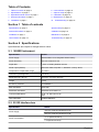 3
3
-
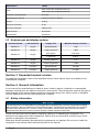 4
4
-
 5
5
-
 6
6
-
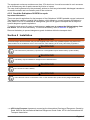 7
7
-
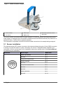 8
8
-
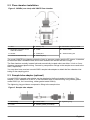 9
9
-
 10
10
-
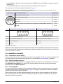 11
11
-
 12
12
-
 13
13
-
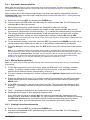 14
14
-
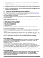 15
15
-
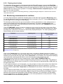 16
16
-
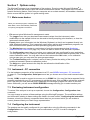 17
17
-
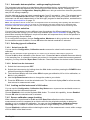 18
18
-
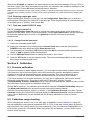 19
19
-
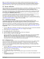 20
20
-
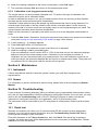 21
21
-
 22
22
-
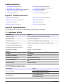 23
23
-
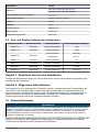 24
24
-
 25
25
-
 26
26
-
 27
27
-
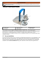 28
28
-
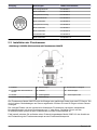 29
29
-
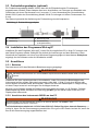 30
30
-
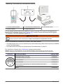 31
31
-
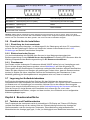 32
32
-
 33
33
-
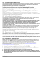 34
34
-
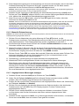 35
35
-
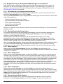 36
36
-
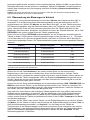 37
37
-
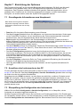 38
38
-
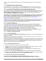 39
39
-
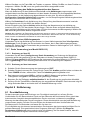 40
40
-
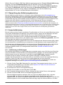 41
41
-
 42
42
-
 43
43
-
 44
44
-
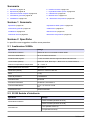 45
45
-
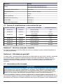 46
46
-
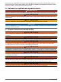 47
47
-
 48
48
-
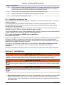 49
49
-
 50
50
-
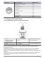 51
51
-
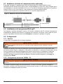 52
52
-
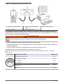 53
53
-
 54
54
-
 55
55
-
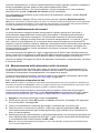 56
56
-
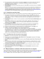 57
57
-
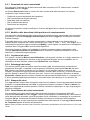 58
58
-
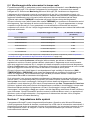 59
59
-
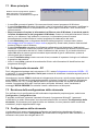 60
60
-
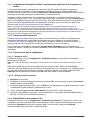 61
61
-
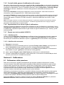 62
62
-
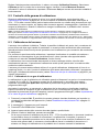 63
63
-
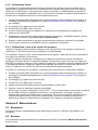 64
64
-
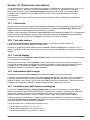 65
65
-
 66
66
-
 67
67
-
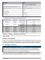 68
68
-
 69
69
-
 70
70
-
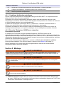 71
71
-
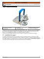 72
72
-
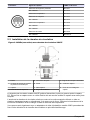 73
73
-
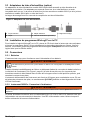 74
74
-
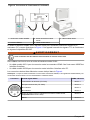 75
75
-
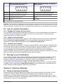 76
76
-
 77
77
-
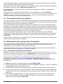 78
78
-
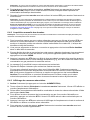 79
79
-
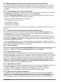 80
80
-
 81
81
-
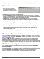 82
82
-
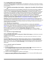 83
83
-
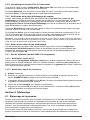 84
84
-
 85
85
-
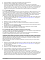 86
86
-
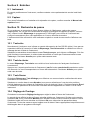 87
87
-
 88
88
-
 89
89
-
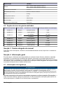 90
90
-
 91
91
-
 92
92
-
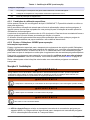 93
93
-
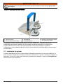 94
94
-
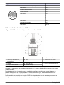 95
95
-
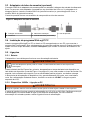 96
96
-
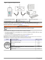 97
97
-
 98
98
-
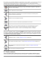 99
99
-
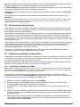 100
100
-
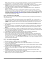 101
101
-
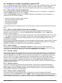 102
102
-
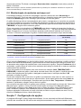 103
103
-
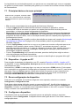 104
104
-
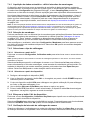 105
105
-
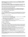 106
106
-
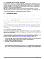 107
107
-
 108
108
-
 109
109
-
 110
110
-
 111
111
-
 112
112
-
 113
113
-
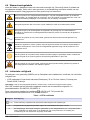 114
114
-
 115
115
-
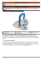 116
116
-
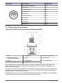 117
117
-
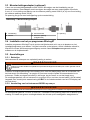 118
118
-
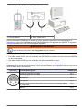 119
119
-
 120
120
-
 121
121
-
 122
122
-
 123
123
-
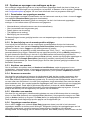 124
124
-
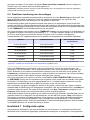 125
125
-
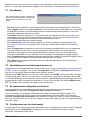 126
126
-
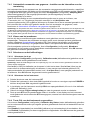 127
127
-
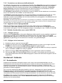 128
128
-
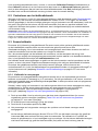 129
129
-
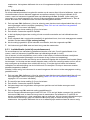 130
130
-
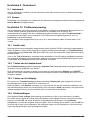 131
131
-
 132
132
-
 133
133
-
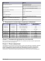 134
134
-
 135
135
-
 136
136
-
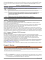 137
137
-
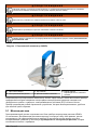 138
138
-
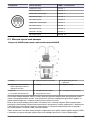 139
139
-
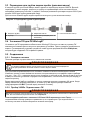 140
140
-
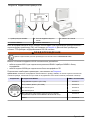 141
141
-
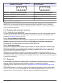 142
142
-
 143
143
-
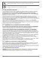 144
144
-
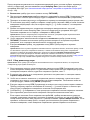 145
145
-
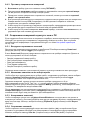 146
146
-
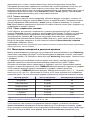 147
147
-
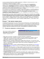 148
148
-
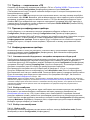 149
149
-
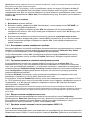 150
150
-
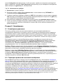 151
151
-
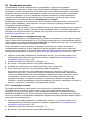 152
152
-
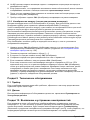 153
153
-
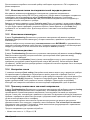 154
154
-
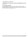 155
155
-
 156
156
-
 157
157
-
 158
158


Hach ORBISPHERE 3650 Atex Basic User Manual
- Type
- Basic User Manual
in andere talen
- English: Hach ORBISPHERE 3650 Atex
- italiano: Hach ORBISPHERE 3650 Atex
- русский: Hach ORBISPHERE 3650 Atex
- français: Hach ORBISPHERE 3650 Atex
- Deutsch: Hach ORBISPHERE 3650 Atex
- português: Hach ORBISPHERE 3650 Atex
Gerelateerde papieren
-
 Hach Lange ORBISPHERE 3100 Basic User Manual
-
 Hach Lange ORBISPHERE 3100 Basic User Manual
-
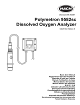 Hach Polymetron 9582sc Basic User Manual
-
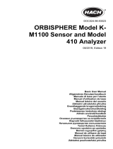 Hach ORBISPHERE K-M1100 Basic User Manual
-
 Hach ORBISPHERE 510 Basic User Manual
-
 Hach ORBISPHERE 31590HP Basic User Manual
-
 Hach ORBISPHERE 31 series Basic User Manual
-
 Hach ORBISPHERE 410 Basic User Manual
-
 Hach 29971-72 Handleiding
-
 Hach ORBISPHERE 366 Series Basic User Manual


Andere documenten
-
Invacare IRC450 Handleiding
-
VOLTCRAFT 2574174 Handleiding
-
Mettler Toledo 5000TOCi Sensor Handleiding
-
 Maxtec Handi Plus Medical Handheld Oxygen Analyzer Handleiding
-
GYS PAINT-THICKNESS SENSOR de handleiding
-
Sulzer Muffin Monster™ – 10000 Installation, Operating And Maintenance Instructions
-
-
-
-
Bacharach PCA®3 Handleiding
