
443 405 --002 990212 Valid from Machine no 452 XXX--XXXX
A6 PAK
Control system for motorised slides
Steuersystem für motorisierte Schlitten
Système de command e pour les glissières
motorisées
Bedieningssysteem voor schuiven met
motoraandrijving
Operating manual
Bedienungsanleitung
Manuel de l’opérateur
Gebruikershandboek

TECHNICAL DESCRIPTION 2.............................
INSTALLATION 7........................................
OPERATION 8..........................................
MAINTENANCE 8....................................
TECHNISCHE BESCHREIBUNG 10.........................
INSTALLATION 15........................................
BETRIEB 16..............................................
WARTUNG 16.........................................
DESCRIPTION TECHNIQUE 18............................
INSTALLATION 23........................................
FONCTIONNEMENT 24...................................
ENTRETIEN 24........................................
TECHNISCHE BESCHRIJVING 26..........................
INSTALLATIE 31..........................................
GEBRUIK 32.............................................
ONDERHOUD 32......................................
DIMENSION DRAWING - MASSBILD - COTES
D’ENCOMBREMENT - MAATSCHE TS 33..............
DIAGRAM - SCHALTPLAN - SCHÉMA - SCHEMA (418 138) 34
DIAGRAM - SCHALTPLAN - SCHÉMA - SCHEMA (418 139) 35
Rights reserved to alter specifications without notice.
Änderungen vorbehalten.
Sous réserve de modifications sans avis préalable.
Recht op wijzigingen zonder voorafgaande medeleling voorbehouden.

-- 1 --
mmvarnea
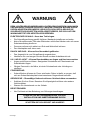
WARNING
ARC WELDING AND CUTTING CAN BE INJURIOUS TO YOURSELF AND
OTHERS. TAKE PRECAUTIONS WHEN WELDING. ASK FOR YOUR
EMPLOYER’S SAFETY PRACTICES WHICH SHOULD BE BASED ON MANU--
FACTURER’S HAZARD DATA.
ELECTRIC SHOCK -- Can kill
S Install and earth the welding unit in accordance with applicable standards.
S Do not touch live electrical parts or electrodes with bare skin, wet gloves or
wet clothing.
S Insulate yourself from earth and the workpiece.
S Ensure your working stance is safe.
FUMES AND GASES -- Can be dangerous to health
S Keep your head out of the fumes.
S Use ventilation, extraction at the arc, or both, to keep fumes and gases from
your breathing zone and the general area.
ARC RAYS -- Can inju re eyes and burn skin
S Protect your eyes and body. Use the correct welding screen and filter lens
and wear protective clothing.
S Protect bystanders with suitable screens or curtains.
FIRE HAZARD
S Sparks (spatter) can cause fire. Make sure therefore that there are no
inflammable materials nearby.
NOISE -- Excessive noise can da mage hearing
S Protect your ears. Use ear defenders or other hearing protection.
S Warn bystanders of the risk.
MALFUNCTION
S Call for expert assistance in the event of malfunction.
READ AND UNDERSTAND THE OPERATING MANUAL
BEFORE INSTALLING OR OPERATING.
PROTECT YOURSELF AND OTHERS!

TECHNICAL DESCRIPTION
-- 2 --
dgb1d1ea
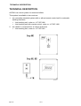
TECHNICAL DESCRIPTION
A6 PAK is a control system for motorised slides.
The system is available in two versions:
1. as a complete standard system with or without remote control unit for automatic
welding machines
S Joint tracking unit, order no. 417 587--880
S Joint tracking unit with remote control, order no. 417 587--882
2. as a build--in component for a column and boom
S Joint tracking unit, order no. 417 587--881
agb1d003

TECHNICAL DESCRIPTION
-- 3 --
dgb1d1ea
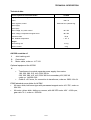
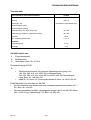
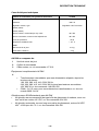
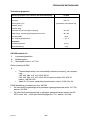
Technical data
Control system for motorised slides A6 PAK
Supply and control voltage 42V AC 50--60 Hz
Power 460 V A
Motor regulator , model Switched four quadrant reg.
Speed (high)
Speed (low)
Rotor voltage, Joy--stick control 40 V DC
Stator voltage, independent magnet motor 48 V DC
Enclosure class IP 53
Max. ambient temperature +45_ C
Weight:
Joint tracking unit 4.5 kg
Remote control 2kg
A6 PAK consists of:
1 Joint tracking unit
2 Control unit
3 Motor cable, order no. 417 310.
Optional equipment for A6 PAK
4
S Transformer to provide separate power supply from mains
190, 220, 380, 415, 440, 500V 50 Hz
200, 230, 380, 415, 440, 500V 60 Hz to secondary 42V, 660 VA
order no. 148 636--002
S Cable 3 x 2.5 mm
2
, for connection to transformer, order no. 2626 134--04.
ESAB standard servo slides for A6 PAK
S A6 servo slide, ball screw type with permanent magnet motor 42 V DC, order no.
334 333.
S A6 motor--driven slide, sliding on runners, with A6 VEC motor 42V -- 4000 rpm,
gear ratio 74:1, order no. 334 426.

TECHNICAL DESCRIPTION
-- 4 --
dgb1d1ea
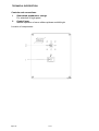
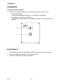
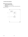
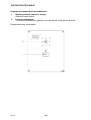
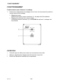
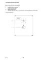
Controls and connections
1 Illuminated pushbutton, orange
For selection of high speed
2 Control lever
Manual operation of servo slides up/down and left/right
Location of components:
agb1d002

TECHNICAL DESCRIPTION
-- 5 --
dgb1d1ea
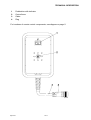
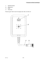
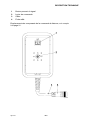
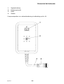
1 Pushbutton with indicator
2 Control lever
3 Cable
4 Plug
For locations of remote control components, see diagram on page 5.
dgb1s003

TECHNICAL DESCRIPTION
-- 6 --
dgb1d1ea
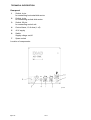
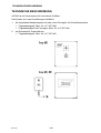
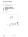
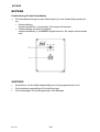
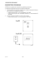
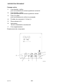
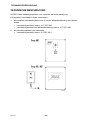
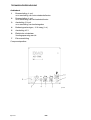
Rear panel
1 Socket, 4 pin.
for connecting horizontal slide motor
2 Socket, 4 pin.
for connecting vertical slide motor
3 Socket, 23 pin.
for connecting control unit
4 Control fuses, 10 A slow (1 off)
5 42 V supply
6 Switch
Supply voltage on/off
7 Spare socket
Location of components:
agb1d005

INSTALLATION
-- 7 --
dgb1i1ea
INSTALLATION
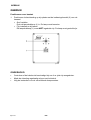
1. For dimensions, see dimensional drawing on page 33.
2. Connection
S see drawing for welding machine on page 34.
S see drawing for column and boom, welding machine and remote control unit
on page 35.
3. Make sure the required power and voltage supplies are available for the entire
installation.
S If any of the power sources LAE 800 -- 1000 -- 1250 -- 1600 are used, and is
set up to supply a control voltage of 42 V, then the required voltage can be
taken from the standard welding machine, see PEG1 socket.
S If the required voltage is not available, or if a LAH 500 --630 42 V power
source is used, then a special power supply must be provided using the 42 V
transformer for A6 PAK (see optional equipment).
4. Controls, see diagram on page 4.

OPERATION
-- 8 --
dgb1o1ea
OPERATION
Positioning to start welding
1. Position the welding equipment over the joint using the control lever (2).
S Coarse adjustment
Press the illuminated pushbutton (1). The lam p should light up.
S Fine adjustment and during welding
The illuminated pushbutton ( 1) must NOT be pressed. The lamp should not
light up.
agb1d0x2
MAINTENANCE
S Check that the cables are undamaged and that they are properly connected.
S Clean the equipment regularly using compressed air.
S Follow the instructions for each component.

-- 9 --
mmvarnga
WARNUNG
BEIM LICHTBOGENSCHWEIßEN UND LICHTBOGENSCHNEIDEN KANN IHNEN
UND ANDEREN SCHADEN ZUGEFÜGT WERDEN. DESHALB MÜSSEN SIE BEI
DIESEN ARBEITEN BESONDERS VORSICHTIG SEIN. BEFOLGEN SIE DIE
SICHERHEITSVORSCHRIFTEN IHRES ARBEITGEBERS, DIE SICH AUF DEN
WARNUNGSTEXT DES HERSTELLERS BEZIEHEN.
ELEKTRISCHER SCHLAG -- Kann den Tod bringen.
S Die Schweißausrüstung gemäß örtlichen Standards installieren und erden.
S Keine Stromführenden Teile oder Elektroden mit bloßen Händen oder mit nasser
Schutzausrüstung berühren.
S Personen müssen sich selbst von Erde und Werkstück isolieren.
S Der Arbeitsplatz muß sicher sein.
RAUCH UND GAS -- Können Ihre Gesundheit gefährden.
S Das Angesicht ist vom Schweißrauch wegzudrehen.
S Ventilieren Sie und saugen Sie den Rauch aus dem Arbeitsbereich ab.
UV-- UND IR--LICHT -- Können Brandschäden an Augen und Haut verursachen
S Augen und Körper schützen. Geeigneten Schutzhelm mit Filtereinsatz und
Schutzkleider tragen.
S Übriges Personal in der Nähe, ist durch Schutzwände oder Vorhänge zu
schützen.
FEUERGEFAHR
S Schweißfunken können ein F euer entzünden. Daher ist dafür zu sorgen, daß
sich am Schweißarbeitsplatz keine brennbaren Gegenstände befinden.
GERÄUSCHE -- Übermäßige Geräusche kö nn en Gehö rschäden verursachen
S Schützen Sie ihre Ohren. Benutzen Sie Kapselgehörschützer oder andere
Gehörschützer.
S Warnen Sie Umstehende vor der Gefahr.
BEI STÖRUNGEN
S Nur Fachleute mit der Behebung von Störungen beauftragen.
LESEN SIE DIE BETRIEBSANWEISUNG VOR DER
INSTALLATION UND INBETRIEBNAHME DURCH.
SCHÜTZEN SIE SICH SELBST UND ANDERE!

TECHNISCHE BESCHREIBUNG
-- 1 0 --
dgb1d1ga
TECHNISCHE BESCHREIBUNG
A6 PAK ist ein Steuersystem für motorisierte Schlitten.
Das System ist in zwei Ausführungen erhältlich:
1. Als komplettes Standardsystem mit oder ohne Fernregler für Schweißautomaten
S Fugenabtastgerät, Best.--Nr. 417 587-- 880
S Fugenabtastgerät mit Fernregler, Best.--Nr. 417 587 --882
2. als Einbauteil für Schweißkrane
S Fugenabtastgerät, Best.--Nr. 417 587-- 881
agb1d003

TECHNISCHE BESCHREIBUNG
-- 1 1 --
dgb1d1ga
Tekniska data
Steuersystem für motorisierte Schlitten A6 PAK
Anschluß-- und Steuerspannung 42V AC 50--60 Hz
Leistung 460 V A
Motorregler, Typ Geschalteter Vierquadrantregler
Geschwindigkeit (hoch)
Geschwindigkeit (niedrig)
Ankerspannung, Joy--Stick--Steuerung 40 V DC
Feldspannung, separater magnetisierter Motor 48 V DC
Schutzart IP 53
Max. Umgebungstemperatur +45_ C
Gewichte:
Fugenabtastgerät 4.5 kg
Fernregler 2kg
A6 PAK besteht aus :
1 Fugenabtastgerät
2 Bedieneinheit
3 Motorkabel, Best. --Nr. 417 310.
Zusatzausrüstung A6 PAK
4
S Zwischentransformator für getrennte Spannungsversorgung, von
190, 220, 380, 415, 440, 500V 50 Hz Netzspannung
200, 230, 380, 415, 440, 500V 60 Hz auf 42V, 660 VA Sekundärspan-
nung. Best.--Nr. 148 636--002
S Kabel 3 x 2,5 mm
2
, für Transformatoranschluß, Best.--Nr. 2626 134--04.
ESAB Standard--Servoschlitten für A6 PAK
S A6--Servoschlitten aus Kugelbuchsentyp mit dauermagnetisiertem Motor 42 V
DC, Best.--Nr. 334 333.
S A6 motorgetriebener Schlitten, gleitgelagerter langer Läufer, mit A6 VEC--Motor
42V -- 4000 U/min, Übersetzung 74:1, Best.--Nr. 334 426.

TECHNISCHE BESCHREIBUNG
-- 1 2 --
dgb1d1ga
Bedienelemente und Anschlü sse
1 Lampendrucktaste, orange
Wahl einer hohen Geschwindigkeit
2 Steuerhebel
Manuelle Steuerung der Servoschlitten auf/ab und links/rechts
Plazierung der Teile:
agb1d002

TECHNISCHE BESCHREIBUNG
-- 1 3 --
dgb1d1ga
1 Signaldrucktaste
2 Steuerhebel
3 Kabel
4 Stiftstecker
Plazierung der Teile für den Fernregler siehe Abb. auf Seite 13.
dgb1s003

TECHNISCHE BESCHREIBUNG
-- 1 4 --
dgb1d1ga
Rückteil
1 Buchsensteckdose, 4polig
zum Anschluß des Horizontalschlittenmotors
2 Buchsensteckdose, 4polig
zum Anschluß des Vertikalschlittenmotors
3 Steckdose, 23polig
zum Anschluß einer Bedieneinheit
4 Steuersicherungen, 10 A träge (1 St)
5 Anschluß 42 V
6 Schalter
Versorgungsspannung ein/aus
7 Reserve--Steckdose
Plazierung der Teile:
agb1d005

INSTALLATION
-- 1 5 --
dgb1i1ga
INSTALLATION
1. Maßangaben, siehe Maßbilder auf Seite 33.
2. Anschluß
S siehe Schaltplan für Automatikausführung auf Seite 34.
S siehe Schaltplan für Kranausführung und Automatikausführung mit Fern-
regler auf Seite 35.
3. Kontrollieren, ob die erforder liche Leistung und Spannung für eine komplette In-
stallation zugänglich ist.
S Wenn eine Stromquelle vom Typ LAE 800 -- 1000 -- 1250 -- 1600 verwendet
und an eine Steuerspannung von 42 V angeschlossen wird, kann die not-
wendige Leistung vom Standardautomaten erhalten werden, siehe Anschluß
PEG1.
S Wenn keine geeignete Spannung vorhanden ist oder die Stromquelle
LAH 500 --630 42 V angewendet wird, ist immer eine besondere Stromversor-
gung mit dem Zwischentransfor m ator 42 V für A6 PAK zu installieren (siehe
Zubehör).
4. Bedienelemente siehe Abb. auf Seite 12.

BETRIEB
-- 1 6 --
dgb1o1ga
BETRIEB
Positionierung für den Schweißstart
1. Die Schweißausrüstung mit dem Steuerhebel (2) in der Schweißfuge positionie-
ren.
S Grobeinstellung
Lampendrucktaste (1) eindrücken. Die Lampe soll leuchten.
S Feineinstellung und beim Schweißen.
Lampendrucktaste (1) soll NICHT eingedrückt sein. Die Lampe soll erloschen
sein.
agb1d0x2
WARTUNG
S Kontrollieren, ob die Kabel unbeschädigt und richtig angeschlossen sind.
S Die Ausrüstung regelmäßig mit Druckluft reinigen.
S Die Anweisungen für die dazugehörigen Teile befolgen.

-- 1 7 --
mmvarnfa
AVERTISSEMENT
LE SOUDAGE ET LE COUPAGE À L’ARC PEUVENT ÊTRE DANGEREUX POUR
VOUS COMME POUR AUTRUI. SOYEZ DONC TRÈS PRUDENT EN UTILISANT
LA MACHINE À SOUDER. OBSERVEZ LES RÈGLES DE SÉCURITÉ DE VOTRE
EMPLOYEUR, QUI DOIVENT ÊTRE BASÉES SUR LES TEXTES D’AVERTISSE-
MENT DU FABRICANT
DÉCHARGE ÉLECTRIQUE -- Peut être mortelle
S Installer et mettre à la terre l’équipement de soudage en suivant les
normes en vigueur.
S Ne pas toucher les parties conductrices. Ne pas toucher les électrodes avec
les mains nues ou des gants de protection humides.
S Isolez--vous du sol et de la pièce à travailler.
S Assurez--vous que votre position de travail est sûre.
FUMÉES ET GAZ -- Peuvent être nuisibles à votre santé
S Eloigner le visage des fumées de soudage.
S Ventiler et aspirer les fumées de soudage pour assurer un environnement de
travail sain.
RADIATIONS LUMINEUSES DE L’ARC -- Peuvent abîmer les yeux et causer des
brûlures à l’épiderme
S Se protéger les yeux et l’épiderme. Utiliser un écran soudeur et porter des
gants et des vêtements de protection.
S Protéger les personnes voisines des effets dangereux de l’arc par des rideaux
ou des écrans protecteurs.
RISQUES D’INCENDIE
S Les étincelles (ou ”puces” de soudage) peuvent causer un incendie. S’assurer
qu’aucun objet inflammable ne se trouve à proximité du lieu de soudage.
BRUIT -- Un niveau élevé de bruit p eut nu ire à vos facu lt és auditives
S Protégez--vous. Utilisez des protecteur s d’oreilles ou toute autre protection
auditive.
S Avertissez des risques encourrus les personnes se trouvant à proximité.
EN CAS DE MAUVAIS FONCTIONNEMENT
S Faire appel à un technicien qualifié.
LIRE ATTENTIVEMENT LE MODE D’EMPLOI AVANT
D’INSTALLER LA MACHINE ET DE L’UTILISER.
PROTÉGEZ--VOUS ET PROTÉGEZ LES AUTRES!

DESCRIPTION TECHNIQUE
-- 1 8 --
dgb1d1fa
DESCRIPTION TECHNIQUE
A6 PAK est un système de comm ande pour glissières motorisées.
Le système est disponible sous deux conceptions différentes:
1. comme système d e commande complet, avec ou sans commande à distance,
pour machines de soudage automatiques
S Unité de suivie de joint, no. de commande 417 587--880
S Unité de suivie de joint avec commande à distance, no. de commande 417
587--882
2. comme composant montable sur potences de soudage
S Unité de suivie de joint, no. de commande 417 587--881
agb1d003

DESCRIPTION TECHNIQUE
-- 1 9 --
dgb1d1fa
Caractéristiques techniques
Système de commande pour glissières motorisées A6 PAK
Tension de raccordement et de commande 42V AC 50--60 Hz
Puissance 460 V A
Régulateur moteur, type Régulateur carré commuté
Vitesse (haute)
Vitesse (basse)
Tension d’induit, commande par Joy--stick 40 V DC
Tension d’excitation, moteur excité séparément 48 V DC
Formedeprotection IP 53
Température ambiante max. +45_ C
Poid s:
Unitédesuiviedejoint 4.5 kg
Commande à distance 2kg
A6 PAK se compose de:
1 Unitédesuiviedejoint
2 Coffret de commande
3 Câble moteur, no. de commande 417 310.
Équipement complémentaire A6 PAK
4
S Transformateur intermédiaire pour une alimentation séparée, depuis les
tensions de réseau
190, 220, 380, 415, 440, 500V 50 Hz
200, 230, 380, 415, 440, 500V 60 Hz jusqu’aux tensions secondaires
42V, 660 VA nr. de commande 148 636--002
S Câble 3 x 2,5 mm
2
, pour raccordement au transformateur, no. de com -
mande 2626 134 -04
Glissières servo ESAB standards pour A6 PAK
S A6 glissière servocommandée de type boîte de glissement à rouleaux, avec mo-
teur excité en continu 42 V DC, no. de commande 334 333.
S A6 glissière motorisée, curseur long avec palier de glissement, moteur A6 VEC
42V -- 4000 tpm dév. 74:1, no. de commande 334 426.

DESCRIPTION TECHNIQUE
-- 2 0 --
dgb1d1fa
Organes de commande et raccordements
1 Bouton poussoir lumineux, orange
Sélection haute vitesse
2 Levier de commande
Commande manuelle des glissières, de haut en bas et de gauche à droite.
Emplacement des composants:
agb1d002

DESCRIPTION TECHNIQUE
-- 2 1 --
dgb1d1fa
1 Bouton poussoir à signal
2 Levier de commande
3 Câble
4 Fiche mâle
Emplacement des composants de la commande à distance, voir croquis
à la page 21.
dgb1s003

DESCRIPTION TECHNIQUE
-- 2 2 --
dgb1d1fa
Panneau arrière
1 Prise femelle, 4--pôles.
pour raccordement de moteur à glissières horizontal
2 Prise femelle, 4--pôles.
pour raccordement de moteur à glissières vertical
3 Prise, 23 --pôles.
pour raccordement du coffret de commande
4 Fusibles de commande, 10 A lent (1)
5 Raccordement 42 V
6 Interrupteur
Tension d’alimentation marche/arrêt
7 Prise supplémentaire
Emplacement des composants:
agb1d005

INSTALLATION
-- 2 3 --
dgb1i1fa
INSTALLATION
1. Dimensions, voir cotes d’encombrement à la page 33.
2. Connexion
S voir schéma de la version automatique à la page 34.
S voir schémas des versions potences de soudage et automatique, avec com-
mande à distance à la page 35.
3. Contrôler que la puissance et la tension nécessaires à une installation complète
soient disponibles.
S Lorsqu’une source d’alimentation de type LAE 800 -- 1000 -- 1250 -- 1600 est
utilisée, et qu’elle est connectée pour une tension de commande de 42 V, la
puissance nécessaire est disponible depuis l’automate standard, voir prise
PEG1.
S En l’absence de tension appropriée, ou quand une source d’alimentation
LAH 500--630 42 V est utilisée, l’alimentation en courant spéciale doit inté-
grer le transformateur intermédiaire 42 V pour A6 PAK (voir accessoires).
4. Organes de commande, voir figure à la page 20.

FONCTIONNEMENT
-- 2 4 --
dgb1o1fa
FONCTIONNEMENT
Positionnement pour démarrer le soudage
1. Positionner l’équipement de soudage avec le levier de commande (2) placé en
fonction du joint de soudage.
S Réglage grossier
Enfoncer le bouton poussoir lumineux (1). La lampe doit être allumée.
S Réglage de précision et lors du soudage
Le bouton poussoir lumineux (1) ne doit PAS être enfoncé. La lampe doit
être éteinte.
agb1d0x2
ENTRETIEN
S Contrôler que les câbles sont entiers et correctement raccordés.
S Nettoyer régulièrement l’équipement à l’aide d’air comprimé.
S Suiver les instructions relatives aux composants.

-- 2 5 --
mmvarnha
WAARSCHUWING
DE VLAMBOOG EN HET SNIJDEN KUNNEN GEVAARLIJK ZIJN VOOR UZELF
EN VOOR ANDEREN; DAAROM MOET U VOORZICHTIG ZIJN BIJ HET LASSEN.
VOLG DE VEILIGHEIDSVOORSCHRIFTEN VAN UW WERKGEVER OP. ZE
MOETEN GEBASEERD ZIJN OP DE WAARSCHUWINGSTEKST VAN DE
PRODUCENT.
ELECTRISCHE SCHOK -- Kan dodelijk zijn
S Installeer en aard de lasuitrusting volgens de geldende normen.
S Raak delen die onder stroom staan en electroden niet aan met onbedekte
handen of met natte beschermuitrusting.
S Zorg ervoor dat u geïsoleerd staat van de aarde en van het werkstuk.
S Zorg ervoor dat u een veilige werkhouding hebt.
ROOK EN GAS -- Kunnen uw gezondheid schaden
S Zorg ervoor dat u niet met uw gezicht in de lasrook hangt.
S Ververs regelmatig de lucht in de werkruimte en zorg ervoor dat de lasrook
en het gas afgezogen worden.
LICHTSTRALEN -- Kunnen de ogen beschadigen en de huid verbranden
S Bescherm uw ogen en uw lichaam. Gebruik een geschikte lashelm met filter en
draag altijd beschermende kleding.
S Scherm uw werkruimte af met geschikte beschermmiddelen of gordijnen, zodat
niemand anders gewond kan raken.
BRANDGEVAAR
S De vonken kunnen brand veroorzaken. Zorg er daarom voor dat er geen
brandgevaarlijk materiaal in de buurt is.
LAWAAI -- Geluidsoverlast kan het gehoor beschadigen
S Bescherm uw oren. Gebruik gehoorbeschermers of andere gehoorbescherming.
S Waarschuw omstanders voor de gevaren.
BIJ DEFECTEN
S Neem contact op met een vakman.
LEES DEZE GEBRUIKSAANWIJZING GRONDIG DOOR
VOOR U OVERGAAT TOT INSTALLATIE EN GEBRUIK.
BESCHERM UZELF EN DE ANDEREN!

TECHNISCHE BESCHRIJVING
-- 2 6 --
dgb1d1ha
TECHNISCHE BESCHRIJVING
A6 PAK is een bedieningssysteem voor schuiven met motoraandrijving.
Het systeem is leverbaar in twee uitvoeringen:
1. als compleet standaardsysteem met of zonder afstandsbediening voor lasauto -
maten
S Lasnaadvolgeenheid, best.nr. 417 587--880
S Lasnaadvolgeenheid met afstandsbediening, best.nr. 417 587--882
2. als inbouwkomponent voor laskranen
S Lasnaadvolgeenheid, best.nr 417 587--881
agb1d003

TECHNISCHE BESCHRIJVING
-- 2 7 --
dgb1d1ha
Technische geg even s
Bedieningssysteem voor schuiven met motoraandrijving A6 PAK
Aansluitings-- en bedieningsspanning 42V AC 50--60 Hz
Vermogen 460 V A
Motorregelaar, type geschakelde vierkwadrant reg.
Snelheid (hoog)
Snelheid (laag)
Ankerspanning, stuurknuppel--bediening 40 V DC
Veldspanning, afzonderlijk gemagnetiseerde motor 48 V DC
Beveiligingsklas IP 53
Max. omgevingstemperatuur +45_ C
Gewichten:
Lasnaadvolgeenheid 4,5 kg
Afstandsbediening 2kg
A6 PAK bestaat uit:
1 Lasnaadvolgeenheid
2 Bedieningsbox
3 Motorkabel, best.nr. 417 310.
ExtrauitrustingA6PAK
4
S Tussentransformator voor afzonderlijke stroomvoorziening, van netspan-
ning
190, 220, 380, 415, 440, 500V 50 Hz
200, 230, 380, 415, 440, 500V 60 Hz naar secundair 42V, 660 VA
best.nr 148 636--002
S Kabel 3 x 2,5 mm
2
, aansluiting transformator, best.nr. 2626 134--04.
ESAB standaard servoschuiven voor A6 PAK
S A6 servoschijf kogelbustype met permanent gemagnetiseerde motor 42 V DC,
best.nr. 334 333.
S A6 schuif met motoraandrijving, in glijlagers gelagerde lange r unner, met A6
VEC--motor 42V -- 4000 tpm overbrengingsverh. 74:1, best.nr. 334 426.

TECHNISCHE BESCHRIJVING
-- 2 8 --
dgb1d1ha
Bedieningsorgaan en aansluitingen
1 Lampdrukknop, oranje
Hoge snelheid kiezen
2 Bedieningshendel
Manueel bedienen van de servoschuiven omhoog/omlaag en links/rechts
Componentposities:
agb1d002

TECHNISCHE BESCHRIJVING
-- 2 9 --
dgb1d1ha
1 Signaaldrukknop
2 Bedieningshendel
3 Kabel
4 Stekker
Componentposities voor afstandsbediening zie afbeelding op blz. 29.
dgb1s003

TECHNISCHE BESCHRIJVING
-- 3 0 --
dgb1d1ha
Achterkant
1 Busaansluiting, 4--pol.
voor aansluiting van horizontaalschuifmotor
2 Busaansluiting, 4--pol.
voor aansluiting van verticaalschuifmotor
3 Aansluiting, 23--pol.
voor aansluiting van bedieningsbox
4 Bedieningszekeringen, 10 A traag (1 st)
5 Aansluiting 42 V
6 Elektrische schakelaar
Voedingsspanning aan/uit
7 Extra aansluiting
Componentposities:
agb1d005

INSTALLATIE
-- 3 1 --
dgb1i1ha
INSTALLATIE
1. Maten, zie maatschetsen op blz. 33.
2. Aansluiten
S zie automaatvariant schema op blz. 34.
S zie kraanvariant en automaatvariant met afstandsbediening schema
op blz. 35.
3. Controleer of het benodigd vermogen en de benodigde spanning beschikbaar
zijn voor een complete installatie.
S Wanneer men een stroombron van het type LAE 800 -- 1000 -- 1250 -- 1600
gebruikt, en als die aangesloten is op bedieningsspanning 42 V, kan het be-
nodigde vermogen afgenomen worden van de standaardautomaat, zie aan-
sluiting PEG1.
S Wanneer de geschikte spanning ontbreekt of wanneer stroombron LAH
500--630 42 V wordt gebruikt, moet er altijd een afzonder lijke stroomvoorzie-
ning geïnstalleerd worden met de tussentransformator 42 V voor A6 PAK
(zie accessoires)
4. Bedieningsorgaan, zie afbeelding op blz. 28.

GEBRUIK
-- 3 2 --
dgb1o1ha
GEBRUIK
Positioneren voor lasstart
1. Positioneer de lasuitrusting op zijn plaats met de bedieningshendel (2) voor de
lasnaad.
S Grof in stellen
Druk de lampdrukknop (1) in. De lamp moet branden.
S Fijn instellen en bij lassen
De lampdrukknop (1) moet NIET ingedrukt zijn. De lamp moet gedoofd zijn.
agb1d0x2
ONDERHOUD
S Controleer of de kabels niet beschadigd zijn en of ze juist zijn aangesloten.
S Maak de uitrusting regelmatig schoon met luchtdruk.
S Volg de instructies voor de verschillende komponenten.

-- 3 3 --
dgb1m11a
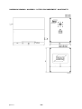
DIMENSION DRAWING - MASSBILD - COTES D’ENCOMBREMENT - MAATSCHETS
dgb1m001

-- 3 4 --
dgb1e11a
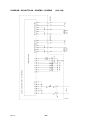
DIAGRAM - SCHALTPLAN - SCHÉMA - SCHEMA (418 138)
agb1e001

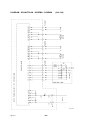
-- 3 5 --
dgb1e11a
DIAGRAM - SCHALTPLAN - SCHÉMA - SCHEMA (418 139)
agb1e002

ESAB AB
SE--695 81 LAXÅ
SWEDEN
Phone +46 584 81 000
Fax +46 584 123 08
www.esab.net
020219
ESAB subsidiaries and representative offices
Europe
AUSTRIA
ESAB Ges.m.b.H
Vienna--Liesing
Tel: +43 1 888 25 11
Fax: +43 1 888 25 11 85
BELGIUM
S.A. ESAB N.V.
Brussels
Tel: +32 2 745 11 00
Fax: +32 2 726 80 05
THE CZECH REPUBLIC
ESAB V AMBERK s.r.o.
Prague
Tel: +420 2 819 40 885
Fax: +420 2 819 40 120
DENMARK
Aktieselskabet ESAB
Copenhagen--Valby
Tel:+4536300111
Fax:+4536304003
FINLAND
ESAB Oy
Helsinki
Tel: +358 9 547 761
Fax: +358 9 547 77 71
FRANCE
ESAB France S.A.
Cergy Pontoise
Tel:+33130755500
Fax:+33130755524
GERMANY
ESAB GmbH
Solingen
Tel: +49 212 298 0
Fax: +49 212 298 204
GREAT BRITAIN
ESAB Group (UK) Ltd
Waltham Cross
Tel: +44 1992 76 85 15
Fax: +44 1992 71 58 03
ESAB Automation Ltd
Andover
Tel: +44 1264 33 22 33
Fax: +44 1264 33 20 74
HUNGARY
ESAB Kft
Budapest
Tel:+3612044182
Fax:+3612044186
ITALY
ESAB Saldatura S.p.A.
Mesero (Mi)
Tel:+3902979681
Fax:+390297289181
THE NETHERLANDS
ESAB Nederland B.V.
Utrecht
Tel: +31 30 248 59 22
Fax: +31 30 248 52 60
NORWAY
AS ESAB
Larvik
Tel:+4733121000
Fax:+4733115203
POLAND
ESAB Sp.z.o.o
Warszaw
Tel: +48 22 813 99 63
Fax: +48 22 813 98 81
PORTUGAL
ESAB Lda
Lisbon
Tel: +351 1 837 1527
Fax: +351 1 859 1277
SLOVAKIA
ESAB Slovakia s.r.o.
Bratislava
Tel:+421744882426
Fax:+421744888741
SPAIN
ESAB Ibérica S.A.
Alcobendas (Madrid)
Tel: +34 91 623 11 00
Fax: +34 91 661 51 83
SWEDEN
ESAB Sverige AB
Gothenburg
Tel:+4631509500
Fax:+4631509222
ESAB International AB
Gothenburg
Tel:+4631509000
Fax:+4631509360
SWITZERLAND
ESAB AG
Dietikon
Tel: +41 1 741 25 25
Fax: +41 1 740 30 55
North and South America
ARGENTINA
CONARCO
Buenos Aires
Tel: +54 11 4 753 4039
Fax: +54 11 4 753 6313
BRAZIL
ESAB S.A.
Contagem--MG
Tel: +55 31 333 43 33
Fax: +55 31 361 31 51
CANADA
ESAB Group Canada Inc.
Missisauga, Ontario
Tel: +1 905 670 02 20
Fax: +1 905 670 48 79
MEXICO
ESAB Mexico S.A.
Monterrey
Tel: +52 8 350 5959
Fax: +52 8 350 7554
USA
ESAB Welding & Cutting Products
Florence, SC
Tel: +1 843 669 44 11
Fax: +1 843 664 44 58
Asia/Pacific
AUSTRALIA
ESAB Australia Pty Ltd
Ermington
Tel: +61 2 9647 1232
Fax: +61 2 9748 1685
CHINA
Shanghai ESAB A/P
Shanghai
Tel: +86 21 6539 7124
Fax: +86 21 6543 6622
INDIA
ESAB India Ltd
Calcutta
Tel: +91 33 478 45 17
Fax: +91 33 468 18 80
INDONESIA
P.T. Esabindo Pratama
Jakarta
Tel: +62 21 460 01 88
Fax: +62 21 461 29 29
MALAYSIA
ESAB (Malaysia) Snd Bhd
Selangor
Tel: +60 3 703 36 15
Fax: +60 3 703 35 52
SINGAPORE
ESAB Singapore Pte Ltd
Singapore
Tel: +65 861 43 22
Fax: +65 861 31 95
ESAB Asia/Pacific Pte Ltd
Singapore
Tel: +65 861 74 42
Fax: +65 863 08 39
SOUTH KOREA
ESAB SeAH Corporation
Kyung --Nam
Tel: +82 551 289 81 11
Fax: +82 551 289 88 63
UNITED ARAB EMIRATES
ESAB Middle East
Dubai
Tel: +971 4 338 88 29
Fax: +971 4 338 87 29
Representative offices
BULGARIA
ESAB Representative Office
Sofia
Tel/Fax: +359 2 974 42 88
EGYPT
ESAB Egypt
Dokki--Cairo
Tel: +20 2 390 96 69
Fax: +20 2 393 32 13
ROMANIA
ESAB Representative Office
Bucharest
Tel/Fax: +40 1 322 36 74
RUSSIA--CIS
ESAB Representative Office
Moscow
Tel: +7 095 937 98 20
Fax: +7 095 937 95 80
ESAB Representative Office
St Petersburg
Tel: +7 812 325 43 62
Fax: +7 812 325 66 85
Distributors
For addresses and phone
numbers to our distributors in
other countries, please visit our
home page
www.esab.net
-
 1
1
-
 2
2
-
 3
3
-
 4
4
-
 5
5
-
 6
6
-
 7
7
-
 8
8
-
 9
9
-
 10
10
-
 11
11
-
 12
12
-
 13
13
-
 14
14
-
 15
15
-
 16
16
-
 17
17
-
 18
18
-
 19
19
-
 20
20
-
 21
21
-
 22
22
-
 23
23
-
 24
24
-
 25
25
-
 26
26
-
 27
27
-
 28
28
-
 29
29
-
 30
30
-
 31
31
-
 32
32
-
 33
33
-
 34
34
-
 35
35
-
 36
36
-
 37
37
-
 38
38


in andere talen
- français: ESAB A6 PAK Manuel utilisateur
- Deutsch: ESAB A6 PAK Benutzerhandbuch
Gerelateerde papieren
-
ESAB PAV Handleiding
-
-
-
-
-
-
-
-
-