Arcam Home Theater System AVR250 Handleiding
- Categorie
- AV-ontvangers
- Type
- Handleiding
Deze handleiding is ook geschikt voor

AVR250
HANDBOOK
Arcam AVR250 surround sound receiver
English
Français
Deutsch
Nederland
s

AVR250
E-2
AVR250
E-3
English
RISQUE DE CHOC ELECTRIQUE
NE PAS OUVRIR
ATTENTION
CAUTION
RISK OF ELECTRIC
SHOCK DO NOT OPEN
CAUTION: To reduce the risk of electric shock, do not remove cover (or back). No user serviceable parts
inside. Refer servicing to qualied service personnel.
WARNING: To reduce the risk of re or electric shock, do not expose this apparatus to rain or moisture.
The lightning ash with an arrowhead symbol within an equilateral triangle, is intended to alert the user to the presence
of uninsulated ‘dangerous voltage’ within the product’s enclosure that may be of sufcient magnitude to constitute a risk
of electric shock to persons.
The exclamation point within an equilateral triangle is intended to alert the user to the presence of important operating
and maintenance (servicing) instructions in the literature accompanying the product.
CAUTION: In Canada and the USA, to prevent electric shock, match the wide blade of the plug to the wide
slot in the socket and insert the plug fully into the socket.
Safety guidelines
Important safety instructions
This product is designed and manufactured to meet strict
quality and safety standards. However, you should be aware
of the following installation and operation precautions:
1. Take heed of warnings and instructions
You should read all the safety and operating instructions
before operating this appliance. Retain this handbook for
future reference and adhere to all warnings in the handbook
or on the appliance.
2. Water and moisture
The presence of electricity near water can be dangerous. Do
not use the appliance near water – for example next to a
bathtub, washbowl, kitchen sink, in a wet basement or near
a swimming pool, etc.
3. Object or liquid entry
Take care that objects do not fall and liquids are not
spilled into the enclosure through any openings. Liquid
lled objects such as vases should not be placed on the
equipment.
4. Ventilation
Do not place the equipment on a bed, sofa, rug or similar
soft surface, or in an enclosed bookcase or cabinet, since
ventilation may be impeded.
5. Heat
Locate the appliance away from naked ames or heat
producing equipment such as radiators, stoves or other
appliances (including other ampliers) that produce heat.
6. Climate
The appliance has been designed for use in moderate
climates.
7. Racks and stands
Only use a rack or stand that is recommended for use with
audio equipment. If the equipment is on a portable rack it
should be moved with great care, to avoid overturning the
combination.
8. Cleaning
Unplug the unit from the mains supply before cleaning.
The case should normally only require a wipe with a soft,
damp, lint-free cloth. Do not use paint thinners or other
chemical solvents for cleaning.
We do not advise the use of furniture cleaning sprays or
polishes as they can cause indelible white marks if the unit
is subsequently wiped with a damp cloth.
9. Power sources
Only connect the appliance to a power supply of the type
described in the operating instructions or as marked on the
appliance.
10. Power-cord protection
Power supply cords should be routed so that they are not
likely to be walked on or pinched by items placed upon or
against them, paying particular attention to cords and plugs,
and the point where they exit from the appliance.
11. Grounding
Ensure that the grounding means of the appliance is not
defeated.
12. Power lines
Locate any outdoor antenna/aerial away from power lines.
13. Non-use periods
If the unit has a stand-by function, a small amount of
current will continue to ow into the equipment in this
mode. Unplug the power cord of the appliance from the
outlet if left unused for a long period of time.
14. Abnormal smell
If an abnormal smell or smoke is detected from the
appliance, turn the power off immediately and unplug the
unit from the wall outlet. Contact your dealer immediately.
15. Servicing
You should not attempt to service the appliance beyond that
described in this handbook. All other servicing should be
referred to qualied service personnel.
16. Damage requiring service
The appliance should be serviced by qualied service
personnel when:
A. the power-supply cord or the plug has been damaged,
or
B. objects have fallen, or liquid has spilled into the
appliance, or
C. the appliance has been exposed to rain, or
D. the appliance does not appear to operate normally or
exhibits a marked change in performance, or
E. the appliance has been dropped or the enclosure
damaged.
17. Speaker connections
Any speakers must be connected to the AVR250 using Class
2 wire (i.e., no connection to earth should be made). Failure
to observe this precaution may cause the AVR250 to be
damaged.
Safety compliance
This product has been designed to meet the IEC 60065
international electrical safety standard.

AVR250
E-2
AVR250
E-3
English
Contents
Safety guidelines......................................E-2
Important safety instructions ............................E-2
Safety compliance ........................................... E-2
Before you start! ......................................E-4
Installation ..............................................E-6
Positioning the unit .......................................... E-6
Notes on installing the AVR250.......................... E-6
Audio connections............................................ E-7
Video connections............................................ E-8
Connecting loudspeakers ..................................E-9
Zone 2 connections.......................................... E-9
Connecting the AM and FM antennas................ E-10
Control connections ....................................... E-10
Connecting to a power supply ......................... E-10
Conguring the AVR250 .........................E-11
Set-up mode................................................. E-11
The ‘Basic’ Set-up Menus................................ E-12
The ‘Advanced’ Set-up Menus.......................... E-16
Saving Settings and Exit Set-up ...................... E-17
Remote control.......................................E-18
Operating your AVR250..........................E-19
Switching on/off ............................................ E-19
Volume control.............................................. E-19
Front panel display ........................................ E-19
Input selection .............................................. E-20
Stereo Direct ................................................ E-20
Zone 2 ......................................................... E-20
Headphones.................................................. E-20
Effects/FX..................................................... E-21
Mode ........................................................... E-21
Treble/Bass................................................... E-21
Remote control buttons .................................. E-21
Using the tuner ............................................. E-22
Using the Main Menu...................................... E-23
Using Zone 2 ............................................... E-24
Surround modes..................................... E-25
Introduction.................................................. E-25
Digital multi-channel sources .......................... E-25
Two-channel source modes ............................. E-26
Multi-channel source modes............................ E-26
DSP Effects Modes......................................... E-27
Speaker positioning ...............................E-27
Bi-wiring and bi-amping loudspeakers...E-28
Before you start – important information! ......... E-28
Bi-wiring your loudspeakers ............................ E-28
Bi-amping your system .................................. E-28
Troubleshooting.....................................E-29
SCART connections.................................E-31
IR Remote Codes.................................... E-32
Technical specications.......................... E-34
Guarantee ..............................................E-35
Worldwide Guarantee ..................................... E-35
On line registration ........................................ E-35
Appendix: Serial programming interface E-36
Introduction.................................................. E-36
Command Specications / Spécications .......... E-37
The small print:
n
Manufactured under licence from Dolby Laboratories, Inc.
‘Dolby’, ‘Pro Logic’, ‘Surround EX’ and the double-D symbol are
trademarks of Dolby Laboratories.
Confidential unpublished works. Copyright © 1992–1999 Dolby
Laboratories, Inc. All rights reserved.
n
Manufactured under license from Digital Theater Systems, Inc.
U.S. Pat. No’s. 5,451,942; 5,956,674; 5,974,380; 5,978,762;
6,226,616; 6,487,535 and other U.S. and world-wide patents
issued and pending. “DTS”, “DTS-ES”, “Neo:6”, and “DTS 96/24” are
trademarks of Digital Theater Systems, Inc.
Copyright © 1996, 2003 Digital Theater Systems, Inc. All Rights
Reserved.

AVR250
E-4
AVR250
E-5
English
Before you start!
Introduction
The AVR250 is a high quality and high performance home cinema processor and multi-channel audio
amplier built to Arcam’s traditional high quality design and manufacturing standards. It combines
high resolution digital processing with high performance audio and video components to bring you an
unrivalled home entertainment centre.
In addition to the built-in tuner, the AVR250 allows switching and volume control of seven analogue and
six digital sources, making it an ideal companion for both home cinema and two-channel stereo systems.
Since many of these source components are also capable of outputting high quality video signals, the
AVR250 includes broadcast quality video switching for composite, S-video, component and most RGB
video signals. There are inputs and outputs for both tape and VCR, as well as a digital output. DVD-
Audio or SACD can be connected via the multi-channel input. Control of the AVR250 is either by front
panel control buttons, IR remote control or an RS232 port (which also can be used to upload future
software enhancements).
As well as providing the audio and video being used in the main listening area, the AVR250 allows
the same, or a different, source to be routed to a second area (called ‘Zone 2’), such as the kitchen,
bedroom, lounge, etc. Zone 2 can have full remote control over the source selection and volume in that
area.
The customised installation of the AVR250 in a listening room is an important process which requires
care at every stage. For this reason, the installation information is very comprehensive and should be
followed carefully.
Using this handbook
Thank you for purchasing the Arcam AVR250 Surround Sound Receiver.
This handbook has been designed to give you all the information you need to install, connect, set up
and use the Arcam AVR250 Surround Sound Receiver. The remote control handset supplied with the
equipment is also described.
It may be that the AVR250 has been installed and set up as part of your Hi-Fi installation by a qualied
Arcam dealer. In this case, you may wish to skip the sections of this handbook dealing with installation
and setting up the unit and move directly to the section detailing the operation of your unit.
Safety
Safety guidelines are set out on page 2 of this handbook.
Many of these items are common sense precautions but, for your own safety, and to ensure that you do
not damage the unit, we recommend that you read them.
This is a class 1 product and requires an earth connection.
What’s in the box?
Please conrm that the following items are in the box when you receive it:
n
Arcam AVR250 surround-sound receiver — the model number is shown on the right of the front
panel of the player;
n
Arcam CR-80 remote control with 2 ‘AAA’ batteries — the remote control model number is shown
on the front at the bottom of the remote control;
n
FM ribbon and AM loop antennae;
n
Mains power lead appropriate for the mains supply in your area;
n
Product registration card and envelope.
If any of these items are missing or incorrect, please contact your Arcam dealer immediately.

AVR250
E-4
AVR250
E-5
English
Before making connections
Before connecting your equipment it is important to think about the following points, as these will affect
your choice of connections and subsequent use of the system.
Audio
Wherever possible, connect both analogue and digital outputs of digital sources. This enables use of
a digital input for the main zone with the corresponding analogue input used for recording onto an
analogue tape deck or VCR, or for the Zone 2 output.
Video
The AVR250 allows for conversion between different video formats. This means that the AVR250 can
convert between composite, S-video and component, if required.
For example, if you are watching a composite input from a VCR, you may view it from the S-video or
Component/RGB video outputs of the AVR250. This allows you to use a single (typically high-quality
Component/RGB) connection between the AVR250 and your display device.
However, neither the record loops nor Zone 2 work from the video converter. This means that to record
a S-video or composite signal, a S -video or composite signal (respectively) must be supplied; to view
video in Zone 2, a composite signal is required.
The video quality hierarchy is as follows:
n
Component/RGB – highest
n
S-video – middle
n
Composite – lowest
If all the video inputs are connected simultaneously from one device, e.g., a DVD player, the AVR250 will
select automatically the best format available.
Zone 2
A line-level signal from the stereo analogue audio together with the composite video inputs are available
for Zone 2. The analogue inputs from source components are required because the AVR250 provides no
analogue-to-digital, DSP processing or digital-to-analogue conversion; the composite video connections
are required since the AVR250 does not perform video format conversion for Zone 2.
For these reasons, we recommend that source devices that have a digital connection are also connected
to the analogue inputs. High quality YUV/RGB and S-video sources should also have their composite
outputs connected to the AVR250 for use in Zone 2.
Inserting the batteries into the remote control
The remote control requires 2 ‘AAA’ batteries to operate. To insert the batteries
into the remote control, please follow these instructions:
1. Open the battery compartment cover on the back of the remote control.
2. Insert two AAA batteries into the battery compartment, following the
polarity indications given inside the compartment itself.
3. Close the cover.
Notes on inserting the remote control batteries
n
Incorrect use of batteries can result in hazards such as leakage and
bursting.
n
Do not mix old and new batteries together.
n
Do not use different kinds of battery together—although they may look
similar, different batteries may have different voltages.
n
Ensure that the plus (+) and minus (—) ends of each battery match the
indications in the battery compartment.
n
Remove batteries from equipment that is not going to be used for a month
or more.
n
When disposing of used batteries, please comply with governmental (or
other) regulations that apply in your country or area.
Using the remote control
Please keep in mind the following when using the remote control:
n
Ensure that there are no obstacles between the remote control and the
remote sensor on the AVR250. The remote has a range of about 7 metres.
(If the remote sensor is obscured, the remote control input jack on the
rear panel is available. Please contact your dealer for further information.)
n
Remote operation may become unreliable if strong sunlight or uorescent
light is shining on the remote sensor of the AVR250.
n
Replace the batteries when you notice a reduction in the operating range of
the remote control.
A. Open the cover of the remote control
battery compartment
B. Insert the batteries into the remote
control
C. Close the cover of the remote control
battery compartment

AVR250
E-6
AVR250
E-7
English
Installation
Positioning the unit
n
Place the receiver on a level, rm surface.
n
Avoid placing the unit in direct sunlight or near sources of heat or damp.
n
Do not place the unit on top of a power ampli er or other source of heat.
n
Ensure adequate ventilation. Do not place the unit in an enclosed space such as a bookcase
or closed cabinet unless there is good provision for ventilation. The receiver is designed to run
warm during normal operation. We recommend a minimum distance of 50mm (2 inches) around
the sides and top of the appliance to provide adequate ventilation.
n
Make sure the IR receiver in the centre of the front panel display is unobstructed, otherwise
this will impair the use of the remote control. If line-of-sight is impractical, an infrared remote
repeater can be used with the rear panel IR connector.
n
Do not place your record deck on top of this unit or any other unit which is mains supplied.
Record decks are very sensitive to the noise generated by mains power supplies which will be
heard as ‘hum’ if the record deck is too close.
Do not place any other component or item on top of the AVR250 as this may obstruct the ventilation
holes, causing the AVR250 to run hot. (The unit placed on top of the AVR250 would become hot, too.)
Notes on installing the AVR250
The inputs are named to make it easier to reference when connecting source components to the AVR250
(e.g., a DVD or VCR), but all inputs have the same circuitry. This means that there is no reason why you
should not connect a different device from that labelled to any of the inputs. For example, if you had two
DVD players and the AV input was not being used, then the second DVD player could be connected to
the AV input.
Cables
We recommend the use of high quality screened analogue, digital and video cables, since inferior
quality cables will degrade the overall quality of your system. Use only cables that are designed for the
particular application as other cables will have different impedance characteristics that will degrade
the performance of your system (for example, do not use cabling intended for audio use to carry video
signals). All cables should be kept as short as is practically possible.
Video and digital connections must be made with cables that are designed for this purpose, i.e., coaxial
cable with a 75Ω impedance. If substandard cables are used you may suffer from poor picture quality
such as ghost images and/or grainy picture quality (snow).
Speaker cables should be kept short to ensure ef cient power transmission and avoid audible distortion.
It is good practice when connecting your equipment to ensure that the mains power supply cabling is
kept as far away as possible from your audio and video cables, as this will provide the best sound and
picture quality. Failure to do so may result in unwanted noise in the audio and video signals.
TAPE
CD DVD-A IN AUDIO VIDEO DIGITAL IN
REMOTE
RS232 CONTROL
FR FL CEN RS LS RSB LSB
OUT
IN
VCR
OUT
IN
PVR
AV
SAT
DVD
S
C
MON
OUT
ZONE2
VIDEO
OUT
DIGITAL
OUT
CD
AV
DVD
SAT
PVR
TAPE
R
L
R
L
IN
IN
OUT
FR
RS
RSB
CEN
FL
LS
LSB
SUB
IN
ZONE
2
IN
LOCAL
OUT
1/RGB 2/S-VID
12V
TRIGGER
(Z1 & Z2)
VIDEO TRIGGER
AC
INLET
AV
DVD
OUT
SAT
AM
GND
HIGH QUALITY VIDEO IN
FM
(USA) 10K
(EU) 9K
AM STEP
GROUND
LIFT
GROUND
230
SPEAKER
IMPEDANCE
AUDIO
PREOUT
SUB.
The AVR250 rear panel

AVR250
E-6
AVR250
E-7
English
Audio connections
n
Wherever possible, connect both the analogue and digital outputs of digital sources. This enables
use of a digital input for the main zone and the corresponding analogue input for recording onto
an analogue tape deck or VCR, and for the Zone 2 output if used.
n
Take care to place the audio cables as far from any power supply cabling as is practically possible
to reduce hum and other noise problems.
Analogue audio connections
STEREO INPUTS
2
VCR,
4
PVR,
5
AV,
6
SAT,
7
DVD,
br
TAPE IN,
bs
CD.
Connect the left and right outputs of your source equipment to the left and right inputs.
Connection of record decks:
The AVR250 is not tted with a phono pre-ampli er. If you wish to connect a record deck
to the AVR250, then you will need an external pre-ampli er. Please contact your dealer for
further information and recommendations on the best option for your system.
MULTI-CHANNEL DVD-A/SACD INPUTS
8
RIGHT,
9
LEFT,
bk
RIGHT SURROUND,
bl
LEFT SURROUND,
bo
CENTRE,
bp
SUB.
Connect the audio outputs of your DVD-Audio or SACD player to these input sockets.
bm
RS BACK, and
bn
LS BACK.
These are available for formats requiring eight channels. Currently no formats are available
requiring these connections, which are provided for future compatibility.
The multi-channel input is intended for use with sources that decode the surround channels
internally, such as DVD-A or SACD players.
The AVR250 switches these analogue inputs directly to the analogue outputs via its own volume
control circuit. This direct path maintains the best possible sound quality for DVD-A and SACD
sources; it has the side-effect that there is no bass-management for DVD-A or SACD players. In
this case, the bass-management functionality of the player itself should be used.
STEREO OUTPUTS
1
VCR OUT,
3
PVR OUT,
bq
TAPE OUT.
Connect the left and right audio outputs sockets to the left and right input sockets of your cassette
deck, VCR or PVR (usually labelled ‘RECORD IN’). The VCR/PVR connections may also be used for a
second or third cassette deck.
Digital audio connections
INPUTS
cl
CD,
cm
DVD,
cn
AV,
co
SAT,
cp
PVR,
cq
TAPE.
Connect the digital ouputs of your available source equipment to these inputs.
If required, each of these six digital inputs can be allocated to a different audio input from that
indicated by the input label, through the ‘Digital Settings’ page of the Set-up menu. This means
that, for example, if you wish to use an optical connection for your DVD player, the optical
connection for the SAT, PVR, or TAPE can be used and the audio from that digital input assigned to
the DVD button.
OUTPUTS
bt
ck
DIGITAL OUT.
Two digital output connections are available: optical and coaxial. The two connections carry the
same information at all times and both may be used simultaneously. Connect the digital outputs to your
digital recording devices such as a CD-R, digital VCR or MiniDisc player.
When a digital source is selected, the digital output will send an exact copy of the incoming digital
signal. For example, for a 5.1 digital source, the digital output will also be in 5.1 format.
When an analogue source is selected, the digital output will be muted.
Subwoofer output
dl
AUDIO PREOUT SUB. Subwoofer output. Connect this to the input of your active subwoofer, if you
have one.
1
AUDIO
OUT
IN
VCR
OUT
IN
PVR
AV
SAT
DVD
R
L
2
3
4
5
6
7
DVD-A IN
FR
RS
RSB
CEN
FL
LS
LSB
SUB
same information at all times and both may be used simultaneously. Connect the digital outputs to your
DIGITAL IN
DIGITAL
OUT
CD
AV
DVD
SAT
PVR
TAPE
AUDIO
PREOUT
SUB.
TAPE
CD
R
L
IN
IN
OUT

AVR250
E-8
AVR250
E-9
English
Video connections
The AVR250 allows for conversion between different video
formats. This means that the AVR250 can convert between
composite, S-video and component, if required.
For example, if you are watching a composite input from a VCR,
you may view it from the S-video or Component/RGB video
outputs of the AVR250. This allows you to use a single (typically
high-quality Component/RGB) connection between the AVR250
and your display device.
The record loops do not work from the video converter.
This means that to record a S-video or composite signal,
a S -video or composite signal (respectively) must be
supplied.
Composite/S-video video connections
dm
dn
MONITOR OUT.
Two video output connectors are provided, one for S -Video and one for composite video. The
outputs carry the same information at all times (and both may be used simultaneously, if required).
Connect one of these outputs to the video input of your display device.
dq
VCR IN,
ds
PVR IN,
dt
AV,
ek
SAT,
el
DVD.
Connect the composite video outputs of your source equipment to these inputs. The choice of
connection to use (S-video or composite) depends on where the signal is to be routed to: if the
signal is to be used in Zone 2, then a composite connection is required; if the signal is to be used
for recording (routed to a VCR, for example), then the connection type must match the connection
to the recording device (i.e., if the recording device requires a S-video signal, then a S-video
connection from the source equipment must be used).
If both connections are made, the signal from the S-video input will be used for the main zone if no
Component/RGB signal is supplied.
dp
VCR OUT,
dr
PVR OUT.
Connect one of the S-video or composite video outputs to the video input of your VCR or PVR. The
connection used must match the video type of the source you wish to record (as described above).
For example: if you wish to record a S-video signal from your satellite receiver on your VCR, the
connection to the VCR must also use S-video.
High quality (Component) video connections
These inputs are suitable for connection to component (YUV/YCrCb) or RGB outputs. These
signals are usually available from a DVD player, set-top box or games console and offer the
best possible picture quality.
Note that the high-quality component video connections operate independently of the
composite/S-video connections.
Generally, the component video standard is used in North America/NTSC regions, while RGB
is used in Europe.
em
AV,
eo
DVD,
ep
SAT INPUTS. Connect the video outputs of your high-quality video
sources to these inputs.
en
HIGH QUALITY VIDEO OUT. Connect these sockets to the component video inputs of your
display device.
Important notes about HQ-video inputs and outputs
n
In the ‘Video Settings’ set-up menu, each of these three high-quality component video
inputs can be allocated individually to any of the other inputs, e.g., the input labelled
“DVD” does not have to be used for DVD, but can be used for something else. See page
14 for further details.
n
You cannot mix component and RGB sources. Selection of component or RGB can be
made in the Set-up menu ‘General Settings’ page (see page 10).
n
The high-quality component video inputs have suf cient bandwidth for line-doubled
NTSC (525/60) or PAL (625/50) video (“progressive scan”) and also US HDTV video
signals. However, when used with such signals the OSD is not overlaid on the picture
but is output at standard interlaced NTSC or PAL (525 or 625 line) rate on a solid
background.
n
When using the HQ-video inputs, the composite and S-video outputs will be muted. This
is because the processing for the on-screen display would create invalid video signals on
these outputs.
SCART RGB 4-WIRE CONNECTION
(SCART refers to the multipole A/V connector used commonly on European A/V equipment.)
Some video projectors and most European TV sets require the use of a 4-wire RGB connection, where
the ‘sync’ signal is separate from RGB. In this case, you need to use the composite video MONITOR
OUT
dn
for the sync information. A cable is available from your dealer to make this 4-wire RGB
connection (refer to the table of SCART connections at the back of the manual). Note that use of this
feature requires (in addition to the RGB connections) a composite video connection between the source
and the AVR250, in order to supply the additional synchronisation signal.
Note that most SCART TV inputs will require the SCART RGB status line to be controlled before the RGB
signal will be displayed. The RGB trigger output will control this signal when connected to the SCART
socket using a cable of the type given on page 32. These cables are available from your dealer.
The AVR250 does not support either 5-wire RGB HV or 3-wire RGB sync-on-green connections.
VIDEO
OUT
IN
VCR
OUT
IN
PVR
AV
SAT
DVD
S
C
MON
OUT
ZONE2
VIDEO
OUT
AV
DVD
OUT
SAT
HIGH QUALITY VIDEO IN
The following video conversions are possible:
To:
From:
Composite S-video Component/
RGB
Composite Yes Yes Yes
S-video Yes Yes Yes
Component/
RGB
No No Yes
Note that conversion between RGB and Component video
(or vice-versa) is not supported by the AVR250.
When you connect
your devices to these
connectors, take care to
follow the letter/colour
coding for each input.
No damage will occur if
connected incorrectly,
but unusually coloured
or unstable pictures will
result.

AVR250
E-8
AVR250
E-9
English
Connecting loudspeakers
The red and black terminals on the back of the AVR250 are used to make the connections to the
loudspeakers. The speakers should be connected to the loudspeaker terminals, refering to the
labels on the rear-panel.
When connecting the speaker terminals of the ampli er with the terminals on the speakers make
sure that like polarities are matched (i.e., match “+” with “+” (usually red) and “–” with “–”
(usually black)). Mismatching of polarities will result in a weak central sound, unclear orientation
of the instruments and the sense of direction of the stereo being impaired.
There are two options for connecting the speaker cable to the ampli er:
Using bare wire ended leads:
1. Strip back the insulation on the wire to reveal about 2cm of conductor (the metal inside
the cable).
2. If the conductor is stranded, twist the strands together tightly to avoid loose strands making
contact with the adjacent terminals or the back panel.
3. Loosen the terminal by turning it anti-clockwise
4. Insert the twisted wire through the hole in the terminal.
5. Tighten by turning clockwise.
When making connections with stranded bare ended wires, take great care that no individual strands of
wire come into contact with the adjacent terminals or with the back panel. If this should happen, it will
cause a short circuit on the output of the ampli er and could damage the ampli er.
Using spade terminals:
1. Loosen the terminal by turning it anti-clockwise
2. Insert the spade connector under the terminal.
3. Tighten by turning clockwise.
Speaker impedance
Before connecting loudspeakers to your AVR250 you must set the impedance switch on the rear to the
correct position (never adjust this switch with the power on or you may damage your speakers). If your
loudspeakers are rated at 6Ω or lower set the switch to the 4Ω position; if your loudspeakers are rated
higher than 6Ω, set the switch to the 8Ω position. This unit should only be used with loudspeakers with
an impedance rating above 4Ω.
Note that failure to set this switch correctly for your speakers may cause the ampli er to shut down due
to overheating.
Zone 2 connections
The AVR250 allows independent routing and control of analogue audio and composite
video to a second room such as a kitchen, bedroom or lounge. This second room is known
as ‘Zone 2’.
For Zone 2, the AVR250 outputs a line-level audio signal taken from the stereo analogue
audio, and a composite video signal taken from the composite video input (for a given
source). The analogue inputs are required because there is no analogue-to-digital, DSP
processing or digital-to-analogue conversion available for Zone 2 signals. As the AVR250
does not convert video formats for Zone 2, a composite video signal must also be
connected from the source.
For these reasons, we recommend that source devices that have a digital connection are
also connected via the analogue inputs. High quality YUV/RGB and S-video sources should
also have their composite video outputs connected to the AVR250 for use in Zone 2.
NOTE: As a composite input is required for Zone 2, it may not be
possible to run your DVD player in progressive scan mode and to use
Zone 2 at the same time, unless your DVD player can output both
progressive scan and composite signals simutaneously.
eq
ZONE 2 OUT.
This is the audio output for Zone 2. Connect these to a line level input on
your Zone 2 ampli er.
do
ZONE 2 VIDEO OUT (Composite video connection).
This is the video output for Zone 2. Connect to your Zone 2 video display
using 75Ω low loss coaxial cable.
fk
IN ZONE 2.
This allows the AVR250 to be controlled remotely from Zone 2 via infrared
remote control. See the panel for connection information.
MON
OUT
ZONE2
VIDEO
OUT
ZONE
2
REMOTE
IN
ZONE
2
IN
LOCAL
OUT
12V
TRIGGER
(Z1 & Z2)
Zone 2 remote controller connection.
A receiver compatible with this connector
fk
is
available from Xantech (part no. 291-10). Please
contact a Xantech registered dealer for this part,
as ARCAM does not stock them.
See www.xantech.com for more information.
The 3.5mm jack plug for this connector is wired
as follows:
3.5mm stereo jack Function
Tip Signal
Ring 0V
Sleeve 12V,
30mA current-limited
This follows the Xantech standard for IR
transmission over wire.
SPEAKER
IMPEDANCE
The speaker connectors
on the rear-panel are
labelled as follows:
FL - Front Left
FR - Front Right
CEN - Centre
RS - Right Surround
LS - Left Surround
RSB - Right Surr. Back
LSB - Left Surr. Back

AVR250
E-10
AVR250
E-11
English
Connecting the AM and FM antennas
FM antenna
An FM antenna is required to receive VHF radio signals.
Although a FM ribbon antenna is supplied as an accessory to the AVR250, for optimal FM radio reception
a roof- or loft-mounted aerial is advised as this will give superior reception. (It is recommended that any
roof-top antenna is tted by an experienced contractor as a contractor will be able to align your antenna
to the nearest FM transmitter.)
In some areas cable radio may be available or, in an apartment building, a distributed antenna system
may be installed. In either of these cases you should have sockets in your home marked FM or VHF (do
not use those marked TV), which should be connected to the FM in socket
fr
of the AVR250.
If you wish to use the supplied FM ribbon cable, mount this as high up as possible on a wall with the ‘T’-
elements positioned horizontally. Try each usable wall of the room to see which gives best reception and
use tacks or adhesive tape to secure the aerial in a T shape (note that no tacks should come into contact
with the internal wire of the aerial). When assembled (see box, right), the plug on the ribbon cable
should be connected to the FM in socket
fr
of the AVR250.
AM antenna
An AM antenna is required to receive AM/medium wave radio signals.
An AM loop antenna is supplied as an accessory with the AVR250. This should be attached to
the AM antenna inputs
fq
with one end connected to AM and the other to Ground (it does not
matter which way round this antenna is tted). Rotate the antenna to discover which position
gives the best reception.
In areas of weak reception, or when the AVR250 is in use inside a steel framed building (such
as an apartment building), you can use a wire between 3 and 5 metres long to strengthen
reception. Mount this high up outside the building (if possible) and connect one end of this wire
to the AM antenna input in addition to the loop aerial supplied (do not disconnect the AM loop
antenna).
AM STEP SIZE
The AM tuning ‘step size’ needs to be set according to your location. This is done using the switch on the
rear panel
fs
: set it to 10kHz if you are in North America or 9kHz anywhere else. Note that this should
be set correctly even if you do not intend to use AM reception as it also alters some FM tuner settings
for use in North America.
Control connections
es
(REMOTE) OUT. This outputs any remote control signal that is received by either the front panel or
from one of the remote control connections. It allows remote control of source components; control is
possible by either connecting this output to the devices to be controlled via the 3.5mm IR jack socket
(Arcam units only) or by using an IR emitter stuck to the centre of the IR sensor window on the source
component (such as a Xantech 283MW mini emitter).
et
IN LOCAL. Use with a local IR receiver when the AVR250 front panel IR receiver is obstructed.
fk
IN ZONE 2. This allows the AVR250 to be controlled remotely from Zone 2 via infrared remote
control (see section ‘Zone 2 connections’ above for further details).
fn
RS232 CONTROL Use with control devices having an RS232 serial port (for example, Crestron and
AMX touch screen controllers). This connection is also used for upgrading control software. See the
sections at the end of this manual for control and programming information.
Trigger outputs
There are three trigger output sockets on the AVR250, each of which is
a 3.5mm stereo jack with two contacts, ‘tip’ and ‘ring’. See the tables for
technical information on the trigger outputs.
er
12V TRIGGER. This can be used for turning on and off automatically
power amps or source equipment for the main zone and Zone 2. The trigger
lead is wired as shown in the panel.
fm
VIDEO TRIGGER 1,
fl
VIDEO TRIGGER 2. These trigger outputs have
different functions depending on how the ‘Video Status’ has been set in the ‘General Settings’ menu. See
page 10 for full details.
Connecting to a power supply
fo
POWER INLET. The AVR250 has a dual voltage power supply that can be switched between 120V and
230V AC. As supplied, this switch should be set correctly for your local supply.
fp
GROUND LIFT switch. In complex set-ups that include satellite inputs or radio antennas, grounding
the unit may increase the level of background hum or buzz in the loudspeakers. If this occurs, set the
GROUND LIFT switch to lift the signal ground from the chassis ground.
DO NOT REMOVE the safety earth from the mains cable under any circumstances.
Mains lead
The appliance is normally supplied with a moulded mains plug already tted to the lead. Check that the
plug supplied with the unit ts your supply. If your mains plug is different, consult your Arcam dealer.
If for any reason the plug needs to be removed, it must be disposed of immediately and securely, as it
is a potential shock hazard when inserted into the mains socket. Should you require a new mains lead,
contact your Arcam dealer.
Plugging in
Push the plug (IEC line socket) of the power cable supplied with the unit into the power input socket
(
fo
) in the back of the unit. Make sure it is pushed in rmly.
Put the plug on the other end of the cable into your power supply socket and switch the socket on.
REMOTE
RS232 CONTROL
IN
ZONE
2
IN
LOCAL
OUT
1/RGB 2/S-VID
12V
TRIGGER
(Z1 & Z2)
Connection Function Voltage
Tip Main zone on On = 12V, 30mA
Off = 0V
Ring Zone 2 on On = 12V, 30mA
Off = 0V
Sleeve Ground 0V
AC
INLET
GROUND
LIFT
GROUND
230
fo
fp
AM
GND
FM
(USA) 10K
(EU) 9K
AM STEP
fq
fr
fs
Connecting the plug to
the FM ribbon cable:
1) loosen the two screws
on the plug;
2) insert the spade
connectors of the ribbon
cable under the screws;
3) re-tighten the screws
onto the connectors.

AVR250
E-10
AVR250
E-11
English
Con guring the AVR250
The AVR250 ‘Set-up Menu’ has six ‘Basic’ and ve ‘Advanced’ menu screens that take you through
the con guration process. The ‘Basic’ menus enable you to match your AVR250 to your speakers; the
‘Advanced’ menus allow you to optimise the operation of your system. Screen shots of these menus are
shown in shaded boxes on the following pages.
The best way to set up the AVR250 is using the on-screen display (OSD). To view the OSD for the initial
set up, use the composite video output to connect to your TV. This is because the high quality video
output has several display modes and may be incompatible with your high quality display device in its
default con guration.
Set-up mode
To enter the Set-up menus press and hold the MENU button on the remote control or on the front panel,
for at least two seconds. The ‘Set-up Menu Index’ is displayed on your display device.
Set-up Menu Index
The Set-up menu index page is the rst page that is displayed when the Set-up menu is
entered. This page allows you access to the six ‘Basic’ and ve ‘Advanced’ menus.
Navigating the Set-up menu
... BY USING THE REMOTE CONTROL
The Set-up menu can be navigated by using the cursor (arrow) keys on the remote
control. This is by far the easiest method.
1. To enter the Set-up menu, press and hold the MENU button (which is located
immediately under the navigation buttons) for at least two seconds, until the
Index page appears. (Pressing the menu button for just a short time will take
you to ‘Main Menu Screen 1’. If this happens, the Main Menu can be closed by pressing MENU for
a second time.)
2. When the menu heading is highlighted, using the
3
and
4
keys will navigate between menu
pages. Using this method to navigate between pages the rst time the unit is being con gured
will help to ensure that no pages are missed out.
3. Use the
5
and
6
keys to navigate up and down the menu lines.
4. To change the setting for a particular menu item, highlight the item then use the
34
keys to
cycle through the options for that item.
5. Once you have set all the menu items on a page to have values that are appropriate for your
system, move the menu highlight to the top of the screen (the menu heading) and press
4
to
move to the next menu page.
6. At any time, press the MENU button to return to the main Set-up menu index screen.
7. To save the changes you have made, return to the Set-up menu index page and highlight the
‘Save Set-up’ item at the bottom of the screen. Press the OK button to save the settings. Press
OK again to exit the Set-up menu.
In addition to the above method of moving from page to page using the
34
keys, each menu page
can be accessed directly from the Set-up menu index page. This is achieved by using the cursor keys to
move the menu highlight to the desired page on the Index page, then pressing OK.
... BY USING THE BUTTONS ON THE FRONT PANEL OF THE AVR250
The AVR250 front panel controls can be used to con gure the options. Follow the instructions given for
using the remote control, in this case using the EFFECT/
6
button for ‘down’, the MODE/
5
button for
‘up’ and the volume control for left and right.
MENU
OK

AVR250
E-12
AVR250
E-13
English
The ‘Basic’ Set-up Menus
1 – General Settings:
Max Volume: This limits the maximum volume setting the system can be turned
up to. This is a useful feature to prevent accidental overdriving of low power-
handling speakers, for example.
Max On Volume: Limits the maximum volume the system operates at when it is
rst switched on. The system comes on at the ‘Max On Volume’ if the last used
(possibly very loud) volume exceeds this value.
Delay units: Controls whether the delay settings for the speakers in surround
modes are speci ed in Imperial or Metric measurements from the listening
position, or in terms of time. Either enter the time delay to each channel if
calculating the delay in milliseconds, or select between Imperial or Metric
measurements and allow the AVR250 to calculate the time delay automatically.
Imperial is measured in feet and Metric is measured more precisely in 0.1m
(10cm) increments (1 foot is approximately 0.3 metres).
Note that changing the units resets all distances/times to zero. It is therefore
important to choose the units (Time, Imperial or Metric) before set up.
OSD Mode: Controls how the on-screen display is viewed.
n
MIXED: the OSD will appear on top of the existing video picture
n
FULL PAGE: the OSD is displayed in white on a full screen black background.
On video signals that have a sync rate of greater than the normal interlaced rate (i.e.,
progressive scan, frame-scaled video, HDTV) the OSD will automatically go into Full Page mode
(black background) so that the control menu can be accessed. Any pop-up displays (such as the
volume bar, source selection information, etc) will be switched off.
Video Status: The video status control is intended for use with SCART connections, but may nd
use for other purposes. It is possible to use a SCART connection between the AVR250 and your
television even though the AVR250 does not have a SCART socket; a pin-out for a SCART lead
suitable for this purpose is given on page 32. We suggest the ‘SQART’ cables manufactured by
QED (www.qed.co.uk); please ask your dealer for details.
This setting controls the two video triggers
fl
fm
on the rear panel and is used to inform the
AVR250 which type of video connection is present between it and your TV, in order that the
AVR250 can set the control lines correctly for SCART connections. Note that if you do not wish to
use the video triggers or a SCART connection, then it does not matter which value this item has.
This item has four settings: COMPOSITE, S-VIDEO, RGB and SCRN CTRL.
COMPOSITE: This mode is used to indicate to your TV that composite video is being sent. It uses
the trigger labelled 1/RGB
fl
(which should be connected to the RGB SCART input on your TV),
as shown. Select this option if you are using the composite video output of the AVR250.
The 2/S-VIDEO trigger is not active in this mode.
S-VIDEO: This mode is used to
indicate to your TV that S-video is
being sent. It uses the trigger labelled
2/S-VIDEO
fm
, as shown. Select this
option if you are using the S-video
output of the AVR250.
Note that, if this option is selected,
the connection labelled ‘S-video
SCART’ (or similar) must be used on
the TV, as not all SCART connectors
are wired for S-video.
The 1/RGB trigger is not active in this
mode.
RGB: This mode is used to indicate to
your TV that RGB video is being sent.
It uses the trigger labelled 1/RGB, as
shown. Select this option if you are
using the RGB output of the AVR250.
If this option is selected, the
connection labelled ‘RGB SCART’ (or
similar) must be used on the TV, as
not all SCART connectors are wired
for RGB.
The 2/S-VIDEO trigger is not active in
this mode.
SCRN CTRL: The two video triggers on
the rear panel have the same signal
for all outputs. This will be +12V
when any video source is selected,
otherwise 0V. This can be used (for
example) to unfurl projector screens
automatically when a video source is
selected.
1/RGB trigger output with COMPOSITE selected:
Connector Function Voltage
Tip RGB mode select 0V
Ring RGB/composite SCART input
select (CVBS status)
Aspect ratio 4:3/16:9
Video present, aspect 4:3 = 12V
Video present, aspect 16:9 = 6V
No video signal = 0V
Sleeve Ground 0V
2/S-VIDEO trigger output with S-VIDEO selected:
Connector Function Voltage
Tip Video source trigger Any video source selected = 12V
No video source selected = 0V
Ring S-video SCART input select
(CVBS status)
Aspect ratio 4:3/16:9
Aspect 4:3 = 12V
Aspect 16:9 = 6V
No video signal = 0V
Sleeve Ground 0V
1/RGB trigger output with RGB selected:
Connector Function Voltage
Tip RGB mode select RGB video = 1V (into a 75ohm
load)
Ring RGB/composite SCART input
select (CVBS status)
Aspect ratio 4:3/16:9
Video present, aspect 4:3 = 12V
Video present, aspect 16:9 = 6V
No video signal = 0V
Sleeve Ground 0V
1/RGB and 2/S-VIDEO trigger outputs with SCRN CTRL selected:
Connector Function Voltage
Tip Main zone on trigger Main zone turned on = 12V
Main zone turned off = 0V
Ring Main zone on trigger Main zone turned on = 12V
Main zone turned off = 0V
Sleeve Ground 0V

AVR250
E-12
AVR250
E-13
English
HQ Video: Choose between RGB or YUV; if you have a YUV display, set this item to YUV, otherwise
set it to RGB.
This setting controls the routing of the HQ-video within the AVR250, either as 3-wire YUV or 4-
wire RGB signals (with the synchronisation signal on composite for RGB). In addition, it controls
the operation of the S-video/composite-to-HQ video converter.
When set to YUV, incoming composite and S-video signals are converted to YUV; in RGB mode,
the iincoming signals are converted to RGB, with the synchronisation signal on the composite
output.
2 – Speaker Sizes
The size and number of loudspeakers are de ned on this page.
Auto Set-up: Allows the setting of ‘standard con gurations’ as in the table below:
Speaker Con g. 1 Con g. 2 Con g. 3 Custom
Front L/R Small Large Large Small/Large
Centre Small Small Small Small/Large/None
Surr L/R Small Small Large Small/Large/None
Surr Back L/R Small Small Small Small/None
Sub-woofer Present None Present Present/None
5.1 Rears Both Both Both Surr L/R/
Sur Back L/R/
Both
The Custom setting allows you to choose any combination of speakers to suit your system. Note that
the centre and rear speakers cannot be set to ‘large’ if the front speakers are set to ‘small’.
5.1 Rears de nes how the speakers in a full ‘7.1’ installation handle 5.1 decoded sources.
n
SURR L/R redirects 5.1 surround signal to the surround left and right speakers. No signal will be
directed to the surround back left or right speakers.
n
SURR BACK L/R redirects 5.1 surround signal to the surround back left and right speakers. No
signal will be directed to the surround left or right speakers.
n
BOTH redirects the 5.1 surround signal to both pairs of speakers with the signal to each set
reduced by 3dB.
A note on speaker sizes:
A Large speaker is one that is capable of handling a full range signal (i.e., 20Hz–20kHz).
A Small speaker is one that is not capable of reproducing a deep bass signal (i.e., below 100Hz),
for example a satellite speaker.
None indicates that there is no speaker connected to that channel.
3 – Subwoofer Settings
If no subwoofer was selected in the previous speaker menus then some of the items on
this page will not be adjustable.
Cross-over Freq.: This setting de nes the frequency at which bass redirection begins.
Frequencies below this level are redirected from ‘small’ speakers to the Fronts or to
the subwoofer; frequencies above this level are not redirected. The value for this
setting depends on your speakers, environment and taste, and is best determined by
experimentation.
The adjustment can be made in increments of 10Hz between 40Hz and 130Hz.
Stereo Mode: Select between Large, Large+Sub or Sat+Sub.
If you have con gured your system to have a subwoofer, then you have the exibility
to choose how bass information is distributed between the front left/right speakers and
the subwoofer when listening to stereo sources. Choose the option which gives you the most solid even
sounding bass (for best results test with a set-up disc or live program material).
n
LARGE: Pure stereo information — all audio is sent to the front left and right speakers. Use this
setting if you have large front speakers.
Note that this option will override the setting con gured on the “Speaker Sizes” menu page.
n
LARGE+SUB: Pure stereo is fed to left and right and extracted bass is sent to the subwoofer. In
this case the low frequency information is, effectively, duplicated.
n
SAT+SUB: Use this setting if you have ‘Small’ satellite left and right speakers. Full bass
management is used in analogue stereo so that analogue sources are fed to the DSP where the
bass is ltered off left and right and redirected to the subwoofer.
Note that the above three Stereo Mode settings pass the audio through the DSP, which may degrade
the sound quality slightly. This can be avoided for the ‘Large’ setting by pressing the DIRECT button to
bypass the DSP processing.
DTS LFE Gain: DTS soundtracks typically have the LFE track recorded 10dB lower than the main audio
tracks. It is, therefore, necessary to compensate for this by raising the LFE output level by 10dB, and
setting the DTS LFE gain to ‘Normal’ activates this compensation. Some DTS soundtracks have been
recorded with the LFE signal at the same levels as the main audio, however, and therefore require no
gain compensation. For these disks set the DTS LFE gain to -10dB.
n
NORMAL: This increases the LFE signal by 10dB and is the recommended setting for the AVR250.
n
-10DB: This allows the LFE to pass directly to the output with no gain adjustment.
Unfortunately, there is no rule for determining which discs are recorded using which method. As a
general guide, however, it is only early DTS music discs that require the -10dB setting.

AVR250
E-14
AVR250
E-15
English
Sub Stereo: This setting allows the volume level of the subwoofer to be adjusted for when the
subwoofer is being used with 2-channel (stereo) sources. The subwoofer level for stereo music often
needs to be set at a lower level than that for cinema use; use this trim setting, with a stereo source, to
reduce the subwoofer output in stereo playback to an acceptable level. The level required depends on
various factors such as speakers, the types and styles of music to be played and personal taste.
DVD-A Sub Level: This setting allows compensation for subwoofer level gain from external decoders or
sources (such as DVD-A players).
When decoding digital inputs, the AVR250 follows the convention for products of this type and sets the
subwoofer level 10dB higher than that of the other channels. Source products such as DVD-audio players
do not follow this pattern, however, setting the subwoofer level to be the same as the other channels.
This means that switching from material that has been decoded by the AVR250 to that decoded
externally may mean that the subwoofer sounds very quiet. This setting provides for the removal of that
difference by allowing the subwoofer level of the DVD-A (multi-channel) input to be raised by 10dB.
n
NORMAL: No gain compensation. This allows the DVD-A sub level to pass directly to the output
with no gain adjustment.
n
+10DB: This increases the DVD-A (multi-channel input) sub level by 10dB
If you are using the AVR250 in combination with the multi-channel analogue outputs of an Arcam DVD-A
player, then this item should be set to ‘+10dB’.
4 – Speaker Delay Settings
The relative positioning of speakers within a room may mean that sound from some
speakers arrives at the listener later
than sound from others. By altering
the delay settings for the different
speakers, this difference in arrival time
can be reduced or eliminated.
When setting the delay, it should be
imagined that the listener is sitting
in a circle of the speakers; the delay
indicates the distance of the speaker
from the listener.
The speaker distance control can be
used to set automatically the appropriate time delays
required for all the speakers in your system. To use this,
measure from the usual listening position to the front
of each individual speaker in the system and enter this
value in the appropriate place. The measurements can
be entered either in feet or metres, as selected from the
‘General Settings’ menu page.
An alternative to using the speaker distance control is to
enter the delays manually in milliseconds.
Note that the delay adjustment is not a substitute for
proper speaker placement, but can help to ensure
accurate and correct signal arrival times from all the
channels to the primary listening position.
No measurement can be entered for a speaker that is
not selected in the previous ‘Speaker Sizes’ menu.
Note: Only enter these delay settings once you have speci ed which delay units (i.e., Time, Imperial
or Metric) you will be using. The delay settings will be lost if the units are changed.
If the delay units are set to Time, then enter the delay in milliseconds for each channel.
Fr
ont
left
Surr
left
Surr
right
Surr
back
left
Sub
woofer
Fr
ont
right
Centre
e.g. 3m
(9ft)
e.g. 4m
(12ft)
e.g. 2m
(6ft)
Surr
back
left
Surr
back
right
Distance measurements for 5.1 [and 7.1]
speaker delay settings

AVR250
E-14
AVR250
E-15
English
5 – Level settings
The relative sensitivity of different speakers can lead to some speakers sounding
disproportionately loud or quiet, relative to others in the system. The level settings of
your AVR250 can help to address this inbalance.
It is important to calibrate the speakers correctly to achieve an accurately centred sound
stage. If possible, we recommend you use a sound pressure level meter (SPL meter)
to perform this part of the set-up as it is dif cult to judge the levels accurately by ear
alone.
Test Tone Cycle
n
MANUAL is best for setting up with a SPL meter as the test tone will not change
to the next speaker until instructed by you. Pink noise is emitted by the
highlighted speaker; when you wish to measure a different speaker, move the
highlight to the new speaker.
n
AUTO is best for setting up by ear. In this state, the test tone changes automatically between
speakers after a two second burst of sound.
On rst installation, watch the OSD display as you cycle through the available speakers with the test
tone. Check that the speaker generating the sound corresponds to that indicated on the OSD. If there is
a discrepancy then check and correct the system cabling before proceeding further.
To calibrate the speakers with a SPL meter, place the meter at ear level with the microphone pointing
towards the ceiling, when seated in the usual listening position. (You will need to set the meter to ‘C’‚
setting with a ‘slow’‚ response and to read 75dB SPL at the centre of the scale.) If you do not have a SPL
meter, simply set the front left speaker to 0dB on the menu and then match all the other speakers to
this level.
Each speaker can be ne-tuned by 1dB increments to ±10dB. The output from each speaker needs to be
adjusted to the 75dB SPL sound level. No adjustments can be made for a speaker that is not selected in
the previous ‘Speaker Sizes’ menu.
Note that inserting headphones into the front panel of the AVR250 will cause all test-tones to be muted
(including the headphone output).
Note: If you are using a 6.1 speaker con guration (a single surround back speaker), we recommend
connecting the surround back speaker to the surround back left channel of the AVR250.
In this case, the level of the connected surround back channel should be increased by 3dB (i.e., the
SPL meter should show a response of 78dB for this channel).
6 – EX Settings
Surr. EX: This can either be set to AUTO or MANUAL and is applicable only when playing
‘Surround EX’-encoded material.
n
AUTO DD EX: The AVR250 will switch automatically to ‘Surround EX’ decoding
when suitably encoded material is detected (this can be temporarily overridden
by pressing the MODE button on the remote control).
n
AUTO PLIIX MOVIE: The AVR250 will switch automatically to ‘Pro Logic IIx Movie’
decoding when suitably encoded material is detected (this can be temporarily
overridden by pressing the MODE button on the remote control).
n
MANUAL: The AVR250 will not select Surround EX automatically. It can however
be selected manually by pressing the MODE button.
Use Channels 6+7 for
Choose one from:
n
DOLBY SURR EX: ‘Dolby Surround EX’ provides two additional rear channels from 5.1 channel
EX-encoded material. This is intended to give better effects steering. In this mode, ampli er
channels 6 and 7 are used to drive the EX speakers.
n
ZONE 2: In this mode, ampli er channels 6 and 7 are used to provide speaker level output for
use in Zone 2.
n
BIAMP L+R: The ampli er channel 6 and 7 are used to provide a second ampli ed output of the
left and right channels. This allows you to bi-amplify your front speakers, which should give an
improvement in the sound quality of these channels.
If you would like to do this, please refer to page 26 for further information.
Note: Changing this setting will require you to change the con guration of the cables connected your
speakers.
English

AVR250
E-16
AVR250
E-17
English
The ‘Advanced’ Set-up Menus
ADV 1 – Speaker Eq.
This allows ne adjustment of bass and treble in 1dB steps (up to ±6dB) for each of the
speakers in the system. Use these adjustments sparingly to compensate for speaker
response problems caused by positioning, adjacent surface textures, or mixed brands of
loudspeakers.
Work with one speaker on at a time and, as an example, use the bass control to reduce
boom problems for speakers placed in corners, and the treble control for speakers
placed near re ective surfaces. We recommend trying to obtain a good speaker
response by speaker placement rst, then apply speaker equalisation last.
The tone control nominal corner frequencies are at 100Hz and 8kHz, shelf type.
Auto Stereo Tone Bypass: Set this item to YES if, when a stereo input signal is
detected (analogue or digital), the tone adjustments set on this page are to be by-
passed. (Note that this does not switch the AVR250 into ‘Direct’ mode, it simply sets the tone controls to
zero.)
ADV 2 – Video Settings
This menu allows advanced adjustment of the video settings for your AVR250.
Zone 1 OSD: Selects whether the main zone OSD is on or off.
n
When set to ON‚ all user adjustments that are made during the general use of
the AVR250 are displayed on the screen. This includes the adjustment of the
volume control, the inputs selected and the set-up menus.
n
When set to OFF‚ there will be no display of the general user adjustments – only
the set-up menus and the main menus are displayed.
It is recommended you keep the OSD turned ON‚ since if you cannot see the front panel
of the AVR250 you will have no idea if any adjustments you have made to the processor
are correct or to your liking.
Video Inputs
: Composite and S-video inputs for DVD, Sat, AV, VCR and PVR have their audio and video
assigned to track each other by default. The ve ‘Video Input’ lines for Tape, CD, FM, AM and DVD-A
allow assignment of a video source to these normally audio-only sources. If desired, it is possible to
allocate the same video source to more than one audio input. This facility allows you to listen to an audio
source and view a separate video source at the same time – for example, you can listen to radio while
watching TV for a sports simulcast.
HQ Video DVD, AV and SAT: Allocate the high quality component or RGB video inputs to any source
buttons. For example, to assign the Component/RGB video from the ‘HQ Video DVD’ input to the DVD
button, set the ‘HQ Video DVD’ item in this menu to ‘DVD’.
If HQ-VIDEO is set to RGB (as described on page 13) and an HQ-video input is assigned to a button,
the AVR250 assumes that RGB signals are present for that input if a composite signal is found on the
corresponding composite input. If this assignment is made but no RGB signals are supplied, the
display will be blank for the assigned source.
ADV 3 – Digital Settings
Coaxial inputs and Optical inputs. Each of the digital inputs can be assigned to any
of the seven stereo source buttons (CD, TAPE, DVD, SAT, AV, VCR and PVR), or can be
assigned No button.
This menu page lists the physical inputs, as per the back panel, on the left hand side of
the screen, with the buttons used to select the inputs listed on the right hand side.
Each digital input can be allocated only to one source button. For example, if you choose
the ‘Coaxial DVD input’ to be assigned to the DVD button, then the choices for the other
digital inputs are: CD, TAPE, SAT, AV, VCR, PVR and NO BUTTON. If you wish to re-
allocate the DVD input to a different button, ‘Coaxial DVD input’ must be assigned to a
different button (or No button) before you can re-assign the DVD input.
: Composite and S-video inputs for DVD, Sat, AV, VCR and PVR have their audio and video

AVR250
E-16
AVR250
E-17
English
English
ADV 4 – Zone 2 Settings
ZONE2 VOL: Sets the volume for Zone 2.
Max Vol 20–83: Limits the maximum volume setting for Zone 2. This is a useful
feature to prevent accidental overdriving of low power-handling speakers, for example.
Fix Vol: This selects between xed and variable audio output to Zone 2. If NO is
selected, the output level can be controlled from Zone 2 or the main system. If you wish
to x the volume level, rst set the Zone 2 volume to the desired level, then select YES.
Max On Vol: Limits the maximum volume Zone 2 operates at when it is rst switched
on. Zone 2 comes on at this volume if the last used volume exceeds this value.
Stand-by: This allows zone 1 (the main zone) to be put into stand-by, either locally
only or by Zone 2 as well.
n
LOCAL ONLY: Only the main zone will be switched into stand-by from the main zone.
n
ALL OFF: Both the main zone and Zone 2 will be switched into stand-by from the main zone.
Access: This acts as a ‘parental control’ device to disable or enable access to sources for Zone 2.
Press the unwanted source button on the remote control handset or front panel to disable it for Zone 2.
Press again to enable the source.
Enabled sources are listed on the ‘Access:’ line of the menu page.
Note: if a source is already in use in Zone 2 when access to it is removed, the source remains active
until a different source is selected in that zone. After this time, the original source is unavailable.
ADV 5 – Analogue Settings
Input trims: Allows the adjustment of the input sensitivity of the analogue inputs (in
Volts rms) so that each one achieves the optimum dynamic range and sounds similar in
loudness to the others.
Available level settings are: LOW 0.5V, MEDIUM 1V, REFERENCE 2V, HIGH 4V. The
reference level of 2V should be appropriate for most inputs.
If a source is very quiet compared with the other sources you can increase its loudness
by selecting the MEDIUM 1V or LOW 0.5V settings.
Saving Settings and Exit Set-up
You can either save the settings now or exit without saving the changes.
Save Set-up
1. Press MENU to go to the ‘Set-up Menu Index’ at the ‘Save Set-up’ point.
2. Press OK to save.
3. Press OK to select ‘Exit Set-up’ and exit system con guration.
Exit without saving
If you choose to ‘Exit Set-up’ without rst saving the changes, then the new settings will be lost.
1. Press MENU to go to the ‘Set-up Menu Index’ at the ‘Save Set-up’ point.
2. Press
4
to select ‘Exit Set-up’.
3. Press OK when ‘Exit Set-up’ is selected to exit system con guration.

AVR250
E-18
AVR250
E-19
English
Remote control
SELECT DEVICE
SET
LAST
SLEEP
A–B
EXIT
GUIDE
CH
VOL
MUTE
0
FM
8 AV 9 MCH7 TUN
5 AUX 6 TAPE4 CD
2
SAT
3
VCR
1
DVD
THX
FX
SUB
P.MODE SUBT TITLE MENU
ZOOM AUDIO MEM RETURN
ANGLE SETUP STATUS SEARCH
DIS TRM 1 2
TST SYN DYN SLP
P – P + TM FAV
MODE
OPEN
MENU
INFO
CR80
DVDCBL VCR TV
SAT CD AMP AUX
OK
AM
NOTE
Remember to install the two AA batteries supplied before
trying to use your remote control.
The CR80 remote control is a multi-function unit that controls the
AVR250 and up to seven other devices. The instructions on this page
only refer to the control of the Arcam AVR250.
For information on using the remote control for other devices, and
a full list of features, see the instruction booklet supplied with the
CR80.
SYN (Lip sync)
Press once to adjust the Lip sync audio delay. Use
the
3
and
4
navigation buttons.
Press again to exit the Lip sync function.
TRM (Speaker trim)
Press to display the OSD Speaker trim level
menu. TRM allows temporary adjustment of
speaker levels, using the navigation buttons.
Press again to exit the ‘Speaker Trim’ function.
Source selection
DVD – DVD input
SAT – Satellite input
VCR – toggle between the VCR and PVR inputs
CD – CD player input
TAPE – Tape (monitor) input
AV – AV input
MCH – DVD-A (multi-channel) input
FM – FM tuner input
AM – AM tuner input
Press the relevant button once to select input;
press and hold to select the analogue input if a
digital input is present.
Device selection
IMPORTANT: Press the ‘AMP’ button rst to operate
the AVR250.
On/Stand-by
This allows the AVR250 to be put into and
taken out of stand-by remotely.
Navigation buttons
Arrow buttons allow navigation around the
menus on the AVR250.
Conrm selection by pressing OK.
SUB (Subwoofer trim)
Allows a temporary trim of the subwoofer
level. Press SUB, then adjust using
the
34
buttons on the navigation panel.
FX (DSP effects mode)
Use this button to cycle through effects
modes for two-channel sources.
MUTE
Press once to mute the main system. Press again
(or use VOL +/–) to un-mute.
VOLUME +/–
Adjusts the volume.
MODE
Use this button to cycle through available
surround modes.
INFO
Press to change the RDS display mode for the
tuner.
DIS (Display)
Press to cycle through Off/Dim/Bright illumination
of the front panel display
The other buttons in this area are used for
DVD control and do not effect the AVR250.
MENU
Press to select the OSD Main menu.
Press and hold for more than two seconds to
select the ‘Set-up Menu Index’.
THX
In Zone 2, use this button to enable ‘Follow
Zone 1’ mode.
Note that the AVR250 does not support THX
processing.
P- / P+ (Tune/Preset Down/Up)
If the tuner is in PRESET mode, then these
buttons decrease/increase the preset selection.
If the tuner is in TUNE mode, then these buttons
decrease/increase the selected frequency.
DYN/MEM
Used to store a radio station in a preset.
Press once to enter store mode; use the
P+/P- buttons to select the preset to use,
then press this button again to conrm the
selection.
1/STATUS
Press this button to toggle between FM
‘stereo mute’ and ‘mono’ on the tuner.
TM
Tuning mode: press this button to toggle
between ‘preset’ and ‘tuning’ modes on the
tuner.

AVR250
E-18
AVR250
E-19
English
Operating your AVR250
For information display we recommend you use the OSD on your TV/screen whenever possible. However,
all key information is also duplicated one line at a time on the front panel display of the AVR250.
Switching on/off
Press the power button in. After approximately two seconds, the power LED will turn green and the
current input and volume level will be shown; after a further 10 seconds, the AVR250 is ready for use.
Please wait until the unit has nished initialising before attempting to operate the AVR250. It is
recommended that if the unit is switched off, you should wait at least 10 seconds before switching the
unit back on.
Stand-by
The AVR250 has a stand-by mode which can be entered by pressing the green stand-by button on the
remote control. When in stand-by mode the display is blank and the power LED glows red. If you do not
wish to put Zone 2 into stand-by at the same time as the main zone, press and hold the stand-by button
on the remote control for about 3 seconds. After this time, the front-panel of the AVR250 will display the
text “Main Off”, before going into stand-by; the LED for Zone 2 will be illuminated to show that Zone 2 is
still operating.
When not being used, the AVR250 may be left in stand-by mode, as power consumption is low. If you
are not using your AVR250 for several days, however, we recommend you switch the unit off completely
using the front panel power button.
To switch on from stand-by, press one of the source buttons on the front panel or on the remote control,
or use the stand-by button on the remote control.
Volume control
To adjust the volume level of the loudspeakers, pre-amp outputs and headphones use the volume
control knob. The volume level is shown on the display. Note that different sources may require different
settings of the volume control to achieve the same perceived volume level.
It is important to realise that the value indicated for the volume level is not an accurate indication of
the power delivered to your loudspeakers. The AVR250 may deliver its full output power long before the
volume control reaches its maximum position, particularly when listening to heavily recorded music. In
comparison, some movie soundtracks can appear to be very quiet, as many directors like to keep the
maximum levels in reserve for special effect sequences.
The volume can be controlled over a range of 100dB in 1dB steps.
Muting the volume
Pressing the MUTE button will mute the output of the AVR250 to the speakers and from the ‘pre-amp
out’ connectors (the output to the record loops remains unaffected). ‘MUTE’ will be shown on the display
while in this state.
Press MUTE for a second time (or adjust the volume) to exit the mute state.
Front panel display
In normal operation, the display shows the current volume setting, with the source shown on the left-
hand side of the display. Smaller illuminated areas indicate the audio input type (digital or analogue)
and the digital stream type (if applicable). If the processing mode changes (for example, from Dolby Pro
Logic decoding to Dolby Digital 5.1), then this will be displayed in large letters for about two seconds.
Changing the display brightness
It is possible to select the illumination level of the front panel display. Press DIS on the remote to cycle
through the three illumination levels (Off/Dim/Bright).
English
A/V SURROUND SOUND RECEIVER
VCR 1AVSATDVD
MENUBASS
CD FM
M O DE
EFFECTTREBLE
OK
PHONES
RDS INFO
FM MUTE/
MONO STORE
PRESET/
TUNE DOWN/UP
VCR 2 AM DVD-A ZONE 2 DIRECT
MUTE
POWER
AVR250
VOLUME
7.1 CHANNEL HIGH PERFORMANCE AMPLIFICATION

AVR250
E-20
AVR250
E-21
English
Input selection
To select a particular source, press the corresponding button on the front panel or on the remote control.
There are eight inputs available: DVD, Sat, AV, PVR, VCR, Tape, CD and DVD-A (multi-channel). In
addition, AM and FM radio reception can be selected from the built-in tuner. Any picture signal associated
with the selected input is switched to the monitor output.
On selecting a source, the AVR250 will attempt to use the digital input in preference to an analogue
input, assuming a digital signal is detected for the source. If you want to override the digital input and
select the analogue input instead, however, this can be achieved by pressing and holding the button for
the selected source for at least two seconds.
The processing mode and ‘Stereo Direct’ functions are remembered and recalled for each input. The
digital input and high quality video input associated with each source may be congured in the device
menus.
The DVD-A input is intended for direct analogue pass-through of DVD Audio or SACD surround sources.
Apart from volume control and level trim, no processing is performed on this input.
Tape operation
The TAPE button selects the audio from a cassette deck connected to the TAPE IN phono sockets of the
AVR250.
Pressing the TAPE button will select audio from the tape input; the TAPE LED will illuminate, together
with the LED of the previously selected input. Illuminating the tape and source LEDs indicates that the
tape loop is active and indicates the source that will be recorded.
Example:
If you want to record from the CD input:
n
Select the CD input;
n
Press the TAPE button – you can now listen to the sound returned from the recording device. In
the case of a three-head cassette deck, this will be the audio as recorded onto the tape.
Note that selecting a different source from CD will cause the recording to change to this new source.
VCR/PVR Operation
The AVR250 has VCR and PVR record loops for audio and video (Composite and S-video only). These are
congured to allow recording of the source that you are watching.
n
Pressing the VCR or PVR button selects audio and video from the VCR/PVR input.
n
The VCR/PVR LED will illuminate, together with the LED of the previously selected input.
Illuminating the VCR and source LEDs indicates that the tape loop is active and indicates the source that
will be recorded.
For example, if you want to record the SAT input:
n
Select the SAT input then put your VCR/PVR into record pause so that it will monitor its input.
n
Press the VCR or PVR button (as appropriate), and you can now watch the audio and video
actually being recorded by your VCR/PVR from the satellite system.
n
Note that, if you select a different source from SAT, the recording changes to this new source.
Stereo Direct
To listen to a pure analogue stereo input, press the DIRECT button. The Direct mode bypasses
automatically all processing and any surround functions. In Direct mode, digital processing is shut down
to improve the sound quality by reducing the digital noise within the AVR250 to an absolute minimum.
The LED above the DIRECT button on the front panel will illuminate to indicate this mode.
Important note: When “stereo direct” mode is enabled, bass management is disabled. For this
reason, “stereo direct” mode is not recommended in systems comprising small ‘satelite’ speakers, as
the full-frequency information that would be directed to these units may cause damage to the speaker.
Zone 2
Pressing the ZONE 2 button allows both the volume and the source being viewed in Zone 2 to be changed
from the main zone. While in this ‘Zone 2’ mode, the LED above the Zone 2 button is illuminated.
When rst pressed, the text ZONE2 SRC is displayed on the front panel (where ‘SRC’ indicates the source
being viewed in Zone 2). Pressing the source buttons on the front panel while in this state changes the
source routed to Zone 2; moving the volume knob adjusts the Zone 2 volume.
To exit this state, press ZONE 2 a second time.
Headphones
To use headphones with the AVR250, plug the headphones into the socket on the left hand side of the
front panel.
When headphones are plugged into the headphones socket the main output is muted.

AVR250
E-20
AVR250
E-21
English
Effects/FX
The EFFECT button (FX on the remote) cycles through the available
effect modes. The effects are only available when the AVR250 is in
stereo mode.
For more information on the effects, see the section ‘DSP Effects
Modes’, page 25.
Mode
When a selected digital input carries a Dolby Digital or DTS signal,
the AVR250 detects it automatically and processes the signal
accordingly.
For an analogue input or when no Dolby Digital or DTS signal is
detected, pressing the MODE button cycles through the available
surround sound modes; for Dolby Digital or DTS signals, the mode button cycles through the processing
modes available for these types of signal. All of the available modes are detailed later in this handbook,
starting on page 26.
The selected mode is displayed in the main section of the display for three seconds, before reverting to
show the current volume. The surround mode continues to be shown on the display.
Treble/Bass
These allow you to alter temporarily the bass and treble controls for all currently active speakers. In the
case of Stereo, this would only apply to the front left and right speakers. In Effects, Pro Logic IIx Music,
Dolby Digital and DTS modes (for example), this would apply to all present speakers.
You can adjust the bass and treble by up to ±6dB. These adjustments are in addition to those made in
‘Speaker Eq’ in the Set-up Menu. However, the maximum overall tone control range for each speaker
using this screen plus the settings in ‘Speaker Eq’ is still ±6dB (not ±12dB).
To select the speaker to be adjusted, press the Treble/Bass button repeatedly until the desired speaker is
shown on the front-panel display. Then use the volume control knob to adjust the setting up or down.
Note that bass and treble alterations are not available in Stereo mode when AUTO STEREO TONE BYPASS
is set to YES, or in Stereo Direct mode.
Remote control buttons
In addition to the buttons detailed above, the following remote control buttons are also relevant.
SUB
This button on the remote allows adjustment of the Subwoofer volume. Press SUB, then adjust using
the
34
buttons on the navigation pad.
INFO
This button has the same effect as the RDS button on the front panel. See below for details of its
operation.
SYN
Delays may be introduced into the video signal by external video processing equipment which causes
a mismatch between the audio and video timing. You will notice this by speech sound being out of
synchronisation with the lip movements in the video.
To compensate for this you can adjust the lip sync audio delay. Press SYN and use the
34
navigation
buttons to change the delay.
See page 22 for a full explanation of this feature.
TRM
This allows temporary adjustment of the speaker levels. Press TRM to access the OSD ‘Speaker Trims’
menu, using the navigation buttons to adjust the levels required. Press again to exit the trim function.
Effect Description
None No effects active, stereo signal
Music Extracted ambience and centre information
Party All speakers on
Club Small room
Hall Medium reverberant room
Sport Very reverberant with extracted ambience
and dry centre dialogue
Church Long reverberant room

AVR250
E-22
AVR250
E-23
English
Using the tuner
The AVR250’s radio tuner can be controlled from the upper row of front panel buttons (see diagram,
below) or from the remote control handset. Note that the tuner behaviour can be seen only via the front-
panel display, as there is no on-screen display for the tuner.
Tuning to a station
Pressing the PRESET/TUNE button (or TM on the remote) toggles between the two tuning modes of the
unit – ‘Tune’ or ‘Preset’. The selected mode is shown brie y on the display. When in frequency display
mode, the frequency will be followed by a ‘T’ in tune mode, and ‘P’ in preset mode.
TUNE MODE
In Tune mode:
n
Press the
3
and
4
buttons on the front panel (or P– or P+ on the remote control handset) for
longer than two seconds to engage automatic tuning. The tuner searches for a radio station
signal of suf cient strength and stops. To skip to the next station, press one of the buttons
again. Automatic tuning is available for both the FM and AM bands.
n
Tapping the
3
and
4
buttons engages manual tuning. This can be used for tuning to a speci c
frequency. It is also useful if you are trying to select a station that is too weak for the auto-
search mode.
Regardless of the mode used to tune your AVR250, when it is accurately tuned to a station ‘TUNED’
lights up in the display.
PRESET MODE
When one or more presets have been de ned, ‘Preset’ mode can be used. In Preset mode, use the
3
and
4
buttons on the front panel (or P– or P+ on the remote control handset) to cycle up and down the
preset stations.
See below for instructions on storing and deleting presets.
Storing a preset
To store a preset, tune to the radio station you wish to store. Press the STORE button (or DYN on the
remote control): the station frequency is shown on the display, followed by a preset number. Select the
preset number you wish to assign to the station using the
3
and
4
buttons on the front panel (or P– or
P+ on the remote control handset), then press the STORE button again.
Once the preset is stored, the display reverts to show the station name (if RDS information is
transmitted) or its frequency.
To quit the memory function without storing a preset, leave the tuner controls untouched for ve
seconds. It is also possible to overwrite a stored station by saving another in its place. There are thirty
presets available for FM use and ten for AM use.
Deleting a preset
Press the STORE button, then select the preset number you want to delete using the
3
and
4
buttons
(or P– or P+ on the remote control handset), followed by the FM MUTE/MONO button (1/STATUS on the
remote control).
The display brie y shows ‘DELETE’ and ‘– –’ is shown in place of the preset number. You can reactivate a
deleted preset number by storing a station in the normal way.
RDS: Radio Data System
The Arcam AVR250 supports RDS Programme Service and RDS Radio Text on FM broadcasts.
When a station carrying RDS information is selected ‘RDS’ lights up in the display and shortly afterwards
the station’s RDS name (e.g. ‘BBC R3’) is shown.
Press the RDS INFO button to view any RDS text information (if a station is not transmitting text
information, the display brie y indicates ‘NO TEXT’ and reverts to show the station name).
Press RDS INFO again to display the station’s frequency.
Pressing RDS INFO a third time returns you to a display of the station name.
If the RDS INFO button is pressed while tuned to a non RDS station, the display shows ‘NO NAME’ for
three seconds before reverting to the default display.
RDS INFO
FM MUTE/
MONO STORE
PRESET/
TUNE DOWN/UP
FM ST

AVR250
E-22
AVR250
E-23
English
FM Mute/Mono
The AVR250’s tuner has an auto-muting circuit that, when engaged, mutes any signal that is of
insuf cient strength for listening. To engage this circuit press the FM MUTE/MONO button on the front
panel: ‘FM MUTE’ is shown in the display. If a signal is muted you will hear no sound through the
loudspeakers.
Should you wish to listen to a station that is ‘auto muted’ press the FM MUTE/MONO button again to
disengage the muting circuit. The tuner now switches to monoaural reception, cancelling much of the
background hiss. ‘FM MUTE’ is no longer displayed and you are able to continue listening.
Listening to the tuner in Zone 2
The tuner can be selected, as other inputs, for routing to Zone 2. Note, though, that it is not possible to
listen to different stations in the main zone and Zone 2 simultaneously. This is because the AVR250 is
tted with just a single tuner module.
Using the Main Menu
Three ‘Main Menu’ screens allow day-to-day changes to be made to the way the AVR250 operates.
Examples include adjusting the tone control for a particular input, or selection of ‘direct’ mode.
The three Main Menu screens are available on your display device. The selected line of each screen is
also displayed on the front panel of the AVR250. Each of the following sections has a picture showing the
screen that is displayed as you move through the menus.
Using the remote control to enter the Main Menu
Brie y press the MENU button to enter ‘Main Menu Screen 1’. Use the navigation
5
and
6
buttons to
go up and down the menu respectively. The
3
and
4
buttons are used to alter the selection on the
highlighted line, or to change to the next screen if the menu heading is highlighted.
Using the front panel to enter the Main Menu
Press the MENU button to enter the main menu. To cycle through the items on a menu, use the
EFFECT /
6
button to go down and
MODE/
5
button to go up one line for each press. Use the volume
control knob for the
3
and
4
functions in order to cycle through the available choices, or to change the
menu page if the menu heading is highlighted.
Main Menu Screen 1
Vol: Shows the present volume being used for the main zone and can be adjusted
from here.
Audio Input: This shows the current audio input source selected. The current
audio input can be changed when this line is highlighted using the source select
buttons on the front panel or the remote. Note that changing the audio input
also changes the video input to the same setting.
Video Input: This shows the current video input source selected. The current
video input can be changed when this line is highlighted using the source select
buttons on the front panel or the remote.
Changing the video input does not change the audio input, so you can watch a
different input from the one you are listening to.
If the audio and video are set to different inputs, they will be reset to be the same input when
the audio input is next changed.
Note: the composite/S-video inputs and the high-quality video inputs are independent
of each other. If you are watching a video source by using the one of the high-quality
video inputs, it is not possible to change the video input independently of the audio.
Video Type: This setting is applicable only to TVs being fed via a SCART lead where the trigger
outputs
fl
and
fm
are connected via suitable SCART header. It shows the video aspect ratio
currently selected for the display, which can be set manually to 4:3 or 16:9, depending on which
format you are feeding into your TV. See page 12 for further details on using these triggers.
Stereo Direct:
n
OFF: the AVR250 functions in its normal way.
n
ON: the AVR250 uses the analogue input signal for the source, bypassing the digital circuitry. In
this mode, the AVR250 functions like an analogue ampli er: it also shuts down all the unused
digital circuitry for optimum stereo performance. Note that no digital output is available in this
case.
Bass and Treble: These allow you to alter temporarily the bass and treble controls for all currently
active speakers. In the case of Stereo, this would only apply to the front left and right speakers.
In Effects, Pro Logic IIx Music, Dolby Digital and DTS modes (for example), this would apply to
all present speakers.
You can adjust the bass and treble by up to ±6dB. These adjustments are in addition to those
made in ‘Speaker Eq’ in the Set-up Menu. However, the maximum overall tone control range for
each speaker using this screen plus the settings in ‘Speaker Eq’ is still ±6dB (not ±12dB).
Note that bass and treble alterations are not available in Stereo mode when AUTO STEREO TONE
BYPASS is set to YES, or in Stereo Direct mode.
Balance: To alter temporarily the sound balance between the front left and right speakers. You can
alter the sound stage to either the left or right by up to 10dB. Note that it is not possible to shift
the audio signal completely over to one channel.
If the audio and video are set to different inputs, they will be reset to be the same input when

AVR250
E-24
AVR250
E-25
English
Main Menu Screen 2
Compression: Allows selection of three different compression ratios (OFF, MEDIUM
and HIGH), where the higher compression is intended for ‘late night’ listening.
The compression effect increases the volume of the quiet passages and
decreases the volume of the louder passages. Compression can be disabled by
setting this item to OFF.
Compression is only available on Dolby Digital recordings and on some DTS
recordings.
Lip Sync: Allows the introduction and adjustment of a time delay between the
audio and video signals to compensate for the sound and picture not being
synchronised. This may be required when extra video processing is used in the
system, for line doubling or progressive scan video, or for when a DVD has been
poorly mastered or a broadcast shows noticeable delay between the video and
audio.
The lip sync function works on all sources, unless Stereo Direct is selected. Lip sync is also
directly available on the SYN button on the remote control.
The range of lip sync delay is 0 to 220 milliseconds.The lip sync adjustment can only correct for
delayed video: if the audio is delayed, set lip sync to its minimum.
Pro Logic IIx Music Mode: This allows the adjustment of the sound eld for Dolby Pro Logic II/IIx
Music decoding of two-channel sources.
n
Dimension: allows the user gradually to adjust the sound eld
either towards the front or towards the rear. If a recording is
too spacious or strong from the surrounds, it can be adjusted
‘forward’ to get a better balance. Likewise, if a stereo recording
is somewhat too ‘narrow’ sounding, it can be adjusted toward the
rear to get a more enveloping, immersive result. We recommend
‘Dimension’ is set to 3 for normal use.
n
Centre Width: With Pro Logic decoding,
dominant centre signals come only from the
centre speaker. If no centre speaker is present,
the decoder splits the centre signal equally to
the left and right speakers to create a ‘phantom’
centre image. The Centre Width control allows
variable adjustment of the centre image so it may
be heard only from the centre speaker; only from
the left/right speakers as a phantom image; or
from all three front speakers to varying degrees.
We recommend ‘Centre Width’ is set to 3 for
normal use.
n
Panorama Mode: Extends the front centre
image to include the surround speakers for
an exciting ‘wrap-around’ effect with side wall
imaging.
MAIN MENU screen 3
This page refers to Zone 2 functions. These are required if your system is installed
to send audio and video to a separate ‘Zone 2’ room, or you wish to make use of the
Zone 2 headphone facility.
Vol: Shows present volume being used in Zone 2 and can be adjusted from here.
This is also the volume control for the headphones output if it is assigned to
Zone 2.
Zone 2 Source: Selects which source is sent to Zone 2. The source can be selected
speci cally, or can be set to Follow Zone 1.
Note that pressing the THX button in Zone 2 will cause the input for Zone 2 to
be set to ‘Follow zone 1’.
Using Zone 2
Introduction
Zone 2 provides the option for the occupants of the master bedroom, children’s room or kitchen to view
or listen to a different source at a different volume level from the main zone.
Control of Zone 2 is via an infra-red receiver that sends commands back to the AVR250. See ‘Control
Connections’ on page 8 for further information.
either towards the front or towards the rear. If a recording is
too spacious or strong from the surrounds, it can be adjusted
‘forward’ to get a better balance. Likewise, if a stereo recording
is somewhat too ‘narrow’ sounding, it can be adjusted toward the
rear to get a more enveloping, immersive result. We recommend
‘Dimension’ is set to 3 for normal use.
dominant centre signals come only from the
centre speaker. If no centre speaker is present,
the decoder splits the centre signal equally to
the left and right speakers to create a ‘phantom’
centre image. The Centre Width control allows
variable adjustment of the centre image so it may
be heard only from the centre speaker; only from
the left/right speakers as a phantom image; or
from all three front speakers to varying degrees.
We recommend ‘Centre Width’ is set to 3 for
normal use.
image to include the surround speakers for
an exciting ‘wrap-around’ effect with side wall
Display Centre spreading
effect
0 No centre spreading
1 20.8°
2 28°
3 36°
4 54°
5 62°
6 69.8°
7 Phantom centre
The ‘Centre Width’ setting for
Dolby Pro Logic IIx Music Mode

AVR250
E-24
AVR250
E-25
English
Surround modes
Introduction
Your AVR250 processor provides all the key decoding and processing modes for analogue and digital
signals.
Modes for Digital sources
Digital recordings are usually encoded to include information about their format type. The AVR250
detects automatically the relevant format in a digital signal, such as Dolby Digital or DTS, and switches
in the appropriate decoding.
Modes For Analogue sources
Analogue recordings do not contain information about their encoding formats, so the desired decoding
mode – such as Dolby Pro Logic – needs to be selected manually.
Mode Memory
The AVR250 has a comprehensive memory that allows it to store different settings for each source
button. The text below applies to all inputs except ‘DVD-A’.
Dolby Digital or DTS audio data (sometimes collectively referred to as ‘bitstream’ sources) can be output
in three mix modes, selected using the MODE button:
n
Surround (e.g., ve main channels plus a subwoofer for a 5.1 source)
n
Stereo Downmix
n
Mono Downmix
The AVR250 will remember which mix mode was last used with a bitstream source. See ‘Multi-channel
Source Modes’ for more information.
Two-channel audio, regardless of whether it is analogue or digital also can be output in three mix modes,
selected using the MODE button:
n
Surround (e.g., Dolby Pro Logic IIx Movie, Neo:6 Music, etc.)
n
Stereo (with effects applied for analogue or digital PCM)
n
Mono
The AVR250 will remember which mix mode was last used with a two-channel source and, if ‘Surround’,
which particular surround mode. See ‘Two Channel Source Modes’ for more information. If an effect
mode has been applied whilst in Stereo, this will also be remembered.
There is a link between the mix modes for multi-channel bitstream (e.g., 5.1) and two-channel bitstream
(2.0 or 2.1) sources. If a 5.1 source is played in Surround mix mode, the AVR250 will remember this
for all bitstream sources (e.g., DTS-ES Matrix, Dolby Digital 3.0 etc.) and use the maximum number of
speakers the signal is encoded for. As a result, when a 2.0 or 2.1 bitstream is played the Surround mix
mode is recalled and the AVR250 enters Dolby Pro Logic IIx Movie mode to try to recreate the surround
environment from what may be a Pro Logic encoded source. If you would rather listen to a 2.0 or 2.1
bitstream in ordinary stereo (with or without a subwoofer), press MODE to cycle through to the Stereo
mix mode (e.g., Dolby Digital 2/0.0 on the display). However, if the source becomes multi-channel
bitstream (e.g., 5.1) again, the AVR250 will recall Stereo mix mode and therefore output a Stereo
Downmix of the multi-channel signal. Full surround output can be re-achieved by pressing MODE to cycle
through to the surround mode encoded on the disc.
Digital multi-channel sources
Digital multi-channel source material is normally provided as ‘5.1 audio’. The ‘5.1 channels’ comprise of:
left, centre and right front speakers, two surround speakers and a low frequency effects (LFE) channel.
Since the LFE channel is not a full range channel, it is referred to as ‘.1’.
Surround systems decode and reproduce the 5.1 channels directly. Dolby Digital EX and DTS-ES
enhanced decoding systems create one extra rear channel from information buried in the two surround
signals of the 5.1 source. These EX and ES enhanced systems are sometimes referred to as ‘6.1’
systems. This extra surround back channel is normally reproduced through two separate loudspeakers,
creating a ‘7.1 system’.
5.1 Playback on 7.1 speaker systems
When listening to 5.1 channel digital recordings, such as Dolby Digital and DTS on a 7.1 channel speaker
system you will have two speakers producing no sound. These two surround back speakers can be
assigned the same signal as the surround speakers in the ‘Speaker Sizes’ page of the Set-up Menu.
When both the surround and surround back speakers are selected the volume from both will be reduced
by 3 dB to keep the sound levels in balance.

AVR250
E-26
AVR250
E-27
English
Two-channel source modes
The following decoding and surround modes are available:
n
Mono
n
Pro Logic Emulation
n
Stereo
n
Neo:6 Cinema
n
Pro Logic II/IIx Movie
n
Neo:6 Music
n
Pro Logic II/IIx Music
These modes are available with two-channel analogue and two-channel PCM digital sources (although a
Dolby Digital 2.0 source may only be decoded as Mono, Stereo or Pro Logic IIx Movie).
Mono: The AVR250 will combine the left and right audio channels from a stereo signal to produce a
mono signal. This can be of benet when playing older audio recordings or VCR tapes, especially
mono LP records.
Analogue Stereo: In this mode the AVR250 works as a conventional high quality audio amplier.
Note that if the subwoofer is enabled in stereo mode, then some processing of the signal will be
carried out. For ultimate sound quality with analogue sources, therefore, select the Stereo Direct
function.
Digital Stereo: Decodes two-channel digital signals such as PCM signals from sources such as CDs
and some DVDs.
Dolby Pro Logic II/IIx: Dolby Pro Logic II decoding is designed to produce a 5-channel output
from two channel source material. This is extended by Dolby Pro Logic IIx decoding, which is
designed to produce a 5- or 7-channel output from two-channel source material and a 7-channel
output from 5-channel material.
There are two different modes available in Pro Logic II/IIx: “Movie” and “Music” modes, which
are intended for use as their names suggest. Due to the different recording methods used for
movies and music, it is recommended that the correct decoding mode for your source material is
used to obtain the best results.
n
Movie Mode: This is intended for use with “cinematic” material, which is mixed and monitored in
a calibrated multi-channel environment. Movie mode is a “xed” mode that is designed to give a
similar sound when listening using a home cinema system to that obtained in a cinema.
n
Music Mode: Stereo music is not designed for surround processing, although good surround
effects can be obtained through careful production. As the optimum decoding method varies
according to the recording, Music mode allows user adjustment of the processing characteristics.
Information about adjusting the Music mode by using ‘Dimension’ and ‘Centre Width’ controls
can be found in the ‘Main Menu Screen 2’ section.
Dolby Pro Logic: Dolby Pro Logic decoding is a legacy mode that is designed to produce a ve-
channel output from two-channel source material. It should be used only when the source
material is encoded as Dolby Pro Logic; otherwise, we recommend the use of Dolby Pro Logic
IIx. This is because Pro Logic processing on straight stereo sources can sound mufed and
compressed.
DTS NEO:6: DTS Neo:6 provides up to six full-band channels of decoding from stereo material.
The AVR250 will derive separate channels corresponding to the standard home theatre speaker
layout.
n
Cinema: A movie mode designed to reproduce a movie theatre environment. Neo:6 technology
allows various sound elements within a channel or channels to be steered separately, and in a
way which follows the original presentation naturally.
n
Music: A music mode designed to produce a lively, high-integrity surround-effect from most two-
channel music sources from all available speakers. Neo:6 music mode expands stereo recordings
into the ve- or six-channel layout without diminishing the subtlety and integrity of the original
stereo recording.
Multi-channel source modes
The following modes are available for multi-channel digital sources. Special modes like DTS-ES 6.1
Matrix and DTS-ES 6.1 Discrete are available only from the correct source material.
For Dolby Digital sources: For DTS sources:
n
Dolby Digital 5.1
n
DTS 5.1
n
Dolby Digital 5.1 Stereo Downmix
n
DTS 5.1 Stereo Downmix
n
Dolby Digital 5.1 Mono Downmix
n
DTS 5.1 Mono Downmix
n
Dolby Digital Ex
n
DTS-ES 6.1 Matrix
n
Dolby Digital Pro Logic IIx
n
DTS-ES 6.1 Discrete
Dolby Digital 5.1: The most commonly used sound format for DVD video, and is also the standard
for US digital television. Dolby Digital 5.1 sources deliver surround sound with ve discrete full-
range channels; left, centre, right, surround left, and surround right, plus a low frequency effects
(LFE) channel.
Dolby Digital Ex: This is an extension to Dolby Digital decoding that provides a 6-channel output
from a 5-channel input. The extra channel is the centre-surround channel (for which the two
surround back speakers are used), and is derived from the left and right surround channel
information. This decode mode should be used only when the source material is “Surround
EX” encoded (which is normally indicated on the disc packaging and should be detected
automatically by the AVR250), but may be used at other times if desired.
Dolby Digital Pro Logic IIx: This is an extension to Dolby Digital decoding that provides a 7-
channel output from a 5-channel input. The extra channels are the surround back channels, that
are derived from the left and right surround channel information.
DTS 5.1: Less common than the Dolby Digital format, but generally recognised within the audio
industry as being of superior sound quality. DTS 5.1 delivers surround sound with ve full range
channels plus an LFE channel.
DTS-ES 6.1 Matrix: This is a 6.1 channel format based on DTS 5.1. It has the sixth channel matrix
encoded into the surround left and surround right channels. The sixth channel is a surround
centre channel and is directed to the surround back left and surround back right speakers.

AVR250
E-26
AVR250
E-27
English
DTS-ES 6.1 Discrete: This is a true discrete 6.1 channel sound format (unlike DTS-ES 6.1 Matrix
where the sixth (surround centre) channel information is extracted from the two surround
channels). DTS-ES 6.1 Discrete mode operates only on sources with DTS-ES 6.1 Discrete audio
encoding, such as certain DVD discs.
A list of available software titles with DTS-ES 6.1 Matrix and DTS-ES 6.1 Discrete titles can be found at
www.dtsonline.com.
DSP Effects Modes
The AVR250 has a number of effects modes that can be used to enhance a stereo signal and to make
use of the surround loudspeakers. DSP effects modes are only available with stereo source signals.
Music: Music surround makes full use of the additional speakers placed at the centre, sides and rear
of the room. This effect uses ambiance extraction for the side and rear speakers and offers the
most subtle surround processing with no reverberation or re ections.
Party: The Party effect allows unprocessed stereo signals to be played over all speakers for
background music or for maximum acoustical output of the system.
Club: The Club effect generates re ections and short reverberation information to the front, side and
rear speakers. It simulates a small club venue, such as a Jazz Club.
Concert Hall: The Concert Hall effect generates the ambient information for the simulation of
a medium size hall. Re ections and medium length reverberation information are sent to all
channels.
Sports: Sports stadium effect is ideal for use when watching live sports events which would
normally be in stereo. The open ambience of a sports stadium is actively recreated around you,
except from the centre channel which is kept clear for commentary.
Church: The Church effect uses a reverberation algorithm which emphasises rich, smooth
reverberant decay in large spaces. As its name suggests, it works well for simulating a space
with long reverberation time relative to its size, such as a large church or cathedral.
Speaker positioning
The AVR250 allows you to connect up to seven speakers and
an active subwoofer in the main system. The output channels
correspond to speakers installed in the front left, centre, front
right, surround left, surround right, left surround back, right
surround back and an active subwoofer (see diagram).
All speakers, with the exception of the subwoofer, should be
arranged around your normal viewing/listening position (see
diagram). The subwoofer should be placed in accordance with
the instructions of the manufacturer; experiment with it in
various positions to obtain the best result.
Front left and right
Position your front left and right speakers to achieve a good
stereo image for normal musical reproduction. If they are
placed too close together there will be a lack of spaciousness;
if they are placed too far apart a stereo image will appear to
have a large ‘hole’ in the middle and will be presented in two halves. If there is no practical alternative
to placing the speakers widely apart, this effect can be overcome in music reproduction by using centre
sound extraction from the left and right speakers (see the description of “Dolby Pro Logic IIx Music
Mode” later in this handbook).
Centre
The centre speaker allows for a more realistic reproduction of dialogue and centre sounds. The centre
speaker should have a similar tonal balance to the front left and right speakers and be positioned at a
similar height.
Surround left and right
The surround left and right speakers reproduce the ambient sound and effects present in a multi-channel
home cinema system and (for home theatre use) should be installed approximately one metre higher
than the listener’s ears.
Surround back left and right
The surround back left and right speakers are used to add extra depth and better sound localisation and
should be installed approximately one metre higher than the listener’s ears. Place the two surround back
speakers such that there is an arc of approximately 150 degrees between each surround back speaker
and the centre speaker. The surround back speakers should face the front of the room as shown in the
diagram to provide the largest ‘sweet spot’.
Note: if you have a 6.1 speaker system, with a single surround back speaker, we recommend that you
connect this speaker to the surround back left channel of the AVR250.
Subwoofer
A subwoofer will greatly improve the bass performance of your system. This is useful for reproducing
special cinema effects, especially where a dedicated LFE (Low-Frequency Effects) channel is available, as
with many Dolby Digital or DTS encoded discs.
Surround
back left
Surround
back right
CentreFront
left
Front
right
Subwoofer
Surround
left
Surround
right

AVR250
E-28
AVR250
E-29
English
Bi-wiring and bi-amping loudspeakers
Bi-wiring improves the sound of your system as it divides the high and low frequency signal currents into
separate speaker cables. The performance of your system can be further enhanced over that achieved
with bi-wiring by extending the principle one stage further to include separate ampli cation for the low
and high frequency drive units in each loudspeaker enclosure. This is called “bi-amping”.
Before you start – important information!
1. Ensure that the volume control is set to minimum before starting these procedures.
2. Do not make any connections to your AVR250 while it is switched on or connected to the mains
supply.
3. After connecting the loudspeakers, but before switching on the AVR250, please check all
connections thoroughly, making sure bare wires or cables are not touching the AVR250 in the
wrong places (which could cause short circuits) and that you have connected positive (+) to
positive and negative (–) to negative.
Bi-wiring your loudspeakers
Bi-wiring avoids signal distortions arising from the high and low frequency currents interacting
with one another within a single cable, as occurs in conventionally wired systems.
You will need:
Speakers – with four input terminals each: the terminals will be marked HF (High Frequency
+ and –) and LF (Low Frequency + and –).
Loudspeaker cables – two pairs of cables per loudspeaker.
How to bi-wire loudspeakers
1. Remove the terminal links on the rear of your loudspeakers.
NOTE: If you do not remove the shorting links from the speaker terminals, the speakers
will still be single-wired!
2. Connect the cables as shown in the diagram, ensuring correct polarity at all times.
Bi-amping your system
Note:
In order to bi-amplify your speakers, your speakers will need to be bi-wirable (have positive and
negative terminals for both high frequency (HF) and low frequency (LF) information). If your
speakers are bi-wirable, ensure that the links between the HF and LF terminals are removed.
WARNING: This step is essential or damage to your AVR250 may result which is not covered
under warranty.
Bi-amping using the AVR250
If channels 6 and 7 of your system are not in use (i.e.,
you have a system comprised of a maximum of ve speakers,
excluding the subwoofer), these spare ampli cation channels may
be used to bi-amplify the front left and right speakers of your
system.
Follow these steps:
1. Remove the terminal links on the rear of your loudspeakers.
WARNING
: This step is essential or damage
to your AVR250 may result which is not
covered under warranty.
2. Connect the cables as shown in the diagram below, ensuring
correct polarity at all times.
3. Ensure that the
USE CHANNELS 6+7 for setting in Basic menu 6
“EX Settings” is set to
BIAMP L+R. (See page 13 for details of how
to do this.)
RS
LS
RSB
LSB
AC
INLET
OUT
SAT
GROUND
LIFT
GROUND
230
SPEAKER
IMPEDANCE
HF
LF
+ –
+
–
Bi-wiring using the
AVR250 (only one speaker
is shown, for clarity)
Bi-amping using the AVR250
If channels 6 and 7 of your system are not in use (i.e.,
you have a system comprised of a maximum of ve speakers,
excluding the subwoofer), these spare ampli cation channels may
be used to bi-amplify the front left and right speakers of your
system.
Follow these steps:
1. Remove the terminal links on the rear of your loudspeakers.
WARNING
to your AVR250 may result which is not
covered under warranty.
2. Connect the cables as shown in the diagram below, ensuring
correct polarity at all times.
3. Ensure that the
“EX Settings” is set to
to do this.)
RS232 CONTROL
FR FL CEN RS LS RSB LSB
AC
INLET
OUT
SAT
HIGH QUALITY VIDEO IN
GROUND
LIFT
GROUND
230
SPEAKER
IMPEDANCE
HF
LF
+ –
+
–
HF
LF
+ –
+
–
Bi-amping using the surround back channels of the
AVR250 (only the front left and right speakers are
shown, for clarity)

AVR250
E-28
AVR250
E-29
English
Troubleshooting
There are no lights on the unit:
Check that:
n
the power cord is plugged into the AVR250 and the
mains socket outlet it is plugged into is switched on.
n
the power button is pressed in.
n
the mains fuse in the plug (if applicable) has not
blown. The AVR250 requires a 6-amp fuse, or greater.
If a red LED is present, the AVR250 is in stand-by mode.
Press any source button on the front panel or on the remote
control.
The unit responds erratically or not at all to the
remote control:
Check that:
n
there are fresh batteries in the remote control.
n
the Remote IR receiver is visible (this is located in the
middle of the front-panel display) and that you are
pointing the remote control towards it.
The front panel display is blank:
Check that:
n
the display hasn’t been turned off. Press the DIS
button on the remote control.
No picture is produced:
Check that:
n
your viewing device is turned on and switched to
display your AVR250. Test by pressing the MENU
button on the AVR250 or AVR250 remote and look for
the AVR250 ‘Main Menu Screen 1’ displayed on your
device.
n
the correct video input is selected on the AVR250
n
the video source is on, is operating normally, and is in
‘play’ mode if appropriate.
The video source is different from the audio:
Check that:
n
the video and audio inputs are correctly selected
in ‘Main Menu Screen 1’. Press MENU, then change
either the video or audio source by rst using the
navigation
5
and
6
buttons, then use the source
buttons to select the correct input.
n
the digital audio inputs and HQ video inputs are
correctly assigned to their sources on the ‘Digital
Settings’ page in the Set-up Menu.
There are bright edges or ‘ghosts’ on the picture:
Check that:
n
the cables used for video connections are designed for
that purpose (i.e., they are 75Ω coaxial cables).
n
the ‘Sharpness’ control on your video display device is
switched off or set near minimum.
There is no on screen display (OSD):
Check that:
n
your video display device is connected to your AVR250
correctly.
n
the on-screen display has not been turned off on the
‘Video Settings’ page in the Set-up Menu.
n
if you are using a component display, check that the
AVR250 is set for component video. See the ‘Basic
Set-up’ section.
OSD Display is pink/red:
If a component video signal is fed into the AVR250 when
the ‘HQ Video’ setting is set to RGB you will have a pink/red
OSD.
To correct this you must set the ‘HQ Video’ line on the
General Settings menu to ‘Component’.
No On-Screen Display (OSD) overlaid on video:
The AVR250 cannot overlay video onto progressive scan or
HDTV signals. In this case, the AVR250 creates a full screen
display with a black background for the menus and turns off
the pop up messages.
No sound is produced:
Check that:
n
the correct input has been selected.
n
the source equipment is on, is operating normally, and
is in ‘play’ mode if appropriate.
n
the volume is turned up to a reasonable level and
‘MUTE’ is not displayed on the front panel display.
n
your power amplier(s) (if any) are turned on and
working correctly.
n
you have assigned the digital input to the correct
source button.
n
the AVR250 is not in Stereo Direct mode with with only
a digital signal supplied.
The sound is poor or distorted:
Check that:
n
the cables to that source and to the power amplier
are making a good connection. If necessary withdraw
the cable from the connector and plug it back in again.
(Turn the power off before doing this)
n
you have not excessively reduced the input sensitivity
on the ‘Input Trims’ page in the Set-up Menu if an
analogue input has been selected. Check that the input
is not clipping by using the ‘Analogue Settings’ page.
n
you have selected the correct size of speakers to suit
your system on the ‘Speaker Sizes’ page in the Set-up
Menu.
Sound only comes from some of the speakers:
Check that:
n
you have an appropriate surround-sound source
selected and playing.
n
the DVD disc is encoded in the appropriate format, and
that the correct format has been selected in the disc
menu of the DVD player (if applicable).
n
the DVD player has been set to output ‘Bitstream’
audio on the digital output.
n
the display window indicates that the disc you are
playing is a multi-channel recording.
n
all the speakers are correctly connected, and are
secure.
n
you have not selected ‘Stereo’ in the mode selection.
n
your speaker balance is correct.
n
all ampliers are turned on and all channels are
working correctly.
n
you have congured your AVR250 to include all the
speakers in your system.
Unable to select Dolby Digital or DTS decoding modes:
The AVR250 can only apply Dolby Digital and DTS decoding
to sources which have been encoded in the same format.
Check that:
n
a digital source is selected and connected.
n
the source is playing appropriately encoded material.
n
the DVD disc is encoded in the appropriate format, and
that the correct format has been selected in the disc
menu of the DVD player (if applicable).
n
the DVD player has been set to output ‘Bitstream’
audio on the digital output.
When playing a Dolby Digital DVD, the AVR250 selects
Dolby Pro Logic:
Check that:
n
you have a digital connection from your DVD player.
n
sometimes Dolby Digital DVD discs contain material
at either the beginning or the end of the main movie
that is not in full 5.1 format, but in two-channel or Pro
Logic encoding.

AVR250
E-30
AVR250
E-31
English
Hum on an analogue input:
Check that:
n
all cables are making a good connection. If necessary
withdraw the cable from the connector and plug it fully
in again. (Turn the power off before doing this.)
n
the connections inside the source cable connector are
not broken or badly soldered.
n
if the hum originates only when one particular source
component is connected, that an aerial, cable or dish
connection to this source is ground isolated. Contact
your installation contractor.
n
try switching the ground lift switch on the back panel.
There is radio or television reception interference:
n
check where the interference is coming from. Switch
off each source component in turn, then any other
equipment. Most electronic equipment does generate
low levels of interference.
n
try re-arranging cabling from the nuisance source away
from other cabling
n
ensure that the cabling used is high quality, specied
for its purpose, and is properly screened.
n
if the problem persists contact your installer.
The source switching changes randomly or freezes on
one source:
Check that:
n
there are no static or impulse interference problems
caused by nearby power equipment switching, e.g.,
heating or air conditioning control. Switch the AVR250
off, wait ten seconds, then switch it on again to clear
an operating problem. Contact your installer if the
problem returns or persists.
Volume is always too loud when I turn the system on
for the main zone or Zone 2:
Check:
n
the ‘Max On Volume’ line of ‘General Settings’ or
‘Zone 2 Settings’ pages in the Set-up Menu. They will
need adjusting to a lower level.
You can’t select a particular input in Zone 2:
Check that:
n
you have not blocked that particular input using the
‘Access’ line of ‘Zone 2 Settings’ in the Set-up Menu.
When Zone 2 is put into stand-by, the main zone is
also turned off:
Check that:
n
the ‘Zone 2 Stand-by’ line of ‘Zone 2 Settings’ in the
Set-up Menu is set to Local Only.
Unstable OSD on screen display:
The AVR250 defaults to the NTSC video standard for US
units and PAL for European units.
If your display device is unable to display the default video
standard, attach a source component the generates the
video standard you wish to use; the AVR250 will switch
automatically to the supplied video standard when the
source is selected.
No Zone 2 audio when playing DTS lm:
Most two-channel DVD players cannot output a stereo
decoded version of the DTS signal – the analogue outputs
are muted when playing back DTS lms. If you want to
watch a DVD in both the Main zone and Zone 2, please use
the Dolby Digital sound track.
No centre image (vocal) in Zone 2 when using the
multi-channel input:
Most DVD/SACD players are unable to provide a two-channel
down-mix of source material at the same time as decoding
a multi-channel audio stream. Therefore, only the front
left and right channels from the multi-channel mix will be
available in Zone 2.
To overcome this, play the stereo mix from the DVD-audio
disc instead.
Strange aspect ratio of video in Zone 2:
Most DVD players can only decode video to one aspect ratio
at a time. For example, if you are using wide screen in the
main zone, then wide screen information will also be fed to
Zone 2.
To overcome this, either set the lm to 4:3 for the main
zone when you want to use Zone 2 as well, or change the
Zone 2 display to a wide screen capable type.
Unable to adjust bass and treble controls:
Bass and treble is not available in ‘Direct’ mode. For
Analogue Stereo and Digital Stereo modes, check that the
‘Auto Stereo Tone Bypass’ line of ‘Speaker Eq’ in the Set-up
Menu is set to NO.
Digital signal drops out when other electrical
appliances turn on (heating, fridge, freezer, etc.):
If a poor quality or incorrect type of cable has been used for
the digital inputs, they can pick up electrical noise. Change
the cable to a 75Ω low loss coaxial type.
Check the connections have not oxidised. Clean the
connectors with contact cleaner if they appear oxidised.

AVR250
E-30
AVR250
E-31
English
SCART connections
These pinouts describe the signal connections between the AVR250 and your display device input.
SCART RGB cable with audio back to processor
Pin Signal Connector type Connector Pin Cable Type Label
1 Audio output B
(right) from TV Tuner
RCA Phono (1) Centre Coaxial cable (1) Audio out R
2 Audio input B (right) Not connected
3 Audio output A (left)
from TV Tuner
RCA Phono (2) Centre Coaxial cable (2) Audio out L
4 Ground (audio) RCA Phono
(1 and 2)
Sleeve Coaxial cable
(1 and 2)
5 Ground (blue) RCA Phono (3) Sleeve Coaxial cable (3)
6 Audio input A (left) Not connected
7 Blue input RCA Phono (3) Centre Coaxial cable (3) Blue
8 RGB/composite
SCART input select
(CVBS status)
Stereo Mini Jack
3.5mm
Ring Screened twin
cable
Trigger RGB
9 Ground (green) RCA Phono (4) Sleeve Coaxial cable (4)
10 Comms data 2 Not connected
11 Green input RCA Phono (4) Centre Coaxial cable (4) Green
12 Comms data 1 Not connected
13 Ground (red) RCA Phono (5) Sleeve Coaxial cable (5)
14 Ground (comms) Not connected
15 Red input RCA Phono (5) Centre Coaxial cable (5) Red
16 RGB mode select Stereo Mini Jack
3.5mm
Tip Screened twin
cable
17 Ground (video input
& output)
RCA Phono (6 and 7) Sleeve Coaxial cable
(6 and 7)
18 Ground (RGB
switching control)
Stereo Mini Jack
3.5mm
Sleeve Screened cable
19 Video output
(composite)
RCA Phono (6) Centre Coaxial cable (6) Comp out
20 Video input
(composite)
RCA Phono (7) Centre Coaxial cable (7) RGB sync
(Comp in)
21 Common ground
(shield)
SCART Sleeve Overall Cable
Screen
SCART S-video cable with audio back to processor
Pin
Signal Connector Type Connector Pin Cable Type Label
1
Audio output B (right)
from TV Tuner
RCA Phono (1) Centre Coaxial cable (1) Audio out R
2
Not connected
3
Audio output A (left)
from TV Tuner
RCA Phono (2) Centre Coaxial cable (2) Audio out L
4
Ground (audio) RCA Phono (1 and 2) Screen Coaxial cable
(1 and 2)
5
Not connected
6
Not connected
7
Not connected
8
CVBS (AV control) Stereo Mini Jack
3.5mm
Ring Screened cable Trigger S-video
9
Not connected
10
Not connected
11
Not connected
12
Not connected
13
Ground (chroma) S-video Mini DIN Pin 2 Coaxial cable (3)
screen
S-video
14
Not connected
15
Chroma input S-video Mini DIN Pin 4 Coaxial cable (3)
centre
S-video
16
Not connected
17
Ground (video input &
output)
S-video Mini DIN Pin 1 Coaxial cable (4)
screen
S-video
18
Ground (S-video
SCART input select)
Stereo Mini Jack
3.5mm
Sleeve Screened twin
cable
19
Not connected
20
Video input (luma) S-video Mini DIN Pin 3 Coaxial cable (4)
centre
S-video
21
Common ground
(shield)
SCART Overall Cable
Screen

AVR250
E-32
AVR250
E-33
English
IR Remote Codes
The following information is supplied for owners of advanced programmable remote controls, such as the
Philips ‘Pronto’ and similar devices, where it is possible to program remote codes directly into the device.
The coding system for the AVR250 is based on the Philips RC-5 standard. The main system control uses
RC-5 system codes ‘16’, with the tuner section using system code ‘17’ (this is to provide compatability
with existing ARCAM tuners). So, for example, to program in a ‘Stand-by’ command, use the command
‘16-124’.
Zone 2 also uses RC-5 system code 16 as standard, as Zone 2 is normally operated in a separate room
using a standard (system code 16) remote control.
Main system control code, system code 16. Items shown in THIS STYLE indicate the equivalent remote
control button of the supplied CR-80 remote control.
Command Command code Command Command code
Stand-by 124
MODE
32
On 123 Mono mode 106
Power toggle 12 Stereo mode 107
Display (DIS) 59 Dolby PLII Movie 108
Menu (MENU) 82 Dolby PLII Music 109
Info 55 (Reserved) 102
Dolby PL Emulation 110
Mute 119 DTS Neo:6 Cinema 111
Un-mute 120 DTS Neo:6 Music 112
Mute toggle (MUTE) 13 Dolby PLIIx Movie 103
Volume up 16 Dolby PLIIx Music 104
Volume down 17 (Reserved) 105
SAT input 0 Effect (FX) 70
AV input 2 Effect off 63
TUNER input 3 Effect: Music 64
DVD input 4 Effect: Party 65
TAPE input 5 Effect: Club 66
VCR input 6 Effect: Hall 67
PVR input (AUX) 8 Effect: Sport 68
CD input 7 Effect: Church 69
DVD-A input 9
Trim menu (TRM) 37
Stereo Direct on 78 Sub trim menu (SUB) 51
Stereo Direct off 79 Lip sync. (SYN) 50
Stereo Direct toggle 10
Satellite video 19
Up 86 AV video 20
Down 85 DVD video 22
Left 81 Tape video 23
Right 80 VCR video 24
OK 87 Video standard 126
Zone 2 mode on 47 Preset/Tune down (P-) 57
Zone 2 mode off 48 Preset/Tune up (P+) 56
Preset/Tune mode toggle 54

AVR250
E-32
AVR250
E-33
English
These extra commands on code 17 allow full control of the tuner in the AVR250 using the remote control
supplied with the T61/T31. The AVR250 responds to these commands in both the main zone and Zone 2.
System code 17
Command Command code
Tune down (seek down if
pressed for >1 second)
31
Tune up (seek up if
pressed for >1 second)
30
Seek down 35
Seek up 34
Preset/Tune up 32
Preset/Tune down 33
Preset/Tune mode toggle 37
Preset store 41
RDS programme 62
RDS text 63
RDS frequency 64
Mono 54
Stereo 39
Preset 1 (preset 9 if
pressed for > 1 second)
1
Preset 2 (preset 10 if
pressed for > 1 second)
2
Preset 3 (preset 11 if
pressed for > 1 second)
3
Preset 4 (preset 12 if
pressed for > 1 second)
4
Preset 5 (preset 13 if
pressed for > 1 second)
5
Command Command code
Preset 6 (preset 14 if
pressed for > 1 second)
6
Preset 7 (preset 15 if
pressed for > 1 second)
7
Preset 8 (preset 16 if
pressed for > 1 second)
8
Preset 9 9
Preset 10 110
Preset 11 111
Preset 12 112
Preset 13 113
Preset 14 114
Preset 15 115
Preset 16 116
Preset 17 117
Preset 18 88
Preset 19 89
Preset 20 90
Preset 21 91
Preset 22 92
Preset 23 93
Preset 24 94
Preset 25 95
Preset 26 96
Preset 27 97
Preset 28 98
Preset 29 99
Preset 30 100
In addition to the system ‘17’ commands shown above, Zone 2 also responds to the following
commands.
System code 16
Command Command code Command Command code
Stand-by 124 SAT input 0
On 123 AV input 2
Power toggle 12 TUNER input 3
DVD input 4
Mute 119 TAPE input 5
Un-mute 120 VCR input 6
Mute toggle (MUTE) 13 PVR input (AUX) 8
Volume up 16 CD input 7
Volume down 17 DVD-A input 9
Preset/Tune down 57
Preset/Tune up 56
Preset/Tune mode toggle 54

AVR250
E-34
AVR250
E-35
English
Technical specications
Analogue audio inputs
Line input sensitivity 0.5/1/2/4V rms (2V rms normal)
Overload margin +2dB
Input impedance >22kΩ
Analogue audio outputs
Level (at 0dB gain) 2V rms
Maximum level 3.5V rms
Impedance 600Ω
Signal/Noise ratio (analogue input) 100dB unweighted (measurement bandwidth 22kHz)
Signal/Noise ratio (digital input) 100dB unweighted (measurement bandwidth 22kHz)
THD+N (analogue input) 90dB (0.003%) (measurement bandwidth 22kHz)
THD+N (digital input) 90dB (0.003%) (measurement bandwidth 22kHz)
Frequency response 20Hz—20kHz (±0.25dB)
Headphone impedance 390Ω
Power amplier
Continuous power output (4 or 8Ω)
any 2 channels driven 90W (20Hz—20kHz @ 0.2% THD)
all 7 channels driven 70W (1kHz @ 0.2% THD)
THD at 80% rated power output 0.02% (at 1kHz)
Video inputs and outputs
Input and output impedance 75Ω
Composite video level 1V
HF response to (-3dB) 12MHz
S-video level (Y/C) 1V/0.28V
HF response to (-3dB) 12MHz
HQ (component) video
level (Y/Cr/Cb) 1V/0.5V/0.5V
level (R/G/B) 1V/1V/1V
HF response to (-3dB) 150MHz
Digital audio inputs
Coaxial connection (level/impedance) 0.5V/75Ω
Acceptable sampling frequencies 44.1kHz, 48kHz and 96kHz
Digital output level/impedance 0.5V/75Ω
Trigger outputs
Output D.C. voltage level
(excl. RGB status)
12V ±1V
Allowable load 30mA max. (min. 400Ω)
Remote inputs and output
Signal modulated 36kHz carrier
Coding Philips RC-5
General
Mains voltage 110V and 230V (switchable)
Power consumption (maximum) 1200VA
Dimensions W x D x H (including feet) 433 x 420 x 145mm
Weight (net) 16.2kg
Weight (packed) 21.4kg
Supplied accessories Mains lead, CR80 remote control, 2 x AA batteries
E&OE. All specication values are typical unless otherwise stated.
Continual improvement policy
Arcam has a policy of continual improvement for its products. This means that designs and specications
are subject to change without notice.
Radio interference
The AVR250 is a digital audio device which have been designed to very high standards of
electromagnetic compatibility.
The unit can radiate RF (radio frequency) energy. In some cases this can cause interference with FM and
AM radio reception. If this is the case, keep the AVR250 player and its connecting cables as far from the
tuner and its aerials as possible. Connecting the AVR250 and the tuner to different mains sockets can
also help to reduce interference.
EU COUNTRIES – These products have been designed to comply with directive 89/336/EEC.
USA – These products comply with FCC requirements.

AVR250
E-34
AVR250
E-35
English
Guarantee
Worldwide Guarantee
This entitles you to have the unit repaired free of charge, during the rst two years after purchase, at
any authorised Arcam distributor provided that it was originally purchased from an authorised Arcam
dealer or distributor. The manufacturer can take no responsibility for defects arising from accident,
misuse, abuse, wear and tear, neglect or through unauthorised adjustment and/or repair, neither can
they accept responsibility for damage or loss occurring during transit to or from the person claiming
under the guarantee.
The warranty covers:
Parts and labour costs for two years from the purchase date. After two years you must pay for both parts
and labour costs. The warranty does not cover transportation costs at any time.
Claims under guarantee
This equipment should be packed in the original packing and returned to the dealer from whom it was
purchased, or failing this, directly to the Arcam distributor in the country of residence. It should be
sent “carriage prepaid” by a reputable carrier — NOT by post. No responsibility can be accepted for the
unit whilst in transit to the dealer or distributor and customers are therefore advised to insure the unit
against loss or damage whilst in transit.
For further details contact Arcam at:
Arcam Customer Support Department,
Pembroke Avenue,
Waterbeach,
CAMBRIDGE, CB5 9QR,
England
If you have a problem, always contact your dealer in the rst instance. If your dealer is unable to answer
any query regarding this or any other Arcam product please contact Arcam Customer Support and we
will do our best to help you.
On line registration
You can register your Arcam product on line at: www.arcam.co.uk

AVR250
E-36
AVR250
E-37
English
Appendix: Serial programming interface
Introduction
This section describes the remote control protocol for controlling the AVR250 via the RS232 interface.
Conventions
n
All values in this section are hexadecimal values, unless otherwise specied.
Data transfer format
n
Transfer rate: 38,400bps.
n
1 start bit, 8 data bits, 1 stop bit, no parity, no ow control.
Command and response formats
Communication between the remote controller (RC) and the AVR250 takes the form of sequences of
ASCII characters, with all commands and responses having the same basic format. The AVR250 shall
always respond to a received command, but may also send messages at other times (i.e., full-duplex
communication).
Each transmission by the RC is seven bytes long with the following format:
<STR> <CC> <P1> <P2> <ETR>
n
STR (Start transmission): 0x50, 0x43, 0x5F (“PC_”)
n
CC (Command code): the code for the command
n
Px (Parameter code): the parameters for the command
n
ETR (End transmission): 0xd
Each response by the AVR250 is eight bytes long with the following format:
<STR> <RC> <AC> <P1> <P2> <ETR>
n
STR (Start transmission): 0x41, 0x56, 0x5f (“AV_”)
n
RC (Reply code): = command code
n
AC (Answer code): answer code (see below)
n
Px (Parameter code): the parameters for the reponse
n
ETR (End transmission): 0xd
The AVR250 responds to each command from the RC within three seconds. The RC may send further
commands before a previous command response has been received.
Answer codes
The following answer codes are dened:
n
Command OK – ‘P’ (0x50): The command has been accepted and processed completely.
n
Command Error – ‘R’ (0x52): An error occurred relating to the command received. This may be
either an invalid command (at this time), or a command formatting error.
State changes as a result of other inputs
It is possible that the state of the AVR250 may be changed as a result of user input via the front panel
buttons or via the IR remote control. Changes resulting from these inputs is relayed to the RC using the
appropriate message type.
For example, if the user changed the front panel display brightness using the DISPLAY button on the
front panel, a display message (dened below) would be sent to the RC. A similar action would be taken
for all other state changes (including decode mode changes).
Example command and response sequence
As an example, the command to be sent to bring the main zone out of stand-by (dened below) is as
follows:
STR CC P1 P2 ETR
PC_ * 1 1 (0xd)
Assuming that the command was accepted by the AVR250, the AVR250 shall respond to this command
with the following sequence:
STR RC AC P1 P2 ETR
AV_ * P 1 1 (0xd)

AVR250
E-36
AVR250
E-37
English
Command Specications / Spécications des commandes /
Befehlsspezikationen / Opdrachtspecicaties
Power / Alimentation / Betriebsbereitschaft / Stroom
Change the stand-by state of a zone.
Modiez l’état de veille d’une zone.
Ändern des Stand-by-Zustands einer Zone.
De standby-status van een zone wijzigen.
Example / Exemple / Beispiel / Voorbeeld
Command/response sequence to bring the main zone out of standby:
Séquence commande/réponse pour désactiver le mode veille de la zone
principale :
Befehls-/Rückmeldesequenz zur Aktivierung der im Stand-by-Modus
bendlichen Hauptzone:
Opdracht- en responsreeks om de hoofdzone uit standby te halen:
n
Com.: PC_*11 – followed by/suivie d’un/gefolgt von/gevolgd door (0xd)
n
Resp.: AV_*P11 – followed by/suivie d’un/gefolgt von/gevolgd door (0xd)
Display Brightness / Luminosité de l’afchage /
Helligkeit des Displays / Displayhelderheid
Change the brightness of the display on the front panel of the AVR250.
Modiez la luminosité de l’afchage du panneau avant du système AVR250.
Ändern der Helligkeit des Displays an der Gerätevorderseite des AVR250.
De helderheid van het display op de voorkant van de AVR250 wijzigen.
Example / Exemple / Beispiel / Voorbeeld
Command/response sequence to change the brightness of the display to “off”:
Séquence commande/réponse pour désactiver la luminosité de l’afchage :
Befehls-/Rückmeldesequenz, mit der der Helligkeitsstatus des Displays auf
„aus“ gesetzt wird:
Opdracht- en responsreeks om de helderheid van het display op 'uit' te zetten:
n
Com.: PC_+10 – followed by/suivie d’un/gefolgt von/gevolgd door (0xd)
n
Resp.: AV_+P10 – followed by/suivie d’un/gefolgt von/gevolgd door (0xd)
Open a menu / Ouverture d’un menu /
Aufrufen eines Menüs / Een menu openen
Open one of the menus of the AVR250.
If the Set-up menu is closed as a result of opening a different menu, any change
made in the Set-up menu is lost.
Ouvrez l’un des menus du système AVR250.
Si le menu Set-up est fermé en raison de l’ouverture d’un autre menu, toute
modication apportée au menu Set-up est perdue.
Aufrufen eines der Menüs des AVR250.
Falls das Set-up-Menü aufgrund des Aufrufs eines anderen Menüs geschlossen wird,
gehen sämtliche im Set-up-Menü vorgenommenen Änderungen verloren.
Een van de menu's van de AVR250 openen.
Als het set-up-menu gesloten wordt omdat er een ander menu geopend wordt,
gaan eventuele wijzigingen die in het set-up-menu gemaakt zijn, verloren.
Example / Exemple / Beispiel / Voorbeeld
Command/response sequence to open the ‘Trim’ menu:
Séquence commande/réponse pour ouvrir le menu Trim :
Befehls-/Rückmeldesequenz zum Aufrufen des Trim-Menüs:
Opdracht- en responsreeks om het menu Trim te openen:
n
Com.: PC_,13 – followed by/suivie d’un/gefolgt von/gevolgd door (0xd)
n
Resp.: AV_,P13 – followed by/suivie d’un/gefolgt von/gevolgd door (0xd)
COMMAND:
Byte: Description:
CC ‘*’ (0x2a) (Command code)
P1 Zone:
‘1’ (0x31) – Zone 1
‘2’ (0x32) – Zone 2
P2 Request:
‘0’ (0x30) – Enter stand-by state
‘1’ (0x31) – Enter power-on state
‘9’ (0x39) – Request power state
RESPONSE:
Byte: Description:
RC ‘*’ (0x2a) (Reply Code)
AC Answer code
P1 Zone:
‘1’ (0x31) – Zone 1
‘2’ (0x32) – Zone 2
P2 Response:
‘0’ (0x30) – Zone is in stand-by
‘1’ (0x31) – Zone is on
COMMAND:
Byte: Description:
CC ‘+’ (0x2b) (Command code)
P1 Zone:
‘1’ (0x31) – Zone 1
P2 Request:
‘0’ (0x30) – Front panel off
‘1’ (0x31) – Front panel dimmed
‘2’ (0x32) – Front panel bright
‘9’ (0x39) – Request brightness
RESPONSE:
Byte: Description:
RC ‘+’ (0x2b) (Reply Code)
AC Answer code
P1 ‘1’ (0x31) – Zone 1
P2 Response:
‘0’ (0x30) – Front panel is off
‘1’ (0x31) – Front panel is dimmed
‘2’ (0x32) – Front panel is bright
COMMAND:
Byte: Description:
CC ‘,’ (0x2c) (Command code)
P1 Zone:
‘1’ (0x31) – Zone 1
P2 Request:
‘1’ (0x31) – Open the Main Menu
‘2’ (0x32) – Open the Set-up Menu
‘3’ (0x33) – Open the Trim Menu
‘4’ (0x34) – Open the Sub Trim Menu
‘5’ (0x35) – Open the Lip Sync Menu
‘9’ (0x39) – Request the open menu
state
RESPONSE:
Byte: Description:
RC ‘,’ (0x2c) (Reply Code)
AC Answer code
P1 ‘1’ (0x31) – Zone 1
P2 Response:
‘0’ (0x30) – No menu is open
or: the current open menu is returned,
as left.

AVR250
E-38
AVR250
E-39
English
Close a menu / Fermeture d’un menu /
Schließen eines Menüs / Een menu sluiten
Close one of the menus of the AVR250.
An error message is returned if the close instruction relates to a menu that is not
open. For example, if the Main menu is open and a close instruction for the Set-up
menu is received, then an error is returned.
Fermez l’un des menus du système AVR250.
Un message d’erreur s’afche si l’instruction de fermeture est relative à un
menu non ouvert. Par exemple, si le menu Main est ouvert et une instruction de
fermeture pour le menu Set-up est reçue, un message d’erreur s’afche.
Schließen eines der Menüs des AVR250
Bezieht sich der Befehl zum Schließen auf ein Menü, das nicht aktiv ist, wird eine
Fehlermeldung ausgegeben. Wenn beispielsweise das Hauptmenü geöffnet ist und
der Befehl zum Schließen des Set-up-Menüs empfangen wird, wird eine Fehler
ausgegeben.
Een van de menu's van de AVR250 sluiten.
Er wordt een foutmelding geretourneerd als de instructie voor het sluiten
betrekking heeft op een menu dat niet open is. Als het hoofdmenu bijvoorbeeld
open is en er een instructie voor het sluiten van het set-up-menu wordt ontvangen,
wordt er een fout geretourneerd.
Example / Exemple / Beispiel / Voorbeeld
Command/response sequence to close the main menu:
Séquence commande/réponse pour fermer le menu Main :
Befehls-/Rückmeldesequenz zum Schließen des Hauptmenüs:
Opdracht- en responsreeks om het hoofdmenu te sluiten:
n
Com.: PC_-11 – followed by/suivie d’un/gefolgt von/gevolgd door (0xd)
n
Resp.: AV_-P10 – followed by/suivie d’un/gefolgt von/gevolgd door (0xd)
Mute / Coupure du son / Stumm / Dempen
Mute/unmute the audio output.
Activez/désactivez le son de la sortie audio.
Stummschaltung der Audioausgabe aktivieren/deaktivieren.
De geluidsuitvoer dempen/dempen opheffen.
Example / Exemple / Beispiel / Voorbeeld
Command/response sequence to mute the main zone:
Séquence commande/réponse pour couper le son de la zone principale :
Befehls-/Rückmeldesequenz zum Stummschalten der Hauptzone:
Opdracht- en responsreeks om de hoofdzone te dempen:
n
Com.: PC_.10 – followed by/suivie d’un/gefolgt von/gevolgd door (0xd)
n
Resp.: AV_.P10 – followed by/suivie d’un/gefolgt von/gevolgd door (0xd)
COMMAND:
Byte: Description:
CC ‘-’ (0x2d) (Command code)
P1 Zone:
‘1’ (0x31) – Zone 1
P2 Request:
‘1’ (0x31) – Close the Main Menu
‘2’ (0x32) – Close the Set-up Menu
‘3’ (0x33) – Close the Trim Menu
‘8’ (0x38) – Close any open menu
RESPONSE:
Byte: Description:
RC ‘-’ (0x2d) (Reply Code)
AC Answer code
P1 ‘1’ (0x31) – Zone 1
P2 Response:
‘0’ (0x30) – No menu is open
COMMAND:
Byte: Description:
CC ‘.’ (0x2e) (Command code)
P1 Zone:
‘1’ (0x31) – Zone 1
‘2’ (0x32) – Zone 2
P2 Request:
‘0’ (0x30) – Mute the zone
‘1’ (0x31) – Unmute the zone
‘9’ (0x39) – Request mute status
RESPONSE:
Byte: Description:
RC ‘.’ (0x2e) (Reply Code)
AC Answer code
P1 ‘1’ (0x31) – Zone 1
‘2’ (0x32) – Zone 2
P2 Response:
‘0’ (0x30) – Zone is muted
‘1’ (0x31) – Zone is not muted
‘2’ (0x32) – Front panel is bright

AVR250
E-38
AVR250
E-39
English
Volume change / Modication du volume /
Ändern der Lautstärke / Volumewijziging
Increment/decrement the audio volume in a zone.
The value returned for the new volume is offset by 0x30. To obtain the correct
value, subtract 0x30 from the reported value.
n
Formula: actual volume = (reported volume – 0x30)
For this reason, the command may return values that cannot be translated into
ASCII characters (occurs if the resulting volume is greater than 78dB).
Augmentez/baissez le volume de l’audio d’une zone.
La valeur retransmise pour le nouveau volume est décalée de 0x30. Pour obtenir la
valeur correcte, ôtez 0x30 de la valeur rapportée.
n
Formule : volume réel = (volume rapporté – 0x30)
Pour cette raison, la commande peut retransmettre des valeurs ne pouvant pas
être traduites en caractères ASCII (lorsque le volume obtenu est supérieur à 78
dB).
Erhöhen/Verringern der Lautstärke in einer Zone.
Der ausgegebene Wert für die neue Lautstärke ist um 0x30 versetzt. Subtrahieren
Sie 0x30 vom angegebenen Wert, um den richtigen Wert zu erhalten
n
Formel: tatsächliche Lautstärke = (angegebene Lautstärke – 0x30))
Aus diesem Grund kann es vorkommen, dass der Befehl möglicherweise
Werte liefert, die sich nicht als ASCII-Zeichen darstellen lassen. Dies geschieht
insbesondere, wenn der ausgegebene Lautstärkewert größer als 78 dB ist.
Het geluidsvolume in een zone verhogen/verlagen.
De geretourneerde waarde voor het nieuwe volume wordt met 0x30 verschoven. Wilt u de juiste waarde
verkrijgen, dan moet u 0x30 van de gerapporteerde waarde aftrekken.
n
Formule: feitelijk volume = (gerapporteerd volume – 0x30)
De opdracht kan hierdoor waarden retourneren die niet in ASCII-tekens omgezet kunnen worden
(gebeurt als het resulterende volume groter is dan 78 dB).
Example / Exemple / Beispiel / Voorbeeld
Example command/response sequence to decrment the volume by 1dB in Zone 2, where the
resulting volume is 56dB:
Séquence commande/réponse pour baisser le volume de la zone 2 de 1 dB, où le volume obtenu est
56 dB :
Befehls-/Rückmeldesequenz zur Verringerung der Lautstärke in Zone 2 um 1 dB auf 56 dB:
Opdracht- en responsreeks om het volume in Zone 2 met 1dB te verlagen, waarbij het resulterende
volume 56 dB is:
n
Com.: PC_/20 – followed by/suivie d’un/gefolgt von/gevolgd door (0xd)
n
Resp.: AV_/P2h – followed by/suivie d’un/gefolgt von/gevolgd door (0xd)
Source selection / Sélection de la source /
Quellenauswahl / Bronselectie
Changes the audio and video input to a zone.
Change l’entrée audio et vidéo d’une zone.
Änderung des Audio- oder Videoeingangs einer Zone.
De audio- en video-ingang naar een zone wijzigen.
Example / Exemple / Beispiel / Voorbeeld
Command/response sequence to change the source for Zone 2 to ‘FM’:
Séquence commande/réponse pour remplacer la source de la Zone 2 par FM :
Befehls-/Rückmeldesequenz zur Änderung der Quelle von Zone 2 auf „FM“:
Voorbeeld opdracht- en responsreeks om de bron voor Zone 2 naar 'FM' te
wijzigen:
n
Com.: PC_126 – followed by/suivie d’un/gefolgt von/gevolgd door (0xd)
n
Resp.: AV_1P26 – followed by a carriage return (0xd)
COMMAND:
Byte: Description:
CC ‘1’ (0x31) (Command code)
P1 Zone:
‘1’ (0x31) – Zone 1
‘2’ (0x32) – Zone 2
P2 Source:
‘0’ (0x30) – DVD
‘1’ (0x31) – SAT
‘2’ (0x32) – AV
‘3’ (0x33) – PVR
‘4’ (0x34) – VCR
‘5’ (0x35) – CD
‘6’ (0x36) – FM
‘7’ (0x37) – AM
‘8’ (0x38) –
DVDA
‘9’ (0x39) – Req.
current input
RESPONSE:
Byte: Description:
RC ‘1’ (0x31) (Reply Code)
AC Answer code
P1 ‘1’ (0x31) – Zone 1
‘2’ (0x32) – Zone 2
P2 Response:
The current source is returned, as for
the command.
COMMAND:
Byte: Description:
CC ‘/’ (0x2f) (Command code)
P1 Zone:
‘1’ (0x31) – Zone 1
‘2’ (0x32) – Zone 2
P2 Request:
‘0’ (0x30) –
Decrement volume by 1dB
‘1’ (0x31) – Increment volume by 1dB
‘9’ (0x39) – Request the current volume
RESPONSE:
Byte: Description:
RC ‘/’ (0x2f) (Reply Code)
AC Answer code
P1 ‘1’ (0x31) – Zone 1
‘2’ (0x32) – Zone 2
P2 Response:
0 – 100 (New volume of zone, in dB)
+ ‘0’ (0x30)

AVR250
E-40
AVR250
E-41
English
Volume set / Réglage du volume /
Einstellen der Lautstärke / Volume-instelling
Set the volume of a zone.
The value transmitted for the new volume must be offset by 0x30.
n
Formula: transmitted volume = (required volume + 0x30)
The value returned for the new volume is offset by 0x30. To obtain the correct
value, subtract 0x30 from the reported value.
n
Formula: actual volume = (reported volume – 0x30)
For these reasons, this command may require/return values that cannot be
translated into ASCII characters (occurs if the volumes are greater than 78dB).
Réglez le volume d’une zone.
La valeur transmise pour le nouveau volume doit être décalée de 0x30.
n
Formule : volume transmis = (volume requis + 0x30)
La valeur retransmise pour le nouveau volume est décalée de 0x30. Pour obtenir la
valeur correcte, ôtez 0x30 de la valeur rapportée.
n
Formule : volume réel = (volume rapporté – 0x30)
C’est pour cela que la commande peut nécessiter/retransmettre des valeurs
ne pouvant pas être traduites en caractères ASCII (lorsque les volumes sont
supérieurs à 78 dB).
Einstellen der Lautstärke einer Zone.
Der übertragene Wert für die neue Lautstärke muss um 0x30 versetzt werden.
n
Formel: übertragene Lautstärke = (gewünschte Lautstärke + 0x30)
Der ausgegebene Wert für die neue Lautstärke ist um 0x30 versetzt. Subtrahieren Sie 0x30 vom
angegebenen Wert, um den richtigen Wert zu erhalten
n
Formel: tatsächliche Lautstärke = (angegebene Lautstärke – 0x30)
Aus diesem Grund kann es vorkommen, dass der Befehl möglicherweise Werte liefert oder benötigt, die
sich nicht als ASCII-Zeichen darstellen lassen. Dies ist insbesondere der Fall, wenn der Lautstärkewert
größer als 78 dB ist.
Het volume van een zone instellen
De overgedragen waarde voor het nieuwe volume moet met 0x30 verschoven worden.
n
Formule: overgedragen volume = (vereist volume + 0x30)
De geretourneerde waarde voor het nieuwe volume wordt met 0x30 verschoven. Wilt u de juiste waarde
verkrijgen, dan moet u 0x30 van de gerapporteerde waarde aftrekken.
n
Formule: feitelijk volume = (gerapporteerd volume – 0x30)
De opdracht kan hierdoor waarden vereisen/retourneren die niet in ASCII-tekens omgezet kunnen
worden (gebeurt als de volumes groter zijn dan 78 dB).
Example / Exemple / Beispiel / Voorbeeld
Command/response sequence to set the volume to 45dB in Zone 1:
Séquence commande/réponse pour régler le volume de la zone 1 sur 45 dB :
Befehls-/Rückmeldesequenz zur Einstellung der Lautstärke in Zone 1 auf 45 dB:
Opdracht- en responsreeks om het volume in Zone 1 op 45 dB in te stellen:
n
Com.: PC_01] – followed by/suivie d’un/gefolgt von/gevolgd door (0xd)
n
Resp.: AV_0P1] – followed by/suivie d’un/gefolgt von/gevolgd door (0xd)
Video selection / Sélection de la vidéo /
Auswahl der Videoquelle / Videoselectie
Changes the video input for the main zone.
Change l’entrée vidéo de la zone principale.
Änderung der Videoquelle der Hauptzone.
De video-ingang voor de hoofdzone wijzigen.
Example / Exemple / Beispiel / Voorbeeld
Command/response sequence to change the video source for the main zone to
‘PVR’:
Séquence commande/réponse pour remplacer la source vidéo de la zone
principale par PVR :
Befehls-/Rückmeldesequenz zur Änderung der Videoquelle der Hauptzone auf
„PVR“ stellt sich beispielsweise dar wie folgt:
Opdracht- en responsreeks om de videobron voor de hoofdzone naar 'PVR' te
wijzigen:
n
Com.: PC_213 – followed by/suivie d’un/gefolgt von/gevolgd door (0xd)
n
Resp.: AV_2P13 – followed by/suivie d’un/gefolgt von/gevolgd door (0xd)
COMMAND:
Byte: Description:
CC ‘0’ (0x30) (Command code)
P1 Zone:
‘1’ (0x31) – Zone 1
‘2’ (0x32) – Zone 2
P2 Request:
0 – 100 (Volume for Zone 1, in dB) +
‘0’ (0x30)
20 – 83 (Volume for Zone 2, in dB) +
‘0’ (0x30)
RESPONSE:
Byte: Description:
RC ‘0’ (0x30) (Reply Code)
AC Answer code
P1 ‘1’ (0x31) – Zone 1
‘2’ (0x32) – Zone 2
P2 Response:
0 – 100 (New volume of zone, in dB)
+ ‘0’ (0x30)
COMMAND:
Byte: Description:
CC ‘2’ (0x32) (Command code)
P1 ‘1’ (0x31) – Zone 1
P2 Source:
‘0’ (0x30) – DVD
‘1’ (0x31) – SAT
‘2’ (0x32) – AV
‘3’ (0x33) – PVR
‘4’ (0x34) – VCR
‘9’ (0x39) – Req. current input
RESPONSE:
Byte: Description:
RC ‘2’ (0x32) (Reply Code)
AC Answer code
P1 ‘1’ (0x31) – Zone 1
P2 Response:
The current video source is returned, as
for the command.

AVR250
E-40
AVR250
E-41
English
Direct mode / Mode Direct / Direktmodus / Modus Direct
Change the stand-by state of a zone.
Modiez l’état de veille d’une zone.
Ändern des Stand-by-Zustands einer Zone.
De standby-status van een zone wijzigen.
Example / Exemple / Beispiel / Voorbeeld
Command/response sequence to switch ‘Direct mode’ on:
Séquence commande/réponse pour activer le mode Direct :
Befehls-/Rückmeldesequenz zur Aktivierung des Direktmodus:
Opdracht- en responsreeks om modus Direct in te schakelen:
n
Com.: PC_311 – followed by/suivie d’un/gefolgt von/gevolgd door (0xd)
n
Resp.: AV_3P11 – followed by/suivie d’un/gefolgt von/gevolgd door (0xd)
Decode mode — two-channel /
Mode de décodage – deux canaux /
Dekodiermodus – Zweikanal /
Decoderingsmodus – tweekanaals
Set the decode mode for two-channel material.
Réglez le mode de décodage pour le matériau à double canal.
Einstellen des Dekodiermodus auf Zweikanalmaterial.
De decoderingsmodus voor tweekanaals materiaal instellen.
Example / Exemple / Beispiel / Voorbeeld
Command/response sequence to change the decode mode to Pro Logic IIx
Movie Mode:
Séquence commande/réponse pour remplacer le mode de décodage par le
mode Pro Logic IIx Movie :
Befehls-/Rückmeldesequenz zur Änderung des Dekodiermodus in den Modus
„Pro Logic IIx Movie“:
Opdracht- en responsreeks om de decoderingsmodus te wijzigen naar de
modus Pro Logic IIx Movie:
n
Com.: PC_413 – followed by/suivie d’un/gefolgt von/gevolgd door (0xd)
n
Resp.: AV_4P13 – followed by/suivie d’un/gefolgt von/gevolgd door (0xd)
Decode mode — multi-channel /
Mode de décodage – multicanal /
Dekodiermodus – Mehrkanal /
Decoderingsmodus – meerkanaals
Set the decode mode for multi-channel material.
Réglez le mode de décodage pour le matériau multicanal.
Einstellen des Dekodiermodus auf Mehrkanalmaterial.
De decoderingsmodus voor meerkanaals materiaal instellen.
Example / Exemple / Beispiel / Voorbeeld
Command/response sequence to change the decode mode to Pro Logic IIx
Movie Mode:
Séquence commande/réponse pour remplacer le mode de décodage par le
mode Pro Logic IIx Movie :
Befehls-/Rückmeldesequenz zur Änderung des Dekodiermodus in den Modus
„Pro Logic IIx Movie“:
Opdracht- en responsreeks om de decoderingsmodus te wijzigen naar de
modus Pro Logic IIx Movie:
n
Com.: PC_512 – followed by/suivie d’un/gefolgt von/gevolgd door (0xd)
n
Resp.: AV_5P13 – followed by/suivie d’un/gefolgt von/gevolgd door (0xd)
COMMAND:
Byte: Description:
CC ‘3’ (0x33) (Command code)
P1 ‘1’ (0x31) – Zone 1
P2 Request:
‘0’ (0x30) – Set ‘Direct Mode’ off
‘1’ (0x31) – Set ‘Direct Mode’ on
‘9’ (0x39) – Request mode setting
RESPONSE:
Byte: Description:
RC ‘3’ (0x33) (Reply Code)
AC Answer code
P1 ‘1’ (0x31) – Zone 1
P2 Response:
‘0’ (0x30) – ‘Direct mode’ is off
‘1’ (0x31) – ‘Direct mode’ is on
COMMAND:
Byte: Description:
CC ‘4’ (0x34) (Command code)
P1 ‘1’ (0x31) – Zone 1
P2 ‘.’ (0x2e) – Mono
‘/’ (0x2f) – Stereo
‘0’ (0x30) – Pro Logic II Movie Mode
‘1’ (0x31) – Pro Logic II Music Mode
‘3’ (0x33) – Pro Logic IIx Movie Mode
‘4’ (0x34) – Pro Logic IIx Music Mode
‘6’ (0x36) – Dolby Pro Logic Emulation
‘7’ (0x37) – Neo:6 Cinema
‘8’ (0x38) – Neo:6 Music
‘9’ (0x39) – Request decode mode
RESPONSE:
Byte: Description:
RC ‘4’ (0x34) (Reply Code)
AC Answer code
P1 ‘1’ (0x31) – Zone 1
P2 Response:
The current decode mode is returned,
as for the command.
COMMAND:
Byte: Description:
CC ‘5’ (0x35) (Command code)
P1 ‘1’ (0x31) – Zone 1
P2 ‘.’ (0x2e) – Mono down-mix
‘/’ (0x2f) – Stereo down-mix
‘0’ (0x30) – Multi-channel mode
‘2’ (0x32) – Pro Logic IIx mode
‘9’ (0x39) – Request decode mode
RESPONSE:
Byte: Description:
RC ‘5’ (0x35) (Reply Code)
AC Answer code
P1 ‘1’ (0x31) – Zone 1
P2 Response:
The current decode mode is returned,
as for the command.

AVR250
E-42
AVR250
E-43
English
Effect / Effet / Effekt / Effect
Set the effect mode for two-channel material.
An error message is returned if the selected effect is not available for the current
source.
Réglez le mode d’effets pour le matériau à double canal.
Un message d’erreur s’afche si l’effet sélectionné n’est pas disponible pour la
source actuelle.
Einstellen des Effektmodus auf Zweikanalmaterial.
Falls der gewählte Effekt für die aktuelle Quelle nicht zur Verfügung steht, wird eine
Fehlermeldung ausgegeben.
De effectmodus voor tweekanaals materiaal instellen.
Er wordt een foutbericht geretourneerd als het geselecteerde effect niet voor de
huidige bron beschikbaar is.
Example / Exemple / Beispiel / Voorbeeld
Command/response sequence to change the effect mode to Party:
Séquence commande/réponse pour remplacer le mode d’effet par Party :
Befehls-/Rückmeldesequenz zur Änderung des Effektmodus in „Party“:
Opdracht- en responsreeks om de effectmodus naar 'Party' te wijzigen:
n
Com.: PC_612 – followed by/suivie d’un/gefolgt von/gevolgd door (0xd)
n
Resp.: AV_6P12 – followed by/suivie d’un/gefolgt von/gevolgd door (0xd)
Select analogue/digital /
Sélection analogique/numérique /
Analog/digital auswählen
Analoog/digitaal selecteren
Select an analogue/digital audio input for the current source.
Sélectionnez une entrée audio analogique/numérique pour la source actuelle.
Auswählen einer analogen oder digitalen Audioquelle als aktuelle Quelle.
Een analoge/digitale geluidsingang voor de huidige bron selecteren.
Example / Exemple / Beispiel / Voorbeeld
Command/response sequence to change the audio input to ‘digital’:
Séquence commande/réponse pour remplacer l’entrée audio par numérique :
Befehls-/Rückmeldesequenz zur Änderung der Audioquelle in „digital“:
Opdracht- en responsreeks om de geluidsingang naar 'digital' te wijzigen:
n
Com.: PC_711 – followed by/suivie d’un/gefolgt von/gevolgd door (0xd)
n
Resp.: AV_7P11 – followed by/suivie d’un/gefolgt von/gevolgd door (0xd)
Navigation / Navigation / Navigation / Navigatie
Cursor/OK instructions.
Instructions Curseur/OK.
Cursor-/OK-Anweisungen
Instructies voor cursor/OK.
Example / Exemple / Beispiel / Voorbeeld
Command/response sequence to move the cursor up:
Séquence commande/réponse pour faire monter le curseur d’un niveau :
Befehls-/Rückmeldesequenz, um den Cursor nach oben zu bewegen:
Opdracht- en responsreeks om de cursor omhoog te bewegen:
n
Com.: PC_81: – followed by/suivie d’un/gefolgt von/gevolgd door (0xd)
n
Resp.: AV_8P1: – followed by/suivie d’un/gefolgt von/gevolgd door (0xd)
COMMAND:
Byte: Description:
CC ‘6’ (0x36) (Command code)
P1 ‘1’ (0x31) – Zone 1
P2 ‘0’ (0x30) – Off
‘1’ (0x31) – Music
‘2’ (0x32) – Party
‘3’ (0x33) – Club
‘4’ (0x34) – Hall
‘5’ (0x35) – Sports
‘6’ (0x36) – Church
‘9’ (0x39) – Request effect mode
RESPONSE:
Byte: Description:
RC ‘6’ (0x36) (Reply Code)
AC Answer code
P1 ‘1’ (0x31) – Zone 1
P2 Response:
The current effect mode is returned, as
for the command.
COMMAND:
Byte: Description:
CC ‘7’ (0x37) (Command code)
P1 ‘1’ (0x31) – Zone 1
P2 ‘0’ (0x30) – Use the analogue audio for
the current source.
‘1’ (0x31) – Use the digital audio for
the current source (if available).
‘9’ (0x39) – Request the audio type in
use for the current source.
RESPONSE:
Byte: Description:
RC ‘7’ (0x37) (Reply Code)
AC Answer code
P1 ‘1’ (0x31) – Zone 1
P2 Response:
‘0’ (0x30) – The analogue audio is in
use for the current source.
‘1’ (0x31) – The digital audio is in use
for the current source.
COMMAND:
Byte: Description:
CC ‘8’ (0x38) (Command code)
P1 ‘1’ (0x31) – Zone 1
P2 ‘:’ (0x3a) – Cursor up
‘;’ (0x3b) – Cursor down
‘<’ (0x3c) – Cursor left
‘=’ (0x3d) – OK
‘>’ (0x3e) – Cursor right
RESPONSE:
Byte: Description:
RC ‘8’ (0x38) (Reply Code)
AC Answer code
P1 ‘1’ (0x31) – Zone 1
P2 Response:
The last cursor action is returned.

AVR250
E-42
AVR250
E-43
English
Store / Mémorisation / Speichern / Opslaan
Store the current frequency in a preset.
The value transmitted/returned for the preset is offset by 0x30.
n
Formula: actual preset = (received preset + 0x30)
Mémorisez la fréquence actuelle dans une présélection.
La valeur transmise/retournée pour la présélection est décalée de 0x30.
n
Formule : présélection réelle = (présélection reçue + 0x30)
Aktuelle Frequenz in einer Voreinstellung abspeichern.
Der übertragene/ausgegebene Wert der Voreinstellung ist um 0x30 versetzt.
n
Formel: aktuelle Voreinstellung = (empfangene Voreinstellung + 0x30)
De huidige frequentie in een voorinstelling opslaan.
De overgedragen/geretourneerde waarde voor de voorinstelling wordt met 0x30
verschoven.
n
Formule: feitelijke voorinstelling = (ontvangen voorinstelling + 0 x 30)
Example / Exemple / Beispiel / Voorbeeld
Command/response sequence to store the current station into preset 30:
Séquence commande/réponse pour mémoriser la station actuelle dans la présélection 30 :
Befehls-/Rückmeldesequenz zur Speicherung des aktuellen Senders in der Voreinstellung 30 sieht
beispielsweise wie folgt aus:
Opdracht- en responsreeks om het huidige station in voorinstelling 30 op te slaan:
n
Com.: PC_B~N – followed by/suivie d’un/gefolgt von/gevolgd door (0xd)
n
Resp.: AV_B~N: – followed by/suivie d’un/gefolgt von/gevolgd door (0xd)
Preset / Présélection / Voreinstellung / Voorinstelling
Increment/decrement the current tuner preset.
The value returned for the new preset is offset by 0x30. To obtain the correct value, subtract 0x30 from
the reported value.
n
Formula: actual preset = (reported preset – 0x30)
Augmentation/diminution de la présélection actuelle du tuner.
La valeur retransmise pour la nouvelle présélection est décalée de 0x30. Pour
obtenir la valeur correcte, ôtez 0x30 de la valeur rapportée.
n
Formule : présélection réelle = (présélection rapportée + 0x30)
Erhöhen/Verringern der aktuellen Tuner-Voreinstellung.
Der ausgegebene Wert für die neue Voreinstellung ist um 0x30 versetzt.
Subtrahieren Sie 0x30 vom angegebenen Wert, um den richtigen Wert zu erhalten.
n
Formel: aktuelle Voreinstellung = (angegebene Voreinstellung + 0x30)
De huidige voorinstelling van tuner verhogen/verlagen.
De geretourneerde waarde voor de nieuwe voorinstelling wordt met 0x30
verschoven. Wilt u de juiste waarde verkrijgen, dan moet u 0x30 van de
weergegeven waarde aftrekken.
n
Formule: feitelijke voorinstelling = (weergegeven voorinstelling – 0 x 30)
Example / Exemple / Beispiel / Voorbeeld
Command/response sequence to increment the preset number from 9 to 10:
Séquence commande/réponse pour augmenter le nombre de présélection de 9
à 10 :
Befehls-/Rückmeldesequenz, um die Sendernummer von 9 auf 10 zu erhöhen:
Opdracht- en responsreeks om het voorinstellingsnummer van 9 naar 10 te verhogen:
n
Com.: PC_9~1 – followed by/suivie d’un/gefolgt von/gevolgd door (0xd)
n
Resp.: AV_9P~: – followed by/suivie d’un/gefolgt von/gevolgd door (0xd)
COMMAND:
Byte: Description:
CC ‘9’ (0x39) (Command code)
P1 ‘~’ (0x7e) (Reserved)
P2 ‘0’ (0x30) – Decrement tuner preset
‘1’ (0x31) – Increment tuner preset
‘9’ (0x39) – Request the current preset
number.
RESPONSE:
Byte: Description:
RC ‘9’ (0x39) (Reply Code)
AC Answer code
P1 ‘~’ (0x7e) (Reserved)
P2 Response:
The preset number after the command
has been processed, + ‘0’ (0x30)
COMMAND:
Byte: Description:
CC ‘B’ (0x42) (Command code)
P1 ‘~’ (0x7e) (Reserved)
P2 1-30: the number of the preset to use,
+ ‘0’ (0x30).
RESPONSE:
Byte: Description:
RC ‘B’ (0x42) (Reply Code)
AC Answer code
P1 ‘~’ (0x7e) (Reserved)
P2 1-30: the number of the preset used, +
‘0’ (0x30).

AVR250
E-44
Tune / Réglage / Senderabstimmung / Afstemmen
Increment/Decrement the tuner frequency in 0.05MHz steps (FM) or 9/10KHz
steps (AM).
The returned frequency is calculated as follows:
AM freq. (kHz) = (((1000’s & 100’s) – 0x30) * 100) +
((10’s & 1’s) – 0x30)))
FM freq. (MHz) = reported freq. (MHz)
FM freq. (kHz) = (reported freq. (kHz) – 0x30)
For these reasons, this command may return values that cannot be translated into
ASCII characters.
Augmentation/diminution de la fréquence du tuner en incréments de 0,05 MHz
(FM) ou 9/10 KHz (AM).
La fréquence retransmise est calculée comme suit :
Fréq. AM (kHz) = (((1000’s & 100’s) – 0x30) * 100) +
((10’s & 1’s) – 0x30)))
Fréq. FM (MHz) = fréq. rapportée (MHz)
Fréq. FM (kHz) = (fréq. rapportée (kHz) – 0x30)
C’est pourquoi la commande peut retransmettre des valeurs ne pouvant pas être
traduites en caractères
Erhöhen oder Verringern der Tuner-Frequenz in Einheiten von 0,05 MHz (UKW)
oder 9/10 kHz (MW).
Die ausgegebene Frequenz wird wie folgt berechnet:
MW-Frequenz (kHz) = (((x1.000 u. x100) – 0x30) * 100) +
((x10 & x1) – 0x30)))
UKW-Frequenz (MHz) = angegebene Frequenz (MHz)
UKW-Frequenz (kHz) = (angegebene Frequenz (kHz) – 0x30)
Aus diesem Grund kann es vorkommen, dass der Befehl möglicherweise Werte liefert, die sich nicht als
ASCII-Zeichen darstellen lassen.
De tunerfrequentie in stappen van 0,05 MHz (FM) of 9/10 KHz (AM) verhogen/verlagen.
De geretourneerde frequentie wordt als volgt berekend:
AM-freq. (kHz) = (((duizendtallen en honderdtallen) – 0x30) * 100) +
((tientallen en eenheden) – 0x30)))
FM-freq. (MHz) = gerapporteerde freq. (MHz)
FM-freq. (kHz) = (gerapporteerde freq. (kHz) – 0x30)
Deze opdracht kan hierdoor waarden retourneren die niet naar ASCII-tekens omgezet kunnen worden.
Example / Exemple / Beispiel / Voorbeeld
Command/response sequence to increment the FM tuning from 85.0MHz to 85.05MHz:
Séquence commande/réponse pour incrémenter le réglage FM de 85,0 MHz à 85,05 MHz :
Befehls-/Rückmeldesequenz zur Erhöhung der UKW-Frequenz von 85 auf 85,05 MHz:
Opdracht- en responsreeks om de FM-afstemming van 85,0 MHz naar 85,05 MHz te verhogen:
n
Com.: PC_@~1 – followed by/suivie d’un/gefolgt von/gevolgd door (0xd)
n
Resp.: AV_@P5: – followed by/suivie d’un/gefolgt von/gevolgd door (0xd)
RDS / Système RDS / RDS / RDS
Change the RDS display mode.
Modiez le mode d’afchage RDS.
Ändern des RDS-Anzeigemodus.
De RDS-displaymodus wijzigen.
Example / Exemple / Beispiel / Voorbeeld
Command/response sequence to set the display to the station name:
Séquence commande/réponse pour régler l’afchage sur le nom de la station :
Befehls-/Rückmeldesequenz zur Anzeige des Sendernamens:
Opdracht- en responsreeks om het display op de stationsnaam in te stellen:
n
Com.: PC_A~1 – followed by/suivie d’un/gefolgt von/gevolgd door (0xd)
n
Resp.: AV_A~1: – followed by/suivie d’un/gefolgt von/gevolgd door (0xd).
COMMAND:
Byte: Description:
CC ‘@’ (0x40) (Command code)
P1 ‘~’ (0x7e) (Reserved)
P2 ‘0’ (0x30) – Decrement tuner frequency
by 1 step.
‘1’ (0x31) – Increment tuner frequency
by 1 step.
‘9’ (0x39) – Request the current tuner
frequency.
RESPONSE:
Byte: Description:
RC ‘@’ (0x40) (Reply Code)
AC Answer code
P1 AM: New frequency
(1000’s & 100’s kHz) + ‘0’ (0x30)
FM: New frequency (MHz)
P2 AM: New frequency
(10’s & 1’s kHz) + ‘0’ (0x30)
FM: New frequency (kHz) + ‘0’ (0x30)
COMMAND:
Byte: Description:
CC ‘A’ (0x41) (Command code)
P1 ‘~’ (0x7e) (Reserved)
P2 ‘0’ (0x30) – Show the current
frequency.
‘1’ (0x31) – Show the station name.
‘2’ (0x32) – Show the station text.
‘9’ (0x39) – Request the current
RDS setting.
RESPONSE:
Byte: Description:
RC ‘A’ (0x41) (Reply Code)
AC Answer code
P1 ‘~’ (0x7e) (Reserved)
P2 ‘0’ (0x30) – Frequency is shown.
‘1’ (0x31) – Station name is shown.
‘2’ (0x32) – Station text is shown.
-
 1
1
-
 2
2
-
 3
3
-
 4
4
-
 5
5
-
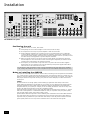 6
6
-
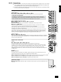 7
7
-
 8
8
-
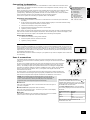 9
9
-
 10
10
-
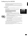 11
11
-
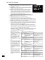 12
12
-
 13
13
-
 14
14
-
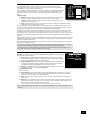 15
15
-
 16
16
-
 17
17
-
 18
18
-
 19
19
-
 20
20
-
 21
21
-
 22
22
-
 23
23
-
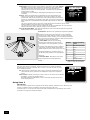 24
24
-
 25
25
-
 26
26
-
 27
27
-
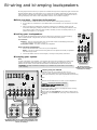 28
28
-
 29
29
-
 30
30
-
 31
31
-
 32
32
-
 33
33
-
 34
34
-
 35
35
-
 36
36
-
 37
37
-
 38
38
-
 39
39
-
 40
40
-
 41
41
-
 42
42
-
 43
43
-
 44
44


Arcam Home Theater System AVR250 Handleiding
- Categorie
- AV-ontvangers
- Type
- Handleiding
- Deze handleiding is ook geschikt voor


