
Einsatzbereich
Speisetrenner mit Hilfsenergie zur sicheren Trennung
von 4...20 mA Normsignalstromkreisen, mit eigen-
sicherem Ausgang [EEx ia] IIC.
Sicherheitshinweise
Das VEGATRENN 149 Ex ist ein zugehöriges Betriebs-
mittel und darf nicht in explosionsgefährdeten Berei-
chen installiert werden. Die Errichtungsbestimmungen
nach EN 50154 / VDE 0165 müssen beachtet werden.
Das Gerät erfüllt die Anforderungen gemäß
EN 61 010-1 /VDE 0411 Teil 1,
EN 50014 / VDE 0170/0171 Teil 1,
EN 50020 / VDE 0170/0171 Teil 7
und hat das Werk in sicherheitstechnisch einwandfrei-
em Zustand verlassen. Ein gefahrloser Betrieb ist nur
sichergestellt, wenn die Betriebsanleitung beachtet
wird.
-Einbau und Anschluß erfordern qualifiziertes Fach-
personal.
-Der Betrieb des Gerätes ist nur im eingebauten
Zustand zulässig.
-Die Schutzleiterverbindung ist vor allen anderen
Verbindungen herzustellen. Bei Unterbrechung des
Schutzleiters können Gefahren auftreten.
-Vergleichen Sie vor Inbetriebnahme die Überein-
stimmung der Versorgungsspannung mit den Anga-
ben auf dem Typenschild. Sehen Sie einen
geeigneten Schalter in der Gebäudeinstallation vor.
Dieser Schalter muß in der Nähe des Gerätes ange-
bracht und als Trennvorrichtung gekennzeichnet
sein.
-Für die Netzleitung ist ein Uberstromschutz (Nenn-
strom <= 10 A) erforderlich.
-Das Gerät enthält keine Teile, die vom Anwender
repariert werden können. Reparaturen sind nur
durch den Hersteller durchführbar.
Funktionsweise
Der Speisetrenner VEGATRENN 149 Ex mit Hilfs-
energie dient der galvanischen Ex-Trennung von 4...20
mA Normsignalstromkreisen. Die Meßumformer-
speisung erfolgt über eine anzulegende Hilfs-
spannung. Eine bidirektionale HART-Kommunikation
mit SMART-Transmittern ist möglich. Der Ausgangs-
stromkreis entspricht der Zündschutzart Eigen-
sicherheit (i).
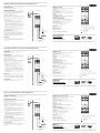
Anschluß
Ist bei langen Signalleitungen mit energiereichen
Transienten (Spannungsspitzen) zu rechnen, empfeh-
len wir die Vorschaltung eines geeigneten Überspan-
nungsschutzes.
1+ Sensor-Speisung (eigensicher)
2 - Sensor-Speisung (eigensicher)
11 + Eingang (SPS/ Auswertgerät)
12 - Eingang (SPS/ Auswertgerät)
L
1(+) Hilfsenergie
N(-) Hilfsenergie
Schutzleiter
Technische Daten
Gehäuse
Bauform: A7 (3: 22,5 mm / H: 73,5 mm / T 118,2 mm)
mit Schnappbefestigung für 35 mm Hutschiene DIN EN
50022-35 Werkstoff: Polycarbonat
Schutzart
Gehäuse IP 40, Klemmen IP 20 nach EN 60529
Anschlußklemmen
unverlierbare Klemmenschrauben M 2,5 mit selbstab-
hebenden Anschlußscheiben. Anschlußquerschnitt:
2 x 2,5 mm² massiv oder 2 x 1,5 mm² Litze mit Hülse
Gewicht
ca. 150 g
Umgebungstemperatur
0° C. .+50° C
Umgebungstemperatur bei Lagerung und Transport
-20° C...+70° C
Ausgang (Sensorstromkreis)
4...20 mA, eigensicher [EEx ia] IIC
Eingang (Auswertstromkreis)
4 ..20 mA, Lastwiderstand 0...700 Ohm, Leerlauf-
spannung 24 V +/-10 %, Signalisierung des Strom-
flusses über gelbe LED in Reihe zum Stromeingang
Explosionsschutz
Errichtung außerhalb des explosionsgefährdeten
Bereichs. Ausgang eigensicher [EEx ia] IIC
Höchstwerte im Fehlerfall:
U
0
= 28,4 V, l
0
= 87,3 mA, P
0
= 620 mW,
[C
0
= 69 nF, L
0
= 2 mH] EEx ia IIC
[C
0
= 470 nF, L
0
= 14 mH] EEx ia IIB
Hilfsenergie
90...253 VAC, 50/60 Hz
Option:
24 VAC +/- 15 %, 50/60 Hz
18 VDC ...36 VDC
Signalübertragung
Meßbereich 4...20 mA,
Linearitätsfehler <= 0,15 %
Technische Änderungen vorbehalten.
VEGATRENN
149EX
2
1
–
+
out
in
+
–
11 12
N(-
)
L
1(+)
Betriebsanleitung Speisetrenner VEGATRENN 149 Ex
VEGA Grieshaber KG
Am Hohenstein 113
D-77761 Schiltach
Tel. (0 78 36) 50 - 0
Fax (0 78 36) 50 - 201
e-mail: [email protected]
VEGATRENN
149EX
2
1
–
+
out
in
+
–
11 12
N(-
)
L
1(+)
Ex-Zone
Operating Instruction active barrier VEGATRENN 149 Ex
VEGA Controls Ltd.
Kendal House
Victoria Way
Burgess Hill
West Sussex, RH 15 9NF
Tel (0 14 44) 87 00 55
Fax (0 14 44) 87 00 80
VEGATRENN
149EX
2
1
–
+
out
in
+
–
11 12
N(-
)
L
1(+)
Mise en service séparateur VEGATRENN 149 Ex
VEGA Technique S.A.
BP 18
Nordhouse
67151 Erstein-Cedex
Tel. 03 88 59 01 50
Fax 03 88 59 01 51
e-mail: [email protected]
Technical Data
Housing
Construction: A7 (W: 22.5 mm / H: 73.5mm / D: 118.2
mm) with snap fixing for35 mm top hat DIN EN 50022-
35 rail.Material: Polycarbonate
Protection class
Housing IP 40, terminals IP 20 to EN60529
Terminals
Secured M 2.5 screw terminals. Cablecore cross
section area: 2 x 2,5 mm² solid or 2 x 1,5 mm² core
with ferrule
Weight
approx 150 p
Ambient temperature
0° C...+50° C
Storage and transport temperature
-20° C...+70° C
Output (sensor circuit)
4...20 mA, intrinsically safe to [EEx ia] IIC
Input (processing circuit)
4...20 mA, load resistance 0...700 Ohm,open circuit
voltage 24 V +/-10 %,Current flow indicated by yellow
LED in series with the input current.
Intrinsic safety
Installation outside the explosive area.
Output intrinsically safe to [EEx ia] IIC
Peak values in fault conditions:
U
0
=28.4V, l
0
=87.3mA, P
0
=620mW,
[C
0
= 69 nF, L
0
= 2 mH] EEx ia IIC
[C
0
= 470 nF, L
0
= 14 mH] EEx ia IIB
Power supply
90...253 VAC, 50/60 Hz
option:
24 VAC +/- 15 %, 50/60 Hz
18 VDC ...36 VDC
Signal transmission
Measurement range 4...20 mA
Linearity error <= 0,15 %
Application
Barrier with power supply for safeseparation of 4...20
mA signalcircuits, with optional [EEx ia] IIC
intrinsically safe output.
Safety notes
The VEGATRENN 149 Ex is an additional system
component and must not be installedin the non-safe
explosion area.The installation requirements of EN
50154 / VDE 0165 must beheeded. It complies with
the safetyrequirements:
EN 61 010-1 / VDE 0411 Part 1,
EN 50014 / VDE 0170/0171 Part 1,
EN50020/VDE 0170/0171 Part 7
and has left our works in perfect andsafe condition.
Safe operation can only beguaranteed if all hints and
warning notes in these operating instructionsare
heeded.
-Installation and connection mustonly be done by
skilled andqualified personnel.
-The unit is only to be operated inan installed
condition.
- Earth (ground) must be connectedbefore any other
connection ismade. It could become dangerousif
the earth connection is broken.
- First check that the power supplyto be used
corresponds with thaton the unit legend plate.
- A power isolator must be installed within reach of
the unit and mustbe labelled as a power isolator.
- The fuse required for overcurrentprotection must be
at least <_10A.
- There are no components in theunit that can be
repaired by theuser. All repairs must be done by
the manufacturer.
Function
The active barrier VEGATRENN 149 Ex is usedfor
galvanic Ex-isolation of 4 ... 20 mAcurrent signal
circuits. The power supply comes from thesupply
voltage required to run theunit. Bi-directional HART
communication with SMART transmitters is possible.
The output signal is protected tointrinsical safety (i).
Connection
If there is a posibility of high energytransients (voltage
peaks), we recommend fitting acorresponding
overvoltage protection unit.
1+ Loop power (intrinsically safe)
2 - Loop power (intrinsically safe)
11 + Input (Signal conditioning instrument)
12 - Input (Signal conditioning instrument)
L
1(+) Power supply
N(-) Power supply
Earth (Ground)
Technical alterations reserved.
Not-Ex-Zone
Sensor
PLC/ Signal
conditioning
instrument
Power
supply
Caractéristiques techniques
Boitier
Construction: A7 (L: 22,5 mm/H: 73,5 mm/P: 118,2 mm)
avec fixation embrochable pour rail profilé 35 mm DIN
EN 50022-35. Matériau: polycarbonate
Protection
Boitier IP40, bornes IP20 selon EN 60529
Bornes de raccordement
Bornes à visser M 2,5 imperdables avec rondelles
auto-taraudeuses. Section de raccordement: maxi
2x2,5 mm²
Poids
Env. 150 g
Température ambiante
0° C...+50° C
Température ambiante lors du transport et du
stockage
-20° C...+70° C
Sortie (circuit capteur)
4...20mA, sécurité intrinsèque [EEx ia] IIC
Entrée (circuit transmetteur)
4...20 mA, résistance de charge 0...700 ohms, tension
à vide 24 V +/-10 %, signalisation du courant via DEL
jaune en série avec la entrée courant
Protection
Installation en dehors de la zone explosible
Sortie à sécurité intrinsèque [EEx ia] IIC
Valeurs max. en cas de défaut:
U
0
=28,4 V, l
0
=87,3 mA, P
0
=620 mW
[C
0
= 69 nF, L
0
= 2 mH] EEx ia IIC
[C
0
= 470 nF, L
0
= 14 mH] EEx iallB
Alimentation
90...253 VAC, 50/60 Hz
option:
24 VAC +/- 15 % 50/60 Hz
18 VDC ...36 VDC
Transmission du signal
Gamme de mesure 4...20 mA,
Erreur de linéarité <= 0,15 %
Sous réserve de toute modification.
1+ Alimentation (sécurité intrinsèque)
2 - Alimentation (sécurité intrinsèque)
11 + Sortie (transmetteur)
12 - Sortie (transmetteur)
L
1(+) Alimentation
N(-) Alimentation
Terre
Domaine d’utilisation
Séparateur avec alimentation pour une séparation sûre
des circuits 4...20 mA avec sortie à sècurité intrinsèque
[EEx ia] IIC.
Conseils de securite
Le VEGATRENN 149 Ex ne doit pas être installé en
zone explosible. Il convient de respecter les directives
d’installation selon EN 50154 / VDE 0165. L’appareil
répond aux exigences selon
EN 61 010-1 / VDE 0411 partie 1,
EN 50014/VDE 0170/0171 partie 1,
EN 50020 / VDE 0170/0171 partie 7
et a quitté nos établissements dans un état technique
irréprochable. Une utilisation sans danger nécessite
néanmoins le respect des directives de mise en
service.
-Montage et raccordement doivent être effectués par
un personnel qualifié
-L’appareil ne doit être utilisé qu’en position montée
-La terre doit être mise en place avant tous les autres
raccordements. L’interruption de la ligne de terre
peut engendrer des dangers.
-Avant la mise en service, comparer la tension
d’alimentation avec les indications sur la plaque
signalétique.
-Prévoir un commutateur approprié, situé à proximité
de l’installation et repéré comme séparateur.
-Le câble d’alimentation doit être protégé par un
fusible (courant nominal <= 10 A).
-L’appareil ne comprend aucune pièce pouvant être
réparée par l’utilisateur. Les réparations ne doivent
être effectuées que par le fabricant.
Fonctionnement
Le séparateur VEGATRENN 149 Ex avec alimentation
sert à la séparation galvanique Ex des circuits de
courant normé 4.. 20 mA; il est alimenté par le réseau.
Une communication bidirectionnelle HART avec
transmetteurs SMART est possible. Le circuit de sortie
a le mode de protection sécurite intrinsèque.
Raccordement
S’il faut s’attendre a des transitoires puissants (pics de
tension) pour les câbles de longueur importante, nous
recommandons de mettre en place un fusible
approprié.
zone Ex
zone non Ex
capteur
API/
trans-
metteur
Alimen-
tation
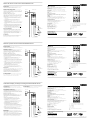
Elektrischer Anschluß
Electrical connection
Raccordement électrique
[EEx ia]IIC
[EEx ia]IIC
[EEx ia]IIC
VEGATRENN
149EX
Ex-Bereich
Nicht-Ex-Bereich
Sensor
SPS/
Auswert-
gerät
Hilfs-
energie
250
Ω
VEGA-
CONNECT
VEGATRENN
149EX
250
Ω
VEGATRENN
149EX
250
Ω
VEGA-
CONNECT
VEGA-
CONNECT
2.22 320 / März 1998

VEGATRENN
149EX
2
1
–
+
out
in
+
–
11 12
N(-
)
L
1(+)
Ex-area
Not-Ex-area
Sensora
SPS/
Analiza-
dores
Alimen-
tación
Manual de instrucciones barrera VEGATRENN 149 Ex
VEGA Iberia S.A.
Plaza del Cedro, 7
20016 San Sebastian
Tel. (0 43) 39 87 74
Fax (0 43) 40 08 56
VEGATRENN
149EX
2
1
–
+
out
in
+
–
11 12
N(-
)
L
1(+)
Zona
periculosa
Zona sicura
Sensor
SPS/
Elabora-
tori
Alimen-
tazione
Manuale operativo barriera attiva VEGATRENN 149 Ex
VEGA Italia srl
Via Giacomo Watt 37
20143 Milano
Tel. (02) 89 14 08 1
Fax (02) 89 14 08 40
e-mail: [email protected]
VEGATRENN
149EX
2
1
–
+
out
in
+
–
11 12
N(-
)
L
1(+)
Ex-zone
Sensor
SPS/
Ingang
voeding
Gebruiksaanwijzing voedings/scheidingsunit VEGATRENN 149 Ex
VEGA Industriële Automatisiering
Postbus 210
3800 AE Amersfoort
Tel. (0 33) 4 50 25 02
Fax (0 33) 4 56 14 14
e-mail: [email protected]
Sujeto a modificación
Datos técnicos
Caja
Construcción: A7 (Ancho: 22,5 mm / Alto: 73,5 mm /
Profun.: 118,2 mm) para montaje rail de 35 mm segun
DIN EN 50022-35 Material: Policarbonato
Protección:
Caja en IP 40, terminales en IP 20 segun EN 60529
Terminales
Bornas M 2,5 en bloques de terminales. Grosor por
hilo: 2 x 2,5 mm² sólido ó 2 x 1,5 mm² con manguito de
empalme.
Peso
Aprox. 150 g.
Temperatura ambiente
0° C...+50° C
Temperatura durante el almacenaje y el transporte
-20° C...+70° C
Salida
4...20 mA intrinsecamente segura [EEx ia] IIC
Entrada
4... 20 mA, resistencia a sobrepresiones 0...700 Ohm,
voltaje circuito abierto 24 V +/-10 %. Corriente
indicada mediante el LED amarillo en serie con la
entrada de corriente.
Seguridad intrínseca
Instalación en zona sin riesgo de explosión. Salida
intrínsecamente segura [EEx ia] IIC
Picos en condiciones de fallo:
U
0
= 28,4 V, l
0
= 87,3 mA, P
0
= 620 mW,
[C
0
= 69 nF, L
0
= 2 mH] EEx ia IIC
[C
0
= 470 nF, L
0
= 14 mH] EEx ia IIB
Alimentación
90 ..253 VAC, 50/60 Hz
variatione:
24 VAC +/- 15 %, 50/60 Hz
18 VDC...36 VDC
Transmisión de señal
Rango de medida: 4...20 mA,
Error linealidad <= 0,15 %
Aplicación
Barrera con alimentación para separación segura de
los circuitos de señal 4...20 mA con salida intrinse-
camente segura [Eex ia] IIC opcional.
Notas sobre seguridad
La barrera VEGATRENN 149 Ex es un componente
adicional y no debe instalarse en zona no segura. Las
normas de instalación EN 50154 / VDE 0165 deberán
ser estrictamente aplicadas. Cumple con las normati-
vas de seguridad
EN 61 01 0-1/ VDE 0411 Part 1,
EN 50014 / VDE 0170/0171 Part 1,
EN 50020 / VDE 0170/0171 Part 7
ofreciendo una total seguridad asi como una perfecta
operación. La seguridad de operación únicamente
está garantizada si se siguen todas las indicaciones y
advertencias de seguridad mencionadas en el pre-
sente manual:
-La instalación y la conexión deberán ser realizadas
única y exclusivamente por personal técnico
cualificado.
-La unidad deberá unicamente ponerse en
funcionamiento una vez se haya terminado la
instalación.
-La puesta a tierra deberá realizarse antes que
cualquier otra conexión. Puede resultar peligrosa en
caso de ser dañada.
-Comprobar que la fuente de alimentación a emplear
se corresponde con la indicada en la placa de la
unidad.
-Instalar aislamiento eléctrico dentro del alcance de
la unidad e identificarlo como aislador eléctrico.
-El fusible requerido para la protección contra
sobretensiones deberá ser de por lo menos < 10 A
-No existen componentes en la unidad que puedan
ser reparados por el usuario. Todas las
reparaciones deberán realizarse por el fabricante.
Funcionamiento
La barrera VEGATRENN 149 Ex se utiliza como
aislamiento Ex galvánico para circuitos de señal de
corriente 4...20 mA. La alimentación proviene de la
fuente de alimentación necesaria para el fun-
cionamiento de la unidad. Comunicación bidireccional
con protocolo HART, con transmisores SMART. La
salida de señal está protegida con seguridad
intrinseca (I).
Conexion
En caso de fuertes oscilaciones en la alimentación
(picos de tensión), recomendamos instalar un
protector para sobretensiones en la unidad.
1+ Lazo alimentado (intrinsecamente seguro)
2 - Lazo alimentado (intrisecamente seguro)
11 + Entrada (Analizadores)
12 - Entrada (Analizadores)
L
1(+) Alimentación
N(-) Alimentación
Tierra
Conexiones eléctricas
Collegamento elletrico
Elektrische aansluiting
Soggetto a modifiche tecniche.
Dati tecnici
Custodia
Costruzione: A7 (W: 22,5 mm/H: 73,5 mm/D: 118,2
mm) con staffa di fissaggio per binario 35 mm DIN EN
50022-35
Materiale: Policarbonato
Classe di protezione
Custodia IP 40, morsetti IP 20 secondo EN 60529
Morsetti
Terminali a vite M 2,5 sezione del cavo: 2 x 2,5 mm²
rigido 2 x 1,5 mm² anima flessibile
Peso
circa 150 gr.
Temperatura ambientale
O° C...+50° C
Temperatura di stoccaggio e di trasporto
-20° C...+70° C
Uscita
4...20 mA, sicurezza intrinseca a [EEx ia] IIC
Ingresso
4...20 mA, resistenza di carico 0...700 Ohm, tensione a
circuito aperto 24 V +/-10 %. Flusso di corrente
indicato tramite LED giallo in serie con l’ingresso in
corrente.
Sicurezza intrinseca
Installazione all’esterno dell’area con
pericolo di esplosione.
Uscita a sicurezza intrinseca a [EEx ia] IIC.
Picchi in condizioni di guasto:
U
0
= 28,4 V, l
0
= 87,3 mA, P
0
= 620 mW,
[C
0
= 69 nF, L
0
= 2 mH] EEx ia IIC
[C
0
= 470 nF, L
0
= 14 mH] EEx ia IIB
Alimentazione
90...253 VAC, 50/60 Hz
option:
24 VAC +/- 15 %, 50/60 Hz
18 VDC...36 VDC
Trasmissione del segnale
Campo di misura 4...20 mA,
Errore di linearit à <= 0,15 %
1+ alimentazione del Loop (sicurezza intrinseca)
2 - alimentazione del Loop (sicurezza intrinseca)
11 + Uscita (Elaboratori)
12 - Uscita (Elaboratori)
L
1(+) Alimentazione
N(-) Alimentazione
Terra
Applicazione
Barriera con alimentazione per separazione di
sicurezza del segnale 4...20mA, con uscita opzionale a
sicurezza intrinseca [EEx ia] IIC.
Note di sicurezza
VEGATRENN 149 Ex e un componente addizionale di
sistema e non può essere installato in un’area non
sicura. Devono essere osservate le regole per
l’installazione secondo l’EN 50154/ VDE 0165; lo
strumento soddisfa le seguenti richieste di sicurezza:
EN 61 010-1 / VDE 0411 Parte 1,
EN 50014 / VDE 0170/0171 Parte 1,
EN 50020 / VDE 0170/0171 Parte7
ed ha lasciato il centro di produzione i lavori in
condizioni di perfetta sicurezza. Il funzionamento in
sicurezza può essere garantito solo se i suggerimenti e
gli avvertimenti contenuti in queste istruzioni saranno
strettamente osservati.
-L’installazione ed il collegamento devono essere
effettuati solo da personale qualificato.
-L’unità può essere messa in funzione solo se
installata.
-ll collegamento di terra deve essere effettuato prima
di qualunque altro collegamento. Potrebbe rivelarsi
pericolosa l’eventuale rottura del collegamento di
terra.
-Per prima cosa assicurarsi che l’alimentazione da
usare corrisponda a quella sulla targhetta dell’unità
-Un isolatore di potenza deve essere installato vicino
all’unità e deve essere contrassegnato come
isolatore di potenza.
-ll fusibile richiesto per la protezione alle
sovracorrenti deve essere almeno 10A.
-Non ci sono componenti nell’unità che possano
essere riparati dall’utilizzatore. Tutte le riparazioni
devono essere effettuate dal produttore.
Funzione
La barriera attiva VEGATRENN 149 Ex viene usata per
l’isolamento galvanico Ex del segnale di corrente 4...20
mA. L’alimentazione viene dalla tensione
d’alimentazione del circuito richiesta per il
funzionamento dell’unità. Con trasmettitori SMART è
possibile la comunicazione HART bidirezionale ll
segnale d’uscita è a sicurezza intrinseca (l).
Collegamento
Se esiste la possibilità di transitori di elevata energia
(picchi di tensione), si raccomanda l’utilizzo di una
idonea unità di protezione alle sovratensioni.
Technische wijzigingen voorbehouden
Technische gegevens
Behuizing
Bouwvorm: A7 (B: 22,5 mm / H: 73,5 r / T 118,2 mm)
met klikbevestiging op DIN normrail EN 50022-35
Materiaal: Polycarbonaat
Beschermklasse
Huis IP 40, Klemmen IP 20 conform EN 60529
Aansluitklemmen
Verliesvrije klemmenschroeven M 2,5 met meegaande
klemplaatjes
Geschikt voor max. 2 x 2,5 mm²
Gewicht
ca. 150 gram.
Omgevingstemperatuur
0° C...+50° C
Omgevingstemperatuur bij opslag en transport
-20° C...+70° C
Uitgang
4-20 mA intrinsiekveilig [EEx ia] IIC
Ingang
4-20 mA max. afsluitbelasting 0-700 Ohm
Open spanning: 24 V +/-10 %
Ingangsstroomsignalering d. m.v. een in gele LED in
serie met de uitgangsstroom.
Explosieveiligheid
De voedings/scheidings unit VEGATRENN 149 Ex moet
zelf buiten het explosiegevaarlijke gebied worden
gemonteerd. Uitgang intrinsiekveilig [EEx ia] IIC.
Maximale waarden in foutsituatie.
U
0
= 28 4 V, l
0
= 87,3 mA, P
0
= 620 mW,
[C
0
= 69 nF, L
0
= 2 mH] EEX ia IIC
[C
0
= 470 nF, L
0
= 14 mH] EEX ia IIB
Voeding
90...253 VAC, 50/60 Hz
option:
24 VAC +/- 15 %, 50/60 Hz
18 VDC...36 VDC
Signaaloverdracht
Meetbereik 4-20 mA,
Lineariteitsfout <= 0,15 %
Toepassing
Voedings/scheidingsunit voor voeding en veilige
scheiding van 4-20 mA signalen met intrinsiekveilige
uitgang [EEx ia] IIC.
Veiligheidsaanwijzing
De VEGATRENN 149 Ex is een separate voedings- c.q.
scheidingsunit en mag zelf niet in het
explosiegevaarlijke gebied gemonteerd worden. De
installatievoorschriften conform EN 50154 / VDE 0165
moeten worden aangehouden. Het instrument voldoet
aan de eisen volgens
EN 61 010-1/ VDE 0411 deel 1,
EN50014/VDE0170/0171 deel 1 en
EN 50020 / VDE 0170/0171 deel 7 en
heeft de fabriek in onberispelijke staat verlaten. Een
veilig gebruik is alleen dan gewaarborgd indien alle
elementen uit deze gebruiksaanwijzing worden
opgevolgd
-Montage en aansluiting door gekwalificeerd
vaktechnisch personeel.
-Het gebruik van het instrument is uitsluitend in
correct ingebouwde en aangesloten situatie
toegestaan.
-Als eerste aansluiting/verbinding dient de
potentiaalvereffeningsleiding (massa) aangesloten
te worden. Bij onderbreking van deze
potentiaalvereffeningsleiding (massa) kunnen er
gevaren optreden.
-Voor ingebruikname eigen voedingspanning
controleren met die op het typeplaatje.
-Indien het instrument wordt gebruikt als
sensorvoeding in bouwtechnische installaties moet
het instrument dicht bij de sensor gemonteerd
worden en als duidelijke scheidingsunit gekenmerkt
zijn.
-Voor de netvoeding wordt een circuit met zekering
van kleiner dan 10 A. geadviseerd.
-Het instrument heeft geen onderdelen die zelf
vervangen kunnen worden. Reparaties kunnen
uitsluitend door de leverancier uitgevoerd worden .
Werkwijze
De voedings/scheidingsunit VEGATRENN 149 Ex is
bedoeld voor de voeding c.q. scheiding van 4-20 mA
normsignalen. Sensorvoeding geschied via een op de
VEGATRENN 149 Ex aangelegde DC of AC
voedingsspanning (naar keuze). Via de VEGATRENN
149 Ex is, met een geschikte smart-sensor, HART bi-
direktionele kommunicatie mogelijk. Het sensor-
uitgangscircuit biedt een intrinsiekveilige bescherming
tegen ontsteking in explosiegevaarlijke gebieden.
Aansluiting
Bij lange signaalleidingen en mogelijke instrooiing is
een overspanningsbeveiliging aan te raden.
1+ sensor/voeding plus (intrinsiekveilig)
2 - sensor/voeding min (intrinsiekveilig)
11 + ingang
12 - ingang
L
1(+) voeding
N(-) voeding
potentiaalvereffening (massa)
[EEx ia]IIC
[EEx ia]IIC
[EEx ia]IIC
VEGATRENN
149EX
250
Ω
VEGATRENN
149EX
250
Ω
VEGATRENN
149EX
250
Ω
VEGA-
CONNECT
VEGA-
CONNECT
VEGA-
CONNECT
2.22 320 / März 1998
-
 1
1
-
 2
2


