
Safety Power Supply
SPS-24V-1A5/BNS (SPS-2423)
SPS-24V-2A5/BNS (SPS-2433)
SPS-24V-4A5/BNS (SPS-2453)
Installation Manual

2
EATON Safety Power Supply (ZNO1031200 PrN) January 2016 www.eaton.eu
Contents
1. INSTRUCTIONS - ENGLISH...................................................................................................................................................................................... 3
1.1 Important Instructions.................................................................................................................................................................................................. 3
1.2 Opertation / LED Description...................................................................................................................................................................................... 4
1.3 Technical Features.......................................................................................................................................................................................................... 5
2. INSTRUCTIONS - FRANÇAIS................................................................................................................................................................................... 6
2.1 Instructions Importantes............................................................................................................................................................................................. 6
2.2 Fonctionnement / Description des voyants.......................................................................................................................................................... 7
2.3 Caractéristiques techniques principales................................................................................................................................................................. 8
3. ISTRUZIONI - ITALIANO........................................................................................................................................................................................... 9
3.1 Istruzioni Importanti...................................................................................................................................................................................................... 9
3.2 Funzionamento / Descrizione LED..........................................................................................................................................................................10
3.3 Caratteristiche tecniche.............................................................................................................................................................................................. 11
4. HINWEISE - DEUTSCH............................................................................................................................................................................................ 12
4.1 Wichtige Hinweise....................................................................................................................................................................................................... 12
4.2 Betrieb / LED Anzeigen............................................................................................................................................................................................... 13
4.3 Technische Merkmale.................................................................................................................................................................................................. 14
5. INSTRUKCJE - POLSKI............................................................................................................................................................................................ 15
5.1 Wazne Instrukcje........................................................................................................................................................................................................... 15
5.2 Praca / opis diod ........................................................................................................................................................................................................... 16
5.3 Właściwości techniczne.............................................................................................................................................................................................. 17
6. INSTRUÇÕES - PORTUGUÊS.................................................................................................................................................................................. 18
6.1 Instruções Importantes.............................................................................................................................................................................................. 18
6.2 Funcionamento / Descrição dos LEDs ................................................................................................................................................................. 19
6.3 Caracteristicas Técnicas.............................................................................................................................................................................................. 20
7. INSTRUCTIES - NEDERLANDS.............................................................................................................................................................................. 21
7.1 Belangrijke Instructies................................................................................................................................................................................................ 21
7.2 Bediening / LED-functies ........................................................................................................................................................................................ 22
7.3 Technische gegeven................................................................................................................................................................................................. 23
8. INSTALLATION AND MAINTENANCE................................................................................................................................................................. 24
8. INSTALLATION ET MAINTENANCE.................................................................................................................................................................... 24
8. INSTALLAZIONE E MANUTENZIONE.................................................................................................................................................................. 24
8. INSTALLATION UND WARTUNG......................................................................................................................................................................... 24
8. INSTALACJA I KONSERWACJA........................................................................................................................................................................... 24
8. INSTALAÇÃO E MANUTENÇÃO............................................................................................................................................................................ 24
8. INSTALLATIE EN ONDERHOUD............................................................................................................................................................................ 24
9. AUTONOMY.............................................................................................................................................................................................................. 34
10. NOTES........................................................................................................................................................................................................................ 35
Contents

3
EATON Safety Power Supply (ZNO1031200 PrN) January 2016 www.eaton.eu
IMPORTANT - SAFETY
Read this manual carefully and in its entirety before any
technical intervention on the device.
The operation must only be performed by qualified
personnel.
Installation and commissioning of product must be done
by following sequence describe below. Order of steps is
important and must be described.
Cut mains off before any intervention on device.
The power supply unit must be provided upstream with:
• a bipolar disconnecting device;
• a circuit breaker: 4A - D Curve.
The device must be carried carefully and stored in proper
conditions (humidity and temperature).
The Installer must check that device has not been damaged
during transport and installation. A damaged product may
cause serious injury. A damaged product must never be
connected to the mains.
The device must never be connected to the mains if it
is not properly fixed to the wall with its housing properly
connected to protective earth (see first step of installation).
Replacing the original battery with a battery of incorrect
type may result in an explosion hazard. Used batteries must
be disposed of in compliance with recycling requirements.
This device is a class A device. In a residential environment,
this device can cause radio frequency interference. In this
case, the user may take appropriate measures.
Use 4 screws with a diameter up to 5 mm. Plugs
and screws must be adapted to type of wall. Each
fixing plugs/screws must support a minimum
weight of 20kg (80kg split on each fixing screw).
Electrical shock risk symbol
Protective earth terminal
Typical applications
The SPS is a two output-24V dc battery backed power
supply. It is a high efficiency switching power supply;
protected from overload and short circuits.
It is specifically recommended as an auxiliary power
supply unit for fire detection system components, such as
electromagnets, notification devices, etc.
Conformity to standards
0333
15
DoP Nos:
SPS-24-1A5/BNS: SPS1A5CE
SPS-24-2A5/BNS: SPS2A5CE
SPS-24-4A5/BNS: SPS4A5CE
This device complies with the following standards:
•
EN 54-4: 1997 / A1: 2003 / A2: 2005;
•
EN12101-10:2005 class A Env. class 1.
Recycling Instructions
Instructions - English
1.1 Important Instructions
Wasted electrical products should not be
disposed of with household waste. Please
recycle where facilites exist. Check with
your local authority or retailer for recycling
advice.

4
EATON Safety Power Supply (ZNO1031200 PrN) January 2016 www.eaton.eu
Colour Status
Green Mains and/or batteries are present.
Yellow There is at least one fault on the SPS. Then the general fault
relay is also activated.
Yellow Mains is not present or its value is out of range.
Yellow • Batteries are not present; or
• Batteries voltage is out of range; or
• There is a charge failure; or
• The batteries resistance level exceeded the threshold.
Yellow Batteries resistance level:
• Low
• Medium
• High
• Both LEDs flashing: default threshold reached. A battery
fault is activated.
Green • ON: output 1/2 is power-supplied.
• OFF: output 1/2 is not power-supplied.
• Flashing: output 1/2 in fault mode (ex.: short-circuit or over-
load).
Green ON when the input is activated. Then output 1 is deactivated
(output 2 remains activated). This deactivation can be delayed
of 10 minutes depending on switch configuration.
General fault relay The general fault relay is activated when there is at least one fault on the SPS.
User input This input is used to activate or deactivate remotely the output 1. Input is activated when a
short-circuit is applied between two terminal pins.
Then output 1 is deactivated (output 2 remains activated). This deactivation can be delayed
by 10 minutes depending on switch configuration.
See 2 - Connection.
Example 1: This input can be used to deactivate output 1 during an alarm using a relay on
the fire panel.
Example 2: This input can be used to deactivate output 1 during mains failure using the
mains fault relay on the fire panel. It will maintain battery capacity for the output 2.
Self resetting electronic fuse Both outputs are protected by an electronic circuit breaker. In case of overload or short
circuit on an output, the voltage of this output is switched off. In this case the output LED
blinks. Every 30 seconds the power supply tries to power on voltage. If overload is no
longer present the voltage is resumed, else the output remains switched off until the next
tr y.
Control of internal resistor of
battery pack
The power supply checks periodically the internal resistor of battery and displays the result
on front LEDs. No LEDs turned off means low resistance. Two LEDs turned on means a
high resistance. If two LEDs are blinking then the threshold is exceeded and a battery
fault is activated. In this condition the battery is not able to supply high current within the
voltage range. Battery wires should also be checked in case of high internal resistor.
}
}
1.2 Operation / LEDs Description
Instructions - English

5
EATON Safety Power Supply (ZNO1031200 PrN) January 2016 www.eaton.eu
Instructions - English
IMPORTANT
Both outputs are electronically protected.
SPS-24V-1A5/BNS SPS-24V-2A5/BNS SPS-24V-4A5/BNS
Network input Voltage (V
in
) 230V ac (-15%;+10%)
Frequency (F
in
) 50Hz
Current max.RMS
(@195V)(I
inmax
)
1.2A 1.5A 2A
Class (EN12101-10) I
Neutral system TT, IT
Circuit breaker Radial leaded time delay fuse (2.5A)
Output Voltage “Out 1”
Voltage “Out2”
@ V
in
> 195V
27.5V (+/-0.5V) 27.5V (+/-0.5V) 27.5V (+/-0.5V)
Voltage “Out 1”
Voltage “Out2”
@ V
in
> 0V
20.4V to 27V 20.4V to 27V 20.4V to 27V
Max current “Out 1”
Max current “Out 2”
1.5A 2.5A 4.5A
Max Current
“Out 1+Out 2”
I
max
a=I
max
b
1.5A 2.5A 4.5A
Min current “Out 1”
Min current “Out 2”
0A
Residual ripple voltage
“Out 1”& “Out 2”
<1%
Relay Max switching current 1A @ 24V
Max switching voltage 120V dc / 50V ac (ELV)
Batteries/charger Charger current max 1.0A (+/-0.1A)
Final voltage 21V
Cut-off voltage 21.0V (+/-0.6V)
Battery capacity 4Ah 7Ah 17Ah
Internal impedance
max R
int
max
0.8Ω 0.6Ω 0.6Ω
Recommended bat-
teries
Yuasa NP4-12 Yuasa NP7-12 Yuasa NP17-12
Circuit breaker (F1) Fuse 5×20 - 2A (F) Fuse 5×20 - 3.15A (F) Fuse 5×20 - 6.3A (F)
Switching delay
(EN12101-10)
0s
Environment Dimension (l×h×d) 300×220×175 (mm)
Operating temperature -5°C to +40°C
Relative humidity 20 to 95%
Altitude <2000m
IP 30
Storage temperature -10°C to +50°C
Environment class
(EN 12101-10)
Class I
1.3 Technical Features

6
EATON Safety Power Supply (ZNO1031200 PrN) January 2016 www.eaton.eu
Instructions - Français
IMPORTANT - SÉCURITÉ
Lisez attentivement cette notice dans son intégralité avant
toute intervention technique sur l’appareil.
L’opération doit être effectuée uniquement par du personnel
qualifié.
L’installation et la mise en service du produit doivent être
effectuées dans l’ordre décrit ci-après. L’ordre des étapes
est important et doit être respecté.
Coupez le secteur avant toute intervention sur l’appareil.
L’équipement doit posséder en amont::
• un sectionneur bipolaire,
• un Coupe-circuit: 4A - courbe D
L’appareil doit être transporté avec soin et stocké dans de
bonnes conditions (humidité et température).
L’installateur doit vérifier que l’appareil n’a pas été
endommagé durant le transport et l’installation. Un appareil
endommagé peut provoquer de graves blessures. Un
appareil endommagé ne doit jamais être raccordé au
secteur.
L’appareil ne doit jamais être raccordé au secteur s’il n’est
pas correctement fixé au mur, avec son boîtier correctement
raccordé à la terre (voir la première étape de l’installation).
Remplacer la batterie d’origine par une batterie de type
incorrect peut provoquer un risque d’explosion. Les batteries
usagées doivent être jetées conformément aux instructions
de recyclage.
Il s’agit d’un appareil de classe A. Dans un environnement
résidentiel, cet appareil peut créer des interférences dans
les fréquences radio. Le cas échéant, l’utilisateur peut
prendre des mesures adéquates.
Utilisez 4 vis de 5 mm de diamètre. Les chevilles et les vis
doivent être adaptées au type de mur. Chaque cheville/vis
de fixation doit supporter un poids minimum de 20 kg (le
poids total de 80 kg est réparti sur chaque vis de fixation).
Risque de choc électrique
Borne la terre principale.
Types d’application
La SPS est une alimentation électrique de sécurité avec
deux sorties en 24V et un jeu de batteries. C’est une
alimentation à découpage à haute efficacité protégée contre
les sur-intensités et les courts-circuits.
Elle est particulièrement recommandée en tant
qu’alimentation auxiliaire pour les périphériques utilisés
dans les systèmes de détection d’incendies tels que les
ventouses magnétiques, électro-aimants, les diffuseurs
lumineux ou sonores, dispositifs de notification, etc.
Conformité aux normes
0333
15
DoP Nos:
SPS-24-1A5/BNS: SPS1A5CE
SPS-24-2A5/BNS: SPS2A5CE
SPS-24-4A5/BNS: SPS4A5CE
•
EN 54-4: 1997 / A1: 2003 / A2: 2005;
•
EN12101-10:2006 class A Env. class 1.
2.1 Instructions Importantes
Les produits électriques usagés ne
doivent pas être jetés avec les déchets
domestiques. Merci de les recycler aux
endroits appropriés. Demandez conseil à
vos autorités locales ou à votre revendeur
pour le recyclage.
Consignes de recyclage

7
EATON Safety Power Supply (ZNO1031200 PrN) January 2016 www.eaton.eu
1.
Couleur Statut
Vert Le secteur et /ou les batteries sont présents.
Jaune Il y a au moins un défaut sur l’alimentationSPS. Le relais de
défaut général est alors également activé.
Jaune Le secteur n’est pas présent ou sa valeur dépasse les toléranc-
es acceptées.
Jaune • Les batteries ne sont pas présentes ; ou
• La tension des batteries dépasse les tolérances acceptées
; ou
• Il y a un défaut de charge ; ou
• Le niveau de résistance des batteries a dépassé le seuil.
Jaune Niveau de résistance des batteries :
• Faible
• Moyen
• Élevé
• Les deux voyants clignotent : le seuil de défaut est atteint.
Un défaut batterie est activé.
Vert • ON : la sortie 1/2 est alimentée.
• OFF : la sortie 1/2 n’est pas alimentée.
• Clignotant : la sortie 1/2 est en mode défaut (ex. : court-
circuit ou surintensité).
Vert Allumé lorsque l’entrée est activée. La sortie 1 est alors dés-
activée (la sortie 2 reste activée). Cette désactivation peut être
temporisée de 10 minutes selon la configuration du switch.
Relais de défaut général Le relais de défaut général est activé quand il y a au moins un défaut sur l’alimentation SPS.
Entrée utilisateur Cette entrée sert à activer ou à désactiver la sortie 1 à distance. L’entrée est activée
lorsqu’un court-circuit a lieu entre deux broches de raccordement.
La sortie 1 est alors désactivée (la sortie 2 reste activée). Cette désactivation peut être tem-
porisée de 10 minutes selon la configuration du switch.
Voir 2 - Raccordement.
Exemple 1 : Cette entrée peut servir à désactiver la sortie 1 pendant une alerte en utilisant
un relais de la centrale incendie.
Exemple 2 : Cette entrée peut servir à désactiver la sortie 1 pendant un défaut secteur en
utilisant le relais de défaut secteur sur la centrale incendie. Cela maintiendra la capacité des
batteries pour la sortie 2.
Fusible électronique à réarme-
ment automatique
Les deux sorties sont protégées par un coupe-circuit électronique. En cas de sur-intensité
ou de court-circuit sur une sortie, la tension de cette sortie est coupée. Dans ce cas, le
voyant de sortie clignote. Toutes les 30 secondes, l’alimentation essaie de remettre la
tension. S’il n’y a plus de surcharge, la tension revient. Sinon, la sortie reste coupée jusqu’à
la tentative suivante.
Contrôle de la résistance interne
de la batterie
L’alimentation vérifie régulièrement la résistance interne de la batterie et affiche le résultat
sur les voyants en face avant. Si tous les voyants sont éteints, la résistance est faible. Si
les deux voyants sont allumés, la résistance est élevée. Si les deux voyants clignotent, le
seuil est alors dépassé et un défaut batterie est activé. Dans ce cas, la batterie n’est pas
en mesure de délivrer une tension de sortie dans les plages de tolérance. Les câbles de la
batterie doivent également être vérifiés en cas de résistance interne élevée.
}
}
2.2 Fonctionnement / Description des voyants
Instructions - Français

8
EATON Safety Power Supply (ZNO1031200 PrN) January 2016 www.eaton.eu
IMPORTANT
Les deux sorties sont protégées électroniquement.
SPS-24V-1A5/BNS SPS-24V-2A5/BNS SPS-24V-4A5/BNS
Entrée secteur Tension (V
in
) 230V ac (-15%;+10%)
Frequency (F
in
) 50Hz
Current max.RMS
(@195V)(I
inmax
)
1.2A 1.5A 2A
Classe (EN12101-10) I
Système neutre Fusible TT, IT
Coupe Circuit Fusible temporisé (2.5A)
Sortie Tension « sortie 1 »
Tension « sortie 2 »
@ V
in
> 195V
27.5V (+/-0.5V) 27.5V (+/-0.5V) 27.5V (+/-0.5V)
Tension « sortie 1 »
Tension « sortie 2 »
@ V
in
> 0V
20.4V to 27V 20.4V to 27V 20.4V to 27V
Courant max « sortie 1 »
Courant max « sortie 2 »
1.5A 2.5A 4.5A
Courant max
« sortie 1 + sortie 2 »
I
max
a=I
max
b
1.5A 2.5A 4.5A
Courant min « sortie 1 »
Courant min « sortie 2 »
0A
Tension d’ondulation
résiduelle
« sortie 1 » et « sortie
2 »
<1%
Relais Courant de coupure max 1 A à 24 V
Tension de coupure max 120V DC / 50V AC (TBT)
Batteries/chargeur Courant de chargeur max 1.0A (+/-0.1A)
Tension finale 21V
Tension de coupure 21.0V (+/-0.6V)
Capacité de la batterie 4Ah 7Ah 17Ah
Impédance interne max.
R
int
max
0.8Ω 0.6Ω 0.6Ω
Batteries recommandées Yuasa NP4-12 Yuasa NP7-12 Yuasa NP17-12
Coupe-circuit (F1) Fusible 5×20 - 2A (F) Fusible 5×20 - 3.15A (F) Fusible 5×20 - 6.3A (F)
Retard de commutaion
(EN12101-10)
0s
Environnement Dimensions (L×H×P) 300×220×175 (mm)
Température de
fonctionnement
-5 °C à +40 °C
Humidité relative (max.) 20 to 95%
Altitude <2000m
IP 30
Température de stockage -10 °C à +50 °C
Classe environnementale
(EN 12101-10)
Classe I
Instructions - Français
2.3 Caractéristiques techniques principales

9
EATON Safety Power Supply (ZNO1031200 PrN) January 2016 www.eaton.eu
Istruzioni - Italiano
IMPORTANTE - SICUREZZA
Leggere attentamente l’intero manuale prima di qualsiasi
intervento tecnico sul dispositivo.
Qualsiasi operazione deve essere eseguita esclusivamente
da personale qualificato.
L’installazione e la messa in funzione del prodotto devono
essere effettuate in conformità alla procedura descritta di
seguito. È importante rispettare l’ordine di esecuzione dei
passaggi indicati.
Scollegare la rete elettrica prima di qualsiasi intervento sul
dispositivo.
L’unità di alimentazione deve essere provvista a monte di:
• un dispositivo di sezionamento bipolare;
• un interruttore: 4A - Curva D.
Il dispositivo deve essere trasportato con cautela e deve
essere conservato in condizioni di umidità e temperatura
adeguate.
L’installatore deve verificare che il dispositivo non abbia
subito danni durante il trasporto e l’installazione. Un prodotto
danneggiato potrebbe causare lesioni gravi. Non collegare
mai un prodotto danneggiato alla rete elettrica.
Non collegare mai il dispositivo alla rete elettrica nel
caso in cui non sia fissato correttamente alla parete e il
relativo alloggiamento non sia collegato correttamente a una
messa a terra di protezione (vedere la prima operazione di
installazione).
Non sostituire la batteria originale con un modello di batteria
errato poiché ciò potrebbe causare un’esplosione. Le
batterie utilizzate devono essere smaltite in conformità con
le normative vigenti.
Questo dispositivo è un dispositivo di classe A. In una zona
residenziale, il dispositivo potrebbe causare interferenze di
radio frequenze. In questo caso, l’utente adotterà le misure
che riterrà più opportune.
Utilizzare 4 viti di un diametro massimo di 5 mm. I connettori
e le viti devono essere conformi al tipo di parete in uso. Ogni
connettore/vite di fissaggio deve poter sostenere un peso
minimo di 20 kg (80 kg suddivisi su ogni vite di fissaggio).
Simbolo di rischio di scosse elettriche
Terminale di protezione di messa a terra
Applicazioni tipiche
Il dispositivo SPS è un gruppo di alimentazione con due
uscite a 24 Vcc dotato di due batterie in tampone. Si tratta
di un gruppo di alimentazione switching ad alta efficienza,
provvisto di sistema di protezione da sovraccarichi e
cortocircuiti.
Viene particolarmente consigliato come unità di alimentazione
ausiliaria per componenti di sistemi di rilevazione degli
incendi, come ad esempio gli elettromagneti, i dispositivi
di notifica, ecc.
Conformità alle normative
0333
15
DoP Nos:
SPS-24-1A5/BNS: SPS1A5CE
SPS-24-2A5/BNS: SPS2A5CE
SPS-24-4A5/BNS: SPS4A5CE
Questo dispositivo è conforme alle seguenti
normative:
• EN54-4: 1997/A1:2003/A2:2006;
• EN12101-10:2005 classe ambientale A
3.1 Istruzioni Importanti
I prodotti elettrici di scarto non devono
essere smaltiti unitamente ai rifiuti domestici
ma presso le strutture preposte. Rivolgersi
al proprio ente locale o al rivenditore per
consigli sullo smaltimento.
Istruzioni per lo smaltimento

10
EATON Safety Power Supply (ZNO1031200 PrN) January 2016 www.eaton.eu
Istruzioni - Italiano
2.
Colore Stato
Verde Rete di alimentazione e/o batterie presenti.
Giallo Si è verificato almeno un guasto nell’SPS. È stato atti-
vato anche il relè di guasto generale.
Giallo La rete di alimentazione non è presente o i suoi valori
non rientrano nell’intervallo di funzionamento.
Giallo • Le batterie non sono presenti; oppure
• La tensione delle batterie non rientra nell’intervallo
di funzionamento; oppure
• Si è verificato un errore di carica batteria; oppure
• Il livello di resistenza delle batterie supera il limite
massimo.
Giallo Livello di resistenza delle batterie:
• Basso
• Medio
• Alto
• Entrambi i LED lampeggiano quando è stato rag-
giunto il limite massimo predefinito oppure è stato
rilevato un guasto alla batteria.
Verde • ACCESO: l’uscita 1/2 risulta alimentata
• SPENTO: l’uscita 1/2 non risulta alimentata
• Lampeggiante: l’uscita 1/2 si trova in modalità di
guasto (ad esempio: cortocircuito o sovraccarico).
Verde ACCESO quando l’ingresso risulta attivato. L’uscita 1
viene disattivata (l’uscita 2 rimane attiva). Questa disat-
tivazione può essere ritardata di 10 minuti a seconda
della configurazione dell’ingresso.
Relè di guasto generale Il relè di guasto generale viene attivato quando si è verificato almeno un guasto nell’SPS.
Ingresso utente Questo ingresso viene utilizzato per attivare o disattivare l’uscita 1 a distanza. L’ingresso
viene attivato quando viene applicato un cortocircuito tra i due morsetti.
Quindi l’uscita 1 viene disattivata (l’uscita 2 rimane attivata). Questa disattivazione può
essere ritardata di 10 minuti a seconda della configurazione del commutatore.
Vedere 2 - Collegamento.
Esempio 1: questo ingresso può essere utilizzato per disattivare l’uscita 1 durante un allarme
utilizzando il relè posto sulla centrale o modulo di uscita.
Esempio 2: questo ingresso può essere utilizzato per disattivare l’uscita 1 durante un guas-
to alla rete di alimentazione usando il relè di guasto posto sulla centrale. La capacità delle
batterie verrà mantenuta per l’uscita 2.
Fusibile elettronico con autori-
pristino
Entrambe le uscite sono protette da un circuito di interruzione elettronico. In caso di sovrac-
carico o cortocircuito su un’uscita, la tensione di tale uscita verrà disattivata. In questo caso,
il LED relativo all’uscita lampeggerà. Ogni 30 secondi il sistema di alimentazione tenterà di
attivare la tensione. Se non si è verificato un sovraccarico, la tensione viene riattivata, altri-
menti l’uscita rimarrà disattivata fino al tentativo successivo.
Controllo della resistenza interna
della batteria
Il sistema di alimentazione verifica periodicamente la resistenza interna della batteria e visualizza
il risultato sui LED frontali. Se i due LED risultano spenti, significa bassa resistenza. Se i due LED
risultano accesi, significa alta resistenza. Se due LED lampeggiano, significa che è stato superato
il limite massimo e che si è verificato un guasto della batteria. In queste condizioni, la batteria non
è in grado di fornire una corrente elevata compresa nell’intervallo di tensione. In caso di elevata
resistenza interna, occorre verificare anche i cavi della batteria.
}
}
3.2 Funzionamento / Descrizione LED

11
EATON Safety Power Supply (ZNO1031200 PrN) January 2016 www.eaton.eu
IMPORTANTE
Entrambe le uscite sono protette elettronicamente
SPS-24V-1A5/BNS SPS-24V-2A5/BNS SPS-24V-4A5/BNS
Ingresso di rete Tensione (V
in
) 230V ca (-15%;+10%)
Frequenza (F
in
) 50 Hz
RMS di corrente massimo
(@195V)(I
inmax
)
1.2A 1.5A 2A
Classe (EN12101-10) I
Sistema neutro TT, IT
Fusibile Fusibile radiale ad azione ritardata(2,5A)
Uscita Tensione “Uscita 1”
Tensione “Uscita 2”
a V
in
> 195V
27.5V (+/-0.5V) 27.5V (+/-0.5V) 27.5V (+/-0.5V)
Tensione “Uscita 1”
Tensione “Uscita 2”
a V
in
> 0V
Da 20.4V to 27V Da 20.4V to 27V Da 20.4V to 27V
Corrente massima “Uscita 1”
Corrente massima “Uscita 2”
1.5A 2.5A 4.5A
Corrente massima “Uscita
1+Uscita 2” I
max
a=I
max
b
1.5A 2.5A 4.5A
Corrente minima “Uscita 1”
Corrente minima “Uscita 2”
0A
Tensione di Ripple residua
“Uscita 1” e “Uscita 2”
<1%
Relè Corrente massima di com-
mutazione
1A a 24V
Tensione massima di com-
mutazione
120V cc / 50V ac (ELV)
Batterie/caricatore Corrente massima di carica
batteria
1.0A (+/-0.1A)
Tensione finale 21V
Tensione di sgancio batteria 21.0V (+/-0.6V)
Capacità della batteria 4Ah 7Ah 17Ah
Massima impedenza interna
R
int
max
0.8Ω 0.6Ω 0.6Ω
Batterie consigliate Yuasa NP4-12 Yuasa NP7-12 Yuasa NP17-12
Fusibile
5 x 20 (F1)
F 2A F 3.15A F 6.3A
Ritardo di commutazione
(EN12101-10)
0s
Ambiente Dimensione (L×H×P) 300×220×175 (mm)
Temperatura di esercizio Da -5°C to +40°C
Umidità relativa Da 20 to 95%
Altitudine <2000m
IP 30
Temperatura di stoccaggio Da -10°C a +50°C
Classe ambientale
(EN 12101-10)
Classe I
3.3 Caratteristiche tecniche
Istruzioni - Italiano

12
EATON Safety Power Supply (ZNO1031200 PrN) January 2016 www.eaton.eu
Hinweise - Deutsch
WICHTIG - SICHERHEIT
Lesen Sie dieses Handbuch sorgfältig und vollständig, bevor
Sie Arbeiten am Gerät beginnen.
Alle Arbeiten dürfen nur von qualifiziertem Fachpersonal
durchgeführt werden.
Installation und Einstellung des Gerätes dürfen nur
entsprechend der folgenden Anleitung ausgeführt werden.
Die Reihenfolge der Schritte bei der Abarbeitung ist
unbedingt einzuhalten.Schalten Sie die Netzversorgung des
Gerätes frei, bevor Sie das Gerät öffnen.
Die Zuleitung der Netzspannung muß ausgerüstet werden
mit:
• einer 2-poligen Trenneinrichtung;
• einem Schutzschalter: 4A - D-Kurve.
Das Gerät muss sorgfältig behandelt und bestimmungsgemäß
(Luftfeuchtigkeit und Temperatur) gelagert werden.
Der Errichter muss prüfen, dass das Gerät bei Transport und
Installation nicht beschädigt wurde. Ein beschädigtes Produkt
kann zu schweren Verletzungen führen. Ein beschädigtes
Gerät darf nicht an das Stromnetz angeschlossen werden.
Das Gerät darf nie an das Stromnetz angeschlossen werden,
sofern es ist nicht korrekt an der Wand montiert und das
Gehäuse an das Potential der Schutzerde angeschlossen
wurde (siehe ersten Schritt der Installation).
Ersetzen des originalen Akkus durch einen Akku des falschen
Typs kann zu Explosionsgefahr führen. Gebrauchte Batterien
müssen in Übereinstimmung mit geltenden Richtlinien zur
Wiederverwertung entsorgt werden.
Dieses Gerät ist ein Gerät der Klasse A. In Wohngebäuden
kann dieses Gerät Hochfrequenz-Störungen verursachen.
Der Benutzer soll in diesem Fall geeignete Maßnahmen
ergreifen. Die Befestigung erfolgt mit 4 Schrauben,
Durchmesser bis 5 mm. Dübel und Schrauben müssen dem
Befestigungsort angepasst sein. Jede/r Dübel/Schraube
muss ein Mindestgewicht von 20 kg (80 kg aufgeteilt auf
alle 4 Befestigungsschrauben) tragen können.
Symbol für Stromschlag-Gefahr
Erdanschluß
Typische Anwendungen
Die SPS ist eine batteriegepufferte Stromversorgung mit
zwei Ausgängen-24V DC. Es ist ein Schaltnetzteil mit hohem
Wirkungsgrad; geschützt gegen Überlast und Kurzschluss.
Es wird speziell zur Versorgung von Brandmelde-
Systemkomponenten wie Elektromagneten, Signalgebern
und ähnlichen Geräte empfohlen.
Normenkonformitä
0333
15
DoP Nos:
SPS-24-1A5/BNS: SPS1A5CE
SPS-24-2A5/BNS: SPS2A5CE
SPS-24-4A5/BNS: SPS4A5CE
• EN54-4: 1997/A1:2003/A2:2006;
• EN12101-10:2005 Klasse A Umkelklasse 1
4.1 Wichtige Hinweise
Defekte elektrische Produkte sollten nicht mit
dem Hausmüll entsorgt werden. Befolgen
Sie die örtlichen Richtlinien der Behörden und
entsorgen Sie die Geräte entsprechend.
Entsorgung / Wiederverwertung

13
EATON Safety Power Supply (ZNO1031200 PrN) January 2016 www.eaton.eu
3.
Grün Status
Grün (Betrieb) Netzspannung oder Akkus in Funktion.
Gelb
(Sammelstörung)
Das Netzteil ist gestört. Das Sammelstörrelais ist
aktiviert.
Gelb
(Netzstörung)
Netzspannung ist nicht vorhanden oder Netzspannung
außerhalb des gültigen Bereichs.
Gelb
(Ladestörung)
• Batterien nicht angeschlossen; oder
• Batteriespannung fehlerhaft; oder
• Ladestörung; oder
• Innenwiderstand der Akkus fehlerhaft.
Gelb Innenwiderstand der Akkus:
• Niedrig
• Mittel
• Hoch
• Beide LEDs blinken: Innenwiderstand der Akkus
fehlerhaft. Eine Ladestörung wird aktiviert
Grün
(Ausgang 1/2)
• AN: Ausgang 1/2 ist spannungsversorgt.
• AUS: Ausgang 1/2 ist spannungsfrei.
• Blinkt: Ausgang 1/2 gestört (z.B. Kurzschluß,
Überlast).
Grün
(Eingang aktiv)
AN wenn Eingang aktiviert. Ausgang 1 ist abge-
schaltet (Ausgang 2 bleibt ein) Die Abschaltung
Ausgang 2 kann bis zu 10 Minuten verzögert erfol-
gen, abhängig von der gewählten Konfiguration..
Sammelstörrelais Das Sammelstörrelais wird durch die erste Störung des Gerätes aktiviert.
Eingang Wird dieser Eingang durch einen Schaltkontakt kurzgeschlossen, schaltet Ausgang 1 sofort
ab.
Ausgang 2 kann bis zu 10 Minuten verzögert abgeschaltet werden, abhängig von der pro-
grammierten Zeit.
Siehe 2 - Anschluß
Beispiel 1: Dieser Eingang kann verwendet werden, um Ausgang 1 während eines Alarms
mit einem Kontakt der Brandmeldezentrale zu deaktivieren.
Beispiel 2: Dieser Eingang kann verwendet werden, um Ausgang 1 bei Netzausfall über die
Brandmeldezentrale zu deaktivieren. Die Batteriekapazität wird für Ausgang 2 reserviert.
Elektronische Sicherungen Beide Ausgänge werden durch elektronische Sicherungen geschützt. Bei Überlast oder
Kurzschluß wird die Ausgangsspannung abgeschaltet. In diesem Fall blinkt die LED Ausgang
1/2. Alle 30 Sekunden wird der entsprechende Ausgang geprüft, sobald Überlast/Kurzschluß
nicht mehr anliegen, wird die Spannung wieder eingeschaltet.
Überwachung des
Innenwiderstandes der Batterien
Das Netzteil prüft den Innenwiderstand der Batterien zyklisch und zeigt diesen mittels LED
am Gerät an. Fehlende Batterien erzeugen zu niedrigen Widerstand (LEDs aus), beide LEDs
werden bei zu hohem Widerstand aktiviert. Blinken beide, liegt der Wert außerhalb der
Vorgaben, die Versorgung der angeschlossenen Geräte durch die Batterien ist nicht mehr
sichergestellt. Bei hohem Widerstand sollten auch die Batterieanschlüsse und -kabel über-
prüft werden.
}
}
4.2 Betrieb / LED Anzeigen
Hinweise - Deutsch

14
EATON Safety Power Supply (ZNO1031200 PrN) January 2016 www.eaton.eu
WICHTIG
Beide Ausgänge werden elektronisch gesichert
SPS-24V-1A5/BNS SPS-24V-2A5/BNS SPS-24V-4A5/BNS
Eingang Netz Spannung (V
in
) 230V ac (-15%;+10%)
Schlussspannung (F
in
) 21V
Ausgangsstrom max.
RMS (@195V)(I
inmax
)
1.2A 1.5A 2A
Klasse (EN12101-10) I
Netzform (Schutzleiter) TT, IT
Absicherung (2.5A)
Ausgang Spannung Ausgang 1
Spannung Ausgang 2
@ V
in
> 195V
27.5V (+/-0.5V) 27.5V (+/-0.5V) 27.5V (+/-0.5V)
Spannung Ausgang 1
Spannung Ausgang 2
@ V
in
> 0V
20.4V to 27V 20.4V to 27V 20.4V to 27V
Maximalstrom
Ausgang 1
Maximalstrom
Ausgang 2
1.5A 2.5A 4.5A
Maximalstrom Ausg. 1
+ 2 I
max
a=I
max
b
1.5A 2.5A 4.5A
Minimalstrom Ausgang
1
Minimalstrom Ausgang
2”
0A
Restwelligkeit
Ausgang 1 + 2
<1%
Störrelais Kontaktbelastung max. 1A @ 24V DC
Schaltspannung max. 120V DC / 50V AC
Batterien/Ladekreis Ladestrom max 1.0A (+/-0.1A)
Schlussspannung 21V
Abschaltspannung 21.0V (+/-0.6V)
Batteriekapazität 4Ah 7Ah 17Ah
Innenwiderstand
Akkusatz R
int
max
0.8Ω 0.6Ω 0.6Ω
Empfohlener
Batterietyp
Yuasa NP4-12 Yuasa NP7-12 Yuasa NP17-12
Akkusicherung
5 x 20 (F1)
F 2A F 3.15A F 6.3A
Schaltverzögerung
(EN12101-10)
0s
Umwelt Abmessungen
(L×B×T)
300×220×175 (mm)
Betriebstemperatur -5°C to +40°C
Relative Luftfeuchte 20 to 95%
Höhe ü NN <2000m
IP 30
Lagertemperatur -10°C to +50°C
Umweltklasse
(EN 12101-10)
Klasse I
Hinweise - Deutsch
4.3 Technische Merkmale

15
EATON Safety Power Supply (ZNO1031200 PrN) January 2016 www.eaton.eu
WAZNE - BEZPIECZENSTWO
Należy dokładnie przeczytać całą niniejszą instrukcję przed
dokonywaniem jakichkolwiek interwencji technicznych w
urządzeniu.
Obsługą urządzenia mogą zajmować się wyłącznie
wykwalifikowani pracownicy.
Należy przeprowadzić instalację produktu i przekazanie go do
eksploatacji stosując się opisanej poniżej sekwencji. Kolejność
kroków jest ważna i należy jej przestrzegać.
Odciąć zasilanie sieciowe przed dokonaniem jakiejkolwiek
interwencji w urządzeniu.
Zasilacz należy wyposażyć w umieszczone przed nim:
• dwubiegunowy odłącznik;
• wyłącznik: 4A - Krzywa D.
Urządzenie należy przenosić ostrożnie i przechowywać we
właściwych warunkach (wilgotnośći temperatura).
Instalator musi sprawdzić, czy urządzenie nie zostało
uszkodzone w trakcie transportu oraz instalacji. Uszkodzony
produkt może spowodować poważne obrażenia. Niedozwolone
jest podłączenie uszkodzonego produktu do sieci zasilającej.
Niedozwolone jest podłączenie urządzenia do sieci zasilającej,
jeżeli nie przymocowano go prawidłowo do ściany a jego
obudowy nie podłączono prawidłowo do uziemienia
ochronnego (patrz pierwszy krok instalacji). Zastąpienie
oryginalnego akumulatora akumulatorem nieprawidłowego
rodzaju może prowadzić do zagrożenia wybuchem. Zużyte
akumulatory należy utylizować zgodniez wymaganiami
dotyczącymi recyklingu.
Urządzenie jest urządzeniem klasy A. W warunkach domowych
może ono spowodować zakłócenia radiowe. W takim
przypadku użytkownik musi podjąć odpowiednie środki.
Użyć 4 wkrętów o średnicy do 5 mm. Kołki i wkręty muszą
być dostosowane do rodzaju ściany. Poszczególne kołki
mocujące/wkręty muszą utrzymywać minimalny ciężar równy
20 kg (80 kg podzielone na poszczególne wkręty mocujące).
Symbol zagrożenia porażeniem prądem
elektrycznym
Zacisk uziemienia ochronnego
Typowe zastosowania
SPS (ang. Safety Power Supply) to zasilacz z podtrzymaniem
akumulatorowym, z dwoma wyjściami 24 V DC. Jest to
wysokowydajny zasilacz przełączający zabezpieczony przed
przeciążeniem i zwarciami.
Zalecany jest szczególnie jako pomocniczy zasilacz do
elementów systemów wykrywania pożarów takich jak
elektromagnesy, urządzenia powiadomieniowe itp
Zgodnosc z normami
0333
15
DoP Nos:
SPS-24-1A5/BNS: SPS1A5CE
SPS-24-2A5/BNS: SPS2A5CE
SPS-24-4A5/BNS: SPS4A5CE
Ten produkt spełnia wymagania następujących
norm:
• EN54-4: 1997/A1:2003/A2:2006;
• EN12101-10:2005 klasa A Klasa
środowiskowa 1
5.1 Wazne Instrukcje
Odpadów elektrycznych nie należy usuwać razem
z odpadami domowymi. Należy przekazywać
je do recyklingu, jeżeli istnieją odpowiednie
udogodnienia. Należy zasięgnąć porady
dotyczącej recyklingu u lokalnych organów
władzy lub u sprzedawcy detalicznego.
Instrukcja dot. recyklingu
` ‘
`
‘ ‘
Instrukcje - Polski

16
EATON Safety Power Supply (ZNO1031200 PrN) January 2016 www.eaton.eu
4.
Kolor Status
Zielony Obecna jest sieć zasilająca i/lub akumulatory.
Żółty W SPS występuje co najmniej jedna awaria. Zostaje wówc-
zas aktywowany także przekaźnik awarii ogólnej.
Żółty Brak sieci zasilającej lub jej wartość nie mieści się w zakre-
sie.
Żółty • Brak akumulatorów; lub
• Napięcie akumulatorów nie mieści się w zakresie; lub
• Nie dochodzi do ładowania; lub
• Poziom rezystancji akumulatorów przekroczył próg.
Żółty Poziom rezystancji akumulatorów:
• Niski
• Średni
• Wysoki
• Obie diody migają: osiągnięto próg domyślny.
Aktywowano awarię akumulatora.
Zielony • WŁ.: wyjście 1/2 jest zasilane.
• WYŁ.: wyjście 1/2 nie jest zasilane.
• Miga: wyjście 1/2 w trybie awarii (np.: zwarcie lub
przeciążenie
Zielony WŁ. gdy wejście jest aktywowane. Potem wyjście 1 zostaje
dezaktywowane (wyjście 2 pozostaje aktywowane). Tę
dezaktywację można opóźnić o 10 minut w zależności od
konfiguracji przełącznika.
Przekaznik awarii ogólnej
Przekaźnik awarii ogólnej zostaje aktywowany, gdy w SPS występuje co najmniej jedna awaria.
Ingresso utente
To wejście służy do zdalnego aktywowania lub dezaktywowania wyjścia 1. Wejście zostaje akty-
wowane wtedy, gdy pomiędzy dwoma pinami zaciskowymi podane jest zwarcie.
Potem wyjście 1 zostaje dezaktywowane (wyjście 2 pozostaje aktywowane).
Tę dezaktywację można opóźnić o 10 minut w zależności od konfiguracji przełącznika.
Patrz 2 - Podłączanie.
Przykład 1: To wejście może służyć do dezaktywowania wejścia 1 w trakcie alarmu za pomocą
przekaźnika na panelu przeciwpożarowym.
Przykład 2: to wejście może służyć do dezaktywowania wejścia 1 w trakcie awarii sieci zasilającej
za pomocą przekaźnika awarii sieci zasilającej na panelu przeciwpożarowym.To spowoduje zach-
owanie pojemności akumulatorów dla wyjścia 2.
Samoresetujacy sie bezpiecznik
elektroniczny
Oba wyjścia zabezpieczono za pomocą wyłącznika elektronicznego. W przypadku przeciążenia lub
zwarcia na wyjściu następuje wyłączenie napięcia na tym wyjściu.
W takim przypadku miga dioda danego wyjścia. Co 30 sekund zasilacz próbuje załączyć napięcie.
Jeżeli nie będzie przeciążenia, wówczas napięcie zostanie przywrócone, w przeciwnym razie
pozostanie ono wyłączone aż do następnej próby.
Kontrola wewnetrznego rezystora
modułu akumulatorowego
Zasilacz sprawdza okresowo wewnętrzny rezystor akumulatora i wyświetla wynik na diodach
umieszczonych z przodu. Jeżeli żadna dioda nie jest wyłączona, to oznacza niską rezystancję. Dwie
diody włączone oznaczają wysoką rezystancję. Dwie migające diody oznaczają, że przekroczony
został prób i aktywowana awaria akumulatora. W tym stanie akumulator nie może doprowadzać
dużego natężenia
w zakresienapięcia. Przewody akumulatora również należy sprawdzać w przypadku wysokiej
rezystancji wewnętrznej.
}
}
5.2 Praca / opis diod
‘
Instrukcje - Polski

17
EATON Safety Power Supply (ZNO1031200 PrN) January 2016 www.eaton.eu
WAZNE – BEZPIECZENSTWO
SPS-24V-1A5/BNS SPS-24V-2A5/BNS SPS-24V-4A5/BNS
Wejscie sieciowe
Napięcie (V
in
) 230V AC (-15%;+10%)
Częstotliwość (F
in
) 50 Hz
Maks. prąd skuteczny
( przy 195 V) (I
inmax
)
1.2A 1.5A 2A
Klasa (EN12101-10) I
Sieć z punktem neutralnym TT, IT
Wyłącznik Bezpiecznik ołowiowy, promieniowy, zwłoczny (2,5A)
Wyjscie
Napięcie „Wyj 1”
Napięcie „Wyj 2”
przy V
in
> 195V
27.5V (+/-0.5V) 27.5V (+/-0.5V) 27.5V (+/-0.5V)
Napięcie „Wyj 1”
Napięcie „Wyj 2”
przy V
in
> 0V
Da 20.4V do 27V Da 20.4V do 27V Da 20.4V do 27V
Maks. prąd „Wyj 1”
Maks. prąd „Wyj 2”
1.5A 2.5A 4.5A
Maks. prąd „Wyj 1+Wyj 2”
Imaxa=Imaxb
1.5A 2.5A 4.5A
Min. prąd „Wyj 1”
Min. prąd „Wyj 2”
0A
Szczątkowe napięcie tętnień
„Wyj 1” i „Wyj 2”
<1%
Przekaznik
Maks. prąd łączeniowy 1A przy 24V
Maks. napięcie łączeniowe 120V cc / 50V ac (ELV)
Akumulatory/
ładowarka
Maks. prąd ładowarki 1.0A (+/-0.1A)
Napięcie końcowe 21V
Napięcie odcięcia 21.0V (+/-0.6V)
Pojemność akumulatora 4Ah 7Ah 17Ah
Maks. impedancja
wewnętrzna R
int
max
0.8Ω 0.6Ω 0.6Ω
Zalecane akumulatory Yuasa NP4-12 Yuasa NP7-12 Yuasa NP17-12
Wyłącznik
5 x 20 (F1)
Bezpiecznik 2A (F) Bezpiecznik 3.15A (F) Bezpiecznik 6.3A (F)
Opóźnienie przełączania
(EN12101-10)
0s
Srodowisko
Wymiary (d×w×g) 300×220×175 (mm)
Temperatura pracy -5°C 40°C
Wilgotność względna 20 95%
Wysokość <2000m
IP 30
Temperatura
przechowywania
-10°C 50°C
Klasa środowiskowa
(EN 12101-10)
Klasa I
‘
‘
‘
‘
‘
`
Instrukcje - Polski
‘
‘
5.3 Własciwosci techniczne

18
EATON Safety Power Supply (ZNO1031200 PrN) January 2016 www.eaton.eu
IMPORTANTE - SEGURANÇA
Leia este manual atenta e integralmente antes de qualquer
intervenção técnica no equipamento. Qualquer intervenção
apenas deve ser realizada por pessoal qualificado.
A instalação e comissionamento do equipamento deve ser
feita na sequência descrita em baixo. A ordem dos passos
é importante e deve ser respeitada.
Desligue a alimentação antes de qualquer intervenção no
equipanento.
A fonte de alimentação deve ser fornecida a montante com:
• um dispositivo de corte bipolar;
• um disjuntor: 4A – Curva D.
O equipamento deve ser transportado cuidadosamente
e armazenado em condições apropriadas (humidade e
temperatura).
O instalador deve verificar que o equipamento não foi
danificado durante o transporte e instalação. Um
equipamento danificado pode causar lesões graves. Um
equipamento danificado nunca deverá ser ligado à tensão
de alimentação.
O equipamento nunca deve ser ligado à alimentação se não
estiver apropriadamente fixo à parede com o seu involucro
ligado à terra (ver primeiro passo da instalação).
Substituir a bateria original por uma bateria de tipo incorrecto
pode resultar em risco de explosão. Baterias usadas devem
ser eliminadas de acordo com os regulamentos sobre
reciclagem em vigor.
Este é um equipamento de classe A. Num ambiente
residêncial, este equipamento pode causar interferências
em sinais de rádio. Neste caso, o utilizador pode tomar
medidas adequadas.
Utilize 4 parafusos com um diametro até 5 mm. Buchas e
parafusos devem ser adaptados ao tipo de parede. Cada
fixação bucha/parafuso deve suportar um peso minimo de
20Kg (80Kg divididos em cada um dos parafusos) .
Simbolo de risco de choque eléctrico
Terminal terra
Aplicações típicas
A SPS é uma fonte de alimentação suportada por baterias
com duas saídas-24V. É uma fonte de alimentação
comutável de alta eficiência; protegida contra sobre-
alimentações e curto-circuitos.
É especialmente recomendada como fonte auxiliar para
componentes de sistemas de detecção de incêndio, tais
como electroimans, dispositivos de notificação, etc.
Conformidade com normas
0333
15
DoP Nos:
SPS-24-1A5/BNS: SPS1A5CE
SPS-24-2A5/BNS: SPS2A5CE
SPS-24-4A5/BNS: SPS4A5CE
Este equipamento cumpre com as seguintes
normas:
• EN54-4: 1997/A1:2003/A2:2006;
• EN12101-10:2005 classe ambientale A
6.1 Instruções Importantes - Português
Residuos de produtos eléctricos não
devem ser eliminados juntamente com lixo
doméstico. Por favor recicle onde existam
meios. Verifique com as autoridades locais
ou distribuidor as exigências regulamentares.
Instruções - Português
Instruções reciclagem

19
EATON Safety Power Supply (ZNO1031200 PrN) January 2016 www.eaton.eu
5.
Cor Estado
Verde Alimentação e/ou baterias estão presentes.
Amarelo Existe pelo menos uma falha na SPS. Então o relé de
falhageral também é activado.
Amarelo Sem alimentação ou valores fora dos limites.
Amarelo • Sem baterias; ou
• Tensão das baterias fora dos limites; ou
• Existe uma falha de carregador; ou
• Nível de resistência das baterias excedeu o limite.
Amarelo Nível de Resistências baterias:
• Baixo
• Medio
• Alto
• Ambos os LEDs piscam: nivel limite antigido. É acti-
vada uma falha de bateria.
Verde • ON: output 1/2 está alimentada
• OFF: output 1/2 não está alimentada.
• Piscar: output 1/2 em modo falha (ex.: curto-circutio,
sobrecarga)
Verde ON quando a entrada está activa. Então a output 1 é
desactivada (output 2 mantém-se activa). A desactiva-
ção pode ser atrasada até 10 minutos dependendo da
configuração dos switchs.
Relé falha geral Este relé activa quando existe pelo menos uma falha na SPS.
Entrada utilizador Entrada utilizada para activar ou desactivar remotamente a output 1. A entrada é activada
aplicando um curto-circuito aos seus terminais.
Então a output 1 é desactivada (output 2 mantém-se activa). Esta desactivação pode ser
atrasada até 10 minutos dependendo da configuração dos switchs.
Ver 2 - Ligação
Exemplo 1: Esta entrada pode ser utilizada para desactivar a output 1 durante um alarme uti-
lizando o relé de fogo da central.
Exemplo 2: Esta entrada pode ser utilizada para desactivar a output 1 durante uma falha de
alimentação utilizando o relé de falha de alimentação da central. Irá manter capacidade de
baterias para a output 2.
Fusivel electrónico rearmável Ambas as Output são protegidas por um fusivel electrónico. Em caso de sobrecarga ou
curto-circuito numa saída, a tensão desta é desligada. Neste caso o led da saída pisca. A
cada 30 segundos a central tentará repor a tensão. Se a sobrecarga não estiver presente a
tensão é reposta, caso contrário a output mantém-se desligada até à próxima tentativa.
Controlo da resistência interna do
pack de baterias
A fonte de alimentação verifica periódicamente a resistência interna da bateria e mostra
o resultado nos LEDs frontais. Sem LEDs acesos significa baixa resistência. Dois LEDs
acesos significa resistência alta. Se dois LEDs piscam, então o limite foi excedido e é gera-
da uma falha de bateria. Nesta condição a bateria perde a capacidade de fornecer corrente
elevada na gama de tensão. Os cabos da bateria também devem ser verificados em caso
de alta resistência interna.
}
}
6.2 Funcionamento, Descrição dos LEDs
Instruções - Português

20
EATON Safety Power Supply (ZNO1031200 PrN) January 2016 www.eaton.eu
6.3 Caracteristicas Técnicas
IMPORTANTE
Ambas as outputs são protegidas electrónicamente.
SPS-24V-1A5/BNS SPS-24V-2A5/BNS SPS-24V-4A5/BNS
Entrada rede Tensão (V
in
) 230V ac (-15%;+10%)
Frequência (F
in
) 50 Hz
Corren. max.RMS
(@195V)(I
inmax
)
1.2A 1.5A 2A
Classe (EN12101-10) I
Sistema de neutro TT, IT
Fusível Fusivel Radial (2,5A)
Output Tensão “Out 1”
Tensão “Out 2”
a V
in
> 195V
27.5V (+/-0.5V) 27.5V (+/-0.5V) 27.5V (+/-0.5V)
Tensão “Out 1”
Tensão “Out 2”
a V
in
> 0V
20.4V a 27V 20.4V a 27V 20.4V a 27V
Corren. Máx. “Out 1”
Corren. Máx. “Out 2”
1.5A 2.5A 4.5A
Corren. Máx “Out 1+Out
2 ”.
I
max
a=I
max
b
1.5A 2.5A 4.5A
Corren. Min. “Out 1”
Corren. Min. “Out 2”
0A
Tensão residual ripple
“Out 1”& “Out 2”
<1%
Relè Corrente máxima 1A @ 24V
Tensão máxima 120V cc / 50V ac (ELV)
Baterias/carregador Corren. Máx. Carregador 1.0A (+/-0.1A)
Tensão final 21V
Tensão de corte 21.0V (+/-0.6V)
Capacidade bateria 4Ah 7Ah 17Ah
Resistência interna max
R
int
max
0.8Ω 0.6Ω 0.6Ω
Baterias recomendadas Yuasa NP4-12 Yuasa NP7-12 Yuasa NP17-12
Fusivel
5 x 20 (F1)
Fusivel 2A (F) Fusivel 3.15A (F) Fusivel 6.3A (F)
Atraso comutação
(EN12101-10)
0s
Ambiente Dimensões (L×A×P) 300×220×175 (mm)
Temperatura
funcionamento
-5°C to +40°C
Humidade relativa 20 to 95%
Altitude <2000m
IP 30
Temperatura armaze-
namento
-10°C a +50°C
Classe ambiental
(EN 12101-10)
Classe I
Instruções - Português

21
EATON Safety Power Supply (ZNO1031200 PrN) January 2016 www.eaton.eu
BELANGRIJK - VEILIGHEID
Lees deze handleiding zorgvuldig en in zijn geheel voordat u
met dit apparaat aan de slag gaat.
De beschreven werkzaamheden mogen alleen door daartoe
gekwalificeerd personeel worden uitgevoerd.
Installatie en instellingen van deze power supply moeten in
de hieronder beschreven volgorde worden uitgevoerd. De
volgorde van de stappen is belangrijk en moet daarom in
acht worden genomen.
Sluit de voedingsspanning af voordat u met dit apparaat aan
de slag gaat.
De stroomtoevoer van de power supply moet voorzien zijn
van:
• een 2-polige aan/uit schakelaar
• een zekering: 4A - D karakteristiek.
De power supply moet voorzichtig worden vervoerd en
onder goede condities (vochtigheid en temperatuur) worden
opgeslagen c.q. geïnstalleerd.
Zorg er voor dat de power supply tijdens vervoer en
installatie niet beschadigd raakt.
Een beschadigde power supply kan tot ernstige
verwondingen leiden. Sluit nooit een beschadigde power
supply aan op de netspanning.
De power supply mag nooit op de netvoeding worden
aangesloten als hij niet op de juiste wijze aan de muur
is bevestigd. De behuizing moet aangesloten zijn op een
beschermingsleiding (aarde). Zie de eerste stap van de
installatie.
Het vervangen van de originele accu door een accu van een
onjuist type kan leiden tot explosiegevaar. Gebruikte accu’s
dienen overeenkomstig de daarvoor geldende voorschriften
te worden afgevoerd.
Deze Safety Power Supply (SPS) is een klasse A apparaat.
In een woonomgeving kan de power supply storing in
de etherfrequenties veroorzaken. In dat geval dient de
gebruiker de nodige maatregelen te treffen.
Gebruik 4 stuks M5 schroeven. Pluggen en schroeven
dienen te worden afgestemd op de soort muur. Elke
bevestigingsschroef moet op z’n minst een gewicht van
20kg kunnen dragen (= 80kg verdeeld over 4 schroeven).
Kans op elektrische schok
Aarde-aansluiting
Typische toepassingen
De SPS is een power supply voor twee 24VDC uitgangen
met twee noodstroomaccu’s. Het is een zeer efficiënte
geschakelde voedingseenheid beveiligd tegen overbelasting
en kortsluiting.
Het wordt speciaal aanbevolen als een aanvullende
voedingseenheid voor onderdelen van een
branddetectiesysteem zoals elektromagneten,
informatiepanelen enz.
Verklaring van conformiteit
0333
15
DoP Nos:
SPS-24-1A5/BNS: SPS1A5CE
SPS-24-2A5/BNS: SPS2A5CE
SPS-24-4A5/BNS: SPS4A5CE
Dit apparaat voldoet aan de volgende
normeringen:
• EN54-4: 1997/A1:2003/A2:2006;
• EN12101-10:2005 klasse A Mil. klasse 1.
7.1 Belangrijke Instructies - Nederlands
Elektrische afvalproducten behoren
niet tot het huishoudelijk afval. Waar
mogelijk dient dit gescheiden te worden
aangeleverd. Raadpleeg hiervoor het lokale
afvalverwerkingsbedrijf.
Afvalverwerking
Instructies - Nederlands

22
EATON Safety Power Supply (ZNO1031200 PrN) January 2016 www.eaton.eu
6.
Kleur Status
Groen Netvoeding en/of accu’s aanwezig.
Geel Er is minstens 1 storing in de power supply. Het relais
voor algemene storing is geactiveerd.
Geel Netvoeding niet aanwezig of onvoldoende
Geel • Accu’s niet aanwezig, of
• Accuspanning onvoldoende, of
• Storing in acculader, of
• Het niveau van de accuweerstand is overschreden.
Geel Accuweerstand
• Laag
• Normaal
• Hoog
• Beide LED’s knipperen indien de standaardwaarde
voor een storingsmelding is overschreden. Een
melding van een accustoring is geactiveerd.
Groen • AAN: Uitgang 1/2 ontvangt voedingspanning
• UIT: Uitgang 1/2 ontvangt geen voedingspanning
• Knippert: Uitgang 1/2 in storingmodus. (bijv. sluiting
of overbelasting).
Groen AAN: Ingang actief. Uitgang 1 is uitgeschakeld (uit-
gang 2 blijft actief). Afhankelijk van de instelling van
de schakelaars kan deze uitschakeling tot tien minuten
worden vertraagd.
Relais voor algemene storing Dit relais is actief indien de power supply tenminste 1 storing heeft..
Gebruikersingang Deze ingang wordt gebruikt voor het in- en uitschakelen van uitgang 1. De ingang is inge-
schakeld na een sluiting over de twee uitgangspennen.
Uitgang 1 is uitgeschakeld (uitgang 2 blijft actief). Afhankelijk van de instelling van de
schakelaars kan deze uitschakeling tot tien minuten worden vertraagd.
Zie 2 - Aansluitingen.
Voorbeeld 1: Deze ingang kunt u gebruiken voor het uitschakelen van uitgang 1 gedurende
een alarmmelding die het relais van het brandpaneel gebruikt.
Voorbeeld 2: Deze ingang kunt u gebruiken voor het uitschakelen van uitgang 1 gedurende
een storing in de netspanning, waarbij het betreffende relais van het brandpaneel wordt
gebruikt. Het accuvermogen voor uitgang 2 blijft hierbij ongewijzigd.
Zelfherstellende elektronische
zekering
Beide uitgangen worden elektronisch beveiligd door een zelfherstellende zekering. In geval
van overbelasting of sluiting wordt de betreffende uitgang uitgeschakeld en knippert de LED
van deze uitgang. Na 30 seconden probeert de power supply de uitgang weer in te schake-
len. Als de storing is opgeheven zal de uitgang weer de gewenste spanning leveren. Is dit
niet het geval, dan blijft de uitgang 30 seconden uitgeschakeld tot de volgende poging.
Controle op interne weerstand
van het accu-pakket
De power supply controleert regelmatig de interne weerstand van de accu’s en toont het
resultaat via de LED’s op het front. Geen brandende LED’s betekent een lage weerstand.
Twee brandende LED’s betekent een hoge weerstand. Als de twee LED’s knipperen is
de standaardwaarde voor een storingsmelding overschreden en wordt een melding van
een accustoring geactiveerd. In deze situatie zijn de accu’s niet in staat om het gewenste
vermogen te leveren. Bij een hoge weerstand dient tevens de bekabeling van de accu’s te
worden gecontroleerd.
}
}
7.2 Bediening / LED-functies
Instructies - Nederlands

23
EATON Safety Power Supply (ZNO1031200 PrN) January 2016 www.eaton.eu
BELANGRIJK
Beide uitgangen zijn elektronisch beveiligd door middel van een zelfherstellende zekering.
SPS-24V-1A5/BNS SPS-24V-2A5/BNS SPS-24V-4A5/BNS
Netwerk ingang Voltage (V
in
) 230V ac (-15%;+10%)
Frequentie (F
in
) 50 Hz
Max. stroomverbr. RMS
(@195V)(I
inmax
)
1.2A 1.5A 2A
Klasse (EN12101-10) I
Neutraal systeem TT, IT
Zekering 2,5A traag, radiaal bedraad
Uitgang Voltage “UIT1”
Voltage “UIT2”
a V
in
> 195V
27.5V (+/-0.5V) 27.5V (+/-0.5V) 27.5V (+/-0.5V)
Voltage “UIT1”
Voltage “UIT2”
a V
in
> 0V
20.4V a 27V 20.4V a 27V 20.4V a 27V
Max. stroomverbr. “UIT1”
Max. stroomverbr. “UIT2”
1.5A 2.5A 4.5A
Max. stroomverbr. “UIT1”
Max. stroomverbr. “UIT2”
I
max
a=I
max
b
1.5A 2.5A 4.5A
Min. stroomverbr. “UIT1”
Min. stroomverbr. “UIT2”
0A
Spanningsrimpel
“UIT1” en “UIT2”
<1%
Relais Max. geschakeld verbruik 1A @ 24V
Max. geschakelde spann. 120V cc / 50V ac (ELV)
Accu’s/acculader Max. vermogen 1.0A (+/-0.1A)
Eindspanning 21V
Afsluitspanning 21.0V (+/-0.6V)
Accuvermogen 4Ah 7Ah 17Ah
Max. interne impedantie
R
int
max
0.8Ω 0.6Ω 0.6Ω
Aanbevolen accu’s Yuasa NP4-12 Yuasa NP7-12 Yuasa NP17-12
Zekering
5 x 20 (F1)
Zek. 2A (F) Zek. 3.15A (F) Zek. 6.3A (F)
Schakelvertraging
(EN12101-10)
0s
Behuizing en
omgeving
Afmetingen (LxHxD) 300×220×175 (mm)
Omgevingstemperatuur -5°C to +40°C
Rel. vochtigheidsgraad 20 to 95%
Hoogte <2000m
IP-klasse 30
Opslagtemperatuur -10°C a +50°C
Milieuklasse
(EN 12101-10)
Klasse 1
Instructies - Nederlands
7.3 Technische gegevens

24
EATON Safety Power Supply (ZNO1031200 PrN) January 2016 www.eaton.eu
Sub-Contents
8 INSTALLATION AND MAINTENANCE................................................................................................................................................................. 24
8 INSTALLATION ET MAINTENANCE..................................................................................................................................................................... 24
8 INSTALLAZIONE E MANUTENZIONE.................................................................................................................................................................. 24
8 INSTALLATION UND WARTUNG......................................................................................................................................................................... 24
8 INSTALACJA I KONSERWACJA........................................................................................................................................................................... 24
8 INSTALAÇÃO E MANUTENÇÃO............................................................................................................................................................................ 24
8 INSTALLATIE EN ONDERHOUD............................................................................................................................................................................ 24
8.1 Fixing................................................................................................................................................................................................................................. 25
8.1 Fixation............................................................................................................................................................................................................................. 25
8.1 Fissaggio ......................................................................................................................................................................................................................... 25
8.1 Befestigung..................................................................................................................................................................................................................... 25
8.1 Mocowanie...................................................................................................................................................................................................................... 25
8.1 Fixação.............................................................................................................................................................................................................................. 25
8.1 Montage........................................................................................................................................................................................................................... 25
8.2 Connecting..................................................................................................................................................................................................................... 27
8.2 Raccordement............................................................................................................................................................................................................... 27
8.2 Collegamento .............................................................................................................................................................................................................. 27
8.2 Anschluß......................................................................................................................................................................................................................... 27
8.2 Podłączanie.................................................................................................................................................................................................................... 27
8.2 Ligação............................................................................................................................................................................................................................. 27
8.2 Aansluitingen................................................................................................................................................................................................................. 27
8.3 Closing and Powering Up......................................................................................................................................................................................... 30
8.3 Refermer et mettre sous tension............................................................................................................................................................................ 30
8.3 Chiusura e alimentazione......................................................................................................................................................................................... 30
8.3 Schließen und Einschalten....................................................................................................................................................................................... 30
8.3 Zamykanie i załączanie zasilanie........................................................................................................................................................................... 30
8.3 Fecho e alimentação................................................................................................................................................................................................... 30
8.3 Afsuiten en opstarten................................................................................................................................................................................................. 30
8.4 Replacing Fuse.............................................................................................................................................................................................................. 31
8.4 Remplacer un fusible.................................................................................................................................................................................................. 31
8.4 Sostituzione del fusibile ............................................................................................................................................................................................ 31
8.4 Sicherungswechsel...................................................................................................................................................................................................... 31
8.4 Wymiana bezpiecznika.............................................................................................................................................................................................. 31
8.4 Substituir fusivel........................................................................................................................................................................................................... 31
8.4 Zekering vervangen.................................................................................................................................................................................................... 31
8.5 Replacing Battery......................................................................................................................................................................................................... 32
8.5 Remplacer les batteries............................................................................................................................................................................................. 32
8.5 Sostituzione delle batterie....................................................................................................................................................................................... 32
8.5 Batteriewechsel............................................................................................................................................................................................................ 32
8.5 Wymiana akumulatorów........................................................................................................................................................................................... 32
8.5 Substituir baterias....................................................................................................................................................................................................... 32
8.5 Accu’s vervangen......................................................................................................................................................................................................... 32
Installation & Maintenance

25
EATON Safety Power Supply (ZNO1031200 PrN) January 2016 www.eaton.eu
280 mm
190 mm
300 mm
220 mm
175 mm
×4
×4
PZD#2
+ 40 °C
- 5 °C
Ø 5mm
min.100 mm
min.100 mm
a.
0 V
L+N
8.1 Fixing
Installation
Installation & Maintenance

26
EATON Safety Power Supply (ZNO1031200 PrN) January 2016 www.eaton.eu
190 mm
280 mm
d.
e.
f.
20 kg
80 kg
1
2
3
b.
c.
Installation & Maintenance

27
EATON Safety Power Supply (ZNO1031200 PrN) January 2016 www.eaton.eu
+ -
+24V Raw
+ - + -+-Scl Sda
I²C Bus BAT. t° probe OUT 2 OUT 1
L Nt(-) t(+)
1
2 3 4
5
6 7
7
230 V
L N
7
L+N
9
9
Ø 24-14AWG
Power/Earth
+ - + -
OUT 2 OUT 1
5
6
+ - + -
5
6
Ø 24-14AWG
OUT 1/2
8.2 Connecting
Installation & Maintenance

28
EATON Safety Power Supply (ZNO1031200 PrN) January 2016 www.eaton.eu
Ø 24-14AWG
General
Fault
9
9
Normal State
(No fault)
Fault State
10
INPUT
10
INPUT
Switch
10
Maximum 3m
OUT 1 = 24V OUT 1 = 24V
OUT 1
24V
OUT 1
24V
0V
0 sec.
0V
10 min.
Ø 24-14AWG
General
Fault
C
NO
NC
INPUT
10
9
Installation & Maintenance

29
EATON Safety Power Supply (ZNO1031200 PrN) January 2016 www.eaton.eu
4
4
t° probe
t(-) t(+)
Ø 24-14AWG
12 V - 7 Ah --> SPS-24-2A5/BNS
12 V - 17 Ah --> SPS-24-4A5/BNS
12 V - 4 Ah --> SPS-24-1A5/BNS
t° probe
b.a.
b.
a.
c.
Installation & Maintenance

30
EATON Safety Power Supply (ZNO1031200 PrN) January 2016 www.eaton.eu
2
3
1
F1
3
2
1
2
+ -
Batt. Batt.
+-
BAT.
+ -
F1
3
BAT.
a. b.
230 V
L+N
8.3 Closing and Powering Up
Installation & Maintenance

31
EATON Safety Power Supply (ZNO1031200 PrN) January 2016 www.eaton.eu
0 V
L+N
2
1
3
F1
F1
3
1
2
1
F1
F1
2
1
2
2
3
1
230 V
L+N
a.
b. c.
d.
e.
f.
Maintenance
8.4 Replacing Fuse
Installation & Maintenance

32
EATON Safety Power Supply (ZNO1031200 PrN) January 2016 www.eaton.eu
2
1
3
0 V
L+N
1
2
2
a.
b. c.
d. e.
f. g.
8.5 Replacing Batteries
Installation & Maintenance

33
EATON Safety Power Supply (ZNO1031200 PrN) January 2016 www.eaton.eu
Installation & Maintenance
h.
i.
j.
k. l.
2
3
1
230 V
L+N

34
EATON Safety Power Supply (ZNO1031200 PrN) January 2016 www.eaton.eu
9. Autonomy
Autonomy

35
EATON Safety Power Supply (ZNO1031200 PrN) January 2016 www.eaton.eu
10. Notes
Notes
_________________________________________________________________________________
_________________________________________________________________________________
_________________________________________________________________________________
_________________________________________________________________________________
_________________________________________________________________________________
_________________________________________________________________________________
_________________________________________________________________________________
_________________________________________________________________________________
_________________________________________________________________________________
_________________________________________________________________________________
_________________________________________________________________________________
_________________________________________________________________________________
_________________________________________________________________________________
_________________________________________________________________________________
_________________________________________________________________________________
_________________________________________________________________________________
_________________________________________________________________________________
_________________________________________________________________________________
_________________________________________________________________________________
_________________________________________________________________________________
_________________________________________________________________________________
_________________________________________________________________________________
_________________________________________________________________________________
_________________________________________________________________________________
_________________________________________________________________________________
_________________________________________________________________________________
_________________________________________________________________________________
_________________________________________________________________________________
_________________________________________________________________________________
_________________________________________________________________________________
_________________________________________________________________________________
_________________________________________________________________________________
_________________________________________________________________________________
_________________________________________________________________________________
_________________________________________________________________________________
_________________________________________________________________________________
_________________________________________________________________________________
_________________________________________________________________________________
_________________________________________________________________________________
_________________________________________________________________________________
_________________________________________________________________________________
_________________________________________________________________________________
_________________________________________________________________________________
_________________________________________________________________________________
_________________________________________________________________________________
_________________________________________________________________________________
_________________________________________________________________________________
_________________________________________________________________________________
_________________________________________________________________________________
_________________________________________________________________________________
_________________________________________________________________________________
_________________________________________________________________________________
_________________________________________________________________________________
_________________________________________________________________________________

Eaton
Cooper Sécurité SAS
PEE II – Rue Beethoven – B.P. 10184
63204 RIOM Cedex – FRANCE
Technical service:
+33 (0)825 826 212 (0,15 € TTC/min)
Customers service:
+33 (0)820 867 867 (0,118 € TTC/min)
www.cooperfrance.com
www.eaton.eu
Eaton
EMEA Headquarters
Route de la Longeraie 7
1110 Morges, Switzerland
Eaton.eu
© 2016 Eaton
All Rights Reserved
Publication No. ZNO1031200 PrN
January 2016
Eaton is a registered trademark.
All trademarks are property
of their respective owners.
Eaton Industries (Netherlands) B.V.
Locatie Zaltbommel
Ambacht 6
5301 KW Zaltbommel
Netherlands
T: +31 (0)418 570 200
www.eaton.nl/electrical
www.coopersafety.nl
Eaton
Cooper Lighting and Safety Ltd
Wheatley Hall Road
Doncaster
South Yorkshire
DN2 4NB
United Kingdom
T: +44 (0) 1302 303 999
F: +44 (0) 1302 303 333
E: sales@cooperfire.com
www.cooperfire.com
Eaton
CEAG
Zentraler Kundendienst
Senator-Schwartz-Ring 26
D-59494 Soest
Deutschland
T: 02921 69-493
F: 0291 69-624
Eaton
Cooper CSA srl
Via San Bovio, 3
20090 Segrate Italia
T: +39 02959501
F: +39 0295950598
www.coopercsa.it
Eaton
Cooper Pretrónica, Lda
Parque Industrial Serra das Minas
Avenida Irene Lisboa
Lote 19, Armazém C, Piso 2 2845-001
Rio de Mouro PORTUGAL
T: +351 219 198 50
Eaton
Cooper Industries Poland
ul. 17 Stycznia 45A02-146 Warszawa
e-mail: [email protected]
T.: 22 320 50 10
W: www.cooperindustries.com.pl
Eaton Industries Belgium bvba-sprl
Locatie Groot-Bijgaarden
Industrialaan 1
1702 Groot-Bijgaarden
Belgium
T: +32 (0)2 719 8800
www.eaton.be
www.coopersafety.be
Changes to the products, to the information contained in this
document, and to prices are reserved; so are errors and omissions.
Only order confirmations and technical documentation by Eaton is
binding. Photos and pictures also do not warrant a specific layout or
functionality. Their use in whatever form is subject to prior approval
by Eaton. The same applies to Trademarks (especially Eaton, Moeller,
and Cutler-Hammer). The Terms and Conditions of Eaton apply, as
referenced on Eaton Internet pages and Eaton order confirmations.
Documenttranscriptie
Safety Power Supply SPS-24V-1A5/BNS (SPS-2423) SPS-24V-2A5/BNS (SPS-2433) SPS-24V-4A5/BNS (SPS-2453) Installation Manual Contents Contents 1. INSTRUCTIONS - ENGLISH......................................................................................................................................................................................3 1.1 Important Instructions..................................................................................................................................................................................................3 1.2 Opertation / LED Description......................................................................................................................................................................................4 1.3 Technical Features.......................................................................................................................................................................................................... 5 2. INSTRUCTIONS - FRANÇAIS................................................................................................................................................................................... 6 2.1 Instructions Importantes............................................................................................................................................................................................. 6 2.2 Fonctionnement / Description des voyants.......................................................................................................................................................... 7 2.3 Caractéristiques techniques principales.................................................................................................................................................................8 3. ISTRUZIONI - ITALIANO........................................................................................................................................................................................... 9 3.1 Istruzioni Importanti......................................................................................................................................................................................................9 3.2 Funzionamento / Descrizione LED..........................................................................................................................................................................10 3.3 Caratteristiche tecniche..............................................................................................................................................................................................11 4. HINWEISE - DEUTSCH............................................................................................................................................................................................ 12 4.1 Wichtige Hinweise....................................................................................................................................................................................................... 12 4.2 Betrieb / LED Anzeigen............................................................................................................................................................................................... 13 4.3 Technische Merkmale..................................................................................................................................................................................................14 5. INSTRUKCJE - POLSKI............................................................................................................................................................................................15 5.1 Wazne Instrukcje...........................................................................................................................................................................................................15 5.2 Praca / opis diod ........................................................................................................................................................................................................... 16 5.3 Właściwości techniczne.............................................................................................................................................................................................. 17 6. INSTRUÇÕES - PORTUGUÊS..................................................................................................................................................................................18 6.1 Instruções Importantes.............................................................................................................................................................................................. 18 6.2 Funcionamento / Descrição dos LEDs ................................................................................................................................................................. 19 6.3 Caracteristicas Técnicas.............................................................................................................................................................................................. 20 7. INSTRUCTIES - NEDERLANDS.............................................................................................................................................................................. 21 7.1 Belangrijke Instructies................................................................................................................................................................................................ 21 7.2 Bediening / LED-functies ........................................................................................................................................................................................ 22 7.3 Technische gegeven................................................................................................................................................................................................. 23 8. 8. 8. 8. 8. 8. 8. INSTALLATION AND MAINTENANCE................................................................................................................................................................. 24 INSTALLATION ET MAINTENANCE....................................................................................................................................................................24 INSTALLAZIONE E MANUTENZIONE.................................................................................................................................................................. 24 INSTALLATION UND WARTUNG......................................................................................................................................................................... 24 INSTALACJA I KONSERWACJA...........................................................................................................................................................................24 INSTALAÇÃO E MANUTENÇÃO............................................................................................................................................................................24 INSTALLATIE EN ONDERHOUD............................................................................................................................................................................ 24 9. AUTONOMY.............................................................................................................................................................................................................. 34 10. NOTES........................................................................................................................................................................................................................35 2 EATON Safety Power Supply (ZNO1031200 PrN) January 2016 www.eaton.eu Instructions - English 1.1 Important Instructions IMPORTANT - SAFETY Read this manual carefully and in its entirety before any technical intervention on the device. The operation must only be performed by qualified personnel. Installation and commissioning of product must be done by following sequence describe below. Order of steps is important and must be described. Typical applications The SPS is a two output-24V dc battery backed power supply. It is a high efficiency switching power supply; protected from overload and short circuits. It is specifically recommended as an auxiliary power supply unit for fire detection system components, such as electromagnets, notification devices, etc. Conformity to standards 15 Cut mains off before any intervention on device. 0333 The power supply unit must be provided upstream with: • a bipolar disconnecting device; • a circuit breaker: 4A - D Curve. DoP Nos: SPS-24-1A5/BNS: SPS1A5CE SPS-24-2A5/BNS: SPS2A5CE SPS-24-4A5/BNS: SPS4A5CE This device complies with the following standards: •• EN 54-4: 1997 / A1: 2003 / A2: 2005; The device must be carried carefully and stored in proper conditions (humidity and temperature). •• EN12101-10:2005 class A Env. class 1. The Installer must check that device has not been damaged during transport and installation. A damaged product may cause serious injury. A damaged product must never be connected to the mains. Recycling Instructions The device must never be connected to the mains if it is not properly fixed to the wall with its housing properly connected to protective earth (see first step of installation). Wasted electrical products should not be disposed of with household waste. Please recycle where facilites exist. Check with your local authority or retailer for recycling advice. Replacing the original battery with a battery of incorrect type may result in an explosion hazard. Used batteries must be disposed of in compliance with recycling requirements. This device is a class A device. In a residential environment, this device can cause radio frequency interference. In this case, the user may take appropriate measures. Use 4 screws with a diameter up to 5 mm. Plugs and screws must be adapted to type of wall. Each fixing plugs/screws must support a minimum weight of 20kg (80kg split on each fixing screw). Electrical shock risk symbol Protective earth terminal EATON Safety Power Supply (ZNO1031200 PrN) January 2016 www.eaton.eu 3 Instructions - English 1.2 Operation / LEDs Description } } Colour Status Green Mains and/or batteries are present. Yellow There is at least one fault on the SPS. Then the general fault relay is also activated. Yellow Mains is not present or its value is out of range. Yellow • • • • Yellow Batteries resistance level: • Low Batteries are not present; or Batteries voltage is out of range; or There is a charge failure; or The batteries resistance level exceeded the threshold. • Medium • High • Both LEDs flashing: default threshold reached. A battery fault is activated. Green • ON: output 1/2 is power-supplied. • OFF: output 1/2 is not power-supplied. • Flashing: output 1/2 in fault mode (ex.: short-circuit or overload). Green ON when the input is activated. Then output 1 is deactivated (output 2 remains activated). This deactivation can be delayed of 10 minutes depending on switch configuration. General fault relay The general fault relay is activated when there is at least one fault on the SPS. User input This input is used to activate or deactivate remotely the output 1. Input is activated when a short-circuit is applied between two terminal pins. Then output 1 is deactivated (output 2 remains activated). This deactivation can be delayed by 10 minutes depending on switch configuration. See 2 - Connection. Example 1: This input can be used to deactivate output 1 during an alarm using a relay on the fire panel. Example 2: This input can be used to deactivate output 1 during mains failure using the mains fault relay on the fire panel. It will maintain battery capacity for the output 2. 4 Self resetting electronic fuse Both outputs are protected by an electronic circuit breaker. In case of overload or short circuit on an output, the voltage of this output is switched off. In this case the output LED blinks. Every 30 seconds the power supply tries to power on voltage. If overload is no longer present the voltage is resumed, else the output remains switched off until the next try. Control of internal resistor of battery pack The power supply checks periodically the internal resistor of battery and displays the result on front LEDs. No LEDs turned off means low resistance. Two LEDs turned on means a high resistance. If two LEDs are blinking then the threshold is exceeded and a battery fault is activated. In this condition the battery is not able to supply high current within the voltage range. Battery wires should also be checked in case of high internal resistor. EATON Safety Power Supply (ZNO1031200 PrN) January 2016 www.eaton.eu Instructions - English 1.3 Technical Features IMPORTANT Both outputs are electronically protected. SPS-24V-1A5/BNS Network input Output Voltage (Vin) Frequency (Fin) Current max.RMS (@195V)(Iinmax) Class (EN12101-10) Neutral system Circuit breaker SPS-24V-2A5/BNS 1.2A Voltage “Out 1” Voltage “Out2” @ Vin > 195V 27.5V (+/-0.5V) 27.5V (+/-0.5V) 27.5V (+/-0.5V) Voltage “Out 1” Voltage “Out2” @ Vin > 0V 20.4V to 27V 20.4V to 27V 20.4V to 27V Max current “Out 1” Max current “Out 2” 1.5A 2.5A 4.5A Max Current “Out 1+Out 2” Imaxa=Imaxb 1.5A 2.5A 4.5A 0A Residual ripple voltage “Out 1”& “Out 2” Batteries/charger Environment 2A I TT, IT Radial leaded time delay fuse (2.5A) Min current “Out 1” Min current “Out 2” Relay SPS-24V-4A5/BNS 230V ac (-15% ;+10%) 50Hz 1.5A <1% Max switching current 1A @ 24V Max switching voltage 120V dc / 50V ac (ELV) Charger current max Final voltage Cut-off voltage Battery capacity Internal impedance max Rint max Recommended batteries Circuit breaker (F1) Switching delay (EN12101-10) Dimension (l×h×d) Operating temperature Relative humidity Altitude IP Storage temperature Environment class (EN 12101-10) EATON Safety Power Supply (ZNO1031200 PrN) 4Ah 0.8Ω 1.0A (+/-0.1A) 21V 21.0V (+/-0.6V) 7Ah 0.6Ω 17Ah 0.6Ω Yuasa NP4-12 Yuasa NP7-12 Yuasa NP17-12 Fuse 5×20 - 2A (F) Fuse 5×20 - 3.15A (F) 0s Fuse 5×20 - 6.3A (F) 300×220×175 (mm) -5°C to +40°C 20 to 95% <2000m 30 -10°C to +50°C Class I January 2016 www.eaton.eu 5 Instructions - Français 2.1 Instructions Importantes IMPORTANT - SÉCURITÉ Lisez attentivement cette notice dans son intégralité avant toute intervention technique sur l’appareil. L’opération doit être effectuée uniquement par du personnel qualifié. L’installation et la mise en service du produit doivent être effectuées dans l’ordre décrit ci-après. L’ordre des étapes est important et doit être respecté. Coupez le secteur avant toute intervention sur l’appareil. Types d’application La SPS est une alimentation électrique de sécurité avec deux sorties en 24V et un jeu de batteries. C’est une alimentation à découpage à haute efficacité protégée contre les sur-intensités et les courts-circuits. Elle est particulièrement recommandée en tant qu’alimentation auxiliaire pour les périphériques utilisés dans les systèmes de détection d’incendies tels que les ventouses magnétiques, électro-aimants, les diffuseurs lumineux ou sonores, dispositifs de notification, etc. Conformité aux normes 15 L’équipement doit posséder en amont:: • un sectionneur bipolaire, • un Coupe-circuit: 4A - courbe D L’appareil doit être transporté avec soin et stocké dans de bonnes conditions (humidité et température). L’installateur doit vérifier que l’appareil n’a pas été endommagé durant le transport et l’installation. Un appareil endommagé peut provoquer de graves blessures. Un appareil endommagé ne doit jamais être raccordé au secteur. L’appareil ne doit jamais être raccordé au secteur s’il n’est pas correctement fixé au mur, avec son boîtier correctement raccordé à la terre (voir la première étape de l’installation). 0333 DoP Nos: SPS-24-1A5/BNS: SPS1A5CE SPS-24-2A5/BNS: SPS2A5CE SPS-24-4A5/BNS: SPS4A5CE •• EN 54-4: 1997 / A1: 2003 / A2: 2005; •• EN12101-10:2006 class A Env. class 1. Consignes de recyclage Les produits électriques usagés ne doivent pas être jetés avec les déchets domestiques. Merci de les recycler aux endroits appropriés. Demandez conseil à vos autorités locales ou à votre revendeur pour le recyclage. Remplacer la batterie d’origine par une batterie de type incorrect peut provoquer un risque d’explosion. Les batteries usagées doivent être jetées conformément aux instructions de recyclage. Il s’agit d’un appareil de classe A. Dans un environnement résidentiel, cet appareil peut créer des interférences dans les fréquences radio. Le cas échéant, l’utilisateur peut prendre des mesures adéquates. Utilisez 4 vis de 5 mm de diamètre. Les chevilles et les vis doivent être adaptées au type de mur. Chaque cheville/vis de fixation doit supporter un poids minimum de 20 kg (le poids total de 80 kg est réparti sur chaque vis de fixation). Risque de choc électrique Borne la terre principale. 6 EATON Safety Power Supply (ZNO1031200 PrN) January 2016 www.eaton.eu Instructions - Français 1. 2.2 Fonctionnement / Description des voyants } } Couleur Statut Vert Le secteur et /ou les batteries sont présents. Jaune Il y a au moins un défaut sur l’alimentationSPS. Le relais de défaut général est alors également activé. Jaune Le secteur n’est pas présent ou sa valeur dépasse les tolérances acceptées. Jaune • Les batteries ne sont pas présentes ; ou • La tension des batteries dépasse les tolérances acceptées ; ou • Il y a un défaut de charge ; ou • Le niveau de résistance des batteries a dépassé le seuil. Jaune Niveau de résistance des batteries : • Faible • Moyen • Élevé • Les deux voyants clignotent : le seuil de défaut est atteint. Un défaut batterie est activé. Vert • ON : la sortie 1/2 est alimentée. • OFF : la sortie 1/2 n’est pas alimentée. • Clignotant : la sortie 1/2 est en mode défaut (ex. : courtcircuit ou surintensité). Vert Allumé lorsque l’entrée est activée. La sortie 1 est alors désactivée (la sortie 2 reste activée). Cette désactivation peut être temporisée de 10 minutes selon la configuration du switch. Relais de défaut général Le relais de défaut général est activé quand il y a au moins un défaut sur l’alimentation SPS. Entrée utilisateur Cette entrée sert à activer ou à désactiver la sortie 1 à distance. L’entrée est activée lorsqu’un court-circuit a lieu entre deux broches de raccordement. La sortie 1 est alors désactivée (la sortie 2 reste activée). Cette désactivation peut être temporisée de 10 minutes selon la configuration du switch. Voir 2 - Raccordement. Exemple 1 : Cette entrée peut servir à désactiver la sortie 1 pendant une alerte en utilisant un relais de la centrale incendie. Exemple 2 : Cette entrée peut servir à désactiver la sortie 1 pendant un défaut secteur en utilisant le relais de défaut secteur sur la centrale incendie. Cela maintiendra la capacité des batteries pour la sortie 2. Fusible électronique à réarmement automatique Les deux sorties sont protégées par un coupe-circuit électronique. En cas de sur-intensité ou de court-circuit sur une sortie, la tension de cette sortie est coupée. Dans ce cas, le voyant de sortie clignote. Toutes les 30 secondes, l’alimentation essaie de remettre la tension. S’il n’y a plus de surcharge, la tension revient. Sinon, la sortie reste coupée jusqu’à la tentative suivante. Contrôle de la résistance interne de la batterie L’alimentation vérifie régulièrement la résistance interne de la batterie et affiche le résultat sur les voyants en face avant. Si tous les voyants sont éteints, la résistance est faible. Si les deux voyants sont allumés, la résistance est élevée. Si les deux voyants clignotent, le seuil est alors dépassé et un défaut batterie est activé. Dans ce cas, la batterie n’est pas en mesure de délivrer une tension de sortie dans les plages de tolérance. Les câbles de la batterie doivent également être vérifiés en cas de résistance interne élevée. EATON Safety Power Supply (ZNO1031200 PrN) January 2016 www.eaton.eu 7 Instructions - Français 2.3 Caractéristiques techniques principales IMPORTANT Les deux sorties sont protégées électroniquement. SPS-24V-1A5/BNS Entrée secteur Tension (Vin) Frequency (Fin) Current max.RMS (@195V)(Iinmax) Classe (EN12101-10) Système neutre Fusible Coupe Circuit Sortie 1.2A Environnement 8 2A Tension « sortie 1 » Tension « sortie 2 » @ Vin > 195V 27.5V (+/-0.5V) 27.5V (+/-0.5V) 27.5V (+/-0.5V) Tension « sortie 1 » Tension « sortie 2 » @ Vin > 0V 20.4V to 27V 20.4V to 27V 20.4V to 27V Courant max « sortie 1 » Courant max « sortie 2 » 1.5A 2.5A 4.5A Courant max « sortie 1 + sortie 2 » Imaxa=Imaxb 1.5A 2.5A 4.5A 0A Tension d’ondulation résiduelle « sortie 1 » et « sortie 2» Batteries/chargeur 230V ac (-15% ;+10%) 50Hz 1.5A SPS-24V-4A5/BNS I TT, IT Fusible temporisé (2.5A) Courant min « sortie 1 » Courant min « sortie 2 » Relais SPS-24V-2A5/BNS <1% Courant de coupure max 1 A à 24 V Tension de coupure max 120V DC / 50V AC (TBT) Courant de chargeur max Tension finale Tension de coupure Capacité de la batterie Impédance interne max. Rint max Batteries recommandées Coupe-circuit (F1) Retard de commutaion (EN12101-10) 1.0A (+/-0.1A) 21V 21.0V (+/-0.6V) 7Ah 0.6Ω 4Ah 0.8Ω Yuasa NP4-12 Fusible 5×20 - 2A (F) Dimensions (L×H×P) Température de fonctionnement Humidité relative (max.) Altitude IP Température de stockage Classe environnementale (EN 12101-10) EATON Safety Power Supply (ZNO1031200 PrN) Yuasa NP7-12 Fusible 5×20 - 3.15A (F) 0s 17Ah 0.6Ω Yuasa NP17-12 Fusible 5×20 - 6.3A (F) 300×220×175 (mm) -5 °C à +40 °C 20 to 95% <2000m 30 -10 °C à +50 °C Classe I January 2016 www.eaton.eu Istruzioni - Italiano 3.1 Istruzioni Importanti IMPORTANTE - SICUREZZA Leggere attentamente l’intero manuale prima di qualsiasi intervento tecnico sul dispositivo. Qualsiasi operazione deve essere eseguita esclusivamente da personale qualificato. L’installazione e la messa in funzione del prodotto devono essere effettuate in conformità alla procedura descritta di seguito. È importante rispettare l’ordine di esecuzione dei passaggi indicati. Applicazioni tipiche Il dispositivo SPS è un gruppo di alimentazione con due uscite a 24 Vcc dotato di due batterie in tampone. Si tratta di un gruppo di alimentazione switching ad alta efficienza, provvisto di sistema di protezione da sovraccarichi e cortocircuiti. Viene particolarmente consigliato come unità di alimentazione ausiliaria per componenti di sistemi di rilevazione degli incendi, come ad esempio gli elettromagneti, i dispositivi di notifica, ecc. Conformità alle normative Scollegare la rete elettrica prima di qualsiasi intervento sul dispositivo. L’unità di alimentazione deve essere provvista a monte di: • un dispositivo di sezionamento bipolare; 15 0333 DoP Nos: SPS-24-1A5/BNS: SPS1A5CE SPS-24-2A5/BNS: SPS2A5CE SPS-24-4A5/BNS: SPS4A5CE • un interruttore: 4A - Curva D. Questo dispositivo è conforme alle seguenti normative: Il dispositivo deve essere trasportato con cautela e deve essere conservato in condizioni di umidità e temperatura adeguate. • EN54-4: 1997/A1:2003/A2:2006; • EN12101-10:2005 classe ambientale A L’installatore deve verificare che il dispositivo non abbia subito danni durante il trasporto e l’installazione. Un prodotto danneggiato potrebbe causare lesioni gravi. Non collegare mai un prodotto danneggiato alla rete elettrica. Non collegare mai il dispositivo alla rete elettrica nel caso in cui non sia fissato correttamente alla parete e il relativo alloggiamento non sia collegato correttamente a una messa a terra di protezione (vedere la prima operazione di installazione). Istruzioni per lo smaltimento I prodotti elettrici di scarto non devono essere smaltiti unitamente ai rifiuti domestici ma presso le strutture preposte. Rivolgersi al proprio ente locale o al rivenditore per consigli sullo smaltimento. Non sostituire la batteria originale con un modello di batteria errato poiché ciò potrebbe causare un’esplosione. Le batterie utilizzate devono essere smaltite in conformità con le normative vigenti. Questo dispositivo è un dispositivo di classe A. In una zona residenziale, il dispositivo potrebbe causare interferenze di radio frequenze. In questo caso, l’utente adotterà le misure che riterrà più opportune. Utilizzare 4 viti di un diametro massimo di 5 mm. I connettori e le viti devono essere conformi al tipo di parete in uso. Ogni connettore/vite di fissaggio deve poter sostenere un peso minimo di 20 kg (80 kg suddivisi su ogni vite di fissaggio). Simbolo di rischio di scosse elettriche Terminale di protezione di messa a terra EATON Safety Power Supply (ZNO1031200 PrN) January 2016 www.eaton.eu 9 Istruzioni - Italiano 3.2 2. Funzionamento / Descrizione LED } } Colore Stato Verde Rete di alimentazione e/o batterie presenti. Giallo Si è verificato almeno un guasto nell’SPS. È stato attivato anche il relè di guasto generale. Giallo La rete di alimentazione non è presente o i suoi valori non rientrano nell’intervallo di funzionamento. Giallo • Le batterie non sono presenti; oppure • La tensione delle batterie non rientra nell’intervallo di funzionamento; oppure • Si è verificato un errore di carica batteria; oppure • Il livello di resistenza delle batterie supera il limite massimo. Giallo Livello di resistenza delle batterie: • Basso • Medio • Alto • Entrambi i LED lampeggiano quando è stato raggiunto il limite massimo predefinito oppure è stato rilevato un guasto alla batteria. Verde • ACCESO: l’uscita 1/2 risulta alimentata • SPENTO: l’uscita 1/2 non risulta alimentata • Lampeggiante: l’uscita 1/2 si trova in modalità di guasto (ad esempio: cortocircuito o sovraccarico). Verde ACCESO quando l’ingresso risulta attivato. L’uscita 1 viene disattivata (l’uscita 2 rimane attiva). Questa disattivazione può essere ritardata di 10 minuti a seconda della configurazione dell’ingresso. Relè di guasto generale Il relè di guasto generale viene attivato quando si è verificato almeno un guasto nell’SPS. Ingresso utente Questo ingresso viene utilizzato per attivare o disattivare l’uscita 1 a distanza. L’ingresso viene attivato quando viene applicato un cortocircuito tra i due morsetti. Quindi l’uscita 1 viene disattivata (l’uscita 2 rimane attivata). Questa disattivazione può essere ritardata di 10 minuti a seconda della configurazione del commutatore. Vedere 2 - Collegamento. Esempio 1: questo ingresso può essere utilizzato per disattivare l’uscita 1 durante un allarme utilizzando il relè posto sulla centrale o modulo di uscita. Esempio 2: questo ingresso può essere utilizzato per disattivare l’uscita 1 durante un guasto alla rete di alimentazione usando il relè di guasto posto sulla centrale. La capacità delle batterie verrà mantenuta per l’uscita 2. Fusibile elettronico con autoripristino Entrambe le uscite sono protette da un circuito di interruzione elettronico. In caso di sovraccarico o cortocircuito su un’uscita, la tensione di tale uscita verrà disattivata. In questo caso, il LED relativo all’uscita lampeggerà. Ogni 30 secondi il sistema di alimentazione tenterà di attivare la tensione. Se non si è verificato un sovraccarico, la tensione viene riattivata, altrimenti l’uscita rimarrà disattivata fino al tentativo successivo. Controllo della resistenza interna della batteria Il sistema di alimentazione verifica periodicamente la resistenza interna della batteria e visualizza il risultato sui LED frontali. Se i due LED risultano spenti, significa bassa resistenza. Se i due LED risultano accesi, significa alta resistenza. Se due LED lampeggiano, significa che è stato superato il limite massimo e che si è verificato un guasto della batteria. In queste condizioni, la batteria non è in grado di fornire una corrente elevata compresa nell’intervallo di tensione. In caso di elevata resistenza interna, occorre verificare anche i cavi della batteria. 10 EATON Safety Power Supply (ZNO1031200 PrN) January 2016 www.eaton.eu Istruzioni - Italiano 3.3 Caratteristiche tecniche IMPORTANTE Entrambe le uscite sono protette elettronicamente SPS-24V-1A5/BNS Ingresso di rete Tensione (Vin) Frequenza (Fin) RMS di corrente massimo (@195V)(Iinmax) Tensione “Uscita 1” Tensione “Uscita 2” a Vin > 195V 27.5V (+/-0.5V) 27.5V (+/-0.5V) 27.5V (+/-0.5V) Tensione “Uscita 1” Tensione “Uscita 2” a Vin > 0V Da 20.4V to 27V Da 20.4V to 27V Da 20.4V to 27V Corrente massima “Uscita 1” Corrente massima “Uscita 2” 1.5A 2.5A 4.5A Corrente massima “Uscita 1+Uscita 2” Imaxa=Imaxb 1.5A 2.5A 4.5A 0A Tensione di Ripple residua “Uscita 1” e “Uscita 2” <1% Corrente massima di commutazione 1A a 24V Tensione massima di commutazione 120V cc / 50V ac (ELV) Batterie/caricatore Corrente massima di carica batteria Tensione finale Tensione di sgancio batteria Capacità della batteria Massima impedenza interna Rint max Batterie consigliate Fusibile 5 x 20 (F1) Ritardo di commutazione (EN12101-10) Ambiente 2A I TT, IT Fusibile radiale ad azione ritardata(2,5A) Corrente minima “Uscita 1” Corrente minima “Uscita 2” Relè SPS-24V-4A5/BNS 230V ca (-15% ;+10%) 50 Hz 1.5A 1.2A Classe (EN12101-10) Sistema neutro Fusibile Uscita SPS-24V-2A5/BNS Dimensione (L×H×P) Temperatura di esercizio Umidità relativa Altitudine IP Temperatura di stoccaggio Classe ambientale (EN 12101-10) EATON Safety Power Supply (ZNO1031200 PrN) 1.0A (+/-0.1A) 4Ah 0.8Ω 21V 21.0V (+/-0.6V) 7Ah 0.6Ω 17Ah 0.6Ω Yuasa NP4-12 F 2A Yuasa NP7-12 F 3.15A Yuasa NP17-12 F 6.3A 0s 300×220×175 (mm) Da -5°C to +40°C Da 20 to 95% <2000m 30 Da -10°C a +50°C Classe I January 2016 www.eaton.eu 11 Hinweise - Deutsch 4.1 Wichtige Hinweise WICHTIG - SICHERHEIT Typische Anwendungen Lesen Sie dieses Handbuch sorgfältig und vollständig, bevor Sie Arbeiten am Gerät beginnen. Die SPS ist eine batteriegepufferte Stromversorgung mit zwei Ausgängen-24V DC. Es ist ein Schaltnetzteil mit hohem Wirkungsgrad; geschützt gegen Überlast und Kurzschluss. Alle Arbeiten dürfen nur von qualifiziertem Fachpersonal durchgeführt werden. Es wird speziell zur Versorgung von BrandmeldeSystemkomponenten wie Elektromagneten, Signalgebern und ähnlichen Geräte empfohlen. Installation und Einstellung des Gerätes dürfen nur entsprechend der folgenden Anleitung ausgeführt werden. Die Reihenfolge der Schritte bei der Abarbeitung ist unbedingt einzuhalten.Schalten Sie die Netzversorgung des Gerätes frei, bevor Sie das Gerät öffnen. Normenkonformitä Die Zuleitung der Netzspannung muß ausgerüstet werden mit: • einer 2-poligen Trenneinrichtung; • einem Schutzschalter: 4A - D-Kurve. 15 0333 DoP Nos: SPS-24-1A5/BNS: SPS1A5CE SPS-24-2A5/BNS: SPS2A5CE SPS-24-4A5/BNS: SPS4A5CE • EN54-4: 1997/A1:2003/A2:2006; • EN12101-10:2005 Klasse A Umkelklasse 1 Das Gerät muss sorgfältig behandelt und bestimmungsgemäß (Luftfeuchtigkeit und Temperatur) gelagert werden. Entsorgung / Wiederverwertung Der Errichter muss prüfen, dass das Gerät bei Transport und Installation nicht beschädigt wurde. Ein beschädigtes Produkt kann zu schweren Verletzungen führen. Ein beschädigtes Gerät darf nicht an das Stromnetz angeschlossen werden. Defekte elektrische Produkte sollten nicht mit dem Hausmüll entsorgt werden. Befolgen Sie die örtlichen Richtlinien der Behörden und entsorgen Sie die Geräte entsprechend. Das Gerät darf nie an das Stromnetz angeschlossen werden, sofern es ist nicht korrekt an der Wand montiert und das Gehäuse an das Potential der Schutzerde angeschlossen wurde (siehe ersten Schritt der Installation). Ersetzen des originalen Akkus durch einen Akku des falschen Typs kann zu Explosionsgefahr führen. Gebrauchte Batterien müssen in Übereinstimmung mit geltenden Richtlinien zur Wiederverwertung entsorgt werden. Dieses Gerät ist ein Gerät der Klasse A. In Wohngebäuden kann dieses Gerät Hochfrequenz-Störungen verursachen. Der Benutzer soll in diesem Fall geeignete Maßnahmen ergreifen. Die Befestigung erfolgt mit 4 Schrauben, Durchmesser bis 5 mm. Dübel und Schrauben müssen dem Befestigungsort angepasst sein. Jede/r Dübel/Schraube muss ein Mindestgewicht von 20 kg (80 kg aufgeteilt auf alle 4 Befestigungsschrauben) tragen können. Symbol für Stromschlag-Gefahr Erdanschluß 12 EATON Safety Power Supply (ZNO1031200 PrN) January 2016 www.eaton.eu Hinweise - Deutsch 4.2 3. Betrieb / LED Anzeigen } } Grün Status Grün (Betrieb) Netzspannung oder Akkus in Funktion. Gelb (Sammelstörung) Das Netzteil ist gestört. Das Sammelstörrelais ist aktiviert. Gelb (Netzstörung) Netzspannung ist nicht vorhanden oder Netzspannung außerhalb des gültigen Bereichs. Gelb (Ladestörung) • • • • Gelb Innenwiderstand der Akkus: • Niedrig Batterien nicht angeschlossen; oder Batteriespannung fehlerhaft; oder Ladestörung; oder Innenwiderstand der Akkus fehlerhaft. • Mittel • Hoch • Beide LEDs blinken: Innenwiderstand der Akkus fehlerhaft. Eine Ladestörung wird aktiviert Grün (Ausgang 1/2) • AN: Ausgang 1/2 ist spannungsversorgt. • AUS: Ausgang 1/2 ist spannungsfrei. • Blinkt: Ausgang 1/2 gestört (z.B. Kurzschluß, Überlast). Grün (Eingang aktiv) AN wenn Eingang aktiviert. Ausgang 1 ist abgeschaltet (Ausgang 2 bleibt ein) Die Abschaltung Ausgang 2 kann bis zu 10 Minuten verzögert erfolgen, abhängig von der gewählten Konfiguration.. Sammelstörrelais Das Sammelstörrelais wird durch die erste Störung des Gerätes aktiviert. Eingang Wird dieser Eingang durch einen Schaltkontakt kurzgeschlossen, schaltet Ausgang 1 sofort ab. Ausgang 2 kann bis zu 10 Minuten verzögert abgeschaltet werden, abhängig von der programmierten Zeit. Siehe 2 - Anschluß Beispiel 1: Dieser Eingang kann verwendet werden, um Ausgang 1 während eines Alarms mit einem Kontakt der Brandmeldezentrale zu deaktivieren. Beispiel 2: Dieser Eingang kann verwendet werden, um Ausgang 1 bei Netzausfall über die Brandmeldezentrale zu deaktivieren. Die Batteriekapazität wird für Ausgang 2 reserviert. Elektronische Sicherungen Beide Ausgänge werden durch elektronische Sicherungen geschützt. Bei Überlast oder Kurzschluß wird die Ausgangsspannung abgeschaltet. In diesem Fall blinkt die LED Ausgang 1/2. Alle 30 Sekunden wird der entsprechende Ausgang geprüft, sobald Überlast/Kurzschluß nicht mehr anliegen, wird die Spannung wieder eingeschaltet. Überwachung des Innenwiderstandes der Batterien Das Netzteil prüft den Innenwiderstand der Batterien zyklisch und zeigt diesen mittels LED am Gerät an. Fehlende Batterien erzeugen zu niedrigen Widerstand (LEDs aus), beide LEDs werden bei zu hohem Widerstand aktiviert. Blinken beide, liegt der Wert außerhalb der Vorgaben, die Versorgung der angeschlossenen Geräte durch die Batterien ist nicht mehr sichergestellt. Bei hohem Widerstand sollten auch die Batterieanschlüsse und -kabel überprüft werden. EATON Safety Power Supply (ZNO1031200 PrN) January 2016 www.eaton.eu 13 Hinweise - Deutsch 4.3 Technische Merkmale WICHTIG Beide Ausgänge werden elektronisch gesichert SPS-24V-1A5/BNS Eingang Netz Spannung (Vin) Schlussspannung (Fin) Ausgangsstrom max. RMS (@195V)(Iinmax) 1.2A Klasse (EN12101-10) Netzform (Schutzleiter) Absicherung Ausgang 14 2A 27.5V (+/-0.5V) 27.5V (+/-0.5V) 27.5V (+/-0.5V) Spannung Ausgang 1 Spannung Ausgang 2 @ Vin > 0V 20.4V to 27V 20.4V to 27V 20.4V to 27V 1.5A 2.5A 4.5A 1.5A 2.5A 4.5A 0A <1% Kontaktbelastung max. 1A @ 24V DC Schaltspannung max. Umwelt SPS-24V-4A5/BNS Spannung Ausgang 1 Spannung Ausgang 2 @ Vin > 195V Minimalstrom Ausgang 1 Minimalstrom Ausgang 2” Restwelligkeit Ausgang 1 + 2 Batterien/Ladekreis 230V ac (-15% ;+10%) 21V 1.5A I TT, IT (2.5A) Maximalstrom Ausgang 1 Maximalstrom Ausgang 2 Maximalstrom Ausg. 1 + 2 Imaxa=Imaxb Störrelais SPS-24V-2A5/BNS Ladestrom max Schlussspannung Abschaltspannung Batteriekapazität Innenwiderstand Akkusatz Rint max Empfohlener Batterietyp Akkusicherung 5 x 20 (F1) Schaltverzögerung (EN12101-10) 120V DC / 50V AC 4Ah 0.8Ω 1.0A (+/-0.1A) 21V 21.0V (+/-0.6V) 7Ah 0.6Ω 17Ah 0.6Ω Yuasa NP4-12 Yuasa NP7-12 Yuasa NP17-12 F 2A F 3.15A F 6.3A Abmessungen (L×B×T) Betriebstemperatur Relative Luftfeuchte Höhe ü NN IP Lagertemperatur Umweltklasse (EN 12101-10) EATON Safety Power Supply (ZNO1031200 PrN) 0s 300×220×175 (mm) -5°C to +40°C 20 to 95% <2000m 30 -10°C to +50°C Klasse I January 2016 www.eaton.eu Instrukcje - Polski ` 5.1 Wazne Instrukcje Typowe zastosowania ` ‘ WAZNE - BEZPIECZENSTWO Należy dokładnie przeczytać całą niniejszą instrukcję przed dokonywaniem jakichkolwiek interwencji technicznych w urządzeniu. Obsługą urządzenia mogą wykwalifikowani pracownicy. zajmować się wyłącznie Należy przeprowadzić instalację produktu i przekazanie go do eksploatacji stosując się opisanej poniżej sekwencji. Kolejność kroków jest ważna i należy jej przestrzegać. Odciąć zasilanie sieciowe przed dokonaniem jakiejkolwiek interwencji w urządzeniu. Zasilacz należy wyposażyć w umieszczone przed nim: • dwubiegunowy odłącznik; • wyłącznik: 4A - Krzywa D. Urządzenie należy przenosić ostrożnie i przechowywać we właściwych warunkach (wilgotnośći temperatura). Instalator musi sprawdzić, czy urządzenie nie zostało uszkodzone w trakcie transportu oraz instalacji. Uszkodzony produkt może spowodować poważne obrażenia. Niedozwolone jest podłączenie uszkodzonego produktu do sieci zasilającej. Niedozwolone jest podłączenie urządzenia do sieci zasilającej, jeżeli nie przymocowano go prawidłowo do ściany a jego obudowy nie podłączono prawidłowo do uziemienia ochronnego (patrz pierwszy krok instalacji). Zastąpienie oryginalnego akumulatora akumulatorem nieprawidłowego rodzaju może prowadzić do zagrożenia wybuchem. Zużyte akumulatory należy utylizować zgodniez wymaganiami dotyczącymi recyklingu. SPS (ang. Safety Power Supply) to zasilacz z podtrzymaniem akumulatorowym, z dwoma wyjściami 24 V DC. Jest to wysokowydajny zasilacz przełączający zabezpieczony przed przeciążeniem i zwarciami. Zalecany jest szczególnie jako pomocniczy zasilacz do elementów systemów wykrywania pożarów takich jak elektromagnesy, urządzenia powiadomieniowe itp ‘ ‘ Zgodnosc z normami 15 0333 DoP Nos: SPS-24-1A5/BNS: SPS1A5CE SPS-24-2A5/BNS: SPS2A5CE SPS-24-4A5/BNS: SPS4A5CE Ten produkt spełnia wymagania następujących norm: • EN54-4: 1997/A1:2003/A2:2006; • EN12101-10:2005 klasa A Klasa środowiskowa 1 Instrukcja dot. recyklingu Odpadów elektrycznych nie należy usuwać razem z odpadami domowymi. Należy przekazywać je do recyklingu, jeżeli istnieją odpowiednie udogodnienia. Należy zasięgnąć porady dotyczącej recyklingu u lokalnych organów władzy lub u sprzedawcy detalicznego. Urządzenie jest urządzeniem klasy A. W warunkach domowych może ono spowodować zakłócenia radiowe. W takim przypadku użytkownik musi podjąć odpowiednie środki. Użyć 4 wkrętów o średnicy do 5 mm. Kołki i wkręty muszą być dostosowane do rodzaju ściany. Poszczególne kołki mocujące/wkręty muszą utrzymywać minimalny ciężar równy 20 kg (80 kg podzielone na poszczególne wkręty mocujące). Symbol zagrożenia porażeniem prądem elektrycznym Zacisk uziemienia ochronnego EATON Safety Power Supply (ZNO1031200 PrN) January 2016 www.eaton.eu 15 Instrukcje - Polski 5.2 4. Praca / opis diod } } Kolor Status Zielony Obecna jest sieć zasilająca i/lub akumulatory. Żółty W SPS występuje co najmniej jedna awaria. Zostaje wówczas aktywowany także przekaźnik awarii ogólnej. Żółty Brak sieci zasilającej lub jej wartość nie mieści się w zakresie. Żółty • Brak akumulatorów; lub • Napięcie akumulatorów nie mieści się w zakresie; lub • Nie dochodzi do ładowania; lub • Poziom rezystancji akumulatorów przekroczył próg. Żółty Poziom rezystancji akumulatorów: • Niski • Średni • Wysoki • Obie diody migają: osiągnięto próg domyślny. Aktywowano awarię akumulatora. Zielony • • • WŁ.: wyjście 1/2 jest zasilane. WYŁ.: wyjście 1/2 nie jest zasilane. Miga: wyjście 1/2 w trybie awarii (np.: zwarcie lub przeciążenie Zielony WŁ. gdy wejście jest aktywowane. Potem wyjście 1 zostaje dezaktywowane (wyjście 2 pozostaje aktywowane). Tę dezaktywację można opóźnić o 10 minut w zależności od konfiguracji przełącznika. ‘ Przekaznik awarii ogólnej Przekaźnik awarii ogólnej zostaje aktywowany, gdy w SPS występuje co najmniej jedna awaria. Ingresso utente To wejście służy do zdalnego aktywowania lub dezaktywowania wyjścia 1. Wejście zostaje aktywowane wtedy, gdy pomiędzy dwoma pinami zaciskowymi podane jest zwarcie. Potem wyjście 1 zostaje dezaktywowane (wyjście 2 pozostaje aktywowane). Tę dezaktywację można opóźnić o 10 minut w zależności od konfiguracji przełącznika. Patrz 2 - Podłączanie. Przykład 1: To wejście może służyć do dezaktywowania wejścia 1 w trakcie alarmu za pomocą przekaźnika na panelu przeciwpożarowym. Przykład 2: to wejście może służyć do dezaktywowania wejścia 1 w trakcie awarii sieci zasilającej za pomocą przekaźnika awarii sieci zasilającej na panelu przeciwpożarowym.To spowoduje zachowanie pojemności akumulatorów dla wyjścia 2. Samoresetujacy sie bezpiecznik elektroniczny Oba wyjścia zabezpieczono za pomocą wyłącznika elektronicznego. W przypadku przeciążenia lub zwarcia na wyjściu następuje wyłączenie napięcia na tym wyjściu. W takim przypadku miga dioda danego wyjścia. Co 30 sekund zasilacz próbuje załączyć napięcie. Jeżeli nie będzie przeciążenia, wówczas napięcie zostanie przywrócone, w przeciwnym razie pozostanie ono wyłączone aż do następnej próby. Kontrola wewnetrznego rezystora modułu akumulatorowego Zasilacz sprawdza okresowo wewnętrzny rezystor akumulatora i wyświetla wynik na diodach umieszczonych z przodu. Jeżeli żadna dioda nie jest wyłączona, to oznacza niską rezystancję. Dwie diody włączone oznaczają wysoką rezystancję. Dwie migające diody oznaczają, że przekroczony został prób i aktywowana awaria akumulatora. W tym stanie akumulator nie może doprowadzać dużego natężenia w zakresienapięcia. Przewody akumulatora również należy sprawdzać w przypadku wysokiej rezystancji wewnętrznej. 16 EATON Safety Power Supply (ZNO1031200 PrN) January 2016 www.eaton.eu Instrukcje - Polski ‘ techniczne ‘ 5.3 Własciwosci ‘ ` WAZNE – BEZPIECZENSTWO SPS-24V-1A5/BNS ‘ Wejscie sieciowe Napięcie (Vin) Częstotliwość (Fin) Maks. prąd skuteczny ( przy 195 V) (Iinmax) Klasa (EN12101-10) Sieć z punktem neutralnym Wyłącznik ‘ Wyjscie 1.2A 27.5V (+/-0.5V) 27.5V (+/-0.5V) 27.5V (+/-0.5V) Napięcie „Wyj 1” Napięcie „Wyj 2” przy Vin > 0V Da 20.4V do 27V Da 20.4V do 27V Da 20.4V do 27V Maks. prąd „Wyj 1” Maks. prąd „Wyj 2” 1.5A 2.5A 4.5A Maks. prąd „Wyj 1+Wyj 2” Imaxa=Imaxb 1.5A 2.5A 4.5A 0A <1% Maks. prąd łączeniowy 1A przy 24V Maks. napięcie łączeniowe ‘ Srodowisko 2A Napięcie „Wyj 1” Napięcie „Wyj 2” przy Vin > 195V Szczątkowe napięcie tętnień „Wyj 1” i „Wyj 2” Akumulatory/ ładowarka SPS-24V-4A5/BNS 230V AC (-15% ;+10%) 50 Hz 1.5A I TT, IT Bezpiecznik ołowiowy, promieniowy, zwłoczny (2,5A) Min. prąd „Wyj 1” Min. prąd „Wyj 2” ‘ Przekaznik SPS-24V-2A5/BNS 120V cc / 50V ac (ELV) Maks. prąd ładowarki 1.0A (+/-0.1A) Napięcie końcowe Napięcie odcięcia Pojemność akumulatora Maks. impedancja wewnętrzna Rint max Zalecane akumulatory Wyłącznik 5 x 20 (F1) Opóźnienie przełączania (EN12101-10) 4Ah 0.8Ω 21V 21.0V (+/-0.6V) 7Ah 0.6Ω 17Ah 0.6Ω Yuasa NP4-12 Bezpiecznik 2A (F) Yuasa NP7-12 Bezpiecznik 3.15A (F) Yuasa NP17-12 Bezpiecznik 6.3A (F) Wymiary (d×w×g) Temperatura pracy Wilgotność względna Wysokość IP Temperatura przechowywania Klasa środowiskowa (EN 12101-10) EATON Safety Power Supply (ZNO1031200 PrN) 0s 300×220×175 (mm) -5°C 40°C 20 95% <2000m 30 -10°C 50°C Klasa I January 2016 www.eaton.eu 17 Instruções - Português 6.1 Instruções Importantes - Português IMPORTANTE - SEGURANÇA Leia este manual atenta e integralmente antes de qualquer intervenção técnica no equipamento. Qualquer intervenção apenas deve ser realizada por pessoal qualificado. A instalação e comissionamento do equipamento deve ser feita na sequência descrita em baixo. A ordem dos passos é importante e deve ser respeitada. Desligue a alimentação antes de qualquer intervenção no equipanento. Aplicações típicas A SPS é uma fonte de alimentação suportada por baterias com duas saídas-24V. É uma fonte de alimentação comutável de alta eficiência; protegida contra sobrealimentações e curto-circuitos. É especialmente recomendada como fonte auxiliar para componentes de sistemas de detecção de incêndio, tais como electroimans, dispositivos de notificação, etc. Conformidade com normas 15 A fonte de alimentação deve ser fornecida a montante com: • um dispositivo de corte bipolar; • um disjuntor: 4A – Curva D. O equipamento deve ser transportado cuidadosamente e armazenado em condições apropriadas (humidade e temperatura). O instalador deve verificar que o equipamento não foi danificado durante o transporte e instalação. Um equipamento danificado pode causar lesões graves. Um equipamento danificado nunca deverá ser ligado à tensão de alimentação. O equipamento nunca deve ser ligado à alimentação se não estiver apropriadamente fixo à parede com o seu involucro ligado à terra (ver primeiro passo da instalação). 0333 DoP Nos: SPS-24-1A5/BNS: SPS1A5CE SPS-24-2A5/BNS: SPS2A5CE SPS-24-4A5/BNS: SPS4A5CE Este equipamento cumpre com as seguintes normas: • EN54-4: 1997/A1:2003/A2:2006; • EN12101-10:2005 classe ambientale A Instruções reciclagem Residuos de produtos eléctricos não devem ser eliminados juntamente com lixo doméstico. Por favor recicle onde existam meios. Verifique com as autoridades locais ou distribuidor as exigências regulamentares. Substituir a bateria original por uma bateria de tipo incorrecto pode resultar em risco de explosão. Baterias usadas devem ser eliminadas de acordo com os regulamentos sobre reciclagem em vigor. Este é um equipamento de classe A. Num ambiente residêncial, este equipamento pode causar interferências em sinais de rádio. Neste caso, o utilizador pode tomar medidas adequadas. Utilize 4 parafusos com um diametro até 5 mm. Buchas e parafusos devem ser adaptados ao tipo de parede. Cada fixação bucha/parafuso deve suportar um peso minimo de 20Kg (80Kg divididos em cada um dos parafusos) . Simbolo de risco de choque eléctrico Terminal terra 18 EATON Safety Power Supply (ZNO1031200 PrN) January 2016 www.eaton.eu Instruções - Português 6.2 5. Funcionamento, Descrição dos LEDs } } Cor Estado Verde Alimentação e/ou baterias estão presentes. Amarelo Existe pelo menos uma falha na SPS. Então o relé de falhageral também é activado. Amarelo Sem alimentação ou valores fora dos limites. Amarelo • Sem baterias; ou • Tensão das baterias fora dos limites; ou • Existe uma falha de carregador; ou • Nível de resistência das baterias excedeu o limite. Amarelo Nível de Resistências baterias: • Baixo • Medio • Alto • Ambos os LEDs piscam: nivel limite antigido. É activada uma falha de bateria. Verde • ON: output 1/2 está alimentada • OFF: output 1/2 não está alimentada. • Piscar: output 1/2 em modo falha (ex.: curto-circutio, sobrecarga) Verde ON quando a entrada está activa. Então a output 1 é desactivada (output 2 mantém-se activa). A desactivação pode ser atrasada até 10 minutos dependendo da configuração dos switchs. Relé falha geral Este relé activa quando existe pelo menos uma falha na SPS. Entrada utilizador Entrada utilizada para activar ou desactivar remotamente a output 1. A entrada é activada aplicando um curto-circuito aos seus terminais. Então a output 1 é desactivada (output 2 mantém-se activa). Esta desactivação pode ser atrasada até 10 minutos dependendo da configuração dos switchs. Ver 2 - Ligação Exemplo 1: Esta entrada pode ser utilizada para desactivar a output 1 durante um alarme utilizando o relé de fogo da central. Exemplo 2: Esta entrada pode ser utilizada para desactivar a output 1 durante uma falha de alimentação utilizando o relé de falha de alimentação da central. Irá manter capacidade de baterias para a output 2. Fusivel electrónico rearmável Ambas as Output são protegidas por um fusivel electrónico. Em caso de sobrecarga ou curto-circuito numa saída, a tensão desta é desligada. Neste caso o led da saída pisca. A cada 30 segundos a central tentará repor a tensão. Se a sobrecarga não estiver presente a tensão é reposta, caso contrário a output mantém-se desligada até à próxima tentativa. Controlo da resistência interna do pack de baterias A fonte de alimentação verifica periódicamente a resistência interna da bateria e mostra o resultado nos LEDs frontais. Sem LEDs acesos significa baixa resistência. Dois LEDs acesos significa resistência alta. Se dois LEDs piscam, então o limite foi excedido e é gerada uma falha de bateria. Nesta condição a bateria perde a capacidade de fornecer corrente elevada na gama de tensão. Os cabos da bateria também devem ser verificados em caso de alta resistência interna. EATON Safety Power Supply (ZNO1031200 PrN) January 2016 www.eaton.eu 19 Instruções - Português 6.3 Caracteristicas Técnicas IMPORTANTE Ambas as outputs são protegidas electrónicamente. SPS-24V-1A5/BNS Entrada rede Tensão (Vin) Frequência (Fin) Corren. max.RMS (@195V)(Iinmax) 1.2A Classe (EN12101-10) Sistema de neutro Fusível Output 27.5V (+/-0.5V) 27.5V (+/-0.5V) 27.5V (+/-0.5V) Tensão “Out 1” Tensão “Out 2” a Vin > 0V 20.4V a 27V 20.4V a 27V 20.4V a 27V Corren. Máx. “Out 1” Corren. Máx. “Out 2” 1.5A 2.5A 4.5A Corren. Máx “Out 1+Out 2”. Imaxa=Imaxb Corren. Min. “Out 1” Corren. Min. “Out 2” 1.5A 2.5A 4.5A 0A <1% Corrente máxima Baterias/carregador Corren. Máx. Carregador Tensão final Tensão de corte Capacidade bateria Resistência interna max Rint max Baterias recomendadas Fusivel 5 x 20 (F1) Atraso comutação (EN12101-10) 20 2A Tensão “Out 1” Tensão “Out 2” a Vin > 195V 1A @ 24V Tensão máxima Ambiente 230V ac (-15% ;+10%) 50 Hz 1.5A SPS-24V-4A5/BNS I TT, IT Fusivel Radial (2,5A) Tensão residual ripple “Out 1”& “Out 2” Relè SPS-24V-2A5/BNS Dimensões (L×A×P) Temperatura funcionamento Humidade relativa Altitude IP Temperatura armazenamento Classe ambiental (EN 12101-10) EATON Safety Power Supply (ZNO1031200 PrN) 120V cc / 50V ac (ELV) 4Ah 0.8Ω 1.0A (+/-0.1A) 21V 21.0V (+/-0.6V) 7Ah 0.6Ω 17Ah 0.6Ω Yuasa NP4-12 Fusivel 2A (F) Yuasa NP7-12 Fusivel 3.15A (F) Yuasa NP17-12 Fusivel 6.3A (F) 0s 300×220×175 (mm) -5°C to +40°C 20 to 95% <2000m 30 -10°C a +50°C Classe I January 2016 www.eaton.eu Instructies - Nederlands 7.1 Belangrijke Instructies - Nederlands BELANGRIJK - VEILIGHEID Lees deze handleiding zorgvuldig en in zijn geheel voordat u met dit apparaat aan de slag gaat. De beschreven werkzaamheden mogen alleen door daartoe gekwalificeerd personeel worden uitgevoerd. Installatie en instellingen van deze power supply moeten in de hieronder beschreven volgorde worden uitgevoerd. De volgorde van de stappen is belangrijk en moet daarom in acht worden genomen. Typische toepassingen De SPS is een power supply voor twee 24VDC uitgangen met twee noodstroomaccu’s. Het is een zeer efficiënte geschakelde voedingseenheid beveiligd tegen overbelasting en kortsluiting. Het wordt speciaal aanbevolen als een aanvullende voedingseenheid voor onderdelen van een branddetectiesysteem zoals elektromagneten, informatiepanelen enz. Verklaring van conformiteit Sluit de voedingsspanning af voordat u met dit apparaat aan de slag gaat. De stroomtoevoer van de power supply moet voorzien zijn van: • een 2-polige aan/uit schakelaar • een zekering: 4A - D karakteristiek. De power supply moet voorzichtig worden vervoerd en onder goede condities (vochtigheid en temperatuur) worden opgeslagen c.q. geïnstalleerd. Zorg er voor dat de power supply tijdens vervoer en installatie niet beschadigd raakt. Een beschadigde power supply kan tot ernstige verwondingen leiden. Sluit nooit een beschadigde power supply aan op de netspanning. 15 0333 DoP Nos: SPS-24-1A5/BNS: SPS1A5CE SPS-24-2A5/BNS: SPS2A5CE SPS-24-4A5/BNS: SPS4A5CE Dit apparaat voldoet aan de volgende normeringen: • EN54-4: 1997/A1:2003/A2:2006; • EN12101-10:2005 klasse A Mil. klasse 1. Afvalverwerking Elektrische afvalproducten behoren niet tot het huishoudelijk afval. Waar mogelijk dient dit gescheiden te worden aangeleverd. Raadpleeg hiervoor het lokale afvalverwerkingsbedrijf. De power supply mag nooit op de netvoeding worden aangesloten als hij niet op de juiste wijze aan de muur is bevestigd. De behuizing moet aangesloten zijn op een beschermingsleiding (aarde). Zie de eerste stap van de installatie. Het vervangen van de originele accu door een accu van een onjuist type kan leiden tot explosiegevaar. Gebruikte accu’s dienen overeenkomstig de daarvoor geldende voorschriften te worden afgevoerd. Deze Safety Power Supply (SPS) is een klasse A apparaat. In een woonomgeving kan de power supply storing in de etherfrequenties veroorzaken. In dat geval dient de gebruiker de nodige maatregelen te treffen. Gebruik 4 stuks M5 schroeven. Pluggen en schroeven dienen te worden afgestemd op de soort muur. Elke bevestigingsschroef moet op z’n minst een gewicht van 20kg kunnen dragen (= 80kg verdeeld over 4 schroeven). Kans op elektrische schok Aarde-aansluiting EATON Safety Power Supply (ZNO1031200 PrN) January 2016 www.eaton.eu 21 Instructies - Nederlands 7.2 6. Bediening / LED-functies } } Kleur Status Groen Netvoeding en/of accu’s aanwezig. Geel Er is minstens 1 storing in de power supply. Het relais voor algemene storing is geactiveerd. Geel Netvoeding niet aanwezig of onvoldoende Geel • Accu’s niet aanwezig, of • Accuspanning onvoldoende, of • Storing in acculader, of • Het niveau van de accuweerstand is overschreden. Geel Accuweerstand • Laag • Normaal • Hoog • Beide LED’s knipperen indien de standaardwaarde voor een storingsmelding is overschreden. Een melding van een accustoring is geactiveerd. Groen • AAN: Uitgang 1/2 ontvangt voedingspanning • UIT: Uitgang 1/2 ontvangt geen voedingspanning • Knippert: Uitgang 1/2 in storingmodus. (bijv. sluiting of overbelasting). Groen AAN: Ingang actief. Uitgang 1 is uitgeschakeld (uitgang 2 blijft actief). Afhankelijk van de instelling van de schakelaars kan deze uitschakeling tot tien minuten worden vertraagd. Relais voor algemene storing Dit relais is actief indien de power supply tenminste 1 storing heeft.. Gebruikersingang Deze ingang wordt gebruikt voor het in- en uitschakelen van uitgang 1. De ingang is ingeschakeld na een sluiting over de twee uitgangspennen. Uitgang 1 is uitgeschakeld (uitgang 2 blijft actief). Afhankelijk van de instelling van de schakelaars kan deze uitschakeling tot tien minuten worden vertraagd. Zie 2 - Aansluitingen. Voorbeeld 1: Deze ingang kunt u gebruiken voor het uitschakelen van uitgang 1 gedurende een alarmmelding die het relais van het brandpaneel gebruikt. Voorbeeld 2: Deze ingang kunt u gebruiken voor het uitschakelen van uitgang 1 gedurende een storing in de netspanning, waarbij het betreffende relais van het brandpaneel wordt gebruikt. Het accuvermogen voor uitgang 2 blijft hierbij ongewijzigd. Zelfherstellende elektronische zekering Beide uitgangen worden elektronisch beveiligd door een zelfherstellende zekering. In geval van overbelasting of sluiting wordt de betreffende uitgang uitgeschakeld en knippert de LED van deze uitgang. Na 30 seconden probeert de power supply de uitgang weer in te schakelen. Als de storing is opgeheven zal de uitgang weer de gewenste spanning leveren. Is dit niet het geval, dan blijft de uitgang 30 seconden uitgeschakeld tot de volgende poging. Controle op interne weerstand van het accu-pakket De power supply controleert regelmatig de interne weerstand van de accu’s en toont het resultaat via de LED’s op het front. Geen brandende LED’s betekent een lage weerstand. Twee brandende LED’s betekent een hoge weerstand. Als de twee LED’s knipperen is de standaardwaarde voor een storingsmelding overschreden en wordt een melding van een accustoring geactiveerd. In deze situatie zijn de accu’s niet in staat om het gewenste vermogen te leveren. Bij een hoge weerstand dient tevens de bekabeling van de accu’s te worden gecontroleerd. 22 EATON Safety Power Supply (ZNO1031200 PrN) January 2016 www.eaton.eu Instructies - Nederlands 7.3 Technische gegevens BELANGRIJK Beide uitgangen zijn elektronisch beveiligd door middel van een zelfherstellende zekering. SPS-24V-1A5/BNS Netwerk ingang Voltage (Vin) Frequentie (Fin) Max. stroomverbr. RMS (@195V)(Iinmax) 1.2A Klasse (EN12101-10) Neutraal systeem Zekering Uitgang Accu’s/acculader Behuizing en omgeving SPS-24V-4A5/BNS 230V ac (-15% ;+10%) 50 Hz 1.5A 2A I TT, IT 2,5A traag, radiaal bedraad Voltage “UIT1” Voltage “UIT2” a Vin > 195V 27.5V (+/-0.5V) 27.5V (+/-0.5V) 27.5V (+/-0.5V) Voltage “UIT1” Voltage “UIT2” a Vin > 0V 20.4V a 27V 20.4V a 27V 20.4V a 27V Max. stroomverbr. “UIT1” Max. stroomverbr. “UIT2” 1.5A 2.5A 4.5A Max. stroomverbr. “UIT1” Max. stroomverbr. “UIT2” Imaxa=Imaxb Min. stroomverbr. “UIT1” Min. stroomverbr. “UIT2” 1.5A 2.5A 4.5A 0A Spanningsrimpel “UIT1” en “UIT2” Relais SPS-24V-2A5/BNS <1% Max. geschakeld verbruik 1A @ 24V Max. geschakelde spann. 120V cc / 50V ac (ELV) Max. vermogen Eindspanning Afsluitspanning Accuvermogen Max. interne impedantie Rint max Aanbevolen accu’s Zekering 5 x 20 (F1) Schakelvertraging (EN12101-10) 4Ah 0.8Ω 1.0A (+/-0.1A) 21V 21.0V (+/-0.6V) 7Ah 0.6Ω 17Ah 0.6Ω Yuasa NP4-12 Zek. 2A (F) Yuasa NP7-12 Zek. 3.15A (F) Yuasa NP17-12 Zek. 6.3A (F) Afmetingen (LxHxD) Omgevingstemperatuur Rel. vochtigheidsgraad Hoogte IP-klasse Opslagtemperatuur Milieuklasse (EN 12101-10) EATON Safety Power Supply (ZNO1031200 PrN) 0s 300×220×175 (mm) -5°C to +40°C 20 to 95% <2000m 30 -10°C a +50°C Klasse 1 January 2016 www.eaton.eu 23 Installation & Maintenance Sub-Contents 8 8 8 8 8 8 8 24 INSTALLATION AND MAINTENANCE................................................................................................................................................................. 24 INSTALLATION ET MAINTENANCE..................................................................................................................................................................... 24 INSTALLAZIONE E MANUTENZIONE.................................................................................................................................................................. 24 INSTALLATION UND WARTUNG......................................................................................................................................................................... 24 INSTALACJA I KONSERWACJA........................................................................................................................................................................... 24 INSTALAÇÃO E MANUTENÇÃO............................................................................................................................................................................24 INSTALLATIE EN ONDERHOUD............................................................................................................................................................................ 24 8.1 8.1 8.1 8.1 8.1 8.1 8.1 Fixing.................................................................................................................................................................................................................................25 Fixation.............................................................................................................................................................................................................................25 Fissaggio .........................................................................................................................................................................................................................25 Befestigung.....................................................................................................................................................................................................................25 Mocowanie......................................................................................................................................................................................................................25 Fixação..............................................................................................................................................................................................................................25 Montage...........................................................................................................................................................................................................................25 8.2 8.2 8.2 8.2 8.2 8.2 8.2 Connecting..................................................................................................................................................................................................................... 27 Raccordement............................................................................................................................................................................................................... 27 Collegamento .............................................................................................................................................................................................................. 27 Anschluß......................................................................................................................................................................................................................... 27 Podłączanie.................................................................................................................................................................................................................... 27 Ligação............................................................................................................................................................................................................................. 27 Aansluitingen................................................................................................................................................................................................................. 27 8.3 8.3 8.3 8.3 8.3 8.3 8.3 Closing and Powering Up......................................................................................................................................................................................... 30 Refermer et mettre sous tension............................................................................................................................................................................ 30 Chiusura e alimentazione......................................................................................................................................................................................... 30 Schließen und Einschalten....................................................................................................................................................................................... 30 Zamykanie i załączanie zasilanie........................................................................................................................................................................... 30 Fecho e alimentação................................................................................................................................................................................................... 30 Afsuiten en opstarten................................................................................................................................................................................................. 30 8.4 8.4 8.4 8.4 8.4 8.4 8.4 Replacing Fuse.............................................................................................................................................................................................................. 31 Remplacer un fusible.................................................................................................................................................................................................. 31 Sostituzione del fusibile ............................................................................................................................................................................................ 31 Sicherungswechsel...................................................................................................................................................................................................... 31 Wymiana bezpiecznika.............................................................................................................................................................................................. 31 Substituir fusivel........................................................................................................................................................................................................... 31 Zekering vervangen.................................................................................................................................................................................................... 31 8.5 8.5 8.5 8.5 8.5 8.5 8.5 Replacing Battery......................................................................................................................................................................................................... 32 Remplacer les batteries............................................................................................................................................................................................. 32 Sostituzione delle batterie....................................................................................................................................................................................... 32 Batteriewechsel............................................................................................................................................................................................................ 32 Wymiana akumulatorów........................................................................................................................................................................................... 32 Substituir baterias....................................................................................................................................................................................................... 32 Accu’s vervangen......................................................................................................................................................................................................... 32 EATON Safety Power Supply (ZNO1031200 PrN) January 2016 www.eaton.eu Installation & Maintenance Installation + 40 °C ×4 ×4 Ø 5mm - 5 °C PZD#2 175 mm 190 mm 220 mm 280 mm 30 0 mm 8.1 Fixing a. L+N min.100 mm 0V min.100 mm EATON Safety Power Supply (ZNO1031200 PrN) January 2016 www.eaton.eu 25 Installation & Maintenance c. b. 280 mm 1 190 mm 2 3 d. 80 kg 20 kg f. e. 26 EATON Safety Power Supply (ZNO1031200 PrN) January 2016 www.eaton.eu Installation & Maintenance 8.2 Connecting + - Scl Sda +24V Raw I²C Bus 1 2 - + BAT. 3 t(-) t(+) + t° probe OUT 2 4 - 5 + - OUT 1 6 L N 7 Power/Earth L+N 230 V 7 Ø 24-14AWG 9 L N 7 9 OUT 1/2 Ø 24-14AWG 5 + 6 - + - OUT 2 5 EATON Safety Power Supply (ZNO1031200 PrN) + - + - OUT 1 6 January 2016 www.eaton.eu 27 Installation & Maintenance C NO General Fault NC 9 9 General Fault Normal State (No fault) Ø 24-14AWG Fault State 9 INPUT 10 Maximum 3m INPUT 10 Switch INPUT 10 10 OUT 1 = 24V OUT 1 = 24V 0 sec. OUT 1 24V OUT 1 24V 0V 10 min. 0V Ø 24-14AWG 28 EATON Safety Power Supply (ZNO1031200 PrN) January 2016 www.eaton.eu Installation & Maintenance b. a. c. 12 V - 4 Ah --> SPS-24-1A5/BNS 12 V - 7 Ah --> SPS-24-2A5/BNS 12 V - 17 Ah --> SPS-24-4A5/BNS t° probe a. b. 4 t(-) t(+) t° probe 4 Ø 24-14AWG EATON Safety Power Supply (ZNO1031200 PrN) January 2016 www.eaton.eu 29 Installation & Maintenance BAT. 1 3 2 2 F1 F1 + BAT. + Batt. + Batt. 3 8.3 Closing and Powering Up a. b. L+N 230 V 3 2 1 30 EATON Safety Power Supply (ZNO1031200 PrN) January 2016 www.eaton.eu Installation & Maintenance Maintenance 8.4 Replacing Fuse a. L+N 0V b. c. 1 3 F1 2 2 1 3 1 F1 e. d. 3 F1 2 1 2 2 F1 f. 1 L+N 230 V EATON Safety Power Supply (ZNO1031200 PrN) January 2016 www.eaton.eu 31 Installation & Maintenance 8.5 Replacing Batteries a. L+N 0V b. c. 1 2 3 d. 2 2 e. 1 f. 32 g. EATON Safety Power Supply (ZNO1031200 PrN) January 2016 www.eaton.eu Installation & Maintenance h. i. j. k. l. 3 L+N 230 V 2 1 EATON Safety Power Supply (ZNO1031200 PrN) January 2016 www.eaton.eu 33 Autonomy 9. Autonomy 34 EATON Safety Power Supply (ZNO1031200 PrN) January 2016 www.eaton.eu Notes 10. Notes _________________________________________________________________________________ _________________________________________________________________________________ _________________________________________________________________________________ _________________________________________________________________________________ _________________________________________________________________________________ _________________________________________________________________________________ _________________________________________________________________________________ _________________________________________________________________________________ _________________________________________________________________________________ _________________________________________________________________________________ _________________________________________________________________________________ _________________________________________________________________________________ _________________________________________________________________________________ _________________________________________________________________________________ _________________________________________________________________________________ _________________________________________________________________________________ _________________________________________________________________________________ _________________________________________________________________________________ _________________________________________________________________________________ _________________________________________________________________________________ _________________________________________________________________________________ _________________________________________________________________________________ _________________________________________________________________________________ _________________________________________________________________________________ _________________________________________________________________________________ _________________________________________________________________________________ _________________________________________________________________________________ _________________________________________________________________________________ _________________________________________________________________________________ _________________________________________________________________________________ _________________________________________________________________________________ _________________________________________________________________________________ _________________________________________________________________________________ _________________________________________________________________________________ _________________________________________________________________________________ _________________________________________________________________________________ _________________________________________________________________________________ _________________________________________________________________________________ _________________________________________________________________________________ _________________________________________________________________________________ _________________________________________________________________________________ _________________________________________________________________________________ _________________________________________________________________________________ _________________________________________________________________________________ _________________________________________________________________________________ _________________________________________________________________________________ _________________________________________________________________________________ _________________________________________________________________________________ _________________________________________________________________________________ _________________________________________________________________________________ _________________________________________________________________________________ _________________________________________________________________________________ _________________________________________________________________________________ _________________________________________________________________________________ EATON Safety Power Supply (ZNO1031200 PrN) January 2016 www.eaton.eu 35 Eaton Cooper Lighting and Safety Ltd Wheatley Hall Road Doncaster South Yorkshire DN2 4NB United Kingdom T: +44 (0) 1302 303 999 F: +44 (0) 1302 303 333 E: [email protected] www.cooperfire.com Eaton Cooper Industries Poland ul. 17 Stycznia 45A02-146 Warszawa e-mail: [email protected] T.: 22 320 50 10 W: www.cooperindustries.com.pl Eaton Cooper CSA srl Via San Bovio, 3 20090 Segrate Italia T: +39 02959501 F: +39 0295950598 www.coopercsa.it Eaton Cooper Pretrónica, Lda Parque Industrial Serra das Minas Avenida Irene Lisboa Lote 19, Armazém C, Piso 2 2845-001 Rio de Mouro PORTUGAL T: +351 219 198 50 Eaton CEAG Zentraler Kundendienst Senator-Schwartz-Ring 26 D-59494 Soest Deutschland T: 02921 69-493 F: 0291 69-624 E: [email protected] Eaton Industries (Netherlands) B.V. Locatie Zaltbommel Ambacht 6 5301 KW Zaltbommel Netherlands T: +31 (0)418 570 200 E: [email protected] www.eaton.nl/electrical www.coopersafety.nl Eaton Cooper Sécurité SAS PEE II – Rue Beethoven – B.P. 10184 63204 RIOM Cedex – FRANCE Technical service: +33 (0)825 826 212 (0,15 € TTC/min) Customers service: +33 (0)820 867 867 (0,118 € TTC/min) www.cooperfrance.com www.eaton.eu Eaton EMEA Headquarters Route de la Longeraie 7 1110 Morges, Switzerland Eaton.eu © 2016 Eaton All Rights Reserved Publication No. ZNO1031200 PrN January 2016 Eaton Industries Belgium bvba-sprl Locatie Groot-Bijgaarden Industrialaan 1 1702 Groot-Bijgaarden Belgium T: +32 (0)2 719 8800 E: [email protected] www.eaton.be www.coopersafety.be Changes to the products, to the information contained in this document, and to prices are reserved; so are errors and omissions. Only order confirmations and technical documentation by Eaton is binding. Photos and pictures also do not warrant a specific layout or functionality. Their use in whatever form is subject to prior approval by Eaton. The same applies to Trademarks (especially Eaton, Moeller, and Cutler-Hammer). The Terms and Conditions of Eaton apply, as referenced on Eaton Internet pages and Eaton order confirmations. Eaton is a registered trademark. All trademarks are property of their respective owners.-
 1
1
-
 2
2
-
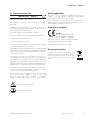 3
3
-
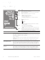 4
4
-
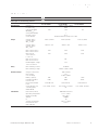 5
5
-
 6
6
-
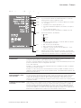 7
7
-
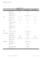 8
8
-
 9
9
-
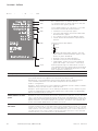 10
10
-
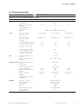 11
11
-
 12
12
-
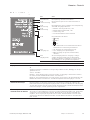 13
13
-
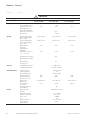 14
14
-
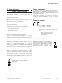 15
15
-
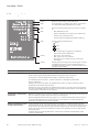 16
16
-
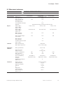 17
17
-
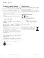 18
18
-
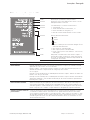 19
19
-
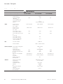 20
20
-
 21
21
-
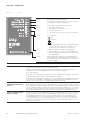 22
22
-
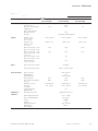 23
23
-
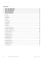 24
24
-
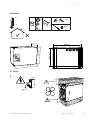 25
25
-
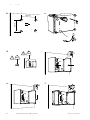 26
26
-
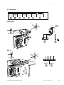 27
27
-
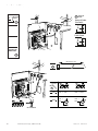 28
28
-
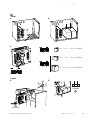 29
29
-
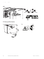 30
30
-
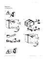 31
31
-
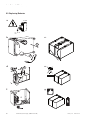 32
32
-
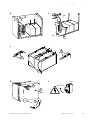 33
33
-
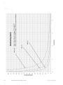 34
34
-
 35
35
-
 36
36


Eaton SPS-24V-4A5/BNS Installatie gids
- Type
- Installatie gids
- Deze handleiding is ook geschikt voor
in andere talen
- English: Eaton SPS-24V-4A5/BNS Installation guide
- italiano: Eaton SPS-24V-4A5/BNS Guida d'installazione
- français: Eaton SPS-24V-4A5/BNS Guide d'installation
- Deutsch: Eaton SPS-24V-4A5/BNS Installationsanleitung
- português: Eaton SPS-24V-4A5/BNS Guia de instalação
- polski: Eaton SPS-24V-4A5/BNS Instrukcja instalacji
Gerelateerde papieren
Andere documenten
-
Comelit ZSP100-2.5 A-18 Handleiding
-
Kensington 33403EU Handleiding
-
Philips AQ6345/00 Handleiding
-
GYS TIG 220 AC/DC de handleiding
-
ASO Safety Solutions ELMON SK 35 de handleiding
-
-
-
-
Silvercrest SPS 5000 A1 Operating Instructions Manual
-
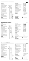 Vega VEGATRENN 149A Ex Handleiding
