Atlantic CHAUFFEO / CHAUFFEO PLUS 2019 Installation and User Manual
- Type
- Installation and User Manual

NOTICE
INSTALLATION
CHAUFFÉO-CHAUFFÉO+
Chaue-eau électrique
Electric water heater - Elektrische boiler
F
EN
NL
NOTICE D’UTILISATION
ET D’INSTALLATION
Installation and operating manual
Installatie- en gebruiksvoorschriften
À conserver par l’utilisateur
Manual must be kept by end user
Richtlijnen te bewaren door de gebruiker
Edition Octobre 2019
ATLANTIC EST UNE MARQUE FRANÇAISE
La sérénité s’installe chez vous

CHAUFFÉO-CHAUFFÉO+
Chaue-eau électrique
Nous vous remercions de votre choix et de votre
confiance. Les chaue-eau CHAUFFÉO et
CHAUFFÉO+ ont été soumis à de nombreux tests
et contrôles afin d’en assurer la qualité et ainsi vous
apporter une entière satisfaction.

Présentation du matériel ......................................2
Caractéristiques...............................................................................2
Les accessoires compatibles............................................................4
Installation .............................................................8
Mise en place du chauffe-eau........................................................8
Raccordement hydraulique ............................................................9
Raccordement électrique .............................................................11
Mise en service du chauffe-eau ..........................15
Remplissage du chauffe-eau........................................................15
Vérification du bon fonctionnement ..........................................15
Mise en service de la commande nomade.........16
Réglage de la molette ..................................................................16
Installation des piles sur la commande nomade.........................16
Procédure d'association avec le chauffe-eau..............................17
Réglage date et heure..................................................................18
Emplacement de la commande nomade.....................................20
Recommandations du GIFAM..............................22
Risques mécaniques......................................................................22
Risques électriques........................................................................22
Risques hydrauliques ....................................................................22
Manuel d’installation
Chauffe-eau
et commande digitale nomade
Sommaire
Manuel à conserver même après installation du produit.
Manuel installation FR.book Page 1 Mercredi, 23. décembre 2009 10:13 10
Avertissements Généraux
Cet appareil n’est pas prévu pour être utilisé par des personnes (y com-
pris les enfants) dont les capacités physiques, sensorielles ou mentales
sont réduites, ou des personnes dénuées d’expérience ou de connais-
sance, sauf si elles ont pu bénécier, par l’intermédiaire d’une personne
responsable de leur sécurité, d’une surveillance ou d’instructions pré-
alables concernant l’utilisation de l’appareil. Il convient de surveiller
les enfants pour s’assurer qu’ils ne jouent pas avec l’appareil. Cet
appareil peut être utilisé par des enfants âgés d’au moins 8 ans et par
des personnes ayant des capacités physiques, sensorielles ou mentales
réduites ou dénuées d’expérience ou de connaissance, s’ils (si elles) sont
correctement surveillé(e)s ou si des instructions relatives à l’utilisation de
l’appareil en toute sécurité leur ont été données et si les risques encourus
ont été appréhendés. Le nettoyage et l’entretien par l’usager ne doivent
pas être effectués par des enfants sans surveillance.
INSTALLATION
ATTENTION : Produit lourd à manipuler avec précaution.
• Installer l’appareil dans un local à l’abri du gel (4°C à 5°C minimum).
• La destruction de l’appareil par surpression due au blocage
de l’organe de sécurité est hors garantie.
• Prévoir une aération du local d’installation. La température de ce
local ne doit pas dépasser 35°C.
• Dans une salle de bain ne pas installer ce produit dans les volumes
V0, V1 et V2 (voir gures page 8).
Si les dimensions ne le permettent pas, ils peuvent néanmoins être
intallés dans le volume V2 ou le plus haut possible dans le volume V1
pour un horizontal.
• Ce produit est destiné pour être utilisé à une altitude maximale de
3000 m.
• Dans le cas d’un chauffe-eau vertical mural, s’assurer que la cloison
est capable de supporter le poids de l’appareil rempli d’eau.
• Laisser au-dessous des extrémités des tubes de l’appareil un espace
libre au moins égal à 300 mm (100 L) – 480 mm (150 L et 200 L) pour
pouvoir intervenir sur les équipements et accessoires.
RACCORDEMENT HYDRAULIQUE
Installer obligatoirement à l’abri du gel un organe de sécurité
Manuel à conserver même après installation
du produit.
FR
1

Présentation du matériel ......................................2
Caractéristiques...............................................................................2
Les accessoires compatibles............................................................4
Installation .............................................................8
Mise en place du chauffe-eau........................................................8
Raccordement hydraulique ............................................................9
Raccordement électrique .............................................................11
Mise en service du chauffe-eau ..........................15
Remplissage du chauffe-eau........................................................15
Vérification du bon fonctionnement ..........................................15
Mise en service de la commande nomade.........16
Réglage de la molette ..................................................................16
Installation des piles sur la commande nomade.........................16
Procédure d'association avec le chauffe-eau..............................17
Réglage date et heure..................................................................18
Emplacement de la commande nomade.....................................20
Recommandations du GIFAM..............................22
Risques mécaniques......................................................................22
Risques électriques........................................................................22
Risques hydrauliques ....................................................................22
Manuel d’installation
Chauffe-eau
et commande digitale nomade
Sommaire
Manuel à conserver même après installation du produit.
Manuel installation FR.book Page 1 Mercredi, 23. décembre 2009 10:13 10
Avertissements Généraux
(ou tout autre dispositif limiteur de pression), neuf, de dimensions
3/4’’ (20/27) et de pression 7 bar - 0,7 MPa sur l’entrée du chauffe-
eau, qui respectera les normes locales en vigueur.
•Un réducteur de pression (non fourni) est nécessaire lorsque la
pression d’alimentation est supérieure à 5 bar - 0,5 MPa. Il devra être
installé sur l’arrivée d’eau froide, après le compteur.
•Raccorder l’organe de sécurité à un tuyau de vidange, maintenu
à l’air libre, dans un environnement non soumis au gel (4°C à 5°C
mini), en pente continue vers le bas pour l’évacuation de l’eau
de dilatation de la chauffe ou en cas de vidange du chauffe-eau.
•Il est impératif d’installer un bac de rétention sous le chauffe-eau
lorsque celui-ci est positionné dans un faux plafond, des combles ou
au-dessus de locaux habités. Une évacuation raccordée à l’égout est
nécessaire.
RACCORDEMENT ÉLECTRIQUE
Avant tout démontage du capot, s’assurer que l’alimentation est
coupée pour éviter tout risque de blessure ou d’électrocution.
L’installation électrique doit comporter en amont du chauffe-eau
un dispositif de coupure omnipolaire (porte fusible, disjoncteur avec
une distance d’ouverture des contacts d’au moins 3 mm, disjoncteur
différentiel de 30 mA).
La mise à la terre est obligatoire. Une borne spéciale portant le repère
est prévue à cet effet.
ENTRETIEN
•Ledispositifdevidangedugroupedesécuritédoitêtremisenfonction-
nement périodiquement (au moins une fois par mois). Cette
manœuvre permet d’évacuer d’éventuels dépôts de tartre et de
vérier qu’il ne soit pas bloqué.
•Pour vidanger l’appareil, couper le courant, fermer l’alimentation
d’eau froide, puis vidanger grâce à la manette du groupe de sécurité
en ayant ouvert un robinet d’eau chaude.
•Silecâbled’alimentationestendommagé,ildoitêtreremplacépar
le fabricant, son service après-vente ou des personnes de qualica-
tion similaire an d’éviter un danger.
La notice d’utilisation de cet appareil est disponible en contactant le
service après-vente.
2

Présentation du matériel ......................................2
Caractéristiques...............................................................................2
Les accessoires compatibles............................................................4
Installation .............................................................8
Mise en place du chauffe-eau........................................................8
Raccordement hydraulique ............................................................9
Raccordement électrique .............................................................11
Mise en service du chauffe-eau ..........................15
Remplissage du chauffe-eau........................................................15
Vérification du bon fonctionnement ..........................................15
Mise en service de la commande nomade.........16
Réglage de la molette ..................................................................16
Installation des piles sur la commande nomade.........................16
Procédure d'association avec le chauffe-eau..............................17
Réglage date et heure..................................................................18
Emplacement de la commande nomade.....................................20
Recommandations du GIFAM..............................22
Risques mécaniques......................................................................22
Risques électriques........................................................................22
Risques hydrauliques ....................................................................22
Manuel d’installation
Chauffe-eau
et commande digitale nomade
Sommaire
Manuel à conserver même après installation du produit.
Manuel installation FR.book Page 1 Mercredi, 23. décembre 2009 10:13 10
Manuel d’installation
et d’entretien
Chauffe-eau
3
FR
Sommaire
Installation
Avant de commencer .............................................4
Contenu du colis ...................................................................... 4
Accessoires à prévoir ................................................................ 4
Outillage nécessaire ................................................................ 5
Main d’œuvre .......................................................................... 5
Schéma général d’installation .............................. 6
Où installer mon chauffe-eau ...............................8
Précautions .............................................................................. 8
Installation spécique en salle de bain .................................. 8
Comment installer mon chauffe-eau ...................9
Chauffe-eau vertical mural ..................................................... 9
Chauffe-eau vertical sur socle .............................................. 10
Chauffe-eau horizontal mural - Raccordement dessous ...... 10
Chauffe-eau horizontal mural - Raccordement côté ........... 11
Raccordement hydraulique du chauffe-eau ......12
Le raccordement classique .................................................... 12
Le raccordement avec limiteur de température .................. 12
Le raccordement avec un réducteur de pression ................ 13
Le remplissage du chauffe-eau ............................................ 13
Raccordement électrique du chauffe-eau .......... 14
Mise en service du chauffe-eau ..........................14
Conseils d’entretien domestique .......................15
Le groupe de sécurité ........................................................... 15
Vidange d’un chauffe-eau .................................................... 15
Entretien de la cuve .............................................................. 16
Champ d’application de la garantie ...................16
Conditions de garantie ........................................17

FR
4
1. Avant de commencer
1.1. Contenu du colis
Votre colis comprend :
1.2. Accessoires à prévoir
1.2.1. Les accessoires obligatoires et conseillés
Pour l’installation de votre chauffe-eau, vous devez prévoir les éléments suivants :
Groupe
de sécurité NEUF
Obligatoire
Siphon
Obligatoire
Limiteur
de température
Obligatoire en neuf
et rénovations lourdes
Bac de récupération
d’eau
Impératif dans le cas d’une
installation à l’étage et au-
dessus d’un local habité
Emballage avec
gabarit de pose
1 ou 2
étriers
Votre chauffe-eau
(exemple : un vertical mural)
Emballage
avec gabarit de pose
Votre chauffe-eau
(exemple : un vertical mural)
Sortie
eaux usées
Sortie de câble murale
Ruban d’étanchéité
ou autre
Réducteur
de pression
Obligatoire si la pression
d’eau de votre habitation est
supérieure à 5 bar (0,5 MPa).
Il doit être installé à la sortie
du compteur. (voir page 13)
Manuel d’installation : Préparation
easyFIX pour modèles verticaux
muraux stéatite
50 L non disponible
75 à 100 litres 1
150 à 200 litres 2
Raccord diélectrique
modèles Blindés modèles Stéatite
Raccord di-électrique

FR
5
FR
1.2.2. Les accessoires optionnels
1.3. Outillage nécessaire
1.4. Main d’œuvre
3
2
1
2 personnes
pour le montage
1
2
2 heures
ECHELLE 1,000
È
Capacité Nombre de plaques
50 à 100 litres 1
150 à 200 litres 2
Console d’accrochage
plafond
Idéale pour xer les chauffe-
eau verticaux muraux
au plafond, quand le mur
est non porteur.
Libère de l’espace sous
le chauffe-eau.
Plaques de xation
rapides
Idéales pour les recoins
exigus comme un placard,
où il n’y a pas d’accès
pour le serrage au mur.
Gain de temps à la pose.
Pattes de xation
universelles
Idéales pour réutiliser
les xations de votre ancien
chauffe-eau sans trous
supplémentaires.
Gain de temps à la pose.
Réhausse
Idéale pour éviter les modi-
cations d’évacuation, pour
les chauffe-eau verticaux
sur socle.
Position conseill
é
e de la r
é
hausse
NOTICE ASSEMBLAGE REHAUSSE
Fournitures:
- 3 entretoises ref. : 112-10-018
- 3 pieds ref. : 112-10-024
- 3 entretoises ref. : 112-10-019
- 12 vis H M8x20 ref. : 112-40-017
- 12 écrous H M8 à embases crantées ref. : 112-40-008
Pour chauffe-eau vertical sur socle (VS)
capacité 150 à 300 litres
Code commercial: 009092
Montage conseillé
Entretoises :
ailes vers l'extérieur
Vis H M8x20
112-10-025D
Pour tous renseignements ou coordonnées,
veuillez consulter la notice du chauffe-eau.
Renseignements techniques - Garanties - Pièces Détachées :
Service clients / SAT C
BP 65 - 85002 La Roche sur Yon Cedex
International : consulter votre installateur
Sortie de câble murale
Ruban d’étanchéité
ou autre
Réducteur
de pression
Obligatoire si la pression
d’eau de votre habitation est
supérieure à 5 bar (0,5 MPa).
Il doit être installé à la sortie
du compteur. (voir page 13)
Manuel d’installation : Préparation
A
LL
Système de xation
(Ø 10 mm mini)
(Selon support)
Kit de cerclage pour mo-
dèles horizontaux muraux
- Raccordement dessous
Obligatoire pour la xation
au plafond.
Peut être utilisé pour reprendre
les xations d’un ancien appareil.
Permet de faire glisser l’appareil de
quelques centimètres lors
de la mise en place
Trépied
Pour les modèles verticaux muraux.
Obligatoire sur les murs non porteurs
et recommandé pour les chauffe-eau
supérieurs à 100 L

FR
6
Groupe
de sécurité
Sortie
eau chaude
Arrivée
eau froide
Siphon
Raccord
di-électrique
Limiteur
de température
Phase
Terre
Neutre
Eau froide
Eau chaude
È
È
Tableau électrique
Disjoncteur 16A,
contacteur jour/nuit
et différentiel 30mA
Robinet dans une salle de bain
par exemple
ATTENTION
Si votre tuyauterie n’est pas
en cuivre (PER , multicouche...),
il est OBLIGATOIRE d’installer
une canalisation en cuivre d’une
longueur minimale de 50 cm
(DTU.60.1) et/ou un limiteur de
température en sortie eau chaude
de votre ballon (voir p. 12).
PRECAUTIONS D’INSTALLATION :
• Température du lieu d’installation
comprise entre 4°C et 35°C
• Positionner le chauffe-eau le plus
près possible des salles d’eau
• Si le chauffe-eau est installé
au-dessus d’un local habité,
mettre un bac de récupération d’eau
Manuel d’installation : Schéma de montage global

FR
7
FR
Évacuation
eaux usées
(égouts)
Arrivée d’eau
réseau
Compteur d’eau
Robinet général
d’arrivée d’eau froide
Réducteur
de pression
Groupe
de sécurité
È
È
00 0 0 0 0 0
Groupe de sécurité
Le groupe de sécurité est un accessoire obligatoire.
Son rôle est de maintenir à l’intérieur du chauffe-
eau une pression inférieure à 7 bar (0,7 MPa)
pour éviter l’explosion de celui-ci
(il remplit donc
le même
rôle qu’une soupape sur une cocotte
minute).
Le groupe de sécurité laisse donc s’échapper
de l’eau lorsque le chauffe-eau est en fonctionne-
ment. Cet écoulement peut représenter jusqu’à 3%
du volume du chauffe eau par cycle de chauffe.
Attention : le groupe de sécurité doit toujours
être raccordé directement à l’entrée eau froide
du ballon. Rien ne doit être installé entre
le groupe de sécurité et le chauffe eau. (aucune
vanne , pas de réducteur de pression …).
Réducteur de pression
Le réducteur de pression est un accessoire
supplémentaire qui doit être installé à la sortie
de votre compteur d’eau si la pression d’eau
de votre habitation s’avère supérieure à 5 bar (0,5 MPa).
Il évitera que la soupape
du groupe de sécurité
ne s’ouvre de manière
intempestive lorsque le
chauffe-eau n’est pas en
fonctionnement.
Pour connaître la pression
d’eau dans votre habitation
vous pouvez vous rensei-
gner auprès de votre four-
nisseur d’eau.
Attention : le réducteur de pression ne doit
jamais être placé entre le groupe de sécurité
et la cuve du chauffe eau
Schéma général d’installation
Exemple avec un chauffe-eau vertical mural
Manuel d’installation : Schéma de montage global

FR
8
2. Où installer mon chauffe-eau ?
2.1 Précautions
•Choisirunlieud’installationdontlatempératureseratoujourscompriseentre4°Cet35°C.
•Le chauffe-eau doit être positionné le plus près possible des points de puisages importants
(salle de bains, cuisine…).
•S’il est placé en dehors du volume habitable (cellier, garage), les tuyauteries et les organes
de sécurité (groupe de securité, réducteur de pression) doivent être isolés.
•Prévoir une aération dans le local an d’éviter les phénomènes de condensation et de corrosion
de la peinture du chauffe-eau.
•S’assurerquel’élémentsupport(murouplafond)estsufsammentrésistantpourrecevoirlepoids
du chauffe-eau plein d’eau (voir tableau p. 9).
•Prévoir en face de chaque équipement électrique un espace sufsant de 40 cm pour l’entretien
périodique de l’élément chauffant.
•En cas d’installation au-dessus de locaux habités (faux-plafond,
combles...), il est IMPÉRATIF de prévoir un bac de récupération d’eau
raccordé à l’égout sous le chauffe-eau (type bac à douche
par exemple).
2.2 Installation spécique en salle de bain
•Installationhorsvolumes(NFC15-100).
Si les dimensions de la salle de bain ne permettent pas de placer le chauffe-eau hors volumes :
0,60 m
0,60 m
0,60 m
Volume
1
Volume
2
0,60 m
0,60 m
0,60 m
Volume
1
Volume
2
0,60 m
0,60 m
0,60 m
Volume
1
Volume
2
Possible dans le Volume 2
Possible dans le Volume 1 si :
- le chauffe-eau est horizontal et placé le plus
haut possible
- les canalisations sont en matériau conducteur
- le chauffe-eau est protégé par un disjoncteur
de courant différentiel résiduel (30mA) branché
en amont du chauffe-eau
Manuel d’installation : Lieu d’installation
Volume
0
Volume
0
Volume
0

FR
9
FR
Gabarit de pose
45 cm
minimum
(Sur carton d'emballage)
Gabarit de pose
45 cm
minimum
(Sur cartond'emballage)
Poids indicatif
du chauffe-eau
rempli
Capacité Poids
50 L 75 kg
75 L 100 kg
100 L 150 kg
150 L 200 kg
200 L 250 kg
3. Comment installer mon chauffe-eau ?
3.1 Chauffe-eau vertical mural
u
Découper le gabarit imprimé sur le carton
et l’utiliser pour faire les marquages.
v
Percer puis cheviller en utilisant des xa-
tions de diamètre (Ø) 10 mm minimum adaptées
à votre mur (plaque de plâtre, béton, brique).
Attention : votre mur doit pouvoir supporter le poids
du chauffe-eau rempli.
Dans le cas contraire, utiliser un trépied (voir para
graphe sur le cas particulier de pose sur trépied).
w
Une fois votre chauffe-eau ou easyFIX mis en place,
xer fermement
.
on
Gabarit
de pose
Gabarit de pose
45 cm
minimum
(Sur carton d'emballage)
Gabarit de pose
45 cm
minimum
(Sur cartond'emballage)
Poids indicatif
du chauffe-eau
rempli
Capacité Poids
50 L 75 kg
75 L 100 kg
100 L 150 kg
150 L 200 kg
200 L 250 kg
Gabarit de pose
45 cm
minimum
(Sur carton d'emballage)
Gabarit de pose
45 cm
minimum
(Sur cartond'emballage)
Poids indicatif
du chauffe-eau
rempli
Capacité Poids
50 L 75 kg
75 L 100 kg
100 L 150 kg
150 L 200 kg
200 L 250 kg
Manuel d’installation : Pose du chauffe-eau
Sans easyFIX.
OK
440 mm
M10
5
couple de serrage : 29Nm maxi
Avec easyFIX
pour les modèles verticaux muraux stéatite 75 L à 200 L.

FR
10
Cas particulier :
Pose d’un chauffe-eau vertical mural sur trépied
L’utilisation d’un trépied est obligatoire pour la pose d’un chauffe-
eau d’une capacité supérieure à 100 L sur un mur non porteur (ne
pouvant pas supporter le poids du ballon rempli).
Poser le chauffe-eau d’abord sur son trépied pour marquer les
points de xation.
Réaliser les perçages.
Réinstaller le chauffe-eau à sa place.
3.2 Chauffe-eau vertical sur socle
La pose d’un chauffe-eau vertical sur socle (fig. u)
ne nécessite aucune xation.
Veiller à l’installer sur une surface plane.
Vous pouvez utiliser une réhausse (fig. v) pour faciliter
le passage des tuyauteries.
3.3 Chauffe-eau horizontal mural - Raccordement dessous
La pose d’un chauffe-eau horizontal peut se faire au mur, au plafond ou sur le sol.
Laisser un espace libre de 400 mm au-dessous du capot pour l’éventuel échange de l’élément chauffant.
L’entrée eau froide et la sortie eau chaude doivent toujours être en bas.
Manuel d’installation : Pose du chauffe-eau
v
u
È
È
È
È
È
È
A
R
R-
M
U
R
BA
C
K-
WALL
A
RR-M
U
R
BA
C
K
-WA
LL
AR
R
-
M
UR
B
A
C
K
-
W
ALL
ARR-M
U
R
B
ACK
-
WA
LL
Fixer l’étrier supérieur.

FR
11
FR
Manuel d’installation : Pose du chauffe-eau
Procédure d’accrochage :
- Assembler les ceintures et les étriers à l’aide de la visserie
jointe dans l’emballage sans les serrer (gs. 1 et 2).
- Mettre en place les étriers avec leur ceinture sur le support
(mur, plafond, sol), puis serrer.
- Positionner le chauffe-eau en respectant l’une.
des 4 possibilités d’accrochage.
- Terminer la xation en bloquant les écrous de la ceinture
sur l’étrier.
x 2
gure 1 gure 2
PLAFOND
SOL
MUR
Impératif :
Aligner les piquages verticalement avec la sortie eau chaude (rouge) au-dessus
de l’eau froide (bleu).
3.4 Chauffe-eau horizontal mural - Raccordement côté

FR
12
Manuel d’installation : Raccordement hydraulique
4. Raccordement hydraulique du chauffe-eau
Le chauffe-eau devra être raccordé conformément aux normes et à la réglementation en vigueur
dans le pays où il sera installé (pour la France : DTU Plomberie 60-1).
4.1 Le raccordement classique
u
Effectuer le branchement du groupe de sécurité NEUF sur l’entrée d’eau froide (bleue) de votre
chauffe-eau.
v
Placer le siphon sous le groupe de sécurité et relier son évacuation vers l’égout.
w
Visser le raccord diélectrique sur la sortie d’eau chaude (rouge) de votre chauffe-eau.
x
Procéder au raccordement de votre tuyauterie sur votre chauffe-eau.
4.2 Le raccordement avec un limiteur de température
Évacuation
eaux usées
Limiteur
Raccord
diélectrique
Siphon
Groupe
de sécurité
de température
OBLIGATOIRE
Eau froide
Eau chaude
Eau mitigée
En neuf et rénovation lourde
(arrêté du 30/11/2005)
IMPÉRATIF
Pour les tuyauteries en PER
Branchement eau chaude Branchement eau froide
Raccord
di-électrique
Groupe de
sécurité NEUF
Téon à
appliquer
dans le sens
de vissage
OBLIGATOIRE OBLIGATOIRE
Siphon
u
v
w
ATTENTION
Vos tuyauteries doivent être rigides (cuivre) ou souples (exibles tressés en inox normalisés)
et supporter 100°C et 10 bar (1 MPa). Sinon, utilisez un limiteur de température.
doit supporter
100° C et 10 bar
Si vos tuyauteries sont en matériaux de synthèse
(plastique ou PER par exemple), il est impératif
d’installer un limiteur de température (ou régula-
teur thermostatique).
Le limiteur ne doit jamais être raccordé directement
au chauffe-eau.
Le limiteur de température permet de limiter
les risques de brûlure.

FR
13
FR
4.3 Le raccordement avec un réducteur de pression
Le réducteur de pression est obligatoire si la pression d'eau de votre habitation s'avère supérieure
à 5 bar (0,5 MPa).
Le placer sur l'arrivée d'eau froide, à la sortie de votre compteur d'eau, jamais directement au chauffe-eau.
4.4 Remplissage du chauffe-eau
u
Ouvrir les robinets d’eau CHAUDE du logement.
v
Ouvrir la vanne d’arrivée d’eau froide
située sur le groupe de sécurité.
w
Le chauffe-eau est rempli dès que vous
observerez un écoulement d’eau froide
à la sortie des robinets d’eau chaude.
Fermez ces derniers.
x
Vérier le bon fonctionnement du groupe
de sécurité en manipulant le robinet
de vidange. Un peu d’eau doit s’écouler.
y
Vérier l’étanchéité au niveau des sortie
et entrée d’eau sur le chauffe-eau.
Si vous constatez une fuite, essayez de resserrer les raccords.
Si la fuite persiste, procédez à la vidange du chauffe-eau (voir page 15) et refaites les raccords.
Recommencez l’opération jusqu’à avoir une étanchéité totale.
Remplissage :
10 Litres
par minute
Eau chaude Eau froide
NON
Piquage
eau froide
Arrivée
eau froide
du réseau
Évacuation
des eaux
usées
Réducteur
de pression
NON
Groupe de sécurité
Piquage
eau froide
Arrivée
eau froide
du réseau
Piquage
eau froide
Arrivée
eau froide
du réseau
OUI
Le réducteur
de pression ne doit
pas être raccordé
directement sur le
chauffe-eau
Évacuation
eaux usées
(égouts)
Arrivée d’eau
réseau
Compteur d’eau
Robinet général
d’arrivée d’eau froide
Réducteur
de pression
Groupe
de sécurité
È
È
00 0 000 0
Schéma général d’installation
Exemple avec un chauffe-eau vertical mural
Sortie
eau chaude
Arrivée
eau froide
Siphon
Raccord
di-électrique
Limiteur
de température
Phase
Terre
Neutre
Eau froide
Eau chaude
È
È
Tableau électrique
Disjoncteur 16A
et contacteur jour/nuit
Robinet dans une salle de bain
par exemple
Arrivée d’eau
réseau
È
u
Ouvrir les robinets d’eau CHAUDE du logement.
v
Ouvrir la vanne d’arrivée d’eau froide située sur le groupe
de sécurité.
w
Le chauffe-eau sera rempli dès que vous observerez un
écoulement d’eau froide à la sortie des robinets d’eau chaude.
Fermez ces derniers.
x
Vérier le bon fonctionnement du groupe de sécurité
en manipulant le robinet de vidange. Un peu d’eau doit
s’écouler.
y
Vérier l’étanchéité au niveau des sortie et entrée d’eau
sur le chauffe-eau.
Manuel d’installation : Raccordement hydraulique
Limiteur
Raccord
diélectrique
Siphon
Groupe
de sécurité
de température
OBLIGATOIRE
Eau froide
Eau chaude
Eau mitigée
En neuf et rénovation lourde
(arrêté du 30/11/2005)
IMPÉRATIF
Pour les tuyauteries en PER

FR
14
Manuel d’installation : Raccordement électrique et Mise en service
5. Raccordement électrique du chauffe-eau
u
S’assurer de la compatibilité du chauffe-eau avec l’installation
électrique.
v
Si le chauffe-eau est pré-câblé, raccorder le câble d’alimen-
tation du chauffe-eau à une sortie de câble (le chauffe-eau
ne doit pas être raccordé à une prise).
Si le chauffe-eau n’est pas pré-câblé, l’utilisation d’une liaison
en câbles rigides de section minimum 3 x 2,5 mm
2
en monophasé (phase, neutre, terre) ou 4 x 2,5 mm
2
en triphasé (3 phases + terre) est impérative (se reporter au
paragraphe «Schémas électriques»).
w
Vérier que le chauffe-eau est rempli en ouvrant un robinet
d’eau CHAUDE. De l’eau FROIDE doit s’écouler.
Si le chauffe-eau est alimenté alors qu’il est vide, vous risquez
de l’endommager (non couvert par la garantie).
x
Remettre le courant.
y
Un raccordement en direct sur les résistances (sans passer
par le thermostat) est formellement interdit car il est extrême-
ment dangereux,la température de l’eau n’étant plus limitée.
6. Mise en service du chauffe-eau
u
Si votre tableau électrique est équipé d’un contacteur
jour/nuit (tarif réduit la nuit), le positionner sur 1 (marche
forcée)
v
Un léger dégagement de fumée peut apparaître pendant
le début de la chauffe (fonctionnement NORMAL).
Après un moment, de l’eau doit s’écouler goutte à goutte
par le groupe de sécurité (raccordé à une évacuation des eaux usées).
Pendant la chauffe et suivant la qualité de l’eau, le chauffe-
eau peut émettre un léger bruit analogue à celui d’une
bouilloire. Ce bruit est normal et ne traduit aucun défaut.
w
Attendre la n de la chauffe pour pouvoir utiliser pleinement
votre chauffe-eau (voir tableau des caractéristiques
pour connaître le temps estimé selon votre modèle).
1
0
AUTO
1
0
AUTO
1
0
AUTO
1
0
AUTO
1
0
AUTO
1
0
AUTO
1
0
AUTO
1
0
AUTO
1
0
AUTO
1
0
AUTO
1
0
AUTO
1
0
AUTO
COUPER LE
COURANT !
NON
OUI
Sortie
de câble
1
2
3
4
5
6
7
8
MAXI
Temps
de chauffe
MAXI = 8 heures
1
2
3
4
5
6
7
8
MAXI
Temps
de chauffe
MAXI = 8 heures
Eau
chaude
Eau
froide

FR
15
FR
7. Conseils d’entretien domestique
Pour conserver les performances de votre chauffe-eau pendant de longues années, il est nécessaire
de faire procéder à un contrôle des équipements par un professionnel tous les 2 ans.
7.1 Le groupe de sécurité
Manœuvrez régulièrement (au moins une fois par mois),
la soupape du groupe de sécurité.
Cette manipulation permet d’évacuer les éventuels
dépôts pouvant obstruer le groupe de sécurité.
Le non-entretien du groupe de sécurité peut entraîner
une détérioration du chauffe-eau (non couvert par la garantie).
7.2 Vidange d’un chauffe-eau
Si le chauffe-eau doit rester sans fonctionner pendant plus d’une semaine (dans une habitation secondaire
par
exemple), et s’il se trouve dans un lieu soumis au gel, il est indispensable de vidanger le chauffe-eau an
de le protéger contre la corrosion.
Une fois le chauffe-eau vidangé, purger l’ensemble de la tuyauterie de votre habitation (ouvrir
l’ensemble
des robinets d’eau froide et d’eau chaude de l’habitation an que tous les tuyaux soient vidés).
1
0
AUTO
1
0
AUTO
1
0
AUTO
COUPER LE
COURANT !
Remplissage :
10 Litres
par minute
u Couper le courant.
v Fermer votre robinet général d’arrivée d’eau froide.
w Ouvrir la molette de la soupape de sécurité ( ¼ de tour).
x Ouvrir les robinets d’eau CHAUDE de manière à faire
un appel d’air.
y Le chauffe-eau est vide lorsque l’eau s’arrête de couler
au groupe de sécurité.
La vidange peut prendre jusqu’à 1h30 ou plus.
z À votre retour, suivre les étapes du paragraphe 6
de «mise en service» (page 14) pour remettre votre
chauffe-eau en marche.
Manœuvrer régulièrement (au moins une fois par mois), la soupape
du groupe de sécurité.
Cette manipulation permet d’évacuer les éventuels dépôts
pouvant obstruer le groupe de sécurité.
Le non-entretien du groupe de sécurité peut entraîner
une détérioration du chauffe-eau (non couvert par la garantie).
1
0
AUTO
1
0
AUTO
1
0
AUTO
Manuel d’installation : Conseils d’entretien

FR
16
7.3 Entretien de la cuve
Vérier l’état de l’anode magnésium tous les deux ans et remplacer celle-ci si son diamètre est inférieur à
10 mm (pour les modèles ACI, l’anode ne nécessite aucun entretien). Un entretien de la cuve par un profession-
nel est fortement conseillé tous les 2 - 3 ans en fonction de la qualité de l’eau : vidange et détartrage.
Dans les régions où l’eau est calcaire, il est possible de traiter l’eau avec un adoucisseur. Ce dernier
doit être bien réglé et la dureté de l’eau doit rester supérieure à 15°f.
L’utilisation d’un adoucisseur n’entraîne pas de dérogation à notre garantie, sous réserve que celui-ci
soit bien réglé, agréé CSTB pour la France, vérié et entretenu régulièrement.
Ne jetez pas votre appareil avec les ordures ménagères, mais déposez-le à un endroit assigné
à cet effet (point de collecte) où il pourra être recyclé.
8. Champ d’application de la garantie
Sont exclues de cette garantie les défaillances dues à :
8.1 Des conditions d’environnement anormales
• Dégâtsdiversprovoquéspardeschocsoudeschutesaucoursdesmanipulationsaprèsledépartd’usine.
•Positionnementdel’appareil dansunendroit soumisaugel ouauxintempéries (ambianceshumides,
agressives ou mal ventilées).
• Utilisationd’uneeauprésentantdescritèresd’agressivitételsqueceuxdénisparleDTUPlomberie60-1
additif 4 eau chaude (taux de chlorures, sulfates, calcium, résistivité et TAC).
• Duretédel’eau<15°f.
• Nonrespectdesnormes(NFEN50160)deréseauélectrique(alimentationélectriqueprésentantdesmini
ou maxi de tension, des fréquences non conformes par exemple).
• Dégâtsrésultantdeproblèmesnondécelablesenraisonduchoixdel’emplacement(endroitsdifcilement
accessibles) et qui auraient pu être évités par une réparation immédiate de l’appareil.
8.2 Une installation non conforme à la réglementation, aux normes et aux règles de l’art
• Absence ou montage incorrect d’un groupe de sécurité neuf et conforme à la norme EN 1487,
ou modication de son réglage...
• Miseenplacedirectementsurlechauffe-eaud’unsystèmehydrauliqueempêchantlefonctionnement
du groupe de sécurité (réduction de pression, robinet d’arrêt...) (voir page 13).
• Corrosionanormaledespiquages(eauchaudeoueaufroide)suiteàunraccordementhydrauliqueincor-
rect (mauvaise étanchéité) ou absence de manchons diélectriques (contact direct fer-cuivre).
• Raccordementélectriquedéfectueux:nonconformeàlanormeNFC15-100ouauxnormesenvigueur
dans le pays, mise à la terre incorrecte, section de câble insufsante, raccordement en câbles souples, non
respect des schémas de raccordements prescrits par le constructeur.
• Positionnementdel’appareilnonconformeauxconsignesdelanotice.
• Corrosionexternesuiteàunemauvaiseétanchéitésurlatuyauterie.
• Absenceoumontageincorrectducapotdeprotectionélectrique.
• Absenceoumontageincorrectdupassagedecâble.
•Chuted’unappareilsuiteàl’utilisationdexationsnonadaptéesausupportd’installation.
8.3 Un entretien défectueux
• Entartrageanormaldesélémentschauffantsoudesorganesdesécurité.
• Nonentretiendugroupedesécuritésetraduisantpardessurpressions.
• Modication du produit d’origine sans avis du constructeur ou utilisation de pièces détachées non
référencées par celui-ci.
• Nonrespectdesconditionsd’entretiendel’anodemagnésium(voirparagraphe«Entretiendelacuve).
Manuel d’installation : Champ d’application de la garantie
Ces appareils sont conformes aux directives 2014/30/UE concernant la comptabilité électromagnétique,
2014/35/UE concernant la basse tension, 2011/65/UE concernant la ROHS et au règlement 2013/814/UE com-
plétant la directive 2009/125/EC pour l’écoconception.

FR
17
FR
Manuel d’installation : Conditions de garantie
9. Conditions de garantie
Le chauffe-eau doit être installé par un professionnel ou une personne qualiée conformément aux règles
de l’art, aux normes en vigueur et aux prescriptions de nos notices techniques. Il sera utilisé normalement et
régulièrement entretenu par un spécialiste.
Dans ces conditions, notre garantie s’exerce par échange ou fourniture gratuite à notre distributeur des pièces
reconnues défectueuses d’origine par nos services, ou le cas échéant de l’appareil, à l’exclusion des frais de
main-d’œuvre et de transport ainsi que de toutes indemnités et prolongation de garantie.
Notre garantie prend effet à compter de la date de pose (facture d’installation ou d’achat faisant foi). En
l’absence de justicatif, la date de prise en compte sera celle de fabrication indiquée sur la plaque signalétique
du chauffe-eau, majorée de six mois.
La garantie de la pièce ou du chauffe-eau de remplacement (sous garantie) cesse en même temps que celle de
la pièce ou du chauffe-eau remplacé (premier matériel facturé).
Les dispositions des présentes conditions de garantie ne sont pas exclusives du bénéce au prot de l’acheteur,
de la garantie légale pour défauts et vices cachés qui s’appliquent en tout état de cause dans les conditions des
articles 1641 et suivants du code civil.
La défaillance d’une pièce ne justie en aucun cas le remplacement de l’appareil. Atlantic tient à votre dispo-
sition l’ensemble des pièces détachées pendant une durée de 7 ans.
Un appareil présumé à l’origine d’un sinistre doit rester sur place à la disposition des
experts, le sinistré doit informer son assureur.

FR
18
Manuel d’installation
et d’entretien
Chauffe-eau
Sommaire
Caractéristiques Techniques
Caractéristiques techniques ................................19
Chauffe-eau verticaux muraux (VM) .................................... 19
Chauffe-eau verticaux sur socle (VS) .................................... 21
Chauffe-eau horizontaux (HM) raccordement dessous ....... 22
Chauffe-eau horizontaux (HM) raccordement coté ............. 23
Présentation des composants ............................. 24
Modèles verticaux muraux Blindés ...................................... 24
Modèles verticaux muraux Stéatite ..................................... 24
Modèles verticaux sur socle Blindés ..................................... 24
Modèles stables Stéatite ....................................................... 25
Modèles horizontaux Blindés ............................................... 25
Procédures d’installations spéciques ..............25
Réglage de la température ................................................... 25
Conditions d’entretien spéciques ...................25
Pièces pouvant être remplacées ........................................... 25
Aide au dépannage ..............................................26
Pas d’eau chaude ................................................................... 26
Compteur électrique qui disjoncte ....................................... 27
Eau tiède ................................................................................ 27
Problème de fuite ................................................................. 28
Bruit de bouillonnement ...................................................... 28
Eau trop chaude .................................................................... 28

FR
19
I. Caractéristiques techniques
I.1 Chauffe-eau verticaux muraux (VM)
* Appareils livrés câblés en triphasé 230/400V3~ commutables en monophasé 230V~
**Temps de chauffe réel pour chauffage de 15° à 65°C
***Consommation d’entretien en kWh pour 24 heures pour de l’eau à 65°C (ambiance 20°C)
Votre chauffe-eau : Caractéristiques techniques
50 litres 75 litres 100 litres
Tension (V) 230 V monophasé
Résistance Blindée Stéatite Blindée Stéatite Blindée Stéatite
Puissance (W) 1 200 1 200 1 200 1 200 1 200 1 200
Dimensions
(mm)
Ø 505 505 510 510 505 510
H 575 575 700 700 910 865
A 370 370 575 575 750
750
B / / / / /
-
C 530 530 530 530 530 530
Temps de chauffe réel**
2h26 2h46 4h10 4h10 5h29 5h46
Qpr (Consommation
entretien)***
0,71 0,79 1,00 1,00 1,24 1,33
V40 (Quantité d’eau
chaude à 40°C)
- - 141 141 179 192
Poids à vide (kg) 23 23 26 26 32 30
Poids rempli (kg) 73 73 101 101 130 130
150 litres 200 litres 200 litres
Tension (V) 230 V monophasé Tous courants*
Résistance Blindée Stéatite Blindée Stéatite Blindée
Puissance (W) 1 650 1 800 2 200 2 200 2 200
Dimensions
(mm)
Ø 530 530 530 530 530
H 1 165 1 165 1 480 1 480 1 480
A 1 050 1 050 1 050 1 050 1 050
B 800 800 800 800 800
C 550 550 550 550 550
Temps de chauffe réel**
5h33 5h33 5h17 5h17 5h17
Qpr (Consommation
entretien)***
1,48 1,48 1,73 1,73 1,73
V40 (Quantité d’eau
chaude à 40°C)
279 279 382 382 382
Poids à vide (kg) 38 38 46 46 46
Poids rempli (kg) 188 188 246 246 246

FR
20
Votre chauffe-eau : Caractéristiques techniques
100 litres
compact
150 litres
compact
200 litres
compact
Tension (V) 230 V monophasé
Résistance Blindée
Puissance (W) 1 200 1 650 2 200
Dimensions
(mm)
Ø 570 570 570
H 735 1 000 1 250
A 600 760 1 050
B / 500 800
C 590 590 590
Temps de chauffe réel* 5h32 5h38 5h33
Qpr (Conso. entretien)** 1,024 1,37 1,67
V40 (Quantité d’eau
chaude à 40°C)
175 266 359
Poids à vide (kg) 31 41 50
Poids rempli (kg) 131 191 250
Représentation schématique
*Temps de chauffe réel pour chauffage de 15° à 65°C
**Consommation d’entretien en kWh pour 24 heures pour de l’eau à 65°C (ambiance 20°C)
È
È
Sortie eau chaude
Arrivée eau froide

FR
21
Votre chauffe-eau : Caractéristiques techniques
I.2 Chauffe-eau verticaux sur socle(VS)
Sortie eau
chaude
Arrivée
eau froide
150 l 200 litres
250 litres 300 litres
Tension (V) 230 V monophasé
Résistance Blindée Blindée Stéatite Blindée Stéatite Blindée Stéatite
Puissance (W) 1 650 2 200 2 200 3 000 3 000 3 000 3 000
Dimensions
(mm)
Ø 530 530 530 530 530 570 570
H 1 170 1 485 1 485 1 805 1 805 1 765 1 765
A 300 300 300 300 300 300 300
B 600 600 600 600 600 640 640
Temps de chauffe réel**
4h46 4h41 4h57 4h40 4h55 5h53 5h37
Qpr (Consommation
entretien)***
1,53 1,45 1,88 2,15 2,22 2,58 2,49
V40 (Quantité d’eau
chaude à 40°C)
259 358 354 477 465 569 531
Poids à vide (kg) 37 43 43 57 58 65 68
Poids rempli (kg) 187 243 243 307 308 365 368
200 l 250 l 300 l
Tension (V) Tous courants*
Résistance Blindée Blindée Blindée
Puissance (W) 2 200 3 000 3 000
Dimensions
(mm)
Ø 530 530 570
H 1 485 1 805 1 765
A 300 300 300
B 600 600 640
Temps de chauffe réel**
4h41 4h40 5h53
Qpr (Consommation
entretien)***
1,45 2,15 2,58
V40 (Quantité d’eau
chaude à 40°C)
358 477 569
Poids à vide (kg) 44 57 68
Poids rempli (kg) 244 307 368
* Appareils livrés câblés en triphasé 230/400V3~ commutables en monophasé 230V~
**Temps de chauffe réel pour chauffage de 15° à 65°C
***Consommation d’entretien en kWh pour 24 heures pour de l’eau à 65°C (ambiance 20°C)
Vue de dessus
Représentation schématique

FR
22
Votre chauffe-eau : Caractéristiques techniques
I.3 Chauffe-eau horizontaux (HM) raccordement dessous
75 litres 100 litres 150 litres 200 litres
Tension (V) 230 V monophasé
Résistance Blindée
Puissance (W) 1 200 1 200 1 650 2 200
Dimensions (mm)
Ø 530 530 530 530
H 680 840 1 140 1 460
A 370 500 800 800
B 120 150 150 470
C 145 275 575 575
Temps de chauffe réel* 4h07 4h57 4h53 5h24
Qpr (Conso. entretien)** 1,29 1,34 1,75 1,98
V40 (Quantité d’eau
chaude à 40°C)
144 183 253 341
Poids à vide (kg) 28 32 39 48
Poids rempli (kg) 103 132 189 248
Différentes possibilités d’accrochage :
Pour une xation au plafond, utiliser obligatoirement le kit de cerclage prévu à cet effet
(accessoire en option, se reporter à sa notice spécique).
*Temps de chauffe réel pour chauffage de 15° à 65°C
**Consommation d’entretien en kWh pour 24 heures pour de l’eau à 65°C (ambiance 20°C)
Représentation schématique
A
H
Ø
(190)
B
315
(290) 125
C
È
È
Sortie eau chaude
Arrivée eau froide
È
È
È
È
È
È

FR
23
Votre chauffe-eau : Caractéristiques techniques
I.4 Chauffe-eau horizontaux (HM) raccordement côté
75 litres 100 litres 150 litres 200 litres
Tension (V) 230 V monophasé
Résistance Blindée
Puissance (W) 2 000 2 000 2 000 2 000
Dimensions
(mm)
Ø 505 570 570 570
H 740 745 1 000 1 255
B Variable
C 530 590 590 590
Temps de chauffe réel* 2h36 3h27 4h41 6h28
Qpr (Consommation
entretien)**
1,34 1,54 1,89 2,15
V40 (Quantité d’eau
chaude à 40°C)
150 190 279 367
Poids à vide (kg) 27 32 41 51
Poids rempli (kg) 102 132 191 251
Ceintures
d’accrochage
*Temps de chauffe réel pour chauffage de 15° à 65°C
**Consommation d’entretien en kWh pour 24 heures pour de l’eau à 65°C (ambiance 20°C)
Sortie eau chaude
Arrivée eau froide
È
È
H
C
Ø
230
B
Différentes possibilités d’accrochage :
Aligner les piquages verticalement avec la sortie eau chaude (rouge) au-dessus de l’eau froide
(bleu).
PLAFOND
SOL
MUR

FR
24
Votre chauffe-eau : Schémas électriques
II. Présentation des composants
II.1 Composants des modèles verticaux muraux Blindés
II.2 Composants des modèles verticaux muraux Stéatite
II.3 Composants des modèles verticaux sur socle Blindés
Sécurité
thermique
Entrée
eau froide
Thermostat
Câble d’alimentation
Sortie eau chaude
Sécurité thermique
Thermostat
Câble d’alimentation
230 V Monophasé Tous courants
Élément chauffant
Câble d’alimentation
Thermostat
Sécurité
thermique

FR
25
Votre chauffe-eau : Schémas électriques
II.4 Composants des modèles stables Stéatite
II.5 Composants des modèles horizontaux Blindés
III. Procédures d’installation spéciques
Réglage de la température
La température est réglée
en usine à 65° C.
La température peut être abaissée
en tournant la molette.
IV. Conditions d’entretien spéciques
Les pièces pouvant être remplacées
•Thermostat •Élément chauffant
•Capot •Joint
•Corpsdechauffe(uniquementpourleschauffe-eauStéatite)
Potentiomètre
+ -
+-
+ -
Le remplacement du corps de chauffe ou l’ouverture du chauffe-eau implique
le remplacement du joint.
Toute opération de remplacement doit être effectuée par une personne habilitée avec
des pièces d’origine constructeur.
Thermostat
Câble d’alimentation
Sécurité thermique
Élément chauffant
Câble d’alimentation
Thermostat
Sécurité
thermique
200 L 250 et 300 L

FR
26
Votre chauffe-eau : Aide au diagnostic de panne
1
0
AUTO
1
0
AUTO
1
0
AUTO
V. Aide au dépannage
V.1 Pas d’eau chaude
Action à mener Solution Cause
1. Faire vérier par un professionnel
l’alimentation électrique (à l’aide
d’un multimètre).
2. Si vous avez une tarication
Heures pleines / Heures creuses,
2.1. Passer en marche forcée
depuis votre tableau électrique.
2.2.
Vérier la position du disjoncteur
(doit être en position ON).
S’il n’y a pas de courant
aux bornes du chauffe-eau :
faites intervenir un électricien.
Défaut d’alimentation électrique.
S’il y a du courant aux bornes
du chauffe-eau, passer à l’action
suivante.
1. Couper le courant sur le chauffe-
eau (le disjoncteur doit être
en position OFF).
2.
Réenclencher la sécurité du thermostat
en appuyant sur le bouton rouge
(voir paragraphe III).
3. Passer en marche forcée depuis
votre tableau électrique.
Si le thermostat se met en sécurité
régulièrement, procéder au détar-
trage du chauffe-eau (voir chapitre
entretien) et resserrer l’ensemble
des connexions électriques (après
avoir coupé le courant).
Si la sécurité n’est pas enclenchée,
passer à l’action suivante.
Mise en sécurité du thermostat.
NOTA : il est préférable
de remplacer le thermostat
si celui-ci s’est mis en sécurité
de nombreuses fois. (>10 fois)
1
0
AUTO
1
0
AUTO
1
0
AUTO

FR
27
Votre chauffe-eau : Aide au diagnostic de panne
Action à mener Solution Cause
1. Couper le courant sur le chauffe-
eau (le disjoncteur doit être
en position OFF)
.
2.
Prendre la mesure de la résistance
sur les bornes de l’élément chauffant
à l’aide d’un multimètre (en position
ohm).
Valeur nulle ou innie. Remplacer la résistance défectueuse.
Valeur ohmique > 0. Remplacer le thermostat.
1
0
AUTO
1
0
AUTO
1
0
AUTO
V.2 Compteur électrique qui disjoncte
Actions à mener Solution Cause
1. Vérier que le compteur ne
disjoncte que lorsque le chauffe-eau
se met en chauffe.
2. Si vous avez une tarication heures
creuses /Heures pleines,
2.1 Passer en marche forcée depuis
votre tableau électrique.
2.2 Vérier la position
du disjoncteur (doit être
en position ON).
Le compteur saute dès que le
disjoncteur du chauffe-eau
est sur ON
.
Sur un produit blindé :
Remplacer l’élément chauffant.
Résistance défectueuse.
Sur un produit stéatite :
Nettoyer l’endroit où est logé
l’élément chauffant (intérieur
creux) à l’aide d’un chiffon
ou d’un goupillon de bouteille.
Si le problème persiste :
Remplacer l’élément chauffant.
Résidus dans le fourreau de la résistance.
Résistance défectueuse.
V.3 Eau tiède
Actions à mener Solution Cause
1.1. Couper l’alimentation électrique
du chauffe-eau.
1.2. Ouvrir le capot plastique.
1.3. Mettre le thermostat au maxi-
mum.
Voir paragraphe III Réglage
de la température.
Laisser le réglage du thermostat
au maximum an de proter
d’une eau bien chaude
et en quantité sufsante.
Mauvais réglage du thermostat.
2.1. Fermer l’arrivée
d’eau froide au
groupe de sécurité.
2.2. Ouvrir un robinet d’eau chaude
de l’habitation.
Si de l’eau s’écoule du robinet
d’eau chaude, alors un des robinets
de l’habitation est défectueux.
Remplacer le robinet défectueux
ou faire appel à un plombier pour
qu’il trouve l’origine du problème.
Un robinet (mitigeur) de l’habitation laisse
passer de l’eau froide dans le circuit d’eau
chaude.

FR
28
Votre chauffe-eau : Aide au diagnostic de panne
V.6 Eau trop chaude
Actions à mener Solution Cause
1.1. Couper immédiatement
l’alimentation électrique
du chauffe-eau.
1.2. Vérier le câblage
électrique du chauffe-eau.
Refaire le câblage électrique
du chauffe-eau selon le schéma
pages 24 et 25.
Branchement direct à la résistance
sans passer par le thermostat.
2.1 Couper l’alimentation électrique
du chauffe-eau.
2.2 Ouvrir le capot plastique.
2.3 Baisser légèrement le réglage du
thermostat en tournant la molette.
Voir page 25, paragraphe III Réglage
de la température.
Régler le thermostat à la tempéra-
ture souhaitée.
Thermostat réglé au maximum.
1
0
AUTO
1
0
AUTO
1
0
AUTO
V.5 Bruit de bouillonnement
Actions à mener Solution Cause
1. Vérier que le bruit a lieu quand
le chauffe-eau est en cours
de chauffe.
Si le bruit a lieu pendant la chauffe,
procéder au détartrage
du chauffe-eau (voir chapitre 7.3
entretien p.16).
Chauffe-eau entartré.
Si le bruit n’a pas lieu pendant
la chauffe ou s’il s’agit de bruits
de claquements ou s’il a lieu
au moment de l’ouverture
d’un robinet, faites intervenir
un plombier pour qu’il trouve
l’origine du problème.
Le chauffe-eau n’est pas en cause.
Actions à mener Solution Cause
Fuite localisée aux piquages d’eau froide et eau chaude
1. Couper l’alimentation électrique
2. Procéder à la vidange du chauffe-
eau (voir p. 15).
Refaire l’ensemble des raccords
(
voir p. 12, chapitre installation).
Mauvaise étanchéité des raccords.
Fuite localisée au niveau des écrous situés sous le capot plastique
1. Couper l’alimentation électrique.
2. Procéder à la vidange du chauffe-
eau (voir p. 15).
Procéder au remplacement
du joint d’étanchéité et de la bride
de fermeture.
Jointd’étanchéitédétérioréoucorps
de chauffe fuyard.
Fuite localisée au niveau de la cuve
1. Couper l’alimentation électrique.
2. Procéder à la vidange du chauffe-
eau (voir p. 15).
Remplacer le chauffe-eau. Corrosion de la cuve.
V.4 Problème de fuite
Sur un produit blindé, il s’agit d’un phénomène normal car la résistance
est directement plongée dans l’eau.

General Warnings
This appliance is not designed to be used by people (including children)
of reduced physical, sensory or mental capacity, or those lacking
previous experience or knowledge unless they have received prior
instruction or supervision from someone responsible for their safety,
about the use of the appliance. Children must be supervised to en-
sure they do not play with the appliance. This appliance may be used
by children of 8 years or over, and by people with of reduced physical,
sensory or metal capacity, or those lacking experience or knowledge
if they are properly supervised or if they have been given instructions
about the safe use of the appliance, and made aware of the associa-
ted risks. Children must not clean or maintain the appliance without
supervision.
INSTALLATION
WARNING: The product is heavy, handle with care.
•Installtheapplianceinafrost-freelocation(minimum4°Cto5°C).
•The warranty does not cover destruction of the appliance through
excess pressure caused by a blockage in the safety valve.
•Ensure the room is well-ventilated. The temperature of this room
should not exceed 35°C.
•Wheninstalledinabathroom,donotinstalltheapplianceinvo-
lumes V0 and V1 (see diagrams on page 36).
If there is not sufsement place, they can be installed in the volume
V2 or the highest possible in the volume V1 for horizontal model.
•Thisdeviceisintendedforuseatamaximumaltitudeof3000m.
•In the case of a vertical wall-mounted water heater, ensure that
the wall is able to bear the weight of the device lled with water.
•Leave a free space underneath the ends of the tubes of at least
300 mm (100 L) – 480 mm (150 L and 200 L) so that the equipment
and accessories can be accessed.
WATER CONNECTION
•A new safety device which conforms to current standards (in
Eu rope EN 1487), pressure 7 bar - 0,7 MPa and size 3/4’’ in diame-
ter must be tted. The safety valve must be protected from frost.
This manual should be kept after installing
the product.
29
EN

General Warnings
• A pressure reducer (not supplied) is required when the feed pressure
is greater than 5 bar - 0.5 MPa. It must be tted to the cold water
inlet, after the meter.
•Connect the safety unit to a drain pipe, kept in the open air,
in an environment not subject to frost (4°C to 5°C min.), on
a continuous downward gradient in order to drain the expansion
water from the heater or if draining the water heater.
•Itiscompulsorytotasumpbelowthewaterheaterifmounted
in a suspended ceiling, under the roof or above living area. A drain
connected to the sewer is required.
ELECTRICAL CONNECTION
Before the protective cover is removed, make sure that the
power supply is switched off in order to prevent any risk of injury
or electrocution. The electrical installation must include a single-pole
cut-off unit upstream of the water heater (fuse holder, circuit brea-
ker with a contact opening distance of at least 3 mm, and 30 mA
differential circuit breaker).
Earthing is mandatory. A special terminal bearing the marking
is designed for this purpose.
MAINTENANCE
•The safety unit’s draining device must be switched on periodically
(at least once a month). This operation enables any limescale deposits
to be removed and to check that it is not blocked.
•Todraintheappliance,turnitoff,shutoffthecoldwatersupply,then
drain it using the safety unit handle having already turned on a cold
water valve.
•Ifthepowercableisdamaged,itmustbereplacedbythe
manufacturer, the after-sales service or similarly qualied persons in
order to avoid any danger.
The instruction book of this product is available by contacting the af-
ter-sales service.
30

Installation and
maintenance manual
Water heater
31
EN
Contents
Installation
Before beginning .................................................32
Contents of the package ...................................................... 32
Accessories required ............................................................... 32
Tooling required .................................................................... 33
Labour .................................................................................... 33
General installation diagram ..............................34
Where to install my water heater ......................36
Precautions ............................................................................ 36
Specic installation in the bathroom ................................... 36
How to install my water heater .........................37
Wall-mounted vertical water heater ................................... 37
Vertical water heater on base .............................................. 38
Wall-mounted horizontal water heater - Underside connection
...... 38
Wall-mounted horizontal water heater - Side connection
..... 39
Connecting the water heater to the water connections
..40
Conventional connection ...................................................... 40
Connection with temperature limiter .................................. 40
Connection with pressure reducer ....................................... 41
Filling the water heater ........................................................ 41
Connecting the water heater to the electricity
...42
Commissioning the water heater ......................42
Domestic maintenance advice
..............................43
The safety unit ....................................................................... 43
Draining a water heater ....................................................... 43
Maintaining the tank ............................................................ 44
Scope of the warranty ........................................44
Warranty conditions ............................................45

EN
32
1 of 2
brackets
Votre chauffe-eau
(exemple : un vertical mural)
Installation Manual: Installation
1. Before starting
1.1. Contents of the package
Your package consists of:
1.2. Accessories required
1.2.1. Mandatory and recommended accessories
To install your water heater, you need the following components:
A NEW
safety unit
Mandatory
Siphon
Mandatory
Temperature
limiter
Mandatory new
and heavy repairs
Water retention tank
Essential in the case of an
installation on the oor and
above a living space.
Emballage avec
gabarit de pose
Package with installation
template
Dielectric union
Steatite models
sheathed models
Your water heater:
(for example: vertical wall-mounted)
Waste
Water outlet
Wall outlet cable
Sealing tape
or other
Pressure reducer
Mandatory if the water pressure
in your house is greater than 5 bar
(0.5 MPa). It must be installed at
the meter outlet (see page 41)
easyFIX for Steatite vertical wall-mounted
models
50 liters unavailable
75 to100 liters 1
150 to 200 liters 2
Raccord di-électrique

EN
33
EN
1.2.2. Optional accessories
1.3. Tooling required
1.4. Labour
3
2
1
2 people required
for assembly
1
2
2 hours
ECHELLE 1,000
È
Capacity Number of plates
50 to 100 litres 1
150 to 200 litres 2
Ceiling attachment
console
Ideal for mounting vertical
wall-mounted water heaters
to the ceiling, when the wall
is not load bearing.
Frees up space under
the water heater.
Quick mounting
plates
Ideal for cramped places like
a cupboard, where there is
no access for tightening to
the wall.
Reduced tting time.
Universal mounting
brackets
Ideal for re-using
your old water heater’s
mountings with
no additional holes
Reduced tting time
Riser
Ideal for avoiding draining
modications on vertical
water heaters
on a base
Installation Manual: Installation
Position conseill
é
e de la r
é
hausse
NOTICE ASSEMBLAGE REHAUSSE
Fournitures:
- 3 entretoises ref. : 112-10-018
- 3 pieds ref. : 112-10-024
- 3 entretoises ref. : 112-10-019
- 12 vis H M8x20 ref. : 112-40-017
- 12 écrous H M8 à embases crantées ref. : 112-40-008
Pour chauffe-eau vertical sur socle (VS)
capacité 150 à 300 litres
Code commercial: 009092
Montage conseillé
Entretoises :
ailes vers l'extérieur
Vis H M8x20
112-10-025D
Pour tous renseignements ou coordonnées,
veuillez consulter la notice du chauffe-eau.
Renseignements techniques - Garanties - Pièces Détachées :
Service clients / SAT C
BP 65 - 85002 La Roche sur Yon Cedex
International : consulter votre installateur
A
LL
Surround kit for horizontal
wall-mounted versions -
Underside connection
Mandatory for mounting
on the ceiling.
Can be used to replace the
mountings of an older appliance.
Enables the appliance to be slid a
few centimetres during installation
Tripod
For vertical wall-mounted models.
Mandatory for walls not able to
hold the weight for water heaters
greater than 100 L.
Mounting system
(Ø 10 mm min.)
(Depending on support)
Wall outlet cable
Sealing tape
or other
Pressure reducer
Mandatory if the water pressure
in your house is greater than 5 bar
(0.5 MPa). It must be installed at
the meter outlet (see page 41)

EN
34
Hot water
outlet
Cold water
inlet
Siphon
Dielect.
connect.
Temp. limiter
Phase
Earth
Neutral
Cold water
Hot water
È
È
Electrical distribution
board
16 A circuit breaker,
day/night switch
and 30 mA differential
Tap in a bathroom
for example
CAUTION
If your pipes are not made from
copper (PER, multi-layer, etc.), it is
MANDATORY to t a copper pipe
with a minimum length of 50 cm
(DTU.60.1) and/or a temperature
limiter at your tank’s hot water tank.
(see p. 40)
INSTALLATION PRECAUTIONS:
• Temperature at the installation point
should be between 4°C and 35°C
• Position the water heater as close as
possible to the water supply rooms
• If the water heater is installed above a
living area,
install a water retention tank
Installation Manual: Overall assembly diagram

EN
35
EN
Waste water
drainage (drains)
Mains water
inlet
Water meter
General valve
Pressure reducer
Safety unit
È
È
00 0 0 0 0 0
Safety unit
The safety unit is a mandatory accessory. Its role
is to maintain an interior water pressure of 7 bar
(0.7 MPa) to prevent explosion (it fulls the same
role as a valve on a pressure cooker).
The safety unit therefore lets water escape when
the water heater is operational. This ow may
represent up to 3% of the volume of the water
heater cycle.
Caution: the safety unit must always be directly
connected to the tank’s cold water tank. Nothing
should be tted between the safety unit and the
water heater. (no valve, no pressure limiter, etc.).
Pressure reducer
The pressure reducer is an additional accessory
which should be installed at your water meter’s
outlet if the water pressure in your house is greater
than 5 bar (0.5 MPa)
.
It prevents the safety unit’s
valve from opening errati-
cally when the water hea-
ter is not operational.
To determine the water
pressure in your house.
You can nd out more
from your water supplier
Warning: the pressure limiter must never be
positioned between the safety unit and the cold
water inlet
General installation diagram
Example with a vertical wall-mounted water heater
Installation Manual: Overall assembly diagram

EN
36
2. Where to install my water heater?
2.1 Precautions
•Chooseaplaceofinstallationwhosetemperatureisalwaysbetween4°Cand35°C.
•The waterheatermustbepositionedascloseaspossible tothemajordraw-offpoints(bathroom,
kitchen, etc.)
•Ifitispositionedoutsidethelivingarea(cellar,garage),thepipesandthesafetyunits(safetyunit,
pressure limiter) must be insulated.
•Make provision in the room for ventilation to prevent condensation and corrosion of the water
heater paint.
•Ensure that the supporting element (wall or ceiling) is sufciently resistant to accommodate
the weight of the water heater full of water (see table p. 37).
•Makeprovisionforaspaceof40cmfortheperiodicmaintenanceoftheheaterelement.
•In the case of installation above living rooms (suspended ceilings,
attics, etc.), it is ESSENTIAL to make provision for a water collection
tank connected to the drain under the water heater (shower type
tank for example).
2.2 Specic installation in the bathroom
•Installationoutsidetheseareas(NFC15-100orstandardsinforceinthecountry).
If bathroom dimensions do not allow the water heater to be positioned outside these areas :
0,60 m
0,60 m
0,60 m
Area
1
Area
2
0,60 m
0,60 m
0,60 m
Area
1
Area
2
0,60 m
0,60 m
0,60 m
Area
1
Area
2
Possible in Area 2
Possible in Area 1 if:
- the water heater is horizontal and positioned
as high as possible
- the pipes are made from conductive material
- the water heater is protected by a circuit
breaker residual differential current (30m A)
connected
Installation Manual: Place of installation
Area
0
Area
0
Area
0

EN
37
EN
3. How to install my water heater?
3.1 Vertical wall-mounted water heater
u
Cut the template printed on the cardboard
and use it to make the markings
v
Drill then plug using (Ø) 10 mm mini
mum diameter mountings suitable for your wall
(plasterboard, concrete, brick).
Warning: your wall must be able to bear the weight
of the full water heater.
If it cannot, use a tripod (see section dedicated to tting
on a tripod)
.
w
Once your water heater or easyFIX is in place, x it on
rmly
on
Installation
template
Gabarit de pose
45 cm
minimum
(Sur carton d'emballage)
Gabarit de pose
45 cm
minimum
(Sur cartond'emballage)
Poids indicatif
du chauffe-eau
rempli
Capacité Poids
50 L 75 kg
75 L 100 kg
100 L 150 kg
150 L 200 kg
200 L 250 kg
Gabarit de pose
45 cm
minimum
(Sur carton d'emballage)
Gabarit de pose
45 cm
minimum
(Sur cartond'emballage)
Approximate weight
of full water heater
Capacity
Weight
50 L 75 kg
75 L 100 kg
100 L 150 kg
150 L 200 kg
200 L 250 kg
Gabarit de pose
45 cm
minimum
(Sur carton d'emballage)
Gabarit de pose
45 cm
minimum
(Sur cartond'emballage)
Poids indicatif
du chauffe-eau
rempli
Capacité Poids
50 L 75 kg
75 L 100 kg
100 L 150 kg
150 L 200 kg
200 L 250 kg
Installation Manual: Fitting the water heater
With easyFIX
for
Steatite vertical wall-mounted models
75 L to 200 L.
Without easyFIX
OK
440 mm
M10
5
Tightening torque : 29Nm max.

EN
38
Specic case:
Fitting a vertical wall-mounted water heater
on a tripod
The use of a tripod is mandatory when tting a water tank with
a capacity greater than 100 L on a non load-bearing wall (cannot
support the weight of the full tank).
First t the water heater on its tripod in order to mark
the mounting points.
Carry out the drilling.
Put the water heater back in place.
3.2 Vertical water heater on base
Fitting a vertical water heater on a base (g. u)
does not require mounting.
Make sure you t it on a at surface.
You can use a riser (g. v) to facilitate routing of the pipes.
3.3 Horizontal wall-mounted water heater - Underside connection
A horizontal water heater can be tted to the wall, ceiling or oor.
Leave a free space of 400 mm underneath the cover in case the heater element in case the heater element
needs to be replaced.
Installation Manual: Fitting the water heater
The cold water inlet and the hot water outlet must always be at the bottom.
È
È
È
È
È
È
v
u
A
R
R-
M
U
R
BA
C
K-
WALL
A
RR-M
U
R
BA
C
K
-WA
LL
AR
R
-
M
UR
B
A
C
K
-
W
ALL
ARR-M
U
R
B
ACK
-
WA
LL
Mount the upper bracket.

EN
39
EN
3.4 Horizontal wall-mounted water heater- Side connection
Installation Manual: Fitting the water heater
Mounting procedure:
- Assemble the belts and brackets using the nuts and bolts
in the package without tightening them (gs. 1 and 2)
- Fit the brackets with their belt on the support (wall,
ceiling, oor), then tighten
- Position the water heater using one of the 4 mounting
options.
- Complete the mounting procedure by tightening
the belt nuts on the bracket
x 2
gure 1 gure 2
CEILING
FLOOR
WALL
Essential:
Align the pick-ups vertically with the hot water outlet (red) above the cold water (blue).

EN
40
4. Water heater water connections
The water heater must be connected in accordance with the standards and regulations
in the country in which it is installed (for France: DTU Plumbing 60-1).
4.1 Conventional connection
u
Connect the NEW safety unit to the cold water inlet (blue) on your water heater.
v
Place the siphon under the safety unit and connect its drain pipe to the drain.
w
Tighten the dielectric connection onto the hot water outlet (red) on your water heater.
x
Tighten your pipes on your water heater.
4.2 Connection with a temperature limiter
Waste water
drainage
Temp.
limiter
Dielectric
connection
Siphon
Unit
safety
MANDATORY
ESSENTIAL
Cold water
Hot water
Mixed water
New and renovated
(decree of 30/11/2005)
For pipes made from PER
Hot water connection Cold water connection
Dielectric
connection
NEW
safety unit
Teon to be
applied in
the direction
of screwing
MANDATORY MANDATORY
Siphon
u
v
w
WARNING
Your pipes must be rigid (copper) or exible (standardised braided stainless steel hoses)
and able to withstand 100°C and 10 bar (1 MPa). Otherwise, use a temperature limiter.
Installation Manual: Water heater water connections
Must withstand
100° C and 10 bar
If your pipes are made from synthetic materials
(plastic or PER for example), it is essential to t
a temperature limiter (or thermostatic regulator).
The limiter must never be connected directly
to the water heater.
The temperature limiter enables the risks
of burning to be limited.

EN
41
EN
4.3 Connecting to a pressure reducer
The pressure reducer is mandatory if the water pressure in your home is greater than 5 bar (0.5 MPa).
Place it on the cold water inlet, to your water meter outlet, never directly to the water heater.
4.4 Filling the water heater
u
Ouvrez les robinets d’eau CHAUDE du logement.
v
Ouvrir la vanne d’arrivée d’eau froide
située sur le groupe de sécurité.
w
Le chauffe-eau est rempli dès que vous
observerez un écoulement d’eau froide
à la sortie des robinets d’eau chaude.
Fermez ces derniers.
x
Vérier le bon fonctionnement du groupe
de sécurité en manipulant le robinet
de vidange. Un peu d’eau doit s’écouler.
y
Vérier l’étanchéité au niveau des sortie
et entrée d’eau sur le chauffe-eau.
If you notice a leak, try to retighten the connections.
If the leak persists, drain the water heater (see page 43) and retighten the connections.
Start the operation again until full sealing is achieved.
Filling:
10 litres
a minute
Hot water Cold water
NO
Cold water
take-off
Inlet mains
cold water
Évacuation
des eaux
usées
Réducteur
de pression
NO
Groupe de sécurité
Piquage
eau froide
Arrivée
eau froide
du réseau
Piquage
eau froide
Arrivée
eau froide
du réseau
YES
Le réducteur
de pression ne doit
pas être raccordé
directement sur le
chauffe-eau
Waste water
drainage (drains)
Ingang
waterleiding
Watermeter
Algemene kraan
bij ingang van koud water
Pressure
reducer
Safety unit
È
È
00 0 000 0
Algemeen installatieschema
Voorbeeld met een verticale muurboiler
Hot water
outlet
Cold water
inlet
Siphon
Dielectric
connection
Temperatuur
-begrenzer
Fase
Aarde
Neutraal
Koud water
Warm water
È
È
Elektrisch schema
Zekering 16 A, contacts-
chakelaar dag/nacht
en differentieelschakelaar
30 mA
Kraan in bijvoorbeeld
een badkamer
Water inlet mains
È
u
Turn on the house’s HOT water taps.
v
Turn on the cold water valve located on the safety unit.
w
The water heater is lled as soon as you notice a ow of cold
water at the hot water valve outlet.
Close these.
x
Check that the safety unit is operating correctly by moving
the drain valve. A little water should ow out.
y
Check the sealing at the water inlet and outlets on the water
heater.
Installation Manual: Water heater water connections
Temp.
limiter
Dielectric
connection
Siphon
Unit
safety
MANDATORY
ESSENTIAL
Cold water
Hot water
Mixed water
New and renovated
(decree of 30/11/2005)
For pipes made from PER

EN
42
5.
Connecting the water heater to the electricity
u
Check the compatibility of the water heater with the electrical
installation.
v
If the water heater is pre-wired, connect the water heater’s
power supply cable to a cable outlet (the water heater should
not be connected to a socket).
If the water heater is not pre-wired, the use of a rigid cable
connection with a minimum cross-section of 3 x 2.5 mm
2
in single-phase (phase, neutral, earth) or 4 x 2.5 mm
2
in three-
phase (3 phases + earth) is essential (refer to the «wiring
diagram» section)
.
w
Check that the water heater is full by turning on a HOT water
tap. COLD water should ow out.
If the water heater is switched on when it is empty, there
is a risk of damage (not covered by the warranty).
x
Switch the electricity back on.
y
A direct connection to the resistors (without passing through
the thermostat) is strictly forbidden as it is extremely
dangerous, the water temperature would not be limited.
6. Commissioning the water heater
u
If your electrical distribution board is equipped with a day/
night switch (reduced night tariff), move it to 1 (forced
operation).
v
There may be some light smoke when heating starts
(NORMAL operation).
After a while, water should ow drop by drop through
the safety unit (connected to a waste water drain pipe).
During heating, and depending on the water quality,
the water heater can emit a sound similar to that made
by a kettle. This sound is normal and does not mean there
is a fault.
w
Wait for heating to nish before using your water heater fully
(see specications table to determine the estimated time
depending on your model).
1
0
AUTO
1
0
AUTO
1
0
AUTO
1
0
AUTO
1
0
AUTO
1
0
AUTO
1
0
AUTO
1
0
AUTO
1
0
AUTO
1
0
AUTO
1
0
AUTO
1
0
AUTO
SWITCH OFF
THE ELECTRICITY!
NO
YES
Outlet
cable
1
2
3
4
5
6
7
8
MAXI
Temps
de chauffe
MAXI = 8 heures
1
2
3
4
5
6
7
8
MAXI
Heating
time
MAX = 8 hours
Hot
water
Cold
water
Installation Manual: Connecting the water heater to the electricity

EN
43
EN
7. Domestic maintenance advice
Your appliance should be checked by a professional every 2 years, in order to guarantee its long-term
performance.
7.1 The safety unit
Manœuvrez régulièrement (au moins une fois par mois),
la soupape du groupe de sécurité.
Cette manipulation permet d’évacuer les éventuels
dépôts pouvant obstruer le groupe de sécurité.
Le non-entretien du groupe de sécurité peut entraîner
une détérioration du chauffe-eau (non couvert par la garantie).
7.2 Draining a water heater
If the water heater needs to remain switched off for more than a week (in a second residence for example),
and it is located in a place exposed to frost, it is essential to drain the water tank in order to protect against
corrosion.
Once the water heater is drained, bleed all the pipes in your house (turn on all your house’s cold and hot water
taps so that the pipes are empty).
1
0
AUTO
1
0
AUTO
1
0
AUTO
SWITCH OFF
THE ELECTRICITY!
Remplissage :
10 Litres
par minute
u Switch off the power
v Turn off your general cold water inlet valve.
w Turn the safety valve wheel (¼ of a turn).
x Turn on the HOT water valves in order to draw in the air.
y The water heater is empty when the water stops owing
to the safety unit.
Draining can take up to one and a half hours or more.
z Once completed, follow the steps in paragraph 6
“commissioning” (page 42) to return your water heater
to working order.
Move the safety unit valve regularly (at least once a month).
This allows deposits which could block the safety unit to be drai-
ned away.
Failure to perform maintenance on the safety unit may result in
deterioration of the water heater (not covered by the warranty).
1
0
AUTO
1
0
AUTO
1
0
AUTO
Installation Manual: Domestic maintenance advice

EN
44
7.3 Maintaining the tank
Check the condition of the magnesium anode every two years and replace it if its diameter is less than 10 mm
(in the case of ACI versions, the anode does not require any maintenance). It is strongly recommended to have
maintenance performed on the tank by a professional every 2 - 3 years depending on the quality of the water:
draining and limescale removal. In areas where the water is hard, it is possible to treat the water with a softener.
This should be regulated and the water hardness should remain greater than 15°f.
Using a softener does not invalidate our warranty as long as it is used in accordance with professional standards,
and is checked and maintained regularly.
Do not throw your appliance away in the domestic waste, but take it to a specially designated place
(collection point) where it can be recycled.
8. Scope of the warranty
Failures caused by the following are not covered under this warranty:
8.1 Abnormal environmental conditions
• Damagecausedbyimpactsorfallsduringhandlingafterleavingthefactory.
•Placing the appliance in a place exposed to frost or adverse weather conditions (damp, aggressive
or poorly ventilated environments).
• Using a water with aggressivity criteria such as dened by the Plumbing DTU 60-1 addendum 4,
hot water (chlorine content, sulphates, calcium, resistivity and TAC).
• Waterhardness<15°f.
• Non-compliancewithelectricalmainsstandards(NFEN50160)(powersupplydoesnotdemonstratemin.
or max. voltage, non-compliant frequencies, for example).
• Damage resulting from problems which cannot be detected due to the choice of position (difcult
to access places) and which could have been avoided by immediate repair of the appliance.
8.2
An installation not compliant with the regulations, standards and good practice
• Missing or incorrect assembly of a safety unit compliant with standard EN 1487, or a change
to its settings, etc.
• Fitting a hydraulic system directly onto the water system preventing operation of the safety unit
(reduction in pressure, stop cock, etc.) (see page 41).
•
Abnormal corrosion of pick-ups (hot or cold water) due to an incorrect water correction (incorrect sealing)
or lack of dielectric sleeves (direct iron-copper contact)
.
• Faulty electrical connection: not compliant with standard NF C 15-100 or standards in force in the
country, incorrect earthing, insufcient cable thickness, exible cables connected, non-compliance with
the connection diagrams provided by the manufacturer.
• Positionoftheappliancenotcompliantwiththeinformationintheinstructions.
• Externalcorrosionduetopoorpipesealing.
• Protectivecoverismissingornotcorrectlytted.
• Cablesleeveismissingorincorrectlytted.
•Appliancefallsduetotheuseofmountingsnotsuitableforsupportingtheinstallation.
8.3 Faulty maintenance
• Abnormalscalingofheaterelementsorsafetyunits.
• Non-maintenanceofthesafetyunitresultinginpressuresurges.
• Modicationoftheoriginalproductwithoutthemanufacturer’sadviceorusingsparepartsnotrecom-
mended by the manufacturer.
• Non-compliancewiththemagnesiumanodemaintenanceconditions(see«tankmaintenance»paragraph)
.
These devices comply with the directive 2014/30/UE according to electromagnetic compatibility, 2014/35/UE
according to low voltage, 2011/65/UE according to ROHS directive and Commission Delegated Regulation
2013/814/UE supplementing 2009/125/EC regulation for ecodesign.
Installation Manual: Scope of the warranty

EN
45
EN
Installation Manual: Warranty conditions
9. Warranty conditions
The water heater should be installed by a qualied professional in accordance with professional practice, the
standards in force and our technical instructions.
It will be used normally and regularly maintained by a specialist.
In these conditions, our warranty covers the exchange or free supply to our Distributor or Installer of repla-
cements to parts agreed to be defective by our staff, or if necessary of the appliance. It does not cover labour
costs, transport costs, or any compensation or extension of the warranty.
The warranty takes effect on the date it is installed, the invoice for installation acting as proof. In the absence
of documentary evidence, the date the warranty takes effect will be six months after the date of manufacture
shown on the identication plate of the water heater.
The warranty on a part or a water heater replaced under warranty ceases at the same time as that of the part
or water heater it replaced. (rst part invoiced).
The provisions of these conditions of warranty do not exclude the benets to the purchaser, or the legal war-
ranty against faults and hidden defects which apply in all cases under the conditions of articles 1641 et seq. of
the civil code.
In no case does the failure of a part justify the replacement of the water heater. Atlantic holds all the spare
parts at your disposal for a period of 7 years.
An appliance which is presumed to have caused a re must be left in place for examination
by experts.The person affected should inform his insurance company.

EN
46
Installation and
Maintenance manual
Water heater
Contents
Technical Specications
Technical specications ....................................... 47
Vertical wall-mounted water heater (VW) .......................... 47
Vertical water heater on base (VB) ...................................... 49
Horizontal water heater (HM) connected underneath ....... 50
Horizontal water heater (HM) side connection ................... 51
Presentation of components ..............................52
Shielded wall-mounted vertical versions ............................. 52
Steatite vertical wall-mounted models ................................ 52
Vertical models on shielded base ......................................... 52
Steatite stable models ........................................................... 53
Shielded horizontal models .................................................. 53
Specic installation procedures ........................53
Setting the temperature ....................................................... 53
Specic maintenance conditions .......................53
Parts which can be replaced ................................................. 53
Troubleshooting guide ........................................54
No hot water ......................................................................... 54
Electric meter which breaks the circuit ................................ 55
Lukewarm water ................................................................... 55
Leak problem ......................................................................... 56
Boiling noise .......................................................................... 56
Water is too hot .................................................................... 56

EN
47
I. Technical specications
I.1 Vertical wall-mounted water heater (VW)
*Appliances supplied with three-phase wiring 230/400V3~ can be switched to 230 V single-phase~
**Real heating time for heating from 15° to 65°C
***Maintenance consumption in kWh for 24 hours for water at 65°C (ambiance 20°C)
Technical specications
50 litres 75 litres 100 litres
Voltage (V)
230 V single-phase
Resistance Shielded Steatite Shielded Steatite Shielded Steatite
Power (W)
1,200 1,200 1,200 1,200 1,200 1,200
Dimensions
(mm)
Ø 505 505 510 510 505 510
H 575 575 700 700 910 865
A 370 370 575 575 750
750
B / / / / /
-
C 530 530 530 530 530 530
Real heating time**
2 h 26 min 2 h 46 min 4 h 10 min 4h 10 min 5 h 29 min 5 h 46 min
Qpr
(Maintenance consumption)
*** 0.71 0.79 1.00 1.00 1.24 1.33
V40 (Amount of hot
water at 40°C)
- - 141 141 179 192
Weight when empty (kg)
23 23 26 26 32 30
Weight when full (kg) 73 73 101 101 130 130
150 litres 200 litres 200 litres
Voltage (V)
230 V single-phase
All currents*
Resistance Shielded Steatite Shielded Steatite Shielded
Power (W)
1,650 1,800 2,200 2,200 2,200
Dimensions
(mm)
Ø 530 530 530 530 530
H 1,165 1,165 1,480 1,480 1,480
A 1,050 1,050 1,050 1,050 1,050
B 800 800 800 800 800
C 550 550 550 550 550
Real heating time**
5 h 33 min 5 h 33 min 5 h 17 min 5 h 17 min 5 h 17 min
Qpr
(Maintenance consumption)
*** 1.48 1.48 1.73 1,73 1.73
V40 (Amount of hot
water at 40°C)
279 279 382 382 382
Weight when empty (kg)
38 38 46 46 46
Weight when full (kg) 188 188 246 246 246

EN
48
Technical specications
100 litres
compact
150 litres
compact
200 litres
compact
Voltage (V)
230 V single-phase
Resistance
Shielded
Power (W)
1,200 1,650 2,200
Dimensions
(mm)
Ø 570 570 570
H 735 1,000 1,250
A 600 760 1,050
B / 500 800
C 590 590 590
Real heating time**
5 h 32 min 5 h 38 min 5 h 33 min
Qpr
(Maintenance consumption)
*** 1.024 1.37 1.67
V40 (Amount of hot
water at 40°C)
175 266 359
Weight when empty (kg)
31 41 50
Weight when full (kg) 131 191 250
Diagrammatic representation
*Real heating time for heating from 15° to 65°C
**Maintenance consumption in kWh for 24 hours for water at 65°C (ambiance 20°C)
Cover
single phase
Cover
three phase
Cold water
Hot water
È
È
Hot water outlet
Cold water inlet
View from below

EN
49
Technical specications
I.2 Vertical water heater on base (VB)
Hot water
outlet
Cold water
inlet
150 l 200 litres
250
litres
300
litres
Voltage (V)
230 V single-phase
Resistance
Shielded Shielded
Steatite
Shielded
Steatite
Shielded
Steatite
Power (W)
1,650 2,200 2,200 3,000 3,000 3,000 3,000
Dimensions
(mm)
Ø 530 530 530 530 530 570 570
H 1,170 1,485 1,485 1,805 1,805 1,765 1,765
A 300 300 300 300 300 300 300
B 600 600 600 600 600 640 640
Real heating time**
4 h 46 min 4 h 41 min 4h 57 min 4 h 40 min 4 h 55 min 5 h 53 min 5 h 37 min
Qpr
(Maintenance consumption)
*** 1.53 1.45 1.88 2.15 2.22 2.58 2.49
V40 (Amount of hot
water at 40°C)
259 358 354 477 465 569 531
Weight when empty (kg)
37 43 43 57 58 65 68
Weight when full (kg) 187 243 243 307 308 365 368
200 l 250 l 300 l
Voltage (V) All currents*
Resistance
Shielded Shielded Shielded
Power (W)
2,200 3,000 3,000
Dimensions
(mm)
Ø 530 530 570
H 1,485 1,805 1,765
A 300 300 300
B 600 600 640
Real heating time**
4 h 41 min 4 h 40 min 5 h 53 min
Qpr
(Maintenance consumption)
*** 1.45 2.15 2.58
V40 (Amount of hot
water at 40°C)
358 477 569
Weight when empty (kg)
44 57 68
Weight when full (kg) 244 307 368
*Appliances supplied with three-phase wiring 230/400V3~ can be switched
to 230 V single-phase~
**Real heating time for heating from 15° to 65°C
***Maintenance consumption in kWh for 24 hours for water at 65°C (ambiance 20°C)
View from above
Diagrammatic representation

EN
50
Technical specications
I.3 Horizontal water heater (HW) with underside connection
75 litres 100 litres 150 litres 200 litres
Voltage (V)
230 V single-phase
Resistance
Shielded
Power (W)
1,200 1,200 1,650 2,200
Dimensions
(mm)
Ø 530 530 530 530
H 680 840 1,140 1,460
A 370 500 800 800
B 120 150 150 470
C 145 275 575 575
Real heating time**
4 h 07 min 4 h 57 min 4 h 53 min 5 h 24 min
Qpr
(Maintenance consumption)
*** 1.29 1.34 1.75 1.98
V40 (Amount of hot
water at 40°C)
144 183 253 341
Weight when empty (kg)
28 32 39 48
Weight when full (kg) 103 132 189 248
Various mounting options:
If mounting to the ceiling, it is essential to use the specically designed surround kit
(optional accessory, refer to its specic instructions).
*Real heating time for heating from 15° to 65°C
**Maintenance consumption in kWh for 24 hours for water at 65°C (ambiance 20°C)
Diagrammatic representation
A
H
Ø
(190)
B
315
(290) 125
C
È
È
Hot water outlet
Cold water inlet
È
È
È
È
È
È

EN
51
Technical specications
I.4 Horizontal water heater (HW) side connection
75 litres 100 litres 150 litres 200 litres
Voltage (V)
230 V single-phase
Resistance
Shielded
Power (W)
2,000 2,000 2,000 2,000
Dimensions
(mm)
Ø 505 570 570 570
H 740 745 1,000 1,255
B Variable
C 530 590 590 590
Real heating time**
2 h 36 min 3 h 27 min 4 h 41 min 6 h 28 min
Qpr
(Maintenance consumption)
*** 1.34 1.54 1.89 2.15
V40 (Amount of hot
water at 40°C)
150 190 279 367
Weight when empty (kg)
27 32 41 51
Weight when full (kg) 102 132 191 251
Mounting belts
*Real heating time for heating from 15° to 65°C
**Maintenance consumption in kWh for 24 hours for water at 65°C (ambiance 20°C)
Hot water outlet
Cold water inlet
È
È
H
C
Ø
230
B
Various mounting options:
Align the take-offs vertically with the hot water outlet (red) above the cold water (blue).
CEILING
FLOOR
WALL

EN
52
Your water heater: Wiring diagrams
II. Presentation of the components
II.1 Components making up the shielded vertical wall-mounted models
II.2 Components making up Steatite vertical wall-mounted models
II.3 Components making up vertical versions on shielded base
Thermal safety
mechanism
Cold water
inlet
Thermostat
Power supply cable
Hot water outlet
Thermal safety
mechanism
Thermostat
Power supply cable
230 V Single-phase All currents
Heater element
Power supply cable
Thermostat
Thermal safety
mechanism

EN
53
Your water heater: Wiring diagrams
II.4 Steatite stable model components
II.5 Shielded horizontal model components
III. Specic installation procedures
Adjusting the temperature
The factory temperature setting is 65° C.
The temperature may be lowered
by turning the wheel.
IV. Specic maintenance conditions
Parts that can be replaced
•Thermostat •Heaterelement
•Cover •Seal
•Heaterbody(onlyforSteatitewaterheaters)
Potentiometer
+ -
+-
+ -
The seal must be replaced if the heater body is replaced or opened.
Any replacement operation must be performed by a qualied person using
the manufacturer’s original parts.
Thermostat
Power supply cable
Thermal safety mechanism
Heater element
Power supply cable
Thermostat
Thermal safety
mechanism
200 L 250 and 300 L

EN
54
Your water heater: Troubleshooting guide
1
0
AUTO
1
0
AUTO
1
0
AUTO
V. Troubleshooting guide
V.1 No hot water
Action to take Solution Cause
1. Have the electrical power supply
checked by a professional (using a
multimeter).
2. If you have Peak/Off-peak hours
pricing,
2.1. Switch to forced operation
from your electric distribution board.
2.2.
Check the position of the circuit
breaker (should be in the ON position)
If there is no current
at the water heater’s terminals:
have an electrician look at it.
Electrical power supply fault.
If there is current at the water
heater’s terminals, go to the next
step.
1. Cut-off the water heater current
(the circuit breaker should be in the
OFF position).
2.
Trigger the thermostat safety device
again by pressing the red button (see
section III).
3. Switch to forced operation from
your electrical distribution board.
If the thermostat regularly goes
into safety mode, descale the
water heater (see the chapter on
maintenance) and retighten all the
electrical connections (after having
switched off the power).
If the safety device is not trigge-
red, move onto the next step.
Thermostat going into safe mode.
NOTE: it is preferable to replace the
thermostat . if it goes into safe mode
numerous times. (more than 10 times)
1
0
AUTO
1
0
AUTO
1
0
AUTO

EN
55
Your water heater: Troubleshooting guide
Action to take Solution Cause
1. Cut-off the water heater power
(the circuit breaker should be in the
OFF position).
2. Take a resistance measurement at
the heater element terminals using a
multimeter (in ohm position).
Null or innite value. Replace the faulty resistor.
Value in ohms > 0. Replace the thermostat.
1
0
AUTO
1
0
AUTO
1
0
AUTO
V.2 Electric meter which breaks the circuit
Action to take Solution Cause
1. Check that the meter only cuts-
out when the water heater starts
heating.
2. If you have Peak/Off-peak hours
pricing,
2.1 Switch to forced operation
from your electrical distribution
board.
2.2 Check the position of the
circuit breaker (should be
in the ON position).
The meter trips as soon as the
water element circuit breaker
is set to ON.
On a shielded product: Replace
the heater element.
Faulty resistor.
On a steatite product: Clean
the area where the heater element
is located (hollow interior) with
a cloth or a bottle brush.
If the problem persists: Replace
the heater element.
Residue in the resistor sleeve.
Faulty resistor.
V.3 Lukewarm water
Action to take Solution Cause
1.1. Switch off the electrical power
supply to the water heater.
1.2. Open the plastic cover.
1.3. Switch the thermostat to
maximum. See Section III Setting the
temperature.
Leave the thermostat setting at
maximum in order to enjoy very
warm water in sufcient quantity.
Incorrect thermostat setting.
2.1. Shut off cold
water inlet on the
safety unit.
2.2. Turn on a hot water
tap in the house.
If water ows from the hot water
tap, then one of the house’s taps
is faulty.
Replace the faulty tap or consult
a plumber to nd the cause
of the problem.
A tap (mixer) allows cold water into the
hot water circuit.

EN
56
Your water heater: Troubleshooting guide
V.6 Water is too hot
Action to take Solution Cause
1.1. Switch the water heater’s
power supply off
immediately.
1.2. Check the water
heater’s electrical wiring.
Reconnect the water heater’s elec-
trical wiring in accordance with
the diagram on pages 52 and 53.
Connect directly to the resistor ithout
passing through the thermostat.
2.1 Turn off the water heater power
supply.
2.2 Open the plastic cover.
2.3 Lower the temperature setting
gradually using the wheel.
See page 53, Section III Setting
the temperature.
Adjust the thermostat to the
desired temperature.
Thermostat set at the maximum.
1
0
AUTO
1
0
AUTO
1
0
AUTO
V.5 Boiling noise
Action to take Solution Cause
1. Check that the noise occurs when
the water heater is in the process
of heating.
If the noise occurs during heating,
descale the water heater (see
Chapter 7.3 maintenance p.44).
Water heater is scaled up.
If the noise does not occur during
heating or it consists of clicking
noises, or it occurs when the valve
is turned on, consult a plumber so
that they can nd the cause of the
problem.
The water heater is not the cause.
Action to take Solution Cause
Leak located on the hot and cold water take-offs
1.
Switch off the electrical power supply
2. Drain the water heater (see p. 43).
Reconnect all the connections (see
p. 40, the section on installation).
Poor connector sealing
Leak coming from the nuts located under the plastic cover
1.
Switch off the electrical power supply
2. Drain the water heater (see p. 43).
Replace the closing ange seal Damaged seal or leaking heater body.
Lek gevonden bij de bak
1.
Switch off the electrical power supply
2. Drain the water heater (see p. 43).
Replace the water heater. Tank corrosion.
V.4 Leak problem
On a shielded product, this is a normal occurrence as the resistor is directly
submerged in the water.

Algemene waarschuwingen
Dit apparaat is niet geschikt voor personen (waaronder kinderen) met
lichamelijke, zintuigelijke of geestelijke beperkingen of personen zon-
der ervaring of kennis, uitgezonderd wanneer ze, met tussenkomst van
een persoon die verantwoordelijk is voor hun veiligheid, worden bege-
leid of vooraf instructies hebben gekregen.\(inclusief kinderen) of per-
sonen zonder enige ervaring of kennis, tenzij ze door een verantwoor-
delijk\persoon worden begeleid en instructies hebben ontvangen. Het
is aanbevolen kinderen in het oog te houden en ervoor te zorgen dat
ze niet met de boiler spelen. Dit apparaat kan worden gebruikt door
kinderen in de leeftijd van minimaal 8 jaar en door personen met een
verminderde sensorische of mentale capaciteit of personen zonder
ervaring of kennis, indien zij goed onder toezicht staan of als er ins-
tructies voor het veilige gebruik van het apparaat zijn gegeven en de
mogelijke risico’s goed zijn begrepen. Het reinigen en het onderhoud
door de gebruiker mogen niet zonder toezicht door kinderen worden
uitgevoerd.
INSTALLATIE
LET OP: Zwaar product, met enige voorzichtigheid hanteren.
• Installeer het apparaat in een ruimte waar het niet vriest (minimaal
4 °C tot 5 °C).
• De vernieling van het toestel door overdruk, te wijten aan de blokke-
ring van de veiligheidsgroep valt buiten de garantie.
• Zorg voor verluchting van de installatieruimte. De temperatuur
van deze ruimte mag niet hoger zijn dan 35 °C.
• Dit product in de volumes V0 en V1 niet in een badkamer
ins talleren (zie de afbeeldingen op pagina 64). Indien er niet vol
doende plaats is, kan deze wel in volume V2 geinstalleerd worden
of de hoogste volume V1 voor een horizontaal model.
• Dit product is bedoelt voor gebruik tot aan een maximale hoogte
tot 3000 m.
• Bij een verticale muurboiler dient u na te gaan of de ophanging
geschikt is voor het gewicht van de boiler gevuld met water.
• Zorg dat er onder de uiteinden van de buizen van het apparaat een
vrije ruimte is van ten minste 300 mm (100 l) – 480 mm (150 l en
200 l) voor een makkelijke toegang tot de materialen en accessoires.
Bewaar deze gebruikshandleiding; zelfs na installatie
van het product.
57
NL

Algemene waarschuwingen
HYDRAULISCHE AANSLUITING
• Verplicht een nieuw veiligheidselement installeren op de warm-
watertoevoer die de geldende normen respecteert (in Europa EN
1487), drukbereik 7 bar - 0,7 MPa en een diameter van 3/4’’. De vei-
ligheidsgroep moet tegen vorst beschermd worden.
• Een drukregelaar (niet bijgeleverd) is noodzakelijk wanneer de
aanvoerdruk hoger is dan 5 bar - 0,5 MPa. Deze moet worden
geplaatst op de ingang van het koude water, na de teller.
• Sluit de beveiligingsinrichting aan op een afvoerbuis, aan de vrije
lucht, in een omgeving waar het niet vriest (min. 4 °C tot 5 °C), altijd
omlaag gericht om dilatatiewater door de opwarming af te voeren
of water wanneer de boiler wordt geleegd.
• Er moet een opvangbak geinstalleerd worden onder de boiler wan-
neer deze geplaatst worden in een verlaagd plafond, op de zolder
of boven bewoonde localen. Een evacuatie verbonden aan de riole
ring is noodzakelijk.
ELEKTRISCHE AANSLUITING
Controleer, voordat de behuizing wordt verwijderd, of de stroom
is uitgeschakeld om elk risico van letsel of elektrocutie te vermijden.
De elektrische installatie moet bovenstrooms van de boiler een om-
nipolaire stroomonderbreker bevatten (smeltzekering, schakelaar
met een openingsafstand van de contacten van ten minste 3 mm,
differentieelschakelaar van 30 mA).
De aardingskabel moet verplicht op de massa aangesloten worden of
op de hiervoor voorziene klem met het aardingsymbool .
ONDERHOUD
Het afvoersysteem van de beveiligingsgroep moet periodiek wor-
den ingeschakeld (ten minste één keer per maand). Hierdoor wordt
eventuele kalkafzetting afgevoerd en kunt u controleren of er geen
blokkades zijn.
Het apparaat legen: schakel de stroom uit, sluit de koudwateraanvoer
en leeg de boiler met de knop van de veiligheidsgroep door een
warmwaterkraan open te draaien.
Indien de voedingskabel beschadigd is, moet deze vervangen worden
door de fabrikant of zijn dienst na verkoop of de gekwaliceerde per-
sonen om gevaar te vermijden.
De gebruiker van dit product is verkrijgbaar door contact na-verkoop
service.
58

Installatie- en
onderhoudshandleiding
Boiler
59
NL
Inhoudsopgave
Installatie
Alvorens te beginnen ..........................................60
Inhoud van verpakking ......................................................... 60
Mogelijke accessoires ............................................................. 60
Vereist gereedschap .............................................................. 61
Vereiste tijd ........................................................................... 61
Algemeen installatieschema ..............................62
Waar plaats ik mijn boiler ................................... 64
Voorzorgsmaatregelen ......................................................... 64
Specieke installatie in badkamer ....................................... 64
Hoe moet ik mijn boiler installeren ...................65
Verticale muurboiler ............................................................. 65
Verticale boiler op sokkel ..................................................... 66
Horizontale muurboiler ........................................................ 66
Boiler horizontale zijde aansluitingen geblindeerde ......... 67
Hydraulische aansluiting van de boiler .............68
De klassieke aansluiting ........................................................ 68
De aansluiting met temperatuurbegrenzer ........................ 68
De aansluiting met drukregelaar ......................................... 69
Het vullen van de boiler ....................................................... 69
Elektrische aansluiting van de boiler ................70
Ingebruikstellen van de boiler ..........................70
Aanbevelingen voor onderhoud door gebruiker
...71
De beveiligingsgroep ............................................................ 71
Het legen van de boiler ........................................................ 71
Onderhoud ............................................................................ 72
Reikwirjdte van de garantie ..............................72
Garantiebepalingen .............................................73

NL
60
1 of 2
beugels
Votre chauffe-eau
(exemple : un vertical mural)
Installatiehandleiding: Opleiding
1. Alvorens te beginnen
1.1. Inhoud van de verpakking
Uw verpakking bevat:
1.2. Mogelijke accessoires
1.2.1. De verplichte en aanbevolen accessoires
Voor de installatie van uw boiler, dient u de volgende onderdelen te voorzien:
NIEUWE
veiligheidsgroep
Sifon
Temperatuur-
beperker
Nieuw en gerenoveerde
modellen verplicht
Wateropvangbak
Verplicht bij een installatie in
een etagewoning of boven
een woonruimte
Emballage avec
gabarit de pose
Raccord di-électrique
Verpakking met plaatsingsmal
Elektrische aansluiting
model met droge
weerstand
model met natte
weerstand
Uw boiler
(voorbeeld: een verticale muurboiler)
Uitgang
afvalwater
Uitgang muurkabel
Plakband
of soortgelijk product
Drukregelaar
Verplicht als de waterdruk in uw
huis hoger ligt dan 5 bar (0,5 MPa).
Deze moet worden geplaatst op
de uitgang van de meter. (zie
pagina 69)
easyFIX voor verticale wandmodellen
met droge weerstand.
50 liter NIET beschikbaar
75 tot 100 liter 1
150 tot 200 liter 2

NL
61
NL
1.2.2. De optionele accessoires
1.3. Vereist gereedschap
1.4. Vereiste tijd
3
2
1
2 personen
voor de montage
1
2
2 uur
ECHELLE 1,000
È
Capaciteit Aantal platen
50 tot 100 liter 1
150 tot 200 liter 2
Console plafond-
bevestiging
Ideaal om de verticale muur-
boileraan het plafond te
bevestigen wanneer er geen
draagmuur is.
Laat ruimte vrij onder de
boiler.
Snelle bevestigings-
pootjes
Ideaal voor kleine ruimten,
zoals een kast of als er
weinig ruimte is voor een
bevestiging in de muur.
Bespaart tijd bij het plaatsen.
Universele bevesti-
gingspootjes
Ideaal om de bevestiging
van uw oude boiler te
gebruiken zonder extra
gaten te maken.
Bespaart tijd bij het plaatsen.
Verhoging
Ideaal voor het vermijden
van aanpassingen aan de
afvoer, voor verticale boilers
op een sokkel.
Installatiehandleiding: Opleiding
Position conseill
é
e de la r
é
hausse
NOTICE ASSEMBLAGE REHAUSSE
Fournitures:
- 3 entretoises ref. : 112-10-018
- 3 pieds ref. : 112-10-024
- 3 entretoises ref. : 112-10-019
- 12 vis H M8x20 ref. : 112-40-017
- 12 écrous H M8 à embases crantées ref. : 112-40-008
Pour chauffe-eau vertical sur socle (VS)
capacité 150 à 300 litres
Code commercial: 009092
Montage conseillé
Entretoises :
ailes vers l'extérieur
Vis H M8x20
112-10-025D
Pour tous renseignements ou coordonnées,
veuillez consulter la notice du chauffe-eau.
Renseignements techniques - Garanties - Pièces Détachées :
Service clients / SAT C
BP 65 - 85002 La Roche sur Yon Cedex
International : consulter votre installateur
Bevestigingssysteem
(min. Ø 10 mm)
(volgens support)
Statief
Voor verticale muurmodellen.
Verplicht voormuren die geen
draagmuur zijn en aanbevolen
voor boilers van meer dan
100 l.
A
LL
Het beugelset
Verplicht voor xatie aan het
plafond.
Kan gebruikt worden om bes-
taande bevestigingspunten van
een oude boiler opnieuw
te gebruiken.
Laat toe om het apparaat enkele
centimeters te verplaatsen bij de
installatie
Uitgang muurkabel
Plakband
of soortgelijk product
Drukregelaar
Verplicht als de waterdruk in uw
huis hoger ligt dan 5 bar (0,5 MPa).
Deze moet worden geplaatst op
de uitgang van de meter. (zie
pagina 69)

NL
62
Uitgang
warm water
Ingang
koud water
Sifon
Diëlektrische
aansluiting
Temperatuur
-begrenzer
Fase
Aarde
Neutraal
Koud water
Warm water
È
È
Elektrisch schema
Zekering 16 A, contacts-
chakelaar dag/nacht
en differentieelschakelaar
30 mA
Kraan in bijvoorbeeld
een badkamer
LET OP
Als uw leidingen niet van koper zijn
(PER , meerlagig...), is het VERPLICHT
om een koperen leidingwerk te
voorzien met een minimale lengte
van 50 cm (DTU.60.1) en/of een
temperatuurbegrenzer bij
de uitgang van het warme water
van uw ballon. (zie p. 68)
VOORZORGSMAATREGELEN BIJ
HET INSTALLEREN:
• Temperatuur van de installatieruimte
moet liggen tussen de 4 °C en 35 °C
• Plaats de boiler zo dicht mogelijk
bij de badkamer
• Plaats een wateropvangbak wanneer
de boiler onder het dak
wordt geplaatst
Installatiehandleiding: Algemeen installatieschema

NL
63
NL
Afvoer
van afvalwater
(riool)
Ingang
waterleiding
Watermeter
Algemene kraan
bij ingang van koud water
Drukregelaar
Beveiligingsgroep
È
È
00 0 0 0 0 0
Beveiligingsgroep
De beveiligingsgroep is een verplichte accessoire.
Het dient om de druk in de boiler lager te houden
dan 7 bar (0,7 MPa) om te voorkomen dat deze
explodeert (het heeft dus dezelfde werking als de
klep bij een hogedrukpan).
De beveiligingsgroep laat dus water ontsnappen
wanneer de boiler werkt. Deze afvloeiing kan
bestaan uit 3% van het volume van de boiler per
opwarmingscyclus.
Let op: de beveiligingsgroep moet altijd direct
aangesloten worden op de ingang van het
koude water van de ballon. Er mag niets worden
geplaatst tussen de beveiligingsgroep en de
boiler. (geen enkele klep , geen drukregelaar,
enz.).
Drukregelaar
De drukregelaar is een supplementaire accessoire
die moet worden geplaatst bij de uitgang van uw
watermeter als de waterdruk in uw huis hoger is
dan 5 bar (0,5 MPa)
.
Deze inrichting vermijdt
dat de klep van een
beveiligingsgroep
ongewenst opent wanneer
de boiler niet werkt.
Om uw druk te kennen,
kunt u navraag doen bij
uw waterleverancier.
Let op: de drukregelaar mag nooit worden
geplaatst tussen de beveiligingsgroep en de bak
van de boiler.
Algemeen installatieschema
Voorbeeld met een verticale muurboiler
Installatiehandleiding: Algemeen installatieschema

NL
64
2. Waar plaats ik mijn boiler?
2.1 Voorzorgsmaatregelen
•Kieseenruimtewaardetemperatuuraltijdtussende4°Cen35°Cligt.
•De boiler moet zo dicht mogelijk in de buurt van de belangrijkste gebruikspunten liggen
(badkamer, keuken, enz.)
•Wanneerdeboilerbuiten dewoonruimtenwordtgeplaatst(kelder,garage),moetendeleidingen
en beveiligingsinrichting (beveiligingsgroep, drukregelaar) worden geïsoleerd.
•Voorzie een verluchting in de ruimte om condensatie en corrosie van de verf van de boiler
te voorkomen.
•Controleer of het ondersteunende element (muur of plafond) het gewicht van de boiler gevuld
met wateraankan (zie tabel p. 65).
•Voorzievoorelkeelektrischeinrichtingvoldoenderuimtevantenminste40cmvoorhetuitvoeren
van periodiek onderhoud aan het verwarmingselement.
•Bij een installatie in eenvalsplafond,onder het dakwerk ofboven
woonruimten, is het VERPLICHT om onder de boiler een
wateropvangbak te voorzien die is aangesloten op een afvoer
(bijv. een douchebak).
2.2 Specieke installatie in een badkamer
•Installatiebuitenvolumes(NFC15-100)
Indien de afmetingen van de badkamer het niet toelaten om de boiler buiten de volumes te plaatsen:
0,60 m
0,60 m
0,60 m
Volume
1
Volume
2
0,60 m
0,60 m
0,60 m
Volume
1
Volume
2
0,60 m
0,60 m
0,60 m
Volume
1
Volume
2
Mogelijk in Volume 2
Mogelijk in Volume 1 als:
- de boiler horizontaal is en zo hoog mogelijk
geplaatst is
- de leidingen van geleidend materiaal zijn
- de boiler beschermd wordt door een residentiële
differentieelschakelaar (30 mA) die stroomop-
waarts is geplaatst van de boiler
Installatiehandleiding: Installatieruimte
Volume
0
Volume
0
Volume
0

NL
65
NL
3. Hoe installeer ik mijn boiler?
3.1 Verticale muurboiler
u
Snij de mal uit die op de verpakking staat gedrukt
en gebruik deze om markeringen te maken
v
Boor gaten en bevestig vervolgens de boiler door gebruik
te maken van bevestigingsmiddelen met een diameter van min.
(Ø) 10 mm aangepast aan uw muur (gipsplaten, beton,
steen).
Let op: uw muur moet het gewicht van de gevulde
boiler kunnen dragen. Als dit niet het geval is, kunt u een
statief gebruiken (zie de paragraaf voor het specieke
plaatsen van een statief).
w
Als uw boiler of easyFIX eenmaal goed geplaatst is,
deze goed bevestigen.
on
Plaatsingsmal
Gabarit de pose
45 cm
minimum
(Sur carton d'emballage)
Gabarit de pose
45 cm
minimum
(Sur cartond'emballage)
Poids indicatif
du chauffe-eau
rempli
Capacité Poids
50 L 75 kg
75 L 100 kg
100 L 150 kg
150 L 200 kg
200 L 250 kg
Gabarit de pose
45 cm
minimum
(Sur carton d'emballage)
Gabarit de pose
45 cm
minimum
(Sur cartond'emballage)
Indicatief gewicht
van gevulde boiler
Capaciteit
Gewicht
50 L 75 kg
75 L 100 kg
100 L 150 kg
150 L 200 kg
200 L 250 kg
Installatiehandleiding: Plaatsen van de boiler
Gabarit de pose
45 cm
minimum
(Sur carton d'emballage)
Gabarit de pose
45 cm
minimum
(Sur cartond'emballage)
Poids indicatif
du chauffe-eau
rempli
Capacité Poids
50 L 75 kg
75 L 100 kg
100 L 150 kg
150 L 200 kg
200 L 250 kg
Zonder easyFIX
Met easyFIX voor de verticale wandmodellen met droge weesrtand 75 tot 200L .
OK
440 mm
M10
5
Anndraaikopel : 29Nm max.

NL
66
Speciek geval:
De verticale muurboiler op een statief plaatsen
Het gebruik van een statief is verplicht bij het plaatsen van
een boiler met een capaciteit van meer dan 100 l en er geen
draagmuur is (de muur kan het gewicht van een gevulde
ballon niet dragen).
Plaats de boiler eerst op het statief om de xatiepunten te
markeren.
Boor de gaten.
Zet de boiler weer op de plaats.
3.2 Verticale boiler op sokkel
Het plaatsen van een verticale boiler op een sokkel (afb. u)
vereist geen enkele bevestiging.
Zorg ervoor dat de boiler op een vlakke ondergrond
wordt geplaatst.
U kunt gebruik maken van een verhoging (afb. v) om
de plaatsing van de leidingen te vergemakkelijken.
3.3 Horizontale wandboiler- aansluiting onderaan
Een horizontale boiler kan op de muur, het plafond of op de vloer worden geplaatst.
Laat een ruimte van 400 mm onder de behuizing om een eventuele vervanging van het verwarming-
selement te voorzien.
Installatiehandleiding: Plaatsen van de boiler
Ingang koud water en uitgang warmwater moet altijd onderaan zijn
È
È
È
È
È
È
v
u
A
R
R-
M
U
R
BA
C
K-
WALL
A
RR-M
U
R
BA
C
K
-WA
LL
AR
R
-
M
UR
B
A
C
K
-
W
ALL
ARR-M
U
R
B
ACK
-
WA
LL
De bovenste beugel plaatsen.

NL
67
NL
3.4 Boiler horizontale zijde aansluitingen geblindeerde
Installatiehandleiding: Plaatsen van de boiler
Procedure ter montage:
- Stel de riemen en beugels samen met de vijzenn
bijgeleverd in de verpakking (guur 1 en 2)
- Plaats de riemen en beugels en schroef de support aan
(muur, plafond of vloer)
- Posioneer de boiler en respecteer één van de vier
ophangingen
- Eindig de bevestiging door het aandraaien van de moeren
op de bevestigindbeugel
x 2
guur 1 guur 2
PLAFOND
VLOER
MUUR
Belangrijk:
Verticaal positioneren van de warm water uitgang (rood) en de koud water aansluiting
(blauw).

NL
68
4. Hydraulische aansluiting van de boiler
4.1 De klassieke aansluiting
u
Sluit de NIEUWE beveiligingsgroep aan op de ingang van het koude water (blauw) van uw boiler.
v
Plaats de sifon onder de beveiligingsgroep en sluit de buis aan op de afvoer.
w
Schroef de diëlektrische aansluiting ast op de uitgang van het warme water (rood) van uw boiler.
x
Sluit uw leidingen verder aan op uw boiler.
4.2 De aansluiting met een temperatuurbegrenzer
Afvoer
afvalwater
Temperatuur-
begrenzer
Diëlektrische
aansluiting
Sifon
Beveiligings-
groep
VERPLICHT
VERPLICHT
Koud water
Warm water
Mengwater
Nieuw en gerenoveerd
(besluit van 30/11/2005)
Voor alle leidingen in PER
Aansluiting warm water Aansluiting koud water
Diëlektrische
aansluiting
NIEUWE
beveiligings-
groep
Teon of vlas
aanbrengen
in de schroe-
frichting
VERPLICHT VERPLICHT
Sifon
u
v
w
LET OP
Uw leidingen moeten stijf zijn (koper) of soepel (exibele buizenomvlochten met
genormaliseerd rvs) enbestand zijn tegen 100 °C en 10 bar (1 MPa). Gebruik anders
een temperatuurbegrenzer.
Installatiehandleiding: Hydraulische aansluiting
Moet 100°C
en 10 bar
kunnen verdragen
Als uw leidingen van synthetische materialen
zijn gemaakt (bijv. kunststof of PER), moet u een
temperatuurbegrenzer plaatsen (of thermostaat-
begrenzer).
De begrenzer mag nooit direct op de boiler worden
aangesloten.
Met de temperatuurbegrenzer wordt het risico van
brandwonden verminderd.

NL
69
NL
4.3 De aansluiting met een drukregelaar
De drukregelaar is verplicht als de waterdruk in uw huis hoger is dan 5 bar (0,5 MPa).
Plaats deze op de ingang van het koude water, bij de uitgangvan uw watermeter, nooit direct op de boiler.
4.4 Het vullen van de boiler
u
Ouvrez les robinets d’eau CHAUDE du logement.
v
Ouvrir la vanne d’arrivée d’eau froide
située sur le groupe de sécurité.
w
Le chauffe-eau est rempli dès que vous
observerez un écoulement d’eau froide
à la sortie des robinets d’eau chaude.
Fermez ces derniers.
x
Vérier le bon fonctionnement du groupe
de sécurité en manipulant le robinet
de vidange. Un peu d’eau doit s’écouler.
y
Vérier l’étanchéité au niveau des sortie
et entrée d’eau sur le chauffe-eau.
Draai de aansluitingen aan als er een lek is waargenomen.
Als de lek blijft bestaan dient u de boiler te legen (zie pagina 71) en de aansluitingen opnieuw
uit te voeren. Voer de procedure opnieuw uit totdat er geen lek meer is.
Vullen:
10 liter
per minuut
Warm water Koud water
NEE
Ingang
koud water
Ingang
koud water
van netwerk
Évacuation
des eaux
usées
Réducteur
de pression
NEE
Groupe de sécurité
Piquage
eau froide
Arrivée
eau froide
du réseau
Piquage
eau froide
Arrivée
eau froide
du réseau
JA
Le réducteur
de pression ne doit
pas être raccordé
directement sur le
chauffe-eau
Afvoer
van afvalwater
(riool)
Ingang
waterleiding
Watermeter
Algemene kraan
bij ingang van koud water
Drukregelaar
Beveiligingsgroep
È
È
00 0 000 0
Algemeen installatieschema
Voorbeeld met een verticale muurboiler
Uitgang
warm water
Ingang
koud water
Sifon
Diëlektrische
aansluiting
Temperatuur
-begrenzer
Fase
Aarde
Neutraal
Koud water
Warm water
È
È
Elektrisch schema
Zekering 16 A, contacts-
chakelaar dag/nacht
en differentieelschakelaar
30 mA
Kraan in bijvoorbeeld
een badkamer
Ingang
waterleiding
È
u
Open de WARMwaterkranen van de woning.
v
Open de klep bij de ingang van het koude water bij
de beveiligingsgroep.
w
De boiler is gevuld zodra u koud water uit de warmwater-
kranen ziet komen.
Sluit de kranen.
x
Controleer de goede werking van de beveiligingsgroep door
de afvoerkraan te openen. Er moet een kleine hoeveelheid
water uitkomen.
y
Controleer de afdichting bij de wateruitgang en -ingang
an de boiler.
Installatiehandleiding: Hydraulische aansluiting
Temperatuur-
begrenzer
Diëlektrische
aansluiting
Sifon
Beveiligings-
groep
VERPLICHT
VERPLICHT
Koud water
Warm water
Mengwater
Nieuw en gerenoveerd
(besluit van 30/11/2005)
Voor alle leidingen in PER

NL
70
5. Elektrische aansluiting van de boiler
u
Controleer of de boiler compatibel is met uw elektrische
installatie.
v
Als de boiler vooraf bekabeld is, sluit u de stroomkabel van
de boiler aan op de uitgang van de kabel (de boiler mag niet
worden aangesloten op een stopcontact).
Als de boiler niet vooraf bekabeld is, is het gebruik van
een stijve kabelverbinding verplicht van minimaal 3 x 2,5 mm
2
in monofase (fase, neutaal, aarde) of 4 x 2,5 mm
2
in trifase
(3 fases + aarde) (zie paragraaf Technische Eigenschappen)
.
w
Controleer of de boiler is gevuld door een WARMwaterkraan
open te draaien. Er moet KOUD water uitkomen.
Als de boiler wordt ingeschakeld voordat deze vol is,
kan deze beschadigen (valt niet onder de garantie).
x
Schakel de stroom weer in.
6. Ingebruikstellen van de boiler
u
Als uw regelpaneel is voorzien van een dag/nachtschakelaar
(lager tarief voor ‘s nachts), dient u deze op 1 (geforceerde
inschakeling) te plaatsen.
v
Er kan een klein beetje rook verschijnen tijdens het opstarten
van het verwarmen (dit is NORMAAL).
Na enige tijd zal het water druppelsgewijs door de beveilig-
ingsgroep stromen (aangesloten op een afvoer voor
afvalwater).
Tijdens het opwarmen en aan de hand van de hoeveelheid
water, kan de boiler een zacht analoog geluid maken zoals
een waterkoker. Dit geluid is normaal en wil niet zeggen
dat er een defect is.
w
Wacht op het einde van de verwarming om uw boiler volledig
te kunnen gebruiken (zie de tabel met eigenschappen voor
de geschatte tijdaan de hand van het model).
1
0
AUTO
1
0
AUTO
1
0
AUTO
1
0
AUTO
1
0
AUTO
1
0
AUTO
1
0
AUTO
1
0
AUTO
1
0
AUTO
1
0
AUTO
1
0
AUTO
1
0
AUTO
SCHAKEL DE
STROOM UIT!
NEE
JA
Uitgang
van de kabel
1
2
3
4
5
6
7
8
MAXI
Temps
de chauffe
MAXI = 8 heures
1
2
3
4
5
6
7
8
MAXI
Max.
opwarmtijd = 8 uur
Warm
water
Koud
water
Installatiehandleiding: elektrische aansluiting en ingebruikstelling

NL
71
NL
7. Aanbevelingen voor onderhoud thuis
Om uw boiler in goede staat te houden gedurende vele jaren, is het nodig om de onderdelen om de
2 jaar door een onderhoudsmonteur na te laten kijken.
7.1 De beveiligingsgroep
Manœuvrez régulièrement (au moins une fois par mois),
la soupape du groupe de sécurité.
Cette manipulation permet d’évacuer les éventuels
dépôts pouvant obstruer le groupe de sécurité.
Le non-entretien du groupe de sécurité peut entraîner
une détérioration du chauffe-eau (non couvert par la garantie).
7.2 Het legen van de boiler
Als de boiler langer dan een week niet wordt gebruikt (bijv. in een vakantiehuis) en als het in een ruimte
is geplaatst waar het kan vriezen, moet de boiler worden geleegd om corrosie tegen te gaan.
Vergeet niet om na het legen van de boiler ook de leidingen van uw huis te legen (open alle koudwater- en
warmwaterkranen zodat alle leidingen leeg lopen).
1
0
AUTO
1
0
AUTO
1
0
AUTO
SCHAKEL DE
STROOM UIT!
Remplissage :
10 Litres
par minute
u Schakel de stroom uit.
v Sluit uw hoofdkraan bij de ingang van het koude water.
w Open de knop van de beveiligingsklep (¼ slag).
x Open de WARMwaterkranen zodat er lucht uitkomt.
y De boiler is leeg als er geen water meer uit de beveilig-
ingsgroep stroomt.
Het legen kan 1u30 of langer in beslag nemen.
z Bij terugkomst volgt u de stappen in paragraaf 6
van «ingebruikstelling» (pag. 70) om uw boiler weer
in gebruik te nemen.
Draai regelmatig (ten minste een keer per maand),de knop van
de beveiligingsgroep.
Dit zorgt ervoor dat eventuele afzettingen losraken die anders
de beveiligingsgroep kunnen blokkeren.
Het niet onderhouden van de beveiligingsgroep kan een
verslechtering betekenen van uw warm water (valt niet onder
de garantie).
1
0
AUTO
1
0
AUTO
1
0
AUTO
Installatiehandleiding: aanbevelingen voor onderhoud

NL
72
7.3 Onderhoud van de bak
De magnesiumanode moet om de twee jaren gecontroleerd worden en moet vervangen worden als de diameter
dunner dan 10 mm is. (De ACI boilers hebben geen onderhoud nodig). Wij raden ten zeerste aan om elke
2 tot 3 jaar de bak te laten nakijken door een onderhoudsmonteur om een goede kwaliteit van het water
te behouden: legen en ontkalken.
In gebieden met hard water is het mogelijk om het water te behandelen met een verzachter. Deze moet goed
ingesteld worden en de hardheid van het water moet hoger blijven dan 15°f.
Het gebruik van een verzachter is geen onthefng van onze garantie, onder voorbehoud dat de verzachter goed
is ingesteld, voldoet aan de CSTB voor Frankrijk en regelmatig gecontroleerd en onderhouden wordt.
Voer uw apparaat niet af bij het huisvuil, maar breng het naar een inzamelpunt dat hiervoor bes-
temd is of waar het kan worden gerecycled.
8. Reikwijdte van de garantie
Uitgezonderd van deze garantie zijn de defecten als gevolg van:
8.1 Afwijkende omgevingsomstandigheden
• Diverseschadedoorschokkenofhetlatenvallentijdenshanteringnahetverlatenvandefabriek.
•Plaatsingvanhetapparaatinruimtendieonderhevigzijnaanbevriezingofslechteweersomstandighed
en(vochtigheid, agressieve omstandigheden of slechte ventilatie).
• Hetgebruikvanwatermetagressievecriteria,zoalsgedenieerddoordeDTUPlomberie(Loodgieterij)
60-1 addendum 4 warm water (gehalten van chloor, sulfaten, calcium,soortelijke weerstand en TAC).
• Hardheidvanhetwater<15°f.
• Hetnietnalevenvandenormen(NFEN50160)vanhetelektrischenetwerk(netvoedinglaatspannings-
min. en -max. zien en bijvoorbeeld frequenties die niet conform zijn).
• Schadealsgevolgvannietaantoonbareproblemendoordekeuzevandeplaatsing(moeilijkbereikbare
plekken) die vermeden hadden kunnen worden door een directe reparatie van het apparaat.
8.2
Een installatie die niet overeenkomt met de regelgeving, de normen en de regels van de kunst
• AfwezigheidofverkeerdemontagevaneennieuwebeveiligingsgroepdieconformdenormEN1487is,
of aanpassingen aan de instelling...
• Directeplaatsingopdeboilervaneenhydraulischsysteemwaardoordebeveiligingsgroepnietgoedkan
werken (drukvermindering, afsluitkraan...) (zie pagina 69).
•
Abnormale corrosie van de inzetstukken (warm of koud water) door een verkeerde hydraulische aanslui-
ting (slechte afdichting) of afwezigheid van diëlektrische moffen (direct contact tussen ijzer en koper)
.
• Defecte elektrische aansluiting: niet overeenkomstig de norm NF C 15-100 of aannormen die gelden
in het land, onjuiste aarding, onvoldoende bekabeling, aansluiting met soepele kabels, het niet
naleven van de aansluitschema’s die worden voorgeschreven door de fabrikant.
• Plaatsingvanhetapparaatdienietovereenkomtmetdeinstructiesindehandleiding.
• Corrosieaandebuitenzijdedooreenslechteafdichtingvanhetleidingwerk.
• Afwezigheidofverkeerdemontagevandeelektrischebeschermkap.
• Afwezigheidofverkeerdemontagevandebekabeling.
•
Het vallen van een apparaat door het gebruik van bevestigingsmiddelen die niet geschikt zijn voor de installatie
.
8.3 Een ontoereikend onderhoud
• Abnormalekalkaanslagopdeverwarmingselementenofbeveiligingsinrichting.
• Hetnietonderhoudenvandebeveiligingsgroepdatzichvertaaltinoverdruk.
• Aanpassing van het originele product zonder de goedkeuring van de fabrikant of gebruik van
reserveonderdelen die niet worden aanbevolen door de fabrikant.
• Alsgeenonderhoudopdemagnesiumanodegebeurdis(zie«onderhoudvandekuip»)
Deze toestellen zijn conform aan de directieve 2014/30/UE betreffende de electromagnetische compatibi-
liteit, 2014/35/UE betreffende laagspanning, 2011/65/UE voor de ROHS en aan het regelmant 2013/814/UE
vervuld aan de directieve 2009/125/EC voor ecoconcept.
Installatiehandleiding: reikwijdte van garantie

NL
73
NL
Installatiehandleiding: garantiebepalingen
9. Garantiebepalingen
De boiler moet worden geïnstalleerd door een erkende installateur volgens de daarvoor geldende normen en
onze technische voorschriften.
Hij moet normaal gebruikt worden en regelmatig door een daartoe gekwaliceerd persoon onderhouden
wor- den.
Onder deze voorwaarden, omvat onze garantie de vervanging of gratis levering aan de leverancier van de
oorspronkelijke onderdelen waarvan onze technische dienst vaststelt dat ze defect zijn en eventueel van het
apparaat, met uitzondering van arbeidsloon en transportkosten, evenals van schadevergoeding en verlenging
van de garantie.
Onze garantie gaat in op de datum waarop het apparaat is geïnstalleerd (volgens de rekening van de instal-
lateur of de aankoopfactuur). Indien deze rekeningen niet aanwezig zijn, geldt de datum van fabricage zoals
vermeld op het typeplaatje van de boiler, vermeerderd met 6 maanden.
De garantie van het te vervangen onderdeel of apparaat (onder garantie) eindigt tegelijkertijd met dat van
het vervangen onderdeel of apparaat (het eerste gefactureerde materiaal).
De onderhavige garantiebepalingen sluiten een beroep van de koper op de wetgeving met betrekking tot
verborgen gebreken niet uit.
Een defect onderdeel geeft geen enkel recht op de vervanging van het apparaat. Atlantic garandeert de
aanwezigheid van alle onderdelen van het apparaat gedurende 7 jaar
.
Een apparaat dat mogelijk schade heeft veroorzaakt moet niet verwijderd worden
voor de komst van schadedeskundigen; het slachtoffer van de schade moet zijn
verzekering waarschuwen.

NL
74
Installatie- en
onderhoudshandleiding
Boiler
Inhoudsopgave
Technische eigenschappen
Technische eigenschappen ..................................75
Verticale muurboiler geblindeerde ...................................... 75
Verticale boiler op voet (VS) ................................................. 77
Horizontale boilers (HM)- aansluiting onderaan ................. 78
Boiler horizontale zijde aansluitingen geblindeerde .......... 79
Weergave van de onderdelen ............................. 80
Onderdelen van de verticale muurmodellen van geblindeerde
...... 80
Onderdelen van de verticale muurmodellen van steatiet
............... 80
Verticale vloermodellen met dompelweerstand ................. 80
Onderdelen van de stabiele modellen van steatiet ............ 81
Onderdelen van de horizontale modellen van geblindeerde
.......... 81
Specieke installatieprocedures .......................81
Instellen van de temperatuur ............................................... 81
Specieke voorwaarden voor onderhoud ........81
De onderdelen die kunnen worden vervangen .................. 81
Probleemoplossing ..............................................82
Geen warm water ................................................................. 82
Elektrische meter schakelt uit .............................................. 83
Lauw water ............................................................................ 83
Lekkage .................................................................................. 84
Geluid van luchtbellen .......................................................... 84
Water is te heet ..................................................................... 84

NL
75
I. Technische eigenschappen
I.1 Verticale muurboiler geblindeerde
* De apparaten worden driefasig 230/400V3~ bekabeld geleverd omvormbaar naar monofasig 230V~
**Werkelijke opwarmtijd bij verwarmen van 15°C tot 65 °C
***Onderhoudsverbruik in kWh gedurende 24 uur voor water tot 65 °C (omgeving 20 °C)
Uw boiler: technische eigenschappen
50 liter 75 liter 100 liter
Spanning (V) 230 V monofase
Weerstand
Geblindeerde
Steatiet
Geblindeerde
Steatiet
Geblindeerde
Steatiet
Vermogen (W) 1 200 1 200 1 200 1 200 1 200 1 200
Afmetingen
(mm)
Ø 505 505 510 510 505 510
H 575 575 700 700 910 865
A 370 370 575 575 750
750
B / / / / /
-
C 530 530 530 530 530 530
Werkelijke opwarmtijd**
2u26 2u46 4u10 4u10 5u29 5u46
Qpr (Onderhoudsverbr)*** 0,71 0,79 1,00 1,00 1,24 1,33
V40 (Hoeveelheid
warm water bij 40 °C)
- - 141 141 179 192
Leeg gewicht (kg) 23 23 26 26 32 30
150 liter 200 liter 200 liter
Spanning (V) 230 V monofase Alle spanningen*
Weerstand
Geblindeerde
Steatiet
Geblindeerde
Steatiet Geblindeerde
Vermogen (W) 1 650 1 800 2 200 2 200 2 200
Afmetingen
(mm)
Ø 530 530 530 530 530
H 1 165 1 165 1 480 1 480 1 480
A 1 050 1 050 1 050 1 050 1 050
B 800 800 800 800 800
C 550 550 550 550 550
Werkelijke opwarmtijd**
5u33 5u33 5u17 5u17 5u17
Qpr (Onderhoudsverbr)*** 1,48 1,48 1,73 1,73 1,73
V40 (Hoeveelheid
warm water bij 40 °C)
279 279 382 382 382
Leeg gewicht (kg) 38 38 46 46 46

NL
76
Uw boiler: technische eigenschappen
100 liter
compact
150 liter
compact
200 liter
compact
Spanning (V) 230 V monofase
Weerstand Geblindeerde
Vermogen (W) 1 200 1 650 2 200
Afmetingen
(mm)
Ø 570 570 570
H 735 1 000 1 250
A 600 760 1 050
B / 500 800
C 590 590 590
Werkelijke opwarmtijd**
5u32 5u38 5u33
Qpr (Onderhoudsverbr)*** 1,024 1,37 1,67
V40 (Hoeveelheid
warm water bij 40 °C)
175 266 359
Leeg gewicht (kg) 31 41 50
Schematische weergave
*Werkelijke opwarmtijd bij verwarmen van 15°C tot 65 °C
**Onderhoudsverbruik in kWh gedurende 24 uur voor water tot 65 °C (omgeving 20 °C)
kap
eenfasig
kap
driefasig
koud water
warm water
È
È
Uitgang warm water
Ingang koud water
kap driefasig

NL
77
Uw boiler: technische eigenschappen
I.2 Verticale boiler op voet (VS)
Uitgang
warm water
Ingang
koud water
150 l 200 liter
250 liter 300 liter
Spanning (V) 230 V monofase
Weerstand
Geblindeerde Geblindeerde
Steatiet
Geblindeerde
Steatiet
Geblindeerde
Stéatite
Vermogen (W) 1 650 2 200 2 200 3 000 3 000 3 000 3 000
Afmetingen
(mm)
Ø 530 530 530 530 530 570 570
H 1 170 1 485 1 485 1 805 1 805 1 765 1 765
A 300 300 300 300 300 300 300
B 600 600 600 600 600 640 640
Werkelijke opwarmtijd**
4u46 4u41 4u57 4u40 4u55 5u53 5u37
Qpr (Onderhoudsverbr)*** 1,53 1,45 1,88 2,15 2,22 2,58 2,49
V40 (Hoeveelheid
warm water bij 40 °C)
259 358 354 477 465 569 531
Leeg gewicht (kg) 37 43 43 57 58 65 68
200 l 250 l 300 l
Spanning (V) Alle spanningen*
Weerstand
Geblindeerde Geblindeerde Geblindeerde
Vermogen (W) 2 200 3 000 3 000
Afmetingen
(mm)
Ø 530 530 570
H 1 485 1 805 1 765
A 300 300 300
B 600 600 640
Werkelijke opwarmtijd**
4u41 4u40 5u53
Qpr (Onderhoudsverbr)*** 1,45 2,15 2,58
V40 (Hoeveelheid
warm water bij 40 °C)
358 477 569
Leeg gewicht (kg) 44 57 68
* De apparaten worden driefasig 230/400V3~ bekabeld geleverd omvormbaar
naar monofasig 230V~
**Werkelijke opwarmtijd bij verwarmen van 15°C tot 65 °C
***Onderhoudsverbruik in kWh gedurende 24 uur voor water tot 65 °C (omgeving 20 °C)
bovenaanzicht
Schematische weergave

NL
78
Uw boiler: technische eigenschappen
I.3 Horizontale boilers (HM)- aansluiting onderaan
75 liter 100 liter 150 liter 200 liter
Spanning (V) 230 V monofase
Weerstand Geblindeerde
Vermogen (W) 1 200 1 200 1 650 2 200
Afmetingen
(mm)
Ø 530 530 530 530
H 680 840 1 140 1 460
A 370 500 800 800
B 120 150 150 470
C 145 275 575 575
Werkelijke opwarmtijd**
4u07 4u57 4u53 5u24
Qpr (Onderhoudsverbr)*** 1,29 1,34 1,75 1,98
V40 (Hoeveelheid
warm water bij 40 °C)
144 183 253 341
Leeg gewicht (kg) 28 32 39 48
Verschillende aansluitmogelijkheden:
Voor bevestiging aan het plafond is het verplicht het beugelset (extra keuze-artikel)
te gebruiken dat speciaal hiervoor bestemd is en de speciale bijbehorende gebruiskaawijzing
te volgen.
*Werkelijke opwarmtijd bij verwarmen van 15°C tot 65 °C
**Onderhoudsverbruik in kWh gedurende 24 uur voor water tot 65 °C (omgeving 20 °C)
Schematische weergave
A
H
Ø
(190)
B
315
(290) 125
C
È
È
Uitgang warm water
Ingang koud water
È
È
È
È
È
È

NL
79
Uw boiler: technische eigenschappen
I.4 Boiler horizontale zijde aansluitingen geblindeerde
75 liter 100 liter 150 liter 200 liter
Spanning (V) 230 V monofase
Weerstand Geblindeerde
Vermogen (W) 2 000 2 000 2 000 2 000
Afmetingen
(mm)
Ø 505 570 570 570
H 740 745 1 000 1 255
B Variabel
C 530 590 590 590
Werkelijke opwarmtijd**
2u36 3u27 4u41 6u28
Qpr (Onderhoudsverbr)*** 1,34 1,54 1,89 2,15
V40 (Hoeveelheid
warm water bij 40 °C)
150 190 279 367
Leeg gewicht (kg) 27 32 41 51
Ophandbeugel
*Werkelijke opwarmtijd bij verwarmen van 15°C tot 65 °C
**Onderhoudsverbruik in kWh gedurende 24 uur voor water tot 65 °C (omgeving 20 °C)
Uitgang warm water
Ingang koud water
È
È
H
C
Ø
230
B
Verschillende aansluitmogelijkheden:
Belangerijk :
Veticaal posioneren van de warm water(rood) uitgang en koud water aansluiting ( blauw).
PLAFOND
VLOER
MUUR

NL
80
Uw boiler: Bedradingsschema
II. Weergave van de onderdelen
II.1 Onderdelen van de verticale muurmodellen van geblindeerde
II.2 Onderdelen van de verticale muurmodellen van steatiet
II.3 Componenten van de verticale vloermodellen met dompelweerstand
Thermische
beveiliging
Ingang
koud water
Thermostaat
Stroomkabel
Uitgang warm water
Thermische beveiliging
Thermostaat
Stroomkabel
230 V monofase alle spanningen
Verwarmingselement
Stroomkabel
Thermostaat
Thermische
beveiliging

NL
81
Uw boiler: Bedradingsschema
II.4 Onderdelen van de stabiele modellen van steatiet
II.5 Onderdelen van de horizontale modellen van geblindeerde
III. Speci eke installatieprocedures
Instellen van de temperatuur
De temperatuur wordt in de fabriek
ingesteld op 65 °C.
De temperatuur kan worden verlaagd
met de draaiknop.
IV. Speci eke voorwaarden voor onderhoud
De onderdelen die kunnen worden vervangen
•Thermostaat •Verwarmingselement
•Verwarmingslichaam •Verbinding
•Behuizing
Potentiometer
+ -
+-
+ -
De vervanging van het verwarmingslichaam of het openen van de boiler
houdt tegelijkertijd in dat de verbinding vervangen moet worden
.
Alle vervangingen moeten worden uitgevoerd door een persoon die beschikt
over de originele reserveonderdelen van de fabrikant.
Thermostaat
Stroomkabel
Thermische beveiliging
Verwarmingselement
Stroomkabel
Thermostaat
Thermische
beveiliging
200 L 250 / 300 L

NL
82
Uw boiler: Probleemoplossing
1
0
AUTO
1
0
AUTO
1
0
AUTO
V. Probleemoplossing
V.1 Geen warm water
Uit te voeren actie Oplossing Oorzaak
1. Laat de elektrische aansluiting
nakijken door een professional
(m.b.v. een multimeter).
2. Wanneer u tariefvoorwaarden
heeft met piekuren / daluren,
2.1. Voer een geforceerde inscha-
keling uit vanaf uw regelpaneel.
2.2.
Controleer de positie van
de schakelaar (moet in de positie ON
(AAN) staan)
.
Indien er geen stroom staat
op de klemmen van het
warmwaterapparaat: roep de hulp
in van een elektricien.
Defecte elektrische aansluiting.
Indien er wel stroom staat
op het warmwaterapparaat: voer
de volgende handeling uit.
1. Schakel de stroom uit naar het
warmwaterapparaat (de schakelaar
moet in de positie OFF (UIT) staan).
2.
Schakel de beveiliging van de ther-
mostaat weer in door op de rode knop te
drukken (zie p. T, paragraaf III).
3. Voer een geforceerde inschakeling
uit vanaf uw regelpaneel.
Indien de thermostaat regelmatig
wordt uitgeschakeld, dient u het
warmwaterapparaat te ontkalken
(zie het hoofdstuk onderhoud)
en dient u alle elektrische aanslui-
tingen weer na te kijken (nadat de
stroom is uitgeschakeld).
Indien de beveiliging niet is
geactiveerd, voert u de volgende
handeling uit.
Thermostaatbeveiliging wordt geactiveerd.
NB.: wij raden aan om de thermostaat te
vervangen indien de beveiliging meerdere
keren is geactiveerd. (>10 keer)
1
0
AUTO
1
0
AUTO
1
0
AUTO

NL
83
Uw boiler: Probleemoplossing
Uit te voeren actie Oplossing Oorzaak
1. Schakel de stroom uit naar de
boiler (de schakelaar moet in de
positie OFF (UIT) staan).
2. Meet de weerstand op de
klemmen van het verwarmings-
element m.b.v. een multimeter (met
aezing Ohm).
Waarde van nul of oneindig. Vervang de defecte weerstand.
Waarde > 0. Vervang de thermostaat.
1
0
AUTO
1
0
AUTO
1
0
AUTO
V.2 Elektrische meter schakelt uit
Uit te voeren actie Oplossing Oorzaak
1. Controleer of de meter alleen
uitschakelt wanneer de boiler gaat
opwarmen.
2. Indien u tariefvoorwaarden heeft
met piekuren /daluren,
2.1 Voer een geforceerde inscha-
keling uit vanaf uw regelpaneel.
2.2 Controleer de positie van de
schakelaar (moet in de positie ON
(AAN) staan).
De meter schakelt uit zodra de
schakelaar van de boiler op ON
(AAN) staat.
Een afgeschermde product:
vervang het verwarmingselement.
Defecte weerstand.
Een speksteen product:
Maak de omgeving schoon waar
het verwarmingselement zich
bevindt (holle binnenzijde) met
een doek of een essenborstel.
Indien het probleem blijft bestaan:
vervang het verwarmingselement.
Resten in de buis van de weerstand.
Defecte weerstand.
V.3 Lauw water
Uit te voeren actie Oplossing Oorzaak
1.1. Schakel de stroom uit naar de
boiler.
1.2. Open de kunststof kap.
1.3. Zet de thermostaat op maximum.
Zie paragraaf III.
Laat de instelling van
de thermostaat op maximum
staan om goed warm water en
voldoende warm water te hebben.
Verkeerde instelling van de thermostaat.
2.1. Sluit de ingang van
het koud water bij de
beveiligingsgroep.
2.2. Open een
warmwaterkraan in huis.
Indien er water uit de warmwa-
terkraan loopt, is er een probleem
met een van de kranen in huis.
Vervang de defecte kraan of roep
de hulp in van een loodgieter
zodat hij/zij de oorzaak van het
probleem kan opsporen.
Een kraan (mengkraan) in huis laat koud
water in het warmwatercircuit komen.

NL
84
Uw boiler: Probleemoplossing
V.6 Water is te heet
Uit te voeren actie Oplossing Oorzaak
1.1. Schakel direct de stroom
naar de boiler uit.
1.2. Controleer de
elektrische bekabeling
van de boiler.
Voer de elektrische bekabeling
opnieuw uit van de boiler volgens
het schema op pagina 80 en 81.
Direct aansluiten op de weerstand zonder
langs de thermostaat te gaan.
2.1 Schakel de stroom naar de boiler
uit.
2.2 Open de kunststof kap.
2.3 Verlaag de instelling van de ther-
mostaat iets door de draaiknop naar
links te draaien.
Zie pagina 81, paragraaf III.
Stel de thermostaat in op de
gewenste temperatuur.
Thermostaat ingesteld op de maxi-
mumtemperatuur.
1
0
AUTO
1
0
AUTO
1
0
AUTO
V.5 Geluid van luchtbellen
Uit te voeren actie Oplossing Oorzaak
1. Controleer of het geluid te horen
is wanneer de boiler bezig is met
opwarmen.
Indien het geluid te horen is tijdens
het opwarmen, dient u de boiler
te ontkalken (zie hoofdstuk 7.3
onderhoud p.72).
Kalk aanwezig in boiler.
Indien het geluid niet te horen
is tijdens het opwarmen of als het
om een klikkend geluid gaat of
als het te horen is bij het openen
van een kraan, dient u de hulp van
een loodgieter in te roepen om de
oorzaak te vinden.
Oorzaak ligt niet bij de boiler.
Uit te voeren actie Oplossing Oorzaak
Lek gevonden bij warmwater- en koudwateraansluitingen
1. Schakel de stroom uit
2. Verwijder al het water uit de boiler
(zie p. 71).
Voer alle aansluitingen opnieuw
uit (zie p. 68, hoofdstuk Instal-
latie).
Slechte afdichting van de aansluitingen.
Lek gevonden bij de moeren onder de kunststof kap
1. Schakel de elektrische stroom uit.
2. Verwijder al het water uit de boiler
(zie p. 71).
Vervang de afdichting en de
sluitring.
Versleten afdichting of lekkend verwar-
mingslichaam.
Lek gevonden bij de bak
1. Schakel de elektrische stroom uit.
2. Verwijder al het water uit de boiler
(zie p. 71).
Vervang de boiler. Corrosie van de bak.
V.4 Lekkage
Op een gepantserde product is een normaal verschijnsel, want weerstand
direct ondergedompeld in water.
U0520421-C- Février 2017


www.atlantic.fr
Edition Février 2020
CERTIFICAT DE GARANTIE
À CONSERVER PAR L’UTILISATEUR DE L’APPAREIL
DURÉE DE GARANTIE
• 5 ans pour la cuve des chaue-eau de 50 à 500 L et leur porte bougie.
• 2 ans pour les équipements amovibles : joint de porte, élément chauant, thermostat…
GUARANTEE CERTIFICATE - To be kept by the heater user - Guarantee period:
• 5 years for the tank for 50 to 500 L water heaters and their heating elements sheath.
• 2 years for removable equipment: door seal, heating element, thermostat…
GARANTIEBON - Te bewaren door de gebruiker van het toestel - Garantieduur:
• 5 jaar op de kuip en de verwarmingselementhuls van de boilers.
• 2 jaar op demonteerbare onderdelen: deurafdichting, verwarmingselement, thermostaat…
BIP
Rue Monge - BP 65
F-85002 LA ROCHE SUR YON
International : consultez votre installateur
Raadpleeg uw installateur
• Le remplacement d’un composant ou d’un produit ne peut en aucun cas prolonger la durée initiale de la garantie.
• Notre responsabilité ne saurait être engagée pour des dommages causés par une mauvaise installation ou par le non-respect des
instructions se trouvant dans le document. ATTENTION : un produit présumé à l’origine d’un sinistre doit rester sur site à la disposition des
experts d’assurance et le sinistré doit en informer son assureur. Tout remplacement doit se faire en accord avec l’assurance.
• Replacement of any component or product will in no case result in the extension of the initial guarantee period.
• Our responsibility can not be liable for damage caused by an improper installation or failure to follow instructions in this document.
WARNING: in the case of an insured event, the product has to be available to insurance adjusters and the victim has to informed his
insurance provider. Insurance needs to agree with any replacement..
• De vervanging van een onderdeel zal in geen geval leiden tot verlenging van de oorspronkelijke garantieperiode.
• Wij kunnen onder geen beding aansprakelijk worden gehouden voor schade die voortvloeit uit een verkeerde installatie of de niet-naleving
van de instructies in het document. OPGELET: indien een produkt wordt verondersteld de oorzaak te zijn van de schade, moet deze ter
plaatse blijven ter beschikking van de experten van de verzekering en het slachtoer moet de schade melden aan zijn verzekering. Een
vervanging kan enkel gebeuren met het akkoord van de verzekering.
DATE D’ACHAT : . . . . . . . . . . . . . . . . . . . . . . . . . . . . . . . . . . . . . . . . . . . . . . . . . . . . . . . . . . . . . . . . . . . . . . . . . . . . . . . . . . . . . . . . . . . . . . . . . . . . . . . . . . . . . .
Purchase date / Aankoopdatum
NOM ET ADRESSE DU CLIENT : . . . . . . . . . . . . . . . . . . . . . . . . . . . . . . . . . . . . . . . . . . . . . . . . . . . . . . . . . . . . . . . . . . . . . . . . . . . . . . . . . . . . . . . . .
Name-Adress / Naam-Adres
. . . . . . . . . . . . . . . . . . . . . . . . . . . . . . . . . . . . . . . . . . . . . . . . . . . . . . . . . . . . . . . . . . . . . . . . . . . . . . . . . . . . . . . . . . . . . . . . . . . . . . . . . . . . . . . . . . . . . . . . . . . . . . . . . . . . . . .
MODÈLE ET N° DE SÉRIE : . . . . . . . . . . . . . . . . . . . . . . . . . . . . . . . . . . . . . . . . . . . . . . . . . . . . . . . . . . . . . . . . . . . . . . . . . . . . . . . . . . . . . . . . . . . . . . . . .
À relever sur l’étiquette signalétique du chaue-eau
Model and serial n° refer to the identification label of the water heater
Model en serienummer overnemen van het identificatielabel van de boiler
Cachet du revendeur
Stamp of the retailer / Stempel van de handelaar
Documenttranscriptie
NOTICE INSTALLATION CHAUFFÉO-CHAUFFÉO+ Chauffe-eau électrique Electric water heater - Elektrische boiler F NOTICE D’UTILISATION ET D’INSTALLATION EN Installation and operating manual Installatie- en gebruiksvoorschriften NL À conserver par l’utilisateur Manual must be kept by end user Richtlijnen te bewaren door de gebruiker ATLANTIC EST UNE MARQUE FRANÇAISE La sérénité s’installe chez vous CHAUFFÉO-CHAUFFÉO+ Chauffe-eau électrique Nous vous remercions de votre choix et de votre c o n fi a n c e . L e s c h a u ff e - e a u C H A U F F É O e t CHAUFFÉO+ ont été soumis à de nombreux tests et contrôles afin d’en assurer la qualité et ainsi vous apporter une entière satisfaction. Manuel installation FR.book Page 1 Mercredi, 23. décembre 2009 10:13 10 Chauffe-eau Cet appareil n’est pas prévu pour être utilisé par des personnes (y compris les enfants) dont capacités physiques, sensorielles ou mentales et les commande digitale nomade sont réduites, ou des personnes dénuées d’expérience ou de connaissance, sauf si elles ont pu bénéficier, par l’intermédiaire d’une personne responsable de leur sécurité, d’une surveillance ou d’instructions préalables concernant l’utilisation de l’appareil. Il convient de surveiller les enfants pour s’assurer qu’ils ne jouent pas avec l’appareil. Cet appareil peut êtreSommaire utilisé par des enfants âgés d’au moins 8 ans et par des personnes ayant des capacités physiques, sensorielles ou mentales Présentation du matériel ...................................... 2 réduites ou dénuées d’expérience ou de connaissance, s’ils (si elles) sont Caractéristiques...............................................................................2 correctement surveillé(e)s ou si des instructions relatives à l’utilisation de accessoires compatibles............................................................4 l’appareil en touteLes sécurité leur ont été données et si les risques encourus Installation ............................................................. 8 ont été appréhendés. Le nettoyage et l’entretien par l’usager ne doivent place du chauffe-eau........................................................ 8 pas être effectuésMise paren des enfants sans surveillance. INSTALLATION Raccordement hydraulique ............................................................9 Raccordement .............................................................11 ATTENTION : Produit lourd électrique à manipuler avec précaution. • Installer l’appareil dans localdu à l’abri du gel (4°C à 5°C minimum). Mise en un service chauffe-eau .......................... 15 • La destructionRemplissage de l’appareil par ........................................................15 surpression due au blocage du chauffe-eau de l’organe de sécurité est garantie. ..........................................15 Vérification duhors bon fonctionnement • Prévoir une aération du local d’installation. La température de ce en service local ne doit pasMise dépasser 35°C. de la commande nomade......... 16 Réglage de la molette ..................................................................16 • Dans une salle de bain ne pas installer ce produit dans les volumes Installation des piles sur la commande nomade......................... 16 V0, V1 et V2 (voir figures page 8). Procédure d'association avec le chauffe-eau ..............................17 Si les dimensions ne le permettent pas, ils peuvent néanmoins être Réglage date et heure..................................................................18 intallés dans le volume V2 ou le plus haut possible dans le volume V1 Emplacement de la commande nomade.....................................20 pour un horizontal. • Ce produit est destiné pour être utilisé à une altitude maximale Recommandations du GIFAM.............................. 22 de 3000 m. Risques mécaniques ...................................................................... 22 • Dans le cas d’un chauffe-eau vertical mural, s’assurer que la cloison Risques électriques........................................................................22 est capable de supporter le poids de l’appareil rempli d’eau. 22 Risques hydrauliques .................................................................... • Laisser au-dessous des extrémités des tubes de l’appareil un espace libre au moins égal à 300 mm (100 L) – 480 mm (150 L et 200 L) pour pouvoir intervenir surà conserver les équipements et accessoires. Manuel même après installation du produit. RACCORDEMENT HYDRAULIQUE Installer obligatoirement à l’abri du gel un organe de sécurité Manuel à conserver même après installation du produit. 1 FR ManuelGénéraux d’installation Avertissements Avertissements Généraux (ou tout autre dispositif limiteur de pression), neuf, de dimensions 3/4’’ .(20/27) et de pression 7 bar - 0,7 MPa sur l’entrée du chauffeeau, .qui respectera les normes locales en vigueur. • Un réducteur de pression (non fourni) est nécessaire lorsque la pression d’alimentation est supérieure à 5 bar - 0,5 MPa. Il devra être installé sur l’arrivée d’eau froide, après le compteur. • Raccorder l’organe de sécurité à un tuyau de vidange, maintenu à l’air libre, dans un environnement non soumis au gel (4°C à 5°C mini), en pente continue vers le bas pour l’évacuation de l’eau de dilatation de la chauffe ou en cas de vidange du chauffe-eau. • Il est impératif d’installer un bac de rétention sous le chauffe-eau lorsque celui-ci est positionné dans un faux plafond, des combles ou au-dessus de locaux habités. Une évacuation raccordée à l’égout est nécessaire. RACCORDEMENT ÉLECTRIQUE Avant tout démontage du capot, s’assurer que l’alimentation est coupée pour éviter tout risque de blessure ou d’électrocution. L’installation électrique doit comporter en amont du chauffe-eau un dispositif de coupure omnipolaire (porte fusible, disjoncteur avec une distance d’ouverture des contacts d’au moins 3 mm, disjoncteur différentiel de 30 mA). La mise à la terre est obligatoire. Une borne spéciale portant le repère est prévue à cet effet. ENTRETIEN • Le dispositif de vidange du groupe de sécurité doit être mis en fonctionnement périodiquement (au moins une fois par mois). Cette manœuvre permet d’évacuer d’éventuels dépôts de tartre et de vérifier qu’il ne soit pas bloqué. • Pour vidanger l’appareil, couper le courant, fermer l’alimentation d’eau froide, puis vidanger grâce à la manette du groupe de sécurité en ayant ouvert un robinet d’eau chaude. • Si le câble d’alimentation est endommagé, il doit être remplacé par le fabricant, son service après-vente ou des personnes de qualifica- tion similaire afin d’éviter un danger. La notice d’utilisation de cet appareil est disponible en contactant le service après-vente. 2 Manuel installation FR.book Page 1 Mercredi, 23. décembre 2009 10:13 10 FR Manueld’installation d’installation Manuel etChauffe-eau d’entretien et commande digitale nomade Chauffe-eau Sommaire Sommaire Installation Présentation du matériel ...................................... 2 Caractéristiques...............................................................................2 Les accessoires Contenu du colis compatibles............................................................4 ....................................................................... 4 Avant de commencer.............................................. 4 Accessoires à prévoir................................................................. 4 8 Installation ............................................................. Outillage nécessaire ................................................................. 5 Mise en place du chauffe-eau........................................................ 8 Main d’œuvre ........................................................................... 5 Raccordement hydraulique ............................................................9 Schéma général d’installation. .............................. 6 Raccordement électrique .............................................................11 OùMise installer mon chauffe-eau................................ en service du chauffe-eau ..........................815 Précautions ............................................................................... 8 Remplissage du chauffe-eau ........................................................15 Installation spécifique en salle de bain ................................... 8 Vérification du bon fonctionnement ..........................................15 Comment installer mon chauffe-eau.................... 9 Mise en vertical servicemural de la...................................................... commande nomade.........916 Chauffe-eau Réglage devertical la molette Chauffe-eau sur ..................................................................16 socle ............................................... 10 Chauffe-eau mural - Raccordement dessous....... 10 16 Installationhorizontal des piles sur la commande nomade......................... Chauffe-eau horizontal mural - Raccordement côté............ 11 Procédure d'association avec le chauffe-eau ..............................17 Réglage date et heure..................................................................18 Raccordement hydraulique du chauffe-eau....... 12 Le Emplacement raccordementde classique ..................................................... 12 la commande nomade.....................................20 Le raccordement avec limiteur de température ................... 12 du GIFAM.............................. Le Recommandations raccordement avec un réducteur de pression ................. 1322 Risques mécaniques ...................................................................... Le remplissage du chauffe-eau ............................................. 13 22 Risques électriques........................................................................22 Risques hydrauliques .................................................................... 22 Raccordement électrique du chauffe-eau........... 14 Mise en service du chauffe-eau........................... 14 Conseils d’entretien domestique........................ 15 Le Manuel groupeà de sécurité ............................................................ 15 conserver même après installation du produit. Vidange d’un chauffe-eau ..................................................... 15 Entretien de la cuve ............................................................... 16 Champ d’application de la garantie.................... 16 Conditions de garantie......................................... 17 3 FR Manuel d’installation : Préparation 1. Avant de commencer 1.1. Contenu du colis Votre colis comprend : easyFIX pour modèles verticaux muraux stéatite 1 ou 2 étriers Emballage Emballage avec avec gabarit de pose gabarit de pose Votre chauffe-eau Votre chauffe-eau (exemple : un vertical mural) (exemple : un vertical mural) 50 L non disponible 75 à 100 litres 1 150 à 200 litres 2 Raccord diélectrique modèles Stéatite modèles Blindés Raccord di-électrique 1.2. Accessoires à prévoir 1.2.1. Les accessoires obligatoires et conseillés Pour l’installation de votre chauffe-eau, vous devez prévoir les éléments suivants : Groupe de sécurité NEUF Sortie de câble murale Obligatoire Sortie eaux usées Siphon Obligatoire Limiteur de température Obligatoire en neuf et rénovations lourdes Bac de récupération d’eau Impératif dans le cas d’une installation à l’étage et audessus d’un local habité 4 Ruban d’étanchéité ou autre Réducteur de pression Obligatoire si la pression d’eau de votre habitation est supérieure à 5 bar (0,5 MPa). Il doit être installé à la sortie du compteur. (voir page 13) FR Manuel d’installation : Préparation (Selon support) Obligatoire pour la fixation au plafond. Peut être utilisé pour reprendre les fixations d’un ancien appareil. Permet de faire glisser l’appareil de quelques centimètres lors de la mise en place Trépied Pour les modèles verticaux muraux. Obligatoire sur les murs non porteurs et recommandé pour les chauffe-eau supérieurs à 100 L FR Kit de cerclage pour modèles horizontaux muraux - Raccordement dessous Système de fixation (Ø 10 mm mini) ALL 1.2.2. Les accessoires optionnels Console d’accrochage plafond Pattes de fixation universelles Idéale pour fixer les chauffeeau verticaux muraux au plafond, quand le mur est non porteur. Idéales pour réutiliser les fixations de votre ancien chauffe-eau sans trous supplémentaires. Libère de l’espace sous le chauffe-eau. Gain de temps à la pose. NOTICE ASSEMBLAGE REHAUSSE Pour chauffe-eau vertical sur socle (VS) capacité 150 à 300 litres Réhausse Plaques de fixation rapides Position conseillée de la réhausse Idéales pour les recoins exigus comme un placard, où il n’y a pas d’accès pour le serrage au mur. È Idéale pour éviter les modifications d’évacuation, pour les chauffe-eau verticaux sur socle. Fournitures: - 3 entretoises ref. : 112-10-018 - 3 pieds ref. : 112-10-024 - 3 entretoises ref. : 112-10-019 - 12 vis H M8x20 ref. : 112-40-017 - 12 écrous H M8 à embases crantées ref. : 112-40-008 Gain de temps à la pose. Capacité Nombre de plaques 50 à 100 litres 1 150 à 200 litres 2 Montage conseillé Vis H M8x20 1.3. Outillage nécessaire Entretoises : ailes vers l'extérieur Pour tous renseignements ou coordonnées, veuillez consulter la notice du chauffe-eau. Code commercial: 009092 Renseignements techniques - Garanties - Pièces Détachées : Service clients / SATC BP 65 - 85002 La Roche sur Yon Cedex International : consulter votre installateur 112-10-025D 3 2 1 1.4. Main d’œuvre 1 2 2 personnes pour le montage 2 heures 5 FR Manuel d’installation : Schéma de montage global Tableau électrique Disjoncteur 16A, contacteur jour/nuit et différentiel 30mA PRECAUTIONS D’INSTALLATION : È Phase Terre Neutre Robinet dans une salle de bain par exemple Arrivée eau froide Raccord di-électrique Siphon ATTENTION Si votre tuyauterie n’est pas en cuivre (PER , multicouche...), il est OBLIGATOIRE d’installer une canalisation en cuivre d’une longueur minimale de 50 cm (DTU.60.1) et/ou un limiteur de température en sortie eau chaude de votre ballon (voir p. 12). Eau froide Eau chaude 6 Sortie eau chaude È • Température du lieu d’installation comprise entre 4°C et 35°C • Positionner le chauffe-eau le plus près possible des salles d’eau • Si le chauffe-eau est installé au-dessus d’un local habité, mettre un bac de récupération d’eau Limiteur de température FR Manuel d’installation : Schéma de montage global Schéma général d’installation FR Exemple avec un chauffe-eau vertical mural Réducteur de pression Il évitera que la soupape du groupe de sécurité ne s’ouvre de manière intempestive lorsque le chauffe-eau n’est pas en fonctionnement. Pour connaître la pression d’eau dans votre habitation vous pouvez vous renseigner auprès de votre fournisseur d’eau. 000 0000 È Le réducteur de pression est un accessoire supplémentaire qui doit être installé à la sortie de votre compteur d’eau si la pression d’eau de votre habitation s’avère supérieure à 5 bar (0,5 MPa). Arrivée d’eau réseau Compteur d’eau Robinet général d’arrivée d’eau froide Attention : le réducteur de pression ne doit jamais être placé entre le groupe de sécurité et la cuve du chauffe eau È Réducteur de pression Évacuation eaux usées (égouts) Groupe de sécurité Groupe de sécurité Le groupe de sécurité est un accessoire obligatoire. Son rôle est de maintenir à l’intérieur du chauffeeau une pression inférieure à 7 bar (0,7 MPa) pour éviter l’explosion de celui-ci (il remplit donc le même rôle qu’une soupape sur une cocotte minute). Le groupe de sécurité laisse donc s’échapper de l’eau lorsque le chauffe-eau est en fonctionnement. Cet écoulement peut représenter jusqu’à 3% du volume du chauffe eau par cycle de chauffe. Attention : le groupe de sécurité doit toujours être raccordé directement à l’entrée eau froide du ballon. Rien ne doit être installé entre le groupe de sécurité et le chauffe eau. (aucune vanne , pas de réducteur de pression …). 7 FR Manuel d’installation : Lieu d’installation 2. Où installer mon chauffe-eau ? 2.1 Précautions • Choisir un lieu d’installation dont la température sera toujours comprise entre 4°C et 35°C. • Le chauffe-eau doit être positionné le plus près possible des points de puisages importants (salle de bains, cuisine…). • S’il est placé en dehors du volume habitable (cellier, garage), les tuyauteries et les organes de sécurité (groupe de securité, réducteur de pression) doivent être isolés. • Prévoir une aération dans le local afin d’éviter les phénomènes de condensation et de corrosion de la peinture du chauffe-eau. • S’assurer que l’élément support (mur ou plafond) est suffisamment résistant pour recevoir le poids du chauffe-eau plein d’eau (voir tableau p. 9). • Prévoir en face de chaque équipement électrique un espace suffisant de 40 cm pour l’entretien périodique de l’élément chauffant. • En cas d’installation au-dessus de locaux habités (faux-plafond, combles...), il est IMPÉRATIF de prévoir un bac de récupération d’eau raccordé à l’égout sous le chauffe-eau (type bac à douche par exemple). 2.2 Installation spécifique en salle de bain • Installation hors volumes (NF C 15-100). 0,60 m Volume 1 Volume 2 Volume 0 0,60 m 0,60 m Si les dimensions de la salle de bain ne permettent pas de placer le chauffe-eau hors volumes : 0,60 m Volume 1 Volume 2 Volume 0 0,60 m Possible dans le Volume 2 8 0,60 m 0,60 m Volume 1 Volume 2 Volume 0 0,60 m 0,60 m Possible dans le Volume 1 si : - le chauffe-eau est horizontal et placé le plus haut possible - les canalisations sont en matériau conducteur - le chauffe-eau est protégé par un disjoncteur de courant différentiel résiduel (30mA) branché en amont du chauffe-eau FR Manuel d’installation : Pose du chauffe-eau 3. Comment installer mon chauffe-eau ? 3.1 Chauffe-eau vertical mural Découper le gabarit imprimé sur le carton et l’utiliser pour faire les marquages. FR u Gabarit de pose on Poids indicatif du chauffe-eau rempli v Capacité Poids Percer puis cheviller en utilisant des fixa- 50 L 75 kg adaptées tions de diamètre (Ø) 10 mm minimum Gabarit de pose à votre mur (plaque de plâtre, 75 béton, brique). L 100 kg Attention : votre mur doit pouvoir supporter le poids 100 L 150 kg du chauffe-eau rempli. 150 L 200 kg Dans le cas contraire, utiliser un trépied (voir para 45 cm graphe sur le cas particulier de200 pose trépied). minimum L sur 250 kg Poids indicatif du chauffe-eau rempli (Sur carton d'emballage) Capacité 75 kg 75 L 100 kg 100 L 150 kg 150 L 200 kg Gabarit de pose (Sur carton d'emballage) Poids indicatif du chauffe-eau rempli 45 cm minimum 200 L 45 cm minimum wCapacité Une fois votre chauffe-eau ou easyFIX mis en place, Poids Poids 50 L Gabarit de pose (Sur carton d'emballage) Gabarit de pose (Sur carton d'emballage) 250 kg 45 cm minimum Sans easyFIX. fixer fermement. 50 L 75 kg 75 L 100 kg 100 L 150 kg 150 L 200 kg Gabarit de pose (Sur carton d'emballage) 45 cm minimum 200 L Gabarit de pose (Sur carton d'emballage) 250 kg 45 cm minimum Avec easyFIX pour les modèles verticaux muraux stéatite 75 L à 200 L. 5 OK M10 440 mm couple de serrage : 29Nm maxi 9 FR Manuel d’installation : Pose du chauffe-eau Cas particulier : Pose d’un chauffe-eau vertical mural sur trépied L’utilisation d’un trépied est obligatoire pour la pose d’un chauffeeau d’une capacité supérieure à 100 L sur un mur non porteur (ne pouvant pas supporter le poids du ballon rempli). Poser le chauffe-eau d’abord sur son trépied pour marquer les points de fixation. Réaliser les perçages. Réinstaller le chauffe-eau à sa place. ALL K-W BAC ARR -MU R LL ALL K-W BAC K-WA BAC ARR- MUR R -MU -WALL ARR BACK UR ARR-M Fixer l’étrier supérieur. 3.2 Chauffe-eau vertical sur socle La pose d’un chauffe-eau vertical sur socle (fig. u) ne nécessite aucune fixation. Veiller à l’installer sur une surface plane. Vous pouvez utiliser une réhausse (fig. v) pour faciliter le passage des tuyauteries. u v 3.3 Chauffe-eau horizontal mural - Raccordement dessous La pose d’un chauffe-eau horizontal peut se faire au mur, au plafond ou sur le sol. L’entrée eau froide et la sortie eau chaude doivent toujours être en bas. È È È È È È Laisser un espace libre de 400 mm au-dessous du capot pour l’éventuel échange de l’élément chauffant. 10 FR Manuel d’installation : Pose du chauffe-eau 3.4 Chauffe-eau horizontal mural - Raccordement côté FR Impératif : Aligner les piquages verticalement avec la sortie eau chaude (rouge) au-dessus de l’eau froide (bleu). PLAFOND MUR SOL Procédure d’accrochage : - Assembler les ceintures et les étriers à l’aide de la visserie jointe dans l’emballage sans les serrer (figs. 1 et 2). - Mettre en place les étriers avec leur ceinture sur le support (mur, plafond, sol), puis serrer. - Positionner le chauffe-eau en respectant l’une. des 4 possibilités d’accrochage. - Terminer la fixation en bloquant les écrous de la ceinture sur l’étrier. figure 1 figure 2 x2 11 FR Manuel d’installation : Raccordement hydraulique 4. Raccordement hydraulique du chauffe-eau Le chauffe-eau devra être raccordé conformément aux normes et à la réglementation en vigueur dans le pays où il sera installé (pour la France : DTU Plomberie 60-1). 4.1 Le raccordement classique u Effectuer le branchement du groupe de sécurité NEUF sur l’entrée d’eau froide (bleue) de votre chauffe-eau. v Placer le siphon sous le groupe de sécurité et relier son évacuation vers l’égout. w Visser le raccord diélectrique sur la sortie d’eau chaude (rouge) de votre chauffe-eau. x Procéder au raccordement de votre tuyauterie sur votre chauffe-eau. ATTENTION Vos tuyauteries doivent être rigides (cuivre) ou souples (flexibles tressés en inox normalisés) et supporter 100°C et 10 bar (1 MPa). Sinon, utilisez un limiteur de température. u Téflon à appliquer dans le sens de vissage Groupe de sécurité NEUF v Siphon w Raccord di-électrique Évacuation eaux usées OBLIGATOIRE OBLIGATOIRE Branchement eau chaude Branchement eau froide 4.2 Le raccordement avec un limiteur de température Si vos tuyauteries sont en matériaux de synthèse (plastique ou PER par exemple), il est impératif d’installer un limiteur de température (ou régulateur thermostatique). Ea Ea uf r oi de um Raccord diélectrique itig ée Groupe de sécurité Le limiteur ne doit jamais être raccordé directement au chauffe-eau. doit supporter 100° C et 10 bar Le limiteur de température permet de limiter les risques de brûlure. e ud Ea ha uc Limiteur de température OBLIGATOIRE En neuf et rénovation lourde (arrêté du 30/11/2005) 12 IMPÉRATIF Pour les tuyauteries en PER Siphon Schéma général d’installation Exemple avec un chauffe-eau vertical mural FR ur 16A r jour/nuit Manuel d’installation : Raccordement hydraulique 4.3 Le raccordement avec un réducteur de pression È Arrivée d’eau réseau 000 0000 FR Le réducteur de pression est obligatoire si la pression d'eau de votre habitation s'avère supérieure Compteur d’eau à 5 bar (0,5 MPa). Le placer sur l'arrivée d'eau froide, à la sortie de votre compteur d'eau, jamais directement au chauffe-eau. Robinet général d’arrivée d’eau froide OUI È Arrivée eau froide Réducteur de pression È Sortie eau chaude PiquagePiquage eau froide eau froide Arrivée eau froide du réseau È Piquage eau froide Groupe de sécurité Réducteur de pression Arrivée d’eau réseau Évacuation È Raccord di-électrique Limiteur de température NON Arrivée eau froide du réseau Groupe de sécurité Siphon n des eaux usées Évacuation eaux usées (égouts) NON Arrivée eau froide du réseau 4.4 Remplissage du chauffe-eau u Ouvrir les robinets d’eau CHAUDE du logement. Eau froide Le réducteur Eau de pression ne doit pas être raccordé directement sur le chauffe-eau chaude Eau froide Eau chaude v Ouvrir lala vanne vanned’arrivée d’arrivéed’eau d’eaufroide froide située sur le groupe de sécurité. située sur le groupe de sécurité. w Le chauffe-eau chauffe-eauest sera rempli dès vous que rempli dès que vous observerez un écoulement d’eau froide à la sortiefroide des robinets d’eau chaude. observerez un écoulement d’eau Fermez cesdes derniers. à la sortie robinets d’eau chaude. Fermez ces derniers. Remplissage : 10 Litres par minute x Vérifier lelebon bon fonctionnement du groupe fonctionnement du groupe de sécurité en manipulant de le sécurité robinet en demanipulant vidange. Un peu d’eau doit le robinet s’écouler. de vidange. Un peu d’eau doit s’écouler. y Vérifier l’étanchéité l’étanchéitéau auniveau niveau sortie desdes sortie et entrée d’eau sur le chauffe-eau. et entrée d’eau sur le chauffe-eau. Si vous constatez une fuite, essayez de resserrer les raccords. Si la fuite persiste, procédez à la vidange du chauffe-eau (voir page 15) et refaites les raccords. Recommencez l’opération jusqu’à avoir une étanchéité totale. 13 FR Manuel d’installation : Raccordement électrique et Mise en service 5. Raccordement électrique du chauffe-eau COUPER LE COURANT ! 1 AUTO 0 1 u S’assurer de la compatibilité du chauffe-eau avec l’installation électrique. 1 AUTO AUTO 0 0 v Si le chauffe-eau est pré-câblé, raccorder le câble d’alimen tation du chauffe-eau à une sortie de câble (le chauffe-eau ne doit pas être raccordé à une prise). NON Si le chauffe-eau n’est pas pré-câblé, l’utilisation d’une liaison en câbles rigides de section minimum 3 x 2,5 mm2 en monophasé (phase, neutre, terre) ou 4 x 2,5 mm2 en triphasé (3 phases + terre) est impérative (se reporter au paragraphe «Schémas électriques»). Eau chaude Vérifier que le chauffe-eau est rempli en ouvrant un robinet d’eau CHAUDE. De l’eau FROIDE doit s’écouler. Si le chauffe-eau est alimenté alors qu’il est vide, vous risquez de l’endommager (non couvert par la garantie). Remettre le courant. Sortie de câble OUI w x 1 AUTO 0 1 1 Eau froide 1 AUTO AUTO AUTO 0 0 0 y Un raccordement en direct sur les résistances (sans passer par le thermostat) est formellement interdit car il est extrême ment dangereux,la température de l’eau n’étant plus limitée. 6. Mise en service du chauffe-eau 1 1 1 AUTO AUTO AUTO 0 0 0 u Si votre tableau électrique est équipé d’un contacteur jour/nuit (tarif réduit la nuit), le positionner sur 1 (marche forcée) v Un léger dégagement de fumée peut apparaître pendant le début de la chauffe (fonctionnement NORMAL). 8 T de MAXI Après un moment, de l’eau doit s’écouler goutte à goutte par le groupe de sécurité (raccordé à une évacuation des eaux usées). Pendant la chauffe et suivant la qualité de l’eau, le chauffe eau peut émettre un léger bruit analogue à celui d’une bouilloire. Ce bruit est normal et ne traduit aucun défaut. 1 MAXI 2 3 w Attendre la fin de la chauffe pour pouvoir utiliser pleinement votre chauffe-eau (voir tableau des caractéristiques pour connaître le temps estimé selon votre modèle). 14 4 8 7 6 5 Temps de chauffe MAXI = 8 heures FR Manuel d’installation : Conseils d’entretien 7. Conseils d’entretien domestique FR Pour conserver les performances de votre chauffe-eau pendant de longues années, il est nécessaire de faire procéder à un contrôle des équipements par un professionnel tous les 2 ans. 7.1 Le groupe de sécurité Manœuvrer Manœuvrez régulièrement régulièrement(au (aumoins moinsune unefois foispar parmois), mois),la soupape du groupe de la soupape du sécurité. groupe de sécurité. Cette manipulation manipulationpermet permet d’évacuer les éventuels dépôts d’évacuer les éventuels pouvant obstruerobstruer le groupe de sécurité. dépôts pouvant le groupe de sécurité. Le non-entretien non-entretiendu groupe du groupe de peut sécurité peut entraîner de sécurité entraîner une détérioration du chauffe-eau (non couvert par la garantie). 7.2 Vidange d’un chauffe-eau Si le chauffe-eau doit rester sans fonctionner pendant plus d’une semaine (dans une habitation secondaire par exemple), et s’il se trouve dans un lieu soumis au gel, il est indispensable de vidanger le chauffe-eau afin de le protéger contre la corrosion. Une fois le chauffe-eau vidangé, purger l’ensemble de la tuyauterie de votre habitation (ouvrir l’ensemble des robinets d’eau froide et d’eau chaude de l’habitation afin que tous les tuyaux soient vidés). u Couper le courant. 1 1 COUPER LE COURANT ! 1 AUTO AUTO AUTO 0 0 0 1 1 1 AUTO AUTO AUTO 0 0 0 v Fermer votre robinet général d’arrivée d’eau froide. w Ouvrir la molette de la soupape de sécurité ( ¼ de tour). x Ouvrir les robinets d’eau CHAUDE de manière à faire un appel d’air. y Le chauffe-eau est vide lorsque l’eau s’arrête de couler au groupe de sécurité. La vidange peut prendre jusqu’à 1h30 ou plus. z À votre retour, suivre les étapes du paragraphe 6 de «mise en service» (page 14) pour remettre votre chauffe-eau en marche. Rempli 10 Li par m 15 FR Manuel d’installation : Champ d’application de la garantie 7.3 Entretien de la cuve Vérifier l’état de l’anode magnésium tous les deux ans et remplacer celle-ci si son diamètre est inférieur à 10 mm (pour les modèles ACI, l’anode ne nécessite aucun entretien). Un entretien de la cuve par un professionnel est fortement conseillé tous les 2 - 3 ans en fonction de la qualité de l’eau : vidange et détartrage. Dans les régions où l’eau est calcaire, il est possible de traiter l’eau avec un adoucisseur. Ce dernier doit être bien réglé et la dureté de l’eau doit rester supérieure à 15°f. L’utilisation d’un adoucisseur n’entraîne pas de dérogation à notre garantie, sous réserve que celui-ci soit bien réglé, agréé CSTB pour la France, vérifié et entretenu régulièrement. Ne jetez pas votre appareil avec les ordures ménagères, mais déposez-le à un endroit assigné à cet effet (point de collecte) où il pourra être recyclé. 8. Champ d’application de la garantie Sont exclues de cette garantie les défaillances dues à : 8.1 Des conditions d’environnement anormales • Dégâts divers provoqués par des chocs ou des chutes au cours des manipulations après le départ d’usine. • Positionnement de l’appareil dans un endroit soumis au gel ou aux intempéries (ambiances humides, agressives ou mal ventilées). • Utilisation d’une eau présentant des critères d’agressivité tels que ceux définis par le DTU Plomberie 60-1 additif 4 eau chaude (taux de chlorures, sulfates, calcium, résistivité et TAC). • Dureté de l’eau < 15°f. • Non respect des normes (NF EN 50160) de réseau électrique (alimentation électrique présentant des mini ou maxi de tension, des fréquences non conformes par exemple). • Dégâts résultant de problèmes non décelables en raison du choix de l’emplacement (endroits difficilement accessibles) et qui auraient pu être évités par une réparation immédiate de l’appareil. 8.2 Une installation non conforme à la réglementation, aux normes et aux règles de l’art • Absence ou montage incorrect d’un groupe de sécurité neuf et conforme à la norme EN 1487, ou modification de son réglage... • Mise en place directement sur le chauffe-eau d’un système hydraulique empêchant le fonctionnement du groupe de sécurité (réduction de pression, robinet d’arrêt...) (voir page 13). • Corrosion anormale des piquages (eau chaude ou eau froide) suite à un raccordement hydraulique incorrect (mauvaise étanchéité) ou absence de manchons diélectriques (contact direct fer-cuivre). • Raccordement électrique défectueux : non conforme à la norme NF C 15-100 ou aux normes en vigueur dans le pays, mise à la terre incorrecte, section de câble insuffisante, raccordement en câbles souples, non respect des schémas de raccordements prescrits par le constructeur. • Positionnement de l’appareil non conforme aux consignes de la notice. • Corrosion externe suite à une mauvaise étanchéité sur la tuyauterie. • Absence ou montage incorrect du capot de protection électrique. • Absence ou montage incorrect du passage de câble. • Chute d’un appareil suite à l’utilisation de fixations non adaptées au support d’installation. 8.3 Un entretien défectueux • Entartrage anormal des éléments chauffants ou des organes de sécurité. • Non entretien du groupe de sécurité se traduisant par des surpressions. • Modification du produit d’origine sans avis du constructeur ou utilisation de pièces détachées non référencées par celui-ci. • Non respect des conditions d’entretien de l’anode magnésium (voir paragraphe «Entretien de la cuve). Ces appareils sont conformes aux directives 2014/30/UE concernant la comptabilité électromagnétique, 2014/35/UE concernant la basse tension, 2011/65/UE concernant la ROHS et au règlement 2013/814/UE complétant la directive 2009/125/EC pour l’écoconception. 16 FR Manuel d’installation : Conditions de garantie Le chauffe-eau doit être installé par un professionnel ou une personne qualifiée conformément aux règles de l’art, aux normes en vigueur et aux prescriptions de nos notices techniques. Il sera utilisé normalement et régulièrement entretenu par un spécialiste. Dans ces conditions, notre garantie s’exerce par échange ou fourniture gratuite à notre distributeur des pièces reconnues défectueuses d’origine par nos services, ou le cas échéant de l’appareil, à l’exclusion des frais de main-d’œuvre et de transport ainsi que de toutes indemnités et prolongation de garantie. FR 9. Conditions de garantie Notre garantie prend effet à compter de la date de pose (facture d’installation ou d’achat faisant foi). En l’absence de justificatif, la date de prise en compte sera celle de fabrication indiquée sur la plaque signalétique du chauffe-eau, majorée de six mois. La garantie de la pièce ou du chauffe-eau de remplacement (sous garantie) cesse en même temps que celle de la pièce ou du chauffe-eau remplacé (premier matériel facturé). Les dispositions des présentes conditions de garantie ne sont pas exclusives du bénéfice au profit de l’acheteur, de la garantie légale pour défauts et vices cachés qui s’appliquent en tout état de cause dans les conditions des articles 1641 et suivants du code civil. La défaillance d’une pièce ne justifie en aucun cas le remplacement de l’appareil. Atlantic tient à votre disposition l’ensemble des pièces détachées pendant une durée de 7 ans. Un appareil présumé à l’origine d’un sinistre doit rester sur place à la disposition des experts, le sinistré doit informer son assureur. 17 FR Manuel d’installation et d’entretien Chauffe-eau Sommaire Caractéristiques Techniques Caractéristiques techniques................................. 19 Chauffe-eau verticaux muraux (VM) ..................................... 19 Chauffe-eau verticaux sur socle (VS) ..................................... 21 Chauffe-eau horizontaux (HM) raccordement dessous........ 22 Chauffe-eau horizontaux (HM) raccordement coté.............. 23 Présentation des composants.............................. 24 Modèles verticaux muraux Blindés ....................................... 24 Modèles verticaux muraux Stéatite ...................................... 24 Modèles verticaux sur socle Blindés ...................................... 24 Modèles stables Stéatite ........................................................ 25 Modèles horizontaux Blindés ................................................ 25 Procédures d’installations spécifiques .............. 25 Réglage de la température .................................................... 25 Conditions d’entretien spécifiques .................... 25 Pièces pouvant être remplacées ............................................ 25 Aide au dépannage............................................... 26 Pas d’eau chaude .................................................................... 26 Compteur électrique qui disjoncte ........................................ 27 Eau tiède ................................................................................. 27 Problème de fuite .................................................................. 28 Bruit de bouillonnement ....................................................... 28 Eau trop chaude ..................................................................... 28 18 FR Votre chauffe-eau : Caractéristiques techniques I. Caractéristiques techniques I.1 Chauffe-eau verticaux muraux (VM) 50 litres 75 litres Tension (V) 230 V monophasé Résistance Puissance (W) Dimensions (mm) 100 litres Blindée Stéatite Blindée Stéatite Blindée Stéatite 1 200 1 200 1 200 1 200 1 200 1 200 Ø 505 505 510 510 505 510 H 575 575 700 700 910 865 A 370 370 575 575 750 750 B / / / / / - C 530 530 530 530 530 530 Temps de chauffe réel** 2h26 2h46 4h10 4h10 5h29 5h46 Qpr (Consommation entretien)*** 0,71 0,79 1,00 1,00 1,24 1,33 V40 (Quantité d’eau chaude à 40°C) - - 141 141 179 192 Poids à vide (kg) 23 23 26 26 32 30 Poids rempli (kg) 73 73 101 101 130 130 150 litres Tension (V) 200 litres 230 V monophasé Résistance Puissance (W) 200 litres Tous courants* Blindée Stéatite Blindée Stéatite Blindée 1 650 1 800 2 200 2 200 2 200 Ø 530 530 530 530 530 H 1 165 1 165 1 480 1 480 1 480 A 1 050 1 050 1 050 1 050 1 050 B 800 800 800 800 800 C 550 550 550 550 550 Temps de chauffe réel** 5h33 5h33 5h17 5h17 5h17 Qpr (Consommation entretien)*** 1,48 1,48 1,73 1,73 1,73 V40 (Quantité d’eau chaude à 40°C) 279 279 382 382 382 Dimensions (mm) Poids à vide (kg) 38 38 46 46 46 Poids rempli (kg) 188 188 246 246 246 * Appareils livrés câblés en triphasé 230/400V3~ commutables en monophasé 230V~ **Temps de chauffe réel pour chauffage de 15° à 65°C ***Consommation d’entretien en kWh pour 24 heures pour de l’eau à 65°C (ambiance 20°C) 19 FR Votre chauffe-eau : Caractéristiques techniques 100 litres compact Tension (V) 200 litres compact 230 V monophasé Résistance Blindée Puissance (W) Dimensions (mm) 150 litres compact 1 200 1 650 2 200 Ø 570 570 570 H 735 1 000 1 250 A 600 760 1 050 B / 500 800 590 590 590 Temps de chauffe réel* C 5h32 5h38 5h33 Qpr (Conso. entretien)** 1,024 1,37 1,67 V40 (Quantité d’eau chaude à 40°C) 175 266 359 Poids à vide (kg) 31 41 50 Poids rempli (kg) 131 191 250 *Temps de chauffe réel pour chauffage de 15° à 65°C **Consommation d’entretien en kWh pour 24 heures pour de l’eau à 65°C (ambiance 20°C) Représentation schématique 20 È È Sortie eau chaude Arrivée eau froide FR Votre chauffe-eau : Caractéristiques techniques I.2 Chauffe-eau verticaux sur socle(VS) 150 l 200 litres Tension (V) 250 litres 300 litres 230 V monophasé Résistance Puissance (W) Blindée Blindée Stéatite Blindée Stéatite Blindée Stéatite 1 650 2 200 2 200 3 000 3 000 3 000 3 000 Ø 530 530 530 530 530 570 570 H 1 170 1 485 1 485 1 805 1 805 1 765 1 765 A 300 300 300 300 300 300 300 B 600 600 600 600 600 640 640 Temps de chauffe réel** 4h46 4h41 4h57 4h40 4h55 5h53 5h37 Qpr (Consommation entretien)*** 1,53 1,45 1,88 2,15 2,22 2,58 2,49 V40 (Quantité d’eau chaude à 40°C) 259 358 354 477 465 569 531 Dimensions (mm) Poids à vide (kg) 37 43 43 57 58 65 68 Poids rempli (kg) 187 243 243 307 308 365 368 200 l Tension (V) 250 l 300 l Résistance Puissance (W) Blindée Blindée Blindée 2 200 3 000 3 000 Ø 530 530 570 H 1 485 1 805 1 765 A 300 300 300 B 600 600 640 Temps de chauffe réel** 4h41 4h40 5h53 Qpr (Consommation entretien)*** 1,45 2,15 2,58 V40 (Quantité d’eau chaude à 40°C) 358 477 569 Dimensions (mm) Représentation schématique Tous courants* Poids à vide (kg) 44 57 68 Poids rempli (kg) 244 307 368 Sortie eau chaude Arrivée eau froide * Appareils livrés câblés en triphasé 230/400V3~ commutables en monophasé 230V~ **Temps de chauffe réel pour chauffage de 15° à 65°C ***Consommation d’entretien en kWh pour 24 heures pour de l’eau à 65°C (ambiance 20°C) Vue de dessus 21 FR Votre chauffe-eau : Caractéristiques techniques I.3 Chauffe-eau horizontaux (HM) raccordement dessous 75 litres 100 litres Tension (V) 150 litres 200 litres 230 V monophasé Résistance Blindée Puissance (W) Dimensions (mm) 1 200 1 200 Ø 530 530 530 530 H 680 840 1 140 1 460 A 370 500 800 800 B 120 150 150 470 C 1 650 2 200 145 275 575 575 Temps de chauffe réel* 4h07 4h57 4h53 5h24 Qpr (Conso. entretien)** 1,29 1,34 1,75 1,98 V40 (Quantité d’eau chaude à 40°C) 144 183 253 341 Poids à vide (kg) 28 32 39 48 Poids rempli (kg) 103 132 189 248 *Temps de chauffe réel pour chauffage de 15° à 65°C **Consommation d’entretien en kWh pour 24 heures pour de l’eau à 65°C (ambiance 20°C) Représentation schématique H (190) B A 315 Ø È È C Sortie eau chaude È Différentes possibilités d’accrochage : È 125 È È È (290) Arrivée eau froide È Pour une fixation au plafond, utiliser obligatoirement le kit de cerclage prévu à cet effet 22 (accessoire en option, se reporter à sa notice spécifique). FR Votre chauffe-eau : Caractéristiques techniques I.4 Chauffe-eau horizontaux (HM) raccordement côté 75 litres 100 litres Tension (V) 150 litres 200 litres 230 V monophasé Résistance Blindée Puissance (W) 2 000 2 000 Ø 505 570 570 570 H 740 745 1 000 1 255 530 590 590 590 Temps de chauffe réel* 2h36 3h27 4h41 6h28 Qpr (Consommation entretien)** 1,34 1,54 1,89 2,15 V40 (Quantité d’eau chaude à 40°C) 150 190 279 367 Dimensions (mm) B 2 000 2 000 Variable C Poids à vide (kg) 27 32 41 51 Poids rempli (kg) 102 132 191 251 *Temps de chauffe réel pour chauffage de 15° à 65°C **Consommation d’entretien en kWh pour 24 heures pour de l’eau à 65°C (ambiance 20°C) Ceintures d’accrochage Sortie eau chaude 230 Ø È B C È Arrivée eau froide Différentes possibilités d’accrochage : H Aligner les piquages verticalement avec la sortie eau chaude (rouge) au-dessus de l’eau froide (bleu). PLAFOND MUR SOL 23 FR Votre chauffe-eau : Schémas électriques II. Présentation des composants II.1 Composants des modèles verticaux muraux Blindés Entrée eau froide Sortie eau chaude Câble d’alimentation Sécurité thermique Thermostat II.2 Composants des modèles verticaux muraux Stéatite Thermostat Sécurité thermique Élément chauffant Câble d’alimentation II.3 Composants des modèles verticaux sur socle Blindés Thermostat Sécurité thermique Câble d’alimentation 24 230 V Monophasé Tous courants FR Votre chauffe-eau : Schémas électriques II.4 Composants des modèles stables Stéatite Thermostat Sécurité thermique Élément chauffant Câble d’alimentation 200 L 250 et 300 L II.5 Composants des modèles horizontaux Blindés Thermostat Sécurité thermique Câble d’alimentation III. Procédures d’installation spécifiques Potentiomètre Réglage de la température La température est réglée en usine à 65° C. La température peut être abaissée en tournant la molette. + - - + + - IV. Conditions d’entretien spécifiques Les pièces pouvant être remplacées • Thermostat • Élément chauffant • Capot • Joint • Corps de chauffe (uniquement pour les chauffe-eau Stéatite) Le remplacement du corps de chauffe ou l’ouverture du chauffe-eau implique le remplacement du joint. Toute opération de remplacement doit être effectuée par une personne habilitée avec des pièces d’origine constructeur. 25 FR Votre chauffe-eau : Aide au diagnostic de panne V. Aide au dépannage V.1 Pas d’eau chaude Action à mener Solution 1. Faire vérifier par un professionnel l’alimentation électrique (à l’aide d’un multimètre). S’il n’y a pas de courant aux bornes du chauffe-eau : faites intervenir un électricien. Cause Défaut d’alimentation électrique. 2. Si vous avez une tarification Heures pleines / Heures creuses, 2.1. Passer en marche forcée depuis votre tableau électrique. 2.2. Vérifier la position du disjoncteur (doit être en position ON). 1 1 1 AUTO AUTO AUTO 0 0 0 S’il y a du courant aux bornes du chauffe-eau, passer à l’action suivante. 1. Couper le courant sur le chauffeeau (le disjoncteur doit être en position OFF). Mise en sécurité du thermostat. NOTA : il est préférable de remplacer le thermostat si celui-ci s’est mis en sécurité de nombreuses fois. (>10 fois) 1 1 AUTO AUTO 0 0 2. Réenclencher la sécurité du thermostat en appuyant sur le bouton rouge (voir paragraphe III). Si le thermostat se met en sécurité régulièrement, procéder au détartrage du chauffe-eau (voir chapitre entretien) et resserrer l’ensemble des connexions électriques (après avoir coupé le courant). 3. Passer en marche forcée depuis Si la sécurité n’est pas enclenchée, passer à l’action suivante. 26 votre tableau électrique. FR Votre chauffe-eau : Aide au diagnostic de panne Action à mener 1. Couper le courant sur le chauffeeau (le disjoncteur doit être en position OFF). 1 Solution Cause Valeur nulle ou infinie. Remplacer la résistance défectueuse. Valeur ohmique > 0. Remplacer le thermostat. 1 AUTO AUTO 0 0 2. Prendre la mesure de la résistance sur les bornes de l’élément chauffant à l’aide d’un multimètre (en position ohm). V.2 Compteur électrique qui disjoncte Actions à mener 1. Vérifier que le compteur ne disjoncte que lorsque le chauffe-eau se met en chauffe. 2. Si vous avez une tarification heures creuses /Heures pleines, 2.1 Passer en marche forcée depuis votre tableau électrique. 2.2 Vérifier la position du disjoncteur (doit être en position ON). Solution Cause Le compteur saute dès que le disjoncteur du chauffe-eau est sur ON. Sur un produit blindé : Remplacer l’élément chauffant. Résistance défectueuse. Sur un produit stéatite : Nettoyer l’endroit où est logé l’élément chauffant (intérieur creux) à l’aide d’un chiffon ou d’un goupillon de bouteille. Résidus dans le fourreau de la résistance. Si le problème persiste : Remplacer l’élément chauffant. Résistance défectueuse. V.3 Eau tiède Actions à mener Solution Cause 1.1. Couper l’alimentation électrique du chauffe-eau. 1.2. Ouvrir le capot plastique. 1.3. Mettre le thermostat au maximum. Voir paragraphe III Réglage de la température. Laisser le réglage du thermostat au maximum afin de profiter d’une eau bien chaude et en quantité suffisante. 2.1. Fermer l’arrivée d’eau froide au groupe de sécurité. Si de l’eau s’écoule du robinet Un robinet (mitigeur) de l’habitation laisse d’eau chaude, alors un des robinets passer de l’eau froide dans le circuit d’eau de l’habitation est défectueux. chaude. Remplacer le robinet défectueux ou faire appel à un plombier pour qu’il trouve l’origine du problème. 2.2. Ouvrir un robinet d’eau chaude de l’habitation. Mauvais réglage du thermostat. 27 FR Votre chauffe-eau : Aide au diagnostic de panne V.4 Problème de fuite Actions à mener Solution Cause Fuite localisée aux piquages d’eau froide et eau chaude 1. Couper l’alimentation électrique 2. Procéder à la vidange du chauffeeau (voir p. 15). Refaire l’ensemble des raccords (voir p. 12, chapitre installation). Mauvaise étanchéité des raccords. Fuite localisée au niveau des écrous situés sous le capot plastique 1. Couper l’alimentation électrique. 2. Procéder à la vidange du chauffeeau (voir p. 15). Procéder au remplacement du joint d’étanchéité et de la bride de fermeture. Joint d’étanchéité détérioré ou corps de chauffe fuyard. Remplacer le chauffe-eau. Corrosion de la cuve. Fuite localisée au niveau de la cuve 1. Couper l’alimentation électrique. 2. Procéder à la vidange du chauffeeau (voir p. 15). V.5 Bruit de bouillonnement Actions à mener 1. Vérifier que le bruit a lieu quand le chauffe-eau est en cours de chauffe. Solution Cause Si le bruit a lieu pendant la chauffe, procéder au détartrage du chauffe-eau (voir chapitre 7.3 entretien p.16). Chauffe-eau entartré. Si le bruit n’a pas lieu pendant la chauffe ou s’il s’agit de bruits de claquements ou s’il a lieu au moment de l’ouverture d’un robinet, faites intervenir un plombier pour qu’il trouve l’origine du problème. Le chauffe-eau n’est pas en cause. Sur un produit blindé, il s’agit d’un phénomène normal car la résistance est directement plongée dans l’eau. V.6 Eau trop chaude Actions à mener 1.1. Couper immédiatement l’alimentation électrique du chauffe-eau. 1 1 AUTO AUTO 0 0 Solution Cause Refaire le câblage électrique du chauffe-eau selon le schéma pages 24 et 25. Branchement direct à la résistance sans passer par le thermostat. Régler le thermostat à la température souhaitée. Thermostat réglé au maximum. 1 AUTO 0 1.2. Vérifier le câblage électrique du chauffe-eau. 2.1 Couper l’alimentation électrique du chauffe-eau. 2.2 Ouvrir le capot plastique. 2.3 Baisser légèrement le réglage du thermostat en tournant la molette. Voir page 25, paragraphe III Réglage de la température. 28 General Warnings INSTALLATION WARNING: The product is heavy, handle with care. EN This appliance is not designed to be used by people (including children) of reduced physical, sensory or mental capacity, or those lacking previous experience or knowledge unless they have received prior instruction or supervision from someone responsible for their safety, about the use of the appliance. Children must be supervised to ensure they do not play with the appliance. This appliance may be used by children of 8 years or over, and by people with of reduced physical, sensory or metal capacity, or those lacking experience or knowledge if they are properly supervised or if they have been given instructions about the safe use of the appliance, and made aware of the associated risks. Children must not clean or maintain the appliance without supervision. • Install the appliance in a frost-free location (minimum 4°C to 5°C). • The warranty does not cover destruction of the appliance through excess pressure caused by a blockage in the safety valve. • Ensure the room is well-ventilated. The temperature of this room should not exceed 35°C. • When installed in a bathroom, do not install the appliance in volumes V0 and V1 (see diagrams on page 36). If there is not suffisement place, they can be installed in the volume V2 or the highest possible in the volume V1 for horizontal model. • This device is intended for use at a maximum altitude of 3000 m. • In the case of a vertical wall-mounted water heater, ensure that the wall is able to bear the weight of the device filled with water. • Leave a free space underneath the ends of the tubes of at least 300 mm (100 L) – 480 mm (150 L and 200 L) so that the equipment and accessories can be accessed. WATER CONNECTION • A new safety device which conforms to current standards (in Eu.rope EN 1487), pressure 7 bar - 0,7 MPa and size 3/4’’ in diameter must be fitted. The safety valve must be protected from frost. This manual should be kept after installing the product. 29 General Warnings • .A pressure reducer (not supplied) is required when the feed pressure is greater than 5 bar - 0.5 MPa. It must be fitted to the cold water inlet, after the meter. • Connect the safety unit to a drain pipe, kept in the open air, in an environment not subject to frost (4°C to 5°C min.), on a continuous downward gradient in order to drain the expansion water from the heater or if draining the water heater. • It is compulsory to fit a sump below the water heater if mounted in a .suspended ceiling, under the roof or above living area. A drain connected to the sewer is required. ELECTRICAL CONNECTION Before the protective cover is removed, make sure that the power supply is switched off in order to prevent any risk of injury or electrocution. The electrical installation must include a single-pole cut-off unit upstream of the water heater (fuse holder, circuit breaker with a contact opening distance of at least 3 mm, and 30 mA differential circuit breaker). Earthing is mandatory. A special terminal bearing the marking is designed for this purpose. MAINTENANCE • The safety unit’s draining device must be switched on periodically (at least once a month). This operation enables any limescale deposits to be removed and to check that it is not blocked. • To drain the appliance, turn it off, shut off the cold water supply, then drain it using the safety unit handle having already turned on a cold water valve. • If the power cable is damaged, it must be replaced by the manufacturer, .the after-sales service or similarly qualified persons in order to avoid any danger. The instruction book of this product is available by contacting the after-sales service. 30 Installation and maintenance manual Water heater Contents Installation Contents of the package ....................................................... 32 Accessories required................................................................ 32 Tooling required ..................................................................... 33 Labour ..................................................................................... 33 EN Before beginning.................................................. 32 General installation diagram............................... 34 Where to install my water heater....................... 36 Precautions ............................................................................. 36 Specific installation in the bathroom .................................... 36 How to install my water heater.......................... 37 Wall-mounted vertical water heater .................................... 37 Vertical water heater on base ............................................... 38 Wall-mounted horizontal water heater - Underside connection ....... 38 Wall-mounted horizontal water heater - Side connection ...... 39 Connecting the water heater to the water connections... 40 Conventional connection ....................................................... 40 Connection with temperature limiter ................................... 40 Connection with pressure reducer ........................................ 41 Filling the water heater ......................................................... 41 Connecting the water heater to the electricity .... 42 Commissioning the water heater ....................... 42 Domestic maintenance advice ............................... 43 The safety unit ........................................................................ 43 Draining a water heater ........................................................ 43 Maintaining the tank ............................................................. 44 Scope of the warranty ......................................... 44 Warranty conditions............................................. 45 31 EN Installation Manual: Installation 1. Before starting 1.1. Contents of the package Your package consists of: easyFIX for Steatite vertical wall-mounted models 50 liters unavailable 75 to100 liters 1 150 to 200 liters 2 1 of 2 brackets Package with installation Emballage templateavec gabarit de pose Your water heater: Votre vertical chauffe-eau (for example: wall-mounted) (exemple : un vertical mural) Dielectric union sheathed models Steatite models Raccord di-électrique 1.2. Accessories required 1.2.1. Mandatory and recommended accessories To install your water heater, you need the following components: A NEW safety unit Wall outlet cable Mandatory Waste Water outlet Siphon Mandatory Sealing tape or other Temperature limiter Mandatory new and heavy repairs Water retention tank Essential in the case of an installation on the floor and above a living space. 32 Pressure reducer Mandatory if the water pressure in your house is greater than 5 bar (0.5 MPa). It must be installed at the meter outlet (see page 41) EN Installation Manual: Installation Tripod For vertical wall-mounted models. Mandatory for walls not able to hold the weight for water heaters greater than 100 L. Surround kit for horizontal wall-mounted versions Underside connection ALL Mandatory for mounting on the ceiling. Can be used to replace the mountings of an older appliance. Enables the appliance to be slid a few centimetres during installation Mounting system (Ø 10 mm min.) (Depending on support) 1.2.2. Optional accessories Ceiling attachment console Universal mounting brackets Ideal for mounting vertical wall-mounted water heaters to the ceiling, when the wall is not load bearing. Ideal for re-using your old water heater’s mountings with no additional holes Frees up space under the water heater. Pour chauffe-eau vertical sur socle (VS) Reduced fitting time NOTICE ASSEMBLAGE REHAUSSE EN capacité 150 à 300 litres Position conseillée de la réhausse Quick mounting plates Riser Ideal for avoiding draining Ideal for cramped places like a cupboard, where there is no access for tightening to the wall. modifications on vertical Fournitures: - 3 entretoises ref. : 112-10-018 water heaters - 3 pieds ref. : 112-10-024 - 3 entretoises ref. : 112-10-019 on a base È - 12 vis H M8x20 ref. : 112-40-017 - 12 écrous H M8 à embases crantées ref. : 112-40-008 Reduced fitting time. Montage conseillé Vis H M8x20 Capacity Number of plates 50 to 100 litres 1 150 to 200 litres 2 Entretoises : ailes vers l'extérieur Pour tous renseignements ou coordonnées, veuillez consulter la notice du chauffe-eau. 1.3. Tooling required Code commercial: 009092 Renseignements techniques - Garanties - Pièces Détachées : Service clients / SATC BP 65 - 85002 La Roche sur Yon Cedex International : consulter votre installateur 112-10-025D 3 2 1 1.4. Labour 1 2 2 people required for assembly 2 hours 33 EN Installation Manual: Overall assembly diagram Electrical distribution board 16 A circuit breaker, day/night switch and 30 mA differential INSTALLATION PRECAUTIONS: È Phase Earth Neutral Cold water inlet Dielect. connect. Siphon Tap in a bathroom for example CAUTION If your pipes are not made from copper (PER, multi-layer, etc.), it is MANDATORY to fit a copper pipe with a minimum length of 50 cm (DTU.60.1) and/or a temperature limiter at your tank’s hot water tank. (see p. 40) Cold water Hot water 34 Hot water outlet È • Temperature at the installation point should be between 4°C and 35°C • Position the water heater as close as possible to the water supply rooms • If the water heater is installed above a living area, install a water retention tank Temp. limiter EN Installation Manual: Overall assembly diagram General installation diagram Example with a vertical wall-mounted water heater Pressure reducer Mains water inlet Water meter General valve EN It prevents the safety unit’s valve from opening erratically when the water heater is not operational. To determine the water pressure in your house. You can find out more from your water supplier 000 0000 È The pressure reducer is an additional accessory which should be installed at your water meter’s outlet if the water pressure in your house is greater than 5 bar (0.5 MPa). Warning: the pressure limiter must never be positioned between the safety unit and the cold water inlet È Pressure reducer Waste water drainage (drains) Safety unit Safety unit The safety unit is a mandatory accessory. Its role is to maintain an interior water pressure of 7 bar (0.7 MPa) to prevent explosion (it fulfils the same role as a valve on a pressure cooker). The safety unit therefore lets water escape when the water heater is operational. This flow may represent up to 3% of the volume of the water heater cycle. Caution: the safety unit must always be directly connected to the tank’s cold water tank. Nothing should be fitted between the safety unit and the water heater. (no valve, no pressure limiter, etc.). 35 EN Installation Manual: Place of installation 2. Where to install my water heater? 2.1 Precautions • Choose a place of installation whose temperature is always between 4°C and 35°C. • The water heater must be positioned as close as possible to the major draw-off points (bathroom, kitchen, etc.) • If it is positioned outside the living area (cellar, garage), the pipes and the safety units (safety unit, pressure limiter) must be insulated. • Make provision in the room for ventilation to prevent condensation and corrosion of the water heater paint. • Ensure that the supporting element (wall or ceiling) is sufficiently resistant to accommodate the weight of the water heater full of water (see table p. 37). • Make provision for a space of 40 cm for the periodic maintenance of the heater element. • In the case of installation above living rooms (suspended ceilings, attics, etc.), it is ESSENTIAL to make provision for a water collection tank connected to the drain under the water heater (shower type tank for example). 2.2 Specific installation in the bathroom • Installation outside these areas (NF C 15-100 or standards in force in the country). 0,60 m Area 1 Area 2 Area 0 0,60 m 0,60 m If bathroom dimensions do not allow the water heater to be positioned outside these areas : 0,60 m Area 1 Area 2 Area 0 0,60 m Possible in Area 2 36 0,60 m 0,60 m Area 1 Area 2 Area 0 0,60 m 0,60 m Possible in Area 1 if: - the water heater is horizontal and positioned as high as possible - the pipes are made from conductive material - the water heater is protected by a circuit breaker residual differential current (30m A) connected EN Installation Manual: Fitting the water heater 3. How to install my water heater? 3.1 Vertical wall-mounted water heater u Cut the template printed on the cardboard and use it to make the markings Installation template on Poids indicatif du chauffe-eau rempli v Drill then plug using (Ø) 10 mm mini Capacité Poids mum diameter mountings suitable for your wall 50 L 75 kg (plasterboard, concrete, brick). Gabarit de pose Warning: your wall must be 75 able to bear L 100 kgthe weight of the full water heater. 100 L 150 kg If it cannot, use a tripod (see section dedicated to fitting 150 L 200 kg on a tripod). Approximate weight of full water heater Capacity 75 kg 75 L 100 kg 100 L 150 kg 150 L 200 kg Gabarit de pose (Sur carton d'emballage) 45 cm minimum 200 L 250 kg Poids indicatif du chauffe-eau rempli w Once your water heater or easyFIX is in place, fix it on firmly Capacité Poids 45 cm minimum 200 L 45 cm minimum 50 L 75 kg 75 L 100 kg 100 L 150 kg 150 L 200 kg 45 cm minimum 200 L Weight 50 L Without easyFIX Gabarit de pose EN (Sur carton d'emballage) (Sur carton d'emballage) Gabarit de pose (Sur carton d'emballage) 250 kg 45 cm minimum Gabarit de pose (Sur carton d'emballage) Gabarit de pose (Sur carton d'emballage) 250 kg 45 cm minimum With easyFIX for Steatite vertical wall-mounted models 75 L to 200 L. 5 OK M10 440 mm Tightening torque : 29Nm max. 37 EN Installation Manual: Fitting the water heater Specific case: Fitting a vertical wall-mounted water heater on a tripod The use of a tripod is mandatory when fitting a water tank with a capacity greater than 100 L on a non load-bearing wall (cannot support the weight of the full tank). First fit the water heater on its tripod in order to mark the mounting points. Carry out the drilling. Put the water heater back in place. ALL K-W BAC ARR -MU R LL ALL K-W BAC K-WA BAC ARR- MUR R -MU -WALL ARR BACK UR ARR-M Mount the upper bracket. 3.2 Vertical water heater on base Fitting a vertical water heater on a base (fig. u) does not require mounting. Make sure you fit it on a flat surface. You can use a riser (fig. v) to facilitate routing of the pipes. u v 3.3 Horizontal wall-mounted water heater - Underside connection A horizontal water heater can be fitted to the wall, ceiling or floor. The cold water inlet and the hot water outlet must always be at the bottom. È È È È È È Leave a free space of 400 mm underneath the cover in case the heater element in case the heater element needs to be replaced. 38 EN Installation Manual: Fitting the water heater 3.4 Horizontal wall-mounted water heater- Side connection Essential: Align the pick-ups vertically with the hot water outlet (red) above the cold water (blue). CEILING WALL FLOOR figure 1 figure 2 x2 EN Mounting procedure: - Assemble the belts and brackets using the nuts and bolts in the package without tightening them (figs. 1 and 2) - Fit the brackets with their belt on the support (wall, ceiling, floor), then tighten - Position the water heater using one of the 4 mounting options. - Complete the mounting procedure by tightening the belt nuts on the bracket 39 EN Installation Manual: Water heater water connections 4. Water heater water connections The water heater must be connected in accordance with the standards and regulations in the country in which it is installed (for France: DTU Plumbing 60-1). 4.1 Conventional connection u v w x Connect the NEW safety unit to the cold water inlet (blue) on your water heater. Place the siphon under the safety unit and connect its drain pipe to the drain. Tighten the dielectric connection onto the hot water outlet (red) on your water heater. Tighten your pipes on your water heater. WARNING Your pipes must be rigid (copper) or flexible (standardised braided stainless steel hoses) and able to withstand 100°C and 10 bar (1 MPa). Otherwise, use a temperature limiter. u Teflon to be applied in the direction of screwing NEW safety unit v Siphon w Waste water drainage Dielectric connection MANDATORY Hot water connection MANDATORY Cold water connection 4.2 Connection with a temperature limiter If your pipes are made from synthetic materials (plastic or PER for example), it is essential to fit a temperature limiter (or thermostatic regulator). The limiter must never be connected directly to the water heater. The temperature limiter of burning to be limited. enables the Co ld Mi xe Dielectric connection ate r r t Ho te wa Temp. limiter MANDATORY New and renovated (decree of 30/11/2005) ESSENTIAL 40 ter Unit safety risks Must withstand 100° C and 10 bar dw wa For pipes made from PER Siphon Algemeen installatieschema EN 4.3 Connecting to a pressure reducer Ingang waterleiding The pressure reducer is mandatory if the water pressure in your home is greater than 5 bar (0.5 MPa). 000 0000 È A, contactsdag/nacht eelschakelaar mA Voorbeeld met een verticale muurboiler Installation Manual: Water heater water connections Watermeter Place it on the cold water inlet, to your water meter outlet, never directly to the water heater. YES Réducteur de pression Piquage eau froide Water inlet mains Évacuation des eaux NO Inlet mains cold water usées Waste water drainage (drains) Safety unit Arrivée eau froide du réseau NO 4.4 Filling the water heater u Turn on les therobinets house’s d’eau HOT water taps.du logement. Ouvrez CHAUDE Koud water Le réducteur Hot de pression ne doit pas être raccordé directement sur le chauffe-eau water Cold water EN Siphon Temperatuur -begrenzer Groupe de sécurité È Pressure reducer Dielectric connection È È Cold water inlet È Hot water outlet Algemene kraan bij ingang van koud water Cold water Piquage take-off eau froide Arrivée eau froide du réseau Warm water v Turn onlathe coldd’arrivée water valve located Ouvrir vanne d’eau froideon the safety unit. située sur le groupe de sécurité. w The water heater filled as you notice a flow of cold Le chauffe-eau estisrempli dèssoon queas vous water at theunhot water valve outlet. observerez écoulement d’eau froide Close these. à la sortie des robinets d’eau chaude. Fermez ces derniers. Filling: 10 litres a minute x Check thefonctionnement safety unit is operating correctly by moving Vérifierthat le bon du groupe the drain valve. de A little water flow out. sécurité en should manipulant le robinet de vidange. Un peu d’eau doit s’écouler. y Check the sealing at the water inlet and outlets on the water heater. y Vérifier l’étanchéité au niveau des sortie et entrée d’eau sur le chauffe-eau. If you notice a leak, try to retighten the connections. If the leak persists, drain the water heater (see page 43) and retighten the connections. Start the operation again until full sealing is achieved. 41 EN Installation Manual: Connecting the water heater to the electricity 5. Connecting the water heater to the electricity SWITCH OFF THE ELECTRICITY! 1 AUTO 0 1 u Check the compatibility of the water heater with the electrical installation. 1 1 AUTO AUTO AUTO 0 0 0 v If the water heater is pre-wired, connect the water heater’s power supply cable to a cable outlet (the water heater should not be connected to a socket). NO If the water heater is not pre-wired, the use of a rigid cable connection with a minimum cross-section of 3 x 2.5 mm2 in single-phase (phase, neutral, earth) or 4 x 2.5 mm2 in three phase (3 phases + earth) is essential (refer to the «wiring diagram» section). w Check that the water heater is full by turning on a HOT water tap. COLD water should flow out. If the water heater is switched on when it is empty, there is a risk of damage (not covered by the warranty). x Outlet cable YES Hot water Cold water Switch the electricity back on. y 1 1 A direct connection to the resistors (without passing through the thermostat) is strictly forbidden as it is extremely dangerous, the water temperature would not be limited. 1 AUTO AUTO AUTO 0 0 0 6. Commissioning the water heater u If your electrical distribution board is equipped with a day/ night switch (reduced night tariff), move it to 1 (forced operation). 1 1 1 AUTO AUTO AUTO 0 0 0 v There may be some light smoke when heating starts (NORMAL operation). 8 7 After a while, water should flow drop by drop through the safety unit (connected to a waste water drain pipe). During heating, and depending on the water quality, the water heater can emit a sound similar to that made by a kettle. This sound is normal and does not mean there is a fault. Te de MAXI 1 MAXI 2 3 w Wait for heating to finish before using your water heater fully (see specifications table to determine the estimated time depending on your model). 42 4 8 7 6 5 Heating time MAX = 8 hours EN Installation Manual: Domestic maintenance advice 7. Domestic maintenance advice Your appliance should be checked by a professional every 2 years, in order to guarantee its long-term performance. 7.1 The safety unit Move the safety unit valve regularly least a month). Manœuvrez régulièrement (au moins(at une foisonce par mois), la soupape du groupe de sécurité. This allows deposits which could block the safety unit to be drained Cetteaway. manipulation permet d’évacuer les éventuels dépôts pouvant obstruer le groupe de sécurité. Failure to perform maintenance on the safety unit may result in deterioration of the water heater (not covered by the warranty). Le non-entretien du groupe de sécurité peut entraîner une détérioration du chauffe-eau (non couvert par la garantie). 7.2 Draining a water heater u Switch off the power 1 1 SWITCH OFF THE ELECTRICITY! 1 AUTO AUTO AUTO 0 0 0 1 1 EN If the water heater needs to remain switched off for more than a week (in a second residence for example), and it is located in a place exposed to frost, it is essential to drain the water tank in order to protect against corrosion. Once the water heater is drained, bleed all the pipes in your house (turn on all your house’s cold and hot water taps so that the pipes are empty). 1 AUTO AUTO AUTO 0 0 0 v Turn off your general cold water inlet valve. w Turn the safety valve wheel (¼ of a turn). x Turn on the HOT water valves in order to draw in the air. y The water heater is empty when the water stops flowing to the safety unit. Draining can take up to one and a half hours or more. z Once completed, follow the steps in paragraph 6 “commissioning” (page 42) to return your water heater to working order. Rempli 10 L par m 43 EN Installation Manual: Scope of the warranty 7.3 Maintaining the tank Check the condition of the magnesium anode every two years and replace it if its diameter is less than 10 mm (in the case of ACI versions, the anode does not require any maintenance). It is strongly recommended to have maintenance performed on the tank by a professional every 2 - 3 years depending on the quality of the water: draining and limescale removal. In areas where the water is hard, it is possible to treat the water with a softener. This should be regulated and the water hardness should remain greater than 15°f. Using a softener does not invalidate our warranty as long as it is used in accordance with professional standards, and is checked and maintained regularly. Do not throw your appliance away in the domestic waste, but take it to a specially designated place (collection point) where it can be recycled. 8. Scope of the warranty Failures caused by the following are not covered under this warranty: 8.1 Abnormal environmental conditions • Damage caused by impacts or falls during handling after leaving the factory. • Placing the appliance in a place exposed to frost or adverse weather conditions (damp, aggressive or poorly ventilated environments). • Using a water with aggressivity criteria such as defined by the Plumbing DTU 60-1 addendum 4, hot water (chlorine content, sulphates, calcium, resistivity and TAC). • Water hardness < 15°f. • Non-compliance with electrical mains standards (NF EN 50160) (power supply does not demonstrate min. or max. voltage, non-compliant frequencies, for example). • Damage resulting from problems which cannot be detected due to the choice of position (difficult to access places) and which could have been avoided by immediate repair of the appliance. 8.2 An installation not compliant with the regulations, standards and good practice • Missing or incorrect assembly of a safety unit compliant with standard EN 1487, or a change to its settings, etc. • Fitting a hydraulic system directly onto the water system preventing operation of the safety unit (reduction in pressure, stop cock, etc.) (see page 41). • Abnormal corrosion of pick-ups (hot or cold water) due to an incorrect water correction (incorrect sealing) or lack of dielectric sleeves (direct iron-copper contact). • Faulty electrical connection: not compliant with standard NF C 15-100 or standards in force in the country, incorrect earthing, insufficient cable thickness, flexible cables connected, non-compliance with the connection diagrams provided by the manufacturer. • Position of the appliance not compliant with the information in the instructions. • External corrosion due to poor pipe sealing. • Protective cover is missing or not correctly fitted. • Cable sleeve is missing or incorrectly fitted. • Appliance falls due to the use of mountings not suitable for supporting the installation. 8.3 Faulty maintenance • Abnormal scaling of heater elements or safety units. • Non-maintenance of the safety unit resulting in pressure surges. • Modification of the original product without the manufacturer’s advice or using spare parts not recommended by the manufacturer. • Non-compliance with the magnesium anode maintenance conditions (see «tank maintenance» paragraph). These devices comply with the directive 2014/30/UE according to electromagnetic compatibility, 2014/35/UE according to low voltage, 2011/65/UE according to ROHS directive and Commission Delegated Regulation 2013/814/UE supplementing 2009/125/EC regulation for ecodesign. 44 EN Installation Manual: Warranty conditions 9. Warranty conditions The water heater should be installed by a qualified professional in accordance with professional practice, the standards in force and our technical instructions. It will be used normally and regularly maintained by a specialist. In these conditions, our warranty covers the exchange or free supply to our Distributor or Installer of replacements to parts agreed to be defective by our staff, or if necessary of the appliance. It does not cover labour costs, transport costs, or any compensation or extension of the warranty. The warranty takes effect on the date it is installed, the invoice for installation acting as proof. In the absence of documentary evidence, the date the warranty takes effect will be six months after the date of manufacture shown on the identification plate of the water heater. The warranty on a part or a water heater replaced under warranty ceases at the same time as that of the part or water heater it replaced. (first part invoiced). The provisions of these conditions of warranty do not exclude the benefits to the purchaser, or the legal warranty against faults and hidden defects which apply in all cases under the conditions of articles 1641 et seq. of the civil code. An appliance which is presumed to have caused a fire must be left in place for examination by experts.The person affected should inform his insurance company. EN In no case does the failure of a part justify the replacement of the water heater. Atlantic holds all the spare parts at your disposal for a period of 7 years. 45 EN Installation and Maintenance manual Water heater Contents Technical Specifications Technical specifications........................................ 47 Vertical wall-mounted water heater (VW) ........................... 47 Vertical water heater on base (VB) ....................................... 49 Horizontal water heater (HM) connected underneath........ 50 Horizontal water heater (HM) side connection.................... 51 Presentation of components............................... 52 Shielded wall-mounted vertical versions .............................. 52 Steatite vertical wall-mounted models ................................. 52 Vertical models on shielded base .......................................... 52 Steatite stable models ............................................................ 53 Shielded horizontal models ................................................... 53 Specific installation procedures ......................... 53 Setting the temperature ........................................................ 53 Specific maintenance conditions ........................ 53 Parts which can be replaced .................................................. 53 Troubleshooting guide......................................... 54 No hot water .......................................................................... 54 Electric meter which breaks the circuit ................................. 55 Lukewarm water .................................................................... 55 Leak problem .......................................................................... 56 Boiling noise ........................................................................... 56 Water is too hot ..................................................................... 56 46 EN Technical specifications I. Technical specifications I.1 Vertical wall-mounted water heater (VW) 50 litres 75 litres Voltage (V) 230 V single-phase Resistance Power (W) Dimensions (mm) 100 litres Shielded Steatite Shielded Steatite Shielded Steatite 1,200 1,200 1,200 1,200 1,200 1,200 Ø 505 505 510 510 505 510 H 575 575 700 700 910 865 A 370 370 575 575 750 750 B / / / / / - C 530 530 530 530 530 530 2 h 26 min 2 h 46 min 4 h 10 min 4h 10 min 5 h 29 min 5 h 46 min 0.71 0.79 1.00 1.00 1.24 1.33 - - 141 141 179 192 Weight when empty (kg) 23 23 26 26 32 30 Weight when full (kg) 73 73 101 101 130 130 Real heating time** Qpr (Maintenance consumption)*** V40 (Amount of hot water at 40°C) 150 litres Voltage (V) 230 V single-phase Resistance Power (W) Dimensions (mm) 200 litres 200 litres All currents* Shielded Steatite Shielded Steatite Shielded 1,650 1,800 2,200 2,200 2,200 Ø 530 530 530 530 530 H 1,165 1,165 1,480 1,480 1,480 A 1,050 1,050 1,050 1,050 1,050 B 800 800 800 800 800 C 550 550 550 550 550 Real heating time** 5 h 33 min 5 h 33 min 5 h 17 min 5 h 17 min 5 h 17 min Qpr (Maintenance consumption)*** 1.48 1.48 1.73 1,73 1.73 V40 (Amount of hot water at 40°C) 279 279 382 382 382 Weight when empty (kg) 38 38 46 46 46 Weight when full (kg) 188 188 246 246 246 *Appliances supplied with three-phase wiring 230/400V3~ can be switched to 230 V single-phase~ **Real heating time for heating from 15° to 65°C ***Maintenance consumption in kWh for 24 hours for water at 65°C (ambiance 20°C) 47 EN Technical specifications 100 litres compact Voltage (V) 200 litres compact 230 V single-phase Resistance Shielded Power (W) Dimensions (mm) 150 litres compact 1,200 1,650 2,200 Ø 570 570 570 H 735 1,000 1,250 A 600 760 1,050 B / 500 800 C Real heating time** Qpr (Maintenance consumption)*** 590 590 590 5 h 32 min 5 h 38 min 5 h 33 min 1.024 1.37 1.67 V40 (Amount of hot water at 40°C) 175 266 359 Weight when empty (kg) 31 41 50 Weight when full (kg) 131 191 250 *Real heating time for heating from 15° to 65°C **Maintenance consumption in kWh for 24 hours for water at 65°C (ambiance 20°C) Diagrammatic representation Cover single phase Cover three phase 48 È È Hot water Hot water outlet Cold water inlet Cold water View from below EN Technical specifications I.2 Vertical water heater on base (VB) 150 l 200 litres Voltage (V) 250 litres 300 litres 230 V single-phase Resistance Shielded Shielded Steatite Shielded Steatite Shielded Steatite Power (W) 1,650 2,200 2,200 3,000 3,000 3,000 3,000 Dimensions (mm) Ø 530 530 530 530 530 570 570 H 1,170 1,485 1,485 1,805 1,805 1,765 1,765 A 300 300 300 300 300 300 300 B 600 600 600 600 600 640 640 Real heating time** 4 h 46 min 4 h 41 min 4h 57 min 4 h 40 min 4 h 55 min 5 h 53 min 5 h 37 min Qpr (Maintenance consumption)*** 1.53 1.45 1.88 2.15 2.22 2.58 2.49 V40 (Amount of hot water at 40°C) 259 358 354 477 465 569 531 Weight when empty (kg) 37 43 43 57 58 65 68 Weight when full (kg) 187 243 243 307 308 365 368 200 l Voltage (V) 250 l 300 l Resistance Shielded Shielded Shielded Power (W) 2,200 3,000 3,000 Ø 530 530 570 H 1,485 1,805 1,765 A 300 300 300 B 600 600 640 Real heating time** 4 h 41 min 4 h 40 min 5 h 53 min Qpr (Maintenance consumption)*** 1.45 2.15 2.58 V40 (Amount of hot water at 40°C) 358 477 569 Dimensions (mm) Diagrammatic representation All currents* Weight when empty (kg) 44 57 68 Weight when full (kg) 244 307 368 Hot water outlet Cold water inlet *Appliances supplied with three-phase wiring 230/400V3~ can be switched to 230 V single-phase~ **Real heating time for heating from 15° to 65°C ***Maintenance consumption in kWh for 24 hours for water at 65°C (ambiance 20°C) View from above 49 EN Technical specifications I.3 Horizontal water heater (HW) with underside connection 75 litres 100 litres Voltage (V) 200 litres 230 V single-phase Resistance Shielded Power (W) Dimensions (mm) 150 litres 1,200 1,200 Ø 530 530 530 530 H 680 840 1,140 1,460 A 370 500 800 800 B 120 150 150 470 C 1,650 2,200 145 275 575 575 4 h 07 min 4 h 57 min 4 h 53 min 5 h 24 min Qpr (Maintenance consumption)*** 1.29 1.34 1.75 1.98 V40 (Amount of hot water at 40°C) 144 183 253 341 Weight when empty (kg) 28 32 39 48 Weight when full (kg) 103 132 189 248 Real heating time** *Real heating time for heating from 15° to 65°C **Maintenance consumption in kWh for 24 hours for water at 65°C (ambiance 20°C) Diagrammatic representation H (190) B A 315 Ø È È C Hot water outlet È Various mounting options: È 125 È È È (290) Cold water inlet È If mounting to the ceiling, it is essential to use the specifically designed surround kit 50(optional accessory, refer to its specific instructions). EN Technical specifications I.4 Horizontal water heater (HW) side connection 75 litres 100 litres Voltage (V) 200 litres 230 V single-phase Resistance Shielded Power (W) Dimensions (mm) 150 litres 2,000 2,000 Ø 505 570 570 570 H 740 745 1,000 1,255 530 590 590 590 B 2,000 2,000 Variable C Real heating time** 2 h 36 min 3 h 27 min 4 h 41 min 6 h 28 min Qpr (Maintenance consumption)*** 1.34 1.54 1.89 2.15 V40 (Amount of hot water at 40°C) 150 190 279 367 Weight when empty (kg) 27 32 41 51 Weight when full (kg) 102 132 191 251 *Real heating time for heating from 15° to 65°C **Maintenance consumption in kWh for 24 hours for water at 65°C (ambiance 20°C) B C È Mounting belts Hot water outlet 230 Ø È Cold water inlet Various mounting options: H Align the take-offs vertically with the hot water outlet (red) above the cold water (blue). CEILING WALL FLOOR 51 EN Your water heater: Wiring diagrams II. Presentation of the components II.1 Components making up the shielded vertical wall-mounted models Cold water inlet Hot water outlet Power supply cable Thermal safety mechanism Thermostat II.2 Components making up Steatite vertical wall-mounted models Thermostat Thermal safety mechanism Heater element Power supply cable II.3 Components making up vertical versions on shielded base Thermostat Thermal safety mechanism Power supply cable 52 230 V Single-phase All currents EN Your water heater: Wiring diagrams II.4 Steatite stable model components Thermostat Thermal safety mechanism Heater element Power supply cable 200 L 250 and 300 L II.5 Shielded horizontal model components Thermostat Thermal safety mechanism Power supply cable III. Specific installation procedures Potentiometer Adjusting the temperature The factory temperature setting is 65° C. The temperature may be lowered by turning the wheel. + - - + + - IV. Specific maintenance conditions Parts that can be replaced • Thermostat • Cover • Heater body (only for Steatite water heaters) • Heater element • Seal The seal must be replaced if the heater body is replaced or opened. Any replacement operation must be performed by a qualified person using the manufacturer’s original parts. 53 EN Your water heater: Troubleshooting guide V. Troubleshooting guide V.1 No hot water Action to take Solution 1. Have the electrical power supply checked by a professional (using a multimeter). If there is no current at the water heater’s terminals: have an electrician look at it. Cause Electrical power supply fault. 2. If you have Peak/Off-peak hours pricing, 2.1. Switch to forced operation from your electric distribution board. 2.2. Check the position of the circuit breaker (should be in the ON position) 1 1 1 AUTO AUTO AUTO 0 0 0 If there is current at the water heater’s terminals, go to the next step. 1. Cut-off the water heater current (the circuit breaker should be in the OFF position). Thermostat going into safe mode. NOTE: it is preferable to replace the thermostat . if it goes into safe mode numerous times. (more than 10 times) 1 1 AUTO AUTO 0 0 2. Trigger the thermostat safety device again by pressing the red button (see section III). If the thermostat regularly goes into safety mode, descale the water heater (see the chapter on maintenance) and retighten all the electrical connections (after having switched off the power). 3. Switch to forced operation from If the safety device is not triggered, move onto the next step. 54 your electrical distribution board. EN Your water heater: Troubleshooting guide Action to take 1. Cut-off the water heater power (the circuit breaker should be in the OFF position). 1 Solution Cause Null or infinite value. Replace the faulty resistor. Value in ohms > 0. Replace the thermostat. 1 AUTO AUTO 0 0 2. Take a resistance measurement at the heater element terminals using a multimeter (in ohm position). V.2 Electric meter which breaks the circuit Action to take 1. Check that the meter only cutsout when the water heater starts heating. Solution Cause The meter trips as soon as the water element circuit breaker is set to ON. On a shielded product: Replace the heater element. Faulty resistor. 2.1 Switch to forced operation from your electrical distribution board. On a steatite product: Clean the area where the heater element is located (hollow interior) with a cloth or a bottle brush. Residue in the resistor sleeve. 2.2 Check the position of the circuit breaker (should be in the ON position). If the problem persists: Replace the heater element. 2. If you have Peak/Off-peak hours pricing, Faulty resistor. V.3 Lukewarm water Action to take Solution Cause 1.1. Switch off the electrical power supply to the water heater. 1.2. Open the plastic cover. 1.3. Switch the thermostat to maximum. See Section III Setting the temperature. Leave the thermostat setting at maximum in order to enjoy very warm water in sufficient quantity. Incorrect thermostat setting. 2.1. Shut off cold water inlet on the safety unit. If water flows from the hot water tap, then one of the house’s taps is faulty. A tap (mixer) allows cold water into the hot water circuit. 2.2. Turn on a hot water tap in the house. Replace the faulty tap or consult a plumber to find the cause of the problem. 55 EN Your water heater: Troubleshooting guide V.4 Leak problem Action to take Solution Cause Leak located on the hot and cold water take-offs 1. Switch off the electrical power supply 2. Drain the water heater (see p. 43). Reconnect all the connections (see p. 40, the section on installation). Poor connector sealing Leak coming from the nuts located under the plastic cover 1. Switch off the electrical power supply 2. Drain the water heater (see p. 43). Replace the closing flange seal Damaged seal or leaking heater body. Replace the water heater. Tank corrosion. Lek gevonden bij de bak 1. Switch off the electrical power supply 2. Drain the water heater (see p. 43). V.5 Boiling noise Action to take 1. Check that the noise occurs when the water heater is in the process of heating. Solution Cause If the noise occurs during heating, descale the water heater (see Chapter 7.3 maintenance p.44). Water heater is scaled up. If the noise does not occur during heating or it consists of clicking noises, or it occurs when the valve is turned on, consult a plumber so that they can find the cause of the problem. The water heater is not the cause. On a shielded product, this is a normal occurrence as the resistor is directly submerged in the water. V.6 Water is too hot Action to take 1.1. Switch the water heater’s power supply off immediately. 1 1 AUTO AUTO 0 0 Solution Cause Reconnect the water heater’s electrical wiring in accordance with the diagram on pages 52 and 53. Connect directly to the resistor ithout passing through the thermostat. Adjust the thermostat to the desired temperature. Thermostat set at the maximum. 1 AUTO 0 1.2. Check the water heater’s electrical wiring. 2.1 Turn off the water heater power supply. 2.2 Open the plastic cover. 2.3 Lower the temperature setting gradually using the wheel. See page 53, Section III Setting the temperature. 56 Dit apparaat is niet geschikt voor personen (waaronder kinderen) met lichamelijke, zintuigelijke of geestelijke beperkingen of personen zonder ervaring of kennis, uitgezonderd wanneer ze, met tussenkomst van een persoon die verantwoordelijk is voor hun veiligheid, worden begeleid of vooraf instructies hebben gekregen.\(inclusief kinderen) of personen zonder enige ervaring of kennis, tenzij ze door een verantwoordelijk\persoon worden begeleid en instructies hebben ontvangen. Het is aanbevolen kinderen in het oog te houden en ervoor te zorgen dat ze niet met de boiler spelen. Dit apparaat kan worden gebruikt door kinderen in de leeftijd van minimaal 8 jaar en door personen met een verminderde sensorische of mentale capaciteit of personen zonder ervaring of kennis, indien zij goed onder toezicht staan of als er instructies voor het veilige gebruik van het apparaat zijn gegeven en de mogelijke risico’s goed zijn begrepen. Het reinigen en het onderhoud door de gebruiker mogen niet zonder toezicht door kinderen worden uitgevoerd. NL Algemene waarschuwingen INSTALLATIE LET OP: Zwaar product, met enige voorzichtigheid hanteren. • • • • • • • Installeer het apparaat in een ruimte waar het niet vriest (minimaal 4 °C tot 5 °C). De vernieling van het toestel door overdruk, te wijten aan de blokke.ring van de veiligheidsgroep valt buiten de garantie. Zorg voor verluchting van de installatieruimte. De temperatuur .van deze ruimte mag niet hoger zijn dan 35 °C. Dit product in de volumes V0 en V1 niet in een badkamer ins.talleren (zie de afbeeldingen op pagina 64). Indien er niet vol doende plaats is, kan deze wel in volume V2 geinstalleerd worden of de hoogste volume V1 voor een horizontaal model. Dit product is bedoelt voor gebruik tot aan een maximale hoogte tot 3000 m. .Bij een verticale muurboiler dient u na te gaan of de ophanging .geschikt is voor het gewicht van de boiler gevuld met water. Zorg dat er onder de uiteinden van de buizen van het apparaat een .vrije ruimte is van ten minste 300 mm (100 l) – 480 mm (150 l en .200 l) voor een makkelijke toegang tot de materialen en accessoires. Bewaar deze gebruikshandleiding; zelfs na installatie van het product. 57 Algemene waarschuwingen HYDRAULISCHE AANSLUITING • • • • Verplicht een nieuw veiligheidselement installeren op de warmwatertoevoer die de geldende normen respecteert (in Europa EN 1487), drukbereik 7 bar - 0,7 MPa en een diameter van 3/4’’. De veiligheidsgroep moet tegen vorst beschermd worden. Een drukregelaar (niet bijgeleverd) is noodzakelijk wanneer de .aanvoerdruk hoger is dan 5 bar - 0,5 MPa. Deze moet worden .geplaatst op de ingang van het koude water, na de teller. Sluit de beveiligingsinrichting aan op een afvoerbuis, aan de vrije .lucht, in een omgeving waar het niet vriest (min. 4 °C tot 5 °C), altijd .omlaag gericht om dilatatiewater door de opwarming af te voeren of water wanneer de boiler wordt geleegd. Er moet een opvangbak geinstalleerd worden onder de boiler wanneer deze geplaatst worden in een verlaagd plafond, op de zolder of .boven bewoonde localen. Een evacuatie verbonden aan de riole ring is noodzakelijk. ELEKTRISCHE AANSLUITING Controleer, voordat de behuizing wordt verwijderd, of de stroom is uitgeschakeld om elk risico van letsel of elektrocutie te vermijden. De elektrische installatie moet bovenstrooms van de boiler een omnipolaire stroomonderbreker bevatten (smeltzekering, schakelaar met een openingsafstand van de contacten van ten minste 3 mm, differentieelschakelaar van 30 mA). De aardingskabel moet verplicht op de massa aangesloten worden of op de hiervoor voorziene klem met het aardingsymbool . ONDERHOUD Het afvoersysteem van de beveiligingsgroep moet periodiek worden ingeschakeld (ten minste één keer per maand). Hierdoor wordt eventuele kalkafzetting afgevoerd en kunt u controleren of er geen blokkades zijn. Het apparaat legen: schakel de stroom uit, sluit de koudwateraanvoer en leeg de boiler met de knop van de veiligheidsgroep door een warmwaterkraan open te draaien. Indien de voedingskabel beschadigd is, moet deze vervangen worden door de fabrikant of zijn dienst na verkoop of de gekwalificeerde personen om gevaar te vermijden. De gebruiker van dit product is verkrijgbaar door contact na-verkoop service. 58 Installatie- en onderhoudshandleiding Inhoudsopgave Installatie NL Boiler Alvorens te beginnen........................................... 60 Inhoud van verpakking .......................................................... 60 Mogelijke accessoires.............................................................. 60 Vereist gereedschap ............................................................... 61 Vereiste tijd ............................................................................ 61 Algemeen installatieschema............................... 62 Waar plaats ik mijn boiler.................................... 64 Voorzorgsmaatregelen .......................................................... 64 Specifieke installatie in badkamer ........................................ 64 Hoe moet ik mijn boiler installeren.................... 65 Verticale muurboiler .............................................................. 65 Verticale boiler op sokkel ...................................................... 66 Horizontale muurboiler ......................................................... 66 Boiler horizontale zijde aansluitingen geblindeerde .......... 67 Hydraulische aansluiting van de boiler.............. 68 De klassieke aansluiting ......................................................... 68 De aansluiting met temperatuurbegrenzer ......................... 68 De aansluiting met drukregelaar .......................................... 69 Het vullen van de boiler ........................................................ 69 Elektrische aansluiting van de boiler ................. 70 Ingebruikstellen van de boiler ........................... 70 Aanbevelingen voor onderhoud door gebruiker .... 71 De beveiligingsgroep ............................................................. 71 Het legen van de boiler ......................................................... 71 Onderhoud ............................................................................. 72 Reikwirjdte van de garantie ............................... 72 Garantiebepalingen.............................................. 73 59 NL Installatiehandleiding: Opleiding 1. Alvorens te beginnen 1.1. Inhoud van de verpakking Uw verpakking bevat: easyFIX voor verticale wandmodellen met droge weerstand. 1 of 2 beugels Verpakking met plaatsingsmal Emballage avec gabarit de pose boiler VotreUw chauffe-eau (voorbeeld: een verticale muurboiler) (exemple : un vertical mural) 50 liter NIET beschikbaar 75 tot 100 liter 1 150 tot 200 liter 2 Elektrische aansluiting model met droge model met natte Raccord di-électrique weerstand weerstand 1.2. Mogelijke accessoires 1.2.1. De verplichte en aanbevolen accessoires Voor de installatie van uw boiler, dient u de volgende onderdelen te voorzien: NIEUWE veiligheidsgroep Uitgang muurkabel Uitgang afvalwater Sifon Temperatuurbeperker Nieuw en gerenoveerde modellen verplicht Wateropvangbak Verplicht bij een installatie in een etagewoning of boven een woonruimte 60 Plakband of soortgelijk product Drukregelaar Verplicht als de waterdruk in uw huis hoger ligt dan 5 bar (0,5 MPa). Deze moet worden geplaatst op de uitgang van de meter. (zie pagina 69) NL Installatiehandleiding: Opleiding Bevestigingssysteem (min. Ø 10 mm) Het beugelset (volgens support) Verplicht voor fixatie aan het plafond. Kan gebruikt worden om bestaande bevestigingspunten van een oude boiler opnieuw te gebruiken. Laat toe om het apparaat enkele centimeters te verplaatsen bij de installatie Statief Voor verticale muurmodellen. Verplicht voormuren die geen draagmuur zijn en aanbevolen voor boilers van meer dan 100 l. NL ALL 1.2.2. De optionele accessoires Console plafondbevestiging Universele bevestigingspootjes Ideaal om de verticale muurboileraan het plafond te bevestigen wanneer er geen draagmuur is. Ideaal om de bevestiging van uw oude boiler te gebruiken zonder extra gaten te maken. Laat ruimte vrij onder de boiler. chauffe-eau vertical sur socle (VS) Bespaart tijd bij hetPour plaatsen. capacité 150 à 300 litres NOTICE ASSEMBLAGE REHAUSSE Position conseillée de la réhausse Snelle bevestigingspootjes Verhoging Ideaal voor kleine ruimten, zoals een kast of als er weinig ruimte is voor een bevestiging in de muur. Ideaal voor het vermijden van aanpassingen aan de Fournitures: afvoer, voor verticale boilers - 3 entretoises ref. : 112-10-018 op een sokkel. - 3 pieds ref. : 112-10-024 È - 3 entretoises ref. : 112-10-019 - 12 vis H M8x20 ref. : 112-40-017 - 12 écrous H M8 à embases crantées ref. : 112-40-008 Bespaart tijd bij het plaatsen. Montage conseillé Capaciteit Aantal platen 50 tot 100 liter 1 150 tot 200 liter 2 Vis H M8x20 Entretoises : ailes vers l'extérieur Pour tous renseignements ou coordonnées, veuillez consulter la notice du chauffe-eau. 1.3. Vereist gereedschap Code commercial: 009092 Renseignements techniques - Garanties - Pièces Détachées : Service clients / SATC BP 65 - 85002 La Roche sur Yon Cedex International : consulter votre installateur 112-10-025D 3 2 1 1.4. Vereiste tijd 1 2 2 personen voor de montage 2 uur 61 NL Installatiehandleiding: Algemeen installatieschema Elektrisch schema Zekering 16 A, contactschakelaar dag/nacht en differentieelschakelaar 30 mA È Fase Aarde Neutraal Kraan in bijvoorbeeld een badkamer Ingang koud water Diëlektrische aansluiting Sifon LET OP Als uw leidingen niet van koper zijn (PER , meerlagig...), is het VERPLICHT om een koperen leidingwerk te voorzien met een minimale lengte van 50 cm (DTU.60.1) en/of een temperatuurbegrenzer bij de uitgang van het warme water van uw ballon. (zie p. 68) Koud water Warm water 62 Uitgang warm water È VOORZORGSMAATREGELEN BIJ HET INSTALLEREN: • Temperatuur van de installatieruimte moet liggen tussen de 4 °C en 35 °C • Plaats de boiler zo dicht mogelijk bij de badkamer • Plaats een wateropvangbak wanneer de boiler onder het dak wordt geplaatst Temperatuur -begrenzer NL Installatiehandleiding: Algemeen installatieschema Algemeen installatieschema Voorbeeld met een verticale muurboiler Deze inrichting vermijdt dat de klep van een beveiligingsgroep ongewenst opent wanneer de boiler niet werkt. Om uw druk te kennen, kunt u navraag doen bij uw waterleverancier. 000 0000 È De drukregelaar is een supplementaire accessoire die moet worden geplaatst bij de uitgang van uw watermeter als de waterdruk in uw huis hoger is dan 5 bar (0,5 MPa). Ingang waterleiding NL Drukregelaar Watermeter Algemene kraan bij ingang van koud water Let op: de drukregelaar mag nooit worden geplaatst tussen de beveiligingsgroep en de bak van de boiler. È Drukregelaar Afvoer van afvalwater (riool) Beveiligingsgroep Beveiligingsgroep De beveiligingsgroep is een verplichte accessoire. Het dient om de druk in de boiler lager te houden dan 7 bar (0,7 MPa) om te voorkomen dat deze explodeert (het heeft dus dezelfde werking als de klep bij een hogedrukpan). De beveiligingsgroep laat dus water ontsnappen wanneer de boiler werkt. Deze afvloeiing kan bestaan uit 3% van het volume van de boiler per opwarmingscyclus. Let op: de beveiligingsgroep moet altijd direct aangesloten worden op de ingang van het koude water van de ballon. Er mag niets worden geplaatst tussen de beveiligingsgroep en de boiler. (geen enkele klep , geen drukregelaar, enz.). 63 NL Installatiehandleiding: Installatieruimte 2. Waar plaats ik mijn boiler? 2.1 Voorzorgsmaatregelen • Kies een ruimte waar de temperatuur altijd tussen de 4 °C en 35 °C ligt. • De boiler moet zo dicht mogelijk in de buurt van de belangrijkste gebruikspunten liggen (badkamer, keuken, enz.) • Wanneer de boiler buiten de woonruimten wordt geplaatst (kelder, garage),moeten de leidingen en beveiligingsinrichting (beveiligingsgroep, drukregelaar) worden geïsoleerd. • Voorzie een verluchting in de ruimte om condensatie en corrosie van de verf van de boiler te voorkomen. • Controleer of het ondersteunende element (muur of plafond) het gewicht van de boiler gevuld met wateraankan (zie tabel p. 65). • Voorzie voor elke elektrische inrichting voldoende ruimte van ten minste 40 cm voor het uitvoeren van periodiek onderhoud aan het verwarmingselement. • Bij een installatie in een vals plafond, onder het dakwerk of boven woonruimten, is het VERPLICHT om onder de boiler een wateropvangbak te voorzien die is aangesloten op een afvoer (bijv. een douchebak). 2.2 Specifieke installatie in een badkamer •Installatie buiten volumes (NFC 15-100) 0,60 m Volume 1 Volume 2 Volume 0 0,60 m 0,60 m Indien de afmetingen van de badkamer het niet toelaten om de boiler buiten de volumes te plaatsen: 0,60 m Volume 2 Volume 1 Volume 0 0,60 m Mogelijk in Volume 2 64 0,60 m 0,60 m Volume 1 Volume 2 Volume 0 0,60 m 0,60 m Mogelijk in Volume 1 als: - de boiler horizontaal is en zo hoog mogelijk geplaatst is - de leidingen van geleidend materiaal zijn - de boiler beschermd wordt door een residentiële differentieelschakelaar (30 mA) die stroomopwaarts is geplaatst van de boiler NL Installatiehandleiding: Plaatsen van de boiler 3. Hoe installeer ik mijn boiler? 3.1 Verticale muurboiler u Snij de mal uit die op de verpakking staat gedrukt en gebruik deze om markeringen te maken Plaatsingsmal NL on Poids indicatif du chauffe-eau rempli Capacité Poids Boor gaten en bevestig vervolgens de boiler door gebruik 50met L een diameter 75 kg te maken van bevestigingsmiddelen van min. Gabarit de pose (Ø) 10 mm aangepast aan uw75muur (gipsplaten, beton, L 100 kg steen). 100 L 150 kg Let op: uw muur moet het gewicht van de gevulde 150 Lhet geval 200 is, kg kunt u een boiler kunnen dragen. Als dit niet 45 cm statief gebruiken (zie de minimum paragraaf voor het 200 L 250 kg specifieke plaatsen van een statief). v Indicatief gewicht van gevulde boiler (Sur carton d'emballage) Capaciteit Gewicht 50 L 75 kg 75 L 100 kg 100 L 150 kg 150 L 200 kg Gabarit de pose Gabarit de pose (Sur carton d'emballage) (Sur carton d'emballage) Poids indicatif du chauffe-eau rempli 45 cm minimum 200 L 45 cm minimum w Poids eenmaal goed geplaatst is, Als uwCapacité boiler of easyFIX deze goed 50 Lbevestigen. 75 kg Zonder easyFIX Gabarit de pose (Sur carton d'emballage) 250 kg 45 cm minimum Gabarit de pose (Sur carton d'emballage) 75 L 100 kg 100 L 150 kg 150 L 200 kg 45 cm minimum 200 L Gabarit de pose (Sur carton d'emballage) 250 kg 45 cm minimum Met easyFIX voor de verticale wandmodellen met droge weesrtand 75 tot 200L . 5 OK M10 440 mm Anndraaikopel : 29Nm max. 65 NL Installatiehandleiding: Plaatsen van de boiler Specifiek geval: De verticale muurboiler op een statief plaatsen Het gebruik van een statief is verplicht bij het plaatsen van een boiler met een capaciteit van meer dan 100 l en er geen draagmuur is (de muur kan het gewicht van een gevulde ballon niet dragen). Plaats de boiler eerst op het statief om de fixatiepunten te markeren. Boor de gaten. Zet de boiler weer op de plaats. ALL K-W BAC ARR -MU R LL ALL K-W BAC K-WA BAC ARR- MUR R -MU -WALL ARR BACK UR ARR-M De bovenste beugel plaatsen. 3.2 Verticale boiler op sokkel Het plaatsen van een verticale boiler op een sokkel (afb. u) vereist geen enkele bevestiging. Zorg ervoor dat de boiler op een vlakke ondergrond wordt geplaatst. U kunt gebruik maken van een verhoging (afb. v) om de plaatsing van de leidingen te vergemakkelijken. u v 3.3 Horizontale wandboiler- aansluiting onderaan Een horizontale boiler kan op de muur, het plafond of op de vloer worden geplaatst. Ingang koud water en uitgang warmwater moet altijd onderaan zijn È È È È È È Laat een ruimte van 400 mm onder de behuizing om een eventuele vervanging van het verwarmingselement te voorzien. 66 NL Installatiehandleiding: Plaatsen van de boiler 3.4 Boiler horizontale zijde aansluitingen geblindeerde Belangrijk: Verticaal positioneren van de warm water uitgang (rood) en de koud water aansluiting (blauw). PLAFOND NL MUUR VLOER Procedure ter montage: - Stel de riemen en beugels samen met de vijzenn bijgeleverd in de verpakking (figuur 1 en 2) - Plaats de riemen en beugels en schroef de support aan (muur, plafond of vloer) - Posioneer de boiler en respecteer één van de vier ophangingen - Eindig de bevestiging door het aandraaien van de moeren op de bevestigindbeugel figuur 1 figuur 2 x2 67 NL Installatiehandleiding: Hydraulische aansluiting 4. Hydraulische aansluiting van de boiler 4.1 De klassieke aansluiting u Sluit de NIEUWE beveiligingsgroep aan op de ingang van het koude water (blauw) van uw boiler. v Plaats de sifon onder de beveiligingsgroep en sluit de buis aan op de afvoer. w Schroef de diëlektrische aansluiting ast op de uitgang van het warme water (rood) van uw boiler. x Sluit uw leidingen verder aan op uw boiler. LET OP Uw leidingen moeten stijf zijn (koper) of soepel (flexibele buizenomvlochten met genormaliseerd rvs) enbestand zijn tegen 100 °C en 10 bar (1 MPa). Gebruik anders een temperatuurbegrenzer. u Teflon of vlas aanbrengen in de schroefrichting NIEUWE beveiligingsgroep v Sifon w Afvoer afvalwater Diëlektrische aansluiting VERPLICHT Aansluiting warm water VERPLICHT Aansluiting koud water 4.2 De aansluiting met een temperatuurbegrenzer Als uw leidingen van synthetische materialen zijn gemaakt (bijv. kunststof of PER), moet u een temperatuurbegrenzer plaatsen (of thermostaatbegrenzer). Ko ud Me ng Diëlektrische aansluiting wa ter Beveiligingsgroep De begrenzer mag nooit direct op de boiler worden aangesloten. Moet 100°C en 10 bar kunnen verdragen Met de temperatuurbegrenzer wordt het risico van brandwonden verminderd. ter rm Wa wa Temperatuurbegrenzer VERPLICHT Nieuw en gerenoveerd (besluit van 30/11/2005) VERPLICHT 68 ter wa Voor alle leidingen in PER Sifon Algemeen installatieschema NL 4.3 De aansluiting met een drukregelaar De drukregelaar is verplicht als de waterdruk in uw huis hoger is dan 5 bar (0,5 MPa). 000 0000 È 6 A, contactsr dag/nacht ieelschakelaar 0 mA Voorbeeld met een verticale muurboiler Installatiehandleiding: Hydraulische aansluiting Ingang waterleiding Watermeter Plaats deze op de ingang van het koude water, bij de uitgangvan uw watermeter, nooit direct op de boiler. JA Réducteur de pression Groupe de sécurité Ingang waterleiding Évacuation des eaux Afvoer usées NEE Ingang koud water van netwerk van afvalwater (riool) Beveiligingsgroep Sifon Temperatuur -begrenzer È Piquage eau froide NL Drukregelaar Diëlektrische aansluiting È È Ingang koud water È Uitgang warm water Algemene kraan bij ingang Ingang van koud water Piquage koud water eau froide Arrivée eau froide du réseau Arrivée eau froide du réseau NEE 4.4 Het vullen van de boiler Le réducteur Warm de pression ne doit pas être raccordé directement sur le chauffe-eau u Open WARMwaterkranen van deduwoning. Ouvrezdeles robinets d’eau CHAUDE logement. Koud water water Koud water Warm water v Open bijd’arrivée de ingang van froide het koude water bij Ouvrirde la klep vanne d’eau de beveiligingsgroep. située sur le groupe de sécurité. w De boiler is gevuld zodra udès koud Le chauffe-eau est rempli quewater vous uit de warmwater kranen ziet un komen. observerez écoulement d’eau froide Sluit de kranen. à la sortie des robinets d’eau chaude. Fermez ces derniers. Vullen: 10 liter per minuut x Controleer de goede werking van beveiligingsgroep door Vérifier le bon fonctionnement du de groupe de afvoerkraan de te sécurité openen.en Ermanipulant moet een kleine hoeveelheid le robinet water uitkomen. de vidange. Un peu d’eau doit s’écouler. y Controleer de afdichting bij des de sortie wateruitgang Vérifier l’étanchéité au niveau en -ingang an de boiler. et entrée d’eau sur le chauffe-eau. Draai de aansluitingen aan als er een lek is waargenomen. Als de lek blijft bestaan dient u de boiler te legen (zie pagina 71) en de aansluitingen opnieuw uit te voeren. Voer de procedure opnieuw uit totdat er geen lek meer is. 69 NL Installatiehandleiding: elektrische aansluiting en ingebruikstelling 5. Elektrische aansluiting van de boiler SCHAKEL DE STROOM UIT! 1 AUTO 0 1 u Controleer of de boiler compatibel is met uw elektrische installatie. 1 AUTO AUTO 0 0 v Als de boiler vooraf bekabeld is, sluit u de stroomkabel van de boiler aan op de uitgang van de kabel (de boiler mag niet worden aangesloten op een stopcontact). NEE Als de boiler niet vooraf bekabeld is, is het gebruik van een stijve kabelverbinding verplicht van minimaal 3 x 2,5 mm2 in monofase (fase, neutaal, aarde) of 4 x 2,5 mm2 in trifase (3 fases + aarde) (zie paragraaf Technische Eigenschappen). JA Controleer of de boiler is gevuld door een WARMwaterkraan open te draaien. Er moet KOUD water uitkomen. Als de boiler wordt ingeschakeld voordat deze vol is, kan deze beschadigen (valt niet onder de garantie). Schakel de stroom weer in. Uitgang van de kabel Warm water w x 1 AUTO 0 1 1 Koud water 1 AUTO AUTO AUTO 0 0 0 6. Ingebruikstellen van de boiler u Als uw regelpaneel is voorzien van een dag/nachtschakelaar (lager tarief voor ‘s nachts), dient u deze op 1 (geforceerde inschakeling) te plaatsen. 1 1 1 AUTO AUTO AUTO 0 0 0 v Er kan een klein beetje rook verschijnen tijdens het opstarten van het verwarmen (dit is NORMAAL). Na enige tijd zal het water druppelsgewijs door de beveilig ingsgroep stromen (aangesloten op een afvoer voor afvalwater). Tijdens het opwarmen en aan de hand van de hoeveelheid water, kan de boiler een zacht analoog geluid maken zoals een waterkoker. Dit geluid is normaal en wil niet zeggen dat er een defect is. 8 T de MAXI 1 MAXI w Wacht op het einde van de verwarming om uw boiler volledig te kunnen gebruiken (zie de tabel met eigenschappen voor de geschatte tijdaan de hand van het model). 70 2 3 4 8 7 6 5 Max. opwarmtijd = 8 uur NL Installatiehandleiding: aanbevelingen voor onderhoud 7. Aanbevelingen voor onderhoud thuis Om uw boiler in goede staat te houden gedurende vele jaren, is het nodig om de onderdelen om de 2 jaar door een onderhoudsmonteur na te laten kijken. 7.1 De beveiligingsgroep Draai regelmatig (ten minste keer Manœuvrez régulièrement (aueen moins uneper foismaand),de par mois), knop van de beveiligingsgroep. la soupape du groupe de sécurité. NL Dit zorgt ervoor dat eventuele afzettingen losraken die anders Cette manipulation permet d’évacuer les éventuels de beveiligingsgroep kunnen blokkeren. dépôts pouvant obstruer le groupe de sécurité. Het niet onderhouden de beveiligingsgroep Le non-entretien du groupevan de sécurité peut entraîner kan een verslechtering betekenen van uw(non warm waterpar(valt niet onder une détérioration du chauffe-eau couvert la garantie). de garantie). 7.2 Het legen van de boiler Als de boiler langer dan een week niet wordt gebruikt (bijv. in een vakantiehuis) en als het in een ruimte is geplaatst waar het kan vriezen, moet de boiler worden geleegd om corrosie tegen te gaan. Vergeet niet om na het legen van de boiler ook de leidingen van uw huis te legen (open alle koudwater- en warmwaterkranen zodat alle leidingen leeg lopen). u Schakel de stroom uit. 1 1 SCHAKEL DE STROOM UIT! 1 AUTO AUTO AUTO 0 0 0 1 1 1 AUTO AUTO AUTO 0 0 0 v Sluit uw hoofdkraan bij de ingang van het koude water. w Open de knop van de beveiligingsklep (¼ slag). x Open de WARMwaterkranen zodat er lucht uitkomt. y De boiler is leeg als er geen water meer uit de beveilig ingsgroep stroomt. Het legen kan 1u30 of langer in beslag nemen. z Bij terugkomst volgt u de stappen in paragraaf 6 van «ingebruikstelling» (pag. 70) om uw boiler weer in gebruik te nemen. Rempli 10 L par m 71 NL Installatiehandleiding: reikwijdte van garantie 7.3 Onderhoud van de bak De magnesiumanode moet om de twee jaren gecontroleerd worden en moet vervangen worden als de diameter dunner dan 10 mm is. (De ACI boilers hebben geen onderhoud nodig). Wij raden ten zeerste aan om elke 2 tot 3 jaar de bak te laten nakijken door een onderhoudsmonteur om een goede kwaliteit van het water te behouden: legen en ontkalken. In gebieden met hard water is het mogelijk om het water te behandelen met een verzachter. Deze moet goed ingesteld worden en de hardheid van het water moet hoger blijven dan 15°f. Het gebruik van een verzachter is geen ontheffing van onze garantie, onder voorbehoud dat de verzachter goed is ingesteld, voldoet aan de CSTB voor Frankrijk en regelmatig gecontroleerd en onderhouden wordt. Voer uw apparaat niet af bij het huisvuil, maar breng het naar een inzamelpunt dat hiervoor bestemd is of waar het kan worden gerecycled. 8. Reikwijdte van de garantie Uitgezonderd van deze garantie zijn de defecten als gevolg van: 8.1 Afwijkende omgevingsomstandigheden • Diverse schade door schokken of het laten vallen tijdens hantering na het verlaten van de fabriek. • Plaatsing van het apparaat in ruimten die onderhevig zijn aan bevriezing of slechte weersomstandighed en(vochtigheid, agressieve omstandigheden of slechte ventilatie). • Het gebruik van water met agressieve criteria, zoals gedefinieerd door de DTU Plomberie (Loodgieterij) 60-1 addendum 4 warm water (gehalten van chloor, sulfaten, calcium,soortelijke weerstand en TAC). • Hardheid van het water < 15°f. • Het niet naleven van de normen (NF EN 50160) van het elektrische netwerk (netvoeding laat spanningsmin. en -max. zien en bijvoorbeeld frequenties die niet conform zijn). • Schade als gevolg van niet aantoonbare problemen door de keuze van de plaatsing (moeilijk bereikbare plekken) die vermeden hadden kunnen worden door een directe reparatie van het apparaat. 8.2 Een installatie die niet overeenkomt met de regelgeving, de normen en de regels van de kunst • Afwezigheid of verkeerde montage van een nieuwe beveiligingsgroep die conform de norm EN 1487 is, of aanpassingen aan de instelling... • Directe plaatsing op de boiler van een hydraulisch systeem waardoor de beveiligingsgroep niet goed kan werken (drukvermindering, afsluitkraan...) (zie pagina 69). • Abnormale corrosie van de inzetstukken (warm of koud water) door een verkeerde hydraulische aansluiting (slechte afdichting) of afwezigheid van diëlektrische moffen (direct contact tussen ijzer en koper). • Defecte elektrische aansluiting: niet overeenkomstig de norm NF C 15-100 of aannormen die gelden in het land, onjuiste aarding, onvoldoende bekabeling, aansluiting met soepele kabels, het niet naleven van de aansluitschema’s die worden voorgeschreven door de fabrikant. • Plaatsing van het apparaat die niet overeenkomt met de instructies in de handleiding. • Corrosie aan de buitenzijde door een slechte afdichting van het leidingwerk. • Afwezigheid of verkeerde montage van de elektrische beschermkap. • Afwezigheid of verkeerde montage van de bekabeling. • Het vallen van een apparaat door het gebruik van bevestigingsmiddelen die niet geschikt zijn voor de installatie. 8.3 Een ontoereikend onderhoud • Abnormale kalkaanslag op de verwarmingselementen of beveiligingsinrichting. • Het niet onderhouden van de beveiligingsgroep dat zich vertaalt in overdruk. • Aanpassing van het originele product zonder de goedkeuring van de fabrikant of gebruik van reserveonderdelen die niet worden aanbevolen door de fabrikant. • Als geen onderhoud op de magnesiumanode gebeurd is(zie « onderhoud van de kuip ») Deze toestellen zijn conform aan de directieve 2014/30/UE betreffende de electromagnetische compatibiliteit, 2014/35/UE betreffende laagspanning, 2011/65/UE voor de ROHS en aan het regelmant 2013/814/UE vervuld aan de directieve 2009/125/EC voor ecoconcept. 72 NL Installatiehandleiding: garantiebepalingen 9. Garantiebepalingen De boiler moet worden geïnstalleerd door een erkende installateur volgens de daarvoor geldende normen en onze technische voorschriften. Hij moet normaal gebruikt worden en regelmatig door een daartoe gekwalificeerd persoon onderhouden wor- den. Onze garantie gaat in op de datum waarop het apparaat is geïnstalleerd (volgens de rekening van de installateur of de aankoopfactuur). Indien deze rekeningen niet aanwezig zijn, geldt de datum van fabricage zoals vermeld op het typeplaatje van de boiler, vermeerderd met 6 maanden. De garantie van het te vervangen onderdeel of apparaat (onder garantie) eindigt tegelijkertijd met dat van het vervangen onderdeel of apparaat (het eerste gefactureerde materiaal). NL Onder deze voorwaarden, omvat onze garantie de vervanging of gratis levering aan de leverancier van de oorspronkelijke onderdelen waarvan onze technische dienst vaststelt dat ze defect zijn en eventueel van het apparaat, met uitzondering van arbeidsloon en transportkosten, evenals van schadevergoeding en verlenging van de garantie. De onderhavige garantiebepalingen sluiten een beroep van de koper op de wetgeving met betrekking tot verborgen gebreken niet uit. Een defect onderdeel geeft geen enkel recht op de vervanging van het apparaat. Atlantic garandeert de aanwezigheid van alle onderdelen van het apparaat gedurende 7 jaar. Een apparaat dat mogelijk schade heeft veroorzaakt moet niet verwijderd worden voor de komst van schadedeskundigen; het slachtoffer van de schade moet zijn verzekering waarschuwen. 73 NL Installatie- en onderhoudshandleiding Boiler Inhoudsopgave Technische eigenschappen Technische eigenschappen................................... 75 Verticale muurboiler geblindeerde ....................................... 75 Verticale boiler op voet (VS) .................................................. 77 Horizontale boilers (HM)- aansluiting onderaan.................. 78 Boiler horizontale zijde aansluitingen geblindeerde........... 79 Weergave van de onderdelen.............................. 80 Onderdelen van de verticale muurmodellen van geblindeerde ....... 80 Onderdelen van de verticale muurmodellen van steatiet ................ 80 Verticale vloermodellen met dompelweerstand .................. 80 Onderdelen van de stabiele modellen van steatiet ............. 81 Onderdelen van de horizontale modellen van geblindeerde ........... 81 Specifieke installatieprocedures ........................ 81 Instellen van de temperatuur ................................................ 81 Specifieke voorwaarden voor onderhoud ......... 81 De onderdelen die kunnen worden vervangen ................... 81 Probleemoplossing............................................... 82 Geen warm water .................................................................. 82 Elektrische meter schakelt uit ............................................... 83 Lauw water ............................................................................. 83 Lekkage ................................................................................... 84 Geluid van luchtbellen ........................................................... 84 Water is te heet ...................................................................... 84 74 NL Uw boiler: technische eigenschappen I. Technische eigenschappen I.1 Verticale muurboiler geblindeerde 50 liter 75 liter Spanning (V) 230 V monofase Weerstand Vermogen (W) Afmetingen (mm) 100 liter Geblindeerde Steatiet Geblindeerde Steatiet Geblindeerde Steatiet 1 200 1 200 1 200 1 200 1 200 1 200 Ø 505 505 510 510 505 510 H 575 575 700 700 910 865 A 370 370 575 575 750 750 B / / / / / - C 530 530 530 530 530 530 Werkelijke opwarmtijd** 2u26 2u46 4u10 4u10 5u29 5u46 Qpr (Onderhoudsverbr)*** 0,71 0,79 1,00 1,00 1,24 1,33 V40 (Hoeveelheid warm water bij 40 °C) - - 141 141 179 192 23 23 26 26 32 30 Leeg gewicht (kg) 150 liter Spanning (V) 200 liter 200 liter 230 V monofase Weerstand Vermogen (W) Alle spanningen* Geblindeerde Steatiet Geblindeerde Steatiet Geblindeerde 1 650 1 800 2 200 2 200 2 200 Ø 530 530 530 530 530 H 1 165 1 165 1 480 1 480 1 480 A 1 050 1 050 1 050 1 050 1 050 B 800 800 800 800 800 C 550 550 550 550 550 Werkelijke opwarmtijd** 5u33 5u33 5u17 5u17 5u17 Qpr (Onderhoudsverbr)*** 1,48 1,48 1,73 1,73 1,73 V40 (Hoeveelheid warm water bij 40 °C) 279 279 382 382 382 Leeg gewicht (kg) 38 38 46 46 46 Afmetingen (mm) * De apparaten worden driefasig 230/400V3~ bekabeld geleverd omvormbaar naar monofasig 230V~ **Werkelijke opwarmtijd bij verwarmen van 15°C tot 65 °C ***Onderhoudsverbruik in kWh gedurende 24 uur voor water tot 65 °C (omgeving 20 °C) 75 NL Uw boiler: technische eigenschappen 100 liter compact Spanning (V) 200 liter compact 230 V monofase Weerstand Geblindeerde Vermogen (W) Afmetingen (mm) 150 liter compact 1 200 1 650 2 200 Ø 570 570 570 H 735 1 000 1 250 A 600 760 1 050 B / 500 800 590 590 590 Werkelijke opwarmtijd** C 5u32 5u38 5u33 Qpr (Onderhoudsverbr)*** 1,024 1,37 1,67 V40 (Hoeveelheid warm water bij 40 °C) 175 266 359 Leeg gewicht (kg) 31 41 50 *Werkelijke opwarmtijd bij verwarmen van 15°C tot 65 °C **Onderhoudsverbruik in kWh gedurende 24 uur voor water tot 65 °C (omgeving 20 °C) Schematische weergave kap eenfasig kap driefasig È È Uitgang warm water Ingang koud water warm water koud water 76 kap driefasig NL Uw boiler: technische eigenschappen I.2 Verticale boiler op voet (VS) 150 l 200 liter Spanning (V) 250 liter 300 liter 230 V monofase Weerstand Geblindeerde Geblindeerde Vermogen (W) 1 650 Steatiet Geblindeerde Steatiet Geblindeerde Stéatite 2 200 3 000 3 000 3 000 3 000 2 200 Ø 530 530 530 530 530 570 570 H 1 170 1 485 1 485 1 805 1 805 1 765 1 765 A 300 300 300 300 300 300 300 B 600 600 600 600 600 640 640 Werkelijke opwarmtijd** 4u46 4u41 4u57 4u40 4u55 5u53 5u37 Qpr (Onderhoudsverbr)*** 1,53 1,45 1,88 2,15 2,22 2,58 2,49 V40 (Hoeveelheid warm water bij 40 °C) 259 358 354 477 465 569 531 Leeg gewicht (kg) 37 43 43 57 58 65 68 Afmetingen (mm) 200 l Spanning (V) 250 l 300 l Weerstand Vermogen (W) Geblindeerde Geblindeerde Geblindeerde 2 200 3 000 3 000 Ø 530 530 570 H 1 485 1 805 1 765 A 300 300 300 B 600 600 640 Werkelijke opwarmtijd** 4u41 4u40 5u53 Qpr (Onderhoudsverbr)*** 1,45 2,15 2,58 V40 (Hoeveelheid warm water bij 40 °C) 358 477 569 Leeg gewicht (kg) 44 57 68 Afmetingen (mm) Schematische weergave Alle spanningen* Uitgang warm water Ingang koud water * De apparaten worden driefasig 230/400V3~ bekabeld geleverd omvormbaar naar monofasig 230V~ **Werkelijke opwarmtijd bij verwarmen van 15°C tot 65 °C ***Onderhoudsverbruik in kWh gedurende 24 uur voor water tot 65 °C (omgeving 20 °C) bovenaanzicht 77 NL Uw boiler: technische eigenschappen I.3 Horizontale boilers (HM)- aansluiting onderaan 75 liter 100 liter Spanning (V) 150 liter 200 liter 230 V monofase Weerstand Geblindeerde Vermogen (W) Afmetingen (mm) 1 200 1 200 Ø 530 530 530 530 H 680 840 1 140 1 460 A 370 500 800 800 B 120 150 150 470 C 1 650 2 200 145 275 575 575 Werkelijke opwarmtijd** 4u07 4u57 4u53 5u24 Qpr (Onderhoudsverbr)*** 1,29 1,34 1,75 1,98 V40 (Hoeveelheid warm water bij 40 °C) 144 183 253 341 Leeg gewicht (kg) 28 32 39 48 *Werkelijke opwarmtijd bij verwarmen van 15°C tot 65 °C **Onderhoudsverbruik in kWh gedurende 24 uur voor water tot 65 °C (omgeving 20 °C) Schematische weergave H (190) B A 315 Ø È È C Uitgang warm water È Verschillende aansluitmogelijkheden: È 125 È È È (290) Ingang koud water È Voor bevestiging aan het plafond is het verplicht het beugelset (extra keuze-artikel) 78te gebruiken dat speciaal hiervoor bestemd is en de speciale bijbehorende gebruiskaawijzing te volgen. NL Uw boiler: technische eigenschappen I.4 Boiler horizontale zijde aansluitingen geblindeerde 75 liter 100 liter Spanning (V) 150 liter 200 liter 230 V monofase Weerstand Geblindeerde Vermogen (W) 2 000 2 000 Ø 505 570 570 570 H 740 745 1 000 1 255 530 590 590 590 Werkelijke opwarmtijd** 2u36 3u27 4u41 6u28 Qpr (Onderhoudsverbr)*** 1,34 1,54 1,89 2,15 V40 (Hoeveelheid warm water bij 40 °C) 150 190 279 367 Leeg gewicht (kg) 27 32 41 51 Afmetingen (mm) B 2 000 2 000 Variabel C *Werkelijke opwarmtijd bij verwarmen van 15°C tot 65 °C **Onderhoudsverbruik in kWh gedurende 24 uur voor water tot 65 °C (omgeving 20 °C) B C È Ophandbeugel Uitgang warm water 230 Ø È Ingang koud water Verschillende aansluitmogelijkheden: H Belangerijk : Veticaal posioneren van de warm water(rood) uitgang en koud water aansluiting ( blauw). PLAFOND MUUR VLOER 79 NL Uw boiler: Bedradingsschema II. Weergave van de onderdelen II.1 Onderdelen van de verticale muurmodellen van geblindeerde Ingang koud water Uitgang warm water Stroomkabel Thermische beveiliging Thermostaat II.2 Onderdelen van de verticale muurmodellen van steatiet Thermostaat Thermische beveiliging Verwarmingselement Stroomkabel II.3 Componenten van de verticale vloermodellen met dompelweerstand Thermostaat Thermische beveiliging Stroomkabel 80 230 V monofase alle spanningen NL Uw boiler: Bedradingsschema II.4 Onderdelen van de stabiele modellen van steatiet Thermostaat Thermische beveiliging Verwarmingselement Stroomkabel 200 L 250 / 300 L II.5 Onderdelen van de horizontale modellen van geblindeerde Thermostaat Thermische beveiliging Stroomkabel III. Specifi eke installatieprocedures Potentiometer Instellen van de temperatuur De temperatuur wordt in de fabriek ingesteld op 65 °C. De temperatuur kan worden verlaagd met de draaiknop. + - - + + - IV. Specifi eke voorwaarden voor onderhoud De onderdelen die kunnen worden vervangen • Thermostaat • Verwarmingslichaam • Behuizing • Verwarmingselement • Verbinding De vervanging van het verwarmingslichaam of het openen van de boiler houdt tegelijkertijd in dat de verbinding vervangen moet worden. Alle vervangingen moeten worden uitgevoerd door een persoon die beschikt over de originele reserveonderdelen van de fabrikant. 81 NL Uw boiler: Probleemoplossing V. Probleemoplossing V.1 Geen warm water Uit te voeren actie Oplossing 1. Laat de elektrische aansluiting nakijken door een professional (m.b.v. een multimeter). Indien er geen stroom staat op de klemmen van het warmwaterapparaat: roep de hulp in van een elektricien. Oorzaak Defecte elektrische aansluiting. 2. Wanneer u tariefvoorwaarden heeft met piekuren / daluren, 2.1. Voer een geforceerde inschakeling uit vanaf uw regelpaneel. 2.2. Controleer de positie van de schakelaar (moet in de positie ON (AAN) staan). 1 1 1 AUTO AUTO AUTO 0 0 0 Indien er wel stroom staat op het warmwaterapparaat: voer de volgende handeling uit. 1. Schakel de stroom uit naar het warmwaterapparaat (de schakelaar moet in de positie OFF (UIT) staan). Thermostaatbeveiliging wordt geactiveerd. NB.: wij raden aan om de thermostaat te vervangen indien de beveiliging meerdere keren is geactiveerd. (>10 keer) 1 1 AUTO AUTO 0 0 2. Schakel de beveiliging van de thermostaat weer in door op de rode knop te drukken (zie p. T, paragraaf III). 3. Voer een geforceerde inschakeling 82 uit vanaf uw regelpaneel. Indien de thermostaat regelmatig wordt uitgeschakeld, dient u het warmwaterapparaat te ontkalken (zie het hoofdstuk onderhoud) en dient u alle elektrische aansluitingen weer na te kijken (nadat de stroom is uitgeschakeld). Indien de beveiliging niet is geactiveerd, voert u de volgende handeling uit. NL Uw boiler: Probleemoplossing Uit te voeren actie 1. Schakel de stroom uit naar de boiler (de schakelaar moet in de positie OFF (UIT) staan). 1 Oplossing Oorzaak Waarde van nul of oneindig. Vervang de defecte weerstand. Waarde > 0. Vervang de thermostaat. 1 AUTO AUTO 0 0 2. Meet de weerstand op de klemmen van het verwarmingselement m.b.v. een multimeter (met aflezing Ohm). V.2 Elektrische meter schakelt uit Uit te voeren actie 1. Controleer of de meter alleen uitschakelt wanneer de boiler gaat opwarmen. 2. Indien u tariefvoorwaarden heeft met piekuren /daluren, 2.1 Voer een geforceerde inschakeling uit vanaf uw regelpaneel. 2.2 Controleer de positie van de schakelaar (moet in de positie ON (AAN) staan). Oplossing Oorzaak De meter schakelt uit zodra de schakelaar van de boiler op ON (AAN) staat. Een afgeschermde product: vervang het verwarmingselement. Defecte weerstand. Een speksteen product: Maak de omgeving schoon waar het verwarmingselement zich bevindt (holle binnenzijde) met een doek of een flessenborstel. Resten in de buis van de weerstand. Indien het probleem blijft bestaan: vervang het verwarmingselement. Defecte weerstand. V.3 Lauw water Uit te voeren actie Oplossing 1.1. Schakel de stroom uit naar de boiler. 1.2. Open de kunststof kap. 1.3. Zet de thermostaat op maximum. Zie paragraaf III. Laat de instelling van de thermostaat op maximum staan om goed warm water en voldoende warm water te hebben. Verkeerde instelling van de thermostaat. 2.1. Sluit de ingang van het koud water bij de beveiligingsgroep. Indien er water uit de warmwaterkraan loopt, is er een probleem met een van de kranen in huis. Een kraan (mengkraan) in huis laat koud water in het warmwatercircuit komen. 2.2. Open een warmwaterkraan in huis. Vervang de defecte kraan of roep de hulp in van een loodgieter zodat hij/zij de oorzaak van het probleem kan opsporen. Oorzaak 83 NL Uw boiler: Probleemoplossing V.4 Lekkage Uit te voeren actie Oplossing Oorzaak Lek gevonden bij warmwater- en koudwateraansluitingen 1. Schakel de stroom uit Voer alle aansluitingen opnieuw 2. Verwijder al het water uit de boiler uit (zie p. 68, hoofdstuk Instal(zie p. 71). latie). Slechte afdichting van de aansluitingen. Lek gevonden bij de moeren onder de kunststof kap 1. Schakel de elektrische stroom uit. Vervang de afdichting en de 2. Verwijder al het water uit de boiler sluitring. (zie p. 71). Versleten afdichting of lekkend verwarmingslichaam. Lek gevonden bij de bak 1. Schakel de elektrische stroom uit. Vervang de boiler. 2. Verwijder al het water uit de boiler (zie p. 71). Corrosie van de bak. V.5 Geluid van luchtbellen Uit te voeren actie 1. Controleer of het geluid te horen is wanneer de boiler bezig is met opwarmen. Oplossing Oorzaak Indien het geluid te horen is tijdens het opwarmen, dient u de boiler te ontkalken (zie hoofdstuk 7.3 onderhoud p.72). Kalk aanwezig in boiler. Indien het geluid niet te horen is tijdens het opwarmen of als het om een klikkend geluid gaat of als het te horen is bij het openen van een kraan, dient u de hulp van een loodgieter in te roepen om de oorzaak te vinden. Oorzaak ligt niet bij de boiler. Op een gepantserde product is een normaal verschijnsel, want weerstand direct ondergedompeld in water. V.6 Water is te heet Uit te voeren actie 1.1. Schakel direct de stroom naar de boiler uit. 1 1 AUTO AUTO 0 0 Oplossing Oorzaak Voer de elektrische bekabeling opnieuw uit van de boiler volgens het schema op pagina 80 en 81. Direct aansluiten op de weerstand zonder langs de thermostaat te gaan. Stel de thermostaat in op de gewenste temperatuur. Thermostaat ingesteld op de maximumtemperatuur. 1 1.2. Controleer de elektrische bekabeling van de boiler. AUTO 0 2.1 Schakel de stroom naar de boiler uit. 2.2 Open de kunststof kap. 2.3 Verlaag de instelling van de thermostaat iets door de draaiknop naar links te draaien. Zie pagina 81, paragraaf III. U0520421-C- Février 2017 84 CERTIFICAT DE GARANTIE À CONSERVER PAR L’UTILISATEUR DE L’APPAREIL DURÉE DE GARANTIE • 5 ans pour la cuve des chauffe-eau de 50 à 500 L et leur porte bougie. • 2 ans pour les équipements amovibles : joint de porte, élément chauffant, thermostat… GUARANTEE CERTIFICATE - To be kept by the heater user - Guarantee period: • 5 years for the tank for 50 to 500 L water heaters and their heating elements sheath. • 2 years for removable equipment: door seal, heating element, thermostat… GARANTIEBON - Te bewaren door de gebruiker van het toestel - Garantieduur: • 5 jaar op de kuip en de verwarmingselementhuls van de boilers. • 2 jaar op demonteerbare onderdelen: deurafdichting, verwarmingselement, thermostaat… • Le remplacement d’un composant ou d’un produit ne peut en aucun cas prolonger la durée initiale de la garantie. • Notre responsabilité ne saurait être engagée pour des dommages causés par une mauvaise installation ou par le non-respect des instructions se trouvant dans le document. ATTENTION : un produit présumé à l’origine d’un sinistre doit rester sur site à la disposition des experts d’assurance et le sinistré doit en informer son assureur. Tout remplacement doit se faire en accord avec l’assurance. • Replacement of any component or product will in no case result in the extension of the initial guarantee period. • Our responsibility can not be liable for damage caused by an improper installation or failure to follow instructions in this document. WARNING: in the case of an insured event, the product has to be available to insurance adjusters and the victim has to informed his insurance provider. Insurance needs to agree with any replacement.. • De vervanging van een onderdeel zal in geen geval leiden tot verlenging van de oorspronkelijke garantieperiode. • Wij kunnen onder geen beding aansprakelijk worden gehouden voor schade die voortvloeit uit een verkeerde installatie of de niet-naleving van de instructies in het document. OPGELET: indien een produkt wordt verondersteld de oorzaak te zijn van de schade, moet deze ter plaatse blijven ter beschikking van de experten van de verzekering en het slachtoffer moet de schade melden aan zijn verzekering. Een vervanging kan enkel gebeuren met het akkoord van de verzekering. DATE D’ACHAT : . . . . . . . . . . . . . . . . . . . . . . . . . . . . . . . . . . . . . . . . . . . . . . . . . . . . . . . . . . . . . . . . . . . . . . . . . . . . . . . . . . . . . . . . . . . . . . . . . . . . . . . . . . . . . . Purchase date / Aankoopdatum NOM ET ADRESSE DU CLIENT : . . . . . . . . . . . . . . . . . . . . . . . . . . . . . . . . . . . . . . . . . . . . . . . . . . . . . . . . . . . . . . . . . . . . . . . . . . . . . . . . . . . . . . . . . Name-Adress / Naam-Adres . . . . . . . . . . . . . . . . . . . . . . . . . . . . . . . . . . . . . . . . . . . . . . . . . . . . . . . . . . . . . . . . . . . . . . . . . . . . . . . . . . . . . . . . . . . . . . . . . . . . . . . . . . . . . . . . . . . . . . . . . . . . . . . . . . . . . . . MODÈLE ET N° DE SÉRIE : . . . . . . . . . . . . . . . . . . . . . . . . . . . . . . . . . . . . . . . . . . . . . . . . . . . . . . . . . . . . . . . . . . . . . . . . . . . . . . . . . . . . . . . . . . . . . . . . . À relever sur l’étiquette signalétique du chauffe-eau Model and serial n° refer to the identification label of the water heater Model en serienummer overnemen van het identificatielabel van de boiler Cachet du revendeur BIP Rue Monge - BP 65 F-85002 LA ROCHE SUR YON Stamp of the retailer / Stempel van de handelaar www.atlantic.fr Edition Février 2020 International : consultez votre installateur Raadpleeg uw installateur-
 1
1
-
 2
2
-
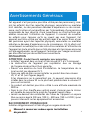 3
3
-
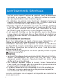 4
4
-
 5
5
-
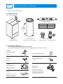 6
6
-
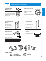 7
7
-
 8
8
-
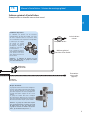 9
9
-
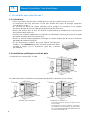 10
10
-
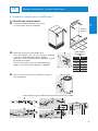 11
11
-
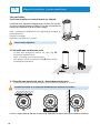 12
12
-
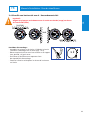 13
13
-
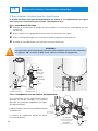 14
14
-
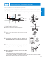 15
15
-
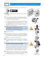 16
16
-
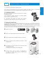 17
17
-
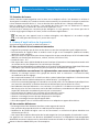 18
18
-
 19
19
-
 20
20
-
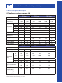 21
21
-
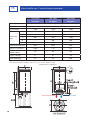 22
22
-
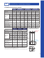 23
23
-
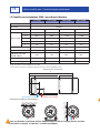 24
24
-
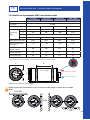 25
25
-
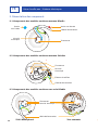 26
26
-
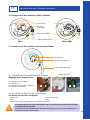 27
27
-
 28
28
-
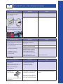 29
29
-
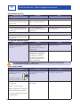 30
30
-
 31
31
-
 32
32
-
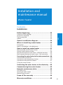 33
33
-
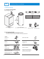 34
34
-
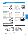 35
35
-
 36
36
-
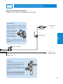 37
37
-
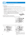 38
38
-
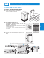 39
39
-
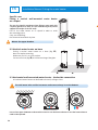 40
40
-
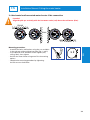 41
41
-
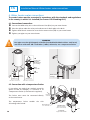 42
42
-
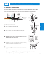 43
43
-
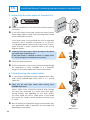 44
44
-
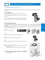 45
45
-
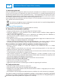 46
46
-
 47
47
-
 48
48
-
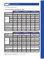 49
49
-
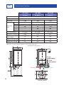 50
50
-
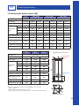 51
51
-
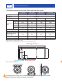 52
52
-
 53
53
-
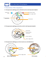 54
54
-
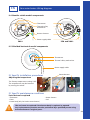 55
55
-
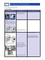 56
56
-
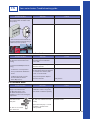 57
57
-
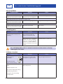 58
58
-
 59
59
-
 60
60
-
 61
61
-
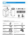 62
62
-
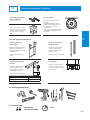 63
63
-
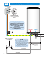 64
64
-
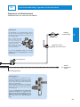 65
65
-
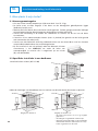 66
66
-
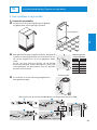 67
67
-
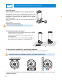 68
68
-
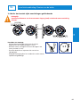 69
69
-
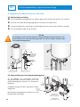 70
70
-
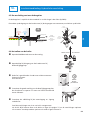 71
71
-
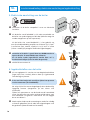 72
72
-
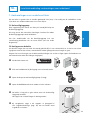 73
73
-
 74
74
-
 75
75
-
 76
76
-
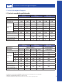 77
77
-
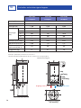 78
78
-
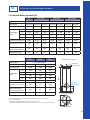 79
79
-
 80
80
-
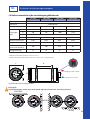 81
81
-
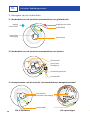 82
82
-
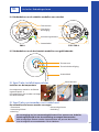 83
83
-
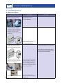 84
84
-
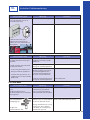 85
85
-
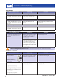 86
86
-
 87
87
-
 88
88


Atlantic CHAUFFEO / CHAUFFEO PLUS 2019 Installation and User Manual
- Type
- Installation and User Manual
in andere talen
- English: Atlantic CHAUFFEO / CHAUFFEO PLUS 2019
- français: Atlantic CHAUFFEO / CHAUFFEO PLUS 2019
Gerelateerde papieren
-
Atlantic ZENEO 2021 Installation and User Manual
-
-
-
-
-
-
-
Andere documenten
-
DeDietrich Installation and user’s instruction manual CEB / CES de handleiding
-
 De Dietrich Installation and user’s instruction manual CEB / CES Handleiding
-
PACIFIC CHAUFFE EAU DRAKKAR de handleiding
-
sauter ESSENTIEL 150 L HORIZONTAL MURAL de handleiding
-
Casselin CDEC68 Handleiding
-
THERMOR CHAUFFE EAU PETITES CAPACITES de handleiding
-
Chattanooga M2 Handleiding
-
Herschel XLS1000W-EU Handleiding
