IMG STAGELINE 25.3490 Handleiding
- Categorie
- Microfoons
- Type
- Handleiding

ELECTRONICS FOR SPECIALISTS ELECTRONICS FOR SPECIALISTS ELECTRONICS FOR SPECIALISTS ELECTRONICS FOR SPECIALISTS
TXS-611SET Bestell-Nr. • Order No. 25.3650 863 – 865 MHz
TXS-616SET Bestell-Nr. • Order No. 25.3490 672 – 697 MHz
TXS-631SET Bestell-Nr. • Order No. 25.3660 863 – 865 MHz
TXS-636SET Bestell-Nr. • Order No. 25.3500 672 – 697 MHz
BEDIENUNGSANLEITUNG
INSTRUCTION MANUAL
MODE D’EMPLOI
ISTRUZIONI PER L’USO
GEBRUIKSAANWIJZING
MANUAL DE INSTRUCCIONES
INSTRUKCJA OBSŁUGI
Drahtloses Mikrofonsystem
Wireless Microphone System


3
ON
LR6.AALR6.AA
CHANNEL
BATT
HI ON
LO OFF
POWER
LOCK
IR
CHANNEL
BATT
0 10
MIN MAX
MIC OUT (BAL.)
SQUELCHVOLUME
POWER
LINE OUT (UNBAL.)
DC INPUT
ACT
TXS-6..SET
IRCHANNELSELECTA B
AF RF
A
B
1 12 3 4 5 6 7
8 9 10 11 12 13
14
15
16
17
21
22
23
24
25
26
28
20
18
19
➀
➂➁

4
English
English Page
Contents
Français
Français Page
Table des matières
Italiano
Italiano Pagina
Indice
Español
Español Página
Contenidos
Nederlands
Nederlands Pagina
Inhoud
Polski
Polski Strona
Spis treści
Deutsch
Deutsch Seite
Inhalt
Deutsch
Inhalt
1 Einsatzmöglichkeiten . . . . . . . . . . 4
2 Übersicht . . . . . . . . . . . . . . . . 4
2.1 Multifrequenz-Empfänger . . . . . . . . . 4
2.2 Funkmikrofon . . . . . . . . . . . . . . .4
2.3 Taschensender. . . . . . . . . . . . . . .5
3 Hinweise für den sicherenGebrauch . . 5
3.1 Konformität und Zulassung . . . . . . . . 5
4 Inbetriebnahme . . . . . . . . . . . . . 6
4.1 Empfänger anschließen . . . . . . . . . . 6
4.2 Batterien in den Sender einsetzen . . . . . 6
4.2.1 Funkmikrofon
1
. . . . . . . . . . . . . .6
4.2.2 Taschensender
2
. . . . . . . . . . . . . 6
4.3 Krawattenmikrofon
2
und Taschensender
2
anschließen und befestigen
. . . . . . . . 6
4.4 Übertragungskanal einstellen . . . . . . . 6
5 Bedienung . . . . . . . . . . . . . . . .7
6 Technische Daten . . . . . . . . . . . . 8
Drahtloses Mikrofonsystem
Diese Bedienungsanleitung richtet sich an Benutzer
ohne besondere Fachkenntnisse. Bitte lesen Sie die
Anleitung vor dem Betrieb gründlich durch und
heben Sie sie für ein späteres Nachlesen auf.
Auf der ausklappbaren Seite 3 finden Sie alle
beschriebenen Bedienelemente und Anschlüsse.
1 Einsatzmöglichkeiten
Mit diesem Mulitfrequenz-Mikrofonsystem, das
im UHF-Bereich arbeitet, lassen sich Sprache und
Gesang drahtlos zu einer Verstärkeranlage über-
tragen. Es eignet sich damit optimal für Anwen-
dungen, die uneingeschränkte Bewegungsfreiheit
erfordern, z. B. bei Bühnenshows, für den DJ-Ein-
satz, bei Sportveranstaltungen.
Besonders komfortabel ist das System durch
die ACT-Funktion (Automatic Channel Targeting).
Damit wird per Knopfdruck über ein Infrarotsignal
das Funkmikrofon oder der Taschensender auf den
am Empfänger gewählten Kanal eingestellt.
Das Mikrofonsystem besteht aus:
1 Multifrequenz-Empfänger in True-Diversity-
Technik*
1 Steckernetzgerät für den Empfänger
1 Audiokabel (2 × 6,3-mm-Klinke)
1 Funkmikrofon (bei TXS-611SET / TXS-616SET) oder
1 Taschensender mit Krawattenmikrofon
(bei TXS-631SET / TXS-636SET)
* True-Diversity-Technik:
Das vom Funkmikrofon oder Taschensender ausgestrahlte
Signal wird von zwei Antennen empfangen und in zwei
separaten Empfangsteilen verstärkt. Das jeweils besser
empfangene Signal wird dann weiterverarbeitet.
2 Übersicht
2.1 Multifrequenz-Empfänger
1 Empfangsantennen A und B
2 Taste SELECT zur Kanaleinstellung
– Zum automatischen Suchen eines freien Emp-
fangskanals die Taste kurz drücken.
– Zur manuellen Einstellung die Taste SELECT so
lange drücken, bis die Einerstelle im Display
(3) blinkt. Durch kurzes Drücken der Taste
die Einerstelle einstellen. Die Taste erneut ge-
drückt halten, bis die Zehnerstelle im Display
blinkt. Durch kurzes Drücken die Zehnerstelle
einstellen. (Die den Kanälen entsprechenden
Frequenzen sind in den Tabellen auf der
Seite 40 angegeben.)
3 Display zur Kanalanzeige
4 Anzeige AF (audio frequency): leuchtet, wenn
das empfangene Tonsignal einen bestimmten
Pegel überschreitet
5
Empfangsanzeigen RF (radio frequency) A
und B: signalisieren, welches der beiden Emp-
fangsteile des Gerätes das stärkere Funksignal
empfängt
6 IR-Fenster für die Infrarotsignale zur Kanalein-
stellung des Funkmikrofons oder des Taschen-
senders
7 Taste ACT zum Aussenden der Infrarotsignale
für die Kanaleinstellung des Funkmikrofons oder
des Taschensenders
8
Stromversorgungsbuchse zum Anschluss des
beiliegenden Netzgerätes
9 Ein- und Auschalter POWER
10
XLR-Audioausgang zum Anschluss an einen
Mikrofoneingang
11
Audioausgang (6,3-mm-Klinke) zum Anschluss
an einen Line-Eingang
12 Lautstärkeregler VOLUME für das Audiosignal
der Ausgänge (10, 11)
13 Regler SQUELCH zum Einstellen der Ansprech-
schwelle für die Störunterdrückung
2.2 Funkmikrofon
nur bei TXS-611SET und TXS-616SET
14 Display mit Kanal- und Batterieanzeige
15 Sensor für die Infrarotsignale zur Kanaleinstel-
lung
16 Ein- und Ausschalter
untere Position: Aus
mittlere Position: Mute
obere Position: Ein

5
Deutsch
17 Batteriefach
18 Schalter LOCK für die Bediensperre
Position OFF Sperre ausgeschaltet
Position ON Sperre eingeschaltet
19 Schalter POWER für die Sendeleistung
Position LO geringe Sendeleistung
Position HI hohe Sendeleistung
2.3 Taschensender
nur bei TXS-631SET und TXS-636SET
20 Sendeantenne
21 Ein- und Ausschalter
OFF = Aus
STBY = Mute
ON = Ein
22 Display mit Kanal- und Batterieanzeige
23 Sensor für die Infrarotsignale zur Kanaleinstel-
lung
24 Batteriefachdeckel
25 Anschlussbuchse für das Krawattenmikrofon
26 Gürtelklemme
27
Regler GAIN zum Einstellen der Verstärkung des
Mikrofonsignals
28 Batteriefach
3 Hinweise für den
sicherenGebrauch
Die Geräte (Empfänger, Netzgerät, Funkmikrofon
oder Taschensender) entsprechen allen relevan
-
ten Richtlinien der EU und tragen deshalb das
-Zeichen.
WARNUNG
Das Netzgerät wird mit lebensge-
fährlicher Netzspannung versorgt.
Nehmen Sie deshalb niemals selbst
Eingriffe daran vor. Es besteht die
Gefahr eines elektrischen Schlages.
•
Das Funksystem ist nur für die Verwendung im
Innenbereich geeignet. Schützen Sie die Geräte
vor Tropf- und Spritzwasser, hoher Luftfeuchtig-
keit und Hitze (zulässiger Einsatztemperaturbe-
reich 0 – 40 °C).
•
Nehmen Sie den Empfänger nicht in Betrieb und
ziehen Sie sofort das Netzgerät aus der Steck-
dose,
1. wenn sichtbare Schäden am Empfänger oder
am Netzgerät vorhanden sind,
2. wenn nach einem Sturz oder Ähnlichem der
Verdacht auf einen Defekt besteht,
3. wenn Funktionsstörungen auftreten.
Lassen Sie die Geräte in jedem Fall in einer Fach-
werkstatt reparieren.
•
Verwenden Sie zum Reinigen nur ein trockenes,
weiches Tuch, niemals Wasser oder Chemikalien.
•
Werden die Geräte zweckentfremdet, nicht
richtig angeschlossen, falsch bedient oder nicht
fachgerecht repariert, kann keine Haftung für
daraus resultierende Sach- oder Personenschä-
den und keine Garantie für die Geräte über-
nommen werden.
Sollen die Geräte endgültig aus dem
Betrieb genommen werden, übergeben
Sie sie zur umweltgerechten Entsorgung
einem örtlichen Recyclingbetrieb.
3.1 Konformität und Zulassung
Hiermit erklärt MONACOR INTERNATIONAL, dass
sich die drahtlosen Mikrofonsysteme
TXS-611SET
TXS-616SET
TXS-631SET
TXS-636SET
in Übereinstimmung mit den grundlegenden An-
forderungen und den übrigen einschlägigen Be-
stimmungen der Richtlinie 2014 / 53 / EU befinden.
Die EU-Konformitätserklärungen sind im Internet
verfügbar:
www.imgstageline.de
Die Modelle TXS-611SET und TXS-631SET sind für
den Betrieb in den EU-Staaten allgemein zugelas-
sen und anmelde- und gebührenfrei.
Für die Modelle TXS-616SET und TXS-636SET
bestehen Beschränkungen oder Anforderun-
gen in folgenden Ländern:
CZ DE EL FI FR
IT LT MT PL
Diese müssen im Gebiet der Bundesrepublik
Deutschland eine Frequenzzuteilung (kosten-
pflichtig) erhalten. Die Formulare und Hinweise
zur Anmeldung der Sender finden Sie im Internet
auf der Seite der Bundesnetzagentur
www.bundesnetzagentur.de
In anderen Ländern muss eine entsprechende Ge-
nehmigung beantragt werden. Informieren Sie sich
bitte vor der Inbetriebnahme des Mikrofonsystems
außerhalb Deutschlands bei der MONACOR-Nie-
derlassung oder der entsprechenden Behörde des

6
Deutsch
Landes. Links zu den nationalen Behörden finden
Sie über die folgende Internetadresse:
www.cept.org
t ECC
t Topics
t Short Range Devices (SRD) and other R&T TE
sub-classes
t EFIS and National Frequency Tables
4 Inbetriebnahme
4.1 Empfänger anschließen
1)
Den Empfänger an das nachfolgende Gerät
(z. B. Verstärker, Mischpult) anschließen. Dazu
sind zwei Audioausgänge vorhanden:
– MIC OUT (10) als XLR-Buchse, symmetrisch,
zum Anschluss an einen Mikrofoneingang
– LINE OUT (11) als 6,3-mm-Klinkenbuchse,
asymmetrisch, zum Anschluss an einen Ein-
gang mit Line-Pegel; hierfür kann das bei-
liegende Anschlusskabel verwendet werden
2) Das beiliegende Netzgerät an die Stromversor-
gungsbuchse (8) anschließen und in eine Steck-
dose (230 V/ 50 Hz) stecken.
4.2 Batterien in den Sender einsetzen
Für den Betrieb des Funkmikrofons und des
Taschensenders werden zwei 1,5-V-Batterien der
Größe Mignon (AA) benötigt.
•
Setzen Sie nur Batterien oder Akkus des gleichen
Typs ein und tauschen Sie sie immer komplett aus.
•
Nehmen Sie bei längeren Nichtgebrauch die Bat-
terien heraus. So bleibt das Gerät bei einem even-
tuellen Auslaufen der Batterien unbe schädigt.
Verbrauchte Batterien und defekte Akkus
dürfen nicht in den Hausmüll geworfen
werden. Geben Sie sie zur umweltgerech-
ten Entsorgung nur in den Sondermüll
(z. B. Sammelbehälter im Einzelhandel).
4.2.1 Funkmikrofon
1
Zum Öffnen des Batteriefachs (17) auf den Pfeil des
Batteriefachdeckels drücken und dabei den Deckel
nach unten schieben.
Die Batterien mit den Plus- und Minuspolen,
wie im Batteriefach angegeben, einsetzen und den
Batteriefachdeckel wieder aufsetzen.
4.2.2 Taschensender
2
Zum Öffnen des Batteriefachs (28) auf den Pfeil
des Batteriefachdeckels (24) drücken und dabei
den Deckel nach unten schieben.
Die Batterien mit den Plus- und Minuspolen,
wie in der Abb. 3 dargestellt, einsetzen und den
Batteriefachdeckel wieder aufsetzen.
4.3 Krawattenmikrofon
2
und Taschen-
sender
2
anschließen und befestigen
1)
Den Stecker des Krawattenmikrofons in die
Klinkenbuchse (25) des Senders stecken. Um
den Stecker vor einem Herausziehen zu sichern,
die Überwurfmutter des Steckers auf die Buchse
schrauben.
2)
Das Krawattenmikrofon an der Kleidung befes-
tigen, möglichst nahe am Mund.
3)
Nach dem Durchführen aller Einstellungen
(Kap.4.4 und 5) den Sender mit der Klemme
(26) an der Kleidung befestigen (z. B. am Gürtel
oder am Hosenbund).
4.4 Übertragungskanal einstellen
Ein freier Übertragungskanal kann am Empfän-
ger automatisch gesucht oder manuell eingestellt
werden. Anschließend wird komfortabel nur durch
einen Knopfdruck das Funkmikrofon
1
bzw. der
Taschensender
2
mit Hilfe eines Infrarotsignals auf
den gleichen Kanal eingestellt.
1)
Den Empfänger mit dem Schalter POWER (9)
einschalten. Zum Einschalten des Taschensen-
ders den Schalter (21) in die Position ON schie-
ben. Zum Einschalten des Funkmikrofons den
Schalter (16) in die obere Position schieben.
Nach den Einschalten leuchtet das entspre-
chende Display (3, 14, 22).
2) Zum automatischen Suchen eines freien Ka-
nals die Taste SELECT (2) kurz drücken. Das
Display (3) signalisiert den Suchvorgang durch
ein umlaufendes Anzeigesegment:
Nach kurzer Zeit zeigt das Display die Nummer
des gefundenen Kanals an. Die zugehörigen
Frequenzen sind in den Tabellen auf der Seite
40 angegeben.
3) Zum manuellen Einstellen einer bestimmten
Übertragungsfrequenz die zugehörige Kanal-
nummer aus den Tabellen auf der Seite 40
heraussuchen. Zum Einstellen der Kanalnummer
1
nur bei TXS-611SET und TXS-616SET
2
nur bei TXS-631SET und TXS-636SET

7
Deutsch
die Taste SELECT (2) so lange drücken, bis die
Einerstelle im Display (3) blinkt. Durch kurzes
Drücken der Taste SELECT die Einerstelle ein-
stellen. Die Taste erneut gedrückt halten, bis
die Zehnerstelle im Display blinkt. Durch kur-
zes Drücken die Zehnerstelle einstellen. Einige
Sekunden nach dem letzten Tastendruck wird
das Blinken beendet. Die Kanaleinstellung ist
dann gespeichert.
4)
Den Infrarotsensor (15, 23) des Funkmikrofons /
Taschensenders in Richtung des IR-Fensters(6)
am Empfänger halten. Der Abstand darf nicht
mehr als 1,5 m betragen und es muss Sicht-
verbindung zwischen Sensor und IR-Fenster
bestehen.
Die Taste ACT (7) einige Sekunden drü-
cken, bis die Display-Hintergrundbeleuchtung
des Funkmikrofons bzw. des Taschensenders
aufleuchtet. Das Funkmikrofon bzw. der Ta-
schensender ist damit auf den gleichen Kanal
wie der Empfänger eingestellt. Das Display (14
bzw. 22) zeigt die Kanalnummer an.
5 Bedienung
1) Die Empfangsantennen (1) senkrecht stellen.
2)
Zuerst den Empfänger mit dem Schalter POWER
(9) einschalten. Die Anzeige AF (4) blinkt zwei-
mal auf. Das Display (3) zeigt den eingestellten
Übertragungskanal an.
Leuchtet bei noch ausgeschaltetem Funk-
mikrofon
1
bzw. Taschensender
2
eine der Emp-
fangsanzeigen RF (5), werden Störungen oder
Signale eines anderen Funksystems empfangen.
In diesem Fall einen anderen Kanal einstellen
(
☞
Kap. 4.4).
3)
Zum Einschalten des Taschensenders den Schal-
ter (21) in die Position ON schieben. Zum Ein-
schalten des Funkmikrofons den Schalter (16) in
die obere Position schieben. Für eine Tonüber-
tragung den Schalter am Funkmikrofon ganz
nach oben schieben bzw. am Taschensender
ganz in die Position ON. In der Mittelposition
arbeitet zwar der Sender, jedoch ist das Mikro-
fonsignal stumm geschaltet.
Nach den Einschalten leuchtet für einige
Sekunden die Hintergrundbeleuchtung des Dis-
plays (14, 22). Das Display zeigt den eingestell-
ten Kanal und den Ladezustand der Batterien an:
BATT BATT BATT
voll entladen
4)
Am Funkmikrofon mit dem Schalter POWER (19)
im Batteriefach die Sendeleistung einstellen:
– obere Position HI = hohe Leistung für eine
große Reichweite, jedoch kürzere Betriebs-
dauer der Batterie
– untere Position LO = geringe Leistung für
eine längere Betriebsdauer, jedoch kürzere
Reichweite
5)
Bei eingeschaltetem Sender (Funkmikrofon bzw.
Taschensender) leuchtet am Empfänger eine
der Empfangsanzeigen RF A oder B (5) entspre-
chend, welches Empfangsteil das bessere Signal
liefert. Leuchtet keine Anzeige, überprüfen:
a
Ist der Sender auf den gleichen Kanal wie der
Empfänger eingestellt?
Werden am Empfänger und am Funkmik-
rofon / Taschensender verschiedene Kanäle
angezeigt, den Bedienschritt 4 des Kapitels
4.4 ausführen.
b Sind die Batterien des Senders verbraucht?
c Ist das Funkmikrofon auf eine niedrige Sen-
deleistung eingestellt?
d Ist der Abstand zwischen Sender und Emp-
fänger zu groß?
Reichweite
TXS-611 / -631 / -636SET : ca. 30 m
TXS-616SET: ca. 50 m
e Ist der Empfang durch Metallgegenstände in
der Übertragungsstrecke gestört?
f
Lässt sich der Empfang durch Schwenken der
Empfangsantennen (1) verbessern?
g
Ist die Störunterdrückung mit dem Regler
SQUELCH (13) zu hoch eingestellt?
(
☞
Bedienschritt 7)
6)
Das nachfolgende Audiogerät einschalten bzw.
den zugehörigen Mischpultregler aufziehen.
In das Mikrofon sprechen / singen und mit dem
Lautstärkeregler VOLUME (12) den Ausgangs-
pegel des Empfängers an den Eingang des
nachfolgenden Gerätes anpassen.
Bei dem Taschensender lässt sich für das
angeschlossene Mikrofon die Verstärkung mit
dem Regler GAIN (27) auf der Rückseite einstel-
len: Ist das Mikrofonsignal zu laut und verzerrt,
den Regler mit einem kleinen Schraubendreher
zurückdrehen. Bei einem zu leisen Signal ergibt
sich dagegen ein schlechter Rauschabstand; den
Regler dann entsprechend aufdrehen.
7)
Mit dem Regler SQUELCH (13) den Schwellwert
einstellen, bei dem die Störunterdrückung an-
sprechen soll. Die Störunterdrückung schaltet
den Empfänger stumm, wenn in Sprech- oder
Hinweis: Blinkt die Anzeige BATT, die Batterien aus-
tauschen.

8
Deutsch
Gesangspausen Störsignale empfangen wer-
den, deren Pegel unter dem eingestellten
Schwellwert liegen. Ein hoher Schwellwert
reduziert jedoch auch die Reichweite des Mikro-
fonsystems. Sinkt nämlich die Funksignalstärke
unter den eingestellten Schwellwert, wird der
Empfänger ebenfalls stumm geschaltet. Darum
bei gutem Empfang einen höheren Schwellwert
einstellen (Regler in Richtung MAX drehen) und
bei größerer Entfernung zwischen Sender und
Empfänger einen niedrigeren Wert (Regler in
Richtung MIN drehen).
8)
Bei dem Funkmikrofon lässt sich die Bedie-
nung sperren. Wird der Schalter LOCK (18) im
Batteriefach in die Position ON geschoben, ist
die Sperre eingeschaltet. Im Display erscheint
ein Schlüsselsymbol. Das Mikrofon kann dann
nicht mit dem Schalter (16) ausgeschaltet oder
per Infrarotsignal auf einen anderen Kanal ein-
gestellt werden. Das Mikrofonsignal lässt sich
jedoch weiterhin stumm schalten, wenn der
Schalter (16) in die mittlere oder untere Position
geschoben wird.
9) Nach dem Betrieb die Geräte mit dem entspre-
chenden Schalter (9, 16, 21) ausschalten. Wird
das Mikrofonsystem längere Zeit nicht benutzt,
das Netzgerät des Empfängers aus der Steck-
dose ziehen, denn es verbraucht auch bei aus-
geschaltetem Empfänger einen geringen Strom.
6 Technische Daten
Trägerfrequenzen
TXS-611 / -631SET:. . . .863 – 865 MHz
TXS-616 / -636SET:. . . .672 – 697 MHz
Kanäle siehe Seite 40
Sendeleistung (EIRP)
TXS-611SET: . . . . . . . .< 10 mW (HI), 1,0 mW (LO)
TXS-616SET: . . . . . . . .< 25 mW (HI), 2,5 mW (LO)
TXS-631SET: . . . . . . . .< 10 mW
TXS-636SET: . . . . . . . .< 10 mW
Reichweite
TXS-611 / -631SET:. . . .ca. 30 m
TXS-616SET: . . . . . . . .ca. 50 m
TXS-636SET: . . . . . . . .ca. 30 m
HF-Rauschabstand: . . . .105 dB
Audiofrequenzbereich: .50 – 18 000 Hz, ±3 dB
Dynamik: . . . . . . . . . . .120 dB
Klirrfaktor: . . . . . . . . . .< 0,5 %
Audioausgänge
MIC OUT: . . . . . . . . . .25 mV, 10 kΩ, XLR, sym.
LINE OUT: . . . . . . . . . .350 mV, 10 kΩ,
6,3-mm-Klinke, asym.
Stromversorgung
Empfänger: . . . . . . . .über beiliegendes Netzgerät
an 230 V/ 50 Hz
Funkmikrofon /
Taschensender: . . . . . .2 × 1,5-V-Batterie,
Größe Mignon (AA)
Einsatztemperatur:
. . . .0 – 40 °C
Abmessungen, Gewicht
Empfänger: . . . . . . . .152 × 38 × 120 mm, 482 g
Funkmikrofon: . . . . . .⌀ 52 mm × 275 mm, 235 g
Taschensender: . . . . . .62 × 105 × 25 mm, 88 g
Änderungen vorbehalten.
Diese Bedienungsanleitung ist urheberrechtlich für MONACOR
®
INTERNATIONAL GmbH & Co. KG geschützt.
Eine Reproduktion für eigene kommerzielle Zwecke – auch auszugsweise – ist untersagt.

9

10
Deutsch
Deutsch Seite
Inhalt
Français
Français Page
Table des matières
Italiano
Italiano Pagina
Indice
Español
Español Página
Contenidos
Nederlands
Nederlands Pagina
Inhoud
Polski
Polski Strona
Spis treści
English
English Page
Contents
English
Contents
1 Applications . . . . . . . . . . . . . . 10
2 Operating Elements and Connections . 10
2.1 Multi-frequency receiver . . . . . . . . . 10
2.2 Wireless microphone . . . . . . . . . . 10
2.3 Pocket transmitter . . . . . . . . . . . . 11
3 Safety Notes . . . . . . . . . . . . . . 11
3.1 Conformity and approval . . . . . . . . 11
4 Setting into Operation . . . . . . . . 12
4.1 Connecting the receiver . . . . . . . . . 12
4.2 Inserting the batteries into the transmitter 12
4.2.1 Wireless microphone
1
. . . . . . . . . 12
4.2.2 Pocket transmitter
2
. . . . . . . . . . . 12
4.3 Connecting and attaching
the tie clip microphone
2
and the pocket transmitter
2
. . . . . . . 12
4.4 Adjusting the transmission channel. . . . 12
5 Operation . . . . . . . . . . . . . . . 13
6 Specifications . . . . . . . . . . . . . 14
Wireless Microphone System
These instructions are intended for users without
any specific technical knowledge. Please read these
instructions carefully prior to operating the unit and
keep them for later reference.
All operating elements and connections de-
scribed can be found on the fold-out page 3.
1 Applications
This multi-frequency microphone system operating
in the UHF range is capable of wireless transmission
of speech and vocals to an amplifier system. Thus,
it is ideally suited for applications requiring total
freedom of movement, e. g. for stage shows, DJ
applications, sports events.
The ACT function (automatic channel target-
ing) is a most convenient feature of the system:
Simply press a button to adjust the wireless mi-
crophone or the pocket transmitter to the channel
selected on the receiver via IR signal.
The microphone system includes:
1 multi-frequency receiver in True Diversity tech-
nology*
1 plug-in power supply unit for the receiver
1 audio cable (2 × 6.3 mm plug)
1 wireless microphone (for TXS-611SET / TXS-616SET) or
1 pocket transmitter with tie clip microphone
(for TXS-631SET / TXS-636SET)
* True Diversity technology
The signal coming from the wireless microphone or
the pocket transmitter is received by two antennas and
amplified in two separate receiving parts. The signal offer-
ing the best reception quality is then processed.
2 Operating Elements and
Connections
2.1 Multi-frequency receiver
1 Receiving antennas A and B
2 Button SELECT for channel adjustment
– To automatically scan a free reception channel,
press the button briefly.
– To manually adjust a channel, keep the button
SELECT pressed until the units digit on the
display (3) starts flashing. Press the button
briefly to adjust the units digit. Keep the but-
ton pressed again until the tens digit on the
display starts flashing. Press the button briefly
to adjust the tens digit. (The frequencies cor-
responding to the channels can be found in
the tables on page40.)
3 Display for channel indication
4
LED AF (audio frequency): lighting up when the
received audio signal exceeds a defined level
5 Reception LEDs RF (radio frequency) A and B:
to indicate which of the two receiving parts of
the unit receives the more powerful radio signal
6 IR window for the IR signals to adjust the chan-
nel of the wireless microphone or of the pocket
transmitter
7 Button ACT for sending the IR signals to adjust
the channel of the wireless microphone or of
the pocket transmitter
8
Power supply jack to connect the power supply
unit provided
9 POWER switch
10
XLR audio output for connection to a micro-
phone input
11 Audio output (6.3 mm jack) for connection to
a line input
12
VOLUME control for the audio signal of the
outputs (10, 11)
13
SQUELCH control to adjust the threshold for
interference suppression
2.2 Wireless microphone
for TXS-611SET and TXS-616SET only
14
Display with channel indication and battery
status indication
15 Sensor for the IR signals to adjust the channel
16 On / off switch
lower position: off
mid-position: mute
upper position: on

11
English
17 Battery compartment
18 Switch LOCK to lock the microphone
position OFF lock deactivated
position ON lock activated
19 Switch POWER for the transmission power
position LO low transmission power
position HI high transmission power
2.3 Pocket transmitter
for TXS-631SET and TXS-636SET only
20 Transmitting antenna
21 On / off switch
OFF
STBY = mute
ON
22
Display with channel indication and battery
status indication
23 Sensor for the IR signals to adjust the channel
24 Cover of battery compartment
25 Jack to connect the tie clip microphone
26 Belt clip
27 GAIN control to adjust the gain of the micro-
phone signal
28 Battery compartment
3 Safety Notes
The units (receiver, power supply unit, wireless
microphone or pocket transmitter) correspond to
all relevant directives of the EU and are therefore
marked with .
WARNING The power supply unit uses danger-
ous mains voltage. Leave servicing
to skilled personnel only. Inexpert
handling of the unit may result in
electric shock.
•
The wireless system is suitable for indoor use
only. Protect the units against dripping water
and splash water, high air humidity and heat (ad-
missible ambient temperature range 0 – 40 °C).
•
Do not operate the receiver and immediately dis-
connect the power supply unit from the socket
1. if the receiver or the power supply unit is vis-
ibly damaged,
2. if a defect might have occurred after a unit
was dropped or suffered a similar accident,
3. if malfunctions occur.
In any case the units must be repaired by skilled
personnel.
•
For cleaning only use a dry, soft cloth; never use
water or chemicals.
•
No guarantee claims for the units and no liability
for any resulting personal damage or material
damage will be accepted if the units are used for
other purposes than originally intended, if they
are not correctly connected or operated, or if
they are not repaired in an expert way.
If the units are to be put out of operation
definitively, take them to a local recycling
plant for a disposal which is not harmful
to the environment.
3.1 Conformity and approval
Herewith, MONACOR INTERNATIONAL declare that
the wireless microphone systems
TXS-611SET
TXS-616SET
TXS-631SET
TXS-636SET
are in accordance with the basic requirements
and the other relevant regulations of the directive
2014 / 53 / EU. The EU declarations of conformity
are available on the Internet:
www.imgstageline.com
Models TXS-611SET and TXS-631SET are generally
approved for operation in EU countries. They are
licence-free and require no registration.
For models TXS-616SET and TXS-636SET, re
-
strictions or requirements apply in the follow-
ing countries:
CZ DE EL FI FR
IT LT MT PL
In the Federal Republic of Germany, a fre-
quency assignment (for which a charge is
payable) is required for these models. The
forms and notes concerning the registration of
the transmitters can be found on the Web site
of the Bundesnetzagentur (Federal Network
Agency) under www.bundesnetzagentur.de.
In other countries, it is necessary to apply for a
corresponding approval. Prior to operating the
microphone system outside Germany, please con-
tact the MONACOR subsidiary or the correspond-
ing authorities of the respective country. Links to
the national authorities can be found via the fol-
lowing Internet address:

12
English
www.cept.org
t ECC
t Topics
t Short Range Devices (SRD) and other R&T TE
sub-classes
t EFIS and National Frequency Tables
4 Setting into Operation
4.1 Connecting the receiver
1)
Connect the receiver to the following unit (e. g.
amplifier, mixer). For this purpose, two audio
outputs are provided:
– MIC OUT (10) as an XLR jack, balanced to
connect a microphone input
– LINE OUT (11) as a 6.3 mm jack, unbal. to
connect an input with line level; use the con-
nection cable provided
2) Connect the power supply unit provided to the
power supply jack (8) and to a mains socket
(230 V/ 50 Hz).
4.2 Inserting the batteries into the
transmitter
For operating the wireless microphone and the
pocket transmitter, two 1.5 V batteries of size AA
are required.
•
Always insert (rechargeable) batteries of the
same type and always replace all of them.
•
If the transmitter is not in use for a longer period
of time, always remove the batteries to prevent
damage to the unit in case of battery leakage!
Used batteries and defective rechargeable
batteries must not be placed in the house-
hold waste. To protect the environment,
always take them to a special waste dis-
posal, e. g. collection container at your
retailer.
4.2.1 Wireless microphone
1
To open the battery compartment (17), press the
arrow of the battery compartment cover and push
the cover downwards.
Insert the batteries with the positive and neg-
ative poles as indicated in the compartment, then
replace the cover.
4.2.2 Pocket transmitter
2
To open the battery compartment (28), press the
arrow of the battery compartment cover (24) and
push the cover downwards.
Insert the batteries with the positive and neg-
ative poles as indicated in fig.3, then replace the
cover.
4.3 Connecting and attaching
the tie clip microphone
2
and the pocket transmitter
2
1)
Connect the plug of the tie clip microphone
to the 3.5 mm jack (25) of the transmitter. To
prevent accidental disconnection, secure the
plug with the cap nut.
2) Attach the tie clip microphone to your clothes,
as close to your mouth as possible.
3)
After all adjustments have been made (chap
-
ters4.4 and 5), use the clip (26) to attach the
transmitter to your clothes (e. g. belt or waist-
band).
4.4 Adjusting the transmission channel
To adjust a free transmission channel on the re
-
ceiver, either use the automatic scan function or
adjust the channel manually. Then simply press
a button to adjust the wireless microphone
1
or
the pocket transmitter
2
to the same channel via
IR signal.
1) Switch on the receiver with the POWER switch
(9). To switch on the pocket transmitter, set the
switch (21) to the position ON. To switch on the
wireless microphone, set the switch (16) to the
upper position. After switching on, the corre-
sponding display (3, 14, 22) lights up.
2)
To automatically scan a free channel, press the
button SELECT (2) briefly. To indicate the scan,
one segment of the numerical display element
starts moving around on the display (3):
After a while, the display shows the number of
the channel found. The correspond ing frequen-
cies can be found in the tables on page 40.
3)
To manually adjust a specific transmission
frequency, find the corresponding channel num-
ber in the tables on page 40. To adjust the
1
for TXS-611SET and TXS-616SET only
2
for TXS-631SET and TXS-636SET only

13
English
channel number, keep the button SELECT(2)
pressed until the units digit on the display (3)
starts flashing. Press the button briefly to adjust
the units digit. Keep the button pressed again
until the tens digit on the display starts flash-
ing. Press the button briefly to adjust the tens
digit. A few seconds after you have pressed the
button for the last time, the the digit will stop
flashing to indicate that the channel adjustment
has been stored.
4)
Point the IR sensor (15, 23) of the wireless
microphone / pocket transmitter towards the IR
window (6) on the receiver. The distance must
not exceed 1.5 m. Make sure that there are
no obstacles between the sensor and the IR
window.
Keep the button ACT (7) pressed for a few
seconds until the display backlight of the wire-
less microphone or the pocket transmitter has
been activated. Thus, the wireless microphone
or the pocket transmitter and the receiver have
been set to the same channel. The display (14
or 22) shows the channel number.
5 Operation
1)
Put the receiving antennas (1) in a vertical
position.
2) Switch on the receiver with the POWER switch
(9) first. The LED AF (4) flashes twice. The display
(3) shows the transmission channel adjusted.
If one of the reception LEDs RF (5) lights up
while the wireless microphone
1
or the pocket
transmitter
2
is still switched off, interfering sig-
nals or signals from another wireless system are
received. In this case, adjust a different channel
(
☞
chapter 4.4).
3)
To switch on the pocket transmitter, set the
switch (21) to the position ON. To switch on the
wireless microphone, set the switch (16) to the
upper position. For transmitting sound, set the
switch on the wireless microphone to the upper
stop or set the switch on the pocket transmitter
to ON. In the mid-position, the transmitter is on,
but the microphone signal is muted.
After switching on, the backlight of the
display (14, 22) lights up for a few seconds.
The display shows the channel adjusted and
the battery status.
BATT BATT BATT
full discharged
Note: Replace the batteries when the indication BATT
starts flashing.
4) On the wireless microphone, adjust the trans-
mitting power with the switch POWER (19) in
the battery compartment.
– upper position HI = high power for a long
range, but reduced battery life
– lower position LO = low power for a long life,
but reduced range
5) When the transmitter (wireless microphone or
pocket transmitter) is switched on, one of the
reception LEDs RF A or B (5) lights up on the
receiver to indicate which receiving part sup-
plies the best signal. If none of them lights up,
please check:
a Have the transmitter and the receiver been
set to the same channel?
If different channels are indicated on the
receiver and on the wireless microphone /
pocket transmitter, proceed with step 4 of
chapter 4.4.
b
Are the batteries of the transmitter dis-
charged?
c
Has the wireless microphone been set to a
low transmitting power?
d Is the distance between the transmitter and
the receiver too long?
Range:
TXS-611 / -631 / -636SET : approx. 30 m
TXS-616SET : approx. 50 m
e
Is the reception disturbed by metal objects in
the transmission path?
f Is it possible to improve the reception when
you turn the receiving antennas (1)?
g
Has the interference suppression been set too
high with the control SQUELCH (13)?
(
☞
step 7)
6) Switch on the following audio unit or advance
the corresponding mixer control. Speak/sing
into the microphone and match the output level
of the receiver to the input of the following unit
with the control VOLUME (12).
On the pocket transmitter, adjust the gain
for the microphone connected with the control
GAIN (27) on the rear side: If the volume of the
microphone signal is too high and the signal is
distorted, turn back the control with a small
screwdriver. If the volume of the signal is too
low, however, the signal-to-noise ratio is poor;
advance the control accordingly.
7)
With the control SQUELCH (13), adjust the
threshold value for response of the interfer-
ence suppression. The interference suppression
will mute the receiver during pauses in speech

14
English
or vocals when interfering signals are received
and their levels are below the threshold value
adjusted. A high threshold value, however, will
also reduce the range of the microphone sys-
tem: If the power of the radio signal falls below
the threshold value adjusted, the receiver is also
muted. Therefore, adjust a high threshold value
(turn the control towards MAX) when the recep-
tion is good and a low value (turn the control
towards MIN) when the distance between the
transmitter and the receiver is long.
8) The wireless microphone has a lock feature. To
activate the lock, set the switch LOCK (18) in
the battery compartment to the position ON.
The displays shows a key symbol and it is not
possible to switch off the microphone with the
switch (16) or to set it to a different channel via
IR signal. However, it is still possible to mute the
microphone when you set the switch (16) to the
mid-position or the lower position.
9) After operation, switch off the units with the
corresponding switch (9, 16, 21). If the micro-
phone system is not in use for a longer period
of time, disconnect the power supply unit of
the receiver from the mains socket; even with
the receiver switched off, it has a low power
consumption.
6 Specifications
Carrier frequencies
TXS-611 / -631SET:. . . .863 – 865 MH
TXS-616 / -636SET:. . . .672 – 697 MHz
channels see page 40
Transmitting power (EIRP)
TXS-611SET: . . . . . . . .< 10 mW (HI), 1.0 mW (LO)
TXS-616SET: . . . . . . . .< 25 mW (HI), 2.5 mW (LO)
TXS-631SET: . . . . . . . .< 10 mW
TXS-636SET: . . . . . . .< 10 mW
Range
TXS-611 / -631SET:. . . .approx. 30 m
TXS-616SET: . . . . . . . .approx. 50 m
TXS-636SET: . . . . . . . .approx. 30 m
RF S/N ratio: . . . . . . . . .105 dB
Audio frequency range: 50 – 18 000 Hz, ±3 dB
Dynamic range: . . . . . . .120 dB
THD: . . . . . . . . . . . . . . .< 0.5 %
Audio outputs
MIC OUT: . . . . . . . . . .25 mV, 10 kΩ, XLR, bal.
LINE OUT: . . . . . . . . . .350 mV, 10 kΩ,
6.3 mm jack, unbal.
Power supply
Receiver: . . . . . . . . . .via power supply unit
provided and connected to
230 V/ 50 Hz
W ireless microphone /
Pocket transmitter: . . .2 × 1.5 V battery, size AA
Ambient temperature: .0 – 40 °C
Dimensions, weight
Receiver: . . . . . . . . . .152 × 38 × 120 mm, 482 g
Wireless microphone: .⌀ 52 mm × 275 mm, 235 g
Pocket transmitter: . . .62 × 105 × 25 mm, 88 g
Subject to technical modification.
All rights reserved by MONACOR
®
INTERNATIONAL GmbH & Co. KG. No part of this instruction manual may
be reproduced in any form or by any means for any commercial use.

15
Nederlands
Nederlands Pagina
Inhoud
Polski
Polski Strona
Spis treści
Table des matières
1 Possibilités d’utilisation . . . . . . . . 15
2 Eléments et branchements . . . . . . 15
2.1 Récepteur multifréquences. . . . . . . . 15
2.2 Microphone sans fil . . . . . . . . . . . 15
2.3 Emetteur de poche . . . . . . . . . . . 16
3 Conseils d’utilisation et de sécurité . . 16
3.1 Conformité et autorisation. . . . . . . . 16
4 Fonctionnement . . . . . . . . . . . . 17
4.1 Branchement du récepteur. . . . . . . . 17
4.2 Insertion des batteries dans l’émetteur . . 17
4.2.1 Microphone sans fil
1
. . . . . . . . . . 17
4.2.2 Emetteur de poche
2
. . . . . . . . . . 17
4.3 Branchement et fixation dumicrophone
cravate
2
et del’émetteur de poche
2
. . . 17
4.4 Réglage du canal de transmission . . . . 17
5 Utilisation . . . . . . . . . . . . . . . 18
6 Caractéristiques techniques . . . . . . 19
Système de microphone sans fil
Cette notice s’adresse aux utilisateurs sans connais-
sances techniques particulières. Veuillez lire la pré-
sente notice avant le fonctionnement et conser
-
vez-la pour pouvoir vous y reporter ultérieurement.
Vous trouverez sur la page 3, dépliable, les
éléments et branchements décrits.
1 Possibilités d’utilisation
Avec ce système micro multifréquences fonction-
nant en UHF, on peut transmettre des discours et
chants sans fil vers une installation d’amplification.
Il est idéal pour des applications nécessitant une
liberté totale de mouvements, par exemple, shows
sur scène, utilisation DJ, manifestations sportives.
Le système est particulièrement confortable
d’utilisation grâce à la fonction ACT (Automatic
Channel Targeting). En appuyant simplement sur
un bouton, le micro sans fil ou l’émetteur de poche
est réglé sur le canal sélectionné sur le récepteur,
via un signal infrarouge.
Le système micro se compose de :
1 récepteur multifréquences, True Diversity*
1 bloc secteur pour le récepteur
1 cordon audio (2 × jack 6,35)
1 microphone sans fil (pour TXS-611SET/-616SET) ou
1 émetteur de poche avec microphone cravate
(pour TXS-631SET et TXS-636SET)
* True Diversity : Le signal émis par le microphone sans fil ou
l’émetteur de poche est reçu par deux antennes et amplifié
dans deux parties de réception distinctes. Le meilleur signal
reçu est ensuite traité.
2 Eléments et branchements
2.1 Récepteur multifréquences
1 Antennes de réception A et B
2 Touche SELECT pour le réglage du canal
– Pour une recherche automatique d’un canal
de réception libre, appuyez brièvement sur
la touche.
– Pour un réglage manuel, maintenez la touche
SELECT enfoncée jusqu’à ce que la position
des unités sur l’affichage (3) clignote. Par une
brève pression sur la touche, réglez la position
des unités. Maintenez à nouveau la touche
enfoncée jusqu’à ce que la position des di
-
zaines sur l’affichage clignote. Par une brève
pression, réglez la position des dizaines. (Les
fréquences correspondantes aux canaux sont
indiquées dans les tableaux de la page 40).
3 Affichage de l’indication du canal
4
LED AF (audio frequency) : brille si le signal
audio reçu dépasse un certain niveau défini
5 LEDs de réception RF (radio frequency) A et B :
indiquent laquelle des deux parties réception de
l’appareil reçoit le signal radio le plus puissant
6
Fenêtre infrarouge pour les signaux infrarouges
pour le réglage des canaux du micro sans fil ou
de l’émetteur de poche
7
Touche ACT pour envoyer les signaux infra-
rouges pour le réglage de canaux du micro sans
fil ou de l’émetteur de poche
8 Prise d’alimentation pour brancher le bloc sec-
teur livré
9 Interrupteur POWER Marche /Arrêt
10
Sortie audio XLR pour brancher à une entrée
micro
11
Sortie audio (jack 6,35) pour brancher à une
entrée ligne
12
Réglage de volume VOLUME pour le signal
audio des sorties (10, 11)
13 Réglage SQUELCH pour régler le seuil d’élimi-
nation des interférences
2.2 Microphone sans fil
uniquement pour les modèles TXS-611SET et
TXS-616SET
14 Affichage avec indication du canal et de l’état
de charge des batteries
15
Capteur pour les signaux infrarouges pour le
réglage des canaux
Français
Français
Français Page
Table des matières

16
Français
16 Interrupteur Marche /Arrêt :
position inférieure : arrêt
position médiane : mute (coupure du son)
position supérieure : marche
17 Compartiment batterie
18
Interrupteur LOCK pour verrouiller le micro-
phone
position OFF verrouillage désactivé
position ON verrouillage activé
19 Interrupteur POWER pour la puissance d’émis-
sion
position LO faible puissance d’émission
position HI puissance d’émission élevée
2.3 Emetteur de poche
uniquement sur les modèles TXS-631SET et
TXS-636SET
20 Antenne d’émission
21 Interrupteur Marche /Arrêt
OFF = arrêt
STBY = mute (coupure du son)
ON = marche
22 Affichage avec indication du canal et de l’état
de charge des batteries
23
Capteur pour les signaux infrarouges pour
régler le canal
24 Couvercle du compartiment batterie
25
Prise de branchement pour le microphone
cravate
26 Clip de ceinture
27
Réglage GAIN pour régler l’amplification du
signal micro
28 Compartiment batterie
3 Conseils d’utilisation
et de sécurité
Ces appareils (récepteur, bloc secteur, microphone
sans fil ou émetteur de poche) répondent à toutes
les directives nécessaires de l’Union européenne et
portent donc le symbole .
AVERTISSEMENT Le bloc secteur est alimenté par
une tension dangereuse. Ne tou-
chez jamais l’intérieur de l‘ap-
pareil, vous pourriez subir une
décharge électrique.
•
Le système sans fil n’est conçu que pour une
utilisation en intérieur.Protégez-le de tout type
de projections d’eau, des éclaboussures, d’une
humidité de l’air élevée et de la chaleur (plage
de température de fonctionnement autorisée :
0 – 40 °C).
•
Ne faites pas fonctionner le récepteur ou débran-
chez immédiatement le bloc secteur du secteur
lorsque :
1.
des dommages visibles apparaissent sur le
récepteur ou le bloc secteur,
2.
après une chute ou un cas similaire, vous avez
un doute sur l’état de l’appareil,
3. des défaillances apparaissent.
Dans tous les cas, les dommages doivent être
réparés par un technicien spécialisé.
•
Pour les nettoyer, utilisez uniquement un chiffon
sec et doux, en aucun cas, de produits chimiques
ou d’eau.
•
Nous déclinons toute responsabilité en cas de
dommages matériels ou corporels consécutifs si
les appareils sont utilisés dans un but autre que
celui pour lequel ils ont été conçus, s’ils ne sont
pas correctement branchés ou utilisés ou s’ils ne
sont pas réparés par une personne habilitée; de
même, la garantie deviendrait caduque.
Lorsque les appareils sont définitvement
retirés du service, vous devez les dépo-
ser dans une usine de recyclage adaptée
pour contribuer à leur élimination non
polluante.
CARTONS ET EMBALLAGE
PAPIER À TRIER
3.1 Conformité et autorisation
Par la présente, MONACOR INTERNATIONAL dé-
clare que les systèmes micro sans fil
TXS-611SET
TXS-616SET
TXS-631SET
TXS-636SET
se trouvent en conformité avec les exigences fon-
damentales et les réglementations inhérentes à la
directive 2014 / 53 / UE. Les déclarations de confor-
mité UE sont disponibles sur Internet :
www.imgstageline.com
Les modèles TXS-611SET et TXS-631SET sont
autorisés sans déclaration ni taxe dans les pays
de l’Union européenne.

17
Français
Pour les modèles TXS-616SET et TXS-636SET,
des limitations ou exigences d’utilisation
existent dans les pays suivants :
CZ DE EL FI FR
IT LT MT PL
En Allemagne, une attribution de fréquence
(payante) est nécessaire pour ces modèles. Vous
trouverez les formulaires et conseils pour la décla-
ration des émetteurs sur le site internet de l’agence
fédérale de réseaux (www.bundesnetzagentur.de).
Dans les autres pays, une autorisation correspon-
dante doit être éventuellement demandée. Ren-
seignez-vous avant la mise en service du système
en dehors de l’Allemagne auprès de la succursale
MONACOR ou des autorités nationales du pays
correspondant. Vous trouverez les liens permettant
d’accéder aux agences nationales compétentes à
l’adresse suivante :
www.cept.org
t ECC
t Topics
t Short Range Devices (SRD) and other R&T TE
sub-classes
t EFIS and National Frequency Tables
4 Fonctionnement
4.1 Branchement du récepteur
1)
Reliez le récepteur à l’appareil suivant (par
exemple amplificateur, table de mixage). Deux
sorties audio sont prévues à cet effet :
– MIC OUT (10), prise XLR femelle, symétrique,
pour brancher à une entrée micro
– LINE OUT (11), prise jack 6,35 femelle, asy-
métrique, pour brancher à une entrée avec
niveau ligne ; on peut utiliser ici le cordon livré
2) Reliez le bloc secteur livré à la prise d’alimen-
tation (8) et à une prise secteur 230 V/ 50 Hz.
4.2 Insertion des batteries
dans l’émetteur
Pour faire fonctionner le microphone sans fil et
l’émetteur de poche, deux batteries 1,5 V de type
R6 sont nécessaires.
•
Insérez uniquement des batteries ou accumu-
lateurs de même type et remplacez toujours la
totalité.
•
En cas de non utilisation prolongée, retirez les
batteries ; elles pourraient couler et endomma-
ger l’appareil.
Ne jetez pas les batteries usagées et les
accumulateurs défectueux dans la pou-
belle domestique ; déposez-les dans un
container spécifique ou ramenez-les à
votre détaillant pour contribuer à leur
èlimination non polluante.
4.2.1 Microphone sans fil
1
Pour ouvrir le compartiment batterie (17), appuyez
sur la flèche du couvercle du compartiment batterie
et poussez le couvercle vers le bas.
Insérez les batteries en respectant le position-
nement des pôles plus et moins comme indiqué
dans le compartiment et remplacez le couvercle.
4.2.2 Emetteur de poche
2
Pour ouvrir le compartiment batterie (28), appuyez
sur la flèche du couvercle (24) et poussez le cou-
vercle vers le bas.
Insérez les batteries en respectant le position-
nement des pôles plus et moins comme indiqué sur
le schéma 3 et remplacez le couvercle.
4.3 Branchement et fixation
dumicrophone cravate
2
et
del’émetteur de poche
2
1)
Branchez la fiche du micro cravate à la prise
jack 3,5 (25) de l’émetteur. Pour éviter qu’on
ne puise retirer la fiche, vissez l’écrou de la fiche
sur la prise.
2) Fixez le micro cravate sur le vêtement, le plus
près possible de la bouche.
3)
Une fois tous les réglages effectués (chapitre4.4
et 5), fixez l’émetteur avec la pince (26) sur le
vêtement (par exemple sur la ceinture ou cein-
ture de pantalon).
4.4 Réglage du canal de transmission
Sur le récepteur, on peut rechercher automatique-
ment un canal de transmission libre ou le régler
manuellement. Appuyez simplement sur un bou-
ton pour régler le micro sans fil
1
ou l’émetteur de
poche
2
sur le même canal, via un signal infrarouge.
1)
Allumez le récepteur avec l’interrupteur POWER
(9). Pour allumer l’émetteur de poche, poussez
l’interrupteur (21) sur la position ON. Pour allu-
mer le micro sans fil, poussez l’interrupteur (16)
sur la position supérieure. Une fois l’appareil al-
lumé, l’affichage correspondant (3, 14, 22) brille.
1
uniquement pour les modèles TXS-611SET et TXS-616SET
2
uniquement pour les modèles TXS-631SET et TXS-636SET

18
Français
2) Pour une recherche automatique d’un canal
libre, appuyez brièvement sur la touche SELECT
(2). L’affichage (3) indique le processus de
recherche par un segment d’affichage se
déplaçant :
Peu de temps après, l’affichage indique le nu-
méro du canal trouvé. Les fréquences corres
-
pondantes sont indiqués dans les tableaux de
la page 40.
3)
Pour un réglage manuel d’une fréquence don-
née de transmission, recherchez le numéro de
canal correspondant dans les tableaux de la page
40. Pour régler le numéro du canal, main-
tenez la touche SELECT (2) enfoncée jusqu’à
ce que la position des unités de l’affichage (3)
clignote. Par une brève pression sur la touche
SELECT, réglez la position des unités. Maintenez
à nouveau la touche enfoncée jusqu’à ce que
la position des dizaines clignote sur l’affichage.
Réglez la position des dizaines par une brève
pression. Quelques secondes après la dernière
pression sur la touche, le clignotement cesse. Le
réglage de canal est alors mémorisé.
4) Pointez le capteur infrarouge (15, 23) du micro
sans fil / émetteur de poche en direction de la
fenêtre infrarouge (6) sur le récepteur. La dis-
tance ne doit pas être supérieure à 1,5 m, il ne
doit pas y avoir d’obstacle entre le capteur et
la fenêtre infrarouge.
Appuyez quelques secondes sur la touche
ACT (7) jusqu’à ce que l’éclairage d’arrière-plan
de l’affichage du micro sans fil ou de l’émetteur
de poche brille. Le micro sans fil ou l’émetteur
de poche est ainsi réglé sur le même canal que
le récepteur. L’affichage (14 ou 22) indique le
numéro du canal.
5 Utilisation
1) Positionnez les antennes de réception (1) à la
verticale.
2)
Allumez tout d’abord le récepteur avec l’in-
terrupteur POWER (9). La LED AF (4) clignote
deux fois. L’affichage (3) indique le canal de
transmission réglé.
Si une des LEDs de réception RF (5) brille
alors que le micro sans fil
1
ou l’émetteur de
poche
2
est encore éteinte, des interférences
ou des signaux d’un autre système sans fil
sont reçus. Dans ce cas, réglez un autre canal
(
☞
chapitre 4.4).
3)
Pour allumer l’émetteur de poche, poussez l’in-
terrupteur (21) sur la positon ON. Pour allumer
le micro sans fil, poussez l’interrupteur (16) sur
la position supérieure. Pour une transmission
audio, poussez entièrement vers le haut l’in-
terrupteur sur le micro sans fil ou mettez-le
entièrement sur la position ON sur l’émetteur
de poche. En position médiane, l’émetteur fonc-
tionne mais le signal du micro est coupé.
Une fois allumé, l’éclairage d’arrière-plan
de l’affichage (14, 22) brille pendant quelques
secondes ; l’affichage indique le canal réglé et
l’état de charge des batteries :
BATT BATT BATT
plein déchargé
Remarque : Si l’indication BATT clignote, remplacez les
batteries.
4) Sur le micro sans fil, réglez la puissance d’émis-
sion avec l’interrupteur POWER (19) dans le
compartiment batterie :
– position supérieure HI = puissance élevée pour
une grande portée mais une durée de vie des
batteries réduite
– position inférieure LO = puissance faible pour
une durée de fonctionnement plus importante
mais une portée réduite
5)
Lorsque l’émetteur est allumé (micro sans fil ou
émetteur de poche), une des LEDs de réception
RF A ou B (5) brille sur le récepteur pour indiquer
quel élément de réception délivre le meilleur
signal. Si aucune LED ne brille, vérifiez :
a L’émetteur est-il réglé sur le même canal que
le récepteur ?
Si sur le récepteur et le micro sans fil / émet-
teur de poche, des canaux différents sont
indiqués, procédez comme décrit dans le
point4 du chapitre 4.4.
b
Les batteries de l’émetteur sont-elles mortes ?
c
Le micro sans fil est-il réglé sur une puissance
d’émission faible ?
d La distance entre l’émetteur et le récepteur
est-elle trop importante ?
portée
TXS-611 / -631 / -636SET : 30 m environ
TXS-616SET : 50 m environ
e
La réception est-elle perturbée par des ob-
jets métalliques se trouvant dans la voie de
transmission ?
1
uniquement pour les modèles TXS-611SET et TXS-616SET
2
uniquement pour les modèles TXS-631SET et TXS-636SET

19
Français
f La réception est-elle améliorée en orientant
les antennes de réception (1) ?
g
L’élimination des interférences est-elle réglée
trop haut avec le réglage SQUELCH (13) ?
(
☞
point 7)
6)
Allumez l’appareil audio suivant ou ouvrez le
réglage correspondant de la table de mixage.
Parlez ou chantez dans le micro et adaptez avec
le réglage de volume VOLUME (12) le niveau
de sortie du récepteur à l’entrée de l’appareil
suivant.
Sur l’émetteur de poche, on peut régler
l’amplification pour le micro relié avec le réglage
GAIN (27) sur la face arrière : Si le signal micro
est trop fort et distordu, tournez le réglage en
arrière avec un petit tournevis pour diminuer.
Si le signal est trop faible, on a un mauvais rap-
port signal / bruit ; ouvrez alors le réglage en
conséquence.
7) Avec le réglage SQUELCH (13), réglez le seuil
pour lequel l’élimination des interférences doit
être effective. L’élimination des interférences
coupe le son du récepteur lorsque des signaux
perturbateurs sont reçus pendant des pauses de
discours ou chant et dont le niveau est sous le
seuil réglé. Un seuil élevé diminue la portée du
système micro. Si la puissance du signal radio
diminue sous le seuil réglé, le son du récep-
teur est également coupé. C’est pourquoi il
est conseillé, lors d’une bonne réception, de
régler un seuil plus élevé (tournez le réglage
vers MAX) et pour un éloignement important
entre l’émetteur et le récepteur, de régler une
valeur plus basse (tournez le réglage vers MIN).
8)
On peut verrouiller l’utilisation sur le micro sans
fil. Si l’interrupteur LOCK (18) dans le compar-
timent batterie est sur ON, le verrouillage est
activé. Sur l’affichage, un symbole de clé est
visible. Le micro ne peut pas être éteint avec
l’interrupteur (16) ou réglé sur un autre canal
par signal infrarouge. Le signal micro peut en-
core être coupé si l’interrupteur (16) est poussé
sur la position médiane ou inférieure.
9)
Après le fonctionnement, éteignez les appareils
avec l’interrupteur correspondant (9, 16, 21) ;
en cas de non utilisation prolongée du système
micro, débranchez le bloc secteur du récepteur
de la prise secteur car il a une faible consomma-
tion même si le récepteur est éteint.
6 Caractéristiques techniques
Fréquences porteuses
TXS-611 / -631SET : . . .863 – 865 MHz
TXS-616 / -636SET : . . .672 – 697 MHz canaux voir
également page 40
Puissance d’émission (EIRP)
TXS-611SET : . . . . . . .< 10 mW (HI), 1,0 mW (LO)
TXS-616SET : . . . . . . .< 25 mW (HI), 2,5 mW (LO)
TXS-631SET : . . . . . . .< 10 mW
TXS-636SET : . . . . . . .< 10 mW
Portée
TXS-611 / -631SET : . . .30 m env.
TXS-616SET : . . . . . . .50 m env.
TXS-636SET : . . . . . . .30 m env.
Rapport
signal / bruit HF : . . . . . .105 dB
Plage de fréquence
audio :
. . . . . . . . . . . . .50 – 18 000 Hz, ±3 dB
Dynamique : . . . . . . . . .120 dB
Taux de distorsion : . . . .< 0,5 %
Sorties audio
MIC OUT : . . . . . . . . .25 mV, 10 kΩ, XLR, sym.
LINE OUT : . . . . . . . . .350 mV, 10 kΩ,
jack 6,35, asym.
Alimentation
Récepteur : . . . . . . . . .par bloc secteur livrée, relié
à 230 V/ 50 Hz
Micro sans fil /
Emetteur de poche : . .2 × batterie 1,5 V, type R6
Température fonc. : . . . .0 – 40 °C
Dimensions, poids
Récepteur : . . . . . . . . .152 × 38 × 120 mm, 482 g
Micro sans fil : . . . . . .⌀ 52 mm × 275 mm, 235 g
Emetteur de poche : . .62 × 105 × 25 mm, 88 g
Tout dr oit de modification réservé.
Notice d’utilisation protégée par le copyright de MONACOR
®
INTERNATIONAL GmbH & Co. KG. Toute repro-
duction même partielle à des fins commerciales est interdite.

20
Deutsch
Deutsch Seite
Inhalt
English
English Page
Contents
Français
Français Page
Table des matières
Español
Español Página
Contenidos
Nederlands
Nederlands Pagina
Inhoud
Polski
Polski Strona
Spis treści
Italiano
Italiano Pagina
Indice
Italiano
Indice
1 Possibilità d’impiego . . . . . . . . . 20
2 Panoramica . . . . . . . . . . . . . . 20
2.1 Ricevitore multifrequenza . . . . . . . . 20
2.2 Radiomicrofono . . . . . . . . . . . . . 20
2.3 Trasmettitore tascabile . . . . . . . . . . 21
3 Avvertenze di sicurezza . . . . . . . . 21
3.1 Conformità e omologazione . . . . . . . 21
4 Messa in funzione . . . . . . . . . . . 22
4.1 Collegare il ricevitore . . . . . . . . . . 22
4.2 Inserire le batterie nel trasmettitore. . . . 22
4.2.1 Radiomicrofono
1
. . . . . . . . . . . . 22
4.2.2 Trasmettitore tascabile
2
. . . . . . . . . 22
4.3 Collegare e fissare il microfono cravatta
2
e il trasmettitore tascabile
2
. . . . . . . . 22
4.4 Impostare il canale di trasmissione . . . . 22
5 Funzionamento . . . . . . . . . . . . 23
6 Dati tecnici. . . . . . . . . . . . . . . 24
Sistema di microfoni senza fili
Queste istruzioni sono rivolte all’utente senza
conoscenze tecniche specifiche. Vi preghiamo di
leggerle attentamente prima della messa in fun-
zione e di conservarle per un uso futuro. A pagina
3, se aperta completamente, vedrete tutti gli ele-
menti di comando e i collegamentidescritti.
1 Possibilità d’impiego
Questo sistema multifrequenza di microfoni che
funziona nel campo UHF, permette la trasmissione
senza fili di lingua parlata e canto a un impianto
d’amplificazione. È indicato in modo ottimale
per delle applicazioni che richiedono una totale
libertà di movimento, p. es. per spettacolo, per DJ e
manifestazioni sportive.
Grazie alla funzione ACT (automatic channel
targeting), il sistema è particolarmente comodo.
In questo caso, con la pressione di un pulsante,
tramite un segnale a infrarossi, s’imposta per il
radiomicrofono o il trasmettitore tascabile il canale
scelto sul ricevitore.
Il sistema microfonico è composto da:
1
ricevitore multifrequenza con tecnica true-diversity*
1 alimentatore a spina per il ricevitore
1 cavo audio (2 × jack 6,3 mm)
1 radiomicrofono (con TXS-611SET e -616SET) oppure
1 trasmettitore tascabile con microfono cravatta
(con TXS-631SET e TXS-636SET)
* Tecnica true-diversity:
Il segnale emesso dal radiomicrofono o dal trasmettitore
tascabile viene ricevuto da due antenne e amplificato in
due unità separate di ricezione. Sarà quindi elaborato il
segnale con la ricezione migliore.
2 Panoramica
2.1 Ricevitore multifrequenza
1 Antenne di ricezione A e B
2 Tasto SELECT per impostare il canale
– Per la ricerca automatica di un canale libero di
ricezione, premere il tasto brevemente.
– Per l’impostazione manuale, tener premuto il
tasto SELECT finché il numero delle unità sul
display (3) si mette a lampeggiare. Con una
pressione breve impostare l’unità. Tenere pre-
muto il tasto un’altra volta finché il carattere
delle decine sul display si mette a lampeggiare.
Con una pressione breve impostare le decine.
(Le frequenze che corrispondono ai canali
sono indicate nelle tabelle a pagina 40.)
3 Display per indicare il canale
4
Spia AF (audio frequency): è accesa se il segnale
audio ricevuto supera un determinato livello
5
Spie di ricezione RF (radio frequency) A e B:
segnalano quale delle due unità di ricezione
dell’apparecchio riceve il segnale radio più
potente
6
Finestra IR per i segnali infrarossi per l’impo-
stazione del canale del radiomicrofono o del
trasmettitore tascabile
7
Tasto ACT per emettere dei segnali infrarossi per
l’impostazione del canale del radiomicrofono o
del trasmettitore tascabile
8
Presa d’alimentazione per il collegamento
dell’alimentatore in dotazione
9 Interruttore on / off POWER
10
Uscita audio XLR per il collegamento con un
ingresso microfono
11 Uscita audio (jack 6,3 mm) per il collegamento
con un ingresso Line
12
Regolatore volume VOLUME per il segnale audio
delle uscite (10, 11)
13
Regolatore SQUELCH per impostare la soglia
di reazione per la soppressione di interferenze
2.2 Radiomicrofono
solo con TXS-611SET e TXS-616SET
14 Display con indicazione del canale e dello stato
delle batterie
15
Sensore per i segnali infrarossi per l’imposta-
zione del canale
16 Interruttore on / off
Posizione inferiore: off
Posizione centrale: mute
Posizione superiore: on

21
Italiano
17 Vano batterie
18 Interruttore LOCK per il blocco dei comandi
Posizione OFF blocco disattivato
Posizione ON blocco attivato
19 Interruttore POWER per la potenza di trasmis-
sione
Posizione LO potenza scarsa di trasmissione
Posizione HI potenza alta di trasmissione
2.3 Trasmettitore tascabile
solo con TXS-631SET e TXS-636SET
20 Antenna di trasmissione
21 Interruttore on / off
OFF = spento
STBY = mute
ON = acceso
22 Display con indicazione del canale e dello stato
delle batterie
23
Sensore per i segnali infrarossi per l’imposta-
zione del canale
24 Coperchio del vano batterie
25 Presa per collegare il microfono cravatta
26 Clip da cintura
27
Regolatore GAIN per impostare l’amplificazione
del segnale del microfono
28 Vano batterie
3 Avvertenze di sicurezza
Gli apparecchi (ricevitore, alimentatore, radio-
microfono o trasmettitore tascabile) sono conformi
a tutte le direttive rilevanti dell’UE e pertanto por-
tano la sigla .
AVVERTIMENTO
L‘alimentatore funziona con
pericolosa tensione di rete. Non
intervenire mai personalmente al
suo interno. Esiste il pericolo di
una scarica elettrica.
•
Il sistema senza fili è previsto solo per l’uso
all’interno di locali. Proteggere gli apparecchi
dall’acqua gocciolante e dagli spruzzi d’acqua,
da alta umidità dell’aria e dal calore (temperatura
d’impiego ammessa fra 0 e 40 °C).
•
Non mettere in funzione il ricevitore e staccare
subito l’alimentatore dalla presa di rete se:
1.
il ricevitore o l’alimentatore presentano dei
danni visibili;
2. dopo una caduta o dopo eventi simili sussiste
il sospetto di un difetto;
3. l’apparecchio non funziona correttamente.
Per la riparazione rivolgersi sempre ad un’officina
competente.
•
Per la pulizia usare solo un panno morbido,
asciutto; non impiegare in nessun caso acqua
o prodotti chimici.
•
Nel caso d’uso improprio, di collegamenti sba-
gliati, d’impiego scorretto o di riparazione non
a regola d’arte degli apparecchi, non si assume
nessuna responsabilità per eventuali danni con-
sequenziali a persone o a cose e non si assume
nessuna garanzia per gli apparecchi.
Se si desidera eliminare gli apparecchi
definitivamente, consegnarli per lo smal-
timento ad un‘istituzione locale per il
riciclaggio.
3.1 Conformità e omologazione
La MONACOR INTERNATIONAL dichiara che i
sistemi microfonici senza fili
TXS-611SET
TXS-616SET
TXS-631SET
TXS-636SET
sono conformi a tutti i requisiti di base e alle
rimanenti disposizioni in materia della direttiva
2014 / 53 / UE. Le dichiarazioni di conformità UE
sono disponibile in Internet:
www.imgstageline.com
I modelli TXS-611SET e TXS-631SET sono omo-
logati per l’impiego negli stati dell’UE, non ri-
chiedono registrazione e sono esenti da tasse.
Per i modelli TXS-616SET e TXS-636SET esistono
restrizioni o requisiti nei seguenti paesi:
CZ DE EL FI FR
IT LT MT PL
In Germania, per questi modelli devono chiedere
l‘assegnazione delle frequenze
(a pagamento).
I moduli e le modalità per la registrazione dei tra-
smettitori si trovano in Internet nel sito dell’agenzia
Federale delle reti (www.bundesnetzagentur.de).
In altri paesi occorre chiedere una licenza corri-
spondente. Vi preghiamo di informarvi prima della
messa in funzione fuori dalla Germania presso la
vostra filiale MONACOR o presso le relative autorità
nazionali. I link per le autorità nazionali si trovano
in Internet al seguente indirizzo:

22
Italiano
www.cept.org
t ECC
t Topics
t Short Range Devices (SRD) and other R&T TE
sub-classes
t EFIS and National Frequency Tables
4 Messa in funzione
4.1 Collegare il ricevitore
1) Collegare il ricevitore con l’apparecchio a valle
(p. es. amplificatore, mixer). A tale scopo sono
presenti due uscite audio:
– MIC OUT (10) come presa XLR, bilanciata per
il collegamento con un ingresso microfono
– LINE OUT (11) come presa jack 6,3 mm, sbi-
lanciata per il collegamento con un ingresso
con livello Line; si può usare in questo caso il
cavo in dotazione
2)
Collegare l’alimentatore in dotazione con la
presa d’alimentazione (8) e inserirlo in una presa
di rete (230 V/ 50 Hz).
4.2 Inserire le batterie nel trasmettitore
Per il funzionamento del radiomicrofono e del
trasmettitore tascabile sono richieste due batterie
1,5 V del tipo stilo (AA).
•
Inserire solo batterie dello stesso tipo e sostituirle
sempre insieme.
•
In caso di non uso prolungato conviene togliere
le batterie per non danneggiare l’apparecchio
se le batterie dovessero perdere.
Non gettare le batterie scariche o difet-
tose nelle immondizie di casa bensì negli
appositi contenitori (p. es. presso il vostro
rivenditore).
4.2.1 Radiomicrofono
1
Per aprire il vano batterie (17) premere sulla freccia
del coperchio e spostare il coperchio verso il basso.
Inserire le batterie con i poli positivo e negativo
come segnalato nel vano batterie, e rimettere il
coperchio.
4.2.2 Trasmettitore tascabile
2
Per aprire il vano batterie (28) premere sulla freccia
del coperchio (24) e spostare il coperchio verso il
basso.
Inserire le batterie con i poli positivo e nega-
tivo come rappresentato in fig. 3, e rimettere il
coperchio.
4.3 Collegare e fissare il microfono cra-
vatta
2
e il trasmettitore tascabile
2
1)
Inserire lo spinotto del microfono cravatta nella
presa jack (25) del trasmettitore. Per escludere
che lo spinotto venga staccato involontaria-
mente, avvitare il dado di accoppiamento sulla
presa.
2)
Fissare il microfono cravatta sui vestiti, il più
vicino possibile alla bocca.
3)
Dopo aver effettuato tutte le impostazioni
(Capp.4.4 e 5) fissare il trasmettitore con il
clip (26) sui vestiti (p. es. alla cintura).
4.4 Impostare il canale di trasmissione
Un canale libero di trasmissione può essere ricer-
cato automaticamente oppure può essere impo-
stato manualmente. Successivamente, con la sola
pressione di un pulsante si regola sul medesimo
canale il radiomicrofono
1
opp. il trasmettitore
tascabile
2
per mezzo di un segnale a infrarossi.
1)
Accendere il ricevitore con l’interruttore POWER
(9). Per accendere il trasmettitore tascabile, spo-
stare l’interruttore (21) in posizione ON. Per
attivare il radiomicrofono, spostare l’interruttore
(16) in posizione superiore. Dopo l’accensione si
accende il relativo display (3, 14, 22).
2) Per la ricerca automatica di un canale libero,
premere brevemente il tasto SELECT (2). Il di-
splay (3) segnala la ricerca tramite un segmento
che scorre:
Dopo poco tempo, il display indica il numero
del canale trovato. Le relative frequenze sono
indicate nelle tabelle a pagina 40.
3) Per l’impostazione manuale di una determi-
nata frequenza di trasmissione, cercare il relativo
numero del canale nelle tabelle a pagina 40.
Per impostare il numero del canale, premere il
tasto SELECT (2) finché l’unità sul display (3) si
mette a lampeggiare. Premendo brevemente il
tasto SELECT, impostare le unità. Tener premuto
ancora una volta il tasto finché le decine si met-
tono a lampeggiare. Premendo brevemente il
tasto, impostare le decine. Alcuni secondi dopo
l’ultima pressione del tasto, il lampeggio smette.
L’impostazione del canale è quindi memoriz-
zata.
4)
Tenere il sensore IR (15, 23) del radiomicro-
fono / trasmettitore tascabile in direzione della
1
solo con TXS-611SET e TXS-616SET
2
solo con TXS-631SET e TXS-636SET

23
Italiano
finestra IR (6) sul ricevitore. La distanza non deve
superare 1,5 m e la vista fra sensore e finestra
IR non deve essere ostacolata.
Premere per alcuni secondi il tasto ACT (7),
finché non si accende la retroilluminazione del
display sul radiomicrofono o del trasmettitore
tascabile. In questo modo, il radiomicrofono o
il trasmettitore tascabile sono impostati per lo
stesso canale come il ricevitore. Il display (14
o22) indica il numero del canale.
5 Funzionamento
1)
Mettere in posizione verticale le antenne di
ricezione (1).
2) Accendere dapprima il ricevitore con l’interrut-
tore POWER (9). La spia AF (4) lampeggia due
volte. Il display (3) indica il canale di trasmissione
impostato.
Se con il radiomicrofono
1
o trasmettitore
tascabile
2
acceso si accende una delle spie di
ricezione RF (5), significa che si ricevono delle
interferenze o i segnali di un altro sistema radio.
In questo caso occorre impostare un canale dif-
ferente (
☞
Cap. 4.4).
3)
Per accendere il trasmettitore tascabile, spostare
l’interruttore (21) in posizione ON. Per accen-
dere il radiomicrofono, spostare l’interruttore
(16) in posizione superiore. Per una trasmissione
audio, spostare l’interruttore sul radiomicrofono
tutto in alto, oppure sul trasmettitore tascabile
in posizione ON. In posizione centrale, il tra-
smettitore lavora, ma il segnale del microfono
è messo su muto.
Dopo l’accensione, per alcuni secondi si
accende la retroilluminazione del display (14,
22). Il display indica il canale impostato e lo
stato di carica delle batterie:
BATT BATT BATT
carica scarica
Nota: Se l’indicazione BATT, lampeggia occorre sosti-
tuire le batterie.
4) Sul radiomicrofono, con l’interruttore POWER
(19) nel vano batterie impostare la potenza di
trasmissione:
– posizione superiore HI = potenza alta per
una grande portata, ma durata minore delle
batterie
– posizione inferiore LO = potenza scarsa per
durata maggiore, ma portata ridotta
5) Con il trasmettitore acceso (radiomicrofono o
trasmettitore tascabile), sul ricevitore si accende
una delle spie di ricezione RF A o B (5) a seconda
dell’unità che riceve il segnale migliore. Se non
si accende nessuna spia, controllare:
a
Sul trasmettitore è impostato lo stesso canale
come sul ricevitore?
Se sul ricevitore e radiomicrofono / trasmetti-
tore tascabile sono indicati canali differenti,
eseguire il punto 4 del capitolo 4.4.
b Sono scariche le batterie?
c
Il radiomicrofono è impostato per una po-
tenza ridotta?
d
La distanza fra trasmettitore e ricevitore è
troppo grande?
Portata
TXS-611 / -631 / -636SET : ca. 30 m
TXS-616SET : ca. 50 m
e La ricezione è disturbata da oggetti metallici
sulla via di trasmissione?
f
La ricezione può essere migliorata spostando
le antenne di ricezione (1)?
g
La soppressione delle interferenze è stata
impostata troppo alta con il regolatore
SQUELCH (13)? (
☞
punto 7)
6) Accendere l’apparecchio audio a valle oppure
aprire il relativo regolatore del mixer. Par-
lare / cantare nel microfono e con il regolatore
VOLUME (12) adattare il livello d’uscita del
ricevitore all’ingresso dell’apparecchio a valle.
Nel trasmettitore tascabile, con il regolatore
GAIN (27) sul retro si può impostare l’amplifica-
zione per il microfono collegato: Se il segnale
del microfono è troppo forte e distorto, ridurre
il regolatore con un piccolo cacciavite. Con un
segnale troppo debole, il rapporto segnale /
rumore è problematico; occorre quindi aprire
di più il regolatore.
7)
Con il regolatore SQUELCH (13) impostare il
valore soglia, con il quale la soppressione delle
interferenze deve reagire. La soppressione delle
interferenze mette il ricevitore su muto se nelle
pause del parlato o del canto si ricevono delle
interferenze, il cui livello è inferiore al livello
soglia impostato. Tuttavia, un alto valore soglia
riduce anche la portata del sistema microfonico.
Infatti, se la potenza del segnale radio si abbassa
sotto il valore soglia impostato, il ricevitore viene
messo su muto. Perciò conviene, con una buona
ricezione, impostare in valore soglia più alto (gi-
rare il regolatore in direzione MAX), e in caso di
distanza maggiore fra trasmettitore e ricevitore
impostare un valore minore (girare il regolatore
in direzione MIN).

24
Italiano
8)
Per il radiomicrofono è possibile bloccare i
comandi. Se nel vano batterie si sposta l’inter-
ruttore LOCK (18) in posizione ON, il blocco
è attivato. Sul display si vede il simbolo della
chiave. A questo punto, il microfono non
può più essere spento con l’interruttore (16)
oppure essere regolato su un canale differente
per mezzo del segnale a infrarossi. Comunque, il
segnale del microfono può ancora essere messo
su muto, spostando l’interruttore (16) in posi-
zione centrale o inferiore.
9)
Dopo l’uso spegnere gli apparecchi con i relativi
interruttori (9, 16, 21). Se il sistema microfonico
non viene usato per un certo periodo, conviene
staccare l’alimentatore del ricevitore dalla presa
di rete perché, anche se è spento, consuma un
po’ di corrente.
6 Dati tecnici
Frequenze portanti
TXS-611 / -631SET:. . . . 863 – 865 MHz
TXS-616 / -636SET:. . . . 672 – 697 MHz
per i canali vedi
pagina40
Potenza di trasmissione (EIRP)
TXS-611SET: . . . . . . . . < 10 mW (HI), 1,0 mW (LO)
TXS-616SET: . . . . . . . . < 25 mW (HI), 2,5 mW (LO)
TXS-631SET: . . . . . . . . < 10 mW
TXS-636SET: . . . . . . . . < 10 mW
Portata
TXS-611 / -631SET:. . . . ca. 30 m
TXS-616SET: . . . . . . . . ca. 50 m
TXS-636SET: . . . . . . . . ca. 30 m
Rapporto S / R HF: . . . . .105 dB
Gamma di
frequenze audio: . . . . . . 50 – 18 000 Hz, ±3 dB
Dinamica: . . . . . . . . . . . 120 dB
Fattore di distorsione: . . < 0,5 %
Uscita audio
MIC OUT: . . . . . . . . . . 25 mV, 10 kΩ, XLR, bil.
LINE OUT: . . . . . . . . . . 350 mV, 10 kΩ,
jack 6,3 mm, sbil.
Alimentazione
Ricevitore: . . . . . . . . . tramite alimentatore in
dotazione con 230 V/ 50 Hz
Radiomicrofono /
Trasmettitore
tascabile: . . . . . . . . . . 2 × batteria 1,5 V,
tipo stilo (AA)
Temperatura d’esercizio:
0 – 40 °C
Dimensioni, peso
Ricevitore: . . . . . . . . . 152 × 38 × 120 mm, 482 g
Radiomicrofono: . . . . . ⌀ 52 mm × 275 mm, 235 g
Trasmettitore tascabile: 62 × 105 × 25 mm, 88 g
Con riserva di modifiche tecniche.
La MONACOR
®
INTERNATIONAL GmbH & Co. KG si riserva ogni diritto di elaborazione in qualsiasi forma delle
presenti istruzioni per l’uso. La riproduzione – anche parziale – per propri scopi commerciali è vietata.

25
Polski
Polski Strona
Spis treści
Draadloos microfoonsysteem
Deze handleiding is bedoeld voor gebruikers zon-
der bijzondere vakkennis. Lees de handleiding
grondig door, alvorens het apparaat in gebruik te
nemen, en bewaar ze voor latere raadpleging. Op
de uitklapbare pagina 3 vindt u een overzicht van
alle bedieningselementen en de aansluitingen.
1 Toepassingen
Met dit multifrequentiemicrofoonsysteem dat in het
UHF-bereik werkt, kunt u spraak en zang draad-
loos naar een versterkerinstallatie sturen. Het is zo
optimaal geschikt voor toepassingen waarbij onbe-
perkte bewegingsvrijheid vereist is, bv. bij toneel-
voorstellingen, DJ-toepassingen, sportmanifestaties.
Bijzonder comfortabel is het systeem dankzij
de ACT-functie, de zogeheten Automatic Chan-
nel Targeting. Hierbij wordt de radiomicrofoon of
de zakzender met een druk op de knop via een
infra roodsignaal op een kanaal ingesteld dat op
de ontvanger is geselecteerd.
Het microfoonsysteem bestaat uit:
1 multifrequentie-ontvanger in True Diversity-
techniek*
1 netadapter voor de ontvanger
1 audiokabel (2 × 6,3 mm-jack)
1 radiomicrofoon (bij TXS-611SET en TXS-616SET) of
1 zakzender met dasspeldmicrofoon
(bij TXS-631SET en TXS-636SET)
* True Diversity-techniek:
Het signaal dat door de radiomicrofoon of zakzender wordt
uitgestraald, wordt door twee antennes ontvangen en in
twee afzonderlijke ontvangstmodules versterkt. Het beste
van de ontvangen signalen wordt dan verder bewerkt.
2 Overzicht
2.1 Multifrequentie-ontvanger
1 Ontvangstantennes A en B
2 Toets SELECT voor het instellen van de kanalen
– Om automatisch een vrij ontvangstkanaal te
zoeken, drukt u kort op de toets.
– Voor het handmatige instellen houdt u de
toets SELECT ingedrukt tot de eenhedenplaats
op het display (3) knippert. Stel de eenheden-
plaats in door kort op de toets te drukken.
Houd de toets opnieuw ingedrukt tot de tien-
tallenplaats op het display knippert. Stel de
tientallenplaats in door kort op de toets te
drukken. (De frequenties die met de kanalen
overeenkomen, staan vermeld in de tabellen
op de pagina 40)
3 Display voor de kanaalaanduiding
4 LED AF (audio frequency): licht op als het ont-
vangen geluidssignaal een bepaald niveau
overschrijdt
5 Ontvangst-LED’s RF (radio frequentie) A en B:
geven aan welk van beide ontvangstmodules
van het toestel het sterkste radiosignaal ont-
vangt
6
IR-venster voor de infraroodsignalen om het
kanaal in te stellen van de radiomicrofoon of
van de zakzender
7 Toets ACT voor het uitsturen van infraroodsig-
nalen om het kanaal in te stellen van de radio-
microfoon of van de zakzender
8
Voedingsspanningsjack voor de aansluiting van
de bijgeleverde netadapter
9 POWER-schakelaar
10 XLR-audio-uitgang voor het aansluiten op een
microfooningang
11 Audio-uitgang (6,3 mm-jack) voor het aanslui-
ten op een lijningang
12
Volumeregelaar VOLUME voor het audiosignaal
van de uitgangen (10, 11)
13
Regelaar SQUELCH om de drempelwaarde voor
de storingsonderdrukking in te stellen
2.2 Radiomicrofoon
alleen bij TXS-611SET en TXS-616SET
14 Display met kanaal- en batterijweergave
15
Sensor voor de infraroodsignalen om het kanaal
in te stellen
16 POWER-schakelaar
onderste stand: Uit
middelste stand: Mute
bovenste stand: Aan
Inhoud
1 Toepassingen . . . . . . . . . . . . . 25
2 Overzicht . . . . . . . . . . . . . . . 25
2.1 Multifrequentie-ontvanger . . . . . . . . 25
2.2 Radiomicrofoon . . . . . . . . . . . . . 25
2.3 Zakzender. . . . . . . . . . . . . . . . 26
3 Veiligheidsvoorschriften. . . . . . . . 26
3.1 Conformiteit en goedkeuring . . . . . . 26
4 Ingebruikneming . . . . . . . . . . . 27
4.1 Ontvanger aansluiten . . . . . . . . . . 27
4.2 Batterijen in de zender plaatsen . . . . . 27
4.2.1 Radiomicrofoon
1
. . . . . . . . . . . . 27
4.2.2 Zakzender
2
. . . . . . . . . . . . . . . 27
4.3 Dasspeldmicrofoon
2
en zakzender
2
aansluiten en bevestigen
. . . . . . . . . 27
4.4 Zendkanaal instellen . . . . . . . . . . . 27
5 Bediening . . . . . . . . . . . . . . . 28
6 Technische gegevens . . . . . . . . . 29
Nederlands
Nederlands
Nederlands Pagina
Inhoud

26
Nederlands
17 Batterijvak
18 Schakelaar LOCK om de bediening te vergren-
delen
stand OFF vergrendeling uitgeschakeld
stand ON vergrendeling ingeschakeld
19 POWER-schakelaar voor het zendvermogen
Positie LO laag zendvermogen
Positie HI groot zendvermogen
2.3 Zakzender
alleen bij TXS-631SET en TXS-636SET
20 Zenderantenne
21 POWER-schakelaar
OFF = Uit
STBY = Mute
ON = Aan
22 Display met kanaal- en batterijweergave
23
Sensor voor de infraroodsignalen om het kanaal
in te stellen
24 Deksel van het batterijvakje
25 Aansluiting voor de dasspeldmicrofoon
26 Riemclip
27
Regelaar GAIN om de versterking van het
microfoonsignaal in te stellen
28 Batterijvak
3 Veiligheidsvoorschriften
De apparaten (ontvanger, netadapter, radiomicro-
foon of zakzender) zijn in overeenstemming met
alle relevante EU-Richtlijnen en dragen daarom het
kenmerk .
WAARSCHUWING
De netspanning van de netadap-
ter is levensgevaarlijk. Open het
toestel niet. U loopt het risico
van een elektrische schok.
•
Het radiosysteem is enkel geschikt voor gebruik
binnenshuis. Vermijd druip- en spatwater, uit
-
zonderlijk warme plaatsen en plaatsen met een
hoge vochtigheid (toegestaan omgevingstem-
peratuurbereik: 0 – 40 °C).
•
Schakel de ontvanger niet in en trek de netadap-
ter onmiddellijk uit het stopcontact,
1.
wanneer de ontvanger of de netadapter zicht-
baar beschadigd zijn,
2. wanneer er een defect zou kunnen optreden
nadat het apparaat bijvoorbeeld is gevallen,
3. wanneer het apparaat slecht functioneert.
De apparaten moeten in elk geval hersteld wor-
den door een gekwalificeerd vakman.
•
Verwijder het stof met een droge, zachte doek.
Gebruik zeker geen water of chemicaliën.
•
In geval van ongeoorloofd of verkeerd gebruik,
verkeerde aansluiting, foutieve bediening of van
herstelling door een niet-gekwalificeerd persoon
vervalt de garantie en de verantwoordelijkheid
voor hieruit resulterende materiële of lichame-
lijke schade.
Wanner de apparaten definitief uit bedrijf
worden genomen, bezorg ze dan voor
verwerking aan een plaatselijk recycla-
gebedrijf.
3.1 Conformiteit en goedkeuring
Hiermee verklaart MONACOR INTERNATIONAL dat
de draadloze microfoonsystemen
TXS-611SET
TXS-616SET
TXS-631SET
TXS-636SET
in overeenstemming zijn met de fundamentele
vereisten en de overige geldende bepalingen van
de richtlijn 2014 / 53 / EU. De EU-conformiteitsver-
klaringen zijn beschikbaar op het internet:
www.imgstageline.com
De modellen TXS-611SET en TXS-631SET zijn
algemeen toegelaten voor het gebruik in de EU-lid-
staten, en ze zijn vrij van registratie en taksen.
Voor de modellen TXS-616SET en TXS-636SET
gelden beperkingen of eisen in onderstaande
landen:
CZ DE EL FI FR
IT LT MT PL
Voor deze modellen moet in Duitsland een fre-
quentietoewijzing (te betalen) worden aange-
vraagd. De formulieren en instructies voor het
aanmelden van de zenders vindt u op de web-
site van het Duitse telecommunicatieagentschap
(www.bundesnetz agentur.de). In andere lan-
den moet een gelijkaardige goedkeuring wor-
den aangevraagd. Informeert bij de betreffende
bevoegde instantie in uw land, voordat u het
microfoonsysteem buiten Duitsland in gebruik
neemt. Links naar de nationale autoriteiten vindt
u via de volgende URL:

27
Nederlands
www.cept.org
t ECC
t Topics
t Short Range Devices (SRD) and other R&T TE
sub-classes
t EFIS and National Frequency Tables
4 Ingebruikneming
4.1 Ontvanger aansluiten
1) Sluit de ontvanger aan op het volgende appa-
raat (bv. versterker, mengpaneel). Hiervoor zijn
twee audio-uitgangen beschikbaar:
– MIC OUT (10) als XLR-jack, gebalanceerd voor
aansluiting op een microfooningang
– LINE OUT (11) als 6,3 mm-jack, ongebalan-
ceerd voor aansluiting op een ingang met
lijnniveau; hiervoor kunt u de bijgeleverde
verbindingskabel gebruiken
2)
Sluit de bijgeleverde netadapter aan op de
voedingsspanningsjack (8) en plug hem in een
stopcontact (230 V/ 50 Hz).
4.2 Batterijen in de zender plaatsen
Voor het gebruik van de radiomicrofoon en de
zakzender zijn twee mignonbatterijen van 1,5 V
(AA) nodig.
•
Gebruik enkel batterijen of accu’s van hetzelfde
type en vervang ze steeds allemaal.
•
Neem de batterijen uit het apparaat, indien u
het langere tijd niet gebruikt. Zo blijft het ap-
paraat onbeschadigd bij eventueel uitlopen van
de batterijen.
Lege batterijen en defecte accu‘s horen
niet in het huisvuil. Verwijder ze voor een
milieuvriendelijke verwerking uitsluitend
als KGA (bv. de inzamelbox in uw gespe-
cialiseerde elektrozaak).
4.2.1 Radiomicrofoon
1
Om het batterijvak (17) te openen, drukt u op de
pijl van het batterijvakdeksel en schuift u het deksel
hierbij naar beneden.
Breng de batterijen met de positieve en nega-
tieve polen aan zoals aangegeven op het batterij-
vak, en plaats het deksel terug.
4.2.2 Zakzender
2
Om het batterijvak (28) te openen, drukt u op de
pijl van het batterijvakdeksel (24) en schuift u het
deksel hierbij naar beneden.
Breng de batterijen met de positieve en ne-
gatieve polen, zoals getoond in figuur 3, aan, en
plaats het deksel van het batterijvak terug.
4.3 Dasspeldmicrofoon
2
en zakzender
2
aansluiten en bevestigen
1)
Plug de stekker van de dasspeldmicrofoon in de
stekkerbus (25) van de zender. Om de stekker
tegen uittrekken te beveiligen, schroeft u de
wartelmoer van de stekker op de bus.
2) Bevestig de dasspeldmicrofoon op de kleding,
zo dicht mogelijk tegen de mond.
3)
Na het doorvoeren van alle instellingen (hoofd-
stuk4.4 en 5) bevestigt u de zender met de
klem (26) aan de kleding (bv. aan de riem of
de broeksband).
4.4 Zendkanaal instellen
Een vrij zendkanaal kan op de ontvanger auto-
matisch gezocht of handmatig ingesteld worden.
Aansluitend stelt u met slechts een druk op de
knop de radiomicrofoon
1
of de zakzender
2
via een
infraroodsignaal op hetzelfde kanaal in.
1)
Schakel de ontvanger met de schakelaar POWER
(9) in. Om de zakzender in te schakelen, schuift
u de schakelaar (21) in de stand ON. Om de
radiomicrofoon in te schakelen, schuift u de
schakelaar (16) in de bovenste stand. Na het
inschakelen licht het overeenkomstige display
(3, 14, 22) op.
2) Om automatisch een vrij kanaal te zoeken,
drukt u kort op de toets SELECT (2). Het dis-
play (3) geeft het zoeken aan door een lopend
displaysegment:
Na korte tijd verschijnt op het display het num-
mer van het gevonden kanaal. De bijbehorende
frequenties staan vermeld in de tabellen op de
pagina 40.
3)
Voor het handmatig instellen van een be-
paalde zendfrequentie zoekt u het overeenkom-
stige kanaalnummer in de tabellen op pagina
40. Om het kanaalnummer in te stellen,
houdt u de toets SELECT (2) ingedrukt tot de
eenhedenplaats op het display (3) knippert. Stel
de eenhedenplaats in door kort op de toets
SELECT te drukken. Houd de toets opnieuw
1
alleen bij TXS-611SET en TXS-616SET
2
alleen bij TXS-631SET en TXS-636SET

28
Nederlands
ingedrukt tot de tientallenplaats op het display
knippert. Stel de tientallenplaats in door kort
op de toets te drukken. Enkele seconden na de
laatste keer drukken op de toets stopt het knip-
peren. Het ingestelde kanaal is dan opgeslagen.
4)
Houd de infraroodzender (15, 23) van de radio-
microfoon / zakzender in de richting van het
IR-venster (6) op de ontvanger. De afstand mag
niet meer dan 1,5 m bedragen en tussen de
sensor en het IR-venster moet er een visuele
verbindingslijn zijn.
Houd de toets ACT (7) enkele seconden
ingedrukt tot de display-achtergrondverlichting
van de radiomicrofoon of van de zakzender
oplicht. De radiomicrofoon of de zakzender is
daarmee op hetzelfde kanaal als de ontvanger
ingesteld. Op het display (14 of 22) wordt het
kanaalnummer weergegeven.
5 Bediening
1) Plaats de ontvangstantennes (1) verticaal.
2)
Schakel de ontvanger met de schakelaar POWER
(9) in. De LED AF (4) knippert tweemaal. Het dis-
play (3) geeft het ingestelde zendkanaal weer.
Als bij nog uitgeschakelde radiomicrofoon
1
of zakzender
2
een van de ontvangst-LED’s RF (5)
oplicht, dan worden storingen of signalen van
een ander radiosysteem ontvangen. Stel in dit
geval een ander kanaal in (
☞
hoofdstuk 4.4).
3) Voor het inschakelen van de zakzender schuift
u de schakelaar (21) in de stand ON. Om de
radio microfoon in te schakelen, schuift u de
schakelaar (16) in de bovenste stand. Voor
geluidstransmissie schuift u de schakelaar op
de radiomicrofoon volledig naar boven of op
de zakzender volledig in de stand ON. In de
middelste stand werkt de zender nog wel, maar
is het microfoonsignaal gedempt.
Na het inschakelen licht gedurende enkele
seconden de achtergrondverlichting van het dis-
play (14, 22) op. Het display geeft het ingestelde
kanaal en het laadniveau van de batterijen aan:
BATT BATT BATT
vol ontladen
Opmerking: Als de LED BATT knippert, moet u de bat-
terijen vervangen.
4)
Stel op de radiomicrofoon met de POWER-scha-
kelaar (19) in het batterijvak het zendvermogen
in:
– bovenste stand HI = hoog vermogen voor
een groot bereik, maar kortere bedrijfsduur
van de batterij
– onderste stand LO = laag vermogen voor een
langere bedrijfsduur, maar kleiner bereik
5)
Bij ingeschakelde zender (radiomicrofoon
of zakzender) licht op de ontvanger de ont-
vangst-LED RF A of B (5) op, afhankelijk van
welk van beide het beste signaal geeft. Als er
geen LED oplicht, controleer dan het volgende:
a
Is de zender op hetzelfde kanaal ingesteld als
de ontvanger?
Als op de ontvanger en de radiomicro-
foon / zakzender verschillende kanalen weer-
gegeven worden, herhaalt u bedieningsstap
4 van het hoofdstuk 4.4.
b Zijn de batterijen van de zender leeg?
c
Is de radiomicrofoon op een laag zendver-
mogen ingesteld?
d Is de afstand tussen zender en ontvanger te
groot?
Reikwijdte
TXS-611 / -631 / -636SET : ca. 30 m
TXS-616SET : ca. 50 m
e Is de ontvangst door metalen voorwerpen in
het zendtraject verstoord?
f
Kunt u de ontvangst door draaien van de
ontvangstantennes (1) verbeteren?
g Is de storingsonderdrukking met de regelaar
SQUELCH (13) te hoog ingesteld?
(
☞
bedieningsstap 7)
6)
Schakel het volgende audioapparaat in of schuif
de betreffende regelaar op het mengpaneel
open. Spreek / zing in de microfoon en pas met
de volumeregelaar VOLUME (12) het uitgangs-
niveau van de ontvanger aan het signaal op
de ingang van het nageschakelde toestel aan.
Bij de zakzender kunt u voor de aangeslo-
ten microfoon de versterking met de regelaar
GAIN (27) aan de achterzijde instellen: Als het
microfoonsignaal te luid en vervormd is, draait
u de regelaar met een kleine schroevendraaier
terug. Een te stil signaal geeft echter aanleiding
tot een slechte signaal / ruis-afstand; draai de
regelaar dan overeenkomstig open.
7) Stel met de regelaar SQUELCH (13) de drem-
pelwaarde in, waarbij de storingsonderdrukking
moet aanspreken. De storingsonderdrukking
dempt de ontvanger, wanneer tijdens spreek- of
zangpauzen storingssignalen worden ontvan-
gen, waarvan het niveau onder de ingestelde
drempelwaarde ligt. Een hoge drempelwaarde

29
Nederlands
reduceert echter ook het bereik van het mi-
crofoonsysteem. Als de sterkte van het radio-
signaal echter onder de ingestelde drempel-
waarde zakt, wordt de ontvanger eveneens
gedempt. Stel daarom bij goede ontvangst een
hogere drempelwaarde in (regelaar naar MAX
draaien) en bij grotere afstand tussen zender
en ontvanger een lagere waarde (regelaar naar
MIN draaien).
8)
Bij de radiomicrofoon kunt u de bediening
vergrendelen. Als de schakelaar LOCK (18) in
het batterijvak in de stand ON is geschoven, is
de vergrendeling ingeschakeld. Op het display
verschijnt een sleutelsymbool. De microfoon
kan dan niet met de schakelaar (16) worden
uitgeschakeld of via infraroodsignaal op een
ander kanaal worden ingesteld. U kunt het
microfoonsignaal echter gedempt houden,
wanneer de schakelaar (16) in de middelste of
onderste stand wordt geschoven.
9)
Schakel de apparaten na gebruik uit met de
betreffende schakelaar (9, 16, 21). Als het
microfoonsysteem langere tijd niet wordt ge-
bruikt, trekt u de netadapter van de ontvanger
uit het stopcontact, want zelfs een uitgescha-
kelde ontvanger verbruikt een geringe hoeveel-
heid stroom.
6 Technische gegevens
Draaggolffrequenties
TXS-611 / -631SET:. . . .863 – 865 MHz
TXS-616 / -636SET:. . . .672 – 697 MHz
Kanalen zie pagina 40
Zendvermogen (EIRP)
TXS-611SET: . . . . . . . .< 10 mW (HI), 1,0 mW (LO)
TXS-616SET: . . . . . . . .< 25 mW (HI), 2,5 mW (LO)
TXS-631SET: . . . . . . . .< 10 mW
TXS-636SET: . . . . . . . .< 10 mW
Reikwijdte
TXS-611 / -631SET:. . . .ca. 30 m
TXS-616SET: . . . . . . . .ca. 50 m
TXS-636SET: . . . . . . . .ca. 30 m
Signaal / Ruis-
verhouding HF: . . . . . . .105 dB
Audiofrequentiebereik: .50 – 18 000 Hz, ±3 dB
Dynamiek: . . . . . . . . . .> 120 dB
THD: . . . . . . . . . . . . . . .< 0,5 %
Audio-uitgangen
MIC OUT: . . . . . . . . . .25 mV, 10 kΩ,
XLR, gebalanceerd
LINE OUT: . . . . . . . . . .350 mV, 10 kΩ,
6,3 mm-jack,
ongebalanceerd
Voedingsspanning
Ontvanger: . . . . . . . . .via bijgeleverde netadapter
op 230 V/ 50 Hz
Radiomicrofoon /
zakzender: . . . . . . . . .2 × 1,5 V-batterij, mignon-
type (AA)
Omgevings-
temperatuurbereik:
. . . .0 – 40 °C
Afmetingen, gewicht
Ontvanger: . . . . . . . . .152 × 38 × 120 mm, 482 g
Radiomicrofoon: . . . . .⌀ 52 mm × 275 mm, 235 g
Zakzender: . . . . . . . . .62 × 105 × 25 mm, 88 g
Wijzigingen voorbehouden.
Deze gebruiksaanwijzing is door de auteurswet be schermd eigendom van MONACOR
®
INTERNATIONAL GmbH
& Co. KG. Een reproductie – ook gedeeltelijk – voor eigen commerciële doeleinden is verboden.

30
Deutsch
Deutsch Seite
Inhalt
English
English Page
Contents
Français
Français Page
Table des matières
Italiano
Italiano Pagina
Indice
Nederlands
Nederlands Pagina
Inhoud
Polski
Polski Strona
Spis treści
Contenidos
1 Aplicaciones . . . . . . . . . . . . . . 30
2 Vista General . . . . . . . . . . . . . 30
2.1 Receptor multifrecuencias . . . . . . . . 30
2.2 Micrófono inalámbrico. . . . . . . . . . 30
2.3 Emisor de petaca . . . . . . . . . . . . 31
3 Notas de Seguridad . . . . . . . . . . 31
3.1 Conformidad y aprobación. . . . . . . . 31
4 Puesta en Marcha . . . . . . . . . . . 32
4.1 Conexión del receptor . . . . . . . . . . 32
4.2 Insertar las baterías en el emisor . . . . . 32
4.2.1 Micrófono inalámbrico
1
. . . . . . . . . 32
4.2.2 Emisor de petaca
2
. . . . . . . . . . . 32
4.3 Conexión y sujeción del micrófono
de corbata
2
y el emisor de petaca
2
. . . . 32
4.4 Ajuste del canal de transmisión. . . . . . 32
5 Funcionamiento . . . . . . . . . . . . 33
6 Especificaciones . . . . . . . . . . . . 34
Español
Sistema de Micrófono Inalámbrico
Estas instrucciones van dirigidas a usuarios sin nin-
gún conocimiento técnico específico. Lea atenta-
mente estas instrucciones antes de utilizar el aparato
y guárdelas para usos posteriores. Puede encontrar
todos los elementos de funcionamiento y las cone-
xiones que se describen en la página 3 desplegable.
1 Aplicaciones
Este sistema de micrófono multifrecuencias fun-
ciona en el rango UHF y es capaz de transmitir
inalámbricamente voz y canto a un amplificador.
Así pues, está adecuado especialmente para apli-
caciones que necesitan una libertad total de movi-
mientos, p. ej. en shows en escenarios, aplicaciones
DJ o eventos deportivos.
La función ACT [Automatic Channel Targeting]
es una función muy práctica del sistema: Simple-
mente pulse un botón para ajustar el micrófono
inalámbrico o el emisor de petaca en el canal selec-
cionado en el receptor mediante señal IR.
El sistema de micrófono incluye:
1 receptor multifrecuencias con tecnología True
Diversity*
1 alimentador para el receptor
1 cable de audio (2 × jack 6,3 mm)
1 micrófono inalámbrico (para TXS-611SET / -616SET) o
1 emisor de petaca con micrófono de corbata
(para TXS-631SET y TXS-636SET)
* Tecnología True Diversity
La señal que proviene del micrófono inalámbrico o del emi-
sor de petaca se recibe mediante dos antenas y se amplifica
en dos partes receptoras separadas. La señal que ofrezca
la mejor calidad de recepción es la que luego se procesa.
2 Vista General
2.1 Receptor multifrecuencias
1 Antenas receptoras A y B
2 Botón SELECT para el ajuste de canal
– Para utilizar la búsqueda automática para un
canal de recepción libre, pulse brevemente
el botón.
– Para utilizar el ajuste manual, mantenga pul-
sado el botón SELECT hasta que el dígito de
las unidades del visualizador (3) empiece a
parpadear. Pulse el botón brevemente para
el dígito de las unidades. Mantenga pulsado
de nuevo el botón hasta que el número de las
decenas del visualizador empiece a parpadear.
Pulse el botón brevemente para ajustar el
número de las decenas. (Las frecuencias
correspondientes a los canales se pueden
encontrar en las tablas de la página 40.)
3 Visualizador para la indicación de canal
4
LED AF (frecuencia de audio): Se ilumina cuando
la señal de audio recibida excede un nivel de-
finido
5 LEDs de recepción RF (frecuencia de radio) A y
B: Para indicar cuál de las dos partes receptoras
del aparato recibe la señal de radio más potente
6 Ventana IR para las señales IR, para ajustar el
canal del micrófono inalámbrico o del emisor
de petaca
7
Botón ACT para enviar las señales IR, para ajus-
tar el canal del micrófono inalámbrico o del
emisor de petaca
8 Toma de alimentación para conectar el alimen-
tador entregado
9 Interruptor POWER
10
Salida de audio XLR para conectar a una entrada
de micrófono
11 Salida audio (jack 6,3 mm) para conectar a una
entrada de línea
12 Control VOLUME para la señal de audio de las
salidas (10, 11)
13 Control SQUELCH para ajustar el umbral para
la supresión de interferencias
2.2 Micrófono inalámbrico
Sólo para TXS-611SET y TXS-616SET
14 Visualizador con indicación de canal y estado
de batería
15 Sensor para las señales IR, para ajustar el canal
16 Interruptor ON / OFF
Posición inferior: apagado
Español
Español Página
Contenidos

31
Español
Posición intermedia: silencio
Posición superior: encendido
17 Compartimento de la batería
18 Interruptor LOCK para bloquear el micrófono
Posición OFF Bloqueo desactivado
Posición ON Bloqueo activado
19 Interruptor POWER para la potencia de trans-
misión
Posición LO Potencia de transmisión baja
Posición HI Potencia de transmisión alta
2.3 Emisor de petaca
Sólo para TXS-631SET y TXS-636SET
20 Antena de transmisión
21 Interruptor ON/OFF
OFF = apagado
STBY = silencio
ON = encendido
22 Visualizador con indicación de canal y estado
de batería
23 Sensor para las señales IR, para ajustar el canal
24 Tapa del compartimento de la batería
25 Toma para conectar el micrófono de pinza de
corbata
26 Pinza de cinturón
27
Control GAIN para ajustar la ganancia de la
señal de micrófono
28 Compartimento de la batería
3 Notas de Seguridad
Los aparatos (receptor, alimentador, micrófono ina-
lámbrico o emisor de petaca) cumplen con todas
las directivas relevantes de la UE por lo tanto están
marcados con el símbolo .
ADVERTENCIA
El alimentador utiliza un voltaje
peligroso. Deje el mantenimiento
en manos del personal cualificado.
El manejo inexperto del aparato
puede provocar una descarga.
•
El sistema inalámbrico está adecuado sólo para
utilizarlo en interiores. Proteja los aparatos de
goteos y salpicaduras, elevada humedad del
aire y calor (temperatura ambiente admisible:
0 – 40 °C).
•
No utilice el receptor y desconecte inmediata-
mente la toma de corriente del enchufe si:
1.
El receptor o el alimentador están visiblemente
dañados.
2. El aparato ha sufrido daños después de una
caída o accidente similar.
3. No funciona correctamente.
Sólo el personal cualificado puede reparar los
aparatos bajo cualquier circunstancia.
•
Utilice sólo un paño suave y seco para la lim-
pieza; no utilice nunca ni productos químicos
ni agua.
•
No podrá reclamarse garantía o responsabilidad
alguna por cualquier daño personal o material
resultante si los aparatos se utilizan para otros
fines diferentes a los originalmente concebidos,
si no se conectan correctamente, no se utilizan
adecuadamente o no se reparan por expertos.
Si va a poner los aparatos fuera de ser-
vicio definitivamente, llévelos a la planta
de reciclaje más cercana para que su
eliminación no sea perjudicial para el
medioambiente.
3.1 Conformidad y aprobación
Por la presente, MONACOR INTERNATIONAL de-
clara que los sistemas de micrófono inalámbricos
TXS-611SET
TXS-616SET
TXS-631SET
TXS-636SET
cumplen los requisitos básicos y las demás regula-
ciones relevantes de la directiva 2014 / 53 / UE. Las
declaraciones de conformidad de la UE están dis-
ponibles en Internet:
www.imgstageline.com
Los modelos TXS-611SET y TXS-631SET están
aprobados para el funcionamiento en países de
la UE; no requieren ninguna licencia ni registro.
Para los modelos TXS-616SET y TXS-636SET,
se aplican restricciones o requisitos en los
siguientes países:
CZ DE EL FI FR
IT LT MT PL
En la República Federal de Alemania, se necesita
una asignación de frecuencia (por lo que se
puede pagar un cargo) para estos modelos. Los
impresos y notas referentes al registro de los emi-
sores se puede encontrar en la web del Bundes-
netzagentur (Agencia Federal de Redes), en www.
bundesnetz agentur.de. En otros países, se necesita
solicitar la aprobación correspondiente. Antes de

32
Español
utilizar el sistema de micrófono fuera de Alemania,
póngase en contacto con la filial de MONACOR o
con las autoridades competentes del país. Puede
encontrar enlaces a las autoridades nacionales
desde las siguientes direcciones de Internet:
www.cept.org
t ECC
t Topics
t Short Range Devices (SRD) and other R&T TE
sub-classes
t EFIS and National Frequency Tables
4 Puesta en Marcha
4.1 Conexión del receptor
1) Conecte el receptor al siguiente aparato (p. ej.
amplificador, mezclador). Para ello hay dos sa-
lidas de audio:
– MIC OUT (10) como toma XLR, simétrica para
conectar una entrada de micrófono
– LINE OUT (11) como jack 6,3 mm, asim. para
conectar una entrada con nivel de línea; utilice
el cable de conexión entregado
2)
Conecte el alimentador a la toma de co-
rriente(8) y a un enchufe (230 V/ 50 Hz).
4.2 Insertar las baterías en el emisor
Para utilizar el micrófono inalámbrico y el emisor
de petaca, se necesitan dos baterías AA de 1,5 V.
•
Inserte siempre baterías (recargables) del mismo
tipo y sustitúyalas siempre todas.
•
Si el emisor no se va a utilizar durante un largo pe-
riodo de tiempo, extraiga las baterías para prevenir
daños en el aparato por culpa de algún derrame.
Las baterías desgastadas no deben de-
positarse en el contenedor habitual. Para
proteger el medioambiente, llévelas siem-
pre a un contenedor especializado (p. ej.
el contenedor selectivo de su tienda).
4.2.1 Micrófono inalámbrico
1
Para abrir el compartimento de la batería (17) pulse
la flecha de la tapa del compartimento de la batería
y apriete la tapa hacia abajo.
Inserte las baterías con los polos positivo y ne-
gativo como se indica en el compartimento, luego
vuelva a poner la tapa.
4.2.2 Emisor de petaca
2
Para abrir el compartimento de la batería (28),
pulse la flecha de la tapa del compartimento de la
batería (24) y apriete la tapa hacia abajo.
Inserte las baterías con los polos positivo y
negativo como se indica en la fig. 3, luego vuelva
a poner la tapa.
4.3 Conexión y sujeción del micrófono
de corbata
2
y el emisor de petaca
2
1) Conecte el conector del micrófono de corbata
al jack 3,5 mm (25) del emisor. Para prevenir
desconexiones accidentales, asegure el conector
con la tuerca.
2) Fije el micrófono de corbata en su ropa, lo más
cerca que pueda de su boca.
3)
Cuando se hayan hecho todos los ajustes (apar-
tados 4.4 y 5), utilice la pinza (26) para sujetar
el emisor en su ropa (p. ej. cinturón).
4.4 Ajuste del canal de transmisión
Para ajustar en el receptor un canal de transmisión
libre, utilice la búsqueda automática o el ajuste
manual. Simplemente pulse un botón para ajustar
el micrófono inalámbrico
1
o el emisor de petaca
2
en el mismo canal mediante señal IR.
1) Conecte el receptor con el interruptor POWER
(9). Para conectar el emisor de petaca, ponga el
interruptor (21) en posición ON. Para conectar
el micrófono inalámbrico, ponga el interrup-
tor(16) en la posición superior. Después de la
conexión, se iluminará el visualizador corres-
pondiente (3, 14, 22).
2) Para utilizar la búsqueda automática para un
canal libre, pulse brevemente el botón SELECT
(2). Para indicar la búsqueda, un segmento del
visualizador numérico empezar a moverse por
el visualizador (3):
Después de un rato, en el visualizador se mues-
tra el número del canal encontrado. Las frecuen-
cias correspondientes se pueden encontrar en
las tablas de la página 40.
3)
Para utilizar el ajuste manual de una frecuencia
de transmisión definida, encuentre el número de
canal correspondiente en las tablas de la página
40. Para ajustar el número de canal, man-
tenga pulsado el botón SELECT (2) hasta que el
dígito de unidades del visualizador (3) empiece
a parpadear. Pulse el botón SELECT brevemente
para ajustar el dígito de las unidades. Mantenga
1
Sólo para TXS-611SET y TXS-616SET
2
Sólo para TXS-631SET y TXS-636SET

33
Español
pulsado de nuevo el botón hasta que el dígito
de las decenas del visualizador empiece a par-
padear. Pulse el botón brevemente para ajustar
el dígito de las decenas. Varios segundos des-
pués de que haya pulsado el botón por última
vez, dejará de parpadear para indicar que se ha
guardado el ajuste de canal.
4)
Apunte el sensor IR (15, 23) del micrófono
inalámbrico / emisor de petaca hacia la ventana
IR (6) del receptor. La distancia no puede ser
superior a 1,5 m. Asegúrese de que no hay obs
-
táculos entre el sensor y la ventana IR.
Mantenga pulsado el botón ACT (7)
durante unos segundos hasta que la luz de
fondo del visualizador del micrófono inalám-
brico o del emisor de petaca se haya activado.
De este modo, el micrófono inalámbrico o el
emisor de petaca y el receptor se habrán ajus-
tado en el mismo canal. El visualizador (14 ó22)
mostrará el número de canal.
5 Funcionamiento
1)
Ponga las antenas receptoras (1) en posición
vertical.
2) Conecte el receptor primero con el interruptor
POWER (9). El LED AF (4) empieza a parpadear
dos veces. En el visualizador (3) se muestra el
canal de transmisión ajustado.
Si uno de los LEDs de recepción RF (5) se
ilumina mientras el micrófono inalámbrico
1
o el
emisor de petaca
2
todavía está apagado, signi-
fica que se reciben señales de interferencia o
señales de otro sistema inalámbrico. En este caso,
ajuste un canal diferente (
☞
apartado4.4).
3)
Para conectar el emisor de petaca, ponga el
interruptor (21) en posición ON. Para conectar
el micrófono inalámbrico, ponga el interruptor
(16) en la posición superior. Para la transmisión
del sonido, ponga el interruptor del micrófono
inalámbrico en el tope superior o ajuste el inter-
ruptor del emisor de petaca en la posición ON.
En la posición intermedia, el emisor está conec-
tado pero la señal de micrófono está silenciada.
Después de la conexión, la luz de fondo del
visualizador (14, 22) se ilumina durante unos
segundos. En el visualizador se muestra el canal
ajustado y el estado de las baterías.
BATT BATT BATT
Llena Descargada
Nota: Cambie las baterías cuando la indicación BATT
empiece a parpadear.
4) En el micrófono inalámbrico, ajuste la potencia
de transmisión con el interruptor POWER (19)
en el compartimento de la batería.
– Posición superior HI = gran potencia para
un rango largo pero duración de la batería
reducida
– Posición inferior LO = poca potencia para du-
ración larga pero rango reducido
5)
Cuando el emisor (micrófono inalámbrico o
emisor de petaca) está conectado, uno de los
LEDs de recepción RF A o B (5) se iluminará en
el receptor para indicar qué parte receptora su-
ministra la mejor señal. Si no se ilumina ninguno
de ellos, compruebe si:
a ¿Se ha ajustado el emisor y el receptor en el
mismo canal?
Si se indican canales diferentes en el receptor
y en micrófono inalámbrico / emisor de pe taca,
proceda con el paso 4 del apartado 4.4.
b ¿Están agotadas las baterías del emisor?
c ¿El micrófono inalámbrico se ha ajustado en
baja potencia de transmisión?
d ¿La distancia entre el emisor y el receptor es
demasiado grande?
Rango
TXS-611 / -631 / -636SET : aprox. 30 m
TXS-616SET : aprox. 50 m
e
¿La recepción se ve interferida por objetos
metálicos en el campo de transmisión?
f ¿Se puede mejorar la recepción cuando gira
las antenas receptoras (1)?
g ¿Ha elevado demasiado la supresión de in-
terferencias con el control SQUELCH (13)?
(
☞
paso 7)
6)
Conecte el siguiente aparato de audio o suba el
control de mezclador correspondiente. Hable /
cante por el micrófono y ajuste el nivel de salida
del receptor a la entrada del siguiente aparato
con el control VOLUME (12).
En el emisor de petaca, ajuste la ganancia
para el micrófono conectado con el control
GAIN (27) de la parte posterior: Si el volumen
de la señal de micrófono es demasiado alta y
se distorsiona la señal, baje el control con un
pequeño destornillador. Sin embargo, si el vo-
lumen de la señal es demasiado bajo, puede
provocar una pobre relación señal / ruido; suba
el control como corresponda.
7)
Con el control SQUELCH (13) ajuste el valor
de umbral para la respuesta de la supresión de
interferencias. La supresión de interferencias
silenciará el receptor durante las pausas en el

34
Español
discurso o charla cuando se reciban señales de
interferencias y su nivel esté por debajo del valor
de umbral ajustado. Sin embargo, un valor de
umbral alto también reducirá el rango del sis-
tema de micrófono: Si la potencia de la señal
de radio cae por debajo del valor de umbral
ajustado, el receptor también se silencia. Por
lo tanto, ajuste un valor de umbral alto (gire
el control hacia MAX) cuando la recepción sea
buena y un valor bajo (gire el control hacia MIN)
cuando la distancia entre el emisor y el receptor
sea grande.
8)
El micrófono inalámbrico tiene una función
de bloqueo. Para activar el bloqueo, ponga el
inter ruptor LOCK (18) en el compartimento de
la batería en la posición ON. En el visualiza-
dor se muestra el símbolo de una llave. En este
caso, no se puede desconectar el micrófono
con el interruptor (16) o ajustarlo en un canal
diferente mediante la señal IR. Sin embargo, se
podrá silenciar el micrófono cuando ponga el
interruptor (16) en la posición intermedia o en
la posición inferior.
9)
Después del funcionamiento, desconecte los
aparatos con el interruptor correspondiente (9,
16, 21). Si el aparato no se va a utilizar durante
un largo periodo de tiempo, desconecte el ali-
mentador del receptor del enchufe; incluso con
el receptor desconectado, el alimentador tiene
un débil consumo.
6 Especificaciones
Frecuencias portadoras
TXS-611 / -631SET:. . . .863 – 865 MHz
TXS-616 / -636SET:. . . .672 – 697 MHz
Canales, ver página 40
Potencia de transmisión (EIRP)
TXS-611SET: . . . . . . . .< 10 mW (HI), 1,0 mW (LO)
TXS-616SET: . . . . . . . .< 25 mW (HI), 2,5 mW (LO)
TXS-631SET: . . . . . . . .< 10 mW
TXS-636SET: . . . . . . .< 10 mW
Rango
TXS-611 / -631SET:. . . .aprox. 30 m
TXS-616SET: . . . . . . . .aprox. 50 m
TXS-636SET: . . . . . . . .aprox. 30 m
Relación
sonido / ruido RF: . . . . . .105 dB
Rango de frecuencias
de audio:
. . . . . . . . . . .50 – 18 000 Hz, ±3 dB
Rango dinámico: . . . . . .120 dB
THD: . . . . . . . . . . . . . . .< 0,5 %
Salidas de audio
MIC OUT: . . . . . . . . . .25 mV, 10 kΩ, XLR, sim.
LINE OUT: . . . . . . . . . .350 mV, 10 kΩ,
jack 6,3 mm, asimétrica
Alimentación
Receptor: . . . . . . . . . .Mediante alimentador
entregado y conectado a
230 V/ 50 Hz
Micrófono inalámbrico /
Emisor de petaca: . . . .2 × batería de 1,5 V tipo AA
Temperatura ambiente: .0 – 40 °C
Dimensiones, peso
Receptor: . . . . . . . . . .152 × 38 × 120 mm, 482 g
Micrófono
inalámbrico: . . . . . . . .⌀ 52 mm × 275 mm, 235 g
Emisor de petaca: . . . .62 × 105 × 25 mm, 88 g
Sujeto a modificaciones técnicas.
Manual de instrucciones protegido por el copyright de MONACOR
®
INTERNATIONAL GmbH & Co. KG. Toda
reproducción mismo parcial para fines comerciales está prohibida.

35
Nederlands
Nederlands Pagina
Inhoud
Bezprzewodowy system mikrofonowy
Niniejsza instrukcja przeznaczona jest dla użytkow-
ników, którzy nie posiadają wiedzy i doświadczenia
technicznego. Przed rozpoczęciem użytkowania
proszę zapoznać się z instrukcją, a następnie za-
chować ją do wglądu. Proszę otworzyć niniejszą
instrukcję na stronie 3. Pokazano tam rozkład złą-
czy i elementów operacyjnych.
1 Zastosowanie
Niniejsze zestawy mikrofonów bezprzewodowych
pracują w zakresie UHF, i przeznaczone są za równo
do użytku półprofesjonalnego jaki i w pełni profe-
sjonalnych zastosowań scenicznych, DJ i in nych,
wymagających dużej mobilności.
Dzięki funkcji ACT (automatic channel tar-
geting) zapewniają łatwą obsługę: za pomocą
jednego przycisku można ustawić ten sam kanał
transmisji na mikrofonie doręcznym lub nadajniku
kieszonkowym, za pomocą sygnału IR.
W skład zestawu wchodzą:
1 odbiornik wieloczęstotliwościowy w technologii
True Diversity*
1 zasilacz do odbiornika
1 kabel audio (2 × wtyk 6,3 mm)
1 mikrofon doręczny z nadajnikiem (w zestawach
TXS-611SET oraz TXS-616SET) lub
1 nadajnik kieszonkowy z mikrofonem krawato-
wym (w zestawach TXS-631SET oraz TXS-636SET)
* Technologia True Diversity
Sygnał z mikrofonu doręcznego lub nadajnika kieszonko-
wego odbierany jest przez dwie anteny i wzmacniany w
dwóch niezależnych układach odbiorczych. Do dalszego
przetwarzania podawany jest sygnał o lepszej jakości.
2 Elementy operacyjne i
połączeniowe
2.1 Odbiornik
1 Anteny odbiorcze A i B
2 Przycisk SELECT do ustawiania kanału
– Aby wykorzystać funkcję automatycznego wy-
szukiwania wolnego kanału, wcisnąć przycisk
na krótko.
–
Aby ustawić kanał ręcznie, przytrzymać wci
-
śnięty przycisk SELECT, aż zacznie migać cyfra
jednostek na wyświetlaczu. Wcisnąć przycisk na
krótko, aby ustawić cyfrę jednostek. Przytrzy-
mać wciśnięty przycisk ponownie, aż za cznie
migać cyfra dziesiątek na wyświetlaczu. Wci-
snąć przycisk na krótko, aby ustawić cyfrę dzie-
siątek. (Tabela częstotliwości po szczególnych
kanałów znajduje się na stronie 40.)
3 Wyświetlacz pokazujący numer kanału
4 Dioda AF (audio frequency): zapala się gdy po-
ziom odbieranego sygnału przekracza poziom
progowy
5
Diody RF (radio frequency) A i B: pokazują która
z anten odbiera w danej chwili silniejszy sygnał
6
Nadajnik IR do ustawiania wybranego kanału
na mikrofonie doręcznym lub nadajniku kie-
szonkowym
7
Przycisk ACT do wysyłania sygnału IR przy usta-
wianiu kanału na mikrofonie doręcznym lub
nadajniku kieszonkowym
8 Gniazdo zasilania do podłączania zasilacza
9 Włącznik POWER
10
Wyjście sygnałowe XLR audio do łączenia z wej-
ściem mikrofonowym
11 Wyjście sygnałowe (gniazdo 6,3 mm) do łącze-
nia z wejściem liniowym
12 Regulator głośności VOLUME poziomu sygnału
na wyjściach (10, 11)
13
Regulator SQUELCH progu działania tłumika
zakłóceń
2.2 Mikrofon doręczny
Tylko dla zestawów TXS-611SET
oraz TXS-616SET
14
Wyświetlacz pokazujący numer kanału oraz
stan baterii
15 Czujnik sygnału IR do ustawiania kanału
16 Włącznik on /off
dolna pozycja: off
środkowa pozycja: mute
górna pozycja: on
Spis treści
1 Zastosowanie . . . . . . . . . . . . . 35
2 Elementy operacyjne i połączeniowe . 35
2.1 Odbiornik . . . . . . . . . . . . . . . . 35
2.2 Mikrofon doręczny . . . . . . . . . . . 35
2.3 Nadajnik kieszonkowy . . . . . . . . . . 36
3 Środki bezpieczeństwa . . . . . . . . 36
3.1 Zgodności i zezwolenia . . . . . . . . . 36
4 Przygotowanie do pracy. . . . . . . . 37
4.1 Podłączanie odbiornika . . . . . . . . . 37
4.2 Wkładanie baterii do nadajnika. . . . . . 37
4.2.1 Mikrofon doręczny
1
. . . . . . . . . . 37
4.2.2 Nadajnik kieszonkowy
2
. . . . . . . . . 37
4.3 Podłączanie mikrofonu krawatowego
2
do
nadajnika kieszonkowego
2
. . . . . . . . 37
4.4 Ustawianie kanału transmisji . . . . . . . 37
5 Obsługa . . . . . . . . . . . . . . . . 38
6 Specyfikacja . . . . . . . . . . . . . . 39
Polski
Polski
Polski Strona
Spis treści

36
Polski
17 Komora bateryjna
18 Przełącznik LOCK do blokowania mikrofonu
pozycja OFF blokada wyłączona
pozycja ON blokada włączona
19 Przełącznik POWER mocy nadajnika
pozycja LO małą moc nadajnika
pozycja HI duża moc nadajnika
2.3 Nadajnik kieszonkowy
Tylko dla zestawów TXS-631SET
oraz TXS-636SET
20 Antena nadawcza
21 Włącznik on / off
OFF = off
STBY = mute
ON = on
22
Wyświetlacz pokazujący numer kanału oraz
stan baterii
23 Czujnik sygnału IR do ustawiania kanału
24 Pokrywa komory bateryjnej
25
Gniazdo do podłączania mikrofonu krawato-
wego
26 Zaczep do paska
27
Regulator GAIN do ustawiania wzmocnienia
sygnału z mikrofonu
28 Komora bateryjna
3 Środki bezpieczeństwa
Urządzenia (odbiornik, nadajniki, zasilacze) speł-
niają wszystkie wymagania norm europejskich,
dzięki czemu zostały oznaczone symbolem .
UWAGA
Zasilacz odbiornika pracuje na niebez-
piecznym napięciu. Naprawą urządzeń
może zajmować się tylko przeszkolony
personel. Samodzielne otwarcie obu-
dowy urządzeń może spowodować
porażenie prądem elektrycznym.
•
Zestaw mikrofonów bezprzewodowych przezna-
czony jest tylko do użytku wewnątrz pomiesz-
czeń; należy chronić go przed działaniem wody,
dużą wilgotnością oraz ciepłem (temperatura
otoczenia powinna wynosić od 0 – 40 °C).
•
Nie wolno używać urządzenia lub natychmiast
odłączyć wtyczkę zasilającą z gniazdka:
1.
jeżeli stwierdzono istnienie widocznego uszko-
dzenia urządzenia lub zasilacza,
2.
jeżeli uszkodzenie urządzenia mogło nastą-
pić w wyniku upadku lub innego podobnego
zdarzenia,
3. jeżeli urządzenie działa nieprawidłowo.
W każdym przypadku naprawę urządzenia na leży
zlecić specjaliście.
•
Do czyszczenia urządzeń należy używać suchej,
miękkiej tkaniny. Nie stosować wody ani środ-
ków chemicznych.
•
Producent ani dostawca nie ponoszą odpo-
wiedzialności za wynikłe szkody (uszkodzenie
sprzętu lub obrażenia użytkownika), jeśli urzą-
dzenie było używane niezgodnie z ich prze-
znaczeniem, nieprawidłowo zamontowane,
podłączone lub obsługiwane bądź poddane
nieautoryzowanej naprawie.
Jeśli urządzenie nie będzie już nigdy wię-
cej używane, wskazane jest przekazanie
go do miejsca utylizacji odpadów, aby
zostało zniszczone bez szkody dla śro-
dowiska.
3.1 Zgodności i zezwolenia
MONACOR INTERNATIONAL deklaruje niniejszym,
że zestawy mikrofonów bezprzewodowych
TXS-611SET
TXS-616SET
TXS-631SET
TXS-636SET
spełniają wszystkie wymagania normy 2014 / 53 / UE.
Deklaracje zgodności można znaleźć w Internecie,
na stronie producenta:
www.imgstageline.com
Modele TXS-611SET oraz TXS-631SET nie wy-
magają licencji i są dopuszczone do stosowania
w krajach UE.
Dla modeli TXS-616SET oraz TXS-636SET ogra
-
niczenia lub dodatkowe wymagania obowią-
zują w następujących krajach:
CZ DE EL FI FR
IT LT MT PL
W Niemczech, wymagane jest posiadanie zezwole-
nia (płatnego) na wykorzystywanie częstotliwo-
ści, na których pracują zestawy TXS-616SET oraz
TXS-636SET. Odpowiednie regulacje można
znaleźć na stronie Bundesnetzagentur (Federal
Network Agency) www.bundesnetzagentur.de. W
innych krajach, należy zapoznać się i przestrzegać
obowiązujących regulacji. Przed rozpoczęciem
wykorzystywania zestawów poza Niemcami, zaleca
się skontaktowanie z lokalnym oddziałem firmy

37
Polski
MONACOR. Listę odpowiednich instytucji można
znaleźć pod następującym adresem internetowym:
www.cept.org
t ECC
t Topics
t Short Range Devices (SRD) and other R&T TE
sub-classes
t EFIS and National Frequency Tables
4 Przygotowanie do pracy
4.1 Podłączanie odbiornika
1)
Podłączyć odbiornik do kolejnego urządzenia
w torze sygnałowym (np. wzmacniacza, mik-
sera). Odbiornik posiada następujące gniazda
połączeniowe:
– MIC OUT (10) na gnieździe XLR, symetryczne
do łączenia z wejściem mikrofonowym
– LINE OUT (11) na gnieździe 6,3 mm, niesy-
metryczne do łączenia z wejściem liniowym;
można wykorzystać dołączony kabel
2) Zasilacz należy podłączać najpierw do gniazda
zasilającego (8) na odbiorniku, a następnie do
gniazdka sieciowego (230 V/ 50 Hz).
4.2 Wkładanie baterii do nadajnika
Mikrofon doręczny oraz nadajnik kieszonkowy
wymagają zasilania z dwóch 1,5 V baterii roz-
miaruAA.
•
Należy wykorzystywać dwie baterie (akumulato-
rowe) tego samego typu i wymieniać na nowe
parami.
•
Jeżeli nadajnik nie będzie przez dłuższy czas uży-
wany, należy wyjąc z niego baterie, aby zapo-
biec uszkodzeniu urządzenia na skutek wylania
baterii!
Zużyte baterie należy wyrzucać do spe-
cjalnie oznaczonych pojemników, nie do
zwykłych koszy na śmieci.
4.2.1 Mikrofon doręczny
1
Aby otworzyć komorę bateryjną (17), wcisnąć
pokrywę na tylnej stronie mikrofonu, w miejscu
oznaczonym strzałką, a następnie zsunąć ją w dół.
Umieścić baterie zgodnie z pokazaną polary-
zacją i założyć pokrywę.
4.2.2 Nadajnik kieszonkowy
2
Aby otworzyć komorę bateryjną (28), wcisnąć po-
krywę (24) na tylnej stronie mikrofonu, w miejscu
oznaczonym strzałką, a następnie zsunąć ją w dół.
Umieścić baterie zgodnie z polaryzacją poka-
zaną na rys. 3 i założyć pokrywę.
4.3 Podłączanie mikrofonu krawato-
wego
2
do nadajnika kieszonkowego
2
1)
Podłączyć wtyk mikrofonu krawatowego do
gniazda 3,5 mm (25) na nadajniku. Zabezpie-
czyć podłączenie nakrętką na wtyku.
2)
Zamocować mikrofon na ubraniu tak, aby
wkładka znajdowała się blisko ust.
3)
Po dokonaniu ustawień (rozdz. 4.4 i 5), umieścić
nadajnik w kieszeni lub przymocować do paska
za pomocą zaczepu (26).
4.4 Ustawianie kanału transmisji
Ustawienia wolnego kanału na odbiorniku doko-
nać automatycznie lub ręcznie. Następnie wcisnąć
przycisk do ustawienia mikrofonu doręcznego
1
lub
nadajnika kieszonkowego
2
za pomocą sygnału IR.
1) Włączyć odbiornik przełącznikiem POWER (9).
Aby włączyć nadajnik kieszonkowy, ustawić
przełącznik (21) na pozycję ON. Aby włączyć
mikrofon doręczny, ustawić przełącznik (16) na
górną pozycję. Po włączeniu, zapalą się odpo-
wiednie wyświetlacze (3, 14, 22).
2) Aby wykorzystać automatyczną funkcję wy-
szukiwania wolnego kanału, wcisnąć na krótko
przycisk SELECT (2). Proces wyszukiwania sygna-
lizowany jest przesuwającym się elementem
dookoła wyświetlacza (3):
Po chwili, wyświetlacz pokaże numer wybra-
nego kanału. Częstotliwości poszczególnych
kanałów można znaleźć na stronie 40.
3) Aby wykorzystać ręczną funkcję ustawiania
częstotliwości, znaleźć odpowiedni numer
kanału w tabeli na stronie 40. Aby ustawić
żądany numer kanału, przytrzymać wciśnięty
przycisk SELECT (2) aż zacznie migać cyfra jed-
nostek na wyświetlaczu (3). Wcisnąć przycisk na
krótko, aby ustawić cyfrę jednostek. Przytrzy-
mać wciśnięty przycisk ponownie, aż zacznie
migać cyfra dziesiątek na wyświetlaczu. Wcisnąć
przycisk na krótko, aby ustawić cyfrę dziesiątek.
Kilka sekund po ostatnim wciśnięciu przycisku,
wyświetlacz przestanie migać i kanał zostanie
ustawiony.
1
tylko dla zestawów TXS-611SET oraz TXS-616SET
2
tylko dla zestawów TXS-631SET oraz TXS-636SET

38
Polski
4)
Skierować czujnik IR (15, 23) mikrofonu doręcz-
nego / nadajnika kieszonkowego na nadajnik IR
(6) na odbiorniku. Odległość nie może przekra
-
czać 1,5 m. Między czujnikiem a nadajnikiem
IR nie mogą znajdować się żadne przeszkody.
Przytrzymać wciśnięty przycisk ACT (7)
przez kilka sekund, aż zapali się podświetle-
nie wy świetlacza mikrofonu doręcznego lub
nadajnika kieszonkowego. Mikrofon doręczny
lub nadajnik kieszonkowy oraz odbiornik mają
już ustawione te same kanały. Wyświetlacz (14
lub22) pokazuje numer kanału.
5 Obsługa
1) Ustawić anteny (1) odbiornika w pozycję pio-
nową.
2) W pierwszej kolejności należy włączyć odbior-
nik, za pomocą przełącznika POWER (9). Dioda
AF (4) mignie dwa razy. Na wyświetlaczu (3)
pokazany zostanie numer kanału.
Jeżeli jedna z diod RF (5) zapali się przy wy-
łączonym mikrofonie doręcznym
1
oraz nadaj-
niku kieszonkowym
2
, oznacza to że na danej
częstotliwości pojawia się sygnał np. z innych
zestawów bezprzewodowych. Należy wówczas
wybrać inny kanał (
☞
rozdz. 4.4).
3)
W celu włączenia nadajnika kieszonkowego,
ustawić przełącznik (21) na pozycję ON. Aby
włączyć mikrofon doręczny, ustawić przełącznik
(16) w górną pozycję. Aby rozpocząć transmisję
dźwięku, ustawić przełącznik mikrofonu doręcz-
nego maksymalnie w górę lub przełącznik na-
dajnika kieszonkowego na ON. W pozycji środ-
kowej nadajnik jest włączony, ale wyciszony.
Po włączeniu, na kilka sekund zapala się
podświetlenie wyświetlacza (14, 22). Wyświe-
tlacz pokazuje wybrany kanał oraz stan baterii.
BATT BATT BATT
pełna rozładowana
Uwaga: Baterie należy wymienić jeżeli wskazanie BATT
zacznie migać.
4)
Ustawić moc nadajnika mikrofonu doręcznego,
za pomocą przełącznika POWER (19) w komo-
rze bateryjnej.
– górna pozycja HI = duża moc i większy zasięg,
ale krótsza żywotność baterii
– dolna pozycja LO = mała moc i dłuższa żywot-
ność baterii, ale mniejszy zasięg
5)
W czasie pracy z mikrofonem doręcznym lub
nadajnikiem kieszonkowym, świeci się jedna z
diod RF A lub B (5), w zależności od tego, która z
anten odbiera silniejszy sygnał. Jeżeli obie diody
nie świecą, należy sprawdzić czy:
a
Nadajnik i odbiornik zostały ustawione na ten
sam kanał?
Jeżeli ustawione są różne kanały, postępować
zgodnie z opisem punkcie 4 w rozdz. 4.4.
b Baterie w nadajniku nie są rozładowane?
c Mikrofon doręczny ma ustawioną małą moc
nadajnika?
d Dystans między odbiornikiem i nadajnikiem
nie jest za duży?
Zasięg
TXS-611 / -631 / -636SET : około 30 m
TXS-616SET : około 50 m
e
Pomiędzy nadajnikiem a odbiornikiem nie
znajdują się metalowe przedmioty lub obiekty
mogące wprowadzać zakłócenia?
f
Można poprawić odbiór sygnału przez zmianę
ustawienia anten (1)?
g
Próg działania tłumika zakłóceń SQUELCH
(13) nie został ustawiony zbyt wysoko?
(
☞
punkt 7)
6)
Włączyć pozostałe urządzenia w systemie audio
lub otworzyć dany kanał miksera. Powiedzieć
coś do mikrofonu, a następnie ustawić poziom
głośności na odbiorniku, za pomocą regulatora
VOLUME (12).
Na nadajniku kieszonkowym, ustawić
wzmocnienie sygnału z mikrofonu, za pomocą
regulatora GAIN (27) na tylnej stronie: Jeżeli
poziom sygnału jest zbyt wysoki i dochodzi do
zniekształcenia sygnału, skręcić regulatora za

39
Polski
pomocą cienkiego śrubokręta. Jeżeli poziom
sygnału jest zbyt niski lub zbyt słaby w stosunku
do szumów, odkręcić odpowiednio regulator.
7) Za pomocą regulatora SQUELCH (13) ustawić
próg działania tłumika zakłóceń. Wycisza on
odbiornik w przerwach między komunikatami
lub utworami muzycznymi, gdy poziom sygnału
spada poniżej ustawionego progu. Im wyższa
wartość zostanie ustawiona, tym lepsze będzie
tłumienie zakłóceń. Należy jednak pamiętać, że
przy większych odległościach między nadajni-
kiem a odbiornikiem, zbyt wysokie ustawienie
progu tłumienia może wyciszyć także sygnał
z nadajnika. Zaleca się ustawienie wysokiego
progu (blisko MAX) jeżeli odbiór jest dobry oraz
niskiego progu (blisko MIN) jeżeli odległość mię-
dzy nadajnikiem a odbiornikiem jest duża.
8)
Mikrofon doręczny posiada funkcję blokady.
Aby ją włączyć, ustawić przełącznik LOCK (18) w
komorze bateryjnej na pozycję ON. Na wyświe-
tlaczu pojawi się symbol klucza. Nie ma wów-
czas możliwości wyłączenia mikrofonu prze-
łącznikiem (16) oraz zmiany kanału za pomocą
sygnału IR. Można jednak wyciszyć mikrofon
po ustawieniu przełącznika (16) na środkową
lub dolną pozycję.
9) Po zakończeniu pracy wyłączyć odbiornik oraz
nadajnik za pomocą odpowiednich przełącz-
ników (9, 16, 21). Jeżeli zestaw mikrofonu
bezprzewodowego nie będzie przez dłuższy
czas wykorzystywany, należy odłączyć zasilacz
od gniazdka sieciowego; wyłączony odbiornik
również pobiera niewielką ilość prądu.
6 Specyfikacja
Częstotliwości pracy
TXS-611/ -631SET: . . . .863 – 865 MHz
TXS-616 / -636SET:. . . .672 – 697 MHz
kanały patrz str. 40
Moc nadajnika (EIRP)
TXS-611SET: . . . . . . . .< 10 mW (HI), 1,0 mW (LO)
TXS-616SET: . . . . . . . .< 25 mW (HI), 2,5 mW (LO)
TXS-631SET: . . . . . . . .< 10 mW
TXS-636SET: . . . . . . .< 10 mW
Zasięg
TXS-611/ -631SET: . . . .około 30 m
TXS-616SET: . . . . . . . .około 50 m
TXS-636SET: . . . . . . . .około 30 m
RF stosunek S / N: . . . . . .105 dB
Pasmo przenoszenia: . . .50 – 18 000 Hz, ±3 dB
Zakres dynamiki: . . . . . .120 dB
THD: . . . . . . . . . . . . . . .< 0,5 %
Wyjścia audio
MIC OUT: . . . . . . . . . .25 mV, 10 kΩ, XLR, sym.
LINE OUT: . . . . . . . . . .350 mV, 10 kΩ,
gniazdo 6,3 mm, niesym.
Zasilanie
Odbiornik: . . . . . . . . .z dołączonego zasilacza
230 V/ 50 Hz
Mikrofon doręczny/
Nadajnik kieszonkowy:
2 × 1,5 V bateria,
rozmiarAA
Zakres temperatur:
. . . .0 – 40 °C
Wymiary, waga
Odbiornik: . . . . . . . . .152 × 38 × 120 mm, 482 g
Mikrofon doręczny: . .⌀ 52 mm × 275 mm, 235 g
Nadajnik kieszonkowy:
62 × 105 × 25 mm, 88g
Z zastrzeżeniem możliwość zmian.
Instrukcje obsługi są chronione prawem copyright for MONACOR
®
INTERNATIONAL GmbH & Co. KG.
Przetwarzanie całości lub części instrukcji dla osobistych korzyści finansowych jest zabronione.

40
Übertragungsfrequenzen • Transmission frequencies • Fréquences de transmission
Frequenze di trasmissione • Zendfrequenties • Frecuencias de transmisión • Częstotliwości kanałów
TXS-611SET • TXS-631SET
CH MHz CH MHz
00 863,000 40 864,000
01 863,025 41 864,025
02 863,050 42 864,050
03 863,075 43 864,075
04 863,100 44 864,100
05 863,125 45 864,125
06 863,150 46 864,150
07 863,175 47 864,175
08 863,200 48 864,200
09 863,225 49 864,225
10 863,250 50 864,250
11 863,275 51 864,275
12 863,300 52 864,300
13 863,325 53 864,325
14 863,350 54 864,350
15 863,375 55 864,375
16 863,400 56 864,400
17 863,425 57 864,425
18 863,450 58 864,450
19 863,475 59 864,475
20 863,500 60 864,500
21 863,525 61 864,525
22 863,550 62 864,550
23 863,575 63 864,575
24 863,600 64 864,600
25 863,625 65 864,625
26 863,650 66 864,650
27 863,675 67 864,675
28 863,700 68 864,700
29 863,725 69 864,725
30 863,750 70 864,750
31 863,775 71 864,775
32
863,800 72 864,800
33 863,825 73 864,825
34 863,850 74 864,850
35 863,875 75 864,875
36 863,900 76 864,900
37 863,925 77 864,925
38 863,950 78 864,950
39 863,975 79 864,975
TXS-616SET • TXS-636SET
CH MHz CH MHz
00 672,00 50 684,50
01 672,25 51 684,75
02 672,50 52 685,00
03 672,75 53 685,25
04 673,00 54 685,50
05 673,25 55 685,75
06 673,50 56 686,00
07 673,75 57 686,25
08 674,00 58 686,50
09 674,25 59 686,75
10 674,50 60 687,00
11 674,75 61 687,25
12 675,00 62 687,50
13 675,25 63 687,75
14 675,50 64 688,00
15 675,75 65 688,25
16 676,00 66 688,50
17 676,25 67 688,75
18 676,50 68 689,00
19 676,75 69 689,25
20 677,00 70 689,50
21 677,25 71 689,75
22 677,50 72 690,00
23 677,75 73 690,25
24 678,00 74 690,50
25 678,25 75 690,75
26 678,50 76 691,00
27 678,75 77 691,25
28 679,00 78 691,50
29 679,25 79 691,75
30 679,50 80 692,00
31 679,75 81 692,25
32
680,00 82 692,50
33 680,25 83 692,75
34 680,50 84 693,00
35 680,75 85 693,25
36 681,00 86 693,50
37 681,25 87 693,75
38 681,50 88 694,00
39 681,75 89 694,25
40 682,00 90 694,50
41 682,25 91 694,75
42 682,50 92 695,00
43 682,75 93 695,25
44 683,00 94 695,50
45 683,25 95 695,75
46 683,50 96 696,00
47 683,75 97 696,25
48 684,00 98 696,50
49 684,25 99 696,75

MONACOR INTERNATIONAL GmbH & Co. KG • Zum Falsch 36 • 28307 Bremen • Germany
Copyright
©
by MONACOR INTERNATIONAL. All rights reserved. A-1228.99.04.10.2018
-
 1
1
-
 2
2
-
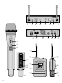 3
3
-
 4
4
-
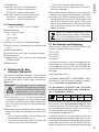 5
5
-
 6
6
-
 7
7
-
 8
8
-
 9
9
-
 10
10
-
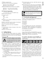 11
11
-
 12
12
-
 13
13
-
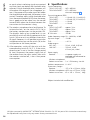 14
14
-
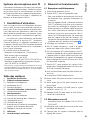 15
15
-
 16
16
-
 17
17
-
 18
18
-
 19
19
-
 20
20
-
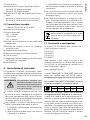 21
21
-
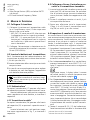 22
22
-
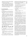 23
23
-
 24
24
-
 25
25
-
 26
26
-
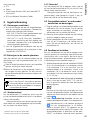 27
27
-
 28
28
-
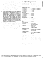 29
29
-
 30
30
-
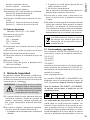 31
31
-
 32
32
-
 33
33
-
 34
34
-
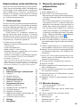 35
35
-
 36
36
-
 37
37
-
 38
38
-
 39
39
-
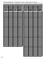 40
40
-
 41
41


IMG STAGELINE 25.3490 Handleiding
- Categorie
- Microfoons
- Type
- Handleiding
in andere talen
- English: IMG STAGELINE 25.3490 User manual
- italiano: IMG STAGELINE 25.3490 Manuale utente
- français: IMG STAGELINE 25.3490 Manuel utilisateur
- español: IMG STAGELINE 25.3490 Manual de usuario
- Deutsch: IMG STAGELINE 25.3490 Benutzerhandbuch
- polski: IMG STAGELINE 25.3490 Instrukcja obsługi
Gerelateerde artikelen
-
IMG STAGELINE TXS-686 Handleiding
-
IMG STAGELINE 0257310 Handleiding
-
Monacor TXS-2402SET Handleiding
-
IMG Stage Line 25.5130 Handleiding
-
-
-
-
-
-
Andere documenten
-
Stageline TXS-860 Handleiding
-
Artsound TXS-882HT Data papier
-
Paso MA853/R850A de handleiding
-
-
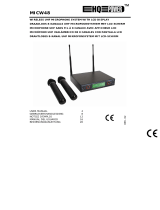 HQ Power MICW48 Handleiding
-
König KN-MICW620 Specificatie
-
Renkforce BM-7200 de handleiding
-
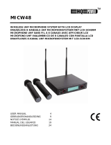 HQ Power MICW48 Handleiding
-
König KN-MICW610UK Specificatie
-
Sony ECM-HW1 de handleiding

