Makita PJ7000 Handleiding
- Categorie
- Elektrisch gereedschap
- Type
- Handleiding

DK
Universalfæser
Brugsanvisning
GR
Συναρμολογητής σανίδων
Οδηγίες χρήσεως
TR
Zıvana Açma Makinası
Kullanma kılavuzu
GB
Plate Joiner
Instruction Manual
Tourillonneuse
Manuel d’instructions
F
Nutfr
D
Betriebsanleitung
äse
Istruzioni per l’uso
Fresatrice
I
Gebruiksaanwijzing
NL
Lamellen freesmachine
Manual de instrucciones
Engalletadora
E
Manual de instruções
Fresadora de Junção
P


8
ENGLISH (Original instructions)
Explanation of general
view
1 Pointer
2 Stopper
3 Adjusting screw
4 Rubber spike
5 Lock lever
6 Angle guide
7 Knob
8 Scale
9 Tighten
10 Loosen
11 Down
12 Up
13 Center of blade thickness
14 Fence
15 Angle scale
16 Blade cover
17 Set plate
18 Thickness of set plate
19 Lock nut
20 Plate joiner blade
21 Inner flange
22 Clamp screw
23 Shaft lock
24 Dust bag
25 Fastener
26 Dust nozzle
27 Exhaust vent
28 Inhalation
vent
29 Slide switch
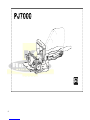
SPECIFICATIONS
Model PJ7000
Type of blade .................................................Plate joiner
Max. grooving depth
Plate joiner blade................................................ 20 mm
No load speed (min–1) .......................................... 11,000
Overall length .....................................................302 mm
Net weight ............................................................. 2.5 kg
Safety class.............................................................. /II
• Due to our continuing program of research and devel-
opment, the specifications herein are subject to change
without notice.
• Specifications may differ from country to country.
• Weight according to EPTA-Procedure 01/2003
ENE013-1
Intended use
The tool is intended for cutting crescent shaped slots for
the placement of flat wooden dowels or biscuit by a
plunging action.
ENF002-2
Power supply
The tool should be connected only to a power supply of the
same voltage as indicated on the nameplate, and can only
be operated on single-phase AC supply. They are double-
insulated and can, therefore, also be used from sockets
without earth wire.
GEA010-1 General Power Tool Safety Warnings
WARNING Read all safety warnings and all
instructions. Failure to follow the warnings and
instructions may result in electric shock, fire and/or serious
injury.
Save all warnings and instructions for future reference.
GEB020-4
PLATE JOINER SAFETY WARNINGS
1. Blades must be rated for at least the speed marked
on the tool. Blades running over rated speed can fly
apart and cause injury.
2. Always use the guard. The guard protects the
operator from broken blade fragments and
unintentional contact with the blade.
3. Hold power tool by insulated gripping surfaces,
because the blade may contact its own cord.
Cutting a “live” wire may make exposed metal parts of
the power tool “live” and could give the operator an
electric shock.
4. Use only the blades specified for this tool.
5. Never operate the tool with the blade locked in
exposed position or without the blade cover
secured properly in place.
6. Make sure that the blade slides smoothly before
operation.
7. Check the blades carefully for cracks or damage
before operation. Replace cracked or damaged
blades immediately.
8. Make sure that the flange fits in the arbor hole
when installing the blade.
9. Inspect for and remove all nails or foreign matter
from the workpieces before operation.
10. Always place the workpieces on a stable
workbench.
11. Secure the workpieces firmly with clamp or vise.
12. NEVER wear gloves during operation.
13. Hold the tool firmly with both hands.
14. Keep your hands and body away from the
grooving area.
15. Run the tool for a while without the blade pointing
toward anybody. Watch for vibration or wobbling
that could indicate poor installation or a poorly
balanced blade.
16. Never reach your hands underneath the
workpieces while the blade is rotating.
17. Do not leave the tool running unattended.

18. Always be sure that the tool is switched off
andunplugged before making any adjustments or
replacing the blade.
19. Some material contains chemicals which may
betoxic. Take caution to prevent dust inhalation
and skin contact. Follow material supplier safety
data.
20. Do not use blunt or damaged blades.
21. Do not use the tool with damaged guards.
SAVE THESE INSTRUCTIONS.
WARNING:
DO NOT let comfort or familiarity with product
(gained from repeated use) replace strict
adherence to safety rules for the subject product.
MISUSE or failure to follow the safety rules stated
in this instruction manual may cause serious
personal injury.
* With the rubber spikes removed.
012681
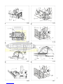
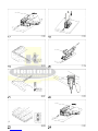
Angle guide (Fig. 2 & 3)
The angle guide height can be moved up and down
to adjust the position of the blade in relation to the top
of the workpiece.
To adjust the angle guide height, loosen the lock
lever down and rotate the knob until the pointer
points to the desired scale graduation marked on the
angle guide.
Then tighten the lock lever up to secure the angle
guide. The scale on the angle guide indicates the
distance from the top of the workpiece to the center
of the blade thickness.
The angle guide is removable from the fence
according to the need of your work. To remove the
angle guide, loosen the lock lever and turn the knob
clockwise until it comes out of the upper end of the
fence.
Fence (Fig. 4 & 5)
NOTE:
• Remove the angle guide according to the need of
your work when using the tool with the angle of the
fence adjusted to other than 0°. When you need to
use the angle guide under the above condition, be
sure to adjust the depth of groove to get a proper
depth.
The angle of the fence can be adjusted between 0°
and 90° (positive stops at 0°, 45° and 90°). To adjust
the angle, loosen the lock lever and tilt the fence until
the pointer points to the desired graduation on the
angle scale. Then tighten the lock lever to secure the
fence. When the fence is set at 90°, both the distance
from the center of the blade thickness to the fence
and the distance from the center of the blade
thickness to the bottom of the blade cover are 10
mm.
Set plate (Fig. 6 & 7)
Use the set plate as shown in Fig. 6 & 7 when cutting
slots in thin workpieces.
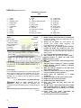
Switch action (Fig. 8)
CAUTION:
• Before plugging in the tool, always check to see
thatthe slide switch actuates properly and returns to
the “OFF” position when the rear of the slide switch
is depressed.
• Switch can be locked in “ON” position for ease of
operatorcomfort during extended use. Apply caution
when locking tool in “ON” position and maintain firm
grasp on tool.
To start the tool, slide the slide switch toward the “I (ON)”
position. For continuous operation, press the front of the
slide switch to lock it.
To stop the tool, press the rear of the slide switch, then
slide it toward the “O (OFF)” position.
FUNCTIONAL DESCRIPTION
CAUTION:
• Always be sure that the tool is switched off and unplugged before adjusting or checking function on the tool.
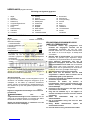
Adjusting the depth of groove (Fig. 1)
6 grooving depths can be preset according to the size of biscuit to be used.
Refer to the table below for the corresponde
nce between the sizes marked on the stopper and the biscuit size. Fine
adjustments to the grooving depth can be made by turning the adjusting screw after loosening the hex nut. This may
become necessary after the blade has been resharpened a few times.
Size on stopper 0 10 20 S D MAX
Biscuit size 0 10 20 — — —
Depth of groove 8 mm 10 mm 12.3 mm 13 mm 14.7 mm 20 mm
*

10
ASSEMBLY
CAUTION:
• Always be sure that the tool is switched off and
unplugged before carrying out any work on the tool.
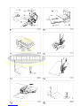
Removing or installing the blade (Fig. 9)
CAUTION:
• When installing the plate joiner blade, mount the
innerflange with the side marked “22” facing toward you.
To remove the blade, loosen the clamp screw and open the
blade cover. Push the shaft lock and loosen the lock nut
using the lock nut wrench. To install the blade, first mount
the inner flange.
Then mount the blade and the lock nut. Securely tighten
the lock nut using the lock nut wrench. Close the blade
cover and tighten the clamp screw to secure the blade
cover.
CAUTION:
• Use only Makita lock nut wrench provided to remove
orinstall the blade.
• Always check the depth of groove after replacing
theblade. Readjust it if necessary.
Dust bag (Fig. 10)
To attach the dust bag, fit it onto the dust nozzle. If the dust
bag becomes an obstacle to your work, turn the dust
nozzle to change the dust bag position.
When the dust bag is about half full, switch off and unplug
the tool. Remove the dust bag from the tool and pull the
bag’s fastener out. Empty the dust bag by tapping it lightly
to remove as much of the dust as possible.
NOTE:
• If you connect a Makita vacuum cleaner to your plate
joiner, more efficient and cleaner operations can be
performed.
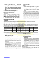
OPERATION
How to make joints
WARNING:
• Always clamp the workpiece to the workbench before
each operation. (Fig. 11 & 12) Corner Joint (Fig. 13, 14 &
15)
T-Butt Joint (Fig. 16, 17 & 18)
Miter Joint (Fig. 19 & 20)
Frame Joint (Fig. 21 & 22) Edge-To-Edge
Joint (Fig. 23 & 24)
To make joints, proceed as follows:
1. Fit the two workpieces together as they will appear in
the finished joint position.
2. Mark the center of the intended biscuit grooves on the
workpiece using a pencil.
NOTE:
• The center of grooves should be at least 50 mm fromthe
outer edge of the workpieces.
• Allow 100 mm – 150 mm between grooves in
multiplebiscuit application.
3. For Corner Joint and T-Butt Joint only Clamp the
vertical workpiece to the workbench.
For Miter Joint only
Clamp one workpiece to the workbench with the
mitered edge facing up.
For Frame Joint and Edge-To-Edge Joint only
Clamp one workpiece to the workbench.
4. Set the depth of groove according to the size of biscuit
to be used. Refer to the table in the “Adjusting the
depth of groove” section.
5. Adjust the angle guide height so that the blade is
centered in the board thickness.
6. Align the center mark on the base with the pencil line
on the workpiece.
7. Switch on the tool and gently push it forward to extend
the blade into the workpiece.
8. Gently return the tool to the original position after the
adjusting screw reaches the stopper.
9. For Corner Joint and T-Butt Joint only Clamp the
horizontal workpiece to the workbench. For Miter
Joint only
Clamp the other workpiece to the workbench with the
mitered edge facing up.
For Frame Joint and Edge-To-Edge Joint only
Clamp the other workpiece to the workbench.
10. For Corner Joint only
Place the tool on the workpiece so that the blade is
facing down. For T-Butt Joint only
Remove the angle guide from the tool. Place the tool
on the workpiece so that the blade is facing down.
11. Repeat the steps 6 – 8 to groove in the horizontal
orthe other workpiece.
If you do not need to center the blade in the board
thickness, proceed as follows:
For Corner Joint, Miter Joint, Frame Joint and EdgeTo-
Edge Joint only
• Remove the angle guide from the tool. Set the fence
at90° for Corner Joint, Frame Joint and Edge-To-Edge
Joint or at 45° for Miter Joint.
• Follow steps 1 – 11 excluding steps 5 and 10
describedabove.
For T-Butt Joint only
• Fit the two workpieces together as they will appear inthe
finished joint position.
• Lay the vertical workpiece on the horizontal one.
Clampboth workpieces to the workbench.
• Remove the angle guide from the tool.
• Follow the steps 2, 4, 6, 7, 8 and 11 described above.
MAINTENANCE
CAUTION:

• Always be sure that the tool is switched off
andunplugged before attempting to perform
inspection or maintenance.
• Never use gasoline, benzine, thinner, alcohol or
thelike. Discoloration, deformation or cracks may
result.
The tool and its air vents have to be kept clean.
Regularly clean the tool’s air vents or whenever the
vents start to become obstructed. (Fig. 25)
To maintain product SAFETY and RELIABILITY,
repairs, carbon brush inspection and replacement,
any other maintenance or adjustment should be
performed by Makita Authorized Service Centers,
always using Makita replacement parts.
OPTIONAL ACCESSORIES
CAUTION:
• These accessories or attachments are recommendedfor
use with your Makita tool specified in this manual. The
use of any other accessories or attachments might
present a risk of injury to persons. Only use accessory or
attachment for its stated purpose.
If you need any assistance for more details regarding these
accessories, ask your local Makita Service Center.
• Angle guide
• Dust bag
• Set plate 4
• Lock nut wrench 20
• Plate joiner blades
NOTE:
• Some items in the list may be included in the tool pack-
age as standard accessories. They may differ from
country to country.
ENG90
5-1 Noise
The typical A-weighted noise level determined
according to EN60745:
Sound pressure level (LpA): 86 dB (A)
Sound power level (LWA): 97 dB (A)
Uncertainty (K): 3 dB (A)
Wear ear protection
ENG9
00-1 Vibration
The vibration total value (tri-axial vector sum)
determined according to EN60745:
Work mode: cutting grooves in MDF
Vibration emission (ah): 2.5 m/s2 or less
Uncertainty (K): 1.5 m/s2
ENG901-1
• The declared vibration emission value has been
mea-sured in accordance with the standard test
method and may be used for comparing one tool
with another.
• The declared vibration emission value may also
beused in a preliminary assessment of exposure.
WARNING:
• The vibration emission during actual use of the
powertool can differ from the declared emission
value depending on the ways in which the tool is
used.
• Be sure to identify safety measures to protect the
oper-ator that are based on an estimation of
exposure in the actual conditions of use (taking
account of all parts of the operating cycle such as
the times when the tool is switched off and when it
is running idle in addition to the trigger time).
ENH101-15
For European countries only
EC Declaration of Conformity
We Makita Corporation as the responsible
manufacturer declare that the following Makita
machine(s):
Designation of Machine: Plate Joiner
Model No./ Type: PJ7000 are of series
production and
Conforms to the following European Directives:
2006/42/EC
And are manufactured in accordance with the following
standards or standardised documents: EN60745
The technical documentation is kept by our authorised
representative in Europe who is:
Makita International Europe Ltd.
Michigan Drive, Tongwell,
Milton Keynes, Bucks MK15 8JD, England
5.4.2011
Tomoyasu Kato Director
Makita Corporation
3-11-8, Sumiyoshi-cho,
Anjo, Aichi, 446-8502, JAPAN

NEDERLANDS (Originele instructies)
Verklaring van algemene gegevens
1 Wijzer
2 Aanslag
3 Stelschroef
4 Rubber dop
5 Vergrendelingshefboom
6 Hoekgeleider
7 Knop
8 Schaalverdeling
9 Vastzetten
10 Losmaken
11 Omlaag
12 Omhoog
13 Midden bladdikte
14 Geleideplaat
15 Hoekschaal
16 Afdekkap
17 Stelplaat
18 Dikte stelplaat
19 Sluitmoer
20 Lamellenfreesblad
21 Binnenflens
22 Klemschroef
23 Asvergrendeling
24 Stofzak
25 Klem
26 Stofmond
27 Uitlaatsleuf
28 Luchtinlaatsleuf
29 Aan/uit-
schakelaar
TECHNISCHE GEGEVENS
Model PJ7000
Type freesblad ............................Lamellen freesmachine
Maximale freesdiepte
Lamellenfreesblad..............................................20 mm
Toerental onbelast/min. (min–1) ............................ 11 000
Totale lengte .......................................................302 mm
Netto gewicht ........................................................ 2,5 kg
Veiligheidsklasse..................................................... /II
• In verband met ononderbroken research en ontwikke-ling
behouden wij ons het recht voor bovenstaande
technische gegevens te wijzigen zonder voorafgaande
kennisgeving.
• De technische gegevens kunnen van land tot land ver-
schillen.
• Gewicht volgens de EPTA-procedure 01/2003
ENE013-1
Gebruiksdoeleinden
De machine is bedoeld voor het frezen van sikkelvormige
gleuven voor het plaatsen van platte, houten pluggen of
lamellen door middel van insteekfrezen.
ENF002-2
Stroomvoorziening
Het gereedschap mag alleen worden aangesloten op een
stroombron van hetzelfde voltage als aangegeven op de
naamplaat, en kan alleen op enkel-fase wisselstroom
worden gebruikt. Het gereedschap is dubbelgeïsoleerd en
kan derhalve ook op een niet-geaard stopcontact worden
aangesloten.
GEA010-1
Algemene veiligheidswaarschuwingen voor elektrisch
gereedschap
WAARSCHUWING! Lees alle
veiligheidswaarschuwingen en alle instructies. Het niet
volgen van de waarschuwingen en instructies kan leiden
tot elektrische schokken, brand en/of ernstig letsel.
Bewaar alle waarschuwingen en instructies om in de
toekomst te kunnen raadplegen.
22
GEB020-4
VEILIGHEIDSWAARSCHUWINGEN VOOR
LAMELLEN FREESMACHINE
1. Freesbladen moeten zijn goedgekeurd voor
minimaal het aangegeven toerental van dit
gereedschap. Freesbladen die met een hoger
toerental draaien dan hun nominaal toerental kunnen
stuk breken en in het rond vliegen, en daarbij letsel
veroorzaken.
2. Gebruik altijd de beschermkap. De beschermkap
beschermt de gebruiker tegen afgebroken stukjes
freesblad en per ongeluk aanraken van het freesblad.
3. Houd elektrisch gereedschap vast aan de
geïsoleerde handgrepen, want het risico bestaat
dat het freesblad het snoer raakt. Als een draad die
onder stroom staat wordt ingesneden, komen de
metalen delen van het gereedschap ook onder stroom
te staan en kunt u een gevaarlijke schok krijgen.
4. Gebruik uitsluitend voorgeschreven bladen.
5. Werk nooit met de machine met het blad
vergrendeld in ontblote stand of zonder dat de
bladafdekkap goed op haar plaats zit.
6. Controleer of het blad vrij ronddraait vooraleer met
de machine te gaan werken.
7. Controleer de bladen op barsten of
beschadigingen vooraleer met de machine te gaan
werken. Vervang een gebarsten of beschadigd
blad onmiddellijk.
8. Controleer of de flens goed in het asgat past bij
het monteren van het blad.
9. Zorg dat het werkstuk vrij is van spijkers en
vreemde voorwerpen vooraleer u met de machine
gaat werken.
10. Plaats de werkstukken altijd op een
stabielewerkbank.
11. Zet de werkstukken stevig vast met een klem
ofbankschroef.
12. Draag NOOIT handschoenen tijdens het
werkenmet de machine.
13. Houd de machine stevig vast met beide handen.

14. Houd uw handen en andere lichaamsdelen uit
debuurt van het freesgedeelte.
15. Laat de machine enige tijd draaien zonder hetblad
op iemand te richten. Let op trillingen of slingering
die kunnen wijzen op een slecht gemonteerd of
uitgebalanceerd blad.
16. Breng de handen nooit onder het werkstuk terwijl
het blad draait.
17. Laat de machine nooit onbeheerd draaien.
18. Controleer altijd of de machine is uitgeschakelden
de stekker uit het stopcontact is getrokken
alvorens afstellingen uit te voeren of het blad te
vervangen.
19. Sommige materialen bevatten chemische
stoffendie giftig kunnen zijn. Neem de nodige
voorzorgsmaatregelen tegen inademing van stof
en contact met de huid. Volg de
veiligheidsinstructies van de leverancier van het
materiaal op.
BESCHRIJVING VAN DE FUNCTIES
LET OP:
20. Gebruik een bot of beschadigd freesblad nietmeer.
21. Gebruik het gereedschap niet wanneer
debeschermkappen beschadigd zijn.
BEWAAR DEZE VOORSCHRIFTEN.
WAARSCHUWING:
Laat u NIET misleiden door een vals gevoel van
comfort en bekendheid met het gereedschap (na
veelvuldig gebruik) en neem alle
veiligheidsvoorschriften van het betreffende
gereedschap altijd strikt in acht. VERKEERD GEBRUIK
of het niet naleven van de veiligheidsvoorschriften in
deze gebruiksaanwijzing kan leiden tot ernstige
verwondingen.
* Met de rubber doppen verwijderd.
012681
Hoekgeleider (Fig. 2 en 3)
De hoogte van de hoekgeleider is omhoog en omlaag
verstelbaar, om de stand van het freesblad ten
opzichte van de bovenkant van het werkstuk in te
stellen.
Om de hoogte van de hoekgeleider in te stellen, zet u
eerst de vergrendelingshefboom omlaag en draait u
de knop totdat de wijzer de juiste hoek aangeeft op
de schaalverdeling afgebeeld op de hoekgeleider.
Zet daarna de vergrendelingshefboom omhoog om
de hoekgeleider te vergrendelen. De schaalverdeling
op de hoekgeleider geeft de afstand aan van de
bovenkant van het werkstuk tot het midden van de
bladdikte.
De hoekgeleider kan worden verwijderd van de
geleideplaat, al naar gelang de vereisten van uw
werkstuk. Voor het losmaken van de hoekgeleider zet
u de vergrendelingshefboom los en dan draait u de
knop rechtsom totdat deze uit de bovenkant van de
geleideplaat uitsteekt.
Geleideplaat (Fig. 4 en 5)
OPMERKING:
• Verwijder de hoekgeleider al naar gelang de aard
van uw werk, voor gebruik van het gereedschap
met de hoek van de geleideplaat in een andere
stand dan 0°. Wanneer u in een dergelijke stand de
hoekgeleider moet gebruiken, let dan vooral goed
op dat de freesdiepte juist is ingesteld.
De hoek van de geleideplaat kan worden ingesteld tussen
0° en 90° (klikstanden op 0°, 45° en 90°). Om de hoek te
regelen, zet u de vergrendelingshefboom los en kantelt u
de geleideplaat tot de wijzer de gewenste stand op de
schaalverdeling aangeeft. Zet dan de
vergrendelingshefboom vast om de geleideplaat te
blokkeren. Wanneer de geleideplaat in een hoek van 90° is
gezet, is zowel de afstand van het midden van de bladdikte
tot de geleideplaat als de afstand van het midden van de
bladdikte tot de onderkant van de zaagbladbeschermkap
10 mm.
Stelplaat (Fig. 6 en 7)
Gebruik de stelplaat zoals wordt getoond in Fig. 6 en 7 om
gleuven in dunne werkstukken te maken.
• Controleer altijd of de machine is uitgeschakeld en zijn stekker uit het stopcontact is verwijderd alvorens de functies
op de machine te controleren of af te stellen.
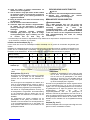
Instellen van de freesdiepte (Fig. 1)
U kunt vooraf één van de zes freesdiepten instellen afhankelijk van de grootte van de lamellen die gebruikt gaan
worden.
Raadpleeg de onderstaande tabel voor de overeenk
omst tussen de afmetingen die zijn vermeld op de aanslag en de
grootte van het verbindingsstuk. Fijnafstelling van de freesdiepte kan door aan de stelschroef te draaien na het
losdraaien van de zeskantmoer. Dit kan noodzakelijk zijn nadat het freesblad enkele keren is geslepen.
Maat op aanslag 0 10 20 S D MAX
Formaat verbindingsstuk 0 10 20 — — —
Freesdiepte 8 mm 10 mm 12,3 mm 13 mm 14,7 mm 20 mm*

Werking van de aan/uit-schakelaar (Fig. 8)
LET OP:
• Controleer altijd, voordat u het gereedschap aansluitop
het elektriciteitsnet, of de aan/uit-schakelaar op de juiste
manier schakelt en weer terugkeert naar de “OFF” (uit)-
stand (O), wanneer op de achterkant van de aan/uit-
schakelaar wordt gedrukt.
• De schakelaar kan in de “ON” (aan)-stand
vergrendeldworden, hetgeen bij langdurig gebruik
comfortabeler werkt. Wees extra voorzichtig wanneer u
de schakelaar in de “ON” (aan)-stand vergrendelt en
houd het gereedschap altijd stevig vast.
23
Om de machine in te schakelen, schuift u de
aan/uitschakelaar naar de “I ON” (aan)-stand. Om het
gereedschap continu te laten werken, drukt u op de
voorkant van de aan/uit-schakelaar om deze te
vergrendelen. Om de machine uit te schakelen drukt u op
de achterkant van de aan/uit-schakelaar en schuift u de
knop naar de “O (OFF)” (uit)-stand.
INEENZETTEN
LET OP:
• Zorg altijd dat de machine is uitgeschakeld en dat zijn
stekker uit het stopcontact is verwijderd alvorens enig
werk aan de machine uit te voeren.
Het blad demonteren of monteren (Fig. 9)
LET OP:
• Bij het monteren van het lamellen freesblad plaatst ude
binnenflens met de zijde met “22” erop naar u gericht.
Om het blad te verwijderen, de klemschroef losdraaien en
de bladafdekkap openen. Druk op de asgrendel en draai
de sluitmoer los met de nokkensleutel. Om het blad te
monteren eerst de binnenflens aanbrengen.
Monteer dan het blad en de sluitmoer. Draai de sluitmoer
stevig vast met de nokkensleutel. Sluit de bladafdekkap en
draai de klemschroef vast om de bladafdekkap te
vergrendelen.
LET OP:
• Gebruik uitsluitend de bijgeleverde Makita-sleutel bijhet
aanbrengen of verwijderen van het freesblad.
• Controleer na het vervangen van het freesblad altijd ofde
freesdiepte juist is. Stel de freesdiepte zo nodig opnieuw
in.
Stofzak (Fig. 10)
Bevestig de stofzak op de stofmond. Als de stofzak tijdens
het werk in de weg zit, verdraait u de stofmond om de
stand van de stofzak te veranderen.
Wanneer de stofzak ongeveer halfvol is, schakelt u het
gereedschap uit en trekt u de stekker uit het stopcontact.
Haal de stofzak van het gereedschap af en trek de klem
eraf. Gooi de stofzak leeg door er zacht tegen te tikken om
zo veel mogelijk stof eruit te verwijderen.
OPMERKING:
• Als u een Makita-stofzuiger aansluit op uw
lamellenfreesmachine, kunt u nog efficiënter en schoner
werken.
BEDIENING
Verbindingen maken
WAARSCHUWING:
• Klem vóór het werk altijd uw werkstuk stevig aan de
werkbank vast. (Fig. 11 en 12)
Hoekverbinding (Fig. 13, 14 en 15)
T-verbinding (Fig. 16, 17 en 18)
Verstekverbinding (Fig. 19 en 20)
Raamverbinding (Fig. 21 en 22)
Langsverbinding (Fig. 23 en 24)
Om verbindingen te maken, gaat u als volgt tewerk:
1. Breng de twee werkstukken in de definitieve stand.
2. Markeer het midden van de groeven voor de
verbindingsstukken met een potlood.
24
OPMERKING:
• Het midden van de groeven moet minstens 50 mm
vande rand van het werkstuk liggen.
• Laat bij meervoudige verbindingsstukken een
afstandvan 100 – 150 mm tussen de groeven.
3. Enkel voor hoekverbinding en T-verbinding
Klem het verticale werkstuk vast op de werkbank.
Enkel voor verstekverbinding
Klem één werkstuk vast op de werkbank met de
verstekgezaagde kant omhoog gericht. Enkel
voor raamverbinding en langsverbinding
Klem één werkstuk vast op de werkbank.
4. Stel de freesdiepte passend in voor het formaat
van de lamellen die gebruikt gaan worden.
Raadpleeg de tabel onder het kopje “Instellen van
de freesdiepte”.
5. Stel de hoogte van de hoekgeleider in zodat het
blad in het midden van de plankdikte staat.
6. Laat de middenmarkering op de grondplaat
samenvallen met de potloodlijn op het werkstuk.
7. Zet de machine aan en duw ze voorzichtig naar
voren om het blad in het werkstuk te brengen.
8. Breng de machine voorzichtig weer in de originele
stand wanneer de stelschroef de aanslag heeft
bereikt.

9. Enkel voor hoekverbinding en T-verbinding
Klem het horizontale werkstuk vast op de
werkbank. Enkel voor verstekverbinding
Klem het andere werkstuk vast op de werkbank
met de verstekgezaagde kant omhoog gericht.
Enkel voor raamverbinding en
langsverbinding Klem één werkstuk vast op de
werkbank.
10. Enkel voor hoekverbinding
Plaats de machine op het werkstuk met het blad
naar onderen gericht. Enkel voor T-verbinding
Verwijder de hoekgeleider van de machine.
Plaats de machine op het werkstuk met het blad
naar onderen gericht.
11. Herhaal de stappen van 6 – 8 om groeven te
frezenin het horizontale of het andere werkstuk.
Indien het blad niet in het midden van de plank moet
worden gecentreerd, gaat u als volgt tewerk:
Enkel voor hoekverbinding, verstekverbinding,
raamverbinding en langsverbinding
• Verwijder de hoekgeleider van de machine. Stel
degeleideplaat in op 90° voor hoekverbinding,
raamverbinding en langsverbinding of op 45° voor
verstekverkbinding.
• Volg stappen 1 – 11 zoals hierboven beschreven,
metuitzondering van stappen 5 en 10.
Enkel voor T-verbinding
• Breng de twee werkstukken in de definitieve stand.
• Plaats het verticale werkstuk op het horizontale.
Klembeide werkstukken op de werkbank.
• Verwijder de hoekgeleider van de machine.
• Volg de stappen 2, 4, 6, 7, 8 en 11 zoals
hierbovenbeschreven.
ONDERHOUD
LET OP:
• Zorg altijd dat het gereedschap is uitgeschakeld en
zijnstekker uit het stopcontact is verwijderd
alvorens te beginnen met inspectie of onderhoud.
• Gebruik nooit benzine, wasbenzine, thinner, alcohol
endergelijke. Hierdoor het verkleuring,
vervormingen en barsten worden veroorzaakt.
Zorg dat het gereedschap goed schoon blijft, vooral
de ventilatiesleuven. Reinig de luchtsleuven
regelmatig en zorg dat ze niet geblokkeerd of
verstopt raken. (Fig. 25)
Om de VEILIGHEID en BETROUWBAARHEID van
het gereedschap te verzekeren, dienen alle
reparaties, inspectie en vervanging van koolborstels,
en alle andere onderhoudswerkzaamheden of
afstellingen te worden uitgevoerd door een erkend
Makita servicecentrum, en dit uitsluitend met gebruik
van originele Makita vervangingsonderdelen.
OPTIONELE ACCESSOIRES
LET OP:
• Deze accessoires of hulpstukken worden
aanbevolenvoor gebruik met het Makita
gereedschap dat in deze gebruiksaanwijzing wordt
beschreven. Het gebruik van andere accessoires of
hulpstukken kan gevaar voor persoonlijke
verwonding opleveren. Gebruik de accessoires of
hulpstukken uitsluitend voor het gespecificeerde
doel.
Wenst u meer informatie over deze accessoires,
neem dan contact op met het dichtstbijzijnde Makita
servicecentrum.
• Hoekgeleider
• Stofzak
• Stelplaat 4
• Sluitmoersleutel 20
• Lamellenfreesblad
OPMERKING:
• Sommige van de onderdelen in deze lijst kunnen
bijge-leverd zijn als standaard-accessoires. Deze
accessoires kunnen per land verschillend zijn.
ENG905-1 Geluidsniveau
De typisch, A-gewogen geluidsniveaus vastgesteld
volgens EN60745:
Geluidsdrukniveau (LpA): 86 dB (A)
Geluidsenergie-niveau (LWA): 97 dB (A)
Onnauwkeurigheid (K): 3 dB (A)
Draag oorbeschermers
ENG90
0-1 Trilling
De totaalwaarde van de trillingen (triaxiale
vectorsom) vastgesteld volgens EN60745:
Toepassing: Groeven frezen in MDF
Trillingsemissie (ah): 2,5 m/s2 of lager
Onnauwkeurigheid (K): 1,5 m/s2
ENG901-1
• De opgegeven trillingsemissiewaarde is gemeten vol-
gens de standaardtestmethode en kan worden gebruikt
om dit gereedschap te vergelijken met andere
gereedschappen.
• De opgegeven trillingsemissiewaarde kan ook
wordengebruikt voor een beoordeling vooraf van de
blootstelling.
WAARSCHUWING:
• De trillingsemissie tijdens het gebruik van het
elektrischgereedschap in de praktijk kan verschillen van
de opgegeven trillingsemissiewaarde afhankelijk van de
manier waarop het gereedschap wordt gebruikt.
• Zorg ervoor dat veiligheidsmaatregelen worden getrof-
fen ter bescherming van de operator die zijn gebaseerd
op een schatting van de blootstelling onder
praktijkomstandigheden (rekening houdend met alle
fasen van de bedrijfscyclus, zoals de tijdsduur gedurende
welke het gereedschap is uitgeschakeld en stationair
draait, naast de ingeschakelde tijdsduur).
ENH101-15

Alleen voor Europese landen
EU-Verklaring van Conformiteit
Wij, Makita Corporation, als de verantwoordelijke
fabrikant, verklaren dat de volgende Makitamachine(s):
Aanduiding van de machine: Lamellen freesmachine
Modelnr./Type: PJ7000 in serie
zijn geproduceerd en
Voldoen aan de volgende Europese richtlijnen:
2006/42/EC
En zijn gefabriceerd in overeenstemming met de volgende
normen of genormaliseerde documenten: EN60745
De technische documentatie wordt bewaard door onze
erkende vertegenwoordiger in Europa, te weten:
Makita International Europe Ltd.
Michigan Drive, Tongwell,
Milton Keynes, Bucks MK15 8JD, Engeland
5.4.2011
Tomoyasu Kato Directeur
Makita Corporation
3-11-8, Sumiyoshi-cho,
Anjo, Aichi, 446-8502, JAPAN
25
885075A995
IDE
Makita
Corporation
Anjo, Aichi, Japan
www.makita.com
-
 1
1
-
 2
2
-
 3
3
-
 4
4
-
 5
5
-
 6
6
-
 7
7
-
 8
8
-
 9
9
-
 10
10
-
 11
11
-
 12
12
-
 13
13
-
 14
14
-
 15
15
-
 16
16


Makita PJ7000 Handleiding
- Categorie
- Elektrisch gereedschap
- Type
- Handleiding
in andere talen
- English: Makita PJ7000 User manual