STIEBEL ELTRON STIEBEL-ELTRON HSBC 300 Electric Hot Water Tank Handleiding
- Categorie
- Warmtepompen
- Type
- Handleiding

BEDIENUNG UND INSTALLATION
OPERATION AND INSTALLATION
UTILISATION ET INSTALLATION
BEDIENING EN INSTALLATIE
USO E INSTALLAZIONE
Integralspeicher | Integral cylinder| Tour hydraulique combinée | Combiboiler |
Caldaia integrale
» HSBC 300 cool (WPM)

2 | HSBC 300 cool www.stiebel-eltron.com
INHALT
BESONDERE HINWEISE
BEDIENUNG
1. Allgemeine Hinweise ����������������������������������������3
1.1 Mitgeltende Dokumente ���������������������������������������� 3
1.2 Sicherheitshinweise ��������������������������������������������� 3
1.3 Andere Markierungen in dieser Dokumentation ���������� 4
1.4 Hinweise am Gerät ���������������������������������������������� 4
1.5 Maßeinheiten ����������������������������������������������������� 4
2. Sicherheit �����������������������������������������������������4
2.1 Bestimmungsgemäße Verwendung ������������������������� 4
2.2 Allgemeine Sicherheitshinweise ������������������������������ 4
2.3 Prüfzeichen ������������������������������������������������������� 4
3. Gerätekompatibilität ����������������������������������������� 5
4. Gerätebeschreibung �����������������������������������������5
5. Reinigung, Pflege und Wartung ����������������������������5
6. Problembehebung �������������������������������������������5
INSTALLATION
7. Sicherheit �����������������������������������������������������6
7.1 Allgemeine Sicherheitshinweise ������������������������������ 6
7.2 Vorschriften, Normen und Bestimmungen ����������������� 6
8. Gerätebeschreibung �����������������������������������������6
8.1 Lieferumfang ����������������������������������������������������� 6
8.2 Zubehör ������������������������������������������������������������ 6
9. Vorbereitungen ����������������������������������������������� 6
9.1 Montageort ������������������������������������������������������� 6
9.2 Transport und Einbringung ������������������������������������ 7
10. Montage ����������������������������������������������������� 12
10.1 Aufstellung des Gerätes ���������������������������������������12
10.2 Heizwasser-Anschluss ����������������������������������������� 12
10.3 Trinkwasser-Anschluss und Sicherheitsgruppe ���������� 14
10.4 Anlage befüllen �������������������������������������������������15
10.5 Gerät entlüften �������������������������������������������������� 16
11. Elektrischer Anschluss ������������������������������������� 16
11.1 Steuerspannung ������������������������������������������������ 17
11.2 Sicherheitskleinspannung ������������������������������������ 17
11.3 Anschlussbelegung Wärmepumpen-Manager ������������ 17
11.4 Zubehör �����������������������������������������������������������18
11.5 Fühlermontage �������������������������������������������������� 19
11.6 Fernbedienung �������������������������������������������������� 19
12. Inbetriebnahme �������������������������������������������� 19
12.1 Kontrollen vor Inbetriebnahme des Wärmepumpen-
Managers ��������������������������������������������������������� 19
12.2 Inbetriebnahme des Wärmepumpen-Managers ��������� 19
13. Einstellungen ����������������������������������������������� 20
13.1 Umwälzpumpen Wilo-Para .../Sc ����������������������������20
14. Übergabe des Gerätes ������������������������������������� 21
15. Außerbetriebnahme ��������������������������������������� 21
16. Wartung ����������������������������������������������������� 21
17. Technische Daten ������������������������������������������� 22
17.1 Maße und Anschlüsse ����������������������������������������� 22
17.2 Elektroschaltplan ����������������������������������������������� 24
17.3 Installationsbeispiel �������������������������������������������� 27
17.4 Angaben zum Energieverbrauch ���������������������������� 27
17.5 Datentabelle ����������������������������������������������������� 27
17.6 Zubehör �����������������������������������������������������������28
UMWELT UND RECYCLING
KUNDENDIENST UND GARANTIE

BESONDERE HINWEISE
Allgemeine Hinweise
DEUTSCH
www.stiebel-eltron.com HSBC 300 cool | 3
BESONDERE HINWEISE
- Das Gerät kann von Kindern ab 8 Jahren sowie
von Personen mit verringerten physischen,
sensorischen oder mentalen Fähigkeiten oder
Mangel an Erfahrung und Wissen benutzt
werden, wenn sie beaufsichtigt werden oder
bezüglich des sicheren Gebrauchs des Gerätes
unterwiesen wurden und die daraus resultie-
renden Gefahren verstanden haben. Kinder
dürfen nicht mit dem Gerät spielen. Reini-
gung und Benutzer-Wartung dürfen nicht von
Kindern ohne Beaufsichtigung durchgeführt
werden.
- Der Anschluss an das Stromnetz ist nur als
fester Anschluss erlaubt. Das Gerät muss
über eine Trennstrecke von mindestens 3mm
allpolig vom Netzanschluss getrennt werden
können.
- Beachten Sie alle nationalen und regionalen
Vorschriften und Bestimmungen.
- Halten Sie die Mindestabstände ein (siehe
Kapitel „Installation/ Vorbereitungen/
Montageort“).
- Die Installation, Inbetriebnahme sowie War-
tung und Reparatur des Gerätes darf nur von
einem Fachhandwerker durchgeführt werden.
Trinkwarmwasserspeicher
- Entleeren Sie das Gerät wie in Kapitel „Instal-
lation/ Wartung/ Trinkwarmwasserspeicher
entleeren“ beschrieben.
- Beachten Sie den maximal zulässigen Druck
(siehe Kapitel „Installation/ Technische
Daten/ Datentabelle“).
- Der Trinkwarmwasserspeicher steht unter
Versorgungsdruck. Während der Aufheizung
tropft das Ausdehnungswasser aus dem
Sicherheitsventil.
- Die Ablauföffnung des Sicherheitsventils muss
zur Atmosphäre geöffnet bleiben.
BEDIENUNG
1. Allgemeine Hinweise
Die Kapitel „Besondere Hinweise“ und „Bedienung“ richten sich
an den Gerätebenutzer und den Fachhandwerker.
Das Kapitel „Installation“ richtet sich an den Fachhandwerker.
Hinweis
Lesen Sie diese Anleitung vor dem Gebrauch sorgfältig
durch und bewahren Sie sie auf.
Geben Sie die Anleitung ggf. an einen nachfolgenden
Benutzer weiter.
1.1 Mitgeltende Dokumente
Anleitungen des Wärmepumpen-Managers WPM
Bedienungs- und Installationsanleitung der angeschlos-
senen Wärmepumpe
Bedienungs- und Installationsanleitungen aller weiteren
zur Anlage gehörenden Komponenten
1.2 Sicherheitshinweise
1.2.1 Aufbau von Sicherheitshinweisen
SIGNALWORT Art der Gefahr
Hier stehen mögliche Folgen bei Nichtbeachtung des Si-
cherheitshinweises.
f Hier stehen Maßnahmen zur Abwehr der Gefahr.
1.2.2 Symbole, Art der Gefahr
Symbol Art der Gefahr
Verletzung
Stromschlag
Verbrennung
(Verbrennung, Verbrühung)
1.2.3 Signalworte
SIGNALWORT Bedeutung
GEFAHR Hinweise, deren Nichtbeachtung schwere Verletzungen
oder Tod zur Folge haben.
WARNUNG Hinweise, deren Nichtbeachtung schwere Verletzungen
oder Tod zur Folge haben kann.
VORSICHT Hinweise, deren Nichtbeachtung zu mittelschweren oder
leichten Verletzungen führen kann.

BEDIENUNG
Sicherheit
4 | HSBC 300 cool www.stiebel-eltron.com
1.3 Andere Markierungen in dieser Dokumentation
Hinweis
Allgemeine Hinweise werden mit dem nebenstehenden
Symbol gekennzeichnet.
f Lesen Sie die Hinweistexte sorgfältig durch.
Symbol Bedeutung
Sachschaden
(Geräte-, Folge-, Umweltschaden)
Geräteentsorgung
f Dieses Symbol zeigt Ihnen, dass Sie etwas tun müssen.
Die erforderlichen Handlungen werden Schritt für Schritt
beschrieben.
1.4 Hinweise am Gerät
Anschlüsse
Symbol Bedeutung
Zulauf/ Eintritt
roter Pfeil: warm
blauer Pfeil: kalt
grüner Pfeil: neutral
Auslauf/ Austritt
roter Pfeil: warm
blauer Pfeil: kalt
grüner Pfeil: neutral
Trinkwarmwasser
Zirkulation
Wärmepumpe
Heizung
1.5 Maßeinheiten
Hinweis
Wenn nicht anders angegeben, sind alle Maße in Milli-
meter.
2. Sicherheit
2.1 Bestimmungsgemäße Verwendung
Das Gerät dient zur saisonalen Beheizung und Kühlung (7°C/
12°C) von Räumen und zur Trinkwasser-Erwärmung.
Das Gerät ist für den Einsatz im häuslichen Umfeld vorgesehen.
Es kann von nicht eingewiesenen Personen sicher bedient wer-
den. In nicht häuslicher Umgebung, z.B. im Kleingewerbe, kann
das Gerät ebenfalls verwendet werden, sofern die Benutzung in
gleicher Weise erfolgt.
Eine andere oder darüber hinausgehende Benutzung gilt als nicht
bestimmungsgemäß. Zum bestimmungsgemäßen Gebrauch ge-
hört auch das Beachten dieser Anleitung sowie der Anleitungen
für eingesetztes Zubehör.
2.2 Allgemeine Sicherheitshinweise
WARNUNG Verbrennung
Bei Auslauftemperaturen größer 43°C besteht Verbrü-
hungsgefahr.
!
WARNUNG Verletzung
Das Gerät kann von Kindern ab 8 Jahren sowie von Per-
sonen mit verringerten physischen, sensorischen oder
mentalen Fähigkeiten oder Mangel an Erfahrung und
Wissen benutzt werden, wenn sie beaufsichtigt werden
oder bezüglich des sicheren Gebrauchs des Gerätes un-
terwiesen wurden und die daraus resultierenden Gefah-
ren verstanden haben. Kinder dürfen nicht mit dem Gerät
spielen. Reinigung und Benutzer-Wartung dürfen nicht
von Kindern ohne Beaufsichtigung durchgeführt werden.
!
WARNUNG Verletzung
Betreiben Sie das Gerät aus Sicherheitsgründen nur mit
geschlossener Frontverkleidung.
!
Sachschaden
Bei unterbrochener Spannungsversorgung ist der aktive
Frostschutz der Anlage nicht gewährleistet.
f Unterbrechen Sie die Spannungsversorgung auch
außerhalb der Heizperiode nicht.
Hinweis
Der Trinkwarmwasserspeicher steht unter Versorgungs-
druck. Während der Aufheizung tropft das Ausdehnungs-
wasser aus dem Sicherheitsventil.
f Tropft nach Beendigung der Aufheizung Wasser, in-
formieren Sie Ihren Fachhandwerker.
2.3 Prüfzeichen
Siehe Typenschild am Gerät.

BEDIENUNG
Gerätekompatibilität
DEUTSCH
www.stiebel-eltron.com HSBC 300 cool | 5
3. Gerätekompatibilität
Sie können das Gerät in Kombination mit den folgenden Luft-Was-
ser-Wärmepumpen betreiben:
- HPA-O 05.1-07.1 CS Premium
- HPA-O 7-13 (C)(S) Premium
- WPL-A 05-07 HK 230 Premium
- WPL 15-25 A(C)(S)
- WPL 19-24 I, A
4. Gerätebeschreibung
Der Pufferspeicher und der Trinkwarmwasserspeicher mit Wär-
meübertrager sind übereinander angeordnet und können für die
Einbringung voneinander getrennt werden.
Das Gerät ist im Kunststoff-Mantel geschäumt und mit einer ab-
nehmbaren Frontverkleidung ausgestattet. Mit der Wärmepumpe
wird das Gerät hydraulisch und elektrisch verbunden. Alle hydrau-
lischen Anschlüsse sind nach oben (Heizung) und hinten (Trink-
wasser) ausgeführt.
Neben dem Trinkwarmwasserspeicher und dem Pufferspeicher
sind weitere Systemkomponenten integriert:
- Wärmepumpen-Manager
- hocheffiziente Umwälzpumpe für einen ungemischten
Heizkreis
- 3-2-Wege-Umschaltventil
- Speicherladepumpe
Trinkwarmwasserspeicher
Der Stahlbehälter ist innen mit Spezial-Direktemail und einer Si-
gnalanode ausgerüstet. Die Anode mit Verbrauchsanzeige ist ein
Schutz des Behälterinneren vor Korrosion.
Das von der Wärmepumpe erwärmte Heizungswasser wird durch
einen Wärmeübertrager im Trinkwarmwasserspeicher gepumpt.
Der Wärmeübertrager gibt die dabei aufgenommene Wärme an
das Trinkwasser ab. Der integrierte Wärmepumpen-Manager steu-
ert die Trinkwasser-Erwärmung auf die gewünschte Temperatur.
Pufferspeicher
Der Stahlbehälter dient der hydraulischen Entkopplung der Volu-
menströme von Wärmepumpe und Heizkreis. Das von der Wärme-
pumpe erwärmte Heizungswasser wird durch die Speicherlade-
pumpe in den Pufferspeicher transportiert. Bei Anforderung wird
das Heizungswasser mit der integrierten Heizkreis-Umwälzpumpe
dem Heizkreis zugeführt.
Wärmepumpen-Manager (WPM)
Die Regelung der Anlage erfolgt über den integrierten Wärme-
pumpen-Manager.
Hinweis
Der Wärmepumpen-Manager verfügt über eine auto-
matische Sommer/Winter-Umschaltung, sodass Sie die
Anlage im Sommer eingeschaltet lassen können.
f Beachten Sie die Anleitungen des Wärmepumpen-Managers.
5. Reinigung, Pflege und Wartung
f Lassen Sie die elektrische Sicherheit am Gerät und die Funk-
tion der Sicherheitsgruppe regelmäßig von einem Fachhand-
werker prüfen.
f Verwenden Sie keine scheuernden oder anlösenden Reini-
gungsmittel. Zur Pflege und Reinigung des Gerätes genügt
ein feuchtes Tuch.
Verbrauchsanzeige Signalanode
!
Sachschaden
Wenn die Verbrauchsanzeige von der weißen auf eine
rote Färbung umgeschlagen ist, lassen Sie die Signalano-
de von einem Fachhandwerker kontrollieren und ggf.
austauschen.
D0000102539
12
1 weiß = Anode ok
2 rot = Kontrolle vom Fachhandwerker notwendig
6. Problembehebung
Problem Ursache Behebung
Das Wasser wird nicht
warm. Die Heizung funk-
tioniert nicht.
Es liegt keine Spannung
an.
Prüfen Sie die Sicherun-
gen in der Hausinstal-
lation.
Wenn Sie die Ursache nicht beheben können, rufen Sie den Fach-
handwerker. Zur besseren und schnelleren Hilfe teilen Sie ihm die
Nummer vom Typenschild mit (000000-0000-000000).
No.: 000000-0000-000000
Made in Germany
D0000102540

INSTALLATION
Sicherheit
6 | HSBC 300 cool www.stiebel-eltron.com
INSTALLATION
7. Sicherheit
Die Installation, Inbetriebnahme sowie Wartung und Reparatur
des Gerätes darf nur von einem Fachhandwerker durchgeführt
werden.
7.1 Allgemeine Sicherheitshinweise
Wir gewährleisten eine einwandfreie Funktion und Betriebssicher-
heit nur, wenn das für das Gerät bestimmte Original-Zubehör und
die originalen Ersatzteile verwendet werden.
7.2 Vorschriften, Normen und Bestimmungen
Hinweis
Beachten Sie alle nationalen und regionalen Vorschriften
und Bestimmungen.
8. Gerätebeschreibung
8.1 Lieferumfang
Mit dem Gerät werden geliefert:
- 4x Stellfuß
- 1x Außentemperaturfühler AF PT
8.2 Zubehör
8.2.1 Notwendiges Zubehör
In Abhängigkeit vom Versorgungsdruck sind Sicherheitsgruppen
und Druckminderventile erhältlich. Diese baumustergeprüften Si-
cherheitsgruppen schützen das Gerät vor unzulässigen Drucküber-
schreitungen.
Für Flächenkühlung notwendig:
- Temperaturfühler PT1000
- Fernbedienung FET
8.2.2 Weiteres Zubehör
- Pumpenbaugruppe für einen gemischten Heizkreis
HSBC3-HKM
- Rohrbausatz RBS-SBC
- Druckschläuche
- Enthärtungsarmatur HZEA
- Temperaturfühler für Kühlung
- Fernbedienung für den Heizbetrieb
- Sicherheitstemperaturbegrenzer für
FußbodenheizungSTB-FB
Rohrbausatz RBS-SBC
Die hydraulischen Anschlüsse können mit dem als Zubehör er-
hältlichen Rohrbausatz RBS-SBC hinter dem Trinkwarmwasser-
speicher nach oben geführt werden.
9. Vorbereitungen
9.1 Montageort
!
Sachschaden
Stellen Sie das Gerät nicht in Feuchträumen auf.
Montieren Sie das Gerät in einem frostfreien und trockenen Raum
in der Nähe der Entnahmestelle. Um Leitungsverluste zu reduzie-
ren, halten Sie den Abstand zwischen Gerät und Wärmepumpe
gering.
Achten Sie auf eine ausreichende Tragfähigkeit und Ebenheit des
Fußbodens (Gewicht siehe Kapitel „Technische Daten/ Datenta-
belle“).
Der Raum darf nicht durch Staub, Gase oder Dämpfe explosions-
gefährdet sein.
Wenn Sie das Gerät in einem Heizraum zusammen mit anderen
Heizgeräten aufstellen, stellen Sie sicher, dass der Betrieb der
anderen Heizgeräte nicht beeinträchtigt wird.
Mindestabstände
≥250 ≥250
≥800
≥100
≥500
≥100
≥500
D0000102541
Die seitlichen Mindestabstände können nach rechts oder links
getauscht werden.

INSTALLATION
Vorbereitungen
DEUTSCH
www.stiebel-eltron.com HSBC 300 cool | 7
9.2 Transport und Einbringung
!
Sachschaden
Lagern und transportieren Sie das Gerät bei Temperatu-
ren von -20°C bis +60°C.
Einbringung
f Schrauben Sie die 4Schrauben an der Einwegpalette heraus.
D0000055519
f Kippen Sie das Gerät an und schrauben Sie die beiliegenden
4Stellfüße ein.
f Heben Sie das Gerät von der Palette. Nutzen Sie die Griffmul-
den an der Unter- und Rückseite des Gerätes für besseren
Halt beim Transport.
Falls enge Türen oder Gänge die Einbringung behindern, können
Sie den oberen vom unteren Geräteteil trennen wie in den folgen-
den Kapiteln beschrieben.
9.2.1 Frontverkleidung demontieren/ montieren
Frontverkleidung demontieren
D0000101859
f Entfernen Sie die 2Sicherungsschrauben an der Oberseite
der Frontverkleidung.
f Haken Sie die Frontverkleidung nach oben aus.
f AA01-X1.18: Ziehen Sie bei Bedarf den Anschlussstecker der
Bedieneinheit vom Anschluss im Gerät ab. Die Funktionsfä-
higkeit vom Gerät wird nicht beeinträchtigt. Die Bedienung
über die Bedieneinheit ist nicht möglich.
f Lösen Sie das Erdungskabel von der Frontverkleidung.
Frontverkleidung montieren
f Montieren Sie die Frontverkleidung in umgekehrter
Reihenfolge.

INSTALLATION
Vorbereitungen
8 | HSBC 300 cool www.stiebel-eltron.com
9.2.2 Übersicht Dämmelemente
D0000101865
1
2 3 4
1 Dämmelement1
2 Dämmelement2
3 Dämmstoffschraube
4 Dämmelement3

INSTALLATION
Vorbereitungen
DEUTSCH
www.stiebel-eltron.com HSBC 300 cool | 9
9.2.3 Geräteteile trennen/ zusammenfügen
Geräteteile trennen
Sachschaden
Das Herausdrehen der Befestigungsschrauben zerstört
die Gewindegänge im Dämmelement.
f Zum Öffnen der 3Befestigungslaschen dürfen die
Befestigungsschrauben nur leicht gelöst, jedoch
nicht vollständig herausgedreht werden.
D0000101928
Hinweis
Zur vereinfachten Demontage sind die Dämmelemente
links- und rechtsseitig mit gekennzeichneten Griffmulden
ausgestattet.
D0000101932
f Entnehmen Sie Dämmelement1.
f Entnehmen Sie Dämmelement2.
D0000080287
f Ziehen Sie den „Fühler Heizung“ am Pufferspeicher heraus.
D0000080288
f Lösen Sie das Fühlerkabel aus der Führungsnut im
Dämmelement.
D0000080289
f Lösen Sie die Steckverbinder der 4hydraulischen Anschlüsse.
Ziehen Sie dazu die Federklemmen mit einem Schraubendre-
her bis zum Anschlag heraus.
f Ziehen Sie die hydraulischen Anschlüsse wie dargestellt ab.

INSTALLATION
Vorbereitungen
10 | HSBC 300 cool www.stiebel-eltron.com
D0000080293
f Entnehmen Sie die 4Hydraulikschläuche.
f Entnehmen Sie die 2Dämmstoffschrauben.
f Entnehmen Sie Dämmelement3.
D0000101956
f Lösen Sie die 2Sicherungsschrauben an den seitlichen
Profilleisten.
f Haken Sie die seitlichen Profilleisten nach oben aus.
D0000080343
f Lösen Sie die 4Schrauben an den Laschen vorn am Gerät.
D0000074613
f Ziehen Sie den oberen Geräteteil nach vorn.
D0000080345
1
1 Griffschiene
f Kippen Sie den oberen Geräteteil nach hinten. Nutzen Sie die
Griffschiene für besseren Halt.
D0000102930
f Stellen Sie den oberen Geräteteil auf einer Unterlage ab, um
Beschädigungen zu vermeiden.

INSTALLATION
Vorbereitungen
DEUTSCH
www.stiebel-eltron.com HSBC 300 cool | 11
Geräteteile zusammenfügen
Sachschaden
Um Kondensatbildung zu vermeiden, müssen die Däm-
melemente eng und ohne Spalte am Unterteil anliegen.
f Achten Sie beim Einsetzen der Dämmelemente da-
rauf, dass die Fügenuten frei sind.
f Klopfen Sie die Dämmelemente mit der Hand fest.
Fügen Sie die Geräteteile in umgekehrter Reihenfolge zusammen.
Die Positionierungshilfen und die Markierung durch eine gestri-
chelte Linie erleichtern das Aufsetzen und Einschieben des oberen
Geräteteils in die Führungsnut am unteren Geräteteil:
D0000080346
1
5
4
3
2
1 Griffschiene
2 Führungsbolzen
3 gestrichelte Linie (Perforation im Blech)
4 Führungsnut
5 Positionierungshilfe
D0000057300
1
1 gestrichelte Linie (Perforation im Blech)
f Stellen Sie den oberen Geräteteil an der gestrichelten Linie
auf den unteren Geräteteil.
D0000074614
f Schieben Sie den oberen Geräteteil nach hinten, bis er bün-
dig zum unteren Geräteteil ist. Wenn Sie die Geräteteile kor-
rekt zusammenfügen, ist die Endposition durch Führungsnut
und Führungsbolzen vorgegeben.
f Befestigen Sie die Laschen vorn am Gerät.
f Montieren Sie die seitlichen Profilleisten.
f Montieren Sie Dämmelement3 und die 4Hydraulikschläuche.
f Montieren Sie die Steckverbinder der 4hydraulischen
Anschlüsse. Achten Sie darauf, dass die Federklemmen
einrasten.
f Stecken Sie den „Fühler Heizung“ am Pufferspeicher ein.
f Verlegen Sie das Fühlerkabel in der dafür vorgesehenen Füh-
rungsnut im Dämmelement.
f Montieren Sie Dämmelement2.
f Montieren Sie Dämmelement1.
f Montieren Sie die Frontverkleidung.

INSTALLATION
Montage
12 | HSBC 300 cool www.stiebel-eltron.com
10. Montage
10.1 Aufstellung des Gerätes
f Halten Sie bei der Aufstellung die Mindestabstände ein (siehe
Kapitel „Vorbereitungen/ Montageort“).
f Mit den Stellfüßen können Sie Bodenunebenheiten
ausgleichen.
10.2 Heizwasser-Anschluss
!
Sachschaden
Die Heizungsanlage, an die das Gerät angeschlossen
wird, muss von einem Fachhandwerker nach den in den
Planungsunterlagen befindlichen Wasser-Installations-
plänen installiert werden.
!
Sachschaden
Bei Einbau zusätzlicher Absperrventile müssen Sie ein
weiteres Sicherheitsventil zugänglich am Wärmeerzeuger
oder in seiner unmittelbaren Nähe in der Vorlaufleitung
einbauen.
Zwischen Wärmeerzeuger und Sicherheitsventil darf kein
Absperrventil vorhanden sein.
Sauerstoffdiffusion
!
Sachschaden
Vermeiden Sie offene Heizungsanlagen. Verwenden Sie
bei Kunststoffrohr-Fußbodenheizungen sauerstoffdiffu-
sionsdichte Rohre.
Bei nicht sauerstoffdiffusionsdichten Kunststoffrohr-Fußboden-
heizungen oder offenen Heizungsanlagen kann durch eindiffun-
dierten Sauerstoff an den Stahlteilen der Heizungsanlage Korro-
sion auftreten (z.B. am Wärmeübertrager des Warmwasserspei-
chers, an Pufferspeichern, Stahlheizkörpern oder Stahlrohren).
f Trennen Sie bei sauerstoffdurchlässigen Heizsystemen das
Heizungssystem zwischen Heizkreis und Pufferspeicher.
!
Sachschaden
Die Korrosionsprodukte (z.B. Rostschlamm) können sich
in den Komponenten der Heizungsanlage absetzen und
durch Querschnittsverengung Leistungsverluste oder
Störabschaltungen bewirken.
Versorgungsleitungen
Hinweis
Je nach Ausführung der Heizungsanlage (Druckverlus-
te) kann die maximal zulässige Leitungslänge zwischen
Gerät und Wärmepumpe variieren. Als Richtwert gehen
Sie von einer maximalen Leitungslänge von 10m und
einem Leitungsdurchmesser von 22-28mm aus.
f Spülen Sie vor dem Anschließen der Wärmepumpe die Rohr-
leitungen gründlich durch. Fremdkörper (z.B. Schweißper-
len, Rost, Sand, Dichtungsmaterial) beeinträchtigen die Be-
triebssicherheit des Systems.
f Montieren Sie die Heizwasser führenden Rohrleitungen
(siehe Kapitel „Technische Daten/ Maße und Anschlüsse“).
f Schützen Sie die Vorlauf- und Rücklaufleitung durch eine
ausreichende Wärmedämmung vor Frost.
f Schließen Sie die hydraulischen Anschlüsse flachdichtend an.
Wenn die verfügbare externe Druckdifferenz überschritten wird,
können Druckverluste in der Heizungsanlage zu einer verminder-
ten Heizleistung führen.
f Beachten Sie bei der Auslegung der Rohrleitungen, dass die
verfügbare externe Druckdifferenz nicht überschritten wird
(siehe Kapitel „Technische Daten/ Datentabelle“).
f Berücksichtigen Sie bei der Berechnung der Druckverluste
die Vor- und Rücklaufleitungen und den Druckverlust der
Wärmepumpe. Die Druckverluste müssen durch die verfüg-
bare Druckdifferenz abgedeckt werden.
10.2.1 HSBC3-HKM (optional)
WARNUNG Stromschlag
Trennen Sie vor Beginn der Arbeiten das Gerät allpolig
vom Netzanschluss und entleeren Sie den Heizkreis über
den Entleerungshahn am Pufferspeicher.
Zur Erweiterung mit einem gemischten Heizkreis können Sie die
als Zubehör erhältliche Pumpenbaugruppe HSBC3-HKM mon-
tieren.
Lieferumfang
D0000080357
1
2
3
4
5
6
789
1 Rohrdämmung
2 Anschlussrohre (*)
3 Temperaturfühler
4 Heizkreis-Umwälzpumpe (*)
5 3-Wege-Mischer (*)
6 Dämmmatte für 3-Wege-Mischer
7 Flachdichtungen
8 Stellmotor für 3-Wege-Mischer (*)
9 Dämmmatte für 3-Wege-Mischer und
Heizkreis-Umwälzpumpe
(*) Ro hrbaugr uppe

INSTALLATION
Montage
DEUTSCH
www.stiebel-eltron.com HSBC 300 cool | 13
Vorbereitung
f Demontieren Sie die Frontverkleidung und das Dämmele-
ment1 (siehe Kapitel „Installation/ Vorbereitungen/ Trans-
port und Einbringung“).
Folgende Komponenten sind HSBC-seitig am Einbauort der Pum-
penbaugruppe vormontiert:
D0000101960
1
2
3
4
1 Dämmstopfen
2 Formteile für 3-Wege-Mischer
3 Dämmmatte geschlossen
4 Übergangsnippel mit aufgeschraubten Blindkappen
f Entnehmen Sie die Dämmstopfen.
f Entnehmen Sie die geschlossene Dämmmatte sowie
die Formteile für den 3-Wege-Mischer und die
Heizkreis-Umwälzpumpe.
f Schrauben Sie unter Gegenhalten die Blindkappen von den
Übergangsnippeln ab.
Montage
1-2 Nm
D0000081576
f Prüfen Sie die Stellung der Achse des 3-Wege-Mischers.
f Passen Sie die Stellung ggf. an.
D0000101969
1
23
(*)
(*) Rohrbaugruppe eingeset zt
1 Formteile für 3-Wege-Mischer
2 Dämmmatte für 3-Wege-Mischer
3 Stellmotor für 3-Wege-Mischer
f Setzen Sie die Rohrbaugruppe ein.
f Legen Sie die Flachdichtungen in die Überwurfmuttern der
Anschlussrohre ein.
f Verschrauben Sie die Überwurfmuttern unter Gegenhalten
an den Übergangsnippeln.
f Prüfen Sie die Ausrichtung der Rohre und Funktionselemente
der Pumpenbaugruppe.
f Ziehen Sie alle Verschraubungen nach.
f Setzen Sie die Formteile für den 3-Wege-Mischer über dem
Mischventilkörper und oberhalb der Pumpe ein.
f Legen Sie die Dämmmatte für den 3-Wege-Mischer auf den
Ventilkörper.
f Montieren Sie den Stellmotor für den 3-Wege-Mischer.
D0000102005
!
Sachschaden
Um Kondensatbildung zu vermeiden, verlegen Sie keine
Kabel in den Fügenuten der EPP-Teile.

INSTALLATION
Montage
14 | HSBC 300 cool www.stiebel-eltron.com
f Verlegen Sie das Anschlusskabel der Pumpenbaugruppe wie
dargestellt zum Schaltkasten.
f Schieben Sie die Rohrdämmung von oben über die Stutzen
der Anschlussrohre.
D0000101997
1
2
(*)
(*) Rohrbaugruppe eingeset zt
1 Formteile für 3-Wege-Mischer
2 Dämmmatte für 3-Wege-Mischer und
Heizkreis-Umwälzpumpe
f Setzen Sie die HKM-seitige Dämmmatte für den 3-Wege-Mi-
scher und die Heizkreis-Umwälzpumpe ein.
f Beachten Sie die Einstellungen der Parameter im Menü „EIN-
STELLUNGEN/ HEIZEN/ HEIZKREIS 2“ in der beiliegenden
Inbetriebnahmeanleitung des Wärmepumpen-Managers.
10.3 Trinkwasser-Anschluss und Sicherheitsgruppe
!
Sachschaden
Der maximal zulässige Druck darf nicht überschritten
werden (siehe Kapitel „Technische Daten/ Datentabelle“).
!
Sachschaden
Das Gerät muss mit Druck-Armaturen betrieben werden.
Kaltwasserleitung
Als Werkstoffe sind feuerverzinkter Stahl, Edelstahl, Kupfer und
Kunststoff zugelassen.
!
Sachschaden
Ein Sicherheitsventil ist erforderlich.
Warmwasserleitung, Zirkulationsleitung
Als Werkstoffe sind Edelstahl, Kupfer und Kunststoff zugelassen.
10.3.1 Trinkwasser-Anschluss und Sicherheitsgruppe
f Spülen Sie die Rohrleitungen gut durch.
f Montieren Sie die Warmwasser-Auslaufleitung und die
Kaltwasser-Zulaufleitung (siehe Kapitel „Technische Daten/
Maße und Anschlüsse“). Schließen Sie die hydraulischen An-
schlüsse flachdichtend an.
f Installieren Sie ein baumustergeprüftes Sicherheitsventil in
der Kaltwasser-Zulaufleitung. Beachten Sie dabei, dass Sie in
Abhängigkeit von dem Versorgungsdruck evtl. zusätzlich ein
Druckminderventil benötigen.
f Dimensionieren Sie die Ablaufleitung so, dass bei voll ge-
öffnetem Sicherheitsventil das Wasser ungehindert ablaufen
kann.
f Die Ablauföffnung des Sicherheitsventils muss zur Atmo-
sphäre geöffnet bleiben.
f Verlegen Sie die Ablaufleitung des Sicherheitsventils mit
einem stetigen Gefälle zum Abfluss.
10.3.2 RBS-SBC (optional)
WARNUNG Stromschlag
Trennen Sie vor Beginn der Arbeiten das Gerät allpolig
vom Netzanschluss und entleeren Sie den Trinkwarm-
wasserspeicher.
Hinweis
Die nachfolgenden Abbildungen zeigen den Rohrbausatz
RBS-SBC (siehe Kapitel „Technische Daten/ Maße und
Anschlüsse“).
Ø=3mm
D0000080428

INSTALLATION
Montage
DEUTSCH
www.stiebel-eltron.com HSBC 300 cool | 15
f Haken Sie die Halterung für die Anschlussrohre oben mittig
am Gerät ein.
f Verwenden Sie die Halterung als Bohrschablone und bohren
Sie die Befestigungslöcher vor.
f Befestigen Sie die Halterung mit den Schrauben.
D0000080429
1
2
1 Halterung
2 gedämmte Anschlussrohre
f Montieren Sie die Anschlussrohre nacheinander, je nach Auf-
stellung des Gerätes links oder rechts beginnend.
f Stecken Sie die Anschlussrohre von unten durch die
Halterung.
f Verschrauben Sie mit den Überwurfmuttern die Anschlüsse
am Gerät.
f Schließen Sie die Rohrleitungen des Rohrbausatzes an die
Hausinstallation an.
10.3.3 Zirkulationsleitung (optional)
Sie können am Anschluss „Zirkulation“ eine Zirkulationsleitung
mit externer Zirkulationspumpe anschließen (siehe Kapitel „Tech-
nische Daten/ Maße und Anschlüsse).
f Entfernen Sie die Dichtkappe vom Anschluss „Zirkulation“
(siehe Kapitel „Technische Daten/ Maße und Anschlüsse“).
f Schließen Sie die Zirkulationsleitung an.
10.4 Anlage befüllen
Wasserbeschaffenheit Heizkreis
Vor Befüllen der Anlage muss eine Wasseranalyse des Füllwassers
vorliegen. Diese Analyse kann z.B. beim zuständigen Wasserver-
sorgungsunternehmen erfragt werden.
Um Schäden durch Steinbildung zu verhindern, müssen Sie das
Füllwasser ggf. durch Enthärten oder Entsalzen aufbereiten. Die
im Kapitel „Technische Daten/ Datentabelle“ genannten Grenz-
werte für das Füllwasser müssen dabei zwingend eingehalten
werden.
f Kontrollieren Sie diese Grenzwerte 8-12Wochen nach der
Inbetriebnahme sowie bei der jährlichen Anlagenwartung
erneut.
Hinweis
Bei einer Leitfähigkeit von >1000μS/cm ist die Wasser-
aufbereitung durch Entsalzung besser geeignet, um Kor-
rosionen zu vermeiden.
Hinweis
Wenn Sie das Füllwasser mit Inhibitoren oder Zusatzstof-
fen behandeln, gelten die Grenzwerte wie beim Entsal-
zen.
Hinweis
Geeignete Geräte für die Enthärtung sowie zum Füllen
und Spülen von Heizungsanlagen können über den Fach-
handel bezogen werden.
!
Sachschaden
Schalten Sie die Anlage vor der Befüllung nicht elektrisch
ein.
10.4.1 Heizungsanlage befüllen
D0000080425
f Befüllen Sie die Heizungsanlage über das Entleerungsventil.
f Entlüften Sie das Rohrleitungssystem.

INSTALLATION
Elektrischer Anschluss
16 | HSBC 300 cool www.stiebel-eltron.com
10.4.2 Trinkwarmwasserspeicher befüllen
f Befüllen Sie den Trinkwarmwasserspeicher über den An-
schluss „Kaltwasser Zulauf“.
f Öffnen Sie alle nachgeschalteten Entnahmeventile so lange,
bis das Gerät gefüllt und das Leitungsnetz luftfrei ist.
f Stellen Sie die Durchflussmenge ein. Beachten Sie dabei,
die maximal zulässige Durchflussmenge bei voll geöffneter
Armatur (siehe Kapitel „Technische Daten/ Datentabelle“).
Reduzieren Sie ggf. die Durchflussmenge an der Drossel der
Sicherheitsgruppe.
f Führen Sie eine Dichtheitskontrolle durch.
f Prüfen Sie das Sicherheitsventil.
10.5 Gerät entlüften
D0000102015
1
2
3
1 Entlüftungsventil
2 Entlüftungsschlauch
3 Schlauchbefestigung
f Lösen Sie den Entlüftungsschlauch aus der
Schlauchbefestigung.
f Hängen Sie das freie Ende des Entlüftungsschlauchs in ein
Auffanggefäß.
f Öffnen Sie zum Entlüften das Entlüftungsventil.
f Schließen Sie nach dem Entlüften das Entlüftungsventil.
f Befestigen Sie den Entlüftungsschlauch.
11. Elektrischer Anschluss
WARNUNG Stromschlag
Führen Sie alle elektrischen Anschluss- und Installati-
onsarbeiten nach Vorschrift aus.
Trennen Sie vor allen Arbeiten das Gerät allpolig vom
Netzanschluss.
WARNUNG Stromschlag
Der Anschluss an das Stromnetz ist nur als fester An-
schluss möglich. Das Gerät muss über eine Trennstre-
cke von mindestens 3mm allpolig vom Netzanschluss
getrennt werden können. Diese Anforderung wird von
Schützen, LS-Schaltern, Sicherungen usw. übernommen.
!
Sachschaden
Sichern Sie die beiden Stromkreise für das Gerät und die
Steuerung getrennt ab.
!
Sachschaden
Beachten Sie das Typenschild. Die angegebene Spannung
muss mit der Netzspannung übereinstimmen.
Hinweis
Es können Ableitströme bis 5mA auftreten.
Der Anschlusskasten des Gerätes befindet sich hinter der Front-
verkleidung (siehe Kapitel „Vorbereitungen/ Transport und Ein-
bringung/ Frontverkleidung demontieren/ montieren“).
D0000102025

INSTALLATION
Elektrischer Anschluss
DEUTSCH
www.stiebel-eltron.com HSBC 300 cool | 17
f Führen Sie alle Netzanschluss- und Fühlerleitungen durch
die Kabeldurchführung in das Gerät hinein.
f Schließen Sie die Netzanschluss- und Fühlerleitungen ent-
sprechend den folgenden Angaben an.
Sie müssen entsprechend der Absicherung folgende Leitungsquer-
schnitte installieren:
Absicherung Zuordnung Leitungsquerschnitt
B 16 A Steuerung 1,5mm²
11.1 Steuerspannung
D0000102039
Klemme Steuerspannung
XD03.1 Netzanschluss
L, N, PE
11.2 Sicherheitskleinspannung
BT06
BT13
BT20
D0000102042
Klemme Sicherheitskleinspannung
AA01-X1.1 Wärmepumpe
AA01-X1.3 Außenfühler
AA01-X1.4 BT06 Temperaturfühler Wärmepumpe Pufferspeicher
AA01-X1.6 BT13 Temperaturfühler Wärmepumpe Vorlauf Heizkreis 2 (Zube-
hör HSBC 3-HKM)
AA01-X1.8 BT20 Temperaturfühler Warmwasserspeicher
Ansteuerung WPM über PWM-Signal
f Beachten Sie die Angaben in der Inbetriebnahmeanleitung
des Wärmepumpen-ManagersWPM.
11.3 Anschlussbelegung Wärmepumpen-Manager
WARNUNG Stromschlag
An die Kleinspannungsanschlüsse des Gerätes dürfen
nur Komponenten angeschlossen werden, die mit Si-
cherheitskleinspannung (SELV) arbeiten und eine sichere
Trennung zur Netzspannung sicherstellen.
Durch Anschluss anderer Komponenten können Teile des
Gerätes und angeschlossene Komponenten unter Netz-
spannung stehen.
f Verwenden Sie nur von uns zugelassene Kompo-
nenten.
D0000071841
Sicherheitskleinspannung
X1.1
CAN A
+
-
L
H
+
-
L
H
CAN (Anschluss für Wärmepumpe und
Wärmepumpen-Erweiterung WPE)
X1.2
CAN B
+
-
L
H
+
-
L
H
CAN (Anschluss für Fernbedienung FET und
Internet Service Gateway ISG)
X1.3 Signal
Masse
1
2
Außenfühler
X1.4 Signal
Masse
1
2
Pufferfühler (Heizkreisfühler 1)
X1.5 Signal
Masse
1
2
Vorlauffühler
X1.6 Signal
Masse
1
2
Heizkreisfühler 2
X1.7 Signal
Masse
1
2
Heizkreisfühler 3
X1.8 Signal
Masse
1
2
Warmwasserspeicher Fühler
X1.9 Signal
Masse
1
2
Quellenfühler
X1.10 Signal
Masse
1
2
2. Wärmeerzeuger (2.WE)
X1.11 Signal
Masse
1
2
VL Kühlen
X1.12 Signal
Masse
1
2
Zirkulationsfühler
X1.13
Signal
Masse
Signal
1
2
3
Fernbedienung FE7/ Telefonfernschalter/
Heizkurvenoptimierung/ SG Ready

INSTALLATION
Elektrischer Anschluss
18 | HSBC 300 cool www.stiebel-eltron.com
Sicherheitskleinspannung
X1.14
ungeregelt 12V
Eingang
GND
+
IN
Analogeingang 0...10V
X1.15
ungeregelt 12V
Eingang
GND
+
IN
Analogeingang 0...10V
X1.16 Signal
Masse
1
2
PWM Ausgang 1
X1.17 Signal
Masse
1
2
PWM Ausgang 2
X1.18
CAN B
+
-
L
H
+
-
L
H
CAN (FES)
X1.19
CAN A
+
-
L
H
+
-
L
H
CAN (Anschluss für Wärmepumpe und
Wärmepumpen-Erweiterung WPE)
Netzspannung
X2.1
L
L
N
PE
L
L
N
Stromversorgung
X2.2 L‘ (EVU Eingang)
L* (Pumpen L)
L‘
L* (Pumpen L)
L‘ (EVU Eingang)
L* (Pumpen L)
X2.3
L
N
PE
L
N
PE
Heizkreispumpe 1
X2.4
L
N
PE
L
N
PE
Heizkreispumpe 2
X2.5
L
N
PE
L
N
PE
Heizkreispumpe 3
X2.6
L
N
PE
L
N
PE
Pufferladepumpe 1
X2.7
L
N
PE
L
N
PE
Pufferladepumpe 2
X2.8
L
N
PE
L
N
PE
Warmwasserladepumpe
X2.9
L
N
PE
L
N
PE
Quellenpumpe/ Abtauen
X2.10
L
N
PE
L
N
PE
Störausgang
X2.11
L
N
PE
L
N
PE
Zirkulationspumpe/ 2.WE Warm-
wasser
X2.12
L
N
PE
L
N
PE
2.WEHeizung
X2.13
L
N
PE
L
N
PE
Kühlen
X2.14
Mischer AUF
N
PE
Mischer ZU
5
N
PE
6
Mischer Heizkreis 2
( X2.14.1 Mischer AUF
X2.14.2 Mischer ZU )
X2.15
Mischer AUF
N
PE
Mischer ZU
5
N
PE
6
Mischer Heizkreis 3
( X2.15.1 Mischer AUF
X2.15.2 Mischer ZU )
Hinweis
Bei jedem Fehler am Gerät schaltet der Ausgang X2.10
ein 230 V-Signal.
Bei temporären Fehlern schaltet der Ausgang für eine
bestimmte Zeit das Signal durch.
Bei Fehlern, die zu einer dauerhaften Abschaltung des
Gerätes führen, schaltet der Ausgang dauerhaft durch.
11.4 Zubehör
11.4.1 HSBC3-HKM (optional)
br
bk
bu
bk
bu
gnye
3
3
AA01-X2.4
AA01-X1.6
AA01-X2.14
N
PE
L
1
2
N
PE
D0000082613
Klemme Sicherheitskleinspannung
AA01-X1.6 BT13 Temperaturfühler WP Vorlauf Heiß-
kreis 2
Klemme Netzspannung
AA01-X2.4 L, N, PE MA11 Motor Pumpe Heizkreis
AA01-X2.14 L, L, N MA19 Motor Mischerventil Heizkreis 2
f Schließen Sie die Komponenten elektrisch an.
11.4.2 Sicherheitstemperaturbegrenzer für
FußbodenheizungSTB-FB (optional)
X2.2X2.3X2.4X2.5 X2.1
L
L
N
PE
L‘
L*
L
N
PE
L
N
PE
L
N
PE
D0000102047
f X2.1 (L), X2.2 (L*): Entfernen Sie die Brücke.

INSTALLATION
Inbetriebnahme
DEUTSCH
www.stiebel-eltron.com HSBC 300 cool | 19
f X2.1 (L), X2.2 (L*): Schließen Sie den Sicherheitstemperatur-
begrenzer an die Klemmen an.
11.5 Fühlermontage
11.5.1 Außentemperaturfühler AF PT
f Beachten Sie für die Installation des Außentemperaturfühlers
die Inbetriebnahmeanleitung des Wärmepumpen-Managers
(siehe Kapitel „Anschluss externer Komponenten“).
11.5.2 Temperaturfühler bei Flächenkühlung (optional)
Bei Flächenkühlung ist die Montage eines als Zubehör erhältlichen
Temperaturfühlers notwendig.
f Demontieren Sie die Frontverkleidung (siehe Kapitel „Vor-
bereitungen/ Transport und Einbringung/ Frontverkleidung
demontieren/ montieren).
D0000090562
f Stecken Sie den Temperaturfühler in die Fühlerhülse „Fühler
WP Kühlen optional“.
D0000090564
f Verlegen Sie das Fühlerkabel in der dafür vorgesehenen Füh-
rungsnut im Dämmelement.
f Schließen Sie den Temperaturfühler an die entsprechende
Klemme am WPM an (siehe Kapitel „Elektrischer Anschluss/
Anschlussbelegung Wärmepumpen-Manager“).
11.6 Fernbedienung
f Beachten Sie für die Installation der Fernbedienung die In-
betriebnahmeanleitung des Wärmepumpen-Managers (siehe
Kapitel „Anschluss externer Komponenten“).
12. Inbetriebnahme
Für die Inbetriebnahme können Sie die kostenpflichtige Unterstüt-
zung unseres Kundendienstes anfordern.
Wenn Sie das Gerät gewerblich einsetzen, beachten Sie bei der
Inbetriebnahme ggf. die Festlegungen der Betriebssicherheitsver-
ordnung. Weitere Auskünfte hierzu erteilt die zuständige Über-
wachungsstelle (in Deutschland z.B. TÜV).
12.1 Kontrollen vor Inbetriebnahme des
Wärmepumpen-Managers
!
Sachschaden
Bei Fußbodenheizungen beachten Sie die maximale Sys-
temtemperatur.
f Prüfen Sie, ob die Heizungsanlage mit dem korrekten Druck
befüllt ist und der Schnellentlüfter geschlossen ist.
f Prüfen Sie, ob der Außenfühler richtig platziert und ange-
schlossen ist.
f Prüfen Sie, ob der Netzanschluss fachgerecht ausgeführt ist.
f Prüfen Sie, ob die Signalleitung zur Wärmepumpe (BUS-Lei-
tung) richtig angeschlossen ist.
12.2 Inbetriebnahme des Wärmepumpen-Managers
Führen Sie die Inbetriebnahme des Wärmepumpen-Managers und
alle Einstellungen entsprechend der Inbetriebnahmeanleitung des
Wärmepumpen-Managers durch.
Hinweis
Die notwendigen Einstellungen am Wärmepumpen-Ma-
nager sind durch eine SD-Karte voreingestellt.
f Wenn der Wärmepumpen-Manager ausgetauscht
werden musste, führen Sie die folgenden Einstellun-
gen durch.
Voraussetzung: Der Wärmepumpen-Manager hat die Wärmepum-
pe erkannt.
f Öffnen Sie das Menü und geben Sie den Code ein.
Parameter Code
ANSICHT (EINSTELLUNGEN) 1 0 0 0
f Stellen Sie die Parameter ein.
Parameter Einstellung
WARMWASSERBETRIEB (EINSTELLUNGEN/ WARMWAS-
SER/ GRUNDEINSTELLUNG)
PARALLELBE-
TRIEB
FUNKTION (INBETRIEBNAHME/ I/O KONFIGURATION/
AUSGANG X1.16)
PWM 100%...0%
PUMPE (INBETRIEBNAHME/ I/O KONFIGURATION/
AUSGANG X1.16)
HEIZUNG LADE-
PUMPENREGE-
LUNG

INSTALLATION
Einstellungen
20 | HSBC 300 cool www.stiebel-eltron.com
Einstellung bei einphasigem Betrieb
Hinweis
Bei einphasigem Anschluss müssen Sie den Wärmepum-
pen-Manager für die Wärmemengenberechnung wie
folgt einstellen.
f Stellen Sie die Parameter ein.
Parameter Einstellung
ANZAHL STUFEN (EINSTELLUNGEN/ HEIZEN/ ELEKTRI-
SCHE NACHERWÄRMUNG)
2
Einstellung für Flächenkühlung
!
Sachschaden
Kondensation durch Taupunktunterschreitung kann zu
einem Sachschaden führen. Das Gerät ist deshalb aus-
schließlich für Flächenkühlung zugelassen.
f Beachten Sie für die Einstellungen der Flächenküh-
lung die Angaben in der Inbetriebnahmeanleitung des
Wärmepumpen-Managers.
13. Einstellungen
13.1 Umwälzpumpen Wilo-Para .../Sc
f Stellen Sie je nach Heizverteilsystem die Betriebsart der
Pumpe ein.
Leuchtanzeigen (LEDs)
Meldeanzeige:
LED leuchtet grün im Normalbetrieb
LED leuchtet/blinkt bei Störung
Anzeige der gewählten Regelungsart
∆p-v, ∆p-c und Konstantdrehzahl
Anzeige der gewählten Kennlinie (I, II, III) innerhalb der
Regelungsart
Anzeigekombinationen der LEDs während der Entlüf-
tungsfunktion, manuellem Neustart und Tastensperre
Bedientaste
Drücken
Regelungsart auswählen
Auswahl der Kennlinie (I, II, III) innerhalb der Rege-
lungsart
Lang drücken
Entlüftungsfunktion aktivieren (3Sekunden drücken)
Manueller Neustart (5Sekunden drücken)
Tasten sperren/entsperren (8Sekunden drücken)
Regelungsarten und Funktionen
Differenzdruck
variabel ∆p-v
(I, II, III)
Empfehlung bei Zweirohr-Heizungssystemen mit Heiz-
körpern zur Reduzierung der Fließgeräusche an Ther-
mostatventilen
Die Pumpe reduziert die Förderhöhe bei sinkendem Vo-
lumenstrom im Rohrleitungsnetz auf die Hälfte.
Einsparung von elektrischer Energie durch Anpassung
der Förderhöhe an den Volumenstrombedarf und ge-
ringere Fließgeschwindigkeiten.
Drei vordefinierte Kennlinien (I, II, III) zur Auswahl.
Differenzdruck
konstant ∆p-c
(I, II, III)
Empfehlung bei Fußbodenheizungen oder bei groß
dimensionierten Rohrleitungen oder allen Anwen-
dungen ohne veränderliche Rohrnetzkennlinie (z.B.
Speicherladepumpen) sowie Einrohr-Heizungssysteme
mit Heizkörpern
Die Regelung hält die eingestellte Förderhöhe konstant,
unabhängig vom geförderten Volumenstrom.
Drei vordefinierte Kennlinien (I, II, III) zur Auswahl.
Konstant-Drehzahl
(I, II, III)
Empfehlung bei Anlagen mit unveränderlichem Anla-
genwiderstand, die einen konstanten Volumenstrom
erfordern.
Die Pumpe läuft in drei vorgegebenen Festdrehzahlstu-
fen (I, II, III).
Hinweis
Werkseinstellung: Konstant-Drehzahl,
Kennlinie III
Entlüften
Anlage sachgerecht füllen und entlüften
Wenn die Pumpe nicht selbsttätig entlüftet:
Entlüftungsfunktion über die Bedientaste aktivieren,
3Sekunden drücken, dann loslassen.
Entlüftungsfunktion startet (Dauer 10Minuten).
Die oberen und unteren LED-Reihen blinken abwech-
selnd im Sekundentakt.
Zum Abbrechen die Bedientaste 3Sekunden drücken.
Hinweis
Nach dem Entlüften zeigt die LED-Anzeige
die zuvor eingestellten Werte der Pumpe.
Regelungsarten einstellen
Regelungsart aus-
wählen
Die LED-Auswahl der Regelungsarten und der dazuge-
hörigen Kennlinien erfolgt im Uhrzeigersinn.
Bedientaste kurz (ca.1Sekunde) drücken.
LEDs zeigen die jeweils eingestellte Regelungsart und
Kennlinie an (siehe folgende Tabelle).
Bedien-
taste
LED-Anzeige Regelungsart Kennlinie
1x
Konstant-Drehzahl
II
II
III
I
H/m
Q/m³/ h
III
I
II
H/m
Q/m³/ h
I
III
II
H/m
Q/m³/ h
sec3
min10

INSTALLATION
Übergabe des Gerätes
DEUTSCH
www.stiebel-eltron.com HSBC 300 cool | 21
Bedien-
taste
LED-Anzeige Regelungsart Kennlinie
2x
Konstant-Drehzahl
I
3x
Differenzdruck variabel ∆p-v
III
4x
Differenzdruck variabel ∆p-v
II
5x
Differenzdruck variabel ∆p-v
I
6x
Differenzdruck konstant ∆p-c
III
7x
Differenzdruck konstant ∆p-c
II
8x
Differenzdruck konstant ∆p-c
I
*9x
Konstant-Drehzahl
III
(*) Mit dem 9.Tastendruck ist die Grundeinstellung (Kons-
tant-Drehzahl, KennlinieIII) wieder erreicht.
14. Übergabe des Gerätes
f Erklären Sie dem Benutzer die Funktion des Gerätes und ma-
chen Sie ihn mit dem Gebrauch des Gerätes vertraut.
f Weisen Sie den Benutzer auf mögliche Gefahren hin.
f Übergeben Sie diese Anleitung.
15. Außerbetriebnahme
!
Sachschaden
Beachten Sie die Temperatureinsatzgrenzen und die Min-
destumlaufmenge auf der Wärmenutzungsseite (siehe
Kapitel „Technische Daten/ Datentabelle“).
!
Sachschaden
Entleeren Sie bei vollständig ausgeschalteter Wärme-
pumpe und Frostgefahr die Anlage (siehe Kapitel „War-
tung/ Trinkwarmwasserspeicher entleeren“).
f Wenn Sie die Anlage außer Betrieb nehmen, stellen Sie den
Wärmepumpen-Manager auf Bereitschaft, damit die Sicher-
heitsfunktionen zum Schutz der Anlage (z.B. Frostschutz)
aktiv bleiben.
16. Wartung
WARNUNG Stromschlag
Führen Sie alle elektrischen Anschluss- und Installati-
onsarbeiten nach Vorschrift aus.
WARNUNG Stromschlag
Trennen Sie vor allen Arbeiten das Gerät allpolig von der
Netzspannung.
Pufferspeicher entleeren
D0000080425
f Entleeren Sie den Pufferspeicher über das Entleerungsventil.
Trinkwarmwasserspeicher entleeren
VORSICHT Verbrennung
Beim Entleeren kann heißes Wasser austreten.
f Schließen Sie das Absperrventil in der
Kaltwasser-Zulaufleitung.
f Öffnen Sie die Warmwasserventile aller Entnahmestellen.
f Entleeren Sie den Trinkwarmwasserspeicher über den An-
schluss „Kaltwasser Zulauf“.
Trinkwarmwasserspeicher reinigen und entkalken
!
Sachschaden
Verwenden Sie keine Entkalkungspumpe und keine Ent-
kalkungsmittel für die Reinigung des Speichers.
f Reinigen Sie das Gerät über den Revisionsflansch.
Anzugsdrehmoment der Flanschschrauben siehe Kapitel „Techni-
sche Daten/ Maße und Anschlüsse“.
Signalanode austauschen
f Tauschen Sie die Signalanode aus, wenn sie verbraucht ist.

INSTALLATION
Technische Daten
22 | HSBC 300 cool www.stiebel-eltron.com
17. Technische Daten
17.1 Maße und Anschlüsse
1848
1904
1326577
771
928
343
450
686
820
1360
1590
93
193
493
593
10-20
d01
e02
d02
e01
c01
c10
c06
b01
B
D0000102170
HSBC 300 cool
b01 Durchführung elektr. Leitungen
c01 Kaltwasser Zulauf Außengewinde G 1
c06 Warmwasser Auslauf Außengewinde G 1
c10 Zirkulation Außengewinde G 1/2
d01 WP Vorlauf Durchmesser mm 28
d02 WP Rücklauf Durchmesser mm 28
e01 Heizung Vorlauf Durchmesser mm 22
e02 Heizung Rücklauf Durchmesser mm 22

INSTALLATION
Technische Daten
DEUTSCH
www.stiebel-eltron.com HSBC 300 cool | 23
Weitere Maße und Anschlüsse
i18
h17
h16
i01
h08
h53
0,5
A
b
0,2
c
0,2
c
0,2
b
0,2
c
0,2
b
0,2
f
0,1
B
D0000102171
HSBC 300 cool
h08 Fühler WP Kühlen
optional
Durchmesser mm 9,5
h16 Fühler Warmwasser Durchmesser mm 9,5
h17 Fühler Warmwasser
optional
Durchmesser mm 9,5
h53 Fühler Heizung Durchmesser mm 9,5
i01 Flansch Außendurchmesser
Anzugsdrehmoment
mm
Nm
140
45
i18 Schutzanode Innengewinde G 1 1/4
17.1.1 Zubehör
HSBC 3-HKM
293
393
771
e31
e30
B
D0000102640
HSBC 3-HKM
e30 Heizung Vorlauf gemischt Durchmesser mm 22
e31 Heizung Rücklauf gemischt Durchmesser mm 22
RBS-SBC
183
343
504
1015
1051
c01
c10
c06
B
D0000102641
RBS-SBC
c01 Kaltwasser Zulauf Durchmesser mm 22
c06 Warmwasser Auslauf Durchmesser mm 22
c10 Zirkulation Durchmesser mm 12

INSTALLATION
Technische Daten
24 | HSBC 300 cool www.stiebel-eltron.com
17.2 Elektroschaltplan
3
2
A
B1
KF 17
MA15
3
N
AB-B
AB-A
21
M
B
AB
A
BK BU BN
MA19
M
1~
M
1~
L LN
BK
BU
BN
X2.2X2.3X2.4X2.5X2.6X2.7
X2.8X2.9X2.10X2.11X2.12X2.13
X2.14
X2.15
X1.1
CAN A
X1.19
CAN A
X1.18
CAN B
X1.17 X1.16 X1.15 X1.14 X1.13 X1.12 X1.2
CAN B
X1.3X1.4X1.5X1.6X1.7X1.8X1.9X1.10X1.11
X2.1
BT06
BT20
MA14
L
MA10
M
1~
N
L
M
1~
N
BT13
X27
AA06
4321
1 = H
2 = L
3 =
4 = +12V
+
-
L
H
+
-
L
H
1
2
1
2
1
2
1
2
1
2
1
2
1
2
1
2
1
2
1
2
1
2
3
+
IN
T
+
IN
T
1
2
1
2
+
-
L
H
+
-
L
H
L
L
N
PE
L‘
L*
L
N
PE
L
N
PE
L
N
PE
L
N
PE
L
N
PE
L
N
PE
L
N
PE
L
N
PE
L
N
PE
L
N
PE
L
N
PE
N
PE
N
PE
AA01 (WPM)
N34
L2
XD03.1
L’ 166
55
Steuerspannung
XE01
Vorderwand/
Front cover
Deckelblech/
Top cover
N
23
L
1
XD06.1
HSBC 3-HE
(Zubehör)
(X2.11)
N
2
L
1
XD06.2
BN (PWM IN)
BU (com.)
BN (PWM IN)
BU (com.)
BU
BNGNYE
BU BNGNYE
L
MA11
M
1~
N
BU BNGNYE
GN
BN
YE
WH
D0000093952

INSTALLATION
Technische Daten
DEUTSCH
www.stiebel-eltron.com HSBC 300 cool | 25
3
2
A
B1
KF 17
MA15
3
N
AB-B
AB-A
21
M
B
AB
A
BK BU BN
MA19
M
1~
M
1~
L LN
BK
BU
BN
X2.2X2.3X2.4X2.5X2.6X2.7
X2.8X2.9X2.10X2.11X2.12X2.13
X2.14
X2.15
X1.1
CAN A
X1.19
CAN A
X1.18
CAN B
X1.17 X1.16 X1.15 X1.14 X1.13 X1.12 X1.2
CAN B
X1.3X1.4X1.5X1.6X1.7X1.8X1.9X1.10X1.11
X2.1
BT06
BT20
MA14
L
MA10
M
1~
N
L
M
1~
N
BT13
X27
AA06
4321
1 = H
2 = L
3 =
4 = +12V
+
-
L
H
+
-
L
H
1
2
1
2
1
2
1
2
1
2
1
2
1
2
1
2
1
2
1
2
1
2
3
+
IN
T
+
IN
T
1
2
1
2
+
-
L
H
+
-
L
H
L
L
N
PE
L‘
L*
L
N
PE
L
N
PE
L
N
PE
L
N
PE
L
N
PE
L
N
PE
L
N
PE
L
N
PE
L
N
PE
L
N
PE
L
N
PE
N
PE
N
PE
AA01 (WPM)
N34
L2
XD03.1
L’ 166
55
Steuerspannung
XE01
Vorderwand/
Front cover
Deckelblech/
Top cover
N
23
L
1
XD06.1
HSBC 3-HE
(Zubehör)
(X2.11)
N
2
L
1
XD06.2
BN (PWM IN)
BU (com.)
BN (PWM IN)
BU (com.)
BU
BNGNYE
BU BNGNYE
L
MA11
M
1~
N
BU BNGNYE
GN
BN
YE
WH
D0000093952

INSTALLATION
Technische Daten
26 | HSBC 300 cool www.stiebel-eltron.com
AA01 Wärmepumpen-Manager WPM
AA06 Bedieneinheit
BT06 Temperaturfühler WP Pufferspeicher
BT13 Temperaturfühler WP Vorlauf HK2 (Zubehör
HSBC 3-HKM)
BT20 Temperaturfühler Warmwasserspeicher
MA10 Motor Pumpe Heizkreis
MA11 Motor Pumpe Heizkreis 2 (Zubehör HSBC
3-HKM)
MA14 Motor Pufferladepumpe
MA15 Motor Umschaltventil Heizung-WW
MA19 Motor Mischerventil Heizkreis 2 (Zubehör
HSBC 3-HKM)
KF17 Relais Umschaltventil Wärmequelle
XD03.1 Anschlussklemme Steuerspannung
XD06.1 Anschlussklemme Beheizung (Zubehör HSBC
3-HE)
XD06.2 Anschlussklemme Beheizung (Zubehör HSBC
3-HE)
XE01 Erdungsklemme Netz
AA01 Sicherheitskleinspannung
AA01 X1.1 Stecker CAN A (Anschluss WP)
AA01 X1.2 Stecker CAN B (Anschluss FET/ISG)
AA01 X1.3 Stecker Außentemperaturfühler
AA01 X1.4 Stecker Puffertemperaturfühler BT06
AA01 X1.5 Stecker Vorlauftemperaturfühler
AA01 X1.6 Stecker Heizkreistemperaturfühler 2
AA01 X1.7 Stecker Heizkreistemperaturfühler 3
AA01 X1.8 Stecker Warmwasserspeicher Fühler BT20
AA01 X1.9 Stecker Quellenfühler
AA01 X1.10 Stecker 2. Wärmeerzeuger
AA01 X1.11 Stecker Vorlauf Kühlen
AA01 X1.12 Stecker Zirkulationsfühler
AA01 X1.13 Stecker Fernbedienung FE7
AA01 X1.14 Stecker Analogeingang 0..10V
AA01 X1.15 Stecker Analogeingang 0..10V
AA01 X1.16 Stecker PWM Ausgang 1
AA01 X1.17 Stecker PWM Ausgang 2
AA01 X1.18 Stecker CAN B (Anschluss FET/ISG)
AA01 X1.19 Stecker CAN A (MFG)
AA01 Steuerspannung
AA01 X2.1 Stecker Stromversorgung
AA01 X2.2 Stecker EVU-Kontakt
AA01 X2.3 Stecker Heizkreispumpe 1
AA01 X2.4 Stecker Heizkreispumpe 2
AA01 X2.5 Stecker Heizkreispumpe 3
AA01 X2.6 Stecker Pufferladepumpe 1
AA01 X2.7 Stecker Pufferladepumpe 2
AA01 X2.8 Stecker Warmwasserladepumpe
AA01 X2.9 Stecker Quellenpumpe/Abtauen
AA01 X2.10 Stecker Störausgang
AA01 X2.11 Stecker Zirkulationspumpe / 2. Wärmeerzeu-
ger Warmwasser
AA01 X2.12 Stecker 2. Wärmeerzeuger Heizung
AA01 X2.13 Stecker Kühlen
AA01 X2.14 Stecker Mischer Heizkreis 2 (X2.14.1 Mischer
AUF/X2.14.2 Mischer ZU)
AA01 X2.15 Stecker Mischer Heizkreis 3 (X2.15.1 Mischer
AUF/X2.15.2 Mischer Zu)
AA06 X27 Klemme Bedieneinheit
AA07 X60 Stecker Temperaturfühler WP-Vorlauf BT01
AA07 X61 Stecker Temperaturfühler WP-Rücklauf BT02
AA07 X62 nicht belegt - Stecker Temperaturfühler
WP-Rücklauf
AA07 X63 nicht belegt - Stecker Temperaturfühler
Warmwasserspeicher intern
AA07 X64 Stecker Temperatur und Volumenstrom Heiz-
kreis BF01
AA07 X65 nicht belegt
AA07 X66 Rast 2,5 Stecker (Druck Heizungsanlage) BP01
AA07 X67 nicht belegt
AA07 X68 Stecker Ansteuerung Motor Umschaltventil
Heizen / Warmwasser
AA07 X69 nicht belegt
AA07 X70 Stecker Ansteuerung Pumpe Heizkreis PWM/1-
10V
AA07 X71 nicht belegt
AA07 X72 Stecker CAN-Bus

INSTALLATION
Technische Daten
DEUTSCH
www.stiebel-eltron.com HSBC 300 cool | 27
17.3 Installationsbeispiel
D0000080569
17.4 Angaben zum Energieverbrauch
Produktdatenblatt: Warmwasserspeicher nach Verordnung (EU)
Nr. 812/2013/ (S.I. 2019 Nr. 539 / Programm 2)
HSBC 300 cool
203801
Hersteller STIEBEL ELTRON
Modellkennung des Lieferanten HSBC 300 cool
Energieeffizienzklasse B
Warmhalteverluste S W61
Speichervolumen V l291
17.5 Datentabelle
HSBC
300
cool
203801
Hydraulische Daten
Nenninhalt Trinkwarmwasserspeicher l270
Nenninhalt Pufferspeicher l 100
Fläche Wärmeübertrager m² 3,20
Inhalt Wärmeübertrager l 21
Externe verfügbare Druckdifferenz Umwälzpumpe Wärme-
pumpe bei 1,0 m³/h
hPa 656
Externe verfügbare Druckdifferenz Umwälzpumpe Wärme-
pumpe bei 1,5 m³/h
hPa 527
Externe verfügbare Druckdifferenz Umwälzpumpe Wärme-
pumpe bei 2,0 m³/h
hPa 210
Externe verfügbare Druckdifferenz Umwälzpumpe Heizkreis
1 bei 1,0 m³/h
hPa 725
Externe verfügbare Druckdifferenz Umwälzpumpe Heizkreis
1 bei 1,5 m³/h
hPa 663
Externe verfügbare Druckdifferenz Umwälzpumpe Heizkreis
1 bei 2,0 m³/h
hPa 444
Externe verfügbare Druckdifferenz Umwälzpumpe Heizkreis
2 (optional) bei 1,0 m³/h
hPa 665
Externe verfügbare Druckdifferenz Umwälzpumpe Heizkreis
2 (optional) bei 1,5 m³/h
hPa 518
Externe verfügbare Druckdifferenz Umwälzpumpe Heizkreis
2 (optional) bei 2,0 m³/h
hPa 189
HSBC
300
cool
Einsatzgrenzen
Max. zulässiger Druck Trinkwarmwasserspeicher MPa 1,00
Prüfdruck Trinkwarmwasserspeicher MPa 1,50
Max. Durchflussmenge l/min 25
Max. zulässiger Druck Pufferspeicher MPa 0,30
Prüfdruck Pufferspeicher MPa 0,45
Max. zulässige Temperatur °C 85
Max. zulässige Temperatur primärseitig °C 75
Anforderung Heizungswasserqualität
Wasserhärte °dH ≤3
pH-Wert (mit Aluminiumverbindungen) 8,0–8,5
pH-Wert (ohne Aluminiumverbindungen) 8,0-10,0
Leitfähigkeit (Enthärten) μS/cm < 1000
Leitfähigkeit (Entsalzen) μS/cm 20–100
Chlorid mg/l < 30
Sauerstoff 8-12 Wochen nach Befüllung (Enthärten) mg/l <0,02
Sauerstoff 8-12 Wochen nach Befüllung (Entsalzen) mg/l <0,1
Leistungsaufnahmen
Leistungsaufnahme Ladepumpe max. W60
Leistungsaufnahme Umwälzpumpe heizungsseitig max. W60
Energetische Daten
Bereitschaftsenergieverbrauch/ 24 h bei 65 °C kWh 1,45
Energieeffizienzklasse B
Elektrische Daten
Nennspannung Steuerung V230
Phasen Steuerung 1/N/PE
Absicherung Steuerung A 1 x B 16
Frequenz Hz 50
Ausführungen
Schutzart (IP) IP20
Dimensionen
Höhe mm 1918
Breite mm 680
Tiefe mm 910
Kippmaß mm 2123
Gewichte
Gewicht gefüllt kg 641
Gewicht leer kg 250

28 | HSBC 300 cool www.stiebel-eltron.com
INSTALLATION | UMWELT UND RECYCLING
Technische Daten
Weitere Daten
HSBC 300 cool
203801
Maximale Aufstellhöhe m2000
17.6 Zubehör
Rohrbausatz RBS-SBC
RBS-SBC
238827
Anschlüsse
Anschluss Kaltwasser mm 22
Anschluss Warmwasser mm 22
Anschluss Zirkulation mm 12
Ausführungen
Geeignet für ...SBC 300 cool / plus und 300 L cool / L plus
Pumpenbaugruppe HSBC 3-HKM
HSBC 3-HKM
238825
Anschlüsse
Anschluss Heizkreis mm 22
Entsorgung von Transport- und
Verkaufsverpackungsmaterial
Damit Ihr Gerät unbeschädigt bei Ihnen ankommt, haben wir
es sorgfältig verpackt. Bitte helfen Sie, die Umwelt zu schützen,
und entsorgen Sie das Verpackungsmaterial des Gerätes sach-
gerecht. Wir beteiligen uns gemeinsam mit dem Großhandel
und dem Fachhandwerk/ Fachhandel in Deutschland an einem
wirksamen Rücknahme- und Entsorgungskonzept für die um-
weltschonende Aufarbeitung der Verpackungen.
Überlassen Sie die Transportverpackung dem Fachhandwerker
beziehungsweise dem Fachhandel.
Entsorgen Sie Verkaufsverpackungen über eines der Dualen
Systeme in Deutschland.
Entsorgung von Altgeräten in Deutschland
Geräteentsorgung
Die mit diesem Symbol gekennzeichneten Geräte dür-
fen nicht mit dem Hausmüll entsorgt werden.
Als Hersteller sorgen wir im Rahmen der Produktverantwor-
tung für eine umweltgerechte Behandlung und Verwertung
der Altgeräte. Weitere Informationen zur Sammlung und Ent-
sorgung erhalten Sie über Ihre Kommune oder Ihren Fach-
handwerker/ Fachhändler.
Bereits bei der Entwicklung neuer Geräte achten wir auf eine
hohe Recyclingfähigkeit der Materialien.
Über das Rücknahmesystem werden hohe Recyclingquoten
der Materialien erreicht, um Deponien und die Umwelt zu ent-
lasten. Damit leisten wir gemeinsam einen wichtigen Beitrag
zum Umweltschutz.
Entsorgung außerhalb Deutschlands
Entsorgen Sie dieses Gerät fach- und sachgerecht nach den
örtlich geltenden Vorschriften und Gesetzen.
UMWELT UND RECYCLINGUMWELT UND RECYCLING

DEUTSCH
www.stiebel-eltron.com HSBC 300 cool | 29
KUNDENDIENST UND GARANTIE
Erreichbarkeit
Sollte einmal eine Störung an einem unserer Produkte auftre-
ten, stehen wir Ihnen natürlich mit Rat und Tat zur Seite.
Rufen Sie uns an:
05531 702-111
oder schreiben Sie uns:
Stiebel Eltron GmbH & Co. KG
- Kundendienst -
Fürstenberger Straße 77, 37603 Holzminden
E-Mail: kundendienst@stiebel-eltron.de
Fax: 05531 702-95890
Weitere Anschriften sind auf der letzten Seite aufgeführt.
Unseren Kundendienst erreichen Sie telefonisch rund um die
Uhr, auch an Samstagen und Sonntagen sowie an Feiertagen.
Kundendiensteinsätze erfolgen während unserer Geschäftszei-
ten (von 7.15 bis 18.00 Uhr, freitags bis 17.00 Uhr). Als Sonder-
service bieten wir Kundendiensteinsätze bis 21.30 Uhr. Für die-
sen Sonderservice sowie Kundendiensteinsätze an Wochenen-
den und Feiertagen werden höhere Preise berechnet.
Garantiebedingungen
Diese Garantiebedingungen regeln zusätzliche Garantieleistun-
gen von uns gegenüber dem Endkunden. Sie treten neben die
gesetzlichen Gewährleistungsansprüche des Kunden. Die ge-
setzlichen Gewährleistungsansprüche gegenüber den sonsti-
gen Vertragspartnern sind nicht berührt.
Diese Garantiebedingungen gelten nur für solche Geräte, die
vom Endkunden in der Bundesrepublik Deutschland als Neuge-
räte erworben werden. Ein Garantievertrag kommt nicht zu-
stande, soweit der Endkunde ein gebrauchtes Gerät oder ein
neues Gerät seinerseits von einem anderen Endkunden erwirbt.
Inhalt und Umfang der Garantie
Die Garantieleistung wird erbracht, wenn an unseren Geräten
ein Herstellungs- und/oder Materialfehler innerhalb der Garan-
tiedauer auftritt. Die Garantie umfasst jedoch keine Leistungen
für solche Geräte, an denen Fehler, Schäden oder Mängel auf-
grund von Verkalkung, chemischer oder elektrochemischer
Einwirkung, fehlerhafter Aufstellung bzw. Installation sowie
unsachgemäßer Einregulierung, Bedienung oder unsachgemä-
ßer Inanspruchnahme bzw. Verwendung auftreten. Ebenso
ausgeschlossen sind Leistungen aufgrund mangelhafter oder
unterlassener Wartung, Witterungseinflüssen oder sonstigen
Naturerscheinungen.
Die Garantie erlischt, wenn am Gerät Reparaturen, Eingriffe oder
Abänderungen durch nicht von uns autorisierte Personen vor-
genommen wurden.
Die Garantieleistung umfasst die sorgfältige Prüfung des Gerä-
tes, wobei zunächst ermittelt wird, ob ein Garantieanspruch
besteht. Im Garantiefall entscheiden allein wir, auf welche Art
der Fehler behoben wird. Es steht uns frei, eine Reparatur des
Gerätes ausführen zu lassen oder selbst auszuführen. Etwaige
ausgewechselte Teile werden unser Eigentum.
Für die Dauer und Reichweite der Garantie übernehmen wir
sämtliche Material- und Montagekosten.
Soweit der Kunde wegen des Garantiefalles aufgrund gesetzli-
cher Gewährleistungsansprüche gegen andere Vertragspartner
Leistungen erhalten hat, entfällt eine Leistungspflicht von uns.
Soweit eine Garantieleistung erbracht wird, übernehmen wir
keine Haftung für die Beschädigung eines Gerätes durch Dieb-
stahl, Feuer, Aufruhr oder ähnliche Ursachen.
Über die vorstehend zugesagten Garantieleistungen hinausge-
hend kann der Endkunde nach dieser Garantie keine Ansprüche
wegen mittelbarer Schäden oder Folgeschäden, die durch das
Gerät verursacht werden, insbesondere auf Ersatz außerhalb des
Gerätes entstandener Schäden, geltend machen. Gesetzliche
Ansprüche des Kunden uns gegenüber oder gegenüber Dritten
bleiben unberührt.
Garantiedauer
Für im privaten Haushalt eingesetzte Geräte beträgt die Garan-
tiedauer 24 Monate; im Übrigen (zum Beispiel bei einem Einsatz
der Geräte in Gewerbe-, Handwerks- oder Industriebetrieben)
beträgt die Garantiedauer 12 Monate.
Die Garantiedauer beginnt für jedes Gerät mit der Übergabe des
Gerätes an den Kunden, der das Gerät zum ersten Mal einsetzt.
Garantieleistungen führen nicht zu einer Verlängerung der
Garantiedauer. Durch die erbrachte Garantieleistung wird keine
neue Garantiedauer in Gang gesetzt. Dies gilt für alle erbrachten
Garantieleistungen, insbesondere für etwaig eingebaute Ersatz-
teile oder für die Ersatzlieferung eines neuen Gerätes.
Inanspruchnahme der Garantie
Garantieansprüche sind vor Ablauf der Garantiedauer, innerhalb
von zwei Wochen, nachdem der Mangel erkannt wurde, bei uns
anzumelden. Dabei müssen Angaben zum Fehler, zum Gerät
und zum Zeitpunkt der Feststellung gemacht werden. Als Ga-
rantienachweis ist die Rechnung oder ein sonstiger datierter
Kaufnachweis beizufügen. Fehlen die vorgenannten Angaben
oder Unterlagen, besteht kein Garantieanspruch.
Garantie für in Deutschland erworbene, jedoch außer-
halb Deutschlands eingesetzte Geräte
Wir sind nicht verpflichtet, Garantieleistungen außerhalb der
Bundesrepublik Deutschland zu erbringen. Bei Störungen eines
im Ausland eingesetzten Gerätes ist dieses gegebenenfalls auf
Gefahr und Kosten des Kunden an den Kundendienst in
Deutschland zu senden. Die Rücksendung erfolgt ebenfalls auf
Gefahr und Kosten des Kunden. Etwaige gesetzliche Ansprüche
des Kunden uns gegenüber oder gegenüber Dritten bleiben
auch in diesem Fall unberührt.
Außerhalb Deutschlands erworbene Geräte
Für außerhalb Deutschlands erworbene Geräte gilt diese Garan-
tie nicht. Es gelten die jeweiligen gesetzlichen Vorschriften und
gegebenenfalls die Lieferbedingungen der Ländergesellschaft
bzw. des Importeurs.
KUNDENDIENST UND GARANTIEKUNDENDIENST UND GARANTIE
UMWELT UND RECYCLINGUMWELT UND RECYCLING

30 | HSBC 300 cool www.stiebel-eltron.com
CONTENTS
SPECIAL INFORMATION
OPERATION
1. General information ��������������������������������������� 31
1.1 Relevant documents�������������������������������������������� 31
1.2 Safety instructions ���������������������������������������������� 31
1.3 Other symbols in this documentation ���������������������� 32
1.4 Information on the appliance �������������������������������� 32
1.5 Units of measurement ����������������������������������������� 32
2. Safety �������������������������������������������������������� 32
2.1 Intended use �����������������������������������������������������32
2.2 General safety instructions ����������������������������������� 32
2.3 Test symbols �����������������������������������������������������32
3. Appliance compatibility ����������������������������������� 33
4. Appliance description ������������������������������������� 33
5. Cleaning, care and maintenance ������������������������� 33
6. Troubleshooting �������������������������������������������� 33
INSTALLATION
7. Safety �������������������������������������������������������� 34
7.1 General safety instructions ����������������������������������� 34
7.2 Instructions, standards and regulations �������������������34
8. Appliance description ������������������������������������� 34
8.1 Standard delivery ����������������������������������������������� 34
8.2 Accessories �������������������������������������������������������34
9. Preparation ������������������������������������������������� 34
9.1 Installation site ��������������������������������������������������34
9.2 Transport and handling ��������������������������������������� 35
10. Installation �������������������������������������������������� 40
10.1 Positioning the appliance ������������������������������������� 40
10.2 Heating water connection �������������������������������������40
10.3 DHW connection and safety assembly ����������������������42
10.4 Filling the system �����������������������������������������������43
10.5 Venting the appliance ������������������������������������������43
11. Electrical connection ��������������������������������������� 44
11.1 Control voltage �������������������������������������������������� 45
11.2 Safety extra low voltage ��������������������������������������� 45
11.3 Heat pump manager terminal assignment ���������������� 45
11.4 Accessories �������������������������������������������������������46
11.5 Sensor installation ���������������������������������������������� 47
11.6 Remote control �������������������������������������������������� 47
12. Commissioning ��������������������������������������������� 47
12.1 Checks before commissioning the heat pump manager 47
12.2 Commissioning the heat pump manager ������������������ 47
13. Settings ����������������������������������������������������� 48
13.1 Wilo-Para .../Sc circulation pumps ��������������������������48
14. Appliance handover ���������������������������������������� 49
15. Shutting down the system �������������������������������� 49
16. Maintenance ������������������������������������������������ 49
17. Specification ������������������������������������������������ 50
17.1 Dimensions and connections ��������������������������������� 50
17.2 Wiring diagram ������������������������������������������������� 52
17.3 Sample installation ��������������������������������������������� 55
17.4 Energy consumption data ������������������������������������� 55
17.5 Data table �������������������������������������������������������� 55
17.6 Accessories ������������������������������������������������������� 56
GUARANTEE
ENVIRONMENT AND RECYCLING

SPECIAL INFORMATION
General information
www.stiebel-eltron.com HSBC 300 cool | 31
ENGLISH
SPECIAL INFORMATION
- The appliance may be used by children over 8
years of age and persons with reduced physi-
cal, sensory or mental capabilities or a lack of
experience and expertise, provided that they
are supervised or they have been instructed
on how to use the appliance safely and have
understood the potential risks. Children must
never play with the appliance. Cleaning and
user maintenance must not be carried out by
children without supervision.
- The connection to the power supply must
be in the form of a permanent connection.
Ensure the appliance can be separated from
the power supply by an isolator that discon-
nects all poles with at least 3mm contact
separation.
- Observe all applicable national and regional
regulations and instructions.
- Observe minimum distances (see chapter "In-
stallation/ Preparations/ Installation site").
- Only a qualified contractor should carry out
installation, commissioning, maintenance and
repair of the appliance.
DHW cylinder
- Drain the appliance as described in chapter
"Installation/ Maintenance/ Draining the
DHW cylinder".
- Observe the maximum permissible pressure
(see chapter "Installation/ Specification/ Data
table").
- The DHW cylinder is under supply pressure.
During the heat-up process, expansion water
will drip from the safety valve.
- The safety valve drain aperture must remain
open to atmosphere.
OPERATION
1. General information
The chapters "Special information" and "Operation" are intended
for appliance users and qualified contractors.
The chapter "Installation" is intended for qualified contractors.
Note
Read these instructions carefully before using the appli-
ance and retain them for future reference.
Pass on these instructions to a new user if required.
1.1 Relevant documents
Instructions for the WPM heat pump manager
Operating and installation instructions for the connected
heat pump
Operating and installation instructions for all other sys-
tem components
1.2 Safety instructions
1.2.1 Structure of safety instructions
KEYWORD Type of risk
Here, possible consequences are listed that may result
from failure to observe the safety instructions.
f Steps to prevent the risk are listed.
1.2.2 Symbols, type of risk
Symbol Type of risk
Injury
Electrocution
Burns
(burns, scalding)
1.2.3 Keywords
KEYWORD Meaning
DANGER Failure to observe this information will result in serious
injury or death.
WARNING Failure to observe this information may result in serious
injury or death.
CAUTION Failure to observe this information may result in non-seri-
ous or minor injury.

OPERATION
Safety
32 | HSBC 300 cool www.stiebel-eltron.com
1.3 Other symbols in this documentation
Note
General information is identified by the adjacent symbol.
f Read these texts carefully.
Symbol Meaning
Material losses
(appliance damage, consequential losses and environmen-
tal pollution)
Appliance disposal
f This symbol indicates that you have to do something. The ac-
tion you need to take is described step by step.
1.4 Information on the appliance
Connections
Symbol Meaning
Inlet/ intake
Red arrow: hot
Blue arrow: Cold
Green arrow: Neutral
Drain/ outlet
Red arrow: hot
Blue arrow: Cold
Green arrow: Neutral
Domestic hot water
DHW circulation
Heat pump
Heating
1.5 Units of measurement
Note
All measurements are given in mm unless stated oth-
erwise.
2. Safety
2.1 Intended use
This appliance is intended to be used for seasonal heating and
cooling of interiors (7°C/ 12°C) and for DHW heating.
The appliance is intended for domestic use. It can be used safely
by untrained persons. The appliance can also be used in non-do-
mestic environments, e.g.in small businesses, as long as it is
used in the same way.
Any other use beyond that described shall be deemed inappro-
priate. Observation of these instructions and of the instructions
for any accessories used is also part of the correct use of this
appliance.
2.2 General safety instructions
WARNING Burns
There is a risk of scalding at outlet temperatures in ex-
cess of 43°C.
!
WARNING Injury
The appliance may be used by children over 8 years of
age and persons with reduced physical, sensory or men-
tal capabilities or a lack of experience and expertise,
provided that they are supervised or they have been
instructed on how to use the appliance safely and have
understood the potential risks. Children must never play
with the appliance. Cleaning and user maintenance must
not be carried out by children without supervision.
!
WARNING Injury
For safety reasons, only operate the appliance with the
front casing closed.
!
Material losses
The system's active frost protection is not guaranteed if
the power supply is interrupted.
f Never interrupt the power supply even outside the
heating season.
Note
The DHW cylinder is under supply pressure. During the
heat-up process, expansion water will drip from the safe-
ty valve.
f If water continues to drip when heating is complet-
ed, please inform your qualified contractor.
2.3 Test symbols
See type plate on the appliance.

OPERATION
Appliance compatibility
www.stiebel-eltron.com HSBC 300 cool | 33
ENGLISH
3. Appliance compatibility
The appliance can be operated in conjunction with the following
air source heat pumps:
- HPA-O 05.1-07.1 CS Premium
- HPA-O 7-13 (C)(S) Premium
- WPL-A 05-07 HK 230 Premium
- WPL 15-25 A(C)(S)
- WPL 19-24 I, A
4. Appliance description
The buffer cylinder and DHW cylinder with indirect coil are ar-
ranged one above the other and can be separated for easier han-
dling.
The appliance has a plastic jacket with foam insulation and is
equipped with a removable front casing. The appliance is connect-
ed hydraulically and electrically to the heat pump. All hydraulic
connections are made at the top (heating) and rear (DHW).
In addition to the DHW cylinder and the buffer cylinder, further
system components are integrated:
- Heat pump manager
- Highly efficient circulation pump for a heating circuit without
mixer
- 3/2-way diverter valve
- Cylinder primary pump
DHW cylinder
The steel cylinder is coated on the inside with special direct enam-
el and is equipped with a signal anode. The anode with consump-
tion indicator protects the cylinder interior from corrosion.
The heating water heated by the heat pump is pumped through an
indirect coil inside the DHW cylinder. The heat channelled through
the indirect coil is thus transferred to the domestic hot water. The
integral heat pump manager regulates the DHW heating to the
required temperature.
Buffer cylinder
The steel cylinder provides hydraulic separation between the flow
rates of heat pump and heating circuit. The heating water heated
by the heat pump is transferred into the buffer cylinder by the
cylinder charging pump. When a demand is issued, the integral
heating circuit pump delivers the heating water to the heating
circuit.
Heat pump manager (WPM)
The system is controlled by means of the integral heat pump man-
ager.
Note
The heat pump manager has an automatic summer/win-
ter changeover so you can leave the system switched on
in summer.
f Please observe the instructions for the heat pump manager.
5. Cleaning, care and maintenance
f Have the electrical safety of the appliance and the function
of the safety assembly regularly checked by a qualified
contractor.
f Never use abrasive or corrosive cleaning agents. A damp
cloth is sufficient for cleaning the unit.
Signal anode with consumption indicator
!
Material losses
If the consumption indicator changes colour from white
to red, have the signal anode checked by a qualified con-
tractor and if necessary replaced.
D0000102539
12
1 White = Anode OK
2 Red = Requires checking by qualified contractor
6. Troubleshooting
Problem Cause Remedy
The water does not heat
up. The heating does not
work.
There is no power.
Check the fuses/ MCBs in
your fuse box/ distribu-
tion board.
If you cannot remedy the fault, contact your qualified contractor.
To facilitate and speed up your enquiry, please provide the serial
number from the type plate (000000-0000-000000).
No.: 000000-0000-000000
Made in Germany
D0000102540

INSTALLATION
Safety
34 | HSBC 300 cool www.stiebel-eltron.com
INSTALLATION
7. Safety
Only a qualified contractor should carry out installation, commis-
sioning, maintenance and repair of the appliance.
7.1 General safety instructions
We guarantee trouble-free function and operational reliability
only if original accessories and spare parts intended for the unit
are used.
7.2 Instructions, standards and regulations
Note
Observe all applicable national and regional regulations
and instructions.
8. Appliance description
8.1 Standard delivery
The following are delivered with the appliance:
- 4x Adjustable foot
- 1x Outside temperature sensor AF PT
8.2 Accessories
8.2.1 Required accessories
Safety assemblies and pressure reducing valves are available
to suit the prevailing supply pressure. These type-tested safety
assemblies protect the appliance against impermissible excess
pressure.
Required for area cooling:
- Pt1000 temperature sensor
- FET remote control
8.2.2 Additional accessories
- Pump assembly for a heating circuit with mixer HSBC3-HKM
- Pipe assembly RBS-SBC
- Pressure hoses
- Water softening fitting HZEA
- Temperature sensor for cooling
- Remote control for heating operation
- STB-FB high limit safety cut-out for underfloor heating
systems
Pipe assembly RBS-SBC
The hydraulic connections can be routed upwards at the rear of
the DHW cylinder using the RBS-SBC pipe assembly available as
an accessory.
9. Preparation
9.1 Installation site
!
Material losses
Never install the appliance in wet rooms.
Install the appliance near the draw-off point in a dry room free
from the risk of frost. To reduce line losses, keep the distance short
between the appliance and the heat pump.
Ensure the floor has sufficient load bearing capacity and evenness
(for weight, see chapter "Specification/ Data table").
The room must not be subject to a risk of explosions arising from
dust, gases or vapours.
If you are installing the appliance in a boiler room together with
other heating equipment, ensure that the operation of the other
heating equipment will not be impaired.
Minimum clearances
≥250 ≥250
≥800
≥100
≥500
≥100
≥500
D0000102541
The minimum side clearances can be swapped between left and
right.

INSTALLATION
Preparation
www.stiebel-eltron.com HSBC 300 cool | 35
ENGLISH
9.2 Transport and handling
!
Material losses
Store and transport the appliance at temperatures be-
tween -20°C and +60°C.
Handling
f Undo the 4screws from the non-returnable pallet.
D0000055519
f Tilt the appliance and screw the 4adjustable feet into the
appliance.
f Lift the appliance off the pallet. For a better hold during
transport, use the recessed grips on the underside and rear
of the appliance.
If narrow doors or hallways hinder handling, you can separate
the upper and lower sections of the appliance as described in the
following chapters.
9.2.1 Removing/fitting the front casing
Removing the front casing
D0000101859
f Remove the 2locking screws on the top of the front casing.
f Unhook the front casing towards the top.
f AA01-X1.18: If required, disconnect the connector plug of the
programming unit from the connection in the appliance. The
functionality of the appliance will not be affected. However,
it will not be possible to operate the appliance via the pro-
gramming unit.
f Remove the earth cable from the front casing.
Fitting the front casing
f Fit the front casing in reverse order.

INSTALLATION
Preparation
36 | HSBC 300 cool www.stiebel-eltron.com
9.2.2 Overview of insulation segments
D0000101865
1
2 3 4
1 Insulation segment1
2 Insulation segment2
3 Insulation material screw
4 Insulation segment3

INSTALLATION
Preparation
www.stiebel-eltron.com HSBC 300 cool | 37
ENGLISH
9.2.3 Separating/ joining the appliance sections
Separating the appliance sections
Material losses
Unscrewing the fastening screws destroys the threads in
the insulation segment.
f To open the 3 fixing tabs, loosen the fastening
screws slightly but do not unscrew them completely.
D0000101928
Note
To make removal simpler, the insulation segments have
labelled recessed grips on the left and right.
D0000101932
f Remove insulation segment1.
f Remove insulation segment2.
D0000080287
f Pull the "heating sensor" out of the buffer cylinder.
D0000080288
f Release the sensor lead from the guide groove in the insula-
tion segment.
D0000080289
f Disconnect the push-fit connectors of the 4hydraulic con-
nections. To do this, pull the spring clips fully out with a
screwdriver.
f Pull the hydraulic connectors as indicated.

INSTALLATION
Preparation
38 | HSBC 300 cool www.stiebel-eltron.com
D0000080293
f Remove the 4hydraulic hoses.
f Remove the 2insulation material screws.
f Remove insulation segment3.
D0000101956
f Undo the 2 locking screws on the side profile strips.
f Lift up and unhook the side profile strips.
D0000080343
f Release the 4screws on the tabs at the front of the appliance.
D0000074613
f Pull the upper section of the appliance towards the front.
D0000080345
1
1 Handle
f Tip the upper section of the appliance backwards. Use the
handle for improved grip.
D0000102930
f Place the upper section of the appliance on a base to prevent
damage.

INSTALLATION
Preparation
www.stiebel-eltron.com HSBC 300 cool | 39
ENGLISH
Joining appliance sections
Material losses
To prevent condensation forming, the insulation seg-
ments must fit closely against the lower section with no
gaps.
f When inserting the insulation segments, ensure that
the joint grooves are kept clear.
f Tap the insulation segments down with your hand.
Rejoin the appliance sections in reverse order.
The positioning aids and the dotted line marking provide assis-
tance when positioning and inserting the upper appliance section
into the guide groove on the lower section:
D0000080346
1
5
4
3
2
1 Handle
2 Guide pin
3 Dotted line (perforation in the panel)
4 Guide groove
5 Positioning aid
D0000057300
1
1 Dotted line (perforation in the panel)
f Place the upper appliance section onto the lower appliance
section along the dotted line.
D0000074614
f Slide the upper appliance section to the back until it is flush
with the lower appliance section. If the appliance sections
are joined correctly, the final position is determined by the
guide groove and guide pin.
f Secure the tabs on the appliance front.
f Fit the side profile strips.
f Fit insulation segment 3 and the 4 hydraulic hoses.
f Connect the push-fit connectors of the 4hydraulic connec-
tions. Ensure that the spring clips click into place.
f Insert the "heating sensor" into the buffer cylinder.
f Lay the sensor lead in the guide groove provided for this pur-
pose in the insulation segment.
f Fit insulation segment2.
f Fit insulation segment1.
f Fit the front casing.

INSTALLATION
Installation
40 | HSBC 300 cool www.stiebel-eltron.com
10. Installation
10.1 Positioning the appliance
f When positioning the appliance, observe minimum clearanc-
es (see chapter "Preparations/ Installation site").
f Use the adjustable feet to compensate for any unevenness in
the floor.
10.2 Heating water connection
!
Material losses
The heating system to which the appliance is connected
must be installed by a qualified contractor in accord-
ance with the water installation drawings in the technical
guides.
!
Material losses
When fitting additional shut-off valves, install a further
safety valve in an accessible location on the heat gen-
erator itself or in the flow line in close proximity to the
heat generator.
There must not be a shut-off valve between the heat gen-
erator and the safety valve.
Oxygen diffusion
!
Material losses
Do not use open vented heating systems. Use oxygen
diffusion-proof pipes in underfloor heating systems with
plastic pipework.
In underfloor heating systems with plastic pipes that are per-
meable to oxygen and in open vented heating systems, oxygen
diffusion may lead to corrosion on the steel components of the
heating system (e.g. on the indirect coil of the DHW cylinder, on
buffer cylinders, steel radiators or steel pipes).
f With heating systems that are permeable to oxygen, separate
the heating system between the heating circuit and the buff-
er cylinder.
!
Material losses
The products of corrosion (e.g. rusty sludge) can set-
tle in the heating system components, which may re-
sult in a lower output or fault shutdowns due to reduced
cross-sections.
Supply lines
Note
The maximum permissible line length between the ap-
pliance and the heat pump will vary, depending on the
version of the heating system (pressure drop). As a stand-
ard value, assume a maximum line length of 10m and a
pipe diameter of 22-28mm.
f Thoroughly flush the pipes before connecting the heat pump.
Foreign bodies (e.g. welding pearls, rust, sand, sealing
material, etc.) can impair the operational reliability of the
system.
f Install the heating water pipes (see chapter "Specification/
Dimensions and connections").
f Protect the flow and return lines against frost with sufficient
thermal insulation.
f Connect the hydraulic connections with flat gaskets.
If the available external pressure difference is exceeded, the pres-
sure drop in the heating system could result in a reduced heating
output.
f When sizing the pipes, ensure that the available external
pressure differential is not exceeded (see chapter "Specifica-
tion/ Data table").
f When calculating the pressure drop, take account of the flow
and return lines and the pressure drop of the heat pump.
The pressure drop must be covered by the available pressure
differential.
10.2.1 HSBC3-HKM (optional)
WARNING Electrocution
Before starting work on the appliance, disconnect all
poles from the power supply and drain the heating circuit
via the drain valve on the buffer cylinder.
To extend the appliance with a heating circuit with mixer, you can
install pump assembly HSBC 3-HKM (available as an accessory).
Standard delivery
D0000080357
1
2
3
4
5
6
789
1 Pipe insulation
2 Connection pipes (*)
3 Temperature sensor
4 Heating circuit pump (*)
5 3-way mixer (*)
6 Insulation mat for 3-way mixer
7 Flat gaskets
8 Servomotor for 3-way mixer (*)
9 Insulation mat for 3-way mixer and heating circuit pump
(*) Pipe assembly

INSTALLATION
Installation
www.stiebel-eltron.com HSBC 300 cool | 41
ENGLISH
Preparation
f Remove the front casing and insulation segment1 (see chap-
ter "Installation/ Preparations/ Transport and handling").
The following components are prefitted on the HSBC side at the
pump assembly installation site:
D0000101960
1
2
3
4
1 Insulation plugs
2 Profiles for 3-way mixer
3 Insulation mat, closed
4 Adaptor with dummy cap screwed on
f Remove the insulation plugs.
f Remove the closed insulation mat and profiles for the 3-way
mixer and the heating circuit pump.
f Counterhold and unscrew the dummy caps from the
adaptors.
Installation
1-2 Nm
D0000081576
f Check the position of the 3-way mixer shaft.
f Adjust the position if necessary.
D0000101969
1
23
(*)
(*) Pipe assembly inserted
1 Profiles for 3-way mixer
2 Insulation mat for 3-way mixer
3 Servomotor for 3-way mixer
f Insert the pipe assembly.
f Insert the flat gaskets into the union nuts for the connection
pipes.
f Counterhold and secure the union nuts to the adaptors.
f Check the alignment of the pipes and functional elements of
the pump assembly.
f Retighten all fittings.
f Install the profiles for the 3-way mixer over the mixing valve
body and above the pump.
f Place the insulation mat for the 3-way mixer on the valve
body.
f Install the servomotor for the 3-way mixer.
D0000102005
!
Material losses
To prevent condensation from forming, do not lay any
cables in the joint grooves of the EPP parts.

INSTALLATION
Installation
42 | HSBC 300 cool www.stiebel-eltron.com
f Route the pump assembly connecting cable to the control
panel as shown.
f Slide the pipe insulation over the connection pipe connectors
from above.
D0000101997
1
2
(*)
(*) Pipe assembly inserted
1 Profiles for 3-way mixer
2 Insulation mat for 3-way mixer and heating circuit pump
f Insert the insulation mat on the HKM side for the 3-way
mixer and the heating circuit pump.
f Observe the parameter settings in menu "SETTINGS/ HEAT-
ING/ HEATING CIRCUIT 2" in the enclosed commissioning
instructions for the heat pump manager.
10.3 DHW connection and safety assembly
!
Material losses
The maximum permissible pressure must not be exceed-
ed (see chapter "Specification/ Data table").
!
Material losses
Operate the appliance only with pressure-tested taps.
Cold water line
Galvanised steel, stainless steel, copper and plastic are approved
materials.
!
Material losses
A safety valve is required.
DHW line, DHW circulation line
Stainless steel, copper and plastic are approved materials.
10.3.1 DHW connection and safety assembly
f Flush the pipes thoroughly.
f Install the DHW outlet line and the cold water inlet line (see
chapter "Specification/ Dimensions and connections"). Con-
nect the hydraulic connections with flat gaskets.
f Install a type-tested safety valve in the cold water supply
line. Please note that, depending on the supply pressure, you
may also need a pressure reducing valve.
f Size the drain pipe so that water can drain off unimpeded
when the safety valve is fully opened.
f The safety valve drain aperture must remain open to
atmosphere.
f Install the safety valve drain pipe with a constant fall to the
drain.
10.3.2 RBS-SBC (optional)
WARNING Electrocution
Before starting work on the appliance, disconnect all
poles from the power supply and drain the DHW cylinder.
Note
The following diagrams show pipe assembly RBS-SBC
(see chapter "Specification/ Dimensions and connec-
tions").
Ø=3mm
D0000080428
f Hook the retainer for the connection pipes into the top centre
of the appliance.
f Use the retainer as a drilling template and pre-drill the fixing
holes.
f Secure the retainer with the screws.

INSTALLATION
Installation
www.stiebel-eltron.com HSBC 300 cool | 43
ENGLISH
D0000080429
1
2
1 Retainer
2 Insulated connection pipes
f Install the connection pipes in sequence, starting on the left
or right depending on the positioning of the appliance.
f Insert the connection pipes through the retainer from below.
f Secure the connections to the appliance using the union nuts.
f Connect the pipes of the pipe assembly to the domestic pipe-
work system.
10.3.3 DHW circulation line (optional)
A DHW circulation line with external DHW circulation pump can
be fitted to the DHW circulation connection (see chapter "Specifi-
cation/ Dimensions and connections").
f Remove the sealing cap from the DHW circulation connection
(see chapter "Specification/ Dimensions and connections").
f Connect the DHW circulation line.
10.4 Filling the system
Heating circuit water quality
Carry out a fill water analysis before filling the system. This analy-
sis may, for example, be requested from the relevant water supply
utility.
To avoid damage as a result of scaling, it may be necessary to
soften or desalinate the fill water. The fill water limits specified
in chapter "Specification/ Data table" must always be observed.
f Recheck these limits 8-12weeks after commissioning and
during the annual system service.
Note
With a conductivity >1000μS/cm, desalination treatment
is recommended in order to avoid corrosion.
Note
If you treat the fill water with inhibitors or additives, the
same limits apply as for desalination.
Note
Suitable appliances for water softening, as well as for
filling and flushing heating systems, can be obtained via
trade suppliers.
!
Material losses
Never switch on the power before filling the system.
10.4.1 Filling the heating system
D0000080425
f Fill the heating system via the drain valve.
f Vent the pipework.
10.4.2 DHW cylinder filling
f Filling the DHW cylinder via the cold water inlet connection.
f Open all downstream draw-off valves until the appliance is
full and the pipework is free of air.
f Adjust the flow rate. For this, observe the maximum permis-
sible flow rate with a fully opened tap (see chapter "Specifi-
cation/ Data table"). If necessary reduce the flow rate at the
butterfly valve of the safety assembly.
f Carry out a tightness check.
f Check the safety valve.
10.5 Venting the appliance
D0000102015
1
2
3
1 Air vent valve
2 Vent hose
3 Hose attachment
f Detach the vent hose from the hose attachment.

INSTALLATION
Electrical connection
44 | HSBC 300 cool www.stiebel-eltron.com
f Hang the free end of the vent hose in a container.
f To ventilate, open the air vent valve.
f After ventilation, close the air vent valve.
f Secure the vent hose.
11. Electrical connection
WARNING Electrocution
Carry out all electrical connection and installation work
in accordance with relevant regulations.
Before any work on the appliance, disconnect all poles
from the power supply.
WARNING Electrocution
The connection to the power supply must be in the form
of a permanent connection. Ensure the appliance can be
separated from the power supply by an isolator that dis-
connects all poles with at least 3mm contact separation.
This requirement can be met by using contactors, circuit
breakers, fuses/MCBs, etc.
!
Material losses
Provide separate fuses for the two power circuits of the
appliance and the control unit.
!
Material losses
Observe the type plate. The specified voltage must match
the mains power supply.
Note
Leakage currents of up to 5 mA may occur.
The terminal box of the appliance is located behind the front casing
(see chapter "Preparations/ Transport and handling/ Removing/
fitting the front casing").
D0000102025
f Route all power cables and sensor leads into the appliance
through the cable entry.
f Connect the power cables and sensor leads as detailed
below.
Install cables with the following cross-sections in accordance with
the respective fuse protection:
Fuse protec-
tion
Assignment Cable cross-section
B 16A Control unit 1.5mm²

INSTALLATION
Electrical connection
www.stiebel-eltron.com HSBC 300 cool | 45
ENGLISH
11.1 Control voltage
D0000102039
Terminal Control voltage
XD03.1 Power supply
L, N, PE
11.2 Safety extra low voltage
BT06
BT13
BT20
D0000102042
Termi-
nal
Safety extra low voltage
AA01-X1.1 Heat pump
AA01-X1.3 Outside sensor
AA01-X1.4 BT06 Temperature sensor, heat pump, buffer cylinder
AA01-X1.6 BT13 Temperature sensor, heat pump, flow, heating circuit 2
(HSBC 3-HKM accessory)
AA01-X1.8 BT20 DHW cylinder temperature sensor
Control by WPM via PWM signal
f Observe the information in the commissioning instructions
for the WPMheat pump manager.
11.3 Heat pump manager terminal assignment
WARNING Electrocution
Only components that operate with safety extra low
voltage (SELV) and that ensure secure separation from
the mains voltage supply may be connected to the low
voltage terminals of the appliance.
Connecting other components can make parts of the ap-
pliance and connected components live.
f Only use components which have been approved by
us.
D0000071841
Safety extra low voltage
X1.1
CAN A
+
-
L
H
+
-
L
H
CAN (connection for heat pump and WPE heat
pump extension)
X1.2
CAN B
+
-
L
H
+
-
L
H
CAN (connection for FET remote control and
ISG Internet Service Gateway)
X1.3 Signal
Earth
1
2
Outside sensor
X1.4 Signal
Earth
1
2
Buffer sensor (heating circuit sensor 1)
X1.5 Signal
Earth
1
2
Flow sensor
X1.6 Signal
Earth
1
2
Heating circuit sensor 2
X1.7 Signal
Earth
1
2
Heating circuit sensor 3
X1.8 Signal
Earth
1
2
DHW cylinder sensor
X1.9 Signal
Earth
1
2
Source sensor
X1.10 Signal
Earth
1
2
2nd heat generator (2.WE)
X1.11 Signal
Earth
1
2
Cooling flow
X1.12 Signal
Earth
1
2
DHW circulation sensor
X1.13
Signal
Earth
Signal
1
2
3
FE7 remote control/ telephone remote
switch/ heating curve optimisation/ SGReady
X1.14
Constant 12V
Input
GND
+
IN
Analogue input 0-10V
X1.15
Constant 12V
Input
GND
+
IN
Analogue input 0-10V
X1.16 Signal
Earth
1
2
PWM output 1
X1.17 Signal
Earth
1
2
PWM output 2

INSTALLATION
Electrical connection
46 | HSBC 300 cool www.stiebel-eltron.com
Safety extra low voltage
X1.18
CAN B
+
-
L
H
+
-
L
H
CAN (FES)
X1.19
CAN A
+
-
L
H
+
-
L
H
CAN (connection for heat pump and WPE heat
pump extension)
Mains power supply
X2.1
L
L
N
PE
L
L
N
Power supply
X2.2
L' (power supply
utility input)
L* (pumps L)
L'
L* (pumps L)
L' (power supply utility input)
L* (pumps L)
X2.3
L
N
PE
L
N
PE
Heating circuit pump 1
X2.4
L
N
PE
L
N
PE
Heating circuit pump 2
X2.5
L
N
PE
L
N
PE
Heating circuit pump 3
X2.6
L
N
PE
L
N
PE
Buffer charging pump 1
X2.7
L
N
PE
L
N
PE
Buffer charging pump 2
X2.8
L
N
PE
L
N
PE
DHW charging pump
X2.9
L
N
PE
L
N
PE
Source pump/ defrost
X2.10
L
N
PE
L
N
PE
Fault output
X2.11
L
N
PE
L
N
PE
DHW circulation pump/ 2nd heat
source DHW
X2.12
L
N
PE
L
N
PE
2ndheat source heating
X2.13
L
N
PE
L
N
PE
Cooling
X2.14
Mixer OPEN
N
PE
Mixer CLOSE
5
N
PE
6
Mixer, heating circuit 2
( X2.14.1 Mixer OPEN
X2.14.2 Mixer CLOSE )
X2.15
Mixer OPEN
N
PE
Mixer CLOSE
5
N
PE
6
Mixer heating circuit 3
( X2.15.1 Mixer OPEN
X2.15.2 Mixer CLOSE )
Note
For every appliance fault, output X2.10 issues a 230V
signal.
In the case of temporary faults, the output switches the
signal through for a specific time.
In the case of faults that result in a permanent appliance
shutdown, the output switches through permanently.
11.4 Accessories
11.4.1 HSBC3-HKM (optional)
br
bk
bu
bk
bu
gnye
3
3
AA01-X2.4
AA01-X1.6
AA01-X2.14
N
PE
L
1
2
N
PE
D0000082613
Terminal Safety extra low voltage
AA01-X1.6 BT13 Temperature sensor, heat pump flow,
heating circuit 2
Terminal Mains power supply
AA01-X2.4 L, N, PE MA11 Motor, pump, heating circuit
AA01-X2.14 L, L, N MA19 Motor, mixing valve heating circuit 2
f Make the electrical connection for the components.
11.4.2 STB-FB high limit safety cut-out for underfloor heating
systems (optional)
X2.2X2.3X2.4X2.5 X2.1
L
L
N
PE
L‘
L*
L
N
PE
L
N
PE
L
N
PE
D0000102047
f X2.1 (L), X2.2 (L*): Remove the jumper.
f X2.1 (L), X2.2 (L*): Connect the high limit safety cut-out to the
terminals.

INSTALLATION
Commissioning
www.stiebel-eltron.com HSBC 300 cool | 47
ENGLISH
11.5 Sensor installation
11.5.1 AF PT outside temperature sensor
f When installing the outside temperature sensor, observe the
commissioning instructions for the heat pump manager (see
chapter "Connecting external components").
11.5.2 Temperature sensor for area cooling (optional)
Area cooling requires the fitting of a temperature sensor, available
as an accessory.
f Remove the front casing (see chapter "Preparations/ Trans-
port and handling/ Removing/fitting the front casing").
D0000090562
f Insert the temperature sensor into the sensor well "Sensor
heat pump cooling, optional".
D0000090564
f Lay the sensor lead in the guide groove provided for this pur-
pose in the insulation segment.
f Connect the temperature sensor to the corresponding ter-
minal on the WPM (see chapter "Electrical connection/ Heat
pump manager terminal assignment").
11.6 Remote control
f When installing the remote control unit, observe the commis-
sioning instructions for the heat pump manager (see chapter
"Connecting external components").
12. Commissioning
Our customer support can assist with commissioning, which is a
chargeable service.
If the appliance is intended for commercial use, observe the rules
of the relevant Health & Safety at Work Act during commissioning.
For further details, check with your local authorising body (in
Germany, for example, this is the TÜV).
12.1 Checks before commissioning the heat pump
manager
!
Material losses
Observe the maximum system temperature in underfloor
heating systems.
f Check that the heating system is filled to the correct pressure
and the quick-action air vent valve is closed.
f Check whether the outside temperature sensor is correctly
placed and connected.
f Check whether the power supply is connected correctly.
f Check whether the signal cable to the heat pump (bus cable)
is correctly connected.
12.2 Commissioning the heat pump manager
Commission the heat pump manager and make all settings in
accordance with the heat pump manager commissioning instruc-
tions.
Note
The required settings on the heat pump manager are
preset using an SD card.
f If the heat pump manager has had to be replaced,
perform the following settings.
Requirement: The heat pump manager has recognised the heat
pump.
f Open the menu and enter the code.
Parameter Code
VIEW (SETTINGS) 1 0 0 0
f Adjust the parameters.
Parameter Setting
DHW MODE (SETTINGS/ DHW/ STANDARD SETTING) PARALLEL OPER-
ATION
FUNCTION (COMMISSIONING/ I/O CONFIGURATION/
OUTPUT X1.16)
PWM 100%...0%
PUMP (COMMISSIONING/ I/O CONFIGURATION/ OUT-
PUT X1.16)
CHARGING PUMP
CONTROL HEAT-
ING

INSTALLATION
Settings
48 | HSBC 300 cool www.stiebel-eltron.com
Setting for single-phase operation
Note
On appliances with a single phase connection, set the
heat pump manager as follows for calculating the amount
of heat.
f Adjust the parameters.
Parameter Setting
NUMBER OF STAGES (SETTINGS/ HEATING/ ELECTRIC
BOOSTER HEATER)
2
Area cooling setting
!
Material losses
Condensation caused by the temperature falling below
the dew point can lead to material losses. The appliance
is therefore approved exclusively for area cooling.
f When making the area cooling settings, observe the infor-
mation in the commissioning instructions for the heat pump
manager.
13. Settings
13.1 Wilo-Para .../Sc circulation pumps
f Set the operating mode of the pump depending on the heat
distribution system.
LED indicators
Operation indicator:
LED illuminates green in normal operation
LED illuminates/flashes when there is a fault
Display of selected control mode
∆p-v, ∆p-c and constant speed
Display of selected curve (I, II, III) within the control
mode
Combinations of LED displays for venting function, man-
ual re-start and key lock
Operating button
Press
Selecting the control mode
To select the curve (I, II, III) within the control mode
Press and hold
To activate the venting function (press for 3seconds)
Manual restart (press for 5seconds)
To lock/unlock the buttons (press for 8seconds)
Control modes and functions
Variable differential
pressure ∆p-v
(I, II, III)
Recommended for two-pipe heating systems with radi-
ators to reduce flow noise at thermostatic valves
The pump reduces the delivery head by half when the
flow rate in the pipework decreases.
Saves energy by matching the delivery head to the flow
rate demand and the lower flow velocities.
Choice of three pre-defined curves (I, II, III).
Constant pressure
differential ∆p-c
(I, II, III)
Recommended for underfloor heating systems, large
pipework or any application with a non-varying pipe-
work curve (e.g. cylinder charging pumps), as well as
single-pipe heating systems with radiators
The control system keeps the set delivery head con-
stant, irrespective of delivered flow rate.
Choice of three pre-defined curves (I, II, III).
Constant speed (I,
II, III)
Recommended for systems with unchanging system
resistance which require a constant throughput.
The pump runs at three preset fixed speed levels (I, II,
III).
Note
Factory setting: Constant speed,
curve III
Venting
Filling and venting the system correctly
If the pump does not vent automatically:
Activate the venting function via the operating button,
press button for 3seconds, then release it.
Venting function starts (duration 10minutes).
The top and bottom rows of LEDs flash alternately every
second.
To cancel, press the operating button for 3seconds.
Note
After venting, the LED indicator displays
the previously set pump values.
Setting control modes
Selecting the control
mode
The LEDs for the control modes and associated curves
illuminate one after the other.
Briefly press the operating button (for approx.1sec-
ond).
LEDs indicate the current selected control mode and
curve (see following table).
Operating
button
LED indicator Control mode Curve
1x
Constant speed
II
2x
Constant speed
I
II
III
I
H/m
Q/m³/ h
III
I
II
H/m
Q/m³/ h
I
III
II
H/m
Q/m³/ h
sec3
min10

INSTALLATION
Appliance handover
www.stiebel-eltron.com HSBC 300 cool | 49
ENGLISH
Operating
button
LED indicator Control mode Curve
3x
Variable differential pressure
∆p-v
III
4x
Variable differential pressure
∆p-v
II
5x
Variable differential pressure
∆p-v
I
6x
Constant differential pressure
∆p-c
III
7x
Constant differential pressure
∆p-c
II
8x
Constant differential pressure
∆p-c
I
*9x
Constant speed
III
(*) Pressing the button for the 9thtime in succession returns the
system to the factory setting (constant speed, curveIII).
14. Appliance handover
f Explain the appliance function to users and familiarise them
with how it works.
f Make users aware of potential dangers.
f Hand over these instructions.
15. Shutting down the system
!
Material losses
Observe the temperature application limits and the min-
imum circulation volume on the heat consumer side (see
chapter "Specification/ Data table").
!
Material losses
Drain the system when there is a risk of frost and the heat
pump is completely switched off (see chapter "Mainte-
nance/ Draining the DHW cylinder").
f If you take the system out of use, set the heat pump manager
to standby so that the safety functions that protect the appli-
ance (e.g. frost protection) remain active.
16. Maintenance
WARNING Electrocution
Carry out all electrical connection and installation work
in accordance with relevant regulations.
WARNING Electrocution
Before any work on the appliance, disconnect all poles
of the appliance from the power supply.
Draining the buffer cylinder
D0000080425
f Drain the buffer cylinder via the drain valve.
Draining the DHW cylinder
CAUTION Burns
Hot water may escape during draining.
f Close the shut-off valve in the cold water supply line.
f Open the hot water taps on all draw-off points.
f Empty the DHW cylinder via the cold water inlet connection.
Cleaning and descaling the DHW cylinder
!
Material losses
Never use descaling pumps or descaling agents to clean
the cylinder.
f Clean the appliance through the inspection flange.
For the torque of the flange screws, see chapter "Specification/
Dimensions and connections".
Replacing the signal anode
f Replace the signal anode if it becomes depleted.

INSTALLATION
50 | HSBC 300 cool www.stiebel-eltron.com
17. Specification
17.1 Dimensions and connections
1848
1904
1326577
771
928
343
450
686
820
1360
1590
93
193
493
593
10-20
d01
e02
d02
e01
c01
c10
c06
b01
B
D0000102170
HSBC 300 cool
b01 Entry electrical cables
c01 Cold water inlet Male thread G 1
c06 DHW outlet Male thread G 1
c10 DHW circulation Male thread G 1/2
d01 Heat pump flow Diameter mm 28
d02 Heat pump return Diameter mm 28
e01 Heating flow Diameter mm 22
e02 Heating return Diameter mm 22

INSTALLATION
www.stiebel-eltron.com HSBC 300 cool | 51
ENGLISH
Other dimensions and connections
i18
h17
h16
i01
h08
h53
0,5
A
b
0,2
c
0,2
c
0,2
b
0,2
c
0,2
b
0,2
f
0,1
B
D0000102171
HSBC 300 cool
h08 Sensor heat pump
cooling, optional
Diameter mm 9.5
h16 Sensor DHW Diameter mm 9.5
h17 Sensor, DHW, optional Diameter mm 9.5
h53 Sensor heating Diameter mm 9.5
i01 Flange External diameter
Torque
mm
Nm
140
45
i18 Protective anode Female thread G 1 1/4
17.1.1 Accessories
HSBC 3-HKM
293
393
771
e31
e30
B
D0000102640
HSBC 3-HKM
e30 Heating flow, mixed Diameter mm 22
e31 Heating return, mixed Diameter mm 22
RBS-SBC
183
343
504
1015
1051
c01
c10
c06
B
D0000102641
RBS-SBC
c01 Cold water inlet Diameter mm 22
c06 DHW outlet Diameter mm 22
c10 DHW circulation Diameter mm 12

INSTALLATION
52 | HSBC 300 cool www.stiebel-eltron.com
17.2 Wiring diagram
3
2
A
B1
KF 17
MA15
3
N
AB-B
AB-A
21
M
B
AB
A
BK BU BN
MA19
M
1~
M
1~
L LN
BK
BU
BN
X2.2X2.3X2.4X2.5X2.6X2.7
X2.8X2.9X2.10X2.11X2.12X2.13
X2.14
X2.15
X1.1
CAN A
X1.19
CAN A
X1.18
CAN B
X1.17 X1.16 X1.15 X1.14 X1.13 X1.12 X1.2
CAN B
X1.3X1.4X1.5X1.6X1.7X1.8X1.9X1.10X1.11
X2.1
BT06
BT20
MA14
L
MA10
M
1~
N
L
M
1~
N
BT13
X27
AA06
4321
1 = H
2 = L
3 =
4 = +12V
+
-
L
H
+
-
L
H
1
2
1
2
1
2
1
2
1
2
1
2
1
2
1
2
1
2
1
2
1
2
3
+
IN
T
+
IN
T
1
2
1
2
+
-
L
H
+
-
L
H
L
L
N
PE
L‘
L*
L
N
PE
L
N
PE
L
N
PE
L
N
PE
L
N
PE
L
N
PE
L
N
PE
L
N
PE
L
N
PE
L
N
PE
L
N
PE
N
PE
N
PE
AA01 (WPM)
N34
L2
XD03.1
L’ 166
55
Steuerspannung
XE01
Vorderwand/
Front cover
Deckelblech/
Top cover
N
23
L
1
XD06.1
HSBC 3-HE
(Zubehör)
(X2.11)
N
2
L
1
XD06.2
BN (PWM IN)
BU (com.)
BN (PWM IN)
BU (com.)
BU
BNGNYE
BU BNGNYE
L
MA11
M
1~
N
BU BNGNYE
GN
BN
YE
WH
D0000093952

INSTALLATION
www.stiebel-eltron.com HSBC 300 cool | 53
ENGLISH
3
2
A
B1
KF 17
MA15
3
N
AB-B
AB-A
21
M
B
AB
A
BK BU BN
MA19
M
1~
M
1~
L LN
BK
BU
BN
X2.2X2.3X2.4X2.5X2.6X2.7
X2.8X2.9X2.10X2.11X2.12X2.13
X2.14
X2.15
X1.1
CAN A
X1.19
CAN A
X1.18
CAN B
X1.17 X1.16 X1.15 X1.14 X1.13 X1.12 X1.2
CAN B
X1.3X1.4X1.5X1.6X1.7X1.8X1.9X1.10X1.11
X2.1
BT06
BT20
MA14
L
MA10
M
1~
N
L
M
1~
N
BT13
X27
AA06
4321
1 = H
2 = L
3 =
4 = +12V
+
-
L
H
+
-
L
H
1
2
1
2
1
2
1
2
1
2
1
2
1
2
1
2
1
2
1
2
1
2
3
+
IN
T
+
IN
T
1
2
1
2
+
-
L
H
+
-
L
H
L
L
N
PE
L‘
L*
L
N
PE
L
N
PE
L
N
PE
L
N
PE
L
N
PE
L
N
PE
L
N
PE
L
N
PE
L
N
PE
L
N
PE
L
N
PE
N
PE
N
PE
AA01 (WPM)
N34
L2
XD03.1
L’ 166
55
Steuerspannung
XE01
Vorderwand/
Front cover
Deckelblech/
Top cover
N
23
L
1
XD06.1
HSBC 3-HE
(Zubehör)
(X2.11)
N
2
L
1
XD06.2
BN (PWM IN)
BU (com.)
BN (PWM IN)
BU (com.)
BU
BNGNYE
BU BNGNYE
L
MA11
M
1~
N
BU BNGNYE
GN
BN
YE
WH
D0000093952

INSTALLATION
54 | HSBC 300 cool www.stiebel-eltron.com
AA01 WPM heat pump manager
AA06 Programming unit
BT06 Temperature sensor, heat pump buffer cylin-
der
BT13 Temperature sensor HP flow HC2 (accessories
HSBC3-HKM)
BT20 DHW cylinder temperature sensor
MA10 Motor, pump, heating circuit
MA11 Motor, pump, heating circuit 2 (HSBC 3-HKM
accessory)
MA14 Buffer charging pump motor
MA15 Motor, diverter valve, heating/DHW
MA19 Motor, mixing valve, heating circuit 2 (HSBC
3-HKM accessory)
KF17 Relay, diverter valve, heat source
XD03.1 Control voltage terminal
XD06.1 Heater terminal (accessories HSBC 3-HE)
XD06.2 Heater terminal (accessories HSBC 3-HE)
XE01 Power supply earth terminal
AA01 Safety extra low voltage
AA01 X1.1 Connector, CAN A (heat pump connection)
AA01 X1.2 Connector, CAN B (FET/ISG connection)
AA01 X1.3 Connector, outside temperature sensor
AA01 X1.4 Connector, buffer temperature sensor BT06
AA01 X1.5 Connector, flow temperature sensor
AA01 X1.6 Connector, heating circuit temperature sensor
2
AA01 X1.7 Connector, heating circuit temperature sensor
3
AA01 X1.8 Connector, DHW cylinder sensor BT20
AA01 X1.9 Connector, source sensor
AA01 X1.10 Connector, 2nd heat generator
AA01 X1.11 Connector, flow, cooling
AA01 X1.12 Connector, DHW circulation sensor
AA01 X1.13 Connector, remote control FE7
AA01 X1.14 Connector, analogue input 0-10V
AA01 X1.15 Connector, analogue input 0-10V
AA01 X1.16 Connector, PWM output 1
AA01 X1.17 Connector, PWM output 2
AA01 X1.18 Connector, CAN B (FET/ISG connection)
AA01 X1.19 Connector, CAN A (MFG)
AA01 Control voltage
AA01 X2.1 Connector, power supply
AA01 X2.2 Connector, power-OFF contact
AA01 X2.3 Connector, heating circuit pump 1
AA01 X2.4 Connector, heating circuit pump 2
AA01 X2.5 Connector, heating circuit pump 3
AA01 X2.6 Connector, buffer charging pump 1
AA01 X2.7 Connector, buffer charging pump 2
AA01 X2.8 Connector, DHW charging pump
AA01 X2.9 Connector, source pump/defrost
AA01 X2.10 Connector, fault output
AA01 X2.11 Connector, DHW circulation pump/ 2nd heat
generator – DHW
AA01 X2.12 Connector, 2nd heat generator – heating
AA01 X2.13 Connector, cooling
AA01 X2.14 Connector, mixer, heating circuit 2 (X2.14.1
Mixer OPEN/X2.14.2 Mixer CLOSE)
AA01 X2.15 Connector, mixer, heating circuit 3 (X2.15.1
Mixer OPEN/X2.15.2 Mixer CLOSE)
AA06 X27 Terminal, programming unit
AA07 X60 Connector, temperature sensor, heat pump
flow BT01
AA07 X61 Connector, temperature sensor, heat pump
return BT02
AA07 X62 Not assigned – connector, temperature sensor,
heat pump return
AA07 X63 Not assigned – connector, temperature sensor,
DHW cylinder, internal
AA07 X64 Connector, temperature and flow rate, heating
circuit, BF01
AA07 X65 Not assigned
AA07 X66 Rast 2.5 connector (heating system pressure)
BP01
AA07 X67 Not assigned
AA07 X68 Connector, switching, motor, diverter valve –
heating / DHW
AA07 X69 Not assigned
AA07 X70 Connector, switching, pump, heating circuit
PWM/1-10V
AA07 X71 Not assigned
AA07 X72 Connector, CAN bus

INSTALLATION
www.stiebel-eltron.com HSBC 300 cool | 55
ENGLISH
17.3 Sample installation
D0000080569
17.4 Energy consumption data
Product datasheet: DHW cylinder to Regulation (EU) No 812/2013
(S.I. 2019 No. 539 / Programme 2)
HSBC 300 cool
203801
Manufacturer STIEBEL ELTRON
Supplier's model identifier HSBC 300 cool
Energy efficiency class B
Standby losses S W61
Cylinder capacity V l291
17.5 Data table
HSBC 300 cool
203801
Hydraulic data
Nominal capacity, DHW cylinder l270
Nominal capacity, buffer cylinder l 100
Surface area, heat exchanger m² 3.20
Capacity, heat exchanger l 21
External available pressure differential, circulation
pump, heat pump at 1.0 m³/h
hPa 656
External available pressure differential, circulation
pump, heat pump at 1.5 m³/h
hPa 527
External available pressure differential, circulation
pump, heat pump at 2.0 m³/h
hPa 210
External available pressure differential, circulation
pump, heating circuit 1 at 1.0 m³/h
hPa 725
External available pressure differential, circulation
pump, heating circuit 1 at 1.5 m³/h
hPa 663
External available pressure differential, circulation
pump, heating circuit 1 at 2.0 m³/h
hPa 444
External available pressure differential, circulation
pump, heating circuit 2 (optional) at 1.0 m³/h
hPa 665
External available pressure differential, circulation
pump, heating circuit 2 (optional) at 1.5 m³/h
hPa 518
External available pressure differential, circulation
pump, heating circuit 2 (optional) at 2.0 m³/h
hPa 189
HSBC 300 cool
Application limits
Max. permissible pressure, DHW cylinder MPa 1.00
Test pressure, DHW cylinder MPa 1.50
Max. flow rate l/min 25
Max. permissible pressure, buffer cylinder MPa 0.30
Test pressure, buffer cylinder MPa 0.45
Max. permissible temperature °C 85
Max. permissible temperature, primary side °C 75
Heating water quality requirements
Water hardness °dH ≤3
pH value (with aluminium fittings) 8.0-8.5
pH value (without aluminium fittings) 8.0-10.0
Conductivity (softening) μS/cm <1000
Conductivity (desalination) μS/cm 20-100
Chloride mg/l <30
Oxygen 8-12 weeks after filling (softening) mg/l <0.02
Oxygen 8-12 weeks after filling (desalination) mg/l <0.1
Power consumption
Max. power consumption, charging pump W 60
Max. power consumption, circulation pump, heating
side
W 60
Energy data
Standby energy consumption/ 24 h at 65 °C kWh 1.45
Energy efficiency class B
Electrical data
Rated voltage, control unit V 230
Phases, control unit 1/N/PE
Control unit fuse protection A 1 x B 16
Frequency Hz 50
Versions
IP rating IP20
Dimensions
Height mm 1918
Width mm 680
Depth mm 910
Height when tilted mm 2123
Weights
Weight, full kg 641
Weight, empty kg 250

INSTALLATION
56 | HSBC 300 cool www.stiebel-eltron.com
Further details
HSBC 300 cool
203801
Maximum height for installation m2000
17.6 Accessories
Pipe assembly RBS-SBC
RBS-SBC
238827
Connections
Cold water connection mm 22
DHW connection mm 22
Connection, DHW circu-
lation
mm 12
Versions
Suitable for ...SBC 300 cool / plus and 300 L cool / L plus
Pump assembly HSBC 3-HKM
HSBC 3-HKM
238825
Connections
Connection, heating circuit mm 22

www.stiebel-eltron.com HSBC 300 cool | 57
ENGLISH
GUARANTEE | ENVIRONMENT AND RECYCLING
Guarantee
The guarantee conditions of our German companies do not
apply to appliances acquired outside of Germany. In countries
where our subsidiaries sell our products a guarantee can only
be issued by those subsidiaries. Such guarantee is only grant-
ed if the subsidiary has issued its own terms of guarantee. No
other guarantee will be granted.
We shall not provide any guarantee for appliances acquired in
countries where we have no subsidiary to sell our products.
This will not aect warranties issued by any importers.
Environment and recycling
We would ask you to help protect the environment. After use,
dispose of the various materials in accordance with national
regulations.
GUARANTEEGUARANTEE
ENVIRONMENT AND RECYCLINGENVIRONMENT AND RECYCLING

58 | HSBC 300 cool www.stiebel-eltron.com
TABLE DES MATIÈRES
REMARQUES PARTICULIÈRES
UTILISATION
1. Remarques générales ������������������������������������� 59
1.1 Documentation applicable ������������������������������������ 59
1.2 Consignes de sécurité ������������������������������������������ 59
1.3 Autres pictogrammes utilisés dans cette
documentation ��������������������������������������������������60
1.4 Remarques apposées sur l’appareil ������������������������60
1.5 Unités de mesure ����������������������������������������������� 60
2. Sécurité ����������������������������������������������������� 60
2.1 Utilisation conforme ������������������������������������������� 60
2.2 Consignes de sécurité générales ����������������������������60
2.3 Label de conformité �������������������������������������������� 60
3. Compatibilité de l’appareil �������������������������������� 61
4. Description de l’appareil ���������������������������������� 61
5. Nettoyage, entretien et maintenance �������������������� 61
6. Dépannage �������������������������������������������������� 61
INSTALLATION
7. Sécurité ����������������������������������������������������� 62
7.1 Consignes de sécurité générales ����������������������������62
7.2 Prescriptions, normes et réglementations�����������������62
8. Description de l’appareil ���������������������������������� 62
8.1 Fourniture ��������������������������������������������������������62
8.2 Accessoires ������������������������������������������������������� 62
9. Travaux préparatoires ������������������������������������� 62
9.1 Lieu d’installation ����������������������������������������������� 62
9.2 Transport, manutention et mise en place ������������������ 63
10. Montage ����������������������������������������������������� 68
10.1 Mise en place de l’appareil �����������������������������������68
10.2 Raccordement eau chaude ������������������������������������68
10.3 Raccordement de l’eau froide et du groupe de sécurité 71
10.4 Remplissage de l’installation ��������������������������������� 72
10.5 Purge de l’appareil ���������������������������������������������72
11. Raccordement électrique ���������������������������������� 73
11.1 Tension de commande ����������������������������������������� 74
11.2 Basse tension de sécurité ������������������������������������� 74
11.3 Affectation des bornes du gestionnaire de pompe à
chaleur ������������������������������������������������������������ 74
11.4 Accessoires ������������������������������������������������������� 75
11.5 Mise en place de la sonde ������������������������������������ 76
11.6 Commande à distance ����������������������������������������� 76
12. Mise en service ��������������������������������������������� 76
12.1 Contrôles à effectuer avant la mise en service du
gestionnaire de pompe à chaleur ��������������������������� 76
12.2 Mise en service du gestionnaire de pompe à chaleur ��� 76
13. Réglages ���������������������������������������������������� 77
13.1 Circulateurs Wilo-Para .../Sc ��������������������������������� 77
14. Remise de l’appareil au client ���������������������������� 78
15. Mise hors service ������������������������������������������ 78
16. Maintenance ������������������������������������������������ 78
17. Caractéristiques techniques ������������������������������ 80
17.1 Cotes et raccordements ���������������������������������������� 80
17.2 Schéma électrique ���������������������������������������������� 82
17.3 Exemple d’installation ����������������������������������������� 85
17.4 Indications relatives à la consommation énergétique ��� 85
17.5 Tableau des données ������������������������������������������� 85
17.6 Accessoires ������������������������������������������������������� 86
GARANTIE
ENVIRONNEMENT ET RECYCLAGE

REMARQUES PARTICULIÈRES
Remarques générales
www.stiebel-eltron.com HSBC 300 cool | 59
FRANÇAIS
REMARQUES
PARTICULIÈRES
- L’appareil peut être utilisé par les enfants à
partir de 8ans, ainsi que par des personnes
aux facultés physiques, sensorielles ou men-
tales réduites, ou par des personnes sans ex-
périence, s’ils sont sous surveillance ou qu’ils
ont été formés à l’utilisation en toute sécurité
de l’appareil, et s’ils ont compris les dangers
encourus. Ne laissez pas les enfants jouer
avec l’appareil. Ne confiez pas le nettoyage ni
les opérations de maintenance réservées aux
utilisateurs à des enfants sans surveillance.
- Le raccordement au secteur n’est autorisé
qu’en installation fixe. L’appareil doit pouvoir
être mis hors tension par un dispositif de cou-
pure omnipolaire ayant une ouverture mini-
male des contacts de 3mm.
- Respectez toutes les prescriptions et régle-
mentations nationales et locales en vigueur.
- Respectez les distances minimales (voir cha-
pitre «Installation/ Travaux préparatoires/
Lieu d’installation»).
- L’installation, la mise en service, la mainte-
nance et les réparations apportées à cet ap-
pareil doivent exclusivement être confiées à
un installateur.
Ballons d’eau chaude sanitaire
- Vidangez l’appareil comme indiqué au cha-
pitre «Installation/ Maintenance/ Vidange
du ballon d’eau chaude sanitaire».
- Tenez compte de la pression maximale admis-
sible (voir le chapitre «Installation/ Données
techniques/ Tableau de données»).
- Le ballon d’ECS est sous pression d’alimen-
tation. Pendant la montée en température,
l’eau d’expansion s’écoule par le groupe de
sécurité.
- La bouche d’évacuation de la soupape de
sécurité doit rester dégagée et mener à l’air
libre.
UTILISATION
1. Remarques générales
Les chapitres « Remarquesparticulières» et «Utilisation»
s’adressent aux utilisateurs et aux professionnels.
Le chapitre «Installation» s’adresse aux installateurs.
Remarque
Lisez attentivement cette notice avant utilisation et
conservez-la soigneusement.
Le cas échéant, remettez cette notice à tout nouvel uti-
lisateur.
1.1 Documentation applicable
Notices du gestionnaire de pompe à chaleur WPM
Notice d’utilisation et d’installation de la pompe à cha-
leur raccordée
Notice d’utilisation et d’installation de tous les autres
composants de l’installation
1.2 Consignes de sécurité
1.2.1 Présentation des consignes de sécurité
MENTION D’AVERTISSEMENT Nature du danger
Sont indiqués ici les risques éventuellement encourus en
cas de non-respect de la consigne de sécurité.
f Indique les mesures permettant de prévenir le dan-
ger.
1.2.2 Symboles, nature du danger
Symbole Nature du danger
Blessure
Électrocution
Brûlure
(brûlure, ébouillantement)
1.2.3 Mentions d’avertissement
MENTION
D’AVERTISSE-
MENT
Signification
DANGER Caractérise des remarques dont le non-respect entraîne de
graves lésions, voire la mort.
AVERTISSEMENT Caractérise des remarques dont le non-respect peut entraî-
ner de graves lésions, voire la mort.
ATTENTION Caractérise des remarques dont le non-respect peut entraî-
ner des lésions légères ou moyennement graves.

UTILISATION
Sécurité
60 | HSBC 300 cool www.stiebel-eltron.com
1.3 Autres pictogrammes utilisés dans cette
documentation
Remarque
Le symbole ci-contre caractérise des remarques géné-
rales.
f Lisez attentivement les consignes.
Symbole Signification
Dommages matériels
(dommages touchant à l’appareil, dommages indirects et
pollution de l’environnement)
Recyclage de l’appareil
f Ce symbole indique que vous devez prendre des mesures.
Les actions requises sont décrites étape par étape.
1.4 Remarques apposées sur l’appareil
Raccords
Symbole Signification
Arrivée/entrée
Flèche rouge: chaud
Flèche bleue: froid
Flèche verte: neutre
Écoulement/sortie
Flèche rouge: chaud
Flèche bleue: froid
Flèche verte: neutre
Eau chaude sanitaire
Circulation
Pompe à chaleur
Chauff.
1.5 Unités de mesure
Remarque
Sauf indication contraire, toutes les cotes sont indiquées
en millimètres.
2. Sécurité
2.1 Utilisation conforme
L’appareil est destiné au chauffage et au rafraîchissement (7°C/
12°C) saisonniers de pièces ainsi qu’à la production de l’eau
chaude sanitaire.
L’appareil est conçu pour une utilisation domestique. Il peut être
utilisé sans risque par des personnes qui ne disposent pas de
connaissances techniques particulières. L’appareil peut également
être utilisé dans un environnement non domestique, par exemple
dans de petites entreprises, à condition que son utilisation soit
de même nature.
Tout autre emploi est considéré comme non conforme. Une uti-
lisation conforme de l’appareil implique également le respect de
cette notice et de celles des accessoires utilisés.
2.2 Consignes de sécurité générales
AVERTISSEMENT Brûlure
Danger de brûlures à des températures de sortie supé-
rieures à 43°C.
!
AVERTISSEMENT Blessure
L’appareil peut être utilisé par les enfants à partir de
8ans, ainsi que par des personnes aux facultés phy-
siques, sensorielles ou mentales réduites, ou par des
personnes sans expérience, s’ils sont sous surveillance
ou qu’ils ont été formés à l’utilisation en toute sécurité de
l’appareil, et s’ils ont compris les dangers encourus. Ne
laissez pas les enfants jouer avec l’appareil. Ne confiez
pas le nettoyage ni les opérations de maintenance ré-
servées aux utilisateurs à des enfants sans surveillance.
!
AVERTISSEMENT Blessure
Pour des raisons de sécurité, n’utilisez l’appareil que si
le panneau avant est fermé.
!
Dommages matériels
Si l’alimentation électrique est coupée, la protection hors
gel de l’installation n’est plus assurée.
f Vous ne devez pas couper l’alimentation électrique,
même en dehors de la période de chauffage.
Remarque
Le ballon d’ECS est sous pression d’alimentation. Pendant
la montée en température, l’eau d’expansion s’écoule par
le groupe de sécurité.
f Appelez votre installateur si de l’eau goutte alors
que la montée en température est achevée.
2.3 Label de conformité
Voir la plaque signalétique sur l’appareil.

UTILISATION
Compatibilité de l’appareil
www.stiebel-eltron.com HSBC 300 cool | 61
FRANÇAIS
3. Compatibilité de l’appareil
Vous pouvez utiliser l’appareil en association avec les pompes à
chaleur air-eau suivantes:
- HPA-O 05.1-07.1 CS Premium
- HPA-O 7-13 (C)(S) Premium
- WPL-A 05-07 HK 230 Premium
- WPL 15-25 A(C)(S)
- WPL 19-24 I, A
4. Description de l’appareil
Le ballon tampon et le ballon d’eau chaude sanitaire avec échan-
geur de chaleur sont disposés l’un au-dessus de l’autre, mais ils
peuvent être séparés pour la mise en place.
L’appareil est isolé par de la mousse expansée injectée dans la
jaquette synthétique et pourvu d’un panneau avant amovible. L’ap-
pareil est relié électriquement et hydrauliquement à la pompe à
chaleur. Tous les raccords hydrauliques sont dirigés vers le haut
(chauffage) et l’arrière (eau sanitaire).
Outre le ballon d’eau chaude sanitaire et le ballon tampon,
d’autres composants sont intégrés:
- Gestionnaire de pompe à chaleur
- Circulateur haute efficacité pour circuit de chauffage sans
vanne mélangeuse
- Vanne d’inversion 3/2 voies
- Pompe de charge du ballon
Ballons d’eau chaude sanitaire
La cuve en acier est pourvue d’un émaillage direct spécial et équi-
pée d’une anode témoin. Cette anode avec indicateur d’usure pro-
tège l’intérieur de la cuve contre la corrosion.
L’eau de chauffage produite par la pompe à chaleur circule dans
l’échangeur de chaleur du ballon d’ECS. L’échangeur de chaleur
transmet la chaleur ainsi récupérée à l’eau sanitaire. Le gestion-
naire de pompe à chaleur intégré commande le chauffage de l’eau
sanitaire à la température souhaitée.
Ballon tampon
Le ballon en acier permet un découplage hydraulique des débits
volumiques de la pompe à chaleur et du circuit de chauffage. L’eau
de chauffage produite par la pompe à chaleur circule au travers de
la pompe de charge dans le ballon tampon. En cas de demande, le
circulateur chauffage intégré fait circuler l’eau de chauffage dans
le circuit de chauffage.
Gestionnaire de pompe à chaleur (WPM)
La régulation de l’installation s’opère à l’aide du gestionnaire de
pompe à chaleur intégré.
Remarque
Le gestionnaire de pompe à chaleur dispose d’une fonc-
tion de basculement automatique en mode été/hiver, ce
qui vous permet de laisser l’installation activée en été.
f Tenez compte des notices du gestionnaire de pompe à
chaleur.
5. Nettoyage, entretien et
maintenance
f Demandez régulièrement à votre installateur de contrôler
la sécurité électrique de l’appareil et le fonctionnement du
groupe de sécurité.
f N’utilisez aucun produit de nettoyage abrasif ou corrosif.
Un chiffon humide suffit pour le nettoyage et l’entretien de
l’appareil.
Indicateur d’usure de l’anode témoin
!
Dommages matériels
Lorsque la couleur de l’indicateur d’usure passe du blanc
au rouge, demandez à votre installateur de contrôler
l’anode témoin et de la remplacer le cas échéant.
D0000102539
12
1 blanc = anode OK
2 rouge = un installateur doit effectuer un contrôle
6. Dépannage
Problème Cause Remède
L’eau ne chauffe pas. Le
chauffage ne fonctionne
pas.
L’appareil n’est pas sous
tension.
Contrôlez les disjoncteurs
de l’installation domes-
tique.
Appelez votre installateur si vous ne réussissez pas à résoudre
le problème. Pour obtenir une aide efficace et rapide, communi-
quez-lui le numéro indiqué sur la plaque signalétique (000000-
0000-000000).
No.: 000000-0000-000000
Made in Germany
D0000102540

INSTALLATION
Sécurité
62 | HSBC 300 cool www.stiebel-eltron.com
INSTALLATION
7. Sécurité
L’installation, la mise en service, la maintenance et les réparations
apportées à cet appareil doivent exclusivement être confiées à un
installateur.
7.1 Consignes de sécurité générales
Nous garantissons le bon fonctionnement et la sécurité de l’appa-
reil uniquement si les accessoires et pièces de rechange utilisés
sont d’origine.
7.2 Prescriptions, normes et réglementations
Remarque
Respectez toutes les prescriptions et réglementations
nationales et locales en vigueur.
8. Description de l’appareil
8.1 Fourniture
Sont fournis avec l’appareil:
- 4x Pied de réglage
- 1x Sonde de température ex-
térieure
AF PT
8.2 Accessoires
8.2.1 Accessoires obligatoires
En fonction de la pression d’alimentation, des groupes de sécurité
et des réducteurs de pression sont nécessaires. Ces groupes de
sécurité homologués protègent l’appareil des surpressions.
Requis pour le rafraîchissement par surface:
- Sonde de température PT1000
- Commande à distance FET
8.2.2 Autres accessoires
- Kit hydraulique pour circuit de chauffage mélangé
HSBC3-HKM
- Kit de tubes RBS-SBC
- Tuyaux antivibratoires
- Cartouche adoucissante HZEA
- Sonde de température pour rafraîchissement
- Commande à distance pour le mode chauffage
- Limiteur de sécurité pour chauffage au sol STB-FB
Kit de tubes RBS-SBC
Le kit de tubes RBS-SBC disponible en option permet un raccorde-
ment hydraulique vers le haut à l’arrière du ballon ECS.
9. Travaux préparatoires
9.1 Lieu d’installation
!
Dommages matériels
Ne placez pas l’appareil dans un environnement humide.
Installez l’appareil dans un local hors gel et sec à proximité du
point de soutirage. Pour réduire les pertes de charge, prévoyez
une courte distance entre l’appareil et la pompe à chaleur.
Veillez à ce que le sol présente une capacité de charge et une
planéité suffisantes (poids: voir le chapitre «Données techniques/
Tableau de données»).
Le local ne doit présenter aucun risque d’explosion dû aux pous-
sières, gaz et vapeurs.
Si l’appareil est installé dans une chaufferie avec d’autres appa-
reils de chauffage, vous devez vous assurer que le fonctionnement
des autres appareils de chauffage n’est pas entravé.
Distances minimales
≥250 ≥250
≥800
≥100
≥500
≥100
≥500
D0000102541
Les distances latérales minimales peuvent être prévues indiffé-
remment côté droit ou côté gauche.

INSTALLATION
Travaux préparatoires
www.stiebel-eltron.com HSBC 300 cool | 63
FRANÇAIS
9.2 Transport, manutention et mise en place
!
Dommages matériels
L’appareil doit être stocké et transporté à des tempéra-
tures comprises entre -20°C et +60°C.
Mise en place
f Dévissez les 4 vis de la palette à usage unique.
D0000055519
f Basculez l’appareil et vissez les 4 pieds réglables fournis.
f Soulevez l’appareil de la palette. Servez-vous des poignées
moulées placées au-dessous et sur le côté de l’appareil pour
une meilleure prise lors du transport.
Si la mise en place de l’appareil est entravée par des portes ou
des passages trop étroits, il est possible de séparer la partie su-
périeure de la partie inférieure comme décrit dans les chapitres
suivants.
9.2.1 Dépose/repose du panneau avant
Dépose du panneau avant
D0000101859
f Retirez les 2vis d’arrêt sur le dessus du panneau avant.
f Décrochez le panneau avant en le soulevant.
f AA01-X1.18: Si nécessaire, débranchez le connecteur de
l’unité de commande de l’appareil. Le fonctionnement de
l’appareil ne sera pas compromis, mais le pilotage via l’unité
de commande sera impossible.
f Débranchez le câble de mise à la terre du panneau avant.
Repose de du panneau avant
f Réinstallez le panneau avant dans l’ordre inverse de la
dépose.

INSTALLATION
Travaux préparatoires
64 | HSBC 300 cool www.stiebel-eltron.com
9.2.2 Vue d’ensemble des éléments isolants
D0000101865
1
2 3 4
1 Élément isolant1
2 Élément isolant2
3 Vis pour isolant
4 Élément isolant3

INSTALLATION
Travaux préparatoires
www.stiebel-eltron.com HSBC 300 cool | 65
FRANÇAIS
9.2.3 Séparation/réassemblage de l’appareil
Séparation des deux parties de l’appareil
Dommages matériels
Le dévissage des vis de fixation détruit les pas de vis dans
l’élément isolant.
f Pour ouvrir les 3pattes de fixation, les vis de fixa-
tion ne doivent être que légèrement desserrées et
pas entièrement dévissées.
D0000101928
Remarque
Pour faciliter le démontage, les éléments isolants sont
dotés à gauche et à droite de poignées coquilles portant
un repère.
D0000101932
f Retirez l’élément isolant1.
f Retirez l’élément isolant2.
D0000080287
f Sortez la «Sonde chauffage» du ballon tampon.
D0000080288
f Sortez le câble de sonde de la rainure de guidage sur l’élé-
ment isolant.
D0000080289
f Détachez les manchons rapides des 4 raccords hydrauliques.
Utilisez un tournevis pour tirer les agrafes des raccords
jusqu’en butée.
f Débranchez les raccords hydrauliques comme représenté
dans l’illustration.

INSTALLATION
Travaux préparatoires
66 | HSBC 300 cool www.stiebel-eltron.com
D0000080293
f Retirez les 4flexibles hydrauliques.
f Retirez les 2vis pour isolant.
f Retirez l’élément isolant3.
D0000101956
f Desserrez les 2vis d’arrêt sur les barres profilées latérales.
f Décrochez les barres profilées latérales par le haut.
D0000080343
f Desserrez les 4 vis des brides situées à l’avant de l’appareil.
D0000074613
f Tirez la partie supérieure vers l’avant.
D0000080345
1
1 Barre poignée
f Faites basculer la partie supérieure vers l’arrière. Utilisez la
barre poignée pour mieux tenir l’appareil.
D0000102930
f Posez la partie supérieure de l’appareil sur un support pour
éviter tout endommagement.

INSTALLATION
Travaux préparatoires
www.stiebel-eltron.com HSBC 300 cool | 67
FRANÇAIS
Réassemblage de l’appareil
Dommages matériels
Afin d’éviter la formation de condensats, les éléments
isolants doivent reposer directement contre la partie in-
férieure, sans espace.
f Lors de la mise en place des éléments isolants,
assurez-vous que les rainures d’assemblage sont
libres.
f Tapotez les éléments isolants à la main pour les
fixer.
Réassemblez les deux parties de l’appareil dans l’ordre inverse
de la séparation.
Les repères de positionnement et la ligne en pointillés facilitent la
mise en place de la partie supérieure de l’appareil et son insertion
dans la rainure de guidage de la partie inférieure:
D0000080346
1
5
4
3
2
1 Barre poignée
2 Boulon-guide
3 Ligne en pointillés (perforations dans la tôle)
4 Rainure de guidage
5 Repère de positionnement
D0000057300
1
1 Ligne en pointillés (perforations dans la tôle)
f Posez la partie supérieure de l’appareil sur la partie infé-
rieure en suivant la ligne en pointillés.
D0000074614
f Faites glisser la partie supérieure vers l’arrière jusqu’à ce
qu’elle arrive au ras de la partie inférieure. Une fois les deux
parties de l’appareil correctement alignées, la position finale
est déterminée par la rainure de guidage et le boulon-guide.
f Fixez les brides à l’avant de l’appareil.
f Montez les barres profilées latérales.
f Montez l’élément isolant3 et les 4flexibles hydrauliques.
f Remettez en place les manchons rapides des 4 raccords
hydrauliques. Veillez à ce que les agrafes s’enclenchent
correctement.
f Introduisez la «Sonde chauffage» dans le ballon tampon.
f Posez le câble de sonde dans la rainure de guidage prévue à
cet effet sur l’élément isolant.
f Montez l’élément isolant2.
f Montez l’élément isolant1.
f Montez le panneau avant.

INSTALLATION
Montage
68 | HSBC 300 cool www.stiebel-eltron.com
10. Montage
10.1 Mise en place de l’appareil
f Respectez les distances minimales lors de la mise en place
(voir chapitre «Travaux préparatoires/ Lieu d’installation»).
f Les pieds réglables permettent de compenser les irrégulari-
tés du sol.
10.2 Raccordement eau chaude
!
Dommages matériels
L’installation de chauffage à laquelle est raccordée l’ap-
pareil doit être réalisée par un installateur selon les sché-
mas hydrauliques des documents de planification.
!
Dommages matériels
En cas de montage de vannes d’isolement supplémen-
taires, vous devez installer une autre soupape de sécurité
facilement accessible sur le générateur de chaleur ou à
proximité immédiate de ce dernier sur la conduite Départ.
Ne prévoyez aucune vanne d’arrêt entre le générateur de
chaleur et le groupe de sécurité.
Diffusion de l’oxygène
!
Dommages matériels
Évitez les installations de chauffage à circuits ouverts.
Pour les chauffages au sol constitués de tubes en ma-
tière synthétique, optez pour des tuyaux résistants à la
diffusion d’oxygène.
Les chauffages au sol constitués de tubes en matière synthé-
tique non étanche à la diffusion d’oxygène et les installations de
chauffage à circuits ouverts sont exposés à la corrosion causée
par l’oxygène qui pénètre à l’intérieur des circuits et attaque les
pièces en acier de l’installation de chauffage (par ex. au niveau
de l’échangeur de chaleur du ballon d’eau chaude sanitaire, des
ballons tampons, des radiateurs en acier ou des tubes en acier).
f En cas de systèmes de chauffage non étanches à l’oxygène,
séparez le circuit de chauffage du ballon tampon.
!
Dommages matériels
Les résidus de corrosion (par ex. boues de rouille)
peuvent se déposer dans les composants de l’installation
de chauffage et provoquer des pertes de performance,
voire des arrêts pour dysfonctionnement dus au rétré-
cissement des sections de passage.
Conduites d’alimentation
Remarque
La longueur maximale admissible des conduites entre
l’appareil et la pompe à chaleur peut varier en fonction
de la conception de l’installation de chauffage (pertes
de charge). Les valeurs indicatives sont de 10m pour
la longueur maximale des conduites, et de 22 à 28mm
pour leur diamètre.
f Avant de raccorder la pompe à chaleur, rincez soigneuse-
ment les conduites. Les corps étrangers (par ex., résidus de
soudure, rouille, sable, matériau d’étanchéité) affectent le
bon fonctionnement du système.
f Installez les conduites hydrauliques (voir le chapitre Données
techniques/ Cotes et raccordements).
f Protégez les conduites départ et retour du gel par une isola-
tion thermique suffisante.
f Réalisez les raccords hydrauliques avec des joints plats.
en cas de dépassement de la pression différentielle externe, les
pertes de charge ainsi générées dans l’installation de chauffage
peuvent entraîner une réduction de la puissance calorifique.
f Lors du dimensionnement des conduites, assurez-vous que
la différence de pression externe disponible n’est pas dé-
passée (voir le chapitre «Données techniques/ Tableau de
données»).
f Lors du calcul des pertes de charge, tenez compte des
conduites de départ et de retour ainsi que de la perte de
charge de la pompe à chaleur. Ces pertes de charge ne
doivent pas dépasser la différence de pression disponible.

INSTALLATION
Montage
www.stiebel-eltron.com HSBC 300 cool | 69
FRANÇAIS
10.2.1 HSBC3-HKM (en option)
AVERTISSEMENT Électrocution
Avant le début des travaux, débranchez l’appareil du
raccordement secteur sur tous les pôles et vidangez le
circuit de chauffage via le robinet de vidange du ballon
tampon.
Pour ajouter un circuit de chauffage mélangé à l’installation,
vous pouvez monter le kit hydraulique HSBC3-HKM disponible
en option.
Fourniture
D0000080357
1
2
3
4
5
6
789
1 Isolation de conduite
2 Conduites de raccordement (*)
3 Sonde de température
4 Circulateur de chauffage (*)
5 Vanne mélangeuse 3 voies (*)
6 Isolation pour vanne mélangeuse 3 voies
7 Joints plats
8 Servomoteur pour vanne mélangeuse 3voies (*)
9 Isolation pour vanne mélangeuse 3 voies et circulateur de
chauffage
(*) Module tuyauterie
Travaux préparatoires
f Démontez le panneau avant et l’élément isolant1 (voir cha-
pitre «Installation/ Travaux préparatoires/ Transport, ma-
nutention et mise en place»).
Les composants suivants sont déjà montés dans le HSBC à l’em-
placement d’installation du kit hydraulique:
D0000101960
1
2
3
4
1 Bouchons isolants
2 Pièces moulées pour vanne mélangeuse 3 voies
3 Isolation fermée
4 Adaptateurs mâles avec bouchons vissés
f Retirez les bouchons isolants.
f Retirez l’isolation fermée ainsi que les pièces moulées pour
la vanne mélangeuse 3voies et le circulateur de chauffage.
f Dévissez les bouchons tout en maintenant les adaptateurs
mâles.
Montage
1-2 Nm
D0000081576
f Contrôlez la position de l’axe de la vanne mélangeuse
3voies.
f Adaptez-la au besoin.

INSTALLATION
Montage
70 | HSBC 300 cool www.stiebel-eltron.com
D0000101969
1
23
(*)
(*) Module tuyauterie installé
1 Pièces moulées pour vanne mélangeuse 3 voies
2 Isolation pour vanne mélangeuse 3 voies
3 Servomoteur pour vanne mélangeuse 3 voies
f Installez le module tuyauterie.
f Placez les joints plats dans les écrous tournants des
conduites de raccordement.
f Vissez les écrous tournants tout en maintenant les adapta-
teurs mâles.
f Contrôlez l’alignement des conduites et des éléments fonc-
tionnels du kit hydraulique.
f Resserrez tous les raccords vissés.
f Placez les pièces moulées pour la vanne mélangeuse 3voies
sur le corps de la vanne mélangeuse et au-dessus de la
pompe.
f Installez l’isolation pour la vanne mélangeuse 3voies sur le
corps de la vanne.
f Montez le servomoteur de la vanne mélangeuse 3voies.
D0000102005
!
Dommages matériels
Afin d’éviter la formation de condensats, ne posez pas de
câbles dans les rainures d’assemblage des pièces en PPE.
f Posez le câble de raccordement du kit hydraulique au coffret
électrique tel qu’indiqué.
f Placez l’isolation de conduite sur les manchons des conduites
de raccordement par le haut.
D0000101997
1
2
(*)
(*) Module tuyauterie installé
1 Pièces moulées pour vanne mélangeuse 3 voies
2 Isolation pour vanne mélangeuse 3 voies et circulateur de
chauffage
f Mettez en place l’isolation du HKM pour la vanne mélan-
geuse 3voies et le circulateur de chauffage.
f Tenez compte du réglage des paramètres dans le menu
«REGLAGES/ CHAUFFER/ CIRCUIT CHAUFFAGE 2» dans les
instructions de mise en service du gestionnaire de pompe à
chaleur.

INSTALLATION
Montage
www.stiebel-eltron.com HSBC 300 cool | 71
FRANÇAIS
10.3 Raccordement de l’eau froide et du groupe de
sécurité
!
Dommages matériels
La pression maximale admissible ne doit pas être dé-
passée (voir le chapitre «Données techniques/ Tableau
de données»).
!
Dommages matériels
Cet appareil doit être utilisé avec des robinetteries adap-
tées.
Tuyau d’eau froide
Les matériaux autorisés sont l’acier galvanisé, l’acier inoxydable,
le cuivre et les matières synthétiques.
!
Dommages matériels
Un groupe de sécurité est requis.
Conduite d’ECS, boucle de circulation
Les matériaux autorisés sont l’acier inoxydable, le cuivre et les
matières synthétiques.
10.3.1 Raccordement de l’eau froide et du groupe de sécurité
f Rincez soigneusement la tuyauterie.
f Installez la conduite de sortie d’eau chaude sanitaire et la
conduite d’arrivée d’eau froide (voir le chapitre «Données
techniques/ Cotes et raccordements»). Réalisez les raccords
hydrauliques avec des joints plats.
f Installez une soupape de sécurité conforme sur le tuyau
d’arrivée d’eau froide. Notez qu’en fonction de la pression
d’alimentation, il peut s’avérer nécessaire d’installer un ré-
ducteur de pression supplémentaire.
f Le tuyau d’évacuation doit être dimensionné de sorte que
l’eau puisse s’écouler librement lorsque la soupape de sécu-
rité est entièrement ouverte.
f La bouche d’évacuation de la soupape de sécurité doit rester
dégagée et mener à l’air libre.
f Posez le tuyau d’évacuation de la soupape de sécurité en
prévoyant une pente continue vers la bouche d’évacuation.
10.3.2 RBS-SBC (en option)
AVERTISSEMENT Électrocution
Avant le début des travaux, débranchez l’appareil du
raccordement secteur sur tous les pôles et vidangez le
ballon d’eau chaude sanitaire.
Remarque
Les illustrations suivantes montrent le kit de tubes RBS-
SBC (voir chapitre «Données techniques/ Cotes et rac-
cordements»).
Ø=3mm
D0000080428
f Accrochez le support des conduites de raccordement sur le
haut de l’appareil, au centre.
f Utilisez le support comme gabarit de perçage et prépercez
les trous de fixation.
f Fixez le support à l’aide des vis.
D0000080429
1
2
1 Support
2 Conduites de raccordement isolés

INSTALLATION
Montage
72 | HSBC 300 cool www.stiebel-eltron.com
f Posez successivement les conduites de raccordement en
commençant par la droite ou la gauche selon l’emplacement
de l’appareil.
f Introduisez les conduites de raccordement par le bas à tra-
vers le support.
f Vissez les raccords à l’appareil à l’aide des écrous tournants.
f Raccordez les conduites du kit de raccordement à l’installa-
tion domestique.
10.3.3 Conduite de circulation (en option)
Vous pouvez raccorder sur le raccord «Boucle de circulation»
une conduite de circulation avec une pompe de circulation externe
(voir le chapitre «Données techniques/ Cotes et raccordements»).
f Retirez le bouchon d’étanchéité du raccord «Boucle de cir-
culation» (voir le chapitre «Données techniques/ Cotes et
raccordements»).
f Raccordez la conduite de bouclage.
10.4 Remplissage de l’installation
Qualité de l’eau du circuit de chauffage
Une analyse d’eau doit être effectuée avant de remplir l’installa-
tion. Vous pouvez demander un telle analyse auprès de la société
de distribution d’eau compétente.
Le cas échéant, l’eau de remplissage doit être adoucie ou démi-
néralisée pour prévenir l’entartrage et les dommages consécutifs.
Respectez impérativement les valeurs limites indiquées pour l’eau
de remplissage au chapitre «Données techniques/ Tableau des
données».
f Contrôlez ces valeurs limites dans un délai de 8 à 12 se-
maines après la mise en service ainsi que lors de la mainte-
nance annuelle.
Remarque
Si l’eau de remplissage présente une conductivité su-
périeure à 1000μS/cm, il est conseillé de procéder à sa
déminéralisation pour prévenir la corrosion.
Remarque
Si vous traitez l’eau de remplissage par adjonction d’in-
hibiteurs ou d’additifs, les valeurs limites sont les mêmes
que pour la déminéralisation.
Remarque
Contactez un revendeur spécialisé pour l’achat d’adou-
cisseurs appropriés, ainsi que d’appareils destinés au
remplissage et au rinçage des installations de chauffage.
!
Dommages matériels
Ne branchez pas l’installation au réseau électrique avant
le remplissage.
10.4.1 Remplissage de l’installation de chauffage
D0000080425
f Remplissez l’installation de chauffage par la vanne de
vidange.
f Purgez l’air du système de conduites.
10.4.2 Remplissage du ballon d’ECS
f Remplissez le ballon d’eau chaude sanitaire par le raccord
d’arrivée d’eau froide.
f Ouvrez tous les robinets de soutirage placés en aval jusqu’à
ce que l’appareil soit rempli et qu’il n’y ait plus d’air dans les
conduites.
f Réglez le débit. Notez le débit maximal admissible lorsque
la robinetterie est ouverte au maximum (voir le chapitre
«Données techniques/ Tableau de données»). Réduisez, si
nécessaire, le débit au niveau du limiteur sur le groupe de
sécurité.
f Effectuez un contrôle d’étanchéité.
f Contrôlez la soupape de sécurité.
10.5 Purge de l’appareil
D0000102015
1
2
3
1 Purgeur
2 Flexible de purge
3 Fixation du flexible
f Détachez le flexible de purge de sa fixation.
f Placez l’extrémité libre du flexible de purge dans un récipient
approprié.
f Ouvrez le purgeur pour procéder à la purge.
f Une fois la purge terminée, fermez le purgeur.
f Fixez le flexible de purge.

INSTALLATION
Raccordement électrique
www.stiebel-eltron.com HSBC 300 cool | 73
FRANÇAIS
11. Raccordement électrique
AVERTISSEMENT Électrocution
Exécutez tous les travaux de raccordement et d’installa-
tion électriques conformément aux prescriptions.
Avant toute intervention, mettez l’appareil hors tension
sur tous les pôles.
AVERTISSEMENT Électrocution
Le raccordement au secteur n’est possible qu’en instal-
lation fixe. L’appareil doit pouvoir être mis hors tension
par un dispositif de coupure omnipolaire ayant une ou-
verture minimale des contacts de 3mm. Cette exigence
est assurée par les contacteurs, les disjoncteurs, les
protections, etc.
!
Dommages matériels
Protégez séparément les deux circuits électriques de l’ap-
pareil et de la commande.
!
Dommages matériels
Respectez les indications de la plaque signalétique. La
tension indiquée doit correspondre à la tension du sec-
teur.
Remarque
Des courants de fuite de 5mA maximum peuvent se pro-
duire.
Le boîtier de raccordement de l’appareil se situe derrière le pan-
neau avant (voir le chapitre «Travaux préparatoires/ Transport,
manutention et mise en place/ Dépose/ repose du panneau
avant»).
D0000102025
f Introduisez tous les câbles d’alimentation électrique et de
sondes dans l’appareil au travers du passe-câble.
f Raccordez les câbles d’alimentation et de sonde conformé-
ment aux indications ci-dessous.
Les sections de câbles ci-dessous sont données à titre indicatif.
L’installateur doit vérifier que ces sections correspondent aux be-
soins et répondent aux normes en vigueur:
Protection
(électrique)
Affectation Section de conducteur
B 16 A Commande 1,5mm²

INSTALLATION
Raccordement électrique
74 | HSBC 300 cool www.stiebel-eltron.com
11.1 Tension de commande
D0000102039
Borne Tension de commande
XD03.1 Raccordement secteur
L, N, PE
11.2 Basse tension de sécurité
BT06
BT13
BT20
D0000102042
Borne Basse tension de sécurité
AA01-X1.1 Pompe à chaleur
AA01-X1.3 Sonde extérieure
AA01-X1.4 BT06 Sonde de température pompe à chaleur ballon tampon
AA01-X1.6 BT13 Sonde de température pompe à chaleur départ circuit de
chauffage2 (accessoires HSBC 3-HKM)
AA01-X1.8 BT20 Sonde de température ballon ECS
Gestion WPM par signal PWM (MLI)
f Tenez compte des indications dans les instructions de mise
en service du gestionnaire de pompe à chaleur WPM.
11.3 Affectation des bornes du gestionnaire de
pompe à chaleur
AVERTISSEMENT Électrocution
Seuls les composants qui fonctionnent sur basse tension
de sécurité (SELV) et qui garantissent une séparation
sûre du secteur peuvent être branchés sur les raccords
très basse tension de l’appareil.
Si d’autres composants sont raccordés, certaines parties
de l’appareil et des appareils raccordés peuvent rester
sous tension.
f Utilisez uniquement les composants agréés par
notre société.
D0000071841
Basse tension de sécurité
X1.1
CAN A
+
-
L
H
+
-
L
H
CAN (branchement de la pompe à chaleur et
de l’extension de pompe à chaleur WPE)
X1.2
CAN B
+
-
L
H
+
-
L
H
CAN (branchement de la commande à dis-
tance FET et de la passerelle Internet Service
Gateway ISG)
X1.3 Signal
Masse
1
2
Sonde extérieure
X1.4 Signal
Masse
1
2
Sonde tampon (sonde du circuit de chauf-
fage1)
X1.5 Signal
Masse
1
2
Sonde départ
X1.6 Signal
Masse
1
2
Sonde circuit de chauffage2
X1.7 Signal
Masse
1
2
Sonde circuit de chauffage3
X1.8 Signal
Masse
1
2
Sonde ballon d’eau chaude sanitaire
X1.9 Signal
Masse
1
2
Sonde source
X1.10 Signal
Masse
1
2
2e générateur de chaleur (2e WE)
X1.11 Signal
Masse
1
2
Départ rafraîchissement
X1.12 Signal
Masse
1
2
Sonde de bouclage ECS
X1.13
Signal
Masse
Signal
1
2
3
Commande à distance FE7/ télérupteur té-
léphonique/ optimisation de la courbe de
chauffe/ SG Ready
X1.14
Non regulée 12 V
Entrée
GND
+
IN
Entrée analogique 0...10V
X1.15
Non regulée 12 V
Entrée
GND
+
IN
Entrée analogique 0...10V
X1.16 Signal
Masse
1
2
Sortie MLI 1
X1.17 Signal
Masse
1
2
Sortie MLI 2

INSTALLATION
Raccordement électrique
www.stiebel-eltron.com HSBC 300 cool | 75
FRANÇAIS
Basse tension de sécurité
X1.18
CAN B
+
-
L
H
+
-
L
H
CAN (FES)
X1.19
CAN A
+
-
L
H
+
-
L
H
CAN (branchement de la pompe à chaleur et
de l’extension de pompe à chaleur WPE)
Tension secteur
X2.1
L
L
N
PE
L
L
N
Alimentation électrique
X2.2 L’ (entrée SDE)
L* (pompes L)
L’
L* (pompes L)
L’ (entrée SDE)
L* (pompes L)
X2.3
L
N
PE
L
N
PE
Circulateur chauffage 1
X2.4
L
N
PE
L
N
PE
Circulateur circuit de chauffage 2
X2.5
L
N
PE
L
N
PE
Circulateur circuit de chauffage 3
X2.6
L
N
PE
L
N
PE
Circulateur ballon tampon1
X2.7
L
N
PE
L
N
PE
Circulateur ballon tampon2
X2.8
L
N
PE
L
N
PE
Circulateur ECS
X2.9
L
N
PE
L
N
PE
Circulateur source/ dégivrage
X2.10
L
N
PE
L
N
PE
Sortie défaut
X2.11
L
N
PE
L
N
PE
Circulateur de bouclage/ 2e WE eau
chaude sanitaire
X2.12
L
N
PE
L
N
PE
2e WEchauffage
X2.13
L
N
PE
L
N
PE
Refroidissement
X2.14
Vanne mélan-
geuse OUVERTE
N
PE
Vanne mélan-
geuse FERMÉE
5
N
PE
6
Vanne mélangeuse circuit de chauf-
fage2
( X2.14.1 Vanne mélangeuse OU-
VERTE
X2.14.2 Vanne mélangeuse FERMÉE )
X2.15
Vanne mélan-
geuse OUVERTE
N
PE
Vanne mélan-
geuse FERMÉE
5
N
PE
6
Vanne mélangeuse circuit de chauf-
fage3
( X2.15.1 Vanne mélangeuse OU-
VERTE
X2.15.2 Vanne mélangeuse FERMÉE )
Remarque
En cas de défaut de l’appareil, la sortie X2.10 active un
signal 230V.
En cas de défauts temporaires, la sortie transmet le signal
pendant une durée déterminée.
En cas de défauts provoquant un arrêt continu de l’appa-
reil, la sortie est activée en permanence.
11.4 Accessoires
11.4.1 HSBC3-HKM (en option)
br
bk
bu
bk
bu
gnye
3
3
AA01-X2.4
AA01-X1.6
AA01-X2.14
N
PE
L
1
2
N
PE
D0000082613
Borne Basse tension de sécurité
AA01-X1.6 BT13 Sonde de température PAC départ
circuit de chauffage2
Borne Tension secteur
AA01-X2.4 L, N, PE MA11 Moteur circulateur circuit de chauf-
fage
AA01-X2.14 L, L, N MA19 Moteur vanne mélangeuse circuit de
chauffage2
f Procédez au raccordement électrique des composants.
11.4.2 Limiteur de sécurité pour chauffage au solSTB-FB (en
option)
X2.2X2.3X2.4X2.5 X2.1
L
L
N
PE
L‘
L*
L
N
PE
L
N
PE
L
N
PE
D0000102047
f X2.1 (L), X2.2 (L*): Retirez le cavalier.
f X2.1 (L), X2.2 (L*): Raccordez le limiteur de sécurité aux
bornes.

INSTALLATION
Mise en service
76 | HSBC 300 cool www.stiebel-eltron.com
11.5 Mise en place de la sonde
11.5.1 Sonde de température extérieure AF PT
f Pour l’installation d’une sonde de température extérieure,
respectez les instructions de mise en service du gestionnaire
de pompe à chaleur (voir chapitre «Raccordement de com-
posants externes»).
11.5.2 Sonde de température pour rafraîchissement par
surface (en option)
Pour le rafraîchissement par surface, la pose d’une sonde de tem-
pérature disponible comme accessoire est requise.
f Déposez le panneau avant (voir le chapitre «Travaux prépa-
ratoires/ Transport, manutention et mise en place/ Dépose/
repose du panneau avant»).
D0000090562
f Insérez la sonde de température dans le doigt de gant
«Sonde rafraîchissement PAC (option)».
D0000090564
f Posez le câble de sonde dans la rainure de guidage prévue à
cet effet sur l’élément isolant.
f Raccordez la sonde de température à la borne correspon-
dante sur le WPM (voir chapitre «Raccordement élec-
trique/ Affectation des bornes du gestionnaire de pompe à
chaleur»).
11.6 Commande à distance
f Pour l’installation de la commande à distance, respectez les
instructions de mise en service du gestionnaire de pompe
à chaleur (voir chapitre «Raccordement de composants
externes»).
12. Mise en service
Vous pouvez faire appel à notre service après-vente pour la mise
en service (prestation facturée).
L’utilisation de l’appareil dans un cadre professionnel suppose,
le cas échéant, le respect de la réglementation en vigueur sur
la sécurité au travail. L’organisme de contrôle compétent vous
fournira les renseignements requis (par ex. le TÜV en Allemagne).
12.1 Contrôles à effectuer avant la mise en service
du gestionnaire de pompe à chaleur
!
Dommages matériels
En cas de chauffage au sol, tenez compte de la tempéra-
ture maximale du système.
f Vérifiez que l’installation de chauffage est remplie à la bonne
pression et que le purgeur automatique est fermé.
f Vérifiez que la sonde extérieure est correctement placée et
raccordée.
f Vérifiez que le raccordement secteur a été effectué de ma-
nière conforme.
f Assurez-vous que la liaison à la pompe à chaleur (liaison
BUS) est correctement raccordée.
12.2 Mise en service du gestionnaire de pompe à
chaleur
Effectuez la mise en service du gestionnaire de pompe à chaleur
et tous les réglages conformément aux instructions de mise en
service du gestionnaire de pompe à chaleur.
Remarque
Les réglages nécessaires sur le gestionnaire de pompe à
chaleur sont prédéfinis au moyen d’une carte SD.
f Si le gestionnaire de pompe à chaleur a dû être
remplacé, effectuez les réglages suivants.
Condition requise: Le gestionnaire de pompe à chaleur a détecté
la pompe à chaleur.
f Ouvrez le menu et saisissez le code.
Paramètres Code
AFFICHAGE (REGLAGES) 1 0 0 0
f Réglez les paramètres.
Paramètres Réglage
MODE ECS (RÉGLAGES/ EAU CHAUDE SANITAIRE/ RÉ-
GLAGE DE BASE)
MODE PARALLELE
FONCTION (MISE EN SERVICE/ CONFIGURATION E/S/
SORTIE X1.16)
PWM 100%...0%
POMPE (MISE EN SERVICE/ CONFIGURATION E/S/ SOR-
TIE X1.16)
REGLAGE CIR-
CULATEUR DE
CHARGE CHAUF-
FAGE

INSTALLATION
Réglages
www.stiebel-eltron.com HSBC 300 cool | 77
FRANÇAIS
Réglage en mode monophasé
Remarque
Dans le cas d’une alimentation en monophasé, vous devez
régler le gestionnaire de pompe à chaleur de la manière
suivante pour le calcul de la quantité de chaleur.
f Réglez les paramètres.
Paramètres Réglage
NOMBRE DE NIVEAUX (REGLAGES/ CHAUFFER/ RESIS-
TANCE ELEC D’APPOINT)
2
Réglage pour le rafraîchissement par surface
!
Dommages matériels
Un risque de condensation existe lorsque la température
descend en dessous du point de rosée, ce qui peut provo-
quer des dommages matériels. C’est pourquoi l’utilisation
de l’appareil est limitée au rafraîchissement par le sol.
f Pour les réglages du rafraîchissement par surface, tenez
compte des indications dans les instructions de mise en ser-
vice du gestionnaire de pompe à chaleur.
13. Réglages
13.1 Circulateurs Wilo-Para .../Sc
f Réglez le mode de fonctionnement de la pompe selon le sys-
tème de distribution du chauffage.
Voyants lumineux (LED)
Indicateurs:
La LED est allumée en vert en mode normal.
La LED est allumée/clignote en cas de défaut.
Affichage du mode de régulation sélectionné
∆p-v, ∆p-c et régime constant
Affichage de la courbe caractéristique sélectionnée (I,
II, III) dans le mode de régulation
Combinaisons d’affichage des LED pendant la fonction
de purge, le redémarrage manuel et le verrouillage des
touches
Touche de commande
Appuyer
Sélection du mode de régulation
Sélection de la courbe caractéristique (I, II, III) dans le
mode de régulation
Appuyer longtemps
Activer la fonction de purge (appuyer 3secondes)
Redémarrage manuel (appuyer 5secondes)
Verrouiller/déverrouiller les touches (appuyer 8se-
condes)
Modes de régulation et fonctions
Pression différen-
tielle
variable ∆p-v
(I, II, III)
Recommandation pour les systèmes de chauffage
bitubes avec corps de chauffe pour réduire les bruits
d’écoulement au niveau des soupapes thermostatiques
La pompe réduit de moitié la hauteur manométrique
en cas de baisse du débit volumique dans le réseau de
conduites.
Économie d’énergie électrique grâce à l’adaptation
de la hauteur manométrique en fonction du débit
volumique nécessaire et à des vitesses d’écoulement
réduites.
Trois courbes caractéristiques prédéfinies (I, II, III) au
choix.
Pression différen-
tielle
constante ∆p-c
(I, II, III)
Recommandation pour les chauffages au sol ou les
conduites de grande taille ou pour toutes les appli-
cations sans courbe caractéristique du réseau de
conduites variable (par ex. pompes de charge du bal-
lon) et les systèmes de chauffage monotubes avec corps
de chauffe
La régulation maintient constante la hauteur mano-
métrique réglée, indépendamment du débit volumique
circulant.
Trois courbes caractéristiques prédéfinies (I, II, III) au
choix.
Régime constant (I,
II, III)
Recommandation pour les installations dont la résis-
tance est invariable et qui nécessitent un débit volu-
mique constant.
La pompe fonctionne avec trois régimes fixes prescrits
(I, II, III).
Remarque
Réglage d’usine: régime constant,
courbe caractéristique III
Purge
Remplir et purger l’installation de manière appropriée
Si la pompe ne se purge pas automatiquement:
Activer la fonction de purge avec la touche de com-
mande; appuyer pendant 3secondes puis relâcher la
touche.
La purge démarre (durée: 10minutes).
Les rangées de LED supérieure et inférieure clignotent
successivement toutes les secondes.
Pour interrompre l’opération, appuyer sur la touche de
commande pendant 3secondes.
Remarque
Après la purge, l’affichage LED indique
les valeurs précédemment réglées pour
la pompe.
Réglage des modes de régulation
Sélection du mode de
régulation
La sélection des LED correspondant au mode de régu-
lation et à la courbe caractéristique correspondante
s’effectue dans le sens horaire.
Appuyer brièvement sur la touche de commande
(env.1seconde).
Les LED indiquent les réglages du mode de régulation
et de la courbe caractéristique (voir le tableau suivant).
II
III
I
H/m
Q/m³/
h
III
I
II
H/m
Q/m³/ h
I
III
II
H/m
Q/m³/ h
sec3
min10

INSTALLATION
Remise de l’appareil au client
78 | HSBC 300 cool www.stiebel-eltron.com
Touche de
commande
Code lumineux Mode de régulation Courbe
caracté-
ristique
1x
Régime constant
II
2x
Régime constant
I
3x
Pression différentielle variable
∆p-v
III
4x
Pression différentielle variable
∆p-v
II
5x
Pression différentielle variable
∆p-v
I
6x
Pression différentielle
constante ∆p-c
III
7x
Pression différentielle
constante ∆p-c
II
8x
Pression différentielle
constante ∆p-c
I
*9x
Régime constant
III
(*) Lorsque la touche a été actionnée 9fois, le système re-
vient au réglage de base (régime constant, courbe
caractéristiqueIII).
14. Remise de l’appareil au client
f Expliquez les différentes fonctions de l’appareil à l’utilisateur,
puis aidez-le à se familiariser avec son utilisation.
f Indiquez à l’utilisateur les risques encourus.
f Remettez-lui cette notice.
15. Mise hors service
!
Dommages matériels
Tenez compte des températures limites et du débit mini-
mal nécessaire côté secondaire (voir le chapitre «Don-
nées techniques/ Tableau de données»).
!
Dommages matériels
Si la pompe à chaleur doit être entièrement mise à l’arrêt
et qu’il y a un risque de gel, vidangez l’installation (voir le
chapitre «Maintenance/ Vidange du ballon d’eau chaude
sanitaire»).
f Si vous mettez l’installation hors service, placez le gestion-
naire de pompe à chaleur en veille de sorte que les fonctions
de sécurité de l’installation (par ex. protection hors gel)
restent actives.
16. Maintenance
AVERTISSEMENT Électrocution
Exécutez tous les travaux de raccordement et d’installa-
tion électriques conformément aux prescriptions.
AVERTISSEMENT Électrocution
Avant toute intervention, mettez l’appareil hors tension
sur tous les pôles.
Vidange du ballon tampon
D0000080425
f Vidangez le ballon tampon par la vanne de vidange.
Vidange du ballon d’eau chaude sanitaire
ATTENTION Brûlure
L’eau vidangée peut être très chaude.
f Fermez le robinet d’arrêt de la conduite d’arrivée d’eau
froide.
f Ouvrez les robinets d’eau chaude sanitaire de tous les points
de soutirage.
f Vidangez le ballon d’eau chaude sanitaire par le raccord
d’arrivée d’eau froide.
Nettoyage et détartrage du ballon d’eau chaude sanitaire
!
Dommages matériels
N’utilisez pas de pompe à détartrer ni de produit de dé-
tartrage pour nettoyer le ballon.
f Nettoyez l’appareil par la bride de visite.
Pour connaître le couple de serrage des vis de bride, voir le cha-
pitre «Données techniques/ Cotes et raccordements».
Remplacement de l’anode témoin
f Remplacez l’anode témoin lorsqu’elle est usée.

INSTALLATION
Maintenance
www.stiebel-eltron.com HSBC 300 cool | 79
FRANÇAIS

INSTALLATION
Caractéristiques techniques
80 | HSBC 300 cool www.stiebel-eltron.com
17. Caractéristiques techniques
17.1 Cotes et raccordements
1848
1904
1326577
771
928
343
450
686
820
1360
1590
93
193
493
593
10-20
d01
e02
d02
e01
c01
c10
c06
b01
B
D0000102170
HSBC 300 cool
b01 Passage des câbles électriques
c01 Arrivée eau froide Filetage mâle G 1
c06 Sortie eau chaude Filetage mâle G 1
c10 Circulation Filetage mâle G 1/2
d01 Départ PAC Diamètre mm 28
d02 Retour PAC Diamètre mm 28
e01 Départ chauffage Diamètre mm 22
e02 Retour chauffage Diamètre mm 22

INSTALLATION
Caractéristiques techniques
www.stiebel-eltron.com HSBC 300 cool | 81
FRANÇAIS
Autres cotes et raccordements
i18
h17
h16
i01
h08
h53
0,5
A
b
0,2
c
0,2
c
0,2
b
0,2
c
0,2
b
0,2
f
0,1
B
D0000102171
HSBC 300 cool
h08 Sonde rafraîchissement
PAC (option)
Diamètre mm 9,5
h16 Sonde ECS Diamètre mm 9,5
h17 Sonde ECS (option) Diamètre mm 9,5
h53 Sonde chauffage Diamètre mm 9,5
i01 Bride Diamètre extérieur
Couple de serrage
mm
Nm
140
45
i18 Anode de protection Filetage femelle G 1 1/4
17.1.1 Accessoires
HSBC 3-HKM
293
393
771
e31
e30
B
D0000102640
HSBC 3-HKM
e30 Départ chauffage circuit mélangé Diamètre mm 22
e31 Retour chauffage circuit mélangé Diamètre mm 22
RBS-SBC
183
343
504
1015
1051
c01
c10
c06
B
D0000102641
RBS-SBC
c01 Arrivée eau froide Diamètre mm 22
c06 Sortie eau chaude Diamètre mm 22
c10 Circulation Diamètre mm 12

INSTALLATION
Caractéristiques techniques
82 | HSBC 300 cool www.stiebel-eltron.com
17.2 Schéma électrique
3
2
A
B1
KF 17
MA15
3
N
AB-B
AB-A
21
M
B
AB
A
BK BU BN
MA19
M
1~
M
1~
L LN
BK
BU
BN
X2.2X2.3X2.4X2.5X2.6X2.7
X2.8X2.9X2.10X2.11X2.12X2.13
X2.14
X2.15
X1.1
CAN A
X1.19
CAN A
X1.18
CAN B
X1.17 X1.16 X1.15 X1.14 X1.13 X1.12 X1.2
CAN B
X1.3X1.4X1.5X1.6X1.7X1.8X1.9X1.10X1.11
X2.1
BT06
BT20
MA14
L
MA10
M
1~
N
L
M
1~
N
BT13
X27
AA06
4321
1 = H
2 = L
3 =
4 = +12V
+
-
L
H
+
-
L
H
1
2
1
2
1
2
1
2
1
2
1
2
1
2
1
2
1
2
1
2
1
2
3
+
IN
T
+
IN
T
1
2
1
2
+
-
L
H
+
-
L
H
L
L
N
PE
L‘
L*
L
N
PE
L
N
PE
L
N
PE
L
N
PE
L
N
PE
L
N
PE
L
N
PE
L
N
PE
L
N
PE
L
N
PE
L
N
PE
N
PE
N
PE
AA01 (WPM)
N34
L2
XD03.1
L’ 166
55
Steuerspannung
XE01
Vorderwand/
Front cover
Deckelblech/
Top cover
N
23
L
1
XD06.1
HSBC 3-HE
(Zubehör)
(X2.11)
N
2
L
1
XD06.2
BN (PWM IN)
BU (com.)
BN (PWM IN)
BU (com.)
BU
BNGNYE
BU BNGNYE
L
MA11
M
1~
N
BU BNGNYE
GN
BN
YE
WH
D0000093952

INSTALLATION
Caractéristiques techniques
www.stiebel-eltron.com HSBC 300 cool | 83
FRANÇAIS
3
2
A
B1
KF 17
MA15
3
N
AB-B
AB-A
21
M
B
AB
A
BK BU BN
MA19
M
1~
M
1~
L LN
BK
BU
BN
X2.2X2.3X2.4X2.5X2.6X2.7
X2.8X2.9X2.10X2.11X2.12X2.13
X2.14
X2.15
X1.1
CAN A
X1.19
CAN A
X1.18
CAN B
X1.17 X1.16 X1.15 X1.14 X1.13 X1.12 X1.2
CAN B
X1.3X1.4X1.5X1.6X1.7X1.8X1.9X1.10X1.11
X2.1
BT06
BT20
MA14
L
MA10
M
1~
N
L
M
1~
N
BT13
X27
AA06
4321
1 = H
2 = L
3 =
4 = +12V
+
-
L
H
+
-
L
H
1
2
1
2
1
2
1
2
1
2
1
2
1
2
1
2
1
2
1
2
1
2
3
+
IN
T
+
IN
T
1
2
1
2
+
-
L
H
+
-
L
H
L
L
N
PE
L‘
L*
L
N
PE
L
N
PE
L
N
PE
L
N
PE
L
N
PE
L
N
PE
L
N
PE
L
N
PE
L
N
PE
L
N
PE
L
N
PE
N
PE
N
PE
AA01 (WPM)
N34
L2
XD03.1
L’ 166
55
Steuerspannung
XE01
Vorderwand/
Front cover
Deckelblech/
Top cover
N
23
L
1
XD06.1
HSBC 3-HE
(Zubehör)
(X2.11)
N
2
L
1
XD06.2
BN (PWM IN)
BU (com.)
BN (PWM IN)
BU (com.)
BU
BNGNYE
BU BNGNYE
L
MA11
M
1~
N
BU BNGNYE
GN
BN
YE
WH
D0000093952

INSTALLATION
Caractéristiques techniques
84 | HSBC 300 cool www.stiebel-eltron.com
AA01 Gestionnaire de pompe à chaleur WPM
AA06 Unité de commande
BT06 Sonde de température PAC ballon tampon
BT13 Sonde de température PAC départ CC2 (acces-
soire HSBC3-HKM)
BT20 Sonde de température ballon ECS
MA10 Moteur circulateur circuit de chauffage
MA11 Moteur circulateur circuit de chauffage2 (ac-
cessoires HSBC 3-HKM)
MA14 Moteur circulateur ballon tampon
MA15 Moteur soupape d’inversion chauffage ECS
MA19 Moteur vanne mélangeuse circuit de chauf-
fage2 (accessoires HSBC 3-HKM)
KF17 Relais vanne d’inversion source de chaleur
XD03.1 Bornier de raccordement tension de com-
mande
XD06.1 Borne corps de chauffe (accessoire HSBC 3-HE)
XD06.2 Borne corps de chauffe (accessoire HSBC 3-HE)
XE01 Borne de mise à la terre réseau
AA01 Basse tension de sécurité
AA01 X1.1 Fiche CAN A (raccordement PAC)
AA01 X1.2 Fiche CAN B (raccordement FET/ISG)
AA01 X1.3 Fiche sonde de température extérieure
AA01 X1.4 Fiche Sonde de température ballon tampon
BT06
AA01 X1.5 Fiche Sonde de température départ
AA01 X1.6 Fiche Sonde de température du circuit de
chauffage 2
AA01 X1.7 Fiche Sonde de température du circuit de
chauffage 3
AA01 X1.8 Fiche Sonde de ballon d’eau chaude sanitaire
BT20
AA01 X1.9 Fiche Sonde source primaire
AA01 X1.10 Fiche 2e générateur de chaleur
AA01 X1.11 Fiche départ refroidissement
AA01 X1.12 Fiche sonde de circulation
AA01 X1.13 Fiche Télécommande FE7
AA01 X1.14 Fiche entrée analogique 0.. 10 V
AA01 X1.15 Fiche entrée analogique 0.. 10 V
AA01 X1.16 Fiche Sortie MLI 1
AA01 X1.17 Fiche Sortie MLI 2
AA01 X1.18 Fiche CAN B (raccordement FET/ISG)
AA01 X1.19 Fiche CAN A (MFG)
AA01 Tension de commande
AA01 X2.1 Fiche alimentation électrique
AA01 X2.2 Fiche contact Heures creuses
AA01 X2.3 Fiche circulateur chauffage 1
AA01 X2.4 Fiche circulateur chauffage 2
AA01 X2.5 Fiche circulateur chauffage 3
AA01 X2.6 Fiche circulateur ballon tampon 1
AA01 X2.7 Fiche circulateur ballon tampon 2
AA01 X2.8 Fiche pompe de charge ECS
AA01 X2.9 Fiche circulateur source / dégivrage
AA01 X2.10 Fiche Sortie défaut
AA01 X2.11 Fiche circulateur de bouclage/ 2e générateur
de chaleur ECS
AA01 X2.12 Fiche 2e générateur de chaleur chauffage
AA01 X2.13 Fiche refroidissement
AA01 X2.14 Fiche vanne mélangeuse circuit de chauffage 2
(X2.14.1 Vanne mélangeuse OUVERTE/X2.14.2
Vanne mélangeuse FERMÉE)
AA01 X2.15 Fiche vanne mélangeuse circuit de chauffage 3
(X2.15.1 Vanne mélangeuse OUVERTE/X2.15.2
Vanne mélangeuse FERMÉE)
AA06 X27 Borne d’unité de commande
AA07 X60 Fiche Sonde de température départ PAC BT01
AA07 X61 Fiche Sonde de température retour PAC BT02
AA07 X62 Libre - connecteur sonde de température re-
tour PAC
AA07 X63 libre - fiche sonde de température ballon ECS
interne
AA07 X64 Fiche température et débit circuit de chauffage
BF01
AA07 X65 Libre
AA07 X66 Connecteur 2,5 broches (pression installation
de chauffage) BP01
AA07 X67 Libre
AA07 X68 Fiche activation moteur soupape d’inversion
chauffage/ECS
AA07 X69 Libre
AA07 X70 Fiche activation pompe circuit de chauffage
PWM/1-10V
AA07 X71 Libre
AA07 X72 Connecteur bus CAN

INSTALLATION
Caractéristiques techniques
www.stiebel-eltron.com HSBC 300 cool | 85
FRANÇAIS
17.3 Exemple d’installation
D0000080569
17.4 Indications relatives à la consommation
énergétique
Fiche produit: Ballon d’eau chaude sanitaire selon la directive
(UE) n° 812/2013/ (S.I. 2019 nº 539 / programme2)
HSBC 300 cool
203801
Fabricant STIEBEL ELTRON
Référence du modèle HSBC 300 cool
Classe d’efficacité énergétique B
Pertes statiques S W 61
Capacité du ballon V l291
17.5 Tableau des données
HSBC 300 cool
203801
Données hydrauliques
Capacité nominale du ballon d’eau chaude sanitaire l270
Capacité nominale ballon tampon l 100
Surface de l’échangeur de chaleur m² 3,20
Volume de l’échangeur de chaleur l 21
Différence de pression externe disponible circula-
teur PAC à 1m³/h
hPa 656
Différence de pression externe disponible circula-
teur PAC à 1,5m³/h
hPa 527
Différence de pression externe disponible circula-
teur PAC à 2m³/h
hPa 210
Différence de pression externe disponible circula-
teur circuit de chauffage1 à 1m³/h
hPa 725
Différence de pression externe disponible circula-
teur circuit de chauffage1 à 1,5m³/h
hPa 663
Différence de pression externe disponible circula-
teur circuit de chauffage1 à 2m³/h
hPa 444
Différence de pression externe disponible circula-
teur circuit de chauffage2 (en option) à 1 m³/h
hPa 665
Différence de pression externe disponible circula-
teur circuit de chauffage2 (en option) à 1,5 m³/h
hPa 518
Différence de pression externe disponible circula-
teur circuit de chauffage2 (en option) à 2m³/h
hPa 189
HSBC 300 cool
Limites d’utilisation
Pression maxi admissible ballon ECS MPa 1,00
Pression d’essai ballon ECS MPa 1,50
Débit maximal l/min 25
Pression maxi admissible ballon tampon MPa 0,30
Pression d’essai ballon tampon MPa 0,45
Température max. admissible °C 85
Température maxi. admissible côté primaire °C 75
Qualité del’eau de chauffage
Dureté de l’eau °dH ≤3
pH (avec composés d’aluminium) 8,0-8,5
pH (sans composés d’aluminium) 8,0-10,0
Conductivité (adoucissement) μS/cm <1000
Conductivité (déminéralisation) μS/cm 20-100
Chlorures mg/l <30
Oxygène 8 à 12 semaines après remplissage (adou-
cissement)
mg/l < 0,02
Oxygène 8 à 12 semaines après remplissage (démi-
néralisation)
mg/l < 0,1
Puissance absorbée
Puissance électrique absorbée maxi circulateur
PAC-ballon tampon
W 60
Puissance électrique absorbée max. circulateur
chauffage
W 60
Données énergétiques
Consommation énergétique en veille/24h à 65°C kWh 1,45
Classe d’efficacité énergétique B
Données électriques
Tension nominale commande V230
Phases commande 1/N/PE
Protection commande A 1 x B 16
Fréquence Hz 50
Versions
Indice de protection (IP) IP20
Dimensions
Hauteur mm 1918
Largeur mm 680
Profondeur mm 910
Hauteur de basculement mm 2123
Poids
Poids, rempli kg 641
Poids, à vide kg 250

INSTALLATION
Caractéristiques techniques
86 | HSBC 300 cool www.stiebel-eltron.com
Autres données
HSBC 300 cool
203801
Hauteur d’installation maximale m2000
17.6 Accessoires
Kit de tubes RBS-SBC
RBS-SBC
238827
Raccords
Raccord eau froide mm 22
Raccord eau chaude sa-
nitaire
mm 22
Raccord boucle de circu-
lation
mm 12
Versions
Convient pour ...SBC 300 cool / plus et 300 L cool / L plus
Kit hydraulique HSBC 3-HKM
HSBC 3-HKM
238825
Raccords
Raccordement circuit de chauffage mm 22

www.stiebel-eltron.com HSBC 300 cool | 87
FRANÇAIS
GARANTIE | ENVIRONNEMENT ET RECYCLAGE
Garantie
Les conditions de garantie de nos sociétés allemandes ne
s’appliquent pas aux appareils achetés hors d’Allemagne. Au
contraire, c’est la liale chargée de la distribution de nos pro-
duits dans le pays qui est seule habilitée à accorder une garan-
tie. Une telle garantie ne pourra cependant être accordée que
si la liale a publié ses propres conditions de garantie. Il ne sera
accordé aucune garantie par ailleurs.
Nous n’accordons aucune garantie pour les appareils achetés
dans des pays où aucune liale de notre société ne distribue
nos produits. D’éventuelles garanties accordées par l’importa-
teur restent inchangées.
Environnement et recyclage
Merci de contribuer à la préservation de notre environnement.
Après usage, procédez à l’élimination des matériaux conformé-
ment à la réglementation nationale.
GARANTIEGARANTIE
ENVIRONNEMENT ET RECYCLAGEENVIRONNEMENT ET RECYCLAGE

88 | HSBC 300 cool www.stiebel-eltron.com
INHOUD
BIJZONDERE INSTRUCTIES
BEDIENING
1. Algemene aanwijzingen ����������������������������������� 89
1.1 Geldende documenten ����������������������������������������� 89
1.2 Veiligheidsaanwijzingen ��������������������������������������89
1.3 Andere aandachtspunten in deze documentatie ���������90
1.4 Info op het toestel ���������������������������������������������� 90
1.5 Meeteenheden ��������������������������������������������������90
2. Veiligheid ��������������������������������������������������� 90
2.1 Reglementair gebruik ������������������������������������������90
2.2 Algemene veiligheidsaanwijzingen �������������������������90
2.3 Keurmerk ��������������������������������������������������������� 90
3. Toestelcompatibiliteit �������������������������������������� 91
4. Toestelbeschrijving ���������������������������������������� 91
5. Reiniging, verzorging en onderhoud ��������������������� 91
6. Problemen verhelpen �������������������������������������� 91
INSTALLATIE
7. Veiligheid ��������������������������������������������������� 92
7.1 Algemene veiligheidsaanwijzingen ������������������������� 92
7.2 Voorschriften, normen en bepalingen���������������������� 92
8. Toestelbeschrijving ���������������������������������������� 92
8.1 Leveringsomvang ����������������������������������������������� 92
8.2 Toebehoren ������������������������������������������������������ 92
9. Voorbereidingen ������������������������������������������� 92
9.1 Montageplaats �������������������������������������������������� 92
9.2 Transport en oplevering ��������������������������������������� 93
10. Montage ����������������������������������������������������� 98
10.1 Het toestel plaatsen �������������������������������������������� 98
10.2 Verwarmingswateraansluiting ������������������������������� 98
10.3 Drinkwateraansluiting en veiligheidsgroep ������������� 100
10.4 Installatie vullen �����������������������������������������������101
10.5 Toestel ontluchten ���������������������������������������������102
11. Elektrische aansluiting ����������������������������������� 102
11.1 Stuurspanning �������������������������������������������������� 103
11.2 Veiligheidslaagspanning �������������������������������������103
11.3 Aansluiting warmtepompmanager ������������������������ 104
11.4 Toebehoren �����������������������������������������������������105
11.5 Sensormontage ������������������������������������������������105
11.6 Afstandsbediening ���������������������������������������������105
12. Ingebruikname �������������������������������������������� 106
12.1 Controles voor ingebruikname van de
warmtepompmanager ����������������������������������������106
12.2 Ingebruikname van de warmtepompmanager ����������106
13. Instellingen ������������������������������������������������ 106
13.1 Circulatiepompen Wilo-Para .../Sc �������������������������106
14. Overdracht van het toestel ������������������������������� 107
15. Buitendienststelling �������������������������������������� 107
16. Onderhoud ������������������������������������������������� 108
17. Technische gegevens�������������������������������������� 110
17.1 Afmetingen en aansluitingen��������������������������������110
17.2 Elektrisch schakelschema ������������������������������������112
17.3 Installatievoorbeeld �������������������������������������������115
17.4 Gegevens over het energieverbruik ������������������������115
17.5 Gegevenstabel ��������������������������������������������������115
17.6 Toebehoren �����������������������������������������������������116
GARANTIE
MILIEU EN RECYCLING

www.stiebel-eltron.com HSBC 300 cool | 89
NEDERLANDS
INSTRUCTIES
- Het toestel kan door kinderen vanaf 8jaar,
alsook door personen met fysieke, zintuiglijke
of geestelijke beperkingen of met een gebrek
aan ervaring en kennis gebruikt worden op
voorwaarde dat er iemand toezicht houdt, of
dat ze onderricht zijn hoe ze het toestel veilig
moeten gebruiken en begrijpen welke geva-
ren hiermee gepaard gaan. Kinderen mogen
niet met het toestel spelen. Kinderen mogen
zonder toezicht het toestel niet reinigen noch
gebruikersonderhoudstaken uitvoeren.
- Aansluiting op het stroomnet is alleen als
vaste aansluiting toegestaan. Het toestel moet
op alle polen met een afstand van minstens
3mm van de aansluiting van het net kunnen
worden losgekoppeld.
- Neem alle nationale en regionale voorschrif-
ten en bepalingen in acht.
- Neem de minimumafstanden in acht (zie
hoofdstuk "Installatie/ Voorbereidingen/
Montageplaats").
- Installatie, ingebruikname, onderhoud en
reparatie van het toestel mogen alleen door
een gekwalificeerde installateur uitgevoerd
worden.
Warmwaterboiler
- Tap het toestel af zoals beschreven in het
hoofdstuk "Installatie/ Onderhoud/ Warmwa-
terboiler aftappen".
- Neem de maximaal toegelaten druk in acht
(zie hoofdstuk "Installatie/ Technische gege-
vens/ Gegevenstabel").
- De warmwaterboiler staat onder voedings-
druk. Tijdens het verwarmingsproces druppelt
expansiewater uit het veiligheidsventiel.
- De uitloopopening van het veiligheidsventiel
moet geopend blijven naar de atmosfeer.
BEDIENING
1. Algemene aanwijzingen
De hoofdstukken "Bijzondere info" en "Bediening" zijn bedoeld
voor de gebruiker van het toestel en de installateur.
Het hoofdstuk "Installatie" is bedoeld voor de installateur.
Aanwijzing
Lees deze handleiding voor gebruik zorgvuldig door en
bewaar deze.
Overhandig de handleiding zo nodig aan een volgende
gebruiker.
1.1 Geldende documenten
Handleidingen van de warmtepompmanager WPM
Bedienings- en installatiehandleiding van de aangeslo-
ten warmtepomp
Bedienings- en installatiehandleidingen van alle overige
componenten die bij de installatie horen
1.2 Veiligheidsaanwijzingen
1.2.1 Opbouw van veiligheidsaanwijzingen
TREFWOORD Soort gevaar
Hier worden de mogelijke gevolgen vermeld wanneer de
veiligheidsaanwijzingen genegeerd worden.
f Hier staan maatregelen om gevaren te voorkomen.
1.2.2 Symbolen, soort gevaar
Symbool Soort gevaar
Letsel
Elektrische schok
Verbranding
(verbranding, verschroeiing)
1.2.3 Trefwoorden
TREFWOORD Betekenis
GEVAAR Aanwijzingen die leiden tot zwaar letsel of overlijden, wan-
neer deze niet in acht genomen worden.
WAARSCHUWING Aanwijzingen die kunnen leiden tot zwaar letsel of overlij-
den, wanneer deze niet in acht genomen worden.
VOORZICHTIG Aanwijzingen die kunnen leiden tot middelmatig zwaar of
licht letsel, wanneer deze niet in acht genomen worden.

BEDIENING
Veiligheid
90 | HSBC 300 cool www.stiebel-eltron.com
1.3 Andere aandachtspunten in deze documentatie
Aanwijzing
Algemene aanwijzingen worden aangeduid met het hier-
naast afgebeelde symbool.
f Lees de aanwijzingsteksten grondig door.
Symbool Betekenis
Materiële schade
(toestel-, gevolg-, milieuschade)
Het toestel afdanken
f Dit symbool geeft aan dat u iets moet doen. De vereiste han-
delingen worden stap voor stap beschreven.
1.4 Info op het toestel
Aansluitingen
Symbool Betekenis
Toevoer/ ingang
rode pijl: warm
blauwe pijl: Koud
groene pijl: neutraal
Uitloop/ uitgang
rode pijl: warm
blauwe pijl: Koud
groene pijl: neutraal
Warm drinkwater
Circulatie
Warmtepomp
Verwar.
1.5 Meeteenheden
Aanwijzing
Tenzij anders vermeld, worden alle afmetingen in milli-
meter aangegeven.
2. Veiligheid
2.1 Reglementair gebruik
Het toestel is bestemd voor seizoensverwarming en -koeling
(7°C/12°C) van ruimten en voor de drinkwateropwarming.
Het toestel is bestemd voor gebruik in een huishoudelijke omge-
ving. Het kan op een veilige manier bediend worden door onge-
schoolde personen. Het toestel kan ook buiten het huishouden
gebruikt worden, bijv. in een klein bedrijf, voor zover het op de-
zelfde wijze gebruikt wordt.
Elk ander gebruik dat verder gaat dan wat hier wordt omschreven,
geldt als niet reglementair. Onder reglementair gebruik valt ook
het in acht nemen van deze handleiding alsmede de handleidingen
voor het gebruikte toebehoren.
2.2 Algemene veiligheidsaanwijzingen
WAARSCHUWING verbranding
Bij uitlooptemperaturen van meer dan 43°C bestaat ge-
vaar voor brandwonden.
!
WAARSCHUWING letsel
Het toestel kan door kinderen vanaf 8jaar, alsook door
personen met fysieke, zintuiglijke of geestelijke beper-
kingen of met een gebrek aan ervaring en kennis ge-
bruikt worden op voorwaarde dat er iemand toezicht
houdt, of dat ze onderricht zijn hoe ze het toestel veilig
moeten gebruiken en begrijpen welke gevaren hiermee
gepaard gaan. Kinderen mogen niet met het toestel
spelen. Kinderen mogen zonder toezicht het toestel niet
reinigen noch gebruikersonderhoudstaken uitvoeren.
!
WAARSCHUWING letsel
Gebruik het toestel om veiligheidsredenen alleen met de
gesloten frontbekleding.
!
Materiële schade
Als de stroomvoorziening wordt onderbroken, is de ac-
tieve vorstbescherming van de installatie niet meer ge-
garandeerd.
f Onderbreek de stroomvoorziening ook buiten de
verwarmingsperiode niet.
Aanwijzing
De warmwaterboiler staat onder voedingsdruk. Tijdens
het verwarmingsproces druppelt expansiewater uit het
veiligheidsventiel.
f Waarschuw uw installateur, als er na het verwarmen
nog water uitdruppelt.
2.3 Keurmerk
Zie het typeplaatje op het toestel.

BEDIENING
Toestelcompatibiliteit
www.stiebel-eltron.com HSBC 300 cool | 91
NEDERLANDS
3. Toestelcompatibiliteit
U kunt het toestel in combinatie met de volgende lucht-water-
-warmtepompen gebruiken:
- HPA-O 05.1-07.1 CS Premium
- HPA-O 7-13 (C)(S) Premium
- WPL-A 05-07 HK 230 Premium
- WPL 15-25 A(C)(S)
- WPL 19-24 I, A
4. Toestelbeschrijving
Het buffervat en de warmwaterboiler met warmtewisselaar zijn
boven elkaar opgesteld en kunnen voor de oplevering van elkaar
gescheiden worden.
Het toestel is ingeschuimd in de kunststof mantel en uitgerust met
een afneembare frontbekleding. Het toestel wordt hydraulisch
en elektrisch verbonden met de warmtepomp. Alle hydraulische
aansluitingen zijn naar boven (verwarming) en naar achteren
(drinkwater) uitgevoerd.
Naast de warmwaterboiler en het buffervat zijn andere systeem-
componenten geïntegreerd:
- Warmtepompmanager
- uiterst efficiënte circulatiepomp voor een ongemengd
verwarmingscircuit
- 3-2-weg omschakelklep
- Boilerlaadpomp
Warmwaterboiler
De stalen boiler is aan de binnenkant voorzien van speciaal direct
email en een veiligheidsanode. De anode met verbruiksindicator
beschermt de binnenkant van het reservoir tegen corrosie.
Het door de warmtepomp opgewarmde cv-water wordt via een
warmtewisselaar naar de warmwaterboiler gepompt. De warmte-
wisselaar geeft de opgenomen warmte daarbij af aan het drinkwa-
ter. De geïntegreerde warmtepompmanager regelt de opwarming
van het drinkwater op de gewenste temperatuur.
Buffervat
Het stalen vat is bestemd voor de hydraulische ontkoppeling van
de debieten van warmtepomp en verwarmingscircuit. Het door de
warmtepomp opgewarmde cv-water wordt door de boilerlaad-
pomp naar het buffervat getransporteerd. Bij aanvraag wordt het
cv-water met de geïntegreerde circulatiepomp van het verwar-
mingscircuit naar het verwarmingscircuit aangevoerd.
Warmtepompmanager (WPM)
De installatie wordt geregeld via de geïntegreerde warmtepomp-
manager.
Aanwijzing
De warmtepompmanager beschikt over een automatische
zomer-winteromschakeling, zodat u de installatie tijdens
de zomer ingeschakeld kunt laten.
f Houd rekening met de handleiding van de
warmtepompmanager.
5. Reiniging, verzorging en onderhoud
f Laat de elektrische veiligheid van het toestel en de werking
van de veiligheidsgroep periodiek controleren door een
installateur.
f Gebruik geen schurende reinigingsmiddelen of reinigings-
middelen met oplosmiddelen. Een vochtige doek volstaat om
het toestel te onderhouden en te reinigen.
Verbruiksindicator signaalanode
!
Materiële schade
Wanneer de kleur van de verbruiksindicator is gewijzigd
van wit naar rood, moet de signaalanode door een instal-
lateur worden gecontroleerd en evt. worden vervangen.
D0000102539
12
1 wit = anode ok
2 rood = controle door installateur vereist
6. Problemen verhelpen
Probleem Oorzaak Oplossing
Het water wordt niet
warm. De verwarming
werkt niet.
Er is geen spanning.
Controleer de zekeringen
van de huisinstallatie.
Waarschuw de installateur, wanneer u de oorzaak niet zelf kunt
verhelpen. Hij kan u sneller en beter helpen als u hem het nummer
op het typeplaatje doorgeeft (000000-0000-000000).
No.: 000000-0000-000000
Made in Germany
D0000102540

INSTALLATIE
Veiligheid
92 | HSBC 300 cool www.stiebel-eltron.com
INSTALLATIE
7. Veiligheid
Installatie, ingebruikname, onderhoud en reparatie van het toestel
mogen alleen door een gekwalificeerde installateur uitgevoerd
worden.
7.1 Algemene veiligheidsaanwijzingen
Wij waarborgen de goede werking en de bedrijfszekerheid uitslui-
tend bij gebruik van originele toebehoren en reserveonderdelen
voor het toestel.
7.2 Voorschriften, normen en bepalingen
Aanwijzing
Neem alle nationale en regionale voorschriften en be-
palingen in acht.
8. Toestelbeschrijving
8.1 Leveringsomvang
Bij het toestel wordt het volgende geleverd:
- 4x Verstelbaar voetje
- 1x Buitentemperatuursensor AF PT
8.2 Toebehoren
8.2.1 Noodzakelijk toebehoren
Afhankelijk van de voedingsdruk zijn veiligheidsgroepen en redu-
ceerventielen verkrijgbaar. Deze typegekeurde veiligheidsgroepen
beschermen het toestel tegen een ontoelaatbare drukoverschrij-
ding.
Noodzakelijk voor oppervlaktekoeling:
- Temperatuursensor PT1000
- Afstandsbediening FET
8.2.2 Overig toebehoren
- Pompmodule voor een gemengd verwarmingscircuit
HSBC3-HKM
- Buiskit RBS-SBC
- Drukslangen
- Onthardingsarmatuur HZEA
- Temperatuursensor voor koeling
- Afstandsbediening voor de verwarmingsfunctie
- Veiligheidstemperatuurbegrenzer voor vloerverwarming
STB-FB
Buiskit RBS-SBC
De hydraulische aansluitingen kunnen met de als toebehoren ver-
krijgbare buiskits RBS-SBC achter de warmwaterboiler omhoog
geleid worden.
9. Voorbereidingen
9.1 Montageplaats
!
Materiële schade
Plaats het toestel niet in een vochtige ruimte.
Monteer het toestel in een vorstvrije en droge ruimte in de buurt
van het aftappunt. Houd de afstand tussen het toestel en de warm-
tepomp beperkt om leidingverliezen te beperken.
Zorg ervoor dat de vloer voldoende draagvermogen heeft en goed
genivelleerd is (voor het gewicht, zie hoofdstuk "Technische ge-
gevens/ Gegevenstabel").
De ruimte mag geen gevaar voor explosies door stof, gassen of
dampen inhouden.
Als u het toestel samen met andere verwarmingstoestellen in een
stookruimte opstelt, moet verzekerd zijn dat de werking van de
andere verwarmingstoestellen niet wordt beïnvloed.
Minimumafstanden
≥250 ≥250
≥800
≥100
≥500
≥100
≥500
D0000102541
De minimale afstanden aan de zijkant kunnen naar rechts of links
worden omgewisseld.

INSTALLATIE
Voorbereidingen
www.stiebel-eltron.com HSBC 300 cool | 93
NEDERLANDS
9.2 Transport en oplevering
!
Materiële schade
Bewaar en transporteer het toestel bij temperaturen van
-20°C tot +60°C.
Oplevering
f Draai de 4schroeven uit de wegwerppallet.
D0000055519
f Kantel het toestel en schroef de bijgeleverde 4verstelbare
voeten in het toestel.
f Til het toestel van de pallet. Gebruik de grijpuitsparingen aan
de onder- en achterzijde van het toestel voor een beter hou-
vast bij het transport.
Als smalle deuren of gangen de oplevering kunnen belemmeren,
kunt u het bovenste van het onderste deel van het toestel scheiden,
zoals in de volgende hoofdstukken is beschreven.
9.2.1 Frontbekleding demonteren/monteren
Frontbekleding demonteren
D0000101859
f Verwijder de 2borgschroeven aan de bovenzijde van de
frontkap.
f Haak de frontbekleding naar boven uit.
f AA01-X1.18: Trek, indien nodig, de aansluitstekker van de
bedieningseenheid uit de aansluiting in het toestel. De goede
werking van het toestel komt niet in het gedrang. Bediening
via de bedieningseenheid is niet mogelijk.
f Maak de aardingskabel los van de frontbekleding.
Frontbekleding monteren
f Monteer de frontbekleding in omgekeerde volgorde.

INSTALLATIE
Voorbereidingen
94 | HSBC 300 cool www.stiebel-eltron.com
9.2.2 Overzicht isolatie-elementen
D0000101865
1
2 3 4
1 Isolatie-element1
2 Isolatie-element2
3 Schroef van isolatiemateriaal
4 Isolatie-element3

INSTALLATIE
Voorbereidingen
www.stiebel-eltron.com HSBC 300 cool | 95
NEDERLANDS
9.2.3 Toestelonderdelen scheiden/samenvoegen
Toestelonderdelen scheiden
Materiële schade
Het uitdraaien van de bevestigingsschroeven beschadigt
de schroefdraad in het isolatie-element.
f Om de 3 bevestigingsbeugels te openen, mogen de
bevestigingsschroeven slechts lichtjes worden losge-
draaid, maar niet volledig worden uitgedraaid.
D0000101928
Aanwijzing
Voor de vereenvoudigde demontage zijn de isolatie-ele-
menten aan linker- en rechterzijde met gemarkeerde
grijpuitsparingen uitgerust.
D0000101932
f Verwijder isolatie-element1.
f Verwijder isolatie-element2.
D0000080287
f Trek de "Sensor verwarming" op het buffervat eruit.
D0000080288
f Maak de sensorkabel uit de geleidingsgroef in het isolatie-
-element los.
D0000080289
f Maak de steekverbinding van de 4hydraulische aansluitingen
los. Trek daarvoor de veerklemmen met een schroevendraai-
er tot aan de aanslag eruit.
f Trek de hydraulische aansluitingen eruit, zoals is
weergegeven.

INSTALLATIE
Voorbereidingen
96 | HSBC 300 cool www.stiebel-eltron.com
D0000080293
f Verwijder de 4hydraulische slangen.
f Verwijder de 2schroeven van isolatiemateriaal.
f Verwijder isolatie-element3.
D0000101956
f Maak de 2borgschroeven los aan de profielbalken aan de
zijkant.
f Haak de profielbalken er naar boven uit.
D0000080343
f Maak de 4schroeven los van de beugels vooraan op het
toestel.
D0000074613
f Trek het bovenste toesteldeel naar voren.
D0000080345
1
1 Griprail
f Kantel het bovenste toesteldeel naar achteren. Gebruik de
griprail voor een beter houvast.
D0000102930
f Leg het bovenste toesteldeel op een ondergrond om bescha-
diging te voorkomen.

INSTALLATIE
Voorbereidingen
www.stiebel-eltron.com HSBC 300 cool | 97
NEDERLANDS
Toesteldelen samenvoegen
Materiële schade
Om condensaatvorming te vermijden, moeten de isolatie-
-elementen dichtbij en zonder spleet tegen het onderstuk
liggen.
f Let er bij het plaatsen van de isolatie-elementen op
dat de voegnaden vrij zijn.
f Klop de isolatie-elementen met de hand vast.
Voeg de toesteldelen in omgekeerde volgorde samen.
De positioneringshulpmiddelen en de markering door een stippel-
lijn vergemakkelijken het opzetten en inschuiven van het bovenste
toesteldeel in de geleidingsgroef op het onderste toesteldeel:
D0000080346
1
5
4
3
2
1 Griprail
2 Geleidingsbout
3 Streeplijn (perforatie in de plaat)
4 Geleidingsgroef
5 Positioneringshulpmiddel
D0000057300
1
1 Streeplijn (perforatie in de plaat)
f Plaats het bovenste toesteldeel op de stippellijn op het on-
derste toesteldeel.
D0000074614
f Schuif het bovenste toesteldeel naar achter, totdat het gelijk
komt met het onderste toesteldeel. Wanneer u de toestelde-
len correct samenvoegt, wordt de eindpositie door de gelei-
dingsgroef en de geleidingsbout bepaald.
f Bevestig de beugels vooraan op het toestel.
f Monteer de zijprofielbalken.
f Monteer isolatie-element3 en de 4hydraulische slangen.
f Monteer de steekverbinding van de 4hydraulische aanslui-
tingen. Let erop dat de veerklemmen vergrendelen.
f Steek de "Sensor verwarming" op het buffervat.
f Leg de sensorkabel in de daartoe voorziene geleidingsgroef
in het isolatie-element.
f Monteer isolatie-element2.
f Monteer isolatie-element1.
f Monteer de frontkap.

INSTALLATIE
Montage
98 | HSBC 300 cool www.stiebel-eltron.com
10. Montage
10.1 Het toestel plaatsen
f Neem bij plaatsing de minimumafstanden in acht (zie hoofd-
stuk "Voorbereidingen/ Montageplaats").
f Oneffenheden kunnen door middel van de verstelbare poten
worden weggewerkt.
10.2 Verwarmingswateraansluiting
!
Materiële schade
De verwarmingsinstallatie waarop het toestel wordt
aangesloten, moet door een installateur worden geïn-
stalleerd in overeenstemming met de waterinstallatie-
schema's in de planningsdocumenten.
!
Materiële schade
Wanneer bijkomende afsluitkleppen ingebouwd worden,
dient u een bijkomend veiligheidsventiel toegankelijk aan
te brengen op de warmteopwekker of in de onmiddellijke
nabijheid ervan in de aanvoerleiding.
Tussen de warmteopwekker en het veiligheidsventiel mag
geen afsluitklep gemonteerd zijn.
Zuurstofdiffusie
!
Materiële schade
Vermijd open verwarmingsinstallaties. Gebruik bij vloer-
verwarmingen met kunststof leidingen zuurstofdiffusie-
dichte leidingen.
Bij vloerverwarmingen met niet-zuurstofdiffusiedichte kunststof-
leidingen of open verwarmingsinstallaties kan door zuurstofdiffu-
sie corrosie optreden aan de stalen delen van de verwarmingsin-
stallatie (bijv.aan de warmtewisselaar van de warmwaterboiler,
aan buffervaten, stalen verwarmingselementen of stalen buizen).
f Scheid bij zuurstofdoorlatende verwarmingssystemen
het verwarmingssysteem tussen verwarmingscircuit en
buffervat.
!
Materiële schade
De corrosieproducten (bijv. roestslib) kunnen neerslaan
in de componenten van de verwarmingsinstallatie en
door vernauwing van de doorsnede de capaciteit van de
installatie beïnvloeden of storingen veroorzaken die lei-
den tot het uitvallen van de installatie.
Voedingsleidingen
Aanwijzing
Afhankelijk van de uitvoering van de verwarmingsin-
stallatie (drukverliezen) kan de maximaal toegelaten
leidinglengte tussen het toestel en de warmtepomp va-
riëren. Als richtwaarde moet worden uitgegaan van een
maximale leidinglengte van 10 m en een leidingdiameter
van 22-28mm.
f Spoel de leidingen grondig door voordat de warmtepomp
wordt aangesloten. Vreemde voorwerpen (bijv. laskorrels,
roest, zand, dichtingsmateriaal) belemmeren de bedrijfsze-
kerheid van het systeem.
f Monteer de verwarmingswater transporterende leidin-
gen (zie hoofdstuk "Technische gegevens/ Afmetingen en
aansluitingen").
f Bescherm de aanvoer- en retourleiding tegen vorst door ze
voldoende te isoleren.
f Sluit de hydraulische aansluitingen met een vlakke afdichting
aan.
Wanneer het beschikbare externe drukverschil wordt overschre-
den, kunnen drukverliezen in de verwarmingsinstallatie tot een
verlaagd verwarmingsvermogen leiden.
f Let er bij het aanleggen van de buizen op dat het beschikbare
externe drukverschil niet wordt overschreden (zie hoofdstuk
"Technische gegevens/ Gegevenstabel").
f Let bij de berekening van de drukverliezen op de aanvoer- en
retourleidingen en het drukverlies van de warmtepomp. De
drukverliezen moeten door het beschikbare drukverschil ge-
dekt worden.

INSTALLATIE
Montage
www.stiebel-eltron.com HSBC 300 cool | 99
NEDERLANDS
10.2.1 HSBC3-HKM (optioneel)
WAARSCHUWING elektrische schok
Ontkoppel het toestel voor het begin van de werkzaam-
heden op alle polen van de netaansluiting en tap het ver-
warmingscircuit af via de aftapkraan op het buffervat.
Voor uitbreiding met een gemengd verwarmingscircuit kunt u de
als toebehoren verkrijgbare pompmodule HSBC3-HKM monteren.
Leveringsomvang
D0000080357
1
2
3
4
5
6
789
1 Buisisolatie
2 Aansluitbuizen (*)
3 Temp.sensor
4 Circulatiepomp verwarmingscircuit (*)
5 3-weg mengklep (*)
6 Isolatiemat voor 3-weg mengklep
7 Vlakke afdichtingen
8 Servomotor voor 3-weg mengklep (*)
9 Isolatiemat voor 3-weg mengklep en circulatiepomp van het
verwarmingscircuit
(*) Buisgroep
Voorbereiding
f Demonteer de frontbekleding en het isolatie-element 1
(zie hoofdstuk "Installatie/ Voorbereidingen/ Transport en
oplevering").
De volgende componenten zijn aan HSBC-zijde op de inbouwlo-
catie van de pompmodule voorgemonteerd:
D0000101960
1
2
3
4
1 Isolatiepluggen
2 Gietstukken voor 3-weg mengklep
3 Isolatiemat gesloten
4 Overgangsnippel met opgeschroefde blindkappen
f Verwijder de isolatiepluggen.
f Verwijder de gesloten isolatiemat alsmede de gietstukken
voor de 3-weg mengklep en de circulatiepomp van het
verwarmingscircuit.
f Schroef de blindkappen van de overgangsnippels af terwijl u
deze tegenhoudt.
Montage
1-2 Nm
D0000081576
f Controleer de stand van de as van de 3-weg mengklep.
f Pas de stand eventueel aan.

INSTALLATIE
Montage
100 | HSBC 300 cool www.stiebel-eltron.com
D0000101969
1
23
(*)
(*) Buismodule geplaatst
1 Gietstukken voor 3-weg mengklep
2 Isolatiemat voor 3-weg mengklep
3 Servomotor voor 3-weg mengklep
f Plaats de buismodule erin.
f Plaats de vlakke afdichtingen in de wartelmoeren van de
aansluitbuizen.
f Schroef de wartelmoeren vast op de overgangsnippels terwijl
u deze tegenhoudt.
f Controleer de uitlijning van de buizen en functie-elementen
van de pompmodule.
f Draai alle schroefkoppelingen aan.
f Plaats de gietstukken voor de 3-weg mengklep over het
mengkleplichaam en boven de pomp.
f Plaats de isolatiemat voor de 3-weg mengklep op het
kleplichaam.
f Monteer de servomotor voor de 3-weg mengklep.
D0000102005
!
Materiële schade
Om condensaatvorming te vermijden, plaatst u geen ka-
bels in de voegnaden van de EPP-stukken.
f Leg de aansluitkabel van de pompmodule, zoals in de afbeel-
ding, naar de schakelkast.
f Schuif de buisisolatie van bovenaf over de stompen van de
aansluitbuizen.
D0000101997
1
2
(*)
(*) Buismodule geplaatst
1 Gietstukken voor 3-weg mengklep
2 Isolatiemat voor 3-weg mengklep en circulatiepomp van het
verwarmingscircuit
f Plaats de isolatiemat aan de HKM-zijde voor de 3-weg meng-
klep en de circulatiepomp van het verwarmingscircuit-.
f Neem de instellingen van de parameters in acht in menu
"INSTELLINGEN/VERWARMEN/VERWARMINGSCIRCUIT 2"
in de meegeleverde ingebruiknamehandleiding van de
warmtepompmanager.
10.3 Drinkwateraansluiting en veiligheidsgroep
!
Materiële schade
De maximaal toegelaten druk mag niet worden over-
schreden (zie hoofdstuk "Technische gegevens/ Gege-
venstabel").
!
Materiële schade
Het toestel dient met drukkranen gebruikt te worden.
Koudwaterleiding
Als materiaal is thermisch verzinkt staal, roestvast staal, koper of
kunststof toegestaan.
!
Materiële schade
Een veiligheidsventiel is vereist.
Warmwaterleiding, circulatieleiding
Als materiaal is roestvast staal, koper en kunststof toegestaan.

INSTALLATIE
Montage
www.stiebel-eltron.com HSBC 300 cool | 101
NEDERLANDS
10.3.1 Drinkwateraansluiting en veiligheidsgroep
f Spoel de buizen grondig door.
f Monteer de warmwateruitloopleiding en de koudwatertoe-
voerleiding (zie hoofdstuk "Technische gegevens/ Afmetin-
gen en aansluitingen"). Sluit de hydraulische aansluitingen
met een vlakke afdichting aan.
f Monteer een typegekeurd veiligheidsventiel in de koudwa-
tertoevoerleiding. Let erop dat, afhankelijk van de voedings-
druk, eventueel ook een drukreduceerventiel moet worden
geplaatst.
f Dimensioneer de afvoerleiding zodanig dat het water
bij volledig geopend veiligheidsventiel ongehinderd kan
wegstromen.
f De uitloopopening van het veiligheidsventiel moet geopend
blijven naar de atmosfeer.
f Leg de afvoerleiding van het veiligheidsventiel met een conti-
nu verval naar de afvoer.
10.3.2 RBS-SBC (optioneel)
WAARSCHUWING elektrische schok
Ontkoppel het toestel voor het begin van de werkzaam-
heden op alle polen van de netaansluiting en tap de
warmwaterboiler af.
Aanwijzing
Op de volgende afbeeldingen staat buiskit RBS-SBC (zie
hoofdstuk "Technische gegevens/ Afmetingen en aan-
sluitingen").
Ø=3mm
D0000080428
f Haak de houder voor de aansluitbuizen boven in het midden
op het toestel.
f Gebruik de houder als boorsjabloon en boor de bevestigings-
gaten voor.
f Zet de houder vast met de schroeven.
D0000080429
1
2
1 Houder
2 Geïsoleerde aansluitbuizen
f Monteer de aansluitbuizen een voor een. begin links of
rechts, afhankelijk van de opstelling van het toestel.
f Steek de aansluitbuizen van onderaf door de houder.
f Schroef de aansluitingen met de wartelmoeren op het
toestel.
f Sluit de buisleidingen van de buiskit aan op de
huisinstallatie.
10.3.3 Circulatieleiding (optioneel)
U kunt op de aansluiting "Circulatie" een circulatieleiding met
externe circulatiepomp aansluiten (zie hoofdstuk “Technische
gegevens/ Afmetingen en aansluitingen).
f Verwijder het afdichtkapje van de aansluiting "Circulatie" (zie
"Technische gegevens/ Afmetingen en aansluitingen").
f Sluit de circulatieleiding aan.
10.4 Installatie vullen
Watertoestand verwarmingscircuit
Voordat de installatie gevuld wordt, moet een analyse van het vul-
water voorhanden zijn. Deze analyse kan bijvoorbeeld opgevraagd
worden bij de bevoegde watermaatschappij.
Om schade door steenvorming te voorkomen, moet het vulwater
eventueel voorbehandeld worden door ontharden of ontzouten.
De in het hoofdstuk "Technische gegevens/gegevenstabel" vermel-

INSTALLATIE
Elektrische aansluiting
102 | HSBC 300 cool www.stiebel-eltron.com
de grenswaarden voor het vulwater moeten absoluut nageleefd
worden.
f Controleer de grenswaarden 8-12weken na de ingebruikna-
me en tijdens het jaarlijkse onderhoud van de installatie.
Aanwijzing
Bij een geleidbaarheid van >1000μS/cm is waterbehan-
deling door ontzouting beter geschikt om corrosie te
vermijden.
Aanwijzing
Wanneer u het vulwater behandelt met inhibitoren of
additieven, gelden dezelfde grenswaarden als bij ont-
zouting.
Aanwijzing
Geschikte toestellen voor ontharden en voor het vullen
en spoelen van verwarmingsinstallaties zijn via de vak-
handel verkrijgbaar.
!
Materiële schade
Schakel de installatie niet elektrisch in, voordat deze is
gevuld.
10.4.1 Verwarmingsinstallatie vullen
D0000080425
f Vul de verwarmingsinstallatie via de aftapkraan.
f Ontlucht het leidingsysteem.
10.4.2 Warmwaterboiler vullen
f Vul de warmwaterboiler via de aansluiting
"Koudwatertoevoer".
f Open alle na het toestel geplaatste aftapkranen totdat het
toestel gevuld is en het leidingnet luchtvrij is.
f Stel het doorstroomvolume in. Let daarbij op het maximaal
toegelaten doorstroomvolume bij een volledig geopende
kraan (zie hoofdstuk "Technische gegevens/ Gegevenstabel").
Reduceer zo nodig het doorstroomvolume op de smoring van
de veiligheidsgroep.
f Voer een dichtheidscontrole uit.
f Test het veiligheidsventiel.
10.5 Toestel ontluchten
D0000102015
1
2
3
1 Ontluchtingsventiel
2 Ontluchtingsslang
3 Slangbevestiging
f Maak de ontluchtingsslang uit de slangbevestiging los.
f Hang het vrije uiteinde van de ontluchtingsslang in een
opvangbak.
f Open het ontluchtingsventiel om te ontluchten.
f Sluit na het ontluchten het ontluchtingsventiel.
f Bevestig de ontluchtingsslang.
11. Elektrische aansluiting
WAARSCHUWING elektrische schok
Voer alle werkzaamheden voor elektriciteitsaansluitin-
gen en montage uit conform de voorschriften.
Scheid alle polen van het toestel van de netaansluiting
voor aanvang van alle werkzaamheden.
WAARSCHUWING elektrische schok
Aansluiting op het elektriciteitsnet is alleen als vaste
aansluiting mogelijk. Het toestel moet op alle polen met
een afstand van minstens 3mm van de aansluiting van
het net kunnen worden losgekoppeld. Aan deze vereiste
wordt voldaan met schakelaars, vermogensschakelaars,
zekeringen, enz.
!
Materiële schade
Beveilig de stroomcircuits voor het toestel en de sturing
afzonderlijk.
!
Materiële schade
Houd rekening met de specificaties op het typeplaatje.
De aangegeven spanning moet overeenkomen met de
netspanning.
Aanwijzing
Er kunnen lekstromen tot 5mA optreden.
De aansluitkast van het toestel bevindt zich achter de frontbekle-
ding (zie hoofdstuk "Voorbereidingen/ Transport en oplevering/
Frontbekleding demonteren/monteren").

INSTALLATIE
Elektrische aansluiting
www.stiebel-eltron.com HSBC 300 cool | 103
NEDERLANDS
D0000102025
f Steek alle netaansluit- en sensorkabels door de kabeldoor-
voer in het toestel.
f Sluit de netaansluit- en sensorkabels aan overeenkomstig de
volgende gegevens.
Het is uit het oogpunt van de beveiliging verplicht de volgende
kabeldoorsnedes te installeren:
Beveiliging Toewijzing Kabeldiameter
B 16 A Sturing 1,5mm²
11.1 Stuurspanning
D0000102039
Klem Stuurspanning
XD03.1 netaansluiting
L, N, PE
11.2 Veiligheidslaagspanning
BT06
BT13
BT20
D0000102042
Klem Veiligheidslaagspanning
AA01-X1.1 Warmtepomp
AA01-X1.3 Buitensensor
AA01-X1.4 BT06 Temperatuursensor warmtepomp buffervat
AA01-X1.6 BT13 Temperatuursensor warmtepomp aanvoer verwarmingscir-
cuit 2 (toebehoren HSBC3-HKM)
AA01-X1.8 BT20 Temperatuurvoeler warmwaterboiler
Aansturing WPM via PWM-signaal
f Houd rekening met de gegevens in de ingebruiknamehand-
leiding van de warmtepompmanagerWPM.

INSTALLATIE
Elektrische aansluiting
104 | HSBC 300 cool www.stiebel-eltron.com
11.3 Aansluiting warmtepompmanager
WAARSCHUWING elektrische schok
Aan de laagspanningsaansluitingen van het toestel
mogen alleen componenten aangesloten worden die met
veiligheidslaagspanning (SELV) werken en een veilige
scheiding ten opzichte van de netspanning verzekeren.
Wanneer andere componenten worden aangesloten,
kunnen delen van het toestel en aangesloten compo-
nenten onder netspanning staan.
f Gebruik uitsluitend door ons toegelaten componen-
ten.
D0000071841
Veiligheidslaagspanning
X1.1
CAN A
+
-
L
H
+
-
L
H
CAN (aansluiting voor warmtepomp en warm-
tepompuitbreiding WPE)
X1.2
CAN B
+
-
L
H
+
-
L
H
CAN (aansluiting voor afstandsbediening FET
en Internet Service Gateway ISG)
X1.3 Signaal
Massa
1
2
Buitensensor
X1.4 Signaal
Massa
1
2
Buffersensor (verwarmingscircuitsensor 1)
X1.5 Signaal
Massa
1
2
Aanvoersensor
X1.6 Signaal
Massa
1
2
Sensor verwarmingscircuit 2
X1.7 Signaal
Massa
1
2
Sensor verwarmingscircuit 3
X1.8 Signaal
Massa
1
2
Sensor warmwaterboiler
X1.9 Signaal
Massa
1
2
Bronsensor
X1.10 Signaal
Massa
1
2
2e warmteopwekker (2e WE)
X1.11 Signaal
Massa
1
2
VL koelen
X1.12 Signaal
Massa
1
2
Circulatiesensor
X1.13
Signaal
Massa
Signaal
1
2
3
Afstandsbediening FE7/Telefoonschakelaar/
Stooklijnoptimalisatie/SG Ready
X1.14
ongeregeld 12V
Ingang
GND
+
IN
Analoge ingang 0...10V
X1.15
ongeregeld 12V
Ingang
GND
+
IN
Analoge ingang 0...10V
X1.16 Signaal
Massa
1
2
PWM uitgang 1
X1.17 Signaal
Massa
1
2
PWM uitgang 2
Veiligheidslaagspanning
X1.18
CAN B
+
-
L
H
+
-
L
H
CAN (FES)
X1.19
CAN A
+
-
L
H
+
-
L
H
CAN (aansluiting voor warmtepomp en warm-
tepompuitbreiding WPE)
Netspanning
X2.1
L
L
N
PE
L
L
N
Voeding
X2.2
L' (ingang ener-
giemaatschappij)
L* (pompen L)
L'
L* (pompen L)
L' (ingang energiemaatschappij)
L* (pompen L)
X2.3
L
N
PE
L
N
PE
Verwarmingscircuitpomp 1
X2.4
L
N
PE
L
N
PE
Verwarmingscirculatiepomp 2
X2.5
L
N
PE
L
N
PE
Verwarmingscirculatiepomp 3
X2.6
L
N
PE
L
N
PE
Bufferpomp 1
X2.7
L
N
PE
L
N
PE
Bufferpomp 2
X2.8
L
N
PE
L
N
PE
Warmwatercirculatiepomp
X2.9
L
N
PE
L
N
PE
Bronpomp/ontdooien
X2.10
L
N
PE
L
N
PE
Storingsuitgang
X2.11
L
N
PE
L
N
PE
Circulatiepomp/2. WE warm water
X2.12
L
N
PE
L
N
PE
2. WE verwarming
X2.13
L
N
PE
L
N
PE
Koelen
X2.14
Mengklep OPEN
N
PE
Mengklep DICHT
5
N
PE
6
Mengklep verwarmingscircuit 2
( X2.14.1 Mengklep OPEN
X2.14.2 Mengklep DICHT )
X2.15
Mengklep OPEN
N
PE
Mengklep DICHT
5
N
PE
6
Mengklep verwarmingscircuit 3
( X2.15.1 Mengklep OPEN
X2.15.2 Mengklep DICHT )
Aanwijzing
Bij iedere fout aan het toestel geeft uitgang X2.10 een
230V-signaal.
Bij tijdelijke fouten geeft de uitgang gedurende een be-
paalde periode het signaal door.
Bij fouten die tot een permanente uitschakeling van het
toestel leiden, schakelt de uitgang voortdurend door.

INSTALLATIE
Elektrische aansluiting
www.stiebel-eltron.com HSBC 300 cool | 105
NEDERLANDS
11.4 Toebehoren
11.4.1 HSBC3-HKM (optioneel)
br
bk
bu
bk
bu
gnye
3
3
AA01-X2.4
AA01-X1.6
AA01-X2.14
N
PE
L
1
2
N
PE
D0000082613
Klem Veiligheidslaagspanning
AA01-X1.6 BT13 Temperatuursensor WP-aanvoer ver-
warmingscircuit 2
Klem Netspanning
AA01-X2.4 L, N, PE MA11 Motor pomp verwarmingscircuit
AA01-X2.14 L, L, N MA19 Motor mengklep verwarmingscircuit 2
f Sluit de componenten elektrisch aan.
11.4.2 Veiligheidstemperatuurbegrenzer voor
vloerverwarming STB-FB (optioneel)
X2.2X2.3X2.4X2.5 X2.1
L
L
N
PE
L‘
L*
L
N
PE
L
N
PE
L
N
PE
D0000102047
f X2.1 (L), X2.2 (L*): Verwijder de brug.
f X2.1 (L), X2.2 (L*): Sluit de veiligheidstemperatuurbegrenzer
aan op de klemmen.
11.5 Sensormontage
11.5.1 Buitentemperatuursensor AF PT
f Houd bij de installatie van de buitentemperatuursen-
sor rekening met de ingebruiknamehandleiding van de
warmtepompmanager (zie hoofdstuk "Aansluiting externe
componenten").
11.5.2 Temperatuursensor bij oppervlaktekoeling (optioneel)
Bij oppervlaktekoeling is de montage van een als toebehoren ver-
krijgbare temperatuursensor vereist.
f Demonteer de frontbekleding (zie hoofdstuk "Voorbereidin-
gen/ Transport en oplevering/ Frontbekleding demonteren/
monteren").
D0000090562
f Steek de temperatuursensor in de sensorhuls "Sensor WP
koelen optioneel".
D0000090564
f Leg de sensorkabel in de daartoe voorziene geleidingsgroef
in het isolatie-element.
f Sluit de temperatuursensor aan op de betreffende klem op
de WPM (zie hoofdstuk "Elektrische aansluiting/aansluitbe-
zetting warmtepompmanager").
11.6 Afstandsbediening
f Houd bij de installatie van de afstandsbediening rekening
met de ingebruiknamehandleiding van de warmtepompma-
nager (zie hoofdstuk "Aansluiting externe componenten").

INSTALLATIE
Ingebruikname
106 | HSBC 300 cool www.stiebel-eltron.com
12. Ingebruikname
Voor de ingebruikname kunt u een beroep doen op onze klanten-
service (tegen betaling).
Als u het toestel commercieel gebruikt, dient u voor de ingebruik-
name rekening te houden met de eventuele voorschriften van
de bedrijfsveiligheidsverordening. Meer informatie hieromtrent
vindt u bij de bevoegde toezichthoudende instantie (in Duitsland
is dat bijv. TÜV).
12.1 Controles voor ingebruikname van de
warmtepompmanager
!
Materiële schade
Bij vloerverwarmingen moet u rekening houden met de
maximale systeemtemperatuur.
f Controleer of de verwarmingsinstallatie met de juiste druk
gevuld is en de snelontluchter gesloten is.
f Controleer of de buitensensor op de juiste wijze geplaatst en
aangesloten is.
f Controleer of de aansluiting op het net op deskundige wijze
is uitgevoerd.
f Controleer of de signaalkabel naar de warmtepomp (BUS-ka-
bel) juist aangesloten is.
12.2 Ingebruikname van de warmtepompmanager
Voer de ingebruikname van de warmtepompmanager en alle in-
stellingen overeenkomstig de ingebruiknamehandleiding van de
warmtepompmanager uit.
Aanwijzing
De vereiste instellingen op de warmtepompmanager zijn
door een SD-kaart vooraf ingesteld.
f Wanneer de warmtepompmanager vervangen moet
worden, voert u de volgende instellingen uit.
Voorwaarde: De warmtepompmanager heeft de warmtepomp
herkend.
f Open het menu en voer de code in.
Parameters Code
WEERGAVE (INSTELLINGEN) 1 0 0 0
f Stel de parameters in.
Parameters Instelling
WARMWATERBEDRIJF (INSTELLINGEN/WARM WATER/
BASISINSTELLING)
PARALLELLE WER-
KING
WERKING (INGEBRUIKNAME/I/O CONFIGURATIE/UIT-
GANG X1.16)
PWM 100%...0%
POMP (INGEBRUIKNAME/I/O CONFIGURATIE/UITGANG
X1.16)
VERWARMING
LAADPOMPREGE-
LING
Instelling bij eenfase-werking
Aanwijzing
Bij de eenfasige aansluiting moet de warmtepompma-
nager voor de berekening van de warmtehoeveelheid als
volgt ingesteld worden.
f Stel de parameters in.
Parameters Instelling
AANTAL TRAPPEN (INSTELLINGEN/VERWARMEN/ELEK-
TRISCHE NAVERWARMING)
2
Instelling voor oppervlaktekoeling
!
Materiële schade
Condensatie door het niet bereiken van het dauwpunt
kan tot materiële schade leiden. Daarom is het toestel
uitsluitend toegelaten voor oppervlaktekoeling.
f Neem voor de instellingen van de oppervlaktekoeling de
gegevens in de ingebruiknamehandleiding van de warmte-
pompmanager in acht.
13. Instellingen
13.1 Circulatiepompen Wilo-Para .../Sc
f Stel, afhankelijk van het verwarmingsverdeelsysteem, de be-
drijfsmodus van de pomp in.
Lichtindicatoren (leds)
Meldingsindicator:
Led licht groen op in normaal bedrijf
Led licht op/knippert bij storing
Weergave van de geselecteerde regelingswijze
∆p-v, ∆p-c en constant toerental
Weergave van de geselecteerde karakteristiek (I, II, III)
binnen de regelingswijze
Weergavecombinaties van de leds tijdens de ontluch-
tingsfunctie, handmatige herstart en toetsvergrende-
ling
Bedieningstoets
Drukken
Regelingswijze selecteren
Selectie van de karakteristiek (I, II, III) binnen de rege-
lingswijze
Lang drukken
Ontluchtingsfunctie activeren (3seconden drukken)
Handmatig herstarten (5seconden drukken)
Toetsen blokkeren/deblokkeren (8seconden drukken)

INSTALLATIE
Overdracht van het toestel
www.stiebel-eltron.com HSBC 300 cool | 107
NEDERLANDS
Regelingswijzen en functies
Drukverschil
variabel ∆p-v
(I, II, III)
Aanbeveling bij tweebuis-verwarmingssystemen met
radiatoren voor de reductie van stromingsgeluiden aan
thermostatische kranen
De pomp vermindert de opvoerhoogte bij het dalende
debiet in het leidingnet tot de helft.
Besparing van elektrische energie door aanpassing van
de opvoerhoogte aan de benodigde volumestroom en
lagere stromingssnelheden.
Drie voorgedefinieerde karakteristieken (I, II, III) om uit
te kiezen.
Drukverschil
constante ∆p-c
(I, II, III)
Aanbeveling bij vloerverwarmingen of bij ruim ge-
dimensioneerde buisleidingen of alle toepassingen
zonder veranderlijke buisnetkarakteristiek (bijv. boiler-
laadpompen) alsmede éénbuis-verwarmingssystemen
met radiatoren
De regeling houdt de ingestelde opvoerhoogte con-
stant, onafhankelijk van het gevraagde debiet.
Drie voorgedefinieerde karakteristieken (I, II, III) om uit
te kiezen.
Constant toerental
(I, II, III)
Aanbeveling bij installaties met onveranderlijke instal-
latieweerstand die een constante volumestroom nodig
hebben.
De pomp draait in drie voorgedefinieerde vaste toeren-
talstanden (I, II, III).
Aanwijzing
Fabrieksinstelling: Constant toerental,
Karakteristiek III
Ontluchten
Warmtepompsysteem vakkundig vullen en ontluchten
Wanneer de pomp niet automatisch ontlucht:
Ontluchtingsfunctie met de bedieningstoets activeren, 3
seconden indrukken, dan loslaten.
Ontluchtingsfunctie start (duurt 10 minuten).
De bovenste en onderste led-rijen knipperen afwisse-
lend in secondeninterval.
Om af te breken, de bedieningstoets 3 seconden in-
drukken.
Aanwijzing
Na het ontluchten toont de led-indicator
de voordien ingestelde waarden van de
pomp.
Regelingswijzen instellen
Regelingswijze se-
lecteren
De led-selectie van de regelingswijzen en van de bij-
behorende karakteristieken gebeurt met de wijzers van
de klok mee.
Bedieningstoets kort (ca. 1 seconde) indrukken.
Leds tonen de momenteel ingestelde regelingswijze en
karakteristiek (zie volgende tabel).
Bedie-
ningstoets
LED-indicator Regelmodus Karakte-
ristiek
1x
Constant toerental
II
Bedie-
ningstoets
LED-indicator Regelmodus Karakte-
ristiek
2x
Constant toerental
I
3x
Drukverschil variabel ∆p-v
III
4x
Drukverschil variabel ∆p-v
II
5x
Drukverschil variabel ∆p-v
I
6x
Drukverschil constant ∆p-c
III
7x
Drukverschil constant ∆p-c
II
8x
Drukverschil constant ∆p-c
I
*9x
Constant toerental
III
(*) Wanneer de negende keer op de toets wordt gedrukt, is de
basisinstelling (constant toerental, karakteristiek III) weer
bereikt.
14. Overdracht van het toestel
f Leg aan de gebruiker de werking van het toestel uit en leer
hem het gebruik ervan kennen.
f Wijs de gebruiker op mogelijk gevaar.
f Overhandig hem deze handleiding.
15. Buitendienststelling
!
Materiële schade
Houd rekening met de temperatuurgrenzen en het mi-
nimale circulatievolume aan de warmteafgiftezijde (zie
hoofdstuk "Technische gegevens/ Gegevenstabel").
!
Materiële schade
Tap bij volledig uitgeschakelde warmtepomp en in geval
van vorstgevaar de installatie af (zie hoofdstuk "Onder-
houd/ Warmwaterboiler aftappen").
f Wanneer de installatie buiten werking wordt gesteld, zet de
warmtepompmanager dan op stand-by, zodat de veiligheids-
functies ter bescherming van de installatie (bijv. vorstbe-
scherming) actief blijven.
II
III
I
H/m
Q/m³/ h
III
I
II
H/m
Q/m³/
h
I
III
II
H/m
Q/m³/
h
sec3
min10

INSTALLATIE
Onderhoud
108 | HSBC 300 cool www.stiebel-eltron.com
16. Onderhoud
WAARSCHUWING elektrische schok
Voer alle werkzaamheden voor elektriciteitsaansluitin-
gen en montage uit conform de voorschriften.
WAARSCHUWING elektrische schok
Koppel alle polen van het toestel los van de netspanning
voordat u met de werkzaamheden begint.
Buffervat aftappen
D0000080425
f Tap het buffervat af via de aftapkraan.
Warmwaterboiler aftappen
VOORZICHTIG verbranding
Tijdens het aftappen kan er heet water uit het toestel
lopen.
f Sluit de afsluitklep in de koudwatertoevoerleiding.
f open de warmwaterklep van alle aftappunten.
f Tap de warmwaterboiler af via de aansluiting
"Koudwatertoevoer".
Warmwaterboiler reinigen en ontkalken
!
Materiële schade
Gebruik geen ontkalkingspomp en geen ontkalkingsmid-
delen om de boiler te reinigen.
f Reinig het toestel via de revisieflens.
Zie voor het aanhaalkoppel van de flensschroeven het hoofdstuk
"Technische gegevens/afmetingen en aansluitingen".
Signaalanode vervangen
f Vervang de signaalanode als deze is versleten.

INSTALLATIE
Onderhoud
www.stiebel-eltron.com HSBC 300 cool | 109
NEDERLANDS

INSTALLATIE
Technische gegevens
110 | HSBC 300 cool www.stiebel-eltron.com
17. Technische gegevens
17.1 Afmetingen en aansluitingen
1848
1904
1326577
771
928
343
450
686
820
1360
1590
93
193
493
593
10-20
d01
e02
d02
e01
c01
c10
c06
b01
B
D0000102170
HSBC 300 cool
b01 Doorvoer elektr.kabels
c01 Koudwatertoevoer Buitendraad G 1
c06 Warmwateruitloop Buitendraad G 1
c10 Circulatie Buitendraad G 1/2
d01 WP-aanvoer Diameter mm 28
d02 WP-retour Diameter mm 28
e01 Verwarming aanvoer Diameter mm 22
e02 Verwarming retour Diameter mm 22

INSTALLATIE
Technische gegevens
www.stiebel-eltron.com HSBC 300 cool | 111
NEDERLANDS
Overige afmetingen en aansluitingen
i18
h17
h16
i01
h08
h53
0,5
A
b
0,2
c
0,2
c
0,2
b
0,2
c
0,2
b
0,2
f
0,1
B
D0000102171
HSBC 300 cool
h08 Sensor WP-koelen
optioneel
Diameter mm 9,5
h16 Voeler warm water Diameter mm 9,5
h17 Voeler warm water
optioneel
Diameter mm 9,5
h53 Sensor verwarming Diameter mm 9,5
i01 Flens Buitendiameter
Aanhaalkoppel
mm
Nm
140
45
i18 Veiligheidsanode Binnendraad G 1 1/4
17.1.1 Toebehoren
HSBC 3-HKM
293
393
771
e31
e30
B
D0000102640
HSBC 3-HKM
e30 Aanvoer verw. gemengd Diameter mm 22
e31 Retour verw. gemengd Diameter mm 22
RBS-SBC
183
343
504
1015
1051
c01
c10
c06
B
D0000102641
RBS-SBC
c01 Koudwatertoevoer Diameter mm 22
c06 Warmwateruitloop Diameter mm 22
c10 Circulatie Diameter mm 12

INSTALLATIE
Technische gegevens
112 | HSBC 300 cool www.stiebel-eltron.com
17.2 Elektrisch schakelschema
3
2
A
B1
KF 17
MA15
3
N
AB-B
AB-A
21
M
B
AB
A
BK BU BN
MA19
M
1~
M
1~
L LN
BK
BU
BN
X2.2X2.3X2.4X2.5X2.6X2.7
X2.8X2.9X2.10X2.11X2.12X2.13
X2.14
X2.15
X1.1
CAN A
X1.19
CAN A
X1.18
CAN B
X1.17 X1.16 X1.15 X1.14 X1.13 X1.12 X1.2
CAN B
X1.3X1.4X1.5X1.6X1.7X1.8X1.9X1.10X1.11
X2.1
BT06
BT20
MA14
L
MA10
M
1~
N
L
M
1~
N
BT13
X27
AA06
4321
1 = H
2 = L
3 =
4 = +12V
+
-
L
H
+
-
L
H
1
2
1
2
1
2
1
2
1
2
1
2
1
2
1
2
1
2
1
2
1
2
3
+
IN
T
+
IN
T
1
2
1
2
+
-
L
H
+
-
L
H
L
L
N
PE
L‘
L*
L
N
PE
L
N
PE
L
N
PE
L
N
PE
L
N
PE
L
N
PE
L
N
PE
L
N
PE
L
N
PE
L
N
PE
L
N
PE
N
PE
N
PE
AA01 (WPM)
N34
L2
XD03.1
L’ 166
55
Steuerspannung
XE01
Vorderwand/
Front cover
Deckelblech/
Top cover
N
23
L
1
XD06.1
HSBC 3-HE
(Zubehör)
(X2.11)
N
2
L
1
XD06.2
BN (PWM IN)
BU (com.)
BN (PWM IN)
BU (com.)
BU
BNGNYE
BU BNGNYE
L
MA11
M
1~
N
BU BNGNYE
GN
BN
YE
WH
D0000093952

INSTALLATIE
Technische gegevens
www.stiebel-eltron.com HSBC 300 cool | 113
NEDERLANDS
3
2
A
B1
KF 17
MA15
3
N
AB-B
AB-A
21
M
B
AB
A
BK BU BN
MA19
M
1~
M
1~
L LN
BK
BU
BN
X2.2X2.3X2.4X2.5X2.6X2.7
X2.8X2.9X2.10X2.11X2.12X2.13
X2.14
X2.15
X1.1
CAN A
X1.19
CAN A
X1.18
CAN B
X1.17 X1.16 X1.15 X1.14 X1.13 X1.12 X1.2
CAN B
X1.3X1.4X1.5X1.6X1.7X1.8X1.9X1.10X1.11
X2.1
BT06
BT20
MA14
L
MA10
M
1~
N
L
M
1~
N
BT13
X27
AA06
4321
1 = H
2 = L
3 =
4 = +12V
+
-
L
H
+
-
L
H
1
2
1
2
1
2
1
2
1
2
1
2
1
2
1
2
1
2
1
2
1
2
3
+
IN
T
+
IN
T
1
2
1
2
+
-
L
H
+
-
L
H
L
L
N
PE
L‘
L*
L
N
PE
L
N
PE
L
N
PE
L
N
PE
L
N
PE
L
N
PE
L
N
PE
L
N
PE
L
N
PE
L
N
PE
L
N
PE
N
PE
N
PE
AA01 (WPM)
N34
L2
XD03.1
L’ 166
55
Steuerspannung
XE01
Vorderwand/
Front cover
Deckelblech/
Top cover
N
23
L
1
XD06.1
HSBC 3-HE
(Zubehör)
(X2.11)
N
2
L
1
XD06.2
BN (PWM IN)
BU (com.)
BN (PWM IN)
BU (com.)
BU
BNGNYE
BU BNGNYE
L
MA11
M
1~
N
BU BNGNYE
GN
BN
YE
WH
D0000093952

INSTALLATIE
Technische gegevens
114 | HSBC 300 cool www.stiebel-eltron.com
AA01 Warmtepompmanager WPM
AA06 Bedieningseenheid
BT06 Temperatuursensor WP buffervat
BT13 Temperatuursensor WP-aanvoer HK2 (toebe-
horen HSBC3-HKM)
BT20 Temperatuurvoeler warmwaterboiler
MA10 Motor pomp verwarmingscircuit
MA11 Motor pomp verwarmingscircuit 2 (toebehoren
HSBC3-HKM)
MA14 Motor bufferpomp
MA15 Motor omschakelventiel verwarming-WW
MA19 Motor mengventiel verwarmingscircuit 2 (toe-
behoren HSBC 3-HKM)
KF17 Relais omschakelklep warmtebron
XD03.1 Aansluitklem stuurspanning
XD06.1 Aansluitklem verwarming (toebehoren HSBC
3-HE)
XD06.2 Aansluitklem verwarming (toebehoren HSBC
3-HE)
XE01 Aardingsklem netvoeding
AA01 Veiligheidslaagspanning
AA01 X1.1 Stekker CAN A (aansluiting WP)
AA01 X1.2 Stekker CAN B (aansluiting FET/ ISG)
AA01 X1.3 Stekker buitentemperatuursensor
AA01 X1.4 Stekker buffertemperatuursensor BT06
AA01 X1.5 Stekker aanvoertemperatuursensor
AA01 X1.6 Stekker verwarmingscircuittemperatuursen-
sor 2
AA01 X1.7 Stekker verwarmingscircuittemperatuursen-
sor 3
AA01 X1.8 Stekker warmwaterboiler sensor BT20
AA01 X1.9 Stekker bronsensor
AA01 X1.10 Stekker 2e warmteopwekker
AA01 X1.11 Stekker aanvoer koelen
AA01 X1.12 Stekker circulatiesensor
AA01 X1.13 Stekker afstandsbediening FE7
AA01 X1.14 Stekker analoge ingang 0..10 V
AA01 X1.15 Stekker analoge ingang 0..10 V
AA01 X1.16 Stekker PWM uitgang 1
AA01 X1.17 Stekker PWM uitgang 2
AA01 X1.18 Stekker CAN B (aansluiting FET/ ISG)
AA01 X1.19 Stekker CAN A (MFG)
AA01 Stuurspanning
AA01 X2.1 Stekker stroomvoorziening
AA01 X2.2 Stekker contact energiemaatschappij
AA01 X2.3 Stekker verwarmingscircuitpomp 1
AA01 X2.4 Stekker verwarmingscircuitpomp 2
AA01 X2.5 Stekker verwarmingscircuitpomp 3
AA01 X2.6 Stekker bufferlaadpomp 1
AA01 X2.7 Stekker bufferlaadpomp 2
AA01 X2.8 Stekker warmwaterlaadpomp
AA01 X2.9 Stekker bronpomp/ontdooien
AA01 X2.10 Stekker storingsuitgang
AA01 X2.11 Stekker circulatiepomp/2e warmteopwekker
warm water
AA01 X2.12 Stekker 2e warmteopwekker verwarming
AA01 X2.13 Stekker koelen
AA01 X2.14 Stekker mengklep verwarmingscircuit 2
(X2.14.1 mengklep OPEN/X2.14.2 mengklep
DICHT)
AA01 X2.15 Stekker mengklep verwarmingscircuit 3
(X2.15.1 mengklep OPEN/X2.15.2 mengklep
DICHT)
AA06 X27 Klem bedieningseenheid
AA07 X60 Stekker temperatuursensor WP-aanvoer BT01
AA07 X61 Stekker temperatuursensor WP-retour BT02
AA07 X62 niet bezet - Stekker temperatuursensor WP-
-retour
AA07 X63 Niet bezet - stekker temperatuursensor warm-
waterboiler intern
AA07 X64 Stekker temperatuur en debiet verwarmings-
circuit BF01
AA07 X65 niet gebruikt
AA07 X66 Inkeping 2,5 stekker (druk verwarmingsinstal-
latie) BP01
AA07 X67 niet gebruikt
AA07 X68 Stekker aansturing motor omschakelklep ver-
warmen/warm water
AA07 X69 niet gebruikt
AA07 X70 Stekker aansturing pomp verwarmingscircuit
PWM/1-10V
AA07 X71 niet gebruikt
AA07 X72 Stekker CAN-Bus

INSTALLATIE
Technische gegevens
www.stiebel-eltron.com HSBC 300 cool | 115
NEDERLANDS
17.3 Installatievoorbeeld
D0000080569
17.4 Gegevens over het energieverbruik
Productgegevensblad: Warmwaterboiler volgens verordening (EU)
nr. 812/2013 (S.I. 2019 nr. 539/programma 2)
HSBC 300 cool
203801
Fabrikant STIEBEL ELTRON
Typeaanduiding van de leverancier HSBC 300 cool
Energierendementsklasse B
Stilstandsverliezen S W61
Boilervolume V l291
17.5 Gegevenstabel
HSBC 300 cool
203801
Hydraulische gegevens
Nominale inhoud warmwaterboiler l270
Nominale inhoud buffervat l 100
Oppervlakte warmtewisselaar m² 3,20
Inhoud warmtewisselaar l 21
Extern beschikbaar drukverschil circulatiepomp
warmtepomp bij 1,0 m³/h
hPa 656
Extern beschikbaar drukverschil circulatiepomp
warmtepomp bij 1,5m³/h
hPa 527
Extern beschikbaar drukverschil circulatiepomp
warmtepomp bij 2,0m³/h
hPa 210
Extern beschikbaar drukverschil circulatiepomp ver-
warmingscircuit 1 bij 1,0 m³/h
hPa 725
Extern beschikbaar drukverschil circulatiepomp ver-
warmingscircuit 1 bij 1,5m³/h
hPa 663
Extern beschikbaar drukverschil circulatiepomp ver-
warmingscircuit 1 bij 2,0m³/h
hPa 444
Extern beschikbaar drukverschil circulatiepomp ver-
warmingscircuit 2 (optioneel) bij 1,0 m³/h
hPa 665
Extern beschikbaar drukverschil circulatiepomp ver-
warmingscircuit 2 (optioneel) bij 1,5m³/h
hPa 518
Extern beschikbaar drukverschil circulatiepomp ver-
warmingscircuit 2 (optioneel) bij 2,0m³/h
hPa 189
HSBC 300 cool
Werkingsgebied
Max. toegelaten druk warmwaterboiler MPa 1,00
Testdruk warmwaterboiler MPa 1,50
Max. doorstroomvolume l/min 25
Max. toegelaten druk buffervat MPa 0,30
Testdruk buffervat MPa 0,45
Max. toegelaten temperatuur °C 85
Max. toegelaten temperatuur primaire zijde °C 75
Vereiste cv-waterkwaliteit
Waterhardheid °dH ≤3
pH-waarde (met aluminium verbindingen) 8,0-8,5
pH-waarde (zonder aluminium verbindingen) 8,0-10,0
Geleidbaarheid (ontharden) μS/cm <1000
Geleidbaarheid (ontzouten) μS/cm 20-100
Chloride mg/l <30
Zuurstof 8 - 12 weken na vulling (ontharden) mg/l < 0,02
Zuurstof 8 - 12 weken na vulling (ontzouten) mg/l < 0,1
Verbruik
Verbruik laadpomp max. W60
Max. verbruik circulatiepomp verwarmingszijde W60
Energiegegevens
Energieverbruik in stand-by/24 uur bij 65 °C kWh 1,45
Energierendementsklasse B
Elektrische gegevens
Nominale spanning sturing V230
Fasen sturing 1/N/PE
Beveiliging sturing A 1 x B 16
Frequentie Hz 50
Uitvoeringen
Beschermingsgraad (IP) IP20
Afmetingen
Hoogte mm 1918
Breedte mm 680
Diepte mm 910
kantelmaat mm 2123
Gewichten
Gevuld gewicht kg 641
Leeg gewicht kg 250

INSTALLATIE
Technische gegevens
116 | HSBC 300 cool www.stiebel-eltron.com
Overige gegevens
HSBC 300 cool
203801
Maximale opstelhoogte m2000
17.6 Toebehoren
Buiskit RBS-SBC
RBS-SBC
238827
Aansluitingen
Aansluiting koud water mm 22
Aansluiting warm water mm 22
Aansluiting circulatie-
leiding
mm 12
Uitvoeringen
Geschikt voor ...SBC 300 cool / plus en 300 L cool / L plus
Pompmodule HSBC 3-HKM
HSBC 3-HKM
238825
Aansluitingen
Aansluiting verwarmingscircuit mm 22

www.stiebel-eltron.com HSBC 300 cool | 117
NEDERLANDS
GARANTIE | MILIEU EN RECYCLING
Garantie
Voor toestellen die buiten Duitsland zijn gekocht, gelden de
garantievoorwaarden van onze Duitse ondernemingen niet.
Bovendien kan in landen waar één van onze dochtermaat-
schappijen verantwoordelijk is voor de verkoop van onze
producten, alleen garantie worden verleend door deze doch-
termaatschappij. Een dergelijk garantie wordt alleen verstrekt,
wanneer de dochtermaatschappij eigen garantievoorwaarden
heeft gepubliceerd. In andere situaties wordt er geen garantie
verleend.
Voor toestellen die in landen worden gekocht waar wij geen
dochtermaatschappijen hebben die onze producten verkopen,
verlenen wij geen garantie. Een eventueel door de importeur
verzekerde garantie blijft onverminderd van kracht.
Milieu en recycling
Wij verzoeken u ons te helpen ons milieu te beschermen. Doe
de materialen na het gebruik weg overeenkomstig de natio-
nale voorschriften.
GARANTIEGARANTIE
MILIEU EN RECYCLINGMILIEU EN RECYCLING

118 | HSBC 300 cool www.stiebel-eltron.com
INDICE
AVVERTENZE SPECIALI
USO
1. Avvertenze generali��������������������������������������� 119
1.1 Documenti di riferimento ������������������������������������119
1.2 Avvertenze di sicurezza���������������������������������������119
1.3 Altre segnalazioni utilizzate in questo documento ���� 120
1.4 Avvertenze riportate sull'apparecchio �������������������� 120
1.5 Unità di misura ������������������������������������������������ 120
2. Sicurezza ��������������������������������������������������� 120
2.1 Uso conforme �������������������������������������������������� 120
2.2 Istruzioni di sicurezza generali ���������������������������� 120
2.3 Marchio di collaudo ������������������������������������������ 120
3. Compatibilità dell'apparecchio �������������������������� 121
4. Descrizione dell'apparecchio ����������������������������� 121
5. Pulizia, cura e manutenzione ���������������������������� 121
6. Risoluzione dei problemi ��������������������������������� 121
INSTALLAZIONE
7. Sicurezza ��������������������������������������������������� 122
7.1 Istruzioni di sicurezza generali �����������������������������122
7.2 Disposizioni, norme e direttive �����������������������������122
8. Descrizione dell'apparecchio ����������������������������� 122
8.1 Contenuto della fornitura ������������������������������������122
8.2 Accessori ��������������������������������������������������������122
9. Operazioni preliminari������������������������������������ 122
9.1 Luogo di montaggio �������������������������������������������122
9.2 Trasporto e movimentazione ������������������������������� 123
10. Montaggio ������������������������������������������������� 128
10.1 Installazione dell'apparecchio �������������������������������128
10.2 Allacciamento acqua per il riscaldamento ����������������128
10.3 Allacciamento acqua potabile e gruppo di sicurezza ��� 131
10.4 Riempimento dell'impianto ����������������������������������132
10.5 Sfiato dell'apparecchio ����������������������������������������132
11. Allacciamento elettrico ����������������������������������� 133
11.1 Tensione di comando ���������������������������������������� 134
11.2 Bassissima tensione di sicurezza �������������������������� 134
11.3 Assegnazione dei collegamenti del quadretto di
comando �������������������������������������������������������� 134
11.4 Accessori ��������������������������������������������������������135
11.5 Installazione dei sensori ������������������������������������ 136
11.6 Telecomando �������������������������������������������������� 136
12. Messa in funzione ����������������������������������������� 136
12.1 Controlli da eseguire prima della messa in funzione
del quadretto di comando ���������������������������������� 136
12.2 Messa in funzione del quadretto di comando������������137
13. Impostazioni ����������������������������������������������� 137
13.1 Pompe di circolazione Wilo-Para .../Sc �������������������137
14. Consegna dell'apparecchio ������������������������������� 138
15. Spegnimento del sistema �������������������������������� 138
16. Manutenzione ��������������������������������������������� 138
17. Dati tecnici �������������������������������������������������140
17.1 Misure e allacciamenti ��������������������������������������� 140
17.2 Schema elettrico �����������������������������������������������142
17.3 Esempio di installazione �������������������������������������145
17.4 Dati relativi al consumo energetico ������������������������145
17.5 Tabella dei dati �������������������������������������������������145
17.6 Accessori ��������������������������������������������������������146
GARANZIA
TUTELA DELL'AMBIENTE E RICICLAGGIO

AVVERTENZE SPECIALI
Avvertenze generali
www.stiebel-eltron.com HSBC 300 cool | 119
ITALIANO
AVVERTENZE SPECIALI
- L'apparecchio può essere utilizzato da bambi-
ni dagli 8 anni in su e da persone affette da
handicap fisico, sensoriale o mentale, nonché
da persone senza esperienza e senza speci-
fiche conoscenze, solo se sotto sorveglianza
o se precedentemente istruite sull'utilizzo si-
curo dell'apparecchio e dopo aver compreso i
pericoli che l'utilizzo comporta. Non lasciare
che i bambini giochino con l'apparecchio. Non
far eseguire le operazioni di pulizia e manu-
tenzione di competenza dell'utente a bambini
non sorvegliati.
- L'allacciamento alla rete elettrica è consentito
solo come allacciamento fisso. Deve inoltre
essere possibile separare l'apparecchio dalla
rete elettrica mediante una linea di seziona-
mento onnipolare di almeno 3 mm.
- Attenersi a tutte le normative e disposizioni
nazionali e regionali in vigore.
- Rispettare le distanze minime (vedere il capi-
tolo "Installazione°/ Operazioni preliminari°/
Luogo di montaggio").
- L'installazione, la messa in funzione, la ma-
nutenzione e la riparazione dell'apparecchio
devono essere eseguite esclusivamente da un
tecnico qualificato.
Caldaie acqua calda sanitaria
- Svuotare l'apparecchio procedendo come de-
scritto nel capitolo "Installazione°/ Manuten-
zione°/ Svuotamento dell'accumulatore acqua
calda sanitaria".
- Rispettare la pressione massima ammessa
(vedere il capitolo "Installazione°/ Dati tecni-
ci°/ Tabella dei dati").
- L'accumulatore dell'acqua calda sanitaria è
sottoposto alla pressione di alimentazione.
Durante il riscaldamento, dalla valvola di sicu-
rezza gocciola dell'acqua di espansione.
- L'apertura di scarico della valvola di sicurezza
deve rimanere aperta verso l'atmosfera.
USO
1. Avvertenze generali
I capitoli "Avvertenze speciali" e "Uso" si rivolgono all'utilizzatore
finale e al tecnico specializzato.
Il capitolo "Installazione" si rivolge al tecnico specializzato.
Avvertenza
Leggere attentamente le presenti istruzioni prima dell'u-
so e conservarle per un futuro riferimento.
Consegnare le istruzioni all'eventuale utilizzatore suc-
cessivo.
1.1 Documenti di riferimento
Istruzioni per il quadretto di comando WPM
Istruzioni di installazione e uso della pompa di calore
collegata
Istruzioni di installazione e uso di tutti gli altri compo-
nenti che fanno parte dell'impianto
1.2 Avvertenze di sicurezza
1.2.1 Struttura delle avvertenze di sicurezza
TERMINE DI SEGNALAZIONE Tipo di pericolo
Qui sono indicate le possibili conseguenze in caso di
mancata osservanza delle avvertenze di sicurezza.
f Qui sono indicate le misure da adottare per evitare
i pericoli.
1.2.2 Simboli, tipo di pericolo
Simbolo Tipo di pericolo
Lesione
Scarica elettrica
Ustione
(ustione, scottatura)
1.2.3 Termini di segnalazione
TERMINE DI SE-
GNALAZIONE
Significato
PERICOLO Note che, se non osservate, causano lesioni gravi o addi-
rittura letali.
AVVERTENZA Note che, se non osservate, possono causare lesioni gravi o
addirittura letali.
CAUTELA Note che, se non osservate, possono causare lesioni me-
dio-gravi o lievi.

USO
Sicurezza
120 | HSBC 300 cool www.stiebel-eltron.com
1.3 Altre segnalazioni utilizzate in questo
documento
Avvertenza
Le avvertenze generali sono contrassegnate dal simbolo
indicato qui a fianco.
f Leggere con attenzione i testi delle avvertenze.
Simbolo Significato
Danni materiali
(danni all'apparecchio, danni indiretti e danni ambientali)
Smaltimento dell'apparecchio
f Questo simbolo indica che si deve intervenire. Le azioni ne-
cessarie vengono descritte passo per passo.
1.4 Avvertenze riportate sull'apparecchio
Allacciamenti
Simbolo Significato
Adduzione/ Entrata
freccia rossa: caldo
freccia blu: freddo
freccia verde: neutro
Erogazione°/ Uscita
freccia rossa: caldo
freccia blu: freddo
freccia verde: neutro
acqua calda potabile
Circolo
pompa di calore
Riscaldamento
1.5 Unità di misura
Avvertenza
Tutte le misure sono riportate in millimetri, salvo diversa
indicazione.
2. Sicurezza
2.1 Uso conforme
L'apparecchio viene utilizzato per il riscaldamento invernale e il
raffrescamento estivo (7°C/ 12°C) degli ambienti e per la pro-
duzione di acqua calda sanitaria.
L'apparecchio è progettato per l'impiego in ambiente domestico.
Può essere utilizzato in modo sicuro anche da persone non speci-
ficatamente istruite. L'apparecchio può essere utilizzato anche in
ambiente non domestico, ad esempio in piccole aziende, purché
ci si attenga alle stesse modalità d'uso.
Qualsiasi uso diverso da quello sopra specificato è considerato non
conforme. Nell'uso conforme rientra anche il completo rispetto di
queste istruzioni, nonché delle istruzioni relative agli accessori
utilizzati.
2.2 Istruzioni di sicurezza generali
AVVERTENZA Ustione
A temperature di erogazione superiori a 43 °C sussiste
il pericolo di ustione.
!
AVVERTENZA Lesione
L'apparecchio può essere utilizzato da bambini dagli 8
anni in su e da persone affette da handicap fisico, sen-
soriale o mentale, nonché da persone senza esperienza
e senza specifiche conoscenze, solo se sotto sorveglianza
o se precedentemente istruite sull'utilizzo sicuro dell'ap-
parecchio e dopo aver compreso i pericoli che l'utilizzo
comporta. Non lasciare che i bambini giochino con l'ap-
parecchio. Non far eseguire le operazioni di pulizia e
manutenzione di competenza dell'utente a bambini non
sorvegliati.
!
AVVERTENZA Lesione
Per motivi di sicurezza si raccomanda di azionare l'ap-
parecchio soltanto con rivestimento anteriore chiuso.
!
Danni materiali
In caso di interruzione dell'alimentazione di tensione, la
protezione antigelo del sistema non è garantita.
f Non interrompere l'alimentazione di tensione nem-
meno fuori del periodo stagionale di riscaldamento.
Avvertenza
L'accumulatore dell'acqua calda sanitaria è sottoposto
alla pressione di alimentazione. Durante il riscalda-
mento, dalla valvola di sicurezza gocciola dell'acqua di
espansione.
f Se al termine del riscaldamento si nota gocciola-
mento d'acqua, informare il proprio tecnico specia-
lizzato.
2.3 Marchio di collaudo
Vedere la targhetta di identificazione dell'apparecchio.

USO
Compatibilità dell'apparecchio
www.stiebel-eltron.com HSBC 300 cool | 121
ITALIANO
3. Compatibilità dell'apparecchio
L'apparecchio può essere utilizzato in combinazione con le se-
guenti pompe di calore aria-acqua:
- HPA-O 05.1-07.1 CS Premium
- HPA-O 7-13 (C)(S) Premium
- WPL-A 05-07 HK 230 Premium
- WPL 15-25 A(C)(S)
- WPL 19-24 I, A
4. Descrizione dell'apparecchio
Il serbatoio tampone e l'accumulatore dell'acqua calda sanitaria
con scambiatore di calore sono posizionati uno sopra l'altro e
possono essere separati per il trasporto.
Il rivestimento dell'apparecchio è un mantello di schiuma plastica
con rivestimento anteriore removibile. L'apparecchio viene colle-
gato alla pompa di calore elettricamente e idraulicamente. Tutti
gli allacciamenti idraulici sono eseguiti verso l'alto (riscaldamento)
e verso il lato posteriore (acqua potabile).
Oltre alla caldaia acqua calda potabile e al serbatoio tampone
sono integrati ulteriori componenti:
- Quadretto di comando pompa di calore
- pompa di circolazione ad alta efficienza per un circuito di
riscaldamento non misto
- valvola deviatrice a 3-2 vie
- Pompa primaria cilindro
Caldaie acqua calda sanitaria
La caldaia di acciaio all'interno è rivestita con una smaltatura di-
retta speciale e contiene un anodo segnale. L'anodo con indicatore
di usura protegge l'interno del serbatoio dalla corrosione.
L'acqua per il riscaldamento scaldata dalla pompa di calore viene
pompata attraverso uno scambiatore di calore interno all'accu-
mulatore dell'acqua calda sanitaria. Lo scambiatore di calore cede
all'acqua potabile il calore assorbito durante il pompaggio. Il qua-
dretto di comando della pompa di calore comanda il riscaldamen-
to dell'acqua sanitaria alla temperatura desiderata.
Serbatoio di accumulo
Il serbatoio di acciaio serve al disaccoppiamento idraulico dei flus-
si volumetrici della pompa di calore e del circuito di riscaldamento.
L'acqua per il riscaldamento scaldata dalla pompa di calore viene
pompata dalla pompa primaria cilindro e trasportata nel serbatoio
tampone. Quando richiesta, l'acqua per il riscaldamento viene ali-
mentata al circuito di riscaldamento con la pompa di circolazione
integrata nell'impianto.
Quadretto di comando della pompa di calore (WPM)
Il sistema viene regolato dal quadretto di comando della pompa
di calore.
Avvertenza
Il quadretto di comando della pompa di calore dispone di
un commutatore Estate/Inverno automatico che permette
di lasciare acceso il sistema anche in estate.
f Attenersi alle indicazioni del quadretto di comando.
5. Pulizia, cura e manutenzione
f Far controllare regolarmente da un tecnico specializzato la
sicurezza elettrica dell'apparecchio e il funzionamento del
gruppo di sicurezza.
f Non usare detergenti aggressivi né contenenti solventi. Per
pulire il rivestimento è sufficiente un panno umido.
Indicazione usura anodo segnale
!
Danni materiali
Quando l'indicatore di usura passa dalla colorazione
bianca alla colorazione rossa, far controllare l'anodo
segnale da un tecnico specializzato e se necessario so-
stituirlo.
D0000102539
12
1 bianco = anodo ok
2 rosso = è necessario un controllo da parte del tecnico
specializzato
6. Risoluzione dei problemi
Problema Causa Rimedio
L'acqua non si scalda. Il
riscaldamento non fun-
ziona.
Alimentazione elettrica
assente.
Controllare i fusibili
dell'impianto elettrico
di casa.
Se non si è in grado di eliminare la causa, rivolgersi al tecnico
specializzato. Per ottenere un'assistenza più rapida e più efficien-
te, indicare il numero riportato sulla targhetta di identificazione
(000000-0000-000000).
No.: 000000-0000-000000
Made in Germany
D0000102540

INSTALLAZIONE
Sicurezza
122 | HSBC 300 cool www.stiebel-eltron.com
INSTALLAZIONE
7. Sicurezza
L'installazione, la messa in funzione, la manutenzione e la ripa-
razione dell'apparecchio devono essere eseguite esclusivamente
da un tecnico qualificato.
7.1 Istruzioni di sicurezza generali
Il funzionamento sicuro e privo di problemi è garantito solo se per
l'apparecchio vengono utilizzati gli appositi accessori e ricambi
originali.
7.2 Disposizioni, norme e direttive
Avvertenza
Attenersi a tutte le normative e disposizioni nazionali e
regionali in vigore.
8. Descrizione dell'apparecchio
8.1 Contenuto della fornitura
L'apparecchio viene fornito completo di:
- 4x Piedino regolabile
- 1x Sensore temperatura ester-
na
AF PT
8.2 Accessori
8.2.1 Accessori necessari
Sono disponibili gruppi di sicurezza e valvole riduttrici di pressio-
ne idonei alla pressione di alimentazione esistente. Questi gruppi
di sicurezza di tipo omologato proteggono l'apparecchio da supe-
ramenti non ammessi della pressione.
Necessari per il raffrescamento radiante:
- Sensore temperatura PT1000
- Telecomando FET
8.2.2 Altri accessori
- Gruppo pompa per un circuito di riscaldamento misto
HSBC3-HKM
- Set di tubi RBS-SBC
- Tubi a pressione
- Rubinetto addolcitore HZEA
- Sensore di temperatura per raffrescamento
- Telecomando per la modalità di riscaldamento
- Limitatore temperatura di sicurezza per sistema di riscalda-
mento a pavimento STB-FB
Set di tubi RBS-SBC
Con il set di tubi RBS-SBC, disponibile come accessorio, gli allac-
ciamenti idraulici si possono far passare dietro la caldaia dell'ac-
qua calda potabile verso l'alto.
9. Operazioni preliminari
9.1 Luogo di montaggio
!
Danni materiali
Non installare l'apparecchio in locali umidi.
Montare l'apparecchio in un ambiente asciutto e non esposto al
gelo vicino al punto di prelievo. Per ridurre le perdite di linea,
mantenere breve la distanza tra apparecchio e pompa di calore.
Accertarsi che il pavimento abbia portata e planarità sufficienti
(per il peso, vedere il capitolo "Dati tecnici°/ Tabella dei dati").
Il locale in cui viene eseguita l'installazione non deve essere espo-
sto al rischio di esplosione a causa di polvere, gas o vapori.
Se l'apparecchio è installato in un vano caldaia insieme ad altri
apparecchi di riscaldamento, è necessario verificare che il fun-
zionamento delle altre apparecchiature non venga compromesso.
Distanze minime
≥250 ≥250
≥800
≥100
≥500
≥100
≥500
D0000102541
Le distanze minime laterali sono intercambiabili tra lato sinistro
e destro.

INSTALLAZIONE
Operazioni preliminari
www.stiebel-eltron.com HSBC 300 cool | 123
ITALIANO
9.2 Trasporto e movimentazione
!
Danni materiali
Immagazzinare e trasportare l'apparecchio a temperature
comprese tra -20°C e +60°C.
Movimentazione
f Svitare le quattro viti di fissaggio sul pallet.
D0000055519
f Inclinare l'apparecchio e avvitare i quattro piedini regolabili
forniti in dotazione.
f Sollevare l'apparecchio dal pallet. Per reggere meglio
l'apparecchio durante il trasporto, utilizzare come mani-
glie gli incavi presenti nella parte inferiore e posteriore
dell'apparecchio.
Se porte o corridoi stretti impediscono la movimentazione, è
possibile separare la parte superiore dell'apparecchio da quella
inferiore, come descritto nel prossimo capitolo.
9.2.1 Smontaggio/Montaggio del rivestimento anteriore
Smontaggio del rivestimento anteriore
D0000101859
f Rimuovere le 2 viti di sicurezza presenti sul lato superiore del
rivestimento anteriore.
f Sganciare il rivestimento anteriore verso l'alto.
f AA01-X1.18: All'occorrenza, sfilare il connettore dell'unità di
programmazione dall'attacco presente sull'apparecchio. La
funzionalità dell'apparecchio non viene compromessa. Non è
possibile l'uso tramite l'unità di programmazione.
f Staccare il cavo di messa a terra dal rivestimento frontale.
Montaggio del rivestimento anteriore
f Montare il rivestimento anteriore seguendo la procedura
inversa.

INSTALLAZIONE
Operazioni preliminari
124 | HSBC 300 cool www.stiebel-eltron.com
9.2.2 Panoramica elementi isolanti
D0000101865
1
2 3 4
1 Elemento isolante 1
2 Elemento isolante 2
3 Vite per materiali isolanti
4 Elemento isolante 3

INSTALLAZIONE
Operazioni preliminari
www.stiebel-eltron.com HSBC 300 cool | 125
ITALIANO
9.2.3 Separazione/Assemblaggio delle parti dell'apparecchio
Separazione delle parti dell'apparecchio
Danni materiali
Se si svitano le viti di fissaggio, si rovinano i filetti nell'e-
lemento isolante.
f Per aprire le 3 linguette di fissaggio è sufficiente al-
lentare leggermente le viti di fissaggio senza svitarle
completamente.
D0000101928
Avvertenza
Per facilitare lo smontaggio, gli elementi isolanti sono
dotati a sinistra e a destra di incavi d'impugnatura con-
trassegnati.
D0000101932
f Estrarre l'elemento isolante 1.
f Estrarre l'elemento isolante 2.
D0000080287
f Sfilare il "Sensore riscaldamento" dal serbatoio tampone.
D0000080288
f Staccare il cavo del sensore dalla scanalatura di guida sull'e-
lemento isolante.
D0000080289
f Allentare i connettori sfilabili dei 4 allacciamenti idraulici.
A tale scopo sfilare i morsetti elastici con un cacciavite fino
all'arresto.
f Sfilare gli allacciamenti idraulici come illustrato in figura.

INSTALLAZIONE
Operazioni preliminari
126 | HSBC 300 cool www.stiebel-eltron.com
D0000080293
f Estrarre i 4 tubi idraulici.
f Prelevare le 2viti per materiali isolanti.
f Prelevare l'elemento isolante3.
D0000101956
f Allentare le 2 viti di sicurezza sui profili laterali.
f Sganciare i profili laterali verso l'alto.
D0000080343
f Allentare le 4 viti delle linguette sul davanti dell'apparecchio.
D0000074613
f Tirare la parte superiore dell'apparecchio in avanti.
D0000080345
1
1 Listello impugnatura
f Inclinare la parte superiore dell'apparecchio all'indietro. Uti-
lizzare il listello impugnatura per una presa migliore.
D0000102930
f Per evitare danni, posare la parte superiore dell'apparecchio
su una base d'appoggio.

INSTALLAZIONE
Operazioni preliminari
www.stiebel-eltron.com HSBC 300 cool | 127
ITALIANO
Assemblaggio delle parti dell'apparecchio
Danni materiali
Per evitare la formazione di condensa, gli elementi iso-
lanti devono aderire perfettamente senza lasciare fessure
sulla parte inferiore.
f Inserire gli elementi isolanti assicurandosi che le
scanalature di giunzione siano libere.
f Fissare gli elementi isolanti battendo con la mano.
Assemblare le parti dell'apparecchio seguendo la procedura in-
versa.
Gli ausili per il posizionamento e la linea tratteggiata di marcatura
facilitano il posizionamento e l'inserimento della parte superiore
dell'apparecchio nella scanalatura di guida della parte inferiore
dell'apparecchio:
D0000080346
1
5
4
3
2
1 Listello impugnatura
2 Perno di guida
3 Linea tratteggiata (perforazione nella lamiera)
4 Scanalatura di guida
5 Ausilio per il posizionamento
D0000057300
1
1 Linea tratteggiata (perforazione nella lamiera)
f Posizionare la parte superiore dell'apparecchio in corri-
spondenza della linea tratteggiata sulla parte inferiore
dell'apparecchio.
D0000074614
f Spingere indietro la parte superiore dell'apparecchio fino a
portarla a filo con la parte inferiore. Se le parti dell'appa-
recchio sono assemblate correttamente, la posizione finale è
predeterminata dalla scanalatura e dal perno di guida.
f Fissare le linguette sul davanti dell'apparecchio.
f Montare i profili laterali.
f Montare l'elemento isolante3 e i 4tubi idraulici.
f Montare i connettori sfilabili dei 4 allacciamenti idraulici. Ve-
rificare che i morsetti a molla scattino in posizione.
f Inserire il "sensore riscaldamento" sul serbatoio tampone.
f Posare il cavo del sensore nell'apposita scanalatura di guida
sull'elemento isolante.
f Montare l'elemento isolante 2.
f Montare l'elemento isolante 1.
f Montare il rivestimento anteriore.

INSTALLAZIONE
Montaggio
128 | HSBC 300 cool www.stiebel-eltron.com
10. Montaggio
10.1 Installazione dell'apparecchio
f Rispettare le distanze minime per l'installazione (vedere il
capitolo "Operazioni preliminari/ Luogo di montaggio").
f Con i piedini regolabili è possibile compensare eventuali di-
slivelli del pavimento.
10.2 Allacciamento acqua per il riscaldamento
!
Danni materiali
Il sistema di riscaldamento al quale viene collegato l'ap-
parecchio deve essere installato da un tecnico specia-
lizzato in base agli schemi di installazione dell'impianto
idraulico forniti con la documentazione di progettazione.
!
Danni materiali
In caso di montaggio di ulteriori valvole di chiusura, è
necessario montare nella tubazione di mandata un'ulte-
riore valvola di sicurezza sul generatore di calore o nelle
sue vicinanze, in modo che sia accessibile.
Tra il generatore di calore e la valvola di sicurezza non
deve essere presente nessuna valvola di chiusura.
Diffusione di ossigeno
!
Danni materiali
Evitare l'uso d'impianti di riscaldamento aperti. In caso
d'impiego di sistemi di riscaldamento a pavimento con
tubi di plastica, utilizzare tubi a tenuta di diffusione di
ossigeno.
L'ossigeno diffuso dei sistemi di riscaldamento a pavimento con
tubi di plastica non a tenuta di diffusione di ossigeno o dei siste-
mi di riscaldamento aperti può causare fenomeni di corrosione
nei componenti in acciaio (ad es. nello scambiatore di calore del
boiler ACS, nei serbatoi tampone, nei radiatori di acciaio o nei
tubi in acciaio).
f In caso di sistemi di riscaldamento permeabili all'ossigeno,
separare il sistema di riscaldamento tra circuito di riscalda-
mento e serbatoio tampone.
!
Danni materiali
I prodotti della corrosione (ad es. fanghiglia di ruggine)
possono depositarsi nei componenti dell'impianto di ri-
scaldamento causando una restrizione della sezione dei
tubi e di conseguenza perdite di potenza o spegnimenti
per guasto.
Tubazioni di alimentazione
Avvertenza
La lunghezza massima consentita delle tubazioni tra ap-
parecchio e pompa di calore può variare in funzione del
tipo di sistema di riscaldamento (perdite di pressione).
Assumere come valore di riferimento per le tubazioni una
lunghezza massima di 10 m e un diametro di 22-28mm.
f Prima di eseguire l'allacciamento della pompa di calore,
lavare a fondo le tubazioni. Corpi estranei (ad es. residui di
saldatura, ruggine, sabbia, materiale di guarnizione ecc.)
influiscono negativamente sull'affidabilità operativa del
sistema.
f Montare le tubazioni per il trasporto dell'acqua riscaldante
(vedere il capitolo "Dati tecnici°/ Misure e allacciamenti").
f Proteggere dal gelo la linea di mandata e quella di ritorno
con una coibentazione sufficiente.
f Collegare gli allacci idraulici con guarnizioni piatte.
In caso di superamento della pressione differenziale esterna di-
sponibile si possono verificare perdite di pressione nel sistema
di riscaldamento che a loro volta comportano una riduzione della
potenzialità calorifera.
f Nella progettazione delle tubazioni, tenere conto del fatto
che la pressione differenziale esterna disponibile non deve
essere superata (vedere il capitolo "Dati tecnici°/ Tabella dei
dati").
f Nel calcolo delle perdite di pressione, considerare le tubazio-
ni di mandata e ritorno e la perdita di pressione della pompa
di calore. Le perdite di pressione devono essere compensate
dalla differenza di pressione disponibile.

INSTALLAZIONE
Montaggio
www.stiebel-eltron.com HSBC 300 cool | 129
ITALIANO
10.2.1 HSBC3-HKM (opzionale)
AVVERTENZA Scarica elettrica
Prima di iniziare i lavori, scollegare l'apparecchio dalla
rete elettrica mediante interruttore onnipolare e svuo-
tare il circuito di riscaldamento mediante l'apposito ru-
binetto del serbatoio tampone.
Per l'ampliamento con un circuito di riscaldamento misto è pos-
sibile montare il gruppo pompa HSBC3-HKM disponibile come
accessorio.
Contenuto della fornitura
D0000080357
1
2
3
4
5
6
789
1 Isolamento tubi
2 Tubi di raccordo (*)
3 Sensori di temperatura
4 Pompa di circolazione circuito di riscaldamento (*)
5 Miscelatore a 3 vie (*)
6 Tappetino isolante per miscelatore a 3 vie
7 Guarnizioni piane
8 Attuatore per miscelatore a 3 vie (*)
9 Tappetino isolante per miscelatore a 3 vie e pompa di circola-
zione circuito di riscaldamento
(*) Gruppo tubi
Preparazione
f Smontare il rivestimento anteriore e l'elemento isolante1
(vedere capitolo "Installazione/ Operazioni preliminari/ Tra-
sporto e movimentazione").
I seguenti componenti sono premontati da parte di HSBC nel luogo
di installazione del gruppo pompa:
D0000101960
1
2
3
4
1 tappi isolanti
2 elementi sagomati per miscelatore a 3 vie
3 tappetino isolante chiuso
4 nippli maschi con tappi ciechi avvitati
f Estrarre i tappi isolanti.
f Estrarre il tappetino isolante chiuso e gli elementi sagomati
per il miscelatore a 3 vie e la pompa di circolazione del circu-
ito di riscaldamento.
f Svitare i tappi ciechi tenendo bloccati i nippli maschi.
Montaggio
1-2 Nm
D0000081576
f Verificare la posizione dell'asse del miscelatore a 3vie.
f Regolare la posizione, se necessario.

INSTALLAZIONE
Montaggio
130 | HSBC 300 cool www.stiebel-eltron.com
D0000101969
1
23
(*)
(*) Gruppo tubi inserito
1 elementi sagomati per miscelatore a 3 vie
2 Tappetino isolante per miscelatore a 3 vie
3 Servomotore per miscelatore a 3 vie
f Inserire il gruppo tubi.
f Inserire le guarnizioni piane nei dadi d'unione dei tubi di
raccordo.
f Avvitare i dadi d'unione tenendo bloccati i nippli maschi.
f Verificare l'allineamento dei tubi e gli elementi funzionali del
gruppo pompa.
f Serrare tutti i raccordi a vite.
f Inserire gli elementi sagomati per il miscelatore a 3 vie sopra
il corpo della valvola di miscelazione e al di sopra della
pompa.
f Sistemare il tappetino isolante per il miscelatore a 3 vie sul
corpo della valvola.
f Montare l'attuatore per il miscelatore a 3vie.
D0000102005
!
Danni materiali
Per evitare la formazione di condensa, non inserire alcun
cavo nelle scanalature di giunzione degli elementi in po-
lipropilene espanso.
f Posare il cavo di collegamento del gruppo pompa verso la
scatola interruttori come illustrato.
f Spingere dall'alto la guaina isolante sui connettori dei tubi di
raccordo.
D0000101997
1
2
(*)
(*) Gruppo tubi inserito
1 elementi sagomati per miscelatore a 3 vie
2 Tappetino isolante per miscelatore a 3 vie e pompa di circola-
zione circuito di riscaldamento
f Inserire il tappetino isolante di HKM per il miscelatore a 3 vie
e la pompa di circolazione del circuito di riscaldamento.
f Osservare le impostazioni dei parametri indicati nel menu
"IMPOSTAZIONI/ RISCALDAMENTO/ CIRCUITO RISCALDA-
MENTO 2" nelle istruzioni di messa in funzione allegate del
quadretto di comando pompa di calore.

INSTALLAZIONE
Montaggio
www.stiebel-eltron.com HSBC 300 cool | 131
ITALIANO
10.3 Allacciamento acqua potabile e gruppo di
sicurezza
!
Danni materiali
Non superare la pressione massima ammessa (vedere
capitolo "Dati tecnici°/ Tabella dei dati").
!
Danni materiali
L'apparecchio deve essere utilizzato con accessori idrau-
lici per l'utilizzo sotto pressione.
Tubazione acqua fredda
Sono ammessi i seguenti materiali: acciaio zincato, acciaio inox,
rame e plastica.
!
Danni materiali
È necessaria una valvola di sicurezza.
Tubazione acqua calda, linea di circolazione DHW
Sono ammessi i seguenti materiali: acciaio inox, rame e plastica.
10.3.1 Allacciamento acqua potabile e gruppo di sicurezza
f Sciacquare bene le tubazioni.
f Montare la tubazione di uscita dell'acqua calda e quella di
adduzione dell'acqua fredda (vedere il capitolo "Dati tecnici°/
Misure e allacciamenti"). Collegare gli allacci idraulici con
guarnizioni piatte.
f Installare una valvola di sicurezza di tipo omologato nella tu-
bazione di adduzione dell'acqua fredda. Si noti che a seconda
della pressione di alimentazione può essere necessario mon-
tare una valvola riduttrice di pressione aggiuntiva.
f Dimensionare la tubazione di scarico in modo che con la
valvola di sicurezza completamente aperta, l'acqua possa
defluire senza ostacoli.
f L'apertura di scarico della valvola di sicurezza deve rimanere
aperta verso l'atmosfera.
f Posizionare la tubazione di scarico della valvola di sicurezza
sempre con pendenza verso lo scarico.
10.3.2 RBS-SBC (opzionale)
AVVERTENZA Scarica elettrica
Prima di iniziare i lavori. scollegare l'apparecchio dalla
rete elettrica mediante interruttore onnipolare e svuo-
tare la caldaia acqua calda potabile.
Avvertenza
Le figure seguenti mostrano il set di tubi RBS-SBC (vedere
capitolo "Dati tecnici/ Misure e allacciamenti").
Ø=3mm
D0000080428
f Agganciare il supporto per i tubi di raccordo in posizione
centrata nella parte superiore dell'apparecchio.
f Utilizzare il supporto come maschera di foratura e praticare i
fori di fissaggio.
f Fissare il supporto con le viti.
D0000080429
1
2
1 Supporto
2 Tubi di raccordo isolati

INSTALLAZIONE
Montaggio
132 | HSBC 300 cool www.stiebel-eltron.com
f Montare in sequenza i tubi di raccordo, partendo da sinistra
o a da destra a seconda della posizione in cui è installato
l'apparecchio.
f Inserire i tubi di raccordo nel supporto dal basso.
f Avvitare gli allacciamenti sull'apparecchio con i dadi
d'unione.
f Collegare le tubazioni del set di tubi all'impianto domestico.
10.3.3 Linea di circolazione DHW (opzionale)
All'allaccio "Circolazione ACS" è possibile allacciare una linea di
circolazione ACS con pompa di circolazione ACS esterna (vedere
il capitolo "Dati tecnici°/ Misure e allacciamenti").
f Rimuovere il cappuccio ermetico dall'allaccio "Circola-
zione DHW" (vedere il capitolo "Dati tecnici°/ Misure e
allacciamenti").
f Allacciare la linea di circolazione ACS.
10.4 Riempimento dell'impianto
Qualità dell'acqua del circuito di riscaldamento
Prima di riempire il sistema, è necessario disporre di un'analisi
dell'acqua utilizzata. Tale analisi può essere richiesta, ad esempio,
alla società che gestisce il servizio idrico.
Per prevenire danni dovuti alla formazione di incrostazioni cal-
caree, l'acqua utilizzata per il riempimento dell'impianto dovrà
essere addolcita o desalinizzata, se necessario. Si dovranno rispet-
tare rigorosamente i valori limite citati nel capitolo "Dati tecnici/
Tabella dei dati".
f Questi valori limite andranno controllati nuovamente a di-
stanza di 8-12 settimane dalla messa in funzione e ad ogni
manutenzione annuale dell'impianto.
Avvertenza
Con una conduttività >1000 μS/cm, il trattamento dell'ac-
qua mediante desalinizzazione è il metodo più idoneo per
prevenire fenomeni corrosivi.
Avvertenza
In caso di trattamento dell'acqua con inibitori o additivi,
si applicano gli stessi valori limite previsti per la desa-
linizzazione.
Avvertenza
Nei negozi specializzati si possono acquistare gli addol-
citori d'acqua e i desalinizzatori idonei, nonché gli appa-
recchi per riempire e lavare gli impianti di riscaldamento.
!
Danni materiali
Non accendere elettricamente l'impianto prima del ri-
empimento.
10.4.1 Riempimento del sistema di riscaldamento
D0000080425
f Riempire il sistema di riscaldamento tramite la valvola di
scarico.
f Sfiatare il sistema delle tubazioni.
10.4.2 Riempimento dell'accumulatore dell'acqua calda
sanitaria
f Riempire l'accumulatore dell'acqua calda sanitaria tramite
l'allaccio "Acqua fredda mandata".
f Aprire le valvole di prelievo collegate a valle quanto basta
per riempire l'apparecchio e togliere completamente l'aria
dalla rete delle tubazioni.
f Regolare la portata. Eseguire questa operazione attenendosi
alla portata massima ammissibile con la rubinetteria com-
pletamente aperta (vedere il capitolo "Dati tecnici°/ Tabella
dei dati"). Se necessario, ridurre la portata agendo sulla
valvola a farfalla di regolazione adduzione del gruppo di
sicurezza.
f Eseguire un controllo della tenuta.
f Controllare la valvola di sicurezza.
10.5 Sfiato dell'apparecchio
D0000102015
1
2
3
1 Valvola di sfiato aria
2 Tubo flessibile di sfiato
3 Fissaggio del tubo flessibile
f Liberare il tubo flessibile di sfiato dal relativo fissaggio.
f Appoggiare l'estremità libera del tubo flessibile di sfiato in
un recipiente di raccolta.
f Per sfiatare, aprire la valvola di sfiato aria.
f Chiudere la valvola di sfiato aria dopo aver sfiatato.
f Fissare il tubo flessibile di sfiato.

INSTALLAZIONE
Allacciamento elettrico
www.stiebel-eltron.com HSBC 300 cool | 133
ITALIANO
11. Allacciamento elettrico
AVVERTENZA Scarica elettrica
Eseguire tutti i lavori di collegamento elettrico e di in-
stallazione come da normativa.
Prima di eseguire qualsiasi intervento sull'apparecchio,
staccare sempre tutti i poli dalla rete.
AVVERTENZA Scarica elettrica
L'allacciamento alla rete elettrica è possibile solo come
allacciamento fisso. Deve inoltre essere possibile sepa-
rare l'apparecchio dalla rete elettrica mediante una linea
di sezionamento onnipolare di almeno 3 mm. Questo
requisito si soddisfa utilizzando contattori, interruttori
magnetotermici, fusibili ecc.
!
Danni materiali
Proteggere con fusibili separati i due circuiti elettrici,
quello per l'apparecchio e quello della centralina di co-
mando.
!
Danni materiali
Osservare la targhetta di identificazione. La tensione in-
dicata deve corrispondere alla tensione di rete.
Avvertenza
Possono manifestarsi correnti di dispersione fino a 5 mA.
La scatola di derivazione dell'apparecchio si trova dietro il rive-
stimento anteriore (vedere il capitolo "Operazioni preliminari°/
Trasporto e movimentazione°/ Smontaggio/Montaggio del rive-
stimento anteriore").
D0000102025
f Far passare tutti i cavi di allacciamento alla rete e dei sen-
sori attraverso il passacavi, fino ad arrivare all'interno
dell'apparecchio.
f Collegare i cavi di collegamento alla rete e i cavi dei sensori
secondo le specifiche seguenti.
Installare cavi con le seguenti sezioni concordemente al dimen-
sionamento del fusibile:
Fusibile Assegnazione Sezione cavo
B 16 A Comando 1,5mm²

INSTALLAZIONE
Allacciamento elettrico
134 | HSBC 300 cool www.stiebel-eltron.com
11.1 Tensione di comando
D0000102039
Morsetto Tensione di comando
XD03.1 Allacciamento alla rete
L, N, PE
11.2 Bassissima tensione di sicurezza
BT06
BT13
BT20
D0000102042
Morset-
to
Bassissima tensione di sicurezza
AA01-X1.1 pompa di calore
AA01-X1.3 Sensore esterno
AA01-X1.4 BT06 Sensore temperatura pompa di calore serbatoio tampone
AA01-X1.6 BT13 Sensore di temperatura pompa di calore mandata circuito
riscaldamento2 (accessorio HSBC 3-HKM)
AA01-X1.8 BT20 Sensore temperatura cilindro DHW
Comando WPM tramite segnale PWM
f Rispettare le indicazioni delle istruzioni per la messa in fun-
zione del quadretto di comando pompa di calore WPM.
11.3 Assegnazione dei collegamenti del quadretto di
comando
AVVERTENZA Scarica elettrica
Agli allacciamenti a bassa tensione dell'apparecchio pos-
sono essere collegati soltanto componenti che funziona-
no a bassa tensione di sicurezza (SELV) e che assicurano
una separazione sicura dalla tensione di rete.
A causa dell'allacciamento di altri componenti, parti
dell'apparecchio e componenti collegati possono trovarsi
sotto tensione di rete.
f Utilizzare esclusivamente componenti da noi omo-
logati.
D0000071841
Bassissima tensione di sicurezza
X1.1
CAN A
+
-
L
H
+
-
L
H
CAN (allacciamento per pompa di calore e am-
pliamento per pompa di calore WPE)
X1.2
CAN B
+
-
L
H
+
-
L
H
CAN (allacciamento per telecomando FET e
Internet Service Gateway ISG)
X1.3 Segnale
Massa
1
2
Sensore esterno
X1.4 Segnale
Massa
1
2
Sensore tampone (sensore circuito di riscal-
damento 1)
X1.5 Segnale
Massa
1
2
Sensore di mandata
X1.6 Segnale
Massa
1
2
Sensore circuito di riscaldamento 2
X1.7 Segnale
Massa
1
2
Sensore circuito di riscaldamento 3
X1.8 Segnale
Massa
1
2
Sensore boiler ACS
X1.9 Segnale
Massa
1
2
Sensore sorgente
X1.10 Segnale
Massa
1
2
2° generatore di calore (2°WE)
X1.11 Segnale
Massa
1
2
Mandata raffreddamento
X1.12 Segnale
Massa
1
2
Sensore circolazione
X1.13
Segnale
Massa
Segnale
1
2
3
Telecomando FE7/ commutazione telefonica
remota/ ottimizzazione curva calorifica/ SG
Ready
X1.14
Non regolato
12V
Ingresso
GND
+
IN
Ingresso analogico 0...10V
X1.15
Non regolato
12V
Ingresso
GND
+
IN
Ingresso analogico 0...10V
X1.16 Segnale
Massa
1
2
Uscita PWM 1

INSTALLAZIONE
Allacciamento elettrico
www.stiebel-eltron.com HSBC 300 cool | 135
ITALIANO
Bassissima tensione di sicurezza
X1.17 Segnale
Massa
1
2
Uscita PWM 2
X1.18
CAN B
+
-
L
H
+
-
L
H
CAN (FES)
X1.19
CAN A
+
-
L
H
+
-
L
H
CAN (allacciamento per pompa di calore e am-
pliamento per pompa di calore WPE)
Tensione di rete
X2.1
L
L
N
PE
L
L
N
Alimentazione di tensione
X2.2
L' (ingresso for-
nitore energia)
L* (L pompe)
L'
L* (pompe L)
L' (ingresso fornitore energia)
L* (L pompe)
X2.3
L
N
PE
L
N
PE
Pompa circuito di riscaldamento 1
X2.4
L
N
PE
L
N
PE
Pompa circuito risc 2
X2.5
L
N
PE
L
N
PE
Pompa circuito risc 3
X2.6
L
N
PE
L
N
PE
Pompa carico tamp 1
X2.7
L
N
PE
L
N
PE
Pompa carico tamp 2
X2.8
L
N
PE
L
N
PE
Pompa carico acqua calda
X2.9
L
N
PE
L
N
PE
Pompa sorgente/ sbrinamento
X2.10
L
N
PE
L
N
PE
Uscita guasto
X2.11
L
N
PE
L
N
PE
Pompa di circolazione / 2° GC acqua
calda
X2.12
L
N
PE
L
N
PE
2° GC riscaldamento
X2.13
L
N
PE
L
N
PE
Raffreddare
X2.14
Miscelatore
APERTO
N
PE
Miscelatore
CHIUSO
5
N
PE
6
Miscelatore circuito di riscalda-
mento 2
( X2.14.1 Miscelatore APERTO
X2.14.2 Miscelatore CHIUSO )
X2.15
Miscelatore
APERTO
N
PE
Miscelatore
CHIUSO
5
N
PE
6
Miscelatore circuito riscaldamento 3
( X2.15.1 Miscelatore APERTO
X2.15.2 Miscelatore CHIUSO )
Avvertenza
Per ogni errore sull'apparecchio, l'uscita X2.10 invia un
segnale 230 V.
In caso di errori temporanei, l'uscita inserisce il segnale
per un determinato intervallo.
In presenza di errori che causano uno spegnimento con-
tinuo dell'apparecchio, anche l'uscita si inserisce conti-
nuamente.
11.4 Accessori
11.4.1 HSBC3-HKM (opzionale)
br
bk
bu
bk
bu
gnye
3
3
AA01-X2.4
AA01-X1.6
AA01-X2.14
N
PE
L
1
2
N
PE
D0000082613
Morsetto Bassissima tensione di sicurezza
AA01-X1.6 BT13 Sensore temperatura PdC mandata
circuito riscaldamento 2
Morsetto Tensione di rete
AA01-X2.4 L, N, PE MA11 Motore pompa circuito riscaldamento
AA01-X2.14 L, L, N MA19 Motore valvola miscelatore circuito di
riscaldamento 2
f Eseguire l'allacciamento elettrico dei componenti.

INSTALLAZIONE
Messa in funzione
136 | HSBC 300 cool www.stiebel-eltron.com
11.4.2 Limitatore di sicurezza della temperatura per sistema di
riscaldamento a pavimento STB-FB (opzionale)
X2.2X2.3X2.4X2.5 X2.1
L
L
N
PE
L‘
L*
L
N
PE
L
N
PE
L
N
PE
D0000102047
f X2.1 (L), X2.2 (L*): Rimuovere il ponte.
f X2.1 (L), X2.2 (L*): Collegare il limitatore di sicurezza della
temperatura ai morsetti.
11.5 Installazione dei sensori
11.5.1 Sensore temperatura esterna AF PT
f Per l'installazione del sensore di temperatura esterna, osser-
vare le istruzioni per la messa in funzione del quadretto di
comando della pompa di calore (vedere il capitolo "Allaccia-
mento di componenti esterni").
11.5.2 Sensore di temperatura per raffrescamento radiante
(opzionale)
Per il raffrescamento radiante è necessario montare un sensore
di temperatura disponibile come accessorio.
f Smontare il rivestimento anteriore (vedere il capitolo "Ope-
razioni preliminari/ Trasporto e movimentazione/ Smontag-
gio/Montaggio del rivestimento anteriore").
D0000090562
f Inserire il sensore di temperatura nell'apposito manicotto
"Sensore PC raffreddamento opzionale".
D0000090564
f Posare il cavo del sensore nell'apposita scanalatura di guida
sull'elemento isolante.
f Collegare il sensore di temperatura al rispettivo morsetto sul
WPM (vedere il capitolo "Allacciamento elettrico / Assegna-
zione dei collegamenti del quadretto di comando pompa di
calore").
11.6 Telecomando
f Per l'installazione del telecomando, osservare le istruzioni
per la messa in funzione del quadretto di comando della
pompa di calore (vedere il capitolo "Allacciamento di compo-
nenti esterni").
12. Messa in funzione
Per la messa in funzione è possibile utilizzare il servizio a paga-
mento della nostra assistenza clienti.
Se per l'apparecchio è previsto un uso commerciale, alla messa
in funzione attenersi alle eventuali disposizioni del Regolamento
sulla sicurezza sul lavoro. Ulteriori informazioni a questo riguardo
possono essere richieste all'organismo di ispezione competente
(in Germania ad esempio è il TÜV).
12.1 Controlli da eseguire prima della messa in
funzione del quadretto di comando
!
Danni materiali
Per i sistemi di riscaldamento a pavimento rispettare la
temperatura massima del sistema.
f Controllare che la pressione del sistema di riscaldamento sia
corretta e che la valvola di sfiato ad azionamento rapido sia
chiusa.
f Controllare che il sensore esterno sia posizionato e collegato
correttamente.
f Controllare che l'allacciamento alla rete sia stato eseguito a
regola d'arte.
f Controllare che il cavo segnale per la pompa di calore (linea
bus) sia collegato correttamente.

INSTALLAZIONE
Impostazioni
www.stiebel-eltron.com HSBC 300 cool | 137
ITALIANO
12.2 Messa in funzione del quadretto di comando
Eseguire la messa in funzione del quadretto di comando della
pompa di calore e tutte le impostazioni come indicato nelle istru-
zioni di messa in funzione del quadretto di comando stesso.
Avvertenza
Le impostazioni necessarie del quadretto di comando
della pompa di calore sono preinstallate tramite una
scheda SD.
f Se occorre sostituire il quadretto di comando della
pompa di calore, avviare le impostazioni seguenti.
Requisito: Il quadretto di comando pompa di calore ha ricono-
sciuto la pompa di calore.
f Aprire il menu e immettere il codice.
Parametro Codice
VISTA (IMPOSTAZIONI) 1 0 0 0
f Impostare i parametri.
Parametro Impostazione
MODALITÀ ACQUA CALDA (IMPOSTAZIONI/ ACQUA
CALDA/ IMPOSTAZIONE STANDARD)
FUNZ PARALLELO
FUNZIONE (MESSA IN FUNZIONE/ CONFIGURAZIONE
I/O/ USCITA X1.16)
PWM 100%...0%
POMPA (MESSA IN FUNZIONE/ CONFIGURAZIONE I/O/
USCITA X1.16)
REGOLAZIONE
POMPA DI CARICO
RISCALDAMENTO
Impostazione per funzionamento monofase
Avvertenza
Nel caso di collegamento monofase, il quadretto di co-
mando deve essere impostato per il calcolo della quantità
di calore come indicato di seguito.
f Impostare i parametri.
Parametro Impostazione
NUMERO STADI (IMPOSTAZIONI/ RISCALDAMENTO/
RISCALDAMENTO SUPPLEMENTARE ELETTRICO)
2
Impostazione per raffrescamento radiante
!
Danni materiali
La formazione di condensa causata dal mancato raggiun-
gimento del punto di rugiada può causare danni mate-
riali. L'apparecchio è pertanto omologato esclusivamente
per il raffrescamento radiante.
f Per le impostazioni del raffrescamento radiante, osservare le
indicazioni delle istruzioni di messa in funzione del quadretto
di comando della pompa di calore.
13. Impostazioni
13.1 Pompe di circolazione Wilo-Para .../Sc
f Impostare la modalità di funzionamento della pompa in fun-
zione del sistema di distribuzione del calore.
Indicatori luminosi (LED)
Spia di segnalazione:
LED verde per funzionamento normale
LED luce fissa/lampeggiante in caso di guasto
Visualizzazione del tipo di regolazione selezionato
∆p-v, ∆p-c e velocità costante
Visualizzazione della curva selezionata (I, II, III) all'in-
terno del tipo di regolazione
Combinazioni di indicazioni dei LED durante la funzione
di sfiato, riavvio manuale e blocco dei tasti
Tasto di comando
Pressione
Selezionare il tipo di regolazione
Selezione della curva selezionata (I, II, III) all'interno
del tipo di regolazione
Premere a lungo
Attivare la funzione di sfiato (premere per 3secondi)
Riavvio manuale (premere per 5secondi)
Bloccare/sbloccare tasti (premere per 8secondi)
Tipi di regolazione e funzioni
Pressione differen-
ziale
variabile ∆p-v
(I, II, III)
Consigliata per sistemi di riscaldamento a doppio tubo
con radiatori per la riduzione della rumorosità del flus-
so sulle valvole termostatiche
La pompa riduce la portata, se il flusso volumetrico si
dimezza nella rete di tubazioni.
L'adeguamento della portata al flusso volumetrico
richiesto e le minori velocità del flusso permettono di
ottenere un risparmio di energia elettrica.
Tre curve predefinite (I, II, III) a scelta.
Pressione differen-
ziale
costante ∆p-c
(I, II, III)
Consigliata per sistemi di riscaldamento a pavimento o
in caso di tubazioni di grandi dimensioni o per tutte le
applicazioni senza curva variabile del sistema di tubi
(ad es. pompe primarie cilindro) e per i sistemi di ri-
scaldamento monotubo con radiatori
Il relè di controllo mantiene costante la portata impo-
stata, indipendentemente dal flusso volumetrico.
Tre curve predefinite (I, II, III) a scelta.
Velocità costante (I,
II, III)
Consigliata per sistemi con resistenza di portata inva-
riabile che richiedono un flusso volumetrico costante.
La pompa funziona con tre livelli di velocità fissi prede-
finiti (I, II, III).
Avvertenza
Impostazione di fabbrica: Velocità co-
stante, curva III
II
III
I
H/m
Q/m³/
h
III
I
II
H/m
Q/m³/
h
I
III
II
H/m
Q/m³/
h

INSTALLAZIONE
Consegna dell'apparecchio
138 | HSBC 300 cool www.stiebel-eltron.com
Sfiato
Riempire e sfiatare correttamente il sistema
Se la pompa non si sfiata autonomamente:
Attivare la funzione di sfiato tramite il tasto di coman-
do, premere per 3°secondi e rilasciare.
La funzione di sfiato si attiva (durata 10°minuti).
Le file di LED superiori e inferiori lampeggiano alterna-
tamente a intervalli di un secondo.
Per interrompere, premere il tasto di comando per
3°secondi.
Avvertenza
Dopo aver sfiatato il sistema, l'indicatore
LED mostra i valori della pompa prece-
dentemente impostati.
Impostare i tipi di regolazione
Selezionare il tipo di
regolazione
La selezione LED dei tipi di regolazione e delle rispetti-
ve curve avviene in senso antiorario.
Premere brevemente il tasto di comando (circa 1°se-
condo).
I LED mostrano il tipo di regolazione impostato e la
curva (vedere tabella seguente).
Tasto di
comando
Indicazione
LED
Tipo di regolazione Curva
caratte-
ristica
1x
Velocità costante
II
2x
Velocità costante
I
3x
Pressione differenziale variabile
∆p-v
III
4x
Pressione differenziale variabile
∆p-v
II
5x
Pressione differenziale variabile
∆p-v
I
6x
Pressione differenziale costante
∆p-c
III
7x
Pressione differenziale costante
∆p-c
II
8x
Pressione differenziale costante
∆p-c
I
*9x
Velocità costante
III
(*) Premendo 9 volte il tasto si raggiunge di nuovo l'impostazio-
ne standard (velocità costante, curva°III).
14. Consegna dell'apparecchio
f Spiegare all'utente il funzionamento dell'apparecchio e aiu-
tarlo a familiarizzarsi con il suo utilizzo.
f Avvertire l'utente in merito a possibili pericoli.
f Consegnare queste istruzioni.
15. Spegnimento del sistema
!
Danni materiali
Rispettare i limiti di applicazione per la temperatura e
la quantità minima di circolazione sul lato utilizzo calore
(vedere il capitolo "Dati tecnici°/ Tabella dei dati").
!
Danni materiali
Quando la pompa di calore è completamente spenta e
sussiste pericolo di gelo, svuotare l'impianto (vedi ca-
pitolo "Manutenzione°/ Svuotamento dell'accumulatore
acqua calda sanitaria").
f Quando si mette fuori funzione l'impianto, regolare il qua-
dretto di comando su Standby, in modo che le funzioni di
sicurezza per la protezione dell'impianto (ad es. antigelo)
restino attive.
16. Manutenzione
AVVERTENZA Scarica elettrica
Eseguire tutti i lavori di collegamento elettrico e di in-
stallazione come da normativa.
AVVERTENZA Scarica elettrica
Prima di eseguire qualsiasi intervento sull'apparecchio,
staccare sempre tutti i poli dalla tensione di rete.
Svuotamento del serbatoio tampone
D0000080425
f Svuotare il serbatoio tampone attraverso la valvola di scarico.
Svuotamento dell'accumulatore acqua calda sanitaria
CAUTELA Ustione
Durante lo svuotamento può fuoriuscire acqua bollente.
f Chiudere la valvola di chiusura della tubazione di adduzione
dell'acqua fredda.
f Aprire le valvole dell'acqua calda in tutti i punti di prelievo.
sec3
min10

INSTALLAZIONE
Manutenzione
www.stiebel-eltron.com HSBC 300 cool | 139
ITALIANO
f Svuotare l'accumulatore dell'acqua calda sanitaria tramite
l'allaccio "Acqua fredda mandata".
Pulizia e decalcificazione dell'accumulatore acqua calda
sanitaria
!
Danni materiali
Non utilizzare pompe di decalcificazione e prodotti anti-
calcare per pulire l'accumulatore.
f Pulire l'apparecchio attraverso la flangia di revisione.
Per le coppie di serraggio delle viti flangiate, fare riferimento al
capitolo "Dati tecnici°/ Misure e allacciamenti".
Sostituzione dell'anodo segnale
f Sostituire l'anodo segnale quando è usurato.

INSTALLAZIONE
Dati tecnici
140 | HSBC 300 cool www.stiebel-eltron.com
17. Dati tecnici
17.1 Misure e allacciamenti
1848
1904
1326577
771
928
343
450
686
820
1360
1590
93
193
493
593
10-20
d01
e02
d02
e01
c01
c10
c06
b01
B
D0000102170
HSBC 300 cool
b01 Passaggio cavi elettrici
c01 Acqua fredda mandata Filettatura di tipo maschio G 1
c06 Acqua calda uscita Filettatura di tipo maschio G 1
c10 Circolo Filettatura di tipo maschio G 1/2
d01 PC mandata Diametro mm 28
d02 PC ritorno Diametro mm 28
e01 Riscaldamento mandata Diametro mm 22
e02 Riscaldamento ritorno Diametro mm 22

INSTALLAZIONE
Dati tecnici
www.stiebel-eltron.com HSBC 300 cool | 141
ITALIANO
Altre misure e allacciamenti
i18
h17
h16
i01
h08
h53
0,5
A
b
0,2
c
0,2
c
0,2
b
0,2
c
0,2
b
0,2
f
0,1
B
D0000102171
HSBC 300 cool
h08 Sensore PC
raffreddamento opzionale
Diametro mm 9,5
h16 Sensore acqua calda Diametro mm 9,5
h17 Sensore acqua calda
opzionale
Diametro mm 9,5
h53 Sensore riscaldamento Diametro mm 9,5
i01 Flangia Diametro esterno
Coppia di serraggio
mm
Nm
140
45
i18 Anodo di protezione Filettatura femmina G 1 1/4
17.1.1 Accessori
HSBC 3-HKM
293
393
771
e31
e30
B
D0000102640
HSBC 3-HKM
e30 Mandata riscaldamento misto Diametro mm 22
e31 Ritorno riscaldamento misto Diametro mm 22
RBS-SBC
183
343
504
1015
1051
c01
c10
c06
B
D0000102641
RBS-SBC
c01 Acqua fredda mandata Diametro mm 22
c06 Acqua calda uscita Diametro mm 22
c10 Circolo Diametro mm 12

INSTALLAZIONE
Dati tecnici
142 | HSBC 300 cool www.stiebel-eltron.com
17.2 Schema elettrico
3
2
A
B1
KF 17
MA15
3
N
AB-B
AB-A
21
M
B
AB
A
BK BU BN
MA19
M
1~
M
1~
L LN
BK
BU
BN
X2.2X2.3X2.4X2.5X2.6X2.7
X2.8X2.9X2.10X2.11X2.12X2.13
X2.14
X2.15
X1.1
CAN A
X1.19
CAN A
X1.18
CAN B
X1.17 X1.16 X1.15 X1.14 X1.13 X1.12 X1.2
CAN B
X1.3X1.4X1.5X1.6X1.7X1.8X1.9X1.10X1.11
X2.1
BT06
BT20
MA14
L
MA10
M
1~
N
L
M
1~
N
BT13
X27
AA06
4321
1 = H
2 = L
3 =
4 = +12V
+
-
L
H
+
-
L
H
1
2
1
2
1
2
1
2
1
2
1
2
1
2
1
2
1
2
1
2
1
2
3
+
IN
T
+
IN
T
1
2
1
2
+
-
L
H
+
-
L
H
L
L
N
PE
L‘
L*
L
N
PE
L
N
PE
L
N
PE
L
N
PE
L
N
PE
L
N
PE
L
N
PE
L
N
PE
L
N
PE
L
N
PE
L
N
PE
N
PE
N
PE
AA01 (WPM)
N34
L2
XD03.1
L’ 166
55
Steuerspannung
XE01
Vorderwand/
Front cover
Deckelblech/
Top cover
N
23
L
1
XD06.1
HSBC 3-HE
(Zubehör)
(X2.11)
N
2
L
1
XD06.2
BN (PWM IN)
BU (com.)
BN (PWM IN)
BU (com.)
BU
BNGNYE
BU BNGNYE
L
MA11
M
1~
N
BU BNGNYE
GN
BN
YE
WH
D0000093952

INSTALLAZIONE
Dati tecnici
www.stiebel-eltron.com HSBC 300 cool | 143
ITALIANO
3
2
A
B1
KF 17
MA15
3
N
AB-B
AB-A
21
M
B
AB
A
BK BU BN
MA19
M
1~
M
1~
L LN
BK
BU
BN
X2.2X2.3X2.4X2.5X2.6X2.7
X2.8X2.9X2.10X2.11X2.12X2.13
X2.14
X2.15
X1.1
CAN A
X1.19
CAN A
X1.18
CAN B
X1.17 X1.16 X1.15 X1.14 X1.13 X1.12 X1.2
CAN B
X1.3X1.4X1.5X1.6X1.7X1.8X1.9X1.10X1.11
X2.1
BT06
BT20
MA14
L
MA10
M
1~
N
L
M
1~
N
BT13
X27
AA06
4321
1 = H
2 = L
3 =
4 = +12V
+
-
L
H
+
-
L
H
1
2
1
2
1
2
1
2
1
2
1
2
1
2
1
2
1
2
1
2
1
2
3
+
IN
T
+
IN
T
1
2
1
2
+
-
L
H
+
-
L
H
L
L
N
PE
L‘
L*
L
N
PE
L
N
PE
L
N
PE
L
N
PE
L
N
PE
L
N
PE
L
N
PE
L
N
PE
L
N
PE
L
N
PE
L
N
PE
N
PE
N
PE
AA01 (WPM)
N34
L2
XD03.1
L’ 166
55
Steuerspannung
XE01
Vorderwand/
Front cover
Deckelblech/
Top cover
N
23
L
1
XD06.1
HSBC 3-HE
(Zubehör)
(X2.11)
N
2
L
1
XD06.2
BN (PWM IN)
BU (com.)
BN (PWM IN)
BU (com.)
BU
BNGNYE
BU BNGNYE
L
MA11
M
1~
N
BU BNGNYE
GN
BN
YE
WH
D0000093952

INSTALLAZIONE
Dati tecnici
144 | HSBC 300 cool www.stiebel-eltron.com
AA01 Quadretto di comando WPM
AA06 Unità di programmazione
BT06 Sonda temperatura serbatoio tampone PDC
BT13 Sensore di temperatura PC mandata CR2 (ac-
cessorio HSBC3-HKM)
BT20 Sensore temperatura cilindro DHW
MA10 Motore pompa circuito riscaldamento
MA11 Motore pompa circuito riscaldamento2 (ac-
cessorio HSBC 3-HKM)
MA14 Motore pompa carico tampone
MA15 Motore valvola di commutazione AC riscalda-
mento
MA19 Motore valvola di miscelazione circuito riscal-
damento2 (accessorio HSBC 3-HKM)
KF17 Relè valvola deviatrice fonte di calore
XD03.1 Morsetto tensione di controllo
XD06.1 Morsetto riscaldamento (accessorio HSBC
3-HE)
XD06.2 Morsetto riscaldamento (accessorio HSBC
3-HE)
XE01 Morsetto di messa a terra rete
AA01 Bassissima tensione di sicurezza
AA01 X1.1 Spina CAN A (allacciamento PC)
AA01 X1.2 Spina CAN B (allacciamento FET/ISG)
AA01 X1.3 Spina sensore temperatura esterna
AA01 X1.4 Spina sensore temperatura tampone BT06
AA01 X1.5 Spina sensore temperatura di mandata
AA01 X1.6 Spina sensore temperatura circuito di riscal-
damento 2
AA01 X1.7 Spina sensore temperatura circuito di riscal-
damento 3
AA01 X1.8 Spina sensore serbatoio acqua calda BT20
AA01 X1.9 Spina sensore sorgente
AA01 X1.10 Spina 2° generatore di calore
AA01 X1.11 Spina mandata raffrescamento
AA01 X1.12 Spina sensore di circolazione
AA01 X1.13 Spina telecomando FE7
AA01 X1.14 Spina ingresso analogico 0..10V
AA01 X1.15 Spina ingresso analogico 0..10V
AA01 X1.16 Spina Uscita PWM 1
AA01 X1.17 Spina Uscita PWM 2
AA01 X1.18 Spina CAN B (allacciamento FET/ISG)
AA01 X1.19 Spina CAN A (MFG)
AA01 Tensione di comando
AA01 X2.1 Spina alimentazione elettrica
AA01 X2.2 Spina contatto EVU
AA01 X2.3 Spina pompa circuito di riscaldamento 1
AA01 X2.4 Spina pompa circuito di riscaldamento 2
AA01 X2.5 spina pompa circuito di riscaldamento 3
AA01 X2.6 Spina pompa carico tampone 1
AA01 X2.7 Spina pompa carico tampone 2
AA01 X2.8 Spina pompa carico acqua calda
AA01 X2.9 Spina pompa sorgente/sbrinamento
AA01 X2.10 Spina uscita guasto
AA01 X2.11 Spina pompa di circolazione / 2° generatore
di calore acqua calda
AA01 X2.12 Spina 2° generatore di calore riscaldamento
AA01 X2.13 Spina raffrescamento
AA01 X2.14 Spina miscelatore circuito di riscaldamento 2
(X2.14.1 miscelatore aperto/X2.14.2 miscela-
tore chiuso)
AA01 X2.15 Spina miscelatore circuito di riscaldamento 3
(X2.15.1 miscelatore aperto/X2.15.2 miscela-
tore chiuso)
AA06 X27 Morsetto unità di programmazione
AA07 X60 Spina sonda temperatura di mandata PDC
BT01
AA07 X61 Spina sonda temperatura ritorno PDC BT02
AA07 X62 non assegnato - Spina sensore temperatura
ritorno PC
AA07 X63 non assegnato - Spina sensore temperatura
boiler ACS interno
AA07 X64 Spina temperatura e flusso volumetrico circu-
ito di riscaldamento BF01
AA07 X65 non assegnato
AA07 X66 Connettore Rast 2,5 (pressione sistema di ri-
scaldamento) BP01
AA07 X67 non assegnato
AA07 X68 Spina comando motore valvola deviatrice ri-
scaldamento / acqua calda
AA07 X69 non assegnato
AA07 X70 Spina comando pompa circuito riscaldamento
PWM/1-10V
AA07 X71 non assegnato
AA07 X72 Spina CAN-Bus

INSTALLAZIONE
Dati tecnici
www.stiebel-eltron.com HSBC 300 cool | 145
ITALIANO
17.3 Esempio di installazione
D0000080569
17.4 Dati relativi al consumo energetico
Scheda dati prodotto: Boiler ACS secondo il Regolamento (UE) n.
812/2013/ (S.I. 2019 n. 539 / Programma 2)
HSBC 300 cool
203801
Produttore STIEBEL ELTRON
ID di modello del fornitore HSBC 300 cool
Classe di efficienza energetica B
Perdite di calore S W 61
Volume del boiler V l291
17.5 Tabella dei dati
HSBC 300 cool
203801
Dati idraulici
Volume nominale caldaia acqua calda sanitaria l270
Volume nominale serbatoio tampone l 100
Superficie scambiatore di calore m² 3,20
Capacità scambiatore di calore l 21
Pressione differenziale esterna disponibile tra
pompa di circolazione e pompa di calore a 1,0 m³/h
hPa 656
Differenza di pressione esterna disponibile tra
pompa di circolazione e pompa di calore a 1,5m³/h
hPa 527
Pressione differenziale esterna disponibile tra
pompa di circolazione e pompa di calore a 2,0m³/h
hPa 210
Pressione differenziale esterna disponibile tra
pompa di circolazione e circuito di riscaldamento1
a 1,0m³/h
hPa
725
Pressione differenziale esterna disponibile tra
pompa di circolazione e circuito di riscaldamento1
a 1,5m³/h
hPa
663
Pressione differenziale esterna disponibile tra
pompa di circolazione e circuito di riscaldamento1
a 2,0m³/h
hPa
444
Pressione differenziale esterna disponibile tra
pompa di circolazione e circuito di riscaldamento2
(opzionale) a1,0m³/h
hPa
665
Pressione differenziale esterna disponibile tra
pompa di circolazione e circuito di riscaldamento2
(opzionale) a1,5 m³/h
hPa
518
Pressione differenziale esterna disponibile tra
pompa di circolazione e circuito di riscaldamento2
(opzionale) a2,0m³/h
hPa
189
HSBC 300 cool
Limiti di applicazione
Pressione max. consentita caldaia acqua calda sa-
nitaria
MPa 1,00
Pressione di prova caldaia acqua calda sanitaria MPa 1,50
Portata max. l/min 25
Pressione max. consentita serbatoio tampone MPa 0,30
Pressione di prova serbatoio tampone MPa 0,45
Temperatura max. consentita °C 85
Temperatura massima consentita lato primario °C 75
Requisiti qualità acqua per il riscaldamento
Durezza dell'acqua °dH ≤3
Valore pH (con legami ad alluminio) 8,0-8,5
Valore pH (senza legami ad alluminio) 8,0-10,0
Conduttività (addolcimento) μS/cm <1000
Conduttività (desalinizzazione) μS/cm 20-100
Cloruro mg/l <30
Ossigeno a distanza di 8-12 settimane dal riempi-
mento (addolcimento)
mg/l <0,02
Ossigeno a distanza di 8-12 settimane dal riempi-
mento (desalinizzazione)
mg/l <0,1
Potenze assorbite
Potenza assorbita max. pompa di carico W 60
Potenza assorbita max. pompa di circolazione lato
riscaldamento
W 60
Dati energetici
Consumo energetico in standby/24h a 65°C kWh 1,45
Classe di efficienza energetica B
Dati elettrici
Tensione di alimentazione comando V230
Fasi comando 1/N/PE
Fusibile comando A 1 x B 16
Frequenza Hz 50
Versioni
Grado di protezione (IP) IP20
Dimensioni
Altezza mm 1918
Larghezza mm 680
Profondità mm 910
Quota ribaltamento mm 2123
Pesi
Peso a pieno kg 641
Peso a vuoto kg 250

INSTALLAZIONE
Dati tecnici
146 | HSBC 300 cool www.stiebel-eltron.com
Ulteriori dati
HSBC 300 cool
203801
Altezza massima installazione (s.l.m.) m2000
17.6 Accessori
Set di tubi RBS-SBC
RBS-SBC
238827
Allacciamenti
Allacciamento acqua
fredda
mm 22
Allacciamento acqua
calda
mm 22
Attacco circolazione DHW mm 12
Versioni
Idonea per ...SBC 300 cool / plus e 300 L cool / L plus
Gruppo pompa HSBC 3-HKM
HSBC 3-HKM
238825
Allacciamenti
Collegamento circuito di riscaldamento mm 22

www.stiebel-eltron.com HSBC 300 cool | 147
ITALIANO
GARANZIA | TUTELA DELL'AMBIENTE E RICICLAGGIO
Garanzia
Per apparecchi acquistati non in Germania, valgono le condi-
zioni di garanzia delle nostre società tedesche. Nei paesi in cui
una delle nostre aliate distribuisce i nostri prodotti, la garan-
zia può essere prestata solo da tale aliata. Questa garanzia
può essere prestata solo se l’aliata ha rilasciato condizioni di
garanzia proprie. Per quant’altro, non viene prestata alcuna
garanzia.
Non prestiamo alcuna garanzia per apparecchi acquistati in
paesi in cui nessuna delle nostre aliate distribuisce i nostri
prodotti. Restano invariate eventuali garanzie prestate dall’im-
portatore.
Ambiente e riciclaggio
Aiutateci a salvaguardare il nostro ambiente. Dopo l’uso, smal-
tire i materiali in conformità con le prescrizioni nazionali in vi-
gore.
GARANZIAGARANZIA
TUTELA DELL'AMBIENTE E RICICLAGGIOTUTELA DELL'AMBIENTE E RICICLAGGIO

Deutschland
STIEBEL ELTRON GmbH & Co. KG
Dr.-Stiebel-Straße 33 | 37603 Holzminden
Tel. 05531 702-0 | Fax 05531 702-480
info@stiebel-eltron.de
www.stiebel-eltron.de
Verkauf Tel. 05531 702-110 | Fax 05531 702-95108 | info-center@stiebel-eltron.de
Kundendienst Tel. 05531 702-111 | Fax 05531 702-95890 | kundendienst@stiebel-eltron.de
Ersatzteilverkauf Tel. 05531 702-120 | Fax 05531 702-95335 | ersatzteile@stiebel-eltron.de
Irrtum und technische Änderungen vorbehalten! | Subject to errors and technical changes! | Sous réserve
d‘erreurs et de modifications techniques! | Onder voorbehoud van vergissingen en technische wijzigingen!|
Salvo error o modificación técnica! | Excepto erro ou alteração técnica | Zastrzeżone zmiany techniczne i
ewentualne błędy | Omyly a technické změny jsou vyhrazeny! | A muszaki változtatások és tévedések jogát
fenntartjuk! | Отсутствие ошибок не гарантируется. Возможны технические изменения. | Chyby a
technické zmeny sú vyhradené! Stand 9646
Australia
STIEBEL ELTRON Australia Pty. Ltd.
294 Salmon Street | Port Melbourne VIC 3207
Tel. 03 9645-1833 | Fax 03 9644-5091
info@stiebel-eltron.com.au
www.stiebel-eltron.com.au
Austria
STIEBEL ELTRON Ges.m.b.H.
Gewerbegebiet Neubau-Nord
Margaritenstraße 4 A | 4063 Hörsching
Tel. 07221 74600-0 | Fax 07221 74600-42
info@stiebel-eltron.at
www.stiebel-eltron.at
Belgium
STIEBEL ELTRON bvba/sprl
't Hofveld 6 - D1 | 1702 Groot-Bijgaarden
Tel. 02 42322-22 | Fax 02 42322-12
info@stiebel-eltron.be
www.stiebel-eltron.be
China
STIEBEL ELTRON (Tianjin) Electric Appliance
Co., Ltd.
Plant C3, XEDA International Industry City
Xiqing Economic Development Area
300385 Tianjin
Tel. 022 8396 2077 | Fax 022 8396 2075
info@stiebeleltron.cn
www.stiebeleltron.cn
Czech Republic
STIEBEL ELTRON spol. s r.o.
Dopraváků 749/3 | 184 00 Praha 8
Tel. 251116-111 | Fax 235512-122
info@stiebel-eltron.cz
www.stiebel-eltron.cz
Finland
STIEBEL ELTRON OY
Kapinakuja 1 | 04600 Mäntsälä
Tel. 020 720-9988
info@stiebel-eltron.fi
www.stiebel-eltron.fi
France
STIEBEL ELTRON SAS
7-9, rue des Selliers
B.P 85107 | 57073 Metz-Cédex 3
Tel. 0387 7438-88 | Fax 0387 7468-26
info@stiebel-eltron.fr
www.stiebel-eltron.fr
Hungary
STIEBEL ELTRON Kft.
Gyár u. 2 | 2040 Budaörs
Tel. 01 250-6055 | Fax 01 368-8097
info@stiebel-eltron.hu
www.stiebel-eltron.hu
Japan
NIHON STIEBEL Co. Ltd.
Kowa Kawasaki Nishiguchi Building 8F
66-2 Horikawa-Cho
Saiwai-Ku | 212-0013 Kawasaki
Tel. 044 540-3200 | Fax 044 540-3210
info@nihonstiebel.co.jp
www.nihonstiebel.co.jp
Netherlands
STIEBEL ELTRON Nederland B.V.
Daviottenweg 36 | 5222 BH 's-Hertogenbosch
Tel. 073 623-0000 | Fax 073 623-1141
info@stiebel-eltron.nl
www.stiebel-eltron.nl
New Zealand
Stiebel Eltron NZ Limited
61 Barrys Point Road | Auckland 0622
Tel. +64 9486 2221
info@stiebel-eltron.co.nz
www.stiebel-eltron.co.nz
Poland
STIEBEL ELTRON Polska Sp. z O.O.
ul. Działkowa 2 | 02-234 Warszawa
Tel. 022 60920-30 | Fax 022 60920-29
biuro@stiebel-eltron.pl
www.stiebel-eltron.pl
Russia
STIEBEL ELTRON LLC RUSSIA
Urzhumskaya street 4,
building 2 | 129343 Moscow
Tel. +7 495 125 0 125
info@stiebel-eltron.ru
www.stiebel-eltron.ru
Slovakia
STIEBEL ELTRON Slovakia, s.r.o.
Hlavná 1 | 058 01 Poprad
Tel. 052 7127-125 | Fax 052 7127-148
info@stiebel-eltron.sk
www.stiebel-eltron.sk
Switzerland
STIEBEL ELTRON AG
Industrie West
Gass 8 | 5242 Lupfig
Tel. 056 4640-500 | Fax 056 4640-501
info@stiebel-eltron.ch
www.stiebel-eltron.ch
Thailand
STIEBEL ELTRON Asia Ltd.
469 Moo 2 Tambol Klong-Jik
Amphur Bangpa-In | 13160 Ayutthaya
Tel. 035 220088 | Fax 035 221188
info@stiebeleltronasia.com
www.stiebeleltronasia.com
United Kingdom and Ireland
STIEBEL ELTRON UK Ltd.
Unit 12 Stadium Court
Stadium Road | CH62 3RP Bromborough
Tel. 0151 346-2300 | Fax 0151 334-2913
info@stiebel-eltron.co.uk
www.stiebel-eltron.co.uk
United States of America
STIEBEL ELTRON, Inc.
17 West Street | 01088 West Hatfield MA
Tel. 0413 247-3380 | Fax 0413 247-3369
info@stiebel-eltron-usa.com
www.stiebel-eltron-usa.com
A 350429-43479-9671
4<AMHCMO=faecja>
-
 1
1
-
 2
2
-
 3
3
-
 4
4
-
 5
5
-
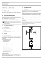 6
6
-
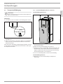 7
7
-
 8
8
-
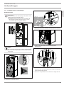 9
9
-
 10
10
-
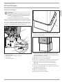 11
11
-
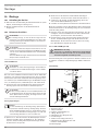 12
12
-
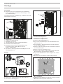 13
13
-
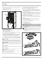 14
14
-
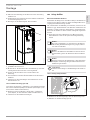 15
15
-
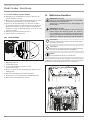 16
16
-
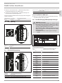 17
17
-
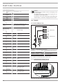 18
18
-
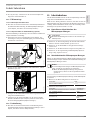 19
19
-
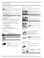 20
20
-
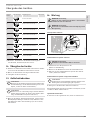 21
21
-
 22
22
-
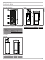 23
23
-
 24
24
-
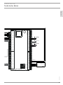 25
25
-
 26
26
-
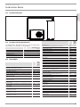 27
27
-
 28
28
-
 29
29
-
 30
30
-
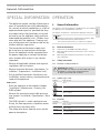 31
31
-
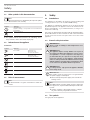 32
32
-
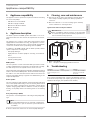 33
33
-
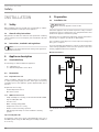 34
34
-
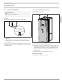 35
35
-
 36
36
-
 37
37
-
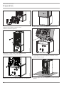 38
38
-
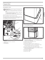 39
39
-
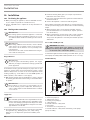 40
40
-
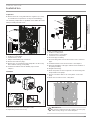 41
41
-
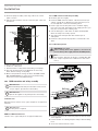 42
42
-
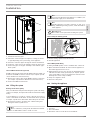 43
43
-
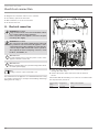 44
44
-
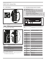 45
45
-
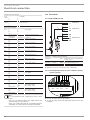 46
46
-
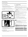 47
47
-
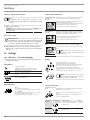 48
48
-
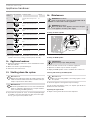 49
49
-
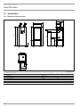 50
50
-
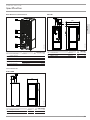 51
51
-
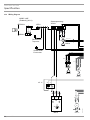 52
52
-
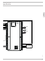 53
53
-
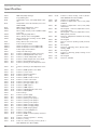 54
54
-
 55
55
-
 56
56
-
 57
57
-
 58
58
-
 59
59
-
 60
60
-
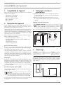 61
61
-
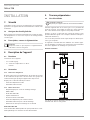 62
62
-
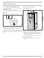 63
63
-
 64
64
-
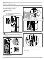 65
65
-
 66
66
-
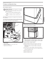 67
67
-
 68
68
-
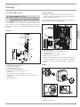 69
69
-
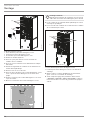 70
70
-
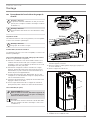 71
71
-
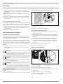 72
72
-
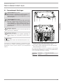 73
73
-
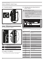 74
74
-
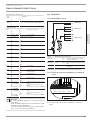 75
75
-
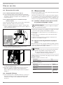 76
76
-
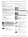 77
77
-
 78
78
-
 79
79
-
 80
80
-
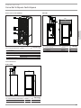 81
81
-
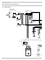 82
82
-
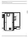 83
83
-
 84
84
-
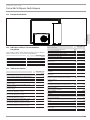 85
85
-
 86
86
-
 87
87
-
 88
88
-
 89
89
-
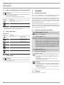 90
90
-
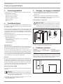 91
91
-
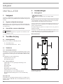 92
92
-
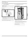 93
93
-
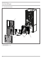 94
94
-
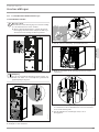 95
95
-
 96
96
-
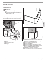 97
97
-
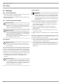 98
98
-
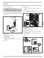 99
99
-
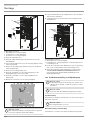 100
100
-
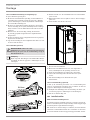 101
101
-
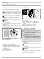 102
102
-
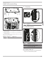 103
103
-
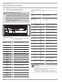 104
104
-
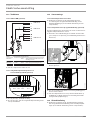 105
105
-
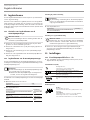 106
106
-
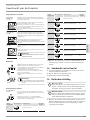 107
107
-
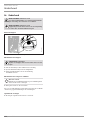 108
108
-
 109
109
-
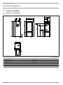 110
110
-
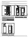 111
111
-
 112
112
-
 113
113
-
 114
114
-
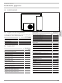 115
115
-
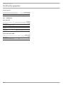 116
116
-
 117
117
-
 118
118
-
 119
119
-
 120
120
-
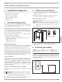 121
121
-
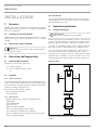 122
122
-
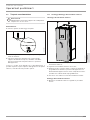 123
123
-
 124
124
-
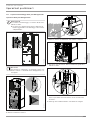 125
125
-
 126
126
-
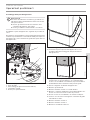 127
127
-
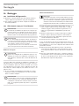 128
128
-
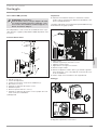 129
129
-
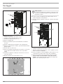 130
130
-
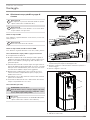 131
131
-
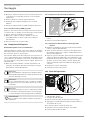 132
132
-
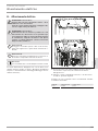 133
133
-
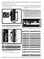 134
134
-
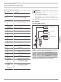 135
135
-
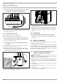 136
136
-
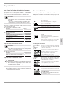 137
137
-
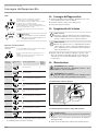 138
138
-
 139
139
-
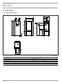 140
140
-
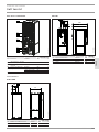 141
141
-
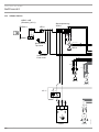 142
142
-
 143
143
-
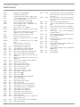 144
144
-
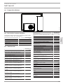 145
145
-
 146
146
-
 147
147
-
 148
148


STIEBEL ELTRON STIEBEL-ELTRON HSBC 300 Electric Hot Water Tank Handleiding
- Categorie
- Warmtepompen
- Type
- Handleiding
in andere talen
Gerelateerde papieren
-
STIEBEL ELTRON HSBC 300_L_cool Operation Instruction
-
-
-
-
-
STIEBEL ELTRON SBP 100 classic Operation Instruction
-
-
-
-