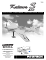
protech Katana S 200 Handleiding
- Categorie
- Speelgoed met afstandsbediening
- Type
- Handleiding

Katana S200 - 1
INSTRUCTION MANUEL • GEBRUIKSAANWIJZING • INSTRUCTIONS DE MONTAGE • ANLEITUNG
T0363
WARNING ! This R/C kit and the model
you will build is not a toy.
LET OP ! Deze bouwdoos van een
radiobestuurd vliegtuig is geen
speelgoed.
ATTENTION ! Ce kit d’avion R/C n’est
pas un jouet.
ACHTUNG ! Dieser Bausatz von
ferngesteurte model
ist kein Spielzeug.
version: 29/05/2002 • T0362
7000 g.
77,0 dm
2
2014 mm
1775 mm

2 - Katana S200
Specifications / Specificaties /
Spécifications / Technische daten
1. Wings
2. Landing gear
3. Cockpit
4. Wing joiner
5. Elevator
6. Rudder
7. Fuselage
8. Cowling
1. Vleugeldelen
2. Landingsgestel
3. Cockpit
4. Vleugelbevestiging
5. Hoogteroer
6. Richtingsroer
7. Romp
8. Motorkap
1. Ailes
2. Train d’atterrissage
principal
3. Verrière de cabine
4. Fixation d’aile
5. Stabilisateur horizontal
6. Dérive
7. Fuselage
8. Capot-moteur
1. Flugelhälften
2. Hauptfahrwerk
3. Kabinehaube
4. Befestigungsrohr
Flächen
5. Höhenleitwerk
6. Seitenleitwerk
7. Rumpf
8. Motorhaube
1
2
5
6
3
4
Kit content / Inhoud van de bouwdoos /
Contenu de la boîte / Bausatzinhalt
Length: 1775 mm
Wing span: 2014 mm
Wing area: 77,0 dm
2
Wing loading: 90,9 g/dm
2
Flying weight: 7000 g
Radio required: 4 channel
programmable
radio with
6 x high torque
(min. 6 kg) servos
Engine: 50 cc engine
(3W 50cc)
Lengte: 1775 mm
Spanwijdte: 2014 mm
Vleugelopp.: 77,0 dm
2
Vleugelbel.: 90,9 g/dm
2
Vlieg gewicht: 7000 g
Radio besturing:4 kanaals
program.
radio met
6 x high torque
(min. 6 kg) servo’s
Motor: 50 cc motor
(3W 50cc)
Longueur: 1775 mm
Envergure: 2014 mm
Surface alaire: 77,0 dm
2
Charge alaire: 90,9 g/dm
2
Poids en vol: 7000 g
Radio requise: Radio 4 voies
progr. avec
6 servos high
torque (min. 6 kg)
Moteur: 50 cc moteur
Länge: 1775 mm
Spannweite: 2014 mm
Tragflügelinhalt: 77,0 dm
2
Gesamtflachen-
belastung: 90,9 g/dm
2
Fluggewicht: 7000 g
Funkfernsteuerung:
4 Kanal progr.
Steuerung mit
6 high torque
servo (min. 6 kg)
Motor
: 50 cc Motor
7
8

Katana S200 - 3
Important Safety Notes.
Be sure to read right through the instructions covering assembly and operation of your model before you attempt to operate it for the first time. You alone are
responsible for the safe operation of your radio-controlled model. Young people should only be permitted to build and fly these models under the instruction and
supervision of an adult who is aware of the hazards involved in this activity.
Use only matching polarised connectors. All cables, connectors and the battery if home-assembled must be insulated to prevent short circuits. Never attempt to
combine different types of plug and socket - e.g. tin-plated and gold-plated types - as such combinations are bound to be unreliable.
NC batteries are capable of holding and releasing enormous amounts of energy, and as such represent a constant hazard of explosion and fire.
We have no control over the way you build and operate your RC model aircraft, and for this reason we are obliged to deny all liability for accidents. All we can do is
point out the hazards and make sure you are aware of them.
If you need help, please enlist the aid of an experienced modeller, a model club or enrol at a model flying training school, Model shops and the specialist model
press are also good sources of information. The best course is always to join a club and fly at the approved model flying site.
Rubber bands deteriorate with age and become brittle. Replace them from time to time to maintain the safety and reliability of your model. Stretch all rubber bands
before use to check that they are still strong enough for their purpose.
Motors should only be run in the open air! The powerful suction of the propeller and the volume of air which it accelerates can easily lead to accidents in enclosed
spaces (e.g. pictures falling down, curtains sucked into the propeller). The model must be held securely by an assistant at all times.
Keep well clear of the rotational plane of propellers - don't stand in line with it or in front of it. You never know when some part may come loose and fly off at high
speed, hitting you or anybody else in the vicinity. Never touch the revolving propeller with any object.
There must be no chance of any object getting in the way of the propeller and preventing it rotating.
Take care with loose clothing such as scarves, loose shirts etc. Flapping cloth can easily be sucked into the area of the propeller and then get tangled in it.
If you start your motor when the model is standing on loose or sandy ground, the propeller will suck up sand and dust and hurl it around. and it could easily get in
your eyes. Wear protective goggles at such times.
Every time you intend to operate your model check carefully that it and everything attached to it (e.g. propeller, gearbox,RC components etc.) are in good condition
and undamaged. If you find a fault do not fly the model until you have corrected it.
Satisfy yourself that your frequency is vacant before you switch on. Radio interference caused by unknown sources can occur at any time without warning. If this
should happen, your model will be uncontrollable and completely unpredictable. Never leave your radio control system unguarded, as other people might pick it up
and try to use it.
Check that nothing is in the way of the propeller before you switch on the electric motor. Never attempt to stop the spinning propeller.Electric motors with a propeller
attached should only be run when installed securely.
lf you are to fly your model safely and avoid problems it is essential that you are aware of its position and attitude throughout each flight - so don't let it fly too far
away! lf you detect a control problem or interference during a flight,immediately land the model to prevent a potential accident Note that the transmitter throttle stick
must be set to the OFF (motor stopped) position before you switch on the power system. To avoid the electric motor starting unexpectedly, switch on the transmitter
first. then the receiving system. Use the reverse sequence when switching off: receiver first, then the transmitter. Check that the control surfaces move in the correct
"sense" when you operate the sticks.
Please don't misunderstand the purpose of these notes. We only want to make you aware of the many dangers and hazards which can arise if you lack knowledge
and experience, or work carelessly or irresponsibly. If you take reasonable care model flying is a highly creative, instructive, enjoyable and relaxing pastime.
Belangrijke Veiligheidsinstructies
Lees de instructies betreffende montage en werking van je model vooraleer u het de eerste maal in gebruik neemt. U alleen bent verantwoordelijk voor de veilige
werking van uw radiobestuurd model. Kinderen zijn enkel toegestaan om deze modellen te bouwen en te vliegen onder het toeziend oog van een volwassene, die
zich bewust is van de gevaren die dit met zich meebrengt.
Gebruik enkel passende gepolariseerde verbindingsstukken. Alle kabels, verbindingsstukken en de batterij, indien deze zelf samengesteld is, moeten geïsoleerd
worden om kortsluiting te voorkomen. Poog nooit verschillende types van pluggen en contacten te kombineren (vb.tin-en goudcontacten), daar zulke combinaties
onbetrouwbaar zijn.
NC-batterijen zijn geschikt om enorme hoeveelheden energie vast te houden en vrij te geven. Zodoende vertegenwoordigt een batterij een constant risico op
explosie en brandgevaar.
Wij hebben geen controle over de manier waarop u het RC-vliegtuig bouwt en gebruikt. Daarom zijn wij verplicht om alle aansprakelijkheid voor ongevallen van de
hand te wijzen. Het enige dat in onze mogelijkheden ligt is u te waarschuwen voor de risico’s.
Als u hulp nodig heeft, roep dan de bijstand van een ervaren modelbouwer of een modelbouwclub in, of schrijf u in bij een modelvliegclub. Modelshops en de
gespecialiseerde pers zijn eveneens een geschikte bron van informatie. De beste les is echter zich aan te sluiten bij een club en te vliegen op de goedgekeurde
vliegplaatsen.
Rubber elastieken verslijten met het gebruiken en worden broos. Vervang ze tijdig, zodoende stelt u de veiligheid en de betrouwbaarheid van uw model veilig. Span
alle rubber elastieken op vooraleer u ze gebruikt om te controleren of ze nog sterk genoeg zijn.
Motoren mogen enkel buiten in openlucht lopen! De sterke zuigkracht van de propeller en de luchtverplaatsing die deze veroorzaakt, kan in kleine ruimten makkelijk
een ongeval tot gevolg hebben (vb. schilderijen die naar beneden vallen, een gordijn dat in de propeller gezogen wordt). Het model moet steeds stevig worden
vastgehouden door een helper.
Houdt de rotatiebaan van een propeller vrij, sta er nooit voor of in de lijn van de propeller. Er kan steeds een deel loskomen en met hoge snelheid wegvliegen, zodat
het uzelf of iemand anders in de omgeving kan verwonden. Raak de ronddraaiende propeller nooit met enig voorwerp aan. Vermijdt steeds dat welk voorwerp ook
het draaien van de propeller verhindert.
Pas op met losse kleding zoals sjaals, losse shirts, … Losse kleding kan makkelijk in de propeller gezogen worden.
Als u de motor start terwijl deze op losse of zanderige grond staat, zal de propeller het zand opzuigen en rondslingeren zodat het in je ogen kan komen. Draag dus
steeds een veiligheidsbril op zo’n momenten.
Controleer, elke keer als u een model wil gebruiken, zorgvuldig of het model en alles wat erbij hoort (vb. propeller, aandrijving, RC-onderdelen, …) in goede staat en
onbeschadigd is. Als u een fout bemerkt, vlieg dan niet met het model tot u de fout hebt opgelost.
Verzeker uzelf ervan dat de frequentie vrij is vooraleer u de zender aanzet. Radiostoringen veroorzaakt door vreemde bronnen kunnen op elk moment en zonder
waarschuwing voorkomen. Als dit gebeurt is je model oncontroleerbaar en volledig onvoorspelbaar. Laat uw radiobesturing nooit onbewaakt achter, andere mensen
zouden kunnen proberen het te gebruiken.
Controleer of er niets in de baan van de propeller is vooraleer u de electromotor aanzet. Probeer nooit de draaiende propeller te stoppen. Electromotoren verbonden
met een propeller mogen enkel lopen als deze veilig geïnstalleerd is.
Als u uw model veilig wil vliegen en u wil problemen vermijden, dan is het essentieel dat u zich bewust bent van zijn positite en hoogte tijdens iedere vlucht. Laat het
dus niet te ver weg vliegen ! Als u een controleprobleem of storingen ontdekt gedurende een vlucht, landt dan onmiddellijk om een mogelijk ongeval te voorkomen.
Bemerk dat de zenderstick voor de motorfunctie in de off-stand moet staan vooraleer u het systeem aanzet. Om te voorkomen dat de electromotor onverwacht start,
zet eerst de zender aan, later pas de ontvanger. Gebruik de omgekeerde volgorde bij het afzetten : eerst de ontvanger, dan de zender. Controleer of de roeren in de
juiste richting bewegen als u de sticks gebruikt.
Heb begrip voor het doel van deze opmerkingen. Wij willen u enkel opmerkzaam maken voor de vele gevaren en risico’s die zich kunnen voordoen als u kennis en
ervaring mist, nonchalant of onverantwoordelijk te werk gaat.
Als u redelijk zorg draagt, is modelvliegen een zeer creatieve, leerrijke, plezierige en ontspannende vrijetijdsbesteding.
Pagina laadt ...

Katana S200 - 5
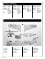
Sharp hobby knife / Scherp hobby mes /
Couteau de modeliste / Hobby messer
Needle nose pliers / Bek tang /
Pince à becs / Beisszange
Philips screw driver / Philips schroevendraaier /
Tournevis Philips / Schraubendreher
Triangle / Driehoeks meetlat /
Equerre / Winkel
Scissors / Schaar / Ciseaux / Schere Wire cutter / Draad stripper / Pince coupante /
Kneifzange
Drill / Boor / Perceuse à main / Handbohrer
To assamble this airplane some tools are needed.
Voor het samenstellen van het vliegtuig zijn er enkele gereedschappen nodig.
Zum bauen dieses Flugzeug werden einige Werkzeuge gebraucht .
Certains outils sont requis pour assembler cet avion.
Tools & items / Gereedschap & benodigdheden /
Outils et équipements / Werkzeuge und erforderliches
Solder iron / Soldeerbout /Lötgerät / Fer à souder

6 - Katana S200
Fixing the vertical fin / Monteren van het richtingsroer /
Fixation du gouvernail de direction / Befestigung von das Seitenruder
Cut out the covering of the
slots. Glue the hinges on both
sides with epoxy.
See fig. 1-2.
Verwijder de folie aan de
scharniersleuven en verlijm de
scharnieren met epoxy aan
beide kanten.
Zie fig. 1-2.
Coupez l’entoilage au niveau
des fentes de charnières. Collez
à l’époxy les trois charnières en
cuivre.
Coupez l’entoilage à la même
place que sur le gouvernail de
direction et collez-le en place à
l’époxy.
Voir fig. 1-2.
Installing the landinggear (tail) / Bevestig het achterste landingsgestel /
Fixation de la béquille orientable de roulette de queue / Befestigung von das Lenkbarer Sporn
Install the tail gear to the botom
of the rudder using 2 TP screws,
see fig. 3.
Install the heavy duty
landinggear and wheel as
shown on fig. 4.
Bevestig de staartwielaansturing
op het richtingsroer zoals op fig.
3.
Bevestig het staartwiel
achteraan de romp door gebruik
te maken van 2 schroeven, zie
fig. 4.
Installez le support de roulette
de queue sur le gouvernail de
direction, utilisez 2 vis à bois,
voir fig. 3.
Installez la béquile et la roue
comme indiqué sur la fig. 4.
fig. 1 fig. 2
fig. 3 fig. 4

Katana S200 - 7
Installing the control horn / Bevestigen van de roerhorn /
Installation du guignol / Befestigung von den Ruderhorn
Drill a hole at the botom of the
rudder, see fig. 5.
Install the control horn, see fig.
6.
Boor een gaatje onderaan het
richtingsroer voor het
bevestigen van de roerhorn, zie
fig. 5-6.
Percez un trou dans le gouver-
nail de profondeur pour le
passage du guignol, voir fig. 5.
Placez le guignol comme
montré dans la fig. 6.
Bohren Sie eine Loch in den
Ruder, sehen Sie Fig. 5.
Plazieren Sie den Horn wie in
Fig. 6 gezeigt.
Installing the servo for vertical fin / Plaatsen van de servo voor het richtingsroer /
Montage du servo dans la dérive / Montieren von die Flügelservos
Glue the servo tray (F61) in the
fuselage, see fig. 7.
Install the rudder servo with TP
screws. Attach the steering rod
to the servo and control horn,
see fig. 8.
Lijm de verdubbeling (F61) in de
romp en bevestig de servo op
de voorziene plaats, zie fig. 7-8.
Collez la platine servo (F61)
dans le fuselage, voir fig. 7.
Fixez le servo avec des vis à
bois. Connectez la tringle de
commande du servo au guignol,
voir fig. 8.
fig. 5 fig. 6
fig. 7 fig. 8

8 - Katana S200
Installing the elevator / Monteren van het hoogteroer /
Fixation du gouvernail de profondeur / Befestigung von das Höhenruder
Cut out the covering of the
slots. Glue the hinges with
epoxy, see fig. 9-10.
Verwijder de folie aan de
scharniersleuven en verlijm deze
met epoxy aan beide zijden, zie
fig. 9-10.
Coupez l’entoilage au niveau
des fentes de charnières. Collez
à l’époxy les trois charnières en
cuivre.
Coupez l’entoilage à la même
place que sur le gouvernail de
profondeur et collez-le en place
à l’époxy.
Voir fig. 9-10.
Installing horn and servo for the elevator / Monteren van de horn en servo voor het hoogteroer /
Montage du servo de profondeur / Montieren von die Servo und Hörner von das Höhenruder
Cut out the covering of the
servo tray and install the servo,
see fig. 11.
Drill a hole at 158mm from the
side (see fig. 14) to install the
control horn on the elevator, see
fig. 12.
Fix the servohorn and linkage as
shown on fig. 13.
Snij de folie weg waar de servo
moet komen en installeer de
servo, zie fig. 11.
Boor een gaatje op een afstand
van 158mm van de zijkant (zie
fig. 14) voor het installeren van
de roerhorn, zie fig. 12.
Bevestig de stuurstang zoals
afgebeeld op fig. 13.
Découpez l’entoilage sur le
stabilisateur à l’endroit du servo,
voir fig. 11.
Percez un trou à 158mm du
bord (voir fig. 14) pour installer
le guignol sur le gouvernail de
profondeur, voir fig. 12.
Fixez le guignol et connectez la
commande comme indiqué sur
la fig. 13.
fig. 9 fig. 10
fig. 11 fig. 12 fig. 13
fig. 14

Katana S200 - 9
Installing the anti-roll pin / Monteren van de paspennen /
Installation du tenon de maintien / Montieren von anti-roll stift
Glue the anti-roll pin in the
stabilizer as shown on fig. 15.
Verlijm de paspennen in de
stabilo, zie fig. 15.
Collez le tenon dans le stabilisa-
teur, voir fig. 15.
Installing the horizontal fin / Monteren van het horizontaal staartvlak /
Installation du stabilisateur / Montieren von Höhenleitwerk
Glue 2 supports (F60) to hold
the anti-roll pin with epoxy, see
fig. 22.
Install the fibre tube and the 2
support (F64) in the fuselage.
See fig. 23.
Attention: Don’t glue the tube
and the 2 supports now, but
only after checking the position,
see fig. 56.
Verlijm de twee
verdubbellingsplaatjes (F60) met
epoxy, zie fig. 22.
Plaats de verdubbellingsplaatjes
(F64) en de huls in de romp.
Zie fig. 23.
Let op: Verlijm de huls en de 2
verdubbellinsplaatjes na
controle van de uitlijning, zie fig.
56.
Collez à l’époxy les 2 supports
(F60) servant aux tenons de
maintien situé sur le stabilisa-
teur, voir fig.22.
Placez le tube en fibre et les 2
supports (F64) dans le fuselage.
Voir fig. 23.
Attention: Collez le tube et les 2
supports après vérification de
l’alignement, voir fig. 56.
fig. 22 fig. 23
fig. 15

10 - Katana S200
Installing the ailerons / Monteren van de rolroeren /
Installation des ailerons / Montieren von Querruder
Install 4 hinges to each aileron,
see fig. 18.
Glue the aileron with epoxy to
each wing panel, see fig. 19.
Verlijm 4 scharnieren in elk
rolroer, zie fig. 18.
Verlijm het rolroer met epoxy in
elk vleugeldeel, zie fig. 19.
Installez 4 charnières sur
chaque aileron, voir fig. 18.
Collez les ailerons à l’époxy sur
chaque panneau d’aile, voir fig.
19.
Installing the stabilizer tube / Monteren van de verbindingsbuis voor de stabilisator /
Installation du tube du stabilisateur / Montieren von Flugelhalterungsrohr
Put the wingjoiner in the
stabilizer. Glue the fibre tube in
the fuselage and place the
stabilizer with wingjoiner into
the tube. After you have alined
the stabilizer you can fix it on
both sides with M3 screws, see
fig. 16-17.
Steek de huls in de romp en
plaats de stabilo met de
verbindingsbuis. Vergeet niet
het geheel uit te lijnen. Na
uitlijning aan beide zijden
doorboren lans onder en fixeren
met M3 bout, zie fig. 16-17.
Placez le tube aluminium dans
le stabilisateur. Collez le tube en
fibre dans le fuselage. Percez un
trou de 2,5mm dans le stabilisa-
teur et à travers le tube. Utilisez
un taraud de M3 pour fileter le
tube. Fixez le tube avec une vis
M3. Voir fig. 16-17.
fig. 16 fig. 17
fig. 18 fig. 19

Katana S200 - 11
Installing horn and servo for the ailerons / Monteren van de horn en servo voor de rolroeren /
Installation du servo et guignol d’aileron / Montieren von Querruderhorn und Querruder servos
Install the aileron servo, horn
and linkage as shown on fig. 20-
21.
Monteer de rolroerservo, de
horn en de stuurstang zoals
afgebeeld op fig. 20-21.
Installez le servo et guignol,
connectez la commande
comme indiqué sur les fig. 20-
21.
Installing the wings / Bevestigen van de vleugels /
Installation des ailes / Montieren von Flächen
Make sure the wing is parallel
with the tail plane, see fig. 24-
25.
Install the wing joint tube and fix
it in the supports (F57), see fig.
26.
Install 4 supports (F59) to hold
the wing pin, see fig. 27.
Attention: Make sure that wing
is at right angle with tail and
fuselage.
Monteer de huls en verlijm de
verdubbellingsplaatjes (F57), zie
fig. 26.
Zorg ervoor dat de vleugel en
het hoogteroer onder dezelfde
hoek staan, zie fig. 24-25.
Monteer de
verdubbellingsplaatsjes (F59)
voor de vleugelpin in de romp,
zie fig. 27.
Installez le tube de renfort et
collez les supports (F57) voir
fig.26.
Assurez-vous que les ailes sont
paralléles au stabilisateur, voir
fig.25.
Collez les 4 supports (F59) pour
les tenons de maintien des
ailes.
fig. 20 fig. 21
fig. 25 fig. 26fig. 24
fig. 27

12 - Katana S200
Installing the motor / Monteren van de motor /
Installation du moteur / Montieren von Motor
Install the motor with soft
mounts. The motor back should
have 5mm off-set with center
line of the fuselage, see fig. 28.
Install the motor as shown in fig.
29.
Attention: It is possible that you
need to add some weight to
nose or tail to adjust the central
gravitation (CG).
At first flight we strongly
recommend you keep the CG
forward.
Monteer de motor met ‘soft
mounts’. De as van de motor
moet 5mm afwijken van de
centerlijn van de romp, zie fig.
28.
Monteer de motor zoals
afgebeeld in fig. 29.
Let op: Het is soms nodig
gewicht in neus of staart te
steken om het zwaartepunt (ZP)
aan te passen.
Bij de eerste vlucht raden wij
aan het ZP naar voor te leggen.
Installez le moteur avec les
silent blocs. L’arrière du moteur
doit être décalé de 5mm par
rapport à l’axe du fuselage, voir
fig.28.
Installez le moteur comme
indiqué sur la fig.29.
Attention: Il est possible que
vous deviez ajouter du poids
dans le nez ou la queue pour
ajuster le centre de gravité
(CG). Pour le 1er vol, nous
recommandons un CG avancé.
Installing the motorcowling / Bevestigen van de motorkap /
Découpe du capot moteur / Montieren von Motorhaube
Drill out the air intake on the
cowl and smoothen it with a file
or sanding paper, see fig. 30-31.
Make sure the motor drive hub
has a spacing of at least 5-6mm
with the cowl end, see fig. 32.
Boor de luchtinlaat uit en vijl of
schuur de randen glad, zie fig.
30-31.
Zorg ervoor dat de
motoraandrijving ten minste 5-
6mm spatie heeft t.o.v. het
voorste van de motorkap, zie fig.
32.
Percez le contour des prises
d’air et enlevez-les délicate-
ment. Ajustez à l’aide d’une lime
ou papier abrasif, voir fig.30-31.
Laissez 5 à 6mm d’espace entre
le carter moteur et le capot, voir
fig.32.
fig. 28 fig. 29
fig. 30 fig. 31 fig. 32

Katana S200 - 13
Installing the servo tray / Monteren van de servo houder /
Installation de la platine servos / Montieren von Servohalterung
Glue the support (F51) with
epoxy to the servo tray (F52),
see fig. 33.
Glue the servo tray in the
fuselage as shown in fig. 34.
Verlijm het verstevigingsstukje
(F51) met epoxy op de servo
houder (F52), zie fig. 33.
Verlijm de servo houder in de
romp zoals afgebeeld op fig. 34.
Collez à l’époxy les supports
(F51) sur la platine servos (F52),
voir fig.33.
Collez la platine servos dans le
fuselage comme indiqué à la
fig.34.
Preparing the hatch and fuselage / Voorbereiden van de cockpitsteun /
Préparation du cockpit / Vorbereiten von Kabinehaube Trappe
Glue the pins as shown on fig.
35-36-37-38.
Lijm de paspennen op de
daarvoor voorziene plaats zoals
afgebeeld op fig. 35-36-37-38.
Collez à l’époxy les tenons sur
les parties du cockpit, voir
fig.35-36-37-38.
fig. 33 fig. 34
fig. 35 fig. 36 fig. 37
fig. 38

14 - Katana S200
Installing the cockpit / Bevestigen van de cockpit /
Fixation de la verrière / Befestigung von Kabinehaube
Mark the trim line with marking
tape and trim the canopy, see
fig. 39.
Cover the canopy edge with
sticker and screw it with 9
(2x10) TP screws on the hatch,
see fig. 40.
Duidt de snijlijn aan met een
kleefband en sknip de cockpit
uit, zie fig. 39.
Vijs deze met 9 (2x10)
zelftappende vijzen op de romp,
zie fig. 40.
Marquez le contour de la
verrière à l’aide de papier
collant, et découpez la partie en
trop.voir fig.39.
Appliqez l’autocollant sur le
contour de la verrière et fixez-la
sur le fuselage à l’aide des 9 vis
autotaraudeuses (2x10mm). voir
fig. 40.
Installing the cockpit / Bevestigen van de cockpit /
Installation du cockpit / Befestigung von Kabinehaube
Glue 2 supports in the hatch,
see fig. 41.
Drill a 2mm hole in the fuselage
true the support and screw the
hatch to the fuselage with 3x15
TP screws, see fig. 42-43.
Verlijm 2 verstevigingsstukjes
aan de onderkant van de
cockpit, zie fig. 41.
Boor een gaatje (ø2mm) in de
romp door de
verstevigingsstukjes en vijs de
cockpit op de romp met 3x15
zelftappende vijzen, zie fig. 42-
43.
Collez les 2 supports à l’inté-
rieur du cockpit, voir fig. 41
Percez un trou de 2 mm dans le
fuselage à travers le support.
Fixez le cockpit sur le fuselage
avec les vis autotaraudeuses de
3x15mm, voir fig. 42-43.
fig. 39 fig. 40
fig. 41 fig. 42 fig. 43

Katana S200 - 15
Fixing the landinggear / Monteren van het landingsgestel /
Montage des train d’atterisage / Montieren von Hauptfahrwerk
Drill a 4mm hole in each leg of
the landinggear, see fig. 44.
Glue the support (F63) in the
wheel pants, see fig. 45.
Follow the landinggear hole to
drill true the wheel pants and
supports, see fig. 46.
Install the wheel, see fig. 47.
Fix the wheel pants with 2
(3x12) TP screws, see fig. 48.
Boor een gaatje ø4mm in elke
steun van het landingsstel, zie
fig. 44.
Verlijm de versteviging (F63) in
de wielkap, zie fig. 45.
Boor door het gaatje van de
steun een gaatje in de wielkap
en versteviging, zie fig. 46.
Monteer het wiel, zie fig. 47.
Fixeer de wielkap met 2 (3x12)
zelftappende vijzen, zie fig. 48.
Percez un trou de 4mm dans
chaque jambe de train, voir
fig.44. Collez le support (F63)
dans le carrenage de roue, voir
fig.45.
Placez la jambe sur le carrenage
et repassez dans le trou afin de
percez le carrenage et le
support, voir fig.46.
Installez la roue et fixez le
carrenage avec 1 vis 3x12mm,
voir fig.48.
Fixing the landinggear / Bevestigen van het landingsstel /
Fixation du train d’atterisage / Befestigung von Hauptfahrwerk
Drill a 3,2mm hole true the
landinggear into the bottom of
the fuselage, see fig. 49.
Tap teeth into the hole (M4), see
fig. 50.
Install the landinggear with 2 M4
screws, see fig. 51.
Boor een gaatje (ø3,2mm) door
het landingsstel in de onderzijde
van de romp, zie fig. 49.
Tap draad in het gat (M4), zie
fig. 50.
Bevestig het landingsstel met 2
M4 vijzen, zie fig. 51.
Positionnez le train sur le
dessous du fuselage et percez
un trou de 3,2mm dans le
fuselage, voir fig.49.
Taraudez (M4) le trou du
fuselage, voir fig.50.
Fixez le train avec 2 vis M4, voir
fig.51.
fig. 47
fig. 48
fig. 44 fig. 45 fig. 46
fig. 49 fig. 50 fig. 51

16 - Katana S200
Decals / Decals /
Autocollants / Dekor
Remove the unnecessary decal
tape, see fig. 52.
Use transition film to move out
the decal and stick it to the
wing, see fig. 53-54.
Repeat these steps for all
decals.
Verwijder het onnodige
stickermateriaal, zie fig. 52.
Gebruik transportfilm om de
sticker van zijn rugmateriaal te
halen en kleef hem dan op de
vleugel, zie fig. 53-54.
Herhaal deze stappen voor alle
decals.
Nous conseillons d’utiliser un
film de transition pour un
positionnement facile et précis
des autocollants, voir fig. 52-53-
54-55.
Checking wing and tail / Controleren van staart en vleugel /
Alignement des ailes et du stabilisateur / Kontrole von Höhenleitwerk und Flächen
Make sure all reference
distances are equal, see fig. 56-
57.
Zorg ervoor dat alle
overeenkomende afstanden
gelijk zijn, zie fig. 56-57.
Assurez-vous que chaque
référence à la même valeur à
gauche et à droite de l’axe, voir
fig. 56-57.
fig. 56 fig. 57
fig. 52 fig. 53 fig. 54
fig. 55

Katana S200 - 17
Centre of gravity / Uitwegen /
Centre de gravité / Schwerpunkt
Rudder deflection / Roeruitslag /
Débattements / Ruderausschlägen
170 mm
35 mm
30 mm
90 mm
90 mm
21 mm
20 mm

18 - Katana S200
Ready for take off / Uw model is vliegklaar /
Votre modèle est prêt à voler / Ihr modell ist fertig zu fliegen
When necessary you can
straight the covering with an
sealing iron. Attention: do not
twist the wing.
Ci nécessaire le recouvrement
peut être amélioré à l’aide d’un
fer à entoiler. Attention à ne pas
vriller l’aile.
Indien nodig kan u de
bespanning met een strijkbout
bijtrekken. Let op: niet de
vleugel torsen.
Wenn erforderlich können Sie
die Bespannfolien mit ein
Bügeleisen nach bearbeiten.
Achtung: Nicht dem Flugel
drehen.
Not included in kit / Niet in de bouwdoos bijgeleverd /
Ne pas inclus dans le kit / Nicht im Baukasten enthalten
• 17 x Hinges
• 6 x Control horn
• 12+2 x Kwiklink
• 12 x M3 screws
• 6 x Pushrods
(2 x Elevator,
2 x Vertical fin,
2 x Ailerons)
• 4 x Wheel collar
• 2 x Wheel axe
• 2 x Wheel
• 1 x Tailgear
• 4 x M4 screw, nut, collar
• 2 x M3 screw, nut
• 1 x Fueltank
• 1 x Pushrods trottle servo
• 17 x Scharnieren
• 6 x Roerhorn
• 12+2 x Kwiklinks
• 12 x M3 vijzen
• 6 x Stuurstang
(2 x Hoogteroer,
2 x Richtingsroer,
2 x Rolroer)
• 4 x Wielcollar
• 2 x Wielas
• 2 x Wiel
• 1 x Staartwielset
• 4 x M4 vijs, moer, rondel
• 2 x M3 vijs, moer
• 1 x Tank
• 1 x Stuurstang gasservo
• 17 x Charnière
• 6 x Guignol
• 12+2 x Chape
• 12 x M3 vis
• 6 x Tiges de commande
(2 x Stabilisateur horizontal,
2 x Profondeur
2 x Ailerons)
•4 x
•2 x
• 2 x Jointes
• 1 x Béquille
• 4 x M4 vis, écrou, rondel
• 2 x M3 vis, écrou
• 1 x Réservoir
• 1 x Tringle de commande
Pagina laadt ...

20 - Katana S200
© Copyright PROTECH
• Your kit is warranted against defects
in material and workmanship.
• This warranty does not apply to any
component parts, which have been
improperly installed, handled,
abused, damaged, modified and
used.
• De kit heeft een garantie voor
materiaalfouten en fabrieksfouten.
• Deze garantie geldt niet voor
onderdelen die niet goed zijn
geïnstalleerd, behandeld, mishandeld,
beschadigd, aangepast en gebruikt.
• Votre kit est garanti contre les défauts
de matériaux et de main d’œuvre.
• Cette garantie ne s’applique pas aux
composants qui ont été incorrecte-
ment montés, manipulés, modifiés et
utilisés ou qui ont été endommagés.
• Ihr Installationssatz wird gegen
Defekte im Material und in der
Kunstfertigkeit gewährleistet.
•
Diese Garantie trifft nicht auf
irgendwelche Bestandteile zu, die
unsachgemäß installiert worden,
angefaßt worden, mißbraucht worden,
beschädigt worden, geändert worden
und benutzt worden sind.
Limited warranty / Beperkte garantie /
Limitation de garantie / Begrenzte garantie
Line up products / Onze lijn produkten /
Notre gamme de produits / Unsere produktwahl
T0367
T0362
Documenttranscriptie
T0363 INSTRUCTION MANUEL • GEBRUIKSAANWIJZING • INSTRUCTIONS DE MONTAGE • ANLEITUNG 1775 mm WARNING ! This R/C kit and the model you will build is not a toy. 20 LET OP ! Deze bouwdoos van een radiobestuurd vliegtuig is geen speelgoed. ATTENTION ! Ce kit d’avion R/C n’est pas un jouet. 14 7000 g. m m 77,0 dm2 ACHTUNG ! Dieser Bausatz von ferngesteurte model ist kein Spielzeug. version: 29/05/2002 • T0362 Katana S200 -1 Specifications / Specificaties / Spécifications / Technische daten Length: Wing span: Wing area: Wing loading: Flying weight: Radio required: Engine: 1775 mm 2014 mm 77,0 dm2 90,9 g/dm2 7000 g 4 channel programmable radio with 6 x high torque (min. 6 kg) servos 50 cc engine (3W 50cc) Lengte: 1775 mm Spanwijdte: 2014 mm Vleugelopp.: 77,0 dm2 Vleugelbel.: 90,9 g/dm2 Vlieg gewicht: 7000 g Radio besturing: 4 kanaals program. radio met 6 x high torque (min. 6 kg) servo’s Motor: 50 cc motor (3W 50cc) Longueur: Envergure: Surface alaire: Charge alaire: Poids en vol: Radio requise: Moteur: 1775 mm 2014 mm 77,0 dm2 90,9 g/dm2 7000 g Radio 4 voies progr. avec 6 servos high torque (min. 6 kg) 50 cc moteur Länge: 1775 mm Spannweite: 2014 mm Tragflügelinhalt: 77,0 dm2 Gesamtflachenbelastung: 90,9 g/dm2 Fluggewicht: 7000 g Funkfernsteuerung: 4 Kanal progr. Steuerung mit 6 high torque servo (min. 6 kg) Motor: 50 cc Motor Kit content / Inhoud van de bouwdoos / Contenu de la boîte / Bausatzinhalt 1 4 5 3 2 6 8 1. Wings 2. Landing gear 3. Cockpit 4. Wing joiner 5. Elevator 6. Rudder 7. Fuselage 8. Cowling 2 - Katana S200 7 1. Vleugeldelen 2. Landingsgestel 3. Cockpit 4. Vleugelbevestiging 5. Hoogteroer 6. Richtingsroer 7. Romp 8. Motorkap 1. Ailes 2. Train d’atterrissage principal 3. Verrière de cabine 4. Fixation d’aile 5. Stabilisateur horizontal 6. Dérive 7. Fuselage 8. Capot-moteur 1. Flugelhälften 2. Hauptfahrwerk 3. Kabinehaube 4. Befestigungsrohr Flächen 5. Höhenleitwerk 6. Seitenleitwerk 7. Rumpf 8. Motorhaube Important Safety Notes. Be sure to read right through the instructions covering assembly and operation of your model before you attempt to operate it for the first time. You alone are responsible for the safe operation of your radio-controlled model. Young people should only be permitted to build and fly these models under the instruction and supervision of an adult who is aware of the hazards involved in this activity. Use only matching polarised connectors. All cables, connectors and the battery if home-assembled must be insulated to prevent short circuits. Never attempt to combine different types of plug and socket - e.g. tin-plated and gold-plated types - as such combinations are bound to be unreliable. NC batteries are capable of holding and releasing enormous amounts of energy, and as such represent a constant hazard of explosion and fire. We have no control over the way you build and operate your RC model aircraft, and for this reason we are obliged to deny all liability for accidents. All we can do is point out the hazards and make sure you are aware of them. If you need help, please enlist the aid of an experienced modeller, a model club or enrol at a model flying training school, Model shops and the specialist model press are also good sources of information. The best course is always to join a club and fly at the approved model flying site. Rubber bands deteriorate with age and become brittle. Replace them from time to time to maintain the safety and reliability of your model. Stretch all rubber bands before use to check that they are still strong enough for their purpose. Motors should only be run in the open air! The powerful suction of the propeller and the volume of air which it accelerates can easily lead to accidents in enclosed spaces (e.g. pictures falling down, curtains sucked into the propeller). The model must be held securely by an assistant at all times. Keep well clear of the rotational plane of propellers - don't stand in line with it or in front of it. You never know when some part may come loose and fly off at high speed, hitting you or anybody else in the vicinity. Never touch the revolving propeller with any object. There must be no chance of any object getting in the way of the propeller and preventing it rotating. Take care with loose clothing such as scarves, loose shirts etc. Flapping cloth can easily be sucked into the area of the propeller and then get tangled in it. If you start your motor when the model is standing on loose or sandy ground, the propeller will suck up sand and dust and hurl it around. and it could easily get in your eyes. Wear protective goggles at such times. Every time you intend to operate your model check carefully that it and everything attached to it (e.g. propeller, gearbox,RC components etc.) are in good condition and undamaged. If you find a fault do not fly the model until you have corrected it. Satisfy yourself that your frequency is vacant before you switch on. Radio interference caused by unknown sources can occur at any time without warning. If this should happen, your model will be uncontrollable and completely unpredictable. Never leave your radio control system unguarded, as other people might pick it up and try to use it. Check that nothing is in the way of the propeller before you switch on the electric motor. Never attempt to stop the spinning propeller.Electric motors with a propeller attached should only be run when installed securely. lf you are to fly your model safely and avoid problems it is essential that you are aware of its position and attitude throughout each flight - so don't let it fly too far away! lf you detect a control problem or interference during a flight,immediately land the model to prevent a potential accident Note that the transmitter throttle stick must be set to the OFF (motor stopped) position before you switch on the power system. To avoid the electric motor starting unexpectedly, switch on the transmitter first. then the receiving system. Use the reverse sequence when switching off: receiver first, then the transmitter. Check that the control surfaces move in the correct "sense" when you operate the sticks. Please don't misunderstand the purpose of these notes. We only want to make you aware of the many dangers and hazards which can arise if you lack knowledge and experience, or work carelessly or irresponsibly. If you take reasonable care model flying is a highly creative, instructive, enjoyable and relaxing pastime. Belangrijke Veiligheidsinstructies Lees de instructies betreffende montage en werking van je model vooraleer u het de eerste maal in gebruik neemt. U alleen bent verantwoordelijk voor de veilige werking van uw radiobestuurd model. Kinderen zijn enkel toegestaan om deze modellen te bouwen en te vliegen onder het toeziend oog van een volwassene, die zich bewust is van de gevaren die dit met zich meebrengt. Gebruik enkel passende gepolariseerde verbindingsstukken. Alle kabels, verbindingsstukken en de batterij, indien deze zelf samengesteld is, moeten geïsoleerd worden om kortsluiting te voorkomen. Poog nooit verschillende types van pluggen en contacten te kombineren (vb.tin-en goudcontacten), daar zulke combinaties onbetrouwbaar zijn. NC-batterijen zijn geschikt om enorme hoeveelheden energie vast te houden en vrij te geven. Zodoende vertegenwoordigt een batterij een constant risico op explosie en brandgevaar. Wij hebben geen controle over de manier waarop u het RC-vliegtuig bouwt en gebruikt. Daarom zijn wij verplicht om alle aansprakelijkheid voor ongevallen van de hand te wijzen. Het enige dat in onze mogelijkheden ligt is u te waarschuwen voor de risico’s. Als u hulp nodig heeft, roep dan de bijstand van een ervaren modelbouwer of een modelbouwclub in, of schrijf u in bij een modelvliegclub. Modelshops en de gespecialiseerde pers zijn eveneens een geschikte bron van informatie. De beste les is echter zich aan te sluiten bij een club en te vliegen op de goedgekeurde vliegplaatsen. Rubber elastieken verslijten met het gebruiken en worden broos. Vervang ze tijdig, zodoende stelt u de veiligheid en de betrouwbaarheid van uw model veilig. Span alle rubber elastieken op vooraleer u ze gebruikt om te controleren of ze nog sterk genoeg zijn. Motoren mogen enkel buiten in openlucht lopen! De sterke zuigkracht van de propeller en de luchtverplaatsing die deze veroorzaakt, kan in kleine ruimten makkelijk een ongeval tot gevolg hebben (vb. schilderijen die naar beneden vallen, een gordijn dat in de propeller gezogen wordt). Het model moet steeds stevig worden vastgehouden door een helper. Houdt de rotatiebaan van een propeller vrij, sta er nooit voor of in de lijn van de propeller. Er kan steeds een deel loskomen en met hoge snelheid wegvliegen, zodat het uzelf of iemand anders in de omgeving kan verwonden. Raak de ronddraaiende propeller nooit met enig voorwerp aan. Vermijdt steeds dat welk voorwerp ook het draaien van de propeller verhindert. Pas op met losse kleding zoals sjaals, losse shirts, … Losse kleding kan makkelijk in de propeller gezogen worden. Als u de motor start terwijl deze op losse of zanderige grond staat, zal de propeller het zand opzuigen en rondslingeren zodat het in je ogen kan komen. Draag dus steeds een veiligheidsbril op zo’n momenten. Controleer, elke keer als u een model wil gebruiken, zorgvuldig of het model en alles wat erbij hoort (vb. propeller, aandrijving, RC-onderdelen, …) in goede staat en onbeschadigd is. Als u een fout bemerkt, vlieg dan niet met het model tot u de fout hebt opgelost. Verzeker uzelf ervan dat de frequentie vrij is vooraleer u de zender aanzet. Radiostoringen veroorzaakt door vreemde bronnen kunnen op elk moment en zonder waarschuwing voorkomen. Als dit gebeurt is je model oncontroleerbaar en volledig onvoorspelbaar. Laat uw radiobesturing nooit onbewaakt achter, andere mensen zouden kunnen proberen het te gebruiken. Controleer of er niets in de baan van de propeller is vooraleer u de electromotor aanzet. Probeer nooit de draaiende propeller te stoppen. Electromotoren verbonden met een propeller mogen enkel lopen als deze veilig geïnstalleerd is. Als u uw model veilig wil vliegen en u wil problemen vermijden, dan is het essentieel dat u zich bewust bent van zijn positite en hoogte tijdens iedere vlucht. Laat het dus niet te ver weg vliegen ! Als u een controleprobleem of storingen ontdekt gedurende een vlucht, landt dan onmiddellijk om een mogelijk ongeval te voorkomen. Bemerk dat de zenderstick voor de motorfunctie in de off-stand moet staan vooraleer u het systeem aanzet. Om te voorkomen dat de electromotor onverwacht start, zet eerst de zender aan, later pas de ontvanger. Gebruik de omgekeerde volgorde bij het afzetten : eerst de ontvanger, dan de zender. Controleer of de roeren in de juiste richting bewegen als u de sticks gebruikt. Heb begrip voor het doel van deze opmerkingen. Wij willen u enkel opmerkzaam maken voor de vele gevaren en risico’s die zich kunnen voordoen als u kennis en ervaring mist, nonchalant of onverantwoordelijk te werk gaat. Als u redelijk zorg draagt, is modelvliegen een zeer creatieve, leerrijke, plezierige en ontspannende vrijetijdsbesteding. Katana S200 - 3 Tools & items / Gereedschap & benodigdheden / Outils et équipements / Werkzeuge und erforderliches To assamble this airplane some tools are needed. Voor het samenstellen van het vliegtuig zijn er enkele gereedschappen nodig. Zum bauen dieses Flugzeug werden einige Werkzeuge gebraucht . Certains outils sont requis pour assembler cet avion. Sharp hobby knife / Scherp hobby mes / Couteau de modeliste / Hobby messer Triangle / Driehoeks meetlat / Equerre / Winkel Needle nose pliers / Bek tang / Pince à becs / Beisszange Scissors / Schaar / Ciseaux / Schere Philips screw driver / Philips schroevendraaier / Tournevis Philips / Schraubendreher Wire cutter / Draad stripper / Pince coupante / Kneifzange Drill / Boor / Perceuse à main / Handbohrer Solder iron / Soldeerbout /Lötgerät / Fer à souder Katana S200 - 5 Fixing the vertical fin / Monteren van het richtingsroer / Fixation du gouvernail de direction / Befestigung von das Seitenruder fig. 1 Cut out the covering of the slots. Glue the hinges on both sides with epoxy. fig. 2 Verwijder de folie aan de scharniersleuven en verlijm de scharnieren met epoxy aan beide kanten. Coupez l’entoilage au niveau des fentes de charnières. Collez à l’époxy les trois charnières en cuivre. Zie fig. 1-2. Coupez l’entoilage à la même place que sur le gouvernail de direction et collez-le en place à l’époxy. See fig. 1-2. Voir fig. 1-2. Installing the landinggear (tail) / Bevestig het achterste landingsgestel / Fixation de la béquille orientable de roulette de queue / Befestigung von das Lenkbarer Sporn fig. 3 Install the tail gear to the botom of the rudder using 2 TP screws, see fig. 3. Install the heavy duty landinggear and wheel as shown on fig. 4. 6 - Katana S200 fig. 4 Bevestig de staartwielaansturing op het richtingsroer zoals op fig. 3. Bevestig het staartwiel achteraan de romp door gebruik te maken van 2 schroeven, zie fig. 4. Installez le support de roulette de queue sur le gouvernail de direction, utilisez 2 vis à bois, voir fig. 3. Installez la béquile et la roue comme indiqué sur la fig. 4. Installing the control horn / Bevestigen van de roerhorn / Installation du guignol / Befestigung von den Ruderhorn fig. 5 Drill a hole at the botom of the rudder, see fig. 5. Install the control horn, see fig. 6. fig. 6 Boor een gaatje onderaan het richtingsroer voor het bevestigen van de roerhorn, zie fig. 5-6. Percez un trou dans le gouvernail de profondeur pour le passage du guignol, voir fig. 5. Placez le guignol comme montré dans la fig. 6. Bohren Sie eine Loch in den Ruder, sehen Sie Fig. 5. Plazieren Sie den Horn wie in Fig. 6 gezeigt. Installing the servo for vertical fin / Plaatsen van de servo voor het richtingsroer / Montage du servo dans la dérive / Montieren von die Flügelservos fig. 7 Glue the servo tray (F61) in the fuselage, see fig. 7. Install the rudder servo with TP screws. Attach the steering rod to the servo and control horn, see fig. 8. fig. 8 Lijm de verdubbeling (F61) in de romp en bevestig de servo op de voorziene plaats, zie fig. 7-8. Collez la platine servo (F61) dans le fuselage, voir fig. 7. Fixez le servo avec des vis à bois. Connectez la tringle de commande du servo au guignol, voir fig. 8. Katana S200 - 7 Installing the elevator / Monteren van het hoogteroer / Fixation du gouvernail de profondeur / Befestigung von das Höhenruder fig. 9 Cut out the covering of the slots. Glue the hinges with epoxy, see fig. 9-10. fig. 10 Verwijder de folie aan de scharniersleuven en verlijm deze met epoxy aan beide zijden, zie fig. 9-10. Coupez l’entoilage au niveau des fentes de charnières. Collez à l’époxy les trois charnières en cuivre. Coupez l’entoilage à la même place que sur le gouvernail de profondeur et collez-le en place à l’époxy. Voir fig. 9-10. Installing horn and servo for the elevator / Monteren van de horn en servo voor het hoogteroer / Montage du servo de profondeur / Montieren von die Servo und Hörner von das Höhenruder fig. 11 fig. 12 fig. 13 fig. 14 Cut out the covering of the servo tray and install the servo, see fig. 11. Drill a hole at 158mm from the side (see fig. 14) to install the control horn on the elevator, see fig. 12. Fix the servohorn and linkage as shown on fig. 13. 8 - Katana S200 Snij de folie weg waar de servo moet komen en installeer de servo, zie fig. 11. Boor een gaatje op een afstand van 158mm van de zijkant (zie fig. 14) voor het installeren van de roerhorn, zie fig. 12. Bevestig de stuurstang zoals afgebeeld op fig. 13. Découpez l’entoilage sur le stabilisateur à l’endroit du servo, voir fig. 11. Percez un trou à 158mm du bord (voir fig. 14) pour installer le guignol sur le gouvernail de profondeur, voir fig. 12. Fixez le guignol et connectez la commande comme indiqué sur la fig. 13. Installing the horizontal fin / Monteren van het horizontaal staartvlak / Installation du stabilisateur / Montieren von Höhenleitwerk fig. 22 fig. 23 Glue 2 supports (F60) to hold the anti-roll pin with epoxy, see fig. 22. Install the fibre tube and the 2 support (F64) in the fuselage. See fig. 23. Verlijm de twee verdubbellingsplaatjes (F60) met epoxy, zie fig. 22. Plaats de verdubbellingsplaatjes (F64) en de huls in de romp. Zie fig. 23. Attention: Don’t glue the tube and the 2 supports now, but only after checking the position, see fig. 56. Let op: Verlijm de huls en de 2 verdubbellinsplaatjes na controle van de uitlijning, zie fig. 56. Collez à l’époxy les 2 supports (F60) servant aux tenons de maintien situé sur le stabilisateur, voir fig.22. Placez le tube en fibre et les 2 supports (F64) dans le fuselage. Voir fig. 23. Attention: Collez le tube et les 2 supports après vérification de l’alignement, voir fig. 56. Installing the anti-roll pin / Monteren van de paspennen / Installation du tenon de maintien / Montieren von anti-roll stift fig. 15 Glue the anti-roll pin in the stabilizer as shown on fig. 15. Verlijm de paspennen in de stabilo, zie fig. 15. Collez le tenon dans le stabilisateur, voir fig. 15. Katana S200 - 9 Installing the stabilizer tube / Monteren van de verbindingsbuis voor de stabilisator / Installation du tube du stabilisateur / Montieren von Flugelhalterungsrohr fig. 16 Put the wingjoiner in the stabilizer. Glue the fibre tube in the fuselage and place the stabilizer with wingjoiner into the tube. After you have alined the stabilizer you can fix it on both sides with M3 screws, see fig. 16-17. fig. 17 Steek de huls in de romp en plaats de stabilo met de verbindingsbuis. Vergeet niet het geheel uit te lijnen. Na uitlijning aan beide zijden doorboren lans onder en fixeren met M3 bout, zie fig. 16-17. Placez le tube aluminium dans le stabilisateur. Collez le tube en fibre dans le fuselage. Percez un trou de 2,5mm dans le stabilisateur et à travers le tube. Utilisez un taraud de M3 pour fileter le tube. Fixez le tube avec une vis M3. Voir fig. 16-17. Installing the ailerons / Monteren van de rolroeren / Installation des ailerons / Montieren von Querruder fig. 18 Install 4 hinges to each aileron, see fig. 18. Glue the aileron with epoxy to each wing panel, see fig. 19. 10 - Katana S200 fig. 19 Verlijm 4 scharnieren in elk rolroer, zie fig. 18. Verlijm het rolroer met epoxy in elk vleugeldeel, zie fig. 19. Installez 4 charnières sur chaque aileron, voir fig. 18. Collez les ailerons à l’époxy sur chaque panneau d’aile, voir fig. 19. Installing horn and servo for the ailerons / Monteren van de horn en servo voor de rolroeren / Installation du servo et guignol d’aileron / Montieren von Querruderhorn und Querruder servos fig. 20 Install the aileron servo, horn and linkage as shown on fig. 2021. fig. 21 Monteer de rolroerservo, de horn en de stuurstang zoals afgebeeld op fig. 20-21. Installez le servo et guignol, connectez la commande comme indiqué sur les fig. 2021. Installing the wings / Bevestigen van de vleugels / Installation des ailes / Montieren von Flächen fig. 24 fig. 25 fig. 26 fig. 27 Make sure the wing is parallel with the tail plane, see fig. 2425. Install the wing joint tube and fix it in the supports (F57), see fig. 26. Install 4 supports (F59) to hold the wing pin, see fig. 27. Attention: Make sure that wing is at right angle with tail and fuselage. Monteer de huls en verlijm de verdubbellingsplaatjes (F57), zie fig. 26. Zorg ervoor dat de vleugel en het hoogteroer onder dezelfde hoek staan, zie fig. 24-25. Monteer de verdubbellingsplaatsjes (F59) voor de vleugelpin in de romp, zie fig. 27. Installez le tube de renfort et collez les supports (F57) voir fig.26. Assurez-vous que les ailes sont paralléles au stabilisateur, voir fig.25. Collez les 4 supports (F59) pour les tenons de maintien des ailes. Katana S200 - 11 Installing the motor / Monteren van de motor / Installation du moteur / Montieren von Motor fig. 28 Install the motor with soft mounts. The motor back should have 5mm off-set with center line of the fuselage, see fig. 28. Install the motor as shown in fig. 29. Attention: It is possible that you need to add some weight to nose or tail to adjust the central gravitation (CG). At first flight we strongly recommend you keep the CG forward. fig. 29 Monteer de motor met ‘soft mounts’. De as van de motor moet 5mm afwijken van de centerlijn van de romp, zie fig. 28. Installez le moteur avec les silent blocs. L’arrière du moteur doit être décalé de 5mm par rapport à l’axe du fuselage, voir fig.28. Monteer de motor zoals afgebeeld in fig. 29. Installez le moteur comme indiqué sur la fig.29. Let op: Het is soms nodig gewicht in neus of staart te steken om het zwaartepunt (ZP) aan te passen. Bij de eerste vlucht raden wij aan het ZP naar voor te leggen. Attention: Il est possible que vous deviez ajouter du poids dans le nez ou la queue pour ajuster le centre de gravité (CG). Pour le 1er vol, nous recommandons un CG avancé. Installing the motorcowling / Bevestigen van de motorkap / Découpe du capot moteur / Montieren von Motorhaube fig. 30 fig. 31 Drill out the air intake on the cowl and smoothen it with a file or sanding paper, see fig. 30-31. Boor de luchtinlaat uit en vijl of schuur de randen glad, zie fig. 30-31. Make sure the motor drive hub has a spacing of at least 5-6mm with the cowl end, see fig. 32. Zorg ervoor dat de motoraandrijving ten minste 56mm spatie heeft t.o.v. het voorste van de motorkap, zie fig. 32. 12 - Katana S200 fig. 32 Percez le contour des prises d’air et enlevez-les délicatement. Ajustez à l’aide d’une lime ou papier abrasif, voir fig.30-31. Laissez 5 à 6mm d’espace entre le carter moteur et le capot, voir fig.32. Installing the servo tray / Monteren van de servo houder / Installation de la platine servos / Montieren von Servohalterung fig. 33 fig. 34 Glue the support (F51) with epoxy to the servo tray (F52), see fig. 33. Verlijm het verstevigingsstukje (F51) met epoxy op de servo houder (F52), zie fig. 33. Collez à l’époxy les supports (F51) sur la platine servos (F52), voir fig.33. Glue the servo tray in the fuselage as shown in fig. 34. Verlijm de servo houder in de romp zoals afgebeeld op fig. 34. Collez la platine servos dans le fuselage comme indiqué à la fig.34. Preparing the hatch and fuselage / Voorbereiden van de cockpitsteun / Préparation du cockpit / Vorbereiten von Kabinehaube Trappe fig. 35 fig. 36 fig. 37 fig. 38 Glue the pins as shown on fig. 35-36-37-38. Lijm de paspennen op de daarvoor voorziene plaats zoals afgebeeld op fig. 35-36-37-38. Collez à l’époxy les tenons sur les parties du cockpit, voir fig.35-36-37-38. Katana S200 - 13 Installing the cockpit / Bevestigen van de cockpit / Fixation de la verrière / Befestigung von Kabinehaube fig. 39 Mark the trim line with marking tape and trim the canopy, see fig. 39. Cover the canopy edge with sticker and screw it with 9 (2x10) TP screws on the hatch, see fig. 40. fig. 40 Duidt de snijlijn aan met een kleefband en sknip de cockpit uit, zie fig. 39. Vijs deze met 9 (2x10) zelftappende vijzen op de romp, zie fig. 40. Marquez le contour de la verrière à l’aide de papier collant, et découpez la partie en trop.voir fig.39. Appliqez l’autocollant sur le contour de la verrière et fixez-la sur le fuselage à l’aide des 9 vis autotaraudeuses (2x10mm). voir fig. 40. Installing the cockpit / Bevestigen van de cockpit / Installation du cockpit / Befestigung von Kabinehaube fig. 41 Glue 2 supports in the hatch, see fig. 41. Drill a 2mm hole in the fuselage true the support and screw the hatch to the fuselage with 3x15 TP screws, see fig. 42-43. 14 - Katana S200 fig. 42 Verlijm 2 verstevigingsstukjes aan de onderkant van de cockpit, zie fig. 41. Boor een gaatje (ø2mm) in de romp door de verstevigingsstukjes en vijs de cockpit op de romp met 3x15 zelftappende vijzen, zie fig. 4243. fig. 43 Collez les 2 supports à l’intérieur du cockpit, voir fig. 41 Percez un trou de 2 mm dans le fuselage à travers le support. Fixez le cockpit sur le fuselage avec les vis autotaraudeuses de 3x15mm, voir fig. 42-43. Fixing the landinggear / Monteren van het landingsgestel / Montage des train d’atterisage / Montieren von Hauptfahrwerk fig. 44 fig. 45 fig. 47 fig. 48 Drill a 4mm hole in each leg of the landinggear, see fig. 44. Glue the support (F63) in the wheel pants, see fig. 45. Follow the landinggear hole to drill true the wheel pants and supports, see fig. 46. Install the wheel, see fig. 47. Fix the wheel pants with 2 (3x12) TP screws, see fig. 48. Boor een gaatje ø4mm in elke steun van het landingsstel, zie fig. 44. Verlijm de versteviging (F63) in de wielkap, zie fig. 45. Boor door het gaatje van de steun een gaatje in de wielkap en versteviging, zie fig. 46. Monteer het wiel, zie fig. 47. Fixeer de wielkap met 2 (3x12) zelftappende vijzen, zie fig. 48. fig. 46 Percez un trou de 4mm dans chaque jambe de train, voir fig.44. Collez le support (F63) dans le carrenage de roue, voir fig.45. Placez la jambe sur le carrenage et repassez dans le trou afin de percez le carrenage et le support, voir fig.46. Installez la roue et fixez le carrenage avec 1 vis 3x12mm, voir fig.48. Fixing the landinggear / Bevestigen van het landingsstel / Fixation du train d’atterisage / Befestigung von Hauptfahrwerk fig. 49 Drill a 3,2mm hole true the landinggear into the bottom of the fuselage, see fig. 49. Tap teeth into the hole (M4), see fig. 50. Install the landinggear with 2 M4 screws, see fig. 51. fig. 50 Boor een gaatje (ø3,2mm) door het landingsstel in de onderzijde van de romp, zie fig. 49. Tap draad in het gat (M4), zie fig. 50. Bevestig het landingsstel met 2 M4 vijzen, zie fig. 51. fig. 51 Positionnez le train sur le dessous du fuselage et percez un trou de 3,2mm dans le fuselage, voir fig.49. Taraudez (M4) le trou du fuselage, voir fig.50. Fixez le train avec 2 vis M4, voir fig.51. Katana S200 - 15 Decals / Decals / Autocollants / Dekor fig. 52 fig. 53 fig. 54 fig. 55 Remove the unnecessary decal tape, see fig. 52. Use transition film to move out the decal and stick it to the wing, see fig. 53-54. Repeat these steps for all decals. Verwijder het onnodige stickermateriaal, zie fig. 52. Gebruik transportfilm om de sticker van zijn rugmateriaal te halen en kleef hem dan op de vleugel, zie fig. 53-54. Nous conseillons d’utiliser un film de transition pour un positionnement facile et précis des autocollants, voir fig. 52-5354-55. Herhaal deze stappen voor alle decals. Checking wing and tail / Controleren van staart en vleugel / Alignement des ailes et du stabilisateur / Kontrole von Höhenleitwerk und Flächen fig. 56 Make sure all reference distances are equal, see fig. 5657. 16 - Katana S200 fig. 57 Zorg ervoor dat alle overeenkomende afstanden gelijk zijn, zie fig. 56-57. Assurez-vous que chaque référence à la même valeur à gauche et à droite de l’axe, voir fig. 56-57. Centre of gravity / Uitwegen / Centre de gravité / Schwerpunkt 170 mm Rudder deflection / Roeruitslag / Débattements / Ruderausschlägen 35 mm 30 mm 21 mm 20 mm 90 mm 90 mm Katana S200 - 17 Ready for take off / Uw model is vliegklaar / Votre modèle est prêt à voler / Ihr modell ist fertig zu fliegen When necessary you can straight the covering with an sealing iron. Attention: do not twist the wing. Indien nodig kan u de bespanning met een strijkbout bijtrekken. Let op: niet de vleugel torsen. Ci nécessaire le recouvrement peut être amélioré à l’aide d’un fer à entoiler. Attention à ne pas vriller l’aile. Wenn erforderlich können Sie die Bespannfolien mit ein Bügeleisen nach bearbeiten. Achtung: Nicht dem Flugel drehen. Not included in kit / Niet in de bouwdoos bijgeleverd / Ne pas inclus dans le kit / Nicht im Baukasten enthalten • • • • • • • • • • • • • 17 x Hinges 6 x Control horn 12+2 x Kwiklink 12 x M3 screws 6 x Pushrods (2 x Elevator, 2 x Vertical fin, 2 x Ailerons) 4 x Wheel collar 2 x Wheel axe 2 x Wheel 1 x Tailgear 4 x M4 screw, nut, collar 2 x M3 screw, nut 1 x Fueltank 1 x Pushrods trottle servo 18 - Katana S200 • • • • • • • • • • • • • 17 x Scharnieren 6 x Roerhorn 12+2 x Kwiklinks 12 x M3 vijzen 6 x Stuurstang (2 x Hoogteroer, 2 x Richtingsroer, 2 x Rolroer) 4 x Wielcollar 2 x Wielas 2 x Wiel 1 x Staartwielset 4 x M4 vijs, moer, rondel 2 x M3 vijs, moer 1 x Tank 1 x Stuurstang gasservo • • • • • • • • • • • • • 17 x Charnière 6 x Guignol 12+2 x Chape 12 x M3 vis 6 x Tiges de commande (2 x Stabilisateur horizontal, 2 x Profondeur 2 x Ailerons) 4x 2x 2 x Jointes 1 x Béquille 4 x M4 vis, écrou, rondel 2 x M3 vis, écrou 1 x Réservoir 1 x Tringle de commande Line up products / Onze lijn produkten / Notre gamme de produits / Unsere produktwahl T0362 T0367 Limited warranty / Beperkte garantie / Limitation de garantie / Begrenzte garantie • Your kit is warranted against defects in material and workmanship. • This warranty does not apply to any component parts, which have been improperly installed, handled, abused, damaged, modified and used. • De kit heeft een garantie voor materiaalfouten en fabrieksfouten. • Deze garantie geldt niet voor onderdelen die niet goed zijn geïnstalleerd, behandeld, mishandeld, beschadigd, aangepast en gebruikt. • Votre kit est garanti contre les défauts de matériaux et de main d’œuvre. • Cette garantie ne s’applique pas aux composants qui ont été incorrectement montés, manipulés, modifiés et utilisés ou qui ont été endommagés. © Copyright PROTECH 20 - Katana S200 • Ihr Installationssatz wird gegen Defekte im Material und in der Kunstfertigkeit gewährleistet. • Diese Garantie trifft nicht auf irgendwelche Bestandteile zu, die unsachgemäß installiert worden, angefaßt worden, mißbraucht worden, beschädigt worden, geändert worden und benutzt worden sind.-
 1
1
-
 2
2
-
 3
3
-
 4
4
-
 5
5
-
 6
6
-
 7
7
-
 8
8
-
 9
9
-
 10
10
-
 11
11
-
 12
12
-
 13
13
-
 14
14
-
 15
15
-
 16
16
-
 17
17
-
 18
18
-
 19
19
-
 20
20


protech Katana S 200 Handleiding
- Categorie
- Speelgoed met afstandsbediening
- Type
- Handleiding
in andere talen
- English: protech Katana S 200 User manual
- français: protech Katana S 200 Manuel utilisateur
- Deutsch: protech Katana S 200 Benutzerhandbuch
Gerelateerde artikelen
-
protech Katana S 180 Handleiding
-
-
-
-
-
-
-
-
-