Yamaha MGP12X Handleiding
- Categorie
- Audiomixers
- Type
- Handleiding
Deze handleiding is ook geschikt voor


MGP16X/MGP12X Owner’s Manual
2
IMPORTANT SAFETY
INSTRUCTIONS
1 Read these instructions.
2 Keep these instructions.
3 Heed all warnings.
4 Follow all instructions.
5 Do not use this apparatus near water.
6 Clean only with dry cloth.
7 Do not block any ventilation openings. Install in accordance with the
manufacturer’s instructions.
8 Do not install near any heat sources such as radiators, heat registers,
stoves, or other apparatus (including amplifiers) that produce heat.
9 Do not defeat the safety purpose of the polarized or grounding-type plug.
A polarized plug has two blades with one wider than the other. A ground-
ing type plug has two blades and a third grounding prong. The wide
blade or the third prong are provided for your safety. If the provided plug
does not fit into your outlet, consult an electrician for replacement of the
obsolete outlet.
10 Protect the power cord from being walked on or pinched particularly at
plugs, convenience receptacles, and the point where they exit from the
apparatus.
11 Only use attachments/accessories specified by the manufacturer.
12 Use only with the cart, stand, tripod, bracket, or table
specified by the manufacturer, or sold with the appa-
ratus. When a cart is used, use caution when moving
the cart/apparatus combination to avoid injury from
tip-over.
13 Unplug this apparatus during lightning storms or
when unused for long periods of time.
14 Refer all servicing to qualified service personnel. Servicing is required
when the apparatus has been damaged in any way, such as power-sup-
ply cord or plug is damaged, liquid has been spilled or objects have
fallen into the apparatus, the apparatus has been exposed to rain or
moisture, does not operate normally, or has been dropped.
(UL60065_03)
PRÉCAUTIONS CONCER-
NANT LA SÉCURITÉ
1 Lire ces instructions.
2 Conserver ces instructions.
3 Tenir compte de tous les avertissements.
4 Suivre toutes les instructions.
5 Ne pas utiliser ce produit à proximité d’eau.
6 Nettoyer uniquement avec un chiffon propre et sec.
7 Ne pas bloquer les orifices de ventilation. Installer l’appareil conformém-
ent aux instructions du fabricant.
8 Ne pas installer l’appareil à proximité d’une source de chaleur comme un
radiateur, une bouche de chaleur, un poêle ou tout autre appareil (y com-
pris un amplificateur) produisant de la chaleur.
9 Ne pas modifier le système de sécurité de la fiche polarisée ou de la fiche
de terre. Une fiche polarisée dispose de deux broches dont une est plus
large que l’autre. Une fiche de terre dispose de deux broches et d’une
troisième pour le raccordement à la terre. Cette broche plus large ou
cette troisième broche est destinée à assurer la sécurité de l’utilisateur.
Si la fiche équipant l’appareil n’est pas compatible avec les prises de
courant disponibles, faire remplacer les prises par un électricien.
10 Acheminer les cordons d’alimentation de sorte qu’ils ne soient pas piét-
inés ni coincés, en faisant tout spécialement attention aux fiches, prises
de courant et au point de sortie de l’appareil.
11 Utiliser exclusivement les fixations et accessoires spécifiés par le fabri-
cant.
12 Utiliser exclusivement le chariot, le stand, le trépied,
le support ou la table recommandés par le fabricant
ou vendus avec cet appareil. Si l’appareil est posé sur
un chariot, déplacer le chariot avec précaution pour
éviter tout risque de chute et de blessure.
13 Débrancher l’appareil en cas d’orage ou lorsqu’il doit
rester hors service pendant une période prolongée.
14 Confier toute réparation à un personnel qualifié. Faire réparer l’appareil
s’il a subi tout dommage, par exemple si la fiche ou le cordon d’alimenta-
tion est endommagé, si du liquide a coulé ou des objets sont tombés à
l’intérieur de l’appareil, si l’appareil a été exposé à la pluie ou à de l’humi-
dité, si l’appareil ne fonctionne pas normalement ou est tombé.
(UL60065_03)
CAUTION: TO REDUCE THE RISK OF
ELECTRIC SHOCK, DO NOT REMOVE
COVER (OR BACK). NO USER-SERVICEABLE
PARTS INSIDE. REFER SERVICING TO
QUALIFIED SERVICE PERSONNEL.
CAUTION
RISK OF ELECTRIC SHOCK
DO NOT OPEN
Explanation of Graphical Symbols
Explication des symboles
The lightning flash with arrowhead symbol within an equilateral tri-
angle is intended to alert the user to the presence of uninsulated
“dangerous voltage” within the product’s enclosure that may be of
sufficient magnitude to constitute a risk of electric shock to persons.
L’éclair avec une flèche à l’intérieur d’un triangle équilatéral est
destiné à attirer l’attention de l’utilisateur sur la présence d’une «
tension dangereuse » non isolée à l’intérieur de l’appareil, pouvant
être suffisamment élevée pour constituer un risque d’électrocution.
The exclamation point within an equilateral triangle is intended to
alert the user to the presence of important operating and mainte-
nance (servicing) instructions in the literature accompanying the
product.
Le point d’exclamation à l’intérieur d’un triangle équilatéral est des-
tiné à attirer l’attention de l’utilisateur sur la présence d’instructions
importantes sur l’emploi ou la maintenance (réparation) de l’appa-
reil dans la documentation fournie.
The above warning is located on the rear of the unit.
L’avertissement ci-dessus est situé sur le arrière de l’appareil.
WARNING
TO REDUCE THE RISK OF FIRE OR ELECTRIC SHOCK, DO NOT EXPOSE
THIS APPARATUS TO RAIN OR MOISTURE.
AVERTISSEMENT
POUR RÉDUIRE LES RISQUES D’INCENDIE OU DE DÉCHARGE ÉLECTRI-
QUE, N’EXPOSEZ PAS CET APPAREIL À LA PLUIE OU À L’HUMIDITÉ.
Thank you for your purchase of the Yamaha MGP16X or MGP12X mixing console.
Please read this manual thoroughly to make the best use of the mixing console for the
longest possible period of time.
After reading this manual, please keep it available for future reference.

MGP16X/MGP12X Owner’s Manual
3
Main Features ................................ 3
PRECAUTIONS.................................4
Making the Most of Your Mixer............ 6
Balanced Cables and Unbalanced Cables ...........6
Connector Types...................................................6
Level Adjustment for Optimum Mix .......................7
Setup ........................................... 8
Setup Examples....................................................8
Rack Mounting.................................................... 10
Security Cover Mounting .................................... 11
Quick Start Guide ...........................12
Step 1 Preparing the Power Supply ...................12
Step 2 Connections ........................................... 12
Step 3 Powering Up the System ........................12
Step 4 Getting Sound to the Speakers...............13
Step 5 Using the Built-in Digital Effects ............. 13
Step 6 <Application>
Using the Ducker function.......................14
Controls and Connectors...................15
Front Panel ......................................................... 15
Rear Panel..........................................................16
Where Your Signal Goes
Once It’s Inside the Box..........................17
Channel Control Block........................................18
Master Control Block...........................................20
About the Detailed Setting Mode......................21
Rear Input/Output Block .....................................25
Troubleshooting .............................27
Appendix......................................28
Digital Effect Program List...................................28
Jack List..............................................................29
Specifications......................................................30
Dimensions.........................................................32
Block Diagram and Level Diagram......................33
ContentsMain Features
Sophisticated analog circuits D-PRE (Discrete
Class-A MIC preamp)
Mono input channels are equipped with Class-A discrete microphone
preamplifiers.
The head amplifier features an inverted Darlington circuit* used in
high-end audio devices, and reproduces low frequencies with excep-
tionally musical characteristics as well as sustained high frequencies.
Independent toggle switching of +48V phantom power and 26dB (pad)
on each channel.
* Inverted Darlington circuit: An amplifying method for eliminating the
nonlinear characteristics of the amplifier element and suppress-
ing the distortion.
The circuit features highly musical phase characteristics.
EQ (equalizer)
The shelving EQ (low/high) on the mono input channels features
Xpressive EQ, which effectively models analog EQ utilizing Yamaha’s
famed VCM (Virtual Circuitry Modeling) technology. We analyzed
vintage EQ analog circuits and redesigned the technology specifically
for the MGP to create an EQ with exceptionally musical characteris-
tics. Furthermore, the cutoff frequency can also be adjusted, enhancing
use of the EQ in sound reinforcement applications, and extending the
sonic control range of the mixer.
Digital effects — REV-X and SPX (pages 21, 28)
Two powerful digital effect blocks are built into the mixer: REV-X (8
types) and SPX (16 types). REV-X gives you a high-density, richly
reverberant sound ambience, with smooth attenuation, spread and
depth that work together to enhance the original sound. The versatile
SPX block features a variety of effect applications, such as reverb,
delay, and modulation effects, along with complex combinations of
multiple effects.
Convenient, practical func-
tions for events – Ducker,
Leveler, and Stereo Image
(pages 14, 18, 19)
The mixer features three exceptionally
convenient features for the stereo input
channels: Ducker, Leveler and Stereo
Image. The Ducker function automatically lowers the level of back-
ground music to accommodate the voice of an announcer coming in on
another channel. The Leveler function automatically maintains a con-
sistent sound volume, even when using sound sources that have differ-
ent mastering levels, such as on an iPod/iPhone filled with a variety of
sources classified according to different genres and ages. Stereo Image
narrows the pan balance of the stereo sound source, and changes stereo
signals to mono. This is useful in restaurants and other spaces where
the left and right speakers are distantly positioned, or when you input
accompaniment sound to the left channel and vocal sound to the right
and want a more natural stereo image.
USB port for playing and charging your iPod/iPhone
(page 20)
The mixer has a built-in USB port (at top) for connection to an iPod/
iPhone. Digital audio output from the iPod/iPhone can be directly input
to the unit, and the iPod/iPhone can be charged while connected.
Accessories
• AC power cord (1)
• Rack mount kit (1) (MGP12X only)
• Owner’s manual (1)

MGP16X/MGP12X Owner’s Manual
4
PRECAUTIONS
PLEASE READ CAREFULLY BEFORE PROCEEDING
* Please keep this manual in a safe place for future reference.
WARNING
Always follow the basic precautions listed below to avoid the possibility of serious injury or even death from
electrical shock, short-circuiting, damages, fire or other hazards. These precautions include, but are not limited to,
the following:
• Do not place the power cord near heat sources such as heaters or radiators,
and do not excessively bend or otherwise damage the cord, place heavy
objects on it, or place it in a position where anyone could walk on, trip over,
or roll anything over it.
• Only use the voltage specified as correct for the device. The required voltage
is printed on the name plate of the device.
• Use only the supplied power cord/plug.
If you intend to use the device in an area other than in the one you purchased,
the included power cord may not be compatible. Please check with your
Yamaha dealer.
• Check the electric plug periodically and remove any dirt or dust which may
have accumulated on it.
• Be sure to connect to an appropriate outlet with a protective grounding
connection. Improper grounding can result in electrical shock.
• This device contains no user-serviceable parts. Do not open the device or
attempt to disassemble the internal parts or modify them in any way. If it
should appear to1 be malfunctioning, discontinue use immediately and have
it inspected by qualified Yamaha service personnel.
• Do not expose the device to rain, use it near water or in damp or wet
conditions, or place on it any containers (such as vases, bottles or glasses)
containing liquids which might spill into any openings. If any liquid such as
water seeps into the device, turn off the power immediately and unplug the
power cord from the AC outlet. Then have the device inspected by qualified
Yamaha service personnel.
• Never insert or remove an electric plug with wet hands.
• Do not put burning items, such as candles, on the unit. A burning item may
fall over and cause a fire.
• When one of the following problems occur, immediately turn off the power
switch and disconnect the electric plug from the outlet. Then have the device
inspected by Yamaha service personnel.
- The power cord or plug becomes frayed or damaged.
- It emits unusual smells or smoke.
- Some object has been dropped into the instrument.
- There is a sudden loss of sound during use of the device.
• If this device should be dropped or damaged, immediately turn off the power
switch, disconnect the electric plug from the outlet, and have the device
inspected by qualified Yamaha service personnel.
CAUTION
Always follow the basic precautions listed below to avoid the possibility of physical injury to you or others, or
damage to the device or other property. These precautions include, but are not limited to, the following:
• When removing the electric plug from the device or an outlet, always hold the
plug itself and not the cord. Pulling by the cord can damage it.
• Remove the electric plug from the outlet when the device is not to be used for
extended periods of time, or during electrical storms.
• Do not place the device in an unstable position where it might accidentally
fall over.
• Do not block the vents. This device has ventilation holes at the bottom and
sides to prevent the internal temperature from becoming too high. In
particular, do not place the device on its side or upside down. Inadequate
ventilation can result in overheating, possibly causing damage to the
device(s), or even fire.
• Do not place the device in a location where it may come into contact with
corrosive gases or salt air. Doing so may result in malfunction.
• Before moving the device, remove all connected cables.
• When setting up the device, make sure that the AC outlet you are using is
easily accessible. If some trouble or malfunction occurs, immediately turn off
the power switch and disconnect the plug from the outlet. Even when the
power switch is turned off, electricity is still flowing to the product at the
minimum level. When you are not using the product for a long time, make
sure to unplug the power cord from the wall AC outlet.
• If the device is mounted in an EIA standard rack, carefully read the section
“Precautions for Rack Mounting” on page 10. Inadequate ventilation can
result in overheating, possibly causing damage to the device(s), malfunction,
or even fire.
• Before connecting the device to other devices, turn off the power for all
devices. Before turning the power on or off for all devices, set all volume
levels to minimum.
Power supply/Power cord
Do not open
Water warning
Fire warning
If you notice any abnormality
Power supply/Power cord
Location
Connections
PA_en_1 1/2

MGP16X/MGP12X Owner’s Manual
5
• Remove the power plug from the AC outlet when cleaning the device.
• Do not insert your fingers or hands in any gaps or openings on the device
(vents, ports, etc.).
• Avoid inserting or dropping foreign objects (paper, plastic, metal, etc.) into
any gaps or openings on the device (vents, ports, etc.) If this happens, turn
off the power immediately and unplug the power cord from the AC outlet.
Then have the device inspected by qualified Yamaha service personnel.
• Do not rest your weight on the device or place heavy objects on it, and avoid
use excessive force on the buttons, switches or connectors.
• Do not use speakers or headphones for a long period of time at a high or
uncomfortable volume level, since this can cause permanent hearing loss. If
you experience any hearing loss or ringing in the ears, consult a physician.
Always turn the power off when the device is not in use.
NOTICE
To avoid the possibility of malfunction/damage to the prod-
uct, damage to data, or damage to other property, follow the
notices below.
Handling and Maintenance
• Do not use the device in the vicinity of a TV, radio, stereo
equipment, mobile phone, or other electric devices. Oth-
erwise, the device, TV, or radio may generate noise.
• Do not expose the device to excessive dust or vibrations,
or extreme cold or heat (such as in direct sunlight, near a
heater, or in a car during the day) to prevent the possibility
of panel disfiguration, damage to the internal components
or unstable operation.
• Do not place vinyl, plastic or rubber objects on the device,
since this might discolor the panel of this device.
• When cleaning the device, use a dry and soft cloth. Do
not use paint thinners, solvents, cleaning fluids, or chemi-
cal-impregnated wiping cloths.
• Condensation can occur in the device due to rapid, dras-
tic changes in ambient temperature—when the device is
moved from one location to another, or air conditioning is
turned on or off, for example. Using the device while con-
densation is present can cause damage. If there is reason
to believe that condensation might have occurred, leave
the device for several hours without turning on the power
until the condensation has completely dried out.
• Avoid setting all equalizer controls and faders to their
maximum. Depending on the condition of the connected
devices, doing so may cause feedback and may damage
the speakers.
• Do not apply oil, grease, or contact cleaner to the faders.
Doing so may cause problems with electrical contact or
fader motion.
• When turning on the AC power in your audio system,
always turn on the power amplifier LAST, to avoid speaker
damage. When turning the power off, the power amplifier
should be turned off FIRST for the same reason.
Connectors
XLR-type connectors are wired as follows (IEC60268 stan-
dard): pin 1: ground, pin 2: hot (+), and pin 3: cold (-).
Insert TRS phone jacks are wired as follows: sleeve:
ground, tip: send, and ring: return.
Information
About copyrights
• Copying of the commercially available musical data including but
not limited to MIDI data and/or audio data is strictly prohibited
except for your personal use.
About this manual
• The illustrations as shown in this manual are for instructional pur-
poses only, and may appear somewhat different from those on
your device.
• Throughout this manual, all panel illustrations show the panel of
the MGP16X.
• In this manual the term “MGP” refers to both the MGP16X and
MGP12X. In cases where different features need to be described
for each model, the MGP16X feature will be described first, fol-
lowed by the MGP12X feature in brackets: MGP16X (MGP12X).
• The company names and product names in this manual are the
trademarks or registered trademarks of their respective compa-
nies.
iPod
TM
, iPhone
TM
iPhone, iPod, iPod classic, iPod nano, and iPod touch are
trademarks of Apple Inc., registered in the U.S. and other
countries.
“Made for iPod” and “Made for iPhone” mean that an elec-
tronic accessory has been designed to connect specifically
to iPod or iPhone respectively, and has been certified by the
developer to meet Apple performance standards. Apple is
not responsible for the operation of this device or its compli-
ance with safety and regulatory standards. Please note that
the use of this accessory with iPod or iPhone may affect
wireless performance.
Maintenance
Handling caution
Yamaha cannot be held responsible for damage caused by improper use
or modifications to the device, or data that is lost or destroyed.
PA_en_1 2/2

MGP16X/MGP12X Owner’s Manual
6
Making the Most of Your Mixer
Balanced Cables and Unbal-
anced Cables
Two types of cables can be used to connect microphones, elec-
tronic instruments, and other audio sources to the mixer’s inputs,
as well as to connect the mixer’s outputs to a power amplifier or
related gear: balanced or unbalanced.
Balanced cables are highly resistant to noise, and are the best
choice for low-level signals such as the output from microphones,
as well as for long cable runs. Unbalanced cables are generally
used for short runs from line-level sources such as synthesizers.
Cable Guidelines
Connector Types
XLR connectors
This 3-pin connector is resistant to externally induced noise, and
is used primarily for balanced connections. With properly
designed receiving circuitry, cables with this type of connector
can also be used for unbalanced signals. XLR type connectors are
the standard for microphone connections as well as most profes-
sional audio gear.
Phone jacks
Phone jacks are available in mono and stereo versions. Stereo
types are also known as “TRS” connectors (Tip-Ring-Sleeve),
and are used for stereo headphone jacks, insert jacks, and also to
carry balanced signals in many cases. Unbalanced types are used
for mono signals -guitar cables are a common example.
RCA Pin Connectors
This type of unbalanced connector is most commonly found on
home audio and video equipment. RCA type pin jacks are often
color coded: white for left audio channel and red for right audio
channel, for example.
Microphones Balanced is best.
Short line-level cables
Unbalanced cable is fine in a rela-
tively noise-free environment.
Long line-level cables Balanced is best.
Male
Female
Stereo/TRS phone plug
Mono phone plug
White
Red

MGP16X/MGP12X Owner’s Manual
7
Making the Most of Your Mixer
Level Adjustment for Optimum
Mix
Equalizer Tips
The best advice that can be given regarding equalization while
recording is simply to use as little equalization as possible. If you
want a little more presence you can turn the HIGH end up a bit.
Or you can boost the bass a little if you feel the low end is lack-
ing. During recording it’s better to use EQ sparingly for compen-
sation only.
Cut for a Cleaner Mix
For example: pianos have a lot of energy in the mid and low fre-
quency ranges that you don’t really perceive as musical sound,
but which can interfere with the clarity of other instruments in
these ranges.
You can basically turn the low EQ on piano channels all the way
down without changing the way they sound in the mix. You’ll
hear the difference, however, in the way the mix sounds more
“spacious,” and instruments in the lower ranges will have better
definition.
Naturally you won’t want to do this if the piano is playing solo.
The reverse applies to kick drums and bass guitars: you can often
roll off the high end to create more space in the mix without com-
promising the character of the instruments. You’ll have to use
your ears, though, because each instrument is different and some-
times you’ll want the “snap” of a bass guitar, for example, to
come through.
The fundamental and harmonic frequency ranges
of some musical instruments.
Comp settings
One form of compression known as “limiting” can, when prop-
erly used, produce a smooth, unified sound with no excessive
peaks or distortion. A common example of the use of compres-
sion is to “tame” a vocal that has a wide dynamic range in order
to tighten up the mix. Compression can also be applied to guitar
tracks to add extra sustain. Too much compression can be a cause
of feedback, however, so use it sparingly.
Use the High-pass Filter for Microphone
Input
As the name implies, a “high-pass filter” allows only signals
above a certain frequency to pass. Conversely, signals below that
“cutoff frequency” are attenuated. When an MGP high-pass filter
is turned on, signals below 100Hz are attenuated.
This can be useful for minimizing low-frequency breath noise
from a vocalist, as well as handling noise, or rumble transmitted
via the microphone stand. It is generally a good idea to turn the
high-pass filter on for microphone channels.
Start with the Featured Part
You can start working on a mix from almost any part, but it makes
the most sense to start with the main instrument or vocal. Set up
an initial level for the main part, and then build the rest of the mix
around it.
For example, if you’re mixing a piano trio with a vocalist, begin
by setting the level of the vocal track at around the nominal level,
and then gradually add the other instruments. Your choices will
also be influenced by the type of music you are working on. If the
song is a ballad you might want to add the piano to the mix after
the vocal, and then add the bass and drums. If it’s a more rhythmi-
cally oriented piece you could add the bass and drums first, and
then the piano. Whatever best serves the music is right.
Cymbal
Piano
Bass drum
Snare drum
Bass guitar
Guitar
Trombone
Trumpet
20 50 100 200 500 1k 2k 5k 10k 20k (Hz)
Fundamental: The frequency that determines the basic
musical pitch.
Harmonics: Multiples of the fundamental frequency that
play a role in determining the timbre of the
instrument.
Output
0 (Min)
10 (Max)
Input

MGP16X/MGP12X Owner’s Manual
8
Setup
DI
Powered monitor speakers
CD player
Computer/Audio interface
iPod/
iPhone
Headphones
Synthesizer
Exciter
Portable
recorder
Powered speakers
Powered monitor
speakers (For musician
monitoring)
Effect processor
Microphone x 2
Microphone x 4
Guitar
Drum
Bass
Setup Examples
1. Sound Reinforcement for
Live Performance
(MGP16X) USB : iPod/iPhone signal CH15/16
(MGP12X) USB : iPod/iPhone signal CH11/12

MGP16X/MGP12X Owner’s Manual
9
Setup
iPod/
iPhone
Headphones
Computer/Audio interface
DJ mixer
DVD player (voice)
CD player
Powered speakers
CH8 (for MC)
* MGP12X: CH4
Power amp
Speakers
Instrument, Microphone
2. For Events and Parties
(MGP16X) USB : iPod/iPhone signal CH15/16
(MGP12X) USB : iPod/iPhone signal CH11/12

Setup
MGP16X/MGP12X Owner’s Manual
10
Rack Mounting
The unit requires at least 11U* of rack space. To take into
account the cable connections, we recommend to ensure at least
13U* of rack space.
* 11U corresponds to about 489mm and 13U is about 578mm.
Precautions for Rack Mounting
This unit is rated for operation at ambient temperatures ranging
from 0 to 40 degrees Celsius. If you install this unit along with
other devices in a poorly ventilated rack, the ambient temperature
inside the rack may rise, resulting in inefficient performance.
Be sure to rack-mount in the following conditions so the unit does
not overheat.
• When mounting the unit in a rack with devices such as power
amplifiers that generate a significant amount of heat, leave
more than 1U of space between the MGP and other equipment.
Also either leave the open spaces uncovered or install appropri-
ate ventilating panels to minimize the possibility of heat
buildup.
• To ensure sufficient airflow, leave the rear of the rack open and
position it at least 10 centimeters from walls or other surfaces.
If the rear of the rack cannot be left open, install a commer-
cially available fan or similar ventilating option to secure suffi-
cient airflow. If you’ve installed a fan kit, there may be cases in
which closing the rear of the rack will produce a greater cool-
ing effect. Refer to the rack and/or fan unit manual for details.
Mounting the MGP16X/MGP12X
1. Two metal rack-mount brackets are screwed
onto the unit. Use a screwdriver to remove
these brackets.
2. Turn the brackets over, and fasten them into
place again using the same screws.
Fasten them to the mixer in order (as shown): q center,
w front, and e back.
CAUTION
Be sure to use the same screws that were removed in step
1. Using other screws can cause damage.
MGP16X
3. Mount the unit into the rack, and fasten it into
place.
w
q
e
w
q
e
11U
13U

MGP16X/MGP12X Owner’s Manual
11
Setup
MGP12X
3. Prepare the included rack-mount kit (2 sup-
ports and 6 screws).
4. Use the included screws to fasten the rack-
mount supports with a triangular mark ( ) on
the top side, to the installed rack-mount brack-
ets in step 2.
Fasten them to the mixer in order (as shown): q center, w
front, and e back.
Similarly fasten the other side as well.
CAUTION
Be sure to use the included screws with the MGP12X.
Using other screws can cause damage.
5. Mount the unit into the rack, and fasten it into
place.
Security Cover Mounting
In order to prevent the control knobs of the front panel from being
operated inadvertently, you can attach a protective cover using
four screw holes on the unit. (Size: M3; horizontal spacing:
410mm for MGP16X and 311mm for MGP12X; vertical spacing:
208.5mm.) Yamaha does not sell such a cover; however, you can
easily make one yourself and attach it to the front cover.
When mounting a cover make sure that the screws used do not go
deeper than 12 millimeters into the front panel. Also, to ensure
that the cover does not come in contact with the panel controls,
leave a space of about 20–25 millimeters between the front panel
and the cover.
w
q
e
11U
13U

MGP16X/MGP12X Owner’s Manual
12
Quick Start Guide
We’ll begin this guide by connecting a pair of speakers
and generating some stereo output. Note that the oper-
ations and procedures will vary somewhat according to
the input devices you are using.
Step 1 Preparing the Power Sup-
ply
1. Make sure that the power switch of the unit is
set to the “ ” position (off).
2. Connect the socket of the included power cord
to the [AC IN] connector.
3. Plug the power cord into a power outlet.
Step 2 Connections
1. Turn all the faders and gain controls com-
pletely down.
2. Connect the microphones and/or instruments
you intend to use.
For details on making connections, refer to the “Setup Exam-
ples” on pages 8, 9.
Step 3 Powering Up the System
To prevent an unwanted burst of noise from the
speakers, power up the devices in the following
order: peripheral devices (instrument, micro-
phone, iPod) MGP mixer power amps (or
powered speakers).
Reverse this order when turning the power off.
CAUTION
• If you are using condenser microphones that require phan-
tom power, turn the mixer’s +48V switch on before turning
on the power to the power amps or powered speakers. See
page 18 for details.
• Be sure to turn the power on/off in the order given in Step 3
above every time you use the device. Failure to do so may
result in loud noise bursts that can damage your equipment,
your ears, or both.
GAIN controls Power switch (rear panel)
Faders
DI
Front Panel
Rear Panel
When using a con-
denser microphone,
set the +48V phantom
switch to ON (page 18).
Although electric guitars and basses can be connected directly
to the mixer’s inputs, the sound is likely to be thin and possibly
noisy. For best results with these types of instruments use a DI
box (direct box) or amp simulator between the instrument and
the mixer.

MGP16X/MGP12X Owner’s Manual
13
Quick Start Guide
Step 4 Getting Sound to the
Speakers
1. Adjust the channel GAIN controls so that the
corresponding peak indicators flash briefly on
the highest peak levels.
NOTE
To use the level meter to get an accurate reading of the incom-
ing signal level, turn the channel PFL switch on. Adjust the
GAIN controls so that level meter indication occasionally rises
above the “<” (0) level.
Note that the PHONES jack outputs the pre-fader signal from
all channels for which the PFL switch is ON, so that those sig-
nals can be monitored via the headphones.
2. Turn on the ON and ST switches for each chan-
nel you are using.
3. Make sure that all PFL and AFL switches are
set to off ( ).
4. Turn on ( ) the ON switch for the STEREO
master.
5. Raise the STEREO master fader to the “0”
position.
6. Set the channel faders to create the desired
initial balance.
7. Adjust the overall volume of the STEREO mas-
ter fader.
The overall headphone level is adjusted by the MONITOR/
PHONES control.
NOTE
If the PEAK indicator lights frequently, slightly lower the chan-
nel faders to avoid distortion.
Step 5 Using the Built-in Digital
Effects
1. Turn the [PROGRAM] knob to select the
desired effect, and then press the knob to
enable it.
For details about available effects, see the Digital Effect Pro-
gram List on page 28.
2. Turn on ( ) the FX1/FX2 ON button.
The button lights up when it is turned on.
3. Set the FX1/FX2 RTN fader to the “0” position.
4. Use the channel FX1/FX2 controls to adjust the
effect depth for each channel.
5. Use the FX1/FX2 RTN fader to adjust the over-
all effect depth.
You can use the PARAMETER control to adjust effect
parameters such as reverb time and delay time. For details
about the parameters of each effect that can be adjusted with
the PARAMETER control, see page 28.
1
2
1
2
5,7
3
1,7
7
63
4
Level meter
MONITOR PHONES control
GAIN controls
Channel ON
switches
PEAK
indicators
Channel ST
switches
PFL switches Channel faders AFL switches
STEREO master fader
STEREO master ON switch
45
1
3,5
2
PAR AM ETE R
controls
FX1/FX2 controls
FX1/FX2 RTN faders
ON buttons
PROGRAM knobs

Quick Start Guide
MGP16X/MGP12X Owner’s Manual
14
Step 6 <Application>
Using the Ducker function
1. Connect a music player or device for playing
background music.
Connect the device to CH13/14 or CH15/16 on the MGP16X,
and to CH9/10 or CH11/12 on the MGP12X.
To connect an iPod/iPhone, use the USB terminal of the
MGP, and then set to the TO CH15/16 (TO CH11/12) switch
to USB ( ).
2. Turn on ( ) the DUCKER switch for each
channel you are using, and then adjust the
channel’s input to an appropriate level.
3. Connect the microphone to the SOURCE chan-
nel (MGP16X: CH8, MGP12X: CH4).
4. Adjust the input of the microphone to an
appropriate level.
5. Turn on ( ) the ON switch of the SOURCE
channel, and then raise the channel fader to
around “0” (nominal).
6. Play the background music, and listen to con-
firm that the sound volume automatically turns
down when you speak into the microphone.
NOTE
• The volume on the SOURCE channel is detected after fader
adjustment.
It is affected by the setting of ON switch and/or the channel
fader.
• If you want to make custom changes to the automatic sound
attenuation, refer to “About the Detailed Setting Mode” on
page 21.
Built-in digital effects
Your mixes can be further refined by adding ambience effects
such as reverb or delay.
The MGP’s internal effects can be used to add reverb or delay
to individual channels in the same way as external effects pro-
cessors.
Reverb and Delay Time
Small adjustments to the reverb/delay time can actually have a
significant effect on the sound. The optimum reverb time for a
piece of music will depend on the music’s tempo and density,
but as a general rule longer reverb times are good for ballads,
while shorter reverb times are more suited to up-tempo tunes.
Delay times can be adjusted to create a wide variety of
“grooves.” When adding delay to a vocal, for example, try set-
ting the delay time to dotted eighth notes (e.) corresponding to
the tune’s tempo.
Reverb Tone
Different reverb programs will have different “reverb tone” due
to differences in the reverb time of the high or low frequencies.
Too much reverb, particularly in the high frequencies, can
result in unnatural sound and interfere with the high frequen-
cies in other parts of the mix. It’s always a good idea to choose
a reverb program that gives you the depth you want without
detracting from the clarity of the mix.
Reverb Level
It’s amazing how quickly your ears can lose perspective and
fool you into believing that a totally washed-out mix sounds
perfectly fine. To avoid falling into this trap start with reverb
level all the way down, then gradually bring the reverb into the
mix until you can just hear the difference. Any more than this
normally becomes a “special effect.”
You don’t want reverb to dominate the mix unless you are try-
ing to create the effect of a band in a cave-which is a perfectly
legitimate creative goal if that’s the sort of thing you’re aiming
for.
2
1
1
3
5
4
2
5
TO CH15/16 (TO CH11/12) switch
DUCKER switches
GAIN control
ON switch
Channel fader
SOURCE channel
GAIN controls
CH13/14, CH15/16
(CH9/10, CH11/12)

MGP16X/MGP12X Owner’s Manual
15
Controls and Connectors
Front Panel
* Throughout this manual, all panel illustrations show the panel of the MGP16X. On the MGP12X, there are four channels in the
mono input section (see 1 below) and 12 channels in the channel I/O connectors section (see 10 on the next page).
Channel Control Block
1. Mono input section ............................................. page 18
2. Mono and stereo input section ........................... page 18
3. Stereo input section............................................ page 18
Master Control Block
4. iPod/iPhone section............................................ page 20
5. Built-in digital effects section .............................. page 21
6. Meter/PHONES section...................................... page 23
7. R E T U R N/2TR IN section.................................... page 23
8. SEND MASTER section ..................................... page 24
9. GROUP/STEREO section .................................. page 24
1 2 3 5 9
8
6
4
7

Controls and Connectors
MGP16X/MGP12X Owner’s Manual
16
Rear Panel
Rear Input/Output Block
10. Channel I/O connectors section ....................... page 25
11. Master I/O connectors section.......................... page 26
12. Power section................................................... page 26
11 1012

MGP16X/MGP12X Owner’s Manual
17
Controls and Connectors
Where Your Signal Goes Once It’s Inside the Box
The purpose of configuring an audio system around a mixer is to collect signals from all channels and mix their levels and other settings
to achieve a good balance. The following simplified mixer block diagram shows how the input signal flows once it’s inside the mixer. For
an overall block diagram of the MGP, see page 33.
Input channel
q Head amp
The very first stage in any mixer, and usually the only stage
with significant “gain” or “amplification.” The head amp has
a “gain” control that adjusts the mixer’s input sensitivity to
match the level of the source. Small signals (e.g. mics) are
amplified, and large signals are attenuated.
w Equalizer
An equalizer boosts (amplifies) or cuts (attenuates) certain
frequency ranges to shape the tone. It can be used to modify
the tone to suit the acoustic characteristics of a room, to make
creative sounds, or for many other purposes. An equalizer
could be a high pass filter that cuts the sound below a speci-
fied frequency.
e PEAK indicator
When the level of an input signal exceeds the level that can be
handled by the mixer’s head amp or equalizer, distortion and
noise will result. The PEAK indicators are used to visually
check the signal level to ensure no overload occurs.
If the PEAK indicator lights continuously, make sure that sig-
nals are not amplified too much by the equalizer, and if
needed, adjust the GAIN control of the head amp to reduce
the level.
It is important to know the mixer stage for which the PEAK
indicators are indicating signal levels. The PEAK indicator of
this unit detects the signal after the head amp and EQ stage.
r Channel fader
A channel fader enables you to adjust the level of the corre-
sponding input channel signal that is going to be routed to the
buses (excluding a pre-fader signal). It is the most often used
control during performance.
Master section
t Bus (Summing Amplifier)
This is where the actual “mixing” takes place. Signals from
all of the mixer’s input channels are “summed” (mixed)
together here.
The signals flow in each channel from top to down after being
adjusted by the level control, and then these signals are
summed (mixed) from left to right. Finally, the overall level is
adjusted by the master control located at far right.
The operation of summing from left to right is the role of the
bus (summing amplifier).
y Master control and level meter
The master controls, specifically, the STEREO fader and
GROUP faders, are the means used to adjust the level of all
signals from all of the mixer’s input channels. The level meter
LED shows the level of the signal flowing to the STEREO
bus.
Simplified Mixer Block Diagram
Input channel Master section
INPUT
HA
EQ
PEAK
CH Fader
SUM
GROUP
Fader
STEREO
Fader
LED meter
OUTPUT
CHs INPUT
q Head amp w Equalizer e PEAK
indicator
r Channel
fader
t Bus y Master control and
level meter

Controls and Connectors
MGP16X/MGP12X Owner’s Manual
18
Channel Control Block
Mono input section
Mono and stereo input section
Stereo input section
q +48V switch and indicator
This switch toggles phantom power on and off. When this
switch is turned on ( ), the mixer supplies DC +48V
power to pins 2 and 3 of all XLR input jacks. Turn this switch
on when using one or more phantom-powered condenser
microphones. The indicator lights when it is turned on.
CAUTION
• Be sure to leave this switch off ( ) if you do not need
phantom power. Humming or damage may result if you
connect to an unbalanced device or to an ungrounded
transformer while this switch is on.
• When turning the switch on, make sure that only a con-
denser microphone is connected to the XLR input jacks.
Devices other than condenser microphones may be
damaged if connected to the phantom power supply.
This precaution does not apply to balanced dynamic
microphones, however, as these will not be affected by
phantom power.
• To prevent damage to speakers, be sure to turn off power
amplifiers (or powered speakers) before turning this
switch on or off. It’s also a good idea to turn the mixers
output controls - the STEREO master and GROUP (1-2,
3-4) faders - all the way down when turning phantom
power on. Neglect of these precautions may result in
large noise bursts that may damage your equipment,
your ears, or both.
w 26dB (PAD) switch
When this switch is turned on ( ), the input signal from
the MIC/LINE jack of the mono channel is attenuated by
26dB.
Turn this switch off ( ) if you’ve connected a microphone
or other device with a low input level to the channel. Turn it
on ( ) if you’ve connected a line-level device.
e (High Pass Filter) switch
Turning this switch on ( ) will apply a high-pass filter that
attenuates frequencies below 100Hz in the signal by a slope
of 12dB/octave.
r DUCKER switch
When this switch is turned on ( ), the volume of the stereo
channels is automatically lowered when a signal exceeding a
certain level is input to the SOURCE channel (MGP16X:
CH8, MGP12X: CH4). You can use this switch, for example,
when you want to have the volume of background music
automatically lowered when making an announcement on the
microphone. For effective use of this switch, see Step 6 on
page 14. The switch lights when it is turned on.
NOTE
You can adjust the attenuation of the Ducker function in the
detailed setting mode (see column on page 21).
q
u
o
!0
!2
!5
!7
!6
!1
!3
!8
!5
!7
!6
!8
!5
!7
!6
!8
!4
o
!0
!2
!1
o
t
!0
!2
!1
!3
!4
!3
!4
e
w
y
q
e
y y
r
i
Mono
channels
1–8 (MGP16X),
1–4 (MGP12X)
Mono/stereo
channels
9–12 (MGP16X),
5–8 (MGP12X)
Stereo
channels
13–16 (MGP16X),
9–12 (MGP12X)

MGP16X/MGP12X Owner’s Manual
19
Controls and Connectors
t LEVELER switch and indicator
When playing music from an iPod/iPhone or other audio
players, the actual sound output level may differ for each
song depending on the assigned category. Turning this switch
on ( ) lets you have the volume adjusted automatically to
a certain level, preventing sudden jumps or dips in the level.
The indicator lights when it is turned on.
NOTE
If an audio player other than iPod/iPhone is connected to the
input jacks (LINE) on the rear panel, initially adjust the input
level according to the softest part (lowest level) of the song,
and then turn on the LEVELER switch. Adjust the input level so
that the level meter indication occasionally rises above the “<”
(0) level while the PFL switch is on.
y GAIN control
Adjusts the sensitivity of the input signal. Monaural channels
have a 26dB switch (w) that lets you change the range of this
control. The adjustable sensitivity range is as follows.
Mono channel
Stereo channel
-34dB to +10dB
u COMP control and indicator
Adjusts the amount of compression applied to the channel.
As the knob is turned to the right the compression ratio
increases while the output gain is automatically adjusted
accordingly. The result is smoother, more even dynamics
because louder signals are attenuated while the overall level
is boosted. The COMP indicator will light when the compres-
sor operates.
NOTE
Avoid setting the compression too high, as the higher average
output level that results may lead to feedback.
i STEREO IMAGE switch
This switch selects the output signal by switching the input
stereo signal to one of the following three signal types.
• MONO : Mono signal
• BLEND : Stereo signal in which left and right inputs
are mixed in a certain percentage for a more nat-
ural stereo image.
• STEREO : Stereo signal (original, as is)
o Equalizer (HIGH, MID, and LOW)
This three-band equalizer adjusts the channel’s high, mid, and
low frequency bands.
Setting the knob to the “t” position produces a flat response
in the corresponding band. Turning the knob to the right
boosts the corresponding frequency band, while turning to the
left attenuates the band. The upper knob sets the center fre-
quency for the mid range, while the lower knob sets the
amount of attenuation or boost (counterclockwise/clockwise)
for the range. For the CH9/10 and CH11/12 (on the
MGP16X), and CH5/6 and CH7/8 (on the MGP12X), the
attenuation/boost can only be set at a fixed 2.5kHz center fre-
quency.
The following table shows the EQ type, frequency, and cut/
boost range for each of the three bands.
* The MID frequency can be adjusted from 250Hz to 5kHz.
The MID frequency is 2.5kHz when the MID frequency
control is set at the center position.
!0 AUX1 PRE, AUX2 controls
These knobs adjust the channel’s signal levels sent to AUX
buses 1 and 2. Each knob controls the signal sent to the corre-
sponding AUX bus. These knobs should generally be set
close to the “t” (nominal) position. The AUX1 control
adjusts the signal before the channel fader (pre-fader). The
signal adjusted by the AUX2 control is determined by the
PRE switch (!1).
!1 PRE switch
This switch selects whether the signal sent to the AUX 2 bus
is taken after the equalizer but before the channel fader (pre-
fader), or after the channel fader (post-fader). When the
switch is on ( ), the mixer sends the pre-fader signal to the
AUX2 bus, so that the AUX2 output is not affected by the
fader.
!2 FX1, FX2 controls
Adjusts the level of the signal (post-fader) sent from the chan-
nel into the FX bus. These knobs should generally be set
close to the “t” position.
NOTE
• To send the signal to the bus engage the ON switch (!4).
• On stereo channels, the LINE L (odd) and LINE R (even)
input signals are mixed before moving into the bus.
26dB switch Range
ON -34dB to +10dB
OFF -60dB to -16dB
Band Type Frequency
Cut/Boost
range
HIGH Shelving 8kHz
±15dBMID Peaking 2.5kHz*
LOW Shelving 125Hz

Controls and Connectors
MGP16X/MGP12X Owner’s Manual
20
!3 PAN control
PAN/BAL control
BAL control
The PAN control knob determines the stereo positioning of
each mono channel signal in the GROUP 1-2, 3-4 buses or in
the stereo L and R buses. For example, rotating the knob
toward L moves the sound to the left (depending on the loca-
tion of the knob).
The BAL control knob sets the balance between left and right
stereo channels. For example, rotate the knob toward L to
increase the volume level of the left or Groups 1 and 3, and
decrease the level of the right or Groups 2 and 4.
!4 ON switch
Turn this switch on ( ) to send the respective channel’s
signal to the buses. The switch lights when on.
!5 Input Meter
The LEDs indicate the input channel’s post-equalizer signal
level. The SIG indicator lights when a signal is being input
into the channel. The PEAK indicator lights when the input
signal level is 3dB below clipping.
!6 Bus assign switches
These switches determine the bus(es) to which each channel’s
signal is sent. Press the switch in ( ) to output the signal to
the corresponding buses.
• 1-2, 3-4 switches: Assign the channel’s signal to the
GROUP1-2, 3-4 buses.
• ST switch: Assigns the channel’s signal to the STE-
REO L and R buses.
NOTE
To send the signal to each bus, engage the ON switch.
!7 PFL switch and indicator
When the PFL (Pre-Fader Listen) switch is on ( ), the
indicator will light and the channel pre-fader signal is output
to the MONITOR OUT and PHONES jacks for monitoring.
!8 Channel fader
Adjusts the level of the channel signal. Use these controls to
adjust the balance between the various channels.
NOTE
To reduce noise, set the fader sliders for any unused channels
all the way down.
Master Control Block
iPod/iPhone section
q USB connector and indicator
This is a USB port dedicated for iPod/iPhone use. Using the
USB cable that came with the iPod/iPhone, connect the iPod/
iPhone. The indicator lights when the mixer recognizes the
iPod/iPhone.
If the mixer does not recognize the device or if a non-compli-
ant iPod/iPhone is connected, the indicator remains off.
For details on supported iPod/iPhone models, see “Supported
iPod/iPhone models” on page 30.
CAUTION
• Use the genuine Apple Dock Connector USB Cable for
the iPod/iPhone connection.
• Connect the USB connector to the iPod/iPhone before
turning the mixer power on.
• When connecting to an iPod/iPhone, allow at least 6 sec-
onds to pass between turning the mixer on and off and
plugging or unplugging the USB cable.
• Please do not use a USB hub.
• The mixer’s USB port is dedicated for iPod/iPhone use
only. Please do not connect other USB devices.
NOTE
• While the indicator lights, the iPod/iPhone is charged.
• If you connect your iPhone, an incoming call cause a ringing
sound to be output. In order to prevent this, we recommend
that your iPhone’s “Airplane” mode be turned on.
w Routing assign switches
Determine the destination of the input signal. The switch set-
ting and the destination is shown below.
NOTE
• The volume of an iPod/iPhone which was assigned to CH15/
16 (CH11/12) cannot be controlled by the GAIN control.
• Use the detailed setting mode in the column on the next
page to attenuate the playback level from an iPod/iPhone
assigned to CH15/16 (CH11/12).
Switch
Switch
Setting
Audio Signal
Input Source
Output Destina-
tion Channels
TO CH15/16
(MGP16X)
TO CH11/12
(MGP12X)
ANALOG
CH15/16 jacks
(MGP16X)
CH11/12 jacks
(MGP12X)
CH15/16
(MGP16X)
Ch11/12
(MGP12X)
USB
iPod/iPhone
TO 2TR IN
ANALOG
2TR IN jacks
2TR IN
USB
iPod/iPhone
qw

MGP16X/MGP12X Owner’s Manual
21
Controls and Connectors
Built-in digital effects section
About the Detailed Setting Mode
The detailed setting mode lets you adjust the attenuation of
the CH15/16 (CH11/12) for adjusting the play level from the
iPod/iPhone, and also adjust the range of the Ducker function.
Procedure
1. Press both FX1 and FX2 PROGRAM knobs simultane-
ously for at least two (2) seconds.
2. “P” flashes on the FX1 LED display and “A” or “d”
lights on the FX2 LED display.
The mixer enters the detailed setting mode. The available
detailed setting parameters, LED display, and range are as
follows.
3. Use the PROGRAM knob to select the parameter (“A”
or “
d”) you want to change.
4. Use the FX2 PARAMETER control to adjust the attenua-
tion.
Please refer to the above table for the range.
5. Press the PROGRAM knob again.
The mixer saves the settings, and then exits the detailed
setting mode.
NOTE
• The mixer retains the last setting made, even after the
power is turned off.
• To restore the default settings, press the TAP button while
in the condition of step 3 above.
• When the parameter setting is different from the default
setting (i.e., when you’ve changed the parameter value
from the default), a dot indication is displayed at the lower
right of the FX2 program number.
* The Ducker attenuation range is common for CH13/14 and
CH15/16 (MGP12X: CH9/10 and CH11/12).
Parameter LED display Range
CH15/16 (CH11/12)
Attenuation
(Attenuator)
A
-24dB – 0dB
Ducker Attenuation
(Ducker Range)
d
-70dB – 0dB
-12dB
-7dB-19dB
-24dB 0dB
-35dB
-56dB -21dB
-70dB 0dB
i
o
t
r
!0
u
y
e
w
q

Controls and Connectors
MGP16X/MGP12X Owner’s Manual
22
q Effect program display
Displays the program number selected with the PROGRAM
knob (w).
w PROGRAM knob
Selects one of 8 internal effects from FX1 and 16 internal
effects from FX2. Turn the knob to select the desired effect,
and then press the knob to enable it.
See page 28 for details about the internal effects.
NOTE
You can also select the desired effect by turning the knob while
holding it down.
e PARAMETER control
Adjusts the parameter (depth, speed, etc.) for the selected
effect. The last value used with each effect type is saved.
NOTE
When you change to a different effect type, the mixer automati-
cally restores the value that was previously used with the newly
selected effect (regardless of the current position of the
PARAMETER Control knob).
r AUX PRE controls (1, 2)
Each knob adjusts the level of the effect-processed sound sent
to the corresponding AUX1 and AUX2 buses.
t TAP button and indicator
This feature lets you set the delay time (tempo) for FX2 by
tapping on the button. The feature only works when the effect
type for FX2 is set to , DELAY or . SINGLE DELAY.
To set the tempo, tap on the button at the appropriate interval.
The average interval (BPM) at which you tap the button will
be calculated, and that value will be set for the tempo. Con-
tinue tapping as necessary until you get the timing right.
The TAP indicator flashes in sync with the tempo when the
, DELAY or . SINGLE DELAY is selected.
NOTE
• The tempo is not set when the average interval at which you
tap the button is out of the range of 80 – 300BPM.
• For more information on the tempo range, see page 28.
• The mixer retains the last tempo setting made, even after the
power is turned off.
y ON button
This button turns the corresponding internal digital effect on
or off. When the function is on, the button lights.
NOTE
The On/Off status of the internal effects will be retained, even
when you turn off the power.
u SIG indicator
Lights when an effect signal is input into the channel.
i Bus assign switches
These switches determine the bus(es) to which the signal of
the internal digital effects is sent. Press the switch in ( ) to
output the signal to the corresponding buses.
• 1-2, 3-4 switches: Assign to the GROUP 1-2, 3-4
buses.
• ST switch: Assigns to the STEREO L/R bus.
o PFL switch and indicator
When the PFL (Pre-Fader Listen) switch is on ( ), the
indicator will light and the pre-FX (1, 2) RTN-fader signal is
output to the MONITOR OUT and PHONES jacks for moni-
toring.
NOTE
If both PFL and AFL switches are turned on, only the PFL
switch is enabled. To monitor the post-fader signal, make sure
to turn off all PFL switches.
!0 FX RTN faders (FX1, FX2)
These adjust the level of the effect sent from the internal
effect to the GROUP 1-2, 3-4 and STEREO L/R buses.
First tap Second tap Third tap Fourth tap
ab c
The average interval will be set (the average of a, b, and c)
To restore the initial factory settings for the internal effects, turn
on the power while holding the TAP button (t) and the ON
button (y).

MGP16X/MGP12X Owner’s Manual
23
Controls and Connectors
Meter/PHONES section
q PHONES jack
Connect a pair of headphones to this TRS phone jack. The
PHONES jack outputs the same signal as the MONITOR
OUT jacks.
w POWER indicator
This indicator lights up when the mixer’s power is ON.
e Level meter
This LED meter displays the level of the signal output from
the STEREO OUT jack, or the signal selected by the 2TR IN
switch and PFL/AFL switch.
The “0” segment corresponds to the nominal output level.
The PEAK segment lights when output reaches the clipping
level.
NOTE
The PFL signal has display priority when an input channel’s
PFL switch is on ( ).
r MONITOR/PHONES control
Controls the level of the signal output to the PHONES jack
and the MONITOR OUT jacks.
RETURN/2TR IN section
q RETURN
• AUX1, AUX2 controls: Adjust the level at which the L/
R signal received at the RETURN jacks (L
(MONO) and R) is sent to the AUX1 and AUX2
buses.
• STEREO control: Adjusts the level at which the signal
received at the RETURN jacks (L (MONO) and
R) is sent to the STEREO L/R bus.
NOTE
If you supply a signal to the RETURN L (MONO) jack only, the
mixer sends the same signal to both the L and R Stereo buses.
w 2TR IN
• 2TR IN switch: If this switch is set to TO MONITOR
( ), the signals input via the 2TR IN jacks or
the iPod/iPhone are sent to the MONITOR OUT
jacks, the PHONES jack, and the level meter. If it
is set to TO STEREO ( ), the signals are sent
to the STEREO L/R buses.
• 2TR IN control: Adjusts the level of the signal sent
from the 2TR IN jacks or the iPod/iPhone to the
STEREO L/R buses.
q
r
w
e
q
w

Controls and Connectors
MGP16X/MGP12X Owner’s Manual
24
SEND MASTER section
q SEND MASTER controls (AUX1, AUX2, FX1,
FX2)
These adjust the signal level sent to the AUX, AUX2, FX1
and FX2 SEND jacks.
NOTE
These SEND MASTER controls do not affect the level of the
signal sent from the internal digital effect to the FX1 and FX2
buses.
w AFL switch and indicator
When the AFL (After-Fader Listen) switch is on, the indica-
tor lights and the signal after the AUX1 and AUX2 controls
(q) adjustment is output to the MONITOR OUT and
PHONES jacks for monitoring.
NOTE
• The PFL signal has priority when both the PFL switch and
AFL switch are on. To monitor the post-fader signal, make
sure to turn off all PFL switches.
• If the PFL (preferred) is enabled, the AFL indicator does not
light, even if the AFL switch is pressed.
GROUP/STEREO section
q GROUP 1-2 fader
Adjusts the signal level to the GROUP OUT 1 and GROUP
OUT 2 jacks.
w GROUP 3-4 fader
Adjusts the signal level to the GROUP OUT 3 and GROUP
OUT 4 jacks.
e ST switch
If this switch is on, the signals are sent to the STEREO L/R
bus via the GROUP1-2 or 3-4 fader. The Group 1 and 3 signal
goes to Stereo L and the Group 2 and 4 signal goes to Stereo
R.
r AFL switch and indicator
When the AFL (After-Fader Listen) switch is on, the indica-
tor lights and the signal after GROUP 1-2 (q) or 3-4 (w)
faders adjustment is output to the MONITOR OUT and
PHONES jacks for monitoring.
NOTE
• The PFL switch has priority when both the PFL switch and
AFL switch are on. To monitor the post-fader signal, make
sure to turn off all PFL switches.
• If the PFL is enabled (preferred), the AFL indicator does not
light, even if the AFL switch is pressed.
t ON switch
Turn this switch on to enable the STEREO master fader. The
switch lights when on.
y STEREO master fader
Adjusts the signal level sent to the STEREO OUT jacks.
w
q
y
q
r
e
w
t

MGP16X/MGP12X Owner’s Manual
25
Controls and Connectors
Rear Input/Output Block
Channel I/O connectors section
q Mono inputs
• INSERT: These jacks are located between the com-
pressor and equalizer of the corresponding input
channel. The INSERT jacks are ideal for connect-
ing devices such as graphic equalizers or noise
filters into the corresponding channels. These are
TRS (tip, ring, sleeve) phone jacks that carry both
the send and return signal (tip = send/out; ring =
return/in; sleeve = ground).
NOTE
Connection to an INSERT I/O jack requires a special insertion
cable as illustrated below. Use a separately-sold Yamaha inser-
tion cable (YIC025/050/070).
CAUTION
The signal output from the INSERT jacks is reverse-
phased. This should not be a problem when connecting to
an effect unit, but please be aware of the possibility of
phase conflict when connecting to other types of device.
A reversed-phased signal may result in degraded sound
quality or even complete sound cancellation.
• MIC/LINE: These are combo jacks that support both
XLR-type and TRS phone-type plugs, and are for
connection of both microphones and/or instru-
ments.
w Mono/Stereo inputs
• LINE: These are unbalanced phone-jack stereo line
inputs.
• MIC: These are balanced XLR-type microphone input
jacks. (1: Ground; 2: Hot; 3: Cold)
NOTE
On any given channel, you may use either an XLR or phone
jack, but not both.
e Stereo input
• LINE: These are stereo input jacks that connect line-
level instruments, such as a synthesizer. These
are unbalanced input jacks. Two jack types are
provided: phone type and RCA pin type.
NOTE
On any given channel, you may use either a phone or RCA
jack, but not both.
y!1 t r e w q
ui!0
!2
o
(MGP12X:
CHs 9/10, 11/12)
(MGP12X: CHs 5/6, 7/8) (MGP12X: CHs 1 to 4)
To the INSERT
I/O jack
Sleeve (ground)
Ring: IN
Tip: OUT
To the input jack
of the external
processor
To the output jack
of the external
processor
Tip: OUT
Tip: IN

Controls and Connectors
MGP16X/MGP12X Owner’s Manual
26
Master I/O connectors section
r 2TR IN
These RCA pin jacks can be used to input a stereo sound
source. Use these jacks when you want to connect a CD
player, and output the signal to the monitor or the STEREO
L/R bus.
NOTE
You can adjust the signal level using the 2TR IN control in the
Master Control block.
t REC OUT
These RCA pin jacks can be connected to an external
recorder such as an MD recorder in order to record the same
signal that is being output via the STEREO OUT jacks.
NOTE
The mixer’s STEREO master fader has no affect on the signal
output via these jacks. Be sure to make appropriate level
adjustments at the recording device.
y MONITOR OUT
Connect these impedance-balanced* TRS phone jacks to
your monitor system. These jacks output the signal before or
after the faders for the various buses. The PFL and AFL indi-
cators in each section indicate which signal is being output.
NOTE
The PFL switch has priority when both the PFL switch and AFL
switch are on. To monitor the post-fader signal, make sure to
turn off all PFL switches.
u RETURN
These are unbalanced phone-jack type line input jacks. The
signal received by these jacks is sent to the STEREO L/R
buses and the AUX1 and AUX2 buses. The mixed signal of L
(MONO) and R is sent to the AUX1 and AUX2 buses.
These jacks are typically used to receive the signal returned
from an external effect device (reverb, delay, etc.).
NOTE
• These jacks can also be used as an auxiliary stereo input.
• If you connect to the L (MONO) jack only, the mixer will rec-
ognize the signal as monaural and will send the identical sig-
nal to both the L and R jacks.
i GROUP OUT
These impedance-balanced* TRS phone jacks output the
GROUP 1-2, 3-4 signals. Use these jacks to connect to the
inputs of a multi-track recorder, external mixer, or another
similar device.
o SEND
You use these jacks, for example, to connect to an effect
device or monitor system.
• AUX1, AUX2: These are balanced XLR-3-32 type out-
put jacks (1: Ground; 2: Hot; 3: Cold).
• FX1, FX2: These are impedance balanced* phone-
jack type output jacks. These jacks output the
signals from the FX1 and FX2 buses, respec-
tively.
!0 STEREO OUT
These are XLR type and TRS phone type balanced output
jacks that output the mixed stereo signal. The signal level is
adjusted by the STEREO master fader before it is output. You
can use these jacks, for example, to connect to the power
amplifier driving your main speakers.
Power section
!1 POWER switch
Turns power to the unit ON or OFF. Press the switch to the
“ ” position to turn on the power. Press the switch to the
“ ” position to turn off the power.
CAUTION
Rapidly turning the unit ON and OFF in succession can
cause it to malfunction. After turning the unit OFF, wait for
about 6 seconds before turning it ON again.
!2 AC IN connector
Connect the included power cord here. First, connect the
power cord to the MGP, and then plug it into an AC outlet.
* Impedance balanced
Since the hot and cold terminals of impedance balanced
output jacks have the same impedance, these output jacks
are less affected by induced noise.

MGP16X/MGP12X Owner’s Manual
27
Troubleshooting
* If any specific problem should persist, please contact your Yamaha dealer.
Power doesn’t come on. Is an independent power-supply unit such as a power generator, or a power strip with switch
plugged into the mixer?
Make sure that the power is turned on.
No sound. Are microphones, external devices, and speakers connected correctly?
Is a Y-shaped cable used to connect the INSERT connector or an external device?
Are your cables connected properly, or are they shorted or faulty?
Are the channel GAIN controls, channel faders, STEREO master fader and GROUP 1-2/3-4 faders
set to appropriate levels?
Are the bus assign switch and 2TR IN switch set properly?
(When using STEREO OUT jacks) Are the ON switch and ST switch of the channels you are using
turned ON?
(When using STEREO OUT jacks) Is the ON switch of the STEREO master turned on?
(When using AUX 1/2 and FX 1/2 jacks) Are the respective SEND MASTER control, AUX 1/2 and
FX 1/2 controls of each channel set to appropriate levels?
(When using MONITOR OUT jacks ) Are the PFL switches for the channels that you are not using
turned on? Make sure to turn off the PFL switch.
[For signals that are input to the 2TR IN and CH15/16 (CH11/12) jacks] Is the routing assign switch
set to USB ( )? Make sure to set the switch to ANALOG ( ).
Sound is faint, distorted, or
noisy.
Are the channel GAIN controls, channel faders, STEREO master fader and GROUP 1-2/3-4 faders
set to appropriate levels?
Is the 26dB switch turned on?
Make sure to turn off the switch when a low-level source, such as a microphone, is input.
Is the output signal from the connected device set to an appropriate level?
Are you applying the effects and compressor at appropriate levels?
You may have to lower the FX (1, 2) control, FX RTN fader, and COMP control levels.
Are two different instruments connected to the XLR-type and phone jacks, or to the phone and RCA
pin jacks on one channel?
Make sure to connect to only one of these jacks on each channel.
Are microphones connected to the MIC input jacks or MIC/LINE input jacks ?
If you are using condenser microphones, is the +48V switch turned ON?
If you are connecting a device which has a specified output level of +4dBu, turn on the 26dB (PAD)
switch of the mono channels or use stereo channels.
(Stereo channel) Is the DUCKER switch turned on?
When a signal is constantly input to CH4 (MGP12X)/CH8 (MGP16X), the sound becomes faint.
No effect is applied. Check that the EFFECT knob on each channel is correctly adjusted.
Check whether the ON button of FX1/FX2 is turned on or off.
Be sure that the PARAMETER control and FX RTN fader are correctly adjusted.
Check that the switch for the desired bus in the FX1/FX2 RTN bus assign switches is turned on.
When an effect device is connected to the FX1 or FX2 jack, is the FX1 or FX2 control on the SEND
MASTER set to appropriate levels?
The FX1/FX2 ON buttons are
not locked.
The FX1/FX2 ON buttons are of a type that do not lock.
I want spoken words to be
heard more clearly.
Make sure that the switch is turned ON.
Are the equalizers (HIGH, MID, and LOW knobs) on each channel adjusted appropriately?
I want to output a monitor
signal for the mixer through
speakers.
Connect a powered speaker to the MONITOR OUT jack.
Make sure to adjust the level of output signal from the MONITOR OUT jack with the MONITOR/
PHONES control.
The level meter doesn’t
show the output signal level.
Are the PFL switches for the channels you are not using turned on?
Make sure to turn off the PFL switch.
iPod/iPhone signal is not
output.
Is the USB cable that came with Pod/iPhone properly connected to the mixer?
Is the routing assign switch set to USB ( )?
Is the LED indicator turned off?
The mixer has not recognized your iPod/iPhone. Check which iPod/iPhone models are supported.
The supported iPod/iPhone
is not recognized.
If your iPod/iPhone has not been charged, it may take some time to be recognized by the mixer.
Please wait.
When a stereo signal is
input, the left and right vol-
ume is different.
Is the pan control set to the center position?
If it is located in the center, try swapping the connections. If the lesser/greater volume signals are
also switched, check the connected device(s).
Is the same type of cable used for the right and left signals?
A cable with resistance lowers the volume.
The sound level is inconsis-
tent, or there is an unnatural
“pumping” in the sound.
Are you applying the compressor at an appropriate level?
You might have to lower the COMP control levels.
The Leveler is not enabled. Is the GAIN control on the stereo channels adjusted appropriately?
The Leveler may not be enabled if you increase the gain too much.

MGP16X/MGP12X Owner’s Manual
28
Appendix
Digital Effect Program List
FX1 REV-X (REV-X algorithm)
FX2 SPX (SPX algorithm)
* “LFO” stands for Low Frequency Oscillator. An LFO is normally used to modulate another signal, determining the modulation speed and
waveform shape.
No. Program Parameter Variable range Description
1 HALL Reverb Time 0.3 s – 10.0 s Reverb simulating a large space such as a hall.
2 WARM HALL Reverb Time 0.3 s – 10.0 s Warm reverb simulating a hall.
3 BRIGHT HALL Reverb Time 0.3 s – 10.0 s Bright reverb simulating a hall.
4 PLATE 1 Reverb Time 0.3 s – 10.0 s Reverb simulating a metal-plate. Suitable for vocals.
5 PLATE 2 Reverb Time 0.3 s – 10.0 s Reverb simulating a metal-plate. Suitable for snare drum sound.
6 ROOM Reverb Time 0.3 s – 3.2 s Reverb simulating the acoustics of a small space (room).
7 WARM ROOM Reverb Time 0.3 s – 3.2 s Warm reverb simulating the acoustics of a small space (room).
8 SLAP ROOM Reverb Time 0.3 s – 3.2 s Reverb simulating a slap echo of a small space (room).
No. Program Parameter Variable range Description
1 HALL Reverb Time 0.3 s – 10.0 s Reverb simulating a large space such as a hall.
2 ROOM Reverb Time 0.3 s – 3.2 s Reverb simulating the acoustics of a small space (room).
3 PLATE Reverb Time 0.3 s – 10.0 s Reverb simulating a metal-plate, producing a more hard-edged sound.
4 LARGE STAGE Reverb Time 0.3 s – 10.0 s Reverb simulating a large stage.
5 SMALL STAGE Reverb Time 0.3 s – 10.0 s Reverb simulating a small stage.
6 VOCAL ECHO Delay Time 30.0 ms – 743.0 ms Echo suitable for vocals.
7 KARAOKE ECHO Delay Time 40.0 ms – 265.0 ms Echo suitable for karaoke.
8DELAY
Delay Time 20.0 ms – 743.0 ms
Feedback delay adding multiple delayed signals.
Delay Time
(when input-
ting Tap)
200 ms – 743.0 ms
80 BPM – 300 BPM
9SINGLE DELAY
Delay Time 0 ms – 743.0 ms
Mono delay adding a delayed signal.
Delay Time
(when input-
ting Tap)
200 ms – 743.0 ms
80 BPM – 300 BPM
10 EARLY REF. Room Size 0.1 – 10.0
Early reflections without the subsequent reverb.
Applies a more elaborate effect than conventional reverb.
11 CHORUS LFO Freq 0 Hz – 39.7 Hz Creates a thick sound by modulating the delay time.
12 PHASER LFO Freq 0 Hz – 8.08 Hz Phase modulation produces a cyclical phasing effect.
13 FLANGER LFO Freq 0 Hz – 8.08 Hz Creates a tone with pitched effect.
14 SYMPHONIC LFO Depth 0 – 127 Creates a thick sound by multiplexing the sound.
15 DOUBLER Pitch Change -63 – +63 Creates an illusion of two people singing the same phrase.
16 RADIO VOICE Cutoff Offset 0 – 127
Reproduces a lo-fi feel in the style of the AM radio. Adjust the parame-
ter to change the frequency range to be emphasized.

MGP16X/MGP12X Owner’s Manual
29
Appendix
Jack List
* These jacks will also accept connection to phone plugs. If you use monaural plugs, the connection will be unbalanced.
Input and Output Jacks Polarities Configurations
MIC/LINE, MIC, AUX SEND,
STEREO OUT
Pin 1: Ground
Pin 2: Hot (+)
Pin 3: Cold (–)
XLR Jack
*LINE (mono channels)
GROUP OUT, STEREO OUT,
MONITOR OUT, FX SEND
Tip: Hot (+)
Ring: Cold (–)
Sleeve: Ground
TRS Phone Jack
INSERT
Tip: Output
Ring: Input
Sleeve: Ground
PHONES
Tip: L
Ring: R
Sleeve: Ground
RETURN
LINE (stereo channels)
Tip: Hot
Sleeve: Ground
Phone Jack
INPUT OUTPUT
Ring
TipSleeve
Sleeve Tip

Appendix
MGP16X/MGP12X Owner’s Manual
30
Specifications
Electrical Characteristics
0 dBu=0.775 Vrms, 0 dBV=1 Vrms
All faders are set to nominal position if not specified. (Nominal position is adjusted to a position that is 10 dB lower than the maximum position)
Output impedance of signal generator(Rs)=150 ohms, Output load impedance=10k ohms (TRS phone output), 600 ohms (XLR output)
*1 Noise is measured with an A-Weighting filter.
*2 Crosstalk is measured with a 1 kHz band pass filter.
*3 Maximum voltage gain is measured under the condition that all faders and GAIN controls are at maximum. PAN/BAL controls are panned
hard left or right.
General Specifications
* The device may not function depending on your iPod/iOS software version. For updated information about supported software versions,
check the Yamaha Pro Audio website (http://www.yamahaproaudio.com/).
UNIT
Frequency Response
20 Hz–20 kHz, refer to the nominal output level @1 kHz
GAIN: min (MONO CH, STEREO CH)
+0.5/-1.0 dB
Total Harmonic Distortion STEREO OUT +14 dBu@20 Hz–20 kHz, GAIN: min 0.02 %
Noise
*1
CH INPUT EIN (Equivalent Input Noise): Rs=150 ohms, GAIN: max -128 dBu
STEREO OUT
GROUP OUT
STEREO and GROUP master faders are at nominal position and all of
bus assign switches are off.
-92 dBu
AUX SEND
FX SEND
AUX and FX master controls are at nominal position, and all of CH mix
controls are at minimum position.
-83 dBu
STEREO OUT Residual Output Noise -102 dBu
Crosstalk at 1 kHz
*2
Adjacent Input Between input channels -74 dB
Input to Output STEREO OUT L/R, PAN: panned hard left or right -74 dB
Maximum Voltage Gain
(1 kHz)
*3
CH INPUT MIC to
CH INSERT OUT 60 dB
STEREO OUT 84 dB
GROUP OUT 84 dB
REC OUT 62 dB
MONITOR OUT 80 dB
PHONES OUT 69 dB
AUX SEND (AUX2: PRE) 76 dB
AUX SEND (AUX2: POST) 86 dB
FX SEND86dB
RETURN to
STEREO OUT 16 dB
AUX SEND12dB
2TR IN to
STEREO OUT 28 dB
MONITOR OUT 34 dB
Supported iPod/iPhone models (as of
Dec. 2011)
*iPod classic, iPod touch (1
st
– 4
th
generation), iPod nano (2
nd
– 6
th
generation), iPhone 4S,
iPhone 4, iPhone 3GS, iPhone 3G, iPhone
Input Channel HPF 100 Hz, 12 dB/oct
Input Channel EQ
HIGH 8 kHz, shelving
MID
MGP16X CHs 1–8, 13–16: 250 Hz to 5 kHz, peaking MGP16X CHs 9–12: 2.5 kHz, peaking
MGP12X CHs 1–4, 9–12: 250 Hz to 5 kHz, peaking MGP12X CHs 5–8: 2.5 kHz, peaking
LOW 125 Hz, shelving
Input Channel Compressor Parameters (ratio, threshold, output gain) are controlled by one knob.
Signal Indicator CH INPUT
PEAK indicator (red)
SIG indicator (green)
PEAK lights if the signal comes within 3 dB of the clipping level.
LED Level Meter
2 x 12 segments LED meter
(PEAK, +10, +6, +3, 0, -3, -6, -10, -15, -20, -25, -30 dB)
Metering point: post stereo master fader or pre monitor level
Phantom Power +48V
Power Supply
Requirements 100–240 V 50/60 Hz, auto sensing, IEC input
Power Consumption
MGP16X: 55 watts max
MGP12X: 45 watts max
Dimensions (W x H x D)
MGP16X: 447 mm x 143 mm x 495 mm (17.6" x 5.6" x 19.5")
MGP12X: 348 mm x 143 mm x 495 mm (13.7" x 5.6" x 19.5")
Weight
MGP16X: 9.0 kg (19.8 lb)
MGP12X: 7.5 kg (16.5 lb)

MGP16X/MGP12X Owner’s Manual
31
Appendix
Analog Input Specifications
0 dBu=0.775 Vrms, 0 dBV=1 Vrms
*1 Sensitivity: The lowest level that will produce an output of +4 dB (1.23 V), or the nominal output level when the unit is set to maximum
level. (All faders and level controls are at their maximum position.)
*2 Combo jacks are balanced (1&Sleeve=GND, 2&Tip=HOT, 3&Ring=COLD)
*3 XLR-3-31 type connectors are balanced. (1=GND, 2=HOT, 3=COLD)
*4 Phone jacks are unbalanced.
*5 Phone jacks are unbalanced. (Tip=Out, Ring=In, Sleeve=GND)
Analog Output Specifications
0 dBu=0.775 Vrms, 0 dBV=1 Vrms
*1 XLR-3-32 type connectors are balanced. (1=GND, 2=HOT, 3=COLD)
*2 Phone jacks are impedance balanced. (Tip=HOT, Ring=COLD, Sleeve=GND)
*3 Phone jacks are unbalanced. (Tip=Out, Ring=In, Sleeve=GND)
*4 Phone jacks are balanced. (Tip=HOT, Ring=COLD, Sleeve=GND)
Digital Input Specifications
Input Connectors PAD Gain
Input
Impedance
Appropriate
Impedance
Input level
Connector
Specifications
Sensitivity
*1
Nominal
Max. before Clipping
MONO CH INPUT
MGP16X: 1–8
MGP12X: 1–4
0
-60 dB
3k ohms
50–600
ohms Mics
-80 dBu (0.078 mV) -60 dBu (0.775 mV) -40 dBu (7.75 mV)
Combo jack
*2
-16 dB -36 dBu (12.3 mV) -16 dBu (123 mV) +4 dBu (1.23 V)
26 dB
-34 dB
600 ohms
Lines
-54 dBu (1.55 mV) -34 dBu (15.5 mV) -14 dBu (155 mV)
+10 dB -10 dBu (245 mV) +10 dBu (2.45 V) +30 dBu (24.5 V)
STEREO CH INPUT
MGP16X: 9–12
MGP12X: 5–8
—
-60 dB
3k ohms
50–600
ohms Mics
-80 dBu (0.078 mV) -60 dBu (0.775 mV) -40 dBu (7.75 mV)
XLR-3-31 type
*3
-16 dB -36 dBu (12.3 mV) -16 dBu (123 mV) -6 dBu (389 mV)
—
-34 dB
10k ohms
600 ohms
Lines
-54 dBu (1.55 mV) -34 dBu (15.5 mV) -14 dBu (155 mV)
Phone jack
*4
+10 dB -10 dBu (245 mV) +10 dBu (2.45 V)
+30 dBu (24.5 V)
STEREO CH INPUT
MGP16X: 13–16
MGP12X: 9–12
— -34 dB
10k ohms
600 ohms
Lines
-54 dBu (1.55 mV) -34 dBu (15.5 mV) -14 dBu (155 mV)
Phone jack
*4
RCA pin jack
— +10 dB -10 dBu (245 mV) +10 dBu (2.45 V)
+30 dBu (24.5 V)
MONO CH
INSERT IN
MGP16X: 1–8
MGP12X: 1–4
— — 10k ohms
600 ohms
Lines
-20 dBu (77.5 mV) 0 dBu (0.775 V) +20 dBu (7.75 V)
Phone jack
(TRS)
*5
RETURN (L, R) — — 10k ohms
600 ohms
Lines
-12 dBu (195 mV) +4 dBu (1.23 V) +24 dBu (12.3 V) Phone jack
*4
2TR IN (L, R) — — 10k ohms
600 ohms
Lines
-26 dBV (50.1 mV) -10 dBV (0.316 V) +10 dBV (3.16 V) RCA pin jack
Output Connectors
Output
Impedance
Appropriate
Impedance
Output Level
Connector
Specifications
Nominal Max. before Clipping
STEREO OUT (L, R) 75 ohms 600 ohms Lines +4 dBu (1.23 V) +24 dBu (12.3 V)
XLR-3-32 type
*1
Phone jack
*4
GROUP OUT (1–4) 150 ohms 10k ohms Lines +4 dBu (1.23 V) +20 dBu (7.75 V) Phone jack
*2
AUX SEND (1, 2) 75 ohms 600 ohms Lines +4 dBu (1.23 V) +24 dBu (12.3 V) XLR-3-32 type
*1
FX SEND (1, 2) 150 ohms 10k ohms Lines +4 dBu (1.23 V) +20 dBu (7.75 V) Phone jack
*2
MONO CH INSERT OUT
MGP16X: 1–8
MGP12X: 1–4
150 ohms 10k ohms Lines 0 dBu (0.775 V) +20 dBu (7.75 V) Phone jack
*3
REC OUT (L, R) 600 ohms 10k ohms Lines -10 dBV (0.316 V) +10 dBV (3.16 V) RCA pin jack
MONITOR OUT (L, R) 150 ohms 10k ohms Lines +4 dBu (1.23 V) +20 dBu (7.75 V) Phone jack
*2
PHONES 100 ohms 40 ohms Phones 3 mW 75 mW Stereo phone jack
Connector Format Connector Specification
USB IN iPod, iPhone exclusive USB A type

Appendix
MGP16X/MGP12X Owner’s Manual
32
Dimensions
* Specifications and descriptions in this owner’s manual are for information purposes only. Yamaha Corporation reserves the
right to modify products or specifications at any time without prior notice. Since specifications, equipment, and options may not
be the same in every locale, please check with your Yamaha dealer.
447 (444 excluding screw heads)
1
4
6
143
495
4
7
8
MGP16X
MGP12X
Unit: mm
348 (345 excluding screw heads)
1
4
6
143
495
4
7
8

MGP16X/MGP12X Owner’s Manual
33
Appendix
Block Diagram and Level Diagram
FX1-IN
FX2-IN
MID
LOW
HIGH
[0dBu]
+48V
+48V
RE
26dB
PAD
HA
+48V
+48V
RE
HA
HPF
100
COMP
COMP(TH)
LOW
MID
HIGH
3-Stage EQ
MID f
[0dBu]
GAIN
MAIN & MONO4
ON
YE
SIG
PEAK
GR
RE
INSERT
[0dBu]
[-60dBu~-16dBu]
[-34dBu~+10dBu]
MIC/LINE
CH INPUT
<CH1-3:MGP12X>
<CH1-7:MGP16X>
STEREO L
STEREO R
FX 2
AUX 1
AUX 2
PFL L
PFL R
FX 1
GROUP 1
GROUP 2
GROUP 3
GROUP 4
PFL CTRL
AFL L
AFL R
AFL CTRL
BA
(CH Fader)
[-10dBu]
PRE
PFL
YE
FX1 [-6dBu]
AUX1 [-6dBu]
AUX2 [-6dBu]
FX2 [-6dBu]
ST
1-2
3-4
[0dBu]
[0dBu]
[0dBu]
PAN
[0dBu]
100
HA
HA
3-Stage EQ
3-Stage EQ
HA
GAIN
[0dBu] [0dBu]
MIC
[-60dBu~-16dBu]
ST CH INPUT
<CH5/6,7/8:MGP12X>
<CH9/10,11/12:MGP16X>
ST CH INPUT
<CH9/10:MGP12X>
<CH13/14:MGP16X>
R
L
L
LINE
[-34dBu~+10dBu]
LINE
[-34dBu~+10dBu]
L/MONO
HA
R
R
GAIN
[0dBu]
HA
ST CH INPUT
<CH11/12:MGP12X>
<CH15/16:MGP16X>
L
L
LINE
[-34dBu~+10dBu]
HA
R
R
L
R
GAIN
[0dBu]
INV
INV
L/MONO
R
INV
[0dBu]
INV
[0dBu]
INV
TO 2TR IN
INV
USB-R-OUT
USB-L-OUT
USB for iPod
GR
BA
TO CH11/12:MGP12X
TO CH15/16:MGP16X
<CH4:MGP12X>
<CH8:MGP16X>
SOURCE
CH INPUT
[-34dBu~+10dBu]
POWER
WH
YE
YE
YE
FX1 ON
PARAMETER
FX 2
(SPX)
PROGRAM 1~16
FX2 ON
PARAMETER
TAP
PROGRAM 1~8
FX 1
(REV-X)
(7 Seg)
FX1 FX2
SUM
[0dBu] [0dBu]
[+4dBu]
[-10dBu]
BA
[+4dBu]
BA
[0dBu]
BA
ON
L
[+4dBu]
R
SUM
[0dBu]
YE
SUM
[0dBu]
SUM
[0dBu]
SUM
[0dBu]
[-10dBu]
SUM
[0dBu] [+4dBu]
BA
[+4dBu]
BA
SUM
[0dBu]
SUM
[0dBu]
SUM
[0dBu]
[+4dBu]
BA
GROUP 1-2
GROUP 3-4
1
2
3
4
STEREO
REC OUT
[-10dBV]
GROUP OUT
[+4dBu]
STEREO OUT
[+4dBu]
MONITOR OUT
[+4dBu]
L
R
ST
ST
[0dBu]
[0dBu]
[0dBu]
[0dBu]
AFL
YE
YE
AFL
SUM
[0dBu] [0dBu]
SUM
INV
SUM
[0dBu]
SUM
INV
INV
SUM
[0dBu]
[0dBu]
[0dBu]
SUM
[0dBu] [0dBu][-6dBu]
[0dBu]
INV
[0dBu]
[0dBu]
AUX1
BA
SUM
[0dBu] [-6dBu]
FX1
[+4dBu]
YE
AFL
[0dBu]
[0dBu]
SUM
[0dBu] [0dBu][-6dBu]
AUX2
BA
[+4dBu]
YE
AFL
AUX2 SEND
[+4dBu]
AUX1 SEND
[+4dBu]
[+4dBu]
BA
[+4dBu]
BA
SUM
[0dBu] [-6dBu]
FX2
MAIN
FX2 SEND
[+4dBu]
FX1 SEND
[+4dBu]
DR
MONITOR/
PHONES
(LED METER)
L
1/3
DR
R
2/4
[-16dBu]
L
R
PHONES
[3mW 40ohms]
2TR IN
[-10dBV]
RETURN
[+4dBu]
[Same as CH1-3 : MGP12X]
[Same as CH1-7 : MGP16X]
ON
YE
RE
GR
PEAK
SIG
[0dBu]
BA
BA
[-10dBu]
(ST CH Fader)
AUX1
PAN/BAL
[0dBu]
ST
1-2
3-4
[0dBu]
[0dBu]
[0dBu]
[-14dBu]
HPF
PRE
FX1
PFL
AUX2
[-14dBu]FX2
[-14dBu]
[-14dBu]
YE
BAL
[Same as CH5/6, 7/8:MGP12X]
[Same as CH9/10,11/12:MGP16X]
[-14dBu]
[-14dBu]
AUX1
AUX2
2TR IN
[-6dBu]
STEREO
ST
[0dBu]
1-2
3-4
[0dBu]
[0dBu]
BA
BA
FX1 RTN
[-10dBu]
SIG
GR
YE
AUX1
AUX2
[-14dBu]
[-14dBu]
PFL
[Same as CH9/10 : MGP12X]
[Same as CH13/14 : MGP16X]
[Same as FX1]
DSP
DSP
[Same as CH1-3 : MGP12X]
[Same as CH1-7 : MGP16X]
FX1L-OUT
FX1R-OUT
FX2L-OUT
FX2R-OUT
TO STEREO/TO MONITOR
DUCKER
DETECT
YE
DUCKER
YE
LEVELER
MONO
STEREO
BLEND
STEREO IMAGE
LOW
MID f
MID
HIGH
INV
INV
SIG
PEAK
GR
RE
ON
YE
+30dBu
+20dBu
+10dBu
0dBu
-10dBu
-30dBu
-40dBu
-50dBu
-60dBu
-20dBu
+20dBu
+10dBu
0dBu
-10dBu
-30dBu
-20dBu
ST CH MIC
Gain:Max [-60dBu]
ST CH MIC
Gain:Min [-16dBu]
ST CH LINE
Gain:Max [-34dBu]
ST CH LINE
Gain:Min [+10dBu]
2TR IN [-10dBV]
RETURN [+4dBu]
MONITOR OUT [+4dBu]
PHONES [3mW @ 40ohms]
MONITOR/PHONES
[Nominal:-16dB]
STEREO Fader
[Nominal:-10dB]
STEREO OUT [+4dBu]AUX, FX SEND [+4dBu]
RETURN
2TR IN
[Nominal:-6dB]
CH AUX, FX
[Nominal:-6dB]
ST CH AUX, FX
[Nominal:-6dB]
Clip Level
AUX,FX SEND
[Nominal:-6dB]
GROUP OUT [+4dBu]
GROUP Fader
[Nominal:-10dB]
Clip Level Clip Level
REC OUT [-10dBV]
INSERT I/O [0dBu]
MONO CH (PAD OFF)
Gain:Max [-60dBu]
MONO CH (PAD OFF)
Gain:Min [-16dBu]
MONO CH (PAD ON)
Gain:Max [-34dBu]
MONO CH (PAD ON)
Gain:Min [+10dBu]
CH Fader
ST CH Fader
[Nominal:-10dB]
Clip Level
Clip Level Clip LevelClip Level
+30dBu
INV
INV
Clip Level

MGP16X/MGP12X Owner’s Manual
34

MGP16X/MGP12X Owner’s Manual
35
1. IMPORTANT NOTICE: DO NOT MODIFY THIS UNIT!
This product, when installed as indicated in the instructions
contained in this manual, meets FCC requirements. Modifica-
tions not expressly approved by Yamaha may void your
authority, granted by the FCC, to use the product.
2. IMPORTANT: When connecting this product to accessories
and/or another product use only high quality shielded cables.
Cable/s supplied with this product MUST be used. Follow all
installation instructions. Failure to follow instructions could
void your FCC authorization to use this product in the USA.
3. NOTE: This product has been tested and found to comply
with the requirements listed in FCC Regulations, Part 15 for
Class “B” digital devices. Compliance with these require-
ments provides a reasonable level of assurance that your use
of this product in a residential environment will not result in
harmful interference with other electronic devices. This equip-
ment generates/uses radio frequencies and, if not installed
and used according to the instructions found in the users
manual, may cause interference harmful to the operation of
other electronic devices. Compliance with FCC regulations
does not guarantee that interference will not occur in all
* This applies only to products distributed by YAMAHA CORPORATION OF AMERICA. (class B)
installations. If this product is found to be the source of inter-
ference, which can be determined by turning the unit “OFF”
and “ON”, please try to eliminate the problem by using one of
the following measures:
Relocate either this product or the device that is being
affected by the interference.
Utilize power outlets that are on different branch (circuit
breaker or fuse) circuits or install AC line filter/s.
In the case of radio or TV interference, relocate/reorient the
antenna. If the antenna lead-in is 300 ohm ribbon lead,
change the lead-in to co-axial type cable.
If these corrective measures do not produce satisfactory
results, please contact the local retailer authorized to distrib-
ute this type of product. If you can not locate the appropriate
retailer, please contact Yamaha Corporation of America,
Electronic Service Division, 6600 Orangethorpe Ave, Buena
Park, CA90620
The above statements apply ONLY to those products distrib-
uted by Yamaha Corporation of America or its subsidiaries.
FCC INFORMATION (U.S.A.)
(weee_eu)
Information for Users on Collection and Disposal of Old Equipment
This symbol on the products, packaging, and/or accompanying documents means that used electrical and electronic
products should not be mixed with general household waste.
For proper treatment, recovery and recycling of old products, please take them to applicable collection points, in accor-
dance with your national legislation and the Directives 2002/96/EC.
By disposing of these products correctly, you will help to save valuable resources and prevent any potential negative
effects on human health and the environment which could otherwise arise from inappropriate waste handling.
For more information about collection and recycling of old products, please contact your local municipality, your waste
disposal service or the point of sale where you purchased the items.
[For business users in the European Union]
If you wish to discard electrical and electronic equipment, please contact your dealer or supplier for further information.
[Information on Disposal in other Countries outside the European Union]
This symbol is only valid in the European Union. If you wish to discard these items, please contact your local authorities
or dealer and ask for the correct method of disposal.
This device complies with Part 15 of the FCC Rules. Operation
is subject to the following two conditions:
(1) this device may not cause harmful interference, and (2) this
device must accept any interference received, including inter-
ference that may cause undesired operation.
CANADA
This Class B digital apparatus complies with Canadian ICES-003.
Cet appareil numérique de la classe B est conforme à la norme NMB-
003 du Canada.
• This applies only to products distributed by Yamaha Canada Music Ltd. (class B)
• Ceci ne s’applique qu’aux produits distribués par Yamaha Canada Musique Ltée.
IMPORTANT NOTICE FOR THE UNITED KINGDOM
Connecting the Plug and Cord
WARNING: THIS APPARATUS MUST BE EARTHED IMPOR-
TANT. The wires in this mains lead are coloured in accordance
with the following code:
GREEN-AND-YELLOW : EARTH
BLUE : NEUTRAL
BROWN :LIVE
As the colours of the wires in the mains lead of this apparatus
may not correspond with the coloured markings identifying the
terminals in your plug proceed as follows:
The wire which is coloured GREEN-and-YELLOW must be
connected to the terminal in the plug which is marked by the
letter E or by the safety earth symbol or colored GREEN or
GREEN-and-YELLOW.
The wire which is coloured BLUE must be connected to the ter-
minal which is marked with the letter N or coloured BLACK.
The wire which is coloured BROWN must be connected to the
terminal which is marked with the letter L or coloured RED.
(3 wires)

For details of products, please contact your nearest Yamaha
representative or the authorized distributor listed below.
Pour plus de détails sur les produits, veuillez-vous adresser à Yamaha ou
au distributeur le plus proche de vous figurant dans la liste suivante.
Die Einzelheiten zu Produkten sind bei Ihrer unten aufgeführten
Niederlassung und bei Yamaha Vertragshändlern in den jeweiligen
Bestimmungsländern erhältlich.
Para detalles sobre productos, contacte su tienda Yamaha más
cercana o el distribuidor autorizado que se lista debajo.
HEAD OFFICE Yamaha Corporation, Audio Products Sales and Marketing Division
Nakazawa-cho 10-1, Naka-ku, Hamamatsu, Japan 430-8650
CANADA
Yamaha Canada Music Ltd.
135 Milner Avenue, Toronto, Ontario,
M1S 3R1, Canada Tel: 416-298-1311
U.S.A.
Yamaha Corporation of America
6600 Orangethorpe Avenue, Buena Park, CA 90620,
U.S.A. Tel: 714-522-9011
MEXICO
Yamaha de México, S.A. de C.V.
Av. Insurgentes Sur 1647 Piso 9, Col. San José
Insurgentes, Delegación Benito Juárez, México,
D.F., C.P. 03900 Tel: 55-5804-0600
BRAZIL
Yamaha Musical do Brasil Ltda.
Rua Joaquim Floriano, 913 - 4º andar, Itaim Bibi,
CEP 04534-013 São Paulo, SP. BRAZIL
Tel: 011-3704-1377
ARGENTINA
Yamaha Music Latin America, S.A.,
Sucursal Argentina
Olga Cossettini 1553, Piso 4 Norte,
Madero Este-C1107CEK
Buenos Aires, Argentina
Tel: 011-4119-7000
VENEZUELA
Yamaha Music Latin America, S.A.,
Sucursal Venezuela
C.C. Manzanares Plaza P4
Ofic. 0401- Manzanares-Baruta
Caracas Venezuela
Tel: 58-212-943-1877
PANAMA AND OTHER LATIN
AMERICAN COUNTRIES/
CARIBBEAN COUNTRIES
Yamaha Music Latin America, S.A.
Torre Banco General, Piso No.7, Marbella,
Calle 47 y Aquilino de la Guardia,
Ciudad de Panamá, República de Panamá
Tel: +507-269-5311
THE UNITED KINGDOM/IRELAND
Yamaha Music Europe GmbH (UK)
Sherbourne Drive, Tilbrook, Milton Keynes,
MK7 8BL, U.K. Tel: 01908-366700
GERMANY
Yamaha Music Europe GmbH
Siemensstraße 22-34, 25462 Rellingen, Germany
Tel: 04101-3030
SWITZERLAND/LIECHTENSTEIN
Yamaha Music Europe GmbH
Branch Switzerland in Zürich
Seefeldstrasse 94, 8008 Zürich, Switzerland
Tel: 044-387-8080
AUSTRIA/BULGARIA
Yamaha Music Europe GmbH Branch Austria
Schleiergasse 20, A-1100 Wien, Austria
Tel: 01-60203900
CZECH REPUBLIC/HUNGARY/
ROMANIA/SLOVAKIA/SLOVENIA
Yamaha Music Europe GmbH
Branch Austria (Central Eastern Europe Office)
Schleiergasse 20, A-1100 Wien, Austria
Tel: 01-60203900
POLAND/LITHUANIA/LATVIA/ESTONIA
Yamaha Music Europe GmbH
Branch Poland Office
ul. Wrotkowa 14 02-553 Warsaw, Poland
Tel: 022-500-2925
MALTA
Olimpus Music Ltd.
The Emporium, Level 3, St. Louis Street Msida
MSD06 Tel: 02133-2144
NETHERLANDS/BELGIUM/
LUXEMBOURG
Yamaha Music Europe Branch Benelux
Clarissenhof 5-b, 4133 AB Vianen, Netherlands
Tel: 0347-358 040
FRANCE
Ya m a h a Mu s i c E u ro p e
7 rue Ambroise Croizat, Zone d'activites Pariest,
77183 Croissy-Beaubourg, France
Tel: 01-64-61-4000
ITALY
Yamaha Music Europe GmbH, Branch Italy
Viale Italia 88, 20020 Lainate (Milano), Italy
Tel: 02-935-771
SPAIN/PORTUGAL
Yamaha Music Europe GmbH Ibérica, Sucursal
en España
Ctra. de la Coruna km. 17,200, 28231
Las Rozas (Madrid), Spain Tel: +34-91-639-88-88
GREECE
Philippos Nakas S.A. The Music House
147 Skiathou Street, 112-55 Athens, Greece
Tel: 01-228 2160
SWEDEN/FINLAND/ICELAND
Yamaha Music Europe GmbH Germany filial
Scandinavia
J. A. Wettergrensgata 1, Box 30053
S-400 43 Göteborg, Sweden Tel: +46 31 89 34 00
DENMARK
Yamaha Music Europe GmbH, Tyskland – filial
Denmark
Generatorvej 6A, DK-2730 Herlev, Denmark
Tel: 44 92 49 00
NORWAY
Yamaha Music Europe GmbH Germany -
Norwegian Branch
Grini Næringspark 1, N-1361 Østerås, Norway
Tel: 67 16 78 00
RUSSIA
Yamaha Music (Russia) LLC.
Room 37, bld. 7, Kievskaya street, Moscow,
121059, Russia Tel: 495 626 5005
OTHER EUROPEAN COUNTRIES
Yamaha Music Europe GmbH
Siemensstraße 22-34, 25462 Rellingen, Germany
Tel: +49-4101-3030
Ya m a h a Mu s i c G u lf F ZE
Office JAFZA 16-512, P.O.Box 17328,
Jebel Ali - Dubai, UAE Tel: +971-4-881-5868
TURKEY
Yamaha Music Europe GmbH
Merkezi Almanya Türkiye İstanbul Şubesi
Maslak Meydan Sokak No:5 Spring Giz Plaza
Bağımsız Böl. No:3, 34398 Şişli İstanbul
Tel: +90-212-999-8010
CYPRUS
Yamaha Music Europe GmbH
Siemensstraße 22-34, 25462 Rellingen, Germany
Tel: 04101-3030
OTHER COUNTRIES
Yam a h a M u s i c G u l f F Z E
Office JAFZA 16-512, P.O.Box 17328,
Jebel Ali - Dubai, U.A.E Tel: +971-4-881-5868
THE PEOPLE’S REPUBLIC OF CHINA
Yamaha Music & Electronics (China) Co.,Ltd.
2F, Yunhedasha, 1818 Xinzha-lu, Jingan-qu,
Shanghai, China Tel: 021-6247-2211
INDIA
Yamaha Music India Pvt. Ltd.
Spazedge building, Ground Floor, Tower A, Sector
47, Gurgaon- Sohna Road, Gurgaon, Haryana, India
Tel: 0124-485-3300
INDONESIA
PT. Yamaha Musik Indonesia (Distributor)
Yamaha Music Center Bldg. Jalan Jend. Gatot
Subroto Kav. 4, Jakarta 12930, Indonesia
Tel: 021-520-2577
KOREA
Yamaha Music Korea Ltd.
8F, 9F, Dongsung Bldg. 158-9 Samsung-Dong,
Kangnam-Gu, Seoul, Korea Tel: 02-3467-3300
MALAYSIA
Yamaha Music (Malaysia) Sdn., Bhd.
No.8, Jalan Perbandaran, Kelana Jaya, 47301
Petaling Jaya, Selangor, Malaysia Tel: 03-78030900
SINGAPORE
Yamaha Music (Asia) Private Limited
Block 202 Hougang Street 21, #02-00,
Singapore 530202, Singapore Tel: 65-6747-4374
TAIWAN
Yamaha Music & Electronics Taiwan Co.,Ltd.
3F, No.6, Section 2 Nan-Jing East Road, Taipei,
Taiwan R.O.C. Tel: 02-2511-8688
THAILAND
Siam Music Yamaha Co., Ltd.
3, 4, 15 and 16th floor, Siam Motors Building,
891/1 Rama 1 Road, Wangmai,
Pathumwan, Bangkok 10330, Thailand
Tel: 02-215-2622
VIETNAM
Yamaha Music Vietnam Company Limited
15th Floor, Nam A Bank Tower, 201-203 Cach
Mang Thang Tam St., Ward 4, Dist.3,
Ho Chi Minh City, Vietnam Tel: +84-8-3818-1122
OTHER ASIAN COUNTRIES
Yamaha Corporation
Sales & Marketing Division
Nakazawa-cho 10-1, Naka-ku, Hamamatsu,
Japan 430-8650 Tel: +81-53-460-2312
AUSTRALIA
Yam a h a M u s i c A u s t r a l i a P t y. L t d .
Level 1, 99 Queensbridge Street, Southbank,
Victoria 3006, Australia Tel: 3-9693-5111
COUNTRIES AND TRUST
TERRITORIES IN PACIFIC OCEAN
Yamaha Corporation
Sales & Marketing Division
Nakazawa-cho 10-1, Naka-ku, Hamamatsu,
Japan 430-8650 Tel: +81-53-460-2312
NORTH AMERICA
CENTRAL & SOUTH AMERICA
EUROPE
AFRICA
MIDDLE EAST
ASIA
OCEANIA
PA36
C.S.G., PA Development Division
© 2011-2013 Yamaha Corporation
311POAP*.*-**C0
WY83800
Yamaha Pro Audio global web site:
http://www.yamahaproaudio.com/
Yamaha Manual Library
http://www.yamaha.co.jp/manual/
Documenttranscriptie
Owner’s Manual Precautions pages 4, 5 Quick Start Guide Troubleshooting pages 12 to 14 page 27 EN Thank you for your purchase of the Yamaha MGP16X or MGP12X mixing console. Please read this manual thoroughly to make the best use of the mixing console for the longest possible period of time. After reading this manual, please keep it available for future reference. Explanation of Graphical Symbols Explication des symboles CAUT I ON The lightning flash with arrowhead symbol within an equilateral triangle is intended to alert the user to the presence of uninsulated “dangerous voltage” within the product’s enclosure that may be of sufficient magnitude to constitute a risk of electric shock to persons. RISK OF ELECTRIC SHOCK DO NOT OPEN L’éclair avec une flèche à l’intérieur d’un triangle équilatéral est destiné à attirer l’attention de l’utilisateur sur la présence d’une « tension dangereuse » non isolée à l’intérieur de l’appareil, pouvant être suffisamment élevée pour constituer un risque d’électrocution. CAUTION: TO REDUCE THE RISK OF ELECTRIC SHOCK, DO NOT REMOVE COVER (OR BACK). NO USER-SERVICEABLE PARTS INSIDE. REFER SERVICING TO QUALIFIED SERVICE PERSONNEL. The exclamation point within an equilateral triangle is intended to alert the user to the presence of important operating and maintenance (servicing) instructions in the literature accompanying the product. Le point d’exclamation à l’intérieur d’un triangle équilatéral est destiné à attirer l’attention de l’utilisateur sur la présence d’instructions importantes sur l’emploi ou la maintenance (réparation) de l’appareil dans la documentation fournie. The above warning is located on the rear of the unit. L’avertissement ci-dessus est situé sur le arrière de l’appareil. IMPORTANT SAFETY INSTRUCTIONS PRÉCAUTIONS CONCERNANT LA SÉCURITÉ 1 2 3 4 5 6 7 1 2 3 4 5 6 7 8 9 10 11 12 13 14 Read these instructions. Keep these instructions. Heed all warnings. Follow all instructions. Do not use this apparatus near water. Clean only with dry cloth. Do not block any ventilation openings. Install in accordance with the manufacturer’s instructions. Do not install near any heat sources such as radiators, heat registers, stoves, or other apparatus (including amplifiers) that produce heat. Do not defeat the safety purpose of the polarized or grounding-type plug. A polarized plug has two blades with one wider than the other. A grounding type plug has two blades and a third grounding prong. The wide blade or the third prong are provided for your safety. If the provided plug does not fit into your outlet, consult an electrician for replacement of the obsolete outlet. Protect the power cord from being walked on or pinched particularly at plugs, convenience receptacles, and the point where they exit from the apparatus. Only use attachments/accessories specified by the manufacturer. Use only with the cart, stand, tripod, bracket, or table specified by the manufacturer, or sold with the apparatus. When a cart is used, use caution when moving the cart/apparatus combination to avoid injury from tip-over. Unplug this apparatus during lightning storms or when unused for long periods of time. Refer all servicing to qualified service personnel. Servicing is required when the apparatus has been damaged in any way, such as power-supply cord or plug is damaged, liquid has been spilled or objects have fallen into the apparatus, the apparatus has been exposed to rain or moisture, does not operate normally, or has been dropped. WARNING TO REDUCE THE RISK OF FIRE OR ELECTRIC SHOCK, DO NOT EXPOSE THIS APPARATUS TO RAIN OR MOISTURE. (UL60065_03) 8 9 10 11 12 13 14 Lire ces instructions. Conserver ces instructions. Tenir compte de tous les avertissements. Suivre toutes les instructions. Ne pas utiliser ce produit à proximité d’eau. Nettoyer uniquement avec un chiffon propre et sec. Ne pas bloquer les orifices de ventilation. Installer l’appareil conformément aux instructions du fabricant. Ne pas installer l’appareil à proximité d’une source de chaleur comme un radiateur, une bouche de chaleur, un poêle ou tout autre appareil (y compris un amplificateur) produisant de la chaleur. Ne pas modifier le système de sécurité de la fiche polarisée ou de la fiche de terre. Une fiche polarisée dispose de deux broches dont une est plus large que l’autre. Une fiche de terre dispose de deux broches et d’une troisième pour le raccordement à la terre. Cette broche plus large ou cette troisième broche est destinée à assurer la sécurité de l’utilisateur. Si la fiche équipant l’appareil n’est pas compatible avec les prises de courant disponibles, faire remplacer les prises par un électricien. Acheminer les cordons d’alimentation de sorte qu’ils ne soient pas piétinés ni coincés, en faisant tout spécialement attention aux fiches, prises de courant et au point de sortie de l’appareil. Utiliser exclusivement les fixations et accessoires spécifiés par le fabricant. Utiliser exclusivement le chariot, le stand, le trépied, le support ou la table recommandés par le fabricant ou vendus avec cet appareil. Si l’appareil est posé sur un chariot, déplacer le chariot avec précaution pour éviter tout risque de chute et de blessure. Débrancher l’appareil en cas d’orage ou lorsqu’il doit rester hors service pendant une période prolongée. Confier toute réparation à un personnel qualifié. Faire réparer l’appareil s’il a subi tout dommage, par exemple si la fiche ou le cordon d’alimentation est endommagé, si du liquide a coulé ou des objets sont tombés à l’intérieur de l’appareil, si l’appareil a été exposé à la pluie ou à de l’humidité, si l’appareil ne fonctionne pas normalement ou est tombé. AVERTISSEMENT POUR RÉDUIRE LES RISQUES D’INCENDIE OU DE DÉCHARGE ÉLECTRIQUE, N’EXPOSEZ PAS CET APPAREIL À LA PLUIE OU À L’HUMIDITÉ. (UL60065_03) 2 MGP16X/MGP12X Owner’s Manual Main Features Contents Sophisticated analog circuits D-PRE (Discrete Class-A MIC preamp) Main Features ................................ 3 Mono input channels are equipped with Class-A discrete microphone preamplifiers. The head amplifier features an inverted Darlington circuit* used in high-end audio devices, and reproduces low frequencies with exceptionally musical characteristics as well as sustained high frequencies. Independent toggle switching of +48V phantom power and 26dB (pad) on each channel. PRECAUTIONS.................................4 Making the Most of Your Mixer............ 6 * Inverted Darlington circuit: An amplifying method for eliminating the nonlinear characteristics of the amplifier element and suppressing the distortion. The circuit features highly musical phase characteristics. Setup ........................................... 8 EQ (equalizer) The shelving EQ (low/high) on the mono input channels features Xpressive EQ, which effectively models analog EQ utilizing Yamaha’s famed VCM (Virtual Circuitry Modeling) technology. We analyzed vintage EQ analog circuits and redesigned the technology specifically for the MGP to create an EQ with exceptionally musical characteristics. Furthermore, the cutoff frequency can also be adjusted, enhancing use of the EQ in sound reinforcement applications, and extending the sonic control range of the mixer. Digital effects — REV-X and SPX (pages 21, 28) Two powerful digital effect blocks are built into the mixer: REV-X (8 types) and SPX (16 types). REV-X gives you a high-density, richly reverberant sound ambience, with smooth attenuation, spread and depth that work together to enhance the original sound. The versatile SPX block features a variety of effect applications, such as reverb, delay, and modulation effects, along with complex combinations of multiple effects. Convenient, practical functions for events – Ducker, Leveler, and Stereo Image (pages 14, 18, 19) The mixer features three exceptionally convenient features for the stereo input channels: Ducker, Leveler and Stereo Image. The Ducker function automatically lowers the level of background music to accommodate the voice of an announcer coming in on another channel. The Leveler function automatically maintains a consistent sound volume, even when using sound sources that have different mastering levels, such as on an iPod/iPhone filled with a variety of sources classified according to different genres and ages. Stereo Image narrows the pan balance of the stereo sound source, and changes stereo signals to mono. This is useful in restaurants and other spaces where the left and right speakers are distantly positioned, or when you input accompaniment sound to the left channel and vocal sound to the right and want a more natural stereo image. Balanced Cables and Unbalanced Cables ...........6 Connector Types...................................................6 Level Adjustment for Optimum Mix ....................... 7 Setup Examples.................................................... 8 Rack Mounting.................................................... 10 Security Cover Mounting .................................... 11 Quick Start Guide ...........................12 Step 1 Step 2 Step 3 Step 4 Step 5 Step 6 Preparing the Power Supply ................... 12 Connections ........................................... 12 Powering Up the System ........................ 12 Getting Sound to the Speakers............... 13 Using the Built-in Digital Effects ............. 13 <Application> Using the Ducker function....................... 14 Controls and Connectors...................15 Front Panel ......................................................... 15 Rear Panel .......................................................... 16 Where Your Signal Goes Once It’s Inside the Box .......................... 17 Channel Control Block ........................................ 18 Master Control Block........................................... 20 About the Detailed Setting Mode ...................... 21 Rear Input/Output Block ..................................... 25 Troubleshooting .............................27 Appendix......................................28 Digital Effect Program List................................... 28 Jack List.............................................................. 29 Specifications...................................................... 30 Dimensions ......................................................... 32 Block Diagram and Level Diagram...................... 33 USB port for playing and charging your iPod/iPhone (page 20) Accessories The mixer has a built-in USB port (at top) for connection to an iPod/ iPhone. Digital audio output from the iPod/iPhone can be directly input to the unit, and the iPod/iPhone can be charged while connected. • AC power cord (1) • Rack mount kit (1) (MGP12X only) • Owner’s manual (1) MGP16X/MGP12X Owner’s Manual 3 PRECAUTIONS PLEASE READ CAREFULLY BEFORE PROCEEDING * Please keep this manual in a safe place for future reference. WARNING Always follow the basic precautions listed below to avoid the possibility of serious injury or even death from electrical shock, short-circuiting, damages, fire or other hazards. These precautions include, but are not limited to, the following: Power supply/Power cord Water warning • Do not place the power cord near heat sources such as heaters or radiators, and do not excessively bend or otherwise damage the cord, place heavy objects on it, or place it in a position where anyone could walk on, trip over, or roll anything over it. • Only use the voltage specified as correct for the device. The required voltage is printed on the name plate of the device. • Use only the supplied power cord/plug. If you intend to use the device in an area other than in the one you purchased, the included power cord may not be compatible. Please check with your Yamaha dealer. • Check the electric plug periodically and remove any dirt or dust which may have accumulated on it. • Be sure to connect to an appropriate outlet with a protective grounding connection. Improper grounding can result in electrical shock. • Do not expose the device to rain, use it near water or in damp or wet conditions, or place on it any containers (such as vases, bottles or glasses) containing liquids which might spill into any openings. If any liquid such as water seeps into the device, turn off the power immediately and unplug the power cord from the AC outlet. Then have the device inspected by qualified Yamaha service personnel. • Never insert or remove an electric plug with wet hands. Fire warning • Do not put burning items, such as candles, on the unit. A burning item may fall over and cause a fire. If you notice any abnormality Do not open • This device contains no user-serviceable parts. Do not open the device or attempt to disassemble the internal parts or modify them in any way. If it should appear to1 be malfunctioning, discontinue use immediately and have it inspected by qualified Yamaha service personnel. • When one of the following problems occur, immediately turn off the power switch and disconnect the electric plug from the outlet. Then have the device inspected by Yamaha service personnel. - The power cord or plug becomes frayed or damaged. - It emits unusual smells or smoke. - Some object has been dropped into the instrument. - There is a sudden loss of sound during use of the device. • If this device should be dropped or damaged, immediately turn off the power switch, disconnect the electric plug from the outlet, and have the device inspected by qualified Yamaha service personnel. CAUTION Always follow the basic precautions listed below to avoid the possibility of physical injury to you or others, or damage to the device or other property. These precautions include, but are not limited to, the following: Power supply/Power cord • Before moving the device, remove all connected cables. • When removing the electric plug from the device or an outlet, always hold the plug itself and not the cord. Pulling by the cord can damage it. • Remove the electric plug from the outlet when the device is not to be used for extended periods of time, or during electrical storms. Location • Do not place the device in an unstable position where it might accidentally fall over. • Do not block the vents. This device has ventilation holes at the bottom and sides to prevent the internal temperature from becoming too high. In particular, do not place the device on its side or upside down. Inadequate ventilation can result in overheating, possibly causing damage to the device(s), or even fire. • Do not place the device in a location where it may come into contact with corrosive gases or salt air. Doing so may result in malfunction. PA_en_1 4 MGP16X/MGP12X Owner’s Manual • When setting up the device, make sure that the AC outlet you are using is easily accessible. If some trouble or malfunction occurs, immediately turn off the power switch and disconnect the plug from the outlet. Even when the power switch is turned off, electricity is still flowing to the product at the minimum level. When you are not using the product for a long time, make sure to unplug the power cord from the wall AC outlet. • If the device is mounted in an EIA standard rack, carefully read the section “Precautions for Rack Mounting” on page 10. Inadequate ventilation can result in overheating, possibly causing damage to the device(s), malfunction, or even fire. Connections • Before connecting the device to other devices, turn off the power for all devices. Before turning the power on or off for all devices, set all volume levels to minimum. 1/2 Maintenance Yamaha cannot be held responsible for damage caused by improper use or modifications to the device, or data that is lost or destroyed. • Remove the power plug from the AC outlet when cleaning the device. Handling caution Always turn the power off when the device is not in use. • Do not insert your fingers or hands in any gaps or openings on the device (vents, ports, etc.). • Avoid inserting or dropping foreign objects (paper, plastic, metal, etc.) into any gaps or openings on the device (vents, ports, etc.) If this happens, turn off the power immediately and unplug the power cord from the AC outlet. Then have the device inspected by qualified Yamaha service personnel. • Do not rest your weight on the device or place heavy objects on it, and avoid use excessive force on the buttons, switches or connectors. • Do not use speakers or headphones for a long period of time at a high or uncomfortable volume level, since this can cause permanent hearing loss. If you experience any hearing loss or ringing in the ears, consult a physician. NOTICE To avoid the possibility of malfunction/damage to the product, damage to data, or damage to other property, follow the notices below. Handling and Maintenance • Do not use the device in the vicinity of a TV, radio, stereo equipment, mobile phone, or other electric devices. Otherwise, the device, TV, or radio may generate noise. • Do not expose the device to excessive dust or vibrations, or extreme cold or heat (such as in direct sunlight, near a heater, or in a car during the day) to prevent the possibility of panel disfiguration, damage to the internal components or unstable operation. • Do not place vinyl, plastic or rubber objects on the device, since this might discolor the panel of this device. • When cleaning the device, use a dry and soft cloth. Do not use paint thinners, solvents, cleaning fluids, or chemical-impregnated wiping cloths. • Condensation can occur in the device due to rapid, drastic changes in ambient temperature—when the device is moved from one location to another, or air conditioning is turned on or off, for example. Using the device while condensation is present can cause damage. If there is reason to believe that condensation might have occurred, leave the device for several hours without turning on the power until the condensation has completely dried out. • Avoid setting all equalizer controls and faders to their maximum. Depending on the condition of the connected devices, doing so may cause feedback and may damage the speakers. • Do not apply oil, grease, or contact cleaner to the faders. Doing so may cause problems with electrical contact or fader motion. • When turning on the AC power in your audio system, always turn on the power amplifier LAST, to avoid speaker damage. When turning the power off, the power amplifier should be turned off FIRST for the same reason. Connectors Information About copyrights • Copying of the commercially available musical data including but not limited to MIDI data and/or audio data is strictly prohibited except for your personal use. About this manual • The illustrations as shown in this manual are for instructional purposes only, and may appear somewhat different from those on your device. • Throughout this manual, all panel illustrations show the panel of the MGP16X. • In this manual the term “MGP” refers to both the MGP16X and MGP12X. In cases where different features need to be described for each model, the MGP16X feature will be described first, followed by the MGP12X feature in brackets: MGP16X (MGP12X). • The company names and product names in this manual are the trademarks or registered trademarks of their respective companies. iPodTM, iPhoneTM iPhone, iPod, iPod classic, iPod nano, and iPod touch are trademarks of Apple Inc., registered in the U.S. and other countries. “Made for iPod” and “Made for iPhone” mean that an electronic accessory has been designed to connect specifically to iPod or iPhone respectively, and has been certified by the developer to meet Apple performance standards. Apple is not responsible for the operation of this device or its compliance with safety and regulatory standards. Please note that the use of this accessory with iPod or iPhone may affect wireless performance. XLR-type connectors are wired as follows (IEC60268 standard): pin 1: ground, pin 2: hot (+), and pin 3: cold (-). Insert TRS phone jacks are wired as follows: sleeve: ground, tip: send, and ring: return. PA_en_1 2/2 MGP16X/MGP12X Owner’s Manual 5 Making the Most of Your Mixer Balanced Cables and Unbalanced Cables Two types of cables can be used to connect microphones, electronic instruments, and other audio sources to the mixer’s inputs, as well as to connect the mixer’s outputs to a power amplifier or related gear: balanced or unbalanced. Balanced cables are highly resistant to noise, and are the best choice for low-level signals such as the output from microphones, as well as for long cable runs. Unbalanced cables are generally used for short runs from line-level sources such as synthesizers. Connector Types XLR connectors This 3-pin connector is resistant to externally induced noise, and is used primarily for balanced connections. With properly designed receiving circuitry, cables with this type of connector can also be used for unbalanced signals. XLR type connectors are the standard for microphone connections as well as most professional audio gear. Cable Guidelines Microphones Balanced is best. Short line-level cables Unbalanced cable is fine in a relatively noise-free environment. Long line-level cables Balanced is best. Male Female Phone jacks Phone jacks are available in mono and stereo versions. Stereo types are also known as “TRS” connectors (Tip-Ring-Sleeve), and are used for stereo headphone jacks, insert jacks, and also to carry balanced signals in many cases. Unbalanced types are used for mono signals -guitar cables are a common example. Stereo/TRS phone plug Mono phone plug RCA Pin Connectors This type of unbalanced connector is most commonly found on home audio and video equipment. RCA type pin jacks are often color coded: white for left audio channel and red for right audio channel, for example. White Red 6 MGP16X/MGP12X Owner’s Manual Making the Most of Your Mixer Level Adjustment for Optimum Mix Equalizer Tips The best advice that can be given regarding equalization while recording is simply to use as little equalization as possible. If you want a little more presence you can turn the HIGH end up a bit. Or you can boost the bass a little if you feel the low end is lacking. During recording it’s better to use EQ sparingly for compensation only. Comp settings One form of compression known as “limiting” can, when properly used, produce a smooth, unified sound with no excessive peaks or distortion. A common example of the use of compression is to “tame” a vocal that has a wide dynamic range in order to tighten up the mix. Compression can also be applied to guitar tracks to add extra sustain. Too much compression can be a cause of feedback, however, so use it sparingly. Output 0 (Min) 10 (Max) Cut for a Cleaner Mix For example: pianos have a lot of energy in the mid and low frequency ranges that you don’t really perceive as musical sound, but which can interfere with the clarity of other instruments in these ranges. You can basically turn the low EQ on piano channels all the way down without changing the way they sound in the mix. You’ll hear the difference, however, in the way the mix sounds more “spacious,” and instruments in the lower ranges will have better definition. Naturally you won’t want to do this if the piano is playing solo. The reverse applies to kick drums and bass guitars: you can often roll off the high end to create more space in the mix without compromising the character of the instruments. You’ll have to use your ears, though, because each instrument is different and sometimes you’ll want the “snap” of a bass guitar, for example, to come through. The fundamental and harmonic of some musical instruments. frequency ranges Cymbal Input Use the High-pass Filter for Microphone Input As the name implies, a “high-pass filter” allows only signals above a certain frequency to pass. Conversely, signals below that “cutoff frequency” are attenuated. When an MGP high-pass filter is turned on, signals below 100Hz are attenuated. This can be useful for minimizing low-frequency breath noise from a vocalist, as well as handling noise, or rumble transmitted via the microphone stand. It is generally a good idea to turn the high-pass filter on for microphone channels. Piano Start with the Featured Part Bass drum Snare drum Bass guitar Guitar Trombone Trumpet 20 50 100 200 500 1k 2k 5k 10k 20k (Hz) Fundamental: The frequency that determines the basic musical pitch. Harmonics: Multiples of the fundamental frequency that play a role in determining the timbre of the instrument. You can start working on a mix from almost any part, but it makes the most sense to start with the main instrument or vocal. Set up an initial level for the main part, and then build the rest of the mix around it. For example, if you’re mixing a piano trio with a vocalist, begin by setting the level of the vocal track at around the nominal level, and then gradually add the other instruments. Your choices will also be influenced by the type of music you are working on. If the song is a ballad you might want to add the piano to the mix after the vocal, and then add the bass and drums. If it’s a more rhythmically oriented piece you could add the bass and drums first, and then the piano. Whatever best serves the music is right. MGP16X/MGP12X Owner’s Manual 7 Setup Setup Examples 1. Sound Reinforcement for Live Performance (MGP16X) USB : iPod/iPhone signal CH15/16 (MGP12X) USB : iPod/iPhone signal CH11/12 iPod/ iPhone CD player Computer/Audio interface Powered monitor speakers Headphones Synthesizer Exciter DI Bass Effect processor Portable recorder Microphone x 4 Microphone x 2 Powered speakers Guitar Powered monitor speakers (For musician monitoring) 8 MGP16X/MGP12X Owner’s Manual Drum Setup 2. For Events and Parties (MGP16X) USB : iPod/iPhone signal CH15/16 (MGP12X) USB : iPod/iPhone signal CH11/12 iPod/ iPhone DJ mixer DVD player (voice) CD player Headphones Computer/Audio interface Instrument, Microphone CH8 (for MC) * MGP12X: CH4 Power amp Powered speakers Speakers MGP16X/MGP12X Owner’s Manual 9 Setup Rack Mounting The unit requires at least 11U* of rack space. To take into account the cable connections, we recommend to ensure at least 13U* of rack space. Mounting the MGP16X/MGP12X 1. Two metal rack-mount brackets are screwed onto the unit. Use a screwdriver to remove these brackets. * 11U corresponds to about 489mm and 13U is about 578mm. Precautions for Rack Mounting This unit is rated for operation at ambient temperatures ranging from 0 to 40 degrees Celsius. If you install this unit along with other devices in a poorly ventilated rack, the ambient temperature inside the rack may rise, resulting in inefficient performance. Be sure to rack-mount in the following conditions so the unit does not overheat. • When mounting the unit in a rack with devices such as power amplifiers that generate a significant amount of heat, leave more than 1U of space between the MGP and other equipment. Also either leave the open spaces uncovered or install appropriate ventilating panels to minimize the possibility of heat buildup. • To ensure sufficient airflow, leave the rear of the rack open and position it at least 10 centimeters from walls or other surfaces. If the rear of the rack cannot be left open, install a commercially available fan or similar ventilating option to secure sufficient airflow. If you’ve installed a fan kit, there may be cases in which closing the rear of the rack will produce a greater cooling effect. Refer to the rack and/or fan unit manual for details. 2. Turn the brackets over, and fasten them into place again using the same screws. e q w e q w Fasten them to the mixer in order (as shown): q center, w front, and e back. CAUTION Be sure to use the same screws that were removed in step 1. Using other screws can cause damage. MGP16X 3. Mount the unit into the rack, and fasten it into place. 13U 11U 10 MGP16X/MGP12X Owner’s Manual Setup MGP12X Security Cover Mounting 3. Prepare the included rack-mount kit (2 supports and 6 screws). In order to prevent the control knobs of the front panel from being operated inadvertently, you can attach a protective cover using four screw holes on the unit. (Size: M3; horizontal spacing: 410mm for MGP16X and 311mm for MGP12X; vertical spacing: 208.5mm.) Yamaha does not sell such a cover; however, you can easily make one yourself and attach it to the front cover. When mounting a cover make sure that the screws used do not go deeper than 12 millimeters into the front panel. Also, to ensure that the cover does not come in contact with the panel controls, leave a space of about 20–25 millimeters between the front panel and the cover. 4. Use the included screws to fasten the rackmount supports with a triangular mark ( ) on the top side, to the installed rack-mount brackets in step 2. e q w Fasten them to the mixer in order (as shown): q center, w front, and e back. Similarly fasten the other side as well. CAUTION Be sure to use the included screws with the MGP12X. Using other screws can cause damage. 5. Mount the unit into the rack, and fasten it into place. 13U 11U MGP16X/MGP12X Owner’s Manual 11 Quick Start Guide We’ll begin this guide by connecting a pair of speakers and generating some stereo output. Note that the operations and procedures will vary somewhat according to the input devices you are using. Step 1 Preparing the Power Supply 1. Make sure that the power switch of the unit is set to the “ ” position (off). 2. Connect the microphones and/or instruments you intend to use. For details on making connections, refer to the “Setup Examples” on pages 8, 9. Front Panel Rear Panel When using a condenser microphone, set the +48V phantom switch to ON (page 18). 2. Connect the socket of the included power cord to the [AC IN] connector. 3. Plug the power cord into a power outlet. Step 2 Connections 1. Turn all the faders and gain controls completely down. GAIN controls Power switch (rear panel) DI Although electric guitars and basses can be connected directly to the mixer’s inputs, the sound is likely to be thin and possibly noisy. For best results with these types of instruments use a DI box (direct box) or amp simulator between the instrument and the mixer. Step 3 Powering Up the System To prevent an unwanted burst of noise from the speakers, power up the devices in the following order: peripheral devices (instrument, microphone, iPod) MGP mixer power amps (or powered speakers). Reverse this order when turning the power off. CAUTION • If you are using condenser microphones that require phantom power, turn the mixer’s +48V switch on before turning on the power to the power amps or powered speakers. See page 18 for details. Faders • Be sure to turn the power on/off in the order given in Step 3 above every time you use the device. Failure to do so may result in loud noise bursts that can damage your equipment, your ears, or both. 12 MGP16X/MGP12X Owner’s Manual Quick Start Guide Step 4 Getting Sound to the Speakers Step 5 Using the Built-in Digital Effects 1. 1. Adjust the channel GAIN controls so that the corresponding peak indicators flash briefly on the highest peak levels. NOTE To use the level meter to get an accurate reading of the incoming signal level, turn the channel PFL switch on. Adjust the GAIN controls so that level meter indication occasionally rises above the “<” (0) level. Note that the PHONES jack outputs the pre-fader signal from all channels for which the PFL switch is ON, so that those signals can be monitored via the headphones. 2. Turn on the ON and ST switches for each channel you are using. 3. Make sure that all PFL and AFL switches are set to off ( 4. Turn on ( ). Turn the [PROGRAM] knob to select the desired effect, and then press the knob to enable it. For details about available effects, see the Digital Effect Program List on page 28. 2. Turn on ( ) the FX1/FX2 ON button. The button lights up when it is turned on. 3. Set the FX1/FX2 RTN fader to the “0” position. 4. Use the channel FX1/FX2 controls to adjust the effect depth for each channel. 5. Use the FX1/FX2 RTN fader to adjust the overall effect depth. ) the ON switch for the STEREO master. 5. Raise the STEREO master fader to the “0” You can use the PARAMETER control to adjust effect parameters such as reverb time and delay time. For details about the parameters of each effect that can be adjusted with the PARAMETER control, see page 28. position. 6. Set the channel faders to create the desired initial balance. 7. Adjust the overall volume of the STEREO master fader. 4 FX1/FX2 controls PARAMETER controls PROGRAM knobs 5 1 The overall headphone level is adjusted by the MONITOR/ PHONES control. NOTE If the PEAK indicator lights frequently, slightly lower the channel faders to avoid distortion. Level meter MONITOR PHONES control STEREO master ON switch 1,7 7 4 GAIN controls 1 Channel ON switches FX1/FX2 RTN faders 3,5 2 ON buttons 2 PEAK indicators 1 2 Channel ST switches 3 PFL switches 6 Channel faders 3 AFL switches 5,7 STEREO master fader MGP16X/MGP12X Owner’s Manual 13 Quick Start Guide Built-in digital effects Your mixes can be further refined by adding ambience effects such as reverb or delay. The MGP’s internal effects can be used to add reverb or delay to individual channels in the same way as external effects processors. Reverb and Delay Time Small adjustments to the reverb/delay time can actually have a significant effect on the sound. The optimum reverb time for a piece of music will depend on the music’s tempo and density, but as a general rule longer reverb times are good for ballads, while shorter reverb times are more suited to up-tempo tunes. Delay times can be adjusted to create a wide variety of “grooves.” When adding delay to a vocal, for example, try setting the delay time to dotted eighth notes (e.) corresponding to the tune’s tempo. Reverb Tone Different reverb programs will have different “reverb tone” due to differences in the reverb time of the high or low frequencies. Too much reverb, particularly in the high frequencies, can result in unnatural sound and interfere with the high frequencies in other parts of the mix. It’s always a good idea to choose a reverb program that gives you the depth you want without detracting from the clarity of the mix. Reverb Level It’s amazing how quickly your ears can lose perspective and fool you into believing that a totally washed-out mix sounds perfectly fine. To avoid falling into this trap start with reverb level all the way down, then gradually bring the reverb into the mix until you can just hear the difference. Any more than this normally becomes a “special effect.” You don’t want reverb to dominate the mix unless you are trying to create the effect of a band in a cave-which is a perfectly legitimate creative goal if that’s the sort of thing you’re aiming for. Step 6 <Application> Using the Ducker function 1. Connect a music player or device for playing background music. Connect the device to CH13/14 or CH15/16 on the MGP16X, and to CH9/10 or CH11/12 on the MGP12X. To connect an iPod/iPhone, use the USB terminal of the MGP, and then set to the TO CH15/16 (TO CH11/12) switch to USB ( ). 2. Turn on ( ) the DUCKER switch for each channel you are using, and then adjust the channel’s input to an appropriate level. 3. Connect the microphone to the SOURCE channel (MGP16X: CH8, MGP12X: CH4). 4. Adjust the input of the microphone to an appropriate level. 5. Turn on ( ) the ON switch of the SOURCE channel, and then raise the channel fader to around “0” (nominal). 6. Play the background music, and listen to confirm that the sound volume automatically turns down when you speak into the microphone. NOTE • The volume on the SOURCE channel is detected after fader adjustment. It is affected by the setting of ON switch and/or the channel fader. • If you want to make custom changes to the automatic sound attenuation, refer to “About the Detailed Setting Mode” on page 21. TO CH15/16 (TO CH11/12) switch 1 DUCKER switches 2 CH13/14, CH15/16 (CH9/10, CH11/12) 1 2 GAIN controls 4 GAIN control 5 ON switch 5 Channel fader 3 14 MGP16X/MGP12X Owner’s Manual SOURCE channel Controls and Connectors Front Panel 4 6 8 7 1 2 3 5 9 * Throughout this manual, all panel illustrations show the panel of the MGP16X. On the MGP12X, there are four channels in the mono input section (see 1 below) and 12 channels in the channel I/O connectors section (see 10 on the next page). Channel Control Block Master Control Block 1. Mono input section ............................................. page 18 4. iPod/iPhone section............................................ page 20 2. Mono and stereo input section ........................... page 18 5. Built-in digital effects section .............................. page 21 3. Stereo input section ............................................ page 18 6. Meter/PHONES section...................................... page 23 7. RETURN/2TR IN section.................................... page 23 8. SEND MASTER section ..................................... page 24 9. GROUP/STEREO section .................................. page 24 MGP16X/MGP12X Owner’s Manual 15 Controls and Connectors Rear Panel 12 11 Rear Input/Output Block 10. Channel I/O connectors section ....................... page 25 11. Master I/O connectors section.......................... page 26 12. Power section ................................................... page 26 16 MGP16X/MGP12X Owner’s Manual 10 Controls and Connectors Where Your Signal Goes Once It’s Inside the Box The purpose of configuring an audio system around a mixer is to collect signals from all channels and mix their levels and other settings to achieve a good balance. The following simplified mixer block diagram shows how the input signal flows once it’s inside the mixer. For an overall block diagram of the MGP, see page 33. Simplified Mixer Block Diagram Input channel Master section PEAK CH Fader INPUT HA EQ LED meter q Head amp w Equalizer e PEAK indicator GROUP Fader r Channel fader STEREO Fader CHs INPUT OUTPUT SUM t Bus y Master control and level meter Input channel Master section q Head amp t Bus (Summing Amplifier) The very first stage in any mixer, and usually the only stage with significant “gain” or “amplification.” The head amp has a “gain” control that adjusts the mixer’s input sensitivity to match the level of the source. Small signals (e.g. mics) are amplified, and large signals are attenuated. w Equalizer An equalizer boosts (amplifies) or cuts (attenuates) certain frequency ranges to shape the tone. It can be used to modify the tone to suit the acoustic characteristics of a room, to make creative sounds, or for many other purposes. An equalizer could be a high pass filter that cuts the sound below a specified frequency. e PEAK indicator When the level of an input signal exceeds the level that can be handled by the mixer’s head amp or equalizer, distortion and noise will result. The PEAK indicators are used to visually check the signal level to ensure no overload occurs. If the PEAK indicator lights continuously, make sure that signals are not amplified too much by the equalizer, and if needed, adjust the GAIN control of the head amp to reduce the level. It is important to know the mixer stage for which the PEAK indicators are indicating signal levels. The PEAK indicator of this unit detects the signal after the head amp and EQ stage. This is where the actual “mixing” takes place. Signals from all of the mixer’s input channels are “summed” (mixed) together here. The signals flow in each channel from top to down after being adjusted by the level control, and then these signals are summed (mixed) from left to right. Finally, the overall level is adjusted by the master control located at far right. The operation of summing from left to right is the role of the bus (summing amplifier). y Master control and level meter The master controls, specifically, the STEREO fader and GROUP faders, are the means used to adjust the level of all signals from all of the mixer’s input channels. The level meter LED shows the level of the signal flowing to the STEREO bus. r Channel fader A channel fader enables you to adjust the level of the corresponding input channel signal that is going to be routed to the buses (excluding a pre-fader signal). It is the most often used control during performance. MGP16X/MGP12X Owner’s Manual 17 Controls and Connectors q +48V switch and indicator Channel Control Block This switch toggles phantom power on and off. When this switch is turned on ( ), the mixer supplies DC +48V power to pins 2 and 3 of all XLR input jacks. Turn this switch on when using one or more phantom-powered condenser microphones. The indicator lights when it is turned on. Mono input section Mono and stereo input section Stereo input section CAUTION • Be sure to leave this switch off ( ) if you do not need phantom power. Humming or damage may result if you connect to an unbalanced device or to an ungrounded transformer while this switch is on. Mono channels Mono/stereo channels Stereo channels 1–8 (MGP16X), 1–4 (MGP12X) 9–12 (MGP16X), 5–8 (MGP12X) 13–16 (MGP16X), 9–12 (MGP12X) q e w y q e y • When turning the switch on, make sure that only a condenser microphone is connected to the XLR input jacks. Devices other than condenser microphones may be damaged if connected to the phantom power supply. This precaution does not apply to balanced dynamic microphones, however, as these will not be affected by phantom power. r t • To prevent damage to speakers, be sure to turn off power amplifiers (or powered speakers) before turning this switch on or off. It’s also a good idea to turn the mixers output controls - the STEREO master and GROUP (1-2, 3-4) faders - all the way down when turning phantom power on. Neglect of these precautions may result in large noise bursts that may damage your equipment, your ears, or both. y i u w 26dB (PAD) switch o o o !0 !0 !0 !1 !1 !1 !2 !2 !2 !3 !3 !3 !4 !4 !4 !5 !5 !5 !6 !6 !6 !7 !7 !7 !8 !8 !8 When this switch is turned on ( ), the input signal from the MIC/LINE jack of the mono channel is attenuated by 26dB. Turn this switch off ( ) if you’ve connected a microphone or other device with a low input level to the channel. Turn it on ( ) if you’ve connected a line-level device. e (High Pass Filter) switch Turning this switch on ( ) will apply a high-pass filter that attenuates frequencies below 100Hz in the signal by a slope of 12dB/octave. r DUCKER switch When this switch is turned on ( ), the volume of the stereo channels is automatically lowered when a signal exceeding a certain level is input to the SOURCE channel (MGP16X: CH8, MGP12X: CH4). You can use this switch, for example, when you want to have the volume of background music automatically lowered when making an announcement on the microphone. For effective use of this switch, see Step 6 on page 14. The switch lights when it is turned on. NOTE 18 MGP16X/MGP12X Owner’s Manual You can adjust the attenuation of the Ducker function in the detailed setting mode (see column on page 21). Controls and Connectors t LEVELER switch and indicator When playing music from an iPod/iPhone or other audio players, the actual sound output level may differ for each song depending on the assigned category. Turning this switch on ( ) lets you have the volume adjusted automatically to a certain level, preventing sudden jumps or dips in the level. The indicator lights when it is turned on. NOTE If an audio player other than iPod/iPhone is connected to the input jacks (LINE) on the rear panel, initially adjust the input level according to the softest part (lowest level) of the song, and then turn on the LEVELER switch. Adjust the input level so that the level meter indication occasionally rises above the “<” (0) level while the PFL switch is on. o Equalizer (HIGH, MID, and LOW) This three-band equalizer adjusts the channel’s high, mid, and low frequency bands. Setting the knob to the “t” position produces a flat response in the corresponding band. Turning the knob to the right boosts the corresponding frequency band, while turning to the left attenuates the band. The upper knob sets the center frequency for the mid range, while the lower knob sets the amount of attenuation or boost (counterclockwise/clockwise) for the range. For the CH9/10 and CH11/12 (on the MGP16X), and CH5/6 and CH7/8 (on the MGP12X), the attenuation/boost can only be set at a fixed 2.5kHz center frequency. The following table shows the EQ type, frequency, and cut/ boost range for each of the three bands. y GAIN control Adjusts the sensitivity of the input signal. Monaural channels have a 26dB switch (w) that lets you change the range of this control. The adjustable sensitivity range is as follows. Mono channel 26dB switch Range ON -34dB to +10dB OFF -60dB to -16dB Stereo channel -34dB to +10dB u COMP control and indicator Adjusts the amount of compression applied to the channel. As the knob is turned to the right the compression ratio increases while the output gain is automatically adjusted accordingly. The result is smoother, more even dynamics because louder signals are attenuated while the overall level is boosted. The COMP indicator will light when the compressor operates. NOTE Avoid setting the compression too high, as the higher average output level that results may lead to feedback. i STEREO IMAGE switch This switch selects the output signal by switching the input stereo signal to one of the following three signal types. • MONO : Mono signal • BLEND : Stereo signal in which left and right inputs are mixed in a certain percentage for a more natural stereo image. • STEREO : Stereo signal (original, as is) Band Type Frequency HIGH Shelving 8kHz MID Peaking 2.5kHz* LOW Shelving 125Hz Cut/Boost range ±15dB * The MID frequency can be adjusted from 250Hz to 5kHz. The MID frequency is 2.5kHz when the MID frequency control is set at the center position. !0 AUX1 PRE, AUX2 controls These knobs adjust the channel’s signal levels sent to AUX buses 1 and 2. Each knob controls the signal sent to the corresponding AUX bus. These knobs should generally be set close to the “t” (nominal) position. The AUX1 control adjusts the signal before the channel fader (pre-fader). The signal adjusted by the AUX2 control is determined by the PRE switch (!1). !1 PRE switch This switch selects whether the signal sent to the AUX 2 bus is taken after the equalizer but before the channel fader (prefader), or after the channel fader (post-fader). When the switch is on ( ), the mixer sends the pre-fader signal to the AUX2 bus, so that the AUX2 output is not affected by the fader. !2 FX1, FX2 controls Adjusts the level of the signal (post-fader) sent from the channel into the FX bus. These knobs should generally be set close to the “t” position. NOTE • To send the signal to the bus engage the ON switch (!4). • On stereo channels, the LINE L (odd) and LINE R (even) input signals are mixed before moving into the bus. MGP16X/MGP12X Owner’s Manual 19 Controls and Connectors !3 PAN control PAN/BAL control BAL control The PAN control knob determines the stereo positioning of each mono channel signal in the GROUP 1-2, 3-4 buses or in the stereo L and R buses. For example, rotating the knob toward L moves the sound to the left (depending on the location of the knob). The BAL control knob sets the balance between left and right stereo channels. For example, rotate the knob toward L to increase the volume level of the left or Groups 1 and 3, and decrease the level of the right or Groups 2 and 4. !4 ON switch Turn this switch on ( ) to send the respective channel’s signal to the buses. The switch lights when on. !5 Input Meter The LEDs indicate the input channel’s post-equalizer signal level. The SIG indicator lights when a signal is being input into the channel. The PEAK indicator lights when the input signal level is 3dB below clipping. !6 Bus assign switches These switches determine the bus(es) to which each channel’s signal is sent. Press the switch in ( ) to output the signal to the corresponding buses. • 1-2, 3-4 switches: Assign the channel’s signal to the GROUP1-2, 3-4 buses. • ST switch: Assigns the channel’s signal to the STEREO L and R buses. NOTE To send the signal to each bus, engage the ON switch. !7 PFL switch and indicator When the PFL (Pre-Fader Listen) switch is on ( ), the indicator will light and the channel pre-fader signal is output to the MONITOR OUT and PHONES jacks for monitoring. !8 Channel fader Adjusts the level of the channel signal. Use these controls to adjust the balance between the various channels. Master Control Block iPod/iPhone section w q USB connector and indicator This is a USB port dedicated for iPod/iPhone use. Using the USB cable that came with the iPod/iPhone, connect the iPod/ iPhone. The indicator lights when the mixer recognizes the iPod/iPhone. If the mixer does not recognize the device or if a non-compliant iPod/iPhone is connected, the indicator remains off. For details on supported iPod/iPhone models, see “Supported iPod/iPhone models” on page 30. CAUTION • Use the genuine Apple Dock Connector USB Cable for the iPod/iPhone connection. • Connect the USB connector to the iPod/iPhone before turning the mixer power on. • When connecting to an iPod/iPhone, allow at least 6 seconds to pass between turning the mixer on and off and plugging or unplugging the USB cable. • Please do not use a USB hub. • The mixer’s USB port is dedicated for iPod/iPhone use only. Please do not connect other USB devices. NOTE • While the indicator lights, the iPod/iPhone is charged. • If you connect your iPhone, an incoming call cause a ringing sound to be output. In order to prevent this, we recommend that your iPhone’s “Airplane” mode be turned on. w Routing assign switches Determine the destination of the input signal. The switch setting and the destination is shown below. Switch Switch Setting Audio Signal Input Source TO CH15/16 (MGP16X) ANALOG CH15/16 jacks (MGP16X) NOTE To reduce noise, set the fader sliders for any unused channels all the way down. q TO CH11/12 (MGP12X) CH11/12 jacks (MGP12X) USB ANALOG iPod/iPhone Output Destination Channels CH15/16 (MGP16X) Ch11/12 (MGP12X) 2TR IN jacks TO 2TR IN 2TR IN USB iPod/iPhone NOTE • The volume of an iPod/iPhone which was assigned to CH15/ 16 (CH11/12) cannot be controlled by the GAIN control. • Use the detailed setting mode in the column on the next page to attenuate the playback level from an iPod/iPhone assigned to CH15/16 (CH11/12). 20 MGP16X/MGP12X Owner’s Manual Controls and Connectors Built-in digital effects section About the Detailed Setting Mode The detailed setting mode lets you adjust the attenuation of the CH15/16 (CH11/12) for adjusting the play level from the iPod/iPhone, and also adjust the range of the Ducker function. q Procedure 1. Press both FX1 and FX2 PROGRAM knobs simultaneously for at least two (2) seconds. 2. “P” flashes on the FX1 LED display and “A” or “d” lights on the FX2 LED display. w The mixer enters the detailed setting mode. The available detailed setting parameters, LED display, and range are as follows. Parameter LED display e Range -24dB – 0dB CH15/16 (CH11/12) Attenuation (Attenuator) A -12dB -19dB -7dB -24dB 0dB r -70dB – 0dB Ducker Attenuation (Ducker Range) d -35dB -56dB -70dB -21dB 0dB t * The Ducker attenuation range is common for CH13/14 and CH15/16 (MGP12X: CH9/10 and CH11/12). 3. Use the PROGRAM knob to select the parameter (“A” or “d”) you want to change. y 4. Use the FX2 PARAMETER control to adjust the attenuation. Please refer to the above table for the range. 5. Press the PROGRAM knob again. The mixer saves the settings, and then exits the detailed setting mode. u NOTE • The mixer retains the last setting made, even after the power is turned off. i • To restore the default settings, press the TAP button while in the condition of step 3 above. • When the parameter setting is different from the default setting (i.e., when you’ve changed the parameter value from the default), a dot indication is displayed at the lower right of the FX2 program number. o !0 MGP16X/MGP12X Owner’s Manual 21 Controls and Connectors q Effect program display y ON button Displays the program number selected with the PROGRAM knob (w). This button turns the corresponding internal digital effect on or off. When the function is on, the button lights. NOTE w PROGRAM knob Selects one of 8 internal effects from FX1 and 16 internal effects from FX2. Turn the knob to select the desired effect, and then press the knob to enable it. See page 28 for details about the internal effects. The On/Off status of the internal effects will be retained, even when you turn off the power. u SIG indicator Lights when an effect signal is input into the channel. NOTE You can also select the desired effect by turning the knob while holding it down. e PARAMETER control Adjusts the parameter (depth, speed, etc.) for the selected effect. The last value used with each effect type is saved. NOTE When you change to a different effect type, the mixer automatically restores the value that was previously used with the newly selected effect (regardless of the current position of the PARAMETER Control knob). r AUX PRE controls (1, 2) Each knob adjusts the level of the effect-processed sound sent to the corresponding AUX1 and AUX2 buses. t TAP button and indicator This feature lets you set the delay time (tempo) for FX2 by tapping on the button. The feature only works when the effect type for FX2 is set to , DELAY or . SINGLE DELAY. To set the tempo, tap on the button at the appropriate interval. The average interval (BPM) at which you tap the button will be calculated, and that value will be set for the tempo. Continue tapping as necessary until you get the timing right. The average interval will be set (the average of a, b, and c) a First tap b Second tap c Third tap Fourth tap The TAP indicator flashes in sync with the tempo when the , DELAY or . SINGLE DELAY is selected. NOTE • The tempo is not set when the average interval at which you tap the button is out of the range of 80 – 300BPM. • For more information on the tempo range, see page 28. • The mixer retains the last tempo setting made, even after the power is turned off. 22 MGP16X/MGP12X Owner’s Manual i Bus assign switches These switches determine the bus(es) to which the signal of the internal digital effects is sent. Press the switch in ( ) to output the signal to the corresponding buses. • 1-2, 3-4 switches: Assign to the GROUP 1-2, 3-4 buses. • ST switch: Assigns to the STEREO L/R bus. o PFL switch and indicator When the PFL (Pre-Fader Listen) switch is on ( ), the indicator will light and the pre-FX (1, 2) RTN-fader signal is output to the MONITOR OUT and PHONES jacks for monitoring. NOTE If both PFL and AFL switches are turned on, only the PFL switch is enabled. To monitor the post-fader signal, make sure to turn off all PFL switches. !0 FX RTN faders (FX1, FX2) These adjust the level of the effect sent from the internal effect to the GROUP 1-2, 3-4 and STEREO L/R buses. To restore the initial factory settings for the internal effects, turn on the power while holding the TAP button (t) and the ON button (y). Controls and Connectors Meter/PHONES section RETURN/2TR IN section q q w w e q RETURN r q PHONES jack Connect a pair of headphones to this TRS phone jack. The PHONES jack outputs the same signal as the MONITOR OUT jacks. w POWER indicator This indicator lights up when the mixer’s power is ON. e Level meter This LED meter displays the level of the signal output from the STEREO OUT jack, or the signal selected by the 2TR IN switch and PFL/AFL switch. The “0” segment corresponds to the nominal output level. The PEAK segment lights when output reaches the clipping level. • AUX1, AUX2 controls: Adjust the level at which the L/ R signal received at the RETURN jacks (L (MONO) and R) is sent to the AUX1 and AUX2 buses. • STEREO control: Adjusts the level at which the signal received at the RETURN jacks (L (MONO) and R) is sent to the STEREO L/R bus. NOTE If you supply a signal to the RETURN L (MONO) jack only, the mixer sends the same signal to both the L and R Stereo buses. w 2TR IN • 2TR IN switch: If this switch is set to TO MONITOR ( ), the signals input via the 2TR IN jacks or the iPod/iPhone are sent to the MONITOR OUT jacks, the PHONES jack, and the level meter. If it is set to TO STEREO ( ), the signals are sent to the STEREO L/R buses. • 2TR IN control: Adjusts the level of the signal sent from the 2TR IN jacks or the iPod/iPhone to the STEREO L/R buses. NOTE The PFL signal has display priority when an input channel’s PFL switch is on ( ). r MONITOR/PHONES control Controls the level of the signal output to the PHONES jack and the MONITOR OUT jacks. MGP16X/MGP12X Owner’s Manual 23 Controls and Connectors SEND MASTER section GROUP/STEREO section t w q e q SEND MASTER controls (AUX1, AUX2, FX1, FX2) These adjust the signal level sent to the AUX, AUX2, FX1 and FX2 SEND jacks. r q y w NOTE These SEND MASTER controls do not affect the level of the signal sent from the internal digital effect to the FX1 and FX2 buses. w AFL switch and indicator When the AFL (After-Fader Listen) switch is on, the indicator lights and the signal after the AUX1 and AUX2 controls (q) adjustment is output to the MONITOR OUT and PHONES jacks for monitoring. NOTE • The PFL signal has priority when both the PFL switch and AFL switch are on. To monitor the post-fader signal, make sure to turn off all PFL switches. • If the PFL (preferred) is enabled, the AFL indicator does not light, even if the AFL switch is pressed. q GROUP 1-2 fader Adjusts the signal level to the GROUP OUT 1 and GROUP OUT 2 jacks. w GROUP 3-4 fader Adjusts the signal level to the GROUP OUT 3 and GROUP OUT 4 jacks. e ST switch If this switch is on, the signals are sent to the STEREO L/R bus via the GROUP1-2 or 3-4 fader. The Group 1 and 3 signal goes to Stereo L and the Group 2 and 4 signal goes to Stereo R. r AFL switch and indicator When the AFL (After-Fader Listen) switch is on, the indicator lights and the signal after GROUP 1-2 (q) or 3-4 (w) faders adjustment is output to the MONITOR OUT and PHONES jacks for monitoring. NOTE • The PFL switch has priority when both the PFL switch and AFL switch are on. To monitor the post-fader signal, make sure to turn off all PFL switches. • If the PFL is enabled (preferred), the AFL indicator does not light, even if the AFL switch is pressed. t ON switch Turn this switch on to enable the STEREO master fader. The switch lights when on. y STEREO master fader Adjusts the signal level sent to the STEREO OUT jacks. 24 MGP16X/MGP12X Owner’s Manual Controls and Connectors Rear Input/Output Block !1 y t r e (MGP12X: w (MGP12X: CHs 5/6, 7/8) q (MGP12X: CHs 1 to 4) CHs 9/10, 11/12) !0 !2 o i Channel I/O connectors section • MIC/LINE: These are combo jacks that support both XLR-type and TRS phone-type plugs, and are for connection of both microphones and/or instruments. q Mono inputs • INSERT: These jacks are located between the compressor and equalizer of the corresponding input channel. The INSERT jacks are ideal for connecting devices such as graphic equalizers or noise filters into the corresponding channels. These are TRS (tip, ring, sleeve) phone jacks that carry both the send and return signal (tip = send/out; ring = return/in; sleeve = ground). NOTE Connection to an INSERT I/O jack requires a special insertion cable as illustrated below. Use a separately-sold Yamaha insertion cable (YIC025/050/070). To the input jack of the external processor To the INSERT I/O jack Sleeve (ground) u w Mono/Stereo inputs • LINE: These are unbalanced phone-jack stereo line inputs. • MIC: These are balanced XLR-type microphone input jacks. (1: Ground; 2: Hot; 3: Cold) NOTE On any given channel, you may use either an XLR or phone jack, but not both. e Stereo input • LINE: These are stereo input jacks that connect linelevel instruments, such as a synthesizer. These are unbalanced input jacks. Two jack types are provided: phone type and RCA pin type. Tip: OUT NOTE Tip: IN On any given channel, you may use either a phone or RCA jack, but not both. Ring: IN Tip: OUT To the output jack of the external processor CAUTION The signal output from the INSERT jacks is reversephased. This should not be a problem when connecting to an effect unit, but please be aware of the possibility of phase conflict when connecting to other types of device. A reversed-phased signal may result in degraded sound quality or even complete sound cancellation. MGP16X/MGP12X Owner’s Manual 25 Controls and Connectors Master I/O connectors section r 2TR IN These RCA pin jacks can be used to input a stereo sound source. Use these jacks when you want to connect a CD player, and output the signal to the monitor or the STEREO L/R bus. NOTE You can adjust the signal level using the 2TR IN control in the Master Control block. t REC OUT These RCA pin jacks can be connected to an external recorder such as an MD recorder in order to record the same signal that is being output via the STEREO OUT jacks. i GROUP OUT These impedance-balanced* TRS phone jacks output the GROUP 1-2, 3-4 signals. Use these jacks to connect to the inputs of a multi-track recorder, external mixer, or another similar device. o SEND You use these jacks, for example, to connect to an effect device or monitor system. • AUX1, AUX2: These are balanced XLR-3-32 type output jacks (1: Ground; 2: Hot; 3: Cold). • FX1, FX2: These are impedance balanced* phonejack type output jacks. These jacks output the signals from the FX1 and FX2 buses, respectively. !0 STEREO OUT NOTE The mixer’s STEREO master fader has no affect on the signal output via these jacks. Be sure to make appropriate level adjustments at the recording device. y MONITOR OUT Connect these impedance-balanced* TRS phone jacks to your monitor system. These jacks output the signal before or after the faders for the various buses. The PFL and AFL indicators in each section indicate which signal is being output. * Impedance balanced Since the hot and cold terminals of impedance balanced output jacks have the same impedance, these output jacks are less affected by induced noise. These are XLR type and TRS phone type balanced output jacks that output the mixed stereo signal. The signal level is adjusted by the STEREO master fader before it is output. You can use these jacks, for example, to connect to the power amplifier driving your main speakers. Power section !1 POWER switch Turns power to the unit ON or OFF. Press the switch to the “ ” position to turn on the power. Press the switch to the “ ” position to turn off the power. CAUTION NOTE The PFL switch has priority when both the PFL switch and AFL switch are on. To monitor the post-fader signal, make sure to turn off all PFL switches. Rapidly turning the unit ON and OFF in succession can cause it to malfunction. After turning the unit OFF, wait for about 6 seconds before turning it ON again. !2 AC IN connector u RETURN These are unbalanced phone-jack type line input jacks. The signal received by these jacks is sent to the STEREO L/R buses and the AUX1 and AUX2 buses. The mixed signal of L (MONO) and R is sent to the AUX1 and AUX2 buses. These jacks are typically used to receive the signal returned from an external effect device (reverb, delay, etc.). NOTE • These jacks can also be used as an auxiliary stereo input. • If you connect to the L (MONO) jack only, the mixer will recognize the signal as monaural and will send the identical signal to both the L and R jacks. 26 MGP16X/MGP12X Owner’s Manual Connect the included power cord here. First, connect the power cord to the MGP, and then plug it into an AC outlet. Troubleshooting Power doesn’t come on. Is an independent power-supply unit such as a power generator, or a power strip with switch plugged into the mixer? Make sure that the power is turned on. No sound. Sound is faint, distorted, or noisy. Are microphones, external devices, and speakers connected correctly? Is a Y-shaped cable used to connect the INSERT connector or an external device? Are your cables connected properly, or are they shorted or faulty? Are the channel GAIN controls, channel faders, STEREO master fader and GROUP 1-2/3-4 faders set to appropriate levels? Are the bus assign switch and 2TR IN switch set properly? (When using STEREO OUT jacks) Are the ON switch and ST switch of the channels you are using turned ON? (When using STEREO OUT jacks) Is the ON switch of the STEREO master turned on? (When using AUX 1/2 and FX 1/2 jacks) Are the respective SEND MASTER control, AUX 1/2 and FX 1/2 controls of each channel set to appropriate levels? (When using MONITOR OUT jacks ) Are the PFL switches for the channels that you are not using turned on? Make sure to turn off the PFL switch. [For signals that are input to the 2TR IN and CH15/16 (CH11/12) jacks] Is the routing assign switch set to USB ( )? Make sure to set the switch to ANALOG ( ). Are the channel GAIN controls, channel faders, STEREO master fader and GROUP 1-2/3-4 faders set to appropriate levels? Is the 26dB switch turned on? Make sure to turn off the switch when a low-level source, such as a microphone, is input. Is the output signal from the connected device set to an appropriate level? Are you applying the effects and compressor at appropriate levels? You may have to lower the FX (1, 2) control, FX RTN fader, and COMP control levels. Are two different instruments connected to the XLR-type and phone jacks, or to the phone and RCA pin jacks on one channel? Make sure to connect to only one of these jacks on each channel. Are microphones connected to the MIC input jacks or MIC/LINE input jacks ? If you are using condenser microphones, is the +48V switch turned ON? If you are connecting a device which has a specified output level of +4dBu, turn on the 26dB (PAD) switch of the mono channels or use stereo channels. (Stereo channel) Is the DUCKER switch turned on? When a signal is constantly input to CH4 (MGP12X)/CH8 (MGP16X), the sound becomes faint. No effect is applied. The FX1/FX2 ON buttons are The FX1/FX2 ON buttons are of a type that do not lock. Check that the EFFECT knob on each channel is correctly adjusted. Check whether the ON button of FX1/FX2 is turned on or off. Be sure that the PARAMETER control and FX RTN fader are correctly adjusted. Check that the switch for the desired bus in the FX1/FX2 RTN bus assign switches is turned on. When an effect device is connected to the FX1 or FX2 jack, is the FX1 or FX2 control on the SEND MASTER set to appropriate levels? not locked. I want spoken words to be heard more clearly. I want to output a monitor signal for the mixer through speakers. The level meter doesn’t show the output signal level. iPod/iPhone signal is not output. The supported iPod/iPhone is not recognized. When a stereo signal is input, the left and right volume is different. The sound level is inconsistent, or there is an unnatural “pumping” in the sound. The Leveler is not enabled. Make sure that the switch is turned ON. Are the equalizers (HIGH, MID, and LOW knobs) on each channel adjusted appropriately? Connect a powered speaker to the MONITOR OUT jack. Make sure to adjust the level of output signal from the MONITOR OUT jack with the MONITOR/ PHONES control. Are the PFL switches for the channels you are not using turned on? Make sure to turn off the PFL switch. Is the USB cable that came with Pod/iPhone properly connected to the mixer? Is the routing assign switch set to USB ( )? Is the LED indicator turned off? The mixer has not recognized your iPod/iPhone. Check which iPod/iPhone models are supported. If your iPod/iPhone has not been charged, it may take some time to be recognized by the mixer. Please wait. Is the pan control set to the center position? If it is located in the center, try swapping the connections. If the lesser/greater volume signals are also switched, check the connected device(s). Is the same type of cable used for the right and left signals? A cable with resistance lowers the volume. Are you applying the compressor at an appropriate level? You might have to lower the COMP control levels. Is the GAIN control on the stereo channels adjusted appropriately? The Leveler may not be enabled if you increase the gain too much. * If any specific problem should persist, please contact your Yamaha dealer. MGP16X/MGP12X Owner’s Manual 27 Appendix Digital Effect Program List FX1 REV-X (REV-X algorithm) No. Parameter Variable range 1 HALL Program Reverb Time 0.3 s – 10.0 s Reverb simulating a large space such as a hall. Description 2 WARM HALL Reverb Time 0.3 s – 10.0 s Warm reverb simulating a hall. 3 BRIGHT HALL Reverb Time 0.3 s – 10.0 s Bright reverb simulating a hall. 4 PLATE 1 Reverb Time 0.3 s – 10.0 s Reverb simulating a metal-plate. Suitable for vocals. 5 PLATE 2 Reverb Time 0.3 s – 10.0 s Reverb simulating a metal-plate. Suitable for snare drum sound. 6 ROOM Reverb Time 0.3 s – 3.2 s Reverb simulating the acoustics of a small space (room). 7 WARM ROOM Reverb Time 0.3 s – 3.2 s Warm reverb simulating the acoustics of a small space (room). 8 SLAP ROOM Reverb Time 0.3 s – 3.2 s Reverb simulating a slap echo of a small space (room). FX2 SPX (SPX algorithm) No. Program Parameter Variable range Description 1 HALL Reverb Time 0.3 s – 10.0 s Reverb simulating a large space such as a hall. 2 ROOM Reverb Time 0.3 s – 3.2 s Reverb simulating the acoustics of a small space (room). 3 PLATE Reverb Time 0.3 s – 10.0 s Reverb simulating a metal-plate, producing a more hard-edged sound. 4 LARGE STAGE Reverb Time 0.3 s – 10.0 s Reverb simulating a large stage. 5 SMALL STAGE Reverb Time 0.3 s – 10.0 s Reverb simulating a small stage. 6 VOCAL ECHO Delay Time 30.0 ms – 743.0 ms Echo suitable for vocals. 7 KARAOKE ECHO Delay Time 40.0 ms – 265.0 ms Echo suitable for karaoke. Delay Time 20.0 ms – 743.0 ms Delay Time (when inputting Tap) 200 ms – 743.0 ms 80 BPM – 300 BPM Delay Time 0 ms – 743.0 ms Delay Time (when inputting Tap) 200 ms – 743.0 ms 80 BPM – 300 BPM Room Size 0.1 – 10.0 8 DELAY 9 SINGLE DELAY 10 EARLY REF. Feedback delay adding multiple delayed signals. Mono delay adding a delayed signal. Early reflections without the subsequent reverb. Applies a more elaborate effect than conventional reverb. 11 CHORUS LFO Freq 0 Hz – 39.7 Hz Creates a thick sound by modulating the delay time. 12 PHASER LFO Freq 0 Hz – 8.08 Hz Phase modulation produces a cyclical phasing effect. 13 FLANGER Creates a tone with pitched effect. 14 SYMPHONIC 15 16 LFO Freq 0 Hz – 8.08 Hz LFO Depth 0 – 127 DOUBLER Pitch Change -63 – +63 RADIO VOICE Cutoff Offset 0 – 127 Creates a thick sound by multiplexing the sound. Creates an illusion of two people singing the same phrase. Reproduces a lo-fi feel in the style of the AM radio. Adjust the parameter to change the frequency range to be emphasized. * “LFO” stands for Low Frequency Oscillator. An LFO is normally used to modulate another signal, determining the modulation speed and waveform shape. 28 MGP16X/MGP12X Owner’s Manual Appendix Jack List Input and Output Jacks Polarities Configurations INPUT MIC/LINE, MIC, AUX SEND, STEREO OUT OUTPUT Pin 1: Ground Pin 2: Hot (+) Pin 3: Cold (–) XLR Jack * LINE (mono channels) GROUP OUT, STEREO OUT, MONITOR OUT, FX SEND Tip: Hot (+) Ring: Cold (–) Sleeve: Ground INSERT Tip: Output Ring: Input Sleeve: Ground PHONES Tip: L Ring: R Sleeve: Ground RETURN LINE (stereo channels) Tip: Hot Sleeve: Ground Ring Sleeve Tip TRS Phone Jack Sleeve Tip Phone Jack * These jacks will also accept connection to phone plugs. If you use monaural plugs, the connection will be unbalanced. MGP16X/MGP12X Owner’s Manual 29 Appendix Specifications Electrical Characteristics 0 dBu=0.775 Vrms, 0 dBV=1 Vrms All faders are set to nominal position if not specified. (Nominal position is adjusted to a position that is 10 dB lower than the maximum position) Output impedance of signal generator(Rs)=150 ohms, Output load impedance=10k ohms (TRS phone output), 600 ohms (XLR output) UNIT Frequency Response Total Harmonic Distortion Noise*1 Crosstalk at 1 kHz*2 CH INPUT STEREO OUT GROUP OUT AUX SEND FX SEND STEREO OUT Adjacent Input Input to Output CH INPUT MIC to Maximum Voltage Gain (1 kHz)*3 RETURN to 2TR IN to 20 Hz–20 kHz, refer to the nominal output level @1 kHz GAIN: min (MONO CH, STEREO CH) STEREO OUT +14 dBu@20 Hz–20 kHz, GAIN: min EIN (Equivalent Input Noise): Rs=150 ohms, GAIN: max STEREO and GROUP master faders are at nominal position and all of bus assign switches are off. AUX and FX master controls are at nominal position, and all of CH mix controls are at minimum position. Residual Output Noise Between input channels STEREO OUT L/R, PAN: panned hard left or right CH INSERT OUT STEREO OUT GROUP OUT REC OUT MONITOR OUT PHONES OUT AUX SEND (AUX2: PRE) AUX SEND (AUX2: POST) FX SEND STEREO OUT AUX SEND STEREO OUT MONITOR OUT +0.5/-1.0 dB 0.02 -128 % dBu -92 dBu -83 dBu -102 -74 -74 60 84 84 62 80 69 76 86 86 16 12 28 34 dBu dB dB dB dB dB dB dB dB dB dB dB dB dB dB dB *1 Noise is measured with an A-Weighting filter. *2 Crosstalk is measured with a 1 kHz band pass filter. *3 Maximum voltage gain is measured under the condition that all faders and GAIN controls are at maximum. PAN/BAL controls are panned hard left or right. General Specifications *iPod classic, iPod touch (1st – 4th generation), iPod nano (2nd – 6th generation), iPhone 4S, iPhone 4, iPhone 3GS, iPhone 3G, iPhone 100 Hz, 12 dB/oct 8 kHz, shelving MGP16X CHs 1–8, 13–16: 250 Hz to 5 kHz, peaking MGP16X CHs 9–12: 2.5 kHz, peaking Input Channel EQ MID MGP12X CHs 1–4, 9–12: 250 Hz to 5 kHz, peaking MGP12X CHs 5–8: 2.5 kHz, peaking LOW 125 Hz, shelving Input Channel Compressor Parameters (ratio, threshold, output gain) are controlled by one knob. PEAK indicator (red) Signal Indicator CH INPUT SIG indicator (green) PEAK lights if the signal comes within 3 dB of the clipping level. 2 x 12 segments LED meter LED Level Meter (PEAK, +10, +6, +3, 0, -3, -6, -10, -15, -20, -25, -30 dB) Metering point: post stereo master fader or pre monitor level Phantom Power +48V Requirements 100–240 V 50/60 Hz, auto sensing, IEC input Power Supply MGP16X: 55 watts max Power Consumption MGP12X: 45 watts max MGP16X: 447 mm x 143 mm x 495 mm (17.6" x 5.6" x 19.5") Dimensions (W x H x D) MGP12X: 348 mm x 143 mm x 495 mm (13.7" x 5.6" x 19.5") MGP16X: 9.0 kg (19.8 lb) Weight MGP12X: 7.5 kg (16.5 lb) Supported iPod/iPhone models (as of Dec. 2011) Input Channel HPF HIGH * The device may not function depending on your iPod/iOS software version. For updated information about supported software versions, check the Yamaha Pro Audio website (http://www.yamahaproaudio.com/). 30 MGP16X/MGP12X Owner’s Manual Appendix Analog Input Specifications Input Connectors PAD Gain Input Impedance Sensitivity*1 -80 dBu (0.078 mV) 50–600 ohms Mics -36 dBu (12.3 mV) 3k ohms -54 dBu (1.55 mV) 600 ohms Lines -10 dBu (245 mV) -80 dBu (0.078 mV) 50–600 3k ohms ohms Mics -36 dBu (12.3 mV) -54 dBu (1.55 mV) 600 ohms 10k ohms Lines -10 dBu (245 mV) -60 dB -16 dB -34 dB 26 dB +10 dB -60 dB STEREO CH INPUT — -16 dB MGP16X: 9–12 -34 dB MGP12X: 5–8 — +10 dB STEREO CH INPUT — -34 dB MGP16X: 13–16 10k ohms — +10 dB MGP12X: 9–12 MONO CH INPUT MGP16X: 1–8 MGP12X: 1–4 0 Appropriate Impedance MONO CH INSERT IN MGP16X: 1–8 MGP12X: 1–4 — — 10k ohms RETURN (L, R) — — 10k ohms 2TR IN (L, R) — — 10k ohms 600 ohms Lines 600 ohms Lines 600 ohms Lines 600 ohms Lines Input level Nominal -60 dBu (0.775 mV) -16 dBu (123 mV) -34 dBu (15.5 mV) +10 dBu (2.45 V) -60 dBu (0.775 mV) -16 dBu (123 mV) -34 dBu (15.5 mV) +10 dBu (2.45 V) Max. before Clipping -40 dBu (7.75 mV) +4 dBu (1.23 V) -14 dBu (155 mV) +30 dBu (24.5 V) -40 dBu (7.75 mV) -6 dBu (389 mV) -14 dBu (155 mV) +30 dBu (24.5 V) Connector Specifications Combo jack*2 XLR-3-31 type*3 Phone jack*4 -54 dBu (1.55 mV) -34 dBu (15.5 mV) -10 dBu (245 mV) +10 dBu (2.45 V) -14 dBu (155 mV) Phone jack*4 +30 dBu (24.5 V) RCA pin jack -20 dBu (77.5 mV) 0 dBu (0.775 V) +20 dBu (7.75 V) -12 dBu (195 mV) +4 dBu (1.23 V) +24 dBu (12.3 V) Phone jack*4 -26 dBV (50.1 mV) -10 dBV (0.316 V) +10 dBV (3.16 V) RCA pin jack Phone jack (TRS)*5 0 dBu=0.775 Vrms, 0 dBV=1 Vrms *1 Sensitivity: The lowest level that will produce an output of +4 dB (1.23 V), or the nominal output level when the unit is set to maximum level. (All faders and level controls are at their maximum position.) *2 Combo jacks are balanced (1&Sleeve=GND, 2&Tip=HOT, 3&Ring=COLD) *3 XLR-3-31 type connectors are balanced. (1=GND, 2=HOT, 3=COLD) *4 Phone jacks are unbalanced. *5 Phone jacks are unbalanced. (Tip=Out, Ring=In, Sleeve=GND) Analog Output Specifications Output Level Max. before Clipping Output Impedance Appropriate Impedance Nominal STEREO OUT (L, R) 75 ohms 600 ohms Lines +4 dBu (1.23 V) +24 dBu (12.3 V) GROUP OUT (1–4) AUX SEND (1, 2) FX SEND (1, 2) MONO CH INSERT OUT MGP16X: 1–8 MGP12X: 1–4 REC OUT (L, R) MONITOR OUT (L, R) PHONES 150 ohms 75 ohms 150 ohms 10k ohms Lines 600 ohms Lines 10k ohms Lines +4 dBu (1.23 V) +4 dBu (1.23 V) +4 dBu (1.23 V) +20 dBu (7.75 V) +24 dBu (12.3 V) +20 dBu (7.75 V) XLR-3-32 type*1 Phone jack*4 Phone jack*2 XLR-3-32 type*1 Phone jack*2 150 ohms 10k ohms Lines 0 dBu (0.775 V) +20 dBu (7.75 V) Phone jack*3 600 ohms 150 ohms 100 ohms 10k ohms Lines 10k ohms Lines 40 ohms Phones -10 dBV (0.316 V) +4 dBu (1.23 V) 3 mW +10 dBV (3.16 V) +20 dBu (7.75 V) 75 mW RCA pin jack Phone jack*2 Stereo phone jack Output Connectors Connector Specifications 0 dBu=0.775 Vrms, 0 dBV=1 Vrms *1 *2 *3 *4 XLR-3-32 type connectors are balanced. (1=GND, 2=HOT, 3=COLD) Phone jacks are impedance balanced. (Tip=HOT, Ring=COLD, Sleeve=GND) Phone jacks are unbalanced. (Tip=Out, Ring=In, Sleeve=GND) Phone jacks are balanced. (Tip=HOT, Ring=COLD, Sleeve=GND) Digital Input Specifications Connector Format Connector Specification USB IN iPod, iPhone exclusive USB A type MGP16X/MGP12X Owner’s Manual 31 Appendix Dimensions MGP16X 478 447 (444 excluding screw heads) 495 146 143 MGP12X 478 348 (345 excluding screw heads) 495 146 143 Unit: mm * Specifications and descriptions in this owner’s manual are for information purposes only. Yamaha Corporation reserves the right to modify products or specifications at any time without prior notice. Since specifications, equipment, and options may not be the same in every locale, please check with your Yamaha dealer. 32 MGP16X/MGP12X Owner’s Manual L R R L [-10dBV] 2TR IN [+4dBu] RETURN L R R POWER R L R L/MONO LINE [-34dBu~+10dBu] L <CH11/12:MGP12X> <CH15/16:MGP16X> ST CH INPUT LINE [-34dBu~+10dBu] <CH9/10:MGP12X> <CH13/14:MGP16X> ST CH INPUT R LINE [-34dBu~+10dBu] L/MONO <CH5/6,7/8:MGP12X> <CH9/10,11/12:MGP16X> MIC [-60dBu~-16dBu] ST CH INPUT <CH4:MGP12X> <CH8:MGP16X> SOURCE CH INPUT INSERT [0dBu] MIC/LINE [-60dBu~-16dBu] [-34dBu~+10dBu] [0dBu] MGP16X/MGP12X MONO CH (PAD OFF) Gain:Max [-60dBu] MONO CH (PAD ON) Gain:Max [-34dBu] FX2 ON TAP PARAMETER PROGRAM 1~16 MONO CH (PAD ON) Gain:Min [+10dBu] FX 2 (SPX) FX1 FX2 GR GR RE ON ON SIG ST CH LINE Gain:Min [+10dBu] ST CH MIC Gain:Max [-60dBu] ST CH LINE Gain:Max [-34dBu] ST CH MIC Gain:Min [-16dBu] [0dBu] PRE [0dBu] PFL ST PAN [0dBu] [0dBu] [0dBu] Clip Level FX2L-OUT FX2R-OUT FX1R-OUT BA [0dBu] CH Fader ST CH Fader [Nominal:-10dB] [-14dBu] [-14dBu] PFL YE AUX2 AUX1 2TR IN [-10dBV] BA BA 3-4 PFL FX2 [-14dBu] FX1 [-14dBu] AUX2 [-14dBu] AUX1 [-14dBu] 3-4 [0dBu] 1-2 [0dBu] ST [0dBu] FX2 [-6dBu] FX1 [-6dBu] AUX2 [-6dBu] AUX1 [-6dBu] ST CH AUX, FX [Nominal:-6dB] 3-4 [0dBu] 1-2 [0dBu] ST [0dBu] RETURN 2TR IN [Nominal:-6dB] TO STEREO/TO MONITOR [Same as CH5/6, 7/8:MGP12X] [Same as CH9/10,11/12:MGP16X] YE YE CH AUX, FX [Nominal:-6dB] [Same as FX1] [-14dBu] [-14dBu] [-10dBu] FX1 RTN PRE BAL [-6dBu] RETURN [+4dBu] Clip Level GR 2TR IN AUX2 AUX1 STEREO SIG BA PAN/BAL [Same as CH1-3 : MGP12X] [Same as CH1-7 : MGP16X] (ST CH Fader) [-10dBu] Clip Level YE FX1L-OUT DUCKER DETECT YE YE PEAK SIG DSP BA BA 1-2 ON [-10dBu] (CH Fader) SIG PEAK [0dBu] PEAK INV INV STEREO IMAGE INSERT I/O [0dBu] Clip Level YE YE YE USB-L-OUT FX1 ON [0dBu] RE GR RE [0dBu] [Same as CH9/10 : MGP12X] [Same as CH13/14 : MGP16X] USB-R-OUT PROGRAM 1~8 MONO CH (PAD OFF) Gain:Min [-16dBu] -60dBu 3-Stage EQ DSP 3-Stage EQ [Same as CH1-3 : MGP12X] [Same as CH1-7 : MGP16X] COMP(TH) COMP 3-Stage EQ 100 DUCKER LEVELER YE YE FX 1 PARAMETER (REV-X) (7 Seg) -20dBu -30dBu -40dBu -50dBu 100 [0dBu] TO 2TR IN INV INV 0dBu -10dBu +10dBu +30dBu +20dBu WH GR USB for iPod INV INV INV HA [0dBu] GAIN HA HPF [-34dBu~+10dBu] HPF MAIN & MONO4 TO CH11/12:MGP12X [0dBu] TO CH15/16:MGP16X HA HA HA GAIN HA +48V [0dBu] HA HA INV GAIN GAIN RE +48V 26dB PAD +48V LOW RE LOW MID f +48V BLEND STEREO <CH1-3:MGP12X> <CH1-7:MGP16X> MID MID HIGH MONO HIGH LOW MID f MID HIGH FX2-IN FX1-IN CH INPUT [0dBu] [0dBu] [0dBu] [0dBu] [0dBu] [0dBu] [0dBu] [0dBu] SUM SUM SUM SUM INV INV SUM SUM SUM SUM SUM SUM SUM SUM SUM SUM [0dBu] [0dBu] [0dBu] [0dBu] [0dBu] [0dBu] [0dBu] [0dBu] [0dBu] [0dBu] [0dBu] [0dBu] [0dBu] [0dBu] [0dBu] [0dBu] INV INV SUM SUM AUX, FX SEND [+4dBu] Clip Level [0dBu] [0dBu] [0dBu] [0dBu] AUX,FX SEND [Nominal:-6dB] MAIN GROUP Fader [Nominal:-10dB] YE [-6dBu] [-6dBu] YE AFL [-6dBu] YE AFL [-6dBu] BA BA BA BA YE ON REC OUT [-10dBV] PHONES [3mW @ 40ohms] MONITOR OUT [+4dBu] Clip Level MONITOR/PHONES [Nominal:-16dB] STEREO OUT [+4dBu] [+4dBu] [+4dBu] [0dBu] [0dBu] [+4dBu] [+4dBu] [+4dBu] [+4dBu] [0dBu] [0dBu] Clip Level STEREO Fader [Nominal:-10dB] GROUP OUT [+4dBu] Clip Level FX2 FX1 AUX2 AUX1 ST ST BA BA BA BA BA BA YE AFL AFL GROUP 3-4 GROUP 1-2 [-10dBu] STEREO [-10dBu] -30dBu -20dBu -10dBu 0dBu +10dBu +30dBu +20dBu SUM SUM DR [+4dBu] [+4dBu] R 2/4 INV [-16dBu] L MONITOR/ 1/3 PHONES INV DR (LED METER) [+4dBu] [+4dBu] R L GROUP OUT [+4dBu] REC OUT [-10dBV] FX2 SEND [+4dBu] FX1 SEND [+4dBu] AUX2 SEND [+4dBu] AUX1 SEND [+4dBu] 4 3 2 1 R L MONITOR OUT [+4dBu] PHONES [3mW 40ohms] STEREO OUT [+4dBu] R L Appendix Block Diagram and Level Diagram Owner’s Manual 33 AFL L AFL R AFL CTRL PFL L PFL R PFL CTRL FX 1 FX 2 AUX 1 AUX 2 GROUP 1 GROUP 2 GROUP 3 GROUP 4 STEREO L STEREO R 34 MGP16X/MGP12X Owner’s Manual FCC INFORMATION (U.S.A.) 1. IMPORTANT NOTICE: DO NOT MODIFY THIS UNIT! This product, when installed as indicated in the instructions contained in this manual, meets FCC requirements. Modifications not expressly approved by Yamaha may void your authority, granted by the FCC, to use the product. 2. IMPORTANT: When connecting this product to accessories and/or another product use only high quality shielded cables. Cable/s supplied with this product MUST be used. Follow all installation instructions. Failure to follow instructions could void your FCC authorization to use this product in the USA. 3. NOTE: This product has been tested and found to comply with the requirements listed in FCC Regulations, Part 15 for Class “B” digital devices. Compliance with these requirements provides a reasonable level of assurance that your use of this product in a residential environment will not result in harmful interference with other electronic devices. This equipment generates/uses radio frequencies and, if not installed and used according to the instructions found in the users manual, may cause interference harmful to the operation of other electronic devices. Compliance with FCC regulations does not guarantee that interference will not occur in all installations. If this product is found to be the source of interference, which can be determined by turning the unit “OFF” and “ON”, please try to eliminate the problem by using one of the following measures: Relocate either this product or the device that is being affected by the interference. Utilize power outlets that are on different branch (circuit breaker or fuse) circuits or install AC line filter/s. In the case of radio or TV interference, relocate/reorient the antenna. If the antenna lead-in is 300 ohm ribbon lead, change the lead-in to co-axial type cable. If these corrective measures do not produce satisfactory results, please contact the local retailer authorized to distribute this type of product. If you can not locate the appropriate retailer, please contact Yamaha Corporation of America, Electronic Service Division, 6600 Orangethorpe Ave, Buena Park, CA90620 The above statements apply ONLY to those products distributed by Yamaha Corporation of America or its subsidiaries. * This applies only to products distributed by YAMAHA CORPORATION OF AMERICA. This device complies with Part 15 of the FCC Rules. Operation is subject to the following two conditions: (1) this device may not cause harmful interference, and (2) this device must accept any interference received, including interference that may cause undesired operation. CANADA This Class B digital apparatus complies with Canadian ICES-003. Cet appareil numérique de la classe B est conforme à la norme NMB003 du Canada. • This applies only to products distributed by Yamaha Canada Music Ltd. (class B) • Ceci ne s’applique qu’aux produits distribués par Yamaha Canada Musique Ltée. (class B) IMPORTANT NOTICE FOR THE UNITED KINGDOM Connecting the Plug and Cord WARNING: THIS APPARATUS MUST BE EARTHED IMPORTANT. The wires in this mains lead are coloured in accordance with the following code: GREEN-AND-YELLOW : EARTH BLUE : NEUTRAL BROWN : LIVE As the colours of the wires in the mains lead of this apparatus may not correspond with the coloured markings identifying the terminals in your plug proceed as follows: The wire which is coloured GREEN-and-YELLOW must be connected to the terminal in the plug which is marked by the letter E or by the safety earth symbol or colored GREEN or GREEN-and-YELLOW. The wire which is coloured BLUE must be connected to the terminal which is marked with the letter N or coloured BLACK. The wire which is coloured BROWN must be connected to the terminal which is marked with the letter L or coloured RED. (3 wires) Information for Users on Collection and Disposal of Old Equipment This symbol on the products, packaging, and/or accompanying documents means that used electrical and electronic products should not be mixed with general household waste. For proper treatment, recovery and recycling of old products, please take them to applicable collection points, in accordance with your national legislation and the Directives 2002/96/EC. By disposing of these products correctly, you will help to save valuable resources and prevent any potential negative effects on human health and the environment which could otherwise arise from inappropriate waste handling. For more information about collection and recycling of old products, please contact your local municipality, your waste disposal service or the point of sale where you purchased the items. [For business users in the European Union] If you wish to discard electrical and electronic equipment, please contact your dealer or supplier for further information. [Information on Disposal in other Countries outside the European Union] This symbol is only valid in the European Union. If you wish to discard these items, please contact your local authorities or dealer and ask for the correct method of disposal. (weee_eu) MGP16X/MGP12X Owner’s Manual 35 For details of products, please contact your nearest Yamaha representative or the authorized distributor listed below. Pour plus de détails sur les produits, veuillez-vous adresser à Yamaha ou au distributeur le plus proche de vous figurant dans la liste suivante. NORTH AMERICA CANADA Yamaha Canada Music Ltd. 135 Milner Avenue, Toronto, Ontario, M1S 3R1, Canada Tel: 416-298-1311 U.S.A. Yamaha Corporation of America 6600 Orangethorpe Avenue, Buena Park, CA 90620, U.S.A. Tel: 714-522-9011 CENTRAL & SOUTH AMERICA MEXICO Yamaha de México, S.A. de C.V. Av. Insurgentes Sur 1647 Piso 9, Col. San José Insurgentes, Delegación Benito Juárez, México, D.F., C.P. 03900 Tel: 55-5804-0600 BRAZIL Yamaha Musical do Brasil Ltda. Rua Joaquim Floriano, 913 - 4º andar, Itaim Bibi, CEP 04534-013 São Paulo, SP. BRAZIL Tel: 011-3704-1377 ARGENTINA Yamaha Music Latin America, S.A., Sucursal Argentina Olga Cossettini 1553, Piso 4 Norte, Madero Este-C1107CEK Buenos Aires, Argentina Tel: 011-4119-7000 VENEZUELA Yamaha Music Latin America, S.A., Sucursal Venezuela C.C. Manzanares Plaza P4 Ofic. 0401- Manzanares-Baruta Caracas Venezuela Tel: 58-212-943-1877 PANAMA AND OTHER LATIN AMERICAN COUNTRIES/ CARIBBEAN COUNTRIES Yamaha Music Latin America, S.A. Torre Banco General, Piso No.7, Marbella, Calle 47 y Aquilino de la Guardia, Ciudad de Panamá, República de Panamá Tel: +507-269-5311 EUROPE THE UNITED KINGDOM/IRELAND Yamaha Music Europe GmbH (UK) Sherbourne Drive, Tilbrook, Milton Keynes, MK7 8BL, U.K. Tel: 01908-366700 GERMANY Yamaha Music Europe GmbH Siemensstraße 22-34, 25462 Rellingen, Germany Tel: 04101-3030 Die Einzelheiten zu Produkten sind bei Ihrer unten aufgeführten Niederlassung und bei Yamaha Vertragshändlern in den jeweiligen Bestimmungsländern erhältlich. Para detalles sobre productos, contacte su tienda Yamaha más cercana o el distribuidor autorizado que se lista debajo. POLAND/LITHUANIA/LATVIA/ESTONIA Yamaha Music Europe GmbH Branch Poland Office ul. Wrotkowa 14 02-553 Warsaw, Poland Tel: 022-500-2925 MALTA Olimpus Music Ltd. The Emporium, Level 3, St. Louis Street Msida MSD06 Tel: 02133-2144 NETHERLANDS/BELGIUM/ LUXEMBOURG Yamaha Music Europe Branch Benelux Clarissenhof 5-b, 4133 AB Vianen, Netherlands Tel: 0347-358 040 FRANCE Yamaha Music Europe 7 rue Ambroise Croizat, Zone d'activites Pariest, 77183 Croissy-Beaubourg, France Tel: 01-64-61-4000 ITALY Yamaha Music Europe GmbH, Branch Italy Viale Italia 88, 20020 Lainate (Milano), Italy Tel: 02-935-771 SPAIN/PORTUGAL Yamaha Music Europe GmbH Ibérica, Sucursal en España Ctra. de la Coruna km. 17,200, 28231 Las Rozas (Madrid), Spain Tel: +34-91-639-88-88 GREECE Philippos Nakas S.A. The Music House 147 Skiathou Street, 112-55 Athens, Greece Tel: 01-228 2160 SWEDEN/FINLAND/ICELAND Yamaha Music Europe GmbH Germany filial Scandinavia J. A. Wettergrensgata 1, Box 30053 S-400 43 Göteborg, Sweden Tel: +46 31 89 34 00 DENMARK Yamaha Music Europe GmbH, Tyskland – filial Denmark Generatorvej 6A, DK-2730 Herlev, Denmark Tel: 44 92 49 00 NORWAY Yamaha Music Europe GmbH Germany Norwegian Branch Grini Næringspark 1, N-1361 Østerås, Norway Tel: 67 16 78 00 RUSSIA Yamaha Music (Russia) LLC. Room 37, bld. 7, Kievskaya street, Moscow, 121059, Russia Tel: 495 626 5005 OTHER EUROPEAN COUNTRIES SWITZERLAND/LIECHTENSTEIN Yamaha Music Europe GmbH Siemensstraße 22-34, 25462 Rellingen, Germany Tel: +49-4101-3030 AUSTRIA/BULGARIA Yamaha Music Gulf FZE Office JAFZA 16-512, P.O.Box 17328, Jebel Ali - Dubai, UAE Tel: +971-4-881-5868 Yamaha Music Europe GmbH Branch Switzerland in Zürich Seefeldstrasse 94, 8008 Zürich, Switzerland Tel: 044-387-8080 Yamaha Music Europe GmbH Branch Austria Schleiergasse 20, A-1100 Wien, Austria Tel: 01-60203900 CZECH REPUBLIC/HUNGARY/ ROMANIA/SLOVAKIA/SLOVENIA Yamaha Music Europe GmbH Branch Austria (Central Eastern Europe Office) Schleiergasse 20, A-1100 Wien, Austria Tel: 01-60203900 PA36 AFRICA MIDDLE EAST TURKEY Yamaha Music Europe GmbH Merkezi Almanya Türkiye İstanbul Şubesi Maslak Meydan Sokak No:5 Spring Giz Plaza Bağımsız Böl. No:3, 34398 Şişli İstanbul Tel: +90-212-999-8010 CYPRUS Yamaha Music Europe GmbH Siemensstraße 22-34, 25462 Rellingen, Germany Tel: 04101-3030 OTHER COUNTRIES Yamaha Music Gulf FZE Office JAFZA 16-512, P.O.Box 17328, Jebel Ali - Dubai, U.A.E Tel: +971-4-881-5868 ASIA THE PEOPLE’S REPUBLIC OF CHINA Yamaha Music & Electronics (China) Co.,Ltd. 2F, Yunhedasha, 1818 Xinzha-lu, Jingan-qu, Shanghai, China Tel: 021-6247-2211 INDIA Yamaha Music India Pvt. Ltd. Spazedge building, Ground Floor, Tower A, Sector 47, Gurgaon- Sohna Road, Gurgaon, Haryana, India Tel: 0124-485-3300 INDONESIA PT. Yamaha Musik Indonesia (Distributor) Yamaha Music Center Bldg. Jalan Jend. Gatot Subroto Kav. 4, Jakarta 12930, Indonesia Tel: 021-520-2577 KOREA Yamaha Music Korea Ltd. 8F, 9F, Dongsung Bldg. 158-9 Samsung-Dong, Kangnam-Gu, Seoul, Korea Tel: 02-3467-3300 MALAYSIA Yamaha Music (Malaysia) Sdn., Bhd. No.8, Jalan Perbandaran, Kelana Jaya, 47301 Petaling Jaya, Selangor, Malaysia Tel: 03-78030900 SINGAPORE Yamaha Music (Asia) Private Limited Block 202 Hougang Street 21, #02-00, Singapore 530202, Singapore Tel: 65-6747-4374 TAIWAN Yamaha Music & Electronics Taiwan Co.,Ltd. 3F, No.6, Section 2 Nan-Jing East Road, Taipei, Taiwan R.O.C. Tel: 02-2511-8688 THAILAND Siam Music Yamaha Co., Ltd. 3, 4, 15 and 16th floor, Siam Motors Building, 891/1 Rama 1 Road, Wangmai, Pathumwan, Bangkok 10330, Thailand Tel: 02-215-2622 VIETNAM Yamaha Music Vietnam Company Limited 15th Floor, Nam A Bank Tower, 201-203 Cach Mang Thang Tam St., Ward 4, Dist.3, Ho Chi Minh City, Vietnam Tel: +84-8-3818-1122 OTHER ASIAN COUNTRIES Yamaha Corporation Sales & Marketing Division Nakazawa-cho 10-1, Naka-ku, Hamamatsu, Japan 430-8650 Tel: +81-53-460-2312 OCEANIA AUSTRALIA Yamaha Music Australia Pty. Ltd. Level 1, 99 Queensbridge Street, Southbank, Victoria 3006, Australia Tel: 3-9693-5111 COUNTRIES AND TRUST TERRITORIES IN PACIFIC OCEAN Yamaha Corporation Sales & Marketing Division Nakazawa-cho 10-1, Naka-ku, Hamamatsu, Japan 430-8650 Tel: +81-53-460-2312 HEAD OFFICE Yamaha Corporation, Audio Products Sales and Marketing Division Nakazawa-cho 10-1, Naka-ku, Hamamatsu, Japan 430-8650 Yamaha Pro Audio global web site: http://www.yamahaproaudio.com/ Yamaha Manual Library http://www.yamaha.co.jp/manual/ C.S.G., PA Development Division © 2011-2013 Yamaha Corporation 311POAP*.*-**C0 WY83800-
 1
1
-
 2
2
-
 3
3
-
 4
4
-
 5
5
-
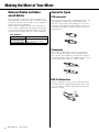 6
6
-
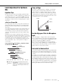 7
7
-
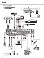 8
8
-
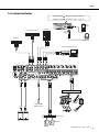 9
9
-
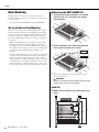 10
10
-
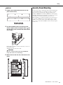 11
11
-
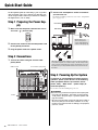 12
12
-
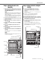 13
13
-
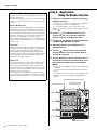 14
14
-
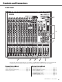 15
15
-
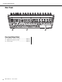 16
16
-
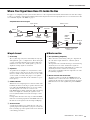 17
17
-
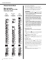 18
18
-
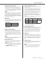 19
19
-
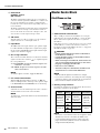 20
20
-
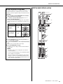 21
21
-
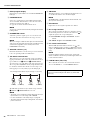 22
22
-
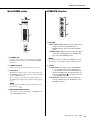 23
23
-
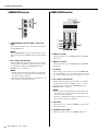 24
24
-
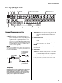 25
25
-
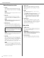 26
26
-
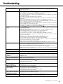 27
27
-
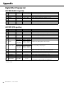 28
28
-
 29
29
-
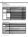 30
30
-
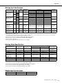 31
31
-
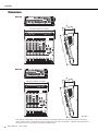 32
32
-
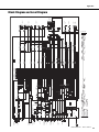 33
33
-
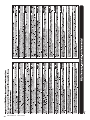 34
34
-
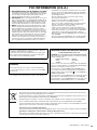 35
35
-
 36
36


Yamaha MGP12X Handleiding
- Categorie
- Audiomixers
- Type
- Handleiding
- Deze handleiding is ook geschikt voor
in andere talen
- English: Yamaha MGP12X User manual
- italiano: Yamaha MGP12X Manuale utente
- русский: Yamaha MGP12X Руководство пользователя
- français: Yamaha MGP12X Manuel utilisateur
- español: Yamaha MGP12X Manual de usuario
- Deutsch: Yamaha MGP12X Benutzerhandbuch
- português: Yamaha MGP12X Manual do usuário
- dansk: Yamaha MGP12X Brugermanual
- suomi: Yamaha MGP12X Ohjekirja
- čeština: Yamaha MGP12X Uživatelský manuál
- svenska: Yamaha MGP12X Användarmanual
- Türkçe: Yamaha MGP12X Kullanım kılavuzu
- polski: Yamaha MGP12X Instrukcja obsługi
- română: Yamaha MGP12X Manual de utilizare
Gerelateerde artikelen
Andere documenten
-
JBSYSTEMS MM-10 MIXER de handleiding
-
 JBSYSTEMS MM 14D de handleiding
-
 Power Dynamics PDM-S1204A de handleiding
-
Alto TMX160DFX Snelstartgids
-
 JBSYSTEMS SMP 12.22 de handleiding
-
Belkin TUNESTUDIO #F8Z109EA de handleiding
-
Velleman HQMX11010 Handleiding
-
Samsung MX-T70 Handleiding
-
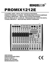 HQ Power PROMIX1212E Handleiding
-
Samsung MX-T50 Handleiding


