
MANUEL D’INSTALLATION
DVH-P5000MP
INSTALLATION MANUAL
This product conforms to new cord colors.
Los colores de los cables de este producto se confor-
man con un nuevo código de colores.
Dieses Produkt entspricht den neuen kabelfarben.
Le code de couleur des câbles utilisé pour ce produit est
nouveau.
Questo prodotto è conforme ai nuovi codici colori.
De kleuren van de snoeren van dit toestel zijn gewijzigd.
English
Español
Deutsch
Français
Italiano
Nederlands

Connecting the Units
Power cable connection 4
Connecting to separately sold power amp 6
When connecting with a multi-channel
processor 8
When connecting the display with RCA
input jack 10
When using a display connected to rear
video output 11
Installation
DIN Front/Rear-mont 12
DIN Front-mont 13
Installation with the rubber bush 13
Removng the unit 13
DIN Rear-mont 14
Installation using the screw holes
on the side of the unit 14
Fixing the front panel 15
Notes
• This unit is for vehicles with a 12-volt battery
and negative grounding. Before installing it in
a recreational vehicle, truck, or bus, check the
battery voltage.
• To avoid shorts in the electrical system, be
sure to disconnect the ≠ battery cable before
beginning installation.
• Refer to the owner’s manual for details on
connecting the power amp and other units,
then make connections correctly.
• Secure the wiring with cable clamps or adhe-
sive tape. To protect the wiring, wrap adhesive
tape around them where they lie against
metal parts.
• Route and secure all wiring so it cannot touch
any moving parts, such as the gear shift,
handbrake, and seat rails. Do not route wiring
in places that get hot, such as near the heater
outlet. If the insulation of the wiring melts or
gets torn, there is a danger of the wiring short-
circuiting to the vehicle body.
• Don’t pass the yellow lead through a hole into
the engine compartment to connect to the
battery. This will damage the lead insulation
and cause a very dangerous short.
• Do not shorten any leads. If you do, the pro-
tection circuit may fail to work when it should.
• Never feed power to other equipment by cut-
ting the insulation of the power supply lead of
the unit and tapping into the lead. The current
capacity of the lead will be exceeded, causing
overheating.
• When replacing fuse, be sure to use only fuse
of the rating prescribed on the fuse holder.
• Since a unique BPTL circuit is employed,
never wire so the speaker leads are directly
grounded or the left and right ≠ speaker
leads are common.
Contents Connecting the Units
2
En

• Speakers connected to this unit must be high-
power types with minimum rating of 50 W and
impedance of 4 to 8 ohms. Connecting speak-
ers with output and/or impedance values
other than those noted here may result in the
speakers catching fire, emitting smoke, or
becoming damaged.
• If the RCA pin jack on the unit will not be
used, do not remove the caps attached to the
end of the connector.
• When this product’s source is switched ON, a
control signal is output through the
blue/white lead. Connect to an external power
amp’s system remote control or the car’s
Auto-antenna relay control terminal (max. 300
mA 12 V DC). If the car features a glass
antenna, connect to the antenna booster
power supply terminal.
• When an external power amp is being used
with this system, be sure not to connect the
blue/white lead to the amp’s power terminal.
Likewise, do not connect the blue/white lead
to the power terminal of the auto-antenna.
Such connection could cause excessive cur-
rent drain and malfunction.
• To avoid short-circuiting, cover the discon-
nected lead with insulating tape. Especially,
insulate the unused speaker leads without
fail. There is a possibility of short-circuiting if
the leads are not insulated.
• To prevent incorrect connection, the input
side of the IP-BUS connector is blue, and the
output side is black. Connect the connectors
of the same colors correctly.
• If this unit is installed in a vehicle that does
not have an ACC (accessory) position on the
ignition switch, the red lead of the unit should
be connected to a terminal coupled with igni-
tion switch ON/OFF operations. If this is not
done, the vehicle battery may be drained
when you are away from the vehicle for sev-
eral hours.
• The black lead is ground. Please ground this
lead separately from the ground of high-cur-
rent products such as power amps.
If you ground the products together and the
ground becomes detached, there is a risk of
damage to the products or fire.
• Cords for this product and those for other
products may be different colors even if they
have the same function. When connecting
this product to another product, refer to the
supplied Installation manuals of both prod-
ucts and connect cords that have the same
function.
No ACC positionACC position
O
N
S
T
A
R
T
O
F
F
A
C
C
O
N
S
T
A
R
T
O
F
F
En
3
English
Español
Deutsch
Français
Italiano
Nederlands
Connecting the Units

Power cable connection
Connecting the Units
En
4
Connect leads of the
same color to each other.
Cap (1*)
When not using this terminal,
do not remove the cap.
ISO connector
Fuse holder
1*
2*
4*
3*
5*
Yellow (2*)
To terminal always supplied
with power regardless of
ignition switch position.
Red (4*)
To electric terminal controlled
by ignition switch (12 V DC)
ON/OFF.
Yellow (3*)
Back-up
(or accessory)
Red (5*)
Accessory
(or back-up)
Black (ground)
To vehicle (metal) body.
Orange/white
To lighting switch terminal.
Note
In some vehicles, the ISO connector may
be divided into two. In this case, be sure
to connect to both connectors.
Fuse resistor
Fuse resistor
IP-BUS cable
Antenna jack
Multi-CD player
(sold separately)
IP-BUS input (Blue)
Refer to pages 6 – 11.
Optical input
Rear audio output
(Refer to pages 8 – 11.)
This product
Note
Depending on the kind of vehicle, the function of 3*
and 5* may be different. In this case, be sure to
connect 2* to 5* and 4* to 3*.

Connecting the Units
En
5
English
Español
Deutsch
Français
Italiano
Nederlands
Blue/white (7*)
To Auto-antenna relay control terminal
(max. 300 mA 12 V DC).
Blue/white (6*)
Blue/white
To system control terminal of the power amp
(max. 300 mA 12 V DC).
Yellow/black
If you use a cellular telephone, connect it via the
Audio Mute lead on the cellular telephone. If not,
keep the Audio Mute lead free of any
connections.
Speaker leads
White
White/black
Gray
Gray/black
Green
Green/black
Violet
Violet/black
: Front left +
: Front left ≠
: Front right +
: Front right ≠
: Rear left + or Subwoofer +
: Rear left ≠ or Subwoofer ≠
: Rear right + or Subwoofer +
: Rear right ≠ or Subwoofer ≠
Light green
Used to detect the ON/OFF status of the parking brake.
This lead must be connected to the power supply side of the
parking brake switch.
Parking brake
switch
Power supply side
Ground side
Note
• The position of the parking brake switch depends
on the vehicle model. For details, consult the
vehicle Owner’s Manual or dealer.
Connection method
Clamp the lead.1. 2. Clamp firmly with
needle-nosed
pliers.
The pin position of the ISO connector will differ
depending on the type of vehicle. Connect 6*
and 7* when Pin 5 is an antenna control type.
In another type of vehicle, never connect 6*
and 7*.
When you connect separately sold
multi-channnel processor (DEQ-P7000)
to this unit, do not connect anything to the
speaker leads and system remote control
(blue/white).

Connecting the Units
En
6
Blue/white (7*)
To Auto-antenna relay control terminal
(max. 300 mA 12 V DC).
Blue/white (6*)
System remote control
Subwoofer output
or non fading Output
(SUBWOOFER OUTPUT or
NON-FADING OUTPUT)
Front output
(FRONT OUTPUT)
Note
Change the initial setting of this product
(refer to the Operation Manual).
The subwoofer output of this unit is monaural.
The pin position of the ISO connector will differ
depending on the type of vehicle. Connect 6*
and 7* when Pin 5 is an antenna control type.
In another type of vehicle, never connect 6*
and 7*.
Note
When you connect DEQ-P7000 to this unit,
separately sold power amp must be connected
to DEQ-P7000.
When you connect separately sold
multi-channnel processor (DEQ-P7000)
to this unit, do not connect anything to the
speaker leads and system remote control
(blue/white).
Rear audio output
(Refer to pages 8 – 11.)
This product
Optical input
IP-BUS input (Blue)
(Refer to page 4.)
Antenna jack
(Refer to page 4.)
15 cm
15 cm
Connecting to separately sold power amp

Connecting the Units
En
7
English
Español
Deutsch
Français
Italiano
Nederlands
Use this for connections when
you have the separately available
amplifier.
Blue/white
To system control terminal of the
power amp (max. 300 mA 12 V DC).
Subwoofer
Subwoofer
Front speaker
Front speaker
Connecting cords
with RCA pin plugs
(sold separately)
Left Right
System remote control
≠
+
≠
+
≠
+
≠
+
Power amp
(sold separately)
Power amp
(sold separately)

Connecting the Units
When connecting with a multi-channel processor
En
8
To audio
inputs
To video
input
IP-BUS cable
(supplied with
multi-CD player)
Black
Blue
IP-BUS cable
(supplied with
multi-channel processor)
Blue
Black
RCA cables
(sold separately)
RCA cable
(supplied with multi-channel processor)
Multi-channel processor
(DEQ-P7000)
(sold separately)
Display with RCA
input jacks
Multi-CD player
(sold separately)

Connecting the Units
En
9
English
Español
Deutsch
Français
Italiano
Nederlands
Rear video output
(REAR VIDEO OUTPUT)
(Yellow)
Optical cable
(supplied with multi-channel processor)
Right (Red)
Left (White)
RCA cable (supplied)
Rear audio output
Right (Red)
Left (White)
6m
23 cm
23 cm
15 cm
Brown
6m
Front video output
(FRONT VIDEO
OUTPUT) (Yellow)
Subwoofer output or non fading
output (SUBWOOFER OUTPUT
or NON-FADING OUTPUT)
This product
Black
Blue
16:9 touchscreen
display (AVD-W6210)
(sold separately)

Connecting the Units
When connecting the display with RCA input jack
En
10
RCA cable
(supplied)
To video input
Display with RCA
input jacks
6m
This product
Front video output
(FRONT VIDEO OUTPUT) (Yellow)
23 cm

Connecting the Units
En
11
When using a display connected to rear video output
This product’s rear video output is for connection of a display to enable passengers in the rear seats
to watch the DVD or Video CD.
WARNING
• NEVER install the display in a location that enables the driver to watch the DVD or Video CD while
driving.
• NEVER connect rear audio output to sold separately power amp.
English
Español
Deutsch
Français
Italiano
Nederlands
Display with RCA
input jacks
RCA cable
(supplied)
To video input
To audio inputs
RCA cable
(sold separately)
6m
This product
Rear video output
(REAR VIDEO OUTPUT) (Yellow)
Rear audio output
Left (White)
Right (Red)
23 cm

Installation
Notes
• Before finally installing the unit, connect the
wiring temporarily, making sure it is all con-
nected up properly, and the unit and the sys-
tem work properly.
• Use only the parts included with the unit to
ensure proper installation. The use of unau-
thorized parts can cause malfunctions.
• Consult with your nearest dealer if installation
requires the drilling of holes or other modifi-
cations of the vehicle.
• Install the unit where it does not get in the
driver’s way and cannot injure the passenger
if there is a sudden stop, like an emergency
stop.
• The semiconductor laser will be damaged if it
overheats, so don’t install the unit anywhere
hot — for instance, near a heater outlet.
• If installation angle exceeds 30° from horizon-
tal, the unit might not give its optimum perfor-
mance.
• The cords must not cover up the area shown
in the figure below. This is necessary to allow
the amplifires to radiate freely.
Do not close this area.
En
12
DIN Front/Rear-mount
This unit can be properly installed either from “Front” (conventional DIN Front-mount) or “Rear”
(DIN Rear-mount installation, utilizing threaded screw holes at the sides of unit chassis). For
details, refer to the following illustrated installation methods.

Installation
En
13
English
Español
Deutsch
Français
Italiano
Nederlands
DIN Front-mount
Installation with the rubber bush
Removing the unit
Holder
After inserting the holder into the
dash-board, then select the
appropriate tabs according to the
thickness of the dash-board
material and bend them.
(Install as firmly as possible using
the top and bottom tabs. To secure,
bend the tabs 90 degrees.)
182
53
Rubber bush
Screw
Dashboard
Frame
Insert the release pin into the hole
in the bottom of the frame and pull
out to remove the frame. (When
reattaching the frame, point the
side with a groove downwards and
attach it.)
Insert the supplied extraction keys into the
unit, as shown in the figure, until they click
into place. Keeping the keys pressed against
the sides of the unit, pull the unit out.

Installation
DIN Rear-mount
Installation using the screw holes on the side of the unit
1. Remove the frame.
2. Fastening the unit to the factory radio mounting bracket.
Select a position where the screw holes of the
bracket and the screw holes of the head unit
become aligned (are fitted), and tighten the
screws at 2 places on each side. Use either
truss screws (5 × 8 mm) or flush surface screws
(5 × 9 mm), depending on the shape of the
screw holes in the bracket.
En
14
Frame
Insert the release pin into the hole in the
bottom of the frame and pull out to remove
the frame. (When reattaching the frame,
point the side with a groove downwards and
attach it.)
Screw
Factory radio
mounting bracket
Dashboard or Console

Installation
En
15
Fixing the front panel
If you do not operate the Detaching and Replacing the Front Panel Function, use the supplied fixing
screws and holder to fix the front panel to this unit.
1. Attach the holders to both sides of the front panel.
2 Replace the front panel to the unit.
3. Flip the holders into upright positions.
4 Fix the front panel to the unit using fixing screws.
English
Español
Deutsch
Français
Italiano
Nederlands
Holder
Fixing screw

Conexión de las unidades
Conexión del cable de alimentación 4
Conexión al amplificador de potencia ven-
dido separadamente 6
Cuando conecte con un procesador multi-
canal 8
Cuando conecte la presentación visual con
tomas de entrada RCA 10
Cuando utilice un presentación visual
conectado a la salida de vídeo trasera 11
Instalación
Montaje delantero/trasero DIN 12
Montaje delantero DIN 13
Instalación con tope de goma 13
Quitado de la unidad 13
Montaje trasero DIN 14
Instalación usando los agujeros para
tornillos ubicados en ambos costados
de la unidad 14
Colocación del panel delantero 15
Notas
• Esta unidad es para vehículos con batería de
12 voltios y con conexión a tierra. Antes de
instalar la unidad en un vehículo recreativo,
camioneta, o autobús, revise el voltaje de la
batería.
• Para evitar cortocircuitos en el sistema eléc-
trico, asegúrese de desconectar el cable de la
batería ≠ antes de comenzar con la instalación.
• Consulte con el manual del usuario para los
detalles sobre la conexión de la alimentación
de amperios y de otras unidades, luego haga
las conexiones correctamente.
• Asegure el cableado con abrazaderas de
cables o con cinta adhesiva. Para proteger el
cableado, envuélvalo con cinta adhesiva donde
éstos se apoyan sobre las piezas de metal.
• Coloque y asegure todo el cableado de tal
manera que no toque las piezas en
movimiento, tal como la palanca de cambio
de velocidades, el freno de mano, y los
pasamanos de los asientos. No coloque el
cableado en lugares que se calientan, tal
como cerca de la salida de un calefactor. Si el
material aislante del cableado se derritiera o
se gastara, habrá el peligro de un cortocircuito
del cableado a la carrocería del vehículo.
• No pase el conductor amarillo a través de un
orificio en el compartimiento del motor para
conectar a la batería. Esto dañará el material
aislante del conductor y causará un cortocir-
cuito peligroso.
• No acorte ningún conductor. Si lo hiciera, la
protección del circuito podría fallar al fun-
cionar cuando debería.
• Nunca alimente energía a otros equipos cor-
tando el aislamiento del conductor de ali-
mentación provista de la unidad y haciendo
un empalme con el conductor. La capacidad
de corriente del conductor se excederá, cau-
sando el recalentamiento.
• Cuando reemplace algún fusible, asegúrese
de utilizar solamente un fusible del ratio
descrito en el soporte de fusibles.
• Ya que se emplea un circuito único BPTL,
nunca coloque los cables de manera que los
conductores del altavoz estén directamente
en conexión a tierra o que el altavoz izquierdo
y derecho ≠ sean comunes.
Contenido Conexión de las unidades
2
Sp

• Los altavoces conectados a esta unidad
deberán ser del tipo de alta potencia,
teniendo un régimen mínimo de 50 W y una
impedancia de 4 a 8 ohmios. La conexión de
altavoces con valores de impedancia y/o de
salida diferentes a los anotados aquí podrían
causar fuego, emisión de humo o daños a los
altavoces.
• Si la toma de clavija RCA en la unidad no se
usa, retire las tapas fijadas al extremo del
conector.
• Cuando se conecta la fuente de este
producto, una señal de control se emite a
través del conductor azul/blanco. Conecte al
control remoto de sistema de un amplificador
de potencia externo o al terminal de controle
de relé de antena automática del vehículo
(máx. 300 mA 12 V CC). Si el vehículo tiene
una antena en vidrio, conecte al terminal de
suministro de energía de la antena.
• Cuando se está utilizando un amperio de
potencia externa con este sistema, asegúrese
de no conectar el conductor azul/blanco al
terminal de potencia de amperios. Asimismo,
no conecte el conductor azul/blanco al termi-
nal de potencia de la auto-antena. Tal conex-
ión podría causar la fuga de corriente exce-
siva y causar fallos de funcionamiento.
• Para evitar cortocircuitos, cubra el conductor
desconectado con cinta aislada.
Especialmente, aísle los conductores de
altavoz no usados. Hay la posibilidad de corto-
circuito si no se aíslan los conductores.
• Para evitar la conexión incorrecta, el lado de
entrada del conector IP-BUS es azul, y el lado
de salida es negro. Conecte los conectores
del mismo color correctamente.
• Si se instala esta unidad en un vehículo que
no tiene una posición ACC (accesorio) en el
interruptor de encendido, el conductor rojo de
la unidad deberá conectarse al terminal
conectado con las operaciones del interruptor
de encendido ON/OFF. Si no se hace esto, la
batería del vehículo podría drenarse cuando
usted esté lejos del vehículo por varias horas.
• El conductor negro es la masa. Conecte a
masa este conductor separadamente desde la
masa de los productos de alta corriente tal
como los amplificadores de potencia.
Si conecta juntos a masa los productos y la
masa se desconecta, se crea el riesgo de
daños a los productos o de incendios.
• Los cables para esta unidad y aquéllas para
las unidades pueden ser de colores
diferentes aun si tienen la misma función.
Cuando se conecta esta unidad a otra,
refiérase a los manuales de instalación de
ambas unidades y conecte los cables que
tienen la misma función.
No en la posición ACC
Posición ACC
O
N
S
T
A
R
T
O
F
F
A
C
C
O
N
S
T
A
R
T
O
F
F
Sp
3
English
Español
Deutsch
Français
Italiano
Nederlands
Conexión de las unidades

Conexión del cable de alimentación
Conexión de las unidades
Sp
4
1*
2*
4*
3*
5*
Reproductor de
Multi-CD (vendido
separadamente)
Cable IP-BUS
Entrada IP-Bus (Azul)
Nota
Dependiendo del tipo del vehículo, la función de 3*
y 5* puede ser diferente. En este caso, asegúrese
de conectar 2* a 5* y 4* a 3*.
Jack para antena
Este producto
Conecte los conductores del
mismo color uno a otro.
Tapa (1*)
Cuando este terminal no se
usa, no retire la tapa.
Amarillo (3*)
Reserva
(o accesorio)
Amarillo (2*)
Al terminal con suministro constante de
electricidad, independientemente de la
posición del interruptor de encendido.
Rojo (5*)
Accesorio
(o reserva)
Rojo (4*)
Al terminal de energía eléctrica contro-
lado por el interruptor de encendido del
vehículo (12 V de CC.) ON/OFF.
Anaranjado/blanco
Al terminal de interruptor de
iluminación.
Negro (masa)
A la carrocería del veículo
(parte metálica).
Conector ISO
Nota
En algunos vehículos, el conector ISO puede
estar dividido en dos partes. En este caso,
asegúrese de conectar a ambos conectores.
Portafusible
Resistencia
de fusible
Resistencia
de fusible
Entrada óptica
Consulte las páginas 6 – 11.
Salida de audio
trasera (Consulte
las páginas 8 – 11.)

Conexión de las unidades
Sp
5
English
Español
Deutsch
Français
Italiano
Nederlands
Amarillo/negro
Si utiliza un teléfono celular, conéctelo por el cable
de enmudecimiento de audio del teléfono celular.
Si no, mantenga el enmudecimiento de audio libre
de cualquier conexión.
1. Apriete el cable. 2. Apriete firmemente
con alicates de
punta de aguja.
Nota
• La posición del freno de estacionamiento depende del
modelo del vehículo. Para conocer detalles, consulte el
manual del propietario del vehículo o a su concesionario.
Verde claro
Se utiliza para detectar el estado ON/OFF del freno de
mano. Este cable debe conectarse al lado de alimentación
del interruptor del freno de mano.
Lado de alimentación
Lado de masa
Interruptor del
freno de mano
Azul/blanco (7*)
Al terminal de control de relé de antena
automática (máx. 300 mA 12 V de CC).
Azul/blanco (6*)
Azul/blanco
Al terminal de control de sistema del amp.
de potencia (máx. 300 mA de 12 V CC).
La posición de los pinos del conector ISO
difiere de acuerdo al tipo de vehículo.
Conecte 6* y 7* cuando el pino 5 es un tipo
de control de antena. En otros tipos de
vehículo, nunca conecte 6* y 7*.
Cables de altavoz
Blanco : Izquierdo delantero +
Blanco/negro : Izquierdo delantero ≠
Gris : Derecho delantero +
Gris/negro : Derecho delantero ≠
Verde : Izquierdo trasero + o Altavoz
secundario +
Verde/negro : Izquierdo trasero ≠ o Altavoz secundario ≠
Violeta : Derecho trasero + o Altavoz secundario +
Violeta/negro : Derecho trasero ≠ o Altavoz secundario ≠
Cuando conecte el procesador multicanal
(DEQ-P7000) vendido separadamente a
esta unidad, no conecte nada a los con-
ductores de los altavoces y al control
remoto del sistema (azul/blanco).
Método de conexión

Conexión de las unidades
Sp
6
15 cm
15 cm
Conexión al amplificador de potencia vendido separadamente
Salida delantera
(FRONT OUTPUT)
Salida de altavoz de
graves secundario o salida sin
atenuación
(SUBWOOFER OUTPUT or NON-
FADING OUTPUT)
Entrada IP-Bus (Azul)
(Consulte la página 4.)
Jack para antena
(Consulte la página 4.)
Este producto
La posición de los pinos del conector ISO
difiere de acuerdo al tipo de vehículo.
Conecte 6* y 7* cuando el pino 5 es un tipo
de control de antena. En otros tipos de
vehículo, nunca conecte 6* y 7*.
Control remoto de sistema
Azul/blanco (6*)
Azul/blanco (7*)
Al terminal de control de relé de antena automática
(máx. 300 mA 12 V de CC).
Nota
Cambie el ajuste inicial de este producto (refiérase
al manual de operación). La salida de altavoz de
graves secundario de esta unidad es monofónica.
Entrada óptica
Cuando conecte el procesador multicanal
(DEQ-P7000) vendido separadamente a
esta unidad, no conecte nada a los con-
ductores de los altavoces y al control
remoto del sistema (azul/blanco).
Nota
C
uando conecte el DEQ-P7000 a esta unidad, se
deberá conectar el amplificador de potencia
vendido separadamente al DEQ-P7000.
Salida de audio trasera
(Consulte las páginas 8 – 11.)

Conexión de las unidades
Sp
7
English
Español
Deutsch
Français
Italiano
Nederlands
≠
+
≠
+
≠
+
≠
+
Cables de conexión con
clavijás RCA
(
vendido separadamente
)
Lleve a cabo las conexiones
cuando utilice un amplificador
diferente.
Azul/blanco
Al terminal de control de sistema del amp.
de potencia (máx. 300 mA de 12 V CC).
Control remoto de sistema
Altavoz secundario
Altavoz secundario
Altavoz delantero Altavoz delantero
Izquierda Derecha
Amplificador de
potencia
(vendido separadamente)
Amplificador de
potencia
(vendido separadamente)

Conexión de las unidades
Cuando conecte con un procesador multicanal
Sp
8
Negro Azul
Azul
Negro
Reproductor de
Multi-CD (en venta
por separado)
Cable RCA
(suministrado con el procesador
multicanal)
Presentación visual con
tomas de entrada RCA
Cable IP-BUS
(suministrado con el
procesador multicanal)
Procesador Multicanal
(DEQ-P7000)
(vendido separadamente)
Cable RCA
(vendido separadamente)
A las entradas
de audio
A la entrada
de vídeo
Cable IP-BUS
(suministrado con
el reproductor de
Multi-CD)

Conexión de las unidades
Sp
9
English
Español
Deutsch
Français
Italiano
Nederlands
6 m
23 cm
23 cm
15 cm
6 m
Este producto
Derecha (Rojo)
Izquierda (Blanco)
Azul
Salida de altavoz de graves secun-
dario o salida sin atenuación
(SUBWOOFER OUTPUT or NON-
FADING OUTPUT)
Cable óptico
(suministrado con el
procesador multicanal)
Salida de vídeo trasera
(REAR VIDEO OUTPUT)
(Amarillo)
Salida de audio trasera
Salida de vídeo delantera
(FRONT VIDEO OUTPUT)
(Amarillo)
Cable RCA
(vendido separadamente)
Negro
Marrón
Derecha (Rojo)
Izquierda (Blanco)
Pantalla de toque 16:9
(AVD-W6210)
(vendido separadamente)
(SPA)

Conexión de las unidades
Cuando conecte la presentación visual con tomas de entrada RCA
Sp
10
6 m
23 cm
Este producto
Salida de vídeo delantera
(FRONT VIDEO OUTPUT) (Amarillo)
Cable RCA
(suministrado)
A la entrada
de video
Presentación visual con
tomas de entrada RCA

Conexión de las unidades
Sp
11
Cuando utilice un presentación visual conectado a la salida de
vídeo trasera
La salida de vídeo trasera de este producto es para la conexión de un presentación visual para permi-
tir que los pasajeros en los asientos traseros puedan ver el DVD o Video CD.
ADVERTENCIA
• NUNCA instale el presentación visual en un lugar que permita el motorista ver el DVD o Video CD
mientras conduce el automóvil.
• NUNCA conecte la salida de audio trasera al amplificador de potencia vendido separadamente.
English
Español
Deutsch
Français
Italiano
Nederlands
6 m
23 cm
Este producto
Cable RCA
(suministrado)
Cable RCA
(vendido separadamente)
A las entradas
de audio
A la entrada
de video
Presentación visual con
tomas de entrada RCA
Salida de vídeo trasera
(REAR VIDEO OUTPUT) (Amarillo)
Salida de audio trasera
Derecha (Rojo)
Izquierda (Blanco)

Instalación
Notas
• Antes de finalmente instalar la unidad,
conecte el cableado temporalmente y
asegúrese de que todo esté conectado correc-
tamente y que la unidad y el sistema funcio-
nan debidamente.
• Utilice sólo las piezas que se incluyen con
esta unidad para asegurar la instalación ade-
cuada. El uso de piezas no autorizadas podría
causar fallos de funcionamiento.
• Consulte con su distribuidor si la instalación
requiere del taladro de orificios u otras modifi-
caciones del vehículo.
• Instale la unidad donde no alcance el espacio
del conductor, y donde no pueda dañar a los
pasajeros si sucediera un paro repentino,
como una detención de emergencia.
• El semiconductor láser se dañará si se sobre-
calienta, por eso no instale la unidad en un
lugar caliente – por ejemplo, cerca de la sal-
ida de un calefactor.
• Si el ángulo de la instalación excede los 30°
del lado horizontal, la unidad podría no
brindar su óptimo funcionamiento.
• Los cordones no deben tapar el área
mostrado en la figura de abajo. Esto es nece-
sario para permitir que los amplificadores
puedan radiar libremente.
Sp
12
Montaje delantero/trasero DIN
Esta unidad quede instalarse correstamente de la “Delantera” (montaje delantero DIN conven-
ciona) o “Trasera” (montaje trasero DIN, utilizando los tornillos roscados en los constados del
chasis de la unidad). Para detalles, refiérase a los métodos de instalación ilustrados abajo.
Evite cerrar este área.

Instalación
Sp
13
English
Español
Deutsch
Français
Italiano
Nederlands
Montaje delantero DIN
Instalación con tope de goma
Quitado de la unidad
182
53
Marco
Inserte el pasador de liberanción en
el orificio de la parte inferior del
marco, y tire hacia afuera para
extraer el marco. (Para la fijación
del marco, apunte el lado con
ranura hacia abajo.)
Inserte las herramientas de extracción suminis-
tradas en la unidad, como se indica en la figura,
hasta que se enganchen en su positión.Tire de la
unidad mientras mantiene las herramientas pre-
sionadas contra los lados de la unidad.
Tablero de
instrumentos
Soporte
Después de insertar el soporte en la tabla de
mandos, luego seleccione las orejetas apropi-
adas según el grosor del material de la tabla de
mandos y dóblelos.
(Instale lo más firme posible usando las lengüe-
tas superior e inferior. Para fijar, doble las
lengüetas 90 grados.)
Tope de goma
Tornillo

Instalación
Montaje trasero DIN
Instalación usando los agujeros para tornillos ubicados en ambos costados de
la unidad
1. Quite el marco.
2. Fijación de la unidad a la ménsula de montaje existente.
Seleccione una posición en la que los orificios
para los tornillos del soporte y del de la unidad
principal queden alineados, y apriete los tornil-
los en 2 lugares de un lado. Utilice ya sea los
tornillos de fijación (5 × 8 mm) o los tornillos a
paño (5 × 9 mm), dependiendo de la forma de
los orificios de tornillo en la ménsula.
Sp
14
Marco
Inserte el pasador de liberanción en el orifi-
cio de la parte inferior del marco, y tire hacia
afuera para extaer el marco. (Para la fijación
del marco, apunte el lado con ranura hacia
abajo.)
Tornillo
Ménsula de montaje
de radio existente
Tablero de instrumentos
o consola

Instalación
Sp
15
Colocación del panel delantero
Si no desea utilizar la función de extracción y colocación del panel delantero, utilice los tornillos de
fijación y sujetadores suministrados y fije el panel delantero a esta unidad.
1. Coloque los sujetadores en ambos lados del panel delantero.
2. Reinstale el panel delantero en la unidad.
3. Mueva los sujetadores en las posiciones verticales.
4. Fije el panel delantero a la unidad utilizando los tornillos de fijación.
English
Español
Deutsch
Français
Italiano
Nederlands
Sujetador
Tornillos de fijación

Anschließen der Einheiten
Anschluß des Stromkabels 4
Anschluß an einen getrennt erhältlichen
Leistungsverstärker 6
Bei Anschluß an einen
Multikanalprozessor 8
Bei Anschluß des Displays mit Cinch-
Eingangsbuchsen 10
Bei Gebrauch eines am hinteren Video-
Ausgang angeschlossenen Displays 11
Einbauverfahren
DIN-Befestigung von vorne/hinten 12
DIN-Vordermontage 13
Einbau mit der Gummibuchse 13
Entnahme des Gerätes 13
DIN-Rückmontage 14
Installation unter Gebrauch der
Gewindebohrungen an der Seite der
Einheit 14
Befestigen der Frontplatte 15
Hinweise
• Dieses Gerät ist für Fahrzeuge mit 12-V-
Batterie und negativer Erdung (Minuspol an
Masse) ausgelegt. Prüfen Sie vor dem Einbau
in ein Wohnmobil, einen Lastwagen oder Bus
die Batteriespannung.
• Um Kurzschlüsse im elektrischen Systen zu
verhindern, ist unbedingt vor dem Einbau das
Minus-Batteriekabel ≠ abzutrennen.
• Nehmen Sie die Anschlüsse gemäß den
Anweisungen zum Anschluß des
Leistungsverstärkers und anderer Geräte in
der Bedienungsanleitung vor.
• Sichern Sie die Leitungen mit Kabelklemmen
oder Klebeband. Zum Schutz der Leitungen
sollten sie an den Stellen, wo sie Metallteile
berühren, mit Klebeband umwickelt werden.
•
Verlegen und sichern Sie alle Leitungen so, daß sie
keine beweglichen Teile wie die Gangschaltung,
die Handbremse und Sitzschienen berühren. Die
Leitungen dürfen nicht an Stellen entlanggeführt
werden, die heiß werden, z.B. an einer
Heizungsauslaßöffnung. Wenn die Isolierung
einer Leitung schmilzt oder aufreißt, besteht die
Gefahr eines Kurzschlusses mit der Karosserie.
• Führen Sie die gelbe Leitung nicht durch ein
Loch in den Motorraum zum Anschluß an die
Batterie. Dadurch wird die Isolierung der
Leitung beschädigt, was zu einem sehr
gefährlichen Kurzschluß führen kann.
• Verkürzen Sie keine Leitungen. In diesem Fall
kann es vorkommen, daß die Schutzschaltung
nicht arbeitet, wenn sie gebraucht wird.
• Führen Sie niemals anderen Geräten Strom
zu, indem Sie die Isolierung der
Stromversorgungsleitung dieses Geräts
durchschneiden und davon Strom abzapfen.
Dadurch wird die Strombelastbarkeit der Leitung
überschritten, was zu Überhitzung führt.
• Benutzen Sie beim Auswechseln von
Sicherungen nur Sicherungen mit dem auf
dem Sicherunshalter angegebenen Nennwert.
•
Da ein einzigartiger BPTL-Schaltkreis verwendet
wird, dürfen die Lautsprecherleitungen niemals
direkt geerdet oder die Minusleitungen
≠
des
rechten und linken Kanals gemeinsam sein.
Inhalt Anschließen der Einheiten
2
Ge

• Lautsprecher, die an dieses Gerät
angeschlossen werden, müssen eine mini-
male Nennleistung von 50 W und eine
Impedanz zwischen 4 und 8 Ohm haben. Falls
Lautsprecher mit anderen Leistungs-
und/oder Impedanzwerten angeschlossen
werden, können die Lautsprecher in Brand
geraten, Rauch entwickeln und beschädigt
werden.
• Die Kappe nicht vom Steckverbinder entfer-
nen, wenn an der Cinchbuchse am Hauptgerät
kein Anschluß hergestellt werden soll.
• Wenn die Programmquelle dieses Produkts
eingeschaltet wird, wird ein Steuersignal über
das blau/weiße Kabel ausgegeben. An eine
System-Fernbedienung eines externen
Leistungsverstärkers oder an Steckverbinder
für Auto-Antennenrelais-Steuerung des
Wagens anschließen (max. 300 mA, 12 V
Gleichspannung). Wenn der Wagen mit einer
Fensterantenne ausgestattet ist, an die
Antennenverstärker-
Stromversorgungsklemme anschließen.
• Bei Verwendung eines externen
Leistungsverstärkers für dieses System muß
die blau/weiße Leitung an die
Leistungsklemme des Verstärkers
angeschlossen werden. Die blau/weiße
Leitung darf nicht an die Leistungsklemme
der Auto-Antenne angeschlossen werden. Ein
solcher Anschluß könnte übermäßige
Stromentnahme und dadurch
Funktionsstörungen verursachen.
• Um einen Kurzschluß zu vermeiden, abge-
trennte Kabel mit Isolierband umwickeln.
Unbenutzte Lautsprecherzuleitungen müssen
unbedingt isoliert werden. Wenn die Kabel
nicht isoliert werden, besteht
Kurzschlußgefahr.
• Um falsche Anschlüsse zu verhindern, ist die
Eingangsseite des IP-Bus-Steckverbinders
blau und die Ausgangsseite schwarz. Die
Steckverbinder derselben Farbe sind korrekt
zu verbinden.
• Wenn dieses Gerät in einem Auto eingebaut
wird, das auf dem Zündschalter keine ACC
(Zubehör)-Position hat, sollte die rote Leitung
des Geräts an eine Klemme angeschlossen
werden, die mit der ON/OFF-Operation des
Zündschalters gekoppelt ist. Andernfalls kann
die Autobatterie entleert werden, wenn Sie
mehrere Stunden von dem Fahrzeug weg
sind.
• Das schwarze Kabel ist das Erdungskabel.
Dieses Kabel ist getrennt von der Erde von
Hochstrom-Geräten, wie z.B.
Leistungsverstärkern, zu erden.
Falls die Geräte zusammen geerdet werden,
und die Erdungsstelle abgetrennt wird,
besteht die Gefahr einer Beschädigung der
Geräte oder eines Brands.
• Kabel dieses Geräts und die anderer Geräte
können unterschiedliche Farben haben, auch
wenn sie die gleichen Funktionen haben.
Beim Anschluß dieses Geräts an ein anderes
Gerät unter Bezugnahme auf die mit beiden
Geräten mitgelieferten
Installationsanleitungen die Kabel mit dersel-
ben Funktion verbinden.
Keine ACC-PositionACC-Position
O
N
S
T
A
R
T
O
F
F
A
C
C
O
N
S
T
A
R
T
O
F
F
Ge
3
English
Español
Deutsch
Français
Italiano
Nederlands
Anschließen der Einheiten

Anschluß des Stromkabels
Anschließen der Einheiten
Ge
4
1*
2*
4*
3*
5*
Multi-CD player
(getrennt
erhältlich)
IP-BUS-Kabel
Hinweis
Je nach Art des Fahrzeugs besitzen 3* und 5* u.U.
unterschiedliche Funktionen. In einem solchen Fall
2* mit 5* und 4* mit 3* verbinden.
Dieses Produkt
Lichtleitereingang
Siehe Seiten 6 bis 11.
Hinterer
Audioausgang
(Siehe Seiten 8
bis 11.)
Antennenbuches
IP-Bus-Eingang (Blau)
Verbinden Sie Leitungen
derselben Farbe miteinander.
Kappe (1*)
Wenn dieser Steckverbinder
nich verwendet wird, die
Kappe aufgesetzt lassen.
Gelb (3*)
Reserve
(oder Zubehör)
Rot (5*)
Zubehör
(oder Reserve)
Rot (4*)
An eine Stromversorgung anschließen,
(12 V Gleichstrom), die mit dem
Zündschloß ein- und ausgeschaltet wird.
Orange/weiß
An Beleuchtungsschalterklemme.
Schwarz (Erdung)
An die Karosserie (Metallteil)
anschließen.
ISO-Anschluß
Hinweis
Bei einigen Fahrzeugen kann der ISO-Steckverbinder in
zwei Hälften geteilt sein. In diesem Fall den Anschluß
unbedingt an beiden Steckverbindern vornehmen.
Sicherungshalter
Sicherungs
widerstand
Sicherungs
widerstand
Gelb (2*)
An eine Stromversorgung anschließen,
die unabhängig vom Zündschloß immer
Strom führt.

Anschließen der Einheiten
Ge
5
English
Español
Deutsch
Français
Italiano
Nederlands
Gelb/Schwarz
Bei Verwendung eines Zellulartelefons dieses über
die Audio Mute-Leitung des Zellulartelefons
anschließen. Andernfalls die Audio Mute-Leitung
frei von Anschlüssen lassen.
Anschlußmethode
1. Klemmen Sie das Kabel
fest.
2. Fest mit einer
Nadelzange
einklemmen.
Hinweis
• Die Position des Parkbremsschalters hängt vom Fahrzeugmodell
ab. Einzelheiten entnehmen Sie aus der technischen
Dokumentation des Fahrzeugs oder erfragen sie beim Händler.
Hellgrün
Dieser Anschluß dient zur Erkennung des ON/OFF-Status der
Handbremse. Das Kabel ist an die Stromversorgungsseite
des Handbremsenschalters anzuschließen.
Stromversorgungsseite
Masseseite
Handbremsens
chalter
Blau/weiß (7*)
An Steckverbinder für
Autoantennenrelais-Steuerung
(max. 300 mA, 12 V Gleichspannung).
Blau/weiß (6*)
Blau/weiß
An Systemsteuerungs-Steckverbinder der
Endstufe (max. 300 mA, 12V Gleichspannung).
Die Pin-Position des ISO-Anschlusses hängt vom
Fahrzeugtyp ab. 6* und 7* anschließen, wenn es
sich bei Pin 5 um einen Antennensteuerungstyp
handelt. Bei einem anderen Fahrzeugtyp 6* und
7* niemals anschließen.
Lautsprecherzuleitungen
Weiß : Vorne links +
Weiß/Schwarz : Vorne links ≠
Grau : Vorne rechts +
Grau/Schwarz : Vorne rechts ≠
Grün : Hinten links + oder
Subwoofer +
Grün/Schwarz : Hinten links ≠ oder Subwoofer ≠
Violett : Hinten rechts + oder Subwoofer +
Violett/Schwarz : Hinten rechts ≠ oder Subwoofer ≠
Wenn Sie einen getrennt erhältlichen
Multikanalprozessor (DEQ-P7000) an dieses
Gerät anschließen, so schließen Sie nichts
an die Lautsprecherleitungen und an die
Systemfernbedienung (blau/weiß) an.

Anschließen der Einheiten
Ge
6
15 cm
15 cm
Anschluß an einen getrennt erhältlichen Leistungsverstärker
Ausgnag für vorderen
Zusatzlautsprecher
(FRONT OUTPUT)
Subwoofer-Ausgang
oder Nicht-Überblend-Ausgang
(SUBWOOFER OUTPUT or
NON-FADING OUTPUT)
IP-Bus-Eingang (Blau)
(Siehe Seite 4.)
Lichtleitereingang
Hinterer Audioausgang
(Siehe Seiten 8 bis 11.)
Antennen-buches
(Siehe Seite 4.)
Die Pin-Position des ISO-Anschlusses hängt vom
Fahrzeugtyp ab. 6* und 7* anschließen, wenn es
sich bei Pin 5 um einen Antennensteuerungstyp
handelt. Bei einem anderen Fahrzeugtyp 6* und
7* niemals anschließen.
System-Fernbedienung
Blau/weiß (6*)
Blau/weiß (7*)
An Steckverbinder für Autoantennenrelais-
Steuerung (max. 300 mA, 12 V Gleichspannung).
Hinweis
Ändern Sie die Grundeinstellung dieses Produkts
(siehe Bedienungsanleitung). Der Subwoofer-
Ausgang dieses Geräts ist Mono.
Wenn Sie einen getrennt erhältlichen
Multikanalprozessor (DEQ-P7000) an dieses
Gerät anschließen, so schließen Sie nichts
an die Lautsprecherleitungen und an die
Systemfernbedienung (blau/weiß) an.
Hinweis
Wenn Sie den DEQ-P7000 an dieses Gerät
anschließen, muss ein getrennt erhältlicher
Leistungsverstärker an den DEQ-P7000
angeschlossen werden.
Dieses Produkt

Anschließen der Einheiten
Ge
7
English
Español
Deutsch
Français
Italiano
Nederlands
≠
+
≠
+
≠
+
≠
+
Verbindungskabel mit
RCA-Stiftstecker
(getrennt erhältlich)
Diese Anschlüsse bei Verwendung
eines anderen Verstärkers
(Sonderzubehör) herstellen.
Blau/weiß
An Systemsteuerungs-
Steckverbinder der Endstufe
(max. 300 mA, 12V Gleichspannung).
System-Fernbedienung
Subwoofer Subwoofer
Vorderer
Zusatzlautsprecher
Vorderer
Zusatzlautsprecher
Links Recht
Leistungsverstärker
(getrennt erhältlich)
Leistungsverstärker
(getrennt erhältlich)

Anschließen der Einheiten
Bei Anschluß an einen Multikanalprozessor
Ge
8
Schwarz Blau
Blau
Schwarz
Multi-CD-Player
(getrennt
erhältlich)
RCA-Kabel
(mit Multikanalprozessor mitgeliefert)
Display mit RCA-
Eingangsbuchsen
IP-BUS-Kabel
(mit Multikanalprozessor
mitgeliefert)
RCA-Kabel
(getrennt erhältlich)
Multikanalprozessor
(DEQ-P7000)
(getrennt erhältlich)
Zu Audio-
Eingängen
Zu Video-
Eingang
IP-BUS-Kabel
(mit Multi-CD-Player
mitgeliefert)

Anschließen der Einheiten
Ge
9
English
Español
Deutsch
Français
Italiano
Nederlands
6 m
23 cm
23 cm
15 cm
6 m
Dieses Produkt
Hinterer Videoausgang
(REAR VIDEO OUTPUT)
(Gelb)
Hinterer Audioausgang
Subwoofer-Ausgang oder Nicht-
Überblend-Ausgang
(SUBWOOFER OUTPUT or NON-
FADING OUTPUT)
Blau
Lichtleiter Kabel
(mit Multikanalprozessor
mitgeliefert)
Vorderer Videoausgang
(FRONT VIDEO OUTPUT)
(Gelb)
RCA-Kabel
(mitgeliefert)
Schwarz
Recht (Rot)
Links (Weiß)
Recht (Rot)
Links (Weiß)
Braun
16:9-Touchscreen-Display
(AVD-W6210)
(getrennt erhältlich)

Anschließen der Einheiten
Bei Anschluß des Displays mit Cinch-Eingangsbuchsen
Ge
10
6 m
23 cm
Dieses Produkt
Vorderer Videoausgang
(FRONT VIDEO OUTPUT) (Gelb)
RCA-Kabel
(mitgeliefert)
Zu Video-
Eingang
Display mit RCA-
Eingangsbuchsen

Anschließen der Einheiten
Ge
11
Bei Gebrauch eines am hinteren Video-Ausgang angeschlossenen
Displays
Der hintere Video-Ausgang dieses Produkts ist zum Anschluß eines Displays vorgesehen, damit
Mitfahrer auf den Rücksitzen DVDs oder Video CDs sehen können.
WARNUNG
• Das Display darf AUF KEINEN FALL an einer Stelle installiert werden, an der es vom Fahrer
während der Fahrt eingesehen werden kann.
• Schließen Sie NIEMALS den hinteren Audioausgang an einen getrennt erhältlichen
Leistungsverstärker an.
English
Español
Deutsch
Français
Italiano
Nederlands
6 m
23 cm
Dieses Produkt
RCA-Kabel
(mitgeliefert)
RCA-Kabel
(getrennt erhältlich)
Zu Audio-
Eingängen
Zu Video-
Eingang
Display mit RCA-
Eingangsbuchsen
Hinterer Videoausgang
(REAR VIDEO OUTPUT) (Gelb)
Hinterer Audioausgang
Recht (Rot)
Links (Weiß)

Einbauverfahren
Hinweise
• Schließen Sie vor dem Einbau die Leitungen
vorübergehend an und stellen Sie sicher, das
alles richtig angeschlossen ist und das Gerät
und das System einwandfrei arbeiten.
• Um einwandfreien Einbau zu gewährleisten,
sollten nur die mit dem Gerät mitgelieferten
Teile verwendet werden. Bei Verwendung von
Nicht-Originalteilen kann es zu
Funktionsstörungen kommen.
• Wenden Sie sich an Ihren Fachhänlder, wenn
zum Einbau des Geräts Löcher gebohrt oder
andere Veränderungen an Ihrem Auto
vorgenommen werden müssen.
• Bauen Sie das Gerät an einer Stelle ein, wo es
den Fahrer nicht behindert und den Beifahrer
bei plötzlichem Bremsen nicht verletzen an.
• Der Halbleiterlaser wird bei Überhitzung
beschädigt, bauen Sie das Gerät daher nicht
an einer Stelle ein, wo es heiß wird, z.B. nahe
einer Heizungsauslaßöffnung.
• Wenn der Einbauwinkel mehr als 30º von der
Horizontalen abweicht, kann es sein, daß das
Gerät nicht optimal arbeitet.
• Die Leitungen dürfen den in der folgenden
Abbildung gezeigten Bereich nicht verdecken.
Dies ist erforderlich, damit die Verstärker frei
Wärme abstrahlen können.
Ge
12
DIN-Befestigung von vorne/hinten
Diese Einheit kann entweder von “vorne” (konventionelle DIN-Vordermontage) oder von “hinten”
(DIN-Rückmontage unter Gebrauch der Gewindebohrungen an den Seiten des Chassis) richtig
installiert werden. Einzelheiten entnehmen Sie bitte den im folgenden dargestellten
Installationsverfahren.
Diesen Bereich nicht
verdecken.

Einbauverfahren
Ge
13
English
Español
Deutsch
Français
Italiano
Nederlands
DIN-Vordermontage
Einbau mit der Gummibuchse
Entnahme des Gerätes
182
53
Rahmen
Setzen Sie den Ausziehschlüssel in
die Öffnung unten am Rahmen ein,
und ziehen Sie den Rahmen zum
Abnehmen heraus. (Zum
Wiederanbringen des Rahmens
lassen Sie die genutete Seite nach
unten.)
Die mitgelieferten Ausziehschlüssel wie in
der Abbildung gezeigt bis zur
Einrastposition in das Gerät einsetzen. Die
Schlüssel gegen die Seiten des Geräts
drücken und das Gerät herausziehen.
Armaturenbrett
Halter
Den Halter in das Armaturenbrett einsetzen,
dann die der Dicke des Armaturenbretts
entsprechenden Zungen auswählen und diese
biegen.
(Mit Hilfe der Ansätze, oben und unten, so fest
wie möglich einsetzen. Zur Sicherung werden
die Ansätze 90 Grad gebogen.)
Gummibuchse
Schraube

Einbauverfahren
DIN-Rückmontage
Installation unter Gebrauch der Gewindebohrungen an der Seite der Einheit
1. Nehmen Sie den Rahmen ab.
2. Anbringen dieser Einheit an die Werks-Radiomontagehalterung.
Wählen Sie eine Position, an der die
Gewindebohrungen der Halterung und die der
Haupteinheit zur Deckung gelangen, und
ziehen Sie die Schrauben an 2 Stellen auf jeder
Seite fest. Je nach Form der
Gewindebohrungen in der Halterung sollten Sie
entweder Flachrundschrauben (5 × 8 mm) oder
bündig abschließende Schrauben (5 × 9 mm)
verwenden.
Ge
14
Rahmen
Setzen Sie den Ausziehschlüssel in die Öff-
nung unten am Rahmen ein, und ziehen Sie
den Rahmen zum Abnehmen heraus. (Zum
Wiederanbringen des Rahmens lassen Sie
die genutete Seite nach unten.)
Schraube
Werks-Radiomontagehalterung
Armaturenbrett oder
Konsole

Einbauverfahren
Ge
15
Befestigen der Frontplatte
Wenn Sie die Funktion zum Abnehmen und Anbringen der Frontplatte nicht verwenden wollen, so
fixieren Sie die Frontplatte mit den mitgelieferten Befestigungsschrauben und dem Haltern an
diesem Gerät.
1. Bringen Sie die Halter an beiden Seiten der Frontplatte an.
2. Bringen Sie die Frontplatte wieder am Gerät an.
3. Klappen Sie die Halter hoch.
4. Sichern Sie die Frontplatte mit den Befestigungsschrauben am Gerät.
English
Español
Deutsch
Français
Italiano
Nederlands
Halter
Befestigungsschraube

Raccordements des appareils
Raccordement du câble d’alimentation 4
Raccordement à un amplificateur de puis-
sance séparé 6
Lors du raccordement d’un processeur
multi-canaux 8
Lors du raccordement à l’écran muni de
prises d’entrée Cinch (RCA) 10
Lors de l’utilisation d’un écran raccordé à la
sortie vidéo arrière 11
Installation
Montage DIN avant/arrière 12
Montage DIN avant 13
Installation avec une bague en
caoutchouc 13
Dépose de l’unite 13
Montage DIN arrière 14
Installation en utilisant les trous de vis
sur les côtés de l’appareil 14
Fixation de la face avant 15
Remarques
•
Cet appareil est destiné aux véhicules avec une
batterie de 12 V, avec pôle négatif à la masse.
Avant de l’installer dans un véhicule de loisir, un
camion ou un car, vérifier la tension de la batterie.
• Afin d’éviter tout risque de court-circuit,
débrancher le câble de la borne négative ≠
de la batterie avant de commencer la pose.
• Pour le raccordement des câbles de l’amplifi-
cateur de puissance et des autres appareils,
se reporter au manuel de l’utilisateur et
procéder comme il est indiqué.
• Fixer les câbles au moyen de colliers ou de
morceaux de ruban adhésif. Pour protéger le
câblage, enrouler la bande adhésive autour
des câbles à l’endroit où ceux-ci sont placés
contre les parties métalliques.
• Acheminer et fixer tout le câblage de telle sorte
qu’il ne touche pas les pièces mobiles, comme
le levier de changement de vitesse, le frein à
main et les rails des sièges. Ne pas acheminer
les câbles dans des endroits qui peuvent
devenir chauds, comme près de la sortie de
radiateur. Si l’isolation des câbles fond ou est
se déchire, il existe un danger de court-circuit
des câbles avec la carrosserie du véhicule.
• Ne pas faire passer le conducteur jaune dans
le compartiment moteur par un trou pour le
connecter avec la batterie. Cela pourrait
endommager sa gaine d’isolation et provo-
quer un grave court-circuit.
• Ne pas court-circuiter les conducteurs. Dans
le cas contraire, le circuit de protection risque
de ne pas fonctionner.
• Ne jamais alimenter un autre appareil par un
branchement sur le câble d’alimentation de
celui-ci. Le courant qui circulerait dans ce
conducteur pourrait dépasser la capacité du
conducteur et entraîner une élévation anor-
male de température.
• Lors du remplacement du fusible, n’utiliser
qu’un fusible de même ampérage (il est
indiqué sur le porte-fusible).
• Un circuit BPTL unique étant employé, n’ef-
fectuez jamais le câblage de sorte que les fils
de haut-parleurs soient directement mis à la
masse ou que les fils de haut-parleurs ≠
gauche et droit soient communs.
Table des matières
Raccordements des appareils
2
Fr

• Les haut-parleurs connectés à cet appareil
doivent être tels qu’ils puissent supporter une
puissance de 50 W, et que leur impédance
soit comprise entre 4 et 8 Ohms. L’utilisation
de haut-parleurs dont la puissance admissi-
ble ou l’impédance seraient différentes des
valeurs indiquées ici, pourrait provoquer leur
inflammation, avec émission de fumée, ou à
tout le moins leur endommagement.
• Si la prise RCA de l’appareil n’est pas utilisée,
ne retirez pas les capuchons que porte le
connecteur.
• Quand la source de ce produit est positionnée
sur ON, un signal de commande est sorti par
le fil bleu/blanc. Connectez-le à la télécom-
mande d’ensemble de l’amplificateur de puis-
sance extérieur ou à la borne de commande
du relais d’antenne motorisée (max. 300 mA,
12 V CC). Si la voiture utilise une antenne de
vitre, connectez-le à la prise d’alimentation de
l’amplificateur d’antenne.
• Lorsqu’un amplificateur de puissance externe
est utilisé avec ce système, veiller à ne pas
connecter le fil bleu/blanc à la borne d’ali-
mentation de l’amplificateur. De la même
manière, ne pas connecter le fil bleu/blanc à
la borne d’alimentation de l’antenne automa-
tique. Un tel branchement pourrait causer
une perte de courant excessive et un mauvais
fonctionnement de l’appareil.
• Pour éviter les courts-circuits, recouvrez les
fils déconnectés par du ruban isolant. En
particulier, n’oubliez pas d’isoler les fils d’en-
ceintes. Un court-circuit peut se produire si
les fils ne sont pas isolés.
• Pour éviter une connexion incorrecte, le côté
entrée du connecteur IP-BUS est bleu et
même couleur correctement.
• Si cette unité est installée dans un véhicule
dont le contacteur d’allumage n’a pas de
position ACC (accessoire), le fil rouge de l’u-
nité doit être connecté à une borne couplée
aux opérations de marche/arrêt du contacteur
d’allumage. Sinon, la batterie du véhicule
peut se décharger lorsque le véhicule n’est
pas utilisé pendant plusieurs heures.
• Le conducteur noir est le fil de masse. Veillez
à relier ce conducteur à une masse qui ne soit
pas la masse d’un appareil gros consomma-
teur d’énergie tel qu’un amplificateur de puis-
sance.
En effet, si vous utilisez la même masse pour
plusieurs appareils et si ces masses sont
supprimées par un défaut de contact, l’en-
dommagement de l’appareil, voire un
incendie sont possibles.
• Les câbles de cet appareil et ceux d’autres
appareils peuvent fort bien ne pas être de la
même couleur bien que remplissant la même
fonction. Pour relier cet appareil à un autre
appareil, utilisez le manuel d’installation de
chacun et effectuez les raccordements en ne
tenant compte que de la fonction de chaque
câble.
Aucune position ACCPosition ACC
O
N
S
T
A
R
T
O
F
F
A
C
C
O
N
S
T
A
R
T
O
F
F
Fr
3
English
Español
Deutsch
Français
Italiano
Nederlands
Raccordements des appareils

Raccordement du câble d’alimentation
Raccordements des appareils
Fr
4
1*
2*
4*
3*
5*
Lecteur de CD à
chargeur (vendu
séparément)
Câble IP-BUS
Remarque
Selon le véhicule, le rôle de 3* et 5* peut être dif-
férent. En ce cas, veillez à relier 2* à 5* et 4* à 3*.
Entrée IP-BUS (Bleu)
Cet appareil
Voyez pages 6 – 11.
Entrée optique
Sortie audio arrière
(Voyez pages 8 – 11.)
Jack d’antenne
Reliez ensemble les conduc-
teurs de même couleur.
Porte-fusible
Résistance
fusible
Résistance
fusible
Capuchon (1*)
Si vous n’utilisez pas ce
connecteur, ne retirez pas le
capuchon.
Jaune (3*)
Secours
(ou accessoire)
Jaune (2*)
Vers une borne alimentée en
permanence indépendamment
de la clé de contact.
Rouge (5*)
Accessoire
(ou secours)
Rouge (4*)
Vers une borne dont l’alimentation
est commandée par la clé de
contact (12 V CC).
Orange/blanc
Vers la borne du contacteur
d’éclairage.
Noir (masse)
Fil de masse vers un élément en
métal apparent de la voiture.
Connecteur ISO
Remarque
Sur certains véhicules, le connecteur ISO
peut comporter deux parties. En ce cas, veillez
à relier ces deux parties.

Raccordements des appareils
Fr
5
English
Español
Deutsch
Français
Italiano
Nederlands
Jaune/noir
Si vous utilisez un téléphone cellulaire, connectez-
le via le câble mise en sourdine audio sur la télé-
phone cellulaire. Sinon, laisser le câble de mise en
sourdine audio sans aucune connexion.
Méthode de connexion
1. Serrez le conducteur. 2. Serrez fermement
avec une pince à
mâchoires pointues.
Remarque
• La position du contacteur de frein à main dépend du mod-
èle de véhicule. Pour les détails, consultez le manuel de
l’utilisateur du véhicule ou un concessionnaire.
S’éclaire de couleur verte
Utilisé pour détecter l’état ON/OFF du frein à main.
Ce conducteur doit être raccordé sur l’alimentation du
contacteur de frein à main.
Côté alimentation
Côté masse
Contacteur de
frein à main
Bleu/blanc (7*)
Vers la borne de commande du relais
d’antenne motorisée (maximum 300
mA sous12 V CC).
Bleu/blanc (6*)
Bleu/blanc
Vers la borne de commande de l’amplificateur
de puissance (maximum 300 mA sous 12 V CC).
La disposition des broches du connecteur
ISO diffère en fonction du type de véhicule.
Connectez 6* et 7* quand la broche 5 est la
commande d’antenne. Sinon, ne connectez
jamais les broches 6* et 7*.
Lorsque vous raccordez le processeur
multi-canaux (DEQ-P7000) à cet appareil,
ne raccordez rien aux fils de haut-parleur
ni à la télécommande (bleu/blanc).
Câbles de liaison aux haut-parleurs
Blanc : Avant gauche +
Blanc/noir : Avant gauche ≠
Gris : Avant droite +
Gris/noir : Avant droite ≠
Vert : Arrière gauche + ou Haut-parleur
d’extrêmes graves +
Vert/noir : Arrière gauche ≠ ou Haut-parleur d’extrêmes graves ≠
Violet : Arrière droite + ou Haut-parleur d’extrêmes graves +
Violet/noir : Arrière droite ≠ ou Haut-parleur d’extrêmes graves ≠

Raccordements des appareils
Fr
6
15 cm
15 cm
Raccordement à un amplificateur de puissance séparé
Sortie avant
(FRONT OUTPUT)
Sortie pour haut-
parleur d’extrêmes graves,
ou sortie sans atténuation
(SUBWOOFER OUTPUT or
NON-FADING OUTPUT)
Entrée IP-BUS (Bleu)
(Voyez page 4.)
Jack d’antenne
(Voyez page 4.)
Cet appareil
Entrée optique
Sortie audio arrière
(Voyez pages 8 – 11.)
La disposition des broches du connecteur
ISO diffère en fonction du type de véhicule.
Connectez 6* et 7* quand la broche 5 est la
commande d’antenne. Sinon, ne connectez
jamais les broches 6* et 7*.
Bleu/blanc (6*)
Bleu/blanc (7*)
Vers la borne de commande du relais d’antenne
motorisée (maximum 300 mA sous 12 V CC).
Remarque
Change le réglage initial de ces appareils (reportez-
vous aux mode d’emploi). La sortie du haut-parleur
d’extrêmes graves de cet appareil est monaurale.
Remarque
Lors du raccordement du DEQ-P7000 à cet
appareil, il faudra raccorder un amplificateur de
puissance vendu séparément au DEQ-P7000.
Lorsque vous raccordez le processeur
multi-canaux (DEQ-P7000) à cet appareil,
ne raccordez rien aux fils de haut-parleur
ni à la télécommande (bleu/blanc).
Télécommande d’ensemble

Raccordements des appareils
Fr
7
English
Español
Deutsch
Français
Italiano
Nederlands
≠
+
≠
+
≠
+
≠
+
Câbles de liaison munis
de prises RCA
(vendu séparément)
Amplificateur de
puissance
(vendu séparément)
Amplificateur de
puissance
(vendu séparément)
Effectuez ces raccordements
lorsque l’installation
comporte un autre amplificateur.
Bleu/blanc
Vers la borne de commande de l’am-
plificateur de puissance (maximum
300 mA sous 12 V CC).
Haut-parleur d’ex-
trêmes graves
Haut-parleur d’ex-
trêmes graves
Haut-parleur avant
Haut-parleur avant
Gauche
Télécommande d’ensemble
Droite

Raccordements des appareils
Lors du raccordement d’un processeur multi-canaux
Fr
8
Noir Bleu
Bleu
Câble à fiches Cinch (RCA)
(fourni avec le processeur
multi-canaux)
Processeur multi-canaux
(DEQ-P7000) (vendu
séparément)
Noir
Lecteur de CD à
chargeur (vendu
séparément)
Écran muni de prises
d’entrée Cinch (RCA)
Câble IP-BUS
(fourni avec le
lecteur de CD à
chargeur)
Câbles à fiches Cinch (RCA)
(vendu séparément)
Vers les
entrées audio
Vers l’entrée
vidéo
Câble IP-BUS
(fourni avec le
processeur
multi-canaux)

Raccordements des appareils
Fr
9
English
Español
Deutsch
Français
Italiano
Nederlands
6 m
23 cm
23 cm
15 cm
6 m
Cet appareil
Droite (Rouge)
Gauche (Blanc)
Sortie pour haut-parleur d’extrêmes
graves, ou sortie sans atténuation
(SUBWOOFER OUTPUT or NON-
FADING OUTPUT)
Câble à fiches
Cinch (RCA)
(fourni)
Câble optique
(fourni avec le processeur
multi-canaux)
Sortie vidéo arrière
(REAR VIDEO OUTPUT) (Jaune)
Sortie vidéo avant
(FRONT VIDEO OUTPUT) (Jaune)
Sortie audio arrière
Droite (Rouge)
Gauche (Blanc)
Brun
Écran tactile 16/9
(AVD-W6210)
(vendu séparément)

Raccordements des appareils
Lors du raccordement à l’écran muni de prises d’entrée Cinch (RCA)
Fr
10
6 m
23 cm
Cet appareil
Sortie vidéo avant
(FRONT VIDEO OUTPUT) (Jaune)
Câble à fiches
Cinch (RCA)
(fourni)
Vers l’entrée
vidéo
Écran muni de prises
d’entrée Cinch (RCA)

Raccordements des appareils
Fr
11
Lors de l’utilisation d’un écran raccordé à la sortie vidéo arrière
La sortie vidéo arrière de cet appareil est destinée à un écran placé de telle sorte que les passagers
arrière puissent regarder les images fournies par un DVD ou un Video CD.
AVERTISSEMENT
• Veillez à ce que l’écran NE SOIT PAS installé en un endroit tel que le conducteur puisse observer
les images fournies par le DVD ou le Video CD tout en conduisant.
• NE raccordez JAMAIS la sortie audio arrière à un amplificateur de puissance vendu séparément.
English
Español
Deutsch
Français
Italiano
Nederlands
6 m
23 cm
Cet appareil
Câble à fiches
Cinch (RCA)
(fourni)
Câble à fiches
Cinch (RCA)
(vendu séparément)
Vers les
entrées audio
Vers l’entrée
vidéo
Écran muni de prises
d’entrée Cinch (RCA)
Sortie vidéo arrière
(REAR VIDEO OUTPUT) (Jaune)
Sortie audio arrière
Droite (Rouge)
Gauche (Blanc)

Installation
Remarques
• Avant de finaliser l’installation de l’appareil,
connecter temporairement le câblage en
s’assurant que tout est correctement con-
necté et que l’appareil et le système fonction-
nent correctement.
• Pour obtenir une bonne installation, n’utiliser
que les pièces de l’appareil. L’utilisation de
pièces non prévues risque de causer un mau-
vais fonctionnement.
• Consulter le concessionnaire le plus proche si
l’installation nécessite le percement de trous
ou toute autre modification du véhicule.
• Installer l’appareil à un endroit où il ne gêne
pas le conducteur et où il ne peut pas blesser
les passagers en cas d’arrêt brusque, comme
pendant un arrêt d’urgence.
• Le laser semiconducteur sera endommagé en
cas de réchauffement excessif. Dans ce cas
ne pas installer l’appareil dans un endroit
présentant une température élevée, tel que
sortie de chauffage.
• L’angle de l’installation, ne doit pas dépasser
30° par rapport à l’horizontale, faute de quoi
l’unité ne fournira pas ses performances opti-
males.
• Les cordons ne doivent pas couvrir la zone
montrée sur la figure ci-dessous. C’est néces-
saire pour permettre à l’amplificateur de ray-
onner librement.
Fr
12
Montage DIN avant/arrière
Cet appareil peut être monté aisement, ou par le procédé de montage avant DIN (normal), ou bien
par le procédé de montage arrière DIN, en utilisant les orifices de vis sur les côtés du châssis de
l'appareil. Pour les détails veuillez vous référer aux méthodes de montage illustrées qui suivent.
Ne recouvrez pas
cette zone.

Installation
Fr
13
English
Español
Deutsch
Français
Italiano
Nederlands
Montage DIN avant
Installation avec une bague en caoutchouc
Dépose de l’unite
182
53
Cadre
Introduisez la tige de déblocage
bans l’orifice du fond du cadre et
tirez pour enlever le cadre. (Pour
remettre le cadre en place, diriger le
côté avec la rainure vers le bas.)
Insérer les clés d’extraction fournis dans l’unité,
comme indiqué dans la figure, jusqu’à ce
qu’elles s’enclenchent en position. En main-
tenant ces clés pressées contre les côtés de
l’unité, retirer l’unité.
Tableau de bord
Support
Après avoir introduit le support dans le tableau
de bord, sélectíonnez les languettes
appropriées en fonction de l’épaisseur du
matériau du tableau de bord et courbez-les.
(Assurez le maintien aussi solidement que pos-
sible en utilisant les languettes inférieures et
supérieures. Cela fait, courbez les languettes de
90 degrés.)
Bague en caoutchouc
Vis

Installation
Montage DIN arrière
Installation en utilisant les trous de vis sur les côtés de l’appareil
1. Enlever le cadre.
2. Fixation de l’appareil au support pour le montage de la radio installée par le constructeur.
Choisir la position selon laquelle les orifices de
vis du support et ceux des vis de l’appareil prin-
cipal sont alignés (correspondent) et serrer les
vis sur 2 endroits de chaque côté. Utiliser l’une
des vis de serrage (5 × 8 mm) ou les ves à tête
plate (5 × 9 mm), selon le forme des trous de vis
sur le support.
Fr
14
Cadre
Introduisez la tige de déblocage dans l’ori-
fice du fond du cadre et tirez pour enlever le
cadre. (Pour remettre le cadre en place,
diriger le côté avec la rainure vers le bas.)
Vis
Support pour le
montage de la radio
Tableau de bord ou console

Installation
Fr
15
Fixation de la face avant
Si vous n’utilisez pas la fonction de dépose et pose de la face avant, utilisez la vis de fixation et les
crochets fournis et fixez la face avant à l’appareil.
1. Attachez les crochets des deux côtés de la face avant.
2. Remettez la face avant en place sur l’appareil.
3. Faites pivoter les crochets en position droite.
4. Fixez la face avant sur l’appareil avec les vis de fixation.
English
Español
Deutsch
Français
Italiano
Nederlands
Crochet
Vis de fixation

Collegamento delle unità
Collegamento del cavo di alimentazione 4
Collegamento ad un amplificatore di
potenza venduto separatamente 6
Se ci si collega ad un processore multi-
canale 8
Quando si collega lo schermo con prese di
ingresso tipo RCA 10
Uso di un schermo collegato all’uscita video
posteriore 11
Installazione
Montaggio DIN forntale/posteriore 12
Montaggio DIN frontale 13
Installazione con la boccola di gomma 13
Estrazione dell’unità 13
Montaggio DIN posteriore 14
Installazione per mezzo dei fori per vite
situati sui lati dell’unità 14
Fissaggio del pannello anteriore 15
Note
• Questo apparecchio è per veicoli con una
batteria da 12 volt e una messa a massa nega-
tiva. Prima di installarlo in un veicolo sportivo,
in un autocarro o in un autobus, controllare la
tensione della batteria.
• Per evitare cortocircuiti nell’impianto elet-
trico, accertarsi di scollegare il cavo della
batteria ≠ prima di iniziare l’installazione.
• Fare riferimento al manuale di istruzioni per i
dettagli sul collegamento dell’amplificatore di
potenza e di altri apparecchi, quindi eseguire i
collegamenti correttamente.
• Fissare i fili con dei fermacavi o del nastro
adesivo. Per proteggere i fili, avvolgervi
attorno del nastro adesivo nei punti in cui essi
sono a contatto con parti metalliche.
• Disporre e fissare tutti i fili in modo tale che
essi non tocchino alcuna parte in movimento,
come l’asta del cambio, il freno a mano e le
guide dei sedili. Non disporre i fili in luoghi
esposti al calore, come nei pressi della bocca
di efflusso dell’impianto di riscaldamento. Se
la guaina isolante dei fili si fonde o si lacera,
c’è il pericolo che i fili possano provocare
cortocircuiti alla carrozzeria del veicolo.
•
Non far passare il cavo giallo attraverso un foro per
inserirlo nel vano motore per collegare la batteria.
Questo danneggia la guaina isolante del cavo e
può causare un cortocircuito molto pericoloso.
• Non accorciare i cavi. Se si accorciano i cavi,
il circuito di protezione potrebbe non
funzionare quando invece dovrebe.
• Non fornire mai alimentazione ad un altro
apparecchio tagliando la guaina isolante del
cavo di alimentazione dell’apparecchio e colle-
gando il cavo. La capacità di corrente del cavo
sarà superata causando surriscaldamento.
• Quando si sostituisce il fusibile, accertarsi di
usare soltanto un fusibile dai limiti di impiego
indicati sul portafusibili.
• Poiché è impiegato un unico circuito BPTL, non
eseguire mai i collegamenti in modo tale che i
fili degli altoparlanti siano messi a massa diret-
tamente o in modo tale che i fili degli altopar-
lanti sinistro e destro ≠ siano in comune.
Indice Collegamento delle unità
2
It

• I diffusori collegati a quest’unità devono
essere di alta potenza da almeno 50 W e da 4
a 8 ohm. Se si usano diffusori con uscita e/o
ingresso inferiori, questi possono prendere
fuoco, emettere fumo o venir danneggiati in
altro modo.
• Se gli spinotti a spillo RCA dell’unità non
vengono usati, non rimuovere i cappucci
dall’estremità del connettore.
• Attivando la sorgente di questo apparecchio,
attraverso il cavo blu/bianco viene emesso un
segnale di comando. Collegare questo cavo al
dispositivo di comando a distanza di un sis-
tema di amplificatore di potenza esterno, o al
terminale di comando del relais dell’antenna
ad alzo automatico (massimo 300 mA, con
corrente continua a 12 V). Se l’automobile
dispone di una antenna a vetro, collegare il
cavo al terminale di alimentazione del booster
dell’antenna.
• Quando si usa un amplificatore di potenza
esterno con questo sistema, accertarsi di non
collegare il cavo blu/bianco al terminale di
alimentazione dell’amplificatore. Allo stesso
modo, non collegare il cavo blu/bianco al
terminale di alimentazione dell’antenna auto-
matica. Tale collegamento potrebbe causare
un consumo di corrente eccessivo e provo-
care problemi di funzionamento.
• Per evitare corti circuiti, coprire con nastro
isolante il cavo staccato. In particolare,
devono assolutamente essere ricoperti con
nastro isolante i cavi non usati degli altopar-
lanti. Se i cavi non vengono isolati possono
verificarsi dei pericolosi corti circuiti.
• Per evitare un collegamento sbagliato, il lato
di ingresso del connettore IP-BUS è blu, men-
tre il lato di uscita è nero. Collegare i connet-
tori dello stesso colore correttamente.
• Se questo apparecchio viene installato in un
veicolo che non possiede una posizione ACC
(accessoria) sull’interruttore di accensione, il
cavo rosso dell’apparecchio deve essere colle-
gato ad un terminale accoppiato con le oper-
azioni di accensione/spegnimento dell’inter-
ruttore di accensione. Se ciò non viene fatto,
la batteria del veicolo può scaricarsi quando
si lascia il veicolo per alcune ore.
• Il cavo nero è quello di messa a terra. Mettere
a terra questo cavo separatamente da quello
di messa a terra di apparecchi funzionanti
con corrente a tensioni elevate, quali gli
amplificatori di potenza.
Se gli apparecchi si trovano messi a terra
insieme, in caso di distacco della messa a
terra, possono verificarsi incendi, o prodursi
danni agli apparecchi.
• I cavi per questo apparecchio e quelli per altri
apparecchi possono avere colori diversi, pur
svolgendo la stessa funzione. Per il collega-
mento di questo apparecchio ad un’altro,
vedere i manuali di installazione di entrambi
gli apparecchi, e provvedere al collegamento
dei cavi aventi la stessa funzione.
Posizione ACC assente
Posizione ACC presente
O
N
S
T
A
R
T
O
F
F
A
C
C
O
N
S
T
A
R
T
O
F
F
It
3
English
Español
Deutsch
Français
Italiano
Nederlands
Collegamento delle unità

Collegamento del cavo di alimentazione
Collegamento delle unità
It
4
1*
2*
4*
3*
5*
Lettori multi-CD
(venduto separa-
tamente)
Cavo IP-BUS
Ingresso IP-BUS (Blu)
Nota
A seconda del tipo di veicolo, la funzione di 3* e 5*
protrebbe essere differente. In tal caso collegare
sempre 2* a 5* e 4* a 3*.
Vedere alle pagine 6 – 11.
Questo prodotto
Ingresso ottico
Terminal per
antenna
Uscita audio
posteriore (Vedere
alle pagine 8 – 11.)
Collegare fra loro cavi di
uguale colore.
Cappuccio (1*)
Se questo terminale non è in
uso, non togliere il cappuccio.
Giallo (3*)
Riserva
(o accessoria)
Giallo (2*)
Al terminale constantemente ali-
mentato, qualunque sia la posi-
zione della chiave d’accensione.
Rosso (5*)
Accessoria
(o riserva)
Rosso (4*)
Collegare alla chiave d’avvia-
mento ON/OFF (12 V di c.c.).
Arancione/bianco
Al terminale dell’interruttore
di illuminazione
Nero (massa)
Al telaio (parte metallica)
dell’automobile.
Portafusibili
Resistenza
fusibile
Resistenza
fusibile
Connettore ISO
Nota
In alcuni veicoli, il connettore ISO potrebbe
essere diviso in due. In tal caso, non mancare
di connettere ambedue i connettori.

Collegamento delle unità
It
5
English
Español
Deutsch
Français
Italiano
Nederlands
Giallo/nero
Se si usa un telefono cellegarlo tramite il cavo di
silenziamento audio sul telefono cellulare. In caso
contrario, non collegare affatto il cavo selinzia-
mento audio.
Metodo di collegamento
1. Fissare il cavo. 2. Fissare saldamente
con pinze a punta.
Nota
• La posizione dell’interruttore freno a mano dipende dal
modello di veicolo. Per dettagli consultare il manuale del
veicolo o il concessionario.
Luce verde
Usato per individuare lo stato attivato (ON)/disattivato (OFF)
del freno a mano. Questo cavo deve essere collegato al lato
alimentazione dell’interruttore freno a mano.
Lato alimentazione
Lato massa
Interruttore
freno a mano
Blu/bianco (7*)
Al terminale di controllo del relè
dell’antenna ad alzo automatico
(max. 300mA, 12 V di c.c).
Blu/bianco (6*)
Blu/bianco
Al terminale di controllo del sistema
dell’amplificatore di potenza
(max. 300 mA, 12 V di c.c).
La posizione dei poli del connettore ISO
differisce in relazione al tipo di veicolo. Se il
polo 5 è del tipo per il comando dell’an-
tenna, collegare 6* e 7*. Nei veicoli di altri
tipi non collegare mai 6* e 7*.
Quando si collega un processore multi-
canale venduto separatamente
(DEQ-P7000) a questo apparecchio, non
collegare niente ai cavi dei diffusori e al
telecomando di sistema (blu/bianco)
Cavi diffusore
Bianco : Anteriore sinistro +
Bianco/nero : Anteriore sinistro ≠
Grigio : Anteriore destro +
Grigio/nero : Anteriore destro ≠
Verde : Posteriore sinistro + o
Subwoofer +
Verde/nero : Posteriore sinistro ≠ o Subwoofer ≠
Violetto : Posteriore destro + o Subwoofer +
Violetto/nero : Posteriore destro ≠ o Subwoofer ≠

Collegamento delle unità
It
6
15 cm
15 cm
Collegamento ad un amplificatore di potenza venduto separatamente
Uscita anteriore
(FRONT OUTPUT)
Uscita del subwoofer o
uscita senza dissolvenza
(SUBWOOFER OUTPUT
or NON-FADING OUTPUT)
Ingresso IP-BUS (Blu)
(Vedere a pagina 4.)
Terminal per antenna
(Vedere a pagina 4.)
Questo prodotto
Ingresso ottico
Uscita audio posteriore
(Vedere alle pagine 8 – 11.)
La posizione dei poli del connettore ISO
differisce in relazione al tipo di veicolo. Se il
polo 5 è del tipo per il comando dell’an-
tenna, collegare 6* e 7*. Nei veicoli di altri
tipi non collegare mai 6* e 7*.
Comando a distanza del
sistema
Blu/bianco (6*)
Blu/bianco (7*)
Al terminale di controllo del relè dell’antenna
ad alzo automatico (max. 300mA, 12 V di c.c).
Nota
Cambiare l’impostazione iniziale di questo prodotto
(far riferimento al manuale d’istruzioni per l’uso).
L’uscita subwoofer di questa unità è di tipo mono.
Nota
Quando si collega il DEQ-P7000 a questo apparec-
chio, l’amplificatore di potenza venduto separata-
mente deve essere collegato al DEQ-P7000 stesso.
Quando si collega un processore multi-
canale venduto separatamente (DEQ-
P7000) a questo apparecchio, non colle-
gare niente ai cavi dei diffusori e al
telecomando di sistema (blu/bianco).

Collegamento delle unità
It
7
English
Español
Deutsch
Français
Italiano
Nederlands
≠
+
≠
+
≠
+
≠
+
Cavi di collegamento con
spine a terminale RCA
(venduto separatamente)
Effettuare questi collegamenti
quando si usa in differente
amplificatore.
Blu/bianco
Al terminale di controllo del sistema del-
l’amplificatore di potenza (max. 300 mA,
12 V di c.c).
Comando a distanza del sistema
Subwoofer Subwoofer
Diffusore
anteriore
Diffusore
anteriore
Sinistra Destra
Amplificatore
(venduto separata-
mente)
Amplificatore
(venduto separata-
mente)

Collegamento delle unità
Se ci si collega ad un processore multi-canale
It
8
Nero Blu
Blu
Cavo RCA
(fornito con il processore
multi-canale)
Processore multi-canale
(DEQ-P7000)
(venduto separatamente)
Cavo IP-BUS
(fornito con il processore
multi-canale)
Nero
Cavi RCA
(venduti sepa-
ratamente)
Cavo IP-BUS
(fornito in dotazione
al lettore multi-CD)
Lettore multi-CD
(venduto
separatamente
)
Schermo con prese di
ingresso di tipo RCA
All’ingresso video
Agli ingressi audio

Collegamento delle unità
It
9
English
Español
Deutsch
Français
Italiano
Nederlands
6 m
23 cm
23 cm
15 cm
6 m
Destra (Rosso)
Sinistra (Bianco)
Blu
Uscita del subwoofer o uscita
senza dissolvenza
(SUBWOOFER OUTPUT or
NON-FADING OUTPUT)
Cavo ottico (fornito con il
processore multi-canale)
Uscita video posteriore
(REAR VIDEO OUTPUT)
(Giallo)
Uscita audio posteriore
Destra (Rosso)
Sinistra (Bianco)
Uscita video anteriore
(FRONT VIDEO OUTPUT)
(Giallo)
Cavo RCA (fornito)
Nero
Questo prodotto
Marrone
Schermo tattile 16:9
(AVD-W6210)
(venduto separatamente)

Collegamento delle unità
Quando si collega lo schermo con prese di ingresso tipo RCA
It
10
6 m
23 cm
Questo prodotto
Uscita video anteriore
(FRONT VIDEO OUTPUT) (Giallo)
Cavo RCA
(fornito)
All’ingresso
video
Schermo con prese di
ingresso di tipo RCA

Collegamento delle unità
It
11
Uso di un schermo collegato all’uscita video posteriore
L’uscita video posteriore di quest’unità è prevista per il collegamento di un schermo che permette ai
passeggeri seduti sui sedili posteriori dell’auto di vedere un DVD o un CD video.
AVVERTENZA
• NON installare MAI il schermo in modo che il conducente possa vedere il DVD o il CD video
riprodotto mentre guida.
• NON collegare MAI l’uscita audio posteriore all’amplificatore di potenza venduto separatamente.
English
Español
Deutsch
Français
Italiano
Nederlands
6 m
23 cm
Questo prodotto
Cavo RCA
(fornito)
Cavo RCA
(venduto
separatamente
)
Agli ingressi
audio
All’ingresso
video
Schermo con prese di
ingresso di tipo RCA
Uscita video posteriore
(REAR VIDEO OUTPUT) (Giallo)
Uscita audio posteriore

Installazione
Note
• Prima di installare definitivamente l’apparec-
chio, collegare i fili temporaneamente e
accertarsi che tutti i collegamenti siano cor-
retti e che l’apparecchio e il sistema funzion-
ino correttamente.
• Per un’installazione appropriata, usare
soltanto i pezzi in dotazione all’apparecchio.
L’uso di pezzi non autorizzati può causare
problemi di funzionamento.
• Rivolgersi al più vicino rivenditore se l’instal-
lazione richiede la trapanatura di fori o altre
modifiche del veicolo.
• Installare l’apparecchio in un punto in cui
esso non intralci le manovre del conducente e
in cui non possa provocare lesioni ai passeg-
geri nel caso dell’arresto improvviso del vei-
colo, come nel caso di una frenata d’emer-
genza.
• Il laser a semiconduttore subisce danni se si
surriscalda; pertanto, non installare
l’apparecchio in luoghi esposti al calore,
come per esempio nei pressi della bocca di
efflusso dell’impianto di riscaldamento.
• Se l’angolo di installazione supera i 30°
rispetto alla posizione orizzontale, l’apparec-
chio potrebbe non fornire prestazioni ottimali.
• I cavi non devono coprire la zona mostrata
nella figura qui sotto: l’amplificatore deve
essere in grado di diffondere il suono libera-
mente.
It
12
Montaggio DIN forntale/posteriore
Questa unità può essere adeguatamente installata sia “frontalmente” (montaggio DIN frontale
convenzionale) sia “posteriormente” (installazione a montaggio DIN posteriore facendo utilizzo
dei fori filettati situati sui lati del telaio dell’unità). Per informazioni in merito, fare riferimento alle
figure che seguono relative ai metodi di installazione.
Non chiudere questa
zona.

Installazione
It
13
English
Español
Deutsch
Français
Italiano
Nederlands
Montaggio DIN frontale
Installazione con la boccola di gomma
Estrazione dell’unità
182
53
Telaio
Inserire nel foro situato sul fondo
del telaio l’attrezzo di rilascio a filo,
quindi estraendolo in modo da
rimuovere il telaio stesso. (Quando
si rimonta il telaio, dirigerne verso il
basso il lato provvisto di
scanalatura e quindi procedere con
il montaggio.)
Inserire le chiavette di estrazione in dotazione
nell’apparecchio, come mostrato nella figura,
finché non scattano in posizione. Tenendo le
chiavette premute contro i lati dell’apparecchio,
estrarre l’apparecchio.
Supporto
Dopo aver inserito il supporto nel cruscotto,
selezionare le linguette appropriate a seconda
dello spessore del materiale del cruscotto e
piegarle.
(Installare quanto più saldamente possibile
servendosi delle linguette superiore e inferiore.
Per fissare, piegare le linguette a 90 gradi.)
Boccola di gomma
Vite
Cruscotto

Installazione
Montaggio DIN posteriore
Installazione per mezzo dei fori per vite situati sui lati dell’unità
1. Rimuovere il telaio.
2. Assicurare l’unità alla staffa di montaggio radio.
Selezionare una posizione in cui i fori per vite
della staffa ed i fori per vite dell’unità principale
risultano allineati (si accoppiano) e quindi ser-
rare le viti nei 2 punti su ciascun lato.
Dipendentemente dalla forma dei fori per vite
presenti sulla staffa, utilizzare viti a trave (5 × 8
mm) oppure viti a testa piatta (5 × 9 mm).
It
14
Telaio
Inserire nel foro situato sul fondo del telaio
l’attrezzo di rilascio a filo, quindi estraendolo
in modo da rimuovere il telaio stesso.
(Quando si rimonta il telaio, dirigerne verso il
basso il lato provvisto di scanalatura e quindi
procedere con il montaggio.)
Vite
Staffa di montahhio radio
Plancia o console

Installazione
It
15
Fissaggio del pannello anteriore
Se non si usa la funzione Rimozione e montaggio del frontalino, usare le viti di fissaggio ed i supporti
in dotazione per fissare il frontalino su questo apparecchio.
1. Assicurare i supporti di fissaggio ad entrambi i lati del pannello anteriore.
2. Rimontare il pannello anteriore sull’unità.
3. Ruotare i supporti nelle posizioni vertiali.
4. Bloccare il pannello anteriore all’unità per mezzo delle apposite viti di fissaggio.
English
Español
Deutsch
Français
Italiano
Nederlands
Supporto
Vite di fissaggio

Aansluiten
Aansluiten van de stroomdraad 4
Aansluiten op een los verkrijgbare eindver-
sterker 6
Wanneer een multikanaals processor wordt
aangesloten 8
Bij aansluiting van het display met RCA
ingangsaansluitingen 10
Bij gebruik van een op de achter-video
uitgangsaansluitingen aangesloten
display 11
Installeren
DIN voor-/achterbevestiging 12
DIN voorbevestiging 13
Installatie met de rubber mof 13
Verwijderen van het apparaat 13
DIN achterbevestiging 14
Installatie via de schroefgaten in
de zijkant van het apparaat 14
Bevestigen van het voorpaneel 15
Opmerkingen
•
Dit apparaat is bestemd voor inbouw in auto’s
met een negatief geaarde 12-volts accu. Alvorens
u het installeert in een auto, bus, vrachtwagen of
ander voer- of vaartuig, dient u eerst te control-
eren of de accuspanning de juiste is.
• Om kortsluiting te vermijden, dient u vooral
voor het installeren de negatieve ≠ accukabel
los te maken.
• Zie voor het aansluiten van de eindversterker
en andere apparatuur de gebruiksaanwijzing
en volg de aanwijzingen nauwgezet op.
•
Houd de bedrading op zijn plaats met kabelklem-
men of met isolatieband. Wikkel ter bescherming
ook isolatieband om de bedrading waar deze de
metalen oppervlakken van de auto raakt
.
• Leid de bedrading altijd zo dat deze niet in
aanraking kan komen met bewegende
onderdelen zoals de versnellingspook, de
handrem en de geleiderails van de stoelen.
Zet de bedrading stevig vast en vermijd ook
plaatsen die warm worden, zoals bij een uit-
blaasopening van de autoverwarming. Als de
isolatie smelt of door beweging doorslijt, zou
er kortsluiting kunnen onstaan.
• Leid de gele draad niet door het brandschot
naar de motorruimte voor aansluiting op de
accu. Hierbij is de kans groot op beschadiging
van de isolatie en zeer gevaarlijke kortsluiting.
• Maak de bedrading niet korter. Bij inkorten
van de bedrading kan het beveiligingscircuit
niet in werking treden wanneer dat nodig is.
• Tap geen stroom af van de bedrading door
een stukje isolatie te verwijderen en een
andere draad aan de kerndraad te verbinden.
Hierdoor kan de maximale stroomcapaciteit
van de draad overschreden worden, met als
gevolg oververhitting.
• Vervang een doorgebrande zekering altijd
alleen door een nieuwe zekering van hetzelfde
type, zoals aangegeven op de zekeringhouder.
• Aangezien er gebruik is gemaakt van een uniek
BPTL circuit, mag u de luidsprekersnoeren
nooit rechtstreeks met de aarde verbinden en
mag u ook niet de negatieve ≠ luidspreker-
draden gemeenschappelijk aansluiten.
Inhoud Aansluiten
2
Du

• Sluit op dit apparaat luidsprekers aan die een
hoog ingangsvermogen kunnen verwerken,
van nominaal tenminste 50 W, met een
impedantie van 4 tot 8 Ohm. Sluit u luidsprek-
ers aan die niet aan deze eisen voldoen, dan
bestaat er de kans dat de luidsprekers in
brand vliegen, beginnen te roken of ander-
szins beschadigd raken.
• Verwijder de dopjes of kapjes niet van het
uiteinde van de stekkeraansluitingen indien u
de RCA penaansluiting van het toestel niet
gebruikt.
• Wanneer de signaalbron van dit product aan
(ON) staat, wordt er een controlesignaal
geproduceerd via de blauw/witte draad. Sluit
deze aan op een systeem-afstandsbediening
van een externe power versterker, of op de
auto-antenne relais bedieningsaansluiting
van de auto zelf (max. 300 mA 12 Volt gelijk-
stroom). Als de auto voorzien is van een glas-
antenne, dient u de aansluiting te maken op
de aansluiting van de stroomvoorziening van
de antennebooster.
• Als u met dit apparaat een externe eindver-
sterker gebruikt, let dan op dat u niet de
blauw/witte draad aansluit op de
stroomvoorzieningsaansluiting van de eind-
versterker. Sluit de blauw/witte draad ook niet
aan op de stroomaansluiting van de auto-
antenne. Een dergelijke aansluiting kan een te
grote stroomafname en daarmee storing
veroorzaken.
• Om kortsluiting te voorkomen dient u de los-
gekoppelde draad af te dekken met
isolatieband. Vergeet vooral niet de
ongebruikte luidsprekerdraden te isoleren.
Als de draden niet geïsoleerd zijn, bestaat er
het gevaar van kortsluiting.
• Om vergissingen te voorkomen is de
ingangskant van de IP-BUS aansluiting blauw
uitgevoerd en de uitgangskant zwart. Let op
dat u bij het aansluiten deze kleurcode volgt.
• Bij inbouw van dit apparaat in een auto waar-
van het kontaktslot geen “ACC” stand heeft,
dient u de rode stroomdraad van dit apparaat
aan te sluiten op een aansluitpunt waarvan de
stroom wordt in- en uitgeschakeld door
ON/OFF zetten van het kontaktsleuteltje. Als u
deze stroomdraad aansluit op een punt dat
altijd stroom krijgt, kan de accu leegraken als
u de auto enkele uren ongebruikt laat.
• De zwarte draad is de aardedraad. Aard deze
draad gescheiden van de aarde van toestellen
met een hoog vermogen, bijvoorbeeld eindver-
sterkers.
De toestellen zouden namelijk mogelijk wor-
den beschadigd of er worde brand veroorzaakt
indien u dit toestel tezamen met andere
toestellen aardt en de aarde wordt ontkop-
peld.
• Snoeren voor dit toestel en overeenkomende
snoeren voor andere toestellen hebben
mogelijk verschillende kleuren ookal is de
functie van de snoeren hetzelfde. Zie voor het
verbinden van dit toestel met een ander toes-
tel daarom de installatiehandleiding van beide
toestellen en verbind de snoeren met dezelfde
functie met elkaar.
Geen ACC standACC stand
O
N
S
T
A
R
T
O
F
F
A
C
C
O
N
S
T
A
R
T
O
F
F
Du
3
English
Español
Deutsch
Français
Italiano
Nederlands
Aansluiten

Aansluiten van de stroomdraad
Aansluiten
Du
4
1*
2*
4*
3*
5*
Multi-CD-
wisselaar
(los verkrijgbaar)
IP-BUS-kabel
Opmerking
De functie van 3* en 5* is mogelijk versc hillend
afhankelijk van het type auto. Indien dit het geval is
moet u 2* met 5* en 4* met 3* verbinden.
Dit toestel
Zie blz. 6 – 11.
Optische
ingangsaansluiting
IP-BUS ingangsaansluiting (Blauw)
Antenneaansluiting
Achter-audio uitgang
(Zie blz. 8 – 11.)
Verbind de draden van
dezelfde kleur met elkaar.
Dopje (1*)
Niet verwijderen indien u deze
aansluiting niet gebruikt.
Geel (3*)
Ondersteuning
(of accessoire)
Geel (2*)
Naar de aansluiting die altijd van
stroom voorzien wordt onafhanke-
lijk van de stand van het contact.
Rood (5*)
Accessoire
(of ondersteuning)
Rood (4*)
Naar de door het contact (12 Volt
gelijkstroom) (ON/OFF) geregelde
elektrische aansluiting.
Oranje/wit
Naar lichtschake laaraansluiting
Zwart (aarde)
Naar de (metalen) carrosserie van
het voertuig.
Zekeringhouder
Zekering
Zekering
ISO aansluiting
Opmerking
In bepaalde auto’s is de ISO aansluiting mogelijk
in tweeën verdeeld. U moet in dat geval een
verbinding met beide aansluitingen maken.

Aansluiten
Du
5
English
Español
Deutsch
Français
Italiano
Nederlands
Geel/zwart
Gebruikt u een celluaire telefoon, sluit u deze dan aan via de
Audio Mute dempingsaansluiting voor de cellulaire telefoon.
Maakt u daarvan geen gebruik, laat de Audio Mute demp-
ingsaansluiting dan vrij, zonder hierop iets aan te sluiten.
Aansluitmethode
1. Doe de draad in de
klem.
2. Maak de stekker-
helften met een
kabeltang dicht.
Opmerking
• De plaats waar de handremschakelaar zich bevindt, hangt
af van het automodel. Zie het instructieboekje van de auto
of vraag uw autodealer.
Licht groen
Via deze draad wordt de stand van de handrem
(aangetrokken/ontspannen) aan het autonavigatiesysteem
doorgegeven. De draad moet verbonden worden met de
stroomaansluiting van de handremschakelaar.
Stroomdraad
Massadraad
Handremschak-
elaar
Blauw/wit (7*)
Naar auto-antenne
relaisbedieningsaansluiting
(max. 300 mA 12 Volt gelijkstroom).
Blauw/wit (6*)
Blauw/wit
Naar systeembedieningsaansluiting
van eindversterker (max. 300 mA 12
Volt gelijkstroom).
De penposities van de ISO stekker kan ver-
schillen afhankelijk van het soort voortuig.
Sluit 6* en 7* aan wanneer Pen 5 van het
antenne-bedieningstype is. In andersoortige
voortuigen mag u 6* en 7* nooit aansluiten.
Wanneer u een los verkrijgbare
multikanaals processor (DEQ-P7000) op dit
toestel aansluit, mag u niets op de
luidsprekerdraden en de systeem-afstands-
bediening (blauw/wit) aansluiten.
Luidsprekerdraden
Wit : Linksvoor +
Wit/zwart : Linksvoor ≠
Grijs : Rechtsvoor +
Grijs/zwart : Rechtsvoor ≠
Groen : Linksachter + of Subwoofer +
Groen/zwart : Linksachter ≠ of Subwoofer ≠
Paars : Rechtsachter + of Subwoofer +
Paars/zwart : Rechtsachter ≠ of Subwoofer ≠

Aansluiten
Du
6
15 cm
15 cm
Aansluiten op een los verkrijgbare eindversterker
Vooruitgang
(FRONT OUTPUT)
Subwoofer uitgang of
Non-fading uitgang
(SUBWOOFER OUTPUT
or NON-FADING OUTPUT)
Optische
ingangsaansluiting
IP-BUS ingangsaansluiting (Blauw)
(Zie blz. 4.)
Achter-audio uitgang
(Zie blz. 8 – 11.)
Antenneaansluiting
(Zie blz. 4.)
De penposities van de ISO stekker kan ver-
schillen afhankelijk van het soort voortuig.
Sluit 6* en 7* aan wanneer Pen 5 van het
antenne-bedieningstype is. In andersoortige
voortuigen mag u 6* en 7* nooit aansluiten.
Systeem-afstandsbediening
Blauw/wit (6*)
Blauw/wit (7*)
Naar auto-antenne relaisbedieningsaansluiting
(max. 300 mA 12 Volt gelijkstroom).
Opmerking
Verander de basisinstelling van dit product (zie
bladzijde de Gebruiksaanwijzing). De subwoofer
weergave van dit product is in mono.
Opmerking
Wanneer u de DEQ-P7000 op dit toestel aansluit,
moet een los verkrijgbare eindversterker op de
DEQ-P7000 worden aangesloten.
Wanneer u een los verkrijgbare
multikanaals processor (DEQ-P7000) op dit
toestel aansluit, mag u niets op de
luidsprekerdraden en de systeem-afstands-
bediening (blauw/wit) aansluiten.
Dit toestel

Aansluiten
Du
7
English
Español
Deutsch
Français
Italiano
Nederlands
≠
+
≠
+
≠
+
≠
+
Aansluitsnoeren met
RCA stekkers
(los verkrijgbaar)
Maak deze verbindingen indien
u een los verkrijgbare versterker
gebruikt.
Blauw/wit
Naar systeembedieningsaansluiting
van eindversterker (max. 300 mA 12
Volt gelijkstroom).
Eindversterker
(los verkrijgbaar)
Eindversterker
(los verkrijgbaar)
Systeem-afstandsbediening
Subwoofer Subwoofer
Voorluid-spreker Voorluid-spreker
Links Rechts

Aansluiten
Wanneer een multikanaals processor wordt aangesloten
Du
8
Blauw
RCA-kabel
(meegeleverd met de multi-
kanaals processor)
Multikanaals processor
(DEQ-P7000)
(los verkrijgbaar)
Zwart Blauw
Display met RCA (tulp)
ingangsaansluitingen
Multi-CD-
wisselaar
(los verkrijgbaar)
Naar de audio
ingangsaansl
uitingen
Naar de video
ingangsaansl
uiting
RCA-kabels
(los verkrijgbaar)
IP-BUS-kabel
(meegeleverd met de
multikanaals processor)
IP-BUS-kabel
(meegeleverd met de
Multi-CD-wisselaar)
Zwart

Aansluiten
Du
9
English
Español
Deutsch
Français
Italiano
Nederlands
6 m
23 cm
23 cm
15 cm
6 m
Rechts (Rood)
Links (Wit)
Subwoofer uitgang of
Non-fading uitgang
(SUBWOOFER OUTPUT
or NON-FADING OUTPUT)
Achter-video uitgang
(REAR VIDEO OUTPUT)
(Geel)
Voor-video uitgang
(FRONT VIDEO OUTPUT)
(Geel)
RCA-kabel
(meegeleverd)
Zwart
Dit toestel
Optische kabel
(meegeleverd met de
multikanaals processor)
Achter-audio uitgang
Blauw
Bruin
16:9 aanraakscherm
(AVD-W6210)
(los verkrijgbaar)
Rechts (Rood)
Links (Wit)

Aansluiten
Bij aansluiting van het display met RCA ingangsaansluitingen
Du
10
6 m
23 cm
Dit toestel
Voor-video uitgang
(FRONT VIDEO OUTPUT) (Geel)
RCA-kabel
(meegeleverd)
Naar de video
ingangsaansl-
uiting
Display met RCA (tulp)
ingangsaansluitingen

Aansluiten
Du
11
Bij gebruik van een op de achter-video uitgangsaansluitingen
aangesloten display
De achter-video uitgangsaansluitingen van dit product zijn bedoeld om een display op aan te sluiten
waarop passagiers op de achterbank naar DVD of Video CD kunnen kijken.
WAARSCHUWING
• Installeer het display NOOIT op een plek waar de bestuurder de DVD of Video CD kan bekijken ter-
wijl hij of zij aan het rijden is.
• Verbind NOOIT de achter-audio uitgang met een los verkrijgbare eindversterker.
English
Español
Deutsch
Français
Italiano
Nederlands
6 m
23 cm
Dit toestel
RCA-kabel
(meegeleverd)
RCA-kabel
(los verkrijgbaar)
Naar de audio
ingangsaansl
uitingen
Naar de video
ingangsaansluiting
Display met RCA (tulp)
ingangsaansluitingen
Achter-video uitgang
(REAR VIDEO OUTPUT) (Geel)
Achter-audio uitgang
Rechts (Rood)
Links (Wit)

Installeren
Opmerkingen
• Voor u het apparaat definitief installeert, is het
raadzaam eerst alle aansluitingen tijdelijk te
maken om te controleren of alles naar
behoren functioneert, zodat u later niet voor
verrassingen komt te staan.
• Gebruik voor het installeren uitsluitend de bij
het apparaat geleverde onderdelen.
Toepassing van andere dan de goedgekeurde
onderdelen kan leiden tot storing in de werk-
ing van het apparaat.
• Raadpleeg uw dichtstbijzijnde dealer als het
voor het installeren van het apparaat nodig
blijkt gaten te boren, of andere wijzigingen
aan te brengen aan de auto.
• Installeer het apparaat op een plaats waar het
de bestuurder niet in de weg kan zitten en
waar het ook bij een noodstop e.d. geen
gevaar voor de inzittenden kan opleveren.
• De halfgeleider-laser in het apparaat is
gevoelig voor beschadiging door oververhit-
ting, dus installeer het apparaat niet te dicht
in de buurt van de autoverwarming of de
warme luchtsroom daarvan.
• Als u het apparaat onder een al te steile hoek
installeert, d.w.z. meer dan 30° uit het horizon-
tale vlak, zal het niet naar behoren kunnen
werken.
• Let erop dat de snoeren niet het gedeelte
bedekken dat is aangegeven in de
onderstaande afbeelding. Dit om te
voorkomen dat de ventilatie van de versterker
wordt belemmerd.
Du
12
DIN voor-/achterbevestiging
Dit apparaat kan op de juiste manier worden bevestigd aan de “voorkant” (conventionele DIN
voorbevestiging) of aan de “achterkant” (DIN achterbevestiging, via de drie schroefgaten in de
zijkant van het chassis van het apparaat). Voor details dient u de afbeeldingen bij de bevestig-
ingsmethoden te raadplegen.
Dit gedeelte niet
afdekken.

Installeren
Du
13
English
Español
Deutsch
Français
Italiano
Nederlands
DIN voorbevestiging
Installatie met de rubber mof
Verwijderen van het apparaat
182
53
Frame
Steek de verwijdersleutel in de
opening aan de onderkant van het
frame en trek zo het frame los.
(Wanneer u het frame weer
terugzet, dient u de kant met de
groef naar beneden te houden.)
Steek de bijgeleverde verwijdersleutels in het
apparaat, zoals in de afbeelding aangegeven, tot
ze op hun plaats vastklikken. Houd de sleutels
tegen de zijkanten van het apparaat aangedrukt
en trek het apparaat naar buiten.
Dashboard
Houder
Nadat u de houder in het dashboard hebt
geplaatst, kiest u de juiste lipjes voor de dikte
van het dashboard-materiaal en buigt u deze
om.
(Plaats zo stevig als mogelijk met gebruik van
de boven- en onderlipjes. Buig de lipjes 90
graden om te vergrendelen.)
Rubber mof
Schroef

Installeren
DIN achterbevestiging
Installatie via de schroefgaten in de zijkant van het apparaat
1. Verwijder het frame.
2. Bevestigen van het apparaat aan de radio-bevestigingsbeugel van de fabrikant.
Kies een positie waarin de schroefgaten in de
beugel en die in het apparaat met elkaar
overeenkomen (passen) en draai aan beide kan-
ten 2 schroeven in. U kunt schroeven met bolle
kop (5 × 8 mm) of met platte kop (5 × 9 mm)
gebruiken, afhankelijk van de vorm van de
schroefgaten in de beugel.
Du
14
Frame
Steek de verwijdersleutel in de opening aan
de onderkant van het frame en trek zo het
frame los. (Wanneer u het frame weer
terugzet, dient u de kant met de groef naar
beneden te houden.)
Schroef
Radio-bevestigingsbeugel
van de fabrikant
Dashboard of console

Installeren
Du
15
Bevestigen van het voorpaneel
Indien u de functie voor Los maken en bevestigen van het voorpaneel niet gebruikt, moet u met de
bijgeleverde bevestigingsschroeven en houders het voorpaneel aan dit apparaat vastzetten.
1. Bevestig de houders aan beide zijden van het voorpaneel.
2. Plaats het voorpaneel weer op het toestel.
3. Klap de houders overeind.
4. Bevestig het voorpaneel met de bevestigingsschroeven aan het toestel.
English
Español
Deutsch
Français
Italiano
Nederlands
Houder
Bevestigingsschroef


Published by Pioneer Corporation.
Copyright © 2003 by Pioneer Corporation.
All rights reserved.
Publication de Pioneer Corporation.
Copyright © 2003 Pioneer Corporation.
Tous droits de reproduction et de traduction
réservés.
Printed in Japan
Imprimé au Japon
<CRD3790-A>
EW
<KSNNF/03C00001>
PIONEER CORPORATION
4-1, MEGURO 1-CHOME, MEGURO-KU, TOKYO 153-8654, JAPAN
PIONEER ELECTRONICS (USA) INC.
P.O. Box 1540, Long Beach, California 90801-1540, U.S.A.
TEL: (800) 421-1404
PIONEER EUROPE NV
Haven 1087, Keetberglaan 1, B-9120 Melsele, Belgium
TEL: (0) 3/570.05.11
PIONEER ELECTRONICS ASIACENTRE PTE. LTD.
253 Alexandra Road, #04-01, Singapore 159936
TEL: 65-472-1111
PIONEER ELECTRONICS AUSTRALIA PTY. LTD.
178-184 Boundary Road, Braeside, Victoria 3195, Australia
TEL: (03) 9586-6300
PIONEER ELECTRONICS OF CANADA, INC.
300 Allstate Parkway, Markham, Ontario L3R OP2, Canada
TEL: (905) 479-4411
PIONEER ELECTRONICS DE MEXICO, S.A. de C.V.
Blvd. Manuel Avila Camacho 138 10 piso
Col.Lomas de Chapultepec, Mexico, D.F. 11000
TEL: 55-9178-4270
Documenttranscriptie
Español Deutsch Français Italiano Nederlands INSTALLATION MANUAL English This product conforms to new cord colors. Los colores de los cables de este producto se conforman con un nuevo código de colores. Dieses Produkt entspricht den neuen kabelfarben. Le code de couleur des câbles utilisé pour ce produit est nouveau. Questo prodotto è conforme ai nuovi codici colori. De kleuren van de snoeren van dit toestel zijn gewijzigd. MANUEL D’INSTALLATION DVH-P5000MP Contents Connecting the Units Power cable connection 4 Connecting to separately sold power amp 6 When connecting with a multi-channel processor 8 When connecting the display with RCA input jack 10 When using a display connected to rear video output 11 Installation DIN Front/Rear-mont 12 DIN Front-mont 13 Installation with the rubber bush 13 Removng the unit 13 DIN Rear-mont 14 Installation using the screw holes on the side of the unit 14 Fixing the front panel 15 2 En Connecting the Units Notes • This unit is for vehicles with a 12-volt battery and negative grounding. Before installing it in a recreational vehicle, truck, or bus, check the battery voltage. • To avoid shorts in the electrical system, be sure to disconnect the ≠ battery cable before beginning installation. • Refer to the owner’s manual for details on connecting the power amp and other units, then make connections correctly. • Secure the wiring with cable clamps or adhesive tape. To protect the wiring, wrap adhesive tape around them where they lie against metal parts. • Route and secure all wiring so it cannot touch any moving parts, such as the gear shift, handbrake, and seat rails. Do not route wiring in places that get hot, such as near the heater outlet. If the insulation of the wiring melts or gets torn, there is a danger of the wiring shortcircuiting to the vehicle body. • Don’t pass the yellow lead through a hole into the engine compartment to connect to the battery. This will damage the lead insulation and cause a very dangerous short. • Do not shorten any leads. If you do, the protection circuit may fail to work when it should. • Never feed power to other equipment by cutting the insulation of the power supply lead of the unit and tapping into the lead. The current capacity of the lead will be exceeded, causing overheating. • When replacing fuse, be sure to use only fuse of the rating prescribed on the fuse holder. • Since a unique BPTL circuit is employed, never wire so the speaker leads are directly grounded or the left and right ≠ speaker leads are common. Connecting the Units OF O STAR STAR T ACC position F T OF O Español AC C N F English • If this unit is installed in a vehicle that does not have an ACC (accessory) position on the ignition switch, the red lead of the unit should be connected to a terminal coupled with ignition switch ON/OFF operations. If this is not done, the vehicle battery may be drained when you are away from the vehicle for several hours. N No ACC position • The black lead is ground. Please ground this lead separately from the ground of high-current products such as power amps. If you ground the products together and the ground becomes detached, there is a risk of damage to the products or fire. Français Italiano • Cords for this product and those for other products may be different colors even if they have the same function. When connecting this product to another product, refer to the supplied Installation manuals of both products and connect cords that have the same function. Deutsch • Speakers connected to this unit must be highpower types with minimum rating of 50 W and impedance of 4 to 8 ohms. Connecting speakers with output and/or impedance values other than those noted here may result in the speakers catching fire, emitting smoke, or becoming damaged. • If the RCA pin jack on the unit will not be used, do not remove the caps attached to the end of the connector. • When this product’s source is switched ON, a control signal is output through the blue/white lead. Connect to an external power amp’s system remote control or the car’s Auto-antenna relay control terminal (max. 300 mA 12 V DC). If the car features a glass antenna, connect to the antenna booster power supply terminal. • When an external power amp is being used with this system, be sure not to connect the blue/white lead to the amp’s power terminal. Likewise, do not connect the blue/white lead to the power terminal of the auto-antenna. Such connection could cause excessive current drain and malfunction. • To avoid short-circuiting, cover the disconnected lead with insulating tape. Especially, insulate the unused speaker leads without fail. There is a possibility of short-circuiting if the leads are not insulated. • To prevent incorrect connection, the input side of the IP-BUS connector is blue, and the output side is black. Connect the connectors of the same colors correctly. Nederlands En 3 Connecting the Units Power cable connection Multi-CD player (sold separately) IP-BUS cable Refer to pages 6 – 11. Note Depending on the kind of vehicle, the function of 3* and 5* may be different. In this case, be sure to connect 2* to 5* and 4* to 3*. Rear audio output (Refer to pages 8 – 11.) 1* 3* Optical input This product 2* Antenna jack IP-BUS input (Blue) 5* 4* Connect leads of the same color to each other. Cap (1*) When not using this terminal, do not remove the cap. Yellow (3*) Back-up (or accessory) Red (5*) Accessory (or back-up) Fuse holder Yellow (2*) To terminal always supplied with power regardless of ignition switch position. Fuse resistor Red (4*) To electric terminal controlled by ignition switch (12 V DC) ON/OFF. Fuse resistor Orange/white To lighting switch terminal. Black (ground) To vehicle (metal) body. ISO connector Note In some vehicles, the ISO connector may be divided into two. In this case, be sure to connect to both connectors. 4 En Connecting the Units English Yellow/black If you use a cellular telephone, connect it via the Audio Mute lead on the cellular telephone. If not, keep the Audio Mute lead free of any connections. Connection method 1. Clamp the lead. Note • The position of the parking brake switch depends on the vehicle model. For details, consult the vehicle Owner’s Manual or dealer. Power supply side Deutsch Light green Used to detect the ON/OFF status of the parking brake. This lead must be connected to the power supply side of the parking brake switch. Parking brake switch Blue/white To system control terminal of the power amp (max. 300 mA 12 V DC). Italiano Blue/white (6*) Français Ground side Blue/white (7*) To Auto-antenna relay control terminal (max. 300 mA 12 V DC). The pin position of the ISO connector will differ depending on the type of vehicle. Connect 6* and 7* when Pin 5 is an antenna control type. In another type of vehicle, never connect 6* and 7*. Nederlands Speaker leads White : Front left + White/black : Front left ≠ Gray : Front right + Gray/black : Front right ≠ Green : Rear left + or Subwoofer + Green/black : Rear left ≠ or Subwoofer ≠ Violet : Rear right + or Subwoofer + Violet/black : Rear right ≠ or Subwoofer ≠ Español 2. Clamp firmly with needle-nosed pliers. When you connect separately sold multi-channnel processor (DEQ-P7000) to this unit, do not connect anything to the speaker leads and system remote control (blue/white). En 5 Connecting the Units Connecting to separately sold power amp 15 cm Front output (FRONT OUTPUT) 15 cm Subwoofer output or non fading Output (SUBWOOFER OUTPUT or NON-FADING OUTPUT) IP-BUS input (Blue) (Refer to page 4.) Rear audio output (Refer to pages 8 – 11.) Optical input Antenna jack (Refer to page 4.) This product The pin position of the ISO connector will differ depending on the type of vehicle. Connect 6* and 7* when Pin 5 is an antenna control type. In another type of vehicle, never connect 6* and 7*. Blue/white (6*) System remote control Blue/white (7*) To Auto-antenna relay control terminal (max. 300 mA 12 V DC). Note Change the initial setting of this product (refer to the Operation Manual). The subwoofer output of this unit is monaural. When you connect separately sold multi-channnel processor (DEQ-P7000) to this unit, do not connect anything to the speaker leads and system remote control (blue/white). 6 En Note When you connect DEQ-P7000 to this unit, separately sold power amp must be connected to DEQ-P7000. Connecting the Units English Power amp (sold separately) Connecting cords with RCA pin plugs (sold separately) Español Power amp (sold separately) Deutsch Use this for connections when you have the separately available amplifier. Blue/white To system control terminal of the power amp (max. 300 mA 12 V DC). Français System remote control ≠ Italiano + Subwoofer Subwoofer + ≠ Nederlands Left Right + Front speaker ≠ Front speaker + ≠ En 7 Connecting the Units When connecting with a multi-channel processor RCA cable (supplied with multi-channel processor) Blue Multi-channel processor (DEQ-P7000) (sold separately) IP-BUS cable (supplied with multi-channel processor) Blue Black IP-BUS cable (supplied with multi-CD player) RCA cables (sold separately) Black Multi-CD player (sold separately) To video input Display with RCA input jacks To audio inputs 8 En Connecting the Units English Front video output (FRONT VIDEO OUTPUT) (Yellow) Rear video output (REAR VIDEO OUTPUT) (Yellow) 23 cm 23 cm Subwoofer output or non fading output (SUBWOOFER OUTPUT or NON-FADING OUTPUT) Español RCA cable (supplied) 6m Right (Red) 15 cm Deutsch Optical cable (supplied with multi-channel processor) Left (White) Black Rear audio output Left (White) Français This product Right (Red) Blue 6m Italiano Brown Nederlands 16:9 touchscreen display (AVD-W6210) (sold separately) En 9 Connecting the Units When connecting the display with RCA input jack Front video output (FRONT VIDEO OUTPUT) (Yellow) 23 cm RCA cable (supplied) This product 6m To video input Display with RCA input jacks 10 En Connecting the Units When using a display connected to rear video output This product’s rear video output is for connection of a display to enable passengers in the rear seats to watch the DVD or Video CD. English WARNING • NEVER install the display in a location that enables the driver to watch the DVD or Video CD while driving. • NEVER connect rear audio output to sold separately power amp. Español Rear video output (REAR VIDEO OUTPUT) (Yellow) RCA cable (supplied) Deutsch 6m 23 cm This product Français Left (White) Right (Red) Rear audio output RCA cable (sold separately) Italiano To audio inputs Nederlands Display with RCA input jacks To video input En 11 Installation Notes • Before finally installing the unit, connect the wiring temporarily, making sure it is all connected up properly, and the unit and the system work properly. • Use only the parts included with the unit to ensure proper installation. The use of unauthorized parts can cause malfunctions. • Consult with your nearest dealer if installation requires the drilling of holes or other modifications of the vehicle. • Install the unit where it does not get in the driver’s way and cannot injure the passenger if there is a sudden stop, like an emergency stop. • The semiconductor laser will be damaged if it overheats, so don’t install the unit anywhere hot — for instance, near a heater outlet. • If installation angle exceeds 30° from horizontal, the unit might not give its optimum performance. • The cords must not cover up the area shown in the figure below. This is necessary to allow the amplifires to radiate freely. Do not close this area. DIN Front/Rear-mount This unit can be properly installed either from “Front” (conventional DIN Front-mount) or “Rear” (DIN Rear-mount installation, utilizing threaded screw holes at the sides of unit chassis). For details, refer to the following illustrated installation methods. 12 En Installation DIN Front-mount Installation with the rubber bush 182 Español 53 English Dashboard Holder After inserting the holder into the dash-board, then select the appropriate tabs according to the thickness of the dash-board material and bend them. (Install as firmly as possible using the top and bottom tabs. To secure, bend the tabs 90 degrees.) Rubber bush Screw Deutsch Removing the unit Frame Italiano Insert the supplied extraction keys into the unit, as shown in the figure, until they click into place. Keeping the keys pressed against the sides of the unit, pull the unit out. Français Insert the release pin into the hole in the bottom of the frame and pull out to remove the frame. (When reattaching the frame, point the side with a groove downwards and attach it.) Nederlands En 13 Installation DIN Rear-mount Installation using the screw holes on the side of the unit 1. Remove the frame. Frame Insert the release pin into the hole in the bottom of the frame and pull out to remove the frame. (When reattaching the frame, point the side with a groove downwards and attach it.) 2. Fastening the unit to the factory radio mounting bracket. Select a position where the screw holes of the bracket and the screw holes of the head unit become aligned (are fitted), and tighten the screws at 2 places on each side. Use either truss screws (5 × 8 mm) or flush surface screws (5 × 9 mm), depending on the shape of the screw holes in the bracket. Screw Dashboard or Console Factory radio mounting bracket 14 En Installation Fixing the front panel If you do not operate the Detaching and Replacing the Front Panel Function, use the supplied fixing screws and holder to fix the front panel to this unit. English 1. Attach the holders to both sides of the front panel. Holder Español 2 Replace the front panel to the unit. Deutsch Français 3. Flip the holders into upright positions. Italiano 4 Fix the front panel to the unit using fixing screws. Nederlands Fixing screw En 15 Contenido Conexión de las unidades Conexión del cable de alimentación 4 Conexión al amplificador de potencia vendido separadamente 6 Cuando conecte con un procesador multicanal 8 Cuando conecte la presentación visual con tomas de entrada RCA 10 Cuando utilice un presentación visual conectado a la salida de vídeo trasera 11 Instalación Montaje delantero/trasero DIN 12 Montaje delantero DIN 13 Instalación con tope de goma 13 Quitado de la unidad 13 Montaje trasero DIN 14 Instalación usando los agujeros para tornillos ubicados en ambos costados de la unidad 14 Colocación del panel delantero 15 2 Sp Conexión de las unidades Notas • Esta unidad es para vehículos con batería de 12 voltios y con conexión a tierra. Antes de instalar la unidad en un vehículo recreativo, camioneta, o autobús, revise el voltaje de la batería. • Para evitar cortocircuitos en el sistema eléctrico, asegúrese de desconectar el cable de la batería ≠ antes de comenzar con la instalación. • Consulte con el manual del usuario para los detalles sobre la conexión de la alimentación de amperios y de otras unidades, luego haga las conexiones correctamente. • Asegure el cableado con abrazaderas de cables o con cinta adhesiva. Para proteger el cableado, envuélvalo con cinta adhesiva donde éstos se apoyan sobre las piezas de metal. • Coloque y asegure todo el cableado de tal manera que no toque las piezas en movimiento, tal como la palanca de cambio de velocidades, el freno de mano, y los pasamanos de los asientos. No coloque el cableado en lugares que se calientan, tal como cerca de la salida de un calefactor. Si el material aislante del cableado se derritiera o se gastara, habrá el peligro de un cortocircuito del cableado a la carrocería del vehículo. • No pase el conductor amarillo a través de un orificio en el compartimiento del motor para conectar a la batería. Esto dañará el material aislante del conductor y causará un cortocircuito peligroso. • No acorte ningún conductor. Si lo hiciera, la protección del circuito podría fallar al funcionar cuando debería. • Nunca alimente energía a otros equipos cortando el aislamiento del conductor de alimentación provista de la unidad y haciendo un empalme con el conductor. La capacidad de corriente del conductor se excederá, causando el recalentamiento. • Cuando reemplace algún fusible, asegúrese de utilizar solamente un fusible del ratio descrito en el soporte de fusibles. • Ya que se emplea un circuito único BPTL, nunca coloque los cables de manera que los conductores del altavoz estén directamente en conexión a tierra o que el altavoz izquierdo y derecho ≠ sean comunes. Conexión de las unidades OF O STAR STAR T Posición ACC F T OF O Español AC C N F English • Si se instala esta unidad en un vehículo que no tiene una posición ACC (accesorio) en el interruptor de encendido, el conductor rojo de la unidad deberá conectarse al terminal conectado con las operaciones del interruptor de encendido ON/OFF. Si no se hace esto, la batería del vehículo podría drenarse cuando usted esté lejos del vehículo por varias horas. N No en la posición ACC Italiano • Los cables para esta unidad y aquéllas para las unidades pueden ser de colores diferentes aun si tienen la misma función. Cuando se conecta esta unidad a otra, refiérase a los manuales de instalación de ambas unidades y conecte los cables que tienen la misma función. Français • El conductor negro es la masa. Conecte a masa este conductor separadamente desde la masa de los productos de alta corriente tal como los amplificadores de potencia. Si conecta juntos a masa los productos y la masa se desconecta, se crea el riesgo de daños a los productos o de incendios. Deutsch • Los altavoces conectados a esta unidad deberán ser del tipo de alta potencia, teniendo un régimen mínimo de 50 W y una impedancia de 4 a 8 ohmios. La conexión de altavoces con valores de impedancia y/o de salida diferentes a los anotados aquí podrían causar fuego, emisión de humo o daños a los altavoces. • Si la toma de clavija RCA en la unidad no se usa, retire las tapas fijadas al extremo del conector. • Cuando se conecta la fuente de este producto, una señal de control se emite a través del conductor azul/blanco. Conecte al control remoto de sistema de un amplificador de potencia externo o al terminal de controle de relé de antena automática del vehículo (máx. 300 mA 12 V CC). Si el vehículo tiene una antena en vidrio, conecte al terminal de suministro de energía de la antena. • Cuando se está utilizando un amperio de potencia externa con este sistema, asegúrese de no conectar el conductor azul/blanco al terminal de potencia de amperios. Asimismo, no conecte el conductor azul/blanco al terminal de potencia de la auto-antena. Tal conexión podría causar la fuga de corriente excesiva y causar fallos de funcionamiento. • Para evitar cortocircuitos, cubra el conductor desconectado con cinta aislada. Especialmente, aísle los conductores de altavoz no usados. Hay la posibilidad de cortocircuito si no se aíslan los conductores. • Para evitar la conexión incorrecta, el lado de entrada del conector IP-BUS es azul, y el lado de salida es negro. Conecte los conectores del mismo color correctamente. Nederlands Sp 3 Conexión de las unidades Conexión del cable de alimentación Reproductor de Multi-CD (vendido separadamente) Cable IP-BUS Consulte las páginas 6 – 11. Nota Dependiendo del tipo del vehículo, la función de 3* y 5* puede ser diferente. En este caso, asegúrese de conectar 2* a 5* y 4* a 3*. 1* 3* 2* Este producto Entrada óptica Salida de audio trasera (Consulte las páginas 8 – 11.) Jack para antena 5* Entrada IP-Bus (Azul) 4* Conecte los conductores del mismo color uno a otro. Tapa (1*) Cuando este terminal no se usa, no retire la tapa. Portafusible Amarillo (3*) Reserva (o accesorio) Amarillo (2*) Al terminal con suministro constante de electricidad, independientemente de la posición del interruptor de encendido. Rojo (5*) Accesorio (o reserva) Rojo (4*) Al terminal de energía eléctrica controlado por el interruptor de encendido del vehículo (12 V de CC.) ON/OFF. Anaranjado/blanco Al terminal de interruptor de iluminación. Negro (masa) A la carrocería del veículo (parte metálica). Conector ISO Nota En algunos vehículos, el conector ISO puede estar dividido en dos partes. En este caso, asegúrese de conectar a ambos conectores. 4 Sp Resistencia de fusible Resistencia de fusible Conexión de las unidades English Amarillo/negro Si utiliza un teléfono celular, conéctelo por el cable de enmudecimiento de audio del teléfono celular. Si no, mantenga el enmudecimiento de audio libre de cualquier conexión. Método de conexión 1. Apriete el cable. Nota • La posición del freno de estacionamiento depende del modelo del vehículo. Para conocer detalles, consulte el manual del propietario del vehículo o a su concesionario. Lado de alimentación Deutsch Verde claro Se utiliza para detectar el estado ON/OFF del freno de mano. Este cable debe conectarse al lado de alimentación del interruptor del freno de mano. Interruptor del freno de mano Cables de altavoz Blanco : Izquierdo delantero + Cuando conecte el procesador multicanal Blanco/negro : Izquierdo delantero ≠ (DEQ-P7000) vendido separadamente a esta unidad, no conecte nada a los conGris : Derecho delantero + ductores de los altavoces y al control Gris/negro : Derecho delantero ≠ remoto del sistema (azul/blanco). Verde : Izquierdo trasero + o Altavoz secundario + Verde/negro : Izquierdo trasero ≠ o Altavoz secundario ≠ Violeta : Derecho trasero + o Altavoz secundario + Sp Violeta/negro : Derecho trasero ≠ o Altavoz secundario ≠ Nederlands La posición de los pinos del conector ISO difiere de acuerdo al tipo de vehículo. Conecte 6* y 7* cuando el pino 5 es un tipo de control de antena. En otros tipos de vehículo, nunca conecte 6* y 7*. Italiano Azul/blanco (6*) Azul/blanco Al terminal de control de sistema del amp. de potencia (máx. 300 mA de 12 V CC). Français Lado de masa Azul/blanco (7*) Al terminal de control de relé de antena automática (máx. 300 mA 12 V de CC). Español 2. Apriete firmemente con alicates de punta de aguja. 5 Conexión de las unidades Conexión al amplificador de potencia vendido separadamente 15 cm Salida delantera (FRONT OUTPUT) 15 cm Entrada IP-Bus (Azul) (Consulte la página 4.) Salida de audio trasera (Consulte las páginas 8 – 11.) Salida de altavoz de graves secundario o salida sin atenuación (SUBWOOFER OUTPUT or NONFADING OUTPUT) Entrada óptica Jack para antena (Consulte la página 4.) Este producto La posición de los pinos del conector ISO difiere de acuerdo al tipo de vehículo. Conecte 6* y 7* cuando el pino 5 es un tipo de control de antena. En otros tipos de vehículo, nunca conecte 6* y 7*. Azul/blanco (6*) Control remoto de sistema Azul/blanco (7*) Al terminal de control de relé de antena automática (máx. 300 mA 12 V de CC). Nota Cambie el ajuste inicial de este producto (refiérase al manual de operación). La salida de altavoz de graves secundario de esta unidad es monofónica. Cuando conecte el procesador multicanal (DEQ-P7000) vendido separadamente a esta unidad, no conecte nada a los conductores de los altavoces y al control remoto del sistema (azul/blanco). 6 Sp Nota Cuando conecte el DEQ-P7000 a esta unidad, se deberá conectar el amplificador de potencia vendido separadamente al DEQ-P7000. Conexión de las unidades English Amplificador de potencia (vendido separadamente) Cables de conexión con clavijás RCA (vendido separadamente) Español Amplificador de potencia (vendido separadamente) Deutsch Lleve a cabo las conexiones cuando utilice un amplificador diferente. Azul/blanco Al terminal de control de sistema del amp. de potencia (máx. 300 mA de 12 V CC). Français Control remoto de sistema ≠ Italiano Altavoz secundario + Altavoz secundario+ ≠ Nederlands Izquierda Derecha + Altavoz delantero ≠ Altavoz delantero + ≠ Sp 7 Conexión de las unidades Cuando conecte con un procesador multicanal Cable RCA (suministrado con el procesador multicanal) Azul Procesador Multicanal (DEQ-P7000) (vendido separadamente) Negro Cable IP-BUS (suministrado con el procesador multicanal) Azul Cable IP-BUS (suministrado con el reproductor de Multi-CD) Cable RCA (vendido separadamente) Negro Reproductor de Multi-CD (en venta por separado) A la entrada de vídeo Presentación visual con tomas de entrada RCA A las entradas de audio 8 Sp Conexión de las unidades 23 cm Cable RCA (vendido separadamente) Español 23 cm Salida de altavoz de graves secundario o salida sin atenuación (SUBWOOFER OUTPUT or NONFADING OUTPUT) English Salida de vídeo delantera (FRONT VIDEO OUTPUT) (Amarillo) Salida de vídeo trasera (REAR VIDEO OUTPUT) (Amarillo) 6m Derecha (Rojo) 15 cm Deutsch Cable óptico (suministrado con el procesador multicanal) Izquierda (Blanco) Negro Salida de audio trasera Izquierda (Blanco) Français Este producto Derecha (Rojo) Azul 6m Italiano Marrón Nederlands Pantalla de toque 16:9 (AVD-W6210) (vendido separadamente) Sp (SPA) 9 Conexión de las unidades Cuando conecte la presentación visual con tomas de entrada RCA Salida de vídeo delantera (FRONT VIDEO OUTPUT) (Amarillo) 23 cm Cable RCA (suministrado) Este producto 6m A la entrada de video Presentación visual con tomas de entrada RCA 10 Sp Conexión de las unidades Cuando utilice un presentación visual conectado a la salida de vídeo trasera ADVERTENCIA • NUNCA instale el presentación visual en un lugar que permita el motorista ver el DVD o Video CD mientras conduce el automóvil. • NUNCA conecte la salida de audio trasera al amplificador de potencia vendido separadamente. English La salida de vídeo trasera de este producto es para la conexión de un presentación visual para permitir que los pasajeros en los asientos traseros puedan ver el DVD o Video CD. Español Deutsch Salida de vídeo trasera (REAR VIDEO OUTPUT) (Amarillo) Cable RCA (suministrado) 6m 23 cm Français Este producto Izquierda (Blanco) Derecha (Rojo) Italiano Salida de audio trasera Cable RCA (vendido separadamente) A las entradas de audio Nederlands Presentación visual con tomas de entrada RCA A la entrada de video Sp 11 Instalación Notas • Antes de finalmente instalar la unidad, conecte el cableado temporalmente y asegúrese de que todo esté conectado correctamente y que la unidad y el sistema funcionan debidamente. • Utilice sólo las piezas que se incluyen con esta unidad para asegurar la instalación adecuada. El uso de piezas no autorizadas podría causar fallos de funcionamiento. • Consulte con su distribuidor si la instalación requiere del taladro de orificios u otras modificaciones del vehículo. • Instale la unidad donde no alcance el espacio del conductor, y donde no pueda dañar a los pasajeros si sucediera un paro repentino, como una detención de emergencia. • El semiconductor láser se dañará si se sobrecalienta, por eso no instale la unidad en un lugar caliente – por ejemplo, cerca de la salida de un calefactor. • Si el ángulo de la instalación excede los 30° del lado horizontal, la unidad podría no brindar su óptimo funcionamiento. • Los cordones no deben tapar el área mostrado en la figura de abajo. Esto es necesario para permitir que los amplificadores puedan radiar libremente. Evite cerrar este área. Montaje delantero/trasero DIN Esta unidad quede instalarse correstamente de la “Delantera” (montaje delantero DIN convenciona) o “Trasera” (montaje trasero DIN, utilizando los tornillos roscados en los constados del chasis de la unidad). Para detalles, refiérase a los métodos de instalación ilustrados abajo. 12 Sp Instalación Montaje delantero DIN Instalación con tope de goma 182 Tope de goma Tornillo Español 53 English Tablero de instrumentos Soporte Después de insertar el soporte en la tabla de mandos, luego seleccione las orejetas apropiadas según el grosor del material de la tabla de mandos y dóblelos. (Instale lo más firme posible usando las lengüetas superior e inferior. Para fijar, doble las lengüetas 90 grados.) Deutsch Quitado de la unidad Marco Nederlands Sp Italiano Inserte las herramientas de extracción suministradas en la unidad, como se indica en la figura, hasta que se enganchen en su positión.Tire de la unidad mientras mantiene las herramientas presionadas contra los lados de la unidad. Français Inserte el pasador de liberanción en el orificio de la parte inferior del marco, y tire hacia afuera para extraer el marco. (Para la fijación del marco, apunte el lado con ranura hacia abajo.) 13 Instalación Montaje trasero DIN Instalación usando los agujeros para tornillos ubicados en ambos costados de la unidad 1. Quite el marco. Marco Inserte el pasador de liberanción en el orificio de la parte inferior del marco, y tire hacia afuera para extaer el marco. (Para la fijación del marco, apunte el lado con ranura hacia abajo.) 2. Fijación de la unidad a la ménsula de montaje existente. Seleccione una posición en la que los orificios para los tornillos del soporte y del de la unidad principal queden alineados, y apriete los tornillos en 2 lugares de un lado. Utilice ya sea los tornillos de fijación (5 × 8 mm) o los tornillos a paño (5 × 9 mm), dependiendo de la forma de los orificios de tornillo en la ménsula. Tornillo Tablero de instrumentos o consola Ménsula de montaje de radio existente 14 Sp Instalación Colocación del panel delantero Si no desea utilizar la función de extracción y colocación del panel delantero, utilice los tornillos de fijación y sujetadores suministrados y fije el panel delantero a esta unidad. English 1. Coloque los sujetadores en ambos lados del panel delantero. Sujetador Español 2. Reinstale el panel delantero en la unidad. Deutsch Français 3. Mueva los sujetadores en las posiciones verticales. Italiano 4. Fije el panel delantero a la unidad utilizando los tornillos de fijación. Nederlands Tornillos de fijación Sp 15 Inhalt Anschließen der Einheiten Anschluß des Stromkabels 4 Anschluß an einen getrennt erhältlichen Leistungsverstärker 6 Bei Anschluß an einen Multikanalprozessor 8 Bei Anschluß des Displays mit CinchEingangsbuchsen 10 Bei Gebrauch eines am hinteren VideoAusgang angeschlossenen Displays 11 Einbauverfahren DIN-Befestigung von vorne/hinten 12 DIN-Vordermontage 13 Einbau mit der Gummibuchse 13 Entnahme des Gerätes 13 DIN-Rückmontage 14 Installation unter Gebrauch der Gewindebohrungen an der Seite der Einheit 14 Befestigen der Frontplatte 15 2 Ge Anschließen der Einheiten Hinweise • Dieses Gerät ist für Fahrzeuge mit 12-VBatterie und negativer Erdung (Minuspol an Masse) ausgelegt. Prüfen Sie vor dem Einbau in ein Wohnmobil, einen Lastwagen oder Bus die Batteriespannung. • Um Kurzschlüsse im elektrischen Systen zu verhindern, ist unbedingt vor dem Einbau das Minus-Batteriekabel ≠ abzutrennen. • Nehmen Sie die Anschlüsse gemäß den Anweisungen zum Anschluß des Leistungsverstärkers und anderer Geräte in der Bedienungsanleitung vor. • Sichern Sie die Leitungen mit Kabelklemmen oder Klebeband. Zum Schutz der Leitungen sollten sie an den Stellen, wo sie Metallteile berühren, mit Klebeband umwickelt werden. • Verlegen und sichern Sie alle Leitungen so, daß sie keine beweglichen Teile wie die Gangschaltung, die Handbremse und Sitzschienen berühren. Die Leitungen dürfen nicht an Stellen entlanggeführt werden, die heiß werden, z.B. an einer Heizungsauslaßöffnung. Wenn die Isolierung einer Leitung schmilzt oder aufreißt, besteht die Gefahr eines Kurzschlusses mit der Karosserie. • Führen Sie die gelbe Leitung nicht durch ein Loch in den Motorraum zum Anschluß an die Batterie. Dadurch wird die Isolierung der Leitung beschädigt, was zu einem sehr gefährlichen Kurzschluß führen kann. • Verkürzen Sie keine Leitungen. In diesem Fall kann es vorkommen, daß die Schutzschaltung nicht arbeitet, wenn sie gebraucht wird. • Führen Sie niemals anderen Geräten Strom zu, indem Sie die Isolierung der Stromversorgungsleitung dieses Geräts durchschneiden und davon Strom abzapfen. Dadurch wird die Strombelastbarkeit der Leitung überschritten, was zu Überhitzung führt. • Benutzen Sie beim Auswechseln von Sicherungen nur Sicherungen mit dem auf dem Sicherunshalter angegebenen Nennwert. • Da ein einzigartiger BPTL-Schaltkreis verwendet wird, dürfen die Lautsprecherleitungen niemals direkt geerdet oder die Minusleitungen ≠ des rechten und linken Kanals gemeinsam sein. Anschließen der Einheiten OF O STAR STAR Keine ACC-Position Italiano T • Kabel dieses Geräts und die anderer Geräte können unterschiedliche Farben haben, auch wenn sie die gleichen Funktionen haben. Beim Anschluß dieses Geräts an ein anderes Gerät unter Bezugnahme auf die mit beiden Geräten mitgelieferten Installationsanleitungen die Kabel mit derselben Funktion verbinden. Français • Das schwarze Kabel ist das Erdungskabel. Dieses Kabel ist getrennt von der Erde von Hochstrom-Geräten, wie z.B. Leistungsverstärkern, zu erden. Falls die Geräte zusammen geerdet werden, und die Erdungsstelle abgetrennt wird, besteht die Gefahr einer Beschädigung der Geräte oder eines Brands. Deutsch ACC-Position F T OF O Español AC C N F English • Wenn dieses Gerät in einem Auto eingebaut wird, das auf dem Zündschalter keine ACC (Zubehör)-Position hat, sollte die rote Leitung des Geräts an eine Klemme angeschlossen werden, die mit der ON/OFF-Operation des Zündschalters gekoppelt ist. Andernfalls kann die Autobatterie entleert werden, wenn Sie mehrere Stunden von dem Fahrzeug weg sind. N Nederlands • Lautsprecher, die an dieses Gerät angeschlossen werden, müssen eine minimale Nennleistung von 50 W und eine Impedanz zwischen 4 und 8 Ohm haben. Falls Lautsprecher mit anderen Leistungsund/oder Impedanzwerten angeschlossen werden, können die Lautsprecher in Brand geraten, Rauch entwickeln und beschädigt werden. • Die Kappe nicht vom Steckverbinder entfernen, wenn an der Cinchbuchse am Hauptgerät kein Anschluß hergestellt werden soll. • Wenn die Programmquelle dieses Produkts eingeschaltet wird, wird ein Steuersignal über das blau/weiße Kabel ausgegeben. An eine System-Fernbedienung eines externen Leistungsverstärkers oder an Steckverbinder für Auto-Antennenrelais-Steuerung des Wagens anschließen (max. 300 mA, 12 V Gleichspannung). Wenn der Wagen mit einer Fensterantenne ausgestattet ist, an die AntennenverstärkerStromversorgungsklemme anschließen. • Bei Verwendung eines externen Leistungsverstärkers für dieses System muß die blau/weiße Leitung an die Leistungsklemme des Verstärkers angeschlossen werden. Die blau/weiße Leitung darf nicht an die Leistungsklemme der Auto-Antenne angeschlossen werden. Ein solcher Anschluß könnte übermäßige Stromentnahme und dadurch Funktionsstörungen verursachen. • Um einen Kurzschluß zu vermeiden, abgetrennte Kabel mit Isolierband umwickeln. Unbenutzte Lautsprecherzuleitungen müssen unbedingt isoliert werden. Wenn die Kabel nicht isoliert werden, besteht Kurzschlußgefahr. • Um falsche Anschlüsse zu verhindern, ist die Eingangsseite des IP-Bus-Steckverbinders blau und die Ausgangsseite schwarz. Die Steckverbinder derselben Farbe sind korrekt zu verbinden. Ge 3 Anschließen der Einheiten Anschluß des Stromkabels Multi-CD player (getrennt erhältlich) Siehe Seiten 6 bis 11. IP-BUS-Kabel Hinweis Je nach Art des Fahrzeugs besitzen 3* und 5* u.U. unterschiedliche Funktionen. In einem solchen Fall Dieses Produkt 2* mit 5* und 4* mit 3* verbinden. Hinterer Audioausgang 1* (Siehe Seiten 8 3* 2* bis 11.) Lichtleitereingang Antennenbuches IP-Bus-Eingang (Blau) 5* 4* Kappe (1*) Wenn dieser Steckverbinder nich verwendet wird, die Kappe aufgesetzt lassen. Verbinden Sie Leitungen derselben Farbe miteinander. Sicherungshalter Gelb (2*) Gelb (3*) An eine Stromversorgung anschließen, Reserve (oder Zubehör) die unabhängig vom Zündschloß immer Strom führt. Rot (5*) Rot (4*) Zubehör An eine Stromversorgung anschließen, (oder Reserve) (12 V Gleichstrom), die mit dem Zündschloß ein- und ausgeschaltet wird. Orange/weiß An Beleuchtungsschalterklemme. Schwarz (Erdung) An die Karosserie (Metallteil) anschließen. ISO-Anschluß Hinweis Bei einigen Fahrzeugen kann der ISO-Steckverbinder in zwei Hälften geteilt sein. In diesem Fall den Anschluß unbedingt an beiden Steckverbindern vornehmen. 4 Ge Sicherungs widerstand Sicherungs widerstand Anschließen der Einheiten English Gelb/Schwarz Bei Verwendung eines Zellulartelefons dieses über die Audio Mute-Leitung des Zellulartelefons anschließen. Andernfalls die Audio Mute-Leitung frei von Anschlüssen lassen. Anschlußmethode 1. Klemmen Sie das Kabel fest. Hinweis • Die Position des Parkbremsschalters hängt vom Fahrzeugmodell ab. Einzelheiten entnehmen Sie aus der technischen Dokumentation des Fahrzeugs oder erfragen sie beim Händler. Stromversorgungsseite Deutsch Hellgrün Dieser Anschluß dient zur Erkennung des ON/OFF-Status der Handbremse. Das Kabel ist an die Stromversorgungsseite des Handbremsenschalters anzuschließen. Handbremsens chalter Lautsprecherzuleitungen Weiß : Vorne links + Wenn Sie einen getrennt erhältlichen Weiß/Schwarz : Vorne links ≠ Multikanalprozessor (DEQ-P7000) an dieses Grau : Vorne rechts + Gerät anschließen, so schließen Sie nichts Grau/Schwarz : Vorne rechts ≠ an die Lautsprecherleitungen und an die Grün : Hinten links + oder Systemfernbedienung (blau/weiß) an. Subwoofer + Grün/Schwarz : Hinten links ≠ oder Subwoofer ≠ Violett : Hinten rechts + oder Subwoofer + Ge Violett/Schwarz : Hinten rechts ≠ oder Subwoofer ≠ Nederlands Die Pin-Position des ISO-Anschlusses hängt vom Fahrzeugtyp ab. 6* und 7* anschließen, wenn es sich bei Pin 5 um einen Antennensteuerungstyp handelt. Bei einem anderen Fahrzeugtyp 6* und 7* niemals anschließen. Italiano Blau/weiß (6*) Blau/weiß An Systemsteuerungs-Steckverbinder der Endstufe (max. 300 mA, 12V Gleichspannung). Français Masseseite Blau/weiß (7*) An Steckverbinder für Autoantennenrelais-Steuerung (max. 300 mA, 12 V Gleichspannung). Español 2. Fest mit einer Nadelzange einklemmen. 5 Anschließen der Einheiten Anschluß an einen getrennt erhältlichen Leistungsverstärker 15 cm Ausgnag für vorderen Zusatzlautsprecher (FRONT OUTPUT) 15 cm Subwoofer-Ausgang oder Nicht-Überblend-Ausgang (SUBWOOFER OUTPUT or NON-FADING OUTPUT) IP-Bus-Eingang (Blau) (Siehe Seite 4.) Hinterer Audioausgang (Siehe Seiten 8 bis 11.) Lichtleitereingang Antennen-buches (Siehe Seite 4.) Dieses Produkt Die Pin-Position des ISO-Anschlusses hängt vom Fahrzeugtyp ab. 6* und 7* anschließen, wenn es sich bei Pin 5 um einen Antennensteuerungstyp handelt. Bei einem anderen Fahrzeugtyp 6* und 7* niemals anschließen. Blau/weiß (6*) System-Fernbedienung Blau/weiß (7*) An Steckverbinder für AutoantennenrelaisSteuerung (max. 300 mA, 12 V Gleichspannung). Hinweis Ändern Sie die Grundeinstellung dieses Produkts (siehe Bedienungsanleitung). Der SubwooferAusgang dieses Geräts ist Mono. Wenn Sie einen getrennt erhältlichen Multikanalprozessor (DEQ-P7000) an dieses Gerät anschließen, so schließen Sie nichts an die Lautsprecherleitungen und an die Systemfernbedienung (blau/weiß) an. 6 Ge Hinweis Wenn Sie den DEQ-P7000 an dieses Gerät anschließen, muss ein getrennt erhältlicher Leistungsverstärker an den DEQ-P7000 angeschlossen werden. Anschließen der Einheiten English Leistungsverstärker (getrennt erhältlich) Verbindungskabel mit RCA-Stiftstecker (getrennt erhältlich) Español Leistungsverstärker (getrennt erhältlich) Deutsch Diese Anschlüsse bei Verwendung eines anderen Verstärkers (Sonderzubehör) herstellen. Blau/weiß An SystemsteuerungsSteckverbinder der Endstufe (max. 300 mA, 12V Gleichspannung). Français System-Fernbedienung ≠ Vorderer +Zusatzlautsprecher ≠ Subwoofer + ≠ Vorderer Zusatzlautsprecher + Nederlands Links Italiano +Subwoofer Recht ≠ Ge 7 Anschließen der Einheiten Bei Anschluß an einen Multikanalprozessor RCA-Kabel (mit Multikanalprozessor mitgeliefert) Blau Multikanalprozessor (DEQ-P7000) (getrennt erhältlich) Schwarz IP-BUS-Kabel (mit Multikanalprozessor mitgeliefert) Blau IP-BUS-Kabel (mit Multi-CD-Player mitgeliefert) RCA-Kabel (getrennt erhältlich) Schwarz Multi-CD-Player (getrennt erhältlich) Zu VideoEingang Display mit RCAEingangsbuchsen Zu AudioEingängen 8 Ge Anschließen der Einheiten English Vorderer Videoausgang (FRONT VIDEO OUTPUT) (Gelb) Hinterer Videoausgang (REAR VIDEO OUTPUT) (Gelb) 23 cm 23 cm RCA-Kabel (mitgeliefert) Español Subwoofer-Ausgang oder NichtÜberblend-Ausgang (SUBWOOFER OUTPUT or NONFADING OUTPUT) 6m Recht (Rot) 15 cm Deutsch Lichtleiter Kabel (mit Multikanalprozessor mitgeliefert) Links (Weiß) Schwarz Hinterer Audioausgang Links (Weiß) Français Dieses Produkt Recht (Rot) Blau 6m Italiano Braun Nederlands 16:9-Touchscreen-Display (AVD-W6210) (getrennt erhältlich) Ge 9 Anschließen der Einheiten Bei Anschluß des Displays mit Cinch-Eingangsbuchsen Vorderer Videoausgang (FRONT VIDEO OUTPUT) (Gelb) 23 cm RCA-Kabel (mitgeliefert) Dieses Produkt 6m Zu VideoEingang Display mit RCAEingangsbuchsen 10 Ge Anschließen der Einheiten Bei Gebrauch eines am hinteren Video-Ausgang angeschlossenen Displays English Der hintere Video-Ausgang dieses Produkts ist zum Anschluß eines Displays vorgesehen, damit Mitfahrer auf den Rücksitzen DVDs oder Video CDs sehen können. Español WARNUNG • Das Display darf AUF KEINEN FALL an einer Stelle installiert werden, an der es vom Fahrer während der Fahrt eingesehen werden kann. • Schließen Sie NIEMALS den hinteren Audioausgang an einen getrennt erhältlichen Leistungsverstärker an. Deutsch Hinterer Videoausgang (REAR VIDEO OUTPUT) (Gelb) RCA-Kabel (mitgeliefert) 6m 23 cm Français Dieses Produkt Links (Weiß) Recht (Rot) Italiano Hinterer Audioausgang RCA-Kabel (getrennt erhältlich) Zu AudioEingängen Nederlands Display mit RCAEingangsbuchsen Zu VideoEingang Ge 11 Einbauverfahren Hinweise • Schließen Sie vor dem Einbau die Leitungen vorübergehend an und stellen Sie sicher, das alles richtig angeschlossen ist und das Gerät und das System einwandfrei arbeiten. • Um einwandfreien Einbau zu gewährleisten, sollten nur die mit dem Gerät mitgelieferten Teile verwendet werden. Bei Verwendung von Nicht-Originalteilen kann es zu Funktionsstörungen kommen. • Wenden Sie sich an Ihren Fachhänlder, wenn zum Einbau des Geräts Löcher gebohrt oder andere Veränderungen an Ihrem Auto vorgenommen werden müssen. • Bauen Sie das Gerät an einer Stelle ein, wo es den Fahrer nicht behindert und den Beifahrer bei plötzlichem Bremsen nicht verletzen an. • Der Halbleiterlaser wird bei Überhitzung beschädigt, bauen Sie das Gerät daher nicht an einer Stelle ein, wo es heiß wird, z.B. nahe einer Heizungsauslaßöffnung. • Wenn der Einbauwinkel mehr als 30º von der Horizontalen abweicht, kann es sein, daß das Gerät nicht optimal arbeitet. • Die Leitungen dürfen den in der folgenden Abbildung gezeigten Bereich nicht verdecken. Dies ist erforderlich, damit die Verstärker frei Wärme abstrahlen können. Diesen Bereich nicht verdecken. DIN-Befestigung von vorne/hinten Diese Einheit kann entweder von “vorne” (konventionelle DIN-Vordermontage) oder von “hinten” (DIN-Rückmontage unter Gebrauch der Gewindebohrungen an den Seiten des Chassis) richtig installiert werden. Einzelheiten entnehmen Sie bitte den im folgenden dargestellten Installationsverfahren. 12 Ge Einbauverfahren DIN-Vordermontage Einbau mit der Gummibuchse 182 Gummibuchse Schraube Español 53 English Armaturenbrett Halter Den Halter in das Armaturenbrett einsetzen, dann die der Dicke des Armaturenbretts entsprechenden Zungen auswählen und diese biegen. (Mit Hilfe der Ansätze, oben und unten, so fest wie möglich einsetzen. Zur Sicherung werden die Ansätze 90 Grad gebogen.) Deutsch Entnahme des Gerätes Rahmen Italiano Nederlands Die mitgelieferten Ausziehschlüssel wie in der Abbildung gezeigt bis zur Einrastposition in das Gerät einsetzen. Die Schlüssel gegen die Seiten des Geräts drücken und das Gerät herausziehen. Français Setzen Sie den Ausziehschlüssel in die Öffnung unten am Rahmen ein, und ziehen Sie den Rahmen zum Abnehmen heraus. (Zum Wiederanbringen des Rahmens lassen Sie die genutete Seite nach unten.) Ge 13 Einbauverfahren DIN-Rückmontage Installation unter Gebrauch der Gewindebohrungen an der Seite der Einheit 1. Nehmen Sie den Rahmen ab. Rahmen Setzen Sie den Ausziehschlüssel in die Öffnung unten am Rahmen ein, und ziehen Sie den Rahmen zum Abnehmen heraus. (Zum Wiederanbringen des Rahmens lassen Sie die genutete Seite nach unten.) 2. Anbringen dieser Einheit an die Werks-Radiomontagehalterung. Wählen Sie eine Position, an der die Gewindebohrungen der Halterung und die der Haupteinheit zur Deckung gelangen, und ziehen Sie die Schrauben an 2 Stellen auf jeder Seite fest. Je nach Form der Gewindebohrungen in der Halterung sollten Sie entweder Flachrundschrauben (5 × 8 mm) oder bündig abschließende Schrauben (5 × 9 mm) verwenden. Schraube Armaturenbrett oder Konsole Werks-Radiomontagehalterung 14 Ge Einbauverfahren Befestigen der Frontplatte 1. Bringen Sie die Halter an beiden Seiten der Frontplatte an. English Wenn Sie die Funktion zum Abnehmen und Anbringen der Frontplatte nicht verwenden wollen, so fixieren Sie die Frontplatte mit den mitgelieferten Befestigungsschrauben und dem Haltern an diesem Gerät. Halter Español 2. Bringen Sie die Frontplatte wieder am Gerät an. Deutsch Français 3. Klappen Sie die Halter hoch. Italiano 4. Sichern Sie die Frontplatte mit den Befestigungsschrauben am Gerät. Nederlands Befestigungsschraube Ge 15 Table des matières Raccordements des appareils Raccordement du câble d’alimentation 4 Raccordement à un amplificateur de puissance séparé 6 Lors du raccordement d’un processeur multi-canaux 8 Lors du raccordement à l’écran muni de prises d’entrée Cinch (RCA) 10 Lors de l’utilisation d’un écran raccordé à la sortie vidéo arrière 11 Installation Montage DIN avant/arrière 12 Montage DIN avant 13 Installation avec une bague en caoutchouc 13 Dépose de l’unite 13 Montage DIN arrière 14 Installation en utilisant les trous de vis sur les côtés de l’appareil 14 Fixation de la face avant 15 2 Fr Raccordements des appareils Remarques • Cet appareil est destiné aux véhicules avec une batterie de 12 V, avec pôle négatif à la masse. Avant de l’installer dans un véhicule de loisir, un camion ou un car, vérifier la tension de la batterie. • Afin d’éviter tout risque de court-circuit, débrancher le câble de la borne négative ≠ de la batterie avant de commencer la pose. • Pour le raccordement des câbles de l’amplificateur de puissance et des autres appareils, se reporter au manuel de l’utilisateur et procéder comme il est indiqué. • Fixer les câbles au moyen de colliers ou de morceaux de ruban adhésif. Pour protéger le câblage, enrouler la bande adhésive autour des câbles à l’endroit où ceux-ci sont placés contre les parties métalliques. • Acheminer et fixer tout le câblage de telle sorte qu’il ne touche pas les pièces mobiles, comme le levier de changement de vitesse, le frein à main et les rails des sièges. Ne pas acheminer les câbles dans des endroits qui peuvent devenir chauds, comme près de la sortie de radiateur. Si l’isolation des câbles fond ou est se déchire, il existe un danger de court-circuit des câbles avec la carrosserie du véhicule. • Ne pas faire passer le conducteur jaune dans le compartiment moteur par un trou pour le connecter avec la batterie. Cela pourrait endommager sa gaine d’isolation et provoquer un grave court-circuit. • Ne pas court-circuiter les conducteurs. Dans le cas contraire, le circuit de protection risque de ne pas fonctionner. • Ne jamais alimenter un autre appareil par un branchement sur le câble d’alimentation de celui-ci. Le courant qui circulerait dans ce conducteur pourrait dépasser la capacité du conducteur et entraîner une élévation anormale de température. • Lors du remplacement du fusible, n’utiliser qu’un fusible de même ampérage (il est indiqué sur le porte-fusible). • Un circuit BPTL unique étant employé, n’effectuez jamais le câblage de sorte que les fils de haut-parleurs soient directement mis à la masse ou que les fils de haut-parleurs ≠ gauche et droit soient communs. Raccordements des appareils OF O STAR STAR T Position ACC F T OF O Español AC C N F English • Si cette unité est installée dans un véhicule dont le contacteur d’allumage n’a pas de position ACC (accessoire), le fil rouge de l’unité doit être connecté à une borne couplée aux opérations de marche/arrêt du contacteur d’allumage. Sinon, la batterie du véhicule peut se décharger lorsque le véhicule n’est pas utilisé pendant plusieurs heures. N Aucune position ACC Italiano • Les câbles de cet appareil et ceux d’autres appareils peuvent fort bien ne pas être de la même couleur bien que remplissant la même fonction. Pour relier cet appareil à un autre appareil, utilisez le manuel d’installation de chacun et effectuez les raccordements en ne tenant compte que de la fonction de chaque câble. Français • Le conducteur noir est le fil de masse. Veillez à relier ce conducteur à une masse qui ne soit pas la masse d’un appareil gros consommateur d’énergie tel qu’un amplificateur de puissance. En effet, si vous utilisez la même masse pour plusieurs appareils et si ces masses sont supprimées par un défaut de contact, l’endommagement de l’appareil, voire un incendie sont possibles. Deutsch • Les haut-parleurs connectés à cet appareil doivent être tels qu’ils puissent supporter une puissance de 50 W, et que leur impédance soit comprise entre 4 et 8 Ohms. L’utilisation de haut-parleurs dont la puissance admissible ou l’impédance seraient différentes des valeurs indiquées ici, pourrait provoquer leur inflammation, avec émission de fumée, ou à tout le moins leur endommagement. • Si la prise RCA de l’appareil n’est pas utilisée, ne retirez pas les capuchons que porte le connecteur. • Quand la source de ce produit est positionnée sur ON, un signal de commande est sorti par le fil bleu/blanc. Connectez-le à la télécommande d’ensemble de l’amplificateur de puissance extérieur ou à la borne de commande du relais d’antenne motorisée (max. 300 mA, 12 V CC). Si la voiture utilise une antenne de vitre, connectez-le à la prise d’alimentation de l’amplificateur d’antenne. • Lorsqu’un amplificateur de puissance externe est utilisé avec ce système, veiller à ne pas connecter le fil bleu/blanc à la borne d’alimentation de l’amplificateur. De la même manière, ne pas connecter le fil bleu/blanc à la borne d’alimentation de l’antenne automatique. Un tel branchement pourrait causer une perte de courant excessive et un mauvais fonctionnement de l’appareil. • Pour éviter les courts-circuits, recouvrez les fils déconnectés par du ruban isolant. En particulier, n’oubliez pas d’isoler les fils d’enceintes. Un court-circuit peut se produire si les fils ne sont pas isolés. • Pour éviter une connexion incorrecte, le côté entrée du connecteur IP-BUS est bleu et même couleur correctement. Nederlands Fr 3 Raccordements des appareils Raccordement du câble d’alimentation Lecteur de CD à chargeur (vendu séparément) Voyez pages 6 – 11. Câble IP-BUS Remarque Selon le véhicule, le rôle de 3* et 5* peut être différent. En ce cas, veillez à relier 2* à 5* et 4* à 3*. 1* 3* 2* Cet appareil Entrée optique Sortie audio arrière (Voyez pages 8 – 11.) Jack d’antenne Entrée IP-BUS (Bleu) 5* 4* Reliez ensemble les conducteurs de même couleur. Capuchon (1*) Si vous n’utilisez pas ce connecteur, ne retirez pas le capuchon. Jaune (3*) Secours (ou accessoire) Rouge (5*) Accessoire (ou secours) Porte-fusible Jaune (2*) Vers une borne alimentée en permanence indépendamment de la clé de contact. Rouge (4*) Vers une borne dont l’alimentation est commandée par la clé de contact (12 V CC). Orange/blanc Vers la borne du contacteur d’éclairage. Noir (masse) Fil de masse vers un élément en métal apparent de la voiture. Connecteur ISO Remarque Sur certains véhicules, le connecteur ISO peut comporter deux parties. En ce cas, veillez à relier ces deux parties. 4 Fr Résistance fusible Résistance fusible Raccordements des appareils English Jaune/noir Si vous utilisez un téléphone cellulaire, connectezle via le câble mise en sourdine audio sur la téléphone cellulaire. Sinon, laisser le câble de mise en sourdine audio sans aucune connexion. Méthode de connexion 1. Serrez le conducteur. Remarque • La position du contacteur de frein à main dépend du modèle de véhicule. Pour les détails, consultez le manuel de l’utilisateur du véhicule ou un concessionnaire. Côté alimentation Deutsch S’éclaire de couleur verte Utilisé pour détecter l’état ON/OFF du frein à main. Ce conducteur doit être raccordé sur l’alimentation du contacteur de frein à main. Contacteur de frein à main Câbles de liaison aux haut-parleurs Blanc : Avant gauche + Lorsque vous raccordez le processeur Blanc/noir : Avant gauche ≠ multi-canaux (DEQ-P7000) à cet appareil, Gris : Avant droite + ne raccordez rien aux fils de haut-parleur Gris/noir : Avant droite ≠ ni à la télécommande (bleu/blanc). Vert : Arrière gauche + ou Haut-parleur d’extrêmes graves + Vert/noir : Arrière gauche ≠ ou Haut-parleur d’extrêmes graves ≠ Violet : Arrière droite + ou Haut-parleur d’extrêmes graves + Fr Violet/noir : Arrière droite ≠ ou Haut-parleur d’extrêmes graves ≠ Nederlands La disposition des broches du connecteur ISO diffère en fonction du type de véhicule. Connectez 6* et 7* quand la broche 5 est la commande d’antenne. Sinon, ne connectez jamais les broches 6* et 7*. Italiano Bleu/blanc (6*) Bleu/blanc Vers la borne de commande de l’amplificateur de puissance (maximum 300 mA sous 12 V CC). Français Côté masse Bleu/blanc (7*) Vers la borne de commande du relais d’antenne motorisée (maximum 300 mA sous12 V CC). Español 2. Serrez fermement avec une pince à mâchoires pointues. 5 Raccordements des appareils Raccordement à un amplificateur de puissance séparé 15 cm Sortie avant (FRONT OUTPUT) 15 cm Entrée IP-BUS (Bleu) (Voyez page 4.) Sortie audio arrière (Voyez pages 8 – 11.) Sortie pour hautparleur d’extrêmes graves, ou sortie sans atténuation (SUBWOOFER OUTPUT or NON-FADING OUTPUT) Entrée optique Jack d’antenne (Voyez page 4.) Cet appareil La disposition des broches du connecteur ISO diffère en fonction du type de véhicule. Connectez 6* et 7* quand la broche 5 est la commande d’antenne. Sinon, ne connectez jamais les broches 6* et 7*. Bleu/blanc (6*) Télécommande d’ensemble Bleu/blanc (7*) Vers la borne de commande du relais d’antenne motorisée (maximum 300 mA sous 12 V CC). Remarque Change le réglage initial de ces appareils (reportezvous aux mode d’emploi). La sortie du haut-parleur d’extrêmes graves de cet appareil est monaurale. Lorsque vous raccordez le processeur multi-canaux (DEQ-P7000) à cet appareil, ne raccordez rien aux fils de haut-parleur ni à la télécommande (bleu/blanc). 6 Fr Remarque Lors du raccordement du DEQ-P7000 à cet appareil, il faudra raccorder un amplificateur de puissance vendu séparément au DEQ-P7000. Raccordements des appareils English Amplificateur de puissance (vendu séparément) Câbles de liaison munis de prises RCA (vendu séparément) Español Amplificateur de puissance (vendu séparément) Deutsch Effectuez ces raccordements lorsque l’installation comporte un autre amplificateur. Bleu/blanc Vers la borne de commande de l’amplificateur de puissance (maximum 300 mA sous 12 V CC). Français Télécommande d’ensemble ≠ Italiano Haut-parleur d’extrêmes graves + Haut-parleur d’extrêmes graves + ≠ Droite Haut-parleur avant + ≠ Nederlands Gauche Haut-parleur avant + ≠ Fr 7 Raccordements des appareils Lors du raccordement d’un processeur multi-canaux Câble à fiches Cinch (RCA) (fourni avec le processeur multi-canaux) Bleu Processeur multi-canaux (DEQ-P7000) (vendu séparément) Noir Câble IP-BUS (fourni avec le processeur multi-canaux) Bleu Câble IP-BUS (fourni avec le lecteur de CD à chargeur) Câbles à fiches Cinch (RCA) (vendu séparément) Noir Lecteur de CD à chargeur (vendu séparément) Vers l’entrée vidéo Écran muni de prises d’entrée Cinch (RCA) Vers les entrées audio 8 Fr Raccordements des appareils English Sortie vidéo avant (FRONT VIDEO OUTPUT) (Jaune) Sortie vidéo arrière (REAR VIDEO OUTPUT) (Jaune) 23 cm 23 cm Câble à fiches Cinch (RCA) (fourni) Español Sortie pour haut-parleur d’extrêmes graves, ou sortie sans atténuation (SUBWOOFER OUTPUT or NONFADING OUTPUT) 6m Droite (Rouge) 15 cm Deutsch Câble optique (fourni avec le processeur multi-canaux) Gauche (Blanc) Sortie audio arrière Gauche (Blanc) Français Cet appareil Droite (Rouge) 6m Italiano Brun Nederlands Écran tactile 16/9 (AVD-W6210) (vendu séparément) Fr 9 Raccordements des appareils Lors du raccordement à l’écran muni de prises d’entrée Cinch (RCA) Sortie vidéo avant (FRONT VIDEO OUTPUT) (Jaune) 23 cm Câble à fiches Cinch (RCA) (fourni) Cet appareil 6m Vers l’entrée vidéo Écran muni de prises d’entrée Cinch (RCA) 10 Fr Raccordements des appareils Lors de l’utilisation d’un écran raccordé à la sortie vidéo arrière La sortie vidéo arrière de cet appareil est destinée à un écran placé de telle sorte que les passagers arrière puissent regarder les images fournies par un DVD ou un Video CD. English AVERTISSEMENT • Veillez à ce que l’écran NE SOIT PAS installé en un endroit tel que le conducteur puisse observer les images fournies par le DVD ou le Video CD tout en conduisant. • NE raccordez JAMAIS la sortie audio arrière à un amplificateur de puissance vendu séparément. Español Deutsch Sortie vidéo arrière (REAR VIDEO OUTPUT) (Jaune) Câble à fiches Cinch (RCA) (fourni) 6m 23 cm Français Cet appareil Gauche (Blanc) Droite (Rouge) Italiano Sortie audio arrière Câble à fiches Cinch (RCA) (vendu séparément) Vers les entrées audio Nederlands Écran muni de prises d’entrée Cinch (RCA) Vers l’entrée vidéo Fr 11 Installation Remarques • Avant de finaliser l’installation de l’appareil, connecter temporairement le câblage en s’assurant que tout est correctement connecté et que l’appareil et le système fonctionnent correctement. • Pour obtenir une bonne installation, n’utiliser que les pièces de l’appareil. L’utilisation de pièces non prévues risque de causer un mauvais fonctionnement. • Consulter le concessionnaire le plus proche si l’installation nécessite le percement de trous ou toute autre modification du véhicule. • Installer l’appareil à un endroit où il ne gêne pas le conducteur et où il ne peut pas blesser les passagers en cas d’arrêt brusque, comme pendant un arrêt d’urgence. • Le laser semiconducteur sera endommagé en cas de réchauffement excessif. Dans ce cas ne pas installer l’appareil dans un endroit présentant une température élevée, tel que sortie de chauffage. • L’angle de l’installation, ne doit pas dépasser 30° par rapport à l’horizontale, faute de quoi l’unité ne fournira pas ses performances optimales. • Les cordons ne doivent pas couvrir la zone montrée sur la figure ci-dessous. C’est nécessaire pour permettre à l’amplificateur de rayonner librement. Ne recouvrez pas cette zone. Montage DIN avant/arrière Cet appareil peut être monté aisement, ou par le procédé de montage avant DIN (normal), ou bien par le procédé de montage arrière DIN, en utilisant les orifices de vis sur les côtés du châssis de l'appareil. Pour les détails veuillez vous référer aux méthodes de montage illustrées qui suivent. 12 Fr Installation Montage DIN avant Installation avec une bague en caoutchouc 182 Español 53 English Tableau de bord Support Après avoir introduit le support dans le tableau de bord, sélectíonnez les languettes appropriées en fonction de l’épaisseur du matériau du tableau de bord et courbez-les. (Assurez le maintien aussi solidement que possible en utilisant les languettes inférieures et supérieures. Cela fait, courbez les languettes de 90 degrés.) Bague en caoutchouc Vis Deutsch Dépose de l’unite Cadre Nederlands Fr Italiano Insérer les clés d’extraction fournis dans l’unité, comme indiqué dans la figure, jusqu’à ce qu’elles s’enclenchent en position. En maintenant ces clés pressées contre les côtés de l’unité, retirer l’unité. Français Introduisez la tige de déblocage bans l’orifice du fond du cadre et tirez pour enlever le cadre. (Pour remettre le cadre en place, diriger le côté avec la rainure vers le bas.) 13 Installation Montage DIN arrière Installation en utilisant les trous de vis sur les côtés de l’appareil 1. Enlever le cadre. Cadre Introduisez la tige de déblocage dans l’orifice du fond du cadre et tirez pour enlever le cadre. (Pour remettre le cadre en place, diriger le côté avec la rainure vers le bas.) 2. Fixation de l’appareil au support pour le montage de la radio installée par le constructeur. Choisir la position selon laquelle les orifices de vis du support et ceux des vis de l’appareil principal sont alignés (correspondent) et serrer les vis sur 2 endroits de chaque côté. Utiliser l’une des vis de serrage (5 × 8 mm) ou les ves à tête plate (5 × 9 mm), selon le forme des trous de vis sur le support. Vis Tableau de bord ou console Support pour le montage de la radio 14 Fr Installation Fixation de la face avant Si vous n’utilisez pas la fonction de dépose et pose de la face avant, utilisez la vis de fixation et les crochets fournis et fixez la face avant à l’appareil. English 1. Attachez les crochets des deux côtés de la face avant. Crochet Español 2. Remettez la face avant en place sur l’appareil. Deutsch Français 3. Faites pivoter les crochets en position droite. Italiano 4. Fixez la face avant sur l’appareil avec les vis de fixation. Nederlands Vis de fixation Fr 15 Indice Collegamento delle unità Collegamento del cavo di alimentazione 4 Collegamento ad un amplificatore di potenza venduto separatamente 6 Se ci si collega ad un processore multicanale 8 Quando si collega lo schermo con prese di ingresso tipo RCA 10 Uso di un schermo collegato all’uscita video posteriore 11 Installazione Montaggio DIN forntale/posteriore 12 Montaggio DIN frontale 13 Installazione con la boccola di gomma 13 Estrazione dell’unità 13 Montaggio DIN posteriore 14 Installazione per mezzo dei fori per vite situati sui lati dell’unità 14 Fissaggio del pannello anteriore 15 2 It Collegamento delle unità Note • Questo apparecchio è per veicoli con una batteria da 12 volt e una messa a massa negativa. Prima di installarlo in un veicolo sportivo, in un autocarro o in un autobus, controllare la tensione della batteria. • Per evitare cortocircuiti nell’impianto elettrico, accertarsi di scollegare il cavo della batteria ≠ prima di iniziare l’installazione. • Fare riferimento al manuale di istruzioni per i dettagli sul collegamento dell’amplificatore di potenza e di altri apparecchi, quindi eseguire i collegamenti correttamente. • Fissare i fili con dei fermacavi o del nastro adesivo. Per proteggere i fili, avvolgervi attorno del nastro adesivo nei punti in cui essi sono a contatto con parti metalliche. • Disporre e fissare tutti i fili in modo tale che essi non tocchino alcuna parte in movimento, come l’asta del cambio, il freno a mano e le guide dei sedili. Non disporre i fili in luoghi esposti al calore, come nei pressi della bocca di efflusso dell’impianto di riscaldamento. Se la guaina isolante dei fili si fonde o si lacera, c’è il pericolo che i fili possano provocare cortocircuiti alla carrozzeria del veicolo. • Non far passare il cavo giallo attraverso un foro per inserirlo nel vano motore per collegare la batteria. Questo danneggia la guaina isolante del cavo e può causare un cortocircuito molto pericoloso. • Non accorciare i cavi. Se si accorciano i cavi, il circuito di protezione potrebbe non funzionare quando invece dovrebe. • Non fornire mai alimentazione ad un altro apparecchio tagliando la guaina isolante del cavo di alimentazione dell’apparecchio e collegando il cavo. La capacità di corrente del cavo sarà superata causando surriscaldamento. • Quando si sostituisce il fusibile, accertarsi di usare soltanto un fusibile dai limiti di impiego indicati sul portafusibili. • Poiché è impiegato un unico circuito BPTL, non eseguire mai i collegamenti in modo tale che i fili degli altoparlanti siano messi a massa direttamente o in modo tale che i fili degli altoparlanti sinistro e destro ≠ siano in comune. Collegamento delle unità OF OF F O STAR STAR T O Español AC C N F English • Se questo apparecchio viene installato in un veicolo che non possiede una posizione ACC (accessoria) sull’interruttore di accensione, il cavo rosso dell’apparecchio deve essere collegato ad un terminale accoppiato con le operazioni di accensione/spegnimento dell’interruttore di accensione. Se ciò non viene fatto, la batteria del veicolo può scaricarsi quando si lascia il veicolo per alcune ore. N T Posizione ACC presente Posizione ACC assente Italiano • I cavi per questo apparecchio e quelli per altri apparecchi possono avere colori diversi, pur svolgendo la stessa funzione. Per il collegamento di questo apparecchio ad un’altro, vedere i manuali di installazione di entrambi gli apparecchi, e provvedere al collegamento dei cavi aventi la stessa funzione. Français • Il cavo nero è quello di messa a terra. Mettere a terra questo cavo separatamente da quello di messa a terra di apparecchi funzionanti con corrente a tensioni elevate, quali gli amplificatori di potenza. Se gli apparecchi si trovano messi a terra insieme, in caso di distacco della messa a terra, possono verificarsi incendi, o prodursi danni agli apparecchi. Deutsch Nederlands • I diffusori collegati a quest’unità devono essere di alta potenza da almeno 50 W e da 4 a 8 ohm. Se si usano diffusori con uscita e/o ingresso inferiori, questi possono prendere fuoco, emettere fumo o venir danneggiati in altro modo. • Se gli spinotti a spillo RCA dell’unità non vengono usati, non rimuovere i cappucci dall’estremità del connettore. • Attivando la sorgente di questo apparecchio, attraverso il cavo blu/bianco viene emesso un segnale di comando. Collegare questo cavo al dispositivo di comando a distanza di un sistema di amplificatore di potenza esterno, o al terminale di comando del relais dell’antenna ad alzo automatico (massimo 300 mA, con corrente continua a 12 V). Se l’automobile dispone di una antenna a vetro, collegare il cavo al terminale di alimentazione del booster dell’antenna. • Quando si usa un amplificatore di potenza esterno con questo sistema, accertarsi di non collegare il cavo blu/bianco al terminale di alimentazione dell’amplificatore. Allo stesso modo, non collegare il cavo blu/bianco al terminale di alimentazione dell’antenna automatica. Tale collegamento potrebbe causare un consumo di corrente eccessivo e provocare problemi di funzionamento. • Per evitare corti circuiti, coprire con nastro isolante il cavo staccato. In particolare, devono assolutamente essere ricoperti con nastro isolante i cavi non usati degli altoparlanti. Se i cavi non vengono isolati possono verificarsi dei pericolosi corti circuiti. • Per evitare un collegamento sbagliato, il lato di ingresso del connettore IP-BUS è blu, mentre il lato di uscita è nero. Collegare i connettori dello stesso colore correttamente. It 3 Collegamento delle unità Collegamento del cavo di alimentazione Lettori multi-CD (venduto separatamente) Vedere alle pagine 6 – 11. Cavo IP-BUS Nota A seconda del tipo di veicolo, la funzione di 3* e 5* protrebbe essere differente. In tal caso collegare sempre 2* a 5* e 4* a 3*. 1* 3* 2* Uscita audio posteriore (Vedere alle pagine 8 – 11.) Terminal per antenna 5* 4* Ingresso IP-BUS (Blu) Collegare fra loro cavi di uguale colore. Cappuccio (1*) Se questo terminale non è in uso, non togliere il cappuccio. Portafusibili Giallo (3*) Giallo (2*) Riserva Al terminale constantemente ali(o accessoria) mentato, qualunque sia la posizione della chiave d’accensione. Rosso (5*) Accessoria (o riserva) Rosso (4*) Collegare alla chiave d’avviamento ON/OFF (12 V di c.c.). Arancione/bianco Al terminale dell’interruttore di illuminazione Nero (massa) Al telaio (parte metallica) dell’automobile. Connettore ISO Nota In alcuni veicoli, il connettore ISO potrebbe essere diviso in due. In tal caso, non mancare di connettere ambedue i connettori. 4 It Ingresso ottico Questo prodotto Resistenza fusibile Resistenza fusibile Collegamento delle unità English Giallo/nero Se si usa un telefono cellegarlo tramite il cavo di silenziamento audio sul telefono cellulare. In caso contrario, non collegare affatto il cavo selinziamento audio. Metodo di collegamento 1. Fissare il cavo. 2. Fissare saldamente con pinze a punta. Español Nota • La posizione dell’interruttore freno a mano dipende dal modello di veicolo. Per dettagli consultare il manuale del veicolo o il concessionario. Lato alimentazione Deutsch Luce verde Usato per individuare lo stato attivato (ON)/disattivato (OFF) del freno a mano. Questo cavo deve essere collegato al lato alimentazione dell’interruttore freno a mano. Interruttore freno a mano Blu/bianco (6*) La posizione dei poli del connettore ISO differisce in relazione al tipo di veicolo. Se il polo 5 è del tipo per il comando dell’antenna, collegare 6* e 7*. Nei veicoli di altri tipi non collegare mai 6* e 7*. : Anteriore sinistro + Quando si collega un processore multi: Anteriore sinistro ≠ canale venduto separatamente : Anteriore destro + (DEQ-P7000) a questo apparecchio, non : Anteriore destro ≠ collegare niente ai cavi dei diffusori e al : Posteriore sinistro + o telecomando di sistema (blu/bianco) Subwoofer + Verde/nero : Posteriore sinistro ≠ o Subwoofer ≠ Violetto : Posteriore destro + o Subwoofer + It Violetto/nero : Posteriore destro ≠ o Subwoofer ≠ Nederlands Cavi diffusore Bianco Bianco/nero Grigio Grigio/nero Verde Blu/bianco Al terminale di controllo del sistema dell’amplificatore di potenza (max. 300 mA, 12 V di c.c). Italiano Blu/bianco (7*) Al terminale di controllo del relè dell’antenna ad alzo automatico (max. 300mA, 12 V di c.c). Français Lato massa 5 Collegamento delle unità Collegamento ad un amplificatore di potenza venduto separatamente 15 cm Uscita anteriore (FRONT OUTPUT) 15 cm Uscita del subwoofer o uscita senza dissolvenza (SUBWOOFER OUTPUT or NON-FADING OUTPUT) Ingresso IP-BUS (Blu) (Vedere a pagina 4.) Uscita audio posteriore (Vedere alle pagine 8 – 11.) Ingresso ottico Terminal per antenna (Vedere a pagina 4.) Questo prodotto La posizione dei poli del connettore ISO differisce in relazione al tipo di veicolo. Se il polo 5 è del tipo per il comando dell’antenna, collegare 6* e 7*. Nei veicoli di altri tipi non collegare mai 6* e 7*. Blu/bianco (6*) Comando a distanza del sistema Blu/bianco (7*) Al terminale di controllo del relè dell’antenna ad alzo automatico (max. 300mA, 12 V di c.c). Nota Cambiare l’impostazione iniziale di questo prodotto (far riferimento al manuale d’istruzioni per l’uso). L’uscita subwoofer di questa unità è di tipo mono. Quando si collega un processore multicanale venduto separatamente (DEQP7000) a questo apparecchio, non collegare niente ai cavi dei diffusori e al telecomando di sistema (blu/bianco). 6 It Nota Quando si collega il DEQ-P7000 a questo apparecchio, l’amplificatore di potenza venduto separatamente deve essere collegato al DEQ-P7000 stesso. Collegamento delle unità English Amplificatore (venduto separatamente) Cavi di collegamento con spine a terminale RCA (venduto separatamente) Español Amplificatore (venduto separatamente) Deutsch Effettuare questi collegamenti quando si usa in differente amplificatore. Blu/bianco Al terminale di controllo del sistema dell’amplificatore di potenza (max. 300 mA, 12 V di c.c). Français Comando a distanza del sistema ≠ Diffusore + anteriore ≠ Subwoofer + ≠ Diffusore anteriore + Nederlands Sinistra Italiano + Subwoofer Destra ≠ It 7 Collegamento delle unità Se ci si collega ad un processore multi-canale Cavo RCA (fornito con il processore multi-canale) Blu Processore multi-canale (DEQ-P7000) (venduto separatamente) Nero Cavo IP-BUS (fornito con il processore multi-canale) Blu Cavo IP-BUS (fornito in dotazione al lettore multi-CD) Cavi RCA (venduti separatamente) Nero Lettore multi-CD (venduto separatamente) All’ingresso video Schermo con prese di ingresso di tipo RCA Agli ingressi audio 8 It Collegamento delle unità English Uscita video anteriore (FRONT VIDEO OUTPUT) (Giallo) Uscita video posteriore (REAR VIDEO OUTPUT) (Giallo) 23 cm Uscita del subwoofer o uscita senza dissolvenza (SUBWOOFER OUTPUT or NON-FADING OUTPUT) 23 cm Español Cavo RCA (fornito) 6m Destra (Rosso) 15 cm Deutsch Cavo ottico (fornito con il processore multi-canale) Sinistra (Bianco) Nero Uscita audio posteriore Sinistra (Bianco) Questo prodotto Français Destra (Rosso) Blu 6m Italiano Marrone Nederlands Schermo tattile 16:9 (AVD-W6210) (venduto separatamente) It 9 Collegamento delle unità Quando si collega lo schermo con prese di ingresso tipo RCA Uscita video anteriore (FRONT VIDEO OUTPUT) (Giallo) 23 cm Cavo RCA (fornito) Questo prodotto 6m All’ingresso video Schermo con prese di ingresso di tipo RCA 10 It Collegamento delle unità Uso di un schermo collegato all’uscita video posteriore L’uscita video posteriore di quest’unità è prevista per il collegamento di un schermo che permette ai passeggeri seduti sui sedili posteriori dell’auto di vedere un DVD o un CD video. English AVVERTENZA • NON installare MAI il schermo in modo che il conducente possa vedere il DVD o il CD video riprodotto mentre guida. • NON collegare MAI l’uscita audio posteriore all’amplificatore di potenza venduto separatamente. Español Uscita video posteriore (REAR VIDEO OUTPUT) (Giallo) Deutsch Cavo RCA (fornito) 6m 23 cm Français Questo prodotto Italiano Uscita audio posteriore Cavo RCA (venduto separatamente) Agli ingressi audio Nederlands Schermo con prese di ingresso di tipo RCA All’ingresso video It 11 Installazione Note • Prima di installare definitivamente l’apparecchio, collegare i fili temporaneamente e accertarsi che tutti i collegamenti siano corretti e che l’apparecchio e il sistema funzionino correttamente. • Per un’installazione appropriata, usare soltanto i pezzi in dotazione all’apparecchio. L’uso di pezzi non autorizzati può causare problemi di funzionamento. • Rivolgersi al più vicino rivenditore se l’installazione richiede la trapanatura di fori o altre modifiche del veicolo. • Installare l’apparecchio in un punto in cui esso non intralci le manovre del conducente e in cui non possa provocare lesioni ai passeggeri nel caso dell’arresto improvviso del veicolo, come nel caso di una frenata d’emergenza. • Il laser a semiconduttore subisce danni se si surriscalda; pertanto, non installare l’apparecchio in luoghi esposti al calore, come per esempio nei pressi della bocca di efflusso dell’impianto di riscaldamento. • Se l’angolo di installazione supera i 30° rispetto alla posizione orizzontale, l’apparecchio potrebbe non fornire prestazioni ottimali. • I cavi non devono coprire la zona mostrata nella figura qui sotto: l’amplificatore deve essere in grado di diffondere il suono liberamente. Non chiudere questa zona. Montaggio DIN forntale/posteriore Questa unità può essere adeguatamente installata sia “frontalmente” (montaggio DIN frontale convenzionale) sia “posteriormente” (installazione a montaggio DIN posteriore facendo utilizzo dei fori filettati situati sui lati del telaio dell’unità). Per informazioni in merito, fare riferimento alle figure che seguono relative ai metodi di installazione. 12 It Installazione Montaggio DIN frontale Installazione con la boccola di gomma 182 Boccola di gomma Vite Español 53 English Cruscotto Supporto Dopo aver inserito il supporto nel cruscotto, selezionare le linguette appropriate a seconda dello spessore del materiale del cruscotto e piegarle. (Installare quanto più saldamente possibile servendosi delle linguette superiore e inferiore. Per fissare, piegare le linguette a 90 gradi.) Deutsch Estrazione dell’unità Telaio Nederlands It Italiano Inserire le chiavette di estrazione in dotazione nell’apparecchio, come mostrato nella figura, finché non scattano in posizione. Tenendo le chiavette premute contro i lati dell’apparecchio, estrarre l’apparecchio. Français Inserire nel foro situato sul fondo del telaio l’attrezzo di rilascio a filo, quindi estraendolo in modo da rimuovere il telaio stesso. (Quando si rimonta il telaio, dirigerne verso il basso il lato provvisto di scanalatura e quindi procedere con il montaggio.) 13 Installazione Montaggio DIN posteriore Installazione per mezzo dei fori per vite situati sui lati dell’unità 1. Rimuovere il telaio. Telaio Inserire nel foro situato sul fondo del telaio l’attrezzo di rilascio a filo, quindi estraendolo in modo da rimuovere il telaio stesso. (Quando si rimonta il telaio, dirigerne verso il basso il lato provvisto di scanalatura e quindi procedere con il montaggio.) 2. Assicurare l’unità alla staffa di montaggio radio. Selezionare una posizione in cui i fori per vite della staffa ed i fori per vite dell’unità principale risultano allineati (si accoppiano) e quindi serrare le viti nei 2 punti su ciascun lato. Dipendentemente dalla forma dei fori per vite presenti sulla staffa, utilizzare viti a trave (5 × 8 mm) oppure viti a testa piatta (5 × 9 mm). Vite Plancia o console Staffa di montahhio radio 14 It Installazione Fissaggio del pannello anteriore Se non si usa la funzione Rimozione e montaggio del frontalino, usare le viti di fissaggio ed i supporti in dotazione per fissare il frontalino su questo apparecchio. English 1. Assicurare i supporti di fissaggio ad entrambi i lati del pannello anteriore. Supporto Español 2. Rimontare il pannello anteriore sull’unità. Deutsch Français 3. Ruotare i supporti nelle posizioni vertiali. Italiano 4. Bloccare il pannello anteriore all’unità per mezzo delle apposite viti di fissaggio. Nederlands Vite di fissaggio It 15 Inhoud Aansluiten Aansluiten van de stroomdraad 4 Aansluiten op een los verkrijgbare eindversterker 6 Wanneer een multikanaals processor wordt aangesloten 8 Bij aansluiting van het display met RCA ingangsaansluitingen 10 Bij gebruik van een op de achter-video uitgangsaansluitingen aangesloten display 11 Installeren DIN voor-/achterbevestiging 12 DIN voorbevestiging 13 Installatie met de rubber mof 13 Verwijderen van het apparaat 13 DIN achterbevestiging 14 Installatie via de schroefgaten in de zijkant van het apparaat 14 Bevestigen van het voorpaneel 15 2 Du Aansluiten Opmerkingen • Dit apparaat is bestemd voor inbouw in auto’s met een negatief geaarde 12-volts accu. Alvorens u het installeert in een auto, bus, vrachtwagen of ander voer- of vaartuig, dient u eerst te controleren of de accuspanning de juiste is. • Om kortsluiting te vermijden, dient u vooral voor het installeren de negatieve ≠ accukabel los te maken. • Zie voor het aansluiten van de eindversterker en andere apparatuur de gebruiksaanwijzing en volg de aanwijzingen nauwgezet op. • Houd de bedrading op zijn plaats met kabelklemmen of met isolatieband. Wikkel ter bescherming ook isolatieband om de bedrading waar deze de metalen oppervlakken van de auto raakt. • Leid de bedrading altijd zo dat deze niet in aanraking kan komen met bewegende onderdelen zoals de versnellingspook, de handrem en de geleiderails van de stoelen. Zet de bedrading stevig vast en vermijd ook plaatsen die warm worden, zoals bij een uitblaasopening van de autoverwarming. Als de isolatie smelt of door beweging doorslijt, zou er kortsluiting kunnen onstaan. • Leid de gele draad niet door het brandschot naar de motorruimte voor aansluiting op de accu. Hierbij is de kans groot op beschadiging van de isolatie en zeer gevaarlijke kortsluiting. • Maak de bedrading niet korter. Bij inkorten van de bedrading kan het beveiligingscircuit niet in werking treden wanneer dat nodig is. • Tap geen stroom af van de bedrading door een stukje isolatie te verwijderen en een andere draad aan de kerndraad te verbinden. Hierdoor kan de maximale stroomcapaciteit van de draad overschreden worden, met als gevolg oververhitting. • Vervang een doorgebrande zekering altijd alleen door een nieuwe zekering van hetzelfde type, zoals aangegeven op de zekeringhouder. • Aangezien er gebruik is gemaakt van een uniek BPTL circuit, mag u de luidsprekersnoeren nooit rechtstreeks met de aarde verbinden en mag u ook niet de negatieve ≠ luidsprekerdraden gemeenschappelijk aansluiten. Aansluiten OF O STAR STAR Geen ACC stand Italiano T • Snoeren voor dit toestel en overeenkomende snoeren voor andere toestellen hebben mogelijk verschillende kleuren ookal is de functie van de snoeren hetzelfde. Zie voor het verbinden van dit toestel met een ander toestel daarom de installatiehandleiding van beide toestellen en verbind de snoeren met dezelfde functie met elkaar. Français • De zwarte draad is de aardedraad. Aard deze draad gescheiden van de aarde van toestellen met een hoog vermogen, bijvoorbeeld eindversterkers. De toestellen zouden namelijk mogelijk worden beschadigd of er worde brand veroorzaakt indien u dit toestel tezamen met andere toestellen aardt en de aarde wordt ontkoppeld. Deutsch ACC stand F T OF O Español AC C N F English • Bij inbouw van dit apparaat in een auto waarvan het kontaktslot geen “ACC” stand heeft, dient u de rode stroomdraad van dit apparaat aan te sluiten op een aansluitpunt waarvan de stroom wordt in- en uitgeschakeld door ON/OFF zetten van het kontaktsleuteltje. Als u deze stroomdraad aansluit op een punt dat altijd stroom krijgt, kan de accu leegraken als u de auto enkele uren ongebruikt laat. N Nederlands • Sluit op dit apparaat luidsprekers aan die een hoog ingangsvermogen kunnen verwerken, van nominaal tenminste 50 W, met een impedantie van 4 tot 8 Ohm. Sluit u luidsprekers aan die niet aan deze eisen voldoen, dan bestaat er de kans dat de luidsprekers in brand vliegen, beginnen te roken of anderszins beschadigd raken. • Verwijder de dopjes of kapjes niet van het uiteinde van de stekkeraansluitingen indien u de RCA penaansluiting van het toestel niet gebruikt. • Wanneer de signaalbron van dit product aan (ON) staat, wordt er een controlesignaal geproduceerd via de blauw/witte draad. Sluit deze aan op een systeem-afstandsbediening van een externe power versterker, of op de auto-antenne relais bedieningsaansluiting van de auto zelf (max. 300 mA 12 Volt gelijkstroom). Als de auto voorzien is van een glasantenne, dient u de aansluiting te maken op de aansluiting van de stroomvoorziening van de antennebooster. • Als u met dit apparaat een externe eindversterker gebruikt, let dan op dat u niet de blauw/witte draad aansluit op de stroomvoorzieningsaansluiting van de eindversterker. Sluit de blauw/witte draad ook niet aan op de stroomaansluiting van de autoantenne. Een dergelijke aansluiting kan een te grote stroomafname en daarmee storing veroorzaken. • Om kortsluiting te voorkomen dient u de losgekoppelde draad af te dekken met isolatieband. Vergeet vooral niet de ongebruikte luidsprekerdraden te isoleren. Als de draden niet geïsoleerd zijn, bestaat er het gevaar van kortsluiting. • Om vergissingen te voorkomen is de ingangskant van de IP-BUS aansluiting blauw uitgevoerd en de uitgangskant zwart. Let op dat u bij het aansluiten deze kleurcode volgt. Du 3 Aansluiten Aansluiten van de stroomdraad Multi-CDwisselaar (los verkrijgbaar) Zie blz. 6 – 11. IP-BUS-kabel Opmerking De functie van 3* en 5* is mogelijk versc hillend afhankelijk van het type auto. Indien dit het geval is moet u 2* met 5* en 4* met 3* verbinden. Achter-audio uitgang (Zie blz. 8 – 11.) 1* 3* Optische ingangsaansluiting Dit toestel 2* Antenneaansluiting IP-BUS ingangsaansluiting (Blauw) 5* 4* Verbind de draden van dezelfde kleur met elkaar. Dopje (1*) Niet verwijderen indien u deze aansluiting niet gebruikt. Zekeringhouder Geel (3*) Geel (2*) Ondersteuning Naar de aansluiting die altijd van (of accessoire) stroom voorzien wordt onafhankelijk van de stand van het contact. Rood (5*) Rood (4*) Accessoire Naar de door het contact (12 Volt (of ondersteuning) gelijkstroom) (ON/OFF) geregelde elektrische aansluiting. Oranje/wit Naar lichtschake laaraansluiting Zwart (aarde) Naar de (metalen) carrosserie van het voertuig. ISO aansluiting Opmerking In bepaalde auto’s is de ISO aansluiting mogelijk in tweeën verdeeld. U moet in dat geval een verbinding met beide aansluitingen maken. 4 Du Zekering Zekering Aansluiten English Geel/zwart Gebruikt u een celluaire telefoon, sluit u deze dan aan via de Audio Mute dempingsaansluiting voor de cellulaire telefoon. Maakt u daarvan geen gebruik, laat de Audio Mute dempingsaansluiting dan vrij, zonder hierop iets aan te sluiten. Aansluitmethode 1. Doe de draad in de klem. Español 2. Maak de stekkerhelften met een kabeltang dicht. Opmerking • De plaats waar de handremschakelaar zich bevindt, hangt af van het automodel. Zie het instructieboekje van de auto of vraag uw autodealer. Stroomdraad Deutsch Licht groen Via deze draad wordt de stand van de handrem (aangetrokken/ontspannen) aan het autonavigatiesysteem doorgegeven. De draad moet verbonden worden met de stroomaansluiting van de handremschakelaar. Handremschakelaar Blauw/wit (6*) Blauw/wit Naar systeembedieningsaansluiting van eindversterker (max. 300 mA 12 Volt gelijkstroom). Italiano Blauw/wit (7*) Naar auto-antenne relaisbedieningsaansluiting (max. 300 mA 12 Volt gelijkstroom). Français Massadraad Luidsprekerdraden Wit : Linksvoor + Wit/zwart : Linksvoor ≠ Grijs : Rechtsvoor + Grijs/zwart : Rechtsvoor ≠ Groen : Linksachter + of Subwoofer + Groen/zwart : Linksachter ≠ of Subwoofer ≠ Paars : Rechtsachter + of Subwoofer + Paars/zwart : Rechtsachter ≠ of Subwoofer ≠ Wanneer u een los verkrijgbare multikanaals processor (DEQ-P7000) op dit toestel aansluit, mag u niets op de luidsprekerdraden en de systeem-afstandsbediening (blauw/wit) aansluiten. Du Nederlands De penposities van de ISO stekker kan verschillen afhankelijk van het soort voortuig. Sluit 6* en 7* aan wanneer Pen 5 van het antenne-bedieningstype is. In andersoortige voortuigen mag u 6* en 7* nooit aansluiten. 5 Aansluiten Aansluiten op een los verkrijgbare eindversterker 15 cm Vooruitgang (FRONT OUTPUT) 15 cm Subwoofer uitgang of Non-fading uitgang (SUBWOOFER OUTPUT or NON-FADING OUTPUT) IP-BUS ingangsaansluiting (Blauw) (Zie blz. 4.) Optische ingangsaansluiting Achter-audio uitgang (Zie blz. 8 – 11.) Antenneaansluiting (Zie blz. 4.) Dit toestel De penposities van de ISO stekker kan verschillen afhankelijk van het soort voortuig. Sluit 6* en 7* aan wanneer Pen 5 van het antenne-bedieningstype is. In andersoortige voortuigen mag u 6* en 7* nooit aansluiten. Blauw/wit (6*) Systeem-afstandsbediening Blauw/wit (7*) Naar auto-antenne relaisbedieningsaansluiting (max. 300 mA 12 Volt gelijkstroom). Opmerking Verander de basisinstelling van dit product (zie bladzijde de Gebruiksaanwijzing). De subwoofer weergave van dit product is in mono. Wanneer u een los verkrijgbare multikanaals processor (DEQ-P7000) op dit toestel aansluit, mag u niets op de luidsprekerdraden en de systeem-afstandsbediening (blauw/wit) aansluiten. 6 Du Opmerking Wanneer u de DEQ-P7000 op dit toestel aansluit, moet een los verkrijgbare eindversterker op de DEQ-P7000 worden aangesloten. Aansluiten English Eindversterker (los verkrijgbaar) Aansluitsnoeren met RCA stekkers (los verkrijgbaar) Español Eindversterker (los verkrijgbaar) Deutsch Maak deze verbindingen indien u een los verkrijgbare versterker gebruikt. Blauw/wit Naar systeembedieningsaansluiting van eindversterker (max. 300 mA 12 Volt gelijkstroom). Français Systeem-afstandsbediening ≠ + Voorluid-spreker ≠ Subwoofer + ≠ Voorluid-spreker + Nederlands Links Italiano + Subwoofer Rechts ≠ Du 7 Aansluiten Wanneer een multikanaals processor wordt aangesloten RCA-kabel (meegeleverd met de multikanaals processor) Blauw Multikanaals processor (DEQ-P7000) (los verkrijgbaar) Zwart IP-BUS-kabel (meegeleverd met de multikanaals processor) Blauw IP-BUS-kabel (meegeleverd met de Multi-CD-wisselaar) RCA-kabels (los verkrijgbaar) Zwart Multi-CDwisselaar (los verkrijgbaar) Naar de video ingangsaansl uiting Display met RCA (tulp) ingangsaansluitingen Naar de audio ingangsaansl uitingen 8 Du Aansluiten 23 cm RCA-kabel (meegeleverd) Español 23 cm Subwoofer uitgang of Non-fading uitgang (SUBWOOFER OUTPUT or NON-FADING OUTPUT) English Voor-video uitgang (FRONT VIDEO OUTPUT) (Geel) Achter-video uitgang (REAR VIDEO OUTPUT) (Geel) 6m Rechts (Rood) 15 cm Deutsch Optische kabel (meegeleverd met de multikanaals processor) Links (Wit) Zwart Achter-audio uitgang Links (Wit) Français Dit toestel Rechts (Rood) Blauw 6m Italiano Bruin Nederlands 16:9 aanraakscherm (AVD-W6210) (los verkrijgbaar) Du 9 Aansluiten Bij aansluiting van het display met RCA ingangsaansluitingen Voor-video uitgang (FRONT VIDEO OUTPUT) (Geel) 23 cm RCA-kabel (meegeleverd) Dit toestel 6m Naar de video ingangsaansluiting Display met RCA (tulp) ingangsaansluitingen 10 Du Aansluiten Bij gebruik van een op de achter-video uitgangsaansluitingen aangesloten display WAARSCHUWING • Installeer het display NOOIT op een plek waar de bestuurder de DVD of Video CD kan bekijken terwijl hij of zij aan het rijden is. • Verbind NOOIT de achter-audio uitgang met een los verkrijgbare eindversterker. English De achter-video uitgangsaansluitingen van dit product zijn bedoeld om een display op aan te sluiten waarop passagiers op de achterbank naar DVD of Video CD kunnen kijken. Español Deutsch Achter-video uitgang (REAR VIDEO OUTPUT) (Geel) RCA-kabel (meegeleverd) 6m 23 cm Français Dit toestel Links (Wit) Rechts (Rood) Italiano Achter-audio uitgang RCA-kabel (los verkrijgbaar) Naar de audio ingangsaansl uitingen Nederlands Display met RCA (tulp) ingangsaansluitingen Naar de video ingangsaansluiting Du 11 Installeren Opmerkingen • Voor u het apparaat definitief installeert, is het raadzaam eerst alle aansluitingen tijdelijk te maken om te controleren of alles naar behoren functioneert, zodat u later niet voor verrassingen komt te staan. • Gebruik voor het installeren uitsluitend de bij het apparaat geleverde onderdelen. Toepassing van andere dan de goedgekeurde onderdelen kan leiden tot storing in de werking van het apparaat. • Raadpleeg uw dichtstbijzijnde dealer als het voor het installeren van het apparaat nodig blijkt gaten te boren, of andere wijzigingen aan te brengen aan de auto. • Installeer het apparaat op een plaats waar het de bestuurder niet in de weg kan zitten en waar het ook bij een noodstop e.d. geen gevaar voor de inzittenden kan opleveren. • De halfgeleider-laser in het apparaat is gevoelig voor beschadiging door oververhitting, dus installeer het apparaat niet te dicht in de buurt van de autoverwarming of de warme luchtsroom daarvan. • Als u het apparaat onder een al te steile hoek installeert, d.w.z. meer dan 30° uit het horizontale vlak, zal het niet naar behoren kunnen werken. • Let erop dat de snoeren niet het gedeelte bedekken dat is aangegeven in de onderstaande afbeelding. Dit om te voorkomen dat de ventilatie van de versterker wordt belemmerd. Dit gedeelte niet afdekken. DIN voor-/achterbevestiging Dit apparaat kan op de juiste manier worden bevestigd aan de “voorkant” (conventionele DIN voorbevestiging) of aan de “achterkant” (DIN achterbevestiging, via de drie schroefgaten in de zijkant van het chassis van het apparaat). Voor details dient u de afbeeldingen bij de bevestigingsmethoden te raadplegen. 12 Du Installeren DIN voorbevestiging Installatie met de rubber mof 182 Rubber mof Schroef Español 53 English Dashboard Houder Nadat u de houder in het dashboard hebt geplaatst, kiest u de juiste lipjes voor de dikte van het dashboard-materiaal en buigt u deze om. (Plaats zo stevig als mogelijk met gebruik van de boven- en onderlipjes. Buig de lipjes 90 graden om te vergrendelen.) Deutsch Verwijderen van het apparaat Frame Nederlands Du Italiano Steek de bijgeleverde verwijdersleutels in het apparaat, zoals in de afbeelding aangegeven, tot ze op hun plaats vastklikken. Houd de sleutels tegen de zijkanten van het apparaat aangedrukt en trek het apparaat naar buiten. Français Steek de verwijdersleutel in de opening aan de onderkant van het frame en trek zo het frame los. (Wanneer u het frame weer terugzet, dient u de kant met de groef naar beneden te houden.) 13 Installeren DIN achterbevestiging Installatie via de schroefgaten in de zijkant van het apparaat 1. Verwijder het frame. Frame Steek de verwijdersleutel in de opening aan de onderkant van het frame en trek zo het frame los. (Wanneer u het frame weer terugzet, dient u de kant met de groef naar beneden te houden.) 2. Bevestigen van het apparaat aan de radio-bevestigingsbeugel van de fabrikant. Kies een positie waarin de schroefgaten in de beugel en die in het apparaat met elkaar overeenkomen (passen) en draai aan beide kanten 2 schroeven in. U kunt schroeven met bolle kop (5 × 8 mm) of met platte kop (5 × 9 mm) gebruiken, afhankelijk van de vorm van de schroefgaten in de beugel. Schroef Dashboard of console Radio-bevestigingsbeugel van de fabrikant 14 Du Installeren Bevestigen van het voorpaneel Indien u de functie voor Los maken en bevestigen van het voorpaneel niet gebruikt, moet u met de bijgeleverde bevestigingsschroeven en houders het voorpaneel aan dit apparaat vastzetten. English 1. Bevestig de houders aan beide zijden van het voorpaneel. Houder Español 2. Plaats het voorpaneel weer op het toestel. Deutsch Français 3. Klap de houders overeind. Italiano 4. Bevestig het voorpaneel met de bevestigingsschroeven aan het toestel. Nederlands Bevestigingsschroef Du 15 PIONEER CORPORATION 4-1, MEGURO 1-CHOME, MEGURO-KU, TOKYO 153-8654, JAPAN PIONEER ELECTRONICS (USA) INC. P.O. Box 1540, Long Beach, California 90801-1540, U.S.A. TEL: (800) 421-1404 PIONEER EUROPE NV Haven 1087, Keetberglaan 1, B-9120 Melsele, Belgium TEL: (0) 3/570.05.11 PIONEER ELECTRONICS ASIACENTRE PTE. LTD. 253 Alexandra Road, #04-01, Singapore 159936 TEL: 65-472-1111 PIONEER ELECTRONICS AUSTRALIA PTY. LTD. 178-184 Boundary Road, Braeside, Victoria 3195, Australia TEL: (03) 9586-6300 PIONEER ELECTRONICS OF CANADA, INC. 300 Allstate Parkway, Markham, Ontario L3R OP2, Canada TEL: (905) 479-4411 PIONEER ELECTRONICS DE MEXICO, S.A. de C.V. Blvd. Manuel Avila Camacho 138 10 piso Col.Lomas de Chapultepec, Mexico, D.F. 11000 TEL: 55-9178-4270 Published by Pioneer Corporation. Copyright © 2003 by Pioneer Corporation. All rights reserved. Publication de Pioneer Corporation. Copyright © 2003 Pioneer Corporation. Tous droits de reproduction et de traduction réservés. Printed in Japan Imprimé au Japon <KSNNF/03C00001> <CRD3790-A> EW-
 1
1
-
 2
2
-
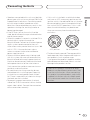 3
3
-
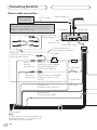 4
4
-
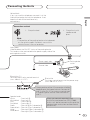 5
5
-
 6
6
-
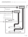 7
7
-
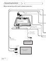 8
8
-
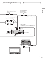 9
9
-
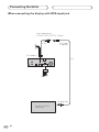 10
10
-
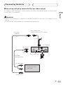 11
11
-
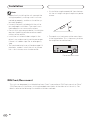 12
12
-
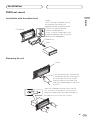 13
13
-
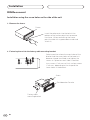 14
14
-
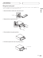 15
15
-
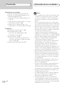 16
16
-
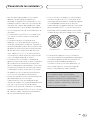 17
17
-
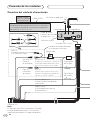 18
18
-
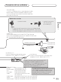 19
19
-
 20
20
-
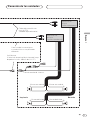 21
21
-
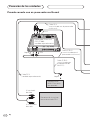 22
22
-
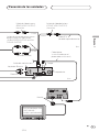 23
23
-
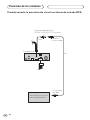 24
24
-
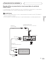 25
25
-
 26
26
-
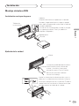 27
27
-
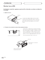 28
28
-
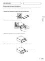 29
29
-
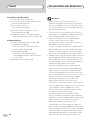 30
30
-
 31
31
-
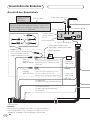 32
32
-
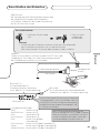 33
33
-
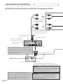 34
34
-
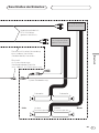 35
35
-
 36
36
-
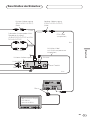 37
37
-
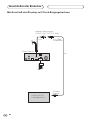 38
38
-
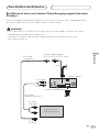 39
39
-
 40
40
-
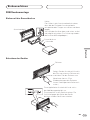 41
41
-
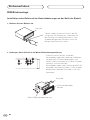 42
42
-
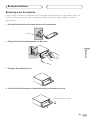 43
43
-
 44
44
-
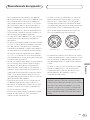 45
45
-
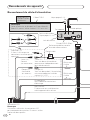 46
46
-
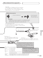 47
47
-
 48
48
-
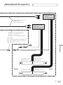 49
49
-
 50
50
-
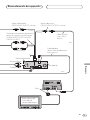 51
51
-
 52
52
-
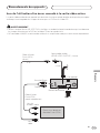 53
53
-
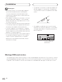 54
54
-
 55
55
-
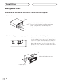 56
56
-
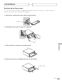 57
57
-
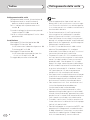 58
58
-
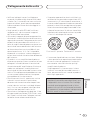 59
59
-
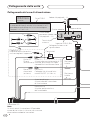 60
60
-
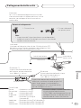 61
61
-
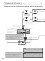 62
62
-
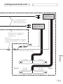 63
63
-
 64
64
-
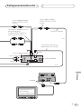 65
65
-
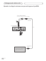 66
66
-
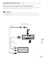 67
67
-
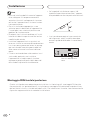 68
68
-
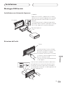 69
69
-
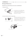 70
70
-
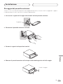 71
71
-
 72
72
-
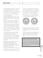 73
73
-
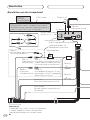 74
74
-
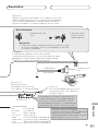 75
75
-
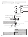 76
76
-
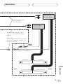 77
77
-
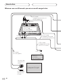 78
78
-
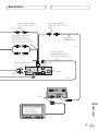 79
79
-
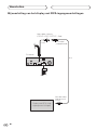 80
80
-
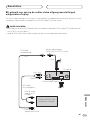 81
81
-
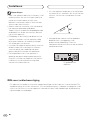 82
82
-
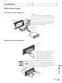 83
83
-
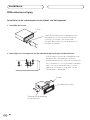 84
84
-
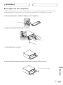 85
85
-
 86
86
-
 87
87
-
 88
88


in andere talen
- English: Pioneer DVH-P5000MP Installation guide
- italiano: Pioneer DVH-P5000MP Guida d'installazione
- français: Pioneer DVH-P5000MP Guide d'installation
- español: Pioneer DVH-P5000MP Guía de instalación
- Deutsch: Pioneer DVH-P5000MP Installationsanleitung
Gerelateerde artikelen
-
Pioneer AVHP5700DVD Installatie gids
-
Pioneer AVHP6600DVD de handleiding
-
-
Pioneer DVH-P4100UB Handleiding
-
Pioneer DEQ-P6600 Installatie gids
-
Pioneer CD-V61FM Handleiding
-
-
Pioneer DEH-P80MP Handleiding
-
-