
Braccio adattatore per porte basculanti a contrappesi, H max 2,4 m
Adaptor arm for overhead doors with counterweights, H max 2,4 m
Bras d'adaptation pour portes basculantes à contrepoids, H max 2,4 m
Adapterarm für Schwingtore mit Gegengewichten - H max. 2.4 m
Brazo adaptador para puertas basculantes a
contrapesos, H máx. 2,4 m
Adaptor arm voor lichte binnenkantelende poort met
tegengewichten, H max. 2,4 m
Documentazione
Tecnica
57
rev. 2.2
09/2003
©
CAME
CANCELLI
AUTOMATICI
119E57
SERIE VER |
VER
SERIES
|
SÉRIE VER |
BAUREIHE
VER
|
SERIE VER |
SERIE
VER
CANCELLI AUTOMATICI
V 201
!
"
Arco
Arch
Arc
Adapterarm
Arco
Gebogener
Carrello
Actioning strut
Chariot
Laufschlitten
Guía
Geleiding
Boccola
Bushing
Bague
Buchse
Casquillo
Ring
Piastra inferiore
Lower plate
Plaque inférieure
Obere Montageplatte
Placa inferior
Binnenplaat
Spina
Pin
Cheville
Stift
Clavija
Pin
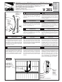
- Superimpose the arch over the actioning
strut (1). Insert the pins into the bushings (2),
and insert the bushings into the actioning
strut (3). Use the two bolts (4) to fasten the
assembly together.
- Sovrapporre l’arco al carrello (1). Inserire le
spine nelle boccole (2) e quest’ultime nel
carrello (3). Bloccare il tutto con i due relativi
bulloni (4).
- Superposer l’arc au chariot (1). Introduire les
chevilles dans les bagues (2) et celles-ci dans
le chariot (3). Bloquer le tout avec les deux
boulons correspondants (4).
- Den Adapterarm an den Laufschlitten halten
(1). Die Stifte in die Buchsen (2) einfügen und
dann die Buchsen in den Laufschlitten (3)
einsetzen und mit den zwei entsprechenden
Mutterschrauben (4) befestigen.
- Sobreponer el arco a la guía (1). Introducir las
clavijas en los casquillos (2) y estos últimos
en la guía (3). Bloquearlo todo con los dos
pernos correspondientes (4).
- Plaats de gebogen adaptorarm op de geleiding
(1) Steek de pin in de ring (2) en daarna de
ring in de geleiding (3) Gebruik de twee
bouten om het systeem bij elkaar te
houden (4).
Fig. A - Position the adaptor arm in the centre
of the door, perpendicular to and level with the
upper edge of the door. Bolt or rivet the two
plates into position. If the cross-member of the
door is not in a position suitable for attachment
of the lower plate, fit a support.
Fig. A - Appoggiare il braccio adattatore al
centro della porta, perpendicolare e a livello
con lo spigolo superiore dell’anta. Fissare le
due piastre con viti o rivetti; se il traverso
della porta non si trova nella posizione utile
al fissaggio della piastra inferiore, aggiungere
un supporto in lamiera.
Fig. A - Placer le bras d’adaptation au centre
de la porte, de façon à ce qu’il soit perpen-
diculaire et de niveau avec l’arête supérieure
du panneau mobile. Fixer les deux plaques
en utilisant des vis ou des rivets. Si la
traverse de la porte ne se trouve pas dans
la position indiquée pour la fixation de la
plaque inférieure, ajouter un support en tôle.
Fig. A - Adapterarm gegen die Tormitte,
senkrecht und bündig mit der Toroberkante,
halten. Beide Platten mit Schrauben oder
Nieten befestigen; kann die untere Platte
nicht am Torquerträger befestigt werden,
muß ein Blechwinkel verwendet werden.
Fig. A - Apoyar el brazo adaptador en el centro
de la puerta, perpendicular y a nivel del ángulo
superior de la hoja. Fijar las dos placas por
medio de tornillos o remaches; si el travesaño
de la puerta no está en la posición idónea para
la fijación de la placa inferior, añadir un soporte
metálico.
Fig. A - Plaats de adaptorarm loodrecht in het
midden van de poort en bevestig hem op de
hoogste horizontale bevestigingbalk van het
beweegbare poortvlak. Bevestig de twee
platen met behulp van vijzen of revetten.
Wanneer de bevestigingsbalk van de poort
zich niet bevindt op de aangeduide plaats
voor de bevestiging van de binnenplaat,
gelieve zelf een bevestiging te voorzien
==
Supporto
Support
Support
Winkel
Soporte
Bevestiging
Traverso
Cross-member
Traverse
Torquerträger
Travesaño
Horizontale bevestigingsbalk
Fig. A
PRE-ASSEMBLING
GB
PREMONTAGGIO
I
PRÉMONTAGE
F
VORMONTAGE
D
VOORMONTEREN
NL
PREMONTAJE
E
ASSEMBLY
GB
MONTAGE
F
MONTAGGIO
I
MONTAGE
D
MONTAJE
E
MONTAGE
NL

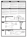
Fig. B - Connect the lever to the sliding block
(replacing the standard lever).
Fig. C - Attach the lever and the actioning strut
by inserting the two screw, bushings and nuts
supplied with the unit. The distance between
the lower plate and the actioning strut should
be approximately 50 mm.
Fig. D - Open the door manually and check that
the distance between the bushing and the end
position of the upper plate is approximately
20 mm.
Fig. B - Assembler le bras-levier au patin du
groupe (en remplaçant le bras de série).
Fig. C - Unir le bras-levier et le chariot en
utilisant les deux vis, les bagues et les
ecrous, fournies avec le matériel, en res-
pectant la distance d’environ 50 mm entre la
plaque inférieure et le chariot.
Fig. D - Ouvrir la porte manuellement et
vérifier qu’une distance d’environ 20 mm
sépare la bague et le point de contact de la
plaque supérieure.
Fig. B - Empalmar el brazo armadura con el
patín del grupo (sustituyendo el brazo sumi-
nistrado).
Fig. C - Unir el brazo armadura y la guía por
medio de los dos tornillos, casquillos y tuercas
suministrados, respetando la medida de 50
mm. aproximadamente entre la placa inferior
y la guía.
Fig. D - Abrir manualmente la puerta para
comprobar que entre el casquillo y el tope de
la placa superior haya unos 20 mm.
Fig. B - Collegare il braccio-leva al pattino del
gruppo (sostituendo il braccio di serie).
Fig. C - Unire braccio leva e carrello con le due
viti, boccole e i dadi in dotazione rispettando
la misura di circa 50 mm tra la piastra infe-
riore ed il carrello.
Fig. D - Aprire manualmente la porta per
verificare che tra la boccola e la battuta della
piastra superiore ci sia circa 20 mm.
Fig. B - Hebelarm und Gleitbacke des An-
triebs verbinden (gegen die serienmäßige
Schubstange auswechseln).
Fig. C - Hebelarm und Laufschlitten mit den
beiden mitgelieferten Schrauben, den
Buchsen und den Muttersverbinden.
Sicherstellen, daß zwischen unterer Platte
und Laufschlitten ein Abstand von ca. 50 mm
eingehalten wird.
Fig. D - Tor mit Hand öffnen und prüfen, ob
der Abstand zwischen Buchse und Anschlag
der oberen Platte 20 mm beträgt.
Fig. B - Bevestig de trekarm op de glijblok van
de motor (vervang de standaard trekarm).
Fig. C - Bevestig de trekarm en de geleiding
met behulp van de bijgeleverde bouten, de
ringen en de moeren bijgeleverd met het
materiaal. De afstand tussen de binnenplaat
en de geleiding moet ongeveer 50 mm zijn.
Fig. D - Open de deur manueel en kijk na of
er een afstand van ongeveer 20mm is
tussen de ring en de aanslag van de binnen-
plaat.
Braccio-leva
Lever
Bras-levier
Hebelarm
Brazo armadura
Trekarm
Piastra superiore
Upper plate
Plaque supérieure
Obere Montageplatte
Placa superior
Binnenplaat
Fig. C
Fig. B
Fig. D
Pattino
Sliding block
Patin
Schlitten
Patín
Glijblok
2
0
m
m
Boccola
Bushing
Bague
Rolle
Casquillo
Ring
Boccole
Bushings
Bagues
Buchsen
Casquillos
Ringen
Braccio-leva
Lever
Bras-levier
Hebelarm
Brazo armadura
Trekarm
Carrello
Actioning strut
Chariot
Führung
Guía
Geleiding
I
GB
F
D E NL
Documenttranscriptie
SERIE VER | VER SERIES | SÉRIE VER | BAUREIHE VER | SERIE VER | SERIE VER Braccio adattatore per porte basculanti a contrappesi, H max 2,4 m Adaptor arm for overhead doors with counterweights, H max 2,4 m Bras d'adaptation pour portes basculantes à contrepoids, H max 2,4 m Adapterarm für Schwingtore mit Gegengewichten - H max. 2.4 m Brazo adaptador para puertas basculantes a contrapesos, H máx. 2,4 m Adaptor arm voor lichte binnenkantelende poort met tegengewichten, H max. 2,4 m Carrello Actioning strut Chariot Laufschlitten Guía Geleiding Arco Arch Arc Adapterarm Arco Gebogener I GB PREMONTAGGIO spine nelle boccole (2) e quest’ultime nel carrello (3). Bloccare il tutto con i due relativi bulloni (4). © CAME CANCELLI AUTOMATICI 119E57 PRE-ASSEMBLING ! E GB Fig. A - Appoggiare il braccio adattatore al centro della porta, perpendicolare e a livello con lo spigolo superiore dell’anta. Fissare le due piastre con viti o rivetti; se il traverso della porta non si trova nella posizione utile al fissaggio della piastra inferiore, aggiungere un supporto in lamiera. Fig. A - Position the adaptor arm in the centre of the door, perpendicular to and level with the upper edge of the door. Bolt or rivet the two plates into position. If the cross-member of the door is not in a position suitable for attachment of the lower plate, fit a support. E MONTAGE Fig. A - Adapterarm gegen die Tormitte, senkrecht und bündig mit der Toroberkante, halten. Beide Platten mit Schrauben oder Nieten befestigen; kann die untere Platte nicht am Torquerträger befestigt werden, muß ein Blechwinkel verwendet werden. Fig. A - Apoyar el brazo adaptador en el centro de la puerta, perpendicular y a nivel del ángulo superior de la hoja. Fijar las dos placas por medio de tornillos o remaches; si el travesaño de la puerta no está en la posición idónea para la fijación de la placa inferior, añadir un soporte metálico. MONTAGE Fig. A - Placer le bras d’adaptation au centre de la porte, de façon à ce qu’il soit perpendiculaire et de niveau avec l’arête supérieure du panneau mobile. Fixer les deux plaques en utilisant des vis ou des rivets. Si la traverse de la porte ne se trouve pas dans la position indiquée pour la fixation de la plaque inférieure, ajouter un support en tôle. NL MONTAJE VOORMONTEREN - Plaats de gebogen adaptorarm op de geleiding (1) Steek de pin in de ring (2) en daarna de ring in de geleiding (3) Gebruik de twee bouten om het systeem bij elkaar te houden (4). F ASSEMBLY VORMONTAGE - Den Adapterarm an den Laufschlitten halten (1). Die Stifte in die Buchsen (2) einfügen und dann die Buchsen in den Laufschlitten (3) einsetzen und mit den zwei entsprechenden Mutterschrauben (4) befestigen. NL PREMONTAJE - Sobreponer el arco a la guía (1). Introducir las clavijas en los casquillos (2) y estos últimos en la guía (3). Bloquearlo todo con los dos pernos correspondientes (4). MONTAGGIO strut (1). Insert the pins into the bushings (2), and insert the bushings into the actioning strut (3). Use the two bolts (4) to fasten the assembly together. D PRÉMONTAGE - Superposer l’arc au chariot (1). Introduire les chevilles dans les bagues (2) et celles-ci dans le chariot (3). Bloquer le tout avec les deux boulons correspondants (4). " D 09/2003 - Sovrapporre l’arco al carrello (1). Inserire le - Superimpose the arch over the actioning F Boccola Bushing Bague Buchse Casquillo Ring I 57 rev. 2.2 V 201 CANCELLI AUTOMATICI Spina Pin Cheville Stift Clavija Pin Documentazione Tecnica MONTAGE Fig. A - Plaats de adaptorarm loodrecht in het midden van de poort en bevestig hem op de hoogste horizontale bevestigingbalk van het beweegbare poortvlak. Bevestig de twee platen met behulp van vijzen of revetten. Wanneer de bevestigingsbalk van de poort zich niet bevindt op de aangeduide plaats voor de bevestiging van de binnenplaat, gelieve zelf een bevestiging te voorzien Fig. A Piastra inferiore Lower plate Plaque inférieure Obere Montageplatte Placa inferior Binnenplaat = = Traverso Cross-member Traverse Torquerträger Travesaño Horizontale bevestigingsbalk Supporto Support Support Winkel Soporte Bevestiging GB I F Fig. B - Collegare il braccio-leva al pattino del gruppo (sostituendo il braccio di serie). Fig. B - Connect the lever to the sliding block (replacing the standard lever). Fig. B - Assembler le bras-levier au patin du groupe (en remplaçant le bras de série). Fig. C - Unire braccio leva e carrello con le due viti, boccole e i dadi in dotazione rispettando la misura di circa 50 mm tra la piastra inferiore ed il carrello. Fig. C - Attach the lever and the actioning strut by inserting the two screw, bushings and nuts supplied with the unit. The distance between the lower plate and the actioning strut should be approximately 50 mm. Fig. C - Unir le bras-levier et le chariot en utilisant les deux vis, les bagues et les ecrous, fournies avec le matériel, en respectant la distance d’environ 50 mm entre la plaque inférieure et le chariot. Fig. D - Open the door manually and check that the distance between the bushing and the end position of the upper plate is approximately 20 mm. Fig. D - Ouvrir la porte manuellement et vérifier qu’une distance d’environ 20 mm sépare la bague et le point de contact de la plaque supérieure. Fig. D - Aprire manualmente la porta per verificare che tra la boccola e la battuta della piastra superiore ci sia circa 20 mm. D E NL Fig. B - Hebelarm und Gleitbacke des Antriebs verbinden (gegen die serienmäßige Schubstange auswechseln). Fig. B - Empalmar el brazo armadura con el patín del grupo (sustituyendo el brazo suministrado). Fig. C - Hebelarm und Laufschlitten mit den beiden mitgelieferten Schrauben, den Buchsen und den Muttersverbinden. Sicherstellen, daß zwischen unterer Platte und Laufschlitten ein Abstand von ca. 50 mm eingehalten wird. Fig. C - Unir el brazo armadura y la guía por medio de los dos tornillos, casquillos y tuercas suministrados, respetando la medida de 50 mm. aproximadamente entre la placa inferior y la guía. Fig. D - Tor mit Hand öffnen und prüfen, ob der Abstand zwischen Buchse und Anschlag der oberen Platte 20 mm beträgt. Fig. D - Abrir manualmente la puerta para comprobar que entre el casquillo y el tope de la placa superior haya unos 20 mm. Fig. B Fig. C Fig. B - Bevestig de trekarm op de glijblok van de motor (vervang de standaard trekarm). Fig. C - Bevestig de trekarm en de geleiding met behulp van de bijgeleverde bouten, de ringen en de moeren bijgeleverd met het materiaal. De afstand tussen de binnenplaat en de geleiding moet ongeveer 50 mm zijn. Fig. D - Open de deur manueel en kijk na of er een afstand van ongeveer 20mm is tussen de ring en de aanslag van de binnenplaat. Pattino Sliding block Patin Schlitten Patín Glijblok Braccio-leva Lever Bras-levier Hebelarm Brazo armadura Trekarm Braccio-leva Lever Bras-levier Hebelarm Brazo armadura Trekarm Boccole Bushings Bagues Buchsen Casquillos Ringen Carrello Actioning strut Chariot Führung Guía Geleiding Fig. D Boccola Bushing Bague Rolle Casquillo Ring Piastra superiore Upper plate Plaque supérieure Obere Montageplatte Placa superior Binnenplaat 20 mm-
 1
1
-
 2
2


CAME VER Serie de handleiding
- Type
- de handleiding
- Deze handleiding is ook geschikt voor
in andere talen
- English: CAME VER Serie Owner's manual
- italiano: CAME VER Serie Manuale del proprietario
- français: CAME VER Serie Le manuel du propriétaire
- español: CAME VER Serie El manual del propietario
- Deutsch: CAME VER Serie Bedienungsanleitung