Aiphone JK-1MED Handleiding
- Categorie
- Deur intercom systemen
- Type
- Handleiding

FK1462 P0109YI
JK-1MED
HANDS FREE COLOR VIDEO INTERCOM MASTER MONITOR STATION
INTERPHONE VIDEO COULEUR MAINS LIBRES MONITEUR MAÎTRE
HANDENVRIJE KLEURENVIDEOFONIE MONITOR-HOOFDPOST
JK-1MED
Master monitor station
Moniteur maître
Monitor-hoofdpost
INSTALLATION & OPERATION MANUAL
MANUEL D
’
INSTALLATION ET D
’
UTILISATION
INSTALLATIE- EN GEBRUIKSHANDLEIDING

- 2 -
EnglishFrançais
Nederlands
PRECAUTIONS
General Prohibitions Prohibition to Dismantle the Unit Prohibition on Subjecting the Unit to Water General Precautions
WARNING
(Negligence could result in death or serious injury.)
1. High voltage is present internally. Do not open the case. Electric shock could result.
2. Do not dismantle or alter the unit. Fire or electric shock could result.
3. Do not connect any non-specified power source to the +, - terminals. Also, do not
install two power supplies in parallel to a single input. Fire or damage to the unit
could result.
4. Keep the unit away from water or any other liquid. Fire or electric shock could result.
5. Do not put any metal or flammable material into the unit through the openings. Fire
or electric shock could result.
6. Do not use power supply with a voltage other than specified. Fire or electric shock
could result.
7. Do not connect any terminal on the unit to an AC power line. Fire or electric shock
could result.
CAUTION
(Negligence could result in injury to people or damage to property.)
1. Do not install or make any wire terminations while power supply is plugged in. It
can cause electrical shock or damage to the unit.
2. Before turning on power, make sure wires are not crossed or shorted. If not, fire or
electric shock could result.
3. When mounting the unit on a wall, install the unit in a convenient location, but not
where it could be jarred or bumped. Injury could result.
4. For power supply, use Aiphone power supply model or model specified for use
with system. If non-specified product is used, fire or malfunction could result.
5. Do not install the unit in any of the following locations. Fire, electric shock, or unit
trouble could result.
* Places under direct sunlight or places near heating equipment that varies in
temperature.
* Places subject to dust, oil, chemicals, etc.
* Places subject to moisture and humidity extremes, such as bathrooms, cellars,
greenhouses, etc.
* Places where the temperature is quite low, such as
inside a refrigerated area or in
front of an air conditioner.
* Places subject to steam or smoke (near heating or cooking surfaces).
* Where noise generating devices such as dimmer switches or inverter electrical
appliances are close by.
* Do not install the unit in locations subject to frequent vibration or impact.
6. Do not put anything on the unit or cover the unit with cloth, etc. Fire or unit trouble
could result.
7. Do not press on the LCD or subject it to a high impact. The LCD glass could be
punctured and result in an injury.
8. If the LCD is punctured, do not allow skin contact with the liquid crystal inside.
Inflammation could result.
* If liquid crystal is ingested, immediately gargle with water and seek medical
attention.
* If contact with the eyes or skin occurs, clean with pure water for at least 15 minutes
and seek medical attention.
General Precautions
1. Keep the unit more than 1 m away from radio or TV set.
2. This
unit is for indoor use only. Do not use outdoors.
3. In areas where broadcasting station antennas are close by, the intercom system may be
affected by radio frequency interference.
4. As to other manufacturer's devices (such as sensor, detectors, door releases) used
with this system, comply with the Specifications and Warranty conditions that the
manufacturers or venders present.
5. Keep the intercom
wires at least 30 cm (12") away from AC 100-240 V lines. Noise
and malfunction could result.
6. If the unit is down or does not operate properly, unplug the power supply or turn off
the JK-1MED and JK-1HD (JK-1SD) POWER switches.
7. The unit is for wall-mount use only. For desktop applications, use desk stand.
8. When wall-mounted, the top of the unit may darken. This does not indicate a
malfunction
.
9. The unit case may become warm with use, but this is not a unit malfunction.
10. If a cellular phone is used close by, the unit may malfunction.
11. The LCD panel is manufactured with very high precision techniques. Small portions
of the panel may fail to light up or some portions may be constantly lit, but this does
not indicate a unit malfunction. Please be aware of this in advance.
12. Refrain
from using the color monitor station in sunlit areas.
13. At night, due to reduced lighting on the object, the monitor sees more noise and the
face becomes more difficult to see, but this is not malfunction.
14. Talk within 50 cm (20") or less from the unit. If you stand too far away, it may be
difficult for the other person to hear the communication.
15. If there are loud noises around the unit (such
as music playing or children crying), the
sound may break up and be difficult to hear.
16. During communication, if you speak before the other person has finished talking, your
voice may not come through clearly. Communication will proceed smoothly if you
wait until the other person has finished before speaking.
17. At a gate or porch illuminated by a fluorescent lamp, the picture may vary, but this is
not a malfunction.
18. When outside temperature lowers sharply after rainfall, etc., the inside of the camera
may fog up slightly, causing a blurry picture, but this is not a malfunction. Normal
operation will be restored when moisture evaporates.
19. Due to the environmental sound around the unit, it may hinder smooth communication,
but this is not a malfunction.
20. The outline of video images disp
layed by video door station may differ from that of
the actual person(s) or background, but this is not a malfunction.
21. If the screen of a video door station freezes during wintertime, the picture may become
difficult to see or the CALL button may not move, but this is not a malfunction.
22. Aiphone assumes no responsibility for corruption of saved information (such as
changes to or deletion of sa
ved information). Please be aware of this in advance.
23. This unit is not compatible with JA, JF, KB, and KC series units.
24. Warm-color lighting shining on the door station may change the tint of the picture on
the monitor.
1
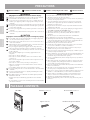
PACKAGE CONTENTS
JK-1MED Mounting screws x 2 Wood mounting screws x 2
Option connector Installation & Operation manual

- 3 -
English Français Nederlands
2
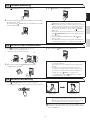
INSTALLATION
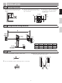
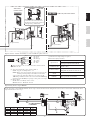
2-1 Mounting locations
1
Install the master monitor station in a place
where the screen is not exposed to direct
sunlight.
2
The master monitor station has switches on
both sides. Allow at least 5 cm (2") of open
space on either side.
3
Allow at least 15 cm (6") of vertical open
space from the center of the mounting
bracket in order to mount the master
monitor station.
+ 5 cm
(2")
+ 5 cm
(2")
JK-1MED
2
3
+ 15 cm
(6")
2-2 Wiring method, wiring distance
Wire the units from station-to-station (daisy-chained).
Ø
0,65 mm 22 AWG
Ø
1,0 mm 18 AWG
A 50 m 165' 100 m 330'
B 5 m 16' 10 m 33'
C 75 m 245' 150 m 490'
JK-1HD
JK-1SD
JK-1MED
JK-DA
JK-DV
JK-DVF
2 4
PS18
PS-1820
PS-1810DIN
PS-1820DIN
A
B C
IER-2
2-3 Cable
1
Use PVC jacket with PE (polyethylene) insulated cable
(x2)
2
Never use individual conductors, twisted pair cable or coaxial cable.
3
When using a cable with unused conductors, terminate both ends of
the unused pair(s) with a 120 resistor .
JK-1MED JK-1HD/JK-1SD
120 120
+
-
A1
A2
B1
B2
L
L
S
S
+
-
SW
SW
B1
B2

- 4 -
EnglishFrançais
Nederlands
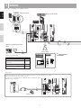
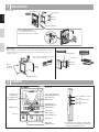
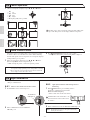
3
WIRING
Insert wires securely into each terminal as shown.
JK-1HD
-
+
JK-1MED
OP
EL-12S
OP
IER-2
1
E
A1 A2
JK-DVFJK-DV
JK-DA
DOOR
PS-1820
PS-1810DIN/
PS-1820DIN
230V AC
N
L
18V DC 1A (PS-1810DIN)
18V DC 2A (PS-1820DIN)
IN 230V~ 50/60Hz
NL
1A
-
+
-
+
100V - 240V -
50/60 Hz
18V DC
2 A
KE
KS
SW
SW
V -
V +
[1]
[2]
[3]
(BR)
(RD)
(OR)
(YE)
(GR)
(BL)
2
NP
DC 18 V
-
+
2
P
2
NP
2
NP
JK-1SD
OPTION
CONNECTOR
OPTION
CONNECTOR
2
NP
2
P
2
P
PS18 PS18
JK-1MED JK-1HD
-
+
BR: Brown
RD: Red
OR: Orange
YE: Yellow
GR: Green
BL: Blue
2
NP
2
P
A1
A2
+
-
B1
B2
+
-
B1
B2
A1
A2
+
-
B1
B2
A1
A2
AB
C
JK-1MEDJKW-BA
JK-DA
JK-DV
JK-DVF
PS18
2
NP
2
NP
2
P
2
NP
2
P
2
P
JK-1HD
JK-1SD
D
Video door station
Door release
An EL-12S (AC 12 V 0.125 A, DC 12 V 0.2 A) or equivalent part and a separate AC transformer are required.
Run separate cables for audio/video and door release.
Door release contact: AC/DC 24 V, 0.5 A (Minimum Contact : 100 mV DC, 0.1 mA)
(N/O dry closure contact L, L).
AC transformer
Optional call extension speaker
IER-2
Power supply
Master monitor station
NP:
Non-polarized
P:
Pol
arized
Presence of sound from IER-2
Item Sound
Chime tone from door station (8-1)
Alarm sound during external sensor
input (8-15)
Audio during instant voice call (8-1)
Chime tone during room-to-room
communication (8-4)

- 5 -
English Français Nederlands
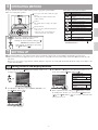
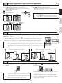
3
WIRING
Insert wires securely into each terminal as shown.
JK-1HD
-
+
JK-1MED
OP
EL-12S
OP
IER-2
1
E
A1 A2
JK-DVFJK-DV
JK-DA
DOOR
PS-1820
PS-1810DIN/
PS-1820DIN
230V AC
N
L
18V DC 1A (PS-1810DIN)
18V DC 2A (PS-1820DIN)
IN 230V~ 50/60Hz
NL
1A
-
+
-
+
100V - 240V -
50/60 Hz
18V DC
2 A
KE
KS
SW
SW
V -
V +
[1]
[2]
[3]
(BR)
(RD)
(OR)
(YE)
(GR)
(BL)
2
NP
DC 18 V
-
+
2
P
2
NP
2
NP
JK-1SD
OPTION
CONNECTOR
OPTION
CONNECTOR
2
NP
2
P
2
P
PS18 PS18
JK-1MED JK-1HD
-
+
BR: Brown
RD: Red
OR: Orange
YE: Yellow
GR: Green
BL: Blue
2
NP
2
P
A1
A2
+
-
B1
B2
+
-
B1
B2
A1
A2
+
-
B1
B2
A1
A2
AB
C
JK-1MEDJKW-BA
JK-DA
JK-DV
JK-DVF
PS18
2
NP
2
NP
2
P
2
NP
2
P
2
P
JK-1HD
JK-1SD
D
Option connector: Control external devices connected with the option connector.
[1] Video signal output: Video can be output to DVR, etc.
(NTSC, 1 Vp-p/75 ) Wiring distance: 3 m
NOTES: When a video signal is output, the monitor station may produce
a buzzing sound depending on the installation environment.
A video signal is only output during calling from a door station to the JK-
1MED/during communication between a door station and the JK-1MED/during
monitoring from the JK-1MED (screen playing recorded pictures is not output).
[2] Options output
(AC/DC 24 V, 1.6 A N/O dry closure contact)
(Minimum Contact : 100 mV DC, 0.1 mA)
Sub master
monitor station
Audio only sub master station
Optional long distance adaptor JKW-BA
Use the long distance adaptor JKW-BA within the distance ranges shown in the table when the wiring distance between the door station and the furthest inside unit is
longer than the distance in 2-2 on p. 3.
To prevent shorts, be sure to cut unused lead wires at the bottom and
insulate the ends.
Ø 0.65 mm 22 AWG Ø 1.0 mm 18 AWG
A 100 m 330' 200 m 650'
B 50 m 165' 100 m 330'
C 50 m 165' 100 m 330'
D 5 m 16' 10 m 33'
[3] External sensor input settings are required.
External sensor input specifications
Input method
N/O dry closure contact
External sensor input
(start signal only detection method)
Detection
confirmation time
100 mS or more
Contact resistance
During N/O dry closure: Less than 700
During N/C dry closure: At least 3 k
Terminal short
current
Less than 10 mA
Voltage between
terminals
Less than DC 20 V
(when open between terminals)
When the JK-1HD is connected, split
power between the master station and
the sub master station if radio signals are
picked up during communication.
NP:
Non-polarized
P:
Polarized
(To optional units)
(To optional units)

- 6 -
EnglishFrançais
Nederlands
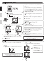
4
MOUNTING
Back wiring
JK-1MED
1
2
8mm
(3/8")
1. Press RELEASE button
(to insert or remove the wire).
2. Insert the cable into the terminal.
Mounting screws x 2
1-gang box
83,5 mm
(3-5/16")
Mounting bracket
Surface wiring
* When a 1-gang box is not mounted, the cable can be routed as surface wiring to the top or
bottom of the unit. Cut a cable inlet on the upper part of the unit to allow passage of the
wiring into the unit.
PS-1810DIN/
PS-1820DIN
PS-1820
Mounting bracket
1-gang box
Din rail
83,5 mm
(3-5/16")
* To pass the cable through the back of the
unit, cut out the cable inlet.
Wood
mounting
screws x 2
Mounting bracket
83,5 mm
(3-5/16")
5
NAMES
JK-1MED
Play LED (red)
PLAY button
Record LED (red)
RECORD button
POWER switch
Speaker
MONITOR button
OFF button
TALK button
Transmit LED (red)
Option button (*)
CALL button
ADJUST button
ZOOM/WIDE button
PAN/TILT button
MENU button
Menu LED (red)
DOOR RELEASE button
Door release LED (red)
Microphone
Color LCD video monitor
Screen brightness control
(0 10)
Receive volume control
(0 10)
Chime tone volume
(0 10)
(*) The option butto
n controls connected option
units such as turning lighting on and off and
activation of added door releases.

- 7 -
English Français Nederlands
6
OPERATING METHOD
To operate this unit, check the symbol and then press the appropriate operation button
This is not a touch-panel operation.
Do not press on the LCD or subject it to high
impact.
The LCD glass could break which could
result in an injury.
Symbol
The symbols differ according to the symbol
screen.
Operation buttons:
Press to select the symbol that is displayed
on the screen.
* The name of the operation button may
differ from the name of the symbol.
To operate a symbol, press the operation
button that is below the symbol.
Example:
To activate manual recording, press
RECORD button below the symbol
* In the manual, an explanation is given using
the
REC
button ( ).
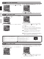
7
SETTING UP
Upon initial installation, set the time first. If the unit is used without setting the time, the menu LED (red) will light up as notification.
When power has not been supplied for at least 3 hours, the time setting will return to the initial setting and the menu LED may flash. Reset the
time again.
If there are no operations for approximately 1 minute during the setup mode, the setting will end autom
atically. If the settings are incomplete, start
again from the beginning.
Symbol Function description
To manually record.
To return to the screen of the previous
operation.
To display the previous (more recent
date) picture.
To play the recorded pictures.
To display the next (older date) picture.
To save or erase an image.
To erase a recorded image.
To fast forward the play screen.
To pause the play screen.
To advance the play screen frame by
frame.
To reverse the play screen frame by
frame.
To erase the display.
To save recorded pictures.
Setting can also be done by pressing
ZOOM/WIDE button.
Main symbols and function descriptions
1
In the standby mode, press MENU button until the setting screen
is displayed (approximately 1 second).
> 1Sec.
2
Press
button or
button to select "INITIAL SETTING", and
press MENU button ( ).
3
Press
button or
button to select the item you want to set or
check, and set with the
MENU button ( ).
SET THE DATE/TIME
To set the year, date, and time.
SET EXTERNAL INPUT
SETTING
To set the external input.
SELECT THE LANGUAGE
To select the language used.
RESTORE DEFAULT
SETTING
To initialize the settings.
4
When completing the time setting, press OFF button to return to
the standby mode. In other cases, set by pressing
MENU button
(
). Press REC button ( ) to cancel the setting and return
to the previous screen.
7-1 Setting screens and display methods

- 8 -
EnglishFrançais
Nederlands
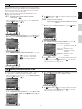
7-3 SET THE DATE/TIME
1
After performing steps 1 and 2 in section 7-1, select "DATE/TIME"
and press MENU button
( )
.
2
In the "ADJUST DATE/TIME" screen, press
button or
button
to select the "Month".
3
Pressing
button sets the "Month" and moves the cursor to "Day".
4
Perform the same steps to set "Day", "Year", "Hour" and "Minute".
After setting "Minute", press MENU button ( ) to complete
the settings.
5
Press OFF button to return to standby mode.
1. If there are no operations for approximately 1 minute during the
setup mode, the setting will end automatically. If the settings end
while incomplete, start again from the beginning.
2. A maximum error of 60 seconds can occur in the displayed
time over a month. Periodically adjusting the time setting is
recommended.
3. When power is not supplied to the unit for a long time, the time
returns to its initial setting of "JAN/01/2009 00 : 00", and the menu
LED (red) will flash as a notification. Reset the time.
NOTES: Operations for setting numbers
button (press once): The date/time increases
by one.
button (press once): The date/time decreases
by one.
button (press once): The cursor moves to the
left.
button (pressed once): The cursor moves to
the right.
button (press and hold for 1 second or more.):
The date or time increases in succession.
button (press and hold for 1 second or more.
):
The date or time decreases in succession.
MENU button: Confirm the setting.
The chime tone for the video door station can be selected from 4 sound
types. The initial setting is 1.
1
After performing step 1 in section 7-1, select "CALL TONE" and
press MENU button ( ).
2
In the "SELECT CALL TONE" screen, press
button or
button
to select the desired chime tone. The selected chime tone sounds,
enabling you to check the sound.
3
Press MENU button ( ) to complete the settings and return to
the "SETTING" screen.
Press REC button ( ) to cancel the
setting and return to the previous screen.
1
After performing steps 1 and 2 in section 7-1, select "LANGUAGE"
in the "INITIAL SETTING" screen and press
MENU button ( ).
2
In the SELECT THE LANGUAGE screen, press
,
,
, and
buttons to select the language.
3
Press MENU button
( )
to complete the settings and return to
the "INITIAL SETTING" screen.
7-2 SELECT THE LANGUAGE
7-4 SELECT CALL TONE

- 9 -
English Français Nederlands
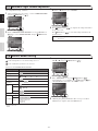
7-5 EXTERNAL INPUT SETTING
When optional units operate (for example, when a sensor is activated or
call button is pressed), the master monitor station and sub master station
will receive an alert sound. Also, when notification at door is enabled,
the door station also receives an alert sound.
These operations must be performed by an installer. Please do not
change these settings yourself.
7-6 Setting communication time
Select the door station communication time from "1 min.", "2 min.", "3
min.", and "5 min.". Communication time initial setting: "1 min."
1
After performing step 1 in section 7-1, select "COMMUNICATION"
and press
MENU button ( ).
2
In the "COMMUNICATION SETTING" screen, press
button or
button to select "COMM. TIME" and press
MENU button ( )
.
3
In the "COMMUNICATION TIME-OUT SETTING" screen, press
button or
button to select the communication time.
4
Press MENU button ( ) to complete the settings and return
to the previous screen. Press
REC button ( ) to cancel the
setting and return to the previous screen.
7-5-1
: Setting the optional units detection method.
Initial setting
1
After performing steps 1 and 2 in section 7-1, select "EXT. INPUT"
and press
MENU button ( ).
2
In the "EXTERNAL INPUT SETTING" screen, press
button and
button to select "DETECTION METHOD" and press
MENU
button (
).
3
In the "EXTERNAL INPUT DETECTION METHOD" screen, press
button or
button to select the detection method.
: dry closure contact input
: dry closure contact input
: External input disabled
4
Press MENU button ( ) to complete the settings and return to
the previous screen.
7-5-2
: Setting the alert sound time.
Initial setting: Notification at door disabled/alert sound
is 30 sec.
1
In the "EXTERNAL INPUT SETTING" screen, press
button or
button to select "NOTICE AT DOOR [1]" and press
MENU
button (
).
2
In the "NOTIFICATION AT DOOR SETTING" screen, press
button or
button to select the "Notification method".
DISABLE 30SEC
: Notification at door
disabled/alert sound is 30
sec.
DISABLE CONT.
: Notification at door
disabled/alert sound is
continuous
ENABLE CONT.
: Notification at door
enabled/alert sound is
continuous
3
Press MENU button ( ) to complete the settings and return
to the previous screen. Press
REC button ( ) to cancel the
setting and return to the previous screen.

- 10 -
EnglishFrançais
Nederlands
7-7 Automatic night volume adjustment
This automatically lowers the communication volume at the door station
only at night.Initial setting: "Disabled"
1
After performing step 1 in section 7-1, select "COMMUNICATION"
and press MENU button ( ).
2
In the "COMMUNICATION SETTING" screen, press
button or
button to select "NIGHT VOLUME" and press MENU button
( ).
3
In the "NIGHT TIME DOOR VOLUME CONTROL" screen, press
button or
button to select "ENABLE".
4
Press MENU button ( ) to complete the settings and return to
the previous screen.
Press REC button ( ) to cancel the setting and return to the
previous screen.
NOTES: Distinguishing between day and night is automatically done by the
door station.
7-8 Restore default setting
All settings can be restored to their condition at the time of purchase.
1. Recorded pictures are erased and settings are reset.
2. Pre-set functions (section 8-7) are not reset.
Settings reset with "RESTORE DEFAULT SETTING"
Setting name Available setting
Time JAN/01/2009 00 : 00
Language
ENG FRA ITA DUT SPA
Door station chime tone
1
(Tone 1)
2
(Tone 2)
3
(Tone 3)
4
(Tone 4)
Communication time 1 min. 2 min. 3 min. 5 min
Automatic night volume
adjustment
Enable Disable
External
input
Detection
N/O N/C Disable
Notification
at door
OFF OFF ON
Sound time
30 sec. Continuous Continuous
Press-to-talk setting
Enable Disable
Recording
Pictures All sa ved pictures are erased.
Screen
Zoom x 3, Wide x 3
Wide x 3, Zoom x 3
Zoom x 6
Wide x 6
are initial vie ws
1
After performing steps 1 and 2 in section 7-1, select "INITIALIZE"
with
or
and press MENU button ( ).
2
In the "INITIALIZE" screen, press MENU button ( )
(approximately 1 sec.) to initialize. Press
REC button ( ) to
cancel initialization and return to the "MENU" screen.
3
4 LEDs light up during initialization. The screen goes out when
initialization is complete. (The menu LED flashes)

- 11 -
English Français Nederlands
7-9 Press-to-talk setting
This disables the press-to-talk setting during communication with a door
station (section 8-1).
Initial setting: (press-to-talk enabled)
1
After performing step 1 in section 7-1, select "COMMUNICATION"
and press MENU button ( ).
2
In the "COMMUNICATION SETTING" screen, press
button or
button to select "ALLOW PTT" and press MENU button ( ).
3
In the "PTT SETTING" screen, press
button or
button to select
ON or OFF.
4
Press MENU button ( ) to complete the settings and return to
the "COMMUNICATION SETTING" screen.
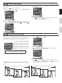
7-10 Setting picture recording
During automatic recording, select the recording method for recording
pictures (up to 6 for each image) from the following four types. The
initial setting is for the first three pictures to be zoom pictures at a pre-set
position, and for the next three pictures to be wide pictures.
Pictures are automatically recorded. First three
pictures are zoom pictures at a pre-set position,
and the next three pictures are wide pictures.
Pictures are automatically recorded. First three
pictures are wide pictures, and the next three
pictures are zoom pictures at a pre-set position.
Pictures are automatically recorded. All six
pictures are zoom pictures at a pre-set position.
Pictures are aut
omatically recorded. All six
pictures are wide pictures.
NOTES: The set picture recording method also applies to
images displayed during a call from the entrance.
The initial setting is for recording to be done with the first three pictures
as zoom pictures at a pre-set position, and the next three pictures as wide
pictures.
1
After performing step 1 in section 7-1, select "PICTURE MEMORY"
and press
MENU button ( ).
2
In the "PICTURE MEMORY SETTING" screen, press
button or
button to select the recording method.
3
Press MENU button ( ) to complete the settings and return
to the "SETTING" screen. Press
REC button ( ) to cancel the
setting and return to the previous screen.
Zoom pictures (from 1st shot to 3rd shot) Wide pictures (from 4th shot to 6th shot)
1st shot
2nd shot
4th shot
5th shot
6th shot
3rd shot

- 12 -
EnglishFrançais
Nederlands
8
OPERATIONS
8-1 Answering a door call (HANDS-FREE mode, PTT mode)
1
Press CALL button.
2
Chime tone sounds, caller is seen on video monitor, and outside sound is
heard.
Audio and video turns off after approximately 45 seconds if not answered.
3
Press TALK button momentarily, and after the beep, communicate hands
free. Transmit LED (red) lights when you talk, and goes off as you listen to
caller (or hear outside sounds).
4
After finishing communication, pressing OFF button and communication
will end after the beep.
NOTES: 1. Communication (video) ends automatically
according to the set communication time. (Refer
to section 7-6)
2. The Transmit LED will light up and go out, but
this is not a malfunction.
1. The screen display will switch automatically according to the picture
recording settings (section 7-10).
2. Even if the screen display changes, ZOOM/WIDE button (section 8-5)
can be used to change the display.
3. When TALK button is pressed momentarily and communication starts,
the screen display will be held as is regardless of the picture recording
settings.
Instant voice call function
2
Even without answering, door area can be seen and heard with video and
audio (for approximately 45 seconds). Inside sound is not heard outside.
PTT mode
3
Press and hold TALK button for at least 1 second. A beep sounds,
and after approximately 1 second another beep sounds, which indicates
PTT mode is engaged. If
TALK button is pressed briefly (less than 0.5
seconds), PTT mode will not be engaged.
4
When communicating, keep TALK button pressed. To hear the caller's
voice, release
TALK button.
5
After finishing communication, press OFF button and communication
will end after the beep.
NOTES: When press-to-talk is disabled, PTT mode cannot be
used.
8-2 Activating door release
1
Press DOOR RELEASE button.
2
Open door while the release mechanism is activated.
During release: The door release LED (red) lights.

- 13 -
English Français Nederlands
8-3 Entrance monitoring
1
Press MONITOR button in the standby mode.
2
The video monitor displays the image from the door station and the
incoming audio is heard.
If you do not press TALK button, the caller will not hear sounds
from the inside station.
3
Press OFF button to end communication.
NOTES: 1. To talk to the visitor during entrance monitoring, momentarily press
TALK button. This allows communication with the entrance.
2. The entrance monitoring turns off automatically after approximately
1 minute. To monitor the entrance again, repeat from the beginning.
3. During entrance monitoring, the entrance monitoring time can
be extended by approximately 1 min. by pressing
MONITOR
button again.
4. During entrance monitoring, the display uses a wide picture display.
If the
ZOOM/WIDE button
is pressed, the display changes to
the zoom picture.
5. At night, the Illuminator LED will not light up until
TALK
button is pressed.
6. If another inside unit attempts to perform entrance monitoring while
one inside unit is already doing so, a warning beeping sound will occur.
8-4 Room-to-room communication
1
Press CALL button to talk with the other person.
A call-in is sent to the sub master station.
The reply of the other person is not heard.
2
If the other person presses TALK button, hands free
communication is possible.
3
Press and release OFF button to end communication.
NOTES: 1. Room-to-room communication ends automatically after
approximately 10 minutes.
To perform room-to-room communication again, repeat from the
beginning.
2. If a call is received from the entrance during room-to-room
communication, the image from the entrance is displayed at the
monitor station and sub monitor station where communication
is taking place. Press
OFF button to end the room-to-
room communication, and press
TALK button to switch to
communication with the door station.
8-5 WIDE/ZOOM switching
1
Press ZOOM/WIDE button when a picture is displayed.
Switching between wide zoom occurs each time the b utton is pressed.
[Wide picture] [Zoom picture]
NOTES: 1. When the caller is not shown in the center of the picture, the zoom
picture can be moved up, down, left, and right. (Refer to section 8-6)
2. When the display changes from the wide picture to the zoom picture,
the zoom picture starts at the pre-set (section 8-7) position.
The wide picture may be distorted in comparison with the zoom
picture due to the characteristics of the door station camera, but this
is not a malfunction.
Or

- 14 -
EnglishFrançais
Nederlands
8-6 Pan/tilt operation
1
When a zoom picture is displayed, press
,
,
, or
button.
: Up
: Do wn
: Left
: Right
Moving diagonally is also possible.
[Zoom picture]
The image range of the zoom picture and wide picture differs. The
edges of the wide picture do not display with the zoom picture.
8-7 Zoom Picture Pre-set
The picture can be set to display using a set zoom picture position
for when a call is received from the door station. When switching
from the wide picture to the zoom picture, the zoom picture displays
starting from the pre-set position.
1
When a zoom picture is displayed, press
,
,
, or
button.
(Ex. Pressing
button moves the picture up.)
While viewing the picture, s
et the desired picture position.
NOTES: 1. To change the zoom picture position that has been set, perform the
zoom position setting again. The previous setting will be overwritten.
2. The zoom picture position set with the master monitor station will
also be displayed at the sub monitor station.
2
Press ZOOM/WIDE button (for at least 2 seconds).
A beep will sound and the position setting will be completed.
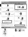
8-8 Night illumination
At night, the door station Illuminator LED lights up during
calling or communication.
8-8-1
When a call is made from the door station
1
If CALL button of door station is pressed
2
When communication ends, the illuminator
LED will go out.
8-8-2
Light up the Illuminator LED during entrance
monitoring
1
When TALK button is pressed during entrance
monitoring, communication starts and the
Illuminator LED will light up.
Inside sound can be heard at the entrance.
Communication starts at this time, so be
aware that inside sound can be heard at
the entrance.
2
When communication ends, the illuminator LED will go out.
NOTES: Distinguishing between day and night is automatically
done by the door station.
The Illuminator
LED lights up.

- 15 -
English Français Nederlands
8-9 Backlight adjustment, Night sensitivity adjustment
To perform adjustment
1
Press ADJUST button when the image is difficult to see.
Automatic adjustment to a more visible screen is performed. The
adjust icon displays at this time.
Adjust icon (day)
Adjust icon (night)
To cancel adjustment
1
Press ADJUST button during adjustment.
The adjust icon will disappear and the screen returns to the pre-
adjustment screen
NOTES: 1. Distinguishing between day and night is automatically done by
the door station.
2. Pressing ADJUST button at night makes the caller's face
easier to see, but moving subjects may be more difficult to see.
<Day> <Night>
[Before adjustment] [Before adjustment]
[After adjustment] [After adjustment]
Adjust icon
display
Adjust icon
display
8-10 Automatic recording
If a call is received from a video door station, the unit starts recording automatically. The record LED (red)
flashes during recording.
Recording starts approximately 2 seconds after CALL button of video door station is pressed. A maximum
length of approximately 6 seconds (6 shots) can be recorded, with 1 picture and 1 shot for each second.
A maximum of 40 images can be recorded (combined total of automatic recording and manual recording images).
If 40 images are exceeded, images are overwritten starting from the image with the oldest recording date.
NOTES: 1. The automatic recording function cannot be cancelled.
2. The recorded pictures are recorded using the method (section 7-10) that has been set. However, if switching
between zoom and wide is performed during automatic recording, the displayed image will be recorded.
3. The picture during entrance monitoring is not automatically recorded. If you wish to record this screen, press
REC button.
The initial setting is for recording to be done with the first three pictures as zoom pictures at a pre-set position, and the next three pictures as wide pictures.
8-11 Manual recording
1
Display a video image with an operation such as entrance
monitoring.
NOTES: 1. Manual recording is not possible during automatic recording (for
approximately 7 seconds after receiving a call from the door station).
2. After the end of automatic recording (approx. 7 seconds after
receiving a call from the door station), recording of another image in
addition to the automatically recorded image can be performed.
3. When manual recording, the displayed image is recorded.
2
Press REC button ( ). The record LED (red) flashes (6 times)
and recording starts.
A maximum length of approximately 6 seconds (6 shots) can be
recorded, with 1 image and 1 shot for each second.
A maximum of 40 images can be recorded (combined total of
automatic recording and manual recording images). When 40
images are exceeded, new images overwrite old images starting
from the oldest recorded date.
Zoom pictures (from 1st shot to 3rd shot) Wide pictures (from 4th shot to 6t
h shot)
1st shot
2nd shot
4th picture
5th picture
6th picture
3rd shot

- 16 -
EnglishFrançais
Nederlands
8-12 Play recorded picture
If there are automatically recorded pictures, such as those taken while you were
out, the play LED (red) flashes.
1
Press PLAY button in standby mode to display the picture with the most
recent date. *
displays on the screen when there are no recorded pictures.
07/16 JAN/01/2009 18:45
07/16 JAN/01/2009 18:45
The operation status displays.
Sequence number of image currently being displayed/total recorded images
Displayed when image is unread.
Displays when image is saved.
[Play-waiting screen]
Time and date of
recording
2
Press PLAY button ( ) on the play-waiting screen. The recorded image
is played. When the play of one image ends, the next image is displayed.
07/16 JAN/01/2009 18:45
06/16 JAN/01/2009 17:45
[During play] [Next picture]
Display
during
play
3
To advance the play screen frame-by-frame, press PLAY button ( ) during
playback to pause. The play moves forward frame-by-frame each time
DOOR RELEASE button ( ) is pressed. When the frames of one image
end, the next picture is displayed.
4
Press OFF button to end.
* In the manual, screen icons and button icons are explained together.
* In addition, the operations shown below are also possible in the play
screen.
REC button ( ):
To display the previous (more recent date) picture. When the button is
pressed for 1 second or more, during the time that the button is pressed the
first picture only of the dates can be checked in succession, from older to
more recent dates. (If
REC button is pressed while the picture with the
most recent date is displayed, the picture with the oldest date will display.)
DOOR RELEASE button ( ):
To display the next (older date) picture. When the button is pressed for 1
second or more, during the time that the button is pressed the first picture only
of the dates can be checked in succession, in the direction of the older dates.
MENU button ( ):
To save or erase an image. (Refer to sections 8-13 and 8-14)
1. When there are multiple unread images, all images enter the "read"
condition even if only one image is played, and the play LED goes off.
2. The recorded pictures are displayed in order based on the date set
during recording.
* The operations shown below are possible during play.
MENU button (
)
:
The pictographic display on the screen can be erased.
PLAY button ( ):
To pause play.
DOOR RELEASE button ( ):
To display the picture with the next oldest date after fast forward playing.
*
In addition, the operations shown below are also possible during pause.
REC button ( ):
The play is reversed frame by frame each time the button is pressed. When the
frames of one image end, the unit returns to the play-waiting screen.
PLAY button ( ):
To return to the play screen.
MENU button ( ):
Pressing the button displays the picture with the next oldest date in the
play-waiting screen.
NOTES: 1. If there are no operations for at least approximately 1 minute, it will
end automatically.
2. If a call is received from a door station during play, the chime tone
sounds and the play is forcibly ended.
8-13 Save recorded picture
10 images can be saved from the recorded images (maximum of 40
images). Saved pictures are not overwritten.
1
Display the picture that you want to save in the play-waiting screen. (Refer to
section 8-12)
Press MENU button ( ) to display the save/erase selection screen.
JAN/01/2009 18:45
NOTES: 1. "CANNOT SAVE" is displayed if the number of possible saves is
exceeded. Cancel unnecessary saved image.
2. Images that have had the save canceled are not erased, but they are
overwritten if the number of recorded images is exceeded.
2
Press PLAY button ( ). If the image is saved, the key symbol is displayed.
If the image has already been saved, the save is canceled. Each time PLAY button
( ) is pressed, the operation switches between save and cancel.
JAN/01/2009 18:45
JAN/01/2009 18:45
* In addition, the operations shown
below are also possible in the save/
erase selection screen.
MENU button ( ):
To erase the display picture.
(Refer to section 8-14)
REC button ( ):
To return to the play-waiting screen.

Warranty
Aiphone warrants thats its products have no material or workmanship defects under normal use conditions for two years after delivery to the end user. Aiphone will perform repair
or replacement free of charge if the product is defective and the warranty applies to the defect. Aiphone reserves unto itself the sole right to make the final decision whether there is
a defect in materials and/or workman
ship and whether or not the product is under warranty. This warranty shall not apply to any Aiphone product which has been subject to misuse,
neglect, accident, or to use in violation of instructions furnished, nor extended to units which have been repaired or altered outside of the factory. This warranty does not cover
batteries or damage caused by batteries used in connection with the unit. This
warranty only includes carry-in repairs. Any repairs must be made at the shop or place designated in
writing by Aiphone. Aiphone will not be responsible for any costs incurred during on-site service calls. Aiphone will not provide compensation for any loss or damage incurred by
the breakdown or malfunction of its products during use, or for any consequent inconvenience or losses that may result.
The object area of is the EU.
Garantie
Aiphone garantit que ce produit ne présente pas de défaut matériel ou de fabrication dans des conditions normales d'utilisation pendant les deux années suivant la livraison à
l'utilisateur final. Aiphone en effectuera gratuitement la réparation ou le remplacement si le produit est défectueux et que la garantie s'applique pour le défaut. Aiphone se réserve
le droit exclusif de décider s’il existe ou non un défaut de matière ou de fabrication et si l’appareil est ou non couvert par la garantie. Cette garantie ne s’applique pas à tout
produit Aiphone qui a été l’objet d’une utilisation impropre, de négligence, d’un accident ou qui a été utilisé en dépit des instructions fournies; elle ne couvre pas non plus les
appareils qui ont été réparés ou modifiés en dehors de l’usine. Cette garantie ne couvre pas les piles ni les dégâts infligés par les piles utilisées dans l’appareil. Cette garantie
comprend uniquement les réparations en atelier. Toutes les réparations doivent être réalisées à l'atelier ou au site désigné par écrit par Aiphone. Aiphone décline toute responsabilité
en cas de frais encourus pour les dépannages à domicile. Aiphone n’indemnisera pas le client en cas de pertes, de dommages ou de désagréments causés par une panne ou un
dysfonctionnement d’un de ses produits.
La zone d’application de est l’UE.
Garantie
Aiphone garandeert dat zijn producten onder normale gebruiksomstandigheden gedurende twee jaar na levering aan de eindgebruiker vrij zijn van materiaal- of fabricagefouten.
Aiphone zal het product kosteloos herstellen of vervangen als het defect is en de garantie van toepassing is op het defect. Aiphone behoudt zich het recht voor om als enige
definitief te bepalen of er al dan niet sprake is van
een materiaal- en/of fabricagefout; en of het product nog onder garantie is. Deze garantie geldt niet voor een Aiphone-product dat
is blootgesteld aan verkeerd gebruik, verwaarlozing, een ongeval of verkeerde bediening en evenmin voor toestellen die buiten de fabriek zijn hersteld of gewijzigd. Deze garantie
geldt niet voor batterijen of schade veroorzaakt door batterijen die in het toestel zijn g
ebruikt. Deze garantie geldt uitsluitend voor herstellingen die worden ingeleverd en opgehaald
door de klant. Alle herstellingen moeten worden uitgevoerd in de winkel of op de plaats die schriftelijk is aangeduid door Aiphone. Kosten die gepaard gaan met herstellingen ter
plaatse kunnen niet worden verhaald op Aiphone. Er kan geen schadeloosstelling van Aiphone worden geëist voor enig verlies of s
chade als gevolg van een defect of storing tijdens
het gebruik van zijn producten, of voor enig ongemak of verlies dat hieruit voortvloeit.
Het toepassingsgebied van is de EU.
This equipment has been tested and found to comply with the limits for a Class B digital device, pursuant to Part 15 of the FCC Rules. These limits are designed to provide
reasonable protection against harmful interference in a residential installation. This equipment generates, uses, and can radiate radio frequency energy, and if not installed and
used in accordance with the instruction
s, may cause harmful interference to radio communications. However, there is no guarantee that interference will not occur in a particular
installation. If this equipment does cause harmful interference to radio or television reception, which can be determined by turning the equipment off and on, the user is encouraged
to try to correct the interference by one or more of the following measures: R
eorient or relocate the receiving antenna Connect the equipment into an outlet on a circuit dif ferent
from that to which the receiver is connected. Increase the separation between the equipment and receiver. Consult the dealer or an e xperienced radio/TV technician for help.
English
Français
Nederlands
AIPHONE CO., LTD., NAGOYA, JAPAN
AIPHONE CORPORATION, BELLEVUE, WA, USA
AIPHONE S.A.S., LISSES-EVRY, FRANCE
Printed in Thailand
http://www.aiphone.com/
-
 1
1
-
 2
2
-
 3
3
-
 4
4
-
 5
5
-
 6
6
-
 7
7
-
 8
8
-
 9
9
-
 10
10
-
 11
11
-
 12
12
-
 13
13
-
 14
14
-
 15
15
-
 16
16
-
 17
17


Aiphone JK-1MED Handleiding
- Categorie
- Deur intercom systemen
- Type
- Handleiding
in andere talen
- English: Aiphone JK-1MED User manual
