HellermannTyton SpotClip-Box de handleiding
- Type
- de handleiding

Operating instructions
Betriebsanleitung
Manuel d’utilisation
Manuale d’uso
Montagehandleiding
Instrukcja obsługi
SpotClip-Box

Europe
HellermannTyton GmbH – Austria
Rennbahnweg 65
1220 Vienna
Tel.: +43 12 59 99 55-0
Fax: +43 12 59 99 11
Email: oce@HellermannTyton.at
www.HellermannTyton.at
HellermannTyton – Czech Republic
Email: oceCZ@HellermannTyton.at
www.HellermannTyton.cz
HellermannTyton – Denmark
Industrivej 44A, 1.
4000 Roskilde
Tel.: +45 702 371 20
Fax: +45 702 371 21
Email: htdk@HellermannTyton.dk
www.HellermannTyton.dk
HellermannTyton – Finland
Sähkötie 8
01510 Vantaa
Tel.: +358 9 8700 450
Fax: +358 9 8700 4520
Email: myynti@HellermannTyton.fi
www.HellermannTyton.fi
HellermannTyton S.A.S. – France
2 rue des Hêtres - CS 80543
78197 Trappes Cedex
Tel.: +33 1 30 13 80 00
Fax: +33 1 30 13 80 60
Email: info@HellermannTyton.fr
www.HellermannTyton.fr
HellermannTyton GmbH –
Germany
Großer Moorweg 45
25436 Tornesch
Tel.: +49 4122 701-0
Fax: +49 4122 701-400
Email: info@HellermannTyton.de
www.HellermannTyton.de
HellermannTyton KFT – Hungary
Kisfaludy u. 13
1044 Budapest
Tel.: +36 1 369 4151
Fax: +36 1 369 4151
Email: oceHU@HellermannTyton.at
www.HellermannTyton.hu
HellermannTyton Ltd – Ireland
Unit A5 Cherry Orchard
Business Park
Ballyfermot, Dublin 10
Tel.: +353 1 626 8267
Fax: +353 1 626 8022
Email: sales@HellermannTyton.ie
www.HellermannTyton.co.uk
HellermannTyton S.r.l. – Italy
Via Visco, 3/5
35010 Limena (PD)
Tel.: +39 049 767 870
Fax: +39 049 767 985
Email: info@HellermannTyton.it
www.HellermannTyton.it
HellermannTyton B.V. –
Belgium/Netherlands
Vanadiumweg 11-C
3812 PX Amersfoort
Tel.: +31 33 460 06 90
Fax: +31 33 460 06 99
Email (NL): info@HellermannTyton.nl
Email (BE): info@HellermannTyton.be
www.HellermannTyton.nl
www.HellermannTyton.be
HellermannTyton AS – Norway
PO Box 240 Alnabru
0614 Oslo
Tel.: +47 23 17 47 00
Fax: +47 22 97 09 70
Email: firmapost@HellermannTyton.no
www.HellermannTyton.no
HellermannTyton Sp. z o.o. –
Poland
Kotunia 111
62-400 Słupca
Tel.: +48 63 2237111
Fax: +48 63 2237110
Email: info@HellermannTyton.pl
www.HellermannTyton.pl
HellermannTyton – Romania
Email: oceRO@HellermannTyton.at
www.HellermannTyton.at
OOO HellermannTyton – Russia
40/4, Pulkovskoe road
BC Technopolis Pulkovo, oce A 8081
196158, St. Petersburg
Tel.: +7 812 386 00 09
Fax: +7 812 386 00 08
Email: info@HellermannTyton.ru
www.Hellermanntyton.ru
HellermannTyton – Slovenia
Branch Oce Ljubljana
Podružnica Ljubljana, Leskoškova 6
1000 Ljubljana
Tel.: +386 1 433 70 56
Fax: +386 1 433 63 21
Email: oceSl@HellermannTyton.at
www.HellermannTyton.si
HellermannTyton España s.l. –
Spain/Portugal
Avda. de la Industria 37 2⁰ 2
28108 Alcobendas, Madrid
Tel.: +34 91 661 2835
Fax: +34 91 661 2368
Email:
HellermannTyton@HellermannTyton.es
www.HellermannTyton.es
HellermannTyton AB – Sweden
Isafjordsgatan 5
16440 Kista
Tel.: +46 8 580 890 00
Fax: +46 8 580 348 02
Email:
kundsupport@HellermannTyton.se
www.HellermannTyton.se
HellermannTyton
Engineering GmbH – Turkey
Saray Mah Dr. Adnan Büyükdeniz
Cad. No:4
Akkom Oce Park 2. Blok Kat: 10
34768 Ümraniye-İstanbul
Tel.: +90 216 687 03 40
Fax: +90 216 250 32 32
Email: info@HellermannTyton.com.tr
www.HellermannTyton.com.tr
HellermannTyton operates

HellermannTyton Ltd – UK
William Prance Road
Plymouth International Medical
and Technology Park
Plymouth, Devon PL6 5WR
Tel.: +44 1752 701 261
Fax: +44 1752 790 058
Email: info@HellermannTyton.co.uk
www.HellermannTyton.co.uk
HellermannTyton Ltd – UK
Sharston Green Business Park
1 Robeson Way
Altrincham Road, Wythenshawe
Manchester M22 4TY
Tel.: +44 161 947 2200
Fax: +44 161 947 2220
Email: sales@HellermannTyton.co.uk
www.HellermannTyton.co.uk
HellermannTyton Ltd – UK
Cley Road, Kingswood Lakeside
Cannock, Staffordshire
WS11 8AA
Tel.: +44 1543 728282
Fax: +44 1543 728284
Email: [email protected]
www.HellermannTyton.co.uk
HellermannTyton Data Ltd – UK
Cornwell Business Park
43-45 Salthouse Road, Brackmills
Northampton NN4 7EX
Tel.: +44 1604 707 420
Fax: +44 1604 705 454
Email: [email protected]
www.htdata.co.uk
Middle East
HellermannTyton – UAE
Email: info@HellermannTyton.ae
www.HellermannTyton.ae
North America
HellermannTyton – Canada
Tel: +1 905 726 1221
Fax: +1 905 726 8538
E-Mail: sales@HellermannTyton.ca
www.HellermannTyton.ca
HellermannTyton – Mexico
Tel.: +52 333 133 9880
Fax: +52 333 133 9861
Email: info@HellermannTyton.com.mx
www.HellermannTyton.com
HellermannTyton – USA
Tel.: +1 414 355 1130
Fax: +1 414 355 7341
Email: [email protected]
www.HellermannTyton.com
South America
HellermannTyton – Argentina
Tel.: +54 11 4754 5400
Fax: +54 11 4752 0374
Email:
ventas@HellermannTyton.com.ar
www.HellermannTyton.com.ar
HellermannTyton – Brazil
Tel.: +55 11 4815 9000
Fax: +55 11 4815 9030
Email:
vendas@HellermannTyton.com.br
www.HellermannTyton.com.br
Asia-Pacific
HellermannTyton – Australia
Tel.: +61 2 9525 2133
Fax: +61 2 9526 2495
Email:
cservice@HellermannTyton.com.au
www.HellermannTyton.com.au
HellermannTyton – China
Tel.: +86 510 8528 2536
Fax: +86 510 8528 2731
Email:
cservice@HellermannTyton.com.cn
www.HellermannTyton.com.cn
HellermannTyton – Hong Kong
Tel.: +852 2832 9090
Fax: +852 2832 9381
Email:
cservice@HellermannTyton.com.hk
www.HellermannTyton.com.sg
HellermannTyton – India
Tel.: +91 120 413 3384
Email:
cservice@HellermannTyton.co.in
www.HellermannTyton.co.in
HellermannTyton – Japan
Tel.: +81 3 5790 3111
Fax: +81 3 5790 3112
Email: [email protected]
www.HellermannTyton.co.jp
HellermannTyton –
Republic of Korea
Tel.: +82 32 833 8012
Fax: +82 32 833 8013
Email:
cservice@HellermannTyton.co.kr
www.HellermannTyton.co.kr
HellermannTyton – Philippines
Tel.: +63 2 752 6551
Fax: +63 2 752 6553
Email:
cservice@HellermannTyton.com.ph
www.HellermannTyton.com.ph
HellermannTyton – Singapore
Tel.: +65 6 586 1919
Fax: +65 6 752 2527
Email: cservice@HellermannTyton.sg
www.HellermannTyton.com.sg
HellermannTyton – Thailand
Tel.: +662 237 6702 / 266 0624
Fax: +662 266 8664
Email:
cservice@HellermannTyton.co.th
www.HellermannTyton.com.sg
Africa
HellermannTyton – South Africa
Tel.: +27 11 879 6600
Fax: +27 11 879 6603
Email: [email protected]
www.HellermannTyton.co.za
HellermannTyton operates globally in 37 countries

2
3
4
6
1
5
A
B C
AC
220V / 12V
D
E

F
H
G
I
J K
Click !
Click !
L
M

English
Deutsch
Français
Italiano
Nederlands
Polski
3
11
19
27
35
43
GBDEFRITNLPL

GBDEFRITNLPL
Operating Instructions • SpotClip-Box • 12-2016
User information
3
Operating Instructions
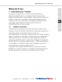
1 User information
These operating instructions only apply for the SpotClip-Box
spacer product and are intended for the user. The user must
carefully read and understand the operating instructions before
commissioning the product. On the fold-out page of the
operating instructions, you will find figures providing an
overview and for the assembly of the product, along with
contact details for your local HellermannTyton country
representative.
1.1 Intended use
The SpotClip-Box spacer for downlight covers ensure a safety
distance between the light, damp-proof foil or vapour barrier
and the insulation wool. The product reduces the risk of
overheating and a fire. It also increases the service life of the
lights. The product is made of self-extinguishing, heat-stabilised
polyamide. The product is designed to reduce the heat loss to a
minimum and to increase the energy eciency. The SpotClip-
Box is suitable both for use in panels as well as in plasterboard.
The product may only be used for the purposes described in
these operating instructions.
The product may only be used in technically perfect condition in
accordance with its intended use and the operating instructions
and only by safety-conscious persons who are fully aware of the
risks involved.

Operating Instructions • SpotClip-Box • 12-2016
Safety instructions
4
1.2 Fire protection properties/standards
The product is self extinguishing and its fire protection
properties comply with UL94 V2. The product is tested
according to the filament test (GWT) at 960°C as well as
standards EN60598-1 and EN60598-2-2. The used insulating
materials and damp-proof foils or vapour barriers comply with
DINEN13501-1A2s1d0 and DIN4102-1A2. Use only
insulating materials and damp-proof foils or vapour barriers of
low flammability, which do not emit smoke in the case of fire
and do not drip.
1.3 Customer service
If you require any information or have any questions for our
customer services, please contact the HellermannTyton branch
in your country. The contact details are listed on the fold-out
page of these operating instructions.
1.4 Information about the operating instructions and
actuality
Please keep these instructions in a safe place.
fPlease note:
due to the continuous development of the product, there may be
deviations between the documentation and the product. The
current edition can be found at:
http://www.hellermanntyton.co.uk/site/downloads.
2 Safety instructions
The product was manufactured according to the current state
of technology and the recognised safety regulations.
Nonetheless, improper use of the product can result in hazards
to the life and limb of the user or third parties, or in damage to
the product and other material property.
These operating instructions contain information on safety.
fAlways follow all of the instructions to prevent personal injury,
material damage or environmental damage.

GBDEFRITNLPL
Operating Instructions • SpotClip-Box • 12-2016
Safety instructions
5
2.1 Representation and layout of warning instructions
The warning instructions relate to actions and are structured as
follows:
WARNING
Type and source of danger!
Explanations on the type and source of danger.
fMeasures to prevent danger.
A warning indicates possible risk of lethal or serious injuries.
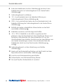
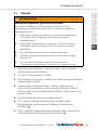
2.2 Limitations of use
fObserve the following requirements for the operational
environment:
• The suspended ceiling height must be sucient in order to
ensure that there is enough insulation above the SpotClip-Box.
• As the installation is partially carried out from above the
suspended ceiling, for this purpose, there must either be access
to this or the assembly must be carried out before the ceiling is
installed.
• Can be used for LED and fluorescent lights with external
transformers. Not suitable for halogen lamps.
• The available inner usable height is 130mm.
• Can be used for ceiling cut-outs with diameters of up to 75mm.
• Can be used with voltages of 230V and 12V.
• Not suitable for the protection of converters or transformers.
These must be installed outside the SpotClip-Box, where
overheating can also not occur.
• Can be used up to IP protection class 65.

Operating Instructions • SpotClip-Box • 12-2016
Product overview
6
3 User obligations
The user must observe and comply with the respectively
applicable national legal regulations and accident prevention
regulations. The use of the SpotClip-Box does not exempt the
user from complying with the installation instructions from the
spotlight manufacturer. Please contact a specialist if you have
any questions.
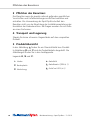
4 Transport and storage
Do not stack heavy objects on the packaged product.
5 Product overview
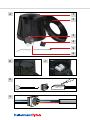
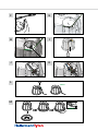
In Figure A , you can find an overview image of the product.
Figures B and C show the product details. You can find the
figures on the fold-out page.
Legends A , B and C :
1 Hood 4 Cable grommet
2 Base plate 5 Q30R cable tie (x 1)
3 Cover 6 HelaCon HECL (x 2)

GBDEFRITNLPL
Operating Instructions • SpotClip-Box • 12-2016
Product overview
7
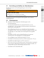
5.1 Installation
WARNING
Possible lethal danger due to fire!
The use of unsuitable insulating material and damp-proof foils or
vapour barriers can cause a lethal fire.
fComply with the local regulation on fire prevention and the
installation instructions from the light manufacturer.
fComply with the applicable stipulations and standards for
insulating materials and damp-proof foils or vapour barriers.
fDo not use flammable insulating materials.
fOnly use flame-resistant damp-proof foils or vapour barriers.
fDo not use insulating materials made of natural substances
such as wood, hemp or straw.
1 Measure and drill through the ceiling plate (see operating
instructions of the recessed light).
2 Clean the area surrounding the ceiling cut-out.
3 To increase the air-tightness, apply a little silicone sealant to the
groove on the base plate provided.
4 Position the base plate centrally over the hole and insert the
frame of the recessed light without the lamp and other
accessories. Clip the springs of the frame onto the base plate of
the SpotClip-Box and secure the frame.
5 Cut the cable grommet to fit and insert the cable.
f12V: cut the cable grommet to size in order to insert the
connection cable of the transformer. Connect the transformer
(Figure D ).
f230V: push the solid conductors through the cable grommet or
cut the cable grommet and insert the cable (Figure E ).

Operating Instructions • SpotClip-Box • 12-2016
Product overview
8
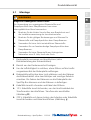
6 Fold over the ends of the cable tie (Figure F ) and thread through
the cable tie socket into the connection area of the hood
(Figure G ).
7 Install the connection area.
f12V: insert the connection cable through the cable
feed-through into the connection area (Figure H ).
f230V: feed the connection cable through the cable
feed-through of the connection area into the hood from below
(Figure I ).
8 Using both of the clamping rails supplied, connect to the mains
(Figure K ).
9 Fit the cable grommet and complete the assembly.
f12V/230V: insert the cable grommet in the groove provided. Fix
the connecting cable using the cable tie and tighten it up. Please
note that at least 4-5cm of the connection cable must hang
from the hood to connect directly to the lamp. Cut off the
protruding end of the cable tie directly at the head (Figures J
and K ).
10 Close off the connection area with the cover (Figure L ).
11 Position the hood on the base plate and close up the product
with the bayonet catch (Figure M ).
12 Connect the lamp according to the operating instructions.
13 Fix the spotlight according to the operating instructions.
;The SpotClip-Box spacer is installed.

GBDEFRITNLPL
Operating Instructions • SpotClip-Box • 12-2016
Maintenance
9
6 Maintenance
The product requires no maintenance.
7 Withdrawing from operation
When installed and used for its intended purpose, the product
will perform continuously without issues.
8 Disposal
At the end of use, the purchaser or the user must dispose of the
product properly. This product has been manufactured in
compliance with the current environmental standards.
fObserve the national regulations for the disposal of recyclable
materials.
fTake the product to a local collection point or recycling centre.
fIf necessary, contact your local environmental oce.

Operating Instructions • SpotClip-Box • 12-2016
Technical data
10
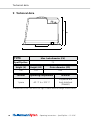
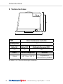
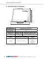
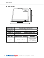
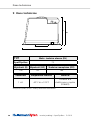
9 Technical data
H
H2
OD
FH
TYPE
Max. hole diameter (FH)
SpotClip-Box 75
Height (H) Height (H2) Outer diameter (OD)
140 130 184
Content Operating temperature Material
1 piece -40°C to +105°C
Polyamide 6.6
heat-stabilised
(PA66HS)
All dimensions in mm. We reserve the right to make technical changes without notice.

GBDEFRITNLPL
Betriebsanleitung • SpotClip-Box • 12-2016
Benutzerhinweise
11
Betriebsanleitung
1 Benutzerhinweise
Diese Betriebsanleitung gilt ausschließlich für das Produkt
SpotClip-Box Abstandhalter und richtet sich an den Benutzer.
Dieser muss die Betriebsanleitung vor der Inbetriebnahme des
Produktes aufmerksam lesen und verstehen. In der
Ausklappseite der Betriebsanleitung befinden sich Abbildungen
zur Übersicht und zur Montage des Produktes sowie die
Adressen der jeweiligen Ländervertretungen von
HellermannTyton.
1.1 Bestimmungsgemäße Verwendung
Der SpotClip-Box Abstandhalter für Einbaustrahler sorgt für
einen sicheren Abstand zwischen Leuchte, Dampfsperrfolie bzw.
Dampfbremse und Dämmwolle. Das Produkt reduziert das
Risiko einer Überhitzung und die Brandgefahr. Ebenso wird die
Lebensdauer der Leuchten erhöht. Das Produkt besteht aus
selbstverlöschendem, hitzestabilisiertem Polyamid.
Das Produkt ist so konzipiert, dass der Wärmeverlust auf ein
Minimum reduziert wird und die Energieezienz gesteigert
wird.
Der SpotClip-Box Abstandhalter eignet sich sowohl für die
Verwendung in Paneelen als auch in Gipskartonplatten (GKP).
Das Produkt darf nur zu dem in dieser Betriebsanleitung
beschriebenen Zweck eingesetzt werden.
Das Produkt darf nur in technisch einwandfreiem Zustand sowie
bestimmungsgemäß, sicherheits- und gefahrenbewusst unter
Beachtung der Betriebsanleitung benutzt werden.

Betriebsanleitung • SpotClip-Box • 12-2016
Sicherheitshinweise
12
1.2 Brandschutzeigenschaften/Normen
Die Brandschutzeigenschaften entsprechen der UL94 V2 und
das Produkt ist selbstverlöschend. Das Produkt ist gemäß dem
Glühdrahttest (GWT) mit 960°C, der Normen EN60598-1 und
EN60598-2-2 getestet. Für die verwendeten Dämmstoffe und
Dampfsperrfolien bzw. Dampfbremsen gelten die DIN
EN13501-1 A2 s1 d0 und die DIN4102-1 A2. Es dürfen
ausschließlich schwer entflammbare Dämmstoffe und
Dampfsperrfolien bzw. Dampfbremsen, die im Brandfall keinen
Rauch entwickeln und nicht abtropfen, verwendet werden.
1.3 Kundenservice
Falls Sie Informationen wünschen oder Fragen an den
Kundenservice haben, wenden Sie sich bitte an die
HellermannTyton Niederlassung in Ihrem Land. Die
Kontaktdaten sind in der Ausklappseite dieser Betriebsanleitung
aufgeführt.
1.4 Informationen zur Betriebsanleitung und Aktualität
Bewahren Sie diese Anleitung sicher auf.
fBeachten Sie:
Durch die ständige Weiterentwicklung des Produkts können
Abweichungen zwischen der Dokumentation und dem Produkt
auftreten. Die aktuelle Ausgabe finden Sie unter
http://www.hellermanntyton.de/site/downloads.
2 Sicherheitshinweise
Das Produkt ist nach dem Stand der Technik und den
anerkannten sicherheitstechnischen Regeln gefertigt. Dennoch
können bei der nicht sachgemäßen Verwendung Gefahren für
Leib und Leben des Benutzers oder Dritter bzw.
Beeinträchtigungen des Produktes und anderer Sachwerte
entstehen.
Die vorliegende Betriebsanleitung beinhaltet Anweisungen zur
Sicherheit.
fBefolgen Sie alle Anweisungen, um Personen-, Sach- oder
Umweltschäden zu vermeiden.

GBDEFRITNLPL
Betriebsanleitung • SpotClip-Box • 12-2016
Sicherheitshinweise
13
2.1 Darstellung und Aufbau von Warnhinweisen
Die Warnhinweise sind handlungsbezogen und wie folgt
aufgebaut:
WARNUNG
Art und Quelle der Gefahr!
Erläuterung zur Art und Quelle der Gefahr.
fMaßnahmen zur Abwendung der Gefahr.
Eine Warnung weist auf mögliche Lebensgefahr oder schwere
Verletzungen hin.
2.2 Einsatzgrenzen
fBeachten Sie die folgenden Anforderungen an die
Einsatzumgebung:
• Die Zwischendeckenhöhe muss ausreichend sein, um zu
gewährleisten, dass genügend Isolationsmaterial oberhalb der
SpotClip-Box vorhanden ist.
• Da die Montage teilweise von oberhalb der Zwischendecke
durchgeführt wird, muss hierzu entweder Zugang bestehen oder
die Montage vor dem Einbau der Deckenplatte durchgeführt
werden.
• Einsetzbar für LED- und Leuchtstoffstrahler mit externem
Transformator. Nicht geeignet für Halogenlampen.
• Die verfügbare innere Nutzhöhe beträgt 130 mm.
• Einsetzbar für Deckenausschnitte mit Durchmessern bis 75 mm.
• Einsetzbar für Spannungen von 230 V und 12 V.
• Nicht zum Schutz von Konvertern oder Transformatoren geeignet.
Diese müssen außerhalb der SpotClip-Box installiert werden, wo
es ebenfalls zu keiner Überhitzung kommen kann.
• Einsetzbar bis IP-Schutzklasse 65

Betriebsanleitung • SpotClip-Box • 12-2016
Pflichten des Benutzers
14
3 Pflichten des Benutzers
Der Benutzer muss die jeweils national geltenden gesetzlichen
Vorschriften und Unfallverhütungsvorschriften beachten und
einhalten. Die Verwendung der SpotClip-Box befreit den
Benutzer nicht von der Beachtung der Installationsanleitung des
Herstellers der Einbauleuchten. Bei Fragen wenden Sie sich bitte
an einen Fachmann.
4 Transport und Lagerung
Stapeln Sie keine schweren Gegenstände auf dem verpackten
Produkt.
5 Produktübersicht
In der Abbildung A finden Sie ein Übersichtsbild zum Produkt.
In Abbildung B und C sind die Produktdetails dargestellt. Die
Abbildungen finden Sie in der Ausklappseite.
Legende A , B und C :
1 Haube 4 Kabeltülle
2 Bodenplatte 5 Kabelbinder Q30R (x 1)
3 Abdeckung 6 HelaCon HECL (x 2)

GBDEFRITNLPL
Betriebsanleitung • SpotClip-Box • 12-2016
Produktübersicht
15
5.1 Montage
WARNUNG
Mögliche Lebensgefahr durch Feuer!
Die Verwendung von ungeeigneten Dämmstoffen und
Dampfsperrfolien bzw. Dampfbremsen kann einen
lebensgefährlichen Brand verursachen.
fBeachten Sie die lokalen Vorschriften zum Brandschutz und
die Installationsanweisung der Leuchtenhersteller.
fBeachten Sie die gültigen Bestimmungen und Normen für
Dämmstoffe und Dampfsperrfolien bzw. Dampfbremsen.
fVerwenden Sie keine leicht entzündlichen Dämmstoffe.
fVerwenden Sie nur feuerbeständige Dampfsperrfolien bzw.
Dampfbremsen.
fVerwenden Sie keine Dämmstoffe aus ökologischen
Materialien wie z.B. Holz, Hanf oder Stroh.
1 Deckenplatte ausmessen und durchbohren (siehe
Betriebsanleitung des Einbaustrahlers).
2 Bereich um den Deckenausschnitt reinigen.
3 Um die Luftdichtigkeit zu erhöhen, etwas Silikon auf die hierfür
vorgesehene Nut der Bodenplatte aufbringen.
4 Bodenplatte mittig über dem Loch platzieren und den Rahmen
des Einbaustrahlers ohne Leuchtkörper und sonstiges Zubehör
einsetzen. Die Federn des Rahmens um die Bodenplatte des
SpotClip-Box klemmen und den Rahmen so befestigen.
5 Kabeltülle zurecht schneiden und Kabel durchführen.
f12V: Kabeltülle zurechtschneiden, um das Anschlusskabel des
Transformators durchzuführen. Transformator anschließen
(Abbildung D ).
f230V: Kabeltülle mit starren Leitern durchstechen oder Kabeltülle
zurechtschneiden und Kabel durchführen (Abbildung E ).

Betriebsanleitung • SpotClip-Box • 12-2016
Produktübersicht
16
6 Ende des Kabelbinders knicken (Abbildung F ) und durch den
Kabelbindersockel im Verbindungsbereich der Haube fädeln
(Abbildung G ).
7 Verbindungsbereich installieren.
f12V: Anschlusskabel durch die Kabeldurchführung im
Verbindungsbereich führen (Abbildung H ).
f230V: Von unterhalb der Haube das Anschlusskabel durch die
Kabeldurchführung des Verbindungsbereichs der Haube führen
(Abbildung I ).
8 Mithilfe der beiden mitgelieferten Klemmleisten an das Netz
anschließen (Abbildung K ).
9 Kabeltülle montieren und Montage abschließen.
f12 V / 230 V: Kabeltülle in der dafür vorgesehenen Nut
platzieren. Das Anschlusskabel mit dem Kabelbinder fixieren und
festziehen. Bitte beachten Sie, dass mindestens 4-5 cm des
Anschlusskabels zum direkten Anschluss an den Leuchtkörper aus
der Haube heraushängen müssen. Das abstehende Ende des
Kabelbinders direkt am Kopf abschneiden (Abbildungen J
und K ).
10 Verbindungsbereich mit der Abdeckung verschließen
(Abbildung L ).
11 Haube auf der Bodenplatte aufsetzen und das Produkt mit dem
Bajonettverschluss verschließen (Abbildung M ).
12 Leuchte nach Betriebsanleitung anschließen.
13 Einbaustrahler nach Betriebsanleitung fixieren.
;Der SpotClip-Box Abstandhalter ist montiert.

GBDEFRITNLPL
Betriebsanleitung • SpotClip-Box • 12-2016
Wartung
17
6 Wartung
Das Produkt ist wartungsfrei.
7 Außerbetriebnahme
Das Produkt kann bei bestimmungsgemäßer Verwendung
zeitlich unbeschränkt genutzt werden.
8 Entsorgung
Nach Nutzungsbeendigung muss der Käufer bzw. der Benutzer
das Produkt ordnungsgemäß entsorgen. Dieses Produkt ist nach
den aktuellen Umweltschutzstandards hergestellt.
fBeachten Sie die nationalen Vorschriften für die Entsorgung von
Wertstoffen.
fGeben Sie das Produkt an örtlichen Sammelstellen oder
Recyclingzentren ab.
fKontaktieren Sie ggf. Ihre örtlichen Behörden.

Betriebsanleitung • SpotClip-Box • 12-2016
Technische Daten
18
9 Technische Daten
H
H2
OD
FH
TYP
Max. Durchmesser Loch (FH)
SpotClip-Box 75
Höhe (H) Höhe (H2) Außendurchmesser (OD)
140 130 184
Inhalt Betriebstemperatur Material
1 Stück -40°C bis +105°C Polyamid6.6
hitzestabilisiert (PA66HS)
Alle Maße in mm. Technische Änderungen vorbehalten.

GBDEFRITNLPL
Manuel d‘utilisation • SpotClip-Box • 12-2016
Consignes d'utilisation
19
Manuel d'utilisation
1 Consignes d'utilisation
Ce manuel d'utilisation s'applique exclusivement au produit
SpotClip-Box et s'adresse à l'utilisateur. Celui-ci doit lire avec
attention et comprendre le manuel d'utilisation avant de
démarrer son installation.
La page rabattable contient des représentations du produit
(photos/dessins) relatives au montage ainsi que les adresses des
représentants nationaux de HellermannTyton.
1.1 Utilisation conforme
SpotClip-Box est un produit qui facilite l'installation des spots
encastrables dans les faux-plafonds tout en assurant le maintien
d'un écart fiable entre le spot encastré et le matériau isolant.
Il réduit ainsi les risques de surchauffe ou d'incendie et permet
d'augmenter la durée de vie de l‘ampoule.
Le produit est fabriqué en polyamide auto-extinguible résistant
à haute température. Le produit a pour objectif de réduire au
maximum les échanges thermiques entre la pièce à éclairer et
l‘extérieur afin d‘augmenter la performance énergétique.
Le SpotClip-Box peut être monté aussi bien sur des panneaux de
lambris que sur des plaques de plâtre.
Le produit doit uniquement être utilisé aux fins décrites dans ce
manuel d'utilisation et ne doit être utilisé que dans un état
irréprochable ainsi que selon l'usage prévu.
Il faut tenir compte des consignes de sécurité et des dangers
présentés dans le présent manuel.

Manuel d‘utilisation • SpotClip-Box • 12-2016
Consignes de sécurité
20
1.2 Propriétés anti-incendie/normes
Le produit est auto-extinguible et ses propriétés de tenue au feu
correspondent à l‘UL94 V2. Le produit est testé conformément
au test de résistance au filament incandescent à 960°C, aux
normes EN60598-1 et EN60598-2-2.
La norme DINEN13501-1A2s1d0 s'applique aux matériaux
isolants ainsi qu'aux pare-vapeur. Cette norme correspond à la
classification M0 antérieure. Seuls des matériaux isolants non
combustibles et des pare-vapeur ignifugés doivent être utilisés,
qui en cas d‘incendie, ne dégagent pas de fumée et ne forment
pas de goutte.
Le design du produit est tout particulièrement adapté aux
applications «Bâtiment Basse Consommation» (BBC) et répond
à la Réglementations Thermique 2012 (RT 2012).
1.3 Service après-vente
Pour toute information ou pour le Service Après Vente, veuillez
contacter HellermannTyton aux coordonnées indiquées sur la
page rabattable.
1.4 Informations relatives au manuel d’utilisation et
ses mises à jour
Conservez ce manuel d‘utilisation dans un endroit sûr.
fVeuillez noter que :
En raison du développement continu de nos produits, des
différences entre la documentation et le produit peuvent se
produire. La version actualisée est disponible à l´adresse
http://www.hellermanntyton.fr/site/telechargements.
2 Consignes de sécurité
Le produit est fabriqué selon l‘état de la technique et des règles
de sécurité reconnues. Cependant, il peut survenir en cas d‘une
utilisation non conforme des dangers pour la santé et la vie de
l‘utilisateur ou de tierces parties, ainsi que des dégradations du
produit et d‘autres biens.

GBDEFRITNLPL
Manuel d‘utilisation • SpotClip-Box • 12-2016
Consignes de sécurité
21
Le présent manuel d'utilisation contient des consignes relatives
à la sécurité.
fRespectez toutes les consignes pour éviter des dommages aux
personnes, aux biens et à l'environnement.
2.1 Représentation et structure des symboles
d'avertissement
Les symboles d‘avertissement sont structurés comme suit:
AVERTISSEMENT
Type et source de danger!
Explication du type et de la source de danger.
fMesures de prévention des dangers potentiels.
Un avertissement indique un risque potentiel pour la vie ou des
blessures graves.
2.2 Limites d'utilisation
fL'environnement d'installation doit respecter les conditions
suivantes:
• La hauteur du faux plafond doit être susamment grande pour
accueillir un SpotClip-Box ainsi que la couche nécessaire d‘isolant
qui va au dessus.
• Une partie du montage se faisant par le dessus du faux plafond, il
faut soit y avoir accès, soit le faire avant de fixer la dalle pour faux
plafond.
• Utilisable pour les spots LED et fluorescents avec transformateur
externe. Non compatible avec de l‘halogène.
• La hauteur de l‘ampoule ne doit pas dépasser 130mm.
• Le diamètre maximum du trou de fixation est de 75mm.
• Compatible avec les alimentations 230V et 12V.
• SpotClip-Box n‘est pas fait pour protéger les convertisseurs ou les
transformateurs qui doivent être placés à l‘extérieur et de
préférence dans une zone où ils ne surchaufferont pas.
• Utilisable jusqu‘à l‘indice de protection IP65.

Manuel d‘utilisation • SpotClip-Box • 12-2016
Obligations de l'utilisateur
22
3 Obligations de l'utilisateur
L'utilisateur doit respecter les directives légales applicables au
niveau national ainsi que les directives de prévention des
accidents. L'utilisation d'un SpotClip-Box n‘affranchit pas de
consulter la notice de montage du spot utilisé. En cas de doute,
faire appel à un professionnel.
4 Transport et stockage
N'empilez aucun objet lourd sur le produit emballé.
5 Vue d’ensemble du produit
La représentation A est une vue d’ensemble du produit. Les
représentations B et C montrent des détails du produit. Toutes
les représentations du produit sont disponibles sur la page
rabattable.
Légendes A , B et C :
1 Cloche 4 Passe-fils sécable
2 Socle 5 Collier de serrage Q30R (x1 pce)
3 Couvercle 6 Bornes HelaCon HECL (x2 pcs)

GBDEFRITNLPL
Manuel d‘utilisation • SpotClip-Box • 12-2016
Vue d’ensemble du produit
23
5.1 Montage
AVERTISSEMENT
Risque d’incendie - Danger mortel!
L'utilisation de matériaux isolants et de pare-vapeur inadaptés peut
provoquer des incendies potentiellement mortels.
fRespectez les directives locales de protection contre les
incendies ainsi que la notice de montage du spot utilisé.
fRespectez les réglementations et normes applicables pour les
matériaux isolants et pare-vapeur.
fN'utilisez aucun matériau isolant facilement inflammable.
fUtilisez uniquement des pare-vapeur ignifugés.
fN'utilisez aucun matériau écologique comme le bois, le
chanvre ou la paille etc.
1 Mesurez et percez la dalle pour faux-plafond (se référer à la
notice du spot).
2 Nettoyez les abords de la découpe dans la dalle pour
faux-plafond.
3 Pour assurer une forte étanchéité, il est possible de rajouter du
silicone dans la rainure prévue à cet effet sur l‘envers du socle
(côté picots).
4 Posez le socle autour du trou précédemment percé. Insérez
l‘armature du spot (sans l‘ampoule et sans le dispositif intérieur
pour les spots étanches). Fixez cette armature à l‘aide de ses
ressorts, en les rabattant sur le socle du SpotClip-Box.
5 Coupez le passe-fils et effectuez la connexion.
f12V: Coupez le passe-fils pour faire passer la douille du
transformateur et le faire glisser le long des fils. Connectez votre
transformateur au réseau (représentation D ).
f230V: Percez directement le passe-fils avec les fils électriques
rigides ou coupez le passe-fils pour passer les câbles
(représentation E ).

Manuel d‘utilisation • SpotClip-Box • 12-2016
Vue d’ensemble du produit
24
6 Pliez à 90° l'extrémité du collier de serrage (représentation F ) et
enfilez-le au travers de la fente, prévue à cet effet, dans la zone
de connectique de la cloche (représentation G ).
7 Installation de la zone de connectique et connexion réseau.
f12V: Passez la douille par l‘orifice de la zone de connectique de
la cloche (représentation H ).
f230V: Passez par en dessous de la cloche et faites passer les fils
de la douille par l‘orifice de la zone de connectique de la cloche
(représentation I ). Faites la connexion avec le réseau à l‘aide des
deux borniers fournis (représentation K ).
8 Installation du passe-fils et fin de l‘installation.
f12V& 230V: Mettez en place le passe-fils sur le haut de la
cloche dans la zone dédiée. Serrez fort le collier sur les fils, en
laissant bien dépasser la douille en dessous de la cloche de
4 à 5 cm, pour pouvoir faire facilement les branchements de
l‘ampoule par la suite. Puis découpez la partie inutile du collier,
derrière la tête (représentations J & K ).
9 Clipsez le couvercle pour refermer la zone de connectique de la
cloche (représentation L ).
10 Mettez en place la cloche sur le socle et tournez pour mettre les
baïonnettes en place (représentation M ).
11 Branchez l'ampoule selon son manuel d'utilisation.
12 Fixez l'ampoule dans le spot selon le manuel d'utilisation.
;Le SpotClip-Box est monté.

GBDEFRITNLPL
Manuel d‘utilisation • SpotClip-Box • 12-2016
Entretien
25
6 Entretien
Ce produit ne nécessite aucun entretien particulier.
7 Mise hors service
Utilisé de manière conforme à ce manuel, l'utilisation du produit
n'est pas limitée dans le temps.
8 Élimination des déchets
À la fin de l'utilisation, l'acheteur ou l'utilisateur doit éliminer le
produit correctement. Ce produit est fabriqué selon les normes
actuelles de protection de l'environnement.
fRespectez les directives nationales concernant l'élimination des
matériaux.
fApportez le produit dans un lieu de collecte ou un centre de
recyclage local.
fContactez si nécessaire les autorités locales.

Manuel d‘utilisation • SpotClip-Box • 12-2016
Caractéristiques techniques
26
9 Caractéristiques techniques
H
H2
OD
FH
RÉFÉRENCE
Diamètre trou (FH) max.
SpotClip-Box 75
Hauteur (H) Hauteur (H2) Diamètre extérieur(OD)
140 130 184
Contenu
Températures
d'utilisation Matière
1pièce De -40°C à +105°C
Polyamide 6.6
haute
température
(PA66HS)
Toutes les dimensions sont en mm et sujettes à modifications.

GBDEFRITNLPL
Manuale d’uso • SpotClip-Box • 12-2016
Indicazioni per l'utente
27
Manuale d’uso
1 Indicazioni per l'utente
Il presente manuale d'uso si riferisce esclusivamente al
distanziale SpotClip-Box e si rivolge all'utente. Questi deve
leggere attentamente e comprendere il manuale d'uso prima di
mettere in funzione il prodotto. Nella pagina pieghevole del
manuale d'uso sono riportate le immagini di panoramica e di
montaggio del prodotto oltre agli indirizzi delle sedi
HellermannTyton nei diversi paesi.
1.1 Utilizzo conforme
Il distanziale SpotClip-Box per faretti da incasso assicura una
distanza sicura tra il faretto sottostante, la barriera al vapore e il
materiale isolante. Il prodotto riduce il rischio di
surriscaldamento e di incendio, garantendo una vita più lunga ai
faretti. Il prodotto è realizzato in poliammide autoestinguente e
stabilizzata al calore. Il prodotto è stato ideato per ridurre al
minimo la perdita di calore e aumentare l'ecienza energetica.
SpotClip-Box è la soluzione ideale sia per i sotti a pannelli che
in cartongesso. Il prodotto deve essere impiegato solo per lo
scopo descritto in questo manuale d'uso.
Il prodotto deve essere utilizzato solo in condizioni tecniche
perfette e in modo conforme, nel rispetto del manuale d'uso e
tenendo presenti la sicurezza e i possibili pericoli correlati.

Manuale d’uso • SpotClip-Box • 12-2016
Avvertenze di sicurezza
28
1.2 Proprietà/Norme antincendio
Il prodotto è autoestinguente secondo la norma UL94 V2.
Il prodotto è testato secondo il test del filo incandescente (GWT)
a 960°C, le norme EN60598-1 e EN60598-2-2. Per i materiali
isolanti e le barriere al vapore valgono le norme DIN EN13501-
1A2s1d0 e DIN4102-1A2. È consentito utilizzare
esclusivamente materiali isolanti dicilmente infiammabili e
barriere al vapore che, in caso di incendio, non sviluppino fumo
e non sgocciolino.
1.3 Servizio clienti
Per chiarimenti o domande rivolgersi al Servizio Clienti della
sede HellermannTyton del proprio Paese. I dati di contatto sono
riportati nella pagina pieghevole di questo manuale d'uso.
1.4 Informazioni sul manuale d'uso e aggiornamento
Conservare il presente manuale d'uso al sicuro.
fNota Bene:
il continuo sviluppo del prodotto può comportare differenze tra la
documentazione e il prodotto effettivo. La versione aggiornata
della documentazione è disponibile all'indirizzo
http://www.hellermanntyton.it/site/downloads.
2 Avvertenze di sicurezza
Il prodotto è realizzato in base allo stato della tecnica e le
norme di sicurezza tecniche riconosciute. Tuttavia, in caso di
utilizzo non corretto, possono presentarsi pericoli per la vita e la
salute dell'utente o di terze persone oppure danni al prodotto e
ad altri beni materiali.
Il presente manuale d'uso contiene indicazioni relative alla
sicurezza.
fRispettare tutte le indicazioni per evitare danni a persone, cose o
all'ambiente.

GBDEFRITNLPL
Manuale d’uso • SpotClip-Box • 12-2016
Avvertenze di sicurezza
29
2.1 Aspetto e composizione delle avvertenze
Le avvertenze si riferiscono ad operazioni e sono così
strutturate:
AVVERTENZA
Tipo e origine del pericolo!
Spiegazione in merito al tipo e origine del pericolo.
fMisure per prevenire il pericolo.
Un'avvertenza indica un possibile pericolo di morte o possibili
lesioni gravi.
2.2 Limiti d'impiego
fRispettare i seguenti requisiti per quanto riguarda l'ambiente
d'impiego:
• L'altezza del sotto intermedio deve essere tale da garantire la
presenza di materiale isolante suciente al di sopra del prodotto
SpotClip-Box.
• Poiché il montaggio viene eseguito in parte dal di sopra del
sotto intermedio, deve essere possibile accedervi o eseguire il
montaggio prima di inserire il pannello del sotto.
• Utilizzabile per faretti LED e faretti fluorescenti con trasformatore
esterno. Non adatto per lampade alogene.
• L'altezza utile interna disponibile corrisponde a 130mm.
• Può essere utilizzato nelle cavità del sotto fino a 75mm
diametro.
• Utilizzabile per tensioni di 230V e 12V.
• Non adatto alla protezione di convertitori o trasformatori che
devono essere installati esternamente allo SpotClip-Box dove è
escluso che si verifichi il surriscaldamento.
• Utilizzabile fino al grado di protezione IP65.

Manuale d’uso • SpotClip-Box • 12-2016
Obblighi dell‘utente
30
3 Obblighi dell'utente
L'utente è tenuto ad osservare e rispettare le norme di legge e
le disposizioni antinfortunistiche nazionali in vigore. L'impiego
dello SpotClip-Box non esonera l'utente dal rispetto delle
istruzioni di installazione del produttore dei faretti da incasso.
Per chiarimenti rivolgersi ad un esperto.
4 Trasporto e stoccaggio
Non impilare oggetti pesanti sul prodotto imballato.
5 Panoramica del prodotto
Nell'immagine A è rappresentata una vista d'insieme del
prodotto. Nell'immagine B e C sono riportati i dettagli del
prodotto. Le immagini sono riportate nella pagina pieghevole.
Legenda A , B e C :
1 Calotta 4 Isolatore passante per cavi
2 Pannello di base 5 Fascetta serracavi Q30R (x 1)
3 Coperchio 6 HelaCon HECL (x 2)

GBDEFRITNLPL
Manuale d’uso • SpotClip-Box • 12-2016
Panoramica del prodotto
31
5.1 Montaggio
AVVERTENZA
Possibile pericolo di morte dovuto alle fiamme!
L'utilizzo di materiali isolanti e barriere al vapore non adatti può
causare un incendio con conseguenze mortali.
fRispettare le norme locali in materia antincendio e le istruzioni
di installazione dei produttori dei faretti.
fRispettare le disposizioni e le norme relative ai materiali
isolanti e alle barriere al vapore.
fNon utilizzare materiali isolanti facilmente infiammabili.
fUtilizzare solo barriere al vapore ignifughe.
fNon utilizzare materiali isolanti realizzati con biomateriali quali
ad esempio legno, canapa o paglia.
1 Misurare il pannello a sotto e forarlo (vedere il manuale d'uso
del faretto da incasso).
2 Pulire l'area attorno alla cavità del sotto.
3 Per aumentare l'impermeabilità all'aria applicare del silicone
nell'incavo apposito del pannello di base.
4 Posizionare il pannello di base al centro sopra al foro e inserire la
cornice del faretto da incasso senza il corpo illuminante e altri
accessori. Agganciare le molle della cornice attorno al pannello di
base dello SpotClip-Box e fissare la cornice.
5 Tagliare a misura l'isolatore passante per cavi ed inserirvi i cavi.
f12V: tagliare a misura l'isolatore passante per cavi per realizzare
il cavo di collegamento del trasformatore. Collegare il
trasformatore (immagine D ).
f230V: perforare l'isolatore passante per cavi con conduttori rigidi
o tagliarlo a misura e farvi passare i cavi (immagine E ).

Manuale d’uso • SpotClip-Box • 12-2016
Panoramica del prodotto
32
6 Piegare l'estremità della fascetta serracavi (immagine F ) e infilare
i fili attraverso la sua base nella zona di connessione della calotta
(immagine G ).
7 Installare la zona di connessione.
f12V: far passare il cavo di collegamento attraverso il passacavi
nella zona di connessione (immagine H ).
f230V: far passare il cavo di collegamento al di sotto della calotta
attraverso il passacavi della zona di connessione della calotta
stessa (immagine I ).
8 Con l'aiuto di entrambe le morsettiere fornite in dotazione
eseguire il collegamento alla rete (immagine K ).
9 Montare l'isolatore passante per cavi e completare il montaggio.
fPosizionare l'isolatore passante per cavi da 12V/230V
nell'apposita scanalatura. Fissare il cavo di collegamento alla
fascetta serracavi e serrarla. Tenere presente che almeno 4-5cm
del cavo di collegamento devono sporgere dalla calotta per il
collegamento diretto al corpo illuminante. Tagliare l'estremità
sporgente della fascetta serracavi direttamente in testa
(immagine J e K ).
10 Chiudere la zona di connessione con il coperchio (immagine L ).
11 Posizionare la calotta sul pannello di base e chiudere il prodotto
con la chiusura a baionetta (immagine M ).
12 Collegare il faretto in base al manuale d'uso.
13 Fissare il faretto da incasso in base al manuale d'uso.
;A questo punto il distanziale SpotClip-Box è montato.

GBDEFRITNLPL
Manuale d’uso • SpotClip-Box • 12-2016
Manutenzione
33
6 Manutenzione
Il prodotto non richiede manutenzione.
7 Messa fuori servizio
Il prodotto può essere utilizzato senza limiti di tempo purché si
seguano le disposizioni.
8 Smaltimento
Quando il prodotto non viene più utilizzato, l'acquirente e/o
l'utente deve smaltirlo correttamente. Il prodotto è realizzato in
base agli attuali standard di protezione ambientale.
fRispettare le norme nazionali per lo smaltimento di materiali
riciclabili.
fConsegnare il prodotto presso i punti di raccolta locali o i centri di
riciclaggio previsti.
fSe necessario, contattare le autorità locali responsabili in materia.

Manuale d’uso • SpotClip-Box • 12-2016
Dati tecnici
34
9 Dati tecnici
H
H2
OD
FH
ARTICOLO
Diametro max. del foro (FH)
SpotClip-Box 75
Altezza (H) Altezza (H2) Diametro esterno (OD)
140 130 184
Cont. conf. Temperatura di esercizio Materiale
1 pezzo -40°C - +105°C
Poliammide6.6
stabilizzata al
calore (PA66HS)
Tutte le dimensioni sono in mm. Soggette a modifiche tecniche.

GBDEFRITNLPL
Bedieningshandleiding • SpotClip-Box • 12-2016
Gebruikersinstructies
35
Bedieningshandleiding
1 Gebruikersinstructies
Deze bedieningshandleiding geldt uitsluitend voor het
afstandhouder SpotClip-Box en is bedoeld voor de gebruiker.
Deze moet de bedieningshandleiding voor het gebruik van het
product aandachtig doorlezen en begrijpen. In de uitklappagina
van de bedieningshandleiding staan afbeeldingen voor het
overzicht en de montage van het product en de adressen van
de nationale verkooporganisaties van HellermannTyton.
1.1 Doelgericht gebruik
De SpotClip-Box afstandhouder voor inbouwspots zorgt voor
een veilige afstand tussen lichtbron, dampremmende folie en
isolatiemateriaal. Het product vermindert het gevaar voor
oververhitting en brand. Ook wordt de levensduur van de
lichtbron verlengd. Het product bestaat uit zelfdovend,
hittegestabiliseerd polyamide. Het product is zodanig
ontworpen, dat het warmteverlies tot een minimum wordt
gereduceerd en de energiezuinigheid wordt verbeterd. De
SpotClip-Box is zowel geschikt voor toepassing in panelen als in
gipsplaten (GKP). Het product mag alleen worden gebruikt voor
de in deze bedieningshandleiding beschreven doeleinden.
Het product mag alleen in technisch optimale toestand en
conform de bedoeling, veilig en bewust van de gevaren
rekening houdend met de bedieningshandleiding worden
gebruikt.

Bedieningshandleiding • SpotClip-Box • 12-2016
Veiligheidsinstructies
36
1.2 Brandwerende eigenschappen/normen
De brandwerende eigenschappen voldoen aan de UL94V2 en
het product is zelfdovend. Het product is getest conform de
gloeidraadtest (GWT) met 960°C en EN60598-1 en
EN60598-2-2. Voor de gebruikte isolatiematerialen en
dampremmende folie gelden DIN EN13501-1A2s1d0 en
DIN4102-1A2. Uitsluitend moeilijk ontvlambare
isolatiematerialen en dampremmende folies mogen worden
gebruikt, die in geval van brand geen rook ontwikkelen en niet
druipen.
1.3 Klantenservice
Indien u informatie wenst of vragen heeft aan de klantenservice,
neem dan contact op met de HellermannTyton-
vertegenwoordiging in uw eigen land. De contactgegevens zijn
vermeld in de uitklappagina van deze bedieningshandleiding.
1.4 Informatie over de bedieningshandleiding en
actualiteit
Bewaar deze handleiding.
fLet op:
Door de continue verdere ontwikkeling van het product kunnen
afwijkingen ontstaan tussen het apparaat en de documentatie.
De actuele uitgave vindt u onder
http://www.hellermanntyton.nl/site/download.
2 Veiligheidsinstructies
Het product is conform de laatste stand van de techniek en de
erkende veiligheidstechnische regels gefabriceerd. Toch kunnen
er bij het verkeerd gebruik gevaren voor lijf en leven van de
gebruiker of derden ontstaan of schade aan het product of
andere materiële zaken.
Deze bedieningshandleiding bevat instructies betreffende de
veiligheid.
fVolg alle instructies op om persoonlijke, materiële of
milieuschade te vermijden.

GBDEFRITNLPL
Bedieningshandleiding • SpotClip-Box • 12-2016
Veiligheidsinstructies
37
2.1 Weergave en opbouw van waarschuwingen
De waarschuwingen zijn aan handelingen gerelateerd en als
volgt opgebouwd:
WAARSCHUWING
Soort en bron van gevaar!
Verklaring van het soort en de bron van het gevaar.
fMaatregelen voor afwenden van het gevaar.
Een waarschuwing wijst op mogelijk levensgevaar of ernstig
lichamelijk letsel.
2.2 Beperking toepassing
fHoud de volgende eisen aan voor wat betreft de
gebruiksomgeving:
• De hoogte tussen het verlaagd plafond moet voldoende zijn, om
te waarborgen, dat voldoende isolatiemateriaal boven de
SpotClip-Box aanwezig is.
• Omdat de montage deels van boven het verlaagd plafond wordt
uitgevoerd, moet hiervoor toegang bestaan of moet de montage
worden uitgevoerd voordat de plafondplaten worden
ingebouwd.
• Toepasbaar voor LED- en spaarlampen met externe transformator.
Niet geschikt voor halogeenlampen.
• De beschikbare interne effectieve hoogte is 130mm.
• Toepasbaar in geboorde gaten met diameters tot 75mm.
• Toepasbaar voor spanningen van 230V en 12V.
• Niet geschikt voor bescherming van convectoren of
transformatoren. Deze moeten buiten de SpotClip-Box worden
geïnstalleerd, waar tevens geen oververhitting kan ontstaan.
• Toepasbaar tot IP-beschermingsklasse 65.

Bedieningshandleiding • SpotClip-Box • 12-2016
Plichten van de gebruiker
38
3 Plichten van de gebruiker
De gebruiker moet de nationaal geldende wettelijke
voorschriften en ongevallenpreventievoorschriften aanhouden.
Het gebruik van de SpotClip-Box ontslaat de gebruiker niet van
de verplichting de installatiehandleiding van de fabrikant van de
inbouwverlichting aan te houden. Neem bij vragen contact op
met een vakman.
4 Transport en opslag
Stapel geen zware objecten op het verpakte product.
5 Productoverzicht
In afbeelding A vindt u een overzicht van het product. In
afbeeldingen B en C worden de productdetails getoond. De
afbeeldingen vindt u in de uitklappagina.
Legenda A , B en C :
1 Kap 4 Kabeltule
2 Bodemplaat 5 Bundelband Q30R (x 1)
3 Afdekking 6 HelaCon HECL (x 2)

GBDEFRITNLPL
Bedieningshandleiding • SpotClip-Box • 12-2016
Productoverzicht
39
5.1 Montage
WAARSCHUWING
Mogelijk levensgevaar door brand!
Gebruik van niet geschikte isolatiematerialen en dampremmende
folies kan een levensgevaarlijke brand tot gevolg hebben.
fHoud de lokale voorschriften aan voor de brandbeveiliging en
de installatie-instructies van de lichtbronfabrikant.
fHoud de geldende bepalingen en normen aan voor
isolatiematerialen en dampremmende folies.
fGebruik geen licht ontvlambare isolatiematerialen.
fGebruik alleen vuurbestendige dampremmende folien.
fGebruik geen isolatiematerialen van ecologische materialen
zoals bijvoorbeeld hout, hennep of stro.
1 Plafondplaat uitmeten en doorboren (zie bedieningshandleiding
van de inbouwspot).
2 Gebied rondom de geboorde gaten reinigen.
3 Om de luchtdichtheid te verbeteren, wat siliconen in de hiervoor
bedoelde groef van de bodemplaat aanbrengen.
4 Bodemplaat in het midden over het gat plaatsen en het frame
van de inbouwspot zonder lichtbron en andere toebehoren
inzetten. De veren van het frame om de bodemplaat van de
SpotClip-Box klemmen en het frame zo bevestigen.
5 Kabeltule op maat knippen en kabel doorvoeren.
f12V: kabeltule op maat knippen, om de aansluitkabel van de
transformator door te voeren. Transformator aansluiten
(afbeelding D ).
f230V: kabeltule met starre aders doorsteken of de kabeltule op
maat knippen en de kabel doorvoeren (afbeelding E ).

Bedieningshandleiding • SpotClip-Box • 12-2016
Productoverzicht
40
6 Uiteinde van de bundelbanden knikken (afbeelding F ) en door de
bundelbandsokkel in het verbindingsgebied van de kap leiden
(afbeelding G ).
7 Verbindingsbereik installeren.
f12V: aansluitkabel door de kabeldoorvoer in het
verbindingsbereik leiden (afbeelding H ).
f230V: vanaf de onderkant van de kap de aansluitkabel door de
kabeldoorvoer van het verbindingsbereik van de kap leiden
(afbeeldingI).
8 Met behulp van de beide meegeleverde klemmenstroken op het
net aansluiten (afbeelding K ).
9 Kabeltule monteren en de montage afsluiten.
f12V/230V: kabeltule in de daarvoor bedoelde groef plaatsen.
De aansluitkabel met de bundelband fixeren en vastzetten. Let
erop, dat minimaal 4-5cm van de aansluitkabel voor de directe
aansluiting op de lichtbron uit de kap moet steken. Het
uitstekende deel van de bundelband direct bij de kop afknippen
(afbeelding J en K ).
10 Verbindingsbereik met de kap sluiten (afbeelding L ).
11 Kap op de bodemplaat plaatsen en het product met de
bajonetsluiting sluiten (afbeelding M ).
12 Lichtbron volgens de bedieningshandleiding aansluiten.
13 Inbouwspot volgens de bedieningshandleiding fixeren.
;De SpotClip-Box afstandhouder is gemonteerd.

GBDEFRITNLPL
Bedieningshandleiding • SpotClip-Box • 12-2016
Onderhoud
41
6 Onderhoud
Het product is onderhoudsvrij.
7 Buiten gebruik nemen
Het product kan bij een correcte installatie en gebruik
theoretisch oneindig lang worden gebruikt.
8 Afvoeren
Wanneer het product niet langer wordt gebruikt moet de
gebruiker het product conform de regelgeving afvoeren. Dit
product is gefabriceerd volgens de meest actuele
milieubeschermingsnormen.
fHoud de nationale voorschriften aan voor het afvoeren van
materialen.
fLever het product in bij de plaatselijke inzamelpunten of
recycle-centra.
fNeem eventueel contact op met de plaatselijke autoriteiten.

Bedieningshandleiding • SpotClip-Box • 12-2016
Technische gegevens
42
9 Technische gegevens
H
H2
OD
FH
TYPE
Max. diameter gat (FH)
SpotClip-Box 75
Hoogte (H) Hoogte (H2) Buitendiametere (OD)
140 130 184
Inhoud Bedrijfstemperatuur Materiaal
1 stuk -40°C tot +105°C
Polyamide6.6
hittegestabiliseerd
(PA66HS)
Alle afmetingen in mm. Technische wijzigingen voorbehouden.

GBDEFRITNLPL
Instrukcja obsługi • SpotClip-Box • 12-2016
Wskazówki dla użytkownika
43
Instrukcja obsługi
1 Wskazówki dla użytkownika
Niniejsza instrukcja obsługi dotyczy wyłącznie kołpaka
osłonowego SpotClip-Box iadresowana jest do jego
użytkowników. Obowiązkiem użytkownika jest uważne
przeczytanie ze zrozumieniem instrukcji obsługi przed
przystąpieniem do korzystania zproduktu. Na rozkładanej
stronie instrukcji obsługi zamieszczono ilustracje prezentujące
zestawienie imontaż produktu oraz adresy krajowych
przedstawicielstw firmy HellermannTyton.
1.1 Użytkowanie zgodnie zprzeznaczeniem
Kołpak dystansowy SpotClip-Box do wpuszczanych opraw
oświetleniowych zapewnia bezpieczny odstęp między oprawą,
folią paroizolacyjną bądź paroizolacją iwełną izolacyjną. Produkt
zmniejsza ryzyko przegrzania ipożaru. Ponadto wydłuża on
żywotność opraw oświetleniowych. Produkt wykonany jest
zsamogasnącego poliamidu stabilizowanego cieplnie.
Konstrukcja produktu do minimum ogranicza straty ciepła
izwiększa efektywność energetyczną. Kołpak SpotClip-Box
nadaje się do stosowania wpanelach oraz płytach gipsowo-
kartonowych. Produkt może być wykorzystywany tylko do
celów opisanych wniniejszej instrukcji obsługi.
Produkt może być użytkowany wyłącznie wnienagannym stanie
technicznym oraz ze świadomością przeznaczenia,
bezpieczeństwa izagrożeń, pod warunkiem przestrzegania
instrukcji obsługi.

Instrukcja obsługi • SpotClip-Box • 12-2016
Zasady bezpieczeństwa
44
1.2 Własności przeciwpożarowe/normy
Własności przeciwpożarowe są zgodne znormą UL94V2
iprodukt jest samogasnący. Produkt został przebadanytestem
rozżarzonego drutu (GWT) otemperaturze 960°C wg normy
EN60598-1 iEN60598-2-2. Dla stosowanych materiałów
izolacyjnych ifolii paroizolacyjnych bądź paroizolacji obowiązują
normy DINEN13501-1A2s1d0 oraz DIN4102-1A2. Wolno
stosować wyłącznie trudnopalne materiały izolacyjne ifolie
paroizolacyjne bądź paroizolacje, które wrazie pożaru nie
wytwarzają dymu inie tworzą płonących kropli.
1.3 Serwis
Chąc uzyskać informacje, lub wrazie pytań do serwisu prosimy
okontakt zfilią HellermannTyton we własnym kraju. Dane
kontaktowe podane są na rozkładanej stronie niniejszej
instrukcji obsługi.
1.4 Informacje na temat instrukcji obsługi iaktualności
Niniejszą instrukcję należy przechowywać wbezpiecznym
miejscu.
fUwaga:
Zuwagi na ciągłe udoskonalanie produktu istnieje możliwość
występowania różnic między dokumentacją aproduktem.
Aktualne wydanie można znaleźć na stronie
http://www.hellermanntyton.pl/site/downloads.
2 Zasady bezpieczeństwa
Produkt został wyprodukowany zgodnie ze stanem techniki
iuznanymi regułami bezpieczeństwa technicznego. Jednak
wprzypadku nieprawidłowego użytkowania mogą wystąpić
zagrożenia dla zdrowia iżycia użytkownika lub osób trzecich
bądź możliwości pojawienia się nieprawidłowości wprodukcie
lub zagrożeń innych wartości materialnych.
Niniejsza instrukcja obsługi zawiera zasady bezpieczeństwa.
fPrzestrzegać wszystkich zasad, aby uniknąć szkód osobowych,
materialnych lub środowiskowych.

GBDEFRITNLPL
Instrukcja obsługi • SpotClip-Box • 12-2016
Zasady bezpieczeństwa
45
2.1 Sposób prezentacji istruktura ostrzeżeń
Ostrzeżenia odnoszą się do czynności iposiadają następującą
strukturę:
OSTRZEŻENIE
Rodzaj iźródło zagrożenia!
Objaśnienie rodzaju iźródła zagrożenia.
fŚrodki zapobiegające zagrożeniu.
Ostrzeżenie wskazuje na potencjalne zagrożenie życia lub
poważne obrażenia ciała.
2.2 Granice użytkowania
fPrzestrzegać następujących wymagań odnoszących się do
otoczenia użytkowania:
• Wysokość sufitu podwieszanego musi być dostateczna, aby
zapewniona była wystarczająca ilość materiału izolacyjnego nad
kołpakiem SpotClip-Box.
• Ponieważ montaż przeprowadza się częściowo nad sufitem
podwieszanym, niezbędny jest dostęp do tej przestrzeni lub
montaż należy przeprowadzić przed zamontowaniem płyty
sufitowej.
• Można stosować do opraw oświetleniowych diodowych (LED)
iświetlówkowych zzewnętrznym transformatorem. Nie nadaje
się do opraw halogenowych.
• Dostępna wewnętrzna wysokość użyteczna wynosi 130mm.
• Przeznaczony do otworów wsuficie ośrednicy do 75mm.
• Przeznaczony do napięcia 230V i12V.
• Nie nadaje się do ochrony konwerterów ani transformatorów.
Należy je zainstalować poza kołpakiem SpotClip-Box, gdzie
również nie może dochodzić do przegrzania.
• Możliwość zastosowania do stopnia ochrony IP65.

Instrukcja obsługi • SpotClip-Box • 12-2016
Obowiązki użytkownika
46
3 Obowiązki użytkownika
Obowiązkiem użytkownika jest przestrzeganie krajowych
przepisów prawnych iprzepisów bhp. Stosowanie kołpaka
SpotClip-Box nie zwalnia użytkownika zprzestrzegania instrukcji
instalacji wydanej przez producenta wpuszczanych opraw
oświetleniowych. Wrazie pytań prosimy skontaktować się ze
specjalistą.
4 Transport iprzechowywanie
Nie układać żadnych ciężkich przedmiotów na zapakowanym
produkcie.
5 Przegląd produktu
Na ilustracji A przedstawiono zdjęcie poglądowe produktu.
Ilustracja B iC prezentuje szczegóły produktu. Ilustracje
znajdują się na rozkładanej stronie instrukcji.
Legenda A , B iC :
1 Kołpak 4 Tulejka kablowa
2 Płyta denna 5 Opaska kablowa Q30R (x 1)
3 Osłona 6 HelaCon HECL (x 2)

GBDEFRITNLPL
Instrukcja obsługi • SpotClip-Box • 12-2016
Przegląd produktu
47
5.1 Montaż
OSTRZEŻENIE
Potencjalne zagrożenie życia wskutek pożaru!
Stosowanie nieodpowiednich materiałów izolacyjnych ifolii
paroizolacyjnych bądź paroizolacji może być przyczyną pożarów
zagrażających życiu.
fPrzestrzegać lokalnych przepisów ochrony przeciwpożarowej
iinstrukcji instalacji wydanej przez producenta opraw
oświetleniowych.
fPrzestrzegać obowiązujących przepisów inorm odnoszących
się do materiałów izolacyjnych ifolii paroizolacyjnych bądź
paroizolacji.
fNie stosować łatwopalnych materiałów izolacyjnych.
fStosować wyłącznie ognioodporne folie paroizolacyjne bądź
paroizolacje.
fNie stosować materiałów izolacyjnych wykonanych
zekologicznych materiałów, np. drewno, konopie lub słoma.
1 Wymierzyć płytę sufitową iwykonać otwór (patrz instrukcja
obsługi oprawy wpuszczanej).
2 Oczyścić okolicę otworu wsuficie.
3 Aby zwiększyć szczelność, nanieść nieco silikonu na przewidziany
rowek wpłycie dennej.
4 Ustawić płytę denną na otworze iwłożyć ramkę oprawy
wpuszczanej bez żarówki ireszty osprzętu. Zacisnąć sprężyny
ramki na płycie dennej kołpaka SpotClip-Box izamocować wten
sposób ramkę.
5 Przyciąć tulejkę kablową iprzeciągnąć kabel.
f12V: przyciąć tulejkę kablową, aby przeciągnąć kabel
przyłączeniowy transformatora. Podłączyć transformator
(ilustracja D ).
f230V: przekłuć tulejkę kablową sztywnymi żyłami lub przyciąć
tulejkę kablową iprzeciągnąć kabel (ilustracja E ).

Instrukcja obsługi • SpotClip-Box • 12-2016
Przegląd produktu
48
6 Zagiąć końcówkę opaski kablowej (ilustracja F ) iprzeciągnąć
przez uchwyt opaski kablowej wobszarze połączenia kołpaka
(ilustracja G ).
7 Zainstalować obszar połączenia.
f12V: poprowadzić kabel przyłączeniowy przez przepust kablowy
wobszarze połączenia (ilustracja H ).
f230V: poprowadzić kabel przyłączeniowy pod kołpakiem przez
przepust kablowy obszaru połączenia kołpaka (ilustracja I ).
8 Podłączyć do sieci za pomocą obu dołączonych listew
zaciskowych (ilustracja K ).
9 Zamontować tulejkę kablową izakończyć montaż.
f12 V / 230 V: włożyć tulejkę kablową wprzewidziany rowek.
Zamocować kabel przyłączeniowy opaską kablową idokręcić.
Należy pamiętać, że zkołpaka musi wystawać 4–5cm kabla
przyłączeniowego do bezpośredniego podłączenia do żarówki.
Odstający koniec opaski kablowej odciąć bezpośrednio przy
głowicy (ilustracji J iK ).
10 Zamknąć obszar połączenia osłoną (ilustracja L ).
11 Nałożyć kołpak na płytę denną izamknąć produkt za pomocą
zamknięcia bagnetowego (ilustracja M ).
12 Podłączyć oprawę oświetleniową zgodnie zinstrukcją obsługi.
13 Zamocować oprawę wpuszczaną zgodnie zinstrukcją obsługi.
;Kołpak dystansowy SpotClip-Box jest zamontowany.

GBDEFRITNLPL
Instrukcja obsługi • SpotClip-Box • 12-2016
Konserwacja
49
6 Konserwacja
Produkt jest bezobsługowy.
7 Wyłączenie zeksploatacji
Produkt pod warunkiem użytkowania zgodnie zprzeznaczeniem
może być stosowany bez ograniczeń czasowych.
8 Utylizacja
Po zakończeniu użytkowania nabywca bądź użytkownik
zobowiązany jest do poddania produktu właściwej utylizacji.
Niniejszy produkt został wyprodukowany zgodnie zaktualnymi
standardami ochrony środowiska.
fPrzestrzegać krajowych przepisów dotyczących utylizacji
materiałów.
fPrzekazać produkt do lokalnego punktu zbiórki lub zakładu
recyklingu.
fWrazie potrzeby należy skontaktować się zlokalnymi władzami.

Instrukcja obsługi • SpotClip-Box • 12-2016
Dane techniczne
50
9 Dane techniczne
H
H2
OD
FH
TYP
Maks. średnica otworu (FH)
SpotClip-Box 75
Wysokość (H) Wysokość (H2) Średnica zewnętrzna (OD)
140 130 184
Zawartość Temperatura robocza Materiał
1szt. -40°C do +105°C
Poliamid6.6
stabilizowany cieplnie
(PA66HS)
Wszystkie wymiary w mm. Zmiany techniczne zastrzeżone.


009-50115 – Printed in France – PEFC certifi ed - © HellermannTyton 12-2016
-
 1
1
-
 2
2
-
 3
3
-
 4
4
-
 5
5
-
 6
6
-
 7
7
-
 8
8
-
 9
9
-
 10
10
-
 11
11
-
 12
12
-
 13
13
-
 14
14
-
 15
15
-
 16
16
-
 17
17
-
 18
18
-
 19
19
-
 20
20
-
 21
21
-
 22
22
-
 23
23
-
 24
24
-
 25
25
-
 26
26
-
 27
27
-
 28
28
-
 29
29
-
 30
30
-
 31
31
-
 32
32
-
 33
33
-
 34
34
-
 35
35
-
 36
36
-
 37
37
-
 38
38
-
 39
39
-
 40
40
-
 41
41
-
 42
42
-
 43
43
-
 44
44
-
 45
45
-
 46
46
-
 47
47
-
 48
48
-
 49
49
-
 50
50
-
 51
51
-
 52
52
-
 53
53
-
 54
54
-
 55
55
-
 56
56


HellermannTyton SpotClip-Box de handleiding
- Type
- de handleiding
in andere talen
Gerelateerde papieren
Andere documenten
-
STIEBEL ELTRON DEL 18-27 Plus Operation and Installation
-
-
-
STIEBEL ELTRON 236739 Operation and Installation
-
-
-
-
-
-
 Deko-light 730448 de handleiding
