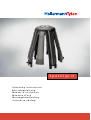
HellermannTyton SpotClip-II de handleiding
- Categorie
- Luidsprekersteunen
- Type
- de handleiding

Operating instructions
Betriebsanleitung
Manuel d’utilisation
Manuale d’uso
Montagehandleiding
Instrukcja obsługi
SpotClip-II

Europe
HellermannTyton GmbH – Austria
Rennbahnweg 65
1220 Vienna
Tel: +43 12 59 99 55-0
Fax: +43 12 59 99 11
E-Mail: oce@HellermannTyton.at
www.HellermannTyton.at
HellermannTyton – Czech Republic
E-Mail: oceCZ@HellermannTyton.at
www.HellermannTyton.cz
HellermannTyton – Denmark
Industrivej 44A, 1.
4000 Roskilde
Tel: +45 702 371 20
Fax: +45 702 371 21
E-Mail: htdk@HellermannTyton.dk
www.HellermannTyton.dk
HellermannTyton – Finland
Sähkötie 8
01510 Vantaa
Tel: +358 9 8700 450
Fax: +358 9 8700 4520
E-Mail: myynti@HellermannTyton.fi
www.HellermannTyton.fi
HellermannTyton S.A.S. – France
2 rue des Hêtres, C.S. 80543
78197 Trappes Cedex
Tel: +33 1 30 13 80 00
Fax: +33 1 30 13 80 60
E-Mail: info@HellermannTyton.fr
www.HellermannTyton.fr
HellermannTyton GmbH –
Germany
Großer Moorweg 45
25436 Tornesch
Tel: +49 4122 701-0
Fax: +49 4122 701-400
E-Mail: info@HellermannTyton.de
www.HellermannTyton.de
HellermannTyton KFT – Hungary
Kisfaludy u. 13
1044 Budapest
Tel: +36 1 369 4151
Fax: +36 1 369 4151
E-Mail: oceHU@HellermannTyton.at
www.HellermannTyton.hu
HellermannTyton Ltd – Ireland
Unit A5 Cherry Orchard
Business Park
Ballyfermot, Dublin 10
Tel: +353 1 626 8267
Fax: +353 1 626 8022
E-Mail: sales@HellermannTyton.ie
www.HellermannTyton.co.uk
HellermannTyton S.r.l. – Italy
Via Visco, 3/5
35010 Limena (PD)
Tel: +39 049 767 870
Fax: +39 049 767 985
E-Mail: info@HellermannTyton.it
www.HellermannTyton.it
HellermannTyton B.V. –
Belgium/Netherlands
Vanadiumweg 11-C
3812 PX Amersfoort
Tel: +31 33 460 06 90
Fax: +31 33 460 06 99
E-Mail (NL): info@HellermannTyton.nl
E-Mail (BE): info@HellermannTyton.be
www.HellermannTyton.nl
www.HellermannTyton.be
HellermannTyton AS – Norway
PO Box 240 Alnabru
0614 Oslo
Tel: +47 23 17 47 00
Fax: +47 22 97 09 70
E-Mail:
firmapost@HellermannTyton.no
www.HellermannTyton.no
HellermannTyton Sp. z o.o. –
Poland
Kotunia 111
62-400 Słupca
Tel.: +48 63 2237111
Fax: +48 63 2237110
E-mail: info@HellermannTyton.pl
www.HellermannTyton.pl
HellermannTyton – Romania
E-Mail: oceRO@HellermannTyton.at
www.HellermannTyton.at
OOO HellermannTyton – Russia
40/4, Pulkovskoe road
BC Technopolis Pulkovo, oce A 8081
196158, St. Petersburg
Tel: +7 812 386 00 09
Fax: +7 812 386 00 08
E-Mail: info@HellermannTyton.ru
www.Hellermanntyton.ru
HellermannTyton – Slovenia
Branch Oce Ljubljana
Podružnica Ljubljana, Leskoškova 6
1000 Ljubljana
Tel: +386 1 433 70 56
Fax: +386 1 433 63 21
E-Mail: oceSl@HellermannTyton.at
www.HellermannTyton.si
HellermannTyton España s.l. –
Spain/Portugal
Avda. de la Industria 37 20 2
28108 Alcobendas, Madrid
Tel: +34 91 661 2835
Fax: +34 91 661 2368
E-Mail:
HellermannTyton@HellermannTyton.es
www.HellermannTyton.es
HellermannTyton AB – Sweden
Datavägen 5, PO Box 569
17526 Järfälla
Tel: +46 8 580 890 00
Fax: +46 8 580 890 01
E-Mail:
kundsupport@HellermannTyton.se
www.HellermannTyton.se
HellermannTyton
Engineering GmbH – Turkey
Saray Mah Dr. Adnan Büyükdeniz
Cad. No:4
Akkom Oce Park 2. Blok Kat: 10
34768 Ümraniye-İstanbul
Tel.: +90 216 687 03 40
Fax: +90 216 250 32 32
E-mail: info@HellermannTyton.com.tr
www.HellermannTyton.com.tr
HellermannTyton operates globally in 37 countries

HellermannTyton Ltd – UK
William Prance Road
Plymouth International Medical
and Technology Park
Plymouth, Devon PL6 5WR
Tel: +44 1752 701 261
Fax: +44 1752 790 058
E-Mail: info@HellermannTyton.co.uk
www.HellermannTyton.co.uk
HellermannTyton Ltd – UK
Sharston Green Business Park
1 Robeson Way
Altrincham Road, Wythenshawe
Manchester M22 4TY
Tel: +44 161 947 2200
Fax: +44 161 947 2220
E-Mail: sales@HellermannTyton.co.uk
www.HellermannTyton.co.uk
HellermannTyton Ltd – UK
Cley Road, Kingswood Lakeside
Cannock, Staffordshire
WS11 8AA
Tel: 01543-728282
Freephone line: 0808-1642204
Fax: 01543-728284
E-Mail: [email protected]
www.HellermannTyton.co.uk
HellermannTyton Data Ltd – UK
Cornwell Business Park
43-45 Salthouse Road, Brackmills
Northampton NN4 7EX
Tel: +44 1604 707 420
Fax: +44 1604 705 454
E-Mail: [email protected]
www.htdata.co.uk
Middle East
HellermannTyton – UAE
E-mail: info@HellermannTyton.ae
www.HellermannTyton.ae
North America
HellermannTyton – Canada
Tel: +1 905 726 1221
Fax: +1 905 726 8538
E-Mail: sales@HellermannTyton.ca
www.HellermannTyton.ca
HellermannTyton – Mexico
Tel: +52 333 133 9880
Fax: +52 333 133 9861
E-Mail:
info@HellermannTyton.com.mx
www.HellermannTyton.com
HellermannTyton – USA
Tel: +1 414 355 1130
Fax: +1 414 355 7341
E-Mail: [email protected]
www.HellermannTyton.com
South America
HellermannTyton – Argentina
Tel: +54 11 4754 5400
Fax: +54 11 4752 0374
E-Mail:
ventas@HellermannTyton.com.ar
www.HellermannTyton.com.ar
HellermannTyton – Brazil
Tel: +55 11 4815 9000
Fax: +55 11 4815 9030
E-Mail:
vendas@HellermannTyton.com.br
www.HellermannTyton.com.br
Asia-Pacific
HellermannTyton – Australia
Tel: +61 2 9525 2133
Fax: +61 2 9526 2495
E-Mail:
cservice@HellermannTyton.com.au
www.HellermannTyton.com.au
HellermannTyton – China
Tel: +86 510 8528 2536
Fax: +86 510 8528 2731
E-Mail:
cservice@HellermannTyton.com.cn
www.HellermannTyton.com.cn
HellermannTyton – Hong Kong
Tel: +852 2832 9090
Fax: +852 2832 9381
E-Mail:
cservice@HellermannTyton.com.hk
www.HellermannTyton.com.sg
HellermannTyton – India
Tel: +91 120 413 3384
Bangalore: +91 776 001 0104
Chennai: +91 996 264 3939
Faridabad: +91 971 851 7797
Ghaziabad: +91 93 1354 1671
Pune: +91 727 601 2200
E-Mail:
cservice@HellermannTyton.co.in
www.HellermannTyton.co.in
HellermannTyton – Japan
Tel: +81 3 5790 3111
Fax: +81 3 5790 3112
E-Mail:
mkt@HellermannTyton.co.jp
www.HellermannTyton.co.jp
HellermannTyton –
Republic of Korea
Tel: +82 31 388 8012
Fax: +82 31 388 8013
E-Mail:
cservice@HellermannTyton.co.kr
www.HellermannTyton.co.kr
HellermannTyton – Philippines
Tel: +63 2 752 6551
Fax: +63 2 752 6553
E-Mail:
cservice@HellermannTyton.com.ph
www.HellermannTyton.com.ph
HellermannTyton – Singapore
Tel.: +65 6 586 1919
Fax: +65 6 752 2527
E-mail: cservice@HellermannTyton.sg
www.HellermannTyton.com.sg
HellermannTyton – Thailand
Tel: +662 237 6702 / 266 0624
Fax: +662 266 8664
E-Mail:
cservice@HellermannTyton.co.th
www.HellermannTyton.com.sg
Africa
HellermannTyton – South Africa
Tel: +27 11 879 6600
Fax: +27 11 879 6603
E-Mail: [email protected]
www.HellermannTyton.co.za
globally in 37 countries

A
B
C
2
1
3
2
1
3
1
2
3

D
F
E
G
HI

English
Deutsch
Français
Italiano
Nederlands
Polski
3
9
15
22
27
33
GBDEFRITNLPL

GBDEFRITNLPL
Instruction manual • SpotClip-II • 03-2017
Operating instructions
3
Instruction manual
1 Operating instructions
This operating manual applies solely to SpotClip-II and is for use by
the operator. The operator should read and understand the operating
manual carefully before beginning the installation.
The fold-out page contains the product views (photos/drawings)
relevant to the installation and also the national addresses of the
HellermannTyton representatives.
fPlease retain this operating manual.
1.1 Correct use
SpotClip-II is a product that simplies the installation of recessed
downlights in false ceilings while providing a consistent space
between the recessed downlight and the ceiling insulation material.
For use mainly on plasterboard, this protective support with 4 arms
and 4 snap-off exible lugs has many thermal and mechanical
advantages. It can even be added to an existing installation at
a later stage.
SpotClip-II enables the glass wool insulation material to be lifted
above the recessed downlight to provide a sucient ow of air
for effective operation. It reduces overheating and re hazards and
increases the life time of the bulbs. The product is manufactured
in self-extinguishing PA66 material resistant to high temperatures.
The product must only be used for the purposes described in this
operating manual and must only be used in perfect condition and as
intended. The safety and hazard instructions described in this manual
must be observed.
1.2 Standards/fire protection properties
The product is self-extinguishing and its re protection properties
correspond to the UL94 V0 ammability rating. The product is tested
according to the lament test (GWT) at 960 °C as well as standards
EN 60598-1 and EN 60598-2-2.

Instruction manual • SpotClip-II • 03-2017
Safety instructions
4
Standard EN13501-1 A2 s1 d0 applies to insulation material
and vapour barriers. This standard corresponds to the earlier M0
classication. Only non-combustible insulation materials and
re-retardant vapour barriers must be used, which in the event of re,
do not emit fumes and do not form droplets.
1.3 After-Sales Service
If you have any questions, please contact the HellermannTyton
representative for your country. The contact details can be found on
the fold-out page.
2 Safety instructions
The product is manufactured in accordance with recognised safety
and technical regulations. However, in the event of incorrect use it
can affect the health and life of the operator or third parties, as well
as damage the product and other property. This operating manual
contains safety instructions.
fPlease follow all the instructions to avoid personal injury and
damage to property and the environment.
2.1 Diagram and organisation of warning symbols
Warning symbols are organised as follows:
WARNING
Type and source of danger!
Explanation of the type and source of danger.
fMeasures to prevent potential hazards.
A warning indicates a potential hazard to life or a risk of serious
injury.
2.2 Operating limits
fThe installation environment must meet the following conditions:
• Suitable for the use of LED and uorescent downlights.

GBDEFRITNLPL
Instruction manual • SpotClip-II • 03-2017
Operator responsibilities
5
• Mineral wool insulation: compatible with halogen recessed
downlights up to 50watts (except sealed downlights and with
the xed installation wiring insulation, supplied with the lighting
unit, resistant to a minimum of 120°C).
• Blow-in insulation: compatible with halogen recessed downlights
up to 35watts (except sealed downlights, only with an M0
non-combustible contact surface and with the xed installation
wiring insulation, supplied with the lighting unit, resistant to a
minimum of 135°C).
• Designed solely for installation above recessed downlights. Not
suitable for protecting converters, transformers or terminals.
• Suitable for ceiling cut-outs with a recessed diameter
of 62 to 90mm.
• The diameter of the drill hole must match the diameter of the
downlight +4 mm to enable the support arms of the SpotClip-II
to t through.
• The maximum available height is 95mm.
3 Operator responsibilities
The operator must comply with the legal directives applicable at
national level and also the directives relating to the prevention of
accidents. The use of a SpotClip-II, does not mean the operator is
exempt from consulting the instruction sheet for the downlight used.
In case of uncertainty, please contact a qualied professional.
4 Transportation and storage
Do not stack heavy objects on the packaged product.
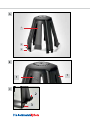
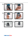
5 Product assembly view
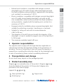
Diagram A is an assembly view of the product. Diagrams B and C
show the details of the product. All the product diagrams are
provided on the fold-out page.
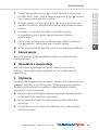
Legends for A , B and C :
1 Snap-off flexible lugs 2 Support arms
3 Retaining lugs

Instruction manual • SpotClip-II • 03-2017
Assembly
6
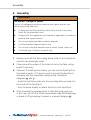
6 Assembly
WARNING
Fire hazard - Danger of death!
The use of inadequate insulation material and vapour barriers can
lead to potentially fatal res.
fComply with local re protection directives and the instruction
sheet for the downlight used.
fComply with the regulations and standards applicable to insulation
material and vapour barriers.
fDo not use highly ignitable insulation material.
fUse re-retardant vapour barriers only.
fDo not use ecological material such as wood, hemp, straw, etc.
fUse board-type insulation material only.
1 Measure and drill the false ceiling board (refer to the instruction
sheet for the downlight used).
2 Clean around the edges of the hole/cut-out in the false ceiling
board if necessary.
fOptional: If installing from below, you can use the SpotClip-Tool
(included in packs of 10 pieces only) to prevent the SpotClip-II
springing into the suspended ceiling during installation
(diagrams H and I ):
- Insert the tool xing clips into the mounting holes provided on
the inside of the SpotClip-II.
- Turn clockwise slightly to attach the tool to the SpotClip-II.
fIf the downlight is equipped with a cable xing lug, and only
in this case, cut off one of the intermediate snap-off exible lugs,
or break it off by bending it inward or outward (diagram B ).

GBDEFRITNLPL
Instruction manual • SpotClip-II • 03-2017
Maintenance
7
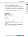
3 Press the mounting brackets together (diagram D ) and insert the
SpotClip-II into the cut-out in the ceiling until the 4 support arms 2
(diagram E ) are mounted above the ceiling cut-out.
4 Fully t the 4 retaining lugs 3 (diagram F ) in the plasterboard to
prevent any misalignment of the system at a later stage.
5 Check that the SpotClip-II is correctly xed in position before tting
the downlight.
6 Fit the recessed downlight (diagram G ) in accordance with the
downlight instruction manual.
;The SpotClip-II is installed.
7 Maintenance
No special maintenance is required.
8 De-commissioning
Used correctly in accordance with this manual, there is no product
use time limit.
9 Disposal
At end of use, the purchaser or operator must dispose of the product
correctly. This product is manufactured in accordance with current
environmental protection standards.
fComply with the national directives concerning the disposal
of material.
fTake the product to a collection point or local recycling centre.
fIf necessary, contact the local authorities.

Instruction manual • SpotClip-II • 03-2017
Technical specifications
8
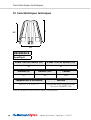
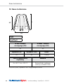
10 Technical specifications
H2 H
FH
REFERENCE
SpotClip-II
Min.Øof fixing hole(FH) Max.Øof fixing hole(FH)
62 90
Height (H) Height (H2) Colour
107 95 Black
Material operating temperatures
From -20°C to +120°C Polyamide 6.6 containing
glass bre (PA66GF15%)
All dimensions are in mm and subject to change.

GBDEFRITNLPL
Bedienungsanleitung • SpotClip-II • 03-2017
Bedienungsanweisungen
9
Bedienungsanleitung
1 Bedienungsanweisungen
Diese Bedienungsanleitung gilt ausschließlich für den SpotClip-II
und wendet sich an den Benutzer. Dieser muss die Bedienungs-
anleitung aufmerksam durchlesen und verstehen, bevor er mit
der Montage beginnt.
Die aufklappbare Doppelseite enthält Produktdarstellungen
(Fotos/Zeichnungen) bezüglich der Montage sowie die Adressen
der nationalen Vertreter von HellermannTyton.
fBewahren Sie diese Bedienungsanleitung auf.
1.1 Konforme Benutzung
Der SpotClip-II ist ein Produkt, das die Montage von Einbaustrahlern
in Zwischendecken erleichtert und gleichzeitig einen zuverlässigen
Abstand zwischen dem Einbaustrahler und dem Dämmmaterial
gewährleistet. Dieser vierbeinige Abstandshalter mit vier trennbaren
Laschen eignet sich hauptsächlich für die Verwendung in Gipskarton-
platten und bietet zahlreiche thermische und mechanische Vorteile.
Er kann auch nachträglich eingebaut werden.
Der SpotClip-II hebt die Glaswolle über dem Einbaustrahler an und
lässt einen für sein korrektes Funktionieren ausreichenden Hohlraum
frei. Er verringert die Überhitzungs- und Brandgefahr und ermöglicht
es, die Lebensdauer der Glühlampe zu verlängern. Das Produkt wird
aus selbstverlöschendem, hitzebeständigem Polyamid 6.6 hergestellt.
Das Produkt ist allein für die in dieser Bedienungsanleitung
beschriebenen Zwecke zu verwenden und muss in einwandfreiem
Zustand sowie bestimmungsgemäß benutzt werden. Die in der
vorliegenden Anweisung dargestellten Sicherheitsvorschriften und
Gefahren müssen beachtet werden.
1.2 Brandschutztechnische Eigenschaften/Normen
Das Produkt ist selbstlöschend, seine Brandschutzeigenschaften
entsprechen der UL94 V0. Das Produkt wurde gemäß der
Glühdrahtprüfung bei 960°C und den Normen EN60598-1
und EN60598-2-2 getestet.

Bedienungsanleitung • SpotClip-II • 03-2017
Sicherheitshinweise
10
Die Norm EN13501-1 A2 s1 d0 gilt für die Dämmmaterialien sowie
die Dampfsperrfolien. Diese Norm entspricht der früheren
Klassizierung M0. Nur nicht brennbare Dämmmaterialien und
feuerfeste Dampfsperrfolien, die im Brandfall keinen Rauch erzeugen
und keine Tropfen bilden, dürfen benutzt werden.
1.3 Kundendienst
Bei Fragen wenden Sie sich bitte an den HellermannTyton Vertreter
Ihres Landes. Die Kontaktdaten sind auf der aufklappbaren
Doppelseite angegeben.
2 Sicherheitshinweise
Das Produkt wird nach dem Stand der Technik und den anerkannten
sicherheitstechnischen Regeln gebaut. Die unsachgemäße
Anwendung kann jedoch Gefahren in Bezug auf die Gesundheit
und das Leben des Benutzers oder Dritter, sowie Produkt- und andere
Sachschäden hervorrufen. Die vorliegende Bedienungsanleitung
umfasst Sicherheitsvorschriften.
fBeachten Sie alle Vorschriften, um Personen-, Sach- oder
Umweltschäden zu vermeiden.
2.1 Darstellung und Aufbau von Warnhinweisen
Die Warnsymbole sind wir folgt strukturiert:
WARNUNG
Gefahrenart u. Gefahrenquelle!
Erklärung der Gefahrenart u. Gefahrenquelle.
fMaßnahmen zur Vorbeugung potenzieller Gefahren.
Eine Warnung weist auf potenzielle Lebensgefahr oder das Risiko
schwerer Verletzungen hin.
2.2 Einsatzgrenzen
fDie Installationsumgebung muss die folgenden Bedingungen
einhalten:
• Für LED- und Leuchtstoffstrahler benutzbar.

GBDEFRITNLPL
Bedienungsanleitung • SpotClip-II • 03-2017
Pflichten des Benutzers
11
• Standarddämmung aus Mineralwolle: kompatibel mit Halogen-
Einbaustrahlern bis zu 50Watt (außer wasserdichten Strahlern mit
Isolierung der festverlegten Installation, die mit Beleuchtungskörper
geliefert werden und mindestens bis zu 120°C temperaturbeständig
sind).
• Schüttdämmung aus Mineralwolle: kompatibel mit Halogen-
Einbaustrahlern bis zu 35Watt (außer wasserdichten Strahlern, nur
mit einer feuerfesten Auageäche M0 und mit Isolierung der
festverlegten Installation, die mit Beleuchtungskörper geliefert
werden und mindestens bis
zu 135 °C temperaturbeständig sind).
• Ausschließlich konzipiert, um über Einbaustrahlern montiert zu
werden. Er ist nicht dazu geeignet, Stromrichter, Transformatoren
oder Klemmleisten zu schützen.
• Für Deckenausschnitte mit Einbaudurchmessern von 62 bis 90mm
geeignet.
• Der Lochkreisdurchmesser muss dem Durchmesser des Strahlers
+4mm für die Montage des SpotClip-II entsprechen.
• Die maximal verfügbare Höhe beträgt 95mm.
3 Pflichten des Benutzers
Der Benutzer muss die auf nationaler Ebene geltenden gesetzlichen
Vorschriften sowie die Richtlinien zur Vorbeugung von Unfällen
beachten. Die Benutzung von SpotClip-II schließt das Lesen der
Montageanleitung des Einbaustrahlers keinesfalls aus. Ziehen
Sie im Zweifelsfall einen Fachmann zu Rate.
4 Transport und Lagerung
Stapeln Sie keine schweren Gegenstände auf das verpackte Produkt.
5 Produktübersicht
Die Abbildung A ist eine Gesamtansicht des Produktes. Die
Abbildungen B und C zeigen Produktdetails. Alle Produktabbildungen
sind auf der aufklappbaren Doppelseite aufgeführt.
Bildunterschriften A , B und C :
1 Trennbare Laschen 2 Montagelaschen
3 Haltedorne

Bedienungsanleitung • SpotClip-II • 03-2017
Montage
12
6 Montage
WARNUNG
Brandrisiko - Lebensgefahr!
Die Benutzung ungeeigneter Dämmmaterialien und
Dampfsperrfolien kann lebensbedrohliche Brände verursachen.
fBeachten Sie die lokalen Brandschutz-Richtlinien sowie die
Montageanleitung des Einbaustrahlers.
fBeachten Sie die für Dämmmaterialien und Dampfsperrfolien
geltenden Vorschriften und Normen.
fBenutzen Sie keine leicht entammbaren Dämmmaterialien.
fBenutzen Sie ausschließlich feuerfeste Dampfsperrfolien.
fBenutzen Sie kein ökologisches Material wie Holz, Hanf, Stroh usw.
fBenutzen Sie ausschließlich Dämmmaterialien in Plattenform.
1 Messen und sägen Sie den Lochkreis der Zwischendeckenplatte
aus (Bitte die Anleitung des Einbaustrahlers berücksichtigen).
2 Reinigen Sie bei Bedarf den Ausschnitt in der Zwischendeckenplatte.
fUnverbindlich: Bei Montage von unten können Sie sich mit dem
Werkzeug SpotClip-Tool (nur in 10 Stück-Packungen enthalten)
behelfen, um zu vermeiden, dass der SpotClip-II bei der Montage
in die Zwischendecke fällt (Abbildungen H und I ):
- Die Befestigungsclips des Werkzeugs in die im Inneren
des SpotClip-II vorgesehenen Kerben schieben.
- Langsam im Uhrzeigersinn drehen, um das Werkzeug am
SpotClip-II zu befestigen.
fWenn und nur wenn der Strahler mit einer Lasche zur
Befestigung der Kabel ausgestattet ist, eine der trennbaren
Zwischenlaschen schneiden oder durch Drücken nach innen oder
außen abbrechen (Abbildung B ).

GBDEFRITNLPL
Bedienungsanleitung • SpotClip-II • 03-2017
Instandhaltung
13
3 Die Befestigungsfüße zusammendrücken (Abbildung D ) und
den SpotClip-II in die Deckenaussparung schieben, bis die
4Montagelaschen (Abbildung E ) über der Deckenaussparung
einrasten.
4 Die 4 Haltedorne 3 (Abbildung F ) in die Gipskartonplatte drücken,
um späteres Verschieben des Systems zu vermeiden.
5 Vor der Montage des Strahlers prüfen, ob der SpotClip-II korrekt
sitzt.
6 Den Einbaustrahler (Abbildung G ) gemäß der Bedienungsanleitung
montieren.
;Der SpotClip-II ist montiert.
7 Instandhaltung
Es ist keine besondere Wartung erforderlich.
8 Außerbetriebnahme
Wenn das Produkt der Bedienungsleitung entsprechend verwendet
wird, kann es zeitlich unbegrenzt benutzt werden.
9 Entsorgung
Nach Ende der Benutzung muss der Käufer oder Benutzer das
Produkt korrekt entsorgen. Dieses Produkt wird den aktuellen
Umweltschutznormen gemäß hergestellt.
fBeachten Sie die nationalen Vorschriften bezüglich
der Entsorgung der Materialien.
fBringen Sie das Produkt zu einer lokalen Sammelstelle
oder einem Recyclingzentrum.
fWenden Sie sich bei Bedarf an die lokalen Behörden.

Bedienungsanleitung • SpotClip-II • 03-2017
Technische Merkmale
14
10 Technische Merkmale
H2 H
FH
REFERENZ
SpotClip-II
Ømin.Befestigungsloch(FH)
Ømax.Befestigungsloch(FH)
62 90
Höhe (H) Höhe (H2) Farbe
107 95 Schwarz
Betriebstemperaturen Material
-20°C bis +120°C Gasfaserverstärktes Polyamid
6.6 (PA66GF15%)
Alle Maße sind in mm angegeben und können geändert werden.

GBDEFRITNLPL
Manuel d‘utilisation • SpotClip-II • 03-2017
Consignes d‘utilisation
15
Manuel d'utilisation
1 Consignes d‘utilisation
Ce manuel d‘utilisation s‘applique exclusivement au SpotClip-II et
s‘adresse à l‘utilisateur. Celui-ci doit lire avec attention et comprendre
le manuel d‘utilisation avant de démarrer son installation.
La page rabattable contient des représentations du produit (photos/
dessins) relatives au montage ainsi que les adresses des représentants
nationaux de HellermannTyton.
fConservez ce manuel d‘utilisation.
1.1 Utilisation conforme
Le SpotClip-II est un produit qui facilite l’installation des spots
encastrables dans les faux-plafonds tout en assurant un écart able
entre le spot encastré et le matériau isolant. Utilisable principalement
sur des plaques de plâtre, ce support protecteur à 4 pieds et 4
languettes sécables présente de nombreux avantages thermiques et
mécaniques. Il peut même être ajouté ultérieurement à une
installation existante.
Le SpotClip-II permet de relever la laine de verre au-dessus du spot
encastré et de laisser une zone d‘air susante à son bon
fonctionnement. Il réduit ainsi les risques de surchauffe et d’incendie
et permet d’augmenter la durée de vie des ampoules. Le produit est
fabriqué en PA66 auto-extinguible résistant aux hautes températures.
Le produit doit uniquement être utilisé aux ns décrites dans ce
manuel d‘utilisation et ne doit être utilisé que dans un état
irréprochable ainsi que selon l‘usage prévu. Il faut tenir compte des
consignes de sécurité et des dangers présentés dans le présent
manuel.
1.2 Propriétés anti-incendie/normes
Le produit est auto-extinguible et ses propriétés de tenue au feu
correspondent à l‘UL94 V0. Le produit est testé conformément au
test de résistance au lament incandescent à 960°C, aux normes
EN60598-1 et EN60598-2-2.

Manuel d‘utilisation • SpotClip-II • 03-2017
Consignes de sécurité
16
La norme EN13501-1 A2 s1 d0 s‘applique aux matériaux isolants
ainsi qu‘aux pare-vapeur. Cette norme correspond à la classication
M0 antérieure. Seuls des matériaux isolants non combustibles et des
pare-vapeur ignifugés doivent être utilisés, qui en cas d‘incendie, ne
dégagent pas de fumée et ne forment pas de gouttes.
1.3 Service après-vente
Si vous avez des questions, adressez-vous au représentant
HellermannTyton de votre pays. Les coordonnées sont indiquées sur
la page rabattable.
2 Consignes de sécurité
Le produit est fabriqué selon l‘état de la technique et des règles de
sécurité reconnues. Cependant, il peut survenir en cas d‘une
utilisation non conforme des dangers pour la santé et la vie de
l‘utilisateur ou de tierces parties, ainsi que des dégradations du
produit et d‘autres biens. Le présent manuel d‘utilisation contient des
consignes relatives à la sécurité.
fRespectez toutes les consignes pour éviter des dommages aux
personnes, aux biens et à l‘environnement.
2.1 Représentation et structure des symboles
d‘avertissement
Les symboles d‘avertissement sont structurés comme suit:
AVERTISSEMENT
Type et source de danger!
Explication du type et de la source de danger.
fMesures de prévention des dangers potentiels.
Un avertissement indique un risque potentiel pour la vie ou des
blessures graves.
2.2 Limites d‘utilisation
fL‘environnement d‘installation doit respecter les conditions
suivantes:
• Utilisable pour les spots à LED et uorescents.

GBDEFRITNLPL
Manuel d‘utilisation • SpotClip-II • 03-2017
Obligations de l‘utilisateur
17
• Isolation en rouleau: compatible avec des spots encastrables
halogènes jusqu‘à 50watts (sauf spots étanches et avec une
isolation du câblage de l‘installation xe, fournie avec le
luminaire, résistant jusqu‘à 120°C minimum).
• Isolation projetée: compatible avec des spots encastrables
halogènes jusqu‘à 35watts (sauf spots étanches, uniquement
avec une surface d‘appui M0 incombustible et avec une isolation
du câblage de l‘installation xe, fournie avec le luminaire,
résistant jusqu‘à 135 °C minimum).
• Conçu uniquement pour être installé au dessus des spots
encastrables. Il n’est pas fait pour protéger les convertisseurs, les
transformateurs ou les borniers.
• Utilisable pour les découpes de plafond avec des diamètres
d‘encastrement de 62mm à 90mm.
• Le diamètre de perçage doit correspondre au diamètre du spot
+4 mm pour le passage des ailettes du SpotClip-II.
• La hauteur maximum disponible est de 95mm.
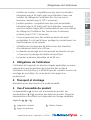
3 Obligations de l‘utilisateur
L‘utilisateur doit respecter les directives légales applicables au niveau
national ainsi que les directives de prévention des accidents.
L’utilisation d’un SpotClip-II, n‘affranchit pas de consulter la notice de
montage du spot utilisé. En cas de doute, faire appel à un
professionnel.
4 Transport et stockage
N‘empilez aucun objet lourd sur le produit emballé.
5 Vue d’ensemble du produit
La représentation A est une vue d‘ensemble du produit. Les
représentations B et C montrent des détails du produit. Toutes les
représentations du produit sont disponibles sur la page rabattable.
Légendes A , B et C :
1 Languettes sécables 2 Ailettes d‘appui
3 Ergots de maintien

Manuel d‘utilisation • SpotClip-II • 03-2017
Montage
18
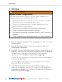
6 Montage
AVERTISSEMENT
Risque d’incendie - Danger mortel!
L‘utilisation de matériaux isolants et de pare-vapeur inadaptés peut
provoquer des incendies potentiellement mortels.
fRespectez les directives locales de protection contre les incendies
ainsi que la notice de montage du spot utilisé.
fRespectez les réglementations et normes applicables pour les
matériaux isolants et pare-vapeur.
fN‘utilisez aucun matériau isolant facilement inammable.
fUtilisez uniquement des pare-vapeur ignifugés.
fN‘utilisez aucun matériau écologique comme le bois, le chanvre, la
paille etc.
fUtilisez uniquement des matériaux isolants sous forme de plaques.
1 Mesurer et percer la dalle pour faux-plafond (se référer à la notice
du spot utilisé).
2 Nettoyer les abords du trou / de la découpe dans la dalle pour
faux-plafond si nécessaire.
fFacultatif : En cas d‘installation par le dessous, vous pouvez vous
aider de l‘outil SpotClip-Tool (inclus uniquement dans les packs de
10 pièces) pour éviter que le SpotClip-II ne saute dans les
combles lors de l‘installation
(représentations H et I )
:
- Insérer les clips de xation de l‘outil dans les encoches prévues à
l‘intérieur du SpotClip-II.
- Tourner légèrement dans le sens des aiguilles d‘une montre
pour xer l‘outil au SpotClip-II.
fSi le spot est équipé d‘une patte permettant la xation des
câbles, et uniquement dans ce cas, couper l‘une des languettes
intermédiaires sécables, ou la casser en la pliant vers l‘intérieur ou
l‘extérieur
(représentation B )
.

GBDEFRITNLPL
Manuel d‘utilisation • SpotClip-II • 03-2017
Entretien
19
3 Comprimer les pattes de montage (représentation D ) et insérer le
SpotClip-II dans la découpe du plafond jusqu‘à ce que les 4 ailettes
d‘appui 2 (représentation E ) se xent au dessus de la découpe du
plafond.
4 Enfoncer les 4 ergots de maintien 3 (représentation F ) dans la
plaque de plâtre pour prévenir tout désalignement ultérieur du
système.
5 Vérier que le SpotClip-II est xé correctement en position avant de
monter le spot.
6 Monter le spot encastrable (représentation G ) selon son manuel
d‘utilisation.
;Le SpotClip-II est monté.
7 Entretien
Aucun entretien particulier n‘est nécessaire.
8 Mise hors service
Utilisé de manière conforme à ce manuel, l‘utilisation du produit n‘est
pas limitée dans le temps.
9 Élimination
À la n de l‘utilisation, l‘acheteur ou l‘utilisateur doit éliminer le
produit correctement. Ce produit est fabriqué selon les normes
actuelles de protection de l‘environnement.
fRespectez les directives nationales concernant l‘élimination des
matériaux.
fApportez le produit dans un lieu de collecte ou un centre de
recyclage local.
fContactez si nécessaire les autorités locales.

Manuel d‘utilisation • SpotClip-II • 03-2017
Caractéristiques techniques
20
10 Caractéristiques techniques
H2 H
FH
RÉFÉRENCE
SpotClip-II
Ømin.trou de fixation(FH) Ømax.trou de fixation(FH)
62 90
Hauteur (H) Hauteur (H2) Couleur
107 95 Noir
Températures d'utilisation Matière
De -20°C à +120°C Polyamide 6.6 chargé en bres
de verre (PA66GF15%)
Toutes les dimensions sont en mm et sujettes à modications.

GBDEFRITNLPL
Manuale d’uso • SpotClip-II • 03-2017
Istruzioni per l’uso
21
Manuale d’uso
1 Istruzioni per l’uso
Questo manuale d‘uso si applica esclusivamente allo SpotClip-II
e si rivolge all‘utilizzatore. Quest’ultimo deve leggere attentamente
e comprendere il manuale d’uso prima di utilizzare il prodotto.
La pagina pieghevole contiene le rappresentazioni del prodotto
(foto/disegni) relative al montaggio, così come gli indirizzi delle sedi
HellermannTyton nei diversi Paesi.
fConservare il presente manuale d’uso.
1.1 Utilizzo conforme
SpotClip-II è un prodotto che facilita l’installazione dei faretti da
incasso nei controsotti assicurando una distanza di sicurezza tra il
faretto incassato e il materiale isolante. Utilizzabile principalmente su
sotti in cartongesso, questo distanziale per faretti a 4 piedini e a
4linguette rimovibili presenta numerosi vantaggi termici e meccanici.
Può anche essere aggiunto a posteriori in un impianto già esistente.
SpotClip-II permette di sollevare la lana di vetro al di sopra del faretto
incassato e di lasciare una zona d’aria suciente al suo
funzionamento. Riduce i rischi di surriscaldamento e di incendio e
permette di aumentare la durata di vita delle lampadine. Il prodotto
è fabbricato in PA66 autoestinguente e resistente alle elevate
temperature.
SpotClip-II deve essere utilizzato unicamente per gli scopi descritti
in questo manuale d’uso; deve essere utilizzato solo in condizioni
perfette e conformemente all‘utilizzo descritto. È necessario tenere
presenti le istruzioni di sicurezza e i pericoli indicati in questo
manuale.
1.2 Proprietà/norme antincendio
SpotClip-II è autoestinguente secondo la norma UL94 V0 ed è testato
conformemente alla prova di resistenza al lo incandescente a 960 °C,
norma EN 60598-1 ed EN60598-2-2.

Manuale d’uso • SpotClip-II • 03-2017
Istruzioni di sicurezza
22
La norma EN13501-1 A2 s1 d0 si applica ai materiali isolanti così
come alle barriere al vapore. Questa norma corrisponde alla
classicazione M0 precedente. Devono essere utilizzati unicamente
materiali isolanti non inammabili e barriere al vapore ignifughe che,
in caso di incendio, non producano fumo e non formino gocce.
1.3 Servizio post-vendita
In caso di domande, rivolgersi al Servizio Clienti HellermannTyton del
proprio Paese. I riferimenti sono indicati sulla pagina pieghevole.
2 Istruzioni di sicurezza
Il prodotto è fabbricato conformemente allo stato della tecnica e alle
regole di sicurezza riconosciute. Tuttavia, in caso di utilizzo non
conforme, possono presentarsi pericoli per la salute e per la vita
dell‘utilizzatore o di terzi, così come il deterioramento del prodotto
di altri beni. Il presente manuale d’uso contiene istruzioni relative alla
sicurezza.
fRispettare tutte le istruzioni per evitare danni alle persone, ai beni
e all’ambiente.
2.1 Rappresentazione e struttura dei simboli
di avvertenza
I simboli di avvertenza sono strutturati come segue:
AVVERTENZA
Tipo e origine del pericolo!
Spiegazione del tipo e dell’origine del pericolo.
fMisure di prevenzione di un potenziale pericolo.
Un'avvertenza indica un potenziale pericolo di lesioni gravi
o per la vita.
2.2 Limiti di utilizzo
fL‘ambiente di installazione deve rispettare le seguente condizioni:
• Utilizzabile per i faretti a LED e uorescenti.

GBDEFRITNLPL
Manuale d’uso • SpotClip-II • 03-2017
Obblighi dell’utilizzatore
23
• Isolamento con lana di roccia: compatibile con i faretti a incasso
alogeni no a 50 watt (tranne i faretti impermeabili e con un
isolamento del cablaggio dell’impianto sso, fornito con
apparecchio di illuminazione resistente no a 120 °C minimo).
• Isolamento a insuaggio: compatibile con i faretti
a incasso alogeni no a 35 watt (tranne i faretti impermeabili,
unicamente con una supercie d’appoggio M0 non combustibile
e con un isolamento del cablaggio dell’impianto sso, fornito con
apparecchio di illuminazione resistente no a 135 °C minimo).
• Progettato unicamente per essere installato al di sopra dei faretti
da incasso. Non è realizzato per proteggere i convertitori,
i trasformatori o i morsetti.
• Utilizzabile per le cavità del sotto con diametro di incasso
da 62mm a 90 mm.
• Il diametro di foratura deve corrispondere al diametro del faretto
+ 4 mm per il passaggio delle alette dello SpotClip-II.
• L’altezza massima disponibile è di 95mm.
3 Obblighi dell’utilizzatore
L‘utilizzatore deve rispettare le norme di legge applicabili a livello
nazionale così come le direttive per la prevenzione degli incidenti.
L’utilizzo di SpotClip-II non esonera dalla consultazione delle istruzioni
di montaggio del faretto utilizzato. In caso di dubbio rivolgersi a un
professionista.
4 Trasporto e stoccaggio
Non poggiare alcun oggetto pesante sul prodotto imballato.
5 Vista d’insieme del prodotto
La rappresentazione A è una vista d‘insieme del prodotto. Le
rappresentazioni B e C mostrano i dettagli del prodotto. Tutte le
rappresentazioni del prodotto sono disponibili sulla pagina pieghevole.
Legenda A , B e C :
1 Linguette rimovibili 2 Alette di appoggio
3 Denti di ritenuta

Manuale d’uso • SpotClip-II • 03-2017
Montaggio
24
6 Montaggio
AVVERTENZA
Rischio di incendio - Pericolo mortale!
L’utilizzo di materiali isolanti e di barriere al vapore inadatte può
causare incendi potenzialmente mortali.
fRispettare le direttive locali per la protezione contro gli incendi così
come le istruzioni di montaggio del faretto utilizzato.
fRispettare i regolamenti e le norme applicabili per i materiali
isolanti e per le barriere al vapore.
fNon utilizzare alcun materiale isolante facilmente inammabile.
fUtilizzare unicamente barriere al vapore ignifughe.
fNon utilizzare alcun materiale ecologico come il legno, la canapa,
la paglia, etc.
fUtilizzare unicamente materiali isolanti sotto forma di lastre.
1 Misurare e forare il pannello del controsotto (consultare le
istruzioni del faretto utilizzato).
2 Se necessario pulire intorno al foro / alla cavità del pannello del
controsotto.
fFacoltativo: In caso di installazione dal basso, è possibile utilizzare
lo strumento SpotClip-Tool (incluso unicamente nel pacco da
10pezzi) per evitare che SpotClip-II salti nel sottotetto durante
l’installazione (rappresentazioni H e I ):
- Inserire le clip di ssaggio dello strumento nelle sedi previste
all’interno dello SpotClip-II.
- Girare leggermente in senso orario per ssare lo strumento allo
SpotClip-II.
fSolo nel caso in cui il faretto sia fornito di fermacavo, tagliare una
delle linguette intermedie rimovibili o romperla piegandola verso
l’interno o verso l’esterno (rappresentazione B ).

GBDEFRITNLPL
Manuale d’uso • SpotClip-II • 03-2017
Manutenzione
25
3 Comprimere le gambe di montaggio (rappresentazione D ) e
inserire SpotClip-II nella cavità del sotto no a quando le 4 alette
di appoggio 2 (rappresentazione E ) si ssano al di sopra della
cavità del sotto.
4 Premere i 4 denti di ritenuta 3 (rappresentazione F ) nel pannello di
cartongesso per prevenire qualsiasi disallineamento del sistema.
5 Vericare che SpotClip-II sia correttamente ssato in posizione
prima di montare il faretto.
6 Montare il faretto da incasso (rappresentazione G ) conformemente
al manuale di utilizzo.
;SpotClip-II è montato.
7 Manutenzione
Non è necessaria alcuna manutenzione particolare.
8 Messa fuori servizio
Se utilizzato conformemente alle istruzioni presenti nel manuale,
l’uso del prodotto non è limitato nel tempo.
9 Smaltimento
Dopo l’uso, l‘acquirente o l‘utilizzatore deve smaltire il prodotto
correttamente. Il prodotto è fabbricato conformemente alle norme
attuali di protezione dell‘ambiente.
fRispettare le direttive nazionali riguardanti l‘eliminazione
dei materiali.
fPortare il prodotto in un luogo di raccolta o in un centro
di riciclaggio locale.
fSe necessario contattare le autorità locali.

Manuale d’uso • SpotClip-II • 03-2017
Caratteristiche tecniche
26
10 Caratteristiche tecniche
H2 H
FH
RIFERIMENTO
SpotClip-II
Ømin.foro di fissaggio(FH) Ømax.foro di fissaggio(FH)
62 90
Altezza (H) Altezza (H2) Colore
107 95 Nero
Temperatura di utilizzo Materiale
Da -20°C a +120°C Poliammide 6.6 rinforzato
con bra di vetro (PA66GF15%)
Tutte le dimensioni sono in mm e soggette a modiche.

GBDEFRITNLPL
Gebruikshandleiding • SpotClip-II • 03-2017
Gebruiksinstructies
27
Gebruikshandleiding
1 Gebruiksinstructies
Deze handleiding geldt uitsluitend voor SpotClip-II en is bedoeld voor
de gebruiker. Deze moet de handleiding zorgvuldig lezen en begrijpen
vóór de installatie te beginnen.
De uitklapbare pagina bevat afbeeldingen van het product
(foto's / tekeningen) in verband met de montage en de adressen
van de nationale vertegenwoordigers van HellermannTyton.
fBewaar deze gebruikershandleiding.
1.1 Beoogd gebruik
De SpotClip-II is een product dat de installatie van inbouwspots
vergemakkelijkt in verlaagde plafonds en tegelijkertijd een
betrouwbare afstand garandeert tussen de inbouwspot en het
isolatiemateriaal. Deze zijn hoofdzakelijk bruikbaar op gipsplaten.
Deze beschermende steun met 4 poten heeft vele thermische en
mechanische voordelen. Deze kan zelfs worden toegevoegd in een
bestaande installatie.
De SpotClip-II laat toe de glaswol over de inbouwspot aan te brengen
en toch voldoende lucht te laten voor de goede werking. Dit
vermindert het risico op oververhitting en brand, en verhoogt de
levensduur van de lampen. Het product wordt geproduceerd in
zelfdovend PA66 bestand tegen hoge temperaturen.
Het product mag alleen worden gebruikt voor de in deze handleiding
beschreven doeleinden, en mag alleen worden gebruikt in perfecte
staat en zoals beoogd. Er moet rekening worden gehouden met de
veiligheidsinstructies en de gevaren die in deze handleiding worden
aangegeven.
1.2 Brandwerende eigenschappen/normen
Het product is zelfdovend en de brandwerende eigenschappen zijn
conform met UL94 V0. Het product is getest conform de
weerstandstest tegen een brandend lament bij 960 °C, volgens EN
60598-1 en EN 60598-2-2.

Gebruikshandleiding • SpotClip-II • 03-2017
Veiligheidsvoorschriften
28
De norm EN 13501-1 A2-s1 d0 geldt voor de isolatiematerialen
en het dampscherm. Deze norm komt overeen met de eerdere
classicatie M0. Alleen niet-brandbare isolatiematerialen en
brandvertragende dampschermen mogen worden gebruikt, die
in geval van brand geen rook uitstoten en geen druppels vormen.
1.3 Klantenservice
Als u vragen heeft, neem contact op met de HellermannTyton-
vertegenwoordiger van uw land. De contactgegevens vindt u op de
uitvouwbare pagina.
2 Veiligheidsvoorschriften
Het product is vervaardigd volgens de huidige stand van de techniek
en de erkende veiligheidstechnische regels. Het kan echter
voorkomen bij oneigenlijk gebruik dat gevaar voor de gezondheid en
het voor leven van de gebruiker of derden optreedt, alsmede dat er
schade aan het product en andere eigendommen ontstaat. Deze
handleiding bevat de instructies betreffende de veiligheid.
fVolg alle instructies op om letsel aan personen, en schade aan
eigendommen en het milieu te voorkomen.
2.1 Structuur en weergave van waarschuwingssymbolen
De waarschuwingssymbolen zijn als volgt gestructureerd:
WAARSCHUWING
Type en bron van gevaar!
Verklaring van het type en de bron van gevaar.
fVoorzorgsmaatregelen om potentiële gevaren te voorkomen.
Een waarschuwing geeft een mogelijk risico voor het leven of gevaar
voor ernstig letsel aan.
2.2 Gebruikslimiet
fDe installatie-omgeving moet voldoen aan de volgende
voorwaarden:
• Geschikt zijn voor LED-en uorescerende spots.

GBDEFRITNLPL
Gebruikshandleiding • SpotClip-II • 03-2017
Verplichtingen van de gebruikers
29
• Rotswol: compatibel zijn met halogeen inbouwspots tot 50 watt
(behalve dichte spots en met isolatie van de bekabeling van de
vaste installatie, geleverd met de armatuur, resistent tot minimaal
120 °C).
• Spuitisolatie: compatibel zijn met halogeen inbouwspots tot
35watt (behalve dichte spots, enkel met een onbrandbaar
steunoppervlak M0 en met isolatie van de bekabeling van de
vaste installatie, geleverd met de armatuur, resistent tot minimaal
135 °C).
• Alleen ontworpen om boven de inbouwspots te worden
geïnstalleerd. Het is niet ontworpen om de omzetters,
transformatoren of klemmenborden te beschermen.
• Bruikbaar voor plafonduitzagingen met inbouwdiameters van
62mm tot 90 mm.
• De uitzaagdiameter moet overeenkomen met de diameter van
de spot + 4 mm voor de passage van de SpotClip-II-vinnen.
• De maximaal beschikbare hoogte is 95mm.
3 Verplichtingen van de gebruikers
De gebruiker moet voldoen aan de wettelijke richtlijnen op nationaal
niveau, evenals aan deze voor de preventie van ongevallen. Het
gebruik van een SpotClip-II stelt de gebruiker niet vrij van de
noodzaak om de handleiding van de gebruikte spot te raadplegen.
Als u twijfelt, neem contact op met een vakman.
4 Transport en opslag
Plaats geen zware voorwerpen op het verpakte product.
5 Aanzicht van het product
De afbeelding A is een algemeen aanzicht van het product als
geheel. De afbeeldingen B en C geven productdetails weer. Alle
afbeeldingen van het product zijn beschikbaar op de uitvouwpagina.
Legenda A , B en C :
1 Poten 2 Steunvinnen
3 Borgnokken

Gebruikshandleiding • SpotClip-II • 03-2017
Montage
30
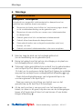
6 Montage
WAARSCHUWING
Brandgevaar - Levensgevaar!
Het gebruik van ongeschikt isolatiemateriaal en dampscherm kan
potentieel een dodelijke brand veroorzaken.
fRespecteer de lokale voorschriften ter bescherming tegen brand
en de installatiehandleiding van de gebruikte spot.
fRespecteer de voorschriften en normen voor isolatiematerialen
en dampscherm.
fGebruik geen enkel licht ontvlambaar isolatiemateriaal.
fGebruik alleen brandwerende dampschermen.
fGeen gebruik maken van ecologische materialen zoals hout,
hennep, stro enz.
fGebruik uitsluitend isolatiematerialen in de vorm van platen.
1 Meet en zaag de plaat van het verlaagd plafond uit
(zie de handleiding van de gebruikte spot).
2 Reinig het gebied rond het gat van de uitzaging in de plaat van
het verlaagd plafond, indien nodig.
fOptioneel: Indien geïnstalleerd van onderaf, kunt u gebruikmaken
van het SpotClip-Tool (alleen inbegrepen in verpakkingen van
10stuks) om te voorkomen dat de SpotClip-II tijdens de installatie
weg veert en verdwijnt boven verlaagd plafond (afbeelding H en I ):
- Steek de bevestigingsklemmen van het gereedschap in de
voorziene gleuven in de SpotClip-II.
- Draai een weinig in de richting van de klok mee om het
gereedschap op de SpotClip-II te bevestigen.
fAls de spot voorzien is van een poot voor het bevestigen van
kabels, en alleen in dit geval, knip dan een van de tussengelegen
lippen af of breek deze af door het naar binnen of naar buiten
buigen (afbeelding B ).

GBDEFRITNLPL
Gebruikshandleiding • SpotClip-II • 03-2017
Onderhoud
31
3 Druk de de montagevoetjes samen (afbeelding
D
) en voer de
SpotClip-II in de plafonduitzaging tot de 4 steunvinnen
2
(afbeelding
E
) zich vastzetten boven de plafonduitzaging.
4 Druk de 4 borgnokken
3
(afbeelding
F
) in de gipsplaat om
eventuele latere foutieve uitlijning van het systeem te voorkomen.
5 Controleer of de SpotClip-II bevestigd is in de juiste positie
vooraleer de spot te monteren.
6 Monteer de inbouwspot (afbeelding
G
) volgens de handleiding.
;De SpotClip-II is gemonteerd.
7 Onderhoud
Er is geen speciaal onderhoud vereist.
8 Buitenwerkingstelling
Indien correct gebruikt zoals beschreven in deze handleiding is het
gebruik van het product niet in de tijd beperkt.
9 Verwijdering
Bij het einde van het gebruik dient de koper of de gebruiker het
product correct te verwijderen. Dit product is vervaardigd conform de
huidige normen voor de bescherming van het milieu.
fRespecteer de nationale regelgeving betreffende de verwijdering
van materialen.
fBreng het product naar een inzamelpunt of een plaatselijk
recyclingcentrum.
fNeem indien nodig contact op met de plaatselijke autoriteiten.

Gebruikshandleiding • SpotClip-II • 03-2017
Technische specificaties
32
10 Technische specificaties
H2 H
FH
REFERENTIE
SpotClip-II
Ømin.bevestigingsgat(FH) Ømax.bevestigingsgat(FH)
62 90
Hoogte (H) Hoogte (H2) Kleur
107 95 Zwart
Gebruikstemperatuur Materiaal
Van -20ºC tot 120ºC Polyamide 6,6 versterkt
met glasvezels (PA66GF15%)
Alle afmetingen zijn in mm en kunnen aan verandering onderhevig zijn.

GBDEFRITNLPL
Instrukcja obsługi • SpotClip-II • 03-2017
Wskazówki dotyczące użytkowania
33
Instrukcja obsługi
1 Wskazówki dotyczące użytkowania
Niniejsza instrukcja obsługi dotyczy wyłącznie produktu SpotClip-II
ijest przeznaczona dla użytkownika. Należy dokładnie przeczytać
izrozumieć instrukcję obsługi przed rozpoczęciem instalacji produktu.
Na stronie rozkładanej zamieszczone zostały ilustracje produktu
(zdjęcia/rysunki), dotyczące jego montażu, a także adresy krajowych
oddziałów rmy HellermannTyton.
fNależy zawsze zachować tę instrukcję do wykorzystania
wprzyszłości.
1.1 Przewidziane zastosowanie
SpotClip-II to produkt ułatwiający instalację reektorów punktowych
przeznaczonych do montażu w sutach podwieszanych, zapewniając
wymagany odstęp pomiędzy wbudowanym reektorem a materiałem
izolacyjnym. Kołpak ochronny, wyposażony w 4 ramiona wsporcze jest
przeznaczony do montażu przede wszystkim w płytach gipsowych
i 4odrywanymi języczkami posiada wiele zalet pod względem
parametrów termicznych imechanicznych. Może on również zostać
wykorzystany w instalacjach już istniejących.
Produkt SpotClip-II umożliwia podniesienie materiału izolacyjnego, np.
wełny szklanej, powyżej wbudowanego reektora punktowego, aby
pozostawić odpowiednią ilość wolnego miejsca, niezbędną dla jego
prawidłowego funkcjonowania. Ogranicza to ryzyko przegrzewania
ipożaru, jednocześnie zapewniając przedłużenie trwałości żarówek.
Produkt jest wykonany z samogasnącego, odpornego na wysokie
temperatury materiału PA66.
Produkt może być wykorzystywany wyłącznie w celach wymienionych
w tej instrukcji obsługi, pod warunkiem, że znajduje się wnienagannym
stanie. Należy ściśle przestrzegać wskazówek bezpieczeństwa i brać
pod uwagę zagrożenia opisane w tej instrukcji.
1.2 Właściwości przeciwpożarowe/normy
Produkt jest samognasnący, a jego odporność na działanie ognia
odpowiada klasykacji UL94 V0. Produkt został zbadany testem
żarzącego się drutu wtemperaturze 960°C, a także jest zgodny
znormami EN60598-1 i EN60598-2-2.

Instrukcja obsługi • SpotClip-II • 03-2017
Wskazówki bezpieczeństwa
34
Norma EN13501-1 A2 s1 d0 obowiązuje w odniesieniu do
materiałów izolacyjnych oraz barier chroniących przed parą. Norma ta
odpowiada wcześniejszej klasykacji M0. Mogą być wykorzystywane
jedynie niepalne materiały izolacyjne i bariery chroniące przed parą,
które w razie pożaru nie powodują wydzielania się dymu i nie tworzą
skroplin.
1.3 Serwis po sprzedaży
W razie jakichkolwiek pytań, należy skontaktować się zkrajowym
przedstawicielem rmy HellermannTyton. Dane adresowe są
zamieszczone na stronie rozkładanej.
2 Wskazówki bezpieczeństwa
Produkt jest wytwarzany zgodnie z najnowszym stanem osiągnięć
technicznych i uznanymi zasadami bezpieczeństwa. Niemniej jednak,
w razie nieprawidłowego użytkowania mogą wystąpić zagrożenia dla
zdrowia i życia użytkownika lub innych osób, jak również uszkodzenia
produktu oraz innego wyposażenia. Niniejsza instrukcja obsługi
zawiera wskazówki dotyczące bezpieczeństwa.
fNależy ściśle przestrzegać tych wskazówek, aby uniknąć
możliwości wystąpienia szkód dla osób, mienia i środowiska.
2.1 Sposób prezentacji i struktura ostrzeżeń
Struktura symboli ostrzegawczych jest następująca:
OSTRZEŻENIE
Typ i źródło zagrożenia!
Objaśnienia dotyczące typu i źródła zagrożenia.
fŚrodki zabezpieczające przed ewentualnymi niebezpieczeństwami.
Ostrzeżenie oznacza potencjalne ryzyko dla życia lub dotyczące
możliwości odniesienia poważnych obrażeń.
2.2 Ograniczenia użytkowania
fOtoczenie instalacji musi spełniać następujące warunki:
• Możliwość stosowania reektorów punktowych LED
ijarzeniowych.

GBDEFRITNLPL
Instrukcja obsługi • SpotClip-II • 03-2017
Obowiązki użytkownika
35
• Wełna mineralna: kompatybilność z przeznaczonymi do wbudowania,
halogenowymi reektorami punktowymi o mocy do 50W (za
wyjątkiem opraw szczelnych oraz opraw dostarczanych w komplecie
ze stałym okablowaniem o izolacji, odpornej na działanie temperatury
co najmniej do 120°C).
• Izolacja metodą wdmuchiwania wewnątrz szczelinowego:
kompatybilność zprzeznaczonymi do wbudowania, halogenowymi
reektorami punktowymi o mocy do 50W (za wyjątkiem produktów
szczelnych oraz izolacji okablowania dostarczanej w zestawie
zoprawą oświetleniową M0 do instalacji stałej, odpornej na działanie
temperatury co najmniej do 135 °C).
• Przeznaczony wyłącznie do instalacji nad wbudowanymi reektorami
punktowymi. Produkt nie jest przeznaczony do zabezpieczania
przetworników, transformatorów lub listw łączeniowych.
• Możliwość wykorzystania w otworach sutowych o średnicy
montażowej od 62mm do 90mm.
• Średnica wierconego otworu musi odpowiadać średnicy reektora
+4 mm dla umożliwienia przeprowadzenia ramion SpotClip-II.
• Maksymalna dostępna wysokość wynosi 95mm.
3 Obowiązki użytkownika
Użytkownik musi ściśle przestrzegać wszystkich przepisów krajowych oraz
zaleceń dotyczących zapobiegania wypadkom. Wykorzystanie produktu
SpotClip-II nie zwalnia z konieczności dokładnego zapoznania się
zinstrukcją montażu stosowanego reektora punktowego. Wrazie
jakichkolwiek wątpliwości należy zlecić wykonanie instalacji specjaliście.
4 Transport i przechowywanie
Nie należy umieszczać żadnych ciężkich przedmiotów na opakowaniu
zproduktem.
5 Widok ogólny produktu
Na ilustracji A pokazany został widok ogólny produktu. Na ilustracjach B
i C pokazane zostały szczegóły produktu. Wszystkie ilustracje dotyczące
produktu znajdują się na stronie rozkładanej.
Opis rysunków A , B i C :
1 Języczki odrywane 2 Ramiona wsporcze
3 Pazurki mocujące

Instrukcja obsługi • SpotClip-II • 03-2017
Montaż
36
6 Montaż
OSTRZEŻENIE
Ryzyko pożaru - Grozi śmiercią!
Wykorzystanie nieodpowiednich materiałów izolacyjnych i
paroizolacji może być przyczyną pożaru ze skutkami śmiertelnymi.
fNależy ściśle przestrzegać miejscowych przepisów dotyczących
zabezpieczenia przeciwpożarowego oraz zaleceń zamieszczonych
winstrukcji montażu stosowanego reektora punktowego.
fNależy ściśle przestrzegać wszystkich przepisów i norm
obowiązujących w odniesieniu do materiałów izolacyjnych
iparoizolacji.
fNie wolno używać żadnych łatwopalnych materiałów izolacyjnych.
fNależy używać wyłącznie paroizolacji zabezpieczonych przed
działaniem ognia.
fNie należy używać żadnych materiałów ekologicznych, takich jak
drewno, konopie, słoma itp.
fNależy używać wyłącznie materiałów izolacyjnych w postaci płyt.
1 Zmierzyć i przewiercić płytę sutu podwieszonego (patrz
instrukcja montażu stosowanego reektora punktowego).
2 W razie potrzeby wyczyścić okolice otworu / wycięcia w płycie
sutu podwieszanego.
fOpcjonalnie: W razie instalacji od spodu, można użyć narzędzia
SpotClip-Tool (dostarczanego wyłącznie w zestawach
zawierających 10 produktów), aby produkt SpotClip-II nie mógł
wypaść podczas instalacji (rys. H i I ):
- Umieścić zaczepy mocujące narzędzia w wycięciach
przeznaczonych do tego celu wewnątrz SpotClip-II.
- Delikatnie przekręcić w kierunku zgodnym z ruchem wskazówek
zegara, aby zamocować narzędzie do produktu SpotClip-II.
fJeżeli reektor punktowy jest wyposażony w łapę umożliwiającą
zamocowanie kabli i tylko w tym przypadku, należy odciąć jeden
z pośrednich języczków odrywanych lub przełamać go do
wnętrza lub na zewnątrz (rys. B ).

GBDEFRITNLPL
Instrukcja obsługi • SpotClip-II • 03-2017
Konserwacja
37
3 Ścisnąć łapy montażowe (rys. D ) i włożyć SpotClip-II do wycięcia
wsucie aż do chwili, kiedy 4 ramiona wsporcze 2 (rys. E ) zostaną
zamocowane nad wycięciem w sucie.
4 Wcisnąć pazurki przytrzymujące 3 (rys. F ) do płyty gipsowej, aby
zapobiec możliwości jakiegokolwiek późniejszego przemieszczenia
kołpaka.
5 Sprawdzić, czy produkt SpotClip-II został zamocowany
wprawidłowej pozycji przed zamontowaniem reektora
punktowego.
6 Zamontować przeznaczony do wbudowania reektor punktowy
(rys. G ) zgodnie z zaleceniami jego instrukcji obsługi.
;W ten sposób produkt SpotClip-II jest zamontowany prawidłowo.
7 Konserwacja
Nie jest konieczne przeprowadzanie żadnych szczególnych prac
konserwacyjnych.
8 Wycofanie z eksploatacji
Pod warunkiem przestrzegania zaleceń zamieszczonych w tej
instrukcji, okres użytkowania produktu nie jest w żaden sposób
ograniczony.
9 Utylizacja
Po zakończeniu użytkowania produktu, nabywca lub użytkownik musi
zapewnić utylizację w sposób zgodny zobowiązującymi przepisami.
Produkt został wytworzony zgodnie zobowiązującymi obecnie
normami ochrony środowiska.
fNależy ściśle przestrzegać przepisów krajowych obowiązujących
w odniesieniu do usuwania materiałów.
fNależy odnieść produkt do miejscowego punktu zbiórki lub
recyklingu.
fW razie konieczności należy skontaktować się z odpowiednią
instytucją lokalną.

Instrukcja obsługi • SpotClip-II • 03-2017
Dane techniczne
38
10 Dane techniczne
H2 H
FH
TYP
SpotClip-II
Ømin.otworu
mocującego(FH)
Ømaks.otworu
mocującego(FH)
62 90
Wysokość (H) Wysokość (H2) Kolor
107 95 Czarny
Zakres temperatury
użytkowej
Materiał
Od -20°C do +120°C Poliamid 6.6 z włóknem
szklanym (PA66GF15%)
Wszystkie wymiary są podane w mm i mogą podlegać zmianom.


Version 2017 - 009-50114 - Imprimé en France - Certifié PEFC - Crédits photos - © HellermannTyton
-
 1
1
-
 2
2
-
 3
3
-
 4
4
-
 5
5
-
 6
6
-
 7
7
-
 8
8
-
 9
9
-
 10
10
-
 11
11
-
 12
12
-
 13
13
-
 14
14
-
 15
15
-
 16
16
-
 17
17
-
 18
18
-
 19
19
-
 20
20
-
 21
21
-
 22
22
-
 23
23
-
 24
24
-
 25
25
-
 26
26
-
 27
27
-
 28
28
-
 29
29
-
 30
30
-
 31
31
-
 32
32
-
 33
33
-
 34
34
-
 35
35
-
 36
36
-
 37
37
-
 38
38
-
 39
39
-
 40
40
-
 41
41
-
 42
42
-
 43
43
-
 44
44


HellermannTyton SpotClip-II de handleiding
- Categorie
- Luidsprekersteunen
- Type
- de handleiding
in andere talen
Gerelateerde papieren
Andere documenten
-
LEDISONS LDD25 Handleiding
-
 Glatz OSYRION Spot Handleiding
-
HOFTRONIC Milano LED Porch Lights Dimmable Handleiding
-
HOFTRONIC RGBWW Finn Smart Recessed Downlight Handleiding
-
HOFTRONIC 1S3W Handleiding
-
HOFTRONIC Granada LED Porch Lights Handleiding
-
HOFTRONIC 1M3W-6TMD Malaga LED Porch Lights Dimmable Handleiding
-
INTERLIGHT IL-CA4K27W Handleiding
-
Aurora AOne AOne Zigbee 240V 6.5W IP65 640lm Fixed Tuneable Dimmable Fire Rated de handleiding
-
integral LED Evolight Handleiding
