GEBRAUCHS- UND MONTAGEANLEITUNG
OPERATING AND INSTALLATION INSTRUCTIONS
GEBRUIKS- EN INSTALLATIEVOORSCHRIFTEN
INSTRUKCJA OBSŁUGI I MONTAŻU
Elektronisch geregelter durchlauferhitzer | Electronically controlled instantaneous
water heater | Elektronisch geregelde elektrische doorstromer | Elektronicznie
regulowany przepływowy ogrzewacz wody
» DEL 18 SLi 25A electronic LCD
» DEL 18/21/24 SLi electronic LCD
» DEL 27 SLi electronic LCD

18
21
24
kW
A
B
478
110
100
414
44
G½
10520225
140
30
35
35
114
368
26_02_02_062226_02_02_0915
mm
4 5 6
22
17 16
15
13
12
11
10
9
8
7
6
5
3
4
1 221
14
18
19
20
INHALTSVERZEICHNIS
1. Bedienung für den Benutzer und den Fachmann _________________________________________________________________________________________________________6
1.1 Gerätebeschreibung ______________________________________________________________________________________________________________________________________________________ 6
1.2 Das Wichtigste in Kürze __________________________________________________________________________________________________________________________________________________ 6
1.3 Sicherheitshinweis ________________________________________________________________________________________________________________________________________________________ 6
1.4 Warmwasserleistung _____________________________________________________________________________________________________________________________________________________ 6
1.5 Temperaturbegrenzung __________________________________________________________________________________________________________________________________________________ 6
1.6 Fernbedienung extern ____________________________________________________________________________________________________________________________________________________ 6
1.7 Einstellungsempfehlung _________________________________________________________________________________________________________________________________________________ 6
1.8 Was tun wenn... ____________________________________________________________________________________________________________________________________________________________ 6
1.9 Wartung und Pflege _______________________________________________________________________________________________________________________________________________________ 6
1.10 Bedienungs- und Installationsanleitung _____________________________________________________________________________________________________________________________ 6
2. Installation für den Fachmann _______________________________________________________________________________________________________________________________7
2.1 Kurzbeschreibung _________________________________________________________________________________________________________________________________________________________ 7
2.2 Wichtige Hinweise _________________________________________________________________________________________________________________________________________________________ 7
2.3 Vorschriften und Bestimmungen _______________________________________________________________________________________________________________________________________ 7
3. Standardmontage für den Fachmann _______________________________________________________________________________________________________________________8
3.1 Allgemeine Montagehinweise __________________________________________________________________________________________________________________________________________ 8
3.2 Montageort _________________________________________________________________________________________________________________________________________________________________ 8
3.3 Gerätemontage Vorbereiten ____________________________________________________________________________________________________________________________________________ 8
3.4 Aufhängeleiste befestigen
F
__________________________________________________________________________________________________________________________________________ 8
3.5 Anschlusskabel ablängen ________________________________________________________________________________________________________________________________________________ 8
3.6 Gerätemontage
F
________________________________________________________________________________________________________________________________________________________ 8
3.7 Wasseranschluss
G
______________________________________________________________________________________________________________________________________________________ 8
3.8 Elektrischer Anschluss____________________________________________________________________________________________________________________________________________________ 8
3.9 Montage abschließen ___________________________________________________________________________________________________________________________________________________ 8
3.10 Erstinbetriebnahme _____________________________________________________________________________________________________________________________________________________ 8
4. Montage-Alternativen für den Fachmann __________________________________________________________________________________________________________________9
4.1 Aufhängeleiste bei Geräteaustausch
J
_____________________________________________________________________________________________________________________________ 9
4.2 Elektroanschluss - AP ____________________________________________________________________________________________________________________________________________________ 9
4.3 Elektroanschluss - oben
L
_____________________________________________________________________________________________________________________________________________ 9
4.4 Gedrehte Gerätekappe ___________________________________________________________________________________________________________________________________________________ 9
4.5 Montage Kabeltülle ______________________________________________________________________________________________________________________________________________________ 9
4.6 Vorrangschaltung
O
_____________________________________________________________________________________________________________________________________________________ 9
4.7 AP-Armaturen ______________________________________________________________________________________________________________________________________________________________ 9
4.8 AP-Lötanschluss ___________________________________________________________________________________________________________________________________________________________ 9
4.9 Montage Rückwand-Unterteil __________________________________________________________________________________________________________________________________________ 9
4.10 Fliesenversatz-Montage __________________________________________________________________________________________________________________________________________________ 9
4.11 Betrieb mit vorgewärmtem Wasser __________________________________________________________________________________________________________________________________10
4.12 Temperaturbegren zung
M
____________________________________________________________________________________________________________________________________________10
5. Technische Daten und Einsatzbereiche für den Fachmann _____________________________________________________________________________________________ 10
5.1 Angaben zum Energieverbrauch ______________________________________________________________________________________________________________________________________10
5.2 Technische Daten (Es gelten die Daten auf dem Geräte-Typenschild) _________________________________________________________________________________________ 11
5.3 Einsatzbereiche ___________________________________________________________________________________________________________________________________________________________11
6. Störungsbeseitigung durch den Fachmann ______________________________________________________________________________________________________________ 12
6.1 Anzeigemöglichkeiten LED-Diagnoseampel ________________________________________________________________________________________________________________________12
6.2 Störungstabelle ___________________________________________________________________________________________________________________________________________________________12
7. Garantie | Umwelt und Recycling _________________________________________________________________________________________________________________________ 13
2

DEUTSCH
18
21
24
kW
A
B
478
110
100
414
44
G½
10520225
140
30
35
35
114
368
26_02_02_062226_02_02_0915
mm
4 5 6
22
17 16
15
13
12
11
10
9
8
7
6
5
3
4
1 221
14
18
19
20
3

18
21
24
kW
elect ronic co mfor
t
C D
E
F
G
1 2
2
1
b
a
a
3/PE ~ 400 V
L
2
III1
L2`
L3`L1`
3/4
1
3
4
2
I
II
U
F
L L
H I
b
a
c
d
30 mm
160 mm
b
a
26_02_02_0625
26_02_02_0624
26_02_02_0934
26_02_02_1101
26_02_02_0537
26_02_02_0005
26_02_02_0627
15
6
a
4
25
24
23
5
b
4

DEUTSCH
1.
3.
4.
2.
d
a
J K
L
M N
O P
Q
R
S
b
a
c
d
b
a
a
a
b
a
c
b
a
c
b
c
44 mm
9,5 mm
20 mm
330 mm
325 mm
50 mm
72 mm
165 mm
c
LR 1-A
c
b
a
b
60
43
max. 60 °C
max. 43 °C
b
c
≤ 18 Nm
SW 24
26_02_02_1123
26_02_02_0628
26_02_02_0573
26_02_02_0630
26_02_02_0550
85_02_02_0003
D0000033104.ai
26_02_02_0530
D0000041391
a
26_02_02_1080
5

1.1 Gerätebeschreibung
Beschreibung:
Das Gerät ist für den Einsatz im häuslichen
Umfeld vorgesehen. Es kann von nicht einge-
wiesenen Personen sicher bedient werden. In
nicht häuslicher Umgebung, z. B. im Kleinge-
werbe, kann das Gerät ebenfalls verwendet
werden, sofern die Benutzung in gleicher
Weise erfolgt.
Eine andere oder darüber hinausgehende
Benutzung gilt als nicht bestimmungsgemäß.
Zum bestimmungsgemäßen Gebrauch gehört
auch das Beachten dieser Anleitung sowie
der Anleitungen für eingesetztes Zubehör.
Der Durchlauferhitzer erwärmt das Wasser,
während es durch das Gerät strömt. Die
Warmwasser-Auslauftemperatur kann stu-
fenlos von 30 bis 60 °C eingestellt werden.
Die eingestellte Temperatur erscheint auf der
Anzeige.
Ab einer Durchflussmenge von 2,5 l/min
schaltet die Steuerung in Abhängigkeit von
der Temperatur-Einstellung und der Kaltwas-
sertemperatur die richtige Heizleistung ein.
1.2 Das Wichtigste in Kürze
Display mit Tempera-
turanzeige 30 - 60 °C
Temperatur-Einstellknopf
Durch Drehen des Einstellknopfes kann die
gewünschte Temperatur stufenlos eingestellt
und auf dem Display abgelesen werden.
Wird bei voll geöffnetem Zapfventil und ma-
ximaler Temperatureinstellung (60 °C) keine
ausreichende Auslauftemperatur erreicht,
fließt mehr Wasser durch das Gerät, als der
Heizkörper erwärmen kann (Leistungsgren-
ze 18, 21, 24 oder 27 kW). In diesem Fall ist
die Wassermenge am Zapfventil entspre-
chend zu reduzieren.
1.3 Sicherheitshinweis
!
WARNUNG Verletzung
Das Gerät kann von Kindern ab 8
Jahren sowie von Personen mit verringerten
physischen, sensorischen oder mentalen
Fähigkeiten oder Mangel an Erfahrung und
Wissen benutzt werden, wenn sie beauf-
sichtigt werden oder bezüglich des sicheren
Gebrauchs des Geräts unterwiesen wurden
und die daraus resultierenden Gefahren
verstanden haben. Kinder dürfen nicht mit
dem Gerät spielen. Reinigung und Benut-
zer-Wartung dürfen nicht von Kindern ohne
Beaufsichtigung durchgeführt werden.
1.4 Warmwasserleistung
Je nach Jahreszeit ergeben sich bei verschie-
denen Kaltwassertemperaturen folgende
maximale Mischwassermen gen bzw. Auslauf-
mengen:
ϑ
1
= Kaltwasser-Zulauftemperatur
1. Bedienung für den Benutzer und den Fachmann
...Störungen am Gerät auftreten
Störung Ursache Behebung
Das Gerät
schaltet trotz
voll geöffnetem
Warmwasser-
ventil nicht ein.
Es liegt keine
Spannung an.
Überprüfen
Sie die Siche-
rungen in der
Hausinstalla-
tion.
Die Einschalt-
menge wird nicht
erreicht. Der
Perlator in der
Armatur oder
der Duschkopf
ist verkalkt oder
verschmutzt.
Reinigen und /
oder entkalken
Sie den Perla-
tor oder den
Duschkopf.
Das Heizsystem
ist defekt.
Rufen Sie den
Fachhandwer-
ker.
Es fließt kurz-
zeitig kaltes
Wasser wäh-
rend warmes
Wasser gezapft
wird.
Die Lufterken-
nung erkennt
Luft im Wasser
und schaltet die
Heizleistung kurz-
zeitig ab.
Das Gerät geht
nach einer
Minute selbst-
ständig wieder
in Betrieb.
Können Sie die Ursache nicht beheben rufen
Sie den Fachhandwerker. Zur besseren und
schnelleren Hilfe teilen Sie ihm die Nummer
vom Typenschild (
A
21), mit:
DEL . . SLi Nr.: . . . . . . - . . . . - . . . . . .
1.9 Wartung und Pflege
!
Wartungsarbeiten, wie z. B. Überprü-
fung der elektrischen Sicherheit, dürfen nur
durch einen Fachmann erfolgen.
Zur Pflege des Gehäuses genügt ein feuchtes
Tuch. Keine scheuernden oder anlösenden
Reinigungsmittel verwenden!
1.10 Bedienungs- und Installati-
onsanleitung
!
Diese Anleitung sorgfältig aufbewah-
ren, bei Besitzerwechsel dem Nachfolger
aushändigen, bei Wartungs- und etwaigen
Instandsetzungsarbeiten dem Fachmann zur
Einsichtnahme überlassen.
ϑ
2
= Mischwassertemperatur
ϑ
3
= Auslauftemperatur.
Nutztemperatur:
– ca. 38 °C: z. B. für Dusche, Handwäsche,
Wannenfüllung usw.
– ca. 60 °C: für Küchenspüle und bei Einsatz
von Thermostat-Armaturen.
ϑ
2
= 38 °C (Mischwassertemperatur)
18 kW 21 kW 24 kW 27 kW
ϑ
1
l/min *
6 °C 8,0 9,4 10,7 12,1
10 °C 9,2 10,7 12,3 13,8
14 °C 10,7 12,5 14,5 16,1
ϑ
3
= 60 °C (Auslauftemperatur)
18 kW 21 kW 24 kW 27 kW
ϑ
1
l/min *
6 °C 4,8 5,6 6,4 7,2
10 °C 5,2 6,0 6,9 7,7
14 °C 5,6 6,5 7,5 8,4
* Tabellenwerte bezogen auf Nennspannung
400 V. Die Auslaufmenge ist abhängig vom
vorhandenen Versorgungsdruck und der
tatsächlich anliegenden Spannung.
1.5 Temperaturbegrenzung
Eine Temperaturbegrenzung auf 43 °C kann
vom Fachmann eingestellt werden.
1.6 Fernbedienung extern
Die Temperatur kann extern über die
Funk-Fernbedienungen FFB 1 und FFB 2
(siehe „7. Sonderzubehör“) eingestellt wer-
den.
Das Bedienteil im Gerät zeigt dann nur die an
der Fernbedienung eingestellte Temperatur
an, es kann keine Verstellung erfolgen!
1.7 Einstellungsempfehlung
Betrieb mit Thermostat-Armatur
Um die Funktion der Thermostat-Armatur zu
gewährleisten, muss die Temperatur am
Gerät größer 50 °C eingestellt werden.
1.8 Was tun wenn...
...bei Unterbrechung der Wasserzufuhr
!
Beschädigungsgefahr!
Nach Unterbrechung der Wasserzu-
fuhr müssen Sie folgende Arbeitsschritte
vor der Wiederinbetriebnahme des Gerätes
durchführen.
• Schrauben Sie die Sicherungen heraus
beziehungsweise schalten Sie diese aus.
• Öffnen Sie ein dem Gerät nachgeschal-
tetes Zapfventil solange, bis das Gerät und
die vorgeschaltete Kaltwasserzuleitung
luftfrei sind.
• Schrauben Sie die vorgeschaltete Si-
cherungen wieder ein beziehungsweise
schalten Sie sie wieder ein.
electronic LCD electronic LCD
1. Bedienung für den Benutzer und den Fachmann
6

DEUTSCH
2. Installation für den Fachmann
2.1 Kurzbeschreibung
Der elektronisch geregelte Durchlauferhitzer
ist ein Druckgerät zur Erwärmung von Kalt-
wasser oder zur Nacherwärmung von bis zu
55 °C vorgewärmtem Wasser geeignet.
Die maximal zulässige Zulauftemperatur be-
trägt 65 °C. Bei höheren Temperaturen kann
das Gerät beschädigt werden.
Mit dem Sonder zubehör „Zentral Thermostat“
(siehe „7. Sonderzubehör“) kann die max. Zu-
lauftemperatur auf 60 °C begrenzt werden.
Es können mit dem Gerät eine oder mehrere
Zapfstellen versorgt werden.
Das Blankdraht-Heizsystem ist mit einem
druckfesten Kupfermantel umschlossen.
Das Heizsystem ist für kalkarme und kalkhal-
tige Wässer geeignet (siehe „5.2 Einsatzbe-
reiche“).
Gerät mit wählbarer Anschlussleistung
Bei dem Durchlauferhitzer DEL 18/21/24 SLi ist
die Anschlussleistung 3-stufig wählbar. Das
Gerät hat im Auslieferungszustand 21 kW.
Soll das Gerät mit einer anderen Leistung
installiert werden, sind folgende Schritte
vorzunehmen:
• Kodierstecker, auf der Geräteelektonik
oberhalb des Hinweisaufklebers, entspre-
chend der gewählten Leistung umstecken.
• Gewählte Leistung auf dem Typenschild
mit einem dokumentenechten Stift an-
kreuzen.
18
21 24
kW
26_02_02_0935
2.2 Wichtige Hinweise
!
Luft in der Kaltwasserleitung kann das
Blankdraht-Heizsystem des Gerätes zerstö-
ren oder löst das Sicherheitssystem aus
(siehe „1.4 Wichtiger Hinweis“).
Das Gerät ist mit einer Lufterkennung
ausgestattet, die eine Beschädigung des
Heizsys tems weitgehend verhindert:
Wird während des Betriebes Luft in das
Gerät eingespült, schaltet das Gerät die
Leistung für eine Minute aus und schützt
somit das Heizsystem.
Armaturen:
• Stiebel Eltron Aufputz-Druckarmaturen für
Durchlauferhitzer (siehe „7. Sonderzube-
hör“).
• Installation mit handelsüblichen Druckar-
maturen ist möglich.
• Thermostat-Druckarmaturen (siehe Hin-
weis „1.8 Einstellungsempfehlung“).
Alle Informationen in dieser Gebrauchs- und
Montageanweisung müssen sorgfältig beach-
tet werden. Sie geben wichtige Hinweise für
die Sicherheit, Bedienung, Installation und
die Wartung des Gerätes.
2.3 Vorschriften und Bestim-
mungen
• Die Montage (Wasser- und Elektroin-
stallation) sowie die Erstinbetriebnahme
und die Wartung dieses Gerätes dürfen
nur von einem Fachmann entsprechend
dieser Anweisung ausgeführt werden.
• Eine einwandfreie Funktion und Betriebs-
sicherheit ist nur mit den für das Gerät
bestimmten Original-Zubehör- und
Ersatzteilen gewährleistet.
Die landesspezifischen Vorschriften und
Bestimmungen bezüglich Wasseran-
schluss und Elektroanschluss sind zu be-
rücksichtigen.
Beachten Sie die Bestimmungen des ört-
lichen Energieversorgungs- und zuständi-
gen Wasserversorgungs-Unternehmens.
• Das Gerät im unteren Rückwandbereich
wandbündig montieren (Maß ≥ 110 mm
B
beachten).
• Das Geräte-Typenschild (Klappe von Gerä-
tekappe öffnen).
• siehe auch „5. Technische Daten“.
• CE-Kennzeichnung
Die CE-Kennzeichnung belegt, dass das
Gerät alle grundlegenden Anforderungen
erfüllt:
– Niederspannungsrichtlinie (Richtlinie
2006/95/EG des Rates).
– Richtlinie über die elektromagnetische
Verträglichkeit (Richtlinie 2004/108/EG
des Rates). Für die geprüften Geräte nach
DIN EN 61000-3-11 finden Sie die „Max.
Netzimpedanz Z max“ im Kapitel „Tech-
nische Daten“. Geräte ohne Angaben ent-
sprechen DINEN61000-3-3. Diese Geräte
unterliegen keiner besonderen Anschluss-
bedingung.
!
Der spezifische elektrische Wider-
stand des Wassers darf nicht kleiner sein als
auf dem Geräte-Typenschild an gegeben! Bei
einem Wasser-Verbundnetz ist der nied-
rigste elektrische Widerstand des Wassers
zu berücksichtigen (siehe „5.2 Einsatzbe-
reiche“). Den spezifischen elektrischen Wi-
derstand oder die elektrische Leitfähigkeit
des Wassers erfahren Sie bei Ihrem Wasser-
versorgungs-Unternehmen.
• Gerätemontage nur im geschlossenen,
frostfreien Raum. Demontiertes Gerät
frostfrei lagern, da sich immer Restwasser
im Gerät befindet.
• Die Schutzart IP 25 (strahlwassergeschützt)
ist nur mit sachgemäß montierter Kabeltülle
gewährleistet.
Wasserinstallation:
– Kaltwasserleitung
Zugelassene Werkstoffe: Feuerverzinktes
Stahlrohr, Edelstahlrohr, Kupferrohr oder
Kunststoffrohr.
– Warmwasserleitung
Zugelassene Werkstoffe: Edelstahlrohr, Kup-
ferrohr oder Kunststoffrohr.
Beim Durchlauferhitzer DEL ... SLi können
Betriebstemperaturen bis max. 60 °C erreicht
werden. Im Störfall können in der Installati-
on kurzfristig Belastungen von max. 80 °C/
1,0 MPa auftreten. Das eingesetzte Kunsts-
stoff-Rohrsystem muss für diese Bedingungen
ausgelegt sein.
• Ein Sicherheitsventil ist nicht erforderlich.
• Armaturen für offene Geräte sind nicht
zulässig!
Elektroinstallation:
• Elektrischer Anschluss nur an festverlegte
Leitungen!
• Das Gerät muss, z. B. durch Sicherungen,
mit einer Trennstrecke von mindestens
3 mm allpolig vom Netz trennbar sein!
2. Installation für den Fachmann
7

3. Standardmontage für den Fachmann
Elektro: UP - unten; Wasser: UP
Legende Abbildung
A
-
G
1 Bedienteil
2 Gerätekappe
3 Rückwand-Unterteil
4 Warmwasser-Schraubanschluss
5 Kaltwasser-Schraubanschluss
(3-Wege-Absperrung)
6 Kabeltülle (elektrische Zuleitung unten)
7 Netzklemme
8 Rückwand-Oberteil
9 Elektronik
10 Sicherheitsschalter (AE 3) mit Rücksetzta-
ste
11 Heizsystem
12 Durchfluss-Sensor (DFE)
13 Kodierstecker nur bei DEL 18/21/24 SLi
14 Steckposition vom Sollwertgeber-Kabel
16 LEDs für Betriebs- und Störungsanzeige
(Diagnoseampel)
15 Befestigungsknebel
17 Stecker vom Sollwertgeberkabel
18 Sicherheits-Temperaturbegrenzer (STB)
19 Auslauf-Sensor (NTC) 20 Rast-
haken für Baugruppenträger (Service)
21 Geräte-Typenschild
22 Aufhängeleiste
23 Sieb im Kaltwasser-Schraubanschluss
24 Durchflussmengenbegrenzer (DMB)
25 Formscheibe
3.1 Allgemeine Montagehinweise
Das Gerät ist werkseitig für den Anschluss
an eine Unterputz-Installation vorbereitet
(siehe Abb.
C
-
I
):
• Übertisch-Gerätemontage
C
(a).
• Wasseranschluss-Unterputz-Schrauban-
schluss
G
(4 und 5).
• Elektroanschluss-Unterputz im unteren
Gerätebereich
F
(6).
• Anschlussleistung 21 kW beim
DEL18/21/24SLi.
3.2 Montageort
Das Gerät ist senkrecht gemäß Abbildung
C
(a-Übertisch oder b-Untertisch) im frostfreien
Raum zu montieren.
3.3 Gerätemontage Vorbereiten
• Gerät öffnen
D
:
a Klappe nach vorn ziehen.
b Klappe nach unten öffnen.
c Befestigungsschraube lösen.
d Gerätekappe abnehmen.
• Rückwand-Unterteil abnehmen
E
:
a Beide Rasthaken drücken.
b Rückwand-Unterteil nach vorne
abnehmen.
• Befestigungsknebel
F
(15) entfernen.
3.4 Aufhängeleiste befestigen
F
• Bohrlöcher für die Aufhängeleiste mit
Hilfe der beiliegenden Montageschablone
anzeichnen.
• Aufhängeleiste mit 2 Schrauben und Dü-
beln (gehören nicht zum Lieferumfang;
sind entsprechend dem Werkstoff der
Befestigungswand zu wählen) befestigen.
3.5 Anschlusskabel ablängen
• Anschlusskabel entsprechend
H
ablängen.
Hinweis: Kappe (a) dient als Montagehilfe des
Anschlusskabels.
3.6 Gerätemontage
F
• Das Elektroanschlusskabel durch die
Kabeltülle (6) führen und die Rückwand
über den Gewindebolzen der Aufhänge-
leiste drücken.
• Gerät montieren, mit dem Befesti-
gungsknebel (15) befestigen.
3.7 Wasseranschluss
G
Wichtige Hinweise:
!
Kaltwasserzuleitung gründlich spülen!
Das mitgelieferte Sieb (23) muss immer mit
dem Durchflussmengenbegrenzer (24, DMB)
oder der Formscheibe (25) (Teile im Beu-
tel am KW-Anschluss und im Beipack) im
KW-Schraubanschluss eingebaut werden.
Generell ist der DMB - 12 l/min (braun) ein-
zubauen. Ausnahme:
– DMB - 7,5 l/min (blau) bei Verwendung
einer Thermostat-Armatur.
– Formscheibe bei geringem Wasserlei-
tungsdruck.
Bei Austausch-Installation ist das Vorhan-
densein des Siebes zu prüfen.
Die 3-Wege-Absperrung (5) darf nicht zum
Drosseln des Durchflusses verwendet wer-
den!
3.8 Elektrischer Anschluss
Das Elektroanschlusskabel an die
Klemmleiste anschließen (siehe Elektroschalt-
plan
I
).
Wichtige Hinweise:
!
Die Schutzart IP 25 (strahlwasserge-
schützt) ist nur bei sachgemäß montierter
Kabeltülle
A
(6) und einer Abdichtung am
Kabelmantel gewährleistet.
Das Gerät muss an den Schutz leiter ange-
schlossen werden.
3.9 Montage abschließen
1. 3-Wege-Absperrung öffnen
G
(5).
2. Rückwand-Unterteil montieren
E
.
3.10 Erstinbetriebnahme
(darf nur durch einen Fachmann erfolgen!)
1
Gerät befüllen und entlüften.
Achtung Trockenganggefahr!
Alle angeschlossenen Zapfventile so
lange mehrfach öffnen und schließen,
bis das Leitungsnetz und das Gerät
luftfrei sind. Luft siehe Hinweis
„2.2 Wichtige Hinweise“.
2
Sicherheitsschalter aktivieren!
Das Gerät wird mit ausgelöstem Si-
cherheitsschalter (AE 3) ausgeliefert
(Rücksetztaste eindrücken).
3
Stecker vom Sollwertgeberkabel auf
die Elektronik stecken!
4
Gerätekappe montieren und mit
Schraube befestigen!
5
Netzspannung einschalten!
6
Arbeitsweise des Durchlaufer hitzers
prüfen!
7
Schutzfolie vom Bedienteil abziehen.
Übergabe des Gerätes!
Dem Benutzer die Funktion des Gerätes erklä-
ren und mit dem Gebrauch vertraut machen.
Wichtige Hinweise:
• Den Benutzer auf mögliche Gefahren
hinweisen (Verbrühung).
• Diese Anweisung zur sorgfältigen Auf-
bewahrung übergeben.
1
2
3
4
5
26_02_02_0634
e
l
e
c
t
r
o
n
i
c
c
o
m
f
o
r
t
3. Standardmontage für den Fachmann
8

DEUTSCH
Montage-Alternativen werden in den Ab-
bildungen
J
-
S
aufgezeigt.
4.1 Aufhängeleiste bei Gerä-
teaustausch
J
• Vorhandene Aufhängeleiste kann bei
Austausch von Stiebel Eltron - Geräten
verwendet werden (außer „DHF“).
Passende Durchführung in der Rückwand
durchstoßen.
• Bei Austausch „DHF" ist die beiliegende
Aufhängeleiste (a) um 180° zu drehen
(Schriftzug „DHF“ in Leserichtung) und
der Gewindebolzen (b, selbstfurchendes
Gewinde) auf der Aufhängeleiste nach
rechts oben zu versetzen.
• Bei Austausch eines Fremdgerätes kön-
nen passende Dübellöcher (c) zur Befe-
stigung der beiliegenden Aufhängeleiste
verwendet werden.
4.2 Elektroanschluss - AP
• Für das Anschlusskabel ist in die Rück-
wand und Gerätekappe eine Durchfüh-
rung zu schneiden bzw. brechen (mög-
liche Ausbruchstellen siehe
K
).
• Bei Elektroanschluss - AP ändert sich die
Schutzart in IP 24 (spritzwassergeschützt).
Achtung:
Das Geräte-Typenchild mit Hilfe eines Ku-
gelschreibers kennzeichnen:
IP 25 durchstreichen und Kästchen IP 24
ankreuzen.
4.3 Elektroanschluss - oben
L
• Für das Elektroanschlusskabel ein ent-
sprechendes Loch in die Kabeltülle
schneiden.
• Die Klemmleiste von unten nach oben
versetzen, dazu den Rasthaken (a) herun-
terdrücken und die Klemmleiste heraus-
ziehen.
Achtung:
Schaltlitzen unter die Litzenführung (b)
verlegen!
Klemmleiste oben (c) einrasten!
4.4 Gedrehte Gerätekappe
Die Gerätekappe kann bei einer Unter-
tischmontage gedreht werden
M
:
• Bedienteil (a) aus Gerätekappe entneh-
men, dazu die Rasthaken drücken.
• Gerätekappe (b) drehen (nicht das Gerät).
Bedienteil einlegen und alle Rasthaken
einrasten.
• Stecker vom Sollwertgeberkabel auf die
Elektronik stecken (siehe
3
„3.10 Erstin-
betriebnahme“).
• Gerätekappe (b) unten einhängen und
oben auf die Rückwand schwenken (für
einen richtigen Sitz der umlaufenden Rück-
wanddichtung ist die Kappe etwas vor- und
zurückzuschieben).
• Gerätekappe verschrauben.
4.5 Montage Kabeltülle
Eine Gerätemontage ist auch mit nachträglich
eingebauter Kabeltülle möglich
N
.
• Kabeltülle mit Hilfe eines Schraubendre-
hers herausdrücken (a).
• Gerät auf der Aufhängeleiste befestigen.
• Bei einem Elektroanschlusskabel von 10
bzw. 16 mm² muss das Loch in der Ka-
beltülle vergrößert werden.
• Kabeltülle über das Elektroanschlusskabel
schieben (b, Montagehilfe), auf die Rück-
wand montieren (c) und einrasten (d).
4.6 Vorrangschaltung
O
Bei der Kombination mit anderen Elektroge-
räten, z. B. Elektro-Speicherheizgeräten, ist
das Lastabwurfrelais einzusetzen:
a Lastabwurfrelais (siehe „7. Sonderzu-
behör“).
b Steuerleitung zum Schaltschütz des
2. Gerätes.
c Steuerkontakt, öffnet beim Einschalten
des Gerätes.
Der Lastabwurf erfolgt bei Betrieb des
Gerätes!
Das Lastabwurfrelais darf nur an die mittlere
Phase der Geräte-Netzklemme angeschlossen
werden.
4.7 AP-Armaturen
Stiebel Eltron Aufputz-Druckarmatur WKMD
oder WBMD
P
(Bestell-Nr. siehe „7. Sonderzubehör“):
• Wasserstopfen G ½ (a) mit Dichtungen
montieren (gehören zum Lieferumfang
der Stiebel Eltron AP-Druckarmaturen).
Bei Fremd-Druckarmaturen ist Sonderzu-
behör „Bausatz 2 Stück Wasser-Stopfen“
(siehe „7. Sonderzubehör“) erforderlich.
• Armatur montieren.
• Rückwand-Unterteil unter die Anschluss-
rohre der Armatur schieben und in Rück-
wand-Oberteil einrasten.
• Anschlussrohre mit dem Gerät verschrau-
ben.
Gerätekappe muss für diese Installation vor-
bereitet werden
R
:
• Durchführungsöffnungen (a) in Gerätekap-
pe sauber ausbrechen, ggf. Feile benut-
zen.
• Lippen aus den beiliegenden Kappen-
Führungsstücken (b) herausbrechen.
(Falls die Anschlussrohre der Armatur
einen leichten Versatz aufweisen, können
die Kappen-Führungsstücke (b) ohne Aus-
brechen der Lippen eingesetzt werden.
Hierbei werden die Rückwand-Führungs-
stücke (c) nicht benutzt).
• Kappen-Führungsstücke in die Durch-
führungs öffnungen der Gerätekappe ein-
rasten.
• Die beiliegenden Rückwand-Füh-
rungs-stücke (c) auf die Rohre montieren
(Ober- und Unterteil auf Rohr drücken
und zusammenschieben).
• Rückwand-Führungsstücke (c) bis An-
schlag an die Geräterückwand schieben.
Gerätebefestigung:
Bei Anschluss an flexible Wasserleitungssy-
steme muss die Rückwand im unteren Ge-
rätebereich mit einer zusätzlichen Schraube
befestigt werden (d).
Gerätekappe oben einhängen und unten auf
die Rückwand schwenken.
Die Stege der Kappen-Führungsstücke müs-
sen in die Rückwand-Führungsstücke greifen
und diese arretieren.
4.8 AP-Lötanschluss
Mit dem Sonderzubehör
Q
(a), Bestell-Nr.
siehe „7. Sonderzubehör“ ist ein Schrauban-
schluss mit bauseitigen 12 mm Kupferrohr-
leitungen möglich.
• Teile vom Sonderzubehör sind zu montie-
ren.
• Einlegeteil mit den Kupferleitungen verlö-
ten.
• Rückwand-Unterteil unter die Anschluss-
rohre der Armatur schieben und in Rück-
wand-Oberteil einrasten.
• Anschlussrohre mit dem Gerät verschrau-
ben.
Achtung:
Die Hinweise aus „4.7 AP-Armaturen“ beach-
ten:
• Gerätekappe, Geräterückwand und Ge-
rätebefestigung müssen für dieses Instal-
lation vorbereitet werden.
• Gerätebefestigung.
• Kappenmontage.
4.9 Montage Rückwand-Unter-
teil
Bei Verwendung von AP-Schraubanschlüssen
kann das Rückwand-Unterteil auch nach der
Armaturenmontage montiert werden. Dazu
sind folgende Schritte nötig
S
:
• Sägen Sie das Rückwand-Unterteil auf.
• Montieren Sie das Rückwand-Unterteil,
indem Sie es seitlich aufbiegen und über
die Aufputzrohre führen.
• Stecken Sie die Verbindungsstücke von
hinten in das Rückwand-Unterteil ein.
• Rasten Sie das Rückwand-Unterteil in die
Rückwand ein.
• Befestigen Sie das Rückwand-Unterteil
mit einer Schraube.
a Rückwand-Unterteil
b Verbindungsstücke aus dem Beipack
c Schraube
4.10 Fliesenversatz-Montage
Bei Fliesenversatz (
B
max. 20 mm) wird mit
dem Knebel (
F
15) zuerst der Wandabstand
justiert und dann das Gerät fixiert.
4. Montage-Alternativen für den Fachmann
Elektro: UP - oben, AP - unten / oben, Lastabwurfrelais; Wasser: AP; Gedrehte Gerätekappe; Fliesenversatz
4. Montage-Alternativen für den Fachmann
9

4.11 Betrieb mit vorgewärmtem
Wasser
Das Gerät ermöglicht eine Nacherwärmung
des zufließenden Wassers bis auf max. 60 °C.
!
Bei Zulauftemperaturen über 55 °C
erfolgt keine Erwärmung des Wassers.
Eine maximale Zulauftemperatur von 60 °C
ist durch den Einbau einer Zentral-Thermo-
statarmatur gewährleistet (siehe
„7. Sonderzubehör“).
4. Montage-Alternativen für den Fachmann
Betrieb mit vorgewärmtem Wasser; Temperaturbegren zung
5.1 Angaben zum Energieverbrauch
Die Produktdaten entsprechen den EU-Verordnungen zur Richtlinie für umweltgerechte Gestaltung energieverbrauchsrelevanter Produkte (ErP).
DEL 18 SLi 25 A DEL 18/21/24 SLi DEL 27 SLi
227498 227499 227500
Hersteller STIEBEL ELTRON STIEBEL ELTRON STIEBEL ELTRON
Lastprofil S S S
Energieeffizienzklasse A A A
Jährlicher Stromverbrauch kWh 479 479 473
Energetischer Wirkungsgrad % 39 39 39
Temperatureinstellung ab Werk °C 60 60 60
Schallleistungspegel dB(A) 15 15 15
Besondere Hinweise zur Effizienzmessung keine Angaben bei Pmax. Gemessen mit DMB 8,5 Ltr/min
5. Technische Daten und Einsatzbereiche für den Fachmann
4.12 Temperaturbegren zung
M
Eine Begrenzung der Auslauftemperatur auf
43 °C kann durch folgende Schritte erfolgen:
1. Kappen-Befestigungsschraube lösen und
Gerätekappe abnehmen.
2. Schiebeschalter in Position „43“ schieben.
3. Gerätekappe montieren und verschrauben.
5. Technische Daten und Einsatzbereiche für den Fachmann
10

DEUTSCH
5.2 Technische Daten (Es gelten die Daten auf dem Geräte-Typenschild)
DEL 18 SLi 25 A DEL 18/21/24 SLi DEL 27 SLi
227498 227499 227500
Elektrische Daten
Nennspannung V 380 400 415 380 400 415 380 400 415
Nennleistung kW 16,2 18 19,4 16,2/19/21,7 18/21/24 19,4/22,6/25,8 24,4 27 29,1
Nennstrom A 24,7 26 27 27,6/31,4/33,3 29/33/35 30,1/34,3/36,3 37,1 39 40,5
Absicherung A 25 25 32 32/32/35 32/32/35 35/35/40 40 40 40
Phasen 3/PE 3/PE 3/PE
Frequenz Hz 50/60 50/60 50/- 50/60 50/60 50/- 50/- 50/- 50/-
Spezifischer Widerstand ρ
15
≥ (bei ϑkalt ≤25°C) Ω cm 900 900 900 900 900 900 900 900 900
Spezifische Leitfähigkeit σ
15
≤ (bei ϑkalt ≤25°C) μS/cm 1111 1111 1111 1111 1111 1111 1111 1111 1111
Spezifischer Widerstand ρ
15
≥ (bei ϑkalt ≤55°C) Ω cm 900 900 900 900 900 900 900 900 900
Spezifische Leitfähigkeit σ
15
≤ (bei ϑkalt ≤55°C) μS/cm 1111 1111 1111 1111 1111 1111 1111 1111 1111
Max. Netzimpedanz bei 380V / 50Hz Ω 0,300 0,331 0,200
Max. Netzimpedanz bei 400V / 50Hz Ω 0,285 0,314 0,190
Max. Netzimpedanz bei 415V / 50Hz Ω 0,274 0,302 0,183
Anschlüsse
Wasseranschluss G 1/2 A G 1/2 A G 1/2 A
Einsatzgrenzen
Max. zulässiger Druck MPa 1 1 1
Max. Zulauftemperatur für Nacherwärmung °C 55 55 55
Werte
Max. zulässige Zulauftemperatur °C 65 65 65
Ein l/min > 2,5 > 2,5 > 2,5
Volumenstrom für Druckverlust l/min 5,2 6,9 7,7
Druckverlust bei Volumenstrom MPa 0,075 (0,05 ohne DMB) 0,125 (0,085 ohne DMB) 0,155 (0,105 ohne DMB)
Volumenstrom-Begrenzung bei l/min 12 (7,5) 12 (7,5) 12 (7,5)
Warmwasserdarbietung l/min 9,2 9,2/10,7/12,3 13,8
Δϑ bei Darbietung K 28 28 28
Hydraulische Daten
Nenninhalt l 0,4 0,4 0,4
Ausführungen
Anschlussleistung wählbar - X -
Temperatureinstellung °C 30-60 30-60 30-60
Schutzklasse 1 1 1
Isolierblock Kunststoff Kunststoff Kunststoff
Heizsystem Wärmeerzeuger Blankdraht Blankdraht Blankdraht
Kappe und Rückwand Kunststoff Kunststoff Kunststoff
Schutzart (IP) IP25 IP25 IP25
Farbe weiß weiß weiß
Dimensionen
Höhe mm 478 478 478
Breite mm 225 225 225
Tiefe mm 105 105 105
Gewichte
Gewicht kg 4,3 4,3 4,3
5.3 Einsatzbereiche
Spezifischer elektrischer Widerstand und spezifische elektrische Leitfähigkeit
Angabe als Einsatzbereiche für verschiedene Bezugstemperaturen
Normangabe bei 15 °C bei 20 °C bei 25 °C
Widerstand
Leitfähigkeit
Leitfähigkeit
Ωcm
mS/m
μS/cm
≥ 900
≤ 111
≤ 1110
≥ 800
≤ 125
≤ 1250
≥ 735
≤ 136
≤ 1360
11

!
GEFAHR Stromschlag
Um das Gerät prüfen zu können, muss die
Spannung am Gerät anliegen!
6.1 Anzeigemöglichkeiten
LED-Diagnoseampel
Anzeigemöglichkeiten
rot leuchtet bei Störung
gelb leuchtet bei Heizbetrieb
grün blinkt: Gerät am Netz
6.2 Störungstabelle
Störung Ursache Diagnoseampel Service-Monitor * Behebung
Das Gerät heizt
nicht auf / die
Solltemperatur
wird nicht er-
reicht.
Es liegt keine Spannung an. keine LED leuchtet Überprüfen Sie die Sicherung in der Hausinstallation.
Der Sicherheitsschalter
(AE3) hat ausgelöst.
keine LED leuchtet
Beseitigen Sie die Fehlerursache.
Schützen Sie das Heizsystem vor Überhitzung, indem Sie ein
dem Gerät nachgeschaltetes Zapfventil eine Minute öffnen. Da-
durch wird das Heizsystem abgekühlt.
Aktivieren Sie den Sicherheitsschalter, indem Sie den Knopf am
Sicherheitsschalter eindrücken, siehe auch Kapitel „Erstinbe-
triebnahme“.
Die Elektronik ist defekt. keine LED leuchtet Überprüfen Sie die Elektronik, gegebenenfalls tauschen.
Ausfall einer Phase. grüne LED blinkt,
gelbe LED ein
Überprüfen Sie die Sicherung in der Hausinstallation.
Das Gerät ist an der
Leistungsgrenze.
grüne LED blinkt,
gelbe LED ein.
Leistungsbalken
100 %
Reduzieren Sie den Durchfluss, gegebenenfalls installieren Sie
den kleineren Durchflussmengenbegrenzer.
Die Zulauftemperatur ist
> 55 °C.
grüne LED blinkt, rote
LED ein
Anzeige C1 (Einlauftem-
peratur)
Begrenzen Sie die Zulauftemperatur.
Der Durchfluss-Sensor
(DFE) ist defekt oder nicht
aufgesteckt.
grüne LED blinkt,
gelbe LED aus
Überprüfen Sie den Durch-
fluss.
Überprüfen Sie die Verbindung des Durchfluss-Sensors, gegebe-
nenfalls tauschen.
Das Heizsystem ist defekt. grüne LED blinkt,
gelbe LED ein
Überprüfen Sie das Heizsystem, gegebenenfalls tauschen.
Der Einlaufsensor ist de-
fekt.
grüne LED blinkt, rote
LED leuchtet perma-
nent
Fehler E1 (ELEC)
Tauschen Sie die Elektronik.
Der Auslaufsensor ist
defekt.
grüne LED blinkt, rote
LED leuchtet perma-
nent
Fehler E3 (NTC)
Überprüfen Sie die Verbindung des Auslaufsensors, gegebenen-
falls tauschen.
Ein Fehler in der Sicher-
heitselektronik.
grüne LED blinkt, rote
LED nur im Zapfbe-
trieb
Fehler E2 (AE3)
Stecken Sie das Verbindungskabel vom Sicherheitsschalter auf
und überprüfen Sie den Sicherheitsschalter.
Ein loses oder defektes
Verbindungskabel zum
Sollwertgeber.
grüne LED blinkt
Stecken Sie das Verbindungskabel vom Sollwertgeber auf und
überprüfen Sie das Verbindungskabel.
Der Sollwertgeber ist
defekt.
grüne LED blinkt Überprüfen Sie den Sollwertgeber, gegebenenfalls tauschen.
Die Temperaturbegrenzung
ist aktiviert.
grüne LED blinkt Deaktivieren Sie die Temperaturbegrenzung.
Die LCD-Anzeige
ist komplett aus.
Ein loses Verbindungskabel
zum Bedienteil.
grüne LED blinkt Stecken Sie das Verbindungskabel am Bedienteil auf und über-
prüfen Sie das Verbindungskabel.
Die Bedienelektronik ist
defekt.
grüne LED blinkt Überprüfen Sie das Bedienteil, gegebenenfalls tauschen.
Der Durchfluss ist
zu gering.
Der Duschkopf / die Perla-
toren sind verkalkt.
(Überprüfen Sie den Durch-
fluss)
Entkalken oder erneuern Sie gegebenenfalls den Duschkopf / die
Perlatoren.
Das Sieb ist verschmutzt. (Überprüfen Sie den Durch-
fluss)
Reinigen Sie das Sieb.
Der Sollwert ist
nicht höher als
43°C einstellbar.
Die Temperaturbegrenzung
ist aktiviert.
grüne LED blinkt
Deaktivieren Sie die Temperaturbegrenzung.
Kurzzeitig kaltes
Wasser beim
Zapfen.
Es ist ein kurzer Durch-
flusseinbruch < 2 l/min
vorhanden.
Das Gerät geht automatisch wieder in Betrieb,
wenn ein Durchfluss > 2,5 l/min vorhanden ist.
Die Lufterkennung sensiert
Luft im Wasser und schaltet
die Heizleistung kurzzeitig
ab.
Das Gerät geht nach einer Minute wieder in Betrieb.
* Weitergehende Diagnosemöglichkeit bietet der Servic-Monitor (siehe „7. Sonderzubehör“).
6. Störungsbeseitigung durch den Fachmann
6. Störungsbeseitigung durch den Fachmann
12

DEUTSCH
8. Garantie | Umwelt und Recycling
7. Sonderzubehör
8. Garantie | Umwelt und Recycling
13
Das Sonderzubehör ist im Fachhandel erhält-
lich.
• Fernbedienungen für DEL ... SLi
Die Funk-Fernbedienungen werden über
drahtlose Bedienteile betrieben. Eine ein-
wandfreie Kommunikation ist bis zu 25 m im
Gebäude gewährleistet. Der Durchlauferhitzer
DEL ... SLi kann mit max. 6 Funk-Fernbedie-
nungen bedient werden.
Das Bedienteil im Gerät zeigt dann nur die an
der Fernbedienung eingestellte Temperatur
an, es kann keine Verstellung erfolgen!
FFB 1 - Funk-Fernbedienung
Bedienung durch ein Funk-Fernbedienteil.
Zubehör: Funk-Fernbedienung (Sender),
Anschlussbaugruppe (Empfänger) und
Wandhalterung.
e
l
e
c
t
r
o
n
i
c
c
o
m
f
o
r
t
26_02_02_063226_02_02_0632
FFB 2 - Funk-Fernbedienung
Funk-Fernbedienteile als Erweiterung der
FFB 1.
Bedienung durch ein weiteres Funk-Fern-
bedienteil.
Zubehör: Funk-Fernbedienung (Sender)
und Wandhalterung.
electr
oniccomf
ort
e
le
c
t
r
o
n
i
c
c
o
m
f
o
r
t
26_02_02_0633
• Armaturen
WKMD - Zweigriff-Küchen-Druckarmatur
WBMD - Zweigriff-Badewannen-Druckar-
matur
• Wasserstopfen G½A
Diese Wasserstopfen sind notwendig,
wenn Sie andere als von uns empfohlene
Aufputz Zweigriff-Druckarmaturen einset-
zen.
• Montagesets Aufputz-Installation
Lötverschraubung - Kupferrohr für Lötan-
schluss Ø 12 mm.
Pressfitting - Kupferrohr.
Pressfitting - Kunststoffrohr (geeignet für
Viega: Sanfix-Plus oder Sanfix-Fosta).
• Universal-Montagerahmen
Montagerahmen mit elektrischer Verdrah-
tung.
• Rohrbausatz-Untertischgeräte
Der Bausatz für Untertisch-Montage ist
notwendig, wenn Sie die Wasseranschlüsse
(G⅜A) oberhalb des Gerätes haben möch-
ten.
• Rohrbausatz-Versatzmontage
Dieser Rohrbausatz mit Rohrbögen ist
notwendig, wenn Sie eine senkrechte
Verschiebung des Gerätes gegenüber dem
Wasseranschluss um 90mm nach unten
haben möchten.Dieser Rohrbausatz ist
notwendig, wenn Sie eine Installation
bei vorhandenen Gas-Wasserheizer-An-
schlüssen (Kaltwasser-Anschluss links und
Warmwasser-Anschluss rechts) vorfinden.
• Rohrbausatz DHB-Austausch
2 Wassersteckkupplungen. Damit können
Sie das Gerät an die vorhandenen Was-
ser-Steckanschlüsse eines DHB anschlie-
ßen.
• Lastabwurfrelais LR 1-A
Das Lastabwurfrelais für den Einbau in
der Elektroverteilung ermöglicht eine
Vorrangschaltung des Durchlauferhitzers
bei gleichzeitigem Betrieb von z.B. Elek-
tro-Speicherheizgeräten.
• ZTA 3/4 - Zentral Thermostat armatur
Thermostatarmatur für zentrale Vormi-
schung, zum Beispiel zum Betrieb eines
Durchlauferhitzers mit einer Solaranlage.
• Service-Monitor
Diagnosegerät für eine Störungserkennung
am DEL ...
Garantie
Für außerhalb Deutschlands erworbene Geräte gelten nicht
die Garantiebedingungen unserer deutschen Gesellschaften.
Vielmehr kann in Ländern, in denen eine unserer Tochterge-
sellschaften unsere Produkte vertreibt, eine Garantie nur von
dieser Tochtergesellschaft erteilt werden. Eine solche Garantie
ist nur dann erteilt, wenn die Tochtergesellschaft eigene Ga-
rantiebedingungen herausgegeben hat. Darüber hinaus wird
keine Garantie erteilt.
Für Geräte, die in Ländern erworben werden, in denen keine
unserer Tochtergesellschaften unsere Produkte vertreibt, er-
teilen wir keine Garantie. Etwaige vom Importeur zugesicherte
Garantien bleiben hiervon unberührt.
Umwelt und Recycling
Bitte helfen Sie, unsere Umwelt zu schützen. Entsorgen Sie die
Materialien nach der Nutzung gemäß nationalen Vorschriften.

List of contents
1 Operating instructions for the user and the qualified installer 18
1.1 Unit description ____________________________________________________________ 18
1.2 The main features in brief _______________________________________________ 18
1.3 Safety instruction __________________________________________________________ 18
1.4 Important information ____________________________________________________ 18
1.5 Hot water output ___________________________________________________________ 18
1.6 Thermal cut-out ____________________________________________________________ 18
1.7 External remote operation ______________________________________________ 18
1.8 Recommended setting ____________________________________________________ 18
1.9 First Aid in the event of faults __________________________________________ 18
1.10 Care and maintenance ____________________________________________________ 18
1.11 Instructions for Installation and Use __________________________________ 18
2 Installation instructions for the qualified installer ______________ 19
2.1 Brief description ___________________________________________________________ 19
2.2 Important information ____________________________________________________ 19
2.3 Instructions and regulations ____________________________________________ 19
3 Standard installation for the qualified installer _________________ 20
3.1 General installation information _______________________________________ 20
3.2 Place of installation _______________________________________________________ 20
3.3 Equipment preparation for installation _______________________________ 20
3.4 Securing the mounting bracket
F
____________________________________ 20
3.5 Trimming the power cable to size ______________________________________ 20
3.6 Equipment installation
F
_______________________________________________ 20
3.7 Water connection
G
_____________________________________________________ 20
3.8 Electrical connection ______________________________________________________ 20
3.9 Completing the installation ______________________________________________ 20
3.10 Initial start-up ______________________________________________________________ 20
4 Installation alternatives for the qualified installer ______________ 21
4.1 Mounting bracket when equipment is replaced
J
________________ 21
4.2 Electrical connection – finished walls _________________________________ 21
4.3 Electrical connection – from above
L
_______________________________ 21
4.4 Rotated equipment cap __________________________________________________ 21
4.5 Installation of cable grommet __________________________________________ 21
4.6 Priority control
O
________________________________________________________ 21
4.7 Compression fittings – finished walls _________________________________ 21
4.8 Soldered fitting – finished walls________________________________________ 21
4.9 Installing lower part of back panel ____________________________________ 21
4.10 Offset installation for tiled surfaces ___________________________________ 21
4.11 Operation with pre-heated water ______________________________________ 22
4.12 Temperature cut-out
M
_________________________________________________ 22
5 Installation alternatives for the qualified installer ______________ 22
5.1 Details on energy consumption ________________________________________ 22
5.2 Technical Data (The data on the unit rating plate apply) __________ 23
5.3 Area of application ________________________________________________________ 23
6 Troubleshooting by the user and the qualified installer ________ 24
6.1 Display options LED diagnostic „traffic lights“ ______________________ 24
6.2 Fault table ___________________________________________________________________ 24
7 Special accessories _________________________________________________ 25
8 Warranty | Environment and Recycling ___________________________ 25
18
21
24
kW
A
B
478
110
100
414
44
G½
10520225
140
30
35
35
114
368
26_02_02_062226_02_02_0915
mm
4 5 6
22
17 16
15
13
12
11
10
9
8
7
6
5
3
4
1 221
14
18
19
20
14

ENGLISH
18
21
24
kW
A
B
478
110
100
414
44
G½
10520225
140
30
35
35
114
368
26_02_02_062226_02_02_0915
mm
4 5 6
22
17 16
15
13
12
11
10
9
8
7
6
5
3
4
1 221
14
18
19
20
15

18
21
24
kW
elect ronic co mfor
t
C D
E
F
G
1 2
2
1
b
a
a
3/PE ~ 400 V
L
2
III1
L2`
L3`L1`
3/4
1
3
4
2
I
II
U
F
L L
H I
b
a
c
d
30 mm
160 mm
b
a
26_02_02_0625
26_02_02_0624
26_02_02_0934
26_02_02_1101
26_02_02_0537
26_02_02_0005
26_02_02_0627
15
6
a
4
25
24
23
5
b
16

ENGLISH
1.
3.
4.
2.
d
a
J K
L
M N
O P
Q
R
S
b
a
c
d
b
a
a
a
b
a
c
b
a
c
b
c
44 mm
9,5 mm
20 mm
330 mm
325 mm
50 mm
72 mm
165 mm
c
LR 1-A
c
b
a
b
60
43
max. 60 °C
max. 43 °C
b
c
≤ 18 Nm
SW 24
26_02_02_1123
26_02_02_0628
26_02_02_0573
26_02_02_0630
26_02_02_0550
85_02_02_0003
D0000033104.ai
26_02_02_0530
D0000041391
a
26_02_02_1080
17

!
1.1 Unit description
Description:
The appliance is intended for domestic use,
i.e. h. it can be used safely by untrained per-
sons. The appliance can also be used in a
non-domestic environment, e.g. in a small bu-
siness, as long as it is used in the same way.
Any other use beyond that described shall be
deemed inappropriate. Observation of these
instructions and of instructions for any acces-
sories used is also part of the correct use of
this appliance. Any changes or conversions to
the appliance void any warranty.
The instantaneous water heater heats water as
it flows through the appliance. The hot water
outlet temperature can be regulated infinitely.
The set temperature appears on the display.
Above a flow rate of 2.5 l/min the control swit-
ches on the right heating power depending
on the temperature setting and the cold water
temperature.
1.2 The main features in brief
Display with temperature
indication
Temperature selector
By turning the adjustment button the re-
quired temperature can be infinitely adju-
sted and read off on the display.
If with the tap fully open and maximum
temperature setting a sufficient outlet
temperature is not reached, more water is
flowing through the unit than the heating
element can heat. In this case the water
quantity must be reduced accordingly at the
tap.
1.3 Safety instruction
There is a risk of scalding at outlet
temperatures above 43 °C.
Where children or persons with limited
physical, sensory or mental capabilities are
to be allowed to control this equipment,
ensure that this will only happen under
supervision or after appropriate instructions
by a person responsible for their safety.
Children should be supervised to ensure
that they never play with the equipment.
Risk of scalding!
If this is unavoidable, we recommend a
permanent temperature limit (see „Tempe-
rature cut-out“).
1. Operating instructions for the user and the qualified installer
1.6 Thermal cut-out
A thermal cut-out at 43 °C can be set by the
qualified installer.
1.7 External remote operation
The temperature can be set externally via the
radio remote control FFB 1 and FFB 2 (see
“7. Special fittings”).
1.8 Recommended setting
Operation with thermostatic fitting
The temperature must be set on the device to
the maximum value.
1.9 First Aid in the event of
faults
• Check the fuses
• Check that the fittings and shower con-
trols are free of limescale or dirt contami-
nation, see also “6. Fault finding”.
If a qualified installer is called in for a current
problem, he must be given a few details from
the unit rating plate (
A
20) so that he can
provide better and faster help:
DEL . . SLi Nr.: . . . . . . - . . . . - . . . . . .
1.10 Care and maintenance
Maintenance work, such as checking
electrical safety, may only be carried out
by a qualified installer.
All that is needed to clean the housing is a
damp cloth. Do not use any abrasive or caustic
cleaning substances.
1.11 Instructions for Installation
and Use
Follow these instructions carefully, and,
in the event of change of ownership, pass
them on to the new user. If any maintenance
or repair work is necessary, give them to the
qualified installer for him to read.
1.4 Important information
If the water supply to the appliance is
interrupted, e.g. because of a risk of
frost, or work on the water pipe, the following
measures must be taken prior to bringing the
appliance back into use:
1. Remove the fuses and/or trip the MCBs, or
switch off the appliance by means of the
temperature selector (“OFF” position).
2. Open a draw-off valve downstream of the
equipment until all air has been purged
from the cold water supply line and the
equipment.
3. Replace the fuses and/or reset the MCBs
or switch the appliance back on.
1.5 Hot water output
Cold water temperatures vary depending on
the time of year. The following maximum out-
put volumes, or mixed water volumes, can be
achieved with these different cold water inlet
temperatures (see Table):
ϑ
1
= Cold water inlet temperature
ϑ
2
= Mixing water temperature
ϑ
3
= Output temperature.
• Useful temperature:
– approx. 38 °C: For example, for showers,
hand basins, filling baths, etc.
– approx. 60 °C: For dishwashers and when
using thermostatic fittings.
ϑ
2
= 38 °C (Mixing water temperature)
18 kW 21 kW 24 kW 27 kW
ϑ
1
l/min *
6 °C 8.0 9.4 10.7 12.1
10 °C 9.2 10.7 12.3 13.8
14 °C 10.7 12.5 14.5 16.1
ϑ
3
= 60 °C (Output temperature)
18 kW 21 kW 24 kW 27 kW
ϑ
1
l/min *
6 °C 4.8 5.6 6.4 7.2
10 °C 5.2 6.0 6.9 7.7
14 °C 5.6 6.5 7.5 8.4
ϑ
3
= 50 °C (Output temperature)
18 kW 27 kW
ϑ
1
l/min *
6 °C 5.9 8.8
10 °C 6.4 9.7
14 °C 7.2 10.7
* The values in this table relate to a supply
voltage of 400 V. The actual outlet volume is
subject to the available supply pressure and
mains voltage.
!
electronic LCD electronic LCD
1 Operating instructions for the user and the qualified installer
!
!
18

ENGLISH
2. Installation instructions for the qualified installer
!
!
2.1 Brief description
The electronically controlled instantaneous
water heater is a pressurised unit suitable for
heating cold water or for further heating water
pre-heated up to 55 °C.
The maximum permissible inlet temperature
is 65 °C. At higher temperatures the unit may
be damaged.
With the special fitting “Central thermostat“
(see “7. Special fittings”) the max. inlet tem-
perature can be limited to 60 °C.
One or more taps can be supplied with the
unit.
The bare-wire heating system is enclosed with
pressurised copper cladding.
The heating system is suitable for low-lime
and lime-containing water (see “5.2 Areas of
use”).
Appliance with output options
For the DEL 18/21/24 SLi instantaneous water
heater, the output is adjustable in three
stages. In its delivered condition the appliance
is set to 21 kW. If the appliance is installed
with a different output, take the following
steps:
• Replug coding card on the appliance PCB
above the information label, according to
the output selected. For rated current and
fuse, see Specification.
• Mark the selected output on the type plate
with a permanent marker.
18
21 24
kW
26_02_02_0935
2.2 Important information
Air trapped in the cold water supply can
damage the bare wire heating system
inside the equipment, or trip the safety system
(see
“1.4 Important information”
).
The DEL
is equipped with an air detector which, to a
great extent, prevents damage to the heating
system:
If, during operation, air is drawn into the DEL,
the equipment shuts down the power for a
few seconds, thereby protecting the heating
system
.
• Valves:
• Stiebel Eltron pressure valves for in-
stantaneous water heaters, for installation
on finished walls (see “7. Special accesso-
ries”)
• Installation may be carried out using
commercially available pressure valves.
• Thermostatic pressure valves (see note
“1.8 Recommended adjustment”).
• All information in these operating and
installation instructions must be followed
carefully. They contain important details
regarding safety, operation, installation
and maintenance of the equipment.
2.3 Instructions and regulations
• The installation (water and electrical
work) and commissioning, as well as the
maintenance of this equipment, must only
be carried out by a qualified contractor in
accordance with these instructions.
• Perfect function and safe operation can
only be guaranteed when using original
accessories and spare parts intended for
this equipment.
• Notice for Australia / New Zealand:
The installation shall comply with AS/NZS
3500.4.
• Observe all locally applicable instructions
and regulations regarding water and
electrical connections.
• Observe all local water and electricity
supply company regulations.
• Install the lower area of the equipment
flush with the wall (observe dimension
≥ 110 mm
B
).
• The type plate (open the hinged flap on
the equipment cap).
• See also “5. Specification”.
The specific electrical resistance of the
water may not be below the value writ-
ten on the rating plate.
If the water is coming from a water-network
the lowest value of the water resistance must
be considered, (see „5.2 area of application“).
The specific electrical resistance of the water
is generally known by the water provider.
• CE designation
The CE designation shows that the appli-
ance meets all the essential requirements:
– Low Voltage Directive (Council Directive
2006/95/EC).
– Electromagnetic Compatibility Direc-
tive (Council Directive 2004/108/EC). For
appliances tested to DINEN61000-3-11,
see chapter „Specification“ for the „Max.
mains impedance Zmax“. Appliances wi-
thout details comply with DINEN61000-3-
3. These appliances are not subject to any
special connection requirements.
• Install the equipment only in an enclosed,
frost-free room. Store dismantled equip-
ment in frost-free conditions, since there
is always a little water left inside the
equipment.
• The protection level IP 25 (hose-proof)
is only guaranteed if a correctly installed
cable grommet is used.
Water installation:
– Cold water line
Permissible materials: Galvanised steel
pipe, stainless steel pipe, copper pipe or
plastic pipe.
– DHW line
Permissible materials: Stainless steel
pipe, copper pipe or plastic pipe.
Operating temperatures up to a max.
60 °C can be reached with the
DEL…SLi instantaneous water heater. Ma-
ximum loads of 80 °C / 1.0 MPa may occur
briefly in the installation in the event of a
fault. The plastic pipe system used must
be designed for such conditions.
• A safety valve is not required.
• Never use valves for open systems!
Electrical installation:
• Electrical connection only to permanently
wired mains power cables
• The equipment must be able to be discon-
nected from the mains power supply, for
example by fuses that disconnect all poles
with at least 3 mm contact separation.
2 Installation instructions for the qualified installer
19

!
!
3. Standard installation for the qualified installer
Electro: UP – bottom; Water: UP
Legend Diagram
A
-
G
1 User interface
2 Equipment cap
3 Base, back wall
4 DHW compression fitting
5 Cold water compression fitting
(three-way shut-off valve)
6 Cable grommet (electrical supply cable
from below)
7 Mains terminal
8 Top, back wall
9 Electronics
10 Safety pressure limiter (AE 3) with reset
button
11 Heating system
12 Flow sensor (DFE)
13 Plug position of thermostat fly lead cable
14 LED for operating and fault display
15 Fixing bar
16 Plug of thermostat fly lead cable
17 Safety thermal cut-out (STB)
18 Outlet sensor (NTC)
19 Locating hook for mounting rack (Service)
20 Unit rating plate
21 Hanging bracket
22 Filter in cold water screw connection
23 Flow rate limiter (DMB)
24 Form disc
3.1 General installation
information
The equipment is prepared at the factory for
standard installation (see figs.
C
-
I
):
• Installation above a worktop
C
(a).
• Water connection, unfinished walls, com-
pression fitting
G
(4 and 5).
• Electrical connection, unfinished walls, in
the lower equipment area
F
(6).
• Output 21 kW for the
DEL 18/21/24 SLi.
3.2 Place of installation
Install the DEL ... vertically in accordance with
C
(a – above or b – below worktop) in a
room free from the risk of frost.
3.3 Equipment preparation for
installation
• Open the equipment
D
:
a Pull the flap forward.
b Open the flap downwards.
c Release the fixing screws.
d Remove the equipment cap.
• Remove the back wall base
E
:
a Press down both snap-in tabs.
b Remove the back wall base by pulling
forwards.
• Remove the fixing toggle
F
(15).
3.4 Securing the mounting bra-
cket
F
• Mark out the fixing holes for the mounting
bracket using the installation template
supplied.
• Secure the mounting bracket with 2
screws and rawl plugs (not supplied;
selection subject to the material of the
relevant wall).
3.5 Trimming the power cable
to size
Trim the power cable to size in accordance
with
H
.
Note: Cap (a) should be used as an aid for
installing the power cable.
3.6 Equipment installation
F
• Route the power cable through the cable
grommet (6) and press the back wall over
the threaded studs of the mounting bracket.
• Fit the equipment, secure the fixing toggle
(15).
3.7 Water connection
G
Important instructions:
Thoroughly flush cold water supply
line!
The filter supplied (22) must always be fitted
with the flow rate limiter (23, DMB) or the
form disc (24) (parts in the bag on the CW
connection and in the accompanying pack) in
the CW screw connection. Generally the DMB
- 12 l/min (brown) is to be installed.
Exception:
– DMB - 7.5 l/min (blue) for use with a ther-
mostatic fitting.
– Form disc for low water pipe pressure.
Upon replacement installation the presen-
ce of the filter must be checked.
Never use the three-way shut-off valve (5) to
reduce the flow rate.
3.8 Electrical connection
Connect the electrical supply cable to the ter-
minal strip (see Wiring diagram
I
).
Important information:
The protection level IP 25 (hose-proof)
can only be ensured with a correctly
fitted cable grommet
A
(6) and seal on the
cable bush.
Connect the equipment to earth.
3.9 Completing the installation
1. Open the three-way shut-off valve
G
(5).
2. Fit the back wall base
E
.
3.10 Initial start-up
(only by a qualified contractor)
1
Fill and vent the equipment. Please note:
risk of running dry! Open and close all
connected draw-off valves several times,
until the air has been purged from the
pipework and the equipment, see “2.2
Important information”.
2
Activate the safety pressure limiter.
The DEL…is supplied with the safety
pressure limiter (AE 3) in a tripped state
(press the reset button).
3
Push set value transducer cable plug
onto the PCB.
4
Fit the equipment cap and secure with
the screw.
5
Switch on the mains power.
6
Check the instantaneous water heater
function.
7
Remove the protective film from the
user interface.
Equipment handover
Explain the equipment function to the user
and familiarise the user with its operation.
Important information:
• Make the user aware of possible dangers
(scalding).
• Hand over these instructions to the user
for safekeeping.
26_02_02_0634
1
3
4
5
3 Standard installation for the qualified installer
e
l
e
c
t
r
o
n
i
c
c
o
m
f
o
r
t
2
20

ENGLISH
Alternative installations are shown in figures
J
-
S
.
4.1 Mounting bracket when
equipment is replaced
J
• The existing mounting bracket can be
used when replacing Stiebel Eltron
equipment (except “DHF”). Use a suitable
grommet in the back wall.
• When replacing “DHF”, turn the mounting
bracket (a) 180° (logo “DHF” turned to-
wards the reader) and move the threaded
stud (b) to the upper r.h. corner.
• When replacing third party equipment,
use suitable holes for rawl plugs (c) to
secure the mounting bracket supplied.
4.2 Electrical connection – finis-
hed walls
• Cut or make an opening for the power
cable in the back wall and equipment cap
(see
K
for possible locations for openings.
• The protection level changes to IP 24
(splash-proof) for electrical connection on
finished walls.
Attention:
The equipment type plate must be marked
as follows in ballpoint pen:
Cross through IP 25 and put a cross in the
box IP 24.
4.3 Electrical connection – from
above
L
• Cut a hole for the power cable in the cable
grommet.
• Push the terminal strip upwards from
below, for this press in the snap-in tab (a)
and isolate the terminal strip.
Attention:
Install flexible wires under the cable gu-
ide (b).
Snap the terminal strip into place at the
top (c).
4.4 Rotated equipment cap
The equipment cap can be rotated for un-
der-worktop installation
M
:
• Press in the snap-in tab to remove the
user interface (a) from the equipment cap.
• Rotate the equipment cap (b) (not the
equipment). Insert the user interface and
lock all snap-in tabs into place.
Attention:
Do not install a user interface with dama-
ged snap-in tabs.
• Push set value transducer cable plug onto
the PCB (see
3
“3.10 Initial start-up”).
• Hang the equipment cap (b) at the bottom
and swing up into position on the back
wall. Push the cap forwards and back-
wards to ensure correct seating of the
surrounding back-wall gasket.
• Screw down the equipment cap.
4.5 Installation of cable
grommet
The equipment may be installed with a retro-
fitted cable grommet
N
.
• Press out the cable grommet using a scre-
wdriver (a).
• Secure the equipment on the mounting
bracket.
When using a 10 or 16 mm² power cable,
enlarge the hole in the cable grommet.
• Push the cable grommet over the power
cable (b, installation aid), fit to the back
wall (c) and snap in place (d).
4.6 Priority control
O
When used in conjunction with other electrical
equipment, e.g. electric storage heaters, use
the load circuit breaker:
a Load circuit breaker (see “7. Special ac-
cessories“).
b Control cable to the contactor of the other
equipment (e.g. electric storage heater),
c Control contact – opens when switching
the DEL ... on.
The load breaker trips as soon as the
DEL... starts.
Only connect the load circuit breaker to the
centre phase of the equipment terminals
(mains power).
4.7 Compression fittings – finis-
hed walls
Stiebel Eltron pressure valve (finished walls)
WKMD or WBMD
P
(part no. see “7. Special accessories”)
• Fit the water plug G ½ with gaskets (a)
(part of the standard delivery of Stiebel
Eltron pressure valves for finished walls).
Two water plugs (special accessory set)
(see “7. Special accessories”) are required
for third party pressure valves.
• Fit the valves.
• Push the back-wall base below the valve
connection pipes and snap it into the
back-wall top.
• Screw the connection pipes to the equip-
ment.
Prepare the equipment cap for this installation
R
:
• Break out the bush knock-outs (a) in the
equipment cap cleanly, if necessary use a
file.
• Knock out the lips from the cap guides
supplied (b). If the valve connection pipes
are slightly offset, the cap guides (b) can
be used without knocking out the lips. In
this case, the back-wall guides (c) are not
used).
• Snap the cap guides into the bush knock-
outs in the equipment cap.
• Fit the back-wall guides supplied (c) onto
the pipes (press top and base onto pipe
and push together).
• Push back-wall guides (c) onto back wall
of the equipment until it stops.
Securing equipment
When connected to flexible water pipe
systems, the back wall must be secured at the
bottom by means of an additional screw (d).
Hang the equipment cap (b) at the top and
swing down onto the back wall. The webs of
the cap guides must grip into the back-wall
guides and lock into them.
4.8 Soldered fitting – finished
walls
Using the special accessory
Q
(a), part no.
see “7. Special accessories”, it is possible to
provide a screw connection with the custo-
mer’s 12 mm copper pipes.
• Install parts of the special accessory.
• Solder the insert to the copper pipes.
• Push the back-wall base underneath the
valve connection pipes and snap into the
top of the back wall.
• Screw the connection pipes to the equip-
ment.
Attention:
Note the information in “4.7 Compression
fittings – finished walls”:
• Equipment cap, equipment back wall and
equipment fixing must be prepared for
this installation method.
• Equipment fixing.
• Cap installation.
4.9 Installing lower part of back
panel
If using threaded connections for finished
walls, the lower part of the back panel can al-
so be installed after fitting the taps/valves. To
do this, carry out the following steps
S
:
• Cut open the lower part of the back panel.
• Fit the lower part of the back panel by
bending it out at the sides and guiding it
over the pipes.
• Insert the connection pieces from behind
into the lower part of the back panel.
• Click the lower part of the back panel into
place.
• Secure the lower part of the back panel
with a screw
.
a Lower part of back panel
b Connection piece from the pack
c Screw
4.10 Offset installation for tiled
surfaces
When the equipment is fitted onto a tiled
surface (
B
max. 20 mm), the toggle (
F
15)
initially adjusts the wall clearance and then
secures the equipment.
4. Installation alternatives for the qualified installer
Electro: UP – top, AP – bottom/top, Load-shedding relay; Water: AP; Turned device cover; Tile offset
4 Installation alternatives for the qualified installer
21

!
4.11 Operation with pre-heated
water
The DEL ... SLi permits further heating of the
inlet water up to max. 60 °C.
With inlet temperatures above 55 °C the
water is not heated.
A maximum inlet temperature of 60 °C is en
-
sured by the installation of a central thermo-
stat fitting (see “
7. Special fittings
”).
4.12 Temperature cut-out
M
A cut-out on the outlet temperature at 43 °C
can be set by the following steps:
1. Unscrew cover fixing screw and remove
unit cover.
2. Push slide switch into position “43”.
3. Fit unit cover and tighten screw.
4. Installation alternatives for the qualified installer
Operation with pre-heated water; Temperature cut-out
5. Technical data and areas for the qualified installer
5.1 Details on energy consumption
The product data complies with EU regulations relating to the Directive on the ecological design of energy related products (ErP).
DEL 18 SLi 25A DEL 18/21/24 SLi DEL 27 SLi
227498 227499 227500
Manufacturer STIEBEL ELTRON STIEBEL ELTRON STIEBEL ELTRON
Load profile S S S
Energy efficiency class A A A
Annual power consumption kWh 479 479 473
Energy conversion efficiency % 39 39 39
Default temperature setting °C 60 60 60
Sound power level dB(A) 15 15 15
Special information on measuring efficiency None Data at Pmax. [Gemessen mit DMB 8,5 Ltr/min]
5 Installation alternatives for the qualified installer
22

ENGLISH
5.2 Technical Data (The data on the unit rating plate apply)
DEL 18 SLi 25A DEL 18/21/24 SLi DEL 27 SLi
227498 227499 227500
Electrical details
Rated voltage V 380 400 415 380 400 415 380 400 415
Rated output kW 16,2 18 19,4 16,2/19/21,7 18/21/24 19,4/22,6/25,8 24,4 27 29,1
Rated current A 24,7 26 27 27,6/31,4/33,3 29/33/35 30,1/34,3/36,3 37,1 39 40,5
Fuse A 25 25 32 32/32/35 32/32/35 35/35/40 40 40 40
Phases 3/PE 3/PE 3/PE
Frequency Hz 50/60 50/60 50/- 50/60 50/60 50/- 50/- 50/- 50/-
Specific resistance ρ
15
≥ (at ϑcold ≤25 °C) Ω cm 900 900 900 900 900 900 900 900 900
Specific conductivity σ
15
≤ (at ϑcold ≤25°C) μS/cm 1111 1111 1111 1111 1111 1111 1111 1111 1111
Specific resistance ρ
15
≥ (at ϑcold ≤55 °C) Ω cm 900 900 900 900 900 900 900 900 900
Specific conductivity σ
15
≤ (at ϑcold ≤55°C) μS/cm 1111 1111 1111 1111 1111 1111 1111 1111 1111
Max. mains impedance at 380V / 50Hz Ω 0,300 0,331 0,200
Max. mains impedance at 400V / 50Hz Ω 0,285 0,314 0,190
Max. mains impedance at 415V / 50Hz Ω 0,274 0,302 0,183
Connections
Water connection G 1/2 A G 1/2 A G 1/2 A
Application limits
Max. permissible pressure MPa 1 1 1
Max. inlet temperature for reheating °C 55 55 55
Values
Max. permissible inlet temperature °C 65 65 65
ON l/min > 2,5 > 2,5 > 2,5
Flow rate for pressure drop l/min 5,2 6,9 7,7
Pressure drop at flow rate MPa 0,075 (0,05 without DMB) 0,125 (0,085 without DMB) 0,155 (0,105 without DMB)
Flow rate limit at l/min 12 (7,5) 12 (7,5) 12 (7,5)
DHW delivery l/min 9,2 9,2/10,7/12,3 13,8
Δϑ at DHW delivery K 28 28 28
Hydraulic data
Rated capacity l 0,4 0,4 0,4
Versions
Connected load options - X -
Temperature adjustment °C 30-60 30-60 30-60
Protection class 1 1 1
Insulation block Plastic Plastic Plastic
Heating system heat generator Bare wire Bare wire Bare wire
Cap and back panel Plastic Plastic Plastic
IP-Rating IP25 IP25 IP25
Colour white white white
Dimensions
Height mm 478 478 478
Width mm 225 225 225
Depth mm 105 105 105
Weights
Weight kg 4,3 4,3 4,3
5.3 Area of application
Specific electrical resistance and specific electrical conductivity.
Details as Ranges of use for different references temperatures
Normes details
at 15 °C bei 20 °C bei 25 °C
Resistance
Conductivity
Conductivity
Ωcm
mS/m
μS/cm
≥ 900
≤ 111
≤ 1110
≥ 800
≤ 125
≤ 1250
≥ 735
≤ 136
≤ 1360
23

6. Troubleshooting by the user and the qualified installer
!
Danger of electrocution
To test the appliance, it must be sup-
plied with power.
6.1 Display options LED diagno-
stic „traffic lights“
Display options
red illuminates in case of faults
yellow illuminates when the appliance is
heating water
green flashing: The appliance is sup-
plied with power
6.2 Fault table
Fault Cause Display diagnosis
LED
Further diagno-
sis with service
monitor *
Elimination
No hot
water/ Outlet
temperature
not correct
No mains voltage
No LED on
User: Check fuse in the house installation
AE3 has tripped Qualified installer: Clarify cause. Rinse heating-system of unit, in
order to avoid over-heating. Switch AE3 on again
(check correct connection STB).
Electronic fault Qualified installer: Check electronics and if necessary replace
Failure of a phase
Green LED
flashing
Yellow LED off
User: Check fuse in the house installation
Unit at power limit Power bar 100 % User: Reduce flow
Qualified installer: If necessary install DMB
Inlet temperature
> 55 °C
Green LED flas-
hingRed LED on
Display C1 (inlet) Qualified installer: Limit inlet temperature
DFE faulty or not
plugged in
Green LED
flashing
Yellow LED of
Check flow Qualified installer: Check or replace DFE connection
Heating system
faulty
Green LED
flashing
Yellow LED on
Qualified installer: Check heating system and replace if necessary
Inlet sensor faulty
Green LED
flashing Red LED
permanently on
Error E1 (ELEC) Qualified installer: Replace electronics
Outlet sensor faulty Error E2 (NTC) Qualified installer: Check connection if necessary replace outlet sen-
sor
Error in the safety
electronics
Green LED flas-
hing Red LED on
in tap operation
Error E3 (AE3) Qualified installer: Attach AE3 connection cable and check AE3
Flow too
small
Showerhead/per-
lators scaled
(Check flow) User: Check fuse in the house installation
Fouling Qualified installer: Clean filter
LCD display
completely off
Loose connecting
cable to control
unit
Green LED
flashing
Qualified installer: Attach/check connecting cable
Control unit elec-
tronics faulty
Qualified installer: Check control unit if necessary replace
Set value
cannot be set
above 43 °C
Temperature cut-
out is activated
Green LED
flashing
Qualified installer: Deactivate temperature cut-out
Short term
cold water
No flow break in
< 2.5 l/min
Unit goes automatically back into operation if sufficient flow present
> 2.5 l/min
Air recognition
trips (cold water
for approx. 1 min)
Unit goes automatically back into operation with delay
* The service monitor offers further diagnosis option (see “7. Special fittings”).
6 Troubleshooting by the user and the qualified installer
24

ENGLISH
7. Special accessories
7 Special accessories
8 Warranty | Environment and Recycling
25
Remote controls for DEL…SLi
The radio remote controls are operated by
means of wireless user interfaces. Perfect
communication is guaranteed up to 25 m in
buildings. The instantaneous water heater
can be operated with a maximum of 6 radio
remote controls.
The control unit on the equipment only shows
the temperature set in the remote control, it
can not adjust the temperature!
• FFB 1 – Radio remote control
Operation from two locations:
Equipment and radio remote control.
Accessory: radio remote control (transmit-
ter), connection module (receiver) and wall
mount.
• FFB 2 – Radio remote control
Radio remote control as an extension of
FFB 1
Accessory: radio remote control (transmit-
ter) and wall mount.
Two-handle pressure valves
• Kitchen valve WKMD
• Bath valve WBMD
Installation accessories
• Under-worktop set – unfinished walls
Connections for finished walls, G 3/8”, top
• Set 2x water plugs G ½
Required with third party pressure valves
(
P
a).
Note:
Not required for Stiebel Eltron valves WKMD
and WBMD.
• Installation set for finished walls
Solder fitting – copper pipe:
Part no. 07 40 19 (
Q
a)
comprising:
– 2 x water plug G ½”.
– 2 x union nut ½” with insert for solder
fitting Ø 12 mm.
Compression fitting – copper pipe:
– 2 x water plug G ½”.
– 2 x compression fitting ½” x 15 mm, plus
gaskets.
Compression fitting – plastic pipe:
– 2 x water plug G ½”.
– 2 x compression fittings ½” x 16 mm
(Viega: Sanfix-Plus or Sanfix-Fosta), plus
gaskets.
• Universal mounting frame
consisting of:
– mounting frame with
– electrical wiring
This set creates a gap of 30 mm between
the equipment back wall and the instal-
lation wall.
This enables the electrical connection
to be routed over unfinished walls at
any point behind the equipment. It in-
creases the equipment depth by 30 mm
and reduces the protection level to IP 24
(splash-proof).
• Offset installation – unfinished walls
consisting of:
– universal mounting frame.
– pipe bends for vertical displacement of the
equipment by 90 mm downwards compared
to the water connection.
• Gas water-heater replacement set
consisting of:
– universal mounting frame.
– pipe bends for installation at existing gas
water-heater connections (cold water left
and hot water right).
• Load circuit breaker LR 1-A
Priority control of the DEL… for simultane-
ous operation of e.g. electric storage hea-
ters. For connection of the LR1-A, see
O
.
• Accessories for operation of a DEL ... with
pre-heated water
ZTA 3/4 – central thermostatic valve
By adding cold water via a bypass pipe, the
central thermostatic valve installed imme-
diately above the storage water cylinder
guarantees that the outlet temperature of
60 °C is not exceeded.
• Service monitor
Diagnostic unit for fault recognition in the
DEL ...
e
l
e
c
t
r
o
n
i
c
c
o
m
f
o
r
t
26_02_02_063226_02_02_0632
electr
oniccomf
ort
e
le
c
t
r
o
n
i
c
c
o
m
f
o
r
t
26_02_02_0633
8. Warranty | Environment and Recycling
Guarantee
The guarantee conditions of our German companies do not
apply to appliances acquired outside of Germany. In countries
where our subsidiaries sell our products a guarantee can only
be issued by those subsidiaries. Such guarantee is only grant-
ed if the subsidiary has issued its own terms of guarantee. No
other guarantee will be granted.
We shall not provide any guarantee for appliances acquired in
countries where we have no subsidiary to sell our products.
This will not aect warranties issued by any importers.
Environment and recycling
We would ask you to help protect the environment. After use,
dispose of the various materials in accordance with national
regulations.

Inhoud
1 Gebruiksaanwijzing voor de gebruiker en de vakman ____________30
1.1 Beschrijving van het toestel _____________________________________________ 30
1.2 Kort overzicht _______________________________________________________________ 30
1.3 Veiligheidsvoorschrift _____________________________________________________ 30
1.4 Belangrijke opmerking ___________________________________________________ 30
1.5 Warmwatervermogen _____________________________________________________ 30
1.6 Temperatuurbegrenzing _________________________________________________ 30
1.7 Afstandsbediening extern ________________________________________________ 30
1.8 Aanbevolen instelling_____________________________________________________ 30
1.9 Eerste hulp bij storingen _________________________________________________ 30
1.10 Onderhoud en verzorging ________________________________________________ 30
1.11 Gebruiks- en montageaanwijzing ______________________________________ 30
2 Montageaanwijzing voor de vakman _______________________________31
2.1 Korte beschrijving _________________________________________________________ 31
2.2 Belangrijke aanwijzingen ________________________________________________ 31
2.3 Voorschriften en bepalingen ____________________________________________ 31
3 Standaardmontage voor de vakman ________________________________32
3.1 Algemene montageaanwijzingen ______________________________________ 32
3.2 Montageplaats ______________________________________________________________ 32
3.3 Toestelmontage voorbereiden __________________________________________ 32
3.4 Ophanglijst bevestigen
F
________________________________________________ 32
3.5 Aansluitkabel afkorten ____________________________________________________ 32
3.6 Montage van het toestel
F
_____________________________________________ 32
3.7 Wateraansluiting
G
_____________________________________________________ 32
3.8 Elektrische aansluiting ____________________________________________________ 32
3.9 Montage afsluiten _________________________________________________________ 32
3.10 Eerste ingebruikname ____________________________________________________ 32
4 Montage-alternatieven voor de vakman ____________________________33
4.1 Ophanglijst bij toestelvervanging
J
__________________________________ 33
4.2 Elektrische aansluiting - opbouw ______________________________________ 33
4.3 Elektrische aansluiting - bovenaan
L
________________________________ 33
4.4 Gedraaide toestelkap _____________________________________________________ 33
4.5 Montage kabeldoorvoer __________________________________________________ 33
4.6 Voorrangsschakeling
O
_________________________________________________ 33
4.7 Opbouwkranen _____________________________________________________________ 33
4.8 Opbouw-soldeeraansluiting _____________________________________________ 33
4.9 Montage achterwand-onderstuk _______________________________________ 33
4.10 Montage bij betegeling ___________________________________________________ 33
4.11 Werking met voorverwarmd water _____________________________________ 34
4.12 Temperatuurbegrenzing
M
____________________________________________ 34
5 Technische gegevens en toepassingsmogelijkheden voor
de vakman _____________________________________________________________34
5.1 Gegevens over het energieverbruik ____________________________________ 34
5.2 Technische gegevens ______________________________________________________ 35
5.3 Toepassingsmogelijkheden ______________________________________________ 35
6 Storingen verhelpen door de gebruiker en de vakman ___________36
6.1 Indicatiemogelijkheden LED-diagnoselamp _________________________ 36
6.2 Storingstabel _______________________________________________________________ 36
7 Speciaal toebehoren __________________________________________________37
8 Garantie | Milieu en recycling ________________________________________ 37
26

NEDERLANDS
18
21
24
kW
A
B
478
110
100
414
44
G½
10520225
140
30
35
35
114
368
26_02_02_062226_02_02_0915
mm
4 5 6
22
17 16
15
13
12
11
10
9
8
7
6
5
3
4
1 221
14
18
19
20
27

18
21
24
kW
elect ronic co mfor
t
C D
E
F
G
1 2
2
1
b
a
a
3/PE ~ 400 V
L
2
III1
L2`
L3`L1`
3/4
1
3
4
2
I
II
U
F
L L
H I
b
a
c
d
30 mm
160 mm
b
a
26_02_02_0625
26_02_02_0624
26_02_02_0934
26_02_02_1101
26_02_02_0537
26_02_02_0005
26_02_02_0627
15
6
a
4
25
24
23
5
b
1.
3.
4.
2.
d
a
J K
L
M N
O P
Q
R
S
b
a
c
d
b
a
a
a
b
a
c
b
a
c
b
c
44 mm
9,5 mm
20 mm
330 mm
325 mm
50 mm
72 mm
165 mm
c
LR 1-A
c
b
a
b
60
43
max. 60 °C
max. 43 °C
b
c
≤ 18 Nm
SW 24
26_02_02_1123
26_02_02_0628
26_02_02_0573
26_02_02_0630
26_02_02_0550
85_02_02_0003
D0000033104.ai
26_02_02_0530
D0000041391
a
26_02_02_1080
28

NEDERLANDS
18
21
24
kW
elect ronic co mfor
t
C D
E
F
G
1 2
2
1
b
a
a
3/PE ~ 400 V
L
2
III1
L2`
L3`L1`
3/4
1
3
4
2
I
II
U
F
L L
H I
b
a
c
d
30 mm
160 mm
b
a
26_02_02_0625
26_02_02_0624
26_02_02_0934
26_02_02_1101
26_02_02_0537
26_02_02_0005
26_02_02_0627
15
6
a
4
25
24
23
5
b
1.
3.
4.
2.
d
a
J K
L
M N
O P
Q
R
S
b
a
c
d
b
a
a
a
b
a
c
b
a
c
b
c
44 mm
9,5 mm
20 mm
330 mm
325 mm
50 mm
72 mm
165 mm
c
LR 1-A
c
b
a
b
60
43
max. 60 °C
max. 43 °C
b
c
≤ 18 Nm
SW 24
26_02_02_1123
26_02_02_0628
26_02_02_0573
26_02_02_0630
26_02_02_0550
85_02_02_0003
D0000033104.ai
26_02_02_0530
D0000041391
a
26_02_02_1080
29

!
1.1 Beschrijving van het toestel
Beschrijving:
Het toestel is bestemd voor gebruik in een
huishoudelijke omgeving.
Het kan veilig worden bediend door personen
die daarover niet zijn geïnstrueerd. Het toestel
kan eveneens ook buiten een huishouden
gebruikt worden, bijv. in het kleinbedrijf, voor
zover het op dezelfde wijze wordt gebruikt.
Elk ander gebruik geldt niet als gebruik
conform de voorschriften. Tot gebruik conform
de voorschriften behoort ook het in acht
nemen van deze handleiding evenals de
handleidingen voor de gebruikte accessoires.
De doorstroomverwarmer verwarmt het water
terwijl het door het toestel stroomt.
De warmwater-uitlooptemperatuur kan
traploos ingesteld worden. De ingestelde
temperatuur verschijnt op het display.
Vanaf een debiet van 2,5 l/min schakelt de
sturing het juiste verwarmingsvermogen in
op basis van de temperatuurinstelling en de
koudwatertemperatuur.
1.2 Kort overzicht
Display met
temperatuuraanduiding
Temperatuur-instelknop
Door de instelknop te draaien, kan de
gewenste temperatuur traploos worden
ingesteld en afgelezen op het display.
Als bij volledig geopende aftapkraan
en maximale temperatuurinstelling
onvoldoende uitlooptemperatuur wordt
verkregen, stroomt er meer water door
het toestel dan het verwarmingselement
kan opwarmen. In dit geval moet het
watervolume op de aftapkraan worden
verminderd.
1.3 Veiligheidsvoorschrift
WAARSCHUWING letsel
Bij uitlooptemperaturen van meer dan
43 °C bestaat er gevaar voor verbranding!
Het toestel kan bediend worden door
kinderen vanaf 8 jaar en personen met
beperkte lichamelijke, zintuiglijke of
geestelijke vermogens, of een gebrek aan
ervaring en kennis, wanneer er toezicht
op hen gehouden wordt of wanneer ze
met betrekking tot het veilige gebruik van
het toestel geïnstrueerd werden en de
risico’s die het toestel met zich meebrengt,
begrepen hebben. Kinderen mogen niet
met het toestel spelen. Reiniging en
gebruikersonderhoud mogen niet door
kinderen uitgevoerd worden zonder dat er
toezicht op hen gehouden wordt.
Als dit niet kan worden vermeden, is
een duurzame temperatuurbegrenzing
aan te bevelen. (zie hoofdstuk
„Temperatuurbegrenzing“).
1. Gebruiksaanwijzing voor de gebruiker en de vakman
1.6 Temperatuurbegrenzing
Een temperatuurbegrenzing tot 43 °C kan door
de vakman worden ingesteld.
1.7 Afstandsbediening extern
De temperatuur kan extern met de radio-
afstandsbedieningen FFB 1 en FFB 2 (zie
„7. Speciaal toebehoren“) worden ingesteld.
Het bedieningsgedeelte op het toestel toont
dan enkel de op de afstandsbediening
ingestelde temperatuur. Een aanpassing is
hier niet mogelijk!
1.8 Aanbevolen instelling
Werking met thermostatische kraan
Om de goede werking van de thermostatische
kraan te verzekeren, de temperatuur op
het apparaat moet worden ingesteld op de
maximum waarde.
1.9 Eerste hulp bij storingen
Zekeringen controleren.
Kranen en douchekop controleren op
verkalking of vervuiling (zie ook
„6. Storingen verhelpen“).
Als u voor een bepaald probleem een beroep
moet doen op de vakman, kan hij u beter en
sneller helpen als u hem een aantal gegevens
op het typeplaatje van het toestel (
A
20)
meedeelt:
DEL . . SLi Nr.: . . . . . . - . . . . - . . . . . .
1.10 Onderhoud en verzorging
Onderhoudswerken zoals het
controleren van de elektrische
veiligheid, mogen enkel worden uitgevoerd
door een vakman.
Voor de verzorging van de behuizing volstaat
een vochtige doek. Gebruik geen schurende of
oplossende reinigingsmiddelen!
1.11 Gebruiks- en
montageaanwijzing
Deze aanwijzing zorgvuldig bewaren,
bij overdracht aan een andere
eigenaar de aanwijzing aan de opvolger
overhandigen, bij onderhoud en eventuele
reparatiewerkzaamheden ter informatie aan
de vakman geven.
1.4 Belangrijke opmerking
Als de watertoevoer van de
DEL ... werd onderbroken,
bijvoorbeeld wegens vorstgevaar of door
werken aan de waterleiding, moet de
volgende procedure worden doorlopen
voor het toestel opnieuw in gebruik wordt
genomen:
1. Zekeringen uitschroeven of uitschakelen.
2. Een voorbij het toestel geplaatste
aftapkraan openen tot het toestel en de
koudwaterleiding vrij zijn van lucht.
3. Zekeringen weer inschroeven of
inschakelen.
1.5 Warmwatervermogen
Afhankelijk van het seizoen krijgt u bij
verschillende koudwatertemperaturen de
volgende maximale mengwatervolumes of
uitloopvolumes:
ϑ
1
= koudwater-toevoertemperatuur
ϑ
2
= mengwatertemperatuur
ϑ
3
= uitlooptemperatuur.
Nuttige temperatuur:
– ca. 38 °C: bijv. om te douchen, de handen te
wassen, de badkuip te vullen, enz.
– ca. 60 °C: voor het keukenaanrecht en bij
gebruik van thermostatische kranen.
ϑ
2
= 38 °C (mengwatertemperatuur)
18 kW 21 kW 24 kW 27 kW
ϑ
1
l/min *
6 °C 8,0 9,4 10,7 12,1
10 °C 9,2 10,7 12,3 13,8
14 °C 10,7 12,5 14,5 16,1
ϑ
3
= 60 °C (uitlooptemperatuur)
18 kW 21 kW 24 kW 27 kW
ϑ
1
l/min *
6 °C 4,8 5,6 6,4 7,2
10 °C 5,2 6,0 6,9 7,7
14 °C 5,6 6,5 7,5 8,4
ϑ
3
= 50 °C (uitlooptemperatuur)
18 kW 27 kW
ϑ
1
l/min *
6 °C 5,9 8,8
10 °C 6,4 9,7
14 °C 7,2 10,7
* Waarden in de tabel gelden voor nominale
spanning 400V. Het uitloopvolume is
afhankelijk van de beschikbare toevoerdruk
en van de effectief aanwezige spanning.
!
electronic LCD electronic LCD
1 Gebruiksaanwijzing voor de gebruiker en de vakman
!
!
30

NEDERLANDS
!
!
2.2 Belangrijke aanwijzingen
Lucht in de koudwaterleiding kan het
blanke draad-verwarmingssysteem
van het toestel beschadigen of activeert
het veiligheidssysteem (zie
„1.4 Belangrijke opmerking“).
De DEL ... is uitgerust met een
luchtherkenning, die beschadiging van het
verwarmingssysteem verregaand voorkomt:
Als er tijdens de werking lucht in de
DEL ... terugkomt, schakelt het toestel het
vermogen gedurende één minuut uit om het
verwarmingssysteem te beschermen.
Kranen:
Stiebel Eltron opbouw-drukkranen voor
doorstroomverwarmers (zie „7. Speciaal
toebehoren“).
Installatie met in de handel verkrijgbare
drukkranen is mogelijk.
Thermostatische drukkranen (zie
opmerking „1.8 Aanbevolen instelling“).
Alle informatie in deze gebruiks- en
montageaanwijzing moet zorgvuldig worden
opgevolgd. Hier vindt u belangrijke instructies
voor de veiligheid, de bediening, de
installatie en het onderhoud van het toestel.
2.3 Voorschriften en bepalingen
De montage (water- en elektrische
installatie), de eerste ingebruikname
en het onderhoud van dit toestel
mogen enkel worden uitgevoerd door
een vakman en met behulp van deze
aanwijzing.
De goede werking en de bedrijfszekerheid
zijn enkel gewaarborgd als voor het
toestel voorgeschreven origineel
toebehoren en originele wisselstukken
worden gebruikt.
De nationale voorschriften en bepalingen
met betrekking tot de wateraansluiting
en de elektrische aansluiting, moeten
worden opgevolgd.
Hou rekening met de voorschriften
van het lokale energie- en
watervoorzieningsbedrijf.
Het toestel aan de achterwand onderaan
goed tegen de wand monteren (afstand
≥ 110 mm
B
).
Het typeplaatje van het toestel (klep van
toestel openen).
Zie ook „5. Technische gegevens“.
De specifieke elektrische weerstand
van het water mag niet kleiner zijn dan
de waarde die aangegeven is op het
typeplaatje! Bij een water-koppelnet moet
rekening worden gehouden met de laagste
elektrische weerstand van het water (zie
„5.2 Toepassingsmogelijkheden“). De
specifieke elektrische weerstand of het
elektrisch geleidend vermogen van het water
kunt u opvragen bij uw water-maatschappij.
2. Montageaanwijzing voor de vakman
2.1 Korte beschrijving
De elektronisch geregelde
doorstroomverwarmer DEL ... is een
druktoestel voor de opwarming van koud
water of voor de bijkomende opwarming van
water dat voorverwarmd is tot 55 °C.
De maximaal toegelaten aanvoertemperatuur
bedraagt 65 °C. Bij hogere temperaturen kan
het toestel beschadigd raken.
Met het speciale toebehoren „Centrale
thermostaat“ (zie „7. Speciaal toebehoren“)
kan de max. aanvoertemperatuur worden
beperkt tot 60 °C.
Dit toestel is geschikt voor één of meer
aftappunten.
Het blanke draad-verwarmingssysteem is
ingesloten in een drukvaste kopermantel.
Het verwarmingssysteem is geschikt voor
kalkarm en kalkhoudend water
(zie „5.2 Toepassingsmogelijkheden“).
Toestel met selecteerbaar aansluitvermogen
Bij de doorstroomverwarmer
DEL18/21/24SLi
kan het aansluitvermogen in 3 standen
worden geselecteerd. Het toestel is bij
levering ingesteld op 21 kW.
Als het toestel met een ander vermogen moet
worden geïnstalleerd, moeten de volgende
stappen worden uitgevoerd:
De codeerstekker op de elektronica van
het toestel boven de sticker verplaatsen
overeenkomstig het gekozen vermogen.
Nominale stroom en zekering zie
Technische gegevens.
Het geselecteerde vermogen op
het typeplaatje aankruisen met een
onuitwisbare pen.
18
21 24
kW
26_02_02_0935
CE-logo
Het CE-logo geeft aan dat het toestel
voldoet aan alle fundamentele vereisten:
– Laagspanningsrichtlijn (Richtlijn
2006/95/EG van de Raad).
– Richtlijn inzake elektromagnetische
compatibiliteit (Richtlijn 2004/108/
EG van de Raad). Voor de gekeurde
toestellen volgens DIN EN 61000-3-
11 vindt u de “Max. netimpedantie Z
max” in het hoofdstuk “Technische
gegevens”. Toestellen zonder vermelding
voldoen aan DIN EN 61000-3-3. Voor
deze toestellen gelden geen speciale
aansluitvoorwaarden.
Het toestel mag enkel worden
gemonteerd in een gesloten, vorstvrije
ruimte. Het gedemonteerde toestel
vorstvrij bewaren, want er blijft altijd
restwater in het toestel achter.
De beschermingsgraad IP 25
(straalwaterbeveiligd) is enkel
gewaarborgd met vakkundig
gemonteerde kabeldoorvoer.
Waterinstallatie:
– Koudwaterleiding
Toegelaten materialen: thermisch
verzinkte staalbuis, roestvrijstalen buis,
koperbuis of kunststofbuis
– Warmwaterleiding
Toegelaten materialen: roestvrijstalen
buis, koperbuis of kunststofbuis.
Bij de doorstroomverwarmer
DEL ... SLi kunnen bedrijfstemperaturen
tot max. 60 °C worden bereikt. In geval
van storing kunnen in de installatie
kortstondig belastingen optreden van
max. 80 °C / 1,0 MPa. Het gebruikte
kunststof-buissysteem moet hiervoor
geschikt zijn.
Een veiligheidsklep is niet vereist.
Kranen voor open toestellen zijn niet
toegelaten!
Elektrische installatie:
Elektrische aansluiting enkel op vaste
leidingen!
Het toestel moet bijvoorbeeld door middel
van zekeringen op alle polen van het net
kunnen worden losgekoppeld met een
spreidingsafstand van ten minste 3 mm!
2 Montageaanwijzing voor de vakman
31

!
!
3. Standaardmontage voor de vakman
Elektro: Opbouw - onder; water: opbouw
Legende afbeelding
A
-
G
1 Bedieningsgedeelte
2 Toestelkap
3 Achterwand-onderstuk
4 Warmwater-schroefaansluiting
5 Koudwater-schroefaansluiting
(3-weg-afsluiting)
6 Kabeldoorvoer (elektrische toevoerkabel
onderaan)
7 Netklem
8 Achterwand-bovenstuk
9 Elektronica
10 Veiligheidsschakelaar (AE 3) met
resetknop
11 Verwarmingssysteem
12 Debietsensor (DFE)
13 Steekpositie van kabel voor detector
nominale waarde
14 LED's voor werkings- en storingsindicatie
(diagnoselamp)
15 Bevestigingsknevel
16 Stekker van kabel voor detector nominale
waarde
17 Veiligheidstemperatuurbegrenzer (STB)
18 Uitloopsensor (NTC)
19 Vergrendelhaak voor moduledrager
(service)
20 Toestel-typeplaatje
21 Ophanglijst
22 Zeef in koudwater-schroefaansluiting
23 Doorstroomvolumebegrenzer (DMB)
24 Vormring
3.1 Algemene
montageaanwijzingen
Het toestel werd in de fabriek voorbereid
voor aansluiting op een inbouwinstallatie
(zie afb.
C
-
I
):
Toestelmontage boven aftappunt
C
(a).
Wateraansluiting inbouw
schroefaansluiting
G
(4 en 5).
Elektrische aansluiting inbouw onderaan
in het toestel
F
(6).
Aansluitvermogen 21 kW bij de
DEL 18/21/24 SLi
3.2 Montageplaats
De DEL ... moet zoals in de afbeelding
C
(a-boven het aftappunt of b-onder het
aftappunt) verticaal in de vorstvrije ruimte
worden gemonteerd.
3.3 Toestelmontage voorbereiden
Toestel openen
D
:
a Klep naar voor trekken.
b Klep langs onder openen.
c Bevestigingsschroef losdraaien.
d Toestelkap afnemen.
Achterwand-onderstuk afnemen
E
:
a Beide vergrendelhaken indrukken.
b Achterwand-onderstuk langs voor
afnemen.
Bevestigingsknevel
F
(15) verwijderen.
3.4 Ophanglijst bevestigen
F
Boorgaten voor de ophanglijst aftekenen
met behulp van de bijgeleverde
montagesjabloon.
De ophanglijst bevestigen met 2
schroeven en pluggen (niet bijgeleverd,
moeten worden gekozen overeenkomstig
het materiaal van de bevestigingswand).
3.5 Aansluitkabel afkorten
Aansluitkabel overeenkomstig
H
afkorten.
Opmerking: Kap (a) dient als montagehulp
voor de aansluitkabel.
3.6 Montage van het toestel
F
De elektrische aansluitkabel door
de kabeldoorvoer (6) steken en de
achterwand op de schroefbouten van de
ophanglijst duwen.
Het toestel monteren, met de
bevestigingsknevel (15) bevestigen.
3.7 Wateraansluiting
G
Belangrijke aanwijzingen:
Koudwatertoevoerleiding grondig
spoelen!
De bijgeleverde zeef (22) moet altijd met de
doorstroomvolumebegrenzer (23,DMB) of de
vormring (24) (onderdelen in het zakje op de
KW-aansluiting en in het toebehoren) in de
KW-schroefaansluiting worden ingebouwd.
Algemeen moet de DMB - 12 l/min (bruin)
worden ingebouwd.
Uitzondering:
– DMB - 7,5 l/min (blauw)
bij gebruik van
een thermostatische kraan.
– Vormring bij geringe waterleidingdruk.
Bij vervanginstallatie moet worden
nagegaan of de zeef aanwezig is.
De 3-weg-afsluiting (5) mag niet worden
gebruikt om het debiet te smoren!
3.8 Elektrische aansluiting
De elektrische aansluitkabel aansluiten op het
klemmenblok (zie elektrisch schema
I
).
Belangrijke aanwijzingen:
Die beschermingsgraad IP 25
(straalwaterbeveiligd) is enkel
gewaarborgd bij vakkundig gemonteerde
kabeldoorvoer
A
(6) en een afdichting op de
kabelmantel.
Het toestel moet worden aangesloten op de
aardleiding.
3.9 Montage afsluiten
1. 3-weg-afsluiting openen
G
(5).
2. Achterwand-onderstuk monteren
E
.
26_02_02_0634
1
3
4
5
3 Standaardmontage voor de vakman
3.10 Eerste ingebruikname
(mag enkel worden uitgevoerd door een vakman!)
1
Toestel vullen en ontluchten.
Gevaar voor drooglopen!
Alle aangesloten aftapkranen moeten
verschillende keren worden geopend en
gesloten tot het leidingnet en het toestel
vrij zijn van lucht. Lucht zie
„2.2 Belangrijke aanwijzingen“.
2
Veiligheidsschakelaar activeren!
De DEL ... wordt geleverd met
geactiveerde veiligheidsschakelaar
(AE3) (resettoets indrukken).
3
Stekker van kabel van detector nominale
waarde op de elektronica steken!
4
Toestelkap monteren en met schroef
bevestigen!
5
Netspanning inschakelen!
6
Werkwijze van de doorstroomverwarmer
controleren!
7
Beschermfolie van het bedieningsgedeelte
aftrekken.
Overdracht van het toestel!
Aan de gebruiker de werking van het toestel
uitleggen en hem vertrouwd maken met het
gebruik ervan.
Belangrijke aanwijzingen:
Wijs de gebruiker op mogelijke gevaren
(verbranding).
Deze aanwijzing overhandigen zodat
ze goed kan worden bewaard.
e
l
e
c
t
r
o
n
i
c
c
o
m
f
o
r
t
2
32

NEDERLANDS
Montage-alternatieven worden in de
afbeeldingen
J
-
S
aangegeven.
4.1 Ophanglijst bij
toestelvervanging
J
De bestaande ophanglijst kan bij
vervanging van Stiebel Eltron-toestellen
worden gebruikt (behalve „DHF“).
De geschikte doorvoer in de achterwand
doorbreken.
Bij vervanging „DHF“ moet de
bijgeleverde ophanglijst (a) 180° worden
gedraaid (logo „DHF“ in leesrichting) en
moet de schroefbout (b, zelftappende
draad) op de ophanglijst naar
rechtsboven worden verplaatst.
Bij vervanging van een vreemd toestel
kunnen passende pluggaten (c) worden
gebruikt om de bijgeleverde ophanglijst
te bevestigen.
4.2 Elektrische aansluiting
- opbouw
Voor de aansluitkabel moet in de
achterwand en in de toestelkap een
doorvoer worden uitgesneden of
uitgebroken (mogelijke uitbreekpunten
zie
K
).
Bij elektrische aansluiting opbouw
wijzigt de beschermingsgraad in IP 24
(spatwaterdicht).
Opgelet:
Het typeplaatje van het toestel met behulp
van een kogelpen aanpassen:
IP 25 doorstrepen en vakje IP 24
aankruisen.
4.3 Elektrische aansluiting -
bovenaan
L
Voor de elektrische aansluitkabel een
passend gat in de kabeldoorvoer snijden.
Het klemmenblok van onder naar boven
verplaatsen, daartoe de vergrendelhaak
(a) omlaag duwen en het klemmenblok
uittrekken.
Opgelet:
Schakeldraden onder de draadgeleiding
(b) plaatsen!
Klemblok bovenaan (c) vastzetten!
4.4 Gedraaide toestelkap
De toestelkap kan worden gedraaid bij
montage onder het aftappunt
M
:
Het bedieningsgedeelte (a) uit
de toestelkap halen, daartoe de
vergrendelhaken indrukken.
De toestelkap (b) draaien (niet het
toestel). Bedieningsgedeelte plaatsen en
alle vergrendelhaken vastzetten.
De stekker van de kabel van de
detector nominale waarde op de
elektronica steken (zie
3
„3.10 Eerste
ingebruikname“).
De toestelkap (b) onderaan inhaken
en bovenaan naar de achterwand
zwenken (voor een goede zitting van de
achterwanddichting moet de kap iets
vooruit en achteruit worden geschoven).
De toestelkap vastschroeven.
4.5 Montage kabeldoorvoer
De toestelmontage is ook mogelijk met
achteraf ingebouwde kabeldoorvoer
N
.
De kabeldoorvoer met behulp van een
schroevendraaier uitduwen (a).
Het toestel op de ophanglijst bevestigen.
Bij een elektrische aansluitkabel van 10 of
16 mm² moet het gat in de kabeldoorvoer
groter worden gemaakt.
De kabeldoorvoer over de elektrische
aansluitkabel schuiven (b, montagehulp),
op de achterwand monteren (c) en
vastzetten (d).
4.6 Voorrangsschakeling
O
Bij combinatie met andere elektrische
toestellen, bijv. elektrische
boilerverwarmingstoestellen, moet het
lastafwerprelais worden gebruikt:
a Lastafwerprelais (zie „7. Speciaal
toebehoren“).
b Stuurkabel voor magneetschakelaar van
het 2de toestel.
c Stuurcontact, gaat open als de DEL ...
inschakelt.
De lastafwerping vindt plaats bij gebruik
van de DEL ... !
Het lastafwerprelais mag enkel worden
aangesloten op de middelste fase van de
netklem van het toestel.
4.7 Opbouwkranen
Stiebel Eltron opbouw-drukkraan WKMD of
WBMD
P
(Bestelnr. zie „7. Speciaal toebehoren“):
Waterstop G ½ (a) met dichtingen
monteren (worden bij de Stiebel Eltron
opbouw-drukkranen geleverd). Bij
vreemde drukkranen is het speciale
toebehoren „Bouwset 2 waterstoppen“
(zie „7. Speciaal toebehoren“) vereist.
Kraan monteren.
Het achterwand-onderstuk onder de
aansluitbuizen van de kraan schuiven en
in het achterwand-bovenstuk vastzetten.
De aansluitbuizen op het toestel
schroeven.
De toestelkap moet voor deze installatie
worden voorbereid
R
.
De doorvoeropeningen (a) in de
toestelkap netjes uitbreken, eventueel
een vijl gebruiken.
De lippen uit de bijgeleverde kap-
geleidingsstukken (b) uitbreken.
(Als de aansluitbuizen van de kraan een
kleine verschuiving vertonen, kunnen
de kapgeleidingsstukken (b) worden
geplaatst zonder de lippen uit te breken.
In dit geval worden de achterwand-
geleidingsstukken (c) niet gebruikt).
De kapgeleidingsstukken vastzetten in de
doorvoeropeningen van de toestelkap.
De bijgeleverde achterwand-
geleidingsstukken (c) op de buizen
monteren (boven- en onderstuk op de
buis duwen en samenschuiven).
De achterwand-geleidingsstukken (c) tot
aan de aanslag op de achterwand van het
toestel schuiven.
Bevestiging van het toestel:
Bij aansluiting op flexibele
waterleidingssystemen moet de achterwand
in het onderste gedeelte van het toestel
worden bevestigd met een bijkomende
schroef (d).
De toestelkap bovenaan inhaken en onderaan
naar de achterwand zwenken.
De lippen van de kapgeleidingsstukken
moeten in de achterwand-geleidingsstukken
grijpen en deze vergrendelen.
4.8 Opbouw-soldeeraansluiting
Met het speciale toebehoren
Q
(a),
bestelnr. zie „7. Speciaal toebehoren“ is een
schroefaansluiting met door de installateur
te leveren 12 mm koperbuizen mogelijk.
Onderdelen van het speciale toebehoren
moeten worden gemonteerd.
Inzetdeel op de koperleidingen solderen.
Het achterwand-onderstuk onder de
aansluitbuizen van de kraan schuiven en
in het achterwand-bovenstuk vastzetten.
De aansluitbuizen op het toestel
schroeven.
Opgelet:
De opmerkingen in „4.7 Opbouwkranen“
opvolgen:
De toestelkap, toestelachterwand en
toestelbevestiging moeten voor deze
installatie worden voorbereid.
Bevestiging van het toestel.
Kapmontage.
4.9 Montage
achterwand-onderstuk
Bij gebruik van opbouwschroefaansluitingen
kan het achterwand-onderstuk ook na de
kraanmontage worden gemonteerd. Daartoe
gaat u als volgt te werk
S
:
Zaag het achterwand-onderstuk open.
Monteer het achterwand-onderstuk door
het zijdelings open te buigen en over de
opbouwbuis te steken.
Steek de verbindingsstukken achterlangs
in het achterwand-onderstuk.
Klik het achterwand-onderstuk vast in de
achterwand.
Bevestig het achterwand-onderstuk met
een schroef.
a Achterwand-onderstuk
b Verbindingsstukken uit het toebehoren
c Schroef
4.10 Montage bij betegeling
Bij betegeling (
B
max. 20 mm) wordt
met behulp van de knevel (
F
15) eerst de
muurafstand aangepast, waarna het toestel
wordt vastgezet.
4. Montage-alternatieven voor de vakman
Elektro: Opbouw - boven, inbouw - onder / boven, lastafwerprelais; water: opbouw; gedraaide toestelkap; betegeling
4 Montage-alternatieven voor de vakman
33

!
4.11 Werking met voorverwarmd
water
De DEL ... SLi kan het binnenkomende water
extra verwarmen tot max. 60 °C.
Bij aanvoertemperaturen boven 55 °C
vindt geen opwarming van het water
plaats. Een maximale toevoertemperatuur
van 60 °C is gewaarborgd door een
centrale thermostatische kraan in te bouwen
(zie „7. Speciaal toebehoren“).
4.12 Temperatuurbegrenzing
M
Een begrenzing van de uitlooptemperatuur op
43 °C is als volgt mogelijk:
1. De kapbevestigingsschroef losmaken en de
toestelkap afnemen.
2. De schuifschakelaar in de stand „43“
schuiven.
3. De toestelkap monteren en vastschroeven.
4. Montage-alternatieven voor de vakman
Werking met voorverwarmd water; temperatuurbegrenzing
5. Technische gegevens en toepassingsmogelijkheden voor de vakman
5.1 Gegevens over het energieverbruik
De productgegevens voldoen aan de EU-verordeningen betreffende de richtlijn voor milieuvriendelijke vormgeving van energiegerelateerde
producten (ErP).
DEL 18 SLi 25A DEL 18/21/24 SLi DEL 27 SLi
227498 227499 227500
Fabrikant STIEBEL ELTRON STIEBEL ELTRON STIEBEL ELTRON
Lastprofiel S S S
Energieklasse A A A
Jaarlijks stroomverbruik kWh 479 479 473
Energetisch rendement % 39 39 39
Temperatuurinstelling af fabriek °C 60 60 60
Geluidsniveau dB(A) 15 15 15
Bijzondere aanwijzingen voor efficiëntiemeting Geen Gegevens bij Pmax. [Gemessen mit DMB 8,5 Ltr/min]
5 Technische gegevens en toepassingsmogelijkheden voor de vakman
34

NEDERLANDS
5.2 Technische gegevens
(De gegevens op het typeplaatje van het apparaat zijn geldig)
DEL 18 SLi 25A DEL 18/21/24 SLi DEL 27 SLi
227498 227499 227500
Elektrische gegevens
Nominale spanning V 380 400 415 380 400 415 380 400 415
Nominaal vermogen kW 16,2 18 19,4 16,2/19/21,7 18/21/24 19,4/22,6/25,8 24,4 27 29,1
Nominale stroom A 24,7 26 27 27,6/31,4/33,3 29/33/35 30,1/34,3/36,3 37,1 39 40,5
Beveiliging A 25 25 32 32/32/35 32/32/35 35/35/40 40 40 40
Fasen 3/PE 3/PE 3/PE
Frequentie Hz 50/60 50/60 50/- 50/60 50/60 50/- 50/- 50/- 50/-
Specifieke weerstand ρ
15
≥ (bij ϑkoud ≤ 25 °C) Ω cm 900 900 900 900 900 900 900 900 900
Specifieke geleiding σ
15
≤ (bij ϑkoud ≤ 25 °C) μS/cm 1111 1111 1111 1111 1111 1111 1111 1111 1111
Specifieke weerstand ρ
15
≥ (bij ϑkoud ≤55°C) Ω cm 900 900 900 900 900 900 900 900 900
Specifieke geleiding σ
15
≤ (bij ϑkoud ≤55°C) μS/cm 1111 1111 1111 1111 1111 1111 1111 1111 1111
Max. netimpedantie bij 380V/50Hz Ω 0,300 0,331 0,200
Max. netimpedantie bij 400V/50Hz Ω 0,285 0,314 0,190
Max. netimpedantie bij 415V/50Hz Ω 0,274 0,302 0,183
Aansluitingen
Wateraansluiting G 1/2 A G 1/2 A G 1/2 A
Werkingsgebied
Max. toegelaten druk MPa 1 1 1
Max. aanvoertemperatuur voor bijverwarming °C 55 55 55
Waarden
Max. toegelaten toevoertemperatuur °C 65 65 65
Aan l/min > 2,5 > 2,5 > 2,5
Volumestroom voor drukverlies l/min 5,2 6,9 7,7
Drukverlies bij volumestroom MPa 0,075 (0,05 zonder DMB) 0,125 (0,085 zonder DMB) 0,155 (0,105 zonder DMB)
Volumestroombegrenzing bij l/min 12 (7,5) 12 (7,5) 12 (7,5)
Warmwateraanbieding l/min 9,2 9,2/10,7/12,3 13,8
Δϑ bij aanbieding K 28 28 28
Hydraulische gegevens
Nominale inhoud l 0,4 0,4 0,4
Uitvoeringen
Aansluitvermogen selecteerbaar - X -
Temperatuurinstelling °C 30-60 30-60 30-60
Beschermingsklasse 1 1 1
Isolatieblok Kunststof Kunststof Kunststof
Verwarmingssysteem warmtegenerator Blanke draad Blanke draad Blanke draad
Kap en achterwand Kunststof Kunststof Kunststof
Beschermingsgraad (IP) IP25 IP25 IP25
Kleur wit wit wit
Afmetingen
Hoogte mm 478 478 478
Breedte mm 225 225 225
Diepte mm 105 105 105
Gewichten
Gewicht kg 4,3 4,3 4,3
5.3 Toepassingsmogelijkheden
Specifieke elektrische weerstand en specifieke elektrische geleidbaarheid
Vermelding als Toepassingsmogelijkheden voor verschillende referentietemperaturen
Genormeerde waarde
bij 15 °C bij 20 °C bij 25 °C
Weerstand
Geleidbaarheid
Geleidbaarheid
Ωcm
mS/m
μS/cm
≥ 900
≤ 111
≤ 1110
≥ 800
≤ 125
≤ 1250
≥ 735
≤ 136
≤ 1360
35

6. Storingen verhelpen door de gebruiker en de vakman
6 Storingen verhelpen door de gebruiker en de vakman
!
Levensgevaar door elektrische schok!
Om het toestel te kunnen controleren, moet
er spanning op het toestel staan.
6.1 Indicatiemogelijkheden
LED-diagnoselamp
Indicatiemogelijkheden
rood brandt bij storing
geel brandt tijdens verwarmingswerking
groen knippert: Toestel aan het net
6.2 Storingstabel
Storing Oorzaak Indicator LED-
diagnoselamp
Verdere diagnose met
servicemonitor*
Oplossing
Geen warm water /
uitlooptemperatuur
niet correct
Geen netspanning
Geen LED aan
Gebruiker: Zekering in de huisinstallatie controleren
AE3 heeft gewerkt Vakman: Oorzaak verhelpen. Verwarmingssysteem spoelen om
oververhitting van het systeem te vermijden.
AE3 weer inschakelen (correcte aansluiting STB controleren)
Elektronica defect Vakman: Elektronica controleren en evt. vervangen
Eén fase uitgevallen
Groene LED knippert,
gele LED aan
Gebruiker: Zekering in de huisinstallatie controleren
Toestel werkt aan de
vermogensgrens
Vermogensbalk 100% Gebruiker: Debiet verminderen
Vakman: Evt. DMB installeren
Toevoertemperatuur
> 55 °C
Groene LED
knippert, rode LED aan
Indicator C1
(inlooptemperatuur)
Vakman: Toevoertemperatuur begrenzen
DFE defect of niet
ingestoken
Groene LED knippert,
gele LED uit
Debiet controleren Vakman: Verbinding DFE controleren, evt. vervangen
Verwarmingssysteem
defect
Groene LED
knippert, gele LED aan
Vakman: Verwarmingssysteem controleren, evt. vervangen
Inloopsensor defect Groene LED
knippert, rode LED
brandt constant
Fout E1 (ELEC) Vakman: Elektronica vervangen
Uitloopsensor defect Fout E3 (NTC) Vakman: Verbinding controleren, evt. uitloopsensor vervangen
Fout in de
beveiligingselektronica
Groene LED knippert,
rode LED enkel tijdens
aftappen
Fout E2 (AE3) Vakman: AE3-verbindingskabel opsteken en AE3 controleren
Debiet te klein Douchekop/perlatoren
verkalkt
(Debiet controleren) Gebruiker: Ontkalken, evt. vervangen
Vervuiling Vakman: Zeef reinigen
LCD-display
volledig uit
Losse verbindingskabel
naar het
bedieningsgedeelte
Groene LED
knippert
Vakman: Verbindingskabel opsteken/controleren
Elektronica
bedieningsgedeelte defect
Vakman: Bedieningsgedeelte controleren, evt. vervangen
Nominale waarde
kan niet hoger
dan 43 °C worden
ingesteld.
Temperatuurbegrenzing is
geactiveerd
Groene LED
knippert
Vakman: Temperatuurbegrenzing deactiveren
Kortstondig koud
water
Korte debietonderbreking
< 2,5 l/min
Toestel gaat automatisch weer in werking als er voldoende > 2,5 l/min
debiet is.
Luchtherkenning activeert
(koud water gedurende
ca. 1 min)
Toestel gaat met vertraging automatisch na een minuut weer in werking
* Verdere diagnosemogelijkheid met de servicemonitor (zie „7. Speciaal toebehoren“).
36

NEDERLANDS
Het speciaal toebehoren is verkrijgbaar in de
vakhandel.
Afstandsbedieningen voor
DEL ... SLi electronic LCD
De radio-afstandsbedieningen werken via
draadloze bedieningsgedeeltes. Een perfecte
communicatie is in het gebouw gewaarborgd
tot 25 m. De doorstroomverwarmer
DEL ... SLi kan worden bediend met max. 6
radio-afstandsbedieningen.
Het bedieningsgedeelte in het toestel toont
dan enkel de op de afstandsbediening
ingestelde temperatuur. Een aanpassing is
hier niet mogelijk!
FFB 1 - radioafstandsbediening
Bediening door één
radiobedieningsgedeelte.
Toebehoren: Radio-afstandsbediening
(zender), aansluitmodule (ontvanger) en
muurbevestiging.
FFB 2 - radioafstandsbediening
Radiobedieningsgedeelte als uitbreiding
op de FFB 1.
Bediening door een bijkomend
radiobedieningsgedeelte.
Toebehoren: Radio-afstandsbediening
(zender) en muurbevestiging.
7. Speciaal toebehoren
Tweegreeps-drukkranen
WKMD - keukenkraan
WBMD - badkraan
Montagetoebehoren
Buiskit voor montage onder het aftappunt
Aansluitingen: Opbouw, G 3/8 bovenaan.
Bouwset 2 waterstoppen G ½
Vereist bij vreemde drukkranen (
P
a).
Opmerking:
Niet vereist bij de Stiebel Eltron kranen
WKMD en WBMD.
Montageset opbouwinstallatie
Soldeerschroefkoppeling – koperbuis
Q
a)
bestaande uit:
– 2 x waterstop G ½.
– 2 x schroefmoer ½“ met inzetdeel voor
soldeeraansluiting Ø 12 mm.
Persfitting - koperbuis:
– 2 x waterstop G ½.
– 2 x persfitting ½“ x 15 mm, met
dichtingen.
Persfitting - kunststofbuis:
– 2 x waterstop G ½.
– 2 x persfitting ½“ x 16 mm (Viega: Sanfix-
Plus of Sanfix-Fosta), met dichtingen.
Universeel montageframe
bestaande uit:
– Montageframe met
– Elektrische bedrading.
Deze bouwset creëert een holle ruimte
van 30 mm tussen de achterwand van het
toestel en de installatiewand.
Op die manier kan op elk willekeurig
punt achter het toestel een elektrische
inbouwaansluiting worden gerealiseerd.
De diepte van het toestel wordt 30 mm
groter. Door deze bouwset verandert
de beschermingsgraad in IP 24
(spatwaterdicht).
Buiskit voor verschoven montage
bestaande uit:
– Universeel montageframe.
– Kniestuk voor verticale verschuiving van
het toestel t.o.v. de wateraansluiting
90 mm omlaag.
Buiskit voor vervanging van
gas-waterverwarmer
bestaande uit:
– Universeel montageframe.
– Kniestuk voor een installatie bij
bestaande aansluitingen voor
gas-waterverwarmer (KW links en
WW rechts).
Lastafwerprelais LR 1-A
Voorrangsschakeling van de DEL ... bij
gelijktijdige werking van bijvoorbeeld
elektrische boilerverwarmingstoestellen.
Aansluiting van de LR 1-A zie
O
.
Toebehoren voor gebruik van een DEL ...
met voorverwarmd water
ZTA 3/4 - centrale thermostatische kraan
De direct boven de boiler geïnstalleerde
centrale thermostatische kraan waarborgt
door bijmenging van koud water via een
bypass-leiding dat de uitlooptemperatuur
van 60 °C niet wordt overschreden.
Servicemonitor
Diagnosetoestel voor storingsidentificatie
op de DEL ...
e
l
e
c
t
r
o
n
i
c
c
o
m
f
o
r
t
26_02_02_063226_02_02_0632
electr
oniccomf
ort
e
le
c
t
r
o
n
i
c
c
o
m
f
o
r
t
26_02_02_0633
8. Garantie | Milieu en recycling
7 Speciaal toebehoren
8 Garantie | Milieu en recycling
Garantie
Voor toestellen die buiten Duitsland zijn gekocht, gelden de
garantievoorwaarden van onze Duitse ondernemingen niet.
Bovendien kan in landen waar één van onze dochtermaat-
schappijen verantwoordelijk is voor de verkoop van onze
producten, alleen garantie worden verleend door deze doch-
termaatschappij. Een dergelijk garantie wordt alleen verstrekt,
wanneer de dochtermaatschappij eigen garantievoorwaarden
heeft gepubliceerd. In andere situaties wordt er geen garantie
verleend.
Voor toestellen die in landen worden gekocht waar wij geen
dochtermaatschappijen hebben die onze producten verkopen,
verlenen wij geen garantie. Een eventueel door de importeur
verzekerde garantie blijft onverminderd van kracht.
Milieu en recycling
Wij verzoeken u ons te helpen ons milieu te beschermen. Doe
de materialen na het gebruik weg overeenkomstig de natio-
nale voorschriften.
37

Spis treści
1 Instrukcja obsługi dla Użytkownika i Instalatora __ 42
1.1 Opis urządzenia ______________________________ 42
1.2 Skrót najważniejszych informacji _________________ 42
1.3 Wskazówka dotycząca bezpieczeństwa ____________ 42
1.4 Ważna wskazówka ____________________________ 42
1.5 Wydajność ciepłej wody ________________________ 42
1.6 Ograniczenie temperatury _______________________ 42
1.7 Zdalne sterowanie _____________________________ 42
1.8 Zalecane nastawienia __________________________ 42
1.9 Pomoc przy usterkach__________________________ 42
1.10 Konserwacja i czyszczenie ______________________ 42
1.11 Instrukcja obsługi i montażu _____________________ 42
2 Instrukcja montażu dla Instalatora / Serwisanta___ 43
2.1 Krótki opis ___________________________________ 43
2.2 Ważne wskazówki _____________________________ 43
2.3 Przepisy i zalecenia ___________________________ 43
3 Montaż standardowy dla Instalatora / Serwisanta _ 44
3.1 Ogólne wskazówki montażowe ___________________ 44
3.2 Miejsce montażu ______________________________ 44
3.3 Przygotowanie montażu urządzenia _______________ 44
3.4 Mocowanie listwy mocującej
F
__________________ 44
3.5 Przygotowanie przewodu zasilającego _____________ 44
3.6 Montaż urządzenia
F
_________________________ 44
3.7 Podłączenie wody
G
__________________________ 44
3.8 Podłączenie elektryczne ________________________ 44
3.9 Zakończenie montażu __________________________ 44
3.10 Pierwsze uruchomienie ________________________ 44
4 Montaż – alternatywy dla Instalatora / Serwisanta _ 45
4.1 Listwa mocująca przy wymianie urządzenia
J
______ 45
4.2 Podłączenie elektryczne natynkowe _______________ 45
4.3 Podłączenie elektryczne u góry
L
________________ 45
4.4 Obrócona obudowa urządzenia __________________ 45
4.5 Montaż tulejki przewodu ________________________ 45
4.6 Włączanie priorytetowe
O
______________________ 45
4.7 Armatury natynkowe ___________________________ 45
4.8 Podłączenie natynkowe lutowane _________________ 45
4.9 Montaż dolnej części ściany tylnej ________________ 45
4.10 Montaż przy przesunięciu płytek glazury ___________ 46
4.11 Praca z wodą wstępnie podgrzaną ________________ 46
4.12 Ograniczenie temperatury
M
____________________ 46
5 Dane techniczne i zakresy stosowania
dla Instalatora / Serwistanta ___________________ 46
5.1 Dane dotyczące zużycia energii __________________ 46
5.2 Dane techniczne ______________________________ 47
5.3 Zakresy stosowania____________________________ 47
6 Usuwanie usterek dla Instalatora / Serwisanta ____ 48
6.1 Możliwe wskazania diagnostycznego wskaźnika LED _ 48
6.2 Tabela usterek ________________________________ 48
7 Osprzęt dodatkowy ___________________________ 49
8 Gwarancja | Ochrona środowiska i recykling _____ 49
38

POLSKI
39
18
21
24
kW
A
B
478
110
100
414
44
G½
10520225
140
30
35
35
114
368
26_02_02_062226_02_02_0915
mm
4 5 6
22
17 16
15
13
12
11
10
9
8
7
6
5
3
4
1 221
14
18
19
20

40
18
21
24
kW
elect ronic co mfor
t
C D
E
F
G
1 2
2
1
b
a
a
3/PE ~ 400 V
L
2
III1
L2`
L3`L1`
3/4
1
3
4
2
I
II
U
F
L L
H I
b
a
c
d
30 mm
160 mm
b
a
26_02_02_0625
26_02_02_0624
26_02_02_0934
26_02_02_1101
26_02_02_0537
26_02_02_0005
26_02_02_0627
15
6
a
4
25
24
23
5
b

POLSKI
41
1.
3.
4.
2.
d
a
J K
L
M N
O P
Q
R
S
b
a
c
d
b
a
a
a
b
a
c
b
a
c
b
c
44 mm
9,5 mm
20 mm
330 mm
325 mm
50 mm
72 mm
165 mm
c
LR 1-A
c
b
a
b
60
43
max. 60 °C
max. 43 °C
b
c
≤ 18 Nm
SW 24
26_02_02_1123
26_02_02_0628
26_02_02_0573
26_02_02_0630
26_02_02_0550
85_02_02_0003
D0000033104.ai
26_02_02_0530
D0000041391
a
26_02_02_1080

!
1.1 Opis urządzenia
Urządzenie jest przeznaczone do użytku
domowego, tzn. że może być bezpiecznie
obsługiwane przez osoby nieposiadające
odpowiedniej wiedzy. Urządzenie można
stosować również poza domem, np. w
małych przedsiębiorstwach, pod warunkiem
takiego samego sposobu użytkowania.
Inne lub wykraczające poza obowiązujące
ustalenia zastosowanie traktowane jest
jako niezgodne z przeznaczeniem. Do
użytkowania zgodnego z przeznaczeniem
należy również przestrzeganie niniejszej
instrukcji obsługi oraz instrukcji obsługi
użytego wyposażenia dodatkowego.
Ogrzewacz przepływowy podgrzewa pr-
zepływającą przez nie wodę.
Żądaną temperaturę ciepłej wody można
za pomocą pokrętła doboru temperatury
nastawiać bezstopniowo zakresie. Nastawi-
ona wartość temperatury pokazywana jest
na wyświetlaczu LCD. W chwili osiągnięcia
przepływu 2,5 l/min. elektronika sterująca
włącza odpowiednią moc grzewczą zależną
od nastawy temperatury i temperatury zim-
nej wody dopływającej do urządzenia.
1.2 Skrót najważniejszych
informacji
Wyświetlacz pokazujący
temperaturę
Pokrętło regulacji tempe-
ratury.
Żądaną temperaturę wody nastawiamy
bezstopniowo, poprzez obracanie po-
krętła regulacji. Nastawioną temperaturę
odczytuje się na wyświetlaczu.Jeżeli przy
pełnym otwarciu armatury i nastawie
maksymalnej wartości, temperatura wody
wypływającej nie osiąga wartości nasta-
wionej, to przepływ wody jest większy od
maksymalnego przepływu, który może
ogrzać grzałka. W takim przypadku należy
zmniejszyć przepływ w punkcie poboru
wody.
1.3 Wskazówka dotycząca
bezpieczeństwa
Ryzyko poparzenia!
W przypadku temperatur na wylo-
cie większych niż 43 °C istnieje ryzyko
poparzenia!
Urządzenie może być obsługiwane przez
dzieci od 8 lat, a także osoby z ograniczo-
nymi zdolnościami ruchowymi, sensory-
cznymi lub z ograniczoną poczytalnością
albo przez osoby bez doświadczenia i
wiedzy, jeśli obsługa odbywać się będzie
pod nadzorem lub jeśli użytkownicy zostali
pouczeni odnośnie bezpiecznego korzy-
stania z urządzenia i zapoznali się z ewen-
tualnymi grożącymi niebezpieczeństwami.
Jeżeli nie można tego uniknąć, zaleca się
zastosowanie stałego ograniczenia tempe-
ratury (lub ograniczenie temperatury).
1. Instrukcja obsługi dla Użytkownika i Instalatora
1.6 Ograniczenie
temperatury
Instalator lub Serwisant może dokonać
ograniczenia temperatury wody
wypływającej na wartość 43 °C.
1.7 Zdalne sterowanie
Temperatura może być również sterowana
poprzez zdalne sterowanie FFB 1 i FFB 2
(pkt. 7 „wyposażenie dodatkowe”).
W przypadku zastosowania zdalnego
sterowania, temperaturę regulujemy
tylko za pomocą pokrętła na zdalnym
sterowaniu, nie ma możliwości regulacji
temperatury za pomocą panelu
obsługowego ogrzewacza.
1.8 Zalecane nastawienia
Praca z armaturą termostatyczną
Aby zapewnić prawidłowe działanie
armatury Termostatycznej, się temperatury
maksymalnej wartości ustalonej.
1.9 Pomoc przy usterkach
● sprawdzić bezpieczniki
● sprawdzić czy perlatory i głowice
prysznicowe nie są zakamienione (patrz
również pkt. „6. Usuwanie usterek
przez Użytkownika“).
Jeżeli konieczne jest wezwanie Serwi-
santa do usterki, to pomocą w dokład-
nym ustaleniu typu urządzenia będzie
podanie niektórych danych z tabliczki
znamionowej urządzenia (
A
20).
DEL . . SLi Nr.: . . . . . . - . . . . - . . . . . .
1.10 Konserwacja i
czyszczenie
Konserwacji urządzenia np.
sprawdzenia bezpieczeństwa
elektrycznego dokonywać może jedynie
upoważniony Instalator/Serwisant.
Do utrzymania obudowy ogrzewacza w
czystości wystarczy wilgotna ściereczka.
Nie należy stosować żadnych szorujących
lub rozpuszczających środków czystości !
1.11 Instrukcja obsługi i
montażu
Niniejszą instrukcję należy starannie
przechować i przekazać nabywcy
w przypadku sprzedaży urządzenia.
Przy pracach konserwacyjnych lub
ewentualnych naprawach udostępnić do
wglądu Serwisantowi.
1.4 Ważna wskazówka
W przypadku wystąpienia przerwy
w dopływie wody do ogrzewacza
spowodowanej np. zabezpieczeniem
przed zamarzaniem lub pracami przy
instalacji wodnej, przed ponownym
uruchomieniem ogrzewacza należy
bezwzględnie wykonać następujące
czynności:
1. wyłączyć ewentualnie wykręcić
bezpieczniki, lub wyłączyć DEL ...
poprzez pokrętło nastawcze (pozycja
„OFF” (wył).
2. podłączony do urządzenia zawór ciepłej
wody otwierać i zamykać tak długo, aż
ogrzewacz oraz instalacja zimnej wody
zostaną odpowietrzone.
3. ponownie włączyć ewentualnie wkręcić
bezpieczniki, lub włączyć ponownie
DEL ...
1.5 Wydajność ciepłej wody
W zależności od pory roku, przy różnych
temperaturach zimnej wody otrzymujemy
następujące ilości ciepłej wody, ew. wody
podmieszanej:
ϑ
1
= temperatura zimnej wody dopływającej
ϑ
2
= temperatura wody podmieszanej
ϑ
3
= temperatura ciepłej wody wypływającej
Przykłady temperatury użytkowej:
- ok. 38
ºC
np. natrysk, mycie rąk, kąpiel w wannie
- ok. 60
ºC
zmywanie, oraz w przypadku armatur
termostatycznych
ϑ
2
= 38 °C (temperatura wody podmie-
szanej)
18 kW 21 kW 24 kW 27 kW
ϑ
1
l/min *
6 °C 8,0 9,4 10,7 12,1
10 °C 9,2 10,7 12,3 13,8
14 °C 10,7 12,5 14,5 16,1
ϑ
3
= 60 °C (temperatura wody wypływa-
jącej)
18 kW 21 kW 24 kW 27 kW
ϑ
1
l/min *
6 °C 4,8 5,6 6,4 7,2
10 °C 5,2 6,0 6,9 7,7
14 °C 5,6 6,5 7,5 8,4
ϑ
3
= 50 °C (temperatura wody wypływa-
jącej)
18 kW 27 kW
ϑ
1
l/min *
6 °C 5,9 8,8
10 °C 6,4 9,7
14 °C 7,2 10,7
* wartości w tabeli w odniesieniu do
napięcia 400 V. Uzyskany przepływ
zależny jest od ciśnienia istniejącego
w instalacji wodnej i napięcia
znamionowego.
!
electronic LCD electronic LCD
1 Instrukcja obsługi dla Użytkownika i Instalatora
!
!
42

POLSKI
2. Instrukcja montażu dla Instalatora / Serwisanta
!
!
2.1 Krótki opis
Elektronicznie regulowane przepływowe
ogrzewacze DEL... są urządzeniami ciśni-
eniowymi do ogrzewania zimnej wody lub
dogrzewania wody podgrzanej do 55 °C.
Maksymalna dopuszczalna temperatura
wody dopływającej wynosi 65 °C. Przy
wyższych temperaturach może nastąpić
uszkodzenie urządzenia.
Przy pomocy osprzętu dodatkowego
(termostat centralny – patrz „7. Osprzęt
dodatkowy“) możliwe jest ograniczenie
maksymalnej temperatury wody dopływa-
jącej do 60 °C.
Urządzenie służy do zaopatrzenia w ciepłą
wodę jednego lub kilku punktów poboru.
System grzejny odkrytej grzałki umieszc-
zony jest w zbiorniku miedzianym i nadaje
się szczególnie do wody zawapnionej, lecz
również do wody o małej zawartości wap-
nia (patrz „5.2 Zakresy stosowania“).
Urządzenie z możliwością wyboru mocy
przyłączowej
W przypadku przepływowego ogrzewacza
wody DEL 18/21/24 SLi można wybrać
jeden z trzech poziomów mocy przyłączo-
wej. Ustawieniem fabrycznym jest 21 kW.
Jeżeli urządzenie ma zostać zainstalowane
z inną mocą, należy wykonać następujące
czynności:
● Przełączyć wtyczkę kodującą w układzie
elektronicznym urządzenia powyżej
naklejki informacyjnej zgodnie
z wybraną mocą. Prąd znamionowy
i zabezpieczenie – patrz Dane
techniczne.
● Zaznaczyć wybraną moc na tabliczce
znamionowej przy użyciu trwałego tuszu.
18
21 24
kW
26_02_02_0935
2.2 Ważne wskazówki
Powietrze w przewodach zimnej
wody może zniszczyć system
grzejny urządzenia lub uruchomić system
bezpieczeństwa (patrz „1.5 Ważna
wskazówka”).
Ogrzewacz DEL ... wyposażony jest
w układ wykrywania powietrza, który
w znacznym stopniu zapobiega
uszkodzeniu systemu grzejnego: Jeśli w
trakcie działania do ogrzewacza
DEL ... dostanie się powietrze, urządzenie
wyłącza grzałkę na kilka sekund, co
stanowi ochronę systemu grzejnego.
Armatury
Natynkowa armatura ciśnieniowa Stiebel
Eltron dla ogrzewaczy przepływowych patrz
„7. Osprzęt dodatkowy”
● możliwe jest również instalowanie z
armaturami dostępnymi w handlu
● ciśnieniowe armatury termostatyczne
patrz wskazówka „1.8 Zalecane
nastawienia”
● Należy dokładnie przestrzegać
wszystkich informacji zawartych
w niniejszej instrukcji. Zawierają
one ważne wskazówki odnośnie
bezpieczeństwa, obsługi, instalowania
oraz konserwacji urządzenia.
2.3 Przepisy i zalecenia
● Montaż (instalacja wodna i instalacja
elektryczna) oraz pierwsze uruchomienie
i konserwacja opisywanego urządzenia
powinny być wykonane jedynie
zgodnie z niniejszą instrukcją, przez
Instalatora posiadającego odpowiednie
uprawnienia.
● Niezawodna praca i bezpieczeństwo
pracy urządzenia zapewnione są tylko
przy zastosowaniu przeznaczonych dla
tego urządzenia oryginalnych części
zamiennych i osprzętu dodatkowego
● Należy przestrzegać wymagań i zaleceń
miejscowego Zakładu Energetycznego
● Umocować urządzenie w dolnej części,
ściśle do ściany (zwrócić uwagę na
wymiar ≥ 110 mm
B
.
● Należy także zwrócić uwagę na:
- tabliczkę znamionową urządzenia
(otworzyć klapkę w dolnej części
urządzenia)
- patrz pkt. „5. dane techniczne“
Elektryczna oporność właściwa wody
nie może być niższa od wartości
podanej na tabliczce znamionowej
urządzenia. Przy wodnej sieci układu
elektroenergetycznego uwzględniać
należy najniższy opór elektryczny wody
(patrz pkt. „5.2 Zakres stosowania“).
Elektryczną oporność właściwą wody lub
elektryczną przewodność wody określi
lokalny Zakład Wodociągowy.
● Oznaczenie CE
Oznaczenie CE zapewnia, że urządzenie
spełnia wszystkie podstawowe wymogi:
– Dyrektywa niskonapięciowa (Dyrektywa
2006/95/WE).
– Dyrektywa kompatybilności
elektromagnetycznej (Dyrektywa Rady
2004/108/WE). W przypadku urządzeń
przebadanych zgodnie z normą DIN EN
61000-3-11 „maks. impedancja sieci
Z maks.” została podana w rozdziale
„Dane techniczne”. Urządzenia bez
wyszczególnionych danych są zgodne
z normą DIN EN 61000-3-3. Urządzenia
te nie podlegają żadnym szczególnym
warunkom przyłączenia.
● Urządzenie, należy zamontować w
zamkniętych, nie narażonych na mróz
pomieszczeniach, Zdemontowane
ogrzewacze przechowywać w
pomieszczeniach nie narażonych na
mróz z uwagi na resztki wody, jakie
zawsze pozostają w urządzeniu.
● Rodzaj zabezpieczenia IP 25
(ochrona strugoszczelna) zapewniony
jest wyłącznie przy prawidłowym
zamontowaniu tulejki przewodu
Instalacja wodna
Materiały instalacji wodnej:
– Przewód zimnej wody
Dopuszczone materiały: ocynkowana
ogniowo rura stalowa, rura ze stali
nierdzewnej, rura miedziana lub rura z
tworzywa sztucznego.
– Przewód ciepłej wody
Dopuszczone materiały: rura ze stali
nierdzewnej, rura miedziana lub rura z
tworzywa sztucznego.
W ogrzewaczach przepływowych
DEL...SLi mogą występować
temperatury pracy do maks. 60
ºC. W
przypadku awarii w instalacji możliwe są
krótkotrwałe obciążenia o wartości maks.
80
ºC / 1,0 MPa. Zastosowany system
rur z tworzywa sztucznego musi być
przystosowany do takich warunków.
● nie jest wymagany zawór
bezpieczeństwa
● niedopuszczalne jest stosowanie
armatur przeznaczonych dla urządzeń
bezciśnieniowych
Instalacja elektryczna
● dopuszczalne jest jedynie stałe
podłączenie elektryczne
● należy przewidzieć możliwość
odłączenia urządzenia od sieci na
wszystkich biegunach na odległość
minimum 3 mm, za pomocą
bezpieczników lub przekaźników.
2 Instrukcja montażu dla Instalatora / Serwisanta
43

!
!
3. Montaż standardowy dla Instalatora / Serwisanta
podłączenie elektryczne podtynkowe, podłączenie wodne podtynkowe
Opis rysunków
A
-
G
1 Panel obsługowy
2 Pokrywa urządzenia
3 Ścianka tylna – część dolna
4 Przyłącze śrubowe ciepłej wody
5 Przyłącze śrubowe zimnej wody
(króciec trójdrożny)
6 Tuleja ochronna elektrycznego kabla
zasilającego
7 Listwa zaciskowa
8 Ścianka tylna – część górna
9 Elektroniczna płytka regulująca
10 Wyłącznik bezpieczeństwa z przyciskiem
odblokowania (AE3)
11 System grzejny
12 Czujnik przepływu
13 Gniazdo do podłączenia panelu
sterującego
14 Diody LED wskazań pracy i usterek
(Usuwanie usterek)
15 Śruba mocująca urządzenie
16 Wtyczka przekaźnika wartości zadanej
17 Ogranicznik bezpieczeństwa temperatury
ciepłej wody (STB)
18 Czujnik temp. wody wypływającej (NTC)
19 Uchwyt mocujący elementy wewnętrzne
20 Tabliczka znamionowa urządzenia
21 Listwa montażowa urządzenia
22 Sitko przyłącza śrubowego zimnej wody
23 Ogranicznik przepływu (DMB)
24 Podkładka
3.1 Ogólne wskazówki
montażowe
Urządzenie jest fabrycznie
przygotowane do instalacji
standardowej (patrz rys.
C
-
I
).
● Montaż urządzenia nad umywalką
C
(a).
● Podłączenie wody podtynkowe śrubowe
G
(4 i 5).
● Podłączenie elektryczne podtynkowe w
dolnej części urządzenia
F
(6).
● Moc przyłączowa 21 kW w przypadku
DEL 18/21/24 SLi.
3.2 Miejsce montażu
Ogrzewacz DEL … należy zamontować
pionowo zgodnie z rysunkiem
C
(a –
nad umywalką, b – pod umywalką,
w pomieszczeniu nie narażonym na
zamarzanie.
3.3 Przygotowanie montażu
urządzenia
● Otworzyć urządzenie
D
:
a otworzyć klapkę do przodu
b otworzyć klapkę w dół
c odkręcić śrubę mocującą
d zdjąć pokrywę urządzenia
● zdjąć dolną część tylnej ścianki
E
:
a wcisnąć oba haki zatrzaskowe
b poprzez pociągnięcie do przodu zdjąć
dolną część ścianki tylnej
● wykręcić pokrętkę mocującą
F
(15).
3.4 Mocowanie listwy mocu-
jącej
F
● Przy pomocy załączonego szablonu
montażowego zaznaczyć miejsca
wiercenia otworów.
● Listwę mocującą przymocować do
ściany, za pomocą 2 wkrętów i kołków
rozporowych (nie należą do zakresu
dostawy), dostosowanych do rodzaju i
materiału ściany.
3.5 Przygotowanie przewodu
zasilającego
● Przygotować przewód zasilający,
przycinając go na odpowiednią długość,
zgodnie z rysunkiem
H
.
Uwaga: tulejka a służy jako pomoc do
montażu przewodu zasilającego.
3.6 Montaż urządzenia
F
● Elektryczny przewód zasilający
poprowadzić przez tulejkę (6), ściankę
tylną wcisnąć na bolce gwintowane
listwy mocującej.
● Zamontować urządzenie, zamocować
pokrętkę mocującą (15).
3.7 Podłączenie wody
G
Ważne wskazówki:
Starannie przepłukać przewody
doprowadzenia zimnej wody.
Dostarczone wraz z urządzeniem sitko
(22) należy zawsze wraz z ogranicznikiem
przepływu (23, DMB) lub podkładką (24)
montować w króćcu śrubowym zimnej
wody (elementy znajdują się w torebce
przymocowanej do króćca zimnej wody).
Wyjątek:
– ogranicznik przepływu (DMB) - 7,5 l/min
(niebieski) przy zastosowaniu armatury
termostatycznej.
– podkładka przy zbyt małym ciśnieniu
wody w instalacji.
W przypadku wymiany urządzenia należy
sprawdzić obecność sitka.
Króciec trójdrożny odcinający (5) nie może
być wykorzystywany do ograniczania
przepływu.
3.8 Podłączenie elektryczne
Przewód zasilania elektrycznego
podłączyć do listwy zaciskowej
I
.
Ważne wskazówki:
Rodzaj ochrony IP 25 (ochrona
strugoszczelna) jest zapewniona jedynie
przy zamontowaniu rurki ochronnej
przewodu
A
(6) i uszczelnieniu przewodu
płaszczem uszczelniającym.
Urządzenie musi być podłączone do
przewodu uziemiającego.
3.9 Zakończenie montażu
1. Otworzyć króciec trójdrożny
G
(5).
2. Założyć dolną część ścianki tylnej
E
.
3.10 Pierwsze uruchomienie
(może wykonać jedynie uprawniony
Instalator / Serwisant)
1
Ogrzewacz napełnić wodą i od-
powietrzyć Uwaga! Niebezpie-
czeństwo działania bez wody!
Przed wkręceniem / włączeniem
bezpieczników należy tak długo
otwierać i zamykać wszystkie zawory
poboru ciepłej wody, aż ogrzewacz
oraz instalacja zostaną dokładnie
odpowietrzone. Przy włączonej
mocy grzewczej powietrze uszkadza
system grzejny! Patrz „2.2 Ważne
wskazówki”
2
Uaktywnić wyłącznik bezpieczeń-
stwa! DEL ... dostarczany jest z
wyłączonym wyłącznikiem bezpie-
czeństwa (AE 3) - wcisnąć przycisk
odblokowania.
3
Do elektronicznej płytki sterującej
podłączyć wtyczkę przewodu na-
dajnika wartości zadanej
4
Założyć i zamocować wkrętem po-
krywę ogrzewacza!
5
Włączyć napięcie elektryczne!
6
Sprawdzić działanie ogrzewacza !
7
Zerwać folię zabezpieczającą z pa-
nelu obsługowego.
Przekazanie urządzenia Użytkownikowi
Wyjaśnić Użytkownikowi przeznaczenie
urządzenia oraz zapoznać z jego obsługą.
Ważne wskazówki:
● Zwrócić Użytkownikowi uwagę na
możliwe zagrożenia (poparzenie).
● Przekazać niniejszą instrukcję do
starannego przechowywania.
3 Montaż standardowy dla Instalatora / Serwisanta
26_02_02_0634
1 2
3
4
5
e
l
e
c
t
r
o
n
i
c
c
o
m
f
o
r
t
44

POLSKI
Montaż – alternatywy pokazano na
rysunkach
J
-
S
.
4.1 Listwa mocująca przy
wymianie urządzenia
J
● W przypadku urządzeń Stiebel
Eltron (oprócz DHF) możliwe jest
wykorzystanie listwy istniejącej. Należy
przebić pasujący przelot w ściance
tylnej.
● W przypadku wymiany „DHF”, listwę
mocującą (a) należy obrócić o 180
O
(napis DHF powinien znajdować się w
kierunku czytania), a bolce gwintowane
(b) przełożyć na prawo u góry.
● Przy wymianie w miejsce urządzenia
innego producenta, możliwe jest
wykorzystanie pasujących otworów po
kołkach (c) do zamocowania załączonej
listwy mocującej.
4.2 Podłączenie elektryczne
natynkowe
● W ściance tylnej i pokrywie urządzenia
należy wyciąć lub wyłamać prowadnicę
do elektrycznego przewodu zasilającego
(możliwe miejsca wyłamania, patrz
K
).
● Przy podłączeniu natynkowym
rodzaj ochrony zmienia się na IP 24
(bryzgoszczelna).
Uwaga:
Przy użyciu długopisu należy dokonać
odpowiedniej zmiany na tabliczce
znamionowej: przekreślić IP 25, i
zaznaczyć kratkę IP 24.
4.3 Podłączenie elektryczne
u góry
L
● wyciąć otwór w rurce ochronnej
przewodu
● listwę zaciskową przemieścić z dołu do
góry. W tym celu wcisnąć zatrzaski (a) i
wyjąć listwę zaciskową.
Uwaga:
Przełożyć opaskę zaciskową z pozycji
górnej na dolną (b)!
Zatrzasnąć listwę zaciskową na górze (c).
4.4 Obrócona obudowa
urządzenia
Przy montażu urządzenia pod umywalką
obudowę urządzenia można obrócić
M
:
● Wyjąć panel obsługowy (a) z obudowy,
wciskając uprzednio zatrzask
● Obrócić pokrywę urządzenia (b) (nie
obracać urządzenia). Włożyć panel
obsługowy i zatrzasnąć zatrzask.
Uwaga:
Panel z uszkodzonym zatrzaskiem nie
może być wmontowany.
● Wsunąć wtyczkę przewodu
nadajnika wartości zadanej na płytkę
elektroniki (patrz
3
„3.10 Pierwsze
uruchomienie”.
● Zawiesić u góry pokrywę urządzenia
(b) i nasunąć u dołu na ściankę tylną.
Dla zapewnienia prawidłowej pozycji
uszczelki ścianki tylnej, należy poruszyć
pokrywą do przodu i do tyłu.
● Przykręcić pokrywę urządzenia.
4.5 Montaż tulejki przewodu
Możliwy jest montaż urządzenia przy
późniejszym założeniu tulejki przewodu
N
.
● Tulejkę przewodu wyjąć przy pomocy
śrubokręta (a).
● Zamocować urządzenie do listwy
mocującej.
● Przy polu przekroju przewodu
zasilającego wynoszącym od 10 do
16 mm
2
należy powiększyć otwór w
tulejce przewodu (oznaczniki
L
).
● Tulejkę przewodu nasunąć na
elektryczny przewód zasilający (b,
pomoc montażowa), zamontować w
ściance tylnej (c) i zatrzasnąć (d).
4.6 Włączanie priorytetowe
O
W przypadku kombinacji z innymi
urządzeniami elektrycznymi, np. z
elektrycznymi piecami akumulacyjnymi
należy zastosować przekaźnik priorytetu:
a Przekaźnik priorytetu (patrz
„7. Osprzęt dodatkowy“).
b Przewód sterowniczy do stycznika
drugiego urządzenia (np. elektrycznego
pieca akumulacyjnego).
c Styk sterowniczy, otwarty przy włączaniu
DEL ....
Zadziałanie priorytetu ciepłej wody
następuje w trakcie działania DEL ...!
Przekaźnik priorytetu można podłą-
czyć jedynie do środkowej fazy listwy
zaciskowej.
4.7 Armatury natynkowe
Ciśnieniowa armatura natynkowa
WKMD lub WBMD
P
, produkcji Stiebel
Eltron, (numer katalogowy patrz
„7. Osprzęt dodatkowy“:
● Zamontować zaślepki G ½” z
uszczelkami (a) – należą do zakresu
dostawy natynkowych armatur
ciśnieniowych Stiebel Eltron. W
przypadku armatur innego producenta
niezbędne jest użycie 2 szt. zaślepek
(patrz pkt. „10. Osprzęt dodatkowy“).
● Zamontować armaturę.
● Dolną część ścianki tylnej wsunąć
pod rurki przyłączeniowe armatury i
zatrzasnąć w górnej części ścianki tylnej.
● Rurki przyłączeniowe armatury połączyć
z króćcami śrubowymi urządzenia.
Pokrywa urządzenia musi być
przygotowana do montażu
R
:
● wyłamać delikatnie otwory przelotowe
(a) w pokrywie urządzenia (ewentualnie
oczyścić pilnikiem)
● wyłamać załączone prowadnice pokrywy
(b) (jeśli rurki podłączeniowe armatury
są lekko przesunięte prowadnice
pokrywy (b) mogą być założone bez
wyłamywania elementów. Przy tym
nie będą wykorzystywane prowadnice
ścianki tylnej (c)
● zatrzasnąć prowadnice pokrywy w
otworach przelotowych pokrywy
● załączone prowadnice ścianki tylnej (c)
zamontować na rurkach. Część górną i
dolną wcisnąć na rurkę.
● prowadnice ścianki tylnej (c) wsunąć do
oporu w ściankę tylną urządzenia.
Mocowanie urządzenia
Przy podłączeniu do elastycznych
przewodów wodnych, tylną ściankę
należy przymocować w dolnym obszarze
urządzenia, przy pomocy dodatkowej śruby
(d).
Pokrywę urządzenia (b) zawiesić u góry
i nasunąć na dole na ściankę tylną.
Jarzma prowadnic pokrywy muszą sięgać
do prowadnic ścianki tylnej i ustalać jej
pozycję.
4.8 Podłączenie natynkowe
lutowane
Przy użyciu osprzętu dodatkowego
Q
nr katalogowy patrz pkt. „7. Osprzęt
dodatkowy“, możliwe jest podłączenie
śrubowe przy pomocy dostarczonej przez
Instalatora rurki miedzianej o średnicy
12 mm.
● Zamontować części wyposażenia
dodatkowego.
● Zlutować wkładkę z przewodami
miedzianymi.
● Wsunąć ściankę tylną pod rurki
podłączeniowe armatury i zatrzasnąć
górną część ścianki tylnej.
● Przykręcić rurki podłączeniowe do
urządzenia.
Uwaga:
Zwrócić uwagę na wskazówki w punkcie
„4.7 Armatury natynkowe”:
● Pokrywa urządzenia, ścianka tylna
urządzenia i mocowanie urządzenia
muszą być przygotowane do takiej
instalacji.
● Mocowanie urządzenia.
● Montaż pokrywy.
4.9 Montaż dolnej części ści-
any tylnej
W przypadku natynkowych przyłączy
śrubowych dolną część ściany tylnej można
zamontować również po montażu armatury.
W tym celu należy wykonać następujące
czynności
S
:
● Przeciąć dolną część ściany tylnej.
● Zamontować dolną część ściany tylnej,
zaginając ją z boku i nasuwając na rury
natynkowe.
● Włożyć elementy łączące od tyłu w dolną
część ściany tylnej.
● Zablokować dolną część ściany tylnej w
ścianie tylnej.
● Zamocować dolną część ściany tylnej
przy użyciu śruby.
a Dolna część ściany tylnej
b Elementy łączące z dołączonego
osprzętu
c Śruba
4. Montaż – alternatywy
dla Instalatora / Serwisanta podłączenie elektryczne podtynkowe
– u góry, przekaźnik priorytetu, podłączenie wody podtynkowe,
obrócona obudowa urządzenia, przesunięcie płytek
4 Montaż – alternatywy dla Instalatora / Serwisanta
45

!
4.10 Montaż przy przesunięciu
płytek glazury
W przypadku przesunięcia płytek glazury
(
B
, maks. 20 mm), w pierwszej
kolejności, przy pomocy pokrętki mocującej
(
F
15), musi zostać ustalona odległość od
ściany i dopiero zamocowane urządzenie.
4.11 Praca z wodą wstępnie
podgrzaną
DEL ... SL umożliwia dodatkowe ogrzanie
wody wstępnie ogrzanej do temperatury
maksimum 60 °C.
W przypadku dopływu wody o tempe-
raturze 55 °C nie następuje podgrza-
nie wody.
Maksymalną temperaturę wody 60 °C na
dopływie zapewnia się przez zastosowanie
centralnej armatury termostatycznej (patrz
pkt. „7. Wyposażenie dodatkowe”).
4. Montaż – alternatywy dla Instalatora / Serwisanta
Praca z wodą wstępnie podgrzaną; Ograniczenie temperatury
4.12 Ograniczenie tempera-
tury
M
Ograniczenie temperatury wypływającej
wody do 43 °C może być dokonane w
następujący sposób:
1. Wykręcić wkręt mocujący pokrywę
przednią ogrzewacza i zdjąć pokrywę
2. przełącznik suwakowy przesunąć w
pozycję „43”
3. zamontować i przymocować wkrętem
pokrywę ogrzewacza
5. Dane techniczne i zakresy stosowania dla Instalatora / Serwistanta
5.1 Dane dotyczące zużycia energii
Dane produktu odpowiadają rozporządzeniom UE dotyczącym dyrektywy do ekologicznego kształtowania produktów istotnych dla
zużycia energii.
DEL 18 SLi 25A DEL 18/21/24 SLi DEL 27 SLi
227498 227499 227500
Producent STIEBEL ELTRON STIEBEL ELTRON STIEBEL ELTRON
Profil obciążeń S S S
Klasa efektywności energetycznej A A A
Roczne zużycie prądu kWh 479 479 473
Sprawność energetyczna % 39 39 39
Fabryczne ustawienie temperatury °C 60 60 60
Poziom mocy akustycznej dB(A) 15 15 15
Szczególne uwagi dotyczące pomiaru efektywności Brak Dane w przypadku Pmaks. [Gemessen mit DMB 8,5 Ltr/min]
5 Dane techniczne i zakresy stosowania dla Instalatora / Serwistanta
46

POLSKI
5.2 Dane techniczne
Obwiązują dane techniczne podane na tabliczce
DEL 18 SLi 25A DEL 18/21/24 SLi DEL 27 SLi
227498 227499 227500
Dane elektryczne
napięcie znamionowe V 380 400 415 380 400 415 380 400 415
Moc znamionowa kW 16,2 18 19,4 16,2/19/21,7 18/21/24 19,4/22,6/25,8 24,4 27 29,1
prąd znamionowy A 24,7 26 27 27,6/31,4/33,3 29/33/35 30,1/34,3/36,3 37,1 39 40,5
zabezpieczenie A 25 25 32 32/32/35 32/32/35 35/35/40 40 40 40
Fazy 3/PE 3/PE 3/PE
Częstotliwość Hz 50/60 50/60 50/- 50/60 50/60 50/- 50/- 50/- 50/-
Oporność właściwa ρ
15
≥ (przy ϑzimna ≤ 25°C) Ω cm 900 900 900 900 900 900 900 900 900
Przewodność właściwa σ
15
≤ (przy ϑzimna ≤ 25°C) μS/cm 1111 1111 1111 1111 1111 1111 1111 1111 1111
Oporność właściwa ρ
15
≥ (przy ϑzimna ≤ 55°C) Ω cm 900 900 900 900 900 900 900 900 900
Przewodność właściwa σ
15
≤ (przy ϑzimna ≤ 55°C) μS/cm 1111 1111 1111 1111 1111 1111 1111 1111 1111
Maks. impedancja sieci przy 380V / 50Hz Ω 0,300 0,331 0,200
Maks. impedancja sieci przy 400V / 50Hz Ω 0,285 0,314 0,190
Maks. impedancja sieci przy 415V / 50Hz Ω 0,274 0,302 0,183
Przyłącza
podłączenie wody G 1/2 A G 1/2 A G 1/2 A
Temperatury, granice stosowania
Maks. dopuszczalne ciśnienie MPa 1 1 1
Maks. temperatura na zasilaniu wody wstępnie
podgrzanej
°C 55 55 55
Wartości
Maks. dopuszczalna temperatura dopływu °C 65 65 65
wł. l/min > 2,5 > 2,5 > 2,5
Strumień przepływu dla straty ciśnienia l/min 5,2 6,9 7,7
Strata ciśnienia przy strumieniu przepływu MPa 0,075 (0,05 bez DMB) 0,125 (0,085 bez DMB) 0,155 (0,105 bez DMB)
Ograniczenie strumienia przepływu przy l/min 12 (7,5) 12 (7,5) 12 (7,5)
Dystrybucja ciepłej wody l/min 9,2 9,2/10,7/12,3 13,8
Δϑ przy dystrybucji K 28 28 28
Dane hydrauliczne
pojemność nominalna l 0,4 0,4 0,4
Wykonanie
Moc przyłączeniowa ustawiana - X -
nastawa temperatury °C 30-60 30-60 30-60
klasa ochrony 1 1 1
Blok izolacyjny Tworzywo sztuczne Tworzywo sztuczne Tworzywo sztuczne
Wytwornica ciepła systemu grzewczego drut nieizolowany drut nieizolowany drut nieizolowany
Pokrywa i ściana tylna Tworzywo sztuczne Tworzywo sztuczne Tworzywo sztuczne
Rodzaj ochrony (IP) IP25 IP25 IP25
kolor Biały Biały Biały
Wymiary
Wysokość mm 478 478 478
Szerokość mm 225 225 225
Głębokość mm 105 105 105
Masy
Ciężar kg 4,3 4,3 4,3
Dane elektryczne
Klasa efektywności energetycznej A A A
5.3 Zakresy stosowania
Zakresy stosowania ogrzewaczy przepływowych w odniesieniu do elektrycznej oporności właściwej wody /
elektrycznej przewodności właściwej
Dane jako
Zakres stosowania dla różnych temperatur odniesienia analizy wody
Dane wg. normy przy 15 °C
przy 20 °C przy 25 °C
właściwa oporność elektryczna
właśćwa przewodność elektryczna
właśćwa przewodność elektryczna
Ωcm
mS/m
µS/cm
≥ 900
≤ 111
≤ 1110
≥ 800
≤ 125
≤ 1250
≥ 735
≤ 136
≤ 1360
47

6.2 Tabela usterek
Usterka Przyczyna
Wskazanie LED
Wskazanie LED Dalsza diagnoza
przy pomocy
monitora serwi-
sowego *
Usunięcie
Brak ciepłej wody
/ Nieprawidłowa
temperatura wody
wypływającej
Brak napięcia zasilania
Nie działa dioda LED
Użytkownik: sprawdzić bezpieczniki domowej in-
stalacji elektrycznej
Zadziałał wyłącznik
bezpieczeństwa AE3
Instalator: Przez urządzenie przepływa woda lecz
grzałka elektryczna nie włącza się.
Sprawdzić wyłącznik bezpieczeństwa
AE3 (wcisnąć przycisk STB)
Uszkodzona elektronika Instalator: Sprawdzić i ew. wymienić elektronikę
Brak jednej fazy Miga zielona dioda,
włączona żółta dioda
Użytkownik: sprawdzić bezpieczniki domowej in-
stalacji elektrycznej
Urządzenie osiągnęło
granicę mocy
Wskaźnik mocy
pokazuje 100%
Użytkownik: zmniejszyć przepływInstalator zamonto-
wać ogranicznik przepływu
Temperatura wody
dopływającej > 55 °C
Miga zielona dioda,
włączona czerwona
dioda
Wskazanie C1
(dopływ)
Instalator: ograniczyć temperaturę wody dopływa-
jącej
Uszkodzony lub nie
podłączony czujnik
przepływu DFE
Miga zielona dio-
da,wyłączona żółta
dioda
Sprawdzić pr-
zepływ
Instalator: sprawdzić podłączenie DFE, ew. wymi-
enić
Uszkodzony system
grzejny
Miga zielona dio-
da,włączona żółta
dioda
Instalator: sprawdzić, ew. wymienić system grzejny
Uszkodzony czujnik
dopływu wody
Miga zielona dioda,
włączona stale czer-
wona dioda
Błąd E 1 (ELEC) Instalator: wymienić elektronikę
Uszkodzony czujnik
wypływu wody
Błąd E 3 (NTC) Instalator: sprawdzić i ew. wymienić czujnik
wypływu wody
Błąd w elektronice zabe-
zpieczającej
Miga zielona dioda,
czerwona dioda
włączona tylko przy
pobieraniu wody
Błąd E 2 (AE3) Instalator: wetknąć przewód podłączeniowy AE3 i
sprawdzić AE3
Zbyt mały pr-
zepływ
Zakamienione perlatory i
głowica prysznicowa
(Sprawdzić
przepływ)
Użytkownik: odkamienić lub wymienić
Zabrudzenie Instalator: wyczyścić sitko
Całkowicie brak
wskazania LCD
Luźny przewód łączący z
panelem obsługowym
Miga zielona dioda
Instalator: sprawdzić przewód łączący
Uszkodzona elektronika
obsługowa
Instalator: sprawdzić panel obsługowy i ew. wymi-
enić
Wartości zadanej
nie można ustawić
wyżej niż 43 °C
Włączone ograniczenie
temperatury
Miga zielona dioda Instalator: wyłączyć ograniczenie temperatury
Chwilowo zimna
woda
Krótkotrwała zmiana
przepływu (< 2,5 l/min.)
Urządzenie włączy się automatycznie przy odpowie-
dnim przepływie (> 2,5 l/min.)
Zadziałał wykrywacz
powietrza (zimna woda
przez ok. 1 min.)
Urządzenie włączy się ponownie (1 min.) z opóźni-
eniem
* Możliwość pełnego diagnozowania urządzenia daje monitor serwisowy (patrz „7. Wyposażenie dodatkowe”)
6. Usuwanie usterek dla Instalatora / Serwisanta
!
Zagrożenie życia przez porażenie
prądem!
Aby istniała możliwość sprawdzenia
urządzenia, należy doprowadzić do niego
napięcie.
6.1 Możliwe wskazania diag-
nostycznego wskaźnika
LED
Możliwe wskazania
czerwony świeci wrazie usterek
żółty świeci wtrybie grzania
zielony miga: urządzenie podłączone
do sieci
6 Usuwanie usterek dla Instalatora / Serwisanta
48

POLSKI
Akcesoria specjalne można nabyć w
sklepach specjalistycznych.
Zdalne sterowanie do DEL ... SLi
Zdalne sterowanie pracuje za pośrednictwem
bezprzewodowych pilotów. Bezproblemowa
komunikacja możliwa jest przy odległości
w budynku, nie przekraczającej 25 m.
Ogrzewacz może być obsługiwany
przy pomocy maksymalnie 6 pilotów
bezprzewodowych. Panel obsługowy w
ogrzewaczu może być nadal używany.
Przy uruchomieniu zdalnego sterowania
w ogrzewaczu należy odłączyć od układu
elektroniki wtyczkę nadajnika wartości
zadanej i przykleić taśmą przylepną do
pokrywy ogrzewacz, w taki sposób, aby po
założeniu pokrywy nie doszło do kontaktu z
elementami znajdującymi się pod napię-
ciem.
● FFB 1 – zdalne sterowanie
bezprzewodowe
Obsługa z dwóch miejsc:
Urządzenie i bezprzewodowe zdalne
sterowanie.
Składa się ze:
Zdalnego sterowania (nadajnika), grupy
przyłączeniowej (odbiornika) i uchwytu
ściennego.
● FFB 2 – zdalne sterowanie
bezprzewodowe
Pilot zdalnego sterowania, jako
rozszerzenie FFB 1.
Składa się ze:
Zdalnego sterowania (nadajnika) i
uchwytu ściennego.
7. Osprzęt dodatkowy
Dwuzaworowa armatura ciśnieniowa
● Armatura kuchenna WKMD
● Armatura łazienkowa WBMD
Osprzęt montażowy
● Zestaw rurek do montażu
podumywalkowego
Przyłącza G 3/8” do montażu
natynkowego
● Zestaw 2 szt. zaślepek G ½”
Niezbędny przy zastosowaniu armatur
ciśnieniowych innego producenta (
P
, a)
Wskazówka: nie potrzebny przy
armaturach WKMD i WBMD produkcji
Stiebel Eltron)
Zestaw montażowy do instalacji
natynkowej
● Dwuzłączka lutowana – rura miedziana
(
Q
a):
zawiera:
– 2 zatyczki wodne G ½.
– 2 nakrętki kołpakowe ½“ z wkładką dla
przyłącza lutowanego Ø 12 mm.
● Złączka rurowa wciskana – rura
miedziana:
– 2 zatyczki wodne G ½.
– 2 złączki rurowe wciskane ½“ x 15 mm
oraz uszczelki.
● Złączka rurowa wciskana – rura z
tworzywa sztucznego:
– 2 zatyczki wodne G ½.
– 2 złączki rurowe wciskane ½“ x 16 mm
(Viega: Sanx-Plus lub Sanx-Fosta) oraz
uszczelki.
● Uniwersalna rama montażowa
Składa się z:
tylnej ścianki z elektrycznym
okablowaniem.
Element ten tworzy przestrzeń 30 mm
pomiędzy tylną ścianą ogrzewacza
a ścianą instalacyjną. Umożliwia ona
wykonanie elektrycznego podłączenia
podtynkowego w dowolnym miejscu za
urządzeniem. Głębokość ogrzewacza
zwiększy się o 30 mm. Poprzez
zastosowanie powyższego elementu
zmienia się rodzaj zabezpieczenia na
IP 24 (ochrona przeciwbryzgowa).
● Zestaw do montażu z przesunięciem
Zestaw zawiera uniwersalną ramę.
Służy do pionowego przesunięcia
urządzenia w dół o 90 mm w stosunku do
przyłącza wody.
● Zestaw rurek, do wymiany w miejsce
gazowego ogrzewacza wody
Składa się z:
- uniwersalnej ramy montażowej.
- kolanka do podłączenia do instalacji
w miejsce gazowego ogrzewacza wody
(woda zimna z lewej strony, woda ciepła z
prawej strony)
● Przekaźnik priorytetu LR 1-A
Przełączanie priorytetowe DEL ...,
przy równoczesnym działaniu np.
elektrycznych pieców akumulacyjnych.
Podłączenie LR 1-A patrz
N
.
● Osprzęt do eksploatacji ogrzewacza
DEL ..., przy wodzie wstępnie
podgrzanej
ZTA ¾ - centralna armatura
termostatyczna
Zainstalowana bezpośrednio na
ogrzewaczem centralna armatura
termostatyczna, poprzez podmieszanie
z wodą zimną, przy pomocy bypassu,
gwarantuje, że temperatura wody
wypływającej, wynosząca 60 ºC, nie
zostanie przekroczona.
● Monitor serwisowy
Urządzenie diagnostyczne do wykrywa-
nia usterek ogrzewacza DEL ...
e
l
e
c
t
r
o
n
i
c
c
o
m
f
o
r
t
26_02_02_063226_02_02_0632
electr
oniccomf
ort
e
le
c
t
r
o
n
i
c
c
o
m
f
o
r
t
26_02_02_0633
8. Gwarancja | Ochrona środowiska i recykling
7 Osprzęt dodatkowy
Gwarancja
Urządzeń zakupionych poza granicami Niemiec nie obejmu-
ją warunki gwarancji naszych niemieckich spółek. Ponadto w
krajach, w których jedna z naszych spółek córek jest dystrybu-
torem naszych produktów, gwarancji może udzielić wyłącznie
ta spółka. Taka gwarancja obowiązuje tylko wówczas, gdy spół-
ka-córka sformułowała własne warunki gwarancji. W innych
przypadkach gwarancja nie jest udzielana.
Nie udzielamy gwarancji na urządzenia zakupione w krajach, w
których żadna z naszych spółek córek nie jest dystrybutorem
naszych produktów. Ewentualne gwarancje udzielone przez
importera zachowują ważność.
Ochrona środowiska irecycling
Pomóż chronić środowisko naturalne. Materiały po wykorzy-
staniu należy utylizować zgodnie zkrajowymi przepisami.
8 Gwarancja | Ochrona środowiska i recykling
Gwarancja
Urządzeń zakupionych poza granicami Niemiec nie obejmu-
ją warunki gwarancji naszych niemieckich spółek. Ponadto w
krajach, w których jedna z naszych spółek córek jest dystrybu-
torem naszych produktów, gwarancji może udzielić wyłącznie
ta spółka. Taka gwarancja obowiązuje tylko wówczas, gdy spół-
ka-córka sformułowała własne warunki gwarancji. W innych
przypadkach gwarancja nie jest udzielana.
Nie udzielamy gwarancji na urządzenia zakupione w krajach, w
których żadna z naszych spółek córek nie jest dystrybutorem
naszych produktów. Ewentualne gwarancje udzielone przez
importera zachowują ważność.
Ochrona środowiska irecycling
Pomóż chronić środowisko naturalne. Materiały po wykorzy-
staniu należy utylizować zgodnie zkrajowymi przepisami.
49

Notatki
50

POLSKI
Notatki
51

Deutschland
STIEBEL ELTRON GmbH & Co. KG
Dr.-Stiebel-Straße 33 | 37603 Holzminden
Tel. 05531 702-0 | Fax 05531 702-480
www.stiebel-eltron.de
Verkauf Tel. 05531 702-110 | Fax 05531 702-95108 | [email protected]
Kundendienst Tel. 05531 702-111 | Fax 05531 702-95890 | [email protected]
Ersatzteilverkauf Tel. 05531 702-120 | Fax 05531 702-95335 | [email protected]
Irrtum und technische Änderungen vorbehalten! | Subject to errors and technical changes! | Sous réserve
d‘erreurs et de modifications techniques! | Onder voorbehoud van ver
g
issin
g
en en technische wi
j
zi
g
in
g
en! |
Salvo error o modificación técnica! | Excepto erro ou alteração técnica | Zastrzeżone zmian
y
techniczne i
ewentualne błędy | Omyly a technické změny jsou vyhrazeny! | A muszaki változtatások és tévedések
j
o
g
át
fenntartjuk! |
Отсутствие ошибок не гарантируется. Возможны технические изменения.
| Ch
y
b
y
a
technické zmeny sú vyhradené! Stand 9046
Australia
STIEBEL ELTRON Australia Pty. Ltd.
6 Prohasky Street | Port Melbourne VIC 3207
Tel. 03 9645-1833 | Fax 03 9645-4366
www.stiebel.com.au
Austria
STIEBEL ELTRON Ges.m.b.H.
Eferdinger Str. 73 | 4600 Wels
Tel. 07242 47367-0 | Fax 07242 47367-42
www.stiebel-eltron.at
Belgium
STIEBEL ELTRON bvba/sprl
't Hofveld 6 - D1 | 1702 Groot-Bijgaarden
Tel. 02 42322-22 | Fax 02 42322-12
www.stiebel-eltron.be
China
STIEBEL ELTRON (Guangzhou) Electric
Appliance Co., Ltd.
Rm 102, F1, Yingbin-Yihao Mansion, No. 1
Yingbin Road
Panyu District | 511431 Guangzhou
Tel. 020 39162209 | Fax 020 39162203
info@stiebeleltron.cn
www.stiebeleltron.cn
Czech Republic
STIEBEL ELTRON spol. s r.o.
K Hájům 946 | 155 00 Praha 5 - Stodůlky
Tel. 251116-111 | Fax 235512-122
www.stiebel-eltron.cz
Finland
STIEBEL ELTRON OY
Kapinakuja 1 | 04600 Mäntsälä
Tel. 020 720-9988
www.stiebel-eltron.fi
France
STIEBEL ELTRON SAS
7-9, rue des Selliers
B.P 85107 | 57073 Metz-Cédex 3
Tel. 0387 7438-88 | Fax 0387 7468-26
www.stiebel-eltron.fr
Hungary
STIEBEL ELTRON Kft.
Gyár u. 2 | 2040 Budaörs
Tel. 01 250-6055 | Fax 01 368-8097
www.stiebel-eltron.hu
Japan
NIHON STIEBEL Co. Ltd.
Kowa Kawasaki Nishiguchi Building 8F
66-2 Horikawa-Cho
Saiwai-Ku | 212-0013 Kawasaki
Tel. 044 540-3200 | Fax 044 540-3210
www.nihonstiebel.co.jp
Netherlands
STIEBEL ELTRON Nederland B.V.
Daviottenweg 36 | 5222 BH 's-Hertogenbosch
Tel. 073 623-0000 | Fax 073 623-1141
www.stiebel-eltron.nl
Poland
STIEBEL ELTRON Polska Sp. z O.O.
ul. Działkowa 2 | 02-234 Warszawa
Tel. 022 60920-30 | Fax 022 60920-29
www.stiebel-eltron.pl
Russia
STIEBEL ELTRON LLC RUSSIA
Urzhumskaya street 4,
building 2 | 129343 Moscow
Tel. 0495 7753889 | Fax 0495 7753887
www.stiebel-eltron.ru
Slovakia
TATRAMAT - ohrievače vody s.r.o.
Hlavná 1 | 058 01 Poprad
Tel. 052 7127-125 | Fax 052 7127-148
www.stiebel-eltron.sk
Switzerland
STIEBEL ELTRON AG
Industrie West
Gass 8 | 5242 Lupfig
Tel. 056 4640-500 | Fax 056 4640-501
www.stiebel-eltron.ch
Thailand
STIEBEL ELTRON Asia Ltd.
469 Moo 2 Tambol Klong-Jik
Amphur Bangpa-In | 13160 Ayutthaya
Tel. 035 220088 | Fax 035 221188
info@stiebeleltronasia.com
www.stiebeleltronasia.com
United Kingdom and Ireland
STIEBEL ELTRON UK Ltd.
Unit 12 Stadium Court
Stadium Road | CH62 3RP Bromborough
Tel. 0151 346-2300 | Fax 0151 334-2913
www.stiebel-eltron.co.uk
United States of America
STIEBEL ELTRON, Inc.
17 West Street | 01088 West Hatfield MA
Tel. 0413 247-3380 | Fax 0413 247-3369
www.stiebel-eltron-usa.com
A 283589-38910-9059
4<AMHCMN=idfija>
-
 1
1
-
 2
2
-
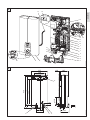 3
3
-
 4
4
-
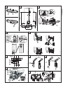 5
5
-
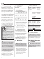 6
6
-
 7
7
-
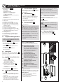 8
8
-
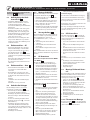 9
9
-
 10
10
-
 11
11
-
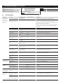 12
12
-
 13
13
-
 14
14
-
 15
15
-
 16
16
-
 17
17
-
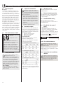 18
18
-
 19
19
-
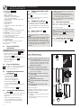 20
20
-
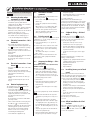 21
21
-
 22
22
-
 23
23
-
 24
24
-
 25
25
-
 26
26
-
 27
27
-
 28
28
-
 29
29
-
 30
30
-
 31
31
-
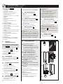 32
32
-
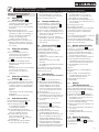 33
33
-
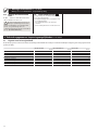 34
34
-
 35
35
-
 36
36
-
 37
37
-
 38
38
-
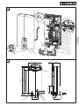 39
39
-
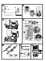 40
40
-
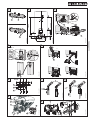 41
41
-
 42
42
-
 43
43
-
 44
44
-
 45
45
-
 46
46
-
 47
47
-
 48
48
-
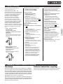 49
49
-
 50
50
-
 51
51
-
 52
52


STIEBEL ELTRON DEL 18/21/24 SL i Operating and Installation Instructions
- Type
- Operating and Installation Instructions
- Deze handleiding is ook geschikt voor
in andere talen
- Deutsch: STIEBEL ELTRON DEL 18/21/24 SL i
- polski: STIEBEL ELTRON DEL 18/21/24 SL i
Gerelateerde papieren
-
STIEBEL ELTRON DHE 27 SLi de handleiding
-
STIEBEL ELTRON DHF 15 C Operating And Installation Instruction
-
-
-
-
STIEBEL ELTRON 236739 Operation and Installation
-
-
-
-