HellermannTyton SpotClip-Kit de handleiding
- Type
- de handleiding

Operating instructions
Betriebsanleitung
Manuel d’utilisation
Manuale d’uso
Montagehandleiding
Instrukcja obsługi
SpotClip-Kit

11-2015 009-50108

Europe
HellermannTyton GmbH – Austria
Rennbahnweg 65
1220 Vienna
Tel: +43 12 59 99 55-0
Fax: +43 12 59 99 11
E-Mail: oce@HellermannTyton.at
www.HellermannTyton.at
HellermannTyton – Czech Republic
E-Mail: oceCZ@HellermannTyton.at
www.HellermannTyton.cz
HellermannTyton – Denmark
Industrivej 44A, 1.
4000 Roskilde
Tel: +45 702 371 20
Fax: +45 702 371 21
E-Mail: htdk@HellermannTyton.dk
www.HellermannTyton.dk
HellermannTyton – Finland
Sähkötie 8
01510 Vantaa
Tel: +358 9 8700 450
Fax: +358 9 8700 4520
E-Mail: myynti@HellermannTyton.fi
www.HellermannTyton.fi
HellermannTyton S.A.S. – France
2 rue des Hêtres, C.S. 80543
78197 Trappes Cedex
Tel: +33 1 30 13 80 00
Fax: +33 1 30 13 80 60
E-Mail: info@HellermannTyton.fr
www.HellermannTyton.fr
HellermannTyton GmbH –
Germany
Großer Moorweg 45
25436 Tornesch
Tel: +49 4122 701-0
Fax: +49 4122 701-400
E-Mail: info@HellermannTyton.de
www.HellermannTyton.de
HellermannTyton KFT – Hungary
Kisfaludy u. 13
1044 Budapest
Tel: +36 1 369 4151
Fax: +36 1 369 4151
E-Mail: oceHU@HellermannTyton.at
www.HellermannTyton.hu
HellermannTyton Ltd – Ireland
Unit 77 Cherry Orchard
Industrial Estate
Ballyfermot, Dublin 10
Tel: +353 1 626 8267
Fax: +353 1 626 8022
E-Mail: sales@HellermannTyton.ie
www.HellermannTyton.co.uk
HellermannTyton S.r.l. – Italy
Via Visco, 3/5
35010 Limena (PD)
Tel: +39 049 767 870
Fax: +39 049 767 985
E-Mail: info@HellermannTyton.it
www.HellermannTyton.it
HellermannTyton B.V. –
Belgium/Netherlands
Vanadiumweg 11-C
3812 PX Amersfoort
Tel: +31 33 460 06 90
Fax: +31 33 460 06 99
E-Mail (NL): info@HellermannTyton.nl
E-Mail (BE): info@HellermannTyton.be
www.HellermannTyton.nl
www.HellermannTyton.be
HellermannTyton AS – Norway
PO Box 240 Alnabru
0614 Oslo
Tel: +47 23 17 47 00
Fax: +47 22 97 09 70
E-Mail:
firmapost@HellermannTyton.no
www.HellermannTyton.no
HellermannTyton Sp. z o.o. –
Poland
ul. Berdychów 57A
62-410 Zagórów
E-Mail: info@HellermannTyton.pl
www.HellermannTyton.pl
HellermannTyton – Romania
E-Mail: oceRO@HellermannTyton.at
www.HellermannTyton.at
OOO HellermannTyton – Russia
40/4, Pulkovskoe road
BC Technopolis Pulkovo, oce A 8081
196158, St. Petersburg
Tel: +7 812 386 00 09
Fax: +7 812 386 00 08
E-Mail: info@HellermannTyton.ru
www.Hellermanntyton.ru
HellermannTyton – Slovenia
Branch Oce Ljubljana
Podružnica Ljubljana, Leskoškova 6
1000 Ljubljana
Tel: +386 1 433 70 56
Fax: +386 1 433 63 21
E-Mail: oceSl@HellermannTyton.at
www.HellermannTyton.si
HellermannTyton España s.l. –
Spain/Portugal
Avda. de la Industria 37 20 2
28108 Alcobendas, Madrid
Tel: +34 91 661 2835
Fax: +34 91 661 2368
E-Mail:
HellermannTyton@HellermannTyton.es
www.HellermannTyton.es
HellermannTyton AB – Sweden
Isafjordsgatan 5
16440 Kista
Tel: +46 8 580 890 00
Fax: +46 8 580 348 02
E-Mail: support@HellermannTyton.se
www.HellermannTyton.se
HellermannTyton Ltd – UK
William Prance Road
Plymouth International Medical
and Technology Park
Plymouth, Devon PL6 5WR
Tel: +44 1752 701 261
Fax: +44 1752 790 058
E-Mail: info@HellermannTyton.co.uk
www.HellermannTyton.co.uk
HellermannTyton Ltd – UK
Sharston Green Business Park
1 Robeson Way
Altrincham Road, Wythenshawe
Manchester M22 4TY
Tel: +44 161 947 2200
Fax: +44 161 947 2220
E-Mail: sales@HellermannTyton.co.uk
www.HellermannTyton.co.uk
HellermannTyton Ltd – UK
Main Contact for Customer Service
Wharf Approach
Aldridge, Walsall, West Midlands
WS9 8BX
Tel: +44 1922 458 151
Fax: +44 1922 743 053
E-Mail: info@HellermannTyton.co.uk
www.HellermannTyton.co.uk
HellermannTyton operates globally in 36 countries

HellermannTyton Data Ltd – UK
Cornwell Business Park
43-45 Salthouse Road, Brackmills
Northampton NN4 7EX
Tel: +44 1604 707 420
Fax: +44 1604 705 454
E-Mail: [email protected]
www.htdata.co.uk
Middle East
HellermannTyton – UAE
Email: info@HellermannTyton.ae
www.HellermannTyton.ae
North America
HellermannTyton – Canada
Tel: +1 905 726 1221
Fax: +1 905 726 8538
E-Mail: sales@HellermannTyton.ca
www.HellermannTyton.ca
HellermannTyton – Mexico
Tel: +52 333 133 9880
Fax: +52 333 133 9861
E-Mail:
info@HellermannTyton.com.mx
www.HellermannTyton.com
HellermannTyton – USA
Tel: +1 414 355 1130
Fax: +1 414 355 7341
E-Mail: [email protected]
www.HellermannTyton.com
South America
HellermannTyton – Argentina
Tel: +54 11 4754 5400
Fax: +54 11 4752 0374
E-Mail:
ventas@HellermannTyton.com.ar
www.HellermannTyton.com.ar
HellermannTyton – Brazil
Tel: +55 11 4815 9000
Fax: +55 11 4815 9030
E-Mail:
vendas@HellermannTyton.com.br
www.HellermannTyton.com.br
Asia-Pacific
HellermannTyton – Australia
Tel: +61 2 9525 2133
Fax: +61 2 9526 2495
E-Mail:
cservice@HellermannTyton.com.au
www.HellermannTyton.com.au
HellermannTyton – China
Tel: +86 510 8528 2536
Fax: +86 510 8528 2731
E-Mail:
cservice@HellermannTyton.com.cn
www.HellermannTyton.com.cn
HellermannTyton – Hong Kong
Tel: +852 2832 9090
Fax: +852 2832 9381
E-Mail:
cservice@HellermannTyton.com.hk
www.HellermannTyton.com.sg
HellermannTyton – India
Tel: +91 120 413 3384
Bangalore: +91 776 001 0104
Chennai: +91 996 264 3939
Faridabad: +91 971 851 7797
Ghaziabad: +91 93 1354 1671
Pune: +91 727 601 2200
E-Mail:
cservice@HellermannTyton.co.in
www.HellermannTyton.co.in
HellermannTyton – Japan
Tel: +81 3 5790 3111
Fax: +81 3 5790 3112
E-Mail:
mkt@HellermannTyton.co.jp
www.HellermannTyton.co.jp
HellermannTyton –
Republic of Korea
Tel: +82 31 388 8012
Fax: +82 31 388 8013
E-Mail:
cservice@HellermannTyton.co.kr
www.HellermannTyton.co.kr
HellermannTyton – Philippines
Tel: +63 2 752 6551
Fax: +63 2 752 6553
E-Mail:
cservice@HellermannTyton.com.ph
www.HellermannTyton.com.ph
HellermannTyton – Singapore
Tel: +65 6 852 8585
Fax: +65 6 756 6798
E-Mail:
cservice@HellermannTyton.sg
www.HellermannTyton.com.sg
HellermannTyton – Thailand
Tel: +662 237 6702 / 266 0624
Fax: +662 266 8664
E-Mail:
cservice@HellermannTyton.co.th
www.HellermannTyton.com.sg
Africa
HellermannTyton – South Africa
Tel: +27 11 879 6680
Fax: +27 11 879 6601
E-Mail: [email protected]
www.HellermannTyton.co.za
globally in 36 countries

2
3
1
6
4
5
A
B
C

5
4
3
D
F
E
G

English
Deutsch
Français
Italiano
Nederlands
Polski
3
13
23
33
43
53
GBDEFRITNLPL


GBDEFRITNLPL
Operating instructions • SpotClip-Kit • 11-2015
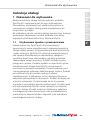
User information
3
Operating Instructions
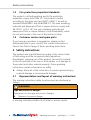
1 User information
These operating instructions only apply for the product
SpotClip-Kit and are intended for the user. These operating
instructions must be read carefully and understood by all
persons before commissioning the product.
On the fold-out page of the operating instructions, you will find
figures providing an overview and for the assembly of the
product, along with contact details for your local
HellermannTyton country representative.
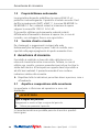
1.1 Intended use
SpotClip-Kit industrial downlight covers ensure a safe distance
between the light, damp-proof foil or vapour barrier and the
insulation wool. The SpotClip-Kit keeps the insulation material
above the downlight at a safe distance and therefore enables
sucient air cirulation for correct operation. The product
reduces the risk of overheating and the risk of fire. It also
increases the service life of the lights. The SpotClip-Kit can also
be retrofitted in existing buildings. The product is made of
self-extinguishing, heat-stabilised Polyamide. The product is
designed for the installation of large lights in dry wall and
acoustic construction for industrial and oce buildings. The
SpotClip-Kit is available in two different sizes. The product is
suitable for use in both, panels and plasterboards. The product
may only be used for the purposes described in these operating
instructions. The product may only be used in technically perfect
condition in accordance with its intended use and the operating
instructions, and only by competent persons who are fully
aware of the risks involved.

Operating instructions • SpotClip-Kit • 11-2015
Safety instructions
4
1.2 Fire protection properties/standards
The product is self extinguishing and its fire protection
properties comply with UL94 V2. The product is tested
according to the glow wire test (GWT) at 960°C as well as
standards EN60598-1 and EN60598-2-2. The used insulating
materials and damp-proof foils or vapour barriers comply with
EN13501-1A2s1d0. Use only insulating materials and
damp-proof foils or vapour barriers of low flammability, which
do not emit smoke in the case of fire and do not drip.
1.3 Customer service and spare parts
If you have any questions or suggestions, please contact
HellermannTytoninyour country. The contact information is
listed in the fold-out page of these operating instructions.
2 Safety instructions
The product was manufactured according to the current state
of technology and the recognised safety regulations.
Nonetheless, improper use of the product can result in hazards
to the life and limb of the user or third parties, or in damage to
the product and other material property. These operating
instructions contain information on safety.
fAlways follow all of the instructions to prevent personal injury,
material damage or environmental damage.
2.1 Representation and layout of warning instructions
The warning instructions relate to actions and are structured as
follows:
WARNING
Type and source of danger!
Explanations on the type and source of danger.
fMeasures to prevent danger.
A warning indicates possible risk of lethal or serious injuries.

GBDEFRITNLPL
Operating instructions • SpotClip-Kit • 11-2015
User obligations
5
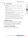
2.2 Limitations of use
fObserve the following requirements for the operational
environment:
• The SpotClip-Kit can only be used for LED and fluorescent lights.
• The required installation diameter can be easily adjusted using
the variable slots.
• The SpotClip-Kit150 can be used for ceiling cut-outs with
diameters from 100mm to 270mm.
• The SpotClip-Kit240 can be used for ceiling cut-outs with
diameters from 170mm to 310mm.
• The available inner usable height is 140mm for the
SpotClip-Kit150 and 230mm for the SpotClip-Kit240.
• The product can be combined with the SpotClip-Plate -
Reinforcement plate for downlights in suspended ceilings.
• The diameter of the ceiling cut-out must be 4mm larger than
required for the spotlight to be able to install the product.
3 User obligations
The user must observe and comply with the respectively
applicable national legal regulations and accident prevention
regulations. The use of the SpotClip-Kit does not exempt the
user from complying with the installation instructions from the
spotlight manufacturer. Please contact a specialist if you have
any questions.
4 Transport and storage
Do not stack heavy objects on the packaged product.

Operating instructions • SpotClip-Kit • 11-2015
Layout
6
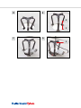
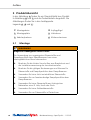
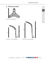
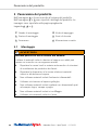
5 Product overview
In Figure A, you can find an overview image of the product.
Figures B and C show the product details. You can find the
figures on the fold-out page.
Legends A , B and C :
1 Assembly legs 4 Support wings
2 Assembly plate 5 Retaining spikes
3 Cable retainers 6 Click mechanism
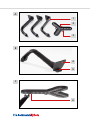
5.1 Installation
WARNING
Possible lethal danger due to fire!
The use of unsuitable insulation material and damp-proof foils or
vapour barriers can cause a lethal fire.
fComply with the local regulation on fire prevention and the
installation instructions from the light manufacturer.
fComply with the applicable stipulations and standards for
insulation materials and damp-proof foils or vapour barriers.
fDo not use flammable insulation materials.
fOnly use flame-resistant damp-proof foils or vapour barriers.
fDo not use insulation materials made of natural substances
such as wood, hemp or straw.
fDo not use any injection insulation materials.
fOnly use board or rolled insulation materials.

GBDEFRITNLPL
Operating instructions • SpotClip-Kit • 11-2015
Product overview
7
Using the tables in Section 9.1 Selection aid for slots, select the
required diameter.
1 Take the product out of its package.
2 Measure the required diameter and select the corresponding slot
for the assembly legs.
3 Connect the assembly legs 1 with the assembly plate 2
(Figure A ) using the click mechanism 6 (Figure C ).
4 Clean the area surrounding the ceiling cut-out.
5 Insert the product into the ceiling cut-out (Figure D ) until the
three support wings 4 (Figure E ) click into place above the
ceiling cut-out.
6 Press the three retaining spikes 5 (Figure E ) into the plasterboard
to prevent subsequent slippage.
7 Check the product for firm seating.
8 Install the light (Figure F ) according to the operating instructions.
The downlight must be carefully installed between the legs of the
SpotClip-Kit.
9 Fasten the supply line for the light with a cable retainer 3
(Figure G ) on the heat protection top.
;The SpotClip-Kit is installed.

Operating instructions • SpotClip-Kit • 11-2015
Maintenance
8
6 Maintenance
The product requires no maintenance.
7 Taking out of operation
When used for its intended purpose, the product will perform
continuously without issues.
8 Disposal
At the end of use, the purchaser or the user must dispose of the
product properly. This product has been manufactured in
compliance with the current environmental standards.
fObserve the national regulations for the disposal of recyclable
materials.
fTake the product to a local collection point or recycling centre.
fIf necessary, contact your local environmental oce.

GBDEFRITNLPL
Operating instructions • SpotClip-Kit • 11-2015
Technical data
9
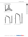
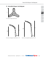
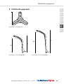
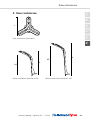
9 Technical data
L
SpotClip-Kit assembly plate
H2 H
H2
H
SpotClip-Kit 150 assembly leg SpotClip-Kit 240 assembly leg

Operating instructions • SpotClip-Kit • 11-2015
Technical data
10
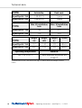
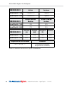
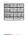
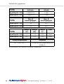
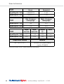
TYPE
Article-No. Pack cont.
SpotClip-Kit 150 148-00119 1 piece
SpotClip-Kit 240 148-00120 1 piece
TYPE
Min.Øinstallation
hole
Max.Øinstallation
hole
SpotClip-Kit 150 100 270
SpotClip-Kit 240 170 310
TYPE
Height
(H)
Height
(H2)
Length
(L)
Colour
SpotClip-Kit 150 157 140 120 Black
SpotClip-Kit 240 247 230 120 Black
Operating temperature Material
-40°C to +105°C Heat-stabilised polyamide6.6
(PA66HS)
All dimensions in mm. We reserve the right to make technical changes without
notice.

GBDEFRITNLPL
Operating instructions • SpotClip-Kit • 11-2015
Technical data
11
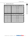
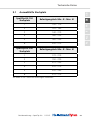
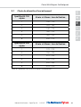
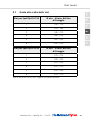
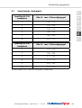
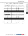
9.1 Selection aid for slots
SpotClip-Kit 150 slot Min. Ø - max. Ø installation hole
1 100 - 170
2 120 - 190
3 140 - 210
4 160 - 230
5 180 - 250
6 200 - 270
SpotClip-Kit 240 slot Min. Ø - max. Ø installation hole
1 170 - 210
2 190 - 230
3 210 - 250
4 230 - 270
5 250 - 290
6 270 - 310
All dimensions in mm. We reserve the right to make technical changes without
notice.

Operating instructions • SpotClip-Kit • 11-201512

GBDEFRITNLPL
Betriebsanleitung • SpotClip-Kit • 11-2015
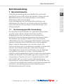
Benutzerhinweise
13
Betriebsanleitung
1 Benutzerhinweise
Diese Betriebsanleitung gilt ausschließlich für das Produkt
SpotClip-Kit und richtet sich an den Benutzer. Dieser muss die
Betriebsanleitung vor der Inbetriebnahme des Produktes
aufmerksam lesen und verstehen.
In der Ausklappseite der Betriebsanleitung befinden sich
Abbildungen zur Übersicht und zur Montage des Produktes
sowie die Adressen der jeweiligen Ländervertretungen von
HellermannTyton.
1.1 Bestimmungsgemäße Verwendung
Der SpotClip-Kit Abstandhalter für industrielle Einbaustrahler
sorgt für einen sicheren Abstand zwischen Leuchte,
Dampfsperrfolie bzw. Dampfbremse und Dämmwolle.
SpotClip-Kit hält das Dämmmaterial über dem Einbaustrahler
auf Abstand und ermöglicht dadurch eine ausreichende
Luftzirkulation für den ordnungsgemäßen Betrieb. Das Produkt
reduziert das Risiko einer Überhitzung und die Brandgefahr.
Ebenso wird die Lebensdauer der Leuchten erhöht. Der
SpotClip-Kit kann auch in bestehenden Gebäuden nachgerüstet
werden. Das Produkt besteht aus selbstverlöschendem,
hitzestabilisiertem Polyamid. Das Produkt ist für die Montage
von größeren Leuchten im Trocken- und Akustikbau für
Industrie und Bürogebäude konzipiert. Es gibt zwei verschiedene
Größen des Produkts. Das Produkt eignet sich sowohl für die
Verwendung in Paneelen als auch in Gipskartonplatten (GKP).
Das Produkt darf nur zu dem in dieser Betriebsanleitung
beschriebenen Zweck eingesetzt werden. Das Produkt darf nur
in technisch einwandfreiem Zustand sowie bestimmungsgemäß,
sicherheits- und gefahrenbewusst unter Beachtung der
Betriebsanleitung benutzt werden.

Betriebsanleitung • SpotClip-Kit • 11-2015
Sicherheitshinweise
14
1.2 Brandschutzeigenschaften/Normen
Die Brandschutzeigenschaften entsprechen der UL94V2 und
das Produkt ist selbstverlöschend. Das Produkt ist gemäß dem
Glühdrahttest (GWT) mit 960 °C, der Normen EN60598-1 und
EN60598-2-2 getestet. Für die verwendeten Dämmstoffe und
Dampfsperrfolien bzw. Dampfbremsen gelten die
EN13501-1A2s1d0. Es dürfen ausschließlich schwer
entflammbare Dämmstoffe und Dampfsperrfolien bzw.
Dampfbremsen, die im Brandfall keinen Rauch entwickeln und
nicht abtropfen, verwendet werden.
1.3 Kundenservice und Ersatzteile
Bei Fragen oder Anregungen wenden Sie sich bitte an
HellermannTyton in Ihrem Land. Die Kontaktdaten sind in der
Ausklappseite dieser Betriebsanleitung aufgeführt.
2 Sicherheitshinweise
Das Produkt ist nach dem Stand der Technik und den
anerkannten sicherheitstechnischen Regeln gefertigt. Dennoch
können bei der nicht sachgemäßen Verwendung Gefahren für
Leib und Leben des Benutzers oder Dritter bzw.
Beeinträchtigungen des Produktes und anderer Sachwerte
entstehen. Die vorliegende Betriebsanleitung beinhaltet
Anweisungen zur Sicherheit.
fBefolgen Sie alle Anweisungen um Personen-, Sach- oder
Umweltschäden zu vermeiden.
2.1 Darstellung und Aufbau von Warnhinweisen
Die Warnhinweise sind handlungsbezogen und wie folgt
aufgebaut:
WARNUNG
Art und Quelle der Gefahr!
Erläuterung zur Art und Quelle der Gefahr.
fMaßnahmen zur Abwendung der Gefahr.
Eine Warnung weist auf mögliche Lebensgefahr oder schwere
Verletzungen hin.

GBDEFRITNLPL
Betriebsanleitung • SpotClip-Kit • 11-2015
Pflichten des Benutzers
15
2.2 Einsatzgrenzen
fBeachten Sie die folgenden Anforderungen an die
Einsatzumgebung:
• Der SpotClip-Kit ist nur für LED- und Leuchtstoeuchten
einsetzbar.
• Der benötigte Einbaudurchmesser kann durch die variablen
Steckplätze leicht angepasst werden.
• Der SpotClip-Kit150 ist einsetzbar für Deckenausschnitte mit
Durchmessern von 100mm bis 270mm.
• Der SpotClip-Kit240 ist einsetzbar für Deckenausschnitte mit
Durchmessern von 170mm bis 310mm.
• Die verfügbare innere Nutzhöhe beträgt 140mm beim
SpotClip-Kit150 und 230mm beim SpotClip-Kit240.
• Das Produkt kann mit der SpotClip-Plate kombiniert werden -
Verstärkungsplatte für Einbaustrahler in abgehängten Decken.
• Der Durchmesser des Deckenausschnitts muss 4 mm größer sein
als für den Spot benötigt, damit das Produkt montiert werden
kann.
3 Pflichten des Benutzers
Der Benutzer muss die jeweils national geltenden gesetzlichen
Vorschriften und Unfallverhütungsvorschriften beachten und
einhalten. Die Verwendung des SpotClip-Kit befreit den
Benutzer nicht von der Beachtung der Installationsanleitung des
Herstellers der Einbauleuchten. Bei Fragen wenden Sie sich bitte
an einen Fachmann.
4 Transport und Lagerung
Stapeln Sie keine schweren Gegenstände auf dem verpackten
Produkt.

Betriebsanleitung • SpotClip-Kit • 11-2015
Aufbau
16
5 Produktübersicht
In der Abbildung A finden Sie ein Übersichtsbild zum Produkt.
In Abbildung B und C sind die Produktdetails dargestellt. Die
Abbildungen finden Sie in der Ausklappseite.
Legende A , B und C :
1 Montagebeine 4 Auflageflügel
2 Montageplatte 5 Haltedorne
3 Kabelaufnahmen 6 Klickmechanismus
5.1 Montage
WARNUNG
Mögliche Lebensgefahr durch Feuer!
Die Verwendung von ungeeigneten Dämmstoffen und
Dampfsperrfolien bzw. Dampfbremsen kann einen
lebensgefährlichen Brand verursachen.
fBeachten Sie die lokalen Vorschriften zum Brandschutz und
die Installationsanweisung der Leuchtenhersteller.
fBeachten Sie die gültigen Bestimmungen und Normen für
Dämmstoffe und Dampfsperrfolien bzw. Dampfbremsen.
fVerwenden Sie keine leicht entzündlichen Dämmstoffe.
fVerwenden Sie nur feuerbeständige Dampfsperrfolien bzw.
Dampfbremsen.
fVerwenden Sie keine Dämmstoffe aus ökologischen
Materialien wie z.B. Holz, Hanf oder Stroh.
fVerwenden Sie keine Einblasdämmstoffe.
fVerwenden Sie nur Dämmstoffe in Plattenform.

GBDEFRITNLPL
Betriebsanleitung • SpotClip-Kit • 11-2015
Produktübersicht
17
Mit Hilfe der Tabellen im Kapitel 9.1 Auswahlhilfe Steckplatz den
benötigten Durchmesser auswählen.
1 Das Produkt aus der Verpackung entnehmen.
2 Den benötigten Durchmesser ausmessen und den
entsprechenden Steckplatz für die Montagebeine auswählen.
3 Montagebeine 1 mit der Montageplatte 2 (Abbildung A ) durch
den Klickmechanismus 6 (Abbildung C ) verbinden.
4 Bereich um den Deckenausschnitt reinigen.
5 Produkt in die Deckenaussparung (Abbildung D ) einsetzen bis die
drei Auflageflügel 4 (Abbildung E ) oberhalb des
Deckenausschnittes einrasten.
6 Die drei Haltedorne 5 (Abbildung E ) in die Gipskartonplatte
eindrücken, um nachträgliches Verrutschen zu verhindern.
7 Festen Sitz des Produktes sicherstellen.
8 Leuchte (Abbildung F ) nach Betriebsanleitung montieren. Der
Einbaustrahler muss vorsichtig zwischen den Beinen des
SpotClip-Kit eingebaut werden.
9 Zuleitung der Leuchte mit einer Kabelaufnahme 3 (Abbildung G )
am Hitzeschutzdach fixieren.
;SpotClip-Kit ist montiert.

Betriebsanleitung • SpotClip-Kit • 11-2015
Wartung
18
6 Wartung
Das Produkt ist wartungsfrei.
7 Außerbetriebnahme
Das Produkt kann bei bestimmungsgemäßer Verwendung
zeitlich unbeschränkt genutzt werden.
8 Entsorgung
Nach Nutzungsbeendigung muss der Käufer bzw. der Benutzer
das Produkt ordnungsgemäß entsorgen. Dieses Produkt ist nach
den aktuellen Umweltschutzstandards hergestellt.
fBeachten Sie die nationalen Vorschriften für die Entsorgung von
Wertstoffen.
fGeben Sie das Produkt an örtlichen Sammelstellen oder
Recyclingzentren ab.
fKontaktieren Sie ggf. Ihre örtlichen Behörden.

GBDEFRITNLPL
Betriebsanleitung • SpotClip-Kit • 11-2015
Technische Daten
19
9 Technische Daten
L
SpotClip-Kit Montageplatte
H2 H
H2
H
SpotClip-Kit 150 Montagebein SpotClip-Kit 240 Montagebein

Betriebsanleitung • SpotClip-Kit • 11-2015
Technische Daten
20
TYP
Art.-Nr. Inhalt
SpotClip-Kit 150 148-00119 1 Stück
SpotClip-Kit 240 148-00120 1 Stück
TYP
Min. Ø
Befestigungsloch
Max. Ø
Befestigungsloch
SpotClip-Kit 150 100 270
SpotClip-Kit 240 170 310
TYP
Höhe (H) Höhe
(H2)
Länge
(L)
Farbe
SpotClip-Kit 150 157 140 120 Schwarz
SpotClip-Kit 240 247 230 120 Schwarz
Betriebstemperatur Material
-40°C bis +105°C Polyamid6.6 hitzestabilisiert
(PA66HS)
Alle Maße in mm. Technische Änderungen vorbehalten.

GBDEFRITNLPL
Betriebsanleitung • SpotClip-Kit • 11-2015
Technische Daten
21
9.1 Auswahlhilfe Steckplatz
SpotClip-Kit 150
Steckplatz Befestigungsloch Min. Ø - Max. Ø
1 100 - 170
2 120 - 190
3 140 - 210
4 160 - 230
5 180 - 250
6 200 - 270
SpotClip-Kit 240
Steckplatz Befestigungsloch Min. Ø - Max. Ø
1 170 - 210
2 190 - 230
3 210 - 250
4 230 - 270
5 250 - 290
6 270 - 310
Alle Maße in mm. Technische Änderungen vorbehalten.

Betriebsanleitung • SpotClip-Kit • 11-201522

GBDEFRITNLPL
Manuel d‘utilisation • SpotClip-Kit • 11-2015
Consignes d'utilisation
23
Manuel d'utilisation
1 Consignes d'utilisation
Ce manuel d'utilisation s'applique exclusivement au produit
SpotClip-Kit et s'adresse à l'utilisateur. Celui-ci doit lire avec
attention et comprendre le manuel d'utilisation avant de
démarrer son installation.
La page rabattable contient des représentations du produit
(photos/dessins) relatives au montage ainsi que les adresses des
représentants nationaux de HellermannTyton.
1.1 Utilisation conforme
Le SpotClip-Kit est un produit qui facilite l‘installation des spots
encastrables industriels (downlights) dans les faux-plafonds tout
en assurant le maintien d‘un écart fiable entre le spot encastré
et le matériau isolant. Le SpotClip-Kit permet de relever la laine
de verre au dessus du downlight et de laisser une zone d’air
susante à son bon fonctionnement. Il réduit ainsi les risques
de surchauffe ou d'incendie et permet d'augmenter la durée de
vie des ampoules. Le SpotClip-Kit peut aussi être ajouté
ultérieurement à une installation existante. Le produit est
fabriqué en polyamide auto-extinguible résistant aux hautes
températures. Le produit est conçu pour le montage de grands
spots encastrables (downlights) dans des faux-plafonds pour
l'industrie et les bureaux. Le produit existe en deux grandeurs. Il
peut être monté aussi bien sur des panneaux de lambris que sur
des plaques de plâtre. Le produit doit uniquement être utilisé
aux fins décrites dans ce manuel d'utilisation et ne doit être
utilisé que dans un état irréprochable ainsi que selon l'usage
prévu. Il faut tenir compte des consignes de sécurité et des
dangers présentés dans le présent manuel.

Manuel d'utilisation • SpotClip-Kit • 11-2015
Consignes de sécurité
24
1.2 Propriétés anti-incendie/normes
Le produit est auto-extinguible et ses propriétés de tenue au feu
correspondent à l‘UL94V2. Le produit est testé conformément
au test de résistance au filament incandescent à 960°C, aux
normes EN60598-1 et EN60598-2-2.
La norme EN13501-1A2s1d0 s‘applique aux matériaux
isolants ainsi qu'aux pare-vapeur. Cette norme correspond à la
classification M0 antérieure. Seuls des matériaux isolants non
combustibles et des pare-vapeur ignifugés doivent être utilisés,
qui en cas d‘incendie, ne dégagent pas de fumée et ne forment
pas de goutte.
1.3 Service après-vente et pièces de rechange
Si vous avez des questions, adressez-vous au représentant
HellermannTyton de votre pays. Les coordonnées sont indiquées
sur la page rabattable.
2 Consignes de sécurité
Le produit est fabriqué selon l‘état de la technique et des règles
de sécurité reconnues. Cependant, il peut survenir en cas d‘une
utilisation non conforme des dangers pour la santé et la vie de
l‘utilisateur ou de tierces parties, ainsi que des dégradations du
produit et d‘autres biens. Le présent manuel d'utilisation
contient des consignes relatives à la sécurité.
fRespectez toutes les consignes pour éviter des dommages aux
personnes, aux biens et à l'environnement.
2.1 Représentation et structure des symboles
d'avertissement
Les symboles d‘avertissement sont structurés comme suit:
AVERTISSEMENT
Type et source de danger!
Explication du type et de la source de danger.
fMesures de prévention des dangers potentiels.
Un avertissement indique un risque potentiel pour la vie ou des
blessures graves.

GBDEFRITNLPL
Manuel d‘utilisation • SpotClip-Kit • 11-2015
Obligations de l'utilisateur
25
2.2 Limites d'utilisation
fL'environnement d'installation doit respecter les conditions
suivantes:
• Le SpotClip-Kit est utilisable pour les spots LED et fluorescents.
• Diamètre d‘encastrement réglable grâce au système de croix et
de pattes clipsées.
• Le SpotClip-Kit150 est utilisable pour les découpes de plafond
avec des diamètres d‘encastrement de 100mm à 270mm.
• Le SpotClip-Kit240 est utilisable pour les découpes de plafond
avec des diamètres d‘encastrement de 170mm à 310mm.
• La hauteur utile intérieure disponible est de 140mm pour le
SpotClip-Kit150 et de 230mm pour le SpotClip-Kit240.
• Le produit peut être combiné avec un SpotClip-Plate – Plaque de
renfort pour downlights en plafonds suspendus.
• Le diamètre de perçage doit correspondre au diamètre du spot
+4mm pour le passage des ailettes du SpotClip-Kit.
3 Obligations de l'utilisateur
L'utilisateur doit respecter les directives légales applicables au
niveau national ainsi que les directives de prévention des
accidents. L'utilisation d'un SpotClip-Kit n‘affranchit pas de
consulter la notice de montage du spot utilisé. En cas de doute,
faire appel à un professionnel.
4 Transport et stockage
N'empilez aucun objet lourd sur le produit emballé.

Manuel d‘utilisation • SpotClip-Kit • 11-2015
Vue d’ensemble du produit
26
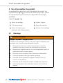
5 Vue d’ensemble du produit
La représentation A est une vue d’ensemble du produit. Les
représentations B et C montrent des détails du produit. Toutes
les représentations du produit sont disponibles sur la page
rabattable.
Légendes A , B et C :
1 Pattes de montage 4 Ailettes d'appui
2 Croix de montage 5 Ergots de maintien
3 Pattes de fixation pour
maintenir le fil d’alimentation
6 Système d‘assemblage
5.1 Montage
AVERTISSEMENT
Risque d’incendie - Danger mortel!
L'utilisation de matériaux isolants et de pare-vapeur inadaptés peut
provoquer des incendies potentiellement mortels.
fRespectez les directives locales de protection contre les
incendies ainsi que la notice de montage du spot utilisé.
fRespectez les réglementations et normes applicables pour les
matériaux isolants et pare-vapeur.
fN'utilisez aucun matériau isolant facilement inflammable.
fUtilisez uniquement des pare-vapeur ignifugés.
fN'utilisez aucun matériau écologique comme le bois, le
chanvre ou la paille etc.
fN'utilisez pas de matériaux isolants insués par projection.
fUtilisez uniquement des matériaux isolants sous forme de
plaques.

GBDEFRITNLPL
Manuel d‘utilisation • SpotClip-Kit • 11-2015
Vue d’ensemble du produit
27
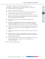
Pour définir le diamètre d‘encastrement adapté à votre
installation, se référer aux données figurant dans le chapitre 9.1
« Choix du diamètre d‘encastrement ».
1 Retirer le produit de l’emballage.
2 Mesurer le diamètre d‘encastrement nécessaire et sélectionner
l‘emplacement approprié pour les pattes de montage.
3 Monter le SpotClip-Kit en encliquetant les pattes de montage 1
dans la croix de montage 2 (représentation A ) grâce au système
d‘assemblage 6 (représentation C ).
4 Nettoyer les abords du trou/de la découpe du plafond si
nécessaire.
5 Insérer le SpotClip-Kit assemblé dans la découpe du plafond
(représentation D ) jusqu'à ce que les trois ailettes d'appui 4
(représentation E ) se fixent au dessus de la découpe du plafond.
6 Enfoncer les trois ergots de maintien 5 (représentation E ) dans la
plaque de plâtre pour prévenir tout désalignement ultérieur du
système.
7 Vérifier que le SpotClip-Kit soit bien en position avant de monter
le spot.
8 Monter le spot encastrable (représentation F ) selon le manuel
d'utilisation de ce dernier. Faire attention à passer le ballast entre
les pattes du SpotClip-Kit.
9 Fixer le câble d'alimentation du spot encastrable dans l‘une des
pattes de fixation pour maintenir le fil d’alimentation 3
(représentation G ).
;Le SpotClip-Kit est monté.

Manuel d'utilisation • SpotClip-Kit • 11-2015
Entretien
28
6 Entretien
Aucun entretien particulier n’est nécessaire.
7 Mise hors service
Utilisé de manière conforme à ce manuel, l‘utilisation du produit
n‘est pas limitée dans le temps.
8 Élimination
À la fin de l'utilisation, l'acheteur ou l'utilisateur doit éliminer le
produit correctement. Ce produit est fabriqué selon les normes
actuelles de protection de l'environnement.
fRespectez les directives nationales concernant l'élimination des
matériaux.
fApportez le produit dans un lieu de collecte ou un centre de
recyclage local.
fContactez si nécessaire les autorités locales.

GBDEFRITNLPL
Manuel d‘utilisation • SpotClip-Kit • 11-2015
Caractéristiques techniques
29
9 Caractéristiques techniques
L
Croix de montage SpotClip-Kit
H2 H
H2
H
Patte de montage du SpotClip-Kit 150 Patte de montage du SpotClip-Kit 240

Manuel d'utilisation • SpotClip-Kit • 11-2015
Caractéristiques techniques
30
RÉFÉRENCE
Article Contenu
SpotClip-Kit150 148-00119 1pièce
SpotClip-Kit240 148-00120 1pièce
RÉFÉRENCE
Ømin. trou de
fixation
Ømax.trou de
fixation
SpotClip-Kit150 100 270
SpotClip-Kit240 170 310
RÉFÉRENCE
Hauteur
(H)
Hauteur
(H2)
Longueur
(L)
Couleur
SpotClip-Kit150 157 140 120 Noir
SpotClip-Kit240 247 230 120 Noir
Températures d'utilisation Matériau
-40°C à +105°C Polyamide 6.6 hautes
températures (PA66HS)
Toutes les dimensions sont en mm et sujettes à modifications.

GBDEFRITNLPL
Manuel d‘utilisation • SpotClip-Kit • 11-2015
Caractéristiques techniques
31
9.1 Choix du diamètre d‘encastrement
SpotClip-Kit 150
repère Ømin. et Ømax.trou de fixation
1 100 - 170
2 120 - 190
3 140 - 210
4 160 - 230
5 180 - 250
6 200 - 270
SpotClip-Kit 240
repère Ømin. et Ømax.trou de fixation
1 170 - 210
2 190 - 230
3 210 - 250
4 230 - 270
5 250 - 290
6 270 - 310
Toutes les dimensions sont en mm et sujettes à modifications.

Manuel d‘utilisation • SpotClip-Kit • 11-201532

GBDEFRITNLPL
Manuale d’uso • SpotClip-Kit • 11-2015
Indicazioni per l'utente
33
Manuale d’uso
1 Indicazioni per l'utente
Il presente manuale d'uso si riferisce esclusivamente al prodotto
SpotClip-Kit e si rivolge all'utente. Questi deve leggere
attentamente e comprendere il manuale d'uso prima di mettere
in funzione il prodotto.
Nella pagina pieghevole del manuale d'uso sono riportate le
immagini di panoramica e di montaggio del prodotto oltre agli
indirizzi delle sedi HellermannTyton nei diversi paesi.
1.1 Utilizzo conforme
Il distanziale SpotClip-Kit per faretti alogeni industriali da incasso
assicura una distanza sicura tra il faretto sottostante, la barriera
al vapore e il materiale isolante. SpotClip-Kit mantiene il
materiale isolante sopra il faretto alogeno da incasso e consente
quindi la circolazione dell'aria per un esercizio corretto. Il
prodotto riduce il rischio di surriscaldamento e di incendio,
garantendo una vita più lunga ai faretti. SpotClip-Kit può essere
installato a posteriori anche in edifici esistenti. Il prodotto è
realizzato in poliammide autoestinguente e stabilizzata al calore.
Il prodotto è concepito per il montaggio di faretti più grandi in
costruzioni a secco, di isolamento acustico in ambito industriale
e per edifici adibiti ad uso ucio. SpotClip-Kit è disponibile in
due dimensioni. Il prodotto è la soluzione ideale sia per i sotti
a pannelli che in cartongesso. Il prodotto deve essere impiegato
solo per lo scopo descritto in questo manuale d'uso. Il prodotto
deve essere utilizzato solo in condizioni tecniche perfette e in
modo conforme, nel rispetto del manuale d'uso e tenendo
presenti la sicurezza e i possibili pericoli correlati.

Manuale d’uso • SpotClip-Kit • 11-2015
Avvertenze di sicurezza
34
1.2 Proprietà/Norme antincendio
Le proprietà antincendio soddisfano la norma UL94V2 e il
prodotto è autoestinguente. Il prodotto è testato secondo il test
del filo incandescente (GWT) a960°C, le norme EN60598-1 e
EN60598-2-2. Per i materiali isolanti e le barriere al vapore
valgono le norme EN13501-1A2s1d0.
È consentito utilizzare esclusivamente materiali isolanti
dicilmente infiammabili e barriere al vapore che, in caso di
incendio, non sviluppino fumo e non sgocciolino.
1.3 Servizio clienti e ricambi
Per chiarimenti o suggerimenti rivolgersi alla sede
HellermannTyton del proprio paese. I dati di contatto sono
riportati nella pagina pieghevole di questo manuale d'uso.
2 Avvertenze di sicurezza
Il prodotto è realizzato in base allo stato della tecnica e le
norme di sicurezza tecniche riconosciute. Tuttavia, in caso di
utilizzo non corretto, possono presentarsi pericoli per la vita e la
salute dell'utente o di terze persone oppure danni al prodotto e
ad altri beni materiali. Il presente manuale d'uso contiene
indicazioni relative alla sicurezza.
fRispettare tutte le indicazioni per evitare danni a persone, cose o
all'ambiente.
2.1 Aspetto e composizione delle avvertenze
Le avvertenze si riferiscono ad operazioni e sono così
strutturate:
AVVERTENZA
Tipo e origine del pericolo!
Spiegazione in merito al tipo e origine del pericolo.
fMisure per prevenire il pericolo.
Un'avvertenza indica un possibile pericolo di morte o possibili
lesioni gravi.

GBDEFRITNLPL
Manuale d’uso • SpotClip-Kit • 11-2015
Obblighi dell'utente
35
2.2 Limiti d'impiego
fRispettare i seguenti requisiti per quanto riguarda l'ambiente
d'impiego:
• SpotClip-Kit può essere utilizzato solo con faretti LED e faretti
fluorescenti.
• Il diametro di incasso necessario può essere adattato facilmente
grazie agli slot variabili.
• SpotClip-Kit150 può essere utilizzato nelle cavità del sotto da
100mm a 270mm di diametro.
• SpotClip-Kit240 può essere utilizzato nelle cavità del sotto da
170mm a 310mm di diametro.
• L'altezza utile interna disponibile corrisponde a 140mm per
SpotClip-Kit150 e 230mm per SpotClip-Kit240.
• Il prodotto può essere combinato con SpotClip-Plate, la piastra di
rinforzo per faretti alogeni da incasso per controsotti.
• Il diametro della cavità del sotto deve essere 4mm più grande
di quella necessaria per lo Spot, in modo da poter montare il
prodotto.
3 Obblighi dell'utente
L'utente è tenuto ad osservare e rispettare le norme di legge e
le disposizioni antinfortunistiche nazionali in vigore. L'impiego
dello SpotClip-Kit non esonera l'utente dal rispetto delle
istruzioni di installazione del produttore dei faretti da incasso.
Per chiarimenti rivolgersi ad un esperto.
4 Trasporto e magazzinaggio
Non impilare oggetti pesanti sul prodotto imballato.

Manuale d’uso • SpotClip-Kit • 11-2015
Panoramica del prodotto
36
5 Panoramica del prodotto
Nell'immagine A si trova una vista d'insieme del prodotto.
Nell'immagine B e C sono riportati i dettagli del prodotto. Le
immagini sono riportate nella pagina pieghevole.
Legenda A , B e C :
1 Gambe di montaggio 4 Aletta di appoggio
2 Piastra di montaggio 5 Denti di ritenuta
3 Fermacavo 6 Meccanismo a scatto
5.1 Montaggio
AVVERTENZA
Possibile pericolo di morte dovuto alle fiamme!
L'utilizzo di materiali isolanti e barriere al vapore non adatti può
causare un incendio con conseguenze mortali.
fRispettare le norme locali in materia antincendio e le istruzioni
di installazione dei produttori dei faretti.
fRispettare le disposizioni e le norme relative ai materiali
isolanti e alle barriere al vapore.
fNon utilizzare materiali isolanti facilmente infiammabili.
fUtilizzare solo barriere al vapore ignifughe.
fNon utilizzare materiali isolanti realizzati con biomateriali quali
ad esempio legno, canapa o paglia.
fNon utilizzare materiali isolanti a insuaggio.
fUtilizzare solo materiali isolanti in lastre.

GBDEFRITNLPL
Manuale d’uso • SpotClip-Kit • 11-2015
Panoramica del prodotto
37
Con l'ausilio delle tabelle nel capitolo 9.1 “Guida alla scelta
dello slot“ selezionare il diametro necessario.
1 Rimuovere il prodotto dall'imballaggio.
2 Misurare il diametro necessario e selezionare lo slot adatto per le
gambe di montaggio.
3 Collegare le gambe di montaggio 1 con la piastra di
montaggio 2 (immagine A ) tramite il meccanismo a scatto 6
(immagine C ).
4 Pulire l'area attorno alla cavità del sotto.
5 Inserire il prodotto nella cavità del sotto (immagine D ), finché
le tre alette di appoggio 4 (immagine E ) si incastrino sopra la
cavità del sotto.
6 Premere i tre denti di ritenuta 5 (immagine E ) nel pannello di
cartongesso, per evitare un successivo spostamento.
7 Assicurarsi che il prodotto abbia una posizione fissa.
8 Montare il faretto (immagine F ) in base al manuale d'uso. Il
faretto alogeno da incasso deve essere montato con cautela tra
le gambe del SpotClip-Kit.
9 Fissare l'alimentazione del faretto con un fermacavo 3
(immagine G ) sulla copertura di protezione dal calore.
;Lo SpotClip-Kit è montato.

Manuale d’uso • SpotClip-Kit • 11-2015
Manutenzione
38
6 Manutenzione
Il prodotto non richiede manutenzione.
7 Messa fuori servizio
Il prodotto può essere utilizzato senza limiti di tempo purché si
seguano le disposizioni.
8 Smaltimento
Quando il prodotto non viene più utilizzato, l'acquirente e/o
l'utente deve smaltirlo correttamente. Il prodotto è realizzato in
base agli attuali standard di protezione ambientale.
fRispettare le norme nazionali per lo smaltimento di materiali
riciclabili.
fConsegnare il prodotto presso i punti di raccolta locali o i centri di
riciclaggio previsti.
fSe necessario, contattare le autorità locali responsabili in materia.

GBDEFRITNLPL
Manuale d’uso • SpotClip-Kit • 11-2015
Dati tecnici
39
9 Dati tecnici
L
Piastra di montaggio SpotClip-Kit
H2 H
H2
H
Gamba di montaggio SpotClip-Kit150 Gamba di montaggio SpotClip-Kit240

Manuale d’uso • SpotClip-Kit • 11-2015
Dati tecnici
40
ARTICOLO
UNS Cont. conf.
SpotClip-Kit 150 148-00119 1 pezzi
SpotClip-Kit 240 148-00120 1 pezzi
ARTICOLO
Ø min. del foro di
fissaggio
Ø max. del foro di
fissaggio
SpotClip-Kit 150 100 270
SpotClip-Kit 240 170 310
ARTICOLO
Altezza
(H)
Altezza
(H2)
Lunghezza
(L)
Colore
SpotClip-Kit 150 157 140 120 Nero
SpotClip-Kit 240 247 230 120 Nero
Temperatura di esercizio Materiale
da -40°C a +105°C Poliammide6.6 stabilizzata al
calore (PA66HS)
Tutte le dimensioni sono in mm. Soggette a modifiche tecniche.

GBDEFRITNLPL
Manuale d’uso • SpotClip-Kit • 11-2015
Dati tecnici
41
9.1 Guida alla scelta dello slot
Slot per SpotClip-Kit 150 Ø min. - Ø max. del foro
di fissaggio
1 100 - 170
2 120 - 190
3 140 - 210
4 160 - 230
5 180 - 250
6 200 - 270
Slot per SpotClip-Kit 240 Ø min. - Ø max. del foro
di fissaggio
1 170 - 210
2 190 - 230
3 210 - 250
4 230 - 270
5 250 - 290
6 270 - 310
Tutte le dimensioni sono in mm. Soggette a modifiche tecniche.

Manuale d’uso • SpotClip-Kit • 11-201542

GBDEFRITNLPL
Montagehandleiding • SpotClip-Kit • 11-2015
Gebruikersinstructies
43
Montagehandleiding
1 Gebruikersinstructies
Deze montagehandleiding geldt uitsluitend voor het product
SpotClip-Kit en is bedoeld voor de gebruiker. Deze moet de
montagehandleiding voor het gebruik van het product
aandachtig doorlezen en begrijpen.
In de uitklappagina van de montagehandleiding staan
afbeeldingen voor het overzicht en de montage van het product
en de adressen van de nationale verkooporganisaties van
HellermannTyton.
1.1 Correct gebruik
De SpotClip-Kit afstandhouder voor industriële inbouwspots
zorgt voor een veilige afstand tussen lichtbron, dampremmende
folie en isolatiemateriaal. De SpotClip-Kit houdt het
isolatiemateriaal boven de inbouwspot op afstand en maakt
daardoor voldoende luchtcirculatie mogelijk voor het correct
bedrijf. Het product vermindert het gevaar voor oververhitting
en brand. Ook wordt de levensduur van de lichtbron verlengd.
De SpotClip-Kit kan ook in bestaande gebouwen naderhand
worden aangebracht. Het product bestaat uit zelfdovend,
hittegestabiliseerd polyamide. Het product is ontwikkeld voor de
montage van grotere lichtbronnen in industriële omgevingen en
de utiliteitsbouw. Er zijn twee verschillende afmetingen van het
product. Het product is zowel geschikt voor toepassing in
panelen als in gipsplaten (GKP). Het product mag alleen worden
gebruikt voor de in deze montagehandleiding beschreven
doeleinden. Het product mag alleen in technisch optimale
toestand en conform de bedoeling, veilig en bewust van de
gevaren rekening houdend met de montagehandleiding worden
gebruikt.

Montagehandleiding • SpotClip-Kit • 11-2015
Veiligheidsinstructies
44
1.2 Brandwerende eigenschappen/normen
De brandwerende eigenschappen voldoen aan de UL94 V2 en
het product is zelfdovend. Het product is getest conform de
gloeidraadtest (GWT) met 960°C en EN60598-1 en
EN60598-2-2. Voor de gebruikte isolatiematerialen en
dampremmende folie gelden EN13501-1 A2 s1 d0. Uitsluitend
moeilijk ontvlambare isolatiematerialen en dampremmende
folies mogen worden gebruikt, die in geval van brand geen rook
ontwikkelen en niet druipen.
1.3 Klantenservice en reserve-onderdelen
Bij vragen of opmerkingen kunt u contact opnemen met
HellermannTytoninuw land. De contactgegevens zijn vermeld
in de uitklappagina van deze montagehandleiding.
2 Veiligheidsinstructies
Het product is conform de laatste stand van de techniek en de
erkende veiligheidstechnische regels gefabriceerd. Toch kunnen
er bij het verkeerd gebruik gevaren voor lijf en leven van de
gebruiker of derden ontstaan of schade aan het product of
andere materiële zaken. Deze montagehandleiding bevat
instructies betreffende de veiligheid.
fVolg alle instructies op om persoonlijke, materiële of
milieuschade te vermijden.
2.1 Weergave en opbouw van waarschuwingen
De waarschuwingen zijn aan handelingen gerelateerd en als
volgt opgebouwd:
WAARSCHUWING
Soort en bron van gevaar!
Verklaring van het soort en de bron van het gevaar.
fMaatregelen voor afwenden van het gevaar.
Een waarschuwing wijst op mogelijk levensgevaar of ernstig
lichamelijk letsel.

GBDEFRITNLPL
Montagehandleiding • SpotClip-Kit • 11-2015
Plichten van de gebruiker
45
2.2 Toepassingsgrenzen
fHoud de volgende eisen aan voor wat betreft de
gebruiksomgeving:
• De SpotClip-Kit is alleen voor LED- en spaarlampen toepasbaar.
• De benodigde inbouwdiameter kan via de variabele steekplaatsen
eenvoudig worden aangepast.
• De SpotClip-Kit150 is toepasbaar in geboorde gaten met
diameters van 100mm tot 270mm.
• De SpotClip-Kit240 is toepasbaar in geboorde gaten met
diameters van 170mm tot 310mm.
• De beschikbare interne effectieve hoogte is 140mm bij de
SpotCip-Kit150 en 230mm bij de SpotClip-Kit240.
• Het product kan met de SpotClip-Plate worden gecombineerd:
verstevigingsplaat voor inbouwspots in verlaagde plafonds.
• De diameter van de geboorde gaten moet 4mm groter zijn dan
nodig is voor de spot, zodat het product kan worden
gemonteerd.
3 Plichten van de gebruiker
De gebruiker moet de nationaal geldende wettelijke
voorschriften en ongevallenpreventievoorschriften aanhouden.
Het gebruik van de SpotClip-Kit ontslaat de gebruiker niet van
de verplichting de installatiehandleiding van de fabrikant van de
inbouwverlichting aan te houden. Neem bij vragen contact op
met een vakman.
4 Transport en opslag
Stapel geen zware objecten op het verpakte product.

Montagehandleiding • SpotClip-Kit • 11-2015
Constructie
46
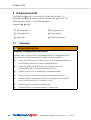
5 Productoverzicht
In afbeelding A vindt u een overzicht van het product. In
afbeeldingen B en C worden de productdetails getoond. De
afbeeldingen vindt u in de uitklappagina.
Legenda A, B en C:
1 Montagebenen 4 Oplegstukken
2 Montageplaat 5 Bevestiging
3 Kabelclips 6 Klikmechanisme
5.1 Montage
WAARSCHUWING
Mogelijk levensgevaar door brand!
Gebruik van niet geschikte isolatiematerialen en dampremmende
folies kan een levensgevaarlijke brand tot gevolg hebben.
fHoud de lokale voorschriften aan voor de brandbeveiliging en
de installatie-instructies van de lampfabrikant.
fHoud de geldende bepalingen en normen aan voor
isolatiematerialen en dampremmende folies.
fGebruik geen licht ontvlambare isolatiematerialen.
fGebruik alleen vuurbestendige dampremmende folien.
fGebruik geen isolatiematerialen van ecologische materialen
zoals bijvoorbeeld hout, hennep of stro.
fGebruik geen inblaasisolatiemateriaal.
fGebruik alleen isolatiematerialen in plaatvorm.

GBDEFRITNLPL
Montagehandleiding • SpotClip-Kit • 11-2015
Productoverzicht
47
Met behulp van de tabellen in hoofdstuk9.1 Selectiehulp
steekplaats de benodigde diameter kiezen.
1 Neem het product uit de verpakking.
2 Meet de benodigde diameter uit en kies de betreffende
steekplaats voor de montagebenen.
3 Montagebenen 1 met montageplaat 2 (afbeeldingA ) via het
klikmechanisme6 (afbeeldingC ) verbinden.
4 Gebied rondom de geboorde gaten reinigen.
5 Product in de geboorde gaten (afbeeldingD) plaatsen, tot de drie
oplegstukken 4 (afbeeldingE) boven de geboorde gaten
vastklikken.
6 De drie bevestigingen 5 (afbeeldingE) in de gipsplaat drukken,
om naderhand wegglijden te voorkomen.
7 Waarborg dat het product goed vastzit.
8 Lichtbron (afbeeldingF) volgens de montagehandleiding
monteren. De inbouwspot moet voorzichtig tussen de benen van
de SpotClip-Kit worden ingebouwd.
9 Kabel van de lichtbron met een kabelclip 3 (afbeeldingG) op de
hittewerende bovenzijde vastzetten.
;De SpotClip-Kit is gemonteerd.

Montagehandleiding • SpotClip-Kit • 11-2015
Onderhoud
48
6 Onderhoud
Het product is onderhoudsvrij.
7 Buiten gebruik nemen
Het product kan bij correct gebruik theoretisch oneindig lang
worden gebruikt.
8 Afvoeren
Wanneer het product niet langer wordt gebruikt moet de
gebruiker het product conform de regelgeving afvoeren. Dit
product is gefabriceerd volgens de meest actuele
milieubeschermingsnormen.
fHoud de nationale voorschriften aan voor het afvoeren van
materialen.
fLever het product in bij de plaatselijke inzamelpunten of
recycle-centra.
fNeem eventueel contact op met de plaatselijke autoriteiten.

GBDEFRITNLPL
Montagehandleiding • SpotClip-Kit • 11-2015
Technische gegevens
49
9 Technische gegevens
L
SpotClip-Kit montageplaat
H2 H
H2
H
SpotClip-Kit 150 montagebeen SpotClip-Kit 240 montagebeen

Montagehandleiding • SpotClip-Kit • 11-2015
Technische gegevens
50
TYPE
Artikelnr. Inhoud
SpotClip-Kit150 148-00119 1 stuk
SpotClip-Kit240 148-00120 1 stuk
TYPE
Min.Ø
bevestigingsgat
Max.Ø
bevestigingsgat
SpotClip-Kit150 100 270
SpotClip-Kit240 170 310
TYPE
Hoogte
(H)
Hoogte
(H2)
Lengte
(L)
Kleur
SpotClip-Kit150 157 140 120 Zwart
SpotClip-Kit240 247 230 120 Zwart
Bedrijfstemperatuur Materiaal
-40°C tot +105°C Polyamide6.6 hittegestabiliseerd
(PA66HS)
Alle afmetingen in mm. Technische wijzigingen voorbehouden.

GBDEFRITNLPL
Montagehandleiding • SpotClip-Kit • 11-2015
Technische gegevens
51
9.1 Selectiehulp steekplaats
SpotClip-Kit150
steekplaats Min. Ø - max. Ø bevestigingsgat
1 100 - 170
2 120 - 190
3 140 - 210
4 160 - 230
5 180 - 250
6 200 - 270
SpotClip-Kit240
steekplaats Min. Ø - max. Ø bevestigingsgat
1 170 - 210
2 190 - 230
3 210 - 250
4 230 - 270
5 250 - 290
6 270 - 310
Alle afmetingen in mm. Technische wijzigingen voorbehouden.

Montagehandleiding • SpotClip-Kit • 11-201552

GBDEFRITNLPL
Instrukcja obsługi • SpotClip-Kit • 11-2015
Wskazówki dla użytkownika
53
Instrukcja obsługi
1 Wskazówki dla użytkownika
Niniejsza instrukcja obsługi dotyczy wyłącznie produktu
SpotClip-Kit iadresowana jest do jego użytkowników.
Obowiązkiem użytkownika jest uważne przeczytanie ze
zrozumieniem instrukcji obsługi przed przystąpieniem do
korzystania zproduktu.
Na rozkładanej stronie instrukcji obsługi zamieszczono ilustracje
prezentujące zestawienie imontaż produktu oraz adresy
krajowych przedstawicielstw firmy HellermannTyton.
1.1 Użytkowanie zgodnie zprzeznaczeniem
Kołpak dystansowy SpotClip-Kit do przemysłowych
wpuszczanych opraw oświetleniowych zapewnia bezpieczny
odstęp między oprawą, folią paroizolacyjną bądź paroizolacją
iwełną izolacyjną. SpotClip-Kit utrzymuje materiał izolacyjny
nad oprawą oświetleniową w odpowiedniej odległości i
umożliwia dzięki temu odpowiednią cyrkulację powietrza
zapewniającą bezpieczną pracę. Produkt zmniejsza ryzyko
przegrzania ipożaru. Ponadto wydłuża on żywotność opraw
oświetleniowych. Kołpak SpotClip-Kit można również
montować wgotowych budynkach. Produkt wykonany jest
zsamogasnącego poliamidu stabilizowanego cieplnie. Produkt
jest przeznaczony do montażu większych opraw
oświetleniowych wzabudowie suchej idźwiękochłonnej w
budynkach przemysłowych i biurowych. Produkt dostępny jest
w dwóch rozmiarach. Produkt nadaje się do stosowania
wpanelach oraz płytach gipsowo-kartonowych. Produkt może
być wykorzystywany tylko do celów opisanych wniniejszej
instrukcji obsługi. Produkt może być użytkowany wyłącznie
wnienagannym stanie technicznym oraz ze świadomością
przeznaczenia, bezpieczeństwa izagrożeń, pod warunkiem
przestrzegania instrukcji obsługi.

Instrukcja obsługi • SpotClip-Kit • 11-2015
Zasady bezpieczeństwa
54
1.2 Własności przeciwpożarowe/normy
Własności przeciwpożarowe są zgodne znormą UL94 V2
iprodukt jest samogasnący. Produkt został przebadanytestem
rozżarzonego drutu (GWT) otemperaturze 960°C wg normy
EN60598-1 iEN60598-2-2. Dla stosowanych materiałów
izolacyjnych ifolii paroizolacyjnych bądź paroizolacji obowiązują
normy EN13501-1 A2 s1 d0. Wolno stosować wyłącznie
trudnopalne materiały izolacyjne ifolie paroizolacyjne bądź
paroizolacje, które wrazie pożaru nie wytwarzają dymu inie
tworzą płonących kropli.
1.3 Serwis iczęści zamienne
Wrazie pytań isugestii prosimy okontakt zfirmą
HellermannTytonwkraju dystrybutora. Dane kontaktowe
podane są na rozkładanej stronie niniejszej instrukcji obsługi.
2 Zasady bezpieczeństwa
Produkt został wyprodukowany zgodnie ze stanem techniki
iuznanymi regułami bezpieczeństwa technicznego. Jednak
wprzypadku nieprawidłowego użytkowania mogą wystąpić
zagrożenia dla zdrowia iżycia użytkownika lub osób trzecich
bądź możliwości pojawienia się nieprawidłowości wprodukcie
lub zagrożeń innych wartości materialnych. Niniejsza instrukcja
obsługi zawiera zasady bezpieczeństwa.
fPrzestrzegać wszystkich zasad, aby uniknąć szkód osobowych,
materialnych lub środowiskowych.
2.1 Sposób prezentacji istruktura ostrzeżeń
Ostrzeżenia odnoszą się do czynności iposiadają następującą
strukturę:
OSTRZEŻENIE
Rodzaj iźródło zagrożenia!
Objaśnienie rodzaju iźródła zagrożenia.
fŚrodki zapobiegające zagrożeniu.
Ostrzeżenie wskazuje na potencjalne zagrożenie życia lub
poważne obrażenia ciała.

GBDEFRITNLPL
Instrukcja obsługi • SpotClip-Kit • 11-2015
Obowiązki użytkownika
55
2.2 Granice użytkowania
fPrzestrzegać następujących wymagań odnoszących się do
otoczenia użytkowania:
• SpotClip-Kit można stosować wyłącznie do opraw
oświetleniowych diodowych (LED) i świetlówkowych.
• Wymaganą średnicę zabudowy można łatwo dostosować
poprzez wybór odpowiedniego gniazda w płytce montażowej.
• SpotClip-Kit150 jest przeznaczony do otworów wsuficie
ośrednicy od 100mm do 270mm.
• SpotClip-Kit240 jest przeznaczony do otworów wsuficie
ośrednicy od 170mm do 310mm.
• Dostępna wewnętrzna wysokość użytkowa wynosi 140mm w
przypadku SpotClip-Kit150 i 230mm w przypadku
SpotClip-Kit240.
• Produkt można łączyć ze SpotClip-Plate – podstawą
wzmacniającą do opraw wpuszczanych w sufitach
podwieszanych.
• Aby zamontować produkt, średnica otworu wsuficie musi być
o4mm większa od średnicy wymaganej pod oprawę punktową.
3 Obowiązki użytkownika
Obowiązkiem użytkownika jest przestrzeganie krajowych
przepisów prawnych iprzepisów bhp. Stosowanie kołpaka
SpotClip-Kit nie zwalnia użytkownika zprzestrzegania instrukcji
instalacji wydanej przez producenta wpuszczanych opraw
oświetleniowych. Wrazie pytań prosimy skontaktować się ze
specjalistą.
4 Transport iprzechowywanie
Nie układać żadnych ciężkich przedmiotów na zapakowanym
produkcie.

Instrukcja obsługi • SpotClip-Kit • 11-2015
Budowa
56
5 Przegląd produktu
Na ilustracji A przedstawiono zdjęcie poglądowe produktu.
Ilustracja B iC prezentuje szczegóły produktu. Ilustracje
znajdują się na rozkładanej stronie instrukcji.
Legenda A , B iC :
1 Ramiona montażowe 4 Stopka
2 Płyta montażowa 5 Pazurki
3 Uchwyty przewodu 6 Mechanizm zatrzaskowy
5.1 Montaż
OSTRZEŻENIE
Potencjalne zagrożenie życia wskutek pożaru!
Stosowanie nieodpowiednich materiałów izolacyjnych ifolii
paroizolacyjnych bądź paroizolacji może być przyczyną pożarów
zagrażających życiu.
fPrzestrzegać lokalnych przepisów ochrony przeciwpożarowej
iinstrukcji instalacji wydanej przez producenta opraw
oświetleniowych.
fPrzestrzegać obowiązujących przepisów inorm odnoszących
się do materiałów izolacyjnych ifolii paroizolacyjnych bądź
paroizolacji.
fNie stosować łatwopalnych materiałów izolacyjnych.
fStosować wyłącznie ognioodporne folie paroizolacyjne bądź
paroizolacje.
fNie stosować materiałów izolacyjnych wykonanych
zekologicznych materiałów, np. drewno, konopie lub słoma.
fNie stosować wtryskiwanych materiałów izolacyjnych.
fStosować wyłącznie materiały izolacyjne wpostaci płyt.

GBDEFRITNLPL
Instrukcja obsługi • SpotClip-Kit • 11-2015
Przegląd produktu
57
Korzystając z tabel w rozdziale 9.1 Pomoc w wyborze gniazda w
płytce montażowej, wybrać wymaganą średnicę.
1 Wyjąć produkt zopakowania.
2 Zmierzyć wymaganą średnicę i wybrać odpowiednie gniazdo w
płytce montażowej dla ramion montażowych.
3 Ramiona montażowe 1 połączyć z płytą montażową 2
(ilustracjaA ) za pomocą mechanizmu zatrzaskowego 6
(ilustracjaC ).
4 Oczyścić okolicę otworu wsuficie.
5 Włożyć produkt wotwór wsuficie (ilustracja D ), aby trzy stopki 4
(ilustracja E ) opierały się od góry na otworze wsuficie.
6 Wcisnąć trzy pazurki 5 (ilustracja E ) wpłytę gipsowo-kartonową,
aby zapobiec przesuwaniu się kołpaka.
7 Upewnić się, że produkt został unieruchomiony.
8 Zamontować oprawę oświetleniową (ilustracja F ) zgodnie
zinstrukcją obsługi. Oprawa wpuszczana musi zostać bezpiecznie
zamontowana pomiędzy stopkami SpotClip-Kit.
9 Zamocować przewód zasilania oprawy oświetleniowej
wuchwycie przewodu 3 (ilustracja G ) przy osłonie termicznej.
;SpotClip-Kit jest zamontowany.

Instrukcja obsługi • SpotClip-Kit • 11-2015
Konserwacja
58
6 Konserwacja
Produkt jest bezobsługowy.
7 Wyłączenie zeksploatacji
Produkt pod warunkiem użytkowania zgodnie zprzeznaczeniem
może być stosowany bez ograniczeń czasowych.
8 Utylizacja
Po zakończeniu użytkowania nabywca bądź użytkownik
zobowiązany jest do poddania produktu właściwej utylizacji.
Niniejszy produkt został wyprodukowany zgodnie zaktualnymi
standardami ochrony środowiska.
fPrzestrzegać krajowych przepisów dotyczących utylizacji
materiałów.
fPrzekazać produkt do lokalnego punktu zbiórki lub zakładu
recyklingu.
fWrazie potrzeby należy skontaktować się zlokalnymi władzami.

GBDEFRITNLPL
Instrukcja obsługi • SpotClip-Kit • 11-2015
Dane techniczne
59
9 Dane techniczne
L
Płyta montażowa SpotClip-Kit
H2 H
H2
H
Ramię montażowe SpotClip-Kit150 Ramię montażowe SpotClip-Kit 240

Instrukcja obsługi • SpotClip-Kit • 11-2015
Dane techniczne
60
TYP
Nr art. Zawartość
SpotClip-Kit 150 148-00119 1szt.
SpotClip-Kit 240 148-00120 1szt.
TYP
Min.Ø otworu
mocującego
Maks.Ø otworu
mocującego
SpotClip-Kit 150 100 270
SpotClip-Kit 240 170 310
TYP
Wyso-
kość (H)
Wyso-
kość(H2)
Długość
(L)
Kolor
SpotClip-Kit 150 157 140 120 Czarny
SpotClip-Kit 240 247 230 120 Czarny
Temperatura robocza Materiał
-40°C do +105°C Poliamid6.6 stabilizowany
cieplnie (PA66HS)
Wszystkie wymiary w mm. Zmiany techniczne zastrzezone.

GBDEFRITNLPL
Instrukcja obsługi • SpotClip-Kit • 11-2015
Dane techniczne
61
9.1 Pomoc w wyborze gniazda w płytce montażowej
Numer gniazda
SpotClip-Kit 150 Otwór mocujący min. Ø – maks. Ø
1 100 - 170
2 120 - 190
3 140 - 210
4 160 - 230
5 180 - 250
6 200 - 270
Numer gniazda
SpotClip-Kit 240 Otwór mocujący min. Ø – maks. Ø
1 170 - 210
2 190 - 230
3 210 - 250
4 230 - 270
5 250 - 290
6 270 - 310
Wszystkie wymiary w mm. Zmiany techniczne zastrzezone.

Instrukcja obsługi • SpotClip-Kit • 11-201562
-
 1
1
-
 2
2
-
 3
3
-
 4
4
-
 5
5
-
 6
6
-
 7
7
-
 8
8
-
 9
9
-
 10
10
-
 11
11
-
 12
12
-
 13
13
-
 14
14
-
 15
15
-
 16
16
-
 17
17
-
 18
18
-
 19
19
-
 20
20
-
 21
21
-
 22
22
-
 23
23
-
 24
24
-
 25
25
-
 26
26
-
 27
27
-
 28
28
-
 29
29
-
 30
30
-
 31
31
-
 32
32
-
 33
33
-
 34
34
-
 35
35
-
 36
36
-
 37
37
-
 38
38
-
 39
39
-
 40
40
-
 41
41
-
 42
42
-
 43
43
-
 44
44
-
 45
45
-
 46
46
-
 47
47
-
 48
48
-
 49
49
-
 50
50
-
 51
51
-
 52
52
-
 53
53
-
 54
54
-
 55
55
-
 56
56
-
 57
57
-
 58
58
-
 59
59
-
 60
60
-
 61
61
-
 62
62
-
 63
63
-
 64
64
-
 65
65
-
 66
66
-
 67
67
-
 68
68


HellermannTyton SpotClip-Kit de handleiding
- Type
- de handleiding
in andere talen
Gerelateerde papieren
Andere documenten
-
HOFTRONIC Milano LED Porch Lights Dimmable Handleiding
-
HOFTRONIC 1S3W Handleiding
-
Dovre VISTA702 de handleiding
-
HOFTRONIC Granada LED Porch Lights Handleiding
-
Grundfos Liftaway B 40-1 Installation And Operating Instructions Manual
-
 Remote Automation Solutions MVS205 Multi-Variable Sensor Handleiding
-
INTERLIGHT IL-CA4K27W Handleiding
-
Davey EcoSalt2 DES2-15EL Installation And Operating Instructions Manual
-
Maxtor 1394 de handleiding
-
Dovre BOLD300 de handleiding
