STIEBEL ELTRON DHB-E 11-27 SLi Operation Instruction
- Type
- Operation Instruction

BEDIENUNG UND INSTALLATION
OPERATING AND INSTALLATION
UTILISATION ET INSTALLATION
GEBRUIK EN INSTALLATIE
OBSŁUGA I INSTALACJA
OBSLUHA A INSTALACE
Elektronisch geregelter Durchlauferhitzer | Electronically controlled instantaneous
water heater | Chauffe-eau instantanés à régulation électronique | Elektronisch
geregelde doorstromer | Elektronicznie regulowany przepływowy ogrzewacz wody |
Elektronicky regulovaný průtokový ohřívač
» DHB-E 11 SLi electronic
» DHB-E 13 SLi electronic
» DHB-E 18 SLi 25 A electronic
» DHB-E 18/21/24 SLi electronic
» DHB-E 27 SLi electronic
30
60
45
35
40
50
55
°C
el ectronic

2 | DHB-E SLi www.stiebel-eltron.com
INHALT
BESONDERE HINWEISE
BEDIENUNG
1. Allgemeine Hinweise ����������������������������������������3
1.1 Sicherheitshinweise ��������������������������������������������� 3
1.2 Andere Markierungen in dieser Dokumentation ���������� 3
1.3 Maßeinheiten ����������������������������������������������������� 4
2. Sicherheit �����������������������������������������������������4
2.1 Bestimmungsgemäße Verwendung ������������������������� 4
2.2 Allgemeine Sicherheitshinweise ������������������������������ 4
2.3 Prüfzeichen ������������������������������������������������������� 4
3. Gerätebeschreibung �����������������������������������������4
4. Bedienung ����������������������������������������������������5
4.1 Einstellungsempfehlungen ������������������������������������ 5
4.2 Temperaturbegrenzung/Verbrühschutz ��������������������� 5
5. Reinigung, Pflege und Wartung ����������������������������5
6. Problembehebung �������������������������������������������5
INSTALLATION
7. Sicherheit �����������������������������������������������������6
7.1 Allgemeine Sicherheitshinweise ������������������������������ 6
7.2 Vorschriften, Normen und Bestimmungen ����������������� 6
8. Gerätebeschreibung �����������������������������������������6
8.1 Lieferumfang ����������������������������������������������������� 6
8.2 Zubehör ������������������������������������������������������������ 6
9. Vorbereitungen ����������������������������������������������� 7
9.1 Montageort ������������������������������������������������������� 7
9.2 Wasserinstallation ����������������������������������������������� 7
9.3 Gerät mit umschaltbarer Anschlussleistung ��������������� 8
10. Montage �������������������������������������������������������8
10.1 Standardmontage������������������������������������������������ 8
10.2 Montage abschließen ������������������������������������������ 10
11. Inbetriebnahme �������������������������������������������� 10
11.1 Erstinbetriebnahme �������������������������������������������� 10
11.2 Wiederinbetriebnahme ���������������������������������������� 11
12. Außerbetriebnahme ��������������������������������������� 11
13. Montage-Alternativen ������������������������������������� 11
13.1 Elektroanschluss Unterputz oben ��������������������������� 11
13.2 Elektroanschluss Aufputz ������������������������������������� 11
13.3 Große Leiterquerschnitte beim Elektroanschluss unten 11
13.4 Anschluss eines Lastabwurfrelais ��������������������������� 12
13.5 Wasserinstallation Aufputz ����������������������������������� 12
13.6 Wasserinstallation Aufputz mit Lötanschluss/ Press-
Fitting ������������������������������������������������������������� 12
13.7 Wasserinstallation Aufputz, Montage der Gerätekappe 12
13.8 Montage Rückwandunterteil bei Aufputz-
Schraubanschluss ����������������������������������������������� 13
13.9 Wandaufhängung bei Geräteaustausch ��������������������13
13.10 Installation bei Fliesenversatz ������������������������������� 13
13.11 Gedrehte Gerätekappe ����������������������������������������� 13
13.12 Temperaturbegrenzung/Verbrühschutz �������������������� 14
14. Störungsbehebung ����������������������������������������� 14
15. Wartung ����������������������������������������������������� 15
16. Technische Daten ������������������������������������������� 15
16.1 Maße und Anschlüsse �����������������������������������������15
16.2 Elektroschaltplan ����������������������������������������������� 16
16.3 Warmwasserleistung������������������������������������������� 16
16.4 Einsatzbereiche/ Umrechnungstabelle �������������������� 16
16.5 Druckverluste ���������������������������������������������������� 17
16.6 Störfallbedingungen ������������������������������������������� 17
16.7 Landesspezifische Zulassungen und Zeugnisse:
Deutschland ������������������������������������������������������ 17
16.8 Angaben zum Energieverbrauch ���������������������������� 17
16.9 Datentabelle ����������������������������������������������������� 17
GARANTIE
UMWELT UND RECYCLING

DEUTSCH
www.stiebel-eltron.com DHB-E SLi | 3
BESONDERE HINWEISE | BEDIENUNG
Allgemeine Hinweise
BESONDERE HINWEISE
- Das Gerät kann von Kindern ab 3Jahren sowie
von Personen mit verringerten physischen, sen-
sorischen oder mentalen Fähigkeiten oder Man-
gel an Erfahrung und Wissen benutzt werden,
wenn sie beaufsichtigt werden oder bezüglich
des sicheren Gebrauchs des Gerätes unterwiesen
wurden und die daraus resultierenden Gefahren
verstanden haben. Kinder dürfen nicht mit dem
Gerät spielen. Reinigung und Benutzer-Wartung
dürfen nicht von Kindern ohne Beaufsichtigung
durchgeführt werden.
- Die Armatur kann eine Temperatur von über
60°C annehmen. Bei Auslauftemperaturen grö-
ßer 43°C besteht Verbrühungsgefahr.
- Das Gerät muss über eine Trennstrecke von min-
destens 3mm allpolig vom Netzanschluss ge-
trennt werden können.
- Die angegebene Spannung muss mit der Netz-
spannung übereinstimmen.
- Das Gerät muss an den Schutzleiter angeschlos-
sen werden.
- Das Gerät muss dauerhaft an eine feste Verdrah-
tung angeschlossen werden.
- Befestigen Sie das Gerät wie in Kapitel „Installati-
on/ Montage“ beschrieben.
- Beachten Sie den maximal zulässigen Druck
(siehe Kapitel „Installation/ Technische Daten/
Datentabelle“).
- Der spezifische Wasserwiderstand des Was-
serversorgungsnetzes darf nicht unterschritten
werden (siehe Kapitel „Installation/ Technische
Daten/ Datentabelle“).
- Entleeren Sie das Gerät wie in Kapitel „Installati-
on/ Wartung/ Gerät entleeren“ beschrieben.
BEDIENUNG
1. Allgemeine Hinweise
Die Kapitel „Besondere Hinweise“ und „Bedienung“ richten sich
an den Gerätebenutzer und den Fachhandwerker.
Das Kapitel „Installation“ richtet sich an den Fachhandwerker.
Hinweis
Lesen Sie diese Anleitung vor dem Gebrauch sorgfältig
durch und bewahren Sie sie auf.
Geben Sie die Anleitung ggf. an einen nachfolgenden
Benutzer weiter.
1.1 Sicherheitshinweise
1.1.1 Aufbau von Sicherheitshinweisen
!
SIGNALWORT Art der Gefahr
Hier stehen mögliche Folgen bei Nichtbeachtung des Si-
cherheitshinweises.
Hier stehen Maßnahmen zur Abwehr der Gefahr.
1.1.2 Symbole, Art der Gefahr
Symbol Art der Gefahr
Verletzung
Stromschlag
Verbrennung
(Verbrennung, Verbrühung)
1.1.3 Signalworte
SIGNALWORT Bedeutung
GEFAHR Hinweise, deren Nichtbeachtung schwere Verletzungen
oder Tod zur Folge haben.
WARNUNG Hinweise, deren Nichtbeachtung schwere Verletzungen
oder Tod zur Folge haben kann.
VORSICHT Hinweise, deren Nichtbeachtung zu mittelschweren oder
leichten Verletzungen führen kann.
1.2 Andere Markierungen in dieser Dokumentation
Hinweis
Allgemeine Hinweise werden mit dem nebenstehenden
Symbol gekennzeichnet.
Lesen Sie die Hinweistexte sorgfältig durch.
!

BEDIENUNG
Sicherheit
4 | DHB-E SLi www.stiebel-eltron.com
Symbol Bedeutung
Sachschaden
(Geräte-, Folge-, Umweltschaden)
Geräteentsorgung
Dieses Symbol zeigt Ihnen, dass Sie etwas tun müssen.
Die erforderlichen Handlungen werden Schritt für Schritt
beschrieben.
1.3 Maßeinheiten
Hinweis
Wenn nicht anders angegeben, sind alle Maße in Milli-
meter.
2. Sicherheit
2.1 Bestimmungsgemäße Verwendung
Das Gerät dient zur Erwärmung von Trinkwasser oder zur Nacher-
wärmung von vorgewärmtem Wasser und kann eine oder mehrere
Entnahmestellen versorgen.
Das Gerät ist für den Einsatz im häuslichen Umfeld vorgesehen.
Es kann von nicht eingewiesenen Personen sicher bedient wer-
den. In nicht häuslicher Umgebung, z. B. im Kleingewerbe, kann
das Gerät ebenfalls verwendet werden, sofern die Benutzung in
gleicher Weise erfolgt.
Eine andere oder darüber hinausgehende Benutzung gilt als nicht
bestimmungsgemäß. Zum bestimmungsgemäßen Gebrauch ge-
hört auch das Beachten dieser Anleitung sowie der Anleitungen
für eingesetztes Zubehör.
2.2 Allgemeine Sicherheitshinweise
VORSICHT Verbrennung
Die Armatur kann während des Betriebs eine Temperatur
von über 60°C annehmen.
Bei Auslauftemperaturen größer 43°C besteht Verbrü-
hungsgefahr.
VORSICHT Verbrennung
Die Warmwasser-Temperatur kann bei Betrieb mit vor-
gewärmtem Wasser, z.B. einer Solaranlage, von der
eingestellten Solltemperatur abweichen.
!
WARNUNG Verletzung
Das Gerät kann von Kindern ab 3 Jahren sowie von Per-
sonen mit verringerten physischen, sensorischen oder
mentalen Fähigkeiten oder Mangel an Erfahrung und
Wissen benutzt werden, wenn sie beaufsichtigt werden
oder bezüglich des sicheren Gebrauchs des Gerätes un-
terwiesen wurden und die daraus resultierenden Gefah-
ren verstanden haben. Kinder dürfen nicht mit dem Gerät
spielen. Reinigung und Benutzer-Wartung dürfen nicht
von Kindern ohne Beaufsichtigung durchgeführt werden.
!
Sachschaden
Das Gerät und die Armatur sind vom Nutzer vor Frost zu
schützen.
2.3 Prüfzeichen
Siehe Typenschild am Gerät.
3. Gerätebeschreibung
Der elektronisch geregelte Durchlauferhitzer hält die Auslauftem-
peratur unabhängig von der Zulauftemperatur bis zur Leistungs-
grenze konstant.
Das Gerät erwärmt das Wasser direkt an der Entnahmestelle, so-
bald Sie das Warmwasserventil an der Armatur öffnen. Durch
kurze Leitungswege entstehen geringe Energie- und Wasserver-
luste.
Einschaltmenge siehe Kapitel „Installation/ Technische Daten/
Datentabelle, Ein“.
Die Warmwasserleistung hängt von der Kaltwassertemperatur,
der Heizleistung, der Durchflussmenge und der eingestellten
Wunschtemperatur ab.
Wenn die maximale Zulauftemperatur für Nacherwärmung über-
schritten wird, erfolgt keine Nacherwärmung.
Warmwasser-Temperatur
Die Warmwasser-Auslauftemperatur können Sie stufenlos ein-
stellen.
Temperaturbegrenzung/Verbrühschutz
Die maximale Auslauftemperatur kann für das Gerät auf 43°C
begrenzt werden. Sprechen Sie hierzu Ihren Fachhandwerker an.
Heizsystem
Das Blankdraht-Heizsystem hat einen druckfesten Kunststoffman-
tel. Das Heizsystem ist (sowohl) für kalkarme als auch kalkhaltige
Wässer geeignet und gegen Verkalkung weitgehend unempfind-
lich. Das Heizsystem sorgt für eine schnelle und effiziente Warm-
wasserversorgung.
Hinweis
Das Gerät ist mit einer Lufterkennung ausgestattet, die
eine Beschädigung des Heizsystems weitgehend verhin-
dert. Gelangt während des Betriebes Luft in das Gerät,
schaltet das Gerät die Heizleistung für eine Minute aus
und schützt somit das Heizsystem.
!

BEDIENUNG
Bedienung
DEUTSCH
www.stiebel-eltron.com DHB-E SLi | 5
4. Bedienung
30
60
45
35
40
50
55
26�02�02�1381
Drehen Sie den Temperatur-Einstellknopf in die gewünschte
Position.
Wenn bei voll geöffneter Armatur und maximaler Temperatur-
einstellung keine ausreichende Auslauftemperatur erreicht wird,
fließt mehr Wasser durch das Gerät, als der Heizkörper erwärmen
kann.
Reduzieren Sie die Durchflussmenge an der Armatur.
4.1 Einstellungsempfehlungen
Thermostat-Armatur
Wenn Sie das Gerät mit einer Thermostat-Armatur betreiben,
empfehlen wir Ihnen, die Temperatur am Gerät auf die maximale
Temperatur einzustellen. Die gewünschte Temperatur stellen Sie
dann an der Thermostat-Armatur ein.
Nach Unterbrechung der Wasserversorgung
!
Sachschaden
Damit das Blankdraht-Heizsystem nach Unterbrechung
der Wasserversorgung nicht zerstört wird, muss das
Gerät mit folgenden Schritten wieder in Betrieb genom-
men werden.
Schalten Sie das Gerät spannungsfrei, indem Sie die
Sicherungen ausschalten.
Öffnen Sie die Armatur eine Minute lang, bis das
Gerät und die vorgeschaltete Kaltwasser-Zuleitung
luftfrei sind.
Schalten Sie die Netzspannung wieder ein.
4.2 Temperaturbegrenzung/Verbrühschutz
Die maximale Auslauftemperatur kann für das Gerät auf 43°C
begrenzt werden. Sprechen Sie hierzu Ihren Fachhandwerker an.
5. Reinigung, Pflege und Wartung
Verwenden Sie keine scheuernden oder anlösenden Reini-
gungsmittel. Zur Pflege und Reinigung des Gerätes genügt
ein feuchtes Tuch.
Kontrollieren Sie regelmäßig die Armaturen. Kalk an den
Armaturausläufen können Sie mit handelsüblichen Entkal-
kungsmitteln entfernen.
6. Problembehebung
Problem Ursache Behebung
Das Gerät schaltet trotz
voll geöffnetem Warm-
wasserventil nicht ein.
Es liegt keine Spannung
an.
Prüfen Sie die Sicherun-
gen in der Hausinstal-
lation.
Der Strahlregler in der
Armatur oder der Dusch-
kopf ist verkalkt oder
verschmutzt.
Reinigen und/ oder ent-
kalken Sie den Strahlreg-
ler oder den Duschkopf.
Während warmes Wasser
entnommen wird, fließt
kurzzeitig kaltes Wasser.
Die Lufterkennung er-
kennt Luft im Wasser und
schaltet die Heizleistung
kurzzeitig ab.
Das Gerät geht nach
1Minute selbstständig
wieder in Betrieb.
Wunschtemperatur
>45°C wird nicht er-
reicht.
Wasserzufuhr wurde un-
terbrochen.
Entlüften Sie das Gerät
und die Kaltwasser-Zu-
leitung (siehe Kapitel
„Bedienung/ Einstel-
lungsempfehlungen/
Nach Unterbrechung der
Wasserversorgung“).
Kaltwasser-Zulauftempe-
ratur ist >45°C.
Verringern Sie die Kalt-
wasser-Zulauftempe-
ratur.
Können Sie die Ursache nicht beheben, rufen Sie den Fachhand-
werker. Zur besseren und schnelleren Hilfe teilen Sie ihm die
Nummer vom Typenschild mit (000000-0000-000000).
26�02�02�0818
DHB-E ... SLi

INSTALLATION
Sicherheit
6 | DHB-E SLi www.stiebel-eltron.com
INSTALLATION
7. Sicherheit
Die Installation, Inbetriebnahme sowie Wartung und Reparatur
des Gerätes darf nur von einem Fachhandwerker durchgeführt
werden.
7.1 Allgemeine Sicherheitshinweise
Wir gewährleisten eine einwandfreie Funktion und Betriebssicher-
heit nur, wenn das für das Gerät bestimmte Original-Zubehör und
die originalen Ersatzteile verwendet werden.
!
Sachschaden
Beachten Sie die max. zulässige Zulauftemperatur (siehe
Kapitel „Installation/ Technischen Daten/ Datentabelle“).
Bei höheren Temperaturen kann das Gerät beschädigt
werden. Mit einer Zentral-Thermostatarmatur (siehe
Kapitel „Installation/ Gerätebeschreibung/ Zubehör“)
können Sie die Zulauftemperatur begrenzen.
7.2 Vorschriften, Normen und Bestimmungen
Hinweis
Beachten Sie alle nationalen und regionalen Vorschriften
und Bestimmungen.
- Die Schutzart IP 25 (strahlwassergeschützt) ist nur mit sach-
gemäß montierter Kabeltülle gewährleistet.
- Der spezifische elektrische Widerstand des Wassers darf
nicht kleiner sein als auf dem Typenschild angegeben.
Bei einem Wasser-Verbundnetz berücksichtigen Sie den
niedrigsten elektrischen Widerstand des Wassers (siehe
Kapitel „Installation/ Technischen Daten/ Datentabelle“).
Den spezifischen elektrischen Widerstand oder die elek-
trische Leitfähigkeit des Wassers erfahren Sie bei Ihrem
Wasserversorgungs-Unternehmen.
8. Gerätebeschreibung
8.1 Lieferumfang
Mit dem Gerät werden geliefert:
- Wandaufhängung
- Montageschablone
- 2 Doppelnippel
- Kaltwasser 3-Wege-Kugelabsperrventil
- Warmwasser T-Stück
- Flachdichtungen
- Sieb
- Durchflussmengen-Begrenzer
- Kunststoff-Formscheibe
- Kunststoff-Verbindungsstücke/ Montagehilfe
- Kappen- und Rückwand-Führungsstücke
8.2 Zubehör
Armaturen
- MEKD-Einhebel-Küchen-Druckarmatur
- MEBD-Einhebel-Badewannen-Druckarmatur
Wasserstopfen G½A
Wenn Sie andere als die im Zubehör empfohlenen Aufputz-Druck-
armaturen einsetzen, verwenden Sie die Wasserstopfen.
Montageset Aufputz-Installation
- Lötverschraubung Kupferrohr für Lötanschluss Ø 12 mm
- Press-Fitting Kupferrohr
- Press-Fitting Kunststoffrohr (geeignet für Viega: Sanfix-Plus
oder Sanfix-Fosta)
Universal-Montagerahmen
- Montagerahmen mit elektrischen Anschlüssen
Rohrbausatz-Untertischgeräte
Wenn Sie die Wasseranschlüsse (G⅜A) oberhalb des Gerätes an-
schließen, benötigen Sie den Bausatz für die Untertischmontage.
Rohrbausatz-Versatzmontage
Wenn Sie eine senkrechte Verschiebung des Gerätes gegenüber
dem Wasseranschluss um 90mm nach unten benötigen, verwen-
den Sie diesen Rohrbausatz.
Rohrbausatz-Gas-Wasserheizer-Austausch
Wenn die vorhandene Installation Gas-Wasserheizer-Anschlüsse
(Kaltwasser-Anschluss links und Warmwasser-Anschluss rechts)
enthält, benötigen Sie diesen Rohrbausatz.
Rohrbausatz DHB-Wassersteckkupplungen
Wenn die vorhandene Installation Wasser-Steckanschlüsse von
einem DHB enthält, verwenden Sie die Wassersteckkupplungen.
Lastabwurfrelais (LR 1-A)
Das Lastabwurfrelais für den Einbau in der Elektroverteilung er-
möglicht eine Vorrangschaltung des Durchlauferhitzers bei gleich-
zeitigem Betrieb von z.B. Elektro-Speicherheizgeräten.
ZTA 3/4 - Zentral-Thermostat-Armatur
Thermostat-Armatur für zentrale Vormischung, zum Beispiel bei
Betrieb eines Durchlauferhitzers mit einer Solaranlage.

INSTALLATION
Vorbereitungen
DEUTSCH
www.stiebel-eltron.com DHB-E SLi | 7
9. Vorbereitungen
9.1 Montageort
!
Sachschaden
Die Installation des Gerätes darf nur im frostfreien Raum
erfolgen.
Montieren Sie das Gerät senkrecht und in der Nähe der
Entnahmestelle.
Das Gerät ist für eine Untertisch- und Übertischmontage geeignet.
Untertischmontage
1
2
26�02�02�0844
1 Kaltwasser Zulauf
2 Warmwasser Auslauf
Übertischmontage
26�02�02�0845
2 1
1 Kaltwasser Zulauf
2 Warmwasser Auslauf
Hinweis
Montieren Sie das Gerät an der Wand. Die Wand
muss ausreichend tragfähig sein.
9.2 Wasserinstallation
- Ein Sicherheitsventil ist nicht erforderlich.
Spülen Sie die Wasserleitung gut durch.
Armaturen
Verwenden Sie geeignete Druckarmaturen (siehe Kapitel „Instal-
lation/ Gerätebeschreibung/ Zubehör“). Offene Armaturen sind
nicht zulässig.
Hinweis
Das 3-Wege-Kugelabsperrventil im Kaltwasser Zulauf
dürfen Sie nicht zum Drosseln des Durchflusses verwen-
den. Das 3-Wege-Kugelabsperrventil dient zur Absper-
rung des Gerätes.
Zugelassene Werkstoffe der Wasserleitungen
- Kaltwasser-Zuleitung:
feuerverzinktes Stahlrohr, Edelstahlrohr, Kupferrohr oder
Kunststoffrohr
- Warmwasser-Auslaufleitung:
Edelstahlrohr, Kupferrohr oder Kunststoffrohr
!
Sachschaden
Beim Einsatz von Kunststoff-Rohrsystemen beachten Sie
die maximale Zulauftemperatur und den maximal zu-
lässigen Druck (siehe Kapitel „Installation/ Technische
Daten/ Datentabelle“).
Volumenstrom
Stellen Sie sicher, dass der Volumenstrom (siehe Kapitel
„Installation/ Technische Daten/ Datentabelle“, Ein) zum
Einschalten des Gerätes erreicht wird.
Falls der benötigte Volumenstrom bei voll geöffnetem Ent-
nahmeventil nicht erreicht wird, erhöhen Sie den Wasserlei-
tungsdruck. Wenn der Volumenstrom trotz Erhöhung nicht
erreicht wird, bauen Sie den Durchflussmengen-Begrenzer
aus und die Kunststoff-Formscheibe ein.
2
1
26�02�02�0820
1 Durchflussmengen-Begrenzer
2 Kunststoff-Formscheibe
Hinweis
Damit die Thermostat-Armatur richtig funktioniert, dür-
fen Sie den Durchflussmengen-Begrenzer nicht gegen die
Kunststoff-Formscheibe austauschen.

INSTALLATION
Montage
8 | DHB-E SLi www.stiebel-eltron.com
9.3 Gerät mit umschaltbarer Anschlussleistung
Das Gerät DHB-E 18/21/24 SLi ist im Anlieferungszustand auf
21kW geschaltet. Soll das Gerät mit einer anderen Leistung ins-
talliert werden, müssen Sie folgende Schritte vornehmen:
Stecken Sie den Codierstecker entsprechend der gewählten
Leistung, wählbare Leistung und Absicherung des Gerätes
siehe „Installation/ Technische Daten/ Datentabelle“.
Kreuzen Sie die gewählte Leistung auf dem Typenschild an.
Verwenden Sie dabei einen dokumentenechten Stift.
Setzen Sie den der Geräteleistung entsprechenden Durch-
flussmengen-Begrenzer ein (siehe Kapitel „Installation/
Technische Daten/ Datentabelle“).
D0000047341
10. Montage
Standardmontage
- Elektroanschluss unten, Unterputz-Installation
- Wasseranschluss Unterputz-Installation
Weitere Montagemöglichkeiten siehe Kapitel „Installation/
Montage-Alternativen“:
- Elektroanschluss Unterputz oben
- Elektroanschluss Aufputz
- Große Leiterquerschnitte beim Elektroanschluss unten
- Anschluss eines Lastabwurfrelais
- Wasserinstallation Aufputz
- Wasserinstallation Aufputz mit Lötanschluss/ Press-Fitting
- Wasserinstallation Aufputz, Montage der Gerätekappe
- Montage Rückwandunterteil bei Aufputz-Schraubanschluss
- Wandaufhängung bei Geräteaustausch
- Installation bei Fliesenversatz
- Gedrehte Gerätekappe
- Temperaturbegrenzung/Verbrühschutz
10.1 Standardmontage
Gerät öffnen
26�02�02�0808
Öffnen Sie das Gerät, indem Sie die Klappe nach vorn und
unten ziehen, die Schraube lösen und die Gerätekappe
aufschwenken.
26�02�02�1101
Trennen Sie die Rückwand, indem Sie die beiden Rasthaken
drücken und das Rückwandunterteil nach vorn abziehen.
Netzanschlusskabel vorbereiten
160
30
1
26�02�02�0824�
1 Montagehilfe
Bereiten Sie das Netzanschlusskabel vor.
Wandaufhängung montieren
D0000059694
Zeichnen Sie die Bohrlöcher mit der Montageschablone an.
Bei der Montage mit Aufputz liegenden Wasseranschlüssen
müssen Sie zusätzlich ein Befestigungsloch im unteren Teil
der Schablone anzeichnen.
Bohren Sie die Löcher und befestigen Sie die Wandaufhän-
gung an 2 Punkten mit geeignetem Befestigungsmaterial
(Schrauben und Dübel gehören nicht zum Lieferumfang).

INSTALLATION
Montage
DEUTSCH
www.stiebel-eltron.com DHB-E SLi | 9
Montieren Sie die Wandaufhängung.
Wasseranschluss herstellen
!
Sachschaden
Führen Sie alle Wasseranschluss- und Installationsarbei-
ten nach Vorschrift aus.
12
D0000053319
Dichten und schrauben Sie die Doppelnippel ein.
5 Nm
24
D0000050947
1
4
5
2
3
2
1 Warmwasser mit T-Stück
2 Dichtung
3 Kaltwasser mit 3-Wege-Kugelabsperrventil
4 Sieb
5 Durchflussmengen-Begrenzer oder Kunststoff-Form-
scheibe (siehe Kapitel „Installation/ Wasserinstallation/
Volumenstrom“)
Hinweis
Beim DHB-E 18/21/24 SLi wird ein zweiter Durchfluss-
mengen-Begrenzer mitgeliefert. Setzen Sie den der Gerä-
teleistung entsprechenden Durchflussmengen-Begrenzer
ein (siehe „Volumenstrom-Begrenzung“ im Kapitel „Ins-
tallation/ Technische Daten/ Datentabelle“):
4,0l/min = rosa
7,5l/min = blau
8,5l/min = grün
Schrauben Sie das T-Stück und das 3-Wege-Kugelabsperr-
ventil mit jeweils einer Flachdichtung auf die Doppelnippel.
!
Sachschaden
Das 3-Wege-Kugelabsperrventil im Kaltwasser Zulauf
dürfen Sie nicht zum Drosseln des Durchflusses verwen-
den.
Gerät montieren
26�02�02�0811
Zur leichteren Montage drücken Sie die Kabeltülle des obe-
ren Elektroanschlusses von hinten in die Rückwand hinein.
Entfernen Sie die Transport-Schutzstopfen aus den
Wasseranschlüssen.
Nehmen Sie den Befestigungsknebel aus dem oberen Teil der
Rückwand heraus.
Führen Sie das Netzanschlusskabel von hinten durch die Ka-
beltülle, bis das Netzanschlusskabel am Kabelmantel anliegt.
Richten Sie das Netzanschlusskabel aus.
Wenn der Querschnitt des Netzanschlusskabels >6mm², ver-
größern Sie das Loch in der Kabeltülle.
Drücken Sie das Gerät über den Gewindebolzen der Wand-
aufhängung, sodass die Weichdichtung durchstoßen wird.
Verwenden Sie ggf. einen Schraubendreher.
Stecken Sie den Befestigungsknebel auf den Gewindebolzen
der Wandaufhängung.
Drücken Sie die Rückwand fest an. Verriegeln Sie den Befes-
tigungsknebel durch eine Rechtsdrehung um 90°.
26�02�02�0858
Schrauben Sie die Rohre mit den Flachdichtungen auf die
Doppelnippel.
!
Sachschaden
Für die Funktion des Gerätes muss das Sieb eingebaut
sein.
Prüfen Sie beim Geräteaustausch, ob das Sieb vor-
handen ist.

INSTALLATION
Inbetriebnahme
10 | DHB-E SLi www.stiebel-eltron.com
Elektroanschluss herstellen
WARNUNG Stromschlag
Führen Sie alle elektrischen Anschluss- und Installati-
onsarbeiten nach Vorschrift aus.
WARNUNG Stromschlag
Der Anschluss an das Stromnetz ist nur als fester An-
schluss in Verbindung mit der herausnehmbaren Kabel-
tülle erlaubt. Das Gerät muss über eine Trennstrecke von
mindestens 3 mm allpolig vom Netzanschluss getrennt
werden können.
WARNUNG Stromschlag
Achten Sie darauf, dass das Gerät an den Schutzleiter
angeschlossen ist.
!
Sachschaden
Beachten Sie das Typenschild. Die angegebene Spannung
muss mit der Netzspannung übereinstimmen.
Schließen Sie das Netzanschlusskabel an die Netzanschluss-
klemme an (siehe Kapitel „Installation/ Technische Daten/
Elektroschaltpläne“).
Rückwandunterteil montieren
26�02�02�1102�
Montieren Sie das Rückwandunterteil in die Rückwand. Ras-
ten Sie das Rückwandunterteil ein.
Richten Sie das montierte Gerät aus, indem Sie den Befesti-
gungsknebel lösen, den Elektroanschluss und die Rückwand
ausrichten und den Befestigungsknebel wieder festdrehen.
Wenn die Geräterückwand nicht anliegt, können Sie das
Gerät unten mit einer zusätzlichen Schraube befestigen.
10.2 Montage abschließen
Öffnen Sie das 3-Wege-Kugelabsperrventil oder das Absperr-
ventil in der Kaltwasser-Zuleitung.
11. Inbetriebnahme
WARNUNG Stromschlag
Die Inbetriebnahme darf nur durch einen Fachhandwer-
ker unter der Beachtung der Sicherheitsvorschriften er-
folgen.
11.1 Erstinbetriebnahme
30
60
45
35
40
50
55
°C
el ectronic
30
60
45
35
40
50
55
°C
el ectronic
..
2..
≥ 60 s
D0000051946
Öffnen und schließen Sie mehrfach alle angeschlossenen
Entnahmeventile, bis das Leitungsnetz und das Gerät luftfrei
sind.
Führen Sie eine Dichtheitskontrolle durch.
Aktivieren Sie den Sicherheitsdruckbegrenzer bei Fließdruck,
indem Sie die Rücksetztaste fest eindrücken (das Gerät wird
mit deaktiviertem Sicherheitsdruckbegrenzer ausgeliefert).
Stecken Sie den Stecker vom Sollwertgeber-Kabel auf die
Elektronik.
Montieren Sie die Gerätekappe. Prüfen Sie den Sitz der
Gerätekappe.
Befestigen Sie die Gerätekappe mit der Schraube.
Schalten Sie die Netzspannung ein.
Kalibrieren Sie die Temperatur. Drehen Sie den Tempera-
tur-Einstellknopf zum Rechts- und Linksanschlag.
Ziehen Sie die Schutzfolie von der Bedienblende ab.
Prüfen Sie die Arbeitsweise des Gerätes.
Übergabe des Gerätes
Erklären Sie dem Benutzer die Funktion des Gerätes und ma-
chen Sie ihn mit dem Gebrauch des Gerätes vertraut.
Weisen Sie den Benutzer auf mögliche Gefahren hin, speziell
die Verbrühungsgefahr.
Übergeben Sie diese Anleitung.

INSTALLATION
Außerbetriebnahme
DEUTSCH
www.stiebel-eltron.com DHB-E SLi | 11
11.2 Wiederinbetriebnahme
!
Sachschaden
Damit das Blankdraht-Heizsystem nach Unterbrechung
der Wasserversorgung nicht zerstört wird, muss das
Gerät mit folgenden Schritten wieder in Betrieb genom-
men werden.
Schalten Sie das Gerät spannungsfrei, indem Sie die
Sicherungen ausschalten.
Öffnen Sie die Armatur eine Minute lang, bis das
Gerät und die vorgeschaltete Kaltwasser-Zuleitung
luftfrei sind.
Schalten Sie die Netzspannung wieder ein.
12. Außerbetriebnahme
Trennen Sie das Gerät allpolig vom Netzanschluss.
Entleeren Sie das Gerät (siehe Kapitel „Installation/ War-
tung/ Gerät entleeren“).
13. Montage-Alternativen
13.1 Elektroanschluss Unterputz oben
26�02�02�1123�
Schneiden Sie die Kabeltülle für das Netzanschlusskabel auf.
Drücken Sie den Rasthaken zur Befestigung der Netzan-
schlussklemme herunter. Ziehen Sie die Netzanschlussklem-
me heraus.
Versetzen Sie die Netzanschlussklemme im Gerät von unten
nach oben. Befestigen Sie die Netzanschlussklemme, indem
Sie sie unter den Rasthaken schieben.
Verlegen Sie die Schaltlitzen unter der Litzenführung.
13.2 Elektroanschluss Aufputz
Hinweis
Bei dieser Anschlussart ändert sich die Schutzart des
Gerätes.
Ändern Sie das Typenschild. Streichen Sie die Anga-
be IP 25 durch und kreuzen Sie das Kästchen IP 24
an. Verwenden Sie dafür einen Kugelschreiber.
!
Sachschaden
Sollten Sie versehentlich ein falsches Loch in die Rück-
wand brechen, müssen Sie eine neue Rückwand verwen-
den.
Schneiden oder brechen Sie die benötigte Durchführung in
der Rückwand sauber heraus (Positionen siehe Kapitel „In-
stallation/ Technische Daten/ Maße und Anschlüsse“). Ent-
graten Sie bei Bedarf scharfe Kanten mit einer Feile.
Führen Sie das Netzanschlusskabel durch die Kabeltülle.
Schließen Sie das Netzanschlusskabel an die Netzanschluss-
klemme an.
13.3 Große Leiterquerschnitte beim
Elektroanschluss unten
Wenn Sie große Leiterquerschnitte verwenden, können Sie die
Kabeltülle nach der Montage des Gerätes montieren.
1.
3.
4.
2.
26�02�02�1124�
Vor der Montage des Gerätes drücken Sie die Kabeltülle mit-
hilfe eines Schraubendrehers heraus.
Schieben Sie die Kabeltülle über das Netzanschlusskabel.
Verwenden Sie die Montagehilfe aus dem Lieferumfang. Bei
einem Querschnitt >6mm² vergrößern Sie das Loch in der
Kabeltülle.
Schieben Sie die Kabeltülle in die Rückwand. Rasten Sie die
Kabeltülle ein.

INSTALLATION
Montage-Alternativen
12 | DHB-E SLi www.stiebel-eltron.com
13.4 Anschluss eines Lastabwurfrelais
Setzen Sie ein Lastabwurfrelais in Kombination mit anderen
Elektrogeräten, z.B. Elektro-Speicherheizgeräte, in der Elektro-
verteilung ein. Der Lastabwurf erfolgt bei Betrieb des Durchlauf-
erhitzers.
!
Sachschaden
Schließen Sie die Phase, die das Lastabwurfrelais schal-
tet, an die gekennzeichnete Klemme der Netzanschluss-
klemme im Gerät an (siehe Kapitel „Installation/ Tech-
nische Daten/ Elektroschaltpläne“).
13.5 Wasserinstallation Aufputz
Hinweis
Bei dieser Anschlussart ändert sich die Schutzart des
Gerätes.
Ändern Sie das Typenschild. Streichen Sie die Anga-
be IP 25 durch und kreuzen Sie das Kästchen IP 24
an. Verwenden Sie dafür einen Kugelschreiber.
19
24
5 Nm
18 Nm
D0000033104
Montieren Sie Wasserstopfen mit Dichtungen, um den Unter-
putzanschluss zu verschließen. Bei den Armaturen aus dem
„Zubehör“ gehören die Wasserstopfen und Dichtungen zum
Lieferumfang. Für andere als von uns empfohlene Druckar-
maturen können Sie Wasserstopfen und Dichtungen als „Zu-
behör“ bestellen.
Montieren Sie eine geeignete Druckarmatur.
Legen Sie das Rückwandunterteil unter die Anschlussrohre
der Armatur und schieben es in die Rückwand ein.
Verschrauben Sie die Anschlussrohre mit dem T-Stück und
dem 3-Wege-Kugelabsperrventil.
13.6 Wasserinstallation Aufputz mit Lötanschluss/
Press-Fitting
Sie können mit dem Zubehör „Lötanschluss“ oder „Press-Fitting“
Kupfer-Rohrleitungen oder auch Kunststoff-Rohrleitungen ver-
binden.
Beim „Lötanschluss“ mit einem Schraubanschluss für 12 mm Kup-
fer-Rohrleitungen müssen Sie wie folgt vorgehen:
Schieben Sie die Überwurfmuttern über die Anschlussrohre.
Verlöten Sie die Einlegeteile mit den Kupferleitungen.
Legen Sie das Rückwandunterteil unter die Anschlussrohre
der Armatur und schieben es in die Rückwand ein.
Verschrauben Sie die Anschlussrohre mit dem T-Stück und
dem 3-Wege-Kugelabsperrventil.
Hinweis
Beachten Sie die Hinweise des Armaturenherstellers.
13.7 Wasserinstallation Aufputz, Montage der
Gerätekappe
4
3
2
1
0000061397
1 Rückwand-Führungsstücke
2 Schraube
3 Kappen-Führungsstücke
4 Durchführungsöffnung
Brechen Sie die Durchführungsöffnungen in der Gerätekappe
sauber heraus. Benutzen Sie bei Bedarf eine Feile.
Hinweis
Sie können bei einem leichten Versatz der Anschlussrohre
die Kappen-Führungsstücken verwenden.
Beim größeren Versatz der Anschlussrohre montie-
ren Sie die Rückwand-Führungsstücke nicht.
Bei der Montage der Anschlussrohre ohne Versatz brechen
Sie die Lippen der Kappenführungsstücke heraus.
Rasten Sie die Kappen-Führungsstücke in die Durchfüh-
rungsöffnungen ein.
Setzen Sie die Rückwand-Führungsstücke auf die Rohre.
Schieben Sie sie zusammen. Anschließend schieben Sie die
Führungsstücke bis zum Anschlag an die Rückwand.
Befestigen Sie die Rückwand unten mit einer Schraube.
Wenn Sie flexible Wasser-Anschlussleitungen verwenden,
verhindern Sie das Verdrehen der Rohrbögen (Bajonett-Ver-
bindungen im Gerät).

INSTALLATION
Montage-Alternativen
DEUTSCH
www.stiebel-eltron.com DHB-E SLi | 13
13.8 Montage Rückwandunterteil bei Aufputz-
Schraubanschluss
Bei Verwendung von AP-Schraubanschlüssen kann das Rück-
wand-Unterteil auch nach der Armaturenmontage montiert wer-
den. Dazu sind folgende Schritte nötig:
Sägen Sie das Rückwand-Unterteil auf.
Montieren Sie das Rückwand-Unterteil, indem Sie es seitlich
aufbiegen und über die Aufputzrohre führen.
Stecken Sie die Verbindungsstücke von hinten in das Rück-
wand-Unterteil ein.
Rasten Sie das Rückwand-Unterteil in die Rückwand ein.
Befestigen Sie das Rückwand-Unterteil mit einer Schraube.
2
1
26�02�02�1080
3
1 Rückwand-Unterteil
2 Verbindungsstücke aus dem Beipack
3 Schraube
13.9 Wandaufhängung bei Geräteaustausch
Eine vorhandene Wandaufhängung von STIEBELELTRON kann bei
Geräteaustausch verwendet werden (Ausnahme Durchlauferhitzer
DHF).
Durchstoßen Sie die Rückwand des Gerätes für den Gewinde-
bolzen auf der montierten Wandaufhängung.
Austausch des Durchlauferhitzers DHF
26�02�02�0815�
Versetzen Sie den Gewindebolzen auf der Wandaufhängung
(der Gewindebolzen hat ein selbstfurchendes Gewinde).
Drehen Sie die Wandaufhängung um 180° und montieren
Sie sie an die Wand (der Schriftzug DHF erscheint dann in
Leserichtung).
13.10 Installation bei Fliesenversatz
110
20
26�02�02�1066�
2
1
1 Mindestauflage des Gerätes
2 Maximaler Fliesenversatz
Justieren Sie den Wandabstand. Verriegeln Sie die Rückwand
mit dem Befestigungsknebel (90° Rechtsdrehung).
13.11 Gedrehte Gerätekappe
Bei einer Untertischmontage kann die Gerätekappe gedreht wer-
den.
26�02�02�0817
Nehmen Sie die Bedieneinheit aus der Gerätekappe. Drücken
Sie dazu die Rasthaken.
Drehen Sie Gerätekappe. Rasten Sie die Bedieneinheit wieder
ein, dabei müssen alle Rasthaken einrasten. Zur leichteren
Montage der Bedieneinheit drücken Sie gegen die Innenseite
der Gerätekappe im schraffierten Bereich.
!
Sachschaden
Eine Bedieneinheit mit defekten Rasthaken darf nicht
eingebaut werden. Die Sicherheit ist dadurch nicht ge-
währleistet.
Stecken Sie das Sollwertgeber-Kabel auf die Elekt-
ronik (siehe Kapitel „Installation/ Inbetriebnahme/
Erstinbetriebnahme“).
Hängen Sie die Gerätekappe oben ein. Schwenken Sie die
Gerätekappe unten auf die Rückwand und drücken die Gerä-
tekappe an, bis sie hörbar einrastet.
Verschrauben Sie die Gerätekappe.

INSTALLATION
Störungsbehebung
14 | DHB-E SLi www.stiebel-eltron.com
13.12 Temperaturbegrenzung/Verbrühschutz
Die maximale Temperaturbegrenzung kann im Bedienelement
der Gerätekappe auf 43°C begrenzt werden. Dazu sind folgende
Schritte notwendig:
Nehmen Sie die Gerätekappe ab.
Nehmen Sie die eingesteckte Elektronikplatine aus dem
Bedienelement der Gerätekappe. Achten Sie dabei auf die
Schnapphaken.
Versetzen Sie den Stecker von links nach rechts (Position
„43°C“).
Bauen Sie das Bedienelement wieder ein, die Schnapp-
haken müssen einrasten. Achten Sie auf die Knopf- und
Achsposition.
VORSICHT Verbrennung
Bei Betrieb mit vorgewärmtem Wasser kann die einge-
stellte Temperaturbegrenzung oder der Verbrühschutz
unwirksam sein.
In diesem Fall begrenzen Sie die Temperatur an der
vorgeschalteten Zentral-Thermostatarmatur, siehe
Kapitel "Installation/ Gerätebeschreibung/ Zube-
hör".
26�02�02�0833
14. Störungsbehebung
WARNUNG Stromschlag
Um das Gerät prüfen zu können, muss die Netzspannung
am Gerät anliegen.
Anzeigemöglichkeiten der Diagnoseampel (LED)
rot leuchtet bei Störung
gelb leuchtet bei Heizbetrieb
grün blinkt: Gerät am Netzanschluss
Störung / Anzeige LED-Diagnoseampel Ursache Behebung
Das Gerät schaltet nicht ein. Der Duschkopf / die Strahlregler sind verkalkt. Entkalken ggf. erneuern Sie den Duschkopf/ die
Strahlregler.
Der Durchfluss ist zu gering. Das Sieb im Gerät ist verschmutzt. Reinigen Sie das Sieb.
Die Solltemperatur wird nicht erreicht. Eine Phase fehlt. Prüfen Sie die Sicherung in der Hausinstallation.
Die Heizung schaltet ab. Die Lufterkennung sensiert Luft im Wasser. Die Heizleis-
tung schaltet kurzzeitig ab.
Das Gerät geht nach einer Minute wieder in Betrieb.
Kein warmes Wasser und keine Ampelanzeige. Die Sicherung hat ausgelöst. Prüfen Sie die Sicherung in der Hausinstallation.
Der Sicherheitsdruckbegrenzer hat ausgeschaltet.
Beseitigen Sie die Fehlerursache (z.B. ein defekter
Druckspüler).
Schützen Sie das Heizsystem vor Überhitzung, in
dem Sie ein dem Gerät nachgeschaltetes Zapfventil
eine Minute öffnen. Dadurch wird das Heizsystem
druckentlastet und abgekühlt.
Aktivieren Sie den Sicherheitsdruckbegrenzer bei
Fließdruck, indem Sie die Rücksetztaste drücken,
siehe auch Kapitel „Installation/ Inbetriebnahme/
Erstinbetriebnahme“.
Die Elektronik ist defekt. Prüfen Sie die Elektronik, ggf. tauschen.
Ampelanzeige: grün blinkt
Kein warmes Wasser bei Durchfluss
>3l/min.
Die Durchflusserkennung DFE ist nicht aufgesteckt.
Stecken Sie den Stecker der Durchflusserkennung
wieder auf.
Die Durchflusserkennung DFE ist defekt. Kontrollieren Sie die Durchflusserkennung, ggf.
tauschen.
Die Solltemperatur wird nicht erreicht.
Der Sollwertgeber oder das Verbindungskabel ist defekt
oder das Verbindungskabel ist nicht aufgesteckt.
Stecken Sie das Verbindungskabel auf, ggf. Sollwert-
geber tauschen.
Die Temperaturbegrenzung ist aktiviert. Deaktivieren Sie die Temperaturbegrenzung.

INSTALLATION
Wartung
DEUTSCH
www.stiebel-eltron.com DHB-E SLi | 15
Störung / Anzeige LED-Diagnoseampel Ursache Behebung
Ampelanzeige: gelb Dauerlicht, grün blinkt
Kein warmes Wasser bei Durchfluss
>3l/min.
Der Sicherheitstemperaturbegrenzer STB hat ausgelöst
oder ist unterbrochen.
Kontrollieren Sie den Sicherheitstemperaturbegren-
zer, ggf. tauschen.
Das Heizsystem ist defekt. Messen Sie den Widerstand vom Heizsystem, ggf.
tauschen.
Die Elektronik ist defekt. Prüfen Sie die Elektronik, ggf. tauschen.
Ampelanzeige: gelb Dauerlicht, grün blinkt Der Auslaufsensor ist defekt. Prüfen Sie die Verbindung, ggf. Auslaufsensor tau-
schen.
Solltemperatur wird nicht erreicht. Gerät an der Leistungsgrenze. Reduzieren Sie den Durchfluss. Bauen Sie den
Durchflussmengen-Begrenzer ein.
Ampelanzeige: rot Dauerlicht, grün blinkt Der Auslaufsensor ist defekt. Prüfen Sie die Verbindung, ggf. Auslaufsensor tau-
schen.
Kein warmes Wasser Der Kaltwasser-Sensor ist defekt. Prüfen Sie die Elektronik, ggf. tauschen.
Wunschtemperatur > 45°C wird nicht erreicht Die Kaltwasser-Zulauftemperatur ist höher als 45°C. Verringern Sie die Kaltwasser-Zulauftemperatur
zum Gerät.
15. Wartung
WARNUNG Stromschlag
Trennen Sie bei allen Arbeiten das Gerät allpolig vom
Netzanschluss.
Gerät entleeren
Das Gerät können Sie für Wartungsarbeiten entleeren.
WARNUNG Verbrennung
Wenn Sie das Gerät entleeren, kann heißes Wasser aus-
treten.
Schließen Sie das 3-Wege-Absperrventil oder das Absperr-
ventil in der Kaltwasser-Zuleitung.
Öffnen Sie alle Entnahmeventile.
Lösen Sie die Wasseranschlüsse vom Gerät.
Lagern Sie ein demontiertes Gerät frostfrei, da sich Restwas-
ser im Gerät befindet, das gefrieren und Schäden verursa-
chen kann.
Sieb reinigen
Reinigen Sie bei Verschmutzung das Sieb im Kaltwasser-Schraub-
anschluss. Schließen Sie das 3-Wege-Absperrventil oder das Ab-
sperrventil in der Kaltwasser-Zuleitung, bevor Sie das Sieb aus-
bauen, reinigen und wieder einbauen.
16. Technische Daten
16.1 Maße und Anschlüsse
478
100
414
44
105≤ 20225
140
30
35
35
114
368
338
47
b03
b02
c01c06
D0000017973
DHB-E SLi
b02 Durchführung elektr. Leitungen I
b03 Durchführung elektr. Leitungen II
c01 Kaltwasser Zulauf Außengewinde G 1/2 A
c06 Warmwasser Auslauf Außengewinde G 1/2 A

INSTALLATION
Technische Daten
16 | DHB-E SLi www.stiebel-eltron.com
Alternative Anschlussmöglichkeiten
165
50
44
30
35
72
325
338
47
b03
b02
b04
b04
b04
b04
b04
D0000019212
DHB-E SLi
b02 Durchführung elektr. Leitungen I
b03 Durchführung elektr. Leitungen II
b04 Durchführung elektr. Leitungen III
16.2 Elektroschaltplan
3/PE ~ 380-415V
85�02�02�0005
1 Beheizung
2 Sicherheitstemperaturbegrenzer
3 Sicherheitsdruckbegrenzer
Vorrangschaltung mit LR 1-A
85�02�02�0003�
2
1
1 Steuerleitung zum Schaltschütz des 2. Gerätes (z.B.
Elektro-Speicherheizgerät).
2 Steuerkontakt öffnet beim Einschalten des
Durchlauferhitzers.
16.3 Warmwasserleistung
Die Warmwasserleistung ist abhängig von der anliegenden Netz-
spannung, der Anschlussleistung des Gerätes und der Kaltwas-
ser-Zulauftemperatur. Die Nennspannung und die Nennleistung
entnehmen Sie dem Typenschild (siehe „Kapitel „Bedienung/
Problembehebung“).
Anschlussleistung in kW 38 °C Warmwasserleistung in l/min.
Nennspannung Kaltwasser-Zulauftemperatur
380 V 400 V 415 V 5°C 10°C 15°C 20°C
10,1 4,4 5,2 6,3 8,0
11 4,8 5,6 6,8 8,7
12,2 5,3 6,2 7,6 9,7
13,5 5,8 6,9 8,4 10,7
14,5 6,3 7,4 9,0 11,5
16,2 7,0 8,3 10,1 12,9
18 7,8 9,2 11,2 14,3
19,4 8,4 9,9 12,0 15,4
16,2 7,0 8,3 10,1 12,9
19 8,2 9,7 11,8 15,1
21,7 9,4 11,1 13,5 17,2
18 7,8 9,2 11,2 14,3
21 9,1 10,7 13,0 16,7
24 10,4 12,2 14,9 19,0
19,4 8,4 9,9 12,0 15,4
22,6 9,8 11,5 14,0 17,9
25,8 11,2 13,2 16,0 20,5
24,4 10,6 12,4 15,2 19,4
27 11,7 13,8 16,8 21,4
Anschlussleistung in kW 50 °C Warmwasserleistung in l/min.
Nennspannung Kaltwasser-Zulauftemperatur
380 V 400 V 415 V 5°C 10°C 15°C 20°C
10,1 3,2 3,6 4,1 4,8
11 3,5 3,9 4,5 5,2
12,2 3,9 4,4 5,0 5,8
13,5 4,3 4,8 5,5 6,4
14,5 4,6 5,2 5,9 6,9
16,2 5,1 5,8 6,6 7,7
18 5,7 6,4 7,3 8,6
19,4 6,2 6,9 7,9 9,2
16,2 5,1 5,8 6,6 7,7
19 6,0 6,8 7,8 9,0
21,7 6,9 7,8 8,9 10,3
18 5,7 6,4 7,3 8,6
21 6,7 7,5 8,6 10,0
24 7,6 8,6 9,8 11,4
19,4 6,2 6,9 7,9 9,2
22,6 7,2 8,1 9,2 10,8
25,8 8,2 9,2 10,5 12,3
24,4 7,7 8,7 10,0 11,6
27 8,6 9,6 11,0 12,9
16.4 Einsatzbereiche/ Umrechnungstabelle
Spezifischer elektrischer Widerstand und spezifische elektrische
Leitfähigkeit (siehe Kapitel „Installation/ Datentabelle“).

INSTALLATION
Technische Daten
DEUTSCH
www.stiebel-eltron.com DHB-E SLi | 17
Normangabe bei
15°C
20°C
25°C
Wider-
stand
ρ ≥
Leitfähigkeit σ ≤
Wider-
stand
ρ ≥
Leitfähigkeit σ ≤
Wider-
stand
ρ ≥
Leitfähigkeit σ ≤
Ωcm mS/m μS/cm Ωcm mS/m μS/cm Ωcm mS/m μS/cm
900 111 1111 800 125 1250 735 136 1361
1000 100 1000 890 112 1124 815 123 1227
1100 91 909 970 103 1031 895 112 1117
1200 83 833 1070 93 935 985 102 1015
1300 77 769 1175 85 851 1072 93 933
16.5 Druckverluste
Armaturen
Druckverlust der Armaturen bei Volumenstrom 10 l/min
Einhandmischer, ca. MPa 0,04 - 0,08
Thermostat-Armatur, ca. MPa 0,03 - 0,05
Duschkopf, ca. MPa 0,03 - 0,15
Rohrnetz-Dimensionierungen
Zur Berechnung der Rohrnetz-Dimensionierungen wird für das
Gerät ein Druckverlust von 0,1MPa empfohlen.
16.6 Störfallbedingungen
Im Störfall können in der Installation kurzfristig Belastungen von
maximal 95 °C bei einem Druck von 1,2 MPa auftreten.
16.7 Landesspezifische Zulassungen und Zeugnisse:
Deutschland
Für das Gerät ist aufgrund der Landesbauordnungen ein allgemei-
nes bauaufsichtliches Prüfzeugnis zum Nachweis der Verwend-
barkeit hinsichtlich des Geräuschverhaltens erteilt.
DIN 4109
PA-IX 6816/I
16.8 Angaben zum Energieverbrauch
Die Produktdaten entsprechen den EU-Verordnungen zur Richtli-
nie für umweltgerechte Gestaltung energieverbrauchsrelevanter
Produkte (ErP).
DHB-E 11 SLi DHB-E 13 SLi DHB-E 18 SLi 25 A DHB-E 18/21/24 SLi DHB-E 27 SLi
232013 232014 232015 232016 232017
Hersteller STIEBEL ELTRON STIEBEL ELTRON STIEBEL ELTRON STIEBEL ELTRON STIEBEL ELTRON
Lastprofil S S S S S
Energieeffizienzklasse A A A A A
Jährlicher Stromverbrauch kWh 472 472 477 477 481
Energetischer Wirkungsgrad % 39 39 39 39 39
Temperatureinstellung ab Werk °C 60 60 60 60 60
Schallleistungspegel dB(A) 15 15 15 15 15
Besondere Hinweise zur Effizienzmessung keine keine keine Angaben bei Pmax. keine
16.9 Datentabelle
DHB-E 11 SLi DHB-E 13 SLi DHB-E 18 SLi
25 A
DHB-E 18/21/24 SLi DHB-E 27 SLi
232013 232014 232015 232016 232017
Elektrische Daten
Nennspannung V 380 400 380 400 415 380 400 415 380 400 415 380 400
Nennleistung kW 10,1 11 12,2 13,5 14,5 16,2 18 19,4 16,2/19/21,7 18/21/24 19,4/22,6/25,8 24,4 27
Nennstrom A 15,4 16 18,5 19,5 20,2 24,7 26 27 27,6/29,5/33,3 29/31/35 30,1/32,2/36,3 37,1 39
Absicherung A 16 16 20 20 20 25 25 32 32/32/35 32/32/35 32/32/40 40 40
Phasen 3/PE 3/PE 3/PE 3/PE 3/PE
Frequenz Hz 50/60 50/60 50/60 50/60 50/- 50/60 50/60 50/- 50/60 50/60 50/- 50/- 50/-
Spezifischer Widerstand ρ
15
≥ (bei
ϑkalt ≤25°C)
Ω cm 900 900 900 900 1000 900 900 1000 900 900 1000 900 900
Spezifische Leitfähigkeit σ
15
≤ (bei
ϑkalt ≤25°C)
μS/cm 1111 1111 1111 1111 1000 1111 1111 1000 1111 1111 1000 1111 1111

18 | DHB-E SLi www.stiebel-eltron.com
GARANTIE | UMWELT UND RECYCLING
GARANTIE
UMWELT UND RECYCLING
DHB-E 11 SLi DHB-E 13 SLi DHB-E 18 SLi
25 A
DHB-E 18/21/24 SLi DHB-E 27 SLi
Spezifischer Widerstand ρ
15
≥ (bei
ϑkalt ≤45°C)
Ω cm 1200 1200 1200 1200 1300 1200 1200 1300 1200 1200 1300 1200 1200
Spezifische Leitfähigkeit σ
15
≤ (bei
ϑkalt ≤45°C)
μS/cm 833 833 833 833 770 833 833 770 833 833 770 833 833
Max. Netzimpedanz bei 50Hz Ω 0,379 0,360 0,347 0,284 0,270 0,260 0,254 0,241
Anschlüsse
Wasseranschluss G 1/2 A G 1/2 A G 1/2 A G 1/2 A G 1/2 A
Einsatzgrenzen
Max. zulässiger Druck MPa 1 1 1 1 1
Max. Zulauftemperatur für Nacher-
wärmung
°C 45 45 45 45 45
Werte
Max. zulässige Zulauftemperatur °C 60 60 60 60 60
Ein l/min >3,0 >3,0 >3,0 >3,0 >3,0
Volumenstrom für Druckverlust l/min 3,1 3,9 5,2 5,2/6,0/6,9 7,7
Druckverlust bei Volumenstrom MPa 0,07 (0,02 ohne
DMB)
0,11 (0,03 ohne
DMB)
0,08 (0,06 ohne
DMB)
0,08/0,10/0,13 (0,06/0,08/0,10 ohne
DMB)
0,16 (0,12 ohne
DMB)
Volumenstrom-Begrenzung bei l/min 4,0 4,0 7,5 7,5/7,5/8,5 8,5
Warmwasserdarbietung l/min 5,6 6,9 9,2 9,2/10,7/12,3 13,8
Δϑ bei Darbietung K 28 28 28 28 28
Hydraulische Daten
Nenninhalt l 0,4 0,4 0,4 0,4 0,4
Ausführungen
Anschlussleistung wählbar - - - X -
Temperatureinstellung °C 30 - 60 30 - 60 30 - 60 30 - 60 30 - 60
Schutzklasse 1 1 1 1 1
Isolierblock Kunststoff Kunststoff Kunststoff Kunststoff Kunststoff
Heizsystem Wärmeerzeuger Blankdraht Blankdraht Blankdraht Blankdraht Blankdraht
Kappe und Rückwand Kunststoff Kunststoff Kunststoff Kunststoff Kunststoff
Farbe weiß weiß weiß weiß weiß
Schutzart (IP) IP25 IP25 IP25 IP25 IP25
Dimensionen
Höhe mm 478 478 478 478 478
Breite mm 225 225 225 225 225
Tiefe mm 105 105 105 105 105
Gewichte
Gewicht kg 3,6 3,6 3,6 3,6 3,6
Garantie
Für außerhalb Deutschlands erworbene Geräte gelten nicht
die Garantiebedingungen unserer deutschen Gesellschaften.
Vielmehr kann in Ländern, in denen eine unserer Tochterge
-
sellschaften unsere Produkte vertreibt, eine Garantie nur von
dieser Tochtergesellschaft erteilt werden. Eine solche Garantie
ist nur dann erteilt, wenn die Tochtergesellschaft eigene Ga
-
rantiebedingungen herausgegeben hat. Darüber hinaus wird
keine Garantie erteilt.
Für Geräte, die in Ländern erworben werden, in denen keine
unserer Tochtergesellschaften unsere Produkte vertreibt, er
-
teilen wir keine Garantie. Etwaige vom Importeur zugesicherte
Garantien bleiben hiervon unberührt.
Umwelt und Recycling
Bitte helfen Sie, unsere Umwelt zu schützen. Entsorgen Sie die
Materialien nach der Nutzung gemäß nationalen Vorschriften.

ENGLISH
www.stiebel-eltron.com DHB-E SLi | 19
CONTENTS
SPECIAL INFORMATION
OPERATION
1. General information ��������������������������������������� 20
1.1 Safety instructions ����������������������������������������������20
1.2 Other symbols in this documentation ����������������������20
1.3 Units of measurement ����������������������������������������� 21
2. Safety �������������������������������������������������������� 21
2.1 Intended use ����������������������������������������������������� 21
2.2 General safety instructions ����������������������������������� 21
2.3 Test symbols �����������������������������������������������������21
3. Appliance description ������������������������������������� 21
4. Operation ��������������������������������������������������� 21
4.1 Recommended settings ���������������������������������������22
4.2 Temperature limit / Anti-scalding protection ������������� 22
5. Cleaning, care and maintenance ������������������������� 22
6. Troubleshooting �������������������������������������������� 22
INSTALLATION
7. Safety �������������������������������������������������������� 23
7.1 General safety instructions ����������������������������������� 23
7.2 Instructions, standards and regulations �������������������23
8. Appliance description ������������������������������������� 23
8.1 Standard delivery �����������������������������������������������23
8.2 Accessories ������������������������������������������������������� 23
9. Preparations ������������������������������������������������ 24
9.1 Installation site �������������������������������������������������� 24
9.2 Water installation ����������������������������������������������� 24
9.3 Appliance with adjustable connected load ���������������� 25
10. Installation �������������������������������������������������� 25
10.1 Standard installation ������������������������������������������� 25
10.2 Completing the installation ����������������������������������� 27
11. Commissioning ��������������������������������������������� 27
11.1 Initial start-up ��������������������������������������������������� 27
11.2 Recommissioning ����������������������������������������������� 28
12. Shutdown ��������������������������������������������������� 28
13. Installation options ���������������������������������������� 28
13.1 Electrical connection from above on unfinished walls �� 28
13.2 Electrical connection on finished walls �������������������� 28
13.3 Large conductor cross-section for electrical
connection from below ���������������������������������������� 28
13.4 Connecting a load shedding relay ���������������������������29
13.5 Water installation on finished walls ������������������������ 29
13.6 Water installation on finished walls with solder/
compression fitting ��������������������������������������������� 29
13.7 Water installation on finished walls; fitting the
appliance cover �������������������������������������������������29
13.8 Fitting the base part of the back panel with threaded
fittings on finished walls ��������������������������������������29
13.9 Wall mounting bracket when replacing an appliance ��� 30
13.10 Installation with offset tiles ����������������������������������� 30
13.11 Pivoting appliance cover �������������������������������������� 30
13.12 Temperature limit / Anti-scalding protection ������������� 30
14. Troubleshooting �������������������������������������������� 31
15. Maintenance ������������������������������������������������ 32
16. Specification ������������������������������������������������ 32
16.1 Dimensions and connections ��������������������������������� 32
16.2 Wiring diagram ������������������������������������������������� 32
16.3 DHW output ������������������������������������������������������ 33
16.4 Application areas/ conversion table ����������������������� 33
16.5 Pressure drop ��������������������������������������������������� 33
16.6 Details on energy consumption ������������������������������ 33
16.7 Data table �������������������������������������������������������� 34
GUARANTEE
ENVIRONMENT AND RECYCLING

SPECIAL INFORMATION
General information
20 | DHB-E SLi www.stiebel-eltron.com
SPECIAL INFORMATION | OPERATION
General information
SPECIAL INFORMATION
- The appliance may be used by children aged 3
and older and persons with reduced physical,
sensory or mental capabilities or a lack of ex-
perience and know-how, provided that they are
supervised or they have been instructed on how
to use the appliance safely and have understood
the resulting risks. Children must never play with
the appliance. Children must never clean the ap-
pliance or perform user maintenance unless they
are supervised.
- The tap can reach temperatures in excess of
60°C. There is a risk of scalding at outlet temper-
atures in excess of 43 °C.
- Ensure the appliance can be separated from the
power supply by an isolator that disconnects all
poles with at least 3mm contact separation.
- The specified voltage must match the mains
voltage.
- The appliance must be connected to earth.
- The appliance must be permanently connected to
fixed wiring.
- Secure the appliance as described in chapter “In-
stallation/ Installation”.
- Observe the maximum permissible pressure (see
chapter “Installation/ Specification/ Data table”).
- The specific water resistivity of the mains water
supply must not be undershot (see chapter “In-
stallation / Specification / Data table”).
- Drain the appliance as described in chap-
ter “Installation/ Maintenance/ Draining the
appliance”.
OPERATION
1. General information
The chapters “Special Information” and “Operation” are intended
for both the user and qualified contractors.
The chapter “Installation” is intended for qualified contractors.
Note
Read these instructions carefully before using the appli-
ance and retain them for future reference.
Pass on the instructions to a new user if required.
1.1 Safety instructions
1.1.1 Structure of safety instructions
!
KEYWORD Type of risk
Here, possible consequences are listed that may result
from failure to observe the safety instructions.
Steps to prevent the risk are listed.
1.1.2 Symbols, type of risk
Symbol Type of risk
Injury
Electrocution
Burns
(burns, scalding)
1.1.3 Keywords
KEYWORD Meaning
DANGER Failure to observe this information will result in serious
injury or death.
WARNING Failure to observe this information may result in serious
injury or death.
CAUTION Failure to observe this information may result in non-seri-
ous or minor injury.
1.2 Other symbols in this documentation
Note
General information is identified by the adjacent symbol.
Read these texts carefully.
!

OPERATION
Safety
ENGLISH
www.stiebel-eltron.com DHB-E SLi | 21
Symbol Meaning
Material losses
(appliance damage, consequential losses and environmen-
tal pollution)
Appliance disposal
This symbol indicates that you have to do something. The ac-
tion you need to take is described step by step.
1.3 Units of measurement
Note
All measurements are given in mm unless stated oth-
erwise.
2. Safety
2.1 Intended use
This appliance is intended for heating domestic hot water (DHW)
or for reheating preheated water and can supply one or several
draw-off points.
This appliance is intended for domestic use. It can be used safely
by untrained persons. The appliance can also be used in a non-do-
mestic environment, e.g. in a small business, as long as it is used
in the same way.
Any other use beyond that described shall be deemed inappropri-
ate. Observation of these instructions and of instructions for any
accessories used is also part of the correct use of this appliance.
2.2 General safety instructions
CAUTION Burns
During operation, the tap can reach temperatures in ex-
cess of 60 °C.
There is a risk of scalding at outlet temperatures in ex-
cess of 43°C.
CAUTION Burns
When operating the appliance with preheated water, e.g.
from a solar thermal system, the DHW temperature may
vary from the selected set temperature.
!
WARNING Injury
The appliance may be used by children aged 3 and older
and persons with reduced physical, sensory or mental
capabilities or a lack of experience and know-how, pro-
vided that they are supervised or they have been in-
structed on how to use the appliance safely and have
understood the resulting risks. Children must never play
with the appliance. Children must never clean the ap-
pliance or perform user maintenance unless they are
supervised.
!
Material losses
The user should protect the appliance and its tap against
frost.
2.3 Test symbols
See type plate on the appliance.
3. Appliance description
The electronically controlled instantaneous water heater main-
tains a constant outlet temperature up to its output limit, irre-
spective of the inlet temperature.
The appliance heats the water directly at the draw-off point, as
soon as you turn on the hot water tap. The short pipe runs ensure
that energy and water losses are minimal.
For the start flow rate, see chapter “Installation/ Specification/
Data table, On”.
The DHW output depends on the cold water temperature, the
heating output, the flow rate and the selected set temperature.
Water will not be reheated if the maximum inlet temperature for
reheating is exceeded.
DHW temperature
The DHW outlet temperature can be variably adjusted.
Temperature limit / Anti-scalding protection
The maximum outlet temperature for the appliance can be limited
to 43°C. For this, contact your local heating contractor.
Heating system
The bare wire heating system has a pressure-tested plastic casing.
The heating system is suitable for (both) soft and hard water and
is largely resistant to scale build-up. This heating system ensures
rapid and efficient DHW availability.
Note
The appliance is equipped with an air detector that large-
ly prevents damage to the heating system. If, during op-
eration, air is drawn into the appliance, the appliance
shuts down for one minute, thereby protecting the heat-
ing system.
4. Operation
30
60
45
35
40
50
55
26�02�02�1381
Turn the temperature selector to the required position.
If the outlet temperature fails to reach the required level with the
tap fully open and the temperature selector set to maximum, then
more water is flowing through the appliance than can be heated
by the heating element.
Reduce the flow rate at the tap.
!

OPERATION
Cleaning, care and maintenance
22 | DHB-E SLi www.stiebel-eltron.com
4.1 Recommended settings
Thermostatic valve
If the appliance is being operated with a thermostatic valve, we
recommend setting the temperature on the appliance to maxi-
mum. The required temperature can then be set at the thermo-
static valve.
Following an interruption to the water supply
!
Material losses
To ensure that the bare wire heating system is not dam-
aged following an interruption to the water supply, the
appliance must be restarted taking the following steps.
Disconnect the appliance from the power supply by
removing the fuses/tripping the MCBs.
Open the tap for one minute until the appliance and
its upstream cold water inlet line are free of air.
Switch the mains power back ON again.
4.2 Temperature limit / Anti-scalding protection
The maximum outlet temperature for the appliance can be limited
to 43°C. For this, contact your local heating contractor.
5. Cleaning, care and maintenance
Never use abrasive or corrosive cleaning agents. A damp
cloth is sufficient for cleaning the appliance.
Check the taps regularly. Limescale deposits at the tap out-
lets can be removed using commercially available descaling
agents.
6. Troubleshooting
Problem Cause Remedy
The appliance will not
start despite the DHW
valve being fully open.
There is no power.
Check the fuses/MCBs in
your fuse box/distribu-
tion panel.
The aerator in the tap
or the shower head is
scaled up or contami-
nated.
Clean and/or descale the
aerator or shower head.
When hot water is being
drawn off, cold water
flows for a short period.
The air sensor detects air
in the water and briefly
switches the heater off.
The appliance restarts
automatically after
1minute.
Required temperature
>45°C is not achieved.
The water supply has
been interrupted.
Vent the appliance and
the cold water supply line
(see chapter "Operation/
Recommended settings/
Following an interruption
to the water supply").
Cold water inlet tempera-
ture is >45°C.
Reduce the cold water
inlet temperature.
If you cannot remedy the fault, notify your qualified contractor.
To facilitate and speed up your request, provide the number from
the type plate (000000-0000-000000).
26�02�02�0818
DHB-E ... SL

INSTALLATION
Safety
ENGLISH
www.stiebel-eltron.com DHB-E SLi | 23
INSTALLATION
7. Safety
Only a qualified contractor should carry out installation, commis-
sioning, maintenance and repair of the appliance.
7.1 General safety instructions
We guarantee trouble-free function and operational reliability only
if original accessories and spare parts intended for the appliance
are used.
!
Material losses
Observe the maximum permissible inlet temperature
(see chapter "Installation/ Specification/ Data table").
Higher temperatures may damage the appliance. The
inlet temperature can be limited by means of a central
thermostatic valve (see chapter "Installation/ Appliance
description/ Accessories").
7.2 Instructions, standards and regulations
Note
Observe all applicable national and regional regulations
and instructions.
- The IP 25 (hoseproof) rating can only be ensured with a cor-
rectly fitted cable grommet.
- The specific electrical resistance of the water must not fall
below that stated on the type plate. In a linked water net-
work, factor in the lowest electrical resistance of the water
(see chapter “Installation/ Specification/ Data table”). Your
water supply utility will advise you of the specific electrical
resistance or conductivity of the water.
8. Appliance description
8.1 Standard delivery
The following are delivered with the appliance:
- Wall mounting bracket
- Installation template
- 2 twin connectors
- Cold water 3-way ball shut-off valve
- DHW tee
- Flat gaskets
- Strainer
- Flow limiter
- Plastic profile washer
- Plastic connection pieces/ installation aid
- Cap and back panel guides
8.2 Accessories
Taps/valves
- MEKD mono lever kitchen pressure tap
- MEBD mono lever bath pressure tap
Plug G½A
If you use pressure taps for finished walls other than those rec-
ommended in the accessories, please use the plugs.
Installation set for finished walls
- Solder fitting - copper pipe for soldered connection Ø12mm
- Compression fitting - copper pipe
- Compression fitting - plastic pipe (suitable for Viega: San-
fix-Plus or Sanfix-Fosta)
Universal mounting frame
- Mounting frame with electrical connections
Pipe assembly for undersink appliances
You will need the undersink installation set if you make the water
connections (G⅜A) at the top of the appliance.
Pipe assembly for offset installation
Use this pipe assembly set if you intend to offset the appliance by
90mm downwards from the water connection.
Pipe assembly for replacing a gas water heater
You will need this pipe assembly set if the existing installation
has gas water heater connections (cold water connection on the
left-hand side, DHW connection on the right-hand side).
Pipe assembly DHB water plug-in couplings
Use the water plug-in couplings if the existing installation contains
water plug-in connections from a DHB water heater.
Load shedding relay (LR 1-A)
The load shedding relay for installation in the distribution board
provides priority control for the instantaneous water heater when
other appliances, such as electric storage heaters, are being op-
erated simultaneously.
ZTA 3/4 – Central thermostatic valve
Thermostatic valve for central premixing, for example when oper-
ating an instantaneous water heater with a solar thermal system.

INSTALLATION
Preparations
24 | DHB-E SLi www.stiebel-eltron.com
9. Preparations
9.1 Installation site
!
Material losses
Install the appliance in a room free from the risk of frost.
Always install the appliance vertically and near the draw-off
point.
The appliance is suitable for undersink and oversink installation.
Undersink installation
1
2
26�02�02�0844
1 Cold water inlet
2 DHW outlet
Oversink installation
26�02�02�0845
2 1
1 Cold water inlet
2 DHW outlet
Note
Mount the appliance on the wall. The wall must have
a sufficient load-bearing capacity.
9.2 Water installation
- No safety valve is required.
Flush the water line thoroughly.
Taps/valves
Use suitable pressure taps/valves (see chapter “Installation/
Appliance description/ Accessories”). Open vented taps are not
permitted.
Note
Never use the 3-way ball shut-off valve in the cold water
inlet to reduce the flow rate. The 3-way ball shut-off valve
is intended to shut off the appliance.
Permissible water line materials
- Cold water inlet line:
Pipes made from galvanised steel, stainless steel, copper or
plastic
- DHW outlet line:
Pipes made from stainless steel, copper or plastic
!
Material losses
If plastic pipework is used, take into account the max-
imum inlet temperature and the maximum permissible
pressure (see chapter "Installation/ Specification/ Data
table").
Flow rate
Ensure that the flow rate for switching on the appliance is
achieved (see chapter “Installation/ Specification/ Data
table”, On).
Increase the water line pressure if the required flow rate is
not achieved when the draw-off valve is fully open. If the
flow rate is not reached despite increasing the pressure, re-
move the flow limiter and install the plastic profile washer.
2
1
26�02�02�0820
1 Flow limiter
2 Plastic profile washer
Note
For the thermostatic valve to function correctly, the flow
limiter must not be replaced with the plastic profile wash-
er.

INSTALLATION
Installation
ENGLISH
www.stiebel-eltron.com DHB-E SLi | 25
9.3 Appliance with adjustable connected load
The appliance DHB-E 18/21/24 SL is set to 21kW when delivered.
If the appliance is to be installed with a different output, take the
following steps:
Plug in the coding card according to the selected output; for
selectable output and fuse protection of the appliance, see
chapter “Installation/ Specification/ Data table”.
Tick the selected output on the type plate. Use a permanent
marker for this.
Install the flow limiter with an output corresponding to that
of the appliance (see chapter “Installation/ Specification/
Data table”).
D0000047341
10. Installation
Standard installation
- Electrical connection from below on unfinished walls
- Water connection on unfinished walls
For further installation options, see chapter “Installation/
Installation options”:
- Electrical connection from above on unfinished walls
- Electrical connection on finished walls
- Large conductor cross-section for electrical connection from
below
- Connecting a load shedding relay
- Water installation on finished walls
- Water installation on finished walls with solder/ compres-
sion fitting
- Water installation on finished walls; fitting the appliance
cover
- Fitting the base part of the back panel with threaded fittings
on finished walls
- Wall mounting bracket when replacing an appliance
- Installation with offset tiles
- Pivoting appliance cover
- Temperature limit / Anti-scalding protection
10.1 Standard installation
Opening the appliance
26�02�02�0808
Open the appliance by pulling the flap forwards and down-
wards, undo the screw and lift up the appliance cover.
26�02�02�1101
Remove the back panel by pressing the two locking hooks
and pulling the base part of the back panel forwards.
Preparing the power cable
160
30
1
26�02�02�0824�
1 Installation aid
Prepare the power cable.
Fitting the wall mounting bracket
D0000059694
Mark out the holes for drilling using the installation template.
If the appliance is to be installed with water connections on
finished walls, also mark out a fixing hole in the lower part
of the template.
Drill the holes and secure the wall mounting bracket at 2
points using suitable fixing materials (screws and rawl plugs
are not part of the standard delivery).
Fit the wall mounting bracket.

INSTALLATION
Installation
26 | DHB-E SLi www.stiebel-eltron.com
Making the water connection
!
Material losses
Carry out all water connection and installation work in
accordance with regulations.
12
D0000053319
Seal and insert the twin connectors.
5 Nm
24
D0000050947
1
4
5
2
3
2
1 DHW with tee
2 Gasket
3 Cold water with 3-way ball shut-off valve
4 Strainer
5 Flow limiter or plastic profile washer (see chapter “Installa-
tion/ Water installation/ Flow rate”)
Note
A second flow limiter is provided with the DHB-E 18/21/24
SL. Install the appropriate flow limiter for output of the
appliance (see "Flow rate regulator" in chapter "Installa-
tion/ Specification/ Data table"):
4.0l/min = pink
7.5 l/min = blue
8.5 l/min = green
Secure the tee and and 3-way ball shut-off valve, each with a
flat gasket, to the twin connector.
!
Material losses
Never use the 3-way ball shut-off valve in the cold water
inlet to reduce the flow rate.
Installing the appliance
26�02�02�0811
For easier installation, push the cable grommet of the upper
electrical connection into the back panel from behind.
Remove the transport plugs from the water connections.
Remove the fixing toggle from the upper part of the back
panel.
Route the power cable through the cable grommet from
behind until the power cable rests against the cable sheath.
Align the power cable.
Enlarge the hole in the cable grommet if the cross-section of
the power cable is >6mm².
Push the appliance over the threaded stud of the wall mount-
ing bracket, so that it breaks through the soft seal. If neces-
sary, use a screwdriver.
Push the fixing toggle on to the threaded stud of the wall
mounting bracket.
Push the back panel firmly against the wall. Lock the fixing
toggle by turning it 90° clockwise.
26�02�02�0858
Fit the pipes with flat gaskets onto the twin connectors.
!
Material losses
The strainer must be fitted for the appliance to function.
When replacing an appliance, check whether the
strainer is installed.

INSTALLATION
Commissioning
ENGLISH
www.stiebel-eltron.com DHB-E SLi | 27
Making the electrical connection
WARNING Electrocution
Carry out all electrical connection and installation work
in accordance with relevant regulations.
WARNING Electrocution
The connection to the power supply must be in the form
of a permanent connection in conjunction with the re-
movable cable grommet. Ensure the appliance can be
separated from the power supply by an isolator that dis-
connects all poles with at least 3 mm contact separation.
WARNING Electrocution
Ensure that the appliance is earthed.
!
Material losses
Observe the type plate. The specified voltage must match
the mains voltage.
Connect the power cable to the mains terminal (see chapter
“Installation/ Specification/ Wiring diagrams”).
Fitting the base part of the back panel
26�02�02�1102�
Fit the base part into the back panel. Click the base part into
place.
Align the mounted appliance by loosening the fixing toggle,
aligning the power supply and back panel, and then re-tight-
ening the fixing toggle. If the back panel does not sit flush
against the wall, you can secure the appliance at the bottom
with an additional screw.
10.2 Completing the installation
Open the 3-way ball shut-off valve or the shut-off valve in the
cold water supply line.
11. Commissioning
WARNING Electrocution
Commissioning may only be carried out by a qualified
contractor in accordance with safety regulations.
11.1 Initial start-up
30
60
45
35
40
50
55
°C
el ectronic
30
60
45
35
40
50
55
°C
el ectronic
..
2..
≥ 60 s
D0000051946
Open and close all connected draw-off valves several times,
until all air has been purged from the pipework and the
appliance.
Carry out a tightness check.
Activate the safety pressure limiter at flow pressure by firmly
pressing in the reset button (the appliance is delivered with
the safety pressure limiter deactivated).
Plug the set value transducer cable plug into the PCB.
Fit the appliance cover. Check that the appliance cover is
seated correctly.
Secure the appliance cover with the screw.
Switch the mains power ON.
Calibrate the temperature. Turn the temperature selector
fully clockwise then fully anti-clockwise.
Remove the protective foil from the control fascia.
Check the function of the appliance.
Appliance handover
Explain the appliance function to users and familiarise them
with its operation.
Make the user aware of potential dangers, especially the risk
of scalding.
Hand over these instructions.

INSTALLATION
Shutdown
28 | DHB-E SLi www.stiebel-eltron.com
11.2 Recommissioning
!
Material losses
To ensure that the bare wire heating system is not dam-
aged following an interruption to the water supply, the
appliance must be restarted taking the following steps.
Disconnect the appliance from the power supply by
removing the fuses/tripping the MCBs.
Open the tap for one minute until the appliance and
its upstream cold water inlet line are free of air.
Switch the mains power back ON again.
12. Shutdown
Isolate all poles of the appliance from the power supply.
Drain the appliance (see chapter “Installation/ Maintenance/
Draining the appliance”).
13. Installation options
13.1 Electrical connection from above on unfinished
walls
26�02�02�1123�
Cut open the cable grommet for the power cable.
Push down the locking hook for securing the mains terminal.
Pull out the mains terminal.
Reposition the mains terminal in the appliance from the bot-
tom to the top. Secure the mains terminal by sliding it under
the locking hook.
Route the control wires under the wire guide.
13.2 Electrical connection on finished walls
Note
This type of connection changes the protection rating of
the appliance.
Change the type plate. Cross out "IP 25" and mark
the box "IP 24". Please use a ballpoint pen to do this.
!
Material losses
If you break open the wrong knock-out in the back panel
by mistake, you must use a new back panel.
Cleanly cut or break out the required cable entry in the back
panel (for positions, see chapter “Installation/ Specification/
Dimensions and connections”). Deburr sharp edges with a
file if necessary.
Route the power cable through the cable grommet. Connect
the power cable to the mains terminal.
13.3 Large conductor cross-section for electrical
connection from below
If you use cables with a large cross-section, you can fit the cable
grommet after the appliance has been installed.
1.
3.
4.
2.
26�02�02�1124�
Before installing the appliance, use a screwdriver to push out
the cable grommet.
Slide the cable grommet over the power cable. Use the
installation aid supplied in the standard delivery. If the
cross-section is >6mm², enlarge the hole in the cable
grommet.
Push the cable grommet into the back panel. Click the cable
grommet into place.

INSTALLATION
Installation options
ENGLISH
www.stiebel-eltron.com DHB-E SLi | 29
13.4 Connecting a load shedding relay
When operating additional electric appliances, such as electric
storage heaters, install a load shedding relay in the distribution
board. The relay responds when the instantaneous water heater
starts.
!
Material losses
Connect the phase that switches the load shedding relay
to the indicated terminal of the mains terminal in the ap-
pliance (see chapter "Installation/ Specification/ Wiring
diagrams").
13.5 Water installation on finished walls
Note
This type of connection changes the protection rating of
the appliance.
Change the type plate. Cross out "IP 25" and mark
the box "IP 24". Please use a ballpoint pen to do this.
19
24
5 Nm
18 Nm
D0000033104
Fit water plugs with gaskets to seal the in-wall connection.
All taps listed under “Accessories” are supplied with plugs
and gaskets as part of their standard delivery. For pressure
taps other than those we recommend, plugs and gaskets can
be ordered as “Accessories”.
Fit a suitable pressure tap.
Push the base part of the back panel under the connecting
pipes of the tap and push it into the back panel.
Secure the connection pipes to the tee and the 3-way ball
shut-off valve.
13.6 Water installation on finished walls with
solder/ compression fitting
You can connect copper or plastic pipes using the accessories
“solder fitting” or “compression fitting”.
With “solder fitting” with threaded connection for 12 mm copper
pipes, proceed as follows:
Push the union nuts over the connection pipes.
Solder the inserts to the copper pipes.
Push the base part of the back panel under the connecting
pipes of the tap and push it into the back panel.
Secure the connection pipes to the tee and the 3-way ball
shut-off valve.
Note
Observe the tap manufacturer's instructions.
13.7 Water installation on finished walls; fitting the
appliance cover
4
3
2
1
0000061397
1 Back panel guide pieces
2 Screw
3 Cover guide pieces
4 Pipe aperture
Cleanly break out the knock-out apertures in the appliance
cover. If necessary, use a file.
Note
Use the cap guide pieces if the connection pipes are
slightly offset.
If the connection pipes are substantially offset, do
not fit the back panel guide pieces.
When installing connection pipes without offset, break off
the tabs on the cover guide pieces.
Click the cover guides into place in the knock-out apertures.
Position the back panel guide pieces on the pipes. Push them
together. Then push the guide pieces against the back panel
as far possible.
Secure the back panel at the bottom with a screw.
If you use flexible water connection pipes, prevent pipe
bends from twisting (bayonet connections in the appliance).
13.8 Fitting the base part of the back panel with
threaded fittings on finished walls
If using threaded connections for finished walls, the base part of
the back panel can also be installed after fitting the taps. To do
this, carry out the following steps:
Saw open the base part of the back panel.
Fit the base part of the back panel by bending it out at the
sides and guiding it over the pipes.
Insert the connection pieces into the base part of the back
panel from behind.
Click the base part into place in the back panel.
Secure the base part of the back panel with a screw.

INSTALLATION
Installation options
30 | DHB-E SLi www.stiebel-eltron.com
2
1
26�02�02�1080
3
1 Base part of the back panel
2 Connection pieces delivered in the pack
3 Screw
13.9 Wall mounting bracket when replacing an
appliance
An existing STIEBELELTRON wall mounting bracket may be used
when replacing appliances (except for DHF instantaneous water
heater).
Break through the back panel of the appliance for the thread-
ed stud on the installed wall mounting bracket.
Replacing a DHF instantaneous water heater
26�02�02�0815�
Reposition the threaded stud on the wall mounting bracket
(the stud has a self-tapping thread).
Rotate the wall mounting bracket 180° and mount it on the
wall (the DHF logo is then turned towards the reader).
13.10 Installation with offset tiles
110
20
26�02�02�1066�
2
1
1 Minimum contact area of the appliance
2 Maximum tile offset
Adjust the wall clearance. Lock the back panel in place using
the fixing toggle (turn 90° clockwise).
13.11 Pivoting appliance cover
The appliance cover can be turned round for undersink instal-
lation.
26�02�02�0817
Remove the programming unit from the appliance cover by
pressing the locking hooks.
Turn the appliance cover and click the programming unit
back into place, ensuring that all locking hooks are engaged.
For easier installation of the programming unit, press against
the inner side of the appliance cover in the shaded area.
!
Material losses
Do not install a programming unit with faulty locking
hooks. Otherwise the safety of the appliance cannot be
guaranteed.
Plug the set value transducer cable into the PCB (see chapter
“Installation/ Commissioning/ Initial start-up”).
Hook the appliance cover in at the top. Pivot the appliance
cover down onto the back panel and press down until it en-
gages audibly.
Secure the appliance cover.
13.12 Temperature limit / Anti-scalding protection
The maximum temperature can be limited to 43°C on the pro-
gramming unit of the appliance cover. For this, the following steps
are necessary:
Remove the appliance cover.
Remove the electronic PCB from the programming unit of the
appliance cover. Be careful with the snap-on hooks.
Move the plug from left to right (position “43°C”).
Refit the programming unit, ensuring the snap-on hooks
click into place. Observe the positions of the push-button and
shaft.
CAUTION Burns
If operating the appliance with preheated water, the set
temperature limit and anti-scalding protection may be
ineffective.
In this case, restrict the temperature at the upstream
central thermostatic valve (see chapter "Installation/
Appliance description/ Accessories").

INSTALLATION
Troubleshooting
ENGLISH
www.stiebel-eltron.com DHB-E SLi | 31
26�02�02�0833
14. Troubleshooting
WARNING Electrocution
To test the appliance, it must be supplied with power.
Indication variants for diagnostic traffic light (LED)
Red Illuminates in the event of a fault
Yellow Illuminates during heating operation
Green Flashing: Appliance is supplied with mains power
Fault / LED diagnostic traffic light signal Cause Remedy
The appliance does not start. The shower head / aerators are scaled up. Descale or if necessary replace the shower head/
aerators.
The flow rate is too low. The strainer in the appliance is dirty. Clean the strainer.
The set temperature is not achieved. One phase down. Check the fuse/MCB in your fuse box/distribution
panel.
The heater switches off. The air detector senses air in the water. Heating output
cuts out temporarily.
The appliance restarts after one minute.
No hot water and no traffic light display. The MCB/fuse has responded/blown. Check the fuse/MCB in your fuse box/distribution
panel.
The safety pressure limiter has tripped.
Remove the cause of the fault (e.g. faulty pressure
flush).
Protect the heating system against overheating by
opening a draw-off valve downstream from the ap-
pliance for one minute. This depressurises and cools
down the heating system.
Activate the safety pressure limiter at flow pressure
by pressing the reset button, also see chapter "In-
stallation/ Commissioning/ Initial start-up".
The PCB is faulty. Check the PCB and replace if necessary.
Traffic light display: Green flashing
No hot water at flow rate
>3l/min.
Flow sensor DFE is not plugged in.
Re-insert the flow sensor plug.
Flow sensor DFE is faulty. Check the flow sensor and replace if necessary.
The set temperature is not achieved.
The set value transducer or connecting cable is faulty, or
the connecting cable is not attached.
Attach the connecting cable; replace the set value
transducer if required.
Temperature limiting is enabled. Disable temperature limiting.
Traffic light display: Yellow constantly on; green
flashing
No hot water at flow rate
>3l/min.
The high limit safety cut-out has responded or suffered
a lead break.
Check the high limit safety cut-out and replace if
necessary.
The heating system is faulty. Check the resistance of the heater and replace if
necessary.
The PCB is faulty. Check the PCB and replace if necessary.
Traffic light display: Yellow constantly on; green
flashing
The outlet sensor is faulty. Check the connection and replace the outlet sensor
if necessary.
Set temperature is not achieved. Appliance is operating at its output limit. Reduce the flow rate. Install the flow limiter.
Traffic light display: Red constantly on; green
flashing
The outlet sensor is faulty. Check the connection and replace the outlet sensor
if necessary.
No hot water The cold water sensor is faulty. Check the PCB and replace if necessary.
Required temperature >45°C not reached. The cold water inlet temperature exceeds 45°C. Reduce the cold water inlet temperature to the ap-
pliance.

INSTALLATION
Maintenance
32 | DHB-E SLi www.stiebel-eltron.com
15. Maintenance
WARNING Electrocution
Before any work on the appliance, ensure omnipolar
disconnection from the power supply.
Draining the appliance
The appliance can be drained for maintenance work.
WARNING Burns
Hot water may escape when you drain the appliance.
Close the 3-way shut-off valve or the shut-off valve in the
cold water supply line.
Open all draw-off valves.
Undo the water connections on the appliance.
If dismantled, store the appliance in a room free from the
risk of frost, as water residues remaining inside the appli-
ance can freeze and cause damage.
Cleaning the strainer
If contaminated, clean the strainer in the threaded cold water
fitting. Close the 3-way shut-off valve or the shut-off valve in the
cold water supply line before removing, cleaning and refitting
the strainer.
16. Specification
16.1 Dimensions and connections
478
100
414
44
105≤ 20225
140
30
35
35
114
368
338
47
b03
b02
c01c06
D0000017973
DHB-E SLi
b02 Entry for cables I
b03 Entry for cables II
c01 Cold water inlet Male thread G 1/2 A
c06 DHW outlet Male thread G 1/2 A
Alternative connection options
165
50
44
30
35
72
325
338
47
b03
b02
b04
b04
b04
b04
b04
D0000019212
DHB-E SLi
b02 Entry for cables I
b03 Entry for cables II
b04 Entry for cables III
16.2 Wiring diagram
3/PE ~ 380-415 V
85�02�02�0005
1 Heater
2 High limit safety cut-out
3 Safety pressure limiter
Priority control with LR 1-A
85�02�02�0003�
2
1
1 Control cable to the contactor of the second appliance (e.g.
electric storage heater).
2 Control contact opens when switching the instantaneous
water heater on.

INSTALLATION
Specication
ENGLISH
www.stiebel-eltron.com DHB-E SLi | 33
16.3 DHW output
The DHW output is subject to the mains voltage, the appliance’s
connected load and the cold water inlet temperature. The rated
voltage and rated output can be found on the type plate (see
chapter “Operation/ Troubleshooting”).
Connected load in kW 38 °C DHW output in l/min.
Rated voltage Cold water inlet temperature
380 V 400 V 415 V 5°C 10°C 15°C 20°C
10,1 4,4 5,2 6,3 8,0
11 4,8 5,6 6,8 8,7
12,2 5,3 6,2 7,6 9,7
13,5 5,8 6,9 8,4 10,7
14,5 6,3 7,4 9,0 11,5
16,2 7,0 8,3 10,1 12,9
18 7,8 9,2 11,2 14,3
19,4 8,4 9,9 12,0 15,4
16,2 7,0 8,3 10,1 12,9
19 8,2 9,7 11,8 15,1
21,7 9,4 11,1 13,5 17,2
18 7,8 9,2 11,2 14,3
21 9,1 10,7 13,0 16,7
24 10,4 12,2 14,9 19,0
19,4 8,4 9,9 12,0 15,4
22,6 9,8 11,5 14,0 17,9
25,8 11,2 13,2 16,0 20,5
24,4 10,6 12,4 15,2 19,4
27 11,7 13,8 16,8 21,4
Connected load in kW 50 °C DHW output in l/min.
Rated voltage Cold water inlet temperature
380 V 400 V 415 V 5°C 10°C 15°C 20°C
10,1 3,2 3,6 4,1 4,8
11 3,5 3,9 4,5 5,2
12,2 3,9 4,4 5,0 5,8
13,5 4,3 4,8 5,5 6,4
14,5 4,6 5,2 5,9 6,9
16,2 5,1 5,8 6,6 7,7
18 5,7 6,4 7,3 8,6
19,4 6,2 6,9 7,9 9,2
16,2 5,1 5,8 6,6 7,7
19 6,0 6,8 7,8 9,0
21,7 6,9 7,8 8,9 10,3
Connected load in kW 50 °C DHW output in l/min.
Rated voltage Cold water inlet temperature
380 V 400 V 415 V 5°C 10°C 15°C 20°C
18 5,7 6,4 7,3 8,6
21 6,7 7,5 8,6 10,0
24 7,6 8,6 9,8 11,4
19,4 6,2 6,9 7,9 9,2
22,6 7,2 8,1 9,2 10,8
25,8 8,2 9,2 10,5 12,3
24,4 7,7 8,7 10,0 11,6
27 8,6 9,6 11,0 12,9
16.4 Application areas/ conversion table
Specific electrical resistance and specific electrical conductivity
(see chapter “Installation/ Data table”).
Standard specifica-
tion at 15 °C
20°C
25°C
Resist-
ance
ρ ≥
Conductivity σ ≤
Resist-
ance
ρ ≥
Conductivity σ ≤
Resist-
ance
ρ ≥
Conductivity σ ≤
Ωcm mS/m μS/cm Ωcm mS/m μS/cm Ωcm mS/m μS/cm
900 111 1111 800 125 1250 735 136 1361
1000 100 1000 890 112 1124 815 123 1227
1100 91 909 970 103 1031 895 112 1117
1200 83 833 1070 93 935 985 102 1015
1300 77 769 1175 85 851 1072 93 933
16.5 Pressure drop
Taps/valves
Tap pressure drop at a flow rate of 10 l/min
Mono lever mixer tap, approx. MPa 0.04 - 0.08
Thermostatic valve, approx. MPa 0.03 - 0.05
Shower head, approx. MPa 0.03 - 0.15
Sizing the pipework
When calculating the size of the pipework, an appliance pressure
drop of 0.1MPa is recommended.
16.6 Details on energy consumption
The product data complies with EU regulations relating to the
Directive on the ecological design of energy related products (ErP).
DHB-E 11 SLi DHB-E 13 SLi DHB-E 18 SLi 25 A DHB-E 18/21/24 SLi DHB-E 27 SLi
232013 232014 232015 232016 232017
Manufacturer STIEBEL ELTRON STIEBEL ELTRON STIEBEL ELTRON STIEBEL ELTRON STIEBEL ELTRON
Load profile S S S S S
Energy efficiency class A A A A A
Annual power consumption kWh 472 472 477 477 481
Energy conversion efficiency % 39 39 39 39 39
Default temperature setting °C 60 60 60 60 60
Sound power level dB(A) 15 15 15 15 15
Special information on measuring efficiency None None None Data at Pmax. None

INSTALLATION
Specication
34 | DHB-E SLi www.stiebel-eltron.com
INSTALLATION | GUARANTEE | ENVIRONMENT AND RECYCLING
Specication
16.7 Data table
DHB-E 11 SLi DHB-E 13 SLi DHB-E 18 SLi 25 A DHB-E 18/21/24 SLi DHB-E 27 SLi
232013 232014 232015 232016 232017
Electrical data
Rated voltage V 380 400 380 400 415 380 400 415 380 400 415 380 400
Rated output kW 10.1 11 12.2 13.5 14.5 16.2 18 19.4 16.2/19/21.7 18/21/24 19.4/22.6/25.8 24.4 27
Rated current A 15.4 16 18.5 19.5 20.2 24.7 26 27 27.6/29.5/33.3 29/31/35 30.1/32.2/36.3 37.1 39
MCB/fuse rating A 16 16 20 20 20 25 25 32 32/32/35 32/32/35 32/32/40 40 40
Phases 3/PE 3/PE 3/PE 3/PE 3/PE
Frequency Hz 50/60 50/60 50/60 50/60 50/- 50/60 50/60 50/- 50/60 50/60 50/- 50/- 50/-
Specific resistance ρ
15
≥ (at ϑcold
≤25°C)
Ω cm 900 900 900 900 1000 900 900 1000 900 900 1000 900 900
Specific conductivity σ
15
≤ (at ϑcold
≤25°C)
μS/cm 1111 1111 1111 1111 1000 1111 1111 1000 1111 1111 1000 1111 1111
Specific resistance ρ
15
≥ (at ϑcold
≤45°C)
Ω cm 1200 1200 1200 1200 1300 1200 1200 1300 1200 1200 1300 1200 1200
Specific conductivity σ
15
≤ (at ϑcold
≤45°C)
μS/cm 833 833 833 833 770 833 833 770 833 833 770 833 833
Max. mains impedance at 50Hz Ω 0.379 0.360 0.347 0.284 0.270 0.260 0.254 0.241
Connections
Water connection G 1/2 A G 1/2 A G 1/2 A G 1/2 A G 1/2 A
Application limits
Max. permissible pressure MPa 1 1 1 1 1
Max. inlet temperature for reheat-
ing
°C 45 45 45 45 45
Values
Max. permissible inlet temperature °C 60 60 60 60 60
On l/min >3.0 >3.0 >3.0 >3.0 >3.0
Flow rate for pressure drop l/min 3.1 3.9 5.2 5.2/6.0/6.9 7.7
Pressure drop at flow rate MPa 0.07 (0.02 with-
out DMB)
0.11 (0.03 without
DMB)
0.08 (0.06 without
DMB)
0.08/0.10/0.13 (0.06/0.08/0.10 without
DMB)
0.16 (0.12 with-
out DMB)
Flow rate limit at l/min 4.0 4.0 7.5 7.5/7.5/8.5 8.5
DHW delivery l/min 5.6 6.9 9.2 9.2/10.7/12.3 13.8
Δϑ on delivery K 28 28 28 28 28
Hydraulic data
Nominal capacity l 0.4 0.4 0.4 0.4 0.4
Versions
Connected load adjustable - - - X -
Temperature setting range °C 30 - 60 30 - 60 30 - 60 30 - 60 30 - 60
Safety category 1 1 1 1 1
Insulating block Plastic Plastic Plastic Plastic Plastic
Heating system heat generator Bare wire Bare wire Bare wire Bare wire Bare wire
Cover and back panel Plastic Plastic Plastic Plastic Plastic
Colour White White White White White
IP rating IP25 IP25 IP25 IP25 IP25
Dimensions
Height mm 478 478 478 478 478
Width mm 225 225 225 225 225
Depth mm 105 105 105 105 105
Weights
Weight kg 3.6 3.6 3.6 3.6 3.6
Guarantee
The guarantee conditions of our German companies do not
apply to appliances acquired outside of Germany. In countries
where our subsidiaries sell our products a guarantee can only
be issued by those subsidiaries. Such guarantee is only grant
-
ed if the subsidiary has issued its own terms of guarantee. No
other guarantee will be granted.
We shall not provide any guarantee for appliances acquired in
countries where we have no subsidiary to sell our products.
This will not aect warranties issued by any importers.
Environment and recycling
We would ask you to help protect the environment. After use,
dispose of the various materials in accordance with national
regulations.
Guarantee
The guarantee conditions of our German companies do not
apply to appliances acquired outside of Germany. In countries
where our subsidiaries sell our products a guarantee can only
be issued by those subsidiaries. Such guarantee is only grant-
ed if the subsidiary has issued its own terms of guarantee. No
other guarantee will be granted.
We shall not provide any guarantee for appliances acquired in
countries where we have no subsidiary to sell our products.
This will not aect warranties issued by any importers.
Environment and recycling
We would ask you to help protect the environment.
After use,
dispose of the various materials in accordance with national
regulations.
GUARANTEE
ENVIRONMENT AND RECYCLING

www.stiebel-eltron.com DHB-E SLi | 35
FRANÇAIS
TABLE DES MATIÈRES
REMARQUES PARTICULIÈRES
UTILISATION
1. Remarques générales ������������������������������������� 36
1.1 Consignes de sécurité ������������������������������������������ 36
1.2 Autres symboles utilisés dans cette documentation ����� 36
1.3 Unités de mesure ����������������������������������������������� 37
2. Sécurité ����������������������������������������������������� 37
2.1 Utilisation conforme ������������������������������������������� 37
2.2 Consignes de sécurité générales ���������������������������� 37
2.3 Label de conformité �������������������������������������������� 37
3. Description de l’appareil ���������������������������������� 37
4. Utilisation ��������������������������������������������������� 38
4.1 Réglages recommandés ��������������������������������������� 38
4.2 Limitation de température/protection anti-
ébouillantement ������������������������������������������������38
5. Nettoyage, entretien et maintenance �������������������� 38
6. Aide au dépannage ���������������������������������������� 38
INSTALLATION
7. Sécurité ����������������������������������������������������� 39
7.1 Consignes de sécurité générales ����������������������������39
7.2 Réglementations, normes et directives ��������������������39
8. Description de l’appareil ���������������������������������� 39
8.1 Fournitures������������������������������������������������������� 39
8.2 Accessoires ������������������������������������������������������� 39
9. Travaux préparatoires ������������������������������������� 40
9.1 Lieu d’implantation��������������������������������������������� 40
9.2 Installation hydraulique ��������������������������������������� 40
9.3 Appareil avec puissance de raccordement modifiable �� 41
10. Pose ���������������������������������������������������������� 41
10.1 Pose standard ��������������������������������������������������� 41
10.2 Fin du montage �������������������������������������������������43
11. Mise en service ��������������������������������������������� 43
11.1 Première mise en service �������������������������������������43
11.2 Remise en service ����������������������������������������������44
12. Mise hors service ������������������������������������������ 44
13. Variantes de montage ������������������������������������� 44
13.1 Raccordement électrique par le haut en installation
encastrée ���������������������������������������������������������44
13.2 Raccordement électrique en saillie �������������������������44
13.3 Conducteur de grande section avec raccordement
électrique par le dessous �������������������������������������44
13.4 Branchement d’un relais de délestage ��������������������� 45
13.5 Installation hydraulique en saillie ��������������������������� 45
13.6 Installation hydraulique en saillie avec raccord à
souder/à sertir ������������������������������������������������� 45
13.7 Installation hydraulique en saillie, montage du capot �� 45
13.8 Montage de la partie inférieure de la paroi arrière
avec raccords filetés en saillie �������������������������������46
13.9 Support mural si remplacement de l’appareil ������������ 46
13.10 Installation avec déport de carrelage ���������������������� 46
13.11 Position du capot inversée ������������������������������������46
13.12 Limitation de température/protection anti-
ébouillantement ������������������������������������������������ 47
14. Aide au dépannage ���������������������������������������� 47
15. Maintenance ������������������������������������������������ 48
16. Données techniques ��������������������������������������� 48
16.1 Cotes et raccordements ���������������������������������������� 48
16.2 Schéma électrique ���������������������������������������������� 49
16.3 Capacité de production d’eau chaude ���������������������� 49
16.4 Domaines d’utilisation/ Tableau de conversion ���������� 50
16.5 Pertes de charge ������������������������������������������������ 50
16.6 Conditions d’incidents ����������������������������������������� 50
16.7 Indications relatives à la consommation énergétique ��� 50
16.8 Tableau de données �������������������������������������������� 50
GARANTIE
UMWELT UND RECYCLING

REMARQUES PARTICULIÈRES
Remarques générales
36 | DHB-E SLi www.stiebel-eltron.com
REMARQUES PARTICULIÈRES | UTILISATION
Remarques générales
REMARQUES
PARTICULIÈRES
- L’appareil peut être utilisé par des enfants dès
l’âge de 3 ans ainsi que par des personnes aux
facultés physiques, sensorielles ou mentales
réduites ou par des personnes sans expérience
sous surveillance ou après formation à l’utilisa-
tion en toute sécurité de l’appareil si les dangers
potentiels ont été compris. Ne laissez pas les en-
fants jouer avec l’appareil. Ni le nettoyage ni la
maintenance relevant de l’utilisateur ne doivent
être effectués par des enfants sans surveillance.
- La température de la robinetterie peut dépasser
60°C. Danger de brûlures à des températures de
sortie supérieures à 43°C.
- L’appareil doit pouvoir être déconnecté du secteur
par un dispositif de coupure multipolaire ayant
une ouverture minimale des contacts de 3mm.
- La tension indiquée doit correspondre à la ten-
sion du secteur.
- L’appareil doit être raccordé au conducteur de
mise à la terre.
- L’appareil doit être raccordé en permanence à un
câblage fixe.
- Fixez l’appareil comme indiqué dans le chapitre
«Installation/ Montage».
- Tenez compte de la pression maximale admissible
(voir le chapitre «Installation/ Données tech-
niques/ Tableau des données»).
- La résistance hydraulique spécifique du réseau
de distribution d’eau doit être atteinte (voir le
chapitre «Installation/ Données techniques/ Ta-
bleau de données»).
- Vidangez l’appareil comme indiqué au cha-
pitre «Installation/ Maintenance / Vidange de
l’appareil».
UTILISATION
1. Remarques générales
Les chapitres «Remarquesparticulières» et «Utilisation»
s’adressent aux utilisateurs de l’appareil et aux installateurs.
Le chapitre «Installation» s’adresse aux installateurs.
Remarque
Lisez attentivement cette notice avant utilisation et
conservez-la soigneusement.
Le cas échéant, veuillez remettre cette notice au nouvel
utilisateur.
1.1 Consignes de sécurité
1.1.1 Structure des consignes de sécurité
!
MENTION D’AVERTISSEMENT Nature du danger
Sont indiqués ici les risques éventuellement encourus en
cas de non-respect de la consigne de sécurité.
Sont indiquées ici les mesures permettant de pallier
le danger.
1.1.2 Symboles, nature du danger
Symbole Nature du danger
Blessure
Électrocution
Brûlure
(brûlure, ébouillantement)
1.1.3 Mentions d’avertissement
MENTION
D’AVERTISSE-
MENT
Signification
DANGER Caractérise des remarques dont le non-respect entraîne de
graves lésions, voire la mort.
AVERTISSEMENT Caractérise des remarques dont le non-respect peut entraî-
ner de graves lésions, voire la mort.
ATTENTION Caractérise des remarques dont le non-respect peut entraî-
ner des lésions légères ou moyennement graves.
1.2 Autres symboles utilisés dans cette
documentation
Remarque
Le symbole ci-contre caractérise des remarques géné-
rales.
Lisez attentivement les remarques.
!

UTILISATION
Sécurité
www.stiebel-eltron.com DHB-E SLi | 37
FRANÇAIS
Symbole Signification
Dommages matériels
(dégâts induits, dommages causés à l’appareil, à l’envi-
ronnement )
Recyclage de l’appareil
Ce symbole signale que vous devez intervenir. Les actions
nécessaires sont décrites étape par étape.
1.3 Unités de mesure
Remarque
Sauf indication contraire, toutes les cotes sont indiquées
en millimètres.
2. Sécurité
2.1 Utilisation conforme
Cet appareil est conçu pour la production d’eau chaude sanitaire
ou le chauffage d’appoint d’une eau préchauffée et peut alimenter
un ou plusieurs points de soutirage.
L’appareil est destiné à une utilisation domestique. Il peut être
utilisé sans risques par des personnes qui ne disposent pas de
connaissances techniques particulières. L’appareil peut également
être utilisé dans un environnement non domestique, p. ex. dans de
petites entreprises, à condition que son utilisation soit du même
ordre.
Tout autre emploi est considéré comme non conforme. Une utili-
sation conforme de l’appareil implique le respect de cette notice
et de celles relatives aux accessoires utilisés.
2.2 Consignes de sécurité générales
ATTENTION Brûlure
Pendant le fonctionnement, la température de la robi-
netterie peut dépasser 60°C.
Danger de brûlures à des températures de sortie supé-
rieures à 43°C.
ATTENTION Brûlure
En cas de fonctionnement avec de l’eau préchauffée, pro-
venant par ex. d’une installation solaire, la température
de l’eau chaude sanitaire peut différer de la température
de consigne réglée.
!
AVERTISSEMENT Blessure
L’appareil peut être utilisé par des enfants dès l’âge de 3
ans ainsi que par des personnes aux facultés physiques,
sensorielles ou mentales réduites ou par des personnes
sans expérience sous surveillance ou après formation à
l’utilisation en toute sécurité de l’appareil si les dangers
potentiels ont été compris. Ne laissez pas les enfants
jouer avec l’appareil. Ni le nettoyage ni la maintenance
relevant de l’utilisateur ne doivent être effectués par des
enfants sans surveillance.
!
Dommages matériels
L’appareil et la robinetterie doivent être protégés du gel
par l’utilisateur.
2.3 Label de conformité
Voir la plaque signalétique sur l’appareil.
3. Description de l’appareil
Ce chauffe-eau instantané à régulation électronique maintient une
température de sortie constante dans les limites de sa puissance
nominale, quelle que soit la température d’arrivée d’eau.
L’appareil chauffe l’eau directement au niveau du point de sou-
tirage dès que vous ouvrez le robinet d’eau chaude. Grâce aux
faibles longueurs des conduites, les pertes d’énergie et d’eau sont
réduites.
Pour le débit d’enclenchement, voir le chapitre «Installation/
Données techniques/ Tableau de données, Marche».
La capacité de production d’eau chaude sanitaire dépend de la
température de l’eau froide, de la puissance de chauffage, du débit
et du réglage de la température souhaitée.
Lorsque la température d’arrivée d’eau maximale pour le chauf-
fage d’appoint est dépassée, ce dernier n’est pas effectué.
Température ECS
Il est possible de régler la température de sortie de l’ECS en conti-
nu.
Limitation de température/protection anti-ébouillantement
La température de sortie maximale peut être limitée à 43°C pour
l’appareil. Veuillez contacter votre installateur à ce sujet.
Système de chauffe
Le système de chauffe à fil nu est doté d’une gaine en matière syn-
thétique résistant à la pression. Le système de chauffe est adapté
aux eaux fortement aussi bien que peu calcaires et est peu sujet
à l’entartrage. Ce système de chauffe permet une alimentation en
eau chaude sanitaire rapide et efficace.
Remarque
L’appareil est équipé d’un détecteur d’air qui prévient en
grande partie l’endommagement du système de chauffe.
Si de l’air pénètre dans l’appareil en cours de fonction-
nement, la puissance de chauffe est désactivée pendant
une minute de manière à protéger le système de chauffe.
!

UTILISATION
Utilisation
38 | DHB-E SLi www.stiebel-eltron.com
4. Utilisation
30
60
45
35
40
50
55
26�02�02�1381
Réglez le bouton de réglage de température sur la tempéra-
ture souhaitée.
Si la température de sortie est insuffisante alors que la robinette-
rie est entièrement ouverte et que la température est réglée sur le
maximum, la quantité d’eau traversant l’appareil est supérieure à
celle que le corps de chauffe est capable de chauffer.
Réduisez le débit au niveau de la robinetterie.
4.1 Réglages recommandés
Robinetterie thermostatique
Si l’appareil fonctionne avec une robinetterie thermostatique,
nous vous recommandons de régler la température de l’appareil
sur la valeur maximale. La température souhaitée sera alors ré-
glée au niveau de la robinetterie thermostatique.
Après coupure d’eau
!
Dommages matériels
Afin d’éviter une panne du système de chauffe à fil nu
après une coupure d’eau, procéder aux étapes suivantes
pour remettre l’appareil en service.
Mettez l’appareil hors tension en coupant le fusible
ou le disjoncteur.
Ouvrez la robinetterie pendant une minute jusqu’à
ce que l’appareil et la conduite d’arrivée d’eau froide
en amont soient purgés.
Rétablissez la tension secteur.
4.2 Limitation de température/protection anti-
ébouillantement
La température de sortie maximale peut être limitée à 43°C pour
l’appareil. Veuillez contacter votre installateur à ce sujet.
5. Nettoyage, entretien et
maintenance
N’utilisez ni produit de nettoyage abrasif ni solvant. Un
chiffon humide suffit pour le nettoyage et l’entretien de
l’appareil.
Contrôlez régulièrement la robinetterie. Vous pouvez élimi-
ner le tartre au niveau des becs de robinetterie avec les pro-
duits de détartrage du commerce.
6. Aide au dépannage
Problème Cause Remède
L’appareil ne démarre
pas, bien que le robinet
d’eau chaude soit entiè-
rement ouvert.
L’appareil n’est pas sous
tension.
Contrôlez les fusibles et
disjoncteurs dans votre
armoire électrique.
Le régulateur de jet placé
dans la robinetterie ou la
pomme de douche sont
entartrés ou encrassés.
Nettoyez et/ou détartrez
le régulateur de jet ou la
pomme de douche.
De l’eau froide s’écoule
temporairement pendant
le prélèvement d’eau
chaude sanitaire.
Le détecteur d’air
constate la présence
d’air dans l’eau et désac-
tive temporairement la
chauffe.
Après 1minute, l’appa-
reil se remet automati-
quement en marche.
La température souhaitée
>45°C n’est pas atteinte.
L’arrivée d’eau a été
coupée.
Purgez l’appareil et la
conduite d’arrivée d’eau
froide (voir chapitre
«Utilisation/ Réglages
recommandés/ Après
coupure d’eau»).
La température d’ad-
mission d’eau froide est
supérieure à 45°C.
Réduisez la température
d’admission d’eau froide.
Appelez un installateur si vous ne réussissez pas à éliminer la
cause du problème. Communiquez-lui le numéro indiqué sur la
plaque signalétique pour qu’il puisse vous aider plus rapidement
et plus efficacement (000000-0000-000000).
26�02�02�0818
DHB-E ... SLi

INSTALLATION
Sécurité
www.stiebel-eltron.com DHB-E SLi | 39
FRANÇAIS
INSTALLATION
7. Sécurité
L’installation, la mise en service, la maintenance et les répara-
tions de cet équipement ne doivent être effectuées que par un
installateur qualifié.
7.1 Consignes de sécurité générales
Nous ne garantissons le bon fonctionnement et la sécurité de
l’appareil que si des accessoires et pièces de rechange d’origine
sont utilisés.
!
Dommages matériels
Tenez compte de la température d’arrivée d’eau maxi-
male admissible (voir chapitre «Installation/ Données
techniques/ Tableau de données»). L’appareil peut subir
des détériorations en cas de températures trop élevées.
Une robinetterie thermostatique centralisée (voir chapitre
«Installation/ Description de l’appareil/ Accessoires»)
vous permet de limiter la température d’arrivée d’eau.
7.2 Réglementations, normes et directives
Remarque
Respectez la législation et les réglementations nationales
et locales en vigueur.
- L’indice de protection IP25 (protégé contre les projections
d’eau) n’est garanti que si le passe-câble est monté dans les
règles de l’art.
- La résistance électrique spécifique de l’eau ne doit pas être
inférieure à celle indiquée sur la plaque signalétique. Pour
les réseaux interconnectés, tenez compte de la résistance
électrique inférieure de l’eau (voir chapitre «Installation/
Données techniques/ Tableau de données»). Votre société
de distribution d’eau est en mesure de délivrer les informa-
tions relatives à la résistance électrique spécifique ou à la
conductivité électrique de l’eau.
8. Description de l’appareil
8.1 Fournitures
Sont fournis avec l’appareil:
- Support mural
- Gabarit de montage
- 2manchons doubles
- Vanne d’arrêt à boisseau sphérique à 3voies pour l’eau
froide
- Raccord en T pour l’eau chaude sanitaire
- Joints plats
- Filtre
- Limiteur de débit
- Rondelle en matière synthétique
- Pièces de raccordement en matière synthétique/ Accessoires
de pose
- Guides de capot et de paroi arrière
8.2 Accessoires
Robinetterie
- MEKD - Robinetterie d’évier sous pression à monocommande
- MEBD - Robinetterie de baignoire sous pression à
monocommande
Bouchon à eau G½mâle
Pour l’installation de robinetteries sous pression en saillie autres
que les accessoires recommandés, utilisez des bouchons à eau.
Kit de montage pour installation en saillie
- Raccord fileté à souder pour tube en cuivre Ø 12 mm
- Raccord à sertir pour tube en cuivre
- Raccord à sertir pour tube en matière synthétique (adapté à
Viega: Sanfix-Plus ou Sanfix-Fosta)
Cadre de montage universel
- Cadre de montage avec raccords électriques
Kit de tubes pour appareils à monter sous évier
Le kit de montage sous évier est nécessaire si les raccordements
hydrauliques (G⅜mâle) se font au-dessus de l’appareil.
Kit de tubes pour montage déporté
Ce kit de tubes est nécessaire si l’appareil doit être décalé ver-
ticalement de 90mm vers le bas par rapport au raccordement
hydraulique.
Kit de tubes pour remplacement d’un chauffe-eau au gaz
Ce kit de tubes est nécessaire si l’installation existante comporte
des raccords pour chauffe-eau au gaz (raccords eau froide à
gauche et eau chaude à droite).
Kit de tubes avec raccords rapides pour DHB
Si l’installation existante est équipée des raccords enfichables
d’un chauffe-eau instantané DHB, utilisez des raccords rapides.
Relais de délestage (LR 1-A)
Le relais de délestage pour tableau de répartition permet une
alimentation électrique du chauffe-eau instantané sur circuit prio-
ritaire en cas de fonctionnement simultané avec des radiateurs
électriques à accumulation par exemple.
ZTA 3/4 - Robinetterie thermostatique centralisée
Robinetterie thermostatique utilisée comme mitigeur centralisé
pour, par exemple, le fonctionnement d’un chauffe-eau instantané
avec une installation solaire.

INSTALLATION
Travaux préparatoires
40 | DHB-E SLi www.stiebel-eltron.com
9. Travaux préparatoires
9.1 Lieu d’implantation
!
Dommages matériels
L’appareil doit impérativement être installé dans un local
hors gel.
Montez l’appareil verticalement à proximité du point de
soutirage.
L’appareil convient au montage sous ou sur évier.
Montage sous évier
1
2
26�02�02�0844
1 Arrivée eau froide
2 Sortie eau chaude
Montage sur évier
26�02�02�0845
2 1
1 Arrivée eau froide
2 Sortie eau chaude
Remarque
Montez l’appareil au mur. Le mur doit être suffisam-
ment porteur pour supporter la charge.
9.2 Installation hydraulique
- Une soupape de sécurité est superflue.
Rincez soigneusement la conduite d’eau.
Robinetterie
Utilisez des robinetteries sous pression appropriées (voir chapitre
«Installation/ Description de l’appareil/ Accessoires»). Les robi-
netteries à écoulement libre ne sont pas autorisées.
Remarque
La vanne d’arrêt à boisseau sphérique à 3voies sur l’ar-
rivée d’eau froide ne doit pas être utilisée pour brider le
débit. La vanne d’arrêt à boisseau sphérique à 3voies
sert à l’isolement de l’appareil.
Matériaux autorisés pour les conduites d’eau
- Conduite d’arrivée d’eau froide:
tube d’acier galvanisé, en inox, en cuivre ou en matière
synthétique
- Conduite de sortie de l’eau chaude sanitaire:
tube en inox, en cuivre ou en matière synthétique
!
Dommages matériels
Si des systèmes de tuyauterie en matière synthétique
sont utilisés, respectez la température d’arrivée d’eau
maximale et la pression maximale admissible (voir le
chapitre «Installation/ Données techniques/ Tableau
de données»).
Débit
Assurez-vous que le débit (voir chapitre «Installation/ Don-
nées techniques/ Tableau de données/ Marche») nécessaire
à la mise en marche de l’appareil peut être atteint.
Si le débit est insuffisant alors que le robinet de soutirage est
entièrement ouvert, augmentez la pression dans la conduite
d’eau. Si le débit reste insuffisant malgré l’augmentation, dé-
montez le limiteur de débit et insérez la rondelle en matière
synthétique.
2
1
26�02�02�0820
1 Limiteur de débit
2 Rondelle en matière synthétique
Remarque
Ne remplacez pas le limiteur de débit par la rondelle en
matière synthétique pour que la robinetterie thermosta-
tique fonctionne correctement.

INSTALLATION
Pose
www.stiebel-eltron.com DHB-E SLi | 41
FRANÇAIS
9.3 Appareil avec puissance de raccordement
modifiable
À la livraison, l’appareil DHB-E 18/21/24 SLi est réglé sur 21kW.
Si l’appareil doit être installé avec une autre puissance, procédez
comme suit:
Enfichez le cavalier de codage conformément à la puissance
souhaitée. Concernant la puissance sélectionnable et la pro-
tection de l’appareil, voir «Installation/ Données techniques/
Tableau de données».
Cochez la puissance sélectionnée sur la plaque signalétique.
Utilisez pour cela un feutre indélébile.
Réglez le limiteur de débit en fonction de la puissance de
l’appareil (voir chapitre «Installation/ Données techniques/
Tableau de données»).
D0000047341
10. Pose
Pose standard
- Raccordement électrique par le dessous, installation
encastrée
- Raccordement hydraulique en installation encastrée
Pour d’autres possibilités de pose, voir chapitre «Installation/
Variantes de montage»:
- Raccordement électrique par le haut en installation
encastrée
- Raccordement électrique en saillie
- Conducteur de grande section avec raccordement électrique
par le dessous
- Branchement d’un relais de délestage
- Installation hydraulique en saillie
- Installation hydraulique en saillie avec raccord à souder/à
sertir
- Installation hydraulique en saillie, montage du capot
- Montage de la partie inférieure de la paroi arrière avec rac-
cords filetés en saillie
- Support mural si remplacement de l’appareil
- Installation avec déport de carrelage
- Position du capot inversée
- Limitation de température/protection anti-ébouillantement
10.1 Pose standard
Ouverture de l’appareil
26�02�02�0808
Ouvrez l’appareil en abaissant le clapet vers l’avant, desser-
rez la vis, puis relevez le capot.
26�02�02�1101
Déposez la paroi arrière en appuyant sur les deux crochets
d’arrêt et en tirant la partie inférieure vers l’avant.
Préparation du câble d’alimentation
160
30
1
26�02�02�0824�
1 Accessoires de pose
Préparez le câble d’alimentation.
Pose du support mural
D0000059694
Tracez les trous de fixation à l’aide du gabarit de montage.
Si l’appareil doit être installé avec des raccords hydrauliques
en saillie, tracez également un trou de fixation au bas du
gabarit.
Percez les trous puis fixez le support mural en 2 points à
l’aide du matériel de fixation adéquat (vis et chevilles non
comprises dans la fourniture).
Fixez le support mural.

INSTALLATION
Pose
42 | DHB-E SLi www.stiebel-eltron.com
Réalisation du raccordement hydraulique
!
Dommages matériels
Exécutez tous les travaux de raccordement et d’installa-
tion hydrauliques suivant les prescriptions.
12
D0000053319
Vissez les manchons doubles avec les joints.
5 Nm
24
D0000050947
1
4
5
2
3
2
1 Eau chaude sanitaire avec raccord en T
2 Joint d’étanchéité
3 Eau froide avec vanne d’arrêt à boisseau sphérique à 3voies
4 Filtre
5 Limiteur de débit ou rondelle en matière synthétique (voir
chapitre «Installation/ Installation hydraulique/Débit
volumique»)
Remarque
Pour le DHB-E 18/21/24 SLi, un deuxième limiteur de
débit est fourni. Réglez le limiteur de débit en fonction
de la puissance de l’appareil (voir chapitre «Limitation
du débit/Installation/ Données techniques/ Tableau de
données»):
4l/min = rose
7,5l/min = bleu
8,5l/Mn = vert
Vissez le raccord en T et la vanne d’arrêt à boisseau sphé-
rique à 3voies sur les manchons doubles avec chacun un
joint plat.
!
Dommages matériels
La vanne d’arrêt à boisseau sphérique à 3voies sur l’ar-
rivée d’eau froide ne doit pas être utilisée pour brider
le débit.
Pose de l’appareil
26�02�02�0811
Pour faciliter la pose, insérez le passe-câble du raccord élec-
trique supérieur depuis l’arrière dans la paroi arrière.
Retirez les capuchons de transport montés sur les raccords
hydrauliques.
Sortez la manette de fixation de la partie supérieure de la
paroi arrière.
Introduisez le câble d’alimentation par l’arrière dans le
passe-câble jusqu’à ce qu’il soit en contact avec la gaine.
Ajustez le câble d’alimentation.
Si le câble d’alimentation présente une section >6mm²,
agrandissez le trou du passe-câble.
Appuyez l’appareil contre le goujon fileté du support mural
afin de percer le joint d’étanchéité souple. Le cas échéant,
utilisez un tournevis.
Enfoncez la manette de fixation sur le goujon fileté du sup-
port mural.
Appuyez fermement sur la paroi arrière. Verrouillez la
manette de fixation en tournant d’un quart de tour vers la
droite.
26�02�02�0858
Vissez les tubes sur les manchons doubles avec les joints
plats.
!
Dommages matériels
Le tamis doit être en place pour garantir le bon fonction-
nement de l’appareil.
En cas de remplacement de l’appareil, assurez-vous
de la présence du filtre.

INSTALLATION
Mise en service
www.stiebel-eltron.com DHB-E SLi | 43
FRANÇAIS
Réalisation du raccordement électrique
AVERTISSEMENT Électrocution
Exécutez tous les travaux de raccordement et d’installa-
tion électriques selon les prescriptions.
AVERTISSEMENT Électrocution
Le raccordement au secteur n’est autorisé que sous forme
d’une connexion fixe réalisée en liaison avec le passe-
câble amovible. L’appareil doit pouvoir être déconnecté
du secteur par un dispositif de coupure multipolaire
ayant une ouverture minimale des contacts de 3 mm.
AVERTISSEMENT Électrocution
Veillez à ce que l’appareil soit raccordé au conducteur
de mise à la terre (liaison équipotentielle).
!
Dommages matériels
Respectez les indications de la plaque signalétique. La
tension indiquée doit correspondre à la tension du sec-
teur.
Branchez le câble d’alimentation sur le bornier de raccorde-
ment au secteur (voir chapitre «Installation/ Données tech-
niques/ Schéma électrique»).
Montage de la partie inférieure de la paroi arrière
26�02�02�1102�
Montez la partie inférieure de la paroi arrière. Enclenchez la
partie inférieure de la paroi arrière.
Alignez l’appareil ainsi posé en desserrant la manette de
fixation, placez correctement le raccordement électrique et la
paroi arrière puis resserrez la manette de fixation. Si l’appui
de la paroi arrière de l’appareil sur le mur n’est pas correct,
il est possible d’ajouter une vis dans la partie inférieure pour
fixer l’appareil.
10.2 Fin du montage
Ouvrez la vanne d’arrêt à boisseau sphérique à 3voies ou le
robinet d’arrêt de la conduite d’arrivée d’eau froide.
11. Mise en service
AVERTISSEMENT Électrocution
La mise en service doit être réalisée par un installateur
respectant les prescriptions de sécurité.
11.1 Première mise en service
30
60
45
35
40
50
55
°C
el ectronic
30
60
45
35
40
50
55
°C
el ectronic
..
2..
≥ 60 s
D0000051946
Ouvrez et fermez plusieurs fois tous les robinets de soutirage
raccordés jusqu’à ce que la tuyauterie et l’appareil soient
purgés.
Effectuez un contrôle d’étanchéité.
La robinetterie étant ouverte, activez le pressostat de sé-
curité en enfonçant fermement la touche de réinitialisation
(à la livraison, le pressostat de sécurité de l’appareil est
désactivé).
Branchez la fiche du câble du générateur de valeur de
consigne au système électronique.
Montez le capot. Vérifiez le bon positionnement du capot.
Fixez le capot à l’aide de la vis.
Mettez sous tension secteur.
Étalonnez la température. Tournez le bouton de réglage de
température jusqu’en butée à droite et à gauche.
Retirez le film de protection du panneau de commande.
Contrôlez le fonctionnement de l’appareil.
Remise de l’appareil au client
Expliquez les différentes fonctions à l’utilisateur, puis fami-
liarisez-le avec l’emploi de l’appareil.
Indiquez à l’utilisateur les risques encourus, notamment les
risques de brûlures.
Remettez-lui cette notice.

INSTALLATION
Mise hors service
44 | DHB-E SLi www.stiebel-eltron.com
11.2 Remise en service
!
Dommages matériels
Afin d’éviter une panne du système de chauffe à fil nu
après une coupure d’eau, procéder aux étapes suivantes
pour remettre l’appareil en service.
Mettez l’appareil hors tension en coupant le fusible
ou le disjoncteur.
Ouvrez la robinetterie pendant une minute jusqu’à
ce que l’appareil et la conduite d’arrivée d’eau froide
en amont soient purgés.
Rétablissez la tension secteur.
12. Mise hors service
Déconnectez l’appareil du secteur sur tous les pôles.
Vidangez l’appareil (voir le chapitre «Installation/ Mainte-
nance/ Vidange de l’appareil»).
13. Variantes de montage
13.1 Raccordement électrique par le haut en
installation encastrée
26�02�02�1123�
Incisez le passe-câble pour le câble d’alimentation.
Poussez le crochet d’arrêt de fixation du bornier de raccor-
dement au secteur vers le bas. Sortez le bornier de raccorde-
ment au secteur.
Déplacez du bas vers le haut le bornier de raccordement au
secteur dans l’appareil. Fixez le bornier de raccordement au
secteur en le poussant sous le crochet d’arrêt.
Posez les fils de commande sous le guide.
13.2 Raccordement électrique en saillie
Remarque
Ce type de raccordement modifie l’indice de protection
de l’appareil.
Modifiez la plaque signalétique. Rayez l’indication
IP25 et cochez la case IP24 à l’aide d’un stylo à
bille.
!
Dommages matériels
Si vous percez par inadvertance une ouverture incorrecte
dans la paroi arrière, vous devez utiliser une nouvelle
paroi arrière.
Dans la paroi arrière, découpez ou rompez proprement la
traversée appropriée (voir le chapitre «Installation/ Don-
nées techniques/ Cotes et raccordements» pour l’emplace-
ment). Ébavurez si nécessaire les arêtes vives à l’aide d’une
lime.
Faites passer le câble d’alimentation au travers du passe-
câble. Raccordez le câble d’alimentation au bornier de rac-
cordement au secteur.
13.3 Conducteur de grande section avec
raccordement électrique par le dessous
Si vous utilisez des conducteurs de grande section, vous pouvez
installer le passe-câble après le montage de l’appareil.
1.
3.
4.
2.
26�02�02�1124�
Avant la pose de l’appareil, appuyez sur le passe-câble à
l’aide d’un tournevis pour le sortir.
Passez le passe-câble sur le câble d’alimentation. Utilisez
l’accessoire de pose compris dans la fourniture. En cas de
section >6mm², agrandissez le trou dans le passe-câble.
Insérez le passe-câble dans la paroi arrière. Enclenchez le
passe-câble.

INSTALLATION
Variantes de montage
www.stiebel-eltron.com DHB-E SLi | 45
FRANÇAIS
13.4 Branchement d’un relais de délestage
Installez un relais de délestage en cas de combinaison avec
d’autres appareils électriques, p. ex. des radiateurs électriques à
accumulation. Le délestage s’effectue pendant le fonctionnement
du chauffe-eau instantané.
!
Dommages matériels
Raccordez la phase d’excitation du relais de délestage à
la borne indiquée dans le bornier de raccordement au
secteur de l’appareil (voir chapitre «Installation/ Don-
nées techniques/ Schéma électrique»).
13.5 Installation hydraulique en saillie
Remarque
Ce type de raccordement modifie l’indice de protection
de l’appareil.
Modifiez la plaque signalétique. Rayez l’indication
IP25 et cochez la case IP24 à l’aide d’un stylo à
bille.
19
24
5 Nm
18 Nm
D0000033104
Montez des bouchons à eau avec des joints d’étanchéité pour
obturer le raccordement encastré. Les robinetteries dispo-
nibles comme accessoires sont fournies avec les bouchons à
eau et joints d’étanchéité correspondants. Si vous utilisez des
robinetteries sous pression autres que celles recommandées,
vous pouvez commander les bouchons à eau et joints d’étan-
chéité correspondants comme accessoires.
Montez une robinetterie sous pression appropriée.
Posez la partie inférieure de la paroi arrière sous les
conduites de raccordement de la robinetterie puis insérez-la
dans la paroi arrière.
Vissez les conduites de raccordement avec le raccord en T et
la vanne d’arrêt à boisseau sphérique à 3voies.
13.6 Installation hydraulique en saillie avec raccord
à souder/à sertir
Vous pouvez raccorder des tubes en cuivre ou en matière syn-
thétique avec les accessoires «raccord à souder» ou «raccord
à sertir».
Pour les raccords à souder avec raccord vissé pour tube en cuivre
de 12mm, procédez de la manière suivante:
Insérez les écrous tournants sur les conduites de
raccordement.
Soudez les inserts aux conduites en cuivre.
Posez la partie inférieure de la paroi arrière sous les
conduites de raccordement de la robinetterie puis insérez-la
dans la paroi arrière.
Vissez les conduites de raccordement avec le raccord en T et
la vanne d’arrêt à boisseau sphérique à 3voies.
Remarque
Respectez les indications du fabricant de la robinetterie.
13.7 Installation hydraulique en saillie, montage du
capot
4
3
2
1
0000061397
1 Guides de panneau arrière
2 Vis
3 Guides de capot
4 Ouverture de passage
Rompez proprement les ouvertures de passage dans le capot
de l’appareil. Si nécessaire, utilisez une lime.
Remarque
En cas de léger déport des conduites de raccordement;
vous pouvez utiliser les guides du capot.
En cas de fort déport des conduites de raccorde-
ment, ne posez pas les guides du capot de paroi
arrière.
Si les conduites de raccordement sont bien alignées, rompez
les lèvres des guides du capot.
Enclenchez les guides de capot dans les ouvertures de
passage.
Placez les guides du capot de paroi arrière sur les conduites.
Insérez-les ensemble. Appuyez ensuite les guides contre le
panneau arrière jusqu’en butée.
Fixez la paroi arrière en bas avec une vis.

INSTALLATION
Variantes de montage
46 | DHB-E SLi www.stiebel-eltron.com
Si vous utilisez des flexibles de raccordement , veillez à ne
pas tordre les tuyaux (raccords à baïonnette dans l’appareil).
13.8 Montage de la partie inférieure de la paroi
arrière avec raccords filetés en saillie
En cas d’utilisation de raccords filetés en saillie, il est possible de
monter la partie inférieure de la paroi arrière après avoir posé la
robinetterie. Pour ce faire, procédez comme suit:
Sciez la partie inférieure de la paroi arrière.
Montez la partie inférieure de la paroi arrière en l’ouvrant
sur le côté et en l’introduisant sur les conduites apparentes.
Insérez les pièces de raccordement par l’arrière dans la par-
tie inférieure de la paroi arrière.
Enclenchez cette partie inférieure dans la paroi arrière.
Fixez la partie inférieure de la paroi arrière au moyen d’une
vis.
2
1
26�02�02�1080
3
1 Partie inférieure de la paroi arrière
2 Pièces de raccordement fournies
3 Vis
13.9 Support mural si remplacement de l’appareil
Il est possible de réutiliser un support mural STIEBELELTRON
en place lors du remplacement d’un appareil (à l’exception du
chauffe-eau instantané DHF).
Percez la paroi arrière de l’appareil pour faire passer le gou-
jon fileté sur le support mural en place.
Remplacement du chauffe-eau instantané DHF
26�02�02�0815�
Déplacez le goujon fileté sur le support mural (ce goujon
possède un filetage auto-taraudant).
Tournez le support mural de 180° et fixez-le au mur (l’ins-
cription DHF doit apparaître dans le bon sens).
13.10 Installation avec déport de carrelage
110
20
26�02�02�1066�
2
1
1 Surface d’appui minimale de l’appareil
2 Déport de carrelage maximum
Ajustez le dégagement au mur. Bloquez la paroi arrière à
l’aide de la manette de fixation (rotation de 90° à droite).
13.11 Position du capot inversée
Pour le montage sous évier, le capot peut être inversé.
26�02�02�0817
Enlevez l’unité de commande du capot. Appuyez, pour ce
faire, sur les crochets d’arrêt.
Retournez le capot. Remettez l’unité de commande en place
en encliquetant tous les crochets d’arrêt. Pour faciliter le
montage de l’unité de commande, appuyez sur l’intérieur du
capot au niveau de la zone hachurée.
!
Dommages matériels
Il est interdit de monter une unité de commande dont
les crochets d’arrêt sont défectueux. La sécurité ne serait
alors plus garantie.
Branchez le câble du générateur de valeur de consigne au
système électronique (voir chapitre «Installation/ Mise en
service/ Première mise en service»).
Remettez le capot en place par le haut. Faites basculer le
capot en bas contre la paroi arrière et appuyez jusqu’à en-
tendre l’enclenchement.
Vissez le capot.

INSTALLATION
Aide au dépannage
www.stiebel-eltron.com DHB-E SLi | 47
FRANÇAIS
13.12 Limitation de température/protection anti-
ébouillantement
La limite de température maximale peut être réglée sur 43°C à
l’aide de l’organe de commande situé sur le capot. Pour ce faire,
procédez comme suit:
Retirez le capot.
Retirez la carte électronique insérée dans l’organe de com-
mande du capot. Tenez compte des crochets d’encliquetage.
Déplacez la fiche de la gauche vers la droite (position
«43°C»).
Remontez l’organe de commande, les crochets d’enclique-
tage doivent s’enclencher. Tenez compte de la position des
boutons et de l’axe.
ATTENTION Brûlure
En cas d’utilisation avec de l’eau préchauffée, la limita-
tion de température réglée ou la protection anti-ébouil-
lantement peuvent être inopérantes.
Dans ce cas, limitez la température au niveau de la
robinetterie thermostatique centralisée installée en
amont, voir chapitre «Installation/ Description de
l’appareil/ Accessoires».
26�02�02�0833
14. Aide au dépannage
AVERTISSEMENT Électrocution
Pour contrôler l’appareil, celui-ci doit être sous tension
secteur.
Possibilités d’affichage des voyants de diagnostic (DEL)
rouge allumé en cas de défaut
jaune allumé en mode chauffage
vert clignotant: appareil raccordé au secteur
Défaut/ Affichage des voyants LED de
diagnostic
Cause Remède
L’appareil ne s’allume pas. La pomme de douche ou le régulateur de jet sont en-
tartrés.
Procédez au détartrage ou remplacez la pomme de
douche/ le régulateur de jet.
Le débit est trop faible. Le filtre de l’appareil est encrassé. Nettoyez le filtre.
Impossible d’atteindre la température de
consigne.
Il manque une phase. Contrôlez le fusible (le disjoncteur) dans votre ar-
moire électrique.
Le chauffage s’arrête. La détection d’air détecte de l’air dans l’eau. La puis-
sance de chauffe se désactive temporairement.
Après une minute, l’appareil se remet en marche.
Pas d’eau chaude et pas d’indication des LED. Le fusible s’est déclenché. Contrôlez le fusible (le disjoncteur) dans votre ar-
moire électrique.
Le pressostat de sécurité a coupé l’appareil.
Remédiez à la cause du problème (par exemple, un
robinet sous pression défectueux).
Protégez le système de chauffe contre la surchauffe
en laissant ouvert pendant une minute un robinet
de soutirage en aval de l’appareil. Le système de
chauffe est ainsi mis hors pression et se refroidit.
La robinetterie étant ouverte, activez le pressostat
de sécurité en appuyant sur la touche de réinitia-
lisation, voir également le chapitre «Installation/
Mise en service/ Première mise en service».
Le système électronique est défectueux. Contrôlez le système électronique, remplacez-le si
nécessaire.
Indication des LED: vert clignotant
Absence d’eau chaude avec débit
>3l/min.
Le dispositif de détection de débit DFE est débranché.
Rebranchez la fiche du dispositif de détection de
débit.
Le dispositif de détection de débit DFE est défectueux. Contrôlez le dispositif de détection de débit, rem-
placez-le si nécessaire.

INSTALLATION
Maintenance
48 | DHB-E SLi www.stiebel-eltron.com
Défaut/ Affichage des voyants LED de
diagnostic
Cause Remède
Impossible d’atteindre la température de
consigne.
Générateur de valeur de consigne ou câble de raccorde-
ment défectueux ou bien ce dernier est débranché.
Rebranchez le câble de raccordement, remplacez le
générateur de valeur de consigne si nécessaire.
La limitation de température est activée. Désactivez la limitation de température.
Indication des LED: orange fixe, vert clignotant
Absence d’eau chaude avec débit
>3l/min.
Le limiteur de sécurité STB s’est déclenché ou est inter-
rompu.
Contrôlez le limiteur de sécurité, remplacez-le si
nécessaire.
Le système de chauffe est défectueux. Mesurez la résistance du système de chauffe, rem-
placez-le si nécessaire.
Le système électronique est défectueux. Contrôlez le système électronique, remplacez-le si
nécessaire.
Indication des LED: jaune fixe, vert clignotant La sonde de sortie est défectueuse. Contrôlez la connexion, remplacez la sonde si né-
cessaire.
Impossible d’atteindre la température de
consigne.
L’appareil a atteint sa limite de puissance. Réduisez le débit. Installez le limiteur de débit.
Indication des LED: rouge fixe, vert clignotant La sonde de sortie est défectueuse. Contrôlez la connexion, remplacez la sonde si né-
cessaire.
Absence d’eau chaude La sonde d’eau froide est défectueuse. Contrôlez le système électronique, remplacez-le si
nécessaire.
La température souhaitée > 45°C n’est pas
atteinte.
La température d’arrivée d’eau froide est supérieure à
45°C.
Diminuez la température d’arrivée d’eau froide.
15. Maintenance
AVERTISSEMENT Électrocution
Déconnectez l’appareil du secteur sur tous les pôles
avant toute intervention.
Vidange de l’appareil
Vous pouvez vidanger l’appareil pour les travaux de maintenance.
AVERTISSEMENT Brûlure
Lors de la vidange de l’appareil, de l’eau brûlante peut
s’écouler.
Fermez la vanne d’arrêt à 3voies ou le robinet d’arrêt de la
conduite d’arrivée d’eau froide.
Ouvrez tous les robinets de soutirage.
Desserrez les raccords hydrauliques de l’appareil.
Veillez à protéger du gel tout appareil démonté, car celui
contient encore de l’eau qui pourrait geler et provoquer des
dommages.
Nettoyage du filtre
Nettoyez le filtre situé dans le raccord fileté d’arrivée d’eau froide
en cas d’encrassement. Fermez la vanne d’arrêt à 3voies ou le
robinet d’arrêt de la conduite d’arrivée d’eau froide avant de dé-
monter le filtre, nettoyez-le et remontez-le.
16. Données techniques
16.1 Cotes et raccordements
478
100
414
44
105≤ 20225
140
30
35
35
114
368
338
47
b03
b02
c01c06
D0000017973
DHB-E SLi
b02 Passage des câbles électriquesI
b03 Passage des câbles électriquesII
c01 Arrivée eau froide Filetage mâle G 1/2 A
c06 Sortie eau chaude Filetage mâle G 1/2 A

INSTALLATION
Données techniques
www.stiebel-eltron.com DHB-E SLi | 49
FRANÇAIS
Autres branchements possibles
165
50
44
30
35
72
325
338
47
b03
b02
b04
b04
b04
b04
b04
D0000019212
DHB-E SLi
b02 Passage des câbles électriquesI
b03 Passage des câbles électriquesII
b04 Passage des câbles électriques III
16.2 Schéma électrique
3/PE ~ 380 à 415V
85�02�02�0005
1 Chauffe
2 Limiteur de sécurité
3 Pressostat de sécurité
Circuit prioritaire avec LR 1-A
85�02�02�0003�
2
1
1 Câble de commande vers le contacteur du 2eappareil (par
exemple radiateur électrique à accumulation).
2 Le contact de commande s’ouvre lorsque le chauffe-eau ins-
tantané se met en marche.
16.3 Capacité de production d’eau chaude
La capacité de production d’eau chaude dépend de la tension
secteur présente, de la puissance raccordée de l’appareil et de
la température d’arrivée d’eau froide. La tension nominale et la
puissance nominale figurent sur la plaque signalétique (voir cha-
pitre «Utilisation/ Aide au dépannage»).
Puissance raccordée en
kW
38°C Capacité de production d’eau
chaude en l/min.
Tension nominale Température d’arrivée d’eau froide
380 V 400 V 415 V 5°C 10°C 15°C 20°C
10,1 4,4 5,2 6,3 8,0
11 4,8 5,6 6,8 8,7
12,2 5,3 6,2 7,6 9,7
13,5 5,8 6,9 8,4 10,7
14,5 6,3 7,4 9,0 11,5
16,2 7,0 8,3 10,1 12,9
18 7,8 9,2 11,2 14,3
19,4 8,4 9,9 12,0 15,4
16,2 7,0 8,3 10,1 12,9
19 8,2 9,7 11,8 15,1
21,7 9,4 11,1 13,5 17,2
18 7,8 9,2 11,2 14,3
21 9,1 10,7 13,0 16,7
24 10,4 12,2 14,9 19,0
19,4 8,4 9,9 12,0 15,4
22,6 9,8 11,5 14,0 17,9
25,8 11,2 13,2 16,0 20,5
24,4 10,6 12,4 15,2 19,4
27 11,7 13,8 16,8 21,4
Puissance raccordée en
kW
50°C Capacité de production d’eau
chaude en l/min.
Tension nominale Température d’arrivée d’eau froide
380 V 400 V 415 V 5°C 10°C 15°C 20°C
10,1 3,2 3,6 4,1 4,8
11 3,5 3,9 4,5 5,2
12,2 3,9 4,4 5,0 5,8
13,5 4,3 4,8 5,5 6,4
14,5 4,6 5,2 5,9 6,9
16,2 5,1 5,8 6,6 7,7
18 5,7 6,4 7,3 8,6
19,4 6,2 6,9 7,9 9,2
16,2 5,1 5,8 6,6 7,7
19 6,0 6,8 7,8 9,0
21,7 6,9 7,8 8,9 10,3
18 5,7 6,4 7,3 8,6
21 6,7 7,5 8,6 10,0
24 7,6 8,6 9,8 11,4
19,4 6,2 6,9 7,9 9,2
22,6 7,2 8,1 9,2 10,8
25,8 8,2 9,2 10,5 12,3
24,4 7,7 8,7 10,0 11,6
27 8,6 9,6 11,0 12,9

INSTALLATION
Données techniques
50 | DHB-E SLi www.stiebel-eltron.com
16.4 Domaines d’utilisation/ Tableau de conversion
Résistance électrique spécifique et conductivité électrique spéci-
fique (voir chapitre «Installation/ Tableau de données»).
Indication normali-
sée à 15°C
20°C
25°C
Résis-
tance
ρ ≥
Conductivité σ ≤
Résis-
tance
ρ ≥
Conductivité σ ≤
Résis-
tance
ρ ≥
Conductivité σ ≤
Ωcm mS/m μS/cm Ωcm mS/m μS/cm Ωcm mS/m μS/cm
900 111 1111 800 125 1250 735 136 1361
1000 100 1000 890 112 1124 815 123 1227
1100 91 909 970 103 1031 895 112 1117
1200 83 833 1070 93 935 985 102 1015
1300 77 769 1175 85 851 1072 93 933
16.5 Pertes de charge
Robinetterie
Perte de charge des robinetteries pour un débit de 10l/min
Mitigeur monocommande, env. MPa 0,04 - 0,08
Robinetterie thermostatique, env. MPa 0,03 - 0,05
Pomme de douche, env. MPa 0,03 - 0,15
Dimensionnement des conduites
La prise en compte d’une perte de charge de 0,1MPa est recom-
mandée pour le dimensionnement des conduites de l’appareil.
16.6 Conditions d’incidents
En cas d’incident, des températures de 95 °C maximum sous pres-
sion de 1,2MPa peuvent survenir brièvement dans l’installation.
16.7 Indications relatives à la consommation énergétique
Les caractéristiques produit correspondent aux prescriptions de
la directive UE sur l’éco-conception applicable aux produits liés
à l’énergie (ErP).
DHB-E 11 SLi DHB-E 13 SLi DHB-E 18 SLi 25 A DHB-E 18/21/24 SLi DHB-E 27 SLi
232013 232014 232015 232016 232017
Fabricant STIEBEL ELTRON STIEBEL ELTRON STIEBEL ELTRON STIEBEL ELTRON STIEBEL ELTRON
Profil de charge S S S S S
Classe d’efficacité énergétique A A A A A
Consommation annuelle d’électricité kWh 472 472 477 477 481
Rendement énergétique % 39 39 39 39 39
Réglage de température départ usine °C 60 60 60 60 60
Niveau de puissance acoustique dB(A) 15 15 15 15 15
Indications particulières concernant les me-
sures d’efficacité
aucune aucune aucune Indications pour Pmax. aucune
16.8 Tableau de données
DHB-E 11 SLi DHB-E 13 SLi DHB-E 18 SLi
25 A
DHB-E 18/21/24 SLi DHB-E 27 SLi
232013 232014 232015 232016 232017
Données électriques
Tension nominale V 380 400 380 400 415 380 400 415 380 400 415 380 400
Puissance nominale kW 10,1 11 12,2 13,5 14,5 16,2 18 19,4 16,2/19/21,7 18/21/24 19,4/22,6/25,8 24,4 27
Intensité nominale A 15,4 16 18,5 19,5 20,2 24,7 26 27 27,6/29,5/33,3 29/31/35 30,1/32,2/36,3 37,1 39
Protection électrique A 16 16 20 20 20 25 25 32 32/32/35 32/32/35 32/32/40 40 40
Phases 3/PE 3/PE 3/PE 3/PE 3/PE
Fréquence Hz 50/60 50/60 50/60 50/60 50/- 50/60 50/60 50/- 50/60 50/60 50/- 50/- 50/-
Résistance spécifique ρ
15
≥ (pour
ϑfroid ≤25°C)
Ω cm 900 900 900 900 1000 900 900 1000 900 900 1000 900 900
Conductivité spécifique σ
15
≤ (pour
ϑfroid ≤25°C)
μS/cm 1111 1111 1111 1111 1000 1111 1111 1000 1111 1111 1000 1111 1111
Résistance spécifique ρ
15
≥ (pour
ϑfroid ≤45°C)
Ω cm 1200 1200 1200 1200 1300 1200 1200 1300 1200 1200 1300 1200 1200
Conductivité spécifique σ
15
≤ (pour
ϑfroid ≤45°C)
μS/cm 833 833 833 833 770 833 833 770 833 833 770 833 833
Impédance de réseau maximale à
50Hz
Ω 0,379 0,360 0,347 0,284 0,270 0,260 0,254 0,241
Raccordements
Raccordement hydraulique G 1/2 A G 1/2 A G 1/2 A G 1/2 A G 1/2 A
Limites d’utilisation
Pression maximale admissible MPa 1 1 1 1 1
Température maximale d’arrivée
d’eau en chauffage d’appoint
°C 45 45 45 45 45
Valeurs

www.stiebel-eltron.com DHB-E SLi | 51
FRANÇAIS
GARANTIE | ENVIRONNEMENT ET RECYCLAGE
GARANTIE
ENVIRONNEMENT ET RECYCLAGE
GARANTIE
UMWELT UND RECYCLING
DHB-E 11 SLi DHB-E 13 SLi DHB-E 18 SLi
25 A
DHB-E 18/21/24 SLi DHB-E 27 SLi
Température d’arrivée d’eau maxi-
male admissible
°C 60 60 60 60 60
Marche l/min >3,0 >3,0 >3,0 >3,0 >3,0
Débit pour perte de charge l/min 3,1 3,9 5,2 5,2/6,0/6,9 7,7
Perte de charge par débit
MPa
0,07 (0,02 sans
limiteur de
débit)
0,11 (0,03 sans limi-
teur de débit)
0,08 (0,06 sans limi-
teur de débit)
0,08/0,10/0,13 (0,06/0,08/0,10 sans
limiteur de débit)
0,16 (0,12 sans
limiteur de
débit)
Limitation de débit à l/min 4,0 4,0 7,5 7,5/7,5/8,5 8,5
Mise à disposition d’eau chaude sa-
nitaire
l/min 5,6 6,9 9,2 9,2/10,7/12,3 13,8
Δϑ pour mise à disposition K 28 28 28 28 28
Données hydrauliques
Capacité nominale l 0,4 0,4 0,4 0,4 0,4
Versions
Puissance de raccordement sélec-
tionnable
- - - X -
Réglage de la température °C 30 - 60 30 - 60 30 - 60 30 - 60 30 - 60
Classe de protection 1 1 1 1 1
Bloc isolant Matière synthé-
tique
Matière synthétique Matière synthétique Matière synthétique Matière synthé-
tique
Générateur de chaleur système de
chauffe
Fil nu Fil nu Fil nu Fil nu Fil nu
Capot et paroi arrière Matière synthé-
tique
Matière synthétique Matière synthétique Matière synthétique Matière synthé-
tique
Couleur blanc blanc blanc blanc blanc
Indice de protection (IP) IP25 IP25 IP25 IP25 IP25
Dimensions
Hauteur mm 478 478 478 478 478
Largeur mm 225 225 225 225 225
Profondeur mm 105 105 105 105 105
Poids
Poids kg 3,6 3,6 3,6 3,6 3,6
Garantie
Les conditions de garantie de nos
sociétés allemandes ne
s’appliquent pas aux appareils achetés hors d’Allemagne.
Au
contraire, c’est la liale chargée de la distribution de nos pro
-
duits dans le pays qui est seule habilitée à accorder une garan
-
tie.
Une telle garantie ne pourra cependant être accordée que
si la liale a publié ses propres conditions de garantie.
Il ne sera
accordé aucune garantie par ailleurs.
Nous n’accordons aucune garantie pour les appareils achetés
dans des pays où aucune liale de notre société ne distribue
nos produits.
D’éventuelles garanties accordées par l’importa-
teur restent inchangées.
Environnement et recyclage
Merci de contribuer à la préservation de notre environnement.
Après usage, procédez à l’élimination des matériaux conformé
-
ment à la réglementation nationale.

52 | DHB-E SLi www.stiebel-eltron.com
INHOUD
BIJZONDERE INFO
BEDIENING
1. Algemene aanwijzingen ����������������������������������� 53
1.1 Veiligheidsaanwijzingen �������������������������������������� 53
1.2 Andere aandachtspunten in deze documentatie ���������53
1.3 Maateenheden ��������������������������������������������������54
2. Veiligheid ��������������������������������������������������� 54
2.1 Voorgeschreven gebruik ��������������������������������������54
2.2 Algemene veiligheidsaanwijzingen �������������������������54
2.3 Keurmerk ��������������������������������������������������������� 54
3. Toestelbeschrijving ���������������������������������������� 54
4. Bediening ��������������������������������������������������� 55
4.1 Instellingsaanbevelingen �������������������������������������� 55
4.2 Temperatuurbegrenzing/ Verbrandingsbeveiliging ����� 55
5. Reiniging, verzorging en onderhoud ��������������������� 55
6. Problemen verhelpen �������������������������������������� 55
INSTALLATIE
7. Veiligheid ��������������������������������������������������� 56
7.1 Algemene veiligheidsaanwijzingen ������������������������� 56
7.2 Voorschriften, normen en bepalingen����������������������56
8. Toestelbeschrijving ���������������������������������������� 56
8.1 Inhoud van het pakket �����������������������������������������56
8.2 Toebehoren ������������������������������������������������������56
9. Voorbereidingen ������������������������������������������� 57
9.1 Montageplaats �������������������������������������������������� 57
9.2 Waterinstallatie �������������������������������������������������57
9.3 Toestel met selecteerbaar aansluitvermogen �������������58
10. Montage ����������������������������������������������������� 58
10.1 Standaardmontage ��������������������������������������������� 58
10.2 Montage afsluiten ���������������������������������������������� 60
11. Ingebruikname ��������������������������������������������� 60
11.1 Eerste ingebruikname ����������������������������������������� 60
11.2 Opnieuw in gebruik nemen ����������������������������������� 61
12. Buitendienststelling ��������������������������������������� 61
13. Alternatieven voor montage ������������������������������ 61
13.1 Elektro-aansluiting onderbouw boven ��������������������� 61
13.2 Elektro-aansluiting opbouw ���������������������������������� 61
13.3 Grote geleiderdoorsneden bij elektro-aansluiting
onder �������������������������������������������������������������� 61
13.4 Aansluiting van een lastafwerprelais �����������������������62
13.5 Waterinstallatie opbouw �������������������������������������� 62
13.6 Waterinstallatie opbouw met soldeeraansluiting/
persfitting �������������������������������������������������������� 62
13.7 Waterinstallatie opbouw, montage van de bovenkap ��� 62
13.8 Montage onderstuk achterwand bij
opbouwschroefaansluiting �����������������������������������63
13.9 Wandbevestiging bij vervanging van het toestel ��������� 63
13.10 Installatie bij betegeling �������������������������������������� 63
13.11 Gedraaide bovenkap ������������������������������������������� 63
13.12 Temperatuurbegrenzing/ Verbrandingsbeveiliging �����64
14. Storingen verhelpen ��������������������������������������� 64
15. Onderhoud �������������������������������������������������� 65
16. Technische gegevens��������������������������������������� 65
16.1 Afmetingen en aansluitingen��������������������������������� 65
16.2 Elektriciteitsschema ��������������������������������������������66
16.3 Warmwatervermogen ������������������������������������������ 66
16.4 Toepassingsgebieden/omrekentabel ����������������������� 67
16.5 Drukverliezen ���������������������������������������������������� 67
16.6 Storingen ��������������������������������������������������������� 67
16.7 Gegevens over het energieverbruik ������������������������� 67
16.8 Gegevenstabel ��������������������������������������������������� 67
GARANTIE
MILIEU EN RECYCLING

www.stiebel-eltron.com DHB-E SLi | 53
NEDERLANDS
BIJZONDERE INFO | BEDIENING
Algemene aanwijzingen
BZONDERE INFO
- Het toestel kan door kinderen vanaf 3 jaar, als-
mede door personen met verminderde fysieke,
sensorische of geestelijke vermogens of met een
gebrek aan ervaring en kennis gebruikt worden,
wanneer er toezicht op hen gehouden wordt, of
wanneer ze met betrekking tot het veilige gebruik
van het toestel geïnstrueerd zijn en de gevaren
die daaruit ontstaan, begrepen hebben. Kinde-
ren mogen niet met het toestel spelen. Kinderen
mogen zonder toezicht geen reiniging of gebrui-
kersonderhoud uitvoeren.
- De kraan kan warmer worden dan 60°C. Bij uit-
looptemperaturen van meer dan 43°C bestaat
gevaar voor brandwonden.
- Het toestel moet op alle polen met een afstand
van minstens 3mm van de aansluiting van het
net kunnen worden losgekoppeld.
- De aangegeven spanning moet overeenkomen
met de netspanning.
- Het toestel moet aangesloten worden op de
aardleiding.
- Het toestel moet permanent op een vaste bedra-
ding aangesloten worden.
- Monteer het toestel zoals beschreven in het
hoofdstuk „Installatie/Montage“.
- Neem de maximaal toegelaten druk in acht (zie
hoofdstuk „Installatie / Technische gegevens /
Gegevenstabel“).
- De specifieke waterweerstand van het watervoor-
zieningsnetwerk mag niet onderschreden worden
(zie hoofdstuk „Installatie/Technische gegevens/
Gegevenstabel“).
- Tap het toestel af zoals beschreven in het hoofd-
stuk „Installatie /Onderhoud /Het toestel
aftappen“.
BEDIENING
1. Algemene aanwijzingen
De hoofdstukken „Bijzondere info“ en „Bediening“ zijn bedoeld
voor de gebruiker van het toestel en voor de installateur.
Het hoofdstuk „Installatie“ is bestemd voor de vakman.
Info
Lees deze handleiding voor gebruik zorgvuldig door en
bewaar deze op een veilige plaats.
Overhandig de handleiding in voorkomende gevallen aan
een volgende gebruiker.
1.1 Veiligheidsaanwijzingen
1.1.1 Structuur veiligheidsaanwijzingen
!
TREFWOORD Soort gevaar
Hier staan mogelijke gevolgen wanneer de veiligheids-
aanwijzing wordt genegeerd.
Hier staan maatregelen om het gevaar af te wen-
den.
1.1.2 Symbolen, soort gevaar
Symbool Soort gevaar
Letsel
Elektrische schok
Verbranden
(verbranding, verschroeiing)
1.1.3 Trefwoorden
TREFWOORD Betekenis
GEVAAR Aanwijzingen die leiden tot zwaar letsel of overlijden, wan-
neer deze niet in acht worden genomen.
WAARSCHUWING Aanwijzingen die kunnen leiden tot zwaar letsel of overlij-
den, wanneer deze niet in acht worden genomen.
VOORZICHTIG Aanwijzingen die kunnen leiden tot middelmatig zwaar of
licht letsel, wanneer deze niet in acht worden genomen.
1.2 Andere aandachtspunten in deze documentatie
Info
Algemene aanwijzingen worden aangeduid met het sym-
bool dat hiernaast staat.
Lees de aanwijzingsteksten grondig door.
!

BEDIENING
Veiligheid
54 | DHB-E SLi www.stiebel-eltron.com
Symbool Betekenis
Materiële schade
(toestel-, gevolg-, milieuschade)
Het toestel afdanken
Dit symbool geeft aan dat u iets moet doen. De vereiste han-
delingen worden stapsgewijs beschreven.
1.3 Maateenheden
Info
Tenzij anders wordt vermeld, worden alle maten in mil-
limeters aangegeven.
2. Veiligheid
2.1 Voorgeschreven gebruik
Het toestel is bestemd voor het opwarmen van drinkwater of het
warm houden van voorverwarmd water en kan één of meerdere
tappunten voeden.
Het toestel is bestemd voor gebruik in een huishoudelijke omge-
ving. Het kan veilig bediend worden door personen die daarover
niet geïnstrueerd zijn. Het toestel kan eveneens buiten een huis-
houden gebruikt worden, bijv. in het kleinbedrijf, voor zover het
op dezelfde wijze gebruikt wordt.
Elk ander gebruik geldt niet als gebruik conform de voorschrif-
ten. Tot gebruik conform de voorschriften behoort ook het in acht
nemen van deze handleiding evenals de handleidingen voor het
gebruikte toebehoren.
2.2 Algemene veiligheidsaanwijzingen
VOORZICHTIG verbranding
De temperatuur van de kraan kan bij gebruik hoger wor-
den dan 60°C.
Bij uitlooptemperaturen van meer dan 43°C bestaat ge-
vaar voor brandwonden.
VOORZICHTIG verbranding
Het is mogelijk dat de warmwatertemperatuur afwijkt
van de ingestelde nominale temperatuur, wanneer de
doorstromer wordt gebruikt met water dat bijv. door
een zonne-installatie is voorverwarmd.
!
WAARSCHUWING letsel
Het toestel kan door kinderen vanaf 3 jaar, alsmede
door personen met verminderde fysieke, sensorische of
geestelijke vermogens of met een gebrek aan ervaring
en kennis gebruikt worden, wanneer er toezicht op hen
gehouden wordt, of wanneer ze met betrekking tot het
veilige gebruik van het toestel geïnstrueerd zijn en de
gevaren die daaruit ontstaan, begrepen hebben. Kinde-
ren mogen niet met het toestel spelen. Kinderen mogen
zonder toezicht geen reiniging of gebruikersonderhoud
uitvoeren.
!
Materiële schade
Het toestel en de kraan dienen door de gebruiker tegen
vorst beschermd te worden.
2.3 Keurmerk
Zie het typeplaatje op het toestel.
3. Toestelbeschrijving
De elektronisch geregelde doorstromer houdt de uitlooptempe-
ratuur tot aan de vermogensgrens constant, onafhankelijk van de
aanvoertemperatuur.
Het toestel verwarmt het water direct aan het tappunt zodra u het
warmwaterventiel in de kraan opent. Door het korte leidingtraject
ontstaan slechts geringe energie- en waterverliezen.
Zie voor de tapdrempel het hoofdstuk „Installatie/ Technische
gegevens/ Gegevenstabel, aan“.
Het warmwatervermogen is afhankelijk van de koudwatertempe-
ratuur, het verwarmingsvermogen, het doorstroomvolume en de
ingestelde gewenste temperatuur.
Wanneer de maximale toevoertemperatuur voor naverwarming
wordt overschreden, wordt er niet naverwarmd.
Warmwatertemperatuur
U kunt de uitlooptemperatuur van het warme water traploos in-
stellen.
Temperatuurbegrenzing/ Verbrandingsbeveiliging
De maximale uitlooptemperatuur kan voor het toestel worden
begrensd op 43°C. Neem daarvoor contact op met uw installateur.
Verwarmingssysteem
Het blankdraadelement heeft een drukvaste kunststofmantel. Het
verwarmingssysteem is (zowel) geschikt voor kalkarm als kalk-
houdend water en is in grote mate ongevoelig voor verkalking. Het
verwarmingssysteem zorgt voor een snelle en efficiënte warm-
watervoorziening.
Info
Het toestel is uitgerust met een luchtherkenning, die
beschadiging van het verwarmingssysteem grotendeels
voorkomt. Als er tijdens de werking lucht in het toestel
komt, schakelt het toestel het verwarmingsvermogen ge-
durende één minuut uit, zodat het verwarmingssysteem
wordt beschermd.
!

BEDIENING
Bediening
www.stiebel-eltron.com DHB-E SLi | 55
NEDERLANDS
4. Bediening
30
60
45
35
40
50
55
26�02�02�1381
Draai de temperatuurinstelknop naar de gewenste positie.
Als bij volledig geopende kraan en maximale temperatuurinstel-
ling onvoldoende uitlooptemperatuur wordt verkregen, loopt er
meer water door het toestel dan het verwarmingselement kan
opwarmen.
Verminder het doorstroomvolume bij de kraan.
4.1 Instellingsaanbevelingen
Thermostatische kraan
Wanneer u het toestel met een thermostatische kraan gebruikt, is
het aan te bevelen de temperatuur op het toestel in te stellen op
de maximale temperatuur. U stelt de gewenste temperatuur dan
in op de thermostatische kraan.
Na onderbreking van de watertoevoer
!
Materiële schade
Om te vermijden dat het blankdraadelement na onder-
breking van de watervoorziening beschadigd raakt, moet
het toestel met de volgende procedure weer in werking
worden gesteld.
Schakel het toestel spanningsvrij door de zekeringen
uit te schakelen.
Open de kraan gedurende een minuut tot het toestel
en de voorgeschakelde koudwatertoevoerleiding vrij
zijn van lucht.
Schakel de netspanning opnieuw in.
4.2 Temperatuurbegrenzing/
Verbrandingsbeveiliging
De maximale uitlooptemperatuur kan voor het toestel worden
begrensd op 43°C. Neem daarvoor contact op met uw installateur.
5. Reiniging, verzorging en onderhoud
Gebruik geen schurende reinigingsmiddelen of reinigings-
middelen met oplosmiddelen. Een vochtige doek volstaat om
het toestel te onderhouden en te reinigen.
Controleer de kranen regelmatig. Verwijder kalk
op de kraanuitlopen met in de handel verkrijgbare
ontkalkingsmiddelen.
6. Problemen verhelpen
Probleem Oorzaak Oplossing
Het toestel schakelt niet
in, hoewel de warmwa-
terkraan volledig open
staat.
Er is geen spanning.
Controleer de zekeringen
van de huisinstallatie.
De straalregelaar in de
kraan of de douchekop is
verkalkt of vuil.
Reinig en/ of ontkalk de
straalregelaar of de dou-
chekop.
Terwijl er warm water
wordt afgenomen,
stroomt er kortstondig
koud water.
De luchtherkenning heeft
lucht in het water vast-
gesteld en schakelt het
verwarmingsvermogen
gedurende korte tijd uit.
Na 1minuut treedt het
toestel automatisch weer
in werking.
Gewenste temperatuur >
45°C wordt niet bereikt.
De watertoevoer is on-
derbroken.
Ontlucht het toestel en
de koudwatertoevoer-
leiding (zie hoofdstuk
"Bediening/ Instel-
lingsaanbevelingen/
Na onderbreking van de
watertoevoer").
De aanvoertempera-
tuur voor koud water is
>45°C.
Verlaag de aanvoer-
temperatuur voor koud
water.
Waarschuw de installateur als u de oorzaak zelf niet kunt verhel-
pen. Houd het nummer op het typeplaatje (000000-0000-000000)
bij de hand voor een betere en snellere afhandeling.
26�02�02�0818
DHB-E ... SLi

INSTALLATIE
Veiligheid
56 | DHB-E SLi www.stiebel-eltron.com
INSTALLATIE
7. Veiligheid
Installatie, ingebruikname, onderhoud en reparatie van het toestel
mogen alleen door een gekwalificeerde installateur uitgevoerd
worden.
7.1 Algemene veiligheidsaanwijzingen
Wij waarborgen de goede werking en de bedrijfszekerheid uit-
sluitend bij gebruik van originele onderdelen en vervangingson-
derdelen voor het toestel.
!
Materiële schade
Neem de maximaal toegelaten toevoertemperatuur in
acht (zie hoofdstuk "Installatie/ Technische gegevens/
Gegevenstabel"). Bij hogere temperaturen kan het toe-
stel beschadigd raken. Met een centrale thermostatische
kraan (zie hoofdstuk "Installatie/ Toestelbeschrijving/
Toebehoren") kunt u de aanvoertemperatuur begrenzen.
7.2 Voorschriften, normen en bepalingen
Info
Neem alle nationale en regionale voorschriften en be-
palingen in acht.
- Beschermingsgraad IP 25 (straalwaterdicht) is alleen ge-
waarborgd met vakkundig gemonteerde kabeltulle.
- De specifieke elektrische weerstand van het water mag niet
lager zijn dan de waarde die aangegeven is op het type-
plaatje. Bij een water-koppelnet moet u rekening houden
met de laagste elektrische weerstand van het water (zie het
hoofdstuk „Installatie/ Technische gegevens/ Gegevensta-
bel“). De specifieke elektrische weerstand of het elektrisch
geleidend vermogen van het water kunt u opvragen bij uw
watermaatschappij.
8. Toestelbeschrijving
8.1 Inhoud van het pakket
Bij het toestel wordt het volgende geleverd:
- Wandbevestiging
- Montagesjabloon
- 2 nippels
- Koud water 3-weg kogelkraan
- Warm water T-stuk
- Vlakke afdichtingen
- Zeef
- Doorstroomvolumebegrenzer
- Kunststof vormring
- Kunststof aansluitstukken/ montagehulp
- Kap- en achterwand-geleidingsstukken
8.2 Toebehoren
Kranen
- MEKD-eengreeps-keuken-drukkraan
- MEBD-eengreeps-bad-drukkraan
Waterstoppen G½A
Wanneer u andere dan de in het toebehoren aanbevolen opbouw-
drukkranen gebruikt, gebruikt u de waterstoppen.
Montageset opbouwinstallatie
- Soldeerschroefkoppeling koperbuis voor soldeeraansluiting
Ø12mm
- Persfitting koperbuis
- Persfitting kunststofbuis (geschikt voor Viega: Sanfix-Plus of
Sanfix-Fosta)
Universeel montageframe
- Montageframe met elektrische aansluitingen
Buiskit voor toestellen onder het aftappunt
Wanneer u de wateraansluitingen (G ⅜ buitendraad) boven het
toestel aansluit, heeft u de buiskit voor montage onder het af-
tappunt nodig.
Buiskit voor verschoven montage
Wanneer u het toestel 90 mm ten opzichte van de wateraansluiting
verticaal omlaag moet verschuiven, gebruikt u deze buiskit.
Buiskit voor vervanging van de gas-waterverwarmer
Wanneer de bestaande installatie gas-waterverwarmeraansluitin-
gen omvat (koudwateraansluiting links en warmwateraansluiting
rechts), heeft u deze buiskit nodig.
Buiskit DHB-watersteekkoppelingen
Wanneer de bestaande installatie watersteekaansluitingen van
een DHB omvat, gebruikt u de watersteekkoppelingen.
Lastafwerprelais (LR 1-A)
Het lastafwerprelais voor inbouw in de elektrische verdeling laat
een voorrangsschakeling van de doorstromer toe, wanneer bij-
voorbeeld tegelijkertijd elektrische boilerverwarmingstoestellen
gebruikt worden.
ZTA 3/4 - centrale thermostatische kraan
Thermostatische kraan voor centrale voormenging, bijvoorbeeld
wanneer een doorstromer wordt gecombineerd met een zonne-in-
stallatie.

INSTALLATIE
Voorbereidingen
www.stiebel-eltron.com DHB-E SLi | 57
NEDERLANDS
9. Voorbereidingen
9.1 Montageplaats
!
Materiële schade
Het toestel mag alleen in een vorstvrije ruimte geïnstal-
leerd worden.
Monteer het toestel verticaal en in de buurt van het tappunt.
Het toestel is geschikt voor montage onder of boven het aftappunt.
Montage onder het aftappunt
1
2
26�02�02�0844
1 Koudwatertoevoer
2 Warmwateruitloop
Montage boven het aftappunt
26�02�02�0845
2 1
1 Koudwatertoevoer
2 Warmwateruitloop
Info
Monteer het toestel aan de muur. De muur moet vol-
doende draagvermogen hebben.
9.2 Waterinstallatie
- Een veiligheidsklep is niet vereist.
Spoel de waterleiding grondig door.
Kranen
Gebruik geschikte drukkranen (zie hoofdstuk „Installatie/ Toe-
stelbeschrijving/ Toebehoren“). Open kranen zijn niet toegestaan.
Info
De 3-weg kogelafsluitklep in de koudwatertoevoer mag
niet gebruikt worden om het debiet te smoren. De 3-weg
kogelafsluitklep dient om het toestel af te sluiten.
Toegestaan materiaal waterleidingen
- Koudwatertoevoerleiding:
thermisch gegalvaniseerde stalen buis, roestvrijstalen buis,
koperbuis of kunststofbuis
- Warmwateruitloopleiding:
roestvrijstalen buis, koperbuis of kunststofbuis
!
Materiële schade
Wanneer kunststofbuizen gebruikt worden, dient u reke-
ning te houden met de maximale aanvoertemperatuur en
de maximaal toegelaten druk (zie hoofdstuk "Installatie/
Technische gegevens/ Gegevenstabel").
Debiet
Controleer of het debiet (zie hoofdstuk „Installatie/ Techni-
sche gegevens/ Gegevenstabel“, aan) voor het inschakelen
van het toestel bereikt wordt.
Als het benodigde debiet bij volledig geopende aftapklep
niet wordt gehaald, verhoogt u de waterleidingdruk. Als het
debiet ondanks de verhoging niet wordt bereikt, demonteert
u de doorstroomvolumebegrenzer en plaatst u de kunststof
vormring.
2
1
26�02�02�0820
1 Doorstroomvolumebegrenzer
2 Kunststof vormring
Info
Voor een goede werking van de thermostatische kraan
mag u de doorstroomvolumebegrenzer niet vervangen
door de kunststof vormring.

INSTALLATIE
Montage
58 | DHB-E SLi www.stiebel-eltron.com
9.3 Toestel met selecteerbaar aansluitvermogen
Het toestel DHB-E 18/21/24 SLi wordt geleverd met de instelling
op 21kW. Als het toestel met een ander vermogen geïnstalleerd
moet worden, gaat u als volgt te werk:
Verplaats de codeerstekker overeenkomstig het gekozen ver-
mogen, selecteerbaar vermogen en de zekering van het toe-
stel, zie „Installatie/ Technische gegevens/ Gegevenstabel“.
Markeer het geselecteerde vermogen op het typeplaatje. Ge-
bruik daarvoor een watervaste stift.
Monteer een doorstroomvolumebegrenzer met het juiste
toestelvermogen (zie hoofdstuk „Installatie/ Technische ge-
gevens/ Gegevenstabel“).
D0000047341
10. Montage
Standaardmontage
- Elektrische installatie onderaan, onderbouwinstallatie
- Wateraansluiting onderbouwinstallatie
Zie voor meer montagemogelijkheden het hoofdstuk
„Installatie/ Alternatieven voor montage“:
- Elektro-aansluiting onderbouw boven
- Elektro-aansluiting opbouw
- Grote geleiderdoorsneden bij elektro-aansluiting onder
- Aansluiting van een lastafwerprelais
- Waterinstallatie opbouw
- Waterinstallatie opbouw met soldeeraansluiting/ persfitting
- Waterinstallatie opbouw, montage van de bovenkap
- Montage onderstuk achterwand bij opbouwschroefaanslui-
ting
- Wandbevestiging bij vervanging van het toestel
- Installatie bij betegeling
- Gedraaide bovenkap
- Temperatuurbegrenzing/ Verbrandingsbeveiliging
10.1 Standaardmontage
Toestel openen
26�02�02�0808
Open het toestel door de klep naar voren omlaag te trekken.
Draai de schroef los en kantel de bovenkap.
26�02�02�1101
Scheid de achterwand door de beide vergrendelhaken in te
drukken en het onderstuk van de achterwand naar voren eraf
te trekken.
Stroomaansluitkabel voorbereiden
160
30
1
26�02�02�0824�
1 Montagehulp
Bereid de netaansluitkabel voor.
Wandbevestiging monteren
D0000059694
Teken de boorgaten af met de montagesjabloon. Wanneer
het toestel gemonteerd wordt met opgebouwde wateraan-
sluitingen, dient u ook een bevestigingsgat in het onderste
gedeelte van de sjabloon af te tekenen.
Boor de gaten en bevestig de wandbevestiging op 2 punten
met het gepaste bevestigingsmateriaal (schroeven en plug-
gen niet meegeleverd).

INSTALLATIE
Montage
www.stiebel-eltron.com DHB-E SLi | 59
NEDERLANDS
Monteer de wandbevestiging.
Wateraansluiting tot stand brengen
!
Materiële schade
Voer alle werkzaamheden voor wateraansluiting en in-
stallatie uit conform de voorschriften.
12
D0000053319
Dicht af en schroef de nippel erin.
5 Nm
24
D0000050947
1
4
5
2
3
2
1 Warm water met T-stuk
2 Dichting
3 Koud water met 3-weg kogelkraan
4 Zeef
5 Doorstroomvolumebegrenzer of kunststof vormring (zie
hoofdstuk „Installatie/ Waterinstallatie/ Debiet“)
Info
Bij de DHB-E 18/21/24 SLi wordt een tweede doorstroom-
volumebegrenzer meegeleverd. Monteer een door-
stroomvolumebegrenzer met het juiste toestelvermogen
(zie "Volumestroombegrenzing" in het hoofdstuk "Instal-
latie/ Technische gegevens/ Gegevenstabel"):
4,0l/min = roze
7,5l/min = blauw
8,5l/min = groen
Schroef het T-stuk en de 3-weg kogelafsluitklep met telkens
een vlakke afdichting op de nippels.
!
Materiële schade
De 3-weg kogelafsluitklep in de koudwatertoevoer mag
niet gebruikt worden om het debiet te smoren.
Toestel monteren
26�02�02�0811
Druk voor een gemakkelijkere montage de kabeltulle van de
bovenste elektro-aansluiting van achteraf in de achterwand.
Verwijder de transportstoppen uit de wateraansluitingen.
Neem de bevestigingsknevel uit het bovenste gedeelte van de
achterwand.
Steek de netaansluitkabel achterlangs door de kabeltulle tot-
dat de netaansluitkabel tegen de kabelmantel komt. Lijn de
netaansluitkabel uit.
Vergroot bij een diameter van de netaansluitkabel van
>6mm² het gat in de kabeltulle.
Duw het toestel over de schroefbout van de wandbevestiging,
zodat de pakkingstof doorboord wordt. Doe dat eventueel
met een schroevendraaier.
Steek de bevestigingsknevel op de schroefbout van de
wandbevestiging.
Druk de achterwand stevig aan. Vergrendel de bevestigings-
knevel door 90° naar rechts te draaien.
26�02�02�0858
Schroef de buizen met de vlakke afdichtingen op de nippel.
!
Materiële schade
Voor de werking van het toestel moet de zeef ingebouwd
zijn.
Controleer bij vervanging van het toestel of de zeef
aanwezig is.

INSTALLATIE
Ingebruikname
60 | DHB-E SLi www.stiebel-eltron.com
Elektriciteit aansluiten
WAARSCHUWING elektrische schok
Voer alle werkzaamheden voor de aansluiting en instal-
latie van de elektriciteit uit conform de voorschriften.
WAARSCHUWING elektrische schok
Aansluiting op het stroomnet is alleen toegestaan als
vaste aansluiting in combinatie met de uitneembare ka-
beltulle. Het toestel moet op alle polen met een afstand
van minstens 3 mm van het stroomnetwerk losgekoppeld
kunnen worden.
WAARSCHUWING elektrische schok
Zorg ervoor dat het toestel op de aardleiding is aange-
sloten.
!
Materiële schade
Houd rekening met de gegevens op het typeplaatje.
De aangegeven spanning moet overeenkomen met de
netspanning.
Sluit de netaansluitkabel aan op de klem van de netaan-
sluiting (zie hoofdstuk „Installatie/ Technische gegevens/
Elektriciteitsschema‘s“).
Onderstuk van achterwand monteren
26�02�02�1102�
Monteer het onderstuk van de achterwand in de achterwand.
Vergrendel het onderstuk van de achterwand.
Lijn het gemonteerde toestel uit door de bevestigingskne-
vel los te maken, de elektro-aansluiting en de achterwand
uit te lijnen en de bevestigingsknevel weer vast te draaien.
Als de achterwand van het toestel niet goed tegen de wand
komt, kunt u het toestel onderaan met een extra schroef
bevestigen.
10.2 Montage afsluiten
Open de 3-weg kogelafsluitklep of de afsluitklep in de
koudwatertoevoerleiding.
11. Ingebruikname
WAARSCHUWING elektrische schok
Ingebruikname mag alleen uitgevoerd worden door een
installateur die rekening houdt met alle veiligheidsvoor-
schriften.
11.1 Eerste ingebruikname
30
60
45
35
40
50
55
°C
el ectronic
30
60
45
35
40
50
55
°C
el ectronic
..
2..
≥ 60 s
D0000051946
Open en sluit meerdere keren alle aangesloten aftapkranen
totdat het leidingwerk en het toestel luchtvrij zijn.
Voer een dichtheidscontrole uit.
Schakel de veiligheidsdrukbegrenzer bij stromingsdruk in
door de resettoets stevig in te drukken (het toestel wordt met
uitgeschakelde veiligheidsdrukbegrenzer geleverd).
Steek de stekker van de kabel van de sensor met de gevraag-
de waarde op de elektronica.
Monteer de bovenkap. Controleer de plaatsing van de
bovenkap.
Zet de bovenkap vast met de schroef.
Schakel de netspanning in.
Kalibreer de temperatuur. Draai de temperatuurinstelknop
naar de rechter- en naar de linkeraanslag.
Trek de beschermfolie van het bedieningspaneel af.
Controleer de werking van het toestel.
Overdracht van het toestel
Leg aan de gebruiker de werking van het toestel uit en maak
hem vertrouwd met het gebruik ervan.
Wijs de gebruiker op mogelijke gevaren, met name het ge-
vaar van brandwonden.
Overhandig hem deze handleiding.

INSTALLATIE
Buitendienststelling
www.stiebel-eltron.com DHB-E SLi | 61
NEDERLANDS
11.2 Opnieuw in gebruik nemen
!
Materiële schade
Om te vermijden dat het blankdraadelement na onder-
breking van de watervoorziening beschadigd raakt, moet
het toestel met de volgende procedure weer in werking
worden gesteld.
Schakel het toestel spanningsvrij door de zekeringen
uit te schakelen.
Open de kraan gedurende een minuut tot het toestel
en de voorgeschakelde koudwatertoevoerleiding vrij
zijn van lucht.
Schakel de netspanning opnieuw in.
12. Buitendienststelling
Koppel het toestel op alle polen los van het elektriciteitsnet.
Tap het toestel af (zie het hoofdstuk „Installatie/ Onder-
houd/ Toestel aftappen“).
13. Alternatieven voor montage
13.1 Elektro-aansluiting onderbouw boven
26�02�02�1123�
Snijd de kabeltulle voor de netaansluitkabel open.
Duw de vergrendelhaak voor bevestiging van de netaansluit-
klem omlaag. Trek de netaansluitklem eruit.
Verplaats de netaansluitklem in het toestel van onder naar
boven. Bevestig de netaansluitklem door deze onder de ver-
grendelhaak te schuiven.
Plaats de schakeldraden onder de draadgeleiding.
13.2 Elektro-aansluiting opbouw
Info
Bij dit aansluittype wijzigt de beschermingsgraad van
het toestel.
Wijzig het typeplaatje. Streep de vermelding IP 25
door en kruis het vakje IP 24 aan. Doe dat met een
balpen.
!
Materiële schade
Als u per ongeluk een verkeerd gat doorbreekt in de ach-
terwand, dient u een nieuwe achterwand te gebruiken.
Snijd of breek de benodigde doorvoer in de achterwand
netjes uit (zie hoofdstuk „Installatie/ Technische gegevens/
Afmetingen en aansluitingen“). Verwijder zo nodig scherpe
randen met een vijl.
Leid de aansluitkabel door de kabeltulle. Sluit de aansluitka-
bel aan op de netaansluitklem.
13.3 Grote geleiderdoorsneden bij elektro-
aansluiting onder
Als u een kabel met een grote diameter gebruikt, kan de kabeltulle
na de montage van het toestel gemonteerd worden.
1.
3.
4.
2.
26�02�02�1124�
Maak voor montage van het toestel de kabeltulle met behulp
van een schroevendraaier los.
Schuif de kabeltulle over de netaansluitkabel. Gebruik de
montagehulp uit het leveringspakket. Vergroot bij een dia-
meter van >6mm² het gat in de kabeltulle.
Schuif de kabeltulle in de achterwand. Vergrendel de
kabeltulle.

INSTALLATIE
Alternatieven voor montage
62 | DHB-E SLi www.stiebel-eltron.com
13.4 Aansluiting van een lastafwerprelais
Plaats een lastafwerprelais in combinatie met andere elektrische
toestellen in de elektrotechnische installatie, bijv. elektrische boi-
lerverwarmingstoestellen. De lastafwerping vindt plaats bij de
werking van de doorstromer.
!
Materiële schade
Sluit de fase die het lastafwerprelais schakelt, aan op de
gemerkte klem van de netaansluitklem in het toestel (zie
hoofdstuk "Installatie/ Technische gegevens/ Elektrici-
teitsschema's").
13.5 Waterinstallatie opbouw
Info
Bij dit aansluittype wijzigt de beschermingsgraad van
het toestel.
Wijzig het typeplaatje. Streep de vermelding IP 25
door en kruis het vakje IP 24 aan. Doe dat met een
balpen.
19
24
5 Nm
18 Nm
D0000033104
Monteer waterstoppen met dichtingen om de inbouwaan-
sluiting af te sluiten. Bij de kranen uit het toebehoren zitten
de waterstoppen en dichtingen in het leveringspakket. Voor
andere dan de door ons aanbevolen drukkranen kunt u wa-
terstoppen en dichtingen als „Toebehoren“ bestellen.
Monteer een geschikte drukkraan.
Plaats het onderstuk van de achterwand onder de aansluit-
buizen van de kraan en zet het vast in de achterwand.
Schroef de aansluitbuizen op het T-stuk en de 3-weg
kogelafsluitklep.
13.6 Waterinstallatie opbouw met
soldeeraansluiting/ persfitting
U kunt met het toebehoren „soldeeraansluiting“ of „persfitting“
koperbuizen of kunststofbuizen verbinden.
Bij „soldeeraansluiting“ met een schroefaansluiting voor 12 mm
koperbuizen dient u als volgt te werk te gaan:
Schuif de wartelmoeren over de aansluitbuizen.
Soldeer de inlegstukken op de koperleidingen.
Plaats het onderstuk van de achterwand onder de aansluit-
buizen van de kraan en zet het vast in de achterwand.
Schroef de aansluitbuizen op het T-stuk en de 3-weg
kogelafsluitklep.
Info
Houd rekening met de info van de fabrikant van de kraan.
13.7 Waterinstallatie opbouw, montage van de
bovenkap
4
3
2
1
0000061397
1 Achterwand-geleidingsstukken
2 Schroef
3 Kapgeleidingstukken
4 Doorvoeropening
Breek de doorvoeropeningen in de bovenkap netjes uit. Ge-
bruik, indien nodig, een vijl.
Info
In geval van een kleine verschuiving van de aansluitbui-
zen kunt u de kapgeleidingsstukken gebruiken.
Zijn de aansluitbuizen in grotere mate verschoven,
monteer dan de achterwandgeleidingsstukken niet.
Bij montage van de aansluitbuizen zonder verschuiving
breekt u de lipjes uit de kapgeleidingsstukken.
Klik de kapgeleidingstukken vast in de doorvoeropeningen.
Plaats de achterwandgeleidingsstukken op de buizen. Schuif
ze in elkaar. Tenslotte schuift u de geleidingsstukken tot aan
de aanslag tegen de achterwand.
Bevestig de achterwand onderaan met een schroef.
Als u flexibele wateraansluitleidingen gebruikt, voorkomt u
dat de kniestukken verdraaien (bajonetaansluitingen in het
toestel).

INSTALLATIE
Alternatieven voor montage
www.stiebel-eltron.com DHB-E SLi | 63
NEDERLANDS
13.8 Montage onderstuk achterwand bij
opbouwschroefaansluiting
Bij gebruik van opbouwschroefaansluitingen kan het onderstuk
van de achterwand ook na de kraanmontage gemonteerd worden.
Daarvoor gaat u als volgt te werk:
Zaag het onderstuk van de achterwand open.
Monteer het onderstuk van de achterwand door het zijde-
lings open te buigen en over de opbouwbuizen te steken.
Steek de verbindingsstukken achterlangs in het onderstuk
van de achterwand.
Klik het onderstuk van de achterwand vast in de achterwand.
Bevestig het onderstuk van de achterwand met een schroef.
2
1
26�02�02�1080
3
1 Onderstuk van de achterwand
2 Verbindingsstukken uit het toebehoren
3 Schroef
13.9 Wandbevestiging bij vervanging van het toestel
Bij het vervangen van het toestel kan een aanwezige wandbeves-
tiging van STIEBELELTRON worden gebruikt (met uitzondering
van doorstromer DHF).
Prik de achterwand van het toestel voor de schroefbout door
op de reeds gemonteerde wandbevestiging.
Vervanging van de doorstromer DHF
26�02�02�0815�
Verschuif de schroefbout op de wandbevestiging (de schroef-
bout heeft een zelftappende schroefdraad).
Draai de wandbevestiging 180° en monteer deze op de wand
(de tekst DHF verschijnt dan in de leesrichting).
13.10 Installatie bij betegeling
110
20
26�02�02�1066�
2
1
1 Minimaal steunvlak van het toestel
2 Maximale tegelverschuiving
Stel de wandafstand af. Zet de achterwand vast met de be-
vestigingsknevel (90° rechtsom draaien).
13.11 Gedraaide bovenkap
Bij montage onder het aftappunt kan de bovenkap gedraaid wor-
den.
26�02�02�0817
Haal de bedieningseenheid uit de bovenkap. Druk hiervoor
op de vergrendelhaken.
Draai de bovenkap. Klik de bedieningseenheid weer vast.
Zorg ervoor dat alle vergrendelhaken hierbij vastgeklikt
worden. Om de bedieningseenheid gemakkelijker te kunnen
monteren, drukt u tegen de binnenzijde van de bovenkap in
de gearceerde zone.
!
Materiële schade
Een bedieningseenheid met defecte vergrendelhaken
mag niet ingebouwd worden. De veiligheid is daardoor
niet meer gewaarborgd.
Steek de kabel van de sensor voor de gevraagde waarde op
de elektronica (zie hoofdstuk „Installatie/ Ingebruikname/
Eerste ingebruikname“).
Haak de bovenkap langs boven vast. Zwenk de bovenkap
omlaag naar de achterwand en duw op de bovenkap tot deze
hoorbaar vergrendelt.
Schroef de bovenkap vast.

INSTALLATIE
Storingen verhelpen
64 | DHB-E SLi www.stiebel-eltron.com
13.12 Temperatuurbegrenzing/
Verbrandingsbeveiliging
De maximale temperatuurbegrenzing kan op het bedieningsele-
ment van de bovenkap worden ingesteld op 43°C. Daarvoor gaat
u als volgt te werk:
Neem de bovenkap af.
Haal de ingestoken elektronicaprint uit het bedienings-
element van de bovenkap. Houd daarbij rekening met de
klikhaken.
Verplaats de stekker van links naar rechts (positie „43°C“).
Herbevestig het bedieningselement, de vergrendelhaken
moeten vastklikken. Let op de knop- en aspositie.
VOORZICHTIG verbranding
Werkt het toestel met voorverwarmd water, dan is het
mogelijk dat de ingestelde temperatuurbegrenzing of
verbrandingsbeveiliging niet werkt.
Beperk dan de temperatuur op de voorgeschakelde,
centrale thermostaatkraan (zie hoofdstuk "Installa-
tie/ Toestelbeschrijving/ Toebehoren").
26�02�02�0833
14. Storingen verhelpen
WAARSCHUWING elektrische schok
Om het toestel te kunnen controleren, moet er spanning
op het toestel staan.
Indicatiemogelijkheden diagnoselampje (LED)
rood brandt bij storing
geel brandt tijdens de verwarmingsfunctie
groen knippert: toestel met netaansluiting
Storing/ weergave LED-diagnoselampje Oorzaak Oplossing
Het toestel schakelt niet in. De douchekop/ straalregelaars zijn verkalkt. Ontkalk of vervang eventueel de douchekop/ straal-
regelaars.
Het debiet is te gering. De zeef in het toestel is vuil. Reinig de zeef.
De nominale temperatuur wordt niet bereikt. Er ontbreekt een fase. Controleer de zekering van de huisinstallatie.
De verwarming schakelt uit. De luchtherkenning detecteert lucht in het water. Het
verwarmingsvermogen schakelt kortstondig uit.
Na één minuut gaat het toestel weer in werking.
Geen warm water en geen lampindicatie. De zekering is geactiveerd. Controleer de zekering van de huisinstallatie.
De veiligheidsdrukbegrenzer is uitgeschakeld.
Verhelp de oorzaak van de fout (bijvoorbeeld een
defecte drukspoelkraan).
Bescherm het verwarmingssysteem tegen over-
verhitting door een voorbij het toestel geschakelde
aftapkraan gedurende één minuut open te zetten.
Daarvoor wordt de druk van het verwarmingssys-
teem afgevoerd en wordt het verwarmingssysteem
afgekoeld.
Activeer de veiligheidsdrukbegrenzer bij stromings-
druk door op de resetknop te drukken, zie ook het
hoofdstuk "Installatie/ Ingebruikname/ Eerste
ingebruikname".
De elektronica is defect. Controleer de elektronica; vervang deze indien
nodig.
Lampindicatie: groen knippert
Geen warm water bij debiet
> 3l/min.
De doorstroomhoeveelheidsmeter DFE is niet aangeslo-
ten.
Sluit de stekker van de doorstroomhoeveelheidsme-
ter weer aan.
De doorstroomhoeveelheidsmeter DFE is defect. Controleer de doorstroomhoeveelheidsmeter; ver-
vang deze indien nodig.
De nominale temperatuur wordt niet bereikt.
De sensor voor de gevraagde waarde of de verbindings-
kabel is defect of de verbindingskabel is niet aangesloten.
Sluit de verbindingskabel aan; vervang evt. de sensor
voor de gevraagde waarde.
De temperatuurbegrenzing is geactiveerd. Schakel de temperatuurbegrenzing uit.

INSTALLATIE
Onderhoud
www.stiebel-eltron.com DHB-E SLi | 65
NEDERLANDS
Storing/ weergave LED-diagnoselampje Oorzaak Oplossing
Lampindicatie: geel is continu verlicht, groen
knippert
Geen warm water bij debiet
> 3 l/min.
De veiligheidstemperatuurbegrenzer STB is geactiveerd
of is onderbroken.
Controleer de veiligheidstemperatuurbegrenzer;
vervang deze indien nodig.
Het verwarmingssysteem is defect. Meet de weerstand van het verwarmingssysteem;
vervang deze indien nodig.
De elektronica is defect. Controleer de elektronica; vervang deze indien
nodig.
Lampindicatie: geel brandt continu, groen
knippert
De uitloopsensor is defect. Controleer de aansluiting, vervang de uitloopsensor
indien nodig.
De nominale temperatuur wordt niet bereikt. Het toestel werkt aan de vermogensgrens. Reduceer het debiet. Plaats de doorstroomvolume-
begrenzer.
Lampindicatie: rood brandt continu, groen
knippert
De uitloopsensor is defect. Controleer de aansluiting, vervang de uitloopsensor
indien nodig.
Er is geen warm water De koudwatersensor is defect. Controleer de elektronica; vervang deze indien
nodig.
Gewenste temperatuur > 45°C wordt niet be-
reikt
De koudwatertoevoertemperatuur is hoger dan 45°C. Verlaag de koudwatertoevoertemperatuur naar het
toestel.
15. Onderhoud
WAARSCHUWING elektrische schok
Scheid alle polen van het toestel van het elektriciteitsnet
voor aanvang van alle werkzaamheden.
Het toestel aftappen
U kunt het toestel voor onderhoudswerkzaamheden aftappen.
WAARSCHUWING verbranding
Wanneer u het toestel aftapt, kan er heet water uitlopen.
Sluit de 3-weg afsluitklep of de afsluitklep in de
koudwatertoevoerleiding.
Open alle aftappunten.
Maak de wateraansluitingen van het toestel los.
Een gedemonteerd toestel moet vorstvrij bewaard worden,
want er kan restwater in het toestel zitten dat bevriezen kan
en daardoor schade veroorzaken kan.
Zeef reinigen
Reinig bij vervuiling de zeef in de koudwaterschroefaansluiting.
Sluit de 3-weg afsluitklep of de afsluitklep in de koudwatertoe-
voerleiding voordat u de zeef demonteert, reinigt en weer in-
bouwt.
16. Technische gegevens
16.1 Afmetingen en aansluitingen
478
100
414
44
105≤ 20225
140
30
35
35
114
368
338
47
b03
b02
c01c06
D0000017973
DHB-E SLi
b02 Doorvoer elektr.kabelsI
b03 Doorvoer elektr.kabelsII
c01 Koudwatertoevoer Buitendraad G 1/2 A
c06 Warmwateruitloop Buitendraad G 1/2 A

INSTALLATIE
Technische gegevens
66 | DHB-E SLi www.stiebel-eltron.com
Optionele aansluitmogelijkheden
165
50
44
30
35
72
325
338
47
b03
b02
b04
b04
b04
b04
b04
D0000019212
DHB-E SLi
b02 Doorvoer elektr.kabelsI
b03 Doorvoer elektr.kabelsII
b04 Doorvoer elektr.kabelsIII
16.2 Elektriciteitsschema
3/PE ~ 380-415 V
85�02�02�0005
1 Verwarming
2 Veiligheidstemperatuurbegrenzer
3 Veiligheidsdrukbegrenzer
Voorrangsschakeling met LR 1-A
85�02�02�0003�
2
1
1 Stuurkabel voor het relais van het 2e toestel (bijv. elektrische
boilerverwarming).
2 Besturingscontact gaat open als de doorstromer inschakelt.
16.3 Warmwatervermogen
Het warmwatervermogen is afhankelijk van de aanwezige
netspanning, het aansluitvermogen van het toestel en de koud-
watertoevoertemperatuur. De nominale spanning en het nominale
vermogen treft u aan op het typeplaatje (zie hoofdstuk „Bedie-
ning/ Problemen verhelpen“).
Aansluitvermogen in kW 38°C warmwatervermogen in l/min.
Nominale spanning Koudwatertoevoertemperatuur
380 V 400 V 415 V 5°C 10°C 15°C 20°C
10,1 4,4 5,2 6,3 8,0
11 4,8 5,6 6,8 8,7
12,2 5,3 6,2 7,6 9,7
13,5 5,8 6,9 8,4 10,7
14,5 6,3 7,4 9,0 11,5
16,2 7,0 8,3 10,1 12,9
18 7,8 9,2 11,2 14,3
19,4 8,4 9,9 12,0 15,4
16,2 7,0 8,3 10,1 12,9
19 8,2 9,7 11,8 15,1
21,7 9,4 11,1 13,5 17,2
18 7,8 9,2 11,2 14,3
21 9,1 10,7 13,0 16,7
24 10,4 12,2 14,9 19,0
19,4 8,4 9,9 12,0 15,4
22,6 9,8 11,5 14,0 17,9
25,8 11,2 13,2 16,0 20,5
24,4 10,6 12,4 15,2 19,4
27 11,7 13,8 16,8 21,4
Aansluitvermogen in kW 50°C warmwatervermogen in l/min.
Nominale spanning Koudwatertoevoertemperatuur
380 V 400 V 415 V 5°C 10°C 15°C 20°C
10,1 3,2 3,6 4,1 4,8
11 3,5 3,9 4,5 5,2
12,2 3,9 4,4 5,0 5,8
13,5 4,3 4,8 5,5 6,4
14,5 4,6 5,2 5,9 6,9
16,2 5,1 5,8 6,6 7,7
18 5,7 6,4 7,3 8,6
19,4 6,2 6,9 7,9 9,2
16,2 5,1 5,8 6,6 7,7
19 6,0 6,8 7,8 9,0
21,7 6,9 7,8 8,9 10,3
18 5,7 6,4 7,3 8,6
21 6,7 7,5 8,6 10,0
24 7,6 8,6 9,8 11,4

INSTALLATIE
Technische gegevens
www.stiebel-eltron.com DHB-E SLi | 67
NEDERLANDS
Aansluitvermogen in kW 50°C warmwatervermogen in l/min.
Nominale spanning Koudwatertoevoertemperatuur
380 V 400 V 415 V 5°C 10°C 15°C 20°C
19,4 6,2 6,9 7,9 9,2
22,6 7,2 8,1 9,2 10,8
25,8 8,2 9,2 10,5 12,3
24,4 7,7 8,7 10,0 11,6
27 8,6 9,6 11,0 12,9
16.4 Toepassingsgebieden/omrekentabel
Specifieke elektrische weerstand en specifieke elektrische geleid-
baarheid (zie hoofdstuk „Installatie/ Gegevenstabel“).
Genormeerde waar-
de bij 15°C
20°C
25°C
Weer-
stand
ρ ≥
Geleidbaarheid
σ ≤
Weer-
stand
ρ ≥
Geleidbaarheid
σ ≤
Weer-
stand
ρ ≥
Geleidbaarheid
σ ≤
Ωcm mS/m μS/cm Ωcm mS/m μS/cm Ωcm mS/m μS/cm
900 111 1111 800 125 1250 735 136 1361
1000 100 1000 890 112 1124 815 123 1227
1100 91 909 970 103 1031 895 112 1117
1200 83 833 1070 93 935 985 102 1015
1300 77 769 1175 85 851 1072 93 933
16.5 Drukverliezen
Kranen
Drukverlies van de kranen bij debiet 10l/min
Eenhendel mengkraan, ca. MPa 0,04 - 0,08
Thermostatische kraan, ca. MPa 0,03 - 0,05
Douchekop, ca. MPa 0,03 - 0,15
Dimensionering van het buisnet
Voor de berekening van de dimensionering van het buisnet wordt
voor het toestel een drukverlies van 0,1 MPa aanbevolen.
16.6 Storingen
In geval van storing kunnen in de installatie kortstondige belas-
tingen van maximaal 95 °C bij een druk van 1,2 MPa optreden.
16.7 Gegevens over het energieverbruik
De productgegevens voldoen aan de EU-verordeningen betreffen-
de de richtlijn voor milieuvriendelijke vormgeving van energiege-
relateerde producten (ErP).
DHB-E 11 SLi DHB-E 13 SLi DHB-E 18 SLi 25 A DHB-E 18/21/24 SLi DHB-E 27 SLi
232013 232014 232015 232016 232017
Fabrikant STIEBEL ELTRON STIEBEL ELTRON STIEBEL ELTRON STIEBEL ELTRON STIEBEL ELTRON
Lastprofiel S S S S S
Energieklasse A A A A A
Jaarlijks stroomverbruik kWh 472 472 477 477 481
Energetisch rendement % 39 39 39 39 39
Temperatuurinstelling af fabriek °C 60 60 60 60 60
Geluidsniveau dB(A) 15 15 15 15 15
Bijzondere aanwijzingen voor efficiëntiemeting Geen Geen Geen Gegevens bij Pmax. Geen
16.8 Gegevenstabel
DHB-E 11 SLi DHB-E 13 SLi DHB-E 18 SLi
25 A
DHB-E 18/21/24 SLi DHB-E 27 SLi
232013 232014 232015 232016 232017
Elektrische gegevens
Nominale spanning V 380 400 380 400 415 380 400 415 380 400 415 380 400
Nominaal vermogen kW 10,1 11 12,2 13,5 14,5 16,2 18 19,4 16,2/19/21,7 18/21/24 19,4/22,6/25,8 24,4 27
Nominale stroom A 15,4 16 18,5 19,5 20,2 24,7 26 27 27,6/29,5/33,3 29/31/35 30,1/32,2/36,3 37,1 39
Zekering A 16 16 20 20 20 25 25 32 32/32/35 32/32/35 32/32/40 40 40
Fasen 3/PE 3/PE 3/PE 3/PE 3/PE
Frequentie Hz 50/60 50/60 50/60 50/60 50/- 50/60 50/60 50/- 50/60 50/60 50/- 50/- 50/-
Specifieke weerstand ρ
15
≥ (bij ϑkoud
≤ 25°C)
Ω cm 900 900 900 900 1000 900 900 1000 900 900 1000 900 900
Specifieke geleidbaarheid σ
15
≤ (bij
ϑkoud ≤ 25°C)
μS/cm 1111 1111 1111 1111 1000 1111 1111 1000 1111 1111 1000 1111 1111
Specifieke weerstand ρ
15
≥ (bij ϑkoud
≤ 45°C)
Ω cm 1200 1200 1200 1200 1300 1200 1200 1300 1200 1200 1300 1200 1200
Specifieke geleidbaarheid σ
15
≤ (bij
ϑkoud ≤ 45°C)
μS/cm 833 833 833 833 770 833 833 770 833 833 770 833 833
Max. netimpedantie bij 50Hz Ω 0,379 0,360 0,347 0,284 0,270 0,260 0,254 0,241

68 | DHB-E SLi www.stiebel-eltron.com
GARANTIE | MILIEU EN RECYCLING
GARANTIE
MILIEU EN RECYCLING
DHB-E 11 SLi DHB-E 13 SLi DHB-E 18 SLi
25 A
DHB-E 18/21/24 SLi DHB-E 27 SLi
Aansluitingen
Aansluiting voor het water G 1/2 A G 1/2 A G 1/2 A G 1/2 A G 1/2 A
Werkingsgebied
Max. toegelaten druk MPa 1 1 1 1 1
Max. toevoertemperatuur voor bijver-
warming
°C 45 45 45 45 45
Waarden
Max. toegelaten toevoertemperatuur °C 60 60 60 60 60
Aan l/min > 3,0 > 3,0 > 3,0 > 3,0 > 3,0
Debiet voor drukverlies l/min 3,1 3,9 5,2 5,2/6,0/6,9 7,7
Drukverlies bij debiet MPa 0,07 (0,02 zonder
DMB)
0,11 (0,03 zonder
DMB)
0,08 (0,06 zonder
DMB)
0,08/0,10/0,13 (0,06/0,08/0,10 zonder
DMB)
0,16 (0,12 zonder
DMB)
Volumestroombegrenzing bij l/min 4,0 4,0 7,5 7,5/7,5/8,5 8,5
Warmwateraanbieding l/min 5,6 6,9 9,2 9,2/10,7/12,3 13,8
Δϑ bij aanbieding K 28 28 28 28 28
Hydraulische gegevens
Nominale inhoud l 0,4 0,4 0,4 0,4 0,4
Uitvoeringen
Aansluitvermogen selecteerbaar - - - X -
Temperatuurinstelling °C 30 - 60 30 - 60 30 - 60 30 - 60 30 - 60
Beveiligingsklasse 1 1 1 1 1
Isolatieblok Kunststof Kunststof Kunststof Kunststof Kunststof
Verwarmingssysteem warmtegene-
rator
Blanke draad Blanke draad Blanke draad Blanke draad Blanke draad
Kap en achterwand Kunststof Kunststof Kunststof Kunststof Kunststof
Kleur wit wit wit wit wit
Beschermingsgraad (IP) IP25 IP25 IP25 IP25 IP25
Afmetingen
Hoogte mm 478 478 478 478 478
Breedte mm 225 225 225 225 225
Diepte mm 105 105 105 105 105
Gewichten
Gewicht kg 3,6 3,6 3,6 3,6 3,6
Garantie
Voor toestellen die buiten Duitsland zijn gekocht, gelden de
garantievoorwaarden van onze Duitse ondernemingen niet.
Bovendien kan in landen waar één van onze dochtermaat
-
schappijen verantwoordelijk is voor de verkoop van onze
producten, alleen garantie worden verleend door deze doch
-
termaatschappij.
Een dergelijk garantie wordt alleen verstrekt,
wanneer de dochtermaatschappij eigen garantievoorwaarden
heeft gepubliceerd.
In andere situaties wordt er geen garantie
verleend.
Voor toestellen die in landen worden gekocht waar wij geen
dochtermaatschappijen hebben die onze producten verkopen,
verlenen wij geen garantie.
Een eventueel door de importeur
verzekerde garantie blijft onverminderd van kracht.
Milieu en recycling
Wij verzoeken u ons te helpen ons milieu te beschermen.
Doe
de materialen na het gebruik weg overeenkomstig de natio
-
nale voorschriften.

www.stiebel-eltron.com DHB-E SLi | 69
POLSKI
SPIS TREŚCI
WSKAZÓWKI SPECJALNE
OBSŁUGA
1. Wskazówki ogólne ����������������������������������������� 70
1.1 Wskazówki dotyczące bezpieczeństwa ���������������������70
1.2 Inne oznaczenia stosowane wniniejszej dokumentacji �70
1.3 Jednostki miar ��������������������������������������������������� 71
2. Bezpieczeństwo �������������������������������������������� 71
2.1 Użytkowanie zgodne z przeznaczeniem �������������������� 71
2.2 Ogólne wskazówki dotyczące bezpieczeństwa ����������� 71
2.3 Znak kontroli ���������������������������������������������������� 71
3. Opis urządzenia �������������������������������������������� 71
4. Obsługa������������������������������������������������������ 72
4.1 Zalecane nastawy ���������������������������������������������� 72
4.2 Ograniczenie temperatury/zabezpieczenie przed
poparzeniem �����������������������������������������������������72
5. Czyszczenie i konserwacja �������������������������������� 72
6. Usuwanie problemów ������������������������������������� 72
INSTALACJA
7. Bezpieczeństwo �������������������������������������������� 73
7.1 Ogólne wskazówki dotyczące bezpieczeństwa �����������73
7.2 Przepisy, normy i wymogi ������������������������������������73
8. Opis urządzenia �������������������������������������������� 73
8.1 Zakres dostawy �������������������������������������������������73
8.2 Osprzęt ������������������������������������������������������������73
9. Przygotowania ��������������������������������������������� 74
9.1 Miejsce montażu ������������������������������������������������ 74
9.2 Instalacja wodna ������������������������������������������������ 74
9.3 Urządzenie zprzełączalną mocą przyłączeniową ��������75
10. Montaż ������������������������������������������������������ 75
10.1 Montaż standardowy������������������������������������������� 75
10.2 Zakończenie montażu ������������������������������������������77
11. Uruchomienie ����������������������������������������������� 77
11.1 Pierwsze uruchomienie ���������������������������������������77
11.2 Ponowne uruchomienie ��������������������������������������� 78
12. Wyłączenie z eksploatacji ��������������������������������� 78
13. Inne sposoby montażu ������������������������������������� 78
13.1 Przyłącze elektryczne podtynkowe górne ����������������� 78
13.2 Przyłącze elektryczne natynkowe ���������������������������78
13.3 Pola przekroju przewodów przy przyłączu
elektrycznym dolnym ������������������������������������������ 78
13.4 Podłączenie przekaźnika priorytetu ������������������������79
13.5 Natynkowa instalacja wodna ��������������������������������� 79
13.6 Instalacja wodna natynkowa zprzyłączem
lutowanym/ złączką rurową zaprasowywaną ������������ 79
13.7 Instalacja wodna natynkowa, montaż pokrywy
urządzenia ������������������������������������������������������� 79
13.8 Montaż dolnej części ścianki tylnej przy złączu
śrubowym natynkowym ���������������������������������������80
13.9 Uchwyt ścienny przy wymianie urządzenia ���������������80
13.10 Instalacja na płytkach ceramicznych ����������������������� 80
13.11 Odwrócona pokrywa urządzenia ����������������������������80
13.12 Ograniczenie temperatury/zabezpieczenie przed
poparzeniem ����������������������������������������������������� 81
14. Usuwanie usterek ������������������������������������������ 81
15. Konserwacja ������������������������������������������������ 82
16. Dane techniczne �������������������������������������������� 82
16.1 Wymiary i przyłącza �������������������������������������������82
16.2 Schemat połączeń elektrycznych ����������������������������83
16.3 Wydajność ciepłej wody użytkowej �������������������������83
16.4 Zakres pracy / tabela przeliczeniowa �����������������������84
16.5 Straty ciśnienia �������������������������������������������������� 84
16.6 Warunki awaryjne ����������������������������������������������84
16.7 Dane dotyczące zużycia energii ������������������������������84
16.8 Tabela danych ���������������������������������������������������84
GWARANCJA
OCHRONA ŚRODOWISKA NATURALNEGO IRECYCLING

WSKAZÓWKI SPECJALNE
Wskazówki ogólne
70 | DHB-E SLi www.stiebel-eltron.com
WSKAZÓWKI SPECJALNE | OBSŁUGA
Wskazówki ogólne
WSKAZÓWKI
SPECJALNE
- Urządzenie może być obsługiwane przez dzieci w
wieku powyżej 3 lat, a także przez osoby oob-
niżonej sprawności ruchowej, sensorycznej lub
umysłowej, lub też przez osoby bez doświadcze-
nia i odpowiedniej wiedzy, jeśli obsługa odbywa
się pod nadzorem lub jeśli osoby te zostały poin-
struowane odnośnie do bezpiecznego użytko-
wania urządzenia i rozumieją wynikające ztego
zagrożenia. Urządzenie nie może być używane
przez dzieci do zabawy. Czyszczenie oraz konser-
wacja wykonywana przez użytkownika są czyn-
nościami, których dzieciom nie wolno wykonywać
bez nadzoru.
- Temperatura armatury może przekroczyć 60°C.
W przypadku temperatur wyższych niż 43 °C ist-
nieje niebezpieczeństwo poparzenia.
- Urządzenie musi być oddzielone od sieci elektry-
cznej za pomocą wielobiegunowego wyłącznika z
rozwarciem styków wynoszącym min. 3mm.
- Podane napięcie musi być zgodne znapięciem
sieciowym.
- Urządzenie musi być podłączone do przewodu
ochronnego.
- Urządzenie musi być trwale podłączone do stałe-
go okablowania.
- Zamocować urządzenie wsposób opisany wroz-
dziale „Instalacja/ Montaż”.
- Nie wolno przekraczać maksymalnego dopus-
zczalnego ciśnienia (patrz rozdział „Instalacja/
Dane techniczne/ Tabela danych”).
- Oporność nie może zejść poniżej oporności właś-
ciwej wody z sieci wodociągowej (patrz rozdział
„Instalacja / Dane techniczne / Tabela danych”).
- Urządzenie opróżniać w sposób opisany w ro-
zdziale „Instalacja/ Konserwacja/ Opróżnianie
urządzenia”.
OBSŁUGA
1. Wskazówki ogólne
Rozdziały „Wskazówki specjalne” i „Obsługa” są przeznaczone dla
użytkowników urządzenia i specjalistów.
Rozdział „Instalacja” przeznaczony jest dla specjalisty.
Wskazówka
Przed przystąpieniem do obsługi urządzenia należy
dokładnie zapoznać się zniniejszą instrukcją izachować
ją do późniejszego wykorzystania.
W przypadku przekazania produktu osobie trzeciej należy
jej również przekazać niniejszą instrukcję.
1.1 Wskazówki dotyczące bezpieczeństwa
1.1.1 Struktura wskazówek dotyczących bezpieczeństwa
!
HASŁO OSTRZEGAWCZE – rodzaj zagrożenia
W tym miejscu określone są potencjalne skutki nieprze-
strzegania wskazówki dotyczącej bezpieczeństwa.
W tym miejscu określone są środki zapobiegające
zagrożeniu.
1.1.2 Symbole irodzaje zagrożenia
Symbol Rodzaj zagrożenia
Obrażenia ciała
Porażenie prądem elektrycznym
Poparzenie
1.1.3 Hasła ostrzegawcze
HASŁO OSTRZE-
GAWCZE
Znaczenie
ZAGROŻENIE Wskazówki, których nieprzestrzeganie prowadzi do ciężkich
obrażeń ciała lub śmierci.
OSTRZEŻENIE Wskazówki, których nieprzestrzeganie może prowadzić do
ciężkich obrażeń ciała lub śmierci.
OSTROŻNIE Wskazówki, których nieprzestrzeganie może prowadzić do
średnich lub lekkich obrażeń ciała.
1.2 Inne oznaczenia stosowane wniniejszej
dokumentacji
Wskazówka
Ogólne wskazówki są oznaczone symbolem umieszczo-
nym obok.
Należy dokładnie zapoznać się ztreścią wskazówek.
!

OBSŁUGA
Bezpieczeństwo
www.stiebel-eltron.com DHB-E SLi | 71
POLSKI
Symbol Znaczenie
Szkody materialne
(uszkodzenie urządzenia, szkody następcze, zanieczyszcze-
nie środowiska naturalnego)
Utylizacja urządzenia
Ten symbol informuje o konieczności wykonania jakiejś czyn-
ności. Wymagane czynności opisane są krok po kroku.
1.3 Jednostki miar
Wskazówka
Jeśli nie określono innych jednostek, wszystkie wymiary
podane są w milimetrach.
2. Bezpieczeństwo
2.1 Użytkowanie zgodne z przeznaczeniem
Urządzenie przeznaczone jest do podgrzewania wody użytkowej
lub dogrzewania wstępnie podgrzanej wody użytkowej imoże
służyć do zasilania jednego lub kilku punktów poboru wody.
Urządzenie przeznaczone jest do użytku domowego. Nieprzeszko-
lone osoby mogą bezpiecznie zniego korzystać. Urządzenie można
stosować również poza domem, np. w małych przedsiębiorstwach
pod warunkiem użytkowania zgodnego z przeznaczeniem.
Inne lub wykraczające poza obowiązujące ustalenia użytkowanie
traktowane jest jako niezgodne z przeznaczeniem. Do użytkowania
zgodnego z przeznaczeniem należy również przestrzeganie ninie-
jszej instrukcji obsługi oraz instrukcji obsługi użytego wyposażenia
dodatkowego.
2.2 Ogólne wskazówki dotyczące bezpieczeństwa
OSTROŻNIE Poparzenie
Podczas pracy temperatura armatury może osiągnąć
wartość powyżej 60 °C.
Wprzypadku temperatur na wyjściu wyższych niż 43°C
istnieje niebezpieczeństwo poparzenia.
OSTROŻNIE Poparzenie
Temperatura ciepłej wody przy zasilaniu wodą wstępnie
podgrzaną, np. przez instalację solarną, może różnić się
od nastawionej temperatury zadanej.
!
OSTRZEŻENIE obrażenia ciała
Urządzenie może być obsługiwane przez dzieci w wieku
powyżej 3 lat, a także przez osoby oobniżonej spra-
wności ruchowej, sensorycznej lub umysłowej, lub też
przez osoby bez doświadczenia i odpowiedniej wiedzy,
jeśli obsługa odbywa się pod nadzorem lub jeśli osoby
te zostały poinstruowane odnośnie do bezpiecznego
użytkowania urządzenia i rozumieją wynikające ztego
zagrożenia. Urządzenie nie może być używane przez
dzieci do zabawy. Czyszczenie oraz konserwacja wyk-
onywana przez użytkownika są czynnościami, których
dzieciom nie wolno wykonywać bez nadzoru.
!
Szkody materialne
Obowiązkiem użytkownika jest zabezpieczenie urządze-
nia i armatury przed mrozem.
2.3 Znak kontroli
Patrz tabliczka znamionowa na urządzeniu.
3. Opis urządzenia
Elektronicznie regulowany przepływowy ogrzewacz wody utrzy-
muje stałą temperaturę na wyjściu, niezależnie od temperatury
na zasilaniu, aż do granicy mocy.
Urządzenie podgrzewa wodę bezpośrednio w punkcie poboru, po
otwarciu zaworu ciepłej wody. Dzięki krótkim przewodom pows-
tają niewielkie straty energii i wody.
Przepływ włączeniowy patrz rozdział „Instalacja/ Dane technicz-
ne/ Tabela danych, Wł.”.
Wydajność ciepłej wody urządzenia zależy od temperatury zimnej
wody, mocy grzejnej, natężenia przepływu wody i nastawionej
temperatury.
Jeśli maksymalna temperatura na zasilaniu wodą wstępnie pod-
grzaną zostanie przekroczona, dogrzewanie nie odbywa się.
Temperatura ciepłej wody użytkowej
Temperaturę ciepłej wody na wyjściu można płynnie regulować.
Ograniczenie temperatury/zabezpieczenie przed poparzeniem
Maksymalną temperaturę wyjścia dla urządzenia można ogranic-
zyć do43°C. W tym celu nawiązać kontakt ze specjalistą.
System grzejny
System grzejny zodkrytą grzałką wyposażony jest wpłaszcz z
tworzywa sztucznego odporny na ciśnienie. System grzejny jest
przeznaczony zarówno do wody oniskiej, jak iowysokiej zawar-
tości wapnia, ponieważ jest wdużym stopniu odporny na zakamie-
nienie. System grzejny zapewnia szybkie iwydajne przygotowanie
ciepłej wody użytkowej.
Wskazówka
Urządzenie jest wyposażone w funkcję wykrywania
powietrza, która wznacznym stopniu zapobiega usz-
kodzeniom systemu grzejnego. Jeżeli podczas pracy do
urządzenia dostaną się pęcherzyki powietrza, urządze-
nie wyłącza moc grzejną na jedną minutę, chroniąc tym
samym system grzejny.
!

OBSŁUGA
Obsługa
72 | DHB-E SLi www.stiebel-eltron.com
4. Obsługa
30
60
45
35
40
50
55
26�02�02�1381
Obrócić pokrętło regulacji temperatury do żądanej pozycji.
Jeżeli przy całkowicie otwartej armaturze imaksymalnej nastawie
temperatury, na wyjściu nie jest osiągana wymagana temperatu-
ra, oznacza to, że przez urządzenie przepływa większa ilość wody
niż może zostać podgrzana przez grzałkę.
Zredukować natężenie przepływu za pomocą armatury.
4.1 Zalecane nastawy
Armatura termostatyczna
Wprzypadku użytkowania urządzenia zarmaturą termostatyczną
zaleca się nastawienie na urządzeniu maksymalnej temperatury.
Żądaną temperaturę należy wówczas nastawić na armaturze ter-
mostatycznej.
W przypadku przerwy w dopływie wody:
!
Szkody materialne
Aby nie uszkodzić systemu grzejnego zodkrytą grzałką,
po przerwie w dopływie wody należy ponownie urucho-
mić urządzenie, wykonując poniższe czynności.
Odłączyć urządzenie od źródła zasilania, wyłączając
bezpieczniki.
Otworzyć armaturę i odczekać około minuty, aż
urządzenie i przewód doprowadzający zimną wodę
do urządzenia zostaną odpowietrzone.
Włączyć ponownie napięcie zasilające.
4.2 Ograniczenie temperatury/zabezpieczenie
przed poparzeniem
Maksymalną temperaturę wyjścia dla urządzenia można ogranic-
zyć do43°C. W tym celu nawiązać kontakt ze specjalistą.
5. Czyszczenie i konserwacja
Nie wolno używać szorujących, ani rozpuszczających środ-
ków czyszczących. Do konserwacji iczyszczenia urządzenia
wystarczy wilgotna ściereczka.
Należy regularnie sprawdzać stan armatury. Osad z wylotu
armatury należy usuwać przy użyciu dostępnych w handlu
środków do odkamieniania.
6. Usuwanie problemów
Problem Przyczyna Rozwiązanie
Urządzenie nie włącza
się, mimo całkowicie
otwartego zaworu ciepłej
wody.
Brak napięcia.
Sprawdzić bezpieczniki
winstalacji domowej.
Regulator strumienia
warmaturze lub głowica
natryskowa jest pokryta
kamieniem lub zanieczy-
szczona.
Oczyścić i/lub usunąć
kamień z regulatora
strumienia lub głowicy
natryskowej.
Podczas pobierania
ciepłej wody chwilowo
wypływa zimna woda.
Funkcja wykrywania
powietrza wykrywa pow-
ietrze wwodzie iwyłącza
moc grzejną.
Urządzenie uruchamia
się automatycznie po
upływie 1 minuty.
Żądana temperatura >
45°C nie jest osiągana.
Doprowadzanie wody
zostało przerwane.
Odpowietrzyć urządzenie
i przewód doprowadza-
jący zimną wodę (patrz
rozdział „Obsługa/
Zalecane nastawy/
Wprzypadku przerwy
wdopływie wody”).
Temperatura na zasila-
niu zimną wodą wynosi
>45°C.
Zmniejszyć temperaturę
na zasilaniu zimną wodą.
Jeśli nie można usunąć przyczyny usterki, należy wezwać serwis.
Wcelu usprawnienia iprzyspieszenia pomocy należy podać numer
urządzenia ztabliczki znamionowej (000000-0000-000000).
26�02�02�0818
DHB-E ... SLi

INSTALACJA
Bezpieczeństwo
www.stiebel-eltron.com DHB-E SLi | 73
POLSKI
INSTALACJA
7. Bezpieczeństwo
Instalacja, uruchomienie, jak również konserwacja inaprawa
urządzenia mogą być wykonane wyłącznie przez specjalistę.
7.1 Ogólne wskazówki dotyczące bezpieczeństwa
Producent zapewnia prawidłowe działanie ibezpieczeństwo eks-
ploatacji tylko wprzypadku stosowania oryginalnego wyposażenia
dodatkowego przeznaczonego do tego urządzenia, oraz oryginal-
nych części zamiennych.
!
Szkody materialne
Przestrzegać maks. dopuszczalnej temperatury na zasila-
niu (patrz rozdział „Instalacja/ Dane techniczne/ Tabela
danych”). Przy wyższych temperaturach może nastąpić
uszkodzenie urządzenia. Centralna armatura termosta-
tyczna (patrz rozdział „Instalacja/ Opis urządzenia/ Wy-
posażenie dodatkowe”) pozwala ograniczyć temperaturę
na zasilaniu.
7.2 Przepisy, normy i wymogi
Wskazówka
Należy przestrzegać wszystkich krajowych i miejscowych
przepisów oraz wymogów.
- Stopień ochrony IP25 (ochrona strugoszczelna) jest zapewni-
ony tylko przy prawidłowo zamontowanej osłonie przewodu.
- Oporność elektryczna właściwa wody nie może być mniejsza
niż podana na tabliczce znamionowej. Wprzypadku sieci wo-
dociągowej należy uwzględnić najniższą oporność elektrycz-
ną wody (patrz rozdział „Instalacja/ Dane techniczne/ Tabela
danych”). Informacjeo właściwej oporności elektrycznej lub
elektrycznej przewodności wody można uzyskać w miejs-
cowym zakładzie wodociągów.
8. Opis urządzenia
8.1 Zakres dostawy
Do urządzenia dołączone są następujące elementy:
- Zawieszenie na ścianie
- Szablon montażowy
- 2 złączki podwójne
- 3-drożny kulowy odcinający zawór zimnej wody
- Trójnik ciepłej wody
- Uszczelki płaskie
- Sitko
- Ogranicznik przepływu
- Krążek kształtowy z tworzywa sztucznego
- Elementy łączące ztworzywa sztucznego/ pomoc
montażowa
- Elementy prowadzące pokrywy iściany tylnej
8.2 Osprzęt
Armatury
- Jednouchwytowa kuchenna armatura ciśnieniowa MEKD
- Jednouchwytowa wannowa armatura ciśnieniowa MEBD
Zatyczka G½A
Jeżeli stosowana jest inna natynkowa armatura ciśnieniowa niż
zalecana, użyć zatyczek zawartych w dostawie.
Zestaw montażowy do instalacji natynkowej
- Dwuzłączka do lutowania – rura miedziana do przyłącza lu-
towanego Ø12mm
- Złączka rurowa zaprasowywana, rura miedziana
- Złączka rurowa zaprasowywana, rura z tworzywa sztucznego
(przeznaczona do produktów firmy Viega: Sanfix-Plus lub
Sanfix-Fosta)
Uniwersalna rama montażowa
- Rama montażowa zprzyłączami elektrycznymi
Zestaw rurek do urządzeń montowanych poniżej punktu
poboru wody
Jeżeli przyłącza wody (G⅜A) mają być podłączone powyżej
urządzenia, konieczny jest zestaw do montażu poniżej punktu
poboru wody.
Zestaw rurek do montażu zprzemieszczeniem
Jeżeli planowane jest przesunięcie urządzenia wpionie względem
przyłącza wody o90mm wdół, zastosować ten zestaw rurek.
Zestaw rurek do przyłączenia w miejsce gazowego
ogrzewacza wody
Ten zestaw rur jest potrzebny, jeżeli dostępna instalacja zawiera
przyłącza gazowego ogrzewacza wody (przyłącze zimnej wody
zlewej strony iprzyłącze ciepłej wody zprawej strony).
Zestaw rurek do złącz wtykowych DHB
Jeżeli dostępna instalacja zawiera przyłącza wtykowe urządzenia
DHB, użyć złączek wtykowych wody.
Przekaźnik priorytetu (LR 1-A)
Przekaźnik priorytetu do montażu w rozdzielnicy umożliwia pri-
orytetowe włączanie przepływowego ogrzewacza wody, przy
równoczesnej pracy na przykład elektrycznych pieców akumu-
lacyjnych.
ZTA 3/4 – Centralna armatura termostatyczna
Armatura termostatyczna do centralnego mieszania wstępnego,
na przykład do eksploatacji przepływowego ogrzewacza wody
zinstalacją solarną.

INSTALACJA
Przygotowania
74 | DHB-E SLi www.stiebel-eltron.com
9. Przygotowania
9.1 Miejsce montażu
!
Szkody materialne
Urządzenie należy zainstalować w pomieszczeniu,
wktórym nie istnieje ryzyko zamarznięcia.
Urządzenie należy zamontować pionowo i w pobliżu punktu
poboru.
Urządzenie jest dostosowane do instalacji poniżej lub powyżej
punktu poboru wody.
Montaż poniżej punktu poboru wody
1
2
26�02�02�0844
1 Zimna woda zasilanie
2 Ciepła woda wyjście
Montaż powyżej punktu poboru wody
26�02�02�0845
2 1
1 Zimna woda zasilanie
2 Ciepła woda wyjście
Wskazówka
Zamontować urządzenie na ścianie. Ściana musi
mieć odpowiednią nośność.
9.2 Instalacja wodna
- Zawór bezpieczeństwa nie jest wymagany.
Dokładnie przepłukać przewód wody.
Armatury
Stosować odpowiednie armatury ciśnieniowe (patrz rozdział „In-
stalacja/ Opis urządzenia/ Wyposażenie dodatkowe”). Nie wolno
stosować armatur bezciśnieniowych.
Wskazówka
Do dławienia przepływu nie wolno używać 3-drożne-
go kulowego odcinającego zaworu wdopływie zimnej
wody. 3-drożny odcinający zawór kulowy służy do od-
cięcia urządzenia.
Dopuszczalne materiały przewodów wodnych
- Przewód doprowadzający zimną wodę:
rura stalowa ocynkowana ogniowo, rura ze stali nierdzew-
nej, rura miedziana lub rura z tworzywa sztucznego
- Przewód wyjścia ciepłej wody:
Rura ze stali nierdzewnej, rura miedziana lub rura ztworzy-
wa sztucznego
!
Szkody materialne
Przy zastosowaniu rur ztworzywa sztucznego przestrze-
gać maksymalnej temperatury na zasilaniu imaksymal-
nego dopuszczalnego ciśnienia (patrz rozdział „Instalac-
ja/ Dane techniczne/ Tabela danych”).
Strumień przepływu
Upewnić się, że osiągnięty został strumień przepływu (patrz
rozdział „Instalacja/ Dane techniczne/ Tabela danych”),
włączeniowego niezbędny do załączenia się urządzenia.
Jeśli nie można uzyskać wymaganego strumienia przepływu
przy całkowicie otwartym zaworze poboru, zwiększyć ciśni-
enie w instalacji wodnej. Jeśli mimo to strumień przepływu
nie zostanie osiągnięty, wymontować ogranicznik przepływu
izamontować krążek kształtowy ztworzywa sztucznego.
2
1
26�02�02�0820
1 Ogranicznik przepływu
2 Krążek kształtowy z tworzywa sztucznego
Wskazówka
Aby armatura termostatyczna działała prawidłowo, nie
wolno zastępować ogranicznika przepływu krążkiem
kształtowym ztworzywa sztucznego.

INSTALACJA
Montaż
www.stiebel-eltron.com DHB-E SLi | 75
POLSKI
9.3 Urządzenie zprzełączalną mocą
przyłączeniową
Urządzenie DHB-E 18/21/24 SLi jest fabrycznie nastawione na
21kW. Jeżeli urządzenie ma zostać zainstalowane zinną mocą,
należy wykonać następujące czynności:
Podłączyć wtyczkę kodującą zgodnie zwybraną mocą; moc
do wyboru izabezpieczenie urządzenia – patrz „Instalacja/
Dane techniczne/ Tabela danych”.
Zaznaczyć wybraną moc na tabliczce znamionowej. Użyć przy
tym trwałego tuszu.
Zamontować ogranicznik przepływu odpowiadający mocy
urządzenia (patrz rozdział „Instalacja/ Dane techniczne/ Ta-
bela danych”).
D0000047341
10. Montaż
Montaż standardowy
- Przyłącze elektryczne na dole, instalacja podtynkowa
- Przyłącze wody, instalacja podtynkowa
Inne sposoby montażu przedstawiono w rozdziale „Instalacja/
Inne sposoby montażu”:
- Przyłącze elektryczne podtynkowe górne
- Przyłącze elektryczne natynkowe
- Pola przekroju przewodów przy przyłączu elektrycznym
dolnym
- Podłączenie przekaźnika priorytetu
- Natynkowa instalacja wodna
- Instalacja wodna natynkowa zprzyłączem lutowanym/
złączką rurową zaprasowywaną
- Instalacja wodna natynkowa, montaż pokrywy urządzenia
- Montaż dolnej części ścianki tylnej przy złączu śrubowym na-
tynkowym
- Uchwyt ścienny przy wymianie urządzenia
- Instalacja na płytkach ceramicznych
- Odwrócona pokrywa urządzenia
- Ograniczenie temperatury/zabezpieczenie przed
poparzeniem
10.1 Montaż standardowy
Otwieranie urządzenia
26�02�02�0808
Otworzyć urządzenie poprzez pociągnięcie pokrywy do
przodu iwdół, odkręcenie śruby iodchylenie pokrywy
urządzenia.
26�02�02�1101
Zdjąć ściankę tylną, naciskając oba haczyki blokujące ipocią-
gając dolną część ścianki tylnej do przodu.
Przygotowanie elektrycznego przewodu zasilającego
160
30
1
26�02�02�0824�
1 Pomoc montażowa
Przygotować sieciowy przewód przyłączeniowy.
Mocowanie uchwytu ściennego
D0000059694
Za pomocą szablonu montażowego zaznaczyć otwory do
wywiercenia. Wprzypadku montażu urządzenia znatyn-
kowymi przyłączami wody należy dodatkowo oznaczyć otwór
mocujący wdolnej części szablonu.
Wywiercić otwory izamocować uchwyt ścienny w2punktach
przy pomocy odpowiednich materiałów mocujących (wkręty
ikołki rozporowe nie są objęte zakresem dostawy).

INSTALACJA
Montaż
76 | DHB-E SLi www.stiebel-eltron.com
Zamontować uchwyt ścienny na ścianie.
Podłączanie wody
!
Szkody materialne
Wszystkie prace w zakresie podłączania wody iprace in-
stalacyjne należy wykonywać zgodnie z przepisami.
12
D0000053319
Uszczelnić iwkręcić złączkę podwójną.
5 Nm
24
D0000050947
1
4
5
2
3
2
1 Ciepła woda ztrójnikiem
2 Uszczelka
3 Zimna woda z3-drożnym kulowym zaworem odcinającym
4 Sitko
5 Ogranicznik przepływu lub krążek kształtowy ztworzywa
sztucznego (patrz rozdział „Instalacja/ Instalacja wodna/
Strumień przepływu”)
Wskazówka
Wprzypadku urządzenia DHB-E 18/21/24 SLi dołączony
jest drugi ogranicznik przepływu. Zamontować ogranicz-
nik przepływu odpowiadający mocy urządzenia (patrz
„Ogranicznik strumienia przepływu” wrozdziale „In-
stalacja/ Dane techniczne/ Tabela danych”):
4,0l/min = różowy
7,5l/min = niebieski
8,5l/min = zielony
Przykręcić trójnik i3-drożny kulowy zawór odcinający wraz
zuszczelką płaską na złączkę podwójną.
!
Szkody materialne
Do dławienia przepływu nie wolno używać 3-drożnego
kulowego odcinającego zaworu wdopływie zimnej wody.
Montaż urządzenia
26�02�02�0811
Dla ułatwienia montażu wcisnąć osłonę przewodu górnego
przyłącza elektrycznego od tyłu wściankę tylną.
Usunąć zabezpieczające zatyczki transportowe zprzyłączy
wody.
Wyjąć przetyczkę mocującą zgórnej części ścianki tylnej.
Wprowadzić sieciowy przewód przyłączeniowy od tyłu przez
osłonę przewodu, tak aby sieciowy przewód przyłączeniowy
przylegał do płaszcza przewodu. Wyprostować sieciowy pr-
zewód przyłączeniowy.
Jeżeli pole przekroju sieciowego przewodu przyłączeniowego
wynosi >6mm², powiększyć otwór wtulejce przewodu.
Wcisnąć urządzenie na sworzeń gwintowany uchwytu ścien-
nego, przebijając miękką uszczelkę. Wrazie potrzeby użyć
śrubokręta.
Założyć przetyczkę mocującą na sworzeń gwintowany uch-
wytu ściennego.
Mocno docisnąć ściankę tylną. Zablokować przetyczkę mocu-
jącą poprzez obrót wprawo o90°.
26�02�02�0858
Przykręcić rurki zuszczelkami płaskimi do złączek
podwójnych.
!
Szkody materialne
Przy eksploatacji urządzenia sitko musi być zamontowa-
ne.
Przy wymianie urządzenia sprawdzić, czy sitko jest
założone.

INSTALACJA
Uruchomienie
www.stiebel-eltron.com DHB-E SLi | 77
POLSKI
Wykonanie przyłącza elektrycznego
OSTRZEŻENIE porażenie prądem elektrycznym
Wszystkie elektryczne prace przyłączeniowe i instalacy-
jne należy wykonywać zgodnie z przepisami.
OSTRZEŻENIE porażenie prądem elektrycznym
Podłączenie do sieci elektrycznej jest dopuszczalne tylko
w postaci przyłącza stałego, w połączeniu z wyjmowaną
osłona przewodu. Urządzenie musi mieć możliwość od-
dzielania od sieci elektrycznej za pomocą wielobieguno-
wego wyłącznika z rozwarciem styków wynoszącym
min. 3 mm.
OSTRZEŻENIE porażenie prądem elektrycznym
Zwrócić uwagę, aby urządzenie zostało podłączone do
przewodu ochronnego.
!
Szkody materialne
Zwrócić uwagę na treść tabliczki znamionowej. Podane
napięcie musi być zgodne znapięciem sieciowym.
Podłączyć sieciowy przewód przyłączeniowy do sieciowego
zacisku przyłączeniowego (patrz rozdział „Instalacja/ Dane
techniczne/ Schematy połączeń elektrycznych”).
Montaż dolnej części tylnej ścianki
26�02�02�1102�
Zamontować dolną część ścianki tylnej wściance tylnej. Zat-
rzasnąć dolną część ścianki tylnej.
Wyprostować zamontowane urządzenie, zwalniając prze-
tyczkę mocującą, wyrównując przyłącze elektryczne itylną
ściankę, anastępnie zpowrotem dokręcając przetyczkę mo-
cującą. Jeżeli ścianka tylna urządzenia nie przylega płasko,
urządzenie można zamocować wjego dolnej części przy uży-
ciu dodatkowej śruby.
10.2 Zakończenie montażu
Otworzyć 3-drożny kulowy zawór odcinający lub zawór odci-
nający wprzewodzie doprowadzającym zimną wodę.
11. Uruchomienie
OSTRZEŻENIE porażenie prądem elektrycznym
Uruchomienie może zostać przeprowadzone wyłącznie
przez specjalistę lub Serwisanta z zachowaniem pr-
zepisów bezpieczeństwa.
11.1 Pierwsze uruchomienie
30
60
45
35
40
50
55
°C
el ectronic
30
60
45
35
40
50
55
°C
el ectronic
..
2..
≥ 60 s
D0000051946
Kilkakrotnie otworzyć i zamknąć wszystkie podłączone arma-
tury poboru wody, aż do usunięcia całego powietrza z prze-
wodów i urządzenia.
Przeprowadzić kontrolę szczelności.
Aktywować ogranicznik ciśnienia bezpieczeństwa przy ciśni-
eniu przepływu, mocno naciskając przycisk resetowania
(urządzenie dostarczane jest zwyłączonym ogranicznikiem
ciśnienia bezpieczeństwa).
Podłączyć wtyczkę przewodu nadajnika wartości zadanej do
układu elektroniki.
Zamontować pokrywę urządzenia. Sprawdzić prawidłowe
osadzenie pokrywy urządzenia.
Zamocować pokrywę urządzenia przy pomocy wkrętu.
Włączyć napięcie sieciowe.
Skalibrować temperaturę. Obrócić pokrętło regulacji tempe-
ratury do oporu wprawo iwlewo.
Zdjąć folię ochronną zpanelu sterowania.
Sprawdzić prawidłowość pracy urządzenia.
Przekazanie urządzenia
Objaśnić użytkownikowi sposób działania urządzenia i zapoz-
nać go ze sposobem użytkowania.
Poinformować użytkownika o potencjalnych zagrożeniach,
zwłaszcza o niebezpieczeństwie poparzenia.
Przekazać niniejszą instrukcję.

INSTALACJA
Wyłączenie z eksploatacji
78 | DHB-E SLi www.stiebel-eltron.com
11.2 Ponowne uruchomienie
!
Szkody materialne
Aby nie uszkodzić systemu grzejnego zodkrytą grzałką,
po przerwie w dopływie wody należy ponownie urucho-
mić urządzenie, wykonując poniższe czynności.
Odłączyć urządzenie od źródła zasilania, wyłączając
bezpieczniki.
Otworzyć armaturę i odczekać około minuty, aż
urządzenie i przewód doprowadzający zimną wodę
do urządzenia zostaną odpowietrzone.
Włączyć ponownie napięcie zasilające.
12. Wyłączenie z eksploatacji
Odłączyć urządzenie na wszystkich biegunach od przyłącza
sieciowego.
Opróżnić urządzenie (patrz rozdział „Instalacja/ Konserwac-
ja/ Opróżnianie urządzenia”).
13. Inne sposoby montażu
13.1 Przyłącze elektryczne podtynkowe górne
26�02�02�1123�
Naciąć tulejkę sieciowego przewodu przyłączeniowego.
Docisnąć wdół hak zatrzaskowy wcelu zamocowania siecio-
wego zacisku przyłączeniowego. Wyciągnąć sieciowy zacisk
przyłączeniowy.
Przełożyć zacisk sieciowy wurządzeniu zdołu do góry. Za-
mocować sieciowy zacisk przyłączeniowy, wsuwając go pod
hak zatrzaskowy.
Poprowadzić przewody przyłączeniowe pod prowadnicą
przewodów.
13.2 Przyłącze elektryczne natynkowe
Wskazówka
Przy takim sposobie podłączenia zmienia się stopień
ochrony urządzenia.
Zmienić zapis na tabliczce znamionowej. Skreślić
„IP 25” izaznaczyć pole „IP 24”. Użyć do tego celu
długopisu.
!
Szkody materialne
Wrazie przygotowania nieodpowiedniego otworu w ści-
ance tylnej, należy użyć nowej ścianki tylnej!
Wyciąć lub równo wyłamać niezbędny otwór przelotowy
w ściance tylnej (pozycje patrz rozdział „Instalacja/ Dane
techniczne/ Wymiary i przyłącza”). W razie potrzeby wygład-
zić ostre krawędzie pilnikiem.
Poprowadzić sieciowy przewód przyłączeniowy przez tulejkę
przewodu. Podłączyć sieciowy przewód przyłączeniowy do
sieciowego zacisku przyłączeniowego.
13.3 Pola przekroju przewodów przy przyłączu
elektrycznym dolnym
Wprzypadku użycia przewodów odużym przekroju tulejkę prze-
wodu można zamontować po zamontowaniu urządzenia.
1.
3.
4.
2.
26�02�02�1124�
Przed przystąpieniem do montażu urządzenia wyjąć przy
użyciu śrubokręta tulejkę przewodu.
Nasunąć osłonę przewodu na sieciowy przewód przyłącze-
niowy. Użyć pomocy montażowej zawartej wzakresie dost-
awy. Przy przekroju >6mm² powiększyć otwór wosłonie
przewodu.
Wsunąć osłonę przewodu wściankę tylną. Zatrzasnąć osłonę
przewodu.

INSTALACJA
Inne sposoby montażu
www.stiebel-eltron.com DHB-E SLi | 79
POLSKI
13.4 Podłączenie przekaźnika priorytetu
W przypadku stosowania innych urządzeń elektrycznych o dużej
mocy, jak np. elektryczny piec akumulacyjny, w rozdzielni elek-
trycznej zainstalować przekaźnik priorytetu. W tym przypadku
praca innych urządzeń podłączonych do przekaźnika będzie ws-
trzymywana na czas pracy ogrzewacza.
!
Szkody materialne
Fazę przekaźnika priorytetu należy podłączyć do odpo-
wiednio oznaczonego sieciowego zacisku przyłączenio-
wego wurządzeniu (patrz rozdział „Instalacja/ Dane
techniczne/ Schematy połączeń elektrycznych”).
13.5 Natynkowa instalacja wodna
Wskazówka
Przy takim sposobie podłączenia zmienia się stopień
ochrony urządzenia.
Zmienić zapis na tabliczce znamionowej. Skreślić
„IP 25” izaznaczyć pole „IP 24”. Użyć do tego celu
długopisu.
19
24
5 Nm
18 Nm
D0000033104
Zamontować korki wody zuszczelkami, aby zamknąć przy-
łącze podtynkowe. W przypadku armatur z wyposażenia do-
datkowego zatyczki i uszczelki należą do zakresu dostawy. Do
innych armatur ciśnieniowych niż zalecane przez nas można
zamówić zatyczki iuszczelki, jako osprzęt.
Zamontować odpowiednią armaturę ciśnieniową.
Podłożyć dolną część ścianki tylnej pod rurki przyłączeniowe
armatury iwsunąć ją wściankę tylną.
Przykręcić rurki przyłączeniowe trójnikiem i3-drożnym ku-
lowym zaworem odcinającym
13.6 Instalacja wodna natynkowa zprzyłączem
lutowanym/ złączką rurową zaprasowywaną
Miedziane przewody rurowe lub przewody rurowe ztworzywa
sztucznego można łączyć elementami osprzętu „przyłącze luto-
wane” lub „złączka rurowa zaprasowywana”.
Wprzypadku „przyłącza lutowanego” zprzyłączem śrubowym
do miedzianych przewodów rurowych 12 mm należy postępować
wnastępujący sposób:
Nasunąć nakrętki kołpakowe na rury przyłączeniowe.
Zlutować wkładki zprzewodami miedzianymi.
Podłożyć dolną część ścianki tylnej pod rurki przyłączeniowe
armatury iwsunąć ją wściankę tylną.
Przykręcić rurki przyłączeniowe trójnikiem i3-drożnym ku-
lowym zaworem odcinającym
Wskazówka
Należy przestrzegać wskazówek producenta armatury!
13.7 Instalacja wodna natynkowa, montaż pokrywy
urządzenia
4
3
2
1
0000061397
1 Elementy prowadzące ściany tylnej
2 Śruba
3 Elementy prowadzące pokrywy
4 Otwór przelotowy
Dokładnie wyłamać otwory przelotowe wpokrywie urządze-
nia. Wrazie potrzeby użyć pilnika.
Wskazówka
Wprzypadku lekkiego przesunięcia rur przyłączeniowych
można skorzystać zelementów prowadzących osłony.
Przy większym przesunięciu rur przyłączeniowych
nie należy montować elementów prowadzących ści-
anki tylnej.
Przy montażu rur przyłączeniowych bez przesunięcia kra-
wędzie elementów prowadzących osłony należy wyłamać.
Zatrzasnąć elementy prowadzące pokrywy wotworach
przelotowych.
Założyć elementy prowadzące ścianki tylnej na rury. Zsunąć
je. Następnie dosunąć elementy prowadzące do ścianki tylnej
aż do oporu.
Przymocować ściankę tylną na dole przy użyciu śruby.

INSTALACJA
Inne sposoby montażu
80 | DHB-E SLi www.stiebel-eltron.com
Wprzypadku stosowania elastycznych przewodów przyłąc-
zeniowych wody zapobiec przekręceniu kolanek rurowych
(połączenia bagnetowe wurządzeniu).
13.8 Montaż dolnej części ścianki tylnej przy złączu
śrubowym natynkowym
Wprzypadku natynkowych przyłączy śrubowych dolną część ści-
any tylnej można zamontować również po montażu armatury.
Wtym celu wymagane są następujące czynności:
Przeciąć dolną część ścianki tylnej.
Zamontować dolną część ścianki tylnej, zaginając ją zboku
inasuwając na rury natynkowe.
Włożyć elementy łączące od tyłu wdolną część ścianki tylnej.
Zablokować dolną część ścianki tylnej wściance tylnej.
Zamocować dolną część ścianki tylnej przy użyciu śruby.
2
1
26�02�02�1080
3
1 Dolna część ścianki tylnej
2 Elementy łączące dołączone do urządzenia
3 Śruba
13.9 Uchwyt ścienny przy wymianie urządzenia
Dostępny uchwyt ścienny firmy STIEBELELTRON można wykorzy-
stać przy wymianie urządzenia (wyjątek: ogrzewacz przepływowy
DHF).
Przebić ściankę tylną urządzenia wmiejscu przejścia sworz-
nia gwintowanego na zamontowanym uchwycie ściennym.
Wymiana ogrzewcza przepływowego DHF
26�02�02�0815�
Przestawić sworzeń gwintowany na uchwycie ściennym
(sworzeń gwintowany posiada gwint samonacinający).
Obrócić uchwyt ścienny o180° izamontować go na ścianie
(napis DHF będzie wówczas ustawiony wkierunku czytania).
13.10 Instalacja na płytkach ceramicznych
110
20
26�02�02�1066�
2
1
1 Minimalne przyleganie urządzenia
2 Maksymalne przesunięcie płytek ceramicznych
Ustawić odpowiednią odległość od ściany. Zablokować ści-
ankę tylną za pomocą przetyczki mocującej (obrót wprawo
o90°).
13.11 Odwrócona pokrywa urządzenia
Wprzypadku montażu poniżej punktu poboru można obrócić po-
krywę urządzenia.
26�02�02�0817
Wyjąć panel obsługowy zpokrywy urządzenia. Wtym celu
nacisnąć haczyki blokujące.
Obrócić pokrywę urządzenia. Zablokować ponownie panel
obsługowy– wszystkie haczyki blokujące muszą się zatrzas-
nąć. Wcelu ułatwienia montażu panela obsługowego należy
naciskać na zakreskowanym obszarze wkierunku strony we-
wnętrznej pokrywy urządzenia.
!
Szkody materialne
Nie wolno montować panela obsługowego zuszkodzony-
mi haczykami blokującymi. Nie można wówczas zapewnić
bezpieczeństwa.
Podłączyć przewód nadajnika wartości zadanej do ukła-
du elektroniki (patrz rozdział „Instalacja/ Uruchomienie/
Pierwsze uruchomienie”).
Zawiesić pokrywę urządzenia ugóry. Przechylić pokrywę
urządzenia udołu wkierunku ścianki tylnej idocisnąć po-
krywę urządzenia, tak aby słychać było zatrzaśnięcie.
Zamontować pokrywę urządzenia.

INSTALACJA
Usuwanie usterek
www.stiebel-eltron.com DHB-E SLi | 81
POLSKI
13.12 Ograniczenie temperatury/zabezpieczenie
przed poparzeniem
Maksymalną granicę temperatury można nastawić za pomocą
panela obsługowego pokrywy urządzenia na 43°C. Wtym celu
należy wykonać następujące czynności:
Zdjąć pokrywę urządzenia.
Wyjąć płytkę elektroniczną zpanela obsługowego pokrywy
urządzenia. Zwrócić przy tym uwagę na haki zatrzaskowe.
Przełożyć wtyczkę ze strony lewej na prawą (pozycja
„43°C”).
Zamontować zpowrotem panel obsługowy, haki zatrzaskowe
muszą się zablokować. Zwrócić uwagę na pozycję przycisku
iosi.
OSTROŻNIE Poparzenie
Przy zasilaniu wodą wstępnie podgrzaną nastawione
ograniczenie temperatury bądź zabezpieczenie przed
poparzeniem mogą być nieskuteczne.
W takim przypadku temperaturę należy ograniczyć
na centralnej armaturze termostatycznej umieszczo-
nej przed urządzeniem, patrz rozdział „Instalacja/
Opis urządzenia/ Osprzęt”.
26�02�02�0833
14. Usuwanie usterek
OSTRZEŻENIE porażenie prądem elektrycznym
Aby umożliwić sprawdzenie urządzenia, należy dopro-
wadzić do niego napięcie zasilające.
Możliwe wskazania lampki diagnostycznej (LED)
czerwony świeci się wrazie usterek
żółty świeci się wtrybie grzania
zielony miga: urządzenie podłączone do sieci
Usterka/ Wskazanie wskaźnika diagnos-
tycznego
Przyczyna Rozwiązanie
Urządzenie nie włącza się. Głowica natryskowa/ Regulatory strumienia pokryte są
kamieniem.
Usunąć kamień lub wymienić głowicę natryskową/
regulatory strumienia.
Zbyt mały przepływ. Zanieczyszczone sitko wurządzeniu. Wyczyścić sitko.
Zadana temperatura nie jest osiągana. Brak fazy. Sprawdzić bezpiecznik winstalacji domowej.
Ogrzewanie wyłącza się.
System wykrywania powietrza sygnalizuje obecność
powietrza w wodzie. W urządzeniu zostaje tymczasowo
wyłączona moc grzejna.
Urządzenie powraca do pracy po minucie.
Brak ciepłej wody ibrak wskazania na wskaź-
niku.
Zadziałał bezpiecznik. Sprawdzić bezpiecznik winstalacji domowej.
Ogranicznik ciśnienia bezpieczeństwa spowodował
wyłączenie.
Usunąć przyczynę błędu (na przykład uszkodzona
turbinka kontroli ciśnienia).
Zabezpieczyć system grzejny przed przegrzaniem,
otwierając na jedną minutę zawór czerpalny znajdu-
jący się za urządzeniem. Powoduje to zredukowanie
ciśnienia ischłodzenie systemu grzejnego.
Aktywować ogranicznik ciśnienia bezpieczeństwa
przy ciśnieniu przepływu, naciskając przycisk rese-
towania, patrz także rozdział „Instalacja/ Urucho-
mienie/ Pierwsze uruchomienie”.
Elektronika uszkodzona. Sprawdzić układ elektroniczny, awrazie potrzeby
wymienić.
Wskazanie kontrolki: kolor zielony miga
Brak ciepłej wody przy przepływie
>3l/min
Wykrywanie przepływu DFE nie jest podłączone.
Zpowrotem podłączyć wtyczkę wykrywania pr-
zepływu.
Uszkodzone wykrywanie przepływu DFE. Sprawdzić moduł wykrywania strumienia, wrazie
potrzeby wymienić.

INSTALACJA
Konserwacja
82 | DHB-E SLi www.stiebel-eltron.com
Usterka/ Wskazanie wskaźnika diagnos-
tycznego
Przyczyna Rozwiązanie
Zadana temperatura nie jest osiągana.
Nadajnik wartości zadanej lub przewód łączący jest uszko-
dzony albo przewód łączący nie jest podłączony.
Podłączyć przewód łączący, w razie potrzeby wy-
mienić nadajnik wartości zadanej.
Ogranicznik temperatury jest włączony. Wyłączyć ograniczenie temperatury.
Wskazanie kontrolki: kolor żółty – światło
ciągłe, kolor zielony miga
Brak ciepłej wody przy przepływie
>3l/min
Ogranicznik temperatury bezpieczeństwa STB zadziałał
lub jest przerwany.
Sprawdzić ogranicznik temperatury bezpieczeństwa,
w razie potrzeby wymienić.
System grzejny jest uszkodzony. Zmierzyć oporność systemu grzejnego
Elektronika uszkodzona. Sprawdzić układ elektroniczny, awrazie potrzeby
wymienić.
Wskazanie kontrolki: kolor żółty – światło
ciągłe, kolor zielony miga
Czujnik wyjścia jest uszkodzony. Sprawdzić połączenie, wrazie potrzeby wymienić
czujnik wyjścia.
Temperatura zadana nie jest osiągana. Urządzenie osiągnęło granicę mocy. Zmniejszyć strumień przepływu wody. Zamontować
ogranicznik przepływu.
Wskazanie kontrolki: kolor czerwony – światło
ciągłe, kolor zielony miga
Czujnik wyjścia jest uszkodzony. Sprawdzić połączenie, wrazie potrzeby wymienić
czujnik wyjścia.
Brak ciepłej wody Uszkodzony czujnik zimnej wody. Sprawdzić układ elektroniczny, awrazie potrzeby
wymienić.
Żądana temperatura > 45°C nie jest osiągana. Temperatura zimnej wody na wyjściu jest wyższa niż
45°C.
Zmniejszyć temperaturę zimnej wody na zasilaniu
urządzenia.
15. Konserwacja
OSTRZEŻENIE porażenie prądem elektrycznym
Przed przystąpieniem do wszelkich prac należy odłączyć
urządzenie na wszystkich biegunach od sieci.
Opróżnianie urządzenia
Urządzenie można opróżnić do celów konserwacyjnych.
OSTRZEŻENIE poparzenie
Podczas opróżniania urządzenia może wyciekać gorąca
woda.
Zamknąć 3-drożny zawór odcinający lub zawór odcinający
wprzewodzie doprowadzającym zimną wodę.
Otworzyć wszystkie zawory poboru.
Odkręcić wszystkie przyłącza wody od urządzenia.
Zdemontowane urządzenie przechowywać wmiejscu zabe-
zpieczonym przed mrozem, ponieważ resztki wody pozost-
ałe wurządzeniu mogą doprowadzić do jego zamarznięcia
iuszkodzenia.
Czyszczenie sitka
W razie zabrudzenia, oczyścić sitko w przyłączu zimnej wody.
Przed wymontowaniem , czyszczeniem sitka i ponownym jego
zamontowaniem zamknąć 3-drożny zawór odcinający lub zawór
odcinający wprzewodzie doprowadzającym zimną wodę.
16. Dane techniczne
16.1 Wymiary i przyłącza
478
100
414
44
105≤ 20225
140
30
35
35
114
368
338
47
b03
b02
c01c06
D0000017973
DHB-E SLi
b02 Przepust na przewody elektr.I
b03 Przepust na przewody elektr.II
c01 Zimna woda zasilanie Gwint zewnętrzny G 1/2 A
c06 Ciepła woda wyjście Gwint zewnętrzny G 1/2 A

INSTALACJA
Dane techniczne
www.stiebel-eltron.com DHB-E SLi | 83
POLSKI
Inne możliwości podłączenia
165
50
44
30
35
72
325
338
47
b03
b02
b04
b04
b04
b04
b04
D0000019212
DHB-E SLi
b02 Przepust na przewody elektr.I
b03 Przepust na przewody elektr.II
b04 Przepust na przewody elektr.III
16.2 Schemat połączeń elektrycznych
3/PE ~ 380-415 V
85�02�02�0005
1 Grzałki
2 Ogranicznik temperatury bezpieczeństwa
3 Ogranicznik ciśnienia bezpieczeństwa
Przełączanie priorytetowe za pomocą LR 1-A
85�02�02�0003�
2
1
1 Przewód sterujący do stycznika 2 urządzenia (np. elektryczny
piec akumulacyjny).
2 Zestyk sterujący otwiera się po włączeniu przepływowego
ogrzewacza wody.
16.3 Wydajność ciepłej wody użytkowej
Wydajność ciepłej wody użytkowej zależy od napięcia zasilające-
go, mocy przyłączeniowej urządzenia i temperatury zimnej wody
na zasilaniu urządzenia. Napięcie znamionowe i moc znamionowa
podane są na tabliczce znamionowej (patrz rozdział „Obsługa/
Usuwanie problemów”).
Moc przyłączeniowa wkW 38°C – wydajność ciepłej wody w
l/min.
Napięcie znamionowe Temperatura dopływającej wody zimnej
380 V 400 V 415 V 5°C 10°C 15°C 20°C
10,1 4,4 5,2 6,3 8,0
11 4,8 5,6 6,8 8,7
12,2 5,3 6,2 7,6 9,7
13,5 5,8 6,9 8,4 10,7
14,5 6,3 7,4 9,0 11,5
16,2 7,0 8,3 10,1 12,9
18 7,8 9,2 11,2 14,3
19,4 8,4 9,9 12,0 15,4
16,2 7,0 8,3 10,1 12,9
19 8,2 9,7 11,8 15,1
21,7 9,4 11,1 13,5 17,2
18 7,8 9,2 11,2 14,3
21 9,1 10,7 13,0 16,7
24 10,4 12,2 14,9 19,0
19,4 8,4 9,9 12,0 15,4
22,6 9,8 11,5 14,0 17,9
25,8 11,2 13,2 16,0 20,5
24,4 10,6 12,4 15,2 19,4
27 11,7 13,8 16,8 21,4
Moc przyłączeniowa wkW 50°C – wydajność ciepłej wody w
l/min.
Napięcie znamionowe Temperatura dopływającej wody zimnej
380 V 400 V 415 V 5°C 10°C 15°C 20°C
10,1 3,2 3,6 4,1 4,8
11 3,5 3,9 4,5 5,2
12,2 3,9 4,4 5,0 5,8
13,5 4,3 4,8 5,5 6,4
14,5 4,6 5,2 5,9 6,9
16,2 5,1 5,8 6,6 7,7
18 5,7 6,4 7,3 8,6
19,4 6,2 6,9 7,9 9,2
16,2 5,1 5,8 6,6 7,7
19 6,0 6,8 7,8 9,0
21,7 6,9 7,8 8,9 10,3
18 5,7 6,4 7,3 8,6
21 6,7 7,5 8,6 10,0
24 7,6 8,6 9,8 11,4
19,4 6,2 6,9 7,9 9,2
22,6 7,2 8,1 9,2 10,8
25,8 8,2 9,2 10,5 12,3
24,4 7,7 8,7 10,0 11,6
27 8,6 9,6 11,0 12,9

INSTALACJA
Dane techniczne
84 | DHB-E SLi www.stiebel-eltron.com
16.4 Zakres pracy / tabela przeliczeniowa
Oporność elektryczna właściwa i przewodność elektryczna właś-
ciwa (patrz rozdział „Instalacja/ Tabela danych”).
Wartość znamionowa
przy 15°C
20°C
25°C
Opor-
ność
ρ ≥
Przewodność
σ ≤
Opor-
ność
ρ ≥
Przewodność
σ ≤
Opor-
ność
ρ ≥
Przewodność σ ≤
Ωcm mS/m μS/cm Ωcm mS/m μS/cm Ωcm mS/m μS/cm
900 111 1111 800 125 1250 735 136 1361
1000 100 1000 890 112 1124 815 123 1227
1100 91 909 970 103 1031 895 112 1117
1200 83 833 1070 93 935 985 102 1015
1300 77 769 1175 85 851 1072 93 933
16.5 Straty ciśnienia
Armatury
Strata ciśnienia w armaturze przy strumieniu przepływu
10l/min
Jednouchwytowa armatura mieszająca, ok. MPa 0,04 - 0,08
Armatura termostatyczna, ok. MPa 0,03 - 0,05
Głowica natryskowa, ok. MPa 0,03 - 0,15
Wymiarowanie sieci rur
Przy wymiarowaniu sieci przewodów zaleca się zastosowanie dla
urządzenia straty ciśnienia wynoszącej 0,1MPa.
16.6 Warunki awaryjne
Wrazie awarii winstalacji mogą chwilowo występować obciążenia
maks.95 °C przy ciśnieniu1,2MPa.
16.7 Dane dotyczące zużycia energii
Dane produktu odpowiadają rozporządzeniom UE dotyczącym
dyrektywy do ekologicznego kształtowania produktów istotnych
dla zużycia energii.
DHB-E 11 SLi DHB-E 13 SLi DHB-E 18 SLi 25 A DHB-E 18/21/24 SLi DHB-E 27 SLi
232013 232014 232015 232016 232017
Producent STIEBEL ELTRON STIEBEL ELTRON STIEBEL ELTRON STIEBEL ELTRON STIEBEL ELTRON
Profil obciążeń S S S S S
Klasa efektywności energetycznej A A A A A
Roczne zużycie prądu kWh 472 472 477 477 481
Współczynnik sprawności energetycznej % 39 39 39 39 39
Fabryczne nastawy temperatury °C 60 60 60 60 60
Poziom mocy akustycznej dB(A) 15 15 15 15 15
Specjalne wskazówki dotyczące pomiaru efek-
tywności
Brak Brak Brak Dane w przypadku
Pmaks.
Brak
16.8 Tabela danych
DHB-E 11 SLi DHB-E 13 SLi DHB-E 18 SLi
25 A
DHB-E 18/21/24 SLi DHB-E 27 SLi
232013 232014 232015 232016 232017
Dane elektryczne
Napięcie znamionowe V 380 400 380 400 415 380 400 415 380 400 415 380 400
Moc znamionowa kW 10,1 11 12,2 13,5 14,5 16,2 18 19,4 16,2/19/21,7 18/21/24 19,4/22,6/25,8 24,4 27
Prąd znamionowy A 15,4 16 18,5 19,5 20,2 24,7 26 27 27,6/29,5/33,3 29/31/35 30,1/32,2/36,3 37,1 39
Zabezpieczenie A 16 16 20 20 20 25 25 32 32/32/35 32/32/35 32/32/40 40 40
Fazy 3/PE 3/PE 3/PE 3/PE 3/PE
Częstotliwość Hz 50/60 50/60 50/60 50/60 50/- 50/60 50/60 50/- 50/60 50/60 50/- 50/- 50/-
Oporność właściwa ρ
15
≥ (przy ϑzimna
≤25°C)
Ω cm 900 900 900 900 1000 900 900 1000 900 900 1000 900 900
Przewodność właściwa σ
15
≤ (przy
ϑzimna ≤25°C)
μS/cm 1111 1111 1111 1111 1000 1111 1111 1000 1111 1111 1000 1111 1111
Oporność właściwa ρ
15
≥ (przy ϑzimna
≤45°C)
Ω cm 1200 1200 1200 1200 1300 1200 1200 1300 1200 1200 1300 1200 1200
Przewodność właściwa σ
15
≤ (przy
ϑzimna ≤45°C)
μS/cm 833 833 833 833 770 833 833 770 833 833 770 833 833
Maks. impedancja sieci przy 50Hz Ω 0,379 0,360 0,347 0,284 0,270 0,260 0,254 0,241
Przyłącza
Podłączenie wody G 1/2 A G 1/2 A G 1/2 A G 1/2 A G 1/2 A
Granice stosowania
Maks. dopuszczalne ciśnienie MPa 1 1 1 1 1
Maks. temp. podgrzanej wody na
zasilaniu
°C 45 45 45 45 45

www.stiebel-eltron.com DHB-E SLi | 85
POLSKI
GWARANCJA | OCHRONA ŚRODOWISKA NATURALNEGO IRECYCLING
GWARANCJA
OCHRONA ŚRODOWISKA NATURALNEGO IRECYCLING
GWARANCJA
OCHRONA ŚRODOWISKA NATURALNEGO IRECYCLING
DHB-E 11 SLi DHB-E 13 SLi DHB-E 18 SLi
25 A
DHB-E 18/21/24 SLi DHB-E 27 SLi
Parametry
Maks. dopuszczalna temperatura na
zasilaniu wody
°C 60 60 60 60 60
Przepływ włączeniowy l/min >3,0 >3,0 >3,0 >3,0 >3,0
Strumień przepływu przy spadku
ciśnienia
l/min 3,1 3,9 5,2 5,2/6,0/6,9 7,7
Spadek ciśnienia przy strumieniu
przepływu
MPa
0,07 (0,02 bez
ogranicznika
przepływu)
0,11 (0,03 bez ogra-
nicznika przepływu)
0,08 (0,06 bez ogra-
nicznika przepływu)
0,08/0,10/0,13 (0,06/0,08/0,10 bez
DMB)
0,16 (0,12 bez
ogranicznika
przepływu)
Ograniczenie strumienia przepływu
przy
l/min 4,0 4,0 7,5 7,5/7,5/8,5 8,5
Wydajność ciepłej wody l/min 5,6 6,9 9,2 9,2/10,7/12,3 13,8
Δϑ przy przygotowaniu ciepłej wody K 28 28 28 28 28
Dane hydrauliczne
Pojemność znamionowa l 0,4 0,4 0,4 0,4 0,4
Wykonania
Moc przyłączeniowa nastawiana - - - X -
Regulacja temperatury °C 30 - 60 30 - 60 30 - 60 30 - 60 30 - 60
Klasa ochronności 1 1 1 1 1
Blok izolacyjny Tworzywo sz-
tuczne
Tworzywo sztuczne Tworzywo sztuczne Tworzywo sztuczne Tworzywo sz-
tuczne
Wytwornica ciepła systemu grzejnego Z odkrytą
grzałką
Z odkrytą grzałką Z odkrytą grzałką Z odkrytą grzałką Z odkrytą
grzałką
Pokrywa i ścianka tylna Tworzywo sz-
tuczne
Tworzywo sztuczne Tworzywo sztuczne Tworzywo sztuczne Tworzywo sz-
tuczne
Kolor Biały Biały Biały Biały Biały
Stopień ochrony (IP) IP25 IP25 IP25 IP25 IP25
Wymiary
Wysokość mm 478 478 478 478 478
Szerokość mm 225 225 225 225 225
Głębokość mm 105 105 105 105 105
Masy
Masa kg 3,6 3,6 3,6 3,6 3,6
Gwarancja
Urządzeń zakupionych poza granicami Niemiec nie obejmu
-
ją warunki gwarancji naszych niemieckich spółek.
Ponadto w
krajach, w których jedna z naszych spółek córek jest dystrybu
-
torem naszych produktów, gwarancji może udzielić wyłącznie
ta spółka.
Taka gwarancja obowiązuje tylko wówczas, gdy spół-
ka-córka sformułowała własne warunki gwarancji.
W innych
przypadkach gwarancja nie jest udzielana.
Nie udzielamy gwarancji na urządzenia zakupione w krajach, w
których żadna z naszych spółek córek nie jest dystrybutorem
naszych produktów.
Ewentualne gwarancje udzielone przez
importera zachowują ważność.
Ochrona środowiska irecycling
Pomóż chronić środowisko naturalne.
Materiały po wykorzy-
staniu należy utylizować zgodnie zkrajowymi przepisami.

86 | DHB-E SLi www.stiebel-eltron.com
OBSAH
ZVLÁŠTNÍ POKYNY
OBSLUHA
1. Obecné pokyny ��������������������������������������������� 87
1.1 Bezpečnostní pokyny ������������������������������������������87
1.2 Jiné symboly použité vtéto dokumentaci ������������������ 87
1.3 Měrné jednotky �������������������������������������������������88
2. Bezpečnost �������������������������������������������������� 88
2.1 Správné používání ���������������������������������������������� 88
2.2 Všeobecné bezpečnostní pokyny ����������������������������88
2.3 Kontrolní symbol ������������������������������������������������88
3. Popis přístroje ���������������������������������������������� 88
4. Obsluha������������������������������������������������������ 88
4.1 Doporučená nastavení ����������������������������������������� 89
4.2 Omezení teploty/ochrana před opařením ������������������89
5. Čištění, péče a údržba ������������������������������������� 89
6. Odstranění problémů �������������������������������������� 89
INSTALACE
7. Bezpečnost �������������������������������������������������� 90
7.1 Všeobecné bezpečnostní pokyny ����������������������������90
7.2 Předpisy, normy a ustanovení �������������������������������90
8. Popis přístroje ���������������������������������������������� 90
8.1 Rozsah dodávky ������������������������������������������������� 90
8.2 Příslušenství �����������������������������������������������������90
9. Příprava ����������������������������������������������������� 91
9.1 Místo montáže ��������������������������������������������������� 91
9.2 Vodovodní instalace �������������������������������������������� 91
9.3 Přístroj s volitelným příkonem ������������������������������� 91
10. Montហ������������������������������������������������������ 92
10.1 Standardní montáž ���������������������������������������������92
10.2 Dokončení montáže ��������������������������������������������94
11. Uvedení do provozu ���������������������������������������� 94
11.1 První uvedení do provozu ������������������������������������� 94
11.2 Opětovné uvedení do provozu��������������������������������94
12. Uvedení mimo provoz ������������������������������������� 94
13. Alternativy montáže ��������������������������������������� 94
13.1 Elektrická přípojka nahoře pod omítkou ������������������� 94
13.2 Elektrická přípojka na zdi ������������������������������������� 95
13.3 Velké průřezy vodičů pro elektrickou přípojku dole ����� 95
13.4 Připojení zátěžového relé �������������������������������������95
13.5 Vodovodní instalace na zdi �����������������������������������95
13.6 Vodovodní instalace na zdi spájenou přípojkou/
lisovacím fitinkem ���������������������������������������������� 95
13.7 Vodovodní instalace na zdi, montáž víka přístroje �������96
13.8 Montáž spodního dílu zadní stěny při provedení se
závitovou přípojkou na zdi ������������������������������������96
13.9 Zavěšení na zeď při výměně přístroje ���������������������� 96
13.10 Instalace na předsazených obkladech ���������������������� 96
13.11 Otočené víko přístroje ����������������������������������������� 97
13.12 Omezení teploty/ochrana před opařením ������������������97
14. Odstraňování poruch �������������������������������������� 98
15. Údržba ������������������������������������������������������� 99
16. Technické údaje �������������������������������������������� 99
16.1 Rozměry a přípojky���������������������������������������������99
16.2 Schéma elektrického zapojení ������������������������������� 99
16.3 Výkon teplé vody ���������������������������������������������� 100
16.4 Oblast použití/ Převodní tabulka �������������������������� 100
16.5 Ztráty tlaku ����������������������������������������������������� 100
16.6 Podmínky vpřípadě poruchy ������������������������������� 100
16.7 Údaje ke spotřebě energie ���������������������������������� 100
16.8 Tabulka údajů ��������������������������������������������������101
ZÁRUKA
ŽIVOTNÍ PROSTŘEDÍ A RECYKLACE

www.stiebel-eltron.com DHB-E SLi | 87
ČESKY
ZVLÁŠTNÍ POKYNY | OBSLUHA
Obecné pokyny
ZVLÁŠTNÍ POKYNY
- Přístroj smí používat děti od 3let a osoby se sní-
ženými fyzickými, senzorickými nebo mentálními
schopnostmi nebo snedostatkem zkušeností a
znalostí pouze pod dozorem nebo po poučení
obezpečném používání přístroje, a poté, co po-
rozuměly nebezpečí, které zjeho používání plyne.
Nenechávejte děti, aby si spřístrojem hrály. Čiš-
tění a údržbu, kterou má provádět uživatel, nesmí
provádět děti samostatně bez dozoru.
- Armatura může dosáhnout teploty vyšší než
60°C. Pokud je výstupní teplota vyšší než 43°C,
hrozí nebezpečí opaření.
- Přístroj musí být možné odpojit odsíťové přípojky
navšech pólech navzdálenost nejméně 3mm.
- Uvedené napětí se musí shodovat se síťovým
napětím.
- Přístroj musí být připojen k ochrannému vodiči.
- Přístroj musí být trvale připojen k pevné kabeláži.
- Upevněte přístroj způsobem popsaným vkapitole
„Instalace/ Montáž“.
- Dodržujte maximální dovolený tlak (viz kapitola
„Instalace/ Technické údaje/ Tabulka stechnic-
kými údaji“).
- Nesmí být nedosažena hodnota měrného odporu
vody z vodovodní sítě (viz kapitola „Instalace /
Technické údaje / Tabulka stechnickými údaji“).
- Vypusťte přístroj způsobem podle popisu vkapi-
tole „Instalace/ Údržba/ Vypuštění přístroje“.
OBSLUHA
1. Obecné pokyny
Kapitoly „Zvláštní pokyny“ a „Obsluha“ jsou určeny uživatelům
přístroje a instalačním technikům.
Kapitola „Instalace“ je určena instalačním technikům.
Upozornění
Dříve, než zahájíte provoz, si pozorně přečtěte tento
návod a pečlivě jej uschovejte.
Případně předejte návod dalšímu uživateli.
1.1 Bezpečnostní pokyny
1.1.1 Struktura bezpečnostních pokynů
!
UVOZUJÍCÍ SLOVO - Druh nebezpečí
Zde jsou uvedeny možné následky nedodržení bezpeč-
nostních pokynů.
Zde jsou uvedena opatření kodvrácení nebezpečí.
1.1.2 Symboly, druh nebezpečí
Symbol Druh nebezpečí
Úraz
Úraz elektrickým proudem
Popálení
(popálení, opaření)
1.1.3 Uvozující slova
UVOZUJÍCÍ
SLOVO
Význam
NEBEZPEČÍ Pokyny, jejichž nedodržení má za následek vážné nebo
smrtelné úrazy.
VÝSTRAHA Pokyny, jejichž nedodržení může mít za následek vážné
nebo smrtelné úrazy.
POZOR Pokyny, jejichž nedodržení může mít za následek středně
vážné nebo lehké úrazy.
1.2 Jiné symboly použité vtéto dokumentaci
Upozornění
Obecné pokyny jsou označeny symbolem zobrazeným
vedle.
Texty upozornění čtěte pečlivě.
!

OBSLUHA
Bezpečnost
88 | DHB-E SLi www.stiebel-eltron.com
Symbol Význam
Věcné škody
(poškození přístroje, následné škody, škody na životním
prostředí)
Likvidace přístroje
Tento symbol vás vyzývá kurčitému jednání. Potřebné úkony
jsou popsány po jednotlivých krocích.
1.3 Měrné jednotky
Upozornění
Pokud není uvedeno jinak, jsou všechny rozměry uvedeny
vmilimetrech.
2. Bezpečnost
2.1 Správné používání
Přístroj slouží kohřevu pitné vody nebo následnému ohřevu pře-
dehřáté vody. Může zásobovat jedno nebo několik odběrných míst.
Přístroj je určen kpoužití vdomácnostech. Mohou jej tedy bezpeč-
ně obsluhovat neškolené osoby. Lze jej používat i mimo domác-
nosti, např. v drobném průmyslu, pokud způsob použití v takových
oblastech odpovídá určení přístroje.
Jiné použití nebo použití nad rámec daného rozsahu je považová-
no za použití vrozporu surčením. Kpoužití vsouladu surčením
patří také dodržování tohoto návodu a návodů kpoužívanému
příslušenství.
2.2 Všeobecné bezpečnostní pokyny
POZOR popálení
Armatura může za provozu dosáhnout teploty vyšší než
60 °C.
Pokud je výstupní teplota vyšší než 43°C hrozí nebezpečí
opaření.
POZOR popálení
Teplota teplé vody se může za provozu spředehřátou
vodou, např. ze solárního systému, lišit od nastavené
požadované teploty.
!
VÝSTRAHA úraz
Přístroj smí používat děti od 3let a osoby se sníženými
fyzickými, senzorickými nebo mentálními schopnostmi
nebo snedostatkem zkušeností a znalostí pouze pod do-
zorem nebo po poučení obezpečném používání přístroje,
a poté, co porozuměly nebezpečí, které zjeho používání
plyne. Nenechávejte děti, aby si spřístrojem hrály. Čiště-
ní a údržbu, kterou má provádět uživatel, nesmí provádět
děti samostatně bez dozoru.
!
Věcné škody
Uživatel musí přístroj a armaturu chránit před mrazem.
2.3 Kontrolní symbol
Viz typový štítek na přístroji.
3. Popis přístroje
Elektronicky regulovaný průtokový ohřívač udržuje stálou výstupní
teplotu nezávisle na teplotě přítoku až na hranici výkonu.
Přístroj ohřívá vodu přímo u odběrného místa, jakmile dojde
kotevření teplovodního ventilu na armatuře. Vzhledem ke krátkým
rozvodům vznikají malé ztráty energie a vody.
Spínací průtok viz kapitola „Instalace/ Technické údaje/ Tabulka
údajů, Zap“.
Výkon ohřevu vody závisí na teplotě studené vody, topném výkonu,
průtokovém množství a nastavené požadované teplotě.
Pokud je překročena maximální teplota přítoku pro následný
ohřev, k následnému ohřevu nedochází.
Teplota teplé vody
Výstupní teplotu vody můžete plynule nastavovat.
Omezení teploty/ochrana před opařením
Maximální výstupní teplota může být na přístroji omezena na
43°C. Kontaktujte svého specializovaného technika.
Topný systém
Topný systém sholou spirálou je vybaven plastovým tlakovým
pláštěm. Topný systém je vhodný pro méně tvrdou i tvrdou vodu
a je v široké míře necitlivý vůči zavápnění. Topný systém zajišťuje
rychlou a účinnou přípravu teplé vody.
Upozornění
Přístroj je vybaven zařízením, které rozpoznává, zda je
v systému vzduch. Tím je zabráněno poškození topné-
ho systému. Pokud se za provozu dostane do přístroje
vzduch, přístroj vypne na jednu minutu topný výkon a
chrání tak topný systém.
4. Obsluha
30
60
45
35
40
50
55
26�02�02�1381
Otočte nastavovací tlačítko teploty do požadované polohy.
Pokud je armatura v odběrném místě zcela otevřená a byla na-
stavena maximální teplota, a přitom není dosaženo dostatečné
výstupní teploty, znamená to, že systémem protéká více vody, než
je schopno topné těleso ohřát.
Průtok snižte na armatuře.
!

OBSLUHA
Čištění, péče a údržba
www.stiebel-eltron.com DHB-E SLi | 89
ČESKY
4.1 Doporučená nastavení
Armatura termostatu
Pokud provozujete přístroj s armaturou s termostatem, doporuču-
jeme nastavit teplotu na přístroji na maximální teplotu. Požado-
vanou teplotu pak nastavte na armatuře s termostatem.
Po přerušení přívodu vody
!
Věcné škody
Aby nedošlo kpoškození topného systému s holou spi-
rálou po přerušení dodávky vody, musí se přístroj opět
uvést do provozu následujícími kroky.
Odpojte přístroj od napětí vypnutím pojistek.
Otevřete armaturu na dobu jedné minuty, dokud
nejsou přístroj a předřazená přípojka studené vody
odvzdušněné.
Opět zapněte napájení ze sítě.
4.2 Omezení teploty/ochrana před opařením
Maximální výstupní teplota může být na přístroji omezena na
43°C. Kontaktujte svého specializovaného technika.
5. Čištění, péče a údržba
Nepoužívejte abrazivní čisticí prostředky nebo prostředky
obsahující rozpouštědla. Košetřování a údržbě přístroje stačí
vlhká textilie.
Kontrolujte pravidelně armatury. Vodní kámen na výtocích
zarmatur odstraníte běžnými prostředky kodstranění vodní-
ho kamene.
6. Odstranění problémů
Problém Příčina Odstranění
I když je ventil teplé vody
zcela otevřen, přístroj se
nezapne.
Došlo kvýpadku elektric-
kého napájení.
Zkontrolujte pojistky
vnitřní instalace.
Perlátor v armatuře nebo
sprchová hlavice jsou za-
neseny vodním kamenem
nebo jsou znečištěné.
Vyčistěte perlátor nebo
sprchovou hlavici a zbav-
te je vodního kamene.
Během odběru teplé vody
protéká krátkodobě stu-
dená voda.
Zařízení rozpoznalo ve
vodě vyšší obsah vzduchu
a krátkodobě přerušilo
ohřev.
Přístroj se za 1minutu
opět samočinně zapne.
Není dosaženo požado-
vané teploty > 45°C.
Byla přerušena dodávka
vody.
Přístroj a přípojku stu-
dené vody odvzdušněte
(viz kapitola „Obsluha/
Doporučená nastavení/
Po přerušení dodávky
vody“).
Teplota přítoku studené
vody >45°C.
Snižte teplotu přítoku
studené vody.
Pokud nelze příčinu odstranit, kontaktujte odborníka. Kzískání
lepší a rychlejší pomoci sdělte číslo ztypového štítku (000000-
0000-000000).
26�02�02�0818
DHB-E ... SLi

INSTALACE
Bezpečnost
90 | DHB-E SLi www.stiebel-eltron.com
INSTALACE
7. Bezpečnost
Instalaci, uvedení do provozu, údržbu a opravy přístroje smí pro-
vádět pouze odborník.
7.1 Všeobecné bezpečnostní pokyny
Řádnou funkci a spolehlivý provoz lze zaručit pouze vpřípadě
použití původního příslušenství a originálních náhradních dílů
určených pro tento přístroj.
!
Věcné škody
Dodržujte maximální přípustnou teplotu přítoku (viz ka-
pitola „Instalace/ Technické údaje/ Tabulka stechnický-
mi údaji“). Při vyšších teplotách může dojít k poškození
přístroje. Instalací centrální termostatické armatury (viz
kapitolu „Instalace/Popis přístroje/Příslušenství“) mů-
žete omezit teplotu přítoku.
7.2 Předpisy, normy a ustanovení
Upozornění
Dodržujte všechny národní a místní předpisy a ustano-
vení.
- Krytí IP 25 (ochrana proti stříkající vodě) je zaručeno pouze v
případě odborně instalované kabelové průchodky.
- Měrný elektrický odpor vody nesmí být menší než hodnota
uvedená na typovém štítku. Vpřípadě propojení několika vo-
dovodních sítí vezměte vúvahu nejnižší elektrický odpor vody
(viz kapitolu „Instalace/ Technické údaje/ Tabulka stech-
nickými údaji“). Hodnoty měrného elektrického odporu vody
nebo elektrické vodivosti vody zjistíte u vašeho dodavatele
vody.
8. Popis přístroje
8.1 Rozsah dodávky
Spolu spřístrojem je dodáváno:
- Zavěšení na zeď
- Montážní šablona
- 2 dvojité vsuvky
- Třícestný kulový uzavírací ventil studené vody
- Tvarovka T na teplou vodu
- plochá těsnění
- sítko
- Omezovač průtoku
- plastová tvarovka
- plastové spojovací prvky/ montážní pomůcky
- Vodicí prvky na zadní stěnu
8.2 Příslušenství
Armatury
- Jednopáková kuchyňská tlaková armatura MEKD
- Jednopáková vanová tlaková baterie MEBD
Vodovodní zátka G½A
Pokud používáte jiné tlakové armatury na zdi, než je doporučeno
v příslušenství, použijte vodní zátku.
Montážní sada k instalaci na stěnu
- Pájecí šroubení – měděná trubka kpřipojení pájením
Ø 12 mm
- Lisovací fitink – měděná trubka
- Lisovací fitink – plastová trubka (vhodná proViega: Sanfix-P-
lus nebo Sanfix-Fosta)
Univerzální montážní rám
- Montážní rám selektrickými přípojkami
Potrubní instalační sada propřístroje podumyvadlo
Pokud přípojky vody (G⅜A) připojíte nad přístrojem, potřebujete
sadu pro odběrné místo.
Instalační sada pro přesazení potrubí
Je-li zapotřebí svislý posun přístroje vůči přípojce vody o 90 mm
směrem dolů, použijte tuto sadu trubek.
Potrubní instalační sada k výměně plynového ohřívače vody
Pokud dostupná instalace obsahuje přípojky plynového ohřívače
vody (přípojka studené vody vlevo a přípojka teplé vody vpravo),
je zapotřebí tato sada trubek.
Potrubní instalační sada pro vodoinstalační spojky DHB
Pokud dostupná instalace obsahuje nástrčné přípojky vody z jed-
noho DHB, použijte nástrčné spojky na vodu.
Zátěžové relé (LR 1-A)
Zátěžové relé kinstalaci do elektrorozvodného systému umožňuje
prioritní spínání průtokového ohřívače při současném provozu
např. elektrických zařízení kohřevu zásobníku.
ZTA 3/4 - centrální termostatická armatura
Termostatická armatura procentrální přípravné směšování vody,
například při provozu průtokového ohřívače se solárním systé-
mem.

INSTALACE
Příprava
www.stiebel-eltron.com DHB-E SLi | 91
ČESKY
9. Příprava
9.1 Místo montáže
!
Věcné škody
Přístroj smí být instalován pouze vmístnosti chráněné
před mrazem.
Přístroj montujte ve svislé poloze vblízkosti odběrného
místa.
Přístroj je vhodný k montáži pod a nad umyvadlo.
Montáž pod umyvadlo
1
2
26�02�02�0844
1 Přítok studené vody
2 Výtok teplé vody
Montáž nad umyvadlo
26�02�02�0845
2 1
1 Přítok studené vody
2 Výtok teplé vody
Upozornění
Namontujte přístroj nastěnu. Stěna musí mít dosta-
tečnou nosnost.
9.2 Vodovodní instalace
- Pojistný ventil není nutný.
Důkladně vypláchněte vodovodní vedení.
Armatury
Použijte vhodné tlakové armatury (viz kapitola „Instalace/ Popis
zařízení/ Příslušenství“). Beztlakové armatury nejsou dovolené.
Upozornění
3cestný kulový uzavírací ventil napřívodu studené vody
se nesmí používat komezování průtoku. 3cestný kulový
uzavírací ventil slouží k uzavření přístroje.
Dovolené materiály vodovodního potrubí
- Přívod studené vody:
Žárově zinkovaná ocelová trubka, trubka zušlechtilé oceli,
měděná trubka nebo plastová trubka
- Výstupní potrubí teplé vody:
Trubka zušlechtilé oceli, měděná trubka nebo plastová
trubka
!
Věcné škody
Vpřípadě použití plastových potrubních systémů dodr-
žujte maximální dovolenou vstupní teplotu a maximální
dovolený tlak (viz kapitola „Instalace / Technické údaje/
Tabulka údajů“).
Objemový průtok
Zkontrolujte, zda je dosaženo objemového průtoku (viz ka-
pitolu „Instalace/ Technické údaje/ Tabulka s technickými
údaji“, zapnutí) kzapnutí přístroje.
V případě, že při plně otevřeném odběrném ventilu není
dosažen požadovaný objemový průtok, zvyšte tlak ve vodo-
vodním potrubí. Pokud objemový průtok není dosažen i přes
zvýšení tlaku, demontujte omezovač průtoku a plastovou
tvarovku.
2
1
26�02�02�0820
1 Omezovač průtoku
2 plastová tvarovka
Upozornění
Aby termostatická armatura fungovala správně, nesmíte
omezovač průtoku vyměnit za plastovou tvarovku.
9.3 Přístroj s volitelným příkonem
Přístroj DHB-E 18/21/24 SLi je ve stavu při dodání zapnutý na
21kW. Pokud budete přístroj instalovat s jiným výkonem, musíte
postupovat takto:
Přepojte kódovaný konektor podle zvoleného výkonu; volitel-
ný výkon a jištění přístroje viz „Instalace/ Technické údaje/
Tabulka údajů“.
Zakřížkujte zvolený výkon na typovém štítku. Použijte k tomu
nesmyvatelné ý popisovač.
Použijte omezovač průtoku odpovídající výkonu přístroje (viz
kapitola „Instalace/ Technické údaje/ Tabulka údajů“).

INSTALACE
Montáž
92 | DHB-E SLi www.stiebel-eltron.com
D0000047341
10. Montáž
Standardní montáž
- Elektrická přípojka dole, instalace pod omítkou
- Vodovodní přípojka s instalací ve stěně (pod omítkou)
Další možnosti montáže viz kapitola „Instalace/ Alternativní
postupy montáže“:
- Elektrická přípojka nahoře pod omítkou
- Elektrická přípojka na zdi
- Velké průřezy vodičů pro elektrickou přípojku dole
- Připojení zátěžového relé
- Vodovodní instalace na zdi
- Vodovodní instalace na zdi spájenou přípojkou/ lisovacím
fitinkem
- Vodovodní instalace na zdi, montáž víka přístroje
- Montáž spodního dílu zadní stěny při provedení se závitovou
přípojkou na zdi
- Zavěšení na zeď při výměně přístroje
- Instalace na předsazených obkladech
- Otočené víko přístroje
- Omezení teploty/ochrana před opařením
10.1 Standardní montáž
Otevření přístroje
26�02�02�0808
Přístroj otevřete tahem za klapku směrem dopředu a dolů,
povolte šroub a vyklopte víko přístroje.
26�02�02�1101
Demontujte zadní stěnu zatlačením obou pojistných háčků a
stáhněte spodní díl zadní stěny dopředu.
Příprava přívodního kabelu
160
30
1
26�02�02�0824�
1 Montážní pomůcka
Připravte přívodní kabel.
Montáž nástěnného závěsu
D0000059694
Vyznačte pomocí montážní šablony vrtané otvory. Vpřípadě
montáže svodovodními přípojkami přímo na zdi musíte navíc
označit i upevňovací otvor ve spodní části šablony.
Vyvrtejte otvory a upevněte zavěšovací konzolu nazeď ve
2bodech vhodným upevňovacím materiálem (šrouby a
hmoždinky nejsou součástí dodávky).
Namontujte konzolu nazeď.
Instalace vodovodní přípojky
!
Věcné škody
Veškeré vodovodní přípojky a instalace provádějte podle
předpisů.
12
D0000053319
Utěsněte a našroubujte dvojitou vsuvku.

INSTALACE
Montáž
www.stiebel-eltron.com DHB-E SLi | 93
ČESKY
5 Nm
24
D0000050947
1
4
5
2
3
2
1 Teplá voda stvarovkouT
2 Těsnění
3 Studená voda s třícestným kulovým uzavíracím ventilem
4 sítko
5 Omezovač průtoku nebo plastová tvarovka (viz kapitola „In-
stalace/ Vodovodní instalace/ Objemový průtok“)
Upozornění
U DHB-E 18/21/24 SLi se dodává i druhý omezovač průto-
ku. Použijte omezovač průtoku odpovídající výkonu pří-
stroje (viz kapitola „Instalace/ Technické údaje/ Tabulka
údajů“).
4,0l/min = růžová
7,5l/min = modrá
8,5l/min = zelená
Našroubujte na dvojitou vsuvku tvarovku T a 3cestný kulový
uzavírací ventil, přitom použijte ploché těsnění.
!
Věcné škody
3cestný kulový uzavírací ventil napřívodu studené vody
se nesmí používat komezování průtoku.
Montáž přístroje
26�02�02�0811
Pro snazší montáž zatlačte kabelovou průchodku horní elek-
trické přípojky zezadu do zadní stěny.
Zvodovodních přípojek odstraňte ochranná transportní
víčka.
Vyjměte upevňovací páčku zhorního dílu zadní stěny.
Zaveďte přívodní kabel zezadu kabelovou průchodkou tak,
aby průchodka přilnula k plášti kabelu. Vyrovnejte přívodní
kabel.
Je-li průřez přívodního kabelu >6mm², zvětšete otvor vka-
belové průchodce.
Zatlačte přístroj na závitový svorník vzavěšení na stěnu,
aby došlo kproražení měkkého těsnění. Případně použijte
šroubovák.
Nasaďte upevňovací páčku na závitový svorník zavěšení na
zeď.
Zadní stěnu pevně přitiskněte. Upevňovací otočnou páčku
zajistěte otočením doprava o 90°.
26�02�02�0858
Přišroubujte potrubí splochým těsněním na dvojité vsuvky.
!
Věcné škody
Zdůvodu funkce přístroje musíte instalovat sítko.
Zkontrolujte při výměně přístroje, zda je kdispozici
sítko.
Připojení přívodu elektrické energie
VÝSTRAHA elektrický proud
Veškerá elektrická zapojení a instalace provádějte podle
předpisů.
VÝSTRAHA elektrický proud
Přípojka kelektrické síti smí být provedena pouze jako
pevná přípojka vkombinaci svyjímatelnou kabelovou
vsuvkou. Přístroj musí být možné odpojit odsíťové pří-
pojky navšech pólech navzdálenost nejméně 3mm.
VÝSTRAHA elektrický proud
Pamatujte, že přístroj musí být připojen kochrannému
vodiči.
!
Věcné škody
Dodržujte údaje uvedené na typovém štítku. Uvedené
napětí se musí shodovat se síťovým napětím.
Připojte přívodní kabel ksíťové svorkovnici (viz kapitolu „In-
stalace/ Technické údaje/ Schéma elektrického zapojení“).

INSTALACE
Uvedení do provozu
94 | DHB-E SLi www.stiebel-eltron.com
Montáž spodní části zadní stěny
26�02�02�1102�
Namontujte spodní díl zadní stěny do zadní stěny. Zajistěte
spodní díl zadní stěny.
Vyrovnejte namontovaný přístroj povolením upevňovací
páčky, vyrovnejte elektrickou přípojku a zadní stěnu a opět
utáhněte upevňovací páčku. Pokud zadní stěna přístroje ne-
přiléhá, můžete přístroj dole upevnit dalším šroubem.
10.2 Dokončení montáže
Otevřete 3cestný kulový uzavírací ventil nebo uzavírací ventil
v přívodu studené vody.
11. Uvedení do provozu
VÝSTRAHA elektrický proud
Uvedení doprovozu smí provádět pouze specializovaný
odborník při dodržení bezpečnostních předpisů.
11.1 První uvedení do provozu
30
60
45
35
40
50
55
°C
el ectronic
30
60
45
35
40
50
55
°C
el ectronic
..
2..
≥ 60 s
D0000051946
Otevřete a uzavřete několikrát všechny připojené odběrné
ventily, dokud nebudou rozvodná síť a přístroj odvzdušněné.
Proveďte kontrolu těsnosti.
Aktivujte bezpečnostní omezovač tlaku při hydraulickém tlaku
pevným stisknutím resetovacího tlačítka (přístroj se dodává
sdeaktivovaným bezpečnostním omezovačem tlaku).
Připojte konektor kabelu snímače požadované hodnoty
kelektronickému systému.
Namontujte kryt přístroje. Ověřte usazení víka přístroje.
Upevněte víko přístroje šrouby.
Zapněte napájení ze sítě.
Proveďte kalibraci teploty. Otočte regulátor teploty až na
doraz doprava a doleva.
Z displeje ovladače odstraňte ochrannou fólii.
Zkontrolujte funkci přístroje.
Předání přístroje
Vysvětlete uživateli funkci přístroje a seznamte ho se způso-
bem jeho užívání.
Upozorněte uživatele na možná rizika, především na nebez-
pečí opaření.
Předejte tento návod.
11.2 Opětovné uvedení do provozu
!
Věcné škody
Aby nedošlo kpoškození topného systému s holou spi-
rálou po přerušení dodávky vody, musí se přístroj opět
uvést do provozu následujícími kroky.
Odpojte přístroj od napětí vypnutím pojistek.
Otevřete armaturu na dobu jedné minuty, dokud
nejsou přístroj a předřazená přípojka studené vody
odvzdušněné.
Opět zapněte napájení ze sítě.
12. Uvedení mimo provoz
Odpojte přístroj na všech pólech od sítě.
Vypusťte vodu z přístroje (viz kapitola „Instalace/ Údržba/
Vypuštění přístroje“).
13. Alternativy montáže
13.1 Elektrická přípojka nahoře pod omítkou
26�02�02�1123�
Rozřízněte kabelovou průchodku pro přívodní kabel.

INSTALACE
Alternativy montáže
www.stiebel-eltron.com DHB-E SLi | 95
ČESKY
Stlačte dolů háčkovou pojistku k upevnění síťové svorkovnice.
Vytáhněte síťovou svorkovnici.
Přemístěte přívodní síťovou svorku v přístroji zespodu naho-
ru. Upevněte svorku přívodního kabelu jejím nasunutím pod
upevňovací háček.
Veďte připojovací vodiče pod vedením pro vodiče.
13.2 Elektrická přípojka na zdi
Upozornění
Při tomto způsobu připojení se mění krytí přístroje.
Proveďte změnu na typovém štítku. Přeškrtněte
údaj IP 25 a označte křížkem políčko IP 24. K tomuto
účelu použijte propisku.
!
Věcné škody
Pokud byste nedopatřením vylomili dozadní stěny ne-
správný otvor, musíte použít novou zadní stěnu.
Čistě vyřízněte nebo prorazte potřebnou průchodku vzadní
stěně přístroje (umístění viz kapitola „Instalace/ Technické
údaje/ Rozměry a přípojky“). Vpřípadě potřeby odstraňte
pilníkem ostré hrany.
Veďte síťový přívodní kabel kabelovou průchodkou. Připojte
síťový přívodní kabel k síťové svorkovnici.
13.3 Velké průřezy vodičů pro elektrickou přípojku
dole
Vpřípadě použití velkých průřezů vodičů můžete instalovat kabe-
lovou průchodku po namontování přístroje.
1.
3.
4.
2.
26�02�02�1124�
Před zahájením montáže přístroje musíte vytlačit kabelovou
průchodku pomocí šroubováku.
Nasuňte kabelovou průchodku na přívodní kabel. Použijte
montážní pomůcku z rozsahu dodávky. Je-li průřez >6mm²,
zvětšete otvor vkabelové průchodce.
Nasaďte kabelovou průchodku do zadní stěny. Zajistěte kabe-
lovou průchodku.
13.4 Připojení zátěžového relé
Zátěžové relé používejte vkombinaci sjinými elektrickými pří-
stroji velektrickém rozvodu, například selektrickými akumulač-
ními ohřívači. K vypnutí zátěže dochází při provozu průtokového
ohřívače.
!
Věcné škody
Připojte fázi, která spíná zátěžové relé, koznačené svor-
ce síťové svorkovnice vpřístroji (viz kapitolu „Instalace/
Technické údaje/ Schémata elektrického zapojení“).
13.5 Vodovodní instalace na zdi
Upozornění
Při tomto způsobu připojení se mění krytí přístroje.
Proveďte změnu na typovém štítku. Přeškrtněte
údaj IP 25 a označte křížkem políčko IP 24. K tomuto
účelu použijte propisku.
19
24
5 Nm
18 Nm
D0000033104
Namontujte vodovodní zátku stěsněním tak, aby došlo kuza-
vření přívodu pod omítkou. Uarmatur z „příslušenství“ jsou
zátky a těsnění součástí dodávky. Pro jiné než doporučené
tlakové armatury lze objednat vodní zátky a těsnění jako
„příslušenství“.
Namontujte vhodnou tlakovou armaturu.
Vložte zadní spodní díl pod připojovací trubky armatury a
zasuňte do zadní stěny.
Připojovací trubky sešroubujte s tvarovkou T a 3cestným ku-
lovým uzavíracím ventilem.
13.6 Vodovodní instalace na zdi spájenou
přípojkou/ lisovacím fitinkem
Pomocí příslušenství „pájená přípojka“ nebo „lisovací fitink“ na-
pojte měděné trubky nebo také plastové trubky.
V případě „pájené přípojky“ se šroubovým připojením na měděné
trubky 12 mm je nutné postupovat následovně:
Nasaďte na přívodní potrubí převlečné matice.
Spájejte vložené díly s měděným rozvodem.
Vložte zadní spodní díl pod připojovací trubky armatury a
zasuňte do zadní stěny.
Připojovací trubky sešroubujte s tvarovkou T a 3cestným ku-
lovým uzavíracím ventilem.
Upozornění
Dodržujte pokyny výrobce armatury.

INSTALACE
Alternativy montáže
96 | DHB-E SLi www.stiebel-eltron.com
13.7 Vodovodní instalace na zdi, montáž víka
přístroje
4
3
2
1
0000061397
1 Vodicí prvky na zadní stranu
2 Šroub
3 Vodicí průchodky víka
4 Průchozí otvor
Vylomte průchozí otvory ve víku přístroje. V případě potřeby
použijte pilník.
Upozornění
Při mírném přesazení připojovacích trubek můžete použít
vodicí prvky víka.
Při větším přesazení připojovacích trubek neinstaluj-
te vodicí prvky zadní stěny.
Při montáži připojovacích trubek bez přesazení vylomte
chlopně vodicích prvků víka.
Nasaďte průchodky víka do otvorů pro průchodky.
Nasaďte vodicí prvky zadní stěny na trubky. Nasuňte je k
sobě. Nakonec posuňte vodicí prvky až nadoraz k zadní stěně.
Upevněte zadní stěnu dole pomocí šroubu.
Pokud používáte pružná přívodní vedení vody, zabraňte poo-
točení kolen (bajonetová spojení v přístroji).
13.8 Montáž spodního dílu zadní stěny při provedení
se závitovou přípojkou na zdi
Při použití šroubových připojení nad omítkou (AP) lze spodní díl
zadní stěny namontovat i poupevnění armatury. Postupujte takto:
Rozřízněte spodní díl zadní stěny.
Namontujte spodní díl zadní stěny tak, že ho postranách
ohnete a povedete přes trubku naomítce.
Zezadu nasaďte spojky do spodního dílu zadní stěny.
Zatlačte spodní díl zadní stěny do zadní stěny.
Upevněte spodní díl zadní stěny šroubem.
2
1
26�02�02�1080
3
1 Zadní strana - spodní díl
2 Dodané spojky
3 Šroub
13.9 Zavěšení na zeď při výměně přístroje
Stávající zavěšení na zeď od výrobce STIEBELELTRON můžete po-
užít při výměně přístroje (výjimkou je průtokový ohřívač DHF).
Prorazte zadní stěnu přístroje pro závitový svorník na již na-
montovaném zavěšení na zeď.
Výměna průtokového ohřívače DHF
26�02�02�0815�
Změňte polohu závitového svorníku na zavěšení na zeď (závi-
tový svorník má samořezný závit).
Otočte zavěšení na zeď o180° a namontujte je na stěnu (po-
piska DHF je ve správné poloze ke čtení).
13.10 Instalace na předsazených obkladech
110
20
26�02�02�1066�
2
1
1 Minimální opěrná plocha přístroje
2 Maximální přesazení obkladů
Nastavte vzdálenost od stěny. Zadní stěnu zajistěte upevňo-
vací otočnou páčkou (otočení doprava o 90°).

INSTALACE
Alternativy montáže
www.stiebel-eltron.com DHB-E SLi | 97
ČESKY
13.11 Otočené víko přístroje
Při montáži pod odběrné místo lze víko přístroje otočit.
26�02�02�0817
Vyjměte ovládací jednotku z víka přístroje. Za tímto účelem
stiskněte zajišťovací háčky.
Otočte víko přístroje. Znovu zaklapněte ovládací jednotku.
Přitom musí všechny zajišťovací háčky zaskočit. Pro snadnější
montáž ovládací jednotky zatlačte proti vnitřní straně víka
přístroje ve šrafované oblasti.
!
Věcné škody
Ovládací jednotka s vadnými zajišťovacími háčky se nesmí
instalovat. Není tak zajištěna bezpečnost.
Zapojte kabel snímače požadované hodnoty kelektronickému
systému (viz kapitolu „Instalace/ Uvedení do provozu/ První
uvedení do provozu“).
Víko přístroje zavěste nahoře. Víko přístroje sklopte dolů na
zadní stěnu a přitlačte je až do slyšitelného zacvaknutí.
Přišroubujte víko přístroje.
13.12 Omezení teploty/ochrana před opařením
Maximální omezení teploty lze nastavit na ovládacím prvku ve
víku přístroje na 43°C. K tomu jsou nezbytné následující kroky:
Sejměte kryt přístroje.
Vyjměte elektronickou desku z ovládacího prvku ve víku pří-
stroje. Přitom dávejte pozor na upevňovací háky.
Přesuňte zástrčku zleva doprava (poloha „43°C“).
Znovu vložte ovládací prvek, zajišťovací háčky musí zaskočit.
Dbejte přitom na polohu knoflíku a osy.
POZOR popálení
Za provozu spředehřátou vodou mohou být nastavený
omezovač teploty nebo ochrana před opařením neúčinné.
Vtakovém případě omezte teplotu na předřazené
centrální termostatické armatuře, viz kapitola „Insta-
lace/ Popis přístroje/ Příslušenství“.
26�02�02�0833

INSTALACE
Odstraňování poruch
98 | DHB-E SLi www.stiebel-eltron.com
14. Odstraňování poruch
VÝSTRAHA elektrický proud
Pokud chcete provést kontrolu přístroje, musí být přístroj
připojen ksíťovému napětí.
Možnosti zobrazení informací na diagnostické liště (LED)
červená svítí při poruše
žlutá svítí při ohřívání
zelená bliká: Přístroj připojený ksíti
Porucha/stav diagnostické kontrolky LED Příčina Odstranění
Přístroj nezapíná. Ve sprchovací hlavici/vperlátorech se usadil vodní
kámen.
Odstraňte vodní kámen nebo vyměňte sprchovací
hlavici/perlátory.
Průtok je příliš nízký. Sítko v přístroji je znečištěné. Vyčistěte sítko.
Nelze dosáhnout požadované teploty. Výpadek jedné fáze. Zkontrolujte pojistky vnitřní instalace.
Topení se vypne. Detekce vzduchu zjistila vzduch ve vodě. Topný výkon se
nakrátko vypne.
Přístroj se za minutu opět zapne.
Žádná teplá voda, kontrolky nesvítí. Vypnuly pojistky. Zkontrolujte pojistky vnitřní instalace.
Bezpečnostní omezovač tlaku provedl vypnutí.
Odstraňte příčinu závady (např. vadné tlakové pro-
plachovací zařízení).
Chraňte systém ohřevu před přehříváním tím, že na
jednu minutu otevřete odběrný ventil za přístrojem.
Z topného systému tak bude vypuštěn tlak a dojde
k ochlazení.
Aktivujte bezpečnostní omezovač tlaku při hydrau-
lickém tlaku stisknutím tlačítka reset, viz též kapito-
la „Instalace/ Uvedení do provozu/ První uvedení
do provozu“.
Závada elektronického systému. Zkontrolujte elektroniku, případně proveďte výmě-
nu.
Kontrolky: bliká zelená
Žádná teplá voda při průtoku
>3l/min.
Snímač průtoku DFE není připojen.
Připojte konektor snímače průtoku.
Snímač průtoku DFE je vadný. Zkontrolujte snímač průtoku, případně jej vyměňte.
Nelze dosáhnout požadované teploty.
Snímač požadované hodnoty nebo spojovací kabel jsou
poškozené nebo není spojovací kabel zapojen.
Zapojte spojovací kabel, příp. vyměňte snímač poža-
dované hodnoty.
Je aktivován omezovač teploty. Deaktivujte omezovač teploty.
Kontrolky: svítí žlutá, bliká zelená
Žádná teplá voda při průtoku
>3l/min.
Byl aktivován bezpečnostní omezovač teploty STB, nebo
došlo kpřerušení.
Zkontrolujte bezpečnostní omezovač teploty, pří-
padně jej vyměňte.
Topný systém je vadný. Změřte odpor topného systému, případně proveďte
výměnu.
Závada elektronického systému. Zkontrolujte elektroniku, případně proveďte výmě-
nu.
Kontrolky: žlutá svítí, zelená bliká Vadný výstupní senzor. Zkontrolujte spojení, případně vyměňte snímač na
výtoku.
Není dosažena nastavená teplota. Přístroj dosahuje hranice svého výkonu. Zmenšete průtok. Namontujte omezovač průtoku.
Kontrolky: Červená svítí, zelená bliká Vadný výstupní senzor. Zkontrolujte spojení, případně vyměňte snímač na
výtoku.
Neteče teplá voda Snímač studené vody je vadný. Zkontrolujte elektroniku, případně proveďte výmě-
nu.
Není dosaženo požadované teploty > 45°C. Teplota přiváděné studené vody je vyšší než 45°C. Snižte teplotu studené vody, přiváděné do přístroje.

INSTALACE
Údržba
www.stiebel-eltron.com DHB-E SLi | 99
ČESKY
15. Údržba
VÝSTRAHA elektrický proud
Při všech činnostech odpojte přístroj na všech pólech
od sítě.
Vypuštění přístroje
K provádění údržbových prací můžete přístroj vypustit.
VÝSTRAHA popálení
Při vyprázdnění přístroje může vytékat horká voda.
Zavřete 3cestný uzavírací ventil nebo uzavírací ventil v přívo-
du studené vody.
Otevřete všechny odběrné ventily.
Odpojte odpřístroje vodovodní přípojky.
Demontovaný přístroj skladujte tak, aby byl chráněn před
mrazem. Případné zbytky vody v přístroji mohou zmrznout a
způsobit škody.
Vyčistění sítka
Vpřípadě znečištění očistěte sítko vešroubení přípojky studené
vody. Uzavřete 3cestný uzavírací ventil nebo uzavírací ventil vpří-
vodu studené vody, než sítko vyjmete, očistíte a opět namontujete.
16. Technické údaje
16.1 Rozměry a přípojky
478
100
414
44
105≤ 20225
140
30
35
35
114
368
338
47
b03
b02
c01c06
D0000017973
DHB-E SLi
b02 Průchodka el. rozvoduI
b03 Průchodka el. vodičůII
c01 Přítok studené vody Vnější závit G 1/2 A
c06 Výtok teplé vody Vnější závit G 1/2 A
Alternativní možnosti připojení
165
50
44
30
35
72
325
338
47
b03
b02
b04
b04
b04
b04
b04
D0000019212
DHB-E SLi
b02 Průchodka el. rozvoduI
b03 Průchodka el. vodičůII
b04 Průchodka el. vodičůIII
16.2 Schéma elektrického zapojení
3/PE ~ 380-415V
85�02�02�0005
1 Topná tělesa
2 Bezpečnostní omezovač teploty
3 Bezpečnostní omezovač tlaku

INSTALACE
Technické údaje
100 | DHB-E SLi www.stiebel-eltron.com
Předřazený spínač s LR 1-A
85�02�02�0003�
2
1
1 Řídicí vodič ke stykači 2.přístroje (např. elektrické zařízení k
ohřevu zásobníku).
2 Řídicí kontakt, který se otevře po zapnutí průtokového
ohřívače.
16.3 Výkon teplé vody
Výkon teplé vody závisí nanapětí sítě, příkonu přístroje a tep-
lotě přítoku studené vody. Jmenovité napětí a jmenovitý výkon
najdete natypovém štítku (viz kapitola „Obsluha/ Odstraňování
problémů“).
Příkon vkW 38°C výkon teplé vody vl/min.
Jmenovité napětí Teplota přiváděné studené vody
380 V 400 V 415 V 5°C 10°C 15°C 20°C
10,1 4,4 5,2 6,3 8,0
11 4,8 5,6 6,8 8,7
12,2 5,3 6,2 7,6 9,7
13,5 5,8 6,9 8,4 10,7
14,5 6,3 7,4 9,0 11,5
16,2 7,0 8,3 10,1 12,9
18 7,8 9,2 11,2 14,3
19,4 8,4 9,9 12,0 15,4
16,2 7,0 8,3 10,1 12,9
19 8,2 9,7 11,8 15,1
21,7 9,4 11,1 13,5 17,2
18 7,8 9,2 11,2 14,3
21 9,1 10,7 13,0 16,7
24 10,4 12,2 14,9 19,0
19,4 8,4 9,9 12,0 15,4
22,6 9,8 11,5 14,0 17,9
25,8 11,2 13,2 16,0 20,5
24,4 10,6 12,4 15,2 19,4
27 11,7 13,8 16,8 21,4
Příkon vkW 508°C výkon teplé vody vl/min.
Jmenovité napětí Teplota přiváděné studené vody
380 V 400 V 415 V 5°C 10°C 15°C 20°C
10,1 3,2 3,6 4,1 4,8
11 3,5 3,9 4,5 5,2
12,2 3,9 4,4 5,0 5,8
13,5 4,3 4,8 5,5 6,4
Příkon vkW 508°C výkon teplé vody vl/min.
Jmenovité napětí Teplota přiváděné studené vody
380 V 400 V 415 V 5°C 10°C 15°C 20°C
14,5 4,6 5,2 5,9 6,9
16,2 5,1 5,8 6,6 7,7
18 5,7 6,4 7,3 8,6
19,4 6,2 6,9 7,9 9,2
16,2 5,1 5,8 6,6 7,7
19 6,0 6,8 7,8 9,0
21,7 6,9 7,8 8,9 10,3
18 5,7 6,4 7,3 8,6
21 6,7 7,5 8,6 10,0
24 7,6 8,6 9,8 11,4
19,4 6,2 6,9 7,9 9,2
22,6 7,2 8,1 9,2 10,8
25,8 8,2 9,2 10,5 12,3
24,4 7,7 8,7 10,0 11,6
27 8,6 9,6 11,0 12,9
16.4 Oblast použití/ Převodní tabulka
Měrný elektrický odpor a měrná elektrická vodivost (viz kapitola
„Instalace/ Tabulka stechnickými údaji“).
Údaj podle normy
při 15°C
20°C
25 °C
odpor
ρ ≥
Vodivost σ ≤ odpor
ρ ≥
Vodivost σ ≤ odpor
ρ ≥
Vodivost σ ≤
≥ Ωcm mS/m μS/cm ≥ Ωcm mS/m μS/cm ≥ Ωcm mS/m μS/cm
900 111 1111 800 125 1250 735 136 1361
1000 100 1000 890 112 1124 815 123 1227
1100 91 909 970 103 1031 895 112 1117
1200 83 833 1070 93 935 985 102 1015
1300 77 769 1175 85 851 1072 93 933
16.5 Ztráty tlaku
Armatury
Tlaková ztráta armatur při objemovém průtoku 10l/min
Páková baterie cca MPa 0,04 - 0,08
Termostatická armatura, cca MPa 0,03 - 0,05
Sprchovací hlavice, cca MPa 0,03 - 0,15
Dimenzování potrubní sítě
Kvýpočtu dimenzování potrubní sítě je pro přístroj doporučena
tlaková ztráta 0,1MPa.
16.6 Podmínky vpřípadě poruchy
Vpřípadě poruchy může vinstalaci krátkodobě vzniknout zatížení
maximálně 95°C při tlaku 1,2MPa.
16.7 Údaje ke spotřebě energie
Údaje o výrobku odpovídají nařízením EU ke směrnici o ekodesig-
nu výrobků v souvislosti se spotřebou energie (ErP).
DHB-E 11 SLi DHB-E 13 SLi DHB-E 18 SLi 25A DHB-E 18/21/24 SLi DHB-E 27 SLi
232013 232014 232015 232016 232017
Výrobce STIEBEL ELTRON STIEBEL ELTRON STIEBEL ELTRON STIEBEL ELTRON STIEBEL ELTRON
Zátěžový profil S S S S S
Třída energetické účinnosti A A A A A

INSTALACE
Technické údaje
www.stiebel-eltron.com DHB-E SLi | 101
ČESKY
DHB-E 11 SLi DHB-E 13 SLi DHB-E 18 SLi 25A DHB-E 18/21/24 SLi DHB-E 27 SLi
Roční spotřeba el. energie kWh 472 472 477 477 481
Energetická účinnost % 39 39 39 39 39
Nastavení teploty od výrobce °C 60 60 60 60 60
Hladina akustického výkonu dB(A) 15 15 15 15 15
Zvláštní pokyny k měření účinnosti žádné žádné žádné Údaje při Pmax. žádné
16.8 Tabulka údajů
DHB-E 11 SLi DHB-E 13 SLi DHB-E 18 SLi
25A
DHB-E 18/21/24 SLi DHB-E 27 SLi
232013 232014 232015 232016 232017
Elektrotechnické údaje
Jmenovité napětí V 380 400 380 400 415 380 400 415 380 400 415 380 400
Jmenovitý výkon kW 10,1 11 12,2 13,5 14,5 16,2 18 19,4 16,2/19/21,7 18/21/24 19,4/22,6/25,8 24,4 27
Jmenovitý proud A 15,4 16 18,5 19,5 20,2 24,7 26 27 27,6/29,5/33,3 29/31/35 30,1/32,2/36,3 37,1 39
Jištění A 16 16 20 20 20 25 25 32 32/32/35 32/32/35 32/32/40 40 40
Fáze 3/PE 3/PE 3/PE 3/PE 3/PE
Frekvence Hz 50/60 50/60 50/60 50/60 50/- 50/60 50/60 50/- 50/60 50/60 50/- 50/- 50/-
Specifický odpor ρ
15
≥ (při ϑstudené
≤25°C)
Ω cm 900 900 900 900 1000 900 900 1000 900 900 1000 900 900
Měrná vodivost σ
15
≤ (při ϑstudená
≤25°C)
μS/cm 1111 1111 1111 1111 1000 1111 1111 1000 1111 1111 1000 1111 1111
Specifický odpor ρ
15
≥ (při ϑstudené
≤45°C)
Ω cm 1200 1200 1200 1200 1300 1200 1200 1300 1200 1200 1300 1200 1200
Měrná vodivost σ
15
≤ (při ϑstudená
≤45°C)
μS/cm 833 833 833 833 770 833 833 770 833 833 770 833 833
Max. impedance sítě při 50 Hz Ω 0,379 0,360 0,347 0,284 0,270 0,260 0,254 0,241
Přípojky
Vodovodní přípojka G 1/2 A G 1/2 A G 1/2 A G 1/2 A G 1/2 A
Meze použitelnosti
Max. dovolený tlak MPa 1 1 1 1 1
Max. teplota přítoku pro dodatečný
ohřev
°C 45 45 45 45 45
Hodnoty
Max. povolená vstupní teplota vody °C 60 60 60 60 60
Zap. l/min. >3,0 >3,0 >3,0 >3,0 >3,0
Objemový průtok pro tlakovou ztrátu l/min. 3,1 3,9 5,2 5,2/6,0/6,9 7,7
Tlakové ztráty při objemovém průtoku MPa 0,07 (0,02 bez
DMB)
0,11 (0,03 bez DMB) 0,08 (0,06 bez DMB) 0,08/0,10/0,13 (0,06/0,08/0,10 bez
DMB)
0,16 (0,12 bez
DMB)
Omezení průtoku při l/min. 4,0 4,0 7,5 7,5/7,5/8,5 8,5
Výkon teplé vody l/min. 5,6 6,9 9,2 9,2/10,7/12,3 13,8
Δϑ při výkonu teplé vody K 28 28 28 28 28
Údaje ohydraulickém systému
Jmenovitý objem l 0,4 0,4 0,4 0,4 0,4
Provedení
Volitelný příkon - - - X -
Nastavení teploty °C 30 - 60 30 - 60 30 - 60 30 - 60 30 - 60
Třída krytí 1 1 1 1 1
Izolační blok plast plast plast plast plast
Zdroj tepla topného systému holá spirála holá spirála holá spirála holá spirála holá spirála
Víko a zadní stěna plast plast plast plast plast
Barva bílá bílá bílá bílá bílá
Krytí (IP) IP25 IP25 IP25 IP25 IP25
Rozměry
Výška mm 478 478 478 478 478
Šířka mm 225 225 225 225 225
Hloubka mm 105 105 105 105 105
Hmotnosti
Hmotnost kg 3,6 3,6 3,6 3,6 3,6

102 | DHB-E SLi www.stiebel-eltron.com
ZÁRUKA | ŽIVOTNÍ PROSTŘEDÍ A RECYKLACE
ZÁRUKA
ŽIVOTNÍ PROSTŘEDÍ A RECYKLACE
Záruka
Pro přístroje nabyté mimo území Německa neplatí záruční
podmínky poskytované našimi rmami vNěmecku.
Vzemích,
ve kterých některá znašich dceřiných společností distribuuje
naše výrobky, poskytuje záruku jenom tato dceřiná společnost.
Takovou záruku lze poskytnout pouze tehdy, pokud dceřiná
společnost vydala vlastní záruční podmínky.
Jinak nelze záruku
poskytnout.
Na přístroje zakoupené vzemích, ve kterých nejsou naše vý
-
robky distribuovány žádnou zdceřiných společností, nepo
-
skytujeme žádnou záruku.
Případné záruky závazně přislíbené
dovozcem zůstávají proto nedotčené.
Životní prostředí a recyklace
Pomozte nám chránit naše životní prostředí.
Materiály po pou-
žití zlikvidujte v souladu s platnými národními předpisy.

www.stiebel-eltron.com DHB-E SLi | 103
ČESKY
POZNÁMKY

Deutschland
STIEBEL ELTRON GmbH & Co. KG
Dr.-Stiebel-Straße 33 | 37603 Holzminden
Tel. 05531 702-0 | Fax 05531 702-480
www.stiebel-eltron.de
Verkauf Tel. 05531 702-110 | Fax 05531 702-95108 | [email protected]
Kundendienst Tel. 05531 702-111 | Fax 05531 702-95890 | [email protected]
Ersatzteilverkauf Tel. 05531 702-120 | Fax 05531 702-95335 | [email protected]
Irrtum und technische Änderungen vorbehalten! | Subject to errors and technical changes! | Sous réserve
d‘erreurs et de modifications techniques! | Onder voorbehoud van ver
g
issin
g
en en technische wi
j
zi
g
in
g
en! |
Salvo error o modificación técnica! | Excepto erro ou alteração técnica | Zastrzeżone zmian
y
techniczne i
ewentualne błędy | Omyly a technické změny jsou vyhrazeny! | A muszaki változtatások és tévedések
j
o
g
át
fenntartjuk! |
Отсутствие ошибок не гарантируется. Возможны технические изменения.
| Ch
y
b
y
a
technické zmeny sú vyhradené! Stand 9147
Australia
STIEBEL ELTRON Australia Pty. Ltd.
6 Prohasky Street | Port Melbourne VIC 3207
Tel. 03 9645-1833 | Fax 03 9645-4366
www.stiebel.com.au
Austria
STIEBEL ELTRON Ges.m.b.H.
Gewerbegebiet Neubau-Nord
Margaritenstraße 4 A | 4063 Hörsching
Tel. 07221 74600-0 | Fax 07221 74600-42
www.stiebel-eltron.at
Belgium
STIEBEL ELTRON bvba/sprl
't Hofveld 6 - D1 | 1702 Groot-Bijgaarden
Tel. 02 42322-22 | Fax 02 42322-12
www.stiebel-eltron.be
China
STIEBEL ELTRON (Guangzhou) Electric
Appliance Co., Ltd.
Rm 102, F1, Yingbin-Yihao Mansion, No. 1
Yingbin Road
Panyu District | 511431 Guangzhou
Tel. 020 39162209 | Fax 020 39162203
info@stiebeleltron.cn
www.stiebeleltron.cn
Czech Republic
STIEBEL ELTRON spol. s r.o.
K Hájům 946 | 155 00 Praha 5 - Stodůlky
Tel. 251116-111 | Fax 235512-122
www.stiebel-eltron.cz
Finland
STIEBEL ELTRON OY
Kapinakuja 1 | 04600 Mäntsälä
Tel. 020 720-9988
www.stiebel-eltron.fi
France
STIEBEL ELTRON SAS
7-9, rue des Selliers
B.P 85107 | 57073 Metz-Cédex 3
Tel. 0387 7438-88 | Fax 0387 7468-26
www.stiebel-eltron.fr
Hungary
STIEBEL ELTRON Kft.
Gyár u. 2 | 2040 Budaörs
Tel. 01 250-6055 | Fax 01 368-8097
www.stiebel-eltron.hu
Japan
NIHON STIEBEL Co. Ltd.
Kowa Kawasaki Nishiguchi Building 8F
66-2 Horikawa-Cho
Saiwai-Ku | 212-0013 Kawasaki
Tel. 044 540-3200 | Fax 044 540-3210
www.nihonstiebel.co.jp
Netherlands
STIEBEL ELTRON Nederland B.V.
Daviottenweg 36 | 5222 BH 's-Hertogenbosch
Tel. 073 623-0000 | Fax 073 623-1141
www.stiebel-eltron.nl
Poland
STIEBEL ELTRON Polska Sp. z O.O.
ul. Działkowa 2 | 02-234 Warszawa
Tel. 022 60920-30 | Fax 022 60920-29
www.stiebel-eltron.pl
Russia
STIEBEL ELTRON LLC RUSSIA
Urzhumskaya street 4,
building 2 | 129343 Moscow
Tel. 0495 7753889 | Fax 0495 7753887
www.stiebel-eltron.ru
Slovakia
TATRAMAT - ohrievače vody s.r.o.
Hlavná 1 | 058 01 Poprad
Tel. 052 7127-125 | Fax 052 7127-148
www.stiebel-eltron.sk
Switzerland
STIEBEL ELTRON AG
Industrie West
Gass 8 | 5242 Lupfig
Tel. 056 4640-500 | Fax 056 4640-501
www.stiebel-eltron.ch
Thailand
STIEBEL ELTRON Asia Ltd.
469 Moo 2 Tambol Klong-Jik
Amphur Bangpa-In | 13160 Ayutthaya
Tel. 035 220088 | Fax 035 221188
info@stiebeleltronasia.com
www.stiebeleltronasia.com
United Kingdom and Ireland
STIEBEL ELTRON UK Ltd.
Unit 12 Stadium Court
Stadium Road | CH62 3RP Bromborough
Tel. 0151 346-2300 | Fax 0151 334-2913
www.stiebel-eltron.co.uk
United States of America
STIEBEL ELTRON, Inc.
17 West Street | 01088 West Hatfield MA
Tel. 0413 247-3380 | Fax 0413 247-3369
www.stiebel-eltron-usa.com
A 296851-40057-9254
B 296850-400002-9245 M
4<AMHCMN=jgifbc>
-
 1
1
-
 2
2
-
 3
3
-
 4
4
-
 5
5
-
 6
6
-
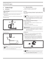 7
7
-
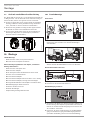 8
8
-
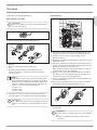 9
9
-
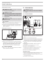 10
10
-
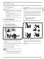 11
11
-
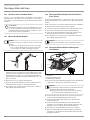 12
12
-
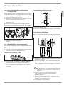 13
13
-
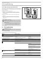 14
14
-
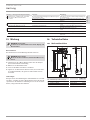 15
15
-
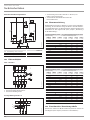 16
16
-
 17
17
-
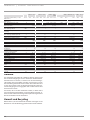 18
18
-
 19
19
-
 20
20
-
 21
21
-
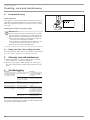 22
22
-
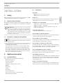 23
23
-
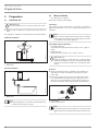 24
24
-
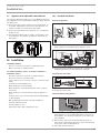 25
25
-
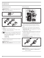 26
26
-
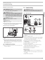 27
27
-
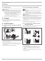 28
28
-
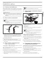 29
29
-
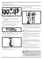 30
30
-
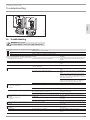 31
31
-
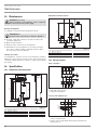 32
32
-
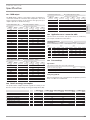 33
33
-
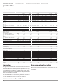 34
34
-
 35
35
-
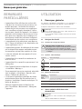 36
36
-
 37
37
-
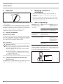 38
38
-
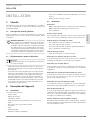 39
39
-
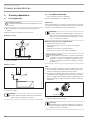 40
40
-
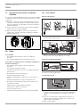 41
41
-
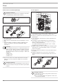 42
42
-
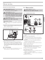 43
43
-
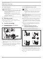 44
44
-
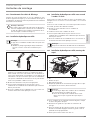 45
45
-
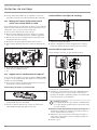 46
46
-
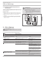 47
47
-
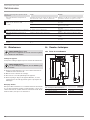 48
48
-
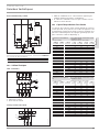 49
49
-
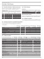 50
50
-
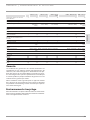 51
51
-
 52
52
-
 53
53
-
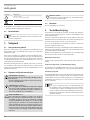 54
54
-
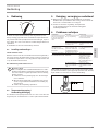 55
55
-
 56
56
-
 57
57
-
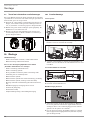 58
58
-
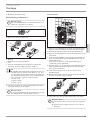 59
59
-
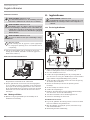 60
60
-
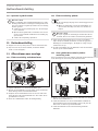 61
61
-
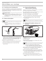 62
62
-
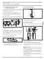 63
63
-
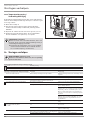 64
64
-
 65
65
-
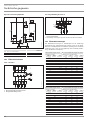 66
66
-
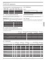 67
67
-
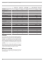 68
68
-
 69
69
-
 70
70
-
 71
71
-
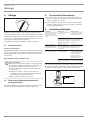 72
72
-
 73
73
-
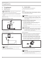 74
74
-
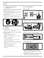 75
75
-
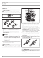 76
76
-
 77
77
-
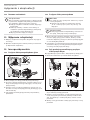 78
78
-
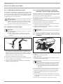 79
79
-
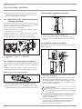 80
80
-
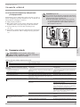 81
81
-
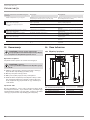 82
82
-
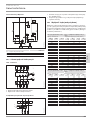 83
83
-
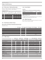 84
84
-
 85
85
-
 86
86
-
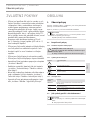 87
87
-
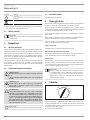 88
88
-
 89
89
-
 90
90
-
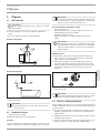 91
91
-
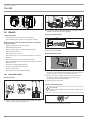 92
92
-
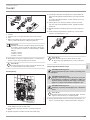 93
93
-
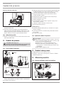 94
94
-
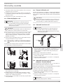 95
95
-
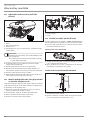 96
96
-
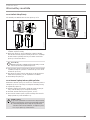 97
97
-
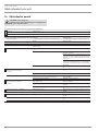 98
98
-
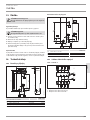 99
99
-
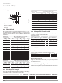 100
100
-
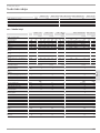 101
101
-
 102
102
-
 103
103
-
 104
104


STIEBEL ELTRON DHB-E 11-27 SLi Operation Instruction
- Type
- Operation Instruction
in andere talen
- français: STIEBEL ELTRON DHB-E 11-27 SLi
- Deutsch: STIEBEL ELTRON DHB-E 11-27 SLi
- polski: STIEBEL ELTRON DHB-E 11-27 SLi
Gerelateerde papieren
-
STIEBEL ELTRON DHB-STi 18-27 Operation Instruction
-
-
-
-
STIEBEL ELTRON 236739 Operation and Installation
-
-
-
-
-