
INTERNO
Montageanleitung

2
Abmessungen, Gewicht und Anschluss
Abmessungen
H - Höhe [mm] 617/686
B - Breite [mm] 790/920
T - Korpustiefe [mm] 580
Einbauabmessungen
H - E Höhe (min.) [mm] 560
B - E Breite (min.) [mm] 690
T - E Korpustiefe (min.) [mm] 510
Gewicht
Gewicht Ofen [kg] 140
Gewicht Bodenplatte [kg] 30
Rauchrohranschluss
R - Ø Durchmesser [mm] 100
RO - H Original Winkelrohr Anschlusshöhe [cm] 26
RO - T1 Original Winkelrohr Tiefe gesamt [cm] 7
RO - T2 Original Winkelrohr Abstand zu
Rückwand
[cm] -
RO - T3 Tiefe von Ofenrückseite zu Mitte
Rauchrohr
[cm] -
RO - S Original Winkelrohr Abstand seitlich [cm] 11
R - H Anschluss hinten Anschlusshöhe [cm] 17
R - S Anschluss hinten Abstand seitlich [cm] 11
Frischluftanschluss
F - Ø Durchmesser [mm] 50
F - H Anschlusshöhe [cm] 14
F - S Abstand seitlich [cm] 30
F - T Abstand Tiefe [cm] 6
Brennstoffmenge
Nennlast Teillast
Brennstoffmenge ~1,6kg* ~0,6kg*
Brenndauer bei vollem
Pelletbehälter
14h* 40h*
* Praxiswerte, können je nach Pelletqualität abweichen.
Hinweis
Der Pelletverbrauch hängt von der Größe der Pellets ab. Je größer die Pellets,
desto langsamer die Zufuhr und umgekehrt.
Technische Daten
Technische Daten
Heizleistungsbereich [kW] 2,5 - 7
Raumheizvermögen abhängig von der
Hausisolierung
[m³] 50 - 160
Brennstoffverbrauch [kg/h] bis zu 1,6
Pelletbehälterkapazität* [l/kg] 36/~20
Netzanschluss [V]/[Hz] 230/50
durchschnittliche elektrische Leistungsaufnahme [W] ~50
Sicherung [A] 2,5 AT
Wirkungsgrad [%] 90,1
CO2-Gehalt [%] 12,2
CO-Emission bez. 13% O [mg/m
N
3
] 60
Staub-Emissionen [mg/m
N
3
] 14
Abgasmassenstrom [g/s] 4,5
Abgastemperatur [°C] 173,2
Kaminzugbedarf [Pa] > 3
*Fassungsvermögen in kg kann aufgrund unterschiedlicher Pelletschüttdichten
abweichen.
Der Eigentümer der Kleinfeuerungsanlage oder der über die Kleinfeuerungsanlage
Verfügungsberechtigte hat die technische Dokumentation aufzubewahren und
auf Verlangen der Behörde oder des Schornsteinfegers vorzulegen.
Hinweis
Bitte beachten Sie die nationalen und europäischen Normen, sowie örtliche
Vorschriften, die für die Installation und den Betrieb der Feuerstätte zutreffend
sind!
Die Verpackung
Ihr erster Eindruck ist uns wichtig!
Die Verpackung Ihres neuen Kaminofens bietet einen hervorragenden Schutz
gegen Beschädigung. Beim Transport können aber trotzdem Schäden an Ofen
und Zubehör entstanden sein.
Hinweis
Bitte prüfen Sie daher Ihren Kaminofen nach Erhalt sorgfältig auf Schäden
und Vollständigkeit! Melden Sie Mängel unverzüglich Ihrem Ofenfachhändler!
Achten Sie bitte beim Auspacken besonders darauf, dass die Steinverkleidung
unversehrt bleibt. Es können sehr leicht Kratzer am Material entstehen.
Steinverkleidungen sind von der Garantie ausgenommen.
Die Verpackung Ihres neuen Kaminofens ist weitgehend umweltneutral.
Tipp
Das Holz der Verpackung ist nicht oberflächenbehandelt und kann daher,
nachdem Sie eventuelle Nägel bzw. Schrauben entfernt haben, in Ihrem
Ofen (ausgenommen Pelletofen) verbrannt werden. Der Karton und die
Folie (PE) können problemlos den kommunalen Abfallsammelstellen zur
Wiederverwertung zugeführt werden.
Elektrischer Anschluss
Der Ofen wird mit einem ca. 2 m langen Anschlusskabel mit Eurostecker
geliefert. Dieses Kabel ist an eine 230Volt / 50Hz Steckdose anzuschließen.
Die durchschnittliche elektrische Leistungsaufnahme beträgt im regulären
Heizbetrieb etwa 50Watt. Während des automatischen Anzündvorganges ca.
150Watt. Das Anschlusskabel muss so gelegt werden, dass jeglicher Kontakt
mit heißen oder scharfkantigen Außenflächen des Ofens vermieden wird.

|3
DE
2
1. INSTALLATION DES KAMINOFENS
Hinweis
Die Montage darf ausschließlich vom autorisierten Fachbetrieb durchgeführt
werden.
Hinweis
Bitte beachten Sie die regional gültigen Sicherheits- und Baubestimmungen.
Kontaktieren Sie diesbezüglich Ihren Schornsteinfegermeister.
Hinweis
Nur hitzebeständige Dichtmaterialien, sowie entsprechende Dichtbänder,
hitzebeständiges Silikon und Mineralwolle verwenden.
Hinweis
Achten Sie darauf, dass das Rauchrohr nicht in den freien Querschnitt des
Schornsteines hineinragt.
Hinweis
Falls Ihr Kaminofen für einen raumluftunabhängigen Betrieb vorgesehen
ist, müssen die Ofenrohranschlüsse für diesen Einsatz dauerhaft dicht
angeschlossen werden. Verwenden Sie zum Aufsetzen des Ofenrohres auf
den konischen Rauchrohrstutzen und zum Einsetzen in das Rohrfutter des
Schornsteines ein geeignetes hitzefestes Silikon.
Hinweis
Der Ofen darf keinesfalls auf ungeschütztem Boden geschoben werden.
Als Montagehilfe und Unterlage eignen sich starke Wellpappe, Karton oder
beispielsweise ein ausgedienter Teppich hervorragend. Damit können Sie den
Ofen auch vorsichtig verschieben.
Zum fachgerechten Anschließen empfehlen wir original Rauchrohre aus dem
RIKA Rauchrohrsortiment.
Anschluss an den Schornstein (Kamin)
Q Das Gerät muss an einem für feste Brennstoffe genehmigten,
feuchteunempfindlichen Schornstein angeschlossen werden. Von
der Feuchteunempfindlichkeit kann abgewichen werden, wenn die
Schornsteinberechnung einen trockenen Betrieb ergibt.
Q Der Schornstein muss für Pelletgeräte für einen Durchmesser von 100 mm
und für Scheitholzgeräte für 130 mm–150 mm je nach Ofenmodell
ausgelegt sein.
Q Vermeiden Sie zu lange Rauchgaswege zum Kamin. Die waagrechte Länge
einer Abgasleitung sollte 1,5Meter nicht überschreiten.
Q Vermeiden Sie viele Richtungsänderungen des Abgasstromes zum Kamin.
Es sollen maximal 3Bögen in der Abgasleitung verarbeitet werden.
Q Verwenden Sie ein Anschlussstück mit Reinigungsöffnung.
Q Die Verbindungsstücke müssen aus Metall ausgeführt sein und die
Anforderungen der Norm erfüllen (die Anschlüsse luftdicht installieren).
Q Vor der Installation muss unbedingt eine Schornsteinberechnung durchgeführt
werden. Die Nachweise müssen für Einfachbelegung nach EN13384-1 und
für Mehrfachbelegung nach EN13384-2 durchgeführt werden.
Q Der maximale Förderdruck (Kaminzug) soll 15 Pa nicht überschreiten.
Q Die Ableitung der Rauchgase muss auch bei einem vorübergehenden
Stromausfall gewährleistet sein.
Hinweis
Beim Anschluss an mehrfachbelegte Schornsteine sind je nach
Ländervorschrift zusätzliche Sicherheitseinrichtungen erforderlich.
Hinweis
Das Eindringen von Kondenswasser über den Kaminanschluss muss
ausgeschlossen werden. Eventuell ist dazu die Montage eines Kondensatringes
notwendig - fragen Sie Ihren zuständigen Schornsteinfegermeister. Schäden
durch Kondenswasser sind von der Garantie ausgeschlossen.
Anschluss an einen Edelstahlschornstein (Kamin)
Der Anschluss muss ebenso nach EN13384-1 oder EN13384-2 berechnet und
nachgewiesen werden.
Es dürfen nur isolierte (doppelwandige) Edelstahlrohre verwendet werden
(biegsame Alu- oder Stahlrohre sind nicht zulässig).
Eine Revisionsklappe für eine regelmäßige Inspektion u. Reinigung muss
vorhanden sein.
Der Anschluss an den Rauchfang ist luftdicht auszuführen.
Verbrennungsluft
Jeder Verbrennungsvorgang benötigt Sauerstoff aus der uns umgebenden
Luft. Diese sogenannte Verbrennungsluft wird bei Einzelöfen ohne externen
Verbrennungsluftanschluss dem Wohnraum entzogen.
Diese entnommene Luft muss dem Wohnraum wieder zugeführt werden. Bei
modernen Wohnungen kann durch sehr dichte Fenster und Türen zu wenig
Luft nachströmen. Problematisch wird die Situation auch durch zusätzliche
Entlüftungen in der Wohnung (z.B. in der Küche oder WC). Können Sie keine
externe Verbrennungsluft zuführen, so lüften Sie den Raum mehrmals täglich,
um einen Unterdruck im Raum oder eine schlechte Verbrennung zu vermeiden.
Zufuhr einer externen Verbrennungsluft
Nur für Geräte, die für einen raumluftunabhängigen Betrieb geeignet sind.
Q Für einen raumluftunabhängigen Betrieb muss dem Gerät über eine dichte
Leitung die Verbrennungsluft von außen zugeführt werden. Lt. EnEV sollte
die Verbrennungsluftleitung absperrbar sein. Die Stellung auf/zu muss
eindeutig erkennbar sein.
Q Schließen Sie an den Ansaugstutzen ein Rohr mit Ø 125 mm für Scheitholz-
u. Kombiöfen oder mit Ø 50 mm oder Ø 60 mm für Pelletöfen an. Fixieren
Sie dieses mit einer Schlauchklemme (nicht im Lieferumfang enthalten!).
Bei Pelletgeräten mit längerer Anschlussleitung sollte nach ca. 1Meter der
Durchmesser auf etwa 100 mm vergrößert werden.
Q Um ausreichende Luftzufuhr zu gewährleisten, soll die Leitung nicht länger
als 4Meter sein und max. 3Biegungen aufweisen.
Q Führt die Leitung ins Freie, muss sie mit einem Windschutz enden.
Q Bei extremer Kälte auf das „Vereisen“ der Zuluftöffnung achten (Kontrolle).
Q Weiters besteht die Möglichkeit, die Verbrennungsluft direkt von einem
anderen genügend belüfteten Raum (z.B. Keller) anzusaugen.
Q Die Verbrennungsluftleitung muss am Luftstutzen des Gerätes dauerhaft
dicht (Kleber oder Kitt) angeschlossen werden.
Q Wird der Ofen längere Zeit nicht betrieben, so ist die Verbrennungsluftleitung
abzusperren um das Eintreten von Feuchtigkeit in den Ofen zu verhindern.
Hinweis
Bitte beachten Sie, dass es bei einer Verbrennungsluftversorgung aus einem
integrierten Schornsteinlüftungsschacht zu Problemen kommen kann. Die
Vorwärmung der Verbrennungsluft verursacht eine der Strömungsrichtung
entgegenwirkende Thermik. Die erhöhten Druckverluste reduzieren den
Unterdruck in der Brennkammer. Der Kaminhersteller muss garantieren,
dass der Widerstand für die Verbrennungsluft selbst unter schwierigsten
Bedingungen bei max. 2 Pa liegt.
Sollten eine oder mehrere dieser Bedingungen NICHT zutreffen, so sind meist eine
schlechte Verbrennung im Ofen und/oder Luftunterdruck im Aufstellraum die Folge.

4
2. WICHTIGE INFORMATIONEN
Allgemeine Warn- und Sicherheitshinweise
Beachten Sie unbedingt die folgenden allgemeinen Warnhinweise.
Q Lesen Sie vor der Installation und Inbetriebnahme des Ofens das gesamte
Handbuch gründlich durch. Beachten Sie unbedingt die nationalen
Bestimmungen und Gesetze, sowie die örtlich gültigen Vorschriften und
Regeln.
Q RIKA Öfen dürfen nur in Wohnräumen mit normaler Luftfeuchtigkeit (trockene
Räume nach VDE 0100 Teil 200) aufgestellt werden. Die Öfen sind nicht
spritzwassergeschützt und dürfen nicht in Nassräumen aufgestellt werden.
Q Für den Transport Ihres Heizgerätes dürfen nur zugelassene Transporthilfen
mit ausreichender Tragfähigkeit verwendet werden.
Q Ihr Heizgerät ist nicht zur Verwendung als Leiter oder Standgerüst geeignet.
Q Durch den Abbrand von Brennmaterial wird Wärmeenergie frei, die zu einer
starken Erhitzung der Oberfläche des Heizgerätes, der Türen, der Tür- und
Bediengriffe, der Türgläser, der Rauchrohre und gegebenenfalls der Frontwand
des Heizgerätes führt. Die Berührung dieser Teile ohne entsprechende
Schutzbekleidung oder Hilfsmittel wie z. B. Hitzeschutzhandschuhe oder
Betätigungsmittel (Bediengriff), ist zu unterlassen.
Q Machen Sie Ihre Kinder auf diese besondere Gefahr aufmerksam und halten
Sie sie während des Heizbetriebes vom Heizgerät fern.
Q Verbrennen Sie ausschließlich das genehmigte Heizmaterial.
Q Das Verbrennen oder Einbringen von leicht brennbaren oder explosiven
Stoffen, wie leere Spraydosen und dgl. in den Brennraum, sowie
deren Lagerung in unmittelbarer Nähe Ihres Heizgerätes, ist wegen
Explosionsgefahr strengstens verboten.
Q Beim Nachheizen sollen keine weiten oder leicht brennbaren Kleidungsstücke
getragen werden.
Q Achten Sie darauf, dass keine Glutstücke aus dem Brennraum auf brennbares
Material fallen.
Q Das Abstellen von nicht hitzebeständigen Gegenständen auf dem Heizgerät
oder in dessen Nähe ist verboten.
Q Legen Sie keine Wäschestücke zum Trocknen auf den Ofen.
Q Ständer zum Trocknen von Kleidungsstücken oder dgl. müssen in
ausreichendem Abstand vom Heizgerät aufgestellt werden – AKUTE
BRANDGEFAHR!
Q Beim Betrieb Ihres Heizgerätes ist das Verarbeiten von leicht brennbaren
und explosiven Stoffen im selben oder in angrenzenden Räumen verboten.
Q Wird der Ofen im Dauerbetrieb beheizt, können sich die Reinigungsintervalle
verkürzen. Ein erhöhter Verschleiß, speziell der thermisch belasteten Teile
ist die Folge. Bitte daher unbedingt die Vorgaben für die Reinigung und
Wartung einhalten!
Hinweis
Abfallstoffe und Flüssigkeiten dürfen im Ofen nicht verbrannt werden!
Hinweis
ACHTUNG beim Befüllen des Vorratsbehälters. Die Öffnung des
Pelletbehälters ist ausreichend dimensioniert, um ein problemloses Einfüllen
zu gewährleisten. Achten Sie penibel darauf, dass keine Pellets auf die
Konvektionsrippen und den heißen Ofenkorpus fallen. Es kann dadurch zu
einer starken Rauchentwicklung kommen.
Tipp
Wir empfehlen daher ein Nachfüllen des Vorratbehälters bei kaltem Ofen.
Hinweis
Um ein Überhitzen der eingebauten Komponenten zu vermeiden verschließen
Sie keinesfalls die Konvektionsöffnungen Ihres Kaminofens!
Bitte beachten Sie, dass es durch den Austritt der heißen Konvektionsluft
oberhalb der Lüftungsschlitze zu Verfärbungen bzw. Ablagerungen an der Wand
kommen kann.
Hinweis
Die ausströmende Konvektionsluft kann Temperaturen bis zu 180° erreichen.
Hinweis
Ihr Kaminofen wird sich während der Aufheiz- und Abkühlphase ausdehnen
und zusammenziehen. Das kann unter Umständen zu leichten Dehn- bzw.
Knackgeräuschen führen. Dies ist ein normaler Vorgang und stellt keinen
Reklamationsgrund dar.
Erstes Anheizen
Der Ofenkorpus, ebenso diverse Stahl- und Gussteile sowie die Rauchrohre,
werden mit einem hitzebeständigen Lack lackiert. Beim ersten Anheizen
trocknet der Lack noch etwas nach. Es kann dabei zu einer geringfügigen
Geruchsentwicklung kommen. Das Berühren bzw. Reinigen der lackierten
Flächen während der Aushärtephase ist zu vermeiden. Das Aushärten des
Lackes ist nach dem Betrieb mit großer Leistung beendet.

|5
DE
4
Sicherheitsabstände (Mindestabstände)
Hinweis
Abstand zu nicht brennbaren Gegenständen:
a > 40cm
b / c ≥ Einbauabmessungen
d ≥ 20cm wenn Vorsprung e = 0 bis 20cm
d ≥ 30cm wenn Vorsprung e = 20 bis 30cm
d ≥ 40cm wenn Vorsprung e > 30cm
Abstand zu brennbaren Gegenständen und zu tragenden Wänden aus
Stahlbeton: a > 80cm
Einbau bei brennbaren Materialien und tragenden Wänden aus Stahlbeton nur
in Verbindung mit Option Hitzeschutzmantel E15888!
b > 20cm
c > 120cm
d > 80cm
Seitenansicht:
d
a
10cm
c
b
b
e
Ansicht von oben:
a
a
b
b
Platzbedarf vor dem Ofen:
5
0
c
m
Vor dem Aufstellen
Bodentragfähigkeit
Überzeugen Sie sich vor dem Aufstellen, ob die Tragfähigkeit der
Unterkonstruktion dem Gewicht des Ofens standhält.
Hinweis
Veränderungen an der Feuerstätte dürfen nicht vorgenommen werden. Dies
führt außerdem zu Verlust von Garantie und Gewährleistung.
Bodenschutz
Bei brennbaren Böden (Holz, Teppich, etc.) ist eine Unterlage (Glas, Stahlblech
oder Keramik) erforderlich.
Rauchrohranschluss
Q Rauchrohre sind eine besondere Gefahrenquelle im Hinblick auf
Rauchgasaustritt und Brandgefahr. Holen Sie für deren Anordnung und
Montage den Rat eines konzessionierten Fachbetriebes ein.
Q Bitte beachten Sie beim Anschluss Ihres Rauchrohres an den Kamin,
im Bereich von mit Holz verkleideten Wänden, die entsprechenden
Einbaurichtlinien.
Q Beachten Sie unbedingt bei ungünstiger Wetterlage die Rauchgasbildung
(Inversionswetterlage) und die Zugverhältnisse.
Q Wenn zu wenig Verbrennungsluft zugeführt wird, kann es zu einer
Verqualmung Ihrer Wohnung oder zu Rauchgasaustritt kommen. Außerdem
können schädliche Ablagerungen im Heizgerät und im Kamin entstehen.
Q Lassen Sie das Feuer bei einem Rauchgasaustritt ausgehen und überprüfen
Sie, ob die Lufteinlassöffnung frei ist und die Rauchgasführungen und
das Ofenrohr sauber sind. Im Zweifelsfall verständigen Sie unbedingt den
Schornsteinfegermeister, da eine Zugstörung auch mit Ihrem Schornstein
zusammenhängen kann.
Kaminöfen der Bauart 1 (BA 1):
Q Für Mehrfachbelegung geeignet. (beachten Sie die unterschiedlichen
Länderbestimmungen)
Q Diese dürfen nur mit geschlossener Feuerraumtür betrieben werden.
Q Wird der Kaminofen nicht betrieben, ist die Feuerraumtür geschlossen zu
halten.
Hinweis
Ihr Pelletofen ist als raumluftunabhängiger Pelletofen nach EN14785 geprüft
und kann raumluftabhängig oder optional raumluftunabhängig betrieben
werden.
RAUMLUFTUNABHÄNGIGER BETRIEB:
Bei dichter Ausführung der Zuluftleitung und der Rauchrohre entspricht der
Ofen dem Typ FC52x / FC62x von raumluftunabhängigen Feuerstätten gemäß
den Zulassungsgrundsätzen des Deutschen Instituts für Bautechnik (DIBt).
Aufgrund seiner Betriebsweise darf der Ofen auch in Nutzungseinheiten
aufgestellt werden, die dauerhaft luftundurchlässig entsprechend dem
Stand der Technik abgedichtet sind, sowie in Nutzungseinheiten, die mit
mechanischen Be- oder Entlüftungsanlagen ausgerüstet sind.
RAUMLUFTABHÄNGIGER BETRIEB:
In Kombination mit raumlufttechnischen Anlagen (z.B.: kontrollierten Be- und
Entlüftungsanlagen, Dunstabzug o.ä.) ist sicherzustellen, dass der Ofen
und die raumlufttechnische Anlage gegenseitig überwacht und abgesichert
werden (z.B. über einen Differenzdruckcontroller etc.). Die notwendige
Verbrennungsluftzufuhr von ca. 20 m3/h muss gewährleistet sein.
Bitte beachten Sie, immer in Absprache mit Ihrem zuständigen
Schornsteinfegermeister, die jeweils gültigen örtlichen Vorschriften und
Regeln. Für Änderungen nach Drucklegung dieser Anleitung können wir keine
Haftung übernehmen. Änderungen behalten wir uns vor.

6
Lieferumfang
B17419
Q 4x N110586 Senkschraube M05x20
Q 4x N111945 Sicherungsmutter M06
Q 2x N108572 ISK-Schraube M06x30
Q 4x L02612 Nivellierungsblech 1mm
Q 4x L02613 Nivellierungsblech 2mm
Q 4x L02614 Nivellierungsblech 3mm
Q 4x L02615 Nivellierungsblech 4mm
Q 10x N112132 SK-Schraube M12x100
Q 10x N112131 Beilagscheibe M12
Q 10x N112133 Dübel
45
405
140
562
70
432
45
411
50
50
Zeichenerklärung
#2
...Innensechskant
#2
#3
...Innensechskant
#3
#5
...Innensechskant
#5
#19
...Gabelschlüssel
#19
#7
...Sechskant #7
#10
...Sechskant #10
...waagrecht
ausrichten
...per Hand
Hinweis
Lesen Sie vor der Installation und Inbetriebnahme des Ofens das gesamte Handbuch gründlich durch. Beachten Sie unbedingt die nationalen Bestimmungen und
Gesetze, sowie die örtlich gültigen Vorschriften und Regeln.
Montageplatzbedarf
Bitte beachten Sie, dass Sie für die Sicherung des ausziehbaren Ofenkorpus einen Freiraum nach unten von mindestens 10cm benötigen.
Abmessungen der Bodenplatte für die Befestigung
vorne

|7
DE
6
Vormontage
Befestigen Sie den Rauchrohr-Adapter auf der Bodenplatte.
Tipp
Für einen optionalen Rauchrohranschluss nach oben tauschen Sie
Rauchrohrstutzen und Kochdeckel gegeneinander aus.
Legen Sie die Bodenplatte in den dafür vorgesehenen Wandverbau.
Gewährleisten Sie, daß die Bodenplatte absolut waagrecht aufliegt. Falls nicht
- gleichen Sie mit Hilfe der Nivellierungsbleche etwaige Unebenheiten von 1mm
bis max. 10mm aus.
Nachdem Sie eine waagrechte Position sichergestellt haben, befestigen Sie die
Bodenplatte.
Abb.: Montagebeispiel
Hinweis
Achten Sie auf eine sichere Befestigung! Da die Einbausituation je nach
baulicher Gegebenheit vor Ort unterschiedlich ist, liegt die Verantwortung
dafür auf Seiten des Aufstellers. Bitte beachten Sie die Gewichtsangaben in
den technischen Daten.
#3
N110586
N112133
N112132
N112131
#19

8
Ofenmontage
Verbinden Sie den Netzstecker mit Ihrer Stromleitung.
Schieben Sie die Führungsschienen bis zum Anschlag aus dem Gehäuse.
Heben Sie den Ofen zu zweit auf die Führungsschiene in die dafür vorgesehenen
Zapfen und sichern Sie diese umgehend.
Montieren Sie die optionalen Sichtblenden am Ofen.
Schieben Sie den Ofen wieder zurück in die Wand.
Sichern Sie den Ofen von unten gegen ungewolltes Ausfahren.
Öffnen Sie die Dekortür.
Entfernen Sie die Abdeckung hinter der Schlüsselhalterung und verbinden Sie
den Ofen mit dem Netzstecker.
Montieren Sie die Teile wieder in umgekehrter Reihenfolge.
Ihr Ofen ist betriebsbereit.
#10
N111945
#7
#5
N108572
#2

Instructions de montage
INTERNO
8

10
Dimensions
Dimensions
H - Hauteur [mm] 617/686
B - Largeur [mm] 790/920
T - Profondeur du corps [mm] 580
Dimensions de montage
H - E Hauteur (min.) [mm] 560
B - E Largeur (min.) [mm] 690
T - E Profondeur du corps (min.) [mm] 510
Poids
Poids du poêle [kg] 140
Poids du socle [kg] 30
Tuyaux de fumées
R - Ø Diamètre [mm] 100
RO - H Hauteur de raccordement avec tuyau
d’angle d’origine
[cm] 26
RO - T1 Profondeur avec tuyau d’angle d’origine [cm] 7
RO - T2 Distance mur - tuyau d’angle d’origine [cm] -
RO - T3 Profondeur fond de poèle - tuyau d’angle
d’origine
[cm] -
RO - S Distance raccord tuyau - paroi latérale [cm] 11
R - H Hauteur de raccordement [cm] 17
R - S Distance raccord derrière - paroi latérale [cm] 11
Raccordement d’air frais
F - Ø Diamètre [mm] 50
F - H Hauteur [cm] 14
F - S Distance raccord - paroi latérale [cm] 30
F - T Profondeur [cm] 6
Quantité de combustible
Charge nominale Charge partielle
Quantité de combustible ~1,6kg* ~0,6kg*
Durée de combustion
d’un réservoir plein
14h* 40h*
*Valeurs tirées de notre expérience, pouvant changer selon le type de granulés.
Attention
La consommation en granulés dépends de la grosseur des granulés. Plus ils
sont grands, plus la vitesse de l‘alimentation se réduit et vice versa.
Caractéristiques techniques
Caractéristiques techniques
Plage de puissance de chauffage [kW] 2,5 - 7
Capacité de chauffage en fonction de l’isolation
du domicile
[m³] 50 - 160
Consommation en combustible [kg/h] jusqu‘à 1,6
Capacité du réservoir* [l/kg] 36/~20
Branchement réseau [V]/[Hz] 230/50
Consommation électrique moyenne [W] ~50
Fusible [A] 2,5 AT
Rendement [%] 90,1
Teneur CO2 [%] 12,2
Émission de CO à 13% O [mg/m
N
3
] 60
Émission de poussières [mg/m
N
3
] 14
Débit massique gaz résiduel [g/s] 4,5
Température gaz résiduel [°C] 173,2
Tirage cheminée requis [Pa] > 3
*En raison de différentes densités apparentes des pellets, la capacité en kg peut diverger.
Le propriétaire ou la personne autorisée à disposer d’une installation à petit
foyer doit garder la documentation technique et la présenter sur demande des
administrations ou du ramoneur.
Attention
Respectez les normes nationales et européennes ainsi que les réglementations
locales concernant l’installation et l’exploitation de l’installation.
Emballage
Votre première impression est pour nous essentielle.
L’emballage de votre nouveau poêle offre une excellente protection contre les
dommages. Le four et ses accessoires peuvent cependant être endommagés
lors du transport.
Attention
Aussi nous vous prions de vérifier attentivement à la réception que votre poêle
est complet et en parfait état. Signalez tout problème à votre représentant.
Faites attention lors du déballage à ne pas abimer le manteau en stéatite.
Le matériel est très sensible aux éraflures. Le manteau en stéatite n’est pas
couvert par la garantie.
L’emballage de votre nouveau poêle est dans une large mesure sans impact
sur l’environnement.
Conseil
Le bois de l’emballage n’est pas traité. Il peut donc être utilisé comme bois
de chauffage (pas pour votre poêle à granulés). Pensez à retirer clous et vis
auparavant. Le carton et les feuilles d’emballage (PE) peuvent sans problème
être envoyés aux décharges communales pour y être recyclés.
Branchement électrique
Le poêle est livré avec un câble électrique d’env. 2 m doté d’une prise Euro.
Branchez-le sur une prise 230 Volt / 50 Hz. La consommation moyenne de
l’appareil en mode de fonctionnement normal est d’env. 50 Watt Elle est d’env.
150 Watt pendant l’amorçage automatique. Le câble doit être placé de façon à
éviter tout contact avec les parties chaudes ou coupantes du poêle.

|11
FR
10
3. INSTALLATION DU POÊLE
Consignes générales
Attention
Le montage doit exclusivement être effectué par un spécialiste agréé.
Attention
Veuillez respecter les dispositions de construction et de sécurité applicables
au niveau régional. Contactez à cet effet votre ramoneur.
Attention
Seuls des matériaux d‘étanchéité résistants à la chaleur et les bandes
d‘étanchéité, le silicone résistant à la chaleur et la laine minérale adéquats
doivent être utilisés.
Attention
En cas d’un fonctionnement indépendant de l‘air ambiant les raccordements
de tuyaux du poêle doivent par conséquent être étanchés durablement.
Utilisez un mastic pour poêle ou une colle résistante à la chaleur pour la mise
en place du tuyau du poêle sur le raccord du conduit de fumée conique et
pour l’insertion dans la garniture de tuyau de la cheminée.
Attention
Le poêle ne doit en aucun cas être glissé sur un sol non protégé.
Conseil
En guise de protection vous pouvez par exemple utiliser du carton ondulé
solide, du carton, ou un vieux tapis. Vous pourrez ainsi pousser plus
facilement le poêle.
Pour un raccordement professionnel, nous recommandons l’utilisation de
conduits de fumée d’origine de marque RIKA.
Raccordement à la cheminée
Q L‘appareil doit être raccordé à une cheminée homologuée pour les
combustibles solides et non sensible à l‘humidité. L‘insensibilité à l‘humidité
peut varier si le calcul de la cheminée aboutit à un fonctionnement à sec.
Q Le conduit de cheminée doit avoir un diamètre de 100 mm au minimum pour
les poêles à pellets et pour les poêles à bois selon le diamètre des tuyaux
gas fumées de 130 mm à 150 mm au minimum.
Q Evitez de trop longs conduits d’évacuation vers la cheminée. Un conduit
d’évacuation à l’horizontale ne doit pas dépasser les 1,5mètres.
Q Evitez le plus possible les changements de direction du conduit d’évacuation
vers la cheminée.
Q Ne pas utilisez plus de 3coudes au maximum dans le montage du conduit
d’évacuation.
Q Utilisez un élément de raccordement avec clapet de nettoyage.
Q Les éléments de raccordement doivent être en métal et remplir les
exigences de la norme (installer les éléments de façon étanche).
Q Avant l’installation, une évaluation du conduit doit être impérativement
réalisée. Les vérifications doivent être exécutées selon la norme EN13384-1.
Q La dépression maximale (dans le conduit) ne doit pas dépasser 15 Pa.
Q L’évacuation des gaz de fumée doit aussi être garantie en cas de panne de
courant transitoire.
Attention
La présence de condensats sur la sortie des fumées doit absolument être
évitée. De ce fait le montage d’un raccord femelle/femelle anti condensats
peut être nécessaire. Parlez-en à votre installateur ou à votre ramoneur. Les
dommages provoqués par les condensats sont exclus de la garantie.
Raccordement à un conduit de cheminée en inox
Le raccordement doit aussi être vérifié selon la norme EN13384-1.
Seuls des tuyaux isolés (double paroi) en inox doivent être utilisés. (Les tuyaux
flexibles en alu ou en acier ne sont pas autorisés.)
Une trappe de visite (clapet de nettoyage) doit être présente pour une inspection
et un nettoyage réguliers.
Le raccordement au conduit doit être réalisé de façon étanche.
Air de combustion
Tout processus de combustion a besoin d‘oxygène provenant de l’air ambiant.
Sur les poêles individuels sans raccordement d’air de combustion externe, cet
air de combustion est prélevé dans la pièce. Cet air prélevé doit être restitué
dans la pièce. Dans les habitations modernes, les fenêtres et portes très
épaisses laissent affluer une quantité d’air trop faible. La situation est également
rendue problématique en raison des ventilations supplémentaires installées
dans l‘habitation (p. ex. dans la cuisine ou les toilettes). Si vous ne pouvez pas
acheminer d‘air de combustion externe, ventilez la pièce plusieurs fois par jour
afin d‘éviter une dépression dans la pièce ou une mauvaise combustion.
Arrivée d‘air extérieur
Uniquement pour des appareils prévus pour un fonctionnement indépendant de l’air
ambiant.
Q Pour un fonctionnement indépendant de l‘air ambiante, l’air de combustion
doit être acheminé vers l’appareil depuis l’extérieur via une conduite étanche.
Selon la norme EnEV, la conduite d’air de combustion doit être pouvoir être
coupée. La position ouverture/fermeture doit être clairement identifiable.
Q Découpez la paroi arrière droite perforée à l’aide d’une lame de scie à
métaux.
Q Connectez au tube d’aspiration, soit un tuyau de diamètre 125 mm pour les
poêles à bois et mixte, soit de diamètre 50 mm ou 60 mm pour les poêles
à pellets. Fixez-le avec un collier de serrage (non fourni !). Pour les poêles à
pellets avec une sortie plus longue, au-delà d‘un mètre environ, le diamètre
doit être augmenté à environ 100 mm. (Cf. gamme RIKA)
Q Afin de garantir une amenée d‘air suffisante, la conduite ne doit pas dépasser
4mètres et ne pas présenter trop de courbures.
Q Si la conduite mène à l’extérieur, elle doit se terminer par une protection
contre le vent.
Q En cas de froid extrême, surveiller l’éventuel gel de l’orifice d’aération
(contrôle).
Q Il est également possible d‘aspirer l’air de combustion directement dans une
autre pièce suffisamment ventilée (une cave p.ex.).
Q La conduite d’air de combustion doit être étanchée au niveau de la tubulure
d’air (colle ou mastic).
Q En cas de non-utilisation prolongée du poêle, il faut boucher le conduit
d’arrivée d’air extérieur, afin d’empêcher l’humidité de pénétrer dans le
poêle.
Attention
Veuillez noter que l’alimentation en air de combustion provenant d’une
gaine de ventilation de cheminée intégrée est susceptible d’entraîner des
problèmes liés aux courants thermiques. En cas d’échauffement de l’air de
combustion affluant vers le bas, ce dernier risque de s’élever et d’exercer une
résistance contre la cheminée, entraînant une réduction de la sous-pression
dans la chambre de combustion. Le fabricant de cheminées doit garantir que
la résistance de l’air de combustion est au maximum égale à 2 PA, même
dans des conditions de fonctionnement défavorables de la cheminée.
Si une ou plusieurs de ces conditions ne sont pas remplies, la conséquence est le plus
souvent une mauvaise combustion dans le poêle et/ou une dépression d’air dans la pièce.

12
4. INFORMATIONS IMPORTANTES
Informations générales de mise en garde et de
sécurité
Veuillez impérativement respecter les indications de mise en garde mentionnées
en introduction.
Q Avant l’installation et la mise en service du poêle, lisez attentivement tout le
manuel. Respectez impérativement les dispositions et lois nationales ainsi
que les directives et règlementations valables au niveau local.
Q Les poêles RIKA doivent uniquement être installés dans des pièces de vie
non humides. Les poêles ne sont pas protégés contre les projections d’eau
et ne doivent pas être installés dans des pièces humides.
Q Pour le transport de votre appareil de chauffage, seuls des auxiliaires de
transport autorisés et dotés d‘une force de levage suffisante doivent être
utilisés.
Q Votre appareil de chauffage n‘est pas fait pour être utilisé comme échelle
ou escabeau.
Q La combustion de matériau inflammable dégage de l’énergie thermique
entraînant un fort échauffement de la surface de l’appareil de chauffage,
des portes, des poignées de portes, du tuyau de fumée et éventuellement
de la paroi frontale de l’appareil de chauffage. Il est interdit d’entrer en
contact avec ces pièces en l‘absence de port de vêtements de protection
ou d‘auxiliaires correspondants tels que des gants thermiques ou des
moyens de manipulation appropriés (poignée de commande).
Q Attirez l’attention de vos enfants sur ce danger et tenez-les éloignés de
l‘appareil de chauffage lors du fonctionnement de ce dernier.
Q Brûlez uniquement le matériau de chauffage autorisé.
Q La combustion ou l’introduction de substances facilement inflammables
ou explosives comme p. ex. des vaporisateurs vides dans la chambre de
combustion et leur stockage à proximité immédiate de votre appareil de
chauffage est strictement interdite en raison des risques d’explosion.
Q Lors de l’alimentation du poêle, ne portez pas de vêtements amples ou
facilement inflammables.
Q Veillez à ce qu’aucune braise ne soit projetée hors de la chambre de
combustion et ne chute sur des matériaux inflammables.
Q Il est interdit de poser des objets non résistants à la chaleur sur l’appareil de
chauffage ou à proximité de ce dernier.
Q Ne mettez pas de linge à sécher sur le poêle.
Q Les séchoirs à linge ou dispositifs de même type doivent être placés à une
distance suffisante de l’appareil de chauffage – RISQUE ÉLEVÉ D’INCENDIE !
Q Lorsque votre appareil de chauffage est en marche, il est interdit de
manipuler des substances facilement combustibles ou explosives dans la
pièce où il est installé ou dans des pièces attenantes.
Q Si le poêle fonctionne en continu, cela a pour conséquence une usure accrue
des pièces et plus particulièrement de celles soumises à des contraintes
thermiques. Les intervalles de nettoyage seront aussi raccourcis. Il est donc
indispensable de respecter scrupuleusement les instructions de nettoyage
et d’entretien.
Attention
Aucun déchet ou liquide ne doit être brûlé dans le poêle!
Attention
Lors du remplissage du réservoir - L’ouverture du réservoir à pellets est
suffisamment grande pour permettre un remplissage sans problème. Faites
bien attention à ce qu’aucun pellet chute dans les nervures de convection ou
le corps du poêle brûlant. Un fort dégagement de fumée pourrait en résulter.
Conseil
Nous recommandons donc un remplissage du réservoir lorsque le poêle est
froid.
Attention
N’obturez, et ne couvrez en aucun cas la grille de convection de votre poêle,
afin d’éviter toute surchauffe des composants de l’appareil.
Faites attention au fait, que la sortie d’air de convection chaud au-dessus des
fentes d’aération peut entraîner des décolorations, voire des dépôts sur le mur.
Attention
La température maximale de l’air de convection se monte à 180 °C à la sortie
de l’appareil.
Attention
Durant les phases de chauffe ou de refroidissement, votre poêle va se dilater
et se rétracter. Cela peut entraîner dans certaines circonstances de légers
bruits de dilatation, ou de craquements. C’est un phénomène normal qui ne
peut constituer un sujet de réclamation.
Première chauffe
Le corps du poêle, ainsi que diverses pièces d’acier ou de fonte, sont peints
avec une laque résistante à la chaleur. Il en est de même pour les tuyaux de
raccordement. Lors de la première mise en route, le séchage de la laque
est parachevé. Cela peut produire un léger dégagement d’odeur. Il faut
impérativement éviter de toucher ou de nettoyer les surfaces laquées lors de
cette phase de durcissement. Le durcissement de la laque est achevé après un
fonctionnement à forte puissance.

|13
FR
12
Distances de sécurité
Attention
Distances par rapport aux objets non inflammables :
a > 40cm
b / c ≥ dimensions de montage
d ≥ 20cm si corniche e = 0 à 20cm
d ≥ 30cm si corniche e = 20 à 30cm
d ≥ 40cm si corniche e > 30cm
Distance par rapport aux objets inflammables et aux murs porteurs en béton
armé : a > 80cm
Montage par rapport aux objets inflammables et aux murs porteurs en béton
armé seulement possible avec bouclier thermique option E15888 !
b > 20cm
c > 120cm
d > 80cm
Vue de coté:
d
a
10cm
c
b
b
e
Vue de haut:
a
a
b
b
Distance devant le poêle:
5
0
c
m
Avant la mise en place
Force portante
Avant la mise en place du poêle, assurez-vous que la force portante du sol
résiste au poids du poêle.
Attention
Aucune modification ne doit être effectuée sur le foyer. La garantie se
trouverait dans ce cas annulée.
Protection du sol
En cas de sols inflammables (bois, moquette, etc.), un support est nécessaire
(verre, tôle d’acier ou céramique).
Raccordement au conduit de fumée
Q Les conduits de fumée sont une source particulièrement de danger en
termes de dégagement de gaz toxiques et de risques d’incendie. Demandez
les conseils d’un spécialiste agréé pour la pose et le montage de ces
derniers.
Q Lors du raccordement de votre conduit de fumée à la cheminée, veuillez
veiller au respect des directives de montage correspondantes dans la zone
des murs à revêtement en bois.
Q En cas de conditions météorologiques défavorables, surveillez
impérativement la formation des gaz de fumées (inversion thermique) et aux
conditions de tirage.
Q En cas d’acheminement d‘air de combustion trop faible, un dégagement de
fumées ou de gaz de fumées risque de se produire dans votre habitation. La
formation de dépôts nocifs dans l‘appareil de chauffage et dans la cheminée
risque par ailleurs de se produire.
Q En cas de dégagement de gaz de fumées, laissez le feu s‘éteindre et vérifiez
que tous les orifices d’amenée d’air sont dégagés et que les conduites de
gaz de fumées et le tuyau du poêle sont propres. En cas de doute, informez
impérativement votre ramoneur. Un défaut de tirage peut également venir
de la cheminée.
Poêles de type 1 (BA 1):
Q Ces derniers doivent exclusivement fonctionner avec la porte du foyer
fermée.
Q Lorsque le poêle ne fonctionne pas, la porte du foyer doit rester fermée.
Attention
En tant que poêle indépendant de l’air ambiant, votre poêle est contrôlé selon
la norme EN 14785. Il peut être installé en fonctionnement dépendant ou
optionnel indépendant de l’air.
LE FONCTIONNEMENT INDÉPENDANT DE L’AIR AMBIANT :
En cas de conduite d’amenée d’air et de tuyau d’évacuation des fumées
étanches, le poêle à pellets est contrôlé correspondant au type FC52x /
FC62x suivant les principes de certification pour le contrôle et l’évaluation
des foyers indépendants de l’air ambiant pour combustible solide de l’Institut
Allemand de la Technique de Construction (Deutsches Institut für Bautechnik
(DIBT). Le poêle peut être installé aussi en espace étanche à l’air et en
association avec des installations techniques d’air ambiant (p. ex. : appareils
de ventilation et d’aération, d’extraction des fumées,).
LE FONCTIONNEMENT DÉPENDANT DE L’AIR AMBIANT :
En cas d’association avec des installations techniques d’air ambiant (p.
ex. : appareils de ventilation et d’aération, d’extraction des fumées, etc.), il
convient de veiller à ce que le poêle et l’installation technique d’air ambiant
soient contrôlés et sécurisés mutuellement (p. ex. par un contrôleur de
pression différentielle). L’alimentation en air de combustion d‘env. 20 m3/h
doit être garantie.
Merci de toujours respecter, en concertation avec votre ramoneur compétent,
les directives et réglementations locales applicables. Nous déclinons toute
responsabilité pour tout changement postérieur à l’impression de la présente
notice. Nous nous réservons le droit de procéder à toute modification.

14
Eléments fournis
B17419
Q 4x N110586 Vis à tête fraisée M05x20
Q 4x N111945 Ecrou de blocage M06
Q 2x N108572 Vis 6 pans creux M06x30
Q 4x L02612 Cale de mise à niveau 1mm
Q 4x L02613 Cale de mise à niveau 2mm
Q 4x L02614 Cale de mise à niveau 3mm
Q 4x L02615 Cale de mise à niveau 4mm
Q 10x N112132 Vis 6 pans M12x100
Q 10x N112131 Rondelle M12
Q 10x N112133 Cheville
45
405
140
562
70
432
45
411
50
50
Explication des symboles
#2
...Clef pour vis à
six pans creux #2
#3
...Clef pour vis à
six pans creux #3
#5
...Clef pour vis à
six pans creux #5
#19
...Clef á la
fourche #19
#7
...Tournevis
hexagonal #7
#10
...Tournevis
hexagonal #10
...équilibrer à
l‘horizontale
...à la main
Attention
Lisez scrupuleusement la totalité de la notice avant l’installation et l’utilisation du poêle. Référez-vous impérativement aux dispositions et lois nationales, ainsi
qu’aux prescriptions et règlements locaux en vigueur
Place nécessaire au montage
Faites attention au fait, qu’un espace libre d’au moins 10 cm vers le bas est nécessaire à la sécurisation du corps du poêle extractible.
Dimensions du socle pour la fixation
avant

|15
FR
14
Préparation du montage
Vissez le boîtier de fumées sur le socle.
Conseil
Pour une sortie de fumées optionnelle vers le haut, inversez le raccord de
sortie avec le bouchon.
Positionnez le socle dans la niche amménagée pour recevoir l’insert.
Il est absolument indispensable de vous assurez que le socle soit parfaitement
horizontal. Si tel n’est pas le cas, mettez de niveau le socle à l’aide des cales
mises à disposition : compensation possible de 1 à 10 mm.
Après avoir mis le socle en position parfaitement horizontale, fixez-le.
Fig. : Exemple de montage (peut varier en fonction des configurations)
Attention
Faites bien attention à ce que l’insert soit solidement fixé ! Comme chaque
situation de montage est différente, et dépendante des conditions techniques
sur place, cela relève de la responsabilité de l’installateur.
Attention à prendre en considération les indications de poids dans les
données techniques.
N110586
#3
N112133
N112132
N112131
#19

16
Montage du poêle
Branchez la prise sur le secteur.
Glissez les rails coulissants, hors de la structure, jusqu’à la butée.
Soulevez le poêle à deux et enclenchez-le dans les tiges des rails coulissants.
Fixez-le aussitôt.
Montez le cadre optionnel.
Repoussez le poêle dans le mur.
Sécurisez le poêle par dessous, contre toute sortie involontaire de son
logement.
Ouvrez la porte vitrée décorative.
Retirez le cache derrière le support de clef et connectez le poêle à la prise.
Remontez les pièces dans l’ordre inverse.
Votre poêle est prêt à fonctionner.
N111945
#10
#7
N108572
#5
#2

Istruzioni di montaggio
INTERNO
16

18
Dimensioni
Dimensioni
H - Altezza [mm] 617/686
B - Larghezza [mm] 790/920
T - Profondità [mm] 580
Dimensioni di montaggio
H - E Altezza (min.) [mm] 560
B - E Larghezza (min.) [mm] 690
T - E Profondità (min.) [mm] 510
Peso
Peso della stufa [kg] 140
Peso della base per montaggio [kg] 30
Raccordo uscita fumi
R - Ø Diametro [mm] 100
RO - H Altezza di collegamento con tubo
angolare originale
[cm] 26
RO - T1 Profondità con tubo angolare originale [cm] 7
RO - T2 Distanza tubo angolare originale e
schienale
[cm] -
RO - T3 Profondità retro stufa centro uscita fumi [cm] -
RO - S Tubo angolare originale distanza laterale [cm] 11
R - H Altezza di collegamento con allacciamento
fumi posteriore
[cm] 17
R - S Distanza laterale per raccordo posteriore [cm] 11
Raccordo aria esterna
F - Ø Diametro [mm] 50
F - H Altezza di collegamento aria esterna [cm] 14
F - S Distanza laterale [cm] 30
F - T Distanza profondità [cm] 6
Quantità di combustibile
Carico nominale Carico parziale
Quantità di combustibile ~1,6kg* ~0,6kg*
Autonomia a pieno
serbatoio pellet
14h* 40h*
*I valori di attività possono variare a seconda della qualità del pellet.
Attenzione
Il consumo di pellet dipende dalle dimensioni dei pellet. Più grande è il pellet,
più lenta l’alimentazione e viceversa.
Dati tecnici
Dati tecnici
Potenza calorica [kW] 2,5 - 7
Volume riscaldabile dipendente dallo stato di
isolamento dell’abitazione
[m³] 50 - 160
Consumo di combustibile [kg/h] fino a 1,6
Capienza serbatoio pellet* [l/kg] 36/~20
Alimentazione elettrica [V]/[Hz] 230/50
Potenza elettrica assorbita media [W] ~50
Fusibile [A] 2,5 AT
Rendimento [%] 90,1
Contenuto CO2 [%] 12,2
Emissioni di CO riferite a 13% O [mg/m
N
3
] 60
Emissioni di polveri [mg/m
N
3
] 14
Flusso fumi di scarico [g/s] 4,5
Temperatura fumi di scarico [°C] 173,2
Tiraggio necessario [Pa] > 3
*La capienza in kg può variare in funzione delle diverse densità apparenti dei pellet.
Il proprietario o l’utente autorizzato del piccolo impianto di combustione ha
l’obbligo di conservare la documentazione tecnica e di esibirla su richiesta delle
autorità e dello spazzacamino.
Attenzione
Si prega di rispettare le norme nazionali ed europee nonché le prescrizioni
locali inerenti l’installazione e il funzionamento di punti di combustione!
L’imballo
La prima impressione di chi riceve la stufa è molto importante per noi!
L’imballo della vostra nuova stufa consente una eccellente protezione contro
i danneggiamenti. Ciò nonostante la stufa e/o gli accessori potrebbero aver
subito danni durante il trasporto.
Attenzione
Al momento della consegna verificare quindi con cura l’eventuale mancanza
di componenti e la presenza di eventuali danni alla stufa! Comunicare
immediatamente le irregolarità riscontrate al vostro rivenditore specializzato!
Quando si disimballa il prodotto prestare particolare attenzione che i
rivestimenti in pietra restino intatti. Possono verificarsi facilmente graffi sul
materiale. I rivestimenti in pietra sono esclusi dalla garanzia.
L’imballo della vostra nuova stufa è completamente realizzato in materiale
ecocompatibile.
Consiglio
Il legno dell’imballo non ha subito alcun trattamento in superficie, e può quindi
essere bruciato nella stufa a legna. Il cartone e la pellicola (PE) possono
essere depositati senza problemi nei normali centri comunali di raccolta rifiuti
per il recupero dei materiali.
Allacciamento elettrico
La stufa viene fornita con un cavo di collegamento lungo circa 2m e provvisto
di spina europea. Questo cavo deve essere allacciato a una presa elettrica da
230Volt / 50Hz. Il consumo medio di corrente elettrica durante il funzionamento
regolare è di circa 50Watt. Durante la procedura di accensione automatica
circa 150Watt. Il cavo di collegamento deve essere disposto in modo tale da
evitare qualsiasi contatto con superfici esterne della stufa calde o taglienti.

|19
IT
18
5. INSTALLAZIONE DELLA STUFA
Attenzione
Il montaggio può essere eseguito esclusivamente da un’azienda specializzata
e autorizzata.
Attenzione
Rispettare le norme edilizie regionali vigenti. Per informazioni in merito
contattare il vostro servizio di spazzacamino.
Attenzione
Utilizzare esclusivamente materiali a tenuta resistenti alle alte temperature,
come anche guarnizioni a nastro idonee, silicone per alte temperature e lana
minerale.
Attenzione
Assicurarsi inoltre che il tubo di uscita fumi non sporga nella sezione libera
della canna fumaria.
Attenzione
Se la stufa è progettata per il funzionamento indipendente dall’aria ambiente
- I raccordi dei tubi della stufa pertanto devono essere collegati in modo
ermeticamente duraturo per tale impiego. Per l’applicazione del tubo della
stufa sul tronchetto conico della ventola dei gas di combustione e per
l’inserimento nel mandrino della canna fumaria, utilizzare un mastice per stufe
adeguato ovvero della colla resistente alle alte temperature.
Attenzione
La stufa non deve per nessun motivo essere fatta scivolare sul pavimento
senza protezione.
Consiglio
Come supporto e strato di base può essere utilizzato dell’ondulato, del
cartone, o anche un vecchio tappeto inutilizzato. Con questo sottostrato è
possibile far scivolare la stufa.
Per un allacciamento a regola d’arte si consiglia di utilizzare i tubi di uscita fumi
della gamma di tubi RIKA.
Collegamento alla canna fumaria
Q La stufa va collegata ad una canna fumaria collaudata per l’utilizzo di
combustibili solidi. La canna deve avere un diametro di almeno 100 mm
(stufa pellet) o Ø 130–150 mm (legna da ardere e forni Combi a base di
diametro raccordo uscita fumi). Evitare condotti dei fumi troppo lunghi.
Q La lunghezza orizzontale del condotto dei fumi non dovrebbe superare
1,5 metri.
Q Evitare un’elevata quantità di cambi di direzione del flusso dei gas di scarico
verso la canna fumaria.
Q Inserire al massimo 3curve nel condotto dei fumi.
Q Vi consigliamo di utilizzare un tubo con ispezione.
Q Tutti le parti del collegamento alla canna fumaria devono essere di metallo e
a norma (installare i collegamenti a tenuta).
Q Prima dell’installazione va assolutamente fatto un calcolo per la canna
fumaria. Il calcolo e la relativa documentazione deve seguire le indicazioni
della norma EN13384-1 e per canne fumarie multiple della norma
EN13384-2.
Q Il tiraggio massimo della canna fumaria non deve superare i 15 Pa.
Q La fuoriuscita dei fumi dev’essere garantita anche in caso di mancanza di
corrente elettrica.
Attenzione
A base di normative regionali, ulteriori impianti di sicurezza sono necessarie
in caso di collegamento a canne fumarie multiple. Il vostro spazzacamino/
tecnico sarà disponibile per ulteriori informazioni.
Attenzione
L’infiltrazione di acqua di condensa attraverso la canna fumaria è
assolutamente da evitare. Eventualmente va montato un anello anticondensa
– chiedete al vostro spazzacamino. Danni causati da acqua di condensa sono
esclusi dalla garanzia.
Collegamento a una canna fumaria in acciaio
inox
Il collegamento va calcolato con relativa documentazione sempre secondo le
norme EN13384-1 oppure EN13384-2.
Vanno utilizzati soltanto tubi di acciaio inox con isolamento (doppia parete), tubi
flessibili in alluminio oppure acciaio non sono ammessi.
Un’ispezione per ispezione e pulizia regolare è obbligatoria.
Il collegamento alla canna fumaria deve essere perfettamente ermetico.
Aria di combustione
Ogni procedimento di combustione richiede ossigeno dall’aria circostante. In
caso di stufe singole prive di alimentazione di aria di combustione dall’esterno
questa cosiddetta aria di combustione viene solitamente prelevata dalla stanza
circostante. Questa aria prelevata deve in qualche modo essere ripristinata
nella stanza. Negli appartamenti moderni, provvisti di finestre e porte
estremamente ermetiche, il riciclo dell’aria è limitato. La situazione viene poi
aggravata dalla presenza di altri dispositivi che sottraggono aria all’interno
dell’appartamento (per es. in cucina o nel bagno). Se non è possibile immettere
aria di combustione esterna, si consiglia di aerare più volte al giorno il locale
per evitare una depressione nel locale o una cattiva combustione.
Aria di combustione dall’esterno
Solo per i dispositivi che sono adatti per una stanza ermetica.
Q Per un funzionamento indipendente dall’aria ambiente, l’aria di combustione
deve essere convogliata all’apparecchio dall’esterno tramite una condotta
ermetica. Ai sensi dell’ordinanza sul risparmio energetico EnEV, la condotta
dell’aria di combustione deve essere chiudibile. La posizione di aperto/
chiuso deve essere chiaramente individuabile.
Q Collegare un tubo Ø 125 mm per stufe a legna e stufe Combi o Ø 50 mm o
Ø 60 mm per stufe a pellet. Fissarlo con una fascetta (non incluso!). In caso
di condotta di raccordo più lunga (pellet), dopo circa 1metro il diametro
dovrebbe essere aumentato a circa Ø 100 mm. (Vedere la gamma RIKA).
Q Per garantire un sufficiente afflusso di aria, la condotta non deve superare i
4metri di lunghezza e non deve avere troppe curve.
Q Se la condotta porta all’aperto, questa deve terminare con uno schermo
frangivento.
Q In presenza di temperature molto fredde verificare l’eventuale “congelamento”
dell’apertura di alimentazione dell’aria (controllo).
Q Inoltre esiste la possibilità di prelevare l’aria di combustione direttamente
dall’esterno oppure da un’altra stanza sufficientemente ventilata (per es. la
cantina).
Q La condotta dell’aria di combustione deve essere allacciata in modo
ermeticamente duraturo (con colla o mastice) sul tronchetto dell’aria
dell’apparecchio.
Q Nel caso in cui la stufa non viene utilizzata per un periodo prolungato, va
chiuso il condotto di aria di combustione per evitare l’eventuale penetrazione
di umidità all’interno della stufa.
Attenzione
Si prega di tenere in considerazione che in caso di alimentazione dell’aria di
combustione da un tubo di ventilazione integrato della canna fumaria possono
insorgere problemi a causa della corrente ascensionale calda. Se l’aria di
combustione che fluisce verso il basso si riscalda, allora questa può salire
verso l’alto e opporre così una resistenza alla canna fumaria, resistenza che
a sua volta riduce la depressione all’interno della camera di combustione.
Il produttore della canna fumaria deve garantire che, anche in condizioni di
funzionamento sfavorevoli, la resistenza massima per l’aria di combustione
ammonti al massimo a 2 Pa.
La mancata osservanza di una o più di queste condizioni porterebbe nella maggior parte
dei casi a una cattiva combustione nella stufa e ad una scarsa pressione dell’aria nella
stanza.

20
6. INFORMAZIONI IMPORTANTI
Avvertenze generali e precauzioni
Osservare tassativamente il capitolo introduttivo riguardante le avvertenze
generali.
Q Prima dell’installazione e della messa in funzione della stufa, leggere
attentamente e in maniera completa il presente manuale. È indispensabile
rispettare le disposizioni e le leggi nazionali, come anche le norme e i
regolamenti vigenti in loco.
Q L’installazione delle stufe RIKA è permessa soltanto in ambienti con umidità
normale (ambienti secchi secondo VDE 0100 Parte 200). Le stufe non sono
protette contro gli spruzzi d’acqua e non vanno installate in ambienti di
elevata umidità come bagni o simili.
Q Per il trasporto del vostro apparecchio di riscaldamento possono essere
utilizzati solamente mezzi provvisti di sufficiente capacità di carico.
Q Non utilizzare la stufa come scala o struttura di appoggio.
Q La combustione di materiale sprigiona energia termica che causa un
forte surriscaldamento della superficie della stufa, degli sportelli e delle
relative maniglie, delle manopole di comando, dei vetri degli sportelli, dei
tubi di uscita fumi ed eventualmente anche della parete anteriore della
stufa. Occorre quindi evitare di entrare in contatto con queste parti senza
adeguati indumenti di protezione o appositi mezzi, come ad esempio guanti
a protezione termica o sistemi di azionamento (maniglia).
Q Spiegare con cura questo pericolo a tutti i bambini e tenerli lontani dalla
stufa durante il funzionamento.
Q Per la combustione utilizzare esclusivamente combustibile approvato.
Q È assolutamente vietato bruciare o introdurre nella camera di combustione
sostanze facilmente infiammabili o esplosive, come ad esempio bombolette
spray vuote o simili. È vietato anche riporle nelle immediate vicinanze della
stufa. Queste azioni possono causare il rischio di esplosione.
Q Quando si aggiunge combustibile nella stufa accesa, occorre evitare di
indossare indumenti ampi o infiammabili.
Q Per aprire gli sportelli utilizzare l’apposito guanto a protezione termica
fornito insieme alla stufa.
Q Si prega di stare attenti all’eventuale fuoriuscita di materiale incandescente
che potrebbe cadere su materiale infiammabile.
Q È vietato deporre oggetti non resistenti al calore sulla stufa o nelle immediate
vicinanze.
Q Non mettere ad asciugare biancheria sulla stufa.
Q Eventuali stendibiancheria o simili devono essere tenuti ad una distanza
accettabile dalla stufa. – ELEVATO PERICOLO DI INCENDIO!
Q Durante il funzionamento della stufa è vietato maneggiare sostanze
facilmente infiammabili o esplosive nella stessa stanza o nelle stanze
adiacenti.
Q Se la stufa viene utilizzata in modo continuo, gli intervalli tra una pulizia
e l’altra possono diminuire. Aumenta inoltre l’usura, soprattutto dei
pezzi esposti particolarmente al calore. Siete quindi pregati di rispettare
assolutamente le indicazioni per la pulizia e la manutenzione!
Attenzione
Non è consentito bruciare rifiuti e liquidi nella stufa!
Attenzione
Non chiudere assolutamente le aperture di convezione della vostra stufa per
evitare il surriscaldamento dei componenti installati!
Si prega di tenere conto della possibilità che la fuoriuscita dell’aria calda di
convezione dalle fessure di ventilazione può causare cambiamenti di colore
oppure depositi di polvere sulle pareti.
Attenzione
La temperatura massima dell’aria calda di convezione è di 180 C° all’uscita
della stufa.
Attenzione
durante il riempimento del serbatoio di alimentazione!
L’apertura del serbatoio dei pellet è sufficiente per garantire di poterlo
riempire senza problemi. Prestare particolare attenzione a non fare cadere
alcun pellet sulle alette di convezione e sul corpo caldo della stufa. Potrebbe
causare un notevole sviluppo di fumi.
Consiglio
Si consiglia pertanto di riempire il serbatoio dei pellet a stufa fredda.
Attenzione
La vostra stufa a legna – durante le fasi di riscaldamento e di raffreddamento
– si dilaterà e si restringerà. Ciò può eventualmente comportare leggeri di
rumori di dilatazione. Si tratta di un processo normale e non rappresenta un
motivo per un eventuale reclamo.
Prima accensione
Il corpo stufa, come anche vari pezzi in acciaio e ghisa e i nostri tubi, vengono
verniciati con una vernice resistente al calore. Durante la prima accensione
la vernice passa un’ulteriore fase di asciugatura. In questa fase è possibile
sentire un leggero odore di vernice. Il contatto diretto e la pulizia delle superfici
verniciate durante la fase di asciugatura è da evitare. L’asciugatura della vernice
si conclude dopo il funzionamento a potenza alta.

|21
IT
20
Distanze di sicurezza (distanza minima)
Attenzione
Distanze da oggetti non infiammabili:
a > 40cm
b / c ≥ dimensioni di montaggio
d ≥ 20cm con aggetto e = 0 fino a 20cm
d ≥ 30cm con aggetto e = 20 fino a 30cm
d ≥ 40cm con aggetto e > 30cm
Distanza da oggetti infiammabili e muri portanti in cemento armato:
a > 80cm
Montaggio con materiali infiammabili e muri portanti in cemento armato
obbligatoriamente con rivestimento anticalore opzionale E15888!
b > 20cm
c >120cm
d >80cm
Vista laterale:
d
a
10cm
c
b
b
e
Pianta:
a
a
b
b
Distanza davanti alla stufa:
5
0
c
m
Prima dell’ installazione
Portata del pavimento
Prima di procedere con l’installazione assicurarsi che la capacità di carico della
struttura sottostante sia in grado di reggere il peso della stufa.
Attenzione
Non è consentito eseguire modifiche sul dispositivo di combustione. Ciò può
comportare inoltre la perdita di qualsiasi garanzia.
Protezione del pavimento
In caso di pavimentazioni infiammabili (legno, moquette, ecc.) è necessario
predisporre una base di appoggio (vetro, lamiera di acciaio o ceramica).
Collegamento del tubo di uscita fumi
Q I tubi di uscita fumi rappresentano una particolare fonte di pericolo a causa
del rischio di incendio e di fuoriuscita di gas tossici. Per la loro disposizione
e il montaggio occorre affidarsi ad un’impresa specializzata.
Q Quando si effettua il collegamento del tubo di uscita fumi ad una canna
fumaria, in presenza di pareti rivestite di legno, occorre rispettare in modo
particolare le istruzioni di montaggio.
Q In caso di condizioni atmosferiche sfavorevoli verificare assolutamente
lo sviluppo di gas di combustione (fenomeni di conversione termica) e le
condizioni di tiraggio.
Q L’immissione di una quantità troppo scarsa di aria per la combustione può
fare in modo che il vostro appartamento si riempia di fumo, o che fuoriescano
gas di combustione. Inoltre potrebbero formarsi dannosi depositi nella stufa
o nella canna fumaria.
Q In caso di fuoriuscita di gas di combustione, lasciare estinguere il fuoco e
quindi verificare se tutte le prese d’aria sono libere, e se anche le condotte
del gas di combustione e il tubo della stufa sono puliti. In caso di dubbio
chiamare immediatamente il servizio spazzacamino, poiché un problema
di tiraggio può essere anche correlato alle condizioni della canna fumaria
Stufe di tipo 1 (BA 1):
Q Adatta a installazione collettiva. (Si prega di tenere conto delle normative
regionali)
Q In questo tipo di stufe lo sportello della camera di combustione deve
rimanere chiuso durante il funzionamento.
Q Se la stufa non viene fatta funzionare, lo sportello della camera di
combustione deve restare chiuso.
Attenzione
Questa stufa è collaudata conformemente a EN14785 come stufa
indipendente dall’aria ambiente e può essere installato funzionamento
dipendente o opzionale indipendente dall’aria ambiente.
FUNZIONAMENTO INDIPENDENTE DALL’ARIA AMBIENTE:
In caso di versione a tenuta della condotta di alimentazione dell’aria e dei tubi
di uscita fumi, la stufa è collaudata al tipo FC52x / FC62x secondo i principi
di omologazione per il collaudo e la valutazione di punti di combustione
indipendenti dall’aria ambiente dell’istituto tedesco per la tecnica edilizia
(Deutsches Institut für Bautechnik - DIBT). La stufa può essere azionato in
combinazione con impianti di aerazione dell’ambiente (per es.: impianti di
ventilazione e di aspirazione dell’aria controllati, cappe aspiranti, o simili).
FUNZIONAMENTO DIPENDENTE DALL’ARIA AMBIENTE:
In combinazione con impianti di aerazione dell’ambiente (per es.: impianti
di ventilazione e di aspirazione dell’aria controllati, cappe aspiranti, o simili)
occorre garantire che la stufa e l’altro impianto siano reciprocamente
sorvegliati e in sicurezza (per es. tramite un dispositivo di controllo della
pressione differenziale, ecc.). Occorre garantire la necessaria alimentazione
di aria di combustione, pari a ca. 20 m3/h.
Siete pregati di rispettare le normative vigenti in loco. Non ci possiamo
assumere nessuna responsabilità per modifiche apportate dopo la
stampatura. Ci riserviamo eventuali modifiche.

22
Articoli consegnati
B17419
Q 4x N110586 Vite a testa conica M05x20
Q 4x N111945 Dado M06
Q 2x N108572 Vite M06x30
Q 4x L02612 Lamiera di livellaggio 1mm
Q 4x L02613 Lamiera di livellaggio 2mm
Q 4x L02614 Lamiera di livellaggio 3mm
Q 4x L02615 Lamiera di livellaggio 4mm
Q 10x N112132 Vite a testa conica M12x100
Q 10x N112131 Rondella M12
Q 10x N112133 Tassello
45
405
140
562
70
432
45
411
50
50
Spiegazione dei simboli
#2
...Testa cava
esagonale #2
#3
...Testa cava
esagonale #3
#5
...Testa cava
esagonale #5
#19
...Chiave a bocca
#19
#7
...Esagonale #7
#10
...Esagonale #10 ...mettere in bolla ...manuale
Attenzione
Prima dell’installazione e della messa in funzione della stufa, leggere attentamente e in maniera completa il presente manuale. È indispensabile rispettare le
disposizioni e le leggi nazionali, come anche le norme e i regolamenti vigenti in loco.
Spazio necessario per il montaggio
Per favore tenere conto del fatto che per la messa in sicurezza del corpo stufa estraibile vi serve una distanza minima di 10 cm verso il basso.
Dimensioni della base per montaggio
davanti

|23
IT
22
Premontaggio
Fissare l’adattatore uscita fumi sulla base.
Tip
Per un raccordo opzionale superiore – invertire il raccordo uscita fumi e il
tappo uscita fumi.
Inserire la base nello spazio predisposto nel muro.
Controllare che la base sia perfettamente appoggiata e in bolla. In caso
contrario – compensare eventuali dislivelli tra 1 mm e massimo 10 mm con le
apposite lamiere di livellamento.
Dopo aver provveduto ad assicurare la posizione perfettamente orrizontale,
fissare la base.
Immagine: Esempio di montaggio (può variare in base alla situazione costruttiva)
Attenzione
Assicurarsi di aver fissato in modo sicuro l‘inserto! Visto che i parametri
di installazione variano in base alle condizioni architettoniche in loco, la
responsabilità della messa in sicurezza rimane in mano all’installatore.
Siete pregati di controllare le indicazioni di peso nei dati tecnici.
N110586
#3
N112133
N112132
N112131
#19

24
Montaggio inserto
Inserire la spina nella presa di corrente.
Estrarre le guide dalla cassa fino al punto di arresto.
Alzare l’inserto in due e appoggiarlo sulle guide, inserendolo bene nella sua
sede e fissandolo con cautela.
Montare i frontalini opzionali.
Reinserire l’inserto all’interno del muro.
Mettere in sicurezza l’inserto fissandolo bene da sotto per evitare un’eventuale
fuoriuscita involontaria.
Aprire la porta decorativa.
Togliere il coperchio dietro al gancio della chiava e collegare l’inserto alla
corrente elettrica.
Rimontare tutti i pezzi in ordine inverso.
Il suo inserto può essere messo in funzione.
N111945
#10
#7
#5
N108572
#2

Assembly instructions
INTERNO
24

26
Dimensions
Dimensions
H - height [mm] 617/686
B - width [mm] 790/920
T - corpus depth [mm] 580
Mounting dimensions
H - E height (min.) [mm] 560
B - E width (min.) [mm] 690
T - E corpus depth (min.) [mm] 510
Weight
Weight of the stove [kg] 140
Weight of the base plate for mounting [kg] 30
Flue pipe connection
R - Ø flue pipe outlet [mm] 100
RO - H original angle pipe connection height [cm] 26
RO - T1 original angle pipe total depth [cm] 7
RO - T2 original angle pipe distance to rear wall [cm] -
RO - T3 deapth from rear wall to middle of flue
pipe
[cm] -
RO - S original angle pipe side distance [cm] 11
R - H rear connection height [cm] 17
R - S rear connection side distance [cm] 11
Fresh air connection
F - Ø diameter [mm] 50
F - H connection height [cm] 14
F - S side distance [cm] 30
F - T connection depth [cm] 6
Amount of fuel
Nominal load Part load
Amount of fuel ~1,6kg* ~0,6kg*
Burning time at full
pellet hopper
14h* 40h*
*Practical values may vary depending on pellet quality.
Note
Pellet consumption depends on the size of the pellets. The larger the pellet,
the slower the feed and vice versa.
Technical specifications
Technical data
Heating power range [kW] 2,5 - 7
Room heating capacity (depending on house
insulation)
[m³] 50 - 160
Fuel consumption [kg/h] up to 1,6
Pellet container capacity* [l/kg] 36/~20
Electric supply [V]/[Hz] 230/50
Average electrical input [W] ~50
Fuse [A] 2,5 AT
Efficiency [%] 90,1
CO2 content [%] 12,2
CO-emission on 13% OO [mg/m
N
3
] 60
Dust emission [mg/m
N
3
] 14
Exhaust [g/s] 4,5
Exhaust temperature [°C] 173,2
Chimney draft requirement [Pa] > 3
*e capacity in kg may deviate due to different pellet bulk densities.
The owner of small firing systems or the person authorised for the small
firing system is to keep the technical documentation and is to submit it to the
authorities or the chimney sweep on request.
Note
Please observe the national and European standards as well as local
regulations concerning the installation and operation of firing installations!
Packaging
Your first impression is important to us!
The packaging of your new stove provides excellent protection against damage.
However damage to the stove and accessories may still occur during transport.
Note
Therefore please check your stove on receipt for damage and completeness!
Report any deficiencies to your dealer immediately! Pay particular attention
during unpacking that the stone panels remain intact. Scratches to the
material can easily occur. Stone panels are excluded from the warrant.
The packaging of your new stove is environmentally neutral to a great extent.
Tip
The wood used in the packaging has not been surface treated and may
therefore be burnt in your stove, but not in the pelletstove. The cardboard and
film (PE) can be disposed of via the municipal waste collection for recycling.
Electrical connection
The stove is supplied with an approx. 2m long connecting cable with a Euro-
plug. This cable is to be connected to a 230Volt / 50Hz socket. The average
electrical power consumption is some 50Watt in heating operation. And approx.
150Watt during automatic ignition. The connection cable must be laid so that
there is no contact to any sharp edges or hot surfaces of the stove.

|27
EN
26
7. INSTALLING THE STOVE
General information
Note
Assembly may only be performed by authorised specialist companies.
Note
Please observe the regional safety and building regulations. Please contact
your master chimney sweep in this context.
Note
Only use heat-resistant sealing materials as well as corresponding sealing
strips, heat-resistant silicon and rock wool.
Note
Also take care that the flue does not project into the free cross-section of
the chimney.
Note
In case of room-air independent operation the stove pipe connections must
be tightly sealed permanently. Use a heat-proof silicon to position the stove
pipe on the conical supports of the flue tube nozzles and for insertion in the
chimney flue lining.
Note
The stove should not be pushed on unprotected floors.
Tip
Strong corrugated cardboard, cardboard or e.g. old carpet is useful to assist
assembly and as a base. The stove can also be pushed on this cardboard
or carpet.
We recommend original flue pipes from RIKA for proper connection.
Connection to the chimney
Q The device must be connected to a flue that is approved for solid fuels and
is insensitive to moisture. The moisture insensitivity may vary if the flue
calculation results in a dry operation. The chimney must have a diameter of
min. 100 mm for pellet stoves and 130 mm -150 mm for log wood stoves
depending on the diameter of the flue pipes.
Q Avoid long flue pipes to the chimney. The horizontal length of the flue pipe
should not exceed 1.5metres.
Q Avoid to many bends of the flue gas pipes. There should not be more than
3bends in the exhaust pipe.
Q Please use a connection with a cleaning opening.
Q Connections must be made of metal and must meet the requirements of the
standard (install the connections airtight).
Q Before installing a chimney calculation must be made. The evidence must be
performed for single occupancy to EN13384-1 and EN13384-2 for multiple
occupancy.
Q The maximum draft of the chimney should not exceed 15 Pa.
Q The derivation of the flue gases must be guaranteed even during a temporary
power outage.
Note
If connecting to multiple connection chimneys and depending on country
regulations, additional safety equipment is required. Your local chimney
sweep will advise you in this case.
Note
Be sure to prevent condensed water from entering via the flue connection. You
may need to have a condensate ring installed - ask your chimney sweeping
expert for more information. Damages caused by condensate are excluded
from manufacturer’s warranty.
Connecting to a steel chimney
The connection must be calculated and shown with EN13384-1
and EN13384-2.
Use only insulated (double) stainless steel tubes (flexible aluminum or steel
tubes are not permitted).
An inspection door for regular inspection and cleaning must be present.
The flue pipe connection to the chimney has to be air-tight.
Combustion air
Every combustion process requires oxygen from the surrounding air. This so-
called combustion air is removed from the living are in the case of individual
stoves without external air connections.
This air removed must be replaced in the living space. Very tightly sealed
windows and doors in modern flats may mean that too little air replaces that
used. The situation also becomes problematical due to additional venting in
flats (e.g. in the kitchen or WC). If you cannot feed in external combustion air,
then air the room several times a day to prevent negativce pressure in the room
or poor combustion.
Feeding in external combustion air
only for devices which are able to run in room-air independent operation.
Q Combustion air must be fed to the stove from outside via a sealed pipe
for operation independent of the room air. According to EnEV, it must be
possible to shut off the combustion air pipe. The open/closed setting must
be clearly recognisable.
Q Connect at the air intake either a pipe Ø 125 mm for log wood and combi
stoves, or Ø 50 mm or Ø 60 mm for pellet stoves. Fix it with a hose clamp
(not included!). At pellet stoves with longer intake pipes than 1 m the
diameter should be increased to 100 mm. (see RIKA range).
Q To ensure sufficient air intake, the intake pipe should not exceed max.
4metres and have max. 3bends.
Q If the line leads outside it must have a windbreak.
Q In extreme cold pay attention to icing on the air intake opening (check).
Q It is also possible to suction in combustion air directly from another
sufficiently vented room (e.g. cellar).
Q The combustion air pipe must be tightly connected (adhesive or cement)
permanently to the air nozzles of the stove.
Q If you do not use the stove for a long time, please close the combustion air
intake to prevent the stove from moisture.
Note
Please note that problems may arise due to updrafts in the case of
combustion air supply from an integrated chimney ventilation shaft. If the
combustion air flowing downwards is heated it may rise and thus counter
the chimney with a resistance which in turn reduces the negative pressure
in the combustion chamber. The chimney manufacturer is to guarantee that
the resistance for the combustion air is a maximum 2 Pa even in the least
favourable operating state of the chimney.
If one or more of these conditions does NOT apply, the result is poor combustion in the
stove and negative pressure in the installation room.

28
8. IMPORTANT INFORMATION
General warning and safety information
Observance of the introductory general warning information is imperative.
Q Read the entire manual thoroughly before installing and putting the stove into
service. Observe the national provisions and laws as well as the regulations
and rules applicable locally.
Q RIKA stoves should only be installed in rooms with normal humidity (dry
areas according to VDE 0100 Part 200). The furnaces are not splash water
protected and may not be installed in wet areas.
Q Only approved transport equipment with sufficient load carrying capacity
may be used with your heating appliance.
Q Your heating appliance is not suitable for use as a ladder or stationary
scaffolding.
Q The burning of fuel releases heat energy that lead to extensive heating of
the stove surfaces, doors, door and operating handles, glass, flue pipes
and possibly the front wall. Refrain from touching these parts without
appropriate protective clothing or equipment e.g. heat-resistant gloves or
means of operation (operating handle).
Q Make your children aware of this particular danger and keep them away from
the stove during heating.
Q Only burn approved heating materials.
Q The combustion or introduction of highly flammable or explosive materials
such as empty spray cans etc. in the combustion chamber and storing them
near the stove is strictly prohibited due to the danger of explosion.
Q No light or inflammable clothing is to be worn when post-heating.
Q Use the heat-resistant gloves supplied to open the doors of your stove.
Q Make sure that no embers fall out of the combustion chamber onto
inflammable material.
Q Placing non-heat resistant objects on the stove or near it is prohibited.
Q Do not place clothing on the stove to dry.
Q Laundry racks etc. must be placed at a sufficient distance to the stove –
ACUTE DANGER OF FIRE!
Q When your stove is burning, the use of highly inflammable and explosive
materials in the same or adjacent rooms is prohibited.
Q If the stove is heated in continuous operation, the cleaning intervals are
shorter. Increased wear, especially of the thermally stressed parts, is the
result. Please therefore strictly follow the requirements for cleaning and
maintenance!
Note
Waste and liquids may not be burnt in the stove!
Note
CAUTION when filling the pellet container. The opening of the pellet container
is sufficiently dimensioned to ensure easy filling. Take great care that no
pellets drop to the convection fins and the hot stove body. This can cause a
lot of smoke.
Tip
Therefore we recommend refilling the pellet container at a cold stove.
Note
To prevent your stove from overheating of the internal components,
do never cover the convection fins!
Please note that due to the warm convection air discoloration or deposits can
occur on the wall above the air vents.
Note
The max. temperature of the convection air is 180° C at the air outlet.
Note
Your stove will expand and contract during the heating and cooling phase.
This can sometimes lead to slight bending or cracking noises. This is normal
and is no reason for a complaint.
First heating
The stove body, just as various steel parts, cast iron parts and the flue pipes
are painted with a heat resistant paint. During the first heating the paint dries
out completely. This may cause a slight smell. Touching or cleaning the painted
surfaces during the curing should be avoided. The hardening of the paint is
finished after the first heating with high power.

|29
EN
28
Safety distances
Note
Distance to non-combustible objects:
a > 40cm
b / c ≥ mounting dimensions
d ≥ 20cm if protrusion e = 0 till 20cm
d ≥ 30cm if protrusion e = 20 till 30cm
d ≥ 40cm if protrusion e > 30cm
Distance to combustible objects and reinforced concrete load-bearing walls:
a > 80cm
Mounting at combustible objects and reinforced concrete load-bearing walls
only in combination with heat shield option E15888!
b > 20cm
c > 120cm
d > 80cm
Lateral view:
d
a
10cm
c
b
b
e
Top view:
a
a
b
b
Distance in front of the stove:
5
0
c
m
Prior to set up
Floor bearing capacity
Ensure that the substructure is capable of bearing the weight of the stove prior
to set-up.
Note
No modifications may be made to the firing installation. This also leads to loss
of warranty and guarantee.
Floor protection
A base is required (glass, sheet steel or ceramic) if the floor is combustible
(wood, carpet, etc.).
Flue pipe connection
Q Flue pipes pose a particular source of hazard regarding gas leaks and
fire. Get the advice of an authorised specialist company for the layout and
assembly.
Q Please observe the corresponding installation guidelines for walls panelled
with wood when connecting your flue pipes to the stove,
Q Observe the formation of flue gas (atmospheric inversion) and draughts
when the weather is unfavourable.
Q Infeed of too little combustion air can lead to smoke in the rooms or to flue
gas leaks. Hazardous deposits in the stove and chimney may also occur.
Q If flue gas escapes, let the fire burn out and check whether all the air inlet
openings are free and the flue gas pipes and the stove pipe are clean. If in
doubt notify the master chimney sweep since draught malfunctions may be
connected to your chimney.
Stoves type 1 (BA 1):
Q Suitable for multiple occupancy. (Note the different country regulations)
Q These may only be operated with the combustion chamber door closed.
Q The combustion chamber door is to be kept closed when the stove is not
in operation.
Note
Your pellet stove has been tested as a room-air independent stove according
to EN14785. It can be operated room air dependent or optional room air
independent.
ROOM-AIR INDEPENDENT OPERATION:
The stove is certificated for type FC52x / FC62x of the approval principles for
the inspection and evaluation of ambient air independent fireplaces specified
by the Deutsches Institut für Bautechnik (DIBT) (German Institute for Building
Technology). Thanks to an air-tight configuration of the air supply line and flue
pipes the stove may be operated in air-tight rooms and in rooms with room-air
installations (e.g. controlled ventilation and venting systems, extractors etc.).
ROOM-AIR DEPENDENT OPERATION:
In combination with room-air installations (e.g. controlled ventilation and
venting systems (extractors etc.) it must be ensured that the stove and
the room air system are monitored and safeguarded mutually (e.g. via a
differential pressure controller). The combustion air infeed of approx.
20 m3/h must be ensured.
Please observe the respective local regulations and rules in consultation with
your master chimney sweep. For changes after the printing of this manual, we
can not assume any liability. We reserve the right to change without notice.

30
Delivered parts
B17419
Q 4x N110586 countersunk screw M05x20
Q 4x N111945 lock nut M06
Q 2x N108572 allen screw M06x30
Q 4x L02612 leveling plate 1mm
Q 4x L02613 leveling plate 2mm
Q 4x L02614 leveling plate 3mm
Q 4x L02615 leveling plate 4mm
Q 10x N112132 hexagonal screw M12x100
Q 10x N112131 washer M12
Q 10x N112133 dowel
45
405
140
562
70
432
45
411
50
50
Explanations to symbols
#2
...Allen key #2
#3
...Allen key #3
#5
...Allen key #5
#19
...open-end
wrench #19
#7
...hex #7
#10
...hex #10 ...align horizontally ...manually
Note
Read the entire manual thoroughly before installing and putting the stove into service. Observe the national provisions and laws as well as the regulations and
rules applicable locally.
Installation space
Please note that you need at least 10cm space below the extendable stove body for securing the stove.
Dimensions of the base plate for mounting
front

|31
EN
30
Pre-assembly
Attach the flue pipe adapter on the base plate.
Tipp
For an optional flue pipe connection to the top - replace flue outlet and cover
against each other.
Place the bottom plate in the appropriate cabinet.
Ensure that the base plate rests absolutely horizontal. If not - use the leveling
plates to compensate any unevenness from 1mm to max. 10mm.
After ensuring a horizontal position, secure the bottom plate.
Fig .: Installation example (may vary depending on the building situation)
Note
Be sure to secure your stove safely. As the unit may be installed differently
according to the structural condition on site, the responsibility for correct
installation is upon the installer. Please consider the weight specification in
the technical data.
N110586
#3
N112133
N112132
N112131
#19

32
Stove assembly
Connect the power cord to your power line.
Slide the rails until it stops out of the housing.
Raise in the stove with a second person to the rail and the appropriate pins and
secure them immediately.
Install the optional wall covers.
Slide the stove back into the wall.
Secure the stove from below against unintentional rolling out.
Open the decorative door.
Remove the cover behind the key holder and connect the stove to the mains
plug.
Assemble the parts in reverse order.
Your stove is ready now.
N111945
#10
#7
#5
N108572
#2

Montagehandleiding
INTERNO
32

34
Afmetingen
Afmeting
H - Hoogte [mm] 617/686
B - Breedte [mm] 790/920
T - Diepte [mm] 580
Montage afmeting
H - E Hoogte (min.) [mm] 560
B - E Breedte (min.) [mm] 690
T - E Diepte (min.) [mm] 510
Gewicht
Gewicht kachel [kg] 140
Gewicht bodemplaat [kg] 30
Rookgasaansluiting
R - Ø diameter [mm] 100
RO - H aansluithoogte met originele bocht [cm] 26
RO - T1 totale diepte met originele bocht [cm] 7
RO - T2 afstand originele bocht vanaf zijkant [cm] -
RO - T3 diepte achterkant kachel tot midden
rookgaskanaal
[cm] -
RO - S afstand originele bocht van de zijkant [cm] 11
R - H aansluithoogte aansluiting achterkant [cm] 17
R - S afstand vanaf zijkant aansluiting achterkant [cm] 11
Verse luchtaansluiting
F - Ø diameter [mm] 50
F - H aansluithoogte [cm] 14
F - S afstand vanaf zijkant [cm] 30
F - T afstand diepte [cm] 6
Hoeveelheid brandstof
Nominaallast Deellast
Hoeveelheid brandstof ~1,6kg* ~0,6kg*
Brandduur bij volledige
pelletcontainer
14uur* 40uur*
* Waarden in de praktijk, kan afwijken naargelang de pelletkwaliteit
Aanwijzing
Het pelletverbruik hangt af van de grootte van de pellets. Hoe groter de
pellets, hoe langzamer de toevoer en omgekeerd.
Technische gegevens
Technische gegevens
Vermogensbereik [kW] 2,5 - 7
Ruimteverwarmingsvermogen afhankelijk van de
isolatie
[m³] 50 - 160
Brandstofverbruik [kg/uur] tot 1,6
Pelletvoorraad* [l/kg] 36/~20
Elektrische aansluiting [V]/[Hz] 230/50
Gemiddeld elektrisch verbruik [W] ~50
Zekering [A] 2,5 AT
Rendement [%] 90,1
CO2 - gehalte [%] 12,2
CO - emissie bij 13% O [mg/m
N
3
] 60
Stofemissie [mg/m
N
3
] 14
Rookgasvolume [g/s] 4,5
Rookgastemperatuur [°C] 173,2
Schouwtrek [Pa] > 3
*Capaciteit in kg kan door verschillende bulkdichtheden van de pellets afwijken.
De eigenaar van de pelletkachel moet de handleiding bewaren. Deze moet op
ieder moment voorgelegd kunnen worden aan de schoorsteenveger.
Aanwijzing
Respecteer de nationale en Europese normen, alsook regionale voorschriften,
die voor de installatie en inbedrijfname van toepassing zijn.
De verpakking
Uw eerste indruk is belangrijk voor ons!
De verpakking van uw nieuwe kachel biedt een uitstekende bescherming tegen
schade. Schade aan de kachel en accessoires kunnen tijdens het transport
echter toch voorkomen.
Aanwijzing
Controleer daarom a.u.b. de kachel bij ontvangst op schade en volledigheid!
Meld gebreken onmiddellijk aan uw dealer! Let er tijdens het uitpakken goed
op dat de stenen en keramische panelen intact blijven. Op het materiaal
kunnen gemakkelijk krassen ontstaan. Natuurstenen en keramische panelen
vallen buiten de garantie.
De verpakking van uw nieuwe kachel is voor een groot deel milieuneutraal.
Tip
Het in de verpakking gebruikte hout is niet oppervlaktebehandeld en mag
daarom in uw houtkachel worden verbrand (niet in pelletkachel!). Het karton en
de PE-folie kunt u via de gemeentelijke ophaaldienst laten recycleren.
Elektrische aansluiting
De kachel wordt met een ca. 2,5 m lange aansluitkabel met eurostekker
geleverd. De kabel moet in een 230 volt, 50 Hz stopcontact gestoken
worden. Het gemiddelde elektrische verbruik bedraagt bij normaal bedrijf
50watt. Gedurende de automatische start bedraagt het vermogen 150watt.
De aansluitkabel moet zo gelegd worden dat contact met hete of scherpe
onderdelen van de kachel wordt vermeden.

|35
NL
34
9. INSTALLATIE VAN DE KACHEL
Aanwijzing
De installatie moet door een erkende installateur uitgevoerd worden.
Aanwijzing
De installatie moet voldoen aan de van toepassing zijnde veiligheids- en
bouwvoorschriften. Neem in verband hiermee a.u.b. contact op met uw
schoorsteenveegbedrijf.
Aanwijzing
Enkel hittebestendige dichtingsmaterialen, zoals aluminium kleefband,
hittebestendig siliconen en minerale wol mogen gebruikt worden.
Aanwijzing
De aansluiting mag niet te ver in de vrije ruimte van het schoorsteenkanaal
worden geplaatst.
Aanwijzing
Indien uw kachel ruimteluchtonafhankelijk wordt aangesloten, moeten de
verbindingen tussen de rookgaskanalen, binnen in de woning, duurzaam
worden afgedicht. Gebruik hiervoor bij de montage een hittebestendig
siliconen dat zich hiertoe leent.
Aanwijzing
De kachel mag niet over onbeschermde vloeren worden verschoven.
Tip
Sterk golfkarton of bijv. oud tapijt zijn handig bij de montage. De kachel kan
ook op dit golfkarton of tapijt worden verschoven.
Voor een juiste aansluiting raden we de originele RIKA rookgas-kanalen aan.
Aansluiting aan het rookgasafvoerkanaal
Q Sluit de kachel aan met een rookgasafvoerkanaal dat bestemd is voor
vaste brandstoffen. Het rookgasafvoerkanaal moet minstens een diameter
van 100 mm bij een pelletkachel hebben en bij een hout- of combikachel
een diameter of Ø 130–150 mm afhankelijk van de diameter van de
rookgasaansluiting.
Q De horizontale verbinding tussen kachel en rookgasafvoerkanaal mag niet
langer zijn dan 1,5meters.
Q Zorg voor zo weinig mogelijk veranderingen van richting in de verbinding
tussen kachel en rookgasafvoerkanaal.
Q Gebruik maximaal drie bochten in de verbinding tussen kachel en
rookgasafvoerkanaal.
Q Maak gebruik van een aansluitstuk met reinigingsopening.
Q Het verbindingstraject tussen kachel en rookgasafvoerkanaal moet met
metalen kanalen gebeuren en moet voldoen aan de normen (aansluitingen
moeten luchtdicht zijn).
Q Alvorens de kachel aan te sluiten op het rookgasafvoerkanaal moet er
een berekening worden uitgevoerd om de goede werking te garanderen
(schoorsteenberekening volgens de norm EN13384-1).
Q Idealerwijze is de onderdruk in de schoorsteen niet hoger dan 15 Pa.
Q Indien er een stroomonderbreking is, moet het rookgasafvoerkanaal in staat
zijn de rookgassen met een natuurlijke onderdruk naar buiten te leiden.
Aanwijzing
Meerdere kachels aansluiten op 1 rookgasafvoerkanaal is niet
toegelaten. Iedere kachel moet worden aangesloten op een individueel
rookgasafvoerkanaal. Voor meer info kan u contact opnemen met uw
installateur/verkoper.
Aanwijzing
Vermijd het binnendringen van condenswater via het rookgaskanaal. U moet
een condensring plaatsen. Vraag uw installateur voor meer info. Schade
ten gevolge van condenswater wordt niet gedekt door de garantie van de
fabrikant.
Aansluiting op een rookgasafvoerkanaal in inox
De aansluiting moet berekend en aangesloten worden volgens de
normEN13384-1.
Gebruik uitsluitend dubbelwandig geïsoleerde inox kanalen (flexibele aluminium-
en flexibele staalkanalen zijn niet toegelaten).
Integreer een reinigingsopening in uw rookgasafvoerkanaal voor een regelmatig
onderhoud en als controleluik.
Alle verbindingen tussen de rookgaskanalen moeten luchtdicht worden
uitgevoerd.
Verbrandingslucht
Ieder verbrandingsproces verbruikt zuurstof uit de omgeving. Deze
verbrandingslucht wordt bij vrijstaande kachels, zonder toevoer van externe
verbrandingslucht, aan de zelfde ruimte onttrokken.
Deze onttrokken lucht moet in de woning toegevoerd worden. Bij luchtdichte
woningen kan weinig lucht naar binnen stromen en is het dus ook aan te raden
om voor voldoende ventilatie te zorgen. Het wordt problematisch wanneer de
woning is voorzien van een ventilatiesysteem (systeem C, D of het gebruik van
een dampkap). Is een externe aansluiting niet mogelijk, dan moet de ruimte
meerdere keren per dag geventileerd worden om een onderdruk in de ruimte of
een slechte verbranding te vermijden.
Toevoer van externe verbrandingslucht
Enkel voor ruimteonafhankelijke kachels
Q Indien de kachel ruimteluchtonafhankelijk wordt aangesloten, moet de
kachel verbonden worden met buitenlucht via een luchtdicht aanvoerkanaal.
Volgens EnEV moet de luchttoevoer afsluitbaar zijn. Het moet duidelijk
zichtbaar zijn wanneer dit open of dicht staat.
Q Verbind het voorziene aansluitstuk met een kanaal van Ø 125 mm bij een
hout- of combikachel of Ø 50 mm of Ø 60 mm bij een pelletkachel. Bevestig
deze met een aansluitklem (niet bijgeleverd!). Als de toevoerleiding langer
wordt dan 1meter, dan wordt de diameter vergroot naar 100 mm. (zie RIKA
assortiment).
Q Om een optimale luchttoevoer te garanderen, mag de leiding niet langer
zijn dan 4meters. Er mogen zo weinig mogelijk bochten gebruikt worden.
Q Eindig buiten met een bocht van 90° naar beneden of een windbescherming.
Q Bij extreme kou moet men de luchttoevoeropening vrijwaren van
“dichtvriezen”.
Q Er bestaat ook de mogelijkheid om lucht uit een aangrenzende ruimte te
zuigen. Let wel, deze ruimte moet dan ook voldoende verlucht zijn zodat
deze niet in onderdruk komt te staan.
Q Het kanaal met de luchttoevoer moet vast gemonteerd worden (met
siliconen of kleefband).
Q Indien u de kachel gedurende een langere periode niet gebruikt, dient de
toevoer van de verbrandingslucht afgesloten te worden, om de toevoer van
vochtige lucht te vermijden.
Aanwijzing
Wees u er a.u.b. bewust van dat er problemen kunnen ontstaan in het
geval van luchttoevoer via een geïntegreerd schoorsteenventilatiekanaal.
Als de naar beneden stromende verbrandingslucht wordt verhit, kan deze
opstijgen en zo de schoorsteen met een weerstand tegenwerken, waardoor
vervolgens de negatieve druk in de verbrandingskamer minder wordt. De
schoorsteenfabrikant moet er voor garant staan dat de weerstand voor
de verbrandingslucht maximaal 2 Pa is, zelfs onder de minst gunstige
bedrijfsomstandigheden voor de schoorsteen.
Als er één of meerdere van deze punten niet wordt gerespecteerd, dan bestaat de kans
dat er een slechte verbranding ontstaat in de kachel of onderdruk in de ruimte waar de
kachel is geplaatst.

36
10. BELANGRIJKE INFORMATIE
Algemene waarschuwing en veiligheidsinformatie
Neem de inleidende algemene waarschuwingen in acht.
Q Lees de instructies voor installatie en bediening. Neem de nationale
regelgeving en wetgeving in acht, evenals de plaatselijke regels en
regelgeving.
Q RIKA kachels mogen enkel in woonruimtes geplaatst worden met normale
luchtvochtigheid (droge ruimtes volgens VDE 0100 Teil 200). De kachels
zijn niet beschermd tegen vocht en mogen niet in natte ruimtes geplaatst
worden.
Q Gebruik voor het verplaatsen van uw kachel alleen goedgekeurd
transportmateriaal met voldoende draagvermogen.
Q Uw kachel is niet geschikt voor gebruik als ladder of vaste steiger.
Q Door de verbranding van brandstof komt hitte vrij die leidt tot intense verhitting
van de kacheloppervlakken, deuren, zoals deur- en bedieningshendels,
rookgaspijpen en mogelijk de voorkant. Raak deze delen niet aan zonder
geschikte beschermende kleding of materiaal, bijv. hittebestendige
handschoenen of bedieningsmiddelen (bedieningshendel).
Q Maak uw kinderen bewust van dit specifieke gevaar en houd hen tijdens het
stoken op afstand van de kachel.
Q Verbrand alleen goedgekeurde materialen.
Q Het verbranden of invoeren van licht ontvlambare of explosieve materialen,
zoals spuitbussen e.d., in de verbrandingskamer of de opslag daarvan naast
de kachel is vanwege explosiegevaar streng verboden.
Q Draag geen lichte of ontvlambare kleding tijdens het navullen.
Q Gebruik het meegeleverde materiaal voor het openen van de deuren van uw
kachel, bijv. hittebestendige handschoenen.
Q Het plaatsen van niet-hittebestendige voorwerpen op de kachel is verboden.
Q Leg geen kleding op de kachel te drogen.
Q Droogrekken met kleding e.d. dienen vanwege brandgevaar op voldoende
afstand van de kachel te worden geplaatst!
Q Als uw kachel brandt, is het gebruik van licht ontvlambare en ontplofbare
stoffen in dezelfde of in nabijgelegen ruimtes verboden.
Q Als de kachel continu werkt, dan kan dit de reinigingsintervallen verkorten.
Het gevolg is een verhoogde slijtage, specifiek voor de thermisch belaste
onderdelen. Volg daarom steeds de richtlijnen voor reiniging en onderhoud!
Aanwijzing
Verbrand geen afval- en vloeibare stoffen in uw kachel!
Aanwijzing
OPGELET tijdens het vullen van pelletvoorraad! De opening van de
pelletvoorraad is voldoende groot om deze probleemloos te vullen. Vermijd
dat er pellets op en tussen het convectierooster vallen. Gebeurt dit toch, dan
ontstaat er een sterke rookontwikkeling.
Tip
Vul de pelletvoorraad bij terwijl de kachel niet in werking is.
Aanwijzing
De convectieopeningen van uw kachel mogen nooit afgedicht worden om
oververhitting van de ingebouwde komponenten te vermijden.
Houdt u er rekening mee dat er door het uittrekken van warme convectielucht,
er verkleuringen of aanslag aan uw wand kan optreden.
Aanwijzing
De maximale temperatuur van de verwarmde lucht op de uitlaat van de kachel
is 180°C.
Aanwijzing
Uw kachel zal tijdens het opwarmen en het afkoelen resp. uitzetten en
samentrekken. Dit kan in bepaalde omstandigheden leiden tot een krakend
geluid. Dit is een normaal voorkomend fenomeen en kan geen aanleiding zijn
voor een garantie-aanvraag.
Ingebruikname eerste keer stoken
Het kachellichaam en diverse staal- en gietijzeren onderdelen, zoals het
rookgaskanaal, worden met een hittebestendige lak behandeld. Bij het eerste
gebruik van de kachel droogt de lak nog wat uit. Daarbij kan nog wat geur
vrijkomen. Het aanraken of reinigen van gelakte onderdelen tijdens het eerste
gebruik is te vermijden. Het uitharden van de lak is voltooid nadat de kachel op
vol vermogen heeft gebrand.

|37
NL
36
Veiligheidsafstanden (minimum afstand)
Aanwijzing
Afstanden tot niet-ontvlambare voorwerpen:
a > 40cm
b / c ≥ montage afmeting
d ≥ 20cm met saillie e = 0 tot 20cm
d ≥ 30cm met saillie e = 20 tot 30cm
d ≥ 40cm met saillie e > 30cm
Afstand tot ontvlambare voorwerpen en tot dragende muren van gewapend
beton: a > 80cm
Montage in ontvlambare voorwerpen en in dragende muren van gewapend
beton enkel in verbinding met hittebescherming mantel optie E15888!
b > 20cm
c > 120cm
d > 80cm
Zijaanzicht
d
a
10cm
c
b
b
e
Aanzicht van bovenaf:
a
a
b
b
Afstand voor de kachel:
5
0
c
m
Voorafgaand aan de plaatsing
Draagkracht van de vloer
Zorg ervoor dat de ondergrond waarop de kachel staat, het gewicht van de
kachel kan dragen.
Aanwijzing
Er mogen geen wijzigingen aan de kachel worden aangebracht. Dit leidt tot
het vervallen van de garantie.
Bescherming van de ondergrond
Bij brandbare ondergronden (hout, parket, tapijt,...) is het aan te raden om een
vuurvaste ondergrond of plaat voor de kachel te leggen.
Aansluiting rookgaskanaal
Q Rookgaskanalen vormen een bijzondere bron van gevaar wat betreft
rookgaslekken en vonken. Win daarom voor het ontwerp en de montage het
advies in van een erkend, gespecialiseerd bedrijf.
Q Neem bij het aansluiten van uw rookgaskanaal op de kachel a.u.b. de
installatierichtlijnen voor met hout beklede muren in acht, indien van
toepassing.
Q Let op de vorming van rookgas (atmosferische inversie) en wegvallende trek
bij ongunstig weer.
Q Onvoldoende toevoer van verbrandingslucht kan leiden tot rook in de
kamers of tot rookgaslekken. Bovendien kunnen er gevaarlijke afzettingen
in de kachel en de schoorsteen ontstaan.
Q Als er rookgas ontsnapt, laat het vuur dan uitdoven. Controleer of alle
luchttoevoeropeningen vrij zijn en of de rookgaskanalen en de kachelkanalen
proper zijn. Waarschuw bij twijfel het schoorsteenveegbedrijf, want slecht
werkende trek kan met de schoorsteen te maken hebben.
Kachel type 1 (BA1):
Q RIKA kachels laten het toe om meerdere kachels op 1 rookgasafvoerkanaal
aan te sluiten. Neem a.u.b. de respectieve plaatselijke regels en regelgeving
in acht.
Q Deze mogen alleen worden gebruikt als de deur van de verbrandingskamer
gesloten is.
Q De verbrandingskamerdeur moet gesloten blijven als de kachel buiten
gebruik is.
Aanwijzing
Uw kachel is getest als ruimteluchtonafhankelijke kachel overeenkomstig
EN14785 en voldoet in België aan de eisen voor ruimteluchtonafhankelijk
gebruik.
Optie RUIMTELUCHTONAFHANKELIJK GEBRUIK:
Indien de luchttoevoer luchtdicht uitgevoerd is kan de kachel gebruikt
worden in woningen die luchtdicht afgewerkt zijn en/of die voorzien zijn van
mechanische ventilatie (toevoer en/of afvoer).
RUIMTELUCHTAFHANKELIJK GEBRUIK
Indien de kachel de verbrandingslucht uit dezelfde ruimte haalt, moet er in
combinatie met ventilatietoestellen (bijv. gecontroleerde ventilatiesystemen,
afzuigsystemen, enz.) voor worden gezorgd dat de kachel en het
ventilatiesysteem wederzijds worden bewaakt en beschermd (bijv. door middel
van een differentiële drukregulator, enz.). Een verbrandingsluchttoevoer van
ong. 20 m3/uur moet zijn gewaarborgd.
Neem a.u.b. de respectieve plaatselijke regels en regelgeving in acht, in
overleg met uw schoorsteenveegbedrijf. Wij kunnen niet verantwoordelijk
gesteld worden voor drukfouten. We behouden ons het recht voor om
wijzigingen aan te brengen.

38
Inhoud levering
B17419
Q 4x N110586 verzonken vijs M05x20
Q 4x N111945 zekeringsmoer M06
Q 2x N108572 Inbusvijs M06x30
Q 4x L02612 Niveleringsplaat 1mm
Q 4x L02613 Niveleringsplaat 2mm
Q 4x L02614 Niveleringsplaat 3mm
Q 4x L02615 Niveleringsplaat 4mm
Q 10x N112132 zeskantvijs M12x100
Q 10x N112131 Platte ring M12
Q 10x N112133 Plug
45
405
140
562
70
432
45
411
50
50
Verklaring symbolen
#2
...Binnenzeskant
#2
#3
...Binnenzeskant
#3
#5
...Binnenzeskant
#5
#19
...Steeksleutel
#19
#7
...Zeskant #7
#10
...Zeskant #10
...waterpas
monteren
...manueel
Aanwijzing
Lees de instructies voor installatie en bediening. Neem de nationale regelgeving en wetgeving in acht, evenals de plaatselijke regels en regelgeving.
Benodigde plaatsruimte
Houd er rekening mee dat je nodig hebt een vrije ruimte van minstens 10 cm naar beneden voor het vastzetten van de uitschuifbare kachel lichaam.
Afmetingen van de bodemplaat voor montage
vooraan

|39
NL
38
Voor de montage
Bevestig de rookgasadapter op de bodemplaat.
Tip
Voor een optionele rookgasaansluiting naar boven, wissel de rookgasaansluiting
met het afsluitdeksel.
Plaats de bodemplaat op de voorziene wandsteun.
Controleer met de waterpas. De bodeplaat kunt u waterpas zetten met behulp
van de nivelleringsplaatjes van 1mm tot max. 10mm.
Bent u zeker dat de bodemplaat waterpas staat, bevestig dan de bodemplaat.
Afb.: Montagevoorbeeld (kan wijzigen in functie van de situatie)
Aanwijzing
Let u op de bevestiging! Aangezien de installatie afhankelijk is van de situatie
ter plekke, ligt de verantwoordelijkheid bij de installateur. Let u alstublieft op
het opgegeven gewicht in de technische gegevens.
N110586
#3
N112133
N112132
N112131
#19

40
Montage
Verbind de stekker met de stroomvoorziening.
Schuif de geleiders naar buiten tot aan de aanslag.
Hef de kachel op en plaats deze op de geleiders op de daarvoor voorziene
tappen.
Monteer het optionele kader.
Schuif de kachel in de wand.
Fixeer de kachel zodat die niet meer kan uitschuiven.
Open de grote sierdeur.
Verwijder de afdekplaat achter de sleutelhouder en sluit de kachel met de
netstekker aan.
Monteer de onderdelen in de omgekeerde volgorde.
De kachel is klaar voor gebruik.
N111945
#10
#7
#5
N108572
#2

|41
NL
40

42
Notizen:

|43
NL
42

Technische und optische Änderungen, sowie Satz- und Druckfehler vorbehalten
© 2020 | RIKA Innovative Ofentechnik GmbH
Z35766_Interno_Montage_DE_FR_IT_EN_NL | 19.05.2020
RIKA Innovative Ofentechnik GmbH
Müllerviertel 20
4563 Micheldorf / AUSTRIA
Tel.: +43 (0)7582/686 - 41, Fax: -43
[email protected] www.rika.at
En cas de doute, comme en cas de traduction manquante ou erronée, seule
la version allemande est valable. Sous réserve de modifications techniques et
visuelles et d´erreurs de composition et d´impression.
© 2020 | RIKA Innovative Ofentechnik GmbH
In caso di dubbio oppure in caso di traduzioni mancanti oppure errate l’unico
documento valido rimane quello in versione tedesca. Con riserva di modifiche
tecniche e visive, come anche di errori di stampa e composizione.
© 2020 | RIKA Innovative Ofentechnik GmbH
In case of doubt as well as missing or incorrect translations, the German
version is the only valid one. Subject to technical and visual changes as well as
layout and printing errors..
© 2020 | RIKA Innovative Ofentechnik GmbH
In geval van twijfel, een vertaalfout of ontbrekende vertalingen is de Duitstalige
handleiding de enige juiste handleiding. Technische en optische wijzigingen,
zoals spelling- of drukfouten voorbehouden.
© 2020 | RIKA Innovative Ofentechnik GmbH
Documenttranscriptie
INTERNO Montageanleitung Abmessungen, Gewicht und Anschluss Technische Daten Technische Daten Heizleistungsbereich [kW] 2,5 - 7 Raumheizvermögen abhängig von der Hausisolierung [m³] 50 - 160 Brennstoffverbrauch [kg/h] bis zu 1,6 Pelletbehälterkapazität* [l/kg] 36/~20 [V]/[Hz] 230/50 [W] ~50 Sicherung [A] 2,5 AT Wirkungsgrad [%] 90,1 CO2-Gehalt [%] Netzanschluss durchschnittliche elektrische Leistungsaufnahme Abmessungen H - Höhe [mm] 617/686 B - Breite [mm] 790/920 T - Korpustiefe [mm] 580 Einbauabmessungen H - E Höhe (min.) [mm] 560 B - E Breite (min.) [mm] 690 T - E Korpustiefe (min.) [mm] 510 Gewicht Ofen [kg] 140 Gewicht Bodenplatte [kg] 30 R - Ø Durchmesser [mm] 100 RO - H Original Winkelrohr Anschlusshöhe [cm] 26 RO - T1 Original Winkelrohr Tiefe gesamt [cm] 7 [cm] - [cm] - RO - S Original Winkelrohr Abstand seitlich [cm] 11 R - H Anschluss hinten Anschlusshöhe [cm] 17 R - S Anschluss hinten Abstand seitlich [cm] 11 F - Ø Durchmesser [mm] 50 F - H Anschlusshöhe [cm] 14 F - S Abstand seitlich [cm] 30 F - T Abstand Tiefe [cm] 6 Gewicht Rauchrohranschluss RO - T2 Original Winkelrohr Abstand zu Rückwand RO - T3 Tiefe von Ofenrückseite zu Mitte Rauchrohr Frischluftanschluss Brennstoffmenge Brennstoffmenge Brenndauer bei vollem Pelletbehälter Nennlast Teillast ~1,6 kg* ~0,6 kg* 14 h* 40 h* * Praxiswerte, können je nach Pelletqualität abweichen. Hinweis Der Pelletverbrauch hängt von der Größe der Pellets ab. Je größer die Pellets, desto langsamer die Zufuhr und umgekehrt. 12,2 CO-Emission bez. 13% O [mg/mN ] 60 Staub-Emissionen [mg/mN ] 14 [g/s] 4,5 Abgastemperatur [°C] 173,2 Kaminzugbedarf [Pa] >3 Abgasmassenstrom 3 3 *Fassungsvermögen in kg kann aufgrund unterschiedlicher Pelletschüttdichten abweichen. Der Eigentümer der Kleinfeuerungsanlage oder der über die Kleinfeuerungsanlage Verfügungsberechtigte hat die technische Dokumentation aufzubewahren und auf Verlangen der Behörde oder des Schornsteinfegers vorzulegen. Hinweis Bitte beachten Sie die nationalen und europäischen Normen, sowie örtliche Vorschriften, die für die Installation und den Betrieb der Feuerstätte zutreffend sind! Die Verpackung Ihr erster Eindruck ist uns wichtig! Die Verpackung Ihres neuen Kaminofens bietet einen hervorragenden Schutz gegen Beschädigung. Beim Transport können aber trotzdem Schäden an Ofen und Zubehör entstanden sein. Hinweis Bitte prüfen Sie daher Ihren Kaminofen nach Erhalt sorgfältig auf Schäden und Vollständigkeit! Melden Sie Mängel unverzüglich Ihrem Ofenfachhändler! Achten Sie bitte beim Auspacken besonders darauf, dass die Steinverkleidung unversehrt bleibt. Es können sehr leicht Kratzer am Material entstehen. Steinverkleidungen sind von der Garantie ausgenommen. Die Verpackung Ihres neuen Kaminofens ist weitgehend umweltneutral. Tipp Das Holz der Verpackung ist nicht oberflächenbehandelt und kann daher, nachdem Sie eventuelle Nägel bzw. Schrauben entfernt haben, in Ihrem Ofen (ausgenommen Pelletofen) verbrannt werden. Der Karton und die Folie (PE) können problemlos den kommunalen Abfallsammelstellen zur Wiederverwertung zugeführt werden. Elektrischer Anschluss Der Ofen wird mit einem ca. 2 m langen Anschlusskabel mit Eurostecker geliefert. Dieses Kabel ist an eine 230 Volt / 50 Hz Steckdose anzuschließen. Die durchschnittliche elektrische Leistungsaufnahme beträgt im regulären Heizbetrieb etwa 50 Watt. Während des automatischen Anzündvorganges ca. 150 Watt. Das Anschlusskabel muss so gelegt werden, dass jeglicher Kontakt mit heißen oder scharfkantigen Außenflächen des Ofens vermieden wird. Hinweis Die Montage darf ausschließlich vom autorisierten Fachbetrieb durchgeführt werden. Hinweis Bitte beachten Sie die regional gültigen Sicherheits- und Baubestimmungen. Kontaktieren Sie diesbezüglich Ihren Schornsteinfegermeister. Hinweis Nur hitzebeständige Dichtmaterialien, sowie entsprechende Dichtbänder, hitzebeständiges Silikon und Mineralwolle verwenden. Hinweis Achten Sie darauf, dass das Rauchrohr nicht in den freien Querschnitt des Schornsteines hineinragt. Hinweis Falls Ihr Kaminofen für einen raumluftunabhängigen Betrieb vorgesehen ist, müssen die Ofenrohranschlüsse für diesen Einsatz dauerhaft dicht angeschlossen werden. Verwenden Sie zum Aufsetzen des Ofenrohres auf den konischen Rauchrohrstutzen und zum Einsetzen in das Rohrfutter des Schornsteines ein geeignetes hitzefestes Silikon. Hinweis Der Ofen darf keinesfalls auf ungeschütztem Boden geschoben werden. Als Montagehilfe und Unterlage eignen sich starke Wellpappe, Karton oder beispielsweise ein ausgedienter Teppich hervorragend. Damit können Sie den Ofen auch vorsichtig verschieben. Anschluss an einen Edelstahlschornstein (Kamin) Der Anschluss muss ebenso nach EN13384‑1 oder EN13384‑2 berechnet und nachgewiesen werden. Es dürfen nur isolierte (doppelwandige) Edelstahlrohre verwendet werden (biegsame Alu- oder Stahlrohre sind nicht zulässig). Eine Revisionsklappe für eine regelmäßige Inspektion u. Reinigung muss vorhanden sein. Der Anschluss an den Rauchfang ist luftdicht auszuführen. Verbrennungsluft Jeder Verbrennungsvorgang benötigt Sauerstoff aus der uns umgebenden Luft. Diese sogenannte Verbrennungsluft wird bei Einzelöfen ohne externen Verbrennungsluftanschluss dem Wohnraum entzogen. Diese entnommene Luft muss dem Wohnraum wieder zugeführt werden. Bei modernen Wohnungen kann durch sehr dichte Fenster und Türen zu wenig Luft nachströmen. Problematisch wird die Situation auch durch zusätzliche Entlüftungen in der Wohnung (z.B. in der Küche oder WC). Können Sie keine externe Verbrennungsluft zuführen, so lüften Sie den Raum mehrmals täglich, um einen Unterdruck im Raum oder eine schlechte Verbrennung zu vermeiden. Zufuhr einer externen Verbrennungsluft Nur für Geräte, die für einen raumluftunabhängigen Betrieb geeignet sind. Q Für einen raumluftunabhängigen Betrieb muss dem Gerät über eine dichte Leitung die Verbrennungsluft von außen zugeführt werden. Lt. EnEV sollte die Verbrennungsluftleitung absperrbar sein. Die Stellung auf/zu muss eindeutig erkennbar sein. Q Schließen Sie an den Ansaugstutzen ein Rohr mit Ø 125 mm für Scheitholzu. Kombiöfen oder mit Ø 50 mm oder Ø 60 mm für Pelletöfen an. Fixieren Sie dieses mit einer Schlauchklemme (nicht im Lieferumfang enthalten!). Bei Pelletgeräten mit längerer Anschlussleitung sollte nach ca. 1 Meter der Durchmesser auf etwa 100 mm vergrößert werden. Q Um ausreichende Luftzufuhr zu gewährleisten, soll die Leitung nicht länger als 4 Meter sein und max. 3 Biegungen aufweisen. Q Führt die Leitung ins Freie, muss sie mit einem Windschutz enden. Q Bei extremer Kälte auf das „Vereisen“ der Zuluftöffnung achten (Kontrolle). Q Weiters besteht die Möglichkeit, die Verbrennungsluft direkt von einem anderen genügend belüfteten Raum (z.B. Keller) anzusaugen. Q Die Verbrennungsluftleitung muss am Luftstutzen des Gerätes dauerhaft dicht (Kleber oder Kitt) angeschlossen werden. Q Wird der Ofen längere Zeit nicht betrieben, so ist die Verbrennungsluftleitung abzusperren um das Eintreten von Feuchtigkeit in den Ofen zu verhindern. Zum fachgerechten Anschließen empfehlen wir original Rauchrohre aus dem RIKA Rauchrohrsortiment. Anschluss an den Schornstein (Kamin) Q Das Gerät muss an einem für feste Brennstoffe genehmigten, feuchteunempfindlichen Schornstein angeschlossen werden. Von der Feuchteunempfindlichkeit kann abgewichen werden, wenn die Schornsteinberechnung einen trockenen Betrieb ergibt. Q Der Schornstein muss für Pelletgeräte für einen Durchmesser von 100 mm und für Scheitholzgeräte für 130 mm–150 mm je nach Ofenmodell ausgelegt sein. Q Vermeiden Sie zu lange Rauchgaswege zum Kamin. Die waagrechte Länge einer Abgasleitung sollte 1,5 Meter nicht überschreiten. Q Vermeiden Sie viele Richtungsänderungen des Abgasstromes zum Kamin. Es sollen maximal 3 Bögen in der Abgasleitung verarbeitet werden. Q Verwenden Sie ein Anschlussstück mit Reinigungsöffnung. Q Die Verbindungsstücke müssen aus Metall ausgeführt sein und die Anforderungen der Norm erfüllen (die Anschlüsse luftdicht installieren). Q Vor der Installation muss unbedingt eine Schornsteinberechnung durchgeführt werden. Die Nachweise müssen für Einfachbelegung nach EN13384‑1 und für Mehrfachbelegung nach EN13384‑2 durchgeführt werden. Q Der maximale Förderdruck (Kaminzug) soll 15 Pa nicht überschreiten. Q Die Ableitung der Rauchgase muss auch bei einem vorübergehenden Stromausfall gewährleistet sein. Hinweis Beim Anschluss an mehrfachbelegte Schornsteine sind je Ländervorschrift zusätzliche Sicherheitseinrichtungen erforderlich. nach Hinweis Bitte beachten Sie, dass es bei einer Verbrennungsluftversorgung aus einem integrierten Schornsteinlüftungsschacht zu Problemen kommen kann. Die Vorwärmung der Verbrennungsluft verursacht eine der Strömungsrichtung entgegenwirkende Thermik. Die erhöhten Druckverluste reduzieren den Unterdruck in der Brennkammer. Der Kaminhersteller muss garantieren, dass der Widerstand für die Verbrennungsluft selbst unter schwierigsten Bedingungen bei max. 2 Pa liegt. Sollten eine oder mehrere dieser Bedingungen NICHT zutreffen, so sind meist eine schlechte Verbrennung im Ofen und/oder Luftunterdruck im Aufstellraum die Folge. Hinweis Das Eindringen von Kondenswasser über den Kaminanschluss muss ausgeschlossen werden. Eventuell ist dazu die Montage eines Kondensatringes notwendig - fragen Sie Ihren zuständigen Schornsteinfegermeister. Schäden durch Kondenswasser sind von der Garantie ausgeschlossen. 2 |3 DE 1. INSTALLATION DES KAMINOFENS 2. WICHTIGE INFORMATIONEN Allgemeine Warn- und Sicherheitshinweise Beachten Sie unbedingt die folgenden allgemeinen Warnhinweise. Q Lesen Sie vor der Installation und Inbetriebnahme des Ofens das gesamte Handbuch gründlich durch. Beachten Sie unbedingt die nationalen Bestimmungen und Gesetze, sowie die örtlich gültigen Vorschriften und Regeln. Q RIKA Öfen dürfen nur in Wohnräumen mit normaler Luftfeuchtigkeit (trockene Räume nach VDE 0100 Teil 200) aufgestellt werden. Die Öfen sind nicht spritzwassergeschützt und dürfen nicht in Nassräumen aufgestellt werden. Q Für den Transport Ihres Heizgerätes dürfen nur zugelassene Transporthilfen mit ausreichender Tragfähigkeit verwendet werden. Q Ihr Heizgerät ist nicht zur Verwendung als Leiter oder Standgerüst geeignet. Q Durch den Abbrand von Brennmaterial wird Wärmeenergie frei, die zu einer starken Erhitzung der Oberfläche des Heizgerätes, der Türen, der Tür- und Bediengriffe, der Türgläser, der Rauchrohre und gegebenenfalls der Frontwand des Heizgerätes führt. Die Berührung dieser Teile ohne entsprechende Schutzbekleidung oder Hilfsmittel wie z. B. Hitzeschutzhandschuhe oder Betätigungsmittel (Bediengriff), ist zu unterlassen. Q Machen Sie Ihre Kinder auf diese besondere Gefahr aufmerksam und halten Sie sie während des Heizbetriebes vom Heizgerät fern. Q Verbrennen Sie ausschließlich das genehmigte Heizmaterial. Q Das Verbrennen oder Einbringen von leicht brennbaren oder explosiven Stoffen, wie leere Spraydosen und dgl. in den Brennraum, sowie deren Lagerung in unmittelbarer Nähe Ihres Heizgerätes, ist wegen Explosionsgefahr strengstens verboten. Q Beim Nachheizen sollen keine weiten oder leicht brennbaren Kleidungsstücke getragen werden. Q Achten Sie darauf, dass keine Glutstücke aus dem Brennraum auf brennbares Material fallen. Q Das Abstellen von nicht hitzebeständigen Gegenständen auf dem Heizgerät oder in dessen Nähe ist verboten. Q Legen Sie keine Wäschestücke zum Trocknen auf den Ofen. Q Ständer zum Trocknen von Kleidungsstücken oder dgl. müssen in ausreichendem Abstand vom Heizgerät aufgestellt werden – AKUTE BRANDGEFAHR! Q Beim Betrieb Ihres Heizgerätes ist das Verarbeiten von leicht brennbaren und explosiven Stoffen im selben oder in angrenzenden Räumen verboten. Q Wird der Ofen im Dauerbetrieb beheizt, können sich die Reinigungsintervalle verkürzen. Ein erhöhter Verschleiß, speziell der thermisch belasteten Teile ist die Folge. Bitte daher unbedingt die Vorgaben für die Reinigung und Wartung einhalten! Hinweis Abfallstoffe und Flüssigkeiten dürfen im Ofen nicht verbrannt werden! Hinweis ACHTUNG beim Befüllen des Vorratsbehälters. Die Öffnung des Pelletbehälters ist ausreichend dimensioniert, um ein problemloses Einfüllen zu gewährleisten. Achten Sie penibel darauf, dass keine Pellets auf die Konvektionsrippen und den heißen Ofenkorpus fallen. Es kann dadurch zu einer starken Rauchentwicklung kommen. Tipp Wir empfehlen daher ein Nachfüllen des Vorratbehälters bei kaltem Ofen. Hinweis Um ein Überhitzen der eingebauten Komponenten zu vermeiden verschließen Sie keinesfalls die Konvektionsöffnungen Ihres Kaminofens! Bitte beachten Sie, dass es durch den Austritt der heißen Konvektionsluft oberhalb der Lüftungsschlitze zu Verfärbungen bzw. Ablagerungen an der Wand kommen kann. Hinweis Die ausströmende Konvektionsluft kann Temperaturen bis zu 180° erreichen. Hinweis Ihr Kaminofen wird sich während der Aufheiz- und Abkühlphase ausdehnen und zusammenziehen. Das kann unter Umständen zu leichten Dehn- bzw. Knackgeräuschen führen. Dies ist ein normaler Vorgang und stellt keinen Reklamationsgrund dar. Erstes Anheizen Der Ofenkorpus, ebenso diverse Stahl- und Gussteile sowie die Rauchrohre, werden mit einem hitzebeständigen Lack lackiert. Beim ersten Anheizen trocknet der Lack noch etwas nach. Es kann dabei zu einer geringfügigen Geruchsentwicklung kommen. Das Berühren bzw. Reinigen der lackierten Flächen während der Aushärtephase ist zu vermeiden. Das Aushärten des Lackes ist nach dem Betrieb mit großer Leistung beendet. Vor dem Aufstellen Bodentragfähigkeit Überzeugen Sie sich vor dem Aufstellen, ob die Tragfähigkeit der Unterkonstruktion dem Gewicht des Ofens standhält. Hinweis Abstand zu nicht brennbaren Gegenständen: a > 40cm b / c ≥ Einbauabmessungen d ≥ 20cm wenn Vorsprung e = 0 bis 20cm d ≥ 30cm wenn Vorsprung e = 20 bis 30cm d ≥ 40cm wenn Vorsprung e > 30cm Hinweis Veränderungen an der Feuerstätte dürfen nicht vorgenommen werden. Dies führt außerdem zu Verlust von Garantie und Gewährleistung. Abstand zu brennbaren Gegenständen und zu tragenden Wänden aus Stahlbeton: a > 80cm Einbau bei brennbaren Materialien und tragenden Wänden aus Stahlbeton nur in Verbindung mit Option Hitzeschutzmantel E15888! b > 20cm c > 120cm d > 80cm Seitenansicht: Bodenschutz Bei brennbaren Böden (Holz, Teppich, etc.) ist eine Unterlage (Glas, Stahlblech oder Keramik) erforderlich. Rauchrohranschluss Q Rauchrohre sind eine besondere Gefahrenquelle im Hinblick auf Rauchgasaustritt und Brandgefahr. Holen Sie für deren Anordnung und Montage den Rat eines konzessionierten Fachbetriebes ein. Q Bitte beachten Sie beim Anschluss Ihres Rauchrohres an den Kamin, im Bereich von mit Holz verkleideten Wänden, die entsprechenden Einbaurichtlinien. Q Beachten Sie unbedingt bei ungünstiger Wetterlage die Rauchgasbildung (Inversionswetterlage) und die Zugverhältnisse. Q Wenn zu wenig Verbrennungsluft zugeführt wird, kann es zu einer Verqualmung Ihrer Wohnung oder zu Rauchgasaustritt kommen. Außerdem können schädliche Ablagerungen im Heizgerät und im Kamin entstehen. Q Lassen Sie das Feuer bei einem Rauchgasaustritt ausgehen und überprüfen Sie, ob die Lufteinlassöffnung frei ist und die Rauchgasführungen und das Ofenrohr sauber sind. Im Zweifelsfall verständigen Sie unbedingt den Schornsteinfegermeister, da eine Zugstörung auch mit Ihrem Schornstein zusammenhängen kann. e d c b a Kaminöfen der Bauart 1 (BA 1): 10cm b Q Für Mehrfachbelegung geeignet. (beachten Sie die unterschiedlichen Länderbestimmungen) Q Diese dürfen nur mit geschlossener Feuerraumtür betrieben werden. Q Wird der Kaminofen nicht betrieben, ist die Feuerraumtür geschlossen zu halten. Hinweis Ihr Pelletofen ist als raumluftunabhängiger Pelletofen nach EN14785 geprüft und kann raumluftabhängig oder optional raumluftunabhängig betrieben werden. Ansicht von oben: b b a a Platzbedarf vor dem Ofen: RAUMLUFTUNABHÄNGIGER BETRIEB: Bei dichter Ausführung der Zuluftleitung und der Rauchrohre entspricht der Ofen dem Typ FC52x / FC62x von raumluftunabhängigen Feuerstätten gemäß den Zulassungsgrundsätzen des Deutschen Instituts für Bautechnik (DIBt). Aufgrund seiner Betriebsweise darf der Ofen auch in Nutzungseinheiten aufgestellt werden, die dauerhaft luftundurchlässig entsprechend dem Stand der Technik abgedichtet sind, sowie in Nutzungseinheiten, die mit mechanischen Be- oder Entlüftungsanlagen ausgerüstet sind. RAUMLUFTABHÄNGIGER BETRIEB: In Kombination mit raumlufttechnischen Anlagen (z.B.: kontrollierten Be- und Entlüftungsanlagen, Dunstabzug o.ä.) ist sicherzustellen, dass der Ofen und die raumlufttechnische Anlage gegenseitig überwacht und abgesichert werden (z.B. über einen Differenzdruckcontroller etc.). Die notwendige Verbrennungsluftzufuhr von ca. 20 m3/h muss gewährleistet sein. 50cm Bitte beachten Sie, immer in Absprache mit Ihrem zuständigen Schornsteinfegermeister, die jeweils gültigen örtlichen Vorschriften und Regeln. Für Änderungen nach Drucklegung dieser Anleitung können wir keine Haftung übernehmen. Änderungen behalten wir uns vor. 4 |5 DE Sicherheitsabstände (Mindestabstände) Zeichenerklärung ...Innensechskant #2 #2 ...Innensechskant #3 #3 ...Sechskant #7 ...Innensechskant #5 #5 ...waagrecht ausrichten ...Sechskant #10 #7 #19 #10 ...Gabelschlüssel #19 ...per Hand Hinweis Lesen Sie vor der Installation und Inbetriebnahme des Ofens das gesamte Handbuch gründlich durch. Beachten Sie unbedingt die nationalen Bestimmungen und Gesetze, sowie die örtlich gültigen Vorschriften und Regeln. Lieferumfang B17419 Q 4x N110586 Senkschraube M05x20 Q 4x L02614 Nivellierungsblech 3mm Q 4x N111945 Sicherungsmutter M06 Q 4x L02615 Nivellierungsblech 4mm Q 2x N108572 ISK-Schraube M06x30 Q 10x N112132 SK-Schraube M12x100 Q 4x L02612 Nivellierungsblech 1mm Q 10x N112131 Beilagscheibe M12 Q 4x L02613 Nivellierungsblech 2mm Q 10x N112133 Dübel Montageplatzbedarf Bitte beachten Sie, dass Sie für die Sicherung des ausziehbaren Ofenkorpus einen Freiraum nach unten von mindestens 10cm benötigen. Abmessungen der Bodenplatte für die Befestigung 70 405 411 432 562 140 45 45 50 50 vorne Befestigen Sie den Rauchrohr-Adapter auf der Bodenplatte. Nachdem Sie eine waagrechte Position sichergestellt haben, befestigen Sie die Bodenplatte. Tipp Für einen optionalen Rauchrohranschluss nach oben tauschen Sie Rauchrohrstutzen und Kochdeckel gegeneinander aus. #19 N112133 N112132 #3 N112131 N110586 Abb.: Montagebeispiel Hinweis Achten Sie auf eine sichere Befestigung! Da die Einbausituation je nach baulicher Gegebenheit vor Ort unterschiedlich ist, liegt die Verantwortung dafür auf Seiten des Aufstellers. Bitte beachten Sie die Gewichtsangaben in den technischen Daten. Legen Sie die Bodenplatte in den dafür vorgesehenen Wandverbau. Gewährleisten Sie, daß die Bodenplatte absolut waagrecht aufliegt. Falls nicht - gleichen Sie mit Hilfe der Nivellierungsbleche etwaige Unebenheiten von 1mm bis max. 10mm aus. 6 |7 DE Vormontage Ofenmontage Verbinden Sie den Netzstecker mit Ihrer Stromleitung. Öffnen Sie die Dekortür. Schieben Sie die Führungsschienen bis zum Anschlag aus dem Gehäuse. Entfernen Sie die Abdeckung hinter der Schlüsselhalterung und verbinden Sie den Ofen mit dem Netzstecker. #2 Heben Sie den Ofen zu zweit auf die Führungsschiene in die dafür vorgesehenen Zapfen und sichern Sie diese umgehend. Montieren Sie die Teile wieder in umgekehrter Reihenfolge. #10 N111945 Ihr Ofen ist betriebsbereit. Montieren Sie die optionalen Sichtblenden am Ofen. #7 Schieben Sie den Ofen wieder zurück in die Wand. Sichern Sie den Ofen von unten gegen ungewolltes Ausfahren. #5 N108572 INTERNO Instructions de montage 8 Dimensions Caractéristiques techniques Caractéristiques techniques Plage de puissance de chauffage [kW] 2,5 - 7 Capacité de chauffage en fonction de l’isolation du domicile [m³] 50 - 160 Consommation en combustible [kg/h] jusqu‘à 1,6 Capacité du réservoir* [l/kg] 36/~20 [V]/[Hz] 230/50 [W] ~50 Fusible [A] 2,5 AT Rendement [%] 90,1 Teneur CO2 [%] Branchement réseau Consommation électrique moyenne Dimensions Émission de CO à 13% O [mg/mN ] 60 [mg/mN ] 14 [g/s] 4,5 Température gaz résiduel [°C] 173,2 Tirage cheminée requis [Pa] >3 H - Hauteur [mm] 617/686 Émission de poussières B - Largeur [mm] 790/920 Débit massique gaz résiduel T - Profondeur du corps [mm] 580 Dimensions de montage H - E Hauteur (min.) [mm] 560 B - E Largeur (min.) [mm] 690 T - E Profondeur du corps (min.) [mm] 510 Poids du poêle [kg] 140 Poids du socle [kg] 30 R - Ø Diamètre [mm] 100 RO - H Hauteur de raccordement avec tuyau d’angle d’origine [cm] 26 RO - T1 Profondeur avec tuyau d’angle d’origine [cm] 7 RO - T2 Distance mur - tuyau d’angle d’origine [cm] - RO - T3 Profondeur fond de poèle - tuyau d’angle d’origine [cm] - RO - S Distance raccord tuyau - paroi latérale [cm] 11 R - H Hauteur de raccordement [cm] 17 R - S Distance raccord derrière - paroi latérale [cm] 11 F - Ø Diamètre [mm] 50 F - H Hauteur [cm] 14 F - S Distance raccord - paroi latérale [cm] 30 F - T Profondeur [cm] 6 Poids Tuyaux de fumées Raccordement d’air frais Quantité de combustible Durée de combustion d’un réservoir plein Charge nominale Charge partielle ~1,6 kg* ~0,6 kg* 14 h* 40 h* *Valeurs tirées de notre expérience, pouvant changer selon le type de granulés. Attention La consommation en granulés dépends de la grosseur des granulés. Plus ils sont grands, plus la vitesse de l‘alimentation se réduit et vice versa. 3 *En raison de différentes densités apparentes des pellets, la capacité en kg peut diverger. Le propriétaire ou la personne autorisée à disposer d’une installation à petit foyer doit garder la documentation technique et la présenter sur demande des administrations ou du ramoneur. Attention Respectez les normes nationales et européennes ainsi que les réglementations locales concernant l’installation et l’exploitation de l’installation. Emballage Votre première impression est pour nous essentielle. L’emballage de votre nouveau poêle offre une excellente protection contre les dommages. Le four et ses accessoires peuvent cependant être endommagés lors du transport. Attention Aussi nous vous prions de vérifier attentivement à la réception que votre poêle est complet et en parfait état. Signalez tout problème à votre représentant. Faites attention lors du déballage à ne pas abimer le manteau en stéatite. Le matériel est très sensible aux éraflures. Le manteau en stéatite n’est pas couvert par la garantie. L’emballage de votre nouveau poêle est dans une large mesure sans impact sur l’environnement. Conseil Le bois de l’emballage n’est pas traité. Il peut donc être utilisé comme bois de chauffage (pas pour votre poêle à granulés). Pensez à retirer clous et vis auparavant. Le carton et les feuilles d’emballage (PE) peuvent sans problème être envoyés aux décharges communales pour y être recyclés. Branchement électrique Quantité de combustible 12,2 3 Le poêle est livré avec un câble électrique d’env. 2 m doté d’une prise Euro. Branchez-le sur une prise 230 Volt / 50 Hz. La consommation moyenne de l’appareil en mode de fonctionnement normal est d’env. 50 Watt Elle est d’env. 150 Watt pendant l’amorçage automatique. Le câble doit être placé de façon à éviter tout contact avec les parties chaudes ou coupantes du poêle. Consignes générales Attention Le montage doit exclusivement être effectué par un spécialiste agréé. Attention Veuillez respecter les dispositions de construction et de sécurité applicables au niveau régional. Contactez à cet effet votre ramoneur. Attention Seuls des matériaux d‘étanchéité résistants à la chaleur et les bandes d‘étanchéité, le silicone résistant à la chaleur et la laine minérale adéquats doivent être utilisés. Attention En cas d’un fonctionnement indépendant de l‘air ambiant les raccordements de tuyaux du poêle doivent par conséquent être étanchés durablement. Utilisez un mastic pour poêle ou une colle résistante à la chaleur pour la mise en place du tuyau du poêle sur le raccord du conduit de fumée conique et pour l’insertion dans la garniture de tuyau de la cheminée. Attention Le poêle ne doit en aucun cas être glissé sur un sol non protégé. Conseil En guise de protection vous pouvez par exemple utiliser du carton ondulé solide, du carton, ou un vieux tapis. Vous pourrez ainsi pousser plus facilement le poêle. Pour un raccordement professionnel, nous recommandons l’utilisation de conduits de fumée d’origine de marque RIKA. Raccordement à la cheminée Q L‘appareil doit être raccordé à une cheminée homologuée pour les combustibles solides et non sensible à l‘humidité. L‘insensibilité à l‘humidité peut varier si le calcul de la cheminée aboutit à un fonctionnement à sec. Raccordement à un conduit de cheminée en inox Le raccordement doit aussi être vérifié selon la norme EN13384‑1. Seuls des tuyaux isolés (double paroi) en inox doivent être utilisés. (Les tuyaux flexibles en alu ou en acier ne sont pas autorisés.) Une trappe de visite (clapet de nettoyage) doit être présente pour une inspection et un nettoyage réguliers. Le raccordement au conduit doit être réalisé de façon étanche. Air de combustion Tout processus de combustion a besoin d‘oxygène provenant de l’air ambiant. Sur les poêles individuels sans raccordement d’air de combustion externe, cet air de combustion est prélevé dans la pièce. Cet air prélevé doit être restitué dans la pièce. Dans les habitations modernes, les fenêtres et portes très épaisses laissent affluer une quantité d’air trop faible. La situation est également rendue problématique en raison des ventilations supplémentaires installées dans l‘habitation (p. ex. dans la cuisine ou les toilettes). Si vous ne pouvez pas acheminer d‘air de combustion externe, ventilez la pièce plusieurs fois par jour afin d‘éviter une dépression dans la pièce ou une mauvaise combustion. Arrivée d‘air extérieur Uniquement pour des appareils prévus pour un fonctionnement indépendant de l’air ambiant. Q Pour un fonctionnement indépendant de l‘air ambiante, l’air de combustion doit être acheminé vers l’appareil depuis l’extérieur via une conduite étanche. Selon la norme EnEV, la conduite d’air de combustion doit être pouvoir être coupée. La position ouverture/fermeture doit être clairement identifiable. Q Découpez la paroi arrière droite perforée à l’aide d’une lame de scie à métaux. Q Connectez au tube d’aspiration, soit un tuyau de diamètre 125 mm pour les poêles à bois et mixte, soit de diamètre 50 mm ou 60 mm pour les poêles à pellets. Fixez-le avec un collier de serrage (non fourni !). Pour les poêles à pellets avec une sortie plus longue, au-delà d‘un mètre environ, le diamètre doit être augmenté à environ 100 mm. (Cf. gamme RIKA) Q Le conduit de cheminée doit avoir un diamètre de 100 mm au minimum pour les poêles à pellets et pour les poêles à bois selon le diamètre des tuyaux gas fumées de 130 mm à 150 mm au minimum. Q Evitez de trop longs conduits d’évacuation vers la cheminée. Un conduit d’évacuation à l’horizontale ne doit pas dépasser les 1,5 mètres. Q Afin de garantir une amenée d‘air suffisante, la conduite ne doit pas dépasser 4 mètres et ne pas présenter trop de courbures. Q Evitez le plus possible les changements de direction du conduit d’évacuation vers la cheminée. Q Si la conduite mène à l’extérieur, elle doit se terminer par une protection contre le vent. Q Ne pas utilisez plus de 3 coudes au maximum dans le montage du conduit d’évacuation. Q En cas de froid extrême, surveiller l’éventuel gel de l’orifice d’aération (contrôle). Q Utilisez un élément de raccordement avec clapet de nettoyage. Q Il est également possible d‘aspirer l’air de combustion directement dans une autre pièce suffisamment ventilée (une cave p.ex.). Q Les éléments de raccordement doivent être en métal et remplir les exigences de la norme (installer les éléments de façon étanche). Q La conduite d’air de combustion doit être étanchée au niveau de la tubulure d’air (colle ou mastic). Q Avant l’installation, une évaluation du conduit doit être impérativement réalisée. Les vérifications doivent être exécutées selon la norme EN13384‑1. Q Q La dépression maximale (dans le conduit) ne doit pas dépasser 15 Pa. En cas de non-utilisation prolongée du poêle, il faut boucher le conduit d’arrivée d’air extérieur, afin d’empêcher l’humidité de pénétrer dans le poêle. Q L’évacuation des gaz de fumée doit aussi être garantie en cas de panne de courant transitoire. Attention La présence de condensats sur la sortie des fumées doit absolument être évitée. De ce fait le montage d’un raccord femelle/femelle anti condensats peut être nécessaire. Parlez-en à votre installateur ou à votre ramoneur. Les dommages provoqués par les condensats sont exclus de la garantie. Attention Veuillez noter que l’alimentation en air de combustion provenant d’une gaine de ventilation de cheminée intégrée est susceptible d’entraîner des problèmes liés aux courants thermiques. En cas d’échauffement de l’air de combustion affluant vers le bas, ce dernier risque de s’élever et d’exercer une résistance contre la cheminée, entraînant une réduction de la sous-pression dans la chambre de combustion. Le fabricant de cheminées doit garantir que la résistance de l’air de combustion est au maximum égale à 2 PA, même dans des conditions de fonctionnement défavorables de la cheminée. Si une ou plusieurs de ces conditions ne sont pas remplies, la conséquence est le plus souvent une mauvaise combustion dans le poêle et/ou une dépression d’air dans la pièce. 10 |11 FR 3. INSTALLATION DU POÊLE 4. INFORMATIONS IMPORTANTES Informations générales de mise en garde et de sécurité Veuillez impérativement respecter les indications de mise en garde mentionnées en introduction. Attention Lors du remplissage du réservoir - L’ouverture du réservoir à pellets est suffisamment grande pour permettre un remplissage sans problème. Faites bien attention à ce qu’aucun pellet chute dans les nervures de convection ou le corps du poêle brûlant. Un fort dégagement de fumée pourrait en résulter. Q Avant l’installation et la mise en service du poêle, lisez attentivement tout le manuel. Respectez impérativement les dispositions et lois nationales ainsi que les directives et règlementations valables au niveau local. Conseil Nous recommandons donc un remplissage du réservoir lorsque le poêle est froid. Q Les poêles RIKA doivent uniquement être installés dans des pièces de vie non humides. Les poêles ne sont pas protégés contre les projections d’eau et ne doivent pas être installés dans des pièces humides. Attention N’obturez, et ne couvrez en aucun cas la grille de convection de votre poêle, afin d’éviter toute surchauffe des composants de l’appareil. Q Pour le transport de votre appareil de chauffage, seuls des auxiliaires de transport autorisés et dotés d‘une force de levage suffisante doivent être utilisés. Faites attention au fait, que la sortie d’air de convection chaud au-dessus des fentes d’aération peut entraîner des décolorations, voire des dépôts sur le mur. Q Votre appareil de chauffage n‘est pas fait pour être utilisé comme échelle ou escabeau. Attention La température maximale de l’air de convection se monte à 180 °C à la sortie de l’appareil. Q La combustion de matériau inflammable dégage de l’énergie thermique entraînant un fort échauffement de la surface de l’appareil de chauffage, des portes, des poignées de portes, du tuyau de fumée et éventuellement de la paroi frontale de l’appareil de chauffage. Il est interdit d’entrer en contact avec ces pièces en l‘absence de port de vêtements de protection ou d‘auxiliaires correspondants tels que des gants thermiques ou des moyens de manipulation appropriés (poignée de commande). Attention Durant les phases de chauffe ou de refroidissement, votre poêle va se dilater et se rétracter. Cela peut entraîner dans certaines circonstances de légers bruits de dilatation, ou de craquements. C’est un phénomène normal qui ne peut constituer un sujet de réclamation. Q Attirez l’attention de vos enfants sur ce danger et tenez-les éloignés de l‘appareil de chauffage lors du fonctionnement de ce dernier. Q Brûlez uniquement le matériau de chauffage autorisé. Q La combustion ou l’introduction de substances facilement inflammables ou explosives comme p. ex. des vaporisateurs vides dans la chambre de combustion et leur stockage à proximité immédiate de votre appareil de chauffage est strictement interdite en raison des risques d’explosion. Q Lors de l’alimentation du poêle, ne portez pas de vêtements amples ou facilement inflammables. Q Veillez à ce qu’aucune braise ne soit projetée hors de la chambre de combustion et ne chute sur des matériaux inflammables. Q Il est interdit de poser des objets non résistants à la chaleur sur l’appareil de chauffage ou à proximité de ce dernier. Q Ne mettez pas de linge à sécher sur le poêle. Q Les séchoirs à linge ou dispositifs de même type doivent être placés à une distance suffisante de l’appareil de chauffage – RISQUE ÉLEVÉ D’INCENDIE ! Q Lorsque votre appareil de chauffage est en marche, il est interdit de manipuler des substances facilement combustibles ou explosives dans la pièce où il est installé ou dans des pièces attenantes. Q Si le poêle fonctionne en continu, cela a pour conséquence une usure accrue des pièces et plus particulièrement de celles soumises à des contraintes thermiques. Les intervalles de nettoyage seront aussi raccourcis. Il est donc indispensable de respecter scrupuleusement les instructions de nettoyage et d’entretien. Attention Aucun déchet ou liquide ne doit être brûlé dans le poêle! Première chauffe Le corps du poêle, ainsi que diverses pièces d’acier ou de fonte, sont peints avec une laque résistante à la chaleur. Il en est de même pour les tuyaux de raccordement. Lors de la première mise en route, le séchage de la laque est parachevé. Cela peut produire un léger dégagement d’odeur. Il faut impérativement éviter de toucher ou de nettoyer les surfaces laquées lors de cette phase de durcissement. Le durcissement de la laque est achevé après un fonctionnement à forte puissance. Avant la mise en place Force portante Avant la mise en place du poêle, assurez-vous que la force portante du sol résiste au poids du poêle. Attention Distances par rapport aux objets non inflammables : a > 40cm b / c ≥ dimensions de montage d ≥ 20cm si corniche e = 0 à 20cm d ≥ 30cm si corniche e = 20 à 30cm d ≥ 40cm si corniche e > 30cm Attention Aucune modification ne doit être effectuée sur le foyer. La garantie se trouverait dans ce cas annulée. Distance par rapport aux objets inflammables et aux murs porteurs en béton armé : a > 80cm Montage par rapport aux objets inflammables et aux murs porteurs en béton armé seulement possible avec bouclier thermique option E15888 ! b > 20cm c > 120cm d > 80cm Protection du sol En cas de sols inflammables (bois, moquette, etc.), un support est nécessaire (verre, tôle d’acier ou céramique). Raccordement au conduit de fumée Q Les conduits de fumée sont une source particulièrement de danger en termes de dégagement de gaz toxiques et de risques d’incendie. Demandez les conseils d’un spécialiste agréé pour la pose et le montage de ces derniers. Q Lors du raccordement de votre conduit de fumée à la cheminée, veuillez veiller au respect des directives de montage correspondantes dans la zone des murs à revêtement en bois. Q En cas de conditions météorologiques défavorables, surveillez impérativement la formation des gaz de fumées (inversion thermique) et aux conditions de tirage. Q En cas d’acheminement d‘air de combustion trop faible, un dégagement de fumées ou de gaz de fumées risque de se produire dans votre habitation. La formation de dépôts nocifs dans l‘appareil de chauffage et dans la cheminée risque par ailleurs de se produire. Q En cas de dégagement de gaz de fumées, laissez le feu s‘éteindre et vérifiez que tous les orifices d’amenée d’air sont dégagés et que les conduites de gaz de fumées et le tuyau du poêle sont propres. En cas de doute, informez impérativement votre ramoneur. Un défaut de tirage peut également venir de la cheminée. Vue de coté: e d c b a Poêles de type 1 (BA 1): 10cm Q Ces derniers doivent exclusivement fonctionner avec la porte du foyer fermée. Q Lorsque le poêle ne fonctionne pas, la porte du foyer doit rester fermée. b Attention En tant que poêle indépendant de l’air ambiant, votre poêle est contrôlé selon la norme EN 14785. Il peut être installé en fonctionnement dépendant ou optionnel indépendant de l’air. Vue de haut: b b a a Distance devant le poêle: LE FONCTIONNEMENT INDÉPENDANT DE L’AIR AMBIANT : En cas de conduite d’amenée d’air et de tuyau d’évacuation des fumées étanches, le poêle à pellets est contrôlé correspondant au type FC52x / FC62x suivant les principes de certification pour le contrôle et l’évaluation des foyers indépendants de l’air ambiant pour combustible solide de l’Institut Allemand de la Technique de Construction (Deutsches Institut für Bautechnik (DIBT). Le poêle peut être installé aussi en espace étanche à l’air et en association avec des installations techniques d’air ambiant (p. ex. : appareils de ventilation et d’aération, d’extraction des fumées,). 50cm LE FONCTIONNEMENT DÉPENDANT DE L’AIR AMBIANT : En cas d’association avec des installations techniques d’air ambiant (p. ex. : appareils de ventilation et d’aération, d’extraction des fumées, etc.), il convient de veiller à ce que le poêle et l’installation technique d’air ambiant soient contrôlés et sécurisés mutuellement (p. ex. par un contrôleur de pression différentielle). L’alimentation en air de combustion d‘env. 20 m3/h doit être garantie. Merci de toujours respecter, en concertation avec votre ramoneur compétent, les directives et réglementations locales applicables. Nous déclinons toute responsabilité pour tout changement postérieur à l’impression de la présente notice. Nous nous réservons le droit de procéder à toute modification. 12 |13 FR Distances de sécurité Explication des symboles ...Clef pour vis à #2 six pans creux #2 ...Clef pour vis à #3 six pans creux #3 ...Clef pour vis à #5 six pans creux #5 ...Tournevis hexagonal #7 ...Tournevis hexagonal #10 ...équilibrer à l‘horizontale #7 #10 #19 ...Clef á la fourche #19 ...à la main Attention Lisez scrupuleusement la totalité de la notice avant l’installation et l’utilisation du poêle. Référez-vous impérativement aux dispositions et lois nationales, ainsi qu’aux prescriptions et règlements locaux en vigueur Eléments fournis B17419 Q 4x N110586 Vis à tête fraisée M05x20 Q 4x L02614 Cale de mise à niveau 3mm Q 4x N111945 Ecrou de blocage M06 Q 4x L02615 Cale de mise à niveau 4mm Q 2x N108572 Vis 6 pans creux M06x30 Q 10x N112132 Vis 6 pans M12x100 Q 4x L02612 Cale de mise à niveau 1mm Q 10x N112131 Rondelle M12 Q 4x L02613 Cale de mise à niveau 2mm Q 10x N112133 Cheville Place nécessaire au montage Faites attention au fait, qu’un espace libre d’au moins 10 cm vers le bas est nécessaire à la sécurisation du corps du poêle extractible. Dimensions du socle pour la f ixation 70 405 411 432 562 140 45 45 50 50 avant Préparation du montage Après avoir mis le socle en position parfaitement horizontale, fixez-le. FR Vissez le boîtier de fumées sur le socle. Conseil Pour une sortie de fumées optionnelle vers le haut, inversez le raccord de sortie avec le bouchon. #19 N112133 N112132 N112131 #3 N110586 Fig. : Exemple de montage (peut varier en fonction des configurations) Attention Faites bien attention à ce que l’insert soit solidement fixé ! Comme chaque situation de montage est différente, et dépendante des conditions techniques sur place, cela relève de la responsabilité de l’installateur. Attention à prendre en considération les indications de poids dans les données techniques. Positionnez le socle dans la niche amménagée pour recevoir l’insert. Il est absolument indispensable de vous assurez que le socle soit parfaitement horizontal. Si tel n’est pas le cas, mettez de niveau le socle à l’aide des cales mises à disposition : compensation possible de 1 à 10 mm. 14 |15 Montage du poêle Branchez la prise sur le secteur. Ouvrez la porte vitrée décorative. Glissez les rails coulissants, hors de la structure, jusqu’à la butée. Retirez le cache derrière le support de clef et connectez le poêle à la prise. #2 Soulevez le poêle à deux et enclenchez-le dans les tiges des rails coulissants. Fixez-le aussitôt. Remontez les pièces dans l’ordre inverse. #10 N111945 Votre poêle est prêt à fonctionner. Montez le cadre optionnel. #7 Repoussez le poêle dans le mur. Sécurisez le poêle par dessous, contre toute sortie involontaire de son logement. #5 N108572 INTERNO Istruzioni di montaggio 16 Dimensioni Dati tecnici Dati tecnici Potenza calorica [kW] 2,5 - 7 Volume riscaldabile dipendente dallo stato di isolamento dell’abitazione [m³] 50 - 160 Consumo di combustibile [kg/h] fino a 1,6 Capienza serbatoio pellet* [l/kg] 36/~20 [V]/[Hz] 230/50 [W] ~50 Fusibile [A] 2,5 AT Rendimento [%] 90,1 Contenuto CO2 [%] Alimentazione elettrica Potenza elettrica assorbita media Dimensioni H - Altezza [mm] 617/686 B - Larghezza [mm] 790/920 T - Profondità [mm] 580 Dimensioni di montaggio H - E Altezza (min.) [mm] 560 B - E Larghezza (min.) [mm] 690 T - E Profondità (min.) [mm] 510 Peso della stufa [kg] 140 Peso della base per montaggio [kg] 30 R - Ø Diametro [mm] 100 RO - H Altezza di collegamento con tubo angolare originale [cm] 26 RO - T1 Profondità con tubo angolare originale [cm] 7 RO - T2 Distanza tubo angolare originale e schienale [cm] - RO - T3 Profondità retro stufa centro uscita fumi [cm] - RO - S Tubo angolare originale distanza laterale [cm] 11 R - H Altezza di collegamento con allacciamento fumi posteriore [cm] 17 R - S Distanza laterale per raccordo posteriore [cm] 11 F - Ø Diametro [mm] 50 F - H Altezza di collegamento aria esterna [cm] 14 F - S Distanza laterale [cm] 30 F - T Distanza profondità [cm] 6 Peso Raccordo uscita fumi Raccordo aria esterna Quantità di combustibile Quantità di combustibile Autonomia a pieno serbatoio pellet Carico nominale Carico parziale ~1,6 kg* ~0,6 kg* 14 h* 40 h* *I valori di attività possono variare a seconda della qualità del pellet. Attenzione Il consumo di pellet dipende dalle dimensioni dei pellet. Più grande è il pellet, più lenta l’alimentazione e viceversa. 12,2 Emissioni di CO riferite a 13% O [mg/mN ] 60 Emissioni di polveri [mg/mN ] 14 [g/s] 4,5 Temperatura fumi di scarico [°C] 173,2 Tiraggio necessario [Pa] >3 Flusso fumi di scarico 3 3 *La capienza in kg può variare in funzione delle diverse densità apparenti dei pellet. Il proprietario o l’utente autorizzato del piccolo impianto di combustione ha l’obbligo di conservare la documentazione tecnica e di esibirla su richiesta delle autorità e dello spazzacamino. Attenzione Si prega di rispettare le norme nazionali ed europee nonché le prescrizioni locali inerenti l’installazione e il funzionamento di punti di combustione! L’imballo La prima impressione di chi riceve la stufa è molto importante per noi! L’imballo della vostra nuova stufa consente una eccellente protezione contro i danneggiamenti. Ciò nonostante la stufa e/o gli accessori potrebbero aver subito danni durante il trasporto. Attenzione Al momento della consegna verificare quindi con cura l’eventuale mancanza di componenti e la presenza di eventuali danni alla stufa! Comunicare immediatamente le irregolarità riscontrate al vostro rivenditore specializzato! Quando si disimballa il prodotto prestare particolare attenzione che i rivestimenti in pietra restino intatti. Possono verificarsi facilmente graffi sul materiale. I rivestimenti in pietra sono esclusi dalla garanzia. L’imballo della vostra nuova stufa è completamente realizzato in materiale ecocompatibile. Consiglio Il legno dell’imballo non ha subito alcun trattamento in superficie, e può quindi essere bruciato nella stufa a legna. Il cartone e la pellicola (PE) possono essere depositati senza problemi nei normali centri comunali di raccolta rifiuti per il recupero dei materiali. Allacciamento elettrico La stufa viene fornita con un cavo di collegamento lungo circa 2 m e provvisto di spina europea. Questo cavo deve essere allacciato a una presa elettrica da 230 Volt / 50 Hz. Il consumo medio di corrente elettrica durante il funzionamento regolare è di circa 50 Watt. Durante la procedura di accensione automatica circa 150 Watt. Il cavo di collegamento deve essere disposto in modo tale da evitare qualsiasi contatto con superfici esterne della stufa calde o taglienti. Attenzione Il montaggio può essere eseguito esclusivamente da un’azienda specializzata e autorizzata. Attenzione Rispettare le norme edilizie regionali vigenti. Per informazioni in merito contattare il vostro servizio di spazzacamino. Attenzione Utilizzare esclusivamente materiali a tenuta resistenti alle alte temperature, come anche guarnizioni a nastro idonee, silicone per alte temperature e lana minerale. Attenzione Assicurarsi inoltre che il tubo di uscita fumi non sporga nella sezione libera della canna fumaria. Attenzione Se la stufa è progettata per il funzionamento indipendente dall’aria ambiente - I raccordi dei tubi della stufa pertanto devono essere collegati in modo ermeticamente duraturo per tale impiego. Per l’applicazione del tubo della stufa sul tronchetto conico della ventola dei gas di combustione e per l’inserimento nel mandrino della canna fumaria, utilizzare un mastice per stufe adeguato ovvero della colla resistente alle alte temperature. Attenzione La stufa non deve per nessun motivo essere fatta scivolare sul pavimento senza protezione. Consiglio Come supporto e strato di base può essere utilizzato dell’ondulato, del cartone, o anche un vecchio tappeto inutilizzato. Con questo sottostrato è possibile far scivolare la stufa. Collegamento a una canna fumaria in acciaio inox Il collegamento va calcolato con relativa documentazione sempre secondo le norme EN13384‑1 oppure EN13384‑2. Vanno utilizzati soltanto tubi di acciaio inox con isolamento (doppia parete), tubi flessibili in alluminio oppure acciaio non sono ammessi. Un’ispezione per ispezione e pulizia regolare è obbligatoria. Il collegamento alla canna fumaria deve essere perfettamente ermetico. Aria di combustione Ogni procedimento di combustione richiede ossigeno dall’aria circostante. In caso di stufe singole prive di alimentazione di aria di combustione dall’esterno questa cosiddetta aria di combustione viene solitamente prelevata dalla stanza circostante. Questa aria prelevata deve in qualche modo essere ripristinata nella stanza. Negli appartamenti moderni, provvisti di finestre e porte estremamente ermetiche, il riciclo dell’aria è limitato. La situazione viene poi aggravata dalla presenza di altri dispositivi che sottraggono aria all’interno dell’appartamento (per es. in cucina o nel bagno). Se non è possibile immettere aria di combustione esterna, si consiglia di aerare più volte al giorno il locale per evitare una depressione nel locale o una cattiva combustione. Aria di combustione dall ’esterno Solo per i dispositivi che sono adatti per una stanza ermetica. Q Per un funzionamento indipendente dall’aria ambiente, l’aria di combustione deve essere convogliata all’apparecchio dall’esterno tramite una condotta ermetica. Ai sensi dell’ordinanza sul risparmio energetico EnEV, la condotta dell’aria di combustione deve essere chiudibile. La posizione di aperto/ chiuso deve essere chiaramente individuabile. Q La stufa va collegata ad una canna fumaria collaudata per l’utilizzo di combustibili solidi. La canna deve avere un diametro di almeno 100 mm (stufa pellet) o Ø 130–150 mm (legna da ardere e forni Combi a base di diametro raccordo uscita fumi). Evitare condotti dei fumi troppo lunghi. Collegare un tubo Ø 125 mm per stufe a legna e stufe Combi o Ø 50 mm o Ø 60 mm per stufe a pellet. Fissarlo con una fascetta (non incluso!). In caso di condotta di raccordo più lunga (pellet), dopo circa 1 metro il diametro dovrebbe essere aumentato a circa Ø 100 mm. (Vedere la gamma RIKA). Q La lunghezza orizzontale del condotto dei fumi non dovrebbe superare 1,5 metri. Per garantire un sufficiente afflusso di aria, la condotta non deve superare i 4 metri di lunghezza e non deve avere troppe curve. Q Evitare un’elevata quantità di cambi di direzione del flusso dei gas di scarico verso la canna fumaria. Se la condotta porta all’aperto, questa deve terminare con uno schermo frangivento. Q In presenza di temperature molto fredde verificare l’eventuale “congelamento” dell’apertura di alimentazione dell’aria (controllo). Q Inoltre esiste la possibilità di prelevare l’aria di combustione direttamente dall’esterno oppure da un’altra stanza sufficientemente ventilata (per es. la cantina). Q La condotta dell’aria di combustione deve essere allacciata in modo ermeticamente duraturo (con colla o mastice) sul tronchetto dell’aria dell’apparecchio. Q Nel caso in cui la stufa non viene utilizzata per un periodo prolungato, va chiuso il condotto di aria di combustione per evitare l’eventuale penetrazione di umidità all’interno della stufa. Per un allacciamento a regola d’arte si consiglia di utilizzare i tubi di uscita fumi della gamma di tubi RIKA. Collegamento alla canna fumaria Q Q Q Q Inserire al massimo 3 curve nel condotto dei fumi. Q Vi consigliamo di utilizzare un tubo con ispezione. Q Tutti le parti del collegamento alla canna fumaria devono essere di metallo e a norma (installare i collegamenti a tenuta). Q Prima dell’installazione va assolutamente fatto un calcolo per la canna fumaria. Il calcolo e la relativa documentazione deve seguire le indicazioni della norma EN13384‑1 e per canne fumarie multiple della norma EN13384‑2. Q Il tiraggio massimo della canna fumaria non deve superare i 15 Pa. Q La fuoriuscita dei fumi dev’essere garantita anche in caso di mancanza di corrente elettrica. Attenzione A base di normative regionali, ulteriori impianti di sicurezza sono necessarie in caso di collegamento a canne fumarie multiple. Il vostro spazzacamino/ tecnico sarà disponibile per ulteriori informazioni. Attenzione L’infiltrazione di acqua di condensa attraverso la canna fumaria è assolutamente da evitare. Eventualmente va montato un anello anticondensa – chiedete al vostro spazzacamino. Danni causati da acqua di condensa sono esclusi dalla garanzia. Attenzione Si prega di tenere in considerazione che in caso di alimentazione dell’aria di combustione da un tubo di ventilazione integrato della canna fumaria possono insorgere problemi a causa della corrente ascensionale calda. Se l’aria di combustione che fluisce verso il basso si riscalda, allora questa può salire verso l’alto e opporre così una resistenza alla canna fumaria, resistenza che a sua volta riduce la depressione all’interno della camera di combustione. Il produttore della canna fumaria deve garantire che, anche in condizioni di funzionamento sfavorevoli, la resistenza massima per l’aria di combustione ammonti al massimo a 2 Pa. La mancata osservanza di una o più di queste condizioni porterebbe nella maggior parte dei casi a una cattiva combustione nella stufa e ad una scarsa pressione dell’aria nella stanza. 18 |19 IT 5. INSTALLAZIONE DELLA STUFA 6. INFORMAZIONI IMPORTANTI Avvertenze generali e precauzioni Osservare tassativamente il capitolo introduttivo riguardante le avvertenze generali. Q Q Prima dell’installazione e della messa in funzione della stufa, leggere attentamente e in maniera completa il presente manuale. È indispensabile rispettare le disposizioni e le leggi nazionali, come anche le norme e i regolamenti vigenti in loco. L’installazione delle stufe RIKA è permessa soltanto in ambienti con umidità normale (ambienti secchi secondo VDE 0100 Parte 200). Le stufe non sono protette contro gli spruzzi d’acqua e non vanno installate in ambienti di elevata umidità come bagni o simili. Q Per il trasporto del vostro apparecchio di riscaldamento possono essere utilizzati solamente mezzi provvisti di sufficiente capacità di carico. Q Non utilizzare la stufa come scala o struttura di appoggio. Q La combustione di materiale sprigiona energia termica che causa un forte surriscaldamento della superficie della stufa, degli sportelli e delle relative maniglie, delle manopole di comando, dei vetri degli sportelli, dei tubi di uscita fumi ed eventualmente anche della parete anteriore della stufa. Occorre quindi evitare di entrare in contatto con queste parti senza adeguati indumenti di protezione o appositi mezzi, come ad esempio guanti a protezione termica o sistemi di azionamento (maniglia). Q Spiegare con cura questo pericolo a tutti i bambini e tenerli lontani dalla stufa durante il funzionamento. Q Per la combustione utilizzare esclusivamente combustibile approvato. Q È assolutamente vietato bruciare o introdurre nella camera di combustione sostanze facilmente infiammabili o esplosive, come ad esempio bombolette spray vuote o simili. È vietato anche riporle nelle immediate vicinanze della stufa. Queste azioni possono causare il rischio di esplosione. Q Quando si aggiunge combustibile nella stufa accesa, occorre evitare di indossare indumenti ampi o infiammabili. Q Per aprire gli sportelli utilizzare l’apposito guanto a protezione termica fornito insieme alla stufa. Q Si prega di stare attenti all’eventuale fuoriuscita di materiale incandescente che potrebbe cadere su materiale infiammabile. Q È vietato deporre oggetti non resistenti al calore sulla stufa o nelle immediate vicinanze. Q Non mettere ad asciugare biancheria sulla stufa. Q Eventuali stendibiancheria o simili devono essere tenuti ad una distanza accettabile dalla stufa. – ELEVATO PERICOLO DI INCENDIO! Q Durante il funzionamento della stufa è vietato maneggiare sostanze facilmente infiammabili o esplosive nella stessa stanza o nelle stanze adiacenti. Q Se la stufa viene utilizzata in modo continuo, gli intervalli tra una pulizia e l’altra possono diminuire. Aumenta inoltre l’usura, soprattutto dei pezzi esposti particolarmente al calore. Siete quindi pregati di rispettare assolutamente le indicazioni per la pulizia e la manutenzione! Attenzione Non è consentito bruciare rifiuti e liquidi nella stufa! Attenzione Non chiudere assolutamente le aperture di convezione della vostra stufa per evitare il surriscaldamento dei componenti installati! Si prega di tenere conto della possibilità che la fuoriuscita dell’aria calda di convezione dalle fessure di ventilazione può causare cambiamenti di colore oppure depositi di polvere sulle pareti. Attenzione La temperatura massima dell’aria calda di convezione è di 180 C° all’uscita della stufa. Attenzione durante il riempimento del serbatoio di alimentazione! L’apertura del serbatoio dei pellet è sufficiente per garantire di poterlo riempire senza problemi. Prestare particolare attenzione a non fare cadere alcun pellet sulle alette di convezione e sul corpo caldo della stufa. Potrebbe causare un notevole sviluppo di fumi. Consiglio Si consiglia pertanto di riempire il serbatoio dei pellet a stufa fredda. Attenzione La vostra stufa a legna – durante le fasi di riscaldamento e di raffreddamento – si dilaterà e si restringerà. Ciò può eventualmente comportare leggeri di rumori di dilatazione. Si tratta di un processo normale e non rappresenta un motivo per un eventuale reclamo. Prima accensione Il corpo stufa, come anche vari pezzi in acciaio e ghisa e i nostri tubi, vengono verniciati con una vernice resistente al calore. Durante la prima accensione la vernice passa un’ulteriore fase di asciugatura. In questa fase è possibile sentire un leggero odore di vernice. Il contatto diretto e la pulizia delle superfici verniciate durante la fase di asciugatura è da evitare. L’asciugatura della vernice si conclude dopo il funzionamento a potenza alta. Distanze di sicurezza (distanza minima) Prima dell ’ installazione Attenzione Non è consentito eseguire modifiche sul dispositivo di combustione. Ciò può comportare inoltre la perdita di qualsiasi garanzia. Distanza da oggetti infiammabili e muri portanti in cemento armato: a > 80cm Montaggio con materiali infiammabili e muri portanti in cemento armato obbligatoriamente con rivestimento anticalore opzionale E15888! b > 20cm c >120cm d >80cm Vista laterale: Protezione del pavimento In caso di pavimentazioni infiammabili (legno, moquette, ecc.) è necessario predisporre una base di appoggio (vetro, lamiera di acciaio o ceramica). Collegamento del tubo di uscita fumi Q I tubi di uscita fumi rappresentano una particolare fonte di pericolo a causa del rischio di incendio e di fuoriuscita di gas tossici. Per la loro disposizione e il montaggio occorre affidarsi ad un’impresa specializzata. Q Quando si effettua il collegamento del tubo di uscita fumi ad una canna fumaria, in presenza di pareti rivestite di legno, occorre rispettare in modo particolare le istruzioni di montaggio. Q In caso di condizioni atmosferiche sfavorevoli verificare assolutamente lo sviluppo di gas di combustione (fenomeni di conversione termica) e le condizioni di tiraggio. Q L’immissione di una quantità troppo scarsa di aria per la combustione può fare in modo che il vostro appartamento si riempia di fumo, o che fuoriescano gas di combustione. Inoltre potrebbero formarsi dannosi depositi nella stufa o nella canna fumaria. Q In caso di fuoriuscita di gas di combustione, lasciare estinguere il fuoco e quindi verificare se tutte le prese d’aria sono libere, e se anche le condotte del gas di combustione e il tubo della stufa sono puliti. In caso di dubbio chiamare immediatamente il servizio spazzacamino, poiché un problema di tiraggio può essere anche correlato alle condizioni della canna fumaria e d c b a Stufe di tipo 1 (BA 1): 10cm b b a a Distanza davanti alla stufa: Adatta a installazione collettiva. (Si prega di tenere conto delle normative regionali) Q In questo tipo di stufe lo sportello della camera di combustione deve rimanere chiuso durante il funzionamento. Q Se la stufa non viene fatta funzionare, lo sportello della camera di combustione deve restare chiuso. Attenzione Questa stufa è collaudata conformemente a EN14785 come stufa indipendente dall’aria ambiente e può essere installato funzionamento dipendente o opzionale indipendente dall’aria ambiente. Pianta: b Q FUNZIONAMENTO INDIPENDENTE DALL’ARIA AMBIENTE: In caso di versione a tenuta della condotta di alimentazione dell’aria e dei tubi di uscita fumi, la stufa è collaudata al tipo FC52x / FC62x secondo i principi di omologazione per il collaudo e la valutazione di punti di combustione indipendenti dall’aria ambiente dell’istituto tedesco per la tecnica edilizia (Deutsches Institut für Bautechnik - DIBT). La stufa può essere azionato in combinazione con impianti di aerazione dell’ambiente (per es.: impianti di ventilazione e di aspirazione dell’aria controllati, cappe aspiranti, o simili). FUNZIONAMENTO DIPENDENTE DALL’ARIA AMBIENTE: In combinazione con impianti di aerazione dell’ambiente (per es.: impianti di ventilazione e di aspirazione dell’aria controllati, cappe aspiranti, o simili) occorre garantire che la stufa e l’altro impianto siano reciprocamente sorvegliati e in sicurezza (per es. tramite un dispositivo di controllo della pressione differenziale, ecc.). Occorre garantire la necessaria alimentazione di aria di combustione, pari a ca. 20 m3/h. 50cm Siete pregati di rispettare le normative vigenti in loco. Non ci possiamo assumere nessuna responsabilità per modifiche apportate dopo la stampatura. Ci riserviamo eventuali modifiche. 20 |21 IT Portata del pavimento Prima di procedere con l’installazione assicurarsi che la capacità di carico della struttura sottostante sia in grado di reggere il peso della stufa. Attenzione Distanze da oggetti non infiammabili: a > 40cm b / c ≥ dimensioni di montaggio d ≥ 20cm con aggetto e = 0 fino a 20cm d ≥ 30cm con aggetto e = 20 fino a 30cm d ≥ 40cm con aggetto e > 30cm Spiegazione dei simboli ...Testa cava #2 esagonale #2 ...Testa cava #3 esagonale #3 ...Esagonale #7 ...Testa cava #5 esagonale #5 ...Esagonale #10 #7 #19 ...mettere in bolla ...Chiave a bocca #19 ...manuale #10 Attenzione Prima dell’installazione e della messa in funzione della stufa, leggere attentamente e in maniera completa il presente manuale. È indispensabile rispettare le disposizioni e le leggi nazionali, come anche le norme e i regolamenti vigenti in loco. Articoli consegnati B17419 Q 4x N110586 Vite a testa conica M05x20 Q 4x L02614 Lamiera di livellaggio 3mm Q 4x N111945 Dado M06 Q 4x L02615 Lamiera di livellaggio 4mm Q 2x N108572 Vite M06x30 Q 10x N112132 Vite a testa conica M12x100 Q 4x L02612 Lamiera di livellaggio 1mm Q 10x N112131 Rondella M12 Q 4x L02613 Lamiera di livellaggio 2mm Q 10x N112133 Tassello Spazio necessario per il montaggio Per favore tenere conto del fatto che per la messa in sicurezza del corpo stufa estraibile vi serve una distanza minima di 10 cm verso il basso. Dimensioni della base per montaggio 70 405 411 432 562 140 45 45 50 50 davanti Premontaggio Dopo aver provveduto ad assicurare la posizione perfettamente orrizontale, fissare la base. Tip Per un raccordo opzionale superiore – invertire il raccordo uscita fumi e il tappo uscita fumi. #19 N112133 #3 N112132 N112131 N110586 Immagine: Esempio di montaggio (può variare in base alla situazione costruttiva) Attenzione Assicurarsi di aver fissato in modo sicuro l‘inserto! Visto che i parametri di installazione variano in base alle condizioni architettoniche in loco, la responsabilità della messa in sicurezza rimane in mano all’installatore. Siete pregati di controllare le indicazioni di peso nei dati tecnici. Inserire la base nello spazio predisposto nel muro. Controllare che la base sia perfettamente appoggiata e in bolla. In caso contrario – compensare eventuali dislivelli tra 1 mm e massimo 10 mm con le apposite lamiere di livellamento. 22 |23 IT Fissare l’adattatore uscita fumi sulla base. Montaggio inserto Inserire la spina nella presa di corrente. Aprire la porta decorativa. Estrarre le guide dalla cassa fino al punto di arresto. Togliere il coperchio dietro al gancio della chiava e collegare l’inserto alla corrente elettrica. #2 Alzare l’inserto in due e appoggiarlo sulle guide, inserendolo bene nella sua sede e fissandolo con cautela. Rimontare tutti i pezzi in ordine inverso. #10 N111945 Montare i frontalini opzionali. Il suo inserto può essere messo in funzione. #7 Reinserire l’inserto all’interno del muro. Mettere in sicurezza l’inserto fissandolo bene da sotto per evitare un’eventuale fuoriuscita involontaria. #5 N108572 INTERNO Assembly instructions 24 Dimensions Technical specif ications Technical data Heating power range [kW] 2,5 - 7 Room heating capacity (depending on house insulation) [m³] 50 - 160 Fuel consumption [kg/h] up to 1,6 Pellet container capacity* [l/kg] 36/~20 [V]/[Hz] 230/50 [W] ~50 Fuse [A] 2,5 AT Efficiency [%] 90,1 CO2 content [%] Electric supply Average electrical input Dimensions H - height [mm] 617/686 B - width [mm] 790/920 T - corpus depth [mm] 580 Mounting dimensions 12,2 CO-emission on 13% OO [mg/mN ] 60 Dust emission [mg/mN ] 14 [g/s] 4,5 Exhaust temperature [°C] 173,2 Chimney draft requirement [Pa] >3 Exhaust 3 3 H - E height (min.) [mm] 560 B - E width (min.) [mm] 690 T - E corpus depth (min.) [mm] 510 Weight of the stove [kg] 140 Weight of the base plate for mounting [kg] 30 R - Ø flue pipe outlet [mm] 100 RO - H original angle pipe connection height [cm] 26 RO - T1 original angle pipe total depth [cm] 7 RO - T2 original angle pipe distance to rear wall [cm] - RO - T3 deapth from rear wall to middle of flue pipe [cm] - RO - S original angle pipe side distance [cm] 11 R - H rear connection height [cm] 17 R - S rear connection side distance [cm] 11 The packaging of your new stove is environmentally neutral to a great extent. Tip The wood used in the packaging has not been surface treated and may therefore be burnt in your stove, but not in the pelletstove. The cardboard and film (PE) can be disposed of via the municipal waste collection for recycling. *The capacity in kg may deviate due to different pellet bulk densities. The owner of small firing systems or the person authorised for the small firing system is to keep the technical documentation and is to submit it to the authorities or the chimney sweep on request. Weight Flue pipe connection Fresh air connection F - Ø diameter [mm] 50 F - H connection height [cm] 14 F - S side distance [cm] 30 F - T connection depth [cm] 6 Amount of fuel Amount of fuel Burning time at full pellet hopper Nominal load Part load ~1,6 kg* ~0,6 kg* 14 h* 40 h* *Practical values may vary depending on pellet quality. Note Pellet consumption depends on the size of the pellets. The larger the pellet, the slower the feed and vice versa. Note Please observe the national and European standards as well as local regulations concerning the installation and operation of firing installations! Packaging Your first impression is important to us! The packaging of your new stove provides excellent protection against damage. However damage to the stove and accessories may still occur during transport. Note Therefore please check your stove on receipt for damage and completeness! Report any deficiencies to your dealer immediately! Pay particular attention during unpacking that the stone panels remain intact. Scratches to the material can easily occur. Stone panels are excluded from the warrant. Electrical connection The stove is supplied with an approx. 2 m long connecting cable with a Europlug. This cable is to be connected to a 230 Volt / 50 Hz socket. The average electrical power consumption is some 50 Watt in heating operation. And approx. 150 Watt during automatic ignition. The connection cable must be laid so that there is no contact to any sharp edges or hot surfaces of the stove. 7. INSTALLING THE STOVE Note Assembly may only be performed by authorised specialist companies. Note Please observe the regional safety and building regulations. Please contact your master chimney sweep in this context. Note Only use heat-resistant sealing materials as well as corresponding sealing strips, heat-resistant silicon and rock wool. Note Also take care that the flue does not project into the free cross-section of the chimney. Note In case of room-air independent operation the stove pipe connections must be tightly sealed permanently. Use a heat-proof silicon to position the stove pipe on the conical supports of the flue tube nozzles and for insertion in the chimney flue lining. Note The stove should not be pushed on unprotected floors. Tip Strong corrugated cardboard, cardboard or e.g. old carpet is useful to assist assembly and as a base. The stove can also be pushed on this cardboard or carpet. Connecting to a steel chimney The connection and EN13384‑2. Q The device must be connected to a flue that is approved for solid fuels and is insensitive to moisture. The moisture insensitivity may vary if the flue calculation results in a dry operation. The chimney must have a diameter of min. 100 mm for pellet stoves and 130 mm -150 mm for log wood stoves depending on the diameter of the flue pipes. be calculated and shown with EN13384‑1 Use only insulated (double) stainless steel tubes (flexible aluminum or steel tubes are not permitted). An inspection door for regular inspection and cleaning must be present. The flue pipe connection to the chimney has to be air-tight. Combustion air Every combustion process requires oxygen from the surrounding air. This socalled combustion air is removed from the living are in the case of individual stoves without external air connections. This air removed must be replaced in the living space. Very tightly sealed windows and doors in modern flats may mean that too little air replaces that used. The situation also becomes problematical due to additional venting in flats (e.g. in the kitchen or WC). If you cannot feed in external combustion air, then air the room several times a day to prevent negativce pressure in the room or poor combustion. Feeding in external combustion air only for devices which are able to run in room-air independent operation. Q Combustion air must be fed to the stove from outside via a sealed pipe for operation independent of the room air. According to EnEV, it must be possible to shut off the combustion air pipe. The open/closed setting must be clearly recognisable. Q Connect at the air intake either a pipe Ø 125 mm for log wood and combi stoves, or Ø 50 mm or Ø 60 mm for pellet stoves. Fix it with a hose clamp (not included!). At pellet stoves with longer intake pipes than 1 m the diameter should be increased to 100 mm. (see RIKA range). Q To ensure sufficient air intake, the intake pipe should not exceed max. 4 metres and have max. 3 bends. Q If the line leads outside it must have a windbreak. Q In extreme cold pay attention to icing on the air intake opening (check). We recommend original flue pipes from RIKA for proper connection. Connection to the chimney must Q Avoid long flue pipes to the chimney. The horizontal length of the flue pipe should not exceed 1.5 metres. Q It is also possible to suction in combustion air directly from another sufficiently vented room (e.g. cellar). Q Avoid to many bends of the flue gas pipes. There should not be more than 3 bends in the exhaust pipe. Q The combustion air pipe must be tightly connected (adhesive or cement) permanently to the air nozzles of the stove. Q Please use a connection with a cleaning opening. Q If you do not use the stove for a long time, please close the combustion air intake to prevent the stove from moisture. Q Connections must be made of metal and must meet the requirements of the standard (install the connections airtight). Q Before installing a chimney calculation must be made. The evidence must be performed for single occupancy to EN13384‑1 and EN13384‑2 for multiple occupancy. Q The maximum draft of the chimney should not exceed 15 Pa. Q The derivation of the flue gases must be guaranteed even during a temporary power outage. Note Please note that problems may arise due to updrafts in the case of combustion air supply from an integrated chimney ventilation shaft. If the combustion air flowing downwards is heated it may rise and thus counter the chimney with a resistance which in turn reduces the negative pressure in the combustion chamber. The chimney manufacturer is to guarantee that the resistance for the combustion air is a maximum 2 Pa even in the least favourable operating state of the chimney. If one or more of these conditions does NOT apply, the result is poor combustion in the stove and negative pressure in the installation room. Note If connecting to multiple connection chimneys and depending on country regulations, additional safety equipment is required. Your local chimney sweep will advise you in this case. Note Be sure to prevent condensed water from entering via the flue connection. You may need to have a condensate ring installed - ask your chimney sweeping expert for more information. Damages caused by condensate are excluded from manufacturer’s warranty. 26 |27 EN General information 8. IMPORTANT INFORMATION General warning and safety information Observance of the introductory general warning information is imperative. Q Read the entire manual thoroughly before installing and putting the stove into service. Observe the national provisions and laws as well as the regulations and rules applicable locally. Q RIKA stoves should only be installed in rooms with normal humidity (dry areas according to VDE 0100 Part 200). The furnaces are not splash water protected and may not be installed in wet areas. Q Only approved transport equipment with sufficient load carrying capacity may be used with your heating appliance. Q Your heating appliance is not suitable for use as a ladder or stationary scaffolding. Q The burning of fuel releases heat energy that lead to extensive heating of the stove surfaces, doors, door and operating handles, glass, flue pipes and possibly the front wall. Refrain from touching these parts without appropriate protective clothing or equipment e.g. heat-resistant gloves or means of operation (operating handle). Q Make your children aware of this particular danger and keep them away from the stove during heating. Q Only burn approved heating materials. Q The combustion or introduction of highly flammable or explosive materials such as empty spray cans etc. in the combustion chamber and storing them near the stove is strictly prohibited due to the danger of explosion. Q No light or inflammable clothing is to be worn when post-heating. Q Use the heat-resistant gloves supplied to open the doors of your stove. Q Make sure that no embers fall out of the combustion chamber onto inflammable material. Q Placing non-heat resistant objects on the stove or near it is prohibited. Q Do not place clothing on the stove to dry. Q Laundry racks etc. must be placed at a sufficient distance to the stove – ACUTE DANGER OF FIRE! Q When your stove is burning, the use of highly inflammable and explosive materials in the same or adjacent rooms is prohibited. Q If the stove is heated in continuous operation, the cleaning intervals are shorter. Increased wear, especially of the thermally stressed parts, is the result. Please therefore strictly follow the requirements for cleaning and maintenance! Note Waste and liquids may not be burnt in the stove! Note CAUTION when filling the pellet container. The opening of the pellet container is sufficiently dimensioned to ensure easy filling. Take great care that no pellets drop to the convection fins and the hot stove body. This can cause a lot of smoke. Tip Therefore we recommend refilling the pellet container at a cold stove. Note To prevent your stove from overheating of the internal components, do never cover the convection fins! Please note that due to the warm convection air discoloration or deposits can occur on the wall above the air vents. Note The max. temperature of the convection air is 180° C at the air outlet. Note Your stove will expand and contract during the heating and cooling phase. This can sometimes lead to slight bending or cracking noises. This is normal and is no reason for a complaint. First heating The stove body, just as various steel parts, cast iron parts and the flue pipes are painted with a heat resistant paint. During the first heating the paint dries out completely. This may cause a slight smell. Touching or cleaning the painted surfaces during the curing should be avoided. The hardening of the paint is finished after the first heating with high power. Safety distances Prior to set up Floor bearing capacity Ensure that the substructure is capable of bearing the weight of the stove prior to set-up. Note Distance to non-combustible objects: a > 40cm b / c ≥ mounting dimensions d ≥ 20cm if protrusion e = 0 till 20cm d ≥ 30cm if protrusion e = 20 till 30cm d ≥ 40cm if protrusion e > 30cm Distance to combustible objects and reinforced concrete load-bearing walls: a > 80cm Mounting at combustible objects and reinforced concrete load-bearing walls only in combination with heat shield option E15888! b > 20cm c > 120cm d > 80cm Lateral view: Floor protection A base is required (glass, sheet steel or ceramic) if the floor is combustible (wood, carpet, etc.). Flue pipe connection Q Flue pipes pose a particular source of hazard regarding gas leaks and fire. Get the advice of an authorised specialist company for the layout and assembly. Q Please observe the corresponding installation guidelines for walls panelled with wood when connecting your flue pipes to the stove, Q Observe the formation of flue gas (atmospheric inversion) and draughts when the weather is unfavourable. Q Infeed of too little combustion air can lead to smoke in the rooms or to flue gas leaks. Hazardous deposits in the stove and chimney may also occur. Q If flue gas escapes, let the fire burn out and check whether all the air inlet openings are free and the flue gas pipes and the stove pipe are clean. If in doubt notify the master chimney sweep since draught malfunctions may be connected to your chimney. e d c b a Stoves type 1 (BA 1): 10cm b Suitable for multiple occupancy. (Note the different country regulations) Q These may only be operated with the combustion chamber door closed. Q The combustion chamber door is to be kept closed when the stove is not in operation. Note Your pellet stove has been tested as a room-air independent stove according to EN14785. It can be operated room air dependent or optional room air independent. Top view: b Q b a a ROOM-AIR INDEPENDENT OPERATION: The stove is certificated for type FC52x / FC62x of the approval principles for the inspection and evaluation of ambient air independent fireplaces specified by the Deutsches Institut für Bautechnik (DIBT) (German Institute for Building Technology). Thanks to an air-tight configuration of the air supply line and flue pipes the stove may be operated in air-tight rooms and in rooms with room-air installations (e.g. controlled ventilation and venting systems, extractors etc.). ROOM-AIR DEPENDENT OPERATION: In combination with room-air installations (e.g. controlled ventilation and venting systems (extractors etc.) it must be ensured that the stove and the room air system are monitored and safeguarded mutually (e.g. via a differential pressure controller). The combustion air infeed of approx. 20 m3/h must be ensured. Distance in front of the stove: 50cm Please observe the respective local regulations and rules in consultation with your master chimney sweep. For changes after the printing of this manual, we can not assume any liability. We reserve the right to change without notice. 28 |29 EN Note No modifications may be made to the firing installation. This also leads to loss of warranty and guarantee. Explanations to symbols #2 ...Allen key #2 #3 ...hex #7 ...Allen key #3 #5 ...hex #10 #7 ...Allen key #5 #19 ...align horizontally ...open-end wrench #19 ...manually #10 Note Read the entire manual thoroughly before installing and putting the stove into service. Observe the national provisions and laws as well as the regulations and rules applicable locally. Delivered parts B17419 Q 4x N110586 countersunk screw M05x20 Q 4x L02614 leveling plate 3mm Q 4x N111945 lock nut M06 Q 4x L02615 leveling plate 4mm Q 2x N108572 allen screw M06x30 Q 10x N112132 hexagonal screw M12x100 Q 4x L02612 leveling plate 1mm Q 10x N112131 washer M12 Q 4x L02613 leveling plate 2mm Q 10x N112133 dowel Installation space Please note that you need at least 10cm space below the extendable stove body for securing the stove. Dimensions of the base plate for mounting 70 405 411 432 562 140 45 45 50 50 front Pre-assembly After ensuring a horizontal position, secure the bottom plate. Attach the flue pipe adapter on the base plate. #19 Tipp For an optional flue pipe connection to the top - replace flue outlet and cover against each other. N112133 N112131 #3 N110586 Fig .: Installation example (may vary depending on the building situation) Note Be sure to secure your stove safely. As the unit may be installed differently according to the structural condition on site, the responsibility for correct installation is upon the installer. Please consider the weight specification in the technical data. Place the bottom plate in the appropriate cabinet. Ensure that the base plate rests absolutely horizontal. If not - use the leveling plates to compensate any unevenness from 1mm to max. 10mm. 30 |31 EN N112132 Stove assembly Connect the power cord to your power line. Open the decorative door. Slide the rails until it stops out of the housing. Remove the cover behind the key holder and connect the stove to the mains plug. #2 Raise in the stove with a second person to the rail and the appropriate pins and secure them immediately. Assemble the parts in reverse order. #10 N111945 Install the optional wall covers. Your stove is ready now. #7 Slide the stove back into the wall. Secure the stove from below against unintentional rolling out. #5 N108572 INTERNO Montagehandleiding 32 Afmetingen Technische gegevens Technische gegevens Vermogensbereik [kW] 2,5 - 7 Ruimteverwarmingsvermogen afhankelijk van de isolatie [m³] 50 - 160 [kg/uur] tot 1,6 [l/kg] 36/~20 [V]/[Hz] 230/50 [W] ~50 Zekering [A] 2,5 AT Rendement [%] 90,1 CO2 - gehalte [%] Brandstofverbruik Pelletvoorraad* Elektrische aansluiting Gemiddeld elektrisch verbruik 12,2 Afmeting CO - emissie bij 13% O [mg/mN ] 60 H - Hoogte [mm] 617/686 Stofemissie [mg/mN ] 14 B - Breedte [mm] 790/920 Rookgasvolume [g/s] 4,5 T - Diepte [mm] 580 Rookgastemperatuur [°C] 173,2 Schouwtrek [Pa] >3 Montage afmeting H - E Hoogte (min.) [mm] 560 B - E Breedte (min.) [mm] 690 T - E Diepte (min.) [mm] 510 Gewicht Gewicht kachel [kg] 140 Gewicht bodemplaat [kg] 30 R - Ø diameter [mm] 100 RO - H aansluithoogte met originele bocht [cm] 26 RO - T1 totale diepte met originele bocht [cm] 7 RO - T2 afstand originele bocht vanaf zijkant [cm] - RO - T3 diepte achterkant kachel tot midden rookgaskanaal [cm] - RO - S afstand originele bocht van de zijkant [cm] 11 R - H aansluithoogte aansluiting achterkant [cm] 17 R - S afstand vanaf zijkant aansluiting achterkant [cm] 11 F - Ø diameter [mm] 50 F - H aansluithoogte [cm] 14 F - S afstand vanaf zijkant [cm] 30 F - T afstand diepte [cm] 6 Rookgasaansluiting 3 3 *Capaciteit in kg kan door verschillende bulkdichtheden van de pellets afwijken. De eigenaar van de pelletkachel moet de handleiding bewaren. Deze moet op ieder moment voorgelegd kunnen worden aan de schoorsteenveger. Aanwijzing Respecteer de nationale en Europese normen, alsook regionale voorschriften, die voor de installatie en inbedrijfname van toepassing zijn. De verpakking Uw eerste indruk is belangrijk voor ons! Verse luchtaansluiting Hoeveelheid brandstof Nominaallast Deellast Hoeveelheid brandstof ~1,6 kg* ~0,6 kg* Brandduur bij volledige 14 uur* 40 uur* pelletcontainer * Waarden in de praktijk, kan afwijken naargelang de pelletkwaliteit Aanwijzing Het pelletverbruik hangt af van de grootte van de pellets. Hoe groter de pellets, hoe langzamer de toevoer en omgekeerd. De verpakking van uw nieuwe kachel biedt een uitstekende bescherming tegen schade. Schade aan de kachel en accessoires kunnen tijdens het transport echter toch voorkomen. Aanwijzing Controleer daarom a.u.b. de kachel bij ontvangst op schade en volledigheid! Meld gebreken onmiddellijk aan uw dealer! Let er tijdens het uitpakken goed op dat de stenen en keramische panelen intact blijven. Op het materiaal kunnen gemakkelijk krassen ontstaan. Natuurstenen en keramische panelen vallen buiten de garantie. De verpakking van uw nieuwe kachel is voor een groot deel milieuneutraal. Tip Het in de verpakking gebruikte hout is niet oppervlaktebehandeld en mag daarom in uw houtkachel worden verbrand (niet in pelletkachel!). Het karton en de PE-folie kunt u via de gemeentelijke ophaaldienst laten recycleren. Elektrische aansluiting De kachel wordt met een ca. 2,5 m lange aansluitkabel met eurostekker geleverd. De kabel moet in een 230 volt, 50 Hz stopcontact gestoken worden. Het gemiddelde elektrische verbruik bedraagt bij normaal bedrijf 50 watt. Gedurende de automatische start bedraagt het vermogen 150 watt. De aansluitkabel moet zo gelegd worden dat contact met hete of scherpe onderdelen van de kachel wordt vermeden. Aanwijzing De installatie moet door een erkende installateur uitgevoerd worden. Aansluiting op een rookgasafvoerkanaal in inox Aanwijzing De installatie moet voldoen aan de van toepassing zijnde veiligheids- en bouwvoorschriften. Neem in verband hiermee a.u.b. contact op met uw schoorsteenveegbedrijf. Gebruik uitsluitend dubbelwandig geïsoleerde inox kanalen (flexibele aluminiumen flexibele staalkanalen zijn niet toegelaten). Aanwijzing Enkel hittebestendige dichtingsmaterialen, zoals aluminium kleefband, hittebestendig siliconen en minerale wol mogen gebruikt worden. Aanwijzing De aansluiting mag niet te ver in de vrije ruimte van het schoorsteenkanaal worden geplaatst. Aanwijzing Indien uw kachel ruimteluchtonafhankelijk wordt aangesloten, moeten de verbindingen tussen de rookgaskanalen, binnen in de woning, duurzaam worden afgedicht. Gebruik hiervoor bij de montage een hittebestendig siliconen dat zich hiertoe leent. Aanwijzing De kachel mag niet over onbeschermde vloeren worden verschoven. Tip Sterk golfkarton of bijv. oud tapijt zijn handig bij de montage. De kachel kan ook op dit golfkarton of tapijt worden verschoven. Voor een juiste aansluiting raden we de originele RIKA rookgas-kanalen aan. Aansluiting aan het rookgasafvoerkanaal Q Sluit de kachel aan met een rookgasafvoerkanaal dat bestemd is voor vaste brandstoffen. Het rookgasafvoerkanaal moet minstens een diameter van 100 mm bij een pelletkachel hebben en bij een hout- of combikachel een diameter of Ø 130–150 mm afhankelijk van de diameter van de rookgasaansluiting. Q De horizontale verbinding tussen kachel en rookgasafvoerkanaal mag niet langer zijn dan 1,5 meters. Q Zorg voor zo weinig mogelijk veranderingen van richting in de verbinding tussen kachel en rookgasafvoerkanaal. Q Gebruik maximaal drie bochten in de verbinding tussen kachel en rookgasafvoerkanaal. Q Maak gebruik van een aansluitstuk met reinigingsopening. Q Het verbindingstraject tussen kachel en rookgasafvoerkanaal moet met metalen kanalen gebeuren en moet voldoen aan de normen (aansluitingen moeten luchtdicht zijn). Q Alvorens de kachel aan te sluiten op het rookgasafvoerkanaal moet er een berekening worden uitgevoerd om de goede werking te garanderen (schoorsteenberekening volgens de norm EN13384‑1). Q Idealerwijze is de onderdruk in de schoorsteen niet hoger dan 15 Pa. Q Indien er een stroomonderbreking is, moet het rookgasafvoerkanaal in staat zijn de rookgassen met een natuurlijke onderdruk naar buiten te leiden. Aanwijzing Meerdere kachels aansluiten op 1 rookgasafvoerkanaal is niet toegelaten. Iedere kachel moet worden aangesloten op een individueel rookgasafvoerkanaal. Voor meer info kan u contact opnemen met uw installateur/verkoper. Aanwijzing Vermijd het binnendringen van condenswater via het rookgaskanaal. U moet een condensring plaatsen. Vraag uw installateur voor meer info. Schade ten gevolge van condenswater wordt niet gedekt door de garantie van de fabrikant. De aansluiting moet berekend en aangesloten worden volgens de norm EN13384‑1. Integreer een reinigingsopening in uw rookgasafvoerkanaal voor een regelmatig onderhoud en als controleluik. Alle verbindingen tussen de rookgaskanalen moeten luchtdicht worden uitgevoerd. Verbrandingslucht Ieder verbrandingsproces verbruikt zuurstof uit de omgeving. Deze verbrandingslucht wordt bij vrijstaande kachels, zonder toevoer van externe verbrandingslucht, aan de zelfde ruimte onttrokken. Deze onttrokken lucht moet in de woning toegevoerd worden. Bij luchtdichte woningen kan weinig lucht naar binnen stromen en is het dus ook aan te raden om voor voldoende ventilatie te zorgen. Het wordt problematisch wanneer de woning is voorzien van een ventilatiesysteem (systeem C, D of het gebruik van een dampkap). Is een externe aansluiting niet mogelijk, dan moet de ruimte meerdere keren per dag geventileerd worden om een onderdruk in de ruimte of een slechte verbranding te vermijden. Toevoer van externe verbrandingslucht Enkel voor ruimteonafhankelijke kachels Q Indien de kachel ruimteluchtonafhankelijk wordt aangesloten, moet de kachel verbonden worden met buitenlucht via een luchtdicht aanvoerkanaal. Volgens EnEV moet de luchttoevoer afsluitbaar zijn. Het moet duidelijk zichtbaar zijn wanneer dit open of dicht staat. Q Verbind het voorziene aansluitstuk met een kanaal van Ø 125 mm bij een hout- of combikachel of Ø 50 mm of Ø 60 mm bij een pelletkachel. Bevestig deze met een aansluitklem (niet bijgeleverd!). Als de toevoerleiding langer wordt dan 1 meter, dan wordt de diameter vergroot naar 100 mm. (zie RIKA assortiment). Q Om een optimale luchttoevoer te garanderen, mag de leiding niet langer zijn dan 4 meters. Er mogen zo weinig mogelijk bochten gebruikt worden. Q Eindig buiten met een bocht van 90° naar beneden of een windbescherming. Q Bij extreme kou moet men de luchttoevoeropening vrijwaren van “dichtvriezen”. Q Er bestaat ook de mogelijkheid om lucht uit een aangrenzende ruimte te zuigen. Let wel, deze ruimte moet dan ook voldoende verlucht zijn zodat deze niet in onderdruk komt te staan. Q Het kanaal met de luchttoevoer moet vast gemonteerd worden (met siliconen of kleefband). Q Indien u de kachel gedurende een langere periode niet gebruikt, dient de toevoer van de verbrandingslucht afgesloten te worden, om de toevoer van vochtige lucht te vermijden. Aanwijzing Wees u er a.u.b. bewust van dat er problemen kunnen ontstaan in het geval van luchttoevoer via een geïntegreerd schoorsteenventilatiekanaal. Als de naar beneden stromende verbrandingslucht wordt verhit, kan deze opstijgen en zo de schoorsteen met een weerstand tegenwerken, waardoor vervolgens de negatieve druk in de verbrandingskamer minder wordt. De schoorsteenfabrikant moet er voor garant staan dat de weerstand voor de verbrandingslucht maximaal 2 Pa is, zelfs onder de minst gunstige bedrijfsomstandigheden voor de schoorsteen. Als er één of meerdere van deze punten niet wordt gerespecteerd, dan bestaat de kans dat er een slechte verbranding ontstaat in de kachel of onderdruk in de ruimte waar de kachel is geplaatst. 34 |35 NL 9. INSTALLATIE VAN DE KACHEL 10. BELANGRIJKE INFORMATIE Algemene waarschuwing en veiligheidsinformatie Neem de inleidende algemene waarschuwingen in acht. Q Lees de instructies voor installatie en bediening. Neem de nationale regelgeving en wetgeving in acht, evenals de plaatselijke regels en regelgeving. Q RIKA kachels mogen enkel in woonruimtes geplaatst worden met normale luchtvochtigheid (droge ruimtes volgens VDE 0100 Teil 200). De kachels zijn niet beschermd tegen vocht en mogen niet in natte ruimtes geplaatst worden. Q Gebruik voor het verplaatsen van uw kachel alleen goedgekeurd transportmateriaal met voldoende draagvermogen. Q Uw kachel is niet geschikt voor gebruik als ladder of vaste steiger. Q Door de verbranding van brandstof komt hitte vrij die leidt tot intense verhitting van de kacheloppervlakken, deuren, zoals deur- en bedieningshendels, rookgaspijpen en mogelijk de voorkant. Raak deze delen niet aan zonder geschikte beschermende kleding of materiaal, bijv. hittebestendige handschoenen of bedieningsmiddelen (bedieningshendel). Q Maak uw kinderen bewust van dit specifieke gevaar en houd hen tijdens het stoken op afstand van de kachel. Q Verbrand alleen goedgekeurde materialen. Q Het verbranden of invoeren van licht ontvlambare of explosieve materialen, zoals spuitbussen e.d., in de verbrandingskamer of de opslag daarvan naast de kachel is vanwege explosiegevaar streng verboden. Q Draag geen lichte of ontvlambare kleding tijdens het navullen. Q Gebruik het meegeleverde materiaal voor het openen van de deuren van uw kachel, bijv. hittebestendige handschoenen. Q Het plaatsen van niet-hittebestendige voorwerpen op de kachel is verboden. Q Leg geen kleding op de kachel te drogen. Q Droogrekken met kleding e.d. dienen vanwege brandgevaar op voldoende afstand van de kachel te worden geplaatst! Q Als uw kachel brandt, is het gebruik van licht ontvlambare en ontplofbare stoffen in dezelfde of in nabijgelegen ruimtes verboden. Q Als de kachel continu werkt, dan kan dit de reinigingsintervallen verkorten. Het gevolg is een verhoogde slijtage, specifiek voor de thermisch belaste onderdelen. Volg daarom steeds de richtlijnen voor reiniging en onderhoud! Aanwijzing Verbrand geen afval- en vloeibare stoffen in uw kachel! Aanwijzing OPGELET tijdens het vullen van pelletvoorraad! De opening van de pelletvoorraad is voldoende groot om deze probleemloos te vullen. Vermijd dat er pellets op en tussen het convectierooster vallen. Gebeurt dit toch, dan ontstaat er een sterke rookontwikkeling. Tip Vul de pelletvoorraad bij terwijl de kachel niet in werking is. Aanwijzing De convectieopeningen van uw kachel mogen nooit afgedicht worden om oververhitting van de ingebouwde komponenten te vermijden. Houdt u er rekening mee dat er door het uittrekken van warme convectielucht, er verkleuringen of aanslag aan uw wand kan optreden. Aanwijzing De maximale temperatuur van de verwarmde lucht op de uitlaat van de kachel is 180°C. Aanwijzing Uw kachel zal tijdens het opwarmen en het afkoelen resp. uitzetten en samentrekken. Dit kan in bepaalde omstandigheden leiden tot een krakend geluid. Dit is een normaal voorkomend fenomeen en kan geen aanleiding zijn voor een garantie-aanvraag. Ingebruikname eerste keer stoken Het kachellichaam en diverse staal- en gietijzeren onderdelen, zoals het rookgaskanaal, worden met een hittebestendige lak behandeld. Bij het eerste gebruik van de kachel droogt de lak nog wat uit. Daarbij kan nog wat geur vrijkomen. Het aanraken of reinigen van gelakte onderdelen tijdens het eerste gebruik is te vermijden. Het uitharden van de lak is voltooid nadat de kachel op vol vermogen heeft gebrand. Veiligheidsafstanden (minimum afstand) Voorafgaand aan de plaatsing Draagkracht van de vloer Zorg ervoor dat de ondergrond waarop de kachel staat, het gewicht van de kachel kan dragen. Aanwijzing Afstanden tot niet-ontvlambare voorwerpen: a > 40cm b / c ≥ montage afmeting d ≥ 20cm met saillie e = 0 tot 20cm d ≥ 30cm met saillie e = 20 tot 30cm d ≥ 40cm met saillie e > 30cm Afstand tot ontvlambare voorwerpen en tot dragende muren van gewapend beton: a > 80cm Montage in ontvlambare voorwerpen en in dragende muren van gewapend beton enkel in verbinding met hittebescherming mantel optie E15888! b > 20cm c > 120cm d > 80cm Zijaanzicht Bescherming van de ondergrond Bij brandbare ondergronden (hout, parket, tapijt,...) is het aan te raden om een vuurvaste ondergrond of plaat voor de kachel te leggen. Aansluiting rookgaskanaal Q Rookgaskanalen vormen een bijzondere bron van gevaar wat betreft rookgaslekken en vonken. Win daarom voor het ontwerp en de montage het advies in van een erkend, gespecialiseerd bedrijf. Q Neem bij het aansluiten van uw rookgaskanaal op de kachel a.u.b. de installatierichtlijnen voor met hout beklede muren in acht, indien van toepassing. Q Let op de vorming van rookgas (atmosferische inversie) en wegvallende trek bij ongunstig weer. Q Onvoldoende toevoer van verbrandingslucht kan leiden tot rook in de kamers of tot rookgaslekken. Bovendien kunnen er gevaarlijke afzettingen in de kachel en de schoorsteen ontstaan. Q Als er rookgas ontsnapt, laat het vuur dan uitdoven. Controleer of alle luchttoevoeropeningen vrij zijn en of de rookgaskanalen en de kachelkanalen proper zijn. Waarschuw bij twijfel het schoorsteenveegbedrijf, want slecht werkende trek kan met de schoorsteen te maken hebben. e d c b a Kachel type 1 (BA1): 10cm b Q RIKA kachels laten het toe om meerdere kachels op 1 rookgasafvoerkanaal aan te sluiten. Neem a.u.b. de respectieve plaatselijke regels en regelgeving in acht. Q Deze mogen alleen worden gebruikt als de deur van de verbrandingskamer gesloten is. Q De verbrandingskamerdeur moet gesloten blijven als de kachel buiten gebruik is. Aanwijzing Uw kachel is getest als ruimteluchtonafhankelijke kachel overeenkomstig EN14785 en voldoet in België aan de eisen voor ruimteluchtonafhankelijk gebruik. Aanzicht van bovenaf: b b a a Optie RUIMTELUCHTONAFHANKELIJK GEBRUIK: Indien de luchttoevoer luchtdicht uitgevoerd is kan de kachel gebruikt worden in woningen die luchtdicht afgewerkt zijn en/of die voorzien zijn van mechanische ventilatie (toevoer en/of afvoer). RUIMTELUCHTAFHANKELIJK GEBRUIK Indien de kachel de verbrandingslucht uit dezelfde ruimte haalt, moet er in combinatie met ventilatietoestellen (bijv. gecontroleerde ventilatiesystemen, afzuigsystemen, enz.) voor worden gezorgd dat de kachel en het ventilatiesysteem wederzijds worden bewaakt en beschermd (bijv. door middel van een differentiële drukregulator, enz.). Een verbrandingsluchttoevoer van ong. 20 m3/uur moet zijn gewaarborgd. Afstand voor de kachel: 50cm Neem a.u.b. de respectieve plaatselijke regels en regelgeving in acht, in overleg met uw schoorsteenveegbedrijf. Wij kunnen niet verantwoordelijk gesteld worden voor drukfouten. We behouden ons het recht voor om wijzigingen aan te brengen. 36 |37 NL Aanwijzing Er mogen geen wijzigingen aan de kachel worden aangebracht. Dit leidt tot het vervallen van de garantie. Verklaring symbolen ...Binnenzeskant #2 #2 ...Binnenzeskant #3 #3 ...Zeskant #7 ...Binnenzeskant #5 #5 ...waterpas monteren ...Zeskant #10 #7 #19 #10 ...Steeksleutel #19 ...manueel Aanwijzing Lees de instructies voor installatie en bediening. Neem de nationale regelgeving en wetgeving in acht, evenals de plaatselijke regels en regelgeving. Inhoud levering B17419 Q 4x N110586 verzonken vijs M05x20 Q 4x L02614 Niveleringsplaat 3mm Q 4x N111945 zekeringsmoer M06 Q 4x L02615 Niveleringsplaat 4mm Q 2x N108572 Inbusvijs M06x30 Q 10x N112132 zeskantvijs M12x100 Q 4x L02612 Niveleringsplaat 1mm Q 10x N112131 Platte ring M12 Q 4x L02613 Niveleringsplaat 2mm Q 10x N112133 Plug Benodigde plaatsruimte Houd er rekening mee dat je nodig hebt een vrije ruimte van minstens 10 cm naar beneden voor het vastzetten van de uitschuifbare kachel lichaam. Afmetingen van de bodemplaat voor montage 70 405 411 432 562 140 45 45 50 50 vooraan Voor de montage Bevestig de rookgasadapter op de bodemplaat. Bent u zeker dat de bodemplaat waterpas staat, bevestig dan de bodemplaat. Tip Voor een optionele rookgasaansluiting naar boven, wissel de rookgasaansluiting met het afsluitdeksel. #19 N112133 N112132 N112131 #3 NL N110586 Afb.: Montagevoorbeeld (kan wijzigen in functie van de situatie) Aanwijzing Let u op de bevestiging! Aangezien de installatie afhankelijk is van de situatie ter plekke, ligt de verantwoordelijkheid bij de installateur. Let u alstublieft op het opgegeven gewicht in de technische gegevens. Plaats de bodemplaat op de voorziene wandsteun. Controleer met de waterpas. De bodeplaat kunt u waterpas zetten met behulp van de nivelleringsplaatjes van 1mm tot max. 10mm. 38 |39 Montage Verbind de stekker met de stroomvoorziening. Open de grote sierdeur. Schuif de geleiders naar buiten tot aan de aanslag. Verwijder de afdekplaat achter de sleutelhouder en sluit de kachel met de netstekker aan. #2 Hef de kachel op en plaats deze op de geleiders op de daarvoor voorziene tappen. Monteer de onderdelen in de omgekeerde volgorde. #10 N111945 Monteer het optionele kader. De kachel is klaar voor gebruik. #7 Schuif de kachel in de wand. Fixeer de kachel zodat die niet meer kan uitschuiven. #5 N108572 NL 40 |41 Notizen: NL 42 |43 Z35766_Interno_Montage_DE_FR_IT_EN_NL | 19.05.2020 En cas de doute, comme en cas de traduction manquante ou erronée, seule la version allemande est valable. Sous réserve de modifications techniques et visuelles et d´erreurs de composition et d´impression. © 2020 | RIKA Innovative Ofentechnik GmbH In caso di dubbio oppure in caso di traduzioni mancanti oppure errate l’unico documento valido rimane quello in versione tedesca. Con riserva di modifiche tecniche e visive, come anche di errori di stampa e composizione. © 2020 | RIKA Innovative Ofentechnik GmbH In case of doubt as well as missing or incorrect translations, the German version is the only valid one. Subject to technical and visual changes as well as layout and printing errors.. © 2020 | RIKA Innovative Ofentechnik GmbH RIKA Innovative Ofentechnik GmbH In geval van twijfel, een vertaalfout of ontbrekende vertalingen is de Duitstalige handleiding de enige juiste handleiding. Technische en optische wijzigingen, zoals spelling- of drukfouten voorbehouden. © 2020 | RIKA Innovative Ofentechnik GmbH Müllerviertel 20 4563 Micheldorf / AUSTRIA Tel.: +43 (0)7582/686 - 41, Fax: -43 [email protected] www.rika.at Technische und optische Änderungen, sowie Satz- und Druckfehler vorbehalten © 2020 | RIKA Innovative Ofentechnik GmbH-
 1
1
-
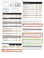 2
2
-
 3
3
-
 4
4
-
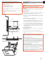 5
5
-
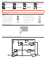 6
6
-
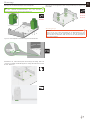 7
7
-
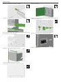 8
8
-
 9
9
-
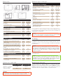 10
10
-
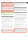 11
11
-
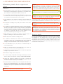 12
12
-
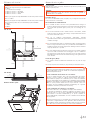 13
13
-
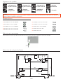 14
14
-
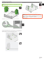 15
15
-
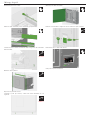 16
16
-
 17
17
-
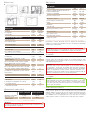 18
18
-
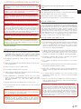 19
19
-
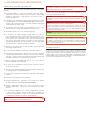 20
20
-
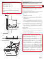 21
21
-
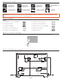 22
22
-
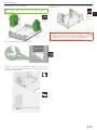 23
23
-
 24
24
-
 25
25
-
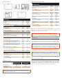 26
26
-
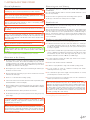 27
27
-
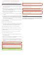 28
28
-
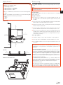 29
29
-
 30
30
-
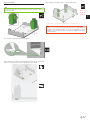 31
31
-
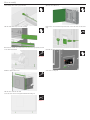 32
32
-
 33
33
-
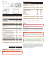 34
34
-
 35
35
-
 36
36
-
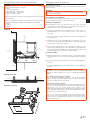 37
37
-
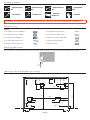 38
38
-
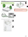 39
39
-
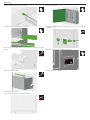 40
40
-
 41
41
-
 42
42
-
 43
43
-
 44
44


RIKA DOMO AH Assembly Instructions Manual
- Categorie
- Open haarden
- Type
- Assembly Instructions Manual
in andere talen
- English: RIKA DOMO AH
- italiano: RIKA DOMO AH
- français: RIKA DOMO AH
- Deutsch: RIKA DOMO AH
Gerelateerde papieren
-
RIKA MultiAir SONO AH Assembly Instructions Manual
-
-
RIKA INTERNO Assembly Instructions Manual
-
RIKA SYMBIA Assembly Instructions Manual
-
-
-
-
Andere documenten
-
MSW MSW-PLT-W20 de handleiding
-
Ravelli HRB 150 de handleiding
-
-
Zibro Diandra 90 s-line de handleiding
-
HASE AKABA de handleiding
-
-
-
-
-