Risco RW432KPP Installation and User Manual
- Type
- Installation and User Manual

WL Panda for LightSYS
Model: RW432KPP
Installation and User Guide

Language Page
3
13
23
33
43
53

05/2019
Page 3 5IN2812 B
The 2-Way WL Panda for LightSYS keypad enables communication between the
wireless keypad and a LightSYS control panel. Being bi-directional, the 2-Way keypad
receives a reply status indication from the panel for each command sent to the panel.
You can operate the keypad either using a code or a proximity tag.
Main Features
Bi-directional Wireless Communication
S.O.S / Two-way communication emergency key
Proximity tag operation
Double tamper protection (Box & Wall)
Battery economy mode
Communication Setup
The WL Panda for LightSYS keypad must identify itself to the system receiver. This can
be done by typing the 11-digit serial number of the keypad into the system or using RF
mode.
Setup using RF communication
1. From the Wired Keypad, navigate to the Programing (installer) menu, select 7)Install >
2)WL Device > 2)Allocation > 1)By RF > 3)Keypad and then press
2. If there are two receivers allocated to the system, select the receiver you wish to
allocate and then press
3. Select the Keypad location in the system and then press
4. On the WL Panda for LightSYS Keypad you wish to allocate, send a Write
message by pressing both keys simultaneously for at least 2
seconds; the keypad will display the Serial Number.
5. On the Wired Keypad, press to complete the allocation procedure

05/2019
Page 4 5IN2812 B
Setup by Serial Number
1. From the Wired Keypad, navigate to the Programing (installer) menu, select 7)Install
> 2)WL Device > 2)Allocation > 2)By Code > 3) Keypad and then press
2. If there are two receivers allocated to the system, select the receiver you wish to
allocate and then press
3. Select the Keypad location in the system and then press
4. Enter the Keypad’s 11-digit Serial Number and then press ; the keypad
will display the Serial Number.
NOTE: Adding the keypad to the system can also be done remotely
using the
configuration software by entering the serial number of the keypad or by RF
communication.

05/2019
Page 5 5IN2812 B
Mounting the Keypad
Mount the keypad on the wall using the supplied mounting bracket.
NOTE: Before mounting the keypad test the keypad communication with the system.
1. Remove the fastening screw that secures the mounting bracket to the keypad (see
Figure 1).
2. Separate the mounting bracket from the keypad (see Figure 2).
3. Release battery cover from the keypad’s battery compartment (see Figure 3).
4. Attach the battery cable to the battery connector (see Figure 4), insert the batteries
(while paying attention to the polarity of the batteries) and close the battery
compartment.
5. Allocate the Keypad to the Receiver (see Communication Setup).
6. Using the mounting holes as a template secure the mounting bracket to the wall
(see Figure 5).
7. Mount the keypad to the mounting bracket and insert the fastening screw to lock
the keypad (see Figures 6 and 1).
Battery Compartment Cover (back side)

05/2019 Page 6 5IN2812 B
Main Keypad Operations
Visual Indicators
The following visual indicators are displayed on the LCD Keypad:
Icon Indication Operation
Trouble
On System trouble
Off System is operating normally
On System is ready to be armed
Off System is not ready to be armed
Slow Flash System is ready to be armed while
exit/entry zone is open
Arm / Alarm
On System is armed in Full Arm or Stay Arm
mode
Off System is disarmed
Slow Flash System is in Exit Delay
Rapid Flash Alarm condition
Stay / Bypass
On System is Stay Arm mode (Part Set) or Zone
Bypass mode
Off No bypass zones in the system
Tamper
On Zone/keypad/external module has been
tampered
Off All zones are operating normally
Cloud
Connectivity
On System connected to cloud
Slow Flash Cloud connectivity trouble
Off No cloud connection configured / No cloud
connectivity

05/2019
Page 7 5IN2812 B
User Operations
Control Keys
The following lists details the user operations from the 2-Way WL Panda for LightSYS
keypad.
Key
Operation
In Normal Operation mode: Used for Away (Full setting).
In User Functions menu: Used to change data.
In Normal Operation mode: Used for Stay arming (Part Setting).
In User Functions menu: Used to change data.
Used to disarm (unset) the system after a user code is entered;
is used to terminate commands and confirm data to be stored.
Used to scroll up a list or to move the cursor to the left;
Provides the system status.
Used to scroll down a list or to move the cursor to the right.
In Normal Operation mode: Used to enter the User Functions menu.
In User Functions menu: Used to move back one step in the menu.
Common User Operations
Key
Operation
Away (Full Setting)
Code >
Stay (Part Settings)
Code >
Disarm (Unset) and Silence
an alarm
Code >

05/2019
Page 8 5IN2812 B
Key
Operation
Away (Full Setting) partition
1/2/3/4
Code > > / / / >
Stay (Part Settings) partition
1/2/3/4
Code > > / / / >
Partition Disarm (Unset)
Code > > / / / >
Duress Unset
Duress Code >
Quick Zones Bypass (Omit)
Code > [Zone No.]
Activate Output
[Code] [Activities] [Output
Control] [Prgrm Output Num]
Define Follow-Me
[Code] [Follow Me]
[Define]
View Fault
[Code] [View] [Fault]
View Event Log
[Code] [Event Log]
Keypad Chime On/Off
[Code] [Activities] [Keypad
sound] [Chime]
Edit User Code
[Code] [Codes/Tags]
[Define]

05/2019
Page 9 5IN2812 B
Key
Operation
Changing Keypad Language
simultaneously for 2 seconds > select
language >
Emergency Keys
The following operations will send emergency notifications to the alarm monitoring
station
Key
Operation
+
Pressing both keys simultaneously for at least two seconds
activates a Fire alarm
+
Pressing both keys simultaneously for at least two seconds
activates an Emergency alarm
+
Pressing both keys simultaneously for at least two seconds
activates a Police (Panic) alarm
Function Keys
Key
Operation
Numerical keys that are used to input numeric codes
(arming, disarming or used to activate specific functions)

05/2019
Page 10 5IN2812 B
Keypad Settings
Note: The following settings must be defined individually for each keypad
connected to the system.
To define keypad settings when idle follow this procedure:
1. Press for two seconds until the Keypad Settings menu appears
2. Select the relevant icon using the keys:
Brightness
Contrast
Keypad’s buzzer volume
3. Press .
4. Press the keys to adjust the level settings.
5. Press to save the adjustment.
6. Press to exit the keypad settings.
Proximity Tag Operation
Present the
Proximity Tag to
the keypad (after
waking the keypad)
as shown in the
following
illustrations:
Figure 8

05/2019 Page 11 5IN2812 B
Sleep Mode
For extending the battery life of the keypad, the keypad is designed with a Sleep mode
function. By default, 10 seconds after the last key has been pressed, the keypad will
turn off its display and LEDs. The time can be configured by your installer to a
maximum of 60 seconds.
Replacing Batteries
1. Remove the fastening screw that secures the mounting bracket to the keypad
(see Figure 1).
2. Slide the keypad and remove it from the mounting bracket.
3. Remove the battery compartment cover.
4. Disconnect the battery cable from the battery connector.
5. Replace the batteries while paying attention to the polarity of the batteries (see
Figure 9).
Figure 9
6. Reconnect the battery cable to the battery connector.
7. Close the battery compartment cover, place the keypad back on the wall and
secure the screw to its place.
CAUTION: Risk of explosion if battery is replaced by an incorrect type. Dispose of
used batteries according to local regulations.

05/2019 Page 12 5IN2812 B
Technical Specification
Electrical
Battery Type CR123, 3V Lithium battery (x 4)
Current Consumption Standby current 9µA, Max current 150 mA
Power Output 868.65MHz: 10 mW
Frequency 433.92, 868.65, 915 MHz
Modulation Type OOK
Typical Battery Life 3 years
Low battery indication 2.6 V
Proximity RF frequency 13.56 MHz
Physical
Dimension (HxWxD) 180 x 115 x 35 mm (7.1 x 4.5 x 1.4“)
Weight (Including batteries) 0.435 kg
Environmental
Operating temperature -10°C to 55°C (14°F to 131°F)
Storage temperature -20°C to 60°C (-4°F to 140°F)
Humidity Range Average relative humidity: 75%
Standard Compliance EN 50131-1, EN 50131-3 Grade 2,
Environmental Class II, EN 50131-6 Type C,
EN 50131-5-3, PD6662:2017
Certification body Applica Test & Certification
Ordering Information
Model Description
RW432KPP400A WL Panda for LightSYS Keypad Prox, 433
RW432KPP800A WL Panda for LightSYS Keypad Prox, 868
Standard Compliance
RED Compliance Statement:
Hereby, RISCO Group declares that this equipment is in compliance with the essential
requirements and other relevant provisions of Directive 2014/53/EU. For the CE
Declaration of Conformity please refer to our website: www.riscogroup.com.

05/2019
Page 13 5IN2812 B
Introduzione
La tastiera radio bidirezionale Panda permette di comunicare con la centrale LightSYS
in modalità bidirezionale evidenziando gli stati del sistema e le conferme per ogni
comando trasmesso. La tastiera permette l’utilizzo tramite codice utente oppure Tag di
prossimità.
Caratteristiche principali
Comunicazione radio bidirezionale
S.O.S. / Tasti di emergenza
Tag di prossimità
Protezione antimanomissione (Apertura e rimozione)
Modalità risparmio batterie
Memorizzazione della Tastiera
La tastiera radio Panda per LightSYS deve essere identificata dalla ricevente del
sistema tramite l’inserimento del numero di serie di 11 cifre o tramite procedura di
auto-apprendimento via radio.
Memorizzazione per auto-apprendimento via radio
1. Tramite tastiera cablata del Sistema, accedere al menu di programmazione tecnica e
selezionare 7)Configurazione > 2)Accessori Radio > 2)Memorizza > 1)Via Radio >
3)Tastiere e premere
2. Se ci sono due ricevitori radio configurati nel Sistema, selezionare il ricevitore in
cui si vuole memorizzare la tastiera e premere
3. Selezionare il numero della tastiera e premere
4. Andare alla tastiera Radio Panda che si vuole memorizzare e trasmettere un messaggio
WRITE premendo simultaneamente i tasti per almeno 2 secondi. La
tastiera visualizzerà sul suo display il proprio numero di serie.

05/2019
Page 14 5IN2812 B
Memorizzazione tramite Numero di Serie
1. Tramite tastiera cablata del Sistema, accedere al menu di programmazione tecnica e
selezionare 7)Configurazione > 2)Accessori Radio > 2)Memorizza > 2)Via Nr. Di
Serie > 3)Tastiere e premere
2. Se ci sono due ricevitori radio configurati nel Sistema, selezionare il ricevitore in
cui si vuole memorizzare la tastiera e premere
3. Selezionare il numero della tastiera e premere
4. Digitare le 11 cifre del numero di serie della tastiera e premere ; la tastiera
visualizzerà il proprio numero di serie sul display.
NOTA: La memorizzazione della tastiera può anche essere effettuata da remoto usando
il software di configurazione CS inserendo il numero di serie della tastiera o
predisponendo la centrale in auto-apprendimento per la memorizzazione radio.

05/2019
Page 15 5IN2812 B
Installazione della tastiera
Installare la tastiera a parete utilizzando la staffa.
NOTA: Prima di posizionare la tastiera verificare la comunicazione radio con la ricevente.
1. Rimuovere la vite che blocca la staffa alla tastiera (vedere Figura 1).
2. Sganciare la staffa dalla tastiera (vedere Figura 2).
3. Rimuovere il coperchio del vano batterie della tastiera (vedere Figura 3).
4. Inserire il cavo del vano batterie nel connettore (vedere Figura 4), inserire le
batterie (fare attenzione alla polarità) e chiudere il coperchio.
5. Memorizzare la tastiera nel Ricevitore radio (vedere la procedura di
Memorizzazione della tastiera).
6. Usare i fori di montaggio come dima e fissare la staffa alla parete (vedere Figura 5).
7. Fissare la tastiera sulla staffa e inserire la vite per bloccarla (vedere Figure 6 e 1).
Coperchio vano batterie (lato
p
osteriore)

05/2019 Page 16 5IN2812 B
Principali Comandi da Tastiera
Icone grafiche
Le icone grafiche che seguono vengono visualizzate sul display LCD della tastiera:
Icona Stato Significato
Anomalia
On Anomalia di sistema
Off Il sistema sta funzionando normalmente
On Il sistema è pronto per essere inserito
Off Il sistema non è pronto per essere inserito
Lampeggio
lento
Il Sistema è pronto per essere inserito anche
se una zona Ingresso/Uscita è aperta
Inserito / Allarme
On Il sistema è inserito in Totale o Parziale
Off Il sistema è disinserito
Lampeggio
lento
Il sistema è in fase di ritardo in uscita per
inserimento
Lampeggio
veloce
Allarme attivato
Parziale /
Esclusione
On Il sistema è inserito in Parziale oppure ci sono
delle zone escluse
Off Nessuna zona del sistema è esclusa
Tamper
On Manomissione di una zona/tastiera/modulo
Off Tutte le zone e i moduli stanno funzionando
correttamente
Connettività
Cloud
On Il sistema è connesso al Cloud
Lampeggio
lento
Anomalia di connessione al Cloud
Off Cloud non configurato o disconnesso

05/2019
Page 17 5IN2812 B
Operazioni Utente
Tasti di Comando
La tabella che segue descrive le operazioni disponibili per l’utente tramite tastiera radio
bidirezionale Panda del sistema LightSYS.
Tasto
Funzione/operazione
Nel modo normale di funzionamento viene utilizzato per inserire il
sistema in Totale.
Nel menu Funzioni Utente vene usato per modificare dati.
Nel modo normale di funzionamento viene utilizzato per inserire il
sistema in Parziale.
Nel menu funzioni utente vene usato per modificare dati.
Usato per disinserire il Sistema dopo aver digitato il proprio codice
utente;
è usato per terminare un comando e confermare i dati selezionati.
Usato per scorrere in su una lista di dati o spostare il cursore a sinistra;
Permette di visualizzare lo stato del sistema.
Usato per scorrere in giù una lista di dati o spostare il cursore a destra.
Nel modo normale di funzionamento viene utilizzato per accedere al
menu delle Funzioni Utente.
All’interno del menu Funzioni Utente serve per tornare al menu
precedente.
Operazioni Utente più comuni
Tasto
Operazione
Inserimento Totale
Codice >
Inserimento Parziale
Codice >
Disinserimento e Tacitazione
allarme
Codice >

05/2019
Page 18 5IN2812 B
Tasto
Operazione
Inserimento Totale partizioni
1/2/3/4
Codice > > / / / >
Inserimento Parziale
partizioni 1/2/3/4
Codice > > / / / >
Disinserimento partizioni
Codice > > / / / >
Disinserimento sotto
coercizione
Codice coercizione >
Esclusione veloce zone
Codice > [Zona N.]
Attiva uscita
[Codice} [Attività] [Attiva
uscite] [Selezionare l’uscita]
Impostazione numeri
telefonici FM
[Codice} [Num. telefonici]
[Programmare/Modificare i numeri]
Visualizza i Guasti
[Codice} [Visualizza]
[Guasti]
Visualizza la memoria eventi
[Codice} [Memoria eventi]
Chime tastiera On/Off
[Codice} [Attività] [Toni
tastiera] [Chime]
Modifica Codici Utente/Tag
[Codice} [Codici/Tag]
[Imposta/Modifica i codici]

05/2019
Page 19 5IN2812 B
Tasto
Operazione
Modifica lingua tastiera
Premere simultaneamente per 2
secondi > selezionare la lingua >
Tasti di Emergenza
Le sequenze ti tasti della tabella in basso permettono di segnalare eventi di emergenza.
Tasto
Funzione/Operazione
+
La pressione simultanea dei due tasti per due secondi attiverà
una segnalazione antincendio
+
La pressione simultanea dei due tasti per due secondi attiverà
una segnalazione di emergenza
+
La pressione simultanea dei due tasti per due secondi attiverà
una segnalazione di Rapina/Panico
Tasti Funzione
Tasto
Fanzine/Operation
Tasti numerici utilizzati per inserire codici numerici per
inserire, disinserire e attivare specifiche funzioni del sistema.

05/2019
Page 20 5IN2812 B
Impostazioni della Tastiera
Nota: le predisposizioni che seguono sono individuali per ogni singola tastiera
configurata nel sistema.
Per modificare le impostazioni della tastiera, procedere come segue:
1. Premere per due secondi fino alla comparsa del menu seguente
2. Selezionare l’icona della funzione da modificare usando i tasti :
Luminosità
Contrasto
Volume cicalino interno tastiera
3. Premere .
4. Premere per modificare i valori dell’opzione selezionata.
5. Premere per memorizzare le modifiche.
6. Premere per uscire dal menu di impostazioni della tastiera.

05/2019 Page 21 5IN2812 B
Funzionamento del Tag di prossimità
Avvicinare il tag alla
tastiera come
illustrato di seguito
(dopo averla fatta
uscire dalla modalità
“Sleep” con la
pressione di un
qualsiasi tasto):
Figura 8
Modalità Sleep
Per prolungare la durata della batteria della tastiera, la tastiera è progettata con una funzione
di modalità “Sleep”. Per impostazione predefinita, 10 secondi dopo aver premuto l'ultimo
tasto, la tastiera disattiva il display e i LED. Il tempo dell’ingresso in modalità “Sleep” può
essere configurato dall'installatore fino a un massimo di 60 secondi.
Sostituzione delle batterie
1. Rimuovere la vite di blocco della tastiera alla staffa di fissaggio (vedere Figura 1).
2. Rimuovere la tastiera dalla staffa.
3. Rimuovere il coperchio del vano batterie.
4. Scollegare il cavo batteria dall’apposito connettore.
5. Sostituire le batterie prestando attenzione alla polarità (vedere Figura 9).
Figura 9
6. Collegare nuovamente il cavo batteria al connettore.
7. Chiudere il vano batterie con il suo coperchio e riposizionare la tastiera nella sua
staffa di fissaggio ricordandosi di inserire la vite di blocco.
ATTENZIONE: Rischio di esplosione se le batterie vengono sostituite con altre di
tipologia non corretta. Smaltire le batterie usate in base alle normative locali.

05/2019 Page 22 5IN2812 B
Specifiche Tecniche
Elettriche
Tipo batterie 4 Batterie al litio 3 Volt, CR123,
Assorbimento in corrente Assorbimento a riposo 9µA, Max. 150 mA
Potenza RF 868.65MHz: 10 mW
Frequenza RF 433.92, 868.65, 915 MHz
Tipo Modulazione OOK
Durata tipica della batteria 3 anni
Soglia batteria scarica 2.6 V
Frequenza lettore di prox. 13.56 MHz
Fisiche
Dimensioni (HxLxP) 180 x 115 x 35 mm (7.1 x 4.5 x 1.4“)
Peso (Batterie incluse) 0.435 kg
Ambientali
Temp. di funzionamento Da -10°C a 55°C (da 14°F a 131°F)
Temperatura di stoccaggio Da -20°C a 60°C (da -4°F a 140°F)
Umidità Umidità relativa media: 75%
Certificazioni EN 50131-1, EN 50131-3 Grado 2, Ambientale
Classe II, EN 50131-6 Tipo C, EN 50131-5-3,
PD6662:2017
Ente di certificazione Applica Test & Certification
Informazioni per l’ordine
Modello Descrizione
RW432KPP400A Tastiera Radio Panda con Prossimità per LightSYS in 433 MHz
RW432KPP800A Tastiera Radio Panda con Prossimità per LightSYS in 868 MHz
Conformità standard
Dichiarazione di Conformità RED:
La sottoscritta RISCO Group, dichiara sotto la propria responsabilità che questo
prodotto è conforme ai requisiti essenziali e alle altre rilevanti disposizioni della
Direttiva Europea 2014/53/EU.
Per le Dichiarazioni di Conformità CE, visitate il nostro sito web: www.riscogroup.com

05/2019
Page 23 5IN2812 B
Introducción
El teclado inalámbrico bidireccional Panda para LightSYS permite la comunicación entre el
teclado inalámbrico y un panel de control de LightSYS. Al ser conexión bidireccional, el
teclado recibe una indicación de estado de respuesta del panel para cada comando
enviado. Puede utilizar el teclado con un código o con un llavero de proximidad.
Funciones principales
Comunicación inalámbrica bidireccional
S.O.S. / Tecla de emergencia
Operación con Llavero de proximidad
Doble protección de tamper (caja y pared)
Modo de ahorro de batería
Configuración de la comunicación
El teclado inalámbrico Panda para LightSYS debe identificarse con el receptor del
sistema. Esto se puede realizar introduciendo en el sistema el número de serie de 11
dígitos del teclado o usando el modo RF.
Configuración mediante comunicación RF
1. Desde el teclado con cable, vaya al menú Programación del Instalador, seleccione
7)Instalación > 2)Dispositivo Inalámbrico > 2)Asignación > 1)Por RF > 3)Teclado
y presione
2. Si hay dos receptores asignados al sistema, seleccione el receptor que desee
asignar y presione
3. Seleccione la ubicación del teclado en el sistema y presione
4. En el teclado inalámbrico Panda para LightSYS que quiera asignar, envíe un mensaje
de escritura presionando los dos botones
al mismo tiempo durante
2 segundos como mínimo; el teclado mostrará el número de serie.

05/2019
Page 24 5IN2812 B
5. En el teclado con cable, presione para finalizar el procedimiento de
asignación.
Configuración mediante número de serie
1. Desde el teclado con cable, vaya al menú Programación del Instalador, seleccione
7)Instalación > 2)Dispositivo Inalámbrico > 2)Asignación > 2)Por Código >
3)Teclado y presione
2. Si hay dos receptores asignados al sistema, seleccione el receptor que desee
asignar y presione
3. Seleccione la ubicación del teclado en el sistema y presione
4. Introduzca el número de serie de 11 dígitos del teclado y presione ; el
teclado mostrará el número de serie.
NOTA: también puede añadir el teclado al sistema de forma remota
mediante el
software de configuración introduciendo el número de serie del teclado o a través de
comunicación RF.

05/2019
Page 25 5IN2812 B
Montaje del teclado
Monte el teclado en la pared usando el soporte de montaje suministrado.
NOTA: antes de montar el teclado, pruebe la comunicación del teclado con el sistema.
1. Quite el tornillo de fijación que une el soporte de montaje al teclado (ver Figura 1).
2. Separe el soporte de montaje del teclado (ver Figura 2).
3. Retire la tapa del compartimento de la batería del teclado (ver Figura 3).
4. Conecte el cable de la batería al conector de la batería (ver Figura 4), inserte las pilas
(respetando la polaridad) y cierre el compartimento de la batería.
5. Asigne el teclado al receptor (ver Configuración de la comunicación).
6. Con los orificios de montaje como plantilla, fije el soporte de montaje a la pared (ver
Figura 5).
7. Monte el teclado en el soporte de montaje e introduzca el tornillo de fijación para
bloquear el teclado (ver Figuras 6 y 1).
Tapa del compartimento de la
b
atería (trasera)

05/2019 Page 26 5IN2812 B
Operaciones principales del teclado
Indicadores visuales
Los siguientes indicadores visuales se muestran en el teclado LCD:
Icono Indicación Operación
Problema
Encendido Problemas en el sistema
Apagado El sistema funciona con normalidad
Encendido El sistema está listo para el armado
Apagado El sistema no está listo para el armado
Parpadeo
lento
El sistema está listo para armado mientras la
zona de salida/entrada está abierta
Armado/Alarma
Encendido El sistema está en modo Armado Total o
Armado Parcial
Apagado El sistema está desarmado
Parpadeo
lento
El sistema está en Tiempo de Salida
Parpadeo
rápido
Situación de alarma
Armado
Parcial/Anulación
Encendido El sistema está en modo Armado Parcial o en
modo Anulación de Zona
Apagado No hay zonas anuladas en el sistema
Tamper
Encendido Se ha manipulado zonas/teclado/módulo externo
Apagado Todas las zonas funcionan con normalidad
Conectividad con
la Nube
Encendido El sistema está conectado a la Nube
Parpadeo
lento
Problemas en la conectividad con la Nube
Apagado No hay configurada ninguna conexión con la
Nube/No hay conectividad con la Nube

05/2019
Page 27 5IN2812 B
Operaciones del usuario
Botones de control
La siguiente lista detalla las operaciones que el usuario puede llevar a cabo desde el
teclado inalámbrico bidireccional Panda para LightSYS.
Botón
Operación
En el modo Normal: se usa para Armar Total.
En el menú de funciones de usuario: se usa para cambiar datos.
En el modo Normal: se usa para Armado Parcial.
En el menú de funciones de usuario: se usa para cambiar datos.
Se usa para desarmar (anular) el sistema después de introducir un
código de usuario;
se usa para finalizar comandos y confirmar los datos que se
van a almacenar.
Se usa para desplazarse hacia arriba en una lista o para mover el
cursor hacia la izquierda;
proporciona el estado del sistema.
Se usa para desplazarse hacia abajo en una lista o para mover el cursor
hacia la derecha.
En el modo Normal: se usa para acceder al menú de funciones de
usuario.
En el menú de funciones de usuario: se usa para retroceder un paso
en el menú.
Operaciones comunes del usuario
Botón
Operación
Armado Total
Código >
Armado Parcial
Código >
Desarmado y Silenciar
alarma
Código >

05/2019
Page 28 5IN2812 B
Botón
Operación
Armado Total – Partición
1/2/3/4
Código > > / / / >
Armado Parcial
–
Partición
1/2/3/4
Código > > / / / >
Desarmado – Partición
Código > > / / / >
Desarmado – Coacción
Código Coacción >
Anulación rápida de zona
(omitir)
Código > [N.º zona]
Activar una salida
[Código] [Actividades]
[Control Salidas] [N.º Salida Prog.]
Definir número privado
[Código] [Número privado]
[Crear/modificar]
Ver fallo
[Código] [Visualizar]
[Problemas]
Ver registro de eventos
[Código] [Registro de Eventos]
Timbre del teclado
(act./desact.)
[Código] [Actividades]
[Sonido Teclado] [Timbre]

05/2019
Page 29 5IN2812 B
Botón
Operación
Editar código de usuario
[Código] [Códigos/Llaves]
[Crear/Modificar]
Cambiar idioma del teclado
a la vez durante 2 segundos >
seleccionar idioma >
Botones de emergencia
Las siguientes acciones enviarán notificaciones de emergencia a la central receptora de
alarmas
Botón
Operación
+
Al presionar los dos botones a la vez durante al menos dos
segundos, se activa la alarma de incendio
+
Al presionar los dos botones a la vez durante al menos dos
segundos, se activa una alarma de emergencia
+
Al presionar los dos botones a la vez durante al menos dos
segundos, se activa una alarma de policía (pánico)
Botones de función
Botón
Operación
Botones numéricos que se usan para introducir códigos
numéricos (para armar, desarmar o activar funciones
específicas)

05/2019
Page 30 5IN2812 B
Ajustes del teclado
Nota: es preciso definir los siguientes ajustes de forma individual en cada teclado
conectado al sistema.
Para definir los ajustes del teclado mientras está inactivo, seguir el
procedimiento que se describe a continuación:
1. Presionar durante dos segundos hasta que aparezca el menú Ajustes del
teclado
2. Seleccionar el icono correspondiente con los botones :
Brillo
Contraste
Volumen del zumbador del
teclado
3. Presionar .
4. Presionar los botones para ajustar los niveles.
5. Presionar para guardar el ajuste.
6. Presionar para salir del menú Ajustes del teclado.

05/2019 Page 31 5IN2812 B
Modo de llavero de proximidad
Acerque el llavero de
proximidad al teclado
(después de activar el
teclado), tal como se
muestra en las ilustraciones
siguientes:
Figura 8
Modo de suspensión
Para ampliar la duración de la batería del teclado, éste está diseñado con una función
de modo de suspensión. Por defecto, 10 segundos después de presionar la última tecla,
el teclado apaga la pantalla y los LED. El instalador puede configurar este tiempo como
máximo con 60 segundos.
Reemplazar las pilas
1. Quite el tornillo de fijación que une el soporte de montaje al teclado (ver Figura 1).
2. Deslice el teclado y extráigalo del soporte de montaje.
3. Quite la tapa del compartimento de la batería.
4. Desconecte el cable de la batería al conector de la batería.
5. Reemplace las pilas teniendo en cuenta su polaridad (ver Figura 9).
Figura 9
6. Vuelva a conectar el cable de la batería al conector de la batería.
7. Cierre la tapa del compartimento de la batería, vuelva a poner el teclado en la
pared y fije el tornillo.
PRECAUCIÓN: Existe riesgo de explosión si las pilas se sustituyen por otras de tipo
incorrecto. Deshágase de las pilas según la normativa local vigente.

05/2019 Page 32 5IN2812 B
Especificaciones técnicas
Datos eléctricos
Tipo de batería Pilas CR123 de litio de 3 V (x 4)
Consumo de corriente Corriente en espera 9 µA; Corriente máx. 150 mA
Salida de potencia 868,65 MHz: 10 mW
Frecuencia 433,92, 868,65, 915 MHz
Tipo de modulación OOK
Duración típica de la batería 3 años
Indicación de batería baja 2,6 V
Frecuencia de RF de proximidad 13,56 MHz
Datos físicos
Dimensiones (AL x AN x PR) 180 x 115 x 35 mm
Peso (pilas incluidas) 0,435 kg
Datos medioambientales
Temperatura de funcionamiento De -10°C a 55°C
Temperatura de almacenaje De -20°C a 60°C
Rango de humedad Humedad media relativa: 75%
Cumplimiento de normativas EN 50131-1, EN 50131-3 Grado 2, Clase II
Medioambiental, EN 50131-6 Tipo C, EN
50131-5-3, PD6662:2017
Organismo de certificación Applica Test & Certification
Información para pedidos
Modelo Descripción
RW432KPP400A Teclado inalámbrico Panda con proximidad para LightSYS, 433
RW432KPP800A Teclado inalámbrico Panda con proximidad para LightSYS, 868
Cumplimiento de normativas
Declaración de Conformidad RED :
Por la presente, RISCO Group declara que este equipo cumple con los requisitos
esenciales y otras disposiciones relevantes de la Directiva 2014/53/EU. Para la
Declaración de Conformidad CE, por favor diríjase a nuestra web:
www.riscogroup.com.

05/2019
Page 33 5IN2812 B
Introduction
Le clavier Panda sans fil bidirectionnel pour LightSYS permet la communication entre le
clavier sans fil et une centrale LightSYS. Grâce à sa technologie bidirectionnelle, le clavier
reçoit en réponse une indication d'état de la centrale pour chaque commande envoyée.
Vous pouvez utiliser le clavier soit avec un code soit avec un tag de proximité.
Caractéristiques principales
Communication sans fil bidirectionnelle
Touche d’urgence/d’appel
Utilisation de tag de proximité
Autoprotection à l’ouverture et à l’arrachement
Mode d'économie de la batterie
Configuration de la communication
Le clavier Panda sans fil pour LightSYS doit être adressé dans la mémoire du récepteur
du système. Vous pouvez pour cela saisir le numéro de série à 11 chiffres du clavier
dans le système ou utiliser le mode RF.
Adressage par communication RF
1. Depuis le clavier filaire, accédez au menu Programmation (installateur),
sélectionnez 7)Install > 2)Access. SF > 2)Allocation SF > 1)Par RF > 3)Clavier, puis
appuyez sur
2. Si deux récepteurs sont adressés sur le système, sélectionnez celui sur lequel vous
souhaitez adresser le clavier, puis appuyez sur
3. Sélectionnez l'emplacement du clavier dans le système, puis appuyez sur
4. Sur le clavier Panda sans fil pour LightSYS que vous souhaitez adresser, envoyez un
message d'écriture en appuyant simultanément sur les touches
pendant au moins 2 secondes ; le numéro de série s'affiche sur le clavier.

05/2019
Page 34 5IN2812 B
5. Sur le clavier filaire, appuyez sur pour terminer la procédure
d’adressage.
Adressage par numéro de série
1. Depuis le clavier filaire, accédez au menu Programmation (installateur),
sélectionnez 7)Install > 2)Access. SF > 2)Allocation SF > 2)Par N) Série >
3)Clavier, puis appuyez sur
2. Si deux récepteurs sont adressés sur le système, sélectionnez celui sur lequel vous
souhaitez adresser le clavier, puis appuyez sur
3. Sélectionnez l'emplacement du clavier dans le système, puis appuyez sur
4. Saisissez le numéro de sérier à 11 chiffres du clavier, puis appuyez sur ;
le numéro de série s'affiche sur le clavier.
REMARQUE : vous pouvez également ajouter à distance le clavier au système via le
logiciel de configuration CS en saisissant le numéro de série du clavier ou via la
communication RF.

05/2019
Page 35 5IN2812 B
Fixation du clavier
Fixez le clavier au mur à l'aide du support de fixation fourni.
REMARQUE : avant d'installer le clavier, vérifiez qu'il communique correctement avec
le système.
1. Retirez la vis qui fixe le support de fixation au clavier (voir Figure 1).
2. Séparez le support de fixation du clavier (voir Figure 2).
3. Ouvrez le couvercle du compartiment à piles du clavier (voir Figure 3).
4. Fixez le câble de batterie au connecteur de batterie (voir Figure 4), insérez les piles
(en respectant les polarités), puis refermez le compartiment à piles.
5. Adressez le clavier au récepteur (reportez-vous à la section Configuration de la
communication).
6. Utilisez les trous de fixation comme gabarits pour fixer le support de fixation au
mur (voir Figure 5).
7. Installez le clavier sur le support de fixation et insérez la vis de fixation pour fixer
le clavier (voir Figures 6 et 1).
Couvercle du compartiment à piles
(arrière)

05/2019 Page 36 5IN2812 B
Fonctions principales sur le clavier
Indicateurs visuels
Les indicateurs visuels suivants sont affichés sur le clavier LCD :
Icône Indication Opération
Défaut
Allumé Défaut système.
Éteint Le système fonctionne normalement.
Allumé Le système est prêt à être armé.
Éteint Le système n'est pas prêt à être armé.
Clignotement
lent
Le système est prêt à être armé et une zone
type Entrée/Sortie est ouverte
Armement /
Alarme
Allumé Le système est armé en mode Armé
complètement ou Armé partiellement.
Éteint Le système est désarmé.
Clignotement
lent
Le système est en mode Temporisation de
sortie.
Clignotement
rapide
Condition d'alarme.
Partiel / Exclusion
Allumé Le système est en mode Armé partiellement
ou Exclusion de zone.
Éteint Il n'existe aucune zone exclue dans le système.
Autoprotection
Allumé Une zone, un clavier ou un module externe
est en état d’autoprotection
Éteint Toutes les zones fonctionnent
normalement.
Connectivité au
Cloud
Allumé Le système est connecté au Cloud.
Clignotement
lent
Problème de connexion au Cloud.
Éteint Aucune connexion au Cloud configurée.

05/2019
Page 37 5IN2812 B
Fonctions utilisateur
Fonction des touches
Les listes suivantes détaillent les fonctions utilisateur sur le clavier sans fil bidirectionnel
Panda pour LightSYS.
Touche
Opération
En fonctionnement normal : utilisé pour Armer (mode complet).
Dans le menu Fonctions utilisateur : utilisé pour modifier les données.
En fonctionnement normal : utilisé pour Armer Partiellement.
Dans le menu Fonctions utilisateur : utilisé pour modifier les données.
Utilisé pour désarmer le système après la saisie du code utilisateur ;
permet aussi de valider les commandes et de confirmer les
données à enregistrer.
Utilisé pour faire défiler une liste vers le haut ou déplacer le curseur
vers la gauche ; indique l'état du système.
Utilisé pour faire défiler une liste vers le bas ou déplacer le curseur
vers la droite.
En fonctionnement normal : utilisé pour accéder au menu de
Fonctions Utilisateur.
Dans le menu Fonctions utilisateur : utilisé pour revenir à l'étape
précédente dans le menu.

05/2019
Page 38 5IN2812 B
Fonctions utilisateur communes
Fonction
Opération
Armement complet
Code >
Armement partiel
Code >
Désarmement et arrêt du son
d’une alarme
Code >
Armement complet partition
1/2/3/4
Code > > / / / >
Armement partiel partition
1/2/3/4
Code > > / / / >
Désarmement par partition
Code > > / / / >
Désarmement sous
contrainte
Code contrainte >
Exclusion de zone rapide
Code > [Nº zone]
Activation de sortie
[Code] [Activités]
[Contrôle Sorties] [Choix sortie
programmable]
Définition Suivez-moi
[Code] [Suivez-moi]
[Définir]
Affichage des défauts
[Code] [Voir] [Défaut]
Affichage du journal des
événements
[Code] [Journal d’événements]

05/2019
Page 39 5IN2812 B
Fonction
Opération
Activation/désactivation
carillon clavier
[Code] [Activités] [Son
clavier] [Carilon]
Modification du code
utilisateur
[Code] [Codes/Tags]
[Définir]
Modification de la langue du
clavier
simultanément pendant 2 secondes >
sélection de la langue >
Touches d'urgence
Les procédures suivantes permettent d'envoyer des notifications d'urgence au centre de
télésurveillance.
Touche
Opération
+
Appuyez simultanément sur ces deux touches pendant au
moins deux secondes pour activer une alarme incendie.
+
Appuyez simultanément sur ces deux touches pendant au
moins deux secondes pour activer une alarme d'urgence.
+
Appuyez simultanément sur ces deux touches pendant au
moins deux secondes pour activer une alarme panique.

05/2019
Page 40 5IN2812 B
Touches de fonction
Touche
Opération
Les touches numériques permettent de saisir des codes
numériques (armement, désarmement ou activation de
fonctions spécifiques).
Configuration du clavier
Remarque : vous devez définir individuellement les paramètres suivants pour
chaque clavier connecté au système.
Pour configurer le clavier lorsqu'il est en veille, procédez comme suit :
1. Appuyez sur la touche pendant deux secondes jusqu'à ce que le menu de
Configuration du clavier s'affiche.
2. Sélectionnez l'icône correspondante à l'aide des touches :
Luminosité
Contraste
Volume du buzzer du clavier
3. Appuyez sur .
4. Appuyez sur les touches pour régler les niveaux.
5. Appuyez sur la touche pour enregistrer les valeurs définies.
6. Appuyez sur la touche pour quitter la configuration du clavier.

05/2019 Page 41 5IN2812 B
Utilisation des tags de proximité
Présentez le tag de
proximité au clavier
(après avoir désactivé le
mode veille sur ce
dernier), comme le
montrent les illustrations
suivantes :
Figure 8
Mode veille
Pour prolonger l'autonomie des piles, le clavier est doté d'un mode veille. Par défaut,
l'afficheur et les voyants du clavier s'éteignent 10 secondes après avoir appuyé sur la
dernière touche. L'installateur peut modifier ce délai jusqu'à 60 secondes maximum.
Remplacement des piles
1. Retirez la vis qui fixe le support de fixation au clavier (voir Figure 1).
2. Faites glisser le clavier, puis retirez-le du support de fixation.
3. Retirez le couvercle du compartiment à piles.
4. Déconnectez le câble de batterie du connecteur de batterie.
5. Remplacez les piles en respectant les polarités (voir Figure 9).
Figure 9
6. Reconnectez le câble de batterie au connecteur de batterie.
7. Fermez le couvercle du compartiment à piles, replacez le clavier sur le support
mural et fixez-le avec la vis.
ATTENTION : risque d'explosion si la pile est remplacée par un type de pile incorrect. La
mise au rebut des piles usagées doit respecter les réglementations locales en vigueur.

05/2019 Page 42 5IN2812 B
Caractéristiques techniques
Électriques
Type de pile Pile au lithium 3 V, CR123 (x4)
Consommation électrique 9 µA en veille, 150 mA max.
Puissance de sortie 868,65 MHz : 10 mW
Fréquence 433,92 ; 868,65 ; 915 MHz
Type de modulation OOK
Autonomie de la pile 3 ans (typique)
Indication batterie basse 2,6 V
Fréquences RF de proximité 13,56 MHz
Physiques
Dimensions (HxLxP) 180 x 115 x 35 mm
Poids (piles incluses) 0,435 kg
Environnementales
Température de fonctionnement -10°C à 55°C
Température de stockage -20°C à 60°C
Plage d'humidité Humidité relative moyenne : 75 %
Conformité aux normes EN 50131-1, EN 50131-3 Grade 2, Classe
environnementale II, EN 50131-6 Type C, EN
50131-5-3, PD6662:2017
Organisme de certification Applica Test & Certification
Informations de commande
Modèle Description
RW432KPP400A Clavier Panda sans fil avec proximité pour LightSYS, 433
RW432KPP800A Clavier Panda sans fil avec proximité pour LightSYS, 868
Conformité aux normes
Rapport de Conformité de RED
Par la présente, RISCO Group, déclare que cet équipement est en conformité
aux conditions essentielles et à d'autres dispositions appropriées de la directive
2014/53/EU. Vous pouvez trouver la copie complète de la déclaration de
conformité à la directive 2014/53/EU sur notre site web, à l’adresse suivante :
www.riscogroup.com.

05/2019
Page 43 5IN2812 B
Introdução
O teclado bidirecional WL Panda para LightSYS permite a comunicação entre o teclado
wireless e um painel de controlo LightSYS. Por ser bidirecional, o teclado recebe uma
indicação de status de resposta do painel para cada comando enviado ao painel. Pode
operar o teclado usando um código ou uma tag de proximidade.
Características principais
Comunicação bidirecional wireless
Chave de emergência/S.O.S
Operação com tag de proximidade
Dupla proteção antiviolação (Box & Wall)
Modo de economia de bateria
Configuração da comunicação
O teclado WL Panda para LightSYS deve identificar-se para o receptor do sistema. Isto
pode ser feito digitando o número de série do teclado com 11 dígitos no sistema ou
usando o modo de RF.
Configuração usando comunicação por RF
1. No teclado com fio, navegue até o menu Programming (programação) (do
instalador), selecione 7) Install (instalar) > 2) WL Device (dispositivo sem fio) >
2) Allocation (atribuição) > 1) By RF (por RF) > 3) Keypad (teclado) e, em
seguida, pressione
2. Se houver dois receptores atribuídos ao sistema, selecione o receptor que você
deseja atribuir e pressione
3. Selecione o local do teclado no sistema e pressione
4. No teclado WL Panda para LightSYS que você deseja atribuir, envie uma mensagem
de gravação pressionando as teclas e simultaneamente por pelo
menos 2 segundos; o teclado mostrará o número de série.

05/2019
Page 44 5IN2812 B
5. No teclado com fio, pressione para concluir o procedimento de alocação.
Configuração através do número de série
1. No teclado com fio, navegue até o menu Programming (programação) (do
instalador), selecione 7) Install (instalar) > 2) WL Device (dispositivo sem fio) >
2) Allocation (atribuição) > 2) By Code (por código) > 3) Keypad (teclado) e, em
seguida, pressione
2. Se houver dois receptores atribuídos ao sistema, selecione o receptor que você
deseja atribuir e pressione .
3. Selecione o local do teclado no sistema e pressione
4. Digite o número de série de 11 dígitos do teclado e pressione ; o teclado
exibirá o número de série.
NOTA: A inclusão do teclado no sistema também pode ser feita remotamente com o
software de configuração, inserindo o número de série do teclado ou por comunicação
RF.

05/2019
Page 45 5IN2812 B
Instalação do teclado
Fixe o teclado na parede usando o suporte de Instalação fornecido.
NOTA: Antes de instalar o teclado, teste a sua comunicação com o sistema.
1. Remova o parafuso de fixação que prende o suporte de Instalação ao teclado
(ver Figura 1).
2. Separe o suporte de Instalação do teclado (ver Figura 2).
3. Liberte a tampa do compartimento de baterias do teclado (ver Figura 3).
4. Fixe o cabo das baterias ao seu conector (ver Figura 4), insira as baterias (prestando
atenção à polaridade das mesmas) e feche o compartimento de baterias.
5. Atribua o Teclado ao Receptor (consulte Configuração de Comunicação).
6. Usando os furos de Instalação como modelo, fixe o suporte de Instalação à parede
(ver Figura 5).
7. Fixe o teclado no suporte de Instalação e insira o parafuso de fixação para travar o
teclado (ver Figuras 6 e 1).
Tampa do Compartimento
de Baterias (parte traseira)
Botão antiviolação

05/2019 Page 46 5IN2812 B
Operações principais do teclado
Indicadores visuais
Os indicadores visuais a seguir são exibidos no teclado LCD:
Ícone Indicação Operação
Problema
Ligado Problema no sistema
Desligado Sistema a operar normalmente
Ligado O sistema está pronto para ser armado
Desligado O sistema não está pronto para ser armado
Piscando
lentamente
O sistema está pronto para ser armado
enquanto a zona de entrada/saída está aberta
Armar/Alarme
Ligado O sistema está armado em modo Full Arm
(Arme Total) ou Stay Arm (Arme Parcial)
Desligado O sistema está desarmado.
Piscando
lentamente
O sistema está em modo de atraso de saída.
Piscando
rápido
Condição do alarme
Ativação
parcial/Bypass
Ligado O sistema está no modo Stay Arm (Ativação
Parcial) ou no modo Zone Bypass (Zonas
com Bypass)
Desligado Nenhuma zona com bypass no sistema
Botão antiviolação
Ligado Ocorreu violação de zona/teclado/módulo
externo.
Desligado Todas as zonas estão a operar normalmente
Conectividade na
cloud
Ligado Sistema conectado à cloud
Piscando
lentamente
Problema de conectividade da cloud
Desligado Nenhuma conexão com a cloud
configurada/Não há conectividade com a
cloud

05/2019
Page 47 5IN2812 B
Operações do usuário
Teclas de controlo
As listas a seguir detalham as operações do usuário para o teclado sem fio bidirecional
Panda para LightSYS.
Teclas de controlo
Tecla
Operação
Em modo de Operação Normal: Usado para o modo Away
(ausência) (armado total).
No menu User Functions (Funções do Usuário): Usado para
modificar dados.
Em modo de Operação Normal: Usado para o modo Stay
(
p
ermanência) (armado
p
arcial).
No menu User Functions (Funções do Usuário): Usado para
modificar dados.
Usado para desarmar (desativar) o sistema após a inserção de
uma senha do usuário.
é usado para finalizar comandos e confirmar os dados a
serem armazenados.
Usada para avançar para cima numa lista ou para mover o cursor
para a esquerda;
Fornece o status do sistema.
Usada para avançar para baixo numa lista ou para mover o
cursor para a direita.
Em modo de Operação Normal: Usadas para aceder ao menu
User Functions (Funções do Usuário).
No menu User Functions (Funções do Usuário): Usadas para
retroceder um
p
asso no menu.
Operações comuns do usuário
Tecla
Operação
Ausente (Ativação completa)
Código >

05/2019
Page 48 5IN2812 B
Tecla
Operação
Presente (Ativação parcial)
Código >
Desarmar (Desativar) e
silenciar um alarme
Código >
Ausente (Ativação completa)
partição 1/2/3/4
Código > > / / / >
Presente (Ativação parcial)
partição 1/2/3/4
Código > > / / / >
Desarmar partição
(Desativar)
Código > > / / / >
Desativar coação
Código de coação >
Desvio rápido de zonas
(omitir)
Código > [Nº da zona]
Ativar saída
[Código] [Atividades]
[controle de saída] [Núm. de saída do prog]
Definir Siga-me
[Código] [Siga-me]
[Definir]
Visualizar falha
[Código] [Visualizar]
[Falha]
Visualizar registo de eventos
[Código] [Registo de eventos]
Ligar/desligar campainha do
teclado
[Código] [Atividades]
[Som do teclado] [Campainha]

05/2019
Page 49 5IN2812 B
Tecla
Operação
Editar código do usuário
[Código] [Códigos/Tags]
[Definir]
Alterar idioma do teclado
simultaneamente durante 2
segundos > selecionar idioma >
Teclas de emergência
As operações a seguir enviarão notificações de emergência à central de monitorização
de alarmes
Tecla
Operação
+
Pressionar as duas teclas simultaneamente pelo menos dois
segundos ativa um alarme de incêndio.
+
Pressionar as duas teclas simultaneamente pelo menos dois
segundos ativa um alarme de emergência
+
Pressionar as duas teclas simultaneamente pelo menos dois
segundos ativa um alarme de polícia (pânico)
Teclas de função
Tecla
Operação
As teclas numéricas que são usadas para inserir códigos
numéricos (armar, desarmar, ou usados para ativar funções
específicas)

05/2019
Page 50 5IN2812 B
Configurações do teclado
Nota: As configurações a seguir devem ser definidas individualmente para cada
teclado conectado ao sistema.
Para definir as configurações do teclado quando ocioso (não usado), siga o
procedimento abaixo:
1. Pressione durante dois segundos até aparecer o menu Keypad Settings
(configurações do teclado)
2. Selecione o ícone desejado usando as teclas e :
Brilho
Contraste
Volume da campainha do teclado
3. Pressione .
4. Pressione as teclas e para ajustar a configuração dos níveis.
5. Pressione para salvar o ajuste.
6. Pressione para sair das configurações do teclado.

05/2019 Page 51 5IN2812 B
Operação do Tag de Proximidade
Apresente a tag de
proximidade ao
teclado (após reativá-
lo), como apresentado
nas ilustrações abaixo:
Figura 8
Modo de repouso
Para prolongar a vida útil das baterias, o teclado foi elaborado com uma função de modo
de repouso. Por padrão, a tela e os LEDs do teclado são desligados 10 segundos após a
última tecla ser pressionada. O tempo pode ser configurado pelo seu instalador até o
máximo de 60 segundos.
Substituição das baterias
1. Remova o parafuso de fixação que prende o suporte de Instalação ao teclado (ver
Figura 1).
2. Deslize o teclado e retire-o do suporte de Instalação.
3. Remova a tampa do compartimento de baterias.
4. Desconecte o cabo das baterias do seu conector.
5. Troque as baterias prestando atenção na sua polaridade (veja a Figura 9).
Figura 9
6. Reconecte o cabo das baterias ao seu conector.
7. Feche a tampa do compartimento de baterias, coloque o teclado de volta na
parede e fixe o parafuso no seu lugar.
CUIDADO: Há risco de explosão caso a bateria seja substituída por uma incompatível.
Descarte baterias usadas de acordo com regulamentos locais.

05/2019 Page 52 5IN2812 B
Especificações técnicas
Elétricas
Ti
p
o de bateria Bateria (
p
ilha) de lítio 3V, CR123 (x 4)
Consumo de corrente Corrente de standb
y
9
µ
A, Corrente máxima 150 m
A
Potência de saída 868,65 MHz: 10 mW
Fre
q
uência 433,92; 868,65; 915 MHz
Ti
p
o de Modulação OOK
Vida útil tí
p
ica das bateria
s
3 anos
Indicação de bateria fraca 2,6 V
Proximidade de frequência
de RF
13,56 MHz
Físicas
Tamanho (AxLxP) 180 x 115 x 35 mm (7,1 x 4,5 x 1,4
p
ol.)
Peso (incluindo baterias) 0,435 k
g
Ambientais
Temperatura de
funcionamento
-10°C a 55 C (14°F a 131°F)
Temperatura de
armazenamento
-20°C a 60 C (-4°F a 140°F)
Faixa de umidade Húmidade relativa média: 75%
Conformidade com normas EN 50131-1, EN 50131-3 Grau 2, Classe Ambiental
II, EN 50131-6 Ti
p
o C, EN 50131-5-3, PD6662:2017
Or
g
anismo de certificação
Applica Test & Certification
Informações sobre pedidos
Modelo Descrição
RW432KPP400A Teclado WL Panda com Função de Proximidade
p
ara Li
g
htSYS, 43
3
RW432KPP800A Teclado WL Panda com Função de Proximidade
p
ara Li
g
htSYS, 86
8
Conformidade com normas
Declaração de conformidade RED:
Por meio deste, o RISCO Group declara que o seu equipamento está em
conformidade com as necessidades essenciais e outras provisões relevantes da
diretiva 2014/53/EU. l Para ver a declaração de conformidade CE, por favor
consulte o nosso website: www.riscogroup.com

05/2019
Page 53 5IN2812 B
Introductie
Het 2-Weg DL Panda bediendeel voor LightSYS laat de communicatie toe tussen een
draadloze bediendeel en het LightSYS paneel. Door de bi-directionele functionaliteit is er
voor elk commando dat verstuurd wordt naar het paneel een terugkoppeling met de
status. U kan het bediendeel bedienen door middel van een code of proximity tag.
Hoofdkenmerken
2-Weg draadloze communicatie
S.O.S / Twee-weg communicatie noodknop
Proximity tag bediening
Dubbele sabotage bescherming (Box & Muur)
Batterij met besparingsmodus
Communicatie Setup
Het DL Panda bediendeel voor LightSYS dient zich te identificeren aan de ontvanger.
Dit is mogelijk door het ingeven van het 11-cijferige serienummer of door gebruik te
maken van de RF mode.
Aanleren door gebruik te maken van RF communicatie
1. Via het bedrade bediendeel dient u te navigeren naar het programmeer (installateur)
menu, selecteer 7)Instellen > 2)DL Apparaat > 2)DL aanleren > 1)dmv RF >
3)Keypad en druk dan op
2. Indien er 2 ontvangers aangeleerd zijn op het systeem, selecteert u de ontvanger
waar u het bediendeel wenst op aan te leren en druk op
3. Selecteer de locatie van het bediendeel in het systeem en druk dan op
4. Op het DL Panda bediendeel voor LightSYS dat u wenst aan te leren dient u een
schrijfboodschap te sturen door gelijktijdig de toetsen gedurende
ten minste 2 seconden in te drukken; Het bediendeel zal dan het serienummer
weergeven.

05/2019
Page 54 5IN2812 B
5. Druk op het bedrade toetsenpaneel op om de toewijzingsprocedure te
voltooien.
Aanleren via serienummer
1. Via het bedrade bediendeel dient u te navigeren naar het programmeer (installateur)
menu, selecteer 7)Instellen > 2)DL Apparaat > 2)DL aanleren > 2)dmv Code > 3)
Keypad en druk dan op
2. Indien er 2 ontvangers aangeleerd zijn op het systeem, selecteert u de ontvanger
waar u het bediendeel wenst op aan te leren en druk op
3. Selecteer de locatie van het bediendeel in het systeem en druk dan op
4. Geef het 11-cijferige serienummer in en druk dan op ; Het bediendeel zal
dan het serienummer weergeven.
Opmerking: Het toevoegen van een bediendeel kan ook uitgevoerd worden vanop
afstand via de configuratie software door het ingeven van het serienummer van het
bediendeel of door RF communicatie.

05/2019
Page 55 5IN2812 B
Installeren van het bediendeel
Monteer het bediendeel op de muur door gebruikt te maken van de meegeleverde
montage beugel.
Opmerking: Alvorens het bediendeel te installeren dient u eerst de communicatie te
testen met het systeem.
1. Verwijder de bevestigingsschroef welke de montage beugel vergrendelt aan het bediendeel
(zie Figuur 1).
2. Koppel de montage beugel los van het bediendeel (zie Figuur 2).
3. Verwijder de batterij afdekplaat van het batterijcompartiment op het bediendeel
(zie Figuur 3).
4. Verbind de batterijkabel met de connector (zie Figuur 4), plaats de batterijen
(gelieve de polariteit van de batterijen in acht te nemen) en sluit het
batterijcompartiment.
5. Koppel het bediendeel met de ontvanger (zie Communicatie Setup).
6. Gebruik de bevestigingsgaten als een sjabloon en bevestig de montagebeugel aan
de muur (zie Figuur 5).
7. Monteer het bediendeel in de montagebeugel en plaats de bevestigingsschroef om
het bediendeel vast te maken (zie Figuren 6 en 1).
Afdekplaat batterij compartiment
(Achterzijde)

05/2019 Page 56 5IN2812 B
Werking van het bediendeel
Visuele indicatoren
De volgende visuele indicatoren worden weergeven op het LCD scherm:
Icoon Indication Beschrijving
Fouten
Aan Systeemfout
Uit Systeem functioneert normaal
Aan Systeem is klaar om ingeschakeld te worden
Uit Systeem is niet klaar om ingeschakeld te worden
Traag
knipperen
Systeem is klaar om ingeschakeld te worden
terwijl de vertraagde zone open is
Ingeschakeld /
Alarm
Aan Systeem is ingeschakeld in Volledig of Deels
ingeschakeld mode
Uit Systeem is uitgeschakeld
Traag
knipperen
Systeem is in uitloopvertraging
Snel
knipperen
Alarm conditie
Deels / Overbrug
Aan Systeem is in Deels ingeschakeld mode of in
zone overbrugging mode
Uit Geen overbrugging van zones in het systeem
Sabotage
Aan Zone/bediendeel/externe module heeft een
sabotage
Uit All zones in normale toestand
Cloud
connectiviteit
Aan Systeem verbonden met de RISCO Cloud
Traag
knipperen
RISCO Cloud connectie probleem
Uit Geen RISCO Cloud connectie geconfigureerd /
Geen RISCO Cloud connectie

05/2019
Page 57 5IN2812 B
Bedieningstoetsen
In de volgende lijst worden de gebruikershandelingen van de 2-weg WL Panda voor
LightSYSYS-toetsenpaneel in detail beschreven.
Bedientoetsen
Toets
Beschrijving
In normale mode: Wordt gebruikt om volledig in te schakelen.
In het gebruikersmenu: Wordt gebruikt om data te veranderen.
In normale mode: Wordt gebruikt om deels in te schakelen.
Bij gebruiker functiemenu’s: wordt gebruikt om instellingen te
wijzigen.
Wordt gebruikt om het systeem uit te schakelen na ingave van een
geldige gebruikerscode; wordt ook gebruikt om commando’s te
annuleren of om instellingen op te slaan.
Wordt gebruikt om naar boven te scrollen in een lijst of om de cursor
naar links te verschuiven;
Geeft de systeem status weer
Wordt gebruikt om in een lijst naar beneden te scrollen of de cursor
te verplaatsen naar rechts
In normale mode: Wordt gebruikt om in het gebruikersmenu te gaan.
In het gebruikersmenu: Wordt gebruikt om een stap terug te gaan in
het menu.
Veelvoorkomende gebruikershandelingen
Toets
Werking
Afwezig (volledig
inschakelen)
Code >
Thuis (deels inschakelen)
Code >
Uitschakelen en geluid van
alarm uitzetten
Code >

05/2019
Page 58 5IN2812 B
Toets
Werking
Afwezig (volledig
inschakelen) partitie 1/2/3/4
Code > > / / / >
Thuis (deels inschakelen)
partitie 1/2/3/4
Code > > / / / >
Partitie uitschakelen
Code > > / / / >
Dwang uitschakelen
Dwangcode >
Snelle zoneoverbrugging
(overslaan)
Code > [Zonenummer]
Uitgang activeren
[Code] [Activiteiten]
[Uitgangscontrole] [Nummer programma-
uitgang]
Follow-me definiëren
[Code] [Follow Me]
[Definiëren]
Storing bekijken
[Code] [Bekijk] [Storing]
Gebeurtenissenlog bekijke
[Code] [Gebeurtenissenlog]
Toetsenpaneelgeluid aan/uit
[Code] [Activiteiten]
[Geluid toetsenpaneel] [Geluid]
Gebruikerscode wijzigen
[Code] [Codes/Tags]
[Definiëren]

05/2019
Page 59 5IN2812 B
Toets
Werking
Taal toetsenpaneel wijzigen
tegelijkertijd 2 seconden indrukken
> selecteer taal >
Noodtoetsen
De volgende bewerkingen zullen een noodmelding versturen naar de meldkamer
Toets
Beschrijving
+
Bij gelijktijdig induwen van beide knoppen, gedurende ten
minste 2 seconden wordt er een Brand alarm gegenereert
+
Bij gelijktijdig induwen van beide knoppen, gedurende ten
minste 2 seconden, wordt er een Nood alarm gegenereert
+
Bij gelijktijdig induwen van beide knoppen, gedurende ten
minste 2 seconden, wordt er een Paniek alarm gegenereert
Functionele toetsen
Toets
Beschrijving
Nummerieke toetsen die gebruikt worden voor het ingeven
van nummerieke codes (inschakelen, uitschakelen of wordt
gebruikt voor het activeren van specifieke functies)

05/2019
Page 60 5IN2812 B
Bediendeel instellingen
Opmerking: De volgende instellingen dienen per bediendeel dat aangesloten is op
het systeem apart ingesteld te worden.
Volg volgende procedure wanneer het bediendeel in rust is:
1. Druk op gedurende twee seconden tot het instelling menu van het
bediendeel verschijnt
2. Selecteer het relevante icoon door gebruik te maken van de toetsen:
Helderheid
Contrast
buzzer volume bediendeel
3. Druk op .
4. Druk op de toetsen om het niveau aan te passen.
5. Druk op om de wijzigingen op te slaan.
6. Druk op om de bediendeelinstellingen te verlaten.
Proximity Tag bediening
Presenteer de
Proximity Tag aan
het bediendeel (na
ontwaken van
bediendeel) zoals
aangegeven in de
volgende illustratie.
Figuur 8

05/2019 Page 61 5IN2812 B
Slaap Mode
Voor het verlengen van de batterijduur van het bediendeel is er een slaap mode functie
ontwikkeld. Standaard instelling is ingesteld op 10 seconden, hierna zal het bediendeel na
de laatste toetsaanslag de display en led’s uitschakelen. Deze tijd kan aangepast worden
door uw installateur tot een maximum van 60 seconden.
Vervangen van de batterijen
1. Verwijder de bevestigingsschroef welke de montage beugel vergrendelt aan het bediendeel
(zie Figuur 1).
2. Schuif het bediendeel naar boven toe en verwijder het van de montage beugel.
3. Verwijder de afdekplaat van het batterijcompartiment.
4. Ontkoppel de batterijkabel van de batterijconnector.
5. Vervang de batterijen terwijl u oplet voor de polariteit van de batterijen (zie
Figuur 9).
Figuur 9
6. Verbind de batterijkabel met de batterijconnector.
7. Sluit het batterij compartiment en plaats het bediendeel terug op de montage
beugel. Vergrendel het bediendeel met de schroef.
OPGELET: Gevaar voor explosie indien u de batterij vervangt door een verkeerd type.
Vernietig de gebruikte batterijen volgens de lokale geldende richtlijnen.

05/2019 Page 62 5IN2812 B
Technische specificaties
Electrisch
Batterij Type CR123, 3V Lithium batterij (x 4)
Stroomverbruik Standby current 9µA, Max current 150 mA
Uitgangsvermogen 868.65MHz: 10 mW
Frequentie 433.92, 868.65, 915 MHz
Modulatie Type OOK
Levensduur batterij 3 jaar
Lage batterij indicatie 2,6 V
Proximity RF frequentie 13.56 MHz
Fysisch
Afmetingen (HxWxD) 180 x 115 x 35 mm (7.1 x 4.5 x 1.4“)
Gewicht (Inclusief batterijen) 0,435 kg
Omgeving
Werkingstemperatuur -10°C tot 55°C (14°F tot 131°F)
Opslagtemperatuur -20°C tot 60°C (-4°F tot 140°F)
Vochtigheidsbereik Gemiddelde relatieve vochtigheid: 75%
Standaard compliance EN 50131-1, EN 50131-3 klasse 2, milieuklasse II,
EN 50131-6 type C, EN 50131-5-3, PD6662:2017
Certificatie-instelling Applica Test & Certification
Bestelinformatie
Model Beschrijving
RW432KPP400A WL Panda Prox bediendeel voor LightSYS, 433
RW432KPP800A WL Panda Prox bediendeel voor LightSYS, 868
Standaard Comformiteit
RED conformiteitsverklaring:
RISCO Group bevestigt dat dit product in lijn is met de essentiële verplichtingen en
andere belangrijke voorzieningen van de 2014/53/EU richtlijnen. Voor de
conformiteitsverklaring zie onze website: www.riscogroup.com

05/2019 Page 63 5IN2812 B
Standard Limited Product Warranty
RISCO Ltd., its subsidiaries and affiliates (“Risco") guarantee Risco’s hardware products to be
free from defects in materials and workmanship when used and stored under normal
conditions and in accordance with the instructions for use supplied by Risco, for a period of (i)
24 months from the date of connection to the Risco Cloud (for cloud connected products) or (ii)
24 months from production (for other products which are non-cloud connected), as the case
may be (each, the “Product Warranty Period” respectively).
Contact with customers only. This Product Warranty is solely for the benefit of the customer
who purchased the product directly from Risco, or from any authorized distributor of Risco.
Nothing in this Warranty obligates Risco to accept product returns directly from end users that
purchased the products for their own use from Risco’s customer or from any installer of Risco,
or otherwise provide warranty or other services to any such end user. Risco customer shall
handle all interactions with its end users in connection with the Warranty, inter alia regarding
the Warranty. Risco’s customer shall make no warranties, representations, guarantees or
statements to its customers or other third parties that suggest that Risco has any warranty or
service obligation to, or any contractual privy with, any recipient of a product.
Return Material Authorization. In the event that a material defect in a product shall be
discovered and reported during the Product Warranty Period, Risco shall, at its option, and at
customer's expense, either: (i) accept return of the defective Product and repair or have
repaired the defective Product, or (ii) accept return of the defective Product and provide a
replacement product to the customer. The customer must obtain a Return Material
Authorization (“RMA”) number from Risco prior to returning any Product to Risco. The
returned product must be accompanied with a detailed description of the defect discovered
(“Defect Description”) and must otherwise follow Risco’s then-current RMA procedure in
connection with any such return. If Risco determines in its reasonable discretion that any
Product returned by customer conforms to the applicable warranty (“Non-Defective
Products”), Risco will notify the customer of such determination and will return the applicable
Product to customer at customer’s expense. In addition, Risco may propose and assess
customer a charge for testing and examination of Non-Defective Products.
Entire Liability. The repair or replacement of products in accordance with this warranty shall
be Risco’s entire liability and customer’s sole and exclusive remedy in case a material defect in
a product shall be discovered and reported as required herein. Risco’s obligation and the
Warranty are contingent upon the full payment by customer for such Product and upon a
proven weekly testing and examination of the product functionality.
Limitations. The Product Warranty is the only warranty made by Risco with respect to the
Products. The warranty is not transferable to any third party. To the maximum extent
permitted by applicable law, the Product Warranty does not apply and will be void if: (i) the
conditions set forth above are not met (including, but not limited to, full payment by customer
for the product and a proven weekly testing and examination of the product functionality); (ii)
if the Products or any part or component thereof: (a) have been subjected to improper
operation or installation; (b) have been subject to neglect, abuse, willful damage, abnormal
working conditions, failure to follow Risco’s instructions (whether oral or in writing); (c) have
been misused, altered, modified or repaired without Risco’s written approval or combined
with, or installed on products, or equipment of the customer or of any third party; (d) have
been damaged by any factor beyond Risco’s reasonable control such as, but not limited to,
power failure, electric power surges, or unsuitable third party components and the interaction
of software therewith or (e) any delay or other failure in performance of the product
attributable to any means of communications, provided by any third party service provider
(including, but not limited to) GSM interruptions, lack of or internet outage and/or telephony
failure.
BATTERIES ARE EXPLICITLY EXCLUDED FROM THE WARRANTY AND RISCO SHALL
NOT BE HELD RESPONSIBLE OR LIABLE IN RELATION THERETO, AND THE ONLY
WARRANTY APPLICABLE THERETO, IF ANY, IS THE BATTERY MANUFACTURER'S
WARRANTY.
Risco makes no other warranty, expressed or implied, and makes no warranty of
merchantability or of fitness for any particular purpose. For the sake of good order and
avoidance of any doubt:

05/2019
Page 64 5IN2812 B
DISCLAIMER. EXCEPT FOR THE WARRANTIES SET FORTH HEREIN, RISCO AND ITS
LICENSORS HEREBY DISCLAIM ALL EXPRESS, IMPLIED OR STATUTORY,
REPRESENTATIONS, WARRANTIES, GUARANTEES, AND CONDITIONS WITH REGARD
TO THE PRODUCTS, INCLUDING BUT NOT LIMITED TO ANY REPRESENTATIONS,
WARRANTIES, GUARANTEES, AND CONDITIONS OF MERCHANTABILITY, FITNESS
FOR A PARTICULAR PURPOSE, TITLE AND LOSS OF DATA. WITHOUT LIMITING THE
GENERALITY OF THE FOREGOING, RISCO AND ITS LICENSORS DO NOT REPRESENT
OR WARRANT THAT: (I) THE OPERATION OR USE OF THE PRODUCT WILL BE TIMELY,
SECURE, UNINTERRUPTED OR ERROR-FREE; (ii) THAT ANY FILES, CONTENT OR
INFORMATION OF ANY KIND THAT MAY BE ACCESSED THROUGH THE PRODUCT BY
CUSTOMER OR END USER SHALL REMAIN SECURED OR NON DAMAGED. CUSTOMER
ACKNOWLEDGES THAT NEITHER RISCO NOR ITS LICENSORS CONTROL THE
TRANSFER OF DATA OVER COMMUNICATIONS FACILITIES, INCLUDING THE
INTERNET, GSM OR OTHER MEANS OF COMMUNICATIONS AND THAT RISCO’S
PRODUCTS, MAY BE SUBJECT TO LIMITATIONS, DELAYS, AND OTHER PROBLEMS
INHERENT IN THE USE OF SUCH MEANS OF COMMUNICATIONS. RISCO IS NOT
RESPONSIBLE FOR ANY DELAYS, DELIVERY FAILURES, OR OTHER DAMAGE
RESULTING FROM SUCH PROBLEMS.
RISCO WARRANTS THAT ITS PRODUCTS DO NOT, TO THE BEST OF ITS KNOWLEDGE,
INFRINGE UPON ANY PATENT, COPYRIGHT, TRADEMARK, TRADE SECRET OR OTHER
INTELLECTUAL PROPERTY RIGHT
IN ANY EVENT RISCO SHALL NOT BE LIABLE FOR ANY AMOUNTS REPRESENTING
LOST REVENUES OR PROFITS, PUNITIVE DAMAGES, OR FOR ANY OTHER INDIRECT,
SPECIAL, INCIDENTAL, OR CONSEQUENTIAL DAMAGES, EVEN IF THEY WERE
FORESEEABLE OR RISCO HAS BEEN INFORMED OF THEIR POTENTIAL.
Risco does not install or integrate the product in the end user security system and is therefore
not responsible for and cannot guarantee the performance of the end user security system
which uses the product.
Risco does not guarantee that the product will prevent any personal injury or property loss by
burglary, robbery, fire or otherwise; or that the product will in all cases provide adequate
warning or protection.
Customer understands that a correctly installed and maintained alarm may only reduce the
risk of burglary, robbery or fire without warning, but is not an assurance or a guarantee that
such an event will not occur or that there will be no personal injury or property loss as a result
thereof. Consequently Risco shall have no liability for any personal injury, property damage or
loss based on a claim that the product fails to give warning.
No employee or representative of Risco is authorized to change this warranty in any way or
grant any other warranty.
Contacting RISCO Group
RISCO Group is committed to customer service and product support. You can contact
us through our website www.riscogroup.com or via the following RISCO branches:
Belgium (Benelux)
Tel: +32-2522-7622
support-be@riscogroup.com
Israel
Tel: +972-3-963-7777
United Kingdom
Tel: +44-(0)-161-655-5500
support-uk@riscogroup.com
China (Shanghai)
Tel: +86-21-52-39-0066
support-cn@riscogroup.com
Ital
y
Tel: +39-02-66590054
support-it@riscogroup.com
USA
Tel: +1-631-719-4400
France
Tel: +33-164-73-28-50
Spain
Tel: +34-91-490-2133
This RISCO product was purchased at:
© RISCO Group 2019. All rights reserved. No part of this document may be
reproduced in any form without prior written permission from the publisher.
Documenttranscriptie
WL Panda for LightSYS Model: RW432KPP Installation and User Guide Language Page 3 13 23 33 43 53 The 2-Way WL Panda for LightSYS keypad enables communication between the wireless keypad and a LightSYS control panel. Being bi-directional, the 2-Way keypad receives a reply status indication from the panel for each command sent to the panel. You can operate the keypad either using a code or a proximity tag. Main Features Bi-directional Wireless Communication S.O.S / Two-way communication emergency key Proximity tag operation Double tamper protection (Box & Wall) Battery economy mode Communication Setup The WL Panda for LightSYS keypad must identify itself to the system receiver. This can be done by typing the 11-digit serial number of the keypad into the system or using RF mode. Setup using RF communication 1. From the Wired Keypad, navigate to the Programing (installer) menu, select 7)Install > 2. If there are two receivers allocated to the system, select the receiver you wish to 2)WL Device > 2)Allocation > 1)By RF > 3)Keypad and then press allocate and then press 3. Select the Keypad location in the system and then press 4. On the WL Panda for LightSYS Keypad you wish to allocate, send a Write message by pressing both keys simultaneously for at least 2 seconds; the keypad will display the Serial Number. 5. On the Wired Keypad, press 05/2019 to complete the allocation procedure Page 3 5IN2812 B Setup by Serial Number 1. From the Wired Keypad, navigate to the Programing (installer) menu, select 7)Install 2. If there are two receivers allocated to the system, select the receiver you wish to > 2)WL Device > 2)Allocation > 2)By Code > 3) Keypad and then press allocate and then press 3. Select the Keypad location in the system and then press 4. Enter the Keypad’s 11-digit Serial Number and then press will display the Serial Number. ; the keypad NOTE: Adding the keypad to the system can also be done remotely using the configuration software by entering the serial number of the keypad or by RF communication. 05/2019 Page 4 5IN2812 B Mounting the Keypad Mount the keypad on the wall using the supplied mounting bracket. NOTE: Before mounting the keypad test the keypad communication with the system. 1. 2. 3. 4. 5. 6. 7. Remove the fastening screw that secures the mounting bracket to the keypad (see Figure 1). Separate the mounting bracket from the keypad (see Figure 2). Release battery cover from the keypad’s battery compartment (see Figure 3). Attach the battery cable to the battery connector (see Figure 4), insert the batteries (while paying attention to the polarity of the batteries) and close the battery compartment. Allocate the Keypad to the Receiver (see Communication Setup). Using the mounting holes as a template secure the mounting bracket to the wall (see Figure 5). Mount the keypad to the mounting bracket and insert the fastening screw to lock the keypad (see Figures 6 and 1). Battery Compartment Cover (back side) 05/2019 Page 5 5IN2812 B Main Keypad Operations Visual Indicators The following visual indicators are displayed on the LCD Keypad: Icon Indication Operation On System trouble Off System is operating normally On System is ready to be armed Off System is not ready to be armed Slow Flash System is ready to be armed while exit/entry zone is open On System is armed in Full Arm or Stay Arm mode Off System is disarmed Slow Flash System is in Exit Delay Trouble Arm / Alarm Stay / Bypass Tamper Cloud Connectivity 05/2019 Rapid Flash Alarm condition On System is Stay Arm mode (Part Set) or Zone Bypass mode Off No bypass zones in the system On Zone/keypad/external module has been tampered Off All zones are operating normally On System connected to cloud Slow Flash Cloud connectivity trouble Off No cloud connection configured / No cloud connectivity Page 6 5IN2812 B User Operations Control Keys The following lists details the user operations from the 2-Way WL Panda for LightSYS keypad. Key Operation In Normal Operation mode: Used for Away (Full setting). In User Functions menu: Used to change data. In Normal Operation mode: Used for Stay arming (Part Setting). In User Functions menu: Used to change data. Used to disarm (unset) the system after a user code is entered; is used to terminate commands and confirm data to be stored. Used to scroll up a list or to move the cursor to the left; Provides the system status. Used to scroll down a list or to move the cursor to the right. In Normal Operation mode: Used to enter the User Functions menu. In User Functions menu: Used to move back one step in the menu. Common User Operations Key Away (Full Setting) Operation Code > Stay (Part Settings) Code > Disarm (Unset) and Silence an alarm 05/2019 Code > Page 7 5IN2812 B Key Away (Full Setting) partition 1/2/3/4 Operation Code > > / / / Code > > / / / > Stay (Part Settings) partition 1/2/3/4 > Partition Disarm (Unset) Code > > / / / > Duress Unset Duress Code > Quick Zones Bypass (Omit) Code > [Zone No.] Activate Output [Code] Control] [Activities] [Output [Prgrm Output Num] Define Follow-Me [Code] [Follow Me] [Code] [View] [Code] [Event Log] [Code] [Activities] [Define] View Fault [Fault] View Event Log Keypad Chime On/Off sound] [Keypad [Chime] Edit User Code [Code] [Codes/Tags] [Define] 05/2019 Page 8 5IN2812 B Key Changing Keypad Language Operation simultaneously for 2 seconds > select language > Emergency Keys The following operations will send emergency notifications to the alarm monitoring station Key Operation + + + Pressing both keys simultaneously for at least two seconds activates a Fire alarm Pressing both keys simultaneously for at least two seconds activates an Emergency alarm Pressing both keys simultaneously for at least two seconds activates a Police (Panic) alarm Function Keys Key Operation Numerical keys that are used to input numeric codes (arming, disarming or used to activate specific functions) 05/2019 Page 9 5IN2812 B Keypad Settings Note: The following settings must be defined individually for each keypad connected to the system. To define keypad settings when idle follow this procedure: 1. Press 2. Select the relevant icon using the for two seconds until the Keypad Settings menu appears keys: Brightness Contrast Keypad’s buzzer volume 3. Press . 4. Press the 5. Press to save the adjustment. 6. Press to exit the keypad settings. keys to adjust the level settings. Proximity Tag Operation Present the Proximity Tag to the keypad (after waking the keypad) as shown in the following illustrations: Figure 8 05/2019 Page 10 5IN2812 B Sleep Mode For extending the battery life of the keypad, the keypad is designed with a Sleep mode function. By default, 10 seconds after the last key has been pressed, the keypad will turn off its display and LEDs. The time can be configured by your installer to a maximum of 60 seconds. Replacing Batteries 1. Remove the fastening screw that secures the mounting bracket to the keypad (see Figure 1). 2. Slide the keypad and remove it from the mounting bracket. 3. Remove the battery compartment cover. 4. Disconnect the battery cable from the battery connector. 5. Replace the batteries while paying attention to the polarity of the batteries (see Figure 9). 6. Reconnect the battery cable to the battery connector. 7. Close the battery compartment cover, place the keypad back on the wall and secure the screw to its place. Figure 9 CAUTION: Risk of explosion if battery is replaced by an incorrect type. Dispose of used batteries according to local regulations. 05/2019 Page 11 5IN2812 B Technical Specification Electrical Battery Type CR123, 3V Lithium battery (x 4) Current Consumption Standby current 9µA, Max current 150 mA Power Output 868.65MHz: 10 mW Frequency 433.92, 868.65, 915 MHz Modulation Type OOK Typical Battery Life 3 years Low battery indication 2.6 V Proximity RF frequency 13.56 MHz Physical Dimension (HxWxD) 180 x 115 x 35 mm (7.1 x 4.5 x 1.4“) Weight (Including batteries) 0.435 kg Environmental Operating temperature -10°C to 55°C (14°F to 131°F) Storage temperature -20°C to 60°C (-4°F to 140°F) Humidity Range Average relative humidity: 75% Standard Compliance EN 50131-1, EN 50131-3 Grade 2, Environmental Class II, EN 50131-6 Type C, EN 50131-5-3, PD6662:2017 Certification body Applica Test & Certification Ordering Information Model Description RW432KPP400A WL Panda for LightSYS Keypad Prox, 433 RW432KPP800A WL Panda for LightSYS Keypad Prox, 868 Standard Compliance RED Compliance Statement: Hereby, RISCO Group declares that this equipment is in compliance with the essential requirements and other relevant provisions of Directive 2014/53/EU. For the CE Declaration of Conformity please refer to our website: www.riscogroup.com. 05/2019 Page 12 5IN2812 B Introduzione La tastiera radio bidirezionale Panda permette di comunicare con la centrale LightSYS in modalità bidirezionale evidenziando gli stati del sistema e le conferme per ogni comando trasmesso. La tastiera permette l’utilizzo tramite codice utente oppure Tag di prossimità. Caratteristiche principali Comunicazione radio bidirezionale S.O.S. / Tasti di emergenza Tag di prossimità Protezione antimanomissione (Apertura e rimozione) Modalità risparmio batterie Memorizzazione della Tastiera La tastiera radio Panda per LightSYS deve essere identificata dalla ricevente del sistema tramite l’inserimento del numero di serie di 11 cifre o tramite procedura di auto-apprendimento via radio. Memorizzazione per auto-apprendimento via radio 1. Tramite tastiera cablata del Sistema, accedere al menu di programmazione tecnica e selezionare 7)Configurazione > 2)Accessori Radio > 2)Memorizza > 1)Via Radio > 2. Se ci sono due ricevitori radio configurati nel Sistema, selezionare il ricevitore in 3)Tastiere e premere cui si vuole memorizzare la tastiera e premere 3. Selezionare il numero della tastiera e premere 4. Andare alla tastiera Radio Panda che si vuole memorizzare e trasmettere un messaggio WRITE premendo simultaneamente i tasti per almeno 2 secondi. La tastiera visualizzerà sul suo display il proprio numero di serie. 05/2019 Page 13 5IN2812 B Memorizzazione tramite Numero di Serie 1. Tramite tastiera cablata del Sistema, accedere al menu di programmazione tecnica e selezionare 7)Configurazione > 2)Accessori Radio > 2)Memorizza > 2)Via Nr. Di 2. Se ci sono due ricevitori radio configurati nel Sistema, selezionare il ricevitore in Serie > 3)Tastiere e premere cui si vuole memorizzare la tastiera e premere 3. Selezionare il numero della tastiera e premere 4. Digitare le 11 cifre del numero di serie della tastiera e premere visualizzerà il proprio numero di serie sul display. ; la tastiera NOTA: La memorizzazione della tastiera può anche essere effettuata da remoto usando il software di configurazione CS inserendo il numero di serie della tastiera o predisponendo la centrale in auto-apprendimento per la memorizzazione radio. 05/2019 Page 14 5IN2812 B Installazione della tastiera Installare la tastiera a parete utilizzando la staffa. NOTA: Prima di posizionare la tastiera verificare la comunicazione radio con la ricevente. 1. Rimuovere la vite che blocca la staffa alla tastiera (vedere Figura 1). 2. Sganciare la staffa dalla tastiera (vedere Figura 2). 3. Rimuovere il coperchio del vano batterie della tastiera (vedere Figura 3). 4. Inserire il cavo del vano batterie nel connettore (vedere Figura 4), inserire le batterie (fare attenzione alla polarità) e chiudere il coperchio. 5. Memorizzare la tastiera nel Ricevitore radio (vedere la procedura di Memorizzazione della tastiera). 6. Usare i fori di montaggio come dima e fissare la staffa alla parete (vedere Figura 5). 7. Fissare la tastiera sulla staffa e inserire la vite per bloccarla (vedere Figure 6 e 1). Coperchio vano batterie (lato posteriore) 05/2019 Page 15 5IN2812 B Principali Comandi da Tastiera Icone grafiche Le icone grafiche che seguono vengono visualizzate sul display LCD della tastiera: Icona Stato Significato On Anomalia di sistema Off Il sistema sta funzionando normalmente On Il sistema è pronto per essere inserito Off Il sistema non è pronto per essere inserito Lampeggio lento Il Sistema è pronto per essere inserito anche se una zona Ingresso/Uscita è aperta On Il sistema è inserito in Totale o Parziale Off Il sistema è disinserito Lampeggio lento Il sistema è in fase di ritardo in uscita per inserimento Lampeggio veloce Allarme attivato On Il sistema è inserito in Parziale oppure ci sono delle zone escluse Off Nessuna zona del sistema è esclusa On Manomissione di una zona/tastiera/modulo Off Tutte le zone e i moduli stanno funzionando correttamente On Il sistema è connesso al Cloud Lampeggio lento Anomalia di connessione al Cloud Off Cloud non configurato o disconnesso Anomalia Inserito / Allarme Parziale / Esclusione Tamper Connettività Cloud 05/2019 Page 16 5IN2812 B Operazioni Utente Tasti di Comando La tabella che segue descrive le operazioni disponibili per l’utente tramite tastiera radio bidirezionale Panda del sistema LightSYS. Tasto Funzione/operazione Nel modo normale di funzionamento viene utilizzato per inserire il sistema in Totale. Nel menu Funzioni Utente vene usato per modificare dati. Nel modo normale di funzionamento viene utilizzato per inserire il sistema in Parziale. Nel menu funzioni utente vene usato per modificare dati. Usato per disinserire il Sistema dopo aver digitato il proprio codice utente; è usato per terminare un comando e confermare i dati selezionati. Usato per scorrere in su una lista di dati o spostare il cursore a sinistra; Permette di visualizzare lo stato del sistema. Usato per scorrere in giù una lista di dati o spostare il cursore a destra. Nel modo normale di funzionamento viene utilizzato per accedere al menu delle Funzioni Utente. All’interno del menu Funzioni Utente serve per tornare al menu precedente. Operazioni Utente più comuni Tasto Inserimento Totale Operazione Codice > Inserimento Parziale Codice > Disinserimento e Tacitazione allarme 05/2019 Codice > Page 17 5IN2812 B Tasto Inserimento Totale partizioni 1/2/3/4 Operazione Codice > > / / / > Codice > > / / / > Inserimento Parziale partizioni 1/2/3/4 Disinserimento partizioni Codice > Disinserimento sotto coercizione > / / / > Codice coercizione > Esclusione veloce zone Codice > [Zona N.] Attiva uscita [Codice} uscite] [Attività] [Attiva [Selezionare l’uscita] Impostazione numeri telefonici FM [Codice} [Num. telefonici] [Programmare/Modificare i numeri] Visualizza i Guasti [Codice} [Visualizza] [Codice} [Memoria eventi] [Codice} [Attività] [Guasti] Visualizza la memoria eventi Chime tastiera On/Off tastiera] [Toni [Chime] Modifica Codici Utente/Tag [Codice} [Codici/Tag] [Imposta/Modifica i codici] 05/2019 Page 18 5IN2812 B Tasto Modifica lingua tastiera Operazione Premere simultaneamente per 2 secondi > selezionare la lingua > Tasti di Emergenza Le sequenze ti tasti della tabella in basso permettono di segnalare eventi di emergenza. Tasto Funzione/Operazione + + + La pressione simultanea dei due tasti per due secondi attiverà una segnalazione antincendio La pressione simultanea dei due tasti per due secondi attiverà una segnalazione di emergenza La pressione simultanea dei due tasti per due secondi attiverà una segnalazione di Rapina/Panico Tasti Funzione Tasto Fanzine/Operation Tasti numerici utilizzati per inserire codici numerici per inserire, disinserire e attivare specifiche funzioni del sistema. 05/2019 Page 19 5IN2812 B Impostazioni della Tastiera Nota: le predisposizioni che seguono sono individuali per ogni singola tastiera configurata nel sistema. Per modificare le impostazioni della tastiera, procedere come segue: 1. Premere 2. Selezionare l’icona della funzione da modificare usando i tasti per due secondi fino alla comparsa del menu seguente : Luminosità Contrasto Volume cicalino interno tastiera 3. Premere 4. Premere 5. Premere 6. Premere 05/2019 . per modificare i valori dell’opzione selezionata. per memorizzare le modifiche. per uscire dal menu di impostazioni della tastiera. Page 20 5IN2812 B Funzionamento del Tag di prossimità Avvicinare il tag alla tastiera come illustrato di seguito (dopo averla fatta uscire dalla modalità “Sleep” con la pressione di un qualsiasi tasto): Figura 8 Modalità Sleep Per prolungare la durata della batteria della tastiera, la tastiera è progettata con una funzione di modalità “Sleep”. Per impostazione predefinita, 10 secondi dopo aver premuto l'ultimo tasto, la tastiera disattiva il display e i LED. Il tempo dell’ingresso in modalità “Sleep” può essere configurato dall'installatore fino a un massimo di 60 secondi. Sostituzione delle batterie 1. Rimuovere la vite di blocco della tastiera alla staffa di fissaggio (vedere Figura 1). 2. Rimuovere la tastiera dalla staffa. 3. Rimuovere il coperchio del vano batterie. 4. Scollegare il cavo batteria dall’apposito connettore. 5. Sostituire le batterie prestando attenzione alla polarità (vedere Figura 9). 6. Collegare nuovamente il cavo batteria al connettore. 7. Chiudere il vano batterie con il suo coperchio e riposizionare la tastiera nella sua staffa di fissaggio ricordandosi di inserire la vite di blocco. Figura 9 ATTENZIONE: Rischio di esplosione se le batterie vengono sostituite con altre di tipologia non corretta. Smaltire le batterie usate in base alle normative locali. 05/2019 Page 21 5IN2812 B Specifiche Tecniche Elettriche Tipo batterie 4 Batterie al litio 3 Volt, CR123, Assorbimento in corrente Assorbimento a riposo 9µA, Max. 150 mA Potenza RF 868.65MHz: 10 mW Frequenza RF 433.92, 868.65, 915 MHz Tipo Modulazione OOK Durata tipica della batteria 3 anni Soglia batteria scarica 2.6 V Frequenza lettore di prox. 13.56 MHz Fisiche Dimensioni (HxLxP) 180 x 115 x 35 mm (7.1 x 4.5 x 1.4“) Peso (Batterie incluse) 0.435 kg Ambientali Temp. di funzionamento Da -10°C a 55°C (da 14°F a 131°F) Temperatura di stoccaggio Da -20°C a 60°C (da -4°F a 140°F) Umidità Umidità relativa media: 75% Certificazioni EN 50131-1, EN 50131-3 Grado 2, Ambientale Classe II, EN 50131-6 Tipo C, EN 50131-5-3, PD6662:2017 Ente di certificazione Applica Test & Certification Informazioni per l’ordine Modello Descrizione RW432KPP400A Tastiera Radio Panda con Prossimità per LightSYS in 433 MHz RW432KPP800A Tastiera Radio Panda con Prossimità per LightSYS in 868 MHz Conformità standard Dichiarazione di Conformità RED: La sottoscritta RISCO Group, dichiara sotto la propria responsabilità che questo prodotto è conforme ai requisiti essenziali e alle altre rilevanti disposizioni della Direttiva Europea 2014/53/EU. Per le Dichiarazioni di Conformità CE, visitate il nostro sito web: www.riscogroup.com 05/2019 Page 22 5IN2812 B Introducción El teclado inalámbrico bidireccional Panda para LightSYS permite la comunicación entre el teclado inalámbrico y un panel de control de LightSYS. Al ser conexión bidireccional, el teclado recibe una indicación de estado de respuesta del panel para cada comando enviado. Puede utilizar el teclado con un código o con un llavero de proximidad. Funciones principales Comunicación inalámbrica bidireccional S.O.S. / Tecla de emergencia Operación con Llavero de proximidad Doble protección de tamper (caja y pared) Modo de ahorro de batería Configuración de la comunicación El teclado inalámbrico Panda para LightSYS debe identificarse con el receptor del sistema. Esto se puede realizar introduciendo en el sistema el número de serie de 11 dígitos del teclado o usando el modo RF. Configuración mediante comunicación RF 1. Desde el teclado con cable, vaya al menú Programación del Instalador, seleccione 7)Instalación > 2)Dispositivo Inalámbrico > 2)Asignación > 1)Por RF > 3)Teclado 2. Si hay dos receptores asignados al sistema, seleccione el receptor que desee y presione asignar y presione 3. Seleccione la ubicación del teclado en el sistema y presione 4. En el teclado inalámbrico Panda para LightSYS que quiera asignar, envíe un mensaje de escritura presionando los dos botones al mismo tiempo durante 2 segundos como mínimo; el teclado mostrará el número de serie. 05/2019 Page 23 5IN2812 B 5. En el teclado con cable, presione asignación. para finalizar el procedimiento de Configuración mediante número de serie 1. Desde el teclado con cable, vaya al menú Programación del Instalador, seleccione 7)Instalación > 2)Dispositivo Inalámbrico > 2)Asignación > 2)Por Código > 2. Si hay dos receptores asignados al sistema, seleccione el receptor que desee 3)Teclado y presione asignar y presione 3. Seleccione la ubicación del teclado en el sistema y presione 4. Introduzca el número de serie de 11 dígitos del teclado y presione teclado mostrará el número de serie. ; el NOTA: también puede añadir el teclado al sistema de forma remota mediante el software de configuración introduciendo el número de serie del teclado o a través de comunicación RF. 05/2019 Page 24 5IN2812 B Montaje del teclado Monte el teclado en la pared usando el soporte de montaje suministrado. NOTA: antes de montar el teclado, pruebe la comunicación del teclado con el sistema. 1. Quite el tornillo de fijación que une el soporte de montaje al teclado (ver Figura 1). 2. Separe el soporte de montaje del teclado (ver Figura 2). 3. Retire la tapa del compartimento de la batería del teclado (ver Figura 3). 4. Conecte el cable de la batería al conector de la batería (ver Figura 4), inserte las pilas (respetando la polaridad) y cierre el compartimento de la batería. 5. Asigne el teclado al receptor (ver Configuración de la comunicación). 6. Con los orificios de montaje como plantilla, fije el soporte de montaje a la pared (ver Figura 5). 7. Monte el teclado en el soporte de montaje e introduzca el tornillo de fijación para bloquear el teclado (ver Figuras 6 y 1). Tapa del compartimento de la batería (trasera) 05/2019 Page 25 5IN2812 B Operaciones principales del teclado Indicadores visuales Los siguientes indicadores visuales se muestran en el teclado LCD: Icono Indicación Operación Encendido Problemas en el sistema Apagado El sistema funciona con normalidad Encendido El sistema está listo para el armado Apagado El sistema no está listo para el armado Parpadeo lento El sistema está listo para armado mientras la zona de salida/entrada está abierta Encendido El sistema está en modo Armado Total o Armado Parcial Apagado El sistema está desarmado Parpadeo lento El sistema está en Tiempo de Salida Parpadeo rápido Situación de alarma Encendido El sistema está en modo Armado Parcial o en modo Anulación de Zona Apagado No hay zonas anuladas en el sistema Encendido Se ha manipulado zonas/teclado/módulo externo Apagado Todas las zonas funcionan con normalidad Encendido El sistema está conectado a la Nube Parpadeo lento Problemas en la conectividad con la Nube Apagado No hay configurada ninguna conexión con la Nube/No hay conectividad con la Nube Problema Armado/Alarma Armado Parcial/Anulación Tamper Conectividad con la Nube 05/2019 Page 26 5IN2812 B Operaciones del usuario Botones de control La siguiente lista detalla las operaciones que el usuario puede llevar a cabo desde el teclado inalámbrico bidireccional Panda para LightSYS. Botón Operación En el modo Normal: se usa para Armar Total. En el menú de funciones de usuario: se usa para cambiar datos. En el modo Normal: se usa para Armado Parcial. En el menú de funciones de usuario: se usa para cambiar datos. Se usa para desarmar (anular) el sistema después de introducir un código de usuario; se usa para finalizar comandos y confirmar los datos que se van a almacenar. Se usa para desplazarse hacia arriba en una lista o para mover el cursor hacia la izquierda; proporciona el estado del sistema. Se usa para desplazarse hacia abajo en una lista o para mover el cursor hacia la derecha. En el modo Normal: se usa para acceder al menú de funciones de usuario. En el menú de funciones de usuario: se usa para retroceder un paso en el menú. Operaciones comunes del usuario Botón Armado Total Operación Código > Armado Parcial Código > Desarmado y Silenciar alarma 05/2019 Código > Page 27 5IN2812 B Botón Armado Total – Partición 1/2/3/4 Operación Código > > / / / > Código > > / / / > Armado Parcial – Partición 1/2/3/4 Desarmado – Partición Código > > / / / > Desarmado – Coacción Código Coacción > Anulación rápida de zona (omitir) Código > [N.º zona] Activar una salida [Código] [Actividades] [Control Salidas] [N.º Salida Prog.] Definir número privado [Código] [Número privado] [Crear/modificar] Ver fallo [Código] [Problemas] [Visualizar] Ver registro de eventos [Código] [Registro de Eventos] [Código] [Actividades] Timbre del teclado (act./desact.) [Sonido Teclado] 05/2019 Page 28 [Timbre] 5IN2812 B Botón Editar código de usuario Operación [Código] [Crear/Modificar] [Códigos/Llaves] Cambiar idioma del teclado a la vez durante 2 segundos > seleccionar idioma > Botones de emergencia Las siguientes acciones enviarán notificaciones de emergencia a la central receptora de alarmas Botón Operación + Al presionar los dos botones a la vez durante al menos dos segundos, se activa la alarma de incendio + Al presionar los dos botones a la vez durante al menos dos segundos, se activa una alarma de emergencia + Al presionar los dos botones a la vez durante al menos dos segundos, se activa una alarma de policía (pánico) Botones de función Botón Operación Botones numéricos que se usan para introducir códigos numéricos (para armar, desarmar o activar funciones específicas) 05/2019 Page 29 5IN2812 B Ajustes del teclado Nota: es preciso definir los siguientes ajustes de forma individual en cada teclado conectado al sistema. Para definir los ajustes del teclado mientras está inactivo, seguir el procedimiento que se describe a continuación: 1. Presionar teclado 2. Seleccionar el icono correspondiente con los botones durante dos segundos hasta que aparezca el menú Ajustes del : Brillo Contraste Volumen teclado del zumbador del 3. Presionar 4. Presionar los botones 5. Presionar para guardar el ajuste. 6. Presionar para salir del menú Ajustes del teclado. 05/2019 . para ajustar los niveles. Page 30 5IN2812 B Modo de llavero de proximidad Acerque el llavero de proximidad al teclado (después de activar el teclado), tal como se muestra en las ilustraciones siguientes: Figura 8 Modo de suspensión Para ampliar la duración de la batería del teclado, éste está diseñado con una función de modo de suspensión. Por defecto, 10 segundos después de presionar la última tecla, el teclado apaga la pantalla y los LED. El instalador puede configurar este tiempo como máximo con 60 segundos. Reemplazar las pilas 1. Quite el tornillo de fijación que une el soporte de montaje al teclado (ver Figura 1). 2. Deslice el teclado y extráigalo del soporte de montaje. 3. Quite la tapa del compartimento de la batería. 4. Desconecte el cable de la batería al conector de la batería. 5. Reemplace las pilas teniendo en cuenta su polaridad (ver Figura 9). 6. Vuelva a conectar el cable de la batería al conector de la batería. 7. Cierre la tapa del compartimento de la batería, vuelva a poner el teclado en la pared y fije el tornillo. Figura 9 PRECAUCIÓN: Existe riesgo de explosión si las pilas se sustituyen por otras de tipo incorrecto. Deshágase de las pilas según la normativa local vigente. 05/2019 Page 31 5IN2812 B Especificaciones técnicas Datos eléctricos Tipo de batería Pilas CR123 de litio de 3 V (x 4) Consumo de corriente Corriente en espera 9 µA; Corriente máx. 150 mA Salida de potencia 868,65 MHz: 10 mW Frecuencia 433,92, 868,65, 915 MHz Tipo de modulación OOK Duración típica de la batería 3 años Indicación de batería baja 2,6 V Frecuencia de RF de proximidad 13,56 MHz Datos físicos Dimensiones (AL x AN x PR) 180 x 115 x 35 mm Peso (pilas incluidas) 0,435 kg Datos medioambientales Temperatura de funcionamiento De -10°C a 55°C Temperatura de almacenaje De -20°C a 60°C Rango de humedad Humedad media relativa: 75% Cumplimiento de normativas EN 50131-1, EN 50131-3 Grado 2, Clase II Medioambiental, EN 50131-6 Tipo C, EN 50131-5-3, PD6662:2017 Organismo de certificación Applica Test & Certification Información para pedidos Modelo Descripción RW432KPP400A Teclado inalámbrico Panda con proximidad para LightSYS, 433 RW432KPP800A Teclado inalámbrico Panda con proximidad para LightSYS, 868 Cumplimiento de normativas Declaración de Conformidad RED : Por la presente, RISCO Group declara que este equipo cumple con los requisitos esenciales y otras disposiciones relevantes de la Directiva 2014/53/EU. Para la Declaración de Conformidad CE, por favor diríjase a nuestra web: www.riscogroup.com. 05/2019 Page 32 5IN2812 B Introduction Le clavier Panda sans fil bidirectionnel pour LightSYS permet la communication entre le clavier sans fil et une centrale LightSYS. Grâce à sa technologie bidirectionnelle, le clavier reçoit en réponse une indication d'état de la centrale pour chaque commande envoyée. Vous pouvez utiliser le clavier soit avec un code soit avec un tag de proximité. Caractéristiques principales Communication sans fil bidirectionnelle Touche d’urgence/d’appel Utilisation de tag de proximité Autoprotection à l’ouverture et à l’arrachement Mode d'économie de la batterie Configuration de la communication Le clavier Panda sans fil pour LightSYS doit être adressé dans la mémoire du récepteur du système. Vous pouvez pour cela saisir le numéro de série à 11 chiffres du clavier dans le système ou utiliser le mode RF. Adressage par communication RF 1. Depuis le clavier filaire, accédez au menu Programmation (installateur), sélectionnez 7)Install > 2)Access. SF > 2)Allocation SF > 1)Par RF > 3)Clavier, puis 2. Si deux récepteurs sont adressés sur le système, sélectionnez celui sur lequel vous appuyez sur souhaitez adresser le clavier, puis appuyez sur 3. Sélectionnez l'emplacement du clavier dans le système, puis appuyez sur 4. Sur le clavier Panda sans fil pour LightSYS que vous souhaitez adresser, envoyez un message d'écriture en appuyant simultanément sur les touches pendant au moins 2 secondes ; le numéro de série s'affiche sur le clavier. 05/2019 Page 33 5IN2812 B 5. Sur le clavier filaire, appuyez sur d’adressage. pour terminer la procédure Adressage par numéro de série 1. Depuis le clavier filaire, accédez au menu Programmation (installateur), sélectionnez 7)Install > 2)Access. SF > 2)Allocation SF > 2)Par N) Série > 2. Si deux récepteurs sont adressés sur le système, sélectionnez celui sur lequel vous 3)Clavier, puis appuyez sur souhaitez adresser le clavier, puis appuyez sur 3. Sélectionnez l'emplacement du clavier dans le système, puis appuyez sur 4. Saisissez le numéro de sérier à 11 chiffres du clavier, puis appuyez sur le numéro de série s'affiche sur le clavier. REMARQUE : vous pouvez également ajouter à distance le clavier au système via le logiciel de configuration CS en saisissant le numéro de série du clavier ou via la communication RF. 05/2019 Page 34 5IN2812 B ; Fixation du clavier Fixez le clavier au mur à l'aide du support de fixation fourni. REMARQUE : avant d'installer le clavier, vérifiez qu'il communique correctement avec le système. 1. Retirez la vis qui fixe le support de fixation au clavier (voir Figure 1). 2. Séparez le support de fixation du clavier (voir Figure 2). 3. Ouvrez le couvercle du compartiment à piles du clavier (voir Figure 3). 4. Fixez le câble de batterie au connecteur de batterie (voir Figure 4), insérez les piles (en respectant les polarités), puis refermez le compartiment à piles. 5. Adressez le clavier au récepteur (reportez-vous à la section Configuration de la communication). 6. Utilisez les trous de fixation comme gabarits pour fixer le support de fixation au mur (voir Figure 5). 7. Installez le clavier sur le support de fixation et insérez la vis de fixation pour fixer le clavier (voir Figures 6 et 1). Couvercle du compartiment à piles (arrière) 05/2019 Page 35 5IN2812 B Fonctions principales sur le clavier Indicateurs visuels Les indicateurs visuels suivants sont affichés sur le clavier LCD : Icône Indication Opération Allumé Défaut système. Éteint Le système fonctionne normalement. Allumé Le système est prêt à être armé. Éteint Le système n'est pas prêt à être armé. Clignotement lent Le système est prêt à être armé et une zone type Entrée/Sortie est ouverte Allumé Le système est armé en mode Armé complètement ou Armé partiellement. Éteint Le système est désarmé. Clignotement lent Le système est en mode Temporisation de sortie. Clignotement rapide Condition d'alarme. Allumé Le système est en mode Armé partiellement ou Exclusion de zone. Éteint Il n'existe aucune zone exclue dans le système. Allumé Une zone, un clavier ou un module externe est en état d’autoprotection Éteint Toutes les normalement. Allumé Le système est connecté au Cloud. Clignotement lent Problème de connexion au Cloud. Éteint Aucune connexion au Cloud configurée. Défaut Armement / Alarme Partiel / Exclusion Autoprotection Connectivité au Cloud 05/2019 Page 36 zones fonctionnent 5IN2812 B Fonctions utilisateur Fonction des touches Les listes suivantes détaillent les fonctions utilisateur sur le clavier sans fil bidirectionnel Panda pour LightSYS. Touche Opération En fonctionnement normal : utilisé pour Armer (mode complet). Dans le menu Fonctions utilisateur : utilisé pour modifier les données. En fonctionnement normal : utilisé pour Armer Partiellement. Dans le menu Fonctions utilisateur : utilisé pour modifier les données. Utilisé pour désarmer le système après la saisie du code utilisateur ; permet aussi de valider les commandes et de confirmer les données à enregistrer. Utilisé pour faire défiler une liste vers le haut ou déplacer le curseur vers la gauche ; indique l'état du système. Utilisé pour faire défiler une liste vers le bas ou déplacer le curseur vers la droite. En fonctionnement normal : utilisé pour accéder au menu de Fonctions Utilisateur. Dans le menu Fonctions utilisateur : utilisé pour revenir à l'étape précédente dans le menu. 05/2019 Page 37 5IN2812 B Fonctions utilisateur communes Fonction Armement complet Opération Code > Armement partiel Code > Désarmement et arrêt du son d’une alarme Code > Armement complet partition 1/2/3/4 Code > > / / / > Code > > / / / > Armement partiel partition 1/2/3/4 Désarmement par partition Code > Désarmement sous contrainte > / / / > Code contrainte > Exclusion de zone rapide Code > [Nº zone] Activation de sortie [Code] [Activités] [Contrôle Sorties] programmable] [Choix sortie [Code] [Suivez-moi] [Code] [Voir] [Code] [Journal d’événements] Définition Suivez-moi [Définir] Affichage des défauts [Défaut] Affichage du journal des événements 05/2019 Page 38 5IN2812 B Fonction Activation/désactivation carillon clavier Opération [Code] clavier] [Activités] [Son [Carilon] Modification du code utilisateur [Code] [Codes/Tags] [Définir] Modification de la langue du clavier simultanément pendant 2 secondes > sélection de la langue > Touches d'urgence Les procédures suivantes permettent d'envoyer des notifications d'urgence au centre de télésurveillance. Touche Opération + Appuyez simultanément sur ces deux touches pendant au moins deux secondes pour activer une alarme incendie. + Appuyez simultanément sur ces deux touches pendant au moins deux secondes pour activer une alarme d'urgence. + 05/2019 Appuyez simultanément sur ces deux touches pendant au moins deux secondes pour activer une alarme panique. Page 39 5IN2812 B Touches de fonction Touche Opération Les touches numériques permettent de saisir des codes numériques (armement, désarmement ou activation de fonctions spécifiques). Configuration du clavier Remarque : vous devez définir individuellement les paramètres suivants pour chaque clavier connecté au système. Pour configurer le clavier lorsqu'il est en veille, procédez comme suit : 1. Appuyez sur la touche pendant deux secondes jusqu'à ce que le menu de Configuration du clavier s'affiche. 2. Sélectionnez l'icône correspondante à l'aide des touches : Luminosité Contraste Volume du buzzer du clavier 3. Appuyez sur 4. Appuyez sur les touches 5. Appuyez sur la touche pour enregistrer les valeurs définies. 6. Appuyez sur la touche pour quitter la configuration du clavier. 05/2019 . pour régler les niveaux. Page 40 5IN2812 B Utilisation des tags de proximité Présentez le tag de proximité au clavier (après avoir désactivé le mode veille sur ce dernier), comme le montrent les illustrations suivantes : Figure 8 Mode veille Pour prolonger l'autonomie des piles, le clavier est doté d'un mode veille. Par défaut, l'afficheur et les voyants du clavier s'éteignent 10 secondes après avoir appuyé sur la dernière touche. L'installateur peut modifier ce délai jusqu'à 60 secondes maximum. Remplacement des piles 1. Retirez la vis qui fixe le support de fixation au clavier (voir Figure 1). 2. Faites glisser le clavier, puis retirez-le du support de fixation. 3. Retirez le couvercle du compartiment à piles. 4. Déconnectez le câble de batterie du connecteur de batterie. 5. Remplacez les piles en respectant les polarités (voir Figure 9). 6. Reconnectez le câble de batterie au connecteur de batterie. 7. Fermez le couvercle du compartiment à piles, replacez le clavier sur le support mural et fixez-le avec la vis. Figure 9 ATTENTION : risque d'explosion si la pile est remplacée par un type de pile incorrect. La mise au rebut des piles usagées doit respecter les réglementations locales en vigueur. 05/2019 Page 41 5IN2812 B Caractéristiques techniques Électriques Type de pile Pile au lithium 3 V, CR123 (x4) Consommation électrique 9 µA en veille, 150 mA max. Puissance de sortie 868,65 MHz : 10 mW Fréquence 433,92 ; 868,65 ; 915 MHz Type de modulation OOK Autonomie de la pile 3 ans (typique) Indication batterie basse 2,6 V Fréquences RF de proximité 13,56 MHz Physiques Dimensions (HxLxP) 180 x 115 x 35 mm Poids (piles incluses) 0,435 kg Environnementales Température de fonctionnement -10°C à 55°C Température de stockage -20°C à 60°C Plage d'humidité Humidité relative moyenne : 75 % Conformité aux normes EN 50131-1, EN 50131-3 Grade 2, Classe environnementale II, EN 50131-6 Type C, EN 50131-5-3, PD6662:2017 Organisme de certification Applica Test & Certification Informations de commande Modèle Description RW432KPP400A Clavier Panda sans fil avec proximité pour LightSYS, 433 RW432KPP800A Clavier Panda sans fil avec proximité pour LightSYS, 868 Conformité aux normes Rapport de Conformité de RED Par la présente, RISCO Group, déclare que cet équipement est en conformité aux conditions essentielles et à d'autres dispositions appropriées de la directive 2014/53/EU. Vous pouvez trouver la copie complète de la déclaration de conformité à la directive 2014/53/EU sur notre site web, à l’adresse suivante : www.riscogroup.com. 05/2019 Page 42 5IN2812 B Introdução O teclado bidirecional WL Panda para LightSYS permite a comunicação entre o teclado wireless e um painel de controlo LightSYS. Por ser bidirecional, o teclado recebe uma indicação de status de resposta do painel para cada comando enviado ao painel. Pode operar o teclado usando um código ou uma tag de proximidade. Características principais Comunicação bidirecional wireless Chave de emergência/S.O.S Operação com tag de proximidade Dupla proteção antiviolação (Box & Wall) Modo de economia de bateria Configuração da comunicação O teclado WL Panda para LightSYS deve identificar-se para o receptor do sistema. Isto pode ser feito digitando o número de série do teclado com 11 dígitos no sistema ou usando o modo de RF. Configuração usando comunicação por RF 1. No teclado com fio, navegue até o menu Programming (programação) (do instalador), selecione 7) Install (instalar) > 2) WL Device (dispositivo sem fio) > 2) Allocation (atribuição) > 1) By RF (por RF) > 3) Keypad (teclado) e, em 2. Se houver dois receptores atribuídos ao sistema, selecione o receptor que você seguida, pressione deseja atribuir e pressione 3. Selecione o local do teclado no sistema e pressione 4. No teclado WL Panda para LightSYS que você deseja atribuir, envie uma mensagem de gravação pressionando as teclas e simultaneamente por pelo menos 2 segundos; o teclado mostrará o número de série. 05/2019 Page 43 5IN2812 B 5. No teclado com fio, pressione para concluir o procedimento de alocação. Configuração através do número de série 1. No teclado com fio, navegue até o menu Programming (programação) (do instalador), selecione 7) Install (instalar) > 2) WL Device (dispositivo sem fio) > 2) Allocation (atribuição) > 2) By Code (por código) > 3) Keypad (teclado) e, em 2. Se houver dois receptores atribuídos ao sistema, selecione o receptor que você seguida, pressione deseja atribuir e pressione . 3. Selecione o local do teclado no sistema e pressione 4. Digite o número de série de 11 dígitos do teclado e pressione exibirá o número de série. ; o teclado NOTA: A inclusão do teclado no sistema também pode ser feita remotamente com o software de configuração, inserindo o número de série do teclado ou por comunicação RF. 05/2019 Page 44 5IN2812 B Instalação do teclado Fixe o teclado na parede usando o suporte de Instalação fornecido. NOTA: Antes de instalar o teclado, teste a sua comunicação com o sistema. 1. Remova o parafuso de fixação que prende o suporte de Instalação ao teclado (ver Figura 1). 2. Separe o suporte de Instalação do teclado (ver Figura 2). 3. Liberte a tampa do compartimento de baterias do teclado (ver Figura 3). 4. Fixe o cabo das baterias ao seu conector (ver Figura 4), insira as baterias (prestando atenção à polaridade das mesmas) e feche o compartimento de baterias. 5. Atribua o Teclado ao Receptor (consulte Configuração de Comunicação). 6. Usando os furos de Instalação como modelo, fixe o suporte de Instalação à parede (ver Figura 5). 7. Fixe o teclado no suporte de Instalação e insira o parafuso de fixação para travar o teclado (ver Figuras 6 e 1). Tampa do Compartimento de Baterias (parte traseira) 05/2019 Page 45 5IN2812 B Botão antiviolação Operações principais do teclado Indicadores visuais Os indicadores visuais a seguir são exibidos no teclado LCD: Ícone Indicação Operação Ligado Problema no sistema Desligado Sistema a operar normalmente Ligado O sistema está pronto para ser armado Desligado O sistema não está pronto para ser armado Piscando lentamente O sistema está pronto para ser armado enquanto a zona de entrada/saída está aberta Ligado O sistema está armado em modo Full Arm (Arme Total) ou Stay Arm (Arme Parcial) Desligado O sistema está desarmado. Piscando lentamente O sistema está em modo de atraso de saída. Piscando rápido Condição do alarme Ligado O sistema está no modo Stay Arm (Ativação Parcial) ou no modo Zone Bypass (Zonas com Bypass) Desligado Nenhuma zona com bypass no sistema Ligado Ocorreu violação de zona/teclado/módulo externo. Desligado Todas as zonas estão a operar normalmente Ligado Sistema conectado à cloud Piscando lentamente Problema de conectividade da cloud Desligado Nenhuma conexão com a cloud configurada/Não há conectividade com a cloud Problema Armar/Alarme Ativação parcial/Bypass Botão antiviolação Conectividade na cloud 05/2019 Page 46 5IN2812 B Operações do usuário Teclas de controlo As listas a seguir detalham as operações do usuário para o teclado sem fio bidirecional Panda para LightSYS. Teclas de controlo Tecla Operação Em modo de Operação Normal: Usado para o modo Away (ausência) (armado total). No menu User Functions (Funções do Usuário): Usado para modificar dados. Em modo de Operação Normal: Usado para o modo Stay (permanência) (armado parcial). No menu User Functions (Funções do Usuário): Usado para modificar dados. Usado para desarmar (desativar) o sistema após a inserção de uma senha do usuário. é usado para finalizar comandos e confirmar os dados a serem armazenados. Usada para avançar para cima numa lista ou para mover o cursor para a esquerda; Fornece o status do sistema. Usada para avançar para baixo numa lista ou para mover o cursor para a direita. Em modo de Operação Normal: Usadas para aceder ao menu User Functions (Funções do Usuário). No menu User Functions (Funções do Usuário): Usadas para retroceder um passo no menu. Operações comuns do usuário Tecla Ausente (Ativação completa) Operação Código > 05/2019 Page 47 5IN2812 B Tecla Presente (Ativação parcial) Operação Código > Desarmar (Desativar) e silenciar um alarme Código > Ausente (Ativação completa) partição 1/2/3/4 Código > > / / / Código > > / / / > Presente (Ativação parcial) partição 1/2/3/4 > Desarmar partição (Desativar) Código > > / / / > Desativar coação Código de coação > Desvio rápido de zonas (omitir) Código > [Nº da zona] Ativar saída [Código] [controle de saída] [Atividades] [Núm. de saída do prog] Definir Siga-me [Código] [Siga-me] [Código] [Visualizar] [Código] [Registo de eventos] [Código] [Atividades] [Definir] Visualizar falha [Falha] Visualizar registo de eventos Ligar/desligar campainha do teclado [Som do teclado] 05/2019 Page 48 [Campainha] 5IN2812 B Tecla Editar código do usuário Operação [Código] [Códigos/Tags] [Definir] Alterar idioma do teclado simultaneamente durante 2 segundos > selecionar idioma > Teclas de emergência As operações a seguir enviarão notificações de emergência à central de monitorização de alarmes Tecla Operação + Pressionar as duas teclas simultaneamente pelo menos dois segundos ativa um alarme de incêndio. + Pressionar as duas teclas simultaneamente pelo menos dois segundos ativa um alarme de emergência + Pressionar as duas teclas simultaneamente pelo menos dois segundos ativa um alarme de polícia (pânico) Teclas de função Tecla Operação As teclas numéricas que são usadas para inserir códigos numéricos (armar, desarmar, ou usados para ativar funções específicas) 05/2019 Page 49 5IN2812 B Configurações do teclado Nota: As configurações a seguir devem ser definidas individualmente para cada teclado conectado ao sistema. Para definir as configurações do teclado quando ocioso (não usado), siga o procedimento abaixo: 1. Pressione durante dois segundos até aparecer o menu Keypad Settings (configurações do teclado) 2. Selecione o ícone desejado usando as teclas e : Brilho Contraste Volume da campainha do teclado 3. Pressione 4. Pressione as teclas 5. Pressione para salvar o ajuste. 6. Pressione para sair das configurações do teclado. 05/2019 . e para ajustar a configuração dos níveis. Page 50 5IN2812 B Operação do Tag de Proximidade Apresente a tag de proximidade ao teclado (após reativálo), como apresentado nas ilustrações abaixo: Figura 8 Modo de repouso Para prolongar a vida útil das baterias, o teclado foi elaborado com uma função de modo de repouso. Por padrão, a tela e os LEDs do teclado são desligados 10 segundos após a última tecla ser pressionada. O tempo pode ser configurado pelo seu instalador até o máximo de 60 segundos. Substituição das baterias 1. Remova o parafuso de fixação que prende o suporte de Instalação ao teclado (ver Figura 1). 2. Deslize o teclado e retire-o do suporte de Instalação. 3. Remova a tampa do compartimento de baterias. 4. Desconecte o cabo das baterias do seu conector. 5. Troque as baterias prestando atenção na sua polaridade (veja a Figura 9). 6. Figura 9 Reconecte o cabo das baterias ao seu conector. 7. Feche a tampa do compartimento de baterias, coloque o teclado de volta na parede e fixe o parafuso no seu lugar. CUIDADO: Há risco de explosão caso a bateria seja substituída por uma incompatível. Descarte baterias usadas de acordo com regulamentos locais. 05/2019 Page 51 5IN2812 B Especificações técnicas Elétricas Tipo de bateria Bateria (pilha) de lítio 3V, CR123 (x 4) Consumo de corrente Corrente de standby 9µA, Corrente máxima 150 mA Potência de saída 868,65 MHz: 10 mW Frequência 433,92; 868,65; 915 MHz Tipo de Modulação OOK Vida útil típica das baterias 3 anos Indicação de bateria fraca 2,6 V Proximidade de frequência de RF 13,56 MHz Físicas Tamanho (AxLxP) 180 x 115 x 35 mm (7,1 x 4,5 x 1,4 pol.) Peso (incluindo baterias) 0,435 kg Ambientais Temperatura de funcionamento -10°C a 55 C (14°F a 131°F) Temperatura de armazenamento -20°C a 60 C (-4°F a 140°F) Faixa de umidade Húmidade relativa média: 75% Conformidade com normas EN 50131-1, EN 50131-3 Grau 2, Classe Ambiental II, EN 50131-6 Tipo C, EN 50131-5-3, PD6662:2017 Organismo de certificação Applica Test & Certification Informações sobre pedidos Modelo Descrição RW432KPP400A Teclado WL Panda com Função de Proximidade para LightSYS, 433 RW432KPP800A Teclado WL Panda com Função de Proximidade para LightSYS, 868 Conformidade com normas Declaração de conformidade RED: Por meio deste, o RISCO Group declara que o seu equipamento está em conformidade com as necessidades essenciais e outras provisões relevantes da diretiva 2014/53/EU. l Para ver a declaração de conformidade CE, por favor consulte o nosso website: www.riscogroup.com 05/2019 Page 52 5IN2812 B Introductie Het 2-Weg DL Panda bediendeel voor LightSYS laat de communicatie toe tussen een draadloze bediendeel en het LightSYS paneel. Door de bi-directionele functionaliteit is er voor elk commando dat verstuurd wordt naar het paneel een terugkoppeling met de status. U kan het bediendeel bedienen door middel van een code of proximity tag. Hoofdkenmerken 2-Weg draadloze communicatie S.O.S / Twee-weg communicatie noodknop Proximity tag bediening Dubbele sabotage bescherming (Box & Muur) Batterij met besparingsmodus Communicatie Setup Het DL Panda bediendeel voor LightSYS dient zich te identificeren aan de ontvanger. Dit is mogelijk door het ingeven van het 11-cijferige serienummer of door gebruik te maken van de RF mode. Aanleren door gebruik te maken van RF communicatie 1. Via het bedrade bediendeel dient u te navigeren naar het programmeer (installateur) menu, selecteer 7)Instellen > 2)DL Apparaat > 2)DL aanleren > 1)dmv RF > 2. Indien er 2 ontvangers aangeleerd zijn op het systeem, selecteert u de ontvanger 3)Keypad en druk dan op waar u het bediendeel wenst op aan te leren en druk op 3. Selecteer de locatie van het bediendeel in het systeem en druk dan op 4. Op het DL Panda bediendeel voor LightSYS dat u wenst aan te leren dient u een schrijfboodschap te sturen door gelijktijdig de toetsen gedurende ten minste 2 seconden in te drukken; Het bediendeel zal dan het serienummer weergeven. 05/2019 Page 53 5IN2812 B 5. Druk op het bedrade toetsenpaneel op voltooien. om de toewijzingsprocedure te Aanleren via serienummer 1. Via het bedrade bediendeel dient u te navigeren naar het programmeer (installateur) menu, selecteer 7)Instellen > 2)DL Apparaat > 2)DL aanleren > 2)dmv Code > 3) Keypad en druk dan op 2. Indien er 2 ontvangers aangeleerd zijn op het systeem, selecteert u de ontvanger waar u het bediendeel wenst op aan te leren en druk op 3. Selecteer de locatie van het bediendeel in het systeem en druk dan op 4. Geef het 11-cijferige serienummer in en druk dan op dan het serienummer weergeven. ; Het bediendeel zal Opmerking: Het toevoegen van een bediendeel kan ook uitgevoerd worden vanop afstand via de configuratie software door het ingeven van het serienummer van het bediendeel of door RF communicatie. 05/2019 Page 54 5IN2812 B Installeren van het bediendeel Monteer het bediendeel op de muur door gebruikt te maken van de meegeleverde montage beugel. Opmerking: Alvorens het bediendeel te installeren dient u eerst de communicatie te testen met het systeem. 1. Verwijder de bevestigingsschroef welke de montage beugel vergrendelt aan het bediendeel (zie Figuur 1). 2. Koppel de montage beugel los van het bediendeel (zie Figuur 2). 3. Verwijder de batterij afdekplaat van het batterijcompartiment op het bediendeel (zie Figuur 3). 4. Verbind de batterijkabel met de connector (zie Figuur 4), plaats de batterijen (gelieve de polariteit van de batterijen in acht te nemen) en sluit het batterijcompartiment. 5. Koppel het bediendeel met de ontvanger (zie Communicatie Setup). 6. Gebruik de bevestigingsgaten als een sjabloon en bevestig de montagebeugel aan de muur (zie Figuur 5). 7. Monteer het bediendeel in de montagebeugel en plaats de bevestigingsschroef om het bediendeel vast te maken (zie Figuren 6 en 1). Afdekplaat batterij compartiment (Achterzijde) 05/2019 Page 55 5IN2812 B Werking van het bediendeel Visuele indicatoren De volgende visuele indicatoren worden weergeven op het LCD scherm: Icoon Indication Beschrijving Aan Systeemfout Uit Systeem functioneert normaal Aan Systeem is klaar om ingeschakeld te worden Uit Systeem is niet klaar om ingeschakeld te worden Traag knipperen Systeem is klaar om ingeschakeld te worden terwijl de vertraagde zone open is Aan Systeem is ingeschakeld in Volledig of Deels ingeschakeld mode Uit Systeem is uitgeschakeld Traag knipperen Systeem is in uitloopvertraging Snel knipperen Alarm conditie Aan Systeem is in Deels ingeschakeld mode of in zone overbrugging mode Uit Geen overbrugging van zones in het systeem Aan Zone/bediendeel/externe module heeft een sabotage Uit All zones in normale toestand Aan Systeem verbonden met de RISCO Cloud Traag knipperen RISCO Cloud connectie probleem Uit Geen RISCO Cloud connectie geconfigureerd / Geen RISCO Cloud connectie Fouten Ingeschakeld / Alarm Deels / Overbrug Sabotage Cloud connectiviteit 05/2019 Page 56 5IN2812 B Bedieningstoetsen In de volgende lijst worden de gebruikershandelingen van de 2-weg WL Panda voor LightSYSYS-toetsenpaneel in detail beschreven. Bedientoetsen Toets Beschrijving In normale mode: Wordt gebruikt om volledig in te schakelen. In het gebruikersmenu: Wordt gebruikt om data te veranderen. In normale mode: Wordt gebruikt om deels in te schakelen. Bij gebruiker functiemenu’s: wordt gebruikt om instellingen te wijzigen. Wordt gebruikt om het systeem uit te schakelen na ingave van een geldige gebruikerscode; wordt ook gebruikt om commando’s te annuleren of om instellingen op te slaan. Wordt gebruikt om naar boven te scrollen in een lijst of om de cursor naar links te verschuiven; Geeft de systeem status weer Wordt gebruikt om in een lijst naar beneden te scrollen of de cursor te verplaatsen naar rechts In normale mode: Wordt gebruikt om in het gebruikersmenu te gaan. In het gebruikersmenu: Wordt gebruikt om een stap terug te gaan in het menu. Veelvoorkomende gebruikershandelingen Toets Afwezig (volledig inschakelen) Werking Code > Thuis (deels inschakelen) Code > Uitschakelen en geluid van alarm uitzetten 05/2019 Code > Page 57 5IN2812 B Toets Afwezig (volledig inschakelen) partitie 1/2/3/4 Werking Code > > / / / Code > > / / / > Thuis (deels inschakelen) partitie 1/2/3/4 > Partitie uitschakelen Code > > / / / > Dwang uitschakelen Dwangcode > Snelle zoneoverbrugging (overslaan) Code > [Zonenummer] Uitgang activeren [Code] [Uitgangscontrole] uitgang] [Activiteiten] [Nummer programma- Follow-me definiëren [Code] [Definiëren] [Follow Me] Storing bekijken [Code] [Bekijk] [Storing] [Code] [Gebeurtenissenlog] [Code] [Activiteiten] Gebeurtenissenlog bekijke Toetsenpaneelgeluid aan/uit [Geluid toetsenpaneel] [Geluid] Gebruikerscode wijzigen [Code] [Definiëren] 05/2019 Page 58 [Codes/Tags] 5IN2812 B Toets Taal toetsenpaneel wijzigen Werking tegelijkertijd 2 seconden indrukken > selecteer taal > Noodtoetsen De volgende bewerkingen zullen een noodmelding versturen naar de meldkamer Toets Beschrijving + Bij gelijktijdig induwen van beide knoppen, gedurende ten minste 2 seconden wordt er een Brand alarm gegenereert + Bij gelijktijdig induwen van beide knoppen, gedurende ten minste 2 seconden, wordt er een Nood alarm gegenereert + Bij gelijktijdig induwen van beide knoppen, gedurende ten minste 2 seconden, wordt er een Paniek alarm gegenereert Functionele toetsen Toets Beschrijving Nummerieke toetsen die gebruikt worden voor het ingeven van nummerieke codes (inschakelen, uitschakelen of wordt gebruikt voor het activeren van specifieke functies) 05/2019 Page 59 5IN2812 B Bediendeel instellingen Opmerking: De volgende instellingen dienen per bediendeel dat aangesloten is op het systeem apart ingesteld te worden. Volg volgende procedure wanneer het bediendeel in rust is: 1. Druk op gedurende twee seconden tot het instelling menu van het bediendeel verschijnt 2. Selecteer het relevante icoon door gebruik te maken van de toetsen: Helderheid Contrast buzzer volume bediendeel 3. Druk op . 4. Druk op de 5. Druk op om de wijzigingen op te slaan. 6. Druk op om de bediendeelinstellingen te verlaten. toetsen om het niveau aan te passen. Proximity Tag bediening Presenteer de Proximity Tag aan het bediendeel (na ontwaken van bediendeel) zoals aangegeven in de volgende illustratie. Figuur 8 05/2019 Page 60 5IN2812 B Slaap Mode Voor het verlengen van de batterijduur van het bediendeel is er een slaap mode functie ontwikkeld. Standaard instelling is ingesteld op 10 seconden, hierna zal het bediendeel na de laatste toetsaanslag de display en led’s uitschakelen. Deze tijd kan aangepast worden door uw installateur tot een maximum van 60 seconden. Vervangen van de batterijen 1. Verwijder de bevestigingsschroef welke de montage beugel vergrendelt aan het bediendeel (zie Figuur 1). 2. Schuif het bediendeel naar boven toe en verwijder het van de montage beugel. 3. Verwijder de afdekplaat van het batterijcompartiment. 4. Ontkoppel de batterijkabel van de batterijconnector. 5. Vervang de batterijen terwijl u oplet voor de polariteit van de batterijen (zie Figuur 9). 6. 7. Figuur 9 Verbind de batterijkabel met de batterijconnector. Sluit het batterij compartiment en plaats het bediendeel terug op de montage beugel. Vergrendel het bediendeel met de schroef. OPGELET: Gevaar voor explosie indien u de batterij vervangt door een verkeerd type. Vernietig de gebruikte batterijen volgens de lokale geldende richtlijnen. 05/2019 Page 61 5IN2812 B Technische specificaties Electrisch Batterij Type CR123, 3V Lithium batterij (x 4) Stroomverbruik Standby current 9µA, Max current 150 mA Uitgangsvermogen 868.65MHz: 10 mW Frequentie 433.92, 868.65, 915 MHz Modulatie Type OOK Levensduur batterij 3 jaar Lage batterij indicatie 2,6 V Proximity RF frequentie 13.56 MHz Fysisch Afmetingen (HxWxD) 180 x 115 x 35 mm (7.1 x 4.5 x 1.4“) Gewicht (Inclusief batterijen) 0,435 kg Omgeving Werkingstemperatuur -10°C tot 55°C (14°F tot 131°F) Opslagtemperatuur -20°C tot 60°C (-4°F tot 140°F) Vochtigheidsbereik Gemiddelde relatieve vochtigheid: 75% Standaard compliance EN 50131-1, EN 50131-3 klasse 2, milieuklasse II, EN 50131-6 type C, EN 50131-5-3, PD6662:2017 Certificatie-instelling Applica Test & Certification Bestelinformatie Model Beschrijving RW432KPP400A WL Panda Prox bediendeel voor LightSYS, 433 RW432KPP800A WL Panda Prox bediendeel voor LightSYS, 868 Standaard Comformiteit RED conformiteitsverklaring: RISCO Group bevestigt dat dit product in lijn is met de essentiële verplichtingen en andere belangrijke voorzieningen van de 2014/53/EU richtlijnen. Voor de conformiteitsverklaring zie onze website: www.riscogroup.com 05/2019 Page 62 5IN2812 B Standard Limited Product Warranty RISCO Ltd., its subsidiaries and affiliates (“Risco") guarantee Risco’s hardware products to be free from defects in materials and workmanship when used and stored under normal conditions and in accordance with the instructions for use supplied by Risco, for a period of (i) 24 months from the date of connection to the Risco Cloud (for cloud connected products) or (ii) 24 months from production (for other products which are non-cloud connected), as the case may be (each, the “Product Warranty Period” respectively). Contact with customers only. This Product Warranty is solely for the benefit of the customer who purchased the product directly from Risco, or from any authorized distributor of Risco. Nothing in this Warranty obligates Risco to accept product returns directly from end users that purchased the products for their own use from Risco’s customer or from any installer of Risco, or otherwise provide warranty or other services to any such end user. Risco customer shall handle all interactions with its end users in connection with the Warranty, inter alia regarding the Warranty. Risco’s customer shall make no warranties, representations, guarantees or statements to its customers or other third parties that suggest that Risco has any warranty or service obligation to, or any contractual privy with, any recipient of a product. Return Material Authorization. In the event that a material defect in a product shall be discovered and reported during the Product Warranty Period, Risco shall, at its option, and at customer's expense, either: (i) accept return of the defective Product and repair or have repaired the defective Product, or (ii) accept return of the defective Product and provide a replacement product to the customer. The customer must obtain a Return Material Authorization (“RMA”) number from Risco prior to returning any Product to Risco. The returned product must be accompanied with a detailed description of the defect discovered (“Defect Description”) and must otherwise follow Risco’s then-current RMA procedure in connection with any such return. If Risco determines in its reasonable discretion that any Product returned by customer conforms to the applicable warranty (“Non-Defective Products”), Risco will notify the customer of such determination and will return the applicable Product to customer at customer’s expense. In addition, Risco may propose and assess customer a charge for testing and examination of Non-Defective Products. Entire Liability. The repair or replacement of products in accordance with this warranty shall be Risco’s entire liability and customer’s sole and exclusive remedy in case a material defect in a product shall be discovered and reported as required herein. Risco’s obligation and the Warranty are contingent upon the full payment by customer for such Product and upon a proven weekly testing and examination of the product functionality. Limitations. The Product Warranty is the only warranty made by Risco with respect to the Products. The warranty is not transferable to any third party. To the maximum extent permitted by applicable law, the Product Warranty does not apply and will be void if: (i) the conditions set forth above are not met (including, but not limited to, full payment by customer for the product and a proven weekly testing and examination of the product functionality); (ii) if the Products or any part or component thereof: (a) have been subjected to improper operation or installation; (b) have been subject to neglect, abuse, willful damage, abnormal working conditions, failure to follow Risco’s instructions (whether oral or in writing); (c) have been misused, altered, modified or repaired without Risco’s written approval or combined with, or installed on products, or equipment of the customer or of any third party; (d) have been damaged by any factor beyond Risco’s reasonable control such as, but not limited to, power failure, electric power surges, or unsuitable third party components and the interaction of software therewith or (e) any delay or other failure in performance of the product attributable to any means of communications, provided by any third party service provider (including, but not limited to) GSM interruptions, lack of or internet outage and/or telephony failure. BATTERIES ARE EXPLICITLY EXCLUDED FROM THE WARRANTY AND RISCO SHALL NOT BE HELD RESPONSIBLE OR LIABLE IN RELATION THERETO, AND THE ONLY WARRANTY APPLICABLE THERETO, IF ANY, IS THE BATTERY MANUFACTURER'S WARRANTY. Risco makes no other warranty, expressed or implied, and makes no warranty of merchantability or of fitness for any particular purpose. For the sake of good order and avoidance of any doubt: 05/2019 Page 63 5IN2812 B DISCLAIMER. EXCEPT FOR THE WARRANTIES SET FORTH HEREIN, RISCO AND ITS LICENSORS HEREBY DISCLAIM ALL EXPRESS, IMPLIED OR STATUTORY, REPRESENTATIONS, WARRANTIES, GUARANTEES, AND CONDITIONS WITH REGARD TO THE PRODUCTS, INCLUDING BUT NOT LIMITED TO ANY REPRESENTATIONS, WARRANTIES, GUARANTEES, AND CONDITIONS OF MERCHANTABILITY, FITNESS FOR A PARTICULAR PURPOSE, TITLE AND LOSS OF DATA. WITHOUT LIMITING THE GENERALITY OF THE FOREGOING, RISCO AND ITS LICENSORS DO NOT REPRESENT OR WARRANT THAT: (I) THE OPERATION OR USE OF THE PRODUCT WILL BE TIMELY, SECURE, UNINTERRUPTED OR ERROR-FREE; (ii) THAT ANY FILES, CONTENT OR INFORMATION OF ANY KIND THAT MAY BE ACCESSED THROUGH THE PRODUCT BY CUSTOMER OR END USER SHALL REMAIN SECURED OR NON DAMAGED. CUSTOMER ACKNOWLEDGES THAT NEITHER RISCO NOR ITS LICENSORS CONTROL THE TRANSFER OF DATA OVER COMMUNICATIONS FACILITIES, INCLUDING THE INTERNET, GSM OR OTHER MEANS OF COMMUNICATIONS AND THAT RISCO’S PRODUCTS, MAY BE SUBJECT TO LIMITATIONS, DELAYS, AND OTHER PROBLEMS INHERENT IN THE USE OF SUCH MEANS OF COMMUNICATIONS. RISCO IS NOT RESPONSIBLE FOR ANY DELAYS, DELIVERY FAILURES, OR OTHER DAMAGE RESULTING FROM SUCH PROBLEMS. RISCO WARRANTS THAT ITS PRODUCTS DO NOT, TO THE BEST OF ITS KNOWLEDGE, INFRINGE UPON ANY PATENT, COPYRIGHT, TRADEMARK, TRADE SECRET OR OTHER INTELLECTUAL PROPERTY RIGHT IN ANY EVENT RISCO SHALL NOT BE LIABLE FOR ANY AMOUNTS REPRESENTING LOST REVENUES OR PROFITS, PUNITIVE DAMAGES, OR FOR ANY OTHER INDIRECT, SPECIAL, INCIDENTAL, OR CONSEQUENTIAL DAMAGES, EVEN IF THEY WERE FORESEEABLE OR RISCO HAS BEEN INFORMED OF THEIR POTENTIAL. Risco does not install or integrate the product in the end user security system and is therefore not responsible for and cannot guarantee the performance of the end user security system which uses the product. Risco does not guarantee that the product will prevent any personal injury or property loss by burglary, robbery, fire or otherwise; or that the product will in all cases provide adequate warning or protection. Customer understands that a correctly installed and maintained alarm may only reduce the risk of burglary, robbery or fire without warning, but is not an assurance or a guarantee that such an event will not occur or that there will be no personal injury or property loss as a result thereof. Consequently Risco shall have no liability for any personal injury, property damage or loss based on a claim that the product fails to give warning. No employee or representative of Risco is authorized to change this warranty in any way or grant any other warranty. Contacting RISCO Group RISCO Group is committed to customer service and product support. You can contact us through our website www.riscogroup.com or via the following RISCO branches: Belgium (Benelux) Tel: +32-2522-7622 [email protected] Israel Tel: +972-3-963-7777 [email protected] United Kingdom Tel: +44-(0)-161-655-5500 [email protected] China (Shanghai) Tel: +86-21-52-39-0066 [email protected] Italy Tel: +39-02-66590054 [email protected] USA Tel: +1-631-719-4400 [email protected] France Tel: +33-164-73-28-50 [email protected] Spain Tel: +34-91-490-2133 [email protected] This RISCO product was purchased at: © RISCO Group 2019. All rights reserved. No part of this document may be reproduced in any form without prior written permission from the publisher. 05/2019 Page 64 5IN2812 B-
 1
1
-
 2
2
-
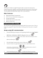 3
3
-
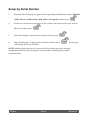 4
4
-
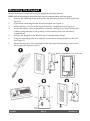 5
5
-
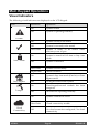 6
6
-
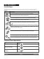 7
7
-
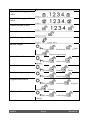 8
8
-
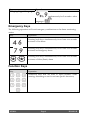 9
9
-
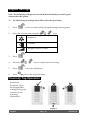 10
10
-
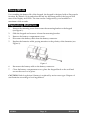 11
11
-
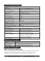 12
12
-
 13
13
-
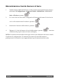 14
14
-
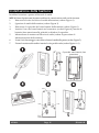 15
15
-
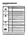 16
16
-
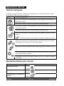 17
17
-
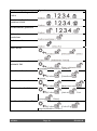 18
18
-
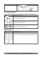 19
19
-
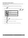 20
20
-
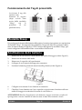 21
21
-
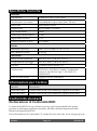 22
22
-
 23
23
-
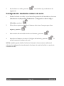 24
24
-
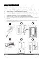 25
25
-
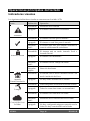 26
26
-
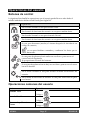 27
27
-
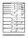 28
28
-
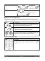 29
29
-
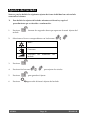 30
30
-
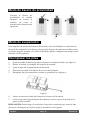 31
31
-
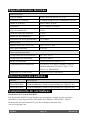 32
32
-
 33
33
-
 34
34
-
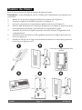 35
35
-
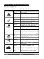 36
36
-
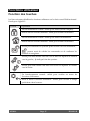 37
37
-
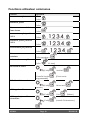 38
38
-
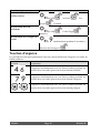 39
39
-
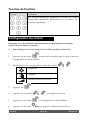 40
40
-
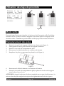 41
41
-
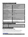 42
42
-
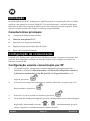 43
43
-
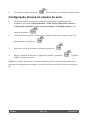 44
44
-
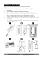 45
45
-
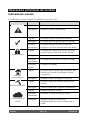 46
46
-
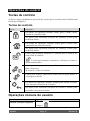 47
47
-
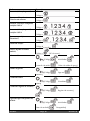 48
48
-
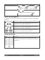 49
49
-
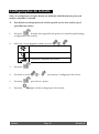 50
50
-
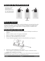 51
51
-
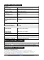 52
52
-
 53
53
-
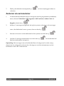 54
54
-
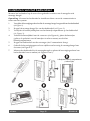 55
55
-
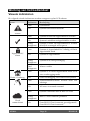 56
56
-
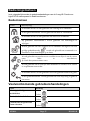 57
57
-
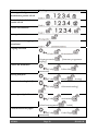 58
58
-
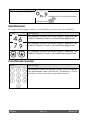 59
59
-
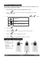 60
60
-
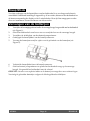 61
61
-
 62
62
-
 63
63
-
 64
64


Risco RW432KPP Installation and User Manual
- Type
- Installation and User Manual
in andere talen
- English: Risco RW432KPP
- italiano: Risco RW432KPP
- français: Risco RW432KPP
- español: Risco RW432KPP
- português: Risco RW432KPP
Gerelateerde papieren
Andere documenten
-
Tyco PowerSeries Neo HS2128 Handleiding
-
Honeywell EKZ008200B Handleiding
-
DSC HS2TCHP Handleiding
-
Chacon 34958 Handleiding
-
-
Marmitek WK820 Handleiding
-
DELTA DORE TYXAL+ CLT 8000 Installatie gids
-
DELTA DORE TTRTC TYXAL+ Installatie gids
-
-
Satel PRF-LCD-A2 Handleiding