Corsair CW-9060031-WW Handleiding
- Categorie
- Computer koeling componenten
- Type
- Handleiding

TM
H150i PRO
RGB
LOW NOISE 360MM RGB LIQUID CPU COOLER
QUICK S TART GUIDE
EMAIL: support@corsair.com
FACEBOOK: facebook.com/corsair
BLOG: blog.corsair.com
FORUM: forum.corsair.com
TWITTER: twitter.com/corsair
USA and CANADA: (510) 657-8747 | INTERNATIONAL: (888) 222-4346 | FAX: (510) 657-8748
corsair.com
47100 BAYSIDE PARKWAY • FREMONT • CALIFORNIA • 94538 • USA
© 2017 - 2019 CORSAIR MEMEORY, INC. All rights reserved.
CORSAIR and the sails logo are registered trademarks in the United States
and/or other countries. All other trademarks are the property of their respective
owners. Product may vary slightly from those pictured. 49-001595 AD
5
H150i PRO
RGB

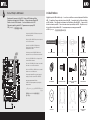
Included Hardware
x2 AMD SCREW CLIP
D
x24 LONG FAN SCREWS
A
x4 LGA 115X/1366 STANDOFF
B
x4 LGA 2011/2011-3/2066
STANDOFF
C
x3 ML120 PWM FANS
H
x12 RADIATOR SCREWS
F
x1 CORSAIR iCUE USB CABLE
(INCLUDED)
G
x4 THUMBSCREWS
E
x1 INTEL BACKPLATE
J
x24 WASHER
I
x1 AMD MOUNTING
BRACKET
L
x1 INTEL MOUNTING BRACKET
(PRE-INSTALLED)
K
Note: Most newer PC cases include a CPU cutout to allow access to the bottom of the
motherboard. If your case does not include a cutout, you will need to remove your motherboard
from the case before installation.
Remarque: la plupart des nouveaux boîtiers de PC comportent un accès facilité au processeur
qui permet d'accéder à la base de la carte mère. Si aucun accès n'est prévu sur votre boîtier,
vous devrez retirer votre carte mère du boîtier avant de procéder à l'installation.
Hinweis: Bei neueren PC-Gehäusen gibt in der Regel eine CPU-Önung Zugang zur Unterseite
der Hauptplatine. Falls Ihr Gehäuse keine derartige Önung aufweist, müssen Sie vor der
Installation die Hauptplatine ausbauen.
Opmerking: De meeste nieuwere pc-behuizingen zijn uitgevoerd met een CPU-uitsparing die de
onderkant van het moederbord toegankelijk maakt. Als dat voor jouw pc niet het geval is, moet
je eerst het moederbord uit de behuizing verwijderen voordat je aan de installatiewerken begint.
Nota: la maggior parte dei case per PC più recenti include un’apertura dietro la CPU che
consente l’accesso alla parte inferiore della scheda madre. Se il case non include un’apertura,
occorrerà rimuovere la scheda madre dal case prima di procedere con l’installazione.
Nota: La mayoría de las carcasas de las nuevas PC incluyen una puerta trasera para el CPU a fin
de permitir el acceso a la parte inferior del motherboard. Si su carcasa no tiene esta entrada,
deberá retirar el motherboard de la carcasa antes de la instalación.
Observação: A maioria dos gabinetes de PC mais recentes incluem uma abertura para CPU que
permite acessar a parte inferior da placa-mãe. Se o seu gabinete não tem uma abertura, será
necessário remover sua placa-mãe do gabinete antes da instalação.
Uwaga: Większość nowszych obudów komputerowych ma wycięcie na procesor, które umożliwia
dostęp do spodu płyty głównej. Jeśli w obudowie nie ma wycięcia, przed instalacją należy wyjąć
płytę główną z obudowy.
Примечание. На большинстве современных корпусов ПК имеется прорезь для предоставления доступа
к нижней части материнской платы. Если на вашем корпусе нет такой прорези, то перед установкой
необходимо удалить материнскую плату из корпуса.
. :
.
注: 大部分型号较新的 PC 机箱都配有 CPU 散热器更换口,可以在不移动主板的情况直接更换 CPU 散热器,
如果您的机箱未预留此空间,需要在水冷安装前取下主板。
EN
FR
DE
NL
IT
ES
PT
PL
RU
AR
CN
Highlighted parts for Intel installation only • Les sections en surbrillance concernent uniquement
l'installation Intel • Die markierten Passagen beziehen sich nur auf die Intel • Gemarkeerde tekst heeft
alleen betrekking op Intel-installatie • Parti evidenziate esclusivamente per l’installazione della staa Intel
Componentes de instalación solamente para Intel • Partes destacadas somente para instalação da Intel
Wyróżnione części dotyczą tylko instalacji produktów Intel • Части, выделенные цветом, только для установки Intel
• 突出显示的部分仅限 Intel 安装
Intel
Note: The H150i PRO RGB comes with Intel mounting bracket pre-installed on the pump
for quick installation.
Remarque: Pour une installation plus rapide, le support de fixation Intel est déjà monté
sur la pompe du dissipateur H150i PRO RGB.
Hinweis: Beim Hochleistungsprozessorkühler H150i PRO RGB ist die
Intel-Montagehalterung bereits auf der Pumpe vorinstalliert und ermöglicht so eine
besonders schnelle Montage.
Opmerking: Voor een snelle installatie wordt de H150i PRO RGB geleverd met een op de
pomp geïnstalleerde Intel-montagebeugel.
Nota: Il sistema di rareddamento H150i PRO RGB presenta una staa di montaggio Intel
preinstallata sulla pompa per un’installazione rapida.
Nota: El H150i PRO RGB viene con un soporte de montaje Intel preinstalado en la bomba
para una instalación rápida.
Observação: O H150i PRO RGB inclui um suporte de montagem Intel pré-instalado na
bomba para uma instalação rápida.
Uwaga: Na pompce układu H150i PRO RGB zamontowano fabrycznie uchwyt montażowy
Intel, który umożliwia szybką instalację.
Примечание. H150i PRO RGB поставляется с установленным на насос монтажным
кронштейном Intel для быстрой установки.
.
Intel
H150i PRO RGB
:
注: H150i PRO RGB 的泵机上预装了 Intel 安装支架,可进行快速安装。

1
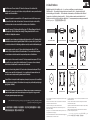
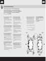
Installing the Intel Backplate
LGA 1366
LGA
115X
figure 1
figure 2
J
Installation de la plaque arrière Intel • Installation der Intel-Rückwand
Installatie van de Intel-achterplaat • Installazione della piastra posteriore Intel
Instalación de la placa de soporte para Intel • Como instalar a placa traseira Intel
Montowanie podstawki montażowej Intel • Установка опорной пластины Intel
• 安装Intel背板
Intel
• For LGA 115X installation, slide the backplate pins inside (figure 1).
• For LGA 1366 installation, slide the backplate pins outside (figure 1).
• Install the assembled backplate (figure 2).
Note: Intel LGA 2011 and LGA 2066 does not require backplate
installation. Proceed to step 2.
• Pour l'installation sur un socket LGA 115X, faites glisser les
broches de la plaque arrière vers l'intérieur (figure 1).
• Pour l'installation sur un socket LGA 1366, faites glisser les
broches de la plaque arrière vers l'extérieur (figure 1).
• Installez la plaque arrière assemblée (figure 2).
Remarque: Intel LGA 2011 et LGA 2066 ne nécessitent pas
l'installation d'une plaque arrière. Passez à l’étape 2.
• Schieben Sie die Stifte der Rückwand nach innen,
um LGA 115X zu montieren (Abbildung 1).
• Schieben Sie die Stifte der Rückwand nach innen,
um LGA 1366 zu montieren (Abbildung 1).
• Montieren Sie die zusammengebaute Rückwand (Abbildung 2).
Hinweis: Der Intel LGA2011 und der LGA2066 erfordern keine
Rückwandinstallation. Fahren Sie mit Schritt2 fort.
• Om de LGA 115X te installeren, schuif je de pinnen van de
achterplaat erin (afbeelding 1).
• Om de LGA 1366 te installeren, schuif je de pinnen van de
achterplaat eruit (afbeelding 1).
• Installeer de ineengezette achterplaat (afbeelding 2).
Opmerking: Voor de Intel LGA 2011 en LGA 2066 hoeft geen
achterplaat te worden geïnstalleerd. Ga door naar stap 2.
• Per l’installazione di LGA 115X, far scorrere i perni della piastra
posteriore verso l’interno (figura 1).
• Per l’installazione di LGA 1366, far scorrere i perni della piastra
posteriore verso l’esterno (figura 1).
• Installare la piastra posteriore assemblata (figura 2).
Nota: I modelli Intel LGA 2011 e LGA 2066 non richiedono
l’installazione della piastra posteriore. andare al passaggio 2.
• Para instalación en LGA 115X, deslice la placa de soporte
con las patillas hacia dentro (figura 1).
• Para instalación en LGA 1366, deslice la placa de soporte
con las patillas hacia fuera (figura 1).
• Instale la placa de soporte ensamblada (figura 2).
Nota: Intel LGA 2011 y LGA 2066 no requieren la instalación de
una placa de respaldo. Continúe con el paso 2.
• Para a instalação da LGA 115X, deslize os pinos da placa traseira
para dentro (figura 1).
• Para a instalação da LGA 1366, deslize os pinos da placa traseira
para fora (figura 1).
• Instale a placa traseira montada (figura 2).
Observação: Intel LGA 2011 e LGA 2066 não exigem instalação de
placa traseira. Prossiga para a etapa 2.
• W przypadku montowania gniazda procesora LGA 115X przesuń
kołki podstawki montażowej do wewnątrz (rysunek 1).
• W przypadku montowania gniazda procesora LGA 1366 przesuń
kołki podstawki montażowej na zewnątrz (rysunek 1).
• Zamocuj przygotowaną podstawkę montażową (rysunek 2).
Uwaga: W przypadku gniazd procesora Intel LGA 2011 i LGA 2066
nie jest konieczne montowanie podstawki. Przejdź do kroku 2.
• При установке LGA 115X задвиньте штырьки внутрь (Рис. 1).
• При установке LGA 1366 задвиньте штырьки наружу (Рис. 1).
• Установите собранную опорную пластину. (Рис. 2)
Примечание. Для Intel LGA 2011 и LGA 2066 установка
опорной пластины не требуется. Перейдите к шагу 2.
.(1 ) 115X LGA •
.(1 ) 1366 LGA •
.(2 ) •
. Intel 2066 LGA 2011 LGA :
.2
• 要安装 LGA 115X,请将背板针脚插入 (图1)。
• 要安装 LGA 1366,请将背板针脚拔出 (图1)。
• 安装组装好的背板 (图2)。
注意: Intel LGA 2011 和 LGA 2066 不需要背面板安装。
继续执行步骤 2。

2
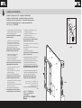
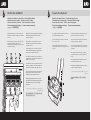
Installing the Intel Stando Screws
3
Install the Fans and Radiator
F
I
A
H
Installation des vis d'entretoise Intel • Installation der Intel-Abstandhalter
Installatie van de Intel-afstandschroeven • Installazione delle viti del supporto Intel
Instalación de los tornillos del separador para Intel • Como instalar os parafusos de suporte Intel
Montowanie śrub dystansowych Intel • Установка опорных винтов Intel
• 安装 Intel 隔架螺丝
Intel
• Attach the provided Intel stando.
• Use (B) for LGA 115X/1366, or (C) for LGA 2011/2011-3/2066.
• Tighten all four screws until firmly secure.
• Fixez les entretoises Intel fournies.
• Utilisez-en (B) pour un socket LGA 115X/1366 ou (C)
pour un socket LGA 2011/2011-3/2066.
• Serrez les quatre vis jusqu'à ce qu'elles ne puissent plus bouger.
• Befestigen Sie den im Lieferumfang
enthaltenen Intel-Abstandhalter.
• Verwenden Sie (B) für LGA 115X/1366 oder (C)
für LGA 2011/2011-3/2066.
• Ziehen Sie alle vier Schrauben fest.
C
B
LGA2011/2011-3/
2066
LGA 115X/1366
• Bevestig de meegeleverde Intel-afstandschroeven.
• Gebruik (B) voor LGA 115X/1366 of (C) voor LGA 2011/2011-3/2066.
• Draai alle vier de schroeven stevig aan totdat ze goed vastzitten.
• Fissare il supporto Intel fornito.
• Usare (B) per LGA 115X/1366 o (C) per LGA 2011/2011-3/2066.
• Stringere saldamente tutte e quattro le viti.
• Conecte el separador para Intel suministrado.
• Utilice (B) para LGA 115X/1366 o (C) para LGA 2011/2011-3/2066.
• Apriete los cuatro tornillos hasta que estén bien fijados.
• Fixe o suporte Intel fornecido.
• Use (B) para LGA 115X/1366, ou (C) para LGA 2011/2011-3/2066.
• Aperte todos os quatro parafusos até que estejam
firmemente presos.
• Zamocuj śruby dystansowe Intel (w komplecie).
• Użyj śruby (B) w przypadku gniazda LGA 115X/1366 lub śruby (C)
w przypadku gniazda LGA 2011/2011-3/2066.
• Mocno dokręć wszystkie cztery śruby.
• Прикрепите входящую в комплект опору Intel.
• Для LGA 115X/1366 используйте (B), а для
LGA 2011/2011-3/2066 — (C).
• Хорошо затяните все четыре винта.
. Intel •
.LGA 2011/2011-3/2066 (C) LGA 115X/1366 (B) •
.
•
• 连接随附的 Intel 隔架。
• 为 LGA 115X/1366 使用 (B),
或者为 LGA 2011/2011-3/2066 使用 (C)。
• 拧紧全部四个螺丝,直至牢牢地固定。
Installation des ventilateurs et du radiateur • Lüfter und Kühler einbauen
Installatie van de fans en radiator • Installare le ventole e il radiatore
Instale los ventiladores y el radiador • Instale as ventoinhas e o radiador
Montowanie wentylatorów i radiatora • Установка вентиляторов и радиатора
• 安装风扇和散热器
Attach the radiator and the fans as shown. For the best cooling
performance, we recommend mounting the fans as an air-intake to
your PC case.
Attachez le radiateur et les ventilateurs, comme illustré. Pour des
performances de refroidissement optimales, nous vous
recommandons d'installer les ventilateurs comme une entrée d'air
sur la tour de votre ordinateur.
Bringen Sie Kühler und Lüfter wie abgebildet an. Für bestmögliche
Kühlleistung empfehlen wir, die Lüfter als Lufteinlass des
PC-Gehäuses zu montieren.
Bevestig de radiator en de fans zoals getoond. Voor de beste
koelprestaties raden we je aan de fans als een luchtinlaat op de
pc-behuizing te monteren.
Collegare il radiatore e le ventole come illustrato. Per ottenere le
prestazioni di rareddamento migliori, si consiglia di montare le
ventole in modo che aspirino aria all’interno del PC.
Fije el radiador y los ventiladores tal como se muestra. Para una
refrigeración óptima, recomendamos montar los ventiladores
como entradas de aire en la carcasa del PC.
Fixe o radiador e as ventoinhas como mostrado. Para um melhor
desempenho de resfriamento, recomendamos a montagem das
ventoinhas como uma entrada de ar para o gabinete do seu PC.
Zamocuj radiator i wentylatory zgodnie z rysunkiem. Aby uzyskać
najwyższą wydajność chłodzenia, zalecamy zamontowanie
wentylatorów w obudowie komputera jako wlotowych.
Установите радиатор и вентилятор, как показано на рисунке.
Для более эффективного охлаждения рекомендуется установить
вентиляторы таким образом, чтобы они нагнетали воздух
внутрь корпуса.
.
.
按图示方法连接散热器和风扇。为了达到最佳散热性能,建议您
将风扇作为进气口安装到 PC 机箱上。

4 5
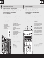
Installing the Pump Unit Connect Power to the Fans and Pump
Installation de la pompe • Montage der Pumpe • Installatie van de pompunit
Installazione dell’unità di pompaggio • Instalación de la unidad de bomba
Como instalar a unidade da bomba • Montowanie pompki • Установка насоса
• 安装泵机装置
E
• Align the bracket and pump over the stando screws as shown.
• Tighten the thumbs screws until all four corners are
firmly secured.
• Alignez le support et la pompe sur les vis d'entretoises
comme indiqué.
• Serrez les vis moletées jusqu'à ce que les quatre coins
soient bien fixés.
• Richten Sie die Halterung und Pumpe über den Abstandhaltern
aus, wie in der Abbildung zu sehen.
• Ziehen Sie die Flügelschrauben an, bis alle vier Ecken
gesichert sind.
• Lijn de beugel en de pomp uit over de afstandschroeven,
zoals getoond.
• Draai de duimschroeven aan totdat alle vier de hoeken
stevig vastzitten.
• Allineare la staa e la pompa con le viti del supporto
come illustrato.
• Stringere saldamente le viti a galletto su tutti e quattro gli angoli.
• Alinee el soporte y la bomba sobre los tornillos del separador
como se muestra.
• Apriete los tornillos de apriete manual hasta que las cuatro
esquinas estén bien fijadas.
• Alinhe o suporte e a bomba com os parafusos de suporte
conforme mostrado.
• Aperte os parafusos de fixação manual até que todos os quatro
cantos estejam firmemente presos.
• Wyrównaj uchwyt i pompkę względem śrub dystansowych
zgodnie z rysunkiem.
• Mocno dokręć śruby radełkowane w czterech rogach.
• Поместите кронштейн и насос над опорными
винтами, как показано на рисунке.
• Затяните винты до полной фиксации всех
четырех углов.
. •
.
•
• 如图所示,将支架和泵机在隔架上对齐。
• 拧紧指旋螺钉,直至全部四个角都牢牢固定。
Branchement des ventilateurs et de la pompe à l'alimentation • Lüfter und Pumpe anschließen
Stroom aansluiten voor de fans en de pomp • Collegare ventole e pompa all’alimentazione
Conexión de la alimentación a los ventiladores y la bomba • Conecte as ventoinhas e a bomba
à energia • Podłączanie zasilania wentylatorów i pompki • Подключение питания вентиляторов
и насоса • • 连接风扇和泵机电源
• Connect pump power cable to an available SATA power plug
(figure 1).
• Connect pump tach cable to the CPU_FAN header
on your motherboard (figure 1).
• Connect each fan to the shrouded 4 pin connectors on the pump
(figure 2).
• Connectez le câble d'alimentation de la pompe à la fiche
d'alimentation SATA (figure 1).
• Connectez le câble d'alimentation de la pompe au cavalier
CPU_FAN de la carte mère (figure 1).
• Connectez chaque ventilateur aux connecteurs carénés
4 broches de la pompe (figure 2).
• Verbinden Sie das Stromkabel der Pumpe mit einem verfügbaren
SATA-Netzstecker (Abbildung 1).
• Verbinden Sie das Stromkabel der Pumpe mit dem
CPU-FAN Header auf dem Mainboard (Abbildung 1).
• Verbinden Sie jeden Lüfter mit den ummantelten
4-Pol-Steckern an der Pumpe (Abbildung 2).
• Sluit de voedingskabel van de pomp aan op een beschikbare
SATA-stroomplug (afbeelding 1).
• Sluit de tach-kabel van de pomp aan op de CPU_FAN-header
op het moederbord (afbeelding 1).
• Sluit elke fan aan op de 4-pins mantelconnectoren op de pomp
(afbeelding 2).
• Collegare il cavo di alimentazione della pompa a una presa di
alimentazione SATA disponibile (figura 1).
• Collegare il cavo tachimetro della pompa all’header
FAN_CPU sulla scheda madre (figura 1).
• Collegare ciascuna ventola ai connettori a 4 pin rivestiti posizionati
sulla pompa (figura 2).
• Conecta el cable de energía de la bomba a un enchufe de
energía SATA disponible (figura 1).
• Conecte el cable de alimentación de la bomba al
cabezal CPU_FAN de la placa base (figura 1).
• Conecta cada ventilador a los conectores de 4 clavijas cubiertos
en la bomba (figura 2).
• Conecte o cabo de alimentação da bomba a um conector
de alimentação SATA disponível (figura 1).
• Conecte o cabo do tacômetro da bomba ao conector CPU_FAN
da sua placa-mãe (figura 1).
• Conecte cada ventoinha aos conectores com proteção de 4 pinos
da bomba (figura 2).
• Połącz przewód zasilający pompki z dostępną wtyczką
zasilania SATA (rysunek 1).
• Podłącz przewód tachometru pompki do złącza CPU_FAN
na płycie głównej (rysunek 1).
• Podłącz każdy wentylator do osłoniętego złącza 4-pinowego
na pompce (rysunek 2).
• Подключите кабель питания насоса к доступному разъему
питания SATA (Рис. 1).
• Подключите кабель питания насоса к разъему CPU_FAN
на материнской плате (Рис. 1).
• Подключите каждый вентилятор к экранированным
4-контактным соединителям насоса (Рис. 2).
.(1 ) SATA •
CPU_FAN •
.(1 )
.(2 ) 4 •
• 连接泵电源线至可用 SATA 电源插头 (图1)。
• 将泵机电源线连接至主板上的 CPU_FAN 接头 (图1)。
• 连接每一个风扇至泵上有保护罩的 4 针连接器 (图2)。
figure 1 figure 2
3-PIN

6
Connect Pump to USB Header
G
Branchement de la pompe à la fiche USB • Pumpe an USB-Header anschließen
Verbinden van de pomp met de USB-header • Collegare la pompa all’header USB
Enchufe el conector USB a la bomba • Conecte a bomba ao conector USB
Podłączanie pompki do gniazda USB • Подключение насоса к разъему USB
• 将泵机连接至 USB 接头
USB
Using the included CORSAIR iCUE USB cable, attach pump unit to
a motherboard USB header.
Utilisez le câble USB CORSAIR iCUE inclus pour brancher la pompe
à une fiche USB de la carte mère.
Verwenden Sie das CORSAIR iCUE USB-Kabel aus dem
Lieferumfang, um die Pumpe an einen USB-Header auf
der Hauptplatine anzuschließen.
Gebruik de meegeleverde CORSAIR iCUE USB-kabel om de
pompunit aan te sluiten op een USB-header van het moederbord.
Usando il cavo USB CORSAIR iCUE incluso, collegare la pompa a
un header USB della scheda madre.
Utilice el cable USB CORSAIR iCUE incluido, para colocar la unidad
de la bomba en un conector USB del motherboard.
Usando o cabo USB iCUE da CORSAIR incluído, conecte a unidade
da bomba a um conector USB da placa-mãe.
Podłącz pompkę do gniazda USB na płycie głównej przy użyciu
znajdującego się w komplecie przewodu USB CORSAIR iCUE.
Используйте входящий комплект USB-кабель
CORSAIR iCUE, чтобы присоединить насос к разъему USB на
материнской плате.
USB CORSAIR iCUE USB
.
使用随附的 CORSAIR iCUE USB 线将泵机装置连接至
主板 USB 接头上。
Included Hardware
Highlighted parts for AMD installation only • Les sections en surbrillance concernent uniquement l'installation
AMD • Die markierten Passagen beziehen sich nur auf die AMD • Gemarkeerde tekst heeft alleen betrekking
op AMD-installatie • Parti evidenziate esclusivamente per l’installazione della staa AMD • Componentes de
instalación solamente para AMD • Partes destacadas somente para instalação da AMD • Wyróżnione części
dotyczą tylko instalacji produktów AMD • Части, выделенные цветом, только для установки AMD
• 突出显示的部分仅限 AMD 安装
AMD
x24 LONG FAN SCREWS
A
x4 LGA 115X/1366 STANDOFF
B
x4 LGA 2011/2011-3/2066
STANDOFF
C
x2 AMD SCREW CLIP
D
x4 THUMBSCREWS
E
x24 WASHER
I
x1 INTEL BACKPLATE
J
x1 INTEL MOUNTING BRACKET
(PRE-INSTALLED)
K
x12 RADIATOR SCREWS
F
x1 CORSAIR iCUE USB CABLE
(INCLUDED)
G
x3 ML120 PWM FANS
H
x1 AMD MOUNTING
BRACKET
L

1
Installing the AMD Mounting Bracket
Installation du support de fixation AMD • Installation der AMD-Montagehalterung
Installatie van de AMD-montagebeugel • Installazione della staa di montaggio AMD
Instalación del soporte de montaje para AMD • Como instalar o suporte de montagem AMD
Montowanie uchwytu montażowego AMD • Установка монтажного кронштейна AMD
• 安装 AMD 安装支架
AMD
Note: It is important that the AMD retention bracket be evenly
secured on all sides before installation!
• Remove the integrated Intel mounting bracket by turning the
mounting bracket, and pulling away from the copper coldplate
(figure 1).
• Install the AMD bracket by aligning the twist lock, pushing in,
turning the opposite direction, and allowing bracket to secure
(figure 2).
Remarque: Il est important que le support de retenue AMD soit
bien sécurisé des deux côtés avant de procéder à l'installation!
• Pour retirer le support de fixation Intel intégré, tournez-le
et éloignez-le de la plaque froide en cuivre (figure 1).
• Pour installer le support AMD, alignez-le avec le verrou rotatif,
poussez-le, tournez-le dans le sens inverse et vérifiez qu'il est
bien immobilisé (figure 2).
Hinweis: Es ist wichtig, dass der AMD-Montagebügel vor der
Installation an allen Seiten gleichmäßig gesichert wird!
• Entfernen Sie die integrierte Intel-Montagehalterung,
indem Sie sie drehen und von der Kupfer-Coldplate fortziehen
(Abbildung1).
• Installieren Sie die AMD-Halterung, indem Sie das Drehschloss
ausrichten, nach innen drücken, in die entgegengesetzte
Richtung drehen und die Halterung somit sichern (Abbildung2).
Opmerking: Het is belangrijk dat de AMD-retentiebeugel aan alle
zijden gelijkmatig vastzit voordat met de installatie wordt
begonnen!
• Verwijder de geïntegreerde Intel-montagebeugel door de
montagebeugel te draaien en af het koperen koelblok te trekken
(afbeelding 1).
• Installeer de AMD-retentiebeugel door de twistlock uit te lijnen,
in te drukken en in de tegengestelde richting te draaien, totdat
de retentiebeugel vastzit (afbeelding 2).
Nota: È importante che la staa di bloccaggio AMD sia
equamente fissata su tutti i lati prima dell’installazione!
• Rimuovere la staa di montaggio Intel integrata facendola
ruotare e staccandola dalla piastra di rareddamento in rame
(figura 1).
• Installare la staa AMD allineando la staa di chiusura e
spingendola verso l’interno e ruotandola nella direzione opposta,
consentendone il fissaggio (figura 2).
Nota: Es importante que el soporte de retención AMD esté
uniformemente fijado a todos los lados antes de la instalación.
• Retire el soporte de montaje Intel integrado. Para ello,
gire el soporte de montaje y despréndalo de la placa refrigerante
de cobre (figura 1).
• Instale el soporte AMD. Para ello, alinee el bloqueo giratorio,
empújelo y gírelo hacia la dirección opuesta hasta que el soporte
quede totalmente fijado (figura 2).
Observação: É importante que o suporte de retenção AMD esteja
uniformemente preso em todos os lados antes da instalação!
• Remova o suporte de montagem Intel integrado girando o
suporte de montagem e retirando-o da placa de resfriamento de
cobre (figura 1).
• Instale o suporte AMD alinhando a trava giratória, pressionando,
fazendo um giro na direção oposta e prendendo o suporte
(figura 2).
Uwaga: Uchwyt montażowy AMD należy zamocować stabilnie i
równomiernie ze wszystkich stron przed instalacją.
• Zdemontuj przymocowany uchwyt montażowy Intel, obracając
go i odrywając od miedzianej płyty chłodzącej (rysunek 1).
• Zamontuj uchwyt AMD. W tym celu dopasuj go do zacisku typu
twist lock, wepchnij i obróć w przeciwnym kierunku, aby stabilnie
zamocować (rysunek 2).
1/8"
1/8"
figure 1 figure 2
K L
Примечание. Очень важно перед установкой равномерно
закрепить крепежный кронштейн AMD на всех сторонах!
• Отсоедините встроенный монтажный кронштейн Intel,
повернув его и сняв с медной платы охлаждения (рис.1).
• Установите кронштейн AMD. Для этого правильно совместите
поворотный замок, вставьте элемент и поворачивайте в
обратном направлении до фиксации кронштейна (рис.2).
AMD :
!
Intel •
.(1 )
AMD •
.(2 )
注: 安装前,请务必将 AMD 挡圈平稳地固定在所有侧面上。
• 转动安装支架以将集成的 Intel 安装支架拆下,然后从铜质
散热板抽离 (图1)。
• 安装 AMD 支架的方法是先对齐扭转锁,推入再往反方向
转动,将支架锁紧 (图2)。

2
Install the Fans and Radiator
Attach the radiator and the fans as shown. For the best cooling
performance, we recommend mounting the fans as an air-intake to
your PC case.
Attachez le radiateur et les ventilateurs, comme illustré. Pour des
performances de refroidissement optimales, nous vous
recommandons d'installer les ventilateurs comme une entrée d'air
sur la tour de votre ordinateur.
Installation des ventilateurs et du radiateur • Lüfter und Kühler einbauen
Installatie van de fans en radiator • Installare le ventole e il radiatore
Instale los ventiladores y el radiador • Instale as ventoinhas e o radiador
Montowanie wentylatorów i radiatora • Установка вентиляторов и радиатора
• 安装风扇和散热器
F
I
A
H
Bringen Sie Kühler und Lüfter wie abgebildet an. Für bestmögliche
Kühlleistung empfehlen wir, die Lüfter als Lufteinlass des
PC-Gehäuses zu montieren.
Bevestig de radiator en de fans zoals getoond. Voor de beste
koelprestaties raden we je aan de fans als een luchtinlaat op de
pc-behuizing te monteren..
Collegare il radiatore e le ventole come illustrato. Per ottenere le
prestazioni di rareddamento migliori, si consiglia di montare le
ventole in modo che aspirino aria all’interno del PC.
Fije el radiador y los ventiladores tal como se muestra. Para una
refrigeración óptima, recomendamos montar los ventiladores como
entradas de aire en la carcasa del PC.
Fixe o radiador e as ventoinhas como mostrado. Para um melhor
desempenho de resfriamento, recomendamos a montagem das
ventoinhas como uma entrada de ar para o gabinete do seu PC.
Zamocuj radiator i wentylatory zgodnie z rysunkiem. Aby uzyskać
najwyższą wydajność chłodzenia, zalecamy zamontowanie
wentylatorów w obudowie komputera jako wlotowych.
Установите радиатор и вентилятор, как показано на рисунке.
Для более эффективного охлаждения рекомендуется установить
вентиляторы таким образом, чтобы они нагнетали воздух
внутрь корпуса.
.
.
按图示方法连接散热器和风扇。为了达到最佳散热性能,建议您
将风扇作为进气口安装到 PC 机箱上。
3
Prepare the Mounting Bracket
Préparation du support de fixation • Montagehalterung vorbereiten
Voorbereiden van de montagebeugel • Preparare la staa di montaggio
Prepare la placa de montaje • Prepare o suporte de montagem
Przygotowanie uchwytu montażowego • Подготовьте монтажный кронштейн
• 准备安装支架
E
D
Insert the AMD screw clips and secure with the screws as shown.
Do not tighten the thumb screws all the way.
Insérez les clips AMD et fixez-les à l'aide des vis comme indiqué.
Ne serrez pas les vis à fond.
Setzen Sie die AMD-Schraubenclips ein und ziehen Sie die
Schrauben wie abgebildet an. Ziehen Sie die Flügelschrauben noch
nicht fest an.
Plaats de AMD-schroefklemmen en draai de schroeven aan, zoals
getoond. Draai de duimschroeven niet helemaal vast.
Inserire i fermi per viti AMD e stringerli con le viti come illustrato.
Non stringere le viti a galletto completamente.
Inserte los clips del soporte AMD y ajústelos con los tornillos, como
se muestra en la imagen. No apriete los tornillos de ajuste manual
excesivamente.
Insira os grampos de parafuso AMD e prenda com os parafusos
conforme mostrado. Não aperte os parafusos de fixação manual
até o final.
Umieść zaczepy śrub AMD i zamocuj śruby zgodnie z rysunkiem.
Nie dokręcaj śrub radełkowanych do końca.
Вставьте винтовые зажимы AMD и закрепите винты, как показано
на рисунке. Не затягивайте винты до конца.
. AMD
.
插入 AMD 螺丝夹并用螺丝固定,如图所示。请勿过度拧紧
指旋螺钉。

5
Connect Power to the Fans and Pump
4
Install the Pump Unit
Installez la pompe • Pumpe installieren • Installatie van de pompunit
Installare l’unità di pompaggio • Instale la unidad de bomba
Instale a unidade da bomba • Montowanie pompki • Установка насоса
• 安装泵机装置
Align the bracket with the Stock AMD mounting clips as shown.
Tighten the thumb screws until secure.
Alignez le support avec les clips de fixation du dissipateur AMD
comme indiqué. Serrez bien les vis.
Richten Sie die Halterung über den AMD-Montageclips aus,
wie in der Abbildung zu sehen. Ziehen Sie die Flügelschrauben
nun fest an.
Lijn de beugel uit de met de gangbare AMD-montageklemmen,
zoals getoond. Draai de duimschroeven aan totdat ze stevig
vastzitten.
Allineare la staa con i fermi di montaggio AMD come illustrato.
Stringere saldamente le viti a galletto
Alinee la placa y los clips de la unidad Stock AMD, como se
muestra en la imagen. Ajuste los tornillos de ajuste
manual hasta que estén firmes.
Alinhe o suporte com os grampos de montagem Stock AMD
conforme mostrado. Aperte os parafusos de fixação manual até
ficarem presos.
Wyrównaj uchwyt względem zaczepów montażowych AMD
zgodnie z rysunkiem. Mocno dokręć śruby radełkowane.
Поместите кронштейн относительно стандартных зажимов AMD,
как показано на рисунке. Затяните винты до конца.
. AMD
.
将支架与备用 AMD 安装夹对齐,如图所示。拧紧指旋螺钉,直至
固定到位。
Branchement des ventilateurs et de la pompe à l'alimentation • Lüfter und Pumpe anschließen
Stroom aansluiten voor de fans en de pomp • Collegare ventole e pompa all’alimentazione
Conexión de la alimentación a los ventiladores y la bomba • Conecte as ventoinhas e a bomba
à energia • Podłączanie zasilania wentylatorów i pompki • Подключение питания вентиляторов
и насоса • • 连接风扇和泵机电源
3-PIN
• Connect pump power cable to an available SATA power plug
(figure 1).
• Connect pump tach cable to the CPU_FAN header
on your motherboard (figure 1).
• Connect each fan to the shrouded 4 pin connectors on the pump
(figure 2).
• Connectez le câble d'alimentation de la pompe à la fiche
d'alimentation SATA (figure 1).
• Connectez le câble d'alimentation de la pompe au cavalier
CPU_FAN de la carte mère (figure 1).
• Connectez chaque ventilateur aux connecteurs carénés
4 broches de la pompe (figure 2).
• Verbinden Sie das Stromkabel der Pumpe mit einem verfügbaren
SATA-Netzstecker (Abbildung 1).
• Verbinden Sie das Stromkabel der Pumpe mit dem
CPU-FAN Header auf dem Mainboard (Abbildung 1).
• Verbinden Sie jeden Lüfter mit den ummantelten
4-Pol-Steckern an der Pumpe (Abbildung 2).
• Sluit de voedingskabel van de pomp aan op een beschikbare
SATA-stroomplug (afbeelding 1).
• Sluit de tach-kabel van de pomp aan op de CPU_FAN-header
op het moederbord (afbeelding 1).
• Sluit elke fan aan op de 4-pins mantelconnectoren op de pomp
(afbeelding 2).
• Collegare il cavo di alimentazione della pompa a una presa di
alimentazione SATA disponibile (figura 1).
• Collegare il cavo tachimetro della pompa all’header
FAN_CPU sulla scheda madre (figura 1).
• Collegare ciascuna ventola ai connettori a 4 pin rivestiti posizionati
sulla pompa (figura 2).
• Conecta el cable de energía de la bomba a un enchufe de
energía SATA disponible (figura 1).
• Conecte el cable de alimentación de la bomba al
cabezal CPU_FAN de la placa base (figura 1).
• Conecta cada ventilador a los conectores de 4 clavijas cubiertos
en la bomba (figura 2).
• Conecte o cabo de alimentação da bomba a um conector
de alimentação SATA disponível (figura 1).
• Conecte o cabo do tacômetro da bomba ao conector CPU_FAN
da sua placa-mãe (figura 1).
• Conecte cada ventoinha aos conectores com proteção de 4 pinos
da bomba (figura 2).
• Połącz przewód zasilający pompki z dostępną wtyczką
zasilania SATA (rysunek 1).
• Podłącz przewód tachometru pompki do złącza CPU_FAN
na płycie głównej (rysunek 1).
• Podłącz każdy wentylator do osłoniętego złącza 4-pinowego
na pompce (rysunek 2).
• Подключите кабель питания насоса к доступному разъему
питания SATA (Рис. 1).
• Подключите кабель питания насоса к разъему CPU_FAN
на материнской плате (Рис. 1).
• Подключите каждый вентилятор к экранированным
4-контактным соединителям насоса (Рис. 2).
.(1 ) SATA •
CPU_FAN •
.(1 )
.(2 ) 4 •
• 连接泵电源线至可用 SATA 电源插头 (图1)。
• 将泵机电源线连接至主板上的 CPU_FAN 接头 (图1)。
• 连接每一个风扇至泵上有保护罩的 4 针连接器 (图2)。
figure 1 figure 2

6
Connect Pump to USB Header
G
Branchement de la pompe à la fiche USB • Pumpe an USB-Header anschließen
Verbinden van de pomp met de USB-header • Collegare la pompa all’header USB
Enchufe el conector USB a la bomba • Conecte a bomba ao conector USB
Podłączanie pompki do gniazda USB • Подключение насоса к разъему USB
• 将泵机连接至 USB 接头
USB
Using the included CORSAIR iCUE USB cable, attach pump unit to
a motherboard USB header.
Utilisez le câble USB CORSAIR iCUE inclus pour brancher la pompe
à une fiche USB de la carte mère.
Verwenden Sie das CORSAIR iCUE USB-Kabel aus dem
Lieferumfang, um die Pumpe an einen USB-Header auf
der Hauptplatine anzuschließen.
Gebruik de meegeleverde CORSAIR iCUE USB-kabel om de
pompunit aan te sluiten op een USB-header van het moederbord.
Usando il cavo USB CORSAIR iCUE incluso, collegare la pompa a
un header USB della scheda madre.
Utilice el cable USB CORSAIR iCUE incluido, para colocar la unidad
de la bomba en un conector USB del motherboard.
Usando o cabo USB iCUE da CORSAIR incluído, conecte a unidade
da bomba a um conector USB da placa-mãe.
Podłącz pompkę do gniazda USB na płycie głównej przy użyciu
znajdującego się w komplecie przewodu USB CORSAIR iCUE.
Используйте входящий комплект USB-кабель
CORSAIR iCUE, чтобы присоединить насос к разъему USB на
материнской плате.
USB CORSAIR iCUE USB
.
使用随附的 CORSAIR iCUE USB 线将泵机装置连接至
主板 USB 接头上。
FAQ
1. How do I know the direction of the air flow of the fan?
An arrow located on the side of the fan indicates the direction
of air flow.
2. Can I reuse the pre-applied thermal paste on the H150i PRO RGB
for a re-installation?
Re-installation of the H150i PRO RGB cooler will require you clean
o the pre-applied thermal paste and apply an aftermarket paste.
3. Where can I purchase additional radiator screws for
push/pull Configuration?
Additional screws can be purchased from www.corsair.com.
1. Comment savoir dans quelle direction le flux d'air du
ventilateur se déplace ?
Une flèche située sur le côté du ventilateur indique la
direction du flux.
2. Est-il possible de réutiliser la pâte thermique pré-appliquée
sur le H150i PRO RGB en vue d'eectuer une nouvelle installation?
Pour réinstaller le dissipateur thermique H150i PRO RGB, il vous
faudra d'abord nettoyer la pâte thermique pré-appliquée pour
la remplacer par une autre pâte neuve.
3. Où peut-on se procurer des vis de radiateurs
supplémentaires pour la configuration « Push-Pull » ?
Vous pouvez acheter ces vis sur le site Web www.corsair.com.
1. Wie erkenne ich die Richtung des Luftstroms,
der durch den Lüfter erzeugt wird?
Die Richtung des Luftstroms wird durch einen Pfeil auf der
Seite des Lüfters signalisiert.
2. Kann ich die auf dem H150i PRO RGB aufgetragene
Wärmeleitpaste bei einer Neuinstallation wiederverwenden?
Bei der Neuinstallation des H150i PRO RGB Kühlsystems muss die
aufgetragene Wärmeleitpaste entfernt und eine neue Paste
aufgetragen werden.
3. Wo kann ich zusätzliche Kühlerschrauben für eine
„Push-Pull-Konfiguration“ erwerben?
Zusätzliche Schrauben können Sie auf www.corsair.com erwerben.
1. Hoe kan ik zien in welke richting de luchtstroom van de fan staat?
Een pijl op de zijkant van de fan geeft de richting van de
luchtstroom aan.
2. Kan ik de koelpasta van de H150i PRO RGB opnieuw gebruiken
voor een volgende installatie?
Als je de H150i PRO RGB-koeler opnieuw wilt installeren, moet je de
gebruikte koelpasta verwijderen en nieuwe pasta aanbrengen.
3. Waar kan ik extra radiatorschroeven voor
push/pull-configuratie kopen?
Extra schroeven zijn beschikbaar op www.corsair.com.
1. Come si determina la direzione del flusso d’aria della ventola?
La freccia situata sulla parte laterale della ventola indica la direzione
del flusso d’aria.
2. È possibile riutilizzare la pasta termoconduttiva
preapplicata sull’H150i PRO RGB per una seconda installazione?
Per reinstallare il dissipatore di calore H150i PRO RGB è necessario
rimuovere la pasta termoconduttiva preapplicata e applicarne una
nuova da acquistarsi tramite i servizi post-vendita.
3. Dove è possibile acquistare viti aggiuntive con
configurazione “push-pull” per il radiatore?
È possibile acquistare viti aggiuntive sul sito www.corsair.com.
1. ¿Cómo puedo saber el sentido en que circula el aire del ventilador?
En el lateral del ventilador hay una flecha que indica el sentido del
flujo de aire.
2. ¿Puedo reutilizar la pasta térmica que venía aplicada
en el H150i PRO RGB para volver a instalar el refrigerador?
Para volver a instalar el refrigerador H150i PRO RGB es preciso
limpiar a fondo la pasta térmica que venía aplicada de fábrica
y aplicar una capa de pasta nueva, adquirida a tal efecto.
3. ¿Dónde puedo comprar un tornillo adicional de Radiador
para configurarlo en modo push/pull (empuje/extracción)?
Se pueden comprar tornillos adicionales en www.corsair.com
1. Como identificar a direção do fluxo de ar da ventoinha?
Uma seta localizada na lateral da ventoinha indica a direção do
fluxo de ar.
2. Posso reutilizar a pasta térmica pré-aplicada no H150i PRO RGB
para uma reinstalação?
A reinstalação do cooler H150i PRO RGB exigirá que você limpe a
pasta térmica pré-aplicada e aplique uma pasta de pós-venda.
3. Onde posso adquirir parafusos adicionais do radiador para a
Configuração empurrar/puxar?
Parafusos adicionais podem ser adquiridos em www.corsair.com.
1. Skąd wiadomo, jaki jest kierunek przepływu powietrza
w wentylatorze?
Kierunek przepływu powietrza wskazuje strzałka znajdująca się z
boku wentylatora.
2. Czy w przypadku ponownego montażu układu H150i PRO RGB
można wykorzystać nałożoną fabrycznie pastę termoprzewodzącą?
Przed ponownym montażem układu chłodzenia H150i PRO RGB
trzeba usunąć nałożoną fabrycznie pastę termoprzewodzącą.
Następnie należy nałożyć pastę dostępną jako materiał eksploatacyjny.
3. Gdzie można kupić dodatkowe śruby do radiatora na
potrzeby konfiguracji push-pull?
Dodatkowe śruby można kupić na stronie www.corsair.com.
1. Как определить направление воздушного потока вентилятора?
Стрелка на боковой части вентилятора обозначает направление
воздушного потока.
2. Можно ли повторно использовать нанесенную термопасту для
переустановки H150i PRO RGB?
Переустановка системы охлаждения H150i PRO RGB требует удаления
остатков нанесенной термопасты и нанесения новой термопасты.
3. Где можно приобрести дополнительный винт для радиатора
приточно-вытяжной конфигурации?
Дополнительные винты можно приобрести на сайте www.corsair.com
.1
.
H150i PRO RGB
.2
H150i PRO RGB
.
.3
.www.corsair.com
1. 如何知道风扇气流的方向?
风扇一侧上标识的箭头会指示气流方向。
2. 我可以重用 H150i PRO RGB 上的预涂硅脂进行重新安装吗?
重新安装 H150i PRO RGB 散热器需要清理掉预涂的硅脂并重新涂上硅脂。
3. 我在哪里可以另外买到用于推/拉配置的散热器螺丝?
可在网站 (www.corsair.com) 上购买额外的螺丝。

Thank you for purchasing the CORSAIR Hydro Series H150i PRO RGB Low Noise Liquid CPU Cooler.
Please visit: corsair.com to download a detailed user guide or to obtain technical support.
Merci d'avoir acheté le dissipateur à liquide pour processeur hautes performances
CORSAIR Hydro Series H150i PRO RGB.
Rendez-vous sur corsair.com pour télécharger un guide d'utilisation complet ou pour obtenir de l'assistance technique.
Vielen Dank, dass Sie sich für den CORSAIR Hochleistungs-Prozessorkühler
Hydro Series H150i PRO RGB mit Kühlmittel entschieden haben.
Auf corsair.com können Sie ein umfassendes Benutzerhandbuch herunterladen und technischen Support erhalten.
Bedankt dat je voor de geluidsarme CPU-vloeistofkoeler H150i PRO RGB van de
CORSAIR Hydro Series hebt gekozen.
Ga naar corsair.com om een uitgebreide gebruikershandleiding te downloaden of om technische ondersteuning te krijgen.
Grazie per aver acquistato il sistema di rareddamento a liquido per CPU a bassa rumorosità
CORSAIR Hydro Series H150i PRO RGB.
Visitare corsair.com per scaricare la guida utente completa o per ottenere supporto tecnico.
Gracias por adquirir el sistema de enfriamiento líquido de máximo rendimiento
Hydro Series H150i PRO RGB de CORSAIR.
Si desea descargar una Guía del usuario detallada o solicitar asistencia técnica, visite corsair.com.
Obrigado por ter adquirido o Cooler líquido para CPU
CORSAIR Hydro Series H150i PRO RGB de baixo ruído.
Visite corsair.com para baixar um guia do usuário detalhado ou para obter suporte técnico.
Dziękujemy za zakup cichego układu chłodzenia procesora cieczą
CORSAIR Hydro Series H150i PRO RGB.
Aby pobrać szczegółową instrukcję lub uzyskać pomoc techniczną, odwiedź witrynę internetową: corsair.com.
Благодарим за приобретение высокопроизводительной системы охлаждения процессора
CORSAIR Hydro Series H150i PRO RGB.
Загрузить подробное руководство пользователя и получить техническую поддержку можно на веб-сайте corsair.com.
.CORSAIR CPU Hydro Series H150i PRO RGB
.
corsair.com :
感谢您购买 Hydro Series H150i PRO RGB 极佳性能液体 CPU 散热器。
请访问: corsair.com 下载详细用户指南或获取技术支持。

NOTE ON ENVIRONMENTAL PROTECTION:
After the implementation of the European Directive 2012/19/EU in the national
legal system, the following applies:
- Electrical and electronic devices may not be disposed of with
domestic waste.
- Consumers are obliged by law to return electrical and electronic devices at
the end of their service lives to the public collecting points set up for this
purpose or point of sale. Details to this are defined by the national law of the
respective country. This symbol on the product, the instruction manual or the
package indicates that a product is subject to these regulations. By recycling,
reusing the materials or other forms of utilising old devices, you are making an
important contribution to protecting our environment.
REMARQUES CONCERNANT LA PROTECTION DE L'ENVIRONNEMENT:
Conformément à la directive européenne 2012/19/EU, et afin d'atteindre un
certain nombre d'objectifs en matière de protection de l'environnement, les
règles suivantes doivent être appliquées:
- Elles concernent les déchets d'équipement électriques et électroniques. Le
pictogramme "picto" présent sur le produit, son manuel d'utilisation ou son
emballage indique que le produit est soumis à cette réglementation.
- Le consommateur doit retourner le produit usager aux points de collecte
prévus à cet eet. Il peut aussi le remettre à un revendeur. En permettant enfin
le recyclage des produits, le consommateur contribuera à la protection de
notre environnement. C'est un acte écologique.
HINWEIS ZUM UMWELTSCHUTZ:
Ab dem Zeitpunkt der Umsetzung der europäischen Richtlinie 2012/19/EU in
nationales Recht gilt folgendes:
- Elektrische und elektronische Geräte dürfen nicht mit dem Hausmüll
entsorgt werden.
- Der Verbraucher ist gesetzlich verpflichtet, elektrische und elektronische
Geräte am Ende ihrer Lebensdauer an den dafür eingerichteten, öentlichen
Sammelstellen oder an die Verkaufstelle zurückzugeben. Einzelheiten dazu
regelt das jeweilige Landesrecht. Das Symbol auf dem Produkt, der
Gebrauchsanleitung oder der Verpackung weist auf diese Bestimmungen hin.
Mit der Wiederverwertung, der stochen Verwertung oder anderer Formen
der Verwertung von Altgeräten leisten Sie einen wichtigen Beitrag zum Schutz
unserer Umwelt. In Deutschland gelten oben genannte Entsorgungsregeln, laut
Batterieverordnung, für Batterien und Akkus entsprechend.
NOTITIE AANGAANDE DE BESCHERMING VAN HET MILIEU:
Ten gevolge van de invoering van de Europese Richtlijn 2012/19/EU in het
nationaal juridisch system, is het volgende van toepassing:
- Electrische en electronische toestellen mogen niet weggegooid worden
tesamen met het huishoudelijk afval.
- Consumenten zijn wettelijk verplicht om electrische en elctronische
apparaten op het einde van gebruik in te dienen bij openbare
verzamelplaatsen speciaal opgezet voor dit doeleinde of bij een verkooppunt.
Verdere specificaties aangaande dit onderwerp zijn omschreven door de
INFORMASJON OM BESKYTTELSE AV MILJØET:
Etter implementering av EU-direktiv 2012/19/EU i det nasjonale lovverk, er
følgende gjort gjeldende:
- Elektrisk og elektronisk utstyr skal ikke kastes sammenmed
husholdningsavfall.
- Forbrukere er pålagt ved lov å returnere elektrisk og elektronisk utstyr ved
enden av levetiden til oentlige oppsamlingspunkter, oppsatt for dette formål
eller til utsalgssteder for slikt utstyr. Detaljer rundt dette er
definert i lovverket i det respektive land. Dette symbolet på produktet,
bruksanvisningen eller forpakningen forteller at et produkt faller inn under
disse betingelsene. Ved resirkulering, gjenbruk av materialet eller på andre
måter å nyttiggjøre gammelt utstyr bidrar du på en viktig måte til å beskytte
vårt felles miljø!nationale wet van het betreende land. Dit symbool op het
product, de gebruiksaanwijzing of de verpakking duidt erop dat het product
onderworpen is aan deze richtlijnen. Door te recycleren, hergebruiken van
materialen of andere vormen van hergebruiken van oude toestellen, levert u
een grote bijdrage aan de bescherming van het mileu.
INFORMAZIONI PER PROTEZIONE AMBIENTALE:
Dopo l'implementazione della Direttiva Europea 2012/19/EU nel sistema legale
nazionale, ci sono le seguenti applicazioni:
- I dispositivi elettrici ed elettronici non devono essere
considerati rifiuti domestici.
- I consumatori sono obbligati dalla legge a restituire I dispositivi elettrici ed
elettronici alla fine della loro vita utile ai punti di raccolta pubblici preposti per
questo scopo o nei punti vendita. Dettagli di quanto riportato sono definiti
dalle leggi nazionali di ogni stato. Questo simbolo sul prodotto, sul manuale
d'istruzioni o sull'imballo indicano che questo prodotto è soggetto
a queste regole.
NOTA SOBRE LA PROTECCIÓN MEDIOAMBIENTAL:
Después de la puesta en marcha de la directiva Europea 2012/19/EU en el
sistema legislativo nacional, Se aplicara lo siguiente:
- Los aparatos eléctricos y electrónicos, así como las pilas y las pilas
recargables, no se deben evacuar en la basura doméstica.
- El usuario está legalmente obligado a llevar los aparatos eléctricos y
electrónicos, así como pilas y pilas recargables, al final de su vida útil a los
puntos de recogida comunales o a devolverlos al lugar donde los adquirió. Los
detalles quedaran definidos por la ley de cada país. El símbolo en el producto,
en las instrucciones de uso o en el embalaje hace referencia a ello. Gracias al
reciclaje, al reciclaje del material o a otras formas de reciclaje de aparatos
usados, contribuye Usted de forma importante a la protección de nuestro
medio ambiente.
NOTA EM PROTECÇÃO AMBIENTAL:
Após a implementação da directiva comunitária 2012/19/EU no sistema legal
nacional, o seguinte aplica-se:
- Todos os aparelhos eléctricos e electrónicos não podem ser despejados
juntamente com o lixo doméstico.
- Consumidores estão obrigados por lei a colocar os aparelhos eléctricos e
electrónicos sem uso em locais públicos específicos para este efeito ou no
ponto de venda. Os detalhes para este processo são definidos por lei pelos
respectivos países. Este símbolo no produto, o manual de instruções ou a
embalagem indicam que o produto está sujeito a estes regulamentos.
Reciclando, reutilizando os materiais dos seus velhos aparelhos, esta a fazer
uma enorme contribuição para a protecção do ambiente.
WSKAZÓWKI DOTYCZACE OCHRONY SRODOWISKA:
Od czasu wprowadzenia europejskiej dyrektywy 2012/19/EU do prawa
narodowego obowiazuja nastepujace ustalenia:
- Urzadzen elektrycznych i elektronicznych nie nalezy wyrzucac wraz z innymi
odpadami domowymi.
- Uzytkownik zobowiazany jest, niepotrzebne lub zniszczone urzadzenia
elektryczne odniesc do punktu zbiórki lub do sprzedawcy. Szczegółowe
kwestie reguluja przepisy prawne danego kraju. Informuje o tym symbol
przekreslonego kosza umieszczony na opakowaniu. Segregujac smieci
pomagasz chronic srodowisko naturalne.
NOT OM MILJÖSKYDD:
Efter implementeringen av EU direktiv 2012/19/EU i den nationella
lagstiftningen, gäller följande:
- Elekriska och elektroniska apparater får inte avyttras med hushållsavfall.
- Konsumenter är skyldiga att återlämna elektriska och elektroniska apparater
vid slutet av dess livslängd till, för detta ändamål, oentliga ppsamlingsplatser.
Detaljer för detta definieras via den nationella lagstiftningen i respektive land.
Denna symbol på produkten, instruktionsmanualen eller på förpackningen
indikerar att produkten innefattas av denna bestämmelse. Genom återvinning
och återanvändning av material bidrar du till att skydda miljön och din
omgivning.
OCHRANA ŽIVOTNÍHO PROSTREDÍ:
Evropská smernice 2012/19/EU stanovuje:
- Elektrické a elektronické prístroje se nesmí vhazovat do domácího odpadu.
- Elektrické a elektronické prístroje musí být zlikvidovány podle zákona na
místech k tomu urcených. Recyklací nebo jiným zpusobem zpracování výrazne
prispíváte k ochrane našeho životního prostredí!
YMPÄRISTÖNSUOJELUA KOSKEVA OHJE:
Siitä lähtien, kun Euroopan unionin direktiivi 2012/19/EU otetaan käyttöön
kansallisessa lainsäädännössä, pätevät seuraavat määräykset:
- Sähkö- ja elektroniikkalaitteita ei saa hävittää talousjätteen mukana.
- Kuluttajalla on lain mukaan velvollisuus toimittaa sähkö- ja
elektroniikkalaitteet niiden käyttöiän päätyttyä niille varattuihin julkisiin
keräyspisteisiin tai palauttaa ne myyntipaikkaan. Tähän liittyvistä
yksityiskohdista säädetään kulloisenkin osavaltion laissa. Näistä määräyksistä
mainitaan myös tuotteen symbolissa, käyttöohjeessa tai pakkauksessa.
Uudelleenkäytöllä, materiaalien uudelleenkäytöllä tai muilla vanhojen laitteiden
uudelleenkäyttötavoilla on tärkeä vaikutus yhteisen ympäristömme suojelussa.
KÖRNYEZETVÉDELMI TUDNIVALÓK:
Az európai irányelvek 2012/19/EU ajánlása szerint, a megjelölt idoponttól
kezdve, minden EU-s tagállamban érvényesek a következok:
- A leselejtezett elektromos és elektronikus készülékeket nem szabad a
háztartási szemétbe dobni.
- Az elhasznált és muködésképtelen elektromos és elektronikus készülékek
gyujtésére törvényi eloírás kötelez mindenkit, ezért azokat el kell szállítani egy
kijelölt gyujto helyre vagy visszavinni a vásárlás helyére. A termék
csomagolásán feltüntetett szimbólum egyértelmu jelzést ad erre vonatkozóan
a felhasználónak. A régi készülékek begyujtése, visszaváltása vagy bármilyen
formában történo újra hasznosítása közös hozzájárulás környezetünk
védelméhez.
OCHRANA ŽIVOTNÉHO PROSTREDIA:
Európska smernica 2012/19/EU stanovuje:
- Elektrické a elektronické zariadenia sa nesmú vyhadzovat do
domáceho odpadu.
- Spotrebitel je zo zákona povinný zlikvidovat elektrické a elektronické
zariadenia na miesta k tomu urcené. Symbolizuje to obrázok v návode na
použitie, alebo na balení výrobku. Recykláciou, alebo inými formami využitia
starých prístrojov prispievate v znacnej miere k ochrane vášho
životného prostredia.
ΥΠΟΔΕΙΞΗ ΣΧΕΤΙΚΑ ΜΕ ΤΗΝ ΠΡΟΣΤΑΣΙΑ ΠΕΡΙΒΑΛΛΟΝΤΟΣ:
Από τη στιγμή που η Ευρωπαϊκή Οδηγία 2012/19/EU ενσωματώνεται στο εθνικό δίκαιο
ισχύουν τα εξής:
- Οι ηλεκτρικές και ηλεκτρονικές συσκευές δεν επιτρέπεται να πετιούνται στα σκουπίδια.
- Ο καταναλωτής υποχ ρεούται δια νόμου να επιστρέφει τις ηλεκτρικές και ηλεκτρονικές
συσκευές στο τέλος της ζωής τους πίσω στα ειδικά προβλεπόμενα σημεία συγκέντρωσης ή
στα καταστήματα αγοράς. Οι λεπτομέρειες ρυθμίζονται στη σχετική νομοθεσία. Το σύμβολο
πάνω στο προϊόν, στο εγχειρίδιο χρήσης ή στη συσκευασία παραπέμπει σε αυτές τις
διατάξεις. Με την επαναχρησιμοποίηση, την ανακύκλωση των υλικών ή με άλλους τρόπους
αξιοποίησης των παλαιών συσκευών συμμετέχετε ενεργά στην προστασία του
περιβάλλοντός μας. Στη Γερμανία ισχύουν αντίστοιχα οι παραπάνω κανόνες απόρριψης
σύμφωνα με τον κανονισμό για μπαταρίες και συσσωρευτές.
ÇEVRE KORUMA UYARISI:
Avrupa Birligi Direktifi 2012/19/EU ulusal yasal uygulamalar için de geçerli
oldugu tarihten itibaren:
- Elektrikli ve elektronik cihazlar normal evsel çöpe atılmamalıdır.
- Tüketiciler için, artık çalısmayan elektrikli ve elektronik cihazları, kamuya ait
toplama yerlerine götürme veya satın alındıkları yerlere geri verme yasal bir
zorunluluktur. Bu konu ile ilgili ayrıntılar ulusal yasalarla düzenlenmektedir.
Ürün üzerinde, kullanma kılavuzunda veya ambalajda bulunan bu sembol
tüketiciyi bu konuda uyarır. Eski cihazların geri kazanımı, yapıldıkları
malzemelerin degerlendirilmesi veya diger degerlendirme sekilleri ile, çevre
korumasına önemli bir katkıda bulunursunuz. Yukarıda adı geçen atık toplama
kuralları Almanya'da piller ve aküler için de geçerlidir.
ANVISNINGER TIL BESKYTTELSE AF MILJØET:
Efter implementeringen af det europæiske direktiv 2012/19/EU i det nationale
lovgivningssystem gælder følgende:
- Elektriske og elektroniske apparater må ikke bortskaes med
husholdningsaaldet.
- Forbrugeren er ved afslutningen af elektriske og elektroniske apparaters
levetid lovmæssigt forpligtet til at aflevere disse på de dertil indrettede
oentlige indsamlingssteder eller hos sælgeren. Enkeltheder vedrørende dette
fastlægges af de respektive landes nationale lovgivning. Dette symbol på
produktet, betjeningsvejledningen eller emballagen viser, at produktet er
underlagt disse bestemmelser. Med genanvendelse, genanvendelse af
materialer eller andre former for genbrug af gamle apparater yder du et
vigtigt bidrag til beskyttelse af vores miljø.
CORSAIR MEMORY, Inc. declares that this equipment is in compliance with
Directive 2014/30/EU and Directive 2011/65/EU. A copy of the original
declaration of conformity can be obtain at regulatory@corsair.com.
CORSAIR MEMORY, Inc. déclare que son équipement est conforme aux
directives 2014/30/EU et 2011/65/EU. Une copie de la déclaration de
conformité originale peut être obtenue en envoyant un courrier électronique à
l’adresse regulatory@corsair.com.
CORSAIR MEMORY, Inc. erklärt, dass dieses Gerät den Richtlinien
2014/30/EU und 2011/65/EU entspricht. Eine Kopie der ursprünglichen
Konformitätserklärung kann unter regulatory@corsair.com
angefordert werden.
CORSAIR MEMORY, Inc. verklaart dat dit apparaat overeenstemt met
Europese Richtlijn 2014/30/EU en Europese Richtlijn 2011/65/EU.
Een kopie van de originele conformiteitsverklaring kan worden verkregen via
regulatory@corsair.com.
CORSAIR MEMORY, Inc. dichiara che questa apparecchiatura
è conforme alla Direttiva 2014/30/EU e 2011/65/EU. Una copia
della dichiarazione originale di conformità è disponibile scrivendo un’email
all’indirizzo regulatory@corsair.com.
CORSAIR MEMORY, Inc. declara que este equipo cumple con las directivas
2014/30/EU y 2011/65/EU. Puede obtener una copia de la declaración de
conformidad original en regulatory@corsair.com.
CORSAIR MEMORY, Inc. declara que este equipamento está em
conformidade com as Normas 2014/30/EU e Norma 2011/65/EU. É possível
obter uma cópia da declaração original de conformidade pelo e-mail
regulatory@corsair.com.
CORSAIR MEMORY, Inc. oswiadcza, ze to urzadzenie jest zgodne z
dyrektywami 2014/30/EU i 2011/65/EU. Kopie deklaracji zgodnosci mozna
uzyskac pod adresem regulatory@corsair.com.
THE AUTHORIZED REPRESENTATIVE IN EUROPE:
CORSAIR MEMORY,
BV Wormerweg 8, 1311 XB, Almere,
Netherlands
-
 1
1
-
 2
2
-
 3
3
-
 4
4
-
 5
5
-
 6
6
-
 7
7
-
 8
8
-
 9
9
-
 10
10
-
 11
11
-
 12
12


Corsair CW-9060031-WW Handleiding
- Categorie
- Computer koeling componenten
- Type
- Handleiding
in andere talen
- English: Corsair CW-9060031-WW User manual
- italiano: Corsair CW-9060031-WW Manuale utente
- français: Corsair CW-9060031-WW Manuel utilisateur
- español: Corsair CW-9060031-WW Manual de usuario
- Deutsch: Corsair CW-9060031-WW Benutzerhandbuch
- português: Corsair CW-9060031-WW Manual do usuário
- polski: Corsair CW-9060031-WW Instrukcja obsługi
Gerelateerde papieren
-
Corsair iCUE H100i RGB PRO XT Liquid CPU Cooler Handleiding
-
-
Corsair HS80 Handleiding
-
Corsair AR Series Handleiding
-
Corsair iCUE Elite Handleiding
-
-
-
-
-