
Bedienungsanleitung
Säulenbohrmaschine
Operating Instructions
Pillar Drill
Mode d’emploi
Perceuse à colonne
Gebruiksaanwijzing
Kolomboormachine
Istruzioni per l’uso
Trapano a colonna
Instrukcja obsługi
Wiertarka kolumnowa
Upute za uporabu
stupne bušilice
Art.-Nr.: 42.505.90 I.-Nr.: 01014
Art.-Nr.: 42.507.85 I.-Nr.: 01014
Art.-Nr.: 42.507.90 I.-Nr.: 01014
Art.-Nr.: 42.512.20 I.-Nr.: 01014
Art.-Nr.: 42.512.10 I.-Nr.: 01014
SB 701/1
SB 1020/1W
SB 1020/1D
SB 1625/1W
SB 1625/1D
Anleitung SB 701-1625 SPK 1 04.06.2004 11:48 Uhr Seite 1

2
Bitte Seite 2 ausklappen
Please fold out page 2 .
Veuillez déplier les page 2
Gelieve blz. 2 uit te vouwen
Aprire le pagine dalla 2
Prosimy rozłożyć instrukcję na stronach 2
Molimo da otvorite stranice 2
Anleitung SB 701-1625 SPK 1 04.06.2004 11:48 Uhr Seite 2

3
1
33
27
28
30
34
35
2 3
32
230 V
400 V
Anleitung SB 701-1625 SPK 1 04.06.2004 11:48 Uhr Seite 3

4
4 5
6 7
22
23
21
17
24
26
30
30
27
29
28
Anleitung SB 701-1625 SPK 1 04.06.2004 11:48 Uhr Seite 4

5
8
9
1
2
3
4
A
B
C
D
10
25
34
SB 701/1
1
2
3
4
A
B
C
D
10
SB 1020/1 - SB 1625/1
Pos. U/Min.
4-A 120
4-C 420
2-C 970
3-D 1480
Pos. U/Min.
4-B 300
2-A 500
1-B 1040
2-D 1580
Pos. U/Min.
3-A 350
3-B 540
1-C 1170
1-D 2500
Pos. U/Min.
4-A 220
4-C 450
2-C 800
3-D 1500
Pos. U/Min.
4-B 300
2-A 530
1-B 1300
2-D 2200
Pos. U/Min.
3-A 350
3-B 580
1-C 1400
1-D 2450
Anleitung SB 701-1625 SPK 1 04.06.2004 11:48 Uhr Seite 5

6
12
31
11
35
34
14
37
13
36
Anleitung SB 701-1625 SPK 1 04.06.2004 11:48 Uhr Seite 6

D
1.0. Gerätebeschreibung (Abb. 1/2/3)
1. Maschinenfuß
2. Säule
3. Befestigungsschrauben
4. Bohrtisch
5. Bohrtischhalter
6. Maschinenkopf
7. Keilriemenabdeckung
8. Motor
9. Griffe
10. Bohrfutter
11. Spindel
12. Befestigungsbohrungen
13. Klappbarer Späneschutz
14. Tiefenanschlag
15. Fixierschraube
16. Schraube
17. Klemmschraube
18. Einschalter
19. Ausschalter
20. Madenschraube
27. Kurbel
2.0. Lieferumfang
Säulenbohrmaschine
Zahnkranzbohrfutter
Bohrfutterschlüssel
Klappbarer Späneschutz
Schraubstock
3.0. Bestimmungsgemäße Verwendung
Diese Säulenbohrmaschine ist zum Bohren von
Metall, Kunststoff, Holz und ähnlichen Werkstoffen
bestimmt und darf nur im privaten Haushaltsbereich
verwendet werden.
Lebensmittel und gesundheitsgefährdende
Materialien dürfen mit der Maschine nicht bearbeitet
werden. Das Bohrfutter ist nur für die Verwendung
von Bohrern und Werkzeugen mit einem Schaft-
durchmesser vom 3-16 mm und zylindrischen Werk-
zeugschaft geeignet. Darüberhinaus können auch,
wie in Kap. 7.5 beschreiben, Werkzeuge mit Kegel-
schaft (siehe tech. Daten der jeweiligen Ausführung
Kap. 9) verwendet werden.Das Gerät ist zum
Gebrauch durch Erwachsene bestimmt. Die
Maschine ist für Kurzzeitbetrieb konzipiert (S2 15
min.). Für jede andere Verwendung als in dieser
Bedienungsanleit-ung angegeben, übernehmen wir
keine Haftung, ebenso er-lischt damit jeder
Garantieanspruch.
4.0. Sicherheitshinweise
Bei der Konstruktion der Säulenbohrmaschine wurde
darauf geachtet, dass Gefährdungen bei bestimm-
ungsgemäße Anwendung weitgehend ausge-
schlossen sind. Dennoch gibt es einige
Sicherheitsmaßnahmen die zu beachten sind, damit
Restgefahren ausgeschlossen werden können.
Richtige Netzspannung beachten!
Achten Sie darauf, dass die Netzspannung mit den
Angaben des Typenschildes übereinstimmt.
Schutzkontaktsteckdose verwenden!
Das Gerät darf nur an einer Steckdose mit
ordnungsgemäß installiertem Schutzkontakt
betrieben werden.
Achtung! Verlängerungskabel!
Der Litzenquerschnitt eines Verlängerungskabels
muss mindestens 1,5 mm
2
betragen. Rollen ‚Sie eine
Kabeltrommel vor Gebrauch immer ganz ab.
Überprüfen Sie das Kabel auf Schäden.
Schutz vor elektrischem Schlag!
Schützen Sie das Gerät vor Feuchtigkeit. Das Gerät
darf weder feucht sein, noch in feuchter Umgebung
betrieben werden. Überprüfen Sie vor jeder Benutz-
ung das Gerät und die Netzanschlussleitung mit
Stecker auf Schäden. Vermeiden Sie Körperberühr-
ungen mit geerdeten Teilen, z.B. Rohren, Heizkörper
etc...
Schutz vor Brand oder Explosion!
Im Inneren des Gerätes befinden sich
funkenbildende Bauteile. Benutzen Sie das Gerät
nicht in der Nähe von brennbaren Flüssigkeiten oder
Gasen. Bei Nichtbeachtung besteht Brand- oder
Explosionsgefahr.
Gerät mit Sorgfalt behandeln!
Benutzen Sie das Kabel nicht, um den Stecker aus
der Steckdose zu ziehen. Schützen Sie das Kabel
vor Hitze, Öl und scharfen Kanten. Halten Sie die
Werkzeuge scharf und sauber, um besser und
sicherer arbeiten zu können. Befolgen Sie die
Wartungsvorschriften und die Hinweise über den
Werkzeugwechsel.
Geeignete Arbeitskleidung und
Schutzausrüstung tragen!
Nicht geeignet ist weite Kleidung, sie kann von
beweglichen Teilen erfasst werden oder Sie können
7
Anleitung SB 701-1625 SPK 1 04.06.2004 11:48 Uhr Seite 7

8
D
hängen bleiben. Tragen Sie bei langen Haaren ein
Haarnetz. Tragen Sie bei Arbeiten mit Werkzeug-
maschinen grundsätzlich keinen Schmuck. Tragen
Sie unbedingt eine Schutzbrille. Bei Nichtbeachtung
können Augenverletzungen entstehen.
Arbeitsplatz in Ordnung halten!
Unordnung in Ihrem Arbeitsbereich führt leicht zu
Unfällen. Lassen Sie keine Werkzeuge,
Gegenstände oder Kabel im unmittelbaren
Arbeitsbereich liegen, Stolpergefahr! Sorgen Sie für
ausreichende Beleuchtung.
Auf andere Personen achten!
Achten Sie bei der Benutzung des Gerätes auf
andere Personen, vor allem Kinder, und halten Sie
diese von Ihrem Arbeitsbereich fern. Lassen Sie
niemanden das Gerät oder das Kabel berühren.
Werkzeuge sicher aufbewahren!
Unbenutzte Geräte an einem trockenen,
verschlossenen Ort und außerhalb der Reichweite
von Kindern aufbewahren.
Gerät nicht überlasten!
Arbeiten Sie nur im angegebenen Leistungsbereich.
Verwenden Sie keine leistungsschwachen
Maschinen für schwere Arbeiten. Benutzen Sie
Werkzeuge nicht für Zwecke, für die sie nicht
bestimmt sind.
Sicherer Stand bei der Arbeit!
Achten Sie bei Ihrer Arbeit auf einen sicheren Stand.
Vermeiden Sie abnormale Körperhaltungen, halten
Sie immer das Gleichgewicht.
Netzstecker ziehen-
bei Nichtgebrauch des Werkzeugs, vor der Wartung
und beim Wechseln der Bohrer.
Netzstecker ziehen-
Stellen Sie sicher, daß der netzanschluß mit
nindestens 10 A abgesichert ist.
Unbeabsichtigten Anlauf vermeiden!
Vergewissern Sie sich, dass der Schalter beim
Einstecken des Steckers in die Steckdose
ausgeschaltet ist.
Beobachten Sie Ihre Arbeit!
Beobachten Sie stets die Maschine und den Gegen-
stand, den Sie bearbeiten. Verwenden Sie Ihre
Maschine niemals, wenn Sie unkonzentriert oder ab-
gelenkt sind. Verwenden Sie Ihre Maschine niemals
unter Alkohol- oder Tabletteneinfluss.
maximale Werkstückgröße!
Es dürfen nur Werkstücke (max. 20 x 20 cm) bear-
beitet werden, die am Bohrtisch oder im Schraub-
stock sicher gespannt werden können.
Werkzeug auf Beschädigung überprüfen!
Vor dem Gebrauch des Werkzeugs müssen Schutz-
vorrichtungen oder leicht beschädigte Teile sorgfältig
auf Ihre einwandfreie Funktion untersucht werden.
Kontrollieren Sie regelmäßig das Kabel des Werk-
zeugs. Sämtliche Teile müssen richtig montiert sein
und alle Bedingungen erfüllen, um den einwand-
freien Betrieb sicherzustellen. Beschädigte Schutz-
vorrichtungen und Teile müssen sachgemäß durch
eine anerkannte Fachwerkstatt repariert oder ausge-
wechselt werden, soweit nichts anderes in der Be-
dienungsanleitung angeben ist. Benutzen Sie keine
Werkzeuge, bei denen sich der Schalter nicht ein
und ausschalten lässt.
Warnung! Der Gebrauch anderer Einsatzwerkzeuge
und anderen Zubehörs als in dieser Gebrauchanleit-
ung angegeben, kann eine Verletzungsgefahr für Sie
bedeuten.
Lesen Sie nun die Bedienungsanleitung und
befolgen Sie die darin enthaltenen Anweisungen.
5.0. Aufstellung
5.1.Montage der Maschine (Abb. 1/4/5)
Legen Sie sich die Bodenplatte (1) zurecht.
Befestigen sie die Säule (2) mit Flansch mit den
beiliegenden Schrauben (3).
Setzen sie das Schneckenrad in den Bohrtisch-
halter ein.
Nun legen sie die Zahnstange (30) in den Bohr-
tischhalter (5) mit der Verzahnung zum
Schneckenrad ein (gleicher Überstand).
Diese Teile müssen sie nun zusammen über die
Säule (2) schieben. Dabei ist zu beachten, daß
die Zahnstange in der Verzahnung des
Schneckenrades sitzt.
Für die Sicherung der Zahnstange am oberen
Abschluß streifen sie die Führungshülse (29)
über die Säule und sichern diese mit der
Schraube.
Jezt können sie den Tisch einsetzen und mit
dem Klemmhebel spannen. Danach die Kurbel
(27) aufstecken und mit der Schraube (28) fest-
ziehen.
Anleitung SB 701-1625 SPK 1 04.06.2004 11:48 Uhr Seite 8

9
D
Zum Schluß setzen sie den kompletten Bohrkopf
auf die Säule. Richten Sie den Kopf senkrecht
mit der Bodenplatte aus und sichern diesen mit
den Schrauben (35).
Die 3 mitgelieferten Griffe (9) schrauben sie in
den Griffhalter.
Vor Montage des Bohrfutters mit dem MK-
Schaft, beide Teile auf Sauberkeit überprüfen.
Anschließend Kegeldorn mit kräftigen Ruck in
den Konus des Bohrfutters einschieben. Danach
den Konus ebenso in die Bohrspindel
einschieben (Abb. 13)
Vor Betrieb regelmäßig Keilriemenspannung
überprüfen (Abb. 9).
Hinweis: Zum Schutz vor Korrosion sind alle
blanken Teile eingefettet. Vor dem Aufsetzen des
Bohrfutters (10) auf die Spindel (11) müssen beide
Teile mit einem umweltfreundlichen Lösungsmittel
vollkommen fettfrei gemacht werden, damit eine
optimale Kraftübertragung gewährleistet ist.
5.2.Aufstellen der Maschine (Abb. 4/5)
Vor der Inbetriebnahme muß die Bohrmaschine
stationär montiert werden. Verwenden Sie dazu die
beiden Befestigungsbohrungen (12) in der Boden-
platte. Achten Sie darauf, dass die Maschine für den
Betrieb und für Einstell- und Wartungsarbeiten frei
zugänglich ist.
Hinweis: Die Befestigungsschrauben dürfen nur so
fest angezogen werden, dass sich die Grundplatte
nicht verspannt oder verformt. Bei übermäßiger
Beanspruchung besteht Gefahr des Bruches.
5.3.Klappbarer Späneschutz (Abb. 6)
Die drei Schrauben (21) herausschrauben.
Transparenten Abdeckung (23) in den Schlitz des
roten Aufnahmerahmens (24) schieben und mit den
Schrauben (21) wieder fixieren.
Die Höhe der Abdeckung (23) ist stufenlos einstell-
bar und über die beiden Flügelschrauben (22) zu
fixieren.
Zum Bohrerwechsel kann der Späneschutz (13)
nach oben geklappt werden.
5.4.Vor Inbetriebnahme beachten
Achten Sie darauf, dass die Spannung des Netzan-
schlusses mit dem Typenschild übereinstimmt.
Schließen Sie die Maschine nur an eine Steckdose
mit ordnungsgemäß installiertem Schutzkontakt an.
Die Bohrmaschine ist mit einem Nullspannungs-
auslöser ausgestattet, der die Bediener vor unge-
wolltem Wiederanlauf nach einem Spannungsabfall
schützt. In diesem Fall muß die Maschine erneut
einschaltet werden.
6.0. Betrieb
Tragen Sie beim arbeiten mit der Tisch-
bohrmaschine geeignete, engan-
liegende Schutzkleidung.
Tragen Sie immer eine Schutzbrille!
Tragen Sie bei langen Haaren immer
ein Haarnetz (oder ein Mütze)!
6.1.Allgemein (Abb. 3)
Zum Einschalten betätigen Sie den grünen Ein-
Schalter „I“ (18), die Maschine läuft an. Zum Aus-
schalten drücken Sie die rote Taste „O“ (19), das Ge-
rät schaltet ab. Die Säulenbohrmaschine mit Dreh-
strombetrieb verfügen über einen links/rechts Lauf.
Der Schalter zur Drehrichtungsänderung (32) darf
nur bei Motorstillstand betätigt werden!
Achten Sie darauf, das Gerät nicht zu überlasten.
Sinkt das Motorgeräusch während des Betriebes,
wird der Motor zu stark belastet.
Belasten Sie das Gerät nicht so stark, dass der
Motor zu Stillstand kommt.
Die Maschine ist für Kurzzeitbetrieb (S2 15 min.)
konzipiert. Die Maschine darf maximal 15 Minuten
unter Volllast betrieben werden, danach muss die
Maschine solange ausgeschaltet werden, bis sich die
Motorwicklung auf Zimmertemperatur abgekühlt hat.
Dadurch wird ein Überhitzen des Motors vermieden.
6.2.Werkzeug in Bohrfutter einsetzen (Abb. 1)
Achten Sie unbedingt darauf, dass beim Werkzeug-
wechsel der Netzstecker gezogen ist. Im Bohrfutter
(10) dürfen nur zylindrische Werkzeuge mit dem
angegebenen maximalen Schaftdurchmesser ge-
spannt werden. Nur einwandfreies und scharfes
Werkzeug benutzen. Keine Werkzeuge benutzen,
die am Schaft beschädigt sind oder sonst in irgend-
einer Weise verformt oder beschädigt sind. Setzen
Sie nur Zubehör und Zusatz-geräte, die in der
Bedienungsanleitung angegeben oder vom
Hersteller freigebeben sind, ein.
6.3.Handhabung des Zahnkranz-Bohrfutters
(SB 701/1)
Ihre Säulenbohrmaschine SB 701/1 ist mit einem
Zahnbohrfutter ausgestattet. Um einen Bohrer einzu-
setzen, ist zuerst der Späneschutz (13) nach oben
zu klappen, anschließend der Bohrer einzusetzen
Anleitung SB 701-1625 SPK 1 04.06.2004 11:48 Uhr Seite 9

10
D
und das Bohrfutter mit dem mitgelieferten Futter-
schlüssel festzuziehen.
Futterschlüssel wieder abziehen. Achten Sie auf
festen Sitz der eingespannten Werkzeuge.
Achtung! Futterschlüssel nicht steckten lassen.
Verletzungsgefahr durch Wegschleudern des
Futterschlüssels.
6.4.Handhabung des Schnellspannbohrfutters
(SB 1020/1 und SB 1625/1)
Die Säulenbohrmaschinen SB 1020/1 und SB
1625/1 sind mit einem Schnellspannbohrfutter aus-
gestattet. Es kann der Werkzeugwechsel ohne Zu-
hilfenahme einses zusätzlichen Futterschlüssels vor-
genommen werden, indem man das Werkzeug in
das Schnellspannbohrfutter einsetzt und von Hand
festspannt
6.5.Verwendung von Werkzeugen mit kegeligem
Schaft (Abb. 12/13)
Die Säulenbohrmaschine verfügt über einen Bohr-
spindelkonus. Um Werkzeuge mit kegeligem Schaft
(MK2 bzw. MK3 Aufnahme, je nach Ausführung) zu
verwenden, gehen Sie wie folgt vor:
Bohrfutter in untere Position bringen.
Kegelschaft mit beiliegendem Austreibkeil (31)
austreiben, dabei darauf achten, daß das Werk-
zeug nicht auf den Boden fallen kann.
Neues Werkzeug mit Kegelschaft (36) ruckartig
in den Bohrspindelkonus einschieben und festen
Sitz des Werkzeuges kontrollieren.
6.6.Drehzahleinstellung (Abb. 1/2/7/8/10/11)
Schalten Sie zuerst die Maschine aus und ziehen Sie
den Netzstecker.
Die verschiedenen Spindeldrehzahlen können durch
Umsetzen des Keilriemens eingestellt werden.
Gehen Sie wie folgt vor:
Lösen der Schraube (16) um die
Keilriemenabdeckung (7), öffnen zu können.
Fixierschrauben (15) lösen und den Motor (8) in
Richtung Maschinenkopf schieben.
Keilriemen auf die gewünschte Position
umsetzen.
Die entsprechenden Drehzahlen entnehmen Sie
der Tabelle 6.12.
Keilriemen spannen, indem Sie den Spanhebel
(34) in richtung Motor drücken und Fixier-
schraube (13) wieder festziehen.
Keilriemenabdeckung schließen und mit der
Schraube (16) festschrauben.
Die Keilriemenabdeckung (7) muß immer fest
verschlossen sein, da die Maschine mit einem
Sicherheitsschalter ausgestattet ist und somit nur
bei geschossener Keilriemenabdeckung (7)
eingeschaltet werden kann.
Achtung! Niemals die Bohrmaschine mit geöffneter
Keilriemenabdeckung laufen lassen. Vor dem Öffnen
des Deckels immer den Netzstecker zeihen. Niemals
in laufende Keilriemen greifen.
6.7 Bohrtiefenanschlag (Abb. 8)
Die Bohrspindel besitzt einen verdrehbaren
Skalenring zum Einstellen der Bohrtiefe.
Einrichtarbeiten nur im Stillstand vornehmen.
Bohrspindel (11) nach unten drücken bis die
Bohrerspitze auf dem Werkstück anliegt.
Klemmschraube (17) lockern und Skalenring (25)
nach vorne drehen bis zum Anschlag.
Skalenring (25) um die gewünschte Bohrtiefe
zurückdrehen und mit der Klemmschraube (17)
fixieren.
6.8 Neigung des Bohrtisches einstellen (Abb. 7)
Schlossschraube (26) unter dem Bohrtisch (4)
lockern.
Bohrtisch (4) auf das gewünschte Winkelmaß
einstellen.
Schlossschraube (26) wieder fest anziehen um
den Bohrtisch (4) in dieser Position zu fixieren.
6.9.Höhe des Bohrtisches einstellen (Abb. 1/14)
Spannschraube (37) lockern
Bohrtisch mit Hilfe der Handkurbel (27) in die
gewünschte Position bringen.
Spannschraube (37) wieder festziehen.
6.10 Werkstück spannen (Abb.1)
Spannen Sie Werkstücke grundsätzlich mit Hilfe
eines Maschinenschraubstocks oder mit geeignetem
Spannmittel fest ein. Werkstücke nie von Hand
halten! Beim Bohren sollten das Werkstück auf dem
Bohrtisch (4) beweglich sein, damit eine Selbstzen-
trierung stattfinden kann. Werkstück unbedingt
gegen Verdrehen sichern. Dies geschieht am besten
durch Anlegen des Werkstückes bzw. des
Maschinenschraubstocks an einen festen Anschlag.
Achtung! Blechteile müssen eingespannt werden,
damit sie nicht hochgerissen werden können. Stellen
Sie den Bohrtisch je nach Werkstück in Höhe und
Neigung richtig ein. Es muss zwischen Werkstück-
oberkante und Bohrerspitze genügend Abstand
bleiben.
6.11 Holzbearbeitung
Bitte beachten Sie, dass beim Bearbeiten von Holz
eine geeignete Staubabsaugung verwendet werden
muss, da Holzstaub gesundheitsgefährdend sein
kann. Tragen Sie bei stauberzeugenden Arbeiten
Anleitung SB 701-1625 SPK 1 04.06.2004 11:48 Uhr Seite 10

11
D
unbedingt eine geeignete Staubschutzmaske.
6.12 Arbeitsgeschwindigkeiten
Achten Sie beim Bohren auf die richtige Drehzahl.
Diese ist abhängig vom Bohrerdurchmesser und
dem Werkstoff.
Unten aufgeführte Liste hilft ihnen bei der Wahl von
Drehzahlen für die verschiedenen Materialien.
Bei den angegebenen Drehzahlen handelt es sich
lediglich um Richtwerte.
Ø Bohrer Grauguss Stahl Eisen Aluminium Bronze
3 2550 1600 2230 9500 8000
4 1900 1200 1680 7200 6000
5 1530 955 1340 5700 4800
6 1270 800 1100 4800 4000
7 1090 680 960 4100 3400
8 960 600 840 3600 3000
9 850 530 740 3200 2650
10 765 480 670 2860 2400
11 700 435 610 2600 2170
12 640 400 560 2400 2000
13 590 370 515 2200 1840
14 545 340 480 2000 1700
16 480 300 420 1800 1500
18 425 265 370 1600 1300
20 380 240 335 1400 1200
22 350 220 305 1300 1100
25 305 190 270 1150 950
6.13. Senken und Zentrierbohren
Mit dieser Tischbohrmaschine können Sie auch
Senken oder Zentrierbohren. Beachten Sie hierbei,
dass das Senken mit der niedrigsten Geschwindig-
keit durchgeführt werden sollte, während zum Zen-
trierbohren eine hohe Geschwindigkeit erforderlich
ist.
7.0. Wartung und Pflege
Die Tischbohrmaschine ist weitgehend wartungsfrei.
Halten Sie das Gerät sauber.
Ziehen Sie vor allen Reinigungs- und Wartungsar-
beiten den Netzstecker.
Verwenden Sie zum Reinigen keine scharfen Lös-
ungsmittel. Achten Sie darauf, dass keine Flüssig-
keiten in das Gerät gelangen. Fetten Sie blanke Teile
nach Beendigung der Arbeiten wieder ein.
Besonderes die Bohrsäule, blanke Teile des Stän-
ders und der Bohrtisch sollten regelmäßig gefettet
werden. Benützen Sie zum Fetten ein handels-
übliches säurefreies Schmierfett.
Achtung: Öl- und fetthaltige Reinigungstücher sowie
Fett- und Ölrückstände nicht in den Hausmüll geben.
Entsorgen Sie diese umweltgerecht. Kontrollieren
und reinigen Sie regelmäßig die Lüftungsöffnungen.
Lagern Sie das Gerät in einem trockenen Raum.
Sollte das Gerät beschädigt sein, versuche Sie nicht,
es selbst zu reparieren. Überlassen Sie die
Reparatur einer Elektrofachkraft.
8.0. Ersatzteilbestellung
Ersatzteile können bei der Fa. ISC GmbH bestellt
werden (Adresse siehe Garantieurkunde), hierbei
sollten folgende Angaben gemacht werden:
Typ des Gerätes
Artikelnummer des Gerätes
Ident- Nummer des Gerätes
Ersatzteil- Nummer des erforderlichen Ersatzteils
Anleitung SB 701-1625 SPK 1 04.06.2004 11:48 Uhr Seite 11

12
D
9.0. Technische Daten SB 701/1 SB 1020/1W SB 1020/1D SB 1625/1 W SB 1625/1 D
Nenneingangsspannung 230V ~/ 50 Hz 230V ~/ 50 Hz 400V ~/ 50 Hz 230V ~/ 50 Hz 400V ~/ 50 Hz
Nennleistung 630 Watt 700 Watt 700 Watt 700 Watt 700 Watt
Betriebsart S2 15 min. S2 15 min. S2 15 min. S2 15 min. S2 15 min.
Motordrehzahl 1400 min
-1
1400 min
-1
1400 min
-1
1400 min
-1
1400 min
-1
Ausgangsdrehzahl 220 - 2.450 min
-1 -1 -1 -1 -1
Geschwindigkeitsstufen 12 12 12 12 12
Bohrfutteraufnahme B 16 B 16 B 16 B 16 B 16
Bohrspindelkonus MK 2 MK 2 MK 2 MK 2 MK 2
Zahnkranzohrfutter Ø 3 - 16 mm Ø 3 - 16 mm Ø 3 - 16 mm Ø 3 - 16 mm Ø 3 - 16 mm
Max. Schaftdurchmesser 16 mm 16 mm 16 mm 16 mm 16 mm
Ausladung 126 mm 169 mm 169 mm 169 mm 169 mm
Größe Bohrtisch 200 x 195 cm 260 x 260 mm 260 x 260 mm 260 x 260 mm 260 x 260 mm
Winkelverstellung Tisch 45° / 0° / 45° 45° / 0° / 45° 45° / 0° / 45° 45° / 0° / 45° 45° / 0° / 45°
Bohrtiefe 60 mm 80 mm 80 mm 80 mm 80 mm
Säulendurchmesser 60 mm 70 mm 70 mm 70 mm 70 mm
Höhe ca. 850 mm ca. 1010 mm ca. 1010 mm ca. 1590 mm ca. 1590 mm
Standfläche 350 x 230 cm 405 x 240 mm 405 x 240 mm 450 x 265 mm 450 x 265 mm
Gewicht 33,5 kg 52,5 kg 52,5 kg 60 kg 60 kg
Schalldruckpegel LPA 61,5 dB(A) 61,5 dB(A) 61,5 dB(A) 61,5 dB(A) 61,5 dB(A)
Schallleistungspegel LWA 74,5 dB(A) 74,5 dB(A) 74,5 dB(A) 74,5 dB(A) 74,5 dB(A)
Technische und optische Veränderungen können im Zuge der Weiterentwicklung ohne Ankündigung vorge-
nommen werden. Alle Maße, Hinweise und Angaben dieser Bedienungsanleitung sind deshalb ohne Gewähr.
Anleitung SB 701-1625 SPK 1 04.06.2004 11:48 Uhr Seite 12
210 - 2220 min 210 - 2220 min 210 - 2220 min 210 - 2220 min

13
GB
1.0. Layout (Fig. 1/2)
1. Machine base
2. Pillar
3. Fixing screw
4. Drill table
5. Drill table clamp shaft
6. Machine head
7. V-belt
8. Motor
9. Grip knobs
10. Drill chuck
11. Spindle
12. Mounting holes
13. Hinged chip guard
14. Depth stop (only SB 401/1)
15. Tightening screw
16. Screw
17. Clamping screw (only SB 501/1)
18. On switch
19. Off switch
20. Grub screw
27. Crank
2.0. Items supplied
Pillar drill
drill chuck
Drill chuck key
Hinged chip guard
Vise
3.0. Proper use
This pillar drill is designed for drilling metal, plastic,
wood and similar materials. It is intended for use in
the private sector only.
Food and harmful materials may not be processed
with the machine. The drill chuck is only designed for
use with drill bits and tools with a shaft diameter of 3
to 16 mm, and for cylindrical tool shanks. In addition,
tools with tapered shanks (see the technical data for
the respective version in Chapter 9) may also be
used, as described in Chapter 7.5. The machine is
intended for use by adults only. It is designed for
temporary operation (S2 15 min). Any use of the
machine other than that which is cited in these
operating instructions releases the manufacturer
from all liability and renders every warranty claim null
and void.
4.0. Safety information
The pillar drill was designed in such a way so as to
all but eliminate potential hazards when the machine
is properly used. However, there are a few safety
precautions to observe in order to ensure that all
residual hazards are ruled out.
Ensure proper voltage
The voltage must comply with the specifications on
the rating plate.
Use a socket-outlet with earthing contact
The device may only be operated from an outlet with
the properly installed earthing contact.
Extension cable
The cord cross section of an extension cable must
measure at least 1.5 mm
2
. Always completely unwind
a cable reel prior to use. Check the cable for defects.
Protection against electrical shock
Keep the device away from moisture. The device
must neither be damp nor be operated in a humid
environment. Prior to every use, check the device
and the mains cable with plug for damage. Avoid
bodily contact with earthed parts e.g. pipes, hot
elements, etc.
Protection against fire and explosion
There are spark producing components inside the
device. Do not use the device in the vicinity of
combustible liquids or gases. Otherwise there is a
risk of fire or explosion.
Handle the device with care
Do not use the cable to pull the plug out of the
socket. Protect the cable from heat, oil and sharp
edges. Keep your tools sharp and clean so that you
can work efficiently and safely. Follow the
maintenance regulations and the instructions for
changing tools.
Wear suitable work clothes and personal
protection equipment
Loose clothing is not suitable, as it can be caught by
moving parts, causing you to become entangled.
Wear a hair net if you have long hair. As a general
rule, jewelry should not be worn when working with
machine tools. Ensure that you wear safety goggles.
Not doing so could result in eye injury.
Keep your work area neat and tidy
Disorder in the work area can easily lead to
accidents. Do not leave any tools, objects, or cable in
the direct vicinity of the work area, as this poses a
tripping hazard! Ensure that there is sufficient
lighting.
Anleitung SB 701-1625 SPK 1 04.06.2004 11:48 Uhr Seite 13

14
GB
Watch out for other persons
Watch out for other persons (especially children)
when using the device, and keep them away from
your work area. Do not let anyone touch the device
or the power cable.
Store the tools in a safe location
Store unused devices in a dry, locked location that is
out of the reach of children.
Avoid overloading the device
Operate the device only within the specified output
range. Do not use any low-powered machines for
heavy duty work. Do not use tools to perform work
for which they were not intended.
Maintain a steady foothold
Ensure that you maintain a steady foothold while
working. Avoid abnormal body positions and always
keep your balance.
Pull out the mains plug
Pull out the mains plug when not using the tool, prior
to maintenance, and when changing the drill bit.
Avoid unintentional start-up
Ensure that switch is turned off when plugging the
plug into the socket.
Keep an eye on your work
Always keep an eye on your machine and the object
you are working on. Never use the machine when
you are not concentrating or are distracted. Never
use the machine when you are under the influence of
alcohol or are taking medication.
Check the tool for damage
Before using the tool, safety devices and any slightly
damaged parts must be carefully checked to ensure
that they are in good working order. Visually examine
the tool’s power cable on a regular basis. All parts
must be correctly assembled and meet all the
conditions required to ensure proper operation.
Unless otherwise specified in the operating
instructions, any damaged safety devices and parts
must be properly repaired or replaced by a
professionally recognized workshop. Never use tools
with defective On/Off switches.
Warning! Using any plug-in tools and accessories
other than those specified in these operating
instructions can lead to injury.
Maximum workpiece size
Workpieces (max. 20 x 20 cm) may only be
processed if they can be clamped securely on the
drill table or in the vise.
Now, please read and follow all steps and
procedures included in the operating
instructions.
5.0. Installation
5.1. Assembling the machine (Figs. 1/4/5)
Place the base plate (1) in the desired position.
Fasten the pillar (2) with flange using the
supplied screws (3).
Insert the screw gear in the drill table support.
Then insert the gear rack (30) in the drill table
support (5) with the teeth facing the screw gear
(identical projection).
Now slip these parts together over the pillar (2).
In doing so, make sure that the gear rack is
correctly seated in the teeth of the screw gear.
To secure the gear rack at the top end, slip on
the guide sleeve (29) over the pillar and fasten
with the screw.
You can now fit the table and clamp in place with
the clamping lever. Following this, fit the crank
(27) and fasten tightly with the screw (28).
Finally, fit the complete bit head to the pillar.
Align the head so that it is horizontal to the base
plate and fasten it in position with the screws
(35).
Screw the 3 supplied handles (9) in the handle
mounts.
Before you mount the drill chuck with the MK
shank, check that both parts are clean. Insert the
taper mandrel in the taper of the drill chuck with
a powerful jolt. Then insert the taper in the
spindle (Fig. 13)
Check the tension of the V-belt regularly before
use (Fig. 9).
Important: All bare parts are greased in order to
protect them from corrosion. Before mounting the
drill chuck (10) onto the spindle (11), both parts must
be completely degreased using an environmentally
friendly solvent. This ensures optimal transmission of
power.
5.2. Installing the machine (Figs. 4/5)
Before you use the drill for the first time it must be
permanently fixed in position. Use both mounting
holes (12) in the base plate to do this. Ensure that
the machine is freely accessible for operation,
adjustment and maintenance.
Important: The fixing screws may only be tightened
Anleitung SB 701-1625 SPK 1 04.06.2004 11:48 Uhr Seite 14

15
GB
to a point where they do not distort or deform the
base plate. Excessive tension can lead to fracture.
5.3. Hinged chip guard (Fig. 5
Unscrew the three recessed head screws (21).
Push the transparent cover (23) into the groove of
the red mounting frame (24) and fasten it again with
the recessed head screws (21).
The height of the cover (23) is infinitely adjustable
and can be locked using the two thumb screws (22).
The chip guard (13) can be flipped up to enable bits
to be changed.
5.4. Prior to starting
Ensure that the voltage of the mains supply complies
with the specifications on the rating plate. Connect
the machine only to a socket with the properly
installed earthing contact.
The table drill is equipped with a no-volt trip that is
designed to protect the operator from an undesired
restart following a drop in voltage. Should this occur,
the machine must be manually restarted.
6.0. Operation
Wear suitable, protective clothing (i.e.
rugged and tight-fitting) when working
with the table drill.
Always wear safety goggles!
Long hair should always be bound
back with a hair net or a cap!
6.1. General (Fig. 3)
To switch on the machine, push in the green On
button “I”. (18); the machine starts up. To switch off,
press the red Off button “O” (19); the device shuts
down. Three-phase a.c. pillar drills come with
forward/reverse functions. Only ever actuate the
switch for changing the direction of rotation (32) with
the motor at a standstill!
Ensure that you do not overload the device. If the
sound of the motor drops in pitch during operation, it
is being overloaded.
Do not overload the device to the point where the
motor comes to a standstill.
It is designed for temporary operation (S2 15 min).
The machine may only be used under full load for a
maximum of 15 minutes, after which the machine
must be shut down until the motor winding has
cooled down to room temperature. This prevents the
motor from overheating.
6.2. Inserting the tool (Fig. 1/2)
Make sure that the power plug is removed from the
socket-outlet before changing tools. Only cylindrical
tools with the stipulated maximum shaft diameter
may be clamped in the scroll chuck (10). Only use a
tool that is sharp and free of defects. Do not use
tools whose shaft is damaged or which are deformed
or flawed in any other way. Use only accessories and
attachments that are specified in the operating
instructions or have been approved by the
manufacturer.
6.3. Handling the scroll chuck (SB 701/1)
Your pillar drill SB 701/1 is equipped with a gear-
toothed drill chuck. T insert a drill bit, flip up the chip
guard (13), insert the drill bit, then tighten down the
drill chuck using the supplied chuck key.
Pull out the chuck key. Ensure that the clamped in
tool is firmly seated.
Important! Do not leave the chuck key in the clamp
hole. Doing so will cause the chuck key to rapidly
shoot out, which could cause injury.
6.4. Handling the quick-change drill chuck (SB
1020/1 and SB 1625/1)
The pillar drills SB 1020/1 and SB 1625/1 are
equipped with a quick-change drill chuck. This
enables tools to be changed without the need for an
additional chuck key. To do so, insert the tool in the
quick-change drill chuck and tighten by hand.
6.5. Use of tools with tapered shanks (Abb. 12/13)
The pillar drill comes with a spindle taper.
To use tools with tapered shanks (MK2 or MK3
mount, subject to version), proceed as follows:
Move the drill chuck to the lower position.
Eject the tapered shank using the supplied drill
drift (31), taking care as you do so to ensure that
the tool does not land on the floor.
Insert the new tool with tapered shank (36) in the
spindle taper with a jolt and then check that the
tool is correctly seated.
6.6. Setting the speed (Fig. 1/2/7/8/10/11)
First switch the machine off, then pull out the mains
plug.
The various spindle speeds can be set by moving the
V-belt.
Proceed as follows:
Remove the screw (16) in order to open the V-
belt cover (7).
Slacken the tightening screw (15) and push the
motor (8) in the direction of the machine head.
Move the V-belt to the desired position.
Anleitung SB 701-1625 SPK 1 04.06.2004 11:48 Uhr Seite 15

16
GB
Please refer to table 6.12 for the corresponding
speeds 6.12.
To tighten the V-belt, press the clamping lever
(34) in the direction of the motor and re-tighten
the fixing screw (13).
Close the V-belt cover and screw down using the
screw (16). The V-belt cover (7) must always be
locked tight, as the machine is equipped with a
safety switch that only allows the machine to be
turned on when the V-belt cover (7) is closed.
Caution! Never let the pillar drill run when the V-belt
cover is open. Always pull the mains plug before
opening the cover. Never touch the V-belt when it is
rotating.
6.7 Drill depth stop point SB 501/1 (Fig. 12)
The drilling spindle has a swiveling scale ring for
setting the drill depth. Only adjust the setting when
the machine is at a standstill.
-Lower the drilling spindle (11) until the tip of the drill
bit touches the workpiece.
-Slacken the clamping screw (17) and turn the scale
ring (25) forwards until it stops.
-Turn the scale ring (25) back to the desired drill
depth, then lock this setting into place using the
clamping screw (17).
6.8. Setting the angle of the drill table (Fig. 7)
Slacken the carriage bolt (26) under the drill table
(4).
Set the drill table (4) to the desired angle.
Tighten down the carriage bolt (26) in order to lock
the drill table (4) into this position.
6.9. Setting the height of the drill table (Fig. 1/4)
Slacken the tightening screw (37).
Set the drill table to the desired position with the help
of the hand crank (27).
Screw the tightening screw (37) back down again.
6.10 Clamping the workpiece (Fig. 1)
As a general rule, use a machine vice or another
suitable clamping device to secure a workpiece in
position. Never hold the workpiece in place with
your hand! When drilling, the workpiece should be
able to travel on the drill table (4) for self-centering
purposes. Ensure that the workpiece cannot rotate.
This is best achieved by placing the workpiece
/machine vice on a sturdy block. Caution! Sheet
metal parts must be clamped in to prevent them from
being torn up. Properly set the height and angle of
the drill table for each workpiece. There must be
enough distance between the upper edge of the
workpiece and the tip of the drill bit.
6.11. Drilling wood
Please note that sawdust must be properly
evacuated when working with wood, as it can pose a
health hazard. Ensure that you wear a suitable dust
mask when performing work that generates dust.
6.12. Working speeds
Ensure that you drill at the proper speed. Drill speed
is dependent on the diameter of the drill bit and the
material in question.
The table below acts as a guide for selecting the
proper speed for various materials.
Note: The drill speeds specified are merely
suggested values.
Drill bit Ø Cast iron Steel Iron Aluminium Bronze
3 2550 1600 2230 9500 8000
4 1900 1200 1680 7200 6000
5 1530 955 1340 5700 4800
6 1270 800 1100 4800 4000
7 1090 680 960 4100 3400
8 960 600 840 3600 3000
9 850 530 740 3200 2650
10 765 480 670 2860 2400
11 700 435 610 2600 2170
12 640 400 560 2400 2000
13 590 370 515 2200 1840
14 545 340 480 2000 1700
16 480 300 420 1800 1500
18 425 265 370 1600 1300
20 380 240 335 1400 1200
22 350 220 305 1300 1100
25 305 190 270 1150 950
6.13. Countersinking and center-drilling
With this table drill, you can also countersink and
center-drill. Please observe that countersinking
should be performed at the lowest speed, while a
high speed is required for center-drilling.
7.0. Care and maintenance
The table drill is to a large extent maintenance-free.
Keep the device clean.
Pull out the mains plug before doing any cleaning
and maintenance work on the machine.
Do not use any harsh, abrasive cleaning solvents.
Ensure that no liquid seeps into the device.
Regrease all bare parts when the work is finished.
The drill pillar, blank parts of the column, and the drill
table especially should be regreased at regular
Anleitung SB 701-1625 SPK 1 04.06.2004 11:48 Uhr Seite 16

17
GB
intervals. Use a standard, acid-free lubricating
grease to do this.
Caution: Do not use your household refuse bin as a
receptacle for oil and grease-soaked cleaning rags or
grease and oil sludge. Dispose of these toxic
materials in an environmentally-friendly fashion.
Regularly check and clean the ventilation holes.
Store the device in a dry room. Should the device
become damaged, do not try to repair it yourself;
leave this work to the hands of a qualified electrical
technician.
8.0. Ordering replacement parts
Replacement parts can be ordered through ISC
GmbH (see the warranty declaration for the
address). The following information should be
provided when placing an order:
Model/type of device
Item number of device
I.D. number of device
Number of the required replacement part
9.0. Technical data SB 701/1 SB 1020/1W SB 1020/1D SB 1625/1W SB 1625/1 D
Nominal input voltage 230V ~/ 50 Hz 230V ~/ 50 Hz 400V ~/ 50 Hz 230V ~/ 50 Hz 400V ~/ 50 Hz
Power rating 630 Watt 700 Watt 700 Watt 700 Watt 700 Watt
Operating mode S2 15 min. S2 15 min. S2 15 min. S2 15 min. S2 15 min.
Motor speed 1400 min
-1
1400 min
-1
1400 min
-1
1400 min
-1
1400 min
-1
Output speed 220 - 2.450 min
-1 -1 -1 -1 -1
Speed levels 12 12 12 12 12
Drill chuck mount B 16 B 16 B 16 B 16 B 16
Spindle taper MK 2 MK 2 MK 2 MK 2 MK 2
Scroll chuck Ø 3 - 16 mm Ø 3 - 16 mm Ø 3 - 16 mm Ø 3 - 16 mm Ø 3 - 16 mm
Max. shaft diameter 16 mm 16 mm 16 mm 16 mm 16 mm
Throat 126 mm 169 mm 169 mm 169 mm 169 mm
Dimensions of drill table 200 x 195 cm 260 x 260 mm 260 x 260 mm 260 x 260 mm 260 x 260 mm
Angle adjustment of tabel 45° / 0° / 45° 45° / 0° / 45° 45° / 0° / 45° 45° / 0° / 45° 45° / 0° / 45°
Drill depth 60 mm 80 mm 80 mm 80 mm 80 mm
Diameter of pillar 60 mm 70 mm 70 mm 70 mm 70 mm
Height ca. 850 mm ca. 1010 mm ca. 1010 mm ca. 1590 mm ca. 1590 mm
Foot print 350 x 230 cm 405 x 240 mm 405 x 240 mm 450 x 265 mm 450 x 265 mm
Weight 33,5 kg 52,5 kg 52,5 kg 60 kg 60 kg
LPA sound pressure level 61,5 dB(A) 61,5 dB(A) 61,5 dB(A) 61,5 dB(A) 61,5 dB(A)
LWA sound power level 74,5 dB(A) 74,5 dB(A) 74,5 dB(A) 74,5 dB(A) 74,5 dB(A)
Anleitung SB 701-1625 SPK 1 04.06.2004 11:48 Uhr Seite 17
210 - 2220 min 210 - 2220 min 210- 2220 min 210 - 2220 min

18
F
1.0. Description de l’appareil (fig. 1/2)
1. Pied de la machine
2. Colonne
3. Vis de fixation
4. Table de perçage
5. Interrupteur table de perçage
6. Tête de la machine
7. Recouvrement de courroie trapézoïdale
8. Moteur
9. Poignées
10. Mandrin de perceuse
11. Broche
12. Trous de fixation
13. Dispositif de protection anti-copeaux rabattable
14. butée de profondeur (uniquement SB 401/1)
15. vis a serrage
16. Vis
17. Vis de serrage (uniquement SB 501/1)
18. Interrupteur de marche
19. Interrupteur d’arrêt
20. Vis sans tête
27. Manivelle
2.0. Volume de livraison
Perceuse à colonne
Mandrin de perceuse
Clé du mandrin
Dispositif rabattable de protection anti-copeaux
Etau
3.0. Utilisation conforme à l’affectation
Cette perceuse à colonne est destinée à percer le
métal, les matières plastiques, le bois et autres
matériaux semblables et doit uniquement être
utilisée dans le secteur des ménages privés. Les
produits alimentaires et matériaux nocifs pour la
santé ne doivent pas être traités avec cette machine.
Le mandrin convient exclusivement à l’emploi de
forets et d’outils d’un diamètre de tige de 3 à 16 mm
et de tiges d’outils cylindriques. En outre, comme
décrit au chap. 7.5, les outils à tige conique (cf.
caractéristiques techn. du modèle respectif, chap. 9)
peuvent également être utilisés. L’appareil est conçu
pour être utilisé par des adultes. La machine est
conçue pour fonctionner sur de courtes durées (S2
15 min.). Nous déclinons toute responsabilité vis-à-
vis de tout autre emploi - rendant aussi toute
garantie caduque - que celui indiqué dans ce
mode d’emploi.
4.0. Consignes de sécurité
Lors de la construction de la perceuse à colonne,
nous avons fait en sorte que l’emploi conforme à
l’affectation de cette machine puisse exclure les
risques pour la plupart. Il faut cependant respecter
certaines consignes de sécurité encore pour exclure
tout risque résiduel.
Respecter la bonne tension!
Veillez à ce que la tension du réseau corresponde
bien à celle indiquée sur la plaque signalétique.
Utilisez une prise de courant de sécurité!
L’appareil doit exclusivement être utilisé lorsqu’il est
raccordé à une prise de courant dont le contact de
sécurité est installé dans les règles de l’art.
Câble de rallonge!
La section minimale des fils d’un câble de rallonge
doit s’élever à 1,5 mm
2
. Avant de l’employer,
déroulez toujours complètement un enrouleur de
câble. Contrôlez le câble quant à d’éventuels
dommages.
Protégez-vous contre les électrocutions!
Protégez l’appareil contre l’humidité. L’appareil ne
doit pas être humide ni employé dans un
environnement humide. Contrôlez l’appareil avant
chaque emploi et la ligne de raccordement au réseau
ainsi que la prise pour repérer d’éventuels
dommages. Evitez d’entrer en contact avec des
composants mis à la terre, par ex. les tubes,
radiateur, etc.
Protection contre l’incendie et les explosions!
Certains composants à l’intérieur de l’appareil
génèrent des étincelles. N’utilisez pas l’appareil à
proximité de fluides ou de gaz combustibles. En cas
de non respect, risque d’incendie ou d’explosion.
Utilisez l’appareil avec précaution!
N’utilisez pas le câble pour tirer le connecteur de la
prise. Protégez le câble de la chaleur, contre tout
contact avec de l’huile et des arêtes acérées. Tenez
vos outils bien acérés et propres pour travailler
correctement et en toute sécurité. Respectez les
consignes de maintenance et les indications pour les
changements d’outil.
Portez des vêtements de travail et des
équipements de protection appropriés!
Les vêtements larges ne conviennent pas, car ils
peuvent être entraînés par des pièces en
mouvement et peuvent rester pendus. Portez un filet
à cheveux pour les cheveux longs. Ne portez jamais
de bijoux lors de travaux avec des machines-outils.
Anleitung SB 701-1625 SPK 1 04.06.2004 11:48 Uhr Seite 18

19
F
Portez absolument des lunettes de protection. Le
non respect peut entraîner des blessures à l’oeil.
Gardez voter poste de travail en bon état d’ordre!
Le désordre dans une zone de travail entraîne
facilement des accidents. Ne laissez pas traîner
d’outils, d’objets ni de câble dans la zone de travail,
risque de trébucher! Veillez à un bon éclairage.
Faites attention aux autres personnes!
Faites attention, lors de l’utilisation de l’appareil, aux
autres personnes, en particuliers aux enfants, et
tenez-les à l’écart de la zone de travail. Ne laissez
personne toucher l’appareil ou le câble.
Conservez les outils dans un endroit sûr!
Les appareils inutilisés devraient être conservés
dans un endroit sec et fermé hors de portée des
enfants .
Ne surchargez pas l’appareil!
Travaillez uniquement dans les limites de la plage de
puissance indiquée. N’utilisez aucun outil trop faible
pour des travaux difficiles. N’utilisez pas d’outils à
des fins pour lesquelles ils ne sont pas destinés.
Maintenez-vous dans une position sûre pendant
le travail!
Veillez à toujours garder une position équilibrée lors
de vos travaux. Evitez de vous tenir de façon
anormale, gardez toujours votre équilibre.
Tirez la fiche de contact
lorsque vous n’employez pas l’appareil, avant la
maintenance et lorsque vous remplacez les forets.
Evitez la mise en marche involontaire !
Assurez-vous que l’interrupteur soit bien en position
d’arrêt lorsque vous enfichez la fiche dans la prise de
contact.
Observez votre travail!
Observez constamment la machine et les objets que
vous usinez. N’employez jamais votre machine si
vous n’êtes pas concentré ou si votre attention est
détournée. N’utilisez jamais votre machine sous
l’influence de l’alcool ou de médicaments.
Taille maximale de pièce à usiner
Seules les pièces à usiner (max. 20 x 20 cm)
pouvant être tendues de façon stable sur la table de
perçage ou dans l’étau peuvent être utilisées.
Contrôlez l’outil quant à d’éventuels
endommagements!
Contrôlez soigneusement le bon fonctionnement
conforme à l’affectation des dispositifs de protection
ou des pièces légèrement abîmées avant d’utiliser
l’outil . Contrôlez régulièrement le câble de l’outil.
Toutes les pièces doivent être correctement montées
et toutes les conditions remplies pour assurer un
fonctionnement impeccable de l’outil. Les dispositifs
de protection et les pièces abîmés doivent être
réparés dans les règles de l’art par un atelier de
service après-vente dûment homologué ou être
échangés si rien d’autre n’est indiqué dans le mode
d’emploi. N’utilisez aucun outil dont l’interrupteur ne
peut pas être mis en ou hors circuit .
Avertissement! L’utilisation d’autres outillages et
accessoires que ceux indiqués dans ce mode
d’emploi peut signifier pour vous un risque de
blessure.
Lisez à présent ce mode d’emploi et suivez les
consignes y étant comprises.
5.0. Mise en place
5.1.Montage de la machine (fig. 1/4/5)
Préparez la plaque de sol (1).
Fixez la colonne (2) avec la bride avec les vis ci-
jointes (3).
Insérez la roue à denture hélicoïdale dans
l’interrupteur table de perçage.
A présent, insérez la crémaillère (30) dans
l’interrupteur table de perçage (5) avec la
denture vers la roue à denture hélicoïdale
(même saillie).
Ces pièces doivent à présent coulisser sur la
colonne (2). Ce faisant assurez-vous que la
crémaillère est bien stable dans la denture de la
roue à denture hélicoïdale.
Pour consolider la crémaillère à la terminaison
supérieure, emmanchez le manchon de guidage
(29) sur la colonne et fixez celui-ci avec la vis.
Vous pouvez à présent placer la table et la serrer
avec le levier de serrage. Ensuite emmanchez la
manivelle (27) et serrez à fond avec la vis (28).
Pour conclure, placez la tête de perçage
complète sur la colonne. Ajustez la tête
verticalement avec la plaque de sol et fixez-la
avec les vis (35).
Vissez les trois poignées jointes à la livraison (9)
dans les supports de poignée.
Avant le montage du mandrin de perçage avec
les tiges MK, contrôlez la propreté des deux
pièces. Introduire ensuite d’un coup fort la tige
MK (8) dans le cône du mandrin de perceuse.
Puis introduire le cône de la même manière dans
la broche de perçage. (Fig. 13)
Avant l’exploitation, contrôlez régulièrement la
tension de la courroie (fig. 9).
Nota : toutes les pièces nues sont graissées pour
les protéger contre la corrosion. Avant de mettre le
Anleitung SB 701-1625 SPK 1 04.06.2004 11:48 Uhr Seite 19

20
F
mandrin (10) en place sur la broche (11), les deux
pièces doivent être entièrement dégraissées à l’aide
d’un solvant biologique afin de garantir une
transmission de force optimale.
5.2. Mise en place de la machine (fig. 4/5)
Avant la mise en service, la perceuse doit être
montée de manière stable. Pour cela, utilisez les
deux perçages de fixation (12) dans la plaque du sol.
Veillez à ce que la machine soit bien accessible pour
le service et pour les travaux de réglage et de
maintenance.
Nota : les vis de fixation doivent être serrées juste
pour éviter que la plaque de base ne se tende ni ne
se déforme. En cas de sollicitation trop importante, il
y a un risque de rupture.
5.3. Dispositif de protection anti-copeaux
rabattable (fig. 5)
Dévissez les trois vis à empreinte cruciforme (21).
Introduire le recouvrement transparent (23) dans la
fente du cadre de logement rouge (24) et fixez-le à
nouveau à l’aide des vis à empreinte cruciforme (21).
La hauteur du recouvrement (23) est réglable en
continu et doit être fixée par l’intermédiaire des deux
vis à oreilles (22).
Pour le changement de foret, la protection anti-
copeaux (13) peut être rabattue vers le haut.
5.4. Avant la mise en service
Veillez à ce que la tension du raccordement réseau
corresponde bien à celle de la plaque signalétique.
Raccordez la machine uniquement à une prise
disposant d’un contact de protection installé dans les
règles de l’art.
La perceuse à table est équipée d’un déclencheur de
tension sur zéro qui protège l’opérateur de toute
remise en circuit inattentionnée après une panne de
tension. Dans ce cas, la machine doit être remise en
circuit.
6.0. Fonctionnement
Portez des vêtements de protection
adéquats à fleur de peau lorsque vous
travaillez avec la perceuse à table.
Portez toujours des lunettes de protection!
Portez toujours un filet à cheveux pour les
cheveux longs (ou une casquette)!
6.1.Généralités (fig. 3)
Pour mettre en service, actionnez l’interrupteur vert
“I” (18), la machine démarre. Pour mettre hors circuit,
appuyez sur la touche rouge “O” (19), l’appareil se
met hors circuit. La perceuse à colonne à
fonctionnement en courant triphasé dispose d’une
marche à gauche/à droite. L’interrupteur pour le
changement de direction (32) doit être uniquement
actionné avec le moteur éteint !
Veillez à ne pas surcharger l’appareil. Si le bruit du
moteur se réduit pendant le service, ceci indique que
le moteur est trop surchargé.
Ne sollicitez pas tant le moteur qu’il s’arrête.
La machine est conçue pour fonctionner sur de
courtes durées (S2 15 min). La machine peut être
exploitée pendant 15 minutes maximum à pleine
charge, ensuite elle doit être mise hors circuit jusqu’à
ce que le bobinage du moteur ait refroidi à la
température ambiante. Ceci permet d’éviter une
surchauffe du moteur.
6.2 Mise en place des outils (fig. 1)
Veillez absolument à ce que la fiche du secteur soit
déconnectée lorsque vous voulez changer d’outil.
Dans le mandrin à couronne dentée (10), seuls les
outils cylindriques d’un diamètre de tige maximum
donné peuvent être tendus. N’utilisez que des outils
d’un état impeccable et aiguisés. N’utilisez aucun
outil endommagé au niveau de sa tige ou déformé,
voire endommagé de quelque manière que ce soit.
Utilisez uniquement des accessoires et appareils
complémentaires indiqués dans ce mode d’emploi ou
recommandés ou indiqués par le producteur de
l‘outil.
6.3.Manipulation du mandrin de perçage à
couronne dentée (SB 701/1)
Votre perceuse à colonne SB 701/1 est équipée d’un
mandrin de perçage denté. Pour enfiler un foret, il
faut tout d’abord rabattre le dispositif de protection
anti-copeaux (13) vers le haut, ensuite placer le
foret, puis serrer à fond le mandrin à l’aide de la clé
jointe à la fourniture.
Retirez la clé. Veillez à ce que les outils tendus
tiennent correctement.
Attention ! Ne laissez pas la clé enfoncée. Risque
de blessure par expulsion de la clé.
6.4.Manipulation du mandrin à tension rapide (SB
1020/1 et SB 1625/1)
Les perceuses à colonne SB 1020/1 et SB 1625/1
sont équipées d’un mandrin à tension rapide. On
peut effectuer un changement d’outil sans l’aide
d’aucun outil supplémentaire en insérant l’outil dans
le mandrin à tension rapide et en le serrant à la
main.
Anleitung SB 701-1625 SPK 1 04.06.2004 11:48 Uhr Seite 20

21
F
6.5.Utilisation des outils avec une à queue
conique (fig. 12/13)
La perceuse à colonne dispose d’un cône de broche
de perçage.
Afin d’utiliser des outils avec une tige conique
(logement MK2 voire MK3 selon le modèle),
procédez de la manière suivante :
Mettez le mandrin de perçage en position
inférieure.
Faites sortir la tige conique avec le tenon de
foret compris dans la livraison (31), ce faisant,
veillez à ce que l’outil ne tombe pas par terre.
Introduisez par secousses le nouvel outil à tige
conique (36) dans le cône de la broche de
perçage et contrôlez la stabilité de l’outil.
6.6. Réglage de la vitesse de rotation
(fig. 1/2/7/8/10/11)
Mettez tout d’abord la machine hors circuit et retirez
la fiche du secteur.
Les diverses vitesses de rotation peuvent être
réglées en déplaçant la courroie trapézoïdale.
Procédez comme suit:
Desserrez la vis (16) pour pouvoir ouvrir le capot
de recouvrement de la courroie trapézoïdale (7).
Desserrez les vis de tension (15) et poussez le
moteur (8) en direction de la tête de la machine.
Déplacez la courroie trapézoïdale dans la
position désirée.
Les vitesses de rotation correspondantes sont
indiquées dans le tableau.
Tendez la courroie trapézoïdale en poussant le
levier de serrage (34) en direction du moteur et
serrez à nouveau la vis de fixation (13).
Fermez le capot de la courroie trapézoïdale et
vissez à fond à l’aide de la vis (16).
Le capot de recouvrement de la courroie
trapézoïdale (7) doit toujours être fixement fermé
étant donné que la machine est équipée d’un
interrupteur de sécurité et qu’elle ne peut donc
être mise en service que lorsque le capot de
recouvrement de la courroie trapézoïdale (7) est
fermé.
Attention! Ne faites jamais marcher la perceuse
lorsque le capot de recouvrement de la courroie
trapézoïdale est ouvert. Avant d’ouvrir le couvercle ,
retirez toujours la fiche du secteur. Ne saisissez
jamais la courroie trapézoïdale lorsqu’elle tourne.
6.7 Butée de profondeur de perçage (fig. 8)
La broche de perçage est dotée d’un anneau gradué
pour le réglage de la profondeur de perçage.
N’entreprendre des travaux de réglage qu’à l’arrêt.
Enfoncez la broche de perçage (11) vers le bas
jusqu’à ce que la pointe du foret se trouve sur
l’outil.
Desserrez la vis de serrage (17) et tournez
l’anneau gradué (25) vers l’avant jusqu’à la
butée.
Tournez en arrière l’anneau gradué (25) de la
profondeur de perçage et fixez avec la vis de
serrage (17).
6.8 Réglez l’inclinaison de la table de perçage
(fig. 7)
Desserrez le boulon brut à tête bombée et collet
carré (26) sous la table de perçage (4).
Réglez la table de perçage (4) sur l’angle
souhaité.
Resserrez à fond la vis (26) et fixez la table de
perçage (4) dans cette position.
6.9 Réglez la hauteur de la table de perçage (fig.
1/14)
Dévissez la vis de serrage (37)
Amenez la table de perçage dans la position
souhaitée à l’aide de la manivelle (27).
Resserrez la vis de serrage (37) à fond.
6.10 Tendez la pièce à usiner (fig.1)
Tendez toujours une pièce à usiner en utilisant un
étau (14) ou à l’aide d’un dispositif à tendre adéquat.
Ne tenez jamais les pièces à usiner à la main!
Lors du perçage, la pièce à usiner doit être amovible
sur la table de perçage (4) pour qu’un centrage
automatique puisse avoir lieu. Assurez toujours la
pièce à usiner pour qu’elle ne se torde pas. Ceci est
possible pour le mieux en plaçant la pièce à usiner
et/ou l’étau contre une butée fixe.
Attention! Les pièces en tôle doivent être tendues de
manière à ne pas monter en chandelle. Réglez
correctement la hauteur et l’inclinaison de la table de
perçage en fonction de la pièce à usiner. Il faut
garder suffisamment de distance entre l’arête
supérieure de la pièce à usiner et la pointe du foret.
6.11. Usinage du bois
Veuillez veiller au fait que lorsque vous usinez le
bois, il vous faut utiliser une aspiration de poussière
adéquate étant donné que la poussière de bois peut
être nocive à la santé. Portez toujours un masque de
protection anti-poussière lorsque vous effectuez des
travaux générateurs de poussière.
6.12. Vitesses de travail
Veillez à ce que la vitesse de rotation soit correcte
pendant le perçage. Celle-ci dépend du diamètre du
foret et de la pièce à usiner.
La liste indiquée ici-bas vous aidera à sélectionner
Anleitung SB 701-1625 SPK 1 04.06.2004 11:48 Uhr Seite 21

22
F
les vitesses de rotation en fonction des matériaux
différents.
Les vitesses de rotation indiquées sont
uniquement des grandeurs de référence.
Ø Foret Fonte grise Acier Fer Aluminium Bronze
3 2550 1600 2230 9500 8000
4 1900 1200 1680 7200 6000
5 1530 955 1340 5700 4800
6 1270 800 1100 4800 4000
7 1090 680 960 4100 3400
8 960 600 840 3600 3000
9 850 530 740 3200 2650
10 765 480 670 2860 2400
11 700 435 610 2600 2170
12 640 400 560 2400 2000
13 590 370 515 2200 1840
14 545 340 480 2000 1700
16 480 300 420 1800 1500
18 425 265 370 1600 1300
20 380 240 335 1400 1200
22 350 220 305 1300 1100
25 305 190 270 1150 950
6.13. Chanfreiner et perçage à centrer
Avec cette perceuse à table, vous pouvez aussi
chanfreiner et effectuer un perçage à centrer. Veillez
ce faisant au fait que le chanfreinage doit être réalisé
à la vitesse la plus basse alors que le perçage à
centrer nécessite une vitesse élevée.
7.0. Maintenance et soin
La perceuse à table est pratiquement sans
maintenance. Gardez l’appareil en bon état de
propreté. Retirez la prise du réseau pour chaque
travail de réglage et de maintenance. N’utilisez pas
de solvant âcre pour le nettoyage. Veillez à ce
qu’aucun liquide ne s’immisce dans l’appareil.
Regraissez les pièces nues après les travaux. La
colonne de perçage, les pièces nues du support et
de la table de perçage doivent particulièrement être
graissées régulièrement. Utilisez une graisse sans
acide commune pour la lubrification.
Attention: les chiffons de nettoyage comprenant de
l’huile et de la graisse et les restes de graisse et
d’huile ne doivent pas être éliminés dans les ordures
ménagères. Eliminez-les dans le respect de
l’environnement. Contrôlez et nettoyez régulièrement
les orifices d’aération. Stockez l’appareil dans une
salle sèche. Si l’appareil est endommagé, n’essayez
pas de le réparer vous-même. Laissez un(e)
spécialiste électricien(ne) effectuer les travaux.
8.0. Commande de pièces de rechange
Les pièces de rechange peuvent être commandées
à l’entr. ISC GmbH (adresse: cf. bon de garantie),
veuillez alors indiquer ce qui suit:
Type de l’appareil
Référence de l’appareil
Numéro d’identification de l’appareil:
Numéro de pièce de rechange de la pièce de
rechange nécessaire
Anleitung SB 701-1625 SPK 1 04.06.2004 11:48 Uhr Seite 22

23
F
SB 701/1 SB 1020/1W SB 1020/1D SB 1625/1W SB 1625/1 D
Tension d’entrée nominale 230V ~/ 50 Hz 230V ~/ 50 Hz 400V ~/ 50 Hz 230V ~/ 50 Hz 400V ~/ 50 Hz
Puissance nominale 630 Watt 700 Watt 700 Watt 700 Watt 700 Watt
Mode d’exploitation S2 15 min. S2 15 min. S2 15 min. S2 15 min. S2 15 min.
Régime moteur 1400 min
-1
1400 min
-1
1400 min
-1
1400 min
-1
1400 min
-1
Régime de départ 220 - 2.450 min
-1 -1 -1 -1 -1
Vitesses 12 12 12 12 12
Logement de mandrin B 16 B 16 B 16 B 16 B 16
Cône de la broche de perçage MK 2 MK 2 MK 2 MK 2 MK 2
Mandrin à couronne dentée Ø 3 - 16 mm Ø 3 - 16 mm Ø 3 - 16 mm Ø 3 - 16 mm Ø 3 - 16 mm
Diamètre de tige max. 16 mm 16 mm 16 mm 16 mm 16 mm
Distance de l’axe de la broche
au bâti 126 mm 169 mm 169 mm 169 mm 169 mm
Dimension table de perçage 200 x 195 cm 260 x 260 mm 260 x 260 mm 260 x 260 mm 260 x 260 mm
Réglage de l’angle de la table 45° / 0° / 45° 45° / 0° / 45° 45° / 0° / 45° 45° / 0° / 45° 45° / 0° / 45°
Profondeur de perçage 60 mm 80 mm 80 mm 80 mm 80 mm
Diamètre de colonne 60 mm 70 mm 70 mm 70 mm 70 mm
Hauteur ca. 850 mm ca. 1010 mm ca. 1010 mm ca. 1590 mm ca. 1590 mm
Encombrement 350 x 230 cm 405 x 240 mm 405 x 240 mm 450 x 265 mm 450 x 265 mm
Poids 33,5 kg 52,5 kg 52,5 kg 60 kg 60 kg
Niveau de pression
acoustique LPA 61,5 dB(A) 61,5 dB(A) 61,5 dB(A) 61,5 dB(A) 61,5 dB(A)
Niveau de puissance
acoustique LWA 74,5 dB(A) 74,5 dB(A) 74,5 dB(A 74,5 dB(A) 74,5 dB(A)
9.0. Caractéristiques techniques
Anleitung SB 701-1625 SPK 1 04.06.2004 11:48 Uhr Seite 23
210 - 2220 min 210 - 2220 min 210 - 2220 min 210 - 2220 min

24
1.0. Beschrijving van het toestel
(fig. 1/2)
1. Machinevoet
2. Kolom
3. Bevestigingsbouten
4. Boortafel
5. Boortafelhouder
6. Machinekop
7. V-snaarafdekking
8. Motor
9. Handgrepen
10. Boorhouder
11. Spil
12. Bevestigingsboorgaten
13. Klapbaar spaanscherm
14. Diepteaanslag (enkel SB 401/1)
15. Spanschroef
16. Schroef
17. Klemschroef (enkel SB 501/1)
18. AAN-schakelaar
19. UIT-schakelaar
20. Stifttap
27. Draaikruk
2.0. Omvang van de levering
Kolomboormachine
Boorhouder
Sleutel voor boorhouder
Klapbaar spaanscherm
Bankschroef
3.0. Reglementair gebruik
Deze kolomboormachine is bedoeld om in metaal,
kunststof, hout en soortgelijke materialen te boren en
mag enkel in de particuliere huidhouding worden
gebruikt.
Levensmiddelen en materialen, die de gezondheid in
gevaar brengen, mogen met de machine niet worden
bewerkt. De boorhouder is enkel geschikt voor het
gebruik van boren en gereedschappen met een
schachtdiameter van 3 tot -16 mm en een
cilindrische gereedschapsschacht. Bovendien
kunnen eveneens gereedschappen met conische
schacht worden gebruikt, zoals beschreven in
hoofdstuk 7.5 (zie technische gegevens van de
respectievelijke uitvoering hoofdst. 9). Het toestel is
bedoeld om door volwassenen te worden gebruikt.
De machine is voor kortstondig bedrijf geconcipieerd
(S2 15 min.). Voor elke andere toepassing dan in
deze handleiding vermeld zijn wij niet aansprakelijk,
evenwel verliest u daardoor elk recht op garantie.
4.0. Veiligheidsvoorschriften
Bij de constructie van de kolomboormachine werd
erop gelet dat risico’s door het doelmatige gebruik
nagenoeg uitgesloten zijn. Toch zijn er enkele
veiligheidsmaatregelen die in acht moeten worden
genomen teneinde restrisico’s te kunnen uitsluiten.
De juiste netspanning in acht nemen !
Let er goed op dat de netspanning overeenkomt met
de gegevens vermeld op het kenplaatje.
Veiligheidsstopcontact gebruiken !
Het toestel mag enkel op een stopcontact met een
behoorlijk geïnstalleerd aardingscontact worden
aangesloten.
Verlengkabel!
De draaddoorsnede van een verlengkabel moet
minstens 1,5 mm
2
bedragen. Rol een kabeltrommel
voor gebruik altijd helemaal af. Controleer de kabel
op beschadigingen.
Bescherming tegen elektrische schok !
Bescherm het toestel tegen vocht. Het toestel mag
noch vochtig zijn noch in een vochtige omgeving
worden gebruikt. Controleer voor elk gebruik het
toestel en de netkabel incl. stekker op mogelijke
beschadigingen. Vermijdt lichamelijk contact met
geaarde delen, b.v. buizen, radiators etc.
Bescherming tegen brand of explosie !
In het toestel bevinden zich vonken vormende
onderdelen. Gebruik het gereedschap niet in de
buurt van brandbare vloeistoffen of gassen. Bij niet-
naleving bestaat brand- of explosiegevaar.
Het toestel zorgvuldig behandelen !
Gebruik de kabel niet om de stekker uit het
stopcontact te trekken. Bescherm de kabel tegen
hitte, olie en scherpe kanten. Hou de
gereedschappen scherp en schoon om beter en
veiliger te kunnen werken. Neem de
onderhoudsvoorschriften en de instructies voor het
verwisselen van gereedschappen in acht.
Gepaste werkkledij en beschermende uitrusting
dragen !
Niet gepast is wijde kleding; zij kan door bewegelijke
onderdelen worden gegrepen of u kunt blijven
hangen. Draag bij lang haar een haarnet. Draag
principieel geen sieraden als u met
gereedschapsmachines werkt. Draag zeker een
NL
Anleitung SB 701-1625 SPK 1 04.06.2004 11:48 Uhr Seite 24

25
veiligheidsbril. Bij niet-naleving kunnen oogletsels
ontstaan.
Hou uw werkplaats netjes!
Wanorde in uw werkplaats leidt gemakkelijk tot
ongevallen. Laat geen gereedschap, voorwerpen of
kabels in de onmiddellijke buurt van uw werkplaats
liggen ! Zorg voor een voldoende verlichting.
Op andere personen letten!
Let tijdens het gebruik van het toestel op andere
personen, vooral op kinderen en hou ze weg van uw
werkplaats. Laat niemand het toestel of de kabel
raken.
Gereedschappen veilig opbergen!
Niet gebruikte toestellen op een droge gesloten
plaats buiten bereik van kinderen bewaren.
Het toestel niet overbelasten!
Werk alleen in het opgegeven vermogensgebied.
Gebruik geen machines met een laag vermogen voor
zwaar werk. Gebruik gereedschappen niet voor
werkzaamheden waar ze niet voor bedoeld zijn.
Veilige stand tijdens het werk!
Let er tijdens uw werk op dat u veilig staat. Vermijdt
abnormale lichaamshoudingen, bewaar steeds uw
evenwicht.
Netstekker trekken
- bij niet-gebruik van het gereedschap, vóór het
onderhoud en vóór het verwisselen van boren.
Vermijdt het onbedoeld aanlopen van de machine !
Vergewis u er zich van dat de boormachine
uitgeschakeld is als u de stekker het stopcontact in
steekt.
Hou uw werk in het oog!
Hou de machine en het voorwerp dat u bewerkt altijd
in het oog. Gebruik uw machine nooit als u er niet
met uw aandacht bij bent of afgeleid bent. Gebruik
uw machine nooit onder invloed van alcohol of
tabletten.
Maximale grootte van de werkstukken
Er mogen enkel werkstukken (max. 20 x 20 cm)
worden bewerkt die op de boortafel of in de
bankschroef veilig kunnen worden gespannen.
Gereedschap op beschadiging controleren!
Veiligheidsinrichtingen of licht beschadigde
onderdelen zorgvuldig op hun behoorlijke perfecte
werkwijze controleren alvorens het gereedschap te
gebruiken. Controleer regelmatig de kabel van het
gereedschap. Alle onderdelen moeten correct
gemonteerd zijn en alle voorwaarden vervullen om
de behoorlijke werkwijze te waarborgen.
Beschadigde veiligheidsinrichtingen en onderdelen
dienen deskundig door een erkende vakwerkplaats
te worden hersteld of vervangen behalve in deze
gebruiksaanwijzing anders vermeld. Gebruik geen
gereedschappen waarvan de schakelaar niet kan
worden in- of uitgeschakeld.
Waarschuwing! Het gebruik van andere
inzetgereedschappen en andere accessoires dan
vermeld in deze gebruiksaanwijzing kan voor u een
gevaar voor verwondingen betekenen.
Lees nu de gebruiksaanwijzing en volg de daarin
vermelde instructies op.
5.0. Opstelling
5.1 Montage van de machine (fig. 1/4/5)
Leg de onderplaat (1) klaar.
Maak de kolom (2) met flens vast d.m.v. de
bijgaande schroeven (3).
Installeer het wormwiel in de boortafelhouder.
Plaats dan de tandheugel (30) in de
boortafelhouder (5) met de vertanding naar het
wormwiel wijzend (steekt even ver erboven uit).
Deze stukken dient u dan samen over de kolom
(2) te schuiven. Let er goed op dat de
tandheugel in de vertanding van het wormwiel
zit.
Voor het vastzetten van de tandheugel aan het
bovenste einde schuift u de geleidehuls (29) over
de kolom en beveiligt u deze d.m.v. de schroef.
U kunt dan de tafel installeren en spannen d.m.v.
de klemhefboom. Vervolgens steekt u er de
draaikruk (27) op en haalt u ze goed aan d.m.v.
de schroef (28).
Tenslotte plaatst u de volledige boorkop op de
kolom. Breng dan de kop verticaal in de juiste
stand ten opzichte van de onderplaat en zet hem
vast d.m.v. de schroeven (35).
De 3 bijgeleverde grepen (9) draait u de
greephouder in.
Voordat u de boorhouder met de MK-schacht
monteert dient u te controleren of beide
onderdelen proper zijn. Vervolgens schuift u de
conische mandrijn met een flinke ruk de conus
van de boorhouder in. Dan schuift u de conus
evenwel de boorspil in (fig. 13).
Vóór inbedrijfstelling dient u de spanning van de
v-snaar regelmatig te controleren (fig. 9).
NL
Anleitung SB 701-1625 SPK 1 04.06.2004 11:48 Uhr Seite 25

26
Aanwijzing: Als bescherming tegen corrosie zijn alle
blanke onderdelen ingevet. Vóór u de boorhouder
(10) op de spil (11) plaatst moet u de beide
onderdelen helemaal van vet ontdoen m.b.v. een
milieuvriendelijk oplosmiddel teneinde een optimale
krachtoverbrenging te verzekeren.
5.2 Opstellen van de machine (fig. 4 5)
Vóór de inbedrijfstelling dient de boormachine
stationair te worden gemonteerd. Gebruik daarvoor
de beide montageboorgaten (12) in de onderplaat.
Let erop dat de machine voor het bedrijf en voor
afstelen onderhoudswerkzaamheden vrij toegankelijk
is.
Aanwijzing: De bevestigingsschroeven mogen enkel
hard worden aangehaald zodat de grondplaat niet
krom wordt getrokken of zich vervormd. Bij
bovenmatige belasting bestaat breukgevaar.
5.3. Klapbaar spaanscherm (fig. 6)
De drie kruiskopschroeven (21) uitdraaien.
Transparante afdekking (23) de gleuf van het rode
montageraam (24) in schuiven en opnieuw fixeren
d.m.v. de kruiskopschroeven (21). De hoogte van de
afdekking (23) is traploos afstelbaar en wordt
gefixeerd m.b.v. de beide vleugelschroeven (22).
Om van boor te verwisselen kan het spaanscherm
(13) omhoog worden geklapt.
5.4. Vóór de inbedrijfstelling in acht nemen
Let er wel op dat de netspanning overeenkomt met
de gegevens vermeld op het kenplaatje. Sluit de
machine enkel aan op een stopcontact met een
behoorlijk geïnstalleerd aardingscontact.
De tafelboormachine is voorzien van een
nulspanningsuitschakelinrichting die de bediener
beschermt tegen onbedoelde herstart van de
machine na een wegvallen van de spanning. In dit
geval moet de machine opnieuw worden aangezet.
6.0. Bedrijf
Draag bij het werken met de
tafelboormachine een gepaste
nauwsluitende beschermende kleding.
Draag altijd een veiligheidsbril!
Draag bij lang haar altijd een haarnet
(of een pet)!
6.1 Algemeen (fig. 3)
Om de machine aan te zetten drukt u de groene
AAN-knop “I” (18) in, de machine start meteen. Om
ze uit te zetten drukt u de rode knop “O” (19) in, het
toestel wordt uitgeschakeld. De kolomboormachines
die op draaistroom werken zijn links- / rechts
draaiend. De schakelaar om van draairichting (32) te
veranderen mag enkel bij stilstaande motor worden
bediend!
Let er goed op dat de machine niet overbelast wordt.
Als het motorgeluid tijdens het boren daalt, wordt de
motor te zwaar belast.
Belast het toestel niet tot de motor tot stilstand komt.
De machine is voor kortstondig bedrijf berekend (S2
15 min.). De machine mag maximaal 15 minuten bij
volle belasting draaien. Daarna moet de machine
worden uitgeschakeld tot de motorwikkeling op
kamertemperatuur is afgekoeld. Op die manier
voorkomt u het oververhitten van de motor.
6.2. Gereedschap inzetten (fig. 1)
Let er zeker op dat de netstekker uit het stopcontact
is getrokken vóór u van gereedschap verwisselt. In
de tandkransboorhouder (10) mogen alleen
cilindrische gereedschappen met de opgegeven
maximale schachtdiameter worden gespannen.
Enkel intact en scherp gereedschap gebruiken. Geen
gereedschappen gebruiken waarvan de schacht
beschadigd is of die anders op één of ander manier
vervormd of beschadigd zijn. Gebruik alleen
accessoires en hulpstukken die vermeld staan in de
handleiding of die door de fabrikant goedgekeurd
zijn.
6.3 Hantering van de tandkransboorhouder (SB
701/1)
Uw kolomboormachine SB 701/1 is voorzien van een
tandkransboorhouder. Om een boor in te zetten eerst
het spaanscherm (13) omhoogklappen, dan de boor
inzetten en de boorhouder aanhalen m.b.v. de
bijgeleverde boorhoudersleutel.
Vervolgens sleutel weer aftrekken. Let er wel op dat
de ingespannen gereedschappen goed vast zitten.
Let op! Boorhoudersleutel niet erin laten zitten.
Blessurerisico door wegspringen van de sleutel.
6.4 Hantering van de snelspanboorhouder (SB
1020/1 en SB 1625/1)
De kolomboormachines SB 1020/1 en SB 1625/1 zijn
voorzien van een snelspanboorhouder. Bij deze
boorhouder kunt u van gereedschap verwisselen
zonder een extra boorhoudersleutel te gebruiken
door het gereedschap de snelspanboorhouder in te
zetten en met de hand vast te spannen.
NL
Anleitung SB 701-1625 SPK 1 04.06.2004 11:48 Uhr Seite 26

27
6.5 Gebruik van gereedschappen met conische
schacht (fig. 12/13)
De kolomboormachine beschikt over een
boorspilconus.
Om gereedschappen met een conische schacht
(MK2 of MK3 houder, naargelang de uitvoering) te
gebruiken, gaat u als volgt te werk:
boorhouder naar de onderste stand brengen,
conische schacht uitdrijven m.b.v. de bijgaande
uitdrijfspie (31); let er wel goed op dat het
gereedschap niet op de grond kan vallen.
nieuw gereedschap met conische schacht (36)
met een ruk de boorspilconus in schuiven en
vervolgens controleren of het gereedschap goed
vast zit.
6.6. Afstellen van het toerental (fig. 1/2/7/8/10/11)
Zet eerst de machine uit en trek de netstekker uit het
stopcontact.
De verschillende spiltoeren kunnen worden afgesteld
door de v-snaar te verplaatsen.
Ga als volgt te werk :
De schroef (16) losdraaien teneinde de v-
snaarafdekking (7) te kunnen openen.
Spanschroeven (15) losdraaien en de motor (8)
in de richting van de machinekop schuiven.
V-snaar naar de gewenste positie verplaatsen.
De overeenkomstige toeren staan vermeld in de
tabel 6.12.
V-snaar spannen door de spanhefboom (34) in
de richting van de motor te duwen en de
fixeerschroef (13) opnieuw aan te halen.
V-snaarafdekking sluiten en vastzetten m.b.v. de
schroef (16).
De v-snaarafdekking (7) moet altijd goed
gesloten zijn, omdat de machine voorzien is van
een veiligheidsschakelaar en bijgevolg enkel bij
gesloten v-snaarafdekking (7) kan worden
aangezet.
Let op! Nooit de boormachine met geopende v-
snaarafdekking laten draaien. Voor het openen van
het deksel altijd eerst de netstekker uit het
stopcontact trekken. Nooit in roterende v-snaren
grijpen.
6.7 Boordiepteaanslag (fig. 8)
Het booras is voorzien van een draaibare schaalring
voor het afstellen van de boordiepte.
Afstelwerkzaamheden enkel bij stilstaande machine
uitvoeren.
Booras (11) omlaagdrukken tot het boorpunt in
contact komt met het werkstuk.
Klemschroef (17) losdraaien en schaalring (25)
naar voren draaien tot tegen de aanslag.
Schaalring (25) met de gewenste boordiepte
terugdraaien en vastzetten d.m.v. de
klemschroef (17).
6.8 Schuine stand van de boortafel afstellen
(fig. 7)
Slotbout (26) onder de boortafel (4) loszetten.
Boortafel (4) op de gewenste hoekmaat afstellen.
Slotbout (26) opnieuw aanhalen teneinde de
boortafel (4) in deze stand vast te zetten.
6.9 Hoogte van de boortafel afstellen (fig. 1/14)
Spanschroef (37) losdraaien
Boortafel naar de gewenste stand brengen
m.b.v. de handkruk (27).
Spanschroef (37) opnieuw aanhalen.
6.10 Werkstuk spannen (fig. 1)
Span werkstukken principieel vast m.b.v. een
machinebankschroef of met een gepast spanmiddel.
Werkstukken nooit met de hand vasthouden!
Tijdens het boren moet het werkstuk op de boortafel
(4) bewegelijk zijn zodat een zelfcentrering kan
plaatsvinden. Werkstuk zeker borgen tegen
verdraaien. Dit gebeurt best door het werkstuk of de
machinebankschroef tegen een vaste aanslag te
schuiven.
Let op ! Stukken van plaatmateriaal moeten worden
ingespannen, anders zouden ze omhoog kunnen
worden gesleept. Stel de boortafel naargelang het
werkstuk qua hoogte en schuine stand correct af. Er
moet voldoende afstand blijven tussen de bovenkant
van het werkstuk en het boorpunt.
6.11. Houtbewerking
Gelieve er op te letten dat bij het bewerken van hout
een gepaste stofafzuiging moet worden gebruikt
omdat houtstof schadelijk voor de gezondheid kan
zijn. Draag bij stofverwekkende werkzaamheden
zeker een gepaste stofmasker.
6.12. Werksnelheden
Let bij het boren op het juiste toerental. Dit is
afhankelijk van de boordiameter en het materiaal.
De onderstaande lijst helpt u bij het kiezen van
toerentallen voor verschillende materialen.
De opgegeven toerentallen zijn slechts
richtwaarden.
Ø boor Grijs gietijzer Staal Ijzer Aluminium Brons
3 2550 1600 2230 9500 8000
4 1900 1200 1680 7200 6000
5 1530 955 1340 5700 4800
6 1270 800 1100 4800 4000
7 1090 680 960 4100 3400
8 960 600 840 3600 3000
NL
Anleitung SB 701-1625 SPK 1 04.06.2004 11:48 Uhr Seite 27

28
9 850 530 740 3200 2650
10 765 480 670 2860 2400
11 700 435 610 2600 2170
12 640 400 560 2400 2000
13 590 370 515 2200 1840
14 545 340 480 2000 1700
16 480 300 420 1800 1500
18 425 265 370 1600 1300
20 380 240 335 1400 1200
22 350 220 305 1300 1100
25 305 190 270 1150 950
6.13. Verzinkboren en centerboren
Met deze tafelboormachine kunt u ook verzinkboren
of centerboren. Let er daarbij op dat het verzinkboren
met de laagste snelheid moet worden uitgevoerd,
terwijl voor het centerboren een hoge snelheid
vereist is.
7.0. Onderhoud
De tafelboormachine is nagenoeg onderhoudsvrij.
Hou het toestel schoon. Trek vóór alle afstel- en
onderhoudswerkzaamheid de netstekker uit het
stopcontact. Gebruik voor het reinigen geen bijtende
oplosmiddelen. Let er goed op dat geen vloeistoffen
in het toestel terechtkomen. Vet blanke onderdelen
aan het einde van de werkzaamheden opnieuw in.
Het is aan te raden vooral de boorkolom, blanke
onderdelen van het standaard en de boortafel
regelmatig in te vetten. Gebruik voor het invetten een
in de handel gebruikelijk zuurvrij smeervet.
Let op: Olie en vet bevattende reinigingsdoeken
alsook vetaanslag en olie horen niet thuis in het
huisvuil. Gelieve zich ervan op een milieuvriendelijke
manier te ontdoen. Controleer en reinig regelmatig
de ventilatieopeningen. Bewaar het toestel in een
droge ruimte. Mocht het toestel beschadigd zijn,
probeer dan niet het zelf te herstellen. Laat de
herstelling door een elektrovakman uitvoeren.
8.0. Bestellen van wisselstukken
Wisselstukken kunnen bij de firma ISC GmbH
worden besteld (voor het adres wordt verwezen naar
de garantiekaart); gelieve daarbij de volgende
gegevens te vermelden :
Type van het toestel
Artikelnummer van het toestel
Ident-nummer van het toestel
Wisselstuknummer van het benodigde stuk.
NL
9.0. Technische gegevens
SB 701/1 SB 1020/1W SB 1020/1D SB 1625/1W SB 1625/1 D
Nominale ingangansspanning 230V ~/ 50 Hz 230V ~/ 50 Hz 400V ~/ 50 Hz 230V ~/ 50 Hz 400V ~/ 50 Hz
Nominaal vermogen 630 Watt 700 Watt 700 Watt 700 Watt 700 Watt
Bedrijfsmodus S2 15 min. S2 15 min. S2 15 min. S2 15 min. S2 15 min.
Motortoerental 1400 min
-1
1400 min
-1
1400 min
-1
1400 min
-1
1400 min
-1
Uitgangstoerental
-1 -1 -1 -1 -1
Snelheidstrappens 12 12 12 12 12
Boorkophouder B 16 B 16 B 16 B 16 B 16
Boorspilconus MK 2 MK 2 MK 2 MK 2 MK2
Tandkransboorhouder Ø 3 - 16 mm Ø 3 - 16 mm Ø 3 - 16 mm Ø 3 - 16 mm Ø 3 - 16 mm
Maximale schachtdiameter 16 mm 16 mm 16 mm 16 mm 16 mm
Uitlading 126 mm 169 mm 169 mm 169 mm 169 mm
Grootte boortafel 200 x 195 cm 260 x 260 mm 260 x 260 mm 260 x 260 mm 260 x 260 mm
Schuinstelling tafel 45° / 0° / 45° 45° / 0° / 45° 45° / 0° / 45° 45° / 0° / 45° 45° / 0° / 45°
Boordiepte 60 mm 80 mm 80 mm 80 mm 80 mm
Kolomdiameter 60 mm 70 mm 70 mm 70 mm 70 mm
Hoogte ca. 850 mm ca. 1010 mm ca. 1010 mm ca. 1590 mm ca. 1590 mm
Benodigde plaats 350 x 230 cm 405 x 240 mm 405 x 240 mm 450 x 265 mm 450 x 265 mm
Gewicht 33,5 kg 52,5 kg 52,5 kg 60 kg 60 kg
Geluidsdrukniveau LPA 61,5 dB(A) 61,5 dB(A) 61,5 dB(A) 61,5 dB(A) 61,5 dB(A)
Geluidsvermogen LWA 74,5 dB(A) 74,5 dB(A) 74,5 dB(A 74,5 dB(A) 74,5 dB(A)
Anleitung SB 701-1625 SPK 1 04.06.2004 11:48 Uhr Seite 28
210 - 2220 min 210 - 2220 min 210 - 2220 min210 - 2220 min220 - 2450 min

29
I
1.0. Descrizione dell’apparecchio
(Fig. 1 / 2)
1. Base dell’apparecchio
2. Colonna
3. Viti di fissaggio:
4. Tavola di foratura
5. Supporto del piano di lavoro
6. Testa della macchina
7. Copertura della cinghia trapezoidale
8. Motore
9. Impugnature
10. Mandrino per punte da trapano
11. Mandrino
12. Fori di fissaggio
13. Dispositivo di protezione trucioli ribaltabile
14. Asta di profondità (solo SB 401/1)
15. Vite di serraggio
16. Vite
17. Vite di bloccaggio (solo SB 501/1)
18. Interruttore ON
19. Interruttore OFF
20. Grano filettato
27. Manovella
2.0. Elementi forniti
Trapano a colonna
Mandrino per punte da trapano
Chiave del mandrino per punte da trapano
Protezione ripiegabile contro i trucioli
Piano di lavoro
3.0. Uso corretto
Questo trapano a colonna è concepito per perforare
metallo, materie plastiche, legno e materiali simili e
deve essere usato solo in ambito privato.
L’apparecchio non deve essere usato per lavorare
generi alimentari e materiali nocivi per la salute. Il
mandrino per punte da trapano è adatto solo per
l’utilizzo di punte ed utensili con un diametro di 3-16
mm e di forma cilindrica. Si possono inoltre usare,
come descritto nel Cap. 7.5, utensili con gambo
conico (vedi le caratteristiche tecniche della versione
relativa, Cap. 9). L’apparecchio deve essere usato
da persone adulte. L’apparecchio è concepito per
brevi periodi di impiego (S2 15 min.). Non ci
assumiamo alcuna responsabilità per ogni altro
utilizzo non riportato in queste istruzioni per l’uso,
che comporta anzi la scadenza del diritto di garanzia.
4.0. Avvertenze di sicurezza
Nella progettazione del trapano a colonna si è
badato di eliminare per quanto possibile i rischi che
ne risultano in caso di uso corretto. Tuttavia ci sono
delle misure di sicurezza da rispettare per evitare
eventuali i rischi residui.
Rispettare la corretta tensione di rete!
Fate attenzione che la tensione di rete corrisponda
alle indicazioni sulla targhetta d’identificazione.
Utilizzate delle prese con contatto di terra!
L’apparecchio deve essere utilizzato solo con una
presa con contatto di terra installato.
Cavo di prolunga!
La sezione dei trefoli di un cavo di prolunga deve
essere almeno di 1,5 mm
2
. Prima dell’uso svolgete
sempre completamente la bobina per cavi.
Controllate il cavo su danni.
Protezione dalle scosse elettriche!
Proteggete l’apparecchio dall’umidità. L’apparecchio
non deve essere bagnato né essere usato in un
ambiente umido. Ogni volta prima di usarli controllate
che l’utensile ed il cavo di allacciamento alla rete non
presentino danni. Evitate di toccare con il corpo
delle parti a massa, ad es. tubi, caloriferi, ecc...
Protezione da incendio o esplosione!
All’interno dell’apparecchio si trovano degli elementi
che generano scintille. Non usate l’utensile nelle
vicinanze di liquidi o di gas infiammabili. In caso di
mancata osservanza esiste il rischio d’incendio o di
esplosione.
Trattate l’apparecchio con cura!
Non usate il cavo per staccare la spina dalla presa di
corrente. Proteggete il cavo dal calore, dall’olio e
dagli spigoli vivi. Tenete gli utensili puliti e affilati per
poter lavorare bene ed in modo sicuro. Seguite le
norme per la manutenzione e le avvertenze per la
sostituzione degli utensili.
Portate indumenti di lavoro e dispositivi di
protezione adatti!
Indumenti ampi non sono adatti perché si possono
impigliare nelle parti mobili.
Se avete i capelli lunghi teneteli raccolti in una retina.
Non portate gioielli mentre lavorate con macchine
utensili.
Portate assolutamente gli occhiali protettivi. Una
mancata osservanza può causare delle lesioni agli
occhi.
Tenete in ordine il posto di lavoro!
Il disordine sul posto di lavoro può causare
Anleitung SB 701-1625 SPK 1 04.06.2004 11:48 Uhr Seite 29

30
I
facilmente degli infortuni. Non lasciate utensili,
oggetti o cavi nella zona di lavoro perché si corre il
rischio di inciamparvi! Assicuratevi che
l’illuminazione sia sufficiente.
Fate attenzione alle altre persone!
Durante l’uso dell’apparecchio fate attenzione alle
altre persone, in particolare ai bambini, e tenetele
lontane dalla vostra zona di lavoro. Non permettete
che altre persone tocchino l’utensile o il cavo.
Tenete gli utensili in luogo sicuro!
Gli utensili non usati si devono conservare in un
luogo pulito, asciutto e chiuso fuori dalla portata dei
bambini.
Non sottoponete l’utensile ad un carico
eccessivo!
Lavorate solo nel range di prestazioni indicato.
Non usate apparecchi troppo deboli per lavori difficili.
Non usate utensili per scopi per i quali non sono stati
concepiti.
Nel lavorare assicurarsi di essere bene in
equilibrio!
Nel lavorare assicuratevi di essere bene in equilibrio.
Evitate di assumere posizioni del corpo insolite,
tenetevi sempre in equilibrio.
Staccate la spina dalla presa di corrente–
quando l’elettroutensile non viene usato, prima di
eseguire la manutenzione e di sostituire le punte da
trapano.
Evitate la messa in moto involontaria!
Accertatevi che l’interruttore sia spento prima di
inserire la spina nella presa di corrente.
Osservate il vostro lavoro!
Osservate sempre l’utensile e l’oggetto che state
lavorando. Non usate mai l’elettroutensile se non
riuscite a concentrarvi o se siete distratti. Non usate
mai l’elettroutensile sotto l’influsso dell’alcol o di
medicinali.
Dimensioni massime des pezzo da lavorare
Si devono solo lavorare pezzi (max. 20 x 20 cm) che
possono venire serrati in modo sicuro sul piano di
lavora o nelle morsa a vite.
Controllate che l’utensile non sia danneggiato!
Prima di usare l’elettroutensile controllate con cura
che i dispositivi di protezione oppure le parti
leggermente danneggiate siano in grado di
funzionare correttamente. Controllate regolarmente il
cavo dell’elettroutensile. Tutte le parti devono essere
montate correttamente e rispondere a tutti i requisiti
per garantire un corretto funzionamento
dell’apparecchio. Fate riparare o sostituire subito a
regola d’arte da un’officina specializzata le parti ed i
dispositivi di protezione danneggiati, salvo sia
indicato diversamente nelle istruzioni per l’uso. Non
usate l’apparecchio se non è possibile accendere e
spegnere l’interruttore.
Avvertenza! L’uso di utensili ed accessori diversi da
quelli consigliati nelle istruzioni per l’uso può
rappresentare un fattore di rischio per l’utilizzatore.
Leggete quindi le istruzioni per l’uso e seguite
tutte le avvertenze in esse contenute.
6.0. Struttura
5.0. Posizionamento
5.1. Montaggio dell’elettroutensile (Fig. 1/4/5)
Preparate la piastra di base (1).
Fissate la colonna (2) con la flangia con le viti in
dotazione (3).
Inserite la ruota a vite nel supporto del piano di
lavoro.
Ora inserite la barra dentata (30) nel supporto
del piano di lavoro (5) con la dentatura verso la
ruota a vite (stessa sporgenza).
Spingete ora questi pezzi insieme sulla colonna
(2). Durante tale operazione fate attenzione che
la barra dentata sia ben fissa nella dentatura
della ruota a vite.
Per fissare la barra dentata sull’estremità
superiore, infilate la boccola di guida (29) sulla
colonna e assicuratela con la vite.
Ora potete inserire il tavolo e serrarlo con la leva
di fissaggio. Applicate poi la manovella (27) e
serrate bene con la vite (28).
Per finire, mettete l’intera testa del trapano sulla
colonna. Regolate la testa verticalmente rispetto
alla piastra di base e fissatela con le viti (35).
Avvitate le 3 impugnature (9) in dotazione nel
relativo supporto.
Prima di montare il mandrino per punte da
trapano con il fusto MK, controllate che entrambe
le parti siano pulite. Quindi inserite il mandrino
conico con uno scatto forte nel cono del
mandrino per punte da trapano. Dopodiché
inserite il cono nello stesso modo nel mandrino
portapunte (Fig. 13).
Prima dell’esercizio verificate regolarmente la
tensione della cinghia trapezoidale (Fig. 9).
Anleitung SB 701-1625 SPK 1 04.06.2004 11:48 Uhr Seite 30

31
Nota: tutte le parti lucide sono lubrificate per
proteggerle dalla corrosione. Prima di montare il
mandrino per punte da trapano (10) sul mandrino
(11), le due parti devono essere completamente
sgrassate con un solvente ecologico, in modo da
garantire una trasmissione di forza ottimale.
5.2. Installazione dell’elettroutensile (Fig. 4/5)
Prima della messa in esercizio si deve montare il
trapano in modo fisso. Utilizzate a tal fine i due fori di
fissaggio (12) nella piastra di base. Fate attenzione
che l’elettroutensile sia accessibile per l’esercizio e
per i lavori di impostazione e manutenzione.
Nota: le viti di fissaggio deve essere serrate in modo
che la piastra di base non sia serrata
eccessivamente o deformata. In caso di sollecitazioni
eccessive sussiste il pericolo di rottura.
5.3. Dispositivo di protezione trucioli ribaltabile
(Fig. 4/5)
Svitate le tre viti con intaglio a croce (21).
Spingete la copertura trasparente (23) nella fessura
del telaio di alloggio rosso (24) e fissatela di nuovo
con le viti con intaglio a croce (21).
L’altezza della copertura (23) si può regolare in
continuo e fissare con le due viti ad alette (22).
Per cambiare l’utensile si può ribaltare la protezione
contro i trucioli (13) verso l’alto.
5.4. Da tenere presente prima della messa in
esercizio
Fate attenzione che la tensione della presa di rete
corrisponda alla targhetta d’identificazione. Collegate
la macchina solo ad una presa che abbia un contatto
di terra installato in modo corretto.
Il trapano da banco è dotato di un interruttore di
minima tensione che protegge l’utilizzatore dal
riavvio improvviso dopo una caduta di tensione. In
questo caso la macchina deve venire accesa di
nuovo.
5.0. Esercizio
Quando lavorate con il trapano da
banco portate degli indumenti
protettivi adatti ed aderenti al corpo.
Portate sempre gli occhiali protettivi!
In caso di capelli lunghi portate
sempre una retina (oppure un
berretto)!
6.1. Generalità (Fig. 3)
Per l’inserimento azionate l’interruttore verde “1”
(18), l’elettroutensile inizia a funzionare. Per il
disinserimento premete il tasto rosso “0” (19),
l’elettroutensile si ferma. Il trapano a colonna con
esercizio a corrente trifase dispone di un movimento
destrorso/sinistrorso. L’interruttore per la modifica
del senso di rotazione (32) deve essere azionato
solo quando il motore è fermo! Fate attenzione a non
sovraccaricare l’elettroutensile. Se il rumore del
motore diminuisce durante l’esercizio, ciò significa
che il motore viene sottoposto a sovraccarico.
Non sovraccaricate l’elettroutensile in modo tale da
provocare l’arresto del motore. L’apparecchio è
concepito per brevi periodi di impiego (S2 15 min.).
L’elettroutensile può essere azionato a pieno carico
per un massimo di 15 minuti, poi deve essere
disinserito fino a quando l’avvolgimento del motore si
raffredda raggiungendo la temperatura ambiente. In
tal modo si evita che il motore si surriscaldi.
6.2. Inserimento della punta (Fig. 1)
Fate assolutamente attenzione che durante la
sostituzione della punta la spina sia staccata dalla
presa di corrente. Nel mandrino per punte da trapano
a corona dentata (10) si devono serrare solo utensili
cilindrici con il diametro massimo indicato per il
gambo. Usate solo utensili affilati ed in perfetto stato.
Non utilizzate utensili con il gambo danneggiato o
deformati e danneggiati in qualsiasi altro modo.
Usate solo accessori ed apparecchi complementari
indicati nelle istruzioni per l’uso o autorizzati dal
produttore.
6.3. Maneggiamento del mandrino per punte da
trapano a corona dentata (SB 701/1)
Il vostro trapano a colonna SB 701/1 è dotato di un
mandrino dentato per punte da trapano. Per inserire
una punta, si deve prima ribaltare verso l’alto la
protezione contro i trucioli (13), poi inserire l’utensile
e serrare il mandrino per punte da trapano con la
chiave relativa in dotazione.
Togliete di nuovo la chiave. Controllate che gli
utensili siano ben serrati.
Attenzione! Non lasciate inserita la chiave. Se viene
scagliata intorno può provocare lesioni.
6.4. Maneggiamento del mandrino per punte da
trapano a serraggio rapido (SB 1020/1 e SB
1625/1)
I trapani a colonna SB 1020/1 e SB 1625/1 sono
dotati di un mandrino per punte da trapano a
serraggio rapido. Si può eseguire il cambio di
utensile senza l’ausilio di una chiave ausiliaria,
inserendo e serrando manualmente l’utensile nel
I
Anleitung SB 701-1625 SPK 1 04.06.2004 11:48 Uhr Seite 31

32
mandrino per punte da trapano a serraggio rapido.
6.5. Uso di utensili con gambo conico (Fig. 12/13)
Il trapano a colonna dispone di un cono del mandrino
portapunta.
Per usare utensili con gambo conico (sede MK2 o
MK3, a seconda del modello), procedete nel modo
seguente:
mettete il mandrino per punte da trapano nella
posizione inferiore;
fate uscire il gambo conico con il cuneo (31) in
dotazione, facendo attenzione che l’utensile non
possa cadere a terra;
spingete di colpo il nuovo utensile con gambo
conico (36) nel cono del mandrino portapunta e
controllate che sia ben serrato.
6.6. Impostazione del numero dei giri
(Fig. 1/2/7/8/10/11)
Spegnete prima la macchina e staccate la spina
dalla presa di corrente.
I diversi numeri di giri del mandrino possono venire
impostati spostando la cinghia trapezoidale.
Procedete come segue
Allentate la vite (16) per potere aprire la
copertura della cinghia trapezoidale (7).
Allentate le viti di serraggio (15) e spostare il
motore (8) verso la testa della macchina.
Per in numeri di giri relativi vedi la tabella.
I relativi numeri di giri sono riportati nella tabella
6.12.
Tendete la cinghia trapezoidale, premendo la
leva di bloccaggio (34) in direzione del motore e
serrando saldamente la vite di fissaggio (13).
Chiudete la copertura della cinghia trapezoidale
e serratela con la vite (16). La copertura della
cinghia trapezoidale (7) deve essere sempre ben
chiusa perché la macchina è dotata di un
interruttore di sicurezza e quindi può venire
accesa solo con la copertura della cinghia
trapezoidale chiusa (7).
Attenzione! Non fare mai fare funzionare la
macchina con la copertura della cinghia trapezoidale
aperta. Prima di aprire la copertura staccate sempre
la spina dalla presa di corrente. Non inserite mai le
mani nella cinghia trapezoidale in movimento.
6.7. Arresto di profondità di foratura (Fig. 8)
Il mandrino di foratura dispone di una scala ad anello
per regolare la profondità di foratura.
Eseguire le operazioni di regolazione solo con
l’elettroutensile fermo.
Premete verso il basso il mandrino di foratura
(11) fino a quando la punta del trapano tocchi il
pezzo da lavorare.
Allentate la vite di serraggio (17) e ruotate la
scala ad anello (25) in avanti fino alla battuta.
Riavvitate la scala ad anello (25) fino alla
profondità di foratura desiderata e fissatela con
la vite di fissaggio (17).
6.8 Impostazione dell’inclinazione del piano di
lavoro (Fig. 7)
Allentate la vite da legno a testa quadra (26)
sotto il piano di lavoro.
Regolate il piano di lavoro (4) sull’inclinazione
desiderata.
Serrate di nuovo saldamente la vite da legno a
testa quadra (26) per fissare il piano di lavoro (4)
in questa posizione.
6.9. Impostazione dell’altezza del piano di lavoro
(Fig. 1/14)
Allentate la vite di serraggio (37).
Portate il piano di lavoro nella posizione
desiderata con l’ausilio della manovella (27).
Serrate di nuovo la vite di serraggio (37).
6.10 Serraggio del pezzo da lavorare (Fig. 1)
Serrate saldamente i pezzi da lavorare con l’ausilio
di una morsa a vite dell’elettroutensile o con un
mezzo di serraggio appropriato.
Non tenete mai con le mani i pezzi da lavorare!
Mentre si esegue la foratura il pezzo da lavorare
deve potersi muovere sul tavolo (4) in modo che
possa avvenire un centraggio automatico.
Bloccate assolutamente il pezzo in modo che non
possa ruotare. Il modo migliore per farlo è quello di
appoggiare rispettivamente il pezzo da lavorare e la
morsa a vite contro una battuta fissa.
Attenzione! Le parti in metallo devono venire serrate
in modo che non vengano scagliate in giro. Regolate
la giusta altezza ed inclinazione della tavola di
foratura a seconda del pezzo da lavorare. Deve
rimanere una distanza sufficiente tra il bordo
superiore del pezzo da lavorare e la punta del
trapano.
6.11. Lavorazione del legno
Tenete presente che lavorando il legno si deve usare
un dispositivo adatto di aspirazione perché la polvere
di legno può essere nociva alla salute. Quando
eseguite lavori con produzione di polvere portate
assolutamente una maschera adatta che protegga
dalla polvere.
6.12. Velocità di lavoro
Nel lavorare fate attenzione al giusto numero di giri
che dipende dal diametro del trapano e dal materiale
da forare.
La lista seguente vi è d’aiuto nello scegliere il
I
Anleitung SB 701-1625 SPK 1 04.06.2004 11:48 Uhr Seite 32

33
numero di giri per i diversi materiali.
valori riportati sono solamente valori indicativi per i
numero di giri.
Ø trapano Ghisa Acciaio Ferro Alluminio Bronzo
grigia
3 2550 1600 2230 9500 8000
4 1900 1200 1680 7200 6000
5 1530 955 1340 5700 4800
6 1270 800 1100 4800 4000
7 1090 680 960 4100 3400
8 960 600 840 3600 3000
9 850 530 740 3200 2650
10 765 480 670 2860 2400
11 700 435 610 2600 2170
12 640 400 560 2400 2000
13 590 370 515 2200 1840
14 545 340 480 2000 1700
16 480 300 420 1800 1500
18 425 265 370 1600 1300
20 380 240 335 1400 1200
22 350 220 305 1300 1100
25 305 190 270 1150 950
6.13. Allargature e fori da centro
Con questo trapano da tavolo potete anche eseguire
allargature e fori da centro. Tenete presente che
l’allargatura deve venire eseguita con la velocità più
bassa possibile, mentre per i fori da centro è
necessaria una velocità elevata.
7.0. Manutenzione e cura
Il trapano da tavolo richiede pochissima
manutenzione.
Tenete pulito l’apparecchio.
Prima di tutte le operazioni di pulizia e manutenzione
staccate la spina dalla presa di corrente.
Per la pulizia non usate solventi aggressivi. Fate
attenzione che i liquidi non penetrino all’interno
dell’apparecchio. Al termine dei lavori ingrassate di
nuovo le parti non rivestite. In particolare la colonna
del trapano, le parti non rivestite del sostegno e del
tavolo di foratura devono venire ingrassate
regolarmente. Usate un grasso neutro di quelli
comunemente reperibili in commercio.
Attenzione Non gettate tra i comuni rifiuti domestici
gli stracci sporchi di grasso oppure i resti di olio e
grasso.
Smaltiteli in modo non inquinante. Controllate e
pulite regolarmente le aperture di aerazione.
Tenete l’apparecchio in una ambiente asciutto.
Se l’apparecchio dovesse presentare dei danni, non
cercate di riparalo da soli. Fate eseguire le
riparazioni da tecnici elettricisti.
7.0. Ordinazione dei ricambi
I pezzi di ricambio possono venire ordinati presso la
ditta ISC GmbH (per l’indirizzo vedi il certificato di
garanzia), riportando i seguenti dati
tipo dell’apparecchio
numero di articolo dell’apparecchio
numero di identificazione dell’apparecchio
numero del pezzo di ricambio richiesto
I
Anleitung SB 701-1625 SPK 1 04.06.2004 11:48 Uhr Seite 33

34
I
9.0. Caratteristiche tecniche
SB 701/1 SB 1020/1W SB 1020/1D SB 1625/1W SB 1625/1 D
Tensione nominale in ingresso 230V ~/ 50 Hz 230V ~/ 50 Hz 400V ~/ 50 Hz 230V ~/ 50 Hz 400V ~/ 50 Hz
Potenza nominale 630 Watt 700 Watt 700 Watt 700 Watt 700 Watt
Modalità operativa S2 15 min. S2 15 min. S2 15 min. S2 15 min. S2 15 min.
Numero dei giri del motore 1400 min
-1
1400 min
-1
1400 min
-1
1400 min
-1
1400 min
-1
Numero di giri in uscita 220 - 2.450 min
-1 -1 -1 -1 -1
Livelli di velocità 12 12 12 12 12
Attacco delle punte da trapano B 16 B 16 B 16 B 16 B 16
Cono del mandrino portapunta MK 2 MK 2 MK 2 MK 2 MK 2
Mandrino per punte da trapano Ø 3 - 16 mm Ø 3 - 16 mm Ø 3 - 16 mm Ø 3 - 16 mm Ø 3 - 16 mm
Diametro max. del gambo 16 mm 16 mm 16 mm 16 mm 16 mm
Sbraccio 126 mm 169 mm 169 mm 169 mm 169 mm
Piano di lavoro grande 200 x 195 cm 260 x 260 mm 260 x 260 mm 260 x 260 mm 260 x 260 mm
Regolazione inclinazione
del tavolo 45° / 0° / 45° 45° / 0° / 45° 45° / 0° / 45° 45° / 0° / 45° 45° / 0° / 45°
Profondità di perforazione 60 mm 80 mm 80 mm 80 mm 80 mm
Diametro colonna 60 mm 70 mm 70 mm 70 mm 70 mm
Altezza ca. 850 mm ca. 1010 mm ca. 1010 mm ca. 1595 mm ca. 1595 mm
Superficie di appoggio 350 x 230 cm 405 x 240 mm 405 x 240 mm 450 x 265 mm 450 x 265 mm
Peso 33,5 kg 52,5 kg 52,5 kg 60 kg 60 kg
Livello di pressione acustica LPA 61,5 dB(A) 61,5 dB(A) 61,5 dB(A) 61,5 dB(A) 61,5 dB(A)
Livello di potenza acustica LWA 74,5 dB(A) 74,5 dB(A) 74,5 dB(A 74,5 dB(A) 74,5 dB(A)
Anleitung SB 701-1625 SPK 1 04.06.2004 11:48 Uhr Seite 34
210 - 2220 min 210 - 2220 min 210 - 2220 min 210 - 2220 min

35
1.0. Opis urządzenia (rys. 1/2)
1. Stopa maszyny
2. Kolumna
3. Śruby mocujące
4. Podstawa wiertarki
5. obejma podstawy
6. Głowica urządzenia
7. Osłona paska klinowego
8. Silnik
9. Końcówki uchwytów
10. uchwyt wiertarskii
11. Wrzeciono
12. Otwory na śruby mocujące
13. Otwierana osłona na wióry
14. Ogranicznik głębokości (tylko model SB 401/1)
15. Śruba mocująca
16. Śruba
17. Śruba zaciskowa (tylko model SB 501/1)
18. Włącznik
19. Wyłącznik
20. Wkręt bez łba
27. korbka
2.0. Zakres dostawy
Wiertarka kolumnowa
uchwyt wiertarski
Klucz do uchwytu wiertarskiego
Otwierana osłona na wióry
Podstawa wiertarki
3.0. Zastosowanie zgodne z
przeznaczeniem
Opisywana tu wiertarka kolumnowa przeznaczona
jest do wiercenia otworów w metalu, tworzywach
sztucznych, drewnie lub podobnych materiałach i
należy ją stosować tylko na użytek prywatny.
Maszyny nie wolno stosować do obróbki środków
spożywczych i materiałów szkodliwych dla zdrowia.
Uchwyt wiertarski przeznaczony jest jedynie do
mocowania wierteł i narzędzi z częściami
chwytowymi w kształcie walca o średnicy od 3 do
16 mm. Ponadto można stosować również, zgodnie
z opisem w rozdz. 7.5, narzędzia z chwytem
stożkowym (patrz Dane techniczne odnośnej wersji
urządzenia, rozdz. 9). Urządzenie przeznaczone jest
do użytkowania przez osoby dorosłe. Maszyna
została zaprojektowana do pracy krótkotrwałej (S2
15 min.). Nie przejmujemy odpowiedzialności za
jakiekolwiek inne zastosowanie niż podane w
poniższej instrukcji obsługi, w takim przypadku
wygasają również wszelkie roszczenia gwarancyjne.
4.0. Wskazówki dotyczące
bezpieczeństwa
Przy opracowywaniu konstrukcji wiertarki
kolumnowej postarano się, aby w jak największym
stopniu wykluczyć zagrożenia w trakcie użytkowania
urządzenia, które jest zgodnego z jego
przeznaczeniem. Pomimo tego należy stosować
jeszcze inne środki bezpieczeństwa, aby wykluczyć
pozostałe zagrożenia.
Przestrzegać prawidłowego napięcia w sieci
zasilającej!
Przestrzegać, aby wartość napięcia w sieci
zasilającej zgadzała się z danymi na tabliczce
znamionowej.
Stosować gniazdo z zestykiem ochronnym!
Urządzenie można podłączyć tylko do gniazdka z
zainstalowanym przepisowo zestykiem ochronnym.
Przedłużacz!
Przekrój przewodu przedłużacza musi wynosić co
najmniej 1,5 mm
2
. Przed użyciem należy całkowicie
rozwinąć kabel z bębna kablowego. Sprawdzić
kabel pod względem uszkodzeń.
Ochrona przed porażeniem prądem!
Chronić urządzenie przed wilgocią. Urządzenie nie
może być wilgotne ani używane w wilgotnym
otoczeniu. Przed każdym użyciem należy sprawdzić
kabel zasilający z wtyczką pod względem
uszkodzeń. Unikać dotykania ciałem uziemionych
części, np. rur, kaloryferów, itp.
Ochrona przed pożarem lub wybuchem!
Wewnątrz urządzenia znajdują się części
wytwarzające iskry. Nie używać urządzenia w
pobliżu palnych cieczy lub gazów. W przypadku
nieprzestrzegania istnieje niebezpieczeństwo pożaru
lub eksplozji.
Starannie dbać o maszynę!
Nie wolno ciągnąć za kabel przy wyciąganiu wtyczki
z gniazdka. Chronić kabel przed wysoką
temperaturą, olejami i ostrymi krawędziami. Dbać o
czystość i dobre naostrzenie narzędzi, aby móc
lepiej i bezpieczniej wykonywać pracę. Stosować się
do przepisów dotyczących konserwacji i wskazówek
na temat wymiany narzędzi.
Nosić odpowiednie ubranie robocze i
wyposażenie ochronne!
PL
Anleitung SB 701-1625 SPK 1 04.06.2004 11:48 Uhr Seite 35

36
Nieodpowiednie jest obszerne ubranie, gdyż może
zostać wciągnięte przez ruchome części urządzenia
lub zawiesić się. Na długie włosy należy zakładać
siatkę na włosy. Przy pracy z obrabiarkami nie
wolno nosić biżuterii. Koniecznie nosić okulary
ochronne. W przypadku nieprzestrzegania może
dojść do zranienia oczu.
Utrzymywać porządek w miejscu pracy!
Nieporządek w miejscu pracy prowadzi łatwo do
wypadków. Nie pozostawiać narzędzi, przedmiotów
lub przewodów leżących w pobliżu stanowiska
pracy: niebezpieczeństwo potknięcia! Zadbać o
wystarczające oświetlenie.
Zwrócić uwagę na inne osoby!
Podczas użytkowania urządzenia zwrócić uwagę na
inne osoby, a zwłaszcza na dzieci, których nie wolno
dopuszczać do stanowiska pracy. Nie pozwalać
nikomu na dotykanie urządzenia lub przewodu.
Przechowywać bezpiecznie urządzenia!
Nieużywane urządzenia należy przechowywać w
suchym, zamykanym na klucz i niedostępnym dla
dzieci pomieszczeniu.
Nie przeciążać urządzenia!
Pracować tylko w podanym zakresie mocy. Do
ciężkich prac nie stosować maszyn o małej mocy.
Nie używać elektronarzędzi do celów, do których nie
są przeznaczone.
Pewna pozycja przy pracy!
Podczas pracy dbać o pewną postawę ciała. Unikać
nienaturalnych postaw ciała, cały czas utrzymywać
równowagę.
Wyciągnąć z gniazdka wtyczkę kabla
zasilającego -
w wypadku nieużywania urządzenia, przed pracami
konserwacyjnymi i przy wymianie wiertła.
Nie dopuszczać do nieoczekiwanego
uruchomienia!
Upewnić się przed podłączeniem wtyczki kabla
zasilającego do gniazdka, że włącznik urządzenia
jest wyłączony.
Zachować uwagę przy wykonywaniu pracy!
Stale obserwować maszynę i obrabiany przedmiot.
Nie używać maszyny, jeżeli jest się
nieskoncentrowanym lub rozproszonym. Nie używać
nigdy maszyny będąc pod wpływem alkoholu lub
tabletek.
Maksymalna wielkość przedmiotu obrabianego
Wolno obrabiać tylko takie przedmioty (max.
wymiary 20 x 20 cm), które można bezpiecznie
zamocować w podstawie wiertarki lub w imadle.
Sprawdzać urządzenie pod względem
uszkodzeń!
Przed użyciem urządzenia należy sprawdzić
elementy zabezpieczające, osłony lub lekko
uszkodzone części, czy funkcjonują bez zastrzeżeń.
Sprawdzać regularnie przewód zasilający
urządzenie. Wszystkie części muszą być prawidłowo
zamontowane i spełniać wszystkie wymagania, aby
zapewnić prawidłową eksploatację. Uszkodzone
elementy zabezpieczające, osłony i części muszą
zostać fachowo naprawione lub wymienione w
autoryzowanym warsztacie serwisowym, o ile nie
podano inaczej w instrukcji obsługi. Nie używać
elektronarzędzi, jeżeli nie działa ich włącznik /
wyłącznik.
Ostrzeżenie! Używanie innych narzędzi lub
osprzętu niż podane w poniższej instrukcji obsługi
może oznaczać niebezpieczeństwo obrażeń
użytkownika.
Należy przeczytać instrukcję obsługi i stosować się
do podanych w niej zaleceń.
5.0. Ustawienie
5.1 Montaż maszyny (rys. 1/4/5)
Ułożyć w odpowiedniej pozycji płytę spodnią (1)
podstawy.
Zamocować kolumnę (2) za pomocą kołnierza i
załączonych śrub (3).
Do obejmy podstawy wiertarki założyć koło
ślimakowe.
Do obejmy podstawy wiertarki (5) założyć teraz
zębatkę (30) z uzębieniem skierowanym do koła
ślimakowego (jednakowy występ po obu
stronach).
Elementy te należy przesunąć razem powyżej
kolumny (2). Należy przestrzegać, aby zębatka
była dobrze osadzona w uzębieniu koła
ślimakowego.
W celu zabezpieczenia zębatki na górnym
końcu, należy nałożyć na kolumnę tuleję
prowadzącą (29) i umocować ją śrubą.
Następnie można założyć podstawę i
zamocować dźwignią zaciskową. Potem osadzić
korbkę (27) i dokręcić na stałe śrubą (28).
Na zakończenie założyć kompletną głowicę
wiertarską na kolumnie. Wyrównać ustawienie
głowicy w pionie za pomocą płyty spodniej i
zabezpieczyć ją śrubami (35).
Trzy uchwyty (9) należące do wyposażenia
wkręcić do zamocowań.
PL
Anleitung SB 701-1625 SPK 1 04.06.2004 11:48 Uhr Seite 36

37
Przed założeniem narzędzia z chwytem
stożkowym do uchwytu wiertarskiego należy
sprawdzić, czy obie części są czyste. Następnie
wsunąć mocnym pociągnięciem wiertło z
chwytem stożkowy (8) do stożkowego uchwytu
wiertarskiego. Potem w ten sam sposób
zamocować uchwyt stożkowy we wrzecionie
wiertarki (rys. 13).
Przed każdym uruchomieniem sprawdzać
regularnie naprężenie paska klinowego (rys. 9).
Wskazówka: W celu ochrony przed korozją
wszystkie niepowlekane części są posmarowane
smarem. Aby zapewnić optymalne przenoszenie siły,
przed założeniem uchwytu wiertarskiego (10) na
wrzeciono wiertarki (11) z obydwu tych części należy
całkowicie usunąć smar. Stosować rozpuszczalnik
nieszkodliwy dla środowiska naturalnego.
5.2. Ustawianie maszyny (rys. 4/5)
Przed uruchomieniem należy wiertarkę zamontować
stacjonarnie. Wykorzystać do tego celu obydwa
otwory na śruby mocujące (12) w płycie spodniej.
Przestrzegać, aby mieć swobodny dostęp do
maszyny podczas pracy, wykonywania czynności
nastawczych i konserwacyjnych.
Wskazówka: Śruby mocujące należy dokręcić tylko
na tyle, żeby płyta podstawy nie uległa naprężeniu
lub odkształceniu. W przypadku nadmiernego
naprężenia zachodzi niebezpieczeństwo pęknięcia.
5.3. Otwierana osłona na wióry (rys. 5)
Wykręcić trzy wkręty z rowkiem krzyżowym (21).
Wsunąć przezroczystą osłonę (23) do rowka w
czerwonej ramie mocującej (24) i unieruchomić na
powrót wkrętami z rowkiem krzyżowym (21).
Wysokość osłony (23) jest regulowana
bezstopniowo i unieruchamiana dwiema śrubami
motylkowymi (22).
W celu wymiany wiertła, można podnieść do góry
osłonę na wióry (13).
5.4. Przestrzegać przed uruchomieniem
Zwrócić uwagę aby wartość napięcia w sieci
zasilającej zgadzała się z danymi na tabliczce
znamionowej. Maszynę wolno podłączyć tylko do
gniazdka z zainstalowanym prawidłowo stykiem
ochronnym.
Wiertarka stołowa wyposażona jest w wyłącznik
niedomiarowo-napięciowy, który chroni
obsługującego przed niezamierzonym
uruchomieniem urządzenia w przypadku spadku
napięcia. W takim przypadku maszynę trzeba na
nowo załączyć.
6.0. Praca
Podczas pracy przy wiertarce stołowej
należy nosić odpowiednie,
przylegające do ciała ubranie robocze.
Nosić zawsze okulary ochronne!
Na długie włosy zawsze zakładać
siatkę na włosy (lub czapkę)!
6.1. Wiadomości ogólne (rys. 3)
W celu włączenia nacisnąć zielony włącznik .I. (18),
następuje uruchomienie maszyny. W celu
wyłączenia nacisnąć czerwony klawisz .0. (19),
następuje wyłączenie urządzenia. Wiertarki
kolumnowe zasilane na prąd przemienny obracają
się w lewo i prawo. Przełącznik kierunku obrotów
(32) można uruchamiać tylko przy zatrzymanym
silniku! Uważać, aby nie przeciążać urządzenia.
Jeżeli podczas pracy obniża się odgłos pracującego
silnika, to jest on za mocno obciążony. Nie wolno
obciążać urządzenia do tego stopnia, żeby doszło
do zatrzymania się silnika. Maszyna została
zaprojektowana do pracy krótkotrwałej (S2 15 min.).
Maszyna może pracować maksymalnie przez 15
minut pod pełnym obciążeniem, a potem należy ją
wyłączyć i odczekać do momentu, aż uzwojenie
silnika wystygnie do temperatury pokojowej. W ten
sposób zapobiega się przegrzaniu silnika.
6.2. Zakładanie narzędzia (rys. 1)
Należy koniecznie przestrzegać, aby przy wymianie
narzędzia wtyczka kabla zasilającego była
wyciągnięta z gniazdka. W zębatym uchwycie
wiertarskim (10) można mocować tylko narzędzia w
kształcie walca o podanej maksymalnej średnicy
części chwytowej. Stosować tylko prawidłowe i
ostre narzędzia. Nie wolno używać narzędzi, które
mają uszkodzoną część chwytową lub są w
jakikolwiek inny sposób zdeformowane lub
uszkodzone. Należy używać tylko osprzętu i
dodatkowego sprzętu, które są podane w instrukcji
obsługi lub zostały dopuszczone przez producenta.
6.3. Stosowanie zębatego uchwytu wiertarskiego
(SB 701/1)
Wiertarka kolumnowa SB 701/1 wyposażona jest w
zębaty uchwyt wiertarski. W celu założenia wiertła,
należy podnieść do góry osłonę na wióry (13),
założyć wiertło i dokręcić uchwyt wiertarski
specjalnym kluczem należącym do wyposażenia
maszyny.
Wyjąć klucz z uchwytu wiertarskiego. Zwrócić
PL
Anleitung SB 701-1625 SPK 1 04.06.2004 11:48 Uhr Seite 37

38
uwagę na mocne osadzenie założonych narzędzi.
Uwaga! Nie pozostawiać w maszynie klucza do
mocowania narzędzia wiertarskiego.
Niebezpieczeństwo zranienia na skutek odrzucenia
klucza.
6.4. Stosowanie szybkomocującego uchwytu
wiertarskiego (SB 1020/1 i SB 1625/1)
Wiertarki kolumnowe SB 1020/1 i SB 1625/1 są
wyposażone w szybkomocujący uchwyt wiertarski.
Wymiana narzędzia odbywa się bez pomocy
dodatkowego klucza mocującego, przez ręczne
założenie i zamocowanie narzędzia w uchwycie
szybkomocującym
6.5. Stosowanie narzędzi z chwytem stożkowym
(rys. 12/13)
Wiertarka kolumnowa wyposażone jest we
wrzeciono z gniazdem stożkowym.
W celu zamocowania narzędzi z chwytem
stożkowym (uchwyt MK2 lub MK3 w zależności od
wersji urządzenia), należy postępować następująco:
Ustawić uchwyt wiertarski w dolnym położeniu.
Wybić narzędzie z chwytem stożkowym za
pomocą załączonego klina do wybijania (31),
uważać przy tym, aby narzędzie nie spadło na
podłogę.
Wsunąć mocnym pociągnięciem nowe
narzędzie z chwytem stożkowym (36) do
gniazda stożkowego wrzeciona wiertarki i
sprawdzić prawidłowe zamocowanie narzędzia.
6.6. Ustawianie prędkości obrotowej
(rys. 1/2/7/8/10/11)
Najpierw wyłączyć maszynę i wyciągnąć z gniazdka
wtyczkę kabla zasilającego.
Różne prędkości obrotowe wrzeciona można
ustawiać przekładając pasek klinowy. Odbywa się to
w następujący sposób:
P Odkręcić śrubę (16), aby otworzyć osłonę paska
klinowego (7).
P Odkręcić śruby mocujące (15) i przesunąć silnik
(8) w kierunku głowicy maszyny.
P
Przełożyć pasek klinowy na wymaganą pozycję.
P Odnośne wartości prędkości obrotowej należy
odczytać w tabeli 6.12.
P Naprężyć pasek klinowy, dociskając dźwignię
napinającą (34) w kierunku silnika i dokręcając
ponownie śrubę mocującą (13).
P Zamknąć osłonę paska klinowego i mocno
przykręcić śrubą (16).
P Osłona paska klinowego (7) musi być zawsze
mocno zamknięta, gdyż maszyna jest
wyposażona w wyłącznik bezpieczeństwa i
można ją włączyć tylko przy zamkniętej osłonie
paska klinowego (7).
Uwaga! Nigdy nie uruchamiać wiertarki z otwartą
osłoną paska klinowego. Przed otwarciem pokrywy
zawsze wyciągnąć z gniazdka wtyczkę kabla
zasilającego. Nigdy nie sięgać do ruchomego paska
klinowego.
6.7. Ogranicznik głębokości wiercenia (rys. 7)
Wrzeciono wiertarki posiada obracany pierścień ze
skalą do regulacji głębokości wiercenia.
Prace nastawcze wykonywać tylko po wyłączeniu
urządzenia.
P Docisnąć do dołu wrzeciono wiertarki (11), aż
końcówka wiertła dotknie do przedmiotu
obrabianego.
P Poluzować śrubę zaciskową (17) i obrócić
pierścień ze skalą (25) do oporu do przodu.
P
Obrócić z powrotem pierścień ze skalą (25) na
wymaganą głębość wiercenia i unieruchomić
śrubą zaciskową (17).
6.8 Ustawianie pochylenia podstawy wiertarki
(rys. 7)
Poluzować śrubę obejmy (26) pod podstawą
wiertarki (4).
Ustawić podstawę wiertarki (4) na żądany
wymiar kąta.
Dokręcić na powrót śrubę obejmy (26), aby
zablokować podstawę wiertarki (4) w tym
położeniu.
6.9 Ustawianie wysokości podstawy wiertarki
(rys. 1/14)
Odkręcić śrubę mocującą (37)
Ustawić w wymaganej pozycji podstawę
wiertarki za pomocą korbki (27).
Ponownie mocno dokręcić śrubę mocującą (37).
6.10 Mocowanie przedmiotu obrabianego (rys. 1)
Przedmioty obrabiane należy mocować zasadniczo
w imadle maszynowym lub w innym odpowiednim
mocowadle. Przedmiotów obrabianych nie wolno
trzymać w ręce! Podczas wiercenia przedmiot
obrabiany powinien być ruchomy na podstawie
wiertarki (4), aby nastąpiło samośrodkowanie.
Koniecznie zabezpieczyć przedmiot obrabiany przed
przekręceniem. Najlepszym rozwiązaniem jest
oparcie przedmiotu obrabianego lub imadła
maszyny o stały zderzak.Uwaga! Części blaszane
należy zamocować, aby nie zostały porwane do
góry. W zależności od przedmiotu obrabianego
należy ustawić prawidłowo wysokość i pochylenie
podstawy wiertarki.
Między górną krawędzią przedmiotu obrabianego a
końcówką wiertła należy pozostawić wystarczający
odstęp.
PL
Anleitung SB 701-1625 SPK 1 04.06.2004 11:48 Uhr Seite 38

39
6.11. Obróbka drewna
Prosimy przestrzegać, że do obróbki drewna należy
podłączyć odpowiedni wyciąg do odsysania pyłu,
gdyż pył drewniany może być szkodliwy dla zdrowia.
Przy pracach wytwarzających pył należy koniecznie
używać odpowiedniej maski przeciwpyłowej.
6.12. Prędkości robocze
Podczas wiercenia zwrócić uwagę na prawidłową
prędkość obrotową.
Jest ona zależna od średnicy wiertła i wierconego
materiału.
Zamieszczona poniżej lista pomoże Państwu w
wyborze prędkości obrotowej dla różnych
materiałów.
W przypadku podanych prędkości obrotowych
chodzi jedynie o wartości orientacyjne.
Ø wiertła żeliwo stal żelazo aluminium brąz
szare
3 2550 1600 2230 9500 8000
4 1900 1200 1680 7200 6000
5 1530 955 1340 5700 4800
6 1270 800 1100 4800 4000
7 1090 680 960 4100 3400
8 960 600 840 3600 3000
9 850 530 740 3200 2650
10 765 480 670 2860 2400
11 700 435 610 2600 2170
12 640 400 560 2400 2000
13 590 370 515 2200 1840
14 545 340 480 2000 1700
16 480 300 420 1800 1500
18 425 265 370 1600 1300
20 380 240 335 1400 1200
22 350 220 305 1300 1100
25 305 190 270 1150 950
6.13. Drążenie i nakiełkowanie
Przy pomocy wiertarki stołowej można również
drążyć i nakiełkować. Należy przy tym przestrzegać,
że drążenie powinno być wykonywane z najniższą
prędkością obrotową, a do nakiełkowania konieczna
jest wysoka prędkość obrotowa.
7.0. Konserwacja i czyszczenie
Wiertarka stołowa jest w zasadzie bezobsługowa.
Utrzymywać urządzenie w czystości.
Wyciągnąć z gniazdka wtyczkę kabla zasilającego
przed czyszczeniem i pracami konserwacyjnymi. Nie
stosować do czyszczenia silnych rozpuszczalników.
Uważać, aby do wnętrza urządzenia nie dostała się
ciecz. Natychmiast po zakończeniu pracy
nasmarować smarem niepowlekane części
urządzenia. Szczególnie kolumnę wiertarki,
niepowlekane części stojaka i podstawę wiertarki
należy regularnie smarować smarem. Do
smarowania stosować dostępny w handlu smar
stały nie zawierający kwasów.
Uwaga: Nie wyrzucać na śmieci płótna używanego
do czyszczenia, zanieczyszczonego olejem i
smarem oraz resztek smaru i oleju. Należy je
usuwać zgodnie z przepisami ochrony środowiska
naturalnego. Regularnie kontrolować i czyścić
szczeliny wentylacyjne. Urządzenie przechowywać
w suchym pomieszczeniu. W wypadku uszkodzenia
urządzenia, nie wolno próbować samodzielnej
naprawy. Naprawę należy zlecić uprawnionemu
elektrykowi.
8.0. Zamawianie części zamiennych
Części zamienne można zamówić w firmie ISC
GmbH (adres patrz w świadectwie gwarancyjnym).
Należy przy tym podać następujące dane:
Typ urządzenia
Nr wyrobu
Nr identyfikacyjny urządzenia
Nr wymaganej części zamiennej
PL
Anleitung SB 701-1625 SPK 1 04.06.2004 11:48 Uhr Seite 39

40
PL
9.0. Dane techniczne
SB 701/1 SB 1020/1W SB 1020/1D SB 1625/1W SB 1625/1 D
Znamionowe napięcie zasilające 230V ~/ 50 Hz 230V ~/ 50 Hz 400V ~/ 50 Hz 230V ~/ 50 Hz 400V ~/ 50 Hz
Moc znamionowa 630 Watt 700 Watt 700 Watt 700 Watt 700 Watt
Rodzaj pracy S2 15 min. S2 15 min. S2 15 min. S2 15 min. S2 15 min.
Prędkość obrotowa silnika 1400 min
-1
1400 min
-1
1400 min
-1
1400 min
-1
1400 min
-1
Prędkość obrotowa na wyjściu 220 - 2.450 min
-1 -1 -1 -1 -1
Stopnie prędkości 12 12 12 12 12
Gniazdo uchwytu wiertarskiego B 16 B 16 B 16 B 16 B 16
Uchwyt stożkowy wrzeciona
wiertarki MK 2 MK 2 MK 2 MK 2 MK 2
Zębaty uchwyt wiertarski Ø 3 - 16 mm Ø 3 - 16 mm Ø 3 - 16 mm Ø 3 - 16 mm Ø 3 - 16 mm
Max. średnica części chwytowej 16 mm 16 mm 16 mm 16 mm 16 mm
Wysięg 126 mm 169 mm 169 mm 169 mm 169 mm
Podstawa o dużej powierzchni 200 x 195 cm 260 x 260 mm 260 x 260 mm 260 x 260 mm 260 x 260 mm
Regulacja ustawienia kątowego
podstawy 45° / 0° / 45° 45° / 0° / 45° 45° / 0° / 45° 45° / 0° / 45° 45° / 0° / 45°
Głębokość wiercenia 60 mm 80 mm 80 mm 80 mm 80 mm
Średnica kolumny 60 mm 70 mm 70 mm 70 mm 70 mm
Wysokość ca. 850 mm ca. 1010 mm ca. 1010 mm ca. 1590 mm ca. 1590 mm
Powierzchnia ustawienia 350 x 230 cm 405 x 240 mm 405 x 240 mm 450 x 265 mm 450 x 265 mm
Ciężar 33,5 kg 52,5 kg 52,5 kg 60 kg 60 kg
Poziom ciśnienia akust. LPA 61,5 dB(A) 61,5 dB(A) 61,5 dB(A) 61,5 dB(A) 61,5 dB(A)
Poziom mocy akust. LWA 74,5 dB(A) 74,5 dB(A) 74,5 dB(A 74,5 dB(A) 74,5 dB(A)
Anleitung SB 701-1625 SPK 1 04.06.2004 11:48 Uhr Seite 40
210 - 2220 min 210 - 2.220 min 210 - 2220 min 210 - 2220 min

41
1.0. Opis uredjaja (sl. 1/2)
1 Postolje stroja
2 Stup
3 Pričvrsni vijci
4 Stol za bušenje
5 Držač stola za bušenje
6 Glava stroja
7 Poklopac klinastog remena
8 Motor
9 Ručke
10 Zaglavnik za svrdlo
11 Vreteno
12 Provrti za pričvršćenje
13 Preklopiva zaštita od strugotina
14 Graničnik dubine (samo SB 401/1)
15 Stezni vijak
16 Vijak
17 Pritezni vijak (samo SB 501/1)
18 Sklopka za uključivanje
19 Sklopka za isključivanje
20 Zatik s navojem
27 Ručica
2.0. Opseg isporuke
Stupna bušilica
Zaglavnik za svrdlo
Ključ zaglavnika za svrdlo
Preklopiva zaštita od strugotina
Škripac
3.0. Namjenska uporaba
Ova stupna bušilica namijenjena je za bušenje
metala, plastike, drva i sličnih materijala i smije se
koristiti samo u domaćinstvu.
Ovim strojem ne smiju se obradjivati živežne
namirnice ili materijali opasni za ljudsko zdravlje.
Zaglavnik je prikladan samo za prihvat svrdla i alata
s promjerom tijela od 3-16 m i cilindričnim tijelom
alata. Prema tome mogu se takodjer, kao što je
opisano u poglavlju 7.5, koristiti alati sa čunjastim
tijelom (vidi teh. podatke o dotičnoj izvedbi u pogl.
9). Uredjaj smiju koristiti samo odrasle osobe. Stoj je
koncipiran za kratkotrajni pogon (S2 15 min.). Za
svako korištenje koje nije navedeno u ovim uputama
za uporabu ne preuzimamo nikakvo jamstvo i ono na
taj način prestaje.
4.0. Sigurnosne napomene
Konstrukcija stupne bušilice isključuje opasnosti
prilikom namjenskog korištenja. Da bi se izbjegle
ostale opasnosti potrebno se je pridržavati mjera
sigurnosti.
Koristite pravilni mrežni napon!
Pripazite na to da mrežni napon odgovara podacima
na tipskoj pločici.
Koristite utičnicu sa zaštitnim kontaktom!
Uredjaj se smije koristiti samo ako je priključen na
utičnicu s propisno instaliranim zaštitnim kontaktom.
Produžni kabel!
Pletenični presjek produžnog kabela mora iznositi
najmanje 1,5 mm
2
. Prije uporabe uvijek do kraja
odmotajte kolut za kabel. Provjerite je li kabel
oštećen.
Zaštita od električnog udara!
Zaštitite uredjaj od vlage. Uredjaj ne smije biti vlažan
niti raditi u vlažnoj okolini. Prije svakog korištenja
provjerite ima li oštećenja na uredjaju i kabelu za
mrežni priključak s utičnicom. Izbjegavajte dodir
tijela s uzemljenim dijelovima, npr. cijevima, grijaćim
tijelima itd.
Zaštita od požara ili eksplozije!
U unutrašnjosti uredjaja nalaze se sastavni dijelovi
koji stvaraju iskre. Ne koristite uredjaj u blizini
zapaljivih tekućina ili plinova. Ne pridržavate li se
navedenog, postoji opasnost od požara ili
eksplozije.
Pažljivo rukujte uredjajem!
Ne izvlačite utikač iz utičnice držeći za kabel. Zaštite
kabel od vrućine, ulja i oštrih rubova. Da biste mogli
raditi bolje i sigurnije, oštrite i čistite alate. Slijedite
propise o održavanju i napomene o zamjeni alata.
Nosite prikladnu radnu odjeću i zaštitnu opremu!
Nije prikladna široka odjeća jer je mogu zahvatiti
gibljivi dijelovi ili može zapeti u uredjaju. Imate li
dugu kosu, stavite mrežicu za kosu. Kod radova s
alatnim strojevima ne nosite nakit. Obavezno nosite
zaštitne naočale. Ne pridržavate li se navedenog
može doći do ozljedjivanja očiju.
Radno mjesto držite urednim!
Nered u Vašem radnom području lako može dovesti
do nesreća. Ne ostavljajte alate, predmete ili kabel u
neposrednoj blizini radnog područja jer postoji
opasnost od spoticanja! Pobrinite se za dobro
osvjetljenje.
Obratite pažnju na druge osobe!
Prilikom korištenja uredjaja pripazite na druge
osobe, prije svega na djecu i držite ih podalje od
svojeg radnog područja. Ne dozvolite nikome da
HR
Anleitung SB 701-1625 SPK 1 04.06.2004 11:48 Uhr Seite 41

42
dodiruje uredjaj ili kabel.
Alate čuvajte na sigurnom mjestu!
Uredjaje koji se ne koriste treba čuvati na suhom,
zaključanom mjestu, izvan dohvata djece.
Ne preopterećujte uredjaj!
Radite samo u navedenom području snage. Za
teške radove ne koristite strojeve male snage. Ne
koristite alate za namjene za koje nisu odredjeni.
Stabilan položaj kod rada!
Pripazite na stabilan položaj kod rada. Izbjegavajte
nenormalne položaje tijela i uvijek držite ravnotežu.
Izvucite mrežni utikač
Kod nekorištenja alata, prije održavanja i kod
zamjene svrdla.
Maksimalna veličina radnog komada
Smiju se obradjivati samo radni komadi (maks. 20 x
20 cm) koji se mogu sigurno pritegnuti na stolu za
bušenje ili u škripcu.
Izbjegavajte nekontrolirano pokretanje uredjaja!
Provjerite je li kod ukapčanja utikača u utičnicu
isključena sklopka.
Promatrajte što radite!
Uvijek promatrajte stroj i predmet koji obradjujete.
Ne koristite stroj ako niste usredotočeni ili Vam je
odvraćena pažnja. Ne koristite stroj ako ste pod
utjecajem alkohola ili lijekova.
Provjerite postoje li na stroju oštećenja!
Prije uporabe alata mora se pažljivo provjeriti
funkcioniraju li zaštitne naprave ili neznatno oštećeni
dijelovi besprijekorno. Redovito kontrolirajte kabel
alata. Da biste zajamčili besprijekoran rad alata,
morate točno montirati sve dijelove i ispuniti sve
uvjete. Oštećene zaštitne naprave i dijelove mora
stručno popraviti ili zamijeniti ovlašteni servis, osim
ako u uputama za uporabu nije drukčije navedeno.
Ne koristite alate kod kojih se sklopke ne mogu
uključiti i isključiti.
Upozorenje! Korištenje drugačijeg alata i pribora
može za Vas predstavljati opasnost od ozljedjivanja.
Pročitajte ove upute za uporabu i pridržavajte se
postojećih napomena.
5.0. Postavljanje
5.1. Montaža stroja (sl. 1/4/5)
Pripremite donju ploču (1).
Pričvrstite stup (2) s prirubnicom pomoću
priloženih vijaka (3).
Umetnite pužno kolo u držač stola za bušenje.
Sad uložite zupčanu letvu (30) u držač stola za
bušenje (5) s ozupčenjem prema pužnom kolu
(jednak istureni dio).
Ove dijelove morate sad primaknuti preko stupa
(2). Pritom treba pripaziti da zupčana letva
sjedne u ozupčenje pužnog kola.
Za osiguranje zupčane letve na gornjem pokrovu
provucite čahuru vodilice (29) preko stupa i
osigurajte je vijkom.
Sad možete umetnuti stol i pritegnuti ga
polugom. Zatim nataknite ručicu (27) i pritegnite
je vijkom (28).
Na kraju stavite na stup kompletnu glavu
bušilice. Centrirajte glavu okomito na donju
ploču i osigurajte je vijcima (35).
3 priložene ručke (9) pričvrstite vijcima u njihove
držače.
Prije montaže zaglavnika za svrdlo s MK-tijelom,
provjerite čistoću oba dijela. Na kraju snažnim
trzajem gurnite čunjasti trn u konus zaglavnika
za svrdlo. Zatim isto tako uvucite konus u
vreteno bušilice (sl. 13).
Prije rada redovito kontrolirajte napetost
klinastog remena (sl. 9).
Napomena: U cilju zaštite od korozije podmažite sve
sjajne dijelove. Prije stavljanja zaglavnika za svrdlo
(10) na vreteno (11) oba dijela se potpuno moraju
odmastiti pomoću ekološkog otapala tako da se
zajamči optimalni prijenos snage.
5.2. Postavaljanje stroja (sl. 4/5)
Prije puštanja u rad bušilica mora biti fiksno
montirana. Za to koristite oba provrta za
pričvršćivanje (12) u donjoj ploči. Pripazite na to da
stroj ima slobodan pristup za rad kao i radove
podešavanja i održavanja.
Napomena: Pričvrsni vijci smiju se pritegnuti toliko
da se osnovna ploča ne napregne ili deformira. Kod
prekomjernog naprezanja postoji opasnost od loma.
6.3. Preklopiva zaštita od strugotina (sl. 5)
Odvinite tri vijka (21). Gurnite prozirni poklopac (23)
u raspor crvenog okvira prihvatnika (24) i ponovno
ga fiksirajte vijcima (21). Visina poklopca (23) može
se kontinuirano podešavati i fiksirati pomoću oba
vijka s krilatom glavom (22).
Zbog zamjene svrdla zaštita od strugotina (13) može
se preklopiti prema gore.
HR
Anleitung SB 701-1625 SPK 1 04.06.2004 11:48 Uhr Seite 42

43
5.4. Pripaziti prije puštanja u pogon
Pripazite da napon mrežnog priključka odgovara
naponu na tipskoj pločici. Priključite stroj samo na
utičnicu s propisno instaliranim zaštitnim kontaktom.
Stolna bušilica je opremljena relejem s nultim
naponom koji štiti korisnika od neželjenog ponovnog
ukapčanja nakon pada napona. U tom slučaju stroj
se mora ponovno uključiti.
6.0. Pogon
Prilikom rada sa stolnom bušilicom
nosite pripijenu, prikladnu zaštitnu
odjeću.
Uvijek nosite zaštitne naočale!
Ako imate dugu kosu, nosite mrežicu
za kosu (ili kapu)!
6.1. Općenito (sl. 3)
Za uključivanje aktivirajte zelenu sklopku .I. (18),
stroj se pokreće. Za isključivanje pritisnite crvenu
tipku .O. (19), uredjaj se isključi. Stupne bušilice s
pogonom na izmjeničnu struju mogu se okretati
ulijevo/udesno. Sklopku za promjenu smjera vrtnje
(32) smijete aktivirati samo kod isključenog motora!
Obratite pažnju na to da ne preopteretite uredjaj!
Smanji li se tijekom rada buka motora, znači da je
previše opterećen. Ne preopterećujte motor toliko
da se zaustavi. Stroj je koncipiran za kratkotrajni
pogon (S2 15 min.). Stroj smije raditi pod punim
opterećenjem maksimalno 15 minuta, nakon toga
mora se isključiti tako kako bi se namotaj motora
ohladio na sobnu temperaturu. Zbog toga treba
izbjegavati pregrijavanje motora.
6.2. Umetanje alata (sl. 1)
Kod zamjene alata obavezno izvucite mrežni utikač.
U nazubljenom zaglavniku za svrdlo (10) smiju se
stegnuti samo cilindrični alati s navedenim
maksimalnim promjerima tijela. Koristite samo
besprijekoran i oštar alat. Ne koristite alate čije je
tijelo oštećeno ili su na neki drugi način deformirani
ili oštećeni. Koristite samo pribor i dodatne uredjaje
koji su navedeni u ovim uputama za uporabu ili koje
je odobrio proizvodjač.
6.3. Rukovanje nazubljenim zaglavnikom za
svrdlo (SB 701/1)
Vaša stupna bušilica SB 701/1 opremljena je
nazubljenim zaglavnikom za svrdlo. Da biste
umetnuli svrdlo najprije treba preklopiti zaštitu od
strugotina (13) prema gore, staviti svrdlo i na kraju
pritegnuti zaglavnik pomoću priloženog ključa.
Uklonite ključ za pritezanje svrdla. Provjerite na
pritegnutost alata.
Pažnja! Ne ostavljajte utaknut ključ za pritezanje
svrdla. Opasnost od ozljedjivanja zbog izbacivanja
ključa.
6.4. Rukovanje zaglavnikom za brzo pritezanje
svrdla (SB 1020/1 i SB 1625/1)
Stupne bušilice SB 1020/1 i SB 1625/1 opremljene
su zaglavnikom za brzo pritezanje svrdla. Zamjena
alata može se izvršiti bez pomoći dodatnog ključa
tako da se alat umetne u zaglavnik i pritegne rukom.
6.5. Korištenje alata sa čunjastim tijelom (sl.
12/13)
Stupna bušilica ima konusno vreteno.
Da biste koristili alate s čunjastim tijelom (prihvatnik
MK2 odnosno MK3, ovisno o izvedbi), postupite na
sljedeći način:
Zaglavnik stavite u donji položaj:
Čunjasto tijelo izbijte pomoću priloženog klina
(31) i pripazite da pritom alat ne padne na pod.
Novi alat s čunjastim tijelom (36) gurnite trzajem
u konusno vreteno i kontrolirajte njegov čvrsti
dosjed.
6.6. Podešavanje broja okretaja (sl. 1/2/7/8/10/11)
Prvo isključite stroj i izvadite mrežni utikač.
Različiti brojevi okretaja vretena mogu se podesiti
premještanjem klinastog remena.
Postupite na sljedeći način:
Otpustite vijak (16) da biste mogli otvoriti
poklopac klinastog remena (7).
Otpustite stezni vijak (15) i pomaknite motor (8) u
smjeru glave stroja.
Premjestite klinasti remen na željenu poziciju.
Odgovarajuće brojeve okretaja pronaći ćete u
tablici 6.12.
Pritegnite klinasti remen tako da zateznu polugu
(34) pritisnete u smjeru motora i ponovno
pritegnete vijak za fiksiranje (13).
Zatvorite poklopac klinastog remena i pritegnite
ga vijkom (16). Poklopac klinastog remena (7)
mora uvijek biti čvrsto zatvoren jer je stroj
opremljen sigurnosnom sklopkom koja se može
uključiti samo kad je taj poklopac (7) zatvoren.
Pažnja! Nikad ne radite s bušilicom ako je poklopac
klinastog remena otvoren. Prije otvaranja poklopca
uvijek izvucite mrežni utikač. Ne zahvaćati u klinasti
remen kad radi.
HR
Anleitung SB 701-1625 SPK 1 04.06.2004 11:48 Uhr Seite 43

44
6.7 Graničnik dubine bušenja (sl. 8)
Vreteno bušilice ima prsten sa skalom (25) koji se
može zakretati u cilju podešavanja dubine bušenja.
Stroj podešavajte samo kad on ne radi.
Vreteno bušilice (11) pritisnite prema dolje tako
da vrh svrdla nalegne na radni komad.
Olabavite pritezni vijak (17) i okrećite prsten
skale (25) prema naprijed do graničnika.
Prsten skale (25) vratite natrag za željenu dubinu
bušenja i fiksirajte pomoću priteznog vijka (17).
6.8. Podešavanje nagiba stola za bušenje (sl. 7)
Otpustite zaporni vijak (26) ispod stola za
bušenje (4).
Stol za bušenje (4) podesite na željeni kut.
Ponovno čvrsto pritegnite zaporni vijak (26) kako
biste fiksirali stol (4) u tom položaju.
6.9. Podešavanje visine stola za bušenje (sl. 1/14)
Olabavite stezni vijak (37)
Stol za bušenje dovedite u željeni položaj
pomoću ručice (27).
Ponovno pritegnite stezni vijak (37).
6.10. Pritezanje radnog komada (sl.1)
Radni komad se uglavnom priteže pomoću strojnog
škripca ili odgovarajućom napravom za pritezanje.
Radne komade nikad ne držite u ruci! Prilikom
bušenja radni komad mora biti gibljiv na stolu za
bušenje (4) tako da se može sam centrirati. Radni
komad obavezno osigurajte od zakretanja. To je
najbolje učiniti tako da radni komad odnosno
škripac za strojeve polegnete na čvrsti graničnik.
Pažnja! Limeni dijelovi moraju biti ukliješteni da ne bi
ispucali. Podesite visinu i nagib stola za bušenje
prema radnom komadu. Izmedju gornjeg ruba
radnog komada i vrha svrdla mora ostati dostatan
razmak.
6.11. Obrada drva
Obratite pažnju da kod obrade drva koristite
prikladno odsisavanje drvene prašine koja bi mogla
ugroziti zdravlje. Prilikom radova kod kojih se stvara
drvena prašina obavezno nosite prikladnu zaštitnu
masku.
6.12. Radne brzine
Kod bušenja pripazite na ispravan broj okretaja. On
ovisi o promjeru svrdla i materijalu.
Niže naveden popis pomoći će Vam kod odabira
broja okretaja za različite materijale.
Kod navedenih brojeva okretaja radi se samo o
orijentacijskim vrijednostima.
Ø svrdla Sivi lijev Čelik Željezo Aluminij Bronca
3 2550 1600 2230 9500 8000
4 1900 1200 1680 7200 6000
5 1530 955 1340 5700 4800
6 1270 800 1100 4800 4000
7 1090 680 960 4100 3400
8 960 600 840 3600 3000
9 850 530 740 3200 2650
10 765 480 670 2860 2400
11 700 435 610 2600 2170
12 640 400 560 2400 2000
13 590 370 515 2200 1840
14 545 340 480 2000 1700
16 480 300 420 1800 1500
18 425 265 370 1600 1300
20 380 240 335 1400 1200
22 350 220 305 1300 1100
25 305 190 270 1150 950
6.13. Bušenje spuštanjem i centriranjem
Pomoću ove stolne bušilice možete bušiti
spuštanjem i centriranjem. Pritom pripazite da se
spuštanje mora provesti s najmanjom brzinom dok
je za centrirano bušenje potrebna velika brzina.
7.0. Njega i održavanje
Stolnu bušilicu ne treba održavati. Čistite uredjaj.
Prije svih radova čišćenja i održavanja izvucite
mrežni utikač.
Za čišćenje ne koristite agresivna otapala. Pripazite
da tekućina ne dospije u uredjaj. Nakon završetka
radova ponovno podmažite sjajne dijelove. Naročito
se redovito moraju podmazivati stup bušilice, sjajni
dijelovi stalka i stol za bušenje. Za podmazivanje
koristite standardna maziva bez primjesa kiselina.
Pažnja: Krpe za čišćenje koje sadrže ulje i mast kao i
ostatke masti i ulja ne bacajte u kućno smeće.
Zbrinite ih na odgovarajući ekološki način. Redovito
kontrolirajte i čistite otvore za prozračivanje. Uredjaj
skladištite u suhoj prostoriji. Ako je uredjaj oštećen,
ne pokušavajte ga sami popraviti. Popravak
prepustite električaru.
8.0. Narudžba rezervnih dijelova
Rezervni dijelovi mogu se naručiti kod tvrtke ISC
GmbH (adresu vidi u jamstvenom listu), pri čemu je
potrebno navesti sljedeće podatke:
Tip uredjaja
Kataloški broj uredjaja
Identifikacijski broj uredjaja
Broj potrebnog rezervnog dijela
HR
Anleitung SB 701-1625 SPK 1 04.06.2004 11:48 Uhr Seite 44

45
HR
9.0. Tehnički podaci
SB 701/1 SB 1020/1W SB 1020/1D SB 1625/1W SB 1625/1
Nazivni ulazni napon 230V ~/ 50 Hz 230V ~/ 50 Hz 400V ~/ 50 Hz 230V ~/ 50 Hz 400V ~/ 50 Hz
Nazivna snaga 630 Watt 700 Watt 700 Watt 700 Watt 700 Watt
Vrsta pogona S2 15 min. S2 15 min. S2 15 min. S2 15 min. S2 15 min.
Broj okretaja motora 1400 min
-1
1400 min
-1
1400 min
-1
1400 min
-1
1400 min
-1
Izlazni broj okretaja 220 - 2.450 min
-1
210 - 2220min
-1
Stupnjevi brzine 12 12 12 12 12
Prihvatnik zaglavnika za svrdlo B 16 B 16 B 16 B 16 B 16
Konusno vreteno MK 2 MK 2 MK 2 MK 2 MK 2
Nazubljeni zaglavnik za svrdlo Ø 3 - 16 mm Ø 3 - 16 mm Ø 3 - 16 mm Ø 3 - 16 mm Ø 3 - 16 mm
Maks. promjer tijela 16 mm 16 mm 16 mm 16 mm 16 mm
Izbočenje 126 mm 169 mm 169 mm 169 mm 169 mm
Veličina stola za bušenje 200 x 195 cm 260 x 260 mm 260 x 260 mm 260 x 260 mm 260 x 260 mm
Podešavanje nagiba stola 45° / 0° / 45° 45° / 0° / 45° 45° / 0° / 45° 45° / 0° / 45° 45° / 0° / 45°
Dubina bušenja 60 mm 80 mm 80 mm 80 mm 80 mm
Promjer stupa 60 mm 70 mm 70 mm 70 mm 70 mm
Visina ca. 850 mm ca. 1010 mm ca. 1010 mm ca. 1590 mm ca. 1590 mm
Platforma 350 x 230 cm 405 x 240 mm 405 x 240 mm 450 x 265 mm 450 x 265 mm
Težina 33,5 kg 52,5 kg 52,5 kg 60 kg 60 kg
Razina zvučnog tlaka LPA 61,5 dB(A) 61,5 dB(A) 61,5 dB(A) 61,5 dB(A) 61,5 dB(A)
Razina zvučne tlaka LWA 74,5 dB(A) 74,5 dB(A) 74,5 dB(A 74,5 dB(A) 74,5 dB(A)
Anleitung SB 701-1625 SPK 1 04.06.2004 11:48 Uhr Seite 45
210 - 2220min
-1
210 - 2220min
-1
210 - 2220min
-1

46
Ersatzteilliste
Pos. Beschreibung Ersatzteilnr.
1 Schnellspannbohrfutter 42.512.10.01.001
2 Zahnkranzbohrfutter SB 701/1 42.505.90.01.002
3 Bohrfutterschlüssel SB 701/1 42.505.90.01.003
4 klappbarer Späneschutz 42.505.90.01.004
5 Schalter Wechselstrom 42.512.10.01.005
6 Schalter Drehstrom 42.512.10.01.006
7 Schraubstock SB 701/1 42.505.90.01.007
8 Schraubstock SB 1020/1, SB 1625/1 42.512.10.01.008
o.B. Keilriemensatz 2 tlg. 42.512.10.01.009
o.B. Montagebeutel incl. Griff 42.512.10.01.010
Ersatzteilzeichnung
;
;
Anleitung SB 701-1625 SPK 1 04.06.2004 11:48 Uhr Seite 46

47
EC ¢‹ÏˆÛË ÂÚÈ Ù˘ ·ÓÙ·fiÎÚÈÛ˘
Dichiarazione di conformità CE
EC Overensstemmelseserklæring
EU prohlášení o konformitě
EU Konformkijelentés
EU Izjava o skladnosti
Oświadczenie o zgodności z normami
Europejskiej Wspólnoty
Vyhásenie EU o konformite
Декларация за съответствие на ЕО
EG Konformitätserklärung
EC Declaration of Conformity
Déclaration de Conformité CE
EC Conformiteitsverklaring
Declaracion CE de Conformidad
Declaração de conformidade CE
EC Konformitetsförklaring
EC Yhdenmukaisuusilmoitus
EC Konfirmitetserklæring
EC Заявление о конформности
Dichiarazione di conformità CE
Declaraţie de conformitate CE
AT Uygunluk Deklarasyonu
®
98/37/EG
73/23/EWG
97/23/EG
89/336/EWG
90/396/EWG
89/686/EWG
87/404/EWG
R&TTED 1999/5/EG
2000/14/EG:
Landau/Isar, den 05.04.2004
Archivierung / For archives: SB 701/1: 4250590-03-4141800-E SB 1020/1W: 4250790-03-4141800-E
SB 1020/1D: 4250790-03-4141800-E SB 1625/1D: 4251210-03-4141800-E
SB 1625/1W: 4251220-03-4141800-E
Tamberg
Produkt-Management
EN 61029-1; EN 55014-1; EN 55014-2; EN 61000-3-2; EN 61000-3-3
ISC GmbH
Eschenstraße 6
D-94405 Landau/Isar
Säulenbohrmaschine SB 701/1; SB 1020/1 W;
SB 1020/1 D; SB 1625/1 W; SB 1625/1 D
Brunhölzl
Leiter Produkt-Management
x
x
x
Der Unterzeichnende erklärt in Namen der Firma die Über-
einstimmung des Produktes.
The undersigned declares in the name of the company that
the product is in compliance with the following guidelines and
standards.
Le soussigné déclare au nom de l’entreprise la conformité du
produit avec les directives et normes suivantes.
De ondertekenaar verklaart in naam van de firma dat het pro-
duct overeenstemt met de volgende richtlijnen en normen.
El abajo firmante declara, en el nombre de la empresa, la
conformidad del producto con las directrices y normas
siguientes.
O signatário declara em nome da firma a conformidade do
produto com as seguintes directivas e normas.
Undertecknad förklarar i firmans namn att produkten över-
ensstämmer med följande direktiv och standarder.
Allekirjoittanut ilmoittaa liikkeen nimissä, että tuote vastaa
seuraavia direktiivejä ja standardeja:
Undertegnede erklærer på vegne av firmaet at produktet
samsvarer med følgende direktiver og normer.
Лодлисавшийся лодтверждает от имени фирмыб что
настояшее изделие соответствует требованиям
следующих нормативных документов.
Az aláíró kijelenti, a cég nevében a termék megegyezését a
következő irányvonalakkal és normákkal.
Subsemnatul declară În numele firmei că produsul core-
spunde următoarelor directive și standarde.
∑mzalayan kiµi, firma adına ürünün aµa©ıda anılan yönetme-
liklere ve normlara uygun olduµ©unu beyan eder.
∂Ó ÔӉ̷ÙÈ Ù˘ ÂÙ·ÈÚ›·˜ ‰ËÏÒÓÂÈ Ô ˘ÔÁÂÁÚ·Ì̤ÓÔ˜ ÙËÓ
Û˘Ìʈӛ· ÙÔ˘ ÚÔ˚fiÓÙÔ˜ ÚÔ˜ ÙÔ˘˜ ·ÎfiÏÔ˘ıÔ˘˜
ηÓÔÓÈÛÌÔ‡˜ Î·È Ù· ·ÎfiÏÔ˘ı· ÚfiÙ˘·.
Il sottoscritto dichiara a nome della ditta la conformità del
prodotto con le direttive e le norme seguenti.
På firmaets vegne erklærer undertegnede, at produktet imø-
dekommer kravene i følgende direktiver og normer.
Níže podepsaný jménem firmy prohlašuje, že výrobek odpo-
vídá následujícím sm
ěrnicím a normám.
Az aláíró kijelenti, a cég nevében a termék megegyezését a
következő irányvonalakkal és normákkal.
Podpisani izjavljam v imenu podjetja, da je proizvod v sklad-
nosti s slede ˇcimi smernicami in standardi.
Niżej podpisany oświadcza w imieniu firmy, że produkt jest
zgodny z następującymi wytycznymi i normami.
Podpisujúci záväzne prehlasuje v mene firmy, že tento
výrobok je v súlade s nasledovnými smernicami a normami.
Долуподписаният декларира от името на фирмата
съответствието на продукта.
L
WM
dB(A); L
WA
dB(A)
Anleitung SB 701-1625 SPK 1 04.06.2004 11:48 Uhr Seite 47

k Nur für EU-Länder
Werfen Sie Elektrowerkzeuge nicht in den Hausmüll!
Gemäß europäischer Richtlinie 2002/96/EG über Elektro- und Elektronik-Altgeräte und Umsetzung in
nationales Recht müssen verbrauchte Elektrowerkzeuge getrennt gesammelt werden und einer
umweltgerechten Wiederverwertung zugeführt werden.
Recycling-Alternative zur Rücksendeaufforderung:
Der Eigentümer des Elektrogerätes ist alternativ anstelle Rücksendung zur Mitwirkung bei der sachge-
rechten Verwertung im Falle der Eigentumsaufgabe verpflichtet. Das Altgerät kann hierfür auch einer
Rücknahmestelle überlassen werden, die eine Beseitigung im Sinne der nationalen Kreislaufwirtschafts-
und Abfallgesetze durchführt. Nicht betroffen sind den Altgeräten beigefügte Zubehörteile und Hilfsmittel
ohne Elektrobestandteile.
t For EU countries only
Never place any electric tools in your household refuse.
To comply with European Directive 2002/96/EC concerning old electric and electronic equipment and its
implementation in national laws, old electric tools have to be separated from other waste and disposed of
in an environment-friendly fashion, e.g. by taking to a recycling depot.
Recycling alternative to the demand to return electrical devices:
As an alternative to returning the electrical device, the owner is obliged to cooperate in ensuring that the
device is properly recycled if ownership is relinquished. This can also be done by handing over the used
device to a returns center, which will dispose of it in accordance with national commercial and industrial
waste management legislation. This does not apply to the accessories and auxiliary equipment without
any electrical components which are included with the used device.
p Uniquement pour les pays de l'Union Européenne
Ne jetez pas les outils électriques dans les ordures ménagères.
Selon la norme européenne 2002/96/CE relative aux appareils électriques et systèmes électroniques
usés et selon son application dans le droit national, les outils électriques usés doivent être récoltés à
part et apportés à un recyclage respectueux de l'environnement.
Possibilité de recyclage en alternative à la demande de renvoi :
Le propriétaire de lʼappareil électrique est obligé, en guise dʼalternative à un envoi en retour, à contribuer
à un recyclage effectué dans les règles de lʼart en cas de cessation de la propriété. Lʼancien appareil
peut être remis à un point de collecte dans ce but. Cet organisme devra lʼéliminer dans le sens de la Loi
sur le cycle des matières et les déchets. Ne sont pas concernés les accessoires et ressources fournies
sans composants électroniques.
Anleitung BSTL 800 Profi_SPK1:_ 21.12.2006 8:07 Uhr Seite 24
48

Enkel voor EU-landen
Elektrisch gereedschap hoort niet bij het huisvuil thuis.
Volgens de Europese richtlijn 2002/96/EG op afgedankte elektrische en elektronische toestellen en
omzetting in nationaal recht dienen afgedankte elektrische gereedschappen afzonderlijk te worden
verzameld en milieuvriendelijk te worden gerecycleerd.
Recyclagealternatief i.p.v. het verzoek het toestel terug te sturen:
In plaats van het elektrische toestel terug te sturen is alternatief de eigenaar van het toestel gehouden
mee te werken aan de adequate recyclage als het eigendom wordt opgegeven. Hiervoor kan het
afgedankte toestel eveneens bij een inzamelplaats worden afgegeven waar het toestel wordt verwijderd
als bedoeld in de wetgeving in zake afvalverwerking en recyclage. Dit geldt niet voor toebehoorstukken
en hulpmiddelen zonder elektrische componenten die bij de afgedankte toestellen zijn bijgevoegd.
C Solo per paesi membri dell'UE
Non gettate gli utensili elettrici nei rifiuti domestici.
Secondo la Direttiva europea 2002/96/CE sui rifiuti di apparecchiature elettriche ed elettroniche e
l'applicazione nel diritto nazionale gli elettroutensili usati devono venire raccolti separatamente e smaltiti
in modo ecologico.
Alternativa di riciclaggio alla richiesta di restituzione
Il proprietario dellʼapparecchio elettrico è tenuto in alternativa, invece della restituzione, a collaborare in
modo che lo smaltimento venga eseguito correttamente in caso ceda lʼapparecchio. Lʼapparecchio
vecchio può anche venire consegnato ad un centro di raccolta che provvede poi allo smaltimento
secondo le norme nazionali sul riciclaggio e sui rifiuti. Non ne sono interessati gli accessori e i mezzi
ausiliari senza elementi elettrici forniti insieme ai vecchi apparecchi.
Tylko dla krajów UE
Zabrania się wyrzucania elektronarzędzi na śmieci.
Zgodnie z Europejską Dyrektywą 2002/96/WE o przeznaczonych na złomowanie elektronarzędziach i
sprzęcie elektronicznym oraz jej konwersji na prawo krajowe, elektronarzędzia należy zbierać osobno i
oddać do punktu zbiórki surowców wtórnych.
Recykling jako alternatywa wobec obowiązku zwrotu urządzenia:
Alternatywnie do obowiązku zwrotu urządzenia elektrycznego po zakończeniu jego użytkowania,
właściciel jest zobowiązany do współuczestnictwa w jego prawidłowej utylizacji. Wycofane z
eksploatacji urządzenie można oddać również do punktu zbiórki surowców wtórnych, który
przeprowadzi utylizację zgodnie z krajowymi przepisami o odpadach i wykorzystaniu surowców
wtórnych. Nie dotyczy to osprzętu należącego do wyposażenia urządzenia i środków pomocniczych nie
zawierających elementów elektrycznych.
Anleitung BSTL 800 Profi_SPK1:_ 21.12.2006 8:07 Uhr Seite 25
Samo za zemlje Europske zajednice
Elektroalate ne bacajte u kućno smeće.
U skladu s europskom odredbom 2002/96/EG o starim električnim i elektroničkim uredjajima i njezinom
primjenom u okviru državnog prava, istrošeni elektroalati moraju se odvojeno sakupiti i zbrinuti na
ekološki način u svrhu recikliranja.
Alternativa s recikliranjem u odnosu na zahtjev za povrat uredjaja:
Vlasnik elektrouredjaja alternativno je obvezan da umjesto povrata robe u slučaju odricanja vlasništva
sudjeluje u stručnom zbrinjavanju elektrouredjaja. Stari uredjaj može se u tu svrhu prepustiti i stanici za
preuzimanje rabljenih uredjaja koja će provesti uklanjanje u smislu državnog zakona o recikliranju i
otpadu. Zakonom nisu obuhvaćeni dijelovi pribora ugradjeni u stare uredjaje i pomoćni materijali bez
električnih elemenata.
49

50
GARANTIEURKUNDE
Auf das in der Anleitung bezeichnete Gerät geben wir 2 Jahre
Garantie, für den Fall, dass unser Produkt mangelhaft sein sollte.
Die 2-Jahres-Frist beginnt mit dem Gefahrenübergang oder der
Übernahme des Gerätes durch den Kunden. Voraussetzung für
die Geltendmachung der Garantie ist eine ordnungsgemäße
Wartung entsprechend der Bedienungsanleitung sowie die be-
stimmungsgemäße Benutzung unseres Gerätes.
Selbstverständlich bleiben Ihnen die gesetzlichen Gewähr-
leistungsrechte innerhalb dieser 2 Jahre erhalten. Die Garan-
tie gilt für den Bereich der Bundesrepublik Deutschland oder der
jeweiligen Länder des regionalen Hauptvertriebspartners als Er-
gänzung der lokal gültigen gesetzlichen Vorschriften. Bitte be-
achten Sie Ihren Ansprechpartner des regional zuständigen Kun-
dendienstes oder die unten aufgeführte Serviceadresse.
ISC GmbH · International Service Center
Eschenstraße 6 · D-94405 Landau/Isar (Germany)
Info-Tel. 0180-5 120 509 • Telefax 0180-5 835 830
Service- und Infoserver: http://www.isc-gmbh.info
Technische Änderungen vorbehalten
Technical changes subject to change
Sous réserve de modifications
Technische wijzigingen voorbehouden
Salvo modificaciones técnicas
Salvaguardem-se alterações técnicas
Förbehåll för tekniska förändringar
Oikeus teknisiin muutoksiin pidätetään
Der tages forbehold för tekniske ændringer
Tekniske endringer forbeholdes
Con riserva di apportare modifiche tecniche
Technikai változások jogát fenntartva
Technické změny vyhrazeny
Tehnične spremembe pridržane.
Zadržavamo pravo na tehnične izmjene.
Technické změny vyhradené
Zastrzega się wprowadzanie zmian technicznych
Se rezervå dreptul la modificåri tehnice.
Сохpaняeтcя прaво на тeхничeскиe изменения
Зaпазва се правото за технически промени
√ ηٷÛÎÂÓ·ÛÙ‹˜ ‰È·ÙËÚ› ÙÔ ‰Èη›ˆÌ·
Ù¯ÓÈÎÒÓ ·ÏÏ·ÁÒÓ
Teknik de©iµiklikler olabilir
Der Nachdruck oder sonstige Vervielfältigung von Dokumentation und
Begleitpapieren der Produkte, auch auszugsweise ist nur mit aus-
drücklicher Zustimmung der ISC GmbH zulässig.
The reprinting or reproduction by any other means, in whole or in
part, of documentation and papers accompanying products is
permitted only with the express consent of ISC GmbH.
La réimpression ou une autre reproduction de la documentation et
des documents d’accompagnement des produits, même incomplète,
n’est autorisée qu’avec l’agrément exprès de l’entreprise ISC GmbH.
Nadruk of andere reproductie van documentatie en geleidepapieren
van de producten, geheel of gedeeltelijk, enkel toegestaan mits
uitdrukkelijke toestemming van ISC GmbH.
La ristampa o l’ulteriore riproduzione, anche parziale, della
documentazione o dei documenti d’accompagnamento dei prodotti è
consentita solo con l’esplicita autorizzazione da parte della ISC
GmbH.
Eftertryk eller anden form for mangfoldiggørelse af skriftligt materiale,
ledsagepapirer indbefattet, som omhandler produkter, er kun tilladt
efter udtrykkelig tilladelse fra ISC GmbH.
Przedruk lub innego rodzaju powielanie dokumentacji wyrobów oraz
dokumentów towarzyszących, nawet we fragmentach dopuszczalne
jest tylko za wyraźną zgodą firmy ISC GmbH.
Az termékek dokumentációjának és kisérô okmányainak az
utánnyomása és sokszorosítása, kivonatosan is csak az ISC GmbH
kifejezett beleegyezésével engedélyezett.
Naknadno tiskanje ili slična umnožavanja dokumentacije i pratećih
papira ovih proizvoda, čak i djelomično kopiranje, moguće je samo
uz izričito dopuštenje tvrtke ISC GmbH.
Anleitung SB 701-1625 SPK 1 04.06.2004 11:48 Uhr Seite 48

51
GARANTIE
Op het in de handleiding genoemde toestel geven wij 2 jaar garantie voor het
geval dat ons product gebreken mocht vertonen. De periode van 2 jaar gaat in
met de gevaarovergang of de overname van het toestel door de klant.
De garantie kan enkel worden geclaimd op voorwaarde dat het toestel naar
behoren is onderhouden en gebruikt conform de handleiding.
Vanzelfsprekend blijven u de wettelijke garantierechten binnen deze 2 jaar
behouden.
De garantie geldt voor het grondgebied van de Bondsrepubliek Duitsland of van
de respectievelijke landen van de regionale hoofdverdeler als aanvulling van de
ter plaatse geldende wettelijke voorschriften. Gelieve zich tot uw contactpersoon
van de regionaal bevoegde klantendienst of tot het hieronder vermelde
serviceadres te wenden.
CERTIFICATO DI GARANZIA
Per l’apparecchio indicato nelle istruzioni concediamo una garanzia di 2 anni,
nel caso il nostro prodotto dovesse risultare difettoso. Questo periodo di 2 anni
inizia con il trapasso del rischio o la presa in consegna dell’apparecchio da parte
del cliente. Le condizioni per la validità della garanzia sono una corretta
manutenzione secondo le istruzioni per l’uso così come un utilizzo appropriato
del nostro apparecchio.
Naturalmente in questo periodo di 2 anni continuiamo ad assumerci gli
obblighi di responsabilità previsti dalla legge.
La garanzia vale per il territorio della Repubblica Federale Tedesca o dei
rispettivi paesi del principale partner di distribuzione di zona a completamento
delle norme di legge in vigore sul posto. Rivolgersi all’addetto del servizio
assistenza clienti incaricato della rispettiva zona o all’indirizzo di assistenza
clienti riportato in basso.
WARRANTY CERTIFICATE
The product described in these instructions comes with a 2 year warranty
covering defects. This 2-year warranty period begins with the passing of risk or
when the customer receives the product.
For warranty claims to be accepted, the product has to receive the correct
maintenance and be put to the proper use as described in the operating
instructions.
Your statutory rights of warranty are naturally unaffected during these 2
years.
This warranty applies in Germany, or in the respective country of the
manufacturer’s main regional sales partner, as a supplement to local
regulations. Please note the details for contacting the customer service center
responsible for your region or the service address listed below.
CERTYFIKAT GWARANCJI
Na opisywane w instrukcji obsługi urządzenie udzielamy 2-letniej gwarancji, na
wypadek wadliwości naszego produktu. 2-letni okres gwarancyjny zaczyna
obowiązywać w momencie przejścia ryzyka lub przejęcia urządzenia przez
klienta.
Warunkiem skorzystania z uprawnień gwarancyjnych jest prawidłowa
konserwacja urządzenia, zgodnie z instrukcją obsługi oraz użytkowanie zgodne
z przeznaczeniem.
Oczywiście w okresie tych 2 lat przysługują Państwu również uprawnienia
gwarancyjne w ramach ustawowej rękojmi.
Gwarancja obowiązuje na terenie Republiki Federalnej Niemiec lub w kraju
generalnego przedstawiciela handlowego, jako uzupełnienie obowiązujących
lokalnie przepisów ustawowych. Prosimy zwrócić się do odpowiedzialnego
pracownika w regionalnym dziale obsługi klienta lub pod podany poniżej adres
serwisu technicznego.
GARANCIJSKI LIST
Za uredjaj opisan u uputama dajemo 2 godine jamstva u slučaju eventulanog
nedostatka na našem proizvodu. Rok od 2 godine započinje s prijelazom rizika
ili s preuzimanjem uredjaja od strane kupca.
Pretpostavka za ostvarivanje prava jamstva je pravilno održavanje u skladu s
uputama za uporabu, kao i svrsishodno korištenje našeg uredjaja.
Razumljivo je da zadržavate zakonsko pravo jamstva unutar te 2 godine.
Jamstvo važi za područje Savezne Republike Njemačke ili dotičnih zemalja
regionalnog glavnog trgovačkog partnera kao dopuna lokalno važećih
zakonskih propisa. Molimo Vas da obratite pažnju na Vašu kontakt osobu
nadležne servisne službe u regiji ili na dolje navedenu adresu servisa.
GARANTIE
Nous fournissons une garantie de 2 ans pour l’appareil décrit dans le mode
d’emploi, en cas de vice de notre produit. Le délai de 2 ans commence avec la
transmission du risque ou la prise en charge de l’appareil par le client.
La condition de base pour le faire valoir de la garantie est un entretien en bonne
et due forme, conformément au mode d’emploi, tout comme une utilisation de
notre appareil selon l’application prévue.
Vous conservez bien entendu les droits de garantie légaux pendant ces 2
ans.
La garantie est valable pour l’ensemble de la République Fédérale d’Allemagne
ou des pays respectifs du partenaire commercial principal en complément des
prescriptions légales locales. Veuillez noter l’interlocuteur du service après-
vente compétent pour votre région ou l’adresse mentionnée ci-dessous.
Anleitung SB 701-1625 SPK 1 04.06.2004 11:48 Uhr Seite 49

ISC GmbH
Eschenstraße 6
D-94405 Landau/Isar
Tel. (0180) 5 120 509 (12 Ct/min), Fax (0180) 5 835 830 (12 Ct/min)
Hans Einhell Österreich Gesellschaft m.b.H.
Mühlgasse 1
A-2353 Guntramsdorf
Tel. (02236) 53516, Fax (02236) 52369
Fubag International
St. Gallerstraße 182
CH-8404 Winterthur
Tel. (052) 2358787, Fax (052) 2358700
Einhell UK Ltd
Unit 5 Morpeth Wharf
Twelve Quays
Birkenhead, Wirral
CH 41 1NG
Tel. 0151 6491500, Fax 0151 6491501
Pour toutes informations ou service après
vente, merci de prendre contact avec votre
revendeur.
Einhell Benelux
Veldsteen 44
NL-4815 PK Breda
Tel. 076 5986470, Fax 076 5986478
Comercial Einhell, S.A.
Travesia Villa Ester, 9 B
Poligono Industrial El Nogal
E-28119 Algete-Madrid
Einhell Portugal Lda.
Apartado 2100
Rua da Aldeia , 225 Apartado 2100
P-4405-017 Arcozelo VNG
Tel. 022 0917500 Fax 022 0917529
Einhell Italia s.r.l.
Via Marconi, 16
I-22070 Beregazzo (Co)
Tel. 031 992080, Fax 031 992084
Einhell Skandinavia
Bergsoesvej 36
DK-8600 Silkeborg
Tel. 087 201200, Fax 087 201203
Hasse Haraldson
Barlastgatan 3
S-41463 Gøteborg
Einhell Norge A/S
Sophus Buggesvaj 48
Postboks 2005
N-3255 Larvik
Sähkötalo Harju OY
Korjaamonkatu 2
FIN-33840 Tampere
Tel. 03 2345000, Fax 03 2345040
Einhell Polska sp. Z.o.o.
Ul. Miedzyleska 2-6
PL-50-514 Wroclaw
Tel. 071 3346508, Fax 071 3346503
Einhell Hungaria Ltd.
Vajda Peter u. 12
H-1089 Budapest
Tel. 01 3039401, Fax 01 2101179
Semak
makina ticaret ve sanayi ltd. sti.
Altay Cesme mah. Yasemin Sok. No: 19
TR 34843 Maltepe - Istanbul
Tel. 0216 4594865, Fax 0216 4429325
Vobler s.r.o
Zupná 4
SK-95301 Zlate Moravce
Tel. 37 6426255, Fax 37 26256
1 Turkestan
Investitions- Baugesellschaft
Christofor Stefanidi
Belinskij-102
KZ-4860008 st. Chimkent
Tel./Fax 03252 242414
Novatech S.r.l.
Bd. Lasar Catargiu 24-26
Sc. A, AP 9 Sector 1
RO-75121 Bucuresti
Tel. 021 4104800, Fax 021 4103568
Poker Plus S.R.O.
Areal vu Bechovice
Budava 10 B
CZ-19011 Prahe - Bechovice 911
Slav GmbH
Mihail Koloni str. 18 W
BG-9000 Varna
Tel. 052 605254
Einhell Croatia d.o.o.
Velika Ves 2
HR-49224 Lepajci
Tel 049 342 444, Fax 049 342 392
GMA-Elektromechanika d.o.o
Cesta Andreja Bitenca 115
SLO 1000 Ljubljana
Tel 01/5838304, Fax 01/5183803
An. Mavrofidopoulos S.A.
Technical & Commercial Company
12, Papastratou & Asklipiou Str.
GR 18545 Piräus
Tel 0210 4136155, Fax 0210 4137692
Bermas
Altufyevskoe shosse, 2A
RUS-127273 Moscow
Tel 095 7870179, Fax 095 5401750
Dirbita
Metalo str. 23
LT-02190 Vilnius
Tel 05 2395769, Fax 05 2395770
AS Baltoil
Roiu alev
Haaslava vald
EE-62102 Tartu
Tel 07 301 700, Fax 07 301 701
1 Halai Trading Co. LLC
POB 9282, Nakheel Rd. Deira, Shop No. 15
UAE-Dubai
Tel. 04 2279554, Fax 04 2217686
Alborz Abzar Co. Ltd.
No. 111, Bastan Passage, Imam Khomeini Ave.
IR-11146 Teheran
Tel 021 6716072, Fax 021 6727177
Einhell BiH d.o.o.
Poslovni Centar 96
BA-72250 Vitez
Eurasia Industrial and Automotive Supply
Bessemer Str.
Duncanville
ZA-Vereeniging 1930
Tel 16 455 571 2, Fax 16 455 571 6
UAE
KZ
EH 06/2004
Anleitung SB 701-1625 SPK 1 04.06.2004 11:48 Uhr Seite 50
-
 1
1
-
 2
2
-
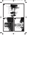 3
3
-
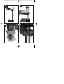 4
4
-
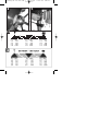 5
5
-
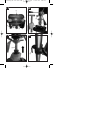 6
6
-
 7
7
-
 8
8
-
 9
9
-
 10
10
-
 11
11
-
 12
12
-
 13
13
-
 14
14
-
 15
15
-
 16
16
-
 17
17
-
 18
18
-
 19
19
-
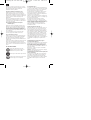 20
20
-
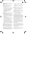 21
21
-
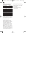 22
22
-
 23
23
-
 24
24
-
 25
25
-
 26
26
-
 27
27
-
 28
28
-
 29
29
-
 30
30
-
 31
31
-
 32
32
-
 33
33
-
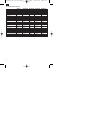 34
34
-
 35
35
-
 36
36
-
 37
37
-
 38
38
-
 39
39
-
 40
40
-
 41
41
-
 42
42
-
 43
43
-
 44
44
-
 45
45
-
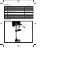 46
46
-
 47
47
-
 48
48
-
 49
49
-
 50
50
-
 51
51
-
 52
52


in andere talen
Gerelateerde papieren
Andere documenten
-
Scheppach DP19Vario Handleiding
-
Parkside 710 B2 Handleiding
-
-
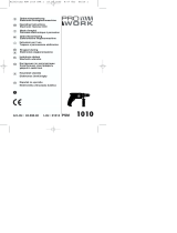 Pro Work PSM 1010 Handleiding
-
-
Bartscher 200255 Handleiding
-
Ferm TDM1009 de handleiding
-
-
-
