Vetus WWCP Waste Water Control Panel Handleiding
- Type
- Handleiding

vetus
WASTE CONTROL
100%
50%
75%
25%
Copyright © 2022 VETUS B.V. Schiedam Holland 090427.02
Installatie- en gebruikershandleiding
Controlepaneel voor vuilwater
Installation and user manual
Waste water control panel
Installations- und Benutzerhandbuch
Schmutzwasser management
Manuel d’Installation et d’utilisation
Tableau de contrôle d’eaux usées
Manual de instalación y usuario
Panel de control para la descarga del agua sanitaria
Manuale d’installazione e d’uso
Controllo livello acque nere
Waste water control panel
NEDERLANDS
4
ENGLISH
12
DEUTSCH
20
FRANÇAIS
28
ESPAÑOL
36
ITALIANO
44
WWCP

2 090427.02 Waste water control panel WWCP

090427.02 3
Waste water control panel WWCP
1 Inleiding . . . . . . . . . . . . . . . . . . . . . . . . . . . . . 4
2 Bediening. . . . . . . . . . . . . . . . . . . . . . . . . . . . 5
3 Installatie . . . . . . . . . . . . . . . . . . . . . . . . . . . . 7
4 Instelprocedure . . . . . . . . . . . . . . . . . . . . . . 8
5 Technische gegevens . . . . . . . . . . . . . . . . 10
1 Introduction . . . . . . . . . . . . . . . . . . . . . . . . 28
2 Commande
. . . . . . . . . . . . . . . . . . . . . . . . . 29
3 Installation. . . . . . . . . . . . . . . . . . . . . . . . . . 31
4 Procédure de réglage. . . . . . . . . . . . . . . . 32
5 Fiche technique . . . . . . . . . . . . . . . . . . . . . 34
Inhoud
Sommaire
1 Introduction . . . . . . . . . . . . . . . . . . . . . . . . 12
2 Operating instructions . . . . . . . . . . . . . . 13
3 Installation. . . . . . . . . . . . . . . . . . . . . . . . . . 15
4 Set-up procedure. . . . . . . . . . . . . . . . . . . . 16
5 Technical specications. . . . . . . . . . . . . . 18
1 Einleitung. . . . . . . . . . . . . . . . . . . . . . . . . . . 20
2 Bedienung . . . . . . . . . . . . . . . . . . . . . . . . . . 21
3 Installation. . . . . . . . . . . . . . . . . . . . . . . . . . 23
4 Einstellverfahren . . . . . . . . . . . . . . . . . . . . 24
5 Technische Daten . . . . . . . . . . . . . . . . . . . 26
1 Introducción . . . . . . . . . . . . . . . . . . . . . . . . 36
2 Instrucciones de uso. . . . . . . . . . . . . . . . . 37
3 Instalación . . . . . . . . . . . . . . . . . . . . . . . . . . 39
4 Procedimiento de conguración . . . . . 40
5 Especicaciones técnicas . . . . . . . . . . . . 42
1 Introduzione . . . . . . . . . . . . . . . . . . . . . . . . 44
2 Funzionamento . . . . . . . . . . . . . . . . . . . . . 45
3 Installazione . . . . . . . . . . . . . . . . . . . . . . . . 47
4 Impostazione
. . . . . . . . . . . . . . . . . . . . . . . 48
5 Caratteristiche tecniche . . . . . . . . . . . . . 50
Content
Inhalt
Índice Indice
6 Aansluitschema’s . . . . . . . . . . . . . . . . . . . . 52
7 Hoofdafmetingen . . . . . . . . . . . . . . . . . . . 55
6 Anschlußschaltplane . . . . . . . . . . . . . . . . 52
7 Hauptabmessungen. . . . . . . . . . . . . . . . . 55
6 Esquemas de conexión . . . . . . . . . . . . . . 52
7 Dimensiones principales. . . . . . . . . . . . . 55
6 Wiring diagrams. . . . . . . . . . . . . . . . . . . . . 52
7 Principal dimensions . . . . . . . . . . . . . . . . 55
6 Schémas électrique. . . . . . . . . . . . . . . . . . 52
7 Dimensions principales. . . . . . . . . . . . . . 55
6 Schemi dei collegamenti. . . . . . . . . . . . . 52
7 Dimensioni principali. . . . . . . . . . . . . . . . 55

4 090427.02 Waste water control panel WWCP
1 Inleiding
Dit controlepaneel voor de vuilwater-installatie (Waste Water Control Panel) geeft allereerst 4
verschillende inhoudsniveau`s van de vuilwatertank aan met behulp van LED`s (25%, 50%, 75%,
100% vol). Indien de tank vol is, zal de rode 100% LED gaan knipperen.
Het bedieningspaneel heeft een beveiliging om te voorkomen dat de pomp per ongeluk aangezet
wordt. Door het indrukken van een combinatie van toetsen wordt de beveiliging uitgeschakeld
en hierna kan men de pomp - automatisch dan wel handmatig - aanzetten. Als de automatische
tankbewaking (AUTO-mode) ingeschakeld is zal de vuilwatertank automatisch worden geleegd
als deze vol is. Wanneer de vuilwatertank leeg is wordt de pomp automatisch uitgeschakeld om
ongewenst drooglopen te voorkomen.
Het paneel moet worden aangesloten op een in de vuilwatertank gemonteerde Vetus niveau-
sensor. Geschikte sensoren zijn de sensor met vlotterarm, art.code: WWSENSORA, en de analoge
ultrasone sensor, art.code: SENSORA.
De digitale ultrasone sensor, art.code: SENSORB, is niet geschikt!
Het paneel is voorzien van een extra uitgang waarmee men een relais kan bekrachtigen, dat de
stroom naar het toilet en/of een waterpomp onderbreekt. Dit relais wordt bekrachtigd als de tank
voor 90% vol is.
Ook kan een elektrisch bediende afsluiter, indien geïnstalleerd, op het paneel worden aangeslo-
ten. Als de tank voor 90% vol is wordt eerst de afsluiter automatisch opengezet en daarna zal de
vuilwaterpomp ingeschakeld worden. Op het paneel is een LED aanwezig dat aangeeft wanneer
de afsluiter gesloten is (indien aangesloten).
Indien het maximale vloeistofniveau incidenteel en/of kortstondig wordt bereikt door de bewe-
gingen van de boot, worden dergelijke pieken genegeerd; het niveau moet langere tijd en onge-
acht de omstandigheden op maximaal staan alvorens de afsluiter en de vuilwaterpomp in werking
worden gezet.
Het bedieningspaneel wordt geleverd zonder de extra’s, zoals vuilwaterpomp, afsluiter en niveau-
sensor.
Let op
Voer de ‘Instelprocedure’ uit voordat het paneel in gebruik wordt genomen!
NEDERLANDS

090427.02 5
Waste water control panel WWCP
2 Bediening
Functie van de LED’s
Uit: het paneel is uitgeschakeld.
Groen: het paneel is ingeschakeld.
Groen
knipperend:
de accuspanning is lager dan 8 Volt.
Uit: -
Groen: de pompcyclus is handmatig geactiveerd.
Uit: de auto-mode is niet ingeschakeld.
Groen: de auto-mode is ingeschakeld.
Elektrisch be-
diende afsluiter met
standterugmelding
Handbediende
afsluiter zonder
standterugmelding
Uit: -
Groen: de afsluiter is gesloten. -
Groen knip-
perend:
de afsluiter is aan het
openen of aan het
sluiten.
de pompcyclus is actief.
de afsluiter is geopend.
Rood: het openen of sluiten is
niet binnen 40 seconden
gelukt.
-
Groen: de pomp is ingeschakeld.
Rood: de pomp is ingeschakeld maar het niveau in de tank
is niet binnen de gestelde tijd 10% gedaald.
Tijdens het instellen hebben de Led’s een andere functie; zie 4 Instelprocedure.
In- of uitschakelen
Met de toets wordt het paneel in- of uitgeschakeld. Na het inschakelen wordt het niveau in
de vuilwatertank aangegeven. De niveaus 25%, 50% en 75% worden met een groene LED aange-
geven. Bij 90% gaat de rode 100% LED aan. Bij meer dan 95% gaat de rode 100% LED knipperen.
NEDERLANDS

6 090427.02 Waste water control panel WWCP
Vrijgeven toetsvergrendeling
Om ongewenste bediening van de toetsen en te voorkomen is een beveiliging inge-
bouwd. Deze beveiliging moet eerst worden uitgeschakeld alvorens de pompfunctie kan worden
ingesteld of gebruikt.
• Druk hiertoe beide toetsen gelijktijdig in en houdt deze gedurende 5 seconden inge-
drukt. Na de pieptoon is de beveiliging gedurende 10 seconden uitgeschakeld en kunnen de
toetsen en worden bediend.
Leegpompen van de vuilwatertank
A - Installatie met een elektrisch bediende afsluiter welke voorzien van standterugmelding:
A1 - Automatisch leegpompen
• Geef de toetsvergrendeling vrij.
• Druk de toets in om het paneel in AUTO-mode te zetten.
Als het niveau in de tank is gestegen tot 95% wordt de pompcy-
clus automatisch geactiveerd.
Eerst wordt de afsluiter is geopend daarna wordt de pomp ingeschakeld. De pomp blijft
nog enige tijd ingeschakeld als de tank is leeggepompt, zie nadraaitijd. Als de pomp is
uitgeschakeld wordt de afsluiter gesloten.
Uitschakelen van de AUTO-mode:
• Druk de toets in om de AUTO-mode weer uit te schakelen, het is niet nodig eerst de
toetsvergrendeling vrij te geven. Als tijdens het leegpompen de toets wordt inge-
drukt wordt de automatische pompcyclus beëindigd en de afsluiter gesloten.
A2 - Niet-automatisch leegpompen
• Geef de toetsvergrendeling vrij.
• Druk op de toets om de pompcyclus te starten.
Eerst wordt de afsluiter is geopend daarna wordt de pomp inge-
schakeld. De pomp blijft nog enige tijd ingeschakeld als de tank
is leeggepompt, zie nadraaitijd. Als de pomp is uitgeschakeld wordt de afsluiter gesloten.
Als tijdens het leegpompen de toets wordt ingedrukt wordt de pompcyclus beëindigd en
de afsluiter gesloten.

090427.02 7
Waste water control panel WWCP
B - Installatie met een handbediende afsluiter welke niet voorzien van standterugmelding:
• Geef de toetsvergrendeling vrij.
• Open de afsluiter.
• Druk op de toets om de pompcyclus te starten.
Let op
De pomp wordt pas ingeschakeld na 40 seconden.
Binnen deze tijd kan alsnog de afsluiter worden open
gezet!
De pomp blijft nog enige tijd ingeschakeld als de tank is leeggepompt, zie nadraaitijd.
• Sluit de afsluiter als de pomp is uitgeschakeld.
WaarschuWing
Omdat de afsluiter niet is voorzien van een standterugmelding is zeer belangrijk om goed te
controleren of de afsluiter open staat voordat de tank wordt leeggepompt!
3 Installatie
Voor hoofdafmetingen zie pagina 55.
• Sluit het paneel aan zoals in de schema’s is aangegeven; zie pag. 52 - 54.
Op de 8-polige connector moet worden aangesloten:
- de voedingsspanning; 12 of 24 Volt, neem in de plus (+) draad een zekering van 10 A op.
- de sensor; een sensor met vlotterarm (WWSENSORA) volgens schema 7-1,
een analoge ultrasone sensor (SENSORA) volgens schema 7-2.
De digitale ultrasone sensor (SENSORB) is niet geschikt!
Het verdient aanbeveling om de sensor pas na het uitvoeren van de instelprocedure in de
tank te monteren.
- de pomp; een pomp die een stroomverbruik heeft van minder dan 10 A kan direct
op het paneel worden aangesloten; zie schema 7-1 en 7-2,
bij een pomp met een stroomverbruik van meer dan 10 A moet een
relais worden toegepast; zie schema 7-3.
- het relais; als de tank vol is kan hiermee een toilet worden uitgeschakeld en/of een
waarschuwingslamp worden ingeschakeld.
Op de 5-polige connector kan een elektrische bediende afsluiter worden aangesloten; zie
schema7-4.
NEDERLANDS

8 090427.02 Waste water control panel WWCP
• Schakel de spanning in.
Is de LED ‘AAN’ aan?
Negeer alle andere LEDs.
• Druk eenmaal op de toets
• Druk de toets in en houdt deze gedurende ca. 10 seconden ingedrukt.
• Houdt de vlotter in de stand VOL.
• Druk eenmaal op de toets .
• Druk op de toets .
Toelichting:
- Vlottersensor: houdt de vlotter in de hoogste stand.
- Ultrasone sensor: houdt de sensor op korte afstand van een reec-
terend oppervlak.
N.B. De sensor moet gedurende ca. 10 seconden
stabiel in deze stand worden gehouden.
OF
• Druk op de
toets om
het instellen van
het ‘Maximale
tankniveau’ over
te slaan.
Instellen van het ‘Maximale tankniveau’.
JA
NEE
4 Instelprocedure
Na het aansluiten van het paneel moet deze worden ingesteld.
De instelprocedure wordt automatisch verlaten als er een minuut lang geen toets is inge-
drukt, of door op de aan/uit toets te drukken.
Altijd hier beginnen met het volgen van de instelprocedure ook indien slechts een en-
kele instelling gewijzigd moet worden!
AGa verder op de volgende pagina.
Zorg er voor dat
een ultrasone sensor
gekalibreerd is; zie ‘Instal-
latieinstructies SENSORA’
090429.01, ‘Kalibreren’.

090427.02 9
Waste water control panel WWCP
OF
• Druk op de
toets om
het instellen van
het ‘Minimale
tankniveau’ over
te slaan.
Instellen van het ‘Minimale tankniveau’.
• Houdt de vlotter in de stand LEEG.
• Druk eenmaal op de toets .
• Druk op de toets .
Toelichting:
- Vlottersensor: houdt de vlotter in de laagste stand.
- Ultrasone sensor: houdt de sensor op een afstand van een reecte-
rend oppervlak gelijk aan de hoogte van de tank.
N.B. De sensor moet gedurende ca. 10 seconden
stabiel in deze stand worden gehouden.
Instellen van de ‘Nadraaitijd’.
• Druk herhaaldelijk op de toets om door de mogelijke instel-
lingen te stappen.
De ingestelde waarde wordt door een van de LED ‘s ‘Tankniveau’
aangegeven.
• Druk op de toets .
Toelichting:
Nadat de tank leeggepompt is kan de pomp nog een aantal minuten
nadraaien. Dit is wenselijk als de niveausensor niet over het gehele
tankbereik meet.
De LED’s van de tankniveau-aanwijzing geven de tijd aan:
100%
50%
75%
25%
100%
50%
75%
25%
100%
50%
75%
25%
100%
50%
75%
25%
100%
50%
75%
25%
30 s 5 min 10 min 20 min 30 min
OF
• Druk op de
toets om
het instellen van
de ‘Nadraaitijd’
over te slaan.
A
BGa verder op de volgende pagina.
Vervolg van vorige pagina.
Zorg er voor dat
een ultrasone sensor
gekalibreerd is; zie ‘Instal-
latieinstructies SENSORA’
090429.01, ‘Kalibreren’.
NEDERLANDS

10 090427.02 Waste water control panel WWCP
Instellen van de ‘Niveauveranderingstijd’.
• Druk herhaaldelijk op de toets om door de mogelijke instel-
lingen te stappen.
De ingestelde waarde wordt door een van de LED ‘s ‘Tankniveau’
aangegeven.
• Druk op de toets .
Toelichting:
Als het niveau in de tank niet binnen bepaalde tijd met 2% na het ac-
tiveren van de pompcyclus daalt wordt de pompcyclus afgebroken en
zal er een alarm klinken. Als het niveau niet daalt kan dit betekenen
dat de pomp verstopt is.
De LED’s van de tankniveau-aanwijzing geven de tijd aan:
100%
50%
75%
25%
100%
50%
75%
25%
100%
50%
75%
25%
2,5 min 5 min 10 min
OF
• Druk op de toets
om het
instellen van de
‘Niveauverande-
ringstijd’ over te
slaan.
BVervolg van vorige pagina.
CGa verder op de volgende pagina.
5 Technische gegevens
Aansluitspanning : 12/24 Volt
Stroomverbruik (stand-by) : 4 mA
Stroomverbruik max. : 100 mA
Ingang:
Voor niveausensor : 0 - 300 ohm (0 ohm = vol, 300 leeg)
bijv. Vetus WWSENSORA of SENSORA
Uitgangen:
Voor vuilwaterpomp : stroomverbruik max. 10 A
Voor elektrische bediende afsluiter : stroomverbruik max. 5 A
Voor WC / Alarm : stroomverbruik max. 1 A
Afmetingen : 85 x 85 mm
Inbouwdiepte : 78 mm

090427.02 11
Waste water control panel WWCP
• Druk op de toets om het instellen te beëindigen.
Instellen van het ‘Type afsluiter’.
• Druk op de toets om handbediende afsluiter of elektrisch
bediende afsluiter met standterugmelding te kiezen.
- LED 100% AAN: => Afsluiter zonder standterugmelding (handbe-
diend).
- LED 100% UIT: => Afsluiter met standterugmelding (elektrisch be-
diend).
Toelichting:
De LED’s van de tankniveau-aanwijzing geven aan of het paneel is
ingesteld voor een handbediende afsluiter of voor een elektrisch be-
diende afsluiter met standterugmelding:
100%
50%
75%
25%
100%
50%
75%
25%
handbediende afsluiter
zonderstandterugmelding
elektrisch bediende afsluiter
met standterugmelding
OF
• Druk op de toets
om het
instellen van het
‘Type afsluiter’
over te slaan en
het instellen te
beëindigen.
CVervolg van vorige pagina.
vetus
WASTE CONTROL
100%
50%
75%
25%
1 2 3 4 5 6
7 8 9 10 11
1. Toets ‘Aan/Uit’
2. LED ‘Aan’
3. Toets ‘Handbediening’
4. LED ‘Handbediening’
5. Toets ’Auto’
6. LED ‘Auto’
7. LED’s Tankniveau
8. Toets ‘Sleutel’
9. LED ‘Afsluiter’
10. Toets ‘Sleutel’
11. LED ‘Pomp’
NEDERLANDS

12 090427.02 Waste water control panel WWCP
1 Introduction
This control panel for the Waste Water installation uses LEDs to show four dierent levels in the
waste water tank (25%, 50%, 75%, and 100% full). If the tank is full, the red 100% LED will ash.
The control panel has a lock to prevent the pump from being switched on by accident. The lock is
switched o by pressing a combination of keys, after which the pump can be switched on either
automatically or manually. If automatic tank monitoring (AUTO mode) is switched on, the waste
water tank will empty automatically when it is full. The pump will switch o automatically when
the waste water tank is empty to prevent it continuing to run when dry.
The panel must be connected to a Vetus level sensor tted in the waste water tank. Suitable sen-
sors are sensors with a oat arm, art. code: WWSENSORA, and the analogue ultrasonic sensor, art.
code: SENSORA.
The digital ultrasonic sensor, art. code: SENSORD, is not suitable!
The panel has an extra output which can be used to power a relay used to interrupt the power to
the toilet and/or a water pump. This relay is powered when the tank is 90% full.
If an electrically operated shut-o valve is installed, this can also be connected to the panel. When
the tank is 90% full, the valve will rst be opened automatically and then the waste water pump
will be switched on. A LED on the panel shows when the shut-o valve is closed (if this is con-
nected).
If the maximum liquid level is reached incidentally and/or for a short period due to the movements
of the boat, such peaks will be ignored. The level must be at maximum for a longer period and ir-
respective of the circumstances before the shut-o valve and the waste water pump are engaged.
The control panel is supplied without the extras, such as the waste water pump, shut-o valve and
level sensor.
note
Carry out the ‘Set up procedure’ before bringing the panel into use!
ENGLISH

090427.02 13
Waste water control panel WWCP
2 Operating instructions
Function of the LEDs
O: the panel is switched o.
Green: the panel is switched on.
Green
ashing:
the battery voltage is less than 8 Volts.
O: -
Green: the pump cycle is set to manual operation
O: the auto mode is not switched on.
Green: the auto mode is switched on.
Electrically operated
shut-o valve with status
feedback
Manually operated shut-
o valve without status
feedback
O: -
Green: the shut-o valve is
closed.
-
Green
ashing:
the shut-o valve is either
opening or closing.
the pump cycle is active.
the shut-o valve is
opened.
Red: opening or closing has
not been successful
within 40 seconds.
-
Green: the pump is switched on.
Red: the pump is switched on but the level in the tank has
not dropped by 10% within the set time.
The LEDs have dierent functions during set up; see 4 Set-up procedure.
Switching on or o
The panel is switched on or o by using the key . The level in the waste water tank is indicated
after switching on. Levels 25%, 50% and 75% are shown with a green LED. The red 100% LED will
come on at 90%. The red 100% LED will ash when the level is higher than 95%.
ENGLISH

14 090427.02 Waste water control panel WWCP
Unlock locked keyboard
A lock is built in to prevent unwanted operation of the and keys. This lock must be
switched o rst before the pump function can be set or used.
• To do this, press and hold both keys in simultaneously for 5 seconds. The lock will be dis-
engaged for 10 seconds after the peep sounds and the and keys can then be oper-
ated.
Pumping the waste water tank empty:
A - Installation with an electrically operated shut-o valve tted with status feedback:
A1 - Automatic emptying
• Unlock the keyboard.
• Press key to set the panel to AUTO mode.
The pump cycle will be started automatically when the level in
the tank has reached 95%.
First the shut-o valve will open and then the pump will switch on. The pump will remain
switched on for some time after the tank has been pumped empty, see nishing time. The
shut-o valve will close when the pump has been switched o.
Switching o AUTO mode:
• Press the key to switch AUTO mode o again. It is not necessary to unlock the key-
board rst. If the key is pressed while the tank is being emptied, the automatic pump
cycle will be stopped and the shut-o valve closed.
A2 - Manual emptying
• Unlock the keyboard.
• Press key to start the pump cycle.
First the shut-o valve will open and then the pump will switch
on. The pump will remain switched on for some time after the
tank has been pumped empty, see nishing time. The shut-o valve will close when the
pump has been switched o.
If the key is pressed while the tank is being emptied, the pump cycle will be stopped and the
shut-o valve closed.

090427.02 15
Waste water control panel WWCP
B - Installation with a manually operated shut-o valve without status feedback:
• Unlock the keyboard.
• Open the shut-o valve.
• Press the key to start the pump cycle.
note
The pump will begin to work after 40 seconds have
passed. The shut-o valve can still be opened during this
time!
The pump will remain switched on for some time after the tank has been pumped empty,
see nishing time.
• Close the shut-o valve after the pump has been switched o.
Warning
Because the shut-o valve does not have status feedback, it is very important to properly
check that the shut-o valve is open before starting to pump the tank empty!
3 Installation
See page 55 for the main dimensions.
Connect the panel as shown in the wiring diagrams, see pages 52 - 54.
- The following must be connected to the 8-pin connector:
- the power supply: 12 or 24 Volt. Fit a 10A fuse in the positive (+) wire.
- the sensor: a sensor with oat arm (WWSENSORA), see diagram 7-1;
an analogue ultrasonic sensor (SENSORA), see diagram 7-2.
The digital ultrasonic sensor (SENSORD) is not suitable!
- It is recommended not to t the sensor in the tank until after the set up procedure has been
completed.
- the pump: a pump with power consumption less than 10 A can be connected di-
rectly to the panel. See diagrams 7-1 and 7-2;
a relay must be used if the pump uses more than 10 A. See diagram 7-3.
- the relay: this can switch o a toilet and/or switch on a warning light when the tank
is full.
An electrically operated shut-o valve can be connected to the 5-pin connector. See diagram 7-4.
ENGLISH

16 090427.02 Waste water control panel WWCP
4 Set-up procedure
The panel must be set up after it has been connected.
The set up procedure will be exited automatically if no key is pressed for more than a minute,
or by pressing the on/o key.
• Switch on the power.
Is the ‘ON’ LED on?
Ignore all other LEDs.
• Press the key once.
• Press and hold the key for approx. 10 seconds.
• Hold the oat in the FULL position.
• Press the key once.
• Press the key.
Explanation:
- Float sensor: hold the oat in the highest position.
- Ultrasonic sensor: hold the sensor close to a reective surface.
Note: The sensor must be held steady in this
position for approx. 10 seconds.
OR
• Press the
key to
bypass setting
the ‘Maximum
tank level’.
Setting the ‘Maximum tank level’.
YES
NO
Always start the set up procedure from the beginning, even if only one setting has to be
changed!
AContinue on the next page.
Make sure that an
ultrasonic sensor has been
calibrated; see ‘Installation
instructions SENSORA’
090429.01, ‘Calibration’.

090427.02 17
Waste water control panel WWCP
OR
• Press the
key to
bypass setting
the ‘Minimum
tank level’.
Setting the ‘Minimum tank level’.
• Hold the oat in the EMPTY position.
• Press the key once.
• Press the key.
Explanation:
- Float sensor: hold the oat in the lowest position.
- Ultrasonic sensor: hold the sensor at a distance from a reective
surface equal to the height of the tank.
Note: The sensor must be held steady in this
position for approx. 10 seconds.
Setting the ‘Finishing time’
• Press the key repeatedly to move through the possible settings.
The set value will be shown by one of the ‘Tank level’ LEDs.
• Press the key.
Explanation:
After the tank has been emptied, the pump can still run for a few min-
utes. This is desirable if the level sensor does not measure over the
whole range of the tank.
The tank level LEDs show the nishing times:
100%
50%
75%
25%
100%
50%
75%
25%
100%
50%
75%
25%
100%
50%
75%
25%
100%
50%
75%
25%
30 s 5 min 10 min 20 min 30 min
OR
• Press the
key to by-
pass setting the
‘Finishing time’.
A
BContinue on the next page.
Continued from previous page.
Make sure that an
ultrasonic sensor has been
calibrated; see ‘Installation
instructions SENSORA’
090429.01, ‘Calibration’.
ENGLISH

18 090427.02 Waste water control panel WWCP
Setting the ‘Level changing time’
• Press the key repeatedly to move through the possible set-
tings.
The set value will be shown by one of the ‘Tank level’ LEDs.
• Press the key.
Explanation:
If the level in the tank does not change by 2% within a set time of ac-
tivating the pump cycle, the pump cycle will be stopped and an alarm
will sound. If the level does not drop, this can mean that the pump is
blocked.
The tank level LEDs show the nishing times:
100%
50%
75%
25%
100%
50%
75%
25%
100%
50%
75%
25%
2,5 min 5 min 10 min
OR
Press the key
to bypass setting
the ‘Level chang-
ing time’.
BContinued from previous page.
CContinue on the next page.
5 Technical specications
Power supply : 12 or 24 Volts
Power consumption (standby) : 4 mA
Max. power consumption : 100 mA
Input:
For level sensor : 0 - 300 ohm (0 ohm = full, 300 = empty)
e.g. Vetus WWSENSORA or SENSORA
Outputs:
For waste water pump : max. power consumption 10 A
For electrically operated shut-o valve : max. power consumption 5 A
For WC / Alarm : max. power consumption 1 A
Dimensions : 85 x 85 mm (3 3/8” x 3 3/8”)
Build-in depth : 78 mm (3 1/16”)

090427.02 19
Waste water control panel WWCP
• Press the key to exit Set-up.
Setting the ‘Type of shut-o valve’.
• Press the key to select ‘manually operated shut-o valve’ or
‘electrically operated shut-o valve with status feedback’.
- 100% LED ON: => Shut-o valve without status feedback (manually
operated).
- 100% LED OFF: => Shut-o valve with status feedback (electrically
operated).
Explanation:
The LEDs used to indicate the tank level show whether the panel has
been set for a manually operated shut-o valve or an electrically oper-
ated shut-o valve with status feedback.
100%
50%
75%
25%
100%
50%
75%
25%
Manually operated shut-o
valve without status feed-
back
Electrically operated shut-o
valve with status feedback
OR
• Press the
key to
bypass setting
‘Type of shut-o
valve’ and to exit
Set-up.
CContinued from previous page.
vetus
WASTE CONTROL
100%
50%
75%
25%
1 2 3 4 5 6
7 8 9 10 11
1. ‘On/O’ key
2. ‘On’ LED
3. ‘Manual operation’ key
4. ‘Manual Operation’ LED
5. ‘Auto’ key
6. ‘Auto’ LED
7. Tank level LEDs
8. ‘Key’ key
9. ‘Shut-o valve’ key
10. ‘Key’ key
11. ‘Pump’ LED
ENGLISH

20 090427.02 Waste water control panel WWCP
1 Einleitung
Diese Schalttafel für die Schmutzwasseranlage (Waste Water Control Panel) zeigt mithilfe von
Leuchtdioden die vier verschiedenen Flüssigkeitsstände des Schmutzwassertanks an (25 %, 50 %,
75 %, 100 % voll) an. Wenn der Tank voll ist, wird dies mit einer rot blinkenden 100%-Leuchtdiode
angezeigt.
Die Bedienungstafel verfügt über einen Einschaltschutz, der verhindert, dass die Pumpe verse-
hentlich eingeschaltet wird. Durch Drücken einer Tastenkombination wird der Einschaltschutz
ausgeschaltet und kann die Pumpe - automatisch oder manuell – eingeschaltet werden. Bei ein-
geschalteter automatischer Tanküberwachung (AUTO-Modus) wird der Schmutzwassertank auto-
matisch geleert, wenn er voll ist. Wenn der Schmutzwassertank leer ist, wird die Pumpe automa-
tisch ausgeschaltet, um ein unerwünschtes Trockenlaufen zu vermeiden.
Die Tafel ist an einen im Schmutzwassertank montierten Vetus Niveausensor anzuschließen. Ge-
eignete Sensoren sind der Sensor mit Schwimmerarm, Art.-Kode: WWSENSORA, und der analoge
Ultraschallsensor, Art.-Kode: SENSORA.
Der digitale Ultraschallsensor, Art.-Kode: SENSORD, ist nicht geeignet!
Die Tafel verfügt über einen zusätzlichen Ausgang, mit dem ein Relais verstärkt werden kann, das
den Strom zur Toilette bzw. zur Wasserpumpe unterbricht. Dieses Relais wird verstärkt, wenn der
Tank zu 90 % gefüllt ist.
Außerdem kann ein elektrisch bedientes Absperrventil – falls installiert – an die Tafel angeschlos-
sen werden. Wenn der Tank zu 90 % gefüllt ist, wird zunächst das Absperrventil automatisch ge-
önet und anschließend wird die Schmutzwasserpumpe eingeschaltet. Eine Leuchtdiode auf der
Tafel signalisiert, wenn das Absperrventil (falls entsprechend angeschlossen) geschlossen ist.
Wird das maximale Flüssigkeitsniveau gelegentlich bzw. kurzfristig beispielsweise durch Bewe-
gungen des Schis erreicht, werden die entsprechenden Spitzenwerte ignoriert; das Niveau muss
längere Zeit und unabhängig von den Umständen den Maximalwert erreicht haben, bevor der
Absperrventil und die Schmutzwasserpumpe eingeschaltet werden.
Die Bedienungstafel wird ohne Zubehör wie Schmutzwasserpumpe, Absperrventil und Niveau-
sensor geliefert.
achtung
Führen Sie das „Einstellverfahren“ durch, bevor die Tafel in Betrieb genommen wird!
DEUTSCH

090427.02 21
Waste water control panel WWCP
2 Bedienung
Funktionen der Leuchtdioden
Aus: Tafel ist ausgeschaltet.
Grün: Tafel ist eingeschaltet.
Grün
blinkend:
Batteriespannung ist unter 8 Volt.
Aus: -
Grün: Pumpzyklus wurde manuell aktiviert.
Aus: Auto-Modus ist nicht eingeschaltet.
Grün: Auto-Modus ist eingeschaltet.
Elektrisch bedientes Ab-
sperrventil mit Stellungs-
rückmeldung
Manuell bedientes
Absperrventil ohne Stel-
lungsrückmeldung
Aus: -
Grün: Absperrventil ist ge-
schlossen.
-
Grün
blinkend:
Absperrventil önet oder
schließt sich.
Pumpzyklus ist aktiviert.
Absperrventil ist geö-
net.
Rot: Önen oder Schließen ist
nicht innerhalb von 40
Sekunden erfolgt.
-
Grün: Pumpe ist eingeschaltet.
Rot: Pumpe ist eingeschaltet, aber das Niveau im Tank ist
nicht innerhalb der vorgeschriebenen Zeit um 10 %
gesunken.
Während des Einstellverfahrens haben die Leuchtdioden eine andere Funktion; siehe Abschnitt 4,
Einstellverfahren
Ein- oder Ausschalten
Mit der Taste wird die Tafel ein- bzw. ausgeschaltet. Nach dem Einschalten wird das Niveau im
Schmutzwassertank angezeigt. Bei den Niveaus 25 %, 50 % und 75 % leuchtet die Leuchtdiode
grün auf. Bei 90 % leuchtet die Diode neben der 100 %-Anzeige auf. Bei über 95 % blinkt die rote
Diode neben der 100 %-Anzeige.
DEUTSCH

22 090427.02 Waste water control panel WWCP
Freigabe Tastensperrung
Um eine unerwünschte Bedienung der Tasten und zu vermeiden, ist eine Sicherung
eingebaut. Diese Sicherung muss zunächst ausgeschaltet werden, bevor die Pumpfunktion einge-
stellt oder eingesetzt werden kann.
• Halten Sie dazu beide Tasten gleichzeitig 5 Sekunden eingedrückt. Nach dem Signal ist
die Sicherung 10 Sekunden lang ausgeschaltet und können die Tasten und betätigt
werden.
Abpumpen des Schmutzwassertanks
A - Anlage mit einem elektrisch bedienten Absperrventil mit Stellungsrückmeldung:
A1 - Automatisches Abpumpen
• Tastensperrung freigeben.
• Taste betätigen, um die Tafel auf AUTO-Modus einzustel-
len.
Wenn das Niveau im Tank auf 95 % gestiegen ist, wird der Pump-
zyklus automatisch aktiviert.
Zunächst wird das Absperrventil geönet, anschließend wird die Pumpe eingeschaltet. Die
Pumpe bleibt nach Leerung des Tanks noch einige Zeit in Betrieb, siehe auch Nachlaufzeit.
Wenn die Pumpe ausgeschaltet ist, wird das Absperrventil geschlossen.
Ausschalten des AUTO-Modus:
• Betätigen Sie die Taste , um den AUTO-Modus wieder auszuschalten. Es ist nicht er-
forderlich, erst die Tastensperrung freizugeben. Wenn während des Abpumpens die Taste
betätigt wird, wird der automatische Pumpzyklus beendet und das Absperrventil
geschlossen.
A2 - Nicht-automatisches Abpumpen
• Tastensperrung freigeben.
• Betätigen Sie die Taste , um den Pumpzyklus zu starten.
Zunächst wird das Absperrventil geönet, anschließend wird die
Pumpe eingeschaltet. Die Pumpe bleibt nach Leerung des Tanks
noch einige Zeit in Betrieb, siehe auch Nachlaufzeit. Wenn die Pumpe ausgeschaltet ist,
wird das Absperrventil geschlossen.
Wird während des Abpumpens die Taste betätigt, wird der Pumpzyklus beendet und das
Absperrventil geschlossen.

090427.02 23
Waste water control panel WWCP
B - Anlage mit manuell bedientem Absperrventil ohne Stellungsrückmeldung:
• Tastensperrung freigeben
• Absperrventil önen
• Taste betätigen, um Pumpzyklus zu starten. n.
achtung
Die Pumpe wird erst nach 40 Sekunden eingeschaltet.
Innerhalb dieser Zeit kann auch das Absperrventil noch
geönet werden!
Die Pumpe bleibt nach Leerung des Tanks noch einige Zeit in Betrieb, siehe auch Nachlauf-
zeit.
• Schließen Sie das Absperrventil, wenn die Pumpe ausgeschaltet ist.
WarnhinWeis
Weil das Absperrventil nicht über eine Stellungsrückmeldung verfügt, ist es vor Abpumpen
des Tanks wichtig zu überprüfen, ob das Absperrventil geönet ist!
3 Installation
Für die Hauptabmessungen siehe Seite 55.
• Schließen Sie die Tafel gemäß der Schemata an (siehe S. 52 – 54).
An den 8-poligen Steckverbinder ist Folgendes anzuschließen:
- Speisespannung: 12 oder 24 Volt, in den Plus (+)-Draht ist eine 10 A-Sicherung aufzunehmen.
- Sensor: ein Sensor mit Schwimmerarm (WWSENSORA) gemäß Schema 7-1,
ein analoger Ultraschallsensor (SENSORA) gemäß Schema 7-2.
Der digitale Ultraschallsensor (SENSORD) ist nicht geeignet!
Es empehlt sich, den Sensor erst nach Durchführung des Einstellverfahrens in den Tank zu
montieren.
- Pumpe: eine Pumpe mit einem Stromverbrauch von weniger als 10 A kann unmittel-
bar angeschlossen werden. Siehe Schema 7-1 und 7-2.
Bei einer Pumpe mit einem Stromverbrauch von über 10 A muss ein Relais
eingesetzt werden. Siehe Schema 7-3.
- Relais: Bei einem vollen Tank kann damit eine Toilette abgeschaltet bzw. eine Warn-
leuchte eingeschaltet werden.
An den 5-poligen Steckverbinder kann ein elektrisch bedientes Absperrventil angeschlossen wer-
den. Siehe Schema 7-4.
DEUTSCH

24 090427.02 Waste water control panel WWCP
• Schalten Sie die Spannung ein.
Leuchtetdie
Leuchtdiode„EIN“auf?
Ignorieren Sie alle anderen
Leuchtdioden.
• Betätigen Sie einmal die Taste .
• Betätigen Sie die Taste und halten Sie diese 10 Sekunden lang eingedrückt.
• Halten Sie den Schwimmer im Stand VOLL.
• Betätigen Sie einmal die Taste .
• Betätigen Sie die Taste .
Erklärung:
- Schwimmersensor: hält den Schwimmer im höchsten Stand.
- Ultraschallsensor: hält den Sensor in kurzer Entfernung einer reek-
tierenden Oberäche.
Achtung: Der Sensor ist ca. 10 Sekunden lang stabil
in diesem Stand zu halten.
ODER
• Betätigen
Sie die Taste
, um die
Einstellung des
„Maximalen
Tankniveaus“
zu übersprin-
gen.
Einstellung des „Maximalen Tankniveaus“.
JA
NEIN
4 Einstellverfahren
Die Tafel ist nach Anschluss einzustellen.
Das Einstellverfahren wird automatisch beendet, wenn eine Minute lang keine Taste betätigt
worden ist oder durch Betätigen der Ein-/Aus-Taste.
Beginnen Sie immer hier mit dem Einstellverfahren, auch wenn nur eine Einstellung ge-
ändert werden muss.
AWeiter auf der nächsten Seite.
Achten Sie darauf,
dass ein Ultraschallsensor
kalibriert ist; Siehe ‘Instal-
lationsanleitung SENSO-
RA’090429.01, ‘Kalibrieren’.

090427.02 25
Waste water control panel WWCP
ODER
• Betätigen
Sie die Taste
, um die
Einstellung des
„Minimalen
Tankniveaus“
zu übersprin-
gen.
Einstellung des „Minimalen Tankniveaus“.
• Halten Sie den Schwimmer im Stand LEER.
• Betätigen Sie einmal die Taste .
• Betätigen Sie die Taste .
Erklärung:
- Schwimmersensor: hält den Schwimmer im niedrigsten Stand.
- Ultraschallsensor: hält den Sensor in Entfernung einer reektieren-
den Oberäche, die der Höhe des Tanks entspricht.
Achtung: Der Sensor ist 10 Sekunden lang stabil in
diesem Stand zu halten.
Einstellen der „Nachlaufzeit“.
• Betätigen Sie wiederholt die Taste , um die verschiedenen Ein-
stellungsmöglichkeiten zu durchlaufen.
Der eingestellte Wert wird von einer der Leuchtdioden „Tankniveau“
angezeigt.
• Betätigen Sie die Taste .
Erläuterung:
Nach Abpumpen des Tanks kann die Pumpe noch einige Minuten
nachlaufen. Das ist wünschenswert, wenn der Niveausensor nicht den
gesamten Tankbereich misst.
Die Leuchtdioden der Tankniveau-Anzeige zeigen die Nachlaufzeit an:
100%
50%
75%
25%
100%
50%
75%
25%
100%
50%
75%
25%
100%
50%
75%
25%
100%
50%
75%
25%
30 Sek 5 Min. 10 Min. 20 Min. 30 Min.
ODER
• Betätigen Sie
die Taste ,
um die Einstel-
lung der „Nach-
laufzeit“ zu
überspringen.
A
BWeiter auf der nächsten Seite.
Fortsetzung vorige Seite.
Achten Sie darauf,
dass ein Ultraschallsensor
kalibriert ist; Siehe ‘Instal-
lationsanleitung SENSO-
RA’090429.01, ‘Kalibrieren’.
DEUTSCH

26 090427.02 Waste water control panel WWCP
Einstellung der „Niveauveränderungszeit“.
• Betätigen Sie wiederholt die Taste , um die verschiedenen Ein-
stellungsmöglichkeiten zu durchlaufen.
Der eingestellte Wert wird von einer der Leuchtdioden „Tankniveau“
angezeigt.
• Betätigen Sie die Taste .
Erläuterung:
Wenn das Niveau im Tank nicht innerhalb einer bestimmten Zeit um 2
% nach Aktivierung des Pumpzyklus sinkt, wird der Pumpzyklus unter-
brochen und ertönt ein Warnsignal. Wenn das Niveau nicht sinkt, kann
das auf eine Verstopfung der Pumpe hinweisen.
Die Leuchtdioden der Tankniveau-Anzeige zeigen die Zeit an:
100%
50%
75%
25%
100%
50%
75%
25%
100%
50%
75%
25%
2,5 Min. 5 Min. 10 Min.
ODER
• Betätigen Sie
die Taste ,
um die Ein-
stellung der
„Niveauverän-
derungszeit“ zu
überspringen.
BFortsetzung vorige Seite.
CWeiter auf der nächsten Seite.
5 Technische Daten
Anschlussspannung : 12/24 Volt
Stromverbrauch (Standby) : 4 mA
Stromverbrauch max. : 100 mA
Eingang:
Für Niveausensor : 0 - 300 Ohm (0 Ohm = voll, 300 leer)
z.B. Vetus WWSENSORA oder SENSORA
Ausgänge:
Für Schmutzwasserpumpe : Stromverbrauch max. 10 A
Für elektrisch bedientes Absperrventil : Stromverbrauch max. 5 A
Für WC / Alarm : Stromverbrauch max. 1 A
Abmessungen : 85 x 85 mm
Einbautiefe : 78 mm

090427.02 27
Waste water control panel WWCP
Betätigen Sie die Taste , um die Einstellung zu beenden.
Einstellung des „Absperrventiltyps“.
• Betätigen Sie die Taste , um manuell bedientes Absperrventil
oder elektrisch bedientes Absperrventil mit Stellungsrückmeldung
zu wählen.
- Leuchtdiode 100 % EIN: => Absperrventil ohne Stellungsrückmel-
dung (manuell bedient).
- Leuchtdiode 100 % AUS: => Absperrventil mit Stellungsrückmel-
dung (elektrisch bedient).
Erläuterung:
Die Leuchtdioden der Tankniveau-Anzeige zeigen an, ob die Tafel für
ein manuell bedientes oder ein elektrisch bedientes Absperrventil mit
Stellungsrückmeldung eingestellt ist:
100%
50%
75%
25%
100%
50%
75%
25%
handbedientes Absperrventil
ohne Stellungsrückmeldung
elektrisch bedientes Absperrven-
til mit Stellungsrückmeldung
ODER
• Betätigen Sie
die Taste ,
um die Einstel-
lung des „Ab-
sperrventiltyps“
zu übersprin-
gen und die
Einstellung zu
beenden.
CFortsetzung vorige Seite.
vetus
WASTE CONTROL
100%
50%
75%
25%
1 2 3 4 5 6
7 8 9 10 11
1. Taste „Ein/Aus“
2. Leuchtdiode „Ein“
3. Taste „Manuelle Bedienung“
4. Leuchtdiode „Manuelle Bedienung“
5. Taste „Auto“
6. Leuchtdiode „Auto“
7. Leuchtdiode „Tankniveau“
8. Taste „Schlüssel“
9. Leuchtdiode „Absperrventil“
10. Taste „Schlüssel“
11. Leuchtdiode „Pumpe“
DEUTSCH

28 090427.02 Waste water control panel WWCP
1 Introduction
Ce panneau de contrôle pour le dispositif des eaux usées indique, avant tout, 4 niveaux de jau-
geage diérents du réservoir d’eaux usées à l’aide de LEDs (25 %, 50 %, 75 % et 100 % plein). La LED
rouge se mettra à clignoter si le réservoir est plein.
Le panneau de commande possède une sécurité pour éviter que la pompe ne soit mise en marche
par inadvertance. En appuyant sur une combinaison de touches, la sécurité est désactivée et
la pompe peut ensuite être mise en marche aussi bien automatiquement que manuellement.
Lorsque le contrôle du réservoir automatique (AUTO-mode) est activé, le réservoir d’eaux usées,
lorsqu’il est plein, est automatiquement vidé. Lorsque le réservoir d’eaux usées est vide, la pompe
est automatiquement désactivée an d’éviter qu’elle ne fonctionne à sec.
Le panneau doit être connecté à l’un des capteurs de niveau Vetus monté dans le réservoir d’eaux
usées. Les capteurs adaptés sont le capteur avec levier de otteur, code d’article : WWSENSORA, et
le capteur ultrasonique analogique, code d’article : SENSORA.
Le capteur ultrasonique analogique, code d’article : SENSORD n’est pas adapté !
Le panneau est équipé d’une sortie supplémentaire avec laquelle il est possible d’alimenter un
relais qui interrompt l’alimentation en courant vers les toilettes et / ou la pompe. Ce relais est ali-
menté lorsque le réservoir est plein à 90 %.
Une vanne à commande électrique peut également être raccordée au panneau, pour autant
qu’installée. Lorsque le réservoir est plein à 90 %, la vanne est tout d’abord ouverte automatique-
ment et la pompe d’eaux usées est ensuite activée. Le panneau est doté d’une LED indiquant, le
cas échéant, la fermeture de la vanne (si raccordée).
Lorsque le niveau de liquide maximum est atteint occasionnellement et/ou pendant une courte
durée par les mouvements du bateau, les pics générés sont alors ignorés ; le niveau doit se trou-
ver au maximum pendant un temps plus long, indépendamment des circonstances, avant que la
vanne et la pompe d’eaux usées ne soient déclenchées.
Le panneau de commande est livré sans les extras tels la pompe d’eaux usées, la vanne et le cap-
teur de niveau.
attention
Eectuez la ‘procédure de réglage’ avant d’utiliser le panneau pour la première fois !
FRANÇAIS

090427.02 29
Waste water control panel WWCP
2 Commande
Fonction des LEDs
Eteinte : le panneau est éteint.
Verte : le panneau est allumé.
Verte
clignotant :
la tension de la batterie est inférieure à 8 volts.
Eteinte : -
Verte : le cycle de pompage est activé manuellement.
Eteinte : le mode automatique (auto) n’est pas activé.
Verte : le mode automatique (auto) est activé.
Vanne à commande élec-
trique avec signalisation
en retour de position
Vanne à commande
manuelle sans signalisa-
tion en retour de position
Eteinte : -
Verte : la vanne est fermée. -
Verte
clignotant :
la vanne est en train de
s’ouvrir ou de se fermer.
le cycle de pompage est
actif.
la vanne est ouverte.
Rouge : l’ouverture ou la ferme-
ture ne s’est pas faite
dans les 40 secondes.
-
Verte : la pompe est activée.
Rouge : la pompe est activée mais le niveau dans le réservoir
n’a pas baissé de 10 % dans le laps de temps déter-
miné.
Les LEDs ont une autre fonction lors du réglage, voir 4, “Procédure de réglage”.
Allumer ou Eteindre
Appuyez sur les touches pour allumer ou éteindre le panneau. Le niveau dans le réservoir
d’eaux usées est indiqué après l’activation. Les niveaux 25%, 50% et 75% sont indiqués avec une
LED verte. A 90 %, la LED rouge 100 % s’allume. A plus de 95%, la LED rouge 100 % se met à cli-
gnoter.
FRANÇAIS

30 090427.02 Waste water control panel WWCP
Déblocage du verrouillage des touches
Une sécurité est intégrée pour éviter toute commande indésirable des touches et .
Cette sécurité doit d’abord être activée avant que la fonction de la pompe puisse être réglée ou
utilisée.
• Appuyez à cet eet simultanément sur les deux touches et tenez ces dernières enfoncées
pendant 5 secondes. Après le bip, la sécurité est désactivée pendant 10 secondes et les touches
et peuvent être utilisées.
Vidage du réservoir d’eaux usées
A - Installation avec une vanne à commande électrique équipée de signalisation en retour
de position :
A1 - Vidage automatique
• Débloquez le verrouillage des touches.
• Appuyez sur la touche pour mettre le panneau en mode
AUTO.
Lorsque le niveau du réservoir est monté jusqu’à 95%, le cycle de
pompage est automatiquement activé.
La vanne est d’abord ouverte et la pompe est ensuite activée. La pompe reste encore
quelques temps activée bien que le réservoir soit vide, voir arrêt diéré. La vanne est fermée
lorsque la pompe est désactivée.
Désactivation du mode AUTO :
• Appuyez sur la touche pour désactiver de nouveau le mode AUTO, sans qu’il soit
nécessaire de débloquer d’abord le verrouillage des touches. Lorsque la touche est
enfoncée pendant le vidage du réservoir, le cycle de pompage est automatiquement ter-
miné et la vanne est fermée.
A2 - Vidage non automatique
• Débloquez le verrouillage des touches.
• Appuyez sur la touche pour démarrer le cycle de pom-
page.
La vanne est d’abord ouverte et la pompe est ensuite activée.
La pompe reste encore quelques temps activée bien que le réservoir soit vide, voir arrêt
diéré. La vanne est fermée lorsque la pompe est désactivée.
Lorsque la touche est enfoncée pendant le vidage, le cycle de pompage est terminé et la
vanne est fermée.

090427.02 31
Waste water control panel WWCP
B - Installation avec une vanne à commande manuelle non équipée de signalisation en re-
tour de position.
• Débloquez le verrouillage des touches.
• Ouvrez la vanne.
• Appuyez sur la touche pour démarrer le cycle de pom-
page.
attention
La pompe n’est activée qu’après 40 secondes. La vanne
peut encore être ouverte pendant ce laps de temps !
La pompe reste encore quelques temps activée lorsque le réservoir est vide, voir arrêt diéré.
• Fermez la vanne lorsque la pompe est désactivée.
Mise en garde
Du fait que la vanne n’est pas équipée d’une signalisation en retour de position, il est extrê-
mement important de correctement contrôler que cette dernière est ouverte avant d’utiliser
la pompe pour vider le réservoir !
3 Installation
Reportez-vous à la page 55 pour les dimensions principales.
• Raccordez le panneau comme indiqué dans les schémas ; voir pages 52 - 54.
Vous devez eectuer la connexion sur le connecteur à 8 pôles :
- l’alimentation : 12 ou 24 Volt, incluez un fusible de 10 A dans le l (+).
- le capteur : un capteur avec levier de otteur (WWSENSORA) selon le schéma 7-1,
un capteur ultrasonique analogique (SENSORA) selon le schéma 7-2.
Le capteur ultrasonique analogique (SENSORD) n’est pas adapté !
Il est recommandé de monter le capteur dans le réservoir uniquement après avoir exécuté
la procédure de réglage.
- la pompe : une pompe avec une consommation d’électricité inférieure à 10 A peut être
directement raccordée au panneau ; voir schémas 7-1 et 7-2,
pour une pompe avec une consommation d’électricité supérieure à 10 A, un
relais doit être utilisé, voir schéma 7-3.
- le relais ; avec le relais, les toilettes peuvent être mises hors tension et / ou une lampe
d’avertissement peut être activée lorsque le réservoir est plein.
Une vanne à commande électrique peut être raccordée au connecteur à 5 pôles ; voir schéma 7-4.
FRANÇAIS

32 090427.02 Waste water control panel WWCP
• Mettez le panneau sous tension.
laLED‘MARCHE’
est-elle allumée ?
Ignorez toutes les autres LEDs.
• Appuyez une fois sur la touche .
• Appuyez sur la touche et maintenez cette dernière enfoncée pendant environ 10 secondes.
• Tenez le otteur en position PLEIN.
• Appuyez une fois sur la touche .
• Appuyez sur la touche .
Explication :
- Capteur de otteur : tenez le otteur dans la position la plus haute.
- Capteur ultrasonique : tenez le capteur à courte distance d’une sur-
face rééchissante.
N.B. Le capteur doit être fermement maintenu
dans cette position pendant environ 10 secondes.
OU
• Appuyez sur
la touche
pour igno-
rer le réglage du
‘niveau de réser-
voir maximum’.
Réglage du ‘Niveau de réservoir maximum’.
OUI
NON
4 Procédure de réglage
Le panneau doit être réglé une fois raccordé.
La procédure de réglage est automatiquement quittée lorsqu’aucune touche n’a été enfoncée
pendant une minute ou bien lorsque l’on appuie sur la touche marche/arrêt.
Commencez toujours la procédure de réglage comme indiqué ci-dessous même si vous
ne devez modier qu’un seul réglage !
AContinuer à la page suivante.
Faites en sorte qu’un
capteur ultrasonique soit
calibré; Voir ‘Instructions
d’installation SENSORA’
090429.01, ‘Etalonnage’.

090427.02 33
Waste water control panel WWCP
OU
• Appuyez sur
la touche
pour igno-
rer le réglage du
‘niveau de réser-
voir minimum’.
Réglage du ‘Niveau de réservoir minimum’.
• Tenez le otteur en position VIDE.
• Appuyez une fois sur la touche .
• Appuyez sur la touche .
Explication :
- Capteur de otteur : tenez le otteur dans la position la plus basse.
- Capteur ultrasonique : tenez le capteur à une distance d’une surface
rééchissante égale à la hauteur du réservoir.
N.B. Le capteur doit être fermement main-
tenu dans cette position pendant environ 10
secondes.
Réglage de ‘l’Arrêt diéré’.
• Appuyez à plusieurs reprises sur la touche pour commuter
entre les réglages possibles.
Le seuil xé est indiqué par l’une des LEDs associées au ‘niveau du
réservoir’.
• Appuyez sur la touche .
Explication :
Une fois le réservoir vide, la pompe peut encore continuer à fonction-
ner pendant quelques minutes. Ceci est souhaitable lorsque le capteur
de niveau ne mesure pas la portée totale du réservoir.
Les LEDs du niveau du réservoir indiquent le temps :
100%
50%
75%
25%
100%
50%
75%
25%
100%
50%
75%
25%
100%
50%
75%
25%
100%
50%
75%
25%
30 s 5 min 10 min 20 min 30 min
OU
• Appuyez sur
la touche
pour igno-
rer le réglage de
l’ ‘Arrêt diéré’.
A
BContinuer à la page suivante.
Suite de la page précédente.
Faites en sorte qu’un
capteur ultrasonique soit
calibré; Voir ‘Instructions
d’installation SENSORA’
090429.01, ‘Etalonnage’.
FRANÇAIS

34 090427.02 Waste water control panel WWCP
Réglage du ‘Temps de changement de ni-
veau’.
• Appuyez à plusieurs reprises sur la touche pour commuter
entre les réglages possibles.
Le seuil xé est indiqué par l’une des LEDs associées au ‘niveau du
réservoir’.
• Appuyez sur la touche .
Explication :
Si le niveau du réservoir ne baisse pas de 2% dans un laps de temps
déterminé après l’activation du cycle de pompage, ce dernier est inter-
rompu et une alarme se fait entendre. Si le niveau ne baisse pas, cela
peut signier que la pompe est obstruée.
Les LEDs du niveau du réservoir indiquent le temps :
100%
50%
75%
25%
100%
50%
75%
25%
100%
50%
75%
25%
2,5 min 5 min 10 min
OU
• Appuyez sur
la touche
pour igno-
rer le réglage
du ‘temps de
changement de
niveau’.
BSuite de la page précédente.
CContinuer à la page suivante.
5 Fiche technique
Tension de raccordement : 12/24 volts
Consommation de courant (en veille) : 4 mA
Consommation de courant maximum : 100 mA
Entrée :
Pour capteur de niveau : 0 - 300 ohm (0 ohm = plein, 300 vide)
par exemple Vetus WWSENSORA ou SENSORA
Sorties :
Pour pompe d’eaux usées. : consommation de courant maximum 10 A
Pour vanne à commande électrique : consommation de courant maximum 5 A
Pour WC / Alarme : consommation de courant maximum 1 A
Dimensions : 85 x 85 mm
Profondeur d’encastrement : 78 mm

090427.02 35
Waste water control panel WWCP
Appuyez sur la touche pour terminer les réglages.
Réglage du ‘Type de vanne’.
• Appuyez sur la touche pour sélectionner la vanne à com-
mande manuelle ou la vanne à commande électrique avec signali-
sation en retour de position.
- LED 100% ALLUMÉE : => Vanne (à commande manuelle) sans signa-
lisation en retour de position
- LED 100% ÉTEINTE : => Vanne (à commande électrique) avec signa-
lisation en retour de position
Explication :
Les LEDs du niveau du réservoir indiquent si le panneau est réglé pour
une vanne à commande manuelle ou pour une vanne à commande
électrique avec signalisation en retour de position :
100%
50%
75%
25%
100%
50%
75%
25%
Vanne à commande manuelle
sans signalisation en retour
de position
Vanne à commande élec-
trique avec signalisation en
retour de position
OU
• Appuyez sur
la touche
pour ignorer
le réglage du
‘type de vanne’
et quitter le
réglage.
CSuite de la page précédente.
vetus
WASTE CONTROL
100%
50%
75%
25%
1 2 3 4 5 6
7 8 9 10 11
1. Touche ‘Marche/Arrêt’
2. LED ‘Marche’
3. Touche ‘Commande manuelle’
4. LED ‘Commande manuelle’
5. Touche ’Auto’
6. LED ‘Auto’
7. LEDs Niveau du réservoir
8. Touche ‘Clé’
9. LED ‘Vanne’
10. Touche ‘Clé’
11. LED ‘Pompe’
FRANÇAIS

36 090427.02 Waste water control panel WWCP
1 Introducción
Este panel de control para la instalación de descarga del agua sanitaria utiliza LED para mostrar
cuatro niveles diferentes en el depósito de agua sanitaria (25%, 50%, 75% y 100% de su capaci-
dad). Si el tanque está lleno, el LED rojo 100% parpadea.
El panel de control tiene un bloqueo para evitar que la bomba se encienda por accidente. El blo-
queo se apaga pulsando una combinación de teclas, después de lo cual puede encenderse tanto
de forma automática como manual. Si la supervisión automática del tanque (modo AUTO) está
encendida, el depósito de aguas sanitarias se vacía automáticamente cuando está lleno. La bomba
se apagará automáticamente cuando el depósito de aguas sanitarias esté vacío para evitar que
continúe funcionando en seco.
El panel debe estar conectado a un sensor de nivel Vetus instalado en el depósito de aguas sanita-
rias. Los sensores adecuados son los sensores con un brazo otador; código de art.: WWSENSORA,
y el sensor ultrasónico analógico, código de art.: SENSORA.
¡El sensor ultrasónico digital, código de art.: SENSORD, no es adecuado!
El panel tiene una salida adicional que se puede utilizar para alimentar un relé con la función de
interrumpir la alimentación del inodoro y/o una bomba de agua. Este relé se enciende cuando el
tanque está lleno al 90%.
Si hay instalada una válvula de apagado por accionamiento eléctrico, esta también puede conec-
tarse al panel. Cuando el tanque está lleno al 90%, la válvula se abrirá automáticamente primero y
luego la bomba de descarga del agua sanitaria se encenderá. Un LED en el panel muestra cuándo
se cierra la válvula de apagado (si está conectado).
Si el nivel de líquido máximo se alcanza incidentalmente y/o durante un breve período de tiempo
debido a los movimientos del barco, estos picos no se tendrá en cuenta. El nivel debe estar al máxi-
mo durante un período más largo y con independencia de las circunstancias antes de encender la
válvula de apagado y la bomba de descarga del agua sanitaria.
El panel de control se suministra sin extras, tales como la bomba de aguas sanitarias, la válvula de
apagado y el sensor de nivel.
nota
¡Lleve a cabo la “Conguración de procedimiento” antes de poner en funcionamiento el
panel en uso!
ESPAÑOL

090427.02 37
Waste water control panel WWCP
2 Instrucciones de uso
Función de los LED
Apagado: el panel está apagado.
Verde: el panel está encendido.
Parpadea
en verde:
el voltaje de la batería es inferior a 8 voltios.
Apagado: -
Verde: el ciclo de la bomba está en funcionamiento manual
Apagado: el modo automático no se enciende.
Verde: el modo automático está encendido.
Válvula de apagado por
accionamiento eléctrico
con retroalimentación de
estado
Válvula de apagado
operada manualmente
sin retroalimentación de
estado
Apagado: -
Verde: la válvula de apagado está
cerrada.
-
Parpadea
en verde:
la válvula de apagado se
está abriendo o cerrando.
el ciclo de la bomba está
activo.
la válvula de apagado está
abierta.
Rojo: la apertura o el cierre no
se han realizado correcta-
mente en 40 segundos.
-
Verde: la bomba está encendida.
Rojo: la bomba está encendida pero el nivel en el tanque no
se ha reducido un 10% dentro del plazo establecido.
Los LED tienen diferentes funciones durante la instalación; véase el punto 4 Procedimiento de
conguración.
Encendido y apagado
El panel se enciende o se apaga con la tecla . El nivel en el tanque de aguas sanitarias se indica
después de la conexión. Niveles del 25%, 50% y 75% se muestran con un LED verde. El LED rojo
100% se encenderá al 90%. El LED rojo 100% parpadeará cuando el nivel sea superior al 95%.
ESPAÑOL

38 090427.02 Waste water control panel WWCP
Desbloquear el teclado bloqueado
El bloqueo se ha diseñado para evitar una operación no deseada de las teclas y . Este
bloqueo debe desconectarse antes de que la función de bomba pueda ajustarse o ser utilizada.
• Para ello presione y mantenga presionada ambas teclas simultáneamente durante 5
segundos. El bloqueo se desactivará durante 10 segundos después de los pitidos y las teclas
y se podrán operar.
Bombeo hasta el vaciado del depósito de aguas sanitarias:
A - Instalación con una válvula de apagado de accionamiento eléctrico equipada con retroa-
limentación de estado:
A1 - Vaciado automático
• Desbloqueo del teclado.
• Pulse la tecla para ajustar el panel al modo AUTO.
El ciclo de bomba se pondrá en marcha automáticamente cuan-
do el nivel en el tanque haya alcanzado el 95%.
En primer lugar la válvula de apagado se abrirá y la bomba se encenderá. La bomba se
mantendrá encendida durante algún tiempo después de que el tanque haya sido bom-
beado hasta su vaciado; ver tiempo de acabado. La válvula de apagado se cierra cuando la
bomba se ha desactivado.
Apagar el modo AUTO:
• Pulse la tecla para apagar de nuevo el modo AUTO. No es necesario desbloquear el
teclado primero. Si la tecla de se presiona mientras que el tanque se está vaciando,
el ciclo de bomba automático se detiene y se cierra la válvula de apagado.
A2 - Vaciado manual
• Desbloqueo del teclado.
• Presione la tecla para iniciar el ciclo de bomba.
En primer lugar la válvula de apagado se abrirá y la bomba se
encenderá. La bomba se mantendrá encendido durante algún
tiempo después de que el tanque ha sido bombeado vacío, ver tiempo de acabado. La
válvula de apagado se cierra cuando la bomba se ha desactivado.
Si la tecla se presiona mientras que el tanque se está vaciando, el ciclo de bomba se detiene
y se cierra la válvula de apagado.

090427.02 39
Waste water control panel WWCP
B - Instalación de una válvula de apagado operada manualmente sin retroalimentación de
estado:
• Desbloqueo del teclado.
• Abra la válvula de apagado.
• Pulse la tecla para iniciar el ciclo de bomba.
nota
La bomba comenzará a funcionar después de 40 segun-
dos. La válvula de apagado todavía puede abrirse duran-
te este tiempo.
La bomba se mantendrá encendido durante algún tiempo después de que el tanque ha
sido bombeado vacío, ver tiempo de acabado.
• Cierre la válvula de apagado después de que la bomba haya sido desactivada.
advertencia
¡Debido a que la válvula de apagado no tiene retroalimentación de estado, es muy impor-
tante controlar adecuadamente que la válvula de apagado está abierta antes de comenzar a
bombear el tanque del todo!
3 Instalación
Consulte la página 55 para las dimensiones principales.
• Conecte el panel tal y como se muestra en los diagramas de cableado; consulte las páginas 52
a 54.
Se deberá conectar lo siguiente al conector de 8 pines:
- la fuente de alimentación:
12 o 24 voltios. Coloque un fusible de 10 amperios en el cable positivo (+).
- el sensor: un sensor con brazo otador (WWSENSORA); véase el diagrama 7-1;
un sensor ultrasónico analógico (SENSORA); véase el diagrama 7-2.
¡El sensor ultrasónico digital (SENSORD) no es adecuado!
Se recomienda no encajar el sensor en el tanque hasta que el procedimiento de congura-
ción se haya completado.
- la bomba: una bomba con un consumo de energía menor a 10 amperios puede conectar-
se directamente al panel. Vea los diagramas 7-1 y 7-2;
se debe utilizar un relé si la bomba utiliza más de 10 A. Consulte el diagrama
7-3.
- el relé: puede apagar un inodoro y/o encender una luz de advertencia cuando el de-
pósito está lleno.
Una válvula de apagado de accionamiento eléctrico puede conectarse al conector de 5 pines. Con-
sulte el diagrama 7-4.
ESPAÑOL

40 090427.02 Waste water control panel WWCP
• Encienda la alimentación.
¿Está encendido el
“ON”del LED?
Ignorar el resto de LED.
• Pulse la tecla una vez.
• Presione y mantenga presionada el la tecla durante aprox. 10 segundos.
• Mantenga el otador en la posición
de llenado.
• Pulse la tecla una vez.
• Pulse la tecla .
Explicación:
- Sensor de otador: mantenga el otador en la posición más alta.
- Sensor de ultrasonidos:
mantenga el sensor cerca de una supercie re-
ectante.
Nota: El sensor debe mantenerse rme en esta
posición durante aprox. 10 segundos.
O
• Pulse la tecla
para
anular la
congura-
ción “Nivel
máximo de
tanque”.
Congurando el “nivel máximo de tanque”.
SI
NO
4 Procedimiento de conguración
El panel debe congurarse después de haberse conectado.
Se abandonará el procedimiento de conguración automáticamente si no pulsa ninguna te-
cla durante más de un minuto, o pulsando la tecla de encendido/apagado.
Inicie siempre el procedimiento de conguración desde el principio, ¡aunque sólo sea un
cambio de ajuste!
AContinúa en la página siguiente.
Asegúrese de que un
sensor de ultrasonidos esté
calibrado; Vea las ‘Instruccio-
nes de instalación SENSORA’
090429.01, ‘Calibración’.

090427.02 41
Waste water control panel WWCP
O
• Pulse la tecla
para
anular la
conguración
“Nivel mínimo
de tanque”.
Congurar el “Nivel mínimo de tanque”.
• Mantenga el otador en la posición
vacía.
• Pulse la tecla una vez.
• Pulse la tecla .
Explicación:
- Sensor de otador: mantenga el otador en la posición más baja.
- Sensor de ultrasonidos: mantenga el sensor a una distancia de una su-
percie reectante igual a la altura del tanque.
Nota: El sensor debe mantenerse rme en esta
posición durante aprox. 10 segundos.
Conguración de “Tiempo de acabado”
• Pulse la tecla varias veces para desplazarse por las posible con-
guraciones.
El valor jado se muestra en uno de los LED de “Nivel de tanque”.
• Pulse la tecla .
Explicación:
Después de que el tanque se haya vaciado, la bomba puede seguir
funcionando durante unos minutos. Esto es conveniente si el sensor
de nivel no mide todo el rango del tanque.
Los LED de nivel de tanque muestran los tiempos de acabado:
100%
50%
75%
25%
100%
50%
75%
25%
100%
50%
75%
25%
100%
50%
75%
25%
100%
50%
75%
25%
30 seg 5 min 10 min 20 min 30 min
O
• Pulse la tecla
para anular
la conguración
“Tiempo de
acabado”.
A
BContinúa en la página siguiente.
Viene de la página anterior.
Asegúrese de que un
sensor de ultrasonidos esté
calibrado; Vea las ‘Instruccio-
nes de instalación SENSORA’
090429.01, ‘Calibración’.
ESPAÑOL

42 090427.02 Waste water control panel WWCP
Conguración de “Tiempo de cambio de ni-
vel”
• Pulse la tecla varias veces para desplazarse por las posible con-
guraciones.
El valor jado se muestra en uno de los LED de “Nivel de tanque”.
• Pulse la tecla .
Explicación:
Si el nivel en el tanque no cambia en 2% dentro del plazo determinado
de la activación del ciclo de bomba, el ciclo de bomba se detendrá y
sonará una alarma. Si el nivel no disminuye, esto puede signicar que
la bomba está bloqueada.
Los LED de nivel de tanque muestran los tiempos de acabado:
100%
50%
75%
25%
100%
50%
75%
25%
100%
50%
75%
25%
2,5 min 5 min 10 min
O
• Pulse la tecla
para anular
la conguración
de “Tiempo
de cambio de
nivel”.
BViene de la página anterior.
CContinúa en la página siguiente.
5 Especicaciones técnicas
Fuente de alimentación : 12 o 24 voltios
Consumo de energía (en espera) : 4 mA
Max. consumo de energía : 100 mA
Entrada:
Para sensor de nivel : 0 a 300 ohm (0 ohm = lleno, 300 = vacío)
p.ej. Vetus WWSENSORA o SENSORA
Salidas:
Para bomba de descarga del agua sanitaria : max. consumo de energía 10 A
Para válvula de apagado de
accionamiento eléctrico : max. el consumo de energía 5 A
Para WC/Alarma : max. consumo de energía 1 A
Dimensiones : 85 x 85 mm
Profundidad de montaje : 78 mm

090427.02 43
Waste water control panel WWCP
• Pulse la tecla para salir de Conguración.
Conguración de “Tipo de válvula de
apagado”.
• Pulse el tecla para seleccionar “válvula de apagado operada
manualmente” o “válvula de apagado operada eléctricamente con
retroalimentación de estado”.
- 100% LED ON: => Válvula de apagado sin retroalimentación de esta-
do (operada manualmente).
- 100% LED OFF: => Válvula de apagado con retroalimentación de es-
tado (operada eléctricamente).
Explicación:
Los LED utilizados para indicar el nivel del tanque muestran si el panel
se ha congurado para una válvula de apagado operada manualmen-
te o una válvula de apagado operada eléctricamente con retroalimen-
tación de estado.
100%
50%
75%
25%
100%
50%
75%
25%
Válvula de apagado operada
manualmente sin retroali-
mentación de estado
Válvula de apagado por
accionamiento eléctrico con
retroalimentación de estado
O
• Pulse la tecla
para evitar
la conguración
“Tipo de válvula
de apagado”
y para salir de
Conguración.
CViene de la página anterior.
vetus
WASTE CONTROL
100%
50%
75%
25%
1 2 3 4 5 6
7 8 9 10 11
1. Tecla “On/O”
2. LED “On”
3. Tecla de “Operación manual”
4. LED de “Operación manual”
5. Tecla “Auto”
6. LED “Auto”
7. LED de nivel de tanque
8. Tecla “Tecla”
9. Tecla “Válvula de apagado”
10. Tecla “Tecla”
11. LED “Bomba”
ESPAÑOL

44 090427.02 Waste water control panel WWCP
1 Introduzione
Il pannello per il controllo del livello delle acque nere (Waste Water Control Panel) indica in primo
luogo quattro diversi livelli del serbatoio delle acque nere, per mezzo di spie LED (25%, 50%, 75%,
100% - pieno). La spia rossa (100%) lampeggiante indica che il serbatoio è pieno.
Il pannello di controllo è dotato di un dispositivo di sicurezza, per evitare che la pompa venga
azionata per errore. Per disattivare il blocco di sicurezza è necessario premere una combinazione
di tasti, dopodiché è possibile avviare la pompa (manualmente o automaticamente). Impostando
il controllo automatico del serbatoio (modalità AUTO), il serbatoio delle acque nere sarà svuotato
automaticamente ogni volta che è pieno. Una volta svuotato il serbatoio, la pompa si ferma auto-
maticamente, onde evitare il prosciugamento eccessivo del serbatoio.
Il pannello di controllo deve essere collegato ad un sensore di livello Vetus montato all’interno del
serbatoio. Sensori idonei a tale scopo sono il sensore galleggiante, codice art. WWSENSORA, e il
sensore ad ultrasuoni nella versione analogica, codice art.: SENSORA.
La versione digitale del sensore ad ultrasuoni, codice art.: SENSORD, non è idonea!
Il pannello è dotato di un’uscita supplementare, alla quale può essere collegato un relè, per inter-
rompere la corrente elettrica che alimenta il wc e/o una pompa dell’acqua. Il relè scatta quando il
serbatoio è pieno al 90%.
Alternativamente, è possibile installare una valvola ad alimentazione elettrica e collegarla al pan-
nello. Nel momento in cui il serbatoio raggiunge il 90% del livello, la valvola si apre automatica-
mente e la pompa per le acque nere entra in funzione. Sul pannello è presente anche una spia LED
che indica se l’eventuale valvola è aperta o meno.
Nel caso in cui il livello massimo dell’acqua nel serbatoio venga raggiunto incidentalmente o mo-
mentaneamente a causa del movimento dell’imbarcazione, tali picchi saranno ignorati; perché la
valvola e la pompa entrino in funzione è necessario infatti che il livello delle acque si mantenga al
massimo per un periodo di tempo più lungo e indipendentemente dalla situazione.
Il pannello di controllo è fornito senza accessori, quali valvole, sensori di livello e pompe per le
acque nere.
attenzione
È necessario completare la ‘procedura di installazione’ prima di mettere in funzione il pan-
nello!
ITALIANO

090427.02 45
Waste water control panel WWCP
2 Funzionamento
Funzione delle spie LED
Spenta: il pannello è spento.
Verde: il pannello è acceso.
Verde lam-
peggiante:
la tensione della batteria è inferiore a 8 Volt.
Spenta: -
Verde: il ciclo di pompaggio è stato avviato manualmente.
Spenta: la modalità AUTO non è inserita.
Verde: la modalità AUTO è inserita.
Valvola ad alimentazione
elettrica con indicatore
di stato
Valvola ad azionamento
manuale senza indicatore
di stato
Spenta: -
Verde: la valvola è chiusa. -
Verde lam-
peggiante:
la valvola si sta aprendo o
chiudendo.
il ciclo di pompaggio è in
corso.
La valvola è aperta.
Rossa: l’apertura o la chiusura
non sono state comple-
tate entro 40 secondi.
-
Verde: la pompa è in funzione.
Rossa: la pompa è in funzione ma il livello all'interno del
serbatoio non è sceso del 10% entro il tempo presta-
bilito.
Durante la fase di installazione le spie LED hanno un’altra funzione, vedere il paragrafo 4 - Impo-
stazione.
Accensione e spegnimento
Il pannello viene acceso e spento per mezzo del pulsante . Una volta acceso, il pannello di
controllo indica il livello delle acque nere all’interno del serbatoio. I livelli 25%, 50% e 75% sono
indicati da una spia LED di colore verde. Se le acque raggiungono il 90%, si accende la spia LED
rossa che indica il raggiungimento del 100% del serbatoio. Se le acque superano il 95%, il LED
rosso comincia a lampeggiare.
ITALIANO

46 090427.02 Waste water control panel WWCP
Disattivazione del dispositivo di sicurezza
Per impedire che i pulsanti e vengano premuti accidentalmente, il pannello è dotato
di un blocco di sicurezza. Per poter programmare o azionare la pompa, è necessario dapprima
disattivare il blocco di sicurezza.
• A tale scopo, premere entrambi i pulsanti contemporaneamente per 5 secondi. Dopo il
segnale acustico, il blocco di sicurezza viene disattivato per 10 secondi, durante i quali è possi-
bile utilizzare i tasti e .
Svuotamento del serbatoio delle acque nere
A - Installazione con una valvola ad alimentazione elettrica dotata di indicatore di stato:
A1 - Svuotamento automatico
• Disattivare il blocco di sicurezza.
• Premere il tasto per attivare la modalità AUTO.
Quando il livello all’interno del serbatoio raggiunge il 95%, il ciclo
di pompaggio viene avviato automaticamente.
La valvola si apre e la pompa entra in funzione. Una volta svuotato il serbatoio, la pompa
rimane ancora in funzione per un certo periodo, vedere intervallo di funzionamento. Dopo
lo spegnimento della pompa, la valvola si richiude.
Per disattivare la modalità AUTO:
• Premere il tasto per disattivare la modalità AUTO. Per compiere quest’operazione
non è necessario disattivare il blocco di sicurezza. Se il tasto viene premuto durante
lo svuotamento del serbatoio, il ciclo di pompaggio automatico viene interrotto e la val-
vola si chiude.
A2 - Svuotamento non automatico
• Disattivare il blocco di sicurezza.
• Premere il tasto per avviare il ciclo di pompaggio.
La valvola si apre e la pompa entra in funzione. Una volta svuotato
il serbatoio, la pompa rimane ancora in funzione per un certo pe-
riodo, vedere intervallo di funzionamento. Dopo lo spegnimento della pompa, la valvola si
richiude.
Se il tasto viene premuto durante lo svuotamento del serbatoio, il ciclo di pompaggio auto-
matico viene interrotto e la valvola si chiude.

090427.02 47
Waste water control panel WWCP
B - Installazione con una valvola ad azionamento manuale sprovvista di indicatore di stato:
• Disattivare il blocco di sicurezza.
• Aprire la valvola.
• Premere il tasto per avviare il ciclo di pompaggio.
attenzione
È necessario attendere 40 secondi anché la pompa en-
tri in funzione. -In quest’arco di tempo è ancora possibile
aprire la valvola.!
Una volta svuotato il serbatoio, la pompa rimane ancora in funzione per un certo periodo,
vedere intervallo di funzionamento.
• Chiudere la valvola quando la pompa si spegne.
avvertiMento iMportante
Poiché la valvola non è dotata di un indicatore di stato, è fondamentale accertarsi che la
valvola sia aperta prima che il serbatoio venga svuotato!
3 Installazione
Per le dimensioni principali, vedere pagina 55.
• Collegare il pannello come mostrato nello schema, vedere pag. 52 - 54.
Al connettore 8 poli devono essere collegati:
- la tensione di alimentazione; 12 o 24 Volt, aggiungere una valvola da 10 A sul lo positivo (+).
- il sensore; questo può essere un sensore galleggiante (WWSENSORA), in tal caso seguire
lo schema 7-1,
oppure un sensore ad ultrasuoni analogico (SENSORA), nel qual caso è neces-
sario seguire lo schema 7-2.
La versione digitale del sensore ad ultrasuoni, (SENSORD), non è idonea!
Si raccomanda di installare il sensore solo dopo che la procedura di installazione del pan-
nello di controllo è stata completata.
- la pompa; se la pompa ha un consumo inferiore ai 10 A, può essere collegata direttamen-
te al pannello di controllo; vedere gli schemi 7-1 e 7-2.
se la pompa ha un consumo superiore ai 10 A è necessario utilizzare un relè;
vedere lo schema 7-3.
il relè; questo può servire a scollegare un wc e/o ad attivare una spia di allarme nel
caso in cui il serbatoio sia pieno.
Al connettore 5 poli può essere collegata una valvola ad alimentazione elettrica; vedere lo schema
7-4.
ITALIANO

48 090427.02 Waste water control panel WWCP
• Accendere l’alimentazione.
Siè accesa
laspiaLED‘ON’?
Ignorare tutte le
altrespie LED.
• Premere una volta il tasto .
• Premere nuovamente il tasto , tenendolo premuto per ca. 10 secondi.
• Tenere il galleggiante in posizione PIENO.
• Premere una volta il tasto .
• Premere il tasto .
Nota esplicativa:
- Sensore galleggiante: tenere il galleggiante nella posizione più elevata.
- Sensore ad ultrasuoni: tenere il sensore vicino ad una supercie riet-
tente.
N.B. Il sensore deve essere tenuto fermo in que-
sta posizione per ca. 10 secondi.
OPPURE
• Premere il ta-
sto per
saltare l’im-
postazione
del ‘Livello
massimo del
serbatoio’.
Impostazione del ‘Livello massimo del serba-
toio’.
SI
NO
4 Impostazione
Una volta installato, il pannello di controllo deve essere impostato.
La procedura di impostazione s’interrompe automaticamente se nessun tasto viene premuto
per più di un minuto, oppure nel caso in cui venga premuto il tasto on/o.
Per impostare il pannello, si raccomanda di seguire la procedura sempre n dal princi-
pio, anche se si desidera modicare solo un’impostazione.
AContinua alla pagina successiva.
Assicurarsi che un sen-
sore ad ultrasuoni sia cali-
brato ; Vedi ‘Istruzioni per
l’installazione SENSORA’
090429.01, ‘Calibratura’.

090427.02 49
Waste water control panel WWCP
OPPURE
• Premere il ta-
sto per
saltare l’im-
postazione
del ‘Livello
minimo del
serbatoio’.
Impostazione del ‘Livello minimo del ser-
batoio’.
• Tenere il galleggiante in posizione VUOTO.
• Premere una volta il tasto .
• Premere il tasto .
Nota esplicativa:
- Sensore galleggiante:
tenere il galleggiante nella posizione più bassa.
- Sensore ad ultrasuoni: tenere il sensore a una distanza dalla supercie
riettente, uguale all’altezza del serbatoio. N.B. Il
sensore deve essere tenuto fermo in questa po-
sizione per ca. 10 secondi.
Impostazione dell’‘Intervallo di funziona-
mento’.
• Premere più volte il tasto , no ad arrivare all’impostazione
dell’intervallo di funzionamento.
Il valore impostato viene indicato da una delle spie LED per l’indica-
zione del livello nel serbatoio.
• Premere il tasto .
Nota esplicativa:
Una volta completata l’operazione di evacuazione del serbatoio, la
pompa può rimanere in funzione ancora per qualche minuto. Ciò è uti-
le nel caso in cui il sensore di livello non sia in grado di rilevare tutta la
supercie del serbatoio.
Le spie LED per l’indicazione del livello all’interno del serbatoio indica-
no in questo caso il tempo:
100%
50%
75%
25%
100%
50%
75%
25%
100%
50%
75%
25%
100%
50%
75%
25%
100%
50%
75%
25%
30 sec 5 min 10 min 20 min 30 min
OPPURE
• Premere il tasto
per saltare
l’impostazione
dell’‘Intervallo di
funzionamento’.
A
BContinua alla pagina successiva.
Continua dalla pagina precedente.
Assicurarsi che un sen-
sore ad ultrasuoni sia cali-
brato ; Vedi ‘Istruzioni per
l’installazione SENSORA’
090429.01, ‘Calibratura’.
ITALIANO

50 090427.02 Waste water control panel WWCP
Impostazione del ‘Tempo previsto per la di-
minuzione del livello’.
• Premere più volte il tasto , no ad arrivare all’impostazione del
tempo per la diminuzione del livello.
Il valore impostato viene indicato da una delle spie LED per l’indica-
zione del livello nel serbatoio.
• Premere il tasto .
Nota esplicativa:
Se il livello del serbatoio non diminuisce del 2% entro un certo periodo
di tempo a partire dall’inizio del ciclo di pompaggio, l’evacuazione si
interrompe e il pannello emette un segnale d’allarme. Se il livello non
diminuisce, infatti, ciò può signicare che il ltro della pompa è sporco.
Le spie LED per l’indicazione del livello all’interno del serbatoio indica-
no in questo caso il tempo:
100%
50%
75%
25%
100%
50%
75%
25%
100%
50%
75%
25%
2 min e 30 sec. 5 min 10 min
OPPURE
• Premere il tasto
per saltare
l’impostazione
del ‘Tempo
previsto per la
diminuzione del
livello’.
BContinua dalla pagina precedente.
CContinua alla pagina successiva.
5 Caratteristiche tecniche
Tensione di alimentazione : 12/24 Volt
Consumo di corrente (stand-by) : 4 mA
Consumo max. di corrente : 100 mA
Ingresso:
Per il sensore di livello : 0 - 300 ohm (0 ohm = pieno, 300 vuoto)
p. es. modelli WWSENSORA o SENSORA di Vetus
Uscite:
Per la pompa per le acque nere : Consumo max. di corrente 10 A
Per la valvola ad alimentazione elettrica : Consumo max. di corrente 5 A
Per il WC / Allarme : Consumo max. di corrente 1 A
Dimensioni : 85 x 85 mm
Profondità incasso : 78 mm

090427.02 51
Waste water control panel WWCP
• Premere il tasto per completare l’impostazione.
Impostazione del ‘Tipo di valvola’.
• Premere il tasto per selezionare una valvola manuale o una
valvola ad alimentazione elettrica con indicatore di stato.
- Spia LED 100% ACCESA: => Valvola senza indicatore di stato (ma-
nuale).
- SPIA LED 100% SPENTA: => Valvola con indicatore di stato (ad ali-
mentazione elettrica).
Nota esplicativa:
Le spie LED per l’indicazione del livello all’interno del serbatoio indica-
no inoltre se il pannello sia stato impostato per l’uso con una valvola
manuale o una valvola elettrica con indicatore di stato:
100%
50%
75%
25%
100%
50%
75%
25%
Valvola manuale senza indica-
tore di stato
Valvola ad alimentazione elet-
trica con indicatore di stato
OPPURE
• Premere il tasto
per saltare
l’impostazione
del ‘Tipo di
valvola’ e termi-
nare la fase di
impostazione.
CContinua dalla pagina precedente.
vetus
WASTE CONTROL
100%
50%
75%
25%
1 2 3 4 5 6
7 8 9 10 11
1. Tasto ‘On/O’
2. Spia LED ‘On’
3. Tasto ‘Manuale’
4. Spia LED ‘Manuale’
5. Tasto ‘Automatico’
6. Spia LED ‘Automatico’
7. Spie LED per l’indicazione del livello
8. Tasto ‘Chiave’
9. Spia LED ‘Valvola’
10. Tasto ‘Chiave’
11. Spia LED ‘Pompa’
ITALIANO

52 090427.02 Waste water control panel WWCP
30
87
86
85 87b
1
6
1 2 3 4 5 6 7 8
+
−
M
10A
1 2 3 4 5 6 7 8
6
5
7
2
98
4
WWSENSORA
− S
3
30
87
86
85 87b
1
6
1 2 3 4 5 6 7 8
+
−
M
10A
1 2 3 4 5 6 7 8
6
5
7
2
98
4
Ultrasonic Tank Sensor
Petrol/Diesel/(Waste)Water
ok
no level
1 2 3 4
− + S Cal
SENSORA
3
6-1
6-2
Aansluitschema’s
Wiring diagrams
Anschlußschaltplane
Schémas électrique
Esquemas de conexión
Schemi dei collegamenti
6

090427.02 53
Waste water control panel WWCP
1 8-polige
Connector
8-pole
Connector
8-poliger
Anschluss
Connecteur à
8 pôles
Conector de
8 polos
Connettore
8 poli
2Accu Battery Akku Batterie Batería Batteria
3 Sensor Sensor Sensor Capteur Sensor Sensore
4 Pomp Pump Pumpe Pompe Bomba Pompa
5 Relais Relay Relais Relais Relé Relé
6 Zekering Fuse Sicherung Fusible Fusible Fusibile
7 Schakelaar Switch Schalter Interrupteur Interruptor Interruttore
8 WC WC WC WC WC WC
9 Waarschu-
wingslamp
Warning
light
Warnleuchte Témoin
d’alerte
Piloto de
aviso
Spia di
allarme
SENSORA
Kleurcode
bedrading
Wiring
colour code
Farbcodes
Verkabelung
Code des
couleurs de
câblage
Código de
color del
cableado
Codice colori
li
1- Wit - White - Weiß - Blanc - Blanco - Bianco
2+ Bruin + Brown + Braun + Brun + Marrón + Marrone
3S Groen S Green S Grün S Vert S Verde S Verde
4Cal Geel Cal Yellow Cal Gelb Cal Jaune Cal Amarillo Cal Giallo
30
87
86
85 87b
30
87
86
85 87b
6
5
1
6
1 2 3 4 5 6 7 8
+
−
M
10A
1 2 3 4 5 6 7 8
6
5
7
2
98
4
WWSENSORA
− S
3
6-3

54 090427.02 Waste water control panel WWCP
12
11
4 3 2 1 0
10
4 3 2 1 0
6-4
10 5-polige
Connector
5-pole
Connector
5-poliger
Anschluss
Connecteur
à 5 pôles
Conector de
5 polos
Connettore
5 poli
11 Elektrisch
bediende
klep
Electrically
operated
valve
Elektrisches
Ventil
Valve élec-
trique
Válvula
eléctrica
Valvola
elettrica
12 Zekering Fuse Sicherung Fusible Fusible Fusibile

090427.02 55
Waste water control panel WWCP
85 (3 3/8”)
85 (3 3/8”)
5(3/16”) 40(1 9/16”)
ø 75 (2 15/16”)
Min. 3 (1/8”), max. 25 (1”)
78 (3 1/16”)
vetus
WASTE CONTROL
100%
50%
75%
25%
76 mm (3”)
Hoofdafmetingen
Principal dimensions
Hauptabmessungen
Dimensions principales
Dimensiones principales
Dimensioni principali
7

Printed in the Netherlands
090427.02 2022-08
Fokkerstraat 571 - 3125 BD Schiedam - Holland
Tel.: +31 (0)88 4884700 - [email protected] - www.vetus.com
-
 1
1
-
 2
2
-
 3
3
-
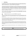 4
4
-
 5
5
-
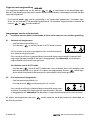 6
6
-
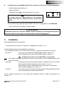 7
7
-
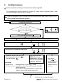 8
8
-
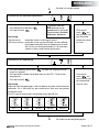 9
9
-
 10
10
-
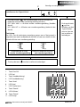 11
11
-
 12
12
-
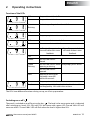 13
13
-
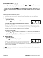 14
14
-
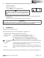 15
15
-
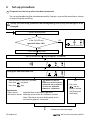 16
16
-
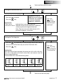 17
17
-
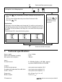 18
18
-
 19
19
-
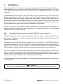 20
20
-
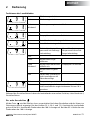 21
21
-
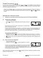 22
22
-
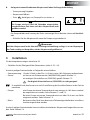 23
23
-
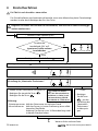 24
24
-
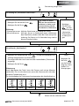 25
25
-
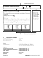 26
26
-
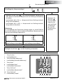 27
27
-
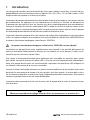 28
28
-
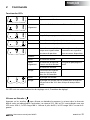 29
29
-
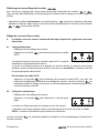 30
30
-
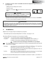 31
31
-
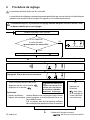 32
32
-
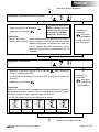 33
33
-
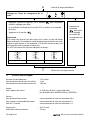 34
34
-
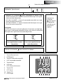 35
35
-
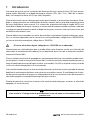 36
36
-
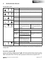 37
37
-
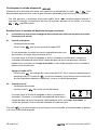 38
38
-
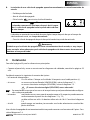 39
39
-
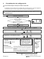 40
40
-
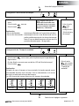 41
41
-
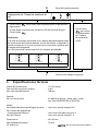 42
42
-
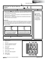 43
43
-
 44
44
-
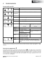 45
45
-
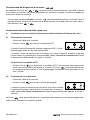 46
46
-
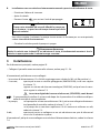 47
47
-
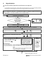 48
48
-
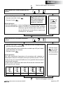 49
49
-
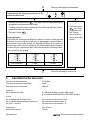 50
50
-
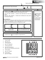 51
51
-
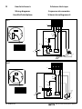 52
52
-
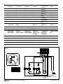 53
53
-
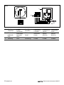 54
54
-
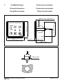 55
55
-
 56
56


Vetus WWCP Waste Water Control Panel Handleiding
- Type
- Handleiding
in andere talen
- English: Vetus WWCP Waste Water Control Panel User manual
- italiano: Vetus WWCP Waste Water Control Panel Manuale utente
- français: Vetus WWCP Waste Water Control Panel Manuel utilisateur
- español: Vetus WWCP Waste Water Control Panel Manual de usuario
- Deutsch: Vetus WWCP Waste Water Control Panel Benutzerhandbuch
Gerelateerde papieren
-
Vetus Complete tank type WWS Installatie gids
-
Vetus ILTCONW Installatie gids
-
-
-
-
-
-
-
-