Sentiotec Barrel sauna Kaski 180 Panorama Handleiding
- Type
- Handleiding

EN
DE
FR
IT
NL
KASKI-180-P
Version 01/23 item no. 1-053-431
ASSEMBLY INSTRUCTIONS
English
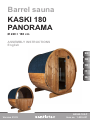
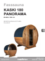
Barrel sauna
KASKI 180
PANORAMA
Ø 220 × 180 cm

Table of Contents
1. Preparing for installation 3
1.1. Important note 3
1.2. Foundation 4
1.3. Anchoring the outdoor sauna 4
1.4. Tools required 4
1.5. Maintenance and cleaning 6
1.6. Disposal 6
2. Assembling the cabin 7
2.1. Mounting the feet 7
2.2. Assembling the barrel staves 7
2.3. Assembling the front and rear wall 7
2.4. Completing the barrel 7
2.5. Mounting the door 8
2.6. Installinginteriorttings 8
2.7. Installing accessories 8
2.8. Covering the roof 8
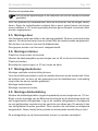
Dimensional drawing (following the last language of the instructions) 9
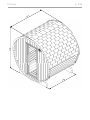
Floor plan (following the last language of the instructions) 10
Parts list (following the last language of the instructions) 11
Assembly illustrations (following the last language of the instructions) 12

EN
Assembly instructions p. 3/8
1. Preparing for installation
Read these assembly instructions carefully and keep them within reach. so that
you can look up product information at any time.
1.1. Important note
●Checkwithyourlocalplanningauthority(municipaloce,magistrate)with
respect to the building regulations and load standards.
●A solid foundation is important for the durability as well as the safety of your
outdoor sauna. We recommend having the foundation laid by a specialist.
●The anchoring of the outdoor sauna is the responsibility of the customer. No
warranty in the event of damage.
●The outdoor sauna is delivered by lorry (also possible by semi-trailer truck).
Access to the unloading area must be ensured.
●Beforeyoubeginwork,checkthepartslisttoensurethatalltheindividual
partshavebeendelivered.Ifyoudiscoveranymissingparts,notifyyour
dealer within 14 days of receiving the sauna cabin.
● Keepthedeliverynote,theinvoiceandtheassemblyinstructionsinasafe
place in case of any questions.
●You need manual skills and an assistant for the installation.
● Allscrewttingsmustbepre-drilled.
Attention!
Theelectricalconnectionmayonlybeperformedbyaqualied
electricianorsimilarlyqualiedperson.
●We recommend installing the bitumen shingles included in the scope of
delivery promptly after completion of the barrel sauna.
● Woodisanaturalproductthatcanswell,shrinkorwarp,despitegoodstor-
age.Forthisreason,someforcemaybenecessaryduringtheinstallation.
●Thewoodoftheoutdoorsaunaisuntreated.Toincreasethelifeexpectancy,
we recommend painting the outside with a suitable paint to protect the wood.
●The inside of the wooden parts used must not be treated with any paint.
These assembly instructions can also be found in the downloads section
of our website: www.sentiotec.com/downloads.

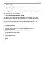
Assembly instructions p. 4/8
1.2. Foundation
The following foundation elements have proven themselves in practice:
• Foundation slab (base plate)
• Strip foundation
Forbothtypes,afoundationthatisabsolutelyatandload-bearingmustbe
ensured. Only then can the assembly of the outdoor sauna be ensured without
anydicultiesandwithapreciset.
1.3. Anchoring the outdoor sauna
Theoutdoorsaunamustbermlyanchoredonthebaseplateorthestrip
foundation. Strong winds can exert a powerful force on the garden sauna. To
preventdamagetoyour,orthirdparty,propertyproperanchoringisessential.
We point out that anchoring the garden sauna is the responsibility of the
customer and we do not accept any liability for accidental damage.
1.4. Tools required
●Hammer with a wooden block and a mallet
●Cordless screwdriver with bits for cross-head screws and Torx
●Roller tape measure
● Drillbitswithadiameterof4mm,5mm,6mm,20–30mm
(for sauna heater power cable)
●Spirit level
●Open-ended spanner
●Utility knife
●Ladder
●Saw

EN
Assembly instructions p. 5/8
60 cm
80 cm
100 cm
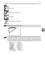
This symbol indicates tips and useful information
Pre-drill
Cut to correct size
Nailing
Carry out wiring
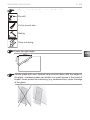
Check the right angle:
Handle glass with care: Special care must be taken with the edges of
the glass—hardened glass can shatter into small pieces in the event of
impact. Insert protective cushioning (e.g: cardboard box) under the edge
of the glass.

Assembly instructions p. 6/8
Pitchpocketsarenotgroundsforreturn,sincetheycanalwaysappearin
spruce wood and the depth at which they lie cannot be detected during
the sorting-out process.
Ifthesearejustunderthesurface,heatcancausethemtosoftenand
“bleed”.
The leaking pitch can be removed with a rag soaked in acetone. If only
dropletsofpitchoccur,allowthesetohardenandthencarefullyscrape
themowithaknife.
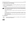
1.5. Maintenance and cleaning
●The sauna should be cleaned inside with a damp cloth. Only use warm
water—no cleaning products.
●We recommend heating the cabin once a month if the sauna is not used for
a long time.
1.6. Disposal
●Dispose of packaging materials in accordance with the applicable
waste disposal regulations.

EN
Assembly instructions p. 7/8
2. Assembling the cabin
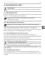
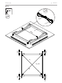
2.1. Mounting the feet
Place the impregnated feet on the foundation as shown in the illustration (see
Page 12). Fix them temporarily with two staves.
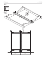
2.2. Assembling the barrel staves
Start by placing the lower stave in position (with drain—see page 13).
Lay four staves to the left and four to the right and screw the feet to the staves.
Make sure that there is no visible gap between the staves.
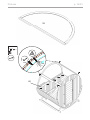
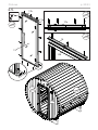
2.3. Assembling the front and rear wall
Connect the individual parts of the front wall as shown (see page 14).
Place the walls in the groove of the staves. Check the vertical alignment with the
spiritlevelandprovisionallyxinplacewithtwostaves.
Placetheglasselementonthebackwallandprovisionallyxinplacewithtwo
staves. Mount the cover strips inside and outside.
Forthelighting,xthewoodenstripinthecentreofthebackwall,approx.10cm
abovetheoor.
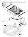
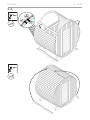
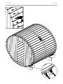
2.4. Completing the barrel
Fit the remaining staves. Fix them to the front and back walls using screws.
Closingthebarrel:Usewhateverisrequiredfromthesuppliedllerset(=stave
in strips).
ATTENTION!
NotetheoorplanonPage 10andillustrationsfromPage 9 onwards.
Always put the staves together with the round part facing upwards.
Makesurethatthefeetarettedparalleltoeachanother.
Note the power supply!
ATTANTION - GLASS BREAKAGE!
Attheglasselement,thescrewsmayONLYbescrewedinush-screws
that are countersunk can cause glass breakage.

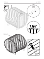
Assembly instructions p. 8/8
Fit the tensioning straps.
Beforetensioningthemetalbands,removethescrewsfromthestaves.Tighten
the metal bands so that there is no visible gap between the staves. This must
be checked regularly and retightened if necessary.
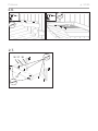
2.5. Mounting the door
Place the door frame in the opening from the outside. Note that the door opens
outwards—the door can be attached on the left or on the right.
Fix the door from the inside with the cover slats.
The door handles are screwed from the inside.
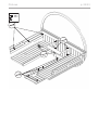
2.6. Installing interior ttings
Placetheoorgridsothatitislevel.
Fitthebenchsupportslatsataheightofapprox.45cmtotheoorgrid.
Install the benches and screw them to the barrel staves.
Fixthebackrestsapprox.20cmabovethebench.
2.7. Installing accessories
Fit the ventilation panel on the inside.
Forthelightingtthemetalclipsonthewoodenstrip.ClamptheLEDstripand
drill the cable bushing at the desired location (the power supply unit may be
placed outside the sauna).
Assemble the protection grille.
Fit the insect screen on the outside.
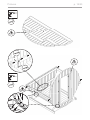
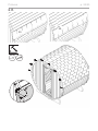
2.8. Covering the roof
Install the triangular strips (drip edge) at a height of approx. 116 cm.
Start attaching the bitumen shingles on the triangular strip with the top of shingle
sheets facing down. Now lay the other shingle sheets overlapping and evenly
oset.Youcanmakethetopridgerowfromsections.Thesearelaidoverlapping
in a scale-like manner. Pay attention to the prevailing wind direction.
The mounting strips on the inner walls can now be removed.
Note that the tension rods are placed in the lower half of the barrel sauna.

MONTAGEANLEITUNG
Deutsch
DE
KASKI-180-P
Version 01/23 Artikel-Nr. 1-053-431
Fasssauna
KASKI 180
PANORAMA
Ø 220 x 180 cm

Inhaltsverzeichnis
1. Montage Vorbereitung 3
1.1. Wichtige Hinweise 3
1.2. Fundament 4
1.3. Verankerung der Außensauna 4
1.4. Benötigtes Werkzeug 4
1.5. Wartung und Reinigung 6
1.6. Entsorgung 6
2. Montage Kabine 7
2.1. Montage Standfüße 7
2.2. Montage Fassdauben 7
2.3. Montage Vorder- und Rückwand 7
2.4. Fertigstellung Fass 7
2.5. Montage Tür 8
2.6. Montage Inneneinrichtung 8
2.7. Montage Zubehör 8
2.8. Montage Dacheindeckung 8
Abbildung Abmessungen (nach der letzten Sprache) 9
Grundriss (nach der letzten Sprache) 10
Stückliste (nach der letzten Sprache) 11
Montage Abbildungen (nach der letzten Sprache) 12

DE
Montageanleitung S. 3/8
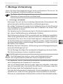
1. Montage Vorbereitung
Lesen Sie diese Montageanleitung gut durch und bewahren Sie sie auf. So
können Sie jederzeit Produktinformationen nachlesen.
1.1. Wichtige Hinweise
●ErkundigenSiesichbeiIhrerzuständigeBaubehörde(Gemeindeamt,Ma-
gistrat) bezüglich den Bauvorschriften und Belastungsnormen.
●EinsolidesFundamentistwichtigfürdieHaltbarkeitsowiefürdieSicherheit
Ihrer Außensauna. Wir empfehlen Ihnen das Fundament von einem Fach-
mann herstellen zu lassen.
●Die Verankerung der Außensauna liegt im Verantwortungsbereich des Kun-
den.KeineGewährleistungbeiauftretendenSchäden.
●Die Außensauna wird per LKW (eventuell auch per Sattelzug) angeliefert.
Dabeimussgewährleistetsein,dassdieZufahrtzumEntladeortmöglichist.
● KontrollierenSie,bevorSiemitderArbeitbeginnen,anhandderStückliste,
oballeEinzelteileauchtatsächlichmitgeliefertwurden.SolltenEinzelteile
ausnahmsweisefehlen,benachrichtigenSiespätestens14TagenachErhalt
derKabineIhrenHändler.
●BewahrenSiedenLieferschein,dieRechnungunddieMontageanleitungfür
eventuelle Rückfragen gut auf.
●Für die Montage benötigen Sie handwerkliche Begabung und einen Helfer.
●Alle Verschraubungen müssen vorgebohrt werden.
Achtung!
DerElektroanschlussdarfnurdurcheineElektrofachkraftoder
einevergleichsweisequaliziertePersonausgeführtwerden.
● Wirempfehlen,dieimLieferumfang enthaltenen Bitumenschindeln zeitnah
nach Fertigstellung der Fasssauna zu montieren.
●HolzisteinNaturprodukt,dastrotzguterLagerungaufquellen,schwinden
odersichverziehenkann.AusdiesemGrundkannesvorkommen,dassbei
der Montage etwas Kraft aufgebracht werden muss.
●DasHolzderAußensaunaistunbehandelt.UmdieLebensdauerzuerhöhen,
empfehlenwir,außenmiteinergeeignetenHolzschutzfarbezustreichen.
●Die Innen zu verwendenden Holzteile dürfen nicht mit Farbe behandelt werden.
Siendendiese Montageanleitung auch im Downloadbereich unserer
Webseite auf www.sentiotec.com/downloads.

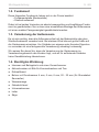
Montageanleitung S. 4/8
1.2. Fundament
DiesefolgendenFundmentehabensichinderPraxisbewährt:
• Fundamentplatte (Bodenplatte)
• Streifenfundament
DabeiistbeibeidenVarianteneinabsolutwaagrechtesundtragfähigesFunda-
mentzugewährleisten.NursokanneineeinwandfreieMontagederAußensauna
miteinerexaktenPassgenauigkeitgewährleistetwerden.
1.3. Verankerung der Außensauna
Esistsehrwichtig,dassdieAußensaunafestmitderBodenplatteoderdem
Streifenfundamentverankertwird.BeistarkemWindkönnengroßeKräfteauf
dieGartensaunaeinwirken.UmSchädenameigenenoderfremdenEigentum
zu vermeiden ist eine fachgerechte Verankerung unbedingt notwendig.
WirweisenSiedaraufhin,dassdieVerankerungderGartensaunaim
VerantwortungsbereichdesKundenliegt,undwirfürauftretendeSchäden
keineGewährleistungübernehmen.
1.4. Benötigtes Werkzeug
● HammerundBeilageholzundeinenGummihammer
●Akkuschrauber mit Bits für Kreuzschrauben und Torx
●Rollmaßband
●BohrermitDurchmesser4mm,5mm,6mm,20-30mm(fürStromkabel
Saunaofen)
●Wasserwaage
● Gabelschlüssel
●Universalmesser
●Leiter
● Säge

DE
Montageanleitung S. 5/8
60 cm
80 cm
100 cm
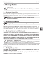
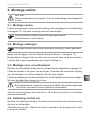
Dieses Symbol kennzeichnet Tipps und nützliche Hinweise
Vorbohren
AblängenaufNaturmaß
Annageln
Verkabelung vornehmen
Überprüfung des rechten Winkel:
VorsichtigerUmgangmitGlas:BesondereVorsichtgiltdenGlaskanten-
GehärtetesGlaskannbeiStößeninkleineScherbenzerspringen.Legen
SieeinSchutzpolster(z.Bsp.:Verpackungs-Karton)unterdieGlaskante.

Montageanleitung S. 6/8
Harzgallen sind kein Reklamationsgrund. Da in Fichtenholz immer wieder
Harzgallen vorkommen und man beim Aussortieren nicht erkennen kann
inwelcherTiefediesesichbenden.
WenndieseknappunterderOberächesindbrechensiebeiHitzeent-
wicklung auf und „bluten“ aus.
DasausgelaufeneHarzkannmanmiteinemAcetongedrängtemLappen
entfernen.WennlediglichHarztropfenentstehen,lassenSiedieseaus-
härtenundschabensieanschließendmiteinemMesservorsichtigab.
1.5. Wartung und Reinigung
●Die Sauna sollte innen mit einem feuchten Tuch gereinigt werden. Verwenden
Sie nur warmes Wasser - keine Reinigungsmittel.
● WirddieSaunalängereZeitnichtbenutzt,empfehlenwir,dieKabineeinmal
im Monat aufzuheizen.
1.6. Entsorgung
●EntsorgenSiedieVerpackungsmaterialiennachdengültigenEnt-
sorgungsrichtlinien.

DE
Montageanleitung S. 7/8
2. Montage Kabine
2.1. Montage Standfüße
LegenSiedieimprägniertenStandfüßeaufdasFundamentwiediesinder
Darstellung angezeigt ist (siehe Seite 12). Fixieren Sie diese provisorisch mit
zwei Dauben.
2.2. Montage Fassdauben
BeginnenSiemitderVerlegungderunterenDaube(mitAbuss-sieheSeite13).
Verlegen Sie je 4 Dauben links und rechts und verschrauben diese mit den
Standfüßen.BeachtenSie,dasskeinSpalt zwischen den Dauben sichtbar ist.
2.3. Montage Vorder- und Rückwand
VerbindenSiedieEinzelteilederVorderwandwieabgebildet(siehe Seite 14)
StellenSiedieWändeindieNutderDauben.KontrollierenSiedielotrechteAus-
richtungmitderWasserwaageundxierendiesprovisorischmitzweiDauben.
SetzenSiedasGlaselementaufdieRückwandundxierendiesprovisorischmit
zwei Dauben. Montieren Sie die Abdeckleisten innen und außen.
FixierenSiedieHolzleistefürdieBeleuchtungca.10cmüberdemBodenmittig
an der Rückwand.
2.4. Fertigstellung Fass
Montieren Sie die restlichen Dauben. Fixieren Sie diese mit der Vorder- und
Rückwand mittels Schrauben.
Verschluss vom Fass: Verwenden Sie die geeignete Kombination aus dem
geliefertenFüllset(=DaubemitLeisten)
ACHTUNG!
BeachtenSiedenGrundrissaufSeite 10unddieAbbildungenabSeite 9.
Die Dauben werden immer mit der Rundung nach oben zeigend zusam-
mengesteckt.
BeachtenSie,dassdieStandfüßeparallelmontiertwerden.
Stromzufuhr beachten!
VORSICHT - GLASBRUCH!
BeimGlaselementdürfendieSchraubenNURbündigeingeschraubt
werden-versenkteSchraubenkönnenGlasbruchauslösen.

Montageanleitung S. 8/8
MontierenSiedieSpannbänder.
VordemSpannenderMetallbänderentfernenSiedieSchraubenderDauben.
SpannenSiedieMetallbändersofest,dasskeinSpaltzwischendenDauben
sichtbarist.Diesmussregelmäßigkontrolliertundggf.nachgespanntwerden.
2.5. Montage Tür
DerTürrahmenwirdvonaußenindieÖnunggestellt.BeachtenSie,dassdie
Türönungnachaußenerfolgt-derTüranschlagistlinksundrechtsmöglich.
Fixieren Sie die Tür von innen mit den Abdeckleisten.
Türgriewerdenvoninnenverschraubt.
2.6. Montage Inneneinrichtung
Legen Sie den Bodenrost waagrecht ein.
MontierenSiedieBankauageleistenineineHöhevonca.45cmzumBodenrost.
LegenSiedieBänkeeinundverschraubenSiesiemitdenFassdauben.
BefestigenSiedieRückenlehnenca.20cmüberderBank.
2.7. Montage Zubehör
Montage Lüftungsteller innen.
Für die Beleuchtung montieren Sie zuerst die Metallklammern auf der Holzleiste.
KlemmenSiedieLED-LeisteeinundbohrenangewünschterStelledieKabel-
durchführung(NetzgerätdarfaußerhalbderSaunaplatziertwerden)
Montage Ofenschutzgitter.
Montage Insektenschutzgitter außen.
2.8. Montage Dacheindeckung
Montieren Sie die Dreiecksleisten (Regen-Tropfnase) in einer Höhe von ca. 116 cm.
Beginnen Sie mit der Montage der Bitumen-Schindeln an der Dreiecksleiste
mit einer auf den Kopf gestellen Schindelbahn. Nun verlegen Sie die weiteren
SchindelbahnenüberlappendundmitgleichmäßigemVersatz.DieFirstreihe
können Sie aus Abschnitten bilden. Diese werden schuppenförmig überlappend
verlegt. Achten Sie dabei auf die Hauptwindrichtung.
DieMontageleistenandenInnenwändenkönnenjetztentferntwerden.
BeachtenSie,dassdieSpannstangeninderunterenHälftederFass-
sauna platziert werden.

FR
KASKI-180-P
Version 01/23 Référence 1-053-431
INSTRUCTIONS DE MONTAGE
Français
Sauna tonneau
KASKI 180
PANORAMA
Ø 220 x 180 cm

Table des matières
1. Préparation du montage 3
1.1. Remarques importantes 3
1.2. Fondation 4
1.3. Ancrage du sauna extérieur 4
1.4. Outils requis 4
1.5. Entretienetnettoyage 6
1.6. Élimination 6
2. Montage de la cabine 7
2.1. Montage des pieds 7
2.2. Montage des douves de tonneaux 7
2.3. Montage des parois avant et arrière 7
2.4. Finition du tonneau 7
2.5. Montage de la porte 8
2.6. Montage de l’équipement intérieur 8
2.7. Montage des accessoires 8
2.8. Montage de la couverture de toit 8
Illustration des dimensions (après la dernière langue) 9
Plan de construction (après la dernière langue) 10
Nomenclature (après la dernière langue) 11
Illustrations de montage (après la dernière langue) 12

FR
Instructions de montage p. 3/8
1. Préparation du montage
Lisez attentivement ces instructions de montage et conservez-les. Vous avez
ainsi accès à tout moment aux informations sur le produit.
1.1. Remarques importantes
●Renseignez-vous auprès de l’autorité locale chargée de la construction
(bureaumunicipal,magistrat)surlesrèglesdeconstructionetlesnormes
relatives aux charges.
● Pourladurabilitéetlasécuritédevotresaunaextérieur,ilestimportantque
la fondation soit solide. Nous vous recommandons de faire construire les
fondations par un spécialiste.
●La responsabilité de l’ancrage du sauna extérieur incombe au client. Aucune
garantie n’est accordée en cas de dommage.
●Le sauna extérieur est livré par camion (éventuellement par semi-remorque).
Il faut donc veiller à ce que l’accès au site de déchargement soit possible.
●Avantdecommencerlestravaux,vériezaumoyendelanomenclaturesi
toutes les pièces ont bien été livrées. S’il devait s’avérer que des pièces
manquent,informezvotrerevendeurdansles14jourssuivantlaréception
de la cabine.
●Conservezlebondelivraison,lafactureetlesinstructionsdemontageen
lieu sûr pour toute question éventuelle.
●Vous avez besoin de compétences manuelles et d’un assistant pour l’ins-
tallation.
●Tous les raccords vissés doivent être préalésés.
Attention !
Seulunélectricienspécialiséouunepersonneayantunequali-
cation similaire est habilité à procéder au raccordement électrique.
●Nous recommandons de monter les bardeaux de bitume inclus dans la livrai-
son peu de temps après l’achèvement du sauna tonneau.
●Malgréunstockagecorrect,leboisestunproduitnaturelquipeutgoner,
se contracter ou se déformer. C’est pourquoi il peut arriver que vous ayez à
appliquer de la force lors du montage.
●Leboisdusaunaextérieurn’estpastraité.Pouraugmentersaduréedevie,
nous recommandons de peindre l’extérieur avec une peinture de protection
du bois adaptée.
●Les pièces en bois utilisées à l’intérieur du sauna ne doivent pas être traitées
avec de la peinture.
Vous pouvez également trouver ces instructions de montage dans la zone
de téléchargement de notre site Web : www.sentiotec.com/downloads.

Instructions de montage p. 4/8
1.2. Fondation
Les fondations suivantes ont fait leurs preuves dans la pratique :
• Plaque de fondation (dalle)
•Semelleslantes
Danslesdeuxvariantes,unefondationabsolumenthorizontaleetporteusedoit
être garantie. Ce n’est que de cette manière qu’un montage parfait du sauna
extérieur peut être garanti avec un ajustement exact.
1.3. Ancrage du sauna extérieur
Il est très important que le sauna extérieur soit solidement ancré à la dalle ou
auxsemelleslantes.Parventfort,degrandesforcespeuventagirsurlesau-
nadejardin.And’éviterd’endommagervotrepropriétéoulesbiensdetiers,
un ancrage professionnel est absolument nécessaire.
Nous attirons votre attention sur le fait que l’ancrage du sauna de jardin est
à la charge du client et que nous déclinons toute responsabilité pour les
dommages qui pourraient survenir.
1.4. Outils requis
● Marteau,calesetmailletencaoutchouc
●Visseuse électrique avec bits pour vis en croix et Torx
●Ruban de mesure
● Foretde4mm,5mm,6mm,20–30mmdediamètre(pourlecâbleélec-
trique du poêle de sauna)
●Niveau à bulle
●Clé à fourche
●Couteau universel
●Échelle
●Scie

FR
Instructions de montage p. 5/8
60 cm
80 cm
100 cm
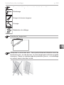
Ce symbole désigne les conseils et indications utiles.
Préalésage
Sciage à la bonne longueur
Clouage
Réalisationducâblage
Contrôle de l’angle droit :
Manipulez le verre avec soin : Faire particulièrement attention avec les
bordsdelavitre;encasdechoc,leverretrempépeutsebriserenpetits
morceaux.Placezunrembourragedeprotection(parex.,unemballage
en carton) sous le bord de la vitre.

Instructions de montage p. 6/8
Lespochesderésineneconstituentpasunmotifderéclamation,enrai-
son de leur présence régulière dans le bois d’épicéa et de l’impossibilité
de déterminer leur profondeur lors de la sélection du bois.
Siellessetrouventjustesouslasurface,elleséclatentets’écoulent
quand elle sont exposées à la chaleur.
Retirezlarésineécouléeàl’aided’unchionimbibéd’acétone.Sivous
constatezuniquementdesgouttesderésine,attendezqu’ellesaient
durci,puisgrattez-lesavecprécautionàl’aided’uncouteau.
1.5. Entretien et nettoyage
● L’intérieurdusaunadoitêtrenettoyéàl’aided’unchionhumide.N’utilisez
quedel’eauchaude,pasdedétergent.
●Silesaunan’estpasutilisépendantunepériodeprolongée,nousrecomman-
donsdechauerlacabineunefoisparmois.
1.6. Élimination
●Éliminez les matériaux d’emballage conformément aux directives
en vigueur relatives à l’élimination.

FR
Instructions de montage p. 7/8
2. Montage de la cabine
2.1. Montage des pieds
Posez les pieds imprégnés sur la fondation comme indiqué sur le schéma (voir
Page 12). Fixez-les provisoirement à l’aide de deux douves.
2.2. Montage des douves de tonneaux
Commencezparposerladouveinférieure(avecécoulement,voirpage13).
Posez4douvesàgaucheet4douvesàdroiteetvissez-lesauxpieds.Cefaisant,
veiller à ce que l’espace entre les douves soit visible.
2.3. Montage des parois avant et arrière
Assemblezlesdiérentespartiesdumuravantcommeindiqué(voirpage14).
Placez les parois dans la rainure des douves. Contrôlez l’aplomb à l’aide du
niveauàbulleetxez-leprovisoirementavecdeuxdouves.
Placezlavitreenverresurlemurdufondetxez-latemporairementavecdeux
lattes. Montez les bandes de recouvrement à l’intérieur et à l’extérieur.
Pourl’éclairage,xezletasseauenboisàenviron10cmdusolaumilieudu
mur du fond.
2.4. Finition du tonneau
Montez les douves restantes. Fixez-les aux parois avant et arrière à l’aide de vis.
Fermeture du tonneau : Utilisez la combinaison appropriée du kit de remplissage
fourni(=douveavecbaguettes)
ATTENTION !
Référez-vous au plan de la page Page 10etauxillustrationsàpartirde
la page Page 9.
Les douves sont toujours à assembler avec le côté arrondi vers le haut.
Veillez à ce que les pieds soient montés en parallèle.
Faites attention à l’alimentation électrique !
ATTENTION - BRIS DE VERRE!
Aveclavitreenverre,lesvisdoiventUNIQUEMENTêtrevisséesàras
- les vis à tête fraisée peuvent casser le verre.

Instructions de montage p. 8/8
Mettez en place les colliers de serrage.
Avantdetendrelesbandesmétalliques,retirezlesvisdesdouves.Tendezles
bandes métalliques de manière à ce qu’il n’y ait aucun espace visible entre les
douves. Cela doit être régulièrement contrôlé et resserré si nécessaire.
2.5. Montage de la porte
Placez le cadre de la porte dans l’ouverture depuis l’extérieur. Veillez à ce que
l’ouverture de la porte se fasse vers l’extérieur (l’ouverture de la porte est pos-
sible à gauche et à droite).
Fixez la porte de l’intérieur avec les baguettes de couverture.
Les poignées de porte sont à visser de l’intérieur.
2.6. Montage de l’équipement intérieur
Posez la grille de sol à l’horizontale.
Montez les baguettes d’appui des bancs à environ 45 cm au-dessus de la grille
de sol. Placez les bancs et vissez-les aux douves du tonneau.
Fixezlesdossiersàenviron20cmau-dessusdesbancs.
2.7. Montage des accessoires
Montage du plateau de ventilation à l’intérieur.
Pourl’éclairage,montezd’abordlesclipsmétalliquessurletasseauenbois.
FixezlabarreàLEDetpercezlepassagedecâbleàl’endroitsouhaité(lebloc
d’alimentation peut être placé à l’extérieur du sauna)
Montage de la grille de protection du poêle.
Montage de la moustiquaire à l’extérieur.
2.8. Montage de la couverture de toit
Montez les baguettes triangulaires (nez de gouttière) à une hauteur d’environ
116 cm.
Commencez par monter les bardeaux de bitume sur la baguette triangulaire
avec un bardeau à l’envers. Posez ensuite les autres bardeaux en les faisant se
chevaucher et en veillant à ce qu’ils aient le même écart. Vous pouvez former
la rangée de faîtage à partir de sections. Celles-ci doivent se chevaucher en
forme d’écailles. Veillez à ce que la direction principale du vent soit respectée.
Les bandes de montage sur les parois intérieures peuvent maintenant être retirées.
Veillez à ce que les barres de tension soient placées dans la moitié
inférieure du sauna tonneau.

IT
KASKI-180-P
Versione 01/23 Codice articolo 1-053-431
ISTRUZIONI DI MONTAGGIO
Italiano
Sauna a botte
KASKI 180
PANORAMA
Ø 220 x 180 cm

Indice
1. Preparazione per il montaggio 3
1.1. Indicazioni importanti 3
1.2. Fondamenta 4
1.3. Ancoraggio della sauna all’aperto 4
1.4. Attrezzi necessari 4
1.5. Manutenzione e pulizia 6
1.6. Smaltimento 6
2. Montaggio cabina 7
2.1. Montaggio dei piedi di appoggio 7
2.2. Montaggio delle doghe della botte 7
2.3. Montaggio della parete anteriore e di quella posteriore 7
2.4. Completamento della botte 7
2.5. Montaggio della porta 8
2.6. Montaggio dell’allestimento interno 8
2.7. Montaggio accessori 8
2.8. Montaggio della copertura del tetto 8
Figura Misure (dopo l’ultima lingua) 9
Pianta (dopo l’ultima lingua) 10
Elenco dei pezzi (dopo l’ultima lingua) 11
Figure di montaggio (dopo l’ultima lingua) 12

IT
Istruzioni di montaggio P. 3/8
1. Preparazione per il montaggio
Leggere con attenzione le presenti istruzioni di montaggio e conservarle. In
questo modo è possibile controllare in qualsiasi momento le informazioni relative
al prodotto.
1.1. Indicazioni importanti
●Informatevipressol’autoritàediliziacompetentelocale(uciocomunaleo
autorità comunali) per i regolamenti edilizi e gli standard di carico.
●Solide fondamenta sono importanti per la durata e la sicurezza della vostra
sauna all’aperto. Vi consigliamo di far eseguire le fondamenta da un profes-
sionista.
●L’ancoraggio della sauna esterna è responsabilità del cliente. Nessuna ga-
ranzia in caso di danni.
●La sauna all’aperto è consegnata da un camion (eventualmente anche da un
autoarticolato). Di conseguenza è necessario assicurarsi che sia possibile
l’accesso al luogo di scarico.
●Primadiiniziareilavori,controllareinbaseall’elencodeipezzisetuttiisingoli
componentisonostatieettivamenteforniti.Seeccezionalmentedovessero
mancaredeisingolicomponenti,contattareilpropriofornitoreentro14giorni
dal ricevimento della cabina.
● Conservatelabolladiconsegna,lafatturaeleistruzionidimontaggioinun
luogo sicuro per eventuali domande.
●Per il montaggio sono necessarie abilità manuali e un aiutante.
●Tutte le connessioni a vite devono essere preforate.
Attenzione!
Il collegamento elettrico deve essere eseguito da elettricisti
specializzatiodapersoneconunaqualicasimile.
●Si consiglia di montare le tegole bituminose incluse nella fornitura subito
dopo il completamento della sauna a botte.
●Illegnoèunprodottonaturalechepuògonarsi,ritirarsiodeformarsianche
se immagazzinato correttamente. In fase di montaggio potrebbe quindi essere
necessario applicare una certa forza.
●Illegnodellasaunaesternanonètrattato.Peraumentareladuratadivita,si
consiglia di dipingere l’esterno con una vernice protettiva per legno adatta.
●I componenti in legno da utilizzare all’interno non devono essere trattati con
vernice.
Le presenti istruzioni di montaggio sono disponibili anche nella sezione
download del nostro sito web all’indirizzo: www.sentiotec.com/downloads.

Istruzioni di montaggio P. 4/8
1.2. Fondamenta
Iseguentielementiperlefondamentahannodimostratolaloroecacianella
pratica:
• piastra di fondazione (piastra di base)
• striscia di fondazione
Conentrambelevarianti,devonoesseregarantitefondamentaperfettamente
orizzontali e portanti. Solo in questo modo è possibile garantire una perfetta
installazione della sauna esterna con un adattamento esatto.
1.3. Ancoraggio della sauna all’aperto
È molto importante che la sauna all’aperto sia saldamente ancorata alla pia-
stradifondooallastrisciadifondazione.Incasodiventoforte,grandiforze
possono agire sulla sauna da giardino. Per evitare danni alla vostra proprietà
oaquelladialtri,unancoraggioprofessionaleèassolutamentenecessario.
Vorremmo sottolineare che l’ancoraggio della sauna da giardino è di
responsabilità del cliente e non ci assumiamo nessuna responsabilità per
eventuali danni.
1.4. Attrezzi necessari
● Martello,pezzodilegnoemartelloingomma
●Avvitatore elettrico con punte per viti con testa a croce e viti Torx
●Metro a nastro avvolgibile
● Puntepertrapanoda4mm,5mm,6mm,20–30mm
(per cavo elettrico della stufa per sauna)
●Livella a bolla
● Chiavessa
●Cutter
●Scala
●Sega

IT
Istruzioni di montaggio P. 5/8
60 cm
80 cm
100 cm
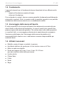
Questosimboloindicaconsiglieindicazioniutili
Preforatura
Taglioallalunghezzaeettiva
Inchiodamento
Cablaggio
Vericadell’ortogonalità:
Maneggiare il vetro con cura: particolare attenzione deve essere prestata
aibordidelvetro–ilvetrotempratopuòfrantumarsiinpiccolipezziincaso
di impatto. Inserire un cuscino di protezione (ad es: scatola di cartone)
sotto il bordo del vetro.

Istruzioni di montaggio P. 6/8
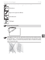
Le tasche di resina non sono motivo di reclamo perché nel legno di
abete rosso sono sempre presenti e durante la selezione non è possibile
rilevare a quale profondità si trovino.
Quandosonoappenaaldisottodellasupercie,conlosviluppodel
calore si rompono e possono «essudare».
Rimuovere la resina fuoriuscita con un panno imbevuto di acetone. Se
sonopresentisologoccediresina,lasciarleindurireepoiraschiarlecon
cautela usando un coltello.
1.5. Manutenzione e pulizia
●La sauna all’interno deve essere pulita con un panno umido. Utilizzare solo
acqua calda senza detergenti.
●Selasaunanonvieneutilizzataperuntempoprolungato,siconsigliadi
riscaldare la cabina una volta al mese.
1.6. Smaltimento
●Smaltire i materiali dell’imballaggio conformemente alle normative
sullo smaltimento vigenti.

IT
Istruzioni di montaggio P. 7/8
2. Montaggio cabina
2.1. Montaggio dei piedi di appoggio
Posizionare i piedi di appoggio impregnati sulle fondamenta come mostrato
nell’illustrazione (vedere Pagina 12). Fissarli temporaneamente con due doghe.
2.2. Montaggio delle doghe della botte
Iniziarepoggiandoladogainferiore(conscarico–vedipagina13).
Posare 4 doghe a sinistra e 4 a destra e avvitarle ai piedi di appoggio. Assicurarsi
che non vi siano spazi vuoti visibili tra le doghe.
2.3. Montaggio della parete anteriore e di quella posteriore
Collegare i singoli componenti del pannello frontale come mostrato (vedere
pagina 14).
Posizionare le pareti nella scanalatura delle doghe. Controllare l’allineamento
perpendicolareconlalivellaabollaessarloprovvisoriamenteconduedoghe.
Posizionarel’elementoinvetrosullapareteessarloprovvisoriamentecondue
doghe. Montare i listelli di copertura all’interno e all’esterno.
Perl’illuminazionessareilbloccodilegnoacirca10cmdaterraalcentrodella
parete di fondo.
2.4. Completamento della botte
Montare le doghe rimanenti. Fissarle alla parete anteriore e a quella posteriore
con delle viti.
Chiusura della botte: Utilizzare la combinazione appropriata dal set per il riem-
pimentofornitoindotazione(=dogaconlistelli).
ATTENZIONE!
Osservare la pianta a Pagina 10eleguredaPagina 9.
Le doghe sono sempre montate insieme con la parte arrotondata rivolta
verso l’alto.
Assicurarsi che i piedi di appoggio siano montati parallelamente.
Osservare l’alimentazione elettrica!
ATTENZIONE - ROTTURA DEL VETRO!
Le viti devono essere a livello con la parte superiore del vetro. Avvitare
troppo profondo può rompere il vetro.

Istruzioni di montaggio P. 8/8
Montare le fasce di tensione.
Primaditenderelefascemetalliche,rimuoverelevitidalledoghe.Stringerele
fascemetallicheinmodochenonsiavisibilealcunospaziotraledoghe.Questo
deveesserecontrollatoregolarmentee,senecessario,riserrare.
2.5. Montaggio della porta
Inserire il telaio della porta nell’apertura dall’esterno. Si noti che l’apertura della
portaèversol’esterno–lacernieradellaportaèpossibileasinistraeadestra.
Fissare la porta dall’interno con i listelli di copertura.
Le maniglie delle porte sono avvitate dall’interno.
2.6. Montaggio dell’allestimento interno
Inserire la griglia di fondo orizzontalmente.
Montare i listelli di supporto della panca a un’altezza di circa 45 cm rispetto alla
griglia di fondo. Inserire le panche e avvitale alle doghe della botte.
Fissareglischienaliacirca20cmsopralapanca.
2.7. Montaggio accessori
Montaggio dei supporti per la ventilazione all’interno.
Perl’illuminazione,montareprimaleclipmetallichesullistelloinlegno.Bloccare
illistelloperLEDeforareilpassacavonellaposizionedesiderata(l’alimentatore
può essere collocato all’esterno della sauna).
Montaggio della griglia di protezione della stufa.
Installare la grigia di protezione per gli insetti all’esterno.
2.8. Montaggio della copertura del tetto
Montare i listelli triangolari (nasello di sgocciolamento) a un’altezza di circa 116 cm.
Iniziare con il montaggio delle tegole bituminose sul listello triangolare con una
fascia di tegole capovolta. Ora posare le altre fasce di tegole sovrapponendole
con uno sfalsamento uniforme. È possibile formare la linea di colmo a partire dalle
sezioni.Questesonodisposteinmodosovrappostoaspinadipesce.Prestare
attenzione alla direzione del vento principale.
Le strisce di montaggio sulle pareti interne possono ora essere rimosse.
Si noti che le aste di tensione sono posizionate nella metà inferiore della
sauna a botte.

NL
MONTAGEHANDLEIDING
Nederlands
KASKI-180-P
Versie 01/23 Artikel-nr. 1-053-431
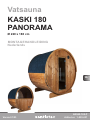
Vatsauna
KASKI 180
PANORAMA
Ø 220 x 180 cm

Inhoudsopgave
1. Montagevoorbereiding 3
1.1. Belangrijke aanwijzingen 3
1.2. Fundering 4
1.3. Verankering van de buitensauna 4
1.4. Vereist gereedschap 4
1.5. Onderhoud en reiniging 6
1.6. Afvoer 6
2. Montage cabine 7
2.1. Montage voeten 7
2.2. Montage vatduigen 7
2.3. Montage voor- en achterwand 7
2.4. Voltooiing van het vat 7
2.5. Montage deur 8
2.6. Montage interieur 8
2.7. Montagetoebehoren 8
2.8. Montage dakbedekking 8
Afbeelding afmetingen (volgens de laatste taal) 9
Plattegrond (volgens de laatste taal) 10
Stuklijst (volgens de laatste taal) 11
Montage afbeeldingen (volgens de laatste taal) 12

NL
Montagehandleiding Pag. 3/8
1. Montagevoorbereiding
Lees deze montagehandleiding goed door en bewaar hem goed. Zo kunt u te
allen tijde productinformatie nalezen.
1.1. Belangrijke aanwijzingen
● Informeerubijuwverantwoordelijkebouwinstantie(gemeentekantoor,ma-
gistraat) naar de bouwvoorschriften en belastingsnormen.
●Eensolidefunderingisbelangrijkvoordehoudbaarheidendeveiligheid
van uw buitensauna. Wij adviseren u om de fundering door een vakbedrijf
te laten aanleggen.
● Voordeverankeringvandebuitensaunaisdeklantverantwoordelijk.Geen
garantie bij eventuele schade.
●De buitensauna wordt op een vrachtwagen (eventueel op een oplegger)
geleverd. Hierbij moet ervoor gezorgd zijn dat de toegang tot de losplaats
mogelijk is.
●Controleer alvorens met de montage te beginnen aan de hand van de stuklijst
ofalleafzonderlijkedelenwerdengeleverd.Alserdelenontbreken,neemdan
uiterlijk 14 dagen na ontvangst van de cabine contact op met uw handelaar.
●Bewaarhetaeveringsbewijs,defactuurendemontagehandleidingvoor
eventuele vragen.
●De montage vereist handvaardigheid en moet door twee personen worden
uitgevoerd
●Alle schroefverbindingen moeten worden voorgeboord.
Let op!
De elektrische aansluiting mag alleen worden uitgevoerd door
eenelektricienofeenvergelijkbaargekwaliceerdpersoon.
●Wij adviseren de meegeleverde bitumineuze shingles snel na voltooiing van
de vatsauna te monteren.
●Houtiseennatuurlijkproductdatondankscorrecteopslagkanuitzetten,
krimpen of krom trekken. Daardoor kan het zijn dat bij de montage kracht
moet worden toegepast.
●Hethoutvandebuitensaunaisonbehandeld.Omdelevensduurteverlengen,
adviseren we om deze vanbuiten te behandelen met een geschikte houtverf.
●Dehoutenonderdelendiebinnenwordengebruikt,mogennietmetverf
worden behandeld.
U vindt deze montagehandleiding ook in de downloadsectie op onze
website www.sentiotec.com/downloads.

Montagehandleiding Pag. 4/8
●Hethoutvandebuitensaunaisonbehandeld.Omdelevensduurteverlengen,
adviseren we om deze vanbuiten te behandelen met een geschikte houtverf.
●Dehoutenonderdelendiebinnenwordengebruikt,mogennietmetverf
worden behandeld.
1.2. Fundering
In de praktijk is gebleken dat deze funderingen goed zijn:
• Funderingsplaat (gietplaat)
• Strokenfundering
Beide varianten moeten absoluut horizontaal zijn en over voldoende draagver-
mogen beschikken. Alleen zo kan een correcte en precies passende montage
van de buitensauna worden gegarandeerd.
1.3. Verankering van de buitensauna
Het is heel belangrijk dat de buitensauna in de gietplaat of de strokenfundering
wordt verankerd. Bij sterke wind kunnen er grote krachten op de buitensauna
inwerken. Om beschadiging van eigen of andermans eigendom te voorkomen
is een deskundige verankering noodzakelijk.
Wij wijzen erop dat de klant zelf verantwoordelijk is voor de verankering
van de buitensauna en wij niet aansprakelijk kunnen worden gesteld voor
eventuele schade.
1.4. Vereist gereedschap
●Hamer en slaghout en een rubberhamer
●Accuschroefmachine met bits voor kruiskopschroeven en torx
●Rolmaat
●Boormachinemetdiameter4mm,5mm,6mm,20–30mm(voorstroomkabel
van saunakachel)
●Waterpas
●Steeksleutel
●Universeel mes
●Ladder
●Zaag

NL
Montagehandleiding Pag. 5/8
60 cm
80 cm
100 cm
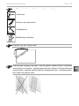
Dit symbool kenmerkt tips en nuttige aanwijzingen
Voorboren
Inkorten op natuurmaat
Vastspijkeren
Bekabeling monteren
Controle van de rechte hoek:
Voorzichtige omgang met glas: met de glazen randen dient u bijzonder
voorzichtigomtegaan–gehardglaskandoorstoteninkleinescherven
versplinteren. Leg een beschermende ondergrond (bijv.: verpakkingskar-
ton) onder de glazen rand.

Montagehandleiding Pag. 6/8
Harsbuilen gelden niet als reclamatiereden. Omdat in sparrenhout van
nature harsbuilen kunnen voorkomen en bij het sorteren niet kan worden
herkend in welke diepte ze zich bevinden.
Alszezichnetonderhetoppervlakbevinden,kunnenzebijhitteopen-
breken en gaan ‘bloeden’.
De uitgelopen hars kan met een in aceton gedompelde doek worden
verwijderd.Alsalleenharsdruppelsontstaan,dezelatenuithardenen
met een mes voorzichtig wegschrapen.
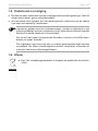
1.5. Onderhoud en reiniging
●Desaunamoetvanbinnenmeteenvochtigedoekwordengereinigd.Gebruik
alleenwarmwater,geenreinigingsmiddel.
●Alsdesaunavoorlangeretijdnietwordtgebruikt,adviserenwijdecabine
een keer per maand te verwarmen.
1.6. Afvoer
●Voer het verpakkingsmateriaal af volgens de geldende afvoerricht-
lijnen.

NL
Montagehandleiding Pag. 7/8
2. Montage cabine
2.1. Montage voeten
Leg de impregneerde voeten op de fundering zoals aangegeven in de afbeelding
(zie pagina 12). Zet deze voorlopig vast met twee duigen.
2.2. Montage vatduigen
Beginmethetleggenvandeondersteduig(metafvoer–ziepagina13).
Breng telkens 4 duigen links en rechts aan en schroef deze op de steunvoeten.
Let erop dat er geen spleettussen de duigen zichtbaar is.
2.3. Montage voor- en achterwand
Monteer de afzonderlijke delen van de voorwand zoals afgebeeld (zie pagina 14)
Plaats de wanden in de groef van de duigen. Controleer de loodrechte uitlijning
metdewaterpas,enzetdezetijdelijkvastmettweeduigen.
Plaats het glaselement op de achterwand en zet het tijdelijk vast met twee duigen.
Monteer de afdeklijsten binnen en buiten.
Voordeverlichtingxeerdehoutenlatca.10cmbovenhetvloerinhetmidden
aan de achterwand.
2.4. Voltooiing van het vat
Monteer de resterende duigen. Zet deze vast met behulp van schroeven aan
de voor- en achterzijde
Afsluitingvanhetvat:Gebruikdejuistecombinatievandegeleverdevulset
(=duigmetranden)
LET OP!
Neem de plattegrond op pagina 10endeafbeeldingenvanafpagina 9
in acht.
De duigen worden altijd met de afronding omhoog in elkaar gestoken.
De standvoeten moeten parallel worden gemonteerd.
Stroomtoevoer in acht nemen!
LET OP - GLASBREUK!
BijhetglaselementmogendeschroevenALLEENvlakwordeningedraaid
- verzonken schroeven kunnen glasbreuk veroorzaken.

Montagehandleiding Pag. 8/8
Monteer de spanbanden.
Voor het spannen de metaalbanden eerst de schroeven van de duigen verwij-
deren. Span de metaalbanden zodanig dat er geen spleet tussen de duigen
meer zichtbaar is. Dit moet regelmatig worden gecontroleerd; eventueel moet
worden nagespannen.
2.5. Montage deur
Het deurframe wordt van buiten in de opening geplaatst. De deur moet naar buiten
openen. De deurscharnieren kunnen zowel links als rechts worden aangebracht.
Zet de deur van binnen vast met de afdekranden.
Deurgrepen worden van binnenuit vastgeschroefd.
2.6. Montage interieur
Plaats het vloerrooster horizontaal.
Monteer de bankopleglatten op een hoogte van ca. 45 cm boven het vloerrooster.
Plaats de banken.
Bevestigderugleuningenca.20cmbovendebank.
2.7. Montagetoebehoren
Montage ventilatie-instelinrichting binnen.
Voor de verlichting monteert u eerst de metalen klemmen op de houten balk. Klem
deledstripvast,enboorophetgewenstepuntdekabeldoorvoer(netvoeding
mag buiten de sauna worden geplaatst)
Montage kachelrooster.
Montage insectenhor buiten.
2.8. Montage dakbedekking
Monteer de driehoekige balken (regen-druppelrand) op een hoogte van ca. 116 cm.
Begin met de montage van de Bitumineuze shingle bij de driehoekige balk met
een omgekeerde schinglebaan. Leg nu de verdere shinglebanen overlappend
en met gelijkmatige verschuiving ten opzichte van elkaar aan. De eerste rij kan
van shingledelen worden gemaakt. Deze worden als schubben overlappend
aangebracht. Neem hierbij de ter plaatse overheersende windrichting in acht.
De montagestrips op de binnenwanden kunnen nu worden verwijderd.
Let op dat de spanstangen in de onderste helft van de vatsauna worden
geplaatst.

Pictures p. 9/23
2260
1840
1580

Pictures p.10/23
1600
590
1600 4040
60
1800
60

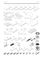
Pictures p. 11/23
1600x225x70mm
1
2 pcs
2
1 pcs
1800x115x40mm
67 pcs
1800x115x40mm
3
2 pcs
1800x45x40mm
4
1 pcs
1800x30x40mm
5
2 pcs
1800x20x40mm
6
7a
7c
7b
7d
8
4 pcs
540x60x40mm
9
2 pcs
1800x42x42mm
10
2 pcs
790x595x40mm
11
1 pcs
800x25x25mm
12
1 pcs
1690x590x80mm
13
1 pcs
14
1 pcs
15a
7b 585 x 332 x 65 mm
7c 2095x817x65mm
7d 525 x 133 x 65 mm
1 pcs
650x33x19mm
19
15b 17a 17b
2 pcs
1590x600x90mm
18
2 pcs
1530x260x40mm
14 pcs
510x70x20mm
20
3 pcs
720x20x8mm
21a
3 pcs
340x20x8mm
21b
1 pcs
22
2 pcs
24
23
4 pcs
25
4 pcs
27
4 pcs
2 pcs
26
28
2 pcs
29
1 pcs
3 pcs
30
31
4 pcs
40x40x20mm
33
12 pcs
100x30x4mm
34
1 pcs
620x115x25mm
35
2 pcs
460x60x25mm
36
2 pcs
315x60x25mm
37
2 pcs
340x40x20mm
38
4x60
64 pcs
3,5x50
19 pcs
3,2x40
47 pcs
3,5x40
26 pcs
4x70
144 pcs
3 x 25
250pcs
7a 2095x817x65mm 2157x1025x65mm
16
1 pcs
1 pcs
1 pcs
15b 650x45x16mm
15a 1660x45x16mm 17b 646 x 28 x 28 mm
17a 1690x28x28mm
1 pcs
1 pcs
1 pcs
1 pcs
1 pcs
1 pcs
1 pcs
1 pcs
1 pcs
1 pcs
3,5x30
24 pcs
3x20
2 pcs
4,5x60
8 pcs
39
2160x1135x40mm
1 pcs
2120x30x10mm
40
2 pcs
5x70
12 pcs

Pictures p. 12/23
2.1.
det 1 - 2 pcs
det 3 - 2 pcs
A - 8 pcs
R - 6 pcs
S - 12 pcs
1
1580
RS
1
A=B
B
A
110 110
110
110
3,5x30
1580
4x70
8 Pcs.
24 Pcs.
33
1
3

Pictures p. 13/23
800
2.2.
800
800800
2
4x70
2 Pcs.
110

Pictures p. 14/23
2.3.
3,5x40
16 Pcs.
3
7a
7b
7c
7d
4x70
16 Pcs.
31

Pictures p. 15/23
12
3,5x50
3 Pcs.
3,5x50
3 Pcs.
100
8
3,5x50
6 Pcs.
4x70

Pictures p. 16/23
3,2x40
40
39

Pictures p. 17/23
2.4.
4x70
4x70

Pictures p. 18/23
3,5x50
~150
~240
Optional
8 Pcs.
45
4x70

Pictures p. 19/23
23
27
25+26
24

Pictures p.20/23
2.5.
44 mm
44 mm
44 mm
4x60
4x60
14 Pcs.
2 x 4 Pcs.
17b
17a
15a
15b
10
17b
40
4x60
14 Pcs.
3,2x40
14 Pcs.
44 mm
4,5x60
16
15b
3 Pcs.
13

Pictures p. 21/23
2.6.
5x70
12 Pcs.
18
4x70
4 Pcs.
2.7.
36
35
4x60
8 Pcs.
3,5x40
4 Pcs.
37 38

Pictures p. 22/23
3,5x40
6 Pcs.
19
18
11
28
4x60
4 Pcs.
3 x 25
6 Pcs.
3,5x50
8 Pcs.

Pictures p. 23/23
2.8.
3 x 25
50 mm
30
250Pcs.
4x60
28 Pcs.
30

sentiotec GmbH | Division of Harvia Group | Wartenburger Straße 31, A-4840 Vöcklabruck
T +43 (0) 7672/22 900-50 | F -80 | [email protected] | www.sentiotec.com
-
 1
1
-
 2
2
-
 3
3
-
 4
4
-
 5
5
-
 6
6
-
 7
7
-
 8
8
-
 9
9
-
 10
10
-
 11
11
-
 12
12
-
 13
13
-
 14
14
-
 15
15
-
 16
16
-
 17
17
-
 18
18
-
 19
19
-
 20
20
-
 21
21
-
 22
22
-
 23
23
-
 24
24
-
 25
25
-
 26
26
-
 27
27
-
 28
28
-
 29
29
-
 30
30
-
 31
31
-
 32
32
-
 33
33
-
 34
34
-
 35
35
-
 36
36
-
 37
37
-
 38
38
-
 39
39
-
 40
40
-
 41
41
-
 42
42
-
 43
43
-
 44
44
-
 45
45
-
 46
46
-
 47
47
-
 48
48
-
 49
49
-
 50
50
-
 51
51
-
 52
52
-
 53
53
-
 54
54
-
 55
55
-
 56
56


Sentiotec Barrel sauna Kaski 180 Panorama Handleiding
- Type
- Handleiding
in andere talen
Gerelateerde papieren
-
Sentiotec Barrel sauna Kaski 220 View Handleiding
-
-
-
-
-
-
-
-
-
HARVIA sentiotec K3-9-N Handleiding
