Pagina wordt geladen...

CARATTERISTICHE
CARACTÉRISTIQUES
CARACTERÍSTICAS
I
F
E
2
TEN2: Motoriduttore elettromeccanico
reversibile per ante battenti. Alimentazione
12Vdc con Encoder, completo di braccio
articolato.
TEN2: Opérateur électromécanique réversible
pour portes battantes.Alimentation 12 Vcc avec
encodeuret brasarticulé
TEN2: Motorreductor electromecánico
reversible para hojas de batiente. Alimentación
12Vdc con Encoder, con brazo articulado
incorporado.
FEATURES
MERKMALE
GB
D
NL
TEN2: Reversible electromechanical gear
motor for swing gates. 12 Vdc power supply with
encoder, complete with articulatedarm.
TEN2: Elektromechanischer nicht
selbsthemmender Antrieb für Drehtore. 12Vdc-
Speisung mit Encoder, einschließlich
Gelenkarm.
TEN2: Omkeerbare elektromechanische
reductiemotor voor draaiende vleugels.
Stroomvoorziening 12Vdc met Encoder,
compleetmet geledearm.
U.M.
I
F
E
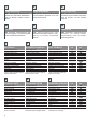
DATI TECNICI
DONNÉES TECHNIQUES
DATOS TÉCNICOS
TEN2
Tensione di alimentazione
Encoder
Lunghezza massima anta
Peso massimo anta
Coppia nominale
Corrente max assorbita
Potenza max assorbita
Movimento
Angolo max. di rotazione
Tempo apertura 90°
Temperatura di funzionamento
Grado di protezione
Grasso motore
Intermittenza lavoro
Tension d'alimentation
Encodeur
Longueur maximum vantail
Poids maximum vantail
Couple nominal
Courant max. absorbé
Puissance max. absorbée
Mouvement
Angle max. de rotation
Temps d'ouverture 90°
Température de fonctionnement
Indice de protection
Graisse moteur
Intermittence travail
Tensión de alimentación
Encoder
Longitud máxima de la hoja
Peso máximo de la hoja
Par nominal
Corriente máx. absorbida
Potencia máx. absorbida
Movimiento
Ángulo máx. de rotación
Tiempo de apertura 90°
Temperatura de funcionamiento
Grado de protección
Grasa motor
Intermitencia de funcionamiento
V 12dc
- Sì-Oui-Si
mm 1500
Kg 170
Nm 70
A5
VA 60
-
° 100°
Sec. 5*
°C -20+70
IP 44
- TS10
%60
reversibile/Réversible
reversible
* Possono variare in funzione del peso e
delle dimensioni dell'anta.
* Peuvent varier en fonction du poids et
des dimensions du vantail.
* Pueden variar según el peso y las
dimensiones de la hoja.
U.M.
GB
D
NL
TECHNICAL DATA TECHNISCHE DATEN
TECHNISCHE GEGEVENS
TEN2
Power supply voltage
Encoder
Maximum leaf length
Maximum leaf weight
Nominal torque
Max. absorbed current
Max. absorbed power
Movement
Max. angle of rotation
90° opening time
Operating temperature
Protection rating
Motor oil
Duty cycle
Versorgungsspannung
Encoder
Höchstlänge Torflügel
Höchstgewicht Torflügel
Nenndrehmoment
Höchststromaufnahme
Höchstleistungsaufnahme
Bewegung
Maximaler Drehwinkel
Öffnungszeit 90°.
Betriebstemperatur
Schutzart
Motorfett
Betriebsintermittenz
Voedingsspanning
Encoder
Maximumlengte vleugel
Maximumgewicht vleugel
Nominale koppel
Max. opgenomen stroom
Max. opgenomen vermogen
Beweging
Max. draaihoek
Tijd opening 90°
Bedrijfstemperatuur
Beschermingsklasse
Motorvet
Bedrijfscyclus
V 12dc
- Yes/Ja
mm 1500
Kg 170
Nm 70
A5
VA 60
-
° 100°
Sec. 5*
°C -20+70
IP 44
- TS10
%60
reversible/Nicht selbsthemmend
omkeerbaar
* May vary according to the weight and
dimensions of the leaf
* Können sich aufgrund des Gewichts und
der Abmessungen des Torflügels ändern.
* Dit kan variëren in functie van gewicht
en afmetingen van de vleugel.
KENMERKEN

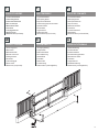
QUADRO D’INSIEME
VUE D'ENSEMBLE
DIBUJO DE CONJUNTO
I F E
OVERALL DIAGRAM GESAMTANSICHT
GB D NL
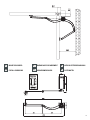
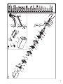
1.Linea dialimentazione
2.Interruttore generale
3.Interruttore differenziale
4.Box concentralina
5.MotoriduttoreTEN2
6.Fotocellule
7.Lampeggiatore 24V
8.Radiocomando
9.Elettroserratura (nonfornita)
1.Ligne d'alimentation
2.Interrupteur général
3.Disjoncteur différentiel
4.Coffretavec logiquede commande
5.OpérateurTEN2
6.Photocellules
7.Clignotant 24V
8.Radiocommande
9.Serrure électrique(non fournie)
1.Línea dealimentación
2.Interruptor general
3.Interruptor diferencial
4.Caja concentral
5.MotorreductorTEN2
6.Fotocélulas
7.Luz intermitente24V
8.Radiomando
9.Electrocerradura (nosuministrada)
1.Power supplyline
2.Main switch
3.Differentialswitch
4.Box withcontrol unit
5.TEN2gear motor
6.Photocells
7.24V flashinglight
8.Radio control
9.Electric lock (not provided)
1.Versorgungsleitung
2.Hauptschalter
3.Differentialschalter
4.Box mitSteuerung
5.AntriebTEN2
6.Fotozellen
7.Blinklicht 24V
8.Funksteuerung
9.Elektroschloss (nicht mitgeliefert)
1.Elektriciteitsleiding
2.Hoofdschakelaar
3.Aardlekschakelaar
4.Box metbesturingseenheid
5.ReductiemotorTEN2
6.Fotocellen
7.Knipperlicht 24V
8.Draadloze bediening
9.Elektrisch slot (niet meegeleverd)
OVERZICHTSTEKENING
3

VERIFICHE PRELIMINARI
I
CONTRÔLES PRÉLIMINAIRES
F
PRELIMINARY CHECKS
ÜBERPRÜFUNGEN UND
VORBEREITUNGEN
CONTROLES VOORAF
GB
D NL
CONTROLES PRELIMINARES
E
4
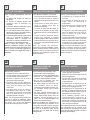
Prima di passare all'installazione assicurarsi
che:
1. La struttura del cancello sia solida ed
appropriata.
2. Le cerniere di supporto dell'anta non
presentino segni di cedimento e/o
irregolarità.
3. Il movimento dell'anta durante tutta la corsa
siasenza puntid'attrito o vibrazioni.
4. La corsa dell'anta deve essere limitata, in
apertura ed in chiusura, da arresti rivestiti in
gommasaldamente fissati al suolo.
5. La figura sottostante indica le misure minime
entro cui si consiglia di utilizzare il
motoriduttore TEN2. E' consigliato non
abbassarsi mai sotto la quota 60mm per non
pregiudicareil funzionamento del motore.
NOTA: le misure sono indicative, solo per
preparare l'installazione. Verificare quale delle
possibili soluzioni può essere applicata al vostro
caso e provare manualmente l'applicazione
prima di procedere al fissaggio della piastra o
dellestaffe.
Avantd'effectuerl'installation,s'assurer que:
1. La structure du portail est solide et adaptée.
2. 2. Les charnières de support du vantail ne
présentent pas de signes d'usure et/ou ni de
défauts.
3. Le mouvement du vantail durant toute la
course ne présente aucun point de
frottementni devibration.
4. La course du vantail doit être limitée, en
ouverture et en fermeture, par des butées
revêtuesde caoutchouc solidement fixées au
sol.
5. La figure ci-dessous indique les mesures
minimum pour lesquelles on conseille
d'utiliser l'opérateur TEN2. Il est conseillé de
ne jamais descendre sous la mesure 60 mm
pour ne pas compromettre le fonctionnement
dumoteur.
NOTE: les mesures sont indicatives,
uniquement pour préparer l'installation. Vérifier,
parmi les solutions possibles, quelle est celle qui
s'applique à votre cas et essayer manuellement
l'application avant d'effectuer la fixation de la
plaqueet despattes.
Antesde comenzarla instalación, controle que:
1. La estructura de la cancela sea firme y
adecuada.
2. 2. Las bisagras de soporte de la hoja no
tengan marcas de aflojamiento ni
irregularidades.
3. El movimiento de la hoja no tenga puntos de
fricción ni vibraciones durante toda su
carrera.
4. La carrera de la hoja debe estar limitada,
tanto en la apertura como en el cierre, por
topes revestidos de goma fijados
perfectamenteal suelo.
5. La figura de aquí abajo muestra las medidas
mínimas dentro de las cuales se aconseja
utilizar el motorreductor TEN2. Se aconseja
no instalarlo nunca a menos de 60 mm para
noperjudicar elfuncionamiento del motor.
NOTA: las medidas son indicativas sólo para
preparar la instalación. Controle las posibles
soluciones que puedan ser útiles para usted y
pruebe manualmente la aplicación antes de fijar
laplaca olos estribos.
Beforeinstalling, check that:
1. The gate's structure is suitable androbust.
2. The gate support hinges show no signs of
structuraldamage and/orirregularities.
3. No friction or vibrations occur at any time
duringthe movementof the gate.
4. The gate's travel must be delimited by
rubber-coatedstops firmly fixed to the ground
during both the opening and closing
manoeuvres.
5. The figure below shows the minimum
measurements within which use of gear
motor TEN2 is recommended. It is advisable
never to go below 60 mm so as not to
jeopardiseoperation ofthe motor.
NOTE: The measurements are guidelines only
and serve to prepare for installation. Check
which of the possible solutions are applicable to
your specific case and test the application
manuallybefore fixing the plate or brackets.
Vor der Installation istsicherzustellen, dass
1. DieTorstruktursolide undgeeignet ist
2. Die Scharniere, die dieTorflügelhalten, keine
Anzeichen auf nachgebendes Material
und/oderUnregelmäßigkeiten aufweisen
3. Das Tor sich im gesamten Lauf ohne
Reibungenoder Vibrationenbewegt
4. Der Torlauf sowohl beim Öffnen als auch
beim Schließen durch mit Gummi
ummantelte Endanschläge begrenzt wird.
Die Anschläge müssen fest im Boden
verankertsein.
5. Die unten stehende Abbildung zeigt die
Mindestabmessungen an, mit denen der
Antrieb TEN2 benützt werden sollte. Wir
empfehlen, nie unter das Maß 60 mm zu
gehen, um die Funktionstüchtigkeit des
Motorsnicht zu beeinträchtigen.
Anmerkung: Die Maße sind unverbindlich und
dienen zur Vorbereitung der Installation. Es ist
zu überprüfen, welche der möglichen Lösungen
im konkreten Fall angewandt werden kann,
dazu wird die Anwendung zuerst manuell
ausprobiert, bevor die Platte oder die Bügel
befestigtwerden.
Voordat u met het installeren begint, dient u zich
vanhet volgendete vergewissen:
1. De structuur van de poort is sterk en voor het
gebruiksdoelgeëigend.
2. De scharnieren van de steun van de vleugel
vertonen geen tekenen van breuk en/of
onregelmatigheden.
3. De vleugel tijdens de manoeuvre over de
gehele afstand van het traject geen
wrijvingspuntenof trillingen vertoont.
4. De beweging van de vleugel wordt op de
openings- en sluitpositie begrensd door van
een rubberen deklaag voorziene stops die
stevigop debodem zijn bevestigd.
5. Op de afbeelding hieronder staan de
minimumafmetingen waarbinnen de
reductiemotor TEN2 het best kan worden
gebruikt. Het is raadzaam nooit onder de 60
mm te komen om de goede werking van de
motor niet in gevaar te brengen.
N.B.: de afmeting vormen slechts een aanwijzing
bij de voorbereiding voor de installatie. Ga na
welke oplossing van toepassing is op uw geval
en test deze handmatig uit voordat u de plaat of
de beugels gaat bevestigen.
Pagina wordt geladen...
Pagina wordt geladen...

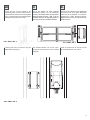
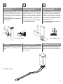
ASSEMBLY PROCEDURE
MONTAGEVERFAHREN
MONTAGEPROCEDURE
GB
D NL
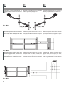
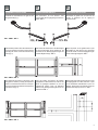
Assemble the articulated arm for right and left
fittingof theexit (Fig. 1).
Den Gelenkarm für eine Rechts- oder
Linksmontage des Ausgangswegs zusammen-
setzen.ABB.1.
Assembleer de gelede arm om hem aan de
rechter- of linkerkant van de uitgang te
monteren.AFB.1.
Determine the position of the articulated arms on
the cross members by drawing a horizontal line
indicating the centre of the front bracket fixing
holes(Fig. 2).
Die Position der Gelenkarme in den Querträgern
mit einer waagrechten Achse bestimmen, die
das Zentrum der Befestigungsbohrungen des
vorderenBügels anzeigt–ABB. 2.
Bepaal de plaats van de gelede armen op de
dwarsbalken en trek daarvoor een horizontale
lijn die het midden van de bevestigingsboringen
vande voorbeugelaangeeft –AFB.2.
Now determine the position of the holes of the
fixing plate for TEN2 by marking the respective
centre-to-centre distances at 93 mm on the post.
Now mark the distances between the respective
holesat 67mm (Fig. 3).
Dann die Position der Bohrung der Befesti-
gungsplatte für TEN2 bestimmen, indem an der
Säule die jeweiligen Abstände von 93 mm
angezeichnet werden. Dann die Distanzen
zwischen den jeweiligen Bohrungen bei 67 mm
anzeichnen.ABB.3.
Bepaal daarna de plaats van de boringen van de
bevestigingsplaat voor TEN2, waarvoor u op de
zuil de betreffende hartafstanden op 93 mm
aftekent. Teken daarna de afstanden tussen de
betreffendeboringenop 67mm af –AFB.3.
FIG.1.-ABB.1 -ABF. 1
FIG.2 -ABB. 2 -ABF. 2
FIG.3 -ABB. 3 -ABF. 3
7
Pagina wordt geladen...

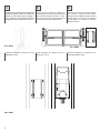
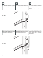
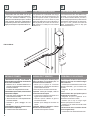
Choose the type of screw suitable for the
material the post is made of and drill four holes.
Insert two M6 nuts into the rear of the fixing plate
(Fig. 4). Use the screws to secure the fixing plate
tothe postin the position shown in Fig. 5.
Die für das Material der Säule geeignete
Schraubenart wählen und vier Bohrungen
ausführen. Zwei Muttern M6 auf der Rückseite der
Befestigungsplatte einsetzen – ABB. 4. Mit den
gewählten Schrauben die Befestigungsplatte an
die Säule in der Position lautABB. 5 befestigen.
Kies de voor het materiaal van de zuil geëigende
schroeven en boor de vier gaten. Breng twee
moeren M6 op de achterkant van de bevesti-
gingsplaat aan – AFB.4. Bevestig de bevesti-
gingsplaat met de schroeven op zijn plaats zoals
opAFB.5te zienis.
Insert the gear motor and secure it using the
M6x90TCEIscrews (Fig.6).
Den Antrieb einsetzen und mit den Innen-
sechskantzylinderkopfschrauben M6x90
befestigen.
Plaats de reductiemotor en zet hem met de
schroevenM6x90TCEI vast –AFB.6.
FIG.6 -ABB. 6 -ABF. 6
GB
DNL
9
FIG.5 -ABB. 5 -ABF. 5
FIG.4 -ABB. 4 -ABF. 4
Pagina wordt geladen...

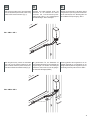
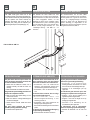
After securing the gear motor, fit the articulated
arm onto the motor's splined shaft. Fasten using
aM8X15TCEI screwand washer. (Fig.7).
Nachdem der Antrieb befestigt wurde, den
Gelenkarm an der Keilwelle des Motors
einsetzen. Mit Innensechskantzylinder-
kopfschraube M8x15 und diesbezüglicher
Scheibebefestigen. ABB.7 befestigen.
Wanneer de reductiemotor is bevestigd, brengt
u de gelede arm op de van groeven voorziene as
van de reductiemotor aan. Bevestig deze met
schroefM8X15TCEI plusborgring. AFB.7.
With the gate closed, position the articulated
arm at its point of maximum extension on the
gate crossbeam. Mark the position of the holes,
thendrill andfasten with suitable screws (Fig. 8).
Bei geschlossener Tür, den Gelenkarm auf
seine weiteste Ausdehnung am Querträger des
Flügels bringen. Die Position der Bohrungen
anzeichnen, dann bohren und mit den geeigne-
tenSchrauben befestigen(ABB. 8).
Plaats bij gesloten deur de gelede arm zo ver
mogelijk uitgestrekt op de dwarsbalk van de
vleugel.Tekende plaats van de gaten af, boor ze
enbevestig zemet de juiste schroeven.AFB.8.
FIG.7 -ABB. 7 -ABF.7
FIG.8 -ABB. 8 -ABF.8
GB
DNL
11
Pagina wordt geladen...

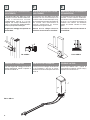
FITTING ELECTRIC LOCK
(NOT PROVIDED)
MONTAGE ELEKTROSCHLOSS
(NICHT MITGELIEFERT)
MONTAGE ELEKTRISCH SLOT
(NIET MEEGELEVERD)
The TEN2 series gear motors are of the
reversible type with self-locking articulated arm.
If you wish to fit an electric lock, Figs. 9 and 10
show two examples of common installations. It
is most important to observe the distances
indicatedin thesefigures.
Carry out all the wiring work as described in
themanual E224.
Die Antriebe der Serie TEN2 sind nicht
selbsthemmend und weisen einen selbstsper-
renden Gelenkarm auf. Wenn ein Elek-
troschloss montiert werden soll, zeigen die
Abb. 9 und 10 die zwei üblichsten Installation-
sbeispiele. Die Maße in den genannten
Abbildungensind unbedingteinzuhalten.
Alle Verkabelungen wie im bedienungsanle-
itungE224 gezeigtausführen.
De reductiemotoren van de serie TEN2
behoren tot het omkeerbare type met zelfblok-
kerende gelede arm. Indien u een elektrisch slot
zou willen monteren, vindt u op afb. 9 en 10 een
voorbeeld van de twee meeste voorkomende
manieren van installatie. Wij raden u aan de op
deze afbeeldingen aangegeven waarden
nauwgezetin achtte nemen.
Voer de bekabeling uit zoals dat in handlei-
dingE224 isaangegeven.
FIG.9 -ABB. 9 -ABF.9 FIG.10 -ABB. 10 -ABF.10
DEN DECKEL EINSETZEN
After completing the wiring and start-up the
system, fit the cover and secure it with a screw
(Fig.13).
Nachdem alle Verkabelungen und die
Inbetriebnahme der Anlage ausgeführt wurden,
den Deckel einsetzen und mit der Schraube der
ABB.13 befestigen.
Wanneer alle kabels zijn aangebracht en de
installatie in bedrijf is gesteld, brengt u de
dekplaat aan en zet hem met de schroef vast
afb.13.
FIT COVER
AANBRENGEN VAN DE DEKPLAAT
FIG.13 -ABB. 13 -ABF.13
GB
DNL
13
Pagina wordt geladen...

MANUAL OPERATION
MANUELLER BETRIEB
HANDMATIGE BEDIENING
The TEN2 series gear motors are of the
reversible type with self-locking articulated arm.
In the absence of electricity, the pedestrian gate
can be opened and closed manually by
releasing the electric lock using the key (if
provided) and pulling the arm towards you.
Movethe gateto open it completely (Fig. 14).
Die Antriebe der Serie TEN2 sind nicht
selbsthemmend und weisen einen selbstsper-
renden Gelenkarm auf. Bei Stromausfall kann
von Hand eingegriffen werden, um den
Gehflügel zu öffnen und zu schließen, indem
das Elektroschloss (wenn vorhanden) gelöst
und der gebogene Arm zu sich gezogen wird.
Dann auf den Flügel einwirken, um eine
vollständige Öffnung – laut ABB. 14 – zu
erreichen.
De reductiemotoren van de serie TEN2
behoren tot het omkeerbare type met zelfblok-
kerende gelede arm. In geval van stroomuitval
kunt u de voetgangersvleugel handmatig
openen en sluiten door het elektrische slot
(indien aanwezig) te ontgrendelen en de
gebogen arm naar zich toe te trekken. Open de
vleugeldaarna helemaal,AFB.14.
FIG.14 -ABB. 14 -ABF.14
STÖRUNGEN UND ABHILFEN
The gear motor does not open or does not
close, the electric motor does not work, and
nonoise orvibration canbe felt.
The gear motor opens haltingly and does not
performthe completemovement.
The gear motor performs the reverse
operation(closing insteadof opening).
a. Check that the electronic control unit is
powered correctly and that the fuses are
working.
b. Make sure that the connections are correct.
a. Make sure that the speed setting on the
controlunit iscorrect.
b. Make sure there is nothing obstructing the
movementof thegate.
c. Check that the encoder cables are wired
correctly.
a. Invert the motor's phase wires.
Der Antrieb öffnet und schließt nicht, der E-
Motor funktioniert nicht und man bemerkt
daherweder einGeräusch nochVibrationen.
Der Antrieb öffnet ruckweise, aber es erfolgt
keinevollständige Bewegung.
Der Antrieb führt die umgekehrte Bewegung
aus(Schließung stattÖffnung).
a. Sicherstellen, dass die elektronische
Steuerung ordnungsgemäß gespeist wird
unddie Sicherungenfunktionstüchtig sind.
b. Sicherstellen, dass die Anschlüsse richtig
sind.
a.Sicherstellen, dass die
Geschwindigkeitseinstellung in der
Steuerungkorrekt ist.
b. Sicherstellen, dass keine Hindernisse die
BewegungdesTorflügels stören.
c. Die korrekte Verkabelung der Encoder-Kabel
prüfen.
a. Die Phasenleiter des Motors umkehren.
De poort gaat open noch dicht, de elektromotor
werktniet,erisgeenenkelgeluidoftrilling
De reductiemotor gaat met horten open, maar
erwordtgeencompletemanoeuvreuitgevoerd.
De reductiemotor voert de tegengestelde
manoeuvreuit(sluitinginplaatsvanopening).
a. Controleer of de elektronische
besturingseenheid naar behoren van stroom
wordtvoorzienenofdezekeringenintactzijn.
b. Controleer of de aansluitingen juist zijn
uitgevoerd.
a. Vergewis u ervan dat de snelheid juist is
afgesteldopdebesturingseenheid;
b. Vergewis u ervan dat de vleugel niet in zijn
bewegingwordtgehinderd.
c. Controleer of de bekabeling van de
encoderkabelsjuistisuitgevoerd.
a. Verwissel de fasedraden van de motor met
elkaar.
PROBLEM SOLVING STORINGEN EN OPLOSSINGEN
GB
DNL
15

IFE
SMALTIMENTO MISE AU REBUT ELIMINACIÓN
Questo prodotto è formato da vari
componenti che potrebbero a loro volta
contenere sostanze inquinanti. Non
disperdere nell'ambiente! Informarsi sul
sistema di riciclaggio o smaltimento del
prodotto attenendosi alle norme di legge
vigentialivello locale.
Ce produit est constitué de divers
composants qui pourraient à leur tour
contenir des substances polluantes. Ne
pas jeter dans la nature ! S'informer sur le
système de recyclage ou de mise au rebut
du produit en respectant les normes
localesenvigueur.
Este producto está formado de varios
componentes que, a su vez, podrían
contener sustancias contaminantes. ¡No
los abandone en el medio ambiente!
Infórmese sobre el sistema de reciclaje o
eliminación del producto, respetando las
normasvigenteslocales.
16
GB D NL
DISPOSAL ENTSORGUNG AFVALVERWERKING
This product consists of various
components which may contain polluting
substances. Do not release to the
environment! Find out about the
procedures for recycling or disposing of
the product in accordance with locally
applicablelaws.
Dieses Produkt besteht aus
verschiedenen Bestandteilen, die
Schadstoffe enthalten könnten. Nicht in
der Umwelt wegwerfen! Informieren Sie
sich über die Systeme zum Recycling
oder zur Entsorgung des Produkts und
halten Sie sich an die örtlich geltenden
Vorschriften.
Dit product bestaat uit verschillende
onderdelen die op hun beurt
verontreinigende stoffen zouden kunnen
bevatten. Laat ze niet in het milieu achter!
Win inlichtingen in over het
recyclingsysteem of over de
afvalverwerking van het product en houd
u aan de wettelijke voorschriften zoals die
inuwlandvantoepassing zijn.
Pagina wordt geladen...

18
IFE
DICHIARAZIONE CE DÉCLARATIONS CE
DECLARACIÓN DE CONFORMIDAD CE
Il fabbricante: Telcoma srl - Via L. Manzoni, 11 31015 - Z.I.
Campidui- Conegliano (TV) - ITALY
DICHIARA che il prodotto è conforme alle condizioni delle
seguenti direttive CEE:
e che: sono state applicate le seguenti (parti/clausole) di
norme armonizzate:
Directive 73/23/EEC, Directive
93/68/EECLow Voltage
Directive89/336/EEC, Directive 92/31/EEC
Directive92/31/EEC Electromagnetic Compatibility
EN60335-1, EN60204-1, EN 61000-6-
3,EN61000-6-1
andfor the only applicable partsthe norms
EN12445e EN12453
Lefabricant: Telcoma srl
Via L. Manzoni 11, Z.I. Campidui - 31015 Conegliano (TV)
ITALIE, DÉCLARE que le produit est conforme aux
conditionsdes directives CEE suivantes:
et que les (parties/clauses) de normes harmonisées
suivantesont été appliquées:
Directive73/23/EEC, Directive 93/68/EEC Low Voltage
Directive89/336/EEC, Directive 92/31/EEC
Directive92/31/EEC Electromagnetic Compatibility
EN60335-1,EN60204-1, EN 61000-6-3, EN61000-6-1
andfor the only applicable partsthe norms
EN12445e EN12453
Elfabricante: Telcoma srl
Via L. Manzoni, 11 31015 - Z.I. Campidui - Conegliano (TV) -
ITALIA - DECLARA que el producto es conforme a las
condiciones de las siguientes directivas CEE:
y que: se han aplicado las siguientes partes/cláusulas de las
normas armonizadas:
Directive
73/23/EEC,Directive 93/68/EEC Low Voltage
Directive89/336/EEC, Directive 92/31/EEC
Directive92/31/EEC Electromagnetic Compatibility
EN60335-1, EN60204-1, EN 61000-
6-3,EN61000-6-1
andfor the only applicable partsthe norms
EN12445e EN12453
DICHIARAZIONE DEL
FABBRICANTE
(Direttiva98/37 CEEAllegato II, ParteB)
Il prodotto è costruito per essere incorporati in una macchina
o per essere assemblati con altri macchinari per costruire
unamacchina considerata dalla Direttiva 98/37CEE
E inoltre dichiara che non è consentito mettere in servizio il
prodottofino a che la macchinain cui sarannoincorporati odi
cuidiverranno componenti siastata identificata e ne siastata
dichiarata la conformità alle condizioni della Direttiva 98/87
CEE e alla legislazione nazionaleche lo traspone, vale a dire
fino a che il prodotto di cui alla presente dichiarazione non
formiun complesso unico con lamacchina finale.
Conegliano,lì
Legalrepresentative
AugustoSilvio Brunello
22/10/2008
(Directive98/37 CEEAnnexe II, PartieB)
Le produit est construit pour être incorporé dans une
machine ou pour être assemblé avec d'autres machines
pour constituer une machine couverte par la Directive 98/37
CEE.
Il déclare également qu'il est interdit de mettre en service le
produit tant que la machine dans laquelle il sera incorporé ou
dont il deviendra un composant n'a pas été identifiée et
déclarée conforme aux conditions de la Directive 98/87 CEE
et à la législation nationale qui la transpose, c'est-à-dire tant
que le produit objet de la présente déclaration ne forme pas
unensemble unique avec la machinefinale.
Conegliano,le
Legalrepresentative
AugustoSilvio Brunello
22/10/2008
(Directiva98/37 CEEAnexo II, ParteB)
El producto ha sido fabricado para ser incorporado en una
máquina o para ser ensamblado con otras máquinas para
construir una máquina considerada por la Directiva 98/37
CEE
También declara que no está permitido poner en
funcionamiento el producto hasta que la máquina en que
seránincorporados o ala que pertenecerán, sea identificada
y sea declarada de conformidad con las condiciones de la
Directiva 98/87 CEE y con la legislación nacional vigente, es
decir hasta que el producto al que se refiere esta
declaración,forme un grupo único conla máquinafinal.
Conegliano,
Legalrepresentative
AugustoSilvio Brunello
22/10/2008
DÉCLARATION DU FABRICANT DECLARACIÓN DEL FABRICANTE
GB D NL
EC DECLARATION EG-ERKLÄRUNG EG-VERKLARING
Themanufacturer: Telcoma srl
Via L. Manzoni, 11 31015 - Z.I. Campidui - Conegliano (TV) -
ITALY - DECLARES that the product complies with the
requirements of the following EEC directives:
and that: the following parts/clauses of harmonised
standards have been adopted:
Directive
73/23/EEC,Directive 93/68/EEC Low Voltage
Directive89/336/EEC, Directive 92/31/EEC
Directive92/31/EEC Electromagnetic Compatibility
EN60335-1, EN60204-1, EN
61000-6-3,EN61000-6-1
andfor the only applicable partsthe norms
EN12445e EN12453
Der Hersteller: TELCOMA S.r.l. - Via L. Manzoni, 11 31015 -
Z.I. Campidui - Conegliano (TV) - ITALY - ERKLÄRT, dass
das Produkt den Vorschriften der folgenden EWG-
Richtlinien entspricht:
und dass die folgenden zugehörigen Normen
(Teile/Klauseln) angewendet wurden:
Directive 73/23/EEC, Directive
93/68/EECLow Voltage
Directive89/336/EEC, Directive 92/31/EEC
Directive92/31/EEC Electromagnetic Compatibility
EN60335-1,
EN60204-1,EN 61000-6-3, EN61000-6-1
andfor the only applicable partsthe norms
En12445e En12453
De fabrikant: Telcoma srl - Via L. Manzoni, 11 31015 - Z.I.
Campidui- Conegliano (TV) - ITALY
VERKLAART dat het product in overeenstemming is met de
voorwaarden van de volgende EEG-richtlijnen:
en dat: zijn toegepast de volgende (delen/clausules) van de
geharmoniseerde normen:
Directive
73/23/EEC,Directive 93/68/EEC Low Voltage
Directive89/336/EEC, Directive 92/31/EEC
Directive92/31/EEC Electromagnetic Compatibility
EN60335-1, EN60204-1, EN
61000-6-3,EN61000-6-1
andfor the only applicable partsthe norms
EN12445e EN12453
MANUFACTURER'S
DECLARATION
(Directive98/37 EECAnnex II, PartB)
Theproduct is designed to beincorporated in a machine orto
be assembled with other machinery to make up a machine
consideredby the Directive 98/37 EEC.
It also declares that the product must not be put into service
until the machinery in which it is to be incorporated or of
which it is to become a component has been identified and
declared in conformity with the Directive 98/87 EEC and with
the national legislation that enacts it, in other words until the
product referred to in this declaration forms a single unit with
thefinal machinery.
Conegliano,
Legalrepresentative
AugustoSilvio Brunello
22/10/2008
(Richtlinie98/37 EWGAnlage II,TeilB)
Das Produkt wurde gebaut, um in eine Maschine integriert
oder um mit anderen Maschinen zusammengebaut zu
werden, um eine Maschine laut Richtlinie 98/37 EWG zu
bilden.
Außerdem erklärt er, dass das Produkt nicht in Betrieb
genommenwerden darf, bisdie Maschine, in die esintegriert
wird oder deren Teil es wird, identifiziert und gemäß der
Richtlinie 98/37 EWG und der nationalen Gesetzgebung als
konform erklärt wird, d.h. bis das Produkt dieser Erklärung
nicht eine einzige Gruppe mit der endgültigen Maschine
bildet.
Conegliano,den 22/10/2008.
Legalrepresentative
AugustoSilvio Brunello
(Richtlijn98/37EEGBijvoegselII,DeelB)
Ditproductisgemaakt om ineenmachineingebouwd te wordenof
met andere machines geassembleerd te worden teneinde een
machine te vormen op grond van de Richtlijn 98/37/ EEG En
bovendienverklaarthijdathetnietgeoorloofdisditproductinbedrijf
te stellen zolang demachine waarinde onderdelenzullen worden
ingebouwd of waarvan zij een onderdeel zullen vormen niet
geïdentificeerd is en waarvoor niet verklaard is dat die in
overeenstemming is met de voorwaarden van de Richtlijn 98/87
EEGen metde nationalewetgeving, waarin diegeïmplementeerd
is, dat wil zeggen zolang het product onderwerp van deze
verklaringnietééngeheelvormtmetdeuiteindelijkemachine.
Conegliano,
Legalrepresentative
AugustoSilvioBrunello
22/10/2008.
ERKLÄRUNG DES HERSTELLERS VERKLARING VAN DE FABRIKANT
Pagina wordt geladen...

Telcoma srl - Via L. Manzoni, 11 - Z.I. Campidui
31015 Conegliano - (TV) Italy - Tel. +39 0438-451099
Fax +39 0438-451102 - Part. IVA 00809520265
http://www.telcoma.it E-mail: info@telcoma .it
CERTIFICATO DI GARANZIA
IFE
La presente garanzia copre gli eventuali guasti e/o anomalie
dovuti a difetti e/o vizi di fabbricazione. La garanzia decade
automaticamente in caso di manomissione o errato utilizzo
delprodotto.
Durante il periodo di garanzia, la ditta Telcoma srl s'impegna
a riparare e/o sostituire le parti difettate e non manomesse.
Restano a intero ed esclusivo carico del cliente il diritto di
chiamata, nonché le spese di rimozione, imballo e trasporto
delprodotto per la riparazione esostituzione.
La présente garantie couvre les pannes et/ou les anomalies
éventuelles dues à des défauts et/ou vices de fabrication. La
garantie cesse automatiquement en cas de modification ou
d'utilisationincorrecte du produit.
Durant la période de garantie, la société TELCOMA S.r.l.
s'engage à réparer et/ou à remplacer les parties
défectueuses et non modifiées. Le forfait déplacement, ainsi
que les frais de retrait, d'emballage et de transport du produit
pour la réparation ou le remplacement restent entièrement
etexclusivement à la charge duclient.
La presente garantía cubre las averías o anomalías
provocadas por defectos o vicios de fabricación. La garantía
pierde automáticamente validez en el caso de
modificacioneso uso incorrecto del producto.
Durante el período de garantía, Telcoma srl se obliga a
reparar y/o sustituir las piezas defectuosas y que no hayan
sido modificadas. Quedan a cargo del cliente el derecho de
llamada y los gastos de desmontaje, embalaje y transporte
delproducto para su reparación ysustitución.
GARANZIA GARANTIE GARANTÍA
GB D NL
This warranty covers faults and malfunctions caused by
manufacturing defects. The warranty is automatically
invalidated in the event of tampering or improper use of the
product.
During the warranty period the company Telcoma srl
undertakes to repair or replace defective parts that have not
been tampered with. Call-out charges along with expenses
of removal, packaging and transport of the product for repair
orreplacement are to be paidby thecustomer.
Die vorliegende Garantie gilt für eventuelle Defekte
und/oder Störungen aufgrund von Fabrikationsfehlern
und/oder -mängeln, Die Garantie wird im Falle von
Handhabung oder falscher Benutzung des Produktes
automatischungültig.
In der Garantiezeit verpflichtet sich die Firma TELCOMA
S.r.l. zur Reparatur und/oder zum Ersatz defekter und nicht
manipulierter Teile. Ausschließlich und voll zu Lasten des
Kunden gehen die Abrufgebühr sowie die Kosten für die
Demontage, die Verpackung und den Transport des
Produktsim Falle einer Reparatur odereines Ersatzes.
Met deze garantie worden eventuele defecten en/of
storingen gedekt die het gevolg zijn van een gebrekkige of
ondeugdelijke constructie. De garantie komt automatisch te
vervallen in geval van onrechtmatige wijzigingen aan of
onjuist gebruik van het product. Tijdens de garantieperiode
verplicht de firma Telcoma zich gebrekkige en ongewijzigde
delen te repareren en/of te vervangen. De voorrijkosten
alsook kosten voor verwijdering, verpakking en vervoer van
het product in verband met reparatie en vervanging komen
geheelen uitsluitend ten laste vande klant.
WARRANTY GARANTIE GARANTIE
PRODOTTO
DATA D’INSTALLAZIONE
TIMBRO E/O FIRMA DELL’INSTALLATORE
%
*
Documenttranscriptie
I F E CARATTERISTICHE CARACTÉRISTIQUES CARACTERÍSTICAS TEN2: Motoriduttore elettromeccanico reversibile per ante battenti. Alimentazione 12Vdc con Encoder, completo di braccio articolato. TEN2: Opérateur électromécanique réversible pour portes battantes. Alimentation 12 Vcc avec encodeur et bras articulé TEN2: Motorreductor electromecánico reversible para hojas de batiente. Alimentación 12Vdc con Encoder, con brazo articulado incorporado. D NL GB MERKMALE FEATURES TEN2: Reversible electromechanical gear motor for swing gates. 12 Vdc power supply with encoder, complete with articulated arm. I KENMERKEN TEN2: Elektromechanischer nicht selbsthemmender Antrieb für Drehtore. 12VdcSpeisung mit Encoder, einschließlich Gelenkarm. F TEN2: Omkeerbare elektromechanische reductiemotor voor draaiende vleugels. Stroomvoorziening 12Vdc met Encoder, compleet met gelede arm. E DATI TECNICI DONNÉES TECHNIQUES DATOS TÉCNICOS U.M. TEN2 Tensione di alimentazione Encoder Lunghezza massima anta Peso massimo anta Coppia nominale Corrente max assorbita Potenza max assorbita Movimento Tension d'alimentation Encodeur Longueur maximum vantail Poids maximum vantail Couple nominal Courant max. absorbé Puissance max. absorbée Mouvement Tensión de alimentación Encoder Longitud máxima de la hoja Peso máximo de la hoja Par nominal Corriente máx. absorbida Potencia máx. absorbida Movimiento V mm Kg Nm A VA - Angolo max. di rotazione Tempo apertura 90° Temperatura di funzionamento Grado di protezione Grasso motore Intermittenza lavoro Angle max. de rotation Temps d'ouverture 90° Température de fonctionnement Indice de protection Graisse moteur Intermittence travail Ángulo máx. de rotación Tiempo de apertura 90° Temperatura de funcionamiento Grado de protección Grasa motor Intermitencia de funcionamiento ° Sec. °C IP % 12dc Sì-Oui-Si 1500 170 70 5 60 reversibile/Réversible reversible 100° 5* -20+70 44 TS10 60 * Possono variare in funzione del peso e delle dimensioni dell'anta. * Peuvent varier en fonction du poids et des dimensions du vantail. * Pueden variar según el peso y las dimensiones de la hoja. U.M. TEN2 12dc Yes/Ja 1500 170 70 5 60 GB D NL TECHNICAL DATA TECHNISCHE DATEN TECHNISCHE GEGEVENS Power supply voltage Encoder Maximum leaf length Maximum leaf weight Nominal torque Max. absorbed current Max. absorbed power Movement Versorgungsspannung Encoder Höchstlänge Torflügel Höchstgewicht Torflügel Nenndrehmoment Höchststromaufnahme Höchstleistungsaufnahme Bewegung Voedingsspanning Encoder Maximumlengte vleugel Maximumgewicht vleugel Nominale koppel Max. opgenomen stroom Max. opgenomen vermogen Beweging V mm Kg Nm A VA - Max. angle of rotation 90° opening time Operating temperature Protection rating Motor oil Duty cycle Maximaler Drehwinkel Öffnungszeit 90°. Betriebstemperatur Schutzart Motorfett Betriebsintermittenz Max. draaihoek Tijd opening 90° Bedrijfstemperatuur Beschermingsklasse Motorvet Bedrijfscyclus ° Sec. °C IP % * May vary according to the weight and dimensions of the leaf * Können sich aufgrund des Gewichts und der Abmessungen des Torflügels ändern. * Dit kan variëren in functie van gewicht en afmetingen van de vleugel. 2 reversible/Nicht selbsthemmend omkeerbaar 100° 5* -20+70 44 TS10 60 I F E QUADRO D’INSIEME VUE D'ENSEMBLE DIBUJO DE CONJUNTO 1. Linea di alimentazione 2. Interruttore generale 3. Interruttore differenziale 4. Box con centralina 5. Motoriduttore TEN2 6. Fotocellule 7. Lampeggiatore 24V 8. Radiocomando 9. Elettroserratura (non fornita) 1. Ligne d'alimentation 2. Interrupteur général 3. Disjoncteur différentiel 4. Coffret avec logique de commande 5. Opérateur TEN2 6. Photocellules 7. Clignotant 24 V 8. Radiocommande 9. Serrure électrique (non fournie) 1. Línea de alimentación 2. Interruptor general 3. Interruptor diferencial 4. Caja con central 5. Motorreductor TEN2 6. Fotocélulas 7. Luz intermitente 24V 8. Radiomando 9. Electrocerradura (no suministrada) D NL GB OVERALL DIAGRAM 1. Power supply line 2. Main switch 3. Differential switch 4. Box with control unit 5. TEN2 gear motor 6. Photocells 7. 24V flashing light 8. Radio control 9. Electric lock (not provided) GESAMTANSICHT 1. Versorgungsleitung 2. Hauptschalter 3. Differentialschalter 4. Box mit Steuerung 5.Antrieb TEN2 6. Fotozellen 7. Blinklicht 24V 8. Funksteuerung 9. Elektroschloss (nicht mitgeliefert) OVERZICHTSTEKENING 1. Elektriciteitsleiding 2. Hoofdschakelaar 3.Aardlekschakelaar 4. Box met besturingseenheid 5. Reductiemotor TEN2 6. Fotocellen 7. Knipperlicht 24V 8. Draadloze bediening 9. Elektrisch slot (niet meegeleverd) 3 I VERIFICHE PRELIMINARI Prima di passare all'installazione assicurarsi che: 1. La struttura del cancello sia solida ed appropriata. 2. Le cerniere di supporto dell'anta non presentino segni di cedimento e/o irregolarità. 3. Il movimento dell'anta durante tutta la corsa sia senza punti d'attrito o vibrazioni. 4. La corsa dell'anta deve essere limitata, in apertura ed in chiusura, da arresti rivestiti in gomma saldamente fissati al suolo. 5. La figura sottostante indica le misure minime entro cui si consiglia di utilizzare il motoriduttore TEN2. E' consigliato non abbassarsi mai sotto la quota 60mm per non pregiudicare il funzionamento del motore. NOTA: le misure sono indicative, solo per preparare l'installazione. Verificare quale delle possibili soluzioni può essere applicata al vostro caso e provare manualmente l'applicazione prima di procedere al fissaggio della piastra o delle staffe. GB PRELIMINARY CHECKS Before installing, check that: 1. The gate's structure is suitable and robust. 2. The gate support hinges show no signs of structural damage and/or irregularities. 3. No friction or vibrations occur at any time during the movement of the gate. 4. The gate's travel must be delimited by rubber-coated stops firmly fixed to the ground during both the opening and closing manoeuvres. 5. The figure below shows the minimum measurements within which use of gear motor TEN2 is recommended. It is advisable never to go below 60 mm so as not to jeopardise operation of the motor. NOTE: The measurements are guidelines only and serve to prepare for installation. Check which of the possible solutions are applicable to your specific case and test the application manually before fixing the plate or brackets. 4 F E CONTRÔLES PRÉLIMINAIRES CONTROLES PRELIMINARES Avant d'effectuer l'installation, s'assurer que: 1. La structure du portail est solide et adaptée. 2. 2. Les charnières de support du vantail ne présentent pas de signes d'usure et/ou ni de défauts. 3. Le mouvement du vantail durant toute la course ne présente aucun point de frottement ni de vibration. 4. La course du vantail doit être limitée, en ouverture et en fermeture, par des butées revêtues de caoutchouc solidement fixées au sol. 5. La figure ci-dessous indique les mesures minimum pour lesquelles on conseille d'utiliser l'opérateur TEN2. Il est conseillé de ne jamais descendre sous la mesure 60 mm pour ne pas compromettre le fonctionnement du moteur. NOTE: les mesures sont indicatives, uniquement pour préparer l'installation. Vérifier, parmi les solutions possibles, quelle est celle qui s'applique à votre cas et essayer manuellement l'application avant d'effectuer la fixation de la plaque et des pattes. D ÜBERPRÜFUNGEN UND VORBEREITUNGEN Vor der Installation ist sicherzustellen, dass 1. Die Torstruktur solide und geeignet ist 2. Die Scharniere, die die Torflügel halten, keine Anzeichen auf nachgebendes Material und/oder Unregelmäßigkeiten aufweisen 3. Das Tor sich im gesamten Lauf ohne Reibungen oder Vibrationen bewegt 4. Der Torlauf sowohl beim Öffnen als auch beim Schließen durch mit Gummi ummantelte Endanschläge begrenzt wird. Die Anschläge müssen fest im Boden verankert sein. 5. Die unten stehende Abbildung zeigt die Mindestabmessungen an, mit denen der Antrieb TEN2 benützt werden sollte. Wir empfehlen, nie unter das Maß 60 mm zu gehen, um die Funktionstüchtigkeit des Motors nicht zu beeinträchtigen. Anmerkung: Die Maße sind unverbindlich und dienen zur Vorbereitung der Installation. Es ist zu überprüfen, welche der möglichen Lösungen im konkreten Fall angewandt werden kann, dazu wird die Anwendung zuerst manuell ausprobiert, bevor die Platte oder die Bügel befestigt werden. Antes de comenzar la instalación, controle que: 1. La estructura de la cancela sea firme y adecuada. 2. 2. Las bisagras de soporte de la hoja no tengan marcas de aflojamiento ni irregularidades. 3. El movimiento de la hoja no tenga puntos de fricción ni vibraciones durante toda su carrera. 4. La carrera de la hoja debe estar limitada, tanto en la apertura como en el cierre, por topes revestidos de goma fijados perfectamente al suelo. 5. La figura de aquí abajo muestra las medidas mínimas dentro de las cuales se aconseja utilizar el motorreductor TEN2. Se aconseja no instalarlo nunca a menos de 60 mm para no perjudicar el funcionamiento del motor. NOTA: las medidas son indicativas sólo para preparar la instalación. Controle las posibles soluciones que puedan ser útiles para usted y pruebe manualmente la aplicación antes de fijar la placa o los estribos. NL CONTROLES VOORAF Voordat u met het installeren begint, dient u zich van het volgende te vergewissen: 1. De structuur van de poort is sterk en voor het gebruiksdoel geëigend. 2. De scharnieren van de steun van de vleugel vertonen geen tekenen van breuk en/of onregelmatigheden. 3. De vleugel tijdens de manoeuvre over de gehele afstand van het traject geen wrijvingspunten of trillingen vertoont. 4. De beweging van de vleugel wordt op de openings- en sluitpositie begrensd door van een rubberen deklaag voorziene stops die stevig op de bodem zijn bevestigd. 5. Op de afbeelding hieronder staan de minimumafmetingen waarbinnen de reductiemotor TEN2 het best kan worden gebruikt. Het is raadzaam nooit onder de 60 mm te komen om de goede werking van de motor niet in gevaar te brengen. N.B.: de afmeting vormen slechts een aanwijzing bij de voorbereiding voor de installatie. Ga na welke oplossing van toepassing is op uw geval en test deze handmatig uit voordat u de plaat of de beugels gaat bevestigen. GB ASSEMBLY PROCEDURE Assemble the articulated arm for right and left fitting of the exit (Fig. 1). D NL MONTAGEVERFAHREN MONTAGEPROCEDURE Den Gelenkarm für eine Rechts- oder Linksmontage des Ausgangswegs zusammensetzen.ABB. 1. Assembleer de gelede arm om hem aan de rechter- of linkerkant van de uitgang te monteren.AFB.1. Die Position der Gelenkarme in den Querträgern mit einer waagrechten Achse bestimmen, die das Zentrum der Befestigungsbohrungen des vorderen Bügels anzeigt –ABB. 2. Bepaal de plaats van de gelede armen op de dwarsbalken en trek daarvoor een horizontale lijn die het midden van de bevestigingsboringen van de voorbeugel aangeeft –AFB.2. Dann die Position der Bohrung der Befestigungsplatte für TEN2 bestimmen, indem an der Säule die jeweiligen Abstände von 93 mm angezeichnet werden. Dann die Distanzen zwischen den jeweiligen Bohrungen bei 67 mm anzeichnen.ABB. 3. Bepaal daarna de plaats van de boringen van de bevestigingsplaat voor TEN2, waarvoor u op de zuil de betreffende hartafstanden op 93 mm aftekent. Teken daarna de afstanden tussen de betreffende boringen op 67 mm af –AFB.3. FIG.1. - ABB. 1 - ABF. 1 Determine the position of the articulated arms on the cross members by drawing a horizontal line indicating the centre of the front bracket fixing holes (Fig. 2). FIG. 2 - ABB. 2 - ABF. 2 Now determine the position of the holes of the fixing plate for TEN2 by marking the respective centre-to-centre distances at 93 mm on the post. Now mark the distances between the respective holes at 67 mm (Fig. 3). FIG. 3 - ABB. 3 - ABF. 3 7 GB Choose the type of screw suitable for the material the post is made of and drill four holes. Insert two M6 nuts into the rear of the fixing plate (Fig. 4). Use the screws to secure the fixing plate to the post in the position shown in Fig. 5. D Die für das Material der Säule geeignete Schraubenart wählen und vier Bohrungen ausführen. Zwei Muttern M6 auf der Rückseite der Befestigungsplatte einsetzen – ABB. 4. Mit den gewählten Schrauben die Befestigungsplatte an die Säule in der Position lautABB. 5 befestigen. FIG. 4 - ABB. 4 - ABF. 4 Insert the gear motor and secure it using the M6x90 TCEI screws (Fig. 6). NL Kies de voor het materiaal van de zuil geëigende schroeven en boor de vier gaten. Breng twee moeren M6 op de achterkant van de bevestigingsplaat aan – AFB.4. Bevestig de bevestigingsplaat met de schroeven op zijn plaats zoals opAFB.5 te zien is. FIG. 5 - ABB. 5 - ABF. 5 Den Antrieb einsetzen und mit den Innensechskantzylinderkopfschrauben M6x90 befestigen. Plaats de reductiemotor en zet hem met de schroeven M6x90 TCEI vast –AFB.6. FIG. 6 - ABB. 6 - ABF. 6 9 GB After securing the gear motor, fit the articulated arm onto the motor's splined shaft. Fasten using a M8X15 TCEI screw and washer. (Fig. 7). D NL Nachdem der Antrieb befestigt wurde, den Gelenkarm an der Keilwelle des Motors einsetzen. Mit Innensechskantzylinderkopfschraube M8x15 und diesbezüglicher Scheibe befestigen. ABB. 7 befestigen. Wanneer de reductiemotor is bevestigd, brengt u de gelede arm op de van groeven voorziene as van de reductiemotor aan. Bevestig deze met schroef M8X15 TCEI plus borgring. AFB.7. Bei geschlossener Tür, den Gelenkarm auf seine weiteste Ausdehnung am Querträger des Flügels bringen. Die Position der Bohrungen anzeichnen, dann bohren und mit den geeigneten Schrauben befestigen (ABB. 8). Plaats bij gesloten deur de gelede arm zo ver mogelijk uitgestrekt op de dwarsbalk van de vleugel. Teken de plaats van de gaten af, boor ze en bevestig ze met de juiste schroeven.AFB.8. FIG. 7 - ABB. 7 - ABF. 7 With the gate closed, position the articulated arm at its point of maximum extension on the gate crossbeam. Mark the position of the holes, then drill and fasten with suitable screws (Fig. 8). FIG. 8 - ABB. 8 - ABF. 8 11 GB D NL FITTING ELECTRIC LOCK (NOT PROVIDED) MONTAGE ELEKTROSCHLOSS (NICHT MITGELIEFERT) MONTAGE ELEKTRISCH SLOT (NIET MEEGELEVERD) The TEN2 series gear motors are of the reversible type with self-locking articulated arm. If you wish to fit an electric lock, Figs. 9 and 10 show two examples of common installations. It is most important to observe the distances indicated in these figures. Die Antriebe der Serie TEN2 sind nicht selbsthemmend und weisen einen selbstsperrenden Gelenkarm auf. Wenn ein Elektroschloss montiert werden soll, zeigen die Abb. 9 und 10 die zwei üblichsten Installationsbeispiele. Die Maße in den genannten Abbildungen sind unbedingt einzuhalten. De reductiemotoren van de serie TEN2 behoren tot het omkeerbare type met zelfblokkerende gelede arm. Indien u een elektrisch slot zou willen monteren, vindt u op afb. 9 en 10 een voorbeeld van de twee meeste voorkomende manieren van installatie. Wij raden u aan de op deze afbeeldingen aangegeven waarden nauwgezet in acht te nemen. Carry out all the wiring work as described in the manual E224. Alle Verkabelungen wie im bedienungsanleitung E224 gezeigt ausführen. FIG. 9 - ABB. 9 - ABF. 9 Voer de bekabeling uit zoals dat in handleiding E224 is aangegeven. FIG. 10 - ABB. 10 - ABF. 10 FIT COVER DEN DECKEL EINSETZEN AANBRENGEN VAN DE DEKPLAAT After completing the wiring and start-up the system, fit the cover and secure it with a screw (Fig. 13). Nachdem alle Verkabelungen und die Inbetriebnahme der Anlage ausgeführt wurden, den Deckel einsetzen und mit der Schraube der ABB. 13 befestigen. Wanneer alle kabels zijn aangebracht en de installatie in bedrijf is gesteld, brengt u de dekplaat aan en zet hem met de schroef vast afb.13. FIG. 13 - ABB. 13 - ABF. 13 13 GB D NL MANUAL OPERATION MANUELLER BETRIEB HANDMATIGE BEDIENING The TEN2 series gear motors are of the reversible type with self-locking articulated arm. In the absence of electricity, the pedestrian gate can be opened and closed manually by releasing the electric lock using the key (if provided) and pulling the arm towards you. Move the gate to open it completely (Fig. 14). Die Antriebe der Serie TEN2 sind nicht selbsthemmend und weisen einen selbstsperrenden Gelenkarm auf. Bei Stromausfall kann von Hand eingegriffen werden, um den Gehflügel zu öffnen und zu schließen, indem das Elektroschloss (wenn vorhanden) gelöst und der gebogene Arm zu sich gezogen wird. Dann auf den Flügel einwirken, um eine vollständige Öffnung – laut ABB. 14 – zu erreichen. De reductiemotoren van de serie TEN2 behoren tot het omkeerbare type met zelfblokkerende gelede arm. In geval van stroomuitval kunt u de voetgangersvleugel handmatig openen en sluiten door het elektrische slot (indien aanwezig) te ontgrendelen en de gebogen arm naar zich toe te trekken. Open de vleugel daarna helemaal,AFB.14. PROBLEM SOLVING STÖRUNGEN UND ABHILFEN STORINGEN EN OPLOSSINGEN The gear motor does not open or does not close, the electric motor does not work, and no noise or vibration can be felt. a. Check that the electronic control unit is powered correctly and that the fuses are working. b. Make sure that the connections are correct. The gear motor opens haltingly and does not perform the complete movement. a. Make sure that the speed setting on the control unit is correct. b. Make sure there is nothing obstructing the movement of the gate. c. Check that the encoder cables are wired correctly. The gear motor performs the reverse operation (closing instead of opening). a. Invert the motor's phase wires. Der Antrieb öffnet und schließt nicht, der EMotor funktioniert nicht und man bemerkt daher weder ein Geräusch noch Vibrationen. a. Sicherstellen, dass die elektronische Steuerung ordnungsgemäß gespeist wird und die Sicherungen funktionstüchtig sind. b. Sicherstellen, dass die Anschlüsse richtig sind. Der Antrieb öffnet ruckweise, aber es erfolgt keine vollständige Bewegung. a. S i c h e r s t e l l e n , d a s s d i e Geschwindigkeitseinstellung in der Steuerung korrekt ist. b. Sicherstellen, dass keine Hindernisse die Bewegung des Torflügels stören. c. Die korrekte Verkabelung der Encoder-Kabel prüfen. Der Antrieb führt die umgekehrte Bewegung aus (Schließung statt Öffnung). a. Die Phasenleiter des Motors umkehren. De poort gaat open noch dicht, de elektromotor werktniet,erisgeenenkelgeluidoftrilling a. C o n t r o l e e r o f d e e l e k t r o n i s c h e besturingseenheid naar behoren van stroom wordtvoorzienenofdezekeringenintactzijn. b. Controleer of de aansluitingen juist zijn uitgevoerd. De reductiemotor gaat met horten open, maar erwordtgeencompletemanoeuvreuitgevoerd. a. Vergewis u ervan dat de snelheid juist is afgesteldopdebesturingseenheid; b. Vergewis u ervan dat de vleugel niet in zijn bewegingwordtgehinderd. c. Controleer of de bekabeling van de encoderkabelsjuistisuitgevoerd. De reductiemotor voert de tegengestelde manoeuvreuit(sluitinginplaatsvanopening). a. Verwissel de fasedraden van de motor met elkaar. FIG. 14 - ABB. 14 - ABF. 14 15 I SMALTIMENTO Questo prodotto è formato da vari componenti che potrebbero a loro volta contenere sostanze inquinanti. Non disperdere nell'ambiente! Informarsi sul sistema di riciclaggio o smaltimento del prodotto attenendosi alle norme di legge vigenti a livello locale. GB DISPOSAL This product consists of various components which may contain polluting substances. Do not release to the environment! Find out about the procedures for recycling or disposing of the product in accordance with locally applicable laws. 16 F E MISE AU REBUT ELIMINACIÓN Ce produit est constitué de divers composants qui pourraient à leur tour contenir des substances polluantes. Ne pas jeter dans la nature ! S'informer sur le système de recyclage ou de mise au rebut du produit en respectant les normes locales en vigueur. D ENTSORGUNG Dieses Produkt besteht aus verschiedenen Bestandteilen, die Schadstoffe enthalten könnten. Nicht in der Umwelt wegwerfen! Informieren Sie sich über die Systeme zum Recycling oder zur Entsorgung des Produkts und halten Sie sich an die örtlich geltenden Vorschriften. Este producto está formado de varios componentes que, a su vez, podrían contener sustancias contaminantes. ¡No los abandone en el medio ambiente! Infórmese sobre el sistema de reciclaje o eliminación del producto, respetando las normas vigentes locales. NL AFVALVERWERKING Dit product bestaat uit verschillende onderdelen die op hun beurt verontreinigende stoffen zouden kunnen bevatten. Laat ze niet in het milieu achter! Win inlichtingen in over het recyclingsysteem of over de afvalverwerking van het product en houd u aan de wettelijke voorschriften zoals die in uw land van toepassing zijn. I DICHIARAZIONE CE Il fabbricante: Telcoma srl - Via L. Manzoni, 11 31015 - Z.I. Campidui - Conegliano (TV) - ITALY DICHIARA che il prodotto è conforme alle condizioni delle seguenti direttive CEE: Directive 73/23/EEC, Directive 93/68/EEC Low Voltage Directive 89/336/EEC, Directive 92/31/EEC Directive 92/31/EEC Electromagnetic Compatibility e che: sono state applicate le seguenti (parti/clausole) di norme armonizzate: EN60335-1, EN60204-1, EN 61000-63, EN61000-6-1 and for the only applicable parts the norms EN12445 e EN12453 DICHIARAZIONE DEL FABBRICANTE (Direttiva 98/37 CEEAllegato II, Parte B) Il prodotto è costruito per essere incorporati in una macchina o per essere assemblati con altri macchinari per costruire una macchina considerata dalla Direttiva 98/37 CEE E inoltre dichiara che non è consentito mettere in servizio il prodotto fino a che la macchina in cui saranno incorporati o di cui diverranno componenti sia stata identificata e ne sia stata dichiarata la conformità alle condizioni della Direttiva 98/87 CEE e alla legislazione nazionale che lo traspone, vale a dire fino a che il prodotto di cui alla presente dichiarazione non formi un complesso unico con la macchina finale. Conegliano, lì 22/10/2008 Legal representative Augusto Silvio Brunello GB EC DECLARATION The manufacturer: Telcoma srl Via L. Manzoni, 11 31015 - Z.I. Campidui - Conegliano (TV) ITALY - DECLARES that the product complies with the requirements of the following EEC directives: Directive 73/23/EEC, Directive 93/68/EEC Low Voltage Directive 89/336/EEC, Directive 92/31/EEC Directive 92/31/EEC Electromagnetic Compatibility and that: the following parts/clauses of harmonised standards have been adopted: EN60335-1, EN60204-1, EN 61000-6-3, EN61000-6-1 and for the only applicable parts the norms EN12445 e EN12453 MANUFACTURER'S DECLARATION (Directive 98/37 EECAnnex II, Part B) The product is designed to be incorporated in a machine or to be assembled with other machinery to make up a machine considered by the Directive 98/37 EEC. It also declares that the product must not be put into service until the machinery in which it is to be incorporated or of which it is to become a component has been identified and declared in conformity with the Directive 98/87 EEC and with the national legislation that enacts it, in other words until the product referred to in this declaration forms a single unit with the final machinery. Conegliano, 22/10/2008 Legal representative Augusto Silvio Brunello 18 F E DÉCLARATIONS CE DECLARACIÓN DE CONFORMIDAD CE Le fabricant: Telcoma srl Via L. Manzoni 11, Z.I. Campidui - 31015 Conegliano (TV) ITALIE, DÉCLARE que le produit est conforme aux conditions des directives CEE suivantes: Directive 73/23/EEC, Directive 93/68/EEC Low Voltage Directive 89/336/EEC, Directive 92/31/EEC Directive 92/31/EEC Electromagnetic Compatibility et que les (parties/clauses) de normes harmonisées suivantes ont été appliquées: EN60335-1, EN60204-1, EN 61000-6-3, EN61000-6-1 and for the only applicable parts the norms EN12445 e EN12453 DÉCLARATION DU FABRICANT (Directive 98/37 CEEAnnexe II, Partie B) Le produit est construit pour être incorporé dans une machine ou pour être assemblé avec d'autres machines pour constituer une machine couverte par la Directive 98/37 CEE. Il déclare également qu'il est interdit de mettre en service le produit tant que la machine dans laquelle il sera incorporé ou dont il deviendra un composant n'a pas été identifiée et déclarée conforme aux conditions de la Directive 98/87 CEE et à la législation nationale qui la transpose, c'est-à-dire tant que le produit objet de la présente déclaration ne forme pas un ensemble unique avec la machine finale. Conegliano, le 22/10/2008 Legal representative Augusto Silvio Brunello D EG-ERKLÄRUNG Der Hersteller: TELCOMA S.r.l. - Via L. Manzoni, 11 31015 Z.I. Campidui - Conegliano (TV) - ITALY - ERKLÄRT, dass das Produkt den Vorschriften der folgenden EWGRichtlinien entspricht: Directive 73/23/EEC, Directive 93/68/EEC Low Voltage Directive 89/336/EEC, Directive 92/31/EEC Directive 92/31/EEC Electromagnetic Compatibility und dass die folgenden zugehörigen Normen (Teile/Klauseln) angewendet wurden: EN60335-1, EN60204-1, EN 61000-6-3, EN61000-6-1 and for the only applicable parts the norms En12445 e En12453 ERKLÄRUNG DES HERSTELLERS (Richtlinie 98/37 EWGAnlage II, Teil B) Das Produkt wurde gebaut, um in eine Maschine integriert oder um mit anderen Maschinen zusammengebaut zu werden, um eine Maschine laut Richtlinie 98/37 EWG zu bilden. Außerdem erklärt er, dass das Produkt nicht in Betrieb genommen werden darf, bis die Maschine, in die es integriert wird oder deren Teil es wird, identifiziert und gemäß der Richtlinie 98/37 EWG und der nationalen Gesetzgebung als konform erklärt wird, d.h. bis das Produkt dieser Erklärung nicht eine einzige Gruppe mit der endgültigen Maschine bildet. Conegliano, den 22/10/2008. Legal representative Augusto Silvio Brunello El fabricante: Telcoma srl Via L. Manzoni, 11 31015 - Z.I. Campidui - Conegliano (TV) ITALIA - DECLARA que el producto es conforme a las condiciones de las siguientes directivas CEE: Directive 73/23/EEC, Directive 93/68/EEC Low Voltage Directive 89/336/EEC, Directive 92/31/EEC Directive 92/31/EEC Electromagnetic Compatibility y que: se han aplicado las siguientes partes/cláusulas de las normas armonizadas: EN60335-1, EN60204-1, EN 610006-3, EN61000-6-1 and for the only applicable parts the norms EN12445 e EN12453 DECLARACIÓN DEL FABRICANTE (Directiva 98/37 CEEAnexo II, Parte B) El producto ha sido fabricado para ser incorporado en una máquina o para ser ensamblado con otras máquinas para construir una máquina considerada por la Directiva 98/37 CEE También declara que no está permitido poner en funcionamiento el producto hasta que la máquina en que serán incorporados o a la que pertenecerán, sea identificada y sea declarada de conformidad con las condiciones de la Directiva 98/87 CEE y con la legislación nacional vigente, es decir hasta que el producto al que se refiere esta declaración, forme un grupo único con la máquina final. Conegliano, 22/10/2008 Legal representative Augusto Silvio Brunello NL EG-VERKLARING De fabrikant: Telcoma srl - Via L. Manzoni, 11 31015 - Z.I. Campidui - Conegliano (TV) - ITALY VERKLAART dat het product in overeenstemming is met de voorwaarden van de volgende EEG-richtlijnen: Directive 73/23/EEC, Directive 93/68/EEC Low Voltage Directive 89/336/EEC, Directive 92/31/EEC Directive 92/31/EEC Electromagnetic Compatibility en dat: zijn toegepast de volgende (delen/clausules) van de geharmoniseerde normen: EN60335-1, EN60204-1, EN 61000-6-3, EN61000-6-1 and for the only applicable parts the norms EN12445 e EN12453 VERKLARING VAN DE FABRIKANT (Richtlijn98/37EEGBijvoegselII,DeelB) Ditproductisgemaaktomineenmachineingebouwdtewordenof met andere machines geassembleerd te worden teneinde een machine te vormen op grond van de Richtlijn 98/37/ EEG En bovendienverklaarthijdathetnietgeoorloofdisditproductinbedrijf te stellen zolang de machine waarin de onderdelen zullen worden ingebouwd of waarvan zij een onderdeel zullen vormen niet geïdentificeerd is en waarvoor niet verklaard is dat die in overeenstemming is met de voorwaarden van de Richtlijn 98/87 EEGenmetdenationalewetgeving,waarindiegeïmplementeerd is, dat wil zeggen zolang het product onderwerp van deze verklaringnietééngeheelvormtmetdeuiteindelijkemachine. Conegliano, 22/10/2008. Legalrepresentative AugustoSilvioBrunello CERTIFICATO DI GARANZIA PRODOTTO TIMBRO E/O FIRMA DELL’INSTALLATORE DATA D’INSTALLAZIONE % I * F E GARANZIA GARANTIE GARANTÍA La presente garanzia copre gli eventuali guasti e/o anomalie dovuti a difetti e/o vizi di fabbricazione. La garanzia decade automaticamente in caso di manomissione o errato utilizzo del prodotto. Durante il periodo di garanzia, la ditta Telcoma srl s'impegna a riparare e/o sostituire le parti difettate e non manomesse. Restano a intero ed esclusivo carico del cliente il diritto di chiamata, nonché le spese di rimozione, imballo e trasporto del prodotto per la riparazione e sostituzione. La présente garantie couvre les pannes et/ou les anomalies éventuelles dues à des défauts et/ou vices de fabrication. La garantie cesse automatiquement en cas de modification ou d'utilisation incorrecte du produit. Durant la période de garantie, la société TELCOMA S.r.l. s'engage à réparer et/ou à remplacer les parties défectueuses et non modifiées. Le forfait déplacement, ainsi que les frais de retrait, d'emballage et de transport du produit pour la réparation ou le remplacement restent entièrement et exclusivement à la charge du client. La presente garantía cubre las averías o anomalías provocadas por defectos o vicios de fabricación. La garantía pierde automáticamente validez en el caso de modificaciones o uso incorrecto del producto. Durante el período de garantía, Telcoma srl se obliga a reparar y/o sustituir las piezas defectuosas y que no hayan sido modificadas. Quedan a cargo del cliente el derecho de llamada y los gastos de desmontaje, embalaje y transporte del producto para su reparación y sustitución. GB D NL WARRANTY GARANTIE GARANTIE This warranty covers faults and malfunctions caused by manufacturing defects. The warranty is automatically invalidated in the event of tampering or improper use of the product. During the warranty period the company Telcoma srl undertakes to repair or replace defective parts that have not been tampered with. Call-out charges along with expenses of removal, packaging and transport of the product for repair or replacement are to be paid by the customer. Die vorliegende Garantie gilt für eventuelle Defekte und/oder Störungen aufgrund von Fabrikationsfehlern und/oder -mängeln, Die Garantie wird im Falle von Handhabung oder falscher Benutzung des Produktes automatisch ungültig. In der Garantiezeit verpflichtet sich die Firma TELCOMA S.r.l. zur Reparatur und/oder zum Ersatz defekter und nicht manipulierter Teile. Ausschließlich und voll zu Lasten des Kunden gehen die Abrufgebühr sowie die Kosten für die Demontage, die Verpackung und den Transport des Produkts im Falle einer Reparatur oder eines Ersatzes. Met deze garantie worden eventuele defecten en/of storingen gedekt die het gevolg zijn van een gebrekkige of ondeugdelijke constructie. De garantie komt automatisch te vervallen in geval van onrechtmatige wijzigingen aan of onjuist gebruik van het product. Tijdens de garantieperiode verplicht de firma Telcoma zich gebrekkige en ongewijzigde delen te repareren en/of te vervangen. De voorrijkosten alsook kosten voor verwijdering, verpakking en vervoer van het product in verband met reparatie en vervanging komen geheel en uitsluitend ten laste van de klant. Telcoma srl - Via L. Manzoni, 11 - Z.I. Campidui 31015 Conegliano - (TV) Italy - Tel. +39 0438-451099 Fax +39 0438-451102 - Part. IVA 00809520265 http://www.telcoma.it E-mail: info@telcoma .it-
 1
1
-
 2
2
-
 3
3
-
 4
4
-
 5
5
-
 6
6
-
 7
7
-
 8
8
-
 9
9
-
 10
10
-
 11
11
-
 12
12
-
 13
13
-
 14
14
-
 15
15
-
 16
16
-
 17
17
-
 18
18
-
 19
19
-
 20
20


in andere talen
- English: Telcoma TEN2 Owner's manual
- italiano: Telcoma TEN2 Manuale del proprietario
- français: Telcoma TEN2 Le manuel du propriétaire
- español: Telcoma TEN2 El manual del propietario
- Deutsch: Telcoma TEN2 Bedienungsanleitung
