
SERIE Z|
Z SERIES |
SÉRIE Z |
BAUREIHE Z |
SERIE Z
|SERIE Z
LM22
CANCELLI AUTOMATICI
SCHEDA PER L’ALIMENTAZIONE DI UN UNIPARK SUPPLEMENTARE
BOARD FOR POWERING A SUPPLEMENTARY UNIPARK
CARTE POUR L’ALIMENTATION D’UN UNIPARK SUPPLÉMENTAIRE
VERSORGUNGSPLATINE FÜR EINEN ZUSÁTZLICHEN UNIPARK
TARJETA PARA LA ALIMENTACIÓN DE UN UNIPARK SUPLEMENTARIO
UITBREIDINGSPRINT VOOR HET VOEDEN VAN EEN EXTRA UNIPARK
Documentazione
Tecnica
T12
rev. 0.3
11/2003
©
CAME
CANCELLI
AUTOMATICI
319T12
Italiano
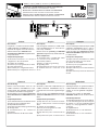
Descrizione
Progettata e costruita interamente dalla
CAME CANCELLI AUTOMATICI S.p.A.,
risponde alle vigenti norme di sicurezza.
Scheda elettrica per
alimentare un
motoriduttore UNIPARK
supplementare
con quadro ZL22.
Componenti principali
1) Morsettiera ad innesto con cavi per il
collegamento alla scheda ZL22
2) Trimmer di sensibilità
3) Pulsante per la programmazione radio
4) Led di segnalazione
5) Morsettiera per collegamenti elettrici
6) Morsettiera per il collegamento al motore
English
Description
Fully designed and built by CAME CAN-
CELLI AUTOMATICI S.p.A., meets the cur-
rent safety standards.
Electric board for
powering a UNIPARK
gearmotor
supplementary with ZL22 board.
Main components
1) Terminal board to coupling with cables
for connection to the ZL22 board
2) Sensitivity trimmer
3) Button for radio programming
4) Signalling LED
5) Terminal board for electrical connections
6) Terminal board for connection to the
motor
Français
Description
Conçue et fabriquée entièrement par CAME
CANCELLI AUTOMATICI S.p.A., elle sa-
tisfait aux normes de sécurité en vigueur.
Carte électrique pour
alimenter un moto-
réducteur UNIPARK
supplémentaire avec
le tableau ZL22.
Principaux composants
1) Plaque à bornes enfichable avec câbles
pour le branchement à la carte ZL22
2) Trimmer de sensibilité
3) Bouton pour la programmation radio
4) Led de signalisation
5) Plaque à bornes pour les branchements
électriques
6) Plaque à bornes pour le branchement au
moteur
Deutsch
Beschreibung
Entwurt und Konstruktion sind von der
CAME CANCELLI AUTOMATICI S.p.A.
entsprechend den geltenden Sicherheits-
vorschriften entwickelt und hergestellt.
Die Schaltkarte zur zusätzlichen
Speisung
eines Getriebemotors UNIPARK
mitTafel
ZL22.
Hauptkomponenten
1) Steckklemmenkasten mit Kabeln für den
Anschluß an die Schaltkarte ZL22
2) Empfindlichkeitstrimmer
3) Drucktaste für die Funkprogrammierung
4) Anzeige-LED
5) Klemmenkasten für elektrische
Anschlüsse
6) Klemmenkasten für Motoranschluß
Español
Descripción
Diseñada y fabricada completamente por
CAME CANCELLI AUTOMATICI S.p.A.,
responde a las normas de seguridad vigen-
tes.
Tarjeta eléctrica para
alimentar un moto-
rreductor UNIPARK
adicional con cuadro
ZL22.
Componentes principales
1) Caja de bornes de conexiones enchufa-
ble con cables para la conexión a la tarjeta
ZL22
2) Trimmer de sensibilidad
3) Botón para la programación radio
4) Led de señalización
5) Caja de bornes para conexiones eléctri-
cas
6) Caja de bornes para conexion al motor
Nederlands
Omschrijving
Volledig ontworpen en gefabriceerd door
CAME CANCELLI AUTOMATICI S.p.A.,
voldoet ze aan alle geldende veiligheid-
snormen.
Print voor het voeden van een extra
UNIPARK motor met de stuurkast ZL22.
Hoofdcomponenten
1) Inplugbare klemmenstrook met kabels
voor de aansluiting met de ZL22 tuurprint
2) Trimmer voor de gevoeligheidsregeling
3) knop voor het programmeren van de
ontvanger
4) Signalisatieled
5) Klemmenstrook voor de elektrische
aansluitingen
6) Klemmenstrook voor het aansluiten
van de motor
ABCDE
ABCDE
1
6
2
3
4
5

2
Italiano
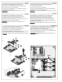
Descrizione del collegamento al quadro ZL22
1) Inserire la scheda LM22 all’interno del quadro.
2) Fissarla con le viti in dotazione.
3) Inserire la morsettiera (n°1) sull’apposito innesto
della scheda base (ZL22).
Attenzione: effettuare le operazioni in assenza di
tensione.
English
Description of the connection to the ZL22 board
1) Insert the LM22 board.
2) Fix it with the screws supplied.
3) Insert the terminal board (n°1) on to the dedicated
coupling of the motherboard (ZL22).
Warning: carry out the operations with the apparatus off.
Français
Description du branchement au tableau ZL22
1) Placer la carte LM22 à l’intérieur du tableau.
2) La fixer avec les vis fournies de série.
3) Placer la plaque à bornes (n°1) sur la fiche corres-
pondante de la carte de base (ZL22).
Attention: couper le courant pour effectuer ces
opérations
Español
Descripción de la conexión al cuadro ZL22
1) Coloque la tarjeta LM22 adentro del cuadro.
2) Fíjela con los tornillos suministrados.
3) Conecte la regleta de conexiones (n°1) en el enchu-
fe correspondiente de la tarjeta base (ZL22).
Atención: corte la tensión para realizar las operaciones.
Deutsch
Beschreibung des Anschlusses an die Tafel ZL22
1) Die Schaltkarte LM22 in die Tafel einführen.
2) Mit dem mitgelieferten Schrauben befestigen.
3) Den Klemmenkasten (n°1) auf der eigens dafür
vorgesehenen Steckverbindung auf der Grundschalt-
karte (ZL22) anbringen.
Achtung: alle Arbeitsgänge ohne Spannung durchführen.
PROG
.
FUSIBILE
LINEA 5A
ZL22
FUSIBILE
CENTRALINA
315mA
ABCDE
ABCDE
ZL22
LM22
Nederlands
Beschrijving van de aansluiting met de ZL22 stuurprint
1) Breng de LM22 kaart in de stuurkast.
2) Bevestig deze met de bijgevoegde schroefjes.
3) Plaats de connector (n°1) op de corresponderende
klem van de basisprint (ZL22).
Opgepast: Zet de spanning af vooraleer deze bewer-
king uit te voeren.
1)
2)
3)

3
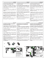
Italiano
Procedura di installazione del trasmetti-
tore per il comando a distanza
1) Codificare il trasmettitore seguendo la
procedura a seconda del tipo di
radiocomando (TOP Quarzati, ATOMO,
TAM, TFM e TOP, vedi procedura dal fasc.
tecnico del ZL22).
2) Tenere premuto il tasto “PROG” sulla
scheda LM22 (il led di segnalazione lam-
peggia).
3) Premere il tasto del trasmettitore (prece-
dentemente codificato) si invia il codice alla
scheda ricevente “AF”, il led rimarrà acce-
so a segnalare l’avvenuta memorizzazione.
PROG = Canale per comandi diretti ad una
funzione della centralina del motoriduttore
(comando "apre-chiude")
N.B.: Se in seguito si vuol cambiare codice,
basta ripetere la sequenza descritta.
English
Installation procedure of the transmitter
for remote control
1) Code the transmitter following the proce-
dure according to the type of radio-control
(quartz TOP, ATOMO, TAM, TFM and TOP,
see procedure in the technical
documentation of the ZL22).
2) Keep the “PROG” button pressed on the
LM22 board (the signalling LED flashes).
3) Click the button of the transmitter
(previously coded) the code is sent to the
“AF” receiver board, the LED will stay on to
signal saving to memory.
PROG = Channel for direct control of one
function performed by te control unit on the
gearmotor ("open-close")
N.B.: If you wish to change the code on your
transmitters in the future, simply repeat the
procedure described above.
Français
Procédure d’installation de l’émetteur
pour la commande à distance
1) Coder l’émetteur en suivant la procédure
selon le type de radiocommande (TOP Au
quartz, ATOMO, TAM, TFM et TOP, voir
procédure sur le fascicule technique du
tableau ZL22).
2) Appuyer sans la relâcher sur la touche
“PROG” de la carte LM22 (LED de
signalisation clignote).
3) Appuyer sur la touche de l’émetteur
(codé précédemment) pour envoyer le code
à la carte “AF” du récepteur, la diode reste
allumée pour signaler que la mémorisation
a bien eu lieu.
PROG = Canal pour obtenir la commande
directe d’une fonction du boîtier du
motoréducteur (commande "ouverture-
fermeture")
N.B.: Si, successivement, on veut changer
le code des émetteur, il suffit de répéter la
séquence décrite ci-dessus.
PROG
.
FUSIBILE
LINEA 5A
ZL22
FUSIBILE
CENT RALINA
315mA
ABCDE
ABCDE
LED acceso
Lit LED
LED allumé
LED Kontrolleuchte
LED encendido
LED brand continu
"AF"
Deutsch
Installation des Übertragungsgeräts
für die Fernsteuerung
1) Den Sender nach dem Verfahren für den
entsprechenden Typ der Fernsteuerung
(TOP Quartzgenaue, ATOMO, TAM, TFM
und TOP) codieren (siehe Verfahren im
Technikheft der ZL22).
2) Auf der Schaltkarte LM22 die Taste
“PROG” eingedrückt halten (das Anzeige-
LED blinkt).
3) Bei Betätigung der Taste des Senders
(vorher codiert), wird der Code an die
Empfangsschaltkarte “AF” gesandt; das
LED bleibt eingeschaltet und zeigt die
erfolgte Speicherung an.
PROG = Kanal für die Direktsteuerung einer
Funktion des Getriebemotor-Schaltkastens
(Steuerung "Öffnen-Schließen")
HINWEIS: bei eventuell erwünschter Sender
codeänderung ist der beschriebene Vorgang
zu wiederholen.
Nederlands
Procedure voor het installeren van de
zender voor de afstandsbediening
1) Codeer de zender volgens de procedure
afhankelijk van het type afstandsbediening
(TOP Quartz, ATOMO, TAM, TFM of TOP,
zie de procedure in de technische
handleiding van de ZL22).
2) Duw zonder los te laten op de knop
“PROG” van de kaart LM22 (de signalisatie
led knippert).
3) Duw op de knop van de zender (reeds
vooraf geprogrammeerd) voor de code te
zenden naar de “AF” print, de led blijft
continu branden om aan te duiden dat de
memorisatie uitgevoerd is.
PROG = Kanaal voor het onmiddellijk te
bekomen van een functie op de print van de
motor (functie "openen en sluiten")
N.B.: Indien men later de code wenst te
wijzigen volstaat het deze procedure te
herhalen.
Español
Procedimiento de instalación del
transmisor para el accionamiento a
distancia
1) Codifique el transmisor siguiendo el
procedimiento según el tipo de radiomando
(TOP Cuarzo, ATOMO, TAM, TFM y TOP,
véase procedimiento del Manual técnico
del ZL22).
2) Mantenga apretado el botón “PROG” en
la tarjeta LM22 (el led de señalización
parpadea).
3) Presione el botón del transmisor (antes
codificado) se envía el código a la tarjeta
receptor “AF”, el led queda encendido para
indicar que se realizó la memorización.
PROG = Canal para mando directo a una
función de la central del motorreductor (man-
do "abre-cierra")
N.B.: Si posteriormente se quisiera cambiar
el código de los propios transmisores, sólo
hay que repetir la secuencia descrita.
1)
3)
FUSIBILE
LINEA 5A
FUSIBILE
CENT RALINA
315mA
ABCDE
ABCDE
"PROG"
LED intermittenza
Flashing LED
LED clignotant
LED Aufblinkende
LED intermitente
LED knippert
2)

Tutti i dati sono stati controllati con la
massima cura. Non ci assumiamo co-
munque alcuna responsabilità per
eventuali errori od omissioni.
All data checked with the maximum care.
However, no liability is accepted for any
error or omission.
Toutes les données ont été contrôlées
très soigneusement. Nous n’assumons
de toute façon aucune responsabilité
pour les erreurs ou omissions
éventuelles.
Die Daten wurden mit höchster Sorgfalt
geprüft. Für eventuelle Fehler oder
Auslassungen übernehmen wir keine
Haftung.
CANCELLI AUTOMATICI
CAME LOMBARDIA S.R.L.______COLOGNO M. (MI)
(+39) 02 26708293 (+39) 02 25490288
CAME SUD S.R.L. ___________________NAPOLI
(+39) 081 7524455 (+39) 081 7529109
CAME (AMERICA) L.L.C.____________MIAMI ( FL)
(+1) 305 5938798 (+1) 305 5939823
CAME AUTOMATISMOS S.A__________MADRID
(+34) 091 5285009 (+34) 091 4685442
CAME BELGIUM__________________LESSINES
(+32) 068 333014 (+32) 068 338019
CAME FRANCE S.A.____NANTERRE CEDEX (PARIS)
(+33) 01 46130505 (+33) 01 46130500
CAME GMBH________KORNTAL BEI (STUTTGART)
(+49) 07 15037830 (+49) 07 150378383
CAME GMBH____________SEEFELD BEI (BERLIN)
(+49) 03 33988390 (+49) 03 339885508
CAME PL SP.ZO.O______________WARSZAWA
(+48) 022 8365076 (+48) 022 8369920
CAME UNITED KINGDOM LTD___NOTTINGHAM
(+44) 0115 9210430 (+44) 0115 9210431
CAME CANCELLI AUTOMATICI S.P.A.
DOSSON DI CASIER (TREVISO)
(+39) 0422 4940 (+39) 0422 4941
SISTEMA QUALITÀ
CERTIFICATO
ASSISTENZA TECNICA
NUMERO VERDE
800 295830
W
EB
www.came.it
E-MAIL
Todos los datos se han controlado con
la máxima atención. No obstante no nos
responsabilizamos de los posibles
errores u omisiones.
De gegevens in deze handleiding werden
nauwkeurig gecontroleerd. Wij wijzen iedere
verantwoordelijkheid af in geval van
drukfouten of vergissingen.
Italiano
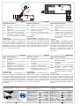
Collegamenti elettrici
M-N: uscita per il collegamento motore
24V (d.c.)
1-2: ingresso (n.c.) per arresto (pulsan-
te di stop)
2-7: ingresso (n.o.) per funzionamento
ciclico (pulsante “apre-chiude”)
2-C1: ingresso (n.c.) per dispositivi di si-
curezza (fotocellule con funzione
di riapertura durante la chiusura)
Regolazioni
Trimmer SENS.
= Sensibilità del sensore
amperometrico. Regola la sensibilità del
sensore che controlla costantemente la
forza sviluppata del motore durante la fase
di apertura e chiusura, se supera il livello
preimpostato, interviene arrestando in aper-
tura e in chiusura il movimento.
English
Electrical connections
M-N: output for the motor connection 24V
(d.c.)
1-2: input (n.c.) to stop (stop button)
2-7: input (n.o.) for cyclical working
(“open-close” button)
2-C1: input (n.c.) for safety devices (pho-
tocells with reopen function during
closing)
Adjustments
Trimmer SENS.
= Sensitivity of the
amperometric sensor. Adjusts the sensitivity
of the sensor that constantly controls the
force generated by the motor during the
opening and closing phase. If the pre-set
level is exceeded, it intervenes arresting in
opening and in closing the movement.
Deutsch
Elektrische Anschlüsse
M-N: Ausgang für den Motoranschluß
24V (G.S.)
1-2: Eingang (n.c.) zum Anhalten
(Stopdrucktaste)
2-7: Eingang (n.o.) für Kreisbetrieb
(Drucktaste “Öffnen-Schließen”)
2-C1: Eingang (n.c.) für Sicherheitsvorri-
chtungen (Fotozellen für die Neuöf-
fnung während der Schließung)
Einstellungen
Trimmer SENS.
= Empfindlichkeit des
Stromsensors. Reguliert die Empfindlichkeit
des Sensors, der laufend die vom Motor
entwickelte Kraft während des Öffnens und
Schließens kontrolliert; bei Überschreitung
der voreingestellten es greift ein, da hält es
in Öffnung an und in Schließung die
Bewegung.
Français
Branchements électriques
M-N: sortie pour le branchement du mo-
teur en 24V (d.c.)
1-2: entrée (n.c.) pour l’arrêt (bouton
stop)
2-7: entrée (n.o.) pour le foncionnement
cyclique (bouton “ouvert-fermé”)
2-C1: entrée (n.c.) pour les dispositifs de
sécurité (photocellule avec fonc-
tion de réouverture durant la phase
de fermeture)
Réglages
Trimmer SENS.
= Sensibilité du capteur
ampèremétrique. Il règle la sensibilité du
capteur qui contrôle constamment la force
développée par le moteur durant la phase
d’ouverture et de fermeture. Si celle-ci
dépasse le niveau préétabli, il intervient en
arrêtant en ouverture et en fermeture le
mouvement.
Español
Conexions eléctricas
M-N: salida para la conexión al motor
24V (d.c.)
1-2: entrada (n.c.) para parada (botón
de parada)
2-7: entrada (n.o.) para funcionamiento
cíclico (botón “abrir-cerrar”)
2-C1: entrada (n.c.) para dispositivos de
seguridad (fotocélulas con función
de apertura durante el cierre)
Regulaciones
Trimmer SENS.
= Sensibilidad del sensor
amperimétrico. Regula la sensibilidad del
sensor que controla constantemente la
fuerza ejercida por el motor durante la
etapa de apertura y cierre, si supera el nivel
predefinido, se activa parando en abertura
y en cierre el movimiento.
ABCDE
ABCDE
SENS.
Nederlands
Elektrische aansluitingen
M-N: Uitgang voor de aansluiting van
de motor 24V (d.c.)
1-2: Ingang(n.c.) voor stopfunctie
(noodstop)
2-7: Ingang (n.o.) voor de cyclische
functie (knop “openen-sluiten”)
2-C1: Ingang (n.c.) voor
veiligheidstoebehoren(functie
heropenen tijdens de sluiting)
Regelingen
Trimmer SENS.
= Gevoeligheid van de
stroomsensor. Regeling van de sensor die
de continu de druk controleerdgedurende
het openen en sluiten van de motor. Indien
deze de vooringestelde waarde overschrijd
dan stopt de beweging tijdens opening en
sluiting
ABCDE
M
N
1
2
7
C1
M1
Documenttranscriptie
SERIE Z| Z SERIES CANCELLI AUTOMATICI | SÉRIE Z | BAUREIHE Z | SERIE Z |SERIE Z Documentazione Tecnica T12 SCHEDA PER L’ALIMENTAZIONE DI UN UNIPARK SUPPLEMENTARE BOARD FOR POWERING A SUPPLEMENTARY UNIPARK CARTE POUR L’ALIMENTATION D’UN UNIPARK SUPPLÉMENTAIRE VERSORGUNGSPLATINE FÜR EINEN ZUSÁTZLICHEN UNIPARK TARJETA PARA LA ALIMENTACIÓN DE UN UNIPARK SUPLEMENTARIO UITBREIDINGSPRINT VOOR HET VOEDEN VAN EEN EXTRA UNIPARK 1 rev. 0.3 11/2003 © LM22 CAME CANCELLI AUTOMATICI 319T12 2 A B C D E A B C D E 3 4 6 5 Italiano Français English Descrizione Description Description Progettata e costruita interamente dalla CAME CANCELLI AUTOMATICI S.p.A., risponde alle vigenti norme di sicurezza. Scheda elettrica per alimentare un motoriduttore UNIPARK supplementare con quadro ZL22. Fully designed and built by CAME CANCELLI AUTOMATICI S.p.A., meets the current safety standards. Electric board for powering a UNIPARK gearmotor supplementary with ZL22 board. Conçue et fabriquée entièrement par CAME CANCELLI AUTOMATICI S.p.A., elle satisfait aux normes de sécurité en vigueur. Carte électrique pour alimenter un motoréducteur UNIPARK supplémentaire avec le tableau ZL22. Main components Componenti principali 1) Terminal board to coupling with cables 1) Morsettiera ad innesto con cavi per il for connection to the ZL22 board collegamento alla scheda ZL22 2) Sensitivity trimmer 2) Trimmer di sensibilità 3) Button for radio programming 3) Pulsante per la programmazione radio 4) Signalling LED 4) Led di segnalazione 5) Terminal board for electrical connections 5) Morsettiera per collegamenti elettrici 6) Terminal board for connection to the 6) Morsettiera per il collegamento al motore motor Deutsch Español Principaux composants 1) Plaque à bornes enfichable avec câbles pour le branchement à la carte ZL22 2) Trimmer de sensibilité 3) Bouton pour la programmation radio 4) Led de signalisation 5) Plaque à bornes pour les branchements électriques 6) Plaque à bornes pour le branchement au moteur Nederlands Beschreibung Descripción Omschrijving Entwurt und Konstruktion sind von der CAME CANCELLI AUTOMATICI S.p.A. entsprechend den geltenden Sicherheitsvorschriften entwickelt und hergestellt. Die Schaltkarte zur zusätzlichen Speisung eines Getriebemotors UNIPARK mitTafel ZL22. Diseñada y fabricada completamente por CAME CANCELLI AUTOMATICI S.p.A., responde a las normas de seguridad vigentes. Tarjeta eléctrica para alimentar un motorreductor UNIPARK adicional con cuadro ZL22. Volledig ontworpen en gefabriceerd door CAME CANCELLI AUTOMATICI S.p.A., voldoet ze aan alle geldende veiligheidsnormen. Print voor het voeden van een extra UNIPARK motor met de stuurkast ZL22. Hauptkomponenten Componentes principales 1) Steckklemmenkasten mit Kabeln für den Anschluß an die Schaltkarte ZL22 2) Empfindlichkeitstrimmer 3) Drucktaste für die Funkprogrammierung 4) Anzeige-LED 5) Klemmenkasten für elektrische Anschlüsse 6) Klemmenkasten für Motoranschluß 1) Caja de bornes de conexiones enchufable con cables para la conexión a la tarjeta ZL22 2) Trimmer de sensibilidad 3) Botón para la programación radio 4) Led de señalización 5) Caja de bornes para conexiones eléctricas 6) Caja de bornes para conexion al motor 1) Inplugbare klemmenstrook met kabels voor de aansluiting met de ZL22 tuurprint 2) Trimmer voor de gevoeligheidsregeling 3) knop voor het programmeren van de ontvanger 4) Signalisatieled 5) Klemmenstrook voor de elektrische aansluitingen 6) Klemmenstrook voor het aansluiten van de motor Hoofdcomponenten Italiano English Descrizione del collegamento al quadro ZL22 Description of the connection to the ZL22 board 1) Inserire la scheda LM22 all’interno del quadro. 2) Fissarla con le viti in dotazione. 3) Inserire la morsettiera (n°1) sull’apposito innesto della scheda base (ZL22). Attenzione: effettuare le operazioni in assenza di tensione. 1) Insert the LM22 board. 2) Fix it with the screws supplied. 3) Insert the terminal board (n°1) on to the dedicated coupling of the motherboard (ZL22). Warning: carry out the operations with the apparatus off. Deutsch Français Description du branchement au tableau ZL22 Beschreibung des Anschlusses an die Tafel ZL22 1) Placer la carte LM22 à l’intérieur du tableau. 2) La fixer avec les vis fournies de série. 3) Placer la plaque à bornes (n°1) sur la fiche correspondante de la carte de base (ZL22). Attention: couper le courant pour effectuer ces opérations 1) Die Schaltkarte LM22 in die Tafel einführen. 2) Mit dem mitgelieferten Schrauben befestigen. 3) Den Klemmenkasten (n°1) auf der eigens dafür vorgesehenen Steckverbindung auf der Grundschaltkarte (ZL22) anbringen. Achtung: alle Arbeitsgänge ohne Spannung durchführen. Español Nederlands Descripción de la conexión al cuadro ZL22 Beschrijving van de aansluiting met de ZL22 stuurprint 1) Coloque la tarjeta LM22 adentro del cuadro. 2) Fíjela con los tornillos suministrados. 3) Conecte la regleta de conexiones (n°1) en el enchufe correspondiente de la tarjeta base (ZL22). Atención: corte la tensión para realizar las operaciones. 1) Breng de LM22 kaart in de stuurkast. 2) Bevestig deze met de bijgevoegde schroefjes. 3) Plaats de connector (n°1) op de corresponderende klem van de basisprint (ZL22). Opgepast: Zet de spanning af vooraleer deze bewerking uit te voeren. 1) 2) LM22 PROG. FUSIBILE CENTRALINA 315mA ZL22 3) ZL22 2 A B C D E A B C D E FUSIBILE LINEA 5A Italiano English Français Procedura di installazione del trasmetti- Installation procedure of the transmitter Procédure d’installation de l’émetteur tore per il comando a distanza for remote control pour la commande à distance 1) Codificare il trasmettitore seguendo la procedura a seconda del tipo di radiocomando (TOP Quarzati, ATOMO, TAM, TFM e TOP, vedi procedura dal fasc. tecnico del ZL22). 1) Code the transmitter following the procedure according to the type of radio-control (quartz TOP, ATOMO, TAM, TFM and TOP, see procedure in the technical documentation of the ZL22). 1) Coder l’émetteur en suivant la procédure selon le type de radiocommande (TOP Au quartz, ATOMO, TAM, TFM et TOP, voir procédure sur le fascicule technique du tableau ZL22). 2) Tenere premuto il tasto “PROG” sulla 2) Keep the “PROG” button pressed on the scheda LM22 (il led di segnalazione lam- LM22 board (the signalling LED flashes). peggia). 3) Click the button of the transmitter 3) Premere il tasto del trasmettitore (prece- (previously coded) the code is sent to the dentemente codificato) si invia il codice alla “AF” receiver board, the LED will stay on to scheda ricevente “AF”, il led rimarrà acce- signal saving to memory. so a segnalare l’avvenuta memorizzazione. PROG = Channel for direct control of one PROG = Canale per comandi diretti ad una function performed by te control unit on the funzione della centralina del motoriduttore gearmotor ("open-close") (comando "apre-chiude") N.B.: If you wish to change the code on your 2) Appuyer sans la relâcher sur la touche “PROG” de la carte LM22 (LED de signalisation clignote). 3) Appuyer sur la touche de l’émetteur (codé précédemment) pour envoyer le code à la carte “AF” du récepteur, la diode reste allumée pour signaler que la mémorisation a bien eu lieu. PROG = Canal pour obtenir la commande directe d’une fonction du boîtier du N.B.: Se in seguito si vuol cambiare codice, transmitters in the future, simply repeat the motoréducteur (commande "ouverturefermeture") basta ripetere la sequenza descritta. procedure described above. N.B.: Si, successivement, on veut changer le code des émetteur, il suffit de répéter la séquence décrite ci-dessus. Deutsch Español Installation des Übertragungsgeräts für die Fernsteuerung Nederlands Procedimiento de instalación del transmisor para el accionamiento a 1) Den Sender nach dem Verfahren für den distancia entsprechenden Typ der Fernsteuerung 1) Codifique el transmisor siguiendo el (TOP Quartzgenaue, ATOMO, TAM, TFM procedimiento según el tipo de radiomando und TOP) codieren (siehe Verfahren im (TOP Cuarzo, ATOMO, TAM, TFM y TOP, Technikheft der ZL22). véase procedimiento del Manual técnico del ZL22). 2) Auf der Schaltkarte LM22 die Taste “PROG” eingedrückt halten (das Anzeige- 2) Mantenga apretado el botón “PROG” en LED blinkt). la tarjeta LM22 (el led de señalización parpadea). 3) Bei Betätigung der Taste des Senders (vorher codiert), wird der Code an die 3) Presione el botón del transmisor (antes Empfangsschaltkarte “AF” gesandt; das codificado) se envía el código a la tarjeta LED bleibt eingeschaltet und zeigt die receptor “AF”, el led queda encendido para erfolgte Speicherung an. indicar que se realizó la memorización. Procedure voor het installeren van de zender voor de afstandsbediening PROG = Kanal für die Direktsteuerung einer PROG = Canal para mando directo a una Funktion des Getriebemotor-Schaltkastens función de la central del motorreductor (man(Steuerung "Öffnen-Schließen") do "abre-cierra") HINWEIS: bei eventuell erwünschter Sender N.B.: Si posteriormente se quisiera cambiar codeänderung ist der beschriebene Vorgang el código de los propios transmisores, sólo zu wiederholen. hay que repetir la secuencia descrita. PROG = Kanaal voor het onmiddellijk te bekomen van een functie op de print van de motor (functie "openen en sluiten") 1) Codeer de zender volgens de procedure afhankelijk van het type afstandsbediening (TOP Quartz, ATOMO, TAM, TFM of TOP, zie de procedure in de technische handleiding van de ZL22). 2) Duw zonder los te laten op de knop “PROG” van de kaart LM22 (de signalisatie led knippert). 3) Duw op de knop van de zender (reeds vooraf geprogrammeerd) voor de code te zenden naar de “AF” print, de led blijft continu branden om aan te duiden dat de memorisatie uitgevoerd is. N.B.: Indien men later de code wenst te wijzigen volstaat het deze procedure te herhalen. 1) FU SIBILE LINEA 5A A B C D E A B C D E FU SIBILE CENT RALINA 315mA FU SIBILE CENT RALINA 315mA "AF" LED intermittenza Flashing LED LED clignotant LED Aufblinkende LED intermitente LED knippert ZL22 3 PROG . FU SIBILE LINEA 5A A B C D E 3) "PROG" A B C D E 2) LED acceso Lit LED LED allumé LED Kontrolleuchte LED encendido LED brand continu A B C D E SENS. M N M1 1 2 7 C1 A B C D E A B C D E English Italiano Français Collegamenti elettrici Electrical connections Branchements électriques M-N: M-N: M-N: uscita per il collegamento motore 24V (d.c.) 1-2: ingresso (n.c.) per arresto (pulsante di stop) 2-7: ingresso (n.o.) per funzionamento ciclico (pulsante “apre-chiude”) 2-C1: ingresso (n.c.) per dispositivi di sicurezza (fotocellule con funzione di riapertura durante la chiusura) Regolazioni Trimmer SENS. = Sensibilità del sensore amperometrico. Regola la sensibilità del sensore che controlla costantemente la forza sviluppata del motore durante la fase di apertura e chiusura, se supera il livello preimpostato, interviene arrestando in apertura e in chiusura il movimento. output for the motor connection 24V (d.c.) 1-2: input (n.c.) to stop (stop button) 2-7: input (n.o.) for cyclical working (“open-close” button) 2-C1: input (n.c.) for safety devices (photocells with reopen function during closing) Adjustments Trimmer SENS. = Sensitivity of the amperometric sensor. Adjusts the sensitivity of the sensor that constantly controls the force generated by the motor during the opening and closing phase. If the pre-set level is exceeded, it intervenes arresting in opening and in closing the movement. Deutsch sortie pour le branchement du moteur en 24V (d.c.) 1-2: entrée (n.c.) pour l’arrêt (bouton stop) 2-7: entrée (n.o.) pour le foncionnement cyclique (bouton “ouvert-fermé”) 2-C1: entrée (n.c.) pour les dispositifs de sécurité (photocellule avec fonction de réouverture durant la phase de fermeture) Réglages Trimmer SENS. = Sensibilité du capteur ampèremétrique. Il règle la sensibilité du capteur qui contrôle constamment la force développée par le moteur durant la phase d’ouverture et de fermeture. Si celle-ci dépasse le niveau préétabli, il intervient en arrêtant en ouverture et en fermeture le mouvement. Español Nederlands Elektrische Anschlüsse Conexions eléctricas Elektrische aansluitingen M-N: Ausgang für den Motoranschluß 24V (G.S.) 1-2: Eingang (n.c.) zum Anhalten (Stopdrucktaste) 2-7: Eingang (n.o.) für Kreisbetrieb (Drucktaste “Öffnen-Schließen”) 2-C1: Eingang (n.c.) für Sicherheitsvorrichtungen (Fotozellen für die Neuöffnung während der Schließung) M-N: Einstellungen Trimmer SENS. = Empfindlichkeit des Stromsensors. Reguliert die Empfindlichkeit des Sensors, der laufend die vom Motor entwickelte Kraft während des Öffnens und Schließens kontrolliert; bei Überschreitung der voreingestellten es greift ein, da hält es in Öffnung an und in Schließung die Bewegung. Regulaciones Trimmer SENS. = Sensibilidad del sensor amperimétrico. Regula la sensibilidad del sensor que controla constantemente la fuerza ejercida por el motor durante la etapa de apertura y cierre, si supera el nivel predefinido, se activa parando en abertura y en cierre el movimiento. M-N: Uitgang voor de aansluiting van de motor 24V (d.c.) 1-2: Ingang(n.c.) voor stopfunctie (noodstop) 2-7: Ingang (n.o.) voor de cyclische functie (knop “openen-sluiten”) 2-C1: Ingang (n.c.) voor veiligheidstoebehoren(functie heropenen tijdens de sluiting) Tutti i dati sono stati controllati con la massima cura. Non ci assumiamo comunque alcuna responsabilità per eventuali errori od omissioni. All data checked with the maximum care. However, no liability is accepted for any error or omission. ASSISTENZA TECNICA NUMERO VERDE 800 295830 CANCELLI AUTOMATICI SISTEMA QUALITÀ CERTIFICATO WEB www.came.it E-MAIL [email protected] CAME CANCELLI AUTOMATICI S.P.A. DOSSON DI CASIER (TREVISO) (+39) 0422 4940 (+39) 0422 4941 salida para la conexión al motor 24V (d.c.) 1-2: entrada (n.c.) para parada (botón de parada) 2-7: entrada (n.o.) para funcionamiento cíclico (botón “abrir-cerrar”) 2-C1: entrada (n.c.) para dispositivos de seguridad (fotocélulas con función de apertura durante el cierre) Toutes les données ont été contrôlées très soigneusement. Nous n’assumons de toute façon aucune responsabilité pour les erreurs ou omissions éventuelles. Die Daten wurden mit höchster Sorgfalt geprüft. Für eventuelle Fehler oder Auslassungen übernehmen wir keine Haftung. CAME LOMBARDIA S.R.L.______COLOGNO M. (MI) (+39) 02 26708293 (+39) 02 25490288 CAME SUD S.R.L. ___________________NAPOLI (+39) 081 7524455 (+39) 081 7529109 CAME (AMERICA) L.L.C.____________MIAMI (FL) (+1) 305 5938798 (+1) 305 5939823 CAME AUTOMATISMOS S.A__________MADRID (+34) 091 5285009 (+34) 091 4685442 CAME BELGIUM__________________LESSINES (+32) 068 333014 (+32) 068 338019 Regelingen Trimmer SENS. = Gevoeligheid van de stroomsensor. Regeling van de sensor die de continu de druk controleerdgedurende het openen en sluiten van de motor. Indien deze de vooringestelde waarde overschrijd dan stopt de beweging tijdens opening en sluiting Todos los datos se han controlado con la máxima atención. No obstante no nos responsabilizamos de los posibles errores u omisiones. De gegevens in deze handleiding werden nauwkeurig gecontroleerd. Wij wijzen iedere verantwoordelijkheid af in geval van drukfouten of vergissingen. CAME FRANCE S.A.____NANTERRE CEDEX (PARIS) (+33) 01 46130505 (+33) 01 46130500 CAME GMBH________KORNTAL BEI (STUTTGART) (+49) 07 15037830 (+49) 07 150378383 CAME GMBH____________SEEFELD BEI (BERLIN) (+49) 03 33988390 (+49) 03 339885508 CAME PL SP.ZO.O______________WARSZAWA (+48) 022 8365076 (+48) 022 8369920 CAME UNITED KINGDOM LTD___NOTTINGHAM (+44) 0115 9210430 (+44) 0115 9210431-
 1
1
-
 2
2
-
 3
3
-
 4
4


in andere talen
- English: CAME LM22 Owner's manual
- italiano: CAME LM22 Manuale del proprietario
- français: CAME LM22 Le manuel du propriétaire
- español: CAME LM22 El manual del propietario
- Deutsch: CAME LM22 Bedienungsanleitung