STIEBEL ELTRON HDB-E 12-24 Si Operation Instruction
- Type
- Operation Instruction

BEDIENUNG UND INSTALLATION
OPERATION AND INSTALLATION
UTILISATION ET INSTALLATION
BEDIENING EN INSTALLATIE
OBSLUHA A INSTALACE
Elektronisch gesteuerter Durchlauferhitzer | Electronically controlled
instantaneous water heater | Chauffe-eau instantané à gestion électronique |
Elektronisch gestuurde doorstroomer | Elektronicky řízený průtokový ohřívač
» HDB-E 12 Si
» HDB-E 18 Si
» HDB-E 21 Si
» HDB-E 24 Si

2 | HDB-E Si www.stiebel-eltron.com
INHALT | BESONDERE HINWEISE
BESONDERE HINWEISE
BEDIENUNG
1. Allgemeine Hinweise ����������������������������������������3
1.1 Sicherheitshinweise ��������������������������������������������� 3
1.2 Andere Markierungen in dieser Dokumentation ���������� 3
1.3 Maßeinheiten ����������������������������������������������������� 3
2. Sicherheit �����������������������������������������������������3
2.1 Bestimmungsgemäße Verwendung ������������������������� 3
2.2 Allgemeine Sicherheitshinweise ������������������������������ 3
2.3 Prüfzeichen ������������������������������������������������������� 4
3. Gerätebeschreibung �����������������������������������������4
4. Bedienung ����������������������������������������������������4
5. Reinigung, Pflege und Wartung ����������������������������4
6. Problembehebung �������������������������������������������4
INSTALLATION
7. Sicherheit �����������������������������������������������������5
7.1 Allgemeine Sicherheitshinweise ������������������������������ 5
7.2 Vorschriften, Normen und Bestimmungen ����������������� 5
8. Gerätebeschreibung �����������������������������������������5
8.1 Lieferumfang ����������������������������������������������������� 5
8.2 Zubehör ������������������������������������������������������������ 5
9. Vorbereitungen ����������������������������������������������� 5
9.1 Montageort ������������������������������������������������������� 6
9.2 Werkseinstellungen ��������������������������������������������� 6
10. Montage �������������������������������������������������������7
10.1 Montage abschließen ������������������������������������������� 9
10.2 Montagealternativen �������������������������������������������� 9
11. Inbetriebnahme �������������������������������������������� 11
11.1 Erstinbetriebnahme �������������������������������������������� 11
11.2 Wiederinbetriebnahme ���������������������������������������� 11
12. Außerbetriebnahme ��������������������������������������� 11
13. Störungsbehebung ����������������������������������������� 12
13.1 Störungstabelle �������������������������������������������������12
14. Wartung ����������������������������������������������������� 13
15. Technische Daten ������������������������������������������� 13
15.1 Maße und Anschlüsse �����������������������������������������13
15.2 Elektroschaltplan ����������������������������������������������� 13
15.3 Warmwasserleistung������������������������������������������� 14
15.4 Einsatzbereiche/ Umrechnungstabelle �������������������� 14
15.5 Druckverluste ���������������������������������������������������� 14
15.6 Störfallbedingungen ������������������������������������������� 14
15.7 Angaben zum Energieverbrauch ���������������������������� 15
15.8 Datentabelle �����������������������������������������������������15
KUNDENDIENST UND GARANTIE
UMWELT UND RECYCLING
BESONDERE HINWEISE
- Das Gerät kann von Kindern ab 8 Jahren sowie
von Personen mit verringerten physischen, sen-
sorischen oder mentalen Fähigkeiten oder Man-
gel an Erfahrung und Wissen benutzt werden,
wenn sie beaufsichtigt werden oder bezüglich
des sicheren Gebrauchs des Gerätes unterwiesen
wurden und die daraus resultierenden Gefahren
verstanden haben. Kinder dürfen nicht mit dem
Gerät spielen. Reinigung und Benutzer-Wartung
dürfen nicht von Kindern ohne Beaufsichtigung
durchgeführt werden.
- Verbrennungsgefahr: Die Armatur kann eine
Temperatur von über 60°C annehmen.
- Das Gerät muss über eine Trennstrecke von min-
destens 3mm allpolig vom Netzanschluss ge-
trennt werden können.
- Befestigen Sie das Gerät wie in Kapitel „Installati-
on/ Montage“ beschrieben.
- Beachten Sie den maximal zulässigen Druck
(siehe Kapitel „Installation/ Technische Daten/
Datentabelle“).
- Entleeren Sie das Gerät wie in Kapitel „Installati-
on/ Wartung/ Gerät entleeren“ beschrieben.

BEDIENUNG
Allgemeine Hinweise
DEUTSCH
www.stiebel-eltron.com HDB-E Si | 3
BEDIENUNG
1. Allgemeine Hinweise
Das Kapitel „Bedienung“ richtet sich an den Gerätebenutzer und
den Fachhandwerker.
Das Kapitel „Installation“ richtet sich an den Fachhandwerker.
Hinweis
Lesen Sie diese Anleitung vor dem Gebrauch sorgfältig
durch und bewahren Sie sie auf.
Geben Sie die Anleitung ggf. an einen nachfolgenden
Benutzer weiter.
1.1 Sicherheitshinweise
1.1.1 Aufbau von Sicherheitshinweisen
!
SIGNALWORT Art der Gefahr
Hier stehen mögliche Folgen bei Nichtbeachtung des Si-
cherheitshinweises.
Hier stehen Maßnahmen zur Abwehr der Gefahr.
1.1.2 Symbole, Art der Gefahr
Symbol Art der Gefahr
Verletzung
Stromschlag
Verbrennung
(Verbrennung, Verbrühung)
1.1.3 Signalworte
SIGNALWORT Bedeutung
GEFAHR Hinweise, deren Nichtbeachtung schwere Verletzungen
oder Tod zur Folge haben.
WARNUNG Hinweise, deren Nichtbeachtung schwere Verletzungen
oder Tod zur Folge haben kann.
VORSICHT Hinweise, deren Nichtbeachtung zu mittelschweren oder
leichten Verletzungen führen kann.
1.2 Andere Markierungen in dieser Dokumentation
Hinweis
Allgemeine Hinweise werden mit dem nebenstehenden
Symbol gekennzeichnet.
Lesen Sie die Hinweistexte sorgfältig durch.
Symbol Bedeutung
Sachschaden
(Geräte-, Folge-, Umweltschaden)
Geräteentsorgung
Dieses Symbol zeigt Ihnen, dass Sie etwas tun müssen.
Die erforderlichen Handlungen werden Schritt für Schritt
beschrieben.
1.3 Maßeinheiten
Hinweis
Wenn nicht anders angegeben, sind alle Maße in Milli-
meter.
2. Sicherheit
2.1 Bestimmungsgemäße Verwendung
Das Druckgerät dient zur Erwärmung von Trinkwasser. Das Gerät
kann ein oder mehrere Entnahmestellen versorgen.
Das Gerät ist für den Einsatz im häuslichen Umfeld vorgesehen.
Es kann von nicht eingewiesenen Personen sicher bedient wer-
den. In nicht häuslicher Umgebung, z. B. im Kleingewerbe, kann
das Gerät ebenfalls verwendet werden, sofern die Benutzung in
gleicher Weise erfolgt.
Eine andere oder darüber hinausgehende Benutzung gilt als nicht
bestimmungsgemäß. Zum bestimmungsgemäßen Gebrauch ge-
hört auch das Beachten dieser Anleitung sowie der Anleitungen
für eingesetztes Zubehör.
2.2 Allgemeine Sicherheitshinweise
VORSICHT Verbrennung
Die Armatur kann während des Betriebs eine Temperatur
von ca. 55°C annehmen.
Bei Auslauftemperaturen größer 43°C besteht Verbrü-
hungsgefahr.
!
WARNUNG Verletzung
Das Gerät kann von Kindern ab 8 Jahren sowie von Per-
sonen mit verringerten physischen, sensorischen oder
mentalen Fähigkeiten oder Mangel an Erfahrung und
Wissen benutzt werden, wenn sie beaufsichtigt werden
oder bezüglich des sicheren Gebrauchs des Gerätes un-
terwiesen wurden und die daraus resultierenden Gefah-
ren verstanden haben. Kinder dürfen nicht mit dem Gerät
spielen. Reinigung und Benutzer-Wartung dürfen nicht
von Kindern ohne Beaufsichtigung durchgeführt werden.
!
Sachschaden
Das Gerät und die Armatur sind vom Nutzer vor Frost zu
schützen.
-
!
!

BEDIENUNG
Gerätebeschreibung
4 | HDB-E Si www.stiebel-eltron.com
2.3 Prüfzeichen
Siehe Typenschild am Gerät.
Landesspezifische Zulassungen und Zeugnisse: Deutschland
Für das Gerät ist auf Grund der Landesbauordnungen ein all-
gemeines bauaufsichtliches Prüfzeugnis zum Nachweis der Ver-
wendbarkeit hinsichtlich des Geräuschverhaltens erteilt.
DIN 4109
PA-IX 6816/I
3. Gerätebeschreibung
Das Gerät erwärmt Trinkwasser, das durch das Gerät strömt. So-
bald ein Warmwasserventil öffnet wird und die Einschaltmenge
erreicht, schaltet die Heizleistung automatisch ein. Die Heizleis-
tung wird durch die Durchflussmenge und die Kaltwassertempe-
ratur bestimmt und angepasst.
Heizsystem
Das Blankdraht-Heizsystem hat einen druckfesten Kunststoffman-
tel. Das Heizsystem ist (sowohl) für kalkarme als auch kalkhaltige
Wässer geeignet und gegen Verkalkung weitgehend unempfind-
lich. Das Heizsystem sorgt für eine schnelle und effiziente Warm-
wasserversorgung.
Hinweis
Das Gerät ist mit einer Lufterkennung ausgestattet, die
eine Beschädigung des Heizsystems weitgehend verhin-
dert. Gelangt während des Betriebes Luft in das Gerät,
schaltet das Gerät die Heizleistung für eine Minute aus
und schützt somit das Heizsystem.
Thermostatarmatur
Das Gerät ist für den Betrieb mit einer Thermostatarmatur ge-
eignet.
4. Bedienung
Sobald Sie das Warmwasserventil an der Armatur öffnen, schaltet
automatisch das Heizsystem des Gerätes ein und das Wasser wird
erwärmt.
Warmwasser-Temperatur einstellen
Wird bei voll geöffnetem Entnahmeventil keine ausreichende Aus-
lauftemperatur erreicht, fließt mehr Wasser durch das Gerät als
das Heizsystem erwärmen kann.
Reduzieren Sie die Durchflussmenge am Entnahmeventil.
Auslaufmengen
Je nach Jahreszeit ergeben sich bei verschiedenen Kaltwasser-
temperaturen unterschiedliche maximale Mischwassermengen
beziehungsweise Auslaufmengen (siehe Kapitel „Installation/
Technische Daten/ Datentabelle“).
Nach Unterbrechung der Wasserversorgung
siehe Kapitel „Installation/ Inbetriebnahme/ Wiederinbetrieb-
nahme“
5. Reinigung, Pflege und Wartung
Verwenden Sie keine scheuernden oder anlösenden Reini-
gungsmittel. Zur Pflege und Reinigung des Gerätes genügt
ein feuchtes Tuch.
Kontrollieren Sie regelmäßig die Armaturen. Kalk an den
Armaturausläufen können Sie mit handelsüblichen Entkal-
kungsmitteln entfernen.
6. Problembehebung
Problem Ursache Behebung
Das Gerät schaltet trotz
voll geöffnetem Warm-
wasserventil nicht ein.
Es liegt keine Spannung
an.
Prüfen Sie die Sicherun-
gen in der Hausinstal-
lation.
Die Einschaltmenge
wird nicht erreicht. Der
Strahlregler in der Arma-
tur oder der Duschkopf
ist verkalkt oder ver-
schmutzt.
Reinigen und/ oder ent-
kalken Sie den Strahlreg-
ler oder den Duschkopf.
Die Wasserversorgung ist
unterbrochen.
Entlüften Sie das Gerät
und die Kaltwasser-Zu-
laufleitung (siehe Kapitel
„Installation/ Inbetrieb-
nahme/ Wiederinbe-
triebnahme“).
Es fließt kurzzeitig kaltes
Wasser, während war-
mes Wasser entnommen
wird.
Die Lufterkennung er-
kennt Luft im Wasser und
schaltet die Heizleistung
kurzzeitig ab.
Das Gerät geht nach
1Minute selbstständig
wieder in Betrieb.
Können Sie die Ursache nicht beheben, rufen Sie den Fachhand-
werker. Zur besseren und schnelleren Hilfe teilen Sie ihm die
Nummer vom Typenschild mit (000000-0000-000000):
HDB-E ..
Nr.: 000000-0000-000000
26�02�02�1366

DEUTSCH
www.stiebel-eltron.com HDB-E Si | 5
INSTALLATION
Sicherheit
INSTALLATION
7. Sicherheit
Die Installation, Inbetriebnahme sowie Wartung und Reparatur
des Gerätes darf nur von einem Fachhandwerker durchgeführt
werden.
7.1 Allgemeine Sicherheitshinweise
Wir gewährleisten eine einwandfreie Funktion und Betriebssicher-
heit nur, wenn das für das Gerät bestimmte Original-Zubehör und
die originalen Ersatzteile verwendet werden.
!
Sachschaden
Beachten Sie die maximale Zulauftemperatur. Bei höhe-
ren Temperaturen kann das Gerät beschädigt werden.
7.2 Vorschriften, Normen und Bestimmungen
Hinweis
Beachten Sie alle nationalen und regionalen Vorschrif-
ten und Bestimmungen, in Deutschland zum Beispiel die
DIN1988/ DINEN806.
- Die Schutzart IP 25 (strahlwassergeschützt) ist nur mit sach-
gemäß montierter Kabeltülle gewährleistet.
- Der spezifische elektrische Widerstand des Wassers darf
nicht kleiner sein als auf dem Typenschild angegeben.
Bei einem Wasser-Verbundnetz berücksichtigen Sie den
niedrigsten elektrischen Widerstand des Wassers (siehe
Kapitel „Installation/ Technischen Daten/ Datentabelle“).
Den spezifischen elektrischen Widerstand oder die elek-
trische Leitfähigkeit des Wassers erfahren Sie bei Ihrem
Wasserversorgungs-Unternehmen.
8. Gerätebeschreibung
8.1 Lieferumfang
- Aufhängeleiste
- Montageschablone
- Doppelnippel
- Kreuzstück
- T-Stück
- Flachdichtungen
- Sieb
- Durchflussmengen-Begrenzer
- Kunststoff-Formscheibe
- Kunststoffkappe
- Kunststoff-Verbindungsstücke
- Kappen-Führungsstücke
8.2 Zubehör
Armaturen
- MEKD-Küchen-Druckarmatur
- MEBD-Badewannen-Druckarmatur
Wasserstopfen G½A
Wenn Sie andere als von uns empfohlene Aufputz Zweigriff-Druck-
armaturen einsetzen, sind die Wasserstopfen notwendig.
Montagesets Aufputz-Installation
- Lötverschraubung Kupferrohr für den Lötanschluss Ø 12 mm.
- Press-Fitting Kupferrohr.
- Press-Fitting Kunststoffrohr (geeignet für Viega: Sanfix-Plus
oder Sanfix-Fosta).
Universal-Montagerahmen
Montagerahmen mit elektrischen Anschlüssen.
Rohrbausatz DHB-Wassersteckkupplungen
2 Wassersteckkupplungen, mit deren Sie das Gerät an die vorhan-
denen Wasser-Steckanschlüsse eines DHB anschließen können.
Lastabwurfrelais (LR 1-A)
Das Lastabwurfrelais für den Einbau in der Elektroverteilung er-
möglicht eine Vorrangschaltung des Durchlauferhitzers bei gleich-
zeitigem Betrieb von z.B. Elektro-Speicherheizgeräten.
9. Vorbereitungen
Spülen Sie die Wasserleitung gut durch.
Armaturen
Verwenden Sie geeignete Armaturen (siehe Kapitel „Instal-
lation/ Gerätebeschreibung/ Zubehör“). Offene Armaturen
sind nicht zulässig.
Ein Sicherheitsventil ist nicht erforderlich.
!
Sachschaden
Verwenden Sie das Kreuzstück nicht zum Drosseln des
Volumenstromes. Das Kreuzstück ist nur für die Absper-
rung des Gerätes.
Zugelassene Werkstoffe der Wasserleitungen
- Kaltwasser-Zuleitung:
feuerverzinktes Stahlrohr, Edelstahlrohr, Kupferrohr oder
Kunststoffrohr
- Warmwasser-Auslaufleitung:
Edelstahlrohr, Kupferrohr oder Kunststoffrohr
!
Sachschaden
Beim Einsatz von Kunststoff-Rohrsystemen beachten Sie
die maximale Zulauftemperatur und den maximal zu-
lässigen Druck (siehe Kapitel „Installatuin/ Technische
Daten/ Datentabelle“).

6 | HDB-E Si www.stiebel-eltron.com
INSTALLATION
Vorbereitungen
Volumenstrom
Stellen Sie sicher, dass der Volumenstrom (siehe Kapitel
„Installation/ Technische Daten/ Datentabelle“, Ein) zum
Einschalten des Gerätes erreicht wird.
Falls der benötigte Volumenstrom bei voll geöffnetem Ent-
nahmeventil nicht erreicht wird, erhöhen Sie den Wasserlei-
tungsdruck. Wenn der Volumenstrom trotz Erhöhung nicht
erreicht wird, bauen Sie den Durchflussmengen-Begrenzer
aus und die Kunststoff-Formscheibe ein.
Fließdruck
Wird die min. Durchflussmenge zum Einschalten des Gerätes
auch bei voll geöffneter Armatur nicht erreicht, müssen Sie den
Durchflussmengen-Begrenzer ausbauen. Ersetzen Sie ihn durch
die mitgelieferte Kunststoff-Formscheibe. Bei Bedarf können Sie
aber auch den Druck in der Wasserinstallation erhöhen.
26�02�02�0820
2 1
1 Durchflussmengen-Begrenzer
2 Kunststoff-Formscheibe
Hinweis
Damit die Thermostat-Armatur richtig funktioniert, dür-
fen Sie den Durchflussmengen-Begrenzer nicht gegen die
Kunststoff-Formscheibe austauschen.
Flexible Wasseranschlussleitungen
Verhindern Sie bei der Installation mit flexiblen Wasseran-
schlussleitungen ein Verdrehen der Rohrbögen. Die Rohrbö-
gen sind mit einer Bajonettverbindung im Gerät montiert.
Befestigen Sie die Rückwand unten mit einer zusätzlichen
Schraube.
9.1 Montageort
!
Sachschaden
Die Installation des Gerätes darf nur im frostfreien Raum
erfolgen.
Montieren Sie das Gerät senkrecht und in der Nähe der
Entnahmestelle.
Das Gerät ist für Untertisch- und Übertischmontage geeignet.
Hinweis
Das Gerät muss an einer ausreichend tragfähigen Wand
montiert werden.
Untertischmontage
26�02�02�1373
1
2
1 Kaltwasser Zulauf
2 Warmwasser Auslauf
Übertischmontage
26�02�02�1374
12
1 Kaltwasser Zulauf
2 Warmwasser Auslauf
9.2 Werkseinstellungen
Die Geräte sind im Lieferzustand vorbereitet:
- Elektroanschluss „unten“, Unterputz-Installation
- Wasseranschluss Unterputz-Installation

DEUTSCH
www.stiebel-eltron.com HDB-E Si | 7
INSTALLATION
Montage
10. Montage
In diesem Kapitel wird die Montage entsprechend der Werksein-
stellungen beschrieben.
Weitere Montagemöglichkeiten siehe Kapitel „Installation/ Mon-
tagealternativen“.
26�02�02�1367
Öffnen Sie das Gerät.
26�02�02�1101
Drücken Sie die beiden die Rasthaken ein. Ziehen Sie das
Rückwandunterteil nach vorne ab.
26�02�02�0810�
Zeichnen Sie die Bohrlöcher mit der Montageschablone an.
Bohren Sie die Löcher und befestigen Sie die Aufhängeleiste
mit 2Schrauben und 2Dübeln (Schrauben und Dübel gehö-
ren nicht zum Lieferumfang).
Hinweis
Bei einer Montage mit flexiblen Wasseranschlüssen
müssen Sie die Rückwand zusätzlich mit einer Schraube
befestigen.
Montieren Sie die Aufhängeleiste.
160
≥ 30
26�02�02�0887
Richten Sie das Netzanschlusskabel her.
Wasseranschluss herstellen
!
Sachschaden
Führen Sie alle Wasseranschluss- und Installationsarbei-
ten nach Vorschrift aus.
12
D0000053319
Dichten und schrauben Sie die Doppelnippel ein.
1 2
26�02�02�0799
1 T-Stück
2 Kreuzstück
Schrauben Sie das T-Stück und das Kreuzstück mit jeweils
einer Flachdichtung auf die Doppelnippel.
Einbau Sieb
!
Sachschaden
Für die Funktion des Gerätes muss das Sieb eingebaut
sein.
Prüfen Sie beim Geräteaustausch, ob das Sieb vor-
handen ist.

8 | HDB-E Si www.stiebel-eltron.com
INSTALLATION
Montage
26�02�02�0856
Montieren Sie das mitgelieferte Sieb in den Kaltwasserzulauf
des Gerätes.
Einbau Durchflussmengen-Begrenzer DMB
26�02�02�0857
Montieren Sie den mitgelieferten Durchflussmengen-Begren-
zer in den Kaltwasserzulauf des Gerätes.
Gerät montieren
26�02�02�0811
Zur leichteren Montage drücken Sie die Kabeltülle des obe-
ren Elektroanschlusses von hinten in die Rückwand hinein.
Entfernen Sie die Transport-Schutzstopfen aus den
Wasseranschlüssen.
Nehmen Sie den Befestigungsknebel aus dem oberen Teil der
Rückwand heraus.
Führen Sie das Netzanschlusskabel von hinten durch die Ka-
beltülle, bis das Netzanschlusskabel am Kabelmantel anliegt.
Richten Sie das Netzanschlusskabel aus.
Wenn der Querschnitt des Netzanschlusskabels >6mm², ver-
größern Sie das Loch in der Kabeltülle.
Drücken Sie das Gerät über den Gewindebolzen der Wand-
aufhängung, sodass die Weichdichtung durchstoßen wird.
Verwenden Sie ggf. einen Schraubendreher.
Stecken Sie den Befestigungsknebel auf den Gewindebolzen
der Wandaufhängung.
Drücken Sie die Rückwand fest an. Verriegeln Sie den Befes-
tigungsknebel durch eine Rechtsdrehung um 90°.
26�02�02�0858
Schrauben Sie die Rohre mit den Flachdichtungen auf die
Doppelnippel.
Elektroanschluss herstellen
WARNUNG Stromschlag
Führen Sie alle elektrischen Anschluss- und Installati-
onsarbeiten nach Vorschrift aus.
WARNUNG Stromschlag
Der Anschluss an das Stromnetz ist nur als fester An-
schluss in Verbindung mit der herausnehmbaren Kabel-
tülle erlaubt. Das Gerät muss über eine Trennstrecke von
mindestens 3 mm allpolig vom Netzanschluss getrennt
werden können.
WARNUNG Stromschlag
Achten Sie darauf, dass das Gerät an den Schutzleiter
angeschlossen ist.
!
Sachschaden
Beachten Sie das Typenschild. Die angegebene Spannung
muss mit der Netzspannung übereinstimmen.
Schließen Sie das Netzanschlusskabel an die Netzanschluss-
klemme an (siehe Kapitel „Installation/ Technische Daten/
Elektroschaltpläne“).
26�02�02�1122�

DEUTSCH
www.stiebel-eltron.com HDB-E Si | 9
INSTALLATION
Montage
10.1 Montage abschließen
26�02�02�1102�
Montieren Sie das Rückwandunterteil. Achten Sie darauf,
dass das Rückwandunterteil einrastet.
Richten Sie das montierte Gerät aus. Lösen Sie den Befes-
tigungsknebel, richten Sie den Elektroanschluss und die
Rückwand aus. Drehen Sie den Befestigungsknebel wieder
fest. Wenn die Geräterückwand nicht anliegt, können Sie das
Gerät unten mit einer zusätzlichen Schraube befestigen.
10.2 Montagealternativen
- Elektroanschluss Unterputz oben
- große Leiterquerschnitte beim Elektroanschluss unten
- Anschluss eines Lastabwurfrelais
- Wasserinstallation Aufputz
- Wasserinstallation Aufputz mit Lötanschluss / Press-Fitting
- Wasserinstallation Aufputz, Gerätekappe montieren
- Montage Rückwand-Unterteil
- Verwendung der vorhandenen Aufhängeleiste bei
Geräteaustausch
- Installation bei Fliesenversatz
Elektroanschluss Unterputz oben
26�02�02�1123�
Schneiden Sie die Kabeltülle für das Netzanschlusskabel auf.
Drücken Sie den Rasthaken zur Befestigung der Netzan-
schlussklemme herunter. Ziehen Sie die Netzanschluss-
klemme heraus.
Versetzen Sie die Netzanschlussklemme im Gerät von unten
nach oben. Befestigen Sie die Netzanschlussklemme, indem
Sie sie unter den Rasthaken schieben.
Große Leiterquerschnitte beim Elektroanschluss unten
Wenn Sie große Leiterquerschnitte verwenden, können Sie die
Kabeltülle nach der Montage des Gerätes montieren.
1.
3.
4.
2.
26�02�02�1124�
Vor der Montage des Gerätes drücken Sie die Kabeltülle mit
Hilfe eines Schraubendrehers heraus.
Schieben Sie die Kabeltülle über das Netzanschlusskabel. Bei
einem Querschnitt >6mm² vergrößern Sie das Loch in der
Kabeltülle.
Schieben Sie die Kabeltülle in die Rückwand. Rasten Sie die
Kabeltülle ein.
Anschluss eines Lastabwurfrelais
Setzen Sie ein Lastabwurfrelais in Kombination mit anderen
Elektrogeräten, z.B. Elektro-Speicherheizgeräte, in der Elektro-
verteilung ein. Der Lastabwurf erfolgt bei Betrieb des Durchlau-
ferhitzers.
!
Sachschaden
Schließen Sie die Phase, die das Lastabwurfrelais schal-
tet, an die gekennzeichnete Klemme der Netzanschluss-
klemme im Gerät an (siehe Kapitel „Installation/ Tech-
nische Daten/ Elektroschaltpläne“).
Wasserinstallation Aufputz
Hinweis
Bei dieser Anschlussart ändert sich die Schutzart des
Gerätes.
Ändern Sie das Typenschild. Streichen Sie die Anga-
be IP 25 durch und kreuzen Sie das Kästchen IP 24
an. Verwenden Sie dafür einen Kugelschreiber.

10 | HDB-E Si www.stiebel-eltron.com
INSTALLATION
Montage
D0000033104
Montieren Sie Wasserstopfen mit Dichtungen, um den Unter-
putzanschluss zu verschließen. Bei den Armaturen aus dem
„Zubehör“ gehören die Wasserstopfen und Dichtungen zum
Lieferumfang. Für andere als von uns empfohlene Druckar-
maturen können Sie Wasserstopfen und Dichtungen als „Zu-
behör“ bestellen.
Montieren Sie eine geeignete Druckarmatur.
Legen Sie das Rückwandunterteil unter die Anschlussrohre
der Armatur und schieben es in die Rückwand ein.
Verschrauben Sie die Anschlussrohre mit dem Gerät.
Wasserinstallation Aufputz mit Lötanschluss/ Press-Fitting
Sie können mit dem Zubehör „Lötanschluss“ oder „Press-Fitting“
Kupfer-Rohrleitungen oder auch Kunststoff-Rohrleitungen ver-
binden.
Beim „Lötanschluss“ mit einem Schraubanschluss für 12 mm Kup-
fer-Rohrleitungen müssen Sie wie folgt vorgehen:
Schieben Sie die Überwurfmuttern über die Anschlussrohre.
Verlöten Sie die Einlegeteile mit den Kupferleitungen.
Legen Sie das Rückwandunterteil unter die Anschlussrohre
der Armatur und schieben es in die Rückwand ein.
Verschrauben Sie die Anschlussrohre mit dem Gerät.
Hinweis
Beachten Sie die Hinweise des Armaturenherstellers.
Wasserinstallation Aufputz, Gerätekappe montieren
26�02�02�0919
2
3
1
1 Kappen-Führungsstücke
2 Durchführungsöffnung
3 Schraube
Brechen Sie die Durchführungsöffnungen in der Gerätekappe
sauber heraus. Benutzen Sie bei Bedarf eine Feile.
Schieben Sie die beiliegenden Kappen-Führungsstücke in die
Durchführungsöffnungen.
Befestigen Sie die Rückwand unten mit einer Schraube.
Wenn Sie flexible Wasser-Anschlussleitungen verwenden,
verhindern Sie das Verdrehen der Rohrbögen (Bajonett-Ver-
bindungen im Gerät).
Montage Rückwandunterteil bei Aufputz-Schraubanschluss
Bei Verwendung von AP-Schraubanschlüssen kann das Rück-
wand-Unterteil auch nach der Armaturenmontage montiert wer-
den. Dazu sind folgende Schritte nötig:
Sägen Sie das Rückwand-Unterteil auf.
Montieren Sie das Rückwand-Unterteil, indem Sie es seitlich
aufbiegen und über die Aufputzrohre führen.
Stecken Sie die Verbindungsstücke von hinten in das Rück-
wand-Unterteil ein.
Rasten Sie das Rückwand-Unterteil in die Rückwand ein.
Befestigen Sie das Rückwand-Unterteil mit einer Schraube.
2
1
3
26�02�02�1080
1 Rückwand-Unterteil
2 Verbindungsstücke aus dem Beipack
3 Schraube
Wandaufhängung bei Geräteaustausch
Eine vorhandene Wandaufhängung von STIEBELELTRON kann bei
Geräteaustausch evtl. verwendet werden (Ausnahme Durchlau-
ferhitzer DHF).
Durchstoßen Sie die Rückwand des Gerätes für den Gewinde-
bolzen auf der montierten Wandaufhängung.
Austausch des Durchlauferhitzers DHF
26�02�02�0815�
Versetzen Sie den Gewindebolzen auf der Wandaufhängung
(der Gewindebolzen hat ein selbstfurchendes Gewinde).
Drehen Sie die Wandaufhängung um 180° und montieren
Sie sie an die Wand (der Schriftzug DHF erscheint dann in
Leserichtung).

DEUTSCH
www.stiebel-eltron.com HDB-E Si | 11
INSTALLATION
Inbetriebnahme
Installation bei Fliesenversatz
110
20
26�02�02�1371
2
1
1 Mindestauflage des Gerätes
2 Maximaler Fliesenversatz
Justieren Sie den Wandabstand. Verriegeln Sie die Rückwand
mit dem Befestigungsknebel (90° Rechtsdrehung).
11. Inbetriebnahme
WARNUNG Stromschlag
Die Inbetriebnahme darf nur durch einen Fachhandwer-
ker unter der Beachtung der Sicherheitsvorschriften er-
folgen.
11.1 Erstinbetriebnahme
≥ 60 s
D0000052474
Öffnen und schließen Sie mehrfach alle angeschlossenen
Entnahmeventile, bis das Leitungsnetz und das Gerät luftfrei
sind.
Führen Sie eine Dichtheitskontrolle durch.
Aktivieren Sie den Sicherheitsdruckbegrenzer bei Fließdruck
indem Sie die Rücksetztaste fest eindrücken (das Gerät wird
mit deaktiviertem Sicherheitsdruckbegrenzer ausgeliefert).
Montieren Sie die Gerätekappe, bis die Gerätekappe hörbar
einrastet. Prüfen Sie den Sitz der Gerätekappe.
Befestigen Sie die Gerätekappe mit der Schraube.
Schalten Sie die Netzspannung ein.
Prüfen Sie die Arbeitsweise des Gerätes.
Ziehen Sie die Schutzfolie von der Blende Gerätekappe ab.
Übergabe des Gerätes
Erklären Sie dem Benutzer die Funktion des Gerätes und ma-
chen Sie ihn mit dem Gebrauch des Gerätes vertraut.
Weisen Sie den Benutzer auf mögliche Gefahren hin, speziell
die Verbrühungsgefahr.
Übergeben Sie diese Anleitung.
11.2 Wiederinbetriebnahme
!
Sachschaden
Damit das Blankdraht-Heizsystem nach Unterbrechung
der Wasserversorgung nicht zerstört wird, muss das
Gerät mit folgenden Schritten wieder in Betrieb genom-
men werden.
Schalten Sie das Gerät spannungsfrei, indem Sie die
Sicherungen ausschalten.
Öffnen Sie die Armatur eine Minute lang, bis das
Gerät und die vorgeschaltete Kaltwasser-Zuleitung
luftfrei sind.
Schalten Sie die Netzspannung wieder ein.
12. Außerbetriebnahme
Trennen Sie das Gerät allpolig vom Netzanschluss.
Entleeren Sie das Gerät (siehe Kapitel „Installation/ War-
tung/ Gerät entleeren“).

12 | HDB-E Si www.stiebel-eltron.com
INSTALLATION
Störungsbehebung
13. Störungsbehebung
WARNUNG Stromschlag
Um das Gerät prüfen zu können, muss die Netzspannung
am Gerät anliegen.
Anzeigemöglichkeiten der Diagnoseampel (LED)
rot leuchtet bei Störung
gelb leuchtet bei Heizbetrieb
grün blinkt: Gerät am Netzanschluss
13.1 Störungstabelle
Störung / Anzeige LED-Diagnoseampel Ursache Behebung
Das Gerät schaltet nicht ein. Der Duschkopf / die Strahlregler sind verkalkt. Entkalken bei Bedarf erneuern Sie den Duschkopf/
die Strahlregler.
Der Durchfluss ist zu gering. Das Sieb im Gerät ist verschmutzt. Reinigen Sie das Sieb.
Die Temperatur wird nicht erreicht. Eine Phase fehlt. Prüfen Sie die Sicherung in der Hausinstallation.
Die Heizung schaltet nicht ein. Die Lufterkennung erfasst Luft im Wasser und schal-
tet die Heizleistung kurzzeitig ab.
Das Gerät geht nach einer Minute wieder in Betrieb.
Kein warmes Wasser und keine Ampelanzeige.
Die Sicherung hat ausgelöst. Prüfen Sie die Sicherung in der Hausinstallation.
Der Sicherheitsdruckbegrenzer (siehe Kapitel „Ins-
tallation/ Technische Daten / Elektroschaltplan“ hat
ausgeschaltet.
Beseitigen Sie die Fehlerursache (zum Beispiel ein
defekter Druckspüler).
Schützen Sie das Heizsystem vor Überhitzung, in dem
Sie ein dem Gerät nachgeschaltetes Entnahmeventil
eine Minute öffnen. Dadurch wird das Heizsystem
druckentlastet und abgekühlt. Aktivieren Sie den
Sicherheitsdruckbegrenzer bei Fließdruck, indem Sie
die Rücksetztaste drücken, siehe auch Kapitel „Instal-
lation/ Inbetriebnahme/ Erstinbetriebnahme“.
Die Elektronik ist defekt. Prüfen Sie die Elektronik und tauschen Sie die Elekt-
ronik ggf. aus.
Kein warmes Wasser bei Durchfluss >2,3l/min.
Ampelanzeige: grün blinkt.
Die Elektronik ist defekt. Prüfen Sie die Elektronik und tauschen Sie die Elekt-
ronik ggf. aus.
Die Durchflusserkennung ist nicht aufgesteckt. Stecken Sie den Stecker der Durchflusserkennung
wieder auf.
Die Durchflusserkennung ist defekt. Kontrollieren Sie die Durchflusserkennung und tau-
schen Sie die Durchflusserkennung ggf. aus.
Kein warmes Wasser bei Durchfluss >2,3l/min.
Ampelanzeige: gelb Dauerlicht, grün blinkt.
Der Sicherheitstemperaturbegrenzer (siehe Kapitel
„Installation/ Technische Daten / Elektroschaltplan“
hat ausgelöst oder ist unterbrochen.
Kontrollieren Sie den Sicherheitstemperaturbegren-
zer und tauschen Sie den Sicherheitstemperaturbe-
grenzer ggf. aus.
Das Heizsystem ist defekt. Messen Sie den Widerstand vom Heizsystem und tau-
schen Sie das Heizsystem ggf. aus.
Die Elektronik ist defekt. Prüfen Sie die Elektronik und tauschen Sie die Elekt-
ronik ggf. aus.
Kein warmes Wasser.
Ampelanzeige: rot Dauerlicht, grün blinkt.
Die Kaltwasser-Zulauftemperatur ist höher als 35°C. Verringern Sie die Kaltwasser-Zulauftemperatur zum
Gerät.
Der Kaltwasser-Sensor ist defekt. Prüfen Sie die Elektronik und tauschen Sie die Elekt-
ronik ggf. aus.

DEUTSCH
www.stiebel-eltron.com HDB-E Si | 13
INSTALLATION
Wartung
14. Wartung
WARNUNG Stromschlag
Trennen Sie bei allen Arbeiten das Gerät allpolig vom
Netzanschluss.
Gerät entleeren
Das Gerät können Sie für Wartungsarbeiten entleeren.
WARNUNG Verbrennung
Wenn Sie das Gerät entleeren, kann heißes Wasser aus-
treten.
Schließen Sie das Absperrventil in der Kaltwasser-Zuleitung.
Öffnen Sie die alle Entnahmeventile.
Lösen Sie die Wasseranschlüsse vom Gerät.
Lagern Sie ein demontiertes Gerät frostfrei, da sich Restwas-
ser im Gerät befindet, das gefrieren und Schäden verursa-
chen kann.
15. Technische Daten
15.1 Maße und Anschlüsse
b02
c01c06
470
100
414
40
11720225
140
35
368
30
338
47
b03
35
D0000023609
HDB-E
b02 Durchführung elektr. Leitungen I
b03 Durchführung elektr. Leitungen II
c01 Kaltwasser Zulauf Außengewinde G 1/2 A
c06 Warmwasser Auslauf Außengewinde G 1/2 A
15.2 Elektroschaltplan
3/PE ~ 380 - 415V
85�02�02�0005
1 Blankdraht-Heizsystem
2 Sicherheitstemperaturbegrenzer
3 Sicherheitsdruckbegrenzer
Vorrangschaltung mit Lastabwurfrelais (LR 1-A)
siehe auch Kapitel „Installation/ Gerätebeschreibung/ Zubehör“
85�02�02�0003�
2
1
1 Steuerleitung zum Schaltschütz des 2. Gerätes (z.B.
Elektro-Speicherheizgerät).
2 Steuerkontakt öffnet beim Einschalten des
Durchlauferhitzers.

14 | HDB-E Si www.stiebel-eltron.com
INSTALLATION
Technische Daten
15.3 Warmwasserleistung
Die Warmwasserleistung ist abhängig von der anliegenden Netz-
spannung, der Anschlussleistung des Gerätes und der Kaltwas-
ser-Zulauftemperatur. Die Nennspannung und die Nennleistung
entnehmen Sie dem Typenschild (siehe „Kapitel „Bedienung/
Problembehebung“).
Anschlussleistung in kW 38 °C Warmwasserleistung in l/min.
Nennspannung Kaltwasser-Zulauftemperatur
380 V 400 V 415 V 5°C 10°C 15°C 20°C
10,1 4,4 5,2 6,3 8,0
11,0 4,8 5,6 6,8 8,7
12,0 5,2 6,1 7,5 9,5
12,2 5,3 6,2 7,6 9,7
13,2 5,7 6,7 8,2 10,5
13,5 5,8 6,9 8,4 10,7
13,6 5,9 6,9 8,4 10,8
14,2 6,1 7,2 8,8 11,3
14,5 6,3 7,4 9,0 11,5
15,0 6,5 7,7 9,3 11,9
16,2 16,2 7,0 8,3 10,1 12,9
16,3 7,1 8,3 10,1 12,9
18,0 7,8 9,2 11,2 14,3
19,0 8,2 9,7 11,8 15,1
19,4 8,4 9,9 12,0 15,4
21,0 9,1 10,7 13,0 16,7
21,7 9,4 11,1 13,5 17,2
22,6 9,8 11,5 14,0 17,9
23,5 10,2 12,0 14,6 18,7
24,0 10,4 12,2 14,9 19,0
24,4 10,6 12,4 15,2 19,4
25,8 11,2 13,2 16,0 20,5
Anschlussleistung in kW 50 °C Warmwasserleistung in l/min.
Nennspannung Kaltwasser-Zulauftemperatur
380 V 400 V 415 V 5°C 10°C 15°C 20°C
10,1 3,2 3,6 4,1 4,8
11,0 3,5 3,9 4,5 5,2
12,0 3,8 4,3 4,9 5,7
12,2 3,9 4,4 5,0 5,8
13,2 4,2 4,7 5,4 6,3
13,5 4,3 4,8 5,5 6,4
13,6 4,3 4,9 5,6 6,5
14,2 4,5 5,1 5,8 6,8
14,5 4,6 5,2 5,9 6,9
15,0 4,8 5,4 6,1 7,1
16,2 16,2 5,1 5,8 6,6 7,7
16,3 5,2 5,8 6,7 7,8
18,0 5,7 6,4 7,3 8,6
19,0 6,0 6,8 7,8 9,0
19,4 6,2 6,9 7,9 9,2
21,0 6,7 7,5 8,6 10,0
21,7 6,9 7,8 8,9 10,3
22,6 7,2 8,1 9,2 10,8
23,5 7,5 8,4 9,6 11,2
24,0 7,6 8,6 9,8 11,4
24,4 7,7 8,7 10,0 11,6
25,8 8,2 9,2 10,5 12,3
15.4 Einsatzbereiche/ Umrechnungstabelle
Spezifischer elektrischer Widerstand und spezifische elektrische
Leitfähigkeit (siehe Kapitel „Installation/ Technische Daten/ Da-
tentabelle“).
Normangabe bei
15°C
20°C
25°C
Spez. Wi-
derstand
ρ ≥
Spez. Leitfä-
higkeit σ ≤
Spez. Wi-
derstand
ρ ≥
Spez. Leitfä-
higkeit σ ≤
Spez. Wi-
derstand
ρ ≥
Spez. Leitfä-
higkeit σ ≤
Ωcm mS/m μS/cm Ωcm mS/m μS/cm Ωcm mS/m μS/cm
1100 91 909 970 103 1031 895 112 1117
1200 83 833 1070 93 935 985 102 1015
15.5 Druckverluste
Armaturen
Druckverlust der Armaturen bei Volumenstrom 10 l/min
Einhandmischer, ca. MPa 0,04 - 0,08
Thermostatarmatur, ca. MPa 0,03 - 0,05
Handbrause, ca. MPa 0,03 - 0,15
Rohrnetz-Dimensionierungen
Zur Berechnung der Rohrnetz-Dimensionierungen wird für das
Gerät ein Druckverlust von 0,1MPa empfohlen.
15.6 Störfallbedingungen
Im Störfall können in der Installation kurzfristig Belastungen von
maximal 95 °C bei einem Druck von 1,2 MPa auftreten.

DEUTSCH
www.stiebel-eltron.com HDB-E Si | 15
INSTALLATION
Technische Daten
15.7 Angaben zum Energieverbrauch
Die Produktdaten entsprechen den EU-Verordnungen zur Richtli-
nie für umweltgerechte Gestaltung energieverbrauchsrelevanter
Produkte (ErP).
HDB-E 12 Si HDB-E 18 Si HDB-E 21 Si HDB-E 24 Si
232003 232004 232005 232006
Hersteller STIEBEL ELTRON STIEBEL ELTRON STIEBEL ELTRON STIEBEL ELTRON
Lastprofil S S S S
Energieeffizienzklasse A A A A
Jährlicher Stromverbrauch kWh 468 480 477 475
Energetischer Wirkungsgrad % 39 39 39 39
Temperatureinstellung ab Werk °C 55 55 55 55
Besondere Hinweise zur Effizienzmessung keine keine keine keine
15.8 Datentabelle
HDB-E 12 Si HDB-E 18 Si HDB-E 21 Si HDB-E 24 Si
232003 232004 232005 232006
Elektrische Daten
Nennspannung V 380 400 415 380 400 415 380 400 415 380 400 415
Nennleistung kW 9,7 10,7 11,5 16,2 18 19,4 19 21 22,6 21,7 24 25,8
Nennstrom A 14,4 15,5 16 24,7 26 27 29,5 31 32,2 33,3 35 36,3
Absicherung A 16 16 16 25 25 32 32 32 32 35 35 40
Phasen 3/PE 3/PE 3/PE 3/PE
Frequenz Hz 50/60 50/60 50/- 50/60 50/60 50/- 50/60 50/60 50/- 50/60 50/60 50/-
Max. Netzimpedanz bei 50Hz Ω 0,379 0,360 0,347 0,325 0,308 0,297 0,284 0,270 0,260
Spezifischer Widerstand ρ
15
≥ (bei ϑkalt ≤35°C) Ω cm ≥1100 ≥1100 ≥1200 ≥1100 ≥1100 ≥1200 ≥1100 ≥1100 ≥1200 ≥1100 ≥1100 ≥1200
Spezifische Leitfähigkeit σ
15
≤ (bei ϑkalt ≤35°C) μS/cm ≤910 ≤910 ≤830 ≤910 ≤910 ≤830 ≤910 ≤910 ≤830 ≤910 ≤910 ≤830
Anschlüsse
Wasseranschluss G 1/2 A G 1/2 A G 1/2 A G 1/2 A
Einsatzgrenzen
Max. zulässiger Druck MPa 1 1 1 1
Werte
Max. zulässige Zulauftemperatur °C 35 35 35 35
Ein l/min >2,3 >2,3 >2,3 >2,3
Volumenstrom für Druckverlust l/min 3,1 5,2 6,0 6,9
Druckverlust bei Volumenstrom MPa 0,07 (0,02 ohne DMB) 0,08 (0,06 ohne DMB) 0,10 (0,08 ohne DMB) 0,13 (0,1 ohne DMB)
Volumenstrom-Begrenzung bei l/min 4 7,5 7,5 8,5
Warmwasserdarbietung l/min 5,5 9,0 10,5 12
Δϑ bei Darbietung K 28 28 28 28
Hydraulische Daten
Nenninhalt l 0,4 0,4 0,4 0,4
Ausführungen
Temperatureinstellung °C 55 55 55 55
Schutzklasse 1 1 1 1
Isolierblock Kunststoff Kunststoff Kunststoff Kunststoff
Heizsystem Wärmeerzeuger Blankdraht Blankdraht Blankdraht Blankdraht
Kappe und Rückwand Kunststoff Kunststoff Kunststoff Kunststoff
Farbe weiß weiß weiß weiß
Schutzart (IP) IP25 IP25 IP25 IP25
Dimensionen
Höhe mm 470 470 470 470
Breite mm 225 225 225 225
Tiefe mm 117 117 117 117
Gewichte
Gewicht kg 3,6 3,6 3,6 3,6

16 | HDB-E Si www.stiebel-eltron.com
KUNDENDIENST UND GARANTIE
Erreichbarkeit
Sollte einmal eine Störung an einem unserer Produkte auftreten,
stehen wir Ihnen natürlich mit Rat und Tat zur Seite.
Rufen Sie uns an:
05531 702-111
oder schreiben Sie uns:
Stiebel Eltron GmbH & Co. KG
- Kundendienst -
Fürstenberger Straße 77, 37603 Holzminden
E-Mail: kundendienst@stiebel-eltron.de
Fax: 05531 702-95890
Weitere Anschriften sind auf der letzten Seite aufgeführt.
Unseren Kundendienst erreichen Sie telefonisch rund um die Uhr,
auch an Samstagen und Sonntagen sowie an Feiertagen. Kunden-
diensteinsätze erfolgen während unserer Geschäftszeiten (von
7.30 bis 16.30 Uhr, freitags bis 14.00 Uhr). Als Sonderservice bieten
wir Kundendiensteinsätze bis 22 Uhr. Für diesen Sonderservice
sowie Kundendiensteinsätze an Sams-, Sonn- und Feiertagen
werden höhere Preise berechnet.
Garantiebedingungen
Diese Garantiebedingungen regeln zusätzliche Garantieleistungen
von uns gegenüber dem Endkunden. Sie treten neben die gesetz-
lichen Gewährleistungsansprüche des Kunden. Die gesetzlichen
Gewährleistungsansprüche gegenüber den sonstigen Vertrags-
partnern sind nicht berührt.
Diese Garantiebedingungen gelten nur für solche Geräte, die vom
Endkunden in der Bundesrepublik Deutschland als Neugeräte
erworben werden. Ein Garantievertrag kommt nicht zustande,
soweit der Endkunde ein gebrauchtes Gerät oder ein neues Gerät
seiner seits von einem anderen Endkunden erwirbt.
Inhalt und Umfang der Garantie
Die Garantieleistung wird erbracht, wenn an unseren Geräten ein
Herstellungs- und/oder Materialfehler innerhalb der Garantie-
dauer auftritt. Die Garantie umfasst jedoch keine Leistungen für
solche Geräte, an denen Fehler, Schäden oder Mängel aufgrund
von Verkalkung, chemischer oder elektrochemischer Einwirkung,
fehlerhafter Aufstellung bzw. Installation sowie unsachgemäßer
Einregulierung, Bedienung oder unsachgemäßer Inanspruch-
nahme bzw. Verwendung auftreten. Ebenso ausgeschlossen sind
Leistungen aufgrund mangelhafter oder unterlassener Wartung,
Witterungs einflüssen oder sonstigen Naturerscheinungen.
Die Garantie erlischt, wenn am Gerät Reparaturen, Eingriffe oder
Abänderungen durch nicht von uns autorisierte Personen vor-
genommen wurden.
Die Garantieleistung umfasst die sorgfältige Prüfung des Gerätes,
wobei zunächst ermittelt wird, ob ein Garantieanspruch besteht.
Im Garantiefall entscheiden allein wir, auf welche Art der Fehler
behoben wird. Es steht uns frei, eine Reparatur des Gerätes aus-
führen zu lassen oder selbst auszuführen. Etwaige ausgewechselte
Teile werden unser Eigentum.
Für die Dauer und Reichweite der Garantie übernehmen wir sämt-
liche Material- und Montagekosten.
Soweit der Kunde wegen des Garantiefalles aufgrund gesetz-
licher Gewährleistungsan sprüche gegen andere Vertragspartner
Leistungen erhalten hat, entfällt eine Leistungs pflicht von uns.
Soweit eine Garantieleistung erbracht wird, übernehmen wir
keine Haftung für die Beschädigung eines Gerätes durch Dieb-
stahl, Feuer, Aufruhr oder ähnliche Ursachen.
Über die vorstehend zugesagten Garantie leistungen hinausgehend
kann der Endkunde nach dieser Garantie keine Ansprüche wegen
mittelbarer Schäden oder Folgeschäden, die durch das Gerät ver-
ursacht werden, insbesondere auf Ersatz außerhalb des Gerätes
entstandener Schäden, geltend machen. Gesetzliche Ansprüche
des Kunden uns gegenüber oder gegenüber Dritten bleiben un-
berührt.
Garantiedauer
Für im privaten Haushalt eingesetzte Geräte beträgt die Garantie-
dauer 24 Monate; im übrigen (zum Beispiel bei einem Einsatz der
Geräte in Gewerbe-, Handwerks- oder Industriebetrieben) beträgt
die Garantiedauer 12 Monate.
Die Garantiedauer beginnt für jedes Gerät mit der Übergabe des
Gerätes an den Kunden, der das Gerät zum ersten Mal einsetzt.
Garantieleistungen führen nicht zu einer Verlängerung der Garan-
tiedauer. Durch die erbrachte Garantieleistung wird keine neue
Garantiedauer in Gang gesetzt. Dies gilt für alle erbrachten Ga-
rantieleistungen, insbesondere für etwaig eingebaute Ersatzteile
oder für die Ersatzlieferung eines neuen Gerätes.
Inanspruchnahme der Garantie
Garantieansprüche sind vor Ablauf der Garantiedauer, innerhalb
von zwei Wochen, nachdem der Mangel erkannt wurde, bei uns
anzumelden. Dabei müssen Angaben zum Fehler, zum Gerät und
zum Zeitpunkt der Feststellung gemacht werden. Als Garantie-
nachweis ist die Rechnung oder ein sonstiger datierter Kaufnach-
weis beizufügen. Fehlen die vorgenannten Angaben oder Unter-
lagen, besteht kein Garantieanspruch.
Garantie für in Deutschland erworbene, jedoch außerhalb
Deutschlands eingesetzte Geräte
Wir sind nicht verpflichtet, Garantieleistungen außerhalb der
Bundesrepublik Deutschland zu erbringen. Bei Störungen eines
im Ausland eingesetzten Gerätes ist dieses gegebenenfalls auf
Gefahr und Kosten des Kunden an den Kundendienst in Deutsch-
land zu senden. Die Rücksendung erfolgt ebenfalls auf Gefahr und
Kosten des Kunden. Etwaige gesetzliche Ansprüche des Kunden
uns gegenüber oder gegenüber Dritten bleiben auch in diesem
Fall unberührt.
Außerhalb Deutschlands erworbene Geräte
Für außerhalb Deutschlands erworbene Geräte gilt diese Garantie
nicht. Es gelten die jeweiligen gesetzlichen Vorschriften und ge-
gebenenfalls die Lieferbedingungen der Ländergesellschaft bzw.
des Importeurs.
KUNDENDIENST UND GARANTIE

DEUTSCH
www.stiebel-eltron.com HDB-E Si | 17
UMWELT UND RECYCLING
Entsorgung von Transport- und
Verkaufsverpackungsmaterial
Damit Ihr Gerät unbeschädigt bei Ihnen ankommt, haben wir
es sorgfältig verpackt. Bitte helfen Sie, die Umwelt zu schützen,
und entsorgen Sie das Verpackungsmaterial des Gerätes sach-
gerecht. Wir beteiligen uns gemeinsam mit dem Großhandel
und dem Fachhandwerk/ Fachhandel in Deutschland an einem
wirksamen Rücknahme- und Entsorgungskonzept für die um-
weltschonende Aufarbeitung der Verpackungen.
Überlassen Sie die Transportverpackung dem Fachhandwerker
beziehungsweise dem Fachhandel.
Entsorgen Sie Verkaufsverpackungen über eines der Dualen
Systeme in Deutschland.
Entsorgung von Altgeräten in Deutschland
Geräteentsorgung
Die mit diesem Symbol gekennzeichneten Geräte dür-
fen nicht mit dem Hausmüll entsorgt werden.
Als Hersteller sorgen wir im Rahmen der Produktverantwor-
tung für eine umweltgerechte Behandlung und Verwertung
der Altgeräte. Weitere Informationen zur Sammlung und Ent-
sorgung erhalten Sie über Ihre Kommune oder Ihren Fach-
handwerker/ Fachhändler.
Bereits bei der Entwicklung neuer Geräte achten wir auf eine
hohe Recyclingfähigkeit der Materialien.
Über das Rücknahmesystem werden hohe Recyclingquoten
der Materialien erreicht, um Deponien und die Umwelt zu ent-
lasten. Damit leisten wir gemeinsam einen wichtigen Beitrag
zum Umweltschutz.
Entsorgung außerhalb Deutschlands
Entsorgen Sie dieses Gerät fach- und sachgerecht nach den
örtlich geltenden Vorschriften und Gesetzen.
UMWELT UND RECYCLING

18 | HDB-E Si www.stiebel-eltron.com
CONTENTS | SPECIAL INFORMATION
SPECIAL INFORMATION
OPERATION
1. General information ��������������������������������������� 19
1.1 Safety instructions ����������������������������������������������19
1.2 Other symbols in this documentation ���������������������� 19
1.3 Units of measurement ����������������������������������������� 19
2. Safety �������������������������������������������������������� 19
2.1 Intended use ����������������������������������������������������� 19
2.2 General safety instructions ����������������������������������� 19
2.3 Test symbols �����������������������������������������������������20
3. Appliance description ������������������������������������� 20
4. Operation ��������������������������������������������������� 20
5. Cleaning. care and maintenance ������������������������� 20
6. Troubleshooting �������������������������������������������� 20
INSTALLATION
7. Safety �������������������������������������������������������� 21
7.1 General safety instructions ����������������������������������� 21
7.2 Regulations. standards and instructions ������������������� 21
8. Appliance description ������������������������������������� 21
8.1 Standard delivery �����������������������������������������������21
8.2 Accessories ������������������������������������������������������� 21
9. Preparations ������������������������������������������������ 21
9.1 Installation site ��������������������������������������������������22
9.2 Factory settings �������������������������������������������������22
10. Installation �������������������������������������������������� 22
10.1 Completing the installation ����������������������������������� 25
10.2 Alternative installation methods�����������������������������25
11. Commissioning ��������������������������������������������� 27
11.1 Commissioning ��������������������������������������������������27
11.2 Recommissioning ����������������������������������������������� 27
12. Shutting down ���������������������������������������������� 27
13. Troubleshooting �������������������������������������������� 28
13.1 Display options for LED diagnostic traffic light �����������28
13.2 Fault table �������������������������������������������������������� 28
14. Maintenance ������������������������������������������������ 29
15. Specification ������������������������������������������������ 29
15.1 Dimensions and connections ��������������������������������� 29
15.2 Wiring diagram ������������������������������������������������� 29
15.3 DHW output ������������������������������������������������������ 30
15.4 Application areas/ conversion table ����������������������� 30
15.5 Pressure drop ��������������������������������������������������� 30
15.6 Fault conditions ������������������������������������������������� 30
15.7 Details on energy consumption ������������������������������ 31
15.8 Data table �������������������������������������������������������� 31
GUARANTEE | ENVIRONMENT AND RECYCLING
SPECIAL INFORMATION
- The appliance may be used by children aged 8
and up and persons with reduced physical, sen-
sory or mental capabilities or a lack of experience
and know-how, provided that they are supervised
or they have been instructed on how to use the
appliance safely and have understood the result-
ing risks. Children must never play with the ap-
pliance. Children must never clean the appliance
or perform user maintenance unless they are
supervised.
- Risk of scalding: The tap can reach temperatures
in excess of 60°C.
- Ensure the appliance can be separated from the
power supply by an isolator that disconnects all
poles with at least 3mm contact separation.
- Secure the appliance as described in chapter “In-
stallation/ Installation”.
- Observe the maximum permissible pressure (see
chapter “Installation/Specification/ Data table”).
- Drain the appliance as described in chap-
ter “Installation/ Maintenance/ Draining the
appliance”.

OPERATION
General information
ENGLISH
www.stiebel-eltron.com HDB-E Si | 19
OPERATION
1. General information
The chapter “Operation” is intended for appliance users and heat-
ing contractors.
The chapter “Installation” is intended for heating contractors.
Note
Read these instructions carefully before using the appli-
ance and retain them for future reference.
Pass on the instructions to a new user if required.
1.1 Safety instructions
1.1.1 Structure of safety instructions
!
KEYWORD Type of risk
Here. possible consequences are listed that may result
from failure to observe the safety instructions.
Steps to prevent the risk are listed.
1.1.2 Symbols. type of risk
Symbol Type of risk
Injury
Electrocution
Burns
(burns. scalding)
1.1.3 Keywords
KEYWORD Meaning
DANGER Failure to observe this information will result in serious
injury or death.
WARNING Failure to observe this information may result in serious
injury or death.
CAUTION Failure to observe this information may result in non-
serious or minor injury.
1.2 Other symbols in this documentation
Note
General information is identified by the symbol shown
on the left.
Read these texts carefully.
Symbol Meaning
Material damage
(appliance. consequential and environmental pollution)
Appliance disposal
This symbol indicates that you have to do something. The ac-
tion you need to take is described step by step.
1.3 Units of measurement
Note
All measurements are given in mm unless stated oth-
erwise.
2. Safety
2.1 Intended use
This appliance is designed for domestic use. It can be used safely
by untrained persons. The appliance can also be used in a non-
domestic environment, e.g. in a small business, as long as it is
used in the same way.
This pressure appliance is designed to heat DHW. The appliance
can supply one or more draw-off points.
Any other use beyond that described shall be deemed inappropri-
ate. Observation of these instructions and of instructions for any
accessories used is also part of the correct use of this appliance.
2.2 General safety instructions
CAUTION Burns
During operation. the tap can reach temperatures of
around 55°C.
There is a risk of scalding at outlet temperatures in ex-
cess of 43 °C.
!
WARNING Injury
The appliance may be used by children aged 8 and up
and persons with reduced physical, sensory or mental
capabilities or a lack of experience provided that they
are supervised or they have been instructed on how to
use the appliance safely and have understood the result-
ing risks. Children must never play with the appliance.
Children must never clean the appliance or perform user
maintenance unless they are supervised.
!
Material damage
Protect the appliance and its tap against frost.
!
!

OPERATION
Appliance description
20 | HDB-E Si www.stiebel-eltron.com
2.3 Test symbols
See type plate on the appliance.
Country-specific approvals and certifications: Germany
A general test certificate [Germany] as verification of suitability
regarding noise emissions has been issued for this appliance.
based on the State Building Regulations [Germany].
DIN 4109
PA-IX 6816/I
3. Appliance description
The appliance heats potable water that flows through it. When
a DHW valve is opened. the heater starts automatically as soon
as the start-up volume has been reached. The heating output
is determined and matched by the flow rate and the cold water
temperature.
Heating system
The heating system is suitable for hard and soft water areas; it
is not susceptible to scale build-up. The heating system ensures
quick and efficient DHW availability.
Note
The appliance is equipped with an air detector that large-
ly prevents damage to the heating system. If. during op-
eration. air is drawn into the appliance. the heater shuts
down automatically for one minute. thereby protecting
the heating system.
Thermostatic valve
The appliance is suited to operation with a thermostatic valve.
4. Operation
The heating system of the appliance starts automatically and heats
the water as soon as you open the DHW valve at the tap.
Setting the DHW temperature
Should the outlet temperature fail to reach the required level with
the draw-off valve fully open. then more water flows through the
appliance than can be heated by the heating system.
Reduce the flow rate with the draw-off valve.
Outlet capacities
Subject to season. different maximum mixed water or outlet ca-
pacities can result from varying cold water temperatures (see
chapter “Specification”).
Following an interruption of the water supply
See chapter “Restarting”
5. Cleaning. care and maintenance
Never use abrasive or corrosive cleaning agents. A damp
cloth is sufficient for cleaning the appliance.
Check the taps/valves regularly. You can remove limescale
deposits at the tap outlets using commercially available des-
caling agents.
6. Troubleshooting
Fault Cause Remedy
The appliance will not
start in spite of a fully
open DHW valve.
There is no power.
Check the fuse/MCB in
your fuse box/distribu-
tion panel.
Starting volume is not
achieved. The jet control-
ler in the tap or shower
head is scaled up or con-
taminated.
Clean and/or descale the
jet controller or shower
head.
The water supply has
been interrupted.
Vent the appliance and
the cold water inlet line
(see chapter “Commis-
sioning/ Restarting”).
Cold water flows briefly
while hot water is being
drawn.
The air sensor detects air
in the water and briefly
switches the heater off.
The appliance restarts
automatically after
1minute.
If you cannot remedy the fault. notify your heating contractor. To
facilitate and speed up your enquiry. please provide the serial
number from the type plate (000000-0000-000000):
HDB-E ..
Nr.: 000000-0000-000000
26�02�02�1366

ENGLISH
www.stiebel-eltron.com HDB-E Si | 21
INSTALLATION
Safety
INSTALLATION
7. Safety
Only a qualified contractor should carry out installation. commis-
sioning. maintenance and repair of the appliance.
7.1 General safety instructions
We guarantee trouble-free operation and operational reliability
only if the original accessories and spare parts intended for the
appliance are used.
!
Material damage
Observe the maximum inlet temperature. The appliance
can be damaged by higher temperatures.
7.2 Regulations. standards and instructions
Note
Observe all applicable national and local instructions and
regulations. e.g. DIN1988/ DINEN806 in Germany.
- The protection rating IP 25 (hoseproof) can only be ensured
with a correctly fitted cable grommet.
- The specific electrical resistance of the water must not fall
below that stated on the type plate. In a linked water net-
work. observe the lowest electrical water resistance (see
chapter “Specification / Application areas”). Your water
supply utility will advise you of the specific electrical water
resistance or conductivity.
8. Appliance description
8.1 Standard delivery
- Mounting bracket
- Installation template
- Twin nipple
- Cross-piece
- DHW tee
- Flat gaskets
- Sieve
- Flow limiter
- Plastic profile washer
- Plastic cap
- Flexible plastic couplings
- Cap and back panel guides
8.2 Accessories
Taps
- MEKD - Pressure-tested kitchen tap
- MEBD - Pressure-tested bath tap
Plug G½A
These plugs are required if you use pressure-tested taps for fin-
ished walls other than the ones recommended by us.
Installation sets for installation on finished walls
- Solder fitting - copper pipe for solder connection Ø 12 mm.
- Compression fitting - copper pipe.
- Compression fitting - plastic pipe (suitable for Viega: Sanfix-
Plus or Sanfix-Fosta).
Universal mounting frame
Mounting frame with electrical connections.
Pipe assembly DHB water plug-in couplings
2 water plug-in couplings allow the appliance to be connected to
the available water plug-in connections of a DHB.
Load shedding relay (LR 1-A)
The load shedding relay which needs to be installed in the dis-
tribution board provides priority control for the instantaneous
water heater when operating. for example. electric storage heat-
ers simultaneously.
9. Preparations
Flush the water line thoroughly.
Taps/valves
Use appropriate pressure-tested Taps (see “Appliance
description / Accessories” chapter). Open taps are not
permitted.
A safety valve is not required.
!
Material damage
If plastic pipework systems are used. take into account
the maximum inlet temperature and the maximum pres-
sure (see chapter “Specification / Data table”).
Permissible water pipe materials
- Cold water inlet pipe:
Galvanised steel pipe. stainless steel pipe. copper pipe or
plastic pipe
- DHW outlet pipe:
Stainless steel pipe. copper pipe or plastic pipe
!
Material damage
If plastic pipework systems are used. take into account
the maximum inlet temperature and the maximum pres-
sure (see chapter “Specification / Data table”).
Flow rate
Ensure that the flow rate (see chapter “Specification / Data
table”. On) for switching on the appliance is achieved.
Increase the mains water pressure if the required flow rate is
not achieved with the draw-off valve fully opened.

22 | HDB-E Si www.stiebel-eltron.com
INSTALLATION
Installation
Flow pressure
If the minimum flow rate required for the appliance to switch on is
not achieved even with the tap fully open. remove the flow limiter.
Replace it with the plastic profile washer supplied. If required the
pressure in the water installation can also be raised.
26�02�02�0820
2 1
1 Flow limiter
2 Plastic profile washer
Note
Always use a flow limiter when operating the appliance
with a thermostatic valve.
Flexible water connection lines
If the appliance is installed with flexible water connection
lines. ensure that the pipe bends do not become twisted.
Pipe bends have a bayonet fitting and are installed inside the
appliance.
Secure the back panel at the bottom with an additional
screw.
9.1 Installation site
!
Material damage
Install the appliance in a room free from the risk of frost.
Always install the appliance vertically near the draw-off
point.
The appliance is suitable for undersink and oversink installations.
Note
The appliance must be fitted to a wall with sufficient
load-bearing capacity.
Undersink installation
26�02�02�1373
1
2
1 Cold water inlet
2 DHW outlet
Oversink installation
26�02�02�1374
12
1 Cold water inlet
2 DHW outlet
9.2 Factory settings
The appliances are prepared in the delivered condition:
- Power supply from “below”. installation on unfinished walls
- Water connection. installation on unfinished walls
10. Installation
This chapter describes installation in accordance with the factory
settings.
For further installation options. see chapter “Installation alterna-
tives”.
26�02�02�1367
Open the appliance.

ENGLISH
www.stiebel-eltron.com HDB-E Si | 23
INSTALLATION
Installation
26�02�02�1101
Press the two locking hooks and remove the lower part of
the back panel towards the front.
26�02�02�0810�
Mark out the holes for drilling using the installation template.
Drill the holes and secure the mounting bracket with
2screws and 2rawl plugs (screws and rawl plugs are not
part of the standard delivery).
Note
If you are installing the appliance with flexible water con-
nections. secure the back panel with a screw.
Fit the mounting bracket.
160
≥ 30
26�02�02�0887
Prepare the power cable.
Making the water connection
!
Material damage
Carry out all water connection and installation work in
accordance with regulations.
12
D0000053319
Seal and insert the twin nipples.
1 2
26�02�02�0799
1 DHW tee
2 Cross-piece
Secure the tee and cross-piece, with a flat gasket each, to the
twin nipples.
Fitting the strainer
!
Material damage
The strainer must be fitted for the appliance to function.
When replacing the appliance. check that the strain-
er is present.
26�02�02�0856
Fit the strainer provided in the cold water inlet of the
appliance.
Installing the DMB flow limiter
26�02�02�0857
Install the flow limiter provided in the cold water inlet of the
appliance.

24 | HDB-E Si www.stiebel-eltron.com
INSTALLATION
Installation
Installing the appliance
26�02�02�0811
For easy installation. push the cable grommet of the upper
electrical connection into the back panel from behind.
Remove the transport plugs from the water connections.
Remove the fixing toggle from the upper part of the back
panel.
Route the power cable from behind through the cable grom-
met until it rests against the cable sheath. Align the power
cable.
In the case of a cross-section >6mm². enlarge the hole in
the cable grommet.
Push the appliance over the threaded stud of the mounting
bracket. so that it breaks through the soft seal. If necessary.
use a screwdriver.
Push the fixing toggle onto the threaded stud of the mount-
ing bracket.
Press the back panel firmly into place and lock the fixing tog-
gle by turning it through 90°.
26�02�02�0858
Fit the pipes with flat gaskets onto the twin nipples.
Connecting the power supply
WARNING Electrocution
Carry out all electrical connection and installation work
in accordance with relevant regulations.
WARNING Electrocution
Connection to the power supply is only permissible in the
form of a permanent connection in conjunction with the
removable cable grommet. The appliance must be able
to be separated from the power supply by an isolator
that disconnects all poles with at least 3 mm contact
separation.
WARNING Electrocution
Ensure that the appliance is earthed.
26�02�02�1122�
Connect the power cable to the mains terminal (see chapter
“Specification / Wiring diagram”). The specified voltage must
match the mains voltage.

ENGLISH
www.stiebel-eltron.com HDB-E Si | 25
INSTALLATION
Installation
10.1 Completing the installation
26�02�02�1102�
Fit the lower part of the back panel. Ensure that it clicks into
place.
Align the appliance by carrying out the following: Loosen
the fixing toggle and align the power supply and back panel.
Retighten the fixing toggle. If the back panel of the appliance
is not flush. the appliance can be secured at the bottom with
an additional screw.
10.2 Alternative installation methods
- Power supply from above for unfinished walls
- large cross-section for power supply from below
- Connecting a load shedding relay
- Water installation for finished walls
- Water installation for finished walls with solder/compression
fitting
- Water installation on finished walls. fitting the appliance cap
- Installing lower part of back panel
- Use of existing mounting bracket when replacing an
appliance
- Installation for offset tiles
Power supply from above for unfinished walls
26�02�02�1123�
Cut off the cable grommet for the power cable.
Push down and remove the locking hook that secures the
mains terminal. then remove the mains terminal.
Reposition the mains terminal from the bottom to the top.
Secure the mains terminal by pushing it under the locking
hook.
Conductor cross-sections for power supply from below
If cables with a large cross-section are used. the cable grommet
can be fitted after the appliance has been installed.
1.
3.
4.
2.
26�02�02�1370
Before installing the appliance. use a screwdriver to push the
cable grommet out.
Push the cable grommet over the power cable. In the case
of a cross-section >6mm². enlarge the hole in the cable
grommet.
Push the cable grommet into the back panel and click grom-
met into place.
Connecting a load shedding relay
Install the load shedding relay in the distribution board in conjunc-
tion with other electric appliances. e.g. electric storage heaters.
The relay responds when the instantaneous water heater starts.
The load shedding relay is available as an accessory.
!
Material damage
Connect the phase that switches the load shedding relay
to the indicated terminal of the mains terminal in the
appliance (see chapter “Specification / Wiring diagram”).
Water installation for finished walls
Suitable pressure-tested taps can be ordered as accessories.
D0000033104
1
2
1 Water plugs
2 Taps

26 | HDB-E Si www.stiebel-eltron.com
INSTALLATION
Installation
Fit the water plugs with gaskets to seal the connection below
the plaster. With twin-lever pressure-tested taps. the plugs
and gaskets are part of the standard delivery. For pressure-
tested taps other than those recommended by us. plugs and
gaskets can be ordered as accessories.
Install the tap.
Push the lower part of the back panel under the connecting
pipes of the tap and push it into the back panel.
Secure the connecting pipes to the appliance.
Water installation for finished walls with solder/compression
fitting
You can connect copper or plastic pipes with the accessories “sol-
der fitting” or “compression fitting”.
With the “solder fitting” with threaded connection for 12 mm cop-
per pipe. proceed as follows:
Push the union nuts over the connecting pipes.
Solder the inserts to the copper pipes.
Push the lower part of the back panel under the connecting
pipes of the tap and push it into the back panel.
Secure the connecting pipes to the appliance.
Note
Observe the tap/valve manufacturer's instructions!
Water installation on finished walls. fitting the appliance cap
see “Appliance description / Accessories” chapter.
2
3
1
26�02�02�0919
1 Cap guides
2 Knock-out
3 Screw
Cleanly break out the knock-outs in the appliance cap. If nec-
essary. use a file.
Push the cap guides provided into the knock-outs.
Secure the back panel at the bottom with a screw. This is
also relevant if flexible water pipework is used.
Installing lower part of back panel
If using threaded connections for finished walls. the lower part of
the back panel can also be installed after fitting the taps/valves.
To do this. carry out the following steps:
Cut open the lower part of the back panel.
Fit the lower part of the back panel by bending it out at the
sides and guiding it over the pipes.
Insert the connection pieces from behind into the lower part
of the back panel.
Click the lower part of the back panel into place.
Secure the lower part of the back panel with a screw.
2
1
3
26�02�02�1080
1 Lower part of back panel
2 Connection piece from the pack
3 Screw
Mounting bracket for appliance replacement
Am existing StiebelEltron mounting bracket may be used when
replacing appliances (except instantaneous water heater DHF).
Break through the back panel of the appliance for the thread-
ed stud on the pre-installed mounting bracket.
DHF replacement
26�02�02�0815�
Reposition the threaded stud on the mounting bracket (the
stud has a self-tapping thread).
Rotate the mounting bracket through 180° and mount it on
the wall (the DHF logo is then turned towards the reader).
Installation for offset tiles
110
20
26�02�02�1371
2
1
1 Minimum contact area of the appliance
2 Maximum tile offset

ENGLISH
www.stiebel-eltron.com HDB-E Si | 27
INSTALLATION
Commissioning
Adjust the wall clearance and lock the back panel with the
fixing toggle by turning it clockwise through 90°.
11. Commissioning
WARNING Electrocution
Commissioning may only be carried out by an authorised
contractor in accordance with safety regulations.
11.1 Commissioning
≥ 60 s
D0000052474
Open and close all connected draw-off valves several times.
until all air has been vented from the pipework and the
appliance.
Carry out a tightness check.
Activate the safety pressure limiter. The instantaneous water
heater is supplied with the safety pressure limiter in the trig-
gered state. Activate the safety pressure limiter at flow pres-
sure by pressing the reset button with a screwdriver.
Fit the appliance cap and secure it with a screw.
Switch the mains power ON.
Check the function of the appliance.
Remove the protective foil from the user interface.
Appliance handover
Explain the appliance function to users and familiarise them
with its operation.
Make users aware of potential dangers. especially the risk of
scalding.
Hand over these instructions.
11.2 Recommissioning
!
Material damage
Following an interruption of the water supply. recommis-
sion the appliance by carrying out the following steps. in
order to prevent the destruction of the bare wire heating
system.
Disconnect the appliance from the power supply by
removing the fuses/tripping the MCBs.
Open the tap until the appliance and its upstream
cold water inlet line are free of air.
Switch the mains power back ON again.
12. Shutting down
Isolate all poles of the appliance from the power supply.
Drain the appliance (see chapter “Maintenance”).

28 | HDB-E Si www.stiebel-eltron.com
INSTALLATION
Troubleshooting
13. Troubleshooting
WARNING Electrocution
In order to check the appliance. it must be supplied
with power.
13.1 Display options for LED diagnostic traffic light
Possible indications
Red Illuminates in case of faults
Yellow Illuminates in heating mode
Green Flashing: appliance is supplied with
mains power
13.2 Fault table
Fault / diagnostic traffic light LED display Cause Remedy
The appliance does not start. The shower head / aerators are scaled up. Descale or if necessary replace the shower head /
aerators.
Inadequate flow rate. The sieve in the appliance is dirty. Clean the strainer.
The temperature is not achieved. One phase down. Check the MCB/fuse in your fuse box.
The heater does not switch on. The air sensor detects the presence of air in the
water and briefly switches the heater off.
The appliance restarts after one minute.
No hot water and no traffic light display.
The MCB/fuse has responded/blown. Check the MCB/fuse in your fuse box.
The safety pressure limiter (see chapter “Specifica-
tion / Wiring diagram” has switched off.
Remove the cause of the fault (e.g. faulty pressure
washer).
Protect the heating system against overheating by
opening a draw-off valve downstream from the ap-
pliance for one minute. This depressurises and cools
down the heater. Activate the safety pressure limiter
at flow pressure by pressing the reset button; see
also chapter “Commissioning”.
The PCB is faulty. Check the PCB and replace if necessary.
No hot water at flow rate of > 23 l/min.
Traffic light display: green flashing.
The PCB is faulty. Check the PCB and replace if necessary.
The flow sensor is not plugged in. Plug the flow sensor plug back in.
The flow sensor is faulty. Check the flow sensor and replace it if required.
No hot water at flow rate of > 23 l/min.
Traffic light display: yellow constantly on; green
flashing.
The high limit safety cut-out has responded (see
chapter “Specification / wiring diagram” or has suf-
fered a break in continuity.
Check the high limit safety cut-out and replace it if
required.
The heating system is faulty. Check the resistance of the heating system. and re-
place the appliance if required.
The PCB is faulty. Check the PCB and replace if necessary.
No hot water.
Traffic light display: red constantly on; green flash-
ing.
The cold water inlet temperature exceeds 35 °C.
Reduce the cold water inlet temperature to the ap-
pliance.
The cold water sensor is faulty. Check the PCB and replace if necessary.

ENGLISH
www.stiebel-eltron.com HDB-E Si | 29
INSTALLATION
Maintenance
14. Maintenance
WARNING Electrocution
Before any work on the appliance. disconnect all poles
from the power supply.
Draining the appliance
You can drain the appliance for maintenance work or to protect
it from frost.
CAUTION Scalding
Hot water may escape when draining the appliance.
Close the shut-off valve in the cold water supply line.
Open all draw-off valves.
Undo the water connections on the appliance.
Store the dismantled appliance in a room free from the risk
of frost. as water residues remaining inside the appliance can
freeze and cause damage.
15. Specification
15.1 Dimensions and connections
b02
c01c06
470
100
414
40
11720225
140
35
368
30
338
47
b03
35
D0000023609
b02 Entry electrical cables I
b03 Entry electrical cables II
c01 Cold water inlet Male thread G 1/2 A
c06 DHW outlet Male thread G 1/2 A
15.2 Wiring diagram
3/PE ~ 380 - 415 V
85�02�02�0005
1 Bare wire heating system
2 High limit safety cut-out
3 Safety pressure limiter
Priority control with load shedding relay (LR 1-A)
See also chapter “Appliance description / Accessories”.
85�02�02�0003�
2
1
1 Control cable to the contactor of the second appliance (e.g.
electric storage heater).
2 Control contact opens when switching the instantaneous
water heater on.

30 | HDB-E Si www.stiebel-eltron.com
INSTALLATION
Specication
15.3 DHW output
The DHW output is subject to the mains voltage, the appliance’s
connected load and the cold water inlet temperature. The rated
voltage and rated output can be found on the type plate (see
chapter “Operation / Troubleshooting”).
Connected load in kW 38 °C DHW output in l/min.
Rated voltage Cold water inlet temperature
380 V 400 V 415 V 5°C 10°C 15°C 20°C
10.1 4.4 5.2 6.3 8.0
11.0 4.8 5.6 6.8 8.7
12.0 5.2 6.1 7.5 9.5
12.2 5.3 6.2 7.6 9.7
13.2 5.7 6.7 8.2 10.5
13.5 5.8 6.9 8.4 10.7
13.6 5.9 6.9 8.4 10.8
14.2 6.1 7.2 8.8 11.3
14.5 6.3 7.4 9.0 11.5
15.0 6.5 7.7 9.3 11.9
16.2 16.2 7.0 8.3 10.1 12.9
16.3 7.1 8.3 10.1 12.9
18.0 7.8 9.2 11.2 14.3
19.0 8.2 9.7 11.8 15.1
19.4 8.4 9.9 12.0 15.4
21.0 9.1 10.7 13.0 16.7
21.7 9.4 11.1 13.5 17.2
22.6 9.8 11.5 14.0 17.9
23.5 10.2 12.0 14.6 18.7
24.0 10.4 12.2 14.9 19.0
24.4 10.6 12.4 15.2 19.4
25.8 11.2 13.2 16.0 20.5
Connected load in kW 50 °C DHW output in l/min.
Rated voltage Cold water inlet temperature
380 V 400 V 415 V 5°C 10°C 15°C 20°C
10.1 3.2 3.6 4.1 4.8
11.0 3.5 3.9 4.5 5.2
12.0 3.8 4.3 4.9 5.7
12.2 3.9 4.4 5.0 5.8
13.2 4.2 4.7 5.4 6.3
13.5 4.3 4.8 5.5 6.4
13.6 4.3 4.9 5.6 6.5
14.2 4.5 5.1 5.8 6.8
14.5 4.6 5.2 5.9 6.9
15.0 4.8 5.4 6.1 7.1
16.2 16.2 5.1 5.8 6.6 7.7
16.3 5.2 5.8 6.7 7.8
18.0 5.7 6.4 7.3 8.6
19.0 6.0 6.8 7.8 9.0
19.4 6.2 6.9 7.9 9.2
21.0 6.7 7.5 8.6 10.0
21.7 6.9 7.8 8.9 10.3
22.6 7.2 8.1 9.2 10.8
23.5 7.5 8.4 9.6 11.2
24.0 7.6 8.6 9.8 11.4
24.4 7.7 8.7 10.0 11.6
25.8 8.2 9.2 10.5 12.3
15.4 Application areas/ conversion table
Specific electrical resistance and specific electrical conductivity
(see chapter “Installation/ Specification/ Data table”).
Standard specification
at 15 °C
20°C
25°C
Spec. re-
sistance
ρ ≥
Spec. conduc-
tivity σ ≤
Spec. re-
sistance
ρ ≥
Spec. conduc-
tivity σ ≤
Spec. re-
sistance
ρ ≥
Spec. conduc-
tivity σ ≤
Ωcm mS/m μS/cm Ωcm mS/m μS/cm Ωcm mS/m μS/cm
1100 91 909 970 103 1031 895 112 1117
1200 83 833 1070 93 935 985 102 1015
15.5 Pressure drop
Pressure drop at taps at flow rate of 10 l/min
Mono-lever mixer tap. approx. MPa 0.04 - 0.08
Thermostatic valve. approx. MPa 0.03 - 0.05
Hand shower. approx. MPa 0.03 - 0.15
Sizing the pipework
When calculating the size of the pipework. a pressure drop for the
appliance of 0.1MPa is recommended.
15.6 Fault conditions
In case of faults. loads up to a maximum of 95 °C at a pressure of
1.2 MPa can occur temporarily in the installation.

ENGLISH
www.stiebel-eltron.com HDB-E Si | 31
INSTALLATION
Specication
15.7 Details on energy consumption
Product data complies with EU regulations relating to the Directive
on the ecodesign of energy related products (ErP).
HDB-E 12 Si HDB-E 18 Si HDB-E 21 Si HDB-E 24 Si
232003 232004 232005 232006
Manufacturer STIEBEL ELTRON STIEBEL ELTRON STIEBEL ELTRON STIEBEL ELTRON
Load profile S S S S
Energy efficiency class A A A A
Annual power consumption kWh 468 480 477 475
Energy conversion efficiency % 39 39 39 39
Default temperature setting °C 55 55 55 55
Special information on measuring efficiency None None None None
15.8 Data table
HDB-E 12 Si HDB-E 18 Si HDB-E 21 Si HDB-E 24 Si
232003 232004 232005 232006
Electrical data
Rated voltage V 380 400 415 380 400 415 380 400 415 380 400 415
Rated output kW 9.7 10.7 11.5 16.2 18 19.4 19 21 22.6 21.7 24 25.8
Rated current A 14.4 15.5 16 24.7 26 27 29.5 31 32.2 33.3 35 36.3
MCB/fuse rating A 16 16 16 25 25 32 32 32 32 35 35 40
Phases 3/PE 3/PE 3/PE 3/PE
Frequency Hz 50/60 50/60 50/- 50/60 50/60 50/- 50/60 50/60 50/- 50/60 50/60 50/-
Max. mains impedance at 50Hz Ω 0.379 0.360 0.347 0.325 0.308 0.297 0.284 0.270 0.260
Specific resistance ρ
15
≥ (at ϕcold ≤35°C) Ω cm ≥1100 ≥1100 ≥1200 ≥1100 ≥1100 ≥1200 ≥1100 ≥1100 ≥1200 ≥1100 ≥1100 ≥1200
Specific conductivity σ
15
≤ (at ϕcold ≤35°C) μS/cm ≤910 ≤910 ≤830 ≤910 ≤910 ≤830 ≤910 ≤910 ≤830 ≤910 ≤910 ≤830
Connections
Water connection G 1/2 A G 1/2 A G 1/2 A G 1/2 A
Application limits
Max. permissible pressure MPa 1 1 1 1
Values
Max. permissible inlet temperature °C 35 35 35 35
On l/min >2.3 >2.3 >2.3 >2.3
Flow rate for pressure drop l/min 3.1 5.2 6.0 6.9
Pressure drop at flow rate MPa 0.07 (0.02 without
DMB)
0.08 (0.06 without
DMB)
0.10 (0.08 without
DMB)
0.13 (0.1 without DMB)
Flow rate limit at l/min 4 7.5 7.5 8.5
DHW delivery l/min 5.5 9.0 10.5 12
Δϑ on delivery K 28 28 28 28
Hydraulic data
Nominal capacity l 0.4 0.4 0.4 0.4
Versions
Temperature setting range °C 55 55 55 55
Safety category 1 1 1 1
Insulating block Plastic Plastic Plastic Plastic
Heating system heat generator Bare wire Bare wire Bare wire Bare wire
Cover and back panel Plastic Plastic Plastic Plastic
Colour white white white white
IP rating IP25 IP25 IP25 IP25
Dimensions
Height mm 470 470 470 470
Width mm 225 225 225 225
Depth mm 117 117 117 117
Weights
Weight kg 3.6 3.6 3.6 3.6

32 | HDB-E Si www.stiebel-eltron.com
GUARANTEE | ENVIRONMENT AND RECYCLING
GUARANTEE | ENVIRONMENT AND
RECYCLING
Guarantee
The guarantee conditions of our German companies do not
apply to appliances acquired outside of Germany. In countries
where our subsidiaries sell our products a guarantee can only
be issued by those subsidiaries. Such guarantee is only grant-
ed if the subsidiary has issued its own terms of guarantee. No
other guarantee will be granted.
We shall not provide any guarantee for appliances acquired in
countries where we have no subsidiary to sell our products.
This will not aect warranties issued by any importers.
Environment and recycling
We would ask you to help protect the environment. After use,
dispose of the various materials in accordance with national
regulations.

FRANÇAIS
www.stiebel-eltron.com HDB-E Si | 33
TABLE DES MATIÈRES | REMARQUES PARTICULIÈRES
REMARQUES PARTICULIÈRES
UTILISATION
1. Remarques générales ������������������������������������� 34
1.1 Consignes de sécurité ������������������������������������������ 34
1.2 Autres repérages utilisés dans cette documentation ����34
1.3 Unités de mesure �����������������������������������������������34
2. Sécurité ����������������������������������������������������� 34
2.1 Utilisation conforme ������������������������������������������� 34
2.2 Consignes de sécurité générales ����������������������������34
2.3 Label de conformité �������������������������������������������� 35
3. Description de l’appareil. ��������������������������������� 35
4. Utilisation ��������������������������������������������������� 35
5. Nettoyage, entretien et maintenance �������������������� 35
6. Aide au dépannage ���������������������������������������� 36
INSTALLATION
7. Sécurité ����������������������������������������������������� 37
7.1 Consignes de sécurité générales ����������������������������37
7.2 Prescriptions, normes et directives ������������������������� 37
8. Description de l’appareil. ��������������������������������� 37
8.1 Fournitures������������������������������������������������������� 37
8.2 Accessoires ������������������������������������������������������� 37
9. Travaux préparatoires ������������������������������������� 37
9.1 Emplacement d’installation ����������������������������������� 38
9.2 Réglages d’usine ������������������������������������������������ 38
10. Montage ����������������������������������������������������� 39
10.1 Fin du montage ������������������������������������������������� 41
10.2 Variantes de montage ����������������������������������������� 41
11. Mise en service ��������������������������������������������� 43
11.1 Première mise en service �������������������������������������43
11.2 Remise en marche ���������������������������������������������� 43
12. Mise hors service ������������������������������������������ 43
13. Aide au dépannage ���������������������������������������� 44
13.1 Possibilités d’affichage des DEL de diagnostic ������������44
13.2 Tableau des pannes ��������������������������������������������44
14. Maintenance ������������������������������������������������ 45
15. Caractéristiques techniques ������������������������������ 45
15.1 Cotes et raccordements ���������������������������������������� 45
15.2 Schéma électrique ���������������������������������������������� 45
15.3 Capacité en eau chaude sanitaire ���������������������������46
15.4 Domaines d’utilisation/ Tableau de conversion ����������46
15.5 Pertes de pression ����������������������������������������������46
15.6 Conditions de pannes ������������������������������������������ 46
15.7 Indications relatives à la consommation énergétique ��� 47
15.8 Tableau de données �������������������������������������������� 47
GARANTIE
ENVIRONNEMENT ET RECYCLAGE
REMARQUES PARTICU-
LIÈRES
- En cas d’utilisation de l’appareil par des enfants
ou des personnes atteintes d’un handicap phy-
sique, sensoriel ou mental, il faut veiller à ce que
ceux-ci le fassent uniquement sous surveillance
ou après avoir reçu les consignes appropriées.
Surveiller les enfants afin de s’assurer qu’ils ne
jouent pas avec l’appareil. Le nettoyage ainsi que
l’entretien relevant de l’utilisateur ne doivent pas
être effectués par des enfants sans surveillance.
- Danger de brûlure: La robinetterie accepte les
températures dépassant 60°C.
- L’appareil doit pouvoir être déconnecté du secteur
par un dispositif de coupure multipolaire ayant
une ouverture minimale des contacts de 3mm.
- Fixez l’appareil comme indiqué au chapitre «Ins-
tallation / Montage».
- Tenez compte de la pression maximale admis-
sible (voir chapitre «Installation / Données tech-
niques/ Tableau de données»).
- Vidangez l’appareil comme indiqué au cha-
pitre «Installation / Maintenance / Vidange de
l’appareil».

UTILISATION
Remarques générales
34 | HDB-E Si www.stiebel-eltron.com
UTILISATION
1. Remarques générales
Le chapitre «Utilisation« s’adresse aux utilisateurs de l’appareil
et aux installateurs.
Le chapitre «Installation« s’adresse aux installateurs.
Remarque.
Veuillez lire attentivement cette notice avant utilisation
et conservez-la.
Remettez cette notice au nouvel utilisateur le cas échéant.
1.1 Consignes de sécurité
1.1.1 Structure des consignes de sécurité
!
MENTION D’AVERTISSEMENT Nature du danger
Sont indiqués ici les risques éventuellement encourus en
cas de non-respect de la consigne de sécurité.
Sont indiquées ici les mesures permettant de pallier
le danger.
1.1.2 Symboles, nature du danger
Symbole Nature du danger
Blessure
Électrocution
Brûlure
(brûlure, ébouillantement)
1.1.3 Mentions d’avertissement
MENTION
D’AVERTISSE-
MENT
Signification
DANGER Caractérise des remarques dont le non-respect entraîne de
graves lésions, voire la mort.
AVERTISSEMENT Caractérise des remarques dont le non-respect peut
entraîner de graves lésions, voire la mort.
ATTENTION Caractérise des remarques dont le non-respect peut en-
traîner des lésions légères ou moyennement graves.
1.2 Autres repérages utilisés dans cette
documentation
Remarque.
Le symbole ci-contre caractérise des remarques géné-
rales.
Lisez attentivement les remarques.
Symbole Signification
Dommage matériel (dégâts consécutifs, sur les appareils
et sur l’environnement)
Recyclage de l’appareil
Ce symbole indique une action à entreprendre. Les actions
nécessaires sont décrites étape par étape.
1.3 Unités de mesure
Remarque.
Sauf indication contraire, toutes les cotes sont indiquées
en millimètres.
2. Sécurité
2.1 Utilisation conforme
L’appareil est destiné à une utilisation domestique. Il peut être
utilisé par des personnes qui ne disposent pas de connaissances
techniques particulières. L’appareil peut également être utilisé
dans un environnement non domestique, p. ex. dans des petites
entreprises, à condition que son utilisation soit du même ordre.
Cet appareil soumis à pression est conçu pour le chauffage de
l’eau sanitaire. L’appareil peut alimenter un ou plusieurs points
de soutirage.
Tout autre emploi est considéré comme non-conforme. Une utili-
sation conforme de l’appareil implique le respect de cette notice
et de celles relatives aux accessoires utilisés.
2.2 Consignes de sécurité générales
ATTENTION Brûlure
La température de la robinetterie en service peut dépas-
ser 55°C.
Risque de brûlure à des températures de sortie supé-
rieures à 43°C.
!
!

UTILISATION
Description de l’appareil.
FRANÇAIS
www.stiebel-eltron.com HDB-E Si | 35
!
AVERTISSEMENT Blessure
L’appareil peut être utilisé par les enfants de 8 ans et
plus ainsi que par les personnes aux facultés physiques,
sensorielles ou mentales limitées ou manquant d’expé-
rience et de connaissances, si elles sont supervisées ou
si elles ont reçu les instructions d’usage de l’appareil
et des risques pouvant résulter de son utilisation. Les
enfants ne doivent pas jouer avec l’appareil. Les opé-
rations de maintenance, de nettoyage à effectuer par
l’utilisateur ne doivent pas être réalisées par des enfants
sans surveillance.
!
Dommage matériel
L’appareil et la robinetterie doivent être protégés du gel
par l’utilisateur.
2.3 Label de conformité
Voir la plaque signalétique sur l’appareil
Homologations et certificats spécifiques au pays : Allemagne
Un agrément d’essai général administratif justifiant de l’utilisa-
tion autorisée relative au comportement sonore est requis pour
cet appareil en raison des prescriptions urbanistiques régionales.
DIN 4109
PA-IX 6816/I
3. Description de l’appareil.
L’appareil chauffe l’eau sanitaire qui traverse l’appareil. Dès qu’un
robinet d’eau chaude est ouvert et que le débit d’enclenchement
est atteint, la puissance chauffage est automatiquement activée.
La puissance chauffage est déterminée et adaptée selon le débit
de passage et la température d’admission d’eau froide.
Système de chauffe
Le système de chauffe convient pour l’eau calcaire ou non calcaire
car il n’est pas sujet à l’entartage. Le système de chauffe assure
une alimentation en eau chaude sanitaire rapide et efficace.
Remarque.
L’appareil est équipé d’un détecteur d’air qui prévient
l’endommagement du système de chauffe. Si de l’air
pénètre dans l’appareil en cours de fonctionnement, la
puissance chauffage est automatiquement désactivée
pendant une minute et le système de chauffe est ainsi
protégé.
Robinetterie thermostatique
Cet appareil convient pour le fonctionnement avec une robinetterie
thermostatique.
4. Utilisation
Dès que vous ouvrez le robinet d’eau chaude sur la robinetterie,
le système de chauffe de l’appareil s’active et l’eau est chauffée.
Réglage de la température de l’eau chaude sanitaire
Si la température de sortie atteinte est insuffisante alors que le
robinet de soutirage est entièrement ouvert, l’eau qui traverse
l’appareil est supérieure à la quantité que peut chauffer le sys-
tème de chauffe.
Diminuez le débit au niveau du robinet de soutirage.
Débits de sortie
Selon la saison, comme les températures de l’eau froide sont dif-
férentes, on obtient des volumes différents d’eaux mélangées,
maximum ou de sortie (voir le chapitre Données techniques).
Après interruption de l’alimentation en eau
voir le chapitre Remise en marche
5. Nettoyage, entretien et
maintenance
N’utilisez ni produit de nettoyage abrasif ni solvant. Un
chiffon humide suffit pour le nettoyage et l’entretien de
l’appareil.
Contrôlez régulièrement les robinetteries. Vous pouvez élimi-
ner le tartre à la sortie des robinetteries avec les produits de
détartrage du commerce.

UTILISATION
Aide au dépannage
36 | HDB-E Si www.stiebel-eltron.com
6. Aide au dépannage
Panne Cause Solution
L’appareil ne démarre
pas malgré un robinet
d’eau chaude sanitaire
entièrement ouvert.
Pas de tension.
Contrôlez les disjonc-
teurs dans votre armoire
électrique.
Impossible d’atteindre le
débit d’enclenchement.
Le régulateur de jet placé
dans la robinetterie ou
la pomme de douche est
entartré(e) ou sale.
Procédez au nettoyage
et/ou au détartrage du
régulateur de jet ou de la
pomme de douche.
L’alimentation en eau est
interrompue.
Purgez l’appareil et la
conduite d’arrivée d’eau
froide (voir le chapitre
Mise en service / Remise
en marche).
De l’eau froide s’écoule
temporairement alors
que de l’eau chaude
sanitaire est prélevée.
La détection de l’air
détecte la présence d’air
dans l’eau et désactive
temporairement la puis-
sance chauffage.
Après 1 minute, l’appa-
reil se remet automati-
quement en marche.
Appelez un installateur si vous ne réussissez pas à éliminer la
cause. Donnez-lui le numéro indiqué sur la plaque signalétique
pour qu’il puisse vous aider plus rapidement et plus efficacement
(000000-0000-000000):
HDB-E ..
Nr.: 000000-0000-000000
26�02�02�1366

FRANÇAIS
www.stiebel-eltron.com HDB-E Si | 37
INSTALLATION
Sécurité
INSTALLATION
7. Sécurité
Le montage, la mise en service, la maintenance et les réparations
de cet équipement ne doivent être effectués que par un installa-
teur qualifié.
7.1 Consignes de sécurité générales
Nous ne garantissons le bon fonctionnement et la sécurité de
l’appareil que si les accessoires et pièces de rechange d’origine
sont employés.
!
Dommage matériel
Tenez compte de la température maximale d’arrivée
d’eau. L’appareil peut subir des détériorations si les tem-
pératures sont trop élevées.
7.2 Prescriptions, normes et directives
Remarque.
Observez les directives et dispositions, nationales et ré-
gionales, p. ex. la DIN 1988/DIN EN 806 pour l’Allemagne.
- Le degré de protection IP25 (protégé contre les jets d’eau)
n’est garanti que si le passe-câble est monté dans les règles
de l’art.
- La résistance électrique spécifique de l’eau ne doit pas être
inférieure à celle indiquée sur la plaque signalétique. Pour
un réseau d’eau interconnecté, il faut tenir compte de la
résistance électrique la plus faible de l’eau (voir le chapitre
Données techniques / Domaines d’application. Vous obtien-
drez des informations sur la résistance électrique spécifique
ou la conductivité électrique de l’eau auprès de votre société
distributrice de l’eau.
8. Description de l’appareil.
8.1 Fournitures
- Support d‘accrochage
- Gabarit de montage
- Double raccord
- Vanne d‘arrêt à boisseau sphérique à 3 voies pour l‘eau
froide
- Raccord en T pour l‘eau chaude sanitaire
- Joints plats
- Filtre
- Disque en matière synthétique
- Capot plastique
- Pièce de raccordement en matière synthétique
- Guides de capot et de paroi arrière
8.2 Accessoires
Robinetterie
- MEKD - robinetterie à pression pour cuisine
- MEBD - robinetterie à pression pour baignoire
Bouchons à eau G½A
Ces bouchons à eau sont nécessaires si vous utilisez des robi-
netteries à pression autres que celles que nous recommandons.
Kits de montage pour installation apparente
- Raccord à souder - tube en cuivre pour raccord soudé
Ø12 mm.
- Raccord à presser - tube en cuivre.
- Raccord à presser - tube en matériau synthétique (convient
pour Viega: Sanfix-Plus ou Sanfix-Fosta).
Cadre de montage universel
Cadre de montage avec branchements électriques.
Kit de tubes pour raccordements à enfichage DHB pour l’eau
2 raccordements à enfichage vous permettront de raccorder
l’appareil sur les raccords rapides existants pour l’eau d’un DHB.
Relais de délestage (LR 1-A)
Le relais de délestage s’installe dans le tableau de distribution
électrique et permet l’alimentation électrique prioritaire du
chauffe-eau instantané en cas de fonctionnement simultané avec
des radiateurs électriques à accumulation par exemple.
9. Travaux préparatoires
Rincez soigneusement la conduite d’eau.
Robinetterie
Utiliser des robinetteries sous pression adaptées (voir cha-
pitre Description de l’appareil / Accessoires). Les robinette-
ries à écoulement libre ne sont pas autorisées.
Une soupape de sécurité n’est pas requise.
!
Dommage matériel
Raccord en croix ne doit pas être utilisé pour ralentir le
débit ! Il ne sert qu’à bloquer.
Matériaux autorisés pour les conduites d’eau
- Conduite d’arrivée d’eau froide:
tube d’acier galvanisé, en inox, en cuivre ou en matière
synthétique
- Conduite de sortie de l’eau chaude sanitaire :
tube en inox, en cuivre ou en matière synthétique.
!
Dommage matériel
Si des systèmes de tuyauterie en matière synthétique sont
utilisés, respectez la température d’entrée d’eau maxi-
male et la pression maximale admissible (voir le chapitre
Données techniques / Tableau de données).

38 | HDB-E Si www.stiebel-eltron.com
INSTALLATION
Travaux préparatoires
Débit volumique
Assurez-vous que le débit volumique (voir chapitre Données
techniques / Tableau de données, Marche) nécessaire pour la
mise en marche de l’appareil est atteint.
Si le débit volumique nécessaire n’est pas atteint lorsque le
robinet de soutirage est entièrement ouvert, augmentez la
pression de la conduite d’eau.
Pression d’écoulement
Si le débit de passage minimum pour l’activation de l’appareil
n’est pas atteint même lorsque la robinetterie est ouverte entière-
ment, vous devez démonter le limiteur de débit. Remplacez-le par
le disque en matière synthétique fourni. Le cas échéant, vous pou-
vez aussi augmenter la pression dans l’installation hydraulique.
26�02�02�0820
2 1
1 Limiteur de débit
2 Disque en matière synthétique
!
Dommage matériel
En fonctionnement avec une robinetterie thermostatique,
le limiteur de débit doit être en place.
Conduites flexibles de raccordement hydraulique
Lors de l’installation de conduites flexibles de raccordement
hydraulique, évitez de tordre les coudes de tuyau. Les coudes
de tuyau sont montés dans l’appareil avec un raccord en
baïonnette.
Fixez la paroi arrière en bas avec une vis. supplémentaire.
9.1 Emplacement d’installation
!
Dommage matériel
L’appareil doit être installé uniquement dans un local
hors gel.
Montez l’appareil verticalement à proximité du point de
soutirage.
L’appareil est adapté à un montage sous évier et sur évier.
Remarque.
L’appareil doit être monté sur un mur suffisamment por-
teur.
Montage en dessous du lavabo
26�02�02�1373
1
2
1 Eau froide arrivée
2 ECS sortie
Montage au dessus du lavabo
26�02�02�1374
12
1 Eau froide arrivée
2 ECS sortie
9.2 Réglages d’usine
Les appareils sont préparés comme suit à leur départ de l’usine :
- Raccordement électrique par le dessous, installation sous
crépi
- raccordement hydraulique en installation encastrée

FRANÇAIS
www.stiebel-eltron.com HDB-E Si | 39
INSTALLATION
Montage
10. Montage
Ce chapitre décrit le montage conformément aux réglages usine.
Pour les autres possibilités de montage, voir le chapitre Variantes
de montage.
26�02�02�1367
Ouvrez l’appareil.
26�02�02�1101
Appuyez sur les deux crochets d’arrêt puis tirez la partie
inférieure de la paroi arrière vers l’avant.
26�02�02�0810�
Reportez les trous de perçage à l’aide du gabarit de
montage.
Percez les trous puis fixez le support d’accrochage à l’aide
de 2vis et de 2chevilles (vis et chevilles ne sont pas fournies
avec l’appareil).
Remarque.
Lors d’un montage avec des raccordements hydrauliques,
vous devez en plus fixer la paroi arrière avec une vis.
Montez le support d’accrochage.
160
≥ 30
26�02�02�0887
Ajutez le câble d’alimentation.
Réalisation de raccordement hydraulique
!
Dommage matériel
Exécutez tous les travaux de raccordement et d’installa-
tion hydrauliques suivant les prescriptions.
12
D0000053319
Étanchéifiez et vissez le manchon double.
1 2
26�02�02�0799
1 Raccord en T pour l’eau chaude sanitaire
2 Raccord en croix
Vissez le raccord en T et le raccord en croix sur le double rac-
cord avec chacun un joint plat.
Montage du filtre
!
Dommage matériel
Le filtre doit être monté pour garantir le bon fonctionne-
ment de l’appareil.
Lorsque vous remplacez l’appareil, vérifiez que le
filtre est présent.
26�02�02�0856

40 | HDB-E Si www.stiebel-eltron.com
INSTALLATION
Montage
Montez le filtre fourni dans l’arrivée d’eau froide de
l’appareil.
Montage du limiteur de débit DMB
26�02�02�0857
Montez le limiteur de débit fourni sur l’arrivée d’eau froide
de l’appareil.
Montage de l’appareil
26�02�02�0811
Pour faciliter le montage, appuyez sur le passe-câble du rac-
cordement électrique supérieur depuis l’arrière pour l’enfon-
cer dans la paroi arrière.
Retirez les capuchons de transport montés sur les raccords
hydrauliques.
Sortez la manette de fixation de la partie supérieure de la
paroi arrière.
Introduisez le câble de raccordement électrique par l’arrière
dans le passe-câble jusqu’à ce que ce dernier adhère à la
gaine du câble. Ajustez le câble de raccordement électrique.
Avec une section de >6mm², agrandissez le trou dans le
passe-câble.
Appuyez l’appareil sur le goujon fileté du support d’accro-
chage afin de percer le joint d’étanchéité souple. Le cas
échéant, utilisez un tournevis.
Insérez la manette de fixation sur le goujon fileté du support
d’accrochage.
Appuyez bien la paroi arrière et bloquez la manette de fixa-
tion en tournant vers la droite sur 90°.
26�02�02�0858
Vissez les tuyaux sur les manchons doubles avec les garni-
tures plates.
Raccordement électrique
AVERTISSEMENT Électrocution
Exécutez tous les travaux de raccordement et d’installa-
tion électriques conformément aux prescriptions.
AVERTISSEMENT Électrocution
Le raccordement au secteur n’est autorisé que sous forme
d’une connexion fixe réalisée en liaison avec le passe-
câble amovible. L‘appareil doit pouvoir être déconnecté
du secteur par un dispositif de coupure multipolaire
ayant une ouverture minimale des contacts de 3mm.
AVERTISSEMENT Électrocution
Veillez à ce que l’appareil soit raccordé au conducteur
de mise à la terre.
26�02�02�1122�
Raccordez le câble de raccordement électrique au bornier
de raccordement au secteur (voir le chapitre Données tech-
niques / Schéma électrique). La tension spécifiée doit corres-
pondre à la tension du secteur.

FRANÇAIS
www.stiebel-eltron.com HDB-E Si | 41
INSTALLATION
Montage
10.1 Fin du montage
26�02�02�1102�
Montez la partie inférieure de la paroi arrière. Veillez bien à
ce que la partie inférieure de la paroi arrière s’encliquète.
Alignez l’appareil monté. Desserrez la manette de fixation,
alignez le raccordement électrique et la paroi arrière. Res-
serrez la manette de fixation en place. Si la paroi arrière
de l’appareil ne s’appuie pas entièrement, vous pouvez
fixer l’appareil avec une vis supplémentaire dans la partie
inférieure.
10.2 Variantes de montage
- Raccordement électrique en haut en installation encastrée
- grosses sections de conducteur avec raccordement électrique
en bas
- Raccordement d’un relais de délestage
- Installation hydraulique apparente
- Installation hydraulique apparente avec raccord à souder/à
presser
- Installation hydraulique apparente, montage du capot
- Montage de la partie inférieure du panneau arrière
- Utilisation du support d’accrochage existant lors d’un rem-
placement d’appareil
- Installation avec déport de carrelage
Raccordement électrique en haut en installation encastrée
26�02�02�1123�
Incisez le passe-câble sur le câble de raccordement
électrique.
Abaissez le crochet d’arrêt de fixation du bornier de raccor-
dement au secteur et sortez ce bornier.
Déplacez du bas vers le haut le bornier de raccordement au
secteur dans l’appareil. Fixez le bornier de raccordement au
secteur en le poussant sous le crochet d’arrêt.
Grosses sections de conducteur avec raccordement électrique
en bas
Le passe-câble peut être installé après le montage de l’appareil
si de grandes sections de câbles sont employées.
1.
3.
4.
2.
26�02�02�1370
Avant le montage de l’appareil, appuyez sur le passe-câble à
l’aide d’un tournevis pour le sortir.
Passez le passe-câble sur le câble de raccordement élec-
trique, Avec une section de >6mm², agrandissez le trou
dans le passe-câble.
Enfoncez le passe-câble dans la paroi arrière et encliquetez
le passe-câble.
Installation hydraulique apparente
Robinetteries, voir chapitre Description de l’appareil / Accessoires.
D0000033104
1
2
1 Bouchons à eau
2 Robinetterie apparentes sous pression
Montez les bouchons à eau avec les joints pour obturer le
raccordement encastré. Les bouchons à eau et les joints sont
fournis avec nos robinetteries sous pression à deux poignées.
Vous pouvez commander les bouchons à eau et les joints
en accessoires si vous utilisez des robinetteries à pression
autres que celles que nous recommandons.
Montez la robinetterie.

42 | HDB-E Si www.stiebel-eltron.com
INSTALLATION
Montage
Posez la partie inférieure de la paroi arrière sous les
conduites de raccordement de la robinetterie puis insérez-la
dans la paroi arrière.
Vissez les conduites de raccordement à l‘appareil.
Installation hydraulique apparente avec raccord à souder/à
presser
Vous pouvez raccorder des conduites en tube de cuivre ou en ma-
tière synthétique avec l‘accessoire Raccord à souder ou à presser.
Dans le cas du raccord à souder avec raccord vissé pour conduites
en tube de cuivre de 12 mm, il faut procéder comme suit:
Insérez les écrous d‘accouplement sur les conduites de
raccordement.
Soudez les inserts aux conduites en cuivre.
Posez la partie inférieure de la paroi arrière sous les
conduites de raccordement de la robinetterie puis insérez-la
dans la paroi arrière.
Vissez les conduites de raccordement à l‘appareil.
Remarque
Respectez les indications du fabricant de la robinetterie.
Installation hydraulique apparente, montage du capot de
l‘appareil
2
3
1
26�02�02�0919
1 Guides de capot
2 Ouverture de passage
3 Vis
Rompez nettement les ouvertures de passage dans le capot
de l‘appareil. Utilisez éventuellement une lime.
Insérez les guides de capot fournis avec l‘appareil dans les
ouvertures pratiquées.
Fixez la paroi arrière en bas avec une vis. Ceci s‘applique
aussi en cas de système de raccordement hydraulique
flexible.
Montage de la partie inférieure du panneau arrière
En utilisant des raccords vissés en saillie, il est possible de monter
la partie inférieure du panneau après avoir posé la robinetterie. Il
est alors nécessaire d’effectuer les étapes suivantes :
Sciez la partie inférieure du panneau arrière.
Montez le la partie inférieure du panneau arrière en le pliant
latéralement et en le passant au-dessus de la tuyauterie en
saillie.
Insérez les pièces de raccordement par l’arrière dans la par-
tie inférieure du panneau arrière.
Enclenchez cette partie inférieure dans le panneau arrière.
Fixez la partie inférieure du panneau arrière au moyen d’une
vis.
2
1
3
26�02�02�1080
1 Partie inférieure du panneau arrière
2 Pièces de raccordement (fournies)
3 Vis
Raccordement d’un relais de délestage
Insérez le relais de délestage si d’autres appareils électriques
sont associés, p. ex. des radiateurs électriques à accumulation. Le
délestage s’effectue lorsque le chauffe-eau instantané fonctionne.
Ce relais de délestage est disponible en accessoire.
!
Dommage matériel
Raccordez la phase qui commute le relais de délestage
à la borne indiquée dans le bornier de raccordement au
secteur de l’appareil (voir le chapitre Données techniques
/ Schéma électrique).
Support d’accrochage en cas de remplacement d’appareil
Un support d’accrochage existant de Stiebel Eltron peut éven-
tuellement être réutilisé lors du remplacement d’un appareil (à
l’exception du chauffe-eau instantané DHF).
Percez la paroi arrière de l’appareil pour le passage du gou-
jon fileté sur le support d’accrochage déjà monté.
Remplacement du DHF
26�02�02�0815�
Déplacez le goujon fileté sur le support d’accrochage (ce gou-
jon possède un filetage auto-taraudant).
Tournez sur 180° le support d’accrochage et montez-le
au mur (l’inscription DHF doit apparaître dans le sens de
lecture).

FRANÇAIS
www.stiebel-eltron.com HDB-E Si | 43
INSTALLATION
Mise en service
Installation avec déport de carrelage
110
20
26�02�02�1371
2
1
1 Surface d’appui minimale de l’appareil
2 Déport de carrelage maximum
Ajustez le dégagement au mur puis bloquez la paroi arrière
avec la manette de fixation en tournant vers la droite sur 90°.
11. Mise en service
AVERTISSEMENT Électrocution
La mise en service doit être réalisée par un installateur
en respectant les prescriptions de sécurité.
11.1 Première mise en service
≥ 60 s
D0000052474
Ouvrez et fermez plusieurs fois tous les robinets de soutirage
raccordés jusqu’à ce que la tuyauterie et l’appareil soient
purgés.
Effectuez un contrôle d’étanchéité.
Activez le pressostat de sécurité. Le chauffe-eau instantané
est fourni avec un pressostat de sécurité déclenché. Activez
le pressostat de sécurité en présence d’une pression d’écou-
lement en appuyant sur la touche de remise à zéro à l’aide
d’un tournevis.
Montez le capot et fixez-le avec la vis.
Mettez sous tension secteur.
Contrôlez le fonctionnement de l’appareil.
Retirez le film de protection du panneau de commande.
Remise de l’appareil
Expliquez les différentes fonctions à l’utilisateur puis familia-
risez-le avec l’emploi de l’appareil.
Indiquez à l’utilisateur les risques encourus, notamment les
risques de brûlure.
Remettez-lui cette notice.
11.2 Remise en marche
!
Dommage matériel
Après interruption de l’alimentation en eau, l’appareil
doit être remis en marche en procédant comme suit pour
ne pas détruire le système de chauffe à fil nu.
Mettez l’appareil hors tension en désactivant les
fusibles..
Ouvrez la robinetterie jusqu’à ce que la conduite
d’arrivée d’eau froide en amont soit purgée.
Remettez sous tension secteur.
12. Mise hors service
Déconnectez tous les pôles d’alimentation secteur de
l’appareil.
Vidangez l’appareil (voir le chapitre Maintenance).

44 | HDB-E Si www.stiebel-eltron.com
INSTALLATION
Aide au dépannage
13. Aide au dépannage
AVERTISSEMENT Électrocution
Pour contrôler l’appareil, il doit être sous tension.
13.1 Possibilités d’affichage des DEL de diagnostic
Possibilités d’affichage
rouge allumée en présence d’une panne
jaune allumée en mode chauffage
vert clignote: Appareil sur le raccordement secteur
13.2 Tableau des pannes
Perturbation / Affichage des DEL de dia-
gnostic
Cause Comment y remédier
L’appareil ne s’allume pas. La pomme de douche ou le régulateur de jet sont
entartrés.
Procédez au détartrage ou remplacez la pomme de
douche ou le régulateur de jet.
Le débit est trop faible. Le filtre de l’appareil est sali. Nettoyez le filtre.
Impossible d’atteindre la température. Une phase manque. Contrôlez le fusible de l’installation domestique.
Le chauffage ne s’allume pas.
La détection de l’air détecte la présence d’air dans
l’eau et désactive temporairement la puissance
chauffage.
Après une minute, l’appareil se remet en marche.
Pas d’eau chaude et pas d’indication sur les DEL.
Le fusible s’est déclenché. Contrôlez le fusible de l’installation domestique.
Le pressostat de sécurité (voir le chapitre Données
techniques / Schéma électrique) s’est déclenché.
Remédiez à la cause du problème (un robinet sous
pression défectueux par ex.).
Protégez l’appareil contre la surchauffe en laissant
ouvert un robinet de soutirage, placé en aval de
l’appareil, pendant une minute. Ceci met le système
de chauffe hors pression et le refroidit. Activez le
pressostat de sécurité en présence d’une pression
d’écoulement en appuyant sur la touche de remise
à zéro, voir également le chapitre Première mise en
service.
Le système électronique est défectueux. Vérifiez le système électronique et le cas échéant,
remplacez-le.
Pas d’eau chaude quand le débit >2,3l/mn.
Affichage des DEL: la verte clignote.
Le système électronique est défectueux. Vérifiez le système électronique et le cas échéant,
remplacez-le.
La détection du débit n’est pas branchée. Rebranchez le connecteur de la détection de débit.
La détection du débit est défectueuse. Vérifiez la détection du débit et le cas échéant, rem-
placez-la.
Pas d’eau chaude quand le débit >2,3l/mn.
Affichage des DEL: la jaune est allumée en continu,
la verte clignote.
Le limiteur de sécurité (voir chapitre «Données Tech-
niques / Schéma électrique») s’est déclenché ou est
interrompu.
Contrôlez le limiteur de sécurité et, le cas échéant,
remplacez-le.
Le système de chauffe est défectueux. Mesurez la résistance du système de chauffe et rem-
placez-le cas échéant.
Le système électronique est défectueux. Vérifiez le système électronique et le cas échéant,
remplacez-le.
Pas d’eau chaude.
Affichage des DEL: la rouge est allumée en continu,
la verte clignote.
La température d’admission d’eau froide est supé-
rieure à 35°C.
Diminuez la température de l’arrivée d’eau froide sur
l’appareil.
Le capteur d’eau froide est défectueux. Vérifiez le système électronique et le cas échéant,
remplacez-le.

FRANÇAIS
www.stiebel-eltron.com HDB-E Si | 45
INSTALLATION
Maintenance
14. Maintenance
AVERTISSEMENT Électrocution
Déconnectez tous les pôles d’alimentation secteur de
l’appareil avant toute intervention.
Vidange de l’appareil
Vous pouvez vidanger l’appareil pour les opérations de mainte-
nance ou pour le protéger du gel.
ATTENTION Brûlure
À la vidange du ballon, l’eau sortant peut être très
chaude.
Fermez la vanne d’arrêt de la conduite d’arrivée d’eau froide.
Ouvrez tous les robinets de soutirage.
Déconnectez les raccordements hydrauliques de l’appareil.
Stockez un appareil démonté en le protégeant du gel, car il
reste de l’eau à l’intérieur, qui pourrait geler et causer des
dommages.
15. Caractéristiques techniques
15.1 Cotes et raccordements
b02
c01c06
470
100
414
40
11720225
140
35
368
30
338
47
b03
35
D0000023609
b02 Passage de câbles électriques I
b03 Passage de câbles électriques II
c01 Eau froide arrivée Filetage mâle G 1/2 A
c06 ECS sortie Filetage mâle G 1/2 A
15.2 Schéma électrique
3/PE ~ 380 - 415 V
85�02�02�0005
1 Système de chauffe à fil nu
2 Limiteur de sécurité
3 Pressostat de sécurité
Circuit de priorité avec relais de délestage (LR 1-A)
voir également le chapitre Description de l’appareil / Accessoires
85�02�02�0003�
2
1
1 Câble de commande vers le contacteur du 2nd appareil
(chauffage électrique à accumulation p. ex.).
2 Le contact de commande s’ouvre lorsque le chauffe-eau ins-
tantané s’enclenche.

46 | HDB-E Si www.stiebel-eltron.com
INSTALLATION
Caractéristiques techniques
15.3 Capacité en eau chaude sanitaire
La capacité en eau chaude sanitaire dépend de la tension secteur,
de la puissance raccordée de l’appareil et de la température d’arri-
vée d’eau froide. La tension nominale et la puissance nominale
sont indiquées sur la plaque signalétique (voir chapitre «Utilisa-
tion / Aide au dépannage»).
Puissance raccordée en
kW
38°C Capacité en eau chaude sani-
taire en l/min
Tension nominale Température d’arrivée d’eau froide
380 V 400 V 415 V 5°C 10°C 15°C 20°C
10,1 4,4 5,2 6,3 8,0
11,0 4,8 5,6 6,8 8,7
12,0 5,2 6,1 7,5 9,5
12,2 5,3 6,2 7,6 9,7
13,2 5,7 6,7 8,2 10,5
13,5 5,8 6,9 8,4 10,7
13,6 5,9 6,9 8,4 10,8
14,2 6,1 7,2 8,8 11,3
14,5 6,3 7,4 9,0 11,5
15,0 6,5 7,7 9,3 11,9
16,2 16,2 7,0 8,3 10,1 12,9
16,3 7,1 8,3 10,1 12,9
18,0 7,8 9,2 11,2 14,3
19,0 8,2 9,7 11,8 15,1
19,4 8,4 9,9 12,0 15,4
21,0 9,1 10,7 13,0 16,7
21,7 9,4 11,1 13,5 17,2
22,6 9,8 11,5 14,0 17,9
23,5 10,2 12,0 14,6 18,7
24,0 10,4 12,2 14,9 19,0
24,4 10,6 12,4 15,2 19,4
25,8 11,2 13,2 16,0 20,5
Puissance raccordée en
kW
50 °C Capacité en eau chaude sani-
taire en l/min
Tension nominale Température d’arrivée d’eau froide
380 V 400 V 415 V 5°C 10°C 15°C 20°C
10,1 3,2 3,6 4,1 4,8
11,0 3,5 3,9 4,5 5,2
12,0 3,8 4,3 4,9 5,7
12,2 3,9 4,4 5,0 5,8
13,2 4,2 4,7 5,4 6,3
13,5 4,3 4,8 5,5 6,4
13,6 4,3 4,9 5,6 6,5
14,2 4,5 5,1 5,8 6,8
14,5 4,6 5,2 5,9 6,9
15,0 4,8 5,4 6,1 7,1
16,2 16,2 5,1 5,8 6,6 7,7
16,3 5,2 5,8 6,7 7,8
18,0 5,7 6,4 7,3 8,6
19,0 6,0 6,8 7,8 9,0
19,4 6,2 6,9 7,9 9,2
21,0 6,7 7,5 8,6 10,0
21,7 6,9 7,8 8,9 10,3
22,6 7,2 8,1 9,2 10,8
23,5 7,5 8,4 9,6 11,2
24,0 7,6 8,6 9,8 11,4
24,4 7,7 8,7 10,0 11,6
25,8 8,2 9,2 10,5 12,3
15.4 Domaines d’utilisation/ Tableau de conversion
Résistance électrique spécifique et conductivité électrique spéci-
fique (voir chapitre «Installation/ Données techniques/ Tableau
des données»).
Indication normée à
15°C
20°C
25°C
Résis-
tance
spéc. ρ ≥
Résistance
Conductivité
σ ≤
Résis-
tance
spéc. ρ ≥
Résistance
Conductivité
σ ≤
Résis-
tance
spéc. ρ ≥
Résistance
Conductivité
σ ≤
Ωcm mS/m μS/cm Ωcm mS/m μS/cm Ωcm mS/m μS/cm
1100 91 909 970 103 1031 895 112 1117
1200 83 833 1070 93 935 985 102 1015
15.5 Pertes de pression
Perte de pression des robinetteries pour un débit volumique
de 10 l/mn
Mitigeur monocommande, env. MPa 0,04 - 0,08
Robinetterie thermostatique, env. MPa 0,03 - 0,05
Douchette à main, env. MPa 0,03 - 0,15
Dimensionnement des conduites
Une perte de pression de 0,1MPa est recommandée pour le di-
mensionnement des conduites.
15.6 Conditions de pannes
En cas de panne, des températures de 95°C maximum à une
pression de 1,2MPa peuvent régner dans l’installation pendant
une courte durée.

FRANÇAIS
www.stiebel-eltron.com HDB-E Si | 47
INSTALLATION
Caractéristiques techniques
15.7 Indications relatives à la consommation
énergétique
Les caractéristiques produit correspondent aux prescriptions de
la directive UE sur l’éco-conception applicable aux produits liés
à l’énergie (EuP).
HDB-E 12 Si HDB-E 18 Si HDB-E 21 Si HDB-E 24 Si
232003 232004 232005 232006
Constructeur STIEBEL ELTRON STIEBEL ELTRON STIEBEL ELTRON STIEBEL ELTRON
Profil de charge S S S S
Classe d’efficacité énergétique A A A A
Consommation annuelle d’électricité kWh 468 480 477 475
Rendement énergétique % 39 39 39 39
Réglage d’usine de la température °C 55 55 55 55
Consignes spéciales pour mesurer le taux d’efficacité Aucune Aucune Aucune Aucune
15.8 Tableau de données
HDB-E 12 Si HDB-E 18 Si HDB-E 21 Si HDB-E 24 Si
232003 232004 232005 232006
Données électriques
Tension nominale V 380 400 415 380 400 415 380 400 415 380 400 415
Puissance nominale kW 9,7 10,7 11,5 16,2 18 19,4 19 21 22,6 21,7 24 25,8
Courant nominal A 14,4 15,5 16 24,7 26 27 29,5 31 32,2 33,3 35 36,3
Protection A 16 16 16 25 25 32 32 32 32 35 35 40
Phases 3/PE 3/PE 3/PE 3/PE
Fréquence Hz 50/60 50/60 50/- 50/60 50/60 50/- 50/60 50/60 50/- 50/60 50/60 50/-
Impédance de réseau maximale à 50Hz Ω 0,379 0,360 0,347 0,325 0,308 0,297 0,284 0,270 0,260
Résistance spécifique ρ
15
≥ (sous ϑfroid ≤35°C) Ω cm ≥1100 ≥1100 ≥1200 ≥1100 ≥1100 ≥1200 ≥1100 ≥1100 ≥1200 ≥1100 ≥1100 ≥1200
Conductivité spécifique σ
15
≤ (sous ϑfroid ≤35°C) μS/cm ≤910 ≤910 ≤830 ≤910 ≤910 ≤830 ≤910 ≤910 ≤830 ≤910 ≤910 ≤830
Raccordements
Raccordement hydraulique G 1/2 A G 1/2 A G 1/2 A G 1/2 A
Limites d’utilisation
Pression maximale admissible MPa 1 1 1 1
Valeurs
Température d’arrivée d’eau maximale admissible °C 35 35 35 35
ON l/min >2,3 >2,3 >2,3 >2,3
Débit pour perte de charge l/min 3,1 5,2 6,0 6,9
Perte de charge par débit MPa 0,07 (0,02 sans DMB) 0,08 (0,06 sans DMB) 0,10 (0,08 sans DMB) 0,13 (0,1 sans DMB)
Limite de débit par l/min 4 7,5 7,5 8,5
Mise à disposition d’eau chaude sanitaire l/min 5,5 9,0 10,5 12
Δϑ pour présentation K 28 28 28 28
Données hydrauliques
Capacité nominale l 0,4 0,4 0,4 0,4
Versions
Réglage de la température °C 55 55 55 55
Classe de protection 1 1 1 1
Bloc isolant Matière synthétique Matière synthétique Matière synthétique Matière synthétique
Générateur de chaleur système de chauffe Fil nu Fil nu Fil nu Fil nu
Capot et paroi arrière Matière synthétique Matière synthétique Matière synthétique Matière synthétique
Couleur blanc blanc blanc blanc
Indice de protection (IP) IP25 IP25 IP25 IP25
Dimensions
Hauteur mm 470 470 470 470
Largeur mm 225 225 225 225
Profondeur mm 117 117 117 117
Poids
Poids kg 3,6 3,6 3,6 3,6

48 | HDB-E Si www.stiebel-eltron.com
GARANTIE | ENVIRONNEMENT ET RECYCLAGE
Garantie
Les conditions de garantie de nos sociétés allemandes ne
s’appliquent pas aux appareils achetés hors d’Allemagne. Au
contraire, c’est la liale chargée de la distribution de nos pro-
duits dans le pays qui est seule habilitée à accorder une garan-
tie. Une telle garantie ne pourra cependant être accordée que
si la liale a publié ses propres conditions de garantie. Il ne sera
accordé aucune garantie par ailleurs.
Nous n’accordons aucune garantie pour les appareils achetés
dans des pays où aucune liale de notre société ne distribue
nos produits. D’éventuelles garanties accordées par l’importa-
teur restent inchangées.
Environnement et recyclage
Merci de contribuer à la préservation de notre environnement.
Après usage, procédez à l’élimination des matériaux conformé-
ment à la réglementation nationale.
GARANTIE
ENVIRONNEMENT ET RECYCLAGE

www.stiebel-eltron.com HDB-E Si | 49
NEDERLANDS
INHOUD | BZONDERE INFO
BIJZONDERE INFO
BEDIENING
1. Algemene aanwijzingen ����������������������������������� 50
1.1 Veiligheidsaanwijzingen ��������������������������������������50
1.2 Andere aandachtspunten in deze documentatie ���������50
1.3 Maateenheden ��������������������������������������������������50
2. Veiligheid ��������������������������������������������������� 50
2.1 Voorgeschreven gebruik ��������������������������������������50
2.2 Algemene veiligheidsaanwijzingen �������������������������50
2.3 Keurmerk ��������������������������������������������������������� 51
3. Toestelbeschrijving ���������������������������������������� 51
4. Bediening ��������������������������������������������������� 51
5. Reiniging, verzorging en onderhoud ��������������������� 51
6. Problemen verhelpen �������������������������������������� 51
INSTALLATIE
7. Veiligheid ��������������������������������������������������� 52
7.1 Algemene veiligheidsaanwijzingen ������������������������� 52
7.2 Voorschriften, normen en bepalingen���������������������� 52
8. Toestelbeschrijving ���������������������������������������� 52
8.1 Inhoud van het pakket ����������������������������������������� 52
8.2 Toebehoren ������������������������������������������������������ 52
9. Voorbereidingen ������������������������������������������� 52
9.1 Montageplaats ��������������������������������������������������53
9.2 Fabrieksinstellingen �������������������������������������������� 53
10. Montage ����������������������������������������������������� 54
10.1 Montage afsluiten ���������������������������������������������� 56
10.2 Montagealternatieven ����������������������������������������� 56
11. Ingebruikname ��������������������������������������������� 58
11.1 Eerste ingebruikname ����������������������������������������� 58
11.2 Opnieuw in gebruik nemen �����������������������������������58
12. Buitendienststelling ��������������������������������������� 58
13. Storingen verhelpen ��������������������������������������� 59
13.1 Indicatiemogelijkheden led-diagnoselampje ������������� 59
13.2 Storingstabel ���������������������������������������������������� 59
14. Onderhoud �������������������������������������������������� 60
15. Technische gegevens��������������������������������������� 60
15.1 Afmetingen en aansluitingen���������������������������������60
15.2 Elektriciteitsschema �������������������������������������������� 60
15.3 Warmwatervermogen ������������������������������������������ 61
15.4 Toepassingsgebieden / omrekeningstabel ���������������� 61
15.5 Drukverliezen ���������������������������������������������������� 61
15.6 Storingen ��������������������������������������������������������� 61
15.7 Gegevens over het energieverbruik ������������������������� 62
15.8 Gegevenstabel ��������������������������������������������������� 62
GARANTIE
MILIEU EN RECYCLING
BZONDERE INFO
- Het toestel kan door kinderen vanaf 8 jaar, als-
mede door personen met verminderde fysieke,
sensorische of geestelijke vermogens of met een
gebrek aan ervaring en kennis gebruikt worden,
wanneer er toezicht op hen gehouden wordt, of
wanneer ze met betrekking tot het veilige gebruik
van het toestel geïnstrueerd zijn en de gevaren
die daaruit ontstaan, begrepen hebben. Kinde-
ren mogen niet met het toestel spelen. Kinderen
mogen zonder toezicht geen reiniging of gebrui-
kersonderhoud uitvoeren.
- Verbrandingsgevaar: de kraan kan warmer wor-
den dan 60°C.
- Het toestel moet op alle polen met een afstand
van minstens 3mm van de aansluiting van het
net losgekoppeld kunnen worden.
- Monteer het toestel zoals beschreven in het
hoofdstuk "Installatie/montage".
- Neem de maximaal toegelaten druk in acht
(zie hoofdstuk "Installatie/technische gegevens/
gegevenstabel").
- Tap het toestel af zoals beschreven in het hoofd-
stuk "Installatie/onderhoud/het toestel aftappen".

BEDIENING
Algemene aanwzingen
50 | HDB-E Si www.stiebel-eltron.com
BEDIENING
1. Algemene aanwijzingen
Het hoofdstuk "Bediening" is bedoeld voor de gebruiker van het
toestel en voor de installateur.
Het hoofdstuk "Installatie" is bestemd voor de installateur.
Info
Lees deze handleiding voor gebruik zorgvuldig door en
bewaar deze op een veilige plaats.
Geef de handleiding door aan een volgende gebruiker.
1.1 Veiligheidsaanwijzingen
1.1.1 Structuur veiligheidsaanwijzingen
!
TREFWOORD Soort gevaar
Hier staan mogelijke gevolgen, wanneer de veiligheids-
aanwijzing wordt genegeerd.
Hier staan maatregelen om het gevaar af te wen-
den.
1.1.2 Symbolen, soort gevaar
Symbool Soort gevaar
Letsel
Elektrische schok
Verbranden
(verbranding, verschroeiing)
1.1.3 Trefwoorden
TREFWOORD Betekenis
GEVAAR Aanwijzingen die leiden tot zwaar letsel of overlijden, wan-
neer deze niet in acht worden genomen.
WAARSCHUWING Aanwijzingen die kunnen leiden tot zwaar letsel of overlij-
den, wanneer deze niet in acht worden genomen.
VOORZICHTIG Aanwijzingen die kunnen leiden tot middelmatig zwaar of
licht letsel, wanneer deze niet in acht worden genomen.
1.2 Andere aandachtspunten in deze documentatie
Info
Algemene aanwijzingen worden aangeduid met het sym-
bool dat hiernaast staat.
Lees de aanwijzingsteksten grondig door.
Symbool Betekenis
Materiële schade
(toestel-, gevolg-, milieuschade)
Het toestel afdanken
Dit symbool geeft aan dat u iets moet doen. De vereiste han-
delingen worden stapsgewijs beschreven.
1.3 Maateenheden
Info
Tenzij anders wordt vermeld, worden alle maten in mil-
limeter aangegeven.
2. Veiligheid
2.1 Voorgeschreven gebruik
Het druktoestel is bestemd voor het verwarmen van drinkwater.
Het toestel kan één of verschillende tappunten voorzien.
Het toestel is bestemd voor gebruik in een huishoudelijke omge-
ving. Het kan veilig bediend worden door personen die daarover
niet geïnstrueerd zijn. Het toestel kan eveneens buiten een huis-
houden gebruikt worden, bijv. in het kleinbedrijf, voor zover het
op dezelfde wijze gebruikt wordt.
Elk ander gebruik geldt niet als gebruik conform de voorschrif-
ten. Tot gebruik conform de voorschriften behoort ook het in acht
nemen van deze handleiding evenals de handleidingen voor de
gebruikte accessoires.
2.2 Algemene veiligheidsaanwijzingen
VOORZICHTIG Verbranding
De temperatuur van de kraan kan bij gebruik hoger wor-
den dan 55°C.
Bij uitlooptemperaturen van meer dan 43°C bestaat ge-
vaar voor brandwonden.
!
WAARSCHUWING letsel
Het toestel kan door kinderen vanaf 8 jaar, alsmede
door personen met verminderde fysieke, sensorische of
geestelijke vermogens of met een gebrek aan ervaring
en kennis gebruikt worden, wanneer er toezicht op hen
gehouden wordt, of wanneer ze met betrekking tot het
veilige gebruik van het toestel geïnstrueerd zijn en de
gevaren die daaruit ontstaan, begrepen hebben. Kinde-
ren mogen niet met het toestel spelen. Kinderen mogen
zonder toezicht geen reiniging of gebruikersonderhoud
uitvoeren.
!
Materiële schade
Het toestel en de kraan dienen door de gebruiker tegen
vorst beschermd te worden.
-
!
!

BEDIENING
Toestelbeschrving
www.stiebel-eltron.com HDB-E Si | 51
NEDERLANDS
2.3 Keurmerk
Zie het typeplaatje op het toestel
Landspecifieke vergunningen en certificaten: Duitsland
Op basis van de lokale verordeningen heeft het toestel een alge-
meen bouwkundig testcertificaat ontvangen om de geschiktheid
op het vlak van het geluidsniveau aan te tonen.
DIN 4109
PA-IX 6816/I
3. Toestelbeschrijving
Het toestel verwarmt het door het toestel stromende drinkwater.
Zodra er een warmwaterventiel wordt geopend en de inschakel-
hoeveelheid is bereikt, schakelt het verwarmingsvermogen au-
tomatisch in. Het verwarmingsvermogen hangt af van het door-
stroomvolume en de koudwatertemperatuur en wordt in functie
hiervan bijgestuurd.
Verwarmingssysteem
Het verwarmingssysteem is geschikt voor kalkarm en kalkhoudend
water en zorgt voor een snelle en efficiënte warmwatervoorzie-
ning.
Info
Het toestel is uitgerust met een luchtherkenning, die
beschadiging van het verwarmingssysteem verregaand
voorkomt. Als er tijdens de werking lucht in het toestel
komt, schakelt het verwarmingsvermogen automatisch
gedurende één minuut uit en wordt het verwarmings-
systeem beschermd.
Thermostatische kraan
Het toestel is geoptimaliseerd voor werking met een thermosta-
tische kraan.
4. Bediening
Zodra u het warmwaterventiel aan de kraan opendraait, wordt
automatisch het verwarmingssysteem van het toestel ingeschakeld
en wordt het water verwarmd.
Warmwatertemperatuur instellen
Als bij een volledig geopende aftapkraan niet de vereiste uitloop-
temperatuur bereikt wordt, stroomt meer water door het toestel
dan het verwarmingselement kan opwarmen.
Verminder het doorstroomvolume via de aftapkraan.
Uitloopvolumes
Afhankelijk van het seizoen krijgt u bij verschillende koudwa-
tertemperaturen verschillende maximale mengwatervolumes of
uitloopvolumes (zie hoofdstuk "Installatie/technische gegevens/
gegevenstabel").
Na onderbreking van de watertoevoer
Zie hoofdstuk "Installatie/ingebruikname/opnieuw in gebruik
nemen"
5. Reiniging, verzorging en onderhoud
Gebruik geen schurende reinigingsmiddelen of reinigings-
middelen met oplosmiddelen. Een vochtige doek volstaat om
het toestel te onderhouden en te reinigen.
Controleer periodiek de kranen. Verwijder kalk op de kraan-
uitlopen met in de handel verkrijgbare ontkalkingsmiddelen.
6. Problemen verhelpen
Probleem Oorzaak Oplossing
Het toestel schakelt niet
in hoewel het warmwa-
terventiel volledig open
staat.
Er is geen spanning.
Controleer de zekeringen
van de huisinstallatie.
Het inschakelvolume
wordt niet bereikt. De
straalregelaar in de
kraan of de douchekop is
verkalkt of vuil.
Reinig en/of ontkalk de
straalregelaar of de dou-
chekop.
De watervoorziening is
onderbroken.
Ontlucht het toestel en
de koudwateraanvoer-
leiding (zie hoofdstuk
"Installatie/ingebruikna-
me/opnieuw in gebruik
nemen").
Er stroomt gedurende
korte tijd koud water uit
terwijl warm water wordt
afgetapt.
De luchtherkenning heeft
lucht in het water vast-
gesteld en schakelt het
verwarmingsvermogen
gedurende korte tijd uit.
Na 1minuut treedt het
toestel automatisch weer
in werking.
Waarschuw de installateur als u de oorzaak zelf niet kunt verhel-
pen. Om beter en sneller geholpen te worden, geeft u best het
nummer op het typeplaatje (000000-0000-000000) door aan de
medewerker :
HDB-E ..
Nr.: 000000-0000-000000
26�02�02�1366

52 | HDB-E Si www.stiebel-eltron.com
INSTALLATIE
Veiligheid
INSTALLATIE
7. Veiligheid
Installatie, ingebruikname, evenals onderhoud en reparatie van
het toestel mogen alleen door een gekwalificeerde installateur
uitgevoerd worden.
7.1 Algemene veiligheidsaanwijzingen
Wij waarborgen de goede werking en de bedrijfszekerheid uit-
sluitend bij gebruik van originele accessoires en onderdelen voor
het toestel.
!
Materiële schade
Houd rekening met de maximale aanvoertemperatuur. Bij
hogere temperaturen kan het toestel beschadigd raken.
7.2 Voorschriften, normen en bepalingen
Info
Neem alle nationale en regionale voorschriften en be-
palingen in acht. In Duitsland zijn dat bijvoorbeeld
DIN1988/DINEN806.
- De beschermingsgraad IP 25 (straalwaterbeveiligd) is alleen
gewaarborgd met vakkundig gemonteerde kabeltulle.
- De specifieke elektrische weerstand van het water mag niet
lager zijn dan de waarde die aangegeven is op het typeplaat-
je. Bij een waterkoppelnet moet u rekening houden met de
laagste elektrische weerstand van het water (zie het hoofd-
stuk "Installatie/technischegegevens/toepassingsmogelijk-
heden"). De specifieke elektrische weerstand of het elektrisch
geleidend vermogen van het water kunt u opvragen bij uw
watermaatschappij.
8. Toestelbeschrijving
8.1 Inhoud van het pakket
- Ophangbeugel
- Montagesjabloon
- Nippel
- Kruisstuk
- T-stuk
- Vlakke afdichtingen
- Zeef
- Doorstroomvolumebegrenzer
- Kunststof vormring
- Kunststof kap
- Kunststof koppelingen
- Kapgeleidingsstukken
8.2 Toebehoren
Kranen
- MEKD-keukendrukkraan
- MEBD-baddrukkraan
Waterstoppen G½A
Deze waterstoppen zijn noodzakelijk, wanneer u andere dan de
door ons aanbevolen opbouw-tweegreeps drukkranen gebruikt.
Montagesets opbouwinstallatie
- Soldeerschroefkoppeling koperen buis voor de soldeeraan-
sluiting Ø12mm.
- Persfitting koperen buis.
- Persfitting kunststof buis (geschikt voor Viega: Sanfix-Plus of
Sanfix-Fosta).
Universeel montageframe
Montageframe met elektrische aansluitingen.
Buiskit DHB-watersteekkoppelingen
2 watersteekkoppelingen waarmee het toestel aangesloten wordt
op de bestaande watersteekaansluitingen van een DHB.
Lastafwerprelais (LR 1-A)
Het lastafwerprelais voor inbouw in de elektrische verdeling laat
een voorrangsschakeling van de doorstromer toe, wanneer bij-
voorbeeld tegelijkertijd elektrische boilerverwarmingstoestellen
gebruikt worden.
9. Voorbereidingen
Spoel de waterleiding grondig door.
Kranen
Gebruik geschikte kranen (zie hoofdstuk "Installatie/toestel-
beschrijving/toebehoren"). Open (drukloze) kranen zijn niet
toegestaan.
Een veiligheidsklep is niet vereist.
!
Materiële schade
Het kruisstuk mag niet gebruikt worden voor het smoren
van het debiet. Het kruisstuk is uitsluitend bedoeld voor
het blokkeren van het toestel.
Toegestaan materiaal waterleidingen
- Koudwateraanvoerleiding:
thermisch gegalvaniseerde stalen buis, roestvrijstalen buis,
koperbuis of kunststofbuis
- Warmwateruitloopleiding:
roestvrijstalen buis, koperbuis of kunststofbuis
!
Materiële schade
Wanneer kunststof buizen gebruikt worden, dient u reke-
ning te houden met de maximale aanvoertemperatuur en
de maximaal toegelaten druk (zie hoofdstuk "Installatie/
technische gegevens/gegevenstabel").

www.stiebel-eltron.com HDB-E Si | 53
NEDERLANDS
INSTALLATIE
Voorbereidingen
Debiet
Controleer of het debiet (zie hoofdstuk "Installatie/technische
gegevens/gegevenstabel", Aan) voor het inschakelen van het
toestel bereikt wordt.
Verhoog de waterleidingdruk, wanneer het benodigde debiet
bij volledig geopende aftapkraan niet gehaald wordt.
Stromingsdruk
Als het minimale doorstroomvolume voor het inschakelen van het
toestel ook bij volledig geopende kraan niet wordt bereikt, dient
u de doorstroomvolumebegrenzer te demonteren. Vervang deze
door de bijgeleverde kunststof vormring. U kunt eventueel ook de
druk in de waterinstallatie verhogen.
26�02�02�0820
2 1
1 Doorstroomvolumebegrenzer
2 Kunststof vormring
Info
Bij werking met een thermostatische kraan moet de
doorstroomvolumebegrenzer worden gebruikt.
Flexibele wateraansluitleidingen
Voorkom bij de installatie van flexibele wateraansluitleidin-
gen dat de kniestukken verdraaien. De kniestukken zijn met
een bajonetkoppeling in het toestel gemonteerd.
Bevestig de achterwand onderaan met een extra schroef.
9.1 Montageplaats
!
Materiële schade
Het toestel mag alleen in een vorstvrije ruimte geïnstal-
leerd worden.
Monteer het toestel verticaal en in de buurt van het tappunt.
Het toestel is geschikt voor onder- en bovenbouwmontage.
Info
Het toestel moet aan een wand gemonteerd worden die
voldoende draagvermogen heeft.
Onderbouwmontage
26�02�02�1373
1
2
1 Koudwatertoevoer
2 Warmwateruitloop
Bovenbouwmontage
26�02�02�1374
12
1 Koudwatertoevoer
2 Warmwateruitloop
9.2 Fabrieksinstellingen
De toestellen zijn in de leveringstoestand voorbereid:
- Elektrische installatie "onderaan", inbouwinstallatie
- Wateraansluiting inbouwinstallatie

54 | HDB-E Si www.stiebel-eltron.com
INSTALLATIE
Montage
10. Montage
In dit hoofdstuk wordt de montage overeenkomstig de fabrieksin-
stellingen beschreven.
Zie voor verdere montagemogelijkheden het hoofdstuk "Installa-
tie/montage/montagealternatieven".
26�02�02�1367
Open het toestel.
26�02�02�1101
Druk beide vergrendelhaken in. Trek het onderstuk van de
achterwand naar voor af.
26�02�02�0810�
Teken de boorgaten af met behulp van de montagesjabloon.
Boor de gaten en bevestig de ophangbeugel met 2schroe-
ven en 2pluggen (schroeven en pluggen worden niet
meegeleverd).
Info
Bij montage met flexibele wateraansluitingen moet u de
achterwand bovendien met een schroef vastzetten.
Monteer de ophangbeugel.
160
≥ 30
26�02�02�0887
Lijn de aansluitkabel uit.
Wateraansluiting tot stand brengen
!
Materiële schade
Voer alle werkzaamheden voor wateraansluiting en in-
stallatie uit conform de voorschriften.
12
D0000053319
Dicht af en schroef de nippel erin.
1 2
26�02�02�0799
1 T-stuk
2 Kruisstuk
Schroef het T-stuk en het kruisstuk met telkens een vlakke
afdichting op de nippel.
Inbouw zeef
!
Materiële schade
Voor de werking van het toestel moet de zeef ingebouwd
zijn.
Controleer bij het vervangen van het toestel of er
een zeef aanwezig is.

www.stiebel-eltron.com HDB-E Si | 55
NEDERLANDS
INSTALLATIE
Montage
26�02�02�0856
Monteer de meegeleverde zeef in de koudwatertoevoer van
het toestel.
Inbouw doorstroomvolumebegrenzer DMB
26�02�02�0857
Plaats de bijgeleverde doorstroomvolumebegrenzer in de
koudwatertoevoer van het toestel.
Toestel monteren
26�02�02�0811
Om de montage te vergemakkelijken, drukt u de kabeltulle
van de bovenste elektrische aansluiting van achteren in de
achterwand.
Verwijder de transportstoppen uit de wateraansluitingen.
Neem de bevestigingsknevel uit het bovenste gedeelte van de
achterwand.
Steek de aansluitkabel achterlangs door de kabeltulle tot
deze tegen de kabelmantel komt. Lijn de aansluitkabel uit.
Vergroot bij een diameter >6mm² het gat in de kabeltulle.
Duw het toestel over de schroefbout van de ophangbeugel,
zodat de pakkingstof doorboord wordt. Doe dat eventueel
met een schroevendraaier.
Steek de bevestigingsknevel op de schroefbout van de
ophangbeugel.
Druk de achterwand stevig aan. Vergrendel de bevestigings-
knevel door 90° naar rechts te draaien.
26�02�02�0858
Schroef de buizen met de vlakke afdichtingen op de nippel.
Elektriciteit aansluiten
WAARSCHUWING elektrische schok
Voer alle werkzaamheden voor elektriciteitsaansluitin-
gen en installatie uit conform de voorschriften.
WAARSCHUWING elektrische schok
De aansluiting op het stroomnet is alleen toegestaan als
vaste aansluiting in combinatie met de uitneembare ka-
beltulle. Het toestel moet op alle polen met een afstand
van minstens 3 mm van de aansluiting van het net los-
gekoppeld kunnen worden.
WAARSCHUWING elektrische schok
Zorg ervoor dat het toestel is aangesloten op de aard-
leiding.
26�02�02�1122�
Sluit de aansluitkabel aan op de klem van de netaansluiting
(zie hoofdstuk "Installatie/technische gegevens/elektriciteits-
schema"). De aangegeven spanning moet overeenkomen met
de netspanning.

56 | HDB-E Si www.stiebel-eltron.com
INSTALLATIE
Montage
10.1 Montage afsluiten
26�02�02�1102�
Monteer het onderstuk van de achterwand. Let erop dat het
onderstuk van de achterwand vastklikt.
Lijn het gemonteerde toestel uit. Maak de bevestigingsknevel
los en lijn de elektrische aansluiting en de achterwand uit.
Draai de bevestigingsknevel weer vast. Als de achterwand
van het toestel niet goed tegen de wand komt, kunt u het
toestel onderaan met een extra schroef vastzetten.
10.2 Montagealternatieven
- Elektrische aansluiting onderbouw boven
- Grote geleiderdoorsnedes bij de elektrische aansluiting
onder
- Aansluiting van een lastafwerprelais
- Waterinstallatie opbouw
- Waterinstallatie opbouw met soldeeraansluiting/persfitting
- Waterinstallatie opbouw, bovenkap monteren
- Montage onderstuk achterwand
- Gebruik de aanwezige ophangbeugel bij vervanging van het
toestel
- Installatie bij betegeling
Elektrische aansluiting onderbouw boven
26�02�02�1123�
Snijd de kabeltulle voor de aansluitkabel open.
Duw de vergrendelhaak voor de bevestiging van de netaansl-
uitklem omlaag. Trek de netaansluitklem eruit.
Verplaats de netaansluitklem in het toestel van onder naar
boven. Bevestig de netaansluitklem door deze onder de ver-
grendelhaak te schuiven.
Grote geleiderdoorsnedes bij de elektrische aansluiting
onderaan
Als u kabels met een grote diameter gebruikt, kan de kabeltulle
na de montage van het toestel gemonteerd worden.
1.
3.
4.
2.
26�02�02�1370
Druk voor de montage van het toestel de kabeltulle met be-
hulp van een schroevendraaier eruit.
Schuif de kabeltulle over de aansluitkabel. Vergroot bij een
diameter >6mm² het gat in de kabeltulle.
Schuif de kabeltulle in de achterwand en klik de kabeltulle
vast.
Aansluiting van een lastafwerprelais
Plaats het lastafwerprelais in combinatie met andere elektrische
toestellen, bijvoorbeeld elektrische boilerverwarmingstoestellen,
in de elektrotechnische installatie. De lastafwerping vindt plaats
bij werking van de doorstromer. Het lastafwerprelais is verkrijg-
baar als toebehoren.
!
Materiële schade
Sluit de fase die het lastafwerprelais schakelt, aan op
de gemerkte klem van de netaansluitklem in het toestel
(zie hoofdstuk "Installatie/technische gegevens/elektri-
citeitsschema").
Waterinstallatie opbouw
Kranen: zie hoofdstuk "Installatie/toestelbeschrijving/toebehoren".
D0000033104
1
2
1 Waterstoppen
2 Opbouwdrukkraan

www.stiebel-eltron.com HDB-E Si | 57
NEDERLANDS
INSTALLATIE
Montage
Monteer voor het sluiten van de inbouwaansluiting de wa-
terstoppen met dichtingen. Bij onze tweegreeps-drukkranen
worden stoppen en dichtingen bij geleverd. Voor andere
drukkranen dan diegene die door ons worden aanbevolen,
kunt u waterstoppen en dichtingen als toebehoren bestellen.
Monteer de kraan.
Schuif het onderstuk van de achterwand onder de aansluit-
buizen van de kraan en zet het vast in de achterwand.
Schroef de aansluitbuizen op het toestel vast.
Waterinstallatie opbouw met soldeeraansluiting/persfitting
Met het toebehoren "Soldeeraansluiting" of "Persfitting" kunt u
koperen buizen of kunststofbuizen verbinden.
Met de "Soldeeraansluiting" met een schroefaansluiting voor 12
mm koperen buizen moet u de volgende werkwijze volgen:
Schuif de schroefmoeren over de aansluitbuizen.
Soldeer de inlegstukken op de koperen buizen.
Schuif het onderstuk van de achterwand onder de aansluit-
buizen van de kraan en zet het vast in de achterwand.
Schroef de aansluitbuizen op het toestel vast.
Info
Houd rekening met de aanwijzingen van de fabrikant van
de kraan.
Waterinstallatie opbouw, bovenkap monteren
26�02�02�0919
2
3
1
1 Kapgeleidingsstukken
2 Doorvoeropening
3 Schroef
Breek de doorvoeropeningen in de bovenkap netjes uit. Ge-
bruik, indien nodig, een vijl.
Schuif de bijgeleverde kapgeleidingsstukken in de
doorvoeropeningen.
Bevestig de achterwand onderaan met een schroef. Werkt u
met flexibele waterleidingssystemen, maak dan ook de ach-
terwand vast.
Montage onderstuk achterwand
Bij gebruik van opbouwschroefaansluitingen kan het onderstuk
van de achterwand ook na de montage van de kraan gemonteerd
worden. Daarvoor gaat u als volgt te werk:
Zaag het onderstuk van de achterwand open.
Monteer het onderstuk van de achterwand door het zijde-
lings open te buigen en over de opbouwbuis te steken.
Steek de verbindingsstukken achterlangs in het onderstuk
van de achterwand.
Klik het onderstuk van de achterwand vast in de achterwand.
Bevestig het onderstuk van de achterwand met een schroef.
2
1
3
26�02�02�1080
1 Onderstuk van de achterwand
2 Verbindingsstukken uit het toebehoren
3 Schroef
Ophangbeugel bij toestelvervanging
Bij het vervangen van het toestel kan eventueel een aanwezige
ophangbeugel van StiebelEltron worden gebruikt (met uitzonde-
ring van doorstromer DHF).
Prik de achterwand van het toestel door voor de schroefbout
op de reeds gemonteerde ophangbeugel.
DHF vervangen
26�02�02�0815�
Verschuif de schroefbout op de ophangbeugel (de schroef-
bout heeft een zelftappende schroefdraad).
Draai de ophangbeugel 180° en monteer deze op de wand
(de tekst DHF verschijnt dan in de leesrichting).

58 | HDB-E Si www.stiebel-eltron.com
INSTALLATIE
Ingebruikname
Installatie bij betegeling
110
20
26�02�02�1371
2
1
1 Minimaal steunvlak van het toestel
2 Maximale tegelverschuiving
Stel de wandafstand af. Zet de achterwand vast met de be-
vestigingsknevel (90° rechtsom te draaien).
11. Ingebruikname
WAARSCHUWING elektrische schok
De ingebruikname mag alleen uitgevoerd worden door
een installateur die rekening houdt met alle veiligheids-
voorschriften.
11.1 Eerste ingebruikname
≥ 60 s
D0000052474
Open en sluit meerdere keren alle aangesloten aftappunten
totdat het leidingwerk en het toestel luchtvrij zijn.
Voer een dichtheidscontrole uit.
Activeer de veiligheidsdrukbegrenzer. De doorstromer wordt
met geactiveerde veiligheidsdrukbegrenzer geleverd. Acti-
veer de veiligheidsdrukbegrenzer bij stromingsdruk door met
een schroevendraaier op de resetknop te drukken.
Monteer de bovenkap en bevestig deze met de schroef.
Schakel de netspanning in.
Controleer het functioneren van het toestel.
Verwijder de beschermfolie van de afdekplaat van de
bovenkap.
Overdracht van het toestel
Leg aan de gebruiker de werking van het toestel uit en maak
hem vertrouwd met het gebruik ervan.
Wijs de gebruiker op mogelijk gevaar, met name het gevaar
van brandwonden.
Overhandig deze handleiding.
11.2 Opnieuw in gebruik nemen
!
Materiële schade
Als de watervoorziening onderbroken is geweest, moet
het toestel via de volgende stappen opnieuw in gebruik
worden genomen, zodat het blankdraadelement niet
kapot gaat:
Schakel het toestel spanningsvrij door de zekeringen
uit te schakelen.
Open de kraan tot het toestel en de voorgeschakelde
koudwatertoevoerleiding geen lucht meer bevatten.
Schakel de netspanning opnieuw in.
12. Buitendienststelling
Koppel het toestel op alle polen los van het elektriciteitsnet.
Tap het toestel af (zie hoofdstuk "Installatie/onderhoud").

www.stiebel-eltron.com HDB-E Si | 59
NEDERLANDS
INSTALLATIE
Storingen verhelpen
13. Storingen verhelpen
WAARSCHUWING elektrische schok
Om het toestel te controleren, moet het toestel stroom
krijgen.
13.1 Indicatiemogelijkheden led-diagnoselampje
Indicatiemogelijkheden
rood brandt bij storing
geel brandt tijdens de verwarmingsfunctie
groen knippert: toestel met netaansluiting
13.2 Storingstabel
Storing/weergave led-diagnoselampje Oorzaak Oplossing
Het toestel schakelt niet in. De douchekop/de straalregelaars zijn verkalkt. Ontkalk of vervang eventueel de douchekop/straal-
regelaars.
Het debiet is te gering. De zeef in het toestel is vuil. Reinig de zeef.
De temperatuur wordt niet bereikt. Er ontbreekt een fase. Controleer de zekering van de huisinstallatie.
De verwarming schakelt niet in.
De luchtherkenning detecteert lucht in het water en
schakelt het verwarmingsvermogen gedurende korte
tijd uit.
Na één minuut gaat het toestel weer in werking.
Geen warm water en geen lampindicatie.
De zekering is geactiveerd. Controleer de zekering van de huisinstallatie.
De veiligheidsdrukbegrenzer is gedeactiveerd (zie
hoofdstuk "Installatie/technische gegevens/elektrici-
teitsschema").
Verhelp de oorzaak van de fout (bijvoorbeeld een de-
fecte drukspoelkraan).
Bescherm het verwarmingssysteem tegen over-
verhitting door een downstream gemonteerde
aftapkraan gedurende één minuut open te zetten.
Daarvoor wordt de druk van het verwarmingssys-
teem afgevoerd en wordt het verwarmingssysteem
afgekoeld. Activeer de veiligheidsdrukbegrenzer bij
stromingsdruk door op de resetknop te drukken, zie
ook het hoofdstuk "Installatie/ingebruikname/eerste
ingebruikname".
De elektronica is defect. Controleer de elektronica en vervang indien nodig de
elektronica.
Geen warm water bij debiet > 2,3l/min.
Lampindicatie: groen knippert.
De elektronica is defect. Controleer de elektronica en vervang indien nodig de
elektronica.
De debietherkenning is niet opgestoken. Sluit de stekker van de doorstroomhoeveelheidsmeter
weer aan.
De debietherkenning is defect. Controleer de debietherkenning en vervang indien
nodig.
Geen warm water bij debiet > 2,3l/min.
Lampindicatie: geel brandt constant, groen knippert.
De veiligheidstemperatuurbegrenzer (zie hoofdstuk
"Installatie/technische gegevens/elektriciteitssche-
ma") heeft gewerkt of is onderbroken.
Controleer de veiligheidstemperatuurbegrenzer en
vervang deze zo nodig.
Het verwarmingssysteem is defect. Meet de weerstand van het verwarmingssysteem en
vervang zo nodig.
De elektronica is defect. Controleer de elektronica en vervang indien nodig de
elektronica.
Er is geen warm water.
Lampindicatie: rood brandt constant, groen knippert.
De koudwatertoevoertemperatuur is hoger dan 35°C. Verlaag de koudwatertoevoertemperatuur naar het
toestel.
De koudwatersensor is defect. Controleer de elektronica en vervang indien nodig de
elektronica.

60 | HDB-E Si www.stiebel-eltron.com
INSTALLATIE
Onderhoud
14. Onderhoud
WAARSCHUWING elektrische schok
Scheid alle polen van het toestel van het elektriciteitsnet
voor aanvang van alle werkzaamheden.
Het toestel aftappen
U kunt het toestel voor onderhoudswerkzaamheden of ter be-
scherming tegen vorst aftappen.
VOORZICHTIG Verbranding
Tijdens het aftappen kan er heet water uit het toestel
lopen.
Sluit de afsluitklep in de koudwatertoevoerleiding.
Open alle aftappunten.
Maak de wateraansluitingen van het toestel los.
Een gedemonteerd toestel moet vorstvrij bewaard worden,
want er kan restwater in het toestel zitten dat kan bevriezen
en daardoor schade kan veroorzaken.
15. Technische gegevens
15.1 Afmetingen en aansluitingen
b02
c01c06
470
100
414
40
11720225
140
35
368
30
338
47
b03
35
D0000023609
HDB-E
b02 Doorvoer elektr.kabelsI
b03 Doorvoer elektr.kabelsII
c01 Koudwatertoevoer Buitendraad G 1/2 A
c06 Warmwateruitloop Buitendraad G 1/2 A
15.2 Elektriciteitsschema
3/PE ~ 380 - 415V
85�02�02�0005
1 Blankdraadelement
2 Veiligheidstemperatuurbegrenzer
3 Veiligheidsdrukbegrenzer
Voorrangschakeling met lastafwerprelais (LR 1-A)
zie ook hoofdstuk "Installatie/toestelbeschrijving/toebehoren"
85�02�02�0003�
2
1
1 Besturingskabel voor het schakelrelais van het 2e toestel (bv.
elektrische boilerverwarming).
2 Besturingscontact gaat open als de doorstromer inschakelt.

www.stiebel-eltron.com HDB-E Si | 61
NEDERLANDS
INSTALLATIE
Technische gegevens
15.3 Warmwatervermogen
De warmwatercapaciteit is afhankelijk van de aanwezige netspan-
ning, het aansluitvermogen van het toestel en de koudwater-
toevoertemperatuur. De nominale spanning en het nominale
vermogen vindt u op het typeplaatje (zie hoofdstuk "Bediening/
probleemoplossing").
Aansluitvermogen in kW 38 °C warmwatervermogen in l/min.
Nominale spanning Koudwater-toevoertemperatuur
380 V 400 V 415 V 5°C 10°C 15°C 20°C
10,1 4,4 5,2 6,3 8,0
11,0 4,8 5,6 6,8 8,7
12,0 5,2 6,1 7,5 9,5
12,2 5,3 6,2 7,6 9,7
13,2 5,7 6,7 8,2 10,5
13,5 5,8 6,9 8,4 10,7
13,6 5,9 6,9 8,4 10,8
14,2 6,1 7,2 8,8 11,3
14,5 6,3 7,4 9,0 11,5
15,0 6,5 7,7 9,3 11,9
16,2 16,2 7,0 8,3 10,1 12,9
16,3 7,1 8,3 10,1 12,9
18,0 7,8 9,2 11,2 14,3
19,0 8,2 9,7 11,8 15,1
19,4 8,4 9,9 12,0 15,4
21,0 9,1 10,7 13,0 16,7
21,7 9,4 11,1 13,5 17,2
22,6 9,8 11,5 14,0 17,9
23,5 10,2 12,0 14,6 18,7
24,0 10,4 12,2 14,9 19,0
24,4 10,6 12,4 15,2 19,4
25,8 11,2 13,2 16,0 20,5
Aansluitvermogen in kW 50 °C warmwatervermogen in l/min.
Nominale spanning Koudwater-toevoertemperatuur
380 V 400 V 415 V 5°C 10°C 15°C 20°C
10,1 3,2 3,6 4,1 4,8
11,0 3,5 3,9 4,5 5,2
12,0 3,8 4,3 4,9 5,7
12,2 3,9 4,4 5,0 5,8
13,2 4,2 4,7 5,4 6,3
13,5 4,3 4,8 5,5 6,4
13,6 4,3 4,9 5,6 6,5
14,2 4,5 5,1 5,8 6,8
14,5 4,6 5,2 5,9 6,9
15,0 4,8 5,4 6,1 7,1
16,2 16,2 5,1 5,8 6,6 7,7
16,3 5,2 5,8 6,7 7,8
18,0 5,7 6,4 7,3 8,6
19,0 6,0 6,8 7,8 9,0
19,4 6,2 6,9 7,9 9,2
21,0 6,7 7,5 8,6 10,0
21,7 6,9 7,8 8,9 10,3
22,6 7,2 8,1 9,2 10,8
23,5 7,5 8,4 9,6 11,2
24,0 7,6 8,6 9,8 11,4
24,4 7,7 8,7 10,0 11,6
25,8 8,2 9,2 10,5 12,3
15.4 Toepassingsgebieden / omrekeningstabel
Voor de specifieke elektrische weerstand en de specifieke elek-
trische geleidbaarheid, zie het hoofdstuk “Installatie/ Technische
gegevens/ Gegevenstabel”.
Genormeerde waarde
bij 15°C
20°C
25°C
Spec.
weer-
stand ρ ≥
Spec. geleid-
baarheid σ ≤
Spec.
weer-
stand ρ ≥
Spec. geleid-
baarheid σ ≤
Spec.
weer-
stand ρ ≥
Spec. geleid-
baarheid σ ≤
Ωcm mS/m μS/cm Ωcm mS/m μS/cm Ωcm mS/m μS/cm
1100 91 909 970 103 1031 895 112 1117
1200 83 833 1070 93 935 985 102 1015
15.5 Drukverliezen
Kranen
Drukverlies van de kranen bij debiet 10 l/min
Eenhendel mengkraan, ca. MPa 0,04 - 0,08
Thermostatische kraan, ca. MPa 0,03 - 0,05
Handdouche, ca. MPa 0,03 - 0,15
Dimensionering van het buisnet
Voor de berekening van de dimensionering van de leidingen wordt
voor het toestel een drukverlies van 0,1 MPa aanbevolen.
15.6 Storingen
In geval van storing kunnen in de installatie kortstondige belas-
tingen van maximaal 95 °C bij een druk van 1,2 MPa optreden.

62 | HDB-E Si www.stiebel-eltron.com
INSTALLATIE
Technische gegevens
15.7 Gegevens over het energieverbruik
De productgegevens voldoen aan de EU-verordeningen betreffen-
de de richtlijn voor milieuvriendelijke vormgeving van energiege-
relateerde producten (ErP).
HDB-E 12 Si HDB-E 18 Si HDB-E 21 Si HDB-E 24 Si
232003 232004 232005 232006
Fabrikant STIEBEL ELTRON STIEBEL ELTRON STIEBEL ELTRON STIEBEL ELTRON
Belastingsprofiel S S S S
Energierendementsklasse A A A A
Jaarlijks stroomverbruik kWh 468 480 477 475
Energetisch rendement % 39 39 39 39
Door de fabriek ingestelde temperatuurwaarde °C 55 55 55 55
Bijzondere info voor rendementsmeting Geen Geen Geen Geen
15.8 Gegevenstabel
HDB-E 12 Si HDB-E 18 Si HDB-E 21 Si HDB-E 24 Si
232003 232004 232005 232006
Elektrische gegevens
Nominale spanning V 380 400 415 380 400 415 380 400 415 380 400 415
Nominaal vermogen kW 9,7 10,7 11,5 16,2 18 19,4 19 21 22,6 21,7 24 25,8
Nominale stroom A 14,4 15,5 16 24,7 26 27 29,5 31 32,2 33,3 35 36,3
Zekering A 16 16 16 25 25 32 32 32 32 35 35 40
Fasen 3/PE 3/PE 3/PE 3/PE
Frequentie Hz 50/60 50/60 50/- 50/60 50/60 50/- 50/60 50/60 50/- 50/60 50/60 50/-
Max. netimpedantie bij 50Hz Ω 0,379 0,360 0,347 0,325 0,308 0,297 0,284 0,270 0,260
Specifieke weerstand ρ
15
≥ (bij ϑkoud ≤35°C) Ω cm ≥1100 ≥1100 ≥1200 ≥1100 ≥1100 ≥1200 ≥1100 ≥1100 ≥1200 ≥1100 ≥1100 ≥1200
Specifieke geleidbaarheid σ
15
≤ (bij ϑkoud ≤35°C) μS/cm ≤910 ≤910 ≤830 ≤910 ≤910 ≤830 ≤910 ≤910 ≤830 ≤910 ≤910 ≤830
Aansluitingen
Wateraansluiting G 1/2 A G 1/2 A G 1/2 A G 1/2 A
Werkingsgebied
Max. toegelaten druk MPa 1 1 1 1
Waarden
Max. toegelaten toevoertemperatuur °C 35 35 35 35
Aan l/min >2,3 >2,3 >2,3 >2,3
Debiet voor drukverlies l/min 3,1 5,2 6,0 6,9
Drukverlies bij debiet MPa 0,07 (0,02 zonder DMB) 0,08 (0,06 zonder DMB) 0,10 (0,08 zonder DMB) 0,13 (0,1 zonder DMB)
Volumestroombegrenzing bij l/min 4 7,5 7,5 8,5
Warmwateraanbieding l/min 5,5 9,0 10,5 12
Δϑ bij aanbieding K 28 28 28 28
Hydraulische gegevens
Nominale inhoud l 0,4 0,4 0,4 0,4
Uitvoeringen
Temperatuurinstelling °C 55 55 55 55
Beveiligingsklasse 1 1 1 1
Isolatieblok Kunststof Kunststof Kunststof Kunststof
Verwarmingssysteem warmtegenerator Blanke draad Blanke draad Blanke draad Blanke draad
Kap en achterwand Kunststof Kunststof Kunststof Kunststof
Kleur wit wit wit wit
Beschermingsgraad (IP) IP25 IP25 IP25 IP25
Afmetingen
Hoogte mm 470 470 470 470
Breedte mm 225 225 225 225
Diepte mm 117 117 117 117
Gewichten
Gewicht kg 3,6 3,6 3,6 3,6

www.stiebel-eltron.com HDB-E Si | 63
NEDERLANDS
GARANTIE | MILIEU EN RECYCLING
GARANTIE
MILIEU EN RECYCLING
Garantie
Voor toestellen die buiten Duitsland zijn gekocht, gelden de
garantievoorwaarden van onze Duitse ondernemingen niet.
Bovendien kan in landen waar één van onze dochtermaat
-
schappijen verantwoordelijk is voor de verkoop van onze
producten, alleen garantie worden verleend door deze doch
-
termaatschappij.
Een dergelijk garantie wordt alleen verstrekt,
wanneer de dochtermaatschappij eigen garantievoorwaarden
heeft gepubliceerd.
In andere situaties wordt er geen garantie
verleend.
Voor toestellen die in landen worden gekocht waar wij geen
dochtermaatschappijen hebben die onze producten verkopen,
verlenen wij geen garantie.
Een eventueel door de importeur
verzekerde garantie blijft onverminderd van kracht.
Milieu en recycling
Wij verzoeken u ons te helpen ons milieu te beschermen.
Doe
de materialen na het gebruik weg overeenkomstig de natio
-
nale voorschriften.

64 | HDB-E Si www.stiebel-eltron.com
OBSAH | ZVLÁŠTNÍ POKYNY
ZVLÁŠTNÍ POKYNY
OBSLUHA
1. Všeobecné pokyny ����������������������������������������� 65
1.1 Bezpečnostní pokyny ������������������������������������������ 65
1.2 Jiné symboly použité vtéto dokumentaci ������������������ 65
1.3 Měrné jednotky ������������������������������������������������� 65
2. Bezpečnost �������������������������������������������������� 65
2.1 Použití vsouladu súčelem������������������������������������ 65
2.2 Všeobecné bezpečnostní pokyny ���������������������������� 65
2.3 Kontrolní symbol ������������������������������������������������ 66
3. Popis přístroje ���������������������������������������������� 66
4. Obsluha������������������������������������������������������ 66
5. Čištění, péče a údržba ������������������������������������� 66
6. Odstranění problémů �������������������������������������� 66
INSTALACE
7. Bezpečnost �������������������������������������������������� 67
7.1 Všeobecné bezpečnostní pokyny ����������������������������67
7.2 Předpisy, normy a ustanovení ������������������������������� 67
8. Popis přístroje ���������������������������������������������� 67
8.1 Rozsah dodávky ������������������������������������������������� 67
8.2 Příslušenství ����������������������������������������������������� 67
9. Příprava ����������������������������������������������������� 67
9.1 Místo montáže ���������������������������������������������������68
9.2 Nastavení zvýroby ��������������������������������������������� 68
10. Montហ������������������������������������������������������ 68
10.1 Dokončení montáže ��������������������������������������������70
10.2 Alternativy montáže �������������������������������������������� 70
11. Uvedení do provozu ���������������������������������������� 73
11.1 První uvedení do provozu ������������������������������������� 73
11.2 Opětovné uvedení do provozu��������������������������������73
12. Uvedení mimo provoz ������������������������������������� 73
13. Odstraňování poruch �������������������������������������� 74
13.1 Varianty hlášení na diagnostických kontrolkách LED ���� 74
13.2 Tabulka poruch �������������������������������������������������� 74
14. Údržba ������������������������������������������������������� 75
15. Technické údaje �������������������������������������������� 75
15.1 Rozměry a přípojky��������������������������������������������� 75
15.2 Schéma elektrického zapojení ������������������������������� 75
15.3 Výkon teplé vody ������������������������������������������������ 76
15.4 Oblast použití/ Převodní tabulka ���������������������������� 76
15.5 Ztráty tlaku ������������������������������������������������������� 76
15.6 Podmínky vpřípadě poruchy ��������������������������������� 76
15.7 Údaje ke spotřebě energie ������������������������������������77
15.8 Tabulka údajů ��������������������������������������������������� 77
ZÁRUKA
ŽIVOTNÍ PROSTŘEDÍ A RECYKLACE
ZVLÁŠTNÍ POKYNY
- Přístroj smí používat děti od 8let a osoby se sní-
ženými fyzickými, senzorickými nebo mentálními
schopnostmi nebo snedostatečnými zkušenostmi
a znalostmi pouze pod dozorem, nebo poté, co
byly poučeny obezpečném používání přístroje a
jsou si vědomy nebezpečí, která zjeho používání
plynou. Nenechávejte děti, aby si spřístrojem
hrály. Čištění a údržbu, kterou má provádět uži-
vatel, nesmí provádět samotné děti bez dozoru.
- Nebezpečí opaření: Armatura může dosáhnout
teploty vyšší než 60°C.
- Přístroj musí být možné odpojit odsíťové přípojky
navšech pólech navzdálenost nejméně 3mm.
- Upevněte přístroj způsobem popsaným vkapitole
„Instalace/ Montáž“.
- Dodržujte maximální přípustný tlak (viz kapitola
„Technické údaje/Tabulka stechnickými údaji“).
- Vypusťte přístroj způsobem podle popisu vkapi-
tole „Instalace/ Údržba / Vypuštění přístroje“.

OBSLUHA
Všeobecné pokyny
www.stiebel-eltron.com HDB-E Si | 65
ČESKY
OBSLUHA
1. Všeobecné pokyny
Kapitola „Obsluha“ je určena uživatelům přístroje a instalačním
technikům.
Kapitola „Instalace“ je určena instalačním technikům.
Upozornění
Dříve, než zahájíte provoz, si pozorně přečtěte tento
návod a pečlivě jej uschovejte.
Případně předejte návod dalšímu uživateli.
1.1 Bezpečnostní pokyny
1.1.1 Struktura bezpečnostních pokynů
!
UVOZUJÍCÍ SLOVO - Druh nebezpečí
Zde jsou uvedeny možné následky nedodržení bezpeč-
nostních pokynů.
Zde jsou uvedena opatření kodvrácení nebezpečí.
1.1.2 Symboly, druh nebezpečí
Symbol Druh nebezpečí
Úraz
Úraz elektrickým proudem
Popálení
(popálení, opaření)
1.1.3 Uvozující slova
UVOZUJÍCÍ
SLOVO
Význam
NEBEZPEČÍ Pokyny, jejichž nedodržení má za následek vážné nebo
smrtelné úrazy.
VÝSTRAHA Pokyny, jejichž nedodržení může mít za následek vážné
nebo smrtelné úrazy.
POZOR Pokyny, jejichž nedodržení může mít za následek středně
vážné nebo lehké úrazy.
1.2 Jiné symboly použité vtéto dokumentaci
Upozornění
Obecné pokyny jsou označeny symbolem zobrazeným
vedle.
Texty upozornění čtěte pečlivě.
Symbol Význam
Věcné škody (poškození přístroje, následné škody, škody
na životním prostředí)
Likvidace přístroje
Tento symbol vás vyzývá k určitému jednání. Potřebné úkony
jsou popsány po jednotlivých krocích.
1.3 Měrné jednotky
Upozornění
Pokud není uvedeno jinak, jsou všechny rozměry uvedeny
vmilimetrech.
2. Bezpečnost
2.1 Použití vsouladu súčelem
Přístroj je určen kpoužití vdomácnostech. Mohou jej tedy bezpeč-
ně obsluhovat neškolené osoby. Lze jej používat i mimo domác-
nosti, např. v drobném průmyslu, pokud způsob použití v takových
oblastech odpovídá určení přístroje.
Tlakové zařízení je určeno kohřevu pitné vody. Přístroj může zá-
sobovat jedno nebo několik odběrných míst.
Jiné použití nebo použití nad rámec daného rozsahu je považo-
váno za použití vrozporu súčelem. K použití v souladu s určením
patří také dodržování tohoto návodu a návodů k používanému
příslušenství.
2.2 Všeobecné bezpečnostní pokyny
POZOR popálení
Armatura může za provozu dosáhnout teploty cca 55°C.
Pokud jsou výstupní teploty vyšší než 43 °C hrozí nebez-
pečí opaření.
!
VÝSTRAHA úraz
Přístroj smí používat děti od 8let a osoby se sníženými
fyzickými, senzorickými nebo mentálními schopnostmi
nebo snedostatečnými zkušenostmi a znalostmi pouze
pod dozorem, nebo poté, co byly poučeny obezpečném
použití přístroje jsou si vědomy nebezpečí, která zjeho
použití plynou. Nenechávejte děti, aby si spřístrojem
hrály. Čištění a údržbu, kterou má provádět uživatel,
nesmí provádět samotné děti bez dozoru.
!
Věcné škody
Uživatel musí přístroj a armaturu chránit před mrazem.
!
!

OBSLUHA
Popis přístroje
66 | HDB-E Si www.stiebel-eltron.com
2.3 Kontrolní symbol
Viz typový štítek na přístroji.
Potvrzení a osvědčení platná vjednotlivých zemích: Německo
Kpřístroji je vydáno na základě místních stavebních řádů obecné
osvědčení okontrole stavebního dozoru jako potvrzení opouži-
telnosti zhlediska hlučnosti.
DIN 4109
PA-IX 6816/I
3. Popis přístroje
Přístroj slouží kohřevu pitné vody, která jím protéká. Jakmile
dojde kotevření ventilu na teplou vodu a je dosaženo množství
kzapnutí, dojde kautomatickému sepnutí topného výkonu. Topný
výkon je stanoven a upraven průtokovým množstvím a teplotou
studené vody.
Topný systém
Topný systém je vhodný pro vodu snízkým obsahem a sobsahem
vodního kamene, systém není citlivý na zanesení vodním kame-
nem. Topný systém zajišťuje rychlou a účinnou přípravu teplé
vody.
Upozornění
Přístroj je vybaven zařízením, které rozpoznává, zda je v
systému voda. Tím je zabráněno poškození topného sys-
tému. Pokud se za provozu dostane do přístroje vzduch,
bude topný výkon automaticky na jednu minutu vypnut,
topný systém je tak chráněný.
Armatura stermostatem
Přístroj je určen kprovozu sarmaturou stermostatem.
4. Obsluha
Jakmile otevřete ventil teplé vody na armatuře, topný systém pří-
stroje se automaticky zapne a voda se ohřívá.
Nastavení teploty teplé vody
Pokud je odběrný ventil zcela otevřený, a přitom není dosaženo
dostatečné výstupní teploty znamená to, že přístrojem protéká
více vody, než je schopen topný systém ohřát.
Snižte průtok odběrného ventilu.
Odebírané množství
Podle ročního období dochází v závislosti na různé teplotě stu-
dené vody k odběru odlišného maximálního množství smíšené
vody, respektive krůznému odtokovému množství (viz kapitola
„Technické údaje“).
Po přerušení přívodu vody
Viz kapitola „Opětovné uvedení do provozu“
5. Čištění, péče a údržba
Nepoužívejte abrazivní čisticí prostředky nebo prostředky
obsahující rozpouštědla! K ošetřování a údržbě přístroje stačí
vlhká textilie.
Kontrolujte pravidelně armatury. Vodní kámen na výtocích z
armatur odstraníte běžnými prostředky k odstranění vodního
kamene.
6. Odstranění problémů
Závada Příčina Odstranění
I když je ventil teplé vody
zcela otevřen, přístroj se
nezapne.
Došlo kvýpadku elektric-
kého napájení.
Zkontrolujte jištění vnitř-
ní instalace.
Nebylo dosaženo množ-
ství k zapnutí přístroje.
Perlátor v armatuře nebo
ve sprchové hlavici je za-
nesen vodním kamenem
nebo je znečištěný.
Očistěte perlátor nebo
sprchovou hlavici a zbav-
te je vodního kamene.
Je přerušen přívod vody.
Odvzdušněte přístroj a
přívod studené vody (viz
kapitola „Uvedení do
provozu/Opětovné uve-
dení do provozu“).
Při odběru teplé vody
teče chvíli studená voda.
Zařízení rozpoznalo ve
vodě vyšší obsah vzdu-
chu a na chvíli vypnulo
topný výkon.
Přístroj se za 1minutu
opět samočinně zapne.
Pokud nelze příčinu odstranit, kontaktujte odborníka. K získání
lepší a rychlejší pomoci si připravte číslo (č. 000000-0000-000000),
které je uvedeno na typovém štítku:
HDB-E ..
Nr.: 000000-0000-000000
26�02�02�1366

www.stiebel-eltron.com HDB-E Si | 67
ČESKY
INSTALACE
Bezpečnost
INSTALACE
7. Bezpečnost
Instalaci, uvedení do provozu, údržbu a opravy přístroje smí pro-
vádět pouze odborník.
7.1 Všeobecné bezpečnostní pokyny
Řádnou funkci a spolehlivý provoz lze zaručit pouze vpřípadě
použití původního příslušenství a originálních náhradních dílů
určených pro tento přístroj.
!
Věcné škody
Dodržujte maximální vstupní teplotu. Při vyšších teplo-
tách může dojít k poškození přístroje.
7.2 Předpisy, normy a ustanovení
Upozornění
Dodržujte všechny národní a místní předpisy a ustanove-
ní. VNěmecku se jedná např. oDIN1988/EN 806.
- Krytí IP 25 (ochrana proti stříkající vodě) je zaručeno pouze v
případě řádně namontované kabelové spony.
- Specifický elektrický odpor vody nesmí být menší než hod-
nota, která je uvedena na typovém štítku. Vpřípadě sloučení
několika vodovodních sítí je nezbytné vzít vúvahu nejnižší
elektrický odpor vody (viz kapitola „Technické údaje / Oblasti
použití“). Hodnoty specifického elektrického odporu vody
nebo elektrické vodivosti vody zjistíte od společnosti, která
vás zásobuje vodou.
8. Popis přístroje
8.1 Rozsah dodávky
- Závěsná lišta
- Montážní šablona
- Dvojitá vsuvka
- Třícestný kulový uzavírací ventil nastudenou vodu
- Tvarovka T nateplou vodu
- Plochá těsnění
- Sítko
- Omezovač průtoku
- Plastová tvarovka
- Plastový uzávěr
- Plastové spojky
- Vodicí prvky nazadní stěnu
8.2 Příslušenství
Armatury
- MEKD - kuchyňská tlaková armatura kohoutky
- MEBD - tlaková armatura kohoutky prokoupelnové vany
Vodovodní zátka G½A
Tyto vodovodní zátky jsou nezbytné, pokud použijete jiné tlakové
armatury kohoutky naomítku, než jaké doporučujeme.
Montážní sada kinstalaci naomítku
- Pájené šroubení - měděná trubka propájenou přípojku
Ø 12 mm.
- Lisovaná fitinka - měděná trubka.
- Lisovaná fitinka - plastová trubka (vhodná proViega: Sanfix-
-Plus nebo Sanfix-Fosta).
Univerzální montážní rám
Montážní rám selektrickými přípojkami.
Sada potrubí nástrčných vodoinstalačních spojek DHB
2 vodoinstalační spojky, jejichž pomocí můžete ke stávajícím vo-
dovodním nástrčným přípojkám DHB připojit přístroj.
Zátěžové relé (LR 1-A)
Zátěžové relé kinstalaci do elektrorozvodného systému umožňuje
prioritní spínání průtokového ohřívače při současném provozu
např. elektrických zařízení kohřevu zásobníku.
9. Příprava
Řádně propláchněte přívod vody.
Armatury
Použijte vhodné tlakové armatury (viz kapitola „Popis přístro-
je/příslušenství“). Otevřené armatury nejsou dovolené.
Použití pojistného ventilu není nutné.
!
Věcné škody
Křížový prvek nesmíte používat k redukování průtoku!
Slouží pouze k uzavírání.
Dovolené materiály vodovodního potrubí
- Přívod studené vody:
Žárově zinkovaná ocelová trubka, trubka zušlechtilé oceli,
měděná trubka nebo plastová trubka
- Výtok teplé vody:
Trubka zušlechtilé oceli, měděná trubka nebo plastová
trubka.
!
Věcné škody
Vpřípadě použití plastových potrubních systémů dodr-
žujte maximální dovolenou teplotu a maximální dovo-
lený tlak, uvedené vkapitole „Technické údaje/Tabulka
súdaji“.
Průtok
Zkontrolujte, zda je dosaženo objemového průtoku (viz ka-
pitola „Technické údaje/Tabulka súdaji“, zapnuto) kzapnutí
přístroje.
Zvyšte tlak ve vodovodu, pokud není dosaženo při plně ote-
vřeném odběrném ventilu potřebného objemového průtoku.

68 | HDB-E Si www.stiebel-eltron.com
INSTALACE
Montáž
Hydraulický tlak
Pokud není dosaženo průtoku kzapnutí přístroje ani při zcela ote-
vřené armatuře, musíte demontovat omezovač průtoku. Vyměňte
jej za dodanou plastovou tvarovku. Případně ovšem také můžete
zvýšit tlak ve vodovodní instalaci.
26�02�02�0820
2 1
1 Omezovač průtoku
2 Plastová tvarovka
Upozornění
Za provozu sarmaturou stermostatem musíte používat
omezovač průtoku.
Flexibilní přívody vody
Při instalaci sflexibilními vodovodními rozvody zabraňte
zkroucení a deformaci kolen. Kolena jsou namontována kpří-
stroji pomocí bajonetového uzávěru.
Upevněte zadní stěnu dole pomocí dalšího šroubu.
9.1 Místo montáže
!
Věcné škody
Přístroj smí být instalován pouze v místnosti chráněné
před mrazem.
Přístroj montujte ve svislé poloze v blízkosti odběrného
místa.
Přístroj je vhodný kmontáži pod a nad umyvadlo.
Upozornění
Přístroj musíte namontovat na dostatečně nosnou stěnu.
Montáž pod umyvadlo
26�02�02�1373
1
2
1 Přítok studené vody
2 Výtok teplé vody
Montáž nad umyvadlo
26�02�02�1374
12
1 Přítok studené vody
2 Výtok teplé vody
9.2 Nastavení zvýroby
Přístroje jsou při dodání připraveny:
- Elektrická přípojka „zespodu“, instalace ve stěně (pod
omítkou)
- Vodovodní přípojka s instalací ve stěně (pod omítkou)
10. Montáž
Vtéto kapitole je uveden popis montáže vsouladu svýrobním
nastavením.
Další možnosti montáže viz kapitola „Alternativní postupy mon-
táže“.
26�02�02�1367
Otevřete přístroj.

www.stiebel-eltron.com HDB-E Si | 69
ČESKY
INSTALACE
Montáž
26�02�02�1101
Zatlačte na obě háčkové pojistky a zatáhněte spodní díl zadní
stěny dopředu.
26�02�02�0810�
Pomocí montážní šablony vyznačte vrtané otvory.
Vyvrtejte otvory a upevněte závěsnou lištu pomocí 2šroubů a
2 hmoždinek (šrouby a hmoždinky nejsou součástí dodávky).
Upozornění
Vpřípadě montáže spoužitím flexibilních vodovodních
přípojek musíte zadní stěnu navíc upevnit šroubem.
Namontujte závěsnou lištu.
160
≥ 30
26�02�02�0887
Instalujte přívodní kabel.
Instalace vodovodní přípojky
!
Věcné škody
Veškeré vodovodní přípojky a instalace provádějte podle
předpisů.
12
D0000053319
Upevněte a přišroubujte dvojitou vsuvku.
1 2
26�02�02�0799
1 Tvarovka T
2 Křížový prvek
Našroubujte na kroužkovou vložku tvarovku T a křížový
prvek, přitom použijte těsnění.
Instalace sítka
!
Věcné škody
Zdůvodu funkce přístroje musíte instalovat sítko.
Při výměně přístroje zkontrolujte, zda je instalováno
sítko.
26�02�02�0856
Namontujte na přítoku studené vody do přístroje dodané
sítko.
Instalace omezovače průtoku DMB
26�02�02�0857
Namontujte na přítoku studené vody do přístroje dodaný
omezovač průtoku.

70 | HDB-E Si www.stiebel-eltron.com
INSTALACE
Montáž
Montáž přístroje
26�02�02�0811
Zdůvodu snadnější montáže zatlačte kabelovou vsuvku horní
elektrické přípojky zezadu do zadní stěny.
Odstraňte zvodovodních přípojek ochranná transportní víčka.
Vyjměte upevňovací páku zhorního dílu zadní stěny.
Zaveďte elektrický přívodní kabel zezadu do kabelové spony
tak, aby došlo kdosednutí spony na plášť kabelu. Srovnejte
elektrický přívodní kabel.
Vpřípadě průřezu >6mm² zvětšete otvor vkabelové vsuvce.
Zatlačte přístroj proti šroubům vzávěsné liště tak, aby došlo
kproražení měkkého těsnění. Případně použijte šroubovák.
Nasaďte upevňovací páku na svorník se závitem závěsné lišty.
Pevně přitlačte zadní stěnu a zajistěte upevňovací páčku oto-
čením doprava o 90°.
26�02�02�0858
Přišroubujte potrubí splochým těsněním na dvojitou vsuvku.
Připojení přívodu elektrické energie
VÝSTRAHA - Elektrický proud
Veškerá elektrická zapojení a instalace provádějte podle
předpisů.
VÝSTRAHA - Elektrický proud
Přípojka kelektrické síti smí být provedena pouze jako
pevná přípojka vkombinaci sesnímatelnou kabelovou
vsuvkou. Přístroj musí být možné odpojit od síťové pří-
pojky na všech pólech na vzdálenost minimálně 3mm.
VÝSTRAHA - Elektrický proud
Pamatujte, že přístroj musí být připojen k ochrannému
vodiči.
26�02�02�1122�
Připojte elektrický přívodní kabel ksíťové přívodní svorce (viz
kapitola „Technické údaje/Schéma elektrického zapojení“).
Uvedené napětí se musí shodovat se síťovým napětím.
10.1 Dokončení montáže
26�02�02�1102�
Namontujte spodní díl zadní stěny. Zajistěte, aby došlo kza-
jištění spodního dílu zadní stěny.
Upravte polohu namontovaného přístroje. Uvolněte upevňo-
vací páku, upravte polohu elektrické přípojky a zadní stěny.
Opět upevněte upevňovací páku. Pokud zadní stěna přístroje
nepřiléhá, můžete přístroj upevnit dalším šroubem.
10.2 Alternativy montáže
- Elektrická přípojka ve zdi - nahoře
- Velké průřezy vodičů pro elektrickou přípojku dole
- Připojení zátěžového relé
- Vodovodní instalace umístěná nastěnu
- Vodovodní instalace provedená nastěně spájenou přípoj-
kou/ tlakovou fitinkou

www.stiebel-eltron.com HDB-E Si | 71
ČESKY
INSTALACE
Montáž
- Vodovodní instalace provedená nastěnu, montáž krytu
přístroje
- Montáž spodního dílu zadní stěny
- Použití stávajících závěsných lišt při výměně přístroje
- Instalace na předsazených obkladech
Elektrická přípojka ve zdi - nahoře
26�02�02�1123�
Ořízněte kabelovou vsuvku pro přívodní elektrický kabel.
Stiskněte háčkovou pojistku k upevnění přívodní síťové svorky
směrem dolů a vytáhněte ji.
Přemístěte přívodní síťovou svorku v přístroji zespodu naho-
ru. Upevněte svorku přívodního kabelu jejím nasunutím pod
upevňovací háček.
Velké průřezy vodičů pro elektrickou přípojku dole
Vpřípadě použití velkých průřezů vodičů můžete namontovat ka-
belovou vsuvku po provedení montáže přístroje.
1.
3.
4.
2.
26�02�02�1370
Před zahájením montáže přístroje musíte vytlačit kabelovou
vsuvku pomocí šroubováku.
Nasuňte kabelovou sponu na přívodní elektrický kabel. Vpří-
padě průřezu >6mm² zvětšete otvor vkabelové vsuvce.
Nasaďte kabelovou vsuvku do zadní stěny a zajistěte ji.
Připojení zátěžového relé
Zátěžové relé používejte vkombinaci sjinými elektrickými pří-
stroji, například stopnými elektrickými akumulačními zásobníky,
velektrickém rozvodu. K sepnutí relé dojde za provozu průto-
kového ohřívače. Zátěžové relé dodáváme formou příslušenství.
!
Věcné škody
Připojte fázi, která spíná zátěžové relé, koznačené svor-
ce elektrického síťového přívodu vpřístroji (viz kapitola
„Technické údaje/Schéma elektrického zapojení“).
Vodovodní instalace umístěná nastěnu
Armatury, viz kapitola „Popis přístroje/příslušenství“.
D0000033104
1
2
1 Vodovodních zátek
2 Tlaková armatura
Namontujte vodovodní zátku spolu stěsněním tak, aby došlo
kuzavření přívodu instalovaného vezdi. Unašich tlakových
armatur kohoutky jsou zátky a těsnění součástí dodávky.
Uostatních tlakových armatur, než které doporučujeme, si
můžete zátky a těsnění objednat jako příslušenství.
Namontujte armaturu.
Nasaďte zadní spodní díl pod připojovací trubky armatury
a nasuňte nazadní stěnu.
Přišroubujte přívodní trubky kpřístroji.
Vodovodní instalace provedená nastěně spájenou přípojkou /
tlakovou fitinkou
Použitím příslušenství pod názvem „pájená přípojka“ nebo „tlako-
vá fitinka“ můžete spojovat nejen měděná, ale i plastová potrubí.
U„pájené přípojky“ se šroubovým připojením naměděné potrubí
oprůměru 12 mm musíte postupovat takto:
Nasaďte napřívodní potrubí převlečnou matici.
Připájejte vložené díly kměděnému rozvodu.
Nasaďte zadní spodní díl pod připojovací trubky armatury
a nasuňte nazadní stěnu.
Přišroubujte přívodní trubky kpřístroji.
Upozornění
Dodržujte pokyny výrobce armatury!

72 | HDB-E Si www.stiebel-eltron.com
INSTALACE
Montáž
Vodovodní instalace provedená nastěnu, montáž krytu
přístroje
2
3
1
26�02�02�0919
1 Vodicí průchodky víka
2 Otvor průchodky
3 Šroub
Proveďte čisté proražení průchodek dovíka přístroje. Použij-
te případně pilník.
Nasaďte přiložené průchodky víka dootvorů pro průchodky.
Upevněte zadní stěnu dole pomocí šroubu. To platí i vpřípa-
dě, že budete používat pružné (flexibilní) vodovodní systémy.
Montáž spodního dílu zadní stěny
Při použití šroubových připojení na omítce (AP) lze spodní díl
zadní stěny namontovat i po upevnění armatury. Postupujte takto:
Rozřízněte spodní díl zadní stěny.
Namontujte spodní díl zadní stěny tak, že ho po stranách
ohnete a povedete přes trubku na omítce.
Zezadu nasaďte spojky do spodního dílu zadní stěny.
Zatlačte spodní díl zadní stěny do zadní stěny.
Upevněte spodní díl zadní stěny šroubem.
2
1
3
26�02�02�1080
1 Spodní díl zadní stěny
2 Dodané spojky
3 Šroub
Závěsná lišta při výměně přístroje
Stávající závěsnou lištu výrobce StiebelEltron můžete případně
použít při výměně přístroje (výjimkou je průtokový ohřívač DHF).
Prorazte zadní stěnu přístroje pro závitový svorník na již na-
montované závěsné liště.
Výměna zařízení DHF
26�02�02�0815�
Změňte polohu závitového svorníku na závěsné liště (závitový
svorník má samořezný závit).
Otočte závěsnou lištu o180° a namontujte ji na stěnu (popis-
ka DHF je ve správné poloze ke čtení).
Instalace na předsazených obkladech
110
20
26�02�02�1371
2
1
1 Minimální opěrná plocha přístroje
2 Maximální přesazení obkladů
Nastavte vzdálenost stěny a upevněte zadní stěnu upevňovací
páčku otočením doprava o 90°.

www.stiebel-eltron.com HDB-E Si | 73
ČESKY
INSTALACE
Uvedení do provozu
11. Uvedení do provozu
VÝSTRAHA - Elektrický proud
Uvedení doprovozu smí provádět pouze specializovaný
odborník při dodržení bezpečnostních předpisů.
11.1 První uvedení do provozu
≥ 60 s
D0000052474
Otevřete a uzavřete několikrát všechny připojené odběrné
ventily, dokud nebudou rozvodná síť a přístroj odvzdušněné.
Proveďte kontrolu těsnosti.
Aktivujte bezpečnostní omezovač tlaku. Průtokový ohřívač je
dodáván svypnutým bezpečnostním omezovačem průtoku.
Aktivujte bezpečnostní omezovač tlaku při hydraulickém tlaku
stisknutím tlačítka reset pomocí šroubováku.
Namontujte víčko a upevněte je šroubem.
Připojte napájení ze sítě.
Zkontrolujte funkci přístroje.
Z displeje ovladače odstraňte ochrannou fólii.
Předání přístroje
Vysvětlete uživateli funkci přístroje a seznamte ho se způso-
bem jeho užívání.
Upozorněte uživatele na možná rizika, především na nebez-
pečí opaření.
Předejte tento návod.
11.2 Opětovné uvedení do provozu
!
Věcné škody
Po přerušení dodávky vody je nutné přístroj opětovně
uvést do provozu pomocí následujících kroků, aby nedo-
šlo k poškození topného systému s holou spirálou.
Odpojte přístroj od napětí vypnutím pojistek.
Otevřete armaturu, dokud nejsou přístroj a předřa-
zená přípojka studené vody odvzdušněné.
Opět zapněte napájení ze sítě.
12. Uvedení mimo provoz
Odpojte přístroj na všech pólech od sítě.
Vypusťte obsah přístroje (viz kapitola „Údržba“).

74 | HDB-E Si www.stiebel-eltron.com
INSTALACE
Odstraňování poruch
13. Odstraňování poruch
VÝSTRAHA - Elektrický proud
Zdůvodu kontroly přístroje musí být kpřístroji připo-
jeno síťové napětí.
13.1 Varianty hlášení na diagnostických kontrolkách
LED
Varianty hlášení
červená svítí při poruše
žlutá svítí v topném režimu
zelená bliká: Přístroj připojený ksíti
13.2 Tabulka poruch
Porucha/stav diagnostické kontrolky LED Příčina Odstranění
Přístroj nezapíná. Ve sprchovací hlavici/vperlátorech se usadil vodní
kámen.
Odstraňte vodní kámen nebo vyměňte sprchovací
hlavici/perlátory.
Průtok je příliš nízký. Sítko v přístroji je znečištěné. Očistěte sítko.
Nebylo dosaženo teploty. Výpadek jedné fáze. Zkontrolujte pojistky v domovní instalaci.
Ohřev se nezapíná. Zařízení rozpoznalo ve vodě vyšší obsah vzduchu a na
chvíli vypnulo topný výkon.
Přístroj se za minutu opět zapne.
Žádná teplá voda, kontrolky nesvítí.
Vypnuly pojistky. Zkontrolujte pojistky v domovní instalaci.
Vypnul bezpečnostní omezovač tlaku (viz kapitola
„Technické údaje/Schéma elektrického zapojení“.
Odstraňte příčinu závady (například defektní tlakové
proplachovací zařízení).
Chraňte systém ohřevu před přehříváním tím, že na
jednu minutu otevřete ventil vodběrném místě za
přístrojem. Z topného systému tak bude vypuštěn
tlak a dojde k ochlazení. Aktivujte bezpečnostní ome-
zovač tlaku při hydraulickém tlaku stisknutím tlačítka
reset, viz též kapitola „První uvedení do provozu“.
Závada elektronického systému. Zkontrolujte elektroniku, případně proveďte výměnu.
Při průtoku >2,3l/min. není dodávána žádná teplá
voda.Kontrolky: Zelená bliká.
Závada elektronického systému. Zkontrolujte elektroniku, případně proveďte výměnu.
Snímač průtoku není připojen. Připojte konektor snímače průtoku.
Závada snímače průtoku. Zkontrolujte snímač průtoku, případně proveďte
výměnu.
Při průtoku >2,3l/min. není dodávána žádná teplá
voda.
Kontrolky: Žlutá svítí, zelená bliká.
Bezpečnostní omezovač teploty (viz kapitola „Tech-
nické údaje/Schéma elektrického zapojení“ vypnul
nebo je přerušen.
Zkontrolujte bezpečnostní omezovač teploty a pří-
padně jej vyměňte.
Topný systém je vadný. Změřte odpor topného systému, případně jej vy-
měňte.
Závada elektronického systému. Zkontrolujte elektroniku, případně proveďte výměnu.
Neteče teplá voda.
Kontrolky: Červená svítí, zelená bliká.
Teplota přiváděné studené vody je vyšší než 35°C. Snižte teplotu studené vody, přiváděné do přístroje.
Snímač studené vody je vadný. Zkontrolujte elektroniku, případně proveďte výměnu.

www.stiebel-eltron.com HDB-E Si | 75
ČESKY
INSTALACE
Údržba
14. Údržba
VÝSTRAHA - Elektrický proud
Při všech činnostech odpojte přístroj na všech pólech
od sítě.
Vyprázdnění přístroje
Přístroj můžete vypustit zdůvodu údržby nebo zdůvodu ochrany
před mrazem.
POZOR opaření
Při vypouštění přístroje může vytékat horká voda.
Uzavřete ventil na přívodu studené vody.
Otevřete všechny odběrné ventily.
Odpojte odpřístroje vodovodní přípojky.
Demontovaný přístroj skladujte tak, aby byl chráněn proti
mrazu. Případné zbytky vody v přístroji mohou zamrznout a
způsobit škody.
15. Technické údaje
15.1 Rozměry a přípojky
b02
c01c06
470
100
414
40
11720225
140
35
368
30
338
47
b03
35
D0000023609
b02 Kabelová průchodka I
b03 Kabelová průchodka II
c01 Přítok studené vody Vnější závit G 1/2 A
c06 Výtok teplé vody Vnější závit G 1/2 A
15.2 Schéma elektrického zapojení
3/PE ~ 380 - 415V
85�02�02�0005
1 Topný systém s holou spirálou
2 Bezpečnostní omezovač teploty
3 Bezpečnostní omezovač tlaku
Prioritní spínání se zátěžovým relé (LR 1-A)
Viz též kapitola „Popis zařízení/Příslušenství“
85�02�02�0003�
2
1
1 Řídicí obvod stykače 2. přístroje (například elektrické ohřívá-
ní zásobníku).
2 Řídicí kontakt, který se otevře po zapnutí průtokového
ohřívače.

76 | HDB-E Si www.stiebel-eltron.com
INSTALACE
Technické údaje
15.3 Výkon teplé vody
Výkon teplé vody závisí nanapětí sítě, příkonu přístroje a tep-
lotě přítoku studené vody. Jmenovité napětí a jmenovitý výkon
najdete natypovém štítku (viz kapitola „Obsluha / Odstraňování
problémů“).
Příkon vkW 38°C výkon teplé vody vl/min.
Jmenovité napětí Teplota přiváděné studené vody
380 V 400 V 415 V 5°C 10°C 15°C 20°C
10,1 4,4 5,2 6,3 8,0
11,0 4,8 5,6 6,8 8,7
12,0 5,2 6,1 7,5 9,5
12,2 5,3 6,2 7,6 9,7
13,2 5,7 6,7 8,2 10,5
13,5 5,8 6,9 8,4 10,7
13,6 5,9 6,9 8,4 10,8
14,2 6,1 7,2 8,8 11,3
14,5 6,3 7,4 9,0 11,5
15,0 6,5 7,7 9,3 11,9
16,2 16,2 7,0 8,3 10,1 12,9
16,3 7,1 8,3 10,1 12,9
18,0 7,8 9,2 11,2 14,3
19,0 8,2 9,7 11,8 15,1
19,4 8,4 9,9 12,0 15,4
21,0 9,1 10,7 13,0 16,7
21,7 9,4 11,1 13,5 17,2
22,6 9,8 11,5 14,0 17,9
23,5 10,2 12,0 14,6 18,7
24,0 10,4 12,2 14,9 19,0
24,4 10,6 12,4 15,2 19,4
25,8 11,2 13,2 16,0 20,5
Příkon vkW 50 °C Warmwasserleistung in l/min.
Jmenovité napětí Teplota přiváděné studené vody
380 V 400 V 415 V 5°C 10°C 15°C 20°C
10,1 3,2 3,6 4,1 4,8
11,0 3,5 3,9 4,5 5,2
12,0 3,8 4,3 4,9 5,7
12,2 3,9 4,4 5,0 5,8
13,2 4,2 4,7 5,4 6,3
13,5 4,3 4,8 5,5 6,4
13,6 4,3 4,9 5,6 6,5
14,2 4,5 5,1 5,8 6,8
14,5 4,6 5,2 5,9 6,9
15,0 4,8 5,4 6,1 7,1
16,2 16,2 5,1 5,8 6,6 7,7
16,3 5,2 5,8 6,7 7,8
18,0 5,7 6,4 7,3 8,6
19,0 6,0 6,8 7,8 9,0
19,4 6,2 6,9 7,9 9,2
21,0 6,7 7,5 8,6 10,0
21,7 6,9 7,8 8,9 10,3
22,6 7,2 8,1 9,2 10,8
23,5 7,5 8,4 9,6 11,2
24,0 7,6 8,6 9,8 11,4
24,4 7,7 8,7 10,0 11,6
25,8 8,2 9,2 10,5 12,3
15.4 Oblast použití/ Převodní tabulka
Měrný elektrický odpor a měrná elektrická vodivost (viz kapitolu
„Instalace/Technické údaje/Tabulka stechnickými údaji“).
Údaj podle normy
při 15°C
20°C
25 °C
Měrný
odpor
ρ ≥
Měrný vodi-
vost σ ≤
Měrný
odpor
ρ ≥
Měrný vodi-
vost σ ≤
Měrný
odpor
ρ ≥
Měrný vodi-
vost σ ≤
≥ Ωcm mS/m μS/cm ≥ Ωcm mS/m μS/cm ≥ Ωcm mS/m μS/cm
1100 91 909 970 103 1031 895 112 1117
1200 83 833 1070 93 935 985 102 1015
15.5 Ztráty tlaku
Tlaková ztráta armatur při objemovém průtoku 10l/min
Páková baterie cca MPa 0,04 - 0,08
Armatura s termostatem cca MPa 0,03 - 0,05
Sprcha cca MPa 0,03 - 0,15
Dimenzování potrubní sítě
Kvýpočtu dimenzování potrubní sítě je pro přístroj doporučena
tlaková ztráta 0,1MPa.
15.6 Podmínky vpřípadě poruchy
V případě poruchy vinstalaci může krátkodobě vzniknout zatížení
maximálně 95°C při tlaku 1,2MPa.

www.stiebel-eltron.com HDB-E Si | 77
ČESKY
INSTALACE
Technické údaje
15.7 Údaje ke spotřebě energie
Údaje o výrobku odpovídají nařízením EU ke směrnici o ekodesig-
nu výrobků v souvislosti se spotřebou energie (ErP).
HDB-E 12 Si HDB-E 18 Si HDB-E 21 Si HDB-E 24 Si
232003 232004 232005 232006
Výrobce STIEBEL ELTRON STIEBEL ELTRON STIEBEL ELTRON STIEBEL ELTRON
Zátěžový profil S S S S
Třída energetické účinnosti A A A A
Roční spotřeba proudu kWh 468 480 477 475
Energetická účinnost % 39 39 39 39
Nastavení teploty u výrobce °C 55 55 55 55
Zvláštní pokyny k měření účinnosti žádné žádné žádné žádné
15.8 Tabulka údajů
HDB-E 12 Si HDB-E 18 Si HDB-E 21 Si HDB-E 24 Si
232003 232004 232005 232006
Elektrotechnické údaje
Jmenovité napětí V 380 400 415 380 400 415 380 400 415 380 400 415
Jmenovitý výkon kW 9,7 10,7 11,5 16,2 18 19,4 19 21 22,6 21,7 24 25,8
Jmenovitý proud A 14,4 15,5 16 24,7 26 27 29,5 31 32,2 33,3 35 36,3
Jištění A 16 16 16 25 25 32 32 32 32 35 35 40
Fáze 3/PE 3/PE 3/PE 3/PE
Frekvence Hz 50/60 50/60 50/- 50/60 50/60 50/- 50/60 50/60 50/- 50/60 50/60 50/-
Max. impedance sítě při 50 Hz Ω 0,379 0,360 0,347 0,325 0,308 0,297 0,284 0,270 0,260
Specifický odpor ρ
15
≥ (při ϑstudenou vodou ≤35°C) Ω cm ≥1100 ≥1100 ≥1200 ≥1100 ≥1100 ≥1200 ≥1100 ≥1100 ≥1200 ≥1100 ≥1100 ≥1200
Specifický vodivost σ
15
≤ (při ϑstudenou vodou ≤35°C) μS/cm ≤910 ≤910 ≤830 ≤910 ≤910 ≤830 ≤910 ≤910 ≤830 ≤910 ≤910 ≤830
Přípojky
Vodovodní přípojka G 1/2 A G 1/2 A G 1/2 A G 1/2 A
Meze použitelnosti
Max. dovolený tlak MPa 1 1 1 1
Hodnoty
Max. povolená vstupní teplota vody °C 35 35 35 35
Zap. l/min. >2,3 >2,3 >2,3 >2,3
Objemový průtok pro tlakovou ztrátu l/min. 3,1 5,2 6,0 6,9
Tlakové ztráty při objemovém průtoku MPa 0,07 (0,02 bez DMB) 0,08 (0,06 bez DMB) 0,10 (0,08 bez DMB) 0,13 (0,1 bez DMB)
Omezení průtoku při l/min. 4 7,5 7,5 8,5
Výkon teplé vody l/min. 5,5 9,0 10,5 12
Δϑ při výkonu teplé vody K 28 28 28 28
Údaje ohydraulickém systému
Jmenovitý objem l 0,4 0,4 0,4 0,4
Provedení
Nastavení teploty °C 55 55 55 55
Třída krytí 1 1 1 1
Izolační blok plast plast plast plast
Zdroj tepla topného systému holá spirála holá spirála holá spirála holá spirála
Víko a zadní stěna plast plast plast plast
Barva bílá bílá bílá bílá
Elektrické krytí (IP) IP25 IP25 IP25 IP25
Rozměry
Výška mm 470 470 470 470
Šířka mm 225 225 225 225
Hloubka mm 117 117 117 117
Hmotnosti
Hmotnost kg 3,6 3,6 3,6 3,6

78 | HDB-E Si www.stiebel-eltron.com
ZÁRUKA | ŽIVOTNÍ PROSTŘEDÍ A RECYKLACE
Záruka
Pro přístroje nabyté mimo území Německa neplatí záruční
podmínky poskytované našimi rmami vNěmecku. Vzemích,
ve kterých některá znašich dceřiných společností distribuuje
naše výrobky, poskytuje záruku jenom tato dceřiná společnost.
Takovou záruku lze poskytnout pouze tehdy, pokud dceřiná
společnost vydala vlastní záruční podmínky. Jinak nelze záruku
poskytnout.
Na přístroje zakoupené vzemích, ve kterých nejsou naše vý-
robky distribuovány žádnou zdceřiných společností, nepo-
skytujeme žádnou záruku. Případné záruky závazně přislíbené
dovozcem zůstávají proto nedotčené.
Životní prostředí a recyklace
Pomozte nám chránit naše životní prostředí. Materiály po pou-
žití zlikvidujte v souladu s platnými národními předpisy.
ZÁRUKA
ŽIVOTNÍ PROSTŘEDÍ A RECYKLACE

www.stiebel-eltron.com HDB-E Si | 79
ČESKY
POZNÁMKY

Deutschland
STIEBEL ELTRON GmbH & Co. KG
Dr.-Stiebel-Straße 33 | 37603 Holzminden
Tel. 05531 702-0 | Fax 05531 702-480
www.stiebel-eltron.de
Verkauf Tel. 05531 702-110 | Fax 05531 702-95108 | [email protected]
Kundendienst Tel. 05531 702-111 | Fax 05531 702-95890 | [email protected]
Ersatzteilverkauf Tel. 05531 702-120 | Fax 05531 702-95335 | [email protected]
Irrtum und technische Änderungen vorbehalten! | Subject to errors and technical changes! | Sous réserve
d‘erreurs et de modifications techniques! | Onder voorbehoud van ver
g
issin
g
en en technische wi
j
zi
g
in
g
en! |
Salvo error o modificación técnica! | Excepto erro ou alteração técnica | Zastrzeżone zmian
y
techniczne i
ewentualne błędy | Omyly a technické změny jsou vyhrazeny! | A muszaki változtatások és tévedések
j
o
g
át
fenntartjuk! |
Отсутствие ошибок не гарантируется. Возможны технические изменения.
| Ch
y
b
y
a
technické zmeny sú vyhradené! Stand 9046
Australia
STIEBEL ELTRON Australia Pty. Ltd.
6 Prohasky Street | Port Melbourne VIC 3207
Tel. 03 9645-1833 | Fax 03 9645-4366
www.stiebel.com.au
Austria
STIEBEL ELTRON Ges.m.b.H.
Eferdinger Str. 73 | 4600 Wels
Tel. 07242 47367-0 | Fax 07242 47367-42
www.stiebel-eltron.at
Belgium
STIEBEL ELTRON bvba/sprl
't Hofveld 6 - D1 | 1702 Groot-Bijgaarden
Tel. 02 42322-22 | Fax 02 42322-12
www.stiebel-eltron.be
China
STIEBEL ELTRON (Guangzhou) Electric
Appliance Co., Ltd.
Rm 102, F1, Yingbin-Yihao Mansion, No. 1
Yingbin Road
Panyu District | 511431 Guangzhou
Tel. 020 39162209 | Fax 020 39162203
info@stiebeleltron.cn
www.stiebeleltron.cn
Czech Republic
STIEBEL ELTRON spol. s r.o.
K Hájům 946 | 155 00 Praha 5 - Stodůlky
Tel. 251116-111 | Fax 235512-122
www.stiebel-eltron.cz
Finland
STIEBEL ELTRON OY
Kapinakuja 1 | 04600 Mäntsälä
Tel. 020 720-9988
www.stiebel-eltron.fi
France
STIEBEL ELTRON SAS
7-9, rue des Selliers
B.P 85107 | 57073 Metz-Cédex 3
Tel. 0387 7438-88 | Fax 0387 7468-26
www.stiebel-eltron.fr
Hungary
STIEBEL ELTRON Kft.
Gyár u. 2 | 2040 Budaörs
Tel. 01 250-6055 | Fax 01 368-8097
www.stiebel-eltron.hu
Japan
NIHON STIEBEL Co. Ltd.
Kowa Kawasaki Nishiguchi Building 8F
66-2 Horikawa-Cho
Saiwai-Ku | 212-0013 Kawasaki
Tel. 044 540-3200 | Fax 044 540-3210
www.nihonstiebel.co.jp
Netherlands
STIEBEL ELTRON Nederland B.V.
Daviottenweg 36 | 5222 BH 's-Hertogenbosch
Tel. 073 623-0000 | Fax 073 623-1141
www.stiebel-eltron.nl
Poland
STIEBEL ELTRON Polska Sp. z O.O.
ul. Działkowa 2 | 02-234 Warszawa
Tel. 022 60920-30 | Fax 022 60920-29
www.stiebel-eltron.pl
Russia
STIEBEL ELTRON LLC RUSSIA
Urzhumskaya street 4,
building 2 | 129343 Moscow
Tel. 0495 7753889 | Fax 0495 7753887
www.stiebel-eltron.ru
Slovakia
TATRAMAT - ohrievače vody s.r.o.
Hlavná 1 | 058 01 Poprad
Tel. 052 7127-125 | Fax 052 7127-148
www.stiebel-eltron.sk
Switzerland
STIEBEL ELTRON AG
Industrie West
Gass 8 | 5242 Lupfig
Tel. 056 4640-500 | Fax 056 4640-501
www.stiebel-eltron.ch
Thailand
STIEBEL ELTRON Asia Ltd.
469 Moo 2 Tambol Klong-Jik
Amphur Bangpa-In | 13160 Ayutthaya
Tel. 035 220088 | Fax 035 221188
info@stiebeleltronasia.com
www.stiebeleltronasia.com
United Kingdom and Ireland
STIEBEL ELTRON UK Ltd.
Unit 12 Stadium Court
Stadium Road | CH62 3RP Bromborough
Tel. 0151 346-2300 | Fax 0151 334-2913
www.stiebel-eltron.co.uk
United States of America
STIEBEL ELTRON, Inc.
17 West Street | 01088 West Hatfield MA
Tel. 0413 247-3380 | Fax 0413 247-3369
www.stiebel-eltron-usa.com
A 296852-38950-9067
B 298033-38950-9067
4<AMHCMN=jgifcj>
-
 1
1
-
 2
2
-
 3
3
-
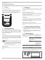 4
4
-
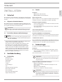 5
5
-
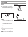 6
6
-
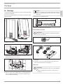 7
7
-
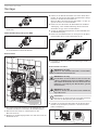 8
8
-
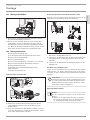 9
9
-
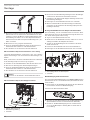 10
10
-
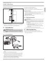 11
11
-
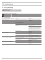 12
12
-
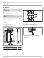 13
13
-
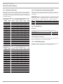 14
14
-
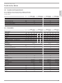 15
15
-
 16
16
-
 17
17
-
 18
18
-
 19
19
-
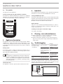 20
20
-
 21
21
-
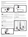 22
22
-
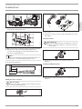 23
23
-
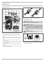 24
24
-
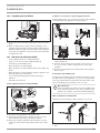 25
25
-
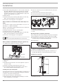 26
26
-
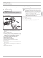 27
27
-
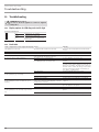 28
28
-
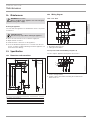 29
29
-
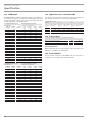 30
30
-
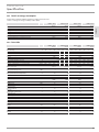 31
31
-
 32
32
-
 33
33
-
 34
34
-
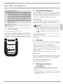 35
35
-
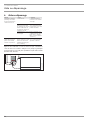 36
36
-
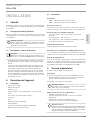 37
37
-
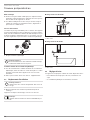 38
38
-
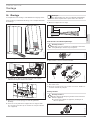 39
39
-
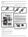 40
40
-
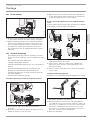 41
41
-
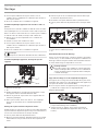 42
42
-
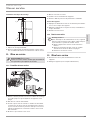 43
43
-
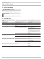 44
44
-
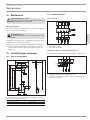 45
45
-
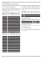 46
46
-
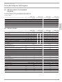 47
47
-
 48
48
-
 49
49
-
 50
50
-
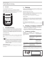 51
51
-
 52
52
-
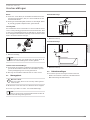 53
53
-
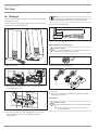 54
54
-
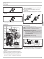 55
55
-
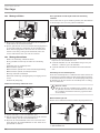 56
56
-
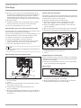 57
57
-
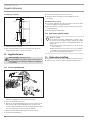 58
58
-
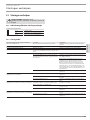 59
59
-
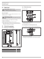 60
60
-
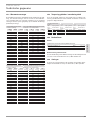 61
61
-
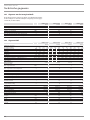 62
62
-
 63
63
-
 64
64
-
 65
65
-
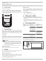 66
66
-
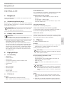 67
67
-
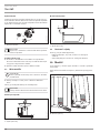 68
68
-
 69
69
-
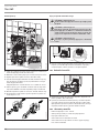 70
70
-
 71
71
-
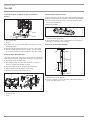 72
72
-
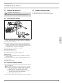 73
73
-
 74
74
-
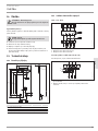 75
75
-
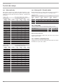 76
76
-
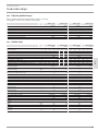 77
77
-
 78
78
-
 79
79
-
 80
80


STIEBEL ELTRON HDB-E 12-24 Si Operation Instruction
- Type
- Operation Instruction
in andere talen
- français: STIEBEL ELTRON HDB-E 12-24 Si
- Deutsch: STIEBEL ELTRON HDB-E 12-24 Si
- slovenčina: STIEBEL ELTRON HDB-E 12-24 Si
Gerelateerde papieren
-
STIEBEL ELTRON HDB-E 12-24 Si Operation Instruction
-
-
-
-
-
-
STIEBEL ELTRON 236739 Operation and Installation
-
-
STIEBEL ELTRON DHF 15 C Operating And Installation Instruction
-

