
1
de
fr
en
nl
de
fr
en
nl
5
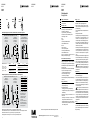
ohne Entspannungstopf| sans pot de détente | without blow tank | zonder ontspanningsreservoir
DNE | DNA: DIN 4751 T2 DSV-H L | m 1) DSV-DGH L | m 1) PSV | bar
DNE = SE ≤ 1 ≤ 1 DNE = SE ≤ 0,2 ≤ 1 ≤ 10
DNE = SE + 1DN ≤ 1,0 ≤ 1 ≤ 10
DNA = SA ≤ 2 ≤ 2 DNA = SA ≤ 5,0 ≤ 2 ≤ 5
DNA = SA + 1DN ≤ 4 ≤ 3 DNA = SA + 1DN ≤ 7,5 ≤ 3 > 5 ≤ 10
mit Entspannungstopf | avec pot de détente | with blow tank | met ontspanningsreservoir
1) Bögen, R ≥ 1,5 · DN
Coudes, R ≥ 1,5 · DN
Bends, R ≥ 1,5 · DN
Bogen, R ≥ 1,5 · DN
Entspannungstöpfe und Dimensionen für die Zu- und Ableitung nach nationalen Vorschriften.
Pots de détente et dimensions pour les conduites d‘alimentation et d’évacuation en fonction des prescriptions nationales.
Blow tanks and dimensions for the supply and discharge according to national provisions.
Ontspanningsreservoirs en afmetingen voor de toe- en afvoer volgens landelijke voorschriften.
SE
SA SA
SE
SA
SE
PSV
Q
DNE
DNA
PSV
Qtpr
EU: EN 12828, Q ≤ 300 kW; CH: SWKI HE301-01, Q ≤ 70 kW
direkt beheizt
chauffé directement
heated directly
direct verwarmd
indirekt beheizt
chauffé indirectement
heated indirectly
indirect verwarmd
DNE
DNA
PSV
Q
direkt und indirekt beheizt
chauffé directement et indirectement
heated directly and indirectly
direct en indirect verwarmd
DNE
DNA
CH: SWKI HE301-01, Q > 70 kW
PSV
ET ET
SWKI HE301-01: ≥ 6 m
Q
PSV
Qtpr
*
EU: EN 12828, Q > 300 kW; CH: SWKI HE301-01, Q > 70 kW
direkt beheizt
chauffé directement
heated directly
direct verwarmd
indirekt beheizt
chauffé indirectement
heated indirectly
indirect verwarmd
ET nur, falls tpr die Tabellenwerte
überschreitet, pD (tpr) > PSV.
ET uniquement si la valeur
tpr est supérieure aux valeurs
indiquées dans le tableau,
pD (tpr) > PSV.*
ET only if tpr exceeds the values
listed in the table, pD (tpr) > PSV.
ET alleen, als tpr de tabelwaarde
overschrijdt, pD (tpr) > PSV.
PSV | bar tpr | °C
2,0 133,5
2,5 138,5
3,0 143,5
3,5 148,0
4,0 152,0
4,5 156,0
5,0 160,0
DSV-DGH
DN 25 | 32
DSV-H DSV-DGH
DN 40 | 50
DSV
WDMOIN0002
06.2021
WDMOIN0002
06.2021
WDMOIN0002
06.2021
Montage- und Bedienpersonal
Das Personal muss die entsprechenden Fachkenntnisse besitzen
und eingewiesen sein.
Anwendung | Aufbau
• Absicherung des maximalen Druckes an Wärmeerzeugern
• Einsatz in Anlagen nach EN 12828, SWKI HE301-01
• Federbelastet, von Hand anlüftbar
• secuguard-Ausführung, 5 Jahre Gewährleistung
• Senkrechter Einbau, Pfeil für Fliessrichtung nach oben
• CE-bauteilgeprüft : Seite 6
DSV-H:
• Rotguss
• Federraum geschützt mittels Membrane
• Frostschutzmittelzusatz bis 100 %
DSV-DGH:
• DSV 25 + 32: Rotguss,
DSV 40 + 50: Sphäroguss GGG
• Federraum geschützt mittels Faltenbalg
• Frostschutzmittelzusatz bis 100 %
Andere als die beschriebenen Anwendungen bedürfen der
Abstimmung mit IMI Hydronic Engineering.
Parameter einhalten, Konformität prüfen
Sicherheitsventile, einschliesslich der Zu- und Ableitung sind
sorgfältig und anlagenspezifisch zu planen. Wir verweisen auf
unsere Werksangaben und die geltenden nationalen Regelungen
des Bestimmungslandes. Folgende Übereinstimmungen sind vor
dem Einbau zu prüfen:
• Bauteilprüfzeichen auf dem Oberteil mit Konformitätserklärung.
• Ansprechdruck PSV mit Vorgaben der Planung
= letzte Ziffer des Bauteilprüfzeichens in bar.
• Anschluss SE mit Vorgaben der Planung
= Kennzeichnung am Ventileingang.
• Maximal zulässige Absicherungstemperatur am Wärmeerzeuger
TAZ ≤ 120 °C.
Umgang | Gewährleistung
! Es gelten die Allgemeinen Verkaufs- und Lieferbedingungen
von IMI Hydronic Engineering.
! Die Gewährleistung erlischt bei:
• Beschädigung oder Entfernung der Werksplombierung.
• Unsachgemässem Umgang entgegen dieser Montage- und
Betriebsanleitung.
! Unsachgemässer Umgang kann Undichtheiten nach sich
ziehen, deshalb:
• Das Eindringen von Fremdkörpern in das Ventil ist bei der
Montage und während des Betriebes zu verhindern.
• Sorgfältige Behandlung bei Lagerung, Transport und Montage.
• Vorsicht bei Farbbehandlung. Gleitende Teile dürfen nicht mit
Farbe in Berührung kommen.
Montage : Seite 5
Nationale Regelungen, wie z.B. DIN 4751 T2 oder
SWKI HE301-01 beachten. Allgemeingültige Hinweise:
• Montage vorzugsweise am höchsten Punkt des Wärme-
erzeugers, bei anzunehmender Dampfausströmung zwingend
(z.B. direkte Beheizung).
• Auf leichte Zugänglichkeit achten, das Bauteilprüfzeichen muss
lesbar sein.
• Einfriergefahr ist auszuschliessen.
• Vor der Montage Anlage und Zuführungsleitung gut durchspülen.
• Keine statischen und dynamischen Belastungen auf die
Anschlüsse. Zu- und Abführungsleitungen separat und ther-
misch kompensiert lagern. Querschnittsverengungen sind unzu-
lässig. Die Leitungen sind so mit Gefälle zu verlegen, dass sich
kein Wasser ansammeln kann. Erforderlichenfalls sind geson-
derte Entwässerungen vorzusehen.
• Die Zuleitung DNE muss mindestens dem Eingangsquerschnitt
des Sicherheitsventiles SE entsprechen. Der Druckverlust darf
3 % des Ansprechdruckes PSV nicht überschreiten. Dies gilt
als erfüllt, wenn die Werte entsprechend Seite 5 eingehalten
werden.
• Die Ableitung DNA muss mindestens dem Ausgangsquerschnitt
SA des Sicherheitsventils entsprechen. Die Entwässerung soll
vorzugsweise durch Gefälle in Strömungsrichtung erfolgen. Der
Einbau von Entspannungstöpfen kann landesspezifisch erforder-
lich werden. Die Mündung der Ableitung muss beobachtbar sein.
Gefahrenstellen, wie die Mündung der Ausblaseleitung und
die Entwässerungsstellen, sind mit einem Gefahrenschild
zu kennzeichnen. Dies gilt auch für die Entlastungsbohrungen
an der Federhaube.
Betrieb | Wartung
Prüfung auf Gängigkeit durch Anlüften. Zeitabstände entspre-
chend den nationalen Regelungen.
• DSV-DGH undicht: Tritt das Medium an der Ableitung aus, dann
in der Regel Beseitigung durch Anlüften. Führt dies nicht zum
Erfolg oder tritt das Medium an der Entlastungsbohrung der
Federhaube aus, dann ist der Kundendienst zu verständigen.
• DSV-H undicht: In der Regel Beseitigung durch Anlüften Führt
dies nicht zum Erfolg dann:
Anlage so absperren, dass Sicherheitsventil drucklos und
Medium abgekühlt. Rändelmutter nach links drehen, das
Ventil ist angelüftet. Mit passendem Gabelschlüssel das gesam-
te Oberteil aus dem Gehäuse schrauben. Sitz und Sitzdichtung
mit Lappen und Pinsel reinigen, nicht schaben! Oberteil wieder
einschrauben und leicht anziehen. Rändelmutter nach rechts bis
zum Anschlag drehen. Das Ventil funktioniert wieder bei dem
eingestellten Druck.
Prüfung
Sicherheitsventile gehören zur Ausrüstung von Druckgeräten
nach PED 2014/68/EU. Entsprechend werden sie werksseitig
geprüft. Je nach Bestimmungsland können sie wiederkehrenden
Prüfungen unterliegen.
DSV
Sicherheitsventile
Montage | Betrieb
We reserve the right to introduce technical alterations without previous notice.
IMI Hydronic Engineering AG • Mühlerainstrasse 26 • CH-4414 Füllinsdorf • Tel. +41 (0)61 906 26 26
www.imi-hydronic.com

2 4
en
de
fr
nl
de
fr
en
nl
de
fr
en
nl
3
Montage- en bedieningspersoneel
Het personeel moet de overeenkomstige vakkennis hebben en
ingewerkt zijn.
Toepassing | Opbouw
• Beveiliging van de maximale druk op de warmtebronnen
• Inzetbaar in installaties conform EN 12828, SWKI HE301-01
• Veerbelast, manueel bedienbaar
• secuguard-uitvoering, 5 jaar garantie
• Verticale inbouw, pijl voor stroomrichting naar boven
• CE-componentcontrole : pagina 6
DSV-H:
• Brons
• Veerruimte door membraan beschermd
• Antivriestoevoeging tot 100 %
DSV-DGH:
• DSV 25 + 32: brons,
DSV 40 + 50: nodulair gietijzer GGG
• Veerruimte door vouwbalg beschermd
• Antivriestoevoeging tot 100 %
Andere toepassingen dan die hier beschreven worden, dienen
met IMI Hydronic Engineering afgestemd te worden.
Parameters aanhouden, onderzoek de conformiteit
Veiligheidsventielen, inclusief toe- en afvoer, moeten worden
gepland op een zorgvuldige manier en aangepast aan de
installatie. Wij verwijzen naar onze fabrieksgegevens en de
geldende landelijke regelingen van het land van bestemming.
Voorafgaand aan de montage moet worden gecontroleerd of de
volgende onderdelen met elkaar overeenstemmen:
• Componentkeurmerk op het bovenste gedeelte met conformi-
teitsverklaring.
• Aanspreekdruk PSV met waarden van de planning
= laatste cijfer van het componentkeurmerk in bar.
• Aansluiting SE met waarden van de planning
= code op de ventielingang.
• Maximaal toelaatbare temperatuurlimiet op de warmtebron
TAZ ≤ 120 °C.
Omgang | Garantie
! De Algemene Verkoops- en Leveringsvoorwaarden van
IMI Hydronic Engineering zijn van kracht.
! De garantie vervalt bij:
• Beschadiging of verwijdering van de fabrieksverzegeling.
• Ondeskundige omgang in strijd met deze montage- en
gebruikshandleiding.
! Ondeskundige omgang kan lekkages veroorzaken, daarom:
• Het binnendringen van vreemde voorwerpen in de ventiel
moet bij de montage en tijdens de werking worden verhin-
derd.
• Zorgvuldige behandeling bij opslag, transport en montage.
• Voorzichtig bij kleurbehandeling. Bewegende onderdelen
mogen niet met kleur in aanraking komen.
Montage : pagina 5
Landelijke regelingen, zoals DIN 4751 T2 of SWKI HE301-01
moet u in acht nemen. Algemeen geldende aanwijzingen:
• Montage bij voorkeur op het hoogste punt van de warmte-
bron, bij mogelijke dampuitstroming verplicht (bijv. directe
verwarming).
• Let op een goede toegankelijkheid, het componentkeurmerk
moet leesbaar zijn.
• Gevaar voor bevriezing moet worden uitgesloten.
• Voorafgaand aan de montage de installatie en de toevoeren
goed doorspoelen.
• Geen statische en dynamische belastingen op de aansluitin-
gen. Toe- en afvoerleidingen apart en thermisch gecompen-
seerd opslaan. Dwarse vernauwingen zijn ontoelaatbaar. De
leidingen moeten zodanig met niveauverschil worden geïn-
stalleerd dat er geen water kan samenstromen. Indien nodig
moeten er aparte ontwateringen worden voorzien.
• De toevoer DNE moet minimaal overeenkomen met de
ingangsdiameter van veiligheidsventiel SE. Het drukverlies
mag niet meer dan 3 % bedragen van aanspreekdruk PSV.
Hieraan wordt voldaan als de waarden zoals vermeld op
pagina 5 worden aangehouden.
• De afvoer DNA moet minimaal overeenkomen met uitvoer-
diameter SA van de veiligheidsventiel. De ontwatering vindt
bij voorkeur plaats door niveauverschil in stroomrichting. De
montage van ontspanningsreservoir kan voor uw land ver-
eist worden. De monding van de afvoer moet zichtbaar zijn.
Gevaarlijke plaatsen, zoals de monding van de uit-
blaasleiding en de ontwateringsplaatsen, moeten worden
aangeduid met een gevaarsbord. Dit geldt ook voor de ontlas-
tingsboring op de veerkap.
Werking | Onderhoud
Controle op doorgankelijkheid door luchtafvoer. Intervallen con-
form de landelijke regelingen.
• DSV-DGH lek: Als het medium bij de afvoer naar buiten komt,
dan kunt u dit doorgaans verhelpen met luchtafvoer. Als dit
geen resultaat oplevert of als het medium bij de ontlastingsbo-
ring van de veerkap naar buiten komt, dan dient u contact op
te nemen met de klantenservice.
• DSV-H lek: Doorgaans verhelpen met luchtafvoer. Levert dit
geen resultaat op, dan:
Installatie zo afsluiten dat de veiligheidsventiel drukvrij
is en het medium afkoelt. Kartelmoer naar links draaien,
de lucht in de ventiel wordt afgevoerd. Met een passende
gaffelsleutel schroeft u het hele bovenstuk uit de behuizing.
Reinig opening en afdichting met doek en penseel, niet schu-
ren! Bovenstuk weer opschroeven en voorzichtig aandraaien.
Kartelmoer naar rechts draaien tot aan de aanslag. De ventiel
werkt weer op de ingestelde druk.
Typegoedkeuring
Veiligheidsventielen horen bij de uitrusting van druktoestellen
conform PED 2014/68/EU. In overeenstemming met deze norm
worden ze in de fabriek gecontroleerd. Afhankelijk van het land
van bestemming kunnen er voor deze toestellen verplichte terug-
kerende controles bestaan.
WDMOIN0002
06.2021
WDMOIN0002
06.2021
DSV
Veiligheidsventielen
Montage | Werking
WDMOIN0002
06.2021
Personnel opérateur et personnel de montage
Le personnel doit être qualifié et posséder des connaissances
spécifiques.
Application | Structure
• Protection de la pression maximale pour les générateurs de
chaleur
• Utilisation dans les installations conformément aux normes
EN 12828, SWKI HE301-01
• À ressort, pouvant être testée manuellement
• Modèle secuguard, 5 ans de garantie
• Installation verticale, flèche pour sens d’écoulement vers le haut
• Composant contrôlé CE : page 6
DSV-H :
• Bronze
• Partie à ressort protégée par une membrane
• Adjuvant antigel jusqu’à 100 %
DSV-DGH :
• DSV 25 + 32 : bronze,
DSV 40 + 50 : graphite sphéroïdal GGG
• Partie à ressort protégée par un joint-soufflet
• Adjuvant antigel jusqu’à 100 %
Un accord de la société IMI Hydronic Engineering est nécessaire
pour toute autre application que celles décrites.
Respect des paramètres, examinez la conformité
Des soupapes de sécurité, y inclus la conduite d’alimentation et
d’évacuation, doivent être planifiées minutieusement et de manière
spécifique à l’installation. Nous renvoyons à nos indications par
défaut et aux réglementations nationales en vigueur dans le pays
de destination. Les conformités suivantes doivent être contrôlées
avant de procéder au montage :
• Signe d’homologation du composant sur la partie supérieure par
rapport à la déclaration de conformité.
• Pression d’ouverture PSV par rapport aux données fixées lors de
la planification
= dernier chiffre du signe d’homologation du composant, en bar.
• Raccordement SE par rapport aux données fixées lors de la
planification
= identification à l’entrée de la soupape.
• Température de protection maximale admissible sur le généra-
teur de chaleur TAZ ≤ 120 °C.
Maniement | Garantie
! Les conditions générales de vente de IMI Hydronic Engineering
sont valables.
! La garantie expire dans les cas suivants :
• Endommagement ou élimination du plombage d’usine.
• Maniement non conforme aux stipulations des instructions de
montage et de service.
! Etant donné qu’un maniement incorrect peut entraîner des fuites,
il faut respecter les points suivants :
• Empêcher la pénétration de corps étrangers dans la soupape
lors du montage et durant le service
• Assurer un maniement correct durant le stockage, le transport et
le montage.
• Travailler avec prudence lors du traitement de couleurs. Des
pièces coulissantes ne doivent pas entrer en contact avec la
couleur.
Montage : page 5
Respecter les réglementations nationales en vigueur, telles que par
exemple DIN 4751 T2 ou SWKI HE301-01. Consignes générales :
• Le montage doit de préférence être effectué sur le point le plus
élevé du générateur de chaleur, ceci étant toute-fois obligatoire si
une évacuation de vapeur est possible (par exemple en cas de
chauffage direct).
• Veiller à assurer un accès simple, le signe d’homologation du
composant doit être lisible.
• Tout risque de gel doit être exclu.
• Bien rincer l’installation et la conduite d’alimentation avant le
montage.
• Veiller à ce que les raccordements ne soient pas soumis à des
contraintes statiques et dynamiques. Garantir un stockage indivi-
duel et à compensation thermique des conduites d’alimentation
et d’évacuation. Des rétrécissements en coupe transversale sont
inadmissibles. Les conduites doivent être posées avec une incli-
naison telle à éviter toute accumulation d’eau. Le cas échéant, il
faut prévoir des évacuations des eaux particulières.
• La conduite d’alimentation DNE doit correspondre au moins à la
coupe transversale d’entrée de la soupape de sécurité SE. La
perte de pression ne doit pas être supérieure à 3 % de la pression
d’ouverture PSV. Ceci est considéré être conforme si les valeurs
indiquées à la page 5 sont respectées.
• La conduite d’évacuation DNA doit correspondre au moins à
la coupe transversale de sortie SA de la soupape de sécurité.
L’évacuation des eaux doit de préférence être réalisée par une
inclinaison dans le sens de l’écoulement. Le montage de pots de
détente peut être nécessaire selon le pays d’utilisation. Le dégor-
gement de la conduite d’évacuation doit pouvoir être observé.
Des points présentant des risques, tels que par exemple
le dégorgement de la conduite d’évacuation et les points
d’évacuation des eaux doivent être pourvus d’un panneau indi-
cateur de danger. Ceci est également valable pour le trou d’équi-
librage figurant sur le recouvrement de ressort des soupapes.
Exploitation | Maintenance
Contrôle du fonctionnement par desserrage. Intervalles conformé-
ment aux réglementations nationales.
• DSV-DGH non étanche : si le fluide s’échappe de la conduite
d’évacuation, il est en règle générale possible d’y remédier par
desserrage. S’il est toutefois impossible d’y remédier ou bien si le
fluide s’échappe au niveau du trou d’équilibrage du recouvrement
de ressort, il faut en informer le service après-vente.
• DSV-H non étanche : En règle générale, il est possible d’y remé-
dier par desserrage. S’il est toutefois impossible d’y remédier :
Sectionner l’installation de manière à ce que la soupape
de sécurité soit sans pression et que le fluide soit refroidi.
Tourner l’écrou moleté vers la gauche pour desserrer la soupape.
Avec une clé plate, dévisser toute la partie supérieure pour la sortir
du boîtier. Nettoyer le siège de soupape et le joint au moyen d’un
chiffon et d’un pinceau. Ne pas gratter! Revisser la partie supérieure
et la serrer légèrement. Tourner l’écrou moleté à fond vers la droite.
La soupape fonctionne alors de nouveau à la pression ajustée.
Contrôle
Les soupapes de sécurité font partie de l’équipement d’appareils
sous pression selon PED 2014/68/EU. Elles sont donc contrôlées
en usine. Selon le pays de destination, elles peuvent éventuelle-
ment être soumises à des contrôles récurrents.
DSV
Soupapes de sécurité
Montage | Exploitation
Installation and operating staff
The staff must have the appropriate knowledge and must be
competent.
Application | Installation
• Protection of the maximum pressure on heat generators
• Deployment in systems according to EN 12828,SWKI HE301-01
• Spring-loaded, can be vented manually
• secuguard version, 5-year warranty
• Vertical installation, arrow for flow direction to the top
• CE-component inspected : page 6
DSV-H:
• Gun Metal
• Spring compartment protected by diaphragm
• Addition of antifreeze agent up to 100 %
DSV-DGH:
• DSV 25 + 32: gun metal,
DSV 40 + 50: nodular graphite iron GGG
• Spring compartment protected by expansion bellow
• Addition of antifreeze agent up to 100 %
Other applications than the ones described require the agree-
ment of IMI Hydronic Engineering.
Observing the parameters, examine the conformity
Safety valves, including the supply and discharge lines, are to
be planned carefully and individually for the specific system. We
refer to our factory specifications and the applicable national
regulations of the country of destination. The following is to be
checked prior to the installation:
• Correspondence of component test mark on the upper part
with declaration of conformity.
• Correspondence of pick-up pressure PSV with planning
specifications
= last digit of the component test mark in bar.
• Correspondence of SE with planning specifications
= identification at the valve mouth.
• Maximum admissible protection temperature at the heat gen-
erator TAZ ≤ 120 °C.
Handling | Warranty
! The General Conditions of Sale and Delivery of IMI Hydronic
Engineering shall apply.
! The warranty expires in the following cases:
• Damage or removal of the factory lead seal.
• Improper handling contrary to these installation and operating
instructions.
! An improper handling may result in leakages, therefore:
• The penetration of foreign matters into the valve is to be
avoided during the installation and the operation.
• A careful handling with respect to storage, transport and
installation is to be ensured.
• Be careful when treating with paint. Sliding parts must not
come into contact with paint.
Installation : page 5
Observe national regulations, such as DIN 4751 T2 or SWKI
HE301-01. General notes:
• It is recommended to perform the installation at the highest
point of the heat generator, with an expected discharge of
vapour (e.g. direct heating) this is com-pulsory.
• Ensure an easy accessibility, the component test mark must
be readable.
• Any risk of freezing is be excluded.
• Thoroughly rinse system and supply line prior to the installation.
• No static and dynamic loads on the connections. Store supply
and discharge lines separately and ensure the thermal com-
pensation. Cross section contractions are not allowed. The
lines are to be installed with a gradient in such a manner that
no water may accumulate. If required, separate drains are to
be provided.
• The DNE supply line must at least correspond to the input
cross section SE of the safety valve. The pressure loss must
not exceed 3 % of the pick-up pressure PSV. This is deemed
to be met if the values according to page 5 are observed.
• The DNA discharge line must at least correspond to the output
cross section SA of the safety valve. The drainage is to be pref-
erably performed by means of gradients in flow direction. The
installation of blow tanks may be required in some countries. It
must be possible to observe the opening of the discharge line.
Dangerous spots, such as the opening of the blow out
line and the drainage points, are to be identified with a
hazard sign. The same applies to the relief well at the spring
bonnet.
Operation | Maintenance
Check for mobility by means of carefully ventilating. Time inter-
vals according to the national regulations.
• DSV-DGH leaky: If the medium penetrates at the discharge,
typically remedy by means of carefully ventilating. If this is not
successful or the medium penetrates at the relief well of the
spring bonnet, please contact the customer service.
• DSV-H leaky: Typically, remedy by means of carefully venti-
lating. If this is not successful, then:
Shut off the system in such a manner that the safety
valve is depressurized and the medium has cooled
down. Turn the knurled nut to the left, the valve is released.
Use the appropriate open-end wrench to screw the complete
upper part out of the casing. Clean receiver and receiver seal
using a cloth and brush, do not scrape! Screw on the upper
part again and tighten carefully. Turn the knurled nut to the
right until the stop. The valve works again at the set pressure.
Test
Safety valves are included in the equipment of pressure devices
according to PED 2014/68/EU. Accordingly, they are tested in
the factory. Depending on the country of destination they may
be subject to recurring inspection.
DSV
Safety valves
Installation | Operation
-
 1
1
-
 2
2


in andere talen
Gerelateerde papieren

Andere documenten
-
Peg-Perego ECE R04 Handleiding
-
Electrolux ERA34291W Handleiding
-
-
-
-
Weller WDD 81V Operating Instructions Manual
-
-
Lenco SP-500 silber de handleiding
-
Atag KA2411L Handleiding
-
Bostitch BULLDOG Handleiding