

D-Box User's Manual English 2 / 76
tiko Energy Solutions AG IM-0007-0006 Rev. 10
Safety Warnings and Working Instructions
Hazard Risk
Read the user manual before installing and operating this product!
Installation by person with electronical expertise and trained on this product
only!
Disconnect all power sources before carrying out any manipulation!
Always use appropriate protection equipment!
Danger! High voltage!
Never touch disconnected wires! Life hazard!
Only use for current/voltage as indicated on the device label! Doing other-
wise can cause device damage and may pose an electrical shock or fire haz-
ard!
Not properly tightened screws can cause a high contact resistance, lead to
overheating, and cause a fire hazard!
Warnings
• Read the installation instructions before you connect the system to its power
source.
• To prevent the system from overheating, do not operate it in an area that ex-
ceeds the maximum admitted ambient temperature of 55 °C.
• This product relies on the building’s installation for short-circuit (over current)
protection. Ensure that a fuse or circuit breaker no larger than 230 VAC, 16 A is
used on all current-carrying conductors.
• Do not work on the system or connect or disconnect cables during periods of
lightning activity.
• This device must be installed only in electrical installations compliant to the most
recent valid national regulations.

D-Box User's Manual English 3 / 76
tiko Energy Solutions AG IM-0007-0006 Rev. 10
• Device is intended for indoor use only.
• Ultimate disposal of this product should be handled according to all national
laws and regulations.
• Any usage of this device in a manner that does not conform to this manual spec-
ification can impair the provided safety protection.
Safety Instructions
Read these safety instructions carefully.
• Follow common household electrical safety practices.
• Read all cautions and warnings on the equipment.
• Disconnect this equipment from the socket before cleaning it. Do not use liquid
or sprayed detergent for cleaning. Use moisture sheet or cloth for cleaning.
• The openings on the enclosure are for air convection and protect the equipment
from overheating. Do not cover the openings.
• Do not pour any liquid into opening. This could cause fire or electrical shock.
• Do not open the enclosure of this product and/or alter this product in any way.
• Have the equipment checked by a service professional if one of the following
situations arises:
o The line is damaged.
o Liquid has entered the equipment.
o The equipment has been exposed to moisture.
o The equipment does not work properly, or you cannot get it to work
according to user’s manual.
o The equipment has been dropped or damaged.
o The equipment has obvious signs of breakage.
• Keep this equipment away from excessive or condensing humidity.
• Do not leave this equipment in an unconditioned environment. Temperatures
above 55 °C will damage the equipment.
• Keep this guide for later reference.
Feedback
You can submit comments via email to [email protected]
You can also submit your comments via regular mail by writing to the following address:
tiko Energy Solutions AG
Pflanzschulstrasse 7
CH-8004 Zürich
We appreciate your comments.

D-Box User's Manual English 4 / 76
tiko Energy Solutions AG IM-0007-0006 Rev. 10
Overview
Intended Use
The D-Box is a decentralized energy meter and switch to control electrical heaters. All D-
Boxes together require an M-Box (Gateway) to communicate to the back-end private
cloud. Each D-Box requires an external temperature sensor (REF CASTH-01.1004-01) to
know about the room it shall control.
D-Boxes and the accessories from the D-Box kit are to be only used in tiko Energy Solu-
tions AG authorized setups. They cannot be used standalone. Any installation or usage
which does not conform to tiko Energy Solutions AG setup is strictly forbidden. tiko Energy
Solutions AG is not responsible for any improper installation/usage of this device.
Features
The D-Box features:
• Relay: 230 V – 16 A
• Fil Pilote IN and OUT
• Status LEDs showing data link and device errors.
• A push button to perform different tests.
Package Content
Open the package and check that you have all the following items:
For Kit K01-CDK-01.1016-01-P1:
• Instruction manual (REF IM-0007-0013)
• D-Box (IMAGE 1 and IMAGE 2)
• Metal holder with screw holes and adhesive tape (IMAGE 6)
• Pre-wired socket (REF CDS-01-P1), see IMAGE 5
If any of the parts are incorrect, missing, or damaged, please contact the retailer where
you made your purchase. Keep the carton box, including the original packing materials, in
case you need to return the unit for repair.

D-Box User's Manual English 5 / 76
tiko Energy Solutions AG IM-0007-0006 Rev. 10
Package Content (Legacy Products)
In case your unit does not come with the metal holder, it belongs to the group of legacy
kits that are not produced anymore. Your package content will be different. In this case
use the following table to check:
K01-CDK-01.1014-01-P1
K02-CDK-01.1014-01-P1
K03-CDK-01.1014-01-P1
K01-CDK-01.1016-01-P1
K02-CDK3-01.1016-01-P1
D-Box (IMAGE 1 and IMAGE 2)
✓
✓
✓
✓
✓
Instruction manual (REF IM-0007-0013)
✓
✓
✓
✓
✓
A sealed bag of Velcro patches and/or double tape to
mount the D-Box to the wall
✓
✓
✓
✓
✓
Socket (REF CDS-01-P1), see IMAGE 3
✓
✓
✓
Pre-wired socket (REF CDS-01-P1), see IMAGE 5
✓
✓
Tap (REF CATA-01.1103-P1), see IMAGE 4
✓
✓
✓
If any of the parts are incorrect, missing, or damaged, please contact the retailer where
you made your purchase. Keep the carton box, including the original packing materials, in
case you need to return the unit for repair.
Device: D-Box
IMAGE 1 and IMAGE 2 show a D-Box from the plug side and from the button side. Your
D-Box may look differently, as for some electricity providers the D-Box comes in a cus-
tom design. (A) marks the location of the LED. It is hidden and only visible when on. (B)
marks the button.
On the bottom side, two labels are indicating:
• The manufacturer
• The device model number (REF) and current rating
• The hardware (HW) and firmware (FW) version
• The unique serial/MAC address as text and as Aztec 2D code (SN/MAC)

D-Box User's Manual English 6 / 76
tiko Energy Solutions AG IM-0007-0006 Rev. 10
Device: Socket
IMAGE 3 shows the socket. It is connected to the electrical wiring of the heater and of-
fers a socket to plug the D-Box. It features 5 screw terminals for the contacts and a strain
relief (IMAGE 7).
On the top cover is indicated
• The manufacturer
• The device model number (REF) and current rating
Device: Continuity Bridge (Tap)
IMAGE 4 shows the continuity bridge. If a customer decides not to take part in the tiko
cloud, the D-Box can be removed from the socket and the continuity bridge is engaged
to restore the original contacts for manual operation of the electric heater.
Accessory: Holder
IMAGE 6 shows the D-Box holder. It is mounted on the wall and holds the D-Box plugged
into the socket. This facilitates the handling of the D-Box, for example on disconnect or
replace: The device can first be brought out from behind the heater and then operated in
a more comfortable position.

D-Box User's Manual English 7 / 76
tiko Energy Solutions AG IM-0007-0006 Rev. 10
Installation
Installation by person with electronical expertise and trained on this
product only!
Do not install the device unless you have removed the main power sup-
ply (main breaker or fuses)!
IMAGE 17 shows possible D-Box locations around the heater. The best
position is bottom left, right or center. Under no circumstances install
the D-Box above the heater. This will result in thermal issues and my
damage the device!
Installing the D-Box
Step 1
Remove power from the electrical panel.
Step 2
Unhook the heater from its holder and put it to the side.
Plan the location of the D-Box in advance. It should be in 2 – 3 cm of
the heater (IMAGE 10) and a permitted position (IMAGE 17). Use, for
example, a pencil to carefully mark the planned location.
Step 3
Disconnect the radiator from the wall.
If you own the Kit K03-CDK-01.1014-01-P1 or K01-CDK-01.1016-01-
P1, the D-Box socket is already equipped with a piece of cable on one
side.
The legacy kits that are not yet equipped with pre-wired socket need an
additional small piece of suitable cable. Ensure the cable is compliant.
Prepare the wires where necessary by crimping bootlace ferrules.
Step 4
Remove the cover from the socket. If you hold the socket like displayed
in IMAGE 18, clamp the phase coming from the wall/source into the top
terminal, and the phase going to the heater into the bottom terminal.
Step 5
Clamp the neutral wire coming from the wall/source and going to the
heater into the middle terminal. There is space on both sides of the
screw for two wires.
Step 6
If your heater supports Fil Pilote: hold the socket as displayed in IM-
AGE 18, clamp the Fil Pilote coming from the wall/source into upper
middle terminal and the Fil Pilote going to the heater into the lower mid-
dle terminal. A proper wiring is displayed in IMAGE 8.

D-Box User's Manual English 8 / 76
tiko Energy Solutions AG IM-0007-0006 Rev. 10
Step 7
Firmly tighten any unused terminal.
Step 8
Fasten the strain relief to prevent the wires in the terminal from being
pulled out.
Tighten again all clamp screws with enough torque. Insuffi-
cient clamping force can result in high contact resistance
that leads to device heating and can result in a fire hazard.
Step 9
Put back the cover of the socket.
Step 10
Engage the D-Box and the socket as displayed in IMAGE 9. Push the
two levers of the socket in order to open the safety shutter and plug in
the D-Box.
Pay attention to the orientation of the socket and D-Box
when plugging. The printed text on the socket and the top
side of the D-Box must be on the same side (see IMAGE 9).
Step 11
IMAGE 17 shows the permitted and prohibited positions for mounting
the D-Box.
It is forbidden to place the D-Box above the heater for ther-
mal reasons. The device could overheat. Preferred position
is below the heater or laterally below (IMAGE 17).
Ensure a distance of 2 cm – 3 cm between the heater and
the D-Box (IMAGE 10).
Depending on the mounting solution supplied with your unit, you will
need to proceed to either Step 11a or Step 11b.
If your device is equipped with the metal holder (IMAGE 6), please pro-
ceed with Step 11a.
If your device is equipped with an air-sealed bag containing 3 patches of
Velcro and/or double tape, please proceed with Step 11b.
Step 11a
The D-Box holder can be mounted with screws (preferred if the condi-
tion of the wall allows it) or with an adhesive tape. It can be installed in
all directions, including upside down (IMAGE 15 and IMAGE 16).
By means of screws:
Use two screws size 4x20 with countersunk head. Examples:
Wood/chipboard screw, screw with dowel.

D-Box User's Manual English 9 / 76
tiko Energy Solutions AG IM-0007-0006 Rev. 10
The type of screw must be appropriate for the correspond-
ing wall.
When using dowels, make sure that (i) the dowel size fits the
screw size and (ii) the type of dowel is appropriate for the
wall.
Fasten the holder in the desired location (IMAGE 12). Refer to IM-
AGE 17 for permitted and prohibited locations of the D-Box.
By means of adhesive tape:
The adhesive tape supplied with the holder is a Nano Suction Tape. Its
adhesive force is generated by nano-sized suction cups. It is adhesive-
free and does not dry out.
Peel off the protective film as shown in IMAGE 13. The permitted and
prohibited positions of the D-Box are shown in IMAGE 17. Press the
holder firmly into the desired position.
The wall must be free of dust. Otherwise, the dust will clog
the nano-sized suction cups and the holder will fall off
shortly after.
When pressing against the wall, ensure that you apply an
evenly distributed force of at least 15 kg. Unlike adhesive-
based tapes, the adhesion force of the Nano Tape depends
on the contact pressure.
After successfully mounting the holder, slide the D-Box (plugged into
the socket, see Step 10) into the holder (IMAGE 14).
tiko is not liable for damage caused by improper mounting
or due to defective condition of the building substance.
Step 11b
Open the sealed bag and place the patches onto the D-Box and socket
at the positions indicated in IMAGE 11.
Remove the protection foils and push the D-Box onto the wall at the
desired location. Refer to IMAGE 17 for permitted locations. Hold it for
several seconds.
The D-Box should now stay in place. If it seems loose, the glue on the
patches has been dried out due to bad storage conditions. Contact your
reseller to obtain fresh patches.

D-Box User's Manual English 10 / 76
tiko Energy Solutions AG IM-0007-0006 Rev. 10
The glue of the patches needs to dry for at least for 24
hours before reaching full strength. Do not unplug or move
the D-Box during this time.
Step 12
Lift the heater back to its hooks.
Step 13
Power on the system by enabling power in the electrical panel. Config-
ure the heater to the hottest possible level/temperature.
Step 14
To finalize the installation, all tiko devices must be configured using the
installation app. Remind that to each room with one or multiple D-Boxes
belongs a temperature sensor (REF: CASTH-01.1004-01).
Operation
Device Operation
There are two functions assigned to the button:
• Short press (min. 1 sec., less than 5 sec.) – test communication quality to the
Gateway. For the description of the LED, see section LED Explanation.
• Long press (more than 5 sec.) – Heater test. For details, please refer to the sec-
tion Heater Test.
The D-Box is subject to the control of the full system and operated by the Data Center
through the Gateway (M-Box). No user interaction is required.

D-Box User's Manual English 11 / 76
tiko Energy Solutions AG IM-0007-0006 Rev. 10
LED Explanation
The D-Box features one LED in the middle of the device. It is only visible when lit.
• In normal operation:
LED
Status
Notes
Off
Operational
Blinking yellow,
2x per second
No PLC connectivity
Blinking yellow,
1x per second
No connection to
cloud/back-end
Red
Power-on self-test failure.
For example, when wrongly wired
Blinking red
Emergency mode
Device is damaged or has hardware mal-
function. The relay is closed so that the
heater can be operated manually.
• In firmware upgrade mode:
LED
Status
Notes
Blinks yel-
low/green 2x
per second
Device running firmware
upgrade
• If the button is pressed for one second, the LED displays the quality of the com-
munication to the Gateway:
LED
Status
Notes
Steady Red
No connectivity
Since the last start of the device, it did not
receive any data.
Blinking yellow,
4x per second
No communication for 2
minutes
At least one data packet was received, but
for 2 minutes the device did not receive
any signal.
Steady Green
The communication is in
the optimal state
• In Heater Test mode: see section Heater Test.

D-Box User's Manual English 12 / 76
tiko Energy Solutions AG IM-0007-0006 Rev. 10
Heater Test
A long press of the button (more than 5 seconds) triggers a test of the electrical heater.
With this, the D-Box can check if the wiring is correct. The test is executed locally on the
D-Box and does not need any connectivity to the Gateway or the back-end.
The test is available for both Fil Pilote and Relay mode. To choose the correct mode, the
D-Box must have been properly configured in the install app.
The test consists of the following steps:
1. Switch the heater ON.
2. Wait for it to consume a certain amount of energy during a certain time.
3. Switch the heater OFF.
4. Ensure if the heater stops consuming.
5. Repetition of steps 1 to 4.
6. Display of the result:
LED
Status
Off
Test not running or stopped.
Blinking Green
Test in progress.
Steady Green
Test completed successfully.
Steady Red
The test failed during a switch.
Blinking Red
The test failed while trying to keep
the heater on or off.
7. Now the button must be pressed again to exit from the test.
If step 7 – exit the test by pressing again the button – is forgotten, the
LED will continue to display the result status. In case this step was for-
gotten during the installation process, just press the button again.
The test relies on a proper configuration of the Relay vs. Fil Pilote
mode of the D-Box. For example, if the Heater features Fil Pilote, but
the D-Box is set to Relay Mode, the test will complete successfully
(but maybe the heater will beep or switch on and off). The other way
around the test will fail.

D-Box User's Manual English 13 / 76
tiko Energy Solutions AG IM-0007-0006 Rev. 10
Uninstalling
The D-Box can be uninstalled in 3 different ways:
Decommissioning
In the backend, the D-Box can be disabled. In this case, a relay inside the D-Box is closed
in such way that the wires are bridged. The D-Box remains in place, but the heater can
be operated manually.
Continuity Bridge
The D-Box is removed from the socket. The socket is bridged using the Continuity Bridge
CATA-01.1103-P1) displayed on IMAGE 4.
Complete Uninstallation
Step 1
Remove power from the electrical panel.
Step 2
Unhook the heater from its holders and put it to the side.
Step 3
Unplug the D-Box, open the socket and unscrew all wires.
Step 4
Reconnect the wires from the heater to the wall/source again.
Step 5
If your unit is equipped with a metal holder, remove it.
If the holder is mounted by means of screw, unscrew the holder, and fill
the holes with putty.
If the holder is mounted with the Nano Tape, carefully and slowly rotate
the holder, until it starts to come off. Further twist and tilt the holder
until it comes off completely. Ensure the wall and/or paint is not dam-
aged. You might need to rub off remaining Nano Tape with your finger.
Step 6
Lift the heater back onto its holders and power on the system by ena-
bling power in the electrical panel.
Step 7
If the device remains property of tiko Energy Solutions AG or
its authorized reseller, it must be returned. Otherwise, the
ultimate disposal of a device shall be handled according to
national laws and regulations.

D-Box User's Manual English 14 / 76
tiko Energy Solutions AG IM-0007-0006 Rev. 10
Specifications
Device Characteristics
Product Number
CD-01.1014-01-P1 (D-Box)
CD-01.1016-01-P1 (D-Box)
CDS-01-P1 (Socket)
CATA-01.1103-P1 (Continuity Bridge)
Input / Output Voltage
230 VAC ± 10%
Input / Output Relay Current
max. 16 A (not fused)
Input / Output Fil Pilote Current
max. 100 mA (fused)
Wire Specification for Load
1.5 mm2 (AWG 16)
Wire Specification for Fil Pilote
1.5 mm2 (AWG 16)
Frequency
50 Hz
Overvoltage Category
OVC II
Voltage of Breaker before D-Box
max. 240 V
Current of Breaker before D-Box
max. 16 A
Connectivity
PLC HomePlug GreenPHY
User Interface
1 push button, 1 LED
Dimensions
136 x 134 x 39 mm (REF CD-01.1014)
160 x 125 x 42 mm (REF CD-01.1016)
Weight
235 g (REF CD-01.1014)
251 g (REF CD-01.1016)
Max. Power Consumption
3 W
Metrology Characteristics
Power Meter
Active Energy: Class C (± 0.5%)
Reactive Energy: Class B (± 1%)
Min. Measurable Current
± 0.05 A
Operating Conditions
Storage Conditions
Temperature (min.)
-10 °C
-20 °C
Temperature (max.)
+55 °C
+70 °C
Relative Humidity
10% - 85%
no condensation
5% - 95%
no condensation
Maximum Altitude
2000 m
-

D-Box User's Manual English 15 / 76
tiko Energy Solutions AG IM-0007-0006 Rev. 10
Obtaining the Declaration of Conformity
Intended Use
The D-Box is a custom single-phase energy meter and remotely controlled switch to be
only used in tiko Energy Solutions AG authorized setups.
Safety Information
tiko Energy Solutions AG
Pflanzschulstrasse 7
CH-8004 Zürich
The products CD-01.1014-01-P1, CD-01.1016-01-P1, CDS-01-P1 and – if part of the
kit – CATA-01.1103-P1 in the form as delivered conform to the provisions of the follow-
ing European directives: 2011/65/EU on hazardous substances, 2014/35/EU on low
voltage devices, 2014/30/EU on electromagnetic compatibility.
A copy of the declaration of conformity can be requested by writing to the postal ad-
dress or is available on http://um.tiko.energy/1014 or http://um.tiko.energy/1016 re-
spectively.

Betriebsanleitung D-Box Deutsch 16 / 76
tiko Energy Solutions AG IM-0007-0006 Rev. 10
Sicherheitshinweise und Arbeitsanweisungen
Gefahrenrisiko
Lesen Sie das Benutzerhandbuch, bevor Sie dieses Gerät installieren und be-
dienen!
Installation ausschliesslich durch Person mit Sachkenntnis in Elektronik und
auf diesem Produkt geschult!
Trennen Sie alle Energiequellen vor der Bedienung dieses Geräts!
Benützen Sie immer angemessene Schutzkleidung!
Gefahr! Hochspannung!
Niemals lose Kabel berühren! Lebensgefahr!
Ausschliesslich für Gebrauch mit Strom/Spannung wie auf dem Geräteetikett
angegeben! Anderenfalls ist eine Beschädigung des Gerätes und damit ein
Stromschlag oder eine Brandgefahr möglich!
Nicht genügend angezogene Schrauben von Klemmen verursachen einen ho-
hen Kontaktwiderstand, welcher zu Überhitzung und Brandgefahr führen
kann!
Warnungen
• Lesen Sie die Installationsanweisungen, bevor Sie dieses Gerät an eine Strom-
quelle anschliessen.
• Um das System vor Überhitzung zu schützen, betreiben Sie es nicht in einer
Umgebung, welche die Temperatur von 55 °C übersteigt.
• Dieses Produkt ist auf das Vorhandensein eines Kurzschlussschutzes im Ge-
bäude angewiesen. Stellen Sie sicher, dass alle stromführenden Leiter durch eine
Sicherung oder einen Leistungsschalter nicht grösser als 230 VAC, 16 A ge-
schützt sind.
• Führen Sie keinesfalls Arbeiten am System oder an den Kabeln durch während
eines Gewitters.
• Dieses Gerät darf nur in elektrischen Installationen installiert werden, die den
jeweils aktuellsten gültigen nationalen Vorschriften entsprechen.

Betriebsanleitung D-Box Deutsch 17 / 76
tiko Energy Solutions AG IM-0007-0006 Rev. 10
• Gerät nur für den Innengebrauch.
• Endgültige Entsorgung dieses Geräts muss gemäss nationalen Gesetzen und
Vorschriften erfolgen.
• Jedweder Gebrauch dieses Geräts, welcher nicht dem Benutzerhandbuch ent-
spricht, kann den vorhandenen Schutz beeinträchtigen.
Sicherheitshinweise
Lesen Sie diese Sicherheitshinweise sorgfältig durch.
• Befolgen Sie gängige Sicherheitsregeln im Haushalt.
• Lesen Sie alle Hinweise und Warnungen auf dem Gerät.
• Entfernen Sie das Gerät aus der Steckdose, bevor Sie es reinigen. Benutzen Sie
kein flüssiges oder gespraytes Reinigungsmittel. Benützen Sie ein feuchtes Tuch
oder Stück Stoff zur Reinigung.
• Die Öffnungen im Gehäuse dienen der Luftzirkulation und schützen das Gerät
vor Überhitzung. Blockieren Sie nicht die Öffnungen.
• Leeren Sie keine Flüssigkeit in eine der Öffnungen. Dies kann zu einem Brand
oder Elektroschock führen.
• Öffnen Sie weder das Gehäuse dieses Gerätes noch modifizieren Sie es auf ir-
gendeine Weise.
• Lassen Sie das Gerät bei einem professionellen Service-Techniker überprüfen,
sollte eine der folgenden Bedingungen auftreten:
o Die Leitung ist beschädigt.
o Flüssigkeit ist ins Gerät eingedrungen.
o Das Gerät wurde Feuchtigkeit ausgesetzt.
o Das Gerät funktioniert nicht einwandfrei, oder es lässt sich nicht wie
im Benutzerhandbuch beschrieben betreiben.
o Das Gerät wurde fallengelassen oder beschädigt.
o Das Gerät weist sichtbare Spuren von Beschädigung auf.
• Halten Sie dieses Gerät von übermässiger oder kondensierender Feuchtigkeit
fern.
• Setzen Sie dieses Gerät nicht einer unkontrollierten Umgebung aus. Tempera-
turen über 55 °C werden das Gerät beschädigen.
• Bewahren Sie dieses Dokument für den späteren Gebrauch auf.
Rückmeldungen
Sie können Bemerkungen an [email protected] senden.
Ebenfalls können Sie uns Bemerkungen auf dem regulären Postweg senden, indem Sie
an diese Anschrift schreiben:
tiko Energy Solutions AG
Pflanzschulstrasse 7
CH-8004 Zürich
Wir freuen uns über Ihre Rückmeldung.

Betriebsanleitung D-Box Deutsch 18 / 76
tiko Energy Solutions AG IM-0007-0006 Rev. 10
Übersicht
Verwendungszweck
Die D-Box ist ein dezentraler Energiemesser und Schalter, um elektrische Heizungen zu
kontrollieren. Alle D-Boxen benötigen eine M-Box (Gateway), um mit der Backend-Cloud
zu kommunizieren. Jede D-Box benötigt einen externen Temperatursensor (REF CASTH-
01.1004-01) zur Kenntnis der Raumtemperatur für die Steuerung.
D-Boxen und Zubehör des D-Box-Kits sind für die ausschliessliche Verwendung in durch
tiko Energy Solutions AG autorisierten Installationen. Jegliche Installation oder Verwen-
dung, welche nicht den Richtlinien von tiko Energy Solutions AG entspricht, ist strikte ver-
boten. tiko Energy Solutions AG ist nicht verantwortlich für unsachgemässe(n) Installatio-
nen oder Gebrauch dieses Geräts.
Merkmale
D-Box-Merkmale:
• Relais: 230 V – 16 A
• Fil Pilote EIN- und AUSGANG
• Status-LED zur Anzeige der Verbindung und von Gerätefehlern
• Ein Taster, um verschiedene Tests durchzuführen.
Packungsinhalt
Öffnen Sie die Verpackung und überprüfen Sie, ob folgende Artikel vorhanden sind:
Für das Kit K01-CDK-01.1016-01-P1:
• Gebrauchsanweisung (REF IM-0007-0013)
• D-Box (BILD 1 und BILD 2)
• Wandhalterung aus Metall mit Schraubenlöcher und Klebeband (BILD 6)
• mit Kabeln konfektionierte Kupplung (REF CDS-01-P1), siehe BILD 5
Sollten Artikel fehlen, falsch sein oder Beschädigungen aufweisen, kontaktieren Sie bitte
den Händler, bei dem Sie Ihren Kauf getätigt haben. Behalten Sie die Kartonschachtel
einschliesslich der Originalverpackung für den Fall, dass Sie das Gerät zur Reparatur ein-
senden müssen.

Betriebsanleitung D-Box Deutsch 19 / 76
tiko Energy Solutions AG IM-0007-0006 Rev. 10
Packungsinhalt (Vorgängerprodukte)
Falls Ihr Gerät nicht mit der Wandhalterung aus Metall geliefert wird, gehört es zur
Gruppe der Vorgängerprodukte. Ihr Packungsinhalt wird von der Beschreibung abwei-
chen. Verwenden Sie in diesem Fall die folgende Tabelle zur Überprüfung:
K01-CDK-01.1014-01-P1
K02-CDK-01.1014-01-P1
K03-CDK-01.1014-01-P1
K01-CDK-01.1016-01-P1
K02-CDK3-01.1016-01-P1
D-Box (BILD 1 und BILD 2)
✓
✓
✓
✓
✓
Gebrauchsanweisung (REF IM-0007-0013)
✓
✓
✓
✓
✓
Ein versiegelter Beutel mit Klettstücken und/oder Dop-
pelklebband, um die D-Box an der Wand anzubringen
✓
✓
✓
✓
✓
Kupplung (REF CDS-01-P1), siehe BILD 3
✓
✓
✓
mit Kabeln konfektionierte Kupplung (REF CDS-01-P1),
siehe BILD 5
✓
✓
Verschluss (CATA-01.1103-P1), siehe BILD 4
✓
✓
✓
Sollten Artikel fehlen, falsch sein oder Beschädigungen aufweisen, kontaktieren Sie bitte
den Händler, bei dem Sie Ihren Kauf getätigt haben. Behalten Sie die Kartonschachtel
einschliesslich der Originalverpackung für den Fall, dass Sie das Gerät zur Reparatur ein-
senden müssen.
Gerät: D-Box
BILD 1 und BILD 2 zeigen eine D-Box von der Stecker- und der Taster-Seite. Es ist mög-
lich, dass Ihre D-Box anders aussieht, da die D-Box für einige Energieversorger in einem
speziellen Design ausgeliefert wird. (A) markiert den Ort des LEDs. Es ist unter dem Ge-
häuse versteckt und nur sichtbar, wenn es leuchtet. (B) markiert den Taster.
Auf der Unterseite befinden sich zwei Etiketten mit folgenden Informationen:
• Hersteller
• Geräte-Modellnummer (REF) und Betriebsleistung
• Hardware- (HW) und Firmwareversion (FW)
• Eindeutige Seriennummer (MAC-Adresse) als Text und Aztec-Code (SN/MAC)

Betriebsanleitung D-Box Deutsch 20 / 76
tiko Energy Solutions AG IM-0007-0006 Rev. 10
Gerät: Kupplung
BILD 3 zeigt die Kupplung. Sie wird an die Stromkabel der elektrischen Heizung ange-
schlossen und ist mit einer Steckdose ausgestattet, um die D-Box einzustecken. Die
Kupplung beinhaltet 5 Schraubenklemmen für die Kabel und eine Zugsentlastung
(BILD 7).
Auf dem Deckel sind folgende Informationen angebracht:
• Hersteller
• Geräte-Modellnummer (REF) und Betriebsleistung
Gerät: Verschluss (Brücke)
BILD 4 zeigt den Verschluss. Möchte ein Kunde nicht an der tiko-Cloud teilnehmen, kann
die D-Box ausgesteckt und die Kupplung mit dem Verschluss überbrückt werden. Damit
sind die ursprünglichen Kontakte zur elektrischen Heizung wiederhergestellt, welcher
nunmehr manuell bedient werden kann.
Zubehör: Wandhalterung
BILD 6 zeigt die D-Box Wandhalterung. Sie wird an der Wand montiert und hält die in
der Kupplung steckende D-Box. Dies erleichtert die Handhabung der D-Box, z.B. beim
Ausstecken oder Austauschen: Das Gerät kann zunächst hinter der Heizung hervorgeholt
und dann in einer bequemeren Position bedient werden.

Betriebsanleitung D-Box Deutsch 21 / 76
tiko Energy Solutions AG IM-0007-0006 Rev. 10
Installation
Installation ausschliesslich durch Person mit Sachkenntnis in Elektronik
und auf diesem Produkt geschult!
Gerät nicht installieren, solange nicht die Hauptstromversorgung abge-
schaltet ist (Hauptschalter oder Sicherung)!
BILD 17 zeigt Möglichkeiten, wie die D-Box neben dem Heizkörper an-
zubringen ist. Idealerweise befindet sie sich unten links, rechts oder in
der Mitte. Unter keinen Umständen darf die D-Box oberhalb des Heiz-
körpers installiert werden! Dies führt zu Überhitzung und kann das Ge-
rät beschädigen!
Installation der D-Box
Schritt 1
Schalten Sie im Verteilkasten den Strom ab.
Schritt 2
Entfernen Sie den Heizkörper von seinen Halterungen und stellen Sie
ihn auf die Seite.
Planen Sie die Platzierung der D-Box im Voraus. Sie sollte sich in 2 –
3 cm Entfernung von der Heizung (BILD 10) und einer zulässigen Position
(BILD 17) befinden. Benützen Sie z.B. einen Bleistift, um den geplanten Standort
sorgfältig zu markieren.
Schritt 3
Trennen Sie die Heizung vom Wandanschluss.
Wenn Sie das Kit K03-CDK-01.1014-01-P1 oder K01-CDK-01.1016-
01-P1 besitzen, ist die Kupplung bereits mit einem Stück Kabel an einer
Seite ausgestattet.
Die älteren Kits, die noch nicht mit einer vorverkabelten Kupplung aus-
gestattet sind, benötigen zusätzlich ein kleines Stück passendes Kabel.
Achten Sie darauf, dass das Kabel konform ist.
Versehen Sie die Adern, wo nötig, mit Aderendhülsen.
Schritt 4
Entfernen Sie den Deckel der Kupplung. Halten Sie die Kupplung wie in
BILD 18 dargestellt. Klemmen Sie die Phase aus der Wand/von der
Quelle in die oberste Klemme, und die Phase zur Heizung in die unterste
Klemme.

Betriebsanleitung D-Box Deutsch 22 / 76
tiko Energy Solutions AG IM-0007-0006 Rev. 10
Schritt 5
Klemmen Sie beide Neutralleiter (von der Wand/Quelle und zur Hei-
zung) in die mittlere Klemme. Sie bietet links und rechts der Schraube
Platz für zwei Adern.
Schritt 6
Falls Ihre Heizung das Fil Pilote-Signal unterstützt: Halten Sie die Kupp-
lung so, wie in BILD 18 dargestellt, und klemmen Sie die Fil Pilote-Ader
vom Kabel aus der Wand/von der Quelle in die Klemme oberhalb der
Mitte. Klemmen Sie die Fil Pilote-Ader vom Kabel zur Heizung in die
Klemme unterhalb der Mitte. Eine korrekte Verkabelung ist in BILD 8
dargestellt.
Schritt 7
Ziehen Sie alle nicht verwendeten Klemmen fest an.
Schritt 8
Klemmen Sie die Kabel nun mit der Zugsentlastung fest, damit die Adern
nicht versehentlich aus den Klemmen gerissen werden können.
Ziehen Sie nun nochmals alle Klemmen mit genügend Dreh-
moment an. Ungenügende Klemmkraft resultiert in hohem
Kontaktwiderstand, welcher zu Überhitzung und Entzün-
dung führen kann!
Schritt 9
Bringen Sie den Deckel wieder auf der Kupplung an.
Schritt 10
Stecken Sie die D-Box in die Kupplung wie in BILD 9 dargestellt: Drü-
cken Sie die beiden Hebel seitlich der Kupplung nach innen, um den Si-
cherheitsverschluss zu öffnen, und Stecken Sie die D-Box ein.
Achten Sie beim Einstecken der D-Box auf die Ausrichtung
der Kupplung. Der Aufdruck auf der Kupplung und die
Oberseite der D-Box müssen auf der gleichen Seite liegen
(siehe BILD 9).
Schritt 11
BILD 17 zeigt die zulässigen und untersagten Positionen für die Platzie-
rung der D-Box.
Es ist aus thermischen Gründen verboten, die D-Box über
der Heizung zu platzieren. Das Gerät könnte sich überhit-
zen. Bevorzugte Position ist unterhalb der Heizung oder
seitlich darunter (BILD 17).
Achten Sie auf einen Abstand von 2 – 3 cm zwischen der
Heizung und der D-Box (BILD 10).

Betriebsanleitung D-Box Deutsch 23 / 76
tiko Energy Solutions AG IM-0007-0006 Rev. 10
Je nach dem, mit welcher Montagelösung Ihr Gerät geliefert wurde,
müssen Sie entweder mit Schritt 11a oder Schritt 11b fortfahren.
Wenn Ihr Gerät mit der Wandhalterung ausgestattet ist (BILD 6), fahren
Sie bitte mit Schritt 11a fort.
Wenn Ihr Gerät mit einem luftdicht verschlossenen Beutel ausgestattet
ist, welcher drei Stücke Klettband und/oder Doppelklebband enthält,
fahren Sie bitte mit Schritt 11b fort.
Schritt 11a
Die D-Box-Wandhalterung kann mit Schrauben (bevorzugt, wenn die
Beschaffenheit der Wand dies zulässt) oder mit einem Klebeband befes-
tigt werden. Es sind alle Ausrichtungen möglich, auch auf dem Kopf ste-
hend (BILD 15 und BILD 16).
Mittels Schrauben:
Verwenden Sie zwei Schrauben der Grösse 4x20 mit Senkkopf. Bei-
spiele: Holz-/Spanplattenschraube, Schraube mit Dübel.
Der Schraubentyp muss für die entsprechende Wand geeig-
net sein.
Achten Sie bei der Verwendung von Dübeln darauf, dass (i)
die Dübelgrösse zur Schraubengrösse passt und (ii) die Art
des Dübels für die Wand geeignet ist.
Befestigen Sie die Wandhalterung an der gewünschten Stelle (BILD 12).
Siehe BILD 17 für zulässige und verbotene Platzierungen der D-Box.
Mittels Klebebandes:
Das an der Wandhalterung aufgebrachte Klebeband ist ein Nano-Tape.
Seine Haftkraft wird durch Saugnäpfe in Nano-Grösse erzeugt. Es ist
Klebstofffrei und trocknet nicht aus.
Ziehen Sie die Schutzfolie wie in BILD 13 gezeigt ab. Die zulässigen und
verbotenen Platzierungen der D-Box sind in BILD 17 dargestellt. Drü-
cken Sie die Wandhalterung mit Kraft am gewünschten Platz fest.
Die Wand muss staubfrei sein. Andernfalls verstopft der
Staub die Nanu-Saugnäpfe und der Halter fällt nach kurzer
Zeit ab.
Achten Sie beim Andrücken an die Wand darauf, dass Sie
eine gleichmässig verteilte Kraft von mindestens 15 kg auf-
bringen. Im Gegensatz zu Klebebändern mit Klebstoff ist die
Haftkraft des Nano-Tape abhängig vom Anpressdruck.

Betriebsanleitung D-Box Deutsch 24 / 76
tiko Energy Solutions AG IM-0007-0006 Rev. 10
Nach erfolgreicher Montage der Wandhalterung schieben Sie die D-Box
(in die Kupplung gesteckt, siehe Schritt 10) in die Halterung (BILD 14).
tiko haftet nicht für Schäden, die durch unsachgemässe
Montage oder durch mangelhafte Beschaffenheit der Bau-
substanz entstehen.
Schritt 11b
Öffnen Sie den Beutel und bringen Sie die Elemente auf der Unterseite
der D-Box und der Kupplung an wie in BILD 11 dargestellt.
Entfernen Sie die Schutzfolien und drücken Sie die D-Box an der Wand
fest. Erlaubte Positionen sind in BILD 17 dargestellt. Halten Sie sie für
einige Sekunden gedrückt.
Die D-Box sollte nun fixiert sein. Sollte sie lose sein, ist der Klebstoff an
den Elementen bereits ausgetrocknet aufgrund unsachgemässer Lage-
rung. Setzen Sie sich in diesem Fall mit Ihrem Lieferanten in Verbindung,
um neue Befestigungselemente anzufordern.
Der Klebstoff der Elemente muss während mindestens 24
Stunden trocknen, um die volle Haftkraft zu erreichen. Ent-
fernen Sie die D-Box nicht während dieser Dauer.
Schritt 12
Heben Sie den Heizkörper wieder in seine Halterungen.
Schritt 13
Schalten Sie das System ein, indem Sie den Strom im Verteilkasten ein-
stellen. Stellen Sie die elektrische Heizung auf die höchstmögliche Tem-
peratur(stufe) ein.
Schritt 14
Um die Installation abzuschliessen, müssen alle tiko-Geräte mittels der
Installations-App konfiguriert werden. Bitte beachten Sie, dass jeder
Raum mit einer oder mehreren D-Boxen einen Temperatursensor benö-
tigt (REF: CASTH-01.1004-01).
Betrieb
Betrieb des Geräts
Der Taster besitzt folgende zwei Funktionalitäten:
• Kurzes Drücken (min. 1 Sek., weniger als 5 Sek.) – teste Verbindungsqualität
zum Gateway. Für die Beschreibung des LEDs beziehen Sie sich bitte auf den
Abschnitt LED-Legende.
• Langes Drücken (mehr als 5 Sek.) – Heizungs-Test. Für Details beziehen Sie sich
bitte auf den Abschnitt Heizungs-Test.

Betriebsanleitung D-Box Deutsch 25 / 76
tiko Energy Solutions AG IM-0007-0006 Rev. 10
Die D-Box wird vom Gesamtsystem kontrolliert und via das Gateway (M-Box) vom
Datacenter gesteuert. Sie benötigt keinen Eingriff des Benutzers.
LED-Legende
Die D-Box besitzt ein LED in der Mitte des Geräts. Es ist nur sichtbar, wenn eingeschaltet.
• Normalbetrieb:
LED
Status
Bemerkungen
Aus
In Betrieb
Blinkt gelb
2x pro Sekunde
Keine Verbindung über
PLC
Blinkt gelb,
1x pro Sekunde
Keine Verbindung zum
Data Center
Rot
Geräteselbsttest fehlge-
schlagen
z.B. bei falscher Verkabelung
Blinkt rot
Notfallmodus
Das Gerät ist beschädigt oder hat eine
Fehlfunktion. Das Relais wird geschlos-
sen, sodass die Heizung manuell betrie-
ben werden kann.
• Im Firmware-Upgrade-Modus:
LED
Status
Notes
Blinkt gelb/grün
2x pro Sekunde
Firmware wird aktualisiert
• Wird der Taster während einer Sekunde gedrückt, zeigt das LED die Verbin-
dungsqualität zum Gateway an:
LED
Status
Bemerkungen
Rot
Keine Verbindung
Das Gerät hat seit dem letzten Start keine
Daten empfangen.
Blinkt gelb,
4x pro Sekunde
Keine Verbindung seit 2
Minuten
Mindestens ein Datenpacket wurde emp-
fangen, aber seit 2 Minuten wurde kein
weiteres Signal mehr empfangen.
Grün
Die Verbindung ist in ei-
nem optimalen Zustand
• Im Heiz-Testmodus: siehe Abschnitt Heizungs-Test.

Betriebsanleitung D-Box Deutsch 26 / 76
tiko Energy Solutions AG IM-0007-0006 Rev. 10
Heizungs-Test
Ein langes Drücken des Tasters (länger als 5 Sekunden) löst einen Test der elektrischen
Heizung aus. Damit kann die D-Box überprüfen, ob die Verkabelung richtig ausgeführt
worden ist. Der Test wird vor Ort durch die D-Box ausgeführt und benötigt keinerlei Ver-
bindung zum Gateway oder Back-End.
Der Test ist sowohl für den Fil Pilote-Modus als auch für den Relais-Modus verfügbar.
Damit die D-Box den entsprechenden Test auswählen kann, muss sie in der Installations-
App richtig konfiguriert worden sein.
Der Test besteht aus den folgenden Schritten:
1. EINSCHALTEN der Heizung
2. Warten, bis innerhalb einer gewissen Zeit eine gewisse Energie bezogen wurde.
3. AUSSCHALTEN der Heizung
4. Sicherstellen, dass die Heizung keine Energie mehr verbraucht.
5. Wiederholung der Schritte 1 bis 4.
6. Anzeigen des Resultats:
LED
Status
Aus
Test läuft nicht oder wurde abgebrochen.
Blinkt Grün
Test wird gerade durchgeführt.
Grün
Test erfolgreich durchgeführt.
Rot
Test während eines Schaltvorgangs fehlge-
schlagen.
Blinkt Rot
Test fehlgeschlagen während des Versuchs,
die Heizung an oder auszuschalten.
7. Nun muss der Taster erneut gedrückt werden, um den Test abzuschliessen.
Wird Schritt 7 – abschliessen des Tests durch erneutes Drücken – ver-
gessen, zeigt das LED weiterhin das Resultat an. Falls dieser Schritt
während des Installationsprozesses vergessen wurde, kann der Taster
einfach erneut gedrückt werden.
Der Test setzt eine korrekte Konfiguration des Relais- oder Fil Pilote-
Modus der D-Box voraus. Wird beispielsweise die Heizung durch den
Fil Pilote gesteuert, aber befindet sich die D-Box im Relais-Modus,
wird der Test erfolgreich sein (aber eventuell wird die Heizung piepsen
oder wiederholt an- und ausschalten). Umgekehrt wird der Test fehl-
schlagen.

Betriebsanleitung D-Box Deutsch 27 / 76
tiko Energy Solutions AG IM-0007-0006 Rev. 10
Deinstallation
Die D-Box kann auf 3 Arten deinstalliert werden:
Dekommissionierung
Die D-Box kann im Data Center deaktiviert werden. In diesem Fall wird der Relais-Kon-
takt geschlossen, sodass der ursprüngliche Anschluss der Heizung wiederhergestellt ist.
Die D-Box bleibt montiert, aber die Heizung kann manuell gesteuert werden.
Verschluss
Die D-Box wird von der Kupplung entfernt. Die Kupplung wird mit dem Verschluss
(CATA-01.1103-P1, dargestellt auf BILD 4), überbrückt.
Vollständige Entfernung
Schritt 1
Schalten Sie im Verteilkasten den Strom ab.
Schritt 2
Entfernen Sie den Heizkörper von seinen Halterungen und stellen Sie
ihn beiseite.
Schritt 3
Ziehen Sie die D-Box aus der Kupplung und lösen Sie alle Kontakte.
Schritt 4
Schliessen Sie die Drähte der Heizung wieder an der Wand/Quelle an.
Schritt 5
Wenn Ihr Gerät mit einer Wandhalterung aus Metall ausgestattet ist,
entfernen Sie diese.
Wenn die Wandhalterung mit Schrauben befestigt ist, schrauben Sie die
Halterung ab und füllen Sie die Löcher mit Spachtel.
Wenn die Halterung mit dem Nano-Tape befestigt ist, drehen Sie die
Halterung vorsichtig und langsam, bis sie sich zu lösen beginnt. Drehen
und wippen Sie die Halterung weiter, bis sie sich vollständig löst. Achten
Sie darauf, dass die Wand und/oder Farbe nicht beschädigt wird. Even-
tuell müssen Sie Reste des Nano-Tapes mit dem Finger abrubbeln.
Schritt 6
Heben Sie den Heizkörper wieder in seine Halterungen und schalten Sie
das System ein, indem Sie den Strom im Verteilkasten einschalten.
Schritt 7
Bleibt das Gerät Eigentum der tiko Energy Solutions AG oder
des autorisierten Händlers, muss es zurückgegeben werden.
Andernfalls muss die endgültige Entsorgung eines Gerätes in
Übereinstimmung mit den nationalen Gesetzen und Vor-
schriften erfolgen.

Betriebsanleitung D-Box Deutsch 28 / 76
tiko Energy Solutions AG IM-0007-0006 Rev. 10
Technische Daten
Gerätespezifikationen
Artikelnummer
CD-01.1014-01-P1 (D-Box)
CD-01.1016-01-P1 (D-Box)
CDS-01-P1 (Kupplung)
CATA-01.1103-P1 (Verschluss)
Ein- / Ausgangsspannung
230 VAC ± 10%
Ein- / Ausgangsstrom Relais
max. 16 A (ohne Sicherung)
Ein- / Ausgangsstrom Fil Pilote
max. 100 mA (mit Sicherung)
Kabelquerschnitt Last
1.5 mm² (AWG 16)
Kabelquerschnitt Fil Pilote
1.5 mm² (AWG 16)
Netzfrequenz
50 Hz
Überspannungsschutz
Klasse II
Spannung Schutzschalter vor D-Box
max. 240 V
Strom Schutzschalter vor D-Box
max. 16 A
Konnektivität
PLC HomePlug GreenPHY
Bedienoberfläche
1 Druckknopf, 1 LED
Abmessungen
136 x 134 x 39 mm (REF CD-01.1014)
160 x 125 x 42 mm (REF CD-01.1016)
Gewicht
235 g (REF CD-01.1014)
251 g (REF CD-01.1016)
Maximaler Eigenverbrauch
3 W
Metrologische Merkmale
Leistungsmessgerät
Wirkleistung: Klasse C (± 0.5%)
Blindleistung: Klasse B (± 1%)
Kleinster messbarer Strom
± 0.05 A
Betriebsbedingungen
Lagerbedingungen
Temperatur (min.)
-10 °C
-20 °C
Temperatur (max.)
+55 °C
+70 °C
Relative Luftfeuchtigkeit
10% - 85%
kein Kondensieren
5% - 95%
kein Kondensieren
Maximale Einsatzhöhe
2000 m
-

Betriebsanleitung D-Box Deutsch 29 / 76
tiko Energy Solutions AG IM-0007-0006 Rev. 10
Beschaffung der Konformitätserklärung
Verwendungszweck
Die D-Box ist ein Einphasenenergiemesser und ferngesteuerter Schalter zur ausschliess-
lichen Verwendung in durch tiko Energy Solutions AG autorisierten Installationen.
Sicherheitshinweise
tiko Energy Solutions AG
Pflanzschulstrasse 7
CH-8004 Zürich
Die Produkte CD-01.1014-01-P1, CD-01.1016-01-P1, CDS-01-P1 und – sofern Teil des
Kits – CATA-01.1103-P1 entsprechen im Lieferzustand den Vorschriften der folgenden
europäischen Richtlinien: 2011/65/EU zu gefährlichen Substanzen, 2014/35/EU zu Nie-
derspannungsgeräten, 2014/30/EU zu elektromagnetischer Verträglichkeit.
Eine Kopie der Konformitätserklärung kann auf dem Postweg angefordert werden
oder steht zur Verfügung unter http://um.tiko.energy/1014 respektive
http://um.tiko.energy/1016

Mode d’emploi D-Box Français 30 / 76
tiko Energy Solutions AG IM-0007-0006 Rev. 10
Avertissements de sécurité et instructions d’utilisation
Catégories de risque
Lisez le manuel d’utilisation avant d’installer et d’utiliser ce produit !
Installation uniquement par une personne possédant une expertise en élec-
tronique et formée à ce produit !
Débranchez toutes les sources d’alimentation avant d’effectuer toute mani-
pulation !
Utilisez toujours un équipement de protection approprié !
Danger ! Haute tension !
Ne touchez jamais les fils déconnectés ! Danger de mort !
Utilisez uniquement avec le courant ou la tension indiqué sur l’étiquette de
l’appareil ! Cela pourrait endommager l’appareil et présenter un risque de dé-
charge électrique ou d’incendie !
Des vis mal serrées peuvent provoquer une résistance de contact élevée, une
surchauffe et un risque d’incendie !
Avertissements
• Lisez les instructions d’installation avant de connecter le système à sa source
d’alimentation.
• Pour éviter toute surchauffe du système, ne le faites pas fonctionner dans une
zone dépassant la température ambiante maximale autorisée de 55 °C.
• Ce produit dépend de l’installation du bâtiment pour la protection contre les
courts-circuits (surtension). Assurez-vous qu’un fusible ou un disjoncteur ne dé-
passant pas 230 VCA, 16 A est utilisé sur le conducteur de phase (tous les con-
ducteurs de courant).
• Ne travaillez pas sur le système et ne connectez pas ou ne débranchez pas les
câbles lorsqu'il y a de l’orage.
• Cet appareil ne doit être installé que sur des installations électriques conformes
aux dernières réglementations nationales en vigueur.
• L’appareil est destiné à être utilisé à l’intérieur uniquement.

Mode d’emploi D-Box Français 31 / 76
tiko Energy Solutions AG IM-0007-0006 Rev. 10
• L’élimination finale de ce produit doit être effectuée conformément à toutes les
lois et réglementations nationales.
• Toute utilisation de cet appareil d’une manière non conforme aux instructions
de ce manuel peut compromettre la sécurité assurée.
Consignes de sécurité
Lisez attentivement ces instructions.
• Suivez les pratiques de sécurité courantes en matière d'électricité domestique.
• Lisez toutes les mises en garde et avertissements sur l’équipement.
• Déconnectez cet équipement de la prise de courant avant de le nettoyer. N'uti-
lisez pas de détergent liquide ou pulvérisé pour le nettoyage. Utilisez un chiffon
humide pour le nettoyage.
• Les ouvertures sur le boîtier sont destinées à la convection de l’air et protègent
l’équipement contre la surchauffe. Ne couvrez pas les ouvertures.
• Ne versez pas de liquide dans l’ouverture. Cela pourrait provoquer un incendie
ou une décharge électrique.
• N’ouvrez pas le boîtier de ce produit et / ou n'apportez aucune modification à
ce produit.
• Faites vérifier l’équipement par un professionnel si l’une des situations suivantes
se présente :
o La ligne est endommagée.
o Du liquide est entré dans l’équipement.
o L’équipement a été exposé à l’humidité.
o L’équipement ne fonctionne pas correctement ou vous ne pouvez pas
le faire fonctionner conformément au manuel d’utilisation.
o L’équipement est tombé ou a été endommagé.
o L’équipement présente des signes évidents de casse.
• Maintenez cet équipement à l’écart de l’humidité excessive ou de la condensa-
tion.
• Ne laissez pas cet équipement dans un environnement inapproprié. Des tempé-
ratures supérieures à 55 °C endommageront l’équipement.
• Conservez ce guide pour référence ultérieure.
Commentaires
Vous pouvez soumettre des commentaires par email à [email protected]
Vous pouvez également envoyer vos commentaires par courrier postal en écrivant à
l’adresse suivante :
tiko Energy Solutions AG
Pflanzschulstrasse 7
CH-8004 Zürich
Nous apprécions vos commentaires.

Mode d’emploi D-Box Français 32 / 76
tiko Energy Solutions AG IM-0007-0006 Rev. 10
Aperçu
Utilisation prévue
La D-Box est un compteur d’énergie décentralisé et un commutateur permettant de con-
trôler les radiateurs électriques. L'ensemble des D-Box nécessitent une M-Box (passe-
relle) pour communiquer avec le cloud privé backend. Chaque D-Box nécessite un cap-
teur de température externe (REF CASTH-01.1004-01) pour obtenir des informations sur
la pièce à contrôler.
Les D-Box et les accessoires du kit D-Box ne doivent être utilisés que dans les installa-
tions autorisées par tiko Energy Solutions AG. Ils ne peuvent pas être utilisés seuls. Toute
installation ou utilisation non conforme à la configuration de tiko Energy Solutions AG est
strictement interdite. tiko Energy Solutions AG n’est pas responsable de l’installation ou de
l’utilisation inappropriées de cet appareil.
Caractéristiques
Fonctionnalités de la D-Box :
• Relais : 230 V – 16 A
• Fil Pilote ENTRÉE et SORTIE
• Voyants d’état indiquant les erreurs de liaison de données et de l’appareil
• Un bouton-poussoir pour effectuer différents tests.
Contenu de la boîte
Ouvrez la boîte et vérifiez que vous avez tous les éléments suivants :
Pour le kit K01-CDK-01.1016-01-P1 :
• Mode d’emploi (REF IM-0007-0013)
• D-Box (IMAGE 1 et IMAGE 2)
• Support en métal avec trous à vis et ruban adhésif (IMAGE 6)
• Prise précâblée (REF CDS-01-P1), voir IMAGE 5
Si l’une des pièces est incorrecte, manquante ou endommagée, veuillez contacter le re-
vendeur auprès duquel vous avez effectué votre achat. Conservez la boîte en carton, y
compris les emballages d’origine, au cas où vous auriez besoin de renvoyer l’appareil pour
réparation.

Mode d’emploi D-Box Français 33 / 76
tiko Energy Solutions AG IM-0007-0006 Rev. 10
Contenu de la boîte (anciens produits)
Si votre appareil n'est pas livré avec le support en métal, cela signifie qu'il appartient au
groupe des anciens kits désormais hors production. Le contenu de votre colis sera diffé-
rent. Dans ce cas, utilisez le tableau suivant pour en vérifier le contenu :
K01-CDK-01.1014-01-P1
K02-CDK-01.1014-01-P1
K03-CDK-01.1014-01-P1
K01-CDK-01.1016-01-P1
K02-CDK3-01.1016-01-P1
D-Box (IMAGE 1 et IMAGE 2)
✓
✓
✓
✓
✓
Mode d’emploi (REF IM-0007-0013)
✓
✓
✓
✓
✓
Un sac scellé contenant des velcros et / ou du double ru-
ban adhésif pour fixer la D-Box au mur
✓
✓
✓
✓
✓
Prise (REF CDS-01-P1), voir IMAGE 3
✓
✓
✓
Prise précâblée (REF CDS-01-P1), voir IMAGE 5
✓
✓
Connecteur (CATA-01.1103-P1), voir IMAGE 4
✓
✓
✓
Si l’une des pièces est incorrecte, manquante ou endommagée, veuillez contacter le re-
vendeur auprès duquel vous avez effectué votre achat. Conservez la boîte en carton, y
compris les emballages d’origine, au cas où vous auriez besoin de renvoyer l’appareil pour
réparation.
Appareil : D-Box
Les IMAGE 1 et 2 montrent une D-Box du côté de la prise et du côté du bouton. Votre
D-Box peut avoir un aspect différent, car pour certains fournisseurs d’électricité, la D-
Box est conçu sur mesure. (A) indique l’emplacement du voyant. Il est caché et visible
uniquement lorsqu’il est activé. (B) indique le bouton.
Sur la face inférieure, deux étiquettes indiquent
• Le nom du constructeur
• Le numéro de modèle de l’appareil (REF) et le courant nominal
• La version du matériel (HW) et du firmware (FW)
• L’adresse série/MAC unique sous forme de texte et de code 2D Aztec
(SN/MAC)

Mode d’emploi D-Box Français 34 / 76
tiko Energy Solutions AG IM-0007-0006 Rev. 10
Appareil : prise
L'IMAGE 3 illustre la prise. Elle est connectée au câblage électrique du radiateur et pré-
sente une prise de courant à brancher la D-Box. Elle comporte 5 bornes à vis pour les
contacts et un réducteur de tension (IMAGE 7).
Sur la partie supérieure, il est indiqué
• Le nom du constructeur
• Le numéro de modèle de l’appareil (REF) et le courant nominal
Appareil : pont de continuité (connecteur)
L’IMAGE 4 montre le pont de continuité. Si un client décide de ne pas participer au tiko
cloud, la D-Box peut être retirée de la prise et le pont de continuité est alors engagé pour
rétablir les contacts d’origine pour le fonctionnement manuel du radiateur électrique.
Accessoire : Support
L'IMAGE 6 illustre le support de la D-Box. Il est fixé au mur et soutient la D-Box branchée
à la prise. Il facilite la manipulation de la D-Box, par exemple lors de son débranchement
ou de son remplacement : il est possible de sortir l'appareil de derrière le radiateur pour
l'utiliser dans une position plus confortable.

Mode d’emploi D-Box Français 35 / 76
tiko Energy Solutions AG IM-0007-0006 Rev. 10
Installation
Installation uniquement par une personne possédant une expertise en
électronique et formée à ce produit !
N’installez pas l’appareil avant d’avoir débranché l’alimentation princi-
pale (disjoncteur principal ou fusibles) !
L’IMAGE 17 indique les emplacements possibles de la D-Box autour du
radiateur. La meilleure position est en bas à gauche, à droite ou au
centre. N’installez en aucun cas la D-Box au-dessus du radiateur. Cela
entraînerait des problèmes thermiques et endommagerait l’appareil !
Installer la D-Box
Étape 1
Coupez l’alimentation du panneau électrique.
Étape 2
Décrocher le radiateur de son support et le mettre de côté.
Prévoyez l'emplacement de la D-Box à l'avance. Celle-ci doit être posi-
tionnée à 2 à 3 cm du radiateur (IMAGE 10) et dans une position autori-
sée (IMAGE 17). Vous pouvez, par exemple, utiliser un crayon pour mar-
quer soigneusement l'emplacement prévu.
Étape 3
Déconnectez le radiateur du mur.
Si vous disposez du Kit K03-CDK-01.1014-01-P1 ou du kit K01-CDK-
01.1016-01-P1, la prise de la D-Box est déjà équipée d'un morceau de
câble sur l'un de ses côtés.
Les anciens kits non encore équipés d'une prise précâblée nécessitent
un petit morceau de câble adapté supplémentaire. Assurez-vous que le
câble soit conforme aux critères requis.
Préparez les fils si nécessaire en sertissant des viroles.
Étape 4
Retirez le cache de la prise. Si vous maintenez la prise comme dans
l’IMAGE 18, fixez la phase provenant du mur ou de la source à la borne
supérieure et la phase du radiateur à la borne inférieure.
Étape 5
Serrez le fil neutre venant du mur ou de la source et allant au radiateur
à la borne du milieu. Il y a de la place des deux côtés de la vis pour deux
fils.
Étape 6
Si votre radiateur prend en charge le système fil pilote : maintenez la
prise comme indiqué dans l’IMAGE 18, fixez le fil pilote provenant du

Mode d’emploi D-Box Français 36 / 76
tiko Energy Solutions AG IM-0007-0006 Rev. 10
mur ou de la source à la borne centrale supérieure et le fil pilote allant
au radiateur dans la borne centrale inférieure. Un câblage approprié est
présenté dans l’IMAGE 8.
Étape 7
Serrez fermement toutes les bornes inutilisées.
Étape 8
Fixez le réducteur de tension pour éviter que les fils de la borne ne se
détachent.
Resserrez toutes les vis de serrage avec suffisamment de
couple. Une force de serrage insuffisante peut entraîner une
résistance de contact élevée entraînant le chauffage de l’ap-
pareil et un risque d’incendie.
Étape 9
Remettez le couvercle de la prise.
Étape 10
Engagez la D-Box et la prise comme indiqué dans l’IMAGE 9 : appuyez
sur les deux leviers de la prise pour ouvrir le volet de sécurité et bran-
chez la D-Box.
Faites attention à l'orientation de la prise et de la D-Box lors
du branchement. Le texte imprimé sur la prise et la face su-
périeure de la D-Box doivent se trouver du même côté (voir
IMAGE 9).
Étape 11
L'IMAGE 17 illustre les positions de montage autorisées et interdites de
la D-Box.
Il est interdit de placer la D-Box au-dessus du radiateur pour
des raisons de température. L'appareil pourrait surchauffer.
La position recommandée est sous le radiateur ou latérale-
ment, en dessous (IMAGE 17).
Veillez à maintenir une distance de 2 cm à 3 cm entre le ra-
diateur et la D-Box (IMAGE 10).
En fonction de la solution de montage fournie avec votre appareil, vous
devrez passer à l'étape 11a ou à l'étape 11b.
Si votre appareil est équipé du support métallique (IMAGE 6), veuillez
passer à l'étape 11a.
Si votre appareil est équipé d'un sac hermétique contenant 3 patchs Vel-
cro et/ou du ruban adhésif double-face, veuillez passer à l'étape 11b.

Mode d’emploi D-Box Français 37 / 76
tiko Energy Solutions AG IM-0007-0006 Rev. 10
Étape 11a
Le support de la D-Box peut être monté avec des vis (de préférence si
l'état du mur le permet) ou en utilisant du ruban adhésif. Il peut être ins-
tallé dans toutes les directions, y compris à l'envers (IMAGE 15 et
IMAGE 16).
Avec des vis :
Utilisez deux vis de taille 4x20 à tête fraisée. Exemples : vis à bois/à ag-
gloméré, vis avec cheville.
Le type de vis doit être adapté au mur sur lequel elles sont
appliquées.
Lorsque vous utilisez des chevilles, assurez-vous que (i) la
taille de la cheville corresponde à la taille de la vis et (ii) que
le type de cheville soit adapté au mur récepteur.
Fixez le support à l'emplacement souhaité (IMAGE 12). Consultez
l'IMAGE 17 pour connaître les emplacements autorisés et interdits de la
D-Box.
Avec du ruban adhésif :
Le ruban adhésif fourni avec le support est de type à ventouses nano-
métriques. Sa force d'adhérence est générée par des ventouses de taille
nanométrique. Il ne contient pas d'adhésif et ne sèche pas.
Décollez le film protecteur comme indiqué sur l'IMAGE 13. Les positions
autorisées et interdites de la D-Box sont indiquées sur l'IMAGE 17. Ap-
puyez fermement sur le support placé dans la position souhaitée.
Le mur doit être exempt de poussière. Dans le cas contraire,
la poussière obstruera les ventouses nanométriques et le
support se détachera du mur peu de temps après.
Lorsque vous appuyez contre le mur, assurez-vous d'appli-
quer une force uniformément répartie d'au moins 15 kg.
Contrairement aux rubans adhésifs, la force d'adhérence du
ruban à ventouses nanométriques dépend de la pression de
contact.
Après avoir correctement monté le support, faites glisser la D-Box (bran-
chée dans la prise, voir l'étape 10) dans le support (IMAGE 14).
tiko n'est pas responsable des dommages causés par un
montage incorrect ou en raison de l'état défectueux de la
substance de construction.

Mode d’emploi D-Box Français 38 / 76
tiko Energy Solutions AG IM-0007-0006 Rev. 10
Étape 11b
Ouvrez le sac scellé et placez les velcros sur la D-Box et la prise aux
emplacements indiqués sur l'IMAGE 11.
Retirez les films de protection et fixez la D-Box sur le mur en exerçant
une pression à l’emplacement souhaité. Reportez-vous à l’IMAGE 17
pour les emplacements optimaux. Maintenez la pression sur la D-Box
pendant plusieurs secondes.
La D-Box devrait maintenant pouvoir rester en place. Si elle semble mal
tenir, il est possible qu'à cause de mauvaises conditions de stockage la
colle sur les velcros se soit desséchée. Contactez votre revendeur pour
obtenir de nouveaux velcros.
La colle des velcros doit sécher pendant au moins 24 heures
avant d’atteindre sa pleine résistance. Ne débranchez et ne
déplacez pas la D-Box pendant cette période.
Étape 12
Soulevez le radiateur pour le remettre sur ses crochets.
Étape 13
Mettez le système sous tension en activant l’alimentation dans le pan-
neau électrique. Configurez le radiateur au niveau le plus élevé ou à la
température la plus chaude possible.
Étape 14
Pour finaliser l’installation, tous les appareils tiko doivent être configurés
à l’aide de l’application d’installation. Rappelez-vous que chaque pièce
avec une ou plusieurs D-Box doit avoir un capteur de température (RÉF
: CASTH-01.1004-01).
Fonctionnement
Fonctionnement de l’appareil
Deux fonctions sont attribuées au bouton :
• Pression brève (min. 1 sec., moins de 5 sec.) – test de la qualité de la communi-
cation avec la Passerelle. Pour la description de la LED, voir la section Explication
des voyants.
• Pression longue (plus de 5 sec.) – test de chauffage. Pour plus de détails, con-
sultez la section Test de chauffage.
La D-Box est soumise au contrôle de l’ensemble du système et est exploitée par le centre
de données via la passerelle (M-Box). Aucune intervention de l’utilisateur n’est nécessaire.

Mode d’emploi D-Box Français 39 / 76
tiko Energy Solutions AG IM-0007-0006 Rev. 10
Explication des voyants
La D-Box est dotée d’un voyant au centre de l’appareil. Il n’est visible que lorsqu’elle est
allumée.
• En fonctionnement normal :
Voyant
État
Notes
Désactivé
Opérationnel
Jaune clignotant,
2 fois par se-
conde
Pas de connectivité API
Jaune clignotant,
1 fois par se-
conde
Pas de connexion au cloud
ou au backend
Rouge
Échec de l’autotest à la
mise sous tension.
Par exemple, si mal câblé
Rouge clignotant
Mode d'urgence
L’appareil est endommagé ou présente un
dysfonctionnement matériel. Le relais est
fermé afin que le radiateur puisse être ac-
tionné manuellement.
• En mode de mise à jour du firmware :
Voyant
État
Notes
Clignote jaune
ou vert 2 fois par
seconde
Appareil en cours de mise
à niveau du firmware
• Si vous appuyez sur le bouton pendant une seconde, le voyant indique la qualité
de la communication avec la Passerelle :
Voyant
État
Notes
Rouge
Pas de connectivité
Depuis le dernier démarrage de l’appareil,
il n’a reçu aucune donnée.
Jaune clignotant,
4 fois par se-
conde
Aucune communication
pendant 2 minutes
Au moins un paquet de données a été
reçu, mais pendant 2 minutes, l’appareil
n’a reçu aucun signal.
Vert
La communication est
dans un état optimal
• En mode Test de chauffage : voir la section Test de chauffage.

Mode d’emploi D-Box Français 40 / 76
tiko Energy Solutions AG IM-0007-0006 Rev. 10
Test de chauffage
Une longue pression sur le bouton (plus de 5 secondes) déclenche un test du chauffage
électrique. La D-Box peut ainsi vérifier si le câblage est correct. Le test est exécuté loca-
lement sur la D-Box et ne nécessite aucune connexion à la Passerelle ou au back-end.
Le test est disponible pour les modes Fil Pilote et Relais. Pour choisir le bon mode, la
D-Box doit avoir été correctement configurée dans l’application d’installation.
Le test comporte les étapes suivantes :
1. Allumer le chauffage.
2. Laisser celui-ci consommer une certaine quantité d’énergie pendant un certain
temps.
3. Éteindre le chauffage.
4. S’assurer que le chauffage cesse de consommer.
5. Répéter les étapes 1 à 4.
6. Affichage du résultat :
Voyant
État
Désactivée
Le test n’est pas en cours ou s’est
arrêté.
Vert clignotant
Test en cours.
Vert
Test terminé avec succès.
Rouge
Le test a échoué lors d’une commu-
tation.
Rouge clignotant
Le test a échoué en essayant de
maintenir le chauffage allumé ou
éteint.
7. Maintenant, vous devez appuyer à nouveau sur le bouton pour quitter le test
Si l'étape 7 – quitter le test en appuyant à nouveau sur le bouton – est
oubliée, le voyant continuera à afficher le statut du résultat. Au cas où
cette étape aurait été oubliée pendant le processus d'installation, il
suffit d’appuyer à nouveau sur le bouton.
Le test repose sur une configuration correcte des modes Relais vs. Fil
Pilote de la D-Box. Par exemple, si le chauffage est en mode Fil Pilote,
mais que la D-Box est définie sur le mode Relais, le test se déroulera
avec succès (mais il se peut que le chauffage émette un bip ou s’allume
et s’éteigne). Dans le cas contraire, le test échouera.

Mode d’emploi D-Box Français 41 / 76
tiko Energy Solutions AG IM-0007-0006 Rev. 10
Désinstallation
La D-Box peut être désinstallé de 3 manières différentes :
Mise hors service
Dans le backend, la D-Box peut être désactivé. Dans ce cas, un relais à l’intérieur de la D-
Box est fermé de manière que les fils soient connectés. La D-Box reste en place, mais le
radiateur peut être actionné manuellement.
Pont de continuité
La D-Box est retirée de la prise. La prise est connectée à l’aide du pont de continuité
CATA-01.1103-P1) comme présenté sur l’IMAGE 4.
Désinstallation complète
Étape 1
Coupez l’alimentation du panneau électrique.
Étape 2
Décrochez le radiateur de son support et mettez-le de côté.
Étape 3
Débranchez la D-Box, ouvrez la prise et dévissez tous les fils.
Étape 4
Rebranchez à nouveau les fils du radiateur à la prise mural/à la source.
Étape 5
Si votre appareil est équipé d'un support métallique, retirez-le.
Si le support est monté au moyen d'une vis, dévissez le support et com-
blez les trous avec du mastic.
Si le support est monté avec le ruban à ventouses nanométriques, faites
doucement et lentement tourner le support jusqu'à ce qu'il commence
à se détacher. Tournez et inclinez davantage le support jusqu'à ce qu'il
se détache complètement. Assurez-vous que le mur et/ou la peinture
ne soient pas endommagés. Vous devrez peut-être gratter les résidus
d'adhésif avec votre doigt.
Étape 6
Remettez le radiateur sur ses supports et mettez le système sous ten-
sion en activant l’alimentation dans le panneau électrique.
Étape 7
Si l’appareil reste la propriété de tiko Energy Solutions AG ou
de son revendeur agréé, il doit être rendu. Sinon, l’élimination
finale d’un appareil doit être effectuée conformément aux
lois et réglementations nationales.

Mode d’emploi D-Box Français 42 / 76
tiko Energy Solutions AG IM-0007-0006 Rev. 10
Caractéristiques
Caractéristiques de l’appareil
Numéro du produit
CD-01.1014-01-P1 (D-Box)
CD-01.1016-01-P1 (D-Box)
CDS-01-P1 (Prise)
CATA-01.1103-P1 (pont de continuité)
Tension d’entrée et de sortie
230 VCA ± 10%
Courant de relais d’entrée et de sortie
max. 16 A (sans fusibles)
Courant fil pilote d'entrée et de sortie
max. 100 mA (avec fusible)
Caractéristiques du fil pour la charge
1,5 mm² (AWG 16)
Caractéristiques du fil pour le fil pilote
1,5 mm² (AWG 16)
Fréquence
50 Hz
Catégorie de surtension
OVC II
Tension du disjoncteur avant la D-Box
max. 240 V
Courant du disjoncteur avant la D-Box
max. 16 A
Connectivité
PLC HomePlug GreenPHY
Interface Utilisateur
1 bouton, 1 voyant
Dimensions
136 x 134 x 39 mm (REF CD-01.1014)
160 x 125 x 42 mm (REF CD-01.1016)
Poids
235 g (REF CD-01.1014)
251 g (REF CD-01.1016)
Max. Consommation électrique
3 W
Caractéristiques métrologiques
Wattmètre
Puissance active : Classe C (± 0,5%)
Puissance apparente : Classe B (± 1%)
Min. Courant mesurable
± 0,05 A
Conditions d’exploitation
Conditions de rangement
Température (min.)
-10 °C
-20 °C
Température (max.)
+55 °C
+70 °C
Humidité relative
10 % - 85 %
pas de condensation
5 % - 95 %
pas de condensation
Altitude maximale
2 000 m
-

Mode d’emploi D-Box Français 43 / 76
tiko Energy Solutions AG IM-0007-0006 Rev. 10
Obtenir de la Déclaration de conformité
Utilisation prévue
La D-Box est un compteur d’énergie monophasé personnalisé et un commutateur télé-
commandé à utiliser uniquement dans les configurations autorisées par tiko Energy Solu-
tions AG.
Consignes de sécurité
tiko Energy Solutions AG
Pflanzschulstrasse 7
CH-8004 Zürich
Les produits CD-01.1014-01-P1, CD-01.1016-01-P1, CDS-01-P1 et - s’ils font partie du
kit - CATA-01.1103-P1 sous leurs formes livrées sont conformes aux dispositions des
directives européennes suivantes : 2011/65/UE sur les substances dangereuses,
2014/35/UE sur les dispositifs à basse tension, 2014/30/UE sur la compatibilité électro-
magnétique.
Une copie de la déclaration de conformité peut être demandée par écrit à l’adresse
postale ou est disponible sur http://um.tiko.energy/1014 ou
http://um.tiko.energy/1016 respectivement.

Manuale Utente D-Box Italiano 44 / 76
tiko Energy Solutions AG IM-0007-0006 Rev. 10
Avvertenze di pericolo ed istruzioni operative
Pericolo
Leggere il manuale dell'utente prima di installare e utilizzare questo prodotto!
L'installazione deve essere effettuata esclusivamente da personale con espe-
rienza elettronica e istruita su questo prodotto!
Scollegare tutte le fonti di alimentazione prima di eseguire qualsiasi manipo-
lazione!
Utilizzare sempre dispositivi di protezione adeguati!
Pericolo! Alta tensione!
Non toccare mai i conduttori scollegati! Pericolo di vita!
Utilizzare solo per corrente/tensione come indicato sull'etichetta del disposi-
tivo! In caso contrario, si possono causare danni al dispositivo e provocare
scosse elettriche o incendi!
Le viti non serrate correttamente possono causare un'elevata resistenza di
contatto, provocare il surriscaldamento e causare incendi!
Avvertenze
• Leggere le istruzioni di installazione prima di collegare il sistema all'alimenta-
zione.
• Per evitare il surriscaldamento del sistema, non utilizzarlo in un'area con tempe-
ratura eccedente quella ambiente massima consentita di 55 °C.
• La protezione contro i cortocircuiti (sovracorrente) di questo prodotto è fornita
dall'impianto dell'edificio. Accertarsi di utilizzare un fusibile o interruttore auto-
matico non superiore a 230 VCA, 16 A su tutti i conduttori di corrente.
• Non intervenire sull'impianto né collegare o scollegare i cavi durante attività di
fulminazione.
• Questo dispositivo può essere installato solo in impianti elettrici conformi alle
norme nazionali in vigore.

Manuale Utente D-Box Italiano 45 / 76
tiko Energy Solutions AG IM-0007-0006 Rev. 10
• Il dispositivo è destinato esclusivamente all'uso interno.
• Lo smaltimento definitivo di questo prodotto deve essere gestito in conformità
a tutte le leggi e alle normative nazionali.
• Qualsiasi utilizzo di questo dispositivo in modo non conforme alle specifiche del
manuale può compromettere la protezione di sicurezza fornita.
Istruzioni di sicurezza
Leggere attentamente le seguenti istruzioni di sicurezza.
• Attenersi alle pratiche comuni di sicurezza elettrica domestica.
• Leggere tutte le precauzioni e le avvertenze sull'apparecchiatura.
• Scollegare questa apparecchiatura dalla presa di corrente prima di pulirla. Non
utilizzare detergenti liquidi o a spruzzo per la pulizia. Per la pulizia utilizzare un
pano asciutto o inumidito.
• Le aperture sull'involucro servono per la convezione dell'aria e proteggono l'ap-
parecchiatura dal surriscaldamento. Non coprire le aperture.
• Non versare alcun liquido nelle aperture. Ciò potrebbe causare incendi o scosse
elettriche.
• Non aprire l'involucro di questo prodotto e/o alterare questo prodotto in alcun
modo.
• Far controllare l'apparecchiatura da un tecnico dell'assistenza se si verifica una
delle seguenti situazioni:
o La linea è danneggiata.
o È penetrato liquido nell’apparecchiatura.
o L'apparecchiatura è stata esposta all'umidità.
o L'apparecchiatura non funziona correttamente o non è possibile farla
funzionare secondo il manuale dell'utente.
o L'apparecchiatura è caduta o è danneggiata.
o L'apparecchiatura presenta evidenti segni di rottura.
• Tenere questa apparecchiatura lontano da umidità eccessiva o di condensa.
• Non lasciare questa apparecchiatura in un ambiente non condizionato. Tempe-
rature superiori a 55 °C danneggiano l'apparecchiatura.
• Conservare questa guida per riferimento futuro.
Feedback
È possibile inviare commenti via e-mail a [email protected]
È anche possibile inviare i propri commenti tramite posta ordinaria scrivendo al se-
guente indirizzo:
tiko Energy Solutions AG
Pflanzschulstrasse 7
CH-8004 Zürich
Apprezziamo i vostri commenti.

Manuale Utente D-Box Italiano 46 / 76
tiko Energy Solutions AG IM-0007-0006 Rev. 10
Panoramica generale
Destinazione d'uso
Il D-Box è un contatore di energia e commutatore decentralizzato per il controllo di ri-
scaldatori elettrici. Tutti i D-Box insieme richiedono un M-Box (Gateway) per comunicare
con il cloud privato di back-end. Ogni D-Box richiede un sensore di temperatura esterno
(RIF CASTH-01.1004-01) per rilevare la temperatura della stanza da controllare.
I D-Box e gli accessori del kit D-Box devono essere utilizzati esclusivamente nelle confi-
gurazioni autorizzate tiko Energy Solutions AG. Non possono essere utilizzati autonoma-
mente. Qualsiasi installazione o utilizzo non conforme alla configurazione tiko Energy So-
lutions AG è severamente vietato. tiko Energy Solutions AG declina qualsiasi responsabilità
per eventuale installazione/utilizzo improprio del presente dispositivo.
Caratteristiche
Caratteristiche di D-Box:
• Relè: 230 V – 16 A
• Fil Pilote IN e OUT
• LED di stato che indicano errori di connessione dati ed errori del dispositivo
• Un pulsante per eseguire diversi test.
Contenuto della confezione
Aprire la confezione e verificare la presenza dei seguenti elementi:
Per il kit K01-CDK-01.1016-01-P1:
• Manuale di istruzioni (RIF IM-0007-0013)
• D-Box (IMMAGINE 1 e IMMAGINE 2)
• Supporto in metallo con fori per viti e nastro adesivo (IMMAGINE 6)
• Presa precablata (RIF CDS-01-P1), vedi IMMAGINE 5
Nel caso in cui uno dei componenti risultasse errato, mancante o danneggiato, contattare
il rivenditore presso il quale è stato effettuato l'acquisto. Conservare la confezione di car-
tone, inclusi i materiali di imballaggio originali, nell'eventualità in cui fosse necessario re-
stituire il dispositivo per la riparazione.

Manuale Utente D-Box Italiano 47 / 76
tiko Energy Solutions AG IM-0007-0006 Rev. 10
Contenuto della confezione (prodotti legacy)
Nel caso in cui la tua unità non venga fornita con il supporto in metallo, significa che
appartiene al gruppo di kit legacy che non vengono più prodotti. Il contenuto della con-
fezione sarà diverso. In questo caso, utilizza la tabella seguente per verificare:
K01-CDK-01.1014-01-P1
K02-CDK-01.1014-01-P1
K03-CDK-01.1014-01-P1
K01-CDK-01.1016-01-P1
K02-CDK3-01.1016-01-P1
D-Box (IMMAGINE 1 e IMMAGINE 2)
✓
✓
✓
✓
✓
Manuale di istruzioni (RIF IM-0007-0013)
✓
✓
✓
✓
✓
Un sacchetto sigillato con toppe in velcro e/o doppio na-
stro per montare il D-Box sulla parete
✓
✓
✓
✓
✓
Presa (RIF CDS-01-P1), vedi IMMAGINE 3
✓
✓
✓
Presa pre-cablata (RIF CDS-01-P1), vedi IMMAGINE 5
✓
✓
Presa intermedia (RIF CATA-01.1103-P1), vedi IMMA-
GINE 4
✓
✓
✓
Nel caso in cui uno dei componenti risultasse errato, mancante o danneggiato, contattare
il rivenditore presso il quale è stato effettuato l'acquisto. Conservare la confezione di car-
tone, inclusi i materiali di imballaggio originali, nell'eventualità in cui fosse necessario re-
stituire il dispositivo per la riparazione.
Dispositivo: D-Box
L'IMMAGINE 1 e l'IMMAGINE 2 mostrano una D-Box dal lato spina e dal lato pulsante.
Il proprio D-Box potrebbe avere un aspetto diverso, poiché per alcuni fornitori di elettri-
cità il D-Box è fornito con un design personalizzato. (A) indica la posizione del LED. È
nascosto e visibile solo quando è attivo. (B) indica il pulsante.
Sul lato inferiore, due etichette indicano
• Il produttore
• Il numero di modello del dispositivo (RIF) e la corrente nominale
• La versione hardware (HW) e firmware (FW)
• L'indirizzo seriale/MAC univoco in formato testuale e come codice 2D Aztec
(SN/MAC)

Manuale Utente D-Box Italiano 48 / 76
tiko Energy Solutions AG IM-0007-0006 Rev. 10
Dispositivo: presa
L'IMMAGINE 3 mostra la presa. È collegato al cablaggio elettrico del riscaldatore e offre
una presa per il collegamento di D-Box. È dotato di 5 morsetti a vite per i contatti e di un
serracavo (IMAGE 7).
Sul coperchio superiore è indicato
• Il produttore
• Il numero di modello del dispositivo (RIF) e la corrente nominale
Dispositivo: ponte di continuità (presa intermedia)
L'IMMAGINE 4 mostra il ponte di continuità. Se un cliente decide di non partecipare al
cloud tiko, il D-Box può essere rimosso dalla presa e il ponte di continuità si attiva per
ripristinare i contatti originali per il funzionamento manuale del riscaldatore elettrico.
Accessorio: supporto
L'IMMAGINE 6 mostra il supporto D-Box. È montato a parete e tiene la D-Box collegata
alla presa. Ciò facilita la manipolazione della D-Box, ad esempio quando viene scollegata
o sostituita: il dispositivo può essere prima estratto da dietro il radiatore e poi azionato
da una posizione più comoda.

Manuale Utente D-Box Italiano 49 / 76
tiko Energy Solutions AG IM-0007-0006 Rev. 10
Installazione
L'installazione deve essere effettuata esclusivamente da personale con
esperienza elettronica e istruita su questo prodotto!
Non installare il dispositivo a meno che non sia stata rimossa l'alimenta-
zione principale (interruttore principale o fusibili)!
L'IMMAGINE 17 mostra le possibili posizioni del D-Box attorno al riscal-
datore. La posizione migliore è in basso a sinistra, a destra o al centro.
Non installare in nessun caso il D-Box sopra il riscaldatore. Ciò compor-
terà problemi termici e danni al dispositivo!
Installazione del D-Box
Punto 1
Rimuovere l'alimentazione dal quadro elettrico.
Punto 2
Sganciare il riscaldatore dal relativo supporto e metterlo da parte.
Pianifica in anticipo la posizione della D-Box. Dovrebbe trovarsi a 2-3
cm dal radiatore (IMMAGINE 10) e in una posizione consentita (IMMA-
GINE 17). Usa, ad esempio, una matita per contrassegnare con cura la
posizione pianificata.
Punto 3
Scollega il radiatore dalla parete.
Se possiedi il kit K03-CDK-01.1014-01-P1 o K01-CDK-01.1016-01-P1,
la presa D-Box è già dotata di un pezzo di cavo su un lato.
I kit legacy che non sono ancora dotati di presa precablata necessitano
di un piccolo pezzo aggiuntivo di cavo adatto. Verifica che il cavo sia
conforme.
Preparare i conduttori ove necessario crimpando i puntalini.
Punto 4
Rimuovere il coperchio dalla presa. Tenendo la presa come mostrato
nell'IMMAGINE 18, fissare la fase proveniente dalla parete/sorgente al
terminale superiore e la fase che va al riscaldatore al terminale inferiore.
Punto 5
Fissare il conduttore neutro proveniente dalla parete/sorgente e diretto
al riscaldatore al terminale centrale. Su entrambi i lati della vite c'è spazio
per due conduttori.

Manuale Utente D-Box Italiano 50 / 76
tiko Energy Solutions AG IM-0007-0006 Rev. 10
Punto 6
Se il riscaldatore supporta il Fil Pilote: tenere la presa come mostrato
nell'IMMAGINE 18, fissare il Fil Pilote proveniente dalla parete/sor-
gente al terminale centrale superiore e il Fil Pilote che va al riscaldatore
al terminale centrale inferiore. Un corretto cablaggio è visualizzato
nell'IMMAGINE 8.
Punto 7
Stringi saldamente qualsiasi terminale inutilizzato.
Punto 8
Fissare il serracavo per evitare che i fili del terminale vengano estratti.
Stringere nuovamente tutte le viti di serraggio con una cop-
pia sufficiente. Una forza di serraggio insufficiente può pro-
vocare un'elevata resistenza di contatto che porta al riscal-
damento del dispositivo e può provocare un rischio di incen-
dio.
Punto 9
Riposizionare il coperchio della presa.
Punto 10
Attivare il D-Box e la presa come mostrato nell'IMMAGINE 9: premere
le due leve della presa per aprire l'otturatore di sicurezza e inserire il D-
Box.
Presta attenzione all'orientamento della presa e della D-Box
durante il collegamento. Il testo stampato sulla presa e il
lato superiore della D-Box devono essere sullo stesso lato
(vedi IMMAGINE 9).
Punto 11
L'IMMAGINE 17 mostra le posizioni consentite e vietate per il montag-
gio della D-Box.
È vietato posizionare la D-Box sopra il radiatore per motivi
termici. Il dispositivo potrebbe surriscaldarsi. La posizione
preferibile è sotto il radiatore o in basso lateralmente (IM-
MAGINE 17).
Mantieni una distanza di 2-3 cm tra il radiatore e la D-Box
(IMMAGINE 10).
A seconda della soluzione di montaggio fornita con l'unità, dovrai prose-
guire con il Punto 11a o 11b.
Se il tuo dispositivo è dotato di supporto in metallo (IMMAGINE 6), pro-
cedi con il Punto 11a.
Se il tuo dispositivo è dotato di una busta ermetica contenente 3 feltrini
e/o nastro biadesivo, procedi con il Punto 11b.

Manuale Utente D-Box Italiano 51 / 76
tiko Energy Solutions AG IM-0007-0006 Rev. 10
Punto 11a
Il supporto della D-Box può essere montato con viti (preferibile se le
condizioni della parete lo consentono) o con nastro adesivo. Può essere
installata in tutte le direzioni, anche capovolta (IMMAGINE 15 e IMMA-
GINE 16).
Tramite viti:
Utilizza due viti da 4x20 a testa svasata. Esempi: vite per legno/trucio-
lare, vite con tassello.
Il tipo di vite deve essere appropriato per la parete corri-
spondente.
Quando si utilizzano tasselli, assicurarsi che (i) la dimensione
del tassello sia adatta alla dimensione della vite e (ii) il tipo
di tassello sia appropriato per il muro.
Fissa il supporto nella posizione desiderata (IMMAGINE 12). Fai riferi-
mento all'IMMAGINE 17 per le posizioni della D-Box consentite e vie-
tate.
Tramite nastro adesivo:
Il nastro adesivo fornito con il supporto è un "nano suction tape". La sua
forza adesiva è generata da ventose di dimensioni nanometriche. È privo
di adesivo e non si secca.
Rimuovi la pellicola protettiva come mostrato nell'IMMAGINE 13. Le
posizioni consentite e vietate della D-Box sono mostrate nell'IMMA-
GINE 17. Premi saldamente il supporto nella posizione desiderata.
Il muro deve essere privo di polvere. In caso contrario, la pol-
vere ostruirà le ventose di dimensioni nanometriche e il sup-
porto cadrà poco dopo.
Quando premi contro il muro, assicurati di applicare una
forza uniformemente distribuita di almeno 15 kg. A diffe-
renza dei nastri adesivi, la forza di adesione del nano tape
dipende dalla pressione di contatto.
Dopo aver montato con successo il supporto, fai scorrere la D-Box (col-
legata alla presa, vedi il Passaggio 10) nel supporto (IMMAGINE 14).
tiko non è responsabile dei danni causati da un montaggio
improprio o da condizioni difettose dei materiali da costru-
zione

Manuale Utente D-Box Italiano 52 / 76
tiko Energy Solutions AG IM-0007-0006 Rev. 10
Punto 11b
Aprire la busta sigillata e posizionare le toppe in velcro sul D-Box e sulla
presa nei punti indicati sull'IMMAGINE 11.
Rimuovere le pellicole protettive e premere il D-Box sulla parete nella
posizione desiderata. Fare riferimento all'IMMAGINE 17 per posizioni
ottimali. Tenerlo premuto per alcuni secondi.
Il D-Box dovrebbe ora rimanere in posizione. Se dovesse apparire allen-
tato, significa che la colla sulle toppe in velcro si è seccata a causa di
cattive condizioni di conservazione. Contattare il rivenditore per otte-
nere nuove toppe di velcro.
La colla delle toppe in velcro deve asciugare per almeno 24
ore prima di raggiungere la massima resistenza. Non scolle-
gare o spostare il D-Box durante questo periodo.
Punto 12
Ricollocare il riscaldatore sui relativi ganci.
Punto 13
Accendere il sistema attivando l'alimentazione nel quadro elettrico.
Configurare il riscaldatore sul livello/temperatura più elevata possibile.
Punto 14
Per finalizzare l'installazione, tutti i dispositivi tiko devono essere confi-
gurati mediante l'app di installazione. Ricordare che per ogni stanza con
uno o più D-Box è previsto un sensore di temperatura (RIF: CASTH-
01.1004-01).
Funzionamento
Funzionamento del dispositivo
Al pulsante sono assegnate due funzioni:
• Pressione breve (min. 1 sec., meno di 5 sec.): test della qualità della comunica-
zione con il Gateway. Per la descrizione del LED, vedere la sezione Spiegazione
LED.
• Pressione lunga (più di 5 sec.): test del riscaldatore. Per i dettagli, fare riferi-
mento-to alla sezione Test del riscaldatore.
Nessuna funzione è attualmente assegnata al pulsante.
Il D-Box è soggetto al controllo dell'intero sistema e gestito dal Data Center attraverso il
Gateway (M-Box). Non è richiesta alcuna interazione da parte dell’utente.

Manuale Utente D-Box Italiano 53 / 76
tiko Energy Solutions AG IM-0007-0006 Rev. 10
Spiegazione LED
Il D-Box presenta un LED al centro del dispositivo. È visibile solo quando illuminato.
• Nel funzionamento normale:
LED
Stato
Note
Spento
Operativo
Giallo lampeg-
giante, 2x al se-
condo
Nessuna connettività PLC
Giallo lampeg-
giante, 1x al se-
condo
Nessuna connessione al
cloud/back-end
Rosso
Errore di autotest all'ac-
censione (POST).
Ad esempio, se cablato in modo errato
Rosso lampeg-
giante
Modalità di emergenza
Il dispositivo è danneggiato o presenta un
malfunzionamento dell'hardware. Il relè è
chiuso in modo che il riscaldatore possa
essere azionato manualmente.
• In modalità aggiornamento firmware:
LED
Stato
Note
Lampeggia
giallo/verde 2x al
secondo
Il dispositivo esegue un
aggiornamento del
firmware
• Se il pulsante viene premuto per un secondo, il LED indicherà la qualità della
comunicazione con il Gateway:
LED
Stato
Note
Rosso lampeg-
giante
Nessuna connessione
Dall'ultimo avvio, il dispositivo non ha ri-
cevuto alcun dato.
Giallo lampeg-
giante, 4x al se-
condo
Nessuna comunicazione
negli ultimi due minuti
È stato ricevuto almeno un pacchetto di
dati, ma per due minuti l'apparecchio non
ha ricevuto alcun segnale.
Verde fisso
La comunicazione è otti-
male
• In modalità Test del riscaldatore: vedi sezione Test del riscaldatore.

Manuale Utente D-Box Italiano 54 / 76
tiko Energy Solutions AG IM-0007-0006 Rev. 10
Test del riscaldatore
Una pressione prolungata del pulsante (più di cinque secondi) avvia un test del riscalda-
tore elettrico. In questo modo il D-Box può controllare se il cablaggio è corretto. Il test
viene eseguito localmente sul D-Box e non necessita di alcuna connessione al Gateway o
al back-end.
Il test è disponibile sia per la modalità Fil Pilote che per quella Relay. Per scegliere la mo-
dalità corretta, il D-Box deve essere stato configurato correttamente nell'app di installa-
zione.
Il test prevede I seguenti passaggi:
1. Accendere il riscaldatore.
2. Aspettare che consumi una determinate quantità di energia in un determinato
intervallo di tempo.
3. Spegnere il riscaldatore.
4. Assicurarsi che il riscaldatore abbia cessato di consumare energia.
5. Ripetere i passaggi da 1 a 4.
6. Visualizzazione dei risultati:
LED
Stato
Spento
Test non in corso o interrotto.
Verde lampeg-
giante
Test in corso.
Verde fisso
Test completato con successo.
Rosso fisso
Il test ha riscontrato un errore durante uno dei
passaggi.
Rosso lampeg-
giante
Il test ha riscontrato un errore durante la fase
di mantenimento in funzione o spegnimento
del riscaldatore.
7. Il pulsante deve essere premuto nuovamente per uscire dalla modalità test.
Se il passaggio 7 - uscire dal test premendo nuovamente il pulsante -
non viene eseguito, il LED continuerà a visualizzare il risultato del test.
Se questo passaggio è stato tralasciato durante il processo di installa-
zione, è sufficiente premere nuovamente il pulsante.
Il test si basa su una corretta configurazione della modalità Relay o Fil
Pilote del D-Box. Ad esempio, se il riscaldatore è dotato di Fil Pilote,
ma il D-Box è impostato in modalità Relay, il test si concluderà con
successo ma il riscaldatore potrebbe emettere un segnale acustico o
accendersi e spegnersi. Nella situazione inversa, il test riscontrerà un
errore.

Manuale Utente D-Box Italiano 55 / 76
tiko Energy Solutions AG IM-0007-0006 Rev. 10
Disinstallazione
Il D-Box può essere disinstallato in tre modi diversi:
Disattivazione
Nel back-end, il D-Box può essere disattivato. In questo caso, un relè all'interno del D-
Box viene chiuso in modo tale da collegare i cavi. Il D-Box rimane in posizione, ma il ri-
scaldatore può essere azionato manualmente.
Ponte di continuità
Il D-Box viene rimosso dalla presa. La presa viene collegata tramite il ponte di continuità
CATA-01.1103-P1 visualizzato nell'IMMAGINE 4.
Disinstallazione completa
Punto 1
Rimuovere l'alimentazione dal quadro elettrico.
Punto 2
Sganciare il riscaldatore dai relativi supporti e metterlo da parte.
Punto 3
Scollegare il D-Box, aprire la presa e svitare tutti i conduttori.
Punto 4
Ricollega i cavi dal radiatore alla parete/fonte.
Punto 5
Se l'unità è dotata di un supporto in metallo, rimuovilo.
Se il supporto è montato tramite vite, svita il supporto e riempi i fori con
del mastice.
Se il supporto è montato tramite nano tape, ruota delicatamente e len-
tamente il supporto, finché non inizia a staccarsi. Ruota ulteriormente e
inclina il supporto fino a quando non si stacca completamente. Assi-cu-
rati che il muro e/o la vernice non si siano danneggiati. Potrebbe es-sere
necessario rimuovere il nano tape rimanente con le dita.
Punto 6
Ricollocare il riscaldatore sui supporti e accendere il sistema attivando
l'alimentazione nel quadro elettrico.
Punto 7
Nel caso che il dispositivo rimane di proprietà di tiko Energy
Solutions AG o del relativo rivenditore autorizzato, egli deve
essere restituito. Altrimenti, lo smaltimento definitivo di un
dispositivo deve essere gestito in conformità alle leggi e alle
normative nazionali.

Manuale Utente D-Box Italiano 56 / 76
tiko Energy Solutions AG IM-0007-0006 Rev. 10
Specifiche
Caratteristiche del dispositivo
Numero di prodotto
CD-01.1014-01-P1 (D-Box)
CD-01.1016-01-P1 (D-Box)
CDS-01-P1 (Presa)
CATA-01.1103-P1 (Ponte di continuità)
Tensione di ingresso/uscita
230 VCA ± 10%
Corrente relè di ingresso/uscita
max. 16 A (senza fusibile)
Corrente Fil Pilote ingresso/uscita
max. 100 mA (con fusibile)
Specifiche del conduttore per il carico
1,5 mm² (AWG 16)
Specifiche dei conduttori per Fil Pilote
1,5 mm² (AWG 16)
Frequenza
50 Hz
Categoria di sovratensione
OVC II
Tensione dell'interruttore automatico a
monte del D-Box
max. 240 V
Corrente dell'interruttore automatico a
monte del D-Box
max. 16 A
Connettività
PLC HomePlug GreenPHY
Interfaccia Utente
1 pulsante, 1 LED
Dimensioni
136 x 134 x 39 mm (RIF CD-01.1014)
160 x 125 x 42 mm (RIF CD-01.1016)
Peso
235 g (RIF CD-01.1014)
251 g (RIF CD-01.1016)
Max Consumo di energia
3 W
Caratteristiche metrologiche
Misuratore di potenza
Potenza attiva: Classe C (± 0,5%)
Potere reattivo: Classe B (± 1%)
Min. Corrente misurabile
± 0,05 A
Condizioni operative
Condizioni di stoccaggio
Temperatura (min.)
-10 °C
-20 °C
Temperatura (max)
+55 °C
+70 °C
Umidità relativa
10% - 85%
senza condensazione
5% - 95%
senza condensazione
Altitudine massimale
2000 m
-

Manuale Utente D-Box Italiano 57 / 76
tiko Energy Solutions AG IM-0007-0006 Rev. 10
Ottenere la Dichiarazione di conformità
Destinazione d'uso
Il D-Box è un contatore di energia monofase personalizzato e un commutatore control-
lato a distanza da utilizzare esclusivamente nelle configurazioni autorizzate tiko Energy
Solutions AG.
Informazioni di sicurezza
tiko Energy Solutions AG
Pflanzschulstrasse 7
CH-8004 Zürich
I prodotti CD-01.1014-01-P1, CD-01.1016-01-P1, CDS-01-P1 e - se parte del kit -
CATA-01.1103-P1 nella forma consegnata sono conformi alle disposizioni delle seguenti
direttive europee: 2011/65/UE sulle sostanze pericolose, 2014/35/UE sui dispositivi a
bassa tensione, 2014/30/UE sulla compatibilità elettromagnetica.
Una copia della dichiarazione di conformità può essere richiesta per iscritto all’indirizzo
postale o è disponibile rispettivamente su http://um.tiko.energy/1014 o
http://um.tiko.energy/1016

Gebruiksaanwijzing D-Box Nederlands 58 / 76
tiko Energy Solutions AG IM-0007-0006 Rev. 10
Veiligheidwaarschuwingen en werkinstructies
Gevaar
Lees de gebruikershandleiding voordat u dit product installeert en bedient!
Installatie door persoon met elektronische expertise en alleen getraind op dit
product!
Koppel alle stroombronnen los voordat u enige aanpassing uitvoert!
Gebruik altijd geschikte beschermingsmiddelen!
Gevaar! Hoogspanning!
Raak nooit losgemaakte draden aan! Levensgevaar!
Gebruik alleen stroom/spanning zoals aangegeven op het apparaatlabel! Als
u dit niet doet, kan dit schade aan het apparaat veroorzaken een elektrische
schok of en brand veroorzaken!
Niet goed vastgedraaide schroeven kunnen een hoge contactweerstand,
oververhitting en brand veroorzaken!
Waarschuwingen
• Lees de installatie-instructies voordat u het systeem op de stroombron aansluit.
• Om te voorkomen dat het systeem oververhit raakt, mag u het niet gebruiken
in een ruimte die de maximaal toegelaten omgevingstemperatuur van 55 °C
overschrijdt.
• Dit product is afhankelijk van de installatie van het gebouw voor kortsluiting
stroombegrenzing Zorg ervoor dat een zekering of stroomonderbreker niet gro-
ter dan 230 VAC, 16 A wordt gebruikt op alle stroomvoerende geleiders.
• Werk niet aan het systeem of verbind of ontkoppel kabels niet tijdens perioden
van bliksemactiviteit.
• Dit apparaat mag alleen worden geïnstalleerd in elektrische installaties die vol-
doen aan de meest recent geldende nationale voorschriften.

Gebruiksaanwijzing D-Box Nederlands 59 / 76
tiko Energy Solutions AG IM-0007-0006 Rev. 10
• Apparaat is alleen bedoeld voor gebruik binnenshuis.
• De uiteindelijke verwijdering van dit product moet worden uitgevoerd volgens
alle nationale wet- en regelgeving.
• Elk gebruik van dit apparaat op een manier die niet voldoet aan deze handlei-
ding, kan de geboden veiligheidsbescherming beïnvloeden.
Veiligheidsinstructies
Lees deze veiligheidsinstructies aandachtig door.
• Volg de gebruikelijke procedures voor elektrische huishoudelijke veiligheid.
• Lees alle waarschuwingen op de apparatuur.
• Koppel dit apparaat los van de contactdoos voordat u het schoonmaakt. Gebruik
geen vloeibaar of gespoten schoonmaakmiddel voor het schoonmaken. Gebruik
een vochtige doek of doekje om schoon te maken.
• De openingen in de behuizing zijn voor luchtconvectie en beschermen de appa-
ratuur tegen oververhitting. Dek de openingen niet af.
• Giet geen vloeistof in de opening. Dit kan brand of een elektrische schok ver-
oorzaken.
• Open de behuizing van dit product niet en/of wijzig dit product op geen enkele
manier.
• Laat de apparatuur controleren door een servicemedewerker als zich een van
de volgende situaties voordoet:
o Het snoer is beschadigd.
o Er is vloeistof in de apparatuur gekomen.
o De apparatuur is blootgesteld aan vocht.
o De apparatuur werkt niet correct of u kunt het niet volgens de gebrui-
kershandleiding laten werken.
o Het apparaat is gevallen of beschadigd.
o Het apparaat vertoont duidelijke tekenen van breuk.
• Houd dit apparaat uit de buurt van extreme of condenserende vochtigheid.
• Laat dit apparaat niet achter in een ongeconditioneerde omgeving. Tempera-
turen boven 55 °C zullen de apparatuur beschadigen.
• Bewaar deze handleiding voor later gebruik.
Feedback
U kunt via e-mail opmerkingen sturen naar [email protected]
U kunt uw opmerkingen ook per gewone post verzenden door te schrijven naar het vol-
gende adres:
tiko Energy Solutions AG
Pflanzschulstrasse 7
CH-8004 Zürich
Wij waarderen uw opmerkingen.

Gebruiksaanwijzing D-Box Nederlands 60 / 76
tiko Energy Solutions AG IM-0007-0006 Rev. 10
Overzicht
Beoogd gebruik
De D-Box is een gedecentraliseerde energiemeter en schakelaar om elektrische kachels
te bedienen. Alle D-Boxen samen vereisen een M-Box (Gateway) om te communiceren
met de back-end private cloud. Elke D-Box vereist een externe temperatuursensor (REF
CASTH-01.1004-01) om te weten welke ruimte hij moet bedienen.
D-Boxen en de accessoires uit de D-Box-set mogen alleen worden gebruikt in geautori-
seerde opstellingen van tiko Energy Solutions AG . Ze kunnen niet op zichzelf worden ge-
bruikt. Elke installatie of elk gebruik dat niet overeenstemt met de opstelling van tiko
Energy Solutions AG is ten strengste verboden. tiko Energy Solutions AG is niet verantwoor-
delijk voor onjuiste installatie/onjuist gebruik van dit apparaat.
Functies
De D-Box beschikt over:
• Relais: 230 V – 16 A
• Fil Pilote IN en UIT
• Status-LED's met gegevensverbinding en apparaat fouten
• Een drukknop om verschillende testen uit te voeren.
Inhoud van de verpakking
Open de verpakking en controleer of u over alle volgende items beschikt:
Voor kit K01-CDK-01.1016-01-P1:
• Gebruikershandleiding (REF IM-0007-0013)
• D-Box (AFBEELDING 1 en AFBEELDING 2)
• Metalen houder met schroefgaten en plakband (AFBEELDING 6)
• Vooraf bekabelde contactdoos (REF CDS-01-P1), raadpleeg AFBEELDING 5
Als een van de onderdelen onjuist is, ontbreekt of beschadigd is, neem dan contact op
met de winkel waar u uw aankoop hebt gedaan. Bewaar de kartonnen doos, inclusief het
originele verpakkingsmateriaal, voor het geval u het apparaat voor reparatie moet retour-
neren.

Gebruiksaanwijzing D-Box Nederlands 61 / 76
tiko Energy Solutions AG IM-0007-0006 Rev. 10
Pakketinhoud (oudere producten)
Als uw apparaat niet wordt geleverd met de metalen houder, behoort dit tot de groep
oudere kits die niet meer worden geproduceerd. De inhoud van uw pakket zal anders zijn.
Gebruik in dit geval de volgende tabel om te controleren:
K01-CDK-01.1014-01-P1
K02-CDK-01.1014-01-P1
K03-CDK-01.1014-01-P1
K01-CDK-01.1016-01-P1
K02-CDK3-01.1016-01-P1
D-Box (AFBEELDING 1 en AFBEELDING 2)
✓
✓
✓
✓
✓
Gebruikershandleiding (REF IM-0007-0013)
✓
✓
✓
✓
✓
Een verzegelde tas met klittenbandpatches en/of dub-
bele tape om de D-Box aan de muur te bevestigen
✓
✓
✓
✓
✓
Contactdoos (REF CDS-01-P1), raadpleeg AFBEEL-
DING 3
✓
✓
✓
Vooraf bekabelde contactdoos (REF CDS-01-P1), raad-
pleeg AFBEELDING 5
✓
✓
Tap (CATA-01.1103-P1), raadpleeg AFBEELDING 4
✓
✓
✓
Als een van de onderdelen onjuist is, ontbreekt of beschadigd is, neem dan contact op
met de winkel waar u uw aankoop hebt gedaan. Bewaar de kartonnen doos, inclusief het
originele verpakkingsmateriaal, voor het geval u het apparaat voor reparatie moet retour-
neren.
Apparaat: D-Box
AFBEELDING 1 en AFBEELDING 2 tonen een D-Box vanaf de stekkerzijde en vanaf de
drukknopzijde. Uw D-Box kan er anders uitzien, omdat voor sommige elektriciteitsleve-
ranciers de D-Box in een aangepast ontwerp wordt geleverd. (A) geeft de locatie van de
LED aan. Het is verborgen en alleen zichtbaar wanneer ingeschakeld. (B) markeert de
drukknop.
Aan de onderkant geven twee labels het volgende aan
• De fabrikant
• Het modelnummer van het apparaat (REF) en de huidige beoordeling
• De hardware- (HW) en firmware- (FW) versie
• Het unieke seriële/MAC-adres als tekst en als Aztec 2D-code (SN/MAC)

Gebruiksaanwijzing D-Box Nederlands 62 / 76
tiko Energy Solutions AG IM-0007-0006 Rev. 10
Apparaat: contactdoos
AFBEELDING 3 toont de contactdoos. Het is verbonden met de elektrische bedrading
van de verwarming en biedt een contactdoos om de D-Box aan te sluiten. Het beschikt
over 5 schroefaansluitingen voor de contacten en een trekontlasting (AFBEELDING 7).
Op de bovenste afdekking wordt het volgende aangegeven
• De fabrikant
• Het modelnummer van het apparaat (REF) en de huidige beoordeling
Apparaat: Continuïteitsbrug (Tap)
AFBEELDING 4 toont de continuïteitsbrug. Als een klant besluit niet deel te nemen aan
de tiko-cloud, kan de D-Box uit de contactdoos worden verwijderd en wordt de continuï-
teitsbrug ingeschakeld om de oorspronkelijke contacten voor handmatige bediening van
de elektrische verwarming te herstellen.
Accessoire: houder
AFBEELDING 6 toont de D-Box-houder. Deze wordt aan de muur gemonteerd en houdt
de D-Box in het aansluitpunt gestoken. Dit vergemakkelijkt het hanteren van de D-Box,
bijvoorbeeld bij het loskoppelen of vervangen: het apparaat kan eerst van achter de ver-
warming worden gehaald en vervolgens in een comfortabelere positie worden bediend.

Gebruiksaanwijzing D-Box Nederlands 63 / 76
tiko Energy Solutions AG IM-0007-0006 Rev. 10
Installatie
Installatie door persoon met elektronische expertise en alleen getraind
op dit product!
Installeer het apparaat niet tenzij u de hoofdvoeding hebt verwijderd
(hoofdschakelaar of zekeringen)!
AFBEELDING 17 toont mogelijke D-Box-locaties rond de verwarming.
De beste positie is linksonder, rechts of in het midden. Installeer in geen
geval de D-Box boven de verwarming. Dit zal leiden tot thermische pro-
blemen en het apparaat beschadigen!
Installeren van de D-Box
Stap 1
Verwijder de stroom van het elektrische paneel.
Stap 2
Haak de verwarming uit de houder en leg hem opzij.
Plan van tevoren de locatie van de D-Box. Hij moet zich op 2 - 3 cm van
de verwarming bevinden (AFBEELDING 10) en in een toegestane positie
(AFBEELDING 17). Gebruik bijvoorbeeld een potlood om de geplande
locatie zorgvuldig te markeren.
Stap 3
Koppel de radiator los van de muur.
Als u de Kit K03-CDK-01.1014-01-P1 of K01-CDK-01.1016-01-P1 be-
zit, is het D-Box-aansluitpunt al aan één kant voorzien van een stuk ka-
bel.
De oudere kits die nog niet zijn uitgerust met een voorbedraad aansluit-
punt hebben een extra klein stukje geschikte kabel nodig. Zorg ervoor
dat de kabel compatibel is.
Maak de draden waar nodig klaar door adereindhulzen te krimpen.
Stap 4
Verwijder de afdekking van de contactdoos. Als u de contactdoos vast-
houdt zoals weergegeven in AFBEELDING 18, klem dan de fase die van
de muur/bron komt in de bovenste aansluiting en de fase die naar de
verwarming gaat in de onderste aansluiting.
Stap 5
Klem de neutrale draad die van de muur/bron komt en naar de verwar-
ming gaat in de middelste aansluiting. Aan beide zijden van de schroef is
ruimte voor twee draden.

Gebruiksaanwijzing D-Box Nederlands 64 / 76
tiko Energy Solutions AG IM-0007-0006 Rev. 10
Stap 6
Als uw verwarming Fil Pilote ondersteunt: houd de contactdoos vast zo-
als weergegeven in AFBEELDING 18, klem de Fil Pilote die van de
muur/bron komt in de bovenste middelste aansluiting en de Fil Pilote
naar de verwarming in de onderste middelste aansluiting. Een juiste be-
drading wordt weergegeven in AFBEELDING 8.
Stap 7
Draai alle ongebruikte aansluitingen stevig vast.
Stap 8
Bevestig de trekontlasting om te voorkomen dat de draden in de aan-
sluiting worden uitgetrokken.
Draai alle klemschroeven weer vast met voldoende aandraai-
moment. Onvoldoende klemkracht kan resulteren in een
hoge contactweerstand die leidt tot verwarming van het ap-
paraat en kan brandgevaar veroorzaken.
Stap 9
Plaats de afdekking van de contactdoos terug.
Stap 10
Schakel de D-Box en de contactdoos in zoals weergegeven in AFBEEL-
DING 9: druk op de twee hendels van de contactdoos om het veilig-
heidsventiel te openen en sluit de D-Box aan.
Let bij het aansluiten op de oriëntatie van het aansluitpunt
en de D-Box. De gedrukte tekst op het aansluitpunt en de
bovenzijde van de D-Box moeten zich aan dezelfde zijde be-
vinden (zie AFBEELDING 9).
Stap 11
AFBEELDING 17 toont de toegestane en verboden posities voor mon-
tage van de D-Box.
Om thermische redenen is het verboden om de D-Box boven
de verwarming te plaatsen. Het apparaat kan oververhit ra-
ken. De voorkeurspositie is onder of schuin onder de ver-
warming (AFBEELDING 17).
Zorg voor een afstand van 2 cm - 3 cm tussen de verwar-
ming en de D-Box (AFBEELDING 10).
Afhankelijk van de montageoplossing die bij uw apparaat is geleverd,
moet u doorgaan met stap 11a of 11b.
Als uw apparaat is uitgerust met een metalen houder (AFBEELDING 6),
gaat u verder met stap 11a.
Als uw apparaat is uitgerust met een luchtdichte zak met 3 stukken klit-
tenband en/of dubbelzijdige tape, gaat u verder met stap 11b.>

Gebruiksaanwijzing D-Box Nederlands 65 / 76
tiko Energy Solutions AG IM-0007-0006 Rev. 10
Stap 11a
De D-Box-houder kan worden gemonteerd met schroeven (dit heeft de
voorkeur als de staat van de muur dit toelaat) of met plakband. Hij kan
in alle richtingen worden geïnstalleerd, ook ondersteboven (AFBEEL-
DING 15 en AFBEELDING 16).
Door middel van schroeven:
Gebruik twee schroeven maat 4x20 met verzonken kop. Voorbeelden:
hout-/spaanplaatschroef, schroef met plug.
Het type schroef moet geschikt zijn voor de betreffende
muur.
Zorg er bij het gebruik van pluggen voor dat (i) de plugmaat
past bij de schroefmaat en (ii) het type plug geschikt is voor
de muur.
Bevestig de houder op de gewenste locatie (AFBEELDING 12). Raad-
pleeg AFBEELDING 17 voor toegestane en verboden locaties van de D-
Box.
Door middel van plakband:
Het plakband dat bij de houder wordt geleverd is een Nano Suction
Tape. De plakkracht wordt gegenereerd door zuignappen van nanofor-
maat. Hij is lijmvrij en droogt niet uit.
Verwijder het beschermende folie zoals weergegeven in AFBEEL-
DING 13. De toegestane en verboden posities van de D-Box worden
getoond in AFBEELDING 17. Druk de houder stevig in de gewenste po-
sitie.
De muur moet stofvrij zijn. Anders verstopt het stof de na-
nozuignappen en valt de houder er kort daarna af.
Zorg bij het drukken tegen de muur voor het uitoefenen van
een gelijkmatig verdeelde kracht van minimaal 15 kg. In te-
genstelling tot zelfklevend plakband is de hechtkracht van
de Nano Tape afhankelijk van de aandrukkracht.
Na geslaagde montage van de houder schuift u de D-Box (aangesloten
op het aansluitpunt, zie stap 10) in de houder (AFBEELDING 14).
tiko is niet aansprakelijk voor schade veroorzaakt door on-
deskundige montage of door gebrekkige staat van de ge-
bouwonderlaag.

Gebruiksaanwijzing D-Box Nederlands 66 / 76
tiko Energy Solutions AG IM-0007-0006 Rev. 10
Stap 11b
Open de verzegelde zak en plaats de patches op de D-Box en de con-
tactdoos op de posities aangegeven in AFBEELDING 11.
Verwijder de beschermfolies en duw de D-Box op de gewenste locatie
op de muur. Raadpleeg AFBEELDING 17 voor optimale locaties. Houd
hem enkele seconden vast.
De D-Box moet nu op zijn plaats blijven. Als hij los lijkt, is de lijm op de
patches uitgedroogd als gevolg van slechte opslagcondities. Neem con-
tact op met uw verkoper voor nieuwe patches.
De lijm van de patches moet minimaal 24 uur drogen voor-
dat de volledige sterkte wordt bereikt. Koppel de D-Box ge-
durende deze tijd niet los of verplaats hem niet.
Stap 12
Til de verwarming terug op zijn haken.
Stap 13
Schakel het systeem in door de stroom in te schakelen in het elektrische
paneel. Configureer de verwarming op het heetst mogelijke niveau/tem-
peratuur.
Stap 14
Om de installatie te voltooien, moeten alle tiko-apparaten aan de hand
van de installatie-app worden geconfigureerd. Houd er rekening mee
dat bij elke kamer met een of meerdere D-Boxen een temperatuursen-
sor hoort (REF: CASTH-01.1004-01).
Bediening
Werking van het apparaat
Er werden twee functies aan de knop toegewezen:
• Kort indrukken (min. 1 sec., minder dan 5 sec.) - test de communicatiekwaliteit
naar de gateway. Raadpleeg de paragraaf met LED-toelichting voor de beschrij-
ving van de ledlampen.
• Lang indrukken (meer dan 5 sec.) - Verwarmingstest. Raadpleeg de sectie Ver-
warmingstest voor meer informatie.
De D-Box is onderworpen aan de controle van het volledige systeem en wordt beheerd
door het datacenter via de Gateway (M-Box). Geen gebruikersinteractie vereist.

Gebruiksaanwijzing D-Box Nederlands 67 / 76
tiko Energy Solutions AG IM-0007-0006 Rev. 10
LED-toelichting
De D-Box heeft één LED in het midden van het apparaat. Hij is alleen zichtbaar wanneer
hij brandt.
• Tijdens normaal bedrijf:
LED
Status
Notities
Uit
Operationeel
Knippert geel, 2x
per seconde
Geen PLC-connectiviteit
Knippert geel, 1x
per seconde
Geen verbinding met
cloud/back-end
Rood
Fout bij zelftest bij inscha-
kelen.
Bijvoorbeeld, wanneer verkeerd bedraad
Rood knippe-
rend
Noodtoestandmodus
Apparaat is beschadigd of er is een hard-
warestoring opgetreden. Het relais is ge-
sloten zodat de verwarming handmatig
kan worden bediend.
• In de firmware-upgrademodus:
LED
Status
Notities
Knippert 2x per
seconde
geel/groen
Apparaat voert een firm-
ware-upgrade uit
• Als de knop één seconde wordt ingedrukt, geeft de ledlamp de kwaliteit van de
communicatie met de gateway weer:
LED
Status
Notities
Rood
Geen connectiviteit
Sinds de laatste start van het apparaat
heeft het geen gegevens ontvangen.
Knipperend geel,
4x per seconde
Geen communicatie ge-
durende 2 minuten
Er is ten minste één datapakket ontvan-
gen, maar gedurende twee minuten heeft
het apparaat geen signaal ontvangen.
Groen
De communicatie is in op-
timale staat
• In de verwarmingstestmodus: zie de sectie Verwarmingstest.

Gebruiksaanwijzing D-Box Nederlands 68 / 76
tiko Energy Solutions AG IM-0007-0006 Rev. 10
Verwarmingstest
Een lange druk op de knop (meer dan 5 seconden) activeert een test van de elektrische
verwarming. Hiermee kan de D-Box controleren of de bedrading correct is. De test wordt
lokaal op de D-Box uitgevoerd en heeft geen connectiviteit met de gateway of de back-
end nodig.
De test is beschikbaar voor zowel Fil Pilote- als Relay-modus. Om de juiste modus te
kiezen, moet de D-Box correct zijn geconfigureerd in de installatie-app.
De test omvat de volgende stappen:
1. Zet de verwarming AAN.
2. Wacht tot deze gedurende een bepaalde tijd een bepaalde hoeveelheid energie
verbruikt.
3. Schakel de verwarming UIT.
4. Zorg ervoor dat de verwarming niet langer verbruikt.
5. Herhaling van stappen 1 tot 4.
6. Weergave van het resultaat:
LED
Status
Uit
Test loopt niet of is gestopt.
Knipperend
groen
Test in uitvoering.
Groen
Test succesvol afgerond.
Rood
De test is mislukt tijdens een
switch.
Knipperend rood
De test is mislukt tijdens het aan of
uit zetten van de verwarming.
7. Druk de knop opnieuw in om de test te verlaten.
Als stap 7 - verlaat de test door nogmaals op de knop te drukken -
wordt vergeten, blijft de ledlamp de resultaatstatus weergeven. Druk
nogmaals op de knop indien deze stap tijdens het installatieproces
werd vergeten.
De test is gebaseerd op een juiste configuratie van de Relay vs. Fil Pi-
lote-modus van de D-Box. Als de verwarming bijvoorbeeld Fil Pilote
heeft, maar de D-Box op de Relay-modus ingesteld is, wordt de test
met succes voltooid (maar misschien piept de verwarming of gaat hij
aan en uit). Andersom mislukt de test.

Gebruiksaanwijzing D-Box Nederlands 69 / 76
tiko Energy Solutions AG IM-0007-0006 Rev. 10
Deïnstalleren
De D-Box kan op 3 verschillende manieren worden verwijderd:
Buitengebruikstelling
De D-Box kan in de backend worden uitgeschakeld. In dit geval wordt een relais in de D-
Box zodanig gesloten dat de draden worden overbrugd. De D-Box blijft op zijn plaats,
maar de verwarming kan handmatig worden bediend.
Continuïteitsbrug
De D-Box wordt uit de contactdoos verwijderd. De contactdoos wordt overbrugd met
behulp van de continuïteitsbrug CATA-01.1103-P1 weergegeven in AFBEELDING 4.
Voltooi de deïnstallatie
Stap 1
Verwijder de stroom van het elektrische paneel.
Stap 2
Haak de verwarming uit de houder en leg hem opzij.
Stap 3
Koppel de D-Box los, open de contactdoos en schroef alle draden los.
Stap 4
Sluit de draden van de verwarming weer aan op de muur/bron.
Stap 5
Als uw apparaat is uitgerust met een metalen houder, verwijdert u deze.
Als de houder met een schroef is gemonteerd, schroef dan de houder
los en vul de gaten met stopverf.
Als de houder is gemonteerd met de Nano Tape, draai de houder dan
voorzichtig en langzaam totdat deze los begint te komen. Draai en kan-
tel de houder verder totdat deze helemaal loskomt. Zorg ervoor dat de
muur en/of verf niet wordt beschadigd. Mogelijk moet u de resterende
Nano Tape met uw vinger afwrijven.
Stap 6
Til de verwarming terug op zijn houders en schakel het systeem in door
stroom in te schakelen in het elektrische paneel.
Stap 7
Als het apparaat blijft eigendom van tiko Energy Solutions AG
of zijn geautoriseerde wederverkoper, moet het worden ge-
retourneerd. Anders moet de uiteindelijke afvoer van een ap-
paraat volgens de nationale wet- en regelgeving worden uit-
gevoerd.

Gebruiksaanwijzing D-Box Nederlands 70 / 76
tiko Energy Solutions AG IM-0007-0006 Rev. 10
Specificaties
Kenmerken van het apparaat
Productnummer
CD-01.1014-01-P1 (D-Box)
CD-01.1016-01-P1 (D-Box)
CDS-01-P1 (contactdoos)
CATA-01.1103-P1 (Continuïteitsbrug)
Ingangs-/uitgangsspanning
230 VAC ± 10%
Ingangs-/Uitgangsstroom relais
max. 16 A (niet gezekerd)
Ingangs-/Uitgangsstroom Fil Pilote
max. 100 mA (gezekerd)
Draadspecificatie voor belasting
1.5 mm2 (AWG 16)
Draadspecificatie voor Fil Pilote
1.5 mm2 (AWG 16)
Frequentie
50 Hz
Overspanningscategorie
OVC II
Spanning van onderbreker vóór D-Box
max. 240 V
Stroom van onderbreker vóór D-Box
max. 16 A
Verbinding
PLC HomePlug GreenPHY
Gebruikersinterface
1 drukknoppen, 1 LED’s
Afmetingen
136 x 134 x 39 mm (REF CD-01.1014)
160 x 125 x 42 mm (REF CD-01.1016)
Gewicht
235 g (REF CD-01.1014)
251 g (REF CD-01.1016)
Max. Stroomverbruik
3 W
Metrologische kenmerken
Krachtmeter
Actieve kracht: klasse C (± 0.5%)
Reactief vermogen: klasse B (± 1%)
Min. Meetbare stroom
± 0.05 A
Bedrijfsvoorwaarden
Opslagcondities
Temperatuur (min.)
-10 °C
-20 °C
Temperatuur (max.)
+55 °C
+70 °C
Relatieve vochtigheid
10% - 85%
geen condensatie
5% - 95%
geen condensatie
Maximumhoogte
2000 m
-

Gebruiksaanwijzing D-Box Nederlands 71 / 76
tiko Energy Solutions AG IM-0007-0006 Rev. 10
De Conformiteitsverklaring ontvangen
Beoogd gebruik
De D-Box is een aangepaste eenfasige energiemeter en op afstand bediende schakelaar
die alleen moet worden gebruikt in geautoriseerde opstellingen van tiko Energy Solutions
AG .
Veiligheidsinformatie
tiko Energy Solutions AG
Pflanzschulstrasse 7
CH-8004 Zürich
De producten CD-01.1014-01-P1, CD-01.1016-01-P1, CDS-01-P1 en - indien onder-
deel van de set - CATA-01.1103-P1 in de vorm zoals geleverd voldoen aan de bepalingen
van de volgende Europese richtlijnen: 2011/65/EU betreffende gevaarlijke stoffen,
2014/35/EU betreffende laagspanningsapparatuur, 2014/30/EU betreffende elektro-
magnetische compatibiliteit.
Een kopie van de conformiteitsverklaring kan schriftelijk worden aangevraagd op het
postadres of is beschikbaar op respectievelijk http://um.tiko.energy/1014 of
http://um.tiko.energy/1016

Notes / Notizen / Notes / Note / Opmerkingen 72 / 76
tiko Energy Solutions AG IM-0007-0006 Rev. 10
...................................................................................................................................
...................................................................................................................................
...................................................................................................................................
...................................................................................................................................
...................................................................................................................................
...................................................................................................................................
...................................................................................................................................
...................................................................................................................................
...................................................................................................................................
...................................................................................................................................
...................................................................................................................................
...................................................................................................................................
...................................................................................................................................
...................................................................................................................................
...................................................................................................................................
...................................................................................................................................
...................................................................................................................................
...................................................................................................................................
...................................................................................................................................

Notes / Notizen / Notes / Note / Opmerkingen 73 / 76
tiko Energy Solutions AG IM-0007-0006 Rev. 10
...................................................................................................................................
...................................................................................................................................
...................................................................................................................................
...................................................................................................................................
...................................................................................................................................
...................................................................................................................................
...................................................................................................................................
...................................................................................................................................
...................................................................................................................................
...................................................................................................................................
...................................................................................................................................
...................................................................................................................................
...................................................................................................................................
...................................................................................................................................
...................................................................................................................................
...................................................................................................................................
...................................................................................................................................
...................................................................................................................................
...................................................................................................................................

D-Box User's Manual 74 / 76
tiko Energy Solutions AG IM-0007-0006 Rev. 10
❶
A
❷
A
B
❸
❹
❺
❻
❼
❽

D-Box User's Manual 75 / 76
tiko Energy Solutions AG IM-0007-0006 Rev. 10
❾
❿
2 – 3 cm
⓫
⓬
(2x) 4x20
⓭
⓮
⓯
⓰

D-Box User's Manual 76 / 76
tiko Energy Solutions AG IM-0007-0006 Rev. 10
⓱
✓
✓
✓
(✓)
(✓)
⓲
From wall /
source
To heater
L
Fil Pilote
NREF
L
Fil Pilote
~
-
 1
1
-
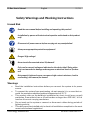 2
2
-
 3
3
-
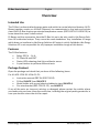 4
4
-
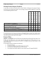 5
5
-
 6
6
-
 7
7
-
 8
8
-
 9
9
-
 10
10
-
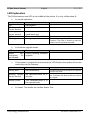 11
11
-
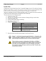 12
12
-
 13
13
-
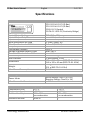 14
14
-
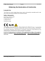 15
15
-
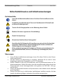 16
16
-
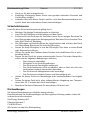 17
17
-
 18
18
-
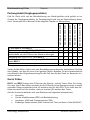 19
19
-
 20
20
-
 21
21
-
 22
22
-
 23
23
-
 24
24
-
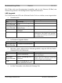 25
25
-
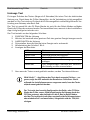 26
26
-
 27
27
-
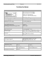 28
28
-
 29
29
-
 30
30
-
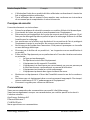 31
31
-
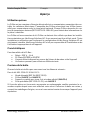 32
32
-
 33
33
-
 34
34
-
 35
35
-
 36
36
-
 37
37
-
 38
38
-
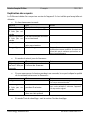 39
39
-
 40
40
-
 41
41
-
 42
42
-
 43
43
-
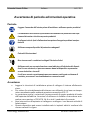 44
44
-
 45
45
-
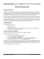 46
46
-
 47
47
-
 48
48
-
 49
49
-
 50
50
-
 51
51
-
 52
52
-
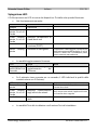 53
53
-
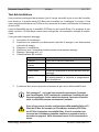 54
54
-
 55
55
-
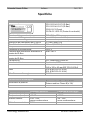 56
56
-
 57
57
-
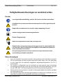 58
58
-
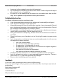 59
59
-
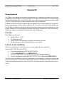 60
60
-
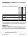 61
61
-
 62
62
-
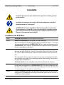 63
63
-
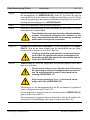 64
64
-
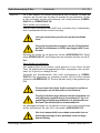 65
65
-
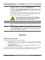 66
66
-
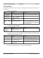 67
67
-
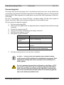 68
68
-
 69
69
-
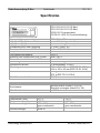 70
70
-
 71
71
-
 72
72
-
 73
73
-
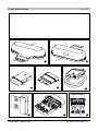 74
74
-
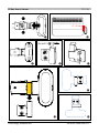 75
75
-
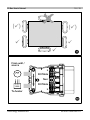 76
76


tiko CD-01.1014-01-P1 Handleiding
- Type
- Handleiding
- Deze handleiding is ook geschikt voor
in andere talen
- English: tiko CD-01.1014-01-P1 User manual
- italiano: tiko CD-01.1014-01-P1 Manuale utente
- français: tiko CD-01.1014-01-P1 Manuel utilisateur
- Deutsch: tiko CD-01.1014-01-P1 Benutzerhandbuch
Gerelateerde papieren
-
tiko K-Box A4 Digitalizing Energy Handleiding
-
tiko Sense-3 Handleiding
-
-
tiko GM-01.0013E Handleiding
-
tiko CMM-01 Series Handleiding
-
tiko CMB-01.1011-01-P1 Handleiding
-
 tiko Class C Handleiding
-
 tiko GM-01.0013M Handleiding
-
-
tiko K-Box A6 Handleiding

