
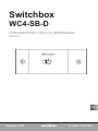
Switchbox
WC4-SB-D
MONTAGE- UND GEBRAUCHSANWEISUNG
Deutsch
EN
FR
IT
NL
DE
DE
DE
Version 01/23 Ident-Nr. 1-024-311

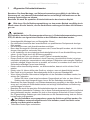
Bedeutung der in der Montageanweisung verwendeten Zeichen:
WARNUNG:
bei Nichtbeachtung besteht die Möglichkeit einer schweren oder sogar tödlichen Verletzung.
VORSICHT:
bei Nichtbeachtung besteht die Möglichkeit von mittleren bis leichten Verletzungen oder Sachschäden.
HINWEIS:
gibt Anwendungstips und nützliche Informationen.
Montage- und Gebrauchsanweisung S. 2/10
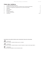
Inhaltsverzeichnis
1 3
2 4
3 5
4 7
5 7
6 8
7 8
8 8
9
Allgemeine Sicherheitshinweise
Montage und elektrischer Anschluss nur für Fachpersonal
FunktionenundKongurationennurfürFachpersonal
Bedienung
Kundendienst
Entsorgung
Technische Daten
Lieferumfang
Abbildungen 9/10

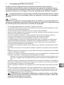
1 Allgemeine Sicherheitshinweise
Bewahren Sie diese Montage- und Gebrauchsanweisung sorgfältig in der Nähe der
Steuerung auf, um jederzeit Sicherheitshinweise und wichtige Informationen zur Be-
dienung nachschlagen zu können.
Beachten Sie auch die speziellen Sicherheitshinweise der einzelnen Kapitel.
Bitte lesen Sie die Bedienungsanleitung vor dem ersten Betrieb sorgfältig durch.
Damit nutzen Sie alle Vorteile, die das Gerät bietet und beugen Schäden und Verletzun-
gen vor.
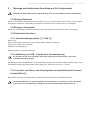
WARNUNG:
Die Switchbox hat keine Übertemperatursicherung (= Sicherheitstemperaturbegrenzer,
STB). Es dürfen nur eigensichere Geräte an der Switchbox betrieben werden.
•Unsachgemäße Montage kann zu Brandgefahr führen!
• DerelektrischeAnschlussdarfausschließlichvonqualiziertemFachpersonaldurchge-
führt werden.
•Der Anschluss muss nach Anschlussschema erfolgen.
•Bevor das Steuergerät in Betrieb genommen wird, muss überprüft werden, ob alle Verbin-
dungen lösungssicher verbunden sind.
•In der Installation ist eine dreipolige Abschaltmöglichkeit mit 3 mm Kontaktöffnung vorzu-
sehen. (In der Regel durch die Sicherung gegeben).
•Dieses Gerät darf nicht von Kindern unter 8 Jahren verwendet werden.
•Dieses Gerät ist nicht dafür bestimmt, durch Personen (einschließlich Kinder) mit einge-
schränkten physischen, sensorischen oder geistigen Fähigkeiten oder mangels Erfahrung
und/oder mangels Wissen benutzt zu werden, es sei denn, sie werden durch eine für ihre
Sicherheit zuständige Person beaufsichtigt.
•Kinder sollten beaufsichtigt werden, um sicherzustellen, dass sie nicht mit dem Gerät
spielen.
•Kinder unter 14 Jahren dürfen das Gerät nur reinigen, wenn sie beaufsichtigt werden.
•Das Gerät ist nicht geeignet Saunaheizgeräte direkt zu steuern! Brandgefahr!
•Wenn Infrarot-Strahler oder andere Heizgeräte mit der Switchbox betrieben werden, be-
achten Sie Folgendes:
•Stellen Sie sicher, dass keine brennbaren Gegenstände auf oder vor dem Infrarot-
Strahler oder dem Heizgerät liegen, bevor Sie die Switchbox einschalten.
•Bewahren Sie diese Montage- und Gebrauchsanweisung sorgfältig in der Nähe der Steu-
erung auf, um jederzeit Sicherheitshinweise und wichtige Informationen zur Bedienung
nachschlagen zu können.
•Beachten Sie auch die speziellen Sicherheitshinweise der einzelnen Kapitel.
•Beim Auftreten besonderer Probleme, die in dieser Gebrauchsanweisung nicht ausführlich
genug behandelt werden, wenden Sie sich zu Ihrer eigenen Sicherheit an Ihren Lieferan-
ten. Eigenmächtige Änderungen oder Umbauten an der Saunasteuerung sind aus Sicher-
heitsgründen nicht gestattet.
• Um die Switchbox zu programmieren muss das Gehäuse geöffnet werden. Da
sichimGehäusenetzspannungsführendeTeilebenden,mussdasGerätvorher
allpolig vom Netz getrennt werden.
•Technische Änderungen vorbehalten.
DE
Montage- und Gebrauchsanweisung S. 3/10

2 Montage und elektrischer Anschluss nur für Fachpersonal
Schäden am Gerät: Montieren Sie die Steuerung nicht mit einem Akkuschrauber! Bruchgefahr!
2.1 Montage Bedienteil
Mit einem Dosenbohrer an der gewünschten Position ein Loch mit Durchmesser 30mm bohren und das Bedien-
teil einsetzen. Mit den im Lieferumfang enthaltenen Schrauben an den Positionen Abb. 2 A befestigen.
2.2 Montage Leistungsteil
Mit den im Lieferumfang enthaltenen Schrauben den Leistungsteil an den Positionen Abb.1 H befestigen.
2.3 Elektrischer Anschluss
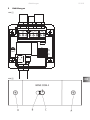
2.3.1. Anschlussbelegung Abb. 1 / Abb. 3
Klemme X1:
INPUT: Netzzuleitung. Absicherung muss extern gemäß Abbildung 3 erfolgen
OUTPUT: Anschluss Last: 230V AC1
ENABLE: Freischalteingang
Steckverbinder X2: Anschluss Bedienteil.
2.3.2 Anbindung des STB – Signals einer Saunasteuerung
Es handelt sich um einen indirekten STB. Nicht eigensichere Geräte dürfen nicht an der
Switchbox betrieben werden.
Die Einbindung des STB Signals kann über den ENABLE Eingang der Switchbox realisiert werden. Wenn 230V
am ENABLE anliegen gibt die Switchbox den Ausgang frei. Siehe auch Punkt 3.1.2 - Enable
2.3.3 Fernstart von Sauna- und Infrarotgeräten mit potentialfreiem Fernstart-
kontakt (Abb.4)
Bei Geräten ohne 230V Fernstarteingang ist die Remote-Erweiterung WC4-SB-REM erforderlich.
Bei direktem Betrieb von Saunaheizgeräten an der Switchbox, ist darauf zu achten, dass diese
eigensicher sind. Die Switchbox verfügt über keine Sicherheitstemperaturbegrenzung.
Montage- und Gebrauchsanweisung nur für Fachpersonal S. 4/10

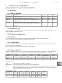
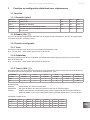
3 FunktionenundKongurationennurfürFachpersonal
3.1 Funktionen
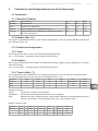
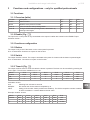
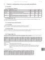
3.1.1 Übersicht (Tabelle)
Funktion Beschreibung S1.1 S1.2 Punkt
Schalter Tastenfunktion AUS AUS 3.2.1
Taste EIN/AUS auf Tastendruck EIN AUS 3.2.2
Timer A Nach Tastendruck für eingestellte Zeit aktiv AUS EIN 3.2.3
Timer B Taktung aktiviert nach Tastendruck; Deaktivierung durch
erneuten Tastendruck
EIN EIN 3.2.4
3.1.2 Enable (Abb. 3)
Die Eingabe am Bedienfeld wird nur an den Ausgang weitergegeben, wenn an Eingang ENABLE 230Vac anlie-
gen. Aktivierung über S2.1.
3.2.FunktionenKonguration
3.2.1 Taste
Der Ausgang ist nur aktiv, wenn die Taste am Bedienfeld gedrückt wird.
S1.3-S1.8undS2.2–S2.8habenkeinenEinflussaufdieFunktion
3.2.2 Schalter
Der Ausgang verhält sich wie ein Schalter. Auf Tastendruck wird der Ausgang solange aktiviert bis ein erneuter
Tastendruck erfolgt.
S1.3-S1.8undS2.2–S2.8habenkeinenEinflussaufdieFunktion
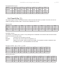
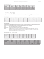
3.2.3 Timer A (Abb. 1)
Der Ausgang bleibt nach Tastendruck für eine eingestellte Zeit aktiv. Der Timer kann durch erneuten Tasten-
druck wieder abgebrochen werden. Die minimal einstellbare Zeit ist 1 Sec
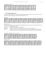
Schalter S1.3 S1.4 S1.5 S1.6 S1.7 S1.8
Stellung Wert Wert Wert Wert Multiplikator Einheit
EIN 1 2 4 8 x 10 Sec.
AUS 0 0 0 0 x 1 Min.
Berechnen der Zeit:
Einheit: Umschalten von Minuten auf Sekunden
Multiplikator: Die über die Werte eingestellte Zahl wird mit 10 multipliziert
Wert: Einstellen der Zahl. Schalterpositionen werden addiert. Bei EIN wird die jeweilige Zahl addiert,
bei AUS wird 0 addiert. Zum eingestellten Wert muss 1 hinzuaddiert werden.
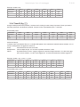
Beispiel: Laufzeit 30 Sec
Schalter S1.3 S1.4 S1.5 S1.6 S1.7 S1.8
Stellung AUS EIN AUS AUS EIN EIN
0 + 2 + 0 + 0 X x 10 Sec.
1+ 0 + 2 + 0 + 0 =3 x 10 →30Sec
DE
Montage-undGebrauchsanweisungnurfürFachpersonal S.5/10

Beispiel: Laufzeit 9min
Schalter S1.3 S1.4 S1.5 S1.6 S1.7 S1.8
Stellung AUS AUS AUS EIN AUS AUS
1 + 0 + 0 + 0 + 8 X x 1 Min.
1 + 0 + 0 + 0 + 8 =9 x 1 →9Min
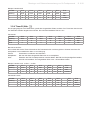
3.2.4 Timer B (Abb. 1)
Der Ausgang beginnt nach Tastendruck gemäß den eingestellten Zeiten zu takten. Der Timer kann durch erneu-
ten Tastendruck wieder abgebrochen werden. Die minimal einstellbare Zeit ist 1 Sec.
Pausenzeit
Schalter S2.2 S2.3 S2.4 S2.5 S2.6 S2.7 S2.8
Stellung Wert Wert Wert Wert Wert Multiplikator Einheit
EIN 1 2 4 8 16 x 10 Sec.
AUS 0 0 0 0 0 x 1 Min
Berechnen der Zeit:
Die Laufzeit wird wie bei Timer A berechnet. Die Pausenzeit wird nach dem gleichen Schema berechnet. Es
steht jedoch noch zusätzlich der Wert 16 zur Verfügung.
Einheit: Umschalten von Minuten auf Sekunden
Multiplikator: Die über die Werte eingestellte Zahl wird mit 10 multipliziert
Wert: Einstellen der Zahl. Schalterpositionen werden addiert. Bei EIN wird die jeweilige Zahl addiert,
bei AUS wird 0 addiert. Zum eingestellten Wert muss 1 hinzuaddiert werden
Beispiel: Laufzeit 1min. 10 Sec. = 70 Sec.
Schalter S1.3 S1.4 S1.5 S1.6 S1.7 S1.8
Stellung AUS EIN EIN AUS EIN EIN
1 + 0 + 2 + 4 + 0 X x 10 Sec.
1 + 0 + 2 + 4 + 0 =7 x 10 →70Sec
Pausenzeit 19min
Schalter S2.2 S2.3 S2.4 S2.5 S2.6 S2.7 S2.8
Stellung AUS EIN AUS AUS EIN AUS AUS
1 + 0 + 2 + 0 + 0 + 16 x 1 Min.
1 + 0 + 2 + 0 + 0 + 16 =19 x1 →19Min
Montage- und Gebrauchsanweisung nur für Fachpersonal S. 6/10

4 Bedienung
Mit der Taste Abb.2 C wird die programmierte Funktion (siehe 4.1) aktiviert.
Die LED Abb. 2 B zeigt den aktuellen Status der Steuerung an.
Alle Funktionen:
GRÜN: Ausgang ist aktiv
ORANGE blinkend: Wenn die ENABLE Funktion aktiviert ist, aber am ENABLE Eingang keine Spannung an-
liegt, blinkt die Status LED orange. Wenn am ENABLE Eingang Spannung angelegt wird, dann erlischt die LED.
Timer B:
Während der Pausenzeit leuchtet die rote LED dauerhaft. Gegen Ende der Pause beginnt die LED zu blinken.
Eingestellte Pausenzeit:
• >=70Sec
abSek.60→langsamesBlinken
abSek.40→mittleresBlinken
abSek.20→schnellesBlinken
• >=10;<70Sec
9→langsam
6→mittel
3→schnell
• >=5;<10
4→mittel
2→schnell
• <5
1 schnell
DE
Gebrauchsanweisung für den Anwender S. 7/10
5 Kundendienst
Bitte tragen Sie Ihre Kundendienst-Adresse hier ein:
……………………......………………………………………………………………………………………………………...
…………………………........………………………………………………………………………………………………….
........…………………………......……………………………………………………………………………………………..
…….………………………………...………………………………………………………………………………………….
……………………......………………………………………………………………………………………………………...
sentiotec GmbH
Wartenburger Straße 31
A-4840 Vöcklabruck
T:+43(0)767222 900-50
F: +43 (0) 7672 20 900-80
E-Mail: info@sentiotec.com
www.sentiotec.com

6 Entsorgung
7
Bitte entsorgen Sie Verpackungsmaterialien nach den gültigen Entsorgungsrichtlinien.
Altgeräte enthalten wiederverwendbare Materialien. Geben Sie deshalb Altgeräte nicht einfach auf die nächste
Mülldeponie, sondern erkundigen Sie sich bei Ihrer Stadt- oder Gemeindeverwaltung nach der Möglichkeit der
Wiederverwertung.
8
Technische Daten
Abmessungen Bedienteil: L x B x T: 32 x 92 x 10mm
AbmessungenLeistungsteil: LxBxT:100x100x56mm
Versorgung: 230Vac/50Hz
Leistungsaufnahme: Max.1,5W
Schaltleistung: 230Vac / 16A ohmsche Last (AC1)
Umgebungsbedingungen: 0-50°C,max.95%rel.F.nichtkondensierend
Die Switchbox hat keine Übertemperatursicherung (= Sicherheitstemperaturbegrenzer,
STB). Es dürfen nur eigensichere Geräte an der Switchbox betrieben werden.
Lieferumfang
Bedienteil mit Anschlusskabel
Leistungsteil
Montagematerial
Bedienungsanleitung
Montage- und Gebrauchsanweisung S. 8/10

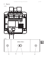
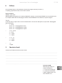
9 Abbildungen
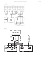
ABB 1
1 2 3 4 5 6 7 8
ENABLE
N
~ V032 ~ V032
INPUT
230V ~ 16A
OUTPUT
L N L L NPEPE
X1
S1
S2
1 2 3 4 5 6 7 8
1 2 3 4 5 6 7 8
ON
OFF
ON
OFF
X2
H
HH
H
ABB 2DE
Abbildungen S. 9/10

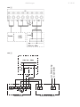
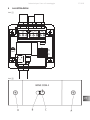
ABB 3
Remote Adapter
IN IN A A
L N
Enable
L LN NPE PE
Switchbox
L
PE
N
F 16A
230V 1N ~ 50Hz
zur Steuerung
to Controller
ABB 4
Abbildungen S. 10/10

Switchbox
WC4-SB-D
INSTALLATION AND USAGE INSTRUCTIONS
English
EN
Version 01/23 Ident No. 1-024-0311

Installation and usage instructions p. 2/10
Table of contents
1 3
2 4
3 5
4 7
5 7
6 8
7 8
8 8
9
General safety information
Assemblyandelectricalconnection–onlyforqualiedprofessionals
Functionsandconfigurations–onlyforqualifiedprofessionals
Operation
Customerservice
Disposal
Technical data
Scope of supply
Illustrations 9/10
Meaning of the signs used in the installation instructions:
WARNING:
There is a risk of serious or even fatal injuries in the event of non-observance.
CAUTION:
There is a risk of moderate to slight injuries or material damage in the event of non-observance.
TIP:
Gives tips for usage and useful information.

1 General safety information
Store these installation and usage instructions carefully in proximity to the control unit
in order to be able to refer to safety information and important operational information
at all times. Please also heed the special safety information in the individual chapters.
Pleasereadtheoperatinginstructionscarefullybeforerstoperation.Thiswill
enableyoutobenetfromalladvantageswhichthedevicehastoofferandtoprevent
damage and injuries.
WARNING:
The switch box does not have excess temperature protection (= safety temperature li-
miter, STL). Only intrinsically safe devices may be operated on the switch box.
• Improperinstallationcanconstitutearehazard!
• Electricalconnectionmayonlybeperformedbyqualiedprofessionals.
•The device must be connected in accordance with the wiring diagram.
• Beforethecontroldeviceisputintooperation,itmustbeveriedthatallconnectionsare
rmlyconnected.
•During installation a 3-pole off switch with a 3 mm contact aperture must be provided for.
(Generally ensured by the fuse).
•This device must not be used by children under 8 years old.
•This device is not intended for use by persons (including children) with limited psycholo-
gical, sensory or mental capacities or a lack of experience and/or knowledge, unless they
are supervised by a person responsible for their safety.
•Children should be supervised to ensure that they do not play with the device.
•Children under 14 years old may only clean the device if they are supervised.
•The device is not suitable for directly controlling sauna heating devices! Fire hazard!
•If infrared emitters or other heaters are operated with the switch box, observe the fol-
lowing:
• Makesurethatnoflammableobjectshavebeenplacedonorinfrontoftheinfrared
emitter or the heater before you switch on the switch box.
•Store these installation and usage instructions carefully in proximity to the control unit in
order to be able to refer to safety information and important operational information at all
times.
•Please also heed the special safety information in the individual chapters.
• Whenparticularproblemsarisewhicharenotcoveredinsufcientdetailintheseusage
instructions, please contact your supplier for your own safety. Unauthorized changes or
conversions to the sauna control are not permitted for safety reasons.
• WARNING: the casing must be opened to programme the switchbox. As there
are components in the casing which have mains voltage running through them, the
device must be disconnected from the power supply beforehand at all poles.
•Subject to technical changes.
Installation and usage instructions p. 3/10
EN

2 Installation and electrical connection –
onlyforqualiedprofessionals
Damage to the device: do not install the control unit wtih a cordless screwdriver!
Risk of breakage!
2.1 Installation of operating unit
Drillaholeofadiameterof30mmatthedesiredpositionusingaholesawandinserttheoperatingunit.Afxat
the positions shown in Fig. 2A with the bolts contained in the scope of supply.
2.2 Installation of power unit
AfxthepowerunitatthepositionsshowninFig.1Hwiththeboltscontainedinthescopeofsupply.
2.3 Electrical connection
2.3.1. Socket allocation Fig. 1 / Fig. 3
Terminal X1:
INPUT: mains supply line. The fuse must be positioned externally in accordance with Figure 3
OUTPUT: connection load: 230V AC1
ENABLE: enable input
Connector X2: operating unit connection.
2.3.2 Connection of the STL (safety temperature limiter) –
signals of a sauna control unit
This is an indirect STL. Devices which are not inherently safe must not be operated on
the switchbox.
The STL signal can be incorporated via the ENABLE input of the switchbox. When 230V is exerted on ENABLE,
the switchbox unblocks the output. See also Point 3.1.2 - Enable
2.3.3 Remote start of sauna and infrared devices with potential-free remote
start contact (Fig. 4)
For devices without 230V remote start input, the remote extension WC4-SB-REM is necessary.
Where sauna heating devices are directly operated on the switchbox, it must be ensured that
they are inherently safe. The switchbox has no safety temperature restriction.
Installation and usage instructions p. 4/10

3 Functionsandcongurations–onlyforqualiedprofessionals
3.1 Functions
3.1.1 Overview (table)
Function Description S1.1 S1.2 Point
Switch Button function OFF OFF 3.2.1
Button ON/OFF at the press of a button ON OFF 3.2.2
Timer A Active for set time after pressing button OFF ON 3.2.3
Timer B Timing activated after pressing button; deactivation by
pressing button again
ON ON 3.2.4
3.1.2 Enable (Fig. 3)
The input in the control panel is only transmitted to the output if 230Vac are exerted on the ENABLE input.
Activation via S2.1.
3.2.Functionsconguration
3.2.1 Button
The output is only active if the button on the control panel is pressed.
S1.3-S1.8 and S2.2-S2.8 have no impact on the function
3.2.2 Switch
The output acts like a switch. The output is activated at the press of a button until the button is pressed again.
S1.3-S1.8 and S2.2 –S2.8 have no impact on the function.
3.2.3 Timer A (Fig. 1)
The output remains active for a set time after the button is pressed. The timer can be cancelled by pressing the
button again. The minimum settable time is 1 sec.
Switch S1.3 S1.4 S1.5 S1.6 S1.7 S1.8
Position Value Value Value Value Multiplier Unit
ON 1 2 4 8 x 10 Sec.
OFF 0 0 0 0 x 1 Min.
Calculation of time:
Unit: switching from minutes to seconds
Multiplier: the number set via the values is multiplied by 10
Value: setting of the number. Switch positions are added up. For ON the respective number is added,
for OFF 0 is added. 1 must be added to the set value.
Example: duration 30 secs.
Switch S1.3 S1.4 S1.5 S1.6 S1.7 S1.8
Position OFF ON OFF OFF ON ON
0 + 2 + 0 + 0 X x 10 Sec.
1+ 0 + 2 + 0 + 0 =3 x 10 →30Sec.
Installationandusageinstructions p. 5/10
EN

Example:duration 9 mins
Switch S1.3 S1.4 S1.5 S1.6 S1.7 S1.8
Position OFF OFF OFF ON OFF OFF
1 + 0 + 0 + 0 + 8 X x 1 Min.
1 + 0 + 0 + 0 + 8 =9 x 1 →9Min.
3.2.4 Timer B (Fig. 1)
The output begins to time in accordance with the set times after the button is pressed. The timer can be can-
celled by pressing the button again. The minimum settable time is 1 sec.
Pausing time
Switch S2.2 S2.3 S2.4 S2.5 S2.6 S2.7 S2.8
Position Value Value Value Value Value Multiplier Unit
ON 1 2 4 8 16 x 10 Sec.
OFF 0 0 0 0 0 x 1 Min.
Calculation of time:
The duration is calculated as for Timer A. The pausing time is calculated in accordance with the same model.
However, the value 16 also exists.
Unit: conversion from minutes to seconds
Multiplier: the number set via the values is multiplied by 10
Value: setting of the number. Switch positions are added. The respective number is added for ON,
0 is added for OFF. 1 must be added to the set value.
Example: duration 1min. 10 Sec. = 70 Sec.
Switch S1.3 S1.4 S1.5 S1.6 S1.7 S1.8
Position OFF ON ON OFF ON ON
1 + 0 + 2 + 4 + 0 X x 10 Sec.
1 + 0 + 2 + 4 + 0 =7 x 10 →70Sec.
Pausing time 19min
Switch S2.2 S2.3 S2.4 S2.5 S2.6 S2.7 S2.8
Position OFF ON OFF OFF ON OFF OFF
1 + 0 + 2 + 0 + 0 + 16 x 1 Min.
1 + 0 + 2 + 0 + 0 + 16 =19 x1 →19Min.
Installation and usage instructions p. 6/10

4 Operation
The programmed function (see 4.1) is activated with the button (Fig. 2 C).
The LED (Fig. 2 B) shows the current status of the control unit.
All functions:
GREEN: output is active
ORANGEflashing:iftheENABLEfunctionisactivated,butthereisnovoltageattheENABLEinput,theLED
statusflashesorange.WhenvoltageisappliedattheENABLEinput,theLEDgoesout.
Timer B:
TheredLEDispermanentlyonduringthepausingtime.TheLEDstartstoflashtowardstheendofthepausing
time.
Set pausing time:
• >=70Sec.
fromSec.60→slowflashing
fromSec.40→moderateflashing
fromSec.20→quickflashing
• >=10;<70Sec.
9→slow
6→moderate
3→quick
• >=5;<10
4→moderate
2→quick
• <5
1 quick
5 Customer service
Please write down the address of your customer service here:
……………………......………………………………………………………………………………………………………...
…………………………........………………………………………………………………………………………………….
........…………………………......……………………………………………………………………………………………..
…….………………………………...………………………………………………………………………………………….
……………………......………………………………………………………………………………………………………...
Installation and usage instructions p. 7/10
EN
sentiotec GmbH
Wartenburger Straße 31
A-4840 Vöcklabruck
T:+43(0)767222 900-50
F: +43 (0) 7672 20 900-80
E-Mail: info@sentiotec.com
www.sentiotec.com

6
7
Disposal
Please dispose of packaging materials in accordance with the applicable disposal regulations.
Used devices contain reusable materials. Therefore please do not simply take used devices to the
nearest was-te disposal site, instead ask your local council about recycling facilities.
8
Technical data
Dimensions of operating unit: L x B x H. 32 x 92 x 10mm
Dimensionsofpowerunit: LxBxH:100x100x56mm
Powersupply: 230Vac/50Hz
Powerconsumption: Max.1,5W
Switching capacity: 230Vac / 16A ohmic load (AC1)
Environmentalconditions: 0-50°C,max.95%rel.humidity,non-condensing
The switch box does not have excess temperature protection (= safety temperature limiter, STL).
Only intrinsically safe devices may be operated on the switch box.
Scope of supply
Operating unit with connection cable
Power unit
Installation material
Operating instructions
Installation and usage instructions p. 8/10

9 Figures
FIG 1
1 2 3 4 5 6 7 8
ENABLE
N
~ V032 ~ V032
INPUT
230V ~ 16A
OUTPUT
L N L L NPEPE
X1
S1
S2
1 2 3 4 5 6 7 8
1 2 3 4 5 6 7 8
ON
OFF
ON
OFF
X2
H
HH
H
FIG 2
Installation and usage instructions p. 9/10
EN

FIG 3
Remote Adapter
IN IN A A
L N
Enable
L LN NPE PE
Switchbox
L
PE
N
F 16A
230V 1N ~ 50Hz
zur Steuerung
to Controller
FIG 4
Installation and usage instructions p. 10/10

Switchbox
WC4-SB-D
MANUEL DE MONTAGE ET D’UTILISATION
Français
FR
Version 01/23 N° ident. : 1-024-311

Manuel de montage et d’utilisation P. 2/10
Table des matières
1 3
2 4
3 5
4 7
5 7
6 8
7 8
8 8
9
Consignes générales de sécurité
Montage et raccordement électrique (uniquement pour le personnel spécialisé)
Fonctionsetconfigurations(uniquementpourlepersonnelspécialisé)
Utilisation
Serviceclients
Élimination
Données techniques
Contenu de la livraison
Illustrations 9/10
Signicationdessymbolesutilisésdanslesprésentesinstructionsdemontage:
ATTENTION :
en cas de non-respect, risque de blessure grave ou mortelle.
PRUDENCE :
en cas de non-respect, risque de blessure moyenne ou légère ou risque de dommage matériel.
REMARQUE :
fournit des astuces d’utilisation et des informations utiles.

1 Consignesgénéralesdesécurité
Veuillezconserversoigneusementlesprésentesinstructionsdemontageet
d’utilisationàproximitédusystèmedecommandedesaunaandepouvoirconsul-
teràtoutmomentlesinformationsrelativesàlasécuritéetàlamanipulation.Veuillez
égalementrespecterlesconsignesdesécuritéspéciquesdesdifférentschapitres.
Lisezattentivementleprésentmoded’emploiavantlapremièremiseenservice
andeproterdetouslesavantagesoffertsparl’appareiletd’évitertoutdommageet
blessure.
ATTENTION :
Leboîtierdecommanden‘estpasprotégédelasurchauffe(=iln‘estpaséquipéd‘un
limiteurdetempératuredesécurité).Seulslesappareilséquipésd‘undispositifinterne
desécuritépeuventêtreutilisésavecleboîtierdecommande.
•Un montage inapproprié peut entraîner un risque d’incendie !
• Leraccordementélectriquenepeutêtreeffectuéquepardupersonnelqualiéetconfor-
mément au schéma de raccordement.
•Le raccordement doit être effectué selon le schéma de raccordement.
• Avantdemettrel’appareildecommandeenservice,vériezsitoutesleschesderaccor-
dement sont correctement branchées.
•Lors de l’installation, prévoyez un moyen de déconnexion des 3 pôles au moyen de
l’ouverture de contact de 3 mm (en règle générale, par le biais du fusible).
•Cet appareil ne doit pas être utilisé par des enfants de moins de 8 ans.
•Le présent appareil ne peut être utilisé par des personnes (y compris des enfants) pré-
sentantdescapacitésphysiques,sensoriellesoumentalesdécientes,ouencoreun
manque d’expérience et/ou de connaissances, sauf si elles sont sous la surveillance
d’une personne responsable de leur sécurité.
• Lesenfantsdoiventêtresurveillésandegarantirquel’appareiln’estpasutilisécomme
un jouet.
•Les enfants de moins de 14 ans peuvent nettoyer l‘appareil uniquement s‘ils sont surveil-
lés.
•L’appareil ne peut être employé pour commander directement les appareils de chauffage
de sauna ! Risque d’incendie !
•Lorsque vous utilisez un émetteur à infrarouge ou tout autre appareil de chauffage avec le
boîtier de commande, veuillez observez les consignes suivantes :
• Assurez-vousqu‘aucunobjetinflammablenesetrouvesuroudevantl‘émetteuràin-
frarouge ou l‘appareil de chauffage avant de mettre le boîtier de commande en mar-
che.
•Veuillez conserver soigneusement les présentes instructions de montage et d’utilisation à
proximitédusystèmedecommandeandepouvoirconsulteràtoutmomentlesinforma-
tions relatives à la sécurité et à la manipulation.
• Veuillezégalementrespecterlesconsignesdesécuritéspéciquesdesdifférentschapit-
res.
• Encasdeproblèmesparticuliers,nontraitéssufsammentendétaildansleprésent
manuel, veuillez-vous adresser à votre fournisseur pour votre propre sécurité. Pour des
raisonsdesécurité,aucunemodicationoutransformationpersonnelledusystèmede
commande de sauna ne peut être effectuée.
• ATTENTION:PourprogrammerlaSwitchbox,leboîtierdoitêtreouvert.Étant
donnéquedespiècessoustensionsetrouventàl’intérieurduboîtier,veillezàdé-
connecteraupréalabletouslespôles.
• Sousréservedemodicationstechniques.
Manuel de montage et d’utilisation P. 3/10
FR

2 Montageetraccordementélectrique
(uniquementpourlepersonnelspécialisé)
Dommagesàl’appareil:n’utilisezjamaisdevisseuseélectriquepourlemontagedusystèmede
commande ! Risque de rupture !
2.1Montagedel’élémentdecommande
Au moyen d’une perceuse, percez un trou de 30 mm de diamètre à l’endroit souhaité et insérez l’élément de
commande. Fixez-le à l’aide des vis fournies (comme indiqué sur l’ill. 2 A).
2.2Montagedel’unitédepuissance
Fixez l’unité de puissance à l’aide des vis fournies (comme indiqué sur l’ill. 1H).
2.3Raccordementélectrique
2.3.1.SchémaderaccordementIll.1 / Ill. 3
Borne X1:
INPUT: câble d’alimentation secteur. La protection externe par fusibles doit être installée conformément à
l’illustration 3
OUTPUT: raccordement charge : 230V AC1
ENABLE: entrée de commande
Connecteur X2: raccordement élément de commande
2.3.2RaccordementdusignalLTS(limiteurdetempératuredesécurité)d’un
système de commande de sauna
Ils’agitd’unlimiteurdetempératuredesécuritéindirect.Lesappareilsquinesontpasàsécuri-
téintrinsèquenepeuventêtreutilisésaveclaSwitchbox.
Le raccordement du signal LTS peut être effectué via l’entrée ENABLE de la Switchbox. Si une puissance de
230V est disponible à l’entrée ENABLE, la Switchbox débloque la sortie. Voir également point 3.1.2 - Enable
2.3.3Démarrageàdistancedesappareilsdesaunaetappareilsinfrarouge
grâceàuncontactdedémarrageàdistancelibredepotentiel(Ill.4)
Pour les appareils ne disposant pas d’une entrée 230V pour le démarrage à distance, l’extension WC4-SB-REM
doit impérativement être installée.
SilesappareilsdechauffagedusaunasontutilisésdirectementaveclaSwitchbox,assurez-
ousqueceux-cisontbiendesdispositifsàsécuritéintrinsèque.LaSwitchboxnedisposeen
effetd’aucunlimiteurdetempératuredesécurité.
Manuel de montage et d’utilisation P. 4/10

3 Fonctionsetcongurations
(uniquementpourlepersonnelspécialisé)
3.1 Fonctions
3.1.1 Aperçu (tableau)
Fonction Description S1.1 S1.2 Point
Commutateur Fonction du bouton OFF OFF 3.2.1
Bouton Fonction ON/OFF en appuyant sur le bouton ON OFF 3.2.2
Timer A En appuyant sur le bouton, le timer est activé pour la du-
rée programmée
OFF ON 3.2.3
Timer B La durée programmée se met à décompter en appuyant
sur le bouton ; désactivation en appuyant de nouveau sur
le bouton
ON ON 3.2.4
3.1.2 Enable (Ill. 3)
L’ordre donné via le pupitre de commande n’est transmis à la sortie que si l’entrée ENABLE dispose d’une puis-
sance de 230Vac. Activation via S2.1.
3.2.Fonctionsconguration
3.2.1 Bouton
La sortie n’est active que si le bouton correspondant est enfoncé sur le pupitre de commande.
S1.3-S1.8etS2.2-S2.8n’ontaucuneinfluencesurlafonction.
3.2.2 Commutateur
La sortie se comporte comme un commutateur. En appuyant sur le bouton, la sortie est activée jusqu’à ce que
le bouton soit de nouveau enfoncé.
S1.3-S1.8etS2.2–S2.8n’ontaucuneinfluencesurlafonction.
3.2.3 Timer A (Ill. 1)
Lorsque le bouton est enfoncé, la sortie reste active pendant toute la durée programmée. Le timer peut être in-
terrompu en appuyant de nouveau sur le bouton. La durée minimale programmable est de 1 seconde.
Commutateur S1.3 S1.4 S1.5 S1.6 S1.7 S1.8
Position Valeur Valeur Valeur Valeur Multiplicateur Unité
ON 1 2 4 8 x 10 sec.
OFF 0 0 0 0 x 1 min.
Calcul du temps :
Unité : Conversion des minutes en secondes
Multiplicateur : Le nombre programmé via les valeurs est multiplié par 10
Valeur : Programmation du nombre. Les positions du commutateur sont additionnées. Pour ON, le
nombre correspondant est ajouté ; pour OFF, la valeur 0 est ajoutée. Le nombre 1 doit ensuite
être additionné à la valeur programmée.
Exemple : durée 30 sec.
Commutateur S1.3 S1.4 S1.5 S1.6 S1.7 S1.8
Position OFF ON OFF OFF ON ON
0 + 2 + 0 + 0 X x 10 sec.
1+ 0 + 2 + 0 + 0 =3 x 10 →30sec.
Manueldemontageetd’utilisation P. 5/10
FR

Exemple : durée 9 min.
Commutateur S1.3 S1.4 S1.5 S1.6 S1.7 S1.8
Position OFF OFF OFF ON OFF OFF
1 + 0 + 0 + 0 + 8 X x 1 min.
1 + 0 + 0 + 0 + 8 =9 x 1 →9min.
3.2.4 Timer B (Ill. 1)
Lorsque le bouton correspondant est enfoncé, la sortie est activée pour la durée programmée. Le timer peut
être interrompu en pressant de nouveau sur le bouton. La durée minimale programmable est de 1 seconde.
Temps de pause
Commutateur S2.2 S2.3 S2.4 S2.5 S2.6 S2.7 S2.8
Position Valeur Valeur Valeur Valeur Valeur Multiplicateur Unité
ON 1 2 4 8 16 x 10 sec.
OFF 0 0 0 0 0 x 1 min.
Calcul du temps :
La durée est calculée de la même façon que pour le Timer A. Le temps de pause est déterminé selon le même
schéma, si ce n‘est que, dans ce cas-ci, la valeur supplémentaire de 16 est disponible.
Unité : Conversion des minutes en secondes
Multiplicateur : Le nombre programmé via les valeurs est multiplié par 10
Valeur : Programmation du nombre. Les positions du commutateur sont additionnées. Pour ON,
le nombre correspondant est ajouté ; pour OFF, la valeur 0 est ajoutée. Le nombre 1 doit
ensuite être additionné à la valeur programmée.
Exemple : durée 1 min. 10 sec. = 70 sec.
Commutateur S1.3 S1.4 S1.5 S1.6 S1.7 S1.8
Position OFF ON ON OFF ON ON
1 + 0 + 2 + 4 + 0 X x 10 sec.
1 + 0 + 2 + 4 + 0 =7 x 10 →70sec.
Temps de pause 19 min.
Commutateur S2.2 S2.3 S2.4 S2.5 S2.6 S2.7 S2.8
Position OFF ON OFF OFF ON OFF OFF
1 + 0 + 2 + 0 + 0 + 16 x 1 min.
1 + 0 + 2 + 0 + 0 + 16 =19 x1 →19min.
Manuel de montage et d’utilisation P. 6/10

4 Utilisation
Au moyen du bouton indiqué à l’Ill. (2) C, la fonction programmée (voir 4.1) est activée. La LED représentée à
l’Ill. (2) B indique le statut actuel du système de commande.
Toutes les fonctions :
VERT : output is active
ORANGE clignotant : si la fonction ENABLE est activée mais qu’aucune tension n’est disponible à l’entrée ENA-
BLE,laLEDorangeclignote.Lorsqu’unetensionsufsanteestprésenteàl’entréeENABLE,laLEDs’éteint.
Timer B:
Pendantletempsdepause,laLEDrougeestalluméeencontinu.Verslandutempsdepause,laLEDsemet
à clignoter.
Temps de pause programmé :
• >=70sec.
àpartirde60sec.60→clignotelentement
àpartirde60sec.40→clignoteàvitessemodérée
àpartirde60sec.20→clignoterapidement
• >=10;<70sec.
9→lentement
6→vitessemodérée
3→rapidement
• >=5;<10
4→vitessemodérée
2→rapidement
• <5
1 rapidement
5 Service clients
Inscrivez les coordonnées de votre service client ici:
……………………......………………………………………………………………………………………………………...
…………………………........………………………………………………………………………………………………….
........…………………………......……………………………………………………………………………………………..
…….………………………………...………………………………………………………………………………………….
……………………......………………………………………………………………………………………………………...
Manuel de montage et d’utilisation P. 7/10
FR
sentiotec GmbH
Wartenburger Straße 31
A-4840 Vöcklabruck
T:+43(0)767222 900-50
F: +43 (0) 7672 20 900-80
E-Mail: info@sentiotec.com
www.sentiotec.com

6
7
Élimination
Veuillez éliminer le matériel d’emballage conformément aux directives correspondantes en vigueur.
Les vieux appareils renferment des matériaux recyclables. Ne les déposez donc pas simplement dans
la dé-charge la plus proche, mais renseignez-vous auprès de votre ville et des autorités de votre
commune au sujet des possibilités de recyclage.
8
Donnéestechniques
Dimensions élément de commande : L x l x P: 32 x 92 x 10 mm
Dimensionsunitédepuissance: LxlxP:100x100x56mm
Alimentation: 230Vac/50Hz
Puissanceabsorbée: Max.1,5W
Puissance de coupure : 230Vac/ 16A charge ohmique (AC1)
Conditionsambiantes: 0-50°C,max.95%d’humiditérelative,sanscondensation
Le boîtier de commande n‘est pas protégé de la surchauffe (= il n‘est pas équipé d‘un
limiteurdetem-pératuredesécurité).Seulslesappareilséquipésd‘undispositifinternede
sécuritépeuventêtreutili-sésavecleboîtierdecommande.
Contenu de la livraison
Élément de commande avec câble de raccordement
Unité de puissance
Matériel de montage
Manuel d’utilisation
Manuel de montage et d’utilisation P. 8/10

9 Illustrations
ILL. 1
1 2 3 4 5 6 7 8
ENABLE
N
~ V032 ~ V032
INPUT
230V ~ 16A
OUTPUT
L N L L NPEPE
X1
S1
S2
1 2 3 4 5 6 7 8
1 2 3 4 5 6 7 8
ON
OFF
ON
OFF
X2
H
HH
H
ILL. 2
FR
Illustrations P. 9/10

ILL. 3
Remote Adapter
IN IN A A
L N
Enable
L LN NPE PE
Switchbox
L
PE
N
F 16A
230V 1N ~ 50Hz
zur Steuerung
to Controller
ILL. 4
Manuel de montage et d’utilisation P. 10/10

Switchbox
WC4-SB-D
ISTRUZIONI PER L’USO E IL MONTAGGIO
Italiano
IT
Versione 01/23 N. ident. 1-024-311

Signicatodeisimboliutilizzatinelleistruzionidimontaggio:
AVVERTENZA:
in caso di mancata osservanza sussiste la possibilità di lesioni serie o di morte.
ATTENZIONE:
in caso di mancata osservanza sussiste la possibilità di lesioni di media e leggera entità o danni alle cose.
NOTA:
fornisce suggerimenti di impiego e informazioni utili.
Istruzioni per l’uso e il montaggio P. 2/10
Indice
1 3
2 4
3 5
4 7
5 7
6 8
7 8
8 8
9
Indicazioni generali di sicurezza
Montaggio e collegamento elettrico solo per personale specializzato
Funzionieconfigurazionisoloperpersonalespecializzato
Utilizzo
Servizioclienti
Smaltimento
Dati tecnici
Fornitura in dotazione
Illustrazioni 9/10

1 Indicazioni generali di sicurezza
Conservare con cura le presenti istruzioni per l’uso e il montaggio nelle vicinanze
dell’unità in modo che le indicazioni di sicurezza e le informazioni importanti per l’uso
possano essere consultate in qualsiasi momento. Osservare anche le indicazioni di si-
curezza speciali contenute nei singoli capitoli.
Leggere con attenzione le istruzioni per l’uso prima di effettuare la messa in
funzione in modo da poter usufruire di tutti i vantaggi offerti dal dispositivo ed evitare
eventuali danni e lesioni personali.
AVVERTENZA:
La scatola di commutazione non è provvista di fusibili termici di protezione (= limitato-
re termico di sicurezza). Solo dispositivi a sicurezza intrinseca possono essere aziona-
ti con la scatola di commutazione.
•Il montaggio non corretto può causare pericolo d’incendio!
•Il collegamento elettrico può essere effettuato esclusivamente da personale specializzato
equalicato.
•Il collegamento elettrico deve essere realizzato in base all’apposito schema elettrico.
• Primadimettereinfunzionel’elementooperativo,vericarechetuttiicollegamentisiano
benssati.
•Durante la ’installazione deve essere prevista un’opzione di spegnimento tripolare con
apertura dei contatti da 3 mm (di norma mediante fusibile).
•Questo dispositivo non deve essere utilizzato da bambini di età inferiore agli 8 anni.
•La presente unità non è idonea all’utilizzo da parte di persone (inclusi bambini) con limita-
teabilitàsiche,sensorialiomentalioconesperienzaeconoscenzeinsufcienti,salvoin
caso di supervisione da parte di persone responsabili per la loro sicurezza.
• Supervisionareibambiniafnchénongiochinoconl’unità.
•I bambini al di sotto dei 14 anni possono pulire l’apparecchio solo in presenza di adulti.
•L’unità non è adatta alla gestione diretta dei dispositivi di riscaldamento per saune! Peri-
colo di incendio!
•Se con la scatola di commutazione vengono azionati irradiatori a raggi infrarossi o altri ris-
caldatori, osservare quanto segue:
•Prima di accendere la scatola di commutazione, assicurarsi che davanti o
sull‘irradiatorearaggiinfrarossiosulriscaldatorenonsitrovinooggettiinammabili.
•Conservare con cura le presenti istruzioni per l’uso e il montaggio nelle vicinanze
dell’unità in modo che le indicazioni di sicurezza e le informazioni importanti per l’uso pos-
sano essere consultate in qualsiasi momento.
•Osservare anche le indicazioni di sicurezza speciali contenute nei singoli capitoli.
• Incasodiparticolariprobleminontrattatiinmanierasufcientementeesaurientenelle
presenti istruzioni, per la propria sicurezza rivolgersi al fornitore. Per ragioni di sicurezza
nonvengonorimborsatemodichearbitrarieallacentralinadellasauna.
• AVVERTENZA: Per effettuare la programmazione della centralina, la struttura
deve essere aperta.Poichéall’internodellastrutturasitrovanocomponentiinten-
sione, tutti i poli dell’unità devono essere scollegati dalla rete.
• Modichetecnicheriservate.
Istruzioni per l’uso e il montaggio P. 3/10
IT

2 Montaggio e collegamento elettrico solo per personale specializzato
Danni all’unità: non effettuare il montaggio della centralina con avvitatore a batteria!
Pericolo di rottura!
2.1 Montaggio dell’elemento operativo
Con l’ausilio di una fresa a tazza, eseguire un foro con diametro di 30 mm nella posizione desiderata e applicare
l’elementooperativo.Fissarel’elementooperativoutilizzandolevitiindotazionecomeindicatonellag.2A.
2.2 Montaggio dell’unità di potenza
Fissarel’unitàdipotenzautilizzandolevitiindotazionecomeindicatonellag.1H.
2.3 Collegamento elettrico
2.3.1.Istruzionidicollegamentog.(1/g.3)
Morsetto X1:
INPUT:cavodialimentazione.Laprotezionedeveessereeffettuataesternamentecomedag.3
OUTPUT: collegamento carico: 230V AC1
ENABLE: enable input (entrata attivata)
Connettore elettrico X2: collegamento elemento operativo.
2.3.2 Collegamento LTS (limitatore di temperatura di sicurezza) - Segnali di
centralina per sauna
Segnale LTS indiretto. I dispositivi non sicuri non possono essere collegati alla centralina.
L’integrazione del segnale LTS può essere effettuata mediante entrata ENABLE della centralina. Se sull’entrata
ENABLE sono presenti 230V, la centralina abilita l’uscita. Si veda anche il punto 3.1.2 - Enable
2.3.3 Avvio a distanza della sauna e di dispositivi a infrarossi con avvio a po-
tenzialezero(g.4)
Per apparecchi senza entrata per avvio a distanza da 230V è necessario un ampliamento a distanza WC4-SB-
REM.
In caso di gestione diretta dei dispositivi di riscaldamento della sauna sulla centralina è neces-
ario fare attenzione che l’unità si trovi in condizioni di sicurezza. La centralina non dispone
dilimitazione di sicurezza della temperatura.
Istruzioni per l’uso e il montaggio P. 4/10

3 Funzioniecongurazionesoloperpersonalespecializzato
3.1 Funzioni
3.1.1 Panoramica (Tabella)
Funzione Descrizione S1.1 S1.2 Punto
Interruttore Funzione del pulsante OFF OFF 3.2.1
Pulsante ON/OFF mediante pressione del pulsante ON OFF 3.2.2
Timer A Attivo per il tempo impostato a seguito di pressione del
pulsante
OFF ON 3.2.3
Timer B Clocking attivato a seguito di pressione del pulsante;
disattivazione mediante nuova pressione del pulsante
ON ON 3.2.4
3.1.2Enable(g.3)
L’immissione sul pannello di comando viene trasmessa all’uscita solo quando sull’entrata ENABLE sono pre-
senti 230V. Attivazione mediante S2.1.
3.2.Congurazionedellefunzioni
3.2.1 Pulsante
L’uscita è attiva solo quando si preme il pulsante sul pannello di comando.
S1.3-S1.8eS2.2–S2.8nonhannoalcunainfluenzasuquestafunzione.
3.2.2 Interruttore
L’uscitasicomportacomeuninterruttore.Conlapressionedelpulsantel’uscitavieneattivatanoanuovapres-
sione.S1.3-S1.8eS2.2–S2.8nonhannoalcunainfluenzasuquestafunzione.
3.2.3TimerA(g.1)
A seguito della pressione del pulsante, l’uscita rimane attiva per il tempo impostato. Il timer può essere interrotto
premendo nuovamente il pulsante. Il tempo minimo impostabile è pari a 1 secondo.
Interruttore S1.3 S1.4 S1.5 S1.6 S1.7 S1.8
Posizione Valore Valore Valore Valore Moltiplicatore Unità
ON 1 2 4 8 x 10 sec.
OFF 0 0 0 0 x 1 min.
Calcolo del tempo:
Unità: Commutazione da minuti a secondi
Moltiplicatore: Viene moltiplicato per 10 il numero impostato attraverso i valori
Valore: Impostazione del numero. Vengono aggiunte le posizioni degli interruttori. Con ON viene
aggiunto il numero relativo, con OFF viene aggiunto 0. Al valore impostato deve essere
aggiunto 1.
Esempio: durata 30 secondi
Interruttore S1.3 S1.4 S1.5 S1.6 S1.7 S1.8
Posizione OFF ON OFF OFF ON ON
0 + 2 + 0 + 0 X x 10 sec.
1+ 0 + 2 + 0 + 0 =3 x 10 →30sec.
Istruzioniperl’usoeilmontaggio P. 5/10
IT

Esempio: durata 9 min.
Interruttore S1.3 S1.4 S1.5 S1.6 S1.7 S1.8
Posizione OFF OFF OFF ON OFF OFF
1 + 0 + 0 + 0 + 8 X x 1 min.
1 + 0 + 0 + 0 + 8 =9 x 1 →9min.
3.2.4TimerB(g.1)
A seguito della pressione del pulsante, l’uscita avvia il clocking in base ai tempi impostati. Il timer può essere
interrotto premendo nuovamente il pulsante. Il tempo minimo impostabile è pari a 1 secondo.
Durata della pausa
Interruttore S2.2 S2.3 S2.4 S2.5 S2.6 S2.7 S2.8
Posizione Valore Valore Valore Valore Valore Moltiplicatore Unità
ON 1 2 4 8 16 x 10 sec.
OFF 0 0 0 0 0 x 1 min.
Calcolo del tempo:
La durata viene calcolata dal Timer A. La durata della pausa viene calcolata in base allo stesso schema. C’è co-
munque a disposizione in aggiunta il valore 16.
Unità: Commutazione da minuti a secondi
Moltiplicatore: Viene moltiplicato per 10 il numero impostato attraverso i valori
Valore: Impostazione del numero. Vengono aggiunte le posizioni degli interruttori. Con ON viene aggi-
nto il numero relativo, con OFF viene aggiunto 0. Al valore impostato deve essere aggiunto 1.
Esempio: durata 1 min. 10 sec. = 70 sec.
Interruttore S1.3 S1.4 S1.5 S1.6 S1.7 S1.8
Posizione OFF ON ON OFF ON ON
1 + 0 + 2 + 4 + 0 X x 10 sec.
1 + 0 + 2 + 4 + 0 =7 x 10 →70sec.
Durata della pausa 19 min.
Interruttore S2.2 S2.3 S2.4 S2.5 S2.6 S2.7 S2.8
Posizione OFF ON OFF OFF ON OFF OFF
1 + 0 + 2 + 0 + 0 + 16 x 1 min.
1 + 0 + 2 + 0 + 0 + 16 =19 x1 →19min.
Istruzioni per l’uso e il montaggio P. 6/10

4 Utilizzo
Conilpulsanteg.(2]Cvieneattivatalafunzionediprogrammazione(siveda4.1).
Laspiag.[2]Bindicalostatocorrentedeicomandi.
Tutte le funzioni:
VERDE: uscita attiva
ARANCIONE lampeggiante: se la funzione ENABLE è attivata, ma sull’entrata ENABLE non è presente tensio-
ne, la spia di stato arancione lampeggia. Quando l’entrata ENABLE riceve tensione, la spia si spegne.
Timer B:
Infasedipausa,laspiarossaèaccesacostantemente.Versolanedellapausa,laspiainiziaalampeggiare.
Pausa impostata:
• >=70sec.
dasec.60→lampeggiamentolento
dasec.40→lampeggiamentomedio
dasec.20→lampeggiamentorapido
• >=10;<70sec.
9→lento
6→medio
3→rapido
• >=5;<10
4→medio
2→rapido
• <5
1 rapido
Istruzioni per l’uso e il montaggio P. 7/10
IT
5 Servizio clienti
Inserisca qui l’indirizzo del Suo servizio clienti:
……………………......………………………………………………………………………………………………………...
…………………………........………………………………………………………………………………………………….
........…………………………......……………………………………………………………………………………………..
…….………………………………...………………………………………………………………………………………….
……………………......………………………………………………………………………………………………………...
sentiotec GmbH
Wartenburger Straße 31
A-4840 Vöcklabruck
T:+43(0)767222 900-50
F: +43 (0) 7672 20 900-80
E-Mail: info@sentiotec.com
www.sentiotec.com

6
7
Smaltimento
Smaltire i materiali d’imballaggio in base alle direttive vigenti in materia.
I dispositivi usati contengono materiali riutilizzabili. Non limitarsi quindi a consegnarli presso il centro di
raccolta più vicino, ma rivolgersi all’amministrazione cittadina o comunale richiedendo informazioni in
relazione alla pos-sibilità di riutilizzo.
8
Dati tecnici
Misure elemento operativo: lung. x largh. x prof.: 32 x 92 x 10mm
Misureunitàdipotenza: lung.xlargh.xprof.:100x100x56mm
Alimentazione: 230Vac/50Hz
Potenzaassorbita: Max.1,5W
Potenza di commutazione: 230Vac/ 16A carico resistivo ohmico (AC1)
Condizioniambientali: 0-50°C,umiditàrelativamax.95%;umid.rel.noncondensante
La scatola di commutazione non è provvista di fusibili termici di protezione (= limitatore termico
di sicu-rezza). Solo dispositivi a sicurezza intrinseca possono essere azionati con la scatola di
commutazione.
Fornitura in dotazione
Elemento operativo con cavo di collegamento
Elemento di potenza
Materiale di montaggio
Istruzioni per l’uso
Istruzioni per l’uso e il montaggio P. 8/10

9 ILLUSTRAZIONI
FIG. 1
1 2 3 4 5 6 7 8
ENABLE
N
~ V032 ~ V032
INPUT
230V ~ 16A
OUTPUT
L N L L NPEPE
X1
S1
S2
1 2 3 4 5 6 7 8
1 2 3 4 5 6 7 8
ON
OFF
ON
OFF
X2
H
HH
H
FIG. 2
Istruzioni per l’uso e il montaggio P. 9/10
IT

FIG. 3
Remote Adapter
IN IN A A
L N
Enable
L LN NPE PE
Switchbox
L
PE
N
F 16A
230V 1N ~ 50Hz
zur Steuerung
to Controller
FIG. 4
Istruzioni per l’uso e il montaggio P. 10/10

Switchbox
WC4-SB-D
MONTAGE- EN GEBRUIKSAANWIJZING
Nederlands
NL
Versie 01/23 Ident-nr. 1-024-311

Betekenis van de tekens in de montageaanwijzing:
OPGEPAST:
bij niet respecteren bestaat de mogelijkheid op een zwaar of zelfs dodelijk letsel.
OPGELET:
bij het niet respecteren bestaat de mogelijkheid op gemiddelde tot lichte letsels of materiële schade.
TIP:
geeft toepassingstips en nuttige informatie.
Montage- en gebruiksaanwijzing S. 2/10
Inhoudsopgave
1 3
2 4
3 5
4 7
5 7
6 8
7 8
8 8
9
Algemene veiligheidsrichtlijnen
Montage en elektrische aansluiting uitsluitend voor vakpersoneel
Functieencon iguratieuitsluitendvoorvakpersoneel
Bediening
Klantenservice
Afvoer
Technische gegevens
Levering
Afbeeldingen 9/10

1 Algemene veiligheidsrichtlijnen
Bewaar deze montage en gebruiksaanwijzing zorgvuldig in de buurt van de bediening, om op
elk moment de veiligheidsrichtlijnen en belangrijke informatie over de bediening te kunnen op-
zoeken. Let ook op de speciale veiligheidsrichtlijnen van de aparte hoofdstukken.
Gelieve de gebruiksaanwijzing voor het eerste bedrijf zorgvuldig door te nemen. Daar-
mee gebruikt u alle voordelen die het toestel biedt en voorkomt u schade en kwetsuren.
OPGEPAST:
De switchbox heeft geen overtemperatuurbeveiliging (= veiligheidstemperatuurbegrenzer,
„STB”). Er mogen uitsluitend intrinsiek veilige apparaten met de switchbox worden gebruikt.
•Onprofessionele montage kan leiden tot brandgevaar !
• Deelektrischeaansluitingmaguitsluitenddoorgekwaliceerdvakpersoneelwordenuitgevoerd.
•De aansluiting moet gebeuren volgens het aansluitschema.
•Voordat het bedieningstoestel in bedrijf wordt genomen, moet worden gecontroleerd of alle verbin-
dingen stevig aan elkaar gekoppeld zijn.
•In de installatie moet er een driepolige uitschakelmogelijkheid met een contactopening van 3 mm
voorzien worden. (In de regel gegeven door de zekering).
•Dit apparaat mag niet door kinderen onder 8 jaar worden gebruikt.
•Dit toestel is niet bedoeld om door mensen (met inbegrip van kinderen) met beperkte fysieke, sen-
sorische of geestelijke vaardigheden of gebrek aan ervaring en/of gebrek aan kennis gebruikt te
worden, behalve als ze onder toezicht staan van iemand die voor hun veiligheid verantwoordelijk
is.
•Bij kinderen moet er toezicht zijn om er zeker van te zijn dat zij niet met het toestel spelen.
•Kinderen onder 14 jaar mogen het apparaat alleen onder toezicht reinigen.
•Het toestel is niet geschikt om verwarmingstoestellen voor de sauna rechtstreeks aan te sturen!
Brandgevaar!
•Neem het volgende in acht, als infraroodstralers of andere verwarmingsapparaten met de switch-
box worden gebruikt:
•Controleer of er geen brandbare voorwerpen op of voor de infraroodstraler of het verwar-
mingsapparaat liggen, voordat u de switchbox inschakelt.
•Bewaar deze montage en gebruiksaanwijzing zorgvuldig in de buurt van de bediening, om op elk
moment de veiligheidsrichtlijnen en belangrijke informatie over de bediening te kunnen opzoeken.
Let ook op de speciale veiligheidsrichtlijnen van de aparte hoofdstukken.
•Bij het optreden van bijzondere problemen, die in deze gebruiksaanwijzing niet uitvoerig genoeg
worden behandeld, wendt u zich voor uw eigen veiligheid tot uw leveranciers. Eigenmachtige
wijzigingen of verbouwingen aan de saunabediening zijn uit veiligheidsoverwegingen niet toege-
staan.
• OPGEPAST: Om de switchbox te programmeren, moet de behuizing geopend worden.
Aangezien er in de behuizing spanningsgeleidende delen zitten, moet het toestel vooraf
volledig van het net worden losgekoppeld.
•Onder voorbehoud van technische veranderingen.
Montage- en gebruiksaanwijzing S. 3/10
NL

2 Montage en elektrische aansluiting uitsluitend voor vakpersoneel
Schade aan het toestel: monteer de bediening niet met een accuschroevendraaier!
Gevaar op glasbreuk!
2.1 Montage bedieningsonderdeel
Met een ijzerboor op de gewenste positie een gat met diameter 30 mm boren en het bedieningsdeel erin aan-
brengen. Op de posities op afb. 2A bevestigen met de schroeven die in de levering zitten.
2.2 Montage vermogensonderdeel
Het vermogensonderdeel op de posities op afb. 1 H bevestigen met de schroeven die in het leverpakket zitten.
2.3 Elektrische aansluiting
2.3.1. Aansluitbezetting (Afb. 1 / Afb. 3)
Klem X1:
INPUT: Nettoevoerleiding. Beveiliging moet extern conform afbeelding 3 gebeuren
OUTPUT: Aansluiting last: 230V AC1
ENABLE: Vrijschakelingang
Stekkerverbinder X2: Aansluiting bedieningsdeel.
2.3.2 Koppeling van het VTB-signaal van een saunabediening
Het gaat om een indirecte VTB. Toestellen die niet zelf veilig zijn, mogen niet via de
switchbox bediend worden.
De koppeling van het VTB-signaal kan via de ENABLE-ingang van de switchbox gerealiseerd worden. Als 230V
aan de ENABLE gekoppeld is, geeft de switchbox de uitgang vrij. Zie ook punt 3.1.2. - Enable
2.3.3 Start op afstand van sauna- en infraroodtoestellen met potentiaalvrij
startcontact op afstand (afst. 4)
Bij toestellen zonder 230V startingang op afstand is de remote uitbreiding WC4-SB-REM vereist.
Bij direct bedrijf van saunaverwarmingstoetsellen van de switchbox, moet erop gelet worden dat
deze zelf veilig zijn. De switchbox beschikt niet over een veiligheidstemperatuurbegrenzing.
Montage- en gebruiksaanwijzing S. 4/10

3 Functiesenconguratieuitsluitendvoorvakpersonee
3.1 Functies
3.1.1 Overzicht (tabel)
Werking Beschrijving S1.1 S1.2 Punt
Schakelaar Toetsfunctie UIT UIT 3.2.1
Toets AAN/UIT op toetsdruk AAN UIT 3.2.2
Timer A Na toetsdruk voor ingestelde tijd actief UIT AAN 3.2.3
Timer B Tijdbasis geactiveerd na toetsdruk; deactivering door nieu-
we toetsdruk
AAN AAN 3.2.4
3.1.2 Enable (Afb. 3)
De invoer op het bedieningsveld zal uitsluitend aan de uitgang worden doorgegeven, als aan de ingang ENAB-
LE 230Vac actief zijn. Activering via S2.1.
3.2.Functiesconguratie
3.2.1 Toets
De uitgang is slechts actief als de toets op het bedienveld ingedrukt wordt.
S1.3 - S1.8 en S2.2 – S2.8 hebben geen invloed op de functie
3.2.2 Schakelaar
De uitgang gedraagt zicht als een schakelaar. Op toetsdruk wordt de uitgang geactiveerd tot er een nieuwe
druk op de toets volgt.
S1.3 - S1.8 en S2.2 – S2.8 hebben geen invloed op de functie
3.2.3 Timer A (Afb. 1)
De uitgang blijft na een druk op de toets gedurende een ingestelde tijd actief. De timer kan door nieuwe druk op
de toetsen weer worden afgebroken. De minimaal instelbare tijd is 1 sec.
Schakelaar S1.3 S1.4 S1.5 S1.6 S1.7 S1.8
Positie Waarde Waarde Waarde Waarde Multiplicator Eenheid
AAN 1 2 4 8 x 10 sec.
UIT 0 0 0 0 x 1 min.
Bereken de tijd:
Eenheid: Omschakelen van minuten op seconden
Multiplicator: Het getal dat boven de waarde is ingesteld, wordt met 10 vermenigvuldigd
Waarde: Instellen van het aantal. Schakelaarposities worden opgeteld. Bij AAN wordt het betreffende
getal erbij geteld, bij UIT wordt 0 erbij geteld. Bij de ingestelde waarde moet 1 worden geteld.
Voorbeeld: Looptijd 30 sec.
Schakelaar S1.3 S1.4 S1.5 S1.6 S1.7 S1.8
Positie UIT AAN UIT UIT AAN AAN
0 + 2 + 0 + 0 X x 10 sec.
1+ 0 + 2 + 0 + 0 =3 x 10 →30sec.
Montage-engebruiksaanwijzing S. 5/10
NL

Voorbeeld: Looptijd 9min
Schakelaar S1.3 S1.4 S1.5 S1.6 S1.7 S1.8
Positie UIT UIT UIT AAN UIT UIT
1 + 0 + 0 + 0 + 8 X x 1 min.
1 + 0 + 0 + 0 + 8 =9 x 1 →9min.
3.2.4 Timer B (Afb. 1)
De uitgang begint na de toetsdruk volgens de ingestelde tijden te takten. De timer kan door nieuwe druk op de
toetsen weer worden afgebroken. De minimaal instelbare tijd is 1 sec.
Pauzetijd
Schakelaar S2.2 S2.3 S2.4 S2.5 S2.6 S2.7 S2.8
Positie Waarde Waarde Waarde Waarde Waarde Multiplicator Eenheid
AAN 1 2 4 8 16 x 10 sec.
UIT 0 0 0 0 0 x 1 min.
Bereken de tijd:
De looptijd wordt zoals bij Timer 1 berekend. De pauzetijd wordt volgens hetzelfde schema berekend. Bovendi-
en is ook nog de waarde 16 beschikbaar.
Eenheid: Omschakelen van minuten op seconden
Multiplicator: Het getal dat boven de waarde is ingesteld, wordt met 10 vermenigvuldigd
Waarde: Instellen van het aantal. Schakelaarposities worden opgeteld. Bij AAN wordt het betreffende
getal erbij geteld, bij UIT wordt 0 erbij geteld. Bij de ingestelde waarde moet 1 worden geteld.
Voorbeeld: Looptijd 1min. 10 sec. = 70 sec.
Schakelaar S1.3 S1.4 S1.5 S1.6 S1.7 S1.8
Positie UIT AAN AAN UIT AAN AAN
1 + 0 + 2 + 4 + 0 X x 10 sec.
1 + 0 + 2 + 4 + 0 =7 x 10 →70sec.
Pauzetijd 19min
Schakelaar S2.2 S2.3 S2.4 S2.5 S2.6 S2.7 S2.8
Positie UIT AAN UIT UIT AAN UIT UIT
1 + 0 + 2 + 0 + 0 + 16 x 1 min.
1 + 0 + 2 + 0 + 0 + 16 =19 x1 →19min.
Montage- en gebruiksaanwijzing S. 6/10

4 Bediening
Met de toets afb.(2) wordt de geprogrammeerde functie (zie 4.1) geactiveerd.
De led afb. (2) B toont de actuele status van de bediening.
Alle functies:
GROEN: Uitgang is actief
ORANJE knipperend: als de ENABLE-functie geactiveerd is, maar er geen spanning is aan de ENABLE-ingang,
knippert de statusled oranje. Als er spanning wordt toegevoerd naar de ENABLE-ingang, dan dooft de led.
Timer B:
Tijdens de pauze brandt de rode led permanent. Tegen het einde van de pauze begint de led te knipperen.
Ingestelde pauzetijd:
• >=70sec.
vanafsec.60→langzaamknipperen
vanafsec.40→middelmatigknipperen
vanafsec.20→snelknipperen
• >=10;<70sec.
9→langzaam
6→gemiddeld
3→snel
• >=5;<10
4→gemiddeld
2→snel
• <5
1 snel
Montage- en gebruiksaanwijzing S. 7/10
NL
5 Klantenservice
A.u.b. hier het adres van uw klantenservice invullen:
……………………......………………………………………………………………………………………………………...
…………………………........………………………………………………………………………………………………….
........…………………………......……………………………………………………………………………………………..
…….………………………………...………………………………………………………………………………………….
……………………......………………………………………………………………………………………………………...
sentiotec GmbH
Wartenburger Straße 31
A-4840 Vöcklabruck
T:+43(0)767222 900-50
F: +43 (0) 7672 20 900-80
E-Mail: info@sentiotec.com
www.sentiotec.com

6
7
Afvoer
Gelieve de verpakkingsmaterialen af te voeren volgens de geldende richtlijnen voor afvoer.
Oude toestellen bevatten herbruikbare materialen. Geef daarom oude toestellen niet gewoon af in het
volgende recyclagepark, maar informeer bij uw stads- of gemeenteadministratie naar de mogelijkheden
voor hergebruikt.
8
Technische gegevens
Afmetingen bedieningsonderdeel: L x B x D: 32 x 92 x 10mm
Afmetingenvermogensdeel: LxBxD:100x100x56mm
Vermogen: 230Vac/50Hz
Wattage: Max.1,5W
Schakelvermogen: 230Vac/ 16Aohm last (AC1)
Omgevingsomstandigheden: 0-50°C,max.95%rel.v.nietcondenserend
De switchbox heeft geen overtemperatuurbeveiliging (= veiligheidstemperatuurbegrenzer, „STB”).
Er mogen uitsluitend intrinsiek veilige apparaten met de switchbox worden gebruikt.
Levering
Bedieningsonderdeel met aansluitkabel
Vermogensdeel
Montagemateriaal
Bedieningshandleiding
Montage- en gebruiksaanwijzing S. 8/10

9 Afbeeldingen
AFB 1
1 2 3 4 5 6 7 8
ENABLE
N
~ V032 ~ V032
INPUT
230V ~ 16A
OUTPUT
L N L L NPEPE
X1
S1
S2
1 2 3 4 5 6 7 8
1 2 3 4 5 6 7 8
ON
OFF
ON
OFF
X2
H
HH
H
AFB 2
Montage- en gebruiksaanwijzing S. 9/10
NL

AFB 3
Remote Adapter
IN IN A A
L N
Enable
L LN NPE PE
Switchbox
L
PE
N
F 16A
230V 1N ~ 50Hz
zur Steuerung
to Controller
AFB 4
Montage- en gebruiksaanwijzing S. 10/10

NOTIZEN / NOTES / NOTE / NOTITIES
……………………………………………………………………………………………………………………………........
.........…………………………………….………………………………………………………………………………..……
......…..………………………………………………………………………………………………………………………….
……...………………………………………………………………………………………………………………...………...
………......……………………………………………………………………………………………………………………...
........…………………………………………………………………………………………………………………………….
……...…………………………………………………………………………………………………………………………..
………......……………………………………………………………………………………………………………………...
…………….......………………………………………………………………………………………………………………..
…………………....…………………………………………………………………………………………………………….
……………………......………………………………………………………………………………………………………...
…………………………........………………………………………………………………………………………………….
........…………………………......……………………………………………………………………………………………..
…….………………………………...………………………………………………………………………………………….
…….………………………………….....……………………………………………………………………………………...
……..……………………………………......………………………………………………………………………………….

sentiotec GmbH | Division of Harvia Group | Wartenburger Straße 31, A-4840 Vöcklabruck
T +43 (0) 7672/22 900-50 | F -80 | [email protected] | www.sentiotec.com
-
 1
1
-
 2
2
-
 3
3
-
 4
4
-
 5
5
-
 6
6
-
 7
7
-
 8
8
-
 9
9
-
 10
10
-
 11
11
-
 12
12
-
 13
13
-
 14
14
-
 15
15
-
 16
16
-
 17
17
-
 18
18
-
 19
19
-
 20
20
-
 21
21
-
 22
22
-
 23
23
-
 24
24
-
 25
25
-
 26
26
-
 27
27
-
 28
28
-
 29
29
-
 30
30
-
 31
31
-
 32
32
-
 33
33
-
 34
34
-
 35
35
-
 36
36
-
 37
37
-
 38
38
-
 39
39
-
 40
40
-
 41
41
-
 42
42
-
 43
43
-
 44
44
-
 45
45
-
 46
46
-
 47
47
-
 48
48
-
 49
49
-
 50
50
-
 51
51
-
 52
52


in andere talen
- English: Sentiotec SwitchBox User manual
- italiano: Sentiotec SwitchBox Manuale utente
- français: Sentiotec SwitchBox Manuel utilisateur