
Studio 500, 1, 2 & 3
Outside Air Kit Installation Instructions
Kit d’air extérieur Instructions d’installation
Kit di aerazione esterna Istruzioni per l’Installazione
Pakket buitenlucht Installatie-instructies
IMPORTANT
Please read these instructions carefully and in conjunction with the appropriate Studio Installation and User instructions.
Care must be taken when handling the stove to avoid injury or damage to the stove.
These instructions will be needed when maintenance or servicing is required.
IMPORTANT
Veuillez lire attentivement ces instructions en conjonction avec les instructions d’installation et d’utilisation appropriées du
Studio. Manipuler le poêle avec précaution pour éviter de se blesser et d’endommager le poêle.
Vous en aurez besoin lors de la maintenance ou de l’entretien.
IMPORTANTE
Leggere le presenti istruzioni con attenzione e in associazione con le Istruzioni per l'installazione e per l'utente di Stovax
Studio. Prestare attenzione quando si maneggia il caminetto per evitare lesioni personali o danni allo stesso.
Le istruzioni saranno necessarie al momento dell'assistenza o della manutenzione sul prodotto.
BELANGRIJK
Lees deze instructies zorgvuldig door, samen met de juiste riva installatie en gebruikshandleiding.
Er dient met zorg met de haard omgegaan te worden om verwondingen of beschadigingen aan de haard te voorkomen.
U zult deze nodig hebben wanneer er onderhoud op de haard uitgevoerd moet worden.
PM2040.1.05.23

2
CONTENTS
General Information ..................................................3
Installation Requirements ........................................5
Installation Instructions ..........................................10
General .....................................................................................10
Internal Positioning of the Air Duct ........................................... 11
External Termination of the Air Duct .........................................13
Fixing Kit to the Appliance ........................................................18
Commissioning ........................................................20
Maintenance ............................................................................. 21
CO Alarms ................................................................................ 21
CONTENU
Informations Générales ............................................3
Conditions d'installation ...........................................6
Instructions d’installation .......................................10
Généralités ...............................................................................10
Positionnement interne du conduit d’air ................................... 11
Extrémité externe du conduit d’air............................................14
Fixation du kit sur l’appareil......................................................18
Mise en Service .......................................................22
Maintenance ............................................................................. 23
Détecteurs-avertisseurs de co..................................................23
CONTENUTO
Informazione Generale ..............................................4
Requisiti per l'install azione .....................................7
Istruzioni per l'installazione ...................................10
Generale ...................................................................................10
Posizionamento interno del condotto di areazione ..................12
Terminazione esterna del condotto dell’aria ............................. 15
Kit di montaggio all’elettrodomestico ........................................ 18
Messa in opera ........................................................24
Manutenzione ........................................................................... 25
Rilevatori di CO ........................................................................25
INHOUD
Algemeen Informatie .................................................4
Plaatsingsvereisten ...................................................8
Installatie-instructies...............................................10
Algemeen .................................................................................10
Interne Positionering van het Luchtkanaal ............................... 12
Externe Afsluiting van het Luchtkanaal .................................... 16
Bevestigingspakket voor het Apparaat ..................................... 18
Ingebruikname .........................................................26
Onderhoud................................................................................27
CO Alarm Melder ...................................................................... 27

3
GENERAL INFORMATION
Direct External Air Supply (DEAS)
The Stovax Studio can be converted for use with a purpose built
Direct External Air Supply (DEAS) by the addition of an optional kit
Stovax part number:
APPLIANCE KIT PART NO.
Studio 500 RVS-AIR
Studio 1 RVS-AIR
Studio 2 RVS-AIR
Studio 3 RVS-AIR
Only this kit should be fitted to supply direct external air to the
Stovax Studio.
The DEAS kit must be installed and commissioned as detailed in
these instructions.
When fitting the appliance with a DEAS all of the following
installation criteria must be met:
The installer must assess the requirement for additional air to
enable the safe use of the appliance, taking into consideration:
The air permeability of the building.
Existing air extraction / circulation systems.
The air requirement of other heating appliances / fireplaces in the
building.
The installer must complete the following spillage checks when
commissioning the appliance:
*General check.
*Cold Test – Appliance Door Shut.
*Hot Test – Refuelling.
*Depressurisation test (effects of extraction fans and
mechanical ventilation systems).
*See page 20 for full details.
Should the appliance fail any test and a solution cannot be
found it must be disconnected from the flue, and left so it is
not possible to use. And the end user notified in writing that it
is not safe to use until the problem is rectified.
In some cases the addition of a normal ADJ vent will be the only
way to ensure correct and safe operation of the appliance.
The user must be instructed on the lighting and use of the
appliance along with the maintenance requirements to enable safe
operation.
These instructions must be read in conjunction with the
Installation and User Instructions for the Studio models:
STUDIO
CASSETTE
STUDIO
FREESTANDING
MK1.5 PM274 PM452
MK 1.75 PM1940
PM1941
PM1940
PM1942
INFORMATIONS GÉNÉRALES
Alimentation Directe en Air Extérieur (ADAE)
Le Stovax Studio peut être converti pour une utilisation avec une
Alimentation Directe en Air Extérieur (ADAE) dédiée en ajoutant un
kit en option Stovax numéro de référence :
MODÈLE CODE PRODUIT
Studio 500 RVS-AIR
Studio 1 RVS-AIR
Studio 2 RVS-AIR
Studio 3 RVS-AIR
Uniquement ce kit devrait être fixé pour alimenter directement de
l'air extérieur à la Stovax Studio.
Le kit ADAE doit être installé et mis en service comme détaillé
dans ces instructions et dans les réglementations nationales en
matière de construction.
En installant l'appareil avec un ADAE tous les critères d'installation
doivent être respectés :
Le technicien doit pouvoir accéder aux conditions nécessaires
pour de l'air supplémentaire afin de permettre l'utilisation sûre de
l'appareil, en prenant en compte :
La perméabilité à l'air du bâtiment.
L'extraction d'air et systèmes de circulation existants.
Les besoins en air des autres appareils de chauffage et
cheminées dans le bâtiment.
Le technicien doit compléter les vérifications de fuite suivantes :
*Contrôles d'ordre général.
*Essai de choc à froid - Porte de l'appareil fermé.
*Essai de choc à chaud - Ravitaillement.
*Test de dépressurisation (effets des ventilateurs d'extraction et
des systèmes mécaniques de ventilation).
*Voir page 22 pour plus de détails.
En cas d'échec de l'appareil à un test et si aucune solution
n'est trouvée, il doit être déconnecté du conduit de façon à ne
pas pouvoir être utilisé. Et l'utilisateur final doit être informé
par écrit qu'il peut être dangereux de l'utiliser avant que le
problème soit réglé.
Dans certains cas, l'ajout d'un conduit normal sera la seule façon
d'assurer le fonctionnement correct et sûr de l'appareil.
L'utilisateur peut être informé sur l'allumage et l'utilisation
de l'appareil, ainsi que sur les besoins de maintenance pour
permettre un fonctionnement sans risque.
Lire attentivement ces instructions en conjonction avec les
instructions d’installation et d’utilisation appropriées du
Studio:
STUDIO
INSERT
STUDIO
POÊLE SUR PIEDS
MK1.5 PM274FR PM452FR
MK 1.75 PM1940FR
PM1941FR
PM1940FR
PM1942FR

4
INFORMAZIONE GENERALE
Kit di areazione esterno sigillato
È possibile convertire Stovax Studio per l'utilizzo con kit
specifici di ventilazione esterna (DEAS) appositamente
realizzati mediante l'aggiunta di un kit opzionale (codice
Stovax):
APPLIANCE KIT PART NO.
Studio 500 RVS-AIR
Studio 1 RVS-AIR
Studio 2 RVS-AIR
Studio 3 RVS-AIR
Solo installare il kit in questione per la fornitura diretta di aria
esterna alle Stovax Studio.
In caso di installazione di DEAS nell'apparecchio, rispettare
tutti i criteri di installazione seguenti:
L'installatore deve valutare i requisiti di aria supplementare
per garantire l'utilizzo sicuro dell'apparecchio, prendendo in
considerazione:
Permeabilità all'aria dell'edificio.
Sistemi di circolazione/aspirazione dell'aria in uso.
Requisiti di aria di ulteriori camini/apparecchi di
riscaldamento dell'edificio.
L'installatore è tenuto a effettuare seguenti le verifiche anti perdite
al momento della messa in funzione dell'apparecchio:
*Verifica generale.
*Test a freddo: chiusura dello sportello dell'apparecchio.
*Test a caldo: rifornimento di combustibile.
*Test di depressurizzazione (effetti delle ventole di aspirazione e
dei sistemi di ventilazione meccanici).
Vedere pagina 24 per maggiori dettagli.
Se l'apparecchio non supera uno dei test e non è
possibile individuare una soluzione, scollegarlo dalla
canna fumaria e renderlo inutilizzabile. Comunicare per
iscritto all'utente finale l'insicurezza dell'apparecchio
prima della risoluzione del problema.
In alcuni casi, l'aggiunta di una ventola normale è l'unica
soluzione per garantire il funzionamento sicuro e corretto
dell'apparecchio.
Illustrare all'utente l'accensione e l'utilizzo dell'apparecchio
insieme ai requisiti di manutenzione a garanzia del
funzionamento sicuro.
Leggere le presenti istruzioni insieme a quelle per
l’installazione e per l’utente: Riva Studio Inserto (PM1098IT) e
Riva Studio Cassetta (PM1123IT).
ALGEMEEN INFORMATIE
Rechtstreekse Externe luchttoevoer (REL):
De Stovax Studio kan worden geconverteerd voor gebruik met een
speciaal ontworpen rechtstreekse externe luchttoevoer door de
toevoeging van een optionele Stovax-kit met onderdeelnummer:
MODEL CODE PRODUIT
Studio 500 RVS-AIR
Studio 1 RVS-AIR
Studio 2 RVS-AIR
Studio 3 RVS-AIR
Enkel deze kit mag worden toegevoegd om de Studio-cassette te
voorzien van rechtstreekse externe lucht.
De REL-kit moet worden geïnstalleerd en in bedrijf genomen zoals
beschreven in deze instructies en de nationale bouwvoorschriften.
Als u een REL monteert op het apparaat, moet er worden voldaan
aan al de volgende installatiecriteria:
De installateur moet de vereiste aan extra lucht evalueren om
het veilig gebruik van het apparaat te verzekeren en moet het
volgende in overweging nemen:
De luchtdoorlaatbaarheid van het gebouw.
Bestaande luchtafvoer-/circulatiesystemen.
De luchtvereiste van andere verwarmingsapparaten/haarden in het
gebouw.
Bij het in bedrijf nemen van de haard dient de installateur de
volgende lekkagetesten uit te voeren:
*Algemene controle.
*Test bij koude haard - deur van haard gesloten.
*Test bij warme haard - bijvullen.
*Onderdruktest (werking van de afzuigventilatoren en de
mechanische ventilatiesystemen).
*Voor volledige details zie pagina 26.
Indien het apparaat voor om het even welke test niet slaagt
en er geen oplossing gevonden kan worden, moet het worden
losgekoppeld van de schoorsteen en zo gelaten worden
zodat het niet gebruikt kan worden. De eindgebruiker moet
schriftelijk op de hoogte worden gesteld dat het niet veilig is
voor gebruik totdat het probleem is opgelost.
In sommige gevallen zal het enkel mogelijk zijn een normale
luchtopening toe te voegen om een correcte en veilige werking
van het apparaat te verzekeren.
De gebruiker dient te worden geïnstrueerd over hoe de haard aan
te steken en te gebruiken, alsmede over het vereiste onderhoud
voor een veilig gebruik.
Lees deze instructies zorgvuldig door, samen met de juiste
Studio installatie en gebruikshandleiding.
STUDIO
INGEBOUWDE
STUDIO
VRIJSTAANDE
MK1.5 PM274 PM452
MK 1.75 PM1940
PM1941
PM1940
PM1942

5
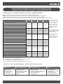
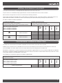
TECHNICAL DATA / LES DONNÉES TECHNIQUES / DATI TECNICI / TECHNISCHE GEGEVENS
GB: The following Technical Data should be considered when installing an External Air Kit.
FR: Les Données Techniques suivantes devraient être prises en considération en installant un Kit d'Air Externe.
IT: È necessario consultare i seguenti Dati tecnici quando si installa un Kit di areazione esterno sigillato.
NL: Er moet rekening worden gehouden met de volgende technische details wanneer u de externe luchttoevoerkit installeert.
STUDIO 500 STUDIO 1 STUDIO 2 STUDIO 3
GB: Appliance Rated Output*
4.9kW 5kW 8kW 11kW
FR: Puissance nominale de l'Appareil*
IT: Erogazione approvata per il dispositivo*
NL: Nominaal vermogen van het apparaat*
GB: Typical Room Size
70m370m3112m3154m3
FR: Taille standard d'une pièce
IT: Dimensione ideale della stanza
NL: Typische kamergrootte
GB: Max length of Ducting
3m 3m 3m 3m
FR: Longueur maximale du conduit
IT: Lunghezza massima del condotto
NL: Maximale kanaallengte
GB: Max No. of Bends (90°)
2 2 2 2
FR: Nombre maximal de Plis (90°)
IT: Numero massimo di curve (90°)
NL: Maximumaantal bochten (90°)
GB: Grill Cover Free Air Space
12300mm212300mm212300mm212300mm2
FR: Espace libre couvert par la grille
IT: Distanza di areazione dalla copertura della griglia
NL: Roosterbedekking vrije luchtruimte
GB: Diameter of Duct**
ø100mm ø100mm ø100mm ø100mm
FR: Diamètre du Conduit**
IT: Diametro del Condotto**
NL: Diameter van Kanaal**
GB: ** Note: Only use duct supplied by Stovax.
FR: ** Remarque: Utilisez uniquement des tuyaux fournis par Stovax
IT: ** Nota: Utilizzare solo condotti forniti da Stovax.
NL: ** Opmerking: Gebruik enkel kanalen die geleverd zijn door Stovax.
INSTALLATION REQUIREMENTS / CONDITIONS D'INSTALLATION
/ REQUISITI PER L'INSTALL AZIONE / PLAATSINGSVEREISTEN
GB: (*In order to achieve
the rated output set the air
controls in the position shown
in the User Instructions)
IT: (*Per ottenere l'erogazione
approvata impostare i controlli
di areazione nella posizione
mostrata diseguito)
FR: (*Pour atteindre la
puissance nominale, réglez
les contrôles à la position
indiquée en Instructions
d’utilisation)
NL: (*Zet de luchtregelaars
op de stand die in
gebruikersinstructies wordt
getoond om het nominaal
vermogen te bereiken)
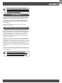
PACKING LIST LISTE DU CONDITIONNEMENT ELENCO DI IMBALLAGGIO PAKLIJST
1 x Collar adapter
2 x Fixing band
1 x Air duct (4"/100mm dia)
1 x Air Vent Outlet
1 x Vent Fascia
4 x Self Tapping Screws
1 x Manchon
2 x Colliers de fixation
1 x Conduit d’air (4"/100mm dia)
1 x Sortie D'évacuation d'air
1 x Grille de ventilation
4 x Fixations
1 x Adattatore a collare
2 x Banda di fissaggio
1 x Condotto di areazione (4"/100mm dia)
1 x Uscita di ventilazione dell'aria
1 x Fascia di ventilazione
4 x Viti autofilettanti
1 x Kraagadapter
2 x Bevestigingsband
1 x Luchtkanaal (4"/100mm Ø)
1 x Uitlaatopening
1 x Ontluchtingsdeksel
4 x Bevestigingsmaterialen
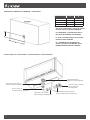
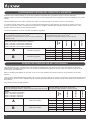
PACKING LIST / LISTE DU CONDITIONNEMENT / ELENCO DI IMBALLAGGIO / PAKLIJST

6
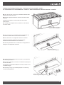
A
B
GB: *NOTE: THE STUDIO 3 OUTLET IS OFFSET,
DOUBLE CHECK YOUR MEASUREMENTS
A B
Studio 500 133.5 303.5
Studio 1 133.5 400
Studio 2 131.5 500
Studio 3 134.5 594.5*
DIMENSIONS / DIMENSION / DIMENSIONI / AFMETINGEN
FR: *REMARQUE: LA SORTIE DU STUDIO 3
EST DÉCALÉE, VÉRIFIEZ VOS MESURES
IT: *NOTA: LA PRESA STUDIO 3 È SFALSATA,
CONTROLLARE LE MISURE
NL: *OPMERKING: DE AFVOER BIJ DE
STUDIO 3 ZIT NIET IN HET MIDDEN; HOUD
HIERMEE REKENING BIJ HET INMETEN
Fixing Band/ Collier de fixation /
Banda di fissaggio/ Bevestigingsband
Fixing Band/ Collier de fixation/
Banda di fissaggio/ Bevestigingsband
Air Vent Outlet/ Sortie D'évacuation d'air/
Uscita di ventilazione dell'aria/ Uitlaatopening
Collar adapter/ Manchon/
Adattatore a collare/ Kraagadapter
Vent Fasica/ Grille de ventilation/
Fascia di ventilazione/
Ontluchtingsdeksel
Air Duct/ Conduit d’air/
Condotto di areazione/ Luchtkanaal
STUDIO CASSETTE / STUDIO INSERT / STUDIO CASSETTA / STUDIO CASSETTE

7
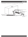
Air Duct/ Conduit d’air/
Condotto di areazione/ Luchtkanaal
Collar adapter/ Manchon/
Adattatore a collare/ Kraagadapter
STUDIO FREESTANDING / STUDIO POÊLE SUR PIEDS / STUDIO LIBERA INSTALLAZIONE / STUDIO VRIJSTAANDE
Self Tapping Screws/ Fixations/ Viti autofilettanti/
Bevestigingsmaterialen
Fixing Band/ Collier de fixation/
Banda di fissaggio/
Bevestigingsband
Vent Fasica/ Grille de ventilation/
Fascia di ventilazione/
Ontluchtingsdeksel
Air Vent Outlet/ Sortie D'évacuation
d'air/ Uscita di ventilazione dell'aria/
Uitlaatopening
Fixing Band/ Collier de fixation/
Banda di fissaggio/ Bevestigingsband

8
GENERAL
Decide on the method of installation, see Installation Instructions
supplied with the appliance.
The kit must be fitted to the appliance prior to installation.
A risk assessment must be completed to confirm the suitability
of using the DEAS prior to installation of the Studio. This should
consider:
Air tightness of the building
Older buildings that are less air tight will naturally have an
additional amount of ventilation air that will compliment the
combustion air required, in particular when the door is opened for
refuelling the appliance. As buildings become more sealed this
air is reduced and it is important to ensure the room where the
appliance is sited is maintained at a positive pressure to reduce
the possibility of spillage.
Existing building ventilation
All buildings will have some form of existing ventilation which
may range from trickle vents in doors and windows, localised
mechanical extraction in kitchens and bathrooms to whole
house mechanical ventilation systems (MHRV). The position and
effectiveness of this will effect the operation of the appliance.
Existing Chimney
This should meet the requirements of Approved Document J
and the specification as detailed in the appliance installation
instructions.
INSTALLATION INSTRUCTIONS / INSTRUCTIONS D’INSTALLATION / ISTRUZIONI PER
L'INSTALLAZIONE/ INSTALLATIE-INSTRUCTIES
GÉNÉRALITÉS
Décider de la méthode d'installation, voir les Instructions
d'Installation fournies avec l'appareil.
Le kit doit être fixé à l'appareil avant l'installation
Une évaluation des risques doit être faite pour confirmer la
pertinence de l'utilisation d’ADAE avant l'installation de la cassette
Elise. Les critères suivants doivent être pris en compte :
La perméabilité à l'air du bâtiment
Les bâtiments plus anciens sont moins étanches à l'air et vont
naturellement avoir plus de ventilation qui va compléter l'air de
combustion requis, en particulier quand la porte est ouverte
pour ravitailler l'appareil. Quand les bâtiments deviennent plus
étanches, l'air est réduit et il est important de s'assurer que la
pièce où l'appareil est situé est maintenue à une pression positive
pour réduire les possibilités de fuite.
Ventilation de bâtiment existant
Tous les bâtiments doivent avoir une forme de ventilation existante
qui peut aller de petites ouvertures dans des portes et fenêtres,
ventilation mécanique dans les cuisines et salles de bains à un
système de ventilation mécanique pour toute la maison (SVMM).
La position et l'efficacité de cela affecteront le fonctionnement de
cet appareil.
Cheminée existante
Elle devrait répondre aux exigences du aux spécifications
détaillées dans les instructions d'installation de l'appareil.
GENERALE
Scegliere il metodo d'installazione. Consultare le istruzioni
d'installazione fornite con l'apparecchio
Montare il kit nell'apparecchio prima dell'installazione
Eseguire una valutazione dei rischi per confermare la possibilità di
utilizzare i DEAS prima dell'installazione delle cassette Elise. La
valutazione deve prendere in considerazione:
Tenuta d'aria dell'edificio
Gli edifici più antichi con minore tenuta d'aria presenteranno
un'ulteriore quantità di aria di ventilazione che andrà a integrare
l'aria di combustione necessaria, in particolare quando lo sportello
è aperto per il rifornimento di combustibile dell'apparecchio. Con
la maggiore ermeticità degli edifici, l'aria in questione sarà ridotta.
Pertanto, è importante garantire il mantenimento di una pressione
positiva negli ambienti in cui è installato l'apparecchio per ridurre i
rischi di perdite.
Ventilazione esistente dell'edificio
Tutti gli edifici presentano forme di ventilazione esistenti, come
ad esempio prese d'aria in porte e finestre, sistemi di aspirazione
meccanici situati in cucine e bagni e sistemi di ventilazione
meccanici dell'intera casa (MHRV). La posizione e l'efficienza degli
elementi in questione influenza il funzionamento dell'apparecchio.
Cappa esistente
Deve rispettare i requisiti indicati nelle istruzioni d'installazione
dell'apparecchio.
ALGEMEEN
Beslissen over de installatiemethode, zie de installatie-instructies
die bij het apparaat geleverd zijn.
De kit moet worden gemonteerd op het apparaat vóór de
installatie.
Er moet een risicobeoordeling worden uitgevoerd zoals beschreven
om de gebruiksgeschiktheid van de REL te bevestigen voordat de
Elise-cassette geïnstalleerd wordt. In deze beoordeling moet het
volgende in overweging worden genomen:
De luchtdichtheid van het gebouw.
Oudere gebouwen die minder luchtdicht zijn zullen normalerwijze
een extra hoeveelheid ventilatielucht hebben die de vereiste
verbrandingslucht zal aanvullen, vooral wanneer de deur geopend
is om het apparaat opnieuw van brandstof te voorzien. Aangezien
gebouwen steeds beter afgedicht worden, vermindert deze lucht en
is het belangrijk een positieve druk te behouden in de kamer waar
het apparaat geplaatst is om het risico op lekken te verkleinen.
Bestaande gebouwsventilatie.
Alle gebouwen hebben een bepaalde vorm van bestaande
ventilatie, variërend van luchtroosters in deuren en ramen, lokale
mechanische afvoeren in keukens en badkamers tot mechanische
ventilatiesystemen (MHRV) in de hele woning. De positie en de
efficiëntie ervan zullen de werking van het apparaat beïnvloeden.
Bestaande schoorsteen.
Deze moet voldoen aan de vereisten van de geldende
voorschriften en de specificatie zoals beschreven in de installatie-
instructies van het apparaat.

9
INTERNAL POSITIONING OF THE AIR DUCT
The air duct must not touch any combustible materials within 550mm of the back of the stove.
Only use Stovax non combustible ducting supplied with the connection kit within 550mm of the air duct connection.
Take care when routing the duct to ensure it is not deformed and restricting the airflow.
Under normal circumstances the Studio 500 & 1 (5kW) requires no additional air supply. If the product is fitted in a well sealed home it may
require additional ventilation to enable the product to work effectively. This could be achieved by the fitting of the external air kit.
See table for additional ventilation requirements.
A) Traditionally Built Homes
• Where leakage is greater than 5m3/hour/m2.
• Ventilation normally required = 550mm2 per kW output over 5kW
B) Modern Construction Homes
• Where leakage is less than 5m3/hour/m2.
• Ventilation normally required = 550mm2 per kW
Model:
Studio 500 Cassette & Freestanding
Studio 1 Cassette & Freestanding
Studio 2 Cassette & Freestanding
Studio 3 Cassette & Freestanding
Studio
500
Studio 1
Studio 2
Studio 3
AAdditional Ventilation
mm2None None 1650 3300
cm2None None 16.5 33
in2None None 2.6 5.3
BAdditional Ventilation
mm22695 2750 4400 6050
cm226.9 27.5 44 60.5
in24.35 4.44 7.1 9.76
POSITIONNEMENT INTERNE DU CONDUIT D’AIR
Le conduit d’air ne doit toucher aucun matériau combustible se trouvant à moins de 550 mm du dos du poêle.
N’utiliser que du conduit stovax non combustible fourni avec le kit de raccordement à moins de 550 mm du raccordement du conduit d’air.
Lors de l’installation du conduit, veiller à ce qu’il ne soit pas déformé et qu’il ne restreigne pas la circulation d’air.
.
Normalement, le Studio 500 & 1 (5 kW) ne nécessite aucune alimentation supplémentaire en air. Si le produit est installé dans une habitation
bien isolée, un système de ventilation supplémentaire sera parfois requis pour permettre un fonctionnement efficace du produit. Pour ce faire,
il est possible d'installer un kit d'alimentation en air externe.
Voir le tableau pour connaître les exigences de ventilation supplémentaire.
Habitations de construction traditionnelle
• Ventilation Min de 50cm2
Modèle:
Studio 500 Insert & Poêle sur pieds
Studio 1 Insert & Poêle sur pieds
Studio 2 Insert & Poêle sur pieds
Studio 3 Insert & Poêle sur pieds
Studio
500
Studio 1
Studio 2
Studio 3
Ventilation Supplémentaire mm25000 5000 7000 3300
cm250 50 70 33

10
POSIZIONAMENTO INTERNO DEL CONDOTTO DI AREAZIONE
Assicurarsi che il condotto dell’aria non tocchi alcun materiale combustibile entro una distanza di 550 mm dal retro della stufa.
Utilizzare soltanto condotti non combustibili stovax forniti con il kit per il collegamento entro una distanza di 550 mm dall’allaccio del condotto
dell’aria.
Durante l’instradamento del condotto, accertarsi che questo non venga deformato e che il flusso d’aria non venga limitato.
In condizioni normali, Studio 500 & 1 (5 kw) non richiede alcuna alimentazione di aria aggiuntiva. Se il prodotto è montato in una casa
provvista di serramenti ermetici, potrebbe essere necessaria una maggiore ventilazione per garantirne il funzionamento efficace. Ciò si
potrebbe ottenere montando un kit di aerazione esterno.
Consultare la tabella per conoscere i requisiti di ventilazione aggiuntiva.
A) Case di vecchia costruzione
• Se la ventilazione è superiore a 5 m3/ora/m2.
• Ventilazione normalmente richiesta = 550 mm2 per una potenza kW
superiore a 5 kW
B) Case di nuova costruzione
• Se la ventilazione è inferiore a 5 m3/ora/m2.
• Ventilazione normalmente richiesta = 550 mm2 per kW
Modello:
Studio 500 Cassetta e modelli Libera installazione
Studio 1 Cassetta e modelli Libera installazione
Studio 2 Cassetta e modelli Libera installazione
Studio 3 Cassetta e modelli Libera installazione
Studio
500
Studio 1
Studio 2
Studio 3
AVentilazione Aggiuntiva
mm2None None 1650 3300
cm2None None 16.5 33
in2None None 2.6 5.3
BVentilazione Aggiuntiva
mm22695 2750 4400 6050
cm226.9 27.5 44 60.5
in24.35 4.44 7.1 9.76
INTERNE POSITIONERING VAN HET LUCHTKANAAL
Het luchtkanaal mag niet in aanraking komen met brandbare materialen binnen een straal van 550mm aan de achterkant van de kachel.
Gebruik alleen onbrandbare leidingen van stovax die met het aansluitpakket meegeleverd worden, binnen een straal van 550mm van de
verbinding van het luchtkanaal.
Wees voorzichtig bij het plaatsen van de buizen om ervoor te zorgen dat deze niet vervormd worden en de doorstroming van de lucht
beperken.
Onder normale omstandigheden heeft de Studio 500 & 1 (5kw) geen extra luchttoevoer nodig. Als het product in een goed geïsoleerde woning
geïnstalleerd is, dan kan er extra ventilatie nodig zijn zodat het product effectief kan functioneren. Dit kan bereikt worden door de buitenlucht
kit te plaatsen.
Zie de tabel voor extra ventilatie vereisten.
A) Traditioneel gebouwde huizen
• Wanneer lekkage groter is dan 5m3/uur/m2.
• Normaal benodigde ventilatie = 550mm2 per kW output groter dan 5 kW
B) Modern gebouwde huizen
• Wanneer lekkage minder is dan 5m3/uur/m2.
• Normaal benodigde ventilatie = 550mm2 per kW
Model:
Studio 500 Cassette & Vrijstaande
Studio 1 Cassette & Vrijstaande
Studio 2 Cassette & Vrijstaande
Studio 3 Cassette & Vrijstaande
Studio
500
Studio 1
Studio 2
Studio 3
AAdditionele ventilatie
mm2Niets Niets 1650 3300
cm2Niets Niets 16.5 33
in2Niets Niets 2.6 5.3
BAdditionele ventilatie
mm22695 2750 4400 6050
cm226.9 27.5 44 60.5
in24.35 4.44 7.1 9.76

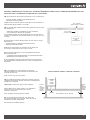
11
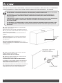
Vent / Ventilation /
Apertura di sfiato / Ventilatie
Duct / Conduit /
Condotto / Leiding
Stove / Poêle
/ Stufa /
Convectorhaard
GB: The external air duct should be positioned so it is not effected by:
– Adverse weather conditions and prevailing winds.
– Blockages caused by debris.
Regular checks should be made to ensure the vent is not blocked, in
particular after windy weather or snow falls.
FR: La conduite d'air extérieure devrait être placée de façon à ne pas
être affectée par :
— Mauvaises conditions climatiques et vents dominants.
— Des obstructions causées par des débris.
Des contrôles réguliers doivent être effectués pour s'assurer que le
conduit n'est pas bloqué, en particulier quand il y a du vent ou en cas
de neige.
IT: Posizionare il condotto dell'aria esterno in modo che non venga
influenzato da:
— Venti prevalenti e condizioni atmosferiche avverse.
— Intasamenti causati da detriti.
Effettuare controlli regolari per verificare che la ventola non
sia ostruita, in particolare in caso di neve o vento.
NL: De externe luchttoevoer moet zo zijn geplaatst dat hij niet
beïnvloed wordt door:
— Ongunstige weersomstandigheden en overheersende winden.
— Blokkeringen veroorzaakt door puin.
Er moet regelmatig controle worden uitgevoerd om te verzekeren
dat de luchtopening niet geblokkeerd is, vooral na winderig weer of
sneeuwval.
GB: If the building has a suspended floor, which has
external ventilation into the void below the termination may
be made into this area.
Note: Choose only one vent position.
FR: Si le bâtiment possède un plancher suspendu ayant une
ventilation externe dans l’espace du dessous, l’extrémité peut
aboutir dans cet espace.
REMARQUE: Choisir une seule position d’aération.
IT: Se l’edificio ha un solaio sospeso, con ventilazione
esterna nel vuoto, la terminazione può essere
disposta in quest’area.
Nota: Scegliere una sola posizione di sfiato.
NL: Als het gebouw een zwevende vloer heeft, met
een externe ventilatie in de ruimte er onder, dan kan de
afsluiting hier worden aangebracht.
Kies slechts één ventilatie-opening.
Possible
Vent /
Ventilation
/ Apertura
di sfiato /
Ventilatie
VOID / ESPACE / VUOTO / RUIMTE
Cassette
/ Insert /
Casetta /
Cassette
STUDIO CASSETTE / INSERT / CASSETTA / CASSETTE
Possible
Vent /
Ventilation
/ Apertura
di sfiato /
Ventilatie
EXTERNAL TERMINATION OF THE AIR DUCT / EXTRÉMITÉ EXTERNE DU CONDUIT D’AIR / TERMINAZIONE ESTERNA DEL CON-
DOTTO DELL’ARIA / EXTERNE AFSLUITING VAN HET LUCHTKANAAL

12
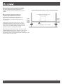
Freestanding / Poêle sur Pieds / Libera
installazione / Vrijstaande
GB: Terminations should be made with a proprietary
fixed open external air vent kit, which gives minimum
free area of greater than listed, positioned so no
blockage can occur and not permit the entry of birds or
animals.
STUDIO FREESTANDING / POÊLE / STUFA / CONVECTORHAARD
Possible
Vent /
Ventilation
/ Apertura
di sfiato /
Ventilatie
Possible
Vent /
Ventilation
/ Apertura
di sfiato /
Ventilatie
VOID / ESPACE / VUOTO / RUIMTE
FR: Les extrémités doivent être réalisées en
utilisant un kit de ventilation d’air externe fixe
de marque déposée qui donne une surface
libre minimale plus importante qu’énumérée,
positionnees de telle manière qu’elles ne puissent
pas être bloquées ou permettre l’entrée d’oiseaux
ou d’animaux.
IT: Eseguire le terminazioni servendosi di un kit per
la ventilazione esterna aperta fissa, che offre un’area
libera minima più grande di quella indicata, posizionata
in modo che non si verifichi alcuna ostruzione e da non
permettere l’ingresso di uccelli o altri animali.
NL: Afsluitingen moeten met een eigen vast, open, extern
ventilatiepakket gemaakt worden, waardoor er een minimale
grotere vrije ruimte ontstaat dan vermeld, en die zodanig
gepositioneerd is dat er geen verstopping kan ontstaan en er geen
vogels of dieren in kunnen komen.

13
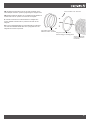
Blanking Plate / Plaque d’obturation/
Piastra di Chiusura / Afdekplaat
Collar Adapter / Manchon /
Adattatore a collare / Kraagadapter
Fixing band / Collier de fixation /
Banda di fissaggio / Bevestigingsband
INTERNAL POSITIONING OF THE AIR DUCT / FIXATION DU KIT SUR L’APPAREIL- INSERT /
KIT DI MONTAGGIO ALL’ELETTRODOMESTICO - CASSETTA / BEVESTIGINGSPAKKET VOOR HET APPARAAT - CASSETTE
GB: The air duct must not touch any combustible materials within
550mm of the back of the stove.
FR: Enlever la plaque d’obturation de la base du boîtier externe
du studio.
IT: Rimuovere la piastra di chiusura alla base della scatola
esterna studio.
NL: Verwijder de afdekplaat aan de onderkant van de buitenste
kist van de studio.
GB: Only use Stovax non combustible ducting supplied with the
connection kit within 550mm of the air duct connection.
FR: Fixer le manchon sous l’appareil à l’aide des vis fournies.
IT: Fissare la flangia di collegamento alla parte inferiore
dell’elettrodomestico utilizzando le viti in dotazione.
NL: Bevestig aansluitflens aan de onderkant van het apparaat met
behulp van de meegeleverde schroeven.
GB: Take care when routing the duct to ensure it is not deformed
and restricting the airflow.
FR: Fixer le conduit d’air au manchon et le maintenir en place grâce
au collier de fixation.
IT: Collegare il tubo all’allaccio/adattatore e fissare il condotto con la
fascetta di fissaggio.
NL: Bevestig de slang op de aansluiting/adapter en maak stevig
vast met bevestigingsband

14
FIXING KIT TO THE APPLIANCE- FREESTANDING / FIXATION DU KIT SUR L’APPAREIL- POÊLE SUR PIEDS / KIT DI MONTAGGIO
ALL’ELETTRODOMESTICO- LIBERA INSTALLAZIONE / BEVESTIGINGSPAKKET VOOR HETAPPARAAT - VRIJSTAANDE
GB: IMPORTANT: IF THIS OUTSIDE AIR KIT IS TO BE INSTALLED ON A FREESTANDING STUDIO WITH A HEAT SHIELD
FITTED, CONSULT THE INSTRUCTION MANUAL SUPPLIED (PM732) PRIOR TO INSTALLATION.
FR: IMPORTANT : SI CE KIT D'AIR EXTÉRIEUR DOIT ÊTRE INSTALLÉ SUR UN STUDIO SUR PIED ÉQUIPÉ D'UN
BOUCLIER THERMIQUE, CONSULTER LE MANUEL D'INSTRUCTIONS FOURNI (PM732) AVANT DE PROCÉDER À
L'INSTALLATION.
IT: IMPORTANTE: SE QUESTO KIT PER L'ARIA ESTERNA DEVE ESSERE INSTALLATO SU UNO STUDIO INDIPENDENTE
CON UNO SCUDO TERMICO, CONSULTARE IL MANUALE DI ISTRUZIONI IN DOTAZIONE (PM732) PRIMA
DELL'INSTALLAZIONE
NL: BELANGRIJK: ALS DEZE EXTERNE LUCHTKIT GEÏNSTALLEERD MOET WORDEN OP EEN VRIJSTAANDE STUDIO
MET EEN GEMONTEERD HITTESCHERM, RAADPLEEG DAN DE MEEGELEVERDE HANDLEIDING (PM732) VÓÓR DE
INSTALLATIE.
Remove / Retirer
/ Rimuovere /
Verwijderen
Rear of Outer Box / L'arrière du boîtier /
Retro dell'involucro esterno /
Achterkant van de buitenste box
4 x screws / 4 x Fixations /
4 x Viti / 4 x Schroeven
Collar Adapter / Entrée
d'air / Adattatore a
collare / Luchtinlaat
GB: Some of the kit must be fitted prior to the permanent
placement of the outer box.
Remove the knock out in the rear of the appliance outer box.
FR: Une partie du kit doit être installée avant la mise en place
permanente du boîtier extérieur.
Retirer la découpe située à l'arrière du boîtier extérieur de
l'appareil
IT: Alcuni kit devono essere montati prima dell'installazione
dell'involucro esterno.
Rimuovere la sagomatura nella retro dell'involucro esterno
dell'apparecchio.
NL: De kit moet gedeeltelijk gemonteerd worden vóór de
permanente plaatsing van de buitenste box.
Verwijder de uitsparing van de achterkant van de buitenste box
van het apparaat.
GB: Attach the Collar Adapter to the rear of the outer box,
securing with the 4 screws provided.
ENSURE A GOOD SEAL IS ACHIEVED.
FR: Attacher la conduite d'arrivée d'air à l'arrière du boîtier
extérieur à l'aide des 4 vis fournies.
S'ASSURER QUE LE RACCORD EST BIEN ÉTANCHE.
IT: Collegare lo scarico dell'aria alla parte retro dell'involucro
esterno, fissandolo con le 4 viti fornite.
VERIFICARE LA PRESENZA DI UN SIGILLO EFFICACE.
NL: Bevestig de luchtinlaat aan de achterkant van de buitenste
box en maak hem vast met de meegeleverde 4 schroeven.
ZORG ERVOOR DAT ALLES GOED VERZEGELD IS.

15
Air Duct / Conduit d’air /
Condotto di areazione /
Luchtkanaal
GB: Thread the Fixing Band onto the air duct and attach to the
Collar Adapter. Secure in position by tightening the integral screw.
FR: Enfiler la bande de fixation sur la conduite d'air et l'attacher à
l'entrée d'air. Fixer en position en serrant la vis intégrale.
IT: Inserire la fascetta sul condotto dell'aria e collegarlo allo
scarico dell'aria. Fissare il tutto in posizione serrando la vite
integrale.
NL: Leg de vasthechtingstape op het luchtkanaal en maak hem
vast aan de luchtinlaat. Maak alles vast op zijn plaats door de
integrale schroef aan te spannen.
Collar Adapter / Entrée d'air /
Adattatore a collare / Luchtinlaat
Screws / Fixations / Viti / Schroeven
Fixing band / Collier de fixation /
Banda di fissaggio / Bevestigingsband

16
If smoke spills from the appliance, warm the chimney further and
repeat the test.
NOTE: Intermittent minor spillage (wisps) of smoke are acceptable
but constant spillage is not.
If smoke still spills into the room, progressively open a window. If
the flue starts to draw the smoke, this will indicate the appliance is
not being provided with adequate air via the dedicated external air
supply system. Note the additional area of ventilation required, and
add permanent ventilation into the room by that amount to correct
the problem.
Retest and confirm safe operation.
C. DE-PRESSURISATION TEST
Turn off any already running extraction systems and open a
window in the room the appliance is situated in to equalise the
dwellings internal pressure with outside.
Close the window.
Light a small fire in the appliance with the recommended amount
of kindling detailed in the manufacturers operating instructions and
allow the appliance to reach its normal operating temperature.
Close all external doors, windows, and ensure all trickle ventilators
that can be closed are closed.
Set to maximum any extract systems in the dwelling (including
cooker hoods, bathroom extractors, and externally vented tumble
driers etc.).
Switch on and set to maximum any additional open flued heating
appliances in the same or adjacent rooms.
Open any connecting doors between the room in which the
appliance is fitted and the room which contains the extractor fan
and or heating appliances. Leave the remaining windows and
doors shut in both rooms.
If the smoke continues to fail to be drawn up the flue, or fails with
additional ventilation beyond that advised by ADJ, thoroughly
inspect the flue / chimney and termination for other faults.
Repeat the Hot Test – refuelling (step 1b.)
If smoke enters the room then additional ventilation may be
required to compensate for the extraction. This can be tested by
gradually opening a window.
If the smoke continues to fail to be drawn up the flue, or fails
with additional ventilation beyond that advised by ADJ Table
1, thoroughly inspect the flue / chimney and termination for
other faults. Ensure satisfactory test results before bringing
the appliance in to use.
If any tests do not pass instruct the user not to use
the appliance until the problem is rectified or an air
vent as detailed in ADJ is fitted and the appliance is
confirmed as safe, in writing.
GENERAL CHECK
Check that the appliance is fully assembled and all parts are in
their correct position.
Check that the manufacturer’s instructions have been followed
with particular regard to the correct fitting and adjustment of the
Dedicated External Air Supply.
Ensure that a carbon monoxide alarm has been securely fitted in a
suitable position.
Complete the appliance commissioning procedure as detailed in
the appliance installation instructions
A. COLD TEST – APPLIANCE DOOR SHUT
Close all doors and windows in the room that contains the
appliance.
Preheat the flue by lighting a small fire using kindling or use a blow
lamp or electric heater.
Light a small smoke pellet (30g / 15m3) in the appliance and shut
the appliance door. All air-controls should be in their maximum
open position.
Check that all of the smoke enters the flue and none comes back
into the room through any part of the stove, connecting flue pipe or
air supply duct.
If smoke enters the room then repeat the flue preheat, increasing
the warmth of the flue to generate additional flue draught.
If it still fails, progressively open a window. If the flue starts to draw
the smoke, this will indicate the appliance is not being provided
with adequate air via the dedicated external air supply system to
the room. Note the additional free area of ventilation provided by
the window and add permanent ventilation into the room by that
amount to correct the problem.
Retest to confirm safe operation.
B. HOT TEST – REFUELLING
Light a small fire in the appliance using the recommended amount
of kindling for the appliance as detailed in the manufacturers
operating instructions. This will establish a flue draught.
Allow the kindling to burn down to glowing char with little or no
visible flames. Insert a smoke match into a smoke match extension
rod (min 15 seconds burn time). Set the appliance air controls
into the manufacturers recommended refuel position. Open the
appliance door. Touch the tip of the smoke match onto a burning
ember in the firebox and then position the smoke match 50mm
above the bed of char or any flames in the centre of the firebox
and 2/3 of the firebox depth in from the front. For the duration
of the smoke match burn observe if the smoke is drawn into the
chimney or spills into the room. Once the smoke is extinguished
close the appliance door.
NOTE: shining a bright light from a torch or lamp into the firebox
will assist visibility of the smoke flow.
COMMISSIONING
GB

17
MAINTENANCE
Check internal and external vents and air ducts at least once a
year for any obstructions.
Regular checks should be made to ensure the vent is not
blocked, in particular after adverse weather.
Check the security of air connections to the stove and tighten if
required.
CO ALARMS
All open flued appliances can be affected by conditions that may
cause products of combustion to enter the dwelling where the
appliance is installed.
ADJ requires that whenever a new or replacement solid fuel / wood
burning appliance is installed a dwelling a carbon monoxide (CO)
alarm, complying with EN50291, must be fitted in the same room
as the appliance. Guidance on installing alarms is contained in
EN50292 and the alarm manufacturers fitting instructions.
These alarms however are usually located high up on a wall and
often out of sight of the user. Because the alarm will activate when
a predetermined level of CO has been reached and exceeded
for a certain period of time, the user will not be aware of any low
level CO spillage within their property, which would indicate the
appliance and/or ventilation systems are not working correctly.
This will be a good indicator for the user to see if the appliance and
ventilation is working correctly and is maintaining a safe air quality.
Provision of a CO Alarm / Monitor must not be
considered a substitute for either installing the
appliance correctly or ensuring regular servicing
and maintenance of the appliance and chimney
system is completed.
GB

18
Remarque : Mettre une lumière vive à l'aide d'une lampe torche
ou de poche dans la chambre à combustion va contribuer à la
visibilité du parcours de la fumée.
Si de la fumée s'échappe de l'appareil, chauffez plus la cheminée
et recommencez le test.
REMARQUE : Un peu de fumée peut parfois s'échapper (mèches),
ce n'est pas grave mais des fuites régulières ne sont pas
normales.
Si de la fumée continue à s'échapper dans la pièce, ouvrez
progressivement une fenêtre. Si le tuyau commence à absorber
la fumer, cela indique que l'appareil ne reçoit pas assez d'air
via le système d'alimentation en air de la pièce. Notez l'espace
vide supplémentaire de ventilation et ajoutez de la ventilation
permanente dans la pièce du même volume pour corriger le
problème.
Recommencez et confirmer le fonctionnement sans risque.
TEST DE DÉPRESSURISATION
Éteignez les systèmes d'extraction en fonctionnement et ouvrez
une fenêtre dans la pièce où se trouve l'appareil pour égaliser la
pression interne du logement avec l'extérieur.
Fermez la fenêtre.
Allumez un petit feu dans l'appareil en utilisant la quantité de petit
bois recommandée par le mode d'emploi du fabriquant et laissez
l'appareil atteindre sa température de fonctionnement normale.
Fermez toutes les portes extérieures, les fenêtres et assurez-bous
que toutes les grilles de ventilation qui peuvent être fermées le
sont.
Mettez au maximum tous les systèmes d'extraction du logement
(dont les hottes aspirantes, les ventilations de salle de bain, les
sèche-linges etc.).
Allumez et réglez au maximum tout appareil de chauffage à
conduit ouvert dans la même pièce ou dans les pièces voisines.
Ouvrez toutes les portes communicantes entre la pièce dans
laquelle se trouve l'appareil et la pièce qui contient la hotte
aspirante ou les autres appareils de chauffage. Laissez les autres
portes et fenêtres fermés dans les deux pièces.
Si la fumée n'est toujours pas aspirée par le conduit ou continue
à ne pas être aspirée avec les ventilations supplémentaires
inspectez minutieusement le conduit, la cheminée et les terminaux
pour d'autres défauts.
Recommencez le Test à Chaud - Ravitaillement (étape 1b.)
Si de la fumée entre dans la pièce, de la ventilation supplémentaire
peut être nécessaire pour compenser l'extraction. Cela peut être
testé en ouvrant progressivement une fenêtre.
Si la fumée n'est toujours pas aspirée par le conduit
ou continue à ne pas être aspirée avec les ventilations
supplémentaires, inspectez minutieusement le conduit, la
cheminée et les terminaux pour d'autres défauts. Assurez-
vous d'obtenir des résultats satisfaisant aux tests avant de
commencer à utiliser l'appareil.
CONTRÔLES D'ORDRE GÉNÉRAL
Assurez-vous que l'appareil est entièrement assemblé et que
toutes les parties sont au bon endroit.
Vérifiez que les instructions du fabricant ont bien été suivies, en
particulier en ce qui concerne le bon positionnement et réglage du
Kit d'Alimentation en Air Extérieur Dédié.
Assurez-bous qu'une alarme à monoxyde de carbone ait bien été
fixée fermement à un endroit approprié.
Exécuter la procédure de mise en service de l’appareil
conformément à l’installation du kit.
A. ESSAI DE CHOC À FROID - PORTE DE L'APPAREIL
FERMÉ.
Fermez toutes les portes et fenêtres de la pièce qui contient
l'appareil.
Préchauffez le tuyau de poêle en allumant un feu à l'aide de petit
bois ou avec un chalumeau ou un chauffage électrique.
Allumez une petite pastille à fumée (30g / 15m3) dans l'appareil et
fermer la porte de l'appareil. Tous les contrôles d'air devraient être
ouverts au maximum.
Vérifiez que toute la fumée entre dans le tuyau de poêle et que
rien ne revienne dans la pierre par une partie du poêle reliant le
tuyau ou le conduit d'air.
Si de la fumée entre dans la pièce, répétez le processus de
préchauffage, en augmentant la chaleur pour produire plus de
courant d'air dans le tuyau.
Si ça ne marche toujours pas, ouvrez progressivement une fenêtre.
Si le tuyau commence à absorber la fumer, cela indique que
l'appareil ne reçoit pas assez d'air via le système d'alimentation en
air de la pièce. Notez l'espace vide supplémentaire de ventilation
fourni par la fenêtre et ajoutez de la ventilation permanente dans la
pièce du même volume pour corriger le problème.
Faites à nouveau un test pour confirmer le fonctionnement
sans risque.
B. ESSAI DE CHOC À CHAUD - RAVITAILLEMENT.
Allumez un petit feu dans l'appareil en utilisant la quantité de petit
bois recommandée pour l'appareil comme décris dans le mode
d'emploi du fabriquant. Cela va créer un courant d'air.
Laissez le petit feu brûler jusqu'à des cendres incandescentes
avec peu ou plus de flammes visibles. Insérez une allumette à
fumée dans une rallonge pour allumette à fumée (min 15 seconde
de combustion). Réglez les contrôles d'air de l'appareil selon les
recommandations du fabriquant. Ouvrez la porte de l'appareil.
Touchez le bout de l'allumette à fumée sur la braise brûlante dans
la chambre à combustion et placez l'allumette à fumée à 50mm
au-dessus des braises ou des flammes au centre de la chambre
à combustion et à 2/3 de profondeur depuis l'avant. Pendant la
durée de combustion de l'allumette à fumée, observez si la fumée
est absorbée dans la cheminée ou s'échappe dans la pièce. Une
fois que la fumée est éteinte, fermez la porte de l'appareil.
MISE EN SERVICE
FR

19
Si un test ne réussit pas, indiquez à l'utilisateur de
ne pas utiliser l'appareil tant que le problème n'est
pas rectifié ou si une ventilation est installée et que
l'appareil est certifié sans risque.
MAINTENANCE
Vérifier l’absence d’obstruction dans les ventilations internes
et externes et les conduits d’air au moins une fois par an.
Il convient de procéder à des contrôles réguliers afin de
s'assurer que l'évent n'est pas obstrué, en particulier après
des intempéries.
Vérifier le bon état des raccordements d’air au poêle et les
resserrer le cas échéant.
DÉTECTEURS-AVERTISSEURS DE CO
Tous les appareils à insert ouvert peuvent être affectés par des
conditions atmosphériques temporaires capables de repousser la
fumée dans la maison. Nous recommendons, lors de l’installation
dans une habitation d’un nouvel appareil ou d’un appareil de
chauffage de remplacement à combustible solide ou à bois ou
biomasse qu’un détecteur-avertisseur de CO soit installé dans la
même pièce que l’appareil.
Cependant, ces détecteurs-avertisseurs sont généralement situés
en hauteur sur un mur et souvent en dehors du champ de vision
de l’utilisateur. Le détecteur-avertisseur s’activant lorsqu’un niveau
prédéterminé de CO a été atteint et dépassé pendant une certaine
période de temps, ce qui indiquerait que l’appareil et/ou les
systèmes d’aération ne fonctionnent pas correctement. L’utilisateur
ne sera pas informé d’une fuite de CO de faible niveau dans sa
propriété.
Ce sera un bon indicateur pour l’utilisateur et lui permettra de voir
si l’appareil et l’aération fonctionnent correctement et maintiennent
une qualité d’air sûre.
La présence d’une alarme ne doit pas être
considérée comme un substitut pour une bonne
installation et un entretien et une maintenance
régulière de l’appareil et de la cheminée.
FR

20
Per la durata dell'accensione del fiammifero fumogeno, osservare
se il fumo viene aspirato dalla cappa o si distribuisce nella stanza.
Una volta esaurito il fumo, chiudere il portello dell'apparecchio.
NOTA: utilizzando nella fornace una torcia o lampada di elevata
intensità, sarà possibile visualizzare al meglio il flusso del fumo.
Nel caso in cui fuoriesca fumo dall'apparecchio, riscaldare
ulteriormente la cappa e ripetere il test.
NOTA: Delle perdite ridotte e intermittenti di fumo (sbuffi)
sono accettabili. Non sono accettabili perdite costanti.
Se la fuoriuscita del fumo non dovesse arrestarsi, aprire una
finestra in maniera progressiva. Se la canna fumaria continua
a produrre fumo, l'apparecchio non è dotato di un'areazione
adeguata attraverso il sistema di fornitura dell'aria esterna
dedicato. Individuare l'area libera aggiuntiva di ventilazione
fornita dalla finestra e aggiungere nella stanza una ventilazione
permanente e sufficiente a risolvere il problema.
Ripetere il test per confermare la sicurezza del funzionamento.
C. TEST DI DEPRESSURIZZAZIONE
Spegnere tutti i sistemi di estrazione già in esecuzione e aprire
una finestra nella stanza l'apparecchio si trova in a pareggiare le
abitazioni pressione interna con l'esterno.
Chiudi la finestra.
Accendere un piccolo fuoco nell'apparecchio usando la quantità
di legna da fiamma consigliata nelle istruzioni operative del
produttore e consentire all'apparecchio di raggiungere la
temperatura operativa normale.
Chiudere tutte le porte esterne, finestre, e garantisce tutti trickle
ventilatori che possono essere chiusi sono chiusi.
IImpostare al livello massimo tutti i sistemi di estrazione
presenti nella stanza o nelle stanze adiacenti (comprese
le cappe di aspirazione, le asciugatrici con ventilazione
esterno, ecc.)
Accendere e impostare al livello massimo qualsiasi altro
dispositivo di riscaldamento dotato di canna fumaria aperta
presente nella stessa stanza o nelle stanze adiacenti.
Aprire qualsiasi porta di collegamento fra la stanza in cui
è installato il dispositivo e la stanza che contiene la ventola
di estrazione o i dispositivi di riscaldamento. Lasciare chiuse
le finestre e le porte rimanenti in entrambe le stanze.
Se il fumo continua a non venire tirato nella canna fumaria o se
il problema persiste con una ventilazione aggiuntiva superiore
a quella suggerita ispezionare con cura la canna fumaria e
l'estremità del condotto per verificare che non siano presenti altri
problemi.
Ripetere il test a caldo B.
Se parte del fumo entra nella stanza, allora è possibile
che sia necessaria della ventilazione aggiuntiva per
compensare l'estrazione. Questa eventualità può venire
testata con l'apertura graduale di una finestra.
CONTROLLO GENERALE
È essenziale assicurarsi che i seguenti controlli vengano messi in
atto:
— Il dispositivo è assemblato completamente e tutti i componenti
si trovano nella posizione corretta.
— Le istruzioni del produttore sono state messe in atto, in
particolare per quanto riguarda la corretta installazione e
regolazione del dispositivo di areazione apposito.
— Verificare il fissaggio di un allarme per il monossido di carbonio
in posizione adeguata.
Completare la procedura di messa in opera del dispositivo come
richiesto durante l'installazione del dispositivo stesso.
A. TEST A FREDDO – SPORTELLO DEL DISPOSITIVO CHIUSO
Chiudere tutte le porte e le finestre nella stanza che contiene il
dispositivo.
Preriscaldare la canna fumaria accendendo un piccolo fuoco con
un po' di legna da fiamma o utilizzare un accendino elettrico o a
gas.
Accendere un pellet a fumo (30g/ 15m3) nel dispositivo e chiudere
lo sportello. Tutti i controlli di areazione devono essere nella
posizione di apertura massima
Controllare che tutto il fumo vada nella canna fumaria e
non ritorni nella stanza tramite alcuna parte del caminetto o
della canna fumaria di connessione.
Se una parte del fumo confluisce nella stanza, riscaldare la canna
fumaria per generare un tiraggio aggiuntivo.
In caso di mancato funzionamento, aprire una finestra in maniera
progressiva. Se la canna fumaria continua a produrre fumo,
l'apparecchio non è dotato di un'areazione adeguata attraverso
il sistema di fornitura dell'aria esterna dedicato nella stanza.
Individuare l'area libera aggiuntiva di ventilazione fornita dalla
finestra e aggiungere nella stanza una ventilazione permanente e
sufficiente a risolvere il problema.
Ripetere il test per confermare la sicurezza del funzionamento.
B. TEST A CALDO - RIFORNIMENTO DI CARBURANTE:
Accendere un piccolo fuoco nell'apparecchio utilizzando il
quantitativo consigliato di legna da fiamma, come indicato nelle
istruzioni operative del produttore. In questo modo sarà possibile
ottenere il tiraggio della canna fumaria.
Lasciar bruciare la legna da fiamma fino a ottenere una brace
luminescente con fiamme di piccola entità o invisibili. Inserire
un fiammifero fumogeno usando un'apposita asticella (tempo di
accensione di almeno 15 secondi). Impostare i controlli dell'aria
dell'apparecchio nella posizione di rifornimento consigliata dal
produttore. Aprire il portello dell'apparecchio. Portare l'estremità del
fiammifero fumogeno a contatto con la brace accesa nella fornace
e collocare il fiammifero fumogeno 50 mm al di sopra del letto di
ceneri o di qualsiasi fiamma presente al centro della fornace e a
una profondità pari a 2/3 di quella della fornace, misurandola a
partire dal lato anteriore.
MESSA IN OPERA

21
In caso di perdurante mancata aspirazione del fumo da
parte della canna fumaria, anche in caso di utilizzo di
una ventilazione aggiuntiva di entità superiore a quella
indicata, ispezionare attentamente la cappa/canna fumaria
e la terminazione in cerca di altri danni. Non utilizzare
l'apparecchio prima di aver ottenuto risultati soddisfacenti del
test.
Se un qualsiasi test non avesse esito positivo,
indicare all'utente di non utilizzare l'apparecchio
fino alla correzione del problema o al montaggio
di un sistema di ventilazione dell'aria, di sicurezza
confermata per iscritto da un installatore registrato.
MANUTENZIONE
Controllare le ventole interne ed esterne e i condotti di
areazione almeno una volta all'anno per assicurarsi che non
siano presenti ostruzioni.
Verificare regolarmente che la ventilazione non sia ostruita, in
particolare nei periodi di cattivo tempo atmosferico.
Controllare lo stato di sicurezza delle connessioni di areazione
verso il caminetto e stringerle se necessario.
RILEVATORI DI CO
Tutti i dispositivi dotati di canna fumaria aperta sono soggetti
all'influenza di condizioni atmosferiche temporanee che possono
permettere ai fumi di entrare nell'edificio.
I regolamenti edilizi impongono che, ogniqualvolta in un'abitazione
venga installato un dispositivo fisso nuovo o sostitutivo a
carburante solido o alimentato a legna/biomassa, è necessario
posizionare un rilevatore di monossido di carbonio nella stessa
stanza in cui il dispositivo stesso è installato. Ulteriori informazioni
sull'installazione del rilevatore di monossido di carbonio sono
disponibili nell'ultima edizione di EN50292 e all'interno delle
istruzioni fornite dal produttore del rilevatore.
Stovax consiglia di utilizzare un allarme per il monossido di
carbonio contenente un apparecchio per la combustione del
carburante solido. Tuttavia, questi allarmi vengono installati nella
parte alta di una parete o fuori dalla portata dell'utente. Poiché
gli allarmi verranno attivati al raggiungimento e superamento,
per un certo periodo di tempo, di un dato livello di CO, l'utente
non verrà avvertito delle perdite di CO di bassa entità nella sua
proprietà, aspetto che potrebbe indicare il funzionamento erroneo
dell'apparecchio e/o dei sistemi di ventilazione.
In questo modo, l'utente potrà visualizzare in maniera intuitiva
il corretto funzionamento della ventilazione e dell'apparecchio e
garantire una qualità dell'aria ottimale e sicura.
L'installazione di un sistema di monitoraggio/
allarme del CO non deve essere considerata
un sostitutivo per la corretta installazione
dell'apparecchio o per la corretta messa in opera e
manutenzione dell'apparecchio e del sistema della
canna fumaria.

22
OPMERKING: schijn helder licht van een zaklamp of lamp in de
vuurkist om de rookstroom beter te kunnen zien.
Als er rook uit het apparaat lekt, blijf de schoorsteen verwarmen en
herhaal de test.
OPMERKING: Periodieke kleine rooklekken (flarden) zijn
aanvaardbaar, maar constante lekken zijn dat niet.
Als er rook in de kamer blijft lekken, open geleidelijk een raam.
Als de schoorsteen de rook begint te trekken, toont dit aan dat het
apparaat niet voorzien wordt van voldoende lucht via het speciale
externe luchttoevoersysteem. Houd rekening met de vereiste extra
ventilatieruimte en voeg permanente ventilatie toe aan de kamer,
uitgaande van die hoeveelheid, om het probleem op te lossen.
Voer de test opnieuw uit en bevestig de veilige werking.
C. WEGVALLENDE DRUKTEST
Schakel alle reeds werkende afvoersystemen uit en open een
raam in de kamer waar het apparaat zich bevindt om de interne
druk van de woning gelijk te maken met die van buiten.
Sluit het raam.
Steek een klein vuurtje aan in het apparaat met de aanbevolen
hoeveelheid aanmaakhout, zoals beschreven in de
gebruiksaanwijzing van de producent en laat het apparaat op de
normale bedrijfstemperatuur komen.
Sluit alle externe deuren en ramen en zorg ervoor dat alle
luchtroosters die gesloten kunnen worden, gesloten zijn.
Zet alle afvoersystemen in de woning op maximum (waaronder
dampkappen, badkamerafzuiginstallaties en extern geventileerde
drogers, enz.).
Schakel in dezelfde of aangrenzende kamer alle bijkomende
verwarmingsapparatuur met een open schoorsteen aan en zet ze
op maximum.
Open de tussendeuren tussen de kamer waarin het apparaat
geplaatst is en de kamer waar de afvoerventilator en/of
verwarmingsapparaten zich bevinden. Houd de andere ramen en
deuren gesloten in beide kamers.
Als de rook nog altijd niet in de schoorsteen getrokken wordt
of als extra ventilatie naast ook niet werkt, controleer dan de
schoorsteen/schouw en afwerking grondig op andere fouten.
Herhaal de warmtetest - brandstofbijvulling (stap 1b).
Als er rook de kamer binnenkomt, kan er extra ventilatie nodig zijn
om te compenseren voor de afvoer. Dit kan worden getest door
geleidelijk een raam te openen.
Als de rook nog altijd niet in de schoorsteen getrokken
wordt of als extra ventilatie ook niet werkt, controleer dan de
schoorsteen/schouw en afwerking grondig op andere fouten.
Zorg ervoor dat de testresultaten bevredigend zijn voordat u
het apparaat in gebruik neemt.
GENERAL CHECK
Controleer of het apparaat volledig gemonteerd is en of alle
onderdelen zich op de juiste plaats bevinden.
Controleer of de instructies van de producent opgevolgd zijn met
bijzondere aandacht voor de correcte montage en aanpassing van
de speciale externe luchttoevoer.
Zorg ervoor dat er een koolmonoxidemelder stevig is gemonteerd
op een geschikte plaats.
Vervolledig de inbedrijfstellingsprocedure van het apparaat zoals
beschreven in de installatie-instructies van het apparaat.
A. KOUDE TEST – DEUR VAN APPARAAT GESLOTEN
Sluit alle deuren en ramen van de kamer waarin het apparaat zich
bevindt.
Verwarm de schoorsteen voor door een klein vuurtje te maken met
behulp van aanmaakhout of gebruik een blaaslamp of elektrische
verwarmer.
Steek een klein rookpellet (30g/15m3) aan in het apparaat en
sluit de deur van het apparaat. Alle luchtregelaars moeten in de
maximale open stand staan.
Controleer of alle rook de schoorsteen binnengaat en dat
er geen rook terugkomt in de kamer via om het even welk
onderdeel van de kachel, de aangesloten schoorsteenbuis of het
luchttoevoerkanaal.
Als er rook de kamer binnenkomt, herhaal dan de voorverwarming
van de schoorsteen, waardoor de warmte van de schoorsteen
verhoogd wordt om extra schoorsteentrek te genereren.
Als het nog altijd niet lukt, open geleidelijk een raam. Als de
schoorsteen de rook begint te trekken, toont dit aan dat het
apparaat niet voorzien wordt van voldoende lucht via het speciale
externe luchttoevoersysteem in de kamer. Houd rekening met de
extra vrije ventilatieruimte die voorzien wordt door het raam en
voeg permanente ventilatie toe aan de kamer, uitgaande van die
hoeveelheid, om het probleem op te lossen.
Voer de test opnieuw uit om de veilige werking te bevestigen.
B. WARMTETEST – BRANDSTOFBIJVULLING
Steek een klein vuurtje aan in het apparaat met behulp van de
aanbevolen hoeveelheid aanmaakhout voor het apparaat zoals
beschreven in de gebruiksaanwijzing van de producent. Dit zal
schoorsteentrek veroorzaken.
Laat het aanmaakhout afbranden tot gloeiende kolen met
kleine of onzichtbare vlammen. Voer een rooklucifer in in een
verlengstang voor rooklucifers (min. 15 seconden brandtijd).
Zet de luchtregelaars van het apparaat in de door de producent
aanbevolen brandstofbijvulstand. Open de deur van het apparaat.
Raak met de bovenkant van de rooklucifer een brandende
sintel aan in de vuurkist en plaats vervolgens de rooklucifer 50
mm boven het kolenbed of boven een vlam in het midden van
de vuurkist en 2/3 in de vuurkist vanaan de voorkant. Zolang
de rooklucifer brandt, controleer of de rook in de schoorsteen
getrokken wordt of in de kamer uitlekt. Zodra er geen rook meer is,
sluit de deur van het apparaat.
INGEBRUIKNAME

23
Als de resultaten van een test niet goed zijn, geef
de gebruiker de instructie om het apparaat niet te
gebruiken totdat het probleem opgelost is of totdat
er een luchtopening gemonteerd is en het apparaat
veilig verklaard is.
ONDERHOUD
Controleer de interne en externe ventilatieopeningen en
luchtkanalen ten minste eenmaal per jaar op verstoppingen.
Er moeten regelmatige controles uitgevoerd worden om er
zeker van te zijn dat de opening niet geblokkeerd is, in het
bijzonder na slecht weer.
Controleer of de luchtaansluitingen stevig op de kachel zijn
aangesloten en draai hen strakker aan indien nodig.
CO ALARM MELDER
Alle apparaten met een open rookkanaal kunnen door tijdelijke
atmosferische omstandigheden beïnvloed worden, waardoor er
gassen het huis binnen kunnen komen.
Bouwvoorschriften eisen dat wanneer er een nieuw of
vervangend apparaat voor vaste brandstof of hout/biomassa
in een woning geïnstalleerd wordt, er in dezelfde ruimte als
het apparaat een koolmonoxide alarm melder geïnstalleerd
moet worden. Verdere aanwijzingen voor de installatie van de
koolmonoxide alarm melder zijn te verkrijgen in de nieuwste
editie van
BS EN50292 en in de handleiding van de fabrikant van het CO
alarm melder.
"Deze melders worden in de regel ergens hoog tegen een muur
gemonteerd, veelal uit het zicht van de gebruiker. Omdat de
melder zal pas afgaan zodra een bepaalde concentratie CO wordt
bereikt resp. overschreden gedurende enige tijd, zal de gebruiker
een lage concentratie CO in het vertrek niet opmerken. Dit is
echter wel een teken voor een niet correcte werking van de haard
en/of ventilatiesystemen.
Dit is een goede indicatie voor de gebruiker om te bepalen of de
haard en ventilatie goed werken en de lucht in de ruimte veilig
blijft.
Plaatsing van een CO alarm melder moet niet
beschouwd worden als een substituut voor een
correcte installatie van het apparaat of regelmatige
onderhoudsbeurten en onderhoud aan het apparaat
en het schoorsteensysteem.

*PRPM2040*
PM2040
FOR ENQUIRIES IN THE U.K (EXCLUDING NI):
Stovax Limited, Spitfire Avenue, Skypark, Clyst Honiton, Exeter, Devon, England EX5 2FR
Tel: (01392) 474011 E-mail: [email protected] www.stovax.com
FOR ENQUIRIES IN EUROPE (INCLUDING NI):
Stovax Heating Group (NI) Ltd (Comp reg NI675194), 40 Linenhall Street, Belfast, BT2 8BA
DX 400 NR Belfast Tel: +44 (0)1392 261990 E-mail: [email protected]
E & O E
-
 1
1
-
 2
2
-
 3
3
-
 4
4
-
 5
5
-
 6
6
-
 7
7
-
 8
8
-
 9
9
-
 10
10
-
 11
11
-
 12
12
-
 13
13
-
 14
14
-
 15
15
-
 16
16
-
 17
17
-
 18
18
-
 19
19
-
 20
20
-
 21
21
-
 22
22
-
 23
23
-
 24
24


Stovax Studio Bauhaus Handleiding
- Type
- Handleiding
- Deze handleiding is ook geschikt voor
in andere talen
- English: Stovax Studio Bauhaus Operating instructions
- italiano: Stovax Studio Bauhaus Istruzioni per l'uso
- français: Stovax Studio Bauhaus Mode d'emploi
Andere documenten
-
Metz mecastudio BL-200/BL-400 Handleiding
-
-
Roland INTEGRA-7 de handleiding
-
Bticino 364231 Handleiding
-
Sony STR-DB940 Handleiding
-
-
-
-
-