
Technical manual
Technisches Handbuch
Livret technique
Technisch boek
EN
DE
FR
MARK INFRA ZONE CONTROL
0664015_R02
NL

2

3
Read through this document before you
begin installation and commissioning
Warning!
Incorrect installation, adjustment, alteration, repair or maintenance work may lead to material
damage or injury. All work must be carried out by certied, qualied professionals. If the
appliance is not positioned in accordance with the instructions, the warranty shall be rendered
void. This appliance is not intended for use by children or persons with a physical, sensory or
mental handicap, or who lack the required experience or expertise, unless they are supervised or
have been instructed in the use of the appliance by somebody who is responsible for their safety.
Children must be supervised to ensure that they do not play with the appliance.
1.0 General
1.1 Subjecttomodication
The manufacturer is continuously striving to improve its products and reserves the right to make
changes in the specications without prior notice. The technical details are assumed to be correct,
but do not form the basis for a contract or guarantee. All orders are accepted on the standard
terms of our general conditions of sale and delivery (available on request).
1.2 Generalwarnings
Installation must meet the current local and/or national regulations. The Infra zone control must
therefore be installed by a competent and qualied tter, in compliance with the national and
international legislation. In the event of faulty installation, calibration, modication, maintenance or
repair, the guarantee shall cease to apply.
2.0 Technicalspecications
2.1 TechnicaldetailsInfrazonecontrol
• Delivery: Control panel with external display
• Dimensions external display (wxhxd): 160x98x43mm
• Dimensions switchbox (wxhxd): 376 x 300 x 120mm
• Weight switchbox: 4800 gram
• Weight display: 206 gram
• Protection class: IP20
• Mounting of display: built-in / wall installation
• Mounting of switchbox: built-on / wall mounting
• Number of zones: 3
• Number of Infra’s per zone: 6
• Temperature range: 2…40°C per 0,5°C.
• Operating options: Auto, continuous day, continuous night or continuous off
• Day-/night temperature monitoring with reading of the actual room temperature on the display
• Automatic switching between summer/winter time.
• Control: on/off, high/low or modulating
EN

4
• High/low control: Auto 1, 2 or 3K
• Time switch with week program (7 switch blocks)
• Overtime timer: 0-180 min. per zone
• Signaling of burner malfunction
• Reset option to release a burner malfunction per zone
• PIN security to modify for example switching times and temperatures
• Languages: English, French, German and Dutch
• Calibration temperature sensor: range from -3°C to +3°C per 0,5°C
• Power: 230Vac / 50Hz.
• Modbus TCP/IP
• Embedded webserver
2.2 Technicaldetailsforexternalglobesensor
• Type name : RSTF PT1000
• Article code : 06 29 082
• Resistance : PT1000
• Dimensions (wxhxd) : 85 x 85 x 27mm (40 mm incl. height external globe sensor)
• Weight : 42 gram
• Electrical connection : 0.14-1.5mm²
• Degree of protection : IP30
2.3 Externalglobesensorresistancetable
PT1000
°C Ω °C Ω °C Ω
- 50 803 + 20 1078 + 90 1347
- 40 843 + 30 1117 + 100 1385
- 30 882 + 40 1155 + 110 1423
- 20 922 + 50 1194 + 120 1461
- 10 961 + 60 1232 + 130 1498
0 1000 + 70 1271 + 140 1536
+ 10 1039 + 80 1309 + 150 1573
2.4 FactorysettingsZoneControlInfra
• Menu code : 1000
• Switching times : Block 1 MA, DI, WO, DO, VR 08:00-17:00 hrs
Block 2-7 off
• Room temperature : Day-time temperature 18°C
Night-time temperature 08°C
• Calibration : +0.0

5
3.0 Installation
3.1 General
The Infra zone control exists of:
- A control box with in it connection terminals and controller;
- An external display to operate the controller;
- External globe sensor(s)
Control box Display Wall mounting plate External globe sensor
3003795 0629082
After unpacking, check the Infra zone control and (if ordered) external globe sensor for damage.
Check for correctness of the type/model and voltage.
3.2 MountingInfrazonecontrol
Determine an appropriate place to mount the Infra zone control (control box, external display and
external globe sensor).
Place the external globe sensor in a draft-free area, within sight of the unit at a height of approx.
1,5 meter from the oor. Connect the sensor to the appropriate terminals in the Infra zone
control. See table on the next page for the correct cable diameter.
EN

6
Make sure the power is off before connecting the wiring. If this is not the case, the power must
be turned off before proceeding. When switching off the power of the device the technical book/
operation manual should be taken into account.
Connect the Infra zone control according to the electrical diagram at the end of this chapter.
Diameter Length
0.8mm
2
80 meter
1.0mm
2
100 meter It is recommended that a protected cable is used here.
1.5mm
2
150 meter
3.3 Checkconnectioncontrolleranddisplay
When the display and controller are connected properly through CAN-bus connections, the
lowest green LED will blink.

7
4.0 Operation and display
4.1 Operation
Buttons
• Scroll up
• Return to last page
• Increase value / edit setting
• Go to next
• Scroll down
• Go to next page
• Decrease value / edit setting
• Go to last
• Scroll down
• Go to next level/menu/edit mode
(open folder, subfolder, parameter setting)
• Open and conrm setting/parameter setting
• Conrm the change/setting.
• Move cursor to the right in edit mode
• Exit menu page / go back to last menu
• Move cursor to the left in edit mode
• (Press and hold) Leave editing mode without
making changes
LED LED green / orange / red
In case the red LED is lighting, it means an
Infra heater is in fault condition. Through the
display it can be seen in which zone this is.
EN

8
4.2 Menustructure
On: ame
Off: no ame
####: No sensor connected. 13.6 ºC: Measured
temperature.
8.0 ºC: Setpoint.
Set the desired day temperature, night temperature, calibration, modulating control, high/low
control for each zone seperately.
Clock program
Set the clock program for each zone.
It is possible to control 3 zones and have 7 timing functions per day.
Select the days, start and end times.

9
Operating mode
Set-up for operating mode for each zone
- auto (clock program will be followed),
- continuous day,
- continuous night,
- out
System menu
In this menu the date/time, language, IP address and password can be changed.
The software version can be requested.
Zone description
To name each zone differently instead of standard: zone 1, zone 2, zone 3.
4.3 Systemmenu
System menu
In this menu the date/time, language, IP address and password can be changed.
The software version can be requested.
Date/time
Set-up of actual date and time.
EN

10
Language
Set-up for desired language (English, Nederlands, Français, Deutsch).
IP address
Set-up IP-address and Subnetmask
Note: After saving the IP address the controller will restart.
Change password
Set-up for changing the password to get access to the menu or to the webpage (standard
password is: 1000).
Software version
The actual software version.

11
4.4 Operationwithacomputer
The unit can be operated using a PC or laptop.
Connect your PC or laptop by means of an Ethernet jack on the display.
Once you have connected both, start your internet browser* and enter the IP address (Default
address: 192.168.1.100).
When you have a connection a log in screen will appear.
Enter the username and password.
User name: user
Password: 1000 (factory setting) **
When the log in details have been correctly entered a tab with status/settings will appear in your
browser. Through the tabs at the top of the page the desired language can be chosen or a menu
can be opened to view or change the clock programm on screen.
* The factory advises Google Chrome or Mozilla Firefox.
** In case you have edited this through the display of the Infra zone control (menu/system menu/
change password) you must enter the changed password.
EN

12
4.4.1 Menu status/settings

13
4.4.2 Menu clock program
EN

14
5.0 Malfunctions
Image Alert Where Meaning
#####ºC Display No sensor connected.
Reset error: No Display An Infra has a fault. Through
the display it can be seen in
which zone.
The right LED burns
red
Display An Infra has a fault. Through
the display it can be seen in
which zone.
------- ºC Internet
browser
No sensor connected.
Lowest LED doesn’t
ash green.
CANbus The display and the controller
aren’t connected with each
other.
6.0 Discarding
Whenever the Infra zone control is replaced or removed, it should be recycled or scrapped in
accordance with national regulations and/or local by-laws.
7.0 Attachments
[1] Wiring diagram display
[2] Modbus-list

15
8.0 Electrical diagram

16

17
Lesen Sie dieses Dokument sorgfältig
durch, bevor Sie das Gerät installieren
Warnhinweis!
Fehlerhaft durchgeführte Installationen, Einstellungen, Änderungen, Reparaturen oder
Wartungsmaßnahmen können zu Sachschäden und Verletzungen führen. Alle Arbeiten müssen von
geprüften, qualizierten Fachleuten durchgeführt werden. Falls das Gerät nicht vorschriftsgemäß
aufgestellt wird, erlischt die Garantie.
Dieses Gerät ist nicht für den Gebrauch durch Personen (einschließlich Kindern) mit
verminderter körperlicher, Sinnes- oder geistiger Leistungsfähigkeit oder mangelnder Erfahrung
und mangelnden Kenntnissen bestimmt, sofern sie nicht unter Aufsicht stehen oder durch eine
Person, die für ihre Sicherheit verantwortlich ist, im Gebrauch des Geräts angeleitet werden.
Kinder müssen vom Gerät ferngehalten werden.
1.0 Allgemeines
1.1 Änderungenvorbehalten
Der Hersteller strebt eine kontinuierliche Verbesserung der Produkte an und behält sich das
Recht vor, ohne vorherige Mitteilung Änderungen an den technischen Daten vorzunehmen.
Die technischen Angaben werden als korrekt angenommen, bilden aber keine Grundlage für
einen Vertrag oder Gewährleistungsansprüche. Sämtliche Bestellungen werden unter den
Standardbedingungen unserer allgemeinen Verkaufs- und Lieferbedingungen (auf Anfrage erhältlich)
entgegengenommen.
1.2 AllgemeineWarnhinweise
Die Installation muss den geltenden landesweiten und örtlichen Bestimmungen entsprechen.
Lassen Sie die INFRA Zonen Regelung daher nur von fachkundigen und qualizierten Installateuren
unter Berücksichtigung der nationalen und internationalen Vorschriften installieren. Im Falle einer
unsachgemäßen Installation, Feinabstimmung, Änderung, Wartung oder Instandsetzung erlischt die
Gewährleistung.
2.0 Technische Daten
2.1 TechnischeDatenINFRAZonenRegelung
• Lieferung: Schaltkasten mit externem Display
• Abmessung ext. Display (BxHxT): 160 x 98 x 43 mm
• Abmessung Schaltschrank (BxHxT): 376 x 300 x 120 mm
• Gewicht Schaltschrank: 4800 g
• Gewicht Display: 206 g
• Schutzklasse: IP20
• Montage Display: Einbau / Wandmontage
• Montage Schaltschrank: Aufbau / Wandmontage
• Zonenanzahl: 3
• maximale Anzahl INFRA-Dunkelstrahler pro Zone: 6
• Bereich der Temperatureinstellung: 2 bis 40°C in 0,5°C Schritten
DE

18
• Betriebsmodus: automatisch, kontinuierlich bei Tag, kontinuierlich bei Nacht oder kontinuierlich
aus
• Tag-/Nachttemperatur Überwachung mit Anzeige und ablesen der aktuellen Raumtemperatur
auf dem Display
• automatische Anpassung der Sommer-/Winterzeit
• Regelung: Ein/Aus, Hoch/Tief, modulierend (PWM)
• Hoch/Tief Regelung: automatisch 1, 2 oder 3K
• Schaltuhr mit Wochenprogramm (7 Schaltblöcke)
• Überstundentimer: 0-180 Minuten pro Zone
• Signalisierung einer Brennerstörung pro Zone
• Resetmöglichkeit zur Entriegelung einer Brennerstörung pro Zone
• Sicherheitscode um u.a. die Schaltzeiten und Temperaturen zu verändern
• Sprachen: Englisch, Französisch, Deutsch, Niederländisch
• Justierung Temperaturfühler: regulierbar von -3°C bis +3°C in 0.5°C Schritten
• Stromversorgung: 230 Vac/ 50Hz
• Modbus TCP/IP
• eingebauter Webserver
2.2 TechnischeDatenexternerSchwarzkugelfühler
• Typenbezeichnung : RSTF PT1000
• Artikelnummer : 06 29 082
• Widerstand : PT1000
• Abmessung (BxHxT) : 85 x 85 x 27mm (40 mm inkl. Höhe des Schwarzkugelfühlers)
• Gewicht : 42 g
• Stromanschluss : 0.14-1.5mm²
• Schutzklasse : IP30
2.3 Widerstandstabelle(externer)Schwarzkugelfühler
PT1000
°C Ω °C Ω °C Ω
- 50 803 + 20 1078 + 90 1347
- 40 843 + 30 1117 + 100 1385
- 30 882 + 40 1155 + 110 1423
- 20 922 + 50 1194 + 120 1461
- 10 961 + 60 1232 + 130 1498
0 1000 + 70 1271 + 140 1536
+ 10 1039 + 80 1309 + 150 1573
2.4 WerkseinstellungenINFRAZonenRegelung
• Menücode : 1000
• Schaltzeiten : Block 1 MO, DI, MI, DO, FR 08:00 bis 17:00 Uhr
Block 2 bis 7 aus
• Raumtemperatur : Tagestemperatur 18°C
Nachttemperatur 08°C
• Justierung : +0.0

19
3.0 Installation
3.1 Allgemein
Die INFRA Zonen Regelung besteht aus:
- einen Schaltschrank mit Anschlussklemmen und Regler;
- ein externes Display zur Bedienung der Regelung;
- externer Schwarzkugelfühler
Schaltschrank Display Wandmontageplatte Schwarzkugelfühler
3003795 0629082
Kontrollieren Sie nach dem Auspacken die INFRA Zonen Regelung und den mitgelieferten
Schwarzkugelfühler auf Beschädigungen. Prüfen Sie den Typen/das Model und die elektrische
Spannung.
3.2 MontageINFRAZonenRegelung
Bestimmen Sie einen geeigneten Platz um die INFRA Zonen Regelung (Schaltschrank, externes
Display und Schwarzkugelfühler) zu montieren.
Bringen Sie den Schwarzkugelfühler zugfrei, in Sichtweite des Gerätes auf einer Höhe von ca. 1,5
m ab Fußboden, an. Schließen Sie außerdem den Fühler an die dafür vorgesehenen Klemmen in der
INFRA Zonen Regelung an. Die folgende Tabelle zeigt die richtigen Kabelquerschnitte.
DE

20
Bevor Sie die Verkabelung vornehmen, prüfen Sie bitte ob der Strom abgestellt ist. Falls dies nicht
der Fall sein sollte, muss zuerst der Strom abgestellt werden, bevor Sie weitermachen können.
Bei dem Ausstellen des Stroms und das Anschließen des Gerätes muss das Technische Handbuch/
Bedienungsanleitung des Gerätes befolgt werden.
Schließen Sie die INFRA Zonen Regelung entsprechend der elektrischen Schaltpläne an, welche
hinten im Technischen Handbuch zu nden sind.
Durchmesser Länge
0.8mm
2
80 Meter
1.0mm
2
100 Meter Es wird angeraten hierfür ein separates Kabel zu
1.5mm
2
150 Meter verwenden.
3.3 ÜberprüfungVerbindungzwischenReglerundDisplay
Wenn der Regler und das Display über den CAN-bus Anschluss richtig miteinander verbunden
sind, blinkt das unterste Lämpchen grün auf.

21
4.0 Bedienung und Display
4.1 Bedienung
Knöpfe
• hoch scrollen
• kehren Sie zurück zur vorherigen Seite
• Wert erhöhen / Einstellung verändern
• gehen Sie weiter
• runter scrollen
• gehen Sie weiter zur nächsten Seite
• Wert verringern / Einstellungen ändern
• gehen Sie zurück
• runter scrollen
• gehen Sie zum nächsten Level/Menü/Eingabemodus (öffnen Sie
den Ordner, Unterordner, Parametereinstellung)
• Öffnen und Bestätigen der Einstellungen/Parametereinstellungen
• Bestätigen der Änderung/Einstellung
• Bewegen Sie den Cursor nach rechts in den Eingabemodus
• verlassen Sie die Menüseite / gehen Sie zurück zum vorherigen
Menü
• Bewegen Sie den Cursor nach links in den Eingabemodus
• (drücken und festhalten) Verlassen Sie den Eingabemodus ohne
jegliche Änderungen vorzunehmen
Lampen Lämpchen grün / orange / rot
Sobald das rote Lämpchen aueuchtet, bedeutet dies, dass der IN-
FRA Dunkelstrahler auf Störung steht. Über das Display kann man
nachverfolgen in welcher Zone sich die Störung bendet.
DE

22
4.2 Menüstruktur
An: Flamme
Aus: keine Flamme
####: kein Fühler
angeschlossen
13.6 ºC: gemessene
Temperatur.
8.0 ºC: Sollwert.
Einstellen der gewünschten Tagestemperatur, Nachttemperatur, Kalibrierung, modulierenden
Regelung, hoch/tief Regelung für jede Zone separat.
Zeitprogramm
Einstellen des Zeitprogramms pro Zone.
Von wann bis wann muss der Regler in die Tagestemperatur schalten.
Pro Zone hat man die Möglichkeit 7 verschiedene Programmblöcke zu programmieren.
Pro Block muss der Arbeitstag, Beginn und Ende ausgewählt werden.

23
Betriebsmodus
Pro Zone kann eingestellt werden, welcher Betriebsmodus befolgt werden muss
- auto (Zeitprogramm wird befolgt)
- kontinuierlich bei Tag
- kontinuierlich bei Nacht
- aus
System Menü
In diesem Menü kann Datum/Zeit, Sprache, IP Adresse, und das Passwort geändert werden.
Zudem kann die Softwareversion abgefragt werden.
Zonen Benennung
Jede Zone kann namentlich benannt werden. Standardmäßig sind die Zonen in Zone 1, Zone 2,
Zone 3 benannt.
4.3 DasSystemMenü
System Menü
In dem Menü kann Datum/Zeit, Sprache, IP Adresse, und das Passwort geändert werden. Zudem
kann die Softwareversion abgefragt werden.
DE

24
Datum/Zeit
Einstellen des aktuellen Datums und der aktuellen Zeit.
Sprache
Gewünschte Sprache auswählen (English, Nederlands, Francais, Deutsch).
IP Adresse
Einstellen der IP Adresse und Subnetzmaske
Anmerkung: Nach dem Speichern der IP Adresse startet der Regler neu.
Passwort ändern
Um in das Menü zu gelangen oder sich über die Webseite einzuloggen, kann das zuvor eingestellte
Passwort geändert werden (Passwort ist standardmäßig auf 1000 eingestellt).
Softwareversion
Die aktuelle Softwareversion.

25
4.4 BedienungmitdemComputer
Das Gerät kann mit dem PC oder Laptop bedient werden.
Verbinden Sie den PC oder Laptop mithilfe eines LAN-Kabels (Ethernet) mit dem Display.
Nachdem die Verbindung steht, starten Sie Ihren Internetbrowser* und geben Sie die IP Adresse
ein (standardmäßig eingestellte Adresse: 192.168.1.100).
Sobald Sie verbunden sind, erscheint ein Fenster zum Einloggen.
Geben Sie den Benutzernamen und das Passwort ein.
Benutzername: user
Passwort: 1000 (standardmäßig ab Werk) **
Sobald die Login-Daten richtig eingegeben wurden, erscheint eine Registerkarte in Ihrem Browser.
Über die Registerkarten oberhalb des Bildschirmes kann nun die gewünschte Sprache ausgewählt
werden, oder das Menü geöffnet werden, um das Zeitprogramm auf dem Bildschirm anzuzeigen
und zu ändern.
* Der Fabrikant empehlt als Internetbrowser Google Chrome oder Mozilla Firefox.
** Falls Sie dieses über das Display der INFRA Zonen Regelung in dem Menü/Systemmenü/
Passwort geändert haben, geben Sie bitte das geänderte Passwort ein.
DE

26
4.4.1 Menü Status/Einstellungen

27
4.4.2 Menü Zeitprogramm
DE

28
5.0 Störung
Abbildung Meldung Wo Bedeutung
#####ºC Display Kein Fühler angeschlossen.
Reset Störung: nein Display Es steht ein INFRA auf
Störung. Über das Display
kann nachverfolgt werden in
welcher Zone die Störung ist.
Das rechte
Lämpchen leuchtet
rot.
Display Es steht ein INFRA auf
Störung. Über das Display
kann nachverfolgt werden in
welcher Zone die Störung ist.
------- ºC Internet-
browser
Kein Fühler angeschlossen.
Unterste Lampe
blinkt nicht grün.
CANbus Das Display und der Regler
sind nicht miteinander ver-
bunden.
6.0 Entsorgung
Falls die INFRA Zonen Regelung ersetzt oder entfernt wird, muss diese entsprechend der
ländlichen oder örtlichen Verordnungen recycelt oder vernichtet werden.
7.0 Anhang
[1] Anschlussplan Display
[2] Modbus-Tabelle

29
8.0 Schaltplan

30

31
Lisez ce document avant de
commencez l’installation et l’utilisation
Attention!
Une installation imparfaite, un ajustement, une altération, une réparation peut entraîner des
dommages matériels ou des blessures. Toutes les manipulations doivent être faites par un
professionnel reconnu et qualié. Si l’appareil n’est pas positionné comme dans les instructions,
la garantie sera déclarée nulle. Cet appareil n’est pas fait pour être utilisé par des enfants ou
des personnes avec un handicap physique, sensoriel ou mental ou qui manque d’expérience ou
d’expertise à moins d’être supervisé ou avoir été instruit par quelqu’un qui qui est responsable
de leur sécurité. Les enfants doivent être supervisés pour assurer qu’ils ne jouent pas avec
l’appareil.
1.0 Général
1.1Sujetàmodication
Le fabriquant ne s’est pas engagé à constamment améliorer ses produits et se réserve le droit
de faire des changements dans les caractéristiques sans en informer. Les détails techniques sont
considérés comme corrects mais ne font pas partie d’un contrat où d’une garantie. Toutes les
commandes sont acceptées selon nos termes de ventes générales et nos conditions de livraisons
(disponible sur demandes)
1.2Dangersgénéraux
L’installation doit être effectuée selon les régulations locales ou nationales. Le contrôleur de l’Infra
zone doit donc être installé par un installeur compétent et qualié, selon la législation nationale u
internationale. Dans le cas d’une mauvaise installation, calibration; modication, maintenance ou
réparation, la garantie ne s’appliquera pas.
2.0Spécicationstechniques
2.1Détailstechniqueducontrôleurdel’InfraZone
Livraison: Contrôleur de panneau avec afchage externe
Dimensions de l’écran externe (Lxlxh) 160x98x43mm
Dimensions du contrôleur (Lxlxh) 376 x 300 x 120mm
Poids du contrôleur: 4800 grammes
Poids de l’écran: 206 grammes
Classe de protection: IP20
Montage de l’écran: intégré / installation sur le mur
Montage du contrôleur: Intégré ou sur le mur
Nombres de zones: 3
Nombre d’infra par zone: 6
Amplitude de température: De 2 à 40°C par 0.5°C
Options de contrôle Auto, jour continu, nuit continue, continuellement off
Afchage de la température nuit/jour avec afchage de la température actuelle sur l’écran.
Changement automatique de la période été/hiver.
Contrôle: on/off, élevé/faible ou modulation
Contrôle élevé/faible: Auto 1,2 ou 3k
FR

32
Changement de période avec le programme hebdomadaire. (7 périodes différentes)
Timer d’heures supplémentaires 0-180 minutes par zone
Signal de dysfonctionnement du brûleur
Option de reset pour arrêter un dysfonctionnement du brûleur.
Code PIN pour modier par exemple le changement de période et de température.
Langues: Anglais, Français, Allemand, et Néerlandais
Calibration du capteur de température: amplitude de -3°C à +3°C par 0.5°C
Alimentation: 230Vac / 50Hz.
Modbus TCP/IP
Serveur web intégré
2.2Détailstechniquespourcapteurexterneglobulaire
Nom du type: RSTF PT1000
Code d’article : 06 29 082
• Résistance: PT1000
Dimensions (Lxlxh) 85 x 85 x 27mm (40 mm en incluant la hauteur du capteur)
Poids : 42 grammes
Connection électrique : 0.14-1.5mm²
Degrés de protection: IP30
2.3Tableauderésistanceducapteurexterne
PT1000
°C Ω °C Ω °C Ω
- 50 803 + 20 1078 + 90 1347
- 40 843 + 30 1117 + 100 1385
- 30 882 + 40 1155 + 110 1423
- 20 922 + 50 1194 + 120 1461
- 10 961 + 60 1232 + 130 1498
0 1000 + 70 1271 + 140 1536
+ 10 1039 + 80 1309 + 150 1573
2.4 FactorysettingsZoneControlInfra
Code du menu : 1000
Horaires de changements : Bloc 1 lu, ma, me, je, ve 08:00-17:00 hrs Bloc 2-7 off
Température de la pièce : Température de la pièce de jour 18°C
Température de la pièce de nuit 08°C
• Calibration : +0,0

33
3.0 Installation
3.1Général
Le contrôleur de zone de l’infra est composé de:
-Un contrôleur avec ses terminaux de connexion et contrôleur
-Un écran externe pour afcher les informations
-Un capteur externe en globe
Un contrôleur Un écran Une plaque de monta-
ge au mur
Un capteur externe
en globe
3003795 0629082
Après déballage, vériez si l’Infra zone et si le capteur externe (si commandé) sont abîmés. Vériez
la conformité du type/modèle et de l’alimentation.
3.2MonterlecontrôleurdezoneInfra
Déterminer un endroit approprié pour monter le contrôleur de zone Infra (boîtier de contrôle,
écran externe et capteur externe)
Placez le capteur externe dans un endroit sans courant d’air, non loin de l’unité et à
approximativement 1.5 mètres du sol. Connectez le capteur aux terminaux appropriés dans le
contrôleur de zone Infra Voir le tableau page suivante pour le diamètre correct du câble.
FR

34
Assurez-vous que l’alimentation est coupée avant de connecter le câblage. Si ce n’est pas le cas, le
courant doit être immédiatement coupé avant toute installation. Quand vous coupez l’alimentation
de l’appareil, le manuel technique doit pris en compte.
Connectez le contrôleur de zone Infra selon le diagramme électrique à la n du chapitre.
Diamètre Longueur
0.8mm
2
80 meter
1.0mm
2
100 meter Il est recommandé d’utiliser des câbles protégés
1.5mm
2
150 meter
3.3Vériezlaconnexionducontrôleuretdel’écran
Quand l’écran et le contrôleur sont connectés correctement via la connexion CAN-bus, la LED
verte la plus basse clignotera.

35
4.0Commandeetafchage
4.1 Lesopérations
Buttons
Déler vers le haut
Retourner à la page précédente
Augmenter la valeur/ éditer les paramètres
Suivant
Déler vers le bas
Aller page suivante
Baisser la valeur/ éditer les paramètres
Aller au dernier
Déler vers le bas
Passer au niveau/menu/paramètre suivant
(Ouvrir le dossier, sous-dossier, paramètres
des réglages)
Ouvrir et conrmer les paramètres/ les
paramètres des réglages
Conrmer le changement des paramètres
Déplacer le curseur vers la droite sur le mode
de modication
Quitter le menu/ retourner au menu précé-
dent
Déplacer le curseur vers la gauche sur le
mode de modication
(Appuyer et maintenir) quitter le monde de
modication sans
Faire de changements
LED LED verte/ orange/ rouge
In case the red LED is lighting, it means an
Infra heater is in fault condition. Through the
display it can be seen in which zone this is.
FR

36
4.2Structuredumenu
On: amme
Off : pas de amme
####: Pas de capteur
connecté
13,6°C: Température
Mesurée
8°C: Réglage
Régler la température désirée de jour, de nuit, la calibration, le contrôle de modulation, contrôle
élevé ou bas pour chaque zone séparée.
Programme de l’horloge
Régler le programme de l’horloge pour chaque zone
Il est possible de contrôler trois zones et d’avoir 7 fonctions de temps par jour.
Sélectionnez les jours, les heures de début et de n

37
Le mode de fonctionnement
Régler les modes opératoires pour chaque zone
-Auto (le programme de l’horloge sera suivi)
-Jour continu
-Nuit continue
-Off
Menu système
Dans ce menu, la date/ l’heure, la langue, l’adresse IP et le mot de passe peuvent être changé
La version de logiciel peut être afchée
Description de zone
Pour appeler les zones différemment au lieu de zone 1, 2, 3
4.3Menusystème
Menu système
Dans ce menu, la date/ l’heure, la langue, l’adresse IP et le mot de passe peuvent être changé
La version de logiciel peut être afchée
Date et heure
Régler la date et l’heure actuelle
FR

38
Langues
Afcher la langue désirée (Anglais, Néerlandais, Français ou Allemand)
Adresse IP
Régler l’adresse IP et le masque de sous réseau
Note: Après avoir changé l’adresse IP, le contrôleur va redémarrer
Changer le mot de passe
Régler le changement de mot de passe pour avoir accès au menu ou à une page web
Le mot de passe est 1000).
Version du logiciel
La version actuelle du logiciel.

39
4.4 Opéreravecunordinateur
L’unité peut être contrôlée avec un ordinateur
Connectez votre ordinateur au moyen d’un câble Ethernet à l’écran.
Une fois que les deux sont connectés, lancez votre navigateur internet et entrez l’adresse IP
(adresse par défaut : 192.168.1.100).
Quand il y a une connexion, un écran de connexion apparaît
Entrez le nom d’utilisateur et le mot de passe
Nom d’utilisateur: user
Mot de passe: 1000 (réglage d’usine) **
Quand les informations de connexion ont été correctement entrées une page avec les statuts et
détails apparait dans votre navigateur Via les onglets en haut de la page, la langue désirée peut être
choisie ou le menu peut être ouvert pour voir ou changer les programmes.
* Le fabriquant conseille Google Chrome ou Mozilla Firefox
** Dans le cas où vous avez changé via l’écran du contrôleur de zone de l’infra (menu/système/
changer de mot de passe) vous devez entrer le nouveau mot de passe
FR

40
4.4.1 Statut/ paramètres du menu

41
4.4.2 Menu du programme horloge
FR

42
5.0 Dysfonctionnements
Image Alerte Où? Signication
#####ºC écran Pas de capteur connecté
Erreur de
redémarrage Non
écran L’infra a un problème La zone
endommagée est afchée sur
l‘écran
La LED de droite est
allumé en rouge
écran L’infra a un problème La zone
endommagée est afchée sur
l‘écran
------- ºC Internet Pas de capteur connecté
La LED la plus basse
ne clignote pas en
vert
CANBus L’écran et le contrôleur ne
sont pas connecté l’un à
l’autre
6.0 Le recyclage
Quand le contrôleur de zone Infra est remplacé ou retiré, il doit être recyclé ou mis dans une
décharge selon les régulations nationales ou locales.
7.0 Accessoires
[1] afchage du diagramme électrique
[2] liste Modbus

43
8.0 Diagramme électrique

44

45
Lees dit document door voordat u
begint met de installatie en
ingebruikname
Waarschuwing!
Een foutief uitgevoerde installatie, wijziging of reparatie kan leiden tot materiële schade of
verwondingen. Alle werkzaamheden moeten door erkende, gekwaliceerde vakmensen worden
uitgevoerd. Indien het toestel niet volgens voorschrift wordt geplaatst, vervalt de garantie. Dit
apparaat is niet bedoeld voor gebruik door personen (inclusief kinderen) met verminderde
lichamelijke, zintuiglijke of geestelijke vermogens, of gebrek aan ervaring en kennis, tenzij zij onder
toezicht staan of worden geïnstrueerd over het gebruik van het apparaat door een persoon die
verantwoordelijk is voor hun veiligheid. Kinderen moeten gecontroleerd worden om ervoor te
zorgen dat ze niet met het apparaat spelen.
1.0 Algemeen
1.1 Wijzigingenvoorbehouden
De fabrikant streeft continu naar verbetering van haar producten, en behoudt zich het recht
voor om zonder voorafgaande kennisgeving veranderingen in de specicaties aan te brengen. De
technische details worden als correct verondersteld maar vormen geen basis voor een contract
of garantie. Alle orders worden geaccepteerd onder de standaard condities van onze algemene
verkoop- en leveringsvoorwaarden (op aanvraag leverbaar).
1.2 Algemenewaarschuwingen
De installatie moet voldoen aan de geldende plaatselijke en/of landelijke voorschriften. Laat
daarom de Infra zone regeling door een vakbekwaam en gekwaliceerd installateur installeren met
inachtneming van de nationale en internationale regelgeving. Bij een foutieve installatie, afregeling,
wijziging, onderhoudsafhandeling of herstelling vervalt de garantie.
2.0 Technische gegevens
2.1 TechnischegegevensInfrazoneregeling
• Levering: Schakelkast met externe display
• Afmeting extern display (bxhxd): 160x98x43mm
• Afmeting Schakelkast (bxhxd): 376 x 300 x 120mm
• Gewicht schakelkast: 4800 gram
• Gewicht display: 206 gram
• Beschermingsklasse: IP20
• Montage display: Inbouw / wandmontage
• Montage Schakelkast: Opbouw / wandmontage
• Aantal zones: 3
• Aantal Infra’s per zone: 6
• Instelbereik temperatuur: 2…40°C per 0,5°C.
NL

46
• Bedrijfswijze keuze: Automatisch, continu dag, continu nacht of continu uit
• Dag-/nachttemperatuur bewaking met aezing van de actuele ruimtetemperatuur op het display
• Automatische zomer-/wintertijdaanpassing.
• Regeling: aan/uit, hoog/laag of modulerend
• Hoog/laag regeling: Automatisch 1, 2 of 3K
• Schakelklok met weekprogramma (7 schakelblokken)
• Overwerktimer: 0-180 min per zone.
• Signalering van een brander storing per zone.
• Resetmogelijkheid voor ontgrendeling van een brander storing per zone.
• Pincodebeveiliging om o.a. de schakeltijden en temperaturen te kunnen wijzigen.
• Talen: Engels, Frans, Duits en Nederlands
• IJking temperatuursensor: instelbaar van -3°C tot +3°C per 0,5°C instelbaar
• Voeding: 230Vac / 50Hz.
• Modbus TCP/IP
• Ingebouwde webserver
2.2 Technischegegevensexternezwartebolvoeler
• Type aanduiding : RSTF PT1000
• Artikelnummer : 06 29 082
• Weerstand : PT1000
• Afmeting (bxhxd) : 85 x 85 x 27mm (40 mm incl. hoogte zwarte bol)
• Gewicht : 42 gram
• Elektrische aansluiting : 0.14-1.5mm²
• Beschermingsgraad : IP30
2.3 Weerstandstabelexternezwartebolvoeler
PT1000
°C Ω °C Ω °C Ω
- 50 803 + 20 1078 + 90 1347
- 40 843 + 30 1117 + 100 1385
- 30 882 + 40 1155 + 110 1423
- 20 922 + 50 1194 + 120 1461
- 10 961 + 60 1232 + 130 1498
0 1000 + 70 1271 + 140 1536
+ 10 1039 + 80 1309 + 150 1573
2.4 FabrieksinstellingenZoneRegelingInfra
• Menu code : 1000
• Schakeltijden : Block 1 MA, DI, WO, DO, VR 08:00-17:00 uur
Block 2 t/m 7 uit
• Ruimtetemperatuur : Dagtemperatuur 18°C
Nachttemperatuur 08°C
• IJking : +0.0

47
3.0 Installatie
3.1 Algemeen
De Infra zone regeling bestaat uit:
- Een schakelkast met daarin de aansluitklemmen en regelaar;
- Een externe display voor bediening van de regeling;
- Externe zwarte bol voeler(s)
Schakelkast Display Wandmontageplaat Zwarte bol voeler
3003795 0629082
Controleer na het uitpakken de Infra zone regeling en de mee bestelde externe zwarte bol voeler
op beschadiging. Controleer op juistheid van het type/model en de elektrische spanning.
3.2 MontageInfrazoneregeling
Bepaal een geschikte plaats om de Infra zone regeling (Schakelkast, externe display en de zwarte
bol voeler(s)) te monteren.
Plaats de externe zwarte bol voeler tochtvrij, in het zicht van het toestel op een hoogte van ca.
1.5m vanaf de vloer. En sluit de voeler aan op de daarvoor bestemde klemmen in de Infra zone
regeling. Zie de tabel op de volgende pagina voor de juiste kabeldiameter.
NL

48
Controleer voor het aansluiten van de bekabeling of de spanning is uitgeschakeld. Indien dit
niet het geval is dient eerst de spanning te worden uitgeschakeld voordat u verder gaat. Bij het
uitschakelen van de spanning van het aan te sluiten toestel, dient hierbij ook het technisch boek/
bedieningshandleiding van het toestel in acht te worden genomen.
Sluit de Infra zone regeling volgens het elektrische schema aan, welke achterin dit technisch boek
staan.
Diameter Lengte
0.8mm
2
80 meter
1.0mm
2
100 meter Geadviseerd wordt om hiervoor een afgeschermde
1.5mm
2
150 meter kabel te gebruiken.
3.3 Controleverbindingregelaardisplay
Wanneer het display en de regelaar op de juiste wijze met elkaar zijn verbonden via de CAN-bus
aansluitingen zal de onderste groene LED knipperen.

49
4.0 Bediening en display
4.1 Bediening
Knoppen
• Scroll omhoog
• Terugkeren naar vorige pagina
• Verhoog waarde / wijzig een instelling
• Ga naar volgende
• Scroll omlaag
• Ga naar volgende pagina
• Verlaag waarde / wijzig een instelling
• Ga naar vorige
• Scroll down
• Ga naar volgende level/menu/edit mode
(open folder, subfolder, parameter setting)
• Openen en bevestigen van de instelling/
parameter setting.
• Bevestigen van de wijziging/instelling
• Verplaats cursor naar rechts in de edit mode
• Exit menu pagina / ga terug naar vorig menu
• Verplaats cursor naar links in de edit mode
• (Druk en houd vast) Verlaat edit mode
zonder wijzigingen aan te brengen
Led’s Led groen / oranje / rood
Indien de rode led oplicht betekent dit dat er
een Infra op storing staat. Via het display is te
zien in welke zone dit is.
NL

50
4.2 Menustructuur
Aan: vlam
Uit: geen vlam
####: Geen voeler
aangesloten.
13.6 ºC: Gemeten
temperatuur.
8.0 ºC: Setpoint.
Instellen van de gewenste dagtemperatuur, nachttemperatuur, calibratie, regeling modulerend,
hoog/laag regeling voor elke zone apart.
Klokprogramma
Instellen van het klokprogramma per zone.
Van wanneer tot wanneer moet de regelaar naar dagtemperatuur schakelen.
Per zone mogelijkheid voor het programmeren van 7 programmablokken.
Per blok selecteren van welke weekdagen en begin en eindtijd.

51
Bedrijfswijze
Per zone kan hier ingesteld worden welke bedrijfswijze gevolgd moet worden
- auto (klokprogramma wordt gevolgd),
- continu dag,
- continu nacht,
- uit
Systeem menu
In dit menu kunnen de datum/tijd, taalkeuze, IP adres, Wachtwoord worden gewijzigd.
En kan de software versie worden opgevraagd.
Zone benaming
Elke zone een naam geven standaard ingesteld zone 1, zone 2, zone 3.
4.3 Hetsysteemmenu
Systeem menu
In dit menu kunnen de datum/tijd, taalkeuze, IP adres, Wachtwoord worden gewijzigd.
En kan de software versie worden opgevraagd.
Datum/tijd
Instellen van de actuele datum en tijd.
NL

52
Taal
Gewenste taal selecteren (English, Nederlands, Français, Deutsch).
IP adres
Instellen IP-adres en Subnetmask
Opmerking: Na het opslaan van het IP adres zal de regelaar opnieuw opstarten.
Wachtwoord wijzigen
Hier kan ingestelde wachtwoord gewijzigd worden om in het menu te komen of om
via de webpagina in te loggen. (Wachtwoord standaard ingesteld op 1000).
Software versie
De actuele softwareversie

53
4.4 Bedieningmeteencomputer
De unit kan met een PC of laptop worden bediend.
Verbind de PC of laptop d.m.v. een ethernet aansluiting op het display.
Nadat u de verbinding heeft gemaakt start u uw internetbrowser* op en voert u het IP adres in.
(Standaard ingestelde adres: 192.168.1.100)
Wanneer u verbinding heeft zal een inlogscherm in beeld verschijnen.
Voer de gebruikersnaam en het wachtwoord in.
Gebruikersnaam: user
Wachtwoord: 1000 (standaard af fabriek) **
Wanneer de inloggegevens juist zijn ingevoerd verschijnt het tabblad status/instellingen in uw
browser. Via de tabbladen aan de bovenzijde van het scherm kan vervolgens de gewenste taal
worden gekozen of het menu worden geopend om het klokprogramma op het scherm te tonen en
te wijzigen.
* De fabrikant adviseert als internetbrowser Google Chrome of Mozilla Firefox.
** Indien u deze heeft gewijzigd via het Display van de Infra zone regeling in het menu/
systeemmenu/wachtwoord wijzigen dient u het gewijzigde wachtwoord in te voeren.
NL

54
4.4.1 Menu status/instellingen

55
4.4.2 Menu klokprogramma
NL

56
5.0 Storingen
Afbeelding Melding Waar Betekenis
#####ºC Display Geen voeler aangesloten.
Reset storing: Nee Display Er staat een Infra op storing.
Via het display is te zien in
welke zone dit is.
De rechter LED
brandt rood
Display Er staat een Infra op storing.
Via het display is te zien in
welke zone dit is.
------- ºC Internet-
browser
Geen voeler aangesloten.
Onderste LED
knippert niet groen.
CANbus Het display en de regelaar zijn
niet met elkaar verbonden.
6.0 Afdanken
Wanneer de Infra zone regeling wordt vervangen of verwijdert dient deze conform landelijke en/of
plaatselijke verordeningen te worden gerecycled of vernietigd.
7.0 Bijlagen
[1] Aansluitschema display
[2] Modbus-lijst

57
8.0 Elektrisch schema

58

59

60
[1]

61
[2]
MODBUS TABLE
Modbus TCP/IP Address 255
Description
Zone 1 Zone 2 Zone 3 R/W min max
Operating mode select 16504 16505 16506 R/W 1 4
1=clock 2=constant day 3=
constant night 4 = off
Actual temperatuur 9004 9005 9006 R 20 400 value /10
Setpoint day 16507 16508 16509 R/W 20 400 value *10
Setpoint night 16510 16511 16512 R/W 20 400 value *10
Overtime minutes 9007 9008 9009 R/W 0 180
Overtime on/off 9010 9011 9012 0 1
Burner on 9013 9014 9015 R 0 1
Error 9016 9017 9018 R 0 1
Actual setpoint 9019 9020 9021 R 20 400 value /10
Actual operating mode 9022 9023 9024 R 0 4
0=night 1=day 2=off
3=constant night 4=
constant day
Description
Zone 1 Zone 2 Zone 3 R/W min max
Clock block 1 Monday 16552 16629 16706 R/W 0 1
Clock block 1 Tuesday 16553 16630 16707 R/W 0 1
Clock block 1 Wednesday 16554 16631 16708 R/W 0 1
Clock block 1 Thursday 16555 16632 16709 R/W 0 1
Clock block 1 Friday 16556 16633 16710 R/W 0 1
Clock block 1 Saturday 16557 16634 16711 R/W 0 1
Clock block 1 Sunday 16558 16635 16712 R/W 0 1
Clock block 1 start hour 16559 16636 16713 R/W 0 23
Clock block 1 start minutes 16560 16637 16714 R/W 0 59
Clock block 1 stop hour 16561 16638 16715 R/W 0 23
Clock block 1 stop minutes 16562 16639 16716 R/W 0 59
Clock block 2 Monday 16563 16640 16717 R/W 0 1
Clock block 2 Tuesday 16564 16641 16718 R/W 0 1
Clock block 2 Wednesday 16565 16642 16719 R/W 0 1
Clock block 2 Thursday 16566 16643 16720 R/W 0 1
Clock block 2 Friday 16567 16644 16721 R/W 0 1
Clock block 2 Saturday 16568 16645 16722 R/W 0 1
Clock block 2 Sunday 16569 16646 16723 R/W 0 1
Clock block 2 start hour
16570 16647 16724 R/W 0 23
Clock block 2 start minutes 16571 16648 16725 R/W 0 59
Clock block 2 stop hour 16572 16649 16726 R/W 0 23
Clock block 2 stop minutes 16573 16650 16727 R/W 0 59
Clock block 3 Monday 16574 16651 16728 R/W 0 1
Clock block 3 Tuesday 16575 16652 16729 R/W 0 1
Clock block 3 Wednesday 16576 16653 16730 R/W 0 1
Clock block 3 Thursday 16577 16654 16731 R/W 0 1
Clock block 3 Friday 16578 16655 16732 R/W 0 1
Clock block 3 Saturday 16579 16656 16733 R/W 0 1
Clock block 3 Sunday 16580 16657 16734 R/W 0 1
Clock block 3 start hour 16581 16658 16735 R/W 0 23
Clock block 3 start minutes 16582 16659 16736 R/W 0 59
Clock block 3 stop hour 16583 16660 16737 R/W 0 23
Clock block 3 stop minutes 16584 16661 16738 R/W 0 59
Clock block 4 Monday 16585 16662 16739 R/W 0 1
Clock block 4 Tuesday 16586 16663 16740 R/W 0 1
Clock block 4 Wednesday 16587 16664 16741 R/W 0 1
Clock block 4 Thursday 16588 16665 16742 R/W 0 1
Clock block 4 Friday 16589
16666 16743 R/W 0 1
Clock block 4 Saturday 16590 16667 16744 R/W 0 1
Clock block 4 Sunday 16591 16668 16745 R/W 0 1
Clock block 4 start hour 16592 16669 16746 R/W 0 23
Clock block 4 start minutes 16593 16670 16747 R/W 0 59
Clock block 4 stop hour 16594 16671 16748 R/W 0 23
Clock block 4 stop minutes 16595 16672 16749 R/W 0 59
Clock block 5 Monday 16596 16673 16750 R/W 0 1
Clock block 5 Tuesday 16597 16674 16751 R/W 0 1
Clock block 5 Wednesday 16598 16675 16752 R/W 0 1
Clock block 5 Thursday 16599 16676 16753 R/W 0 1
Clock block 5 Friday 16600 16677 16754 R/W 0 1
Clock block 5 Saturday 16601 16678 16755 R/W 0 1
Clock block 5 Sunday 16602 16679 16756 R/W 0 1
Clock block 5 start hour 16603 16680 16757 R/W 0 23
Clock block 5 start minutes 16604 16681 16758 R/W 0 59
Clock block 5 stop hour 16605 16682 16759 R/W 0 23
Clock block 5 stop minutes 16606 16683 16760 R/W 0 59
Clock block 6Monday 16607 16684 16761 R/W 0 1
Clock block 6 Tuesday
16608 16685
16762 R/W 0 1
Clock block 6 Wednesday 16609 16686 16763 R/W 0 1
Clock block 6 Thursday 16610 16687 16764 R/W 0 1
Clock block 6 Friday 16611 16688 16765 R/W 0 1
Clock block 6 Saturday 16612 16689 16766 R/W 0 1
Clock block 6 Sunday 16613 16690 16767 R/W 0 1
Clock block 6 start hour 16614 16691 16768 R/W 0 23
Clock block 6 start minutes 16615 16692 16769 R/W 0 59
Clock block 6 stop hour 16616 16693 16770 R/W 0 23
Clock block 6 stop minutes 16617 16694 16771 R/W 0 59
Clock block 7 Monday 16618 16695 16772 R/W 0 1
Clock block 7 Tuesday 16619 16696 16773 R/W 0 1
Clock block 7 Wednesday 16620 16697 16774 R/W 0 1
Clock block 7 Thursday 16621 16698 16775 R/W 0 1
Clock block 7 Friday 16622 16699 16776 R/W 0 1
Clock block 7 Saturday 16623 16700 16777 R/W 0 1
Clock block 7 Sunday 16624 16701 16778 R/W 0 1
Clock block 7 start hour 16625 16702 16779 R/W 0 23
Clock block 7 start minutes 16626 16703 16780 R/W 0 59
Clock block 7 stop hour 16627 16704 16781
R/W 0 23
Clock block 7 stop minutes 16628 16705 16782 R/W 0 59
Value
Modbus Holding registers
Modbus
Value
MODBUS TABLE
Modbus TCP/IP Address 255
Description
Zone 1 Zone 2 Zone 3 R/W min max
Operating mode select 16504 16505 16506 R/W 1 4
1=clock 2=constant day 3=
constant night 4 = off
Actual temperatuur 9004 9005 9006 R 20 400 value /10
Setpoint day 16507 16508 16509 R/W 20 400 value *10
Setpoint night 16510 16511 16512 R/W 20 400 value *10
Overtime minutes 9007 9008 9009 R/W 0 180
Overtime on/off 9010 9011 9012 0 1
Burner on 9013 9014 9015 R 0 1
Error 9016 9017 9018 R 0 1
Actual setpoint 9019 9020 9021 R 20 400 value /10
Actual operating mode 9022 9023 9024 R 0 4
0=night 1=day 2=off
3=constant night 4=
constant day
Description
Zone 1 Zone 2 Zone 3 R/W min max
Clock block 1 Monday 16552 16629 16706 R/W 0 1
Clock block 1 Tuesday 16553 16630 16707 R/W 0 1
Clock block 1 Wednesday 16554 16631 16708 R/W 0 1
Clock block 1 Thursday 16555 16632 16709 R/W 0 1
Clock block 1 Friday 16556 16633 16710 R/W 0 1
Clock block 1 Saturday 16557 16634 16711 R/W 0 1
Clock block 1 Sunday 16558 16635 16712 R/W 0 1
Clock block 1 start hour 16559 16636 16713 R/W 0 23
Clock block 1 start minutes 16560 16637 16714 R/W 0 59
Clock block 1 stop hour 16561 16638 16715 R/W 0 23
Clock block 1 stop minutes 16562 16639 16716 R/W 0 59
Clock block 2 Monday 16563 16640 16717 R/W 0 1
Clock block 2 Tuesday 16564 16641 16718 R/W 0 1
Clock block 2 Wednesday 16565 16642 16719 R/W 0 1
Clock block 2 Thursday 16566 16643 16720 R/W 0 1
Clock block 2 Friday 16567 16644 16721 R/W 0 1
Clock block 2 Saturday 16568 16645 16722 R/W 0 1
Clock block 2 Sunday 16569 16646 16723 R/W 0 1
Clock block 2 start hour
16570 16647 16724 R/W 0 23
Clock block 2 start minutes 16571 16648 16725 R/W 0 59
Clock block 2 stop hour 16572 16649 16726 R/W 0 23
Clock block 2 stop minutes 16573 16650 16727 R/W 0 59
Clock block 3 Monday 16574 16651 16728 R/W 0 1
Clock block 3 Tuesday 16575 16652 16729 R/W 0 1
Clock block 3 Wednesday 16576 16653 16730 R/W 0 1
Clock block 3 Thursday 16577 16654 16731 R/W 0 1
Clock block 3 Friday 16578 16655 16732 R/W 0 1
Clock block 3 Saturday 16579 16656 16733 R/W 0 1
Clock block 3 Sunday 16580 16657 16734 R/W 0 1
Clock block 3 start hour 16581 16658 16735 R/W 0 23
Clock block 3 start minutes 16582 16659 16736 R/W 0 59
Clock block 3 stop hour 16583 16660 16737 R/W 0 23
Clock block 3 stop minutes 16584 16661 16738 R/W 0 59
Clock block 4 Monday 16585 16662 16739 R/W 0 1
Clock block 4 Tuesday 16586 16663 16740 R/W 0 1
Clock block 4 Wednesday 16587 16664 16741 R/W 0 1
Clock block 4 Thursday 16588 16665 16742 R/W 0 1
Clock block 4 Friday 16589
16666 16743 R/W 0 1
Clock block 4 Saturday 16590 16667 16744 R/W 0 1
Clock block 4 Sunday 16591 16668 16745 R/W 0 1
Clock block 4 start hour 16592 16669 16746 R/W 0 23
Clock block 4 start minutes 16593 16670 16747 R/W 0 59
Clock block 4 stop hour 16594 16671 16748 R/W 0 23
Clock block 4 stop minutes 16595 16672 16749 R/W 0 59
Clock block 5 Monday 16596 16673 16750 R/W 0 1
Clock block 5 Tuesday 16597 16674 16751 R/W 0 1
Clock block 5 Wednesday 16598 16675 16752 R/W 0 1
Clock block 5 Thursday 16599 16676 16753 R/W 0 1
Clock block 5 Friday 16600 16677 16754 R/W 0 1
Clock block 5 Saturday 16601 16678 16755 R/W 0 1
Clock block 5 Sunday 16602 16679 16756 R/W 0 1
Clock block 5 start hour 16603 16680 16757 R/W 0 23
Clock block 5 start minutes 16604 16681 16758 R/W 0 59
Clock block 5 stop hour 16605 16682 16759 R/W 0 23
Clock block 5 stop minutes 16606 16683 16760 R/W 0 59
Clock block 6Monday 16607 16684 16761 R/W 0 1
Clock block 6 Tuesday 16608 16685
16762 R/W 0 1
Clock block 6 Wednesday 16609 16686 16763 R/W 0 1
Clock block 6 Thursday 16610 16687 16764 R/W 0 1
Clock block 6 Friday 16611 16688 16765 R/W 0 1
Clock block 6 Saturday 16612 16689 16766 R/W 0 1
Clock block 6 Sunday 16613 16690 16767 R/W 0 1
Clock block 6 start hour 16614 16691 16768 R/W 0 23
Clock block 6 start minutes 16615 16692 16769 R/W 0 59
Clock block 6 stop hour 16616 16693 16770 R/W 0 23
Clock block 6 stop minutes 16617 16694 16771 R/W 0 59
Clock block 7 Monday 16618 16695 16772 R/W 0 1
Clock block 7 Tuesday 16619 16696 16773 R/W 0 1
Clock block 7 Wednesday 16620 16697 16774 R/W 0 1
Clock block 7 Thursday 16621 16698 16775 R/W 0 1
Clock block 7 Friday 16622 16699 16776 R/W 0 1
Clock block 7 Saturday 16623 16700 16777 R/W 0 1
Clock block 7 Sunday 16624 16701 16778 R/W 0 1
Clock block 7 start hour 16625 16702 16779 R/W 0 23
Clock block 7 start minutes 16626 16703 16780 R/W 0 59
Clock block 7 stop hour 16627 16704 16781
R/W 0 23
Clock block 7 stop minutes 16628 16705 16782 R/W 0 59
Value
Modbus Holding registers
Modbus
Value

62
MODBUS TABLE
Modbus TCP/IP Address 255
Description
Zone 1 Zone 2 Zone 3 R/W min max
Operating mode select 16504 16505 16506 R/W 1 4
1=clock 2=constant day 3=
constant night 4 = off
Actual temperatuur 9004 9005 9006 R 20 400 value /10
Setpoint day 16507 16508 16509 R/W 20 400 value *10
Setpoint night 16510 16511 16512 R/W 20 400 value *10
Overtime minutes 9007 9008 9009 R/W 0 180
Overtime on/off 9010 9011 9012 0 1
Burner on 9013 9014 9015 R 0 1
Error 9016 9017 9018 R 0 1
Actual setpoint 9019 9020 9021 R 20 400 value /10
Actual operating mode 9022 9023 9024 R 0 4
0=night 1=day 2=off
3=constant night 4=
constant day
Description
Zone 1 Zone 2 Zone 3 R/W min max
Clock block 1 Monday 16552 16629 16706 R/W 0 1
Clock block 1 Tuesday 16553 16630 16707 R/W 0 1
Clock block 1 Wednesday 16554 16631 16708 R/W 0 1
Clock block 1 Thursday 16555 16632 16709 R/W 0 1
Clock block 1 Friday 16556 16633 16710 R/W 0 1
Clock block 1 Saturday 16557 16634 16711 R/W 0 1
Clock block 1 Sunday 16558 16635 16712 R/W 0 1
Clock block 1 start hour 16559 16636 16713 R/W 0 23
Clock block 1 start minutes 16560 16637 16714 R/W 0 59
Clock block 1 stop hour 16561 16638 16715 R/W 0 23
Clock block 1 stop minutes 16562 16639 16716 R/W 0 59
Clock block 2 Monday 16563 16640 16717 R/W 0 1
Clock block 2 Tuesday 16564 16641 16718 R/W 0 1
Clock block 2 Wednesday 16565 16642 16719 R/W 0 1
Clock block 2 Thursday 16566 16643 16720 R/W 0 1
Clock block 2 Friday 16567 16644 16721 R/W 0 1
Clock block 2 Saturday 16568 16645 16722 R/W 0 1
Clock block 2 Sunday 16569 16646 16723 R/W 0 1
Clock block 2 start hour
16570 16647 16724 R/W 0 23
Clock block 2 start minutes 16571 16648 16725 R/W 0 59
Clock block 2 stop hour 16572 16649 16726 R/W 0 23
Clock block 2 stop minutes 16573 16650 16727 R/W 0 59
Clock block 3 Monday 16574 16651 16728 R/W 0 1
Clock block 3 Tuesday 16575 16652 16729 R/W 0 1
Clock block 3 Wednesday 16576 16653 16730 R/W 0 1
Clock block 3 Thursday 16577 16654 16731 R/W 0 1
Clock block 3 Friday 16578 16655 16732 R/W 0 1
Clock block 3 Saturday 16579 16656 16733 R/W 0 1
Clock block 3 Sunday 16580 16657 16734 R/W 0 1
Clock block 3 start hour 16581 16658 16735 R/W 0 23
Clock block 3 start minutes 16582 16659 16736 R/W 0 59
Clock block 3 stop hour 16583 16660 16737 R/W 0 23
Clock block 3 stop minutes 16584 16661 16738 R/W 0 59
Clock block 4 Monday 16585 16662 16739 R/W 0 1
Clock block 4 Tuesday 16586 16663 16740 R/W 0 1
Clock block 4 Wednesday 16587 16664 16741 R/W 0 1
Clock block 4 Thursday 16588 16665 16742 R/W 0 1
Clock block 4 Friday 16589
16666 16743 R/W 0 1
Clock block 4 Saturday 16590 16667 16744 R/W 0 1
Clock block 4 Sunday 16591 16668 16745 R/W 0 1
Clock block 4 start hour 16592 16669 16746 R/W 0 23
Clock block 4 start minutes 16593 16670 16747 R/W 0 59
Clock block 4 stop hour 16594 16671 16748 R/W 0 23
Clock block 4 stop minutes 16595 16672 16749 R/W 0 59
Clock block 5 Monday 16596 16673 16750 R/W 0 1
Clock block 5 Tuesday 16597 16674 16751 R/W 0 1
Clock block 5 Wednesday 16598 16675 16752 R/W 0 1
Clock block 5 Thursday 16599 16676 16753 R/W 0 1
Clock block 5 Friday 16600 16677 16754 R/W 0 1
Clock block 5 Saturday 16601 16678 16755 R/W 0 1
Clock block 5 Sunday 16602 16679 16756 R/W 0 1
Clock block 5 start hour 16603 16680 16757 R/W 0 23
Clock block 5 start minutes 16604 16681 16758 R/W 0 59
Clock block 5 stop hour 16605 16682 16759 R/W 0 23
Clock block 5 stop minutes 16606 16683 16760 R/W 0 59
Clock block 6Monday 16607 16684 16761 R/W 0 1
Clock block 6 Tuesday 16608 16685
16762 R/W 0 1
Clock block 6 Wednesday 16609 16686 16763 R/W 0 1
Clock block 6 Thursday 16610 16687 16764 R/W 0 1
Clock block 6 Friday 16611 16688 16765 R/W 0 1
Clock block 6 Saturday 16612 16689 16766 R/W 0 1
Clock block 6 Sunday 16613 16690 16767 R/W 0 1
Clock block 6 start hour 16614 16691 16768 R/W 0 23
Clock block 6 start minutes 16615 16692 16769 R/W 0 59
Clock block 6 stop hour 16616 16693 16770 R/W 0 23
Clock block 6 stop minutes 16617 16694 16771 R/W 0 59
Clock block 7 Monday 16618 16695 16772 R/W 0 1
Clock block 7 Tuesday 16619 16696 16773 R/W 0 1
Clock block 7 Wednesday 16620 16697 16774 R/W 0 1
Clock block 7 Thursday 16621 16698 16775 R/W 0 1
Clock block 7 Friday 16622 16699 16776 R/W 0 1
Clock block 7 Saturday 16623 16700 16777 R/W 0 1
Clock block 7 Sunday 16624 16701 16778 R/W 0 1
Clock block 7 start hour 16625 16702 16779 R/W 0 23
Clock block 7 start minutes 16626 16703 16780 R/W 0 59
Clock block 7 stop hour 16627 16704 16781
R/W 0 23
Clock block 7 stop minutes 16628 16705 16782 R/W 0 59
Value
Modbus Holding registers
Modbus
Value

63

64

65

MARK BV
BENEDEN VERLAAT 87-89
VEENDAM (NEDERLAND)
POSTBUS 13, 9640 AA VEENDAM
TELEFOON +31(0)598 656600
FAX +31 (0)598 624584
www.mark.nl
MARK EIRE BV
COOLEA, MACROOM
CO. CORK
P12 W660 (IRELAND)
PHONE +353 (0)26 45334
FAX +353 (0)26 45383
www.markeire.com
MARK BELGIUM b.v.b.a.
ENERGIELAAN 12
2950 KAPELLEN
(BELGIË/BELGIQUE)
TELEFOON +32 (0)3 6669254
FAX +32 (0)3 6666578
www.markbelgium.be
MARK DEUTSCHLAND GmbH
MAX-PLANCK-STRASSE 16
46446 EMMERICH AM RHEIN
(DEUTSCHLAND)
TELEFON +49 (0)2822 97728-0
TELEFAX +49 (0)2822 97728-10
www.mark.de
MARK POLSKA Sp. z o.o
UL. KAWIA 4/16
42-200 CZE˛S T O C H O W A ( P O L S K A )
PHONE +48 34 3683443
FAX +48 34 3683553
www.markpolska.pl
S.C. MARK ROMANIA S.R.L.
STR. KOS KAROLY NR. 1 A
540297 TARGU MURES
(ROMANIA)
TEL/FAX +40 (0)265-266.332
www.markromania.ro
Documenttranscriptie
0664015_R02 MARK INFRA ZONE CONTROL Technical manual EN Technisches Handbuch DE Livret technique FR Technisch boek NL 2 Read through this document before you begin installation and commissioning Warning! Incorrect installation, adjustment, alteration, repair or maintenance work may lead to material damage or injury. All work must be carried out by certified, qualified professionals. If the appliance is not positioned in accordance with the instructions, the warranty shall be rendered void. This appliance is not intended for use by children or persons with a physical, sensory or mental handicap, or who lack the required experience or expertise, unless they are supervised or have been instructed in the use of the appliance by somebody who is responsible for their safety. Children must be supervised to ensure that they do not play with the appliance. 1.0 General 1.1 Subject to modification The manufacturer is continuously striving to improve its products and reserves the right to make changes in the specifications without prior notice. The technical details are assumed to be correct, but do not form the basis for a contract or guarantee. All orders are accepted on the standard terms of our general conditions of sale and delivery (available on request). 1.2 General warnings Installation must meet the current local and/or national regulations. The Infra zone control must therefore be installed by a competent and qualified fitter, in compliance with the national and international legislation. In the event of faulty installation, calibration, modification, maintenance or repair, the guarantee shall cease to apply. 2.0 Technical specifications 2.1 Technical details Infra zone control • Delivery: Control panel with external display • Dimensions external display (wxhxd): 160x98x43mm • Dimensions switchbox (wxhxd): 376 x 300 x 120mm • Weight switchbox: 4800 gram • Weight display: 206 gram • Protection class: IP20 • Mounting of display: built-in / wall installation • Mounting of switchbox: built-on / wall mounting • Number of zones: 3 • Number of Infra’s per zone: 6 • Temperature range: 2…40°C per 0,5°C. • Operating options: Auto, continuous day, continuous night or continuous off • Day-/night temperature monitoring with reading of the actual room temperature on the display • Automatic switching between summer/winter time. • Control: on/off, high/low or modulating 3 EN • • • • • • • • • • • High/low control: Auto 1, 2 or 3K Time switch with week program (7 switch blocks) Overtime timer: 0-180 min. per zone Signaling of burner malfunction Reset option to release a burner malfunction per zone PIN security to modify for example switching times and temperatures Languages: English, French, German and Dutch Calibration temperature sensor: range from -3°C to +3°C per 0,5°C Power: 230Vac / 50Hz. Modbus TCP/IP Embedded webserver 2.2 Technical details for external globe sensor • Type name : RSTF PT1000 • Article code : 06 29 082 • Resistance : PT1000 • Dimensions (wxhxd) : 85 x 85 x 27mm (40 mm incl. height external globe sensor) • Weight : 42 gram • Electrical connection : 0.14-1.5mm² • Degree of protection : IP30 2.3 External globe sensor resistance table PT1000 °C Ω °C Ω °C Ω - 50 803 + 20 1078 + 90 1347 - 40 843 + 30 1117 + 100 1385 - 30 882 + 40 1155 + 110 1423 - 20 922 + 50 1194 + 120 1461 - 10 961 + 60 1232 + 130 1498 0 1000 + 70 1271 + 140 1536 + 10 1039 + 80 1309 + 150 1573 2.4 Factory settings Zone Control Infra • Menu code : 1000 • Switching times : Block 1 MA, DI, WO, DO,VR 08:00-17:00 hrs Block 2-7 off • Room temperature : Day-time temperature 18°C Night-time temperature 08°C • Calibration : +0.0 4 3.0 Installation 3.1 General The Infra zone control exists of: - A control box with in it connection terminals and controller; - An external display to operate the controller; - External globe sensor(s) EN Control box Display 3003795 Wall mounting plate External globe sensor 0629082 After unpacking, check the Infra zone control and (if ordered) external globe sensor for damage. Check for correctness of the type/model and voltage. 3.2 Mounting Infra zone control Determine an appropriate place to mount the Infra zone control (control box, external display and external globe sensor). Place the external globe sensor in a draft-free area, within sight of the unit at a height of approx. 1,5 meter from the floor. Connect the sensor to the appropriate terminals in the Infra zone control. See table on the next page for the correct cable diameter. 5 Make sure the power is off before connecting the wiring. If this is not the case, the power must be turned off before proceeding. When switching off the power of the device the technical book/ operation manual should be taken into account. Connect the Infra zone control according to the electrical diagram at the end of this chapter. Diameter 0.8mm2 1.0mm2 1.5mm2 Length 80 meter 100 meter 150 meter It is recommended that a protected cable is used here. 3.3 Check connection controller and display When the display and controller are connected properly through CAN-bus connections, the lowest green LED will blink. 6 4.0 Operation and display 4.1 Operation EN Buttons • Scroll up • Return to last page • Increase value / edit setting • Go to next • Scroll down • Go to next page • Decrease value / edit setting • Go to last • Scroll down • Go to next level/menu/edit mode (open folder, subfolder, parameter setting) • Open and confirm setting/parameter setting • Confirm the change/setting. • Move cursor to the right in edit mode • Exit menu page / go back to last menu • Move cursor to the left in edit mode • (Press and hold) Leave editing mode without making changes LED LED green / orange / red In case the red LED is lighting, it means an Infra heater is in fault condition. Through the display it can be seen in which zone this is. 7 4.2 Menu structure On: flame Off: no flame ####: No sensor connected. 13.6 ºC: Measured temperature. 8.0 ºC: Setpoint. Set the desired day temperature, night temperature, calibration, modulating control, high/low control for each zone seperately. Clock program Set the clock program for each zone. It is possible to control 3 zones and have 7 timing functions per day. Select the days, start and end times. 8 Operating mode Set-up for operating mode for each zone - auto (clock program will be followed), - continuous day, - continuous night, - out EN System menu In this menu the date/time, language, IP address and password can be changed. The software version can be requested. Zone description To name each zone differently instead of standard: zone 1, zone 2, zone 3. 4.3 System menu System menu In this menu the date/time, language, IP address and password can be changed. The software version can be requested. Date/time Set-up of actual date and time. 9 Language Set-up for desired language (English, Nederlands, Français, Deutsch). IP address Set-up IP-address and Subnetmask Note: After saving the IP address the controller will restart. Change password Set-up for changing the password to get access to the menu or to the webpage (standard password is: 1000). Software version The actual software version. 10 4.4 Operation with a computer The unit can be operated using a PC or laptop. Connect your PC or laptop by means of an Ethernet jack on the display. EN Once you have connected both, start your internet browser* and enter the IP address (Default address: 192.168.1.100). When you have a connection a log in screen will appear. Enter the username and password. User name: Password: user 1000 (factory setting) ** When the log in details have been correctly entered a tab with status/settings will appear in your browser. Through the tabs at the top of the page the desired language can be chosen or a menu can be opened to view or change the clock programm on screen. * The factory advises Google Chrome or Mozilla Firefox. ** In case you have edited this through the display of the Infra zone control (menu/system menu/ change password) you must enter the changed password. 11 4.4.1 Menu status/settings 12 4.4.2 Menu clock program EN 13 5.0 Malfunctions Image Alert Where Meaning #####ºC Display No sensor connected. Reset error: No Display An Infra has a fault. Through the display it can be seen in which zone. The right LED burns red Display An Infra has a fault. Through the display it can be seen in which zone. ------- ºC Internet browser No sensor connected. Lowest LED doesn’t flash green. CANbus The display and the controller aren’t connected with each other. 6.0 Discarding Whenever the Infra zone control is replaced or removed, it should be recycled or scrapped in accordance with national regulations and/or local by-laws. 7.0 Attachments [1] Wiring diagram display [2] Modbus-list 14 8.0 Electrical diagram 15 16 Lesen Sie dieses Dokument sorgfältig durch, bevor Sie das Gerät installieren Warnhinweis! Fehlerhaft durchgeführte Installationen, Einstellungen, Änderungen, Reparaturen oder Wartungsmaßnahmen können zu Sachschäden und Verletzungen führen. Alle Arbeiten müssen von geprüften, qualifizierten Fachleuten durchgeführt werden. Falls das Gerät nicht vorschriftsgemäß aufgestellt wird, erlischt die Garantie. Dieses Gerät ist nicht für den Gebrauch durch Personen (einschließlich Kindern) mit verminderter körperlicher, Sinnes- oder geistiger Leistungsfähigkeit oder mangelnder Erfahrung und mangelnden Kenntnissen bestimmt, sofern sie nicht unter Aufsicht stehen oder durch eine Person, die für ihre Sicherheit verantwortlich ist, im Gebrauch des Geräts angeleitet werden. Kinder müssen vom Gerät ferngehalten werden. 1.0 Allgemeines 1.1 Änderungen vorbehalten Der Hersteller strebt eine kontinuierliche Verbesserung der Produkte an und behält sich das Recht vor, ohne vorherige Mitteilung Änderungen an den technischen Daten vorzunehmen. Die technischen Angaben werden als korrekt angenommen, bilden aber keine Grundlage für einen Vertrag oder Gewährleistungsansprüche. Sämtliche Bestellungen werden unter den Standardbedingungen unserer allgemeinen Verkaufs- und Lieferbedingungen (auf Anfrage erhältlich) entgegengenommen. 1.2 Allgemeine Warnhinweise Die Installation muss den geltenden landesweiten und örtlichen Bestimmungen entsprechen. Lassen Sie die INFRA Zonen Regelung daher nur von fachkundigen und qualifizierten Installateuren unter Berücksichtigung der nationalen und internationalen Vorschriften installieren. Im Falle einer unsachgemäßen Installation, Feinabstimmung, Änderung, Wartung oder Instandsetzung erlischt die Gewährleistung. 2.0 Technische Daten 2.1 Technische Daten INFRA Zonen Regelung • Lieferung: Schaltkasten mit externem Display • Abmessung ext. Display (BxHxT): 160 x 98 x 43 mm • Abmessung Schaltschrank (BxHxT): 376 x 300 x 120 mm • Gewicht Schaltschrank: 4800 g • Gewicht Display: 206 g • Schutzklasse: IP20 • Montage Display: Einbau / Wandmontage • Montage Schaltschrank: Aufbau / Wandmontage • Zonenanzahl: 3 • maximale Anzahl INFRA-Dunkelstrahler pro Zone: 6 • Bereich der Temperatureinstellung: 2 bis 40°C in 0,5°C Schritten 17 DE • Betriebsmodus: automatisch, kontinuierlich bei Tag, kontinuierlich bei Nacht oder kontinuierlich aus • Tag-/Nachttemperatur Überwachung mit Anzeige und ablesen der aktuellen Raumtemperatur auf dem Display • automatische Anpassung der Sommer-/Winterzeit • Regelung: Ein/Aus, Hoch/Tief, modulierend (PWM) • Hoch/Tief Regelung: automatisch 1, 2 oder 3K • Schaltuhr mit Wochenprogramm (7 Schaltblöcke) • Überstundentimer: 0-180 Minuten pro Zone • Signalisierung einer Brennerstörung pro Zone • Resetmöglichkeit zur Entriegelung einer Brennerstörung pro Zone • Sicherheitscode um u.a. die Schaltzeiten und Temperaturen zu verändern • Sprachen: Englisch, Französisch, Deutsch, Niederländisch • Justierung Temperaturfühler: regulierbar von -3°C bis +3°C in 0.5°C Schritten • Stromversorgung: 230 Vac/ 50Hz • Modbus TCP/IP • eingebauter Webserver 2.2 Technische Daten externer Schwarzkugelfühler • Typenbezeichnung : RSTF PT1000 • Artikelnummer : 06 29 082 • Widerstand : PT1000 • Abmessung (BxHxT) : 85 x 85 x 27mm (40 mm inkl. Höhe des Schwarzkugelfühlers) • Gewicht : 42 g • Stromanschluss : 0.14-1.5mm² • Schutzklasse : IP30 2.3 Widerstandstabelle (externer) Schwarzkugelfühler PT1000 °C Ω °C Ω °C Ω - 50 803 + 20 1078 + 90 1347 - 40 843 + 30 1117 + 100 1385 - 30 882 + 40 1155 + 110 1423 - 20 922 + 50 1194 + 120 1461 - 10 961 + 60 1232 + 130 1498 0 1000 + 70 1271 + 140 1536 + 10 1039 + 80 1309 + 150 1573 2.4 Werkseinstellungen INFRA Zonen Regelung • Menücode : 1000 • Schaltzeiten : Block 1 MO, DI, MI, DO, FR 08:00 bis 17:00 Uhr Block 2 bis 7 aus • Raumtemperatur : Tagestemperatur 18°C Nachttemperatur 08°C • Justierung : +0.0 18 3.0 Installation 3.1 Allgemein Die INFRA Zonen Regelung besteht aus: - einen Schaltschrank mit Anschlussklemmen und Regler; - ein externes Display zur Bedienung der Regelung; - externer Schwarzkugelfühler DE Schaltschrank Display 3003795 Wandmontageplatte Schwarzkugelfühler 0629082 Kontrollieren Sie nach dem Auspacken die INFRA Zonen Regelung und den mitgelieferten Schwarzkugelfühler auf Beschädigungen. Prüfen Sie den Typen/das Model und die elektrische Spannung. 3.2 Montage INFRA Zonen Regelung Bestimmen Sie einen geeigneten Platz um die INFRA Zonen Regelung (Schaltschrank, externes Display und Schwarzkugelfühler) zu montieren. Bringen Sie den Schwarzkugelfühler zugfrei, in Sichtweite des Gerätes auf einer Höhe von ca. 1,5 m ab Fußboden, an. Schließen Sie außerdem den Fühler an die dafür vorgesehenen Klemmen in der INFRA Zonen Regelung an. Die folgende Tabelle zeigt die richtigen Kabelquerschnitte. 19 Bevor Sie die Verkabelung vornehmen, prüfen Sie bitte ob der Strom abgestellt ist. Falls dies nicht der Fall sein sollte, muss zuerst der Strom abgestellt werden, bevor Sie weitermachen können. Bei dem Ausstellen des Stroms und das Anschließen des Gerätes muss das Technische Handbuch/ Bedienungsanleitung des Gerätes befolgt werden. Schließen Sie die INFRA Zonen Regelung entsprechend der elektrischen Schaltpläne an, welche hinten im Technischen Handbuch zu finden sind. Durchmesser Länge 0.8mm2 80 Meter 1.0mm2 100 Meter 2 1.5mm 150 Meter Es wird angeraten hierfür ein separates Kabel zu verwenden. 3.3 Überprüfung Verbindung zwischen Regler und Display Wenn der Regler und das Display über den CAN-bus Anschluss richtig miteinander verbunden sind, blinkt das unterste Lämpchen grün auf. 20 4.0 Bedienung und Display 4.1 Bedienung DE Knöpfe • hoch scrollen • kehren Sie zurück zur vorherigen Seite • Wert erhöhen / Einstellung verändern • gehen Sie weiter • runter scrollen • gehen Sie weiter zur nächsten Seite • Wert verringern / Einstellungen ändern • gehen Sie zurück • runter scrollen • gehen Sie zum nächsten Level/Menü/Eingabemodus (öffnen Sie den Ordner, Unterordner, Parametereinstellung) • Öffnen und Bestätigen der Einstellungen/Parametereinstellungen • Bestätigen der Änderung/Einstellung • Bewegen Sie den Cursor nach rechts in den Eingabemodus • verlassen Sie die Menüseite / gehen Sie zurück zum vorherigen Menü • Bewegen Sie den Cursor nach links in den Eingabemodus • (drücken und festhalten) Verlassen Sie den Eingabemodus ohne jegliche Änderungen vorzunehmen Lampen Lämpchen grün / orange / rot Sobald das rote Lämpchen aufleuchtet, bedeutet dies, dass der INFRA Dunkelstrahler auf Störung steht. Über das Display kann man nachverfolgen in welcher Zone sich die Störung befindet. 21 4.2 Menüstruktur An: Flamme Aus: keine Flamme ####: kein Fühler angeschlossen 13.6 ºC: gemessene Temperatur. 8.0 ºC: Sollwert. Einstellen der gewünschten Tagestemperatur, Nachttemperatur, Kalibrierung, modulierenden Regelung, hoch/tief Regelung für jede Zone separat. Zeitprogramm Einstellen des Zeitprogramms pro Zone. Von wann bis wann muss der Regler in die Tagestemperatur schalten. Pro Zone hat man die Möglichkeit 7 verschiedene Programmblöcke zu programmieren. Pro Block muss der Arbeitstag, Beginn und Ende ausgewählt werden. 22 Betriebsmodus Pro Zone kann eingestellt werden, welcher Betriebsmodus befolgt werden muss - auto (Zeitprogramm wird befolgt) - kontinuierlich bei Tag - kontinuierlich bei Nacht - aus DE System Menü In diesem Menü kann Datum/Zeit, Sprache, IP Adresse, und das Passwort geändert werden. Zudem kann die Softwareversion abgefragt werden. Zonen Benennung Jede Zone kann namentlich benannt werden. Standardmäßig sind die Zonen in Zone 1, Zone 2, Zone 3 benannt. 4.3 Das System Menü System Menü In dem Menü kann Datum/Zeit, Sprache, IP Adresse, und das Passwort geändert werden. Zudem kann die Softwareversion abgefragt werden. 23 Datum/Zeit Einstellen des aktuellen Datums und der aktuellen Zeit. Sprache Gewünschte Sprache auswählen (English, Nederlands, Francais, Deutsch). IP Adresse Einstellen der IP Adresse und Subnetzmaske Anmerkung: Nach dem Speichern der IP Adresse startet der Regler neu. Passwort ändern Um in das Menü zu gelangen oder sich über die Webseite einzuloggen, kann das zuvor eingestellte Passwort geändert werden (Passwort ist standardmäßig auf 1000 eingestellt). Softwareversion Die aktuelle Softwareversion. 24 4.4 Bedienung mit dem Computer Das Gerät kann mit dem PC oder Laptop bedient werden. Verbinden Sie den PC oder Laptop mithilfe eines LAN-Kabels (Ethernet) mit dem Display. DE Nachdem die Verbindung steht, starten Sie Ihren Internetbrowser* und geben Sie die IP Adresse ein (standardmäßig eingestellte Adresse: 192.168.1.100). Sobald Sie verbunden sind, erscheint ein Fenster zum Einloggen. Geben Sie den Benutzernamen und das Passwort ein. Benutzername: Passwort: 1000 user (standardmäßig ab Werk) ** Sobald die Login-Daten richtig eingegeben wurden, erscheint eine Registerkarte in Ihrem Browser. Über die Registerkarten oberhalb des Bildschirmes kann nun die gewünschte Sprache ausgewählt werden, oder das Menü geöffnet werden, um das Zeitprogramm auf dem Bildschirm anzuzeigen und zu ändern. * ** Der Fabrikant empfiehlt als Internetbrowser Google Chrome oder Mozilla Firefox. Falls Sie dieses über das Display der INFRA Zonen Regelung in dem Menü/Systemmenü/ Passwort geändert haben, geben Sie bitte das geänderte Passwort ein. 25 4.4.1 Menü Status/Einstellungen 26 4.4.2 Menü Zeitprogramm DE 27 5.0 Störung Abbildung Meldung Wo Bedeutung #####ºC Display Kein Fühler angeschlossen. Reset Störung: nein Display Es steht ein INFRA auf Störung. Über das Display kann nachverfolgt werden in welcher Zone die Störung ist. Das rechte Lämpchen leuchtet rot. Display Es steht ein INFRA auf Störung. Über das Display kann nachverfolgt werden in welcher Zone die Störung ist. ------- ºC Internetbrowser Kein Fühler angeschlossen. Unterste Lampe blinkt nicht grün. CANbus Das Display und der Regler sind nicht miteinander verbunden. 6.0 Entsorgung Falls die INFRA Zonen Regelung ersetzt oder entfernt wird, muss diese entsprechend der ländlichen oder örtlichen Verordnungen recycelt oder vernichtet werden. 7.0 Anhang [1] Anschlussplan Display [2] Modbus-Tabelle 28 8.0 Schaltplan 29 30 Lisez ce document avant de commencez l’installation et l’utilisation Attention! Une installation imparfaite, un ajustement, une altération, une réparation peut entraîner des dommages matériels ou des blessures. Toutes les manipulations doivent être faites par un professionnel reconnu et qualifié. Si l’appareil n’est pas positionné comme dans les instructions, la garantie sera déclarée nulle. Cet appareil n’est pas fait pour être utilisé par des enfants ou des personnes avec un handicap physique, sensoriel ou mental ou qui manque d’expérience ou d’expertise à moins d’être supervisé ou avoir été instruit par quelqu’un qui qui est responsable de leur sécurité. Les enfants doivent être supervisés pour assurer qu’ils ne jouent pas avec l’appareil. 1.0 Général 1.1 Sujet à modification Le fabriquant ne s’est pas engagé à constamment améliorer ses produits et se réserve le droit de faire des changements dans les caractéristiques sans en informer. Les détails techniques sont considérés comme corrects mais ne font pas partie d’un contrat où d’une garantie. Toutes les commandes sont acceptées selon nos termes de ventes générales et nos conditions de livraisons (disponible sur demandes) 1.2 Dangers généraux L’installation doit être effectuée selon les régulations locales ou nationales. Le contrôleur de l’Infra zone doit donc être installé par un installeur compétent et qualifié, selon la législation nationale u internationale. Dans le cas d’une mauvaise installation, calibration; modification, maintenance ou réparation, la garantie ne s’appliquera pas. 2.0 Spécifications techniques 2.1 Détails technique du contrôleur de l’Infra Zone Livraison: Contrôleur de panneau avec affichage externe Dimensions de l’écran externe (Lxlxh) 160x98x43mm Dimensions du contrôleur (Lxlxh) 376 x 300 x 120mm Poids du contrôleur: 4800 grammes Poids de l’écran: 206 grammes Classe de protection: IP20 Montage de l’écran: intégré / installation sur le mur Montage du contrôleur: Intégré ou sur le mur Nombres de zones: 3 Nombre d’infra par zone: 6 Amplitude de température: De 2 à 40°C par 0.5°C Options de contrôle Auto, jour continu, nuit continue, continuellement off Affichage de la température nuit/jour avec affichage de la température actuelle sur l’écran. Changement automatique de la période été/hiver. Contrôle: on/off, élevé/faible ou modulation Contrôle élevé/faible: Auto 1,2 ou 3k 31 FR Changement de période avec le programme hebdomadaire. (7 périodes différentes) Timer d’heures supplémentaires 0-180 minutes par zone Signal de dysfonctionnement du brûleur Option de reset pour arrêter un dysfonctionnement du brûleur. Code PIN pour modifier par exemple le changement de période et de température. Langues: Anglais, Français, Allemand, et Néerlandais Calibration du capteur de température: amplitude de -3°C à +3°C par 0.5°C Alimentation: 230Vac / 50Hz. Modbus TCP/IP Serveur web intégré 2.2 Détails techniques pour capteur externe globulaire Nom du type: RSTF PT1000 Code d’article : 06 29 082 • Résistance: PT1000 Dimensions (Lxlxh) 85 x 85 x 27mm (40 mm en incluant la hauteur du capteur) Poids : 42 grammes Connection électrique : 0.14-1.5mm² Degrés de protection: IP30 2.3 Tableau de résistance du capteur externe PT1000 °C Ω °C Ω °C Ω - 50 803 + 20 1078 + 90 1347 - 40 843 + 30 1117 + 100 1385 - 30 882 + 40 1155 + 110 1423 - 20 922 + 50 1194 + 120 1461 - 10 961 + 60 1232 + 130 1498 0 1000 + 70 1271 + 140 1536 + 10 1039 + 80 1309 + 150 1573 2.4 Factory settings Zone Control Infra Code du menu : 1000 Horaires de changements : Bloc 1 lu, ma, me, je, ve 08:00-17:00 hrs Bloc 2-7 off Température de la pièce : Température de la pièce de jour 18°C Température de la pièce de nuit 08°C • Calibration : +0,0 32 3.0 Installation 3.1 Général Le contrôleur de zone de l’infra est composé de: -Un contrôleur avec ses terminaux de connexion et contrôleur -Un écran externe pour afficher les informations -Un capteur externe en globe FR Un contrôleur Un écran 3003795 Une plaque de monta- Un capteur externe ge au mur en globe 0629082 Après déballage, vérifiez si l’Infra zone et si le capteur externe (si commandé) sont abîmés.Vérifiez la conformité du type/modèle et de l’alimentation. 3.2 Monter le contrôleur de zone Infra Déterminer un endroit approprié pour monter le contrôleur de zone Infra (boîtier de contrôle, écran externe et capteur externe) Placez le capteur externe dans un endroit sans courant d’air, non loin de l’unité et à approximativement 1.5 mètres du sol. Connectez le capteur aux terminaux appropriés dans le contrôleur de zone Infra Voir le tableau page suivante pour le diamètre correct du câble. 33 Assurez-vous que l’alimentation est coupée avant de connecter le câblage. Si ce n’est pas le cas, le courant doit être immédiatement coupé avant toute installation. Quand vous coupez l’alimentation de l’appareil, le manuel technique doit pris en compte. Connectez le contrôleur de zone Infra selon le diagramme électrique à la fin du chapitre. Diamètre 0.8mm2 1.0mm2 1.5mm2 Longueur 80 meter 100 meter 150 meter Il est recommandé d’utiliser des câbles protégés 3.3 Vérifiez la connexion du contrôleur et de l’écran Quand l’écran et le contrôleur sont connectés correctement via la connexion CAN-bus, la LED verte la plus basse clignotera. 34 4.0 Commande et affichage 4.1 Les opérations FR Buttons Défiler vers le haut Retourner à la page précédente Augmenter la valeur/ éditer les paramètres Suivant Défiler vers le bas Aller page suivante Baisser la valeur/ éditer les paramètres Aller au dernier Défiler vers le bas Passer au niveau/menu/paramètre suivant (Ouvrir le dossier, sous-dossier, paramètres des réglages) Ouvrir et confirmer les paramètres/ les paramètres des réglages Confirmer le changement des paramètres Déplacer le curseur vers la droite sur le mode de modification Quitter le menu/ retourner au menu précédent Déplacer le curseur vers la gauche sur le mode de modification (Appuyer et maintenir) quitter le monde de modification sans Faire de changements LED LED verte/ orange/ rouge In case the red LED is lighting, it means an Infra heater is in fault condition. Through the display it can be seen in which zone this is. 35 4.2 Structure du menu On: flamme Off : pas de flamme ####: Pas de capteur connecté 13,6°C: Température Mesurée 8°C: Réglage Régler la température désirée de jour, de nuit, la calibration, le contrôle de modulation, contrôle élevé ou bas pour chaque zone séparée. Programme de l’horloge Régler le programme de l’horloge pour chaque zone Il est possible de contrôler trois zones et d’avoir 7 fonctions de temps par jour. Sélectionnez les jours, les heures de début et de fin 36 Le mode de fonctionnement Régler les modes opératoires pour chaque zone -Auto (le programme de l’horloge sera suivi) -Jour continu -Nuit continue -Off FR Menu système Dans ce menu, la date/ l’heure, la langue, l’adresse IP et le mot de passe peuvent être changé La version de logiciel peut être affichée Description de zone Pour appeler les zones différemment au lieu de zone 1, 2, 3 4.3 Menu système Menu système Dans ce menu, la date/ l’heure, la langue, l’adresse IP et le mot de passe peuvent être changé La version de logiciel peut être affichée Date et heure Régler la date et l’heure actuelle 37 Langues Afficher la langue désirée (Anglais, Néerlandais, Français ou Allemand) Adresse IP Régler l’adresse IP et le masque de sous réseau Note: Après avoir changé l’adresse IP, le contrôleur va redémarrer Changer le mot de passe Régler le changement de mot de passe pour avoir accès au menu ou à une page web Le mot de passe est 1000). Version du logiciel La version actuelle du logiciel. 38 4.4 Opérer avec un ordinateur L’unité peut être contrôlée avec un ordinateur Connectez votre ordinateur au moyen d’un câble Ethernet à l’écran. FR Une fois que les deux sont connectés, lancez votre navigateur internet et entrez l’adresse IP (adresse par défaut : 192.168.1.100). Quand il y a une connexion, un écran de connexion apparaît Entrez le nom d’utilisateur et le mot de passe Nom d’utilisateur: Mot de passe: user 1000 (réglage d’usine) ** Quand les informations de connexion ont été correctement entrées une page avec les statuts et détails apparait dans votre navigateur Via les onglets en haut de la page, la langue désirée peut être choisie ou le menu peut être ouvert pour voir ou changer les programmes. * Le fabriquant conseille Google Chrome ou Mozilla Firefox ** Dans le cas où vous avez changé via l’écran du contrôleur de zone de l’infra (menu/système/ changer de mot de passe) vous devez entrer le nouveau mot de passe 39 4.4.1 Statut/ paramètres du menu 40 4.4.2 Menu du programme horloge FR 41 5.0 Dysfonctionnements Image Alerte Où? Signification #####ºC écran Pas de capteur connecté Erreur de redémarrage Non écran L’infra a un problème La zone endommagée est affichée sur l‘écran La LED de droite est allumé en rouge écran L’infra a un problème La zone endommagée est affichée sur l‘écran ------- ºC Internet Pas de capteur connecté La LED la plus basse ne clignote pas en vert CANBus L’écran et le contrôleur ne sont pas connecté l’un à l’autre 6.0 Le recyclage Quand le contrôleur de zone Infra est remplacé ou retiré, il doit être recyclé ou mis dans une décharge selon les régulations nationales ou locales. 7.0 Accessoires [1] affichage du diagramme électrique [2] liste Modbus 42 8.0 Diagramme électrique 43 44 Lees dit document door voordat u begint met de installatie en ingebruikname Waarschuwing! Een foutief uitgevoerde installatie, wijziging of reparatie kan leiden tot materiële schade of verwondingen. Alle werkzaamheden moeten door erkende, gekwalificeerde vakmensen worden uitgevoerd. Indien het toestel niet volgens voorschrift wordt geplaatst, vervalt de garantie. Dit apparaat is niet bedoeld voor gebruik door personen (inclusief kinderen) met verminderde lichamelijke, zintuiglijke of geestelijke vermogens, of gebrek aan ervaring en kennis, tenzij zij onder toezicht staan of worden geïnstrueerd over het gebruik van het apparaat door een persoon die verantwoordelijk is voor hun veiligheid. Kinderen moeten gecontroleerd worden om ervoor te zorgen dat ze niet met het apparaat spelen. 1.0 Algemeen 1.1 Wijzigingen voorbehouden De fabrikant streeft continu naar verbetering van haar producten, en behoudt zich het recht voor om zonder voorafgaande kennisgeving veranderingen in de specificaties aan te brengen. De technische details worden als correct verondersteld maar vormen geen basis voor een contract of garantie. Alle orders worden geaccepteerd onder de standaard condities van onze algemene verkoop- en leveringsvoorwaarden (op aanvraag leverbaar). 1.2 Algemene waarschuwingen De installatie moet voldoen aan de geldende plaatselijke en/of landelijke voorschriften. Laat daarom de Infra zone regeling door een vakbekwaam en gekwalificeerd installateur installeren met inachtneming van de nationale en internationale regelgeving. Bij een foutieve installatie, afregeling, wijziging, onderhoudsafhandeling of herstelling vervalt de garantie. 2.0 Technische gegevens 2.1 Technische gegevens Infra zone regeling • Levering: Schakelkast met externe display • Afmeting extern display (bxhxd): 160x98x43mm • Afmeting Schakelkast (bxhxd): 376 x 300 x 120mm • Gewicht schakelkast: 4800 gram • Gewicht display: 206 gram • Beschermingsklasse: IP20 • Montage display: Inbouw / wandmontage • Montage Schakelkast: Opbouw / wandmontage • Aantal zones: 3 • Aantal Infra’s per zone: 6 • Instelbereik temperatuur: 2…40°C per 0,5°C. 45 NL • • • • • • • • • • • • • • • Bedrijfswijze keuze: Automatisch, continu dag, continu nacht of continu uit Dag-/nachttemperatuur bewaking met aflezing van de actuele ruimtetemperatuur op het display Automatische zomer-/wintertijdaanpassing. Regeling: aan/uit, hoog/laag of modulerend Hoog/laag regeling: Automatisch 1, 2 of 3K Schakelklok met weekprogramma (7 schakelblokken) Overwerktimer: 0-180 min per zone. Signalering van een brander storing per zone. Resetmogelijkheid voor ontgrendeling van een brander storing per zone. Pincodebeveiliging om o.a. de schakeltijden en temperaturen te kunnen wijzigen. Talen: Engels, Frans, Duits en Nederlands IJking temperatuursensor: instelbaar van -3°C tot +3°C per 0,5°C instelbaar Voeding: 230Vac / 50Hz. Modbus TCP/IP Ingebouwde webserver 2.2 Technische gegevens externe zwarte bol voeler • Type aanduiding : RSTF PT1000 • Artikelnummer : 06 29 082 • Weerstand : PT1000 • Afmeting (bxhxd) : 85 x 85 x 27mm (40 mm incl. hoogte zwarte bol) • Gewicht : 42 gram • Elektrische aansluiting : 0.14-1.5mm² • Beschermingsgraad : IP30 2.3 Weerstandstabel externe zwarte bol voeler PT1000 °C Ω °C Ω °C Ω - 50 803 + 20 1078 + 90 1347 - 40 843 + 30 1117 + 100 1385 - 30 882 + 40 1155 + 110 1423 - 20 922 + 50 1194 + 120 1461 - 10 961 + 60 1232 + 130 1498 0 1000 + 70 1271 + 140 1536 + 10 1039 + 80 1309 + 150 1573 2.4 Fabrieksinstellingen Zone Regeling Infra • Menu code : 1000 • Schakeltijden : Block 1 MA, DI, WO, DO,VR 08:00-17:00 uur Block 2 t/m 7 uit • Ruimtetemperatuur : Dagtemperatuur 18°C Nachttemperatuur 08°C • IJking : +0.0 46 3.0 Installatie 3.1 Algemeen De Infra zone regeling bestaat uit: - Een schakelkast met daarin de aansluitklemmen en regelaar; - Een externe display voor bediening van de regeling; - Externe zwarte bol voeler(s) NL Schakelkast Display 3003795 Wandmontageplaat Zwarte bol voeler 0629082 Controleer na het uitpakken de Infra zone regeling en de mee bestelde externe zwarte bol voeler op beschadiging. Controleer op juistheid van het type/model en de elektrische spanning. 3.2 Montage Infra zone regeling Bepaal een geschikte plaats om de Infra zone regeling (Schakelkast, externe display en de zwarte bol voeler(s)) te monteren. Plaats de externe zwarte bol voeler tochtvrij, in het zicht van het toestel op een hoogte van ca. 1.5m vanaf de vloer. En sluit de voeler aan op de daarvoor bestemde klemmen in de Infra zone regeling. Zie de tabel op de volgende pagina voor de juiste kabeldiameter. 47 Controleer voor het aansluiten van de bekabeling of de spanning is uitgeschakeld. Indien dit niet het geval is dient eerst de spanning te worden uitgeschakeld voordat u verder gaat. Bij het uitschakelen van de spanning van het aan te sluiten toestel, dient hierbij ook het technisch boek/ bedieningshandleiding van het toestel in acht te worden genomen. Sluit de Infra zone regeling volgens het elektrische schema aan, welke achterin dit technisch boek staan. Diameter 0.8mm2 1.0mm2 1.5mm2 Lengte 80 meter 100 meter 150 meter Geadviseerd wordt om hiervoor een afgeschermde kabel te gebruiken. 3.3 Controle verbinding regelaar display Wanneer het display en de regelaar op de juiste wijze met elkaar zijn verbonden via de CAN-bus aansluitingen zal de onderste groene LED knipperen. 48 4.0 Bediening en display 4.1 Bediening NL Knoppen • Scroll omhoog • Terugkeren naar vorige pagina • Verhoog waarde / wijzig een instelling • Ga naar volgende • Scroll omlaag • Ga naar volgende pagina • Verlaag waarde / wijzig een instelling • Ga naar vorige • Scroll down • Ga naar volgende level/menu/edit mode (open folder, subfolder, parameter setting) • Openen en bevestigen van de instelling/ parameter setting. • Bevestigen van de wijziging/instelling • Verplaats cursor naar rechts in de edit mode • Exit menu pagina / ga terug naar vorig menu • Verplaats cursor naar links in de edit mode • (Druk en houd vast) Verlaat edit mode zonder wijzigingen aan te brengen Led’s Led groen / oranje / rood Indien de rode led oplicht betekent dit dat er een Infra op storing staat. Via het display is te zien in welke zone dit is. 49 4.2 Menustructuur Aan: vlam Uit: geen vlam ####: Geen voeler aangesloten. 13.6 ºC: Gemeten temperatuur. 8.0 ºC: Setpoint. Instellen van de gewenste dagtemperatuur, nachttemperatuur, calibratie, regeling modulerend, hoog/laag regeling voor elke zone apart. Klokprogramma Instellen van het klokprogramma per zone. Van wanneer tot wanneer moet de regelaar naar dagtemperatuur schakelen. Per zone mogelijkheid voor het programmeren van 7 programmablokken. Per blok selecteren van welke weekdagen en begin en eindtijd. 50 Bedrijfswijze Per zone kan hier ingesteld worden welke bedrijfswijze gevolgd moet worden - auto (klokprogramma wordt gevolgd), - continu dag, - continu nacht, - uit NL Systeem menu In dit menu kunnen de datum/tijd, taalkeuze, IP adres, Wachtwoord worden gewijzigd. En kan de software versie worden opgevraagd. Zone benaming Elke zone een naam geven standaard ingesteld zone 1, zone 2, zone 3. 4.3 Het systeem menu Systeem menu In dit menu kunnen de datum/tijd, taalkeuze, IP adres, Wachtwoord worden gewijzigd. En kan de software versie worden opgevraagd. Datum/tijd Instellen van de actuele datum en tijd. 51 Taal Gewenste taal selecteren (English, Nederlands, Français, Deutsch). IP adres Instellen IP-adres en Subnetmask Opmerking: Na het opslaan van het IP adres zal de regelaar opnieuw opstarten. Wachtwoord wijzigen Hier kan ingestelde wachtwoord gewijzigd worden om in het menu te komen of om via de webpagina in te loggen. (Wachtwoord standaard ingesteld op 1000). Software versie De actuele softwareversie 52 4.4 Bediening met een computer De unit kan met een PC of laptop worden bediend. Verbind de PC of laptop d.m.v. een ethernet aansluiting op het display. NL Nadat u de verbinding heeft gemaakt start u uw internetbrowser* op en voert u het IP adres in. (Standaard ingestelde adres: 192.168.1.100) Wanneer u verbinding heeft zal een inlogscherm in beeld verschijnen. Voer de gebruikersnaam en het wachtwoord in. Gebruikersnaam: Wachtwoord: user 1000 (standaard af fabriek) ** Wanneer de inloggegevens juist zijn ingevoerd verschijnt het tabblad status/instellingen in uw browser.Via de tabbladen aan de bovenzijde van het scherm kan vervolgens de gewenste taal worden gekozen of het menu worden geopend om het klokprogramma op het scherm te tonen en te wijzigen. * ** De fabrikant adviseert als internetbrowser Google Chrome of Mozilla Firefox. Indien u deze heeft gewijzigd via het Display van de Infra zone regeling in het menu/ systeemmenu/wachtwoord wijzigen dient u het gewijzigde wachtwoord in te voeren. 53 4.4.1 Menu status/instellingen 54 4.4.2 Menu klokprogramma NL 55 5.0 Storingen Afbeelding Melding Waar Betekenis #####ºC Display Geen voeler aangesloten. Reset storing: Nee Display Er staat een Infra op storing. Via het display is te zien in welke zone dit is. De rechter LED brandt rood Display Er staat een Infra op storing. Via het display is te zien in welke zone dit is. ------- ºC Internetbrowser Geen voeler aangesloten. Onderste LED knippert niet groen. CANbus Het display en de regelaar zijn niet met elkaar verbonden. 6.0 Afdanken Wanneer de Infra zone regeling wordt vervangen of verwijdert dient deze conform landelijke en/of plaatselijke verordeningen te worden gerecycled of vernietigd. 7.0 Bijlagen [1] Aansluitschema display [2] Modbus-lijst 56 8.0 Elektrisch schema 57 58 59 60 [1] [2] MODBUS TABLE MODBUS Modbus TCP/IPTABLE Operating mode select Operating mode select Actual temperatuur Actual temperatuur Setpoint day Setpoint day night Setpoint Overtimenight minutes Overtime minutes on/off Overtime Burner onon/off Burner Error on Error Actual setpoint Actual setpoint Address 255 Address 255 Modbus Holding registers Modbus Zone 1 Holding Zone 2registers Zone 3 Zone 1 Zone 2 Zone 3 16504 16505 16506 16504 16505 16506 9004 9005 9006 9004 9005 9006 16507 16508 16509 16507 16508 16509 16510 16511 16512 16510 16511 16512 9007 9008 9009 9007 9008 9009 9010 9011 9012 9010 9011 9012 9013 9014 9015 9013 9014 9015 9016 9017 9018 9016 9017 9018 9019 9020 9021 9019 9020 9021 Value Value R/W R/W R/W R/W R R R/W R/W R/W R/W R R R R Actual operating mode Actual operating mode Description Description Clock block 1 Monday Clock block 1 Monday Tuesday Clock block 1 Tuesday Wednesday Clock block 1 Wednesday Thursday Clock block 1 Thursday Friday Clock block 1 Friday Saturday Clock block 1 Saturday Sunday Clock block 1 Sunday start hour Clock block 1 start hour minutes Clock block 1 start minutes stop hour Clock block 1 stop hour minutes Clock block 1 minutes 2 stop Monday Clock block 2 Monday Tuesday Clock block 2 Tuesday Wednesday Clock block 2 Wednesday Thursday Clock block 2 Thursday Friday Clock block 2 Friday Saturday Clock block 2 Saturday Sunday Clock block 2 Sunday start hour hour Clock block 2 start minutes Clock block 2 start minutes stop hour Clock block 2 stop hour minutes Clock block 2 minutes 3 stop Monday Clock block 3 Monday Tuesday Clock block 3 Tuesday Wednesday Clock block 3 Wednesday Thursday Clock block 3 Thursday Friday Clock block 3 Friday Saturday Clock block 3 Saturday Sunday Clock block 3 Sunday start hour Clock block 3 start minutes hour Clock block 3 start minutes stop hour Clock block 3 stop hour minutes Clock block 3 minutes 4 stop Monday Clock block 4 Monday Tuesday Clock block 4 Tuesday Wednesday Clock block 4 Wednesday Thursday Clock block 4 Thursday Friday 9022 9022 Modbus Modbus Zone 1 Zone 1 16552 16552 16553 16553 16554 16554 16555 16555 16556 16556 16557 16557 16558 16558 16559 16559 16560 16560 16561 16561 16562 16562 16563 16563 16564 16564 16565 16565 16566 16566 16567 16567 16568 16568 16569 16569 16570 16570 16571 16571 16572 16572 16573 16573 16574 16574 16575 16575 16576 16576 16577 16577 16578 16578 16579 16579 16580 16580 16581 16581 16582 16582 16583 16583 16584 16584 16585 16585 16586 16586 16587 16587 16588 16588 16589 R ValueR Value R/W R/W R/W R/W R/W R/W R/W R/W R/W R/W R/W R/W R/W R/W R/W R/W R/W R/W R/W R/W R/W R/W R/W R/W R/W R/W R/W R/W R/W R/W R/W R/W R/W R/W R/W R/W R/W R/W R/W R/W Modbus TCP/IP Description Description 9023 9023 Zone 2 Zone 2 16629 16629 16630 16630 16631 16631 16632 16632 16633 16633 16634 16634 16635 16635 16636 16636 16637 16637 16638 16638 16639 16639 16640 16640 16641 16641 16642 16642 16643 16643 16644 16644 16645 16645 16646 16646 16647 16647 16648 16648 16649 16649 16650 16650 16651 16651 16652 16652 16653 16653 16654 16654 16655 16655 16656 16656 16657 16657 16658 16658 16659 16659 16660 16660 16661 16661 16662 16662 16663 16663 16664 16664 16665 16665 16666 9024 9024 Zone 3 Zone 3 16706 16706 16707 16707 16708 16708 16709 16709 16710 16710 16711 16711 16712 16712 16713 16713 16714 16714 16715 16715 16716 16716 16717 16717 16718 16718 16719 16719 16720 16720 16721 16721 16722 16722 16723 16723 16724 16724 16725 16725 16726 16726 16727 16727 16728 16728 16729 16729 16730 16730 16731 16731 16732 16732 16733 16733 16734 16734 16735 16735 16736 16736 16737 16737 16738 16738 16739 16739 16740 16740 16741 16741 16742 16742 16743 min min max max 1 1 20 20 20 20 0 0 0 0 0 20 20 4 4 400 400 400 400 180 180 1 1 1 1 400 400 0 0 4 4 min min 0 0 0 0 0 0 0 0 0 0 0 0 0 0 0 0 0 0 0 0 0 0 0 0 0 0 0 0 0 0 0 0 0 0 0 0 0 0 max max 1 1 1 1 1 1 1 1 23 23 59 59 23 23 59 59 1 1 1 1 1 1 1 1 23 23 59 59 23 23 59 59 1 1 1 1 1 1 1 1 23 23 59 59 23 23 59 59 1 1 1 1 1 1=clock 2=constant day 3= 1=clock day 3= constant2=constant night 4 = off constant value /10night 4 = off value /10 *10 value *10 value *10 value /10 value /101=day 2=off 0=night 0=night 1=day 2=off 3=constant night 4= 3=constant constant daynight 4= constant day 61 Clock block 3 start hour Clock block 3 start minutes Clock block 3 stop hour Clock block 3 stop minutes Clock block 4 Monday Clock block 4 Tuesday Clock block 4 Wednesday Clock block 4 Thursday Clock block 4 Friday Clock block 4 Saturday Clock block 4 Sunday Clock block 4 start hour Clock block 4 start minutes Clock block 4 stop hour Clock block 4 stop minutes Clock block 5 Monday Clock block 5 Tuesday Clock block 5 Wednesday Clock block 5 Thursday Clock block 5 Friday Clock block 5 Saturday Clock block 5 Sunday Clock block 5 start hour Clock block 5 start minutes Clock block 5 stop hour Clock block 5 stop minutes Clock block 6Monday Clock block 6 Tuesday Clock block 6 Wednesday Clock block 6 Thursday Clock block 6 Friday Clock block 6 Saturday Clock block 6 Sunday Clock block 6 start hour Clock block 6 start minutes Clock block 6 stop hour Clock block 6 stop minutes Clock block 7 Monday Clock block 7 Tuesday Clock block 7 Wednesday Clock block 7 Thursday Clock block 7 Friday Clock block 7 Saturday Clock block 7 Sunday Clock block 7 start hour Clock block 7 start minutes Clock block 7 stop hour Clock block 7 stop minutes 62 16581 16582 16583 16584 16585 16586 16587 16588 16589 16590 16591 16592 16593 16594 16595 16596 16597 16598 16599 16600 16601 16602 16603 16604 16605 16606 16607 16608 16609 16610 16611 16612 16613 16614 16615 16616 16617 16618 16619 16620 16621 16622 16623 16624 16625 16626 16627 16628 16658 16659 16660 16661 16662 16663 16664 16665 16666 16667 16668 16669 16670 16671 16672 16673 16674 16675 16676 16677 16678 16679 16680 16681 16682 16683 16684 16685 16686 16687 16688 16689 16690 16691 16692 16693 16694 16695 16696 16697 16698 16699 16700 16701 16702 16703 16704 16705 16735 16736 16737 16738 16739 16740 16741 16742 16743 16744 16745 16746 16747 16748 16749 16750 16751 16752 16753 16754 16755 16756 16757 16758 16759 16760 16761 16762 16763 16764 16765 16766 16767 16768 16769 16770 16771 16772 16773 16774 16775 16776 16777 16778 16779 16780 16781 16782 R/W R/W R/W R/W R/W R/W R/W R/W R/W R/W R/W R/W R/W R/W R/W R/W R/W R/W R/W R/W R/W R/W R/W R/W R/W R/W R/W R/W R/W R/W R/W R/W R/W R/W R/W R/W R/W R/W R/W R/W R/W R/W R/W R/W R/W R/W R/W R/W 0 0 0 0 0 0 0 0 0 0 0 0 0 0 0 0 0 0 0 0 0 0 0 0 0 0 0 0 0 0 0 0 0 0 0 0 0 0 0 0 0 0 0 0 0 0 0 0 23 59 23 59 1 1 1 1 1 1 1 23 59 23 59 1 1 1 1 1 1 1 23 59 23 59 1 1 1 1 1 1 1 23 59 23 59 1 1 1 1 1 1 1 23 59 23 59 63 64 65 MARK BV BENEDEN VERLAAT 87-89 VEENDAM (NEDERLAND) POSTBUS 13, 9640 AA VEENDAM TELEFOON +31(0)598 656600 FAX +31 (0)598 624584 [email protected] www.mark.nl MARK DEUTSCHLAND GmbH MAX-PLANCK-STRASSE 16 46446 EMMERICH AM RHEIN (DEUTSCHLAND) TELEFON +49 (0)2822 97728-0 TELEFAX +49 (0)2822 97728-10 [email protected] www.mark.de MARK EIRE BV COOLEA, MACROOM CO. CORK P12 W660 (IRELAND) PHONE +353 (0)26 45334 FAX +353 (0)26 45383 [email protected] www.markeire.com MARK POLSKA Sp. z o.o UL. KAWIA 4/16 42-200 CZE˛STOCHOWA (POLSKA) PHONE +48 34 3683443 FAX +48 34 3683553 [email protected] www.markpolska.pl MARK BELGIUM b.v.b.a. ENERGIELAAN 12 2950 KAPELLEN (BELGIË/BELGIQUE) TELEFOON +32 (0)3 6669254 FAX +32 (0)3 6666578 [email protected] www.markbelgium.be S.C. MARK ROMANIA S.R.L. STR. KOS KAROLY NR. 1 A 540297 TARGU MURES (ROMANIA) TEL/FAX +40 (0)265-266.332 [email protected] www.markromania.ro-
 1
1
-
 2
2
-
 3
3
-
 4
4
-
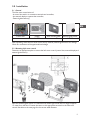 5
5
-
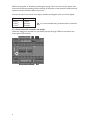 6
6
-
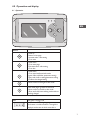 7
7
-
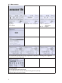 8
8
-
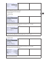 9
9
-
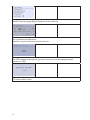 10
10
-
 11
11
-
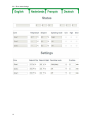 12
12
-
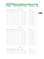 13
13
-
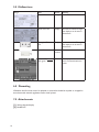 14
14
-
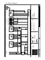 15
15
-
 16
16
-
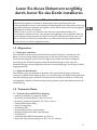 17
17
-
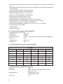 18
18
-
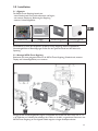 19
19
-
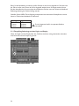 20
20
-
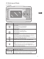 21
21
-
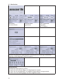 22
22
-
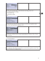 23
23
-
 24
24
-
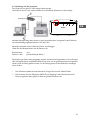 25
25
-
 26
26
-
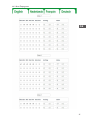 27
27
-
 28
28
-
 29
29
-
 30
30
-
 31
31
-
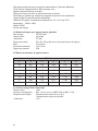 32
32
-
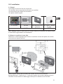 33
33
-
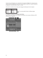 34
34
-
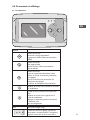 35
35
-
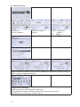 36
36
-
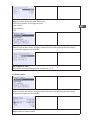 37
37
-
 38
38
-
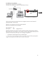 39
39
-
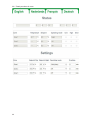 40
40
-
 41
41
-
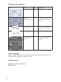 42
42
-
 43
43
-
 44
44
-
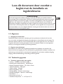 45
45
-
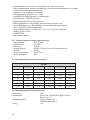 46
46
-
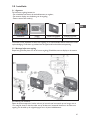 47
47
-
 48
48
-
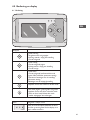 49
49
-
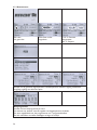 50
50
-
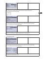 51
51
-
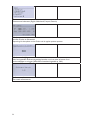 52
52
-
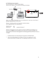 53
53
-
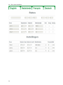 54
54
-
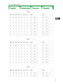 55
55
-
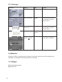 56
56
-
 57
57
-
 58
58
-
 59
59
-
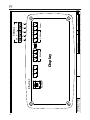 60
60
-
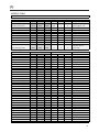 61
61
-
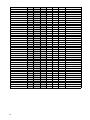 62
62
-
 63
63
-
 64
64
-
 65
65
-
 66
66


Mark 3003795 Technical Manual
- Type
- Technical Manual
- Deze handleiding is ook geschikt voor
in andere talen
- English: Mark 3003795
- français: Mark 3003795
- Deutsch: Mark 3003795
Gerelateerde papieren
Andere documenten
-
Equip 769248 Data papier
-
Trane WFE 2 Technical Manual
-
Gossen MetraWatt METRAHIT ETECH Handleiding
-
-
 Hach Polymetron 9523sc pH Basic User Manual
-
REMEHA iSense Handleiding
-
REMEHA Timer thermostat Handleiding
-
RADSON 51004 Handleiding
-
OJ Electronics ETO2-EU Handleiding
-
